DE102009046662A1 - Device for removing containers - Google Patents
Device for removing containers Download PDFInfo
- Publication number
- DE102009046662A1 DE102009046662A1 DE102009046662A DE102009046662A DE102009046662A1 DE 102009046662 A1 DE102009046662 A1 DE 102009046662A1 DE 102009046662 A DE102009046662 A DE 102009046662A DE 102009046662 A DE102009046662 A DE 102009046662A DE 102009046662 A1 DE102009046662 A1 DE 102009046662A1
- Authority
- DE
- Germany
- Prior art keywords
- transport
- containers
- container
- transport container
- identification
- Prior art date
- Legal status (The legal status is an assumption and is not a legal conclusion. Google has not performed a legal analysis and makes no representation as to the accuracy of the status listed.)
- Withdrawn
Links
Images


Classifications
-
- B—PERFORMING OPERATIONS; TRANSPORTING
- B65—CONVEYING; PACKING; STORING; HANDLING THIN OR FILAMENTARY MATERIAL
- B65G—TRANSPORT OR STORAGE DEVICES, e.g. CONVEYORS FOR LOADING OR TIPPING, SHOP CONVEYOR SYSTEMS OR PNEUMATIC TUBE CONVEYORS
- B65G37/00—Combinations of mechanical conveyors of the same kind, or of different kinds, of interest apart from their application in particular machines or use in particular manufacturing processes
- B65G37/02—Flow-sheets for conveyor combinations in warehouses, magazines or workshops
-
- G—PHYSICS
- G01—MEASURING; TESTING
- G01N—INVESTIGATING OR ANALYSING MATERIALS BY DETERMINING THEIR CHEMICAL OR PHYSICAL PROPERTIES
- G01N35/00—Automatic analysis not limited to methods or materials provided for in any single one of groups G01N1/00 - G01N33/00; Handling materials therefor
- G01N35/02—Automatic analysis not limited to methods or materials provided for in any single one of groups G01N1/00 - G01N33/00; Handling materials therefor using a plurality of sample containers moved by a conveyor system past one or more treatment or analysis stations
- G01N35/04—Details of the conveyor system
- G01N2035/0401—Sample carriers, cuvettes or reaction vessels
- G01N2035/0418—Plate elements with several rows of samples
- G01N2035/0422—Plate elements with several rows of samples carried on a linear conveyor
-
- G—PHYSICS
- G01—MEASURING; TESTING
- G01N—INVESTIGATING OR ANALYSING MATERIALS BY DETERMINING THEIR CHEMICAL OR PHYSICAL PROPERTIES
- G01N35/00—Automatic analysis not limited to methods or materials provided for in any single one of groups G01N1/00 - G01N33/00; Handling materials therefor
- G01N35/02—Automatic analysis not limited to methods or materials provided for in any single one of groups G01N1/00 - G01N33/00; Handling materials therefor using a plurality of sample containers moved by a conveyor system past one or more treatment or analysis stations
- G01N35/04—Details of the conveyor system
- G01N2035/046—General conveyor features
- G01N2035/0465—Loading or unloading the conveyor
Landscapes
- Immunology (AREA)
- General Health & Medical Sciences (AREA)
- Life Sciences & Earth Sciences (AREA)
- Chemical & Material Sciences (AREA)
- Physics & Mathematics (AREA)
- Biochemistry (AREA)
- Health & Medical Sciences (AREA)
- General Physics & Mathematics (AREA)
- Analytical Chemistry (AREA)
- Pathology (AREA)
- Engineering & Computer Science (AREA)
- Mechanical Engineering (AREA)
- Specific Conveyance Elements (AREA)
- Auxiliary Devices For And Details Of Packaging Control (AREA)
- Medical Preparation Storing Or Oral Administration Devices (AREA)
- Feeding Of Articles To Conveyors (AREA)
Abstract
Die Erfindung betrifft eine Vorrichtung (10) zur Entnahme von Behältern (3), insbesondere von pharmazeutischen Behältern (3), aus einer die Behälter (3) in Transportbehältern (1) fördernden ersten Transporteinrichtung (15), mit einer am Transportweg der ersten Transporteinrichtung (15) angeordneten ersten Identifikationseinrichtung (32) zur Identifikation der Transportbehälter (1), mit einer der ersten Identifikationseinrichtung (32) nachgeordneten Ausschleuseinrichtung (24), die einen Transportbehälter (1) auf eine zweite Transporteinrichtung (23) überführt, an deren Förderstrecke eine Entnahmeeinrichtung (35) zur Entnahme wenigstens eines Behälters (3) angeordnet ist, und mit einer Einschleuseinrichtung (27) zum Wiedereinschleusen des Transportbehälters (1) in die erste Fördereinrichtung (15).The invention relates to a device (10) for removing containers (3), in particular pharmaceutical containers (3), from a first transport device (15) conveying the containers (3) in transport containers (1), with one on the transport path of the first transport device (15) arranged first identification device (32) for identifying the transport container (1), with a discharge device (24) downstream of the first identification device (32), which transfers a transport container (1) to a second transport device (23), on the conveying path of which a Removal device (35) is arranged for removing at least one container (3), and with a transfer device (27) for re-transferring the transport container (1) into the first conveyor device (15).
Description
Stand der TechnikState of the art
Die Erfindung betrifft eine Vorrichtung zur Entnahme von Behältern.The invention relates to a device for removing containers.
In der pharmazeutischen Verpackungsindustrie ist es bekannt, Behälter wie Spritzenkörper, Vials oder Ampullen auf kombinierten Füll- und Verschließanlagen zu verarbeiten. Hierbei werden die pharmazeutischen Behälter beispielsweise mit einem flüssigen Pharmazeutika befüllt, gewogen und anschließend mit einem Verschlusselement verschlossen. Im Rahmen des Produktionsprozesses bzw. der unterschiedlichen Bearbeitungsschritte werden die Behälter weiterhin verschiedenen Kontrollen unterzogen, um eine ordnungsgemäße Befüllung sowie einen ordnungsgemäßen Verschluss der Behälter zu gewährleisten. Sollte es hierbei zu Fehlern während der Verarbeitung der Behälter gekommen sein, so ist es erforderlich, die Behälter an einer geeigneten Station auszuschleusen.In the pharmaceutical packaging industry it is known to process containers such as syringe bodies, vials or ampoules on combined filling and sealing systems. Here, the pharmaceutical container, for example, filled with a liquid pharmaceuticals, weighed and then sealed with a closure element. As part of the production process or the different processing steps, the containers continue to undergo various controls to ensure proper filling and proper closure of the containers. Should this lead to errors during the processing of the containers, it is necessary to discharge the containers at a suitable station.
Bekannt ist es, die Behälter aus einer die Behälter fördernden Fördereinrichtung direkt zu entnehmen. Das bedeutet, dass die dabei entstehenden Lücken bei der Entnahme der Behälter entweder mit „Gut-Behältern” aufgefüllt werden müssen, um bei nachfolgenden Verarbeitungsschritten keine Schwierigkeiten an den entsprechenden Stationen hervorzurufen, oder dass für die Zeit der Überprüfung bzw. Entnahme der Behälter aus der Fördereinrichtung die Fördereinrichtung angehalten werden muss. Dies ist insbesondere dann problematisch, wenn die Überprüfung bzw. das Ausschleusen der Behälter aus der Förderanlage relativ viel Zeit beansprucht.It is known to remove the containers directly from a conveying device that conveys the containers. This means that the resulting gaps in the removal of the containers must be filled with either "good containers" to cause in subsequent processing steps no difficulties at the corresponding stations, or that for the period of review or removal of the container from the Conveyor the conveyor must be stopped. This is particularly problematic when the review or the removal of the container from the conveyor claimed a relatively long time.
Aus der
Offenbarung der ErfindungDisclosure of the invention
Ausgehend von dem dargestellten Stand der Technik liegt der Erfindung die Aufgabe zugrunde, eine Vorrichtung zur Entnahme von Behältern derart auszubilden, dass ein laufender Produktions- bzw. Förderprozess in der Verpackungsanlage möglichst wenig gestört wird. Diese Aufgabe wird bei einer Vorrichtung zur Entnahme von Behälter mit den Merkmalen des Anspruchs 1 gelöst. Der Erfindung liegt dabei die Idee zugrunde, durch eine Ausschleuseinrichtung Transportbehälter, die potenziell fehlerhafte Behälter enthalten, auf eine von einer ersten Transporteinrichtung getrennte bzw. separate zweite Transporteinrichtung zu überführen. Dadurch wird es ermöglicht, dass der Produktions- bzw. Transportfluss von Transportbehältern auf der ersten Fördereinrichtung nicht gestört wird, d. h. nachfolgende Transportbehälter mit „Gut-Behältnissen” weitertransportiert werden, ohne dass die betreffenden Transportbehälter ausgeschleust bzw. gestoppt werden.Starting from the illustrated prior art, the invention has the object, an apparatus for removing containers in such a way that a running production or conveying process in the packaging plant is disturbed as little as possible. This object is achieved in a device for removing containers with the features of claim 1. The invention is based on the idea to transfer by a discharge device transport containers containing potentially defective container on a separate or separate from a first transport means second transport device. This makes it possible that the production or transport flow of transport containers on the first conveyor is not disturbed, d. H. subsequent transport containers are transported on with "good containers" without the respective transport containers being ejected or stopped.
Dadurch, dass sich der Transportbehälter mit den potenziell fehlerhaften Behältern auf der zweiten Transporteinrichtung befindet, kann die Überprüfung der Behälter in dem Transportbehälter auf der zweiten Transporteinrichtung prinzipiell beliebig lange dauern, ohne dass dies zu Nachteilen führt. Insbesondere können auch relativ aufwändige bzw. zeitintensive Tests an den Behältern durchgeführt werden.Due to the fact that the transport container with the potentially defective containers is located on the second transport device, the checking of the containers in the transport container on the second transport device can, in principle, take any length, without resulting in disadvantages. In particular, relatively complex or time-consuming tests can be carried out on the containers.
Vorteilhafte Weiterbildungen der erfindungsgemäßen Vorrichtung zur Entnahme von Behältern sind in den Unteransprüchen angegeben. In den Rahmen der Erfindung fallen sämtliche Kombinationen aus zumindest zwei von in den Ansprüchen, der Beschreibung und/oder den Figuren offenbarten Merkmalen.Advantageous developments of the device according to the invention for the removal of containers are given in the dependent claims. All combinations of at least two of the features disclosed in the claims, the description and / or the figures fall within the scope of the invention.
In einer bevorzugten Ausführungsform der Erfindung ist es vorgesehen, dass der Transportbehälter eine Aufnahmeeinrichtung für eine Vielzahl von in Aufnahmen angeordneten Behältern aufweist und, dass die Aufnahmeeinrichtung in dem Transportbehälter heraus- und einführbar angeordnet ist. Dadurch lassen sich auf einfache Art und Weise die in den Aufnahmen der Aufnahmeeinrichtung angeordneten Behälter mittels einer geeigneten Entnahmeeinrichtung entnehmen und beispielsweise durch „Gut-Behältnisse” ersetzen, so dass der Transportbehälter anschließend beispielsweise direkt wieder in den Produktionsfluss bzw. in die erste Transporteinrichtung eingeschleust werden kann.In a preferred embodiment of the invention, it is provided that the transport container has a receiving device for a plurality of containers arranged in receptacles and that the receiving device in the transport container out and is arranged to be inserted. As a result, the containers arranged in the receptacles of the receptacle can be removed in a simple manner by means of a suitable removal device and replaced, for example, by "good containers", so that the transport containers are subsequently introduced, for example, directly back into the production flow or into the first transport device can.
Besonders bevorzugt ist hierbei, Wenn im Bereich der zweiten Transporteinrichtung eine Einrichtung zur Entnahme und zum Transport der Aufnahmeeinrichtung aus dem Transportbehälter angeordnet ist, die die Aufnahmeeinrichtung zur Entnahme wenigstens eines Behälters aus dem Transportbehälter der Entnahmeeinrichtung zuführt. Dadurch wird eine hohe Flexibilität bezüglich der Anordnung der Entnahmeeinrichtung erzielt, so dass die Entnahme von Behältern räumlich von der Entnahme der Aufnahmeeinrichtungen getrennt ist.In this case, if in the region of the second transport device, a device for removal and transport of the receiving device from the transport container is arranged, which supplies the receiving device for removing at least one container from the transport container of the removal device. This results in a high degree of flexibility with respect to the arrangement of the removal device, so that the removal of containers is spatially separated from the removal of the receiving devices.
Um sicherzustellen, dass die richtigen Behälter aus den Transportbehältern entnommen werden, ist es darüber hinaus in einer weiteren bevorzugten Ausführungsform der Erfindung vorgesehen, dass im Bereich der zweiten Transporteinrichtung eine zweite Identifikationseinrichtung angeordnet ist und, dass die zweite Identifikationseinrichtung mit der Entnahmeeinrichtung zur Entnahme mindestens eines Behälters aus dem Transportbehälter zusammenwirkt. Dadurch wird sichergestellt, dass nur solche Behälter aus dem Transportbehälter entnommen werden, welche mittels der ersten und der zweiten Identifikationseinrichtung als fehlerhaft identifiziert wurden.In order to ensure that the correct containers are removed from the transport containers, it is additionally provided in a further preferred embodiment of the invention that a second identification device is arranged in the region of the second transport device and that the second identification device with the removal device for removal of at least one Container cooperates from the transport container. This ensures that only those containers are removed from the transport container, which were identified by means of the first and the second identification device as faulty.
Weiterhin ist in vorteilhafter Weise vorgesehen, dass im Bereich der zweiten Transporteinrichtung eine Ausschleuseinrichtung für Transportbehälter angeordnet ist. Diese Ausschleuseinrichtung dient dazu, Transportbehälter auszuschleusen, welche entweder von der ersten Fördereinrichtung direkt ausgeschleust werden, oder solche Transportbehälter auszuschleusen, welche selbst nach Umlauf über die zweite Fördereinrichtung noch als fehlerhaft identifiziert werden.Furthermore, it is advantageously provided that a discharge device for transport containers is arranged in the region of the second transport device. This discharge device serves to discharge transport containers, which are either discharged directly from the first conveyor, or auszuschleusen such transport containers, which are still identified as defective even after circulation on the second conveyor.
Insbesondere kann es vorgesehen sein, dass im Bereich der zweiten Transporteinrichtung eine Prüfeinrichtung, insbesondere eine Wiegeeinrichtung, angeordnet ist. Im Bereich der zweiten Transporteinrichtung können somit die Behälter, welche vorab als kritisch bzw. fehlerhaft identifiziert, oder vom Bediener oder von der Maschinensteuerung gezielt oder zufällig ausgewählt wurden, mittels geeigneter Prüfeinrichtungen überprüft werden. Hierdurch können die Produktionsschritte der Verpackungsanlage überprüft oder sichergestellt werden, dass keine Behälter ausgeschleust werden, die „gut” sind.In particular, provision may be made for a test device, in particular a weighing device, to be arranged in the region of the second transport device. Thus, in the area of the second transport device, the containers which have been previously identified as being critical or faulty, or which have been selectively or randomly selected by the operator or by the machine control, can be checked by means of suitable testing devices. In this way, the production steps of the packaging system can be checked or ensured that no containers are discharged, which are "good".
Ein einfaches Handling der Transportbehälter auf der ersten Transporteinrichtung und der zweiten Transporteinrichtung wird ermöglicht, wenn die beiden Transporteinrichtungen jeweils als Transportbänder ausgebildet sind, auf denen die Transportbehälter durch Reibschluss gefördert werden. Solche Transporteinrichtungen sind in der Montagetechnik bzw. in Fertigungsanlagen in vielfältigster Weise bekannt und ermöglichen beispielsweise durch den Einsatz von quer verlaufenden Förderbändern sowie in den Förderweg der Transportbehälter hineinragende Auslenk- oder Blockierelemente die Steuerung der Bewegung der Transportbehälter.A simple handling of the transport container on the first transport device and the second transport device is made possible if the two transport devices are each designed as conveyor belts on which the transport containers are conveyed by frictional engagement. Such transport devices are known in assembly technology or in production plants in a variety of ways and allow, for example by the use of transverse conveyor belts as well as in the conveying path of the transport container projecting deflection or blocking elements controlling the movement of the transport container.
Um das Ergebnis der Überprüfung oder die Anzahl nicht fehlerhafter Behälter in dem Transportbehältnis zu dokumentieren oder sonstige Informationen aufbringen zu können, ist es in einer vorteilhaften Weiterbildung der Erfindung vorgesehen, dass im Bereich der ersten Transporteinrichtung eine Kennzeichnungseinrichtung für die in diesem Bereich transportierten Transportbehälter angeordnet ist.In order to be able to document the result of the check or the number of non-defective containers in the transport container or to apply other information, it is provided in an advantageous development of the invention that in the region of the first transport means an identification device for the transported in this area transport container is arranged ,
Die erfindungsgemäße Vorrichtung zur Entnahme von Behältern ist bevorzugt Bestandteil einer Verpackungsanlage, welche eine Vielzahl von Bearbeitungsstationen aufweist. Hierbei schließt sich die erfindungsgemäße Vorrichtung bevorzugt ans Ende der Verpackungsanlage an, d. h., dass an dieser Stelle alle während des Produktionsprozesses der Behälter festgestellten Unregelmäßigkeiten bzw. Fehler an den Behältern dadurch berücksichtigt werden, dass die entsprechenden Behälter aus der Verpackungsanlage ausgeschleust werden. Hierzu ist es in einer bevorzugten Ausführungsform vorgesehen, dass die erste Identifikationseinrichtung der Vorrichtung mit einer Steuereinrichtung der Verpackungsanlage gekoppelt ist. Dadurch, dass in der Steuereinrichtung der Verpackungsanlage alle während des Produktionsprozesses der einzelnen Behälter aufgetretenen Fehler bzw. Daten gespeichert werden können, kann mit einer derartigen Merkmalskombination sichergestellt werden, dass alle potenziell fehlerhaften Behälter mittels der erfindungsgemäßen Vorrichtung ausgeschleust werden.The device for removing containers according to the invention is preferably part of a packaging installation which has a plurality of processing stations. Here, the device according to the invention preferably connects to the end of the packaging system, d. h., That at this point all detected during the production process of the container irregularities or errors in the containers are taken into account by the corresponding containers are discharged from the packaging plant. For this purpose, it is provided in a preferred embodiment that the first identification device of the device is coupled to a control device of the packaging system. By virtue of the fact that all errors or data which have occurred during the production process of the individual containers can be stored in the control device of the packaging installation, it can be ensured with such a feature combination that all potentially defective containers are removed by means of the device according to the invention.
Weitere Vorteile und Merkmale der Erfindung ergeben sich aus der nachfolgenden Beschreibung bevorzugter Ausführungsbeispiele sowie anhand der Zeichnung. Diese zeigt in:Further advantages and features of the invention will become apparent from the following description of preferred embodiments and from the drawing. This shows in:
In der
In der
In den
Um Spritzenkörper
Die Verpackungsanlage
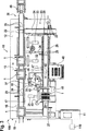
Die Vorrichtung
Die erste Transporteinrichtung
Wesentlich ist noch, dass fluchtend mit dem Transportband
Im Bereich der ersten Transporteinrichtung
Hierbei ist die erste Kamera
In etwa im mittleren Bereich der Tischplatte
An den Handhabungsroboter
Ferner erkennt man auf der Tischplatte
Die soweit beschriebene Vorrichtung
Sollte es sich demgegenüber bei dem Transportbehälter
Die so behandelte Aufnahmeeinrichtung
Wesentlich ist noch, dass diejenigen Transportbehälter
Die soweit beschriebene Vorrichtung
ZITATE ENTHALTEN IN DER BESCHREIBUNG QUOTES INCLUDE IN THE DESCRIPTION
Diese Liste der vom Anmelder aufgeführten Dokumente wurde automatisiert erzeugt und ist ausschließlich zur besseren Information des Lesers aufgenommen. Die Liste ist nicht Bestandteil der deutschen Patent- bzw. Gebrauchsmusteranmeldung. Das DPMA übernimmt keinerlei Haftung für etwaige Fehler oder Auslassungen.This list of the documents listed by the applicant has been generated automatically and is included solely for the better information of the reader. The list is not part of the German patent or utility model application. The DPMA assumes no liability for any errors or omissions.
Zitierte PatentliteraturCited patent literature
- DE 19604100 A1 [0004] DE 19604100 A1 [0004]
Claims (10)
Priority Applications (6)
| Application Number | Priority Date | Filing Date | Title |
|---|---|---|---|
| DE102009046662A DE102009046662A1 (en) | 2009-11-12 | 2009-11-12 | Device for removing containers |
| US13/509,680 US20130015108A1 (en) | 2009-11-12 | 2010-10-01 | Device for extracting containers |
| PCT/EP2010/064627 WO2011057862A1 (en) | 2009-11-12 | 2010-10-01 | Device for extracting containers |
| IN2146DEN2012 IN2012DN02146A (en) | 2009-11-12 | 2010-10-01 | |
| CN201080051075.2A CN102612654B (en) | 2009-11-12 | 2010-10-01 | For taking out the device of container |
| EP10762647.5A EP2499501B1 (en) | 2009-11-12 | 2010-10-01 | Device for extracting containers and packaging machine |
Applications Claiming Priority (1)
| Application Number | Priority Date | Filing Date | Title |
|---|---|---|---|
| DE102009046662A DE102009046662A1 (en) | 2009-11-12 | 2009-11-12 | Device for removing containers |
Publications (1)
| Publication Number | Publication Date |
|---|---|
| DE102009046662A1 true DE102009046662A1 (en) | 2011-05-19 |
Family
ID=43416615
Family Applications (1)
| Application Number | Title | Priority Date | Filing Date |
|---|---|---|---|
| DE102009046662A Withdrawn DE102009046662A1 (en) | 2009-11-12 | 2009-11-12 | Device for removing containers |
Country Status (6)
| Country | Link |
|---|---|
| US (1) | US20130015108A1 (en) |
| EP (1) | EP2499501B1 (en) |
| CN (1) | CN102612654B (en) |
| DE (1) | DE102009046662A1 (en) |
| IN (1) | IN2012DN02146A (en) |
| WO (1) | WO2011057862A1 (en) |
Cited By (1)
| Publication number | Priority date | Publication date | Assignee | Title |
|---|---|---|---|---|
| DE102019201950A1 (en) * | 2019-02-14 | 2020-08-20 | Syntegon Technology Gmbh | Device and method for inserting mixing balls in pharmaceutical containers |
Families Citing this family (5)
| Publication number | Priority date | Publication date | Assignee | Title |
|---|---|---|---|---|
| CH712191A1 (en) * | 2016-03-04 | 2017-09-15 | Wrh Walter Reist Holding Ag | Conveyor with a conveyor chain and with a plurality of attached to the conveyor chain Fördergutbehältern. |
| DE102016209710A1 (en) * | 2016-06-02 | 2017-12-07 | Robert Bosch Gmbh | Apparatus and method for inspecting containers |
| WO2019094547A1 (en) * | 2017-11-08 | 2019-05-16 | Windgap Medical, Inc. | A system and method for providing and assembling an auto-injector |
| CN109436801A (en) * | 2018-11-29 | 2019-03-08 | 杭州捷能科技有限公司 | A kind of part automatic charging device and part automatic charging method |
| DE102019129329A1 (en) * | 2019-10-30 | 2021-05-06 | Ma Micro Automation Gmbh | Handling device and removal station |
Citations (4)
| Publication number | Priority date | Publication date | Assignee | Title |
|---|---|---|---|---|
| DE19604100A1 (en) | 1996-02-06 | 1997-08-14 | Bosch Gmbh Robert | Device for handling objects arranged in a packaging container |
| DE10204247A1 (en) * | 2002-02-02 | 2003-08-21 | Opel Adam Ag | Method for transferring components into and out of a transport system especially for production of motor vehicle electronic modules, involves using control system for writing production data on data carrier to be fixed to component |
| DE202004018512U1 (en) * | 2004-10-08 | 2005-09-22 | Kuka Schweissanlagen Gmbh | Process line especially for vehicle body sections has a closed loop transporter with switches to feed separate groups of process stations |
| DE102004035061A1 (en) * | 2004-07-20 | 2006-02-16 | Bausch + Ströbel Maschinenfabrik Ilshofen GmbH + Co. KG | Device for filling an injection body with a liquid comprises a weighing unit having a lifting mechanism for lifting the injection body from its seat in the carrier plate |
Family Cites Families (17)
| Publication number | Priority date | Publication date | Assignee | Title |
|---|---|---|---|---|
| DE3408081A1 (en) * | 1984-03-05 | 1985-09-19 | Siemens AG, 1000 Berlin und 8000 München | PICKING DEVICE |
| US5578331A (en) * | 1994-06-10 | 1996-11-26 | Vision Products, Inc. | Automated apparatus for preparing contact lenses for inspection and packaging |
| US5623415A (en) * | 1995-02-16 | 1997-04-22 | Smithkline Beecham Corporation | Automated sampling and testing of biological materials |
| JP3031242B2 (en) * | 1996-05-20 | 2000-04-10 | 株式会社日立製作所 | Multi-item analyzer |
| CA2255839A1 (en) * | 1996-07-05 | 1998-01-15 | Mark Gross | Automated sample processing system |
| JP3336894B2 (en) * | 1997-01-29 | 2002-10-21 | 株式会社日立製作所 | Automatic analyzer |
| DE19819812C2 (en) * | 1998-05-04 | 2000-11-02 | Olympus Diagnostica Gmbh | Laboratory primary sample distributor with a distribution device |
| DE19819813C2 (en) * | 1998-05-04 | 2000-11-02 | Olympus Diagnostica Gmbh | Use of a laboratory primary sample distributor for archiving |
| JP4136187B2 (en) * | 1999-05-14 | 2008-08-20 | シスメックス株式会社 | Sample transfer device |
| FR2867861B1 (en) * | 2004-03-16 | 2006-07-14 | Abx Sa | DEVICE FOR SUPPLYING TOTAL BLOOD ANALYZERS |
| EP1630550A1 (en) * | 2004-08-27 | 2006-03-01 | Moller & Devicon A/S | Methods and apparatuses of detecting foreign particles or faults in a plurality of filled containers |
| CH702317B1 (en) * | 2007-08-02 | 2011-06-15 | Stevanato Group Internat As | Structure of the pack of glass vials for pharmaceutical use. |
| DE102007048684B4 (en) * | 2007-10-10 | 2010-09-09 | Polysius Ag | laboratory system |
| JP5198094B2 (en) * | 2008-03-07 | 2013-05-15 | シスメックス株式会社 | Analysis equipment |
| US8822224B2 (en) * | 2008-07-02 | 2014-09-02 | Prairie Ventures Llc | Method for automatic testing of anatomical laboratory specimens |
| EP2148205B1 (en) * | 2008-07-25 | 2013-01-02 | F. Hoffmann-La Roche AG | A method and laboratory system for handling sample tubes and an image analysing unit |
| JP5378859B2 (en) * | 2009-03-30 | 2013-12-25 | シスメックス株式会社 | Sample testing system |
-
2009
- 2009-11-12 DE DE102009046662A patent/DE102009046662A1/en not_active Withdrawn
-
2010
- 2010-10-01 CN CN201080051075.2A patent/CN102612654B/en active Active
- 2010-10-01 WO PCT/EP2010/064627 patent/WO2011057862A1/en active Application Filing
- 2010-10-01 IN IN2146DEN2012 patent/IN2012DN02146A/en unknown
- 2010-10-01 EP EP10762647.5A patent/EP2499501B1/en active Active
- 2010-10-01 US US13/509,680 patent/US20130015108A1/en not_active Abandoned
Patent Citations (4)
| Publication number | Priority date | Publication date | Assignee | Title |
|---|---|---|---|---|
| DE19604100A1 (en) | 1996-02-06 | 1997-08-14 | Bosch Gmbh Robert | Device for handling objects arranged in a packaging container |
| DE10204247A1 (en) * | 2002-02-02 | 2003-08-21 | Opel Adam Ag | Method for transferring components into and out of a transport system especially for production of motor vehicle electronic modules, involves using control system for writing production data on data carrier to be fixed to component |
| DE102004035061A1 (en) * | 2004-07-20 | 2006-02-16 | Bausch + Ströbel Maschinenfabrik Ilshofen GmbH + Co. KG | Device for filling an injection body with a liquid comprises a weighing unit having a lifting mechanism for lifting the injection body from its seat in the carrier plate |
| DE202004018512U1 (en) * | 2004-10-08 | 2005-09-22 | Kuka Schweissanlagen Gmbh | Process line especially for vehicle body sections has a closed loop transporter with switches to feed separate groups of process stations |
Cited By (2)
| Publication number | Priority date | Publication date | Assignee | Title |
|---|---|---|---|---|
| DE102019201950A1 (en) * | 2019-02-14 | 2020-08-20 | Syntegon Technology Gmbh | Device and method for inserting mixing balls in pharmaceutical containers |
| US11713143B2 (en) | 2019-02-14 | 2023-08-01 | Syntegon Technology Gmbh | Apparatus and method for placing mixing balls into pharmaceutical containers |
Also Published As
| Publication number | Publication date |
|---|---|
| US20130015108A1 (en) | 2013-01-17 |
| EP2499501A1 (en) | 2012-09-19 |
| EP2499501B1 (en) | 2013-07-03 |
| WO2011057862A1 (en) | 2011-05-19 |
| CN102612654B (en) | 2016-07-06 |
| IN2012DN02146A (en) | 2015-08-07 |
| CN102612654A (en) | 2012-07-25 |
Similar Documents
| Publication | Publication Date | Title |
|---|---|---|
| EP2570350B1 (en) | Method and device for filling and sealing pharmaceutical objects | |
| EP2448820B1 (en) | Device for filling and sealing pharmaceutical containers | |
| EP2280873B1 (en) | Filling and sealing machine for containers | |
| EP2499501B1 (en) | Device for extracting containers and packaging machine | |
| DE102010004630A1 (en) | Packaging plant with discharge station | |
| DE102010005267A1 (en) | Conveying device for use with attachment device for packaged goods distribution system for packaged goods, has conveying head which has receiving area for manual placing of packaged goods | |
| DE102017100010A1 (en) | Device and method for filling nested containers | |
| DE102010028125A1 (en) | Device for filling and closing capsules filled with at least one filling substance | |
| DE202009012064U1 (en) | Device for conveying objects, labeling device, inspection device and rotary filler with such a conveying device | |
| DE102005062715B4 (en) | Apparatus for filling receptacles with the products of a rotary press | |
| DE102014001741A1 (en) | Labeling device, labeling system and method for loading a product with a label | |
| DE102010040505A1 (en) | Machine and method for filling and closing capsules, in particular consisting of hard gelatine | |
| DE102015203060B4 (en) | Inspection device and method for inspecting containers | |
| DE102005014116B4 (en) | Method and device for controlled filling | |
| DE102017120730A1 (en) | Device and method for aligning containers | |
| EP3678792B1 (en) | Device and method for removing containers which have been incorrectly imprinted in a direct printing machine | |
| DE102004012043A1 (en) | Device and method for the positionally correct transfer of cuboid goods | |
| EP4043366A1 (en) | Transfer device for transferring components to a safety-critical production side | |
| DE102018128498A1 (en) | Component tracking procedures | |
| EP3789129A1 (en) | Method and apparatus for monitoring the operation of a container cleaner | |
| EP3463695B1 (en) | Device and method for inspecting containers | |
| DE4332645A1 (en) | Drinks-pouring machine | |
| DE102014209001A1 (en) | Method and device for aligning individual elements, in particular filter elements, during transfer for further processing | |
| DE102021127564B3 (en) | Device and method for closing containers with closures | |
| DE102017108903B4 (en) | Treatment device and container treatment machine |
Legal Events
| Date | Code | Title | Description |
|---|---|---|---|
| OM8 | Search report available as to paragraph 43 lit. 1 sentence 1 patent law | ||
| R119 | Application deemed withdrawn, or ip right lapsed, due to non-payment of renewal fee |