DE102004030037B4 - accumulator - Google Patents
accumulator Download PDFInfo
- Publication number
- DE102004030037B4 DE102004030037B4 DE102004030037A DE102004030037A DE102004030037B4 DE 102004030037 B4 DE102004030037 B4 DE 102004030037B4 DE 102004030037 A DE102004030037 A DE 102004030037A DE 102004030037 A DE102004030037 A DE 102004030037A DE 102004030037 B4 DE102004030037 B4 DE 102004030037B4
- Authority
- DE
- Germany
- Prior art keywords
- accumulator
- cells
- battery
- constructions
- battery cells
- Prior art date
- Legal status (The legal status is an assumption and is not a legal conclusion. Google has not performed a legal analysis and makes no representation as to the accuracy of the status listed.)
- Active
Links
- 210000004027 cell Anatomy 0.000 description 150
- 238000010276 construction Methods 0.000 description 82
- 238000001514 detection method Methods 0.000 description 8
- 238000010586 diagram Methods 0.000 description 5
- 229910001416 lithium ion Inorganic materials 0.000 description 5
- 238000000034 method Methods 0.000 description 5
- GCICAPWZNUIIDV-UHFFFAOYSA-N lithium magnesium Chemical compound [Li].[Mg] GCICAPWZNUIIDV-UHFFFAOYSA-N 0.000 description 4
- 238000005259 measurement Methods 0.000 description 4
- 239000000126 substance Substances 0.000 description 4
- PXHVJJICTQNCMI-UHFFFAOYSA-N Nickel Chemical compound [Ni] PXHVJJICTQNCMI-UHFFFAOYSA-N 0.000 description 3
- 239000003990 capacitor Substances 0.000 description 3
- 230000000295 complement effect Effects 0.000 description 3
- 230000005611 electricity Effects 0.000 description 3
- -1 For example Polymers 0.000 description 2
- WHXSMMKQMYFTQS-UHFFFAOYSA-N Lithium Chemical compound [Li] WHXSMMKQMYFTQS-UHFFFAOYSA-N 0.000 description 2
- HBBGRARXTFLTSG-UHFFFAOYSA-N Lithium ion Chemical compound [Li+] HBBGRARXTFLTSG-UHFFFAOYSA-N 0.000 description 2
- 210000002421 cell wall Anatomy 0.000 description 2
- 238000007599 discharging Methods 0.000 description 2
- 229910052744 lithium Inorganic materials 0.000 description 2
- 238000012544 monitoring process Methods 0.000 description 2
- 229910052759 nickel Inorganic materials 0.000 description 2
- 229910052596 spinel Inorganic materials 0.000 description 2
- 239000011029 spinel Substances 0.000 description 2
- RNFJDJUURJAICM-UHFFFAOYSA-N 2,2,4,4,6,6-hexaphenoxy-1,3,5-triaza-2$l^{5},4$l^{5},6$l^{5}-triphosphacyclohexa-1,3,5-triene Chemical compound N=1P(OC=2C=CC=CC=2)(OC=2C=CC=CC=2)=NP(OC=2C=CC=CC=2)(OC=2C=CC=CC=2)=NP=1(OC=1C=CC=CC=1)OC1=CC=CC=C1 RNFJDJUURJAICM-UHFFFAOYSA-N 0.000 description 1
- 239000004743 Polypropylene Substances 0.000 description 1
- 238000009825 accumulation Methods 0.000 description 1
- 230000000903 blocking effect Effects 0.000 description 1
- OJIJEKBXJYRIBZ-UHFFFAOYSA-N cadmium nickel Chemical compound [Ni].[Cd] OJIJEKBXJYRIBZ-UHFFFAOYSA-N 0.000 description 1
- CKFRRHLHAJZIIN-UHFFFAOYSA-N cobalt lithium Chemical compound [Li].[Co] CKFRRHLHAJZIIN-UHFFFAOYSA-N 0.000 description 1
- 238000004891 communication Methods 0.000 description 1
- 229920001971 elastomer Polymers 0.000 description 1
- 239000003063 flame retardant Substances 0.000 description 1
- 230000017525 heat dissipation Effects 0.000 description 1
- 238000004519 manufacturing process Methods 0.000 description 1
- 229910052987 metal hydride Inorganic materials 0.000 description 1
- 230000003071 parasitic effect Effects 0.000 description 1
- 229920001155 polypropylene Polymers 0.000 description 1
- 238000012552 review Methods 0.000 description 1
- 230000011664 signaling Effects 0.000 description 1
- 229920002725 thermoplastic elastomer Polymers 0.000 description 1
- 238000012546 transfer Methods 0.000 description 1
- 238000004804 winding Methods 0.000 description 1
Images


Classifications
-
- B—PERFORMING OPERATIONS; TRANSPORTING
- B23—MACHINE TOOLS; METAL-WORKING NOT OTHERWISE PROVIDED FOR
- B23D—PLANING; SLOTTING; SHEARING; BROACHING; SAWING; FILING; SCRAPING; LIKE OPERATIONS FOR WORKING METAL BY REMOVING MATERIAL, NOT OTHERWISE PROVIDED FOR
- B23D45/00—Sawing machines or sawing devices with circular saw blades or with friction saw discs
-
- B—PERFORMING OPERATIONS; TRANSPORTING
- B23—MACHINE TOOLS; METAL-WORKING NOT OTHERWISE PROVIDED FOR
- B23D—PLANING; SLOTTING; SHEARING; BROACHING; SAWING; FILING; SCRAPING; LIKE OPERATIONS FOR WORKING METAL BY REMOVING MATERIAL, NOT OTHERWISE PROVIDED FOR
- B23D47/00—Sawing machines or sawing devices working with circular saw blades, characterised only by constructional features of particular parts
-
- B—PERFORMING OPERATIONS; TRANSPORTING
- B25—HAND TOOLS; PORTABLE POWER-DRIVEN TOOLS; MANIPULATORS
- B25F—COMBINATION OR MULTI-PURPOSE TOOLS NOT OTHERWISE PROVIDED FOR; DETAILS OR COMPONENTS OF PORTABLE POWER-DRIVEN TOOLS NOT PARTICULARLY RELATED TO THE OPERATIONS PERFORMED AND NOT OTHERWISE PROVIDED FOR
- B25F5/00—Details or components of portable power-driven tools not particularly related to the operations performed and not otherwise provided for
-
- H—ELECTRICITY
- H01—ELECTRIC ELEMENTS
- H01M—PROCESSES OR MEANS, e.g. BATTERIES, FOR THE DIRECT CONVERSION OF CHEMICAL ENERGY INTO ELECTRICAL ENERGY
- H01M10/00—Secondary cells; Manufacture thereof
-
- H—ELECTRICITY
- H01—ELECTRIC ELEMENTS
- H01M—PROCESSES OR MEANS, e.g. BATTERIES, FOR THE DIRECT CONVERSION OF CHEMICAL ENERGY INTO ELECTRICAL ENERGY
- H01M10/00—Secondary cells; Manufacture thereof
- H01M10/42—Methods or arrangements for servicing or maintenance of secondary cells or secondary half-cells
- H01M10/44—Methods for charging or discharging
-
- H—ELECTRICITY
- H01—ELECTRIC ELEMENTS
- H01M—PROCESSES OR MEANS, e.g. BATTERIES, FOR THE DIRECT CONVERSION OF CHEMICAL ENERGY INTO ELECTRICAL ENERGY
- H01M10/00—Secondary cells; Manufacture thereof
- H01M10/42—Methods or arrangements for servicing or maintenance of secondary cells or secondary half-cells
- H01M10/48—Accumulators combined with arrangements for measuring, testing or indicating the condition of cells, e.g. the level or density of the electrolyte
-
- H—ELECTRICITY
- H01—ELECTRIC ELEMENTS
- H01M—PROCESSES OR MEANS, e.g. BATTERIES, FOR THE DIRECT CONVERSION OF CHEMICAL ENERGY INTO ELECTRICAL ENERGY
- H01M4/00—Electrodes
- H01M4/02—Electrodes composed of, or comprising, active material
- H01M4/36—Selection of substances as active materials, active masses, active liquids
- H01M4/58—Selection of substances as active materials, active masses, active liquids of inorganic compounds other than oxides or hydroxides, e.g. sulfides, selenides, tellurides, halogenides or LiCoFy; of polyanionic structures, e.g. phosphates, silicates or borates
-
- H—ELECTRICITY
- H01—ELECTRIC ELEMENTS
- H01M—PROCESSES OR MEANS, e.g. BATTERIES, FOR THE DIRECT CONVERSION OF CHEMICAL ENERGY INTO ELECTRICAL ENERGY
- H01M6/00—Primary cells; Manufacture thereof
- H01M6/50—Methods or arrangements for servicing or maintenance, e.g. for maintaining operating temperature
-
- H—ELECTRICITY
- H02—GENERATION; CONVERSION OR DISTRIBUTION OF ELECTRIC POWER
- H02J—CIRCUIT ARRANGEMENTS OR SYSTEMS FOR SUPPLYING OR DISTRIBUTING ELECTRIC POWER; SYSTEMS FOR STORING ELECTRIC ENERGY
- H02J5/00—Circuit arrangements for transfer of electric power between ac networks and dc networks
-
- H—ELECTRICITY
- H02—GENERATION; CONVERSION OR DISTRIBUTION OF ELECTRIC POWER
- H02J—CIRCUIT ARRANGEMENTS OR SYSTEMS FOR SUPPLYING OR DISTRIBUTING ELECTRIC POWER; SYSTEMS FOR STORING ELECTRIC ENERGY
- H02J7/00—Circuit arrangements for charging or depolarising batteries or for supplying loads from batteries
- H02J7/02—Circuit arrangements for charging or depolarising batteries or for supplying loads from batteries for charging batteries from ac mains by converters
-
- H—ELECTRICITY
- H01—ELECTRIC ELEMENTS
- H01M—PROCESSES OR MEANS, e.g. BATTERIES, FOR THE DIRECT CONVERSION OF CHEMICAL ENERGY INTO ELECTRICAL ENERGY
- H01M10/00—Secondary cells; Manufacture thereof
- H01M10/05—Accumulators with non-aqueous electrolyte
- H01M10/052—Li-accumulators
-
- H—ELECTRICITY
- H01—ELECTRIC ELEMENTS
- H01M—PROCESSES OR MEANS, e.g. BATTERIES, FOR THE DIRECT CONVERSION OF CHEMICAL ENERGY INTO ELECTRICAL ENERGY
- H01M10/00—Secondary cells; Manufacture thereof
- H01M10/05—Accumulators with non-aqueous electrolyte
- H01M10/052—Li-accumulators
- H01M10/0525—Rocking-chair batteries, i.e. batteries with lithium insertion or intercalation in both electrodes; Lithium-ion batteries
-
- H—ELECTRICITY
- H01—ELECTRIC ELEMENTS
- H01M—PROCESSES OR MEANS, e.g. BATTERIES, FOR THE DIRECT CONVERSION OF CHEMICAL ENERGY INTO ELECTRICAL ENERGY
- H01M10/00—Secondary cells; Manufacture thereof
- H01M10/36—Accumulators not provided for in groups H01M10/05-H01M10/34
-
- H—ELECTRICITY
- H01—ELECTRIC ELEMENTS
- H01M—PROCESSES OR MEANS, e.g. BATTERIES, FOR THE DIRECT CONVERSION OF CHEMICAL ENERGY INTO ELECTRICAL ENERGY
- H01M50/00—Constructional details or processes of manufacture of the non-active parts of electrochemical cells other than fuel cells, e.g. hybrid cells
- H01M50/20—Mountings; Secondary casings or frames; Racks, modules or packs; Suspension devices; Shock absorbers; Transport or carrying devices; Holders
- H01M50/233—Mountings; Secondary casings or frames; Racks, modules or packs; Suspension devices; Shock absorbers; Transport or carrying devices; Holders characterised by physical properties of casings or racks, e.g. dimensions
- H01M50/242—Mountings; Secondary casings or frames; Racks, modules or packs; Suspension devices; Shock absorbers; Transport or carrying devices; Holders characterised by physical properties of casings or racks, e.g. dimensions adapted for protecting batteries against vibrations, collision impact or swelling
-
- H—ELECTRICITY
- H01—ELECTRIC ELEMENTS
- H01M—PROCESSES OR MEANS, e.g. BATTERIES, FOR THE DIRECT CONVERSION OF CHEMICAL ENERGY INTO ELECTRICAL ENERGY
- H01M50/00—Constructional details or processes of manufacture of the non-active parts of electrochemical cells other than fuel cells, e.g. hybrid cells
- H01M50/20—Mountings; Secondary casings or frames; Racks, modules or packs; Suspension devices; Shock absorbers; Transport or carrying devices; Holders
- H01M50/271—Lids or covers for the racks or secondary casings
-
- H—ELECTRICITY
- H01—ELECTRIC ELEMENTS
- H01M—PROCESSES OR MEANS, e.g. BATTERIES, FOR THE DIRECT CONVERSION OF CHEMICAL ENERGY INTO ELECTRICAL ENERGY
- H01M50/00—Constructional details or processes of manufacture of the non-active parts of electrochemical cells other than fuel cells, e.g. hybrid cells
- H01M50/20—Mountings; Secondary casings or frames; Racks, modules or packs; Suspension devices; Shock absorbers; Transport or carrying devices; Holders
- H01M50/289—Mountings; Secondary casings or frames; Racks, modules or packs; Suspension devices; Shock absorbers; Transport or carrying devices; Holders characterised by spacing elements or positioning means within frames, racks or packs
-
- H—ELECTRICITY
- H02—GENERATION; CONVERSION OR DISTRIBUTION OF ELECTRIC POWER
- H02J—CIRCUIT ARRANGEMENTS OR SYSTEMS FOR SUPPLYING OR DISTRIBUTING ELECTRIC POWER; SYSTEMS FOR STORING ELECTRIC ENERGY
- H02J7/00—Circuit arrangements for charging or depolarising batteries or for supplying loads from batteries
- H02J7/00032—Circuit arrangements for charging or depolarising batteries or for supplying loads from batteries characterised by data exchange
- H02J7/00038—Circuit arrangements for charging or depolarising batteries or for supplying loads from batteries characterised by data exchange using passive battery identification means, e.g. resistors or capacitors
-
- H—ELECTRICITY
- H02—GENERATION; CONVERSION OR DISTRIBUTION OF ELECTRIC POWER
- H02J—CIRCUIT ARRANGEMENTS OR SYSTEMS FOR SUPPLYING OR DISTRIBUTING ELECTRIC POWER; SYSTEMS FOR STORING ELECTRIC ENERGY
- H02J7/00—Circuit arrangements for charging or depolarising batteries or for supplying loads from batteries
- H02J7/0013—Circuit arrangements for charging or depolarising batteries or for supplying loads from batteries acting upon several batteries simultaneously or sequentially
- H02J7/0014—Circuits for equalisation of charge between batteries
-
- H02J7/0021—
-
- H—ELECTRICITY
- H02—GENERATION; CONVERSION OR DISTRIBUTION OF ELECTRIC POWER
- H02J—CIRCUIT ARRANGEMENTS OR SYSTEMS FOR SUPPLYING OR DISTRIBUTING ELECTRIC POWER; SYSTEMS FOR STORING ELECTRIC ENERGY
- H02J7/00—Circuit arrangements for charging or depolarising batteries or for supplying loads from batteries
- H02J7/0042—Circuit arrangements for charging or depolarising batteries or for supplying loads from batteries characterised by the mechanical construction
-
- Y—GENERAL TAGGING OF NEW TECHNOLOGICAL DEVELOPMENTS; GENERAL TAGGING OF CROSS-SECTIONAL TECHNOLOGIES SPANNING OVER SEVERAL SECTIONS OF THE IPC; TECHNICAL SUBJECTS COVERED BY FORMER USPC CROSS-REFERENCE ART COLLECTIONS [XRACs] AND DIGESTS
- Y02—TECHNOLOGIES OR APPLICATIONS FOR MITIGATION OR ADAPTATION AGAINST CLIMATE CHANGE
- Y02E—REDUCTION OF GREENHOUSE GAS [GHG] EMISSIONS, RELATED TO ENERGY GENERATION, TRANSMISSION OR DISTRIBUTION
- Y02E60/00—Enabling technologies; Technologies with a potential or indirect contribution to GHG emissions mitigation
- Y02E60/10—Energy storage using batteries
Abstract
Akkumulator zum Verbinden mit einem Elektrowerkzeug (34) oder einem Akkumulatorlader (38), umfassend: ein Akkumulator-Gehäuse (42); mindestens drei Anschlüsse, einschließlich eines positiven Anschlusses (98), eines Erdeanschlusses (102) und eines Sensoranschlusses (106), wobei die mindestens drei Anschlüsse so ausgebildet sind, dass sie mit entsprechenden Anschlüssen des Elektrowerkzeugs (34) oder des Akkumulatorladers (38) verbindbar sind; eine Vielzahl von wiederaufladbaren Akkumulatorzellen (46a–e; 346a–g), die innerhalb des Gehäuses angeordnet und gehalten sind, wobei Ladungen zwischen den Akkumulatorzellen und dem Elektrowerkzeug (34) oder dem Akkumulatorlader (38) übertragbar sind; eine Ausgleichsschaltung (459), die so ausgebildet ist, dass sie ein Ladezustandsungleichgewicht zwischen den Akkumulatorzellen (46a–e; 346a–g) basierend auf einer Vielzahl von Spannungen der Akkumulatorzellen (46a–e; 346a–g), die zur gleichen Zeit gemessen werden, detektiert; und eine Steuerschaltung (430), die so ausgebildet ist, dass sie im Falle eines durch die Ausgleichsschaltung (459) detektierten Ladezustandsungleichgewichts den Ladezustand der Akkumulatorzellen (46a–e; 346a–g) ausgleicht, wobei die Steuerschaltung einen...An accumulator for connection to a power tool (34) or an accumulator charger (38), comprising: an accumulator housing (42); at least three connections, including a positive connection (98), an earth connection (102) and a sensor connection (106), the at least three connections being designed such that they can be connected to corresponding connections of the power tool (34) or of the battery charger (38) are; a plurality of rechargeable battery cells (46a-e; 346a-g) arranged and held within the housing, charges being transferable between the battery cells and the power tool (34) or the battery charger (38); an equalization circuit (459) configured to determine a state of charge imbalance between the battery cells (46a-e; 346a-g) based on a plurality of voltages of the battery cells (46a-e; 346a-g) measured at the same time are detected; and a control circuit (430) which is designed such that it compensates for the state of charge of the battery cells (46a-e; 346a-g) in the event of a state of charge imbalance detected by the compensation circuit (459), the control circuit ...
Description
Die vorliegende Erfindung betrifft allgemein Akkumulatoren bzw. Wechselakkumulatoren und insbesondere Elektrowerkzeugakkumulatoren.The present invention generally relates to rechargeable batteries and more particularly to power tool accumulators.
Typische Elektrowerkzeuge, zum Beispiel ein kabelloses Elektrowerkzeug, werden durch eine wieder aufladbare Batterie bzw. einen wiederaufladbaren Akkumulator versorgt. Dieser Akkumulator kann periodisch in einem kompatiblen Akkumulatorlader geladen werden.Typical power tools, such as a cordless power tool, are powered by a rechargeable battery or rechargeable battery. This accumulator can be periodically charged in a compatible accumulator charger.
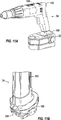
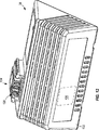
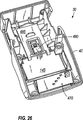
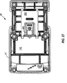
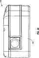
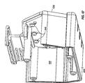
Wie in
Der existierende Akkumulator
Der existierende Akkumulator
Die vorliegende Erfindung stellt einen Akkumulator bereit, der im Wesentlichen eine oder mehrere unabhängige Probleme bei den vorstehend beschriebenen und weiter existierenden Akkumulatoren löst.The present invention provides an accumulator that substantially solves one or more independent problems with the above-described and existing accumulators.
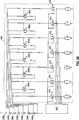
Zudem stellt in einigen Aspekten und in einigen Aufbauten die vorliegende Erfindung einen Akkumulator bereit, der eine Vielzahl von Zellen, einen Sensor zum Erfassen der Spannung der ersten Gruppe der Vielzahl von Zellen, einen Sensor zum Erfassen der Spannung einer zweiten Gruppe der Vielzahl von Zellen und eine Steuereinrichtung zum Vergleichen der Spannung der ersten Gruppe mit der Spannung der zweiten Gruppe, um zu bestimmen, ob eine aus der Vielzahl der Zellen auf einer Spannung oder unter einer Spannung ist.In addition, in some aspects and in some constructions, the present invention provides an accumulator comprising a plurality of cells, a sensor for detecting the voltage of the first group of the plurality of cells, a sensor for detecting the voltage of a second group of the plurality of cells, and control means for comparing the voltage of the first group with the voltage of the second group to determine whether one of the plurality of cells is at a voltage or below a voltage.
In einigen Aspekten und in einigen Aufbauten stellt die vorliegende Erfindung weiterhin ein Verfahren zum Bestimmen einer Spannung einer Zelle eines Akkumulators bereit, wobei der Akkumulator eine Vielzahl von Zellen enthält und wobei das Verfahren die Schritte des Erfassens der Spannung einer ersten Gruppe aus der Vielzahl von Zellen, des Erfassens der Spannung einer zweiten Gruppe aus der Vielzahl von Zellen und das Vergleichen der Spannung der ersten Gruppe mit der Spannung der zweiten Gruppe enthält, um zu bestimmen, ob eine Zelle aus der Vielzahl von Zellen auf oder unter einer Spannung ist.In some aspects and in some constructions, the present invention further provides a method of determining a voltage of a cell of a rechargeable battery, wherein the rechargeable battery includes a plurality of cells, and wherein the method comprises the steps of detecting the voltage of a first group of the plurality of cells detecting the voltage of a second group of the plurality of cells and comparing the voltage of the first group with the voltage of the second group to determine whether a cell of the plurality of cells is at or below a voltage.
Aus der
Aus der
Aus der
Aus der
Unabhängige Merkmale und unabhängige Vorteile der Erfindung werden für Fachleute bei der Durchsicht der detaillierten Beschreibung und der Zeichnungen ersichtlich.Independent features and independent advantages of the invention will become apparent to those skilled in the art upon review of the detailed description and drawings.
Bevor einige der Ausführungsformen der Erfindung im Detail erläutert werden, wird darauf hingewiesen, dass die Erfindung nicht in ihrer Anwendung auf die Details der Konstruktion und der Anordnung der Komponenten beschränkt ist, die in der nachfolgenden Beschreibung erläutert werden oder in den nachfolgenden Zeichnungen gezeigt werden. Die Erfindung kann weitere Ausführungsformen haben und kann auf verschiedene Arten und Weisen praktisch umgesetzt und ausgeführt werden. Auch wird darauf hingewiesen, dass die Wortwahl und die Terminologie, die hier verwendet wird, zum Zwecke der Beschreibung ist und nicht als beschränkend betrachtet werden darf. Die Verwendung von ”enthalten”, ”aufweisen” oder ”haben” und Variationen davon sind hier derart gemeint, dass sie Gegenstände, die danach aufgelistet sind, und Äquivalente davon und auch zusätzliche Gegenstände umfassen.Before some of the embodiments of the invention are explained in detail, it is to be understood that the invention is not limited in its application to the details of construction and arrangement of the components which will be set forth in the following description or shown in the following drawings. The invention may have other embodiments and may be practiced and practiced in various ways. It is also to be understood that the words and terminology used herein are for the purpose of description and should not be considered as limiting. The use of "contain," "have," or "have," and variations thereof, are meant herein to include items listed thereafter and equivalents thereof as well as additional items.
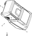
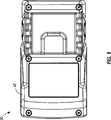
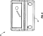
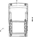
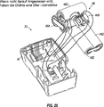
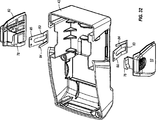
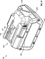
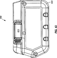
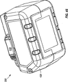
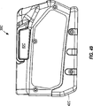
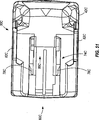
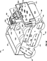
Ein Akkumulator
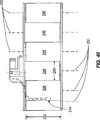
Wie in
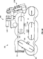
Die Akkumulatorzellen
Wie in
Die Akkumulatorzellen
Die Akkumulatorzellen
Wie in
Der Akkumulator
Wie in
Jedes Vorspannteil
Wie in
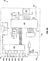
Der Akkumulator
Der Sensoranschluss
In einigen Aufbauten und in einigen Aspekten kann der Sensoranschluss
In einigen Aufbauten kann die Schaltung
In einigen Aufbauten und in einigen Aspekten kann die Schaltung
In einigen Aufbauten können die Spannungseigenschaften des Akkumulators
In einigen Aufbauten kann der Mikroprozessor
In einigen Aufbauten und in einigen Aspekten kann der Akkumulator
In einigen Aufbauten aktiviert der Mikroprozessor
Komponenten der Schaltung
Wie in
In einigen Aufbauten und in einigen Aspekten arbeitet die Ladeschaltung
Für einige Aufbauten und für einige Aspekte werden zusätzliche, unabhängige Merkmale, Strukturen und Operationen des Akkumulatorladers
Der Akkumulator
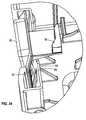
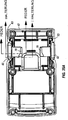
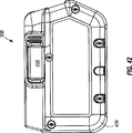
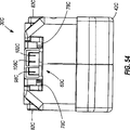
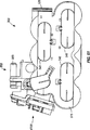
Ein alternativer Aufbau eines Akkumulators
Wie vorstehend gesagt wurde, kann der Akkumulator
Die gemeinsamen Elemente werden durch das gleiche Bezugszeichen ”B” identifiziert. Ein weiterer Aufbau eines Akkumulators
Außer anders hier nachfolgend spezifiziert kann sich der Akkumulator
In einigen Aufbauten kann der Akkumulator
In einigen Aufbauten kann der Akkumulator
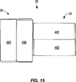
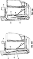
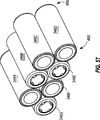
Die Akkumulatorzellen
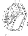
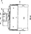
Wie in
In dem dargestellten Aufbau ist die erste Endkappe
In einigen Aufbauten können die erste Endkappe
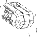
In einigen Aufbauten und in einigen Aspekten kann die Endkappenanordnung
In dem gezeigten Aufbau kann die Endkappenanordnung
In einigen Aufbauten und in einigen Aspekten kann der Akkumulator
Claims (6)
Applications Claiming Priority (14)
| Application Number | Priority Date | Filing Date | Title |
|---|---|---|---|
| US52371203P | 2003-11-19 | 2003-11-19 | |
| US52371603P | 2003-11-19 | 2003-11-19 | |
| US60/523716 | 2003-11-19 | ||
| US60/523712 | 2003-11-19 | ||
| US10/720027 | 2003-11-20 | ||
| US10/720,027 US7157882B2 (en) | 2002-11-22 | 2003-11-20 | Method and system for battery protection employing a selectively-actuated switch |
| US10/719680 | 2003-11-20 | ||
| US10/719,680 US7176654B2 (en) | 2002-11-22 | 2003-11-20 | Method and system of charging multi-cell lithium-based batteries |
| US10/721800 | 2003-11-24 | ||
| US10/721,800 US7253585B2 (en) | 2002-11-22 | 2003-11-24 | Battery pack |
| US57427804P | 2004-05-24 | 2004-05-24 | |
| US60/574278 | 2004-05-24 | ||
| US57461604P | 2004-05-25 | 2004-05-25 | |
| US60/574616 | 2004-05-25 |
Publications (2)
| Publication Number | Publication Date |
|---|---|
| DE102004030037A1 DE102004030037A1 (en) | 2005-06-23 |
| DE102004030037B4 true DE102004030037B4 (en) | 2012-01-12 |
Family
ID=34624153
Family Applications (1)
| Application Number | Title | Priority Date | Filing Date |
|---|---|---|---|
| DE102004030037A Active DE102004030037B4 (en) | 2003-11-19 | 2004-06-22 | accumulator |
Country Status (4)
| Country | Link |
|---|---|
| JP (17) | JP4624012B2 (en) |
| CN (1) | CN1619876B (en) |
| DE (1) | DE102004030037B4 (en) |
| GB (6) | GB2420032A (en) |
Families Citing this family (60)
| Publication number | Priority date | Publication date | Assignee | Title |
|---|---|---|---|---|
| DE102006042603A1 (en) | 2006-09-11 | 2008-03-27 | Robert Bosch Gmbh | loader |
| JP4998846B2 (en) * | 2007-01-18 | 2012-08-15 | 日立工機株式会社 | Cordless power tool |
| JP4922031B2 (en) * | 2007-03-19 | 2012-04-25 | 日立工機株式会社 | Portable tools |
| JP2008236881A (en) * | 2007-03-19 | 2008-10-02 | Hitachi Koki Co Ltd | Charger |
| JP5370709B2 (en) | 2007-10-29 | 2013-12-18 | 日立工機株式会社 | Battery pack and electric tool equipped with the same |
| JP4104648B1 (en) * | 2007-09-13 | 2008-06-18 | 和征 榊原 | Battery pack |
| CN104103851B (en) * | 2007-09-14 | 2018-10-09 | A123系统有限责任公司 | Lithium rechargable battery with the reference electrode for state of health monitoring |
| JP2009289578A (en) * | 2008-05-29 | 2009-12-10 | Makita Corp | Battery pack of electric tool |
| JP2010040226A (en) * | 2008-08-01 | 2010-02-18 | Hitachi Koki Co Ltd | Battery pack for electric tools |
| JP5365108B2 (en) | 2008-09-04 | 2013-12-11 | ミツミ電機株式会社 | Semiconductor integrated circuit |
| WO2010045588A1 (en) | 2008-10-16 | 2010-04-22 | Royal Appliance Mfg.Co. | Battery powered cordless cleaning system |
| US8192789B2 (en) | 2008-11-07 | 2012-06-05 | Sakti3, Inc. | Method for manufacture and structure of multiple electrochemistries and energy gathering components within a unified structure |
| JP5436850B2 (en) * | 2008-12-19 | 2014-03-05 | 株式会社マキタ | Power tool battery pack |
| WO2010088244A1 (en) * | 2009-01-27 | 2010-08-05 | Techtronic Power Tools Technology Limited | Battery pack with high and low current discharge terminals |
| KR20120003432A (en) * | 2009-03-31 | 2012-01-10 | 산요덴키가부시키가이샤 | Battery module, battery system, and electric vehicle |
| JP2011163847A (en) * | 2010-02-08 | 2011-08-25 | Denso Corp | Battery voltage monitoring apparatus |
| JP5461221B2 (en) | 2010-02-12 | 2014-04-02 | 株式会社マキタ | Electric tool powered by multiple battery packs |
| JP5567956B2 (en) * | 2010-09-16 | 2014-08-06 | 矢崎総業株式会社 | Cell voltage equalization device for multiple assembled batteries |
| JP5579046B2 (en) | 2010-12-27 | 2014-08-27 | 株式会社マキタ | Electric tool equipment |
| JP2012183611A (en) * | 2011-03-07 | 2012-09-27 | Makita Corp | Electric power tool having a plurality of secondary battery cells as power source |
| AU2011205026B2 (en) * | 2011-07-27 | 2014-06-05 | Chou, Shan-Shan | Charge system for series connected rechargeable batteries |
| DE102011086799A1 (en) * | 2011-11-22 | 2013-05-23 | Robert Bosch Gmbh | System with a hand tool case and a hand tool battery |
| JP2015028839A (en) * | 2011-11-25 | 2015-02-12 | 三洋電機株式会社 | Battery pack |
| KR101897822B1 (en) * | 2011-12-02 | 2018-09-13 | 삼성에스디아이 주식회사 | Battery pack |
| JP2014050234A (en) * | 2012-08-31 | 2014-03-17 | Hitachi Koki Co Ltd | Power supply device |
| JP6098117B2 (en) | 2012-10-31 | 2017-03-22 | 日立工機株式会社 | Portable tools |
| JP5605588B2 (en) * | 2012-12-21 | 2014-10-15 | 日立工機株式会社 | Battery pack and electric tool equipped with the same |
| JP2014148018A (en) * | 2013-02-01 | 2014-08-21 | Makita Corp | Hand-held electric polisher |
| JP2014148017A (en) * | 2013-02-01 | 2014-08-21 | Makita Corp | Hand-held electric cutter |
| JP6133103B2 (en) * | 2013-04-04 | 2017-05-24 | 株式会社マキタ | Battery pack for electric tools |
| KR101529551B1 (en) * | 2013-08-12 | 2015-06-19 | 주식회사 아이티엠반도체 | Battery protecting device for replaceable secondary battery |
| JP6103237B2 (en) * | 2013-10-24 | 2017-03-29 | 株式会社豊田自動織機 | Battery pack |
| JP6103238B2 (en) * | 2013-10-24 | 2017-03-29 | 株式会社豊田自動織機 | Battery pack |
| JP2014100785A (en) * | 2014-01-15 | 2014-06-05 | Makita Corp | Power tool using plural battery packs as power source |
| GB201403971D0 (en) * | 2014-03-06 | 2014-04-23 | 7Rdd Ltd | Portable power supply improvements |
| JP6195233B2 (en) * | 2014-04-30 | 2017-09-13 | 日立工機株式会社 | Battery pack, charging system and power tool |
| GB2542742A (en) * | 2014-05-18 | 2017-03-29 | Black & Decker Inc | Power tool system |
| JP6282546B2 (en) * | 2014-07-11 | 2018-02-21 | 株式会社マキタ | Electric tool |
| JP6514866B2 (en) * | 2014-08-29 | 2019-05-15 | 株式会社マキタ | Rechargeable electric device |
| KR102316436B1 (en) * | 2014-11-17 | 2021-10-22 | 삼성전자주식회사 | Method for controlling different kind of battery cells and electronic device thereof |
| CN104362370A (en) * | 2014-11-25 | 2015-02-18 | 上海动力储能电池系统工程技术有限公司 | Lithium manganate lithium ion battery and preparation method thereof |
| EP4358392A2 (en) * | 2015-04-03 | 2024-04-24 | ConMed Corporation | Autoclave tolerant battery powered motorized surgical hand piece tool and motor control method |
| CN104868571A (en) * | 2015-05-24 | 2015-08-26 | 中煤张家口煤矿机械有限责任公司 | Charger specialized for battery |
| JP6686341B2 (en) * | 2015-09-18 | 2020-04-22 | マックス株式会社 | Rechargeable tool |
| CN108698217B (en) * | 2016-02-16 | 2021-09-03 | 株式会社牧田 | Electric working machine |
| DE102016203429A1 (en) * | 2016-03-02 | 2017-09-07 | Robert Bosch Gmbh | Battery pack for a hand tool |
| JP6777912B2 (en) | 2016-10-07 | 2020-10-28 | 株式会社マキタ | Battery pack and electric work machine |
| CN109891621B (en) * | 2016-10-31 | 2022-02-22 | 工机控股株式会社 | Battery pack, electric machine using battery pack, and electric machine system |
| CN110024210A (en) | 2016-11-30 | 2019-07-16 | 日立汽车系统株式会社 | Battery control device |
| KR101970102B1 (en) * | 2018-02-20 | 2019-08-13 | 프레스토라이트아시아 주식회사 | Control device having simple structure in a motor control system |
| CN111971812A (en) | 2018-03-26 | 2020-11-20 | 米沃奇电动工具公司 | High power battery powered portable power supply |
| US11271415B2 (en) | 2018-05-18 | 2022-03-08 | Milwaukee Electric Tool Corporation | Portable power source |
| IT201800003293U1 (en) * | 2018-08-30 | 2020-03-01 | Bagioni Alfiero Snc Di Bagioni Aurenzo E Antonella | ELECTRICALLY POWERED AGRICULTURAL MACHINE |
| CN109888908A (en) * | 2018-12-19 | 2019-06-14 | 北京航空航天大学 | A kind of navigation system time-division multiplex low cost precision voltage source |
| KR20200098977A (en) * | 2019-02-13 | 2020-08-21 | 주식회사 엘지화학 | A battery module for detecting a high temperature of a battery cell and a method for detecting a high temperature of the battery cell |
| USD933010S1 (en) | 2019-05-29 | 2021-10-12 | Milwaukee Electric Tool Corporation | Portable power source |
| JP7298309B2 (en) * | 2019-05-31 | 2023-06-27 | 株式会社Gsユアサ | Voltage measurement circuit, power storage device |
| JP7450203B2 (en) | 2019-08-06 | 2024-03-15 | パナソニックIpマネジメント株式会社 | Electric tool |
| JP7088216B2 (en) * | 2020-01-10 | 2022-06-21 | トヨタ自動車株式会社 | Reference jig |
| EP4068561A4 (en) * | 2021-01-28 | 2022-10-05 | Contemporary Amperex Technology Co., Limited | Charging method and power conversion device |
Citations (2)
| Publication number | Priority date | Publication date | Assignee | Title |
|---|---|---|---|---|
| DE68927774T2 (en) * | 1988-03-11 | 1997-06-26 | Black & Decker Inc | Battery blocks |
| EP1076370A2 (en) * | 1998-08-13 | 2001-02-14 | Black & Decker Inc. | Cordless power tool system |
Family Cites Families (65)
| Publication number | Priority date | Publication date | Assignee | Title |
|---|---|---|---|---|
| JPS6150778A (en) * | 1984-08-10 | 1986-03-13 | 松下電工株式会社 | Battery type electric tool |
| JP2925241B2 (en) * | 1990-05-28 | 1999-07-28 | 旭化成工業株式会社 | Rechargeable battery device |
| JPH05251112A (en) * | 1992-03-06 | 1993-09-28 | Matsushita Electric Ind Co Ltd | Battery pack and charging apparatus |
| JP3121963B2 (en) * | 1993-06-30 | 2001-01-09 | 太陽誘電株式会社 | battery pack |
| KR950703809A (en) * | 1993-07-14 | 1995-09-20 | 에프. 제이. 스미트 | Circuit arrangement for charging rechargeable batteries |
| JP3249272B2 (en) * | 1993-12-24 | 2002-01-21 | 株式会社マキタ | How to display the remaining capacity of the battery pack |
| JP3384079B2 (en) * | 1994-02-10 | 2003-03-10 | 日立工機株式会社 | Battery pack charging device |
| US5594320A (en) * | 1994-09-09 | 1997-01-14 | Rayovac Corporation | Charge equalization of series connected cells or batteries |
| JPH0974689A (en) * | 1995-09-06 | 1997-03-18 | Toshiba Battery Co Ltd | Power unit using battery pack |
| JPH0984271A (en) * | 1995-09-19 | 1997-03-28 | Toshiba Corp | Charger for radio communication device |
| US5757163A (en) * | 1995-09-29 | 1998-05-26 | Black & Decker Inc. | Battery Charger and method for simultaneously charging multiple batteries from a single power supply |
| US5646503A (en) * | 1995-10-04 | 1997-07-08 | Motorola, Inc. | Method for balancing power sources and structure therefor |
| JP3547878B2 (en) * | 1995-12-27 | 2004-07-28 | 株式会社東芝 | Charging device |
| JPH09271144A (en) * | 1996-01-29 | 1997-10-14 | Sony Corp | Power supply identifying method, battery pack, and electronic device |
| JP3508384B2 (en) * | 1996-04-05 | 2004-03-22 | ソニー株式会社 | Battery charging apparatus and method, and battery pack |
| JPH09306550A (en) * | 1996-05-20 | 1997-11-28 | Sony Corp | Battery pack, electronic appliance, and electronic appliance system |
| US5945811A (en) * | 1996-05-21 | 1999-08-31 | Matsushita Electric Industrial Co., Ltd. | Pulse charging method and a charger |
| US5726554A (en) * | 1996-05-24 | 1998-03-10 | Compaq Computer Corporation | Charging a battery having a nominal critical terminal voltage |
| JPH09331636A (en) * | 1996-06-11 | 1997-12-22 | Oki Electric Ind Co Ltd | Charger of secondary battery |
| KR0181164B1 (en) * | 1996-07-06 | 1999-05-15 | 삼성전자주식회사 | Charging apparatus for variable kinds of batteries and its control method |
| JP3661904B2 (en) | 1997-02-03 | 2005-06-22 | ソニー株式会社 | Charging apparatus and charging method |
| JP3767068B2 (en) * | 1997-02-26 | 2006-04-19 | 宇部興産株式会社 | Secondary battery charging device and charging method |
| JP3239794B2 (en) * | 1997-04-14 | 2001-12-17 | 松下電器産業株式会社 | Battery pack charger |
| US6523447B2 (en) * | 1997-09-26 | 2003-02-25 | Black & Decker Inc. | Cordless chop saw |
| JPH11150879A (en) * | 1997-11-20 | 1999-06-02 | Hitachi Koki Co Ltd | Charging device of battery |
| JPH11178229A (en) * | 1997-12-16 | 1999-07-02 | Nec Corp | Charger |
| JP3177955B2 (en) * | 1997-12-19 | 2001-06-18 | 日本電気株式会社 | Rechargeable battery charging method and charging system |
| JPH11234916A (en) * | 1998-02-16 | 1999-08-27 | Rohm Co Ltd | Lithium ion battery pack |
| CA2231260A1 (en) * | 1998-03-06 | 1999-09-06 | William G. Dunford | Battery equalizer |
| JPH11275722A (en) * | 1998-03-19 | 1999-10-08 | Furukawa Electric Co Ltd:The | Small sagging overhead power transmission cable stringing method |
| JP4013003B2 (en) * | 1998-03-27 | 2007-11-28 | 宇部興産株式会社 | battery pack |
| JP3390668B2 (en) * | 1998-06-09 | 2003-03-24 | 株式会社マキタ | Charging device |
| JP2000030751A (en) * | 1998-07-10 | 2000-01-28 | Toyota Central Res & Dev Lab Inc | Charging/discharging method for lithium secondary battery |
| JP3989107B2 (en) * | 1998-07-27 | 2007-10-10 | 三洋電機株式会社 | How to balance the charge of secondary batteries |
| JP2000078766A (en) * | 1998-08-31 | 2000-03-14 | Toshiba Corp | Portable electronic equipment and charging circuit |
| JP2000102185A (en) * | 1998-09-21 | 2000-04-07 | Mitsubishi Cable Ind Ltd | Secondary battery pack |
| US6296065B1 (en) * | 1998-12-30 | 2001-10-02 | Black & Decker Inc. | Dual-mode non-isolated corded system for transportable cordless power tools |
| JP2000287364A (en) * | 1999-03-30 | 2000-10-13 | Sony Corp | Secondary battery device, control therefor, and electronic apparatus |
| EP1049187A3 (en) * | 1999-04-27 | 2004-04-28 | Hitachi, Ltd. | Lithium secondary battery |
| JP2001086656A (en) * | 1999-07-09 | 2001-03-30 | Fujitsu Ltd | Battery monitor |
| JP3869585B2 (en) * | 1999-07-30 | 2007-01-17 | 三洋電機株式会社 | Discharge method of multiple secondary batteries and assembled battery |
| JP3540230B2 (en) * | 2000-01-19 | 2004-07-07 | Necマイクロシステム株式会社 | Semiconductor integrated circuit |
| JP2001218376A (en) * | 2000-02-03 | 2001-08-10 | Toyota Motor Corp | Device and method for controlling charring condition of single batteries constituting batter pack, and battery module using device, and electric-motor vehicle |
| US7183748B1 (en) * | 2000-02-07 | 2007-02-27 | Fujitsu Limited | Electric charger and power supply device for portable terminal |
| JP3778262B2 (en) * | 2000-12-21 | 2006-05-24 | 株式会社マキタ | Charging method and battery pack |
| JP2001283934A (en) * | 2000-03-29 | 2001-10-12 | Canon Inc | Battery pack idetifying device and battery pack |
| JP4542675B2 (en) * | 2000-06-27 | 2010-09-15 | 株式会社デンソー | Voltage correction device for battery pack for electric vehicle |
| JP2002093466A (en) * | 2000-09-08 | 2002-03-29 | Matsushita Electric Ind Co Ltd | Charge control circuit |
| JP3457637B2 (en) * | 2000-09-27 | 2003-10-20 | 埼玉日本電気株式会社 | Battery type detection device |
| JP2002110254A (en) * | 2000-09-29 | 2002-04-12 | Toshiba Corp | Non-aqueous electrolyte secondary battery |
| JP3872643B2 (en) * | 2000-11-15 | 2007-01-24 | 三菱化学株式会社 | Battery circuit |
| JP4691796B2 (en) * | 2001-02-14 | 2011-06-01 | ソニー株式会社 | Charging / discharging device and method, power supply device and method, power supply system and method, program storage medium, and program |
| JP3546856B2 (en) * | 2001-04-25 | 2004-07-28 | 松下電器産業株式会社 | Battery pack and battery pack failure diagnosis method |
| JP3803042B2 (en) * | 2001-06-11 | 2006-08-02 | 矢崎総業株式会社 | Apparatus and method for adjusting state of charge of battery pack |
| EP1266725A1 (en) * | 2001-06-16 | 2002-12-18 | Atlas Copco Electric Tools GmbH | Electric power tool with rechargeable energy accumulator |
| JP4605952B2 (en) * | 2001-08-29 | 2011-01-05 | 株式会社日立製作所 | Power storage device and control method thereof |
| JP2003111284A (en) * | 2001-09-27 | 2003-04-11 | Nec Mobile Energy Kk | Power saving battery pack |
| JP2003153460A (en) | 2001-11-12 | 2003-05-23 | Japan Storage Battery Co Ltd | Charging/discharging controller of storage battery |
| JP2003164066A (en) * | 2001-11-21 | 2003-06-06 | Hitachi Koki Co Ltd | Battery pack |
| JP3782393B2 (en) * | 2001-12-28 | 2006-06-07 | 株式会社東芝 | Battery pack and rechargeable vacuum cleaner |
| US6833685B2 (en) * | 2002-02-19 | 2004-12-21 | Black & Decker Inc. | Battery charger with standby mode |
| JP3530519B2 (en) | 2002-03-27 | 2004-05-24 | 三菱重工業株式会社 | Voltage equalizing device for power storage device and power storage system provided with the device |
| JP2003299257A (en) * | 2002-04-01 | 2003-10-17 | Canon Inc | Charger |
| JP2003348762A (en) * | 2002-05-28 | 2003-12-05 | Sanyo Electric Co Ltd | Charger |
| GB2419242B (en) * | 2002-11-22 | 2007-01-31 | Milwaukee Electric Tool Corp | Method And System For Battery Charging |
-
2004
- 2004-06-22 DE DE102004030037A patent/DE102004030037B4/en active Active
- 2004-06-23 GB GB0601879A patent/GB2420032A/en not_active Withdrawn
- 2004-06-23 GB GB0601873A patent/GB2420030A/en not_active Withdrawn
- 2004-06-23 GB GB0601876A patent/GB2420031A/en not_active Withdrawn
- 2004-06-23 GB GB0601872A patent/GB2420029A/en not_active Withdrawn
- 2004-06-23 GB GB0601844A patent/GB2420028A/en not_active Withdrawn
- 2004-06-23 GB GB0601841A patent/GB2420027A/en not_active Withdrawn
- 2004-06-25 JP JP2004188877A patent/JP4624012B2/en active Active
- 2004-06-25 JP JP2004188878A patent/JP2005151795A/en active Pending
- 2004-06-25 JP JP2004188876A patent/JP4011563B2/en active Active
- 2004-09-21 CN CN2004100824366A patent/CN1619876B/en active Active
-
2007
- 2007-12-05 JP JP2007315201A patent/JP2008086200A/en active Pending
- 2007-12-05 JP JP2007315200A patent/JP2008113551A/en active Pending
- 2007-12-05 JP JP2007315199A patent/JP5506150B2/en active Active
- 2007-12-05 JP JP2007315202A patent/JP2008113552A/en active Pending
-
2009
- 2009-11-09 JP JP2009255846A patent/JP4547036B2/en active Active
-
2011
- 2011-09-27 JP JP2011210412A patent/JP2012010591A/en active Pending
- 2011-09-29 JP JP2011214012A patent/JP2012010593A/en active Pending
-
2014
- 2014-09-11 JP JP2014184997A patent/JP5890878B2/en active Active
-
2016
- 2016-06-09 JP JP2016115099A patent/JP2016187301A/en active Pending
-
2017
- 2017-11-21 JP JP2017223276A patent/JP2018038262A/en active Pending
-
2018
- 2018-09-14 JP JP2018172083A patent/JP6726245B2/en active Active
-
2019
- 2019-02-04 JP JP2019017587A patent/JP6913117B2/en active Active
-
2021
- 2021-01-14 JP JP2021004076A patent/JP7198293B2/en active Active
-
2022
- 2022-06-06 JP JP2022091492A patent/JP7372396B2/en active Active
Patent Citations (3)
| Publication number | Priority date | Publication date | Assignee | Title |
|---|---|---|---|---|
| DE68927774T2 (en) * | 1988-03-11 | 1997-06-26 | Black & Decker Inc | Battery blocks |
| EP1076370A2 (en) * | 1998-08-13 | 2001-02-14 | Black & Decker Inc. | Cordless power tool system |
| EP1363340A2 (en) * | 1998-08-13 | 2003-11-19 | Black & Decker Inc. | Cordless power tool system |
Also Published As
Similar Documents
| Publication | Publication Date | Title |
|---|---|---|
| DE102004030037B4 (en) | accumulator | |
| DE112005001203B4 (en) | Battery pack, power tool, electrical combination thereof and method of operation | |
| US9379569B2 (en) | Lithium-battery pack for a hand held power tool | |
| DE10009618B4 (en) | battery unit | |
| DE102006015664A1 (en) | Battery pack and wireless electrical tool having this | |
| DE10362314B3 (en) | Lithium Ion Battery Pack | |
| DE102008013548A1 (en) | battery charger | |
| DE19641989A1 (en) | Double battery charger for nickel-metal-hydride or lithium-ion types e.g. for portable radios | |
| DE202010012151U1 (en) | battery Pack | |
| WO2006094785A2 (en) | Accumulator and method for the operation thereof | |
| DE10157859A1 (en) | Device for charging of battery packet with several battery segments, has each battery segment charged as function of charge property from group consisting of time, battery type, environment, and battery temperature | |
| DE212012000140U1 (en) | Hand power tools and battery packs for these | |
| DE202012104154U1 (en) | power tool | |
| DE202007017829U1 (en) | Lithium battery pack and system to charge it | |
| DE10354874B4 (en) | Battery charger | |
| EP1927152A1 (en) | Rechargeable battery pack and electrical hand tool device | |
| DE102020209400A1 (en) | Method for controlling a charging or discharging current of an exchangeable battery pack and/or an electrical device and system for carrying out the method | |
| DE102020210377A1 (en) | Exchangeable battery pack and/or electrical consumers with an electromechanical interface for the energy supply | |
| WO2023083651A1 (en) | Method for charging or discharging an exchangeable energy store by means of an electrical device and system comprising an exchangeable energy store and an electrical device for carrying out the method | |
| DE2819584C2 (en) | Circuit for securing memory cells | |
| DE202021004371U1 (en) | Battery charger and charging docking station used with it | |
| DE4140827A1 (en) | Assembly for changing lead battery with nickel cadmium battery charger | |
| DE102020209396A1 (en) | Method for detecting electrical fault conditions in a replaceable battery pack and system for carrying out the method | |
| DE2948700C2 (en) | Circuit for securing memory cells | |
| WO2007012504A1 (en) | Method for regulating charging of nickel cadmium and nickel metal hydride batteries, and power supply unit |
Legal Events
| Date | Code | Title | Description |
|---|---|---|---|
| 8110 | Request for examination paragraph 44 | ||
| R016 | Response to examination communication | ||
| R016 | Response to examination communication | ||
| R018 | Grant decision by examination section/examining division | ||
| R026 | Opposition filed against patent |
Effective date: 20120412 |
|
| R031 | Decision of examining division/federal patent court maintaining patent unamended now final |
Effective date: 20131129 |