CN211403195U - Energy filling station monitoring system based on BS framework - Google Patents
Energy filling station monitoring system based on BS framework Download PDFInfo
- Publication number
- CN211403195U CN211403195U CN202020405822.9U CN202020405822U CN211403195U CN 211403195 U CN211403195 U CN 211403195U CN 202020405822 U CN202020405822 U CN 202020405822U CN 211403195 U CN211403195 U CN 211403195U
- Authority
- CN
- China
- Prior art keywords
- network card
- server
- module
- monitoring system
- station monitoring
- Prior art date
- Legal status (The legal status is an assumption and is not a legal conclusion. Google has not performed a legal analysis and makes no representation as to the accuracy of the status listed.)
- Active
Links
Images
Landscapes
- Filling Or Discharging Of Gas Storage Vessels (AREA)
Abstract
The utility model discloses an energy filling station monitored control system based on BS framework aims at solving current filling station because the discretization distributes the technical problem that the cost of labor that causes is high, data utilization is low. The utility model discloses a natural gas sub-station compressor controller, LNG L-CNG controller, industry switch, first network card, server, second network card, customer end, natural gas sub-station compressor controller and LNG L-CNG controller pass through industry switch and first network card communication connection, and industry switch and server pass through first network card communication connection, and server and customer end pass through second network card communication connection. The beneficial effects of the utility model reside in that: the centralized control is realized, the data utilization rate is high, the labor cost is low, and the remote maintenance management and the operation decision are convenient.
Description
Technical Field
The utility model relates to an energy filling station technical field, concretely relates to energy filling station monitored control system based on BS framework.
Background
The energy filling station is an important component of a municipal energy supply system and is an energy supply point of a vehicle. In view of higher safety requirements, the energy filling stations are monitored on site and need 24-hour uninterrupted operation, and the operation management and control are used for analyzing and executing operation by acquiring real-time data and equipment process states through the monitoring work stations.
However, the existing filling stations are operated independently, and each filling station needs to be distributed with a plurality of workers for maintenance, so that the management efficiency is not improved, the human resource is wasted, and the high-intensity work is not beneficial to the on-site immediate processing.
In addition, discrete filling stations cannot communicate data with each other, effective cross validation cannot be formed, and powerful basis cannot be provided for decision making.
SUMMERY OF THE UTILITY MODEL
The utility model provides an energy filling station monitored control system based on BS framework distributes the technical problem that the cost of labor is high, data utilization is low that causes in order to solve current filling station discretization.
In order to solve the technical problem, the utility model adopts the following technical scheme:
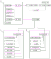
the monitoring system comprises a natural gas substation compressor controller, an LNG/L-CNG controller, an industrial switch, a first network card, a server, a second network card and a client, wherein the natural gas substation compressor controller and the LNG/L-CNG controller are in communication connection with the first network card through the industrial switch, the industrial switch is in communication connection with the server through the first network card, the server is in communication connection with the client through the second network card, and data are transmitted through a BS framework network.
Furthermore, the first network card and the industrial switch are provided with correspondingly connected Ethernet interfaces.
Further, an equipment communication module, a variable database module, a message service module and a safety service module are connected between the server and the first network card.
Furthermore, the second network card is connected with a first VPN access switch, the client is connected with a second VPN access switch, and the first VPN access switch is in communication connection with the second VPN access switch.
Further, the server is a WEB server, and the client is a WEB client connected correspondingly.
Furthermore, the WEB client includes one or more of a computer, a smart phone, and a tablet computer.
Further, the natural gas substation compressor controller is connected with a process gas pipeline module, a combustible gas alarm driving module, a pneumatic control module, a hydraulic control module and a cooling control module.
Further, the LNG/L-CNG controller is connected with a combustible gas alarm control module, an LNG filling module, an L-CNG filling module and an instrument module.
Compared with the prior art, the utility model has the beneficial technical effects of:
1. the utility model discloses a data interaction of local control system and server is realized to first network card, realizes the data interaction of server and customer end through the second network card, utilizes the server to gather and show the control data of filling the website storage in local to release the surveillance center, be favorable to centralized monitoring and strange land management, make things convenient for the surveillance center to carry out cross contrast to each filling station data simultaneously, provide strong data support when making the decision for filling the station.
2. The utility model discloses a customer end can monitor the equipment process state at many places filling station, reduces artifical administrative cost, improves the managerial efficiency.
Drawings
Fig. 1 is the utility model discloses energy filling station monitored control system's based on BS framework topological structure schematic diagram.
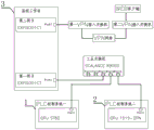
Fig. 2 is the utility model discloses energy filling station monitored control system's based on BS framework hardware connection schematic diagram.
In the figure, 1 is a natural gas substation compressor, 2 is an LNG/L-CNG unit, and 3 is a monitoring workstation.
Detailed Description
The following embodiments are only intended to illustrate the present invention in detail, and do not limit the scope of the present invention in any way.
The programs referred to or relied on in the following embodiments are all conventional programs or simple programs in the art, and those skilled in the art can make routine selection or adaptation according to specific application scenarios.
The unit modules, components, structures, mechanisms, sensors, and other devices referred to in the following examples are all conventional commercially available products unless otherwise specified.
Example 1: an energy filling station monitoring system based on a BS (base station) framework is shown in figures 1 and 2 and comprises a natural gas substation compressor 1, an LNG/L-CNG unit 2 and a monitoring workstation 3.
The compressor 1 of the existing natural gas substation comprises a PLC control system, and is communicated, signal acquisition and control output with a process gas pipeline system, a combustible gas alarm probe, a pneumatic control system, a host system, a hydraulic system, a cooling system and an ESD system in a manner of hard connecting wires, serial communication lines, industrial Ethernet lines, optical fibers and the like;
the existing LNG/L-CNG unit 2 comprises a PLC control system II which communicates, acquires and controls output of signals with a combustible gas alarm controller, an LNG system, an L-CNG system, an instrument wind system and an ESD system II in a manner of hard connecting wires, serial communication lines, industrial Ethernet lines, optical fibers and the like;
in this embodiment, an industrial switch is added, and the PLC control system in the LNG/L-CNG unit 2 and the PLC control system in the industrial ethernet and natural gas substation compressor 1 are connected, specifically, the CPU in the natural gas substation compressor 1 is ST60 type, the CPU in the LNG/L-CNG unit 2 is 1515-2PN type, their network ports 1 are respectively connected to the network ports Port4 and Port5 of the industrial switch scalnce XB005, the network Port3 of the industrial switch scalnce XB is connected to the network Port1 of the first network card EXPI9301CT, the first network card EXPI9301CT is connected to the original main board PCI-E slot in the monitoring workstation 3, and the local data acquired by the PLC control system in the natural gas substation compressor and the LNG/L-CNG unit is transmitted to the server side of the monitoring workstation through the first network card and the industrial switch. The server side in the monitoring workstation comprises a WEB service, an equipment communication service, a variable database service, a message service, a security service and a human-computer interface, and the WEB server can transmit the collected data to the Internet.
After the data acquisition and uploading is completed, the data needs to be sent to the client. At this time, a second network card EXPI9301CT is added, the second network card is inserted into an original main board PCI-E slot in the monitoring workstation 3 according to the use instruction, a network Port1 of the second network card communicates through a VPN network, a first VPN access switch and a second VPN access switch are arranged, the first VPN access switch is located at the monitoring workstation 3, the second VPN access switch is located at a client side, and mutual communication of the VPN networks is formed between the first VPN access switch and the second VPN access switch.
In this embodiment, the client selects a plurality of WEB clients, the number of the clients may be multiple, the types of the clients may be one or more of a computer, a smart phone or a tablet computer connected to the internet, and in this embodiment, a computer is used and is arranged in the monitoring center and connected to the monitoring large screen. The WEB server in the monitoring workstation 3 communicates with the computer client of the monitoring center through a data transmission network which constructs a BS framework, and aims to centralize the core part for realizing the system function on the server, thereby greatly simplifying the load of the computer at the client, reducing the cost and workload of system maintenance and upgrading, and reducing the total cost of users.
The present invention has been described in detail with reference to the accompanying drawings and examples; however, it will be understood by those skilled in the art that various changes in the specific parameters of the embodiments described above, equivalent substitutions of parts and structures, etc. may be made without departing from the spirit of the invention, thereby forming a plurality of specific embodiments, which are common variations of the invention and will not be described in detail herein.
Claims (8)
1. An energy filling station monitoring system based on BS framework is characterized in that: the system comprises a natural gas substation compressor controller, an LNG/L-CNG controller, an industrial switch, a first network card, a server, a second network card and a client, wherein the natural gas substation compressor controller and the LNG/L-CNG controller are in communication connection with the first network card through the industrial switch, the industrial switch is in communication connection with the server through the first network card, and the server is in communication connection with the client through the second network card;
and the server is provided with a WEB communication unit for releasing data to the client through a BS architecture network.
2. The BS-based architecture energy fueling station monitoring system of claim 1 wherein: and the first network card and the industrial switch are provided with correspondingly connected Ethernet interfaces.
3. The BS-based architecture energy fueling station monitoring system of claim 1 wherein: and an equipment communication module, a variable database module, a message service module and a safety service module are connected between the server and the first network card.
4. The BS-based architecture energy fueling station monitoring system of claim 1 wherein: the second network card is connected with a first VPN access switch, the client is connected with a second VPN access switch, and the first VPN access switch is in communication connection with the second VPN access switch.
5. The BS architecture-based energy filling station monitoring system of claim 4, wherein: the server is a WEB server, and the client is a WEB client which is correspondingly connected.
6. The BS-based architecture energy fueling station monitoring system of claim 5 wherein: the WEB client comprises a computer, a smart phone and a tablet computer.
7. The BS-based architecture energy fueling station monitoring system of claim 1 wherein: the natural gas substation compressor controller is connected with a process gas pipeline module, a combustible gas alarm driving module, a pneumatic control module, a hydraulic control module and a cooling control module.
8. The BS-based architecture energy fueling station monitoring system of claim 1 wherein: the LNG/L-CNG controller is connected with a combustible gas alarm control module, an LNG filling module, an L-CNG filling module and an instrument module.
Priority Applications (1)
| Application Number | Priority Date | Filing Date | Title |
|---|---|---|---|
| CN202020405822.9U CN211403195U (en) | 2020-03-26 | 2020-03-26 | Energy filling station monitoring system based on BS framework |
Applications Claiming Priority (1)
| Application Number | Priority Date | Filing Date | Title |
|---|---|---|---|
| CN202020405822.9U CN211403195U (en) | 2020-03-26 | 2020-03-26 | Energy filling station monitoring system based on BS framework |
Publications (1)
| Publication Number | Publication Date |
|---|---|
| CN211403195U true CN211403195U (en) | 2020-09-01 |
Family
ID=72209477
Family Applications (1)
| Application Number | Title | Priority Date | Filing Date |
|---|---|---|---|
| CN202020405822.9U Active CN211403195U (en) | 2020-03-26 | 2020-03-26 | Energy filling station monitoring system based on BS framework |
Country Status (1)
| Country | Link |
|---|---|
| CN (1) | CN211403195U (en) |
Cited By (1)
| Publication number | Priority date | Publication date | Assignee | Title |
|---|---|---|---|---|
| KR20220144051A (en) * | 2021-04-19 | 2022-10-26 | 주식회사 한국가스기술공사 | HMI operation structure of LNG supply system |
-
2020
- 2020-03-26 CN CN202020405822.9U patent/CN211403195U/en active Active
Cited By (2)
| Publication number | Priority date | Publication date | Assignee | Title |
|---|---|---|---|---|
| KR20220144051A (en) * | 2021-04-19 | 2022-10-26 | 주식회사 한국가스기술공사 | HMI operation structure of LNG supply system |
| KR102498586B1 (en) * | 2021-04-19 | 2023-02-09 | 주식회사 한국가스기술공사 | HMI operation structure of LNG supply system |
Similar Documents
| Publication | Publication Date | Title |
|---|---|---|
| CN111131480A (en) | Cloud edge cooperative service system for smart power plant | |
| CN106603958B (en) | Distributed storage remote centralized monitoring system and method for transformer substation inspection robot | |
| CN107911347A (en) | A kind of monitoring system of distribution network and information transferring method based on across security partitioning | |
| CN105337422B (en) | Intelligence based on Internet of Things supplies Distribution Management System | |
| CN204965668U (en) | Cable pit conflagration on -line monitoring device of transformer substation | |
| WO2018184166A1 (en) | Distributed real-time data server | |
| CN103984323A (en) | Integrated configurable industrial information monitoring, analyzing and controlling system | |
| CN110675077A (en) | Power failure maintenance scheduling system under ubiquitous internet | |
| CN211403195U (en) | Energy filling station monitoring system based on BS framework | |
| CN101169652B (en) | Intelligent apparatus and communication method with outside and device | |
| CN110825013A (en) | Intelligent remote monitoring, early warning and control terminal | |
| CN110690756A (en) | Intelligent management and control system for grounding wire of power transmission line | |
| CN106371356A (en) | Base station power and environment monitoring system, interface protocol and base station power and environment monitoring method | |
| CN106850816A (en) | A kind of remote network control system based on VLAN | |
| CN212473483U (en) | Input/output device, manual unlocking disc and interval monitoring system | |
| CN210605442U (en) | Based on special LORA wireless communication control system of nuclear power station PLC | |
| CN203537075U (en) | Monitoring device of battery pack centralized charging station | |
| CN112217286A (en) | Electronic network command issuing system and method based on artificial intelligence | |
| CN102880124B (en) | A kind of controller data monitoring system and method and excavator | |
| CN214479838U (en) | Offline debugging structure for centralized control side and monitoring system on power station side of hydropower station | |
| CN101022542A (en) | Remote monitoring system | |
| CN212181304U (en) | Intelligent remote monitoring, early warning and control terminal | |
| CN214795042U (en) | Remote monitoring system for frequency converter of wind power plant | |
| CN219642124U (en) | Industrial control system based on Powerlink | |
| CN210405342U (en) | Switch real-time monitoring management system |
Legal Events
| Date | Code | Title | Description |
|---|---|---|---|
| GR01 | Patent grant | ||
| GR01 | Patent grant |