CN1311187C - Method and device for illumination - Google Patents
Method and device for illumination Download PDFInfo
- Publication number
- CN1311187C CN1311187C CNB018209556A CN01820955A CN1311187C CN 1311187 C CN1311187 C CN 1311187C CN B018209556 A CNB018209556 A CN B018209556A CN 01820955 A CN01820955 A CN 01820955A CN 1311187 C CN1311187 C CN 1311187C
- Authority
- CN
- China
- Prior art keywords
- light
- light source
- optical element
- produced
- lighting
- Prior art date
- Legal status (The legal status is an assumption and is not a legal conclusion. Google has not performed a legal analysis and makes no representation as to the accuracy of the status listed.)
- Expired - Fee Related
Links
Images
Classifications
-
- F—MECHANICAL ENGINEERING; LIGHTING; HEATING; WEAPONS; BLASTING
- F21—LIGHTING
- F21S—NON-PORTABLE LIGHTING DEVICES; SYSTEMS THEREOF; VEHICLE LIGHTING DEVICES SPECIALLY ADAPTED FOR VEHICLE EXTERIORS
- F21S8/00—Lighting devices intended for fixed installation
-
- F—MECHANICAL ENGINEERING; LIGHTING; HEATING; WEAPONS; BLASTING
- F21—LIGHTING
- F21V—FUNCTIONAL FEATURES OR DETAILS OF LIGHTING DEVICES OR SYSTEMS THEREOF; STRUCTURAL COMBINATIONS OF LIGHTING DEVICES WITH OTHER ARTICLES, NOT OTHERWISE PROVIDED FOR
- F21V23/00—Arrangement of electric circuit elements in or on lighting devices
-
- F—MECHANICAL ENGINEERING; LIGHTING; HEATING; WEAPONS; BLASTING
- F21—LIGHTING
- F21S—NON-PORTABLE LIGHTING DEVICES; SYSTEMS THEREOF; VEHICLE LIGHTING DEVICES SPECIALLY ADAPTED FOR VEHICLE EXTERIORS
- F21S10/00—Lighting devices or systems producing a varying lighting effect
- F21S10/02—Lighting devices or systems producing a varying lighting effect changing colors
- F21S10/023—Lighting devices or systems producing a varying lighting effect changing colors by selectively switching fixed light sources
-
- F—MECHANICAL ENGINEERING; LIGHTING; HEATING; WEAPONS; BLASTING
- F21—LIGHTING
- F21S—NON-PORTABLE LIGHTING DEVICES; SYSTEMS THEREOF; VEHICLE LIGHTING DEVICES SPECIALLY ADAPTED FOR VEHICLE EXTERIORS
- F21S10/00—Lighting devices or systems producing a varying lighting effect
- F21S10/04—Lighting devices or systems producing a varying lighting effect simulating flames
- F21S10/043—Lighting devices or systems producing a varying lighting effect simulating flames by selectively switching fixed light sources
-
- F—MECHANICAL ENGINEERING; LIGHTING; HEATING; WEAPONS; BLASTING
- F24—HEATING; RANGES; VENTILATING
- F24C—DOMESTIC STOVES OR RANGES ; DETAILS OF DOMESTIC STOVES OR RANGES, OF GENERAL APPLICATION
- F24C7/00—Stoves or ranges heated by electric energy
- F24C7/002—Stoves
- F24C7/004—Stoves simulating flames
-
- F—MECHANICAL ENGINEERING; LIGHTING; HEATING; WEAPONS; BLASTING
- F21—LIGHTING
- F21W—INDEXING SCHEME ASSOCIATED WITH SUBCLASSES F21K, F21L, F21S and F21V, RELATING TO USES OR APPLICATIONS OF LIGHTING DEVICES OR SYSTEMS
- F21W2131/00—Use or application of lighting devices or systems not provided for in codes F21W2102/00-F21W2121/00
- F21W2131/40—Lighting for industrial, commercial, recreational or military use
- F21W2131/406—Lighting for industrial, commercial, recreational or military use for theatres, stages or film studios
-
- F—MECHANICAL ENGINEERING; LIGHTING; HEATING; WEAPONS; BLASTING
- F21—LIGHTING
- F21Y—INDEXING SCHEME ASSOCIATED WITH SUBCLASSES F21K, F21L, F21S and F21V, RELATING TO THE FORM OR THE KIND OF THE LIGHT SOURCES OR OF THE COLOUR OF THE LIGHT EMITTED
- F21Y2115/00—Light-generating elements of semiconductor light sources
- F21Y2115/10—Light-emitting diodes [LED]
Landscapes
- Engineering & Computer Science (AREA)
- General Engineering & Computer Science (AREA)
- Chemical & Material Sciences (AREA)
- Combustion & Propulsion (AREA)
- Mechanical Engineering (AREA)
- Non-Portable Lighting Devices Or Systems Thereof (AREA)
- Circuit Arrangement For Electric Light Sources In General (AREA)
- Circuit Arrangements For Discharge Lamps (AREA)
- Crystals, And After-Treatments Of Crystals (AREA)
- Push-Button Switches (AREA)
- Illuminated Signs And Luminous Advertising (AREA)
- Vehicle Body Suspensions (AREA)
Abstract
The invention relates to an illumination device for producing an illumination pattern (6) with a variable shape and luminous intensity to a target (5). The illumination device comprises at least partly translucent and light-reflecting optical piece (1), several light sources (3) producing a conical light pattern, fixed in such a manner that the position and angle of the same can be adjusted in relation to each other and/or to the optical piece (1), and an electronic control unit (4) that is electrically coupled to each light source (3) in such a manner that the intensity of the light produced by each light source (3) can be adjusted under the control of the control unit (4). The optical piece (1) is attached in such a manner that the light beams produced by the light sources (3) are arranged to propagate at least partly via the optical piece (1) to the target (5) to be illuminated. The light beams produced by each light source (3) are arranged to form a part of the illumination pattern (6) produced by means of the illumination device, the form of said illumination pattern being substantially independent of the external form of the optical piece. The invention also relates to a method for producing an illumination pattern (6) with a variable shape and luminous intensity to a target. In the method, conical light patterns are produced by means of several light sources (3), of which light patterns at least some are directed via the optical piece (1) to the target (5) to be illuminated. The shape of the illumination pattern (6) produced by means of the method is substantially independent of the external shape of the optical piece.
Description
Technical field
The present invention relates to a kind of method that is used to throw light on and a kind ofly be used for producing (projection) changes the lighting figure of its feature with respect to the time equipment.Lighting apparatus comprises: the optical element of and anaclasis translucent to small part; Produce several light sources of conical light figure, it is attached in the following manner: its position and angle can be relative to each other and/or optical element and being conditioned; Electronic control unit, it is electrically coupled to each light source in the following manner: the light intensity that is produced by each light source can be conditioned under the control of control module, and optical element is fixed in the following manner: the light beam that is produced by light source is arranged so that it expands to target to be thrown light on by optical element at least in part.In described method, for being formed with the lighting figure of shape-variable and luminous intensity, conical light figure is formed at target by several light sources, in the light figure, at least some are by target translucent to small part and that anaclasis optical element guiding is to be thrown light on, and light source relative to each other and/or the position of optical element and angle can be conditioned, and the luminous intensity of at least one light source is conditioned.
Background technology
Generally well-known enforcement light projector, the light of light source propagates into target surface by translucent and/or photorefractive element therein, thus based on the optical characteristics of described element and produce the light figure.The stability that shortcoming is the light figure of described equipment.
Generally well-known enforcement video projector, by it, might be on target surface with the lighting figure projection of moving.Shortcoming in implementing monochromatic light effect process is the large scale of for example projecting apparatus, to the structure and the relative high manufacturing cost of environmental condition sensitivity.
Patent US 4,972, and 305 disclose a kind of system that is used to produce the light figure, have used special forming element therein, as the element through etching of technical design.In this system, repetition is resulted from the surface of screen or correspondence through the figure of the shape of etching element.Forming element is light reflection and/or the translucent component that is placed on the base.Light is directed to the shaping element from main light source and at least one secondary light source at least, and wherein the form of forming element is projected on the target surface of screen or correspondence.The color and the intensity of the light that is produced by main light source can be conditioned.In addition, light source and/or forming element can be rotated, and light figure wherein to be produced changes in a corresponding way.In conjunction with light source, also might arrange an element, by it, the light beam of light source is defined.Mainly repeated the form of forming element by the light figure of light source generation according to this publication.By changing the characteristic of Different Light, might only influence the form of shade and color rather than fundamental figure itself.
Summary of the invention
The objective of the invention is on big degree, to eliminate above-mentioned shortcoming and improve the state of common technique in this area and introduce a kind of method and apparatus that is used to throw light on changing the light graphic projection of its feature with respect to the time in target.The present invention is based on the thought that produces conical light by several light sources, wherein the light beam that is produced is directed to optical element.In optical element, different light beams are changed in a different manner, and the light beam of Different Light is directed to target surface.In addition, the luminous intensity of light beam is changed at least, and wherein the light figure of temporal variation results from the target surface by described method.
Principal character according to lighting apparatus of the present invention is that the light beam that is produced by each light source is arranged to form the part of the lighting figure that produces by lighting apparatus, and its form is independent of the outer shape of optical element basically.
Principal character according to method of the present invention is, the light beam that is produced by each light source is arranged to form the part of the lighting figure that produces by lighting apparatus, and its form is independent of the outer shape of optical element basically.
When the method and apparatus with prior art compares, can realize significant advantage by the present invention.Can implement with small size and simple structure according to lighting apparatus of the present invention.The action that changes the light figure needn't change optical element, if particularly considered the figure of not sharing the same light that may implement with lighting apparatus when design optical element.In addition, the manufacturing according to lighting apparatus of the present invention is economical.And, because this lighting apparatus is little dimensionally, when the equipment with prior art compares, be easier to locate them.In addition, in the equipment according to the preferred embodiment of the present invention, heating is unconspicuous, and this is because led light source can be used as light source.In according to the second preferred embodiment of the invention method, optical fiber is used to conduct the light that is produced by light source, and wherein light source can more freely be located and light source can be protected preferably and is not subjected to the influence of environmental condition such as humidity.Like this, even under the hostile environment condition, also can be disposed by the light figure that light source produces.
Description of drawings
Describe the present invention in greater detail below with reference to appended accompanying drawing, this accompanying drawing has been described based on the equipment according to the means of illumination of the preferred embodiment of the present invention.
The specific embodiment
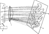
This equipment comprises several light sources 3 and at least one optical element 1 that produces conical light.The light beam that is produced by at least one light source is directly or by optical conductor such as the optical fiber optical element 1 that leads.Like this, be directed at least some light beams its direction of change before beam propagation arrives target surface 5 of the light source 3 of optical element 1.Control by electronic control unit 4 by the light intensity that light source 3 produces.In this electronic control unit 4, might implementing application etc., by it, each light source 3 can be controlled and light figure temporal variation can be resulted from the target surface 5.It is pulse width modulation (PWM) that a favourable enforcement that is used to control light source luminescent intensity is replaced, but other control method also can be used in same known mode.
Light source 3 can for example can reformed mode be attached on the Plane Installation base with the placement of at least one light source and/or direction.The energy that is used for light source transmits by conductor 2, and this conductor can be an elastic conductor for example.
In enforcement of the present invention, the aspect, center is with the placement of the light source 3 of the mode that can produce institute's light requirement figure and the enforcement of optical element 1.Develop the three dimensional design program recently, by it, might design the feature of difform element and analog element, for example the direction of light source.Based on can be thus according to the structural planning of the equipment of means of illumination of the present invention implementing with this auxiliary design of modern computer and the simulation tool of desiring to be used for three dimensional design.Virtual light source and virtual optics element by location in the three dimensional design space of 3D instrument is suitable for being shaped light beam of light source can carry out this design.By the position of change light source and the form and the further feature of luminous intensity and optical element, might design and simulate a kind of structure, might produce required light effect by it.The necessary data of facilities and equipments structure is as the result of design work and obtained.For example, the optical element that belongs to this structure can be made by selected materials on the basis of this data.If described material is a glass, might be implemented in necessary casting mold in the manufacturing on the design data basis (cast mould).
In according to lighting apparatus of the present invention, the outer shape of optical element 1 needn't be similar to the lighting figure that produces by lighting apparatus, and required lighting figure for example produces by influencing the light direction of propagation by optical element 1.In according to lighting apparatus of the present invention, the citation form of lighting figure does not produce by optical element 1, but produces in the following manner: the net shape of lighting figure is the combination of the formed field of illumination of separating light beam and forming by the several light beams that produce by light source 3.The shape of these field of illuminations, color and internal intensity distribute and can revise by one or more optical elements 1 through one or more optical elements 1 by the guiding light beam.Like this, required lighting figure comes painted by light beam to a certain extent.Each light beam can be considered to a kind of color corresponding to the stroke (brushstroke) in the width of cloth picture.Optical element 1 can be considered to corresponding to the paintbrush in artist's hand, and it makes color reach correct form and position in the picture.In addition, by according to lighting apparatus of the present invention, intensity that might be by control light figure makes the lighting figure that produced vividly as the function of the time of operating period.
In lighting apparatus, the control module 4 of separation also is necessary, and by it, the control function of equipment is implemented to produce luminous effect.Control module typically is made up of microprocessor or microcontroller and peripheral components (not shown) and power-supply device.This electronic control unit 4 preferably comprises the functional programs of controlling lighting apparatus.According to this program, control module can be controlled the luminous intensity of each light source 3 separately.In addition, other miscellaneous function of control module 4 controllable devices, as the structure division of equipment, the moving as optical element 1 or one or more light source 3 with respect to other structure division.Be useful on the instrument of the program of exploitation control module, might implement complicated software by it.Obviously in some applications might be in groups to light source, wherein, control module is used to control the light source that is not single or the group of being made up of light source 3 except that single light source.
Be generated as the combined effect of the structure of the control function of electronic control unit 4 of lighting apparatus and equipment by the luminous effect of implementing according to equipment of the present invention.
According to means of illumination of the present invention applicable to for example by implementing to produce sight light (mood lighting) based on the equipment of this method, can obtain for example to imitate the luminous effect of campfire by it.This embodiment has utilized the lighting figure that has as the narrow cone shape of the feature of light source 3 in the following manner: each single beam is by optical element 1 target goal surface 5 obliquely, have the light figure of several elongations of the shape of similar flame to be formed therein, it produces the lighting figure 6 of imitation campfire together.Electronic control unit 4 is used to control the luminous intensity of light source 3 as the function of time to change in the mode of the shape of the lighting figure 6 of the different piece of flame figure and luminous intensity, imitates true campfire thus.
Second embodiment is a kind of based on the equipment according to means of illumination of the present invention, and by it, the luminous effect of similar northern lights can be produced.The structure of this equipment is similar to the structure according to the equipment of previous embodiment.Its difference mainly is the placement of light source 3 and the shape and the placement of color and optical element 1, and the control program of control module 4.
In enforcement of the present invention, basic thought is to utilize the possibility of modern technologies to design and implement in practice the lighting apparatus of mentioned kind.Basic structure according to equipment of the present invention is quite simple, but the placement of the different structure part that its needs is quite complicated and the control of optical characteristics are to realize required luminous effect, do not have modern design and simulation tool, it is implemented is impossible or irrational in practice.In addition, for the function of equipment, the ability of aspect, the center image graphics that to be control produced in controlled mode by equipment.
In the equipment according to the preferred embodiment of the present invention, light source 3 is LED parts.
Also can realize the alternative embodiment of this equipment on according to the basis of means of illumination of the present invention.For example, optical element can be made by glass or plastics, and it be configured as intentionally irregularly shaped, this irregularly shaped part of right-angle prism or ball or shape of the paraboloid of revolution or another regular geometric element of being different from.Also may exist by several optical elements of successively and/or placing with being adjacent to each other.Also at least one light may be produced the combination that light source replaces with light source and optical fiber in the following manner: first end of optical fiber optically is connected to light and produces light source, and wherein second end of optical fiber is arranged to produce the light beam that is directed to optical element.Also may there be a speculum, be used for the light path guiding illumination figure between optical element and target surface.Target surface is the standing part of equipment.
Obviously the present invention not only is confined to the foregoing description, but it can be modified in the scope of appended claim.
Claims (11)
1. a lighting figure (6) that is used for to shape-variable and luminous intensity to be arranged results from the lighting apparatus of target (5), and this equipment comprises:
The optical element (1) of and anaclasis translucent to small part;
Produce several light sources (3) of conical light figure, it is attached in the following manner: its position and angle can be relative to each other and/or optical element (1) and being conditioned;
Electronic control unit (4), it is electrically coupled to each light source (3) in the following manner: the light intensity that is produced by each light source can be conditioned under the control of electronic control unit (4), and
Optical element (1) is attached in the following manner: the light beam that is produced by light source (3) is arranged to propagate into target to be thrown light on (5) by optical element (1) at least in part, is characterised in that: the light beam that is produced by each light source (3) is arranged to propagate by identical optical element (1); The light beam that is produced by each light source (3) is arranged to form the only part of the lighting figure (6) that is produced by lighting apparatus, wherein lighting figure (6) is arranged to the combination of several light beams of being produced by light source (3) and forms, and the shape of described lighting figure is independent of the outer shape of optical element basically; And electronic control unit comprises control program, is used to control the light intensity that is produced by each light source.
2. according to the lighting apparatus of claim 1, be characterised in that this lighting apparatus is coupled as the part of another luminaire regularly.
3. according to the lighting apparatus of claim 1 or 2, be characterised in that light source (3) is the LED parts.
4. according to the lighting apparatus of claim 1 or 2, be characterised in that electronic control unit implements by microprocessor technology or digital circuit technique, and pulse width modulation (PWM) is arranged to use in the control of light source luminescent intensity.
5. according to the lighting apparatus of claim 1 or 2, be characterised in that optical element (1) made by glass or plastics, and it is configured as irregularly shaped intentionally, this irregularly shaped part of right-angle prism or ball or shape of the paraboloid of revolution or another regular geometric element of being different from.
6. according to the lighting apparatus of claim 1 or 2, be characterised in that by successively and/or several optical elements (1) of placing with being adjacent to each other.
7. according to the lighting apparatus of claim 1 or 2, be characterised in that at least one light produces the combination that light source (3) is replaced by light source (3) and optical fiber in the following manner: first end of optical fiber optically is connected to light and produces light source (3), and wherein second end of optical fiber is arranged to produce the light beam that is directed to optical element (1).
8. according to the lighting apparatus of claim 1 or 2, be characterised in that in the equipment in the light path between optical element (1) and target surface (5) that the speculum of guiding illumination figure is arranged.
9. according to the lighting apparatus of claim 1 or 2, be characterised in that target surface (5) is the standing part of equipment.
10. according to the lighting apparatus of claim 1 or 2, be characterised in that to which comprises at least first group of light source (3) and second group of light source (3), wherein be controlled by an electronic control unit described first group of light source and second group of light source in the operating period of equipment.
11. a lighting figure (6) that is used for to shape-variable and luminous intensity to be arranged is formed at the method for target (5), in the method, conical light figure produces by several light sources (3), in this light figure, at least some are by optical element (1) the guiding target (5) to be thrown light on of and anaclasis translucent to small part, light source (3) relative to each other and/or the position of optical element (1) and angle can be conditioned, and the luminous intensity of at least one light source is conditioned, and is characterised in that by the light beam of each light source (3) generation to propagate by identical optical element (1); Form the only part of the lighting figure (6) that produces by lighting apparatus by the light beam of each light source (3) generation, the wherein combination of several light beams of being produced by light source (3) of lighting figure (6) and forming, the shape of described lighting figure is independent of the outer shape of optical element basically; And control program is used to control the light intensity that is produced by each light source.
Applications Claiming Priority (2)
| Application Number | Priority Date | Filing Date | Title |
|---|---|---|---|
| FI20002820 | 2000-12-21 | ||
| FI20002820A FI109430B (en) | 2000-12-21 | 2000-12-21 | Lighting method and device |
Publications (2)
| Publication Number | Publication Date |
|---|---|
| CN1531637A CN1531637A (en) | 2004-09-22 |
| CN1311187C true CN1311187C (en) | 2007-04-18 |
Family
ID=8559780
Family Applications (1)
| Application Number | Title | Priority Date | Filing Date |
|---|---|---|---|
| CNB018209556A Expired - Fee Related CN1311187C (en) | 2000-12-21 | 2001-12-20 | Method and device for illumination |
Country Status (14)
| Country | Link |
|---|---|
| US (1) | US6988820B2 (en) |
| EP (1) | EP1350060B1 (en) |
| JP (1) | JP2004517452A (en) |
| KR (1) | KR20040004466A (en) |
| CN (1) | CN1311187C (en) |
| AT (1) | ATE360783T1 (en) |
| CA (1) | CA2431708A1 (en) |
| DE (1) | DE60128140T2 (en) |
| FI (1) | FI109430B (en) |
| HK (1) | HK1070121A1 (en) |
| NO (1) | NO20032825L (en) |
| PL (1) | PL361878A1 (en) |
| RU (1) | RU2336458C2 (en) |
| WO (1) | WO2002055926A1 (en) |
Families Citing this family (27)
| Publication number | Priority date | Publication date | Assignee | Title |
|---|---|---|---|---|
| US20050097792A1 (en) * | 2003-11-06 | 2005-05-12 | Damir Naden | Apparatus and method for simulation of combustion effects in a fireplace |
| US20060026875A1 (en) * | 2004-08-09 | 2006-02-09 | Joost Elffers | Apparatus for generating shadow display images and design methodology therefor |
| GB2418014B (en) | 2004-09-10 | 2009-05-06 | Basic Holdings | Apparatus for producing an optical effect |
| GB2418013B (en) * | 2004-09-10 | 2008-09-24 | Basic Holdings | Apparatus for Producing an Optical Effect |
| GB2419182B (en) * | 2004-10-13 | 2009-06-03 | Basic Holdings | Apparatus for producing an optical effect or for simulating fires and simulated fireplaces including such apparatus |
| GB2428784B (en) * | 2005-07-22 | 2009-05-06 | Basic Holdings | Simulated fire apparatus |
| GB0605001D0 (en) * | 2006-03-13 | 2006-04-19 | Basic Holdings | Fuel and flame effect fires |
| DE102006006363B4 (en) * | 2006-02-11 | 2012-01-12 | Eads Deutschland Gmbh | Device for displaying visual information in the interior or in a cabin of a motor vehicle or an aircraft |
| GB2439341B (en) * | 2006-06-22 | 2010-11-03 | Basic Holdings | Illumination of an electric fire |
| JP2010503172A (en) * | 2006-09-08 | 2010-01-28 | コーニンクレッカ フィリップス エレクトロニクス エヌ ヴィ | Illumination device having a plurality of light sources and two illumination patterns |
| GB2444073B (en) * | 2006-11-24 | 2009-09-02 | Basic Holdings | Simulated electric fire incorporating LEDs |
| GB2444074B (en) * | 2006-11-24 | 2009-11-18 | Basic Holdings | Simulated electric fire having a light source generating multiple colours |
| US7598683B1 (en) | 2007-07-31 | 2009-10-06 | Lsi Industries, Inc. | Control of light intensity using pulses of a fixed duration and frequency |
| US8903577B2 (en) * | 2009-10-30 | 2014-12-02 | Lsi Industries, Inc. | Traction system for electrically powered vehicles |
| US8604709B2 (en) | 2007-07-31 | 2013-12-10 | Lsi Industries, Inc. | Methods and systems for controlling electrical power to DC loads |
| KR101482105B1 (en) * | 2008-03-14 | 2015-01-13 | 엘지전자 주식회사 | Air conditioner |
| DE102008017073A1 (en) * | 2008-04-03 | 2009-10-08 | Zumtobel Lighting Gmbh | Lighting arrangement with several separate lighting units |
| US8197115B2 (en) | 2008-12-30 | 2012-06-12 | Dean Andrew Wilkinson | Luminaire with adjustable light source |
| TW201132085A (en) * | 2009-04-22 | 2011-09-16 | Koninkl Philips Electronics Nv | Systems and apparatus for light-based social communications |
| JP6479469B2 (en) * | 2011-07-20 | 2019-03-06 | フィリップス ライティング ホールディング ビー ヴィ | Optical element, illumination system, and luminaire for providing skylight appearance |
| EP2752095B1 (en) * | 2011-12-31 | 2018-03-07 | Philips Lighting Holding B.V. | Personalized lighting for open area |
| RU2012101478A (en) * | 2012-01-17 | 2013-07-27 | Владимир Витальевич Мирошниченко | LIGHTED DEVICE HOUSING |
| US9549441B2 (en) * | 2014-03-20 | 2017-01-17 | The Boeing Company | Lighting device to simulate natural motion |
| US20160217718A1 (en) * | 2015-01-22 | 2016-07-28 | Travis Silver | Illuminated product and method for coordinating the location of attendees at an event |
| DE102015114842A1 (en) | 2015-09-04 | 2017-03-09 | Lupyled Gmbh | Foil-like lighting device |
| US11184967B2 (en) | 2018-05-07 | 2021-11-23 | Zane Coleman | Angularly varying light emitting device with an imager |
| US10816939B1 (en) | 2018-05-07 | 2020-10-27 | Zane Coleman | Method of illuminating an environment using an angularly varying light emitting device and an imager |
Citations (3)
| Publication number | Priority date | Publication date | Assignee | Title |
|---|---|---|---|---|
| FR2418102A1 (en) * | 1978-02-27 | 1979-09-21 | Laude Jean Pierre | MOBILE PATTERNS OF SCATTERED LIGHT PROJECTION DEVICE |
| US4972305A (en) * | 1988-05-16 | 1990-11-20 | Blackburn R Geoffrey | Light image generating system |
| CN2069068U (en) * | 1990-02-14 | 1991-01-09 | 唐宗先 | Composite lamp for lighting |
Family Cites Families (4)
| Publication number | Priority date | Publication date | Assignee | Title |
|---|---|---|---|---|
| US3215022A (en) | 1964-05-15 | 1965-11-02 | Elden G Chapman | Apparatus for projected light effects |
| US3366786A (en) | 1965-04-15 | 1968-01-30 | Richard P. Delano | Apparatus for producing color effects |
| GB1529711A (en) * | 1975-07-01 | 1978-10-25 | Rca Corp | Optical etc phase filters producing near-field patterns |
| US6471387B1 (en) * | 2001-09-28 | 2002-10-29 | Atlantic City Coin & Slot Service Company, Inc. | Illuminated display for a gaming device |
-
2000
- 2000-12-21 FI FI20002820A patent/FI109430B/en active
-
2001
- 2001-12-20 RU RU2003123126/28A patent/RU2336458C2/en not_active IP Right Cessation
- 2001-12-20 DE DE60128140T patent/DE60128140T2/en not_active Expired - Fee Related
- 2001-12-20 KR KR10-2003-7008251A patent/KR20040004466A/en not_active Application Discontinuation
- 2001-12-20 CN CNB018209556A patent/CN1311187C/en not_active Expired - Fee Related
- 2001-12-20 CA CA002431708A patent/CA2431708A1/en not_active Abandoned
- 2001-12-20 US US10/451,257 patent/US6988820B2/en not_active Expired - Fee Related
- 2001-12-20 JP JP2002556541A patent/JP2004517452A/en active Pending
- 2001-12-20 PL PL36187801A patent/PL361878A1/en unknown
- 2001-12-20 AT AT01994851T patent/ATE360783T1/en not_active IP Right Cessation
- 2001-12-20 WO PCT/FI2001/001137 patent/WO2002055926A1/en active IP Right Grant
- 2001-12-20 EP EP01994851A patent/EP1350060B1/en not_active Expired - Lifetime
-
2003
- 2003-06-20 NO NO20032825A patent/NO20032825L/en not_active Application Discontinuation
-
2005
- 2005-03-18 HK HK05102394A patent/HK1070121A1/en not_active IP Right Cessation
Patent Citations (3)
| Publication number | Priority date | Publication date | Assignee | Title |
|---|---|---|---|---|
| FR2418102A1 (en) * | 1978-02-27 | 1979-09-21 | Laude Jean Pierre | MOBILE PATTERNS OF SCATTERED LIGHT PROJECTION DEVICE |
| US4972305A (en) * | 1988-05-16 | 1990-11-20 | Blackburn R Geoffrey | Light image generating system |
| CN2069068U (en) * | 1990-02-14 | 1991-01-09 | 唐宗先 | Composite lamp for lighting |
Also Published As
| Publication number | Publication date |
|---|---|
| US6988820B2 (en) | 2006-01-24 |
| FI109430B (en) | 2002-07-31 |
| WO2002055926A1 (en) | 2002-07-18 |
| JP2004517452A (en) | 2004-06-10 |
| CA2431708A1 (en) | 2002-07-18 |
| HK1070121A1 (en) | 2005-06-10 |
| RU2336458C2 (en) | 2008-10-20 |
| PL361878A1 (en) | 2004-10-04 |
| DE60128140D1 (en) | 2007-06-06 |
| EP1350060B1 (en) | 2007-04-25 |
| FI20002820A0 (en) | 2000-12-21 |
| US20040027669A1 (en) | 2004-02-12 |
| ATE360783T1 (en) | 2007-05-15 |
| EP1350060A1 (en) | 2003-10-08 |
| RU2003123126A (en) | 2005-02-10 |
| NO20032825D0 (en) | 2003-06-20 |
| CN1531637A (en) | 2004-09-22 |
| KR20040004466A (en) | 2004-01-13 |
| NO20032825L (en) | 2003-06-20 |
| DE60128140T2 (en) | 2007-12-27 |
Similar Documents
| Publication | Publication Date | Title |
|---|---|---|
| CN1311187C (en) | Method and device for illumination | |
| US20160215961A1 (en) | Illumination device with spinning zoom lens | |
| KR100587618B1 (en) | Apparatus having a light source and sol-gel monolithic diffuser | |
| GB2264555A (en) | Flame effect display | |
| Torres et al. | Illumination aesthetics: Light as a creative material within computational design | |
| CN109210492A (en) | Multi-functional heavy wall Light-guiding optics system | |
| CN1834530A (en) | Laser light raster performance appts | |
| CN208832369U (en) | Multi-functional heavy wall Light-guiding optics system | |
| EP2921773B1 (en) | Lighting device to simulate natural motion | |
| US11506359B2 (en) | Homogenous lit line image vehicle lamp assembly | |
| UA62380A (en) | Device for production of light image | |
| US9611989B1 (en) | Systems and methods for modular indirect lighting | |
| US20040136072A1 (en) | Dynamic image device with diffractive optical element | |
| KR200374000Y1 (en) | Basic light viewing instrument for the students' experiment | |
| CN101027903A (en) | Rear projection screen based electronic window | |
| CN1239941C (en) | Optical diffraction chip dynamic image apparatus and making method thereof | |
| CN117031858A (en) | Three-dimensional identification system | |
| EP1236194A1 (en) | Adjustable 3d multicolor wave generator system | |
| TW202141156A (en) | Array structure light pattern projection device | |
| SU1240426A1 (en) | Colour and music set | |
| CN114321767A (en) | Optical system capable of realizing 3D lighting effect | |
| RU2029908C1 (en) | Laser device with lighting effects | |
| CN116134368A (en) | Projection with extended illumination area | |
| JPH03130680A (en) | Simulating apparatus for radar signal |
Legal Events
| Date | Code | Title | Description |
|---|---|---|---|
| C06 | Publication | ||
| PB01 | Publication | ||
| C10 | Entry into substantive examination | ||
| SE01 | Entry into force of request for substantive examination | ||
| REG | Reference to a national code |
Ref country code: HK Ref legal event code: DE Ref document number: 1070121 Country of ref document: HK |
|
| C14 | Grant of patent or utility model | ||
| GR01 | Patent grant | ||
| C17 | Cessation of patent right | ||
| CF01 | Termination of patent right due to non-payment of annual fee |
Granted publication date: 20070418 Termination date: 20100120 |