CN1180610C - Method for correcting image distortion and device for realizing the same - Google Patents
Method for correcting image distortion and device for realizing the same Download PDFInfo
- Publication number
- CN1180610C CN1180610C CNB991018451A CN99101845A CN1180610C CN 1180610 C CN1180610 C CN 1180610C CN B991018451 A CNB991018451 A CN B991018451A CN 99101845 A CN99101845 A CN 99101845A CN 1180610 C CN1180610 C CN 1180610C
- Authority
- CN
- China
- Prior art keywords
- signal
- pulse
- level
- correct
- ray tube
- Prior art date
- Legal status (The legal status is an assumption and is not a legal conclusion. Google has not performed a legal analysis and makes no representation as to the accuracy of the status listed.)
- Expired - Fee Related
Links
Images


Classifications
-
- H—ELECTRICITY
- H04—ELECTRIC COMMUNICATION TECHNIQUE
- H04N—PICTORIAL COMMUNICATION, e.g. TELEVISION
- H04N3/00—Scanning details of television systems; Combination thereof with generation of supply voltages
- H04N3/10—Scanning details of television systems; Combination thereof with generation of supply voltages by means not exclusively optical-mechanical
- H04N3/16—Scanning details of television systems; Combination thereof with generation of supply voltages by means not exclusively optical-mechanical by deflecting electron beam in cathode-ray tube, e.g. scanning corrections
- H04N3/22—Circuits for controlling dimensions, shape or centering of picture on screen
- H04N3/23—Distortion correction, e.g. for pincushion distortion correction, S-correction
- H04N3/233—Distortion correction, e.g. for pincushion distortion correction, S-correction using active elements
-
- H—ELECTRICITY
- H04—ELECTRIC COMMUNICATION TECHNIQUE
- H04N—PICTORIAL COMMUNICATION, e.g. TELEVISION
- H04N17/00—Diagnosis, testing or measuring for television systems or their details
- H04N17/04—Diagnosis, testing or measuring for television systems or their details for receivers
- H04N17/045—Self-contained testing apparatus
Abstract
To facilitate the adjustment of the S correction in apparatus comprising cathode-ray tubes (televisions, monitors), the process consists in displaying visual marks on the screen, at the location of the picture points which remain stationary as the amplitude of the S correction which is applied to the sawtooth current flowing through the deflection coils of the cathode-ray tube is varied.
Description
Technical field
The present invention relates to a kind of method and a kind of device of realizing this method that is used to proofread and correct the distortion in images that forms by cathode ray tube.The invention particularly relates to the adjusting that the S in the television set proofreaies and correct.
Background technology
Cathode ray tube is the most general display device in the present television set.Schematically demonstrate a television set 6 in Fig. 1 a, it comprises the cathode ray tube of a routine.Cathode ray tube comprises an electron gun 1, and electron gun 1 produces electron beam 2, and electron beam 2 is accelerated and focuses to a fluorescent screen 3, thereby forms a point of image.Be positioned at the outer deflecting coil 4 of cathode ray tube and make the deflection of electron beam electro permanent magnetic, thereby scan screen and form a complete image.
A television image is that even field and odd field form by two normally, and in order to show a complete image, electron beam from the top to the bottom and from the left side to twice of right side scanning screen.
To only be conceived to the vertical deflection of electron beam below.
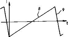
The electric current of the coil 4 of the vertical deflector of flowing through has been shown in Fig. 1 c.The overall shape of this signal is the sawtooth waveforms shape, its rising part 8 is corresponding to electron beam scanning (live part of image) to screen from the top to the bottom, its part 9 is returned the top (field blanking at interval) of screen corresponding to electron beam, and vision signal sends a black level to screen (the non-live part of image) in the whole duration of part 9.The duration that time span between the end of the initial sum of part 8 part 9 in succession equals one.
Turn back to Fig. 1 a, can be pointed out that, the distance between the surface of electron gun 1 and screen 3 is not constant: it is along with mind-set top or bottom from screen are moved and increased.In fact, in the cathode ray tube of up-to-date being called as " flat screen ", the radius of curvature of the screen 3 of electron beam 2 projections is more much bigger than the deflection center C and the radius of curvature R between its theoretical projection surface 5 of electron beam.
The result who does like this is, when not carrying out timing, the image that presents on screen 3 can distort, especially at the top and the bottom position of image.Thus, if one has equidistant horizontal resolution chart and projects on the screen, can obtain the image shown in Fig. 1 b, wherein, the distance between centers of tracks of locating in the top and the bottom of image is greater than the distance between centers of tracks in center.
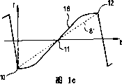
In order to proofread and correct this existing picture, known way is that the coil to vertical deflector applies an electric current, and this electric current is not the accurate sawtooth current shown in Fig. 1 c, but the wherein sawtooth shown in Fig. 1 e presents the electric current of serpentine part 18.This correction is called as " S correction ".The image that obtains when proofreading and correct the best is as shown in Fig. 1 d.
This S proofreaies and correct and must be provided with in the amplitude of not proofreading and correct shape of the end of the television set production line serpentine shape by change part 18 with respect to sawtooth 8 '.In this adjustment process, the change of the amplitude that three points 10,11,12 of the part 18 of this curve can not proofreaied and correct because of S changes, and these points will be called as the fixing point that S proofreaies and correct below.
In order to be best with image rectification, it also is essential that S is proofreaied and correct with respect to screen centering.That is to say that respectively through the moment of point 10,11,12, electron beam must scan first row of screen, middle row and last column respectively at sawtooth current.
In addition, in some television receiver, known way is to produce overscanning line (or being called row) few in number at the top of screen and bottom, and these lines are used to implement test.For example, these lines can be used to send color information and the automatic adjustment that is used to realize colour temperature.
These overscanning lines needn't be displayed on the screen certainly, because they do not carry and the relevant information of " useful " television image that is sent.Therefore, must regulate, so that electron beam does not scan the surface of screen during these overscanning lines at the end of television set production line.
Therefore, at the end of television reception machine production line, the operator must regulate a plurality of parameters: the position of overscanning line, and position and amplitude that S proofreaies and correct, or the like.
In fact, the operator regulates in the following manner:
At first, the operator sends a resolution chart to television set, this figure is called as the convergence figure and is made up of the grid of a line of equidistance, and the corresponding image-region of fixing point that operator's mark and S proofread and correct, that is to say, the operator changes the amplitude that S proofreaies and correct, so that those keep motionless line on the view screen;
In second step, after the position of these lines had been labeled, the operator must be positioned these lines respectively top, centre and the bottom of screen by the flow through amplitude and the skew of sawtooth current of coil of deflector of adjusting; The purpose of doing like this is to make fixing point that S proofreaies and correct with respect to the image pair that forms on screen, and this makes can also be avoided showing the overscanning line on screen;
In the 3rd step, the operator must readjust the amplitude that S proofreaies and correct, and presents equidistant on screen up to each line of grid graph.
A series of like this adjustings are actually very time-consuming, the objective of the invention is to simplify these operations, reduce and regulate every time that television set is required.
Summary of the invention
For this purpose, theme of the present invention is a kind ofly to be used for the distortion in images that the target ray tube forms and to carry out the method that S proofreaies and correct, and it is variable putting on the amplitude that the S of sawtooth current of the deflecting coil of the cathode ray tube of flowing through proofreaies and correct.According to the present invention, this method is included in the step of the position display of visually mark of screen epigraph point, and the amplitude that described picture point is proofreaied and correct at described S keeps static when changing.
The invention provides a kind of distortion in images that is used for the formation of target ray tube and carry out the method that S proofreaies and correct, comprise the following steps: that with sinusoidal signal and sawtooth signal addition wherein the signal that produces by the addition step drives the deflecting coil of cathode ray tube; And when the amplitude of described sinusoidal signal changes, display of visually mark on the screen of cathode ray tube, with the position of signature picture point, described picture point is maintained fixed on described cathode ray tube.
The distortion in images that the present invention also provides a kind of target ray tube to form is carried out the equipment that S proofreaies and correct, it is characterized in that, it comprises the device shown that is used for producing in the position of the picture point that is not subjected to described S correct influences visable indicia, the device shown that wherein is used to produce visable indicia comprises: a sawtooth signal generator, its output is connected to the input that a S proofreaies and correct sinusoidal signal generator, S correction sinusoidal signal generator also receives as the reference voltage of input and exports a S and proofread and correct sinusoidal signal, for the input voltage value that equals reference voltage, S proofreaies and correct sinusoidal wave vanishing; Adder, the sawtooth signal that is used for that generator is exported adds with described S correction sinusoidal signal is in the same place; Comparison means is used for described sawtooth signal and each reference voltage are compared respectively, and is used to produce the signal that comprises pulse, and described pulse produces when sawtooth signal is passed through each reference voltage respectively; And display unit, along with the variation of the signal that comprises described pulse that is received, this device is used for the position display of visually mark of the picture point that influences in the changes in amplitude that is not subjected to described sinusoidal signal on the screen of cathode ray tube.
By means of the present invention, be omitted at the first step of making the above-mentioned adjusting of carrying out when finishing, because the position of the corresponding image-region of fixing point that operator's energy Direct observation and S proofread and correct.In addition, this makes more accurate than prior art, because it does not rely on the subjective sensation of operator to each line position of convergence figure.
According to an aspect of the present invention, shown visable indicia is a black line.
Thus, for the operator, the resolution chart that sends a white for example to screen is just enough, can easily distinguish the corresponding black line of proofreading and correct with S of fixing point like this.
According to one particular embodiment of the present invention, the step of display of visually mark comprises:
In the curve of the electric current of the deflecting coil of flowing through the moment through those points of " fixing point " that be called as S and proofread and correct, produce the pulse that duration equals a video line at least, described fixing point is not subjected to the influence of the variation of the amplitude that described S proofreaies and correct; And
Described pulse is inserted in " super husky fort (Super Sand Castle) " signal, described " super husky fort " signal is to be produced by the circuit of the scanning of control cathode ray tube, and described pulse indication black level correspondingly will be presented at the position of those lines on the screen.
Therefore, the present invention adopts a signal in the scan control circuit Already in, especially " super husky fort " signal that it produced is implemented, so just make video processor in the line flyback of electron beam and field blanking interim, send a black level to the electron gun of cathode ray tube.
According to (in addition) of the present invention aspect, shown visable indicia is a multi-color cord.
This provides more attractive additional display capabilities for the operator.
According to another specific embodiment, the step of display of visually mark comprises:
In the curve of the electric current of the deflecting coil of flowing through the moment through those points of " fixing point " that be called as S and proofread and correct, produce the pulse that duration equals a video line at least, described fixing point is not subjected to the influence of the variation of the amplitude that described S proofreaies and correct; And
The picture and text that produced by a character generator are inserted in described pulse insert in the signal, so that control character is in the demonstration at the place, the corresponding picture position of fixing point of proofreading and correct with described S.
Therefore, according to this embodiment, enforcement of the present invention is to adopt another signal that is pre-existing in: picture and text insert signal, and it is normally used for picture and text are inserted in the vision signal.
Another advantage of the present invention is that it can adopt the circuit and the signal that have existed in the television set to implement easily.
According to a preferred aspect of the present invention, the S that is applied in the vertical deflection circuit of cathode ray tube of this method proofreaies and correct.
The distortion in images that the invention still further relates to a kind of target ray tube formation is carried out the device that S proofreaies and correct, this device is realized above-mentioned method, it is characterized in that it comprises the device shown that is used for producing in the position of the picture point that is not subjected to described S correct influences visable indicia.
According to (again) of the present invention aspect, the device shown that is used to produce visable indicia comprises:
A sawtooth signal generator, its output (end) is connected to the input that a S proofreaies and correct sine-wave generator, S proofreaies and correct sine-wave generator and also receives as input (signal) reference voltage and output S correction sinusoidal wave, for the input voltage value that equals reference voltage, S proofreaies and correct sinusoidal wave vanishing;
Adder is used for that the sawtooth signal of described generator output is proofreaied and correct sine wave with described S and is in the same place;
Comparison means is used for described sawtooth signal and each reference voltage are compared respectively, and is used for producing when sawtooth signal is passed through each reference voltage respectively pulse; With
Display unit, along with the variation of the signal that comprises described pulse that is received, this device is used on screen the position display of visually mark of the picture point that influences in the changes in amplitude that not proofreaied and correct by described S.
The invention still further relates to a kind of television set, it is equipped with the cathode ray tube that comprises above-mentioned S means for correcting.
Description of drawings
Other features and advantages of the present invention will be disclosed by the following explanation that the reference accompanying drawing is done two specific non-limiting examples of the present invention, in the accompanying drawing:
Fig. 1 a (top describe) schematically demonstrates a television set that comprises cathode ray tube;
Fig. 1 b (top describe) demonstrates and is not carrying out timing, the display shape of the corresponding image of resolution chart on screen of forming with a line of equidistance;
Fig. 1 c (top describe) demonstrates without any timing, the electric current of the coil of the vertical deflector of flowing through;
Fig. 1 d (top describe) demonstrates S timing image the display shape on screen identical with Fig. 1 b;
Fig. 1 e (top describe) demonstrates is having the S timing, the electric current of the coil of the vertical deflector of flowing through;
Fig. 2 schematically demonstrates the first that realizes device of the present invention;
Fig. 3 a and 3b schematically demonstrate two embodiment of the second portion of realizing device of the present invention;
Fig. 4 demonstrates the transfer function of a circuit element of the device shown in Fig. 2;
Fig. 5 demonstrates the distribution profile of the signal specific that is produced by device shown in Figure 2;
Fig. 6 a and 6b demonstrate the distribution profile of a vision signal respectively and the distribution profile of what is called " the super husky fort " signal that produced by the device shown in Fig. 3 a.
Embodiment
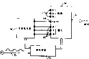
Fig. 2 demonstrates the part of the circuit of the vertical scanning that is used for the control cathode ray tube that is field scan.The function of this circuit is to make synchronously vertical deflection of electron beam and the vision signal that received.
This circuit comprises a vetical sawtooth generator 20, and this saw-toothed wave generator 20 is controlled by field sync signal, and the latter comes from the vision signal that television set receives.As known in those skilled in the art, vetical sawtooth generator is normally by being provided with a current source and the series connection of switch formation, this switch is subjected to vertical synchronization to insert cue (cue) (or field synchronization cue) control, and a capacitor of switch in parallel setting makes and might pass through charging and discharge generation sawtooth waveforms therewith.
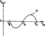
The signal of the output of saw-toothed wave generator 20 is sent to the input V that a S proofreaies and correct sine-wave generator 21
INThis generator has transfer function as shown in Figure 4.At its output V
OUT, it produces a sine wave 31, and this sine wave is corresponding at its input V
INThree magnitude of voltage V that receive
B, V
MAnd V
HAnd vanishing, and at V
BAnd V
MBetween be negative value, and at V
MAnd V
HBetween be on the occasion of.Be sent to the reference voltage V of sine-wave generator 21
B, V
MAnd V
HBe so to select: V
BGreater than the minimum voltage (being shown among Fig. 5) of the sawtooth waveforms 30 that produces by generator 20, V
HLess than the maximum voltage of described sawtooth waveforms 30, V
MRoughly the intermediate voltage with sawtooth waveforms 30 is suitable.Their value is for example V
B=3 volts, V
M=4 volts, V
H=5 volts.As what it will be appreciated that later, those are called as bottom position, medium position and the tip position of the fixing point of S correction to these magnitudes of voltage corresponding to the front.Sinusoidal wave amplitude can be regulated by known mode.
The sinusoidal wave addition that adder 22 will be produced by the sawtooth waveforms 30 and the generator 21 of generator 20 generations.By dotted line 32 expressions, this signal is a sawtooth waveforms to the signal that this addition obtains in Fig. 5, and the part of its minimum slope presents overall serpentine.
This signal is sent to the voltage/current amplifier 23 of a gain-variable, and this amplifier 23 will send to the coil 24 of the vertical deflector of cathode ray tube has the electric current that S proofreaies and correct.By the gain of resonance-amplifier 23, can regulate the size of screen epigraph, make it to expand in vertical direction bigger or lesser extent.Also be provided with the measure of the skew (offset) that is used to regulate the electric current that is sent to the vertical deflector coil, so as to make image on screen with mode vertical moving so, that is, make it occupy the center.
Can find, when the S that is produced by generator 21 proofreaies and correct sine wave to the sawtooth waveforms that produced by generator 20, fix a point really on the resulting curve 32 not change with respect to initial sawtooth waveforms 30.For this reason, in Fig. 5, be denoted as these points of 40,41 and 42 and be called as the fixing point that S proofreaies and correct.
Really, in the image that on the screen of cathode ray tube, forms, when the operator regulates the amplitude (that is to say sinusoidal wave amplitude) that S proofreaies and correct, do not change with corresponding those image-regions of these fixing points of the sawtooth current of the coil that flows through deflector.
In addition, what it may also be pointed out that is, lays respectively under the bottom fixing point 40 of little slope section of sawtooth waveforms 30 and two parts 33,34 on the top fixing point 42 are not subjected to adding sinusoidal wave influence yet.These are corresponding to the overscanning row that is not shown on screen.Why the top of S correction that Here it is and bottom fixing point should be accurately corresponding to first row that will show on screen and the reasons of last column.
According to the present invention, when the operator regulates the S timing, the corresponding image-region of proofreading and correct with " S " of fixing point is identified on the screen by a suitable show tags (display).
For this reason, get back to Fig. 2, the sawtooth waveforms that is produced by generator 20 is sent to the input of three comparators 25,26,27, and each of these comparators receives reference voltage V at its second input respectively
B, V
MAnd V
HThese voltages are identical with the voltage that is sent to sine-wave generator 21.
Each comparator 25,26,27 output voltage strobe pulse (strobe), these pulses present a rising edge separately, and rising edge is in sawtooth waveforms respectively through overvoltage value V
B, V
MAnd V
HThe moment.See moment of the fixing point that these are proofreaied and correct through S corresponding to sawtooth waveforms constantly as top.
Be sent to the input of a signal processing logic circuit 28 by the strobe pulse of comparator 25,26,27 outputs, signal 35 of circuit 28 outputs, this signal presents a plurality of pulses with delegation's duration, and has each rising edge of a strobe pulse input.
This signal 35 is signals of one-period, and its cycle equals one duration of vision signal, and it comprises that duration equals three pulses of delegation in each cycle.This signal will be used to the corresponding image-region of fixing point that mark and S are proofreaied and correct on screen.
In addition, be provided with an input 29 in signal processing logic circuit 28, it is used to send a signal C/I, so that the generation of startup or cut-off signals 35.According to the value (0 or 1) of the signal C/I that receives on the input 29, signal 35 will produce or not produce.In fact, when the television set operate as normal, the mark of fixing point should not be displayed on the screen, so that do not disturb shown image.
According to first embodiment, a plurality of pulses that the duration of signal 35 equals delegation will be added to a signal, and this signal is called as " super husky fort (Super Sand Castle) " because of its jagged profile.
" super husky fort " signal is a signal that produces in scan control circuit by known mode, and it especially is used to the moment notice video processor with the line flyback of electron beam or field retrace, flyback moment be otherwise known as horizontal blanking interval and vertical blanking time, black level is sent to screen during this period.
An example of " super husky fort " signal is shown among Fig. 6 b.This signal is to be formed by the vision signal shown in Fig. 6 a.This vision signal comprises the horizontal synchronizing pulse 14,14 ' of the section start that is positioned at each video line, follows burst signal 15,15 ' thereafter.The effect of burst signal is that the chrominance carrier for composite video signal sends phase reference and frequency reference in vision signal.This vision signal also comprises a part 16 subsequently, and this part is corresponding to the live part of the image that will show on screen.In this example, this is a white line, because signal is in its maximum level.The cycle of section start that starts from the section start of horizontal synchronizing pulse 14 and end at the live part 16 of this journey is called as horizontal blanking interval.
Be denoted as in the cycle of TST, field blackout period is adjusted in a plurality of pulses.This cycle is corresponding in one, at electron beam from the top to the bottom scan screen, electron beam rises to the required time of top of screen.
In horizontal blanking with in field blackout period, image should show black level, so that the scanning vestige of electron beam is sightless.
For this reason, known way is to produce to comprise that duration equals the horizontal blanking and the field blanking signal of the strobe pulse of row and vertical blanking time.Other well known practice is to produce burst gate (gating) pulse during burst signal 15,15 ', so that extract the information relevant with colourity from vision signal.
Add by strobe pulse and to be in the same place, obtain a signal: " super husky fort " signal with three grades of level with horizontal blanking, field blanking and burst gate.
The profile of Fig. 6 b shows resulting " super husky fort " signal.It presents (pulse) edge 53, a plurality of (pulse) edge 54 and a plurality of (pulse) edge 55, edge 53 is corresponding to the field blanking level, edge 54 has the level that is higher than the field blanking level, it is corresponding to line blanking level, edge 55 has the level that is higher than line blanking level, and it is corresponding to colour burst gating (level).Here it is why this signal be also sometimes referred to as the reason of " husky fort " signal with three grades of level." the super husky fort " signal that is sent to video processor is compared with a reference voltage, and the level of this reference voltage is between zero level and field blanking level 53.According to this comparison, when one of above mentioned edge 53,54,55 that is higher than described reference voltage of " super husky fort " signal process, video processor just shows black level on screen.On the contrary, when signal was in its zero level 56 that is lower than described reference voltage, the vision signal that is received was displayed on the screen when " super husky fort ".
According to the present invention, the signal 35 (Fig. 2) that comprises the pulse of the fixing point position of indicating the S correction is added to " super husky fort " signal.Therefore in Fig. 6 b as can be seen, a horizontal blanking impulse 17 has been inserted in " super husky fort " signal, has substituted the level 19 that should have.This pulse 17 notice video processors: do not answer display video capable 16 ', should show black level.
By a white resolution chart is sent to screen of TV set, that is to say that (transmission) vision signal makes might only show white line, therefore the operator will can accurately observe the position of the corresponding image-region of proofreading and correct with S of fixing point, because will show a black line on each of these positions.
Therefore, in order to regulate the location that S proofreaies and correct, for the operator, just enough by carrying out following modification: as to revise the amplitude (by revising the gain of amplifier 23) and the skew of the electric current of the coil be sent to vertical deflector, be positioned at bottom, middle part and the top of screen up to the corresponding black line in position of the fixing point of proofreading and correct with S.
The adjusting that is realized is thus than faster in the prior art and more accurate, because the operator observes the line of describing the position of fixing point on screen continuously.
Fig. 3 a shows the mode that obtains above-mentioned modified " super husky fort " signal.
On first input end, logic sum gate 36 received signals 35, this signal 35 comes from signal processing logic circuit 28 (Fig. 2) and comprises the pulse that is used to locate the fixing point that S proofreaies and correct, and on second input, it receives the output of a comparator 37.
On its first input end, comparator 37 receives a signal HFLY (representative " horizontal flyback sweep "), and this signal comprises the parabola flyback pulse that is produced by the horizontal sweep control circuit according to known mode, and its duration corresponding to line flyback at interval.Second input of comparator 37 receives a reference voltage V
Ref, this voltage is selected as the minimum value of the pulse of approach signal HFLY, so logical signal of comparator 37 outputs, this signal comprises that duration equals line flyback strobe pulse at interval.
The output of logic sum gate 36 is coupled to the first input end of " super husky fort " signal generator 38, and on other two inputs, this generator 38 also receives burst gate and field blanking signal (they are defined) in the above.
" super husky fort " signal that " super husky fort " signal generator 38 will be revised is sent to an output pin 43 of scan control processor 45 (partly being shown among Fig. 3 a), and this pin is connected to an input pin 44 of video processor 46.
Fig. 3 b illustrates the second embodiment of the present invention, and wherein, the signal 35 that comprises the pulse of the fixing point position of indicating the S correction is used to control the demonstration of specific character on screen, so that the position of mark and the corresponding image-region of described fixing point.
As having known, this makes and the picture and text that character generator 50 produces might be inserted in the video image.
According to a second embodiment of the present invention, microprocessor 51 instruction character generators 50 insert picture and text with the pulse of signal 35 and insert in the signal, the latter is sent to the FBTXT input of video processor 46, so, make video processor for example locate the display color line with the corresponding picture position of fixing point of S correction.
Multi-color cord is produced according to this known manner by character generator 50, but can expect any other display capabilities (arrow, picture and text etc.).
Certainly, the present invention is not limited to the above embodiments, and comprises all mapping modes.Especially, signal 35 can have the pulse of duration greater than delegation (duration), and for example, it can comprise the pulse of the duration with two row or triplex row.It can also comprise the pulse of duration less than delegation, especially in a second embodiment.
Except the cathode ray tube of interlacing scan (adopting an even field and odd field to form an image), the present invention is also applicable to the cathode ray tube (such as the cathode ray tube in the video-frequency monitor) of continuous sweep.
Claims (11)
1. a distortion in images that is used for the formation of target ray tube is carried out the method that S proofreaies and correct, and comprises the following steps:
With sinusoidal signal and sawtooth signal addition, wherein the signal that produces by the addition step drives the deflecting coil of cathode ray tube; And
When the amplitude of described sinusoidal signal changes, display of visually mark on the screen of cathode ray tube, with the position of signature picture point, described picture point is maintained fixed on described cathode ray tube.
2. according to the method for claim 1, it is characterized in that the described visable indicia that is shown is black line or multi-color cord.
3. according to the method for claim 1, it is characterized in that the step of display of visually mark comprises:
At the curve of the electric current of the deflecting coil of flowing through through described fixing point (10-12; Moment 40-42) produces the pulse that duration equals a video line at least, and described fixing point is not subjected to the influence of the changes in amplitude of described sinusoidal signal; And
Described pulse is inserted in " super husky fort " signal, described " super husky fort " signal is to be produced by the circuit of the scanning of control cathode ray tube, and described pulse indication black level correspondingly will be presented at the position of those lines on the screen of cathode ray tube.
4. according to the method for claim 1, it is characterized in that the step of display of visually mark comprises:
At the curve of the electric current of the deflecting coil of flowing through through described fixing point (10-12; Moment 40-42) produces the pulse that duration equals a video line at least, and described fixing point is not subjected to the influence of the changes in amplitude of described sinusoidal signal; And
The picture and text that produced by a character generator (50) are inserted in described pulse insert in the signal, so as control character with the demonstration at place, the corresponding picture position of described fixing point.
5. the method that one of requires according to aforesaid right is characterized in that, the S that it is applied in the vertical deflection circuit of cathode ray tube proofreaies and correct.
6. the distortion in images of a target ray tube formation is carried out the equipment that S proofreaies and correct, it is characterized in that, it comprises the device shown that is used for producing in the position of the picture point that is not subjected to described S correct influences visable indicia, and the device shown that wherein is used to produce visable indicia comprises:
A sawtooth signal generator (20), its output are connected to the input (V that a S proofreaies and correct sinusoidal signal generator (21)
IN), S proofreaies and correct sinusoidal signal generator (21) and also receives as the reference voltage (V that imports
B, V
M, V
H) and output (V
OUT) S proofread and correct sinusoidal signal (31), for the input voltage value that equals reference voltage, S proofreaies and correct sinusoidal wave vanishing;
Adder (22), the sawtooth signal that is used for that generator (20) is exported adds with described S correction sinusoidal signal (31) is in the same place;
Comparison means (25,26,27,28) is used for described sawtooth signal and each reference voltage (V
B, V
M, V
H) compare respectively, and being used to produce the signal that comprises pulse, described pulse is to pass through each reference voltage (V respectively in sawtooth signal
B, V
M, V
H) time produces; With
Display unit (36,38,46,50,51), along with the variation of the signal that comprises described pulse (35) that is received, this device is used for the position display of visually mark of the picture point that influences in the changes in amplitude that is not subjected to described sinusoidal signal on the screen of cathode ray tube.
7. according to the equipment of claim 6, also comprise " super husky fort " signal generator (38), this generator receives horizontal blanking strobe pulse, field blanking strobe pulse and burst gating pulse, so that produce " super husky fort " signal: field blanking level, greater than the line blanking level of field blanking level and greater than the burst gating pulse level of line blanking level with three grades of level
Wherein said " super husky fort " signal generator is received signal (35) also, and this signal (35) comprises the described pulse that level equals line blanking level, so that the insertion that produces by described pulse is modified " super husky fort " signal, and
This equipment also comprises a video processor (46), it receives described modification " super husky fort " signal, and, equal the vision signal of black level to level of electron gun output of cathode ray tube when the level of " super husky fort " signal during greater than reference value between zero level and field blanking level.
8. according to the equipment of claim 6, also comprise:
A character generator (50), it produces character and inserts signal and text rgb signal, and these signals are sent to the first input end (48) and second input (49) of a video processor (46) respectively; With
A microprocessor (51), its control character generator (50) and video processor (46), and receive the signal (35) that comprises described pulse, and instruction character generator (50) inserts the picture and text that described pulse is inserted into the first input end (48) that is sent to video processor (46) in the signal, so that make described video processor display of visually mark on the screen of cathode ray tube, the position of demonstration is the position of the picture point that is maintained fixed when the changes in amplitude of sinusoidal signal.
9. television set (6) that has cathode ray tube is characterized in that it comprises:
The distortion in images that the target ray tube forms is carried out the equipment that S proofreaies and correct, and this equipment comprises the device shown that is used for producing in the position of the picture point that is not subjected to described S correct influences visable indicia, and the device shown that wherein is used to produce visable indicia comprises:
A sawtooth signal generator (20), its output are connected to the input (V that a S proofreaies and correct sinusoidal signal generator (21)
IN), S proofreaies and correct sinusoidal signal generator (21) and also receives as the reference voltage (V that imports
B, V
M, V
H) and output (V
OUT) S proofread and correct sinusoidal signal (31), for the input voltage value that equals reference voltage, S proofreaies and correct sinusoidal wave vanishing;
Adder (22), the sawtooth signal that is used for that generator (20) is exported adds with described S correction sinusoidal signal (31) is in the same place;
Comparison means (25,26,27,28) is used for described sawtooth signal and each reference voltage (V
B, V
M, V
H) compare respectively, and being used to produce the signal that comprises pulse, described pulse is to pass through each reference voltage (V respectively in sawtooth signal
B, V
M, V
H) time produces; With
Display unit (36,38,46,50,51), along with the variation of the signal that comprises described pulse (35) that is received, this device is used for the position display of visually mark of the picture point that influences in the changes in amplitude that is not subjected to described sinusoidal signal on the screen of cathode ray tube.
10. television set as claimed in claim 9, wherein said equipment also comprises " super husky fort " signal generator (38), this generator receives horizontal blanking strobe pulse, field blanking strobe pulse and burst gating pulse, so that produce " super husky fort " signal: field blanking level, greater than the line blanking level of field blanking level and greater than the burst gating pulse level of line blanking level with three grades of level
Wherein said " super husky fort " signal generator is received signal (35) also, and this signal (35) comprises the described pulse that level equals line blanking level, so that the insertion that produces by described pulse is modified " super husky fort " signal, and
This equipment also comprises a video processor (46), it receives described modification " super husky fort " signal, and, equal the vision signal of black level to level of electron gun output of cathode ray tube when the level of " super husky fort " signal during greater than reference value between zero level and field blanking level.
11. television set as claimed in claim 9, wherein said equipment also comprises:
A character generator (50), it produces character and inserts signal and text rgb signal, and these signals are sent to the first input end (48) and second input (49) of a video processor (46) respectively; With
A microprocessor (51), its control character generator (50) and video processor (46), and receive the signal (35) that comprises described pulse, and instruction character generator (50) inserts the picture and text that described pulse is inserted into the first input end (48) that is sent to video processor (46) in the signal, so that make described video processor display of visually mark on the screen of cathode ray tube, the position of demonstration is the position of the picture point that is maintained fixed when the changes in amplitude of sinusoidal signal.
Applications Claiming Priority (2)
| Application Number | Priority Date | Filing Date | Title |
|---|---|---|---|
| FR9802403 | 1998-02-27 | ||
| FR9802403A FR2775549B1 (en) | 1998-02-27 | 1998-02-27 | IMAGE DEFORMATION CORRECTION METHOD AND DEVICE USING THE SAME |
Publications (2)
| Publication Number | Publication Date |
|---|---|
| CN1231563A CN1231563A (en) | 1999-10-13 |
| CN1180610C true CN1180610C (en) | 2004-12-15 |
Family
ID=9523451
Family Applications (1)
| Application Number | Title | Priority Date | Filing Date |
|---|---|---|---|
| CNB991018451A Expired - Fee Related CN1180610C (en) | 1998-02-27 | 1999-02-02 | Method for correcting image distortion and device for realizing the same |
Country Status (5)
| Country | Link |
|---|---|
| US (1) | US6329768B1 (en) |
| EP (1) | EP0939558A1 (en) |
| JP (1) | JPH11331630A (en) |
| CN (1) | CN1180610C (en) |
| FR (1) | FR2775549B1 (en) |
Families Citing this family (7)
| Publication number | Priority date | Publication date | Assignee | Title |
|---|---|---|---|---|
| US6982766B1 (en) * | 1997-08-29 | 2006-01-03 | Thomson Licensing | Digital raster correction |
| JP3672771B2 (en) * | 1999-07-14 | 2005-07-20 | 松下電器産業株式会社 | Deflection device |
| CN102256157B (en) * | 2010-05-20 | 2013-04-03 | 北京创毅视讯科技有限公司 | Method and apparatus for determining video signal distortion of mobile simulated television |
| CN104505037B (en) * | 2014-12-24 | 2016-10-19 | 武汉思创电子有限公司 | The antialiasing display packing of a kind of medical monitor and system thereof |
| CN109859155A (en) * | 2017-11-30 | 2019-06-07 | 京东方科技集团股份有限公司 | Image distortion detection method and system |
| CN111107330B (en) * | 2019-12-05 | 2021-08-31 | 华侨大学 | Color cast correction method for Lab space |
| CN116704011B (en) * | 2023-08-04 | 2024-03-05 | 深圳市凯立特光电科技有限公司 | LED display screen pixel correction analysis system based on data processing |
Family Cites Families (7)
| Publication number | Priority date | Publication date | Assignee | Title |
|---|---|---|---|---|
| JPS55671A (en) * | 1978-12-28 | 1980-01-07 | Toshiba Corp | Convergence correction system for color television picture receiver |
| GB8408694D0 (en) * | 1984-04-04 | 1984-05-16 | Rca Corp | Dynamic "s" correction |
| US4645985A (en) * | 1986-02-26 | 1987-02-24 | Rca Corporation | S-correction circuit for a video display |
| JPH06233149A (en) * | 1993-01-29 | 1994-08-19 | Sony Corp | Vertical pin distortion correcting circuit |
| GB9401364D0 (en) * | 1994-01-25 | 1994-03-23 | Rca Thomson Licensing Corp | Deflection circuits with distortion correction |
| WO1998009429A1 (en) * | 1996-08-26 | 1998-03-05 | Philips Electronics N.V. | Diode modulator generating a line s-correction |
| JP3393029B2 (en) * | 1997-01-20 | 2003-04-07 | 富士通株式会社 | Display image distortion correction method for display device, distortion detection device, distortion correction device, and display device provided with the distortion correction device |
-
1998
- 1998-02-27 FR FR9802403A patent/FR2775549B1/en not_active Expired - Fee Related
-
1999
- 1999-02-02 CN CNB991018451A patent/CN1180610C/en not_active Expired - Fee Related
- 1999-02-02 US US09/241,475 patent/US6329768B1/en not_active Expired - Fee Related
- 1999-02-22 EP EP99400415A patent/EP0939558A1/en not_active Withdrawn
- 1999-02-26 JP JP11050693A patent/JPH11331630A/en active Pending
Also Published As
| Publication number | Publication date |
|---|---|
| CN1231563A (en) | 1999-10-13 |
| FR2775549A1 (en) | 1999-09-03 |
| US6329768B1 (en) | 2001-12-11 |
| EP0939558A1 (en) | 1999-09-01 |
| JPH11331630A (en) | 1999-11-30 |
| FR2775549B1 (en) | 2000-03-31 |
Similar Documents
| Publication | Publication Date | Title |
|---|---|---|
| CN1165161C (en) | Image display method and equipment | |
| CN1225918C (en) | Image signal processor and method | |
| CN1250999A (en) | Image displaying calibration system, apparatus and method therefor, apparatus and method for image display | |
| CN1248375A (en) | Display device, marker signal forming method, marker signal detection circuit and control signal generation circuit | |
| CN1180610C (en) | Method for correcting image distortion and device for realizing the same | |
| CN1791232A (en) | High-precision HDTV image definition test pattern and its forming method | |
| CN1698373A (en) | Motion correction device and method | |
| CN1722201A (en) | Display module, drive method of display panel and display device | |
| CN1050484C (en) | Device for reducing ripple interference in colour cathode-ray tube | |
| CN1251488C (en) | Picture noise eliminator and CRT display | |
| CN1165155C (en) | Distorsion correcting circuit and its display device | |
| CN1175364C (en) | Display plate to set pixel-amplitude ratio to predetermined value and corresponding display device | |
| CN1422073A (en) | Display equipment with format converter | |
| CN1312646A (en) | Synchronous frequency changing circuit | |
| CN1917597A (en) | The display device for offering movie modes and method for controlling the same | |
| CN1268766A (en) | Cathode ray tube and image correcting method | |
| CN1138249C (en) | Cathode-ray tube system capable of providing small diameter electronic beam light spot | |
| CN1366327A (en) | Cathode ray tube | |
| CN1216357C (en) | Method and device for adjusting phase for flat screens | |
| CN1189015C (en) | Scanning speed modulating circuit for picture display | |
| CN1148959C (en) | Method for doubling the vertical refresh rate of an image sequence generated in an interlaced scanning process | |
| CN1655624A (en) | Convergence control apparatus for video display | |
| CN1509576A (en) | Restration adjuster and method thereof | |
| KR100671203B1 (en) | Cathode-Ray Tube Display Apparatus | |
| CN1190074C (en) | Flyback pulse wideth adjustment circuit in one-chip video signal processing unit and method |
Legal Events
| Date | Code | Title | Description |
|---|---|---|---|
| C06 | Publication | ||
| PB01 | Publication | ||
| C10 | Entry into substantive examination | ||
| SE01 | Entry into force of request for substantive examination | ||
| C14 | Grant of patent or utility model | ||
| GR01 | Patent grant | ||
| C17 | Cessation of patent right | ||
| CF01 | Termination of patent right due to non-payment of annual fee |
Granted publication date: 20041215 Termination date: 20100202 |