CN115942909A - Systems, devices, and methods for analyte sensor insertion - Google Patents
Systems, devices, and methods for analyte sensor insertion Download PDFInfo
- Publication number
- CN115942909A CN115942909A CN202180053331.XA CN202180053331A CN115942909A CN 115942909 A CN115942909 A CN 115942909A CN 202180053331 A CN202180053331 A CN 202180053331A CN 115942909 A CN115942909 A CN 115942909A
- Authority
- CN
- China
- Prior art keywords
- sensor
- sharps
- carrier
- applicator
- assembly
- Prior art date
- Legal status (The legal status is an assumption and is not a legal conclusion. Google has not performed a legal analysis and makes no representation as to the accuracy of the status listed.)
- Pending
Links
Images


Classifications
-
- A—HUMAN NECESSITIES
- A61—MEDICAL OR VETERINARY SCIENCE; HYGIENE
- A61B—DIAGNOSIS; SURGERY; IDENTIFICATION
- A61B5/00—Measuring for diagnostic purposes; Identification of persons
- A61B5/68—Arrangements of detecting, measuring or recording means, e.g. sensors, in relation to patient
- A61B5/6846—Arrangements of detecting, measuring or recording means, e.g. sensors, in relation to patient specially adapted to be brought in contact with an internal body part, i.e. invasive
- A61B5/6847—Arrangements of detecting, measuring or recording means, e.g. sensors, in relation to patient specially adapted to be brought in contact with an internal body part, i.e. invasive mounted on an invasive device
-
- A—HUMAN NECESSITIES
- A61—MEDICAL OR VETERINARY SCIENCE; HYGIENE
- A61B—DIAGNOSIS; SURGERY; IDENTIFICATION
- A61B5/00—Measuring for diagnostic purposes; Identification of persons
- A61B5/145—Measuring characteristics of blood in vivo, e.g. gas concentration, pH value; Measuring characteristics of body fluids or tissues, e.g. interstitial fluid, cerebral tissue
- A61B5/14503—Measuring characteristics of blood in vivo, e.g. gas concentration, pH value; Measuring characteristics of body fluids or tissues, e.g. interstitial fluid, cerebral tissue invasive, e.g. introduced into the body by a catheter or needle or using implanted sensors
-
- A—HUMAN NECESSITIES
- A61—MEDICAL OR VETERINARY SCIENCE; HYGIENE
- A61B—DIAGNOSIS; SURGERY; IDENTIFICATION
- A61B2560/00—Constructional details of operational features of apparatus; Accessories for medical measuring apparatus
- A61B2560/04—Constructional details of apparatus
- A61B2560/0443—Modular apparatus
-
- A—HUMAN NECESSITIES
- A61—MEDICAL OR VETERINARY SCIENCE; HYGIENE
- A61B—DIAGNOSIS; SURGERY; IDENTIFICATION
- A61B2560/00—Constructional details of operational features of apparatus; Accessories for medical measuring apparatus
- A61B2560/06—Accessories for medical measuring apparatus
- A61B2560/063—Devices specially adapted for delivering implantable medical measuring apparatus
-
- A—HUMAN NECESSITIES
- A61—MEDICAL OR VETERINARY SCIENCE; HYGIENE
- A61B—DIAGNOSIS; SURGERY; IDENTIFICATION
- A61B5/00—Measuring for diagnostic purposes; Identification of persons
- A61B5/145—Measuring characteristics of blood in vivo, e.g. gas concentration, pH value; Measuring characteristics of body fluids or tissues, e.g. interstitial fluid, cerebral tissue
- A61B5/14532—Measuring characteristics of blood in vivo, e.g. gas concentration, pH value; Measuring characteristics of body fluids or tissues, e.g. interstitial fluid, cerebral tissue for measuring glucose, e.g. by tissue impedance measurement
-
- A—HUMAN NECESSITIES
- A61—MEDICAL OR VETERINARY SCIENCE; HYGIENE
- A61B—DIAGNOSIS; SURGERY; IDENTIFICATION
- A61B5/00—Measuring for diagnostic purposes; Identification of persons
- A61B5/145—Measuring characteristics of blood in vivo, e.g. gas concentration, pH value; Measuring characteristics of body fluids or tissues, e.g. interstitial fluid, cerebral tissue
- A61B5/14546—Measuring characteristics of blood in vivo, e.g. gas concentration, pH value; Measuring characteristics of body fluids or tissues, e.g. interstitial fluid, cerebral tissue for measuring analytes not otherwise provided for, e.g. ions, cytochromes
Landscapes
- Health & Medical Sciences (AREA)
- Life Sciences & Earth Sciences (AREA)
- Physics & Mathematics (AREA)
- Medical Informatics (AREA)
- Surgery (AREA)
- Engineering & Computer Science (AREA)
- Biomedical Technology (AREA)
- Heart & Thoracic Surgery (AREA)
- Biophysics (AREA)
- Molecular Biology (AREA)
- Pathology (AREA)
- Animal Behavior & Ethology (AREA)
- General Health & Medical Sciences (AREA)
- Public Health (AREA)
- Veterinary Medicine (AREA)
- Optics & Photonics (AREA)
- Measurement Of The Respiration, Hearing Ability, Form, And Blood Characteristics Of Living Organisms (AREA)
Abstract
An assembly and method for delivering an analyte sensor including a reusable applicator having a proximal portion and a distal portion is disclosed. The reusable applicator may include a housing, a sensor carrier configured to releasably receive the first analyte sensor, a sharps carrier configured to releasably receive the sharps module, and an actuator movable relative to the housing. The actuator may include three positions: a first position of the sensor carrier and the sharps carrier at a proximal portion of the reusable applicator, a second position of the sensor carrier and the sharps carrier at a distal portion of the reusable applicator for delivering a first analyte sensor, and a third position of the sensor carrier at the distal portion of the reusable applicator and the sharps carrier at the proximal portion of the reusable applicator after delivery of the first analyte sensor from the reusable applicator, wherein the first position, the second position, and the third position are different, and wherein the actuator is configured to return from the third position to the first position for delivering another analyte sensor.
Description
Technical Field
The subject matter described herein relates generally to systems, devices, and methods for inserting at least a portion of an analyte sensor into a subject using an applicator.
Background
The detection and/or monitoring of analyte levels (e.g., glucose, ketone, lactate, oxygen, hemoglobin A1C, etc.) is of paramount importance to the health of individuals with diabetes. Patients with diabetes experience complications including loss of consciousness, cardiovascular disease, retinopathy, neuropathy, and nephropathy. A diabetic patient typically needs to monitor his or her glucose level to ensure that it remains within a clinically safe range, and can also use this information to determine if and/or when insulin is required to lower the glucose level in his or her body, or when additional glucose is required to raise the glucose level in his or her body.
Growing clinical data demonstrate a strong correlation between glucose monitoring frequency and glycemic control. However, despite this correlation, many individuals diagnosed with diabetic disease cannot monitor their glucose levels as frequently as they should due to a combination of factors including convenience, test judgment, pain and expense associated with glucose testing.
In order to increase patient compliance with frequent glucose monitoring programs, in vivo analyte monitoring systems may be utilized, wherein a sensor control device may be worn on the body of an individual in need of analyte monitoring. To increase the comfort and convenience of the individual, the sensor control device may have a small form factor and may be assembled and applied by the individual with the sensor applicator. The applying process includes inserting at least a portion of the sensor that senses an analyte level of a user in a bodily fluid located in a layer of the human body using an applicator or an insertion mechanism such that the sensor is in contact with the bodily fluid. The sensor control device may also be configured to transmit analyte data to another device from which an individual or her health care provider ("HCP") may review the data and make treatment decisions.
While current sensors may be convenient for users, they are also susceptible to faults. These failures may be caused by user error, lack of proper training, poor user coordination, overly complicated procedures, physiological reactions to the inserted sensors, and other problems. For example, some prior art systems may be overly dependent on the precise assembly and deployment of the sensor control device and applicator by the individual user. Other prior art systems may utilize sharp insertion and retraction mechanisms that are prone to damage to surrounding tissue at the sensor insertion site, which can result in inaccurate analyte level measurements. These challenges and others described herein can result in incorrect insertion of sensors and/or suboptimal analyte measurements, and thus, an inability to properly monitor a patient's analyte levels.
Furthermore, applicators for inserting at least a portion of an in vivo analyte sensor may include several components, typically comprised of a mixture of plastic materials, which may be difficult to separate after use, making recycling difficult. In addition, the packaging materials used for such applicators must meet a number of engineering design requirements, including providing a tight seal for shelf life storage requirements, requiring tight tolerance parts with special plastic materials to achieve low moisture conversion, providing sufficient lubricity so that insertion forces can be maintained, and the like. Furthermore, the applicator is typically packaged inside a carton along with the alcohol wipe. As a result, applicators are often manufactured for single use and use non-biodegradable materials, making them difficult to recycle and/or not durable enough for repeated use.
Accordingly, there is a need for more reliable sensor insertion devices, systems, and methods that are easy to use by a patient, less prone to error, and reusable. Further, there is a need for an applicator that meets engineering design requirements but is durable enough to be used multiple times and/or recyclable.
Disclosure of Invention
Objects and advantages of the disclosed subject matter will be set forth in and apparent from the description that follows, as well as will be learned by practice of the disclosed subject matter. Additional advantages of the disclosed subject matter will be realized and attained by the methods and systems particularly pointed out in the written description and claims hereof, as well as from the appended drawings.
To achieve these and other advantages and in accordance with the purpose of the disclosed subject matter, as embodied and broadly described, the disclosed subject matter relates to an assembly for delivering an analyte sensor, the assembly including a reusable applicator having a proximal portion and a distal portion. The reusable applicator is configured to deliver a first analyte sensor and includes a housing, a sensor carrier configured to releasably receive the first analyte sensor, a sharps carrier configured to releasably receive the sharps module, and an actuator movable relative to the housing. The actuator includes a first position at which the sensor carrier and the sharps carrier are at the proximal portion of the reusable applicator, a second position at which the sensor carrier and the sharps carrier are at the distal portion of the reusable applicator for delivering the first analyte sensor from the reusable applicator, and a third position after delivery of the first analyte sensor, the sensor carrier is at the distal portion of the reusable applicator and the sharps carrier is at the proximal portion of the reusable applicator. The first position, the second position, and the third position are different. The actuator is configured to return from the third position to the first position for delivery of another analyte sensor.
The reusable applicator may include a drive spring that moves the sensor carrier and the sharps carrier from the proximal portion to the distal portion and a retraction spring that moves the actuator to the third position. The drive spring may be actuated by movement of the actuator from a first position to a second position. The retraction spring may be actuated by movement of the sensor carrier from a proximal position to a distal position of the reusable applicator.
According to certain embodiments, the reusable applicator may further comprise a latch to retain the sensor carrier in the proximal portion of the reusable applicator when the actuator is moved from the second position toward the third position. According to some embodiments, with the actuator in the third position, the sharps carrier is accessible from the proximal portion of the reusable applicator to release the sharps module. The reusable applicator may include a visual indicator of the position of the actuator. The actuator may include a button configured to extend a first predetermined length relative to the housing in a first position, a second predetermined length relative to the housing in a second position, and a third predetermined length relative to the housing in a third position, wherein the third predetermined length is greater than the first predetermined length and the first predetermined length is greater than the second predetermined length. The button may be configured to open to remove the sharps module.
According to embodiments of the present disclosure, the components may be made of recyclable materials. The reusable applicator may comprise acetal. The assembly may include a sealable container to package the reusable applicator. The sealable container may have a low moisture conversion rate. The sealable container may be configured to not require a desiccant. The assembly may include an applicator cap sealingly coupled to the housing using a gasket-less seal.
According to an embodiment of the present disclosure, a method of using an assembly for delivering an analyte sensor may include providing a reusable applicator having a proximal portion and a distal portion and including a housing, a sensor carrier having a first analyte sensor control device releasably received therein, a sharps carrier having a sharps module releasably received therein, and an actuator movable relative to the housing, moving the actuator of the assembly from a first position toward a second position to move the sensor carrier and the sharps carrier from the proximal portion of the reusable applicator to the distal portion of the reusable applicator to deliver a first analyte sensor from the sensor carrier, moving the sharps carrier from the proximal portion of the reusable applicator to the proximal portion of the reusable applicator, and after delivering the first analyte sensor, moving the actuator of the assembly to a third position, and returning the actuator from the third position to the first position to receive another analyte sensor for delivery. The first position, the second position, and the third position are different. The reusable applicator may include a drive spring to move the sensor carrier and the spike carrier from the proximal portion to the distal portion. The reusable applicator may include a retraction spring to move the actuator to the third position.
According to some embodiments, returning the actuator from the third position to the first position may include using the actuator of the assembly to reload the retraction spring by moving the sharps carrier from the proximal portion of the reusable applicator to the distal portion of the reusable applicator, and to reload the drive spring by moving the sensor carrier and the sharps carrier from the distal portion of the reusable applicator to the proximal portion of the reusable applicator.
The method may further include accessing the sharps carrier from a proximal portion of the reusable applicator for releasing the sharps module. The actuator may include a button, and the method may include opening the button to access and remove the first sharps module when the actuator is in the third position.
According to embodiments of the present disclosure, the reusable applicator may include a latch to retain the sensor carrier at the proximal portion of the reusable applicator when the sensor carrier is moved from the second position to the third position.
Drawings
The details of the subject matter set forth herein, both as to its structure and operation, may be apparent from consideration of the accompanying drawings in which like reference numerals refer to like parts. The components in the figures are not necessarily to scale, emphasis instead being placed upon illustrating the principles of the subject matter. Moreover, all illustrations are intended to convey concepts, where relative sizes, shapes and other detailed attributes may be shown schematically rather than literally or precisely.
Fig. 1 is a system overview of a sensor applicator, a reader device, a monitoring system, a network, and a remote system.
Fig. 2A is a block diagram depicting an example implementation of a reader device.
Fig. 2B and 2C are block diagrams depicting example embodiments of a sensor control device.
Fig. 3A-3G are progressive views of an example implementation of assembly and application of the system of fig. 1, including a two-piece architecture.
Fig. 4A is a side view depicting an example embodiment of an applicator device coupled with a cap.
Fig. 4B is a side perspective view depicting an example embodiment of an applicator device disengaged from a cap.
Fig. 4C is a perspective view depicting an example embodiment of an applicator device and a distal end of an electronics housing.
Fig. 5 is a proximal perspective view depicting an example embodiment of a tray with a coupled antiseptic cap.
Fig. 6A is a proximal perspective cutaway depicting an example embodiment of a tray with a sensor transport component.
Fig. 6B is a proximal perspective view depicting the sensor delivery member.
Fig. 7A is a side view depicting an example embodiment of a housing.
Fig. 7B is a perspective view depicting an example embodiment of a distal end of a housing.
Fig. 7C is a side cross-sectional view depicting an example embodiment of a housing.
Fig. 8A is a side view depicting an example embodiment of a sheath.
Fig. 8B is a perspective view depicting an example embodiment of the proximal end of the sheath.
Fig. 8C is a close-up perspective view depicting an example embodiment of a distal side of a pawl catch of a sheath.
Fig. 8D is a side view depicting an example embodiment of features of a sheath.
Fig. 8E is an end view of an example embodiment of the proximal end of the sheath.
Fig. 8F is a perspective view depicting an example embodiment of a compressible distal end of an applicator.
Fig. 8G-8K are cross-sectional views depicting example geometries for embodiments of a compressible distal end of an applicator.
Fig. 8L is a perspective view of an example embodiment of an applicator having a compressible distal end.
Fig. 8M is a cross-sectional view depicting an example embodiment of an applicator having a compressible distal end.
Fig. 9A is a perspective proximal view depicting an example embodiment of a sensor carrier.
Fig. 9B is a distal perspective view depicting an example embodiment of a sensor carrier.
FIG. 10 is a proximal perspective view of an example embodiment of a sharps carrier.
FIG. 11 is a side cross-section depicting an example embodiment of a sharps carrier.
Fig. 12A-12B are top and bottom perspective views, respectively, depicting an example embodiment of a sensor module.
Fig. 13A and 13B are perspective and compression views, respectively, depicting an example embodiment of a sensor connector.
FIG. 14 is a perspective view depicting an example embodiment of a sensor.
Fig. 15A and 15B are bottom and top perspective views, respectively, of an example embodiment of a sensor module assembly.
Fig. 16A and 16B are close-up partial views of an example embodiment of a sensor module assembly.
FIG. 17A is a perspective view depicting an example embodiment of a sharps module.
FIG. 17B is a perspective view depicting another example embodiment of a sharps module.
Fig. 17C and 17D are side and perspective views depicting another example embodiment of a sharps module.
Fig. 17E is a cross-sectional view depicting an example embodiment of an applicator.
FIG. 17F is a flow chart depicting an example embodiment method for sterilizing an applicator assembly.
Fig. 17G and 17H are photographs depicting example embodiments of a sharp tip.
Fig. 17I and 17J are perspective views depicting example embodiments of a sharps module.
Fig. 18A is a front view depicting an example embodiment of an applicator according to the disclosed subject matter.
Fig. 18B is a cross-sectional view depicting various components of the applicator of fig. 18A.
Fig. 19A is a cross-sectional view depicting an example embodiment of an applicator during a deployment stage.
Fig. 19B and 19C are perspective views of example embodiments of a sheath and a sensor carrier, respectively.
Fig. 19D is a cross-sectional view depicting an example embodiment of an applicator during a deployment stage.
Fig. 19E and 19F are perspective and close-up partial views, respectively, of an example embodiment of a sheath-sensor carrier assembly.
Fig. 19G is a cross-sectional view depicting an example embodiment of an applicator during a deployment stage.
Fig. 19H and 19I are close-up partial views of an example embodiment of a sheath-sensor carrier assembly.
Fig. 19J is a cross-sectional view depicting an example embodiment of an applicator during a deployment stage.
Fig. 19K and 19L are close-up partial views of an example embodiment of a sheath-sensor carrier assembly.
Fig. 19M is a front view depicting an example embodiment of an applicator during a deployment phase.
Fig. 19N is a cross-sectional view depicting an example embodiment of an applicator during a deployment phase.
Fig. 19O is a cross-sectional view depicting an example embodiment of an applicator during a deployment phase.
Fig. 19P and 19Q are perspective views of an example embodiment of a disposable sensor carrier of a reusable motorized applicator.
Fig. 19R-1 and 19R-2 are perspective views of example embodiments of a disposable sensor carrier and a reusable applicator base of a reusable motorized applicator.
Fig. 19S-19U are cross-sectional views depicting an example embodiment of a reusable powered applicator during various stages of operation.
Fig. 19V is a top view of an example embodiment of a disposable sensor carrier and a reusable applicator base of a reusable motorized applicator.
Fig. 19W and 19X are a cross-sectional view and a perspective view, respectively, of the reusable powered applicator in a ready-to-load state.
Fig. 20A-20G depict an example embodiment of an applicator, where fig. 20A is a front perspective view of the embodiment, fig. 20B is a front side view of the embodiment, fig. 20C is a back side view of the embodiment, fig. 20D is a left side view of the embodiment, fig. 20E is a right side view of the embodiment, fig. 20F is a top view of the embodiment, and fig. 20G is a bottom view of the embodiment.
Fig. 21A-21G illustrate another example embodiment of an applicator, where fig. 21A is a front perspective view of the embodiment, fig. 21B is a front side view of the embodiment, fig. 21C is a rear side view of the embodiment, fig. 21D is a left side view of the embodiment, fig. 21E is a right side view of the embodiment, fig. 21F is a top view of the embodiment, and fig. 21G is a bottom view of the embodiment.
Fig. 21H-21I are enlarged cross-sectional side views of the interface between the applicator housing and the applicator cap of an example embodiment of the applicator.
Fig. 21J-21K are enlarged cross-sectional side views of the applicator housing and applicator cap.
Fig. 22A to 22G depict an example embodiment of a sensor control device, where fig. 22A is a front perspective view of the embodiment, fig. 22B is a front side view of the embodiment, fig. 22C is a rear side view of the embodiment, fig. 22D is a left side view of the embodiment, fig. 22E is a right side view of the embodiment, fig. 22F is a top view of the embodiment, and fig. 22G is a bottom view of the embodiment.
Fig. 23A-23G depict another example embodiment of a sensor control device, where fig. 23A is a front perspective view of the embodiment, fig. 23B is a front side view of the embodiment, fig. 23C is a back side view of the embodiment, fig. 23D is a left side view of the embodiment, fig. 23E is a right side view of the embodiment, fig. 23F is a top view of the embodiment, and fig. 23G is a bottom view of the embodiment.
Fig. 24A to 24G depict another example embodiment of a sensor control device, where fig. 24A is a front perspective view of the embodiment, fig. 24B is a front side view of the embodiment, fig. 24C is a rear side view of the embodiment, fig. 24D is a left side view of the embodiment, fig. 24E is a right side view of the embodiment, fig. 24F is a top view of the embodiment, and fig. 24G is a bottom view of the embodiment.
Fig. 25A to 25G depict another example embodiment of a sensor control device, where fig. 25A is a front perspective view of the embodiment, fig. 25B is a front side view of the embodiment, fig. 25C is a rear side view of the embodiment, fig. 25D is a left side view of the embodiment, fig. 25E is a right side view of the embodiment, fig. 25F is a top view of the embodiment, and fig. 25G is a bottom view of the embodiment.
Fig. 26A to 26G depict another example embodiment of a sensor control device, where fig. 26A is a front perspective view of the embodiment, fig. 26B is a front side view of the embodiment, fig. 26C is a rear side view of the embodiment, fig. 26D is a left side view of the embodiment, fig. 26E is a right side view of the embodiment, fig. 26F is a top view of the embodiment, and fig. 26G is a bottom view of the embodiment.
Fig. 27A to 27G depict another example embodiment of a sensor control device, where fig. 27A is a front perspective view of the embodiment, fig. 27B is a front side view of the embodiment, fig. 27C is a rear side view of the embodiment, fig. 27D is a left side view of the embodiment, fig. 27E is a right side view of the embodiment, fig. 27F is a top view of the embodiment, and fig. 27G is a bottom view of the embodiment.
Fig. 28A-28G depict another example embodiment of a sensor control device, where fig. 28A is a front perspective view of the embodiment, fig. 28B is a front side view of the embodiment, fig. 28C is a rear side view of the embodiment, fig. 28D is a left side view of the embodiment, fig. 28E is a right side view of the embodiment, fig. 28F is a top view of the embodiment, and fig. 28G is a bottom view of the embodiment.
Fig. 29A to 29G depict another example embodiment of a sensor control device, where fig. 29A is a front perspective view of the embodiment, fig. 29B is a front side view of the embodiment, fig. 29C is a rear side view of the embodiment, fig. 29D is a left side view of the embodiment, fig. 29E is a right side view of the embodiment, fig. 29F is a top view of the embodiment, and fig. 29G is a bottom view of the embodiment.
Fig. 30A-30G depict an example embodiment of an applicator, where fig. 30A is a front perspective view of the embodiment, fig. 30B is a front side view of the embodiment, fig. 30C is a rear side view of the embodiment, fig. 30D is a left side view of the embodiment, fig. 30E is a right side view of the embodiment, fig. 30F is a top view of the embodiment, and fig. 30G is a bottom view of the embodiment.
Fig. 31A-31G depict another example embodiment of an applicator, where fig. 31A is a front perspective view of the embodiment, fig. 31B is a front side view of the embodiment, fig. 31C is a rear side view of the embodiment, fig. 31D is a left side view of the embodiment, fig. 31E is a right side view of the embodiment, fig. 31F is a top view of the embodiment, and fig. 31G is a bottom view of the embodiment.
Fig. 32A to 32G depict an example embodiment of a sensor control device, where fig. 32A is a front perspective view of the embodiment, fig. 32B is a front side view of the embodiment, fig. 32C is a rear side view of the embodiment, fig. 32D is a left side view of the embodiment, fig. 32E is a right side view of the embodiment, fig. 32F is a top view of the embodiment, and fig. 32G is a bottom view of the embodiment.
Fig. 33A to 33G depict another example embodiment of a sensor control device, where fig. 33A is a front perspective view of the embodiment, fig. 33B is a front side view of the embodiment, fig. 33C is a rear side view of the embodiment, fig. 33D is a left side view of the embodiment, fig. 33E is a right side view of the embodiment, fig. 33F is a top view of the embodiment, and fig. 33G is a bottom view of the embodiment.
Fig. 34A to 34G depict another example embodiment of a sensor control device, where fig. 34A is a front perspective view of the embodiment, fig. 34B is a front side view of the embodiment, fig. 34C is a rear side view of the embodiment, fig. 34D is a left side view of the embodiment, fig. 34E is a right side view of the embodiment, fig. 34F is a top view of the embodiment, and fig. 34G is a bottom view of the embodiment.
Fig. 35A-35G depict another example embodiment of a sensor control device, where fig. 35A is a front perspective view of the embodiment, fig. 35B is a front side view of the embodiment, fig. 35C is a rear side view of the embodiment, fig. 35D is a left side view of the embodiment, fig. 35E is a right side view of the embodiment, fig. 35F is a top view of the embodiment, and fig. 35G is a bottom view of the embodiment.
FIG. 36 is a graph reflecting certain characteristics of an example embodiment of a material and seal for a package.
Detailed Description
Before the present subject matter is described in detail, it is to be understood that this disclosure is not limited to particular embodiments described, as such may, of course, vary. It is also to be understood that the terminology used herein is for the purpose of describing particular embodiments only, and is not intended to be limiting, since the scope of the present disclosure will be limited only by the appended claims.
As used herein and in the appended claims, the singular forms "a," "an," and "the" include plural referents unless the context clearly dictates otherwise.
The publications discussed herein are provided solely for their disclosure prior to the filing date of the present application. Nothing herein is to be construed as an admission that the present disclosure is not entitled to antedate such publication by virtue of prior disclosure. Further, the dates of publication provided may be different from the actual publication dates which may need to be independently confirmed.
In general, embodiments of the present disclosure include systems, devices, and methods of use for an analyte sensor insertion applicator for use with in vivo analyte monitoring systems. The applicator may be provided to the user in a sterile package in which the electronics housing of the sensor control device is contained. According to some embodiments, a structure separate from the applicator, such as a container, may also be provided to the user as a sterile package containing the sensor module and the sharps module therein. The user may couple the sensor module to the electronics housing and may couple the sharps to the applicator using an assembly process that includes inserting the applicator into the container in a specified manner. In other embodiments, the applicator, sensor control device, sensor module, and sharps module may be provided in a single package. The applicator may be used to position the sensor control device on the human body, with the sensors in contact with the bodily fluids of the wearer. Embodiments provided herein are improvements that reduce the likelihood of a sensor being improperly inserted or damaged or causing an adverse physiological response. Other improvements and advantages are also provided. Various configurations of these devices are described in detail by way of embodiments, which are merely examples.
In addition, many embodiments include in vivo analyte sensors that are structurally configured such that at least a portion of the sensor is located or locatable in the body of a user to obtain information about at least one analyte of the body. However, it should be noted that the embodiments disclosed herein may be used with in vivo analyte monitoring systems that incorporate in vitro capabilities, as well as with in vitro or ex vivo analyte monitoring systems, including completely non-invasive systems.
Moreover, for each and every embodiment of the methods disclosed herein, systems and apparatuses capable of performing each of those embodiments are encompassed within the scope of the present disclosure. For example, embodiments of sensor control devices are disclosed, and these devices may have one or more sensors, analyte monitoring circuitry (e.g., analog circuitry), memory (e.g., for storing instructions), power supply, communication circuitry, a trigger, a receiver, a processor, and/or a controller (e.g., for executing instructions) that may perform or facilitate the performance of any and all method steps. These sensor control device embodiments are useful and can be used to implement those steps performed by the sensor control device from any and all of the methods described herein.
As described above, various embodiments of systems, devices, and methods are described herein that provide for improved assembly and use of analyte sensor insertion devices for use with in vivo analyte monitoring systems. In particular, several embodiments of the present disclosure are designed to improve sensor insertion methods with respect to in vivo analyte monitoring systems, and in particular, to minimize damage to the insertion site during the sensor insertion process. For example, some embodiments include a motorized sensor insertion mechanism configured to operate at a higher controlled speed relative to a manual insertion mechanism in order to reduce trauma to the insertion site. In other embodiments, applicators with compressible distal ends can stretch and flatten the skin surface at the insertion site, and thus can reduce the likelihood of a failed insertion due to skin doming. In other embodiments, sharps having offset tips, or sharps manufactured using plastic materials or die casting processes, may also reduce damage to the insertion site. In summary, these embodiments may increase the likelihood of successful insertion of the sensor and reduce the amount of damage at the insertion site, which are just a few advantages.
However, before describing these aspects of the embodiments in detail, it is first desirable to describe examples of devices that may be present within, for example, an in vivo analyte monitoring system, and examples of their operation, all of which may be used with the embodiments described herein.
There are various types of in vivo analyte monitoring systems. For example, a "continuous analyte monitoring" system (or a "continuous glucose monitoring" system) may automatically and continuously transmit data from the sensor control device to the reader device, e.g., according to a schedule, without prompting. As another example, a "flash analyte monitoring" system (or a "flash glucose monitoring" system or simply a "flash" system) may transmit data from a sensor control device in response to a scan or request for data by a reader device, such as using Near Field Communication (NFC) or Radio Frequency Identification (RFID) protocols. In vivo analyte monitoring systems may also operate without the need for finger stick calibration.
In vivo analyte monitoring systems are distinguished from "in vitro" systems that contact a biological sample outside of the body (or "ex vivo") and typically include a meter device having a port for receiving an analyte test strip carrying a user's bodily fluids that can be analyzed to determine the user's blood glucose level.
In-vivo monitoring systems may include a sensor that, when positioned in-vivo, comes into contact with a bodily fluid of a user and senses the level of an analyte contained therein. The sensor may be part of a sensor control device that is located on the body of the user and contains electronics and a power source that enable and control analyte sensing. The sensor control device and its variants may also be referred to as a "sensor control unit," "on-body electronics" device or unit, "on-body" device or unit, or "sensor data communication" device or unit, to name a few examples.
The in vivo monitoring system may also include a device that receives sensed analyte data from the sensor control device and processes and/or displays the sensed analyte data to a user in any number of forms. Such a device and its variants may be referred to as a "handheld reader device," "reader device" (or simply "reader"), "handheld electronics" (or simply "handheld"), "portable data processing" device or unit, "data receiver," "receiver" device or unit (or simply "receiver"), or "remote" device or unit, to name a few examples. Other devices such as personal computers have also been used with or incorporated into in vivo and in vitro monitoring systems.
Example embodiments of in vivo analyte monitoring systems
Fig. 1 is a conceptual diagram depicting an example embodiment of an analyte monitoring system 100 that includes a sensor applicator 150, a sensor control device 102, and a reader device 120. Here, the sensor applicator 150 may be used to deliver the sensor control device 102 to a monitoring location on the user's skin where the sensor 104 is held in place by the adhesive patch 105 for a period of time. Sensor control device 102 is further described in fig. 2B and 2C, and may communicate with reader device 120 via communication path 140 using wired or wireless technology. Example wireless protocols include bluetooth, bluetooth low energy (BLE, BTLE, bluetooth smart, etc.), near Field Communication (NFC), etc. The user can use screen 122 and input 121 to monitor applications installed in memory on reader device 120 and can use power port 123 to recharge the device battery. Although only one reader device 120 is shown, the sensor control device 102 may communicate with multiple reader devices 120. Each reader device 120 may communicate and share data with each other. More details regarding reader device 120 are set forth below with reference to fig. 2A. Reader device 120 may communicate with local computer system 170 via communication path 141 using a wired or wireless communication protocol. The local computer system 170 may include one or more of a laptop computer, desktop computer, tablet, smart phone, set-top box, video game console, or other computing device, and the wireless communication may include any of a number of suitable wireless networking protocols, including bluetooth, bluetooth low energy (BTLE), wi-Fi, and so forth. Local computer system 170 may communicate with network 190 via communication path 143, similar to how reader device 120 may communicate with network 190 via communication path 142 via wired or wireless communication protocols as previously described. The network 190 may be any of a variety of networks such as private and public networks, local or wide area networks, and the like. The trusted computer system 180 may include a server and may provide authentication services and secure data storage and may communicate with the network 190 via the communication path 144 through wired or wireless techniques.
Example embodiments of a reader device
Fig. 2A is a block diagram depicting an example implementation of a reader device 120 configured as a smartphone. Here, the reader device 120 may include a display 122, an input component 121, and a processing core 206 including a communication processor 222 coupled with a memory 223 and an application processor 224 coupled with a memory 225. A separate memory 230, an RF transceiver 228 having an antenna 229, and a power supply 226 having a power management module 238 may also be included. In addition, the reader device 120 may also include a multi-function transceiver 232 that may communicate through Wi-Fi, NFC, bluetooth, BTLE, and GPS using an antenna 234. As understood by those skilled in the art, these components are electrically and communicatively coupled in a manner to form a functional device.
Example embodiments of a sensor control device
Fig. 2B and 2C are block diagrams depicting an example implementation of a sensor control device 102 having an analyte sensor 104 and sensor electronics 160 (including analyte monitoring circuitry) that may have most of the processing power for presenting final result data suitable for display to a user. In fig. 2B, a single semiconductor chip 161, which may be a custom Application Specific Integrated Circuit (ASIC), is depicted. Shown within ASIC 161 are certain high-level functional units, including an Analog Front End (AFE) 162, power management (or control) circuitry 164, a processor 166, and communication circuitry 168 (which may be implemented as a trigger, receiver, transceiver, passive circuitry, or other device according to a communication protocol). In this embodiment, both the AFE162 and the processor 166 function as analyte monitoring circuitry, but in other embodiments either circuit may perform the analyte monitoring function. The processor 166 may include one or more processors, microprocessors, controllers, and/or microcontrollers, each of which may be a discrete chip or distributed among multiple different chips (and portions thereof).
Memory 163 is also included within ASIC 161 and may be shared by various functional units present within ASIC 161, or may be distributed between two or more of them. The memory 163 may also be a separate chip. The memory 163 may be volatile and/or nonvolatile memory. In this embodiment, the ASIC 161 is coupled with a power source 172, which may be a button cell battery or the like. The AFE162 interfaces with the in vivo analyte sensor 104, receives measurement data therefrom, and outputs the data in digital form to a processor 166, which in turn processes the data to arrive at final result glucose discrete values and trend values, etc. This data may then be provided to the communication circuitry 168 for transmission to the reader device 120 (not shown) via the antenna 171, for example, where the resident software application requires minimal further processing to display the data.
Fig. 2C is similar to fig. 2B, but instead includes two discrete semiconductor chips 162 and 174, which may be packaged together or separately. Here, the AFE162 resides on the ASIC 161. Processor 166 is integrated with power management circuitry 164 and communication circuitry 168 on chip 174. AFE162 includes memory 163 and chip 174 includes memory 165, which may be isolated or distributed within it. In one example embodiment, AFE162 is combined with power management circuitry 164 and processor 166 on one chip, while communication circuitry 168 is on a separate chip. In another example embodiment, AFE162 and communication circuitry 168 are on one chip, and processor 166 and power management circuitry 164 are on another chip. It should be noted that other chip combinations are possible, including three or more chips, each chip taking responsibility for the individual functions described, or sharing one or more functions to achieve fail-safe redundancy.
Example embodiments of an Assembly Process for a sensor control device
According to some embodiments, the components of the sensor control device 102 may be available to the user in multiple packages, requiring final assembly by the user before delivery to the appropriate user location. Fig. 3A-3E depict an example embodiment of an assembly process of the sensor control device 102 by a user, including preparing individual components to prepare a sensor for delivery prior to coupling the components. In other embodiments, such as those described with reference to fig. 17B-17F, the components of the sensor control device 102 and the applicator 150 may be obtained by the user in a single package. Fig. 3F-3G depict example implementations of delivering the sensor control device 102 to an appropriate user location by selecting an appropriate delivery location and applying the device 102 to that location.
Fig. 3A depicts a sensor container or tray 810 with a removable lid 812. The user prepares sensor tray 810 by removing lid 812, which serves as a sterile barrier to protect the interior contents of sensor tray 810 and otherwise maintain a sterile interior environment. Removal of the cover 812 exposes a platform 808 positioned within the sensor tray 810, and the plug assembly 207 (partially visible) is disposed within and otherwise strategically embedded within the platform 808. Plug assembly 207 includes a sensor module (not shown) and a spike module (not shown). The sensor module carries the sensor 104 (fig. 1) and the sharps module carries an associated sharps member for assisting in delivering the sensor 104 subcutaneously under the skin of the user during application of the sensor control device 102 (fig. 1).
Fig. 3B depicts the sensor applicator 150 and the user preparing the sensor applicator 150 for final assembly. The sensor applicator 150 includes a housing 702 sealed at one end with an applicator cap 708. In some embodiments, for example, an O-ring or another type of sealing gasket may seal the interface between housing 702 and applicator cap 708. In at least one embodiment, an O-ring or sealing gasket may be molded to one of housing 702 and applicator cap 708. Applicator cap 708 provides a barrier that protects the internal contents of sensor applicator 150. In particular, sensor applicator 150 includes an electronics housing (not shown) that holds electrical components for sensor control device 102 (fig. 1), and applicator cap 708 may or may not maintain a sterile environment for the electrical components. Preparation of the sensor applicator 150 includes disengaging the housing 702 from the applicator cap 708, which may be accomplished by unscrewing the applicator cap from the housing 702. The applicator cap 708 may then be discarded or otherwise placed aside.
Fig. 3C depicts a user inserting sensor applicator 150 into sensor tray 810. The sensor applicator 150 includes a sheath 704 configured to be received by the platform 808 to temporarily unlock the sheath 704 relative to the housing 702, and also to temporarily unlock the platform 808 relative to the sensor tray 810. Advancing the housing 702 into the sensor tray 810 causes the plug assembly 207 (fig. 3A) (including the sensor and sharps module) disposed within the sensor tray 810 to couple to the electronics housing disposed within the sensor applicator 150.
In fig. 3D, the user removes sensor applicator 150 from sensor tray 810 by proximally retracting housing 702 relative to sensor tray 810.
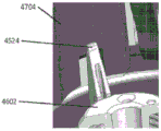
Fig. 3E depicts the bottom or interior of sensor applicator 150 after removal from sensor tray 810 (fig. 3A and 3C). The sensor applicator 150 is removed from the sensor tray 810 with the sensor control device 102 fully assembled therein and positioned for delivery to the target monitoring location. As shown, the spike 2502 extends from the bottom of the sensor control device 102 and carries a portion of the sensor 104 within its hollow or recessed portion. The sharp 2502 is configured to penetrate the skin of a user, thereby placing the sensor 104 in contact with bodily fluids.
Fig. 3F and 3G depict example delivery of the sensor control device 102 to a target monitoring location 221 (e.g., the back of a user's arm). Fig. 3F shows the user advancing the sensor applicator 150 toward the target monitoring location 221. Upon engaging the skin at the target monitoring location 221, the sheath 704 collapses into the housing 702, which allows the sensor control apparatus 102 (fig. 3E and 3G) to advance into engagement with the skin. With the aid of sharp 2502 (fig. 3E), sensor 104 (fig. 3E) is advanced percutaneously into the patient's skin at target monitoring location 221.
Fig. 3G shows the user retracting the sensor applicator 150 from the target monitoring position 221, with the sensor control device 102 successfully attached to the user's skin. An adhesive patch 105 (fig. 1) applied to the bottom of the sensor control device 102 adheres to the skin to secure the sensor control device 102 in place. When the housing 702 is fully advanced at the target monitoring location 221, the sharps 2502 (fig. 3E) are automatically retracted while the sensor 104 (fig. 3E) remains in place to measure analyte levels.
According to some embodiments, the system 100 as described with respect to fig. 3A-3G and elsewhere herein may provide reduced or eliminated opportunities for accidental breakage, permanent deformation, or incorrect assembly of applicator components as compared to prior art systems. Since the applicator housing 702 directly engages the platform 808 when the sheath 704 is unlocked, rather than indirectly via the sheath 704, the relative angle between the sheath 704 and the housing 702 will not result in fracture or permanent deformation of the arm or other component. The likelihood of relatively high forces during assembly (such as in conventional devices) will be reduced, which in turn reduces the chance of unsuccessful assembly by the user. Further details regarding the implementation of applicators, their components, and variations thereof are described in U.S. patent publications 2013/0150691, 2016/0331283, and 2018/0235520, all of which are incorporated herein by reference in their entirety and for all purposes.
Example embodiments of sensor applicator devices
Fig. 4A is a side view depicting an example embodiment of applicator device 150 coupled with nut 708. This is one example of how the applicator 150 may be transported to and received by the user prior to the user assembling the sensor. In other embodiments, the applicator 150 may be transported to the user with the sensor and sharps contained therein. Fig. 4B is a side perspective view depicting the applicator 150 and cap 708 after detachment. Fig. 4C is a perspective view depicting an example embodiment of the distal end of the applicator device 150 with the electronics housing 706 and adhesive patch 105 removed from their positions to be retained within the sensor carrier 710 of the sheath 704 when the cap 708 is in place.
Example embodiments of a tray and sensor Module Assembly
Fig. 5 is a perspective proximal view depicting an example embodiment of a tray 810 having a sterile cover 812 removably coupled thereto, which in some embodiments may represent how the package is shipped to and received by a user prior to assembly.
Fig. 6A is a perspective proximal cross-sectional view depicting a sensor delivery component within a tray 810 according to some embodiments. Platform 808 is slidably coupled within tray 810. The desiccant 502 is stationary relative to the tray 810. The sensor module 504 is mounted within a tray 810.
Fig. 6B is a perspective proximal view depicting an example embodiment of the sensor module 504 in greater detail. Here, the retaining arm extensions 1834 of the platform 808 releasably secure the sensor module 504 in place. The module 2200 is coupled with the connector 2300, the sharps module 2500, and the sensor (not shown) such that it can be removed together as the sensor module 504 during assembly.
Example embodiments of an applicator housing
Fig. 7A is a side view depicting an example embodiment of an applicator housing 702 that may include an internal cavity with support structures for applicator functions. The user may push the housing 702 in a distal direction to activate the applicator assembly process, and then also cause delivery of the sensor control device 102, after which the lumen of the housing 702 may be used as a receptacle for the sharps. In an example embodiment, various features are shown, including a housing orientation feature 1302 for orienting the device during assembly and use. Anti-pry ring notch 1304 may be a recess located around the outer circumference of housing 702, distal to anti-pry ring guard 1314 and proximal to anti-pry ring holder 1306. The anti-pry ring notch 1304 retains the anti-pry ring so that a user can identify whether the device has been pried or otherwise used. The housing threads 1310 may secure the housing 702 to complementary threads on the cap 708 (fig. 4A and 4B) by aligning with the complementary cap threads and rotating in a clockwise or counterclockwise direction. The side grip region 1316 of the housing 702 may provide an outer surface location at which a user may grip the housing 702 in order to use it. Grip tabs 1318 are ridges that are slightly raised relative to side grip regions 1316, which may aid in easy removal of housing 702 from cap 708. Shark teeth 1320 may be raised sections with flat sides on the clockwise edge to shear the anti-pry ring (not shown) and hold it in place after the user has unscrewed the cap 708 and housing 702. In the example embodiment, four shark teeth 1320 are used, although more or fewer shark teeth may be used as desired.
Fig. 7B is a perspective view depicting the distal end of the housing 702. Here, three housing guide structures (or "guide ribs") 1321 are positioned at 120 degrees relative to each other and at 60 degrees relative to the locking structure (or "locking rib") 1340, three of which are also positioned at 120 degrees relative to each other. Other symmetrical or asymmetrical angular orientations may be used, as well as any number of one or more structures 1321 and 1340. Here, each structure 1321 and 1340 is configured as a planar rib, but other shapes may be used. Each guide rib 1321 includes a guide edge (also referred to as a "jacket track") 1326 that can pass along a surface of jacket 704 (e.g., rail 1418 described with respect to fig. 8A). Insertion hard stop 1322 may be a flat distal-facing surface of housing guide rib 1321 located near a proximal end of housing guide rib 1321. Insertion of hard stop 1322 provides a surface for abutting sensor carrier travel limiter face 1420 of sheath 704 (fig. 8B) during use, preventing further movement of sensor carrier travel limiter face 1420 in the proximal direction. During assembly, carrier interface post 1327 passes through aperture 1510 (FIG. 9A) of sensor carrier 710. The sensor carrier interface 1328 can be a rounded, distally facing surface of the housing guide rib 1321 that interfaces with the sensor carrier 710.
Fig. 7C is a side cross-section depicting an example embodiment of a housing. In an example embodiment, the side cross-sectional profiles of the housing guide ribs 1321 and the locking ribs 1340 are shown. Locking ribs 1340 include sheath snap introduction features 1330 near the distal end of locking ribs 1340 that flare distally outward from a central axis 1346 of housing 702. As sheath 704 is moved toward the proximal end of housing 702, each sheath snap introduction feature 1330 causes detent snap rounded portions 1404 of detent snaps 1402 of sheath 704 shown in fig. 8C to flex inwardly toward central axis 1346. Once past the distal point of sheath snap introduction feature 1330, detent snap 1402 of sheath 704 locks in place in locking groove 1332. As such, the pawl catch 1402 cannot easily move in the distal direction due to the surface having a plane approximately perpendicular to the central axis 1346, as shown by pawl catch flat 1406 in fig. 8C.
As the housing 702 is moved further in the proximal direction toward the skin surface, and as the sheath 704 is advanced toward the distal end of the housing 702, the pawl catch 1402 translates into the unlocking groove 1334 and the applicator 150 is in the "armed" position, ready for use. As the user further applies force to the proximal end of housing 702 while sheath 704 is pressed against the skin, pawl catch 1402 clears firing pawl 1344. This begins the firing sequence by releasing the energy stored in the deflected pawl catch 1402, which travels in a proximal direction relative to the skin surface toward the sheath stop ramp 1338, which flares slightly outward relative to the central axis 1346 and slows the motion of the sheath 704 during the firing sequence. After unlocking groove 1334, the next groove encountered by detent catch 1402 is final locking groove 1336 into which detent catch 1402 enters at the end of the stroke or push sequence performed by the user. Final locking groove 1336 may be a proximally facing surface perpendicular to central axis 1346 that engages detent catch flats 1406 after detent catch 1402 passes and prevents reuse of the device by holding sheath 704 securely in place relative to housing 702. Insertion hard stop 1322 of housing guide rib 1321 prevents sheath 704 from advancing proximally relative to housing 702 by engaging sensor carrier travel limiter face 1420.
Example embodiments of an applicator sheath
Fig. 8A and 8B are side and perspective views, respectively, depicting an example embodiment of a sheath 704. In this example embodiment, the sheath 704 may place the sensor control device 102 over the skin surface of the user prior to application. The sheath 704 may also include features that help hold the sharp in place for proper application of the sensor, determine the force required to apply the sensor, and guide the sheath 704 relative to the housing 702 during application. Detent catch 1402 is near the proximal end of sheath 704, as further described below with reference to FIG. 8C. The sheath 704 may have a generally cylindrical cross-section with a first radius in a proximal segment (closer to the top of the figure) that is shorter than a second radius in a distal segment (closer to the bottom of the figure). A plurality of detent clearances 1410 are also shown, three in the example embodiment. Sheath 704 can include one or more detent gaps 1410, each detent gap can be a cut-out with space for sheath snap introduction feature 1330 to enter distally until a distal surface of lock rib 1340 contacts a proximal surface of detent gap 1410.
Guide 1418 is disposed between a sensor carrier travel limiter face 1420 at the proximal end of sheath 704 and a cutout surrounding locking arm 1412. Each guide track 1418 can be a channel between two ridges, wherein a leading edge 1326 of the housing guide rib 1321 can slide distally relative to the sheath 704.
Locking arm 1412 is disposed near the distal end of sheath 704 and may include an attached distal end and a free proximal end, which may include a locking arm interface 1416. When locking arm interfaces 1416 of locking arms 1412 engage locking interfaces 1502 of sensor carrier 710, locking arms 1412 can lock sensor carrier 710 to sheath 704. Locking arm reinforcing ribs 1414 may be disposed near a center location of each locking arm 1412 and may serve as reinforcing points for additional weak points of each locking arm 1412 to prevent the locking arms 1412 from over bending or breaking.
The pawl catch reinforcement feature 1422 may be positioned along a distal segment of the pawl catch 1402 and may provide reinforcement for the pawl catch 1402. Alignment notch 1424 may be a cut-out near the distal end of sheath 704 that provides an opening for a user to align with the sheath orientation feature of platform 808. The reinforcement rib 1426 may include a stiffener, here triangular in shape, that provides support for the pawl base 1436. The housing guide track gap 1428 may be a cutout for the distal surface of the housing guide rib 1321 to slide during use.
Fig. 8C is a close-up perspective view depicting an example embodiment of detent catch 1402 of sheath 704. Pawl catch 1402 may include pawl catch bridge 1408 near or at its proximal end. Pawl catch 1402 may also include pawl catch flats 1406 on a distal side of pawl catch bridge 1408. The outer surface of the pawl catch bridge 1408 may include a pawl catch circle 1404 that is a rounded surface allowing the pawl catch bridge 1408 to more easily move across the inner surface of the housing 702, such as the locking ribs 1340.
Fig. 8D is a side view depicting an example embodiment of a sheath 704. Here, the alignment notch 1424 may be relatively close to the pawl gap 1410. Detent clearance 1410 is at a relatively proximal location on the distal portion of sheath 704.
Fig. 8E is an end view depicting an example embodiment of the proximal end of the sheath 704. Here, the rear wall 1446 of the guide rail may provide a channel to slidably couple with the housing guide rib 1321 of the housing 702. The sheath rotation limiter 1448 may be a notch that reduces or prevents rotation of the sheath 704.
Fig. 8F is a perspective view depicting an example embodiment of a compressible distal end 1450 that can be attached and/or detached from the sheath 704 of the applicator 150. In a general sense, the embodiments described herein operate by flattening and stretching the skin surface at a predetermined site for sensor insertion. In addition, embodiments described herein may also be used for other medical applications, such as transdermal drug delivery, needle injection, wound closure sutures, device implantation, application of adhesive surfaces to the skin, and other similar applications.
By way of background, those skilled in the art will appreciate that skin is a highly anisotropic tissue from a biomechanical standpoint, and varies widely between individuals. This may affect the extent to which communication may be performed between the underlying tissue and the surrounding environment, for example, with respect to drug diffusion rates, the ability to penetrate the skin with the sharp, or sensors inserted into the body at the sharp guide insertion site.
In particular, embodiments described herein relate to improving the aforementioned applications by reducing the anisotropic properties of skin in a predetermined area by flattening and stretching the skin. Smoothing the skin (e.g., flattening to remove wrinkles) before mating with a similar shape (e.g., a flat, rounded adhesive pad of a sensor control unit) may result in a more consistent surface area contact interface. More consistent contact (or drug dosage) may be achieved when the surface contour of the skin approaches the contour specification of the design surface of the device (or, for example, the design contact area for drug delivery). This may also be advantageous for abradable adhesives that do not wrinkle by creating a continuous adhesive-skin contact in a predetermined area. Other advantages may include (1) increased wear duration for functionally dependent skin adhesion devices, and (2) more predictable skin contact area, which will improve drug delivery in transdermal drug/drug delivery.
In addition, skin applanation (e.g., due to tissue compression) in combination with stretching can reduce the viscoelastic properties of the skin and increase its stiffness, which in turn can increase the success rate of sensor placement and functionality associated with the sharp.
With respect to sensor insertion, a puncture wound may contribute to early signal distortion (ESA) in the sensor and may be mitigated when the skin has been flattened and stretched stiff. Some known methods of minimizing puncture wounds include: (1) Reducing the size of the introducer, or (2) limiting the length of the needle inserted into the body. However, these known methods may reduce the insertion success rate due to skin compliance. For example, when the sharp tip contacts the skin, the skin deforms inward into the body before the tip penetrates the skin, a phenomenon also known as "skin doming". If the sharp is not sufficiently rigid due to a small cross-sectional area and/or not long enough, the sharp may not be able to create an insertion point large enough or at a desired location due to deflection so that the sensor passes through the skin and is properly positioned. The degree of skin doming can vary between and within subjects, meaning that the distance between the sharp and the skin surface can vary between insertion events. Reducing this variation by stretching and flattening the skin may allow for a more accurately functioning and consistent sensor insertion mechanism.
Referring to fig. 8F, a perspective view depicts an example embodiment of a compressible distal end 1450 of the applicator 150. According to some embodiments, compressible distal end 1450 may be made of an elastomeric material. In other embodiments, compressible distal end 1450 can be made of metal, plastic, composite legs or springs, or a combination thereof.
In some embodiments, compressible distal end 1450 can be detached from applicator 150 and used with various other similar or dissimilar applicators or medical devices. In other embodiments, compressible distal end 1450 can be fabricated as part of sheath 704. In other embodiments, the compressible distal end 1450 may be attached to other portions of the applicator 150 (e.g., a sensor carrier), or alternatively, may be used as a separate, stand-alone device. Further, while the compressible distal end 1450 is shown in fig. 8F and 8G as having a continuous ring geometry, other configurations may be used. For example, fig. 8H-8K are cross-sectional views depicting various example compressible distal ends having an octagonal geometry 1451 (fig. 8H), a star geometry 1452 (fig. 8I), a non-continuous loop geometry 1453 (fig. 8J), and a non-continuous rectangular geometry (fig. 8K). With respect to fig. 8J and 8K, a compressible distal end having a non-continuous geometry will have a plurality of points or spans to contact a predetermined area of skin. Those skilled in the art will recognize that other geometries are possible and are well within the scope of the present disclosure.
Fig. 8L and 8M are perspective and cross-sectional views, respectively, depicting an applicator 150 having a compressible distal end 1450. As shown in fig. 8L and 8M, the applicator 150 may further include an applicator housing 702, a sheath 704 to which the compressible distal end 1450 is attached, a sharp 2502, and a sensor 104.
In operation, the compressible distal end 1450 of the applicator is first positioned on the skin surface of the subject, according to some embodiments. The subject then exerts a force on the applicator, for example, in a distal direction, which causes the compressible distal end 1450 to stretch and flatten the portion of the underlying skin surface. In some embodiments, for example, compressible distal end 1450 can be constructed of an elastomeric material and biased in a radially inward direction. In other embodiments, compressible distal end 1450 may be biased in a radially outward direction. The force on the applicator may cause an edge portion of the compressible distal end 1450 that contacts the skin surface to displace in a radially outward direction, thereby creating a radially outward force on the portion of the skin surface below the applicator and causing the skin surface to be stretched and flattened.
Furthermore, according to some embodiments, applying a force on the applicator also causes the medical device, such as a sensor control unit, to advance from a first position within the applicator to a second position adjacent the skin surface. According to an aspect of some embodiments, the compressible distal end 1450 may be in an unloaded state in a first position (e.g., before a force is exerted on the applicator) and may be in a loaded state in a second position (e.g., after a force is exerted on the applicator). The medical device is then applied to the stretched and flattened portion of the skin surface underlying compressible distal end 1450. According to some embodiments, the application of the medical device may include placing the adhesive surface 105 of the sensor control unit 102 on the skin surface and/or positioning at least a portion of the analyte sensor below the skin surface. The analyte sensor may be an in vivo analyte sensor configured to measure an analyte level in a bodily fluid of a subject. In other embodiments, application of the medical device may include placing a drug-loaded patch on a skin surface. One skilled in the art will appreciate that the compressible distal end may be used with any of the above-described medical applications and is not meant to be limited to use in an applicator for analyte sensor insertion.
Example embodiments of the sensor Carrier
Fig. 9A is a perspective proximal view depicting an example embodiment of a sensor carrier 710 that can hold sensor electronics within an applicator 150. It may also hold a sharps carrier 1102 with a sharps module 2500. In this example embodiment, sensor carrier 710 has a generally hollow, rounded, flat cylindrical shape and may include one or more deflectable spike carrier locking arms 1524 (e.g., three) that extend proximally from a proximal surface around a centrally located spring alignment ridge 1516 for maintaining alignment of spring 1104. Each locking arm 1524 has a detent or retaining feature 1526 located at or near its proximal end. The impact lock 1534 may be an outwardly extending tab located on the outer circumference of the sensor carrier 710 and may lock the sensor carrier 710 prior to firing for added safety. Rotation limiter 1506 may be a relatively short protrusion extending proximally on the proximal surface of sensor carrier 710 that limits the rotation of carrier 710. As described below with reference to fig. 10 and 11, spike carrier locking arms 1524 may interface with spike carrier 1102.
Fig. 9B is a distal perspective view of sensor carrier 710. Here, one or more sensor electronics retaining spring arms 1518 (e.g., three) are normally biased toward the position shown and include detents 1519 that, when received within recesses or cavities 1521, can pass over a distal surface of the electronics housing 706 of the device 102. In certain embodiments, after sensor control device 102 has been adhered to the skin with applicator 150, the user pulls applicator 150 in a proximal direction, i.e., away from the skin. The adhesive force holds the sensor control device 102 to the skin and overcomes the lateral force applied by the spring arm 1518. As a result, spring arm 1518 deflects radially outward and disengages detent 1519 from sensor control device 102, thereby releasing sensor control device 102 from applicator 150.
Example embodiments of Sharp Carrier
Fig. 10 and 11 are a proximal perspective view and a side cross-sectional view, respectively, depicting an example embodiment of a sharps carrier 1102. The sharps carrier 1102 may grasp and hold the sharps module 2500 within the applicator 150. Near the distal end of spike carrier 1102 may be an anti-rotation slot 1608 that prevents spike carrier 1102 from rotating when located within the central region of spike carrier locking arm 1524 (as shown in fig. 9A). The anti-rotation slot 1608 may be located between the segments of the spike carrier base ramps 1610, which may ensure that the spike carrier 1102 is fully retracted through the sheath 704 as the spike carrier 1102 is retracted at the end of the deployment process.
As shown in fig. 11, the sharps holding arms 1618 may be located in the interior of the sharps carrier 1102 about a central axis, and may include a sharps holding clamp 1620 at the distal end of each arm 1618. The spike retaining clamp 1620 may have a proximal surface that may be nearly perpendicular to the central axis and may abut a distally facing surface of the spike bushing 2516 (fig. 17A).
Example embodiments of a sensor Module
Fig. 12A and 12B are top and bottom perspective views, respectively, depicting an example implementation of a sensor module 504. The module 504 may hold a connector 2300 (fig. 13A and 13B) and a sensor 104 (fig. 14). The module 504 can be securely coupled with the electronics housing 706. One or more deflectable arms or module snaps 2202 may snap into corresponding features 2010 of housing 706. The sharps slot 2208 may provide a location for sharps tip 2502 to pass through and for sharps shaft 2504 to temporarily reside. Sensor stand (ridge) 2212 can define the sensor position in a horizontal plane, prevent the sensor from lifting connector 2300 off the post, and keep sensor 104 parallel to the plane of the connector seal. It may also define a sensor bending geometry and a minimum bending radius. It can limit the travel of the sensor in the vertical direction and prevent the tower from protruding above the electronics housing surface and define the sensor tail length below the patch surface. The sensor wall 2216 may constrain the sensor and define a sensor bend geometry and a minimum bend radius.
Fig. 13A and 13B are perspective views depicting an example embodiment of a connector 2300 in an open state and a closed state, respectively. Connector 2300 may be made of silicone rubber that encapsulates a compliant impregnated carbon polymer module that serves as conductive contacts 2302 between sensor 104 and circuit contacts for electronics within housing 706. The connector may also serve as a moisture barrier for the sensor 104 when assembled in a compressed state after transfer from the container to the applicator and after application to the skin of the user. The plurality of sealing surfaces 2304 can provide a water-tight seal for the electrical and sensor contacts. One or more hinges 2208 may connect two distal and proximal portions of the connector 2300.
Fig. 14 is a perspective view depicting an example implementation of the sensor 104. The neck 2406 may be an area that allows the sensor to fold, e.g., ninety degrees. The membrane on tail 2408 may cover the active analyte sensing elements of sensor 104. Tail 2408 may be the portion of sensor 104 that resides under the user's skin after insertion. Indicia 2404 may include contacts and sealing surfaces. The biasing tower 2412 may be a tab that biases the tail 2408 into the sharps slot 2208. The offset fulcrums 2414 may be branches of the offset towers 2412 that contact the inner surface of the pin to bias the tail into the slot. The bias adjusters 2416 can reduce local bending of the tail connections and prevent sensor trace damage. Contacts 2418 may electrically couple the active portion of the sensor to connector 2300. Maintenance loop 2420 can translate the electrical path ninety degrees from vertical and engage sensor mount 2212 (fig. 12B).
15A and 15B are bottom and top perspective views, respectively, depicting an example embodiment of a sensor module assembly including sensor module 504, connector 2300, and sensor 104. According to one aspect of the above described embodiment, during or after insertion, the sensor 104 may be subjected to an axial force that pushes up against the sensor 104 in a proximal direction and into the sensor module 105, as illustrated by force F1 of fig. 15A. According to some embodiments, this may result in an adverse force F2 being applied to the neck 2406 of the sensor 104, and thus an adverse force F3 being transferred to the maintenance loop 2420 of the sensor 104. In some embodiments, for example, the axial force F1 may occur due to a sensor insertion mechanism (where the sensor is designed to push itself through tissue during insertion), a sharps retraction mechanism, or due to a physiological response generated by tissue surrounding the sensor 104 (e.g., after insertion).
16A and 16B are close-up partial views of example embodiments of sensor module assemblies with certain axial stiffening features. In a general sense, embodiments described herein relate to mitigating the effects of axial forces on a sensor due to an insertion and/or retraction mechanism or due to a physiological response to the sensor in the body. As can be seen in fig. 16A and 16B, according to one aspect of an embodiment, the sensor 3104 includes a proximal portion having a hook feature 3106 configured to engage a catch feature 3506 of the sensor module 3504. In some embodiments, the sensor module 3504 may also include a clearance region 3508 to allow the distal portion of the sensor 3104 to swing back during assembly, allowing the assembly of the hook feature 3106 of the sensor 3104 to be over and into the fastener component 3506 of the sensor module 3504.
According to another aspect of the embodiments, the hook feature 3106 and the catch feature 3506 operate as follows. Sensor 3104 includes a proximal sensor portion coupled to sensor module 3504 as described above, and a distal sensor portion positioned below the skin surface in contact with bodily fluids. As seen in fig. 16A and 16B, the proximal sensor portion includes a hook feature 3106 adjacent to a fastener feature 3506 of the sensor module 3504. During or after sensor insertion, one or more forces are applied in a proximal direction along the longitudinal axis of the sensor 3104. In response to the one or more forces, the hook feature 3106 engages the fastener feature 3506 to prevent the sensor 3104 from being displaced along the longitudinal axis in the proximal direction.
According to another aspect of an embodiment, the sensor 3104 may be assembled with the sensor module 3504 as follows. The sensor 3104 is loaded into the sensor module 3504 by displacing the proximal sensor portion in a lateral direction to bring the hook feature 3106 into proximity with the catch feature 3506 of the sensor module 3504. More specifically, displacing the proximal sensor portion in the lateral direction causes the proximal sensor portion to move into the gap region 3508 of the sensor module 3504.
Although fig. 16A and 16B depict the hook feature 3106 as part of the sensor 3104 and the catch feature 3506 as part of the sensor module 3504, those skilled in the art will appreciate that the hook feature 3106 could alternatively be part of the sensor module 3504 and, likewise, the catch feature 3506 could alternatively be part of the sensor 3106. Similarly, those skilled in the art will also recognize that other mechanisms (e.g., detents, latches, fasteners, screws, etc.) implemented on sensor 3104 and sensor module 3504 to prevent axial displacement of sensor 3104 are possible and within the scope of the present disclosure.
Example embodiments of a sharps Module
FIG. 17A is a perspective view depicting an example embodiment of a sharps module 2500 prior to assembly within sensor module 504 (FIG. 6B). The sharp 2502 may include a distal tip 2506 that can penetrate the skin while carrying the sensor tail in a hollow or recess of sharp shaft 2504 to bring the active surface of the sensor tail into contact with bodily fluids. Bushing pushing cylinder 2508 may provide a surface for pushing the sharps carrier during insertion. The bushing post 2512 may provide space for the sharp piece bushing contact surface 1622 (fig. 11) to extend. The bushing dog positioning cylinders 2514 can provide a distally facing surface of the bushing dogs 2516 for the sharp piece bushing contact surface 1622 to abut. The bushing dogs 2516 may include a conical surface that opens the clamp 1620 during installation of the sharps module 2500. Further details regarding embodiments of the sharp module, sharp, its components, and variations thereof are described in U.S. patent publication No. 2014/0171771, which is hereby incorporated by reference in its entirety and for all purposes.
Fig. 17B, 17C, and 17D depict example embodiments of plastic spike modules. By way of background, according to one aspect of an embodiment, a plastic spike may be advantageous in at least two respects.
First, plastic sharps can result in reduced tissue damage during the skin insertion process relative to metal sharps. Due to their manufacturing processes, such as chemical etching and mechanical forming, metal sharps are often characterized by sharp edges and burrs that can cause damage to tissue at the insertion site. Conversely, plastic sharps can be designed with rounded edges and smooth surfaces to reduce trauma when the sharp is positioned through tissue. Furthermore, those skilled in the art will appreciate that reducing damage during the insertion process can result in a reduction in ESA and improve the accuracy of analyte level readings shortly after insertion.
Second, the plastic sharp simplifies the applicator manufacturing and assembly process. As with the previously described embodiments, some applicators are provided to the user in two pieces: (1) An applicator containing the sharps and sensor electronics in a sensor control unit, and (2) a sensor receptacle. This requires the user to assemble the sensor into the sensor control unit. One reason for a two-piece assembly is to allow electron beam sterilization of the sensor to occur separately from the applicator containing the metal sharps and sensor electronics. Metal sharps, such as those made of stainless steel, have a higher density than sharps made of polymeric or plastic materials. As a result, scattering of the electron beam from the impinging metal sharp can damage the sensor electronics of the sensor control unit. By utilizing plastic sharps, such as those made of polymeric materials, and additional shielding features for keeping the electron beam path away from the sensor electronics, the applicator and sensor can be sterilized and packaged in a single package, thereby reducing manufacturing costs and simplifying the assembly process for the user.
Referring to fig. 17B, a perspective view of an example embodiment of a plastic sharps module 2550 is shown and may include a hub 2562 coupled to a proximal end of the sharps, a sharps shaft 2554, a sharps distal tip 2556 configured to penetrate a skin surface, and a sensor channel 2558 configured to receive at least a portion of an analyte sensor 104. Any or all of the components of sharps module 2550 may be constructed of a plastic material, such as a thermoplastic material, a Liquid Crystal Polymer (LCP), or similar polymer material. According to some embodiments, for example, the sharps module may comprise a polyetheretherketone material. In other embodiments, silicone or other lubricants may be applied to the outer surface of the sharps module and/or incorporated into the polymeric material of the sharps module to reduce damage caused during the insertion process. Further, to reduce trauma during insertion, one or more of the spike shaft 2554, the spike distal tip 2556, or the alignment feature 2568 (described below) may include rounded and/or smooth edges.
According to some embodiments, when assembled, the distal end of the analyte sensor may be in a proximal position relative to the sharp distal tip 2556. In other embodiments, the distal end of the analyte sensor and the sharp distal tip 2556 are co-located.
According to another aspect of some embodiments, the plastic sharps module 2550 can further include an alignment feature 2568 configured to prevent rotational movement along the vertical axis 2545 of the sharps module 2550 during the insertion process, wherein the alignment feature 2568 can be positioned along a proximal portion of the sharps shaft 2554.
Fig. 17C and 17D are side and perspective views, respectively, depicting another example embodiment of a plastic spike module 2570. Similar to the embodiment described with reference to fig. 17B, the plastic spike module 2570 may include a hub 2582 coupled to the proximal end of the spike, a spike shaft 2574, a spike distal tip 2576 configured to penetrate the skin surface, and a sensor channel 2578 configured to receive at least a portion of the analyte sensor 104. Any or all of the components of sharps module 2570 may be constructed of a plastic material, such as a thermoplastic, LCP, or similar polymeric material. In some embodiments, silicone or other lubricants may be applied to the outer surface of the sharps module 2570 and/or incorporated into the polymer material of the sharps module 2570 to reduce damage caused during the insertion process.
According to some embodiments, the sharps shaft 2574 can include a distal portion 2577 terminating at a distal tip 2576, at least a portion of the sensor channel 2578 being disposed in the distal portion. The sharps shaft 2574 can also have a proximal portion 2575 adjacent to the distal portion 2577, wherein the proximal portion 2575 is solid, partially solid, or hollow and is coupled to the hub 2582. Although fig. 17C and 17D depict the sensor channel 2578 as being located only within the distal portion 2577, those skilled in the art will appreciate that the sensor channel 2578 could also extend through a majority of the sharps shaft 2574 (e.g., as shown in fig. 17B) or along the entire length of the sharps shaft 2574, including extending through at least a portion of the proximal portion 2575. In addition, according to another aspect of some embodiments, at least a portion of the proximal portion 2575 can have a wall thickness that is greater than the wall thickness of the distal portion 2577 to reduce the likelihood of stress buckling of the sharp during the insertion process. According to another aspect of some embodiments, the plastic sharps module 2570 may include one or more ribs (not shown) adjacent the sharps sleeve portion 2582 to reduce compressive loads around the sleeve 2582 and to mitigate stress buckling of the sharps during the insertion process.
Fig. 17E is a cross-sectional view depicting an example embodiment of an applicator 150 having a plastic sharps module during an E-beam sterilization process. As shown by the rectangular area a, the electron beam is focused on the sensor 104 and the plastic sharps 2550 of the applicator 150 during the sterilization process. According to some embodiments, a cap 708 has been secured to the applicator housing 702 to seal the sensor control device 102 within the applicator 150. During the sterilization process, as indicated by the diagonal arrows originating from plastic sharps 2550, electron beam scattering in the direction and path of sensor electronics 160 has been reduced because plastic sharps 2550 have been used rather than metal sharps. Although fig. 17E depicts a focused electron beam sterilization process, those skilled in the art will recognize that applicators having plastic sharps module embodiments may also be used during non-focused electron beam sterilization processes.
Fig. 17F is a flow chart depicting an example embodiment method 1100 for disinfecting an applicator assembly according to the embodiments described above. In step 1105, the sensor control device 102 is loaded into the applicator 150. Sensor control device 102 may include various components, including an electronics housing, a printed circuit board positioned within the electronics housing and containing processing circuitry, an analyte sensor extending from a bottom portion of the electronics housing, and a plastic spike module having a plastic spike extending through the electronics housing. According to some embodiments, the plastic spike may also receive a portion of the analyte sensor extending from the bottom of the electronics housing. As previously described, at step 1110, cap 708 is secured to applicator housing 702 of applicator 150, thereby sealing sensor control device 102 within applicator 150. At step 1115, analyte sensor 104 and plastic sharps 2550 are sterilized with radiation while sensor control device 102 is positioned within applicator 150.
According to some embodiments, the sensor control device 102 may further include at least one shield positioned within the electronics housing, wherein the one or more shields are configured to protect the processing circuitry from radiation during the sterilization process. In some embodiments, the shield may include a magnet that generates a static magnetic field to divert radiation away from the processing circuitry. In this manner, the plastic spike module and magnetic shield/deflector combination can cooperate to protect the sensor electronics from radiation during the sterilization process.
Another example embodiment of a sharp designed to reduce trauma during the sensor insertion and retraction process will now be described. More specifically, certain embodiments described herein relate to a point that includes a metallic material (e.g., stainless steel) and is manufactured by a die casting process. According to one aspect of an embodiment, a die cast sharp may be characterized as having a sharp tip, wherein all other edges include rounded edges. As previously mentioned, metal sharps manufactured by chemical etching and mechanical forming processes can result in sharps edges and undesirable hook features. For example, fig. 17G is a photograph depicting a metal sharp 2502 fabricated by a chemical etching and mechanical forming process. As can be seen in fig. 17G, metal sharp 2502 includes a sharp distal tip 2506 having a hook feature. These and other unintended transitional features can result in increased trauma to tissue during the sensor insertion and retraction process. In contrast, fig. 17H is a photograph depicting die-cast sharps 2602, i.e., metal sharps manufactured by a die-casting process. As can be seen in fig. 17H, die cast sharps 2602 further includes a sharps distal tip 2606. However, die-cast sharps 2602 include only smooth rounded edges without any unintended sharp edges or transitions.
As with the previously described embodiments of sharps, the die cast sharps 2602 embodiments described herein may also be assembled into a sharps module having a sharps portion and a sleeve portion. Also, the sharp portion includes a sharp shaft, a sharp proximal end coupled to the distal end of the hub portion, and a sharp distal tip configured to penetrate the skin surface. According to one aspect of an embodiment, one or all of the sharps portion, the sharps shaft, and/or the sharps distal tip of the die cast sharps 2602 can include one or more rounded edges.
Further, one skilled in the art will appreciate that the die-cast sharps 2602 embodiments described herein may similarly be used with any of the sensors described herein, including in vivo analyte sensors configured to measure analyte levels in a bodily fluid of a subject. For example, in some embodiments, die-cast sharps 2602 can include a sensor channel (not shown) configured to receive at least a portion of an analyte sensor. Likewise, in some embodiments of a sharps module assembly utilizing die-cast sharps 2602, the distal end of the analyte sensor may be in a proximal position relative to the sharps distal tip 2606. In other embodiments, the distal end of the analyte sensor and the sharp distal tip 2606 are co-located.
Other example embodiments of sharps designed to reduce trauma during the sensor insertion process will now be described. Referring back to fig. 17A, an example embodiment of a sharps module 2500 (analyte sensor not shown) is depicted and includes a sharps 2502 that includes a sensor channel having a U-shaped geometry configured to receive at least a portion of an analyte sensor and a distal tip 2506 configured to penetrate a skin surface during a sensor insertion process.
In certain embodiments, the sharp module may include a sharp having a distal tip with an offset geometry configured to create a smaller opening in the skin relative to other sharps (e.g., sharp 2502 depicted in fig. 17A). Turning to fig. 17I, a perspective view of an example embodiment of a sharps module 2620 (with analyte sensor 104) having an offset tip portion is shown. Similar to the sharps module previously described, the sharps module 2620 may include a sharps shaft 2624 coupled to the hub 2632 at a proximal end, a sensor channel 2628 configured to receive at least a portion of the analyte sensor 104, and a distal tip 2626 configured to penetrate the skin surface during the sensor insertion process.
According to one aspect of an embodiment, one or more side walls 2629 forming a sensor channel 2628 are disposed along the sharps shaft 2624 at a predetermined distance Dsc from the distal tip 2626. In certain embodiments, the predetermined distance Dsc may be between 1mm and 8 mm. In other embodiments, the predetermined distance Dsc may be between 2mm and 5 mm. Those skilled in the art will recognize that other predetermined distances Dsc may be utilized and are well within the scope of the present disclosure. In other words, according to some embodiments, the sensor channel 2628 is in a spaced relationship with the distal tip 2626. In this regard, distal tip 2626 has a reduced cross-sectional footprint relative to distal tip 2506 of sharps module 2500 whose sensor channel is adjacent distal tip 2506, for example. According to another aspect of this embodiment, at the end of the distal tip 2626 is an offset tip portion 2627 configured to prevent the sensor tip 2408 from being damaged during insertion and creating a small opening in the skin. In some embodiments, the offset tip portion 2627 may be a separate element coupled to the distal end of the sharps shaft 2624. In other embodiments, the offset tip portion 2627 can be formed by the distal tip 2506 or a portion of the sharps shaft 2624. During insertion, when the sharp is moved into the skin surface, the offset tip portion 2627 may cause the skin side around the skin opening to stretch and widen in the lateral direction without further cutting of the skin tissue. In this regard, less damage is created during the sensor insertion process.
Referring next to fig. 17J, a perspective view of another example embodiment of a sharps module 2640 (with analyte sensor 104) with an offset tip portion is shown. Similar to the previous embodiments, the sharps module 2640 may include a sharps shaft 2644 coupled to the hub 2652 at a proximal end, a sensor channel 2648 configured to receive at least a portion of the analyte sensor 104, and a distal tip 2646 configured to penetrate the skin surface during the sensor insertion process. According to one aspect of an embodiment, the sensor channel 2648 can include a first sidewall 2649a and a second sidewall 2649b, wherein the first sidewall 2649a extends to the distal tip 2646, wherein a distal end of the first sidewall 2649a forms an offset tip portion 2647, and wherein the second sidewall 2649b is disposed along the sharps axis 2644 at a predetermined distance from the distal tip 2646, and wherein a distal end of the second sidewall 2649b is proximal to the distal end of the first sidewall 2649a. Those skilled in the art will appreciate that in other embodiments, the second sidewall 2649b can extend to the distal tip 2646 to form an offset tip portion 2647 instead of the first sidewall 2649a. Additionally, offset tip portion 2647 may be formed from a third or fourth sidewall (not shown), and such geometries are well within the scope of the present disclosure.
With respect to the sharps and sharps module embodiments described herein, one skilled in the art will recognize that any or all of the components may comprise a metallic material, such as stainless steel, or a plastic material, such as a liquid crystal polymer. Furthermore, one skilled in the art will appreciate that any of the spike and/or spike module embodiments described herein may be used or combined with any sensor, sensor module, sensor carrier, sheath, applicator device, or any other analyte monitoring system component described herein.
Example embodiments of reusable powered applicators
Fig. 18A and 18B are front and cross-sectional views, respectively, depicting an example embodiment of a reusable, motorized applicator 4150 for inserting an analyte sensor into a subject. According to one aspect of an embodiment, the actuator 4802 of the powered applicator 4150 operates as a trigger that releases and activates the drive spring 4606 under slight pressure to push the sensor carrier 4710 downward and insert the sharps and analyte sensor into the subject. After insertion of the analyte sensor, the retraction spring 4604 causes the sharp to be withdrawn from the subject. According to one aspect of an embodiment, after delivery of a first analyte sensor, the powered applicator 4150 may be reloaded and reused for subsequent delivery of another analyte sensor within the subject. For example, a used sharp (not shown) may be removed, the retraction spring 4604 and the drive spring 4606 may be reloaded, and the actuator 4802 reset, such that the powered applicator 4150 may be reused, as described in further detail below. According to one aspect of an embodiment, the powered applicator 4150 may provide a higher, more controllable insertion speed relative to applicators that rely on force for manual insertion. A further advantage of powered applicator 4150 over applicators that rely on force for manual insertion is that it may improve insertion success and may also reduce trauma at the insertion site. Further, the powered applicator 4150 may be advantageous because it may be reusable, thereby reducing overall cost and environmental impact.
Referring to fig. 18A and 18B, various components of the powered applicator 4150 will now be described. As can be seen in fig. 18A as a front view of the assembled motorized applicator 4150 (in an initial state) and fig. 18B as a cross-sectional view of the motorized applicator, the motorized applicator 4150 may include the following components: housing 4702, actuator 4802, sharp carrier 4602, retraction spring 4604, sheath 4704, striker 4705, drive spring 4606, sensor carrier 4710. Further, although not shown, the powered applicator 4150 may also include any of the embodiments of the sensor control unit, analyte sensor, and sharps described herein or in other publications that have been incorporated by reference.
Fig. 19A-19O are various views depicting an example embodiment of a reusable powered applicator 4150 during various stages of deployment and re-preparation.
Fig. 19A is a cross-sectional view showing the powered applicator 4150 in an initial state, in which the distal end of the applicator 4150 is ready for positioning on the skin surface of a subject. In an initial state, the drive spring 4606 and the retraction spring 4604 are each in a preloaded state. Drive spring 4606 includes a first end coupled to striker 4705 and a second end coupled to sensor carrier 4710. Retraction spring 4604 includes a first end coupled to spike carrier 4602 and a second end coupled to sensor carrier 4710. As best seen in fig. 19A, in the initial state, the sensor carrier 4710 and the sharps carrier 4602 are in a first position within the applicator 4150, in spaced relation to the skin surface. Further, as best seen in fig. 19A, in the initial state, the actuator 4802 is in an initial, cocked position within the powered applicator 4150. The cocked position of the actuator may be a first position, wherein the sensor carrier and the sharps carrier are in a proximal portion of the reusable applicator.
In accordance with an aspect of an embodiment, in an initial state, the sensor carrier 4710 can be coupled to the sheath 4704 by one or more latch-tab structures. Fig. 19B depicts a perspective view of the sheath 4704 including one or more sheath tabs 4706. Fig. 19C depicts a perspective view of a sensor carrier 4710 that includes one or more corresponding sensor carrier latches 4603. In an initial state, each of the one or more sensor carrier latches 4603 is engaged to a corresponding sheath latch 4706, as best seen in fig. 19A. Although fig. 19B and 19C depict three sheath tabs 4706 and three sensor carrier latches 4603, those skilled in the art will appreciate that fewer or more latch-tab structures may be utilized and that those embodiments are well within the scope of the present disclosure.
Fig. 19D is a cross-sectional view illustrating the powered applicator 4150 in a fired state, wherein a force F1 is applied to the actuator 4802 in a distal direction (as indicated by the arrow). In accordance with one aspect of an embodiment, applying force F1 causes actuator 4802 to move in a distal direction, causing plunger 4705 to move in a distal direction along sheath 4704, which subsequently disengages sheath tab 4706 from sensor carrier latch 4603 (as indicated by the white arrow). Disengagement of the sheath tab 4706 from the sensor carrier latch 4603 causes the drive spring 4606 to actuate or expand in a distal direction, thereby "firing" the applicator 4150. As the drive spring 4606 expands in the distal direction, the sensor carrier 4710 and the spike carrier 4602 also displace in the distal direction to a second position adjacent to the skin surface.
According to some embodiments, prior to disengagement of the sheath tab 4706, the application of force F1 may increase the load thereon by further compressing the drive spring 4606.
According to one aspect of an embodiment, the "column-on-column" design of the sheath 4704 and striker 4705 can provide for stable and simultaneous release of all three sensor carrier latches 4603. Furthermore, in some embodiments, certain features may provide enhanced stability when sensor carrier 4710 and spike carrier 4602 are displaced from a first position to a second position. For example, as shown in fig. 19E, the sensor carrier 4710 can include one or more sensor carrier tabs 4605 configured to travel in a distal direction along one or more sheath rails 4707 of the sheath 4704. Additionally, as shown in fig. 19F, according to some embodiments, the sensor carrier 4710 can include one or more sensor carrier bumpers 4607, each of which can be biased against an inner surface of the sheath 4704 while the sensor carrier 4710 and the sharps carrier 4602 are displaced from the first position to the second position.
Fig. 19G is a cross-sectional view showing the powered applicator 4150 in an insertion state during which the sharp and a portion of the analyte sensor (not shown) are positioned below the skin surface and in contact with the bodily fluid of the subject. Furthermore, at this stage, the sharps retraction process has not yet begun. Additionally, as best seen in fig. 19G, after the powered applicator 4150 has been "fired," i.e., in the inserted state, the actuator 4802 may be in a second position, e.g., flush with the housing 4702, with the sensor carrier 4710 and the sharps carrier 4602 in a distal portion of the reusable applicator for delivering the first analyte sensor. Although shown flush with the housing, the second position of the actuator 4802 can be any depressed position relative to the first position. In the second position, as best seen in fig. 19D or 19G, the relative length of actuator 4802 to housing 4702 is less than the relative length of actuator 4802 to housing 4702 in the first position. Further, the actuator 4802 may be biased using, for example, a spring housed within the housing 4702 such that when the force F1 is removed, the actuator 4802 may return to an initial position. As best seen in fig. 19I, the sensor carrier locking arms 4524 continue to be restrained by the sheath 4704, thereby preventing retraction of the sharps carrier 4602 (and sharps).
According to another aspect of an embodiment, during the insertion state, when sensor carrier 4710 reaches the second position, sensor carrier 4710 and a distal portion of a sensor control unit (not shown) coupled with sensor carrier 4710 are in stationary contact with the skin surface. According to aspects of the embodiments, the sheath 4704 may include a latch to hold the sensor carrier 4710 in the second position. In some embodiments, the distal portion of the sensor control unit may be an adhesive surface.
Further, according to some embodiments, as best seen in fig. 19H, during the insertion state, the sensor carrier tabs 4605 positioned within the sheath rails 4707 have traveled in the distal direction to the second position, but are still positioned above the bottom of the applicator 4150, as shown by distance R.
Fig. 19J is a cross-sectional view showing the powered applicator 4150 in a sharps retracted state. According to one aspect of an embodiment, after the insertion state is complete, each of the sensor carrier locking arms 4524 are positioned in the sheath notch 4708, as best seen in fig. 19L. Thus, the sensor carrier locking arms 4524 biased in the radially outward direction may expand in the radially outward direction through the sheath recesses 4708. Next, the sensor carrier locking arms 4524 disengage from the spike carrier 4602 and release the spike carrier, and the retraction spring 4604 is free to expand or actuate in the proximal direction. When the retraction spring 4604 expands in the proximal direction, the sharp carrier 4602 is displaced to a third position within the applicator 4150 (e.g., the top of the sheath 4704), which causes the sharp to withdraw from the skin surface. Notably, in the third position, the sensor carrier 4710 remains locked in the second distal position because the sensor carrier 4710 is latched to the sheath 4704. Further, when the sharps carrier 4602 is displaced proximally within the powered applicator 4150, the sharps carrier 4602 causes the actuator 4802 to extend to the third position. As best seen in fig. 19J, the actuator 4802 in the third position extends fully beyond its initial position in the proximal direction, providing a visual indication to the subject that the powered applicator 4150 has been used. Thus, the relative length of actuator 4802 to housing 4702 in the third position is greater than the relative length of actuator 4802 to housing 4702 in the first position.
According to another aspect of the embodiments, as shown in fig. 19M, the sharp member may be removed from the powered applicator 4150 after delivery of the first sensor. For example, the actuator 4802 may include a button or cap 4802a that may be used to access a spike carrier (as shown in fig. 19J) and a spike sleeve (e.g., spike sleeve 2562 as shown in fig. 17B). The patient may then open the button or cap 4802a to remove the sharps sleeve (e.g., sharps sleeve 2562 as shown in fig. 17B) from the sharps carrier 4602 (as shown in fig. 19J) for safe disposal. For example, a sharps sleeve (e.g., sharps sleeve 2562 as shown in fig. 19J) may be disengaged from the sharps carrier 4602 (as shown in fig. 19J) by rotating or twisting the sharps sleeve relative to the sharps carrier 4602 (as shown in fig. 19J). For example, the spike bushing may be rotated or twisted 15 degrees, 30 degrees, 45 degrees, 60 degrees, 75 degrees, 90 degrees, etc., or any angle in the range of 0-90 degrees.
Fig. 19N is a cross-sectional view showing the powered applicator 4150 in an initial rearmed state, in which force F2 is applied to advance the actuator 4802 in a distal direction (as indicated by the arrow). According to one aspect of an embodiment, application of force F2 causes the spike carrier 4602 to move in a distal direction toward the sensor carrier 4710 until the sensor carrier locking arms 4524 reengage the spike carrier 4602. Thus, the sharps carrier 4602 recompresses and reloads the retraction spring 4604 for subsequent use. As best seen in fig. 19N, in the initial rearming state, the actuator 4802 may be in a fourth position, e.g., flush against the housing 4702. Further, actuator 4802 may be latched or locked within housing 4702 such that when force F2 is removed, actuator 4802 remains flush against housing 4702.
Fig. 19O is a cross-sectional view showing the motorized applicator 4150 in a final rearmed state, wherein a force F3 is applied to the sensor carrier 4710 to advance the sensor carrier 4710 and the sharps carrier 4602 in a proximal direction (as indicated by the arrows). Displacement of sensor carrier 4710 and sharps carrier 4602 in a proximal direction causes striker 4705 to move in a proximal direction along sheath 4704 and drive spring 4606 to compress. Subsequently, the sheath tab 4706 reengages the sensor carrier latch 4603, causing the drive spring 4606 to fully compress, thereby rearming the powered applicator 4150. As previously discussed, the "post-to-post" design of the sheath 4704 and striker 4705 can provide stable and simultaneous re-engagement of all three sensor carrier latches 4603. Thus, in the "rearm" state, the drive spring 4606 and the retraction spring 4604 are each in a preloaded state. Further, in the "rearmed" state, the sensor carrier 4710 and the sharps carrier 4602 have returned to the first position within the powered applicator 4150 in spaced relation to the skin surface. Further, as best seen in fig. 19O, the actuator 4802 is in an initial, cocked position within the powered applicator 4150.
According to one aspect of an embodiment, the actuator 4802 and/or powered applicator 4150 may include a visual indicator corresponding to the position of the actuator 4802. More specifically, the actuator 4802 and/or powered applicator 4150 may include a visual indicator to indicate whether the actuator 4802 is in the initial, second, third, or fourth position. For example, the visual indicators may include color coding along the outer surface 4802a of the actuator 4802 with each location represented by a different color (e.g., green for the initial location, yellow for the second location, green for the third location, and green for the fourth location), with distance markings and/or words and the like on the outer surface 4802a corresponding to the different locations. Thus, during use, a user can quickly determine the position of the actuator 4802.
Fig. 19P-19X depict another example embodiment of a reusable, motorized applicator 4150' for inserting an analyte sensor into a subject. According to one aspect of an embodiment, the reusable powered applicator 4150 'may include a disposable portion that includes the disposable sensor carrier 4710' as shown in top-down and bottom-up perspective views in fig. 19P and 19Q, respectively. According to another aspect of an embodiment, the disposable sensor carrier 4710' can be configured to releasably retain a sensor control device 102 having a sharp 4502 and a sensor module 4504 disposed therethrough. Although not shown in fig. 19P and 19Q, the disposable portion may also include one or more adhesive patches, adhesive pads, and/or a sharps/sensor guard configured to adhere to the skin of the user.
According to another aspect of an embodiment, the reusable powered applicator 4150' may also include a reusable portion that includes the reusable applicator base 4712. Fig. 19R-1 and 19R-2 depict perspective views of the reusable applicator base 4712 and disposable sensor carrier 4710' in coupled and uncoupled states, respectively. According to some embodiments, the disposable sensor carrier 4710' may also include one or more snaps or latches 4711 for coupling with a corresponding rack of the reusable applicator base 4712. Additionally, the reusable applicator base 4712 may include one or more carrier locking arms 4724 for engagement with a sharps carrier.
Fig. 19S, 19T, 19U, and 19W are cross-sectional views depicting example embodiments of a reusable powered applicator 4150' in various stages of operation. For example, fig. 19S is a cross-sectional view depicting the reusable powered applicator 4150 'in a cocked state, wherein the distal end of the reusable powered applicator 4150' is ready to be positioned on the skin surface of the subject. In the cocked state, the drive spring 4606 and the retraction spring 4604 are each in a preloaded state. According to one aspect of an embodiment, the drive spring 4606 may include a first end coupled with the striker 4705 and a second end coupled to the reusable applicator base 4712. As shown in fig. 19S, in the ready-to-fire state, the disposable sensor carrier 4710', the reusable applicator base 4712 and the sharps carrier 4602 are in a first position within the reusable powered applicator 4150' in spaced relation to the skin surface. Also, as shown in fig. 19S, actuator 4802 'is in a cocked position, wherein a proximal portion of actuator 4802' is at a predetermined height relative to housing 4702. Further, in the cocked state, the disposable sensor carrier 4710' is configured to retain the sensor control device 102 with the sharp 4502 extending therethrough.
When a force F1 is applied to the actuator 4802 'in a distal direction (as indicated by the arrow), the reusable powered applicator 4150' is "fired". In accordance with one aspect of an embodiment, application of the force F1 causes the actuator 4802' to move in a distal direction, thereby causing the plunger 4705 to move in a distal direction along the sheath 4704. When the striker 4705 advances in the distal direction, it disengages the sheath tab 4706 from the sensor carrier latch (e.g., as described with respect to fig. 19D), which allows the drive spring 4606 to expand in the distal direction. When the drive spring 4606 expands in the distal direction, the disposable sensor carrier 4710', the reusable applicator base 4712, the sharps carrier 4602, and the sensor control device 102 are also displaced in the distal direction to a second position adjacent the skin surface (fig. 19T).
According to some embodiments, application of force F1 may increase the load on the drive spring 4606 by further compressing it prior to disengagement of the sheath tab 4706. As previously described, the "post-to-post" design of the sheath 4704 and striker 4705 can provide for stable and simultaneous release of the sensor carrier latch. Furthermore, in some embodiments, certain features may provide enhanced stability while the disposable sensor carrier 4710', the reusable applicator base 4712, and the sharps carrier 4602 are displaced from a first position to a second position. For example, in some embodiments, the disposable sensor carrier 4710' may include one or more sensor carrier tabs configured to travel in a distal direction along one or more sheath rails of the sheath 4704, similar to the structure described with respect to fig. 19E. Also, according to some embodiments, the disposable sensor carrier 4710 'may include one or more sensor carrier bumpers, wherein each sensor carrier bumper may be biased against an inner surface of the sheath 4704 while the disposable sensor carrier 4710', the reusable applicator base 4712, and the sharps carrier 4602 are displaced from the first position to the second position.
Fig. 19T is another cross-sectional view depicting the reusable powered applicator 4150' in a state after it has been fired and the sensor control device 102 has been deployed. As shown in fig. 19T, the actuator 4802' is in a return position of increased height, which may provide a visual cue to the user that the sensor control 102 has been applied and at least a portion of the sensor 104 has been successfully inserted. In some embodiments, the return position of actuator 4802 'can be higher than the position of actuator 4802' prior to firing. In other embodiments, the return position of actuator 4802 'can be the same as or less than the position of actuator 4802' prior to firing. As further shown in fig. 19T, the sharp 4502 has been automatically retracted from the skin by a retraction mechanism. In several aspects, the retraction mechanism of the reusable powered applicator 4150' operates in a similar manner to the retraction mechanism of the applicator 4150, as previously described with respect to fig. 19J. Further, according to another aspect of the embodiments, the retraction mechanism of the reusable powered applicator 4150' may be configured to output an audible cue to indicate successful insertion. Subsequently, the reusable powered applicator 4150' may be removed from the insertion site on the skin, leaving the sensor control device 102 deployed on the skin with at least a portion of the sensor 104 inserted.
Fig. 19U is another cross-sectional view depicting the reusable powered applicator 4150' during the sharps ejection stage. According to one aspect of an embodiment, after the reusable powered applicator 4150 'has been removed from the skin, a force F2 may then be applied to the actuator 4802' to cause ejection of the sharp piece 4502. As shown in fig. 19U, application of force F2 may cause a proximal portion of the actuator 4802 'to become substantially or fully depressed relative to the housing 4702 of the reusable powered applicator 4150'. According to another aspect of an embodiment, the application of force F2 may also cause distal portion 4803 of the actuator to advance in a distal direction until distal portion 4803 contacts spike carrier retaining arm 4618 of spike carrier 4602. Advancement of distal portion 4803 further causes, by application of force F2, sharps carrier retention arms 4618 to deploy and disengage sharps bushings 4582 on the proximal end of sharps 4502. Subsequently, the sharp 4502, which is no longer held by the sharp carrier retaining arm 4618, can be ejected by the distal portion 4803 as it continues to be advanced in the distal direction. In some embodiments, for example, after removal from the skin surface, the reusable powered applicator 4150 'may be positioned above the sharps container such that the sharps 4502 are safely ejected from the reusable powered applicator 4150' into the sharps container.
According to another aspect of an embodiment, the sensor carrier ejection phase may occur after or simultaneously with the sharps ejection phase. Fig. 19V is a top view of the reusable applicator base 4712 and disposable sensor carrier 4710' in a coupled state (also shown in fig. 19R-1). The disposable sensor carrier 4710 'may be configured to disengage the reusable applicator base 4712 in response to a force being exerted on one or more snaps or latches 4711 of the disposable sensor carrier 4710'. In some embodiments, for example, applying a force F2 to actuator 4802 '(as shown in fig. 19U) may further cause the cylindrical base portion of sharps carrier 4602 (e.g., as reflected by the dashed circle) to push one or more snaps or latches 4711 of disposable sensor carrier 4710' downward. In other embodiments, one or more distally extending features (not shown) of the actuator 4802 'may each be configured to interface with a corresponding catch or latch 4711 of the disposable sensor carrier 4710'. In response to a downward force applied to the one or more snaps or latches 4711, the sensor carrier 4710 'disengages from the reusable applicator base 4712 and is ejected from the reusable powered applicator 4150'.
Referring again to fig. 19U, according to another aspect of the embodiments, application of the force F2 may further cause the sharps carrier 4602 to advance in a distal direction until the carrier locking arms 4724 of the reusable applicator base 4712 re-engage the sharps carrier 4602. Thus, the sharps carrier 4602 recompresses and reloads the retraction spring 4604 for subsequent use. Reloading of the retraction spring 4604 can occur during either or both of the sharps ejection stage or the sensor carrier ejection stage.
Fig. 19W is another cross-sectional view depicting the reusable powered applicator 4150' in a ready-to-load state. According to one aspect of an embodiment, in the ready-to-load state, the sharps and disposable sensor carrier have been ejected, the sharps carrier has been re-latched, the retraction spring has been re-loaded, and the reusable powered applicator 4150' is ready to accept a new disposable sensor carrier, as well as a new sensor control device and a new sharps. According to some embodiments, the position of the actuator 4802' may be used as a visual indicator of the ready-to-load state. For example, in some embodiments, in the ready-to-load state, the height of actuator 4802' relative to housing 4702 can be less than the height of actuator 4802' in the ready-to-fire state (fig. 19S) or the height of actuator 4802' in the deployed state (fig. 19T).
Fig. 19X is a perspective view depicting the reusable powered applicator 4150' in a ready-to-load state. As further shown in fig. 19X, a new disposable assembly including a new disposable sensor carrier 4710 'and a new sharps 4502 is positioned below the reusable powered applicator 4150'. In some embodiments, the disposable assembly may be pre-loaded with a new sensor control device 102 (not shown). In other embodiments, a new sensor control device 102 (not shown) may be loaded into the disposable assembly after it is inserted into the reusable powered applicator 4150'. According to another aspect of an embodiment, a new disposable assembly is received into the distal end of the reusable powered applicator 4150'. In some embodiments, to prevent misalignment of the components, the disposable assembly may include one or more alignment features (e.g., ledges, tabs, detents, slots, ridges, ribs) associated with one or more corresponding alignment features (e.g., ledges, tabs, detents, slots, ridges, ribs) of the reusable powered applicator 4150 'such that the disposable assembly may only be inserted into the reusable powered applicator 4150' when the corresponding features are aligned.
According to another aspect of an embodiment, after proper alignment, the disposable assembly may be inserted into the distal end of the reusable powered applicator 4150 'such that each of the one or more snaps or latches 4711 (fig. 19R-2) engages a corresponding landing of the reusable applicator base 4712 (not shown) within the reusable powered applicator 4150'. When the disposable assembly is inserted into the distal end of the reusable powered applicator 4150', the spike hub 4582 of the spike 4502 engages the spike carrier retaining arms of the spike carrier (not shown). According to some embodiments, the sensor control device 102 may then be loaded into the disposable sensor carrier 4710' (if the sensor control device is not an integral part of the disposable component).
With respect to the drive spring 4606 and the spike retraction spring 4604, it should be noted that although compression springs are shown in fig. 18A-18B and 19A-19O, those skilled in the art will appreciate that other types of springs may be used in any of the embodiments described herein, including but not limited to torsion springs, coil springs, leaf springs, and the like. Further, those skilled in the art will appreciate that the insertion speed and retraction speed of the applicator embodiments described herein may be varied by varying the stiffness or length of the drive spring and retraction spring, respectively. Similarly, one skilled in the art will appreciate that the timing of the sharps retraction can be modified by modifying the depth of the sheath channel (e.g., increasing the depth of the sheath channel can result in earlier sharps retraction).
With respect to any of the applicator embodiments described herein and any components thereof, including but not limited to the sharps, the sharps module, and the sensor module embodiments, one skilled in the art will appreciate that the embodiments may be sized and configured for use with a sensor configured to sense analyte levels in bodily fluids in the epidermis, dermis, or subcutaneous tissue of a subject. In some embodiments, for example, both the sharp and distal portions of the analyte sensors disclosed herein can be sized and configured to be positioned at a particular end depth (i.e., the furthest point of penetration in a tissue or layer of the body of the subject, such as in the epidermis, dermis, or subcutaneous tissue). With respect to some applicator embodiments, one skilled in the art will appreciate that certain embodiments of the sharp may be sized and configured to be positioned at different tip depths in the body of the subject relative to the final tip depth of the analyte sensor. In some embodiments, for example, the sharp may be positioned at a first end depth in the epidermis of the subject and the distal portion of the analyte sensor may be positioned at a second end depth in the dermis of the subject prior to retraction. In other embodiments, the sharp may be positioned at a first end depth in the dermis of the subject prior to retraction, while the distal portion of the analyte sensor may be positioned at a second end depth in the subcutaneous tissue of the subject. In further embodiments, the sharp may be positioned at a first end depth prior to retraction and the analyte sensor may be positioned at a second end depth, wherein the first end depth and the second end depth are both in the same layer or tissue of the subject's body.
In addition, with respect to any of the applicator embodiments described herein, including but not limited to the motorized applicators of fig. 18A, 18B, and 19A-19O, those skilled in the art will appreciate that the analyte sensor and one or more structural components coupled thereto, including but not limited to one or more spring mechanisms, may be disposed in an off-center position within the applicator relative to one or more axes of the applicator. In some applicator embodiments, for example, the analyte sensor and spring mechanism may be disposed in a first off-center position on a first side of the applicator relative to the axis of the applicator, and the sensor electronics may be disposed in a second off-center position on a second side of the applicator relative to the axis of the applicator. In other applicator embodiments, the analyte sensor, spring mechanism, and sensor electronics may be disposed in an off-center position on the same side relative to the axis of the applicator. Those skilled in the art will appreciate that other arrangements and configurations in which any or all of the analyte sensor, spring mechanism, sensor electronics, and other components of the applicator are disposed in a centered or off-center position relative to one or more axes of the applicator are possible and well within the scope of the present disclosure.
A number of deflectable structures are described herein, including but not limited to deflectable pawl catch 1402, deflectable locking arm 1412, sharps carrier locking arm 1524, sharps retention arm 1618, and module catch 2202. These deflectable structures are constructed of a resilient material, such as plastic or metal (or otherwise), and operate in a manner well known to those of ordinary skill in the art. The deflectable structures each have a rest state or position toward which the resilient material is biased. If a force is applied that causes the structure to deflect or move from this rest state or position, the bias of the resilient material will cause the structure to return to the rest state or position once the force is removed (or reduced). In many cases, these structures are configured as arms with detents or snaps, but other structures or configurations that maintain the same deflectable characteristics and the ability to return to a rest position may be used, including but not limited to legs, clips, snaps, abutments on deflectable members, and the like.
Example embodiments of an applicator and sensor control device for a one-piece architecture
As previously described, certain embodiments of the sensor control device 102 and applicator 150 may be provided to the user in multiple packages. For example, some embodiments, such as those described with respect to fig. 3A-3G, may include a "two-piece" architecture that requires final assembly by a user before the sensor can be properly delivered to a target monitoring location. More specifically, the sensors and associated electrical components included in the sensor control device are provided to the user in a plurality (e.g., two) of packages, where each package may or may not be sealed with a sterile barrier, but is at least enclosed within the package. The user must open the package and follow the instructions to manually assemble the components and then transport the sensor to the target monitoring location using the applicator. For example, referring again to fig. 3A-3G, the sensor tray and applicator are provided to the user as separate packages, thus requiring the user to open each package and finally assemble the system. In some applications, the discrete sealed packages allow the tray and applicator to be sterilized in a separate sterilization process that is unique to the contents of each package and is otherwise incompatible with the contents of another package.
More specifically, trays including plug assemblies (including sensors and sharps) may be sterilized using radiation sterilization, such as electron beam (or "e-beam") irradiation. However, radiation sterilization can damage electrical components disposed within the housing of the sensor control device. Thus, if it is desired to sterilize the applicator containing the housing of the sensor control device, it may be sterilized via another method, such as chemical sterilization using, for example, ethylene oxide in a gaseous state. However, gaseous chemical sterilization can damage enzymes or other chemicals and biological substances included on the sensor. Due to this sterilization incompatibility, the tray and applicator can be sterilized in separate sterilization processes and then packaged separately, requiring the user to finally assemble the components at the time of reception.
According to other embodiments of the present disclosure, a sensor control device (e.g., an analyte sensor device) may include a one-piece architecture that incorporates sterilization techniques specifically designed for the one-piece architecture. The one-piece construction allows the sensor control device assembly to be shipped to the user in a single sealed package without any final user assembly steps. Instead, the user need only open one package and then transport the sensor control device to the target monitoring location. The one-piece system architecture described herein may prove advantageous in eliminating component parts, various manufacturing process steps, and user assembly steps. As a result, packaging and waste is reduced, and the likelihood of user error or contamination of the system is mitigated.
According to some embodiments, a Sensor Subassembly (SSA) may be constructed and sterilized. The sterilization may be, for example, radiation, such as electron beam (e-beam radiation), but other sterilization methods may alternatively be used, including but not limited to gamma radiation, X-ray radiation, or any combination thereof. Embodiments of methods of making analyte monitoring systems using such SSA, and embodiments of sensor control devices having such SSA and applicators used therewith, are now described. SSA may be manufactured and then sterilized. During sterilization, the SSA may include both the analyte sensor and the insertion sharps. The sterilized SSA can then be assembled to form a sensor control device (e.g., assembled into a sensor control device), for example, the sterilized SSA can be placed such that the sensor is in electrical contact with any electronics in the sensor carrier. This sensor control device can then be assembled to form (e.g., assembled into) an applicator (e.g., as a one-piece component), wherein the applicator (also referred to as an analyte sensor inserter) is configured to apply the sensor control device to the body of a user. The one-piece assembly can be packaged and/or dispensed (e.g., shipped) to a user or healthcare professional.
Fig. 20A-20G depict a first embodiment of a one-piece applicator for use with a sensor control device having SSA. Fig. 21A-21G depict a second embodiment of a one-piece applicator for use with a sensor control device having SSA. As can be seen in fig. 21A-21E, the one-piece applicator 5150 may include a housing 4702 and an applicator cap 4802 that may mate with the housing 4702. The applicator cap 4802 provides a barrier to protect the internal contents of the one-piece applicator 5150. In some embodiments, the applicator cap 4802 may be secured to the housing 4702 by a threaded engagement, and upon rotation (e.g., unscrewing) of the applicator cap 4802 relative to the housing 4702, the applicator cap 4802 may be released from the housing 4702. However, in other embodiments, the applicator cap 4802 may be secured to the housing 4702 via an interference fit or shrink fit engagement. Thus, to insert the analyte sensor using the one-piece applicator 210, the user may remove the applicator cap 210 from the housing 208. Further, although not depicted, the one-piece applicator 5150 may also include any of the embodiments of powered applicators, sensor control units, analyte sensors, and sharps described herein or in other publications that have been incorporated by reference.
As described herein below, the coupling engagement between the housing 4702 and the applicator cap 4802 may provide sterility to components positioned within the one-piece applicator 5150 by maintaining a sterile environment as sealed with the applicator cap 4802. The embodiments described herein below may be applied to analyte monitoring systems that incorporate a two-piece or one-piece architecture. More particularly, in embodiments employing a two-piece architecture, an electronics housing (not shown) holding electrical components for sensor control device 102 (fig. 1) may be positioned within housing 4702, and applicator cap 4802 maintains a sterile environment. In contrast, in embodiments employing a one-piece architecture, the one-piece applicator 5150 may contain a fully assembled sensor control 102 (fig. 1), and the applicator cap 4802 maintains a sterile environment for the fully assembled sensor control.
Fig. 21H-21K show enlarged cross-sectional side views of the interface between the housing 4702 and the applicator cap 4802. As shown, applicator cap sealing lip 20702U of casing 4702 includes a first axial extension 2002a, and sealing interface 20708E of applicator cap 4802 provides a cavity 2002d that is matable with first axial extension 2002 a. In the illustrated embodiment, the diameter of cavity 2002d formed by second and third axial extensions 2002b, 2002c of applicator cap 4802 is sized to receive the diameter of first axial extension 2002a of housing 4702 within cavity 2002d. For example, as shown in fig. 21J, the axial extension 2002a can have a thickness D1 at a height H1, as measured from a distal edge of the axial extension 2002 a. Similarly, the second axial extension 2002c may have a thickness D5 at a height H3, as measured from the proximal edge of the applicator cap 210; cavity 2002D may have thicknesses D2, D3, and D4 at heights H2, H3, and H4, respectively, as measured from the proximal edge of applicator cap 210. In certain embodiments, D1 may measure 1mm with a tolerance of +/-0.03mm, D2, D3, D4 may have any suitable dimensions, H1 may measure 1.66mm with a tolerance of +/-0.1mm, H2 may measure 8.25mm with a tolerance of +/-0.1mm, H3 may measure 9.25mm with a tolerance of +/-0.1mm, H4 may measure 9.75mm with a tolerance of +/-0.1mm. However, in other embodiments, the reverse may be employed without departing from the scope of the present disclosure, wherein the diameter of the first axial extension 2002a may be sized to receive the diameter of the second axial extension 2002 b.
In each embodiment, two radial seals 2004, 2006 may be defined or otherwise disposed at the interface between the first and second axial extensions 2002a, 2002b, and the radial seals 2004 and 2006 may help prevent migration of fluids or contaminants through the interface in either axial direction. Further, the dual radial seals described herein may accommodate tolerances and thermal variations coupled with stress relaxation via redundant sealing strategies. In the illustrated embodiment, the dual radial seals 2004, 2006 utilize a "wedge" effect to effectively seal between the first and second axial extensions 2002a, 2002 b.
Fig. 22A-22G depict a first embodiment of a sensor control device having SSA but no adhesive patch. Fig. 23A to 23G show a second embodiment of a sensor control device having an SSA and an adhesive patch.
Fig. 24A-24G depict a third embodiment of a sensor control device having an SSA and a bottom surface recess, but no adhesive patch. Fig. 25A-25G depict a fourth embodiment of a sensor control device having an SSA, a bottom surface recess, and an adhesive patch.
Fig. 26A-26G depict a fifth embodiment of a sensor control device having SSA but no adhesive patch. Fig. 27A-27G depict a sixth embodiment of a sensor control device having an SSA and an adhesive patch.
Fig. 28A-28G depict a seventh embodiment of a sensor control device having an SSA and a bottom surface recess, but no adhesive patch. Fig. 29A-29G depict an eighth embodiment of a sensor control device having an SSA, a bottom surface recess, and an adhesive patch.
Suitable devices, systems, methods, components and additional details of their operation and related features are set forth in international publication No. WO2018/136898 to Rao et al, international publication No. WO2019/236850 to Thomas et al, international publication No. WO2019/236859 to Thomas et al, international publication No. WO2019/236876 to Thomas et al, and U.S. patent application No. 16/433,931 filed 6.6.2019, each of which is incorporated herein by reference in its entirety.
According to other embodiments, the sensor control device including the battery and sensor may be built into the applicator as a one-piece assembly and sterilized using a Focused Electron Beam (FEB). Alternatively, other sterilization methods may be used instead, including but not limited to gamma radiation, X-ray radiation, or any combination thereof. Embodiments of methods of manufacturing analyte monitoring systems and utilizing, for example, FEB sterilization, and embodiments of sensor control devices and applicators for use therewith, are now described. The sensor control device including the sensor and the sharps may be manufactured or assembled, for example, the sensor may be placed in electrical contact with any electronics in the sensor carrier of the sensor control device. This sensor control device may then be assembled to form (e.g., assembled into) an applicator (e.g., as a one-piece assembly), wherein the applicator is configured to apply the sensor control device to the body of the user. Such an assembled applicator with the sensor control device therein may then be sterilized using, for example, the FEB. The sterilized applicator can then be packaged and/or dispensed (e.g., shipped) to a user or health care professional. In some embodiments, the desiccant and foil seal may be added to the sterilized one-piece component prior to packaging.
Fig. 30A-30G depict a first embodiment of an applicator for disinfecting with, for example, a FEB. Fig. 31A-31G depict a second embodiment of an applicator for disinfecting with, for example, FEB.
Fig. 32A-32G depict a first embodiment of a sensor control device for sterilization with, for example, a FEB without the use of an adhesive patch. Fig. 33A-33G depict a second embodiment of a sensor control device for sterilization with, for example, an FEB in conjunction with an adhesive patch.
Fig. 34A-34G depict a third embodiment of a sensor control device having a bottom surface recess and for sterilization with, for example, a FEB without the use of an adhesive patch. Fig. 35A-35G depict a fourth embodiment of a sensor control device having a bottom surface recess and for sterilization using, for example, an FEB in conjunction with an adhesive patch.
For all embodiments shown and described in fig. 20A-35G, the solid line may alternatively be depicted as a dashed line, which does not form part of the design. For all embodiments of the sensor control devices described in fig. 22A-29G and 32A-35G, the adhesive patches may alternatively be shown in dashed lines if shown in solid lines, and may be shown in dashed or solid lines if not shown.
Various aspects of the present subject matter are set forth below in a review and/or addition to the embodiments described thus far, with emphasis here being placed on the interrelationship and interchangeability of the following embodiments. In other words, it is emphasized that each feature of the embodiments can be combined with each and every other feature unless explicitly stated otherwise or logically unreasonable.
In many example embodiments, there is provided a method for applying a medical device to a subject using an applicator, the method comprising: positioning a distal end of the applicator on a skin surface of a subject, wherein at least a portion of the distal end comprises a compressible material; applying a force on the applicator to cause the medical device to advance from a first position within the applicator to a second position adjacent the skin surface and to cause the distal end of the applicator to stretch and flatten a portion of the skin surface adjacent the applicator; and applying the medical device to the stretched and flattened portion of the skin surface.
In these method embodiments, applying a force on the applicator may further comprise displacing at least a compressible portion of the distal end of the applicator in a radially outward direction. Displacing at least the compressible portion of the distal end of the applicator may further comprise generating a radially outward force on a portion of the skin surface adjacent the applicator.
In these method embodiments, applying the medical device to the stretched and flattened portion of the skin surface may further comprise placing the adhesive surface on the skin surface.
In these method embodiments, applying the medical device to the stretched and flattened portion of the skin surface may further comprise positioning at least a portion of the analyte sensor below the skin surface. The analyte sensor may be an in vivo analyte sensor configured to measure an analyte level in a bodily fluid of a subject.
In these method embodiments, at least the compressible portion of the distal end of the applicator may be biased in a radially inward direction. Alternatively, at least the compressible portion of the distal end of the applicator may be biased in a radially outward direction.
In these method embodiments, the at least compressible portion of the distal end may be in an unloaded state in the first position and the at least compressible portion of the distal end may be in a loaded state in the second position.
In these method embodiments, at least the compressible portion of the distal end of the applicator may comprise one or more of an elastomeric material, a metal, a plastic, or a composite leg or spring, or a combination thereof.
In these method embodiments, the cross-section of at least the compressible portion of the distal end of the applicator may comprise a continuous loop or a non-continuous shape.
In these method embodiments, the distal end of the applicator may be configured to disengage from the applicator.
In many example embodiments, there is provided an apparatus comprising: a medical device; and an applicator comprising a distal end configured to be positioned on a skin surface of a subject, wherein at least a portion of the distal end comprises a compressible material, wherein in response to applying a force to the applicator: the medical device may be configured to be advanced from a first position within the applicator to a second position adjacent the skin, the distal end of the applicator may be configured to stretch and flatten a portion of the skin surface adjacent the applicator, and the medical device may also be configured to stretch and flatten the portion applied to the skin surface.
In these device embodiments, at least the compressible portion of the distal end of the applicator may be configured to displace in a radially outward direction in response to application of a force to the applicator. The at least compressible portion of the distal end of the applicator may also be configured to generate a radially outward force on a portion of the skin surface adjacent the applicator.
In these device embodiments, the medical device may include an adhesive surface that may be configured to interface with a skin surface.
In these apparatus embodiments, the medical device may include an analyte sensor, at least a portion of which may be configured to be positioned below the skin surface. The analyte sensor may be an in vivo analyte sensor configured to measure an analyte level in a bodily fluid of a subject.
In these device embodiments, at least the compressible portion of the distal end of the applicator may be biased in a radially inward direction. Alternatively, at least the compressible portion of the distal end of the applicator may be biased in a radially outward direction.
In these device embodiments, the at least compressible portion of the distal end may be in an unloaded state in the first position, and wherein the at least compressible portion of the distal end may be in a loaded state in the second position.
In these device embodiments, at least the compressible portion of the distal end of the applicator may comprise one or more of an elastomeric material, metal, plastic, or composite legs or springs, or a combination thereof.
In these device embodiments, the cross-section of at least the compressible portion of the distal end of the applicator may comprise a continuous loop or a non-continuous shape.
In these device embodiments, the distal end of the applicator may be configured to disengage from the applicator.
In many embodiments, there is provided an assembly for use in an applicator, the assembly comprising: a spike module comprising a spike portion and a hub portion, wherein the spike portion may comprise a spike shaft, a spike proximal end coupled to the distal end of the hub portion, and a spike distal tip configured to penetrate a skin surface of a subject, wherein the spike module may further comprise a plastic material.
In these assembly embodiments, the sharp member shaft may include one or more rounded edges.
In these assembly embodiments, the sharps module may also include a thermoplastic material.
In these assembly embodiments, the sharps module may also comprise polyetheretherketone material.
In these assembly embodiments, the sharps shaft may include an alignment stage configured to prevent rotational movement along a vertical axis during the insertion process. The alignment stage may be positioned along a proximal portion of the sharp shaft.
In these assembly embodiments, the assembly may further comprise an analyte sensor, wherein the analyte sensor may be an in vivo analyte sensor configured to measure an analyte level in a bodily fluid of the subject. The distal end of the analyte sensor may be at a proximal position relative to the sharp distal tip. The distal end of the analyte sensor and the sharp distal tip may be co-located. At least a portion of the analyte sensor may be positioned within the sensor channel of the spike shaft.
In these assembly embodiments, the sharps module may also include a liquid crystal polymer material.
In these assembly embodiments, the assembly may further comprise a lubricant disposed on the outer surface of the sharp module.
In these assembly embodiments, the plastic material may include a lubricant.
In these assembly embodiments, the assembly can further comprise a sensor channel, wherein at least a portion of the sensor channel can be disposed in the distal portion of the sharp shaft. The sensor channel may extend from a proximal portion of the sharp member shaft to a distal portion of the sharp member shaft. The sensor channel may be configured such that it does not extend beyond the distal portion of the sharp shaft. The proximal portion of the sharp member shaft may be hollow. The proximal portion of the spike shaft may be solid. The wall thickness of at least a portion of the proximal portion of the sharp member shaft may be greater than the wall thickness of the distal portion of the sharp member shaft.
In these assembly embodiments, the assembly may further include one or more rib structures adjacent the liner portion, wherein the one or more rib structures may be configured to reduce a compressive load around the liner portion.
In many embodiments, a method of making an analyte monitoring system is provided, the method comprising: loading a sensor control device into the sensor applicator, the sensor control device comprising: an electronics housing; a printed circuit board positioned within the electronics housing and including processing circuitry; an analyte sensor extending from a bottom portion of the electronics housing; and a sharps module comprising a plastic material and removably coupled to the electronics housing, wherein the sharps module comprises a sharps, and wherein the sharps extends through the electronics housing and receives a portion of the analyte sensor extending from a bottom of the electronics housing; securing a cap to the sensor applicator, thereby providing a barrier sealing the sensor control device within the sensor applicator; and sterilizing the analyte sensor and the sharps with radiation while the sensor control device is positionable within the sensor applicator.
In these method embodiments, the sensor control device may further include at least one shield positioned within the electronics housing, and wherein the method may further include shielding the processing circuitry from radiation during sterilization with the at least one shield. The at least one shield may include a magnet, and wherein shielding the processing circuitry with the at least one shield may include: generating a static magnetic field using a magnet; and steering the radiation away from the processing circuitry using the static magnetic field. Sterilizing the analyte sensor and the sharps with radiation may also include sterilizing the analyte sensor and the sharps using an unfocused electron beam.
In these method embodiments, the analyte sensor may be an in vivo analyte sensor configured to measure a level of an analyte in a bodily fluid located within the body of the subject.
In these method embodiments, the sharps module may further comprise a thermoplastic material.
In these method embodiments, the sharps module may also include a polyetheretherketone material.
In these method embodiments, sterilizing the analyte sensor and the sharps may further comprise focusing an electron beam on the analyte sensor and the sharps.
In many embodiments, there is provided an assembly for use in an applicator, the assembly comprising: a spike module comprising a spike portion and a hub portion, wherein the spike portion may comprise a spike shaft, a spike proximal end coupled to a distal end of the hub portion, and a spike distal tip configured to penetrate a skin surface of a subject, wherein the spike portion may further comprise a metallic material and may be formed by a die casting process.
In these assembly embodiments, the spike portion may also comprise a stainless steel material.
In these assembly embodiments, the sharp portion does not include a sharp edge.
In these assembly embodiments, the sharp portion may include one or more rounded edges.
In these assembly embodiments, the sharp member shaft may include one or more rounded edges.
In these assembly embodiments, the sharp shaft and sharp distal tip may include one or more rounded edges.
In these assembly embodiments, the assembly may further comprise an analyte sensor, wherein the analyte sensor may be an in vivo analyte sensor configured to measure an analyte level in a bodily fluid of a subject. The distal end of the analyte sensor may be at a proximal position relative to the sharp distal tip. The distal end of the analyte sensor and the sharp distal tip may be co-located. At least a portion of the analyte sensor may be positioned within the sensor channel of the spike shaft.
In many embodiments, a method of maintaining structural integrity of a sensor control unit including an analyte sensor and a sensor module is provided, the method comprising: positioning a distal sensor portion of an analyte sensor below a skin surface and in contact with a bodily fluid, wherein the analyte sensor may include a proximal sensor portion coupled to a sensor module, and wherein the proximal sensor portion includes a hook feature adjacent to a capture feature of the sensor module; receiving one or more forces in a proximal direction along a longitudinal axis of the analyte sensor; and causing the hook feature to engage the capture feature and prevent the analyte sensor from being displaced in a proximal direction along the longitudinal axis.
In these method embodiments, the method may further comprise loading the analyte sensor into the sensor module by displacing the proximal sensor portion in a lateral direction to bring the hook feature into proximity with the capture feature of the sensor module. Displacing the proximal sensor portion in the lateral direction may include causing the proximal sensor portion to move into a clearance region of the sensor module.
In these method embodiments, the one or more forces may be generated by a sharp retraction process.
In these method embodiments, the one or more forces may be generated by a physiological response to the analyte sensor.
In these method embodiments, the analyte sensor may be an in vivo analyte sensor configured to measure an analyte level in a bodily fluid of a subject.
In many embodiments, there is provided a sensor control unit comprising: a sensor module including a capture feature; an analyte sensor comprising a distal sensor portion and a proximal sensor portion, wherein the distal sensor portion is configurable to be positioned below a skin surface and in contact with a bodily fluid, and wherein the proximal sensor portion is coupleable to a sensor module and may comprise a hook feature adjacent to the capture feature, wherein the hook feature is configurable to engage the capture feature and prevent displacement of the analyte sensor in a proximal direction along a longitudinal axis of the analyte sensor and caused by one or more forces received by the analyte sensor.
In these sensor control unit embodiments, the sensor module may be configured to receive the analyte sensor by displacing the proximal sensor portion in a lateral direction and bringing the hook feature into proximity with the capture feature of the sensor module. The sensor module may further include a clearance region configured to receive the proximal sensor portion when the proximal sensor portion is displaceable in the lateral direction.
In these sensor control unit embodiments, the one or more forces may be generated by a sharp retraction process.
In these sensor control unit embodiments, the one or more forces may be generated by a physiological reaction to the analyte sensor.
In these sensor control unit embodiments, the analyte sensor may be an in vivo analyte sensor configured to measure an analyte level in a bodily fluid of a subject.
In many embodiments, a method of inserting an analyte sensor into a subject using an applicator is provided, the method comprising: positioning a distal end of an applicator on a skin surface, wherein the applicator may comprise a drive spring, a retraction spring, a sensor carrier, a sharps carrier, and an analyte sensor; applying a first force to the applicator to cause the drive spring to displace the sensor carrier and the sharps carrier from a first position within the applicator in spaced relation to the skin surface to a second position adjacent the skin surface and position the sharps of the sharps carrier and a portion of the analyte sensor below the skin surface and in contact with a bodily fluid of the subject; and applying a second force to the applicator to cause the retraction spring to displace the sharp carrier from the second position to a third position within the applicator and withdraw the sharp from the skin surface.
In these method embodiments, applying the first force may comprise applying a force in a distal direction, and wherein applying the second force may comprise applying a force in a proximal direction.
In these method embodiments, the applicator may further comprise a striker and a sheath, and wherein applying the first force to the applicator further causes the striker to disengage the one or more sheath tabs of the sheath from the one or more sensor carrier latches of the sensor carrier and causes the drive spring to expand. The drive spring may be in a preloaded state prior to application of the first force, and wherein disengaging the one or more sheath tabs causes the drive spring to expand in a distal direction. Applying the first force to the applicator increases the load on the drive spring before causing the striker to disengage from the one or more sheath tabs. The drive spring may be in a preloaded state prior to application of the first force, and wherein the drive spring may include a first end coupled to the striker and a second end coupled to the sensor carrier.
In these method embodiments, the applicator may further comprise a sensor control unit coupled with the sensor carrier, and wherein a distal portion of the sensor control unit may be in contact with the skin surface in the second position. Displacing the sensor carrier and the sharps carrier from the first position to the second position may include one or more sensor carrier tabs of the sensor carrier traveling in a distal direction along one or more sheath tracks of the sheath. The one or more sensor carrier bumpers of the sensor carrier may be biased against the inner surface of the sheath while the sensor carrier and the sharps carrier may be displaced from the first position to the second position.
In these method embodiments, applying the second force further causes the plurality of sensor carrier locking arms of the sensor carrier to disengage from the sharps carrier and causes the retraction spring to expand. Disengaging the plurality of sensor carrier locking arms from the sharps carrier can include positioning the plurality of sensor carrier locking arms into a plurality of sheath notches of a sheath. Each of the plurality of sensor carrier locking arms can be biased in a radially outward direction, and wherein the sheath notch can be configured to allow the plurality of sensor carrier locking arms to expand in the radially outward direction. The retraction spring may be in a preloaded state prior to application of the second force, and wherein disengaging the plurality of sensor carrier locking arms causes the retraction spring to expand in a proximal direction.
In these method embodiments, the retraction spring may be in a preloaded state prior to application of the second force, and wherein the retraction spring may include a first end coupled to the spike carrier and a second end coupled to the sensor carrier.
In these method embodiments, applying the second force further causes the drive spring to displace the sensor carrier to the bottom portion of the applicator.
In these method embodiments, the analyte sensor may be an in vivo analyte sensor configured to measure an analyte level in a bodily fluid of a subject.
In many embodiments, there is provided an applicator for inserting an analyte sensor into a subject, the applicator comprising: a drive spring; a retraction spring; a sensor carrier; a sharps carrier coupled to the sharps; and an analyte sensor; wherein the drive spring is configurable to displace the sensor carrier and the sharps carrier from a first position within the applicator in spaced relation to the skin surface to a second position adjacent the skin surface upon application of a first force to the applicator, and wherein the sharps and a portion of the analyte sensor are positionable below the skin surface and in contact with bodily fluid of the subject at the second position, and wherein the retraction spring is configurable to displace the sharps carrier from the second position within the applicator to a third position and to withdraw the sharps from the skin surface upon application of a second force to the applicator.
In these applicator embodiments, the application of the first force may comprise applying a force in a distal direction, and wherein the application of the second force may comprise applying a force in a proximal direction.
In embodiments of these applicators, the applicator may further include a striker and a sheath, wherein the striker may be configured to disengage one or more sheath tabs of the sheath from one or more sensor carrier latches of the sensor carrier and cause the drive spring to expand upon application of the first force. The drive spring may be in a preloaded state prior to application of the first force, and wherein the drive spring may be configured to expand in a distal direction in response to disengagement of the one or more sheath tabs from the one or more sensor carrier latches. The drive spring may be configured to receive an increased load prior to disengagement of the striker from the one or more sheath tabs. The drive spring may be in a preloaded state prior to application of the first force, and wherein the drive spring may include a first end coupled to the striker and a second end coupled to the sensor carrier.
In these applicator embodiments, the applicator may further comprise a sensor control unit coupled with the sensor carrier, wherein a distal portion of the sensor control unit may be configured to contact the skin surface at the second location.
In these applicator embodiments, the applicator may further comprise one or more sensor carrier tabs of the sensor carrier configured to travel in a distal direction along one or more sheath rails of the sheath between the first position and the second position.
In these applicator embodiments, the applicator may further comprise one or more sensor carrier bumpers of the sensor carrier configured to bias against the inner surface of the sheath between the first position and the second position.
In these applicator embodiments, the applicator may further comprise a plurality of sensor carrier locking arms of the sensor carrier, wherein the sensor carrier locking arms may be configured to disengage from the sharps carrier and cause the retraction spring to expand in response to application of the second force. The applicator may further include a plurality of sheath notches of the sheath, wherein the plurality of sheath notches may be configured to receive the plurality of sensor carrier locking arms and cause the sensor carrier locking arms to disengage from the sharps carrier. Each of the plurality of sensor carrier locking arms can be biased in a radially outward direction, and wherein the sheath notch can be configured to allow the plurality of sensor carrier locking arms to expand in the radially outward direction. The retraction spring may be in a preloaded state prior to application of the second force, and wherein the retraction spring may be configured to expand in a proximal direction when the plurality of sensor carrier locking arms are disengaged from the sharps carrier.
In these applicator embodiments, the retraction spring may be in a preloaded state prior to application of the second force, and wherein the retraction spring may include a first end coupled to the sharps carrier and a second end coupled to the sensor carrier.
In these applicator embodiments, the drive spring may also be configured to displace the sensor carrier to the bottom portion of the applicator in response to application of the second force.
In these applicator embodiments, the analyte sensor may be an in vivo analyte sensor configured to measure an analyte level in a bodily fluid of a subject.
In many embodiments, there is provided an assembly for use in an applicator, the assembly comprising: a sharps module comprising a sharps portion and a hub portion, wherein the sharps portion may comprise a sharps shaft, a sharps proximal end coupled to the hub portion, and a sharps distal tip configured to penetrate a skin surface of a subject, wherein the sharps shaft comprises a sensor channel configured to receive at least a portion of an analyte sensor, wherein the sensor channel may be in spaced relation to the sharps distal tip, and wherein the sharps distal tip comprises an offset tip portion configured to create an opening in the skin surface.
In these assembly embodiments, the sharps module may also comprise a stainless steel material.
In these assembly embodiments, the sharps module may also include a plastic material.
In these assembly embodiments, wherein the offset tip portion may also be configured to prevent damage to the sensor tip portion of the analyte sensor during the sensor insertion process.
In these assembly embodiments, the cross-sectional area of the offset tip portion may be less than the cross-sectional area of the sharp shaft.
In these assembly embodiments, the offset tip portion may comprise a separate element coupled to the sharp shaft.
In these assembly embodiments, the sensor channel may include one or more sidewalls of the spike shaft. The offset tip portion may be formed from a portion of one or more sidewalls of the sharp member shaft. The sensor channel may include a first sidewall and a second sidewall, wherein the offset tip portion may be formed by an end of the first sidewall of the spike shaft, and wherein an end of the second sidewall may be located proximal to the end of the first sidewall.
In many embodiments, a method of manufacturing an analyte monitoring system is provided, comprising: sterilizing a sensor sub-assembly comprising a sensor and a sharps member; assembling the sterilized sensor subassembly into a sensor control device; assembling the sensor control device into the applicator; and packaging the applicator with the sensor control device therein for dispensing.
In these method embodiments, the sensor control device may be as shown or substantially as shown in any one of fig. 20A-21G.
In these method embodiments, the applicator may be as shown or substantially shown in any of fig. 22A-29G.
In many embodiments, a method of manufacturing an analyte monitoring system is provided, the method comprising: assembling a sensor control device comprising a sensor and a sharp piece; assembling the sensor control device into the applicator; sterilizing an applicator having a sensor control device therein with a focused electron beam; and packaging the applicator with the sensor control device therein for dispensing.
In these method embodiments, the sensor control device may be as shown or substantially as shown in any one of fig. 30A-31G.
In these method embodiments, the applicator may be as shown or substantially shown in any of fig. 32A-35G.
Example embodiments of Environment-aware packages and Components
According to embodiments of the present disclosure, analyte monitoring systems incorporating a two-piece architecture or a one-piece architecture may be shipped to a user in a sealed package. More particularly, in embodiments employing a two-piece architecture, the applicator 150 and the sensor container or tray 810 may be shipped in a single sealed package. Alternatively, the applicator 150 and sensor container or tray 810 may be shipped in separate sealed packages. In contrast, in embodiments employing a one-piece architecture, the one-piece applicator 5150 may be shipped in a single sealed package. The sealed package, according to embodiments of the present disclosure, may comprise a sealed foil pouch or any other sealed package known to one of ordinary skill in the art. The sealed packages described herein may be designed to maintain a low moisture conversion rate (MVTR) such that the one-piece analyte monitoring system and the two-piece analyte monitoring system have a stable shelf life. For example, as shown in the graph depicted in fig. 36, MVTR was tested on a number of different materials and seals at 30 ℃ and 65% relative humidity.
According to embodiments of the present disclosure, the sealed package may be resealable. For example, the sealed package may include a resealing mechanism, such as a zipper-type interlocking closure, or any other method or system known to those of ordinary skill in the art.
Additionally, the sealed package may include a prepaid, pre-printed return shipping label that allows the user to return the used applicator, container, and/or sensor control for recycling or sharps for disposal. Further, the sealed packages described herein may prove advantageous in eliminating the component parts and various manufacturing process steps. For example, by carefully planning humidity control during manufacturing, the sealed packages described herein may eliminate the need for desiccants or allow for the use of smaller, off-the-shelf desiccants within the sealed package. Furthermore, pressure decay leak testing may no longer be required during the manufacturing process. For example, once the applicator has been assembled and packaged, pressure decay testing is performed during manufacturing. In this way, the housing and cap are designed using materials that achieve a proper seal between the components to ensure that the product meets its intended shelf life. However, if a foil sealed bag is used, it is no longer necessary to perform rigorous pressure decay tests on different components.
In accordance with embodiments of the present disclosure, any of the applicator embodiments described herein and any components thereof, including but not limited to the housing, sheath, sharps carrier, electronics carrier, striker, sharps sleeve, sensor module embodiments, actuator, and sensor container or tray, may be made of a variety of rigid materials. In some embodiments, for example, the component may be made of an engineering thermoplastic, such as acetal or polyoxymethylene. Using a single material to construct the various components of the applicator embodiments described herein may be advantageous in improving recyclability, lubricity, and tight tolerance control. In particular, acetal can be used to provide lubricity (i.e., low friction) between parts that move relative to one another (e.g., sheath and housing, sharp carrier and housing). In this way, reducing friction may help provide sufficient force to achieve successful sensor insertion. The use of acetal may additionally reduce the need for pressure decay testing during manufacturing. In other embodiments, for example, other materials having the same or similar properties as acetal, such as polybutylene terephthalate (PBT), can be used for any or all of the above ingredients. In addition, the use of a sealable package reduces the need for tight part tolerance control, which is typically required to achieve a proper seal between the applicator housing and the cap, thus allowing for the use of a single material for manufacturing. Parts with smaller tolerances often require tightly controlled machining and processing, thereby increasing the cost of manufacturing the part. Therefore, the use of a single material can reduce manufacturing costs. For example, after separating any metal components (e.g., the drive spring, the battery, and the retraction spring) using a magnet, all remaining components made of the same material can be easily recycled.
Exemplary embodiments and features are set forth in the following numbered clauses.
1. An assembly for delivering an analyte sensor, comprising:
a reusable applicator configured to deliver a first analyte sensor, the reusable applicator having a proximal portion and a distal portion and comprising:
a housing;
a sensor carrier configured to releasably receive a first analyte sensor;
a sharps carrier configured to releasably receive a sharps module; and
an actuator movable relative to the housing, the actuator having:
a first position, in which the sensor carrier and the sharps carrier are at a proximal portion of the reusable applicator,
a second position in which the sensor carrier and the sharps carrier are at the distal portion of the reusable applicator for delivering the first analyte sensor from the reusable applicator, an
A third position in which, after delivery of the first analyte sensor, the sensor carrier is at a distal portion of the reusable applicator, and the sharps carrier is at a proximal portion of the reusable applicator,
wherein the first position, the second position, and the third position are different, and wherein the actuator is configured to return from the third position to the first position to deliver another analyte sensor.
2. The assembly for delivering an analyte sensor of clause 1, wherein the reusable applicator further comprises a drive spring for moving the sensor carrier and the sharps carrier from the proximal portion to the distal portion and a retraction spring for moving the actuator to the third position.
3. The assembly for delivering an analyte sensor of clause 2, wherein the drive spring is actuated by movement of the actuator from the first position to the second position.
4. The assembly for delivering an analyte sensor of clauses 2 or 3, wherein the retraction spring is actuated by movement of the sensor carrier from a proximal position to a distal position of the reusable applicator.
5. The assembly for delivering an analyte sensor according to any of clauses 1-4, wherein the reusable applicator further comprises a latch to retain the sensor carrier at the distal portion of the reusable applicator when the actuator is moved from the second position toward the third position.
6. The assembly for delivery of an analyte sensor according to any of clauses 1 to 5, wherein with the actuator in the third position, the sharps carrier is accessible from the proximal portion of the reusable applicator to release the sharps module.
7. The assembly for delivering an analyte sensor of any of clauses 1 to 6, wherein the actuator further comprises a visual indicator of the position of the actuator.
8. The assembly for delivering an analyte sensor of clause 7, wherein the actuator comprises a button configured to extend a first predetermined length relative to the housing in the first position, a second predetermined length relative to the housing in the second position, and a third predetermined length relative to the housing in the third position, and wherein the third predetermined length is greater than the first predetermined length and the first predetermined length is greater than the second predetermined length.
9. The assembly for delivering an analyte sensor of clause 8, wherein the button is configured to be opened to remove the sharps module.
10. The assembly for transporting an analyte sensor according to any of clauses 1-9, wherein the reusable applicator assembly is made of a recyclable material.
11. The assembly for delivering an analyte sensor of clause 10, wherein the reusable applicator comprises acetal.
12. The assembly for delivering an analyte sensor according to any of clauses 1-11, further comprising a sealable container to package the reusable applicator assembly.
13. The assembly for delivering an analyte sensor according to clause 12, wherein the sealable container has a low moisture conversion rate.
14. The assembly for delivering an analyte sensor of clause 13, wherein the sealable container is configured to eliminate the need for a desiccant.
15. The assembly for delivering an analyte sensor according to any of clauses 1-14, further comprising an applicator cap sealingly coupled to the housing with a gasketless seal.
16. A method of using an assembly for transporting an analyte sensor, comprising:
providing a reusable applicator having a proximal portion and a distal portion, the reusable applicator comprising a housing, a sensor carrier having a first analyte sensor releasably received therein, a sharps carrier having a sharps module releasably received therein, and an actuator movable relative to the housing;
moving an actuator of the reusable applicator assembly from a first position to a second position to move the sensor carrier and the sharps carrier from the proximal portion of the reusable applicator toward the distal portion of the reusable applicator to deliver the analyte sensor from the sensor carrier;
after delivering the first analyte sensor, moving the sharps carrier from the distal portion of the reusable applicator toward the proximal portion of the reusable applicator and moving the actuator of the reusable applicator assembly to a third position; and
returning the actuator from the third position to the first position to receive another analyte sensor for delivery;
wherein the first position, the second position, and the third position are different.
17. The method of using an assembly for delivering an analyte sensor of clause 16, wherein the reusable applicator further comprises a drive spring to move the sensor carrier and the sharps carrier from the proximal portion to the distal portion.
18. The method of using the assembly for delivering an analyte sensor of clauses 16 or 17, wherein the reusable applicator further comprises a retraction spring to move the actuator to the third position.
19. The method of using the assembly for delivering an analyte sensor of clauses 17 or 18, wherein after returning the actuator from the third position to the first position, the method further comprises:
reloading the retraction spring with an actuator of the reusable applicator assembly by moving the sharps carrier from the proximal portion of the reusable applicator to the distal portion of the reusable applicator; and
the drive spring is reloaded by moving the sensor carrier and the sharps carrier from the distal portion of the reusable applicator to the proximal portion of the reusable applicator.
20. The method of using the assembly for delivering an analyte sensor according to any of clauses 16-19, wherein the reusable applicator further comprises a latch to retain the sensor carrier at the distal portion of the reusable applicator when the actuator is moved from the second position toward the third position.
21. The method of using an assembly for delivering an analyte sensor according to any of clauses 16-20, further comprising accessing the sharps carrier from a proximal portion of the reusable applicator to release the sharps module.
22. The method of using an assembly for delivering an analyte sensor according to any of clauses 16-21, wherein the reusable applicator comprises a visual indicator of the position of the actuator.
23. The method of using an assembly for delivering an analyte sensor according to any of clauses 16-22, wherein the actuator comprises a button, and the method further comprises opening the button to access and remove the first spike module when the actuator is in the third position.
24. An assembly, comprising:
a reusable applicator configured to insert at least a portion of the analyte sensor below a skin surface and in contact with bodily fluids, the reusable applicator comprising:
a housing;
an actuator configured to move in a distal direction relative to the housing;
a sharps carrier releasably coupled with the sharps module;
a reusable applicator base releasably engaged with a disposable sensor carrier, the disposable sensor carrier configured to releasably retain a sensor control device; and is
The sensor control means comprises an analyte sensor,
wherein the sensor control device is configured to advance in the distal direction from a first position within the reusable applicator to a second position adjacent the skin surface after application of the first force on the actuator, and
wherein the reusable applicator is further configured to eject the disposable sensor carrier and sharps module therefrom in response to application of a second force on the actuator.
25. The assembly of clause 24, further comprising a drive spring including a first end in contact with the striker, wherein application of the first force on the actuator causes the drive spring to expand.
26. The assembly of clause 25, further comprising a retraction spring disposed within the sharps carrier.
27. The assembly of clause 26, wherein the reusable applicator base includes one or more carrier locking arms configured to engage the sharps carrier.
28. The assembly of clause 27, wherein expansion of the drive spring causes the reusable applicator base, the retraction spring, the sharps carrier, the sharps module, the disposable sensor carrier, and the sensor control device to advance in a distal direction toward the skin surface.
29. The assembly of clause 28, wherein the one or more carrier locking arms are configured to disengage from the spike carrier when the sensor control device is advanced from the first position to the second position, and wherein the retraction spring is configured to expand after the one or more carrier locking arms disengage from the spike carrier.
30. The assembly of any of clauses 24-29, wherein the spike module comprises a spike sleeve configured to engage with a spike carrier.
31. The assembly of clause 30, wherein the sharps module further comprises a sharps.
32. The assembly of any of clauses 24-31, wherein the disposable sensor carrier comprises one or more latches configured to couple with one or more corresponding racks of the reusable applicator base.
33. The assembly of any of clauses 24-32, wherein the actuator is at a first height relative to the housing prior to application of the first force, wherein the actuator is configured to return to a second height relative to the housing after application of the first force, and wherein the second height is greater than the first height.
34. The assembly according to any of clauses 24-33, wherein application of the second force on the actuator causes the distal portion of the actuator to contact the spike carrier.
35. The assembly of clause 34, wherein the sharps carrier comprises one or more sharps carrier retention arms, and wherein contact of the distal portion of the actuator with the sharps carrier causes the one or more sharps carrier retention arms to expand and disengage from the sharps module.
36. The assembly of clause 35, wherein the distal portion of the actuator is configured to eject the sharps module from the sharps carrier.
37. The assembly according to any of clauses 24-36, wherein application of the second force on the actuator causes the reusable applicator base to re-engage and retain the sharps carrier.
38. The assembly of clause 37, wherein re-engagement of the sharps carrier by the reusable applicator base causes the retraction spring to recompress and reload.
39. A method of using an assembly comprising a reusable applicator and a first sensor control device, the reusable applicator comprising a housing, an actuator configured to move in a distal direction relative to the housing, a sharps carrier releasably coupled with a first sharps module, and a reusable applicator base releasably engaged with a first disposable sensor carrier, the method comprising:
placing the reusable applicator against the skin surface and applying a first force on the actuator to advance the first sensor control from a first position within the reusable applicator to a second position adjacent the skin surface;
removing the reusable applicator from the skin surface and leaving the first sensor control device on the skin surface; and
a second force is applied on the actuator to eject the first sharps module, the first disposable sensor carrier, from the reusable applicator.
40. The method of clause 39, wherein the reusable applicator further comprises a drive spring having a first end in contact with the striker, the method further comprising causing the drive spring to expand in response to application of the first force on the actuator.
41. The method of clause 40, wherein the reusable applicator further comprises a retraction spring disposed within the sharps carrier.
42. The method of clause 41, wherein the reusable applicator base includes one or more carrier locking arms configured to engage the sharps carrier.
43. The method of clause 42, further comprising:
in response to expansion of the drive spring, the reusable applicator base, the retraction spring, the sharps carrier, the sharps module, the disposable sensor carrier, and the first sensor control device are caused to advance in a distal direction toward the skin surface.
44. The method of clause 43, further comprising:
causing the one or more carrier locking arms to disengage from the sharps carrier when the first sensor control is advanced from the first position to the second position; and
causing the retraction spring to expand after the one or more carrier locking arms disengage from the sharps carrier.
45. The method of any of clauses 39-44, wherein the sharps module comprises a sharps sleeve configured to engage with a sharps carrier.
46. The method of clause 45, wherein the sharps module further comprises a sharps.
47. The method of any of clauses 39-46, wherein the first disposable sensor carrier comprises one or more latches configured to couple with one or more corresponding racks of the reusable applicator base.
48. The method of any of clauses 39-47, wherein the actuator is at a first height relative to the housing prior to applying the first force, wherein the actuator is configured to return to a second height relative to the housing after applying the first force, and wherein the second height is greater than the first height.
49. The method of any of clauses 39-48, further comprising:
in response to application of a second force on the actuator, the distal portion of the actuator is caused to contact the sharps carrier.
50. The method of clause 49, wherein the sharps carrier includes one or more sharps carrier retaining arms, the method further comprising:
the one or more sharps carrier retention arms are caused to deploy and disengage from the sharps module in response to contact of the distal portion of the actuator with the sharps carrier.
51. The method of any of clauses 39-50, further comprising:
the second sharps module and the second disposable sensor carrier are loaded into the reusable applicator through the distal end of the reusable applicator.
52. The method of clause 51, further comprising:
after loading the second sharps module and the second disposable sensor carrier into the reusable applicator, the second sensor control device is loaded into the reusable applicator through the distal end of the reusable applicator.
53. The method of clause 51, further comprising:
the second sensor control device is loaded into the reusable applicator through the distal end of the reusable applicator while the second sharps module and the second disposable sensor carrier are loaded into the reusable applicator.
In summary, an assembly and method for delivering an analyte sensor comprising a reusable applicator having a proximal portion and a distal portion is disclosed. The reusable applicator may include a housing, a sensor carrier configured to releasably receive the first analyte sensor, a sharps carrier configured to releasably receive the sharps module, and an actuator movable relative to the housing. The actuator may include three positions: a first position of the sensor carrier and the sharps carrier at a proximal portion of the reusable applicator, a second position of the sensor carrier and the sharps carrier at a distal portion of the reusable applicator for delivering a first analyte sensor, and a third position of the sensor carrier at the distal portion of the reusable applicator and the sharps carrier at the proximal portion of the reusable applicator after delivery of the first analyte sensor from the reusable applicator, wherein the first position, the second position, and the third position are different, and wherein the actuator is configured to return from the third position to the first position for delivering another analyte sensor.
The present specification encompasses and specifically contemplates methods that are non-surgical, non-invasive and methods that are practiced in vitro. The method is typically performed by a user who need not be a medical professional.
It should be noted that all features, elements, components, functions, and steps described with respect to any embodiment provided herein are intended to be freely combinable with and substitutable with those from any other embodiment. If a feature, element, component, function, or step is described only in relation to one embodiment, it is to be understood that the feature, element, component, function, or step may be used with each other embodiment described herein unless explicitly stated otherwise. Thus, this paragraph at any time serves as a antecedent basis and written support for the introduction to the claims, combining features, elements, components, functions, and steps from different embodiments, or replacing features, elements, components, functions, and steps of one embodiment with features, elements, components, functions, and steps from another embodiment, even though the following description does not explicitly state that such combination or replacement is possible in certain instances. Thus, the foregoing descriptions of specific embodiments of the disclosed subject matter have been presented for purposes of illustration and description. It is expressly recognized that it is overly burdensome to explicitly recite each possible combination and alternative, particularly given the permissibility of each and every such combination and alternative will be readily recognized by one of ordinary skill in the art.
While the embodiments are susceptible to various modifications and alternative forms, specific examples thereof have been shown in the drawings and are herein described in detail. It will be apparent to those skilled in the art that various modifications and variations can be made in the methods and systems of the disclosed subject matter without departing from the spirit or scope of the disclosed subject matter. Thus, it is intended that the disclosed subject matter include modifications and variations as come within the scope of the appended claims and their equivalents. Furthermore, any feature, function, step, or element of the embodiments and the negative limitation that defines the scope of the claims by a feature, function, step, or element that is not within the scope of the claims may be recited in or added to the claims.
Claims (53)
1. An assembly for delivering an analyte sensor, comprising:
a reusable applicator configured to deliver a first analyte sensor, the reusable applicator having a proximal portion and a distal portion and comprising:
a housing;
a sensor carrier configured to releasably receive the first analyte sensor;
a sharps carrier configured to releasably receive a sharps module; and
an actuator movable relative to the housing, the actuator having:
a first position in which the sensor carrier and the sharps carrier are at the proximal portion of the reusable applicator,
a second position in which the sensor carrier and the sharps carrier are at the distal portion of the reusable applicator for delivery of the first analyte sensor from the reusable applicator, an
A third position in which, after delivery of the first analyte sensor, the sensor carrier is at the distal portion of the reusable applicator and the sharps carrier is at the proximal portion of the reusable applicator,
wherein the first, second and third positions are different, and wherein the actuator is configured to return from the third position to the first position for delivery of another analyte sensor.
2. The assembly for delivering an analyte sensor of claim 1, wherein the reusable applicator further comprises: a drive spring to move the sensor carrier and the sharps carrier from the proximal portion to the distal portion; and retracting a spring to move the actuator to the third position.
3. The assembly for delivering an analyte sensor of claim 2, wherein the drive spring is actuated by movement of the actuator from the first position to the second position.
4. The assembly for delivering an analyte sensor of claim 2, wherein the retraction spring is actuated by movement of the sensor carrier from a proximal position to a distal position of the reusable applicator.
5. The assembly for delivering an analyte sensor of claim 1, wherein the reusable applicator further comprises a latch to retain the sensor carrier at the distal portion of the reusable applicator when the actuator is moved from the second position toward the third position.
6. The assembly for delivery of an analyte sensor of claim 1, wherein with the actuator in the third position, the sharps carrier is accessible from the proximal portion of the reusable applicator to release the sharps module.
7. The assembly for delivering an analyte sensor of claim 1, wherein the actuator further comprises a visual indicator of the position of the actuator.
8. The assembly for delivering an analyte sensor of claim 7, wherein the actuator comprises a button configured to extend a first predetermined length relative to the housing in the first position, a second predetermined length relative to the housing in the second position, and a third predetermined length relative to the housing in the third position, and wherein the third predetermined length is greater than the first predetermined length and the first predetermined length is greater than the second predetermined length.
9. The assembly for delivering an analyte sensor of claim 8, wherein the button is configured to be opened to remove the sharps module.
10. The assembly for delivering an analyte sensor of claim 1, wherein the reusable applicator assembly is made of a recyclable material.
11. The assembly for delivering an analyte sensor of claim 10, wherein the reusable applicator comprises acetal.
12. The assembly for delivery of an analyte sensor of claim 1, further comprising a sealable container to package the reusable applicator assembly.
13. The assembly for transporting an analyte sensor of claim 12, wherein the sealable container has a low moisture conversion rate.
14. The assembly for transporting an analyte sensor of claim 13, wherein the sealable container is configured to eliminate the need for a desiccant.
15. The assembly for delivering an analyte sensor of claim 1, further comprising an applicator cap sealingly coupled to the housing with a gasket-less seal.
16. A method of using an assembly for delivering an analyte sensor, comprising:
providing a reusable applicator having a proximal portion and a distal portion, the reusable applicator comprising: a housing; a sensor carrier having a first analyte sensor releasably received therein; a sharps carrier having a sharps module releasably received therein; and an actuator movable relative to the housing;
moving the actuator of the reusable applicator assembly from a first position to a second position to move the sensor carrier and the sharps carrier from the proximal portion of the reusable applicator toward the distal portion of the reusable applicator to deliver the analyte sensor from the sensor carrier;
after delivering the first analyte sensor, moving the sharps carrier from the distal portion of the reusable applicator toward the proximal portion of the reusable applicator and moving the actuator of the reusable applicator assembly to a third position; and
returning the actuator from the third position to the first position to receive another analyte sensor for delivery;
wherein the first position, the second position, and the third position are different.
17. The method of using an assembly for delivering an analyte sensor of claim 16, wherein the reusable applicator further comprises a drive spring to move the sensor carrier and the sharps carrier from the proximal portion to the distal portion.
18. The method of using an assembly for delivering an analyte sensor of claim 16, wherein the reusable applicator further comprises a retraction spring to move the actuator to the third position.
19. The method of using an assembly for delivering an analyte sensor of claim 17, wherein after returning the actuator from the third position to the first position, the method further comprises:
reloading the retraction spring with the actuator of the reusable applicator assembly by moving the sharps carrier from the proximal portion of the reusable applicator to the distal portion of the reusable applicator; and
reloading the drive spring by moving the sensor carrier and the sharps carrier from the distal portion of the reusable applicator to the proximal portion of the reusable applicator.
20. The method of using an assembly for delivering an analyte sensor of claim 16, wherein the reusable applicator further comprises a latch to retain the sensor carrier at the distal portion of the reusable applicator when the actuator is moved from the second position toward the third position.
21. The method of using an assembly for delivering an analyte sensor of claim 16, further comprising: accessing the sharps carrier from the proximal portion of the reusable applicator to release the sharps module.
22. The method of using an assembly for delivering an analyte sensor of claim 16, wherein the reusable applicator includes a visual indicator of the position of the actuator.
23. The method of using an assembly for delivering an analyte sensor of claim 16, wherein the actuator comprises a button, and the method further comprises: opening the button to access and remove the first sharps module when the actuator is in the third position.
24. An assembly, comprising:
a reusable applicator configured to insert at least a portion of an analyte sensor below a skin surface and in contact with bodily fluids, the reusable applicator comprising:
a housing;
an actuator configured to move in a distal direction relative to the housing;
a sharps carrier releasably coupled with the sharps module;
a reusable applicator base releasably engaged with a disposable sensor carrier configured to releasably retain a sensor control device; and is
The sensor control device comprises the analyte sensor,
wherein the sensor control device is configured to advance in a distal direction from a first position within the reusable applicator to a second position adjacent the skin surface after application of a first force on the actuator, and
wherein the reusable applicator is further configured to eject the disposable sensor carrier and the sharps module therefrom in response to application of a second force on the actuator.
25. The assembly of claim 24, further comprising a drive spring including a first end in contact with a striker, wherein application of the first force on the actuator causes the drive spring to expand.
26. The assembly of claim 25, further comprising a retraction spring disposed within the sharps carrier.
27. The assembly of claim 26, wherein the reusable applicator base includes one or more carrier locking arms configured to engage the sharps carrier.
28. The assembly of claim 27, wherein expansion of the drive spring causes the reusable applicator base, the retraction spring, the sharps carrier, the sharps module, the disposable sensor carrier, and the sensor control device to advance in the distal direction toward the skin surface.
29. The assembly of claim 28, wherein the one or more carrier locking arms are configured to disengage from the sharps carrier when the sensor control device is advanced from the first position to the second position, and wherein the retraction spring is configured to expand after the one or more carrier locking arms disengage from the sharps carrier.
30. The assembly of claim 24, wherein said sharps module includes a sharps bushing configured to engage said sharps carrier.
31. The assembly of claim 30, wherein said sharps module further comprises a sharps.
32. The assembly of claim 24, wherein the disposable sensor carrier comprises one or more latches configured to couple with one or more corresponding racks of the reusable applicator base.
33. The assembly of claim 24, wherein the actuator is at a first height relative to the housing prior to application of the first force, wherein the actuator is configured to return to a second height relative to the housing after application of the first force, and wherein the second height is greater than the first height.
34. The assembly according to claim 24, wherein application of said second force on said actuator causes a distal portion of said actuator to contact said sharps carrier.
35. The assembly of claim 34, wherein the sharps carrier includes one or more sharps carrier retention arms, and wherein contact of the distal portion of the actuator with the sharps carrier causes the one or more sharps carrier retention arms to deploy and disengage from the sharps module.
36. The assembly according to claim 35, wherein said distal portion of said actuator is configured to eject said sharps module from said sharps carrier.
37. The assembly of claim 24, wherein application of the second force on the actuator causes the reusable applicator base to re-engage and retain the sharps carrier.
38. The assembly of claim 37, wherein re-engagement of the sharps carrier by the reusable applicator base causes the retraction spring to recompress and reload.
39. A method of using an assembly comprising a reusable applicator and a first sensor control device, the reusable applicator comprising: a housing; an actuator configured to move in a distal direction relative to the housing; a spike carrier releasably coupled with the first spike module; and a reusable applicator base releasably engaged with the first disposable sensor carrier, the method comprising:
placing the reusable applicator against a skin surface and applying a first force on the actuator to advance the first sensor control from a first position within the reusable applicator to a second position adjacent the skin surface;
removing the reusable applicator from the skin surface and leaving the first sensor control device on the skin surface; and
applying a second force on the actuator to eject the first sharps module, the first disposable sensor carrier, from the reusable applicator.
40. The method of claim 39, wherein the reusable applicator further comprises a drive spring having a first end in contact with a striker, the method further comprising: causing the drive spring to expand in response to the application of the first force on the actuator.
41. The method of claim 40, wherein the reusable applicator further comprises a retraction spring disposed within the sharps carrier.
42. The method of claim 41, wherein the reusable applicator base includes one or more carrier locking arms configured to engage the sharps carrier.
43. The method of claim 42, further comprising:
in response to expansion of the drive spring, causing the reusable applicator base, the retraction spring, the sharps carrier, the sharps module, the disposable sensor carrier, and the first sensor control device to advance in the distal direction toward the skin surface.
44. The method of claim 43, further comprising:
causing the one or more carrier locking arms to disengage from the sharps carrier when the first sensor control is advanced from the first position to the second position; and
causing the retraction spring to expand after disengagement of the device carrier locking arm or arms from the sharps carrier.
45. The method of claim 39, wherein the sharps module includes a sharps bushing configured to engage with the sharps carrier.
46. The method of claim 45, wherein said sharps module further comprises a sharps.
47. The method of claim 39, wherein the first disposable sensor carrier comprises one or more latches configured to couple with one or more corresponding racks of the reusable applicator base.
48. The method of claim 39, wherein the actuator is at a first height relative to the housing prior to applying the first force, wherein the actuator is configured to return to a second height relative to the housing after applying the first force, and wherein the second height is greater than the first height.
49. The method of claim 39, further comprising:
causing a distal portion of the actuator to contact the sharps carrier in response to application of the second force on the actuator.
50. The method of claim 49, wherein the sharps carrier includes one or more sharps carrier retention arms, the method further comprising:
causing the one or more sharps carrier retention arms to deploy and disengage from the sharps module in response to contact of the distal portion of the actuator with the sharps carrier.
51. The method of claim 39, further comprising:
loading a second sharps module and a second disposable sensor carrier into the reusable applicator through a distal end of the reusable applicator.
52. The method of claim 51, further comprising:
loading a second sensor control device into the reusable applicator through the distal end of the reusable applicator after loading the second sharps module and the second disposable sensor carrier into the reusable applicator.
53. The method of claim 51, further comprising:
loading a second sensor control device into the reusable applicator through the distal end of the reusable applicator while simultaneously loading the second sharps module and the second disposable sensor carrier into the reusable applicator.
Applications Claiming Priority (3)
| Application Number | Priority Date | Filing Date | Title |
|---|---|---|---|
| US202063072743P | 2020-08-31 | 2020-08-31 | |
| US63/072,743 | 2020-08-31 | ||
| PCT/US2021/048086 WO2022047251A2 (en) | 2020-08-31 | 2021-08-27 | Systems, devices, and methods for analyte sensor insertion |
Publications (1)
| Publication Number | Publication Date |
|---|---|
| CN115942909A true CN115942909A (en) | 2023-04-07 |
Family
ID=78078342
Family Applications (1)
| Application Number | Title | Priority Date | Filing Date |
|---|---|---|---|
| CN202180053331.XA Pending CN115942909A (en) | 2020-08-31 | 2021-08-27 | Systems, devices, and methods for analyte sensor insertion |
Country Status (8)
| Country | Link |
|---|---|
| US (1) | US20220167919A1 (en) |
| EP (1) | EP4203819A2 (en) |
| JP (1) | JP2023540275A (en) |
| CN (1) | CN115942909A (en) |
| AU (1) | AU2021333904A1 (en) |
| CA (1) | CA3188510A1 (en) |
| MY (1) | MY192294A (en) |
| WO (1) | WO2022047251A2 (en) |
Families Citing this family (1)
| Publication number | Priority date | Publication date | Assignee | Title |
|---|---|---|---|---|
| USD999913S1 (en) * | 2020-12-21 | 2023-09-26 | Abbott Diabetes Care Inc | Analyte sensor inserter |
Family Cites Families (12)
| Publication number | Priority date | Publication date | Assignee | Title |
|---|---|---|---|---|
| US20070060801A1 (en) * | 2005-08-31 | 2007-03-15 | Isense Corporation | Transcutaneous introducer assembly |
| US10376213B2 (en) * | 2009-06-30 | 2019-08-13 | Waveform Technologies, Inc. | System, method and apparatus for sensor insertion |
| CA3182961A1 (en) | 2011-12-11 | 2013-06-20 | Abbott Diabetes Care Inc | Analyte sensor devices, connections, and methods |
| US9636060B2 (en) | 2012-12-18 | 2017-05-02 | Abbott Diabetes Care Inc. | Dermal layer analyte sensing devices and methods |
| US10376187B2 (en) * | 2014-09-03 | 2019-08-13 | Nova Biomedical Corporation | Subcutaneous sensor inserter and method |
| US10213139B2 (en) | 2015-05-14 | 2019-02-26 | Abbott Diabetes Care Inc. | Systems, devices, and methods for assembling an applicator and sensor control device |
| US10595900B2 (en) * | 2015-10-21 | 2020-03-24 | Dexcom, Inc. | Transcutaneous analyte sensors, applicators therefor, and associated methods |
| US10765369B2 (en) * | 2016-04-08 | 2020-09-08 | Medtronic Minimed, Inc. | Analyte sensor |
| US11369412B2 (en) * | 2016-04-27 | 2022-06-28 | Phc Holdings Corporation | Sensor insertion device and biosensor |
| US11071478B2 (en) | 2017-01-23 | 2021-07-27 | Abbott Diabetes Care Inc. | Systems, devices and methods for analyte sensor insertion |
| JP7210614B2 (en) | 2018-06-07 | 2023-01-23 | アボット ダイアベティス ケア インコーポレイテッド | Centralized Sterilization and Aseptic Subassemblies for Specimen Monitoring Systems |
| EP3801254A1 (en) | 2018-06-07 | 2021-04-14 | Abbott Diabetes Care Inc. | Focused sterilization and sterilized sub-assemblies for analyte monitoring systems |
-
2021
- 2021-08-27 JP JP2023514024A patent/JP2023540275A/en active Pending
- 2021-08-27 US US17/460,043 patent/US20220167919A1/en active Pending
- 2021-08-27 WO PCT/US2021/048086 patent/WO2022047251A2/en unknown
- 2021-08-27 AU AU2021333904A patent/AU2021333904A1/en active Pending
- 2021-08-27 EP EP21786627.6A patent/EP4203819A2/en active Pending
- 2021-08-27 CN CN202180053331.XA patent/CN115942909A/en active Pending
- 2021-08-27 CA CA3188510A patent/CA3188510A1/en active Pending
- 2021-08-27 MY MYPI2021004955A patent/MY192294A/en unknown
Also Published As
| Publication number | Publication date |
|---|---|
| US20220167919A1 (en) | 2022-06-02 |
| JP2023540275A (en) | 2023-09-22 |
| WO2022047251A2 (en) | 2022-03-03 |
| MY192294A (en) | 2022-08-17 |
| AU2021333904A1 (en) | 2023-03-02 |
| EP4203819A2 (en) | 2023-07-05 |
| WO2022047251A3 (en) | 2022-04-28 |
| CA3188510A1 (en) | 2022-03-03 |
Similar Documents
| Publication | Publication Date | Title |
|---|---|---|
| CN113195022A (en) | Systems, devices, and methods for analyte sensor insertion | |
| CN110461217B (en) | Systems, devices, and methods for analyte sensor insertion | |
| US20220080678A1 (en) | Systems, devices, and methods for an analyte sensor | |
| CN115942909A (en) | Systems, devices, and methods for analyte sensor insertion | |
| US20220125480A1 (en) | Systems, devices, and methods for analyte sensor applicators | |
| US20230108476A1 (en) | Systems, devices, and methods for analyte monitoring | |
| US20220079478A1 (en) | Systems, devices, and methods for analyte monitoring | |
| US20220202367A1 (en) | Systems, devices, and methods for analyte monitoring | |
| US20230301561A1 (en) | Systems, devices, and methods for analyte monitoring | |
| US20240008769A1 (en) | Systems, devices, and methods for analyte monitoring | |
| US20220183595A1 (en) | Systems, devices, and methods for analyte sensor insertion |
Legal Events
| Date | Code | Title | Description |
|---|---|---|---|
| PB01 | Publication | ||
| PB01 | Publication | ||
| SE01 | Entry into force of request for substantive examination | ||
| SE01 | Entry into force of request for substantive examination |