JP7210614B2 - Centralized Sterilization and Aseptic Subassemblies for Specimen Monitoring Systems - Google Patents

Centralized Sterilization and Aseptic Subassemblies for Specimen Monitoring Systems Download PDF

Info

Publication number
JP7210614B2
JP7210614B2 JP2020567938A JP2020567938A JP7210614B2 JP 7210614 B2 JP7210614 B2 JP 7210614B2 JP 2020567938 A JP2020567938 A JP 2020567938A JP 2020567938 A JP2020567938 A JP 2020567938A JP 7210614 B2 JP7210614 B2 JP 7210614B2
Authority
JP
Japan
Prior art keywords
sensor
applicator
cap
control device
sterilization
Prior art date
Legal status (The legal status is an assumption and is not a legal conclusion. Google has not performed a legal analysis and makes no representation as to the accuracy of the status listed.)
Active
Application number
JP2020567938A
Other languages
Japanese (ja)
Other versions
JP2022503394A (en
Inventor
ルイス ペース
ヴィンセント エム ディパルマ
クリストファー エム ハリス
バイロン ジェイ ランバート
ヴ エイチ ル
ジョナサン ディー マニオン
ジョナサン ディー マッカンレス
スティーヴン ティー ミッチェル
トゥアン グエン
ダーメンドラ パテル
カーター ダブリュ フィリップ
スティーヴン ティー プジジャント
ヴィヴェク エス ラオ
ピーター ジー ロビンソン
マシュー シモンズ
クリストファー エー トーマス
ピーター エム ヴォイト
シュエチー ウ
Current Assignee (The listed assignees may be inaccurate. Google has not performed a legal analysis and makes no representation or warranty as to the accuracy of the list.)
Abbott Diabetes Care Inc
Original Assignee
Abbott Diabetes Care Inc
Priority date (The priority date is an assumption and is not a legal conclusion. Google has not performed a legal analysis and makes no representation as to the accuracy of the date listed.)
Filing date
Publication date
Application filed by Abbott Diabetes Care Inc filed Critical Abbott Diabetes Care Inc
Publication of JP2022503394A publication Critical patent/JP2022503394A/en
Priority to JP2023002151A priority Critical patent/JP2023052735A/en
Application granted granted Critical
Publication of JP7210614B2 publication Critical patent/JP7210614B2/en
Active legal-status Critical Current
Anticipated expiration legal-status Critical

Links

Images

Classifications

    • GPHYSICS
    • G16INFORMATION AND COMMUNICATION TECHNOLOGY [ICT] SPECIALLY ADAPTED FOR SPECIFIC APPLICATION FIELDS
    • G16HHEALTHCARE INFORMATICS, i.e. INFORMATION AND COMMUNICATION TECHNOLOGY [ICT] SPECIALLY ADAPTED FOR THE HANDLING OR PROCESSING OF MEDICAL OR HEALTHCARE DATA
    • G16H40/00ICT specially adapted for the management or administration of healthcare resources or facilities; ICT specially adapted for the management or operation of medical equipment or devices
    • G16H40/60ICT specially adapted for the management or administration of healthcare resources or facilities; ICT specially adapted for the management or operation of medical equipment or devices for the operation of medical equipment or devices
    • G16H40/67ICT specially adapted for the management or administration of healthcare resources or facilities; ICT specially adapted for the management or operation of medical equipment or devices for the operation of medical equipment or devices for remote operation
    • AHUMAN NECESSITIES
    • A61MEDICAL OR VETERINARY SCIENCE; HYGIENE
    • A61BDIAGNOSIS; SURGERY; IDENTIFICATION
    • A61B5/00Measuring for diagnostic purposes; Identification of persons
    • A61B5/0002Remote monitoring of patients using telemetry, e.g. transmission of vital signals via a communication network
    • A61B5/0015Remote monitoring of patients using telemetry, e.g. transmission of vital signals via a communication network characterised by features of the telemetry system
    • A61B5/002Monitoring the patient using a local or closed circuit, e.g. in a room or building
    • AHUMAN NECESSITIES
    • A61MEDICAL OR VETERINARY SCIENCE; HYGIENE
    • A61BDIAGNOSIS; SURGERY; IDENTIFICATION
    • A61B5/00Measuring for diagnostic purposes; Identification of persons
    • A61B5/0002Remote monitoring of patients using telemetry, e.g. transmission of vital signals via a communication network
    • A61B5/0015Remote monitoring of patients using telemetry, e.g. transmission of vital signals via a communication network characterised by features of the telemetry system
    • A61B5/0022Monitoring a patient using a global network, e.g. telephone networks, internet
    • AHUMAN NECESSITIES
    • A61MEDICAL OR VETERINARY SCIENCE; HYGIENE
    • A61BDIAGNOSIS; SURGERY; IDENTIFICATION
    • A61B5/00Measuring for diagnostic purposes; Identification of persons
    • A61B5/145Measuring characteristics of blood in vivo, e.g. gas concentration, pH value; Measuring characteristics of body fluids or tissues, e.g. interstitial fluid, cerebral tissue
    • A61B5/14503Measuring characteristics of blood in vivo, e.g. gas concentration, pH value; Measuring characteristics of body fluids or tissues, e.g. interstitial fluid, cerebral tissue invasive, e.g. introduced into the body by a catheter or needle or using implanted sensors
    • AHUMAN NECESSITIES
    • A61MEDICAL OR VETERINARY SCIENCE; HYGIENE
    • A61BDIAGNOSIS; SURGERY; IDENTIFICATION
    • A61B5/00Measuring for diagnostic purposes; Identification of persons
    • A61B5/145Measuring characteristics of blood in vivo, e.g. gas concentration, pH value; Measuring characteristics of body fluids or tissues, e.g. interstitial fluid, cerebral tissue
    • A61B5/14532Measuring characteristics of blood in vivo, e.g. gas concentration, pH value; Measuring characteristics of body fluids or tissues, e.g. interstitial fluid, cerebral tissue for measuring glucose, e.g. by tissue impedance measurement
    • AHUMAN NECESSITIES
    • A61MEDICAL OR VETERINARY SCIENCE; HYGIENE
    • A61BDIAGNOSIS; SURGERY; IDENTIFICATION
    • A61B5/00Measuring for diagnostic purposes; Identification of persons
    • A61B5/68Arrangements of detecting, measuring or recording means, e.g. sensors, in relation to patient
    • A61B5/6846Arrangements of detecting, measuring or recording means, e.g. sensors, in relation to patient specially adapted to be brought in contact with an internal body part, i.e. invasive
    • A61B5/6847Arrangements of detecting, measuring or recording means, e.g. sensors, in relation to patient specially adapted to be brought in contact with an internal body part, i.e. invasive mounted on an invasive device
    • A61B5/686Permanently implanted devices, e.g. pacemakers, other stimulators, biochips
    • AHUMAN NECESSITIES
    • A61MEDICAL OR VETERINARY SCIENCE; HYGIENE
    • A61BDIAGNOSIS; SURGERY; IDENTIFICATION
    • A61B90/00Instruments, implements or accessories specially adapted for surgery or diagnosis and not covered by any of the groups A61B1/00 - A61B50/00, e.g. for luxation treatment or for protecting wound edges
    • A61B90/70Cleaning devices specially adapted for surgical instruments
    • AHUMAN NECESSITIES
    • A61MEDICAL OR VETERINARY SCIENCE; HYGIENE
    • A61LMETHODS OR APPARATUS FOR STERILISING MATERIALS OR OBJECTS IN GENERAL; DISINFECTION, STERILISATION OR DEODORISATION OF AIR; CHEMICAL ASPECTS OF BANDAGES, DRESSINGS, ABSORBENT PADS OR SURGICAL ARTICLES; MATERIALS FOR BANDAGES, DRESSINGS, ABSORBENT PADS OR SURGICAL ARTICLES
    • A61L2/00Methods or apparatus for disinfecting or sterilising materials or objects other than foodstuffs or contact lenses; Accessories therefor
    • A61L2/02Methods or apparatus for disinfecting or sterilising materials or objects other than foodstuffs or contact lenses; Accessories therefor using physical phenomena
    • A61L2/04Heat
    • A61L2/06Hot gas
    • A61L2/07Steam
    • AHUMAN NECESSITIES
    • A61MEDICAL OR VETERINARY SCIENCE; HYGIENE
    • A61LMETHODS OR APPARATUS FOR STERILISING MATERIALS OR OBJECTS IN GENERAL; DISINFECTION, STERILISATION OR DEODORISATION OF AIR; CHEMICAL ASPECTS OF BANDAGES, DRESSINGS, ABSORBENT PADS OR SURGICAL ARTICLES; MATERIALS FOR BANDAGES, DRESSINGS, ABSORBENT PADS OR SURGICAL ARTICLES
    • A61L2/00Methods or apparatus for disinfecting or sterilising materials or objects other than foodstuffs or contact lenses; Accessories therefor
    • A61L2/02Methods or apparatus for disinfecting or sterilising materials or objects other than foodstuffs or contact lenses; Accessories therefor using physical phenomena
    • A61L2/08Radiation
    • A61L2/087Particle radiation, e.g. electron-beam, alpha or beta radiation
    • AHUMAN NECESSITIES
    • A61MEDICAL OR VETERINARY SCIENCE; HYGIENE
    • A61LMETHODS OR APPARATUS FOR STERILISING MATERIALS OR OBJECTS IN GENERAL; DISINFECTION, STERILISATION OR DEODORISATION OF AIR; CHEMICAL ASPECTS OF BANDAGES, DRESSINGS, ABSORBENT PADS OR SURGICAL ARTICLES; MATERIALS FOR BANDAGES, DRESSINGS, ABSORBENT PADS OR SURGICAL ARTICLES
    • A61L2/00Methods or apparatus for disinfecting or sterilising materials or objects other than foodstuffs or contact lenses; Accessories therefor
    • A61L2/16Methods or apparatus for disinfecting or sterilising materials or objects other than foodstuffs or contact lenses; Accessories therefor using chemical substances
    • A61L2/20Gaseous substances, e.g. vapours
    • A61L2/206Ethylene oxide
    • AHUMAN NECESSITIES
    • A61MEDICAL OR VETERINARY SCIENCE; HYGIENE
    • A61LMETHODS OR APPARATUS FOR STERILISING MATERIALS OR OBJECTS IN GENERAL; DISINFECTION, STERILISATION OR DEODORISATION OF AIR; CHEMICAL ASPECTS OF BANDAGES, DRESSINGS, ABSORBENT PADS OR SURGICAL ARTICLES; MATERIALS FOR BANDAGES, DRESSINGS, ABSORBENT PADS OR SURGICAL ARTICLES
    • A61L2/00Methods or apparatus for disinfecting or sterilising materials or objects other than foodstuffs or contact lenses; Accessories therefor
    • A61L2/16Methods or apparatus for disinfecting or sterilising materials or objects other than foodstuffs or contact lenses; Accessories therefor using chemical substances
    • A61L2/20Gaseous substances, e.g. vapours
    • A61L2/208Hydrogen peroxide
    • AHUMAN NECESSITIES
    • A61MEDICAL OR VETERINARY SCIENCE; HYGIENE
    • A61BDIAGNOSIS; SURGERY; IDENTIFICATION
    • A61B2505/00Evaluating, monitoring or diagnosing in the context of a particular type of medical care
    • A61B2505/05Surgical care
    • AHUMAN NECESSITIES
    • A61MEDICAL OR VETERINARY SCIENCE; HYGIENE
    • A61BDIAGNOSIS; SURGERY; IDENTIFICATION
    • A61B2560/00Constructional details of operational features of apparatus; Accessories for medical measuring apparatus
    • A61B2560/04Constructional details of apparatus
    • A61B2560/0406Constructional details of apparatus specially shaped apparatus housings
    • AHUMAN NECESSITIES
    • A61MEDICAL OR VETERINARY SCIENCE; HYGIENE
    • A61BDIAGNOSIS; SURGERY; IDENTIFICATION
    • A61B2560/00Constructional details of operational features of apparatus; Accessories for medical measuring apparatus
    • A61B2560/04Constructional details of apparatus
    • A61B2560/0443Modular apparatus
    • A61B2560/045Modular apparatus with a separable interface unit, e.g. for communication
    • AHUMAN NECESSITIES
    • A61MEDICAL OR VETERINARY SCIENCE; HYGIENE
    • A61BDIAGNOSIS; SURGERY; IDENTIFICATION
    • A61B2562/00Details of sensors; Constructional details of sensor housings or probes; Accessories for sensors
    • A61B2562/12Manufacturing methods specially adapted for producing sensors for in-vivo measurements
    • AHUMAN NECESSITIES
    • A61MEDICAL OR VETERINARY SCIENCE; HYGIENE
    • A61BDIAGNOSIS; SURGERY; IDENTIFICATION
    • A61B2562/00Details of sensors; Constructional details of sensor housings or probes; Accessories for sensors
    • A61B2562/16Details of sensor housings or probes; Details of structural supports for sensors
    • A61B2562/164Details of sensor housings or probes; Details of structural supports for sensors the sensor is mounted in or on a conformable substrate or carrier
    • AHUMAN NECESSITIES
    • A61MEDICAL OR VETERINARY SCIENCE; HYGIENE
    • A61BDIAGNOSIS; SURGERY; IDENTIFICATION
    • A61B2562/00Details of sensors; Constructional details of sensor housings or probes; Accessories for sensors
    • A61B2562/18Shielding or protection of sensors from environmental influences, e.g. protection from mechanical damage
    • AHUMAN NECESSITIES
    • A61MEDICAL OR VETERINARY SCIENCE; HYGIENE
    • A61BDIAGNOSIS; SURGERY; IDENTIFICATION
    • A61B2562/00Details of sensors; Constructional details of sensor housings or probes; Accessories for sensors
    • A61B2562/24Hygienic packaging for medical sensors; Maintaining apparatus for sensor hygiene
    • A61B2562/242Packaging, i.e. for packaging the sensor or apparatus before use
    • AHUMAN NECESSITIES
    • A61MEDICAL OR VETERINARY SCIENCE; HYGIENE
    • A61BDIAGNOSIS; SURGERY; IDENTIFICATION
    • A61B2562/00Details of sensors; Constructional details of sensor housings or probes; Accessories for sensors
    • A61B2562/24Hygienic packaging for medical sensors; Maintaining apparatus for sensor hygiene
    • A61B2562/245Means for cleaning the sensor in-situ or during use, e.g. hygienic wipes
    • AHUMAN NECESSITIES
    • A61MEDICAL OR VETERINARY SCIENCE; HYGIENE
    • A61BDIAGNOSIS; SURGERY; IDENTIFICATION
    • A61B5/00Measuring for diagnostic purposes; Identification of persons
    • A61B5/145Measuring characteristics of blood in vivo, e.g. gas concentration, pH value; Measuring characteristics of body fluids or tissues, e.g. interstitial fluid, cerebral tissue
    • A61B5/1468Measuring characteristics of blood in vivo, e.g. gas concentration, pH value; Measuring characteristics of body fluids or tissues, e.g. interstitial fluid, cerebral tissue using chemical or electrochemical methods, e.g. by polarographic means
    • A61B5/1473Measuring characteristics of blood in vivo, e.g. gas concentration, pH value; Measuring characteristics of body fluids or tissues, e.g. interstitial fluid, cerebral tissue using chemical or electrochemical methods, e.g. by polarographic means invasive, e.g. introduced into the body by a catheter
    • A61B5/14735Measuring characteristics of blood in vivo, e.g. gas concentration, pH value; Measuring characteristics of body fluids or tissues, e.g. interstitial fluid, cerebral tissue using chemical or electrochemical methods, e.g. by polarographic means invasive, e.g. introduced into the body by a catheter comprising an immobilised reagent
    • AHUMAN NECESSITIES
    • A61MEDICAL OR VETERINARY SCIENCE; HYGIENE
    • A61BDIAGNOSIS; SURGERY; IDENTIFICATION
    • A61B5/00Measuring for diagnostic purposes; Identification of persons
    • A61B5/145Measuring characteristics of blood in vivo, e.g. gas concentration, pH value; Measuring characteristics of body fluids or tissues, e.g. interstitial fluid, cerebral tissue
    • A61B5/1486Measuring characteristics of blood in vivo, e.g. gas concentration, pH value; Measuring characteristics of body fluids or tissues, e.g. interstitial fluid, cerebral tissue using enzyme electrodes, e.g. with immobilised oxidase
    • A61B5/14865Measuring characteristics of blood in vivo, e.g. gas concentration, pH value; Measuring characteristics of body fluids or tissues, e.g. interstitial fluid, cerebral tissue using enzyme electrodes, e.g. with immobilised oxidase invasive, e.g. introduced into the body by a catheter or needle or using implanted sensors
    • AHUMAN NECESSITIES
    • A61MEDICAL OR VETERINARY SCIENCE; HYGIENE
    • A61LMETHODS OR APPARATUS FOR STERILISING MATERIALS OR OBJECTS IN GENERAL; DISINFECTION, STERILISATION OR DEODORISATION OF AIR; CHEMICAL ASPECTS OF BANDAGES, DRESSINGS, ABSORBENT PADS OR SURGICAL ARTICLES; MATERIALS FOR BANDAGES, DRESSINGS, ABSORBENT PADS OR SURGICAL ARTICLES
    • A61L2/00Methods or apparatus for disinfecting or sterilising materials or objects other than foodstuffs or contact lenses; Accessories therefor
    • A61L2/02Methods or apparatus for disinfecting or sterilising materials or objects other than foodstuffs or contact lenses; Accessories therefor using physical phenomena
    • A61L2/08Radiation
    • A61L2/082X-rays
    • AHUMAN NECESSITIES
    • A61MEDICAL OR VETERINARY SCIENCE; HYGIENE
    • A61LMETHODS OR APPARATUS FOR STERILISING MATERIALS OR OBJECTS IN GENERAL; DISINFECTION, STERILISATION OR DEODORISATION OF AIR; CHEMICAL ASPECTS OF BANDAGES, DRESSINGS, ABSORBENT PADS OR SURGICAL ARTICLES; MATERIALS FOR BANDAGES, DRESSINGS, ABSORBENT PADS OR SURGICAL ARTICLES
    • A61L2202/00Aspects relating to methods or apparatus for disinfecting or sterilising materials or objects
    • A61L2202/10Apparatus features
    • A61L2202/12Apparatus for isolating biocidal substances from the environment
    • A61L2202/122Chambers for sterilisation
    • AHUMAN NECESSITIES
    • A61MEDICAL OR VETERINARY SCIENCE; HYGIENE
    • A61LMETHODS OR APPARATUS FOR STERILISING MATERIALS OR OBJECTS IN GENERAL; DISINFECTION, STERILISATION OR DEODORISATION OF AIR; CHEMICAL ASPECTS OF BANDAGES, DRESSINGS, ABSORBENT PADS OR SURGICAL ARTICLES; MATERIALS FOR BANDAGES, DRESSINGS, ABSORBENT PADS OR SURGICAL ARTICLES
    • A61L2202/00Aspects relating to methods or apparatus for disinfecting or sterilising materials or objects
    • A61L2202/10Apparatus features
    • A61L2202/18Aseptic storing means
    • AHUMAN NECESSITIES
    • A61MEDICAL OR VETERINARY SCIENCE; HYGIENE
    • A61LMETHODS OR APPARATUS FOR STERILISING MATERIALS OR OBJECTS IN GENERAL; DISINFECTION, STERILISATION OR DEODORISATION OF AIR; CHEMICAL ASPECTS OF BANDAGES, DRESSINGS, ABSORBENT PADS OR SURGICAL ARTICLES; MATERIALS FOR BANDAGES, DRESSINGS, ABSORBENT PADS OR SURGICAL ARTICLES
    • A61L2202/00Aspects relating to methods or apparatus for disinfecting or sterilising materials or objects
    • A61L2202/20Targets to be treated
    • A61L2202/24Medical instruments, e.g. endoscopes, catheters, sharps
    • BPERFORMING OPERATIONS; TRANSPORTING
    • B65CONVEYING; PACKING; STORING; HANDLING THIN OR FILAMENTARY MATERIAL
    • B65BMACHINES, APPARATUS OR DEVICES FOR, OR METHODS OF, PACKAGING ARTICLES OR MATERIALS; UNPACKING
    • B65B55/00Preserving, protecting or purifying packages or package contents in association with packaging
    • B65B55/02Sterilising, e.g. of complete packages

Landscapes

  • Health & Medical Sciences (AREA)
  • Life Sciences & Earth Sciences (AREA)
  • Public Health (AREA)
  • General Health & Medical Sciences (AREA)
  • Veterinary Medicine (AREA)
  • Animal Behavior & Ethology (AREA)
  • Engineering & Computer Science (AREA)
  • Physics & Mathematics (AREA)
  • Biomedical Technology (AREA)
  • Surgery (AREA)
  • Medical Informatics (AREA)
  • Pathology (AREA)
  • Heart & Thoracic Surgery (AREA)
  • Molecular Biology (AREA)
  • Epidemiology (AREA)
  • Biophysics (AREA)
  • Optics & Photonics (AREA)
  • Chemical & Material Sciences (AREA)
  • Chemical Kinetics & Catalysis (AREA)
  • General Chemical & Material Sciences (AREA)
  • Emergency Medicine (AREA)
  • Computer Networks & Wireless Communication (AREA)
  • Nuclear Medicine, Radiotherapy & Molecular Imaging (AREA)
  • Oral & Maxillofacial Surgery (AREA)
  • Business, Economics & Management (AREA)
  • General Business, Economics & Management (AREA)
  • Primary Health Care (AREA)
  • Measurement Of The Respiration, Hearing Ability, Form, And Blood Characteristics Of Living Organisms (AREA)
  • Infusion, Injection, And Reservoir Apparatuses (AREA)
  • Investigating Or Analysing Biological Materials (AREA)

Description

糖尿病は、血中ブドウ糖を調整する膵臓によって生成されるホルモンであるインシュリンを身体が生成しない又は適正に利用しない不治の慢性疾患である。例えば、食後に血中ブドウ糖レベルが増大すると、インシュリンは、血中ブドウ糖を血液から体細胞の中に移動することによって血中ブドウ糖レベルを低減する。膵臓が十分なインシュリンを生成しない(I型糖尿病として公知の病態)又は身体がインシュリンを適正に利用しない(II型糖尿病として公知の病態)時に、血中ブドウ糖は血液中に留まり、これは、高血糖症又は異常に高い血糖レベルをもたらす可能性があると考えられる。 Diabetes is an incurable chronic disease in which the body fails to produce or properly utilize insulin, a hormone produced by the pancreas that regulates blood glucose. For example, when blood glucose levels increase after a meal, insulin reduces blood glucose levels by moving blood glucose out of the blood and into body cells. When the pancreas does not produce enough insulin (a condition known as Type I diabetes) or the body does not utilize insulin properly (a condition known as Type II diabetes), blood glucose remains in the blood, It is believed that it can lead to glycemia or abnormally high blood sugar levels.

糖尿病の症状が注意深くモニタ及び処置されない場合に、糖尿病性ケトアシドーシス、非ケトン性高浸透圧性昏睡、心血管系疾患、脳卒中、腎不全、脚部潰瘍、眼損傷、及び神経損傷を含む多くの合併症が生じる可能性がある。従来、モニタリングは、個人が血液を引き出すために指を針刺する段階と血液をブドウ糖レベルに関して検査する段階とを伴ってきた。最近の進歩は、数日間、数週間、又はそれよりも長い期間にわたって体液との接触状態に維持される生体センサを用いた血中ブドウ糖の継続的かつ長期のモニタリングを可能にしている。 Many complications, including diabetic ketoacidosis, nonketotic hyperosmolar coma, cardiovascular disease, stroke, renal failure, leg ulcers, eye injuries, and nerve injuries, when diabetic symptoms are not carefully monitored and treated. illness may occur. Traditionally, monitoring has involved an individual pricking a finger to draw blood and testing the blood for glucose levels. Recent advances have enabled continuous long-term monitoring of blood glucose using biosensors that are maintained in contact with bodily fluids for days, weeks, or longer.

例えば、検体モニタリングシステムが、ブドウ糖のような体液検体の長期モニタリングを容易にするために開発されてきた。検体モニタリングシステムは、生体センサを体液との接触状態に置くように構成されたセンサアプリケータを典型的に含む。より具体的には、ユーザの皮膚へのセンサの送出中に、センサの少なくとも一部分は、皮膚面の下に、例えば、皮下組織又は真皮組織に位置決めされる。 For example, analyte monitoring systems have been developed to facilitate long-term monitoring of bodily fluid analytes such as glucose. Analyte monitoring systems typically include a sensor applicator configured to place a biosensor in contact with bodily fluids. More specifically, during delivery of the sensor to the user's skin, at least a portion of the sensor is positioned below the skin surface, eg, in subcutaneous or dermal tissue.

体内に埋め込まれる又は皮膚の下に位置決めされるデバイスが挿入時に無菌であることは重要である。滅菌は、細菌、真菌、及びウイルスのような伝染性物質を実質的に除去する又は死滅させるあらゆる数の処理を含むことができる。これらの伝染性物質は、デバイスから除去されなかった場合に、ユーザの健康及び安全に対して実質的に有害である場合がある。 It is important that devices that are implanted in the body or positioned under the skin are sterile upon insertion. Sterilization can include any number of treatments that substantially remove or kill infectious agents such as bacteria, fungi, and viruses. These contagious substances can be substantially harmful to the health and safety of the user if not removed from the device.

全てではないが一部の検体モニタリングシステムは、センサ及び電子構成要素を滅菌するのに別々の滅菌処理を要求する場合があるであろう。例えば、電子ビーム滅菌は、センサを極限的に滅菌するのに使用することができる放射線滅菌の一例である。しかし、放射線滅菌は、センサに関連付けられた電子構成要素に害を及ぼす可能性がある。その結果、電子構成要素は、一般的に、例えば酸化エチレンを用いたガス状化学滅菌を通じて滅菌される。しかし、酸化エチレンは、センサ上に与えられた化学製剤を損傷する可能性がある。従って、電子機器とセンサを1つのユニットに統合することは、滅菌処理を複雑にする可能性がある。 Some, but not all, analyte monitoring systems may require a separate sterilization process to sterilize the sensor and electronic components. For example, electron beam sterilization is an example of radiation sterilization that can be used to extreme sterilize the sensor. Radiation sterilization, however, can harm the electronic components associated with the sensor. As a result, electronic components are commonly sterilized through gaseous chemical sterilization using, for example, ethylene oxide. However, ethylene oxide can damage chemicals applied on the sensor. Therefore, integrating electronics and sensors into one unit can complicate the sterilization process.

米国特許第10,136,816号明細書U.S. Pat. No. 10,136,816

ISO/ASTM 51649:2005(E)「300keVと25MeVの間のエネルギでの放射線処理に関する電子ビーム機器での線量測定のための標準的技術(Standard Practice for Dosimetry in an Electron Beam Facility for Radiation Processing at Energies between 300 keV and 25 MeV)」ISO/ASTM 51649:2005(E) "Standard Practice for Dosimetry in an Electron Beam Facility for Radiation Processing at Energy between 300 keV and 25 MeV between 300 keV and 25 MeV)"

これらの問題は、各構成要素を別々にパッケージ化して適切な滅菌方法を用いて滅菌することができるように構成要素をセンサユニット(例えば、生体検体センサ)とアダプタユニット(データ送信電子機器を閉じ込める)に分離することによって回避することができる。しかし、この手法は、追加の構成要素、追加のパッケージ化、追加の処理段階、及び2つの構成要素の最終ユーザ組み立てを必要とし、ユーザ過誤の可能性を招く。すなわち、構成要素を分離することなく滅菌することができる検体モニタリングシステムに対する必要性が存在する。 These issues enclose the sensor unit (e.g., bioanalyte sensor) and adapter unit (data transmission electronics) so that each component can be packaged separately and sterilized using an appropriate sterilization method. ) can be avoided by separating the However, this approach requires additional components, additional packaging, additional processing steps, and final user assembly of the two components, and introduces potential for user error. Thus, a need exists for an analyte monitoring system that can be sterilized without separating its components.

以下の図は、本発明の開示のある一定の態様を例示するために含められたものであり、限定的な実施形態として捉えるべきではない。開示する主題は、本発明の開示の範囲から逸脱することなく形態及び機能のかなりの修正、変更、組合せ、及び均等物が可能である。 The following figures are included to illustrate certain aspects of the present disclosure and should not be taken as limiting embodiments. The disclosed subject matter is capable of considerable modifications, alterations, combinations, and equivalents in form and function without departing from the scope of the present disclosure.

本発明の開示の1又は2以上の実施形態を組み込むことができる例示的検体モニタリングシステムを描く概念図である。1 is a conceptual diagram depicting an exemplary analyte monitoring system that may incorporate one or more embodiments of the present disclosure; FIG. ツーピースアーキテクチャを組み込む図1のシステムのアセンブリの段階図である。2 is a step-by-step diagram of the assembly of the system of FIG. 1 incorporating a two-piece architecture; FIG. ツーピースアーキテクチャを組み込む図1のシステムのアセンブリの段階図である。2 is a step-by-step diagram of the assembly of the system of FIG. 1 incorporating a two-piece architecture; FIG. ツーピースアーキテクチャを組み込む図1のシステムのアセンブリの段階図である。2 is a step-by-step diagram of the assembly of the system of FIG. 1 incorporating a two-piece architecture; FIG. ツーピースアーキテクチャを組み込む図1のシステムのアセンブリの段階図である。2 is a step-by-step diagram of the assembly of the system of FIG. 1 incorporating a two-piece architecture; FIG. ツーピースアーキテクチャを組み込む図1のシステムのアセンブリの段階図である。2 is a step-by-step diagram of the assembly of the system of FIG. 1 incorporating a two-piece architecture; FIG. ツーピースアーキテクチャを組み込む図1のシステムの応用を示す図である。Figure 2 shows an application of the system of Figure 1 incorporating a two-piece architecture; ツーピースアーキテクチャを組み込む図1のシステムの応用を示す図である。Figure 2 shows an application of the system of Figure 1 incorporating a two-piece architecture; 例示的センサ制御デバイスの等角図である。1 is an isometric view of an exemplary sensor control device; FIG. 例示的センサ制御デバイスの側面図である。FIG. 4 is a side view of an exemplary sensor control device; 図3A~図3Bのプラグアセンブリの等角図である。3B is an isometric view of the plug assembly of FIGS. 3A-3B; FIG. 図3A~図3Bのプラグアセンブリの分解図である。3B is an exploded view of the plug assembly of FIGS. 3A-3B; FIG. 図3A~図3Bの電子機器ハウジングの分解図である。3B is an exploded view of the electronics housing of FIGS. 3A-3B; FIG. 図3A~図3Bの電子機器ハウジングの底面等角図である。3B is a bottom isometric view of the electronics housing of FIGS. 3A-3B; FIG. 図2Bのキャップが結合された図1のセンサアプリケータの側面図である。2C is a side view of the sensor applicator of FIG. 1 with the cap of FIG. 2B coupled thereto; FIG. 図2Bのキャップが結合された図1のセンサアプリケータの断面側面図である。2C is a cross-sectional side view of the sensor applicator of FIG. 1 with the cap of FIG. 2B coupled thereto; FIG. 図6Bのキャップ内に装着された図6Bのセンサ制御デバイスの拡大断面側面図である。6C is an enlarged cross-sectional side view of the sensor control device of FIG. 6B mounted within the cap of FIG. 6B; FIG. 図6Bのセンサアプリケータ内に装着された図6Bのセンサ制御デバイスの別の実施形態の拡大断面側面図である。6C is an enlarged cross-sectional side view of another embodiment of the sensor control device of FIG. 6B mounted within the sensor applicator of FIG. 6B; FIG. 本発明の開示の1又は2以上の実施形態による例示的外部滅菌アセンブリの概略図である。1 is a schematic diagram of an exemplary external sterilization assembly according to one or more embodiments of the present disclosure; FIG. 本発明の開示の1又は2以上の実施形態による例示的外部滅菌アセンブリの概略図である。1 is a schematic diagram of an exemplary external sterilization assembly according to one or more embodiments of the present disclosure; FIG. 本発明の開示の1又は2以上の実施形態による例示的外部滅菌アセンブリの概略図である。1 is a schematic diagram of an exemplary external sterilization assembly according to one or more embodiments of the present disclosure; FIG. 本発明の開示の1又は2以上の実施形態による例示的外部滅菌アセンブリの概略図である。1 is a schematic diagram of an exemplary external sterilization assembly according to one or more embodiments of the present disclosure; FIG. 本発明の開示の1又は2以上の実施形態による例示的外部滅菌アセンブリの概略図である。1 is a schematic diagram of an exemplary external sterilization assembly according to one or more embodiments of the present disclosure; FIG. 例示的センサ制御デバイスの等角図である。1 is an isometric view of an exemplary sensor control device; FIG. 図1のセンサアプリケータの側面図である。2 is a side view of the sensor applicator of FIG. 1; FIG. 図14Aのセンサアプリケータの断面側面図である。14B is a cross-sectional side view of the sensor applicator of FIG. 14A; FIG. 1又は追加の2以上の実施形態による図14Aのセンサアプリケータ及び図14Bの外部滅菌アセンブリの別の例示的実施形態の断面側面図である。14B is a cross-sectional side view of another exemplary embodiment of the sensor applicator of FIG. 14A and the external sterilization assembly of FIG. 14B according to one or more additional embodiments; FIG. 1又は2以上の追加の実施形態による図14Aのセンサアプリケータ及び図14Bの外部滅菌アセンブリの別の例示的実施形態の断面側面図である。14B is a cross-sectional side view of another exemplary embodiment of the sensor applicator of FIG. 14A and the external sterilization assembly of FIG. 14B according to one or more additional embodiments; FIG. 1又は2以上の実施形態による図14Bの外部滅菌アセンブリの一例の等角上面図である。14B is an isometric top view of an example of the external sterilization assembly of FIG. 14B according to one or more embodiments; FIG. 1又は2以上の実施形態による図14Bの外部滅菌アセンブリの一例の等角底面図である。14B is an isometric bottom view of an example of the external sterilization assembly of FIG. 14B according to one or more embodiments; FIG. 例示的センサ制御デバイスの等角図である。1 is an isometric view of an exemplary sensor control device; FIG. 図1のセンサアプリケータの側面図である。2 is a side view of the sensor applicator of FIG. 1; FIG. 図3Aのセンサアプリケータの部分断面側面図である。3B is a partial cross-sectional side view of the sensor applicator of FIG. 3A; FIG. 本発明の開示の1又は2以上の実施形態による図19Bのアプリケータインサートの様々な図のうちの1つである。19B is one of various views of the applicator insert of FIG. 19B in accordance with one or more embodiments of the present disclosure; FIG. 本発明の開示の1又は2以上の実施形態による図19Bのアプリケータインサートの様々な図のうちの1つである。19B is one of various views of the applicator insert of FIG. 19B in accordance with one or more embodiments of the present disclosure; FIG. 本発明の開示の1又は2以上の実施形態による図19Bのアプリケータインサートの様々な図のうちの1つである。19B is one of various views of the applicator insert of FIG. 19B in accordance with one or more embodiments of the present disclosure; FIG. 本発明の開示の1又は2以上の実施形態による混成滅菌アセンブリを示す図19Aのセンサアプリケータの別の断面側面図である。19B is another cross-sectional side view of the sensor applicator of FIG. 19A showing a hybrid sterilization assembly according to one or more embodiments of the present disclosure; FIG. 図20A~図20Cのアプリケータインサートの別の実施形態の等角図である。20C is an isometric view of another embodiment of the applicator insert of FIGS. 20A-20C; FIG. 図20A~図20Cのアプリケータインサートの別の実施形態の断面側面図である。20C is a cross-sectional side view of another embodiment of the applicator insert of FIGS. 20A-20C; FIG. 本発明の開示の1又は2以上の実施形態を組み込むことができる例示的検体モニタリングシステムの図である。1 is a diagram of an exemplary analyte monitoring system that may incorporate one or more embodiments of the present disclosure; FIG. 本発明の開示の1又は2以上の追加の実施形態による例示的内部滅菌アセンブリの概略図である。FIG. 4 is a schematic diagram of an exemplary internal sterilization assembly according to one or more additional embodiments of the present disclosure; 本発明の開示の1又は2以上の追加の実施形態による別の例示的内部滅菌アセンブリの概略図である。FIG. 10 is a schematic diagram of another exemplary internal sterilization assembly in accordance with one or more additional embodiments of the present disclosure; 例示的センサ制御デバイスの等角図である。1 is an isometric view of an exemplary sensor control device; FIG. 例示的センサ制御デバイスの側面図である。FIG. 4 is a side view of an exemplary sensor control device; 図26A~図26Bのプラグアセンブリの等角図である。Figures 26A-26B are isometric views of the plug assembly of Figures 26A-26B; 図26A~図26Bのプラグアセンブリの分解図である。Figure 26B is an exploded view of the plug assembly of Figures 26A-26B; プラグ及び保存バイアルの分解等角底面図である。FIG. 10 is an exploded isometric bottom view of the plug and storage vial; 図26A~図26Bの電子機器ハウジングの分解図である。Figure 26B is an exploded view of the electronics housing of Figures 26A-26B; 図26A~図26Bの電子機器ハウジングの底面等角図である。Figures 26A-26B are bottom isometric views of the electronics housing of Figures 26A-26B; 図2Bのキャップが結合された図1のセンサアプリケータの側面図である。2C is a side view of the sensor applicator of FIG. 1 with the cap of FIG. 2B coupled thereto; FIG. 図2Bのキャップが結合された図1のセンサアプリケータの断面側面図である。2C is a cross-sectional side view of the sensor applicator of FIG. 1 with the cap of FIG. 2B coupled thereto; FIG. 図29A~図29Bのキャップの例示的実施形態の斜視図である。29B is a perspective view of an exemplary embodiment of the cap of FIGS. 29A-29B; FIG. キャップ内に位置決めされたセンサ制御デバイスの断面側面図である。FIG. 4 is a cross-sectional side view of a sensor control device positioned within a cap; 例示的センサ制御デバイスの等角図である。1 is an isometric view of an exemplary sensor control device; FIG. 例示的センサ制御デバイスの側面図である。FIG. 4 is a side view of an exemplary sensor control device; 図32A~図32Bのセンサ制御デバイスの分解斜視上面図である。32B is an exploded perspective top view of the sensor control device of FIGS. 32A-32B; FIG. 図32A~図32Bのセンサ制御デバイスの分解斜視底面図である。32B is an exploded perspective bottom view of the sensor control device of FIGS. 32A-32B; FIG. 図2Bのキャップが結合された図1のセンサアプリケータの側面図である。2C is a side view of the sensor applicator of FIG. 1 with the cap of FIG. 2B coupled thereto; FIG. 図2Bのキャップが結合された図1のセンサアプリケータの断面側面図である。2C is a cross-sectional side view of the sensor applicator of FIG. 1 with the cap of FIG. 2B coupled thereto; FIG. センサアプリケータ内に装着されたセンサ制御デバイスの拡大断面側面図である。FIG. 10 is an enlarged cross-sectional side view of the sensor control device mounted within the sensor applicator; キャップポストの頂上に装着されたセンサ制御デバイスの拡大断面底面図である。FIG. 10 is an enlarged cross-sectional bottom view of the sensor control device mounted on top of the cap post; 例示的センサ制御デバイスの等角図である。1 is an isometric view of an exemplary sensor control device; FIG. 例示的センサ制御デバイスの側面図である。FIG. 4 is a side view of an exemplary sensor control device; 例示的センサ制御デバイスの底面図である。FIG. 4B is a bottom view of an exemplary sensor control device; 図37A~図37Cのセンサ制御デバイスの等角分解上面図である。37C is an isometric exploded top view of the sensor control device of FIGS. 37A-37C; FIG. 図37A~図37Cのセンサ制御デバイスの等角分解底面図である。37C is an isometric exploded bottom view of the sensor control device of FIGS. 37A-37C; FIG. 図37A~図37Cのセンサ制御デバイスの例示的アセンブリを示す図である。Figures 37A-37C illustrate an exemplary assembly of the sensor control device of Figures 37A-37C; 図37A~図37Cのセンサ制御デバイスの例示的アセンブリを示す図である。Figures 37A-37C illustrate an exemplary assembly of the sensor control device of Figures 37A-37C; 図37A~図37Cのセンサ制御デバイスの例示的アセンブリを示す図である。Figures 37A-37C illustrate an exemplary assembly of the sensor control device of Figures 37A-37C; 図37A~図37Cのセンサ制御デバイスの例示的アセンブリを示す図である。Figures 37A-37C illustrate an exemplary assembly of the sensor control device of Figures 37A-37C; 図37A~図37Cの事前組み立て式センサ制御デバイスが配置されたセンサアプリケータの側面図である。FIG. 37C is a side view of a sensor applicator with the pre-assembled sensor control device of FIGS. 37A-37C positioned thereon; FIG. 図37A~図37Cの事前組み立て式センサ制御デバイスが配置されたセンサアプリケータの断面側面図である。FIG. 37C is a cross-sectional side view of a sensor applicator with the pre-assembled sensor control device of FIGS. 37A-37C disposed therein; 例示的放射線滅菌中のセンサ制御デバイスの拡大断面図である。FIG. 4 is an enlarged cross-sectional view of the sensor control device during exemplary radiation sterilization; 例示的放射線滅菌中のセンサ制御デバイスの拡大断面図である。FIG. 4 is an enlarged cross-sectional view of the sensor control device during exemplary radiation sterilization; 片面電子ビーム滅菌(又は照射)処理に関して近似貫通深度をグラフィックに描くプロットを示す図である。FIG. 5 shows a plot graphically depicting approximate penetration depth for a single-sided electron beam sterilization (or irradiation) process; 1又は2以上の実施形態による図37A~図37Cの事前組み立て式センサ制御デバイスが配置されたセンサアプリケータの断面側面図である。FIG. 37C is a cross-sectional side view of a sensor applicator with the pre-assembled sensor control device of FIGS. 37A-37C disposed thereon according to one or more embodiments; 例示的センサ制御デバイスの側面図である。FIG. 4 is a side view of an exemplary sensor control device; 図44のセンサ制御デバイスの分解図である。Figure 45 is an exploded view of the sensor control device of Figure 44; 1又は2以上の実施形態による図45の組み立てられて密封されたサブアセンブリの断面側面図である。46 is a cross-sectional side view of the assembled and sealed subassembly of FIG. 45 according to one or more embodiments; FIG. 図44の完全に組み立てられたセンサ制御デバイスの断面側面図である。45 is a cross-sectional side view of the fully assembled sensor control device of FIG. 44; FIG. 図2Bのキャップが結合された図1のセンサアプリケータの例示的実施形態の側面図である。2C is a side view of the exemplary embodiment of the sensor applicator of FIG. 1 with the cap of FIG. 2B coupled thereto; FIG. 図2Bのキャップが結合された図1のセンサアプリケータの例示的実施形態の断面側面図である。2C is a cross-sectional side view of the exemplary embodiment of the sensor applicator of FIG. 1 with the cap of FIG. 2B coupled thereto; FIG. 図47A~図47Bのキャップの例示的実施形態の斜視図である。47B is a perspective view of an exemplary embodiment of the cap of FIGS. 47A-47B; FIG. 図47A~図47Bのキャップ内に位置決めされたセンサ制御デバイスの断面側面図である。FIG. 47C is a cross-sectional side view of a sensor control device positioned within the cap of FIGS. 47A-47B; 別の例示的センサ制御デバイスの等角図である。FIG. 4 is an isometric view of another exemplary sensor control device; 別の例示的センサ制御デバイスの側面図である。FIG. 10 is a side view of another exemplary sensor control device; 図50A~図50Bのセンサ制御デバイスの分解等角上面図である。Figures 50A-50B are exploded isometric top views of the sensor control device of Figures 50A-50B; 図50A~図50Bのセンサ制御デバイスの分解等角底面図である。50B is an exploded isometric bottom view of the sensor control device of FIGS. 50A-50B; FIG. 1又は2以上の実施形態による組み立てられて密封されたサブアセンブリの断面側面図である。FIG. 10 is a cross-sectional side view of an assembled and sealed subassembly according to one or more embodiments; センサアプリケータと図50A~図50Bのセンサ制御デバイスとのアセンブリを示す段階的断面側面図である。Figures 50A-50B are step-by-step cross-sectional side views showing the assembly of the sensor applicator and the sensor control device of Figures 50A-50B; センサアプリケータと図50A~図50Bのセンサ制御デバイスとのアセンブリを示す段階的断面側面図である。Figures 50A-50B are step-by-step cross-sectional side views showing the assembly of the sensor applicator and the sensor control device of Figures 50A-50B; センサアプリケータと図50A~図50Bのセンサ制御デバイスとのアセンブリを示す段階的断面側面図である。Figures 50A-50B are step-by-step cross-sectional side views showing the assembly of the sensor applicator and the sensor control device of Figures 50A-50B; 1又は2以上の追加の実施形態による図53Cのキャップポストの斜視図である。53D is a perspective view of the cap post of FIG. 53C according to one or more additional embodiments; FIG. 1又は2以上の追加の実施形態による図53Cのキャップポストの上面図である。53D is a top view of the cap post of FIG. 53C according to one or more additional embodiments; FIG. 図12B~図12Cのキャップ内に位置決めされた図50A~図50Bのセンサ制御デバイスの断面側面図である。50A-50B positioned within the cap of FIGS. 12B-12C. FIG. センサ制御デバイスをターゲットモニタリング場所に展開するように待機しているセンサアプリケータの断面側面図である。FIG. 4 is a cross-sectional side view of a sensor applicator ready to deploy a sensor control device at a target monitoring location; センサ制御デバイスをターゲットモニタリング場所に展開するように待機しているセンサアプリケータの断面側面図である。FIG. 4 is a cross-sectional side view of a sensor applicator ready to deploy a sensor control device at a target monitoring location; 図50A~図50Bのセンサ制御デバイスを有するセンサアプリケータの例示的実施形態の組み立て及び分解を示す段階的断面側面図である。50A-50B are step-by-step cross-sectional side views illustrating assembly and disassembly of an exemplary embodiment of a sensor applicator having the sensor control device of FIGS. 50A-50B; 図50A~図50Bのセンサ制御デバイスを有するセンサアプリケータの例示的実施形態の組み立て及び分解を示す段階的断面側面図である。50A-50B are step-by-step cross-sectional side views illustrating assembly and disassembly of an exemplary embodiment of a sensor applicator having the sensor control device of FIGS. 50A-50B; 図50A~図50Bのセンサ制御デバイスを有するセンサアプリケータの例示的実施形態の組み立て及び分解を示す段階的断面側面図である。50A-50B are step-by-step cross-sectional side views illustrating assembly and disassembly of an exemplary embodiment of a sensor applicator having the sensor control device of FIGS. 50A-50B; 1又は2以上の実施形態によるハウジングの等角底面図である。FIG. 10 is an isometric bottom view of a housing according to one or more embodiments; シース及び他の構成要素が少なくとも部分的に位置決めされたハウジングの等角底面図である。FIG. 4 is an isometric bottom view of a housing with a sheath and other components at least partially positioned; 1又は2以上の実施形態によるセンサ制御デバイスが設置されたセンサアプリケータの拡大断面側面図である。FIG. 2 is an enlarged cross-sectional side view of a sensor applicator with a sensor control device installed according to one or more embodiments; 1又は2以上の実施形態によるキャップの等角上面図である。FIG. 10 is an isometric top view of a cap according to one or more embodiments; 1又は2以上の実施形態によるキャップとハウジングの間の係合の拡大断面図である。FIG. 10 is an enlarged cross-sectional view of an engagement between a cap and a housing according to one or more embodiments; 1又は2以上の実施形態によるセンサキャップの等角図である。FIG. 11 is an isometric view of a sensor cap according to one or more embodiments; 1又は2以上の実施形態によるカラーの等角図である。FIG. 4 is an isometric view of a collar according to one or more embodiments; 本発明の開示の1又は2以上の実施形態による例示的センサ制御デバイスの等角上面図である。1 is an isometric top view of an exemplary sensor control device in accordance with one or more embodiments of the present disclosure; FIG. 本発明の開示の1又は2以上の実施形態による例示的センサアプリケータの概略側面図である。1 is a schematic side view of an exemplary sensor applicator in accordance with one or more embodiments of the present disclosure; FIG. 図62及び図63のセンサアプリケータ及びセンサ制御デバイスの分解等角図である。Figure 64 is an exploded isometric view of the sensor applicator and sensor control device of Figures 62 and 63; 図62及び図63のセンサアプリケータ及びセンサ制御デバイスの分解等角図である。Figure 64 is an exploded isometric view of the sensor applicator and sensor control device of Figures 62 and 63; 1又は2以上の実施形態によるセンサ制御デバイスの例示的展開を描く図63及び図64A~図64Bのセンサアプリケータの段階的断面側面図である。64A-64B are step-by-step cross-sectional side views of the sensor applicator of FIGS. 63 and 64A-64B depicting exemplary deployments of sensor control devices in accordance with one or more embodiments; 1又は2以上の実施形態によるセンサ制御デバイスの例示的展開を描く図63及び図64A~図64Bのセンサアプリケータの段階的断面側面図である。64A-64B are step-by-step cross-sectional side views of the sensor applicator of FIGS. 63 and 64A-64B depicting exemplary deployments of sensor control devices in accordance with one or more embodiments; 1又は2以上の実施形態によるセンサ制御デバイスの例示的展開を描く図63及び図64A~図64Bのセンサアプリケータの段階的断面側面図である。64A-64B are step-by-step cross-sectional side views of the sensor applicator of FIGS. 63 and 64A-64B depicting exemplary deployments of sensor control devices in accordance with one or more embodiments; 1又は2以上の実施形態によるセンサ制御デバイスの例示的展開を描く図63及び図64A~図64Bのセンサアプリケータの段階的断面側面図である。64A-64B are step-by-step cross-sectional side views of the sensor applicator of FIGS. 63 and 64A-64B depicting exemplary deployments of sensor control devices in accordance with one or more embodiments; 1又は2以上の実施形態による図65A~図65Dのセンサ保持器とセンサ制御デバイスの間の係合の拡大断面側面図である。65D is an enlarged cross-sectional side view of the engagement between the sensor retainer and sensor control device of FIGS. 65A-65D according to one or more embodiments; FIG. 1又は2以上の追加の実施形態による図62のセンサ制御デバイスを有する別のセンサアプリケータの分解等角図である。63 is an exploded isometric view of another sensor applicator having the sensor control device of FIG. 62 according to one or more additional embodiments; FIG. 1又は2以上の実施形態によるセンサ制御デバイスの例示的展開を描く図67のセンサアプリケータの段階的断面側面図である。68 are step-by-step cross-sectional side views of the sensor applicator of FIG. 67 depicting exemplary deployments of sensor control devices in accordance with one or more embodiments; FIG. 1又は2以上の実施形態によるセンサ制御デバイスの例示的展開を描く図67のセンサアプリケータの段階的断面側面図である。68 are step-by-step cross-sectional side views of the sensor applicator of FIG. 67 depicting exemplary deployments of sensor control devices in accordance with one or more embodiments; FIG. 1又は2以上の実施形態によるセンサ制御デバイスの例示的展開を描く図67のセンサアプリケータの段階的断面側面図である。68 are step-by-step cross-sectional side views of the sensor applicator of FIG. 67 depicting exemplary deployments of sensor control devices in accordance with one or more embodiments; FIG. 1又は2以上の実施形態によるセンサ制御デバイスの例示的展開を描く図67のセンサアプリケータの段階的断面側面図である。68 are step-by-step cross-sectional side views of the sensor applicator of FIG. 67 depicting exemplary deployments of sensor control devices in accordance with one or more embodiments; FIG. センサ保持器の尖鋭ハブ及びフィンガの拡大概略図である。FIG. 4B is an enlarged schematic view of the sharpened hub and fingers of the sensor retainer; ニードルシュラウドの上側部分と相互作用するフィンガの拡大概略図である。FIG. 4B is an enlarged schematic view of the fingers interacting with the upper portion of the needle shroud; ニードルシュラウドの上側部分と相互作用するフィンガの拡大概略図である。FIG. 4B is an enlarged schematic view of the fingers interacting with the upper portion of the needle shroud; 1又は2以上の実施形態によるセンサ保持器とセンサ制御デバイスの間の例示的係合の拡大断面側面図である。FIG. 10 is an enlarged cross-sectional side view of an exemplary engagement between a sensor retainer and a sensor control device according to one or more embodiments; 1又は2以上の実施形態によるセンサ保持器とセンサ制御デバイスの間の例示的係合の拡大断面側面図である。FIG. 10 is an enlarged cross-sectional side view of an exemplary engagement between a sensor retainer and a sensor control device according to one or more embodiments; 本発明の開示の1又は2以上の実施形態による例示的センサ保持器の等角側面図である。FIG. 4 is an isometric side view of an exemplary sensor retainer in accordance with one or more embodiments of the present disclosure; 本発明の開示の1又は2以上の実施形態による例示的センサ保持器の断面側面図である。FIG. 4 is a cross-sectional side view of an exemplary sensor retainer in accordance with one or more embodiments of the present disclosure; 1又は2以上の実施形態によるセンサ制御デバイスを保持する図71A~図71Bのセンサ保持器の拡大断面側面図である。FIG. 71B is an enlarged cross-sectional side view of the sensor holder of FIGS. 71A-71B holding a sensor control device according to one or more embodiments; 1又は2以上の実施形態によるセンサ制御デバイスを保持する図71A~図71Bのセンサ保持器の拡大断面側面図である。FIG. 71B is an enlarged cross-sectional side view of the sensor holder of FIGS. 71A-71B holding a sensor control device according to one or more embodiments; 1又は2以上の実施形態による例示的センサアプリケータの側面図である。FIG. 11 is a side view of an exemplary sensor applicator according to one or more embodiments; 1又は2以上の実施形態による例示的センサアプリケータの断面側面図である。FIG. 4 is a cross-sectional side view of an exemplary sensor applicator according to one or more embodiments; 図73Bの内部アプリケータカバーの等角上面図である。73B is an isometric top view of the inner applicator cover of FIG. 73B; FIG. 図73Bの内部アプリケータカバーの等角底面図である。73C is an isometric bottom view of the inner applicator cover of FIG. 73B; FIG. 1又は2以上の実施形態による図73Bのセンサキャップの例示的実施形態の等角図である。73B is an isometric view of an exemplary embodiment of the sensor cap of FIG. 73B, according to one or more embodiments; FIG. 1又は2以上の実施形態による図74A~図74Bの内部アプリケータカバーによって受け入れられた図75のセンサキャップの等角断面側面図である。76 is an isometric cross-sectional side view of the sensor cap of FIG. 75 received by the inner applicator cover of FIGS. 74A-74B according to one or more embodiments; FIG. 1又は2以上の実施形態による図73A~図73Bのセンサアプリケータからの図73Aのアプリケータキャップ及び図74A~図74Bの内部アプリケータカバーの段階的除去を示す図である。74A-74B illustrate the gradual removal of the applicator cap of FIG. 73A and the inner applicator cover of FIGS. 74A-74B from the sensor applicator of FIGS. 73A-73B according to one or more embodiments; 本発明の開示の1又は2以上の追加の実施形態による例示的センサアプリケータの概略図である。FIG. 4 is a schematic diagram of an exemplary sensor applicator according to one or more additional embodiments of the present disclosure; 1又は2以上の追加の実施形態による例示的センサ制御デバイスの分解図である。FIG. 4 is an exploded view of an exemplary sensor control device according to one or more additional embodiments; 図79のセンサ制御デバイスの一実施形態の底面図である。FIG. 80 is a bottom view of one embodiment of the sensor control device of FIG. 79; 本発明の開示の1又は2以上の実施形態によるセンサ制御デバイスの等角図である。1 is an isometric view of a sensor control device according to one or more embodiments of the present disclosure; FIG. 本発明の開示の1又は2以上の実施形態によるセンサ制御デバイスの側面図である。1 is a side view of a sensor control device according to one or more embodiments of the present disclosure; FIG. 図81のセンサ制御デバイスの分解斜視上面図である。82 is an exploded perspective top view of the sensor control device of FIG. 81; FIG. 図1の検体モニタリングシステムに適合するセンサアプリケータ内に装着された図81Aのセンサ制御デバイスを含む例示的センサ制御デバイスアセンブリの斜視断面側面図である。81B is a perspective cross-sectional side view of an exemplary sensor-control device assembly including the sensor-control device of FIG. 81A mounted within a sensor applicator compatible with the analyte monitoring system of FIG. 1; FIG. 図83のセンサ制御デバイスアセンブリの拡大断面側面図である。84 is an enlarged cross-sectional side view of the sensor control device assembly of FIG. 83; FIG. センサアプリケータのセンサキャリアに保持されたセンサ制御デバイスを含む図83のセンサ制御デバイスアセンブリのいくつかの部材の底面図である。84 is a bottom view of some members of the sensor control device assembly of FIG. 83 including a sensor control device held in a sensor carrier of a sensor applicator; FIG. 本発明の開示の1又は2以上の実施形態による例示的滅菌アセンブリの概略図である。1 is a schematic diagram of an exemplary sterilization assembly according to one or more embodiments of the present disclosure; FIG. 本発明の開示の1又は2以上の実施形態による別の例示的滅菌アセンブリの概略図である。FIG. 10 is a schematic diagram of another exemplary sterilization assembly in accordance with one or more embodiments of the present disclosure; 本発明の開示の1又は2以上の実施形態による別の例示的滅菌アセンブリの概略底面図である。FIG. 12B is a schematic bottom view of another exemplary sterilization assembly in accordance with one or more embodiments of the present disclosure; 本発明の開示の1又は2以上の追加の実施形態による図88Aの滅菌アセンブリの代替実施形態の概略底面図である。88B is a schematic bottom view of an alternative embodiment of the sterilization assembly of FIG. 88A according to one or more additional embodiments of the present disclosure; FIG. 本発明の開示の1又は2以上の追加の実施形態による図88Aの滅菌アセンブリの代替実施形態の概略底面図である。88B is a schematic bottom view of an alternative embodiment of the sterilization assembly of FIG. 88A according to one or more additional embodiments of the present disclosure; FIG. 1又は2以上の実施形態による例示的センサ制御デバイスの概略等角図である。1 is a schematic isometric view of an exemplary sensor control device according to one or more embodiments; FIG. 1又は2以上の実施形態による別の滅菌アセンブリの概略図である。FIG. 11 is a schematic diagram of another sterilization assembly according to one or more embodiments; 本発明の開示の1又は2以上の実施形態による例示的センサ制御デバイスの側面図である。1 is a side view of an exemplary sensor control device in accordance with one or more embodiments of the present disclosure; FIG. 本発明の開示の1又は2以上の実施形態による例示的センサ制御デバイスの等角図である。1 is an isometric view of an exemplary sensor control device in accordance with one or more embodiments of the present disclosure; FIG. 1又は2以上の実施形態による図2のセンサ制御デバイスの分解等角上面図である。3 is an exploded isometric top view of the sensor control device of FIG. 2 according to one or more embodiments; FIG. 1又は2以上の実施形態による図2のセンサ制御デバイスの分解等角底面図である。3 is an exploded isometric bottom view of the sensor control device of FIG. 2 according to one or more embodiments; FIG. 1又は2以上の実施形態による図91A~図91B及び図92A~図92Bのセンサ制御デバイスの断面側面図である。91A-91B and 92A-92B according to one or more embodiments; FIG. 図91A~図91B及び図92A~図92Bのセンサ制御デバイスの別の実施形態の一部分の分解等角図である。Figures 91A-91B and 92A-92B are exploded isometric views of a portion of another embodiment of the sensor control device; 図91A~図91B及び図92A~図92Bのセンサキャップの等角上面図である。Figures 91A-91B and 92A-92B are isometric top views of the sensor cap; 1又は2以上の実施形態による例示的センサアプリケータの側面図である。FIG. 11 is a side view of an exemplary sensor applicator according to one or more embodiments; 1又は2以上の実施形態による例示的センサアプリケータの断面側面図である。FIG. 4 is a cross-sectional side view of an exemplary sensor applicator according to one or more embodiments; 1又は2以上の実施形態による図95Bのキャップポストの斜視図である。95B is a perspective view of the cap post of FIG. 95B according to one or more embodiments; FIG. 1又は2以上の実施形態による図95Bのキャップポストの上面図である。95B is a top view of the cap post of FIG. 95B according to one or more embodiments; FIG. 1又は2以上の実施形態によるアプリケータキャップ内に位置決めされたセンサ制御デバイスの断面側面図である。FIG. 11 is a cross-sectional side view of a sensor control device positioned within an applicator cap according to one or more embodiments; センサと尖鋭体の間の例示的相互作用を示すセンサ制御デバイスの断面図である。FIG. 4 is a cross-sectional view of the sensor control device showing an exemplary interaction between a sensor and a sharp object; センサ制御デバイスの少なくとも一部分を収容するのに使用される例示的検体モニタリングシステムエンクロージャの断面側面図である。1 is a cross-sectional side view of an exemplary analyte monitoring system enclosure used to house at least a portion of a sensor control device; FIG. 図99の破線ボックスによって示すセンサアプリケータとキャップの間のインタフェースの拡大断面側面図である。FIG. 99 is an enlarged cross-sectional side view of the interface between the sensor applicator and the cap indicated by the dashed box in FIG. 99; ガス状化学滅菌中又はその後の図99の破線ボックスによって示すセンサアプリケータとキャップの間のインタフェースの拡大断面側面図である。FIG. 100 is an enlarged cross-sectional side view of the interface between the sensor applicator and cap indicated by the dashed box in FIG. 99 during or after gaseous chemical sterilization; 図1のセンサ制御デバイスの少なくとも一部分を収容するのに使用される別の例示的検体モニタリングシステムエンクロージャの断面側面図である。2 is a cross-sectional side view of another exemplary analyte monitoring system enclosure used to house at least a portion of the sensor control device of FIG. 1; FIG. 例示的ガス状化学滅菌中のハウジングとキャップの間のインタフェースに対応する有限要素解析結果を提供する図である。FIG. 4 provides finite element analysis results corresponding to the interface between the housing and cap during exemplary gaseous chemical sterilization. 例示的ガス状化学滅菌中のハウジングとキャップの間のインタフェースに対応する有限要素解析結果を提供する図である。FIG. 4 provides finite element analysis results corresponding to the interface between the housing and cap during exemplary gaseous chemical sterilization. 例示的ガス状化学滅菌中のハウジングとキャップの間のインタフェースに対応する有限要素解析結果を提供する図である。FIG. 4 provides finite element analysis results corresponding to the interface between the housing and cap during exemplary gaseous chemical sterilization. 例示的センサ制御デバイスの等角図である。1 is an isometric view of an exemplary sensor control device; FIG. 1又は2以上の実施形態による図103のセンサ制御デバイスの分解等角図である。104 is an exploded isometric view of the sensor control device of FIG. 103 according to one or more embodiments; FIG. 1又は2以上の実施形態による図103のセンサ制御デバイスの分解等角図である。104 is an exploded isometric view of the sensor control device of FIG. 103 according to one or more embodiments; FIG. 1又は2以上の実施形態による図104A~図104Bの組み立てられたセンサ制御デバイスの断面側面図である。104A-104B are cross-sectional side views of the assembled sensor control device of FIGS. 104A-104B according to one or more embodiments; 別の例示的センサ制御デバイスの等角図である。FIG. 4 is an isometric view of another exemplary sensor control device; 1又は2以上の実施形態による図106のセンサ制御デバイスの分解等角図である。107 is an exploded isometric view of the sensor control device of FIG. 106 according to one or more embodiments; FIG. 1又は2以上の実施形態による図106のセンサ制御デバイスの分解等角図である。107 is an exploded isometric view of the sensor control device of FIG. 106 according to one or more embodiments; FIG. 1又は2以上の実施形態による図107A~図107Bの組み立てられたセンサ制御デバイスの断面側面図である。107A-107B are cross-sectional side views of the assembled sensor control device of FIGS. 107A-107B according to one or more embodiments; 本発明の開示の原理に従ってセンサ制御デバイスを製造するための例示的変換工程の等角図である。1 is an isometric view of an exemplary conversion process for manufacturing a sensor control device in accordance with the principles of the present disclosure; FIG. 1又は2以上の実施形態による図109のセンサ制御デバイスの段階的製作を描く図である。110 depicts step-by-step fabrication of the sensor control device of FIG. 109 according to one or more embodiments; FIG. 1又は2以上の実施形態による図109のセンサ制御デバイスの段階的製作を描く図である。110 depicts step-by-step fabrication of the sensor control device of FIG. 109 according to one or more embodiments; FIG. 1又は2以上の実施形態による図109のセンサ制御デバイスの段階的製作を描く図である。110 depicts step-by-step fabrication of the sensor control device of FIG. 109 according to one or more embodiments; FIG. 1又は2以上の実施形態による図109のセンサ制御デバイスの段階的製作を描く図である。110 depicts step-by-step fabrication of the sensor control device of FIG. 109 according to one or more embodiments; FIG. 1又は2以上の実施形態による図109のセンサ制御デバイスの段階的製作を描く図である。110 depicts step-by-step fabrication of the sensor control device of FIG. 109 according to one or more embodiments; FIG. 1又は2以上の実施形態による圧力試験及び/又は真空密封に向けて準備段階にある図109のセンサ制御デバイスの上面図である。110 is a top view of the sensor control device of FIG. 109 in preparation for pressure testing and/or vacuum sealing according to one or more embodiments; FIG. 圧縮器を有する図109のセンサ制御デバイスの断面側面図である。110 is a cross-sectional side view of the sensor control device of FIG. 109 with a compressor; FIG. 1又は2以上の実施形態による例示的センサ制御デバイスの部分断面側面図である。FIG. 4 is a partial cross-sectional side view of an exemplary sensor control device in accordance with one or more embodiments; 1又は2以上の実施形態による例示的センサアプリケータの断面側面図である。FIG. 4 is a cross-sectional side view of an exemplary sensor applicator according to one or more embodiments; 図27A~図27Bのプラグの例示的実施形態の上面斜視図である。FIG. 27B is a top perspective view of the exemplary embodiment of the plug of FIGS. 27A-27B; 図27A~図27Bのプラグの例示的実施形態の底面斜視図である。27B is a bottom perspective view of the exemplary embodiment of the plug of FIGS. 27A-27B; FIG. 開放状態にある図27A~図27Bのコネクタの例示的実施形態を描く斜視図である。FIG. 27C is a perspective view depicting an exemplary embodiment of the connector of FIGS. 27A-27B in an open state; FIG. 閉鎖状態にある図27A~図27Bのコネクタの例示的実施形態を描く斜視図である。27B is a perspective view depicting an exemplary embodiment of the connector of FIGS. 27A-27B in a closed state; FIG. 図27A~図27Bのセンサの例示的実施形態の斜視図である。27B is a perspective view of an exemplary embodiment of the sensor of FIGS. 27A-27B; FIG. センサモジュールアセンブリの例示的実施形態を描く底面斜視図である。FIG. 10A is a bottom perspective view depicting an exemplary embodiment of a sensor module assembly; センサモジュールアセンブリの例示的実施形態を描く上面斜視図である。[0014] Figure 1B is a top perspective view depicting an exemplary embodiment of a sensor module assembly; ある一定の軸線方向補剛特徴部を有する図114A~図114Bのセンサプラグの例示的実施形態の拡大部分図である。114B is an enlarged partial view of an exemplary embodiment of the sensor plug of FIGS. 114A-114B having certain axial stiffening features; FIG. ある一定の軸線方向補剛特徴部を有する図114A~図114Bのセンサプラグの例示的実施形態の拡大部分図である。114B is an enlarged partial view of an exemplary embodiment of the sensor plug of FIGS. 114A-114B having certain axial stiffening features; FIG. 本発明の開示の1又は2以上の実施形態による例示的センサの側面図である。1 is a side view of an exemplary sensor according to one or more embodiments of the present disclosure; FIG. 1又は2以上の実施形態による例示的コネクタアセンブリの等角図である。FIG. 4 is an isometric view of an exemplary connector assembly according to one or more embodiments; 1又は2以上の実施形態による例示的コネクタアセンブリの部分分解等角図である。FIG. 4 is a partially exploded isometric view of an exemplary connector assembly according to one or more embodiments; 図120A~図120Bのコネクタの等角底面図である。120B is an isometric bottom view of the connector of FIGS. 120A-120B; FIG. 1又は2以上の実施形態による別の例示的コネクタアセンブリの等角図である。FIG. 4 is an isometric view of another exemplary connector assembly according to one or more embodiments; 1又は2以上の実施形態による別の例示的コネクタアセンブリの部分分解等角図である。FIG. 4 is a partially exploded isometric view of another exemplary connector assembly according to one or more embodiments; 図121A~図121Bのコネクタの等角底面図である。Figures 121A-121B are isometric bottom views of the connector of Figures 121A-121B;

本出願は、一般的に、生体内検体モニタリングシステムに使用するためのアプリケータとセンサ制御デバイスとを組み立てるためのシステム、デバイス、及び方法に関する。 This application relates generally to systems, devices, and methods for assembling applicators and sensor control devices for use in in-vivo analyte monitoring systems.

図1は、本発明の開示の1又は2以上の実施形態を組み込むことができる例示的検体モニタリングシステム100を描く概念図である。システム100(以下では「システム100」)を用いて、アセチルコリン、アミラーゼ、ビリルビン、コレステロール、ヒト絨毛性ゴナドトロピン、クレアチンキナーゼ(例えば、CK-MB)、クレアチン、DNA、フルクトサミン、ブドウ糖、グルタミン、成長ホルモン、ホルモン、ケトン(例えば、ケトン体)、乳酸、酸素、過酸化物、前立腺特異抗原、プロトロンビン、RNA、甲状腺刺激ホルモン、及びトロポニンを含むがこれらに限定されない様々な検体を検出及び定量化することができる。抗生物質(例えば、ゲンタマイシン及びバンコマイシンなど)、ジギトキシン、ジゴキシン、依存性薬物、テオフィリン、及びワルファリン等であるがこれらに限定されない薬物の濃度を決定することができる。 FIG. 1 is a conceptual diagram depicting an exemplary analyte monitoring system 100 that may incorporate one or more embodiments of the present disclosure. Using system 100 (hereinafter "system 100"), acetylcholine, amylase, bilirubin, cholesterol, human chorionic gonadotropin, creatine kinase (e.g., CK-MB), creatine, DNA, fructosamine, glucose, glutamine, growth hormone, A variety of analytes can be detected and quantified, including but not limited to hormones, ketones (e.g., ketone bodies), lactate, oxygen, peroxide, prostate specific antigen, prothrombin, RNA, thyroid stimulating hormone, and troponin. can. Concentrations of drugs such as, but not limited to, antibiotics (such as gentamicin and vancomycin), digitoxin, digoxin, drugs of abuse, theophylline, and warfarin can be determined.

図示のように、システム100は、センサアプリケータ102(これに代えて、「挿入器」とも呼ぶ)と、センサ制御デバイス104(「生体内検体センサ制御デバイス」とも呼ぶ)と、読取器デバイス106とを含む。センサアプリケータ102は、センサ制御デバイス104をユーザの皮膚上のターゲットモニタリング場所(例えば、ユーザの腕)に送出するのに使用される。送出された状態で、センサ制御デバイス104は、その底部に結合された接着パッチ108によって皮膚上の定位置に維持される。センサ110の一部分がセンサ制御デバイス104から延び、モニタ期間中にユーザの皮膚の面の下に経皮的に位置決めされ、かつ他に保持することができるように位置決めされる。 As shown, the system 100 includes a sensor applicator 102 (alternatively referred to as an "inserter"), a sensor control device 104 (also referred to as an "in-vivo analyte sensor control device"), and a reader device 106. including. Sensor applicator 102 is used to deliver sensor control device 104 to a target monitoring location (eg, the user's arm) on the user's skin. As delivered, the sensor control device 104 is maintained in place on the skin by an adhesive patch 108 bonded to its bottom. A portion of the sensor 110 extends from the sensor control device 104 and is positioned percutaneously under the surface of the user's skin during the monitoring period and is positioned so as to be otherwise retainable.

組織内へのセンサ110の導入を促進するために導入器を含めることができる。導入器は、例えば、多くの場合に「尖鋭体」と呼ぶニードルを含むことができる。これに代えて、導入器は、シース又はブレードのような他のタイプのデバイスを含むことができる。導入器は、組織挿入の前にセンサ110の近くに一時的に存在させ、その後に引き抜くことができる。導入器は、それが存在する間に、センサ110が辿るアクセス通路を開通させることによって組織内へのセンサ110の挿入を容易にすることができる。例えば、導入器は、センサ110の皮下埋め込みを可能にするために表皮を貫通して真皮へのアクセス通路を提供することができる。アクセス通路を開通させた後に、センサ110が定位置に留まる間に導入器が危害を与えることのないように導入器を引き抜く(後退させる)ことができる。図示の実施形態では、導入器は、中実又は中空のもの、面取りを施した又は施していないもの、及び/又は断面が円形又は非円形とすることができる。より具体的な実施形態では、適切な導入器は、約250ミクロンの断面直径を有することができる鍼灸針と断面直径及び/又は先端設計において同等とすることができる。しかし、適切な導入器は、特定の用途に対する必要性に応じてより大きいか又はより小さい断面直径を有することができる。 An introducer may be included to facilitate introduction of sensor 110 into tissue. An introducer can include, for example, a needle, often referred to as a "sharp". Alternatively, the introducer can include other types of devices such as sheaths or blades. The introducer can be briefly present near the sensor 110 prior to tissue insertion and then withdrawn. While present, the introducer can facilitate insertion of the sensor 110 into tissue by opening an access passage followed by the sensor 110 . For example, the introducer can penetrate the epidermis to provide an access passageway to the dermis to allow subcutaneous implantation of the sensor 110 . After opening the access passageway, the introducer can be withdrawn (retracted) while the sensor 110 remains in place so that the introducer does not pose a threat. In the illustrated embodiment, the introducer may be solid or hollow, chamfered or not, and/or circular or non-circular in cross-section. In a more specific embodiment, a suitable introducer can be comparable in cross-sectional diameter and/or tip design to an acupuncture needle, which can have a cross-sectional diameter of about 250 microns. However, suitable introducers can have larger or smaller cross-sectional diameters depending on the needs of a particular application.

一部の実施形態では、導入器の先端は(導入器が存在する間に)、導入器が最初に組織を貫通してセンサ110に対するアクセス通路を開通するようにセンサ110の終端部の上に傾斜させることができる。他の例示的実施形態では、センサ110は、導入器の内腔又は溝の中に存在することができ、導入器は、センサ110に対するアクセス通路を同じく開通させる。いずれの場合にも、導入器は、センサ110の挿入を容易にした後に引き抜かれる。更に、導入器(尖鋭体)は、様々な材料、例えば、様々なタイプの金属及びプラスチックで製造することができる。 In some embodiments, the tip of the introducer (while the introducer is present) overlies the terminal end of sensor 110 so that the introducer first penetrates the tissue and opens an access passageway to sensor 110 . Can be tilted. In other exemplary embodiments, sensor 110 can reside within a lumen or groove of an introducer, which likewise opens an access passageway to sensor 110 . In either case, the introducer is withdrawn after facilitating insertion of sensor 110 . Additionally, the introducer (point) can be made of a variety of materials, such as various types of metals and plastics.

センサ制御デバイス104が適正に組み立てられた状態で、センサ110は、センサ制御デバイス104の中に含まれる1又は2以上の電子構成要素又はセンサ電子機器との連通状態(例えば、電気的、機械的のような)に入れられる。一部の用途では、例えば、センサ制御デバイス104は、データプロセッサ(例えば、特定用途向け集積回路又はASIC)が装着されたプリント回路基板(PCB)を含むことができ、センサ110はこのデータプロセッサと作動的に結合することができ、更にデータプロセッサはアンテナ及び電源と結合することができる。 With the sensor control device 104 properly assembled, the sensor 110 is in communication (e.g., electrical, mechanical) with one or more electronic components or sensor electronics contained within the sensor control device 104. ). In some applications, for example, the sensor control device 104 may include a printed circuit board (PCB) with a data processor (e.g., an application specific integrated circuit or ASIC) mounted thereon, and the sensor 110 and the data processor. The data processor can be operatively coupled and the data processor can be coupled with the antenna and the power source.

センサ制御デバイス104と読取器デバイス106は、一方向又は双方向の暗号化された又は暗号化されていないローカル通信経路又はローカル通信リンク112を通して互いに通信するように構成される。一部の実施形態により、読取器デバイス106は、センサ110又はそれに関連付けられたプロセッサによって決定された検体濃度及び警報又は通知を閲覧するための出力媒体を構成し、更に、1又は2以上のユーザ入力を可能にすることができる。読取器デバイス106は、多目的スマート電話又は専用電子読取器機器とすることができる。1つの読取器デバイス106のみを示すが、ある一定の事例では、複数の読取器デバイス106が存在することができる。 The sensor control device 104 and reader device 106 are configured to communicate with each other over a one-way or two-way encrypted or unencrypted local communication path or link 112 . According to some embodiments, reader device 106 constitutes an output medium for viewing analyte concentrations and alarms or notifications determined by sensor 110 or a processor associated therewith; input can be enabled. Reader device 106 may be a multipurpose smart phone or a dedicated electronic reader appliance. Although only one reader device 106 is shown, multiple reader devices 106 may be present in certain instances.

読取器デバイス106は、リモート端末114及び/又は高信頼コンピュータシステム116とそれぞれ有線又は無線の一方向又は双方向の暗号化された又は暗号化されていない場合がある通信経路/リンク118及び/又は120を通して通信することができる。これに加えて又はこれに代えて、読取器デバイス106は、通信経路/リンク124を通してネットワーク122(例えば、携帯電話ネットワーク、インターネット、又はクラウドサーバ)と通信することができる。ネットワーク122は、更に通信経路/リンク126を通してリモート端末114に、及び/又は通信経路/リンク128を通して高信頼コンピュータシステム116に通信的に結合することができる。 The reader device 106 communicates with a remote terminal 114 and/or a trusted computer system 116, respectively, wired or wireless one-way or two-way communication paths/links 118 and/or which may be encrypted or unencrypted. 120 can communicate. Additionally or alternatively, reader device 106 can communicate with network 122 (eg, a cellular network, the Internet, or a cloud server) through communication path/link 124 . Network 122 may also be communicatively coupled to remote terminal 114 through communications path/link 126 and/or to trusted computer system 116 through communications path/link 128 .

これに代えて、センサ制御デバイス104は、関与する読取器デバイス106が存在することなくリモート端末114及び/又は高信頼コンピュータシステム116と直接通信することができる。例えば、一部の実施形態により、センサ110は、全内容が引用によって本明細書に組み込まれている米国特許第10,136,816号明細書に説明されているようにネットワーク122への直接通信リンクを通してリモート端末114及び/又は高信頼コンピュータシステム116と通信することができる。 Alternatively, sensor control device 104 can communicate directly with remote terminal 114 and/or trusted computer system 116 without the presence of reader device 106 involved. For example, in some embodiments, sensor 110 communicates directly to network 122 as described in US Pat. No. 10,136,816, which is incorporated herein by reference in its entirety. It may communicate with remote terminal 114 and/or trusted computer system 116 over the link.

通信経路又は通信リンクの各々に対して、近距離無線連通(NFC)、無線周波数識別(RFID)、BLUETOOTH(登録商標)プロトコル又はBLUETOOTH(登録商標)低エネルギプロトコル、又はWiFiなどのようなあらゆる適切な電子連通プロトコルを使用することができる。一部の実施形態により、リモート端末114及び/又は高信頼コンピュータシステム116は、1次ユーザ以外に、ユーザの検体レベルに関心を有する個人によってアクセス可能にすることができる。読取器デバイス106は、ディスプレイ130と任意的な入力構成要素132とを含むことができる。一部の実施形態により、ディスプレイ130はタッチ画面インタフェースを含むことができる。 For each of the communication paths or links, any suitable communication such as Near Field Communication (NFC), Radio Frequency Identification (RFID), BLUETOOTH Protocol or BLUETOOTH Low Energy Protocol, or WiFi, etc. Any electronic communication protocol can be used. According to some embodiments, remote terminal 114 and/or trusted computer system 116 may be accessible by individuals other than the primary user who have an interest in the user's analyte level. Reader device 106 may include display 130 and optional input component 132 . According to some embodiments, display 130 can include a touch screen interface.

一部の実施形態では、センサ制御デバイス104は、データを読取器デバイス106に自動的に伝達することができる。例えば、データが得られる時又は予め決められた期間が経過した後の予め決められた頻度等で検体濃度データを自動的かつ定期的に通信することができ、データは、送信時(例えば、1分毎、5分毎、又は他の予め決められた期間)までメモリに格納される。他の実施形態では、センサ制御デバイス104は、読取器デバイス106と非自動方式で設定スケジュールに従わずに通信することができる。例えば、データは、センサ電子機器が読取器デバイス106の通信範囲に入れられた時にRFID技術を用いてセンサ制御デバイス104から通信することができる。読取器デバイス106に通信されるまで、データは、センサ制御デバイス104のメモリに格納されたままに留まることができる。従って、患者は、読取器デバイス106の直近性を常時維持しなくてもよく、代わりに好都合な時にデータをアップロードすることができる。更に他の実施形態では、自動と非自動の組合せのデータ伝達を実施することができる。例えば、データ伝達は、読取器デバイス106がセンサ制御デバイス104の通信範囲に存在しなくなるまで自動ベースで続行することができる。 In some embodiments, sensor control device 104 can automatically communicate data to reader device 106 . For example, analyte concentration data can be communicated automatically and periodically, such as when the data is available or at a predetermined frequency after a predetermined period of time has elapsed, and the data may be communicated at the time of transmission (e.g., one minutes, 5 minutes, or other predetermined time period). In other embodiments, the sensor control device 104 can communicate with the reader device 106 in a non-automatic manner and without following a set schedule. For example, data can be communicated from the sensor control device 104 using RFID technology when the sensor electronics are brought within communication range of the reader device 106 . The data can remain stored in the memory of the sensor control device 104 until communicated to the reader device 106 . Thus, the patient does not have to maintain the proximity of the reader device 106 all the time, but can instead upload the data at their convenience. In still other embodiments, a combination of automatic and non-automatic data transmission can be implemented. For example, data transmission may continue on an automatic basis until reader device 106 is no longer within communication range of sensor control device 104 .

センサ110をターゲットモニタリング場所に適正に送出することができる前にユーザによる最終組み立てを必要とする「ツーピース」アーキテクチャとして公知のものでは、センサ制御デバイス104は、多くの場合にセンサアプリケータと共に含められる。より具体的には、センサ110と、センサ制御デバイス104内に含まれる関連の電子構成要素とが複数(2つ)のパッケージでユーザに提供され、ユーザは、パッケージを開梱し、センサアプリケータ102を用いてセンサ110をターゲットモニタリング場所に送出する前に取り扱い説明に従ってこれらの構成要素を手動で組み立てなければならない。 In what is known as a "two-piece" architecture that requires final assembly by the user before the sensor 110 can be properly delivered to the target monitoring location, the sensor control device 104 is often included with the sensor applicator. . More specifically, the sensor 110 and associated electronic components contained within the sensor control device 104 are provided to the user in multiple (two) packages, and the user unpacks the package and applies the sensor applicator. These components must be assembled manually according to the instructions before using 102 to deliver the sensor 110 to the target monitoring location.

しかし、ごく最近になって、センサ制御デバイス及びセンサアプリケータの先進設計は、いずれの最終ユーザ組み立て段階も必要としない単一密封パッケージでシステムをユーザに出荷することを可能にするワンピースアーキテクチャをもたらした。最終ユーザ組み立て段階を行う代わりに、ユーザは、1つのパッケージを開梱し、その後に、センサ制御デバイスをターゲットモニタリング場所に送出するだけでよい。ワンピースシステムアーキテクチャは、構成要素部品、様々な製作工程段階、及びユーザ組み立て段階を排除することで有利であることが判明している。その結果、パッケージ化及び廃棄物が低減され、ユーザ過誤又はシステムへの汚染の可能性が軽減される。 More recently, however, advanced designs of sensor control devices and sensor applicators have resulted in a one-piece architecture that allows the system to be shipped to the user in a single hermetic package that does not require any final user assembly steps. rice field. Instead of going through a final user assembly step, the user need only unpack one package and then ship the sensor control device to the target monitoring location. A one-piece system architecture has proven advantageous by eliminating component parts, various manufacturing process steps, and user assembly steps. As a result, packaging and waste are reduced, and the potential for user error or contamination of the system is reduced.

図示の実施形態では、システム100は、センサ110をターゲットモニタリング場所に適正に送出することができる前にユーザによる最終組み立てを必要とする「ツーピース」アーキテクチャとして公知のものを含むことができる。より具体的には、センサ110と、センサ制御デバイス104内に含まれる関連の電子構成要素とが複数(2つ)のパッケージでユーザに提供され、これらのパッケージの各々は、無菌障壁で密封される場合又はされない場合があるが、少なくともパッケージ化時に閉じられる。ユーザは、パッケージを開梱し、取り扱い説明に従って構成要素を手動で組み立て、その後に、センサアプリケータ102を用いてセンサ110をターゲットモニタリング場所に送出しなければならない。 In the illustrated embodiment, system 100 may include what is known as a "two-piece" architecture that requires final assembly by a user before sensor 110 can be properly delivered to a target monitoring location. More specifically, the sensor 110 and associated electronic components contained within the sensor control device 104 are provided to the user in multiple (two) packages, each of which is sealed with a sterile barrier. It may or may not be closed at least during packaging. The user must unpack the package, manually assemble the components according to the instructions, and then use the sensor applicator 102 to deliver the sensor 110 to the target monitoring location.

図2A~図2Gは、ツーピースアーキテクチャを組み込むシステム100の組み立て及び応用を示す図である。図2A及び図2Bは、それぞれ、最終組み立てに向けてユーザに提供される第1及び第2のパッケージを示している。より具体的には、図2Aは、取外し可能な蓋204を有するセンサ容器又はセンサトレイ202を示している。ユーザは、センサトレイ202の内容物を保護するための無菌障壁として作用し、他に無菌内部環境を維持する蓋204を取り外すことによってセンサトレイ202を準備する。蓋204を取り外すことにより、センサトレイ202内に位置決めされたプラットフォーム206が露出し、プラットフォーム206の中にはプラグアセンブリ207(部分的に見えている)が位置決めされ、他に計画的に埋め込まれている。プラグアセンブリ207は、センサモジュール(図示せず)と尖鋭体モジュール(図示せず)とを含む。センサモジュールは、センサ110(図1)を担持し、尖鋭体モジュールは、センサ制御デバイス104(図1)の適用中にセンサ110をユーザの皮膚の下に経皮的に送出することを支援するように使用される関連の尖鋭体を担持する。 Figures 2A-2G illustrate the assembly and application of system 100 incorporating a two-piece architecture. Figures 2A and 2B respectively show the first and second packages provided to the user for final assembly. More specifically, FIG. 2A shows sensor container or sensor tray 202 having removable lid 204 . The user prepares sensor tray 202 by removing lid 204, which acts as a sterile barrier to protect the contents of sensor tray 202 and otherwise maintains a sterile internal environment. Removal of the lid 204 exposes a platform 206 positioned within the sensor tray 202, within which a plug assembly 207 (partially visible) is positioned, as well as other deliberately embedded sensors. there is Plug assembly 207 includes a sensor module (not shown) and a sharps module (not shown). The sensor module carries the sensor 110 (FIG. 1) and the sharp module assists in transcutaneously delivering the sensor 110 under the user's skin during application of the sensor control device 104 (FIG. 1). It carries the associated sharps used as such.

図2Bは、センサアプリケータ102と、ユーザが最終組み立てに向けてセンサアプリケータ102の準備を整えている場所とを示している。センサアプリケータ102は、アプリケータキャップ210を用いて一端で密封されたハウジング208を含む。一部の実施形態では、例えば、Oリング又は別のタイプの密封ガスケットが、ハウジング208とアプリケータキャップ210の間のインタフェースを密封することができる。少なくとも1つの実施形態では、Oリング又は密封ガスケットは、ハウジング208及びアプリケータキャップ210の一方の上に鋳造することができる。アプリケータキャップ210は、センサアプリケータ102の内容物を保護する障壁を与える。特に、センサアプリケータ102は、センサ制御デバイス104(図1)に対する電子構成要素を保持する電子機器ハウジング(図示せず)を含有し、アプリケータキャップ210は、これらの電子構成要素に対する無菌環境を維持しても又はしなくてもよい。センサアプリケータ102の準備段階は、ハウジング208をアプリケータキャップ210から切り離す段階を含み、この段階は、アプリケータキャップ210をハウジング208から捩り外すことによって達成することができる。その後に、アプリケータキャップ210は、処分するか又は他に脇に置くことができる。 FIG. 2B shows the sensor applicator 102 and where the user is preparing the sensor applicator 102 for final assembly. The sensor applicator 102 includes a housing 208 sealed at one end with an applicator cap 210 . In some embodiments, for example, an O-ring or another type of sealing gasket can seal the interface between housing 208 and applicator cap 210 . In at least one embodiment, an O-ring or sealing gasket can be cast onto one of housing 208 and applicator cap 210 . Applicator cap 210 provides a barrier to protect the contents of sensor applicator 102 . In particular, sensor applicator 102 contains an electronics housing (not shown) that holds the electronic components for sensor control device 104 (FIG. 1), and applicator cap 210 provides a sterile environment for these electronic components. may or may not be maintained. Preparing the sensor applicator 102 includes disconnecting the housing 208 from the applicator cap 210 , which can be accomplished by unscrewing the applicator cap 210 from the housing 208 . The applicator cap 210 can then be discarded or otherwise set aside.

図2Cは、ユーザがセンサアプリケータ102をセンサトレイ202の中に挿入することを描いている。センサアプリケータ102は、プラットフォーム206によって受け入れられるように構成されたシース212を含み、シース212はハウジング208から一時的にアンロックされ、更にプラットフォーム206はセンサトレイ202から一時的にアンロックされる。ハウジング208をセンサトレイ202の中に進めて入れることにより、センサトレイ202内に位置決めされてセンサモジュールと尖鋭体モジュールとを含むプラグアセンブリ207(図2A)は、センサアプリケータ102内に位置決めされた電子機器ハウジングに結合されることになる。 FIG. 2C depicts a user inserting sensor applicator 102 into sensor tray 202 . Sensor applicator 102 includes a sheath 212 configured to be received by platform 206 , sheath 212 being temporarily unlocked from housing 208 and platform 206 being temporarily unlocked from sensor tray 202 . A plug assembly 207 (FIG. 2A) positioned within sensor tray 202 and including a sensor module and a sharp module was positioned within sensor applicator 102 by advancing housing 208 into sensor tray 202 . It will be coupled to the electronics housing.

図2Dでは、ユーザは、ハウジング208をセンサトレイ202に対して近位に後退させることによってセンサアプリケータ102をセンサトレイ202から除去している。 In FIG. 2D, the user has removed sensor applicator 102 from sensor tray 202 by retracting housing 208 proximally relative to sensor tray 202 .

図2Eは、センサトレイ202(図2)からの除去の後のセンサアプリケータ102の底部又は内部を示している。センサアプリケータ102は、その中にセンサ制御デバイス104が完全に組み立てられており、ターゲットモニタリング場所への送出に向けて位置決めされた状態でセンサトレイ202から取り外されている。図示のように、センサ制御デバイス104の底部から尖鋭体220が延び、尖鋭体220は、その中空部分又は陥凹部分の中にセンサ110の一部分を担持する。尖鋭体220は、ユーザの皮膚を貫通し、それによってセンサ110を体液との接触状態に入れるように構成される。 FIG. 2E shows the bottom or interior of sensor applicator 102 after removal from sensor tray 202 (FIG. 2). The sensor applicator 102 is removed from the sensor tray 202 with the sensor control device 104 fully assembled therein and positioned for delivery to the target monitoring location. As shown, a point 220 extends from the bottom of sensor control device 104 and carries a portion of sensor 110 within a hollow or recessed portion thereof. Sharp body 220 is configured to penetrate the user's skin, thereby bringing sensor 110 into contact with bodily fluids.

図2F及び図2Gは、ユーザの腕の背部のようなターゲットモニタリング場所222へのセンサ制御デバイス104の例示的送出を示している。図2Fは、ユーザがセンサアプリケータ102をターゲットモニタリング場所222に向けて前進させていることを示している。ターゲットモニタリング場所222にある皮膚に係合した後に、シース212はハウジング208の中に収縮し、それによってセンサ制御デバイス104(図2E及び図2G)が皮膚との係合状態に進行して入ることが可能になる。尖鋭体220(図2E)の補助に関して、センサ110(図2E)は、ターゲットモニタリング場所222にある患者の皮膚の中に経皮的に前進させられる。 Figures 2F and 2G show exemplary delivery of the sensor control device 104 to a target monitoring location 222, such as the back of the user's arm. FIG. 2F shows the user advancing sensor applicator 102 toward target monitoring location 222 . After engaging the skin at the target monitoring location 222, the sheath 212 retracts into the housing 208, thereby advancing the sensor control device 104 (FIGS. 2E and 2G) into skin engagement. becomes possible. With the aid of sharp body 220 (FIG. 2E), sensor 110 (FIG. 2E) is advanced percutaneously into the patient's skin at target monitoring location 222 .

図2Gは、センサ制御デバイス104がユーザの皮膚に成功裏に接着された状態で、ユーザがターゲットモニタリング場所からセンサアプリケータ102を後退させていることを示している。センサ制御デバイス104の底部に付加された接着パッチ108(図1)が皮膚に接着し、センサ制御デバイス104を定位置に固定する。ハウジング208がターゲットモニタリング場所222まで完全に前進した時に、尖鋭体220(図2E)は自動的に後退し、一方、センサ110(図2E)は定位置に残されて検体レベルを測定する。 FIG. 2G shows the user withdrawing the sensor applicator 102 from the target monitoring location with the sensor control device 104 successfully adhered to the user's skin. An adhesive patch 108 (FIG. 1) attached to the bottom of sensor control device 104 adheres to the skin and secures sensor control device 104 in place. When housing 208 has been fully advanced to target monitoring location 222, sharps 220 (Fig. 2E) are automatically retracted while sensor 110 (Fig. 2E) is left in place to measure analyte levels.

ツーピースアーキテクチャシステムでは、センサトレイ202(図2A)とセンサアプリケータ102(図2B)がユーザに別々のパッケージとして提供され、従って、ユーザが各パッケージを開梱し、最終的にシステムを組み立てることが必要である。一部の用途では、別々の密封パッケージは、各パッケージの内容物に独特であり、他に他方の内容物と適合しない別々の滅菌処理においてセンサトレイ202とセンサアプリケータ102を滅菌することを可能にする。 In a two-piece architecture system, the sensor tray 202 (FIG. 2A) and sensor applicator 102 (FIG. 2B) are provided to the user as separate packages so that the user can unpack each package and finally assemble the system. is necessary. In some applications, separate sealed packages allow sensor tray 202 and sensor applicator 102 to be sterilized in separate sterilization processes that are unique to the contents of each package and otherwise incompatible with the contents of the other. to

より具体的には、センサ110(図1及び図2E)と尖鋭体220(図2E)とを含むプラグアセンブリ207(図2A)を含むセンサトレイ202は、電子ビーム(又は「電子ビーム」)照射のような放射線滅菌を用いて滅菌することができる。しかし、放射線滅菌は、センサ制御デバイス104の電子機器ハウジング内に位置決めされた電子構成要素を損傷する場合がある。従って、センサ制御デバイス104の電子機器ハウジングを閉じ込めるセンサアプリケータ102を滅菌する必要性に応じて、例えば、酸化エチレンを用いたガス状化学滅菌のような別の方法によってセンサアプリケータ102を滅菌することができる。しかし、ガス状化学滅菌は、センサ110上に含まれる酵素又は他の化学製剤及び生物製剤を損傷する場合がある。この滅菌不適合性に起因して、センサトレイ202とセンサアプリケータ102とを別々の滅菌処理において滅菌し、その後に、別々にパッケージ化することができ、従って、受け入れ時にユーザが構成要素を最終的に組み立てることが必要である。 More specifically, sensor tray 202, which includes plug assembly 207 (FIG. 2A), which includes sensor 110 (FIGS. 1 and 2E) and sharp body 220 (FIG. 2E), is exposed to electron beam (or "electron beam") illumination. It can be sterilized using radiation sterilization such as. Radiation sterilization, however, may damage electronic components positioned within the electronics housing of sensor control device 104 . Accordingly, in response to the need to sterilize the sensor applicator 102 enclosing the electronics housing of the sensor control device 104, the sensor applicator 102 is sterilized by another method such as gaseous chemical sterilization using ethylene oxide, for example. be able to. However, gaseous chemical sterilization may damage enzymes or other chemical and biological agents contained on sensor 110 . Due to this sterilization incompatibility, the sensor tray 202 and the sensor applicator 102 can be sterilized in separate sterilization processes and then packaged separately so that the user can finalize the components upon receipt. It is necessary to assemble to

本発明の開示の実施形態により、システム100(図1)は、ワンピースアーキテクチャに向けて特別に設計された滅菌技術を組み込むワンピースアーキテクチャを含むことができる。ワンピースアーキテクチャは、いずれの最終ユーザ組み立て段階も必要としない単一密封パッケージでシステム100をユーザに出荷することを可能にする。最終ユーザ組み立て段階を行う代わりに、ユーザは、1つのパッケージを開梱し、その後に、図2E~図2Gを参照して上記で一般的に説明したようにセンサ制御デバイスをターゲットモニタリング場所に送出するだけでよい。本明細書に説明するワンピースシステムアーキテクチャは、構成要素部品、様々な製作工程段階、及びユーザ組み立て段階を排除することで有利であることが判明している。その結果、パッケージ化及び廃棄物が低減され、ユーザ過誤又はシステムへの汚染の可能性が軽減される。 According to embodiments of the present disclosure, system 100 (FIG. 1) can include a one-piece architecture that incorporates sterilization technology specifically designed for one-piece architecture. The one-piece architecture allows system 100 to be shipped to the user in a single sealed package that does not require any final user assembly steps. Instead of performing the final user assembly stage, the user unpacks one package and then delivers the sensor control device to the target monitoring location as generally described above with reference to Figures 2E-2G. just do it. The one-piece system architecture described herein has been found to be advantageous in eliminating component parts, various fabrication process steps, and user assembly steps. As a result, packaging and waste are reduced, and the potential for user error or contamination of the system is reduced.

コリメータを用いた集束電子ビーム滅菌
図3A及び図3Bは、それぞれ、本発明の開示の1又は2以上の実施形態による例示的センサ制御デバイス302の等角図及び側面図である。センサ制御デバイス302(これに代えて、「パック」とも呼ぶ)は、いくつかの点で図1のセンサ制御デバイス104と同様とすることができ、従って、それを参照することで最も明快に理解することができる。センサ制御デバイス302は、図1のセンサ制御デバイス104を置換することができ、従って、センサ制御デバイス302をユーザの皮膚上のターゲットモニタリング場所に送出するセンサアプリケータ102(図1)と併用することができる。
Focused Electron Beam Sterilization Using a Collimator FIGS. 3A and 3B are isometric and side views, respectively, of an exemplary sensor control device 302 according to one or more embodiments of the present disclosure. Sensor control device 302 (alternatively referred to as a "puck") may be similar in some respects to sensor control device 104 of FIG. can do. The sensor control device 302 can replace the sensor control device 104 of FIG. 1 and thus be used in conjunction with the sensor applicator 102 (FIG. 1) to deliver the sensor control device 302 to a target monitoring location on the user's skin. can be done.

しかし、センサ制御デバイス302は、ワンピースシステムアーキテクチャの中に組み込むことができる。ツーピースアーキテクチャシステムとは異なり、例えば、ユーザには、複数のパッケージを開梱してセンサ制御デバイス302を最終的に組み立てることが必要とされない。最終組み立てを必要とする代わりに、ユーザによる受け入れ時に、センサ制御デバイス302は既に完全に組み立てられた状態でセンサアプリケータ102の中に適正に位置決めされている。センサ制御デバイス302を使用するために、ユーザは、即座にセンサ制御デバイス302をターゲットモニタリング場所に送出する前に、1つの障壁(例えば、図2Bのアプリケータキャップ210)を破るだけでよい。 However, sensor control device 302 can be incorporated into a one-piece system architecture. Unlike two-piece architecture systems, for example, the user is not required to unpack multiple packages to finally assemble the sensor control device 302 . Instead of requiring final assembly, the sensor control device 302 is already fully assembled and properly positioned within the sensor applicator 102 upon receipt by the user. To use the sensor control device 302, the user need only break one barrier (eg, the applicator cap 210 of FIG. 2B) before immediately delivering the sensor control device 302 to the target monitoring location.

図示のように、センサ制御デバイス302は、ほぼ円盤形であって円形断面を有することができる電子機器ハウジング304を含む。しかし、他の実施形態では、電子機器ハウジング304は、本発明の開示の範囲から逸脱することなく長円形(例えば、錠剤形)、角丸正方形、又は多角形のような他の断面形状を示すことができる。電子機器ハウジング304は、センサ制御デバイス302を作動させるのに使用される様々な電気構成要素を収容するか又は他に閉じ込めるように構成することができる。 As shown, the sensor control device 302 includes an electronics housing 304 that is generally disc-shaped and can have a circular cross-section. However, in other embodiments, electronics housing 304 exhibits other cross-sectional shapes, such as oval (eg, tablet-shaped), rounded squares, or polygonal, without departing from the scope of the present disclosure. be able to. Electronics housing 304 may be configured to house or otherwise enclose various electrical components used to operate sensor control device 302 .

電子機器ハウジング304は、シェル306と、それと嵌合可能なマウント308とを含むことができる。シェル306は、スナップフィット係合、締まり嵌め、音波溶接、又は1又は2以上の機械ファスナ(例えば、スクリュー)のような様々な方式によってマウント308に固定することができる。一部の場合に、シェル306は、それとマウント308の間に密封インタフェースが発生するようにマウント308に固定することができる。そのような実施形態では、シェル306及びマウント308の外径部(周囲)又はその近くにガスケット又は他のタイプのシール材料を配置することができ、これら2つの構成要素を互いに固定することによってガスケットを圧縮し、それによって密封インタフェースを発生させることができる。他の実施形態では、シェル306及びマウント308のうちの一方又は両方の外径部(周囲)に接着剤を付加することができる。接着剤は、シェル306をマウント308に固定して構造一体性を与えるが、これら2つの構成要素の間のインタフェースを密封し、それによって電子機器ハウジング304の内部を外部汚染から隔離することもできる。センサ制御デバイス302が制御環境内で組み立てられる場合に、内部電気構成要素を最終的に滅菌する必要がない場合がある。滅菌の代わりに、接着剤結合が、組み立てられた電子機器ハウジング304に対する十分な無菌障壁を与えることができる。 Electronics housing 304 can include a shell 306 and a mount 308 matable therewith. Shell 306 can be secured to mount 308 in a variety of manners, such as snap-fit engagement, interference fit, sonic welding, or one or more mechanical fasteners (eg, screws). In some cases, shell 306 can be secured to mount 308 such that a sealed interface occurs between it and mount 308 . In such embodiments, a gasket or other type of sealing material may be placed at or near the outer diameters (perimeters) of shell 306 and mount 308 to secure the two components to each other. can be compressed thereby creating a sealed interface. In other embodiments, adhesive may be applied to the outer diameter (perimeter) of one or both of shell 306 and mount 308 . The adhesive secures shell 306 to mount 308 to provide structural integrity, but can also seal the interface between these two components, thereby isolating the interior of electronics housing 304 from external contamination. . Terminal sterilization of the internal electrical components may not be necessary if the sensor control device 302 is assembled in a controlled environment. Instead of sterilization, adhesive bonding can provide a sufficient sterile barrier for the assembled electronics housing 304 .

センサ制御デバイス302は、電子機器ハウジング304に結合することができるプラグアセンブリ310を更に含むことができる。プラグアセンブリ310は、いくつかの点で図2Aのプラグアセンブリ207と同様とすることができる。例えば、プラグアセンブリ310は、尖鋭体モジュール314(部分的に見えている)と相互接続可能なセンサモジュール312(部分的に見えている)を含むことができる。センサモジュール312は、センサ316(部分的に見えている)を担持し、かつ他に含むように構成することができ、尖鋭体モジュール314は、センサ制御デバイス302の適用中にセンサ316をユーザの皮膚の下に経皮的に送出することを支援するように使用される尖鋭体318(部分的に見えている)を担持し、かつ他に含むように構成することができる。図示のように、センサ316及び尖鋭体318の対応する各部分は、電子機器ハウジング304から、より具体的にはマウント308の底部から延びる。センサ316の露出部分は、尖鋭体318の中空部分又は陥凹部分の中に受け入れることができる。センサ316の残余部分は、電子機器ハウジング304内に位置決めされる。 Sensor control device 302 can further include a plug assembly 310 that can be coupled to electronics housing 304 . Plug assembly 310 may be similar in some respects to plug assembly 207 of FIG. 2A. For example, plug assembly 310 can include sensor module 312 (partially visible) interconnectable with sharps module 314 (partially visible). Sensor module 312 may be configured to carry and otherwise include sensor 316 (partially visible), and sharp module 314 may be configured to provide sensor 316 to the user during application of sensor control device 302 . It can be configured to carry and otherwise include a sharp 318 (partially visible) used to assist in percutaneous delivery under the skin. As shown, corresponding portions of sensor 316 and sharps 318 extend from electronics housing 304 and, more specifically, from the bottom of mount 308 . The exposed portion of sensor 316 may be received within a hollow or recessed portion of sharp 318 . The remainder of sensor 316 is positioned within electronics housing 304 .

図4A及び図4Bは、それぞれ、1又は2以上の実施形態によるプラグアセンブリ310の等角図及び分解図である。センサモジュール312は、センサ316と、プラグ402と、コネクタ404とを含むことができる。プラグ402は、センサ316とコネクタ404の両方を受け入れて支持するように設計することができる。図示のように、センサ316の一部分を受け入れるためにプラグ402の中を通るチャネル406を定めることができる。更に、プラグ402は、電子機器ハウジング304(図3A~図3B)の底部上に設けられた対応する特徴部の中にスナップ係合するように構成された1又は2以上の偏向可能アーム407を提供することができる。 4A and 4B are isometric and exploded views, respectively, of plug assembly 310 according to one or more embodiments. Sensor module 312 may include sensor 316 , plug 402 and connector 404 . Plug 402 may be designed to receive and support both sensor 316 and connector 404 . As shown, a channel 406 can be defined through plug 402 to receive a portion of sensor 316 . Additionally, plug 402 includes one or more deflectable arms 407 configured to snap into corresponding features provided on the bottom of electronics housing 304 (FIGS. 3A-3B). can provide.

センサ316は、テール408と、フラグ410と、テール408とフラグ410とを相互接続するネック412とを含む。テール408は、チャネル406の中を少なくとも部分的に通って延び、更にプラグ402から遠位に延びるように構成することができる。テール408は、酵素又は他の化学製剤又は生物製剤を含み、一部の実施形態では、膜が化学製剤を覆うことができる。使用時に、テール408がユーザの皮膚の下に経皮的に受け入れられ、テール408上に含まれる化学製剤は、体液の存在下での検体モニタリングを容易にすることを支援する。 Sensor 316 includes tail 408 , flag 410 , and neck 412 interconnecting tail 408 and flag 410 . Tail 408 can be configured to extend at least partially through channel 406 and further extend distally from plug 402 . Tail 408 includes an enzyme or other chemical or biological agent, and in some embodiments a membrane can cover the chemical agent. In use, tail 408 is transdermally received under the user's skin, and the chemical agents contained on tail 408 help facilitate analyte monitoring in the presence of bodily fluids.

フラグ410は、センサ接点414(図4Bには3つを示す)がその上に位置決めされたほぼ平坦な面を含むことができる。センサ接点414は、コネクタ404の中に封入された対応する個数のコンプライアント炭素含浸ポリマーモジュール(図示せず)に位置合わせするように構成することができる。 Flag 410 may include a substantially flat surface on which sensor contacts 414 (three are shown in FIG. 4B) are positioned. Sensor contacts 414 can be configured to align with a corresponding number of compliant carbon-impregnated polymer modules (not shown) encapsulated within connector 404 .

コネクタ404は、それが開放状態と閉鎖状態の間で移動することを可能にする1又は2以上のヒンジ418を含む。図4A~図4Bには閉鎖状態にあるコネクタ404を示すが、コネクタ404は、フラグ410とコンプライアント炭素含浸ポリマーモジュールとを中に受け入れるように開放状態にピボット回転することができる。コンプライアント炭素含浸ポリマーモジュールは、センサ316と電子機器ハウジング304(図3A~図3B)の中に設けられた対応する回路接点との間に導電連通を与えるように構成された電気接点420(3つを示す)を提供する。コネクタ404は、シリコーンゴムで製造することができ、圧縮状態で組み立てられる時及びユーザの皮膚への適用後にセンサ316に対する水分障壁として作用することができる。 Connector 404 includes one or more hinges 418 that allow it to move between open and closed states. Although FIGS. 4A-4B show connector 404 in a closed state, connector 404 can pivot to an open state to receive flag 410 and compliant carbon-impregnated polymer modules therein. The compliant carbon-impregnated polymer module has electrical contacts 420 (3 provided). Connector 404 can be made of silicone rubber and can act as a moisture barrier to sensor 316 when assembled in compression and after application to the user's skin.

尖鋭体モジュール314は、尖鋭体318と、それを担持する尖鋭体ハブ422とを含む。尖鋭体318は、細長シャフト424と、その遠位端にある尖鋭体先端426とを含む。シャフト424は、チャネル406の中を通って延び、更にプラグ402から遠位に延びるように構成することができる。更に、シャフト424は、センサ316のテール408を少なくとも部分的に取り囲む中空部分又は陥凹部分428を含むことができる。尖鋭体先端426は、テール408上に存在する活性化学製剤を体液との接触状態に入れるためにテール408を担持しながら皮膚を貫通するように構成することができる。 The sharps module 314 includes a sharps 318 and a sharps hub 422 that carries it. Sharpener 318 includes an elongated shaft 424 and a sharpener tip 426 at its distal end. Shaft 424 can be configured to extend through channel 406 and further extend distally from plug 402 . Additionally, shaft 424 may include a hollow or recessed portion 428 that at least partially surrounds tail 408 of sensor 316 . The sharp tip 426 can be configured to penetrate the skin while carrying the tail 408 to bring active chemical agents present on the tail 408 into contact with bodily fluids.

尖鋭体ハブ422は、プラグアセンブリ310(及び全体のセンサ制御デバイス302)をセンサアプリケータ102(図1)に結合することを支援するように各々を構成することができるハブ小型シリンダ430及びハブスナップ歯止め432を含むことができる。 Sharp body hub 422 can each be configured to assist in coupling plug assembly 310 (and overall sensor control device 302) to sensor applicator 102 (Fig. 1). A pawl 432 may be included.

図5A及び図5Bは、それぞれ、1又は2以上の実施形態による電子機器ハウジング304の分解図及び底面等角図である。シェル306とマウント308は、センサ制御デバイス302(図3A~図3B)の様々な電子構成要素を取り囲む又は他に実質的に封入する対向クラムシェル半体として働く。 5A and 5B are exploded and bottom isometric views, respectively, of an electronics housing 304 according to one or more embodiments. Shell 306 and mount 308 act as opposing clamshell halves that surround or otherwise substantially enclose various electronic components of sensor control device 302 (FIGS. 3A-3B).

電子機器ハウジング304の中にプリント回路基板(PCB)502を配置することができる。PCB502には、データ処理ユニット、レジスタ、トランジスタ、コンデンサ、インダクタ、ダイオード、及びスイッチを含むがこれらに限定されない複数の電子モジュール(図示せず)を装着することができる。データ処理ユニットは、例えば、センサ制御デバイス302の作動に関連付けられた1又は2以上の機能又はルーチンを実施するように構成された特定用途向け集積回路(ASIC)を含むことができる。より具体的には、データ処理ユニットはデータ処理機能を実施するように構成することができ、この場合に、そのような機能は、各々がユーザのサンプリングされた検体レベルに対応する複数のデータ信号のフィルタリング及び符号化を含むことができるがこれらに限定されない。データ処理ユニットは、読取器デバイス106(図1)と通信するためのアンテナを含むか又は他にそれと通信することができる。 A printed circuit board (PCB) 502 may be disposed within the electronics housing 304 . PCB 502 may be populated with a plurality of electronic modules (not shown) including, but not limited to, data processing units, resistors, transistors, capacitors, inductors, diodes, and switches. The data processing unit may include, for example, an application specific integrated circuit (ASIC) configured to implement one or more functions or routines associated with operating the sensor control device 302 . More specifically, the data processing unit may be configured to perform data processing functions, wherein such functions process multiple data signals each corresponding to a user's sampled analyte level. can include, but are not limited to, filtering and encoding of The data processing unit may include or otherwise communicate with the reader device 106 (FIG. 1).

図示のように、シェル306、マウント308、及びPCB502の各々は、対応する中心開口504、506、及び508をそれぞれ定める。電子機器ハウジング304が組み立てられると、中心開口504と506と508は、プラグアセンブリ310(図4A~図4B)を受け入れるように同軸上に位置合わせする。バッテリ510は、電子機器ハウジング304の中に収容され、センサ制御デバイス302に給電するように構成することができる。 As shown, shell 306, mount 308, and PCB 502 each define corresponding central openings 504, 506, and 508, respectively. When electronics housing 304 is assembled, central openings 504, 506 and 508 are coaxially aligned to receive plug assembly 310 (FIGS. 4A-4B). A battery 510 may be contained within the electronics housing 304 and configured to power the sensor control device 302 .

図5Bでは、マウント308の底部内にプラグレセプタクル512を定めることができ、プラグレセプタクル512は、プラグアセンブリ310(図4A~図4B)が電子機器ハウジング304に受け入れられてそこに結合され、それによってセンサ制御デバイス302(図3A~図3B)を完全に組み立てることができる場所を提供する。プラグ402(図4A~図4B)のプロファイルは、プラグレセプタクル512に適合するか又はそれと相補的に成形することができ、プラグレセプタクル512は、プラグ402の偏向可能アーム407(図4A~図4B)とインタフェースしてそれを受け入れるように構成された1又は2以上のスナップ係合レッジ514(2つを示す)を提供することができる。プラグアセンブリ310は、プラグ402をプラグレセプタクル512の中に前進させることによって電子機器ハウジング304に結合され、偏向可能アーム407が対応するスナップ係合レッジ514の中にロックすることが可能になる。プラグアセンブリ310(図4A~図4B)が電子機器ハウジング304に適正に結合された状態で、PCB502の下側に定められた1又は2以上の回路接点516(3つを示す)が、コネクタ404(図4A~図4B)の電気接点420(図4A~図4B)と導電連通することができる。 In FIG. 5B, a plug receptacle 512 can be defined within the bottom of mount 308 to which plug assembly 310 (FIGS. 4A-4B) is received and coupled to electronics housing 304, thereby It provides a location where the sensor control device 302 (FIGS. 3A-3B) can be fully assembled. The profile of the plug 402 (FIGS. 4A-4B) can match or be complementary shaped to the plug receptacle 512, which defines the deflectable arm 407 of the plug 402 (FIGS. 4A-4B). One or more snap engagement ledges 514 (two shown) configured to interface with and receive the same can be provided. Plug assembly 310 is coupled to electronics housing 304 by advancing plug 402 into plug receptacle 512 , allowing deflectable arms 407 to lock into corresponding snap engagement ledges 514 . With the plug assembly 310 ( FIGS. 4A-4B ) properly mated to the electronics housing 304 , one or more circuit contacts 516 (three shown) defined on the underside of the PCB 502 are connected to the connector 404 . It can be in conductive communication with the electrical contacts 420 (FIGS. 4A-4B) of (FIGS. 4A-4B).

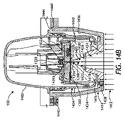
図6A及び図6Bは、それぞれ、アプリケータキャップ210が結合されたセンサアプリケータ102の側面図及び断面側面図である。より具体的には、図6A~図6Bは、少なくとも1つの実施形態によるセンサアプリケータ102をどのような状態でユーザに出荷し、ユーザがどのような状態で受け入れることができるかを示している。しかし、一部の実施形態では、センサアプリケータ102をバッグ(図示せず)の中に更に密封し、その状態でユーザに配送することができる。バッグは、センサ316に悪影響を与える可能性があるセンサアプリケータ102内への水分の移動を防止することを支援する様々な材料で製造することができる。少なくとも1つの実施形態では、例えば、密封背部を箔で製造することができる。本明細書に説明又は開示するセンサアプリケータのいずれか及び全てをバッグの中に密封し、その状態でユーザに配送することができる。 6A and 6B are side and cross-sectional side views, respectively, of sensor applicator 102 with applicator cap 210 coupled thereto. More specifically, FIGS. 6A-6B illustrate how the sensor applicator 102 according to at least one embodiment may be shipped to and received by a user. . However, in some embodiments, the sensor applicator 102 can be further sealed in a bag (not shown) and shipped as such to the user. The bag can be made of various materials to help prevent the migration of moisture into the sensor applicator 102 that could adversely affect the sensor 316 . In at least one embodiment, for example, the sealing back can be made of foil. Any and all of the sensor applicators described or disclosed herein can be sealed in a bag and shipped as such to the user.

本発明の開示によりかつ図6Bに見られるように、センサ制御デバイス302は、ユーザに配送される前に既に組み立てられてセンサアプリケータ102の中に設置されている。アプリケータキャップ210は、ハウジング208に螺合することができ、不正開封防止リング602を含むことができる。ハウジング208に対してアプリケータキャップ210を回転させた(例えば捩って外した)時に、不正開封防止リング602がネジ切れ、それによってアプリケータキャップ210をセンサアプリケータ102から自由にすることができる。それに続いて、ユーザは、図2E~図2Gを参照して上記で一般的に説明したように、センサ制御デバイス302をターゲットモニタリング場所に送出することができる。 According to the present disclosure and as seen in FIG. 6B, sensor control device 302 is already assembled and installed in sensor applicator 102 prior to delivery to the user. Applicator cap 210 can be threaded onto housing 208 and can include a tamper evident ring 602 . When the applicator cap 210 is rotated (e.g., twisted off) relative to the housing 208, the tamper evident ring 602 can unscrew, thereby freeing the applicator cap 210 from the sensor applicator 102. . Subsequently, the user can deliver the sensor control device 302 to the target monitoring location as generally described above with reference to Figures 2E-2G.

一部の実施形態では、上述のように、センサアプリケータ102の内部構成要素を保護するために、密封係合によってアプリケータキャップ210をハウジング208に固定することができる。少なくとも1つの実施形態では、例えば、Oリング又は別のタイプの密封ガスケットは、ハウジング208とアプリケータキャップ210の間のインタフェースを密封することができる。Oリング又は密封ガスケットは、個別の構成要素部品とするか又はこれに代えてハウジング208及びアプリケータキャップ210の一方の上に鋳造することができる。 In some embodiments, the applicator cap 210 can be secured to the housing 208 by sealing engagement to protect the internal components of the sensor applicator 102, as described above. In at least one embodiment, an O-ring or another type of sealing gasket, for example, can seal the interface between housing 208 and applicator cap 210 . The O-ring or sealing gasket can be a separate component part or alternatively can be cast onto one of the housing 208 and the applicator cap 210 .

ハウジング208は、様々な剛性材料で製造することができる。一部の実施形態では、例えば、ハウジング208は、ポリケトンのような熱可塑性ポリマーで製造することができる。他の実施形態では、ハウジング208は、センサアプリケータ102の内部内への水分の移動を防止するのに役立たせることができる環状オレフィンコポリマー(COC)で製造することができる。認められるように、本明細書に説明又は議論するハウジングのいずれか及び全てをポリケトン又はCOCで製造することができる。 Housing 208 can be manufactured from a variety of rigid materials. In some embodiments, for example, housing 208 can be made of a thermoplastic polymer such as polyketone. In other embodiments, housing 208 can be made of a cyclic olefin copolymer (COC) that can help prevent moisture migration into the interior of sensor applicator 102 . As will be appreciated, any and all of the housings described or discussed herein can be made of polyketone or COC.

特に図6Bを参照すると、尖鋭体ハブ422をセンサアプリケータ102の中に含まれるセンサキャリア604と嵌合させることによってセンサ制御デバイス302をセンサアプリケータ102の中に装填することができる。センサ制御デバイス302がセンサキャリア604と嵌合された状態で、次いで、アプリケータキャップ210をセンサアプリケータ102に固定することができる。 Referring specifically to FIG. 6B, sensor control device 302 can be loaded into sensor applicator 102 by mating sharps hub 422 with sensor carrier 604 contained within sensor applicator 102 . With the sensor control device 302 mated with the sensor carrier 604 , the applicator cap 210 can then be secured to the sensor applicator 102 .

図示の実施形態では、アプリケータキャップ210の中にコリメータ606が位置決めされ、コリメータ606は、センサアプリケータ102の中に閉じ込められている間のセンサ制御デバイス302を支持するのに一般的に役立たせることができる。一部の実施形態では、コリメータ606は、アプリケータキャップ210と共に鋳造するか又はアプリケータキャップ210上にオーバーモールドするなどでアプリケータキャップ210の一体部分又は延長部分を形成することができる。他の実施形態では、コリメータ606は、本発明の開示の範囲から逸脱することなく、アプリケータキャップ210の中に嵌合された又はそれに取り付けられた個別の構造体を含むことができる。更に他の実施形態では、下記で議論するように、コリメータ606は、ユーザによって受け入れされるパッケージ内からは排除されるが、他に配送に向けてセンサアプリケータ102を滅菌する及び準備する間に使用することができる。 In the illustrated embodiment, collimator 606 is positioned within applicator cap 210 and generally serves to support sensor control device 302 while confined within sensor applicator 102 . be able to. In some embodiments, the collimator 606 can form an integral part or an extension of the applicator cap 210, such as by being cast with or overmolded onto the applicator cap 210. FIG. In other embodiments, collimator 606 may comprise a separate structure fitted within or attached to applicator cap 210 without departing from the scope of the present disclosure. In still other embodiments, as discussed below, the collimator 606 is excluded from within the packaging accepted by the user, but otherwise during sterilization and preparation of the sensor applicator 102 for delivery. can be used.

コリメータ606は、無菌であることを必要とするセンサ制御デバイス302の部分を受け入れて保護することを支援し、更にセンサアプリケータ102の無菌構成要素をセンサ制御デバイス302内の他の場所からの微生物汚染から隔離するように設計することができる。この設計を達成するために、コリメータ606は、電子機器ハウジング304の底部から延びるセンサ316及び尖鋭体318を受け入れるように構成された滅菌ゾーン608(これに代えて、「無菌障壁包囲空間」又は「無菌センサ経路」とも呼ぶ)を定めるか又は他に提供することができる。滅菌ゾーン608は、コリメータ606の本体の中を少なくとも部分的に通って延びる孔又は通路を一般的に含むことができる。図示の実施形態では、滅菌ゾーン608は、コリメータ606の全体の中を通って延びるが、これに代えて、本発明の開示の範囲から逸脱することなくコリメータ606の中を部分的にしか通らずに延びることができる。 Collimator 606 helps to receive and protect portions of sensor control device 302 that need to be sterile, and further protects the sterile components of sensor applicator 102 from microorganisms from elsewhere within sensor control device 302 . It can be designed to be isolated from contamination. To achieve this design, collimator 606 includes a sterile zone 608 (alternatively, a “sterile barrier enclosure” or “sterile barrier enclosure”) configured to receive sensor 316 and sharps 318 extending from the bottom of electronics housing 304 . (also referred to as a "sterile sensor path") can be defined or otherwise provided. The sterilization zone 608 can generally include holes or passageways that extend at least partially through the body of the collimator 606 . In the illustrated embodiment, the sterilization zone 608 extends entirely through the collimator 606, but alternatively only partially through the collimator 606 without departing from the scope of the present disclosure. can extend to

センサ制御デバイス302がセンサアプリケータ102の中に装填され、そこにコリメータ606を有するアプリケータキャップ210が固定された状態で、滅菌ゾーン608によって少なくとも部分的に定められた密封領域610の中にセンサ316及び尖鋭体318を配置することができる。密封領域610は、センサ316及び尖鋭体318を外部汚染から隔離するように構成され、電子機器ハウジング304内の選択部分とコリメータ606の滅菌ゾーン608とを含む(包含する)ことができる。 With the sensor control device 302 loaded into the sensor applicator 102 and an applicator cap 210 having a collimator 606 secured thereto, the sensor is positioned within a sealed area 610 at least partially defined by a sterilization zone 608 . 316 and sharps 318 can be positioned. Sealed area 610 is configured to isolate sensor 316 and sharps 318 from external contamination and can include (enclose) selected portions within electronics housing 304 and sterile zone 608 of collimator 606 .

センサアプリケータ102内に位置決めされている間に、完全に組み立てられたセンサ制御デバイス302は、放射線滅菌612を受けることができる。放射線滅菌612は、例えば、電子ビーム照射を含むことができるが、これに代えて、低エネルギX線照射を含むがこれに限定されない他の滅菌方法を使用することができる。一部の実施形態では、放射線滅菌612は、連続工程照射又はパルスビーム照射のいずれかによって送出することができる。パルスビーム照射では、放射線滅菌612のビームがターゲット場所に集束され、そこに滅菌される構成要素部品又はデバイスが移動され、この点に指向性放射線パルスを供給するように放射線滅菌612が作動される。次いで、放射線滅菌612は停止され、滅菌される別の構成要素部品又はデバイスがターゲット場所に移動され、この処理が繰り返される。 While positioned within sensor applicator 102 , fully assembled sensor control device 302 can undergo radiation sterilization 612 . Radiation sterilization 612 may include, for example, electron beam irradiation, although other sterilization methods may alternatively be used including, but not limited to, low energy X-ray irradiation. In some embodiments, radiation sterilization 612 can be delivered by either continuous process irradiation or pulsed beam irradiation. In pulsed beam irradiation, the beam of radiation sterilizer 612 is focused to a target location, the component part or device to be sterilized is moved there, and radiation sterilizer 612 is activated to deliver a directed pulse of radiation to this point. . Radiation sterilization 612 is then stopped, another component part or device to be sterilized is moved to the target location, and the process is repeated.

コリメータ606は、放射線滅菌612からの放射線(例えば、ビーム、波、エネルギのような)をセンサ316及び尖鋭体318のような無菌であることを必要とする構成要素に向けて集束させるように構成することができる。より具体的には、滅菌ゾーン608の孔又は通路は、センサ316及び尖鋭体318上に入射してこれらを滅菌する放射線の伝達を可能にし、一方、コリメータ606の残余部分は、伝播放射線が電子機器ハウジング304の中にある電子構成要素を破壊又は損傷することを防止(阻止)する。 Collimator 606 is configured to focus radiation (eg, beams, waves, energy, etc.) from radiation sterilizer 612 toward components requiring sterility, such as sensor 316 and sharps 318 . can do. More specifically, the holes or passages in sterilization zone 608 allow transmission of radiation incident on sensor 316 and sharps 318 to sterilize them, while the remainder of collimator 606 allows the propagating radiation to be electrons. Prevent (prevent) destroying or damaging the electronic components located within the device housing 304 .

滅菌ゾーン608は、滅菌に向けて放射線をセンサ316及び尖鋭体318上に適正に集束させるのに必要なあらゆる適切な断面形状を示すことができる。図示の実施形態では、例えば、滅菌ゾーン608は、形状が円錐形又は切頭円錐形である。しかし、他の実施形態では、滅菌ゾーン608は、本発明の開示の範囲から逸脱することなく立方形、長方形(例えば、平行四辺形を含む)、又はピラミッド形のような多角形断面形状を示すことができる。 Sterilization zone 608 may exhibit any suitable cross-sectional shape required to properly focus radiation onto sensor 316 and sharpener 318 for sterilization. In the illustrated embodiment, for example, the sterilization zone 608 is conical or frustoconical in shape. However, in other embodiments, the sterilization zone 608 exhibits polygonal cross-sectional shapes such as cubic, rectangular (including, for example, parallelograms), or pyramidal without departing from the scope of the present disclosure. be able to.

図示の実施形態では、滅菌ゾーン608は、第1の端部に第1の開口614aを第1の端部と反対の第2の端部に第2の開口614bを提供する。第1の開口614aは、センサ316及び尖鋭体318を滅菌ゾーン608の中に受け入れるように構成することができ、第2の開口614bは、放射線滅菌612からの放射線(例えば、ビーム、波のような)が滅菌ゾーン608に進入し、センサ316及び尖鋭体318上に入射することを可能にすることができる。 In the illustrated embodiment, the sterilization zone 608 provides a first opening 614a at a first end and a second opening 614b at a second end opposite the first end. A first opening 614a can be configured to receive sensor 316 and sharps 318 into sterilization zone 608, and a second opening 614b can receive radiation (e.g., beam, wave-like) from radiation sterilization 612. ) can be allowed to enter the sterilization zone 608 and impinge on the sensor 316 and sharps 318 .

滅菌ゾーン608の形状が円錐形又は切頭円錐形である実施形態では、第1の開口614aは、第2の開口614bの直径よりも小さい直径を有することができる。そのような実施形態では、例えば、第1の開口614aのサイズは、約0.5mmと約3.0mmの間の範囲に及ぶことができ、第2の開口614bのサイズは、約5.0mmと約16.0mmの間の範囲に及ぶことが可能である。しかし、認められるように、第1及び第2の開口614a、614bのそれぞれの直径は、本発明の開示の範囲から逸脱することなくかつ用途に基づいて、本明細書で提供する範囲よりも大きいか又は小さいことが可能である。実際に、第1及び第2の開口614a、614bの直径は、十分な照射量の放射線がセンサ316及び尖鋭体318上に入射することを可能にするほど十分な大きさであることのみが必要である。更に、少なくとも1つの実施形態では、滅菌ゾーン608は、形状が円筒形とすることができ、この場合に、第1の開口614aと第2の開口614bは同一の直径を示す。 In embodiments where the sterilization zone 608 is conical or frusto-conical in shape, the first opening 614a can have a smaller diameter than the second opening 614b. In such embodiments, for example, the size of the first opening 614a can range between about 0.5 mm and about 3.0 mm, and the size of the second opening 614b is about 5.0 mm. and about 16.0 mm. However, it will be appreciated that the diameter of each of the first and second openings 614a, 614b may be larger than the ranges provided herein without departing from the scope of the present disclosure and based on the application. or less. In fact, the diameters of the first and second openings 614a, 614b need only be large enough to allow a sufficient dose of radiation to be incident on the sensor 316 and sharps 318. is. Further, in at least one embodiment, sterilization zone 608 can be cylindrical in shape, where first opening 614a and second opening 614b exhibit the same diameter.

コリメータ606の本体は、放射線滅菌612が本体材料を貫通し、それによって電子機器ハウジング304の中にある電子構成要素を損傷することを低減又は排除する。この低減又は排除を達成するために、一部の実施形態では、コリメータ606は、0.9グラム毎立方センチメートル(g/cc)よりも高い質量密度を有する材料で製造することができる。コリメータ606に対する一例示的材料はポリエチレンであるが、これに代えて、ポリエチレンと類似の又はそれよりも高い質量密度を有するいずれかの材料を含むことができる。一部の実施形態では、例えば、コリメータ606に対する材料は、金属(例えば、鉛、ステンレス鋼)又は密度ポリマーを含むことができるがこれらに限定されない。 The body of collimator 606 reduces or eliminates radiation sterilizer 612 from penetrating the body material and thereby damaging electronic components within electronics housing 304 . To achieve this reduction or elimination, in some embodiments collimator 606 can be made of a material having a mass density greater than 0.9 grams per cubic centimeter (g/cc). One exemplary material for collimator 606 is polyethylene, but alternatively can include any material having a similar or higher mass density than polyethylene. In some embodiments, for example, materials for collimator 606 can include, but are not limited to, metals (eg, lead, stainless steel) or density polymers.

少なくとも1つの実施形態では、コリメータ606を0.9グラム毎立方センチメートル(g/cc)よりも低い質量密度を有する材料で製造することができるが、依然として電子機器ハウジング304の中にある電子構成要素の上に入射する放射線滅菌612を低減又は排除するようにコリメータ606が作動することができるようにコリメータ606の設計を変更することができる。この設計変更を達成するために、一部の実施形態では、場合によって高感度電子機器の上に入射する前に放射線滅菌612から伝播する電子により大量の材料を通過することが要求されるようにコリメータ606のサイズ(例えば、長さ)を拡大することができる。多めの量の材料は、放射線滅菌612が高感度電子機器に対して無害になるように放射線滅菌612の照射強度を吸収又は放散するのに役立たせることができる。しかし、他の実施形態では、その逆が同等に成り立つ場合がある。より具体的には、コリメータ606に対する材料が十分に大きい質量密度を提供する限り、コリメータ606のサイズ(例えば、長さ)は縮小することができる。 In at least one embodiment, collimator 606 can be made of a material that has a mass density of less than 0.9 grams per cubic centimeter (g/cc), while still reducing the amount of electronic components residing within electronics housing 304 . The design of collimator 606 can be modified such that collimator 606 can operate to reduce or eliminate radiation sterilization 612 incident thereon. To accomplish this design change, in some embodiments, electrons propagating from radiation sterilizer 612 may be required to pass through a large amount of material before impinging on potentially sensitive electronics. The size (eg, length) of collimator 606 can be increased. A larger amount of material can help absorb or dissipate the radiation intensity of radiation sterilizer 612 such that radiation sterilizer 612 is harmless to sensitive electronic equipment. However, in other embodiments, the opposite may equally be true. More specifically, the size (eg, length) of collimator 606 can be reduced as long as the materials for collimator 606 provide a sufficiently high mass density.

コリメータ606の本体の放射線遮断特性に加えて、一部の実施形態では、センサ制御デバイス302が放射線滅菌612を受ける間に高感度電子構成要素を放射線から保護するためにセンサハウジング304の中に1又は2以上のシールド616(図示せず)を配置することができる。シールド616は、例えば、データ処理ユニット618と放射線源(例えば、電子ビーム電子加速器)の間に挟まるように配置することができる。そのような実施形態では、データ処理ユニット618の高感度電子回路を他に損傷する可能性がある放射線露出(例えば、電子ビーム放射線又はエネルギ)を遮断又は軽減するために、シールド616をデータ処理ユニット618に隣接してかつ他にデータ処理ユニット618及び放射線源に位置合わせして位置決めすることができる。 In addition to the radiation shielding properties of the body of collimator 606 , in some embodiments, a radiation shield is provided within sensor housing 304 to protect sensitive electronic components from radiation while sensor control device 302 undergoes radiation sterilization 612 . Or more than one shield 616 (not shown) can be deployed. Shield 616 may, for example, be interposed between data processing unit 618 and a radiation source (eg, an electron beam electron accelerator). In such embodiments, the shield 616 is provided to the data processing unit 618 to block or reduce radiation exposure (e.g., electron beam radiation or energy) that might otherwise damage the sensitive electronics of the data processing unit 618 . It can be positioned adjacent to 618 and otherwise aligned with the data processing unit 618 and the radiation source.

シールド616は、放射線の透過を遮断(又は実質的に遮断)する機能を有するいずれかの材料で製造することができる。シールド616に適する材料は、鉛、タングステン、鉄系金属(例えば、ステンレス鋼)、銅、タンタル、タングステン、オスミウム、又はこれらのあらゆる組合せを含むがこれらに限定されない。適切な材料は、密度が約5グラム毎立方センチメートル(g/cc)と約15g/ccの間の範囲に及ぶ耐食性、オーステナイト系、及びいずれかの非磁性の金属とすることができる。シールド616は、プレス加工、鋳造、射出鋳造、焼結、2ショット鋳造、又はこれらのあらゆる組合せを含むがこれらに限定されない様々な製造技術によって製作することができる。 Shield 616 can be made of any material capable of blocking (or substantially blocking) the transmission of radiation. Suitable materials for shield 616 include, but are not limited to, lead, tungsten, ferrous metals (eg, stainless steel), copper, tantalum, tungsten, osmium, or any combination thereof. Suitable materials can be corrosion-resistant, austenitic, and any non-magnetic metals with densities ranging between about 5 grams per cubic centimeter (g/cc) and about 15 g/cc. Shield 616 may be made by a variety of manufacturing techniques including, but not limited to, stamping, casting, injection casting, sintering, two-shot casting, or any combination thereof.

しかし、他の実施形態では、シールド616は、ポリアミド、ポリカーボネート、又はポリスチレン等であるがこれらに限定されない金属充填熱可塑性ポリマーを含むことができる。そのような実施形態では、シールド616は、遮蔽材料を接着性母材の中に混合し、この組合せを成形される構成要素の上に又は他に直接データ処理ユニット618上に滴下することによって製作することができる。更に、そのような実施形態では、シールド616は、データ処理ユニット618を封入(又は実質的に封入)するエンクロージャを含むことができる。 However, in other embodiments, shield 616 may comprise a metal-filled thermoplastic polymer such as, but not limited to, polyamide, polycarbonate, or polystyrene. In such embodiments, the shield 616 is fabricated by mixing the shielding material into an adhesive matrix and dropping this combination onto the component to be molded or otherwise directly onto the data processing unit 618. can do. Further, in such embodiments, shield 616 may include an enclosure that encloses (or substantially encloses) data processing unit 618 .

一部の実施形態では、滅菌ゾーン608を完全に密封し、従って、密封領域610を完全に密封するために、コリメータ606の端部にコリメータシール620を付加することができる。図示のように、コリメータシール620は、第2の開口614bを密封することができる。コリメータシール620は、放射線滅菌612の前又は後に付加することができる。コリメータシール620が放射線滅菌612を始める前に付加される実施形態では、コリメータシール620は、放射線が中を通って伝播することを可能にする放射線透過性微生物障壁材料で製造することができる。定位置にコリメータシール620を有することで、密封領域610は、ユーザがアプリケータキャップ210を取り外す(捩って外す)まで組み立てられたセンサ制御デバイス302に対する無菌環境を維持することができる。 In some embodiments, a collimator seal 620 can be added to the end of the collimator 606 to completely seal the sterilization zone 608 and thus the sealing area 610 . As shown, a collimator seal 620 can seal the second opening 614b. Collimator seal 620 can be added before or after radiation sterilization 612 . In embodiments where the collimator seal 620 is added before radiation sterilization 612 begins, the collimator seal 620 can be made of a radiolucent microbial barrier material that allows radiation to propagate therethrough. Having the collimator seal 620 in place allows the sealing area 610 to maintain a sterile environment for the assembled sensor control device 302 until the user removes (twists off) the applicator cap 210 .

一部の実施形態では、コリメータシール620は、異なる材料の2又は3以上の層を含むことができる。第1の層は、DuPont(登録商標)から入手可能なTyvek(登録商標)のような合成材料(例えば、フラッシュスパン密度ポリエチレン繊維)で製造することができる。Tyvek(登録商標)は非常に耐久性及び耐穿刺性が高く、かつ蒸気の透過を可能にする。Tyvek(登録商標)層は、放射線滅菌612の前に又はその後に続けて適用することができ、滅菌ゾーン608及び密封領域610内への汚染物質及び水分の移動を防止するために箔又は他の耐蒸気性及び耐湿性の材料層をTyvek(登録商標)層の上に密封(例えば、熱溶着)することができる。他の実施形態では、コリメータシール620は、コリメータ606の端部に付加された単一保護層のみを含む場合がある。そのような実施形態では、この単一層は、滅菌処理に向けてガス透過性を有するが、滅菌処理が完了した後に水分及び他の有害要素に対する保護の機能も有する。従って、コリメータシール620は、本発明の開示の範囲から逸脱することなく水分層及び汚染物質層として働くことができる。 In some embodiments, collimator seal 620 can include two or more layers of different materials. The first layer can be made of a synthetic material (eg, flash-spun density polyethylene fibers) such as Tyvek® available from DuPont®. Tyvek® is very durable and puncture resistant and allows vapor transmission. A Tyvek® layer may be applied prior to or subsequent to radiation sterilization 612 and may be a foil or other layer to prevent migration of contaminants and moisture into sterilization zone 608 and sealed area 610 . A vapor and moisture resistant material layer can be sealed (eg, heat welded) onto the Tyvek® layer. In other embodiments, collimator seal 620 may include only a single protective layer applied to the ends of collimator 606 . In such embodiments, this single layer is gas permeable for sterilization, but also functions as a protection against moisture and other detrimental elements after sterilization is complete. Accordingly, collimator seal 620 can serve as a moisture layer and a contaminant layer without departing from the scope of the present disclosure.

センサ316及び尖鋭体318は、電子機器ハウジング304の底部からセンサアプリケータ102及びアプリケータキャップ210の中心線とほぼ同心の滅菌ゾーン608の中に延びるが、本明細書では偏心配置を有することを考えていることに注意されたい。より具体的には、少なくとも1つの実施形態では、センサ316及び尖鋭体318は、電子機器ハウジング304の底部からセンサアプリケータ102及びアプリケータキャップ210の中心線に対して偏心して延びる。そのような実施形態では、本発明の開示の範囲から逸脱することなく、滅菌ゾーン608も偏心して配置してセンサ316及び尖鋭体318を受け入れるようにコリメータ606を再設計するか又は他に構成することができる。 Sensor 316 and sharpener 318 extend from the bottom of electronics housing 304 into sterilization zone 608 generally concentric with the centerline of sensor applicator 102 and applicator cap 210, but are herein noted to have an eccentric arrangement. Notice what I'm thinking. More specifically, in at least one embodiment, sensor 316 and sharp 318 extend from the bottom of electronics housing 304 off-center with respect to the centerline of sensor applicator 102 and applicator cap 210 . In such embodiments, collimator 606 is redesigned or otherwise configured to also eccentrically locate sterilization zone 608 to receive sensor 316 and sharps 318 without departing from the scope of the present disclosure. be able to.

一部の実施形態では、コリメータ606は、上記で一般的に説明したようにアプリケータキャップ210の中又は他にセンサアプリケータ102の中に収容することができる第1のコリメータ又は「内部」コリメータを含むことができる。センサアプリケータ102を滅菌することを支援するように、第2のコリメータ又は「外部」コリメータ(図示せず)を組み立て(製造)工程の中に含めるか又は他に使用することができる。そのような実施形態では、外部コリメータは、放射線滅菌612をセンサ316及び尖鋭体318上に集束させることを支援するようにセンサアプリケータ102及びアプリケータキャップ210の外部に配置し、内部コリメータ606と同時に使用することができる。 In some embodiments, collimator 606 is a first or "inner" collimator that can be housed in applicator cap 210 or otherwise in sensor applicator 102 as generally described above. can include A second collimator or "external" collimator (not shown) may be included in the assembly (manufacturing) process or otherwise used to assist in sterilizing the sensor applicator 102 . In such embodiments, an external collimator is positioned external to sensor applicator 102 and applicator cap 210 to help focus radiation sterilization 612 onto sensor 316 and sharp 318, and internal collimator 606 and can be used simultaneously.

一実施形態では、例えば、外部コリメータは、放射線滅菌612を最初に受け入れることができる。内部コリメータ606と同様に、外部コリメータは、その中を通って延びる孔又は通路を提供するか又は定めることができる。外部コリメータの通路を通した放射線滅菌612のビームは、第2の開口614bを通して内部コリメータ606の滅菌ゾーン608の中に集束させ、そこに受け入れることができる。従って、外部コリメータは、放射線エネルギを事前集束させ、内部コリメータ606は、放射線エネルギをセンサ316及び尖鋭体318上に完全に集束させることができる。 In one embodiment, for example, the external collimator can receive radiation sterilization 612 first. Similar to the inner collimator 606, the outer collimator may provide or define a hole or passageway extending therethrough. A beam of radiation sterilization 612 through the passage of the outer collimator can be focused through a second opening 614b into the sterilization zone 608 of the inner collimator 606 and received therein. Thus, the external collimator pre-focuses the radiation energy and the internal collimator 606 allows the radiation energy to be fully focused onto the sensor 316 and sharps 318 .

一部の実施形態では、外部コリメータがセンサ316及び尖鋭体318を適正に滅菌するために放射線滅菌612を適正かつ完全に集束させる機能を有する場合は内部コリメータ606を排除することができる。そのような実施形態では、センサアプリケータを外部コリメータに隣接するように配置し、その後に、センサアプリケータに放射線滅菌612を適用することができ、外部コリメータは、放射線エネルギが電子機器ハウジング304の中にある高感度電子機器を損傷することを防止することができる。更に、そのような実施形態では、センサアプリケータ102は、アプリケータキャップ210内に位置決めされた内部コリメータ606なしでユーザに配送し、それによって製造及び使用での複雑さを排除することができる。 In some embodiments, the internal collimator 606 can be eliminated if the external collimator has the ability to properly and completely focus the radiation sterilizer 612 to properly sterilize the sensor 316 and sharps 318 . In such embodiments, the sensor applicator can be placed adjacent to the external collimator, after which radiation sterilization 612 can be applied to the sensor applicator, the external collimator allowing the radiation energy to pass through the electronics housing 304 . It can prevent damaging the sensitive electronics inside. Further, in such embodiments, sensor applicator 102 can be shipped to users without internal collimator 606 positioned within applicator cap 210, thereby eliminating complexity in manufacturing and use.

図7Aは、1又は2以上の実施形態によるアプリケータキャップ210内に装着されたセンサ制御デバイス302の拡大断面側面図である。上記に示したように、センサ316及び尖鋭体318の一部分を密封領域610内に配置され、それによって外部汚染から隔離することができる。密封領域610は、電子機器ハウジング304内の選択部分とコリメータ606の滅菌ゾーン608とを含む(包含する)ことができる。1又は2以上の実施形態では、密封領域610は、少なくとも第1のシール702aと、第2のシール702bと、コリメータシール620とによって定められる又は他に形成することができる。 FIG. 7A is an enlarged cross-sectional side view of sensor control device 302 mounted within applicator cap 210 in accordance with one or more embodiments. As indicated above, a portion of sensor 316 and sharp 318 may be disposed within sealed area 610 and thereby isolated from external contamination. The sealed area 610 can include (enclose) selected portions within the electronics housing 304 and the sterile zone 608 of the collimator 606 . In one or more embodiments, the sealing area 610 can be defined or otherwise formed by at least a first seal 702a, a second seal 702b, and a collimator seal 620.

第1のシール702aは、尖鋭体ハブ422と電子機器ハウジング304の上部との間のインタフェースを密封するように配置することができる。より具体的には、第1のシール702aは、尖鋭体ハブ422とシェル306の間のインタフェースを密封することができる。更に、第1のシール702aは、シェル306内に定められた第1の中心開口504を汚染物質が第1の中心開口504を通って電子機器ハウジング304の中に移動することを阻止するように取り囲むことができる。一部の実施形態では、第1のシール702aは、尖鋭体ハブ422の一部を形成することができる。例えば、第1のシール702aは、尖鋭体ハブ422上にオーバーモールドすることができる。他の実施形態では、第1のシール702aは、シェル306の上にオーバーモールドすることができる。更に他の実施形態では、第1のシール702aは、本発明の開示の範囲から逸脱することなく、尖鋭体ハブ422とシェル306の上面の間に挟まるOリングなどのような個別の構造体を含むことができる。 A first seal 702 a may be arranged to seal the interface between the sharp hub 422 and the top of the electronics housing 304 . More specifically, first seal 702 a can seal the interface between sharp hub 422 and shell 306 . Additionally, the first seal 702 a seals the first central opening 504 defined in the shell 306 to prevent contaminants from migrating through the first central opening 504 and into the electronics housing 304 . can be surrounded. In some embodiments, first seal 702 a may form part of sharps hub 422 . For example, first seal 702 a can be overmolded onto sharp hub 422 . In other embodiments, the first seal 702a can be overmolded onto the shell 306. FIG. In still other embodiments, the first seal 702a may be a separate structure such as an O-ring sandwiched between the sharp hub 422 and the top surface of the shell 306 without departing from the scope of the present disclosure. can contain.

第2のシール702bは、コリメータ606と電子機器ハウジング304の底部との間のインタフェースを密封するように配置することができる。より具体的には、第2のシール702bは、マウント308とコリメータ606の間、又はこれに代えてコリメータ606とマウント308の底部の中に受け入れられたプラグ402の底部との間のインタフェースを密封するように配置することができる。図示のようにプラグ402を含む用途では、第2のシール702bは、プラグレセプタクル512の周りを密封し、他に取り囲むように構成することができる。プラグ402を排除する実施形態では、これに代えて、第2のシール702bは、マウント308内に定められた第2の中心開口506(図5A)を取り囲むことができる。その結果、第2のシール702bは、汚染物質がコリメータ606の滅菌ゾーン608の中に移動することを防止し、更にプラグレセプタクル512(又はこれに代えて、第2の中心開口506)を通って電子機器ハウジング304の中に移動することを防止することができる。 A second seal 702 b may be arranged to seal the interface between the collimator 606 and the bottom of the electronics housing 304 . More specifically, second seal 702 b seals the interface between mount 308 and collimator 606 , or alternatively between collimator 606 and the bottom of plug 402 received in the bottom of mount 308 . can be arranged to In applications that include the plug 402 as shown, the second seal 702b can be configured to seal around the plug receptacle 512 and surround the other. In embodiments that eliminate plug 402, second seal 702b may alternatively surround a second central opening 506 (FIG. 5A) defined in mount 308. As shown in FIG. As a result, the second seal 702b prevents contaminants from migrating into the sterilization zone 608 of the collimator 606 and also through the plug receptacle 512 (or alternatively, the second central opening 506). It can be prevented from moving into the electronics housing 304 .

一部の実施形態では、第2のシール702bは、コリメータ606の一部を形成することができる。例えば、第2のシール702bは、コリメータ606の上にオーバーモールドすることができる。他の実施形態では、第2のシール702bは、プラグ402上又はマウント308の底部上にオーバーモールドすることができる。更に他の実施形態では、第2のシール702bは、本発明の開示の範囲から逸脱することなく、コリメータ606とプラグ402又はマウント308の底部の間に挟まるOリングなどのような個別の構造体を含むことができる。 In some embodiments, second seal 702b may form part of collimator 606 . For example, the second seal 702b can be overmolded over the collimator 606. FIG. In other embodiments, the second seal 702b can be overmolded on the plug 402 or on the bottom of the mount 308. FIG. In still other embodiments, the second seal 702b can be a separate structure, such as an O-ring, sandwiched between the collimator 606 and the bottom of the plug 402 or mount 308 without departing from the scope of the present disclosure. can include

センサ制御デバイス302をセンサアプリケータ102の中に装填し(図6B)、アプリケータキャップ210をセンサアプリケータ102に固定した後に、第1及び第2のシール702a、702bは圧縮状態になり、対応する密封インタフェースを発生させる。第1及び第2のシール702a、702bは、対向構造体間に密封インタフェースを発生させる機能を有する様々な材料で製造することができる。適切な材料は、シリコーン、熱可塑性エラストマー(TPE)、ポリテトラフルオロエチレン(PTFE又はTeflon(登録商標))、又はこれらのあらゆる組合せを含むがこれらに限定されない。 After loading the sensor control device 302 into the sensor applicator 102 (FIG. 6B) and securing the applicator cap 210 to the sensor applicator 102, the first and second seals 702a, 702b are in a compressed state, correspondingly. to create a hermetic interface. The first and second seals 702a, 702b can be made of various materials that function to create a sealed interface between opposing structures. Suitable materials include, but are not limited to, silicone, thermoplastic elastomer (TPE), polytetrafluoroethylene (PTFE or Teflon®), or any combination thereof.

上記で議論したように、コリメータシール620は、滅菌ゾーン608の底部及び従って密封領域610の底部を完全に密封するように構成することができる。従って、第1及び第2のシール702a、702b及びコリメータシール620の各々は、そのそれぞれの密封場所に対応する障壁を生成する。これらのシール702aと702bと620の組合せは、センサ316及び尖鋭体318を包含する密封領域610を最終的に滅菌することを可能にする。 As discussed above, collimator seal 620 can be configured to completely seal the bottom of sterilization zone 608 and thus the bottom of sealing area 610 . Accordingly, each of the first and second seals 702a, 702b and collimator seal 620 creates a barrier corresponding to its respective sealing location. The combination of these seals 702a, 702b, and 620 allows for terminal sterilization of the sealing area 610, which contains the sensor 316 and sharp body 318. FIG.

図7Bは、1又は2以上の実施形態によるセンサアプリケータ102内に装着されたセンサ制御デバイス302の別の実施形態の拡大断面側面図である。より具体的には、図7Bは、第1及び第2のシール702a、702bの代替実施形態を示している。ここでもまた、第1のシール702aは、尖鋭体ハブ422と電子機器ハウジング304の上部との間のインタフェースを密封し、より具体的には、シェル306内に定められた第1の中心開口504を完全に密封するように配置される。しかし、図示の実施形態では、第1のシール702aは、軸線方向及び半径方向の両方に密封するように構成することができる。より具体的には、センサ制御デバイス302がセンサアプリケータ102の中に導入される時に、尖鋭体ハブ422は、センサキャリア604によって受け入れられる。第1のシール702aは、センサキャリア604の1又は2以上の軸線方向に延びる部材704と、センサキャリア604の1又は2以上の半径方向に延びる部材706とを同時に付勢するように構成することができる。そのような二重付勢係合は、第1のシール702aを軸線方向及び半径方向の両方に圧縮し、それによって第1のシール702aが電子機器ハウジング304の上部を半径方向と軸線方向の両方に密封することを可能にする。 FIG. 7B is an enlarged cross-sectional side view of another embodiment of sensor control device 302 mounted within sensor applicator 102 in accordance with one or more embodiments. More specifically, Figure 7B shows an alternate embodiment of the first and second seals 702a, 702b. Again, first seal 702a seals the interface between sharps hub 422 and the top of electronics housing 304, and more specifically, first central opening 504 defined in shell 306. are arranged so as to completely seal the However, in the illustrated embodiment, the first seal 702a can be configured to seal both axially and radially. More specifically, sharp hub 422 is received by sensor carrier 604 when sensor control device 302 is introduced into sensor applicator 102 . The first seal 702a is configured to simultaneously bias one or more axially extending members 704 of the sensor carrier 604 and one or more radially extending members 706 of the sensor carrier 604. can be done. Such dual biasing engagement compresses the first seal 702a both axially and radially such that the first seal 702a compresses the top of the electronics housing 304 both radially and axially. allow it to be sealed to

ここでもまた、第2のシール702bは、コリメータ606と電子機器ハウジング304の底部との間、より具体的にはマウント308とコリメータ606の間、又はこれに代えてコリメータ606とマウント308の底部の中に受け入れられたプラグ402の底部との間のインタフェースを密封するように配置される。しかし、図示の実施形態では、第2のシール702bは、滅菌ゾーン608の中に延び、マウント308の底部から延びるセンサ316及び尖鋭体1408を受け入れるようにサイズが決定された円筒形長手陥凹708を定めるか又は他に提供する。一部の実施形態では、水分に敏感な生物学的構成要素に対する低湿度環境の維持を助けるために円筒形縦凹部の中に乾燥剤710を位置決めすることができる。 Again, the second seal 702b is between the collimator 606 and the bottom of the electronics housing 304, more specifically between the mount 308 and the collimator 606, or alternatively between the collimator 606 and the bottom of the mount 308. It is arranged to seal the interface between it and the bottom of the plug 402 received therein. However, in the illustrated embodiment, the second seal 702b extends into the sterilization zone 608 and extends from the bottom of the mount 308, the sensor 316 and a cylindrical longitudinal recess 708 sized to receive the sharp 1408. or provide to others. In some embodiments, a desiccant 710 can be positioned within the cylindrical vertical recess to help maintain a low humidity environment for moisture sensitive biological components.

一部の実施形態では、第2のシール702bを排除することができ、コリメータ606を電子機器ハウジング304に直接に結合することができる。より具体的には、少なくとも1つの実施形態では、コリメータ606をマウント308の下側に螺合可能に結合することができる。そのような実施形態では、コリメータ606は、マウント308の底部内に定められたねじ切り開口に嵌合するように構成されたねじ切り延長部を提供するか又は他に定めることができる。コリメータ606をマウント308に螺合可能に結合することは、コリメータ606と電子機器ハウジング304の底部との間のインタフェースを密封し、従って、密封領域610を隔離する働きをすることができる。更に、そのような実施形態では、コリメータ606及びマウント308上に定められたネジ山のピッチ及びゲージは、アプリケータキャップ210とセンサアプリケータ102の間の螺合的係合のものに適合することが可能である。その結果、アプリケータキャップ210がセンサアプリケータ102に螺合されるか又はそこから外される時に、コリメータ606を相応に電子機器ハウジング404に螺合するか又はそこから捩って外すことができる。 In some embodiments, the second seal 702 b can be eliminated and the collimator 606 can be coupled directly to the electronics housing 304 . More specifically, in at least one embodiment, collimator 606 can be threadably coupled to the underside of mount 308 . In such embodiments, collimator 606 may provide or otherwise define a threaded extension configured to fit into a threaded opening defined in the bottom of mount 308 . Threadably coupling collimator 606 to mount 308 can serve to seal the interface between collimator 606 and the bottom of electronics housing 304 , thus isolating sealing area 610 . Further, in such embodiments, the thread pitch and gauge defined on collimator 606 and mount 308 should match that of the threaded engagement between applicator cap 210 and sensor applicator 102 . is possible. As a result, when the applicator cap 210 is threaded onto or unthreaded from the sensor applicator 102, the collimator 606 can be threaded onto or twisted off the electronics housing 404 accordingly. .

本明細書に開示する実施形態は、以下を含む。 Embodiments disclosed herein include the following.

A.センサアプリケータと、センサアプリケータ内に位置決めされ、電子機器ハウジングを含むセンサ制御デバイスと、電子機器ハウジングの底部から延びるセンサと、電子機器ハウジングの上部に隣接して位置決めされた尖鋭体ハブと、尖鋭体ハブによって担持され、電子機器ハウジングを通って延び、更に電子機器ハウジングの底部から延びる尖鋭体とを含む検体モニタリングシステム。検体モニタリングシステムは、センサアプリケータに結合されたキャップと、キャップ内に位置決めされ、電子機器ハウジングの底部から延びるセンサ及び尖鋭体を受け入れる滅菌ゾーンを定めるコリメータとを更に含む。 A. a sensor applicator, a sensor control device positioned within the sensor applicator and including an electronics housing, a sensor extending from the bottom of the electronics housing, and a sharps hub positioned adjacent the top of the electronics housing; a sharps carried by a sharps hub, extending through the electronics housing, and extending from the bottom of the electronics housing. The analyte monitoring system further includes a cap coupled to the sensor applicator and a collimator positioned within the cap and defining a sterile zone for receiving the sensor and sharps extending from the bottom of the electronics housing.

B.検体モニタリングシステムを準備する方法は、センサ制御デバイスをセンサアプリケータの中に装填する段階を含み、センサ制御デバイスは、電子機器ハウジングと、電子機器ハウジングの底部から延びるセンサと、電子機器ハウジングの上部に隣接して位置決めされた尖鋭体ハブと、尖鋭体ハブによって担持され、電子機器ハウジングを通って延び、更に電子機器ハウジングの底部から延びる尖鋭体とを含む。本方法は、キャップをセンサアプリケータに固定する段階であって、コリメータがキャップ内に位置決めされ、電子機器ハウジングの底部から延びるセンサ及び尖鋭体を受け入れる滅菌ゾーンを定める上記固定する段階段階と、滅菌ゾーン内に位置決めされている間にセンサ及び尖鋭体を放射線滅菌で滅菌する段階と、放射線滅菌からの放射線が電子機器ハウジング内の電子構成要素を損傷することをコリメータによって防止する段階とを更に含む。 B. A method of preparing an analyte monitoring system includes loading a sensor control device into a sensor applicator, the sensor control device comprising an electronics housing, a sensor extending from the bottom of the electronics housing, and a sensor extending from the bottom of the electronics housing. and a sharpener carried by the sharpener hub, extending through the electronics housing, and extending from the bottom of the electronics housing. The method includes the steps of securing the cap to the sensor applicator, wherein a collimator is positioned within the cap to define a sterilization zone for receiving the sensor and sharps extending from the bottom of the electronics housing; Radiation sterilization of the sensor and sharps while positioned in the zone, and preventing radiation from the radiation sterilization from damaging electronic components within the electronics housing with the collimator. .

C.検体モニタリングシステムを準備する方法は、センサ制御デバイスをセンサアプリケータの中に装填する段階を含み、センサ制御デバイスは、電子機器ハウジングと、電子機器ハウジングの底部から延びるセンサと、電子機器ハウジングの上部に隣接して位置決めされた尖鋭体ハブと、尖鋭体ハブによって担持され、電子機器ハウジングを通って延び、更に電子機器ハウジングの底部から延びる尖鋭体とを含む。本方法は、センサアプリケータをコリメータに隣接して位置決めする段階と、センサ及び尖鋭体に放射線滅菌を受ける段階と、放射線滅菌からの放射線が電子機器ハウジング内の電子構成要素を損傷することをコリメータによって防止する段階とを更に含む。 C. A method of preparing an analyte monitoring system includes loading a sensor control device into a sensor applicator, the sensor control device comprising an electronics housing, a sensor extending from the bottom of the electronics housing, and a sensor extending from the bottom of the electronics housing. and a sharpener carried by the sharpener hub, extending through the electronics housing, and extending from the bottom of the electronics housing. The method includes positioning a sensor applicator adjacent to the collimator, subjecting the sensor and sharps to radiation sterilization, and determining that radiation from the radiation sterilization damages electronic components within the electronics housing of the collimator. and preventing by

実施形態A、B、及びCの各々は、以下の追加の要素のうちの1又は2以上をあらゆる組合せで有することができる:要素1:滅菌ゾーンが、コリメータの中を少なくとも部分的に通って延びる通路を含むこと。要素2:滅菌ゾーンが、円錐形、切頭円錐形、立方形、長方形、ピラミッド形、及びこれらのあらゆる組合せから構成される群から選択される断面形状を含むこと。要素3:滅菌ゾーンが、切頭円錐形であり、第1の端部に第1の開口を第2の端部に第2の開口を定め、第1の開口は、電子機器ハウジングの底部から延びるセンサ及び尖鋭体を受け入れ、第2の開口にシールが位置決めされること。要素4:滅菌ゾーンと電子機器ハウジングの内部の一部分とを包含する密封領域を更に含み、密封領域は、尖鋭体ハブと電子機器ハウジングの上部との間のインタフェースを密封する第1のシールと、コリメータと電子機器ハウジングの底部との間のインタフェースを密封する第2のシールと、滅菌ゾーンの端部を密封する第3のシールとによって定められること。要素5:第1のシールが、電子機器ハウジングの上部内に定められた中心開口を取り囲んで汚染物質が中心開口を通って電子機器ハウジングの内部の一部分の中に移動することを防止し、第2のシールが、電子機器ハウジングの底部内に定められた開口を取り囲んで汚染物質がこの開口を通って電子機器ハウジングの内部の一部分の中に移動することを防止すること。要素6:第1のシールが、軸線方向密封及び半径方向密封のうちの一方又は両方を提供すること。要素7:第2のシールが、滅菌ゾーンの中に延びてセンサ及び尖鋭体を受け入れる円筒形縦凹部を定めること。要素8:電子機器ハウジング内に位置決めされたプリント回路基板と、プリント回路基板に装着されたデータ処理ユニットと、データ処理ユニットを放射線滅菌処理からの放射線から保護するために電子機器ハウジング内に位置決めされたシールドとを更に含むこと。要素9:シールドが、鉛、タングステン、鉄、ステンレス鋼、銅、タンタル、オスミウム、非磁性金属と混合された熱可塑性ポリマー、及びこれらのあらゆる組合せから構成される群から選択される非磁性金属で製造されること。 Each of embodiments A, B, and C can have one or more of the following additional elements in any combination: Element 1: The sterilization zone passes at least partially through the collimator. Include an extended passageway. Element 2: The sterilization zone includes a cross-sectional shape selected from the group consisting of conical, frustoconical, cubic, rectangular, pyramidal, and any combination thereof. Element 3: The sterilization zone is frusto-conical and defines a first opening at a first end and a second opening at a second end, the first opening leading from the bottom of the electronics housing. A seal is positioned in the second opening to receive the extending sensor and sharp. Element 4: further comprising a sealing area encompassing the sterilization zone and a portion of the interior of the electronics housing, the sealing area comprising a first seal that seals the interface between the sharps hub and the top of the electronics housing; defined by a second seal that seals the interface between the collimator and the bottom of the electronics housing, and a third seal that seals the end of the sterilization zone; Element 5: a first seal surrounds a central opening defined within the top of the electronics housing to prevent migration of contaminants through the central opening into a portion of the interior of the electronics housing; 2. A seal surrounds an opening defined in the bottom of the electronics housing to prevent migration of contaminants through the opening into a portion of the interior of the electronics housing. Element 6: The first seal provides one or both of an axial seal and a radial seal. Element 7: The second seal defines a longitudinal cylindrical recess extending into the sterilization zone to receive the sensor and sharps. Element 8: A printed circuit board positioned within the electronics housing, a data processing unit mounted to the printed circuit board, and a data processing unit positioned within the electronics housing to protect the data processing unit from radiation from the radiation sterilization process. and a shield. Element 9: The shield is a non-magnetic metal selected from the group consisting of lead, tungsten, iron, stainless steel, copper, tantalum, osmium, thermoplastic polymers mixed with non-magnetic metals, and any combination thereof. be manufactured.

要素10:キャップがセンサアプリケータに固定される時に、滅菌ゾーンと電子機器ハウジングの内部の一部分とを包含する密封領域を生成する段階を更に含むこと。要素11:密封領域を生成する段階が、尖鋭体ハブと電子機器ハウジングの上部との間のインタフェースを第1のシールによって密封する段階と、コリメータと電子機器ハウジングの底部との間のインタフェースを第2のシールによって密封する段階と、滅菌ゾーンの端部を第3のシールによって密封する段階とを含むこと。要素12:尖鋭体ハブと電子機器ハウジングの上部との間のインタフェースを第1のシールによって密封する段階が、軸線方向密封及び半径方向密封のうちの一方又は両方を第1のシールによって提供する段階を含むこと。要素13:コリメータが、内部コリメータを含み、放射線滅菌を用いてセンサ及び尖鋭体を滅菌する段階が、センサアプリケータをその外部に位置決めされた外部コリメータに隣接して位置決めする段階と、内部コリメータが受光するように外部コリメータによって放射線を集束させる段階と、放射線が電子機器ハウジング内の電子構成要素を損傷することを外部及び内部コリメータによって防止する段階とを更に含むこと。要素14:滅菌ゾーンが、コリメータの第1の端部に第1の開口をコリメータの第2の端部に第2の開口を定め、センサ及び尖鋭体を滅菌する段階が、第2の開口を通して放射線を滅菌ゾーンの中に導入する段階を含むこと。要素15:放射線滅菌からの放射線が電子構成要素を損傷することを防止する段階が、放射線をコリメータの材料によって遮断する段階を含むこと。要素16:電子機器ハウジングの中にプリント回路基板が位置決めされ、プリント回路基板にデータ処理ユニットが装着され、本方法が、電子機器ハウジング内に位置決めされたシールドによってデータ処理ユニットを放射線滅菌処理からの放射線から保護する段階を更に含むこと。 Element 10: Further comprising creating a sealed area encompassing the sterilization zone and a portion of the interior of the electronics housing when the cap is secured to the sensor applicator. Element 11: The step of creating a sealing area includes sealing the interface between the sharp body hub and the top of the electronics housing with a first seal, and sealing the interface between the collimator and the bottom of the electronics housing with a first seal. sealing with two seals and sealing the end of the sterile zone with a third seal. Element 12: Sealing the interface between the sharps hub and the top of the electronics housing with a first seal provides one or both of an axial seal and a radial seal with the first seal. including Element 13: The collimator comprises an internal collimator, and sterilizing the sensor and sharps using radiation sterilization positions the sensor applicator adjacent to the externally positioned external collimator; Further comprising the steps of: focusing the radiation to be received by an external collimator; and preventing the radiation from damaging electronic components within the electronics housing by the external and internal collimators. Element 14: A sterilization zone defines a first opening at the first end of the collimator and a second opening at the second end of the collimator, and sterilizing the sensor and sharps is performed through the second opening. including introducing radiation into the sterilization zone. Element 15: Preventing radiation from radiation sterilization from damaging electronic components includes blocking radiation with a collimator material. Element 16: A printed circuit board is positioned within the electronics housing, a data processing unit is mounted on the printed circuit board, and the method protects the data processing unit from radiation sterilization by a shield positioned within the electronics housing. Further including the step of protecting from radiation.

要素17:センサアプリケータをコリメータに隣接して位置決めする段階が、放射線滅菌中にコリメータがセンサアプリケータの外部に存在するようにコリメータを配置する段階を含むこと。 Element 17: Positioning the sensor applicator adjacent the collimator includes positioning the collimator such that the collimator is external to the sensor applicator during radiation sterilization.

非限定例として、A、B、及びCに適用可能な例示的組合せは、要素2と要素3、要素4と要素5、要素4と要素6、要素4と要素7、要素8と要素9、要素10と要素11、及び要素11と要素12の組合せを含む。 By way of non-limiting example, exemplary combinations applicable to A, B, and C are elements 2 and 3, elements 4 and 5, elements 4 and 6, elements 4 and 7, elements 8 and 9, Including combinations of elements 10 and 11 and elements 11 and 12.

外部滅菌アセンブリ
再度図1を簡単に参照すると、センサ制御デバイス104は、エンドユーザに配送される前に、生存可能な微生物が不在のものにするために製品を滅菌されなければならない。一般的に、センサ110は、電子ビーム(「電子ビーム」)照射のような放射線滅菌を用いて滅菌される。しかし、放射線滅菌は、センサ制御デバイス104の中にある電子構成要素を損傷する可能性があり、センサ制御デバイス104は、一般的に、ガス状化学滅菌(例えば、酸化エチレンを用いた)によって滅菌される。しかし、ガス状化学滅菌は、センサ110上に含まれる酵素又は他の化学製剤及び生物製剤を損傷する場合がある。
External Sterilization Assembly Referring again briefly to FIG. 1, the sensor control device 104 must be product sterilized to be free of viable microorganisms before delivery to the end user. Generally, sensor 110 is sterilized using radiation sterilization, such as electron beam (“electron beam”) irradiation. Radiation sterilization, however, can damage electronic components within sensor control device 104, and sensor control device 104 is typically sterilized by gaseous chemical sterilization (eg, using ethylene oxide). be done. However, gaseous chemical sterilization may damage enzymes or other chemical and biological agents contained on sensor 110 .

過去においては、この滅菌不適合性は、センサ110と電子構成要素とを分離し、各々を個々に滅菌することによって回避されてきた。しかし、この方式は、追加の部品、パッケージ化、処理段階、及びユーザ過誤の可能性を招くユーザによる最終組み立てを必要とする。本発明の開示により、滅菌を必要とする構成要素部品に向けて放射線滅菌(例えば、ビーム、波、エネルギのような)を集束させ、同時に伝播放射線が高感度電子構成要素を破壊又は損傷することを防止するように設計された外部滅菌アセンブリを用いてセンサ制御デバイス104又は最終滅菌を必要とするあらゆるデバイスを適正に滅菌することができる。 In the past, this sterilization incompatibility has been avoided by separating sensor 110 and electronic components and sterilizing each individually. However, this approach requires additional parts, packaging, processing steps, and final assembly by the user, which introduces potential for user error. The present disclosure focuses radiation sterilization (e.g., beams, waves, energy, etc.) toward component parts requiring sterilization while propagating radiation destroys or damages sensitive electronic components. Sensor control device 104, or any device requiring terminal sterilization, can be properly sterilized using an external sterilization assembly designed to prevent sterilization.

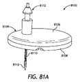
図8は、1又は2以上の実施形態による例示的外部滅菌アセンブリ800の概略図である。外部滅菌アセンブリ800(以下では「アセンブリ800」)は、医療デバイス802を滅菌することを支援するように設計され、かつ他にそのように構成することができる。医療デバイス802は、例えば、いくつかの点で図1のセンサ制御デバイス104と類似のセンサ制御デバイスを含むことができるが、これに代えて、他のタイプの医療デバイス、健康管理製品、又は特定の構成要素部品の最終滅菌を必要とするシステムを含むことができる。本発明の開示の原理を組み込むことができる例示的医療デバイス又は健康管理製品は、摂取可能製品、心調律管理(CRM)デバイス、皮下感知デバイス、外部装着医療デバイス、又はこれらのあらゆる組合せを含むがこれらに限定されない。 FIG. 8 is a schematic diagram of an exemplary external sterilization assembly 800 according to one or more embodiments. External sterilization assembly 800 (hereinafter “assembly 800”) is designed and can otherwise be configured to assist in sterilizing medical device 802 . Medical device 802 can include, for example, a sensor control device similar in some respects to sensor control device 104 of FIG. can include systems that require terminal sterilization of the component parts of the Exemplary medical devices or health care products that may incorporate principles of the present disclosure include ingestible products, cardiac rhythm management (CRM) devices, subcutaneous sensing devices, externally worn medical devices, or any combination thereof. It is not limited to these.

医療デバイス802は、ハウジング804と、要滅菌部品806と、1又は2以上の感放射線構成要素808とを含むことができる。図示の実施形態では、感放射線構成要素808は、ハウジング804内に位置決めされたプリント回路基板(PCB)810に装着することができ、ハウジング804は、センサ制御デバイスに対する電子機器ハウジングを含むことができる。感放射線構成要素808は、データ処理ユニット(例えば、特定用途向け集積回路又はASIC)、レジスタ、トランジスタ、コンデンサ、インダクタ、ダイオード、及びスイッチ等であるがこれらに限定されない1又は2以上の電子モジュールを含むことができる。しかし、他の実施形態では、感放射線構成要素808は、図12を参照して本明細書に説明する放射線感受性の化学溶液又は検体を含むことができる。 Medical device 802 can include a housing 804 , parts requiring sterilization 806 , and one or more radiation sensitive components 808 . In the illustrated embodiment, the radiation sensitive components 808 can be mounted on a printed circuit board (PCB) 810 positioned within the housing 804, which can include the electronics housing for the sensor control device. . Radiation sensitive components 808 may include one or more electronic modules such as, but not limited to, data processing units (e.g., application specific integrated circuits or ASICs), resistors, transistors, capacitors, inductors, diodes, and switches. can contain. However, in other embodiments, radiation sensitive component 808 can include a radiation sensitive chemical solution or analyte as described herein with reference to FIG.

一部の実施形態では、部品806は、ハウジング804から延びるセンサ(例えば、図1のセンサ110)を含むことができる。図示のように、部品806は、ハウジング804の底部から傾斜して延びることができるが、これに代えて、ハウジング804の底部と垂直にハウジング804の別の面から延びることができる。少なくとも1つの実施形態では、部品806はまた、滅菌を必要とする可能性があり、かつユーザの皮膚の下にセンサを埋め込むのに役立たせることができる尖鋭体を更に含むことができる。一部の実施形態では、図示のように、部品806は、それが使用に向けて必要になるまでその露出部分(例えば、センサ及び関連の尖鋭体)を保護する密封障壁を形成するキャップ812で封入することができる。 In some embodiments, component 806 can include a sensor (eg, sensor 110 of FIG. 1) extending from housing 804 . As shown, component 806 can extend from the bottom of housing 804 at an angle, but alternatively can extend from another side of housing 804 perpendicular to the bottom of housing 804 . In at least one embodiment, component 806 may also include a sharp point, which may require sterilization and may aid in implanting the sensor under the user's skin. In some embodiments, as shown, component 806 is capped with a cap 812 that forms a sealed barrier that protects exposed portions thereof (eg, sensors and associated sharps) until it is needed for use. can be enclosed.

使用に向けて部品806を適正に滅菌するために、医療デバイス802は放射線滅菌814を受けることができる。適切な放射線滅菌814の処理は、電子ビーム(eビーム)照射、ガンマ線照射、X線照射、又はこれらのあらゆる組合せを含むがこれらに限定されない。キャップ812を含む実施形態では、キャップ812は、部品806の放射線滅菌を容易にするためにキャップ812の中を通る放射線814の伝播を可能にする材料で製造することができる。キャップ812に適する材料は、非磁性金属(例えば、アルミニウム、銅、金、銀のような)、熱可塑性セラミック、ゴム(例えば、エボナイト)、複合材料(例えば、繊維ガラス、炭素繊維強化ポリマーのような)、エポキシ、又はこれらのあらゆる組合せを含むがこれらに限定されない。一部の実施形態では、キャップ812は、透明又は半透明とすることができるが、本発明の開示の範囲から逸脱することなく他に不透明とすることができる。 Medical device 802 may undergo radiation sterilization 814 to properly sterilize components 806 for use. Suitable radiation sterilization 814 treatments include, but are not limited to, electron beam (e-beam) irradiation, gamma irradiation, X-ray irradiation, or any combination thereof. In embodiments that include a cap 812, the cap 812 can be made of a material that allows propagation of radiation 814 therethrough to facilitate radiation sterilization of the component 806. FIG. Suitable materials for cap 812 include non-magnetic metals (such as aluminum, copper, gold, silver), thermoplastic ceramics, rubbers (such as ebonite), composite materials (such as fiberglass, carbon fiber reinforced polymers). ), epoxies, or any combination thereof. In some embodiments, cap 812 may be transparent or translucent, but may otherwise be opaque without departing from the scope of the present disclosure.

アセンブリ800は、医療デバイス802の外部に位置決めされて部品806を滅菌することを支援し、同時に伝播放射線814が感放射線構成要素808を破壊又は損傷することを防止(阻止)するように構成された放射線シールド816を含むことができる。この防止(阻止)を達成するために、放射線シールド816は、その本体の中を少なくとも部分的に通って延びる孔又は通路を一般的に含むコリメータ818を提供することができる。コリメータ818は、放射線814を部品806に向けて集束させるように構成された滅菌ゾーン820を定める。図示の実施形態では、部品806は、滅菌に向けて滅菌ゾーン820の中に受け入れることができる。 Assembly 800 was configured to be positioned external to medical device 802 to assist in sterilizing components 806 while preventing propagating radiation 814 from destroying or damaging radiation sensitive components 808 . A radiation shield 816 may be included. To accomplish this prevention (blocking), radiation shield 816 may provide collimator 818 that generally includes a hole or passage extending at least partially through its body. Collimator 818 defines a sterilization zone 820 configured to focus radiation 814 toward component 806 . In the illustrated embodiment, the component 806 can be received within a sterilization zone 820 for sterilization.

放射線シールド816は、放射線814(例えば、ビーム、波、エネルギのような)を部品806に向けて集束させる間に放射線シールド816を貫通し、それによってハウジング804の中にある感放射線構成要素808を損傷する放射線814を低減又は排除する材料で製造することができる。言い換えれば、放射線シールド816は、送出されているビームエネルギの照射量を吸収するほど十分な密度を有する材料で製造することができる。一部の実施形態では、例えば、放射線シールド816は、0.9グラム毎立方センチメートル(g/cc)よりも高い質量密度を有するいずれかの材料で製造することができる。しかし、他の実施形態では、適切な材料の質量密度は、本発明の開示の範囲から逸脱することなく0.9g/ccよりも低いことが可能である。放射線シールド816に適する材料は、密度ポリマー(例えば、ポリエチレン、ポリプロピレン、ポリスチレン、ポリテトラフルオロエチレンのような)、金属(例えば、鉛、ステンレス鋼、アルミニウムのような)、これらのあらゆる組合せ、又は0.9g/ccよりも高い質量密度を有するいずれかの材料を含むがこれらに限定されない。 Radiation shield 816 penetrates radiation shield 816 while focusing radiation 814 (eg, beams, waves, energy, etc.) toward component 806 , thereby damaging radiation sensitive components 808 within housing 804 . It can be made of materials that reduce or eliminate damaging radiation 814 . In other words, radiation shield 816 can be made of a material that has sufficient density to absorb the dose of beam energy being delivered. In some embodiments, for example, radiation shield 816 can be made of any material having a mass density greater than 0.9 grams per cubic centimeter (g/cc). However, in other embodiments, the mass density of suitable materials can be lower than 0.9 g/cc without departing from the scope of the present disclosure. Suitable materials for radiation shield 816 include density polymers (such as polyethylene, polypropylene, polystyrene, polytetrafluoroethylene), metals (such as lead, stainless steel, aluminum), any combination thereof, or zero Including, but not limited to, any material having a mass density greater than .9 g/cc.

コリメータ818は、滅菌に向けて放射線を部品806上に集束させるのに必要なあらゆる適切な断面形状を示すことができる。図示の実施形態では、例えば、コリメータ818は、形状が円錐形又は切頭円錐形である。しかし、他の実施形態では、コリメータ818は、本発明の開示の範囲から逸脱することなく立方形、長方形(例えば、平行四辺形を含む)、又はピラミッド形のような多角形断面形状を示すことができる。更に他の実施形態では、コリメータ818は、平行側面を有する円形断面形状を示すことができる。 Collimator 818 can exhibit any suitable cross-sectional shape needed to focus radiation onto component 806 for sterilization. In the illustrated embodiment, for example, collimator 818 is conical or frustoconical in shape. However, in other embodiments, collimator 818 may exhibit polygonal cross-sectional shapes such as cubic, rectangular (including, for example, parallelograms), or pyramidal without departing from the scope of the present disclosure. can be done. In still other embodiments, collimator 818 can exhibit a circular cross-sectional shape with parallel sides.

図示の実施形態では、コリメータ818は、第1の開口822aと第2の開口822bを提供し、この場合に、第1の開口822aと第2の開口822bは、滅菌ゾーン820の両端に定められる。第1の開口822aは、放射線814が滅菌ゾーン820に進入して部品806上に入射することを可能にし、第2の開口822bは、部品806を滅菌ゾーン820の中に受け入れるように構成することができる。コリメータ818の形状が円錐形又は切頭円錐形である実施形態では、第2の開口822bは、第1の開口822aの直径よりも小さい直径を有することができる。そのような実施形態では、例えば、第2の開口822bのサイズは、約0.5mmと約3.0mmの間の範囲に及ぶことができ、第1の開口822aのサイズは、約5.0mmと約16.0mmの間の範囲に及ぶことが可能である。しかし、認められるように、第1及び第2の開口822a、822bのそれぞれの直径は、本発明の開示の範囲から逸脱することなく本明細書で提供するものよりも大きいか又は小さいことが可能である。実際に、第1及び第2の開口822a、822bの直径は、デバイスサイズに対してスケーリングすることができ、十分な放射線照射量が部品806上に入射することを可能にするほど十分な大きさのものであることのみが必要である。更に、少なくとも1つの実施形態では、コリメータ818は、形状が円筒形とすることができ、この場合に、第1の開口822aと第2の開口822bは同一の直径を示す。 In the illustrated embodiment, the collimator 818 provides a first opening 822a and a second opening 822b, where the first opening 822a and the second opening 822b are defined at opposite ends of the sterilization zone 820. . A first opening 822 a allows radiation 814 to enter sterilization zone 820 and impinge on component 806 , and a second opening 822 b is configured to receive component 806 into sterilization zone 820 . can be done. In embodiments where the collimator 818 is conical or frustoconical in shape, the second opening 822b can have a smaller diameter than the diameter of the first opening 822a. In such embodiments, for example, the size of the second opening 822b can range between about 0.5 mm and about 3.0 mm, and the size of the first opening 822a is about 5.0 mm. and about 16.0 mm. However, it will be appreciated that the diameter of each of the first and second openings 822a, 822b can be larger or smaller than provided herein without departing from the scope of the present disclosure. is. In practice, the diameters of the first and second openings 822a, 822b can be scaled with respect to device size and are large enough to allow sufficient radiation dose to be incident on the component 806. It is only necessary that the Further, in at least one embodiment, collimator 818 may be cylindrical in shape, in which case first opening 822a and second opening 822b exhibit the same diameter.

一部の実施形態では、アセンブリ800は、ハウジング804内に位置決めされた障壁シールド824を更に含むことができる。障壁シールド824は、放射線814(例えば、電子)がハウジング804の中で感放射線構成要素808に向けて伝播することを遮断することを支援するように構成することができる。障壁シールド824は、放射線シールド816に関して上述した材料のうちのいずれかで製造することができる。図示の実施形態では、障壁シールド824は、ハウジング804の中で垂直に位置決めされるが、これに代えて、感放射線構成要素808を保護するのに適するいずれかの他の角度構成で位置決めすることができる。 In some embodiments, assembly 800 can further include barrier shield 824 positioned within housing 804 . Barrier shield 824 can be configured to help block radiation 814 (eg, electrons) from propagating within housing 804 toward radiation sensitive component 808 . Barrier shield 824 can be made of any of the materials described above for radiation shield 816 . In the illustrated embodiment, barrier shield 824 is positioned vertically within housing 804, but may alternatively be positioned in any other angular configuration suitable for protecting radiation sensitive component 808. can be done.

図9は、本発明の開示の1又は2以上の追加の実施形態による別の例示的外部滅菌アセンブリ900の概略図である。外部滅菌アセンブリ900(以下では「アセンブリ900」)は、いくつかの点で図8のアセンブリ800と同様とすることができ、従って、それを参照することで最も明快に理解することができ、この場合に、類似の番号は、再度説明しない類似の構成要素を示すことになる。アセンブリ800と同様に、アセンブリ900は、医療デバイス902を滅菌することを支援するように設計され、かつ他にそのように構成することができる。図示の実施形態では、医療デバイス902は、ツーピースセンサ制御デバイスを含むことができるが、これに代えて、医療デバイス802に関して本明細書に示した医療デバイスのうちのいずれかを含むことができる。 FIG. 9 is a schematic diagram of another exemplary external sterilization assembly 900 according to one or more additional embodiments of the present disclosure. External sterilization assembly 900 (hereinafter "assembly 900") may be similar in some respects to assembly 800 of FIG. In some cases, similar numbers will indicate similar components that are not described again. Similar to assembly 800 , assembly 900 can be designed and otherwise configured to assist in sterilizing medical device 902 . In the illustrated embodiment, medical device 902 may include a two-piece sensor control device, but may alternatively include any of the medical devices shown herein with respect to medical device 802.

図示のように、医療デバイス902は、ハウジング904と、要滅菌部品906と、ハウジング904内に位置決めされた1又は2以上の感放射線構成要素908とを含むことができる。ハウジング904は、部品906と感放射線構成要素908とを閉じ込めるパッケージ又はエンクロージャを含むことができる。感放射線構成要素908は、図8の感放射線構成要素808に関して本明細書に示した電子モジュールのうちのいずれかを含むことができる。部品906は、例えば、ニードル/センササブアセンブリを含むことができ、使用に向けて部品906を適正に滅菌するための放射線滅菌814を受けることができる。 As shown, medical device 902 can include housing 904 , parts requiring sterilization 906 , and one or more radiation sensitive components 908 positioned within housing 904 . Housing 904 may include a package or enclosure enclosing components 906 and radiation sensitive components 908 . Radiation sensitive component 908 can include any of the electronic modules described herein with respect to radiation sensitive component 808 of FIG. Part 906 can include, for example, a needle/sensor subassembly and can undergo radiation sterilization 814 to properly sterilize part 906 for use.

アセンブリ900は、医療デバイス902の外部に位置決めされて部品906を滅菌することを支援し、同時に伝播放射線814が感放射線構成要素908を損傷することを防止(阻止)するように構成された放射線シールド910を含むことができる。図示の実施形態では、放射線シールド910は、医療デバイス902を中に位置決めすることができる内部キャビティ912を定めるか又は他に提供することができる。図8の放射線シールド816と同様に、放射線シールド910は、その本体の中を少なくとも部分的に通って延び、キャビティ912へのアクセスを与える孔又は通路を一般的に含むコリメータ914を提供することができる。コリメータ914は、放射線814を部品906に向けて集束させることを支援する滅菌ゾーン916を定めることができる。コリメータ914の場所を除く放射線シールド910を貫通し、それによってハウジング904の中にある感放射線構成要素908を損傷する放射線814を低減又は排除するために、放射線シールド910は、放射線シールド816に関して上述した材料のうちのいずれかで製造することができる。 Assembly 900 is a radiation shield positioned external to medical device 902 and configured to assist in sterilizing components 906 while preventing propagating radiation 814 from damaging radiation sensitive components 908 . 910 can be included. In the illustrated embodiment, the radiation shield 910 can define or otherwise provide an internal cavity 912 in which the medical device 902 can be positioned. Similar to radiation shield 816 of FIG. 8, radiation shield 910 extends at least partially through its body and can provide a collimator 914 that generally includes holes or passageways that provide access to cavity 912 . can. Collimator 914 can define a sterilization zone 916 that helps focus radiation 814 toward component 906 . To reduce or eliminate radiation 814 penetrating the radiation shield 910 except at the location of the collimator 914 and thereby damaging the radiation sensitive components 908 residing within the housing 904, the radiation shield 910 has been described above with respect to the radiation shield 816. It can be made from any of the materials.

部品906を適正に滅菌するために、放射線滅菌814は、医療デバイス902に向けることができる。コリメータ914及び滅菌ゾーン916は、放射線滅菌814を部品906に向けて集中及び/又は集束させるように構成することができ、一方、放射線シールド910の残余部分は、伝播放射線814がハウジング904の中にある感放射線構成要素908を損傷することを防止(阻止)する。図示の実施形態では、コリメータ914及び滅菌ゾーン916は平行側面を有する円形断面形状を示すが、これに代えて、円錐形、切頭円錐形、ピラミッド形、多角形、又はこれらのあらゆる組合せを含むがこれらに限定されない他の断面形状を示すことができると考えられる。 Radiation sterilization 814 can be directed at medical device 902 to properly sterilize component 906 . Collimator 914 and sterilization zone 916 can be configured to focus and/or focus radiation sterilization 814 toward component 906 while the remainder of radiation shield 910 directs propagating radiation 814 into housing 904 . Prevent (block) damage to certain radiation sensitive components 908 . In the illustrated embodiment, collimator 914 and sterilization zone 916 exhibit circular cross-sectional shapes with parallel sides, but alternatively include conical, frustoconical, pyramidal, polygonal, or any combination thereof. could exhibit other cross-sectional shapes, including but not limited to these.

一部の実施形態では、アセンブリ900は、放射線814(例えば、電子)がハウジング904の中で感放射線構成要素908に向けて伝播することを遮断することを支援するようにハウジング904内に位置決めされた障壁シールド824を更に含むことができる。 In some embodiments, assembly 900 is positioned within housing 904 to help block radiation 814 (e.g., electrons) from propagating within housing 904 towards radiation sensitive component 908 . A barrier shield 824 may also be included.

図10は、本発明の開示の1又は2以上の追加の実施形態による別の例示的外部滅菌アセンブリ1000の概略図である。外部滅菌アセンブリ1000(以下では「アセンブリ1000」)は、いくつかの点で図15のアセンブリ900と同様とすることができ、従って、それを参照することで最も明快に理解することができ、この場合に、類似の番号は、再度説明しない類似の構成要素を示すことになる。アセンブリ900と同様に、アセンブリ1000は、医療デバイス1002を滅菌することを支援するように設計され、かつ他にそのように構成することができる。図示の実施形態では、医療デバイス1002は、図1のセンサ制御デバイス104と類似のセンサ制御デバイスを含むことができるが、これに代えて、図8の医療デバイス802に関して本明細書に示した医療デバイスのうちのいずれかを含むことができる。 FIG. 10 is a schematic diagram of another exemplary external sterilization assembly 1000 according to one or more additional embodiments of the present disclosure. External sterilization assembly 1000 (hereinafter "assembly 1000") may be similar in some respects to assembly 900 of FIG. In some cases, similar numbers will indicate similar components that are not described again. Similar to assembly 900, assembly 1000 can be designed and otherwise configured to assist in sterilizing medical device 1002. FIG. In the illustrated embodiment, medical device 1002 can include a sensor control device similar to sensor control device 104 of FIG. any of the devices.

図示のように、医療デバイス1002は、ハウジング1004と、要滅菌部品1006と、ハウジング1004内に位置決めされた1又は2以上の感放射線構成要素1008とを含むことができる。図示の実施形態では、ハウジング1004は、センサ制御デバイス(例えば、図1のセンサ制御デバイス104)に対する電子機器ハウジングを含むことができ、感放射線構成要素1008は、図8の感放射線構成要素808に関して本明細書に示した電子モジュールのうちのいずれかを含むことができる。一部の実施形態では、部品1006は、ハウジング1004から延びるセンサ(例えば、図1のセンサ110)を含むことができ、同じく滅菌を必要とし、ユーザの皮膚の下にセンサを埋め込むことを支援する尖鋭体を更に含むことができる。 As shown, medical device 1002 can include housing 1004 , parts requiring sterilization 1006 , and one or more radiation sensitive components 1008 positioned within housing 1004 . In the illustrated embodiment, housing 1004 can include an electronics housing for a sensor control device (eg, sensor control device 104 of FIG. 1), and radiation sensitive component 1008 is similar to radiation sensitive component 808 of FIG. Any of the electronic modules shown herein can be included. In some embodiments, component 1006 can include a sensor (e.g., sensor 110 of FIG. 1) extending from housing 1004, also requiring sterilization, and assisting in embedding the sensor under the user's skin. A sharp object can be further included.

アセンブリ1000は、医療デバイス1002の外部に位置決めされて部品1006を滅菌することを支援し、同時に伝播放射線814が感放射線構成要素1008を破壊又は損傷することを防止(阻止)するように構成された放射線シールド1010を含むことができる。放射線シールド1010を貫通し、それによってハウジング1004の中にある感放射線構成要素1008を損傷する放射線814を低減又は排除するために、放射線シールド1010は、図8の放射線シールド816に関して上述した材料のうちのいずれかで製造することができる。 Assembly 1000 was configured to be positioned external to medical device 1002 to assist in sterilizing components 1006 while preventing propagating radiation 814 from destroying or damaging radiation sensitive components 1008. A radiation shield 1010 may be included. To reduce or eliminate radiation 814 penetrating radiation shield 1010 and thereby damaging radiation sensitive components 1008 located within housing 1004, radiation shield 1010 may be made of any of the materials described above with respect to radiation shield 816 in FIG. can be manufactured by either

図示の実施形態では、放射線シールド1010は、滅菌に向けて医療デバイス1002を中に位置決めすることができる内部キャビティ1012を定めるか又は他に提供することができる。一部の実施形態では、放射線シールド1010は箱を含むことができ、この箱内に内部キャビティ1012を形成することができる。放射線シールド1010は、その本体の中を少なくとも部分的に通って延び、キャビティ1012内へのアクセスを与えるコリメータ1014を提供することができる。コリメータ1014は、滅菌に向けて放射線814を部品1006に向けて集束させる滅菌ゾーン1016を定めることができる。 In the illustrated embodiment, the radiation shield 1010 can define or otherwise provide an internal cavity 1012 into which the medical device 1002 can be positioned for sterilization. In some embodiments, the radiation shield 1010 can include a box within which an internal cavity 1012 can be formed. Radiation shield 1010 may extend at least partially through its body to provide a collimator 1014 that provides access into cavity 1012 . Collimator 1014 can define a sterilization zone 1016 that focuses radiation 814 toward component 1006 for sterilization.

部品1006を適正に滅菌するために、放射線滅菌814は、医療デバイス1002に向けることができる。コリメータ1014及び滅菌ゾーン1016は、放射線滅菌814を部品1006に向けて集中及び/又は集束させることができ、一方、放射線シールド1010の残余部分は、伝播放射線814がハウジング1004の中にある感放射線構成要素1008を損傷することを防止(阻止)する。図示の実施形態では、コリメータ1014は平行側面を有する円形断面形状を示すが、これに代えて、円錐形、切頭円錐形、ピラミッド形、多角形、又はこれらのあらゆる組合せを含むがこれらに限定されない他の断面形状を示すことができると考えられる。 Radiation sterilization 814 can be directed at medical device 1002 to properly sterilize component 1006 . Collimator 1014 and sterilization zone 1016 can concentrate and/or focus radiation sterilization 814 toward component 1006 while the remainder of radiation shield 1010 is in a radiation sensitive configuration with propagating radiation 814 within housing 1004. Prevent (block) the element 1008 from being damaged. In the illustrated embodiment, collimator 1014 exhibits a circular cross-sectional shape with parallel sides, but alternatives include, but are not limited to, conical, frustoconical, pyramidal, polygonal, or any combination thereof. It is envisioned that other cross-sectional shapes that are not shown can be shown.

図11は、本発明の開示の1又は2以上の追加の実施形態による別の例示的外部滅菌アセンブリ1100の概略図である。外部滅菌アセンブリ1100(以下では「アセンブリ1100」)は、いくつかの点でそれぞれ図8、図9、及び図10のアセンブリ800、900、及び1000と同様とすることができ、従って、これらの図を参照することで最も明快に理解することができる。アセンブリ800~1000と同様に、アセンブリ1100は、医療デバイス1102を滅菌することを支援するように設計され、かつ他にそのように構成することができる。図示の実施形態では、医療デバイス1102は、ツーピースセンサ制御デバイスを含むことができるが、これに代えて、医療デバイス802に関して本明細書に示した医療デバイスのうちのいずれかを含むことができる。 FIG. 11 is a schematic diagram of another exemplary external sterilization assembly 1100 according to one or more additional embodiments of the present disclosure. External sterilization assembly 1100 (hereinafter "assembly 1100") can be similar in some respects to assemblies 800, 900, and 1000 of FIGS. 8, 9, and 10, respectively; can be most clearly understood by referring to Similar to assemblies 800-1000, assembly 1100 can be designed and otherwise configured to assist in sterilizing medical device 1102. As shown in FIG. In the illustrated embodiment, medical device 1102 can include a two-piece sensor control device, but can alternatively include any of the medical devices shown herein with respect to medical device 802.

図示のように、医療デバイス1102は、ハウジング1104と、要滅菌部品1106と、ハウジング1104内に位置決めされた1又は2以上の感放射線構成要素1108とを含むことができる。感放射線構成要素1108は、図8の感放射線構成要素808に関して本明細書に示した電子モジュールのうちのいずれかを含むことができる。図示の実施形態では、部品1106は、例えば、ニードル/センササブアセンブリを含むことができ、使用に向けて部品1106を適正に滅菌するための放射線滅菌814を受けることができる。 As shown, medical device 1102 can include housing 1104 , parts requiring sterilization 1106 , and one or more radiation sensitive components 1108 positioned within housing 1104 . Radiation sensitive component 1108 can include any of the electronic modules described herein with respect to radiation sensitive component 808 of FIG. In the illustrated embodiment, the component 1106 can include, for example, a needle/sensor subassembly and can undergo radiation sterilization 814 to properly sterilize the component 1106 for use.

アセンブリ1100は、医療デバイス1102の外部に位置決めされて部品1106を滅菌することを支援し、同時に伝播放射線814が感放射線構成要素1108を損傷することを防止(阻止)するように構成された放射線シールド1110を含むことができる。放射線シールド1110を貫通し、それによって感放射線構成要素1108を損傷する放射線814を低減又は排除するために、放射線シールド1110は、図8の放射線シールド816に関して上述した材料のうちのいずれかで製造することができる。 Assembly 1100 is a radiation shield positioned external to medical device 1102 and configured to assist in sterilizing components 1106 while preventing propagating radiation 814 from damaging radiation sensitive components 1108 . 1110 can be included. To reduce or eliminate radiation 814 penetrating the radiation shield 1110 and thereby damaging the radiation sensitive component 1108, the radiation shield 1110 is made of any of the materials described above with respect to the radiation shield 816 of FIG. be able to.

図示の実施形態では、放射線シールド1110は、第1の部分1112aと、それと嵌合可能(又は係合可能)な第2の部分1112bとを含むクラムシェル構造を含むことができる。放射線シールド1110は、滅菌に向けて医療デバイス1102を中に位置決めすることができる内部キャビティ1114を提供するか又は他に定めることができる。一部の実施形態では、図示のように、第1の部分1112aと第2の部分1112bが適正に嵌合された時に内部キャビティ1114が形成されるようにこれらの部分が協働して内部キャビティ1114の一部分を定めることができる。しかし、他の実施形態では、内部キャビティ1114は、完全に第1の部分1112aの中に又は完全に第2の部分1112bの中に定めることができる。 In the illustrated embodiment, the radiation shield 1110 can include a clamshell structure including a first portion 1112a and a second portion 1112b matable (or engagable) therewith. Radiation shield 1110 may provide or otherwise define an internal cavity 1114 in which medical device 1102 may be positioned for sterilization. In some embodiments, as shown, first portion 1112a and second portion 1112b cooperate to form an internal cavity 1114 when properly mated. 1114 can be defined. However, in other embodiments, the internal cavity 1114 can be defined entirely within the first portion 1112a or entirely within the second portion 1112b.

一部の実施形態では、アセンブリ1100は、医療デバイス1102を保護するように構成された吸収体1116を更に含むことができる。少なくとも1つの実施形態では、図示のように、吸収体1116の一部分は、第1及び第2の部分1112a、1112bの各々によって提供するか又は他にその一部を形成することができる。そのような実施形態では、内部キャビティ1114は、少なくとも部分的に吸収体1116によって定めることができる。吸収体1116は、制動放射陽子を発生させることなく迷放射線を吸収する材料で製造することができる。吸収体1116に対する材料は、例えば、図8の放射線シールド816に関して本明細書に示した密度ポリマーのうちのいずれかを含むことができる。 In some embodiments, assembly 1100 can further include an absorbent 1116 configured to protect medical device 1102 . In at least one embodiment, as shown, a portion of the absorbent body 1116 can be provided by or otherwise form part of each of the first and second portions 1112a, 1112b. In such embodiments, internal cavity 1114 may be at least partially defined by absorbent 1116 . Absorber 1116 can be made of a material that absorbs stray radiation without generating bremsstrahlung protons. Materials for absorber 1116 can include, for example, any of the density polymers shown herein with respect to radiation shield 816 of FIG.

図8の放射線シールド816と同様に、放射線シールド1110は1つのコリメータを提供することができる。しかし、図示の実施形態では、放射線シールド1110は、第1のコリメータ1118aと第2のコリメータ1118bを提供し、かつ他に定めるが、これに代えて、本発明の開示の範囲から逸脱することなくコリメータ1118a、1118bの一方のみを含む場合がある。第1のコリメータ1118aは、放射線シールド1110の第1の部分1112aの中を少なくとも部分的に通って延びる孔又は通路を一般的に含み、第2のコリメータ1118bは、第2の部分1112bの中を少なくとも部分的に通って延びる孔又は通路を一般的に含む。各コリメータ1118a、1118bは、内部キャビティ1114内へのアクセスを与え、コリメータ1118a、1118bは協働して、内部キャビティ1114を含みかつ滅菌に向けて放射線814を部品1106に向けて集束させることを支援する滅菌ゾーン1120を定める。 Similar to radiation shield 816 of FIG. 8, radiation shield 1110 can provide one collimator. However, in the illustrated embodiment, the radiation shield 1110 provides a first collimator 1118a and a second collimator 1118b, and alternatively, without departing from the scope of the present disclosure, as otherwise specified. Only one of the collimators 1118a, 1118b may be included. The first collimator 1118a generally includes a hole or passage extending at least partially through the first portion 1112a of the radiation shield 1110, and the second collimator 1118b extends through the second portion 1112b. It generally includes a hole or passageway extending at least partially therethrough. Each collimator 1118a, 1118b provides access into the internal cavity 1114, and the collimators 1118a, 1118b cooperate to contain the internal cavity 1114 and assist in focusing the radiation 814 toward the part 1106 for sterilization. defines a sterilization zone 1120 for

部品1106を適正に滅菌するために、医療デバイス1102を内部キャビティ1114の中に位置決めすることができ、対向部分1112a、1112bを嵌合させて医療デバイス1102を封入することができる。医療デバイス1102は、キャビティ1114の中に適正に位置決めされると滅菌ゾーン1120の中に置くことができる。次いで、放射線滅菌814を医療デバイス1102に向けて放射線シールド1110の対向する側に向けることができ、コリメータ1118a、1118bは、放射線滅菌814を部品1106に向けてその両側に集中及び/又は集束させることができる。放射線シールド1110の残余部分は、伝播放射線814がハウジング1104の中にある感放射線構成要素1108を損傷することを防止(阻止)する。図示の実施形態では、各コリメータ1118a、1118bは、円錐形又は切頭円錐形の断面形状を示すが、これに代えて、円形、ピラミッド形、多角形、又はこれらのあらゆる組合せを含むがこれらに限定されない他の断面形状を示すことができると考えられる。 To properly sterilize the component 1106, the medical device 1102 can be positioned within the internal cavity 1114 and the opposing portions 1112a, 1112b can be mated to enclose the medical device 1102. FIG. Medical device 1102 can be placed in sterilization zone 1120 when properly positioned in cavity 1114 . The radiation sterilizer 814 can then be directed toward the medical device 1102 on opposite sides of the radiation shield 1110, and the collimators 1118a, 1118b focus and/or focus the radiation sterilizer 814 toward the component 1106 on either side thereof. can be done. The remainder of radiation shield 1110 prevents (blocks) propagating radiation 814 from damaging radiation sensitive components 1108 within housing 1104 . In the illustrated embodiment, each collimator 1118a, 1118b exhibits a conical or frustoconical cross-sectional shape, but alternatively includes circular, pyramidal, polygonal, or any combination thereof. It is contemplated that other non-limiting cross-sectional shapes can be presented.

一部の実施形態では、アセンブリ1100は、放射線814(例えば、電子)がハウジング1104の中で感放射線構成要素1108に向けて伝播することを遮断することを支援するようにハウジング1104内に位置決めされた1又は2以上の障壁シールド824(2つを示す)を更に含むことができる。 In some embodiments, assembly 1100 is positioned within housing 1104 to help block radiation 814 (e.g., electrons) from propagating within housing 1104 towards radiation sensitive component 1108 . One or more barrier shields 824 (two shown) may also be included.

図12は、本発明の開示の1又は2以上の追加の実施形態による別の例示的外部滅菌アセンブリ1200の概略図である。外部滅菌アセンブリ1200(以下では「アセンブリ1200」)は、図示の実施形態では皮下ニードル又は皮下注射器を含む医療デバイス1202を滅菌することを支援するように設計され、かつ他にそのように構成することができる。図示のように、医療デバイス1202は、ハウジング1204(例えば、バレル又はバイアル)と、要滅菌部品1206と、ハウジング1204内に位置決めされた1又は2以上の感放射線構成要素1208とを含むことができる。図示の実施形態では、感放射線構成要素1208は、照射に敏感な可能性がある化学溶液又は検体(例えば、活性薬剤、医薬、生物製剤のような)を含むことができ、部品1206は、化学溶液を送出するように設計されたニードルを含むことができる。 FIG. 12 is a schematic diagram of another exemplary external sterilization assembly 1200 according to one or more additional embodiments of the present disclosure. External sterilization assembly 1200 (hereinafter "assembly 1200") is designed and otherwise configured to assist in sterilizing medical devices 1202, which in the illustrated embodiment include a hypodermic needle or hypodermic syringe. can be done. As shown, the medical device 1202 can include a housing 1204 (eg, a barrel or vial), parts requiring sterilization 1206, and one or more radiation sensitive components 1208 positioned within the housing 1204. . In the illustrated embodiment, radiation sensitive component 1208 can contain a chemical solution or analyte (such as, for example, an active agent, pharmaceutical, biological agent) that can be sensitive to irradiation, and component 1206 is a chemical A needle designed to deliver the solution can be included.

一部の実施形態では、図示のように、部品1206は、それを封入するキャップ1210(例えば、ニードルキャップ)が包む又は他に取り囲むことができる。更に、少なくとも1つの実施形態では、キャップ1210は、Oリングなどのような密封要素1212でハウジング1204に密封することができる。キャップ1210と密封要素1212は協働して、使用することを必要とするまで部品1206の露出部分を囲んで保護する無菌障壁システムを形成することができる。使用に向けて部品1206を適正に滅菌するために、部品1206は、放射線滅菌814を受けることができる。 In some embodiments, as shown, component 1206 can be wrapped or otherwise surrounded by a cap 1210 (eg, a needle cap) that encloses it. Additionally, in at least one embodiment, cap 1210 can be sealed to housing 1204 with a sealing element 1212, such as an O-ring or the like. Cap 1210 and sealing element 1212 can cooperate to form a sterile barrier system that encloses and protects the exposed portion of component 1206 until needed for use. To properly sterilize the parts 1206 for use, the parts 1206 can undergo radiation sterilization 814 .

アセンブリ1200は、医療デバイス1202の外部に位置決めされて部品1206を滅菌することを支援し、同時に伝播放射線814が感放射線構成要素1208を損傷することを防止(阻止)するように構成された放射線シールド1214を含むことができる。図示のように、放射線シールド1214はコリメータ1216を提供することができ、コリメータ1216は、放射線シールド1214の本体の中を少なくとも部分的に通って延びる孔又は通路を一般的に含み、滅菌に向けて放射線814を部品1206に向けて集束させるように構成された滅菌ゾーン1218を定める。図示の実施形態では、部品1206は、滅菌ゾーン1218の中に受け入れることができる。コリメータ1216は、部品1206上に入射してそれを滅菌する放射線814の伝達を可能にし、一方、放射線シールド1214の残余部分は、伝播放射線814がハウジング1204の中にある感放射線構成要素1208を損傷することを防止(阻止)する。図示の実施形態では、コリメータ1216は、形状が円錐形又は切頭円錐形であるが、これに代えて、多角形、ピラミッド形、円形、又はこれらのあらゆる組合せのような他の断面形状を示すことができる。 Assembly 1200 is a radiation shield positioned external to medical device 1202 and configured to assist in sterilizing components 1206 while preventing propagating radiation 814 from damaging radiation sensitive components 1208 . 1214 can be included. As shown, the radiation shield 1214 can provide a collimator 1216, which generally includes holes or passages extending at least partially through the body of the radiation shield 1214, for sterilization. A sterilization zone 1218 is defined that is configured to focus radiation 814 toward component 1206 . In the illustrated embodiment, component 1206 is receivable within sterilization zone 1218 . Collimator 1216 allows transmission of radiation 814 incident on component 1206 to sterilize it, while the remainder of radiation shield 1214 allows propagating radiation 814 to damage radiation sensitive component 1208 within housing 1204 . to prevent (deter) In the illustrated embodiment, collimator 1216 is conical or frustoconical in shape, but alternatively exhibits other cross-sectional shapes such as polygonal, pyramidal, circular, or any combination thereof. be able to.

キャップ1210を含む実施形態では、部品1206の放射線滅菌を容易にするために、キャップ1210の本体は、その中を通る放射線814の伝播を可能にする材料を含むことができる。キャップ1210に適する材料は、図8のキャップ812に関して本明細書に示したものと同じとすることができる。 In embodiments that include cap 1210, the body of cap 1210 can include a material that allows propagation of radiation 814 therethrough to facilitate radiation sterilization of component 1206. FIG. Suitable materials for cap 1210 can be the same as those shown herein for cap 812 in FIG.

一部の実施形態では、アセンブリ1200は、放射線814(例えば、電子)がハウジング1204の中で感放射線構成要素1208(例えば、化学溶液)に向けて伝播することを遮断することを支援するように位置決めされた障壁シールド824を更に含むことができる。図示の実施形態では、障壁シールド824は、感放射線構成要素1208が部品1206(例えば、ニードル)を通ってハウジング1204を抜け出ることを可能にするように構成された中心開口1220を定めるか又は他に提供することができる。他の実施形態では、障壁シールド824は、感放射線構成要素1208が部品1206を通ってハウジング1204を出て行くことを可能にする蛇行通路を提供することができる。 In some embodiments, assembly 1200 helps block radiation 814 (e.g., electrons) from propagating within housing 1204 toward radiation sensitive component 1208 (e.g., chemical solution). A positioned barrier shield 824 may also be included. In the illustrated embodiment, barrier shield 824 defines a central opening 1220 configured to allow radiation sensitive component 1208 to exit housing 1204 through part 1206 (e.g., a needle) or otherwise. can provide. In other embodiments, barrier shield 824 can provide a tortuous path that allows radiation sensitive component 1208 to exit housing 1204 through component 1206 .

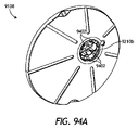
図13は、本発明の開示の1又は2以上の追加の実施形態による例示的センサ制御デバイス1302の等角図である。センサ制御デバイス1302は、図1のセンサ制御デバイス104と同じか又は同様とすることができ、従って、センサ制御デバイス1302をユーザの皮膚上のターゲットモニタリング場所に送出するセンサアプリケータ102(図1)と併用することができる。更に、センサ制御デバイス1302は、これに代えて、本明細書に説明した図8~図12の医療デバイス1402~1202のうちの1又は2以上と類似の医療デバイスとして特徴付けることができる。従って、センサ制御デバイス1302も、使用される前に適正な滅菌を必要とする場合がある。 FIG. 13 is an isometric view of an exemplary sensor control device 1302 according to one or more additional embodiments of the present disclosure. The sensor control device 1302 can be the same or similar to the sensor control device 104 of FIG. 1, thus the sensor applicator 102 (FIG. 1) delivering the sensor control device 1302 to a target monitoring location on the user's skin. can be used in combination with Further, the sensor control device 1302 may alternatively be characterized as a medical device similar to one or more of the medical devices 1402-1202 of FIGS. 8-12 described herein. Accordingly, the sensor control device 1302 may also require proper sterilization before being used.

図示のように、センサ制御デバイス1302は、ほぼ円盤形であって円形断面を有することができる電子機器ハウジング1304を含む。しかし、他の実施形態では、電子機器ハウジング1304は、本発明の開示の範囲から逸脱することなく長円形(例えば、錠剤形)、角丸正方形、又は多角形のような他の断面形状を示すことができる。電子機器ハウジング1304は、センサ制御デバイス1302を作動させるのに使用される様々な電子構成要素を収容するか又は他に閉じ込めるように構成することができる。 As shown, the sensor control device 1302 includes an electronics housing 1304 that is generally disc-shaped and can have a circular cross-section. However, in other embodiments, electronics housing 1304 exhibits other cross-sectional shapes such as oval (eg, tablet-shaped), rounded squares, or polygonal without departing from the scope of the present disclosure. be able to. Electronics housing 1304 can be configured to house or otherwise enclose various electronic components used to operate sensor control device 1302 .

電子機器ハウジング1304は、シェル1306と、それと嵌合可能なマウント1308とを含むことができる。シェル1306は、スナップフィット係合、締まり嵌め、音波溶接、又は1又は2以上の機械ファスナ(例えばスクリュー)、又はこれらのあらゆる組合せのような様々な方式によってマウント1308に固定することができる。一部の場合に、シェル1306は、それとマウント1308の間に密封インタフェースが発生するようマウント1308に固定することができる。そのような実施形態では、シェル1306及びマウント1308の外径部(周囲)又はその近くにガスケット又は他のタイプのシール材料を位置決めすることができ、これら2つの構成要素を互いに固定することによってガスケットを圧縮し、それによって密封インタフェースを発生させることができる。他の実施形態では、シェル1306及びマウント1308のうちの一方又は両方の外径部(周囲)に接着剤を付加することができる。接着剤は、シェル1306をマウント1308に固定して構造一体性を与えるが、これら2つの構成要素の間のインタフェースを密封し、それによって電子機器ハウジング1304の内部を外部汚染から隔離することもできる。 Electronics housing 1304 can include a shell 1306 and a mount 1308 matable therewith. Shell 1306 can be secured to mount 1308 in a variety of manners, such as snap fit engagement, interference fit, sonic welding, or one or more mechanical fasteners (eg, screws), or any combination thereof. In some cases, shell 1306 can be secured to mount 1308 such that a sealed interface occurs between it and mount 1308 . In such embodiments, a gasket or other type of sealing material may be positioned at or near the outer diameter (perimeter) of shell 1306 and mount 1308 to secure the two components together, thereby securing the gasket. can be compressed thereby creating a sealed interface. In other embodiments, adhesive may be applied to the outer diameter (perimeter) of one or both of shell 1306 and mount 1308 . The adhesive secures shell 1306 to mount 1308 to provide structural integrity, but can also seal the interface between these two components, thereby isolating the interior of electronics housing 1304 from external contamination. .

図示の実施形態では、センサ制御デバイス1302は、電子機器ハウジング1304に結合することができるプラグアセンブリ1310を更に含むことができる。プラグアセンブリ1310は、尖鋭体モジュール1314(部分的に見えている)と相互接続可能なセンサモジュール1312(部分的に見えている)を含むことができる。センサモジュール1312は、センサ1316(部分的に見えている)を担持し、かつ他にそれを含むように構成することができ、尖鋭体モジュール1314は、センサ制御デバイス1302の適用中にセンサ1316をユーザの皮膚の下に経皮的に送出することを支援するように使用される尖鋭体1318(部分的に見えている)を担持し、かつ他にそれを含むように構成することができる。尖鋭体モジュール1314は、尖鋭体1318を担持する尖鋭体ハブ1320を含むことができる。 In the illustrated embodiment, the sensor control device 1302 can further include a plug assembly 1310 that can be coupled to the electronics housing 1304 . The plug assembly 1310 can include a sensor module 1312 (partially visible) interconnectable with a sharp module 1314 (partially visible). Sensor module 1312 can be configured to carry and otherwise include sensor 1316 (partially visible), and sharp module 1314 can be configured to operate sensor 1316 during application of sensor control device 1302 . It can be configured to carry and otherwise include a sharp 1318 (partially visible) used to assist in percutaneous delivery under the user's skin. The sharps module 1314 can include a sharps hub 1320 that carries a sharps 1318 .

図示のように、センサ1316及び尖鋭体1318の対応する各部分は、電子機器ハウジング1304から、より具体的にはマウント1308の底部から延びる。センサ1316の露出部分(これに代えて、「テール」とも呼ぶ)を尖鋭体1318の中空部分又は陥凹部分の中に受け入れることができる。センサ1316の残余部分は、電子機器ハウジング1304内に位置決めされる。 As shown, sensor 1316 and corresponding portions of sharps 1318 extend from electronics housing 1304 and, more specifically, from the bottom of mount 1308 . An exposed portion (alternatively referred to as a “tail”) of sensor 1316 may be received within a hollow or recessed portion of sharp 1318 . The remainder of sensor 1316 is positioned within electronics housing 1304 .

図14Aは、図1のセンサアプリケータ102の側面図である。図示のように、センサアプリケータ102は、ハウジング1402と、それに取外し可能に結合されたアプリケータキャップ1404とを含む。一部の実施形態では、アプリケータキャップ1404は、ハウジング1402に螺合することができ、不正開封防止リング1406を含むことができる。ハウジング1402に対してアプリケータキャップ1404を回転させる(例えば捩って外す)時に、不正開封防止リング1406がネジ切れ、それによってアプリケータキャップ1404をセンサアプリケータ102から自由にすることができる。アプリケータキャップ1404が取り外された状態で、ユーザは、センサアプリケータ102を用いてセンサ制御デバイス1302(図13及び図14B)をユーザの身体上のターゲットモニタリング場所に位置決めすることができる。 FIG. 14A is a side view of sensor applicator 102 of FIG. As shown, sensor applicator 102 includes housing 1402 and applicator cap 1404 removably coupled thereto. In some embodiments, the applicator cap 1404 can be threaded onto the housing 1402 and can include a tamper evident ring 1406 . Upon rotating (eg, twisting off) the applicator cap 1404 relative to the housing 1402 , the tamper evident ring 1406 can unscrew, thereby freeing the applicator cap 1404 from the sensor applicator 102 . With the applicator cap 1404 removed, the user can use the sensor applicator 102 to position the sensor control device 1302 (FIGS. 13 and 14B) on the user's body at a target monitoring location.

一部の実施形態では、センサアプリケータ102の内部構成要素を保護するために、密封係合によってアプリケータキャップ1404をハウジング1402に固定することができる。少なくとも1つの実施形態では、例えば、Oリング又は別のタイプの密封ガスケットが、ハウジング1402とアプリケータキャップ1404の間のインタフェースを密封することができる。Oリング又は密封ガスケットは、個別の構成要素部品とするか又はこれに代えてハウジング1402及びアプリケータキャップ1404の一方の上に鋳造することができる。 In some embodiments, the applicator cap 1404 can be secured to the housing 1402 by sealing engagement to protect the internal components of the sensor applicator 102 . In at least one embodiment, an O-ring or another type of sealing gasket, for example, can seal the interface between housing 1402 and applicator cap 1404 . The O-ring or sealing gasket can be a separate component part or alternatively can be cast onto one of the housing 1402 and the applicator cap 1404 .

図14Bは、センサアプリケータ102の断面側面図である。図示のように、センサ制御デバイス1302は、センサアプリケータ102の中に受け入れることができ、アプリケータキャップ1404をセンサアプリケータ102に結合されてセンサ制御デバイス1302をアプリケータキャップ1404内に固定することができる。センサ制御デバイス1302は、電子機器ハウジング1304内に位置決めされた1又は2以上の感放射線構成要素1408を含むことができる。感放射線構成要素1408は、データ処理ユニット、レジスタ、トランジスタ、コンデンサ、インダクタ、ダイオード、スイッチ、又はこれらのあらゆる組合せ等であるがこれらに限定されない電子構成要素又は電子モジュールを含むことができる。データ処理ユニットは、例えば、センサ制御デバイス1302の作動に関連付けられた1又は2以上の機能又はルーチンを実施するように構成された特定用途向け集積回路(ASIC)を含むことができる。作動時に、データ処理ユニットは、ユーザのサンプリングされた検体レベルに対応するデータ信号のフィルタリング及び符号化のようなデータ処理機能を実施することができる。データ処理ユニットは、読取器デバイス106(図1)と通信するためのアンテナを含む又は他にそれと通信することができる。 14B is a cross-sectional side view of sensor applicator 102. FIG. As shown, sensor control device 1302 is receivable within sensor applicator 102 and applicator cap 1404 is coupled to sensor applicator 102 to secure sensor control device 1302 within applicator cap 1404 . can be done. Sensor control device 1302 may include one or more radiation sensitive components 1408 positioned within electronics housing 1304 . Radiation sensitive components 1408 may include electronic components or modules such as, but not limited to, data processing units, resistors, transistors, capacitors, inductors, diodes, switches, or any combination thereof. The data processing unit may include, for example, an application specific integrated circuit (ASIC) configured to implement one or more functions or routines associated with operating the sensor control device 1302 . In operation, the data processing unit is capable of performing data processing functions such as filtering and encoding data signals corresponding to the user's sampled analyte levels. The data processing unit may include or otherwise communicate with the reader device 106 (FIG. 1).

図示の実施形態では、アプリケータキャップ1404の中にキャップ充填物1410を位置決めすることができ、キャップ充填物1410は、センサ制御デバイス1302をセンサアプリケータ102の中で支持するのに一般的に役立たせることができる。1又は2以上の実施形態では、キャップ充填物1410は、アプリケータキャップ1404と共に鋳造するか又はその上にオーバーモールドする等を施したアプリケータキャップ1404の一体部分又は延長部を含むことができる。他の実施形態では、キャップ充填物1410は、本発明の開示の範囲から逸脱することなく、アプリケータキャップ1404の中に嵌合された又は他にそれに取り付けられた個別の構造体を含むことができる。 In the illustrated embodiment, a cap fill 1410 can be positioned within the applicator cap 1404, and the cap fill 1410 generally served to support the sensor control device 1302 within the sensor applicator 102. can let In one or more embodiments, the cap filling 1410 can comprise an integral part or extension of the applicator cap 1404, such as cast with or overmolded onto the applicator cap 1404. In other embodiments, cap fill 1410 may comprise a separate structure fitted within or otherwise attached to applicator cap 1404 without departing from the scope of the present disclosure. can.

センサ制御デバイス1302、より具体的には電子機器ハウジング1304の底部から延びるセンサ1316及び尖鋭体1318の遠位端は、センサアプリケータ102内に位置決めされている間に滅菌することができる。より具体的には、完全に組み立てられたセンサ制御デバイス1302に、図8~図12の放射線滅菌814と同様とすることができる放射線滅菌1412を受けることができる。放射線滅菌1412は、連続工程照射又はパルスビーム照射のいずれかによって送出することができる。パルスビーム照射では、放射線滅菌1412のビームがターゲット場所に集束され、そこに滅菌される構成要素部品又はデバイスが移動され、この点に指向性放射線パルスを供給するように照射が作動される。次いで、放射線滅菌1412は停止され、滅菌される別の構成要素部品又はデバイスがターゲット場所に移動され、この処理が繰り返される。 The sensor control device 1302 , and more specifically the sensor 1316 extending from the bottom of the electronics housing 1304 and the distal end of the sharp 1318 , can be sterilized while positioned within the sensor applicator 102 . More specifically, the fully assembled sensor control device 1302 can undergo radiation sterilization 1412, which can be similar to radiation sterilization 814 of FIGS. 8-12. Radiation sterilization 1412 can be delivered by either continuous process irradiation or pulsed beam irradiation. In pulsed beam irradiation, the radiation sterilization 1412 beam is focused to a target location, the component part or device to be sterilized is moved there, and the irradiation is activated to deliver a directed pulse of radiation to this point. Radiation sterilization 1412 is then stopped, another component part or device to be sterilized is moved to the target location, and the process is repeated.

本発明の開示により、センサ1316及び尖鋭体1318の遠位端を滅菌する段階では、放射線1412を集束させることを支援し、同時に伝播放射線1412が感放射線構成要素1408を損傷することを防止(阻止)するために外部滅菌アセンブリ1414を用いことができる。図示のように、外部滅菌アセンブリ1414(以下では「アセンブリ1414」)は、少なくとも部分的にセンサアプリケータ102の外部に位置決めされた放射線シールド1416を含むことができる。放射線シールド1416は、放射線1412(例えば、ビーム、波、エネルギのような)を滅菌される構成要素に向けて集束させることを支援するように構成された外部コリメータ1418を提供するか又は定めることができる。より具体的には、外部コリメータ1418は、センサ1316及び尖鋭体1318上に入射してこれらを滅菌する放射線1412の伝達を可能にするが、放射線1412が電子機器ハウジング1304の中にある感放射線構成要素1408を損傷することを防止する。 In accordance with the present disclosure, the step of sterilizing the distal end of sensor 1316 and point 1318 assists in focusing radiation 1412 while preventing propagating radiation 1412 from damaging radiation sensitive component 1408. ), an external sterilization assembly 1414 can be used. As shown, an external sterilization assembly 1414 (hereinafter “assembly 1414 ”) can include a radiation shield 1416 positioned at least partially external to sensor applicator 102 . The radiation shield 1416 may provide or define an external collimator 1418 configured to help focus the radiation 1412 (eg, beams, waves, energy, etc.) toward the components to be sterilized. can. More specifically, external collimator 1418 allows transmission of radiation 1412 incident on sensor 1316 and sharp 1318 to sterilize them, but in a radiation sensitive configuration where radiation 1412 is within electronics housing 1304. Prevents damage to element 1408 .

図示の実施形態では、外部コリメータ1418は、キャップ充填物1410によって定められた内部コリメータ1420に位置合わせするように設計される。外部コリメータ1418と同様に、内部コリメータ1420は、放射線1412を滅菌される構成要素に向けて集束させるのに役立たせることができる。図示のように、キャップ充填物1410は、放射線シールド1416の端部を受け入れ、他にそれに嵌合するようにサイズが決定された半径方向ショルダー1422を定めることができ、外部コリメータ1418は、半径方向ショルダー1422において内部コリメータ1420に移行する。一部の実施形態では、外部コリメータ1418と内部コリメータ1420の間の移行は、連続的、面一、又は平滑なものとすることができる。しかし、他の実施形態では、この移行は、本発明の開示の範囲から逸脱することなく断続的又は段階的なものとすることができる。 In the illustrated embodiment, outer collimator 1418 is designed to align with inner collimator 1420 defined by cap filling 1410 . Similar to external collimator 1418, internal collimator 1420 can help focus radiation 1412 toward the component being sterilized. As shown, the cap fill 1410 can define a radial shoulder 1422 sized to receive and otherwise fit the end of the radiation shield 1416, and the external collimator 1418 can radially Transition to internal collimator 1420 at shoulder 1422 . In some embodiments, the transition between outer collimator 1418 and inner collimator 1420 can be continuous, flush, or smooth. However, in other embodiments, this transition may be intermittent or gradual without departing from the scope of the present disclosure.

外部コリメータ1418と内部コリメータ1420は協働して、放射線1412を集束させ、かつセンサ1316及び尖鋭体1318の遠位端をその中に位置決めすることができる滅菌ゾーン1424を定める。伝播放射線1412は、滅菌ゾーン1424を通過し、センサ1316及び尖鋭体1318上に入射してこれらを滅菌することができる。しかし、キャップ充填物1410及び放射線シールド1416の各々は、放射線1412が滅菌ゾーン1424の内壁を貫通し、それによってハウジング1304の中にある感放射線構成要素1408を損傷することを実質的に防止する材料で製造することができる。言い換えれば、キャップ充填物1410及び放射線シールド1416の各々は、送出されているビームエネルギを吸収するほど十分な密度を有する材料で製造することができる。一部の実施形態では、例えば、キャップ充填物1410及び放射線シールド1416のうちの一方又は両方は、0.9グラム毎立方センチメートル(g/cc)よりも高い質量密度を有する材料で製造することができる。しかし、他の実施形態では、適切な材料の質量密度は、本発明の開示の範囲から逸脱することなく0.9g/ccよりも低いことが可能である。キャップ充填物1410及び放射線シールド1416に適する材料は、密度ポリマー(例えば、ポリエチレン、ポリプロピレン、ポリスチレン、ポリテトラフルオロエチレンのような)、金属(例えば、鉛、ステンレス鋼、アルミニウムのような)、これらのあらゆる組合せ、又は0.9g/ccよりも高い質量密度を有するいずれかの材料を含むがこれらに限定されない。少なくとも1つの実施形態では、キャップ充填物1410は、機械加工又は3D印刷されたポリプロピレンで製造することができ、放射線シールド1416は、ステンレス鋼で製造することができる。 External collimator 1418 and internal collimator 1420 cooperate to focus radiation 1412 and define a sterile zone 1424 in which sensor 1316 and the distal end of sharp 1318 can be positioned. Propagating radiation 1412 may pass through sterilization zone 1424 and be incident on sensor 1316 and sharp 1318 to sterilize them. However, cap filling 1410 and radiation shield 1416 are each made of a material that substantially prevents radiation 1412 from penetrating the inner walls of sterilization zone 1424 and thereby damaging radiation sensitive components 1408 within housing 1304. can be manufactured in In other words, cap fill 1410 and radiation shield 1416 may each be made of a material having sufficient density to absorb the beam energy being delivered. In some embodiments, for example, one or both of cap fill 1410 and radiation shield 1416 can be made of a material having a mass density greater than 0.9 grams per cubic centimeter (g/cc). . However, in other embodiments, the mass density of suitable materials can be less than 0.9 g/cc without departing from the scope of the present disclosure. Suitable materials for cap fill 1410 and radiation shield 1416 include density polymers (such as polyethylene, polypropylene, polystyrene, polytetrafluoroethylene), metals (such as lead, stainless steel, aluminum), and the like. Including but not limited to any combination or any material having a mass density greater than 0.9 g/cc. In at least one embodiment, the cap fill 1410 can be made of machined or 3D printed polypropylene and the radiation shield 1416 can be made of stainless steel.

一部の実施形態では、キャップ充填物1410及び放射線シールド1416のうちの一方又は両方は、0.9g/ccよりも低い質量密度を有する材料で製造することができるが、これらが、放射線滅菌1412が感放射線構成要素1408を損傷することを防止するように依然として作動させることができるように滅菌ゾーン1424の設計を変更することができる。そのような実施形態では、場合によって感放射線構成要素1408上に入射する前に放射線滅菌1412から伝播する電子により大量の材料を通過することが要求されるように滅菌ゾーン1424のサイズ(例えば、長さ)を拡大することができる。多めの量の材料は、放射線滅菌1412が高感度電子機器に対して無害になるように放射線滅菌1412の照射強度を吸収又は放散するのに役立たせることができる。しかし、他の実施形態では、その逆が同等に成り立つ場合がある。より具体的には、キャップ充填物1410及び/又は放射線シールド1416に対する材料が十分に大きい質量密度を提供する限り、滅菌ゾーン1424のサイズ(例えば、長さ)を縮小することができる。 In some embodiments, one or both of cap fill 1410 and radiation shield 1416 can be made of materials having mass densities less than 0.9 g/cc, although radiation sterilization 1412 The design of the sterilization zone 1424 can be modified so that it can still operate to prevent radiation sensitive components 1408 from being damaged. In such embodiments, the sterilization zone 1424 may be sized (e.g., length ) can be expanded. A larger amount of material can help absorb or dissipate the radiation intensity of radiation sterilizer 1412 such that radiation sterilizer 1412 is harmless to sensitive electronic equipment. However, in other embodiments, the opposite may equally be true. More specifically, the size (eg, length) of sterilization zone 1424 can be reduced as long as the materials for cap fill 1410 and/or radiation shield 1416 provide a sufficiently high mass density.

外部及び内部コリメータ1418、1420によって定められた滅菌ゾーン1424は、滅菌に向けて放射線1412をセンサ1316及び尖鋭体1318上に適正に集束させるのに必要なあらゆる適切な断面形状を示すことができる。図示の実施形態では、例えば、外部及び内部コリメータ1418、1420の各々は、形状が円錐形又は切頭円錐形である。しかし、他の実施形態では、外部及び内部コリメータ1418、1420のうちの一方又は両方は、本発明の開示の範囲から逸脱することなく立方形、長方形(例えば、平行四辺形を含む)、又はピラミッド形のような多角形断面形状を示すことができる。更に他の実施形態では、外部及び内部コリメータ1418、1420のうちの一方又は両方は、円形の断面と平行な側面とを示すことができる。 The sterilization zone 1424 defined by the external and internal collimators 1418, 1420 can exhibit any suitable cross-sectional shape required to properly focus the radiation 1412 onto the sensor 1316 and sharps 1318 for sterilization. In the illustrated embodiment, for example, each of the outer and inner collimators 1418, 1420 is conical or frustoconical in shape. However, in other embodiments, one or both of the outer and inner collimators 1418, 1420 may be cubic, rectangular (including, for example, parallelograms), or pyramidal without departing from the scope of the present disclosure. A polygonal cross-sectional shape such as a shape can be shown. In still other embodiments, one or both of the outer and inner collimators 1418, 1420 can exhibit circular cross-sections and parallel sides.

図示の実施形態では、滅菌ゾーン1424は、外部コリメータ1418によって定められた第1の開口1426aと、内部コリメータ1420によって定められた第2の開口1426bとを提供し、この場合に、第1の開口1426aと第2の開口1426bは、滅菌ゾーン1424の両端に位置付けられる。第1の開口1426aは、放射線1412が滅菌ゾーン1424に進入することを可能にし、第2の開口1426bは、放射線1412がセンサ1316及び尖鋭体1318に当たることができる場所を提供する。図示の実施形態では、第2の開口1426bは、センサ1316及び尖鋭体1318を滅菌ゾーン1424内に受け入れることができる場所も提供する。 In the illustrated embodiment, the sterilization zone 1424 provides a first opening 1426a defined by the outer collimator 1418 and a second opening 1426b defined by the inner collimator 1420, where the first opening 1426 a and a second opening 1426 b are positioned at opposite ends of the sterilization zone 1424 . A first opening 1426 a allows radiation 1412 to enter sterilization zone 1424 and a second opening 1426 b provides a location where radiation 1412 can strike sensor 1316 and sharps 1318 . In the illustrated embodiment, second opening 1426 b also provides a location where sensor 1316 and sharp 1318 can be received within sterilization zone 1424 .

滅菌ゾーン1424の形状が円錐形又は切頭円錐形である実施形態では、第1の開口1426aの直径は、第2の開口1426bの直径よりも大きいことが可能である。そのような実施形態では、例えば、第1の開口1426aのサイズは、約5.0mmと約16.0mmの間の範囲に及ぶことができ、第2の開口1426bのサイズは、約0.5mmと約3.0mmの間の範囲に及ぶことが可能である。しかし、第1及び第2の開口1426a、1426bのそれぞれの直径は、本発明の開示の範囲から逸脱することなくかつ用途に基づいて、本明細書で提供するものよりも大きいか又は小さいことが可能である。実際に、第1及び第2の開口1426a、1426bの直径は、十分な放射線照射量がセンサ1316及び尖鋭体1318上に入射することを可能にするほど十分な大きさであることのみが必要である。 In embodiments where the sterilization zone 1424 is conical or frustoconical in shape, the diameter of the first opening 1426a can be larger than the diameter of the second opening 1426b. In such embodiments, for example, the size of first opening 1426a can range between about 5.0 mm and about 16.0 mm, and the size of second opening 1426b is about 0.5 mm. and about 3.0 mm. However, the diameter of each of the first and second openings 1426a, 1426b can be larger or smaller than provided herein without departing from the scope of the present disclosure and based on the application. It is possible. In fact, the diameters of first and second openings 1426a, 1426b need only be large enough to allow sufficient radiation dose to be incident on sensor 1316 and sharp 1318. be.

図示の実施形態では、滅菌ゾーン1424(例えば、外部及び内部コリメータ1418、1420)の内壁は、第1の開口1426aと第2の開口1426bの間でセンサアプリケータ102の中心線に対して実質的に一定の角度を延びる。壁の角度は、センサアプリケータ102の中心線に対して0°と90°の間のいずれかの角度とすることができる。しかし、壁の角度は、好ましくは、センサアプリケータ102の中心線に対して45°と90°の間にあるとすることができる。しかし、他の実施形態では、壁の角度は、本発明の開示の範囲から逸脱することなく第1の開口1426aと第2の開口1426bの間で変化することが可能である。そのような実施形態では、壁の一部分は、隣接部分と異なる角度で短い距離だけ延びることができ、又は他に壁は、第1の開口1426aと第2の開口1426bの間で波打つことができる。 In the illustrated embodiment, the inner walls of the sterilization zone 1424 (eg, the outer and inner collimators 1418, 1420) are substantially aligned with the centerline of the sensor applicator 102 between the first opening 1426a and the second opening 1426b. Extends a certain angle to The wall angle can be anywhere between 0° and 90° with respect to the centerline of the sensor applicator 102 . However, the wall angle may preferably be between 45° and 90° with respect to the centerline of sensor applicator 102 . However, in other embodiments, the wall angle can vary between the first opening 1426a and the second opening 1426b without departing from the scope of the present disclosure. In such embodiments, a portion of the wall may extend a short distance at a different angle than the adjacent portion, or alternatively the wall may undulate between the first opening 1426a and the second opening 1426b. .

一部の実施形態では、外部及び内部コリメータ1418によって定められた滅菌ゾーン1424は、実質的に円筒形とし、他に円形又は多角形の断面を示すことができる。そのような実施形態では、第1の開口1426aと第2の開口1426bは同一の直径を示すことができ、滅菌ゾーン1424の壁は、滅菌ゾーン1424の第1の端部と第2の端部の間で実質的に平行とすることができる。 In some embodiments, the sterilization zone 1424 defined by the outer and inner collimators 1418 can be substantially cylindrical, or otherwise exhibit a circular or polygonal cross-section. In such embodiments, the first opening 1426a and the second opening 1426b can exhibit the same diameter, and the walls of the sterilization zone 1424 are formed at first and second ends of the sterilization zone 1424. can be substantially parallel between

一部の実施形態では、キャップ充填物1410と放射線シールド1416の間のインタフェースにキャップシール1428(破線に示す)を位置決めすることができる。キャップシール1428は、放射線透過性微生物障壁を含むことができる。一部の実施形態では、例えば、キャップシール1428は、DuPont(登録商標)から入手可能なTYVEK(登録商標)のような合成材料(例えば、フラッシュスパン密度ポリエチレン繊維)で製造することができる。キャップシール1428は、センサ1316及び尖鋭体1318を外部汚染から隔離するように構成された密封領域1430の一部を形成することを支援するように滅菌ゾーン1424の一部分を完全に密封することができる。 In some embodiments, a cap seal 1428 (shown in dashed lines) can be positioned at the interface between the cap fill 1410 and the radiation shield 1416 . Cap seal 1428 may include a radiolucent microbial barrier. In some embodiments, for example, the cap seal 1428 can be made of a synthetic material (eg, flash-spun density polyethylene fibers) such as TYVEK® available from DuPont®. Cap seal 1428 can completely seal a portion of sterile zone 1424 to help form a portion of sealed area 1430 configured to isolate sensor 1316 and sharp 1318 from external contamination. .

密封領域1430は、電子機器ハウジング1304内の選択部分と滅菌ゾーン1424とを含む(包含する)ことができる。1又は2以上の実施形態では、密封領域1430は、少なくともキャップシール1428と、第1のシール又は「上部」シール1432aと、第2のシール又は「底部」シール1432bとによって定められる又は他に形成することができる。キャップシール1428、並びに上部及び底部シール1432a、1432bの各々は、そのそれぞれの密封場所に対応する障壁を生成し、それによってセンサ1316及び尖鋭体1318を閉じ込める滅菌ゾーン1424を最終的に滅菌することを可能にする。 Sealed area 1430 can include (enclose) selected portions within electronics housing 1304 and sterile zone 1424 . In one or more embodiments, the sealing area 1430 is defined or otherwise formed by at least a cap seal 1428, a first or "top" seal 1432a, and a second or "bottom" seal 1432b. can do. Each of the cap seal 1428 and the top and bottom seals 1432a, 1432b create barriers corresponding to their respective sealing locations, thereby ultimately sterilizing the sterilization zone 1424 enclosing the sensor 1316 and sharps 1318. to enable.

上部シール1432aは、尖鋭体ハブ1320と電子機器ハウジング1304の上部(すなわち、図13のシェル1306)との間のインタフェースを密封し、それによって汚染物質が電子機器ハウジング1304の中に移動することを防止するように位置決めすることができる。一部の実施形態では、上部シール1432aは、尖鋭体ハブ1320上にオーバーモールドするなどで尖鋭体ハブ1320の一部を形成することができる。しかし、他の実施形態では、上部シール1432aは、シェル1306の上面の一部を形成するか又はその上にオーバーモールドすることができる。更に他の実施形態では、上部シール1432aは、本発明の開示の範囲から逸脱することなく、尖鋭体ハブ1320とシェル1306の上面との間に挟まるOリングなどのような個別の構造体を含むことができる。 Top seal 1432a seals the interface between sharps hub 1320 and the top of electronics housing 1304 (ie, shell 1306 in FIG. 13), thereby preventing contaminants from moving into electronics housing 1304. can be positioned to prevent In some embodiments, the top seal 1432a can form part of the sharp hub 1320, such as by being overmolded onto the sharp hub 1320. FIG. However, in other embodiments, the top seal 1432a may form part of or be overmolded onto the top surface of the shell 1306 . In still other embodiments, top seal 1432a comprises a separate structure, such as an O-ring, sandwiched between sharp hub 1320 and the top surface of shell 1306 without departing from the scope of the present disclosure. be able to.

底部シール1432bは、キャップ充填物1410と電子機器ハウジング1304の底部(すなわち、図13のマウント1308)との間のインタフェースを密封するように配置することができる。底部シール1432bは、汚染物質が滅菌ゾーン1424の中に移動すること、及び電子機器ハウジング1304の中に移動することを防止することができる。一部の実施形態では、底部シール1432bは、キャップ充填物1410の上にオーバーモールドする等を施すことによってキャップ充填物1410の一部を形成することができる。他の実施形態では、底部シール1432bは、マウント1308の底部の一部を形成するか又はその上にオーバーモールドすることができる。更に他の実施形態では、底部シール1432bは、本発明の開示の範囲から逸脱することなく、キャップ充填物1410とマウント1308の間に挟まるOリングなどのような個別の構造体を含むことができる。 A bottom seal 1432b can be arranged to seal the interface between the cap fill 1410 and the bottom of the electronics housing 1304 (ie, mount 1308 in FIG. 13). Bottom seal 1432 b can prevent contaminants from migrating into sterilization zone 1424 and into electronics housing 1304 . In some embodiments, the bottom seal 1432b may form part of the cap filling 1410, such as by being overmolded over the cap filling 1410. FIG. In other embodiments, the bottom seal 1432b can form part of or be overmolded on the bottom of the mount 1308 . In still other embodiments, the bottom seal 1432b can include a separate structure, such as an O-ring, sandwiched between the cap fill 1410 and the mount 1308 without departing from the scope of the present disclosure. .

センサ制御デバイス1302をセンサアプリケータ102の中に装填し、アプリケータキャップ1404をセンサアプリケータ102に固定した後に、上部及び底部シール1432a、1432bは圧縮し、対応する密封インタフェースを発生させることができる。上部及び底部シール1432a、1432bは、対向構造体間に密封インタフェースを発生させる機能を有する様々な材料で製造することができる。適切な材料は、シリコーン、熱可塑性エラストマー(TPE)、ポリテトラフルオロエチレン(例えば、TEFLON(登録商標))、又はこれらのあらゆる組合せを含むがこれらに限定されない。 After loading the sensor control device 1302 into the sensor applicator 102 and securing the applicator cap 1404 to the sensor applicator 102, the top and bottom seals 1432a, 1432b can be compressed to create corresponding sealing interfaces. . The top and bottom seals 1432a, 1432b can be made of various materials that function to create a sealed interface between opposing structures. Suitable materials include, but are not limited to, silicone, thermoplastic elastomer (TPE), polytetrafluoroethylene (eg, TEFLON®), or any combination thereof.

センサ1316及び尖鋭体1318は、電子機器ハウジング1304の底部からセンサアプリケータ102及びアプリケータキャップ1404の中心線とほぼ同心の滅菌ゾーン1424の中に延びるが、本明細書では偏心配置を有することを考えていることに注意されたい。より具体的には、少なくとも1つの実施形態では、センサ1316及び尖鋭体1318は、電子機器ハウジング1304の底部からセンサアプリケータ102及びアプリケータキャップ1404の中心線に対して偏心して延びる。そのような実施形態では、本発明の開示の範囲から逸脱することなく、滅菌ゾーン1424も偏心して配置してセンサ1316及び尖鋭体1318を受け入れるように外部及び内部コリメータ1418、1420を再設計するか又は他に構成することができる。 The sensor 1316 and sharp 1318 extend from the bottom of the electronics housing 1304 into the sterile zone 1424 generally concentric with the centerline of the sensor applicator 102 and applicator cap 1404, although here noted to have an eccentric arrangement. Notice what I'm thinking. More specifically, in at least one embodiment, sensor 1316 and sharp 1318 extend from the bottom of electronics housing 1304 off-center with respect to the centerline of sensor applicator 102 and applicator cap 1404 . In such an embodiment, the external and internal collimators 1418, 1420 could be redesigned to also eccentrically position the sterilization zone 1424 to receive the sensor 1316 and sharps 1318 without departing from the scope of the present disclosure. or can be otherwise configured.

一部の実施形態では、外部滅菌アセンブリ1414は、放射線シールド1416に結合された又はその一部を形成する滅菌ハウジング又は滅菌「ポッド」1434を更に含むことができる。滅菌ポッド1434は、センサアプリケータ102の全て又は一部分を受け入れるようにサイズが決定されたチャンバ1436を提供するか又は他に定める。滅菌ポッド1434の中に適正に着座する(受け入れられる)と、センサアプリケータ102は、センサ1316及び尖鋭体1318を滅菌するための放射線滅菌1412を受けることができる。放射線1412が滅菌ポッド1434の壁の中を通って伝播することを防止することを支援するために、滅菌ポッド1434は、放射線シールド1416に関して本明細書に示した材料のうちのいずれかで製造することができる。 In some embodiments, external sterilization assembly 1414 can further include a sterilization housing or sterilization “pod” 1434 coupled to or forming part of radiation shield 1416 . Sterilization pod 1434 provides or otherwise defines a chamber 1436 sized to receive all or a portion of sensor applicator 102 . Once properly seated (received) within sterilization pod 1434 , sensor applicator 102 can undergo radiation sterilization 1412 to sterilize sensor 1316 and sharp 1318 . To help prevent radiation 1412 from propagating through the walls of sterilization pod 1434, sterilization pod 1434 is manufactured from any of the materials shown herein for radiation shield 1416. be able to.

一部の実施形態では、放射線シールド1416は、1又は2以上の機械ファスナ1438(1つを示す)を用いて滅菌ポッド1434に取外し可能に結合することができるが、これに代えて、締まり嵌め、スナップフィット係合等によって取外し可能に結合することができる。放射線シールド1416を滅菌ポッド1434に取外し可能に結合することにより、放射線シールド1416は、特定の滅菌用途に適合する別様に設計(サイズ決定)された様々なタイプ及び設計のセンサアプリケータ102に対するシールドと交換可能であることが可能になる。従って、滅菌ポッド1434は、放射線シールド1416を外部コリメータ1418に関して異なるパラメータを有する他のシールド設計と必要に応じて交換することを可能にするユニバーサルマウントを含むことができる。 In some embodiments, the radiation shield 1416 can be removably coupled to the sterilization pod 1434 using one or more mechanical fasteners 1438 (one shown), but alternatively an interference fit. , a snap-fit engagement or the like. By removably coupling the radiation shield 1416 to the sterilization pod 1434, the radiation shield 1416 provides a shield for various types and designs of differently designed (sized) sensor applicators 102 to suit specific sterilization applications. It becomes possible to be interchangeable with Accordingly, sterilization pod 1434 can include a universal mount that allows radiation shield 1416 to be exchanged with other shield designs having different parameters for external collimator 1418 as needed.

一部の実施形態では、外部滅菌アセンブリ1414は、滅菌ポッド1434に結合された又はその一部を形成する装着トレイ1440を更に含むことができる。滅菌ポッド1434は、例えば、1又は2以上の機械ファスナ1442(1つを示す)を用いて装着トレイ1440に取外し可能に結合することができる。装着トレイ1440は、センサアプリケータ102を受け入れるようにサイズが決定され、センサアプリケータ102がチャンバ1436に進入することを可能にするようにチャンバ1436に位置合わせ可能な中心開口1444を提供するか又は定めることができる。下記で説明するように、一部の実施形態では、装着トレイ1440は、滅菌に向けて複数のセンサアプリケータを受け入れるための対応する複数の中心開口1444を定めることができる。 In some embodiments, external sterilization assembly 1414 can further include a loading tray 1440 coupled to or forming part of sterilization pod 1434 . Sterilization pod 1434 can be removably coupled to mounting tray 1440 using, for example, one or more mechanical fasteners 1442 (one shown). The mounting tray 1440 is sized to receive the sensor applicator 102 and provides a central opening 1444 alignable with the chamber 1436 to allow the sensor applicator 102 to enter the chamber 1436, or can be determined. As described below, in some embodiments, the mounting tray 1440 can define a corresponding plurality of central openings 1444 for receiving multiple sensor applicators for sterilization.

図15は、1又は2以上の追加の実施形態によるセンサアプリケータ102及び外部滅菌アセンブリ1414の別の例示的実施形態の断面側面図である。図示のように、センサ制御デバイス1302は、ここでもまたセンサアプリケータ102の中に受け入れられ、アプリケータキャップ1404はハウジング1402に結合され、その中にセンサ制御デバイス1302が固定される。 FIG. 15 is a cross-sectional side view of another exemplary embodiment of sensor applicator 102 and external sterilization assembly 1414 in accordance with one or more additional embodiments. As shown, the sensor control device 1302 is again received within the sensor applicator 102 and the applicator cap 1404 is coupled to the housing 1402 in which the sensor control device 1302 is secured.

図示の実施形態では、アプリケータキャップ1404は反転することができ、電子機器ハウジング1304の底部から延びるセンサ1316及び尖鋭体1318の遠位端を受け入れるようにサイズが決定されたキャップポスト1502を定めるか又は他に提供することができる。キャップポスト1502は、センサ1316及び尖鋭体1318を外部汚染から隔離するように構成された密封領域1430の一部を形成することを支援する。図示の実施形態では、密封領域1430は、キャップポスト1502と、それぞれの密封場所に対応する障壁を生成する上部及び底部シール1432a、1432bとによって定められる又は他に形成することができる。ここでもまた、上部シール1432aは、尖鋭体ハブ1320と電子機器ハウジング1304の上部(すなわち、図13のシェル1306)との間のインタフェースを密封するように配置することができ、底部シール1432bは、アプリケータキャップ1404と電子機器ハウジング1304の底部(すなわち、図13のマウント1308)との間のインタフェースを密封するように配置することができる。一部の実施形態では、底部シール1432bは、キャップポスト1502と電子機器ハウジング1304の底部の間に挟まることができる。 In the illustrated embodiment, the applicator cap 1404 can be inverted and defines a cap post 1502 sized to receive the distal end of the sensor 1316 and sharpener 1318 extending from the bottom of the electronics housing 1304 . or can be provided elsewhere. Cap post 1502 helps form part of sealing area 1430 configured to isolate sensor 1316 and sharp 1318 from external contamination. In the illustrated embodiment, the sealing area 1430 can be defined or otherwise formed by the cap post 1502 and top and bottom seals 1432a, 1432b that create barriers corresponding to the respective sealing locations. Again, top seal 1432a can be positioned to seal the interface between sharps hub 1320 and the top of electronics housing 1304 (i.e., shell 1306 in FIG. 13), and bottom seal 1432b can It can be arranged to seal the interface between the applicator cap 1404 and the bottom of the electronics housing 1304 (ie, the mount 1308 in FIG. 13). In some embodiments, bottom seal 1432b can be sandwiched between cap post 1502 and the bottom of electronics housing 1304 .

図示の実施形態では、放射線シールド1416は、センサアプリケータ102の外部に位置決めすることができ、アプリケータキャップ1404の反転部分の中に延びることができる。放射線シールド1416によって設けられた外部コリメータ1418は、放射線1412をセンサ1316及び尖鋭体1318に向けて集束させるように構成された滅菌ゾーン1504を定める。図示の実施形態では、キャップポスト1502と、キャップポスト1502内に位置決めされたセンサ1316及び尖鋭体1318の部分とが滅菌ゾーン1504の中に延びる。伝播放射線1412は、滅菌ゾーン1504を通過し、キャップポスト1502内に位置決めされたセンサ1316及び尖鋭体1318を滅菌することができる。しかし、上記に示したように、放射線シールド1416は、放射線1412が滅菌ゾーン1504の壁を貫通し、それによってハウジング1304の中にある感放射線構成要素1408を損傷することを実質的に防止する材料で製造することができる。 In the illustrated embodiment, radiation shield 1416 can be positioned externally of sensor applicator 102 and can extend into the inverted portion of applicator cap 1404 . An external collimator 1418 provided by radiation shield 1416 defines a sterile zone 1504 configured to focus radiation 1412 toward sensor 1316 and sharps 1318 . In the illustrated embodiment, cap post 1502 and portions of sensor 1316 and sharps 1318 positioned within cap post 1502 extend into sterilization zone 1504 . Propagating radiation 1412 can pass through sterilization zone 1504 and sterilize sensor 1316 and sharps 1318 positioned within cap post 1502 . However, as indicated above, radiation shield 1416 is a material that substantially prevents radiation 1412 from penetrating the walls of sterilization zone 1504 and thereby damaging radiation sensitive components 1408 within housing 1304 . can be manufactured in

図示の実施形態では、外部コリメータ1418は、滅菌ゾーン1504の第1の端部に第1の開口1506aを滅菌ゾーン1504の第2の端部に第2の開口1506bを定める。第1の開口1506aは、放射線1412が滅菌ゾーン1504に進入することを可能にし、第2の開口1506bは、放射線1412をセンサ1316及び尖鋭体1318に向けて集束させる場所を提供する。第2の開口1506bは、キャップポスト1502内に位置決めされたセンサ1316及び尖鋭体1318を滅菌ゾーン1504の中に受け入れることができる場所を提供することができる。 In the illustrated embodiment, the external collimator 1418 defines a first opening 1506 a at a first end of the sterilization zone 1504 and a second opening 1506 b at a second end of the sterilization zone 1504 . A first opening 1506 a allows radiation 1412 to enter sterilization zone 1504 and a second opening 1506 b provides a location to focus radiation 1412 toward sensor 1316 and sharps 1318 . A second opening 1506 b can provide a location where sensor 1316 and sharp 1318 positioned within cap post 1502 can be received within sterilization zone 1504 .

図示のように、外部コリメータ1418及び関連の滅菌ゾーン1504は、形状が円錐形又は切頭円錐形であり、第1の開口1506aの直径は、第2の開口1506bの直径よりも大きい。第1の開口1506aのサイズは、約5.0mmと約16.0mmの間の範囲に及ぶことができ、第2の開口1506bのサイズは、約0.5mmと約3.0mmの間の範囲に及ぶことが可能であるが、これに代えて、これらのサイズは、本発明の開示の範囲から逸脱することなく、提供した範囲よりも大きいか又は小さいことが可能である。実際に、開口1506a、1506bのサイズは、デバイスの大きさに依存して異なることが可能である。しかし、他の実施形態では、外部コリメータ1418及び関連の滅菌ゾーン1504は、実質的に円筒形とし、他に円形又は多角形の断面を示すことができ、この場合に、第1の開口1506aと第2の開口1506bは実質的に同一の直径を示し、滅菌ゾーン1504の壁は実質的に平行である。 As shown, the external collimator 1418 and associated sterilization zone 1504 are conical or frustoconical in shape, with the diameter of the first opening 1506a being larger than the diameter of the second opening 1506b. The size of first opening 1506a can range between about 5.0 mm and about 16.0 mm, and the size of second opening 1506b can range between about 0.5 mm and about 3.0 mm. , but alternatively these sizes can be larger or smaller than the ranges provided without departing from the scope of the present disclosure. In fact, the size of openings 1506a, 1506b can vary depending on the size of the device. However, in other embodiments, the external collimator 1418 and associated sterilization zone 1504 may be substantially cylindrical and otherwise exhibit a circular or polygonal cross-section, in which case the first opening 1506a and the The second openings 1506b exhibit substantially the same diameter and the walls of the sterilization zone 1504 are substantially parallel.

図16は、1又は2以上の追加の実施形態によるセンサアプリケータ102及び外部滅菌アセンブリ1414の別の例示的実施形態の断面側面図である。図示のように、ここでもまたセンサ制御デバイス1302はセンサアプリケータ102の中に受け入れられ、アプリケータキャップ1404はハウジング1402に結合され、その中にセンサ制御デバイス1302が固定される。 FIG. 16 is a cross-sectional side view of another exemplary embodiment of sensor applicator 102 and external sterilization assembly 1414 in accordance with one or more additional embodiments. As shown, the sensor control device 1302 is again received within the sensor applicator 102 and the applicator cap 1404 is coupled to the housing 1402 in which the sensor control device 1302 is secured.

図示の実施形態では、アプリケータキャップ1404は、ここでもまた反転することができ、電子機器ハウジング1304の底部から延びるセンサ1316及び尖鋭体1318の遠位端を受け入れるようにサイズが決定されたキャップポスト1602を定めるか又は他に提供することができる。更に、放射線シールド1416は、センサアプリケータ102の外部に位置決めすることができ、アプリケータキャップ1404の反転部分の中に延びることができる。より具体的には、放射線シールド1416は、アプリケータキャップ1404の反転部分の中に延び、更にキャップポスト1602の底部まで延びることができる。しかし、図15のキャップポスト1502とは異なり、キャップポスト1602の底部は開口端部とすることができる。一部の実施形態では、キャップポスト1602の開口端部を完全に密封するために、キャップポスト1602と放射線シールド1416の間のインタフェースにキャップシール1604を位置決めすることができる。キャップシール1604は、図14Bのキャップシール1428と同様とすることができ、従って、再度説明することはしない。 In the illustrated embodiment, the applicator cap 1404 can again be inverted and has a cap post sized to receive the distal ends of the sensor 1316 and sharpener 1318 extending from the bottom of the electronics housing 1304. 1602 may be defined or otherwise provided. Additionally, radiation shield 1416 can be positioned externally of sensor applicator 102 and can extend into the inverted portion of applicator cap 1404 . More specifically, radiation shield 1416 can extend into the inverted portion of applicator cap 1404 and further to the bottom of cap post 1602 . However, unlike the cap post 1502 of FIG. 15, the bottom of the cap post 1602 can be open ended. In some embodiments, a cap seal 1604 can be positioned at the interface between the cap post 1602 and the radiation shield 1416 to completely seal the open end of the cap post 1602 . The cap seal 1604 can be similar to the cap seal 1428 of Figure 14B and thus will not be described again.

一部の実施形態では、アプリケータキャップ1404の中にキャップ充填物1606を位置決めすることができる。1又は2以上の実施形態では、キャップ充填物1606は、アプリケータキャップ1404と共に鋳造するか又はその上にオーバーモールドする等を施したアプリケータキャップ1404の一体部分又は延長部を含むことができる。他の実施形態では、キャップ充填物1606は、本発明の開示の範囲から逸脱することなく、アプリケータキャップ1404の中に嵌合された又は他にそれに取り付けられた個別の構造体を含むことができる。キャップ充填物1606は、放射線1412を滅菌される構成要素に向けて集束させるのに役立たせることができる内部コリメータ1608を提供するか又は他に定めることができる。少なくとも1つの実施形態では、図示のように、キャップポスト1602は、内部コリメータ1608の中に受け入れることができる。 In some embodiments, cap filling 1606 can be positioned within applicator cap 1404 . In one or more embodiments, the cap filling 1606 can comprise an integral part or extension of the applicator cap 1404, such as cast with or overmolded onto the applicator cap 1404. In other embodiments, cap fill 1606 may comprise a separate structure fitted within or otherwise attached to applicator cap 1404 without departing from the scope of the present disclosure. can. The cap filling 1606 can provide or otherwise define an internal collimator 1608 that can help focus the radiation 1412 toward the components to be sterilized. In at least one embodiment, the cap post 1602 can be received within an internal collimator 1608 as shown.

外部コリメータ1418と内部コリメータ1608は協働して、放射線1412をセンサ1316及び尖鋭体1318に向けて集束させる滅菌ゾーン1610を定めることができる。伝播放射線1412は、滅菌ゾーン1610を通過し、センサ1316及び尖鋭体1318上に入射してこれらを滅菌することができる。しかし、キャップ充填物1606及び放射線シールド1416の各々は、放射線1412が滅菌ゾーン1610の内壁を貫通し、それによってハウジング1304の中にある感放射線構成要素1408を損傷することを実質的に防止する本明細書に説明する材料のうちのいずれかで製造することができる。少なくとも1つの実施形態では、キャップ充填物1606は、機械加工又は3D印刷されたポリプロピレンで製造することができ、放射線シールド1416は、ステンレス鋼で製造することができる。 External collimator 1418 and internal collimator 1608 can cooperate to define sterilization zone 1610 that focuses radiation 1412 toward sensor 1316 and sharps 1318 . Propagating radiation 1412 may pass through sterilization zone 1610 and be incident on sensor 1316 and sharp 1318 to sterilize them. However, cap filling 1606 and radiation shield 1416 each substantially prevent radiation 1412 from penetrating the inner wall of sterilization zone 1610 and thereby damaging radiation sensitive components 1408 within housing 1304. It can be made of any of the materials described herein. In at least one embodiment, the cap fill 1606 can be made of machined or 3D printed polypropylene and the radiation shield 1416 can be made of stainless steel.

外部及び内部コリメータ1418、1608は、滅菌に向けて放射線1412をセンサ1316及び尖鋭体1318に向けて適正に集束させるのに必要なあらゆる適切な断面形状を示すことができる。図示の実施形態では、例えば、外部コリメータ1418は、形状が円錐形又は切頭円錐形であり、内部コリメータ1608は実質的に円筒形であり、実質的に平行な内壁を有する。しかし、他の実施形態では、外部及び内部コリメータ1418、1608は、本発明の開示の範囲から逸脱することなく他の断面形状を示すことができる。 External and internal collimators 1418, 1608 may exhibit any suitable cross-sectional shape required to properly focus radiation 1412 toward sensor 1316 and sharpener 1318 for sterilization. In the illustrated embodiment, for example, the outer collimator 1418 is conical or frustoconical in shape and the inner collimator 1608 is substantially cylindrical and has substantially parallel inner walls. However, in other embodiments, the outer and inner collimators 1418, 1608 can exhibit other cross-sectional shapes without departing from the scope of the present disclosure.

図示の実施形態では、外部コリメータ1418は、放射線1412が滅菌ゾーン1610に進入することを可能にする第1の開口1612aと、放射線1412をキャップポスト1602内に位置決めされたセンサ1316及び尖鋭体1318に集束させるためにキャップポスト1602への底部開口又はその近くに位置決めされた第2の開口1612bとを定める。従来の実施形態の場合と同様に、第1の開口1612aの直径は、第2の開口1612bの直径よりも大きく、第1の開口1612aのサイズは、約5.0mmと約16.0mmの間の範囲に及ぶことができ、第2の開口1612bのサイズは、約0.5mmと約3.0mmの間の範囲に及ぶことが可能である。図示の実施形態では、外部コリメータ1418は、放射線1412の電子をキャップポスト1602への底部開口に向けて通過させ、センサ1316及び尖鋭体1318の場所の電子を増大する。 In the illustrated embodiment, the external collimator 1418 has a first opening 1612a that allows the radiation 1412 to enter the sterilization zone 1610 and directs the radiation 1412 to the sensor 1316 and sharpener 1318 positioned within the cap post 1602. A second opening 1612b positioned at or near the bottom opening to the cap post 1602 for focusing. As with conventional embodiments, the diameter of first opening 1612a is greater than the diameter of second opening 1612b, and the size of first opening 1612a is between about 5.0 mm and about 16.0 mm. and the size of the second opening 1612b can range between about 0.5 mm and about 3.0 mm. In the illustrated embodiment, an external collimator 1418 passes electrons of radiation 1412 toward the bottom opening to cap post 1602 and augments the electrons at sensor 1316 and point 1318 .

キャップシール1604は、放射線シールド1416とキャップポスト1602及び/又はキャップ充填物1606との間のインタフェースに位置決めすることができる。キャップシール1604は、センサ1316及び尖鋭体1318を外部汚染から隔離するように構成された密封領域1430の一部を形成することを支援するように滅菌ゾーン1610の一部分を完全に密封することができる。密封領域1430は、電子機器ハウジング1304内の選択部分と滅菌ゾーン1610とを含む(包含する)ことができる。図示の実施形態では、密封領域1430は、キャップポスト1602と、それぞれの密封場所に対応する障壁を生成する上部及び底部シール1432a、1432bとによって定められる又は他に形成することができる。底部シール1432bは、アプリケータキャップ1404と電子機器ハウジング1304の底部(すなわち、図13のマウント1308)との間のインタフェースを密封するように配置することができる。 Cap seal 1604 can be positioned at the interface between radiation shield 1416 and cap post 1602 and/or cap fill 1606 . Cap seal 1604 can completely seal a portion of sterile zone 1610 to help form a portion of sealed area 1430 configured to isolate sensor 1316 and sharps 1318 from external contamination. . Sealed area 1430 can include (enclose) selected portions within electronics housing 1304 and sterile zone 1610 . In the illustrated embodiment, the sealing area 1430 can be defined or otherwise formed by the cap post 1602 and top and bottom seals 1432a, 1432b that create barriers corresponding to the respective sealing locations. A bottom seal 1432b can be arranged to seal the interface between the applicator cap 1404 and the bottom of the electronics housing 1304 (ie, mount 1308 in FIG. 13).

図17A及び図17Bは、それぞれ、1又は2以上の実施形態による外部滅菌アセンブリ1414の一例の等角上面図及び等角底面図である。少なくとも1つの実施形態では、アセンブリ1414は、複数のセンサアプリケータ102(すなわち、センサ制御デバイスが設置されたもの)を含み、これらを滅菌することを支援するように設計され、かつ他にそのように構成することができる。図示の実施形態では、装着トレイ1440は、複数の中心開口1444(図17A)を定め、複数の滅菌ポッド1434をこれらの中心開口1444に位置合わせされて装着トレイ1440に結合することができる。センサアプリケータ102は、中心開口1444を通して滅菌ポッド1434の中に受け入れることができ、各滅菌ポッド1434は、それに結合された又は他にその一部を形成する対応するシールド1416(図17B)を有することができる。 17A and 17B are isometric top and bottom views, respectively, of an example external sterilization assembly 1414 according to one or more embodiments. In at least one embodiment, assembly 1414 includes a plurality of sensor applicators 102 (i.e., with sensor control devices installed) and is designed to assist in sterilizing them and otherwise so. can be configured to In the illustrated embodiment, the loading tray 1440 defines a plurality of central openings 1444 (FIG. 17A), and a plurality of sterilization pods 1434 can be aligned with the central openings 1444 and coupled to the loading tray 1440 . Sensor applicators 102 are receivable into sterilization pods 1434 through central openings 1444, each sterilization pod 1434 having a corresponding shield 1416 (FIG. 17B) coupled thereto or otherwise forming part thereof. be able to.

一部の実施形態では、アセンブリ1414は、装着トレイ1440と嵌合可能なカバー1702を更に含むことができる。カバー1702は、それが装着トレイ1440の上に置かれた時にセンサアプリケータ102の上部を受け入れるようにサイズが決定された複数の開口1106を含む又は定めることができる。一部の実施形態では、放射線滅菌がアセンブリ1414の壁の中を通って伝播することを防止することを支援するように、カバー1702は、放射線シールド1416に関して本明細書に示した材料のうちのいずれかで製造することができる。カバー1702が装着トレイ1414と嵌合された状態で、センサアプリケータ102をアセンブリ1414の中に封入するか又は他に包むことができる。 In some embodiments, assembly 1414 can further include cover 1702 mateable with loading tray 1440 . Cover 1702 may include or define a plurality of openings 1106 sized to receive the top of sensor applicator 102 when it is placed over mounting tray 1440 . In some embodiments, cover 1702 is made of one of the materials shown herein for radiation shield 1416 to help prevent radiation sterilization from propagating through the walls of assembly 1414. Either can be manufactured. With cover 1702 mated with mounting tray 1414 , sensor applicator 102 can be enclosed or otherwise wrapped in assembly 1414 .

本明細書に開示する実施形態は、以下を含む。 Embodiments disclosed herein include the following.

D.要滅菌部分と、感放射線構成要素とを有する医療デバイスの外部に位置決め可能な放射線シールドと、放射線シールドによって定められ、要滅菌部分に位置合わせ可能なコリメータとを含み、コリメータが放射線滅菌処理からの放射線を要滅菌部分に向けて集束させ、放射線が感放射線構成要素を損傷することを放射線シールドが防止することを特徴とする外部滅菌アセンブリ。 D. a radiation shield positionable externally of a medical device having a portion to be sterilized and a radiation sensitive component; and a collimator defined by the radiation shield and alignable to the portion to be sterilized, wherein the collimator provides radiation from the radiation sterilization process. An external sterilization assembly, wherein the radiation shield focuses the radiation toward the part requiring sterilization and the radiation shield prevents the radiation from damaging the radiation sensitive components.

E.ハウジングと、ハウジングに結合されたキャップと、ハウジング内に位置決めされたセンサ制御デバイスとを含むセンサアプリケータの外部に位置決め可能な放射線シールドを含み、センサ制御デバイスが、電子機器ハウジングと、電子機器ハウジング内に位置決めされた感放射線構成要素と、電子機器ハウジングから延びるセンサ及び尖鋭体とを含む部滅菌アセンブリ。外部滅菌アセンブリは、放射線シールドによって定められてセンサ及び尖鋭体に位置合わせ可能な外部コリメータを更に含み、外部コリメータは、放射線滅菌処理からの放射線をセンサ及び尖鋭体に向けて集束させ、放射線シールドは、放射線が感放射線構成要素を損傷することを防止する。 E. a radiation shield positionable external to a sensor applicator comprising a housing, a cap coupled to the housing, and a sensor control device positioned within the housing, the sensor control device being positioned within the electronics housing; A partial sterilization assembly including a radiation sensitive component positioned therein and a sensor and sharps extending from an electronics housing. The external sterilization assembly further includes an external collimator defined by the radiation shield and alignable with the sensor and sharps, the external collimator focusing radiation from the radiation sterilization process toward the sensor and sharps, the radiation shield comprising: , to prevent radiation from damaging radiation sensitive components.

F.ハウジングと、ハウジングに結合されたキャップと、ハウジング内に位置決めされたセンサ制御デバイスとを有するセンサアプリケータの外部に放射線シールドを配置する段階を含み、センサ制御デバイスが、電子機器ハウジングと、電子機器ハウジング内に位置決めされた感放射線構成要素と、電子機器ハウジングから延びるセンサ及び尖鋭体とを含む方法。本方法は、放射線シールドによって定められた外部コリメータによって放射線滅菌処理からの放射線をセンサ及び尖鋭体に向けて集束させる段階と、放射線が感放射線構成要素を損傷することを放射線シールドによって防止する段階とを更に含む。 F. positioning a radiation shield external to a sensor applicator having a housing, a cap coupled to the housing, and a sensor control device positioned within the housing, the sensor control device being positioned between the electronics housing and the electronics; A method including a radiation sensitive component positioned within a housing and a sensor and sharpened body extending from the electronics housing. The method comprises the steps of: focusing radiation from the radiation sterilization process toward the sensor and sharps with an external collimator defined by the radiation shield; and preventing the radiation from damaging radiation sensitive components with the radiation shield. further includes

実施形態D、E、及びFの各々は、以下の追加の要素のうちの1又は2以上をあらゆる組合せで有することができる:要素1:放射線シールドが、密度ポリマー、金属、及びこれらのあらゆる組合せから構成される群から選択される材料で製造されること。要素2:感放射線構成要素が、電子モジュール、化学溶液、及びこれらのあらゆる組合せから構成される群から選択されること。要素3:コリメータが、円錐形、切頭円錐形、ピラミッド形、円形、立方形、長方形、及びこれらのあらゆる組合せから構成される群から選択される断面形状を含むこと。要素4:要滅菌部分を封入し、密封障壁を与えるキャップを更に含むこと。要素5:放射線シールドが、医療デバイスを受け入れる内部キャビティを定め、コリメータは、放射線を内部キャビティの中に集束させること。 Each of embodiments D, E, and F can have one or more of the following additional elements in any combination: Element 1: The radiation shield is made of density polymer, metal, and any combination thereof. Manufactured from a material selected from the group consisting of Element 2: The radiation sensitive component is selected from the group consisting of electronic modules, chemical solutions, and any combination thereof. Element 3: The collimator includes a cross-sectional shape selected from the group consisting of conical, frustoconical, pyramidal, circular, cubic, rectangular, and any combination thereof. Element 4: further including a cap enclosing the parts requiring sterilization and providing a sealing barrier. Element 5: The radiation shield defines an internal cavity for receiving the medical device, and the collimator focuses the radiation into the internal cavity.

要素6:放射線シールドが、密度ポリマー、金属、及びこれらのあらゆる組合せから構成される群から選択される材料で製造されること。要素7:外部コリメータが、円錐形、切頭円錐形、ピラミッド形、円形、立方形、長方形、及びこれらのあらゆる組合せから構成される群から選択される断面形状を含むこと。要素8:センサアプリケータの少なくとも一部分を受け入れるチャンバを定める滅菌ポッドを更に含み、放射線シールドが、滅菌ポッドに取外し可能に結合されること。要素9:チャンバに位置合わせ可能であり、センサアプリケータを受け入れるようにサイズが決定された中心開口を定める装着トレイと、センサアプリケータを包むために装着トレイと嵌合可能なカバーとを更に含むこと。要素10:外部コリメータが、キャップ内に位置決めされたキャップ充填物によって定められた内部コリメータに位置合わせ可能であり、外部コリメータと内部コリメータが協働して、センサ及び尖鋭体を中に受け入れる滅菌ゾーンを定めること。要素11:外部及び内部コリメータが、円錐形、切頭円錐形、ピラミッド形、円形、立方形、長方形、及びこれらのあらゆる組合せから構成される群から選択される断面形状を含むこと。要素12:外部コリメータと内部コリメータの間のインタフェースに位置決めされたキャップシールを更に含むこと。要素13:キャップが、反転され、センサ及び尖鋭体を受け入れるキャップポストを与えること。要素14:外部コリメータとキャップポストが協働して滅菌ゾーンを定め、キャップポスト内に位置決めされたセンサ及び尖鋭体が、滅菌ゾーンの中に延びること。 Element 6: The radiation shield is made of a material selected from the group consisting of density polymers, metals, and any combination thereof. Element 7: The external collimator includes a cross-sectional shape selected from the group consisting of conical, frustoconical, pyramidal, circular, cubic, rectangular, and any combination thereof. Element 8: further including a sterilization pod defining a chamber for receiving at least a portion of the sensor applicator, the radiation shield being removably coupled to the sterilization pod. Element 9: Further including a mounting tray alignable with the chamber and defining a central opening sized to receive the sensor applicator, and a cover matable with the mounting tray to enclose the sensor applicator. . Element 10: A sterile zone in which an outer collimator is alignable to an inner collimator defined by a cap filling positioned within the cap, the outer collimator and the inner collimator cooperating to receive the sensor and sharps therein. be defined. Element 11: The outer and inner collimators include a cross-sectional shape selected from the group consisting of conical, frustoconical, pyramidal, circular, cubic, rectangular, and any combination thereof. Element 12: Further including a cap seal positioned at the interface between the outer collimator and the inner collimator. Element 13: The cap is inverted to provide a cap post that receives the sensor and sharps. Element 14: The external collimator and cap post cooperate to define a sterilization zone, and the sensor and sharps positioned within the cap post extend into the sterilization zone.

要素15:放射線シールドをセンサアプリケータの外部に配置する段階が、滅菌ポッドによって定められたチャンバの中にセンサアプリケータを配置する段階を含み、放射線シールドが、滅菌ポッドに取外し可能に結合されること。要素16:滅菌ポッドによって定められたチャンバの中にセンサアプリケータを配置する段階が、装着トレイによって定められ、チャンバに位置合わせされた中心開口を通してセンサアプリケータを延ばす段階と、装着トレイ上にカバーを配置し、それによってセンサアプリケータを包む段階と、センサアプリケータがカバーによって包まれている間に放射線滅菌処理をもたらす段階とを更に含むこと。要素17:外部コリメータが、円錐形、切頭円錐形、ピラミッド形、円形、立方形、長方形、及びこれらのあらゆる組合せから構成される群から選択される断面形状を含むこと。 Element 15: Positioning the radiation shield external to the sensor applicator includes positioning the sensor applicator within a chamber defined by a sterilization pod, the radiation shield removably coupled to the sterilization pod. thing. Element 16: Placing the sensor applicator in a chamber defined by the sterilization pod, extending the sensor applicator through a central opening aligned with the chamber defined by the mounting tray, and placing a cover over the mounting tray. thereby encasing the sensor applicator; and subjecting the sensor applicator to radiation sterilization while encased by the cover. Element 17: The external collimator includes a cross-sectional shape selected from the group consisting of conical, frustoconical, pyramidal, circular, cubic, rectangular, and any combination thereof.

非限定例として、D、E、及びFに適用可能な例示的組合せは、要素8と要素9、要素10と要素11、要素10と要素12、要素13と要素14、及び要素15と要素16の組合せを含む。 By way of non-limiting example, exemplary combinations applicable to D, E, and F are elements 8 and 9, elements 10 and 11, elements 10 and 12, elements 13 and 14, and elements 15 and 16. including combinations of

混成滅菌アセンブリ
再度図1を簡単に参照すると、センサ制御デバイス104は、エンドユーザに配送される前に、生存可能な微生物が不在のものにするために製品を滅菌しなければならない。一般的に、センサ110は、電子ビーム(「電子ビーム」)照射のような放射線滅菌を用いて滅菌される。しかし、放射線滅菌は、センサ制御デバイス104の中にある電子構成要素を損傷する可能性があり、センサ制御デバイス104は、一般的に、ガス状化学滅菌(例えば、酸化エチレンを用いた)によって滅菌される。しかし、ガス状化学滅菌は、センサ110上に含まれる酵素又は他の化学製剤及び生物製剤を損傷する場合がある。
Hybrid Sterilization Assembly Referring briefly again to FIG. 1, the sensor control device 104 must sterilize the product to be free of viable microorganisms before delivery to the end user. Generally, sensor 110 is sterilized using radiation sterilization, such as electron beam (“electron beam”) irradiation. Radiation sterilization, however, can damage electronic components within sensor control device 104, and sensor control device 104 is typically sterilized by gaseous chemical sterilization (eg, using ethylene oxide). be done. However, gaseous chemical sterilization may damage enzymes or other chemical and biological agents contained on sensor 110 .

過去において、この滅菌不適合性は、センサ110と電子構成要素を分離し、各々を個々に滅菌することによって回避されてきた。しかし、この方式は、追加の部品、パッケージ化、処理段階、及びユーザ過誤の可能性を招くユーザによる最終組み立てを必要とする。本発明の開示により、滅菌を必要とする構成要素部品に向けて放射線滅菌(例えば、ビーム、波、エネルギのような)を集束させ、同時に伝播放射線が高感度電子構成要素を破壊又は損傷することを防止するように設計された複数の外部滅菌アセンブリを用いてセンサ制御デバイス104又は最終滅菌を必要とするあらゆるデバイスを適正に滅菌することができる。 In the past, this sterilization incompatibility has been avoided by separating sensor 110 and electronic components and sterilizing each individually. However, this approach requires additional parts, packaging, processing steps, and final assembly by the user, which introduces potential for user error. The present disclosure provides for focusing radiation sterilization (such as beams, waves, energy) toward component parts requiring sterilization while propagating radiation destroys or damages sensitive electronic components. Sensor control device 104 or any device requiring terminal sterilization can be properly sterilized using multiple external sterilization assemblies designed to prevent sterilization.

図18は、本発明の開示の1又は2以上の実施形態による例示的センサ制御デバイス1802の等角図である。センサ制御デバイス1802は、図1のセンサ制御デバイス104と同じか又は同様とすることができ、従って、センサ制御デバイス1802をユーザの皮膚上のターゲットモニタリング場所に送出するセンサアプリケータ102(図1)と併用することができる。従って、センサ制御デバイス1802も、使用される前に適正な滅菌を必要とする。 FIG. 18 is an isometric view of an exemplary sensor control device 1802 according to one or more embodiments of the present disclosure. The sensor control device 1802 can be the same or similar to the sensor control device 104 of FIG. 1, and thus the sensor applicator 102 (FIG. 1) that delivers the sensor control device 1802 to a target monitoring location on the user's skin. can be used in combination with Accordingly, the sensor control device 1802 also requires proper sterilization before being used.

図示のように、センサ制御デバイス1802は、ほぼ円盤形であって円形断面を有することができる電子機器ハウジング1804を含む。しかし、他の実施形態では、電子機器ハウジング1804は、本発明の開示の範囲から逸脱することなく長円形(例えば、錠剤形又は卵形)、角丸正方形、多角形、又はこれらのあらゆる組合せのような他の断面形状を示すことができる。電子機器ハウジング1804は、センサ制御デバイス1802を作動させるのに使用される様々な電子構成要素を収容するか又は他に閉じ込めるように構成することができる。 As shown, the sensor control device 1802 includes an electronics housing 1804 that is generally disc-shaped and can have a circular cross-section. However, in other embodiments, electronics housing 1804 may be oval (eg, tablet or oval), rounded square, polygonal, or any combination thereof without departing from the scope of the present disclosure. Other cross-sectional shapes such as can be shown. Electronics housing 1804 can be configured to house or otherwise enclose various electronic components used to operate sensor control device 1802 .

電子機器ハウジング1804は、シェル1806と、それと嵌合可能なマウント1808とを含むことができる。シェル1806は、スナップフィット係合、締まり嵌め、音波溶接又はレーザ溶接、又は1又は2以上の機械ファスナ(例えばスクリュー)、又はこれらのあらゆる組合せのような様々な方式によってマウント1808に固定することができる。一部の場合に、シェル1806は、それとマウント1808の間に密封インタフェースが発生するようマウント1808に固定することができる。そのような実施形態では、ガスケット又は他のタイプのシール材料をシェル1806及びマウント1808の外径部(周囲)又はその近くに位置決めすることができ、これら2つの構成要素を互いに固定することによってガスケットを圧縮し、それによって密封インタフェースを発生させることができる。他の実施形態では、シェル1806及びマウント1808のうちの一方又は両方の外径部(周囲)に接着剤を付加することができる。接着剤は、シェル1806をマウント1808に固定して構造一体性を与えるが、これら2つの構成要素の間のインタフェースを密封し、それによって電子機器ハウジング1804の内部を外部汚染から隔離することもできる。 Electronics housing 1804 can include a shell 1806 and a mount 1808 matable therewith. Shell 1806 may be secured to mount 1808 in a variety of manners, such as snap fit engagement, interference fit, sonic or laser welding, or one or more mechanical fasteners (eg, screws), or any combination thereof. can. In some cases, shell 1806 can be secured to mount 1808 such that a sealed interface occurs between it and mount 1808 . In such embodiments, a gasket or other type of sealing material may be positioned at or near the outer diameter (perimeter) of shell 1806 and mount 1808, securing the two components together to provide a gasket seal. can be compressed thereby creating a sealed interface. In other embodiments, adhesive may be applied to the outer diameter (perimeter) of one or both of shell 1806 and mount 1808 . The adhesive secures shell 1806 to mount 1808 to provide structural integrity, but can also seal the interface between these two components, thereby isolating the interior of electronics housing 1804 from external contamination. .

図示の実施形態では、センサ制御デバイス1802は、電子機器ハウジング1804に結合することができるプラグアセンブリ1810を任意的に含むことができる。プラグアセンブリ1810は、尖鋭体モジュール1814(部分的に見えている)と相互接続可能なセンサモジュール1812(部分的に見えている)を含むことができる。センサモジュール1812は、センサ1816(部分的に見えている)を担持し、かつ他にそれを含むように構成することができ、尖鋭体モジュール1814は、センサ制御デバイス1802の適用中にセンサ1816をユーザの皮膚の下に経皮的に送出することを支援するように使用される導入器又は尖鋭体1818(部分的に見えている)を担持し、かつ他にそれを含むように構成することができる。図示の実施形態では、尖鋭体モジュール1814は、尖鋭体1818を担持する尖鋭体ハブ1820を含む。 In the illustrated embodiment, sensor control device 1802 can optionally include plug assembly 1810 that can be coupled to electronics housing 1804 . The plug assembly 1810 can include a sensor module 1812 (partially visible) interconnectable with a sharp module 1814 (partially visible). Sensor module 1812 can be configured to carry and otherwise include sensor 1816 (partially visible), and sharps module 1814 can operate sensor 1816 during application of sensor control device 1802. Configured to carry and otherwise include an introducer or sharp 1818 (partially visible) used to assist in percutaneous delivery under the user's skin can be done. In the illustrated embodiment, sharps module 1814 includes a sharps hub 1820 that carries sharps 1818 .

図示のように、センサ1816及び尖鋭体1818の対応する各部分は、電子機器ハウジング1804から、より具体的にはマウント1808の底部から遠位に延びる。少なくとも1つの実施形態では、センサ1816の露出部分(これに代えて、「テール」とも呼ぶ)は、尖鋭体1818の中空部分又は陥凹部分の中に受け入れることができる。センサ1816の残余部分は、電子機器ハウジング1804内に位置決めされる。 As shown, sensor 1816 and corresponding portions of sharps 1818 extend distally from electronics housing 1804 and, more specifically, from the bottom of mount 1808 . In at least one embodiment, an exposed portion of sensor 1816 (alternatively referred to as a “tail”) can be received within a hollow or recessed portion of sharpened body 1818 . The remainder of sensor 1816 is positioned within electronics housing 1804 .

図19Aは、図1のセンサアプリケータ102の側面図である。図示のように、センサアプリケータ102は、ハウジング1902と、それに取外し可能に結合されたアプリケータキャップ1904とを含む。一部の実施形態では、アプリケータキャップ1904は、ハウジング1902に螺合することができ、かつ不正開封防止リング1906を含むことができる。ハウジング1902に対してアプリケータキャップ1904を回転させる(例えば捩って外す)時に、不正開封防止リング1906がネジ切れ、それによってアプリケータキャップ1904をセンサアプリケータ102から自由にすることができる。アプリケータキャップ1904が取り外された状態で、ユーザは、センサアプリケータ102を用いてセンサ制御デバイス1802(図18)をユーザの身体上のターゲットモニタリング場所に位置決めすることができる。 FIG. 19A is a side view of sensor applicator 102 of FIG. As shown, sensor applicator 102 includes housing 1902 and applicator cap 1904 removably coupled thereto. In some embodiments, applicator cap 1904 can be threaded onto housing 1902 and can include tamper evident ring 1906 . Upon rotating (eg, twisting off) the applicator cap 1904 relative to the housing 1902 , the tamper evident ring 1906 may unscrew, thereby freeing the applicator cap 1904 from the sensor applicator 102 . With the applicator cap 1904 removed, the user can use the sensor applicator 102 to position the sensor control device 1802 (FIG. 18) on the user's body at a target monitoring location.

図19Bは、センサアプリケータ102の部分断面側面図である。図示のように、センサ制御デバイス1802は、センサアプリケータ102の中に受け入れることができ、アプリケータキャップ1904をハウジング1902に結合されてセンサ制御デバイス1802をハウジング1902の中に固定することができる。センサ制御デバイス1802は、電子機器ハウジング1804内に位置決めされた1又は2以上の感放射線構成要素1908を含むことができる。感放射線構成要素1908は、データ処理ユニット、レジスタ、トランジスタ、コンデンサ、インダクタ、ダイオード、スイッチ、又はこれらのあらゆる組合せ等であるがこれらに限定されない電子構成要素又は電子モジュールを含むことができる。データ処理ユニットは、例えば、センサ制御デバイス1802の作動に関連付けられた1又は2以上の機能又はルーチンを実施するように構成された特定用途向け集積回路(ASIC)を含むことができる。作動時に、データ処理ユニットは、ユーザのサンプリングされた検体レベルに対応するデータ信号のフィルタリング及び符号化のようなデータ処理機能を実施することができる。データ処理ユニットは、読取器デバイス106(図1)と通信するためのアンテナを含む又は他にそれと通信することができる。 19B is a partial cross-sectional side view of sensor applicator 102. FIG. As shown, sensor control device 1802 can be received within sensor applicator 102 and applicator cap 1904 can be coupled to housing 1902 to secure sensor control device 1802 within housing 1902 . Sensor control device 1802 may include one or more radiation sensitive components 1908 positioned within electronics housing 1804 . Radiation sensitive components 1908 may include electronic components or modules such as, but not limited to, data processing units, resistors, transistors, capacitors, inductors, diodes, switches, or any combination thereof. The data processing unit may include, for example, an application specific integrated circuit (ASIC) configured to implement one or more functions or routines associated with operating the sensor control device 1802 . In operation, the data processing unit is capable of performing data processing functions such as filtering and encoding data signals corresponding to the user's sampled analyte levels. The data processing unit may include or otherwise communicate with the reader device 106 (FIG. 1).

図示の実施形態では、アプリケータキャップ1904の中にアプリケータインサート1910を位置決めすることができ、アプリケータインサート1910は、センサ制御デバイス1802をセンサアプリケータ102の中で支持するのに一般的に役立たせることができる。一実施形態では、アプリケータインサート1910は、アプリケータキャップ1904と共に鋳造するか又はその上にオーバーモールドする等を施したアプリケータキャップ1904の一体部分又は延長部を含むことができる。他の実施形態では、アプリケータインサート1910は、本発明の開示の範囲から逸脱することなく、アプリケータキャップ1904の中に嵌合された又は他にそれに取り付けられた個別の構造体を含むことができる。そのような実施形態では、例えば、アプリケータキャップ1904をハウジング1908の上に螺合することにより、アプリケータインサート1910の内面1912をアプリケータインサート1910の底縁、底面、又は底部分との軸線方向及び/又は半径方向の係合に徐々に前進させ、それによってアプリケータインサート1910をアプリケータキャップ1904の中に軸線方向に固定することができる。 In the illustrated embodiment, an applicator insert 1910 can be positioned within the applicator cap 1904, and the applicator insert 1910 generally served to support the sensor control device 1802 within the sensor applicator 102. can let In one embodiment, applicator insert 1910 may comprise an integral part or extension of applicator cap 1904 , such as cast with or overmolded onto applicator cap 1904 . In other embodiments, applicator insert 1910 may comprise a separate structure fitted within or otherwise attached to applicator cap 1904 without departing from the scope of the present disclosure. can. In such an embodiment, for example, the applicator cap 1904 may be threaded onto the housing 1908 such that the inner surface 1912 of the applicator insert 1910 is axially aligned with the bottom edge, bottom surface, or bottom portion of the applicator insert 1910 . and/or may be gradually advanced into radial engagement, thereby axially securing the applicator insert 1910 within the applicator cap 1904 .

センサアプリケータ102は、シース1914を更に含むことができ、一部の実施形態では、アプリケータインサート1910は、シース1914に係合してアプリケータインサート1910をアプリケータキャップ1904の中で回転不能にすることができる。より具体的には、アプリケータインサート1910は、シース1914内に定められた対応する溝又はスロット1918と嵌合可能な1又は2以上の半径方向位置合わせ特徴部1916(1つを示す)を提供するか又は他に定めることができる。半径方向位置合わせ特徴部1916は、例えば、アプリケータインサート1910の本体から延びるレール、フラグ、タブ、又は突起などを含むことができ、例えば、半径方向位置合わせ特徴部1916を長手方向にスロット1918の中に摺入することによってスロット1918に嵌合することができる。半径方向位置合わせ特徴部1916とスロット1918の間の嵌合的係合は、センサ制御デバイス1802に対して角度的(回転的)にアプリケータインサート1910を向けるのに役立たせることができる。しかし、認められるように、これに代えて、嵌合可能構造体間を逆転することができ、この場合に、代わりに半径方向位置合わせ特徴部1916がシース1914上に設けられ、スロット1918がアプリケータインサート1910上に設けられる。 The sensor applicator 102 can further include a sheath 1914, and in some embodiments, the applicator insert 1910 engages the sheath 1914 to prevent the applicator insert 1910 from rotating within the applicator cap 1904. can do. More specifically, applicator insert 1910 provides one or more radial alignment features 1916 (one shown) mateable with corresponding grooves or slots 1918 defined within sheath 1914 . or may be determined otherwise. Radial alignment features 1916 can include, for example, rails, flags, tabs, projections, or the like extending from the body of applicator insert 1910 and extend radial alignment features 1916 longitudinally of slots 1918, for example. It can fit into slot 1918 by sliding in. Mating engagement between radial alignment feature 1916 and slot 1918 can help orient applicator insert 1910 angularly (rotationally) with respect to sensor control device 1802 . However, as will be appreciated, the mateable structures could alternatively be reversed, in which case the radial alignment feature 1916 would instead be provided on the sheath 1914 and the slot 1918 would be on the applicator. It is provided on the caterer insert 1910 .

アプリケータインサート1910は、下記でより詳細に説明する混成滅菌アセンブリの一部を形成する内部コリメータ1920aを提供し、かつ他に定めることができる。内部コリメータ1920aは、滅菌ゾーン1922の一部分、より具体的には滅菌ゾーン1922の上側部分1924を定めるのに役立たせることができる。センサ制御デバイス1802がセンサアプリケータ102に設置されると、センサ1816及び尖鋭体1818の遠位端は、電子機器ハウジング1804の底部から延びて上側部分1924の中に存在することができる。 Applicator insert 1910 provides and may otherwise define an internal collimator 1920a that forms part of a hybrid sterilization assembly described in more detail below. The internal collimator 1920a can help define a portion of the sterilization zone 1922, and more specifically the upper portion 1924 of the sterilization zone 1922. When the sensor control device 1802 is installed in the sensor applicator 102 , the sensor 1816 and the distal ends of the sharps 1818 can extend from the bottom of the electronics housing 1804 and reside in the upper portion 1924 .

一部の実施形態では、滅菌ゾーン1922の上側部分1924への開口部に微生物障壁1926aを位置決めすることができる。微生物障壁1926aは、滅菌ゾーン1922の上側部分1924の少なくとも一部を密封することを支援し、それによってセンサ1816及び尖鋭体1818の遠位端を外部汚染から隔離することができる。微生物障壁1926aは、合成材料(例えば、フラッシュスパン密度ポリエチレン繊維)のような放射線透過性材料で製造することができる。一例示的合成材料は、DuPont(登録商標)から入手可能なTYVEK(登録商標)を含む。しかし、他の実施形態では、微生物障壁1926aは、テープ、紙、膜、箔、又はこれらのあらゆる組合せを含むことができるがこれらに限定されない。少なくとも1つの実施形態では、微生物障壁1926aは、本発明の開示の範囲から逸脱することなくアプリケータインサート1910の薄肉部分を含むか又は他にそれによって形成することができる。 In some embodiments, a microbial barrier 1926a can be positioned at the opening to the upper portion 1924 of the sterilization zone 1922 . Microbial barrier 1926a can help seal at least a portion of upper portion 1924 of sterile zone 1922, thereby isolating sensor 1816 and distal ends of sharps 1818 from external contamination. Microbial barrier 1926a can be made of a radiolucent material such as a synthetic material (eg, flash-spun density polyethylene fibers). One exemplary synthetic material includes TYVEK® available from DuPont®. However, in other embodiments, microbial barrier 1926a can include, but is not limited to, tape, paper, membrane, foil, or any combination thereof. In at least one embodiment, microbial barrier 1926a may include or otherwise be formed by a thinned portion of applicator insert 1910 without departing from the scope of the present disclosure.

一部の実施形態では、アプリケータキャップ1904への開口部1928に水分障壁1926bを配置するか又は他に位置決めすることができる。微生物障壁1926aと同様に、水分障壁1926bは、センサアプリケータ102の一部分を外部汚染から隔離することを支援するように構成することができる。水分障壁1926bは、微生物障壁1926aに関して上述した材料のうちのいずれかで製造することができる。しかし、少なくとも1つの実施形態では、水分障壁1926bは、本発明の開示の範囲から逸脱することなくアプリケータキャップ1904の薄肉部分を含むことができる。そのような実施形態では、開口部1928は必要ではなくなる。 In some embodiments, a moisture barrier 1926b can be placed or otherwise positioned in the opening 1928 to the applicator cap 1904. FIG. Similar to microbial barrier 1926a, moisture barrier 1926b can be configured to help isolate a portion of sensor applicator 102 from external contamination. Moisture barrier 1926b can be made of any of the materials described above for microbial barrier 1926a. However, in at least one embodiment, moisture barrier 1926b can include a thinned portion of applicator cap 1904 without departing from the scope of the present disclosure. In such embodiments, opening 1928 would not be necessary.

図20A~図20Cは、本発明の開示の1又は2以上の実施形態によるアプリケータインサート1910の様々な図である。より具体的には、図20Aは、アプリケータインサート1910の等角上面図であり、図20Bは等角底面図であり、図20Cは等角断面図である。図示のように、アプリケータインサート1910は、第1の端部又は上端2004aと、その反対にある第2の端部又は下端2004bとを有するほぼ円筒形の本体2002を含む。上端2004aは、センサ1816(図19B)及び尖鋭体1918(図19B)を通して受け入れるようにサイズが決定された開口2005を除いてほぼ閉鎖しており、下端2004bはほぼ開口している。 20A-20C are various views of an applicator insert 1910 according to one or more embodiments of the present disclosure. More specifically, FIG. 20A is an isometric top view, FIG. 20B is an isometric bottom view, and FIG. 20C is an isometric cross-sectional view of applicator insert 1910 . As shown, applicator insert 1910 includes a generally cylindrical body 2002 having a first or upper end 2004a and an opposite second or lower end 2004b. Upper end 2004a is generally closed except for opening 2005 sized to receive through sensor 1816 (FIG. 19B) and sharpener 1918 (FIG. 19B), and lower end 2004b is generally open.

上述した半径方向位置合わせ特徴部1916が本体2002の側壁上に設けられる。一部の実施形態では、本体2002の側壁上に追加の半径方向位置合わせ特徴部2006(3つの示す)を提供するか又は他に定めることができる。図示の実施形態では、追加の半径方向位置合わせ特徴部2006の各々は、側壁上で互いに角度方向にオフセットされて協働してスロット2010を互いの間に定める1対の長手に延びるタブ又は突出部2008を含む。スロット2010は、センサ制御デバイス1802(図19B)に対して角度的(回転的)にアプリケータインサート1910を向けることを支援するようにシース1914(図19B)上に設けられた突出部又はタブを受け入れるようにサイズ決定することができる。更に、半径方向位置合わせ特徴部1916の配置と同様に、追加の半径方向位置合わせ特徴部2006の嵌合可能構造体間は、これに代えて逆転することができ、この場合に、代わりに追加の半径方向位置合わせ特徴部2006がシース1914上に設けられ、対応する突出部又はタブがアプリケータインサート1910上に設けられる。 Radial alignment features 1916 described above are provided on the sidewalls of body 2002 . In some embodiments, additional radial alignment features 2006 (three shown) may be provided or otherwise defined on the sidewalls of body 2002 . In the illustrated embodiment, each of the additional radial alignment features 2006 is a pair of longitudinally extending tabs or projections that are angularly offset from each other on the sidewalls and cooperate to define slots 2010 therebetween. A portion 2008 is included. The slot 2010 has protrusions or tabs provided on the sheath 1914 (Fig. 19B) to assist in angularly (rotationally) orienting the applicator insert 1910 with respect to the sensor control device 1802 (Fig. 19B). Can be sized to accept. Further, similar to the placement of radial alignment features 1916, the intermateable structure of additional radial alignment features 2006 could alternatively be reversed, in which case additional radial alignment features 2006 are provided on sheath 1914 and corresponding protrusions or tabs are provided on applicator insert 1910 .

図20A及び図20Cに最も良く見られるように、アプリケータインサート1910は、センサアプリケータ102(図19B)の中でセンサ制御デバイス1802(図19B)に対するアプリケータインサート1910の向きを適正に定めるのに同じく役立つように使用することができる1又は2以上のセンサ位置付け特徴部2012を更に含むことができる。図示のように、センサ位置付け特徴部2012は、本体2002の上端2004a上に定められてそこから軸線方向に延びることができる。センサ位置付け特徴部2012は、センサ制御デバイス1802の底部内に定められた対応する開口の中に受け入れられるようにサイズ決定することができる。図示の実施形態では、センサ位置付け特徴部2012は円筒形突出部を含むが、これに代えて、センサ制御デバイス1802の底部上の対応する特徴部に嵌合するのに適する他のタイプの構造特徴部を含むことができる。センサ制御デバイス1802が偏心した向きを含み、センサ1916及び尖鋭体1918がセンサ制御デバイスの中心線と同心ではない実施形態では、センサ位置付け特徴部2012は、半径方向位置合わせ特徴部1916及び追加の半径方向位置合わせ特徴部2006と共に特に有利であることが判明している。 As best seen in FIGS. 20A and 20C, the applicator insert 1910 properly orients the applicator insert 1910 relative to the sensor control device 1802 (FIG. 19B) within the sensor applicator 102 (FIG. 19B). can further include one or more sensor positioning features 2012 that can also be used to assist in As shown, the sensor positioning feature 2012 can be defined on the upper end 2004a of the body 2002 and extend axially therefrom. Sensor positioning features 2012 can be sized to be received within corresponding openings defined in the bottom of sensor control device 1802 . In the illustrated embodiment, the sensor positioning features 2012 include cylindrical protrusions, but alternatively other types of structural features suitable for mating with corresponding features on the bottom of the sensor control device 1802. can contain parts. In embodiments in which the sensor control device 1802 includes an eccentric orientation and the sensor 1916 and sharps 1918 are not concentric with the centerline of the sensor control device, the sensor positioning feature 2012 includes the radial alignment feature 1916 and the additional radius It has been found to be particularly advantageous in conjunction with directional alignment feature 2006 .

内部コリメータ1920aは、アプリケータインサート1910の上端2004aに形成するか又は他に提供することができる。図20Cに最も良く見られるように、内部コリメータ1920aは、アプリケータインサート1910によって定めることができ、視準インサート2014とガスケット2016とを含むことができる。内部コリメータ1920aは、最初に視準インサート2014を製作するか又は他に生成することによって製作することができる。次いで、アプリケータインサート1910を視準インサート2014上にオーバーモールドすることができる。同様に、視準インサート2014は、アプリケータインサート1910の中にインサート鋳造することができる。従って、アプリケータインサート1910は、硬質プラスチックで製造することができる。次いで、2ショット目の鋳造(オーバーモールド)工程でガスケット2016をアプリケータインサート1910上に鋳造することができる。 An internal collimator 1920a may be formed or otherwise provided at the upper end 2004a of the applicator insert 1910. As shown in FIG. As best seen in FIG. 20C, internal collimator 1920a can be defined by applicator insert 1910 and can include collimating insert 2014 and gasket 2016. As best seen in FIG. The internal collimator 1920a can be fabricated by first fabricating or otherwise creating the collimating insert 2014. As shown in FIG. Applicator insert 1910 can then be overmolded onto collimating insert 2014 . Similarly, the collimating insert 2014 can be insert-molded into the applicator insert 1910 . Accordingly, applicator insert 1910 can be manufactured from hard plastic. The gasket 2016 can then be cast onto the applicator insert 1910 in a second shot casting (overmolding) process.

視準インサート2014は、それを滅菌放射線が貫通することを低減又は防止する材料で製造することができる。視準インサート2014に適する材料は、密度ポリマー(例えば、ポリエチレン、ポリプロピレン、ポリスチレン、ポリテトラフルオロエチレン、ポリアミドのような)、金属(例えば、鉛、タングステン、ステンレス鋼、アルミニウムのような)、複合材料、又はこれらのあらゆる組合せを含むがこれらに限定されない。一部の実施形態では、視準インサート2014は、0.9グラム毎立方センチメートル(g/cc)よりも高い質量密度を有するいずれかの材料で製造することができる。 The collimating insert 2014 can be made of a material that reduces or prevents sterilizing radiation from penetrating it. Suitable materials for the collimating insert 2014 include density polymers (such as polyethylene, polypropylene, polystyrene, polytetrafluoroethylene, polyamide), metals (such as lead, tungsten, stainless steel, aluminum), composite materials. , or any combination thereof. In some embodiments, the collimating insert 2014 can be made of any material having a mass density greater than 0.9 grams per cubic centimeter (g/cc).

ガスケット2016は、アプリケータインサート1910がセンサアプリケータ102(図19B)内に取り付けられる時に電子機器ハウジング1804(図19B)の底部との密封インタフェースを形成することを支援するいずれかの材料で製造することができる。ガスケット2016に適する材料は、シリコーン、熱可塑性エラストマー(TPE)、ポリテトラフルオロエチレン(例えば、TEFLON(登録商標)、又はこれらのあらゆる組合せを含むがこれらに限定されない。図示のように、ガスケット2016は、アプリケータインサート1910によって定められた空隙2018を充填することができ、本体2002の上端2004aの上面を通り過ぎるような及び/又はそこから突出する環状突出部2020を提供することができる。環状突出部2020は、密封インタフェースを容易にするだけではなくアプリケータインサート1910がセンサアプリケータ102内に取り付けられる時に公差を埋めるのにも役立つことで有利であることが判明している。更に、ガスケット2016の質量は、下記で説明する滅菌処理の間に放射線を吸収し、それによって放射線伝播に対抗する別の保護層を提供するのに役立たせることができる。少なくとも1つの実施形態では、ガスケット2016は、視準インサート2014を内部コリメータ1920aから排除することができる程十分に大きいもの又は十分な放射線を吸収する材料とすることができる。 Gasket 2016 is made of any material that assists in forming a sealing interface with the bottom of electronics housing 1804 (FIG. 19B) when applicator insert 1910 is installed within sensor applicator 102 (FIG. 19B). be able to. Suitable materials for gasket 2016 include, but are not limited to, silicone, thermoplastic elastomer (TPE), polytetrafluoroethylene (eg, TEFLON®), or any combination thereof. , can fill the void 2018 defined by the applicator insert 1910 and can provide an annular projection 2020 that passes over and/or protrudes from the top surface of the upper end 2004a of the body 2002. Annular projection 2020. 2020 has been found to be advantageous not only in facilitating a sealing interface, but also in helping to close tolerances when the applicator insert 1910 is mounted within the sensor applicator 102. Additionally, the gasket 2016 The mass can help absorb radiation during the sterilization process described below, thereby providing another layer of protection against radiation propagation.In at least one embodiment, gasket 2016: The collimating insert 2014 can be large enough or a material that absorbs enough radiation so that it can be excluded from the internal collimator 1920a.

図21は、本発明の開示の1又は2以上の実施形態による混成滅菌アセンブリ2102を示す図19Aのセンサアプリケータ102の別の断面側面図である。これに代えて、「分割視準アセンブリ」又は「協働視準アセンブリ」と呼ぶ混成滅菌アセンブリ2102は、センサアプリケータ102内に位置決めされている間にセンサ制御デバイス1802、より具体的には電子機器ハウジング1804の底部から延びるセンサ1816及び尖鋭体1818の遠位端を滅菌することを支援するように使用することができる。より具体的には、センサ1816及び尖鋭体1818の露出部分を滅菌するために、完全に組み立てられたセンサ制御デバイス1802は、放射線滅菌2104を受けることができる。適切な放射線滅菌2104の処理は、電子ビーム(eビーム)照射、ガンマ線照射、X線照射、又はこれらのあらゆる組合せを含むがこれらに限定されない。 21 is another cross-sectional side view of sensor applicator 102 of FIG. 19A showing hybrid sterilization assembly 2102 in accordance with one or more embodiments of the present disclosure. Alternatively, hybrid sterilization assembly 2102, referred to as a "split collimating assembly" or "cooperative collimating assembly", is positioned within sensor applicator 102 while sensor control device 1802, more specifically electronic It can be used to help sterilize the distal end of sensor 1816 and sharp 1818 extending from the bottom of instrument housing 1804 . More specifically, fully assembled sensor control device 1802 can undergo radiation sterilization 2104 to sterilize exposed portions of sensor 1816 and sharps 1818 . Suitable radiation sterilization 2104 treatments include, but are not limited to, electron beam (e-beam) irradiation, gamma irradiation, X-ray irradiation, or any combination thereof.

放射線滅菌2104は、連続工程照射又はパルスビーム照射のいずれかによって送出することができる。パルスビーム照射では、放射線滅菌2104のビームがターゲット場所に集束され、そこに滅菌される構成要素部品又はデバイスが移動され、この点に指向性放射線パルスを供給するように照射が作動される。次いで、放射線滅菌2104は停止され、滅菌される別の構成要素部品又はデバイスがターゲット場所に移動され、この処理が繰り返される。 Radiation sterilization 2104 can be delivered by either continuous process irradiation or pulsed beam irradiation. In pulsed beam irradiation, the radiation sterilization 2104 beam is focused at a target location, the component part or device to be sterilized is moved there, and the irradiation is activated to deliver a directed pulse of radiation to this point. Radiation sterilization 2104 is then stopped, another component part or device to be sterilized is moved to the target location, and the process is repeated.

本発明の開示により、センサ1816及び尖鋭体1818の遠位端を滅菌する段階では放射線2104を集束させることを支援し、同時に伝播放射線2104が感放射線構成要素1908を損傷することを防止(阻止)するために混成滅菌アセンブリ2102を使用することができる。図示のように、混成滅菌アセンブリ2102(以下では「アセンブリ2102」)は、上述の内部コリメータ1920aと外部コリメータ1920bを含むことができる。図示のように、内部コリメータ1920aは、センサアプリケータ102の中に位置決めすることができ、外部コリメータ1920bは、アプリケータキャップ1904への開口部1928を貫通することによってセンサアプリケータ102(すなわち、アプリケータキャップ1904)の中に延びることができる。内部コリメータ1920aと外部コリメータ1920bは協働して、センサ1816及び尖鋭体1818上に入射してこれらを滅菌するように放射線2104(例えば、ビーム、波、エネルギのような)を集束させる滅菌ゾーン1922を定めることができる。 According to the present disclosure, the step of sterilizing the sensor 1816 and the distal end of the sharp 1818 assists in focusing the radiation 2104 while preventing (blocking) the propagating radiation 2104 from damaging the radiation sensitive component 1908. A hybrid sterilization assembly 2102 can be used to do so. As shown, hybrid sterilization assembly 2102 (hereinafter "assembly 2102") can include inner collimator 1920a and outer collimator 1920b as described above. As shown, an inner collimator 1920a can be positioned within the sensor applicator 102 and an outer collimator 1920b can extend through the sensor applicator 102 (i.e., the applicator 1920) by penetrating an opening 1928 into the applicator cap 1904. 1904). Inner collimator 1920a and outer collimator 1920b cooperate to provide a sterilization zone 1922 that focuses radiation 2104 (e.g., beams, waves, energy, etc.) to impinge on and sterilize sensor 1816 and sharpened body 1818. can be determined.

図示の実施形態では、外部コリメータ1920bは、内部コリメータ1920a、より具体的には視準インサート2014に位置合わせするように設計される。少なくとも1つの実施形態では、例えば、視準インサート2014は、アプリケータキャップ1904の中に延びた外部コリメータ1920bの端部を受け入れ、他に嵌合するようにサイズが決定された半径方向ショルダー2106を定めることができる。外部コリメータ1920bは、半径方向ショルダー2106において内部コリメータ1920aに移行することができる。一部の実施形態では、外部コリメータ1920aと内部コリメータ1920bの間の移行は、連続的、面一、又は平滑なものとすることができる。しかし、他の実施形態では、この移行は、本発明の開示の範囲から逸脱することなく断続的又は段階的なものとすることができる。 In the illustrated embodiment, the outer collimator 1920b is designed to align with the inner collimator 1920a, and more specifically the collimating insert 2014. FIG. In at least one embodiment, for example, the collimating insert 2014 receives the end of the external collimator 1920b that extends into the applicator cap 1904 and has a radial shoulder 2106 sized to fit the other. can be determined. Outer collimator 1920b may transition into inner collimator 1920a at radial shoulder 2106 . In some embodiments, the transition between outer collimator 1920a and inner collimator 1920b can be continuous, flush, or smooth. However, in other embodiments, this transition may be intermittent or gradual without departing from the scope of the present disclosure.

内部コリメータ1920aの視準インサート2014と同様に、外部コリメータ1920bは、放射線2104が滅菌ゾーン1922の内壁を貫通し、それによって電子機器ハウジング1804の中にある感放射線構成要素1908を損傷することを実質的に防止する材料で製造することができる。従って、外部コリメータ1920bは、視準インサート2014に適するものとして本明細書に示した材料のうちのいずれかで製造することができる。少なくとも1つの実施形態では、視準インサート2014及び外部コリメータ1920bの各々は、ステンレス鋼で製造することができる。しかし、更に、上述のように、ガスケット2016が、放射線が感放射線構成要素1908を損傷することに対抗する何らかの程度の遮蔽又は保護を提供することができる。 Similar to collimating insert 2014 of inner collimator 1920 a , outer collimator 1920 b substantially prevents radiation 2104 from penetrating the inner wall of sterilization zone 1922 and thereby damaging radiation sensitive components 1908 within electronics housing 1804 . It can be manufactured from materials that effectively prevent Accordingly, the external collimator 1920b can be made of any of the materials shown herein as suitable for the collimating insert 2014. In at least one embodiment, each of the collimating insert 2014 and external collimator 1920b can be made of stainless steel. In addition, however, gasket 2016 may provide some degree of shielding or protection against radiation damaging radiation sensitive component 1908, as described above.

内部及び外部コリメータ1920a、1920bによって定められた滅菌ゾーン1922は、滅菌に向けて放射線2104をセンサ1816及び尖鋭体1818上に適正に集束させるのに必要なあらゆる適切な断面形状を示すことができる。図示の実施形態では、例えば、外部及び内部コリメータ1920a、1920bの各々は、形状が円錐形又は切頭円錐形である。しかし、他の実施形態では、内部及び外部コリメータ1920a、1920bのうちの一方又は両方は、本発明の開示の範囲から逸脱することなく立方形、長方形(例えば、平行四辺形を含む)、又はピラミッド形のような多角形断面形状を示すことができる。更に他の実施形態では、内部及び外部コリメータ1920a、1920bのうちの一方又は両方は、平行側面を有する円形断面形状を示すことができる。 The sterilization zone 1922 defined by the inner and outer collimators 1920a, 1920b can exhibit any suitable cross-sectional shape required to properly focus the radiation 2104 onto the sensor 1816 and sharps 1818 for sterilization. In the illustrated embodiment, for example, each of the outer and inner collimators 1920a, 1920b is conical or frustoconical in shape. However, in other embodiments, one or both of the inner and outer collimators 1920a, 1920b may be cubic, rectangular (eg, including parallelograms), or pyramidal without departing from the scope of the present disclosure. A polygonal cross-sectional shape such as a shape can be shown. In still other embodiments, one or both of the inner and outer collimators 1920a, 1920b can exhibit a circular cross-sectional shape with parallel sides.

図示の実施形態では、滅菌ゾーン1922は、外部コリメータ1920bによって定められた第1の開口2108aと、内部コリメータ1920aによって定められた第2の開口2108bとを提供し、この場合に、第1の開口2108aと第2の開口2108bは、滅菌ゾーン1922の両端に位置付けられる。第1の開口2108aは、放射線2104が滅菌ゾーン1922に進入することを可能にし、第2の開口2108bは、センサ1816及び尖鋭体1818を滅菌ゾーン1922内に受け入れることができる場所を提供する。 In the illustrated embodiment, the sterilization zone 1922 provides a first opening 2108a defined by the outer collimator 1920b and a second opening 2108b defined by the inner collimator 1920a, where the first opening 2108 a and a second opening 2108 b are positioned at opposite ends of the sterilization zone 1922 . A first opening 2108 a allows radiation 2104 to enter sterilization zone 1922 and a second opening 2108 b provides a location where sensor 1816 and sharps 1818 can be received within sterilization zone 1922 .

滅菌ゾーン1922の形状が円錐形又は切頭円錐形である実施形態では、第1の開口2108aの直径は、第2の開口2108bの直径よりも大きいことが可能である。そのような実施形態では、例えば、第1の開口2108aのサイズは、約5.0mmと約16.0mmの間の範囲に及ぶことができ、第2の開口2108bのサイズは、約0.5mmと約5.0mmの間の範囲に及ぶことが可能である。しかし、第1及び第2の開口2108a、2108bのそれぞれの直径は、本発明の開示の範囲から逸脱することなくかつ用途に基づいて、本明細書で提供する範囲よりも大きいか又は小さいことが可能である。実際に、第1及び第2の開口2108a、2108bの直径は、十分な放射線照射量がセンサ1816及び尖鋭体1818上に入射することを可能にするほど十分な大きさであることのみが必要である。 In embodiments where the sterilization zone 1922 is conical or frustoconical in shape, the diameter of the first opening 2108a can be larger than the diameter of the second opening 2108b. In such embodiments, for example, the size of first opening 2108a can range between about 5.0 mm and about 16.0 mm, and the size of second opening 2108b is about 0.5 mm. and about 5.0 mm. However, the diameter of each of the first and second openings 2108a, 2108b can be larger or smaller than the ranges provided herein without departing from the scope of the present disclosure and based on the application. It is possible. In fact, the diameters of first and second openings 2108a, 2108b need only be large enough to allow sufficient radiation dose to be incident on sensor 1816 and sharps 1818. be.

滅菌ゾーン1922が実質的に円筒形であり、他に円形又は多角形の断面を示す実施形態では、第1の開口2108aと第2の開口2108bは、同一の直径を示すことができる。そのような実施形態では、滅菌ゾーン1922の壁は、滅菌ゾーン1922の第1の端部と第2の端部の間で実質的に平行であること又は平行でないことが可能である。 In embodiments where sterilization zone 1922 is substantially cylindrical and otherwise exhibits a circular or polygonal cross-section, first opening 2108a and second opening 2108b can exhibit the same diameter. In such embodiments, the walls of the sterilization zone 1922 can be substantially parallel or non-parallel between the first and second ends of the sterilization zone 1922 .

図示の実施形態では、滅菌ゾーン1922(例えば、内部及び外部コリメータ1920a、1920b)の内壁は、第1の開口2108aと第2の開口2108bの間でセンサアプリケータ102の中心線に対して実質的に一定の角度で延びる。壁の角度は、センサアプリケータ102の中心線に対して0°と90°の間のいずれかの角度とすることができる。しかし、壁の角度は、好ましくは、中心線に対して45°と90°の間にあるとすることができる。しかし、他の実施形態では、壁の角度は、本発明の開示の範囲から逸脱することなく第1の開口2108aと第2の開口2108bの間で変化することが可能である。そのような実施形態では、壁の一部分は、隣接部分と異なる角度で短い距離だけ延びることができ、又は他に壁は、第1の開口2108aと第2の開口2108bの間で波打つことができる。 In the illustrated embodiment, the inner walls of the sterilization zone 1922 (eg, inner and outer collimators 1920a, 1920b) are substantially aligned with the centerline of the sensor applicator 102 between the first opening 2108a and the second opening 2108b. extending at an angle to The wall angle can be anywhere between 0° and 90° with respect to the centerline of the sensor applicator 102 . However, the wall angle may preferably be between 45° and 90° to the centerline. However, in other embodiments, the wall angle can vary between the first opening 2108a and the second opening 2108b without departing from the scope of the present disclosure. In such embodiments, a portion of the wall may extend a short distance at a different angle than the adjacent portion, or alternatively the wall may undulate between the first opening 2108a and the second opening 2108b. .

微生物障壁1926aは、内部コリメータ1920aと外部コリメータ1920bの間のインタフェースに設置され、他に半径方向ショルダー2106又はその近くに位置決めすることができる。微生物障壁1926aは、放射線滅菌処理の間に存在することができる。上述のように、微生物障壁1926aは、滅菌ゾーン1922の少なくとも一部分を密封するのに役立たせることができる。より具体的には、微生物障壁1926aは、センサ1816及び尖鋭体1818を外部汚染から隔離するように構成された密封領域2110の一部を形成することを支援するように滅菌ゾーン1922の一部分を完全に密封することができる。密封領域2110は、電子機器ハウジング1804内の選択部分と滅菌ゾーン1922とを含む(包含する)ことができる。1又は2以上の実施形態では、密封領域2110は、少なくとも微生物障壁1926aと、第1のシール又は「上部」シール2112aと、第2のシール又は「底部」シール2112bとによって定められる又は他に形成することができる。微生物障壁1926a、並びに上部及び底部シール2112a、2112bの各々は、そのそれぞれの密封場所に対応する障壁を生成し、それによってセンサ1816及び尖鋭体1818を閉じ込める滅菌ゾーン1922を最終的に滅菌することを可能にする。 Microbial barrier 1926a is placed at the interface between inner collimator 1920a and outer collimator 1920b, and may otherwise be positioned at or near radial shoulder 2106. FIG. A microbial barrier 1926a can be present during the radiation sterilization process. As discussed above, microbial barrier 1926a can help seal at least a portion of sterile zone 1922. FIG. More specifically, microbial barrier 1926a completes a portion of sterile zone 1922 to help form a portion of sealed area 2110 configured to isolate sensor 1816 and sharps 1818 from external contamination. can be sealed to Sealed area 2110 can include (enclose) selected portions within electronics housing 1804 and sterile zone 1922 . In one or more embodiments, the sealing area 2110 is defined or otherwise formed by at least a microbial barrier 1926a, a first or "top" seal 2112a, and a second or "bottom" seal 2112b. can do. The microbial barrier 1926a and each of the top and bottom seals 2112a, 2112b create a corresponding barrier to their respective sealing locations, thereby ultimately sterilizing the sterilization zone 1922 enclosing the sensor 1816 and sharps 1818. to enable.

上部シール2112aは、尖鋭体ハブ1820と電子機器ハウジング1804の上部(すなわち、図18のシェル1806)との間のインタフェースを密封し、それによって汚染物質が電子機器ハウジング1804の中に移動することを防止するように位置決めすることができる。一部の実施形態では、上部シール2112aは、尖鋭体ハブ1820上にオーバーモールドする等を施すことで尖鋭体ハブ1820の一部を形成することができる。しかし、他の実施形態では、上部シール2112aは、シェル1806の上面の一部を形成するか又は上面上にオーバーモールドすることができる。更に他の実施形態では、上部シール2112aは、本発明の開示の範囲から逸脱することなく、尖鋭体ハブ1820とシェル1806の上面の間に挟まるOリングなどのような個別の構造体を含むことができる。 Top seal 2112a seals the interface between sharps hub 1820 and the top of electronics housing 1804 (ie, shell 1806 in FIG. 18), thereby preventing contaminants from migrating into electronics housing 1804. can be positioned to prevent In some embodiments, the top seal 2112 a may form part of the sharp hub 1820 , such as by being overmolded onto the sharp hub 1820 . However, in other embodiments, the top seal 2112a may form part of the top surface of the shell 1806 or be overmolded onto the top surface. In still other embodiments, top seal 2112a may comprise a separate structure, such as an O-ring, sandwiched between sharp hub 1820 and the top surface of shell 1806 without departing from the scope of the present disclosure. can be done.

底部シール2112bは、ガスケット2016(図20C)、より具体的にはアプリケータインサート1910上にオーバーモールドされた環状突出部2020(図20A及び図20C)を含むことができる。作動時に、底部シール2112bは、アプリケータインサート1910と電子機器ハウジング1804の底部(すなわち、図18のマウント1808)との間のインタフェースを密封するように配置することができる。底部シール2112bは、汚染物質が滅菌ゾーン1922の中に移動すること、及び電子機器ハウジング1804の中に移動することを防止することができる。 The bottom seal 2112b can include a gasket 2016 (FIG. 20C) and more specifically an annular protrusion 2020 (FIGS. 20A and 20C) overmolded onto the applicator insert 1910. FIG. In operation, bottom seal 2112b can be positioned to seal the interface between applicator insert 1910 and the bottom of electronics housing 1804 (ie, mount 1808 in FIG. 18). Bottom seal 2112 b can prevent contaminants from migrating into sterilization zone 1922 and into electronics housing 1804 .

センサ制御デバイス1802をセンサアプリケータ102の中に装填し、アプリケータキャップ1904をセンサアプリケータ102に固定した後に、上部及び底部シール2112a、2112bは徐々に圧縮状態になり、対応する密封インタフェースを発生させることができる。上部及び底部シール2112a、2112bは、対向構造体間に密封インタフェースを発生させる機能を有する様々な材料で製造することができる。適切な材料は、シリコーン、熱可塑性エラストマー(TPE)、ポリテトラフルオロエチレン(例えば、TEFLON(登録商標)、又はこれらのあらゆる組合せを含むがこれらに限定されない。 After loading the sensor control device 1802 into the sensor applicator 102 and securing the applicator cap 1904 to the sensor applicator 102, the top and bottom seals 2112a, 2112b are gradually compressed to create a corresponding sealing interface. can be made The top and bottom seals 2112a, 2112b can be made of various materials that function to create a sealed interface between opposing structures. Suitable materials include, but are not limited to, silicone, thermoplastic elastomer (TPE), polytetrafluoroethylene (eg, TEFLON®), or any combination thereof.

放射線滅菌処理が完了した状態で、外部コリメータ1920bをアプリケータキャップ1904から取り外すことができ、アプリケータキャップ1904内の開口部1928を塞ぐように水分障壁1926bを位置決めすることができる。配送時に、ユーザは、センサ制御デバイス1802を送出するための準備段階でアプリケータキャップ1904を簡単に取り外すことができる。少なくとも1つの実施形態では、アプリケータキャップ1904を取り外すことにより、分解に向けてアプリケータインサート1910をアプリケータキャップ1904に固定することを可能にする方式でアプリケータキャップ1904の中に受け入れられたものとすることができるアプリケータインサート1910も同時に取り外されることになる。そのような実施形態では、例えば、アプリケータインサート1910は、スナップフィット係合などを用いてアプリケータキャップ1904に結合することができる。 Once the radiation sterilization process is complete, the external collimator 1920b can be removed from the applicator cap 1904 and the moisture barrier 1926b can be positioned to block the opening 1928 in the applicator cap 1904. Upon shipment, the user can simply remove the applicator cap 1904 in preparation for delivering the sensor control device 1802 . In at least one embodiment, the applicator cap 1904 is received within the applicator cap 1904 in a manner that allows the applicator insert 1910 to be secured to the applicator cap 1904 for disassembly by removing the applicator cap 1904. The applicator insert 1910, which can be , will also be removed at the same time. In such embodiments, for example, applicator insert 1910 can be coupled to applicator cap 1904 using a snap-fit engagement or the like.

一部の実施形態では、センサ制御デバイス1802内の空隙を埋める埋め込み材料2114を電子機器ハウジング1804に充填することができる。埋め込み材料2114は、ISO 10993の要件を満たす生体適合材料を含むことができる。一部の実施形態では、例えば、埋め込み材料2114は、Henkel(登録商標)から入手可能なResinaid(登録商標)3672のようなウレタン材料又はSI5055又はSI5240のようなシリコーン材料を含むことができる。他の実施形態では、埋め込み材料2114は、Delo(登録商標)から入手可能なGE4949のようなアクリレート接着剤材料を含むことができる。 In some embodiments, the electronics housing 1804 can be filled with potting material 2114 that fills voids within the sensor control device 1802 . The implant material 2114 can include biocompatible materials that meet ISO 10993 requirements. In some embodiments, for example, potting material 2114 can include a urethane material such as Resinaid® 3672 available from Henkel® or a silicone material such as SI5055 or SI5240. In other embodiments, potting material 2114 may comprise an acrylate adhesive material such as GE4949 available from Delo®.

埋め込み材料2114は、伝播放射線2104を吸収又は偏向するための追加の安全障壁として作用することができる。少なくとも1つの実施形態では、例えば、埋め込み材料2114は、少なくとも85kGyの電子ビーム耐性を提供することができる。従って、感放射線構成要素1908上に入射する前に、電子機器ハウジング1804の中に一般的に存在する空気を通過する代わりに埋め込み材料2114を通過することを放射線2104に課すことができる。埋め込み材料2114は密度材料を含まない可能性があるが、それにも関わらず別のレベルの放射線シールドとして作用することができる。更に、埋め込み材料2114は、センサ制御デバイス1802及び電子機器ハウジング1804のロバスト性を高めることができる。従って、埋め込み材料2114を使用することにより、電子機器ハウジング1804を必要に応じてより薄い材料から製造することを可能にすることができる。 Potting material 2114 can act as an additional safety barrier to absorb or deflect propagating radiation 2104 . In at least one embodiment, for example, potting material 2114 can provide e-beam tolerance of at least 85 kGy. Therefore, radiation 2104 can be forced to pass through potting material 2114 instead of through the air typically present in electronics housing 1804 before being incident on radiation sensitive component 1908 . The potting material 2114 may not contain density material, but can nonetheless act as another level of radiation shield. Additionally, potting material 2114 can increase the robustness of sensor control device 1802 and electronics housing 1804 . Accordingly, the use of potting material 2114 may allow electronics housing 1804 to be manufactured from thinner material if desired.

センサ1816及び尖鋭体1818は、電子機器ハウジング1804の底部から滅菌ゾーン1922の中にセンサアプリケータ102及びアプリケータキャップ1904の中心線とほぼ同心に延びるが、本明細書では偏心配置を有することを考えていることに注意されたい。より具体的には、少なくとも1つの実施形態では、センサ1816及び尖鋭体1818は、電子機器ハウジング1804の底部からセンサアプリケータ102及びアプリケータキャップ1904の中心線に対して偏心して延びる。そのような実施形態では、本発明の開示の範囲から逸脱することなく、滅菌ゾーン1922も偏心して配置してセンサ1816及び尖鋭体1818を受け入れるように内部及び外部コリメータ1920a、1920bを再設計するか又は他に構成することができる。 Sensor 1816 and sharpener 1818 extend from the bottom of electronics housing 1804 into sterilization zone 1922 generally concentric with the centerline of sensor applicator 102 and applicator cap 1904, but are noted herein to have an eccentric arrangement. Notice what I'm thinking. More specifically, in at least one embodiment, sensor 1816 and sharpener 1818 extend from the bottom of electronics housing 1804 off-center with respect to the centerline of sensor applicator 102 and applicator cap 1904 . In such an embodiment, the inner and outer collimators 1920a, 1920b could be redesigned to also eccentrically position the sterilization zone 1922 to receive the sensor 1816 and sharps 1818 without departing from the scope of the present disclosure. or can be otherwise configured.

図22A及び図22Bは、アプリケータインサート1910の別の実施形態の等角図及び断面側面図である。図22A~図22Bに示すアプリケータインサート1910は、殆どの点で図20A~図20Cのアプリケータインサート1910と同様とすることができる。しかし、図20A~図20Cのアプリケータインサート1910とは異なり、図22A~図22Bのアプリケータインサート1910は、内部コリメータ1920aが本体2002の中心線2202(図22B)に対して偏心して位置付けられた偏心した向きを提供する。そのような実施形態では、センサ制御デバイス1802(図19B及び図21)は、センサ1816(図19B及び図21)及び尖鋭体1818(図19B及び図21)がアプリケータインサート1910の上端2004a内に定められた開口2005の中に延びることができるように偏心した向きを提供することができる。更に、そのような実施形態では、半径方向位置合わせ特徴部1916、追加の半径方向位置合わせ特徴部2006、及びセンサ位置付け特徴部2012は、センサアプリケータ102(図19B及び図21)の中にあるセンサ制御デバイス1802に対するアプリケータインサート1910の向きを適正に定めることを支援することで特に有利であることが判明している。 22A and 22B are isometric and cross-sectional side views of another embodiment of an applicator insert 1910. FIG. The applicator insert 1910 shown in Figures 22A-22B can be similar in most respects to the applicator insert 1910 of Figures 20A-20C. However, unlike the applicator insert 1910 of FIGS. 20A-20C , the applicator insert 1910 of FIGS. Provides eccentric orientation. In such an embodiment, the sensor control device 1802 (FIGS. 19B and 21) is configured so that the sensor 1816 (FIGS. 19B and 21) and the sharp body 1818 (FIGS. 19B and 21) are located within the upper end 2004a of the applicator insert 1910. An eccentric orientation can be provided so that it can extend into the defined opening 2005 . Further, in such embodiments, radial alignment feature 1916, additional radial alignment feature 2006, and sensor positioning feature 2012 are in sensor applicator 102 (FIGS. 19B and 21). Assisting in properly orienting the applicator insert 1910 with respect to the sensor control device 1802 has been found to be particularly advantageous.

本明細書に開示する実施形態は、以下を含む。 Embodiments disclosed herein include the following.

H.センサ、尖鋭体、及び感放射線構成要素を含むセンサ制御デバイスが設置されたハウジングと、ハウジングに取外し可能に結合されたアプリケータキャップと、アプリケータキャップの中に位置決め可能なアプリケータインサートであって、センサ及び尖鋭体の遠位端を受け入れる内部コリメータを定める上記アプリケータインサートと、アプリケータキャップの中に伸張可能な外部コリメータとを含み、内部コリメータと外部コリメータが協働して、放射線滅菌処理からの放射線をセンサ及び尖鋭体に向けて集束させ、同時に放射線が感放射線構成要素を損傷することを防止するセンサアプリケータ。 H. A housing containing a sensor control device including a sensor, a sharp body, and a radiation sensitive component, an applicator cap removably coupled to the housing, and an applicator insert positionable within the applicator cap, comprising: , the applicator insert defining an internal collimator for receiving the sensor and the distal end of the sharp, and an external collimator extendable within the applicator cap, the internal collimator and the external collimator cooperating to provide radiation sterilization. A sensor applicator that focuses radiation from a sensor and point toward the sensor and sharps while preventing the radiation from damaging radiation sensitive components.

I.センサ、尖鋭体、及び感放射線構成要素を含むセンサ制御デバイスをセンサアプリケータのハウジングの中に配置する段階と、アプリケータインサートによって定められた内部コリメータの中にセンサ及び尖鋭体の遠位端を受け入れる段階と、アプリケータキャップをハウジングに取外し可能に結合され、それによってアプリケータインサートをアプリケータキャップの中に固定する段階と、外部コリメータをアプリケータキャップの中に延ばし込み、外部コリメータと内部コリメータとを位置合わせする段階と、放射線滅菌処理からの放射線をセンサ及び尖鋭体に向けて内部コリメータと外部コリメータとを用いて協働して集束させ、同時に放射線が感放射線構成要素を損傷することを防止する段階とを含むセンサ制御デバイスを滅菌する方法。 I. placing a sensor control device including a sensor, a sharpener, and a radiation sensitive component within a housing of the sensor applicator; receiving; removably coupling the applicator cap to the housing thereby securing the applicator insert within the applicator cap; and cooperatively focus radiation from the radiation sterilization process toward the sensor and the sharp with the internal and external collimators while the radiation damages the radiation sensitive component. A method of sterilizing a sensor control device, comprising: preventing.

J.センサアプリケータのアプリケータキャップの中に位置決め可能なアプリケータインサートと、アプリケータインサートによって定められてセンサアプリケータのハウジング内に位置決めされたセンサ制御デバイスのセンサ及び尖鋭体の遠位端を受け入れる内部コリメータと、アプリケータキャップの中に伸張可能かつ内部コリメータに位置合わせ可能な外部コリメータとを含み、内部コリメータと外部コリメータが協働して、放射線滅菌処理からの放射線をセンサ及び尖鋭体に向けて集束させ、同時に放射線が感放射線構成要素を損傷することを防止することを特徴とする混成滅菌アセンブリ。 J. an applicator insert positionable within the applicator cap of the sensor applicator; and an interior defined by the applicator insert for receiving the distal end of the sensor and sharp of the sensor control device positioned within the housing of the sensor applicator. including a collimator and an external collimator extendable within the applicator cap and aligned with the internal collimator, the internal collimator and external collimator cooperating to direct radiation from the radiation sterilization process toward the sensor and the sharps. A hybrid sterilization assembly characterized by focusing and simultaneously preventing radiation from damaging radiation sensitive components.

実施形態H、I、及びJの各々は、以下の追加の要素のうちの1又は2以上をあらゆる組合せで有することができる:要素1:アプリケータインサートをアプリケータキャップの中に軸線方向に固定するために、アプリケータインサートが、アプリケータキャップの内面に係合すること。要素2:アプリケータキャップがハウジングに結合される時にハウジングからアプリケータキャップの中に延びるシースと、アプリケータインサート上に設けられ、シース上に設けられた1又は2以上の対応する特徴部と嵌合可能であり、それによってセンサ制御デバイスに対してアプリケータインサートを回転的に向ける1又は2以上の半径方向位置合わせ特徴部とを更に含むこと。要素3:センサ制御デバイスに対してアプリケータインサートを回転的に向けるために、アプリケータインサート上に設けられ、センサ制御デバイス上に設けられた1又は2以上の対応する特徴部と嵌合可能な1又は2以上のセンサ位置付け特徴部を更に含むこと。要素4:内部コリメータが、視準インサートを含み、外部コリメータが、視準インサートに位置合わせ可能であること。要素5:視準インサート及び外部コリメータの各々が、密度ポリマー、金属、複合材料、及びこれらのあらゆる組合せから構成される群から選択される材料で製造されること。要素6:内部コリメータが、密封インタフェースを発生させるためにセンサ制御デバイスの底部に係合可能なガスケットを更に含むこと。要素7:内部コリメータと外部コリメータが協働して、円錐形、切頭円錐形、ピラミッド形、円形、立方形、長方形、及びこれらのあらゆる組合せから構成される群から選択される断面形状を示す滅菌ゾーンを定めること。要素8:センサ制御デバイス内に位置決めされた埋め込み材料を更に含むこと。 Each of embodiments H, I, and J can have one or more of the following additional elements in any combination: Element 1: Axially secures the applicator insert in the applicator cap. To do so, the applicator insert engages the inner surface of the applicator cap. Element 2: a sheath extending from the housing into the applicator cap when the applicator cap is coupled to the housing; a sheath provided on the applicator insert and mating with one or more corresponding features provided on the sheath; and one or more radial alignment features capable of alignment thereby rotationally orienting the applicator insert with respect to the sensor control device. Element 3: Provided on the applicator insert and matable with one or more corresponding features provided on the sensor control device for rotationally orienting the applicator insert with respect to the sensor control device Further including one or more sensor positioning features. Element 4: The inner collimator includes a collimating insert and the outer collimator is alignable to the collimating insert. Element 5: Each of the collimating insert and external collimator is made of a material selected from the group consisting of density polymers, metals, composites, and any combination thereof. Element 6: The internal collimator further includes a gasket engageable with the bottom of the sensor control device to create a sealed interface. Element 7: The inner collimator and the outer collimator cooperate to exhibit a cross-sectional shape selected from the group consisting of conical, frustoconical, pyramidal, circular, cubic, rectangular, and any combination thereof. Define a sterile zone. Element 8: Further including a potting material positioned within the sensor control device.

要素9:アプリケータキャップの内面をアプリケータインサートに対して係合し、それによってアプリケータインサートをアプリケータキャップ内で軸線方向に固定する段階を更に含むこと。要素10:内部コリメータが、ガスケットを含み、本方法が、アプリケータインサートがアプリケータキャップ内で軸線方向に固定される時にガスケットをセンサ制御デバイスの底部に対して係合する段階と、ガスケットとセンサ制御デバイスの底部との密封インタフェースを発生させる段階とを更に含むこと。要素11:内部コリメータと外部コリメータが協働して、センサ及び尖鋭体を受け入れる滅菌ゾーンを定め、本方法が、内部コリメータと外部コリメータの間のインタフェースに位置決めされた微生物障壁によって滅菌ゾーンの少なくとも一部分を密封する段階を更に含むこと。要素12:内部コリメータが、視準インサートを含み、外部コリメータを内部コリメータに位置合わせする段階が、外部コリメータを視準インサートに位置合わせする段階を含むこと。要素13:内部コリメータと外部コリメータが協働して、円錐形、切頭円錐形、ピラミッド形、円形、立方形、長方形、及びこれらのあらゆる組合せから構成される群から選択される断面形状を示す滅菌ゾーンを定めること。 Element 9: Further comprising engaging an inner surface of the applicator cap against the applicator insert, thereby axially securing the applicator insert within the applicator cap. Element 10: The internal collimator includes a gasket, the method engaging the gasket against the bottom of the sensor control device when the applicator insert is axially secured within the applicator cap; creating a sealed interface with the bottom of the control device. Element 11: The inner collimator and the outer collimator cooperate to define a sterilization zone for receiving the sensor and the sharp, the method comprising at least a portion of the sterilization zone by a microbial barrier positioned at the interface between the inner collimator and the outer collimator. further comprising the step of sealing the Element 12: The inner collimator includes a collimating insert, and aligning the outer collimator with the inner collimator includes aligning the outer collimator with the collimating insert. Element 13: The inner collimator and outer collimator cooperate to exhibit a cross-sectional shape selected from the group consisting of conical, frustoconical, pyramidal, circular, cubic, rectangular, and any combination thereof. Define a sterile zone.

要素14:内部コリメータと外部コリメータの間のインタフェースに位置決めされた微生物障壁を更に含むこと。要素15:内部コリメータが、視準インサートを含み、視準インサート及び外部コリメータの各々が、密度ポリマー、金属、複合材料、及びこれらのあらゆる組合せから構成される群から選択される材料で製造されること。要素16:内部コリメータが、密封インタフェースを発生させるためにセンサ制御デバイスの底部に係合可能なガスケットを更に含むこと。要素17:内部コリメータと外部コリメータが協働して、円錐形、切頭円錐形、ピラミッド形、円形、立方形、長方形、及びこれらのあらゆる組合せから構成される群から選択される断面形状を示す滅菌ゾーンを定めること。 Element 14: Further including a microbial barrier positioned at the interface between the inner collimator and the outer collimator. Element 15: The inner collimator includes a collimating insert, each of the collimating insert and the outer collimator being made of a material selected from the group consisting of density polymers, metals, composites, and any combination thereof. thing. Element 16: The internal collimator further includes a gasket engageable with the bottom of the sensor control device to create a sealed interface. Element 17: The inner collimator and outer collimator cooperate to exhibit a cross-sectional shape selected from the group consisting of conical, frustoconical, pyramidal, circular, cubic, rectangular, and any combination thereof. Define a sterile zone.

非限定例として、H、I、及びJに適用可能な例示的組合せは、要素4と要素5、要素4と要素6、要素9と要素10、及び要素15と要素16の組合せを含む。 As non-limiting examples, exemplary combinations applicable to H, I, and J include combinations of elements 4 and 5, elements 4 and 6, elements 9 and 10, and elements 15 and 16.

内部滅菌アセンブリ
エンドユーザに配送される前に、一部の医療デバイスは、生存可能な微生物が不在のものにするために製品を滅菌しなければならない。しかし、一部の医療デバイスは、電子ビーム(「電子ビーム」)照射のような放射線滅菌を用いて滅菌しなければならない皮下感知デバイス又は皮下センサを含む。しかし、放射線滅菌は、医療デバイスに関連付けられた電子構成要素を損傷する可能性があり、これらの電子構成要素は、一般的に、ガス状化学滅菌(例えば、酸化エチレンを用いた)によって滅菌される。しかし、ガス状化学滅菌は、皮下感知デバイス上に含まれる酵素又は他の化学製剤及び生物製剤を損傷する場合がある。
Internal Sterile Assembly Prior to delivery to the end user, some medical devices must sterilize the product to be free of viable microorganisms. However, some medical devices include subcutaneous sensing devices or sensors that must be sterilized using radiation sterilization such as electron beam (“electron beam”) irradiation. However, radiation sterilization can damage electronic components associated with medical devices, and these electronic components are commonly sterilized by gaseous chemical sterilization (e.g., using ethylene oxide). be. However, gaseous chemical sterilization can damage enzymes or other chemical and biological agents contained on subcutaneous sensing devices.

過去において、この滅菌不適合性は、皮下感知デバイスと電子構成要素とを分離し、各々を個々に滅菌することによって回避されてきた。しかし、この方式は、追加の部品、パッケージ化、処理段階、及びユーザ過誤の可能性を招くユーザによる最終組み立てを必要とする。本発明の開示により、滅菌を必要とする構成要素部品に向けて放射線滅菌(例えば、ビーム、波、エネルギのような)を集束させ、同時に伝播放射線が高感度電子構成要素を破壊又は損傷することを防止するように設計された外部滅菌アセンブリを用いて最終滅菌を必要とするあらゆるデバイスを適正に滅菌することができる。 In the past, this sterilization incompatibility has been avoided by separating the subcutaneous sensing device and the electronic components and sterilizing each individually. However, this approach requires additional parts, packaging, processing steps, and final assembly by the user, which introduces potential for user error. The present disclosure focuses radiation sterilization (e.g., beams, waves, energy, etc.) toward component parts requiring sterilization while propagating radiation destroys or damages sensitive electronic components. Any device requiring terminal sterilization can be properly sterilized using an external sterilization assembly designed to prevent .

図23は、本発明の開示の1又は2以上の実施形態による例示的内部滅菌アセンブリ2300の概略図である。内部滅菌アセンブリ2300(以下では「アセンブリ2300」)は、医療デバイス2302を滅菌することを支援するように設計され、かつ他にそのように構成することができる。医療デバイス2302は、1又は2以上の構成要素部品の最終滅菌を必要とするいずれかのデバイス、機構、アセンブリ、又はシステムを含むタイプの健康管理製品を含むことができる。医療デバイス2302の適切な例は、摂取可能製品、心調律管理(CRM)デバイス、皮下感知デバイス、外部装着医療デバイス、薬剤送達デバイス、又はこれらのあらゆる組合せを含むがこれらに限定されない。 FIG. 23 is a schematic illustration of an exemplary internal sterilization assembly 2300 according to one or more embodiments of the present disclosure. Internal sterilization assembly 2300 (hereinafter “assembly 2300 ”) is designed and can otherwise be configured to assist in sterilizing medical device 2302 . Medical device 2302 can include any type of healthcare product that includes any device, mechanism, assembly, or system that requires terminal sterilization of one or more component parts. Suitable examples of medical device 2302 include, but are not limited to, ingestible products, cardiac rhythm management (CRM) devices, subcutaneous sensing devices, externally worn medical devices, drug delivery devices, or any combination thereof.

図示の実施形態では、医療デバイス2302は、「生体内検体センサ制御デバイス」とも呼ぶ皮下感知デバイス又は「センサ制御デバイス」を含む。図示のように、医療デバイス2302は、センサアプリケータ2304(これに代えて、「挿入器」とも呼ぶ)の中に収容することができ、センサアプリケータ2304にはキャップ2306を取外し可能に結合することができる。医療デバイス2302は、ハウジング2308と、要滅菌部品2310と、1又は2以上の感放射線構成要素2312とを含むことができる。一部の実施形態では、部品2310は、ハウジング2308から延びるセンサを含むことができる。少なくとも1つの実施形態では、部品2310はまた、滅菌を必要とする可能性があり、かつセンサをユーザの皮膚の下に埋め込むのに役立たせることができる尖鋭体を更に含むことができる。図示のように、部品2310は、ハウジング2308の底面から傾斜して延びることができるが、これに代えて、ハウジング2308の底面又は別の面から垂直に延びることができる。更に、図示のように、部品2310は、ハウジング2308の一端から又は他にハウジング2308の中心線からオフセットして延びることができるが、これに代えて、本発明の開示の範囲から逸脱することなくハウジングと同心に延びることができる。 In the illustrated embodiment, the medical device 2302 includes a subcutaneous sensing device or "sensor control device", also referred to as an "in-vivo analyte sensor control device". As shown, the medical device 2302 can be housed within a sensor applicator 2304 (alternatively referred to as an "inserter") to which a cap 2306 is removably coupled. be able to. Medical device 2302 can include housing 2308 , sterilizable parts 2310 , and one or more radiation sensitive components 2312 . In some embodiments, component 2310 can include sensors extending from housing 2308 . In at least one embodiment, component 2310 may also include a sharp point, which may require sterilization and may aid in implanting the sensor under the user's skin. As shown, component 2310 can extend obliquely from the bottom surface of housing 2308, but can alternatively extend vertically from the bottom surface or another surface of housing 2308. FIG. Additionally, as shown, component 2310 may extend from one end of housing 2308 or otherwise offset from the centerline of housing 2308, but alternatively, without departing from the scope of the present disclosure. It can extend concentrically with the housing.

センサアプリケータ2304は、医療デバイス2302をユーザの皮膚上のターゲットモニタリング場所(例えば、ユーザの腕)に送出するのに使用される。一部の実施形態では、キャップ2306をセンサアプリケータ2304に螺合し、キャップ2306をセンサアプリケータ2304との係合から捩り外すことによってセンサアプリケータ2304から取り外すことができる。キャップ2306が取り外された状態で、ユーザは、センサアプリケータ2304を用いてセンサ制御デバイス2302をユーザの身体上のターゲットモニタリング場所に位置決めすることができる。部品2310は、それをユーザの皮膚の面の下に経皮的に位置決めし、他にそこに保持することができるように位置決めされる。一部の実施形態では、医療デバイス2302は、センサアプリケータ2304からの吐出に向けてバネ懸架式とすることができる。送出された状態で、医療デバイス2302は、その底部に結合された接着パッチ(図示せず)によって皮膚上の定位置に維持することができる。 Sensor applicator 2304 is used to deliver medical device 2302 to a target monitoring location (eg, the user's arm) on the user's skin. In some embodiments, the cap 2306 can be threaded onto the sensor applicator 2304 and removed from the sensor applicator 2304 by twisting the cap 2306 out of engagement with the sensor applicator 2304 . With the cap 2306 removed, the user can use the sensor applicator 2304 to position the sensor control device 2302 at the target monitoring location on the user's body. Part 2310 is positioned so that it can be positioned percutaneously under the surface of the user's skin and otherwise held there. In some embodiments, medical device 2302 can be spring-loaded for ejection from sensor applicator 2304 . As delivered, the medical device 2302 can be maintained in place on the skin by an adhesive patch (not shown) bonded to its bottom.

図示の実施形態では、感放射線構成要素2312をハウジング2308内に位置決めされたプリント回路基板(PCB)2314に装着することができる。感放射線構成要素2312は、データ処理ユニット(例えば、特定用途向け集積回路又は「ASIC」)、レジスタ、トランジスタ、コンデンサ、インダクタ、ダイオード、スイッチ、又はこれらのあらゆる組合せ等であるがこれらに限定されない1又は2以上の電子モジュールを含むことができる。しかし、他の実施形態では、感放射線構成要素2312は、放射線感受性の化学溶液又は検体(例えば、活性薬剤、医薬、生物製剤のような)を含むことができる。そのような実施形態では、医療デバイス2302は、これに代えて、皮下ニードル又は皮下注射器を含むことができ、化学溶液又は検体を医療デバイス2302のアンプルの中に位置決めすることができる。 In the illustrated embodiment, the radiation sensitive component 2312 can be mounted on a printed circuit board (PCB) 2314 positioned within the housing 2308 . The radiation sensitive component 2312 may be a data processing unit (e.g., application specific integrated circuit or "ASIC"), resistor, transistor, capacitor, inductor, diode, switch, or any combination thereof, such as, but not limited to. or may include more than one electronic module. However, in other embodiments, radiation sensitive component 2312 can include a radiation sensitive chemical solution or analyte (eg, such as an active agent, pharmaceutical, biological agent). In such embodiments, medical device 2302 may alternatively include a hypodermic needle or hypodermic syringe to position a chemical solution or sample into an ampoule of medical device 2302 .

医療デバイス2302は、使用に向けて部品2310を適正に滅菌するための放射線滅菌2316を受けることができる。適切な放射線滅菌2316の処理は、電子ビーム(eビーム)照射、ガンマ線照射、X線照射、又はこれらのあらゆる組合せを含むがこれらに限定されない。キャップ2306は、放射線2316が部品2310上に入射してそれを滅菌することを可能にするコリメータ2318を定めることができる。しかし、キャップ2306は、伝播放射線2316が感放射線構成要素2312を破壊又は損傷することを防止(阻止)することを支援する放射線シールドとして作用することができる。これを達成するために、キャップ2306は、それを放射線2316が貫通することを低減又は防止する材料で製造することができる。 Medical device 2302 may undergo radiation sterilization 2316 to properly sterilize component 2310 for use. Suitable radiation sterilization 2316 treatments include, but are not limited to, electron beam (e-beam) irradiation, gamma irradiation, X-ray irradiation, or any combination thereof. Cap 2306 can define a collimator 2318 that allows radiation 2316 to impinge on component 2310 to sterilize it. However, cap 2306 can act as a radiation shield to help prevent (deter) propagating radiation 2316 from destroying or damaging radiation sensitive component 2312 . To accomplish this, cap 2306 can be made of a material that reduces or prevents radiation 2316 from penetrating it.

より具体的には、キャップ2306は、送出されている放射線2316のビームエネルギの照射量を吸収するほど十分な密度を有する材料で製造することができる。一部の実施形態では、例えば、キャップ2306は、0.9グラム毎立方センチメートル(g/cc)よりも高い質量密度を有するいずれかの材料で製造することができる。しかし、他の実施形態では、適切な材料の質量密度は、本発明の開示の範囲から逸脱することなく0.9g/ccよりも低いことが可能である。キャップ2306に適する材料は、密度ポリマー(例えば、ポリエチレン、ポリプロピレン、ポリスチレン、ポリテトラフルオロエチレンのような)、金属(例えば、鉛、ステンレス鋼、アルミニウムのような)、これらのあらゆる組合せ、又は0.9g/ccよりも高い質量密度を有するいずれかの材料を含むがこれらに限定されない。 More specifically, cap 2306 can be made of a material having sufficient density to absorb the dose of beam energy of radiation 2316 being delivered. In some embodiments, for example, cap 2306 can be made of any material having a mass density greater than 0.9 grams per cubic centimeter (g/cc). However, in other embodiments, the mass density of suitable materials can be less than 0.9 g/cc without departing from the scope of the present disclosure. Suitable materials for cap 2306 include density polymers (eg, polyethylene, polypropylene, polystyrene, polytetrafluoroethylene, etc.), metals (eg, lead, stainless steel, aluminum, etc.), any combination thereof, or zero. Including, but not limited to, any material having a mass density greater than 9 g/cc.

図示のように、コリメータ2318は、キャップ2306の中を少なくとも部分的に通って延びる孔又は通路を一般的に含む。コリメータ2318は、放射線2316を部品2310に向けて集束させるように構成された滅菌ゾーン2320を定める。図示の実施形態では、部品2310は、滅菌に向けて滅菌ゾーン2320の中に受け入れることができる。コリメータ2318は、滅菌に向けて放射線2316を部品2310上に集束させるのに必要なあらゆる適切な断面形状を示すことができる。図示の実施形態では、例えば、コリメータ2318は、形状が円錐形又は切頭円錐形である。しかし、他の実施形態では、コリメータ2318は、本発明の開示の範囲から逸脱することなく立方形、長方形(例えば、平行四辺形を含む)、又はピラミッド形のような多角形断面形状を示すことができる。更に他の実施形態では、コリメータ2318は、平行側面を有する円形断面形状を示すことができる。 As shown, collimator 2318 generally includes a hole or passageway that extends at least partially through cap 2306 . Collimator 2318 defines a sterilization zone 2320 configured to focus radiation 2316 toward component 2310 . In the illustrated embodiment, the component 2310 can be received within the sterilization zone 2320 for sterilization. Collimator 2318 can exhibit any suitable cross-sectional shape needed to focus radiation 2316 onto component 2310 for sterilization. In the illustrated embodiment, for example, collimator 2318 is conical or frustoconical in shape. However, in other embodiments, collimator 2318 may exhibit polygonal cross-sectional shapes such as cubic, rectangular (including, for example, parallelograms), or pyramidal without departing from the scope of the present disclosure. can be done. In still other embodiments, collimator 2318 can exhibit a circular cross-sectional shape with parallel sides.

図示の実施形態では、コリメータ2318は、第1の開口2322aと第2の開口2322bを提供し、この場合に、第1の開口2322aと第2の開口2322bは、滅菌ゾーン2320の両端に定められる。第1の開口2322aは、放射線2316が滅菌ゾーン2320に進入して部品2310上に入射することを可能にし、第2の開口2322bは、部品2310を滅菌ゾーン2320の中に受け入れるように構成することができる。コリメータ2318の形状が円錐形又は切頭円錐形である実施形態では、第2の開口2322bは、第1の開口2322aの直径よりも小さい直径を有することができる。そのような実施形態では、例えば、第2の開口2322bのサイズは、約0.5mmと約3.0mmの間の範囲に及ぶことができ、第1の開口2322aのサイズは、約5.0mmと約16.0mmの間の範囲に及ぶことが可能である。しかし、認められるように、第1及び第2の開口2322a、2322bのそれぞれの直径は、本発明の開示の範囲から逸脱することなく、本明細書で提供する範囲よりも大きいか又は小さいことが可能である。実際に、第1及び第2の開口2322a、2322bの直径は、デバイスサイズに対してスケーリングすることができ、十分な放射線照射量が部品2310上に入射することを可能にするほど十分な大きさであることのみが必要である。更に、少なくとも1つの実施形態では、コリメータ2318は、形状が円筒形とすることができ、この場合に、第1の開口2322aと第2の開口2322bとは同一の直径を示す。 In the illustrated embodiment, the collimator 2318 provides a first opening 2322a and a second opening 2322b, where the first opening 2322a and the second opening 2322b are defined at opposite ends of the sterilization zone 2320. . A first opening 2322a is configured to allow radiation 2316 to enter sterilization zone 2320 and impinge on component 2310, and a second opening 2322b is configured to receive component 2310 into sterilization zone 2320. can be done. In embodiments where the collimator 2318 is conical or frustoconical in shape, the second opening 2322b can have a smaller diameter than the diameter of the first opening 2322a. In such embodiments, for example, the size of the second opening 2322b can range between about 0.5 mm and about 3.0 mm, and the size of the first opening 2322a is about 5.0 mm. and about 16.0 mm. However, it will be appreciated that the diameter of each of the first and second openings 2322a, 2322b can be larger or smaller than the ranges provided herein without departing from the scope of the present disclosure. It is possible. In practice, the diameters of the first and second openings 2322a, 2322b can be scaled with respect to device size and are large enough to allow sufficient radiation dose to be incident on the component 2310. need only be Further, in at least one embodiment, collimator 2318 can be cylindrical in shape, where first opening 2322a and second opening 2322b exhibit the same diameter.

一部の実施形態では、コリメータ2318の開口部に及び他に第1の開口2322aにキャップシール2324(破線に示す)を位置決めすることができる。キャップシール2324は、放射線透過性微生物障壁を含むことができる。一部の実施形態では、例えば、キャップシール2324は、DuPont(登録商標)から入手可能なTyvek(登録商標)のような合成材料(例えば、フラッシュスパン密度ポリエチレン繊維)で製造することができる。しかし、他の実施形態では、キャップシール2324は、テープ、紙、箔、又はこれらのあらゆる組合せを含むことができるがこれらに限定されない。更に他の実施形態では、キャップシール2324は、本発明の開示の範囲から逸脱することなくキャップ2306の薄肉部分を含むことができる。そのような実施形態では、第1の開口2322aを排除することができる。 In some embodiments, a cap seal 2324 (shown in dashed lines) can be positioned over the opening of the collimator 2318 and also over the first opening 2322a. Cap seal 2324 may include a radiolucent microbial barrier. In some embodiments, for example, the cap seal 2324 can be made of a synthetic material (eg, flash-spun density polyethylene fibers) such as Tyvek® available from DuPont®. However, in other embodiments, cap seal 2324 can include, but is not limited to, tape, paper, foil, or any combination thereof. In still other embodiments, cap seal 2324 can include a thinned portion of cap 2306 without departing from the scope of the present disclosure. In such embodiments, first opening 2322a can be eliminated.

キャップシール2324は、滅菌ゾーン2320の一部分を完全に密封して部品2310を外部汚染から隔離することができ、同時に放射線2316がキャップシール2324を通して部品2310を滅菌することを可能にする。一部の実施形態では、滅菌ゾーン2320の中に乾燥剤(図示せず)を配置することができる。 Cap seal 2324 can completely seal off a portion of sterilization zone 2320 to isolate parts 2310 from external contamination while allowing radiation 2316 to sterilize parts 2310 through cap seal 2324 . In some embodiments, a desiccant (not shown) can be placed within the sterilization zone 2320 .

一部の実施形態では、アセンブリ2300は、ハウジング2308内に位置決めされた障壁シールド2326を更に含むことができる。障壁シールド2326は、放射線2316(例えば、電子)がハウジング2308の中で感放射線構成要素2312に向けて伝播することを遮断することを支援するように構成することができる。障壁シールド2326は、キャップ2306に関して上述した材料のうちのいずれかで製造することができる。図示の実施形態では、障壁シールド2326は、ハウジング2308の中で垂直に位置決めされるが、これに代えて、感放射線構成要素2312を保護するのに適するいずれかの他の角度構成で位置決めすることができる。 In some embodiments, assembly 2300 can further include barrier shield 2326 positioned within housing 2308 . Barrier shield 2326 can be configured to help block radiation 2316 (eg, electrons) from propagating towards radiation sensitive component 2312 within housing 2308 . Barrier shield 2326 can be made of any of the materials described above for cap 2306 . In the illustrated embodiment, barrier shield 2326 is positioned vertically within housing 2308, but may alternatively be positioned in any other angular configuration suitable for protecting radiation sensitive component 2312. can be done.

図24は、本発明の開示の1又は2以上の追加の実施形態による別の例示的内部滅菌アセンブリ2400の概略図である。内部滅菌アセンブリ2400(以下では「アセンブリ2400」)は、いくつかの点で図23のアセンブリ2300と同様とすることができ、従って、それを参照することで最も明快に理解することができ、この場合に、類似の番号は、再度詳細には説明しない類似の構成要素を表している。図23のアセンブリ2300と同様に、例えば、アセンブリ2400は、図23の医療デバイス2302と類似とすることができる医療デバイス2402を滅菌することを支援するように設計され、かつ他にそのように構成することができる。医療デバイス2402は、図23の医療デバイス2302と類似のセンサ制御デバイスを含むことができるが、これに代えて、本明細書に説明する健康管理製品のうちのいずれかを含むことができる。 FIG. 24 is a schematic diagram of another exemplary internal sterilization assembly 2400 in accordance with one or more additional embodiments of the present disclosure. Internal sterilization assembly 2400 (hereinafter "assembly 2400") may be similar in some respects to assembly 2300 of FIG. In some cases, similar numbers represent similar components that are not described in detail again. Similar to assembly 2300 of FIG. 23, for example, assembly 2400 is designed and otherwise configured to assist in sterilizing medical device 2402, which can be similar to medical device 2302 of FIG. can do. Medical device 2402 may include a sensor control device similar to medical device 2302 of FIG. 23, but may alternatively include any of the healthcare products described herein.

図示のように、医療デバイス2402は、センサアプリケータ2404内に、より具体的にはセンサアプリケータ2404内に定められたポケット2406の中に収容することができる。一部の実施形態では、ポケット2406の中に乾燥剤(図示せず)を配置することができる。図23の医療デバイス2302と同様に、医療デバイス2402は、ハウジング2308と、要滅菌部品2310と、感放射線構成要素2312とを含むことができる。一部の実施形態では、アセンブリ2400は、上記で一般的に説明した障壁シールド2326を更に含むことができる。図示のように、部品2310は、ハウジング2308の底面から垂直に延びることができるが、これに代えて、傾斜して又は別の面から延びることができる。更に、図示のように、部品2310は、ハウジング2308の中心線に沿って延びることができるが、これに代えて、本発明の開示の範囲から逸脱することなく中心線に対して偏心して延びることができる。 As shown, the medical device 2402 can be received within the sensor applicator 2404 and, more specifically, within a pocket 2406 defined within the sensor applicator 2404 . In some embodiments, a desiccant (not shown) can be placed in pocket 2406 . Similar to medical device 2302 of FIG. In some embodiments, assembly 2400 can further include barrier shield 2326, generally described above. As shown, component 2310 may extend vertically from the bottom surface of housing 2308, but may alternatively extend at an angle or from another plane. Additionally, as shown, component 2310 can extend along the centerline of housing 2308, but alternatively can extend off-center with respect to the centerline without departing from the scope of the present disclosure. can be done.

センサアプリケータ2404は、医療デバイス2402をユーザの皮膚上のターゲットモニタリング場所(例えば、ユーザの腕)に送出するのに使用される。図示のように、センサアプリケータ2404は、その中に少なくとも部分的に受け入れられたバネ懸架式ボタン2408を含むことができる。ボタン2408は、センサアプリケータ2404内に定められたチャネル2409の中を延び、チャネル2409の下端でハウジング2308の上部に係合可能である。少なくとも1つの実施形態では、ボタン2406の底部がハウジング2308に係合する場所に密封インタフェースを提供する。医療デバイス2402は、ボタン2408を押下し、それがハウジング2308に対して作用し、それによって医療デバイス2402をポケット2406から出し、センサアプリケータ2404から離れるように遠位に押すことによって使用に向けてポケット2406から展開することができる。部品2310は、それをユーザの皮膚の面の下に経皮的に位置決めし、他にそこに保持することができるように位置決めされる。送出された状態で、医療デバイス2402は、その底部に結合された接着パッチ(図示せず)によって皮膚上の定位置に維持することができる。 Sensor applicator 2404 is used to deliver medical device 2402 to a target monitoring location (eg, the user's arm) on the user's skin. As shown, the sensor applicator 2404 can include a spring-loaded button 2408 at least partially received therein. Button 2408 extends through a channel 2409 defined within sensor applicator 2404 and is engageable with the top of housing 2308 at the lower end of channel 2409 . At least one embodiment provides a sealing interface where the bottom of button 2406 engages housing 2308 . Medical device 2402 is ready for use by depressing button 2408 , which acts against housing 2308 , thereby moving medical device 2402 out of pocket 2406 and pushing distally away from sensor applicator 2404 . It can be deployed from pocket 2406 . Part 2310 is positioned so that it can be positioned percutaneously under the surface of the user's skin and otherwise held there. As delivered, the medical device 2402 can be maintained in place on the skin by an adhesive patch (not shown) bonded to its bottom.

使用前に部品2310を適正に滅菌するために、医療デバイス2402は、放射線滅菌2316を受けることができる。図示の実施形態では、放射線滅菌2316は、センサアプリケータ2404の上部に向けられ、ボタン2408は、放射線2316が部品2310上に入射してそれを滅菌することを可能にするコリメータ2410を定める。図示のように、コリメータ2410は、ボタン2408の中を少なくとも部分的に通って延びる孔又は通路を一般的に含む。コリメータ2410は、放射線2316を部品2310に向けて集束させ、滅菌に向けて放射線2316を部品2310上に集束させるのに必要なあらゆる適切な断面形状を示すことができる。図示の実施形態では、例えば、コリメータ2410は、形状が少なくとも部分的に円錐形又は切頭円錐形である。しかし、他の実施形態では、コリメータ2410は、本発明の開示の範囲から逸脱することなく立方形、長方形(例えば、平行四辺形を含む)、又はピラミッド形のような多角形断面形状を示すことができる。更に他の実施形態では、コリメータ2410は、平行側面を有する円形断面形状を示すことができる。 Medical device 2402 may undergo radiation sterilization 2316 to properly sterilize component 2310 prior to use. In the illustrated embodiment, radiation sterilizer 2316 is directed at the top of sensor applicator 2404 and button 2408 defines collimator 2410 that allows radiation 2316 to impinge on component 2310 to sterilize it. As shown, collimator 2410 generally includes a hole or passageway that extends at least partially through button 2408 . Collimator 2410 focuses radiation 2316 toward component 2310 and can exhibit any suitable cross-sectional shape needed to focus radiation 2316 onto component 2310 for sterilization. In the illustrated embodiment, for example, collimator 2410 is at least partially conical or frustoconical in shape. However, in other embodiments, collimator 2410 can exhibit polygonal cross-sectional shapes such as cubic, rectangular (including, for example, parallelograms), or pyramidal without departing from the scope of the present disclosure. can be done. In still other embodiments, collimator 2410 can exhibit a circular cross-sectional shape with parallel sides.

しかし、センサアプリケータ2404の各部分及びボタン2408は、コリメータ2410を通るものを除く伝播放射線2316が感放射線構成要素2312を破壊又は損傷することを防止(阻止)することを支援する放射線シールドとしても作用することができる。これを達成するために、センサアプリケータ2404及びボタン2408を図23のキャップ2306の材料と類似の材料で製造することができる。少なくとも1つの実施形態では、放射線滅菌2316は、それをコリメータ2410の中に直接集束させる及び/又は目標にし、それによってセンサアプリケータ2404の隣接部分への放射線2316の露出を軽減するように構成されたデバイス又は機械から放出することができる。 However, portions of sensor applicator 2404 and button 2408 are also radiation shields that help prevent (deter) propagating radiation 2316 , except through collimator 2410 , from destroying or damaging radiation sensitive component 2312 . can act. To accomplish this, sensor applicator 2404 and button 2408 can be made of a material similar to that of cap 2306 of FIG. In at least one embodiment, radiation sterilizer 2316 is configured to focus and/or target it directly into collimator 2410, thereby reducing exposure of radiation 2316 to adjacent portions of sensor applicator 2404. can be released from any device or machine.

一部の実施形態では、ポケット2406の開口部に第1のシール2412a(破線に示す)を位置決めすることができ、ボタン2406の上部のコリメータ2410への開口部に第2のシール2412bを配置することができる。シール2412a、2412bは、図23のキャップシール2324と類似の放射線透過性微生物障壁を含むことができる。第1のシール2412aは、センサアプリケータ2404の底部上のポケット2406を完全に密封して部品2310を外部汚染から隔離することができ、第2のシール2412bは、コリメータ2410を完全に密封することができ、同時に放射線2316が第1のシール2412aを通して部品2310を滅菌することを可能にする。 In some embodiments, a first seal 2412a (shown in dashed lines) can be positioned at the opening of the pocket 2406 and a second seal 2412b is positioned at the opening to the collimator 2410 above the button 2406. be able to. Seals 2412a, 2412b can include a radiolucent microbial barrier similar to cap seal 2324 of FIG. A first seal 2412a can completely seal the pocket 2406 on the bottom of the sensor applicator 2404 to isolate the component 2310 from external contamination, and a second seal 2412b can completely seal the collimator 2410. while allowing radiation 2316 to sterilize component 2310 through first seal 2412a.

図25は、本発明の開示の1又は2以上の追加の実施形態による別の例示的内部滅菌アセンブリ2500の概略図である。内部滅菌アセンブリ2500(以下では「アセンブリ2500」)は、いくつかの点で図23及び図24のアセンブリ2300及び2400と同様とすることができ、従って、それらを参照することで最も明快に理解することができ、この場合に、類似の番号は、再度詳細には説明しない類似の構成要素を表している。図23及び図24のアセンブリ2300及び2400と同様に、例えば、アセンブリ2500は、図23及び図24の医療デバイス2302及び2402と同様とすることができる医療デバイス2502を滅菌することを支援するように設計され、かつ他にそのように構成することができる。医療デバイス2502は、図23及び図24の医療デバイス2302及び2402と類似のセンサ制御デバイスを含むことができるが、これに代えて、本明細書に説明する健康管理製品のうちのいずれかを含むことができる。 FIG. 25 is a schematic diagram of another exemplary internal sterilization assembly 2500 in accordance with one or more additional embodiments of the present disclosure. Internal sterilization assembly 2500 (hereinafter "assembly 2500") may be similar in some respects to assemblies 2300 and 2400 of FIGS. , where similar numbers represent similar components that are not described in detail again. Similar to assemblies 2300 and 2400 of FIGS. 23 and 24, for example, assembly 2500 can be similar to medical devices 2302 and 2402 of FIGS. can be designed and otherwise configured as such. Medical device 2502 may include sensor control devices similar to medical devices 2302 and 2402 of FIGS. 23 and 24, but instead include any of the health care products described herein. be able to.

図示のように、医療デバイス2502は、バネ懸架式シース2506を含むことができるセンサアプリケータ2504の中に収容することができる。医療デバイス2502は、少なくとも部分的にシース2506によって定められたポケット2508の中に位置決めすることができる。一部の実施形態では、ポケット2508の中に乾燥剤(図示せず)を配置することができる。図23及び図24の医療デバイス2302及び2402と同様に、医療デバイス2502は、ハウジング2308と、要滅菌部品2310と、感放射線構成要素2312とを含むことができる。一部の実施形態では、アセンブリ2500は、上記で一般的に説明した障壁シールド2326を更に含むことができる。 As shown, a medical device 2502 can be housed within a sensor applicator 2504 that can include a spring-loaded sheath 2506 . Medical device 2502 can be positioned within pocket 2508 defined at least partially by sheath 2506 . In some embodiments, a desiccant (not shown) can be placed in pocket 2508 . Similar to medical devices 2302 and 2402 of FIGS. In some embodiments, assembly 2500 can further include barrier shield 2326, generally described above.

図示のように、部品2310は、ハウジング2308の底面から垂直に延びることができるが、これに代えて、傾斜して又は別の面から延びることができる。更に、図示のように、部品2310は、ハウジング2308の中心線に沿って延びることができるが、これに代えて、本発明の開示の範囲から逸脱することなく中心線に対して偏心して延びることができる。 As shown, component 2310 may extend vertically from the bottom surface of housing 2308, but may alternatively extend at an angle or from another plane. Additionally, as shown, component 2310 can extend along the centerline of housing 2308, but alternatively can extend off-center with respect to the centerline without departing from the scope of the present disclosure. can be done.

センサアプリケータ2504は、医療デバイス2502をユーザの皮膚上のターゲットモニタリング場所(例えば、ユーザの腕)に送出するのに使用される。医療デバイス2502は、シース2506をユーザの皮膚に対して押圧し、それによってシース2506をセンサアプリケータ2504の本体の中に陥没させることによって使用に向けてポケット2508から展開することができる。シース2506がハウジング2308を通り過ぎる場所まで圧壊すると、医療デバイス2502をセンサアプリケータ2504から放出することができる。部品2310は、それをユーザの皮膚の面の下に経皮的に位置決めし、他にそこに保持することができるように位置決めされる。送出された状態で、医療デバイス2502は、その底部に結合された接着パッチ(図示せず)によって皮膚上の定位置に維持することができる。 Sensor applicator 2504 is used to deliver medical device 2502 to a target monitoring location (eg, the user's arm) on the user's skin. Medical device 2502 can be deployed from pocket 2508 for use by pressing sheath 2506 against the user's skin, thereby retracting sheath 2506 into the body of sensor applicator 2504 . Once the sheath 2506 has collapsed past the housing 2308 to a point, the medical device 2502 can be released from the sensor applicator 2504 . Part 2310 is positioned so that it can be positioned percutaneously under the surface of the user's skin and otherwise held there. As delivered, the medical device 2502 can be maintained in place on the skin by an adhesive patch (not shown) bonded to its bottom.

使用前に部品2310を適正に滅菌するために、医療デバイス2502は、放射線滅菌2316を受けることができる。図示の実施形態では、放射線滅菌2316は、それが部品2310上に入射してそれを滅菌することを可能にするコリメータ2510を定めるセンサアプリケータ2504の上部に向けられる。図示のように、コリメータ2510は、センサアプリケータ2504の本体の中を通って延びる孔又は通路を一般的に含む。コリメータ2510は、放射線2316を部品2310に向けて集束させ、滅菌に向けて放射線2316を部品2310上に集束させるのに必要なあらゆる適切な断面形状を示すことができる。図示の実施形態では、例えば、コリメータ2510は、形状が円錐形又は切頭円錐形である。しかし、他の実施形態では、コリメータ2510は、本発明の開示の範囲から逸脱することなく立方形、長方形(例えば、平行四辺形を含む)、又はピラミッド形のような多角形断面形状を示すことができる。更に他の実施形態では、コリメータ2510は、平行側面を有する円形断面形状を示すことができる。 Medical device 2502 may undergo radiation sterilization 2316 to properly sterilize component 2310 prior to use. In the illustrated embodiment, radiation sterilizer 2316 is directed to the top of sensor applicator 2504 defining collimator 2510 that allows it to impinge on component 2310 and sterilize it. As shown, collimator 2510 generally includes a hole or passageway extending through the body of sensor applicator 2504 . Collimator 2510 focuses radiation 2316 toward component 2310 and can exhibit any suitable cross-sectional shape needed to focus radiation 2316 onto component 2310 for sterilization. In the illustrated embodiment, for example, collimator 2510 is conical or frustoconical in shape. However, in other embodiments, collimator 2510 can exhibit polygonal cross-sectional shapes such as cubic, rectangular (including, for example, parallelograms), or pyramidal without departing from the scope of the present disclosure. can be done. In still other embodiments, collimator 2510 can exhibit a circular cross-sectional shape with parallel sides.

しかし、センサアプリケータ2504は、コリメータ2510を通るものを除く伝播放射線2316が感放射線構成要素2312を破壊又は損傷することを防止(阻止)することを支援する放射線シールドとしても作用することができる。これを達成するために、センサアプリケータ2504は、図23のキャップ2306の材料と類似の材料で製造することができる。少なくとも1つの実施形態では、放射線滅菌2316は、それをコリメータ2510の中に直接集束させる及び/又は目標にし、それによってセンサアプリケータ2504の隣接部分への放射線2316の露出を軽減するように構成されたデバイス又は機械から放出することができる。 However, sensor applicator 2504 can also act as a radiation shield to help prevent (deter) propagating radiation 2316 , except through collimator 2510 , from destroying or damaging radiation sensitive component 2312 . To accomplish this, sensor applicator 2504 can be made of a material similar to that of cap 2306 of FIG. In at least one embodiment, radiation sterilizer 2316 is configured to focus and/or target it directly into collimator 2510, thereby reducing exposure of radiation 2316 to adjacent portions of sensor applicator 2504. can be released from any device or machine.

一部の実施形態では、ポケット2508の開口部に第1のシール2512a(破線に示す)を位置決めすることができ、センサアプリケータ2504の上部のコリメータ2510への開口部に第2のシール2512bを配置することができる。シール2512a、2512bは、図23のキャップシール2324と類似の放射線透過性微生物障壁を含むことができる。第1のシール2512aは、センサアプリケータ2504の底部にあるポケット2508を完全に密封して部品2310を外部汚染から隔離することができ、第2のシール2512bはコリメータ2510を完全に密封することができ、同時に放射線2316がこれらのシールを通して部品2310を滅菌することを可能にする。 In some embodiments, a first seal 2512a (shown in dashed lines) can be positioned at the opening of the pocket 2508 and a second seal 2512b at the opening to the collimator 2510 at the top of the sensor applicator 2504. can be placed. Seals 2512a, 2512b can include a radiolucent microbial barrier similar to cap seal 2324 of FIG. A first seal 2512 a can completely seal the pocket 2508 at the bottom of the sensor applicator 2504 to isolate the component 2310 from external contamination, and a second seal 2512 b can completely seal the collimator 2510 . while allowing radiation 2316 to sterilize component 2310 through these seals.

本明細書に開示する実施形態は、以下を含む。 Embodiments disclosed herein include the following.

K.センサアプリケータと、センサアプリケータの中に少なくとも部分的に収容され、要滅菌部分と感放射線構成要素とを有する医療デバイスと、センサアプリケータに取外し可能に結合され、要滅菌部分に位置合わせ可能なコリメータを提供するキャップとを含み、コリメータが放射線滅菌処理からの放射線を要滅菌部分に向けて集束させ、放射線が感放射線構成要素を損傷することが防止される内部滅菌アセンブリ。 K. a sensor applicator, a medical device at least partially contained within the sensor applicator and having a sterilizable portion and a radiation sensitive component, removably coupled to the sensor applicator and alignable with the sterilizable portion. and a cap providing a fine collimator, the collimator focusing radiation from the radiation sterilization process toward the part requiring sterilization and preventing the radiation from damaging radiation sensitive components.

実施形態Kは、以下の追加の要素のうちの1又は2以上をあらゆる組合せで有することができる:要素1:感放射線構成要素が、電子モジュール、化学溶液、及びこれらのあらゆる組合せから構成される群から選択されること。要素2:コリメータが、円錐形、切頭円錐形、ピラミッド形、円形、立方形、長方形、及びこれらのあらゆる組合せから構成される群から選択される断面形状を含むこと。要素3:医療デバイスが、生体内検体センサ制御デバイスを含み、要滅菌部分が、生体内検体センサ制御デバイスのハウジングから延びるセンサ及び尖鋭体のうちの少なくとも一方を含むこと。要素4:センサ及び尖鋭体のうちの少なくとも一方が、ハウジングの底部から傾斜して延びること。要素5:センサ及び尖鋭体のうちの少なくとも一方が、ハウジングの底面から垂直に延びること。要素6:センサ及び尖鋭体のうちの少なくとも一方が、ハウジングの底部からハウジングの中心線に沿って延びること。要素7:センサ及び尖鋭体のうちの少なくとも一方が、ハウジングの底部からハウジングの中心線に対してオフセットして延びること。要素8:キャップが、0.9g/ccよりも高い質量密度を有する材料で製造されること。要素9:キャップが、密度ポリマー、金属、及びこれらのあらゆる組合せから構成される群から選択される材料で製造されること。要素10:医療デバイスが、感放射線構成要素を収容するハウジングを有する生体内検体センサ制御デバイスを含み、内部滅菌アセンブリが、放射線がハウジングの中で感放射線構成要素に向けて伝播することを遮断するためにハウジング内に位置決めされた障壁シールドを更に含むこと。要素11:センサアプリケータの中に少なくとも部分的に受け入れられ、医療デバイスの上部に係合可能なバネ懸架式ボタンを更に含み、ボタンの中を通るコリメータが定められること。要素12:ボタンと医療デバイスとの交差部に密封インタフェースを更に含むこと。要素13:ボタン及びセンサアプリケータのうちの少なくとも一方が、密度ポリマー、金属、及びこれらのあらゆる組合せから構成される群から選択される材料で製造されること。要素14:センサアプリケータが、バネ懸架式シースを含み、医療デバイスが、シースによって少なくとも部分的に定められたポケットの中に収容されること。要素15:センサアプリケータの中を通るコリメータが定められること。 Embodiment K can have one or more of the following additional elements in any combination: Element 1: The radiation sensitive component consists of an electronic module, a chemical solution, and any combination thereof. To be selected from a group. Element 2: The collimator includes a cross-sectional shape selected from the group consisting of conical, frustoconical, pyramidal, circular, cubic, rectangular, and any combination thereof. Element 3: The medical device includes an in-vivo analyte sensor control device, and the sterilization-requiring part includes at least one of a sensor and a sharpened body extending from a housing of the in-vivo analyte sensor control device. Element 4: At least one of the sensor and sharpened body extends obliquely from the bottom of the housing. Element 5: At least one of the sensor and sharpener extends vertically from the bottom surface of the housing. Element 6: At least one of the sensor and sharpened body extends from the bottom of the housing along the centerline of the housing. Element 7: At least one of the sensor and sharpened body extends from the bottom of the housing offset with respect to the centerline of the housing. Element 8: The cap should be made of a material with a mass density greater than 0.9 g/cc. Element 9: The cap is made of a material selected from the group consisting of density polymers, metals, and any combination thereof. Element 10: A medical device includes an in-vivo analyte sensor control device having a housing containing a radiation sensitive component, and an internal sterile assembly blocks radiation from propagating within the housing towards the radiation sensitive component. further including a barrier shield positioned within the housing for the purpose. Element 11: further including a spring-loaded button at least partially received within the sensor applicator and engageable with the upper portion of the medical device, defining a collimator passing through the button. Element 12: Further including a sealing interface at the intersection of the button and the medical device. Element 13: At least one of the button and sensor applicator is made of a material selected from the group consisting of density polymers, metals, and any combination thereof. Element 14: The sensor applicator includes a spring-loaded sheath, and the medical device is housed within a pocket at least partially defined by the sheath. Element 15: Defining a collimator that passes through the sensor applicator.

非限定例として、A、B、及びCに適用可能な例示的組合せは、要素3と要素4、要素3と要素5、要素3と要素6、要素3と要素7、要素8と要素9、要素11と要素12、要素11と要素13、及び要素14と要素15の組合せを含む。 By way of non-limiting example, exemplary combinations applicable to A, B, and C are elements 3 and 4, elements 3 and 5, elements 3 and 6, elements 3 and 7, elements 8 and 9, Including combinations of elements 11 and 12, elements 11 and 13, and elements 14 and 15.

センサ保存バイアルを有するワンピース生体センサ設計
図26A及び図26Bは、それぞれ、本発明の開示の1又は2以上の実施形態による例示的センサ制御デバイス2602の等角図及び側面図である。センサ制御デバイス2602(これに代えて、「パック」とも呼ぶ)は、いくつかの点で図1のセンサ制御デバイス104と同様とすることができ、従って、それを参照することで最も明快に理解することができる。センサ制御デバイス2602は、図1のセンサ制御デバイス104を置換することができ、従って、センサ制御デバイス2602をユーザの皮膚上のターゲットモニタリング場所に送出するセンサアプリケータ102(図1)と併用することができる。
One Piece Biosensor Design with Sensor Storage Vial FIGS. 26A and 26B are isometric and side views, respectively, of an exemplary sensor control device 2602 in accordance with one or more embodiments of the present disclosure. Sensor control device 2602 (alternatively referred to as a "puck") may be similar in some respects to sensor control device 104 of FIG. can do. The sensor control device 2602 can replace the sensor control device 104 of FIG. 1 and thus be used in conjunction with the sensor applicator 102 (FIG. 1) to deliver the sensor control device 2602 to a target monitoring location on the user's skin. can be done.

しかし、センサ制御デバイス2602は、図1のセンサ制御デバイス104とは対照的にワンピースシステムアーキテクチャの中に組み込むことができる。ツーピースアーキテクチャとは異なり、例えば、ユーザには、複数のパッケージを開梱し、センサ制御デバイス2602を最終的に組み立てることが必要とされない。最終組み立てを必要とする代わりに、ユーザによる受け入れ時に、センサ制御デバイス2602は、既に完全に組み立てられてセンサアプリケータ102(図1)の中に適正に位置決めされている。センサ制御デバイス2602を使用するために、ユーザは、即座にセンサ制御デバイス2602をターゲットモニタリング場所に送出する前に1つの障壁(例えば、図2Bのアプリケータキャップ210)を開通させるだけでよい。 However, sensor control device 2602 can be incorporated into a one-piece system architecture in contrast to sensor control device 104 of FIG. Unlike a two-piece architecture, for example, the user is not required to unpack multiple packages and finally assemble the sensor control device 2602 . Instead of requiring final assembly, the sensor control device 2602 is already fully assembled and properly positioned within the sensor applicator 102 (FIG. 1) upon acceptance by the user. To use the sensor control device 2602, the user need only open one barrier (eg, the applicator cap 210 of FIG. 2B) before immediately delivering the sensor control device 2602 to the target monitoring location.

図示のように、センサ制御デバイス2602は、ほぼ円盤形であって円形断面を有することができる電子機器ハウジング2604を含む。しかし、他の実施形態では、電子機器ハウジング2604は、本発明の開示の範囲から逸脱することなく長円形又は多角形のような他の断面形状を示すことができる。電子機器ハウジング2604は、センサ制御デバイス2602を作動させるのに使用される様々な電気構成要素を収容するか又は他に閉じ込めるように構成することができる。 As shown, the sensor control device 2602 includes an electronics housing 2604 that is generally disc-shaped and can have a circular cross-section. However, in other embodiments, electronics housing 2604 may exhibit other cross-sectional shapes, such as oval or polygonal, without departing from the scope of the present disclosure. Electronics housing 2604 may be configured to house or otherwise enclose various electrical components used to operate sensor control device 2602 .

電子機器ハウジング2604は、シェル2606と、それと嵌合可能なマウント2608とを含むことができる。シェル2606は、スナップフィット係合、締まり嵌め、音波溶接、又は1又は2以上の機械ファスナ(例えばスクリュー)のような様々な方式によってマウント2608に固定することができる。一部の場合に、シェル2606は、それとマウント2608の間に密封インタフェースが発生するようマウント2608に固定することができる。そのような実施形態では、シェル2606及びマウント2608の外径部(周囲)又はその近くにガスケット又は他のタイプのシール材料を位置決めすることができ、これら2つの構成要素を互いに固定することによってガスケットを圧縮し、それによって密封インタフェースを発生させることができる。他の実施形態では、シェル2606及びマウント2608のうちの一方又は両方の外径部(周囲)に接着剤を付加することができる。接着剤は、シェル2606をマウント2608に固定して構造一体性を与えるが、これら2つの構成要素の間のインタフェースを密封し、それによって電子機器ハウジング2604の内部を外部汚染から隔離することもできる。センサ制御デバイス2602が制御環境内で組み立てられる場合に、内部電気構成要素を最終的に滅菌する必要がない場合がある。滅菌の代わりに、接着剤結合が、組み立てられた電子機器ハウジング2604に対する十分な無菌障壁を与えることができる。 Electronics housing 2604 can include a shell 2606 and a mount 2608 matable therewith. Shell 2606 can be secured to mount 2608 in a variety of manners, such as snap fit engagement, interference fit, sonic welding, or one or more mechanical fasteners (eg, screws). In some cases, shell 2606 can be secured to mount 2608 such that a sealed interface occurs between it and mount 2608 . In such embodiments, a gasket or other type of sealing material may be positioned at or near the outer diameter (perimeter) of shell 2606 and mount 2608, securing these two components together to provide a gasket seal. can be compressed thereby creating a sealed interface. In other embodiments, adhesive may be applied to the outer diameter (perimeter) of one or both of shell 2606 and mount 2608 . The adhesive secures shell 2606 to mount 2608 to provide structural integrity, but can also seal the interface between these two components, thereby isolating the interior of electronics housing 2604 from external contamination. . Terminal sterilization of the internal electrical components may not be necessary if the sensor control device 2602 is assembled in a controlled environment. Instead of sterilization, adhesive bonding can provide a sufficient sterile barrier to assembled electronics housing 2604 .

センサ制御デバイス2602は、電子機器ハウジング2604に結合することができるプラグアセンブリ2610を更に含むことができる。プラグアセンブリ2610は、いくつかの点で図2Aのプラグアセンブリ207と同様とすることができる。例えば、プラグアセンブリ2610は、尖鋭体モジュール2614(部分的に見えている)と相互接続可能なセンサモジュール2612(部分的に見えている)を含むことができる。センサモジュール2612は、センサ2616(部分的に見えている)を担持し、かつ他にそれを含むように構成することができ、尖鋭体モジュール2614は、センサ制御デバイス2602の適用中にセンサ2616をユーザの皮膚の下に経皮的に送出することを支援するように使用される尖鋭体2618(部分的に見えている)を担持し、かつ他にそれを含むように構成することができる。図示のように、センサ2616及び尖鋭体2618の対応する各部分は、電子機器ハウジング2604から、より具体的にはマウント2608の底部から延びる。センサ2616の露出部分は、尖鋭体2618の中空部分又は陥凹部分の中に受け入れることができる。センサ2616の残余部分は、電子機器ハウジング2604内に位置決めされる。 Sensor control device 2602 can further include plug assembly 2610 that can be coupled to electronics housing 2604 . Plug assembly 2610 can be similar in some respects to plug assembly 207 of FIG. 2A. For example, plug assembly 2610 can include sensor module 2612 (partially visible) interconnectable with sharps module 2614 (partially visible). Sensor module 2612 can be configured to carry and otherwise include sensor 2616 (partially visible), and sharps module 2614 can operate sensor 2616 during application of sensor control device 2602. It can be configured to carry and otherwise include a sharp 2618 (partially visible) used to assist in percutaneous delivery under the user's skin. As shown, corresponding portions of sensor 2616 and sharps 2618 extend from electronics housing 2604 and, more specifically, from the bottom of mount 2608 . The exposed portion of sensor 2616 can be received within a hollow or recessed portion of sharp 2618 . The remainder of sensor 2616 is positioned within electronics housing 2604 .

下記でより詳細に議論するように、センサ制御デバイス2602は、センサ2616及び尖鋭体2618の露出部分を囲んでガス状化学滅菌から保護する保存障壁を提供するセンサ保存バイアル2620を更に含むことができる。 As discussed in more detail below, the sensor control device 2602 can further include a sensor storage vial 2620 that surrounds the exposed portions of the sensor 2616 and sharps 2618 to provide a storage barrier that protects against gaseous chemical sterilization. .

図27A及び図27Bは、それぞれ、1又は2以上の実施形態によるプラグアセンブリ2610の等角図及び分解図である。センサモジュール2612は、センサ2616と、プラグ2702と、コネクタ2704とを含むことができる。プラグ2702は、センサ2616とコネクタ2704の両方を受け入れて支持するように設計することができる。図示のように、センサ2616の一部分を受け入れるためにプラグ2702の中を通るチャネル2706を定めることができる。更に、プラグ2702は、電子機器ハウジング2604(図26A~図26B)の底部上に設けられた対応する特徴部の中にスナップ係合するように構成された1又は2以上の偏向可能アーム2707を提供することができる。 27A and 27B are isometric and exploded views, respectively, of plug assembly 2610 according to one or more embodiments. Sensor module 2612 can include sensor 2616 , plug 2702 and connector 2704 . Plug 2702 can be designed to receive and support both sensor 2616 and connector 2704 . As shown, a channel 2706 can be defined through plug 2702 to receive a portion of sensor 2616 . Additionally, plug 2702 includes one or more deflectable arms 2707 configured to snap into corresponding features provided on the bottom of electronics housing 2604 (FIGS. 26A-26B). can provide.

センサ2616は、テール2708と、フラグ2710と、テール2708とフラグ2710とを相互接続するネック2712とを含む。テール2708は、チャネル2706の中を少なくとも部分的に通って延び、更にプラグ2702から遠位に延びるように構成することができる。テール2708は、酵素又は他の化学製剤又は生物製剤を含み、一部の実施形態では膜が化学製剤を覆うことができる。使用時に、テール2708がユーザの皮膚の下に経皮的に受け入れられ、テール2708上に含まれる化学製剤が、体液の存在下での検体モニタリングを容易にすることを支援する。 Sensor 2616 includes tail 2708 , flag 2710 , and neck 2712 interconnecting tail 2708 and flag 2710 . Tail 2708 can be configured to extend at least partially through channel 2706 and further extend distally from plug 2702 . Tail 2708 includes an enzyme or other chemical or biological agent, and in some embodiments a membrane can cover the chemical agent. In use, tail 2708 is transdermally received under a user's skin, and chemical agents contained on tail 2708 help facilitate analyte monitoring in the presence of bodily fluids.

フラグ2710は、センサ接点2714(図27Bには3つを示す)がその上に位置決めされたほぼ平坦な面を含むことができる。センサ接点2714は、コネクタ2704の中に封入された対応する個数のコンプライアント炭素含浸ポリマーモジュール(その上部を2720の場所に示す)に位置合わせするように構成することができる。 Flag 2710 may include a substantially flat surface on which sensor contacts 2714 (three are shown in FIG. 27B) are positioned. Sensor contacts 2714 can be configured to align with a corresponding number of compliant carbon-impregnated polymer modules (tops of which are shown at 2720) encapsulated within connector 2704. FIG.

コネクタ2704は、それが開放状態と閉鎖状態の間で移動することを可能にする1又は2以上のヒンジ2718を含む。図27A~図27Bでは、閉鎖状態にあるコネクタ2704を示すが、フラグ2710とコンプライアント炭素含浸ポリマーモジュールとを中に受け入れるように開放状態にピボット回転することができる。コンプライアント炭素含浸ポリマーモジュールは、センサ2616と、電気ハウジング2604(図26A~図26B)の中に設けられた対応する回路接点との間に導電連通を与えるように構成された電気接点2720(3つを示す)を提供する。コネクタ2704は、シリコーンゴムで製造することができ、圧縮状態で組み立てられる時及びユーザの皮膚への適用後にセンサ2616に対する水分障壁として作用することができる。 Connector 2704 includes one or more hinges 2718 that allow it to move between open and closed states. 27A-27B show the connector 2704 in a closed state, but can be pivoted open to receive the flag 2710 and compliant carbon-impregnated polymer module therein. The compliant carbon-impregnated polymer module has three electrical contacts 2720 (3 provided). Connector 2704 can be made of silicone rubber and can act as a moisture barrier to sensor 2616 when assembled in compression and after application to the user's skin.

尖鋭体モジュール2614は、尖鋭体2618と、それを担持する尖鋭体ハブ2722とを含む。尖鋭体2618は、細長シャフト2724と、その遠位端にある尖鋭体先端2726とを含む。シャフト2724は、チャネル2706の中を通って延び、更にプラグ2702から遠位に延びるように構成することができる。更に、シャフト2724は、センサ2616のテール2708を少なくとも部分的に取り囲む中空部分又は陥凹部分2728を含むことができる。尖鋭体先端2726は、テール2708上に存在する活性化学製剤を体液との接触状態に入れるためにテール2708を担持しながら皮膚を貫通するように構成することができる。 The sharps module 2614 includes a sharps 2618 and a sharps hub 2722 that carries it. Sharpener 2618 includes an elongated shaft 2724 and a sharpener tip 2726 at its distal end. Shaft 2724 can be configured to extend through channel 2706 and further distally from plug 2702 . Additionally, shaft 2724 may include a hollow or recessed portion 2728 that at least partially surrounds tail 2708 of sensor 2616 . Sharp tip 2726 can be configured to penetrate the skin while carrying tail 2708 to bring active chemical agents present on tail 2708 into contact with body fluids.

尖鋭体ハブ2722は、プラグアセンブリ2610(及びセンサ制御デバイス2602全体)をセンサアプリケータ102(図1)に結合することを支援するように各々を構成することができるハブ小型シリンダ2730及びハブスナップ歯止め2732を含むことができる。 Sharp body hub 2722 can each be configured to assist in coupling plug assembly 2610 (and overall sensor control device 2602) to sensor applicator 102 (FIG. 1). Hub mini cylinder 2730 and hub snap pawl 2732 can be included.

特に図27Bを参照すると、保存バイアル2620は、第1の端部2736aと、その反対の第2の端部2736bとを有するほぼ円筒形で細長の本体2734を含むことができる。第1の端部2736aは、本体2734の中に定められた内側チャンバ2738内へのアクセスを与えるように開放されたものとすることができる。それとは対照的に、第2の端部2736bは閉鎖されたものとすることができ、拡大ヘッド2740を提供するか又は他に定めることができる。拡大ヘッド2740は、本体2734の残余の外径よりも大きい外径を示す。しかし、他の実施形態では、拡大ヘッド2740は、第1の端部2736aと第2の端部2736bの間の中間場所に位置決めすることができる。 Referring particularly to FIG. 27B, storage vial 2620 can include a generally cylindrical elongated body 2734 having a first end 2736a and an opposite second end 2736b. First end 2736 a may be open to provide access into inner chamber 2738 defined in body 2734 . In contrast, the second end 2736b can be closed and can provide or otherwise define an enlarged head 2740 . Enlarged head 2740 exhibits an outer diameter that is greater than the outer diameter of the rest of body 2734 . However, in other embodiments, the enlarged head 2740 can be positioned at an intermediate location between the first end 2736a and the second end 2736b.

図27Cは、プラグ2702及び保存バイアル2620の分解等角底面図である。図示のように、プラグ2702は、保存バイアル2620、より具体的には本体2734の第1の端部2736aを受け入れるように構成された開口2742を定めることができる。チャネル2706は、保存バイアル2620がプラグ2702に結合された時にチャネル2706から遠位に延びる構成要素が内側チャンバ2738の中に受け入れられることになるように開口2742において終端することができる。 27C is an exploded isometric bottom view of plug 2702 and storage vial 2620. FIG. As shown, the plug 2702 can define an opening 2742 configured to receive the storage vial 2620 and more specifically the first end 2736a of the body 2734 . Channel 2706 can terminate in opening 2742 such that components extending distally from channel 2706 will be received within inner chamber 2738 when storage vial 2620 is coupled to plug 2702 .

保存バイアル2620は、開口2742においてプラグ2702に取外し可能に結合することができる。一部の実施形態では、例えば、保存バイアル2620は、開口2742の中に締まり嵌め又は摩擦嵌めによって受け入れることができる。他の実施形態では、保存バイアル2620は、僅かな分離力によって破壊することができる易壊性部材(例えば、せん断リング)又は易壊性物質を用いて開口2742の中に固定することができる。そのような実施形態では、例えば、保存バイアル2620は、少量の面塗り(点塗り)の糊又は軽塗りのワックスを用いて開口2742の中に固定することができ、又は易剥離性糊を含むことができる。下記で説明するように、保存バイアル2620は、センサ制御デバイス2602(図26A~図26B)をユーザの皮膚上のターゲットモニタリング場所に送出する前にはプラグ2702から分離されているとすることができる。 Storage vial 2620 can be removably coupled to plug 2702 at opening 2742 . In some embodiments, for example, storage vial 2620 can be received in opening 2742 with an interference or friction fit. In other embodiments, storage vial 2620 can be secured within aperture 2742 using a frangible member (eg, shear ring) or frangible substance that can be broken by a slight separation force. In such embodiments, for example, storage vial 2620 can be secured within opening 2742 with a small amount of glue (stipple) or a light coat of wax, or include an easy release glue. be able to. As described below, the storage vial 2620 can be separated from the plug 2702 prior to delivery of the sensor control device 2602 (FIGS. 26A-26B) to the target monitoring location on the user's skin. .

再度図27A及び図27Bを参照すると、内側チャンバ2738は、集合的に「センサ2616及び尖鋭体2618の遠位部分」と呼ぶテール2708、シャフト2724の遠位セクション、及び尖鋭体先端2726を受け入れるようにサイズが決定され、他に構成することができる。内側チャンバ2738は、センサ2616の化学製剤との逆効果の相互作用を起こす可能性がある物質が内側チャンバ2738の中に移動することを防止するように密封又は他に隔離することができる。より具体的には、ガス状化学滅菌中に使用されるガスは、テール2708上に設けられた酵素(及び検体の流入を調整する膜コーティングのような他のセンサ構成要素)に悪影響を及ぼす可能性があるので、ガス状化学滅菌処理の間にセンサ2616及び尖鋭体2618の遠位部分を保護又は隔離するように内側チャンバ2728を密封することができる。 Referring again to FIGS. 27A and 27B, inner chamber 2738 is adapted to receive tail 2708, distal section of shaft 2724, and point tip 2726, collectively referred to as "distal portion of sensor 2616 and point 2618." , and can be configured in other ways. The inner chamber 2738 may be sealed or otherwise isolated to prevent migration of substances into the inner chamber 2738 that may adversely interact with the chemical agent of the sensor 2616 . More specifically, the gases used during gaseous chemical sterilization can adversely affect enzymes provided on tail 2708 (and other sensor components such as membrane coatings that regulate the influx of analytes). Inner chamber 2728 can be sealed to protect or isolate the distal portion of sensor 2616 and sharp body 2618 during the gaseous chemical sterilization process.

一部の実施形態では、シール2744(図27B)は、内側チャンバ2738と外部環境の間に密封障壁を与えることができる。少なくとも1つの実施形態では、シール2744は、内側チャンバ2738の中に位置決めすることができるが、これに代えて、本発明の開示の範囲から逸脱することなく本体2734の外部に位置決めすることができる。センサ2616及び尖鋭体2618の遠位部分は、シール2744を貫通して内側チャンバ2738の中に延びることができるが、シール2744は、センサ2616及び尖鋭体2618の遠位部分の周りで密封インタフェースを維持して内側チャンバ2738内への汚染物質の移動を防止することができる。シール2744は、例えば、柔軟なエラストマー又はワックスで製造することができる。 In some embodiments, seal 2744 (FIG. 27B) can provide a sealed barrier between inner chamber 2738 and the outside environment. In at least one embodiment, the seal 2744 can be positioned within the inner chamber 2738, but alternatively can be positioned outside the body 2734 without departing from the scope of the present disclosure. . The distal portions of sensor 2616 and sharps 2618 can extend through seal 2744 and into inner chamber 2738 , but seal 2744 provides a sealing interface around the distal portions of sensor 2616 and sharps 2618 . can be maintained to prevent migration of contaminants into the inner chamber 2738 . Seal 2744 can be made of, for example, a flexible elastomer or wax.

他の実施形態では(又はシール2744に加えて)、内側チャンバ2738の中にセンサ保存流体2746(図27B)が存在することができ、センサ2616及び尖鋭体2618の遠位部分を保存流体2746の中に浸漬するか又は他にそれによって封入することができる。保存流体2746は、滅菌ガスがテール2708上に設けられた酵素と相互作用することを防止する密封インタフェースを発生させることができる。 In other embodiments (or in addition to seal 2744), sensor storage fluid 2746 (FIG. 27B) can reside within inner chamber 2738, and sensor 2616 and the distal portion of sharp body 2618 can be exposed to storage fluid 2746. It can be immersed in or otherwise encapsulated by it. Storage fluid 2746 can create a sealed interface that prevents sterilizing gas from interacting with enzymes provided on tail 2708 .

センサ2616及び尖鋭体2618を適正に滅菌するために、プラグアセンブリ2610は、放射線滅菌を受けることができる。適切な放射線滅菌処理は、電子ビーム(eビーム)照射、ガンマ線照射、X線照射、又はこれらのあらゆる組合せを含むがこれらに限定されない。一部の実施形態では、保存バイアル2620をプラグ2702に結合する前にプラグアセンブリ2610は、放射線滅菌を受けることができる。しかし、他の実施形態では、プラグアセンブリ2610は、保存バイアル2620をプラグ2702に結合された後に滅菌することができる。そのような実施形態では、保存バイアル2620の本体2734及び保存流体2746は、センサ2616及び尖鋭体2618の遠位部分の放射線滅菌を容易にするために中を通る放射線の伝播を可能にする材料及び/又は物質を含むことができる。 To properly sterilize sensor 2616 and sharps 2618, plug assembly 2610 can undergo radiation sterilization. Suitable radiation sterilization processes include, but are not limited to, electron beam (e-beam) irradiation, gamma irradiation, X-ray irradiation, or any combination thereof. In some embodiments, plug assembly 2610 can undergo radiation sterilization prior to coupling storage vial 2620 to plug 2702 . However, in other embodiments, plug assembly 2610 can be sterilized after storage vial 2620 is coupled to plug 2702 . In such embodiments, body 2734 and storage fluid 2746 of storage vial 2620 are made of materials and materials that allow propagation of radiation therethrough to facilitate radiation sterilization of sensor 2616 and distal portion of sharpener 2618. / or may contain substances.

本体2734に適する材料は、非磁性金属(例えば、アルミニウム、銅、金、銀のような)、熱可塑性セラミック、ゴム(例えば、エボナイト)、複合材料(例えば、繊維ガラス、炭素繊維強化ポリマーのような)、エポキシ、又はこれらのあらゆる組合せを含むがこれらに限定されない。一部の実施形態では、本体2734に対する材料は、透明又は半透明とすることができるが、本発明の開示の範囲から逸脱することなく他に不透明とすることができる。 Suitable materials for body 2734 include non-magnetic metals (such as aluminum, copper, gold, silver), thermoplastic ceramics, rubbers (such as ebonite), composite materials (such as fiberglass, carbon fiber reinforced polymers). ), epoxies, or any combination thereof. In some embodiments, the material for body 2734 may be transparent or translucent, but may otherwise be opaque without departing from the scope of the present disclosure.

保存流体2746は、センサ2616及び尖鋭体2618の遠位部分を封入する機能を有するいずれかの不活性な生体適合流体(すなわち、液体、ガス、ゲル、ワックス、又はこれらのあらゆる組合せ)を含むことができる。一部の実施形態では、保存流体2746は、その中を通る放射線の伝播を可能にすることができる。保存流体2746は、ガス状化学滅菌に含まれる化学物質に不可溶な流体を含むことができる。保存流体2746の適切な例は、シリコーン油、鉱物油、ゲル(例えば、ワセリン)、ワックス、真水、塩水、合成流体、グリセリン、ソルビタンエステル、又はこれらのあらゆる組合せを含むがこれらに限定されない。認められるように、保存流体2746が容易に流れることのないように、より粘性の高いゲル及び流体を好ましいとすることができる。 Storage fluid 2746 includes any inert biocompatible fluid (i.e., liquid, gas, gel, wax, or any combination thereof) that functions to encapsulate sensor 2616 and the distal portion of sharp body 2618. can be done. In some embodiments, storage fluid 2746 can allow propagation of radiation therethrough. Storage fluid 2746 can include fluids that are insoluble in the chemicals involved in gaseous chemical sterilization. Suitable examples of storage fluid 2746 include, but are not limited to, silicone oil, mineral oil, gel (eg, petrolatum), wax, plain water, salt water, synthetic fluid, glycerin, sorbitan ester, or any combination thereof. As will be appreciated, more viscous gels and fluids may be preferred so that storage fluid 2746 does not flow easily.

一部の実施形態では、保存流体2746は、酸化窒素のような抗炎症剤又は別の公知の抗炎症剤を含むことができる。抗炎症剤は、ユーザの皮膚中への尖鋭体2618及びセンサ2616の貫通によって引き起こされる局所炎症反応を最小にすることで有利であることが判明している。炎症がブドウ糖読取値の精度に影響を及ぼす場合があり、抗炎症剤を含めることによって治癒処理を加速することができ、その結果、正確な読取値をより迅速に取得することができることが認識されている。 In some embodiments, storage fluid 2746 may include an anti-inflammatory agent such as nitric oxide or another known anti-inflammatory agent. Anti-inflammatory agents have been found to be advantageous in minimizing the local inflammatory response caused by the penetration of sharps 2618 and sensor 2616 into the user's skin. It is recognized that inflammation can affect the accuracy of glucose readings, and the inclusion of anti-inflammatory agents can accelerate the healing process, resulting in accurate readings being obtained more quickly. ing.

図28A及び図28Bは、それぞれ、1又は2以上の実施形態による電子機器ハウジング2604の分解図及び等角図である。シェル2606とマウント2608は、センサ制御デバイス2602(図26A~図26B)の様々な電子構成要素を取り囲む又は他に実質的に封入する対向クラムシェル半体として働く。 28A and 28B are exploded and isometric views, respectively, of an electronics housing 2604 according to one or more embodiments. Shell 2606 and mount 2608 act as opposing clamshell halves that surround or otherwise substantially enclose various electronic components of sensor control device 2602 (FIGS. 26A-26B).

電子機器ハウジング2604の中にはプリント回路基板(PCB)2802を位置決めすることができる。PCB2802には、データ処理ユニット、レジスタ、トランジスタ、コンデンサ、インダクタ、ダイオード、及びスイッチを含むがこれらに限定されない複数の電子モジュール(図示せず)を装着することができる。データ処理ユニットは、例えば、センサ制御デバイス2602の作動に関連付けられた1又は2以上の機能又はルーチンを実施するように構成された特定用途向け集積回路(ASIC)を含むことができる。より具体的には、データ処理ユニットはデータ処理機能を実施するように構成することができ、この場合に、そのような機能は、各々がユーザのサンプリングされた検体レベルに対応する複数のデータ信号のフィルタリング及び符号化を含むことができるがこれらに限定されない。データ処理ユニットは、読取器デバイス106(図1)と通信するためのアンテナを含む又は他にそれと通信することができる。 A printed circuit board (PCB) 2802 may be positioned within the electronics housing 2604 . PCB 2802 may be populated with a number of electronic modules (not shown) including, but not limited to, data processing units, resistors, transistors, capacitors, inductors, diodes, and switches. The data processing unit may include, for example, an application specific integrated circuit (ASIC) configured to implement one or more functions or routines associated with operation of sensor control device 2602 . More specifically, the data processing unit may be configured to perform data processing functions, wherein such functions process multiple data signals each corresponding to a user's sampled analyte level. can include, but are not limited to, filtering and encoding of The data processing unit may include or otherwise communicate with the reader device 106 (FIG. 1).

図示のように、シェル2606、マウント2608、及びPCB2802の各々は、対応する中心開口2804、2806、及び2808をそれぞれ定める。電子機器ハウジング2604が組み立てられると、中心開口2804と2806と2808とは、プラグアセンブリ2610(図27A~図27B)を受け入れるように同軸上に位置合わせする。電子機器ハウジング2604の中にバッテリ2810を収容し、センサ制御デバイス2602に給電するように構成することができる。 As shown, each of shell 2606, mount 2608, and PCB 2802 define corresponding central openings 2804, 2806, and 2808, respectively. When electronics housing 2604 is assembled, central openings 2804, 2806 and 2808 are coaxially aligned to receive plug assembly 2610 (FIGS. 27A-27B). A battery 2810 may be contained within the electronics housing 2604 and configured to power the sensor control device 2602 .

図28Bでは、マウント2808の底部内にプラグレセプタクル2812を定めることができ、プラグレセプタクル2812は、プラグアセンブリ2610(図27A~図27B)を受け入れて電子機器ハウジング2604に結合され、それによってセンサ制御デバイス2602(図26A~図3B)を完全に組み立てることができる場所を提供することができる。プラグ2702(図27A~図27C)のプロファイルは、プラグレセプタクル2812に適合するか又はそれと相補的に成形することができ、プラグレセプタクル2812は、プラグ2702の偏向可能アーム2707(図27A~図27B)とインタフェースしてそれを受け入れるように構成された1又は2以上のスナップ係合レッジ2814(2つを示す)を提供することができる。プラグアセンブリ2610は、プラグ2702をプラグレセプタクル2812の中に前進させることによって電子機器ハウジング2604に結合され、偏向可能アーム2707が対応するスナップ係合レッジ2814の中に係合することが可能になる。プラグアセンブリ2610(図27A~図27B)が電子機器ハウジング2604に適正に結合された状態で、PCB2802の下側に定められた1又は2以上の回路接点2816(3つを示す)が、コネクタ2704(図27A~図27B)の電気接点2720(図27A~図27B)と導電連通することができる。 In FIG. 28B, a plug receptacle 2812 can be defined within the bottom of mount 2808 that receives plug assembly 2610 (FIGS. 27A-27B) and is coupled to electronics housing 2604, thereby providing a sensor control device. A location can be provided where 2602 (FIGS. 26A-3B) can be fully assembled. The profile of the plug 2702 (FIGS. 27A-27C) can match or be complementary shaped to the plug receptacle 2812, which defines the deflectable arm 2707 (FIGS. 27A-27B) of the plug 2702. One or more snap engagement ledges 2814 (two shown) configured to interface with and receive the same can be provided. Plug assembly 2610 is coupled to electronics housing 2604 by advancing plug 2702 into plug receptacle 2812 , allowing deflectable arms 2707 to engage within corresponding snap engagement ledges 2814 . With the plug assembly 2610 (FIGS. 27A-27B) properly mated to the electronics housing 2604, one or more circuit contacts 2816 (three shown) defined on the underside of the PCB 2802 are connected to the connector 2704. It can be in conductive communication with the electrical contacts 2720 (FIGS. 27A-27B) of (FIGS. 27A-27B).

図29A及び図29Bは、それぞれ、アプリケータキャップ210が結合されたセンサアプリケータ102の例示的実施形態の側面図及び断面側面図である。より具体的には、図29A~図29Bは、センサアプリケータ102をどのような状態でユーザに出荷し、ユーザがどのような状態で受け入れることができるかを示している。本発明の開示によりかつ図29Bに見られるように、センサ制御デバイス2602は、ユーザに配送される前に既に組み立てられてセンサアプリケータ102の中に設置されている。 29A and 29B are side and cross-sectional side views, respectively, of an exemplary embodiment of sensor applicator 102 with applicator cap 210 coupled thereto. More specifically, FIGS. 29A-29B illustrate how the sensor applicator 102 may be shipped to and accepted by the user. According to the present disclosure and as seen in FIG. 29B, sensor control device 2602 is already assembled and installed in sensor applicator 102 prior to delivery to the user.

上記に示したように、プラグアセンブリ2610を電子回路ハウジング2604に結合する前に、センサ2616及び尖鋭体2618の遠位部分を滅菌するための放射線滅菌をプラグアセンブリ2610は受けることができる。適正に滅菌された状態で、次いで、上記で一般的に説明したように、プラグアセンブリ2610は電子回路ハウジング2604に結合され、それによって完全に組み立てられたセンサ制御デバイス2602を形成することができる。次いで、センサ制御デバイス2602をセンサアプリケータ102の中に装填し、アプリケータキャップ210をセンサアプリケータ102に結合することができる。アプリケータキャップ210は、ハウジング208に螺合することができ、かつ不正開封防止リング2902を含むことができる。ハウジング208に対してアプリケータキャップ210を回転させた(例えば捩って外した)時に、不正開封防止リング2902がネジ切れ、それによってアプリケータキャップ210をセンサアプリケータ102から自由にすることができる。 As indicated above, prior to coupling the plug assembly 2610 to the electronics housing 2604, the plug assembly 2610 may undergo radiation sterilization to sterilize the distal portion of the sensor 2616 and sharps 2618. Once properly sterilized, the plug assembly 2610 can then be coupled to the electronics housing 2604 as generally described above, thereby forming the fully assembled sensor control device 2602. The sensor control device 2602 can then be loaded into the sensor applicator 102 and the applicator cap 210 coupled to the sensor applicator 102 . Applicator cap 210 can be threaded onto housing 208 and can include a tamper evident ring 2902 . When the applicator cap 210 is rotated (e.g., twisted off) with respect to the housing 208, the tamper evident ring 2902 can unscrew, thereby freeing the applicator cap 210 from the sensor applicator 102. .

本発明の開示により、センサアプリケータ102内に装填されている間に、センサ制御デバイス2602は、電子機器ハウジング2604及びいずれかの他のセンサ制御デバイス2602の露出部分を滅菌するように構成されたガス状化学滅菌2904を受けることができる。ガス状化学滅菌2904を達成するために、センサアプリケータ102と相互接続されたキャップ210とによって協働して定められた滅菌チャンバ2906の中に化学物質を注入することができる。一部の用途では、化学物質は、アプリケータキャップ210内でその近位端2910に定められた1又は2以上の通気孔2908を通して滅菌チャンバ2906の中に注入することができる。ガス状化学滅菌2904に使用することができる例示的化学物質は、酸化エチレン、過酸化水素蒸気、及び酸化窒素(例えば、亜酸化窒素、二酸化窒素のような)を含むがこれらに限定されない。 In accordance with the present disclosure, the sensor control device 2602 is configured to sterilize the electronics housing 2604 and any other exposed portions of the sensor control device 2602 while loaded into the sensor applicator 102. It can undergo gaseous chemical sterilization 2904 . To achieve gaseous chemical sterilization 2904 , chemicals can be injected into a sterilization chamber 2906 jointly defined by the sensor applicator 102 and the interconnected cap 210 . In some applications, chemicals can be injected into sterilization chamber 2906 through one or more vent holes 2908 defined in applicator cap 210 at proximal end 2910 thereof. Exemplary chemicals that can be used for gaseous chemical sterilization 2904 include, but are not limited to, ethylene oxide, vaporized hydrogen peroxide, and nitric oxides (such as nitrous oxide, nitrogen dioxide).

センサ2616及び尖鋭体2618の遠位部分は保存バイアル2620の中に密封されるので、ガス状化学滅菌処理中に使用される化学物質は、テール2708上に設けられた酵素、化学製剤、又は生物製剤と相互作用しない。 Sensor 2616 and the distal portion of sharps 2618 are sealed in storage vial 2620 so that the chemicals used during the gaseous chemical sterilization process do not interfere with enzymes, chemical agents, or biological agents provided on tail 2708. Does not interact with formulations.

滅菌チャンバ2906内で望ましい無菌性保証レベルが達成された状態で、気溶体が除去され、滅菌チャンバ2906は曝気される。曝気は、一連の減圧及びそれに続く滅菌チャンバ2906の中を通じた窒素ガス循環又は除菌空気循環によって達成することができる。滅菌チャンバ2906が適正に曝気された状態で、通気孔2908をシール2912(破線に示す)で塞ぐことができる。 Once the desired sterility assurance level has been achieved within the sterilization chamber 2906, the gas solution is removed and the sterilization chamber 2906 is aerated. Aeration can be accomplished by a series of vacuums followed by nitrogen gas circulation or sterile air circulation through the sterilization chamber 2906 . With the sterilization chamber 2906 properly aerated, the vent 2908 can be closed with a seal 2912 (shown in dashed lines).

一部の実施形態では、シール2912は、異なる材料の2又は3以上の層を含むことができる。第1の層は、DuPont(登録商標)から入手可能なTyvek(登録商標)のような合成材料(例えば、フラッシュスパン密度ポリエチレン繊維)で製造することができる。Tyvek(登録商標)は非常に耐久性及び耐穿刺性が高く、かつ蒸気の透過を可能にする。Tyvek(登録商標)層は、ガス状化学滅菌処理の前に又はそれに続けて付加することができ、滅菌チャンバ2906内への汚染物質及び水分の移動を防止するために箔又は他の耐蒸気性及び耐湿性の材料層をTyvek(登録商標)層の上に密封(例えば、熱溶着)することができる。他の実施形態では、シール2912は、アプリケータキャップ210に付加された単一保護層のみを含む場合がある。そのような実施形態では、この単一層は、滅菌処理に向けてガス透過性を有するが、滅菌処理が完了した後に水分及び他の有害要素に対する保護の機能も有する。 In some embodiments, seal 2912 can include two or more layers of different materials. The first layer can be made of a synthetic material (eg, flash-spun density polyethylene fibers) such as Tyvek® available from DuPont®. Tyvek® is very durable and puncture resistant and allows vapor transmission. A Tyvek® layer can be applied prior to or subsequent to the gaseous chemical sterilization process and can be applied to foil or other vapor resistant layers to prevent migration of contaminants and moisture into the sterilization chamber 2906. and a moisture resistant material layer can be sealed (eg, heat welded) onto the Tyvek® layer. In other embodiments, seal 2912 may include only a single protective layer applied to applicator cap 210 . In such embodiments, the single layer is gas permeable for sterilization, but also serves as protection against moisture and other detrimental elements after sterilization is complete.

シール2912が定位置にある状態では、アプリケータキャップ210は、外部汚染に対する障壁を提供し、それによってユーザがアプリケータキャップ210を取り外す(捩って外す)まで組み立てられたセンサ制御デバイス2602に対する無菌環境を維持する。アプリケータキャップ210は、搬送及び保存中に、センサ制御デバイス2602をユーザの皮膚に固定するのに使用される接着パッチ2914が汚れた状態になることを防止する無塵環境を生成することができる。 With the seal 2912 in place, the applicator cap 210 provides a barrier to external contamination, thereby maintaining sterility for the assembled sensor control device 2602 until the user removes (twists off) the applicator cap 210 . maintain the environment; The applicator cap 210 can create a dust-free environment that prevents the adhesive patch 2914 used to secure the sensor control device 2602 to the user's skin from becoming soiled during shipping and storage. .

図30は、本発明の開示によるアプリケータキャップ210の例示的実施形態の斜視図である。図示のように、アプリケータキャップ210はほぼ円形の断面を有し、アプリケータキャップ210をセンサアプリケータ102に結合する(図29A及び図29B)のに使用される一連のネジ山7302を定める。アプリケータキャップ210の底部内に通気孔2908も見えている。 FIG. 30 is a perspective view of an exemplary embodiment of applicator cap 210 in accordance with the present disclosure. As shown, applicator cap 210 has a generally circular cross-section and defines a series of threads 7302 that are used to couple applicator cap 210 to sensor applicator 102 (FIGS. 29A and 29B). A vent 2908 is also visible in the bottom of applicator cap 210 .

アプリケータキャップ210は、アプリケータキャップ210の内部内で中心に位置付けられ、アプリケータキャップ210の底部から近位に延びるキャップポスト3004を更に提供し、かつ他に定めることができる。キャップポスト3004は、センサ制御デバイス2602がセンサアプリケータ102(図29A~図29B)の中に閉じ込められている間のセンサ制御デバイス2602を支持することを支援するように構成することができる。更に、キャップポスト3004は、アプリケータキャップ210がセンサアプリケータ102に結合される時に保存バイアル2620を受け入れるように構成された開口部3006を定めることができる。 The applicator cap 210 may further provide and otherwise define a cap post 3004 centrally located within the interior of the applicator cap 210 and extending proximally from the bottom of the applicator cap 210 . Cap post 3004 can be configured to help support sensor control device 2602 while sensor control device 2602 is confined within sensor applicator 102 (FIGS. 29A-29B). Additionally, cap post 3004 can define an opening 3006 configured to receive storage vial 2620 when applicator cap 210 is coupled to sensor applicator 102 .

一部の実施形態では、キャップポスト3004への開口部3006は、保存バイアル2620が通過することを可能にするために伸縮性又は可撓性を有する1又は2以上のコンプライアント特徴部3008を含むことができる。一部の実施形態では、例えば、コンプライアント特徴部3008は、保存バイアル2620を受け入れるために半径方向外向きに撓むように構成された複数のコンプライアントフィンガを含むコレット型デバイスを含むことができる。しかし、他の実施形態では、コンプライアント特徴部3008は、保存バイアル2620を受け入れるために半径方向に拡大するように構成されたエラストマー又は別のタイプのコンプライアント材料を含むことができる。 In some embodiments, opening 3006 to cap post 3004 includes one or more compliant features 3008 that are stretchable or flexible to allow storage vial 2620 to pass through. be able to. In some embodiments, for example, compliant feature 3008 can include a collet-type device that includes a plurality of compliant fingers configured to flex radially outward to receive storage vial 2620. However, in other embodiments, compliant feature 3008 may comprise an elastomer or another type of compliant material configured to radially expand to receive storage vial 2620 .

図31は、1又は2以上の実施形態によるアプリケータキャップ210内に位置決めされたセンサ制御デバイス2602の断面側面図である。図示のように、キャップポスト3004は、保存バイアル2620を受け入れるように構成されたポストチャンバ3102を定める。キャップポスト3004への開口部3006は、ポストチャンバ3102内へのアクセスを与え、第1の直径D1を提供する。それとは対照的に、保存バイアル2620の拡大ヘッド2740が、第1の直径D1よりも大きく、更に保存バイアル2620の残余の外径よりも大きい第2の直径D2を提供する。従って、保存バイアル2620がポストチャンバ3102の中に延びる時に、開口部3006のコンプライアント特徴部3008は、拡大ヘッド2740を受け入れるために半径方向外向きに撓む(拡大する)ことができる。 FIG. 31 is a cross-sectional side view of sensor control device 2602 positioned within applicator cap 210 in accordance with one or more embodiments. As shown, cap post 3004 defines post chamber 3102 configured to receive storage vial 2620 . An opening 3006 to the cap post 3004 provides access into the post chamber 3102 and provides a first diameter D1. In contrast, enlarged head 2740 of storage vial 2620 provides a second diameter D 2 greater than first diameter D 1 and greater than the remaining outer diameter of storage vial 2620 . Thus, as storage vial 2620 extends into post chamber 3102 , compliant feature 3008 of opening 3006 can flex (expand) radially outward to receive enlarged head 2740 .

一部の実施形態では、拡大ヘッド2740は、コンプライアント特徴部3008を半径方向外向きに付勢することを支援する傾斜した外面を提供するか又は他に定めることができる。しかし、拡大ヘッド2740は、保存バイアル2620がポストチャンバ3102の外に逆戻りすることを防止する上側ショルダー3104を定めることができる。より具体的には、ショルダー3104は、コンプライアント特徴部3008に係合するが、逆戻り方向にはコンプライアント特徴部3008が半径方向外向きに撓むように付勢することにはならない鋭角面を第2の直径D2の場所に含むことができる。 In some embodiments, enlarged head 2740 may provide or otherwise define an angled outer surface that assists in urging compliant features 3008 radially outward. However, enlarged head 2740 can define an upper shoulder 3104 that prevents storage vial 2620 from moving back out of post chamber 3102 . More specifically, shoulder 3104 forms a second sharp surface that engages compliant feature 3008 but does not urge compliant feature 3008 to flex radially outward in the reverse direction. can be contained at a location of diameter D 2 .

拡大ヘッド2740が開口部3006を迂回した状態で、コンプライアント特徴部3008は、その自然な状態まで(又はそれに向けて)撓んで戻る。一部の実施形態では、コンプライアント特徴部3008は、保存バイアル2620の外面に係合することができるが、それにも関わらずアプリケータキャップ210が保存バイアル2620に対して回転することを可能にすることができる。従って、ユーザがアプリケータキャップ210をセンサアプリケータ102(図29A~図29B)に対して回転させることによってアプリケータキャップ210を除去する時に、保存バイアル2620は、キャップポスト3004に対して静止状態に留まることができる。 With the enlarged head 2740 bypassed the opening 3006, the compliant feature 3008 flexes back to (or toward) its natural state. In some embodiments, the compliant feature 3008 can engage the outer surface of the storage vial 2620 yet allow the applicator cap 210 to rotate relative to the storage vial 2620. be able to. Thus, storage vial 2620 remains stationary relative to cap post 3004 when the user removes applicator cap 210 by rotating applicator cap 210 relative to sensor applicator 102 (FIGS. 29A-29B). can stay.

アプリケータキャップ210をセンサアプリケータ102から除去し、それによって同じくセンサ制御デバイス2602をアプリケータキャップ210から分離すると、拡大ヘッド2740上に定められたショルダー3104は、開口部3006でコンプライアント特徴部3008に係合することになる。ショルダー3104の直径は開口部3006の直径よりも大きいので、ショルダー3104は、コンプライアント特徴部3008に結合し、それによって保存バイアル2620をセンサ制御デバイス2602から分離することになり、それによってセンサ2616及び尖鋭体2618の遠位部分が露出される。従って、コンプライアント特徴部3008は、アプリケータキャップ210をセンサアプリケータ102及びセンサ制御デバイス2602から分離する時に拡大ヘッド2740がポストチャンバ3102から開口部3006を通って抜け出ることを防止することができる。分離された保存バイアル2620は、ポストチャンバ3102の中に落ち込み、その中に留まることになる。 When the applicator cap 210 is removed from the sensor applicator 102 , thereby also separating the sensor control device 2602 from the applicator cap 210 , the shoulder 3104 defined on the enlarged head 2740 becomes compliant with the compliant feature 3008 at the opening 3006 . will be engaged. Because the diameter of shoulder 3104 is greater than the diameter of opening 3006, shoulder 3104 will couple to compliant feature 3008, thereby separating storage vial 2620 from sensor control device 2602, thereby allowing sensor 2616 and A distal portion of sharp 2618 is exposed. Accordingly, compliant feature 3008 can prevent enlarged head 2740 from exiting post chamber 3102 through opening 3006 when applicator cap 210 is separated from sensor applicator 102 and sensor control device 2602 . The separated storage vial 2620 will drop into the post chamber 3102 and remain therein.

一部の実施形態では、上記で一般的に説明したようにコンプライアント特徴部3008を含む開口部3006の代わりに、開口部3006にねじ切りすることができる。そのような実施形態では、保存バイアル2620の遠位端の近くの小部分にもねじ切りし、開口部3006のネジ山に螺合可能に係合することができる。保存バイアル2620は、ポストチャンバ3102の中に螺合回転によって受け入れることができる。しかし、アプリケータキャップ210をセンサアプリケータ102から取り外す時に、開口部3006上の対向するネジ山と保存バイアル2620上のネジ山とが結合し、保存バイアル2620をセンサ制御デバイス2602から分離することができる。 In some embodiments, the opening 3006 can be threaded instead of the opening 3006 including the compliant feature 3008 as generally described above. In such embodiments, a small portion near the distal end of storage vial 2620 may also be threaded to threadably engage the threads of opening 3006 . A storage vial 2620 can be received in the post chamber 3102 with a threaded rotation. However, when the applicator cap 210 is removed from the sensor applicator 102, the opposing threads on the opening 3006 and the threads on the storage vial 2620 can mate, separating the storage vial 2620 from the sensor control device 2602. can.

従って、センサ制御デバイス2602を検体モニタリングシステム(例えば、図1の検体モニタリングシステム100)の中に組み込むことに対するいくつかの利点が存在する。センサ制御デバイス2602は最終的に制御環境内で組み立てられるので、公差を低減するか又は完全に排除することができ、それによってセンサ制御デバイス2602を薄くかつ小さいものにすることが可能になる。更に、センサ制御デバイス2602は最終的に制御環境内で組み立てられるので、工場でセンサ制御デバイス2602の徹底した事前試験が行われ、それによって最終配送に向けたパッケージ化の前にセンサユニットを完全に試験することができる。 Accordingly, there are several advantages to incorporating sensor control device 2602 into an analyte monitoring system (eg, analyte monitoring system 100 of FIG. 1). Because the sensor control device 2602 is ultimately assembled in a controlled environment, tolerances can be reduced or eliminated entirely, allowing the sensor control device 2602 to be thin and small. Further, since the sensor control device 2602 is ultimately assembled in a controlled environment, thorough pre-testing of the sensor control device 2602 is performed at the factory, thereby perfecting the sensor unit prior to packaging for final delivery. can be tested.

本明細書に開示する実施形態は、以下を含む。 Embodiments disclosed herein include the following.

L.電子機器ハウジングと、電子機器ハウジングと嵌合可能なプラグアセンブリであって、センサを有するセンサモジュールと尖鋭体を有する尖鋭体モジュールとを含む上記プラグアセンブリと、プラグアセンブリに結合され、内側チャンバを定める保存バイアルとを含み、センサ及び尖鋭体の遠位部分が、内側チャンバの中に受け入れ可能であり、かつ内側チャンバの中でガス状化学滅菌から隔離されるセンサ制御デバイス。 L. an electronics housing; a plug assembly matable with the electronics housing, the plug assembly including a sensor module having a sensor and a sharpened module having a sharpened body; coupled to the plug assembly and defining an inner chamber. a storage vial, wherein the sensor and the distal portion of the sharpened body are receivable within the inner chamber and isolated from gaseous chemical sterilization within the inner chamber.

M.センサアプリケータと、センサアプリケータ内に位置決めされ、電子機器ハウジングを含むセンサ制御デバイスと、電子機器ハウジングに結合されたプラグアセンブリであって、センサを有するセンサモジュールと尖鋭体を有する尖鋭体モジュールとを含む上記プラグアセンブリと、プラグアセンブリに結合され、内側チャンバを定める保存バイアルとを含む検体モニタリングシステム。検体モニタリングシステムは、センサアプリケータに結合されてセンサアプリケータの中にセンサ制御デバイスを密封する障壁を提供するキャップを更に含み、センサ及び尖鋭体の遠位部分は、内部チャンバの中に受け入れられ、内部チャンバの中でガス状化学滅菌から隔離される。 M. a sensor applicator, a sensor control device positioned within the sensor applicator and including an electronics housing, and a plug assembly coupled to the electronics housing, the sensor module having a sensor and the sharps module having a sharpened body. and a storage vial coupled to the plug assembly and defining an inner chamber. The analyte monitoring system further includes a cap coupled to the sensor applicator to provide a barrier to seal the sensor control device within the sensor applicator, the sensor and the distal portion of the sharpened body being received within the internal chamber. , isolated from gaseous chemical sterilization in an internal chamber.

N.電子機器ハウジングと、電子機器ハウジングと嵌合可能なプラグアセンブリであって、センサを有するセンサモジュールと尖鋭体を有する尖鋭体モジュールとを含む上記プラグアセンブリと、プラグアセンブリに結合され、内側チャンバを定める保存バイアルとを含むセンサ制御デバイスをセンサアプリケータの中に装填する段階を含む検体モニタリングシステムを準備する方法。本方法は、キャップをセンサアプリケータに固定し、それによってセンサ制御デバイスをセンサアプリケータの中に密封する障壁を提供する段階と、センサ制御デバイスがセンサアプリケータ内に位置決めされている間にセンサ制御デバイスをガス状化学滅菌で滅菌する段階と、内側チャンバの中に受け入れられたセンサ及び尖鋭体の遠位部分をガス状化学滅菌から隔離する段階とを更に含む。 N. an electronics housing; a plug assembly matable with the electronics housing, the plug assembly including a sensor module having a sensor and a sharpened module having a sharpened body; coupled to the plug assembly and defining an inner chamber. A method of preparing an analyte monitoring system comprising loading a sensor control device including a storage vial into a sensor applicator. The method includes securing a cap to the sensor applicator, thereby providing a barrier that seals the sensor control device within the sensor applicator; Further comprising sterilizing the control device with gaseous chemical sterilization and isolating the distal portion of the sensor and sharpened body received within the inner chamber from the gaseous chemical sterilization.

実施形態L、M、及びNの各々は、以下の追加の要素のうちの1又は2以上をあらゆる組合せで有することができる:要素1:センサモジュールが、プラグを更に含み、保存バイアルが、プラグに取外し可能に結合されること。要素2:保存バイアルが、拡大ヘッドを提供し、拡大ヘッドの直径が、保存バイアルの残余の直径よりも大きいこと。要素3:内側チャンバとその外部の間に密封障壁を与えるシールを更に含み、センサ及び尖鋭体の遠位部分が、シールを貫通して内側チャンバの中に延びること。要素4:センサ及び尖鋭体の遠位部分をガス状化学滅菌から隔離する保存流体を内側チャンバの中に更に含むこと。要素5:センサ及び尖鋭体の遠位部分が、保存流体内に少なくとも部分的に浸漬されること。要素6:保存流体が、シリコーン油、鉱物油、ゲル、ワックス、真水、塩水、合成流体、グリセリン、ソルビタンエステル、及びこれらのあらゆる組合せから構成される群から選択される不活性生体適合流体を含むこと。要素7:保存流体が、抗炎症剤を含むこと。 Each of embodiments L, M, and N can have one or more of the following additional elements in any combination: Element 1: the sensor module further comprises a plug; be removably coupled to the Element 2: The storage vial provides an enlarged head, the diameter of the enlarged head being greater than the diameter of the remainder of the storage vial. Element 3: further including a seal that provides a sealing barrier between the inner chamber and its exterior, with the distal portion of the sensor and sharpened body extending through the seal and into the inner chamber. Element 4: Further containing a storage fluid within the inner chamber that isolates the sensor and the distal portion of the sharp from gaseous chemical sterilization. Element 5: The distal portion of the sensor and sharp is at least partially immersed in the storage fluid. Element 6: The storage fluid comprises an inert biocompatible fluid selected from the group consisting of silicone oils, mineral oils, gels, waxes, fresh water, salt water, synthetic fluids, glycerin, sorbitan esters, and any combination thereof. thing. Element 7: The storage fluid contains an anti-inflammatory agent.

要素8:キャップが、ポストチャンバと、保存バイアルの拡大ヘッドをポストチャンバの中に受け入れる開口部とを定めるキャップポストを与えること。要素9:開口部が、拡大ヘッドを受け入れるために半径方向外向きに撓む1又は2以上のコンプライアント特徴部を含むこと。要素10:1又は2以上のコンプライアント特徴部が、複数のコンプライアントフィンガを含むこと。要素11:1又は2以上のコンプライアント特徴部が、キャップをセンサアプリケータ及びセンサ制御デバイスから分離する時に拡大ヘッドが開口部を通ってポストチャンバを抜け出ることを防止すること。要素12:キャップが、保存バイアルがポストチャンバの中に受け入れられる時に保存バイアルに対して回転可能であること。要素13:センサ及び尖鋭体の遠位部分をガス状化学滅菌から隔離する保存流体を内側チャンバの中に更に含むこと。 Element 8: The cap provides a cap post defining a post chamber and an opening for receiving the enlarged head of the storage vial into the post chamber. Element 9: The opening includes one or more compliant features that flex radially outward to receive the enlarged head. Element 10: One or more compliant features include a plurality of compliant fingers. Element 11: One or more compliant features to prevent the enlarged head from exiting the post chamber through the opening when separating the cap from the sensor applicator and sensor control device. Element 12: The cap is rotatable relative to the storage vial when the storage vial is received in the post chamber. Element 13: Further containing a storage fluid within the inner chamber that isolates the sensor and the distal portion of the sharp from gaseous chemical sterilization.

要素14:プラグアセンブリを組み立てる段階と、センサ及び尖鋭体の遠位部分が内側チャンバの中に受け入れられるように保存バイアルをプラグアセンブリに結合する段階と、プラグアセンブリが電子機器ハウジングに結合され、それによってセンサ制御デバイスを提供する段階とが、センサアプリケータの中にセンサ制御デバイスを装填する段階に先行すること。要素15:保存バイアルをプラグアセンブリに結合する段階に放射線滅菌によってプラグアセンブリを滅菌する段階が先行すること。要素16:センサ及び尖鋭体の遠位部分をガス状化学滅菌から隔離する段階が、内側チャンバの中に存在する保存流体内にセンサ及び尖鋭体の遠位部分を少なくとも部分的に浸漬する段階を含むこと。要素17:キャップが、1又は2以上のコンプライアント特徴部が開口部に配置されたポストチャンバを定めるキャップポストを提供し、キャップをセンサアプリケータに固定する段階が、保存バイアルの拡大ヘッドを開口部を通じてポストチャンバの中に受け入れる段階と、拡大ヘッドを受け入れるために1又は2以上のコンプライアント特徴部を半径方向外向きに撓ませる段階とを含むこと。 Element 14: Assembling the plug assembly; coupling the storage vial to the plug assembly such that the sensor and the distal portion of the sharpener are received within the inner chamber; and providing the sensor control device by preceding the step of loading the sensor control device into the sensor applicator. Element 15: The step of coupling the storage vial to the plug assembly is preceded by the step of sterilizing the plug assembly by radiation sterilization. Element 16: Isolating the sensor and the distal portion of the sharp from gaseous chemical sterilization comprises at least partially immersing the sensor and the distal portion of the sharp in a storage fluid present within the inner chamber. include. Element 17: The cap provides a cap post defining a post chamber with one or more compliant features disposed in the opening, and securing the cap to the sensor applicator opens the enlarged head of the storage vial. receiving into the post chamber through the portion; and flexing the one or more compliant features radially outward to receive the enlarged head.

非限定例として、L、M、及びNに適用可能な例示的組合せは、要素4と要素5、要素4と要素6、要素4と要素7、要素8と要素9、要素9と要素10、要素9と要素17、要素8と要素12、要素8と要素13、及び要素14と要素15の組合せを含む。 By way of non-limiting example, exemplary combinations applicable to L, M, and N are elements 4 and 5, elements 4 and 6, elements 4 and 7, elements 8 and 9, elements 9 and 10, Including combinations of elements 9 and 17, elements 8 and 12, elements 8 and 13, and elements 14 and 15.

集束電子ビーム滅菌を用いたワンピースセンサ設計の隔離
図32A及び図32Bは、それぞれ、本発明の開示の1又は2以上の実施形態による例示的センサ制御デバイス3202の等角図及び側面図である。センサ制御デバイス3202(これに代えて、「パック」とも呼ぶ)は、いくつかの点で図1のセンサ制御デバイス104と同様とすることができ、従って、それを参照することで最も明快に理解することができる。一部の用途では、センサ制御デバイス3202は、図1のセンサ制御デバイス104を置換することができ、従って、センサ制御デバイス3202をユーザの皮膚上のターゲットモニタリング場所に送出するセンサアプリケータ102(図1)と併用することができる。
32A and 32B are isometric and side views, respectively, of an exemplary sensor control device 3202 according to one or more embodiments of the present disclosure. Sensor control device 3202 (alternatively referred to as a "puck") may be similar in some respects to sensor control device 104 of FIG. can do. In some applications, the sensor control device 3202 can replace the sensor control device 104 of FIG. 1) can be used in combination.

しかし、センサ制御デバイス3202は、図1のセンサ制御デバイス104とは対照的にワンピースシステムアーキテクチャの中に組み込むことができる。ツーピースアーキテクチャとは異なり、例えば、ユーザには、複数のパッケージを開梱し、使用前にセンサ制御デバイス3202を最終的に組み立てることが必要とされない。最終組み立てを必要とする代わりに、ユーザによる受け入れ時に、センサ制御デバイス3202は既に完全に組み立てられてセンサアプリケータ102(図1)の中に適正に位置決めされている。センサ制御デバイス3202を使用するために、ユーザは、即座にセンサ制御デバイス3202をターゲットモニタリング場所に送出する前に1つの障壁を開通させる(例えば、図2Bのアプリケータキャップ210を取り外す)だけでよい。 However, sensor control device 3202 can be incorporated into a one-piece system architecture in contrast to sensor control device 104 of FIG. Unlike a two-piece architecture, for example, the user is not required to unpack multiple packages and finally assemble the sensor control device 3202 prior to use. Instead of requiring final assembly, the sensor control device 3202 is already fully assembled and properly positioned within the sensor applicator 102 (FIG. 1) upon acceptance by the user. To use the sensor control device 3202, the user need only open one barrier (eg, remove the applicator cap 210 in FIG. 2B) before immediately delivering the sensor control device 3202 to the target monitoring location. .

図示のように、センサ制御デバイス3202は、ほぼ円盤形であって円形断面を有することができる電子機器ハウジング3204を含む。しかし、他の実施形態では、電子機器ハウジング3204は、本発明の開示の範囲から逸脱することなく長円形又は多角形のような他の断面形状を示すことができる。電子機器ハウジング3204は、センサ制御デバイス3202を作動させるのに使用される様々な電気構成要素を収容するか又は他に閉じ込めるように構成することができる。 As shown, the sensor control device 3202 includes an electronics housing 3204 that is generally disc-shaped and can have a circular cross-section. However, in other embodiments, electronics housing 3204 may exhibit other cross-sectional shapes, such as oval or polygonal, without departing from the scope of the present disclosure. Electronics housing 3204 can be configured to house or otherwise enclose various electrical components used to operate sensor control device 3202 .

電子機器ハウジング3204は、シェル3206と、それと嵌合可能なマウント3208とを含むことができる。シェル3206は、スナップフィット係合、締まり嵌め、音波(又は超音波)溶接、又は1又は2以上の機械的ファスナ(例えばスクリュー)を使用すること、又はこれらのあらゆる組合せのような様々な方式によってマウント3208に固定することができる。一部の実施形態では、シェル3206とマウント3208の間のインタフェースを密封することができる。そのような実施形態では、シェル3206及びマウント3208の外径部(周囲)又はその近くにガスケット又は他のタイプのシール材料を位置決めする又は付加することができる。シェル3206をマウント3208に固定することによってシール材料を圧縮し、それによって密封インタフェースを発生させることができる。少なくとも1つの実施形態では、シェル3206及びマウント3208のうちの一方又は両方の外径部(周囲)に接着剤を付加することができ、接着剤は、シェル3206をマウント3208に固定するだけではなく、インタフェースを密封することができる。 Electronics housing 3204 can include a shell 3206 and a mount 3208 matable therewith. Shell 3206 may be secured by various methods such as snap fit engagement, interference fit, sonic (or ultrasonic) welding, or using one or more mechanical fasteners (e.g., screws), or any combination thereof. It can be secured to mount 3208 . In some embodiments, the interface between shell 3206 and mount 3208 can be sealed. In such embodiments, a gasket or other type of sealing material may be positioned or added at or near the outer diameter (perimeter) of shell 3206 and mount 3208 . Securing shell 3206 to mount 3208 can compress the sealing material, thereby creating a sealed interface. In at least one embodiment, an adhesive can be applied to the outer diameter (perimeter) of one or both of shell 3206 and mount 3208 , the adhesive not only securing shell 3206 to mount 3208 . , the interface can be sealed.

シェル3206とマウント3208の間に密封インタフェースが提供される実施形態では、これら2つの構成要素の間の外部汚染から電子機器ハウジング3204の内部を実質的に隔離することができる。そのような実施形態でセンサ制御デバイス3202が制御された無菌環境内で組み立てられる場合に、内部電気構成要素を滅菌する(例えば、ガス状化学滅菌により)必要がない場合がある。内部電気構成要素を滅菌することを必要とする代わりに、密封係合が、組み立てられた電子機器ハウジング3204に対して十分な無菌障壁を提供することができる。 Embodiments in which a sealed interface is provided between shell 3206 and mount 3208 can substantially isolate the interior of electronics housing 3204 from external contamination between these two components. If the sensor control device 3202 is assembled in a controlled aseptic environment in such embodiments, it may not be necessary to sterilize the internal electrical components (eg, by gaseous chemical sterilization). Instead of requiring the internal electrical components to be sterilized, the sealing engagement can provide a sufficient sterility barrier for the assembled electronics housing 3204.

センサ制御デバイス3202は、センサモジュール3210(図32Bに部分的に見えている)と尖鋭体モジュール3212(部分的に見えている)とを更に含むことができる。センサモジュール3210と尖鋭体モジュール3212は相互接続可能にされ、電子機器ハウジング3204に結合することができる。センサモジュール3210は、センサ3214(図32B)を担持し、かつ他にそれを含むように構成することができ、尖鋭体モジュール3212は、センサ制御デバイス3202の適用中にセンサ3214をユーザの皮膚の下に経皮的に送出することを支援するように使用される尖鋭体3216(図32B)を担持し、かつ他にそれを含むように構成することができる。 The sensor control device 3202 can further include a sensor module 3210 (partially visible in FIG. 32B) and a sharps module 3212 (partially visible). Sensor module 3210 and sharps module 3212 can be interconnected and coupled to electronics housing 3204 . The sensor module 3210 can be configured to carry and otherwise include a sensor 3214 (FIG. 32B), which the sharp module 3212 applies to the user's skin during application of the sensor control device 3202. It can be configured to carry and otherwise include sharps 3216 (FIG. 32B) used to assist in subcutaneous delivery.

図32Bに示すように、センサ3214及び尖鋭体3216の対応する各部分は、電子機器ハウジング3204から、より具体的にはマウント3208の底部から延びる。センサ3214の露出部分は、尖鋭体3216の中空部分又は陥凹部分の中に受け入れることができる。センサ3214の残余部分は、電子機器ハウジング3204内に位置決めされる。 As shown in FIG. 32B, the sensor 3214 and corresponding portions of the sharps 3216 extend from the electronics housing 3204, and more specifically from the bottom of the mount 3208. As shown in FIG. The exposed portion of sensor 3214 can be received within a hollow or recessed portion of sharp 3216 . The remainder of sensor 3214 is positioned within electronics housing 3204 .

マウント3208の下側に接着パッチ3218を位置決めし、かつ他に取り付けることができる。図1の接着パッチ108と同様に、接着パッチ3218は、センサ制御デバイス3202を作動中にユーザの皮膚上の定位置に固定して維持するように構成することができる。一部の実施形態では、接着パッチ3218とマウント3208の底部の間に転写接着剤3220が挟まることができる。転写接着剤3220は、センサ制御デバイス3202の組み立て工程を容易にするのに役立たせることができる。 An adhesive patch 3218 can be positioned on the underside of the mount 3208 and attached to the other. Similar to adhesive patch 108 of FIG. 1, adhesive patch 3218 can be configured to securely maintain sensor control device 3202 in place on the user's skin during operation. In some embodiments, a transfer adhesive 3220 can be sandwiched between the adhesive patch 3218 and the bottom of the mount 3208 . Transfer adhesive 3220 can help facilitate the assembly process of sensor control device 3202 .

図33A及び図33Bは、それぞれ、1又は2以上の実施形態によるセンサ制御デバイス3202の分解斜視上面図及び分解斜視底面図である。図示のように、電子機器ハウジング3204のシェル3206とマウント3208は、センサ制御デバイス3202の様々な電子構成要素を取り囲む又は他に実質的に封入する対向クラムシェル半体として働く。 33A and 33B are exploded perspective top and bottom views, respectively, of a sensor control device 3202 according to one or more embodiments. As shown, shell 3206 and mount 3208 of electronics housing 3204 act as opposing clamshell halves that surround or otherwise substantially enclose various electronic components of sensor control device 3202 .

電子機器ハウジング3204の中にはプリント回路基板(PCB)3302を位置決めすることができる。図33Bに示すように、PCB3302の下側に複数の電子モジュール3304を装着することができる。例示的電子モジュール3304は、レジスタ、トランジスタ、コンデンサ、インダクタ、ダイオード、及びスイッチを含むがこれらに限定されない。PCB3302にはデータ処理ユニット3306(図33B)を装着することができ、データ処理ユニット3306は、例えば、センサ制御デバイス3202の作動に関連付けられた1又は2以上の機能又はルーチンを実施するように構成された特定用途向け集積回路(ASIC)を含むことができる。より具体的には、データ処理ユニット3306は、各々がユーザのサンプリングされた検体レベルに対応する複数のデータ信号のフィルタリング及び符号化のようなデータ処理機能を実施するように構成することができる。データ処理ユニット3306は、読取器デバイス106(図1)と通信するためのアンテナを含む又は他にそれと通信することができる。 A printed circuit board (PCB) 3302 may be positioned within the electronics housing 3204 . A plurality of electronic modules 3304 can be attached to the underside of the PCB 3302, as shown in FIG. 33B. Exemplary electronic modules 3304 include, but are not limited to, resistors, transistors, capacitors, inductors, diodes, and switches. A data processing unit 3306 (FIG. 33B) can be attached to the PCB 3302 and is configured, for example, to perform one or more functions or routines associated with the operation of the sensor control device 3202. It may include an application specific integrated circuit (ASIC) designed for More specifically, data processing unit 3306 can be configured to perform data processing functions such as filtering and encoding of multiple data signals each corresponding to a user's sampled analyte level. Data processing unit 3306 may include or otherwise communicate with reader device 106 (FIG. 1), including an antenna.

図示のように、シェル3206、マウント3208、及びPCB3302の各々は、対応する中心開口3308a、3308b、3308cをそれぞれ定める。センサ制御デバイス3202が組み立てられると、中心開口3308a~3308cは、これらの中を通るセンサモジュール及び尖鋭体モジュール3210、3212の一部分を受け入れるように同軸的に位置合わせする。 As shown, shell 3206, mount 3208, and PCB 3302 each define corresponding central openings 3308a, 3308b, 3308c, respectively. When the sensor control device 3202 is assembled, the central openings 3308a-3308c are coaxially aligned to receive portions of the sensor module and sharps modules 3210, 3212 therethrough.

電子機器ハウジング3204の中にはバッテリ3310及び対応するバッテリマウント3312を収容することができる。バッテリ3310は、センサ制御デバイス3202に給電するように構成することができる。 A battery 3310 and corresponding battery mount 3312 may be contained within the electronics housing 3204 . A battery 3310 can be configured to power the sensor control device 3202 .

センサモジュール3210は、センサ3214とコネクタ3314を含むことができる。センサ3214は、テール3316と、フラグ3318と、これらを相互接続するネック3320とを含む。テール3316は、マウント3208内に定められた中心開口3308bの中を通って延び、更にマウント3208の下側から遠位に延びるように構成することができる。テール3316は、酵素又は他の化学製剤又は生物製剤を含み、一部の実施形態では膜が化学製剤を覆うことができる。使用時に、テール3316は、ユーザの皮膚の下に経皮的に受け入れられ、テール3316上に含まれる化学製剤は、体液の存在下での検体モニタリングを容易にすることを支援する。 Sensor module 3210 can include sensor 3214 and connector 3314 . Sensor 3214 includes tail 3316, flag 3318, and neck 3320 interconnecting them. Tail 3316 extends through a central opening 3308 b defined within mount 3208 and can be configured to extend distally from the underside of mount 3208 . Tail 3316 includes an enzyme or other chemical or biological agent, and in some embodiments a membrane can cover the chemical agent. In use, tail 3316 is transdermally received under the user's skin, and the chemical agents contained on tail 3316 help facilitate analyte monitoring in the presence of bodily fluids.

フラグ3318は、1又は2以上のセンサ接点3322(図33Aには3つを示す)がその上に位置決めされたほぼ平坦な面を含むことができる。フラグ3318は、コネクタ3314の中に受け入れられるように構成することができ、この場合に、センサ接点3322は、コネクタ3314の中に封入された対応する個数のコンプライアント炭素含浸ポリマーモジュール(図示せず)に位置合わせする。 Flag 3318 may include a generally flat surface on which one or more sensor contacts 3322 (three are shown in FIG. 33A) are positioned. The flag 3318 can be configured to be received within the connector 3314, where the sensor contacts 3322 connect to a corresponding number of compliant carbon-impregnated polymer modules (not shown) encapsulated within the connector 3314. ).

コネクタ3314は、それが開放状態と閉鎖状態の間でピボット回転することを可能にする1又は2以上のヒンジ3324を含む。図33A~図33Bには閉鎖状態にあるコネクタ3314を示すが、コネクタ3314は、フラグ3318と、その中にあるコンプライアント炭素含浸ポリマーモジュールとを受け入れるように開放状態に移行することができる。コンプライアント炭素含浸ポリマーモジュールは、センサ3214とPCB3302上に設けられた対応する回路接点3328との間に導電連通を与えるように構成された電気接点3326(図33Aには3つを示す)を提供する。センサモジュール3210が電子機器ハウジング3204に適正に結合された状態で、回路接点3328は、コネクタ3314の電気接点3326と導電連通する。コネクタ3314は、シリコーンゴムで製造することができ、センサ3214に対する水分障壁として作用することができる。 Connector 3314 includes one or more hinges 3324 that allow it to pivot between open and closed states. Although FIGS. 33A-33B show connector 3314 in a closed state, connector 3314 can transition to an open state to receive flag 3318 and the compliant carbon-impregnated polymer module therein. The compliant carbon-impregnated polymer module provides electrical contacts 3326 (three are shown in FIG. 33A) configured to provide conductive communication between the sensors 3214 and corresponding circuit contacts 3328 provided on the PCB 3302. do. With sensor module 3210 properly coupled to electronics housing 3204 , circuit contacts 3328 are in conductive communication with electrical contacts 3326 of connector 3314 . Connector 3314 can be made of silicone rubber and can act as a moisture barrier for sensor 3214 .

尖鋭体モジュール3212は、尖鋭体3216と、それを担持する尖鋭体ハブ3330とを含む。尖鋭体3216は、細長シャフト3332と、その遠位端にある尖鋭体先端3334とを含む。シャフト3332は、同軸上に位置合わせされた中心開口3308a~3308cの各々の中を通って延び、更にマウント3208の底部から遠位に延びるように構成することができる。更に、シャフト3332は、センサ3214のテール3316を少なくとも部分的に取り囲む中空部分又は陥凹部分3336を含むことができる。尖鋭体先端3334は、テール3316の活性化学製剤を体液との接触状態に入れるためにテール3316を担持しながら皮膚を貫通するように構成することができる。 The sharps module 3212 includes a sharps 3216 and a sharps hub 3330 that carries it. Sharpener 3216 includes an elongate shaft 3332 and a sharpener tip 3334 at its distal end. A shaft 3332 extends through each of the coaxially aligned central openings 3308 a - 3308 c and can be configured to extend distally from the bottom of the mount 3208 . Additionally, shaft 3332 can include a hollow or recessed portion 3336 that at least partially surrounds tail 3316 of sensor 3214 . The sharp tip 3334 can be configured to penetrate the skin while carrying the tail 3316 to bring the active chemical agent of the tail 3316 into contact with bodily fluids.

尖鋭体ハブ3330は、センサ制御デバイス3202をセンサアプリケータ102(図1)に結合することを支援するように各々を構成することができるハブ小型シリンダ3338及びハブスナップ歯止め3340を含むことができる。 Sharp body hub 3330 can include hub mini-cylinder 3338 and hub snap pawl 3340, each of which can be configured to assist in coupling sensor control device 3202 to sensor applicator 102 (FIG. 1).

特に図33Aを参照すると、一部の実施形態では、センサモジュール3210は、電子機器ハウジング3204の中に含まれるセンサマウントポケット3342の中に少なくとも部分的に受け入れることができる。一部の実施形態では、センサマウントポケット3342は、個別の構造体を含むことができるが、これに代えて、マウント3208の一体部分又は延長部を形成することができる。センサマウントポケット3342は、センサ3214及びコネクタ3314を受け入れて着座させるように成形され、かつ他に構成することができる。図示のように、センサマウントポケット3342は、センサ3214及びコネクタ3314を受け入れる領域をほぼ取り囲む外周3344を定める。少なくとも1つの実施形態では、外周3344は、電子機器ハウジング3204が完全に組み立てられた時にPCB3302の下側に密封することができる。一部の実施形態では、外周3344にガスケット(例えば、Oリングなど)、接着剤、又は別のタイプのシール材料を付加(配置)することができ、これらは、センサマウントポケット3342とPCB3302の間のインタフェースを密封するように働くことができる。 Referring specifically to FIG. 33A, in some embodiments, sensor module 3210 can be at least partially received within sensor mount pocket 3342 contained within electronics housing 3204 . In some embodiments, sensor mount pocket 3342 may comprise a separate structure, but alternatively may form an integral part or extension of mount 3208 . Sensor mount pocket 3342 may be shaped and otherwise configured to receive and seat sensor 3214 and connector 3314 . As shown, the sensor mount pocket 3342 defines a perimeter 3344 that generally surrounds the area that receives the sensor 3214 and connector 3314 . In at least one embodiment, perimeter 3344 can be sealed to the underside of PCB 3302 when electronics housing 3204 is fully assembled. In some embodiments, gaskets (e.g., O-rings, etc.), adhesives, or another type of sealing material can be added (placed) to the perimeter 3344 , which act between the sensor mount pocket 3342 and the PCB 3302 . can act to seal the interface of the

センサマウントポケット3342とPCB3302の下側の間のインタフェースを密封することは、電子機器ハウジング3204の中に密封ゾーン又は密封領域を生成する又は定めるのに役立たせることができる。密封領域は、ガス状化学滅菌中に使用される潜在的に有害な滅菌ガスからセンサ3214のテール3316を隔離(保護)することを支援することで有利であることが判明している。 Sealing the interface between the sensor mount pocket 3342 and the underside of the PCB 3302 can help create or define a sealed zone or area within the electronics housing 3204 . The sealed area has been found to be advantageous in helping to isolate (protect) the tail 3316 of the sensor 3214 from potentially harmful sterilizing gases used during gaseous chemical sterilization.

特に図33Bを参照すると、マウント3208の底部上に複数のチャネル又は溝3346を提供することができる。図示のように、溝3346は、半径方向に延びる複数のチャネルとの組合せで複数の同心リングを形成することができる。マウント3208の下側に接着パッチ3218(図32A~図32B)を取り付けることができ、一部の実施形態では、接着パッチ3218とマウント3208の底部の間に転写接着剤3220(図32A~図32B)が挟まることができる。溝3346は、接着パッチ3218の下で電子機器ハウジング3204の中心から離れる水分の放出を促進することで有利であることが判明している。 Referring particularly to FIG. 33B, multiple channels or grooves 3346 can be provided on the bottom of mount 3208 . As shown, groove 3346 can form multiple concentric rings in combination with multiple radially extending channels. An adhesive patch 3218 (FIGS. 32A-32B) can be attached to the underside of the mount 3208, and in some embodiments, a transfer adhesive 3220 (FIGS. 32A-32B) is applied between the adhesive patch 3218 and the bottom of the mount 3208. ) can be interposed. Groove 3346 has been found to be advantageous in facilitating the release of moisture away from the center of electronics housing 3204 under adhesive patch 3218 .

一部の実施形態では、マウント3208の底部上のマウント3208の中心にキャップポストシールインタフェース3348を定めることができる。図示のように、キャップポストシールインタフェース3348は、マウント3208の底部の実質的に平坦な部分を含むことができる。キャップポストシールインタフェース3348の中心に第2の中心開口3308bが定められ、溝3346は、キャップポストシールインタフェース3348を取り囲むことができる。キャップポストシールインタフェース3348は、ガス状化学滅菌中に使用される潜在的に有害な滅菌ガスからセンサ3214のテール3316を隔離(保護)するのに役立たせることができる密封面を提供することができる。 In some embodiments, a cap post seal interface 3348 can be defined in the center of mount 3208 on the bottom of mount 3208 . As shown, cap post seal interface 3348 can include a substantially flat portion of the bottom of mount 3208 . A second central opening 3308 b is defined in the center of the cap post seal interface 3348 and the groove 3346 can surround the cap post seal interface 3348 . The cap post seal interface 3348 can provide a sealing surface that can help isolate (protect) the tail 3316 of the sensor 3214 from potentially harmful sterilizing gases used during gaseous chemical sterilization. .

図34A及び図34Bは、それぞれ、アプリケータキャップ210が結合されたセンサアプリケータ102の側面図及び断面側面図である。より具体的には、図34A~図34Bは、センサアプリケータ102をどのような状態でユーザに出荷し、ユーザがどのような状態で受け入れることができるかを示している。本発明の開示によりかつ図34Bに見られるように、センサ制御デバイス3202は、ユーザに配送される前に既に組み立てられてセンサアプリケータ102の中に設置されている。アプリケータキャップ210は、ハウジング208に螺合することができ、不正開封防止リング3402を含むことができる。ハウジング208に対してアプリケータキャップ210を回転させた(例えば捩って外した)時に、不正開封防止リング3402がネジ切れ、それによってアプリケータキャップ210をセンサアプリケータ102から自由にすることができる。それに続いて、ユーザは、図2E~図2Gを参照して上記で一般的に説明したようにセンサ制御デバイス3202をターゲットモニタリング場所に送出することができる。 34A and 34B are side and cross-sectional side views, respectively, of sensor applicator 102 with applicator cap 210 coupled thereto. More specifically, FIGS. 34A-34B illustrate how the sensor applicator 102 may be shipped to and received by the user. According to the present disclosure and as seen in FIG. 34B, sensor control device 3202 is already assembled and installed in sensor applicator 102 prior to delivery to the user. Applicator cap 210 can be threaded onto housing 208 and can include a tamper evident ring 3402 . When the applicator cap 210 is rotated (eg, twisted off) with respect to the housing 208, the tamper evident ring 3402 can unscrew, thereby freeing the applicator cap 210 from the sensor applicator 102. . Subsequently, the user can deliver the sensor control device 3202 to the target monitoring location as generally described above with reference to Figures 2E-2G.

特に図34Bを参照すると、尖鋭体ハブ3330をセンサアプリケータ102の中に含まれるセンサキャリア3404と嵌合させることによってセンサ制御デバイス3202をセンサアプリケータ102の中に装填することができる。より具体的には、ハブ小型シリンダ3338及びハブスナップ歯止め3340をセンサキャリア3404の対応する嵌合特徴部によって受け入れることができる。 Referring specifically to FIG. 34B, sensor control device 3202 can be loaded into sensor applicator 102 by mating sharps hub 3330 with sensor carrier 3404 contained within sensor applicator 102 . More specifically, hub minicylinder 3338 and hub snap pawl 3340 can be received by corresponding mating features of sensor carrier 3404 .

センサ制御デバイス3202がセンサキャリア3404と嵌合された状態で、次いで、アプリケータキャップ210をセンサアプリケータ102に固定することができる。図示のように、アプリケータキャップ210は、アプリケータキャップ210の内部内で中心に位置付けられ、その底部から近位に延びるキャップポスト3406を提供し、他に定めることができる。キャップポスト3406は、センサ制御デバイス3202がセンサアプリケータ102の中に閉じ込められている間のセンサ制御デバイス3202を支持することを支援するように構成することができる。更に、キャップポスト3406は、電子機器ハウジング3204の底部から延びるセンサ3214及び尖鋭体3216を受け入れるように構成されたポストチャンバ3408を定めることができる。センサ制御デバイス3202がセンサアプリケータ102の中に装填された状態で、ポストチャンバ3408によって少なくとも部分的に定められ、ガス状化学滅菌中にセンサ3214及び尖鋭体3216を隔離するように構成された密封領域3410の中にセンサ3214及び尖鋭体3216を位置決めすることができる。 With the sensor control device 3202 mated with the sensor carrier 3404 , the applicator cap 210 can then be secured to the sensor applicator 102 . As shown, the applicator cap 210 may be provided with a cap post 3406 centrally located within the interior of the applicator cap 210 and extending proximally from the bottom thereof, or otherwise defined. Cap post 3406 can be configured to help support sensor control device 3202 while sensor control device 3202 is confined within sensor applicator 102 . Additionally, the cap post 3406 can define a post chamber 3408 configured to receive the sensor 3214 and sharp 3216 extending from the bottom of the electronics housing 3204 . With the sensor control device 3202 loaded into the sensor applicator 102, a seal defined at least in part by the post chamber 3408 and configured to isolate the sensor 3214 and the sharp 3216 during gaseous chemical sterilization. A sensor 3214 and a sharp 3216 can be positioned within the region 3410 .

一部の実施形態では、センサ制御デバイス3202を組み立ててセンサアプリケータ102の中に装填する前に、センサ3214及び尖鋭体3216の遠位部分を滅菌するためにセンサモジュール及び尖鋭体モジュール3210、3212は放射線滅菌を受けることができる。適正に滅菌された状態で、次いで、センサモジュール及び尖鋭体モジュール3210、3212を電子機器ハウジング3204に結合することができ、更に完全に組み立てられたセンサ制御デバイス3202を上述のようにセンサアプリケータ102の中に装填することができる。 In some embodiments, prior to assembly and loading of the sensor control device 3202 into the sensor applicator 102, the sensor and sharps modules 3210, 3212 are removed to sterilize the distal portions of the sensor 3214 and sharps 3216. can undergo radiation sterilization. Once properly sterilized, the sensor and sharps modules 3210, 3212 can then be coupled to the electronics housing 3204, and the fully assembled sensor control device 3202 attached to the sensor applicator 102 as described above. can be loaded into the

しかし、他の実施形態では、最初に完全に組み立てられたセンサ制御デバイス3202をセンサアプリケータ102の中に装填することができ、次いで、センサモジュール及び尖鋭体モジュール3210、3212がセンサアプリケータ102内に位置決めされている間に、これらのモジュールは、放射線滅菌3412を受けることができる。放射線滅菌3412は、例えば、電子ビーム照射を含むことができるが、これに代えて、ガンマ線照射、X線照射、又はこれらのあらゆる組合せを含むがこれらに限定されない他の滅菌方法を使用することができる。 However, in other embodiments, the fully assembled sensor control device 3202 can be loaded into the sensor applicator 102 first, and then the sensor and sharps modules 3210, 3212 are loaded into the sensor applicator 102. These modules can be subjected to radiation sterilization 3412 while positioned in the . Radiation sterilization 3412 can include, for example, electron beam irradiation, although other sterilization methods may alternatively be used including, but not limited to, gamma irradiation, X-ray irradiation, or any combination thereof. can.

一部の実施形態では、図示のように、センサ制御デバイス3202は、「集束」放射線滅菌3412を受けることができ、この場合に、放射線滅菌3412からの放射線(例えば、ビーム、波のような)が、センサモジュール及び尖鋭体モジュール3210、3212(例えば、センサ3214及び尖鋭体3216)に印加され、他にこれらに向けられる。そのような実施形態では、データ処理ユニット3306(図33B)を含むPCB3302(図33A~図33B)に結合された電気構成要素3304(図33B)を伝播放射線の範囲外に位置決めすることができ、それによってこれらの電気構成要素は、放射線による影響を受けないことになる。電気構成要素3304及びデータ処理ユニット3306は、例えば、集束放射線滅菌3412の範囲(広がり)の中に収まらないようにPCB3302上でその外周の近くに位置決めすることができる。他の実施形態では、電気構成要素が放射線による影響を受けないことを適正な電磁シールドによって高感度電気構成要素3304を遮蔽することによって達成することができる。 In some embodiments, as shown, the sensor control device 3202 can undergo “focused” radiation sterilization 3412, where the radiation (eg, beam, wave-like) from the radiation sterilization 3412 is applied to the sensor and sharps modules 3210, 3212 (eg, sensor 3214 and sharps 3216) and directed elsewhere. In such embodiments, electrical components 3304 (FIG. 33B) coupled to PCB 3302 (FIGS. 33A-33B) containing data processing unit 3306 (FIG. 33B) can be positioned out of range of propagating radiation, These electrical components are thereby immune to radiation. The electrical components 3304 and data processing unit 3306 can be positioned on the PCB 3302 near its perimeter so as not to fit within the extent of the focused radiation sterilizer 3412, for example. In other embodiments, radiation immunity of the electrical components can be achieved by shielding the sensitive electrical components 3304 with an appropriate electromagnetic shield.

本発明の開示により、センサアプリケータ102内に装填されている間に、センサ制御デバイス3202は、電子機器ハウジング3204及びいずれかの他のセンサ制御デバイス3202の露出部分を滅菌するためのガス状化学滅菌3414を受けることができる。ガス状化学滅菌3414を達成するために、センサアプリケータ102と相互接続されたキャップ210とによって協働して定められた滅菌チャンバ3416の中に化学物質を注入することができる。一部の用途では、化学物質は、アプリケータキャップ210内でその近位端3420に定められた1又は2以上の通気孔3418を通して注入することができる。ガス状化学滅菌3414に使用することができる例示的化学物質は、酸化エチレン、過酸化水素蒸気、及び酸化窒素(例えば、亜酸化窒素、二酸化窒素のような)を含むがこれらに限定されない。 In accordance with the present disclosure, the sensor control device 3202, while loaded into the sensor applicator 102, is treated with a gaseous chemical to sterilize the electronics housing 3204 and any other exposed portions of the sensor control device 3202. Sterilization 3414 can be received. To achieve gaseous chemical sterilization 3414 , chemicals can be injected into a sterilization chamber 3416 jointly defined by sensor applicator 102 and interconnected cap 210 . In some applications, chemicals may be injected through one or more vent holes 3418 defined within the applicator cap 210 at its proximal end 3420 . Exemplary chemicals that can be used for gaseous chemical sterilization 3414 include, but are not limited to, ethylene oxide, vaporized hydrogen peroxide, and nitric oxides (such as nitrous oxide, nitrogen dioxide).

センサ3214及び尖鋭体3216は密封領域3410の中に密封されるので、ガス状化学滅菌処理中に使用される化学物質は、テール3316上に設けられた酵素、化学製剤、又は生物製剤と相互作用しない。 Sensor 3214 and sharps 3216 are sealed within sealed area 3410 so that chemicals used during gaseous chemical sterilization processes interact with enzymes, chemicals, or biologicals provided on tail 3316. do not do.

滅菌チャンバ3416の中で望ましい無菌性保証レベルが達成された状態で、気溶体が除去され、滅菌チャンバ3416は曝気される。曝気は、一連の減圧及びそれに続く滅菌チャンバ3416を通じた窒素循環又は除菌空気循環によって達成することができる。滅菌チャンバ3416が適正に曝気された状態で、通気孔3418をアプリケータキャップ210の近位端3420に付加されたシール3422(破線に示す)で塞ぐことができる。 Once the desired sterility assurance level has been achieved in the sterilization chamber 3416, the gas solution is removed and the sterilization chamber 3416 is aerated. Aeration can be accomplished by a series of vacuums followed by nitrogen circulation or sterile air circulation through the sterilization chamber 3416 . With the sterilization chamber 3416 properly aerated, the vent 3418 can be closed with a seal 3422 (shown in dashed lines) added to the proximal end 3420 of the applicator cap 210 .

一部の実施形態では、シール3422は、異なる材料の2又は3以上の層を含むことができる。第1の層は、DuPont(登録商標)から入手可能なTyvek(登録商標)のような合成材料(例えば、フラッシュスパン密度ポリエチレン繊維)で製造することができる。Tyvek(登録商標)は非常に耐久性及び耐穿刺性が高く、かつ蒸気の透過を可能にする。Tyvek(登録商標)層は、ガス状化学滅菌3414の前に又はそれに続けて付加することができ、滅菌チャンバ3416内への汚染物質及び水分の移動を防止するために箔又は他の耐蒸気性及び耐湿性の材料層をTyvek(登録商標)層の上に密封(例えば、熱溶着)することができる。他の実施形態では、シール3422は、アプリケータキャップ210に付加された単一保護層のみを含む場合がある。そのような実施形態では、この単一層は、滅菌処理に向けてガス透過性を有するが、滅菌処理が完了した後に水分及び他の有害要素に対する保護の機能も有する。 In some embodiments, seal 3422 can include two or more layers of different materials. The first layer can be made of a synthetic material (eg, flash-spun density polyethylene fibers) such as Tyvek® available from DuPont®. Tyvek® is very durable and puncture resistant and allows vapor transmission. A Tyvek® layer may be applied prior to or subsequent to gaseous chemical sterilization 3414 and may be applied to foil or other vapor resistant layers to prevent migration of contaminants and moisture into the sterilization chamber 3416. and a moisture resistant material layer can be sealed (eg, heat welded) onto the Tyvek® layer. In other embodiments, seal 3422 may include only a single protective layer applied to applicator cap 210 . In such embodiments, the single layer is gas permeable for sterilization, but also serves as protection against moisture and other detrimental elements after sterilization is complete.

シール3422が定位置にある状態では、アプリケータキャップ210は、外部汚染に対する障壁を提供し、それによってユーザがアプリケータキャップ210を取り外す(捩って外す)まで組み立てられたセンサ制御デバイス3202に対する無菌環境を維持する。アプリケータキャップ210は、搬送及び保存中にセンサ制御デバイス3202をユーザの皮膚に固定するのに使用される接着パッチ3218が汚れた状態になることを防止する無塵環境を生成することができる。 With the seal 3422 in place, the applicator cap 210 provides a barrier to external contamination, thereby maintaining sterility for the assembled sensor control device 3202 until the user removes (twists off) the applicator cap 210 . maintain the environment; The applicator cap 210 can create a dust-free environment that prevents the adhesive patch 3218 used to secure the sensor control device 3202 to the user's skin from becoming contaminated during shipping and storage.

図35は、1又は2以上の実施形態によるアプリケータキャップ210が固定されたセンサアプリケータ102内に装着されたセンサ制御デバイス3202の拡大断面側面図である。上述のように、センサ3214及び尖鋭体3216は、密封領域3410内に配置され、それによってセンサ3214の化学製剤との逆効果の相互作用を起こす可能性がある物質から保護することができる。より具体的には、ガス状化学滅菌3414(図34B)中に使用されるガスは、センサ3214のテール3316上に設けられた酵素に悪影響を及ぼす場合があり、密封領域3410が、そのような化学物質の移動からテール3316を保護する。 FIG. 35 is an enlarged cross-sectional side view of sensor control device 3202 mounted within sensor applicator 102 with applicator cap 210 secured in accordance with one or more embodiments. As described above, the sensor 3214 and sharps 3216 can be disposed within the sealed area 3410 and thereby protected from substances that may adversely interact with the chemicals of the sensor 3214 . More specifically, gases used during gaseous chemical sterilization 3414 (FIG. 34B) may adversely affect enzymes provided on tail 3316 of sensor 3214, and sealed area 3410 may be such Protect tail 3316 from chemical migration.

図示のように、密封領域3410は、電子機器ハウジング3204内の選択部分とキャップポスト3406のポストチャンバ3408とを含む(包含する)ことができる。1又は2以上の実施形態では、密封領域3410は、少なくとも第1のシール3502aと第2のシール3502bと第3のシール3502cとによって定められる又は他に形成することができる。第1のシール3502aは、尖鋭体ハブ3330とシェル3206の間のインタフェースを密封するように配置することができる。更に、第1のシール3502aは、流体(例えば、ガス状化学物質)が第1の中心開口3308aを通って電子機器ハウジング3204の中に移動することが防止されるように、シェル3206内に定められた第1の中心開口3308aを取り囲むことができる。 As shown, the sealing area 3410 can include (enclose) selected portions within the electronics housing 3204 and the post chambers 3408 of the cap posts 3406 . In one or more embodiments, the sealing area 3410 can be defined or otherwise formed by at least a first seal 3502a, a second seal 3502b, and a third seal 3502c. A first seal 3502 a can be arranged to seal the interface between the sharp hub 3330 and the shell 3206 . Further, first seal 3502a is defined within shell 3206 such that fluid (eg, gaseous chemicals) is prevented from moving into electronics housing 3204 through first central opening 3308a. can surround a first central opening 3308a.

一部の実施形態では、第1のシール3502aは、尖鋭体ハブ3330の一部を形成することができる。例えば、第1のシール3502aは、尖鋭体ハブ3330上にオーバーモールドすることができる。他の実施形態では、第1のシール3502aは、シェル3206の上面上にオーバーモールドすることができる。更に他の実施形態では、第1のシール3502aは、本発明の開示の範囲から逸脱することなく、尖鋭体ハブ3330とシェル3206の上面の間に挟まるOリングなどのような個別の構造体を含むことができる。 In some embodiments, the first seal 3502a can form part of the sharps hub 3330 . For example, first seal 3502 a can be overmolded onto sharp hub 3330 . In other embodiments, the first seal 3502a can be overmolded onto the top surface of the shell 3206. FIG. In still other embodiments, the first seal 3502a may be a separate structure such as an O-ring sandwiched between the sharp hub 3330 and the upper surface of the shell 3206 without departing from the scope of the present disclosure. can contain.

第2のシール3502bは、キャップポスト3406とマウント3208の底部との間のインタフェースを密封するように配置することができ、マウント3208内に定められた第2の中心開口3308bを取り囲むことができる。その結果、第2のシール3502bは、流体(例えば、ガス状化学物質)がキャップポスト3406のポストチャンバ3408の中に移動することを防止し、更に第2の中心開口3308bを通って電子機器ハウジング3204の中に移動するのも防止することができる。 A second seal 3502b can be arranged to seal the interface between the cap post 3406 and the bottom of the mount 3208 and can surround a second central opening 3308b defined in the mount 3208. As a result, the second seal 3502b prevents fluid (eg, gaseous chemicals) from moving into the post chamber 3408 of the cap post 3406 and also through the second central opening 3308b to the electronics housing. Moving into 3204 can also be prevented.

一部の実施形態では、第2のシール3502bは、キャップポスト3406の一部を形成することができる。例えば、第2のシール3502bは、キャップポスト3406の上部の上にオーバーモールドすることができる。他の実施形態では、第2のシール3502bは、マウント3208の底部でキャップポストシールインタフェース3348上にオーバーモールドすることができる。更に他の実施形態では、第2のシール3502bは、本発明の開示の範囲から逸脱することなく、キャップポスト3406とマウント3208の底部の間に挟まるOリングなどのような個別の構造体を含むことができる。 In some embodiments, the second seal 3502b can form part of the cap post 3406. For example, the second seal 3502b can be overmolded over the top of the cap post 3406. FIG. In other embodiments, the second seal 3502b can be overmolded onto the cap post seal interface 3348 at the bottom of the mount 3208. In still other embodiments, the second seal 3502b comprises a separate structure, such as an O-ring, sandwiched between the cap post 3406 and the bottom of the mount 3208 without departing from the scope of the present disclosure. be able to.

センサ制御デバイス3202をセンサアプリケータ102の中に装填し、アプリケータキャップ210をセンサアプリケータ102に固定した後に、第1及び第2のシール3502a、3502bは圧縮状態になり、対応する密封インタフェースを発生させる。第1及び第2のシール3502a、3502bは、対向する構造体間に密封インタフェースを発生させる機能を有する様々な材料で製造することができる。適切な材料は、シリコーン、熱可塑性エラストマー(TPE)、ポリテトラフルオロエチレン(Teflon(登録商標))、ゴム、エラストマー、又はこれらのあらゆる組合せを含むがこれらに限定されない。 After loading the sensor control device 3202 into the sensor applicator 102 and securing the applicator cap 210 to the sensor applicator 102, the first and second seals 3502a, 3502b are in compression, closing the corresponding sealing interfaces. generate. The first and second seals 3502a, 3502b can be made of various materials that function to create a sealed interface between opposing structures. Suitable materials include, but are not limited to, silicones, thermoplastic elastomers (TPE), polytetrafluoroethylene (Teflon®), rubbers, elastomers, or any combination thereof.

第3のシール3502cは、センサマウントポケット3342とPCB3302の間、より具体的にはセンサマウントポケット3342の外周3344とPCB3302の下側との間のインタフェースを密封するように配置することができる。第3のシール3502cは、外周3344に付加(配置)されたガスケット(例えば、Oリングなど)、接着剤、又は別のタイプのシール材料を含むことができる。作動時に、第3のシール3502cは、流体(例えば、ガス状化学物質、液体のような)がセンサマウントポケット3342の中に及び従ってポストチャンバ3408の中に移動してテール3316上の酵素との逆効果の反応を起こすことを防止することができる。 A third seal 3502c may be positioned to seal the interface between the sensor mount pocket 3342 and the PCB 3302, and more specifically between the perimeter 3344 of the sensor mount pocket 3342 and the underside of the PCB 3302. The third seal 3502c may include a gasket (eg, O-ring, etc.), adhesive, or another type of sealing material applied (disposed) on the perimeter 3344 . In operation, the third seal 3502c allows fluid (eg, gaseous chemicals, liquids, etc.) to migrate into the sensor mount pocket 3342 and thus into the post chamber 3408 to interact with the enzyme on the tail 3316. It is possible to prevent adverse reactions from occurring.

アプリケータキャップ210は、それをセンサアプリケータ102に相対回転によって螺合することによってセンサアプリケータ102に固定することができる。アプリケータキャップ210がセンサアプリケータ102に対して回転すると、キャップポスト3406は、第2のシール3502bがマウント3208の底部にあるキャップポストシールインタフェース3348に係合するまで前進する。キャップポストシールインタフェース3348に係合した後に、第2のシール3502bは、マウント3208に摩擦係合し、それによって全体の電子機器ハウジング3204の同じ角度方向の対応する回転を付勢することができる。 Applicator cap 210 may be secured to sensor applicator 102 by threading it onto sensor applicator 102 with relative rotation. As applicator cap 210 rotates relative to sensor applicator 102 , cap post 3406 advances until second seal 3502 b engages cap post seal interface 3348 at the bottom of mount 3208 . After engaging the cap post seal interface 3348, the second seal 3502b can frictionally engage the mount 3208, thereby urging corresponding rotation of the entire electronics housing 3204 in the same angular direction.

図1のセンサ制御デバイス104のような従来技術のセンサ制御デバイスでは、一般的に、電子機器ハウジングの外部に円錐形キャリア把持特徴部が定められ、センサマウントポケット3342の半径方向に付勢されるアーム上に設けられた対応する円錐形特徴部に嵌合するように構成される。これらの対応する円錐形特徴部の間の嵌合的係合は、電子機器ハウジングがセンサアプリケータ102の中で回転することを防止することを支援する。 Prior art sensor control devices, such as sensor control device 104 of FIG. It is configured to mate with a corresponding conical feature provided on the arm. The mating engagement between these corresponding conical features helps prevent the electronics housing from rotating within the sensor applicator 102 .

それとは対照的に、本発明の開示のセンサ制御デバイス3202の電子機器ハウジング3204は、その外径部(周囲)の周りに傾斜して他に連続的に滑らかな外面3504を提供するか又は他に定める。一部の実施形態では、図示のように、滑らかな外面3504は、マウント3208上に提供することができるが、これに代えて、本発明の開示の範囲から逸脱することなくシェル3206上に提供することができる。センサ制御デバイス3202をセンサアプリケータ102の中で中心に定めることを支援するように、センサマウントポケット3342の1又は2以上の半径方向に付勢されるアームを外面3504に係合するように位置決めすることができる。電子機器ハウジング3204は、第2のシール3502bとマウント3208の底部の間の摩擦係合によって回転するように付勢されるので、外面3504は、半径方向に付勢されるアームに摺動的に係合し、それによってアームの回転は抑制されない。 In contrast, the electronics housing 3204 of the sensor control device 3202 of the present disclosure slopes around its outer diameter (perimeter) to otherwise provide a continuously smooth outer surface 3504 or otherwise. stipulated in In some embodiments, as shown, a smooth outer surface 3504 can be provided on the mount 3208, or alternatively on the shell 3206 without departing from the scope of the present disclosure. can do. Positioning one or more radially biased arms of the sensor mount pocket 3342 to engage the outer surface 3504 to assist in centering the sensor control device 3202 within the sensor applicator 102 can do. As the electronics housing 3204 is biased to rotate by the frictional engagement between the second seal 3502b and the bottom of the mount 3208, the outer surface 3504 slides against the radially biased arms. engagement, thereby unrestraining rotation of the arm.

図36は、1又は2以上の実施形態によるキャップポスト3406の上に位置決めされたセンサ制御デバイス3202の拡大断面底面図である。図示のように、マウント3208の下側に接着パッチ3218が位置決めされ、転写接着剤3220が接着パッチ3218とマウント3208の間に挟まる。 FIG. 36 is an enlarged cross-sectional bottom view of sensor control device 3202 positioned over cap post 3406 in accordance with one or more embodiments. An adhesive patch 3218 is positioned under the mount 3208 and a transfer adhesive 3220 is sandwiched between the adhesive patch 3218 and the mount 3208 as shown.

接着パッチ3218は、マウント3208の底部上に定められた溝3346の殆どを塞ぐ又は他に覆うことができる。更に、図示のように、接着パッチ3218は、キャップポストシールインタフェース3348の中に短い距離だけ延びることができる。溝3346が水分を電子機器ハウジング3204の中心から、更にキャップポストシールインタフェース3348から離れるように適正に向けることを可能にするために、接着パッチ3218(及び含まれる場合は転写接着剤3220)は、溝3346に位置合わせされ、かつ他に流体連通するように位置決めされた1又は2以上のチャネル3602を提供するか又は他に定めることができる。図示の実施形態では、チャネル3602は、電子機器ハウジング3204の中心から半径方向外向きに延びるが、これに代えて、他の構成で定めることができ、それにも関わらず溝3346と相互接続してチャネル3602と溝3346の間の流体連通を容易にすることができる。 Adhesive patch 3218 may block or otherwise cover most of groove 3346 defined on the bottom of mount 3208 . Additionally, as shown, adhesive patch 3218 can extend a short distance into cap post seal interface 3348 . To enable groove 3346 to properly direct moisture away from the center of electronics housing 3204 and away from cap post seal interface 3348, adhesive patch 3218 (and transfer adhesive 3220 if included): One or more channels 3602 may be provided or otherwise defined aligned with groove 3346 and positioned in fluid communication with the other. In the illustrated embodiment, channel 3602 extends radially outward from the center of electronics housing 3204, but may alternatively be defined in other configurations and still interconnect with groove 3346. Fluid communication between channel 3602 and groove 3346 can be facilitated.

作動時に、電子機器ハウジング3204の中心の周りに及びキャップポストシールインタフェース3348に水分が蓄積された状態で、水分は、チャネル3602を通って溝3346の中に流れ込むことができる。溝3346の中に入ると、水分は、接着パッチ3218の下で半径方向外向きにセンサ制御デバイス3202の外周に向けて流れることができる。 In operation, with moisture accumulated around the center of the electronics housing 3204 and at the cap post seal interface 3348, moisture can flow through the channels 3602 and into the grooves 3346. Once in groove 3346 , moisture can flow radially outward under adhesive patch 3218 toward the outer circumference of sensor control device 3202 .

本明細書に開示する実施形態は、以下を含む。 Embodiments disclosed herein include the following.

O.センサアプリケータと、センサアプリケータ内に位置決めされたセンサ制御デバイスであって、シェルとシェルと嵌合可能なマウントとを有する電子機器ハウジングを含む上記センサ制御デバイスと、電子機器ハウジング内に位置決めされたプリント回路基板と、マウントの底部から延びるセンサと、シェルの上部に隣接して位置決めされた尖鋭体ハブと、尖鋭体ハブによって担持され、電子機器ハウジングを通って延び、更にマウントの底部から延びる尖鋭体とを含む検体モニタリングシステム。検体モニタリングシステムは、センサアプリケータに結合されたキャップであって、マウントの底部から延びるセンサ及び尖鋭体を受け入れるポストチャンバを定めるキャップポストを与える上記キャップと、ポストチャンバと電子機器ハウジングの内部の一部分とを包含する密封領域とを更に含み、密封領域は、尖鋭体ハブとシェルの間のインタフェースを密封する第1のシールと、キャップポストとマウントの底部との間のインタフェースを密封する第2のシールと、マウントとプリント回路基板の間のインタフェースを密封する第3のシールとによって定められ、センサ及び尖鋭体の一部分が密封領域内に存在し、それによってガス状化学滅菌から隔離される。 O.D. a sensor applicator; a sensor control device positioned within the sensor applicator, the sensor control device including an electronics housing having a shell and a mount mateable with the shell; a sensor extending from the bottom of the mount; a sharps hub positioned adjacent the top of the shell; and carried by the sharps hub and extending through the electronics housing and extending from the bottom of the mount. an analyte monitoring system including a sharp object; The analyte monitoring system includes a cap coupled to the sensor applicator to provide a cap post defining a post chamber for receiving the sensor and sharps extending from the bottom of the mount, the post chamber and a portion of the interior of the electronics housing. a first seal sealing the interface between the sharp hub and the shell and a second seal sealing the interface between the cap post and the bottom of the mount. Defined by a seal and a third seal that seals the interface between the mount and the printed circuit board, the sensor and a portion of the sharps reside within the sealed area and are thereby isolated from gaseous chemical sterilization.

P.シェルとシェルと嵌合可能なマウントとを有する電子機器ハウジングと、電子機器ハウジング内に位置決めされたプリント回路基板と、マウントの底部から延びるセンサを有するセンサモジュールと、尖鋭体ハブと尖鋭体ハブによって担持され、電子機器ハウジングを通って延び、更にマウントの底部から延びる尖鋭体とを有する尖鋭体モジュールとを含むセンサ制御デバイスをセンサアプリケータの中に装填する段階を含む検体モニタリングシステムを準備する方法。本方法は、マウントの底部から延びるセンサ及び尖鋭体を受け入れるポストチャンバを定めるキャップポストを与えるキャップをセンサアプリケータに固定する段階と、キャップがセンサアプリケータに固定される時に、ポストチャンバと電子機器ハウジングの内部の一部分とを含有し、センサ及び尖鋭体の一部分が中に存在する密封領域を生成する段階と、センサ制御デバイスがセンサアプリケータ内に位置決めされている間にガス状化学滅菌でセンサ制御デバイスを滅菌する段階と、センサ及び尖鋭体のうちで密封領域内に存在する部分をガス状化学滅菌から隔離する段階とを更に含む。 P. an electronics housing having a shell and a mount mateable with the shell; a printed circuit board positioned within the electronics housing; a sensor module having a sensor extending from the bottom of the mount; A method of preparing an analyte monitoring system comprising loading into a sensor applicator a sensor control device comprising a sharpener module carried and extending through an electronics housing and having a sharpener extending from a bottom of a mount. . The method includes the steps of securing a cap to the sensor applicator providing a cap post defining a post chamber for receiving the sensor and sharps extending from the bottom of the mount; creating a sealed area containing a portion of the interior of the housing and within which the sensor and a portion of the sharp reside; and sealing the sensor with gaseous chemical sterilization while the sensor control device is positioned within the sensor applicator. It further includes sterilizing the control device and isolating from gaseous chemical sterilization those portions of the sensor and sharps that are within the sealed area.

実施形態O及びPの各々は、以下の追加の要素のうちの1又は2以上をあらゆる組合せで有することができる:要素1:第1のシールが、シェル内に定められた中心開口を取り囲み、流体が中心開口を通って電子機器ハウジング内の上記部分の中に移動することを防止すること。要素2:第2のシールが、マウント内に定められた中心開口を取り囲み、流体が中心開口を通って電子機器ハウジング内のこの部分の中に移動することを防止し、更に流体がポストチャンバの中に移動することを防止すること。要素3:第1のシールが、尖鋭体ハブ上にオーバーモールドされること。要素4:第1のシールが、尖鋭体ハブとシェルの上面の間に挟まること。要素5:第2のシールが、キャップポスト上にオーバーモールドされること。要素6:第2のシールが、キャップポストとマウントの底面の間に挟まること。要素7:第1及び第2のシールが、シリコーン、熱可塑性エラストマー、ポリテトラフルオロエチレン、及びこれらのあらゆる組合せから構成される群から選択される材料で製造されること。要素8:マウントが、センサモジュールを電子機器ハウジングの中に少なくとも部分的に受け入れるセンサマウントポケットを提供し、第3のシールが、センサマウントポケットの外周に位置決めされること。要素9:第3のシールが、ガスケット及び接着剤の一方を含むこと。要素10:マウントの底部上に定められた複数の溝と、マウントの底部上でマウントの中心に定められたキャップポストシールインタフェースとを更に含み、第2のシールが、キャップポストシールインタフェースに密封すること。要素11:マウントの底部に結合され、キャップポストシールインタフェースの中に半径方向に延びる接着パッチと、接着パッチ内に定められ、複数の溝と相互接続してキャップポストシールインタフェースと複数の溝の間の流体連通を容易にする1又は2以上のチャネルとを更に含むこと。要素12:電子機器ハウジングが、キャップをセンサアプリケータに結合する時にセンサ制御デバイスがセンサアプリケータに対して支障なく回転することを可能にする傾斜した滑らかな外面を定めること。 Each of embodiments O and P can have one or more of the following additional elements in any combination: Element 1: A first seal surrounds a central opening defined in the shell; To prevent fluid from moving through the central opening into the portion within the electronics housing. Element 2: A second seal surrounds a central opening defined in the mount to prevent fluid from traveling through the central opening and into this portion of the electronics housing, and to prevent fluid from moving into the post chamber. prevent movement inside. Element 3: The first seal is overmolded onto the sharp hub. Element 4: The first seal is sandwiched between the sharp hub and the top surface of the shell. Element 5: The second seal is overmolded onto the cap post. Element 6: A second seal sandwiched between the cap post and the bottom surface of the mount. Element 7: The first and second seals are made of a material selected from the group consisting of silicones, thermoplastic elastomers, polytetrafluoroethylene, and any combination thereof. Element 8: The mount provides a sensor mount pocket that at least partially receives the sensor module within the electronics housing, and the third seal is positioned around the sensor mount pocket. Element 9: The third seal includes one of a gasket and an adhesive. Element 10: further including a plurality of grooves defined on the bottom of the mount and a cap post seal interface defined on the bottom of the mount centrally of the mount, the second seal sealing to the cap post seal interface. thing. Element 11: an adhesive patch bonded to the bottom of the mount and extending radially into the cap post seal interface; and one or more channels that facilitate fluid communication between the Element 12: The electronics housing defines a slanted smooth exterior surface that allows the sensor control device to freely rotate relative to the sensor applicator when coupling the cap to the sensor applicator.

要素13:キャップがセンサアプリケータに固定される時に密封領域を生成する段階が、尖鋭体ハブとシェルの間のインタフェースを第1のシールで密封する段階と、キャップポストとマウントの底部との間のインタフェースを第2のシールで密封する段階と、マウントとプリント回路基板の間のインタフェースを第3のシールで密封する段階とを含むこと。要素14:センサ及び尖鋭体を放射線滅菌で滅菌する段階と、センサモジュール及び尖鋭体モジュールを電子機器ハウジングに組み立てる段階が、センサ制御デバイスをセンサアプリケータの中に装填する段階に先行すること。要素15:センサ制御デバイスがセンサアプリケータ内に位置決めされている間にセンサ及び尖鋭体を放射線滅菌で滅菌する段階が、センサ制御デバイスをガス状化学滅菌で滅菌する段階に先行すること。要素16:放射線滅菌が、集束放射線滅菌及び低エネルギ放射線滅菌のうちの少なくとも一方であること。要素17:電子機器ハウジングが、傾斜した滑らかな外面を定め、本方法は、キャップをセンサアプリケータに固定する時にセンサ制御デバイスがセンサアプリケータに対して回転することを可能にする段階を更に含むこと。 Element 13: Creating a sealing area when the cap is secured to the sensor applicator seals the interface between the sharp body hub and the shell with a first seal and between the cap post and the bottom of the mount. sealing the interface between the mount and the printed circuit board with a second seal; and sealing the interface between the mount and the printed circuit board with a third seal. Element 14: Radiation sterilization of the sensor and sharps and assembly of the sensor module and sharps module into the electronics housing precede loading of the sensor control device into the sensor applicator. Element 15: Sterilizing the sensor and sharps with radiation sterilization while the sensor control device is positioned in the sensor applicator precedes sterilizing the sensor control device with gaseous chemical sterilization. Element 16: Radiation sterilization is at least one of focused radiation sterilization and low energy radiation sterilization. Element 17: The electronics housing defines a slanted smooth exterior surface, and the method further includes allowing the sensor control device to rotate relative to the sensor applicator when securing the cap to the sensor applicator. thing.

非限定例として、O及びPに適用可能な例示的組合せは、要素1と要素2、要素1と要素3、要素1と要素4、要素1と要素5、要素1と要素6、要素1と要素7、要素1と要素8、要素3と要素4、要素3と要素5、要素3と要素6、要素10と要素11、及び要素15と要素16の組合せを含む。 By way of non-limiting example, exemplary combinations applicable to O and P are elements 1 and 2, elements 1 and 3, elements 1 and 4, elements 1 and 5, elements 1 and 6, elements 1 and Includes combinations of elements 7, 1 and 8, 3 and 4, 3 and 5, 3 and 6, 10 and 11, and 15 and 16.

ASICシールドを有するワンピースパックアーキテクチャ、低及び中エネルギ放射線滅菌の使用、及び磁気偏向
図37A~図37Cは、それぞれ、本発明の開示の1又は2以上の実施形態による例示的センサ制御デバイス3702の等角図、側面図、及び底面図である。センサ制御デバイス3702(又は身体上パッチ又は身体上ユニットとも呼ぶ)は、いくつかの点で図1のセンサ制御デバイス104と同様とすることができ、従って、それを参照することで最も明快に理解することができる。センサ制御デバイス3702は、図1のセンサ制御デバイス104を置換することができ、従って、センサ制御デバイス3702をユーザの皮膚上のターゲットモニタリング場所に送出するセンサアプリケータ102(図1)と併用することができる。しかし、図1のセンサ制御デバイス104とは対照的に、様々な構造的な利点及び改善が、センサ制御デバイス3702をワンピースシステムアーキテクチャの中に組み込むことを可能にする。
One-piece pack architecture with ASIC shielding, use of low and medium energy radiation sterilization, and magnetic deflection FIGS. They are a corner view, a side view and a bottom view. Sensor control device 3702 (also referred to as on-body patch or on-body unit) may be similar in some respects to sensor control device 104 of FIG. can do. The sensor control device 3702 can replace the sensor control device 104 of FIG. 1 and thus be used in conjunction with the sensor applicator 102 (FIG. 1) to deliver the sensor control device 3702 to a target monitoring location on the user's skin. can be done. However, in contrast to sensor control device 104 of FIG. 1, various structural advantages and improvements allow sensor control device 3702 to be incorporated into a one-piece system architecture.

図1のセンサ制御デバイス104とは異なり、例えば、ユーザには、ターゲットモニタリング場所への送出の前に複数のパッケージを開梱し、センサ制御デバイス3702を最終的に組み立てることが必要とされない。最終組み立てを必要とする代わりに、ユーザによる受け入れ時に、センサ制御デバイス3702は既に完全に組み立てられてセンサアプリケータ102の中に適正に位置決めされているものとすることができる。センサ制御デバイス3702を使用するために、ユーザは、即座にセンサ制御デバイス3702をターゲットモニタリング場所に送出する前に1つの障壁(例えば、図2Bのアプリケータキャップ210)を破るだけでよい。 Unlike the sensor control device 104 of FIG. 1, for example, the user is not required to unpack multiple packages and finally assemble the sensor control device 3702 prior to delivery to the target monitoring location. Instead of requiring final assembly, the sensor control device 3702 may already be fully assembled and properly positioned within the sensor applicator 102 upon acceptance by the user. To use the sensor control device 3702, the user need only break one barrier (eg, applicator cap 210 in FIG. 2B) before immediately delivering the sensor control device 3702 to the target monitoring location.

最初に図37Aを参照すると、センサ制御デバイス3702は、ほぼ円盤形であり、かつほぼ円形の断面を有することができる電子機器ハウジング3704を含む。しかし、他の実施形態では、電子機器ハウジング3704は、本発明の開示の範囲から逸脱することなく長円形又は多角形のような他の断面形状を示すことができる。電子機器ハウジング3704は、シェル3706と、それと嵌合可能なマウント3708とを含むことができる。マウント3708の下側に接着パッチ3710を位置決めし、かつ他に取り付けることができる。図1の接着パッチ108と同様に、接着パッチ3710は、作動中にセンサ制御デバイス3702をユーザの皮膚上の定位置に固定して維持するように構成することができる。 Referring first to FIG. 37A, the sensor control device 3702 includes an electronics housing 3704 that is generally disc-shaped and can have a generally circular cross-section. However, in other embodiments, electronics housing 3704 may exhibit other cross-sectional shapes, such as oval or polygonal, without departing from the scope of the present disclosure. Electronics housing 3704 can include a shell 3706 and a mount 3708 matable therewith. An adhesive patch 3710 can be positioned on the underside of the mount 3708 and attached to the other. Similar to adhesive patch 108 of FIG. 1, adhesive patch 3710 can be configured to secure and maintain sensor control device 3702 in place on the user's skin during operation.

一部の実施形態では、シェル3706は、基準特徴部3712を定めることができる。図示のように、基準特徴部3712は、シェル3706内に定められて電子機器ハウジング3704の中に短い距離だけ延びる凹部又は遮光ポケットを含むことができる。基準特徴部3712は、工場組み立て中にセンサ制御デバイス3702の少なくとも1つの自由度の制御を容易にすることを支援するように構成された「データムc」特徴部として働くことができる。それとは対照的に、従来のセンサ制御デバイス(例えば、図1のセンサ制御デバイス104)は、一般的に、シェルの側部から半径方向に延びるタブを含む。タブは、製造過程クロッキングデータムとして使用されるが、製作の終了時には除去しなければならず、この除去段階に、かつてタブが存在していたシェルの検査が続き、それによって従来の製作工程に追加の複雑さが加わる。 In some embodiments, shell 3706 can define reference feature 3712 . As shown, reference feature 3712 can include a recess or light-tight pocket defined in shell 3706 and extending a short distance into electronics housing 3704 . Reference feature 3712 can serve as a “datum c” feature configured to help facilitate control of at least one degree of freedom of sensor control device 3702 during factory assembly. In contrast, conventional sensor control devices (eg, sensor control device 104 of FIG. 1) typically include tabs extending radially from the sides of the shell. The tabs are used as in-process clocking datums, but must be removed at the end of fabrication, this removal step being followed by inspection of the shell where the tabs once resided, thereby allowing the conventional fabrication process to continue. Adds additional complexity.

シェル3706は、電子機器ハウジング3704の中心を通って延長可能な尖鋭体(図示せず)を受け入れるようにサイズが決定された中心開口3714を定めることができる。 Shell 3706 can define a central opening 3714 sized to receive a sharp (not shown) extendable through the center of electronics housing 3704 .

図37Bは、電子機器ハウジング3704から延びるセンサ3716の部分を示している。センサ3716の残余部分は、電子機器ハウジング3704内に位置決めされる。図1のセンサ110と同様に、センサ3716の露出部分は、使用中にユーザの皮膚の下に経皮的に位置決めされるように構成される。センサ3716の露出部分は、酵素又は他の化学製剤又は生物製剤を含むことができ、一部の実施形態では膜が化学製剤を覆うことができる。 FIG. 37B shows a portion of sensor 3716 extending from electronics housing 3704 . The remainder of sensor 3716 is positioned within electronics housing 3704 . Similar to sensor 110 of FIG. 1, the exposed portion of sensor 3716 is configured to be positioned transcutaneously under the user's skin during use. The exposed portion of sensor 3716 can include an enzyme or other chemical or biological agent, and in some embodiments a membrane can cover the chemical agent.

センサ制御デバイス3702は、従来のセンサ制御デバイス(例えば、図1のセンサ制御デバイス104)よりも小さいとすることができる高さH及び直径Dをもたらす構造的改善を提供する。少なくとも1つの実施形態では、例えば、高さHは、従来のセンサ制御デバイスの高さよりも約1mm又はそれよりも低いとすることができ、直径Dは、従来のセンサ制御デバイスの直径よりも約2mm又はそれよりも小さいとすることができる。 Sensor control device 3702 provides structural improvements resulting in a height H and diameter D that can be smaller than conventional sensor control devices (eg, sensor control device 104 of FIG. 1). In at least one embodiment, for example, height H can be about 1 mm or less than the height of conventional sensor control devices, and diameter D can be about 1 mm less than the diameter of conventional sensor control devices. It can be 2 mm or smaller.

更に、センサ制御デバイス3702の構造的改善は、シェル3706が、面取りされた又は傾斜した外周3718を提供するか又は他に定めることを可能にする。それとは対照的に、一般的に、従来のセンサ制御デバイスは、内部構成要素を含むために丸まった又は外向きに円弧形の外周を必要とする。低い高さH、小さい直径D、及び傾斜した外周3718の各々は、より薄く、より小さく、ユーザの皮膚に取り付けている間に鋭角のコーナに引っ掛かることで早期に剥離してしまうことが起こり難いセンサ制御デバイス3702をもたらすことで有利であることが判明している。 Additionally, structural improvements to the sensor control device 3702 allow the shell 3706 to provide or otherwise define a chamfered or sloped perimeter 3718 . In contrast, conventional sensor control devices generally require a rounded or outwardly arcuate perimeter to contain the internal components. The low height H, small diameter D, and sloped perimeter 3718 are each thinner, smaller, and less likely to prematurely delaminate by catching on sharp corners during application to a user's skin. It has been found advantageous to provide a sensor control device 3702 .

図37Cは、マウント3708の下側に定められた中心開口3720を示している。中心開口3720は、尖鋭体(図示せず)とセンサ3716との組合せを受け入れるようにサイズ決定することができ、この場合に、センサ3716は、尖鋭体の中空部分又は陥凹部分の中に受け入れられる。電子機器ハウジング3704が組み立てられると、中心開口3720は、シェル3706(図37A)の中心開口3714と同軸上に位置合わせされ、尖鋭体は、各中心開口3714、3720の中を同時に通って延びることによって電子機器ハウジングを貫通する。 FIG. 37C shows a central opening 3720 defined on the underside of mount 3708 . Central opening 3720 can be sized to receive a combination of a sharp body (not shown) and sensor 3716, where sensor 3716 is received within a hollow or recessed portion of the sharp body. be done. When the electronics housing 3704 is assembled, the central opening 3720 is coaxially aligned with the central opening 3714 of the shell 3706 (FIG. 37A) and the sharps extend through each central opening 3714, 3720 simultaneously. through the electronics housing.

図38A及び図38Bは、それぞれ、1又は2以上の実施形態によるセンサ制御デバイス3702の分解上面図及び分解底面図である。シェル3706とマウント3708は、センサ制御デバイス3702の様々な電子構成要素を取り囲む又は他に実質的に封入する対向クラムシェル半体として働く。図示のように、センサ制御デバイス3702は、複数の電子モジュール3806が結合されたプリント回路基板(PCB)3804を含むプリント回路基板アセンブリ(PCBA)3802を含むことができる。例示的電子モジュール3806は、レジスタ、トランジスタ、コンデンサ、インダクタ、ダイオード、及びスイッチを含むがこれらに限定されない。従来のセンサ制御デバイスは、一般的に、PCBの片面上にのみPCB構成要素をスタックする。それとは対照的に、センサ制御デバイス3702内のPCB構成要素3806は、PCB3804の両面(すなわち、上面と底面)の面区域の方々に分散させることができる。 38A and 38B are exploded top and bottom views, respectively, of a sensor control device 3702 according to one or more embodiments. Shell 3706 and mount 3708 act as opposing clamshell halves that surround or otherwise substantially enclose various electronic components of sensor control device 3702 . As shown, the sensor control device 3702 can include a printed circuit board assembly (PCBA) 3802 including a printed circuit board (PCB) 3804 with a plurality of electronic modules 3806 coupled thereto. Exemplary electronic modules 3806 include, but are not limited to, resistors, transistors, capacitors, inductors, diodes, and switches. Conventional sensor control devices typically stack PCB components on only one side of the PCB. In contrast, the PCB components 3806 within the sensor control device 3702 can be distributed around the surface areas of both sides (ie, top and bottom) of the PCB 3804 .

電子モジュール3806とは別に、PCBA3802は、PCB3804に装着されたデータ処理ユニット3808を更に含むことができる。データ処理ユニット3808は、例えば、センサ制御デバイス3702の作動に関連付けられた1又は2以上の機能又はルーチンを実施するように構成された特定用途向け集積回路(ASIC)を含むことができる。より具体的には、データ処理ユニット3808は、データ処理機能を実施するように構成することができ、この場合に、そのような機能は、各々がユーザのサンプリングされた検体レベルに対応する複数のデータ信号のフィルタリング及び符号化を含むことができるがこれらに限定されない。データ処理ユニット3808は、読取器デバイス106(図1)と通信するためのアンテナを含む又は他にそれと通信することができる。 Apart from electronic module 3806 , PCBA 3802 can further include a data processing unit 3808 mounted on PCB 3804 . Data processing unit 3808 may include, for example, an application specific integrated circuit (ASIC) configured to implement one or more functions or routines associated with operation of sensor control device 3702 . More specifically, the data processing unit 3808 can be configured to perform data processing functions, where such functions include multiple levels each corresponding to a user's sampled analyte level. It can include, but is not limited to, filtering and encoding of data signals. Data processing unit 3808 may include or otherwise communicate with reader device 106 (FIG. 1), including an antenna.

バッテリ開口3810が、PCB3804内にを定められ、かつセンサ制御デバイス3702に給電するように構成されたバッテリ3812を受け入れて着座させるようにサイズ決定することができる。PCB3804には軸線方向バッテリ接点3814a及び半径方向バッテリ接点3814bを結合することができ、これらの接点は、バッテリ開口3810の中に延びてバッテリ3812からPCB3804への電力の伝達を容易にすることができる。名称が示唆する通り、軸線方向バッテリ接点3814aは、バッテリ3812に対する軸線方向接触を与えるように構成することができ、それに対して半径方向バッテリ接点3814bは、バッテリ3812に対する半径方向接触を与えることができる。バッテリ接点3814a、3814bを用いてバッテリ3812をバッテリ開口3810の中に位置付けることは、センサ制御デバイス3702の高さH(図37B)を低減することを支援し、同時にPCB3804を中心に位置付け、その構成要素を両面(すなわち、上面と底面)上に分散させることを可能にする。これらのことは、電子機器ハウジング3704上に面取り部3718(図37B)を提供することを容易にすることを支援する。 A battery opening 3810 may be sized to receive and seat a battery 3812 defined within the PCB 3804 and configured to power the sensor control device 3702 . Axial battery contacts 3814a and radial battery contacts 3814b can be coupled to the PCB 3804 and can extend into the battery openings 3810 to facilitate the transfer of power from the battery 3812 to the PCB 3804. . As the name suggests, the axial battery contacts 3814a can be configured to provide axial contact to the battery 3812, while the radial battery contacts 3814b can provide radial contact to the battery 3812. . Positioning the battery 3812 within the battery opening 3810 with the battery contacts 3814a, 3814b helps reduce the height H (FIG. 37B) of the sensor control device 3702 while centering the PCB 3804 and optimizing its configuration. Allows elements to be distributed on both sides (ie top and bottom). These help facilitate providing a chamfer 3718 (FIG. 37B) on the electronics housing 3704 .

センサ3716は、PCB3804に対して中心に位置付けることができ、テール3816と、フラグ3818と、これらを相互接続するネック3820とを含むことができる。テール3816は、マウント3708の中心開口3720の中を通って延び、ユーザの皮膚の下に経皮的に受け入れられるように構成することができる。更に、テール3816は、検体のモニタリングを容易にすることを支援するようにテール3816上に含められた酵素又は他の化学製剤を有することができる。 The sensor 3716 can be centered relative to the PCB 3804 and can include a tail 3816, a flag 3818 and a neck 3820 interconnecting them. Tail 3816 extends through central opening 3720 of mount 3708 and can be configured to be percutaneously received under the skin of a user. Additionally, tail 3816 can have enzymes or other chemicals included thereon to help facilitate analyte monitoring.

フラグ3818は、1又は2以上のセンサ接点3822(図38Bには3つを示す)がその上に位置決めされたほぼ平坦な面を含むことができる。センサ接点3822は、PCB3804上に設けられた1又は2以上の回路接点3824(図38Aには3つを示す)に位置合わせされてこれらに係合するように構成することができる。一部の実施形態では、センサ接点3822は、フラグ3818に印刷された又は他に指状に付加された炭素含浸ポリマーを含むことができる。一般的に、従来のセンサ制御デバイスは、センサとPCBの間の導電接点として機能する1又は2以上のコンプライアント炭素含浸ポリマーモジュールを封入するシリコーンゴムで製造されたコネクタを含む。それとは対照的に、本発明の開示のセンサ接点3822は、センサ3716とPCB3804の間に直接に接続を与え、それによって従来技術のコネクタに対する必要性が排除され、高さH(図37B)が有利に低減される。更に、コンプライアント炭素含浸ポリマーモジュールを排除することによって有意な回路抵抗が排除され、従って、回路の導電性が改善される。 Flag 3818 may include a generally flat surface on which one or more sensor contacts 3822 (three are shown in FIG. 38B) are positioned. The sensor contacts 3822 can be configured to align with and engage one or more circuit contacts 3824 (three are shown in FIG. 38A) provided on the PCB 3804 . In some embodiments, the sensor contacts 3822 can include a carbon impregnated polymer printed on the flag 3818 or otherwise attached to the fingers. Conventional sensor control devices typically include a connector made of silicone rubber that encapsulates one or more compliant carbon-impregnated polymer modules that serve as conductive contacts between the sensor and the PCB. In contrast, the sensor contacts 3822 of the present disclosure provide a direct connection between the sensor 3716 and the PCB 3804, thereby eliminating the need for prior art connectors and reducing the height H (FIG. 37B) to Advantageously reduced. Further, by eliminating the compliant carbon-impregnated polymer module, significant circuit resistance is eliminated, thus improving circuit conductivity.

センサ制御デバイス3702は、フラグ3818とシェル3706の内面の間に挟まるように位置決めすることができるコンプライアント部材3826を更に含むことができる。より具体的には、シェル3706とマウント3708とが互いに組み込まれると、コンプライアント部材3826は、センサ接点3822を対応する回路接点3824との連続係合に押圧する受動的付勢荷重をフラグ3818に対して与えるように構成することができる。図示の実施形態では、コンプライアント部材3826は弾性Oリングであるが、これに代えて、本発明の開示の範囲から逸脱することなく圧縮バネなどのようないずれかの他のタイプの付勢デバイス又は付勢機構を含むことができる。 Sensor control device 3702 can further include a compliant member 3826 that can be positioned to be sandwiched between flag 3818 and the inner surface of shell 3706 . More specifically, when shell 3706 and mount 3708 are assembled together, compliant member 3826 applies a passive biasing load to flag 3818 that urges sensor contacts 3822 into continuous engagement with corresponding circuit contacts 3824 . can be configured to provide In the illustrated embodiment, the compliant member 3826 is a resilient O-ring, but could alternatively be any other type of biasing device such as a compression spring or the like without departing from the scope of the present disclosure. Or it can include a biasing mechanism.

センサ制御デバイス3702は、第1のシールド3828a及び第2のシールド3828bとして示す1又は2以上の電磁シールドを更に含むことができる。シールド3828a、3828bは、シェル3706とマウント3708の間、すなわち、電子機器ハウジング3704(図37A~図37B)の中に位置決めすることができる。図示の実施形態では、第1のシールド3828aは、PCB3804の上面に対面するようにPCB3804の上方に位置決めされ、第2のシールド3828bは、PCB3804の底面に対面するようにPCB3804の下方に位置決めされる。 Sensor control device 3702 may further include one or more electromagnetic shields, shown as first shield 3828a and second shield 3828b. Shields 3828a, 3828b may be positioned between shell 3706 and mount 3708, ie, within electronics housing 3704 (FIGS. 37A-37B). In the illustrated embodiment, a first shield 3828a is positioned above the PCB 3804 to face the top surface of the PCB 3804 and a second shield 3828b is positioned below the PCB 3804 to face the bottom surface of the PCB 3804. .

シールド3828a、3828bは、センサ制御デバイス3702が放射線滅菌を受ける間に高感度電子構成要素を放射線から保護するように構成することができる。より具体的には、シールド3828a、3828bのうちの少なくとも一方は、データ処理ユニット3808と電子ビーム電子加速器のような放射線源と間に挟まるように位置決めすることができる。一部の実施形態では、例えば、シールド3828a、3828bのうちの少なくとも一方は、データ処理ユニット3808及び放射線源に隣接し、他に位置合わせするように配置され、データ処理ユニット3808の高感度電子回路を他に損傷する可能性がある放射線吸収線量を遮断又は軽減することができる。 Shields 3828a, 3828b can be configured to protect sensitive electronic components from radiation while sensor control device 3702 undergoes radiation sterilization. More specifically, at least one of the shields 3828a, 3828b can be positioned to be interposed between the data processing unit 3808 and a radiation source such as an electron beam electron accelerator. In some embodiments, for example, at least one of the shields 3828a, 3828b is positioned adjacent to and in alignment with the data processing unit 3808 and the radiation source, and the sensitive electronic circuitry of the data processing unit 3808. can block or reduce absorbed doses of radiation that could otherwise damage

図示の実施形態では、データ処理ユニット3808は、第1のシールド3828aと第2のシールド3828bがデータ処理ユニット3808を軸線方向に実質的に挟むように第1のシールド3828aと第2のシールド3828bの間に挟まる。しかし、少なくとも1つの実施形態では、放射線滅菌中にデータ処理ユニット3808を適正に保護するのにシールド3828a、3828bの一方しか必要とされない場合がある。例えば、センサ制御デバイス3702がマウント3708の底部に向けられる放射線滅菌を受ける場合に、データ処理ユニット3808と放射線源の間に挟まる第2のシールド3828bしか必要とされない場合があり、第1のシールド3828aを排除することができる。これに代えて、センサ制御デバイス3702がシェル3706の上部に向けられる放射線滅菌を受ける場合に、データ処理ユニット3808と放射線源の間に挟まる第1のシールド3828aしか必要とされない場合があり、第2のシールド3828bを排除することができる。しかし、他の実施形態では、本発明の開示の範囲から逸脱することなく両方のシールド3828a、3828bを使用することができる。 In the illustrated embodiment, the data processing unit 3808 includes a first shield 3828a and a second shield 3828b such that the first shield 3828a and the second shield 3828b substantially axially sandwich the data processing unit 3808. be sandwiched between However, in at least one embodiment, only one of the shields 3828a, 3828b may be required to adequately protect the data processing unit 3808 during radiation sterilization. For example, if the sensor control device 3702 undergoes radiation sterilization directed toward the bottom of the mount 3708, only a second shield 3828b sandwiched between the data processing unit 3808 and the radiation source may be needed, and the first shield 3828a can be eliminated. Alternatively, if the sensor control device 3702 is subjected to radiation sterilization directed toward the top of the shell 3706, only the first shield 3828a sandwiched between the data processing unit 3808 and the radiation source may be required, and the second shield 3828a may be required. shield 3828b can be eliminated. However, in other embodiments both shields 3828a, 3828b may be used without departing from the scope of the present disclosure.

シールド3828a、3828bは、放射線の伝達を減衰させる(又は実質的に減衰させる)機能を有するいずれかの材料で製造することができる。シールド3828a、3828bに適する材料は、鉛、タングステン、鉄系金属(例えば、ステンレス鋼)、銅、タンタル、タングステン、オスミウム、アルミニウム、炭素、又はこれらのあらゆる組合せを含むがこれらに限定されない。シールド3828a、3828bに適する材料は、密度が約2グラム毎立方センチメートル(g/cc)と約23g/ccの間の範囲に及ぶ耐食性、オーステナイト系、及びいずれかの非磁性の金属とすることができる。シールド3828a、3828bは、プレス加工、鋳造、射出鋳造、焼結、2ショット鋳造、又はこれらのあらゆる組合せを含むがこれらに限定されない様々な製造技術によって製作することができる。 Shields 3828a, 3828b can be made of any material capable of attenuating (or substantially attenuating) the transmission of radiation. Suitable materials for shields 3828a, 3828b include, but are not limited to lead, tungsten, ferrous metals (eg, stainless steel), copper, tantalum, tungsten, osmium, aluminum, carbon, or any combination thereof. Suitable materials for shields 3828a, 3828b can be corrosion-resistant, austenitic, and any non-magnetic metals with densities ranging between about 2 grams per cubic centimeter (g/cc) and about 23 g/cc. . Shields 3828a, 3828b may be made by a variety of manufacturing techniques including, but not limited to, stamping, casting, injection casting, sintering, two-shot casting, or any combination thereof.

しかし、他の実施形態では、シールド3828a、3828bは、ポリアミド、ポリカーボネート、又はポリスチレン等であるがこれらに限定されない金属充填熱可塑性ポリマーを含むことができる。そのような実施形態では、シールド3828a、3828bは、遮蔽材料を接着性母材の中に混合し、この組合せを成形される構成要素上に又は他に直接的にデータ処理ユニット3808上に滴下することによって製作することができる。更に、そのような実施形態では、シールド3828a、3828bは、データ処理ユニット3808を封入(又は実質的に封入)するエンクロージャを含むことができる。そのような実施形態では、シールド3828a、3828bは、上述のように金属充填熱可塑性ポリマーを含むことができ、又はこれに代えて、放射線の透過を減衰させる(又は実質的に減衰させる)機能を有する本明細書に説明する材料のうちのいずれかで製造することができる。 However, in other embodiments, the shields 3828a, 3828b can comprise a metal-filled thermoplastic polymer such as, but not limited to polyamide, polycarbonate, or polystyrene. In such embodiments, the shields 3828a, 3828b mix the shielding material into an adhesive matrix and drip this combination onto the component to be molded or otherwise directly onto the data processing unit 3808. It can be manufactured by Further, in such embodiments, the shields 3828a, 3828b may include an enclosure that encloses (or substantially encloses) the data processing unit 3808. FIG. In such embodiments, the shields 3828a, 3828b may comprise a metal-filled thermoplastic polymer as described above, or alternatively may function to attenuate (or substantially attenuate) the transmission of radiation. It can be made of any of the materials described herein with

シェル3706は、第1のクロッキングレセプタクル3830a(図38B)と第2のクロッキングレセプタクル3830b(図38B)を提供するか又は他に定めることができ、マウント3708は、第1のクロッキングポスト3832a(図38A)と第2のクロッキングポスト3832b(図38A)を提供するか又は他に定めることができる。第1及び第2のクロッキングレセプタクル3830a、3830bをそれぞれ第1及び第2のクロッキングポスト3832a、3832bと嵌合させることにより、シェル3706がマウント3708に適正に位置合わせすることになる。 The shell 3706 may provide or otherwise define a first clocking receptacle 3830a (Fig. 38B) and a second clocking receptacle 3830b (Fig. 38B), and the mount 3708 defines a first clocking post 3832a. (FIG. 38A) and a second clocking post 3832b (FIG. 38A) may be provided or otherwise defined. Mating the first and second clocking receptacles 3830a, 3830b with the first and second clocking posts 3832a, 3832b, respectively, causes the shell 3706 to be properly aligned with the mount 3708. FIG.

特に図38Aを参照すると、マウント3708の内面は、シェル3706がマウント3708に嵌合された時にセンサ制御デバイス3702の様々な構成要素部品を含むように構成された複数のポケット又は凹部を提供するか又は他に定めることができる。例えば、マウント3708の内面は、センサ制御デバイス3702が組み立てられた時にバッテリ3812の一部分を受け入れるように構成されたバッテリロケータ3834を定めることができる。隣接する接点ポケット3836は、軸線方向接点3814aの一部分を受け入れるように構成することができる。 38A, the inner surface of mount 3708 provides a plurality of pockets or recesses configured to contain various component parts of sensor control device 3702 when shell 3706 is mated to mount 3708. Or it can be defined elsewhere. For example, an inner surface of mount 3708 can define a battery locator 3834 configured to receive a portion of battery 3812 when sensor control device 3702 is assembled. Adjacent contact pocket 3836 may be configured to receive a portion of axial contact 3814a.

更に、PCB3804の底部上に位置決めされた様々な電子モジュール3806を含む複数のモジュールポケット3838をマウント3708の内面内に定めることができる。更に、センサ制御デバイス3702が組み立てられた時に第2のシールド3828bの少なくとも一部分を受け入れるシールドロケータ3840をマウント3708の内面内に定めることができる。バッテリロケータ3834、接点ポケット3836、モジュールポケット3838,及びシールドロケータ3840は、全てがマウント3708の内面の中に短い距離だけ延び、その結果、センサ制御デバイス3702の全高H(図37B)を従来のセンサ制御デバイスと比較して低減することができる。モジュールポケット3838は、PCB構成要素を両面(すなわち、上面と底面)上に配置することを可能にすることによってPCB3804の直径を最小にするのに役立たせることができる。 Additionally, a plurality of module pockets 3838 containing various electronic modules 3806 positioned on the bottom of the PCB 3804 can be defined within the inner surface of the mount 3708 . Additionally, a shield locator 3840 can be defined within the inner surface of the mount 3708 that receives at least a portion of the second shield 3828b when the sensor control device 3702 is assembled. Battery locator 3834, contact pocket 3836, module pocket 3838, and shield locator 3840 all extend a short distance into the inner surface of mount 3708, thereby reducing the overall height H (FIG. 37B) of sensor control device 3702 to that of a conventional sensor. can be reduced compared to control devices. Module pocket 3838 can help minimize the diameter of PCB 3804 by allowing PCB components to be placed on both sides (ie, top and bottom).

引き続き図38Aを参照すると、マウント3708は、その外周の周りに定められた複数のキャリア把持特徴部3842(2つを示す)を更に含むことができる。キャリア把持特徴部3842は、組み立て中に転写接着剤(図示せず)を付加することができるマウント3708の底部3844から軸線方向にオフセットされる。マウントの底部と交差する円錐形キャリア把持特徴部を一般的に含む従来のセンサ制御デバイスとは対照的に、本発明の開示のキャリア把持特徴部3842は、転写接着剤が付加される平面(すなわち、底部3844)からオフセットされる。このオフセットは、組み立て中に送出システムが転写接着剤に不用意に取り付けられないことを保証することを支援することで有利であることが判明している。更に、本発明の開示のキャリア把持特徴部3842は、スカロップ形転写接着剤に対する必要性を排除し、それによって転写接着剤の製造が簡素化され、転写接着剤をマウント3708に対して正確にクロッキングする必要性が排除される。これは、固定面積及び従って固定強度も増大する。 With continued reference to FIG. 38A, the mount 3708 can further include a plurality of carrier gripping features 3842 (two shown) defined around its perimeter. Carrier gripping feature 3842 is axially offset from bottom 3844 of mount 3708 to which transfer adhesive (not shown) can be applied during assembly. In contrast to conventional sensor control devices that typically include a conical carrier-gripping feature that intersects the bottom of the mount, the carrier-gripping feature 3842 of the present disclosure provides a flat surface to which the transfer adhesive is applied (i.e. , bottom 3844). This offset has been found to be advantageous in helping ensure that the delivery system is not inadvertently attached to the transfer adhesive during assembly. Additionally, the carrier gripping feature 3842 of the present disclosure eliminates the need for scalloped transfer adhesive, thereby simplifying the production of the transfer adhesive and accurately clamping the transfer adhesive to the mount 3708. Eliminates the need for locking. This also increases the anchorage area and thus the anchorage strength.

図38Bを参照すると、マウント3708の底部3844は、マウント3708の外周又はその近くに定められて互いに等距離に離間させることができる複数の溝3846を提供するか又は他に定めることができる。底部3844には転写接着剤(図示せず)を結合することができ、溝3846は、使用中に水分をセンサ制御デバイス3702からマウント3708の周囲に向けて離れるように搬送(移送)することを支援するように構成することができる。一部の実施形態では、溝3846の間隙が、マウント3708の反対の面(内面)上に定められたモジュールポケット3838(図38A)間に挟まることができる。認められるように、溝3846の位置とモジュールポケット3838の位置とを交互にすることにより、マウント3708の両面上の対向特徴部が互いの中に延びないことを保証する。これは、マウント3708に対する材料の使用を最大に高めることを支援し、それによってセンサ制御デバイス3702の最小限の高さH(図37B)を維持するのに役立たせることができる。モジュールポケット3838は、モールドシンクを有意に低減して転写接着剤が固定する底部3844の平坦性を改善することができる。 Referring to FIG. 38B, the bottom 3844 of the mount 3708 may provide or otherwise define a plurality of grooves 3846 defined at or near the perimeter of the mount 3708 and spaced equidistant from each other. A transfer adhesive (not shown) can be bonded to the bottom portion 3844 and the grooves 3846 are intended to transport moisture away from the sensor control device 3702 towards the perimeter of the mount 3708 during use. can be configured to support In some embodiments, the gaps of grooves 3846 can be sandwiched between module pockets 3838 (FIG. 38A) defined on opposite (inner) surfaces of mount 3708 . As will be appreciated, alternating the locations of grooves 3846 and module pockets 3838 ensures that opposing features on opposite sides of mount 3708 do not extend into each other. This can help maximize material usage for the mount 3708, thereby helping to maintain a minimum height H (FIG. 37B) of the sensor control device 3702. FIG. The module pocket 3838 can significantly reduce mold sink and improve the flatness of the bottom 3844 that the transfer adhesive secures.

引き続き図38Bを参照すると、シェル3706の内面は、シェル3706がマウント3708に嵌合された時にセンサ制御デバイス3702の様々な構成要素部品を含むように構成された複数のポケット又は凹部を提供するか又は他に定めることができる。例えば、シェル3706の内面は、マウント3708のバッテリロケータ3834(図38A)と反対に配置可能であり、かつセンサ制御デバイス3702が組み立てられた時にバッテリ3812の一部分を受け入れるように構成された対向するバッテリロケータ3848を定めることができる。更に、センサ制御デバイス3702が組み立てられた時に第1のシールド3828aの少なくとも一部分を受け入れるシールドロケータ3850をシェル3706の内面内に定めることができる。対向するバッテリロケータ3848及びシールドロケータ3850は、シェル3706の内面の中に短い距離だけ延び、この延びは、センサ制御デバイス3702の全高H(図37B)を低減することを支援する。 With continued reference to FIG. 38B, the inner surface of shell 3706 provides a plurality of pockets or recesses configured to contain various component parts of sensor control device 3702 when shell 3706 is mated to mount 3708. Or it can be defined elsewhere. For example, the inner surface of the shell 3706 can be positioned opposite the battery locator 3834 (FIG. 38A) of the mount 3708 and configured to receive a portion of the battery 3812 when the sensor control device 3702 is assembled. A locator 3848 can be defined. Additionally, a shield locator 3850 can be defined within the inner surface of the shell 3706 that receives at least a portion of the first shield 3828a when the sensor control device 3702 is assembled. The opposing battery locator 3848 and shield locator 3850 extend a short distance into the inner surface of the shell 3706, which extension helps reduce the overall height H (FIG. 37B) of the sensor control device 3702.

尖鋭体及びセンサロケータ3852はまた、シェル3706の内面によって提供されるか又は他にその上に定めることができる。尖鋭体及びセンサロケータ3852は、尖鋭体(図示せず)とセンサ3716の一部分の両方を受け入れるように構成することができる。更に、尖鋭体及びセンサロケータ3852は、マウント3708の内面上に設けられた対応する尖鋭体及びセンサロケータ2054(図38A)に位置合わせする及び/又は嵌合するように構成することができる。 Sharps and sensor locator 3852 may also be provided by or otherwise defined on the inner surface of shell 3706 . Point and sensor locator 3852 can be configured to receive both a point (not shown) and a portion of sensor 3716 . Further, sharps and sensor locators 3852 can be configured to align and/or mate with corresponding sharps and sensor locators 2054 (FIG. 38A) provided on the inner surface of mount 3708 .

図39A~図39Dは、1又は2以上の実施形態によるセンサ制御デバイス3702の段階的な例示的アセンブリを示している。図39Aでは、シェル3706の内面内に定められた対向するバッテリロケータ3848の中にバッテリ3812が装填され、シールドロケータ3850の中に第1のシールド3828aが装填されている。センサ3716のコンプライアント部材3826及びフラグ3818の各々は、第1のクロッキングレセプタクル3830aに装着することができる。センサ3716のテール3816は、尖鋭体及びセンサロケータ3852の中に挿入することができる。 Figures 39A-39D illustrate a step-by-step exemplary assembly of a sensor control device 3702 according to one or more embodiments. 39A, battery 3812 is loaded into opposing battery locators 3848 defined within the inner surface of shell 3706, and first shield 3828a is loaded into shield locator 3850. In FIG. Each of compliant member 3826 and flag 3818 of sensor 3716 can be attached to first clocking receptacle 3830a. Tail 3816 of sensor 3716 can be inserted into sharpener and sensor locator 3852 .

図39Bでは、バッテリ開口3810をバッテリ3812に位置合わせするようにPCB3804をシェル3706の中に装填することができ、軸線方向及び半径方向のバッテリ接点3814a、3814bが電気連通を容易にする。 In FIG. 39B, the PCB 3804 can be loaded into the shell 3706 so that the battery opening 3810 is aligned with the battery 3812, and axial and radial battery contacts 3814a, 3814b facilitate electrical communication.

図39Cでは、第2のシールド3828bが、マウント3708の内面内に定められたシールドロケータ3840の中に装填されている。この時点で、マウント3708はシェル3706(図39A及び図39B)に結合される準備が整っている。この結合を達成するために、シェル3706の第1及び第2のクロッキングレセプタクル3830a、3830b(図39B)は、それぞれマウント3708の第1及び第2のクロッキングポスト3832a、3832bと同軸的に位置合わせすることができる。シェル3706及びマウント3708のうちの一方又は両方に、これら2つの構成要素を互いに固定するための接着剤を付加することができる。一実施形態では、例えば、接着剤は、シェル3706の外径部(周囲)の周りに付加することができ、次いで、シェル3706をマウント3708に移送し、マウント3708の対応する外径部(周囲)と嵌合させることができる。他の実施形態では、接着剤は、本発明の開示の範囲から逸脱することなくマウント3708の外径部(周囲)又はシェル3706とマウント3708の両方の外径部(周囲)の周りに付加することができる。少なくとも1つの実施形態では、接着剤を用いて第1及び第2のクロッキングレセプタクル3830a、3830bをそれぞれ第1及び第2のクロッキングポスト3832a、3832bに固定することができる。 39C, a second shield 3828b is loaded into shield locators 3840 defined within the inner surface of mount 3708. In FIG. At this point, mount 3708 is ready to be coupled to shell 3706 (Figs. 39A and 39B). To accomplish this coupling, first and second clocking receptacles 3830a, 3830b (FIG. 39B) of shell 3706 are positioned coaxially with first and second clocking posts 3832a, 3832b of mount 3708, respectively. can be matched. Adhesive may be applied to one or both of shell 3706 and mount 3708 to secure the two components together. In one embodiment, for example, an adhesive can be applied around the outer diameter (perimeter) of shell 3706 and then transferred shell 3706 to mount 3708 and the corresponding outer diameter (perimeter) of mount 3708 . ). In other embodiments, the adhesive is applied around the outer diameter (perimeter) of mount 3708 or both the outer diameter (perimeter) of shell 3706 and mount 3708 without departing from the scope of the present disclosure. be able to. In at least one embodiment, an adhesive can be used to secure the first and second clocking receptacles 3830a, 3830b to the first and second clocking posts 3832a, 3832b, respectively.

図39Dは、センサ3716及びセンサ制御デバイス3702の対応する電子機器が適正に機能することを保証するために試験することができる組み立てられたセンサ制御デバイス3702を示している。接着剤は、シェル3706をマウント3708に固定して構造一体性を与えることができるだけではなく、これら2つの構成要素の間のインタフェースを密封し、それによって電子機器ハウジング3704の内部を外部汚染から隔離することができる。その結果、センサ制御デバイス3702の内部電気構成要素をガス状化学滅菌(例えば、酸化エチレン)によって滅菌する必要性をなくすことができる。滅菌を必要とするのではなく、接着剤は、組み立てられたセンサ制御デバイス3702内に対する無菌の水分障壁を提供する。 FIG. 39D shows an assembled sensor control device 3702 that can be tested to ensure that the sensor 3716 and corresponding electronics of the sensor control device 3702 are functioning properly. The adhesive can not only secure the shell 3706 to the mount 3708 to provide structural integrity, but also seal the interface between these two components, thereby isolating the interior of the electronics housing 3704 from external contamination. can do. As a result, the need to sterilize the internal electrical components of sensor control device 3702 by gaseous chemical sterilization (eg, ethylene oxide) can be eliminated. Rather than requiring sterilization, the adhesive provides a sterile moisture barrier within the assembled sensor control device 3702 .

接着パッチ3710は、マウント3708の底部3844に付加することができる。一部の実施形態では、接着パッチ3710は、それをマウント3708の底部3844に取り付けることを可能にするために取り外される取外し可能剥離ライナを有することができる。 Adhesive patch 3710 can be applied to bottom 3844 of mount 3708 . In some embodiments, adhesive patch 3710 can have a removable release liner that is removed to allow it to be attached to bottom 3844 of mount 3708 .

接着パッチ3710を固定する前又は固定した後のいずれにおいても、尖鋭体モジュール3904は、センサ制御デバイス3702に結合することができる。図示のように、尖鋭体モジュール3904は、尖鋭体ハブ3906と、尖鋭体ハブ3906によって担持されて電子機器ハウジング3704の中を通って延びる尖鋭体3908とを含むことができる。尖鋭体モジュール3904をセンサ制御デバイス3702に結合するために、尖鋭体3908の尖鋭体先端3910は、シェル3706及びマウント3708それぞれの同軸的に位置合わせされた中心開口3714、3720を通して延ばすことができる。尖鋭体先端3910がセンサ制御デバイス3702を貫通する時に、テール3816を尖鋭体先端3910の中空部分又は陥凹部分の中に受け入れることができる。尖鋭体先端3910は、テール3816上に存在する活性化学製剤を体液との接触状態に入れるためにテール3816を担持しながら皮膚を貫通するように構成することができる。 The sharps module 3904 can be coupled to the sensor control device 3702 either before or after securing the adhesive patch 3710 . As shown, the sharps module 3904 can include a sharps hub 3906 and a sharps 3908 carried by the sharps hub 3906 and extending through the electronics housing 3704 . To couple the sharps module 3904 to the sensor control device 3702, the sharps tip 3910 of the sharps 3908 can extend through coaxially aligned central openings 3714, 3720 of the shell 3706 and mount 3708, respectively. The tail 3816 can be received within a hollow or recessed portion of the sharp tip 3910 as the sharp tip 3910 penetrates the sensor control device 3702 . The sharp tip 3910 can be configured to penetrate the skin while carrying the tail 3816 to bring the active chemical present on the tail 3816 into contact with bodily fluids.

尖鋭体先端3910は、尖鋭体ハブ3906がシェル3706の上面に係合するまでセンサ制御デバイス3702を通して前進させることができる。図示のように、尖鋭体ハブ3906は、センサ制御デバイス3702をセンサアプリケータ(例えば、図1のセンサアプリケータ102)に結合することを支援するように各々を構成することができるハブ小型シリンダ3912及びハブスナップ歯止め3914を含むことができる。 Sharp tip 3910 can be advanced through sensor control device 3702 until sharp hub 3906 engages the top surface of shell 3706 . As shown, sharps hub 3906 can each be configured to assist in coupling sensor control device 3702 to a sensor applicator (eg, sensor applicator 102 of FIG. 1) and hub minicylinder 3912. and hub snap pawls 3914 may be included.

図40A及び図40Bは、それぞれ、アプリケータキャップ210で密封されたセンサアプリケータ102の側面図及び断面側面図である。本発明の開示によりかつ図40Bに見られるように、センサ制御デバイス3702は、ユーザに配送される前に上記で一般的に議論したように既に組み立てられてセンサアプリケータ102の中に設置されている。従って、図40A~図40Bは、センサアプリケータ102をどのような状態でユーザに出荷し、ユーザがどのような状態で受け入れることができるかを示している。 40A and 40B are side and cross-sectional side views, respectively, of sensor applicator 102 sealed with applicator cap 210. FIG. According to the present disclosure and as seen in FIG. 40B, the sensor control device 3702 is already assembled and installed in the sensor applicator 102 as generally discussed above prior to delivery to the user. there is Accordingly, FIGS. 40A-40B illustrate in what condition the sensor applicator 102 may be shipped to and received by the user.

アプリケータキャップ210は、外部汚染に対する障壁を提供し、これは、センサアプリケータ102内に位置決めされた組み立てられたセンサ制御デバイス3702に対する無菌環境を維持するように構成することができる。アプリケータキャップ210は、搬送及び保存中に接着パッチ3710(図40B)が汚れた状態になることを防止する無塵環境を生成することができる。アプリケータキャップ210は、ハウジング208に螺合することができ、かつ不正開封防止リング4002を含むことができる。ハウジング208に対してアプリケータキャップ210を回転させた(例えば捩って外した)時に、不正開封防止リング4002がネジ切れ、それによってアプリケータキャップ210をセンサアプリケータ102から自由にすることができる。 Applicator cap 210 provides a barrier to external contamination, which can be configured to maintain a sterile environment for assembled sensor control device 3702 positioned within sensor applicator 102 . The applicator cap 210 can create a dust-free environment that prevents the adhesive patch 3710 (FIG. 40B) from becoming soiled during shipping and storage. Applicator cap 210 can be threaded onto housing 208 and can include a tamper evident ring 4002 . When the applicator cap 210 is rotated (eg, twisted off) with respect to the housing 208, the tamper evident ring 4002 can unscrew, thereby freeing the applicator cap 210 from the sensor applicator 102. .

図40Bに示すように、センサ3716及び尖鋭体3908は、組み立てられたセンサ制御デバイス3702の中に既に組み込まれている。その結果、センサトレイ202(図2)を必要とするか、又は図2A~図2Dに示してそれらを参照して上述したようにユーザがセンサ制御デバイス3702を最終的に組み立てることを必要とするツーピースアーキテクチャシステムの必要はない。組み立てを必要とする代わりに、センサ制御デバイス3702は、ユーザへの出荷に向けてパッケージ化される前にセンサアプリケータ102の中に装填されている間に完全に滅菌することができる。 As shown in FIG. 40B, sensor 3716 and sharpened body 3908 are already incorporated into assembled sensor control device 3702 . As a result, either the sensor tray 202 (FIG. 2) is required or the user finally assembles the sensor control device 3702 as shown in FIGS. 2A-2D and described above with reference to them. There is no need for a two piece architecture system. Instead of requiring assembly, sensor control device 3702 can be fully sterilized while loaded into sensor applicator 102 before being packaged for shipment to a user.

より具体的には、センサアプリケータ102の中に装填(位置決め)されている間にセンサ3716及び尖鋭体3908を滅菌するためにセンサ制御デバイス3702は放射線滅菌4004を受けることができる。放射線滅菌4004は、例えば、電子ビーム照射を含むことができるが、これに代えて、ガンマ線照射、低エネルギX線照射、又はこれらのあらゆる組合せを含むがこれらに限定されない他の滅菌方法を使用することができる。 More specifically, sensor control device 3702 can undergo radiation sterilization 4004 to sterilize sensor 3716 and sharp 3908 while loaded (positioned) in sensor applicator 102 . Radiation sterilization 4004 can include, for example, electron beam irradiation, but alternatively uses other sterilization methods including, but not limited to, gamma irradiation, low energy X-ray irradiation, or any combination thereof. be able to.

一部の実施形態では、図示のように放射線滅菌4004は、アプリケータキャップ210の中を通過し、他にその近位端4006を通してセンサ制御デバイス3702に適用することができる。アプリケータキャップ210は、放射線が通過することを可能にするいずれかの材料で製造することができる。少なくとも1つの実施形態では、例えば、キャップ210は熱可塑性で製造することができる。放射線滅菌4004は、アプリケータキャップ210の中を通って伝播し、センサ制御デバイス3702上に入射してセンサ3716及び尖鋭体3908上に存在する可能性がある微生物又は他の汚染物質を不活性化するか又は死滅させることができる。 In some embodiments, radiation sterilization 4004 can be passed through applicator cap 210 as shown and otherwise applied to sensor control device 3702 through proximal end 4006 thereof. Applicator cap 210 can be made of any material that allows radiation to pass through. In at least one embodiment, for example, cap 210 can be made of thermoplastic. Radiation sterilization 4004 propagates through applicator cap 210 and impinges on sensor control device 3702 to deactivate any microorganisms or other contaminants that may be present on sensor 3716 and sharps 3908. can be killed or killed.

一部の実施形態では、放射線滅菌4004は、電子ビーム(eビーム)照射を含むことができる。電子ビーム照射は、照射処理の前にセンサ制御デバイス3702をセンサアプリケータ102の中に予め装着することを可能にする貫通処理である。パッケージ化した後にセンサ制御デバイス3702を滅菌することにより、滅菌とパッケージ化の間の時間中の汚染の可能性が低減される。 In some embodiments, radiation sterilization 4004 can include electron beam (e-beam) irradiation. E-beam irradiation is a penetration process that allows the sensor control device 3702 to be preloaded into the sensor applicator 102 prior to the irradiation process. Sterilizing the sensor control device 3702 after packaging reduces the potential for contamination during the time between sterilization and packaging.

図41A及び図41Bは、本発明の開示の1又は2以上の実施形態による例示的放射線滅菌4004中のセンサ制御デバイス3702の拡大断面図である。一態様では、1又は2以上の電子ビーム加速器を用いて放射線滅菌4004を発生させる、より具体的には、電子は、集中高荷電電子ストリームに加速することができる。材料が電子ストリームの中を通過すると、電子ストリームからのエネルギが吸収され、このエネルギの吸収は、化学的及び生物学的結合を変更する。「吸収線量」としても公知の予め決められた吸収レベルでは、微生物のDNA鎖及び生殖細胞が破壊され、それによってターゲットデバイス又はパッケージが実質的に滅菌される。過度に低い放射線量は完全な滅菌をもたらさない場合があり、一方、過度に高い放射線量は、滅菌されるセンサ制御デバイス3702及びパッケージ(図40Bのアプリケータキャップ210)の材料に対して悪影響をもたらす場合がある。 41A and 41B are enlarged cross-sectional views of sensor control device 3702 during exemplary radiation sterilization 4004 according to one or more embodiments of the present disclosure. In one aspect, radiation sterilization 4004 is generated using one or more electron beam accelerators, more specifically electrons can be accelerated into a concentrated highly charged electron stream. As the material passes through the electron stream, it absorbs energy from the electron stream, and the absorption of this energy alters chemical and biological bonds. At a predetermined level of absorption, also known as the "absorbed dose," the microbial DNA strands and germ cells are destroyed, thereby substantially sterilizing the target device or package. An excessively low radiation dose may not result in complete sterilization, while an excessively high radiation dose may adversely affect the materials of the sensor control device 3702 and packaging (applicator cap 210 in FIG. 40B) being sterilized. may result.

センサ制御デバイス3702の中に含まれる電磁シールド3828a、3828bは、センサ制御デバイス3702に放射線滅菌4004を施している間にデータ処理ユニット3808のような高感度電子構成要素を遮蔽し、他に保護することで有利であることが判明している。 The electromagnetic shielding 3828a, 3828b included within the sensor control device 3702 shields and otherwise protects sensitive electronic components such as the data processing unit 3808 while subjecting the sensor control device 3702 to radiation sterilization 4004. has been found to be advantageous.

図41Aでは、第1及び第2のシールド3828a、3828bのうちの一方又は両方は、放射線滅菌4004からの吸収線量からデータ処理ユニット3808を遮蔽するのに役立たせることができる。より具体的には、電磁シールド3828a、3828bは、他にデータ処理ユニット3808を損傷する可能性がある放射線露出を遮断又は他に軽減するように位置合わせされ、他に位置決めすることができる。図示の実施形態では、放射線滅菌4004の放射線エネルギは、データ処理ユニット3808に対して直角に伝播し、少なくとも第2のシールド3828bが、データ処理ユニット3808と放射線滅菌4004の供給源の間に挟まる。 41A, one or both of the first and second shields 3828a, 3828b can help shield the data processing unit 3808 from absorbed dose from radiation sterilization 4004. In FIG. More specifically, the electromagnetic shields 3828 a , 3828 b may be aligned and otherwise positioned to block or otherwise reduce radiation exposure that could otherwise damage the data processing unit 3808 . In the illustrated embodiment, the radiation energy of the radiation sterilizer 4004 propagates perpendicular to the data processing unit 3808 and at least a second shield 3828b is sandwiched between the data processing unit 3808 and the radiation sterilizer 4004 source.

図41Bでは、第1のシールド3828aが、データ処理ユニット3808を覆い、かつ他に封入し、それによって放射線滅菌4004からの吸収放射線量からデータ処理ユニット3808を遮蔽することを支援する。より具体的には、データ処理ユニット3808の周りにエンクロージャを形成することにより、又は他にデータ処理ユニット3808を損傷する可能性がある放射線露出を遮断又は他に軽減するように第1のシールド3828aを位置決めすることができる。そのような実施形態では、第2のシールド3828bは不要な場合がある。 41B, a first shield 3828a covers and encloses the data processing unit 3808, thereby helping to shield the data processing unit 3808 from absorbed radiation dose from radiation sterilization 4004. In FIG. More specifically, the first shield 3828a forms an enclosure around the data processing unit 3808 or otherwise shields or otherwise reduces radiation exposure that could damage the data processing unit 3808. can be positioned. In such embodiments, the second shield 3828b may not be required.

放射線滅菌4004の電子ビーム照射処理は、連続露出又は断続露出を含むことができ、電子ビーム加速器は、利用可能な機械類と内部及び面の望ましい放射線量制限を図るという決定とに依存して連続パワー又は変動パワーのものとすることができる。電子ビーム照射の貫通パワーは、放射線滅菌4004を受けている下層材料の密度と電子ビーム加速器のエネルギレベルとに相関する。完全貫通を達成するためには、材料が大きく密である程、電子ビーム加速器は高いエネルギを出力しなければならない。 The e-beam irradiation process of radiation sterilization 4004 can include continuous or intermittent exposure, and the e-beam accelerator can be used continuously depending on the available machinery and the determination to achieve desired internal and surface radiation dose limits. It can be of power or varying power. The penetration power of the electron beam irradiation is a function of the density of the underlying material undergoing radiation sterilization 4004 and the energy level of the electron beam accelerator. To achieve full penetration, the larger and denser the material, the higher the energy the electron beam accelerator must output.

図42は、水のような単位密度材料に関して貫通深度の近似値を電子ビーム放射線滅菌のエネルギレベルの関数としてグラフィックに描くプロット図4200である。プロット図4200によって示すように、電子ビーム放射線滅菌の電子のエネルギレベルが高い程、放射線は選択される材料の中に深く貫通することになる。殆どの標準電子ビーム滅菌処理は、プロット図4200によると水のような単位密度材料(密度=1g/cc)に関して所与の材料の中に約3.8cm貫通することになる10メガ電子ボルト(MeV)のエネルギレベルで作動する。 FIG. 42 is a plot 4200 graphically depicting approximate penetration depth as a function of electron beam radiation sterilization energy level for a unit density material such as water. As shown by plot 4200, the higher the energy level of the electrons in electron beam radiation sterilization, the deeper the radiation penetrates into the selected material. Most standard e-beam sterilization processes, according to plot 4200, for a unit density material such as water (density = 1 g/cc) will penetrate about 3.8 cm into a given material at 10 mega electron volts ( MeV) energy levels.

本発明の開示の実施形態により、電子ビーム滅菌(例えば、図40B及び図41A~図41Bの放射線滅菌4004)は、低エネルギレベルで行うことができ、それにも関わらず、高エネルギレベル(例えば、10MeV又はそれよりも高い)において達成されるものと同等又は同程度の滅菌線量をもたらすことができる。一部の実施形態では、例えば、放射線滅菌は、約0.5MeVと約3.0MeVの間の範囲に及ぶエネルギレベルで行うことができ、より高いエネルギレベルでの照射と同等の線量をもたらすことができる。更に他の実施形態では、放射線滅菌は、本発明の開示の範囲から逸脱することなく0.1MeV程度の低いエネルギレベルで行うことができる。 According to embodiments of the present disclosure, e-beam sterilization (eg, radiation sterilization 4004 in FIGS. 40B and 41A-41B) can be performed at low energy levels, yet at high energy levels (eg, 10 MeV or higher). In some embodiments, for example, radiation sterilization can be performed at energy levels ranging between about 0.5 MeV and about 3.0 MeV, yielding equivalent doses to irradiation at higher energy levels. can be done. In still other embodiments, radiation sterilization can be performed at energy levels as low as 0.1 MeV without departing from the scope of the present disclosure.

プロット図4200により、約0.5MeVと約3.0MeVの間の範囲に及ぶエネルギレベルでの線量照射は、1g/ccの密度を有する材料に関して約0.2cmと約1.0cmの間の範囲に及ぶ貫通深度に等しい。従って、より低いエネルギレベルでは、放射線がシールドを殆ど又は全く貫通しないようにするのに高密度材料及び小さい厚みによって高感度電子構成要素を遮蔽することを可能にすることができる。 Plot 4200 indicates that dose delivery at energy levels ranging between about 0.5 MeV and about 3.0 MeV will range between about 0.2 cm and about 1.0 cm for a material with a density of 1 g/cc. equal to the penetration depth of Thus, at lower energy levels, it may be possible to shield sensitive electronic components with high density materials and small thicknesses such that little or no radiation penetrates the shield.

上述のことを踏まえて、データ処理ユニット3808(図41A~図41B)を保護するために、シールド3828a、3828b(図41A~図41B)の材料及び構成を低エネルギ放射線滅菌の観点から選択及び最適化(調整)することができる。所与の材料の貫通深度は、ISO/ASTM 51649:2005(E)「300keVと25MeVの間のエネルギでの放射線処理に関する電子ビーム機器での線量測定のための標準的技術(Standard Practice for Dosimetry in an Electron Beam Facility for Radiation Processing at Energies between 300 keV and 25 MeV)」から入手した次式(1)によって例えば0.2MeVから2.0MeV内で決定することができる。 In light of the above, the materials and configurations of the shields 3828a, 3828b (FIGS. 41A-41B) are selected and optimized with respect to low-energy radiation sterilization to protect the data processing unit 3808 (FIGS. 41A-41B). can be adjusted (adjusted). The penetration depth of a given material is defined in ISO/ASTM 51649:2005(E) "Standard Practice for Dosimetry in Electron Beam Instruments for Radiation Treatment at Energy Between 300 keV and 25 MeV". An Electron Beam Facility for Radiation Processing at Energies between 300 keV and 25 MeV)", for example within 0.2 MeV to 2.0 MeV.

Figure 0007210614000001

上式中の「E」は電子ビーム加速器のエネルギレベル(MeV)であり、「ρ」は所与の材料の密度(g/cm3)である。式1は、ポリスチレンを通じた片面照射に関するモンテカルロシュミレーションから導出したものである。従って、この計算による貫通深度は、ポリマー及びより高い密度の材料に関する近似値である。前式に基づいて、表1は、シールド3828a、3828bに対する候補材料とすることができる様々な材料、g/ccを単位とするそれぞれの密度、及び1MeV、2MeV、及び5MeVのエネルギレベルEにおいて計算した貫通深度Rpを列記している。 where "E" is the electron beam accelerator energy level (MeV) and "ρ" is the density of the given material (g/cm 3 ). Equation 1 was derived from Monte Carlo simulations for single-sided irradiation through polystyrene. Therefore, this calculated penetration depth is an approximation for polymers and higher density materials. Based on the above equations, Table 1 shows various materials that may be candidate materials for shields 3828a, 3828b, their respective densities in g/cc, and energy levels E of 1 MeV, 2 MeV, and 5 MeV. The penetration depth Rp is listed.

Figure 0007210614000002

表1に示すように、材料の密度が高い程、貫通深度は小さく、その結果、より低いエネルギレベルでは、高感度電子構成要素を十分に遮蔽するのに材料を薄めにすることができる。更に、シールド材料が薄い程、製品(例えば、センサ制御デバイス3702)を薄くすることができる。 As shown in Table 1, the denser the material, the smaller the penetration depth, so that at lower energy levels the material can be thinner enough to shield sensitive electronic components. Furthermore, the thinner the shield material, the thinner the product (eg, sensor control device 3702) can be.

本発明の開示の1又は2以上の実施形態により、データ処理ユニット3808を放射線露出から保護するシールド3828a、3828bは、少なくとも2.0g/ccの密度を有するいずれかの非磁性金属とすることができる。他の実施形態では、シールド3828a、3828bは、少なくとも5.0g/ccの密度を有する非磁性金属とすることができる。表1により、シールド3828a、3828bに適する材料は、鉄、ステンレス鋼、銅、鉛、タンタル、タングステン、及びオスミウムを含むことができるがこれらに限定されない。低コスト及び利用可能性の理由からステンレス鋼を好ましい材料とすることができる。一部の実施形態では、シールド3828a、3828bに対する材料は、約2.0g/ccと約23.0g/ccの間の範囲に及ぶ密度を有するいずれかの非磁性金属とすることができる。他の実施形態では、シールド3828a、3828bに対する材料は、約5.0g/ccと約15.0g/ccの間の範囲に及ぶ密度を有する非磁性金属とすることができる。 According to one or more embodiments of the present disclosure, shields 3828a, 3828b that protect data processing unit 3808 from radiation exposure can be any non-magnetic metal having a density of at least 2.0 g/cc. can. In other embodiments, shields 3828a, 3828b can be a non-magnetic metal with a density of at least 5.0 g/cc. According to Table 1, suitable materials for shields 3828a, 3828b can include, but are not limited to, iron, stainless steel, copper, lead, tantalum, tungsten, and osmium. Stainless steel may be a preferred material because of its low cost and availability. In some embodiments, the material for shields 3828a, 3828b can be any non-magnetic metal with a density ranging between about 2.0 g/cc and about 23.0 g/cc. In other embodiments, the material for the shields 3828a, 3828b can be non-magnetic metals with densities ranging between about 5.0 g/cc and about 15.0 g/cc.

他の実施形態では、データ処理ユニット3808を放射線露出から保護する遮シールド3828a、3828bは、遮蔽金属が少なくとも2.0g/ccの密度を提供する金属充填熱可塑性ポリマーとすることができる。そのような実施形態では、金属充填熱可塑性ポリマーは、ポリアミド、ポリカーボネート、又はポリスチレンとすることができるがこれらに限定されない。そのような実施形態では、シールド3828a、3828bは、遮蔽材料(金属)を接着性母材の中に混合し、この組合せを成形される構成要素上に滴下すること又は他にデータ処理ユニット3808上に直接滴下することによって製作することができる。更に、そのような実施形態では、シールド3828a、3828bは、データ処理ユニット3808を封入する(又は実質的に封入する)エンクロージャを含むことができる。 In other embodiments, the shielding shields 3828a, 3828b that protect the data processing unit 3808 from radiation exposure can be metal-filled thermoplastic polymers where the shielding metal provides a density of at least 2.0 g/cc. In such embodiments, the metal-filled thermoplastic polymer can be, but is not limited to, polyamide, polycarbonate, or polystyrene. In such embodiments, the shields 3828a, 3828b are made by mixing the shielding material (metal) into an adhesive matrix and dripping this combination onto the component to be molded or otherwise applied onto the data processing unit 3808. can be made by dropping directly onto Further, in such embodiments, the shields 3828a, 3828b may include an enclosure that encloses (or substantially encloses) the data processing unit 3808. FIG.

図43は、1又は2以上の追加の実施形態によるアプリケータキャップ210がそこに固定されたセンサアプリケータ102内に装着されたセンサ制御デバイス3702の断面図である。図41A~図41Bの実施形態と同様に、1又は2以上のシールドを用いてセンサ制御デバイス3702の高感度電子構成要素を保護することができる。しかし、図41A~図41Bの実施形態とは異なり、図43のシールドは、放射線滅菌4004(図40B及び図41A~図41B)からの伝播放射線をデータ処理ユニット3808から離れるように又は他に向きを変えるように迂回させるように構成された磁気シールドである。 FIG. 43 is a cross-sectional view of a sensor control device 3702 mounted within a sensor applicator 102 having an applicator cap 210 secured thereto according to one or more additional embodiments. Similar to the embodiment of FIGS. 41A-41B, one or more shields can be used to protect the sensitive electronic components of sensor control device 3702. FIG. However, unlike the embodiment of FIGS. 41A-41B, the shield of FIG. is a magnetic shield configured to divert to alter the

より具体的には、静磁場を発生させることによってデータ処理ユニット3808のような着目構成要素から離れるように電子ビームを局所的に偏向させることができる。荷電粒子は磁場の中を通って進行する時に力を受け、この力の方向は、磁場の方向及び電荷の速度の方向に対して垂直である。数式形式では、質量m及び電荷qを有し、磁場B内で速度vで移動する粒子は、次式によって特徴付けられる力を受ける。 More specifically, the electron beam can be locally deflected away from the component of interest, such as data processing unit 3808, by generating a static magnetic field. A charged particle experiences a force as it travels through a magnetic field, the direction of this force being perpendicular to the direction of the magnetic field and the direction of charge velocity. In mathematical form, a particle with mass m and charge q moving with velocity v in a magnetic field B experiences a force characterized by:

Figure 0007210614000003

上式は、力Fの大きさが次式で与えられることを示すベクトル式である。 The above equation is a vector equation indicating that the magnitude of the force F is given by

Figure 0007210614000004

上式中のθは、速度vと磁場Bの間の角度であり、力の方向は、速度vと磁場Bの両方に対して垂直である(右手の法則によって与えられる意味で)。一様な磁場Bの中に注入され、磁場Bと垂直に移動する電子(電荷-e)は、次式で与えられる力を受ける。 where θ is the angle between velocity v and magnetic field B, and the force direction is perpendicular to both velocity v and magnetic field B (in the sense given by the right-hand rule). An electron (charge -e) injected into a uniform magnetic field B and moving perpendicular to the magnetic field B experiences a force given by

Figure 0007210614000005

この時に、力Fは速度vと垂直に留まり、電子は、半径Rの円形経路で移動する。この場合に、半径方向(求心)加速度は次式で与えられる。 At this time the force F remains perpendicular to the velocity v and the electron travels in a circular path of radius R. In this case, the radial (centripetal) acceleration is given by:

Figure 0007210614000006

ここで次式のようにニュートンの運動の第2法則を適用する。 Here, Newton's second law of motion is applied as follows.

Figure 0007210614000007

Figure 0007210614000008

従って、電子の経路の半径Rは次式で与えられる。 Therefore, the radius R of the electron path is given by

Figure 0007210614000009

従って、質量mと電荷eを有し、速度vで磁場Bの中を通ってこの速度vの方向と垂直に進行する電子は、半径Rの円で偏向され、更に磁場Bの影響外の場所に来るとこの円に対してタンジェンシャルに偏向されることになる。磁場は、伝播放射線(例えば、電子ビーム)が着目構成要素(例えば、データ処理ユニット3808)に当たることができる前の伝播放射線の経路に沿ういずれかの場所に配置する(発生させる)ことができる。 Therefore, an electron with mass m and charge e traveling perpendicularly to the direction of this velocity v through a magnetic field B with velocity v will be deflected in a circle of radius R and will be deflected in a circle outside the influence of the magnetic field B When it comes to , it will be tangentially deflected with respect to this circle. The magnetic field can be placed (generated) anywhere along the path of the propagating radiation (eg, electron beam) before it can strike the component of interest (eg, data processing unit 3808).

一実施形態では、静磁場を発生させるために第1の磁石4302aを電子機器ハウジング3704の中でデータ処理ユニット3808に隣接するように位置決めすることができる。図示の実施形態では、第1の磁石4302aは、図41A~図41Bの第2のシールド3828bが位置決めされていた場所に位置決めされる。そのような実施形態では、伝播放射線ビーム4304(例えば、電子ビーム)は、第1の磁石4302aを通過し、この磁石によって発生した静磁場は、放射線ビーム4304をデータ処理ユニット3808から離れるように迂回させることになる。 In one embodiment, a first magnet 4302a can be positioned within electronics housing 3704 adjacent data processing unit 3808 to generate a static magnetic field. In the illustrated embodiment, the first magnet 4302a is positioned where the second shield 3828b of FIGS. 41A-41B was positioned. In such embodiments, a propagating radiation beam 4304 (eg, an electron beam) passes through a first magnet 4302a and a static magnetic field generated by this magnet diverts the radiation beam 4304 away from the data processing unit 3808. will let you

別の実施形態では又は上述の実施形態に加えて、静磁場を発生させるために第2の磁石4302bをアプリケータキャップ210の中に位置決めすることができる。図示の実施形態では、第2の磁石4302bは、放射線源(例えば、電子ビーム加速器)とデータ処理ユニット3808の間に挟まるように位置決めされる。伝播放射線ビーム4306(例えば、電子ビーム)は、第2の磁石4302bを通過することができ、この磁石によって発生した静磁場は、放射線ビーム4306をデータ処理ユニット3808から離れるように迂回させることになる。 Alternatively or in addition to the embodiments described above, a second magnet 4302b can be positioned within the applicator cap 210 to generate a static magnetic field. In the illustrated embodiment, the second magnet 4302b is positioned sandwiched between the radiation source (eg, electron beam accelerator) and the data processing unit 3808. FIG. A propagating radiation beam 4306 (eg, an electron beam) can pass through a second magnet 4302b, and the static magnetic field generated by this magnet will divert the radiation beam 4306 away from the data processing unit 3808. .

更に他の実施形態では又は上述の実施形態に加えて、静磁場を発生させるために第3の磁石4302cをアプリケータキャップ210及びセンサアプリケータ102の外部に位置決めすることができる。図示の実施形態では、第3の磁石4302cは、アプリケータキャップ210の外側に位置決めされ、かつ他に放射線源(例えば、電子ビーム加速器)とデータ処理ユニット3808の間に挟まる。伝播放射線ビーム4308(例えば、電子ビーム)は、第3の磁石4302cを通過することができ、この磁石によって発生した静磁場は、放射線ビーム4308をデータ処理ユニット3808から離れるように迂回させることになる。 In still other embodiments or in addition to the embodiments described above, a third magnet 4302c can be positioned external to the applicator cap 210 and sensor applicator 102 to generate a static magnetic field. In the illustrated embodiment, the third magnet 4302c is positioned outside the applicator cap 210 and is otherwise sandwiched between the radiation source (eg, electron beam accelerator) and the data processing unit 3808. A propagating radiation beam 4308 (eg, an electron beam) can pass through a third magnet 4302c, and the static magnetic field generated by this magnet will divert the radiation beam 4308 away from the data processing unit 3808. .

認められるように、センサ制御デバイス3702に対する磁石4302a~4302cの正確な位置合わせを考慮に入れ、相応に場所及び磁場強度に十分なマージンを適用することが必要になる。 As will be appreciated, it will be necessary to take into account the precise alignment of the magnets 4302a-4302c with respect to the sensor control device 3702 and apply sufficient margins for location and magnetic field strength accordingly.

本明細書に開示する実施形態は、以下を含む。 Embodiments disclosed herein include the following.

Q.電子機器ハウジングと、電子機器ハウジング内に位置決めされ、データ処理ユニットが装着されたプリント回路基板と、電子機器ハウジングの底部から延びるセンサと、電子機器ハウジングに取外し可能に結合された尖鋭体モジュールであって、電子機器ハウジングを通って延び、センサのうちで電子機器ハウジングの底部から延びる部分を受け入れる尖鋭体を有する上記尖鋭体モジュールと、放射線滅菌処理からの放射線からデータ処理ユニットを保護するために電子機器ハウジング内に位置決めされた少なくとも1つのシールドとを含むセンサ制御デバイス。 Q. an electronics housing; a printed circuit board positioned within the electronics housing and having a data processing unit mounted thereon; a sensor extending from the bottom of the electronics housing; and a sharps module removably coupled to the electronics housing. a sharps module extending through the electronics housing and receiving a portion of the sensor extending from the bottom of the electronics housing; and at least one shield positioned within the instrument housing.

R.センサアプリケータと、センサアプリケータ内に位置決めされ、電子機器ハウジングを含むセンサ制御デバイスと、電子機器ハウジング内に位置決めされ、データ処理ユニットが装着されたプリント回路基板と、電子機器ハウジングの底部から延びるセンサと、電子機器ハウジングに取外し可能に結合された尖鋭体モジュールであって、電子機器ハウジングを通って延び、センサのうちで電子機器ハウジングの底部から延びる部分を受け入れる尖鋭体を有する上記尖鋭体モジュールと、放射線滅菌処理からの放射線からデータ処理ユニットを保護するために電子機器ハウジング内に位置決めされた少なくとも1つのシールドとを含む検体モニタリングシステム。検体モニタリングシステムは、センサ制御デバイスをセンサアプリケータの中に密封する障壁を提供するためにセンサアプリケータに結合されるキャップを更に含む。 R. a sensor applicator, a sensor control device positioned within the sensor applicator and including an electronics housing, a printed circuit board positioned within the electronics housing and having a data processing unit mounted thereon, and extending from the bottom of the electronics housing. A sensor and a sharps module removably coupled to the electronics housing, the sharps module having a sharp that extends through the electronics housing and receives a portion of the sensor that extends from the bottom of the electronics housing. and at least one shield positioned within the electronics housing to protect the data processing unit from radiation from the radiation sterilization process. The analyte monitoring system further includes a cap coupled to the sensor applicator to provide a barrier that seals the sensor control device within the sensor applicator.

S.電子機器ハウジング内に位置決めされ、データ処理ユニットが装着されたプリント回路基板と、電子機器ハウジングの底部から延びるセンサと、電子機器ハウジングに取外し可能に結合された尖鋭体モジュールであって、電子機器ハウジングを通って延び、センサのうちで電子機器ハウジングの底部から延びる部分を受け入れる尖鋭体を有する上記尖鋭体モジュールと、電子機器ハウジング内に位置決めされた少なくとも1つのシールドとを含むセンサ制御デバイスをセンサアプリケータの中に装填する段階を含む検体モニタリングシステムを準備する方法。本方法は、キャップをセンサアプリケータに固定し、それによってセンサ制御デバイスをセンサアプリケータの中に密封する障壁を提供する段階と、センサ制御デバイスがセンサアプリケータ内に位置決めされている間にセンサ及び尖鋭体を放射線滅菌を用いて滅菌する段階と、少なくとも1つのシールドによってデータ処理ユニットを放射線滅菌からの放射線から遮蔽する段階とを更に含む。 S. A printed circuit board positioned within the electronics housing and having a data processing unit mounted thereon, a sensor extending from the bottom of the electronics housing, and a sharps module removably coupled to the electronics housing, comprising: a sensor control device including the sharpener module having a sharpener extending through and receiving a portion of the sensor extending from the bottom of the electronics housing; and at least one shield positioned within the electronics housing. A method of preparing an analyte monitoring system including loading into a detector. The method comprises securing a cap to the sensor applicator thereby providing a barrier to seal the sensor control device within the sensor applicator; and sterilizing the sharps using radiation sterilization; and shielding the data processing unit from radiation from the radiation sterilization with at least one shield.

T.マウントと嵌合可能なシェルを有する電子機器ハウジングと、電子機器ハウジング内に位置決めされ、バッテリを受け入れるようにサイズが決定されたバッテリ開口と、バッテリ開口の中に延びて電気連通をもたらす軸線方向バッテリ接点と、バッテリ開口の中に延びんで電気連通をもたらす半径方向バッテリ接点とを含むセンサ制御デバイス。 T. An electronics housing having a shell mateable with the mount, a battery opening positioned within the electronics housing and sized to receive the battery, and an axial battery extending into the battery opening to provide electrical communication. A sensor control device including contacts and radial battery contacts extending into battery openings to provide electrical communication.

実施形態Q、R、S、及びTの各々は、以下の追加の要素のうちの1又は2以上をあらゆる組合せで有することができる:要素1:プリント回路基板内に定められたバッテリ開口と、バッテリ開口の中に受け入れられたバッテリと、プリント回路基板に結合され、バッテリ開口の中に延びて電気連通を容易にする軸線方向バッテリ接点と、プリント回路基板に結合され、バッテリ開口の中に延びて電気連通を容易にする半径方向バッテリ接点とを更に含むこと。要素2:センサとプリント回路基板の間の直接に接続を容易にするために、センサのフラグ上に位置決めされた1又は2以上のセンサ接点と、プリント回路基板上に設けられ、1又は2以上のセンサ接点に係合可能な1又は2以上の回路接点とを更に含むこと。要素3:少なくとも1つのシールドが、データ処理ユニットと放射線源の間に挟まり、放射線滅菌を容易にすること。要素4:少なくとも1つのシールドが、プリント回路基板の底部に対面する第1のシールドと、プリント回路基板の上部に対面する第2のシールドとを含み、データ処理ユニットが、第1のシールドと第2のシールドの間に挟まること。要素5:少なくとも1つのシールドが、データ処理ユニットを封入するエンクロージャを含むこと。要素6:少なくとも1つのシールドが、約2g/ccと約23g/ccの間の範囲に及ぶ密度を提供する非磁性金属で製造されること。要素7:少なくとも1つのシールドが、少なくとも2.0g/ccの密度を有する非磁性金属と混合された熱可塑性ポリマーで製造されること。要素8:プリント回路基板の上面及び底面に結合された複数の電子モジュールを更に含むこと。要素9:電子機器ハウジングが、互いに固定されて接着剤で密封されたマウントとシェルとを含むこと。要素10:少なくとも1つのシールドが、放射線をデータ処理ユニットから離れるように迂回させるように位置決めされた磁石を含むこと。 Embodiments Q, R, S, and T can each have one or more of the following additional elements in any combination: Element 1: a battery opening defined in the printed circuit board; A battery received in the battery opening, axial battery contacts coupled to the printed circuit board and extending into the battery opening to facilitate electrical communication, and axial battery contacts coupled to the printed circuit board and extending into the battery opening. and radial battery contacts facilitating electrical communication. Element 2: one or more sensor contacts positioned on the flag of the sensor and one or more provided on the printed circuit board to facilitate direct connection between the sensor and the printed circuit board; and one or more circuit contacts engagable with the sensor contacts. Element 3: At least one shield is interposed between the data processing unit and the radiation source to facilitate radiation sterilization. Element 4: The at least one shield includes a first shield facing the bottom of the printed circuit board and a second shield facing the top of the printed circuit board, the data processing unit comprising the first shield and the second shield. To be sandwiched between two shields. Element 5: At least one shield includes an enclosure enclosing the data processing unit. Element 6: At least one shield is made of a non-magnetic metal that provides a density ranging between about 2 g/cc and about 23 g/cc. Element 7: At least one shield is made of a thermoplastic polymer mixed with a non-magnetic metal having a density of at least 2.0 g/cc. Element 8: Further including a plurality of electronic modules coupled to the top and bottom surfaces of the printed circuit board. Element 9: An electronics housing including a mount and a shell secured together and sealed with an adhesive. Element 10: At least one shield includes a magnet positioned to divert radiation away from the data processing unit.

要素11:少なくとも1つのシールドが、データ処理ユニットと放射線源の間に挟まり、放射線滅菌を容易にすること。要素12:少なくとも1つのシールドが、少なくとも2.0g/ccの密度を有する非磁性金属で製造されること。要素13:センサアプリケータ内に位置決めされている間に、センサ制御デバイスが、約0.1MeVと約10.0MeVの間の範囲に及ぶエネルギレベルで放射線滅菌を受けること。要素14:少なくとも1つのシールドが、放射線をデータ処理ユニットから離れるように迂回させるように位置決めされた磁石を含むこと。 Element 11: At least one shield interposed between the data processing unit and the radiation source to facilitate radiation sterilization. Element 12: At least one shield is made of a non-magnetic metal with a density of at least 2.0 g/cc. Element 13: Subjecting the sensor control device to radiation sterilization while positioned within the sensor applicator at an energy level ranging between about 0.1 MeV and about 10.0 MeV. Element 14: At least one shield includes a magnet positioned to divert radiation away from the data processing unit.

要素15:少なくとも1つのシールドが、データ処理ユニットと放射線源の間に挟まって放射線滅菌を容易にし、少なくとも2.0g/ccの密度を有する非磁性金属で製造され、本方法が、約0.1MeVと約10.0MeVの間の範囲に及ぶエネルギレベルで放射線滅菌を行う段階を更に含むこと。要素16:電子機器ハウジングが、マウントと嵌合可能なシェルを含み、接着剤を用いてシェルをマウントに密封し、それによって無菌障壁を発生させる段階がセンサ制御デバイスをセンサアプリケータの中に装填する段階に先行すること。要素17:少なくとも1つのシールドが、磁石を含み、少なくとも1つのシールドによってデータ処理ユニットを遮蔽する段階が、磁石によって静磁場を発生させる段階と、静磁場によって放射線をデータ処理ユニットから離れるように迂回させる段階とを含むこと。 Element 15: At least one shield is sandwiched between the data processing unit and the radiation source to facilitate radiation sterilization and is made of a non-magnetic metal having a density of at least 2.0 g/cc, the method Further comprising radiation sterilization at an energy level ranging between 1 MeV and about 10.0 MeV. Element 16: The electronics housing includes a shell mateable with the mount, and sealing the shell to the mount with an adhesive thereby creating a sterile barrier loads the sensor control device into the sensor applicator. to precede the step of Element 17: The at least one shield includes a magnet, and shielding the data processing unit with the at least one shield includes generating a static magnetic field with the magnet and diverting radiation away from the data processing unit with the static magnetic field. and

要素18:プリント回路基板の上面及び底面に結合された複数の電子モジュールを更に含むこと。要素19:複数の電子モジュールを含むための複数のモジュールポケットがマウントの内面内に定められること。要素20:マウントとシェルが、互いに固定され、かつ接着剤を用いて密封されること。要素21:シェルが、電子機器ハウジングの中に短い距離だけ延びる基準特徴部を定めること。要素22:マウントの下側に位置決めされた接着パッチを更に含むこと。要素23:シェルが、傾斜した外周を定めること。要素24:電子機器ハウジングの中に部分的に位置決めされ、1又は2以上のセンサ接点を有するフラグを有するセンサと、フラグとシェルの内面の間に挟まり、フラグに対して受動的付勢荷重を与え、1又は2以上のセンサ接点をプリント回路基板上に設けられた対応する1又は2以上の回路接点との係合状態に押圧するように位置決めされたコンプライアント部材とを更に含むこと。要素25:コンプライアント部材が、弾性Oリングを含むこと。要素26:電子機器ハウジング内に位置決めされた少なくとも1つのシールドと、シェル又はマウントの内面内に定められて少なくとも1つのシールドの少なくとも一部分を受け入れるシールドロケータとを更に含むこと。要素27:少なくとも1つのシールドが、第1のシールドと第2のシールドを含み、シールドロケータが、シェルの内面内に定められて第1のシールドの少なくとも一部分を受け入れる第1のシールドロケータと、マウントの内面内に定められて第2のシールドの少なくとも一部分を受け入れる第2のシールドロケータとを含むこと。要素28:マウント又はシェルの一方の上に定められた1又は2以上のクロッキングレセプタクルと、マウント又はシェルの他方の上に定められ、1又は2以上のクロッキングレセプタクルの中に受け入れられてシェルをマウントに適正に位置合わせするようにサイズが決定された1又は2以上のクロッキングポストとを更に含むこと。要素29:シェル及びマウントのうちの少なくとも一方の内面内にバッテリロケータが定められ、かつバッテリの一部分を含むようにサイズ決定されること。要素30:シェル及びマウントのうちの少なくとも一方の内面が、バッテリロケータに隣接して軸線方向接点の一部分を受け入れるようにサイズが決定された接点ポケットを更に定めること。要素31:マウントの外周の周りに定められ、マウントの底部から軸線方向にオフセットされた複数のキャリア把持特徴部を更に含むこと。 Element 18: Further including a plurality of electronic modules coupled to the top and bottom surfaces of the printed circuit board. Element 19: A plurality of module pockets defined within the inner surface of the mount for containing a plurality of electronic modules. Element 20: The mount and shell are fixed together and sealed with an adhesive. Element 21: The shell defines a reference feature that extends a short distance into the electronics housing. Element 22: Further including an adhesive patch positioned on the underside of the mount. Element 23: The shell defines an inclined perimeter. Element 24: A sensor positioned partially within the electronics housing and having a flag with one or more sensor contacts and sandwiched between the flag and the inner surface of the shell to provide a passive biasing load against the flag. and a compliant member positioned to urge the one or more sensor contacts into engagement with corresponding one or more circuit contacts provided on the printed circuit board. Element 25: The compliant member includes a resilient O-ring. Element 26: further including at least one shield positioned within the electronics housing and a shield locator defined within an inner surface of the shell or mount for receiving at least a portion of the at least one shield. Element 27: at least one shield including a first shield and a second shield, a first shield locator defined within the inner surface of the shell to receive at least a portion of the first shield; a mount; and a second shield locator defined within the interior surface of the shield for receiving at least a portion of the second shield. Element 28: one or more clocking receptacles defined on one of the mount or shell and one or more clocking receptacles defined on the other of the mount or shell and received in the shell. and one or more clocking posts sized to properly align the mount with the mount. Element 29: A battery locator defined within the inner surface of at least one of the shell and the mount and sized to contain a portion of the battery. Element 30: An inner surface of at least one of the shell and the mount further defining a contact pocket sized to receive a portion of the axial contact adjacent the battery locator. Element 31: further including a plurality of carrier gripping features defined around the perimeter of the mount and axially offset from the bottom of the mount.

非限定例として、Q、R、S、及びTに適用可能な例示的組合せは、要素3と要素4、要素12と要素13、要素18と要素19、要素20と要素21、要素24と要素25、要素26と要素27、及び要素28と要素30の組合せを含む。 By way of non-limiting example, exemplary combinations applicable to Q, R, S, and T are elements 3 and 4, elements 12 and 13, elements 18 and 19, elements 20 and 21, elements 24 and 25, elements 26 and 27, and elements 28 and 30.

センサキャップを有するワンピース検体モニタリングシステム
再度簡単に図1及び図2A~図2Gを参照すると、ツーピースアーキテクチャシステムに対して、センサトレイ202とセンサアプリケータ102とが別々のパッケージとしてユーザに提供され、従って、ユーザがパッケージを開梱し、最終的にシステムを組み立てることが必要である。一部の用途では、別々の密封パッケージは、各パッケージの内容物に独特であって他に他方の内容物には適合しない別々の滅菌処理においてセンサトレイ202とセンサアプリケータ102とを滅菌することを可能にする。より具体的には、センサ110と尖鋭体220とを含むプラグアセンブリ207を含むセンサトレイ202は、電子ビーム(又は「電子ビーム」)照射のような放射線滅菌を用いて滅菌することができる。しかし、放射線滅菌は、センサ制御デバイス104の電子機器ハウジング内に位置決めされた電子構成要素を損傷する場合がある。従って、センサ制御デバイス104の電子機器ハウジングを閉じ込めるセンサアプリケータ102を滅菌する必要がある場合に、それは、例えば酸化エチレンを使用するガス状化学滅菌のような別の方法によって滅菌することができる。しかし、ガス状化学滅菌は、センサ110上に含まれる酵素又は他の化学製剤及び生物製剤を損傷する場合がある。この滅菌不適合性の理由から、センサトレイ202とセンサアプリケータ102は、一般的に、別々の滅菌処理において滅菌され、その後に別々にパッケージ化され、それによってユーザが使用に向けてこれらの構成要素を最終的に組み立てることが必要である。
One-Piece Analyte Monitoring System with Sensor Cap Referring again briefly to FIGS. 1 and 2A-2G, for a two-piece architecture system, sensor tray 202 and sensor applicator 102 are provided to the user as separate packages, thus , requiring the user to unpack the package and finally assemble the system. In some applications, separate sealed packages sterilize sensor tray 202 and sensor applicator 102 in separate sterilization processes that are unique to the contents of each package and otherwise incompatible with the contents of the other. enable More specifically, sensor tray 202, including plug assembly 207 including sensor 110 and sharps 220, can be sterilized using radiation sterilization, such as electron beam (or "electron beam") irradiation. Radiation sterilization, however, may damage electronic components positioned within the electronics housing of sensor control device 104 . Therefore, if the sensor applicator 102 enclosing the electronics housing of the sensor control device 104 needs to be sterilized, it can be sterilized by another method such as gaseous chemical sterilization using ethylene oxide, for example. However, gaseous chemical sterilization may damage enzymes or other chemical and biological agents contained on sensor 110 . Because of this sterilization incompatibility, sensor tray 202 and sensor applicator 102 are typically sterilized in separate sterilization processes and then packaged separately so that the user can separate these components for use. need to be finally assembled.

本発明の開示の実施形態により、ワンピースアーキテクチャセンサ制御デバイスに特化して設計された滅菌技術を受けることができるワンピースアーキテクチを提供するようにセンサ制御デバイス104を改造することができる。ワンピースアーキテクチャは、いずれの最終ユーザ組み立て段階も必要としない単一密封パッケージでセンサアプリケータ102とセンサアプリケータ102とをユーザに出荷することを可能にする。最終ユーザ組み立て段階を行う代わりに、ユーザは、1つのパッケージを開梱し、その後に、センサ制御デバイス104をターゲットモニタリング場所に送出するだけでよい。本明細書に説明するワンピースシステムアーキテクチャは、構成要素部品、様々な製作工程段階、及びユーザ組み立て段階を排除することで有利であることが判明している。その結果、パッケージ化及び廃棄物が低減され、ユーザ過誤又はシステムへの汚染の可能性が軽減される。 According to embodiments of the present disclosure, the sensor control device 104 can be modified to provide a one-piece architecture that can be subjected to sterilization techniques specifically designed for the one-piece architecture sensor control device. The one-piece architecture allows the sensor applicator 102 and sensor applicator 102 to be shipped to the user in a single sealed package that does not require any final user assembly steps. Instead of performing a final user assembly step, the user need only unpack one package and then ship the sensor control device 104 to the target monitoring location. The one-piece system architecture described herein has been found advantageous by eliminating component parts, various fabrication process steps, and user assembly steps. As a result, packaging and waste are reduced, and the potential for user error or contamination of the system is reduced.

図44は、本発明の開示の1又は2以上の実施形態による例示的センサ制御デバイス4402の側面図である。センサ制御デバイス4402は、いくつかの点で図1のセンサ制御デバイス104と同様とすることができ、従って、それを参照することで最も明快に理解することができる。更に、センサ制御デバイス4402は、センサ制御デバイス104を置換することができ、従って、センサ制御デバイス4402をユーザの皮膚上のターゲットモニタリング場所に送出することができる図1のセンサアプリケータ102と併用することができる。 FIG. 44 is a side view of an exemplary sensor control device 4402 according to one or more embodiments of the present disclosure. The sensor control device 4402 may be similar in some respects to the sensor control device 104 of FIG. 1 and may therefore be most clearly understood by reference thereto. Further, the sensor control device 4402 can replace the sensor control device 104 and thus be used in conjunction with the sensor applicator 102 of FIG. 1, which can deliver the sensor control device 4402 to a target monitoring location on the user's skin. be able to.

しかし、図1のセンサ制御デバイス104とは異なり、センサ制御デバイス4402は、ユーザが複数のパッケージを開梱し、適用前にセンサ制御デバイス4402を最終的に組み立てることを必要としないワンピースシステムアーキテクチャを含むことができる。最終組み立てを必要とする代わりに、ユーザによる受け入れ時に、センサ制御デバイス4402は既に完全に組み立てられてセンサアプリケータ102(図1)の中に適正に位置決めされているものとすることができる。センサ制御デバイス4402を使用するために、ユーザは、即座にセンサ制御デバイス4402を使用に向けてターゲットモニタリング場所に送出する前に1つの障壁(例えば、図2Bのアプリケータキャップ210)を開通させるだけでよい。 However, unlike the sensor control device 104 of FIG. 1, the sensor control device 4402 provides a one-piece system architecture that does not require the user to unpack multiple packages and finally assemble the sensor control device 4402 prior to application. can contain. Instead of requiring final assembly, the sensor control device 4402 may already be fully assembled and properly positioned within the sensor applicator 102 (FIG. 1) upon acceptance by the user. To use the sensor control device 4402, the user simply opens one barrier (eg, the applicator cap 210 of FIG. 2B) before immediately delivering the sensor control device 4402 for use to the target monitoring location. OK.

図示のように、センサ制御デバイス4402は、ほぼ円盤形であって円形断面を有することができる電子機器ハウジング4404を含む。しかし、他の実施形態では、電子機器ハウジング4404は、本発明の開示の範囲から逸脱することなく長円形又は多角形のような他の断面形状を示すことができる。電子機器ハウジング4404は、センサ制御デバイス4402を作動させるのに使用される様々な電気構成要素を収容するか又は他に閉じ込めるように構成することができる。少なくとも1つの実施形態では、接着パッチ4405を電子機器ハウジング4404の底部に位置決めすることができる。接着パッチ4405は、図1の接着パッチ108と同様とすることができ、従って、センサ制御デバイス4402を使用に向けてユーザの皮膚に接着させるのに役立たせることができる。 As shown, the sensor control device 4402 includes an electronics housing 4404 that is generally disc-shaped and can have a circular cross-section. However, in other embodiments, electronics housing 4404 may exhibit other cross-sectional shapes, such as oval or polygonal, without departing from the scope of the present disclosure. Electronics housing 4404 can be configured to house or otherwise enclose various electrical components used to operate sensor control device 4402 . In at least one embodiment, adhesive patch 4405 can be positioned on the bottom of electronics housing 4404 . Adhesive patch 4405 can be similar to adhesive patch 108 of FIG. 1 and thus can help adhere sensor control device 4402 to the user's skin for use.

電子機器ハウジング4404は、シェル4406と、それと嵌合可能なマウント4408とを含むことができる。シェル4406は、スナップフィット係合、締まり嵌め、音波溶接、1又は2以上の機械的ファスナ(例えばスクリュー)、ガスケット、接着剤、又はこれらのあらゆる組合せのような様々な方式によってマウント4408に固定することができる。一部の場合に、シェル4406は、それとマウント4408の間に密封インタフェースが発生するようマウント4408に固定することができる。そのような実施形態では、ガスケット又は接着剤のようなシール部材4409をシェル4406及びマウント4408の外径部(周囲)又はその近くに位置決めすることができ、これら2つの構成要素を互いに固定することによってシール部材4409を圧縮し、それによって密封インタフェースを発生させることができる。シール部材4409は、シェル4406をマウント4408に固定して構造一体性を与えるが、電子機器ハウジング4404の内部を外部汚染から隔離することもできる。センサ制御デバイス4402が制御環境内で組み立てられる場合に、内部電気構成要素を最終的に滅菌する必要がない場合がある。滅菌の代わりに、密封インタフェースが、組み立てられた電子機器ハウジング4404に対する十分な無菌障壁を与えることができる。 Electronics housing 4404 can include a shell 4406 and a mount 4408 matable therewith. Shell 4406 is secured to mount 4408 by various manners such as snap fit engagement, interference fit, sonic welding, one or more mechanical fasteners (eg, screws), gaskets, adhesives, or any combination thereof. be able to. In some cases, shell 4406 can be secured to mount 4408 such that a sealed interface occurs between it and mount 4408 . In such embodiments, a sealing member 4409, such as a gasket or adhesive, can be positioned at or near the outer diameter (perimeter) of shell 4406 and mount 4408 to secure these two components together. can compress the sealing member 4409 thereby creating a sealing interface. Seal member 4409 secures shell 4406 to mount 4408 to provide structural integrity, but can also isolate the interior of electronics housing 4404 from external contamination. Terminal sterilization of the internal electrical components may not be necessary if the sensor control device 4402 is assembled in a controlled environment. Instead of sterilization, a sealed interface can provide a sufficient sterile barrier to the assembled electronics housing 4404 .

センサ制御デバイス4402は、センサ4410(部分的に見えている)と、センサ制御デバイス4402の適用中にセンサ4410を経皮的にユーザの皮膚の下に送出することを支援するように使用される尖鋭体4412(部分的に見えている)とを更に含むことができる。図示のように、センサ4410及び尖鋭体4412の対応する各部分は、電子機器ハウジング4404から、より具体的にはマウント4408の底部から遠位に延びる。尖鋭体4412は、それを固定して担持するように構成された尖鋭体ハブ4414を含むことができる。尖鋭体4412をセンサ制御デバイス4402に結合するために、尖鋭体ハブ4414がシェル4406の上側部分に係合するまで尖鋭体4412を電子機器ハウジング4404を通して軸線方向に前進させることができる。尖鋭体4412が電子機器ハウジング4404を貫通する時に、センサ4410の露出部分を尖鋭体4412の中空部分又は、陥凹(円弧形)部分の中に受け入れることができる。センサ4410の残余部分は、電子機器ハウジング4404内に位置決めされる。 The sensor control device 4402 is used with the sensor 4410 (partially visible) to assist in transcutaneously delivering the sensor 4410 under the user's skin during application of the sensor control device 4402. Point 4412 (partially visible) can also be included. As shown, sensor 4410 and corresponding portions of sharps 4412 extend distally from electronics housing 4404 and, more specifically, from the bottom of mount 4408 . Sharp 4412 can include a sharp hub 4414 configured to fixedly carry it. To couple the sharps 4412 to the sensor control device 4402 , the sharps 4412 can be axially advanced through the electronics housing 4404 until the sharps hub 4414 engages the upper portion of the shell 4406 . The exposed portion of the sensor 4410 can be received within a hollow or recessed (arc-shaped) portion of the point 4412 when the point 4412 penetrates the electronics housing 4404 . The remainder of sensor 4410 is positioned within electronics housing 4404 .

センサ制御デバイス4402は、分解状態(切り離し状態)に示すセンサキャップ4416を更に含むことができる。センサキャップ4416は、センサ制御デバイス4402(例えば、電子機器ハウジング4404)にマウント4408の底部又はその近くで取外し可能に結合することができる。図示のように、センサキャップ4416は、第1の端部4418aと、その反対側にある第2の端部4418bとを有するほぼ円筒形で細長の本体を含むことができる。第1の端部4418aは開放され、本体の中に定められた内側チャンバ4420内へのアクセスを与えることができる。それとは対照的に、第2の端部4418bは閉鎖することができ、係合特徴部4422を提供するか又は他に定めることができる。本明細書に説明するように、係合特徴部4422は、センサアプリケータのキャップ(例えば、図1及び図2A~図2Gのアプリケータキャップ210)をセンサアプリケータから取り外す時にセンサキャップ4416がセンサ制御デバイス4402から取り外されるようにセンサキャップ4416がセンサアプリケータのキャップに嵌合することを支援するように構成することができる。係合特徴部4422は、センサキャップ4416の第2の端部4418b又はその近くに示すが、これに代えて、第1の端部4418aと第2の端部4418bの間の中間場所に位置決めすることができる。 The sensor control device 4402 can further include a sensor cap 4416 shown in an exploded (disconnected) state. Sensor cap 4416 can be removably coupled to sensor control device 4402 (eg, electronics housing 4404 ) at or near the bottom of mount 4408 . As shown, the sensor cap 4416 can include a generally cylindrical elongated body having a first end 4418a and an opposite second end 4418b. A first end 4418a can be open to provide access into an inner chamber 4420 defined within the body. In contrast, the second end 4418b can be closed and can provide or otherwise define an engagement feature 4422 . As described herein, the engagement feature 4422 allows the sensor cap 4416 to remain attached to the sensor when the sensor applicator cap (eg, the applicator cap 210 of FIGS. 1 and 2A-2G) is removed from the sensor applicator. It can be configured to assist the sensor cap 4416 to fit onto the cap of the sensor applicator to be removed from the control device 4402 . The engagement feature 4422 is shown at or near the second end 4418b of the sensor cap 4416, but is alternatively positioned at an intermediate location between the first end 4418a and the second end 4418b. be able to.

下記でより詳細に議論するように、センサキャップ4416は、センサ4410及び尖鋭体4412の露出部分を取り囲み、これらをガス状化学滅菌から保護する密封障壁を与えることができる。センサキャップ4416は、最初に放射線滅菌を用いて滅菌することができる密封サブアセンブリを形成することを支援し、この放射線滅菌に続いて、放射線滅菌に高感度を有するセンサ制御デバイス4402の構成要素を密封サブアセンブリに組み付け、その後に、これらの構成要素は、ガス状化学滅菌を受けることができる。 As discussed in more detail below, the sensor cap 4416 can surround the exposed portions of the sensor 4410 and sharp 4412 to provide a sealed barrier to protect them from gaseous chemical sterilization. Sensor cap 4416 helps form a sealed subassembly that can be sterilized using radiation sterilization first, followed by radiation sterilization sensitive components of sensor control device 4402. After assembly into a sealed subassembly, these components can undergo gaseous chemical sterilization.

図45は、1又は2以上の実施形態によるセンサ制御デバイス4402の分解図である。シェル4406とマウント4408は、センサ制御デバイス4402の様々な電子構成要素を取り囲む又は他に実質的に封入する対向クラムシェル半体として働く。接着パッチ4405は、マウント4408の底部4501に付加することができる。 Figure 45 is an exploded view of a sensor control device 4402 according to one or more embodiments. Shell 4406 and mount 4408 act as opposing clamshell halves that surround or otherwise substantially enclose the various electronic components of sensor control device 4402 . Adhesive patch 4405 can be applied to bottom 4501 of mount 4408 .

図示のように、シェル4406は、尖鋭体及びセンサロケータ4502とクロッキングレセプタクル4504とを提供するか又は他に定めることができる。尖鋭体及びセンサロケータ4502は、尖鋭体4412とセンサ4410の両方の各部分を受け入れるように構成することができる。更に、尖鋭体及びセンサロケータ4502は、マウント4408内に定められた中心開口4506に位置合わせされてその中に部分的に受け入れられるように構成することができる。同様に、クロッキングレセプタクル4504は、マウント4408の内面上に定められたクロッキングポスト(図示せず)に位置合わせされてその中に部分的に受け入れられるように構成することができる。尖鋭体及びセンサロケータ4502を中心開口4506と嵌合させ、同時にクロッキングレセプタクル4504をクロッキングポストと嵌合させることは、シェル4406をマウント4408と軸線方向及び回転方向に位置合わせするのに役立たせることができる。 As shown, shell 4406 may provide or otherwise define sharps and sensor locator 4502 and clocking receptacle 4504 . Point and sensor locator 4502 can be configured to receive portions of both point 4412 and sensor 4410 . Further, the sharpener and sensor locator 4502 can be configured to be aligned with and partially received in a central opening 4506 defined in mount 4408 . Similarly, clocking receptacle 4504 may be configured to be aligned with and partially received in a clocking post (not shown) defined on the inner surface of mount 4408 . Mating the sharps and sensor locator 4502 with the central opening 4506 while mating the clocking receptacle 4504 with the clocking post helps axially and rotationally align the shell 4406 with the mount 4408. be able to.

一部の実施形態では、第1のシール部材4508a(すなわち、図44のシール部材4409)をシェル4406及びマウント4408のうちの一方又は両方に付加してこれらの2つの構成要素を互いに固定することができる。図示のように、第1のシール部材4508aは、シェル4406、マウント4408、又はこれら両方の外径部(周囲)の周りに付加することができる。別の実施形態では又は上述の実施形態に加えて、尖鋭体及びセンサロケータ4502と中心開口4506の間のインタフェースを密封するために第2のシール部材4508bを使用することができる。より具体的には、第2のシール部材4508bは、尖鋭体及びセンサロケータ4502を取り囲む環状リッジ4510に密封インタフェースを提供するように構成することができる。シェル4406とマウント4408とが嵌合される時に、環状リッジ4510をマウント4408の底部上に定められた対向面に並置することができ、シール部材4508bは、対向構造体間の密封を容易にすることができる。シール部材4508a、4508bは、例えば、接着剤又はガスケットを含むことができ、各々は、シェル4406をマウント4408に固定し、これら2つの構成要素の間のインタフェースを密封し、それによって電子機器ハウジング4404(図44)の内部を外部汚染から隔離するのに役立たせることができる。 In some embodiments, a first seal member 4508a (i.e., seal member 4409 in FIG. 44) is applied to one or both of shell 4406 and mount 4408 to secure these two components together. can be done. As shown, a first sealing member 4508a can be applied around the outer diameter (perimeter) of shell 4406, mount 4408, or both. Alternatively, or in addition to the embodiments described above, a second sealing member 4508b can be used to seal the interface between the sharps and sensor locator 4502 and the central opening 4506 . More specifically, second sealing member 4508 b can be configured to provide a sealing interface to annular ridge 4510 surrounding sharp and sensor locator 4502 . When shell 4406 and mount 4408 are mated, annular ridge 4510 can juxtapose opposing surfaces defined on the bottom of mount 4408, and sealing member 4508b facilitates sealing between the opposing structures. be able to. Seal members 4508a, 4508b, which can include, for example, an adhesive or gasket, each secure shell 4406 to mount 4408 and seal the interface between these two components, thereby sealing electronics housing 4404. (FIG. 44) to help isolate the interior from external contamination.

センサ制御デバイス4402は、シェル4406とマウント4408を嵌合させることによって形成される内部キャビティの中に位置決めすることができるプリント回路基板(PCB)4516を含むことができる。データ処理ユニット4518及びバッテリ4520は、PCB4516に装着すること又は他にPCB4516と相互作用を行うことができる。データ処理ユニット4518は、例えば、センサ制御デバイス4402の作動に関連付けられた1又は2以上の機能又はルーチンを実施するように構成された特定用途向け集積回路(ASIC)を含むことができる。より具体的には、データ処理ユニット4518は、データ処理機能を実施するように構成することができ、この場合に、そのような機能は、各々がユーザのサンプリングされた検体レベルに対応する複数のデータ信号のフィルタリング及び符号化を含むことができるがこれらに限定されない。データ処理ユニット4518は、読取器デバイス106(図1)と通信するためのアンテナを含む又は他にそれと通信することができる。 Sensor control device 4402 can include a printed circuit board (PCB) 4516 that can be positioned within an internal cavity formed by mating shell 4406 and mount 4408 . Data processing unit 4518 and battery 4520 may be attached to or otherwise interact with PCB 4516 . Data processing unit 4518 may include, for example, an application specific integrated circuit (ASIC) configured to implement one or more functions or routines associated with operation of sensor control device 4402 . More specifically, the data processing unit 4518 can be configured to perform data processing functions, where such functions include multiple levels each corresponding to a user's sampled analyte level. It can include, but is not limited to, filtering and encoding of data signals. Data processing unit 4518 may include or otherwise communicate with reader device 106 (FIG. 1), including an antenna.

バッテリ4520は、センサ制御デバイス4402、より具体的にはPCB4516の電子構成要素に電力を供給することができる。図45には示していないが、PCB4516には他の電子モジュール又は電子構成要素を装着することができ、これらの電子モジュール又は電子構成要素は、1又は2以上のレジスタ、トランジスタ、コンデンサ、インダクタ、ダイオード、及びスイッチを含むことができるがこれらに限定されない。 The battery 4520 can power the sensor control device 4402 and more specifically the electronic components of the PCB 4516 . Although not shown in FIG. 45, the PCB 4516 can be populated with other electronic modules or components, such as one or more resistors, transistors, capacitors, inductors, Can include, but is not limited to, diodes and switches.

センサ制御デバイス4402は、(構成要素部品の中でも取りわけ)シェル4406と、センサ4410と、尖鋭体4412と、センサキャップ4416とを含む密封サブアセンブリ4522(破線で示す)を提供するか又は他に含むことができる。下記でより詳細に議論するように、密封サブアセンブリ4522は、センサ4410上に設けられた化学製剤に他に悪影響を及ぼす可能性があるガス状化学滅菌処理中にセンサキャップ4416の内側チャンバ4420の中にあるセンサ4410及び尖鋭体4412を隔離するのに役立たせることができる。 The sensor control device 4402 may provide (among other component parts) a sealing subassembly 4522 (shown in phantom) that includes a shell 4406, a sensor 4410, a sharp 4412, and a sensor cap 4416, or otherwise. can contain. As will be discussed in more detail below, sealing subassembly 4522 protects inner chamber 4420 of sensor cap 4416 during gaseous chemical sterilization processes that could otherwise adversely affect chemicals provided on sensor 4410 . It can help isolate the sensor 4410 and sharp 4412 inside.

図示のように、センサ4410は、テール4524と、フラグ4526と、これらを相互接続するネック4528とを含む。テール4524は、マウント4408の中心開口4506の中を通って延び、ユーザの皮膚の下に経皮的に受け入れられるように構成することができる。更に、テール4524は、検体のモニタリングを容易にすることを支援するようにテール4524上に含められた酵素又は他の化学製剤を有することができる。フラグ4526は、PCB4516上に設けられた1又は2以上の回路接点(図示せず)に位置合わせされてこれらに係合するように構成された1又は2以上のセンサ接点4530(3つの示す)を有するほぼ平坦な面を含むことができる。一部の実施形態では、センサ接点4530は、フラグ4526に印刷された又は他に指状に付加された炭素含浸ポリマーを含むことができる。 As shown, sensor 4410 includes tail 4524, flag 4526, and neck 4528 interconnecting them. Tail 4524 extends through central opening 4506 of mount 4408 and can be configured to be percutaneously received under the skin of a user. Additionally, tail 4524 can have enzymes or other chemicals included thereon to help facilitate analyte monitoring. The flag 4526 has one or more sensor contacts 4530 (three shown) configured to align with and engage one or more circuit contacts (not shown) provided on the PCB 4516. can include a substantially flat surface having a In some embodiments, the sensor contacts 4530 can include a carbon impregnated polymer printed on the flag 4526 or otherwise attached to the fingers.

密封サブアセンブリを組み立てる段階では、フラグ4526は、クロッキングレセプタクル4504に受け入れることができ、テール4524は、尖鋭体及びセンサロケータ4502の中に受け入れることができる。一部の実施形態では、環状リッジ4510内にネック4528を受け入れて着座させる溝4532を定めることができ、溝4532は、ネック4528を上下で密封し、それによってテール4524上に含まれる酵素及び他の化学製剤を隔離することができる。 Flag 4526 can be received in clocking receptacle 4504 and tail 4524 can be received in point and sensor locator 4502 during assembly of the sealing subassembly. In some embodiments, a groove 4532 can be defined to receive and seat the neck 4528 within the annular ridge 4510 , the groove 4532 sealing the neck 4528 above and below, thereby allowing the enzymes and other enzymes contained on the tail 4524 to be contained on the tail 4524 . of chemicals can be isolated.

センサ制御デバイス4402は、クロッキングレセプタクル4504によって受け入れ可能であってフラグ4526とシェル4406の内面の間に挟まるように位置決めされたコンプライアント部材4534を更に含むことができる。コンプライアント部材4534は、センサ接点4530をPCB4516上の対応する回路接点との連続係合に押圧する受動的付勢荷重をフラグ4526に対して与えるように構成することができる。図示の実施形態では、コンプライアント部材4534は弾性Oリングであるが、これに代えて、圧縮バネなどのようないずれかの他のタイプの付勢デバイス又は付勢機構を含むことができる。しかし、他の実施形態では、コンプライアント部材4534は、シェル4406のオーバーモールド部分又は共鋳造部品のようなシェル4406の一体部品を形成することができる。 Sensor control device 4402 can further include a compliant member 4534 receivable by clocking receptacle 4504 and positioned to be sandwiched between flag 4526 and the inner surface of shell 4406 . Compliant member 4534 can be configured to provide a passive biasing load against flag 4526 that urges sensor contacts 4530 into continuous engagement with corresponding circuit contacts on PCB 4516 . In the illustrated embodiment, the compliant member 4534 is a resilient O-ring, but could alternatively include any other type of biasing device or mechanism, such as a compression spring or the like. However, in other embodiments, compliant member 4534 can form an integral part of shell 4406, such as an overmolded portion of shell 4406 or a co-cast part.

尖鋭体4412は、同軸上に位置合わせされた尖鋭体及びセンサロケータ4502とシェル4406及びマウント4408それぞれの中心開口4506との中を通って延長可能な尖鋭体先端4536を含むことができる。一部の実施形態では、尖鋭体先端4536がセンサ制御デバイス4402の中を通って延びる時に、センサ4410のテール4524は、尖鋭体先端4536の中空部分又は陥凹部分の中に受け入れることができる。尖鋭体先端4536は、テール4524の活性化学製剤を体液との接触状態に入れるためにテール4524を担持しながら皮膚を貫通するように構成することができる。尖鋭体先端4536は、尖鋭体ハブ4414がシェル4406の上面に係合するまでセンサ制御デバイス4402を通して前進させることができる。一部の実施形態では、尖鋭体ハブ4414は、シェル4406の上面に密封インタフェースを形成することができる。 Sharp 4412 can include a sharp tip 4536 extendable through coaxially aligned sharp and sensor locator 4502 and central opening 4506 of shell 4406 and mount 4408, respectively. In some embodiments, the tail 4524 of the sensor 4410 can be received in a hollow or recessed portion of the sharp tip 4536 when the sharp tip 4536 extends through the sensor control device 4402 . The sharp tip 4536 can be configured to penetrate the skin while carrying the tail 4524 to bring the active chemical agent of the tail 4524 into contact with bodily fluids. Sharp tip 4536 can be advanced through sensor control device 4402 until sharp hub 4414 engages the top surface of shell 4406 . In some embodiments, sharps hub 4414 can form a sealing interface to the top surface of shell 4406 .

図示の実施形態では、密封サブアセンブリ4522は、カラム4542とそこから半径方向外向きに延びる環状ショルダー4544とを提供するか又は他に定めるカラー4540を更に含むことができる。密封サブアセンブリ4522を組み立てる段階では、カラム4542の少なくとも一部分をセンサキャップ4416の内側チャンバ4420の中に第1の端部4418aで受け入れることができる。センサキャップ4416は、カラー4540に取外し可能に結合され、センサ制御デバイス4402をユーザの皮膚上のターゲットモニタリング場所に送出する前にカラー4540から分離することができる。一部の実施形態では、センサキャップ4416は、締まり嵌め又は摩擦嵌めによってカラー4540に取外し可能に結合することができる。他の実施形態では、センサキャップ4416は、カラム4542に螺合することができる。更に他の実施形態では、センサキャップ4416は、僅かな分離力(例えば、軸線方向又は回転方向の力)によって破壊することができる易壊性の部材(例えば、せん断リング)又は物質を用いてカラー4540に取外し可能に結合することができる。そのような実施形態では、例えば、センサキャップ4416は、少量の面塗り(点塗り)の糊又は軽塗りのワックスを用いてカラー4540に固定することができる。 In the illustrated embodiment, the sealing subassembly 4522 may further include a collar 4540 that provides or otherwise defines a column 4542 and an annular shoulder 4544 extending radially outwardly therefrom. In assembling the sealing subassembly 4522, at least a portion of the column 4542 can be received within the inner chamber 4420 of the sensor cap 4416 at the first end 4418a. Sensor cap 4416 is removably coupled to collar 4540 and can be separated from collar 4540 prior to delivery of sensor control device 4402 to a target monitoring location on the user's skin. In some embodiments, the sensor cap 4416 can be removably coupled to the collar 4540 with an interference or friction fit. In other embodiments, sensor cap 4416 can be threaded onto column 4542 . In still other embodiments, the sensor cap 4416 is attached to the collar using a frangible member (eg, shear ring) or substance that can be broken by a slight separating force (eg, axial or rotational force). 4540 can be removably coupled. In such an embodiment, for example, the sensor cap 4416 can be secured to the collar 4540 using a small amount of glue or a light coat of wax.

一部の実施形態では、第3のシール部材4508cが環状ショルダー4544と環状リッジ4510の間に挟まって密封インタフェースを形成することができる。そのような実施形態では、第3のシール部材4508cは、環状リッジ4510内に定められた溝4532の中に延び(流れ)、それによってセンサ4410のネック4528の周りを密封することができる。第1及び第2のシール部材4508a、4508bと同じく第3のシール部材4508cは、接着剤又はガスケットを含むことができる。 In some embodiments, a third sealing member 4508c can be sandwiched between annular shoulder 4544 and annular ridge 4510 to form a sealing interface. In such embodiments, the third sealing member 4508c can extend (flow) into a groove 4532 defined within the annular ridge 4510, thereby sealing around the neck 4528 of the sensor 4410. The third sealing member 4508c as well as the first and second sealing members 4508a, 4508b can comprise adhesives or gaskets.

しかし、一部の実施形態では、カラー4540は、密封サブアセンブリ4522から排除することができ、これに代えて、センサキャップ4416を尖鋭体及びセンサロケータ4502に取外し可能に結合することができる。そのような実施形態では、センサキャップ4416は、締まり嵌め又は摩擦嵌めにより、螺合により、易壊性の部材又は物質を用いて、又はこれらのあらゆる組合せによって尖鋭体及びセンサロケータ4502に取外し可能に結合することができる。 However, in some embodiments, collar 4540 can be eliminated from sealing subassembly 4522 and instead sensor cap 4416 can be removably coupled to sharpener and sensor locator 4502 . In such embodiments, the sensor cap 4416 is removably attached to the sharps and sensor locator 4502 by an interference or friction fit, by a threaded fit, by using a frangible member or substance, or any combination thereof. can be combined.

図46Aは、1又は2以上の実施形態による図45の密封サブアセンブリ4522の組み立てられたものの断面側面図である。密封サブアセンブリ4522を組み立てるために、最初にコンプライアント部材4534をクロッキングレセプタクル4504の周りに受け入れることができ、その後に、センサ4410のフラグ4526をコンプライアント部材4534の上に、更にクロッキングレセプタクル4504の周りに位置決めすることができる。これに代えて、コンプライアント部材4534は、クロッキングレセプタクル4504でシェル4406の一部を形成(例えば、共鋳造、オーバーモールドのような)することができ、フラグ4526をその上に位置決めすることができる。センサ4410のテール4524は、尖鋭体及びセンサロケータ4502の中に受け入れることができ、ネック4528は、環状リッジ4510内に定められた溝4532の中に着座させることができる。 46A is an assembled cross-sectional side view of the sealing subassembly 4522 of FIG. 45 according to one or more embodiments. To assemble the sealing subassembly 4522, the compliant member 4534 can first be received around the clocking receptacle 4504, after which the flag 4526 of the sensor 4410 is placed over the compliant member 4534 and the clocking receptacle 4504. can be positioned around the Alternatively, compliant member 4534 can form a portion of shell 4406 (eg, co-cast, over-molded, etc.) with clocking receptacle 4504 and flag 4526 can be positioned thereon. can. Tail 4524 of sensor 4410 can be received in point and sensor locator 4502 and neck 4528 can be seated in groove 4532 defined in annular ridge 4510 .

次いで、カラー4540は、環状ショルダー4544が環状リッジ4510に載るまで尖鋭体及びセンサロケータ4502の上から延ばすことができる。一部の実施形態では、第3のシール部材4508cは、環状ショルダー4544と環状リッジ4510の間に挟まって密封インタフェースを形成することができ、更に溝4532の中に延びて(流れて)ネック4528の周りにシールを形成する。次いで、上記で一般的に説明したように、センサキャップ4416は、カラー4540及び尖鋭体及びセンサロケータ4502のうちの一方又は両方の一部分が内側チャンバ4420の中に受け入れられるようにカラー4540に取外し可能に結合することができる。しかし、一部の実施形態では、カラー4540を排除することができ、代わりにセンサキャップ4416を尖鋭体及びセンサロケータ4502上に受け入れることができ、第3のシール部材4508cは、センサキャップ4416と尖鋭体及びセンサロケータ4502の間のインタフェースを密封することができる。 Collar 4540 can then extend over sharps and sensor locator 4502 until annular shoulder 4544 rests on annular ridge 4510 . In some embodiments, the third sealing member 4508c can be sandwiched between the annular shoulder 4544 and the annular ridge 4510 to form a sealing interface and further extend (flow) into the groove 4532 to neck 4528. forming a seal around the The sensor cap 4416 is then removable from the collar 4540 such that a portion of the collar 4540 and one or both of the sharps and sensor locator 4502 is received within the inner chamber 4420, as generally described above. can be bound to However, in some embodiments, the collar 4540 can be eliminated and the sensor cap 4416 can instead be received over the sharpener and sensor locator 4502, and the third sealing member 4508c is the sensor cap 4416 and the sharpener. The interface between the body and sensor locator 4502 can be sealed.

センサキャップ4416を組み立てる前又は組み立てた後に、シェル4406の上部内に定められた開口4602を通して尖鋭体先端4536を延ばし、尖鋭体ハブ4414がシェル4406の上面に係合するまで尖鋭体及びセンサロケータ4502を通して尖鋭体4412を前進させることによって尖鋭体4412をセンサ制御デバイス4402に結合することができる。図示の実施形態では、尖鋭体ハブ4414がシェル4406に係合する上面は、シェル4406の陥凹部分を含むが、これに代えて、シェル4406の隣接部分と同じ高さにある上面を含むことができる。 Before or after assembling sensor cap 4416 , sharp tip 4536 is extended through opening 4602 defined in the top of shell 4406 and sharp and sensor locator 4502 are extended until sharp hub 4414 engages the top surface of shell 4406 . The sharp 4412 can be coupled to the sensor control device 4402 by advancing the sharp 4412 through. In the illustrated embodiment, the upper surface where the sharps hub 4414 engages the shell 4406 includes a recessed portion of the shell 4406, but alternatively includes an upper surface that is flush with the adjacent portion of the shell 4406. can be done.

内側チャンバ4420は、テール4524及び尖鋭体先端4536を受け入れるようにサイズが決定され、他に構成することができる。更に、内側チャンバ4420は、テール4524の化学製剤との逆効果の相互作用を起こす可能性がある物質からセンサ4410を隔離するために密封することができる。より具体的には、内側チャンバ4420は、ハブ4414とシェル4406の間のインタフェースにおいて密封し、環状ショルダー4544と環状リッジ4510とのインタフェースにおいて密封し(例えば、第3のシール部材4508cにより)、更にセンサキャップ4416とカラー4540の間のインタフェースにおいて密封する(例えば、締まり嵌めなどにより)ことができる。一部の実施形態では、内側チャンバ4420の中に好ましい湿度レベルを維持するための乾燥剤4603を存在させることができる。 Inner chamber 4420 is sized to receive tail 4524 and sharp tip 4536 and can be otherwise configured. Additionally, the inner chamber 4420 can be sealed to isolate the sensor 4410 from substances that may adversely interact with the chemicals in the tail 4524 . More specifically, inner chamber 4420 seals at the interface between hub 4414 and shell 4406, seals at the interface between annular shoulder 4544 and annular ridge 4510 (eg, by third sealing member 4508c), and A seal can be provided at the interface between sensor cap 4416 and collar 4540 (eg, by an interference fit, etc.). In some embodiments, a desiccant 4603 can be present within the inner chamber 4420 to maintain a preferred humidity level.

適正に組み立てられた状態で、センサ4410及び尖鋭体4412を適正に滅菌するために密封サブアセンブリ4522は、放射線滅菌を受けることができる。放射線滅菌はデータ処理ユニット4518(図45)のようなPCB4516(図45)に関連付けられた高感度電気構成要素を損傷する可能性があるので、有利な態様においては、この滅菌段階は、センサ制御デバイス4402(図45)の他の構成要素部品から距離を置いて行うことができる。 Once properly assembled, the sealing subassembly 4522 can be subjected to radiation sterilization to properly sterilize the sensor 4410 and sharp 4412. Since radiation sterilization can damage sensitive electrical components associated with PCB 4516 (FIG. 45), such as data processing unit 4518 (FIG. 45), this sterilization step is advantageously It can be done remotely from other component parts of the device 4402 (Fig. 45).

適切な放射線滅菌処理は、電子ビーム(eビーム)照射、ガンマ線照射、X線照射、又はこれらのあらゆる組合せを含むがこれらに限定されない。一部の実施形態では、センサキャップ4416をカラー4540(又は尖鋭体及びセンサロケータ4502)に結合する前に、密封サブアセンブリ4522は、放射線滅菌を受けることができる。しかし、他の実施形態では、センサキャップ4416がカラー4540(又は尖鋭体及びセンサロケータ4502)に結合された後に密封サブアセンブリ4522を滅菌することができる。そのような実施形態では、センサキャップ4416の本体は、センサ4410及び尖鋭体4412の遠位部分の放射線滅菌を容易にするために放射線の内部伝播を可能にする材料を含むことができる。適切な材料は、非磁性金属(例えば、アルミニウム、銅、金、銀のような)、熱可塑性セラミック、ゴム(例えば、エボナイト)、複合材料(例えば、繊維ガラス、炭素繊維強化ポリマーのような)、エポキシ、又はこれらのあらゆる組合せを含むがこれらに限定されない。一部の実施形態では、センサキャップ4416は透明又は半透明とすることができるが、本発明の開示の範囲から逸脱することなく他に不透明とすることができる。 Suitable radiation sterilization processes include, but are not limited to, electron beam (e-beam) irradiation, gamma irradiation, X-ray irradiation, or any combination thereof. In some embodiments, prior to coupling sensor cap 4416 to collar 4540 (or sharps and sensor locator 4502), sealing subassembly 4522 can undergo radiation sterilization. However, in other embodiments, the sealing subassembly 4522 can be sterilized after the sensor cap 4416 is coupled to the collar 4540 (or sharp and sensor locator 4502). In such embodiments, the body of sensor cap 4416 can include a material that allows internal propagation of radiation to facilitate radiation sterilization of sensor 4410 and the distal portion of sharp 4412 . Suitable materials include non-magnetic metals (such as aluminum, copper, gold, silver), thermoplastic ceramics, rubbers (such as ebonite), composite materials (such as fiberglass, carbon fiber reinforced polymers). , epoxy, or any combination thereof. In some embodiments, sensor cap 4416 may be transparent or translucent, but may otherwise be opaque without departing from the scope of the present disclosure.

図46Bは、1又は2以上の実施形態による完全に組み立てられたセンサ制御デバイス4402の断面側面図である。上記で議論したように組み立てられて適正に滅菌された状態で、図46Aの密封サブアセンブリ4522をセンサ制御デバイス4402の残りの構成要素部品に組み込むことができる。PCB4516をシェル4406の中に位置決めすることができ、その後に、マウント4408をシェル4406に固定することができる。シェル4406をマウント4408と軸線方向及び回転方向に位置合わせするために、センサキャップ4416をマウント4408の中心開口4506に位置合わせしてそこを通して延ばすことができる。次いで、尖鋭体及びセンサロケータ4502を中心開口4506の中に受け入れることができ、クロッキングレセプタクル4504をマウント4408によって定められたクロッキングポスト4604と嵌合させることができる。 Figure 46B is a cross-sectional side view of a fully assembled sensor control device 4402 according to one or more embodiments. Once assembled and properly sterilized as discussed above, the sealing subassembly 4522 of FIG. 46A can be incorporated into the remaining component parts of the sensor control device 4402. The PCB 4516 can be positioned within the shell 4406 and then the mounts 4408 can be secured to the shell 4406 . To axially and rotationally align shell 4406 with mount 4408 , sensor cap 4416 can be aligned with and extend through central opening 4506 of mount 4408 . Sharps and sensor locator 4502 can then be received in central opening 4506 and clocking receptacle 4504 can be mated with clocking post 4604 defined by mount 4408 .

上記で議論したように、第1及び第2のシール部材4508a、4508bを用いてマウント4408をシェル4406に固定し、更に電子機器ハウジング4404の内部を外部汚染から隔離することができる。図示の実施形態では、第2のシール部材4508bは、カラー4540の環状ショルダー4544とマウント4408の一部分、より具体的には中心開口4506との間に挟まることができる。次いで、接着パッチ4405をマウント4408の底部4501に付加することができる。 As discussed above, first and second seal members 4508a, 4508b may be used to secure mount 4408 to shell 4406 and further isolate the interior of electronics housing 4404 from external contamination. In the illustrated embodiment, the second seal member 4508b can be sandwiched between an annular shoulder 4544 of the collar 4540 and a portion of the mount 4408, more specifically the central opening 4506. Adhesive patch 4405 can then be applied to bottom 4501 of mount 4408 .

図47A及び図47Bは、それぞれ、アプリケータキャップ210が結合されたセンサアプリケータ102の例示的実施形態の側面図及び断面側面図である。より具体的には、図47Aは、センサアプリケータ102をどのような状態でユーザに出荷し、ユーザがどのような状態で受け入れることができるかを示しており、図47Bは、センサアプリケータ102内に位置決めされたセンサ制御デバイス4402を示している。従って、完全に組み立てられたセンサ制御デバイス4402は、ユーザに配送される前に既に組み立てられてセンサアプリケータ102の中に設置されており、これは、他にユーザが実施しなければならないと考えられるいずれかの追加の組み立て段階も排除する。 47A and 47B are side and cross-sectional side views, respectively, of an exemplary embodiment of sensor applicator 102 with applicator cap 210 coupled thereto. More specifically, FIG. 47A shows how the sensor applicator 102 may be shipped to a user and accepted by the user, and FIG. A sensor control device 4402 is shown positioned within. Thus, the fully assembled sensor control device 4402 is already assembled and installed in the sensor applicator 102 before being shipped to the user, which is otherwise assumed to be performed by the user. It also eliminates any additional assembly steps required.

完全に組み立てられたセンサ制御デバイス4402は、センサアプリケータ102の中に装填することができ、その後に、アプリケータキャップ210をセンサアプリケータ102に結合することができる。一部の実施形態では、アプリケータキャップ210は、ハウジング208に螺合することができ、かつ不正開封防止リング4702を含むことができる。ハウジング208に対してアプリケータキャップ210を回転させた(例えば捩って外した)時に、不正開封防止リング4702がネジ切れ、それによってアプリケータキャップ210をセンサアプリケータ102から自由にすることができる。 A fully assembled sensor control device 4402 can be loaded into the sensor applicator 102 after which the applicator cap 210 can be coupled to the sensor applicator 102 . In some embodiments, applicator cap 210 can be threaded onto housing 208 and can include tamper evident ring 4702 . When the applicator cap 210 is rotated (eg, twisted off) with respect to the housing 208, the tamper evident ring 4702 can unscrew, thereby freeing the applicator cap 210 from the sensor applicator 102. .

本発明の開示により、センサアプリケータ102内に装填されている間に、センサ制御デバイス4402は、電子機器ハウジング4404及びいずれかの他のセンサ制御デバイス4402の露出部分を滅菌するように構成されたガス状化学滅菌4704を受けることができる。ガス状化学滅菌4704を達成するために、センサアプリケータ102と相互接続されたキャップ210とによって協働して定められた滅菌チャンバ4706の中に化学物質を注入することができる。一部の用途では、化学物質は、アプリケータキャップ210内でその近位端610に定められた1又は2以上の通気孔4708を通して滅菌チャンバ4706の中に注入することができる。ガス状化学滅菌4704に使用することができる例示的化学物質は、酸化エチレン、過酸化水素蒸気、酸化窒素(例えば、亜酸化窒素、二酸化窒素のような)を含むがこれらに限定されない。 In accordance with the present disclosure, the sensor control device 4402 is configured to sterilize the electronics housing 4404 and any other exposed portions of the sensor control device 4402 while loaded into the sensor applicator 102. It can undergo gaseous chemical sterilization 4704 . To achieve gaseous chemical sterilization 4704 , chemicals can be injected into a sterilization chamber 4706 jointly defined by sensor applicator 102 and interconnected cap 210 . In some applications, chemicals can be injected into sterilization chamber 4706 through one or more vent holes 4708 defined in applicator cap 210 at proximal end 610 thereof. Exemplary chemicals that can be used for gaseous chemical sterilization 4704 include, but are not limited to, ethylene oxide, vaporized hydrogen peroxide, nitric oxides (such as nitrous oxide, nitrogen dioxide).

センサ4410及び尖鋭体4412の遠位部分はセンサキャップ4416の中に密封されるので、ガス状化学滅菌処理中に使用される化学物質は、テール4524上及び検体の流入を調整する膜コーティングのような他のセンサ構成要素上に設けられた酵素、化学製剤、及び生物製剤と相互作用しない。 Since the sensor 4410 and the distal portion of the sharpener 4412 are sealed within the sensor cap 4416, the chemicals used during the gaseous chemical sterilization process are similar to those on the tail 4524 and the membrane coating that regulates the influx of analytes. do not interact with enzymes, chemicals, and biologicals provided on other sensor components.

滅菌チャンバ4706の中で望ましい無菌性保証レベルが達成された状態で、気溶体を除去することができ、滅菌チャンバ4706を曝気することができる。曝気は、一連の減圧及びそれに続く滅菌チャンバ4706を通じたガス(例えば、窒素)循環又は除菌空気循環によって達成することができる。滅菌チャンバ4706が適正に曝気された状態で、通気孔4708をシール4712(破線に示す)で塞ぐことができる。 Once the desired sterility assurance level has been achieved in the sterilization chamber 4706, the gas solution can be removed and the sterilization chamber 4706 can be aerated. Aeration can be accomplished by a series of vacuums followed by gas (eg, nitrogen) circulation or sterile air circulation through the sterilization chamber 4706 . With the sterilization chamber 4706 properly aerated, the vent 4708 can be closed with a seal 4712 (shown in dashed lines).

一部の実施形態では、シール4712は、異なる材料の2又は3以上の層を含むことができる。第1の層は、DuPont(登録商標)から入手可能なTyvek(登録商標)のような合成材料(例えば、フラッシュスパン密度ポリエチレン繊維)で製造することができる。Tyvek(登録商標)は非常に耐久性及び耐穿刺性が高く、かつ蒸気の透過を可能にする。Tyvek(登録商標)層は、ガス状化学滅菌処理の前に又はそれに続けて付加することができ、滅菌チャンバ4706内への汚染物質及び水分の移動を防止するために箔又は他の耐蒸気性及び耐湿性の材料層をTyvek(登録商標)層の上に密封(例えば、熱溶着)することができる。他の実施形態では、シール4712は、アプリケータキャップ210に付加された単一保護層のみを含む場合がある。そのような実施形態では、この単一層は、滅菌処理に向けてガス透過性を有することができるが、滅菌処理が完了した後に水分及び他の有害要素に対する保護の機能を有することができる。 In some embodiments, seal 4712 can include two or more layers of different materials. The first layer can be made of a synthetic material (eg, flash-spun density polyethylene fibers) such as Tyvek® available from DuPont®. Tyvek® is very durable and puncture resistant and allows vapor transmission. The Tyvek® layer can be applied prior to or subsequent to the gaseous chemical sterilization process and can be applied to foil or other vapor resistant layers to prevent migration of contaminants and moisture into the sterilization chamber 4706. and a moisture resistant material layer can be sealed (eg, heat welded) onto the Tyvek® layer. In other embodiments, seal 4712 may include only a single protective layer applied to applicator cap 210 . In such embodiments, this single layer can be gas permeable for sterilization, but can function as a protector against moisture and other detrimental elements after sterilization is complete.

シール4712が定位置にある状態では、アプリケータキャップ210は、外部汚染に対する障壁を提供し、それによってユーザがアプリケータキャップ210を取り外す(捩って外す)まで組み立てられたセンサ制御デバイス4402に対する無菌環境を維持する。アプリケータキャップ210は、搬送及び保存中に接着パッチ4714が汚れた状態になることを防止する無塵環境を生成することができる。 With the seal 4712 in place, the applicator cap 210 provides a barrier to external contamination, thereby maintaining sterility for the assembled sensor control device 4402 until the user removes (twists off) the applicator cap 210 . maintain the environment; The applicator cap 210 can create a dust-free environment that prevents the adhesive patch 4714 from becoming soiled during shipping and storage.

図48は、本発明の開示によるアプリケータキャップ210の例示的実施形態の斜視図である。図示のように、アプリケータキャップ210は、ほぼ円形であり、アプリケータキャップ210をセンサアプリケータ102に結合する(図47A及び図47B)のに使用される一連のネジ山4802を定める。アプリケータキャップ210の底部内に上記で議論した通気孔4708も見えている。 FIG. 48 is a perspective view of an exemplary embodiment of applicator cap 210 in accordance with the present disclosure. As shown, applicator cap 210 is generally circular and defines a series of threads 4802 that are used to couple applicator cap 210 to sensor applicator 102 (FIGS. 47A and 47B). Also visible in the bottom of the applicator cap 210 is the vent hole 4708 discussed above.

アプリケータキャップ210は、アプリケータキャップ210の内部内で中心に位置付けられ、その底部から近位に延びるキャップポスト4804を更に提供し、かつ他に定めることができる。キャップポスト4804は、アプリケータキャップ210をセンサアプリケータ102に結合する時に、センサキャップ4416(図44、図45、図46A~図46B)を受け入れるように構成することができる。より具体的には、キャップポスト4804は、センサキャップ4416の係合特徴部4422(図44)と相互作用する(例えば、受け入れる)ように構成された受け入れ特徴部4806を定めることができる。しかし、アプリケータキャップ210をセンサアプリケータ102から取り外す時に、受け入れ特徴部4806は係合特徴部4422を保持し、それによってセンサキャップ4416がキャップポスト4804から分離することを防止することができる。従って、アプリケータキャップ210をセンサアプリケータ102から取り外すことにより、同時にセンサキャップ4416がセンサ制御デバイス4402(図47B)から切り離され、それによってセンサ4410(図47B)及び尖鋭体4412(図47B)の遠位部分が露出される。 The applicator cap 210 may further provide and otherwise define a cap post 4804 centrally located within the interior of the applicator cap 210 and extending proximally from the bottom thereof. Cap post 4804 can be configured to receive sensor cap 4416 ( FIGS. 44 , 45 , 46A-46B ) when applicator cap 210 is coupled to sensor applicator 102 . More specifically, the cap post 4804 can define a receiving feature 4806 configured to interact with (eg, receive) an engaging feature 4422 (FIG. 44) of the sensor cap 4416. However, when the applicator cap 210 is removed from the sensor applicator 102 , the receiving feature 4806 can retain the engagement feature 4422 thereby preventing the sensor cap 4416 from separating from the cap post 4804 . Thus, removing applicator cap 210 from sensor applicator 102 simultaneously disconnects sensor cap 4416 from sensor control device 4402 (FIG. 47B), thereby disconnecting sensor 4410 (FIG. 47B) and sharps 4412 (FIG. 47B). A distal portion is exposed.

認められるように、本発明の開示の範囲から逸脱することなく係合特徴部及び受け入れ特徴部4422、4806の多くの設計変形を採用することができる。アプリケータキャップ210をセンサアプリケータ102に結合する時に係合特徴部4422を受け入れ特徴部4806によって受け入れ、その後に、アプリケータキャップ210を取り外す時にセンサキャップ4416がキャップポスト4804から分離することを防止することを可能にするあらゆる設計を使用することができる。一部の実施形態では、例えば、係合特徴部及び受け入れ特徴部4422、4806は、初期係合を可能にするが、その後の切断を防止する螺合インタフェース又は鉤状嵌合プロファイルを含むことができる。 As will be appreciated, many design variations of the engagement and receiving features 4422, 4806 may be employed without departing from the scope of the present disclosure. Engagement feature 4422 is received by receiving feature 4806 when applicator cap 210 is coupled to sensor applicator 102 and subsequently prevents sensor cap 4416 from separating from cap post 4804 when applicator cap 210 is removed. Any design that allows this can be used. In some embodiments, for example, the engagement and receiving features 4422, 4806 can include threaded interfaces or barbed mating profiles that allow initial engagement but prevent subsequent disconnection. can.

図示の実施形態では、受け入れ特徴部4806は、係合特徴部4422(図44)を受け入れるために伸縮性又は可撓性を有する1又は2以上のコンプライアント部材4808を含む。係合特徴部4422は、例えば、拡大ヘッドを含む又は1又は2以上の半径方向突起を定めることができ、コンプライアント特徴部4808は、拡大ヘッド又は半径方向突起を受け入れるために半径方向外向きに撓むように構成された複数のコンプライアントフィンガを含むコレット型デバイスを含むことができる。しかし、他の実施形態では、コンプライアント部材4808は、拡大ヘッド又は半径方向突起を受け入れるために半径方向に拡大するように構成されたエラストマー又は別のタイプのコンプライアント材料を含むことができる。 In the illustrated embodiment, receiving feature 4806 includes one or more compliant members 4808 that are stretchable or flexible to receive engagement feature 4422 (FIG. 44). Engagement feature 4422 can, for example, include an enlarged head or define one or more radial projections, and compliant feature 4808 extends radially outward to receive the enlarged head or radial projection. A collet-type device can be included that includes a plurality of compliant fingers configured to flex. However, in other embodiments, compliant member 4808 may comprise an elastomer or another type of compliant material configured to radially expand to receive an enlarged head or radial projection.

図49は、1又は2以上の実施形態によるアプリケータキャップ210内に位置決めされたセンサ制御デバイス4402の断面側面図である。例示する描写図では、簡略化のためにセンサアプリケータ102(図47A~図47B)の残余を省略している。図示のように、受け入れ特徴部4806への開口部が、第1の直径D1を示し、それに対してセンサキャップ4416の係合特徴部4422は、第1の直径D1よりも大きく、更にセンサキャップ4416の残余の外径よりも大きい第2の直径D2を提供する。従って、センサキャップ4416がキャップポスト4804の中に延びる時に、コンプライアント特徴部4808は、係合特徴部4422を受け入れるために半径方向外向きに撓む(拡大する)ことができる。 FIG. 49 is a cross-sectional side view of sensor control device 4402 positioned within applicator cap 210 in accordance with one or more embodiments. The illustrated drawings omit the remainder of the sensor applicator 102 (FIGS. 47A-47B) for simplicity. As shown, the opening to the receiving feature 4806 exhibits a first diameter D1, whereas the engagement feature 4422 of the sensor cap 4416 is larger than the first diameter D1, and the sensor A second diameter D 2 is provided that is greater than the remaining outer diameter of cap 4416 . Thus, as the sensor cap 4416 extends into the cap post 4804 , the compliant features 4808 can flex (expand) radially outward to receive the engagement features 4422 .

一部の実施形態では、係合特徴部4422は、コンプライアント部材4808を半径方向外向きに付勢することを支援する傾斜した外面を提供するか又は他に定めることができる。しかし、係合特徴部4422は、センサキャップ4416がキャップポスト4804の外に逆戻りすることを防止する上側ショルダー4902を定めることができる。より具体的には、ショルダー4902は、コンプライアント部材4808に係合するが、逆戻り方向にはコンプライアント部材4808が半径方向外向きに撓むように付勢することにはならない鋭角面を第2の直径D2の場所に含むことができる。 In some embodiments, the engagement feature 4422 may provide or otherwise define an angled outer surface that assists in biasing the compliant member 4808 radially outward. However, engagement feature 4422 can define an upper shoulder 4902 that prevents sensor cap 4416 from backing out of cap post 4804 . More specifically, shoulder 4902 engages compliant member 4808 but does not urge compliant member 4808 to flex radially outward in the reverse direction by forming a sharpened surface to a second diameter. It can be included in the D2 location.

係合特徴部4422が受け入れ特徴部4806を迂回した状態で、コンプライアント部材4808は、その自然な状態まで(又はそれに向けて)撓んで戻る。アプリケータキャップ210をセンサアプリケータ102(図47A~図47B)から取り外す時に、ショルダー4902は、コンプライアント部材4808に係合して結合し、それによってセンサキャップ4416をセンサ制御デバイス4402から分離し、センサ4410及び尖鋭体4412の遠位部分を露出させることになる。 With the engagement feature 4422 bypassed the receiving feature 4806, the compliant member 4808 flexes back to (or toward) its natural state. When the applicator cap 210 is removed from the sensor applicator 102 (FIGS. 47A-47B), the shoulder 4902 engages and couples the compliant member 4808, thereby separating the sensor cap 4416 from the sensor control device 4402; The sensor 4410 and the distal portion of the sharp 4412 will be exposed.

一部の実施形態では、これに代えて、受け入れ特徴部4806にねじ切りすることができ、更に係合特徴部4422にもねじ切りして受け入れ特徴部4806のネジ山に螺合可能に係合するように構成することができる。センサキャップ4416は、キャップポスト4804の中に螺合回転によって受け入れることができる。アプリケータキャップ210をセンサアプリケータ102から取り外す時に、反対係合特徴部4422上のネジ山と受け入れ特徴部4806上のネジ山とが結合し、センサキャップ4416をセンサ制御デバイス4402から分離することができる。 In some embodiments, the receiving feature 4806 may alternatively be threaded and the engagement feature 4422 may also be threaded to threadably engage the threads of the receiving feature 4806 . can be configured to Sensor cap 4416 can be received in cap post 4804 by threading rotation. When the applicator cap 210 is removed from the sensor applicator 102, the threads on the counter-engaging feature 4422 and the threads on the receiving feature 4806 can mate to separate the sensor cap 4416 from the sensor control device 4402. can.

図50A及び図50Bは、それぞれ、本発明の開示の1又は2以上の実施形態による別の例示的センサ制御デバイス5002の等角図及び側面図である。センサ制御デバイス5002は、いくつかの点で図44のセンサ制御デバイス4402と同様とすることができ、従って、それを参照することで最も明快に理解することができる。更に、センサ制御デバイス5002は、図1のセンサ制御デバイス104を置換することができ、従って、センサ制御デバイス5002をユーザの皮膚上のターゲットモニタリング場所に送出することができる図1のセンサアプリケータ102と併用することができる。図44のセンサ制御デバイス4402と同様に、センサ制御デバイス5002はワンピースアーキテクチャを含むことができる。 50A and 50B are isometric and side views, respectively, of another exemplary sensor control device 5002 in accordance with one or more embodiments of the present disclosure. The sensor control device 5002 may be similar in some respects to the sensor control device 4402 of FIG. 44 and thus may be most clearly understood by reference thereto. Further, the sensor control device 5002 can replace the sensor control device 104 of FIG. 1 and thus can deliver the sensor control device 5002 to a target monitoring location on the user's skin. can be used in combination with Similar to sensor control device 4402 of FIG. 44, sensor control device 5002 can include a one-piece architecture.

図示のように、センサ制御デバイス5002は、シェル5006と、それと嵌合可能なマウント5008とを含む電子機器ハウジング5004を含む。シェル5006は、スナップフィット係合、締まり嵌め、音波溶接、1又は2以上の機械的ファスナ(例えばスクリュー)、ガスケット、接着剤、又はこれらのあらゆる組合せのような様々な方式によってマウント5008に固定することができる。一部の場合に、シェル5006は、それとマウント5008の間に密封インタフェースが発生するようマウント5008に固定することができる。 As shown, the sensor control device 5002 includes an electronics housing 5004 including a shell 5006 and a mount 5008 matable therewith. Shell 5006 may be secured to mount 5008 by various manners such as snap fit engagement, interference fit, sonic welding, one or more mechanical fasteners (eg, screws), gaskets, adhesives, or any combination thereof. be able to. In some cases, shell 5006 can be secured to mount 5008 such that a sealed interface occurs between it and mount 5008 .

センサ制御デバイス5002は、機能が図44のセンサ4410及び尖鋭体4412と類似のセンサ5010(部分的に見えている)及び尖鋭体5012(部分的に見えている)を更に含むことができる。センサ5010及び尖鋭体5012の対応する各部分は、電子機器ハウジング5004(例えば、マウント5008)から遠位に延びる。尖鋭体5012は、それを固定して担持するように構成された尖鋭体ハブ5014を含むことができる。図50Bに最も良く見られるように、尖鋭体ハブ5014は、嵌合部材5016を含む又は他に定めることができる。尖鋭体5012をセンサ制御デバイス5002に結合するために、尖鋭体ハブ5014がシェル5006の上側部分に係合し、嵌合部材5016がマウント5008の底部から遠位に延びるまで尖鋭体5012を電子機器ハウジング5004を通して軸線方向に前進させることができる。尖鋭体5012が電子機器ハウジング5004を貫通する時に、センサ5010の露出部分を尖鋭体5012の中空部分又は、陥凹(円弧形)部分の中に受け入れることができる。センサ5010の残余部分は、電子機器ハウジング5004内に位置決めされる。 The sensor control device 5002 may further include a sensor 5010 (partially visible) and sharpener 5012 (partially visible) similar in function to sensor 4410 and sharpener 4412 of FIG. Corresponding portions of sensor 5010 and sharp 5012 extend distally from electronics housing 5004 (eg, mount 5008). Sharp 5012 can include a sharp hub 5014 configured to fixedly carry it. As best seen in FIG. 50B, the sharps hub 5014 may include or otherwise define a mating member 5016 . To couple the sharps 5012 to the sensor control device 5002, the sharps hub 5014 engages the upper portion of the shell 5006 and the sharps 5012 are coupled to the electronics until the mating member 5016 extends distally from the bottom of the mount 5008. It can be advanced axially through the housing 5004 . The exposed portion of the sensor 5010 can be received within a hollow or recessed (arcuate) portion of the point 5012 when the point 5012 penetrates the electronics housing 5004 . The remainder of sensor 5010 is positioned within electronics housing 5004 .

センサ制御デバイス5002は、図50A~図50Bに電子機器ハウジング5004から分解された又は切り離された状態に示すセンサキャップ5018を更に含むことができる。図44のセンサキャップ4416と同様に、センサキャップ5018は、センサ5010及び尖鋭体5012の露出部分を囲んでガス状化学滅菌から保護する密封障壁を与えるのに役立たせることができる。図示のように、センサキャップ5018は、第1の端部5020aとその反対側にある第2の端部5020bとを有するほぼ円筒形の本体を含むことができる。第1の端部5020aは開放され、本体の中に定められた内側チャンバ5022内へのアクセスを与えることができる。それとは対照的に、第2の端部5020bは閉鎖することができ、係合特徴部5024を提供するか又は他に定めることができる。図44の係合特徴部4422と同様に、係合特徴部5024は、センサキャップ5018をセンサアプリケータ(例えば、図1のセンサアプリケータ102)のキャップ(例えば、図2Bのアプリケータキャップ210)に嵌合させるのに役立たせることができ、アプリケータのキャップをセンサアプリケータから取り外す時にセンサキャップ5018をセンサ制御デバイス5002から取り外すのに役立たせることができる。 The sensor control device 5002 can further include a sensor cap 5018, shown exploded or separated from the electronics housing 5004 in FIGS. 50A-50B. Similar to sensor cap 4416 of FIG. 44, sensor cap 5018 can help provide a hermetic barrier surrounding exposed portions of sensor 5010 and sharp 5012 to protect against gaseous chemical sterilization. As shown, the sensor cap 5018 can include a generally cylindrical body having a first end 5020a and an opposite second end 5020b. A first end 5020a can be open to provide access into an inner chamber 5022 defined within the body. In contrast, the second end 5020b can be closed and can provide or otherwise define an engagement feature 5024. FIG. Similar to engagement feature 4422 of FIG. 44, engagement feature 5024 attaches sensor cap 5018 to a sensor applicator (eg, sensor applicator 102 of FIG. 1) cap (eg, applicator cap 210 of FIG. 2B). and can help remove the sensor cap 5018 from the sensor control device 5002 when the applicator cap is removed from the sensor applicator.

センサキャップ5018は、センサ制御デバイス5004にマウント5008の底部又はその近くで取外し可能に結合することができる。より具体的には、センサキャップ5018は、マウント5008の底部から遠位に延びる嵌合部材5016に取外し可能に結合することができる。少なくとも1つの実施形態では、例えば、嵌合部材5016は、センサキャップ5018によって定められた雌ネジ5026b(図50A)のセットと嵌合可能な雄ネジ5026a(図50B)のセットを定めることができる。一部の実施形態では、雄ネジ及び雌ネジ5026a、5026bは、部品を鋳造するのに有利であることを実証することができる角ネジ設計(例えば、螺旋状の湾曲を欠く)を含むことができる。これに代えて、雄ネジ及び雌ネジ5026a、5026bは、螺旋螺合的係合を構成することができる。従って、センサキャップ5018をセンサ制御デバイス5002に尖鋭体ハブ5014の嵌合部材5016の場所で螺合可能に結合することができる。他の実施形態では、センサキャップ5018は、締まり嵌め又は摩擦嵌め、又は僅かな分離力(例えば、軸線方向又は回転方向の力)によって破壊することができる易壊性の部材又は物質を含むがこれらに限定されない他のタイプの係合手段によって嵌合部材5016に取外し可能に結合することができる。 Sensor cap 5018 can be removably coupled to sensor control device 5004 at or near the bottom of mount 5008 . More specifically, sensor cap 5018 can be removably coupled to mating member 5016 extending distally from the bottom of mount 5008 . In at least one embodiment, for example, the mating member 5016 can define a set of external threads 5026a (FIG. 50B) that are matable with a set of internal threads 5026b (FIG. 50A) defined by the sensor cap 5018. . In some embodiments, the male and female threads 5026a, 5026b can include an angular thread design (eg, lacking helical curvature) that can prove advantageous for casting parts. can. Alternatively, the male and female threads 5026a, 5026b can form a helical threaded engagement. Accordingly, the sensor cap 5018 may be threadably coupled to the sensor control device 5002 at the fitting member 5016 of the sharp hub 5014 . In other embodiments, the sensor cap 5018 includes an interference fit or a friction fit, or a frangible member or substance that can be broken by a slight separation force (eg, axial or rotational force). can be removably coupled to the fitting member 5016 by other types of engagement means, including but not limited to.

一部の実施形態では、センサキャップ5018は、第1の端部5020aと第2の端部5020bの間を延びるモノリシック(単一)構造体を含むことができる。しかし、他の実施形態では、センサキャップ5018は、2又は3以上の構成要素部品を含むことができる。図示の実施形態では、例えば、センサキャップ5018は、第1の端部5020aに位置決めされたシールリング5028と、第2の端部5020bに位置決めされた乾燥剤キャップ5030とを含むことができる。シールリング5028は、下記でより詳細に説明するように内側チャンバ5022を密封することを役立つように構成することができる。少なくとも1つの実施形態では、シールリング5028は弾性Oリングを含むことができる。乾燥剤キャップ5030は、内側チャンバ5022の中で好ましい湿度レベルを維持することを支援する乾燥剤を収容するか又は含むことができる。乾燥剤キャップ5030は、センサキャップ5018の係合特徴部5024を定めるか又は他に提供することができる。 In some embodiments, sensor cap 5018 can include a monolithic structure extending between first end 5020a and second end 5020b. However, in other embodiments, the sensor cap 5018 can include two or more component parts. In the illustrated embodiment, for example, the sensor cap 5018 can include a sealing ring 5028 positioned at the first end 5020a and a desiccant cap 5030 positioned at the second end 5020b. A seal ring 5028 can be configured to help seal the inner chamber 5022 as described in more detail below. In at least one embodiment, sealing ring 5028 can include a resilient O-ring. Desiccant cap 5030 may contain or include a desiccant that helps maintain a preferred humidity level within inner chamber 5022 . Desiccant cap 5030 may define or otherwise provide engagement features 5024 of sensor cap 5018 .

図51A及び図51Bは、それぞれ、1又は2以上の実施形態によるセンサ制御デバイス5002の分解等角上面図及び分解等角底面図である。シェル5006とマウント5008とは、センサ制御デバイス5002の様々な電子構成要素を取り囲む又は他に実質的に封入する対向クラムシェル半体として働く。電子機器ハウジング5004の中に収容される電子構成要素は、図45を参照して説明した電子構成要素と同様とすることができ、従って再度説明することはしない。図示していないが、センサ制御デバイス5002は、マウント5008の底部5102(図51B)に付加することができ、使用に向けてセンサ制御デバイス5002をユーザの皮膚に接着させるのに役立たせることができる接着パッチを含むことができる。 51A and 51B are exploded isometric top and bottom isometric views, respectively, of a sensor control device 5002 according to one or more embodiments. Shell 5006 and mount 5008 act as opposing clamshell halves that surround or otherwise substantially enclose the various electronic components of sensor control device 5002 . The electronic components housed within the electronics housing 5004 can be similar to the electronic components described with reference to Figure 45 and will therefore not be described again. Although not shown, the sensor control device 5002 can be attached to the bottom 5102 (FIG. 51B) of the mount 5008 and can help adhere the sensor control device 5002 to the user's skin for use. Adhesive patches may be included.

センサ制御デバイス5002は、構成要素部品の中でも取りわけ、シェル5006と、センサ5010と、尖鋭体5012と、センサキャップ5018とを含む密封サブアセンブリを提供するか又は他に含むことができる。図45の密封サブアセンブリ4522と同様に、センサ制御デバイス5002の密封サブアセンブリは、センサ5010上に設けられた化学製剤に他に悪影響を及ぼす可能性があるガス状化学滅菌処理中にセンサキャップ5018の内側チャンバ5022(図51A)の中にあるセンサ5010及び尖鋭体5012を隔離するのに役立たせることができる。 The sensor control device 5002 may provide or otherwise include a sealing subassembly that includes, among other component parts, a shell 5006, a sensor 5010, a sharp 5012, and a sensor cap 5018. Similar to the sealing subassembly 4522 of FIG. can help isolate the sensor 5010 and sharp 5012 within an inner chamber 5022 (FIG. 51A) of the .

センサ5010は、マウント5008内に定められた開口5106からユーザの皮膚の下に経皮的に受け入れられるように延びるテール5104を含むことができる。更に、テール5104は、検体のモニタリングを容易にすることを支援するようにテール5104上に含められた酵素又は他の化学製剤を有することができる。尖鋭体5012は、シェル5006によって定められた開口5110(図51A)の中を通って延長可能な尖鋭体先端5108を含むことができ、開口5110は、マウント5008の開口5106と同軸上に位置合わせすることができる。尖鋭体先端5108が電子機器ハウジング5004を貫通する時に、センサ5010のテール5104を尖鋭体先端5108の中空部分又は陥凹部分の中に受け入れることができる。尖鋭体先端5108は、テール5104の活性化学製剤を体液との接触状態に入れるためにテール5104を担持しながら皮膚を貫通するように構成することができる。 The sensor 5010 can include a tail 5104 that extends from an opening 5106 defined in the mount 5008 to be percutaneously received under the user's skin. Additionally, tail 5104 can have enzymes or other chemicals included thereon to help facilitate analyte monitoring. Sharp 5012 can include a sharp tip 5108 extendable through an aperture 5110 (FIG. 51A) defined by shell 5006, which is coaxially aligned with aperture 5106 of mount 5008. can do. The tail 5104 of the sensor 5010 can be received within a hollow or recessed portion of the sharp tip 5108 when the sharp tip 5108 penetrates the electronics housing 5004 . The sharp tip 5108 can be configured to penetrate the skin while carrying the tail 5104 to bring the active chemical agent in the tail 5104 into contact with bodily fluids.

尖鋭体先端5108は、尖鋭体ハブ5014がシェル5006の上面に係合するまで電子機器ハウジング5004を通して前進させることができ、嵌合部材5016は、マウント5008の底部5102内の開口5106から延びる。一部の実施形態では、Oリング又はシールリングのようなシール部材(図示せず)は、尖鋭体ハブ5014とシェル5006の上面の間に挟まってこれら2つの構成要素の間のインタフェースを密封するのに役立たせることができる。一部の実施形態では、シール部材は、個別の構成要素部品を含むことができるが、これに代えて、共鋳造又はオーバーモールドされる構成要素部品のようなシェル5006の一体部品を形成することができる。 The sharp tip 5108 can be advanced through the electronics housing 5004 until the sharp hub 5014 engages the top surface of the shell 5006 and the mating member 5016 extends from the opening 5106 in the bottom 5102 of the mount 5008 . In some embodiments, a sealing member (not shown) such as an O-ring or seal ring is sandwiched between the sharp body hub 5014 and the upper surface of the shell 5006 to seal the interface between these two components. can help In some embodiments, the seal member can comprise separate component parts, but alternatively form an integral part of the shell 5006, such as co-cast or over-molded component parts. can be done.

密封サブアセンブリは、電子機器ハウジング5004内に位置決めされて開口5106の中に少なくとも部分的に延びるカラー5112を更に含むことができる。カラー5112は、その上面上に環状リッジ5114を定めるか又は他に提供するほぼ環状の構造体とすることができる。一部の実施形態では、環状リッジ5114内に溝5116を定めることができ、センサ5010のうちで電子機器ハウジング5004の中で横方向に延びる部分を含むか又は他に受け入れるように構成することができる。 The sealing subassembly can further include a collar 5112 positioned within the electronics housing 5004 and extending at least partially into the opening 5106 . Collar 5112 may be a generally annular structure defining or otherwise providing an annular ridge 5114 on its upper surface. In some embodiments, a groove 5116 can be defined within the annular ridge 5114 and can include or otherwise be configured to receive a portion of the sensor 5010 that extends laterally within the electronics housing 5004. can.

密封サブアセンブリを組み立てる段階では、カラー5112の底部5118を開口5106で露出させることができ、底部5118は、センサキャップ5018の第1の端部5020a、より具体的にはシールリング5028に密封的に係合することができる。それとは対照的に、カラー5112の上部の環状リッジ5114は、シェル5006の内面(図示せず)に密封的に係合することができる。少なくとも1つの実施形態では、シール部材(図示せず)は、環状リッジ5114とシェル5006の内面の間に挟まって密封インタフェースを形成することができる。そのような実施形態では、シール部材は、環状リッジ5114内に定められた溝5116の中に延び(流れ)、これは、電子機器ハウジング5004の中で横方向に延びるセンサ5010の周りを密封することができる。シール部材は、例えば、接着剤、ガスケット、又は超音波溶接部を含むことができ、テール5104上に含まれる酵素及び他の化学製剤を隔離するのに役立たせることができる。 In assembling the sealing subassembly, the bottom portion 5118 of the collar 5112 can be exposed at the opening 5106 and is sealingly attached to the first end 5020a of the sensor cap 5018, more specifically the sealing ring 5028. can engage. In contrast, an upper annular ridge 5114 of collar 5112 can sealingly engage an inner surface (not shown) of shell 5006 . In at least one embodiment, a sealing member (not shown) can be sandwiched between the annular ridge 5114 and the inner surface of the shell 5006 to form a sealing interface. In such embodiments, the seal member extends (flows) into a groove 5116 defined within the annular ridge 5114, which seals around the sensor 5010 extending laterally within the electronics housing 5004. be able to. Sealing members can include, for example, adhesives, gaskets, or ultrasonic welds, and can help isolate enzymes and other chemicals contained on tail 5104 .

図52は、1又は2以上の実施形態による組み立てられて密封されたサブアセンブリ5200の断面側面図である。密封サブアセンブリ5200は、図50A~図50B及び図51A~図51Bのセンサ制御デバイスの一部を形成することができ、シェル5006、センサ5010、尖鋭体5012、センサキャップ5018、及びカラー5112の各部分を含むことができる。密封サブアセンブリ5200は、様々な方式で組み立てることができる。1つの組み立て工程では、シェル5006の上部内に定められた開口5110を通して尖鋭体先端5108を延ばすこと、更に尖鋭体ハブ5014がシェル5006の上部に係合して嵌合部材196がシェル5006から遠位に延びるまでシェル5006を通して尖鋭体5012を前進させることによって尖鋭体5012をセンサ制御デバイス5002に結合することができる。一部の実施形態では、シール部材5202(例えば、Oリング又はシールリング)は、尖鋭体ハブ5014とシェル5006の上面の間に挟まってこれら2つの構成要素の間のインタフェースを密封するのに役立たせることができる。 FIG. 52 is a cross-sectional side view of an assembled and sealed subassembly 5200 according to one or more embodiments. A sealing subassembly 5200 can form part of the sensor control device of FIGS. can contain parts. The sealing subassembly 5200 can be assembled in various ways. One assembly process includes extending sharp tip 5108 through opening 5110 defined in the top of shell 5006 and sharp hub 5014 engaging the top of shell 5006 to move mating member 196 away from shell 5006 . The sharps 5012 can be coupled to the sensor control device 5002 by advancing the sharps 5012 through the shell 5006 until they extend into position. In some embodiments, a sealing member 5202 (eg, an O-ring or seal ring) is sandwiched between the sharp body hub 5014 and the upper surface of the shell 5006 to help seal the interface between these two components. can let

次いで、カラー5112を嵌合部材5016の上に(周りに)受け入れ、シェル5006の内面5204に向けて前進させて環状リッジ5114が内面5204に係合することを可能にすることができる。シール部材5206は、環状リッジ5114と内面5204の間に挟まり、それによって密封インタフェースを形成することができる。シール部材5206は、環状リッジ5114内に定められた溝5116(図51A~図51B)の中に延び(流れ)、これは、電子機器ハウジング5004(図51A~図51B)の中で横方向に延びるセンサ4410のセンサ5010の周りを密封することができる。しかし、他の実施形態では、上述のように、最初にカラー5112をシェル5006の内面5204に密封することができ、それに続けて開口5110を通して尖鋭体5012及び尖鋭体ハブ5014を延ばすことができる。 Collar 5112 can then be received over (around) mating member 5016 and advanced toward inner surface 5204 of shell 5006 to allow annular ridge 5114 to engage inner surface 5204 . A sealing member 5206 can be sandwiched between the annular ridge 5114 and the inner surface 5204, thereby forming a sealing interface. The seal member 5206 extends (flows) into a groove 5116 (FIGS. 51A-51B) defined in the annular ridge 5114, which flows laterally within the electronics housing 5004 (FIGS. 51A-51B). The extending sensor 4410 can be sealed around the sensor 5010 . However, in other embodiments, the collar 5112 can be first sealed to the inner surface 5204 of the shell 5006, followed by extending the sharpener 5012 and sharpener hub 5014 through the opening 5110, as described above.

センサキャップ5018の雌ネジ5026bを嵌合部材5016の雄ネジ5026aと螺合可能に嵌合させることによってセンサキャップ5018をセンサ制御デバイス5002に取外し可能に結合することができる。センサキャップ5018と嵌合部材5016の間の嵌合的係合部を締める(回転させる)ことにより、センサキャップ5018の第1の端部5020aをカラー5112の底部5118との密封係合に付勢することができる。更に、センサキャップ5018と嵌合部材5016の間の嵌合的係合部を締めることにより、尖鋭体ハブ5014とシェル5006の上部との間、及び環状リッジ5114とシェル5006の内面5204との間の密封インタフェースを強化することができる。 The sensor cap 5018 can be removably coupled to the sensor control device 5002 by threadably mating the female threads 5026 b of the sensor cap 5018 with the male threads 5026 a of the fitting member 5016 . Tightening (rotating) the mating engagement between sensor cap 5018 and mating member 5016 biases first end 5020 a of sensor cap 5018 into sealing engagement with bottom 5118 of collar 5112 . can do. Additionally, by tightening the mating engagement between the sensor cap 5018 and the mating member 5016, the contact force between the sharp body hub 5014 and the top of the shell 5006 and between the annular ridge 5114 and the inner surface 5204 of the shell 5006 can be increased. The sealing interface of the can be strengthened.

内側チャンバ5022は、テール5104及び尖鋭体先端5108を受け入れるようにサイズが決定され、他に構成することができる。更に、内側チャンバ5022を密封してテール5104の化学製剤との逆効果の相互作用を起こす可能性がある物質からテール5104及び尖鋭体先端5108を隔離することができる。一部の実施形態では、内側チャンバ5022内の適正な湿度レベルを維持するための乾燥剤5208(破線に示す)を存在させることができる。 The inner chamber 5022 is sized to receive the tail 5104 and sharp tip 5108 and can be otherwise configured. Additionally, the inner chamber 5022 can be sealed to isolate the tail 5104 and sharp tip 5108 from substances that may adversely interact with the chemicals in the tail 5104 . In some embodiments, a desiccant 5208 (shown in dashed line) can be present to maintain proper humidity levels within the inner chamber 5022 .

適正に組み立てられた状態で、センサ5010及び尖鋭体5012を適正に滅菌するために、密封サブアセンブリ5200は、本明細書に説明する放射線滅菌処理のうちのいずれかを受けることができる。この滅菌段階は、高感度電気構成要素への損傷を防止するためにセンサ制御デバイスの残余(図50A~図50B及び図51A~図51B)から距離を置いて行うことができる。センサキャップ5018を尖鋭体ハブ5014に結合する前に、密封サブアセンブリ5200は、放射線滅菌を受けることができる。センサキャップ5018を尖鋭体ハブ5014に結合された後に滅菌する時は、センサキャップ5018をその中を通る放射線の伝播を可能にする材料で製造することができる。一部の実施形態では、センサキャップ5018は透明又は半透明とすることができるが、本発明の開示の範囲から逸脱することなく他に不透明とすることができる。 Once properly assembled, the sealing subassembly 5200 can undergo any of the radiation sterilization processes described herein to properly sterilize the sensor 5010 and sharp 5012. This sterilization step can be done at a distance from the rest of the sensor control device (FIGS. 50A-50B and 51A-51B) to prevent damage to sensitive electrical components. Prior to coupling sensor cap 5018 to sharp hub 5014, sealing subassembly 5200 may undergo radiation sterilization. When the sensor cap 5018 is sterilized after it is coupled to the sharp hub 5014, the sensor cap 5018 can be made of a material that allows the propagation of radiation therethrough. In some embodiments, sensor cap 5018 may be transparent or translucent, but may otherwise be opaque without departing from the scope of the present disclosure.

図53A~図53Cは、1又は2以上の実施形態によるセンサアプリケータ102とセンサ制御デバイス5002とのアセンブリを示す段階的断面側面図である。センサ制御デバイス5002が完全に組み立てられると、次いで、それをセンサアプリケータ102の中に装填することができる。図53Aを参照すると、尖鋭体ハブ5014は、センサ制御デバイス5002をセンサアプリケータ102に結合することを支援するように構成されたハブスナップ歯止め5302を含む又は他に定めることができる。より具体的には、センサ制御デバイス5002をセンサアプリケータ102の中に前進させることができ、ハブスナップ歯止め5302をセンサアプリケータ102内に位置決めされた尖鋭体キャリア5306の対応するアーム5304によって受け入れることができる。 53A-53C are step-by-step cross-sectional side views illustrating assembly of sensor applicator 102 and sensor control device 5002 according to one or more embodiments. Once the sensor control device 5002 is fully assembled, it can then be loaded into the sensor applicator 102 . 53A, sharps hub 5014 may include or otherwise define hub snap pawls 5302 configured to assist in coupling sensor control device 5002 to sensor applicator 102. Referring to FIG. More specifically, sensor control device 5002 can be advanced into sensor applicator 102 such that hub snap pawl 5302 is received by corresponding arm 5304 of sharps carrier 5306 positioned within sensor applicator 102 . can be done.

図53Bには、尖鋭体キャリア5306によって受け入れられ、従って、センサアプリケータ102の中に固定されたセンサ制御デバイス5002を示している。センサ制御デバイス5002がセンサアプリケータ102の中に装填された状態で、センサアプリケータ102にアプリケータキャップ210を結合することができる。一部の実施形態では、アプリケータキャップ210とハウジング208は、アプリケータキャップ210をハウジング208の上に時計周り(又は反時計周り)方向に螺合し、それによってアプリケータキャップ210をセンサアプリケータ102に固定することを可能にする反対の嵌合可能なネジ山5308のセットを有することができる。 FIG. 53B shows sensor control device 5002 received by sharps carrier 5306 and thus secured within sensor applicator 102 . The applicator cap 210 can be coupled to the sensor applicator 102 with the sensor control device 5002 loaded into the sensor applicator 102 . In some embodiments, the applicator cap 210 and housing 208 are threaded onto the housing 208 in a clockwise (or counterclockwise) direction, thereby connecting the applicator cap 210 to the sensor applicator. 102 can have an opposite set of matable threads 5308 to allow it to be secured.

図示のように、センサアプリケータ102の中にはシース212が更に位置決めされ、センサアプリケータ102は、シース212が衝撃事象中に早期に圧壊してしまわないことを保証するように構成されたシースロッキング機構5310を含むことができる。図示の実施形態では、シースロッキング機構5310は、アプリケータキャップ210とシース212の間に螺合的係合を構成することができる。より具体的には、アプリケータキャップ210の内面上に1又は2以上の雌ネジ5312aを定めるか又は他に提供することができ、シース212上に1又は2以上の雄ネジ5312bを定めるか又は他に提供することができる。雌ネジ5312aと雄ネジ5312bは、アプリケータキャップ210がセンサアプリケータ102にネジ山5308で螺合される時に螺合可能に嵌合するように構成することができる。雌ネジ及び雄ネジ5312a、5312bは、アプリケータキャップ210をハウジング208上に螺合することを可能にするネジ山5308と同じネジ山ピッチを有することができる。 As shown, a sheath 212 is further positioned within the sensor applicator 102 and is a sheath configured to ensure that the sheath 212 does not prematurely collapse during an impact event. A locking mechanism 5310 can be included. In the illustrated embodiment, sheath locking mechanism 5310 can configure a threaded engagement between applicator cap 210 and sheath 212 . More specifically, one or more internal threads 5312a may be defined or otherwise provided on the inner surface of the applicator cap 210 and one or more external threads 5312b may be defined on the sheath 212 or can be provided elsewhere. Female threads 5312 a and male threads 5312 b can be configured to threadably mate when applicator cap 210 is threaded onto sensor applicator 102 with threads 5308 . The female and male threads 5312 a , 5312 b can have the same thread pitch as the threads 5308 that allow the applicator cap 210 to be screwed onto the housing 208 .

図53Cには、ハウジング208に完全に螺合(結合)されたアプリケータキャップ210を示している。図示のように、アプリケータキャップ210は、アプリケータキャップ210の内部内で中心に位置付けられ、その底部から近位に延びるキャップポスト5314を更に提供し、かつ他に定めることができる。キャップポスト5314は、アプリケータキャップ210がハウジング208上にねじ込まれる時に、センサキャップ5018の少なくとも一部分を受け入れるように構成することができる。 FIG. 53C shows applicator cap 210 fully threaded (coupled) to housing 208 . As shown, the applicator cap 210 may further provide and otherwise define a cap post 5314 centrally located within the interior of the applicator cap 210 and extending proximally from the bottom thereof. Cap post 5314 can be configured to receive at least a portion of sensor cap 5018 when applicator cap 210 is screwed onto housing 208 .

センサ制御デバイス5002がセンサアプリケータ102の中に装填され、アプリケータキャップ210が適正に固定された状態で、次いで、センサ制御デバイス5002に、電子機器ハウジング5004及びいずれかの他のセンサ制御デバイス5002の露出部分を滅菌するように構成されたガス状化学滅菌を受けることができる。ガス状化学滅菌処理は、図47Bのガス状化学滅菌4704と同様とすることができ、従って、再度詳細に説明することはしない。センサ5010及び尖鋭体5012の遠位部分はセンサキャップ5018の中に密封されるので、ガス状化学滅菌処理中に使用される化学物質は、テール5104上及び検体の流入を調整する膜コーティングのような他のセンサ構成要素上に設けられた酵素、化学製剤、及び生物製剤と相互作用することができない。 With the sensor control device 5002 loaded into the sensor applicator 102 and the applicator cap 210 properly secured, the sensor control device 5002 is then attached to the electronics housing 5004 and any other sensor control device 5002 . can be subjected to gaseous chemical sterilization configured to sterilize exposed portions of the . The gaseous chemical sterilization process can be similar to gaseous chemical sterilization 4704 of FIG. 47B and thus will not be described in detail again. Since the sensor 5010 and the distal portion of the sharp 5012 are sealed within the sensor cap 5018, the chemicals used during the gaseous chemical sterilization process are similar to the membrane coating on the tail 5104 and to regulate the influx of analytes. are unable to interact with enzymes, chemicals, and biologicals provided on other sensor components.

図54A及び図54Bは、それぞれ、1又は2以上の追加の実施形態によるキャップポスト5314の斜視図及び上面図である。例示する描写図では、センサキャップ5018の一部分がキャップポスト5314の中に受け入れられており、より具体的には、センサキャップ5018の乾燥剤キャップ5030がキャップポスト5314内に位置決めされている。 54A and 54B are perspective and top views, respectively, of a cap post 5314 according to one or more additional embodiments. In the exemplary depiction, a portion of sensor cap 5018 is received within cap post 5314 and, more specifically, desiccant cap 5030 of sensor cap 5018 is positioned within cap post 5314 .

図示のように、キャップポスト5314は、アプリケータキャップ210(図53C)をセンサアプリケータ102(図53A~図53C)に結合(例えば、螺合)する時にセンサキャップ5018の係合特徴部5024を受け入れるように構成された受け入れ特徴部5402を定めることができる。しかし、アプリケータキャップ210をセンサアプリケータ102から取り外す時に、受け入れ特徴部5402は、係合特徴部914が方向を逆転させることを防止し、それによってセンサキャップ5018がキャップポスト5314から分離することを防止することができる。分離の代わりに、アプリケータキャップ210をセンサアプリケータ102から取り外すことにより、同時にセンサキャップ5018がセンサ制御デバイス5002(図50A~図50B及び図53A~図53C)から切り離され、それによってセンサ5010(図53A~図53C)及び尖鋭体5012(図53A~図53C)の遠位部分が露出されることになる。 As shown, cap post 5314 engages engagement feature 5024 of sensor cap 5018 when coupling (eg, threading) applicator cap 210 (FIG. 53C) to sensor applicator 102 (FIGS. 53A-53C). A receiving feature 5402 configured to receive can be defined. However, when the applicator cap 210 is removed from the sensor applicator 102, the receiving feature 5402 prevents the engagement feature 914 from reversing direction, thereby preventing the sensor cap 5018 from separating from the cap post 5314. can be prevented. Instead of separation, removing the applicator cap 210 from the sensor applicator 102 simultaneously disconnects the sensor cap 5018 from the sensor control device 5002 (FIGS. 50A-50B and 53A-53C), thereby disconnecting the sensor 5010 ( 53A-53C) and the distal portion of the sharp 5012 (FIGS. 53A-53C) will be exposed.

本発明の開示の範囲から逸脱することなく、受け入れ特徴部5402の多くの設計変形を採用することができる。図示の実施形態では、受け入れ特徴部5402は、係合特徴部5024(図50A~図50B)を受け入れるために伸縮性又は可撓性を有する1又は2以上のコンプライアント部材5404(2つを示す)を含む。係合特徴部5024は、例えば、拡大ヘッドを含むことができ、コンプライアント特徴部5404は、拡大ヘッドを受け入れるために半径方向外向きに撓むように構成された複数のコンプライアントフィンガを含むコレット型デバイスを含むことができる。 Many design variations of receiving feature 5402 may be employed without departing from the scope of the present disclosure. In the illustrated embodiment, the receiving feature 5402 comprises one or more compliant members 5404 (two shown) that are stretchable or flexible to receive the engagement feature 5024 (FIGS. 50A-50B). )including. Engagement feature 5024 can include, for example, an enlarged head, and compliant feature 5404 can include a plurality of compliant fingers configured to flex radially outward to receive the enlarged head. can include

コンプライアント部材5404は、係合特徴部5024の外壁上に設けられた1又は2以上の対向カム面5408と相互作用するように構成された対応するランプ面5406を更に提供するか又は他に定めることができる。ランプ面5406と対向カム面5408との構成及び位置合わせは、アプリケータキャップ210がセンサキャップ5018に対して第1の方向A(例えば、時計周り)に回転することができるが、アプリケータキャップ210が第2の方向B(例えば、反時計周り)に回転された時に、キャップポスト5314がセンサキャップ5018に結合するようなものである。より具体的には、アプリケータキャップ210が(従って、キャップポスト5314が)第1の方向Aに回転すると、カム面5408がランプ面5406に係合し、それによってコンプライアント部材5404が半径方向外向きに屈曲又は他に偏向するように付勢され、ラチェット効果がもたらされる。しかし、アプリケータキャップ210を(従って、キャップポスト5314を)第2の方向Bに回転させることにより、カム面5408の傾斜面5410がランプ面5406の対向傾斜面5412に衝突するように駆動され、その結果、センサキャップ5018がコンプライアント部材5404に結合する。 The compliant member 5404 further provides or otherwise defines a corresponding ramp surface 5406 configured to interact with one or more opposing camming surfaces 5408 provided on the outer wall of the engagement feature 5024. be able to. The configuration and alignment of the ramp surface 5406 and the opposing cam surface 5408 allows the applicator cap 210 to rotate in a first direction A (eg, clockwise) relative to the sensor cap 5018, but the applicator cap 210 is such that the cap post 5314 couples to the sensor cap 5018 when is rotated in a second direction B (eg, counterclockwise). More specifically, as applicator cap 210 (and thus cap post 5314) rotates in first direction A, cam surface 5408 engages ramp surface 5406, thereby causing compliant member 5404 to move radially outward. It is biased to bend or otherwise deflect in an orientation to provide a ratchet effect. However, by rotating applicator cap 210 (and thus cap post 5314) in second direction B, angled surface 5410 of cam surface 5408 is driven against opposing angled surface 5412 of ramp surface 5406, As a result, sensor cap 5018 couples to compliant member 5404 .

図55は、1又は2以上の実施形態によるアプリケータキャップ210内に位置決めされたセンサ制御デバイス5002の断面側面図である。図示のように、受け入れ特徴部5402への開口部が第1の直径D3を示し、それに対してセンサキャップ5018の係合特徴部5024は、第1の直径D3よりも大きく、更にセンサキャップ5018の残余の外径よりも大きい第2の直径D4を提供する。センサキャップ5018がキャップポスト5314の中に延びる時に、受け入れ特徴部5402のコンプライアント部材5404は、係合特徴部5024を受け入れるために半径方向外向きに撓む(拡大する)ことができる。一部の実施形態では、図示のように、係合特徴部5024は、コンプライアント部材5404を半径方向外向きに付勢することを支援する傾斜した又は切頭円錐形の外面を提供するか又は他に定めることができる。係合特徴部5024が受け入れ特徴部5402を迂回した状態で、コンプライアント部材5404は、その自然な状態まで(又はそれに向けて)撓んで戻ることができ、それによってセンサキャップ5018がキャップポスト5314の中にロックされる。 FIG. 55 is a cross-sectional side view of sensor control device 5002 positioned within applicator cap 210 in accordance with one or more embodiments. As shown, the opening to the receiving feature 5402 exhibits a first diameter D3 , whereas the engagement feature 5024 of the sensor cap 5018 is larger than the first diameter D3 , and the sensor cap is larger than the first diameter D3. A second diameter D 4 is provided that is greater than the remaining outer diameter of 5018 . Compliant member 5404 of receiving feature 5402 can flex (expand) radially outward to receive engagement feature 5024 when sensor cap 5018 extends into cap post 5314 . In some embodiments, as shown, the engagement feature 5024 provides a sloped or frusto-conical outer surface that assists in biasing the compliant member 5404 radially outward, or can be determined otherwise. With the engagement feature 5024 bypassed the receiving feature 5402 , the compliant member 5404 can flex back to (or toward) its natural state, thereby allowing the sensor cap 5018 to rest against the cap post 5314 . locked inside.

アプリケータキャップ210がハウジング208(図53A~図53C)に第1の方向Aに螺合される(その上にねじ込まれる)と、キャップポスト5314が相応に同じ方向に回転し、センサキャップ5018が徐々にキャップポスト5314の中に導入される。キャップポスト5314が回転すると、コンプライアント部材5404のランプ面5406がセンサキャップ5018の対向カム面5408に対してラチェット作動する。この作動は、アプリケータキャップ210がハウジング208上に完全に螺合される(ねじ込まれる)まで続く。一部の実施形態では、ラチェット作用は、アプリケータキャップ210がその最終位置に達する前にアプリケータキャップ210の2回の全周回転にわたって発生することができる。 When applicator cap 210 is threaded onto housing 208 (FIGS. 53A-53C) in a first direction A, cap post 5314 correspondingly rotates in the same direction and sensor cap 5018 rotates. Gradually introduced into cap post 5314 . As the cap post 5314 rotates, the ramp surface 5406 of the compliant member 5404 ratchets against the opposing cam surface 5408 of the sensor cap 5018 . This actuation continues until the applicator cap 210 is fully threaded onto the housing 208 . In some embodiments, the ratcheting action can occur over two full rotations of applicator cap 210 before applicator cap 210 reaches its final position.

アプリケータキャップ210を取り外すために、アプリケータキャップ210が第2の方向Bに回転され、相応にキャップポスト5314が同じ方向に回転し、その結果、カム面5408(すなわち、図54A~図54Bの傾斜面5410)がランプ面5406(すなわち、図54A~図54Bの傾斜面5412)に結合する。従って、アプリケータキャップ210の第2の方向Bの回転の継続により、センサキャップ5018が相応に同じ方向に回転し、それによって嵌合部材5016から螺脱し、センサキャップ5018をセンサ制御デバイス5002から切り離すことが可能になる。センサキャップ5018をセンサ制御デバイス5002から切り離すことにより、センサ5010及び尖鋭体5012の遠位部分が露出し、こうしてセンサ制御デバイス5002が放出(使用)に向けて定位置に位置決めされる。 To remove the applicator cap 210, the applicator cap 210 is rotated in a second direction B, correspondingly rotating the cap post 5314 in the same direction, so that the cam surface 5408 (i.e., in FIGS. 54A-54B) 5410) joins the ramp surface 5406 (ie, angled surface 5412 in FIGS. 54A-54B). Accordingly, continued rotation of the applicator cap 210 in the second direction B causes the sensor cap 5018 to correspondingly rotate in the same direction, thereby threading off the engagement member 5016 and disconnecting the sensor cap 5018 from the sensor control device 5002 . becomes possible. Separating the sensor cap 5018 from the sensor control device 5002 exposes the sensor 5010 and the distal portion of the sharp 5012, thus positioning the sensor control device 5002 in position for release (use).

図56A及び図56Bは、1又は2以上の実施形態によるセンサ制御デバイス5002をターゲットモニタリング場所に展開するように待機しているセンサアプリケータ102の断面側面図である。より具体的には、図56Aは、センサ制御デバイス5002を展開する(放出する)準備が整ったセンサアプリケータ102を示しており、図56Bは、センサ制御デバイス5002を展開する(放出する)行程にあるセンサアプリケータ102を示している。図示のように、アプリケータキャップ210(図53A~図53C及び図55)が取り外されており、相応に上述のようにセンサキャップ5018(図53A~図53C及び図55)が切り離され(取り外かれ)、その結果、センサ5010のテール5104及び尖鋭体5012の尖鋭体先端5108が露出している。シース212及び尖鋭体キャリア5306と共に、センサアプリケータ102は、センサ制御デバイス5002をセンサアプリケータ102の中に配置して固定することを支援するセンサキャリア5602(これに代えて、「パック」キャリアと呼ぶ)を更に含む。 56A and 56B are cross-sectional side views of sensor applicator 102 awaiting deployment of sensor control device 5002 at a target monitoring location according to one or more embodiments. More specifically, FIG. 56A shows the sensor applicator 102 ready to deploy (release) the sensor control device 5002, and FIG. 1 shows the sensor applicator 102 at the . As shown, applicator cap 210 (FIGS. 53A-53C and 55) has been removed and correspondingly sensor cap 5018 (FIGS. 53A-53C and 55) has been disconnected (removed) as described above. him), thereby exposing the tail 5104 of the sensor 5010 and the sharp tip 5108 of the sharp 5012 . Along with the sheath 212 and the sharps carrier 5306, the sensor applicator 102 includes a sensor carrier 5602 (alternatively referred to as a "puck" carrier) that assists in positioning and securing the sensor control device 5002 within the sensor applicator 102. Also includes ).

最初に図56Aを参照すると、図示のように、シース212は、ハウジング208の中に定められた対応する1又は2以上のデテント5606(1つを示す)と相互作用するように構成された1又は2以上のシースアーム5604(1つを示す)を含む。デテント5606は、代わりに「発射」デテントとも呼ぶ。センサ制御デバイス5002がセンサアプリケータ102内に最初に取り付けられる時に、シースアーム5604をデテント5606の中に受け入れることができ、それによってセンサアプリケータ102は発射位置に置かれる。発射位置では、嵌合部材5016は、センサ制御デバイス5002の底部を超えて遠位に延びる。下記で議論するように、センサアプリケータ102を発射する行程は、嵌合部材5016がユーザの皮膚と接触しないように嵌合部材5016を後退させる。 Referring first to FIG. 56A, as shown, sheath 212 is configured to interact with one or more corresponding detents 5606 (one shown) defined within housing 208. or includes two or more sheath arms 5604 (one shown). Detent 5606 is alternatively referred to as a "fire" detent. When the sensor control device 5002 is first mounted within the sensor applicator 102, the sheath arm 5604 can be received within the detent 5606, thereby placing the sensor applicator 102 in the firing position. In the fired position, engagement member 5016 extends distally beyond the bottom of sensor control device 5002 . As discussed below, the stroke of firing sensor applicator 102 retracts engagement member 5016 so that engagement member 5016 does not contact the user's skin.

センサキャリア5602は、尖鋭体キャリア5306上に定められた対応する1又は2以上の溝5610(1つを示す)と相互作用するように構成された1又は2以上のキャリアアーム5608(1つを示す)を含むことができる。尖鋭体キャリア5306によって定められたキャビティの中にバネ5612を位置決めすることができ、バネ5612は、ハウジング208の中で尖鋭体キャリア5306を上方に受動的に付勢することができる。しかし、キャリアアーム5608が溝5610の中に適正に受け入れられると、尖鋭体キャリア5306は定位置に維持され、上向きに移動することが防止される。キャリアアーム5608は、シース212と尖鋭体キャリア5306の間に挟まり、シース212上に定められた半径方向ショルダー5614をキャリアアーム5608を溝5610の中に係合した状態に維持し、それによって尖鋭体キャリア5306を定位置に維持するようにサイズ決定することができる。 Sensor carrier 5602 includes one or more carrier arms 5608 (one shown) configured to interact with corresponding one or more grooves 5610 (one shown) defined on sharps carrier 5306 . shown). A spring 5612 can be positioned within the cavity defined by the sharp carrier 5306 and can passively bias the sharp carrier 5306 upward within the housing 208 . However, when carrier arm 5608 is properly received in groove 5610, sharps carrier 5306 is maintained in place and prevented from moving upward. Carrier arm 5608 is sandwiched between sheath 212 and sharps carrier 5306 such that a radial shoulder 5614 defined on sheath 212 maintains carrier arm 5608 engaged within groove 5610, thereby removing the sharps. The carrier 5306 can be sized to keep it in place.

図56Bでは、センサアプリケータ102は発射行程にある。図2F~図2Gを参照して本明細書で議論したように、この行程は、シース212がユーザの皮膚に係合するまでセンサアプリケータ102をターゲットモニタリング場所に向けて前進させることによって達成することができる。皮膚に対してセンサアプリケータ102を押圧し続けることにより、シースアーム5604を対応するデテント5606から切断することができ、それによってシース212がハウジング208の中に圧壊することが可能になる。シース212が圧壊し始めると、最終的に半径方向ショルダー5614がキャリアアーム5608との半径方向係合から脱出し、それによってキャリアアーム5608が溝5610から切断することが可能になる。次いで、バネ5612の受動的バネ力が解除されて尖鋭体キャリア5306が上方に押圧され、それによってキャリアアーム5608が溝5610との係合から押し出され、尖鋭体キャリア5306がハウジング208の中で上方に若干移動することが可能になる。一部の実施形態では、キャリアアーム5608と溝5610の間の係合に打ち勝つのに必要なバネ力を強めるために、バネ5612の設計の中に数本のコイルを組み込むことができる。少なくとも1つの実施形態では、切断を容易にすることを支援するように、キャリアアーム5608及び溝5610のうちの一方又は両方は傾斜させることができる。 In FIG. 56B, the sensor applicator 102 is on its firing stroke. As discussed herein with reference to FIGS. 2F-2G, this travel is accomplished by advancing the sensor applicator 102 toward the target monitoring location until the sheath 212 engages the user's skin. be able to. Continued pressure of sensor applicator 102 against the skin can disconnect sheath arms 5604 from corresponding detents 5606 , thereby allowing sheath 212 to collapse into housing 208 . As sheath 212 begins to collapse, eventually radial shoulders 5614 move out of radial engagement with carrier arms 5608 , thereby allowing carrier arms 5608 to disconnect from grooves 5610 . The passive spring force of spring 5612 is then released to urge sharps carrier 5306 upwardly, thereby pushing carrier arms 5608 out of engagement with grooves 5610 and pushing sharps carrier 5306 upwardly within housing 208 . It is possible to move slightly to In some embodiments, several coils can be incorporated into the design of spring 5612 to increase the spring force required to overcome engagement between carrier arm 5608 and groove 5610 . In at least one embodiment, one or both of carrier arm 5608 and groove 5610 can be angled to help facilitate cutting.

尖鋭体キャリア5306がハウジング208内で上向きに移動すると、尖鋭体ハブ5014は、相応に同じ方向に移動することができ、これは、嵌合部材5016がセンサ制御デバイス5002の底部と面一、実質的に面一、又は準面一になるように嵌合部材5016の部分後退をもたらすことができる。認められるように、この部分後退は、他にセンサの挿入に悪影響を及ぼす、過度の疼痛をもたらす、又はセンサ制御デバイス5002の底部上に位置決めされた接着パッチ(図示せず)が皮膚に適正に接着することを妨げる可能性があるユーザの皮膚との接触状態に嵌合部材5016が入らないことを保証する。 As the sharps carrier 5306 moves upwardly within the housing 208, the sharps hub 5014 can correspondingly move in the same direction, which means that the mating member 5016 is flush with the bottom of the sensor control device 5002, substantially flush. Partial retraction of the mating member 5016 can be provided so that it is substantially flush or semi-flush. As will be appreciated, this partial retraction may otherwise adversely affect sensor insertion, cause excessive pain, or prevent the adhesive patch (not shown) positioned on the bottom of sensor control device 5002 from properly adhering to the skin. Ensuring that the engagement member 5016 does not come into contact with the user's skin which could interfere with adhesion.

図57A~図57Cは、1又は2以上の実施形態によるセンサアプリケータ102とセンサ制御デバイス5002との代替実施形態の組み立て及び分解を示す段階的断面側面図である。上記で一般的に説明したように、ハブスナップ歯止め5302をセンサアプリケータ102内に位置決めされた尖鋭体キャリア5306のアーム5304の中に結合することにより、完全に組み立てられたセンサ制御デバイス5002をセンサアプリケータ102の中に装填することができる。 57A-57C are step-by-step cross-sectional side views illustrating assembly and disassembly of alternative embodiments of sensor applicator 102 and sensor control device 5002 according to one or more embodiments. The fully assembled sensor control device 5002 is attached to the sensor by coupling the hub snap pawl 5302 into the arm 5304 of the sharps carrier 5306 positioned within the sensor applicator 102 as generally described above. It can be loaded into applicator 102 .

図示の実施形態では、シース212のシースアーム5604は、ハウジング208の中に定められた第1のデテント5702a及び第2のデテント5702bと相互作用するように構成することができる。第1のデテント5702aは、これに代えて「ロッキング」デテントと呼ぶ場合があり、第2のデテント5702bは、これに代えて「発射」デテントと呼ぶ場合がある。センサ制御デバイス5002がセンサアプリケータ102内に最初に取り付けられる時に、シースアーム5604を第1のデテント5702aの中に受け入れることができる。下記で議論するように、シース212は、シースアーム5604を第2のデテント5702bに移動するように作動させることができ、それによってセンサアプリケータ102が発射位置に置かれる。 In the illustrated embodiment, the sheath arms 5604 of the sheath 212 can be configured to interact with a first detent 5702a and a second detent 5702b defined within the housing 208 . The first detent 5702a may alternatively be referred to as a "locking" detent, and the second detent 5702b may alternatively be referred to as a "firing" detent. When the sensor control device 5002 is first mounted within the sensor applicator 102, the sheath arm 5604 can be received within the first detent 5702a. As discussed below, the sheath 212 can be actuated to move the sheath arm 5604 to the second detent 5702b, thereby placing the sensor applicator 102 in the firing position.

図57Bでは、シース212がアプリケータキャップ210の中に受け入れられるように、アプリケータキャップ210がハウジング208に位置合わせされ、ハウジング208に向けて前進している。アプリケータキャップ210をハウジング208に対して回転させる代わりに、アプリケータキャップ210のネジ山をハウジング208の対応するネジ山にスナップ係合してアプリケータキャップ210をハウジング208に結合することができる。アプリケータキャップ210内に定められた軸線方向の切れ込み又はスロット5703(1つを示す)が、アプリケータキャップ210のうちでそのねじ切り部に近い部分をハウジング208のねじ切り部との係合状態にスナップ係合することを可能にする。アプリケータキャップ210がハウジング208にスナップ係合された状態で、センサキャップ5018をキャップポスト5314の中に相応にスナップ係合することができる。 In FIG. 57B, applicator cap 210 is aligned with housing 208 and advanced toward housing 208 such that sheath 212 is received within applicator cap 210 . Instead of rotating applicator cap 210 relative to housing 208 , applicator cap 210 can be coupled to housing 208 by snapping the threads of applicator cap 210 onto corresponding threads of housing 208 . Axial notches or slots 5703 (one shown) defined in applicator cap 210 snap the portion of applicator cap 210 near its threads into engagement with threads on housing 208 . allow to engage. With the applicator cap 210 snapped onto the housing 208, the sensor cap 5018 can be snapped into the cap post 5314 accordingly.

図53A~図53Cの実施形態と同様に、センサアプリケータ102は、シース212が衝撃事象中に早期に圧壊してしまわないことを保証するように構成されたシースロッキング機構を含むことができる。図示の実施形態では、シースロッキング機構は、シース212のベースに定められ、アプリケータキャップ210のベースの近くに定められた1又は2以上のリブ5706(2つを示す)及びショルダー5708と相互作用するように構成された1又は2以上のリブ5704(1つを示す)を含む。リブ5704は、アプリケータキャップ210をハウジング208に取り付けながらリブ5706とショルダー5708の間にインターロックするように構成することができる。より具体的には、アプリケータキャップ210がハウジング208上にスナップ係合された状態で、アプリケータキャップ210を回転させる(例えば、時計周りに)ことができ、それによってシース212のリブ5704がアプリケータキャップ210のリブ5706とショルダー5708の間に位置付けられ、その結果、ユーザが使用に向けてアプリケータキャップ210を取り外すためにアプリケータキャップ210を逆回転させるまでアプリケータキャップ210が定位置に「ロック」される。アプリケータキャップ210のリブ5706とショルダー5708との間へのリブ5704の係合は、シース212が早期に圧壊してしまうことを防止することができる。 53A-53C, the sensor applicator 102 can include a sheath locking mechanism configured to ensure that the sheath 212 does not prematurely collapse during an impact event. In the illustrated embodiment, the sheath locking mechanism is defined at the base of the sheath 212 and interacts with one or more ribs 5706 (two shown) and shoulders 5708 defined near the base of the applicator cap 210 . includes one or more ribs 5704 (one shown) configured to Rib 5704 can be configured to interlock between rib 5706 and shoulder 5708 while attaching applicator cap 210 to housing 208 . More specifically, with the applicator cap 210 snapped onto the housing 208, the applicator cap 210 can be rotated (eg, clockwise) such that the ribs 5704 of the sheath 212 engage the application. positioned between rib 5706 and shoulder 5708 of applicator cap 210 so that applicator cap 210 stays in place until the user reverses rotation of applicator cap 210 to remove applicator cap 210 for use. locked. The engagement of rib 5704 between rib 5706 and shoulder 5708 of applicator cap 210 can prevent sheath 212 from prematurely collapsing.

図57Cでは、アプリケータキャップ210がハウジング208から取り外されている。図53A~図53Cの実施形態の場合と同様に、アプリケータキャップ210を逆回転させ、相応に上記で一般的に説明したようにキャップポスト5314が同じ方向に回転し、センサキャップ5018が嵌合部材5016から外されることによってアプリケータキャップ210を取り外すことができる。更に、センサキャップ5018をセンサ制御デバイス5002から切り離すことにより、センサ5010及び尖鋭体5012の遠位部分が露出する。 57C, applicator cap 210 has been removed from housing 208. In FIG. As in the embodiment of Figures 53A-53C, the applicator cap 210 is reverse rotated and correspondingly the cap post 5314 is rotated in the same direction and the sensor cap 5018 is engaged as generally described above. The applicator cap 210 can be removed by detaching it from the member 5016 . Further, disconnecting the sensor cap 5018 from the sensor control device 5002 exposes the sensor 5010 and the distal portion of the sharp 5012 .

アプリケータキャップ210がハウジング208から捩り外される時に、シース212上に定められたリブ5704は、アプリケータキャップ210上に定められたリブ5706の上部に摺動的に係合することができる。リブ5706の上部は、アプリケータキャップ210が回転される時にシース212の上向き変位をもたらす対応するランプ面を提供することができ、シース212を上向きに移動する結果として、シースアーム5604が屈曲して第1のデテント5702aとの係合から脱出し、第2のデテント5702bの中に受け入れられる。シース212が第2のデテント5702bまで移動すると、半径方向ショルダー5614がキャリアアーム5608との半径方向係合から脱出し、それによってバネ5612の受動的バネ力が尖鋭体キャリア5306を上方に押し上げ、キャリアアーム5608を溝5610との係合から押し出すことが可能になる。尖鋭体キャリア5306がハウジング208内で上向きに移動すると、嵌合部材5016がセンサ制御デバイス5002の底部と面一、実質的に面一、又は準面一になるまで相応に後退することができる。この時点で、センサアプリケータ102は発射位置にある。従って、この実施形態では、アプリケータキャップ210を取り外すことにより、嵌合部材5016が相応に後退する。 Ribs 5704 defined on sheath 212 can slidably engage the tops of ribs 5706 defined on applicator cap 210 when applicator cap 210 is unscrewed from housing 208 . The top of rib 5706 can provide a corresponding ramp surface that provides upward displacement of sheath 212 when applicator cap 210 is rotated, moving sheath 212 upward resulting in sheath arm 5604 flexing. It comes out of engagement with first detent 5702a and is received within second detent 5702b. As sheath 212 moves to second detent 5702b, radial shoulder 5614 moves out of radial engagement with carrier arm 5608, causing the passive spring force of spring 5612 to push sharp carrier 5306 upward, causing carrier arm 5608 to move upward. Arm 5608 can be pushed out of engagement with groove 5610 . As the sharps carrier 5306 moves upwardly within the housing 208 , it can be correspondingly retracted until the mating member 5016 is flush, substantially flush, or semi-flush with the bottom of the sensor control device 5002 . At this point, sensor applicator 102 is in the firing position. Thus, in this embodiment, removal of applicator cap 210 retracts engagement member 5016 accordingly.

図58Aは、1又は2以上の実施形態によるハウジング208の等角底面図である。図示のように、ハウジング208の中に1又は2以上の縦リブ5802(4つの示す)を定めることができる。リブ5802は、互いに等距離又は非等距離で離間し、ハウジング208の中心線に対して実質的に平行に延びることができる。第1及び第2のデテント5702a、5702bは、縦リブ5802のうちの1又は2以上の上に定めることができる。 FIG. 58A is an isometric bottom view of housing 208 according to one or more embodiments. As shown, one or more longitudinal ribs 5802 (four shown) may be defined within housing 208 . The ribs 5802 can be equidistantly or non-equidistantly spaced from each other and extend substantially parallel to the centerline of the housing 208 . The first and second detents 5702a, 5702b can be defined on one or more of the longitudinal ribs 5802. As shown in FIG.

図58Bは、シース212及び他の構成要素が少なくとも部分的に中に位置決めされたハウジング208の等角底面図である。図示のように、シース212は、ハウジング208の縦リブ5802に嵌合するように構成された1又は2以上の縦スロット5804を提供するか又は他に定めることができる。上記で一般的に説明したようにシース212がハウジング208の中へと圧壊すると、シース212をその移動中にハウジングに位置合わせされた状態に維持することを支援するようにリブ5802をスロット5804の中に受け入れることができる。認められるように、この受け入れにより、ハウジング208の同じ寸法制限及び公差制限内でより厳しい周方向及び半径方向の位置合わせをもたらすことができる。 FIG. 58B is an isometric bottom view of housing 208 with sheath 212 and other components at least partially positioned therein. As shown, the sheath 212 may provide or otherwise define one or more longitudinal slots 5804 configured to mate with the longitudinal ribs 5802 of the housing 208 . When sheath 212 is collapsed into housing 208 as described generally above, ribs 5802 are aligned with slots 5804 to help keep sheath 212 aligned with the housing during its movement. can be accepted inside. As will be appreciated, this accommodation can provide tighter circumferential and radial alignment within the same dimensional and tolerance limits of housing 208 .

図示の実施形態では、センサキャリア5602をセンサ制御デバイス5002を定位置に軸線方向に保持し(例えば、センサキャップ5018が取り外された後に)、更に周方向に保持するように構成することができる。この構成を達成するために、センサキャリア5602は、1又は2以上の支持リブ5806と1又は2以上の可撓性アーム5808とを含むことができる。支持リブ5806は、半径方向内向きに延びてセンサ制御デバイス5002に半径方向支持を与える。可撓性アーム5808は、部分的にセンサ制御デバイス5002の円周の周りに延び、可撓性アーム5808の端部をセンサ制御デバイス5002の側部内に定められた対応する溝5810の中に受け入れることができる。従って、可撓性アーム5808は、センサ制御デバイス5002に軸線方向及び半径方向の両方の支持を与えることができることが可能である。少なくとも1つの実施形態では、可撓性アーム5808の端部は、シース212によって設けられた対応するシースロッキングリブ5812によってセンサ制御デバイス5002の溝5810の中に付勢され、他に定位置にロックすることができる。 In the illustrated embodiment, the sensor carrier 5602 can be configured to axially hold the sensor control device 5002 in place (e.g., after the sensor cap 5018 is removed) and also to hold it circumferentially. To achieve this configuration, the sensor carrier 5602 can include one or more support ribs 5806 and one or more flexible arms 5808. Support ribs 5806 extend radially inward to provide radial support to sensor control device 5002 . The flexible arms 5808 extend partially around the circumference of the sensor control device 5002 and receive the ends of the flexible arms 5808 into corresponding grooves 5810 defined in the sides of the sensor control device 5002. be able to. Thus, it is possible that the flexible arm 5808 can provide both axial and radial support to the sensor control device 5002 . In at least one embodiment, the ends of flexible arms 5808 are biased into grooves 5810 of sensor control device 5002 by corresponding sheath locking ribs 5812 provided by sheath 212, otherwise locked in place. can do.

一部の実施形態では、センサキャリア5602は、ハウジング208に1又は2以上の点5814で超音波溶接することができる。しかし、他の実施形態では、センサキャリア5602は、これに代えて、本発明の開示の範囲から逸脱することなくスナップフィット係合によってハウジング208に結合することができる。この結合は、搬送及び発射中にセンサ制御デバイス5002を定位置に保持するのに役立たせることができる。 In some embodiments, sensor carrier 5602 can be ultrasonically welded to housing 208 at one or more points 5814 . However, in other embodiments, sensor carrier 5602 may alternatively be coupled to housing 208 by a snap-fit engagement without departing from the scope of the present disclosure. This coupling can help hold the sensor control device 5002 in place during transport and firing.

図59は、1又は2以上の実施形態によるセンサ制御デバイス5002が中に取り付けられたセンサアプリケータ102の拡大断面側面図である。上記で議論したように、センサキャリア5602は、対応する溝5610の場所で尖鋭体キャリア5306に係合可能な1又は2以上のキャリアアーム5608(2つを示す)を含むことができる。少なくとも1つの実施形態では、溝5610は、尖鋭体キャリア5306上に定められた突起5902の対によって定めることができる。キャリアアーム5608を溝5610の範囲に受け入れることは、全ての後退段階(発射)中に尖鋭体キャリア5306を望ましくない傾斜から安定化するのに役立たせることができる。 FIG. 59 is an enlarged cross-sectional side view of sensor applicator 102 with sensor control device 5002 mounted therein according to one or more embodiments. As discussed above, sensor carrier 5602 can include one or more carrier arms 5608 (two shown) engageable with sharps carrier 5306 at corresponding grooves 5610 . In at least one embodiment, grooves 5610 can be defined by pairs of protrusions 5902 defined on sharps carrier 5306 . Receiving carrier arm 5608 within groove 5610 can help stabilize sharps carrier 5306 from unwanted tilting during all retraction phases (firing).

図示の実施形態では、尖鋭体キャリア5306のアーム5304は、尖鋭体ハブ5014の半径方向及び2軸方向の運動をより精巧に制御するほど十分に硬質なものとすることができる。一部の実施形態では、尖鋭体ハブ5014の高さの相対制御は、設計に関してより重要である可能性があるので、例えば、尖鋭体ハブ5014とアーム5304の間のクリアランスを両方の軸線方向により強く制限することができる。 In the illustrated embodiment, the arms 5304 of the sharps carrier 5306 can be sufficiently rigid to provide finer control of radial and biaxial motion of the sharps hub 5014 . In some embodiments, relative control of the height of the sharpener hub 5014 may be more important with respect to the design, so that, for example, the clearance between the sharpener hub 5014 and the arm 5304 is increased in both axial directions. can be strongly restricted.

図示の実施形態では、センサキャリア5602は、尖鋭体ハブ5014を受け入れるようにサイズが決定された中心ボス5904を定めるか又は他に提供することができる。一部の実施形態では、図示のように、尖鋭体ハブ5014は、1又は2以上の半径方向リブ5906(2つを示す)を提供することができる。少なくとも1つの実施形態では、中心ボス5904の内径部は、センサアプリケータ102の寿命中、並びに作動及びアセンブリの全てのフェーズにおいて尖鋭体ハブ5014に半径方向支持及び傾斜支持を与えることを支援する。更に、複数の半径方向リブ5906を有することにより、尖鋭体ハブ5014の長さ対幅比が増大し、それによって傾斜に対する支持も改善される。 In the illustrated embodiment, the sensor carrier 5602 may define or otherwise provide a central boss 5904 sized to receive the sharp hub 5014 . In some embodiments, as shown, the sharp hub 5014 can be provided with one or more radial ribs 5906 (two shown). In at least one embodiment, the inner diameter of central boss 5904 helps provide radial and tilt support to sharp body hub 5014 during the life of sensor applicator 102 and during all phases of actuation and assembly. Additionally, having multiple radial ribs 5906 increases the length-to-width ratio of the sharpener hub 5014, which also improves tilting support.

図60は、1又は2以上の実施形態によるアプリケータキャップ210の等角上面図である。図示の実施形態では、アプリケータキャップ210のねじ切り部の近くでアプリケータキャップ210の上側部分を分離する2つの軸線方向スロット5703を示している。上述のように、スロット5703は、外向きに撓むアプリケータキャップ210をハウジング208(図57B)との係合状態にスナップ係合するのに役立たせることができる。それとは対照的に、アプリケータキャップ210は、エンドユーザがハウジング208から捻り外す(捩って外す)ことができる。 FIG. 60 is an isometric top view of applicator cap 210 according to one or more embodiments. In the illustrated embodiment, two axial slots 5703 are shown separating the upper portion of the applicator cap 210 near the threads of the applicator cap 210 . As mentioned above, the slots 5703 can help snap the outwardly deflecting applicator cap 210 into engagement with the housing 208 (FIG. 57B). In contrast, the applicator cap 210 can be unscrewed (twisted off) from the housing 208 by the end user.

図60Aは、アプリケータキャップ210によって定められたリブ5706(1つが見えている)を更に示している。シース212(図57C)上に定められたリブ5704(図57C)とインターロックすることにより、リブ5706は、衝撃事象又は落下事象中に早期の圧壊を妨げるためにシース212を全ての方向にロックするのに役立たせることができる。シース212は、上記で一般的に説明したようにユーザがアプリケータキャップ210をハウジング(図59C)から捩り外した時にアンロックすることができる。本明細書に説明するように、各リブ5706の上部は、対応するランプ面6002を提供することができ、アプリケータキャップ210が回転されてハウジング208から捩って外す時に、シース212上に定められたリブ5704は、ランプ面6002に摺動的に係合することができ、これは、ハウジング208内へのシース212の上向き変位をもたらす。 FIG. 60A further shows ribs 5706 (one visible) defined by applicator cap 210 . By interlocking with ribs 5704 (FIG. 57C) defined on sheath 212 (FIG. 57C), ribs 5706 lock sheath 212 in all directions to prevent premature collapse during impact or drop events. can help you do that. The sheath 212 can be unlocked when the user twists the applicator cap 210 off the housing (FIG. 59C) as described generally above. As described herein, the top of each rib 5706 can provide a corresponding ramp surface 6002 that rests on sheath 212 when applicator cap 210 is rotated and twisted off housing 208 . The raised ribs 5704 can slidably engage the ramp surface 6002 , which effects upward displacement of the sheath 212 into the housing 208 .

一部の実施形態では、保存期間を通して適正な水分レベルを維持する乾燥剤構成要素を保持するための追加特徴部をアプリケータキャップ210の中に提供することができる。そのような追加特徴部は、スナップ、圧入のためのポスト、熱かしめ、超音波溶接等とすることができる。 In some embodiments, additional features may be provided in the applicator cap 210 to hold a desiccant component that maintains proper moisture levels throughout storage. Such additional features may be snaps, posts for press fitting, heat staking, ultrasonic welding, and the like.

図60Bは、1又は2以上の実施形態によるアプリケータキャップ210とハウジング208の間の係合の拡大断面図である。図示のように、アプリケータキャップ210は、雌ネジ6004のセットを定めることができ、ハウジング208は、雌ネジ6004に係合可能な雄ネジ6006のセットを定めることができる。本明細書に説明するように、アプリケータキャップ210は、ハウジング208上にスナップ係合することができ、このスナップ係合は、雄ネジ6006を軸線方向に通り過ぎるように雌ネジ6004を矢印に示す方向に前進させ、それによってアプリケータキャップ210を外向きに撓ませることによって達成することができる。この移行を容易にすることを支援するように、雌ネジ及び雄ネジ6004、6006の対応する面6008を湾曲させる、傾斜させる、又は面取りすることができる。各ネジ山6004、6006上に対応する平坦面6010を提供し、アプリケータキャップ210がハウジング208上の定位置に適正にスナップ係合される時に嵌合的に係合するように構成することができる。これらの平坦面6010は、ユーザがアプリケータキャップ210をハウジング208から螺脱する時に互いに摺動的に係合することができる。 FIG. 60B is an enlarged cross-sectional view of the engagement between applicator cap 210 and housing 208 according to one or more embodiments. As shown, the applicator cap 210 can define a set of internal threads 6004 and the housing 208 can define a set of external threads 6006 engagable with the internal threads 6004 . As described herein, the applicator cap 210 can be snapped onto the housing 208 with the female threads 6004 arrowed axially past the male threads 6006 . direction, thereby flexing the applicator cap 210 outward. Corresponding surfaces 6008 of the female and male threads 6004, 6006 can be curved, beveled, or chamfered to help facilitate this transition. A corresponding flat surface 6010 may be provided on each thread 6004 , 6006 and configured to matingly engage when the applicator cap 210 is properly snapped into place on the housing 208 . can. These flat surfaces 6010 can slidably engage each other when the user unscrews the applicator cap 210 from the housing 208 .

アプリケータキャップ210とハウジング208の間の螺合的係合は、水分、粉塵等から内側構成要素を保護する密封係合をもたらす。一部の実施形態では、ハウジング208は、アプリケータキャップ210上に定められた対応する溝1914の中に受け入れられるように構成された安定化特徴部6012を定めるか又は他に提供することができる。安定化特徴部6012は、アプリケータキャップ210がハウジング208上にスナップ係合されるとアプリケータキャップ210を安定化及び硬化させるのに役立たせることができる。この安定化及び硬化は、センサアプリケータ102に追加の落下ロバスト性を与えることで有利であることが判明している。更に、この安定化及び硬化は、アプリケータキャップ210の取り出しトルクを高めるのに役立たせることができる。 The threaded engagement between applicator cap 210 and housing 208 provides a sealing engagement that protects the internal components from moisture, dust and the like. In some embodiments, the housing 208 may define or otherwise provide stabilizing features 6012 configured to be received in corresponding grooves 1914 defined on the applicator cap 210. . Stabilizing feature 6012 can help stabilize and stiffen applicator cap 210 when applicator cap 210 is snapped onto housing 208 . This stabilization and hardening has been found to be beneficial in giving the sensor applicator 102 additional drop robustness. Additionally, this stabilization and hardening can help increase the ejection torque of the applicator cap 210 .

図61A及び図61Bは、それぞれ、1又は2以上の実施形態によるセンサキャップ5018及びカラー5112の等角図である。図61Aを参照すると、一部の実施形態では、センサキャップ5018は射出成形部品を含むことができる。射出成形部品を含むことは、ねじ切りコアを取り付けるか又は内側チャンバ5022にねじ切りするのとは反対に、内側チャンバ5022の中に定められた雌ネジ5026aを鋳造することで有利であることが判明している。一部の実施形態では、尖鋭体ハブ5014(図50A~図50B)の嵌合部材5016に対する過移動を防止する1又は2以上の停止リブ6102(1つが見えている)を内側チャンバ5022の中に定めることができる。 61A and 61B are isometric views of sensor cap 5018 and collar 5112, respectively, according to one or more embodiments. Referring to FIG. 61A, in some embodiments the sensor cap 5018 can comprise an injection molded part. Including an injection molded part has been found to be advantageous by casting internal threads 5026a defined within the inner chamber 5022 as opposed to attaching a threaded core or threading into the inner chamber 5022. ing. In some embodiments, the inner chamber 5022 includes one or more stop ribs 6102 (one visible) that prevent over-travel of the sharps hub 5014 (FIGS. 50A-50B) relative to the mating member 5016. can be defined in

図61Aと図61Bの両方を参照すると、一部の実施形態では、センサキャップ5018の第1の端部5020a上に1又は2以上の突起6104(2つを示す)を定め、カラー5112上に定められた1又は2以上の対応する凹み6106(2つを示す)に嵌合するように構成することができる。しかし、他の実施形態では、代わりに、本発明の開示の範囲から逸脱することなく突起6104をカラー5112上に定めることができ、凹み6106をセンサキャップ5018上に定めることができる。 61A and 61B, in some embodiments, one or more projections 6104 (two shown) are defined on the first end 5020a of the sensor cap 5018, and on the collar 5112 It can be configured to fit into one or more defined corresponding recesses 6106 (two shown). However, in other embodiments, protrusion 6104 can be defined on collar 5112 and recess 6106 can be defined on sensor cap 5018 instead without departing from the scope of this disclosure.

嵌合可能な突起6104と凹み6106は、センサアプリケータ102の寿命中及び作動/アセンブリの全てのフェーズを通してカラー5112からの(従って、センサ制御デバイス5002からの)センサキャップ5018の不慮の捩り外れを防止するためにセンサキャップ5018を回転ロックすることで有利であることが判明している。一部の実施形態では、図示のように、凹み6106は、いんげん豆の一般的形状で形成するか又は他に定めることができる。この形状は、カラー5112に対するセンサキャップ5018の何らかの程度の過回転を許すことで有利であることが判明している。これに代えて、同じ利点をこれら2つの部分の間の平坦端部螺合係合によって達成することができる。 The matable protrusions 6104 and recesses 6106 prevent accidental twisting of the sensor cap 5018 from the collar 5112 (and thus from the sensor control device 5002) during the life of the sensor applicator 102 and throughout all phases of actuation/assembly. It has been found advantageous to rotationally lock the sensor cap 5018 to prevent this. In some embodiments, as shown, the recess 6106 may be formed or otherwise defined in the general shape of a kidney bean. This shape has been found to be advantageous in allowing some degree of over-rotation of the sensor cap 5018 relative to the collar 5112 . Alternatively, the same advantages can be achieved with a flat end threaded engagement between the two parts.

本明細書に開示する実施形態は、以下を含む。 Embodiments disclosed herein include the following.

U.電子機器ハウジングと、電子機器ハウジング内に位置決めされたセンサであって、電子機器ハウジングの底部から延びるテールを有する上記センサと、電子機器ハウジングを通って延びる尖鋭体であって、電子機器ハウジングの底部から延びる尖鋭体先端を有する上記尖鋭体と、電子機器ハウジングの底部に取外し可能に結合されたセンサキャップであって、テール及び尖鋭体を受け入れる密封内側チャンバを定める上記センサキャップとを含むセンサ制御デバイス。 U.S.A. an electronics housing; a sensor positioned within the electronics housing, the sensor having a tail extending from the bottom of the electronics housing; and a sensor cap removably coupled to the bottom of the electronics housing, the sensor cap defining a sealed inner chamber for receiving the tail and sharpener. .

V.センサアプリケータと、センサアプリケータ内に位置決めされたセンサ制御デバイスであって、電子機器ハウジングと、電子機器ハウジング内に位置決めされたセンサであって、電子機器ハウジングの底部から延びるテールを有する上記センサと、電子機器ハウジングを通って延びる尖鋭体であって、電子機器ハウジングの底部から延びる尖鋭体先端を有する上記尖鋭体とを含む上記センサ制御デバイスと、電子機器ハウジングの底部に取外し可能に結合されたセンサキャップであって、係合特徴部とテール及び尖鋭体を受け入れる密封内側チャンバとを定める上記センサキャップとを含む検体モニタリングシステム。検体モニタリングシステムは、センサアプリケータに結合されてキャップをセンサアプリケータに結合する時に係合特徴部を受け入れる受け入れ特徴部を定めるキャップポストを与えるキャップを更に含むことができ、キャップをセンサアプリケータから取り外すことにより、センサキャップが電子機器ハウジングから切り離され、それによってテール及び尖鋭体先端が露出される。 V. A sensor applicator, a sensor control device positioned within the sensor applicator, the electronics housing, and a sensor positioned within the electronics housing, the sensor having a tail extending from the bottom of the electronics housing. and a sharpened body extending through the electronics housing, said sharpened body having a sharpened tip extending from the bottom of the electronics housing; and removably coupled to the bottom of the electronics housing. and a sensor cap defining an engagement feature and a sealed inner chamber for receiving the tail and sharp. The analyte monitoring system may further include a cap coupled to the sensor applicator to provide a cap post defining a receiving feature for receiving the engagement feature when the cap is coupled to the sensor applicator, the cap being removed from the sensor applicator. Removal separates the sensor cap from the electronics housing, thereby exposing the tail and sharp tip.

W.電子機器ハウジングと、電子機器ハウジング内に位置決めされたセンサであって、電子機器ハウジングの底部から延びるテールを有する上記センサと、電子機器ハウジングを通って延びる尖鋭体であって、電子機器ハウジングの底部から延びる尖鋭体先端を有する上記尖鋭体と、電子機器ハウジングの底部に取外し可能に結合されたセンサキャップであって、テール及び尖鋭体を受け入れる密封内側チャンバを定める上記センサキャップとを含むセンサ制御デバイスをセンサアプリケータの中に装填する段階を含む検体モニタリングシステムを準備する方法。本方法は、キャップをセンサアプリケータに固定する段階と、センサ制御デバイスがセンサアプリケータ内に位置決めされている間にガス状化学滅菌によってセンサ制御デバイスを滅菌する段階と、内側チャンバ内のテール及び尖鋭体先端をガス状化学滅菌から隔離する段階とを更に含む。 W. an electronics housing; a sensor positioned within the electronics housing, the sensor having a tail extending from the bottom of the electronics housing; and a sensor cap removably coupled to the bottom of the electronics housing, the sensor cap defining a sealed inner chamber for receiving the tail and sharpener. into a sensor applicator. The method includes securing the cap to the sensor applicator; sterilizing the sensor control device by gaseous chemical sterilization while the sensor control device is positioned within the sensor applicator; isolating the sharp tip from gaseous chemical sterilization.

実施形態U、V、及びWの各々は、以下の追加の要素のうちの1又は2以上をあらゆる組合せで有することができる:要素1:センサキャップが、内側チャンバにアクセスするために開放された第1の端部と、第1の端部と反対側にあり、センサアプリケータのキャップに係合可能な係合特徴部を与える第2の端部とを有する円筒形本体を含み、キャップをセンサアプリケータから取り外すことによってセンサキャップが電子機器ハウジングから相応に取り外され、それによってテール及び尖鋭体先端が露出すること。要素2:電子機器ハウジングが、マウントと嵌合可能なシェルを含み、センサ制御デバイスが、シェルの内面上に定められた尖鋭体及びセンサロケータと、尖鋭体及びセンサロケータの周りに受け入れられるカラーとを更に含み、センサキャップが、カラーに取外し可能に結合されること。要素3:センサキャップが、締まり嵌め、螺合的係合、易壊性部材、及び易壊性物質のうちの1又は2以上によってカラーに取外し可能に結合されること。要素4:環状リッジが尖鋭体及びセンサロケータを取り囲み、カラーが、カラムと、カラムから半径方向外向きに延びる環状ショルダーとを提供し、環状ショルダーと環状リッジの間にシール部材が挟まって密封インタフェースを形成すること。要素5:環状リッジが、溝を定め、センサの一部分が、溝の中に着座し、シール部材が、溝の中に延びてセンサのこの部分の周りを密封すること。要素6:シール部材が、第1のシール部材であり、センサ制御デバイスが、環状ショルダーとマウントの一部分の間に挟まって密封インタフェースを形成する第2のシール部材を更に含むこと。要素7:電子機器ハウジングが、マウントと嵌合可能なシェルを含み、センサ制御デバイスが、尖鋭体を担持してシェルの上面に係合可能な尖鋭体ハブと、尖鋭体ハブによって定められて電子機器ハウジングの底部から延びる嵌合部材とを更に含み、センサキャップが、嵌合部材に取外し可能に結合されること。要素8:マウント内に定められた開口の中に少なくとも部分的に受け入れ可能であり、センサキャップとシェルの内面とに密封的に係合するカラーを更に含むこと。要素9:シール部材が、カラーとシェルの内面の間に挟まって密封インタフェースを形成すること。要素10:カラーが、溝を定め、センサの一部分が、溝の中に着座し、シール部材が、溝の中に延びてセンサのこの部分の周りを密封すること。 Each of embodiments U, V, and W can have one or more of the following additional elements in any combination: Element 1: Sensor cap opened to access inner chamber a cylindrical body having a first end and a second end opposite the first end and providing an engagement feature engageable with the cap of the sensor applicator; Detachment from the sensor applicator correspondingly removes the sensor cap from the electronics housing, thereby exposing the tail and sharp tip. Element 2: An electronics housing includes a shell mateable with a mount, a sensor control device having a sharp and sensor locator defined on an inner surface of the shell and a collar received about the sharp and sensor locator. and wherein the sensor cap is removably coupled to the collar. Element 3: The sensor cap is removably coupled to the collar by one or more of an interference fit, threaded engagement, frangible member, and frangible substance. Element 4: An annular ridge surrounds the sharpened body and the sensor locator, a collar provides a column and an annular shoulder extending radially outwardly from the column, and a sealing member sandwiched between the annular shoulder and the annular ridge for a sealing interface. to form Element 5: An annular ridge defines a groove, a portion of the sensor seats in the groove, and a seal member extends into the groove to seal around this portion of the sensor. Element 6: The seal member is the first seal member and the sensor control device further includes a second seal member sandwiched between the annular shoulder and a portion of the mount to form a sealed interface. Element 7: An electronics housing includes a shell mateable with a mount, a sensor control device carrying a sharps hub engageable with the upper surface of the shell, and an electronic device defined by the sharps hub. a fitting member extending from the bottom of the instrument housing, wherein the sensor cap is removably coupled to the fitting member. Element 8: further including a collar at least partially receivable within the opening defined in the mount and sealingly engaging the sensor cap and the inner surface of the shell. Element 9: A sealing member is sandwiched between the collar and the inner surface of the shell to form a sealing interface. Element 10: A collar defines a groove, a portion of the sensor seats in the groove, and a sealing member extends into the groove to seal around this portion of the sensor.

要素11:受け入れ特徴部が、係合特徴部を受け入れるために撓む1又は2以上のコンプライアント部材を更に含み、1又は2以上のコンプライアント部材が、キャップをセンサアプリケータから取り外す時に係合特徴部がキャップポストから抜け出ることを防止すること。要素12:1又は2以上のコンプライアント部材のうちの少なくとも1つの上に定められたランプ面と、係合特徴部によって設けられ、ランプ面に係合可能な1又は2以上のカム面とを更に含み、ランプ面及び1又は2以上のカム面が、キャップ及びキャップポストがセンサキャップに対して第1の方向に回転することを許すが、キャップ及びキャップポストがセンサキャップに対して第1の方向と反対の第2の方向に回転することを防止すること。要素13:電子機器ハウジングが、マウントと嵌合可能なシェルを含み、センサ制御デバイスが、尖鋭体を担持してシェルの上面に係合可能な尖鋭体ハブと、尖鋭体ハブによって定められて電子機器ハウジングの底部から延びる嵌合部材とを更に含み、センサキャップが、嵌合部材に取外し可能に結合され、キャップを第2の方向に回転させることによってセンサキャップが嵌合部材から切り離されること。要素14:電子機器ハウジングが、マウントと嵌合可能なシェルを含み、センサ制御デバイスが、シェルの内面上に定められた尖鋭体及びセンサロケータと、尖鋭体及びセンサロケータの周りに受け入れられるカラーとを更に含み、センサキャップが、カラーに取外し可能に結合されること。 Element 11: The receiving feature further includes one or more compliant members that flex to receive the engaging feature, the one or more compliant members engaging when the cap is removed from the sensor applicator. To prevent a characteristic part from slipping out of a cap post. Element 12: a ramp surface defined on at least one of the one or more compliant members and one or more cam surfaces provided by engagement features and engagable with the ramp surface; further comprising wherein the ramp surface and the one or more cam surfaces allow the cap and cap post to rotate relative to the sensor cap in a first direction, while the cap and cap post rotate relative to the sensor cap in a first direction; To prevent rotation in a second direction opposite to the direction. Element 13: An electronics housing includes a shell mateable with a mount, a sensor control device carrying a sharps hub engageable with the upper surface of the shell, and an electronic device defined by the sharps hub. a fitting member extending from the bottom of the instrument housing, wherein the sensor cap is removably coupled to the fitting member and the sensor cap is disengaged from the fitting member by rotating the cap in the second direction. Element 14: An electronics housing includes a shell mateable with a mount, a sensor control device having a sharp and sensor locator defined on an inner surface of the shell and a collar received about the sharp and sensor locator. and wherein the sensor cap is removably coupled to the collar.

要素15:キャップが、受け入れ特徴部を定めるキャップポストを提供し、センサキャップが、係合特徴部を定め、本方法が、キャップがセンサアプリケータに固定される時に受け入れ特徴部によって係合特徴部を受け入れる段階を更に含むこと。要素16:キャップをセンサアプリケータから取り外す段階と、キャップが取り外されている時に係合特徴部を受け入れ特徴部上に係合する段階と、それによってセンサキャップを電子機器ハウジングから切り距離を置いてテール及び尖鋭体先端を露出させる段階とを更に含むこと。要素17:テール及び尖鋭体先端を放射線滅菌を用いて滅菌する段階と、テール及び尖鋭体先端を内側チャンバの中に密封する段階とがセンサ制御デバイスをセンサアプリケータの中に装填する段階に先行すること。 Element 15: The cap provides a cap post defining a receiving feature, the sensor cap defines an engaging feature, and the method applies the engaging feature by the receiving feature when the cap is secured to the sensor applicator. further comprising the step of receiving Element 16: Removing the cap from the sensor applicator and engaging the engagement feature over the receiving feature when the cap is removed, thereby cutting the sensor cap away from the electronics housing. exposing the tail and sharp tip. Element 17: Sterilizing the tail and sharp tip using radiation sterilization and sealing the tail and sharp tip in the inner chamber precedes loading the sensor control device into the sensor applicator. to do.

非限定例として、U、V、及びWに適用可能な例示的組合せは、要素2と要素3、要素2と要素4、要素4と要素5、要素4と要素6、要素7と要素8、要素8と要素9、要素9と要素10、要素11と要素12、及び要素15と要素16の組合せを含む。 By way of non-limiting example, exemplary combinations applicable to U, V, and W are elements 2 and 3, elements 2 and 4, elements 4 and 5, elements 4 and 6, elements 7 and 8, Including combinations of elements 8 and 9, elements 9 and 10, elements 11 and 12, and elements 15 and 16.

作動ニードルシュラウドを有するセンサアプリケータ
再度簡単に図1を参照すると、センサ110をターゲットモニタリング場所に適正に送出することができる前にユーザによる最終組み立てを必要とする「ツーピース」アーキテクチャとして公知のものでは、センサ制御デバイス104は、多くの場合にセンサアプリケータと共に含められる。そのような用途では、センサ110と、センサ制御デバイス104内に含まれる関連の電子構成要素とが複数(2つ)のパッケージでユーザに提供され、ユーザは、パッケージを開梱し、センサアプリケータ6302を用いてセンサ110をターゲットモニタリング場所に送出する前に取り扱い説明に従ってこれらの構成要素を手動で組み立てなければならない。しかし、ごく最近になって、センサ制御デバイス及び関連のセンサアプリケータの先進設計は、いずれの最終ユーザ組み立て段階も必要としない単一密封パッケージでシステムをユーザに出荷することを可能にするワンピースアーキテクチャをもたらした。最終ユーザ組み立て段階を行う代わりに、ユーザは、1つのパッケージを開梱し、アプリケータキャップを除去し、その後に、センサ制御デバイスをターゲットモニタリング場所に送出するだけでよい。
Sensor Applicator with Actuation Needle Shroud Referring briefly again to FIG. , the sensor control device 104 is often included with the sensor applicator. In such applications, the sensor 110 and associated electronic components contained within the sensor control device 104 are provided to the user in multiple (two) packages, and the user unpacks the package and uses the sensor applicator. Before using 6302 to deliver sensor 110 to the target monitoring location, these components must be assembled manually according to the instructions. More recently, however, advanced designs of sensor control devices and associated sensor applicators have introduced a one-piece architecture that allows the system to be shipped to the user in a single hermetic package that does not require any final user assembly steps. brought Instead of performing a final user assembly step, the user need only unpack one package, remove the applicator cap, and then ship the sensor control device to the target monitoring location.

これらの進歩にも関わらず、従来のセンサアプリケータは、センサ制御デバイスの外周全体を取り囲むシュラウドを一般的に含む。センサ制御デバイスを展開するために、シュラウドが皮膚に対して押圧されてセンサアプリケータの中に後退し、その結果、導入器とセンサとの組合せがユーザの皮膚の下に経皮的に送出される。シュラウドを導入器の近くの挿入部位から離れるように配置することにより、挿入部位にある皮膚は、ほぼ軟かい非圧縮状態に留められる。圧縮されていない軟かい組織の中にセンサを挿入するのは、一般的に皮膚「テンティング」と呼ばれる皮膚に導入器先端が進入する時に発生する皮膚の陥入に起因して困難である場合がある。本発明の開示の実施形態は、挿入部位又はその近くに圧力を印加するニードルシュラウドを組み込むセンサアプリケータを含む。 Despite these advances, conventional sensor applicators typically include a shroud that surrounds the entire perimeter of the sensor control device. To deploy the sensor control device, the shroud is pressed against the skin and retracted into the sensor applicator so that the introducer/sensor combination is transcutaneously delivered under the user's skin. be. By positioning the shroud away from the insertion site near the introducer, the skin at the insertion site remains in a generally soft, uncompressed state. When insertion of the sensor into uncompressed soft tissue is difficult due to skin invagination that occurs when the introducer tip penetrates the skin, commonly referred to as skin "tenting" There is Embodiments of the present disclosure include sensor applicators that incorporate a needle shroud that applies pressure at or near the insertion site.

図62は、本発明の開示の1又は2以上の実施形態による例示的センサ制御デバイス6202の等角上面図である。センサ制御デバイス6202は、図1のセンサ制御デバイス104と同じか又は同様とすることができ、従って、センサアプリケータ(図示せず)の作動を通してユーザの皮膚上のターゲットモニタリング場所に送出されるように設計することができる。図示のように、センサ制御デバイス6202は、ほぼ円盤形であって円形断面を有することができる電子機器ハウジング6204を含む。しかし、他の実施形態では、電子機器ハウジング6204は、本発明の開示の範囲から逸脱することなく楕円形、長円形(例えば、錠剤形又は卵形)、角丸正方形、多角形、又はこれらのあらゆる組合せのような他の断面形状を示すことができる。電子機器ハウジング6204は、センサ制御デバイス6202を作動させるのに使用される様々な電子構成要素を収容するか又は他に閉じ込めることができる。例えば、電子機器ハウジング内には、プリント回路基板(PCB)を位置決めすることができ、プリント回路基板には、バッテリ、データ処理ユニット、並びに様々なレジスタ、トランジスタ、コンデンサ、インダクタ、ダイオード、及びスイッチのうちの1又は2以上を持たせることができる。 FIG. 62 is an isometric top view of an exemplary sensor control device 6202 according to one or more embodiments of the present disclosure. Sensor control device 6202 can be the same or similar to sensor control device 104 of FIG. can be designed to As shown, the sensor control device 6202 includes an electronics housing 6204 that is generally disc-shaped and can have a circular cross-section. However, in other embodiments, the electronics housing 6204 may be oval, oblong (eg, tablet or oval), rounded square, polygonal, or any combination thereof without departing from the scope of the present disclosure. Other cross-sectional shapes, such as any combination, can be presented. Electronics housing 6204 may house or otherwise enclose various electronic components used to operate sensor control device 6202 . For example, a printed circuit board (PCB) may be positioned within the electronics housing, and includes a battery, a data processing unit, and various resistors, transistors, capacitors, inductors, diodes, and switches. can have one or more of them.

電子機器ハウジング6204は、シェル6206と、それと嵌合可能なマウント6208とを含むことができる。シェル6206は、スナップフィット係合、締まり嵌め、音波溶接、又は1又は2以上の機械的ファスナ(例えばスクリュー)、又はこれらのあらゆる組合せのような様々な方式によってマウント6208に固定することができる。一部の場合に、シェル6206は、それとマウント6208の間に密封インタフェースが発生するようマウント6208に固定することができる。そのような実施形態では、ガスケット又は他のタイプの密封材料をシェル6206及びマウント6208の外径部(周囲)又はその近くに位置決めすることができ、これら2つの構成要素を互いに固定することによってガスケットを圧縮し、それによって密封インタフェースを発生させることができる。他の実施形態では、シェル6206及びマウント6208のうちの一方又は両方の外径部(周囲)に接着剤を付加することができる。接着剤は、シェル6206をマウント6208に固定して構造一体性を与えるが、これら2つの構成要素の間のインタフェースを密封し、それによって電子機器ハウジング6204の内部を外部汚染から隔離することもできる。 Electronics housing 6204 can include a shell 6206 and a mount 6208 matable therewith. Shell 6206 can be secured to mount 6208 in a variety of manners, such as snap fit engagement, interference fit, sonic welding, or one or more mechanical fasteners (eg, screws), or any combination thereof. In some cases, shell 6206 can be secured to mount 6208 such that a sealed interface occurs between it and mount 6208 . In such embodiments, a gasket or other type of sealing material may be positioned at or near the outer diameter (perimeter) of the shell 6206 and mount 6208 to secure the two components together to provide a gasket seal. can be compressed thereby creating a sealed interface. In other embodiments, adhesive may be applied to the outer diameter (perimeter) of one or both of shell 6206 and mount 6208 . The adhesive secures shell 6206 to mount 6208 to provide structural integrity, but can also seal the interface between these two components, thereby isolating the interior of electronics housing 6204 from external contamination. .

図示の実施形態では、センサ制御デバイス6202は、尖鋭体モジュール6212と相互接続可能なセンサモジュール6210を更に含む。センサモジュール6210は、カラー6214によって電子機器ハウジング6204に結合することができ、カラー6214は、電子機器ハウジング6204を通して定められた開口6215の中で電子機器ハウジング6204に装着することができる。センサモジュール6210は、センサ6216と、電子機器ハウジング6204の中に収容された電子構成要素にセンサ6216を接続することを支援するように使用される可撓性コネクタ6218とを含むことができる。センサ6216のテール6220は、電子機器ハウジング6204から、より具体的にはマウント6208の底部から遠位に延びることができる。 In the illustrated embodiment, the sensor control device 6202 further includes a sensor module 6210 interconnectable with the sharp module 6212 . The sensor module 6210 can be coupled to the electronics housing 6204 by a collar 6214 that can be mounted to the electronics housing 6204 within an opening 6215 defined through the electronics housing 6204 . The sensor module 6210 can include a sensor 6216 and a flexible connector 6218 used to help connect the sensor 6216 to electronic components housed within the electronics housing 6204 . Tail 6220 of sensor 6216 can extend distally from electronics housing 6204 and, more specifically, from the bottom of mount 6208 .

尖鋭体モジュール6212は、センサ制御デバイス6202の展開中にセンサ6216をユーザの皮膚の下に経皮的に送出することを支援するように使用される導入器又は尖鋭体6222を担持するか又は他に含むことができる。図示の実施形態では、尖鋭体モジュール6212は、尖鋭体6222を担持する尖鋭体ハブ6224を含む。一実施形態では、尖鋭体ハブ6224は、尖鋭体6222上にオーバーモールドすることができるが、これに代えて、プラスチック、金属、又は別の適切な材料から別々の構成要素として製作し、尖鋭体6222に固定、溶接、又は機械的に取り付けることができる。テール6220と同様に、尖鋭体6222の遠位端も、電子機器ハウジング6204から、より具体的にはマウント6208の底部から遠位に延びることができる。少なくとも1つの実施形態では、テール6220は、尖鋭体6222の中空部分又は陥凹部分の中に受け入れることができる。 The sharps module 6212 carries an introducer or sharps 6222 used to assist in percutaneously delivering the sensor 6216 under the user's skin during deployment of the sensor control device 6202 or otherwise. can be included in In the illustrated embodiment, sharps module 6212 includes a sharps hub 6224 that carries sharps 6222 . In one embodiment, the sharps hub 6224 can be overmolded onto the sharps 6222, but alternatively is fabricated as a separate component from plastic, metal, or another suitable material, and the sharps are It can be fixed, welded, or mechanically attached to the 6222. Similar to tail 6220 , the distal end of sharp 6222 can also extend distally from electronics housing 6204 , and more specifically from the bottom of mount 6208 . In at least one embodiment, tail 6220 can be received within a hollow or recessed portion of sharp 6222 .

センサ制御デバイス6202は、センサ6216及び尖鋭体6222が電子機器ハウジング6204の中心軸からオフセットされた場所で遠位に延びる偏心アセンブリとして示すが、本明細書では、本発明の開示の範囲から逸脱することなく同心設計においてセンサ6216及び尖鋭体6222が中心軸に位置合わせする実施形態を考えている。更に、マウント6208の下側に接着パッチ6226を位置決めし、かつ他に取り付けることができる。図1の接着パッチ108と同様に、接着パッチ6226は、作動中にセンサ制御デバイス6202をユーザの皮膚上の定位置に固定して維持するように構成することができる。 Although the sensor control device 6202 is shown as an eccentric assembly in which the sensor 6216 and sharp body 6222 extend distally where it is offset from the central axis of the electronics housing 6204, it is outside the scope of the present disclosure herein. We contemplate embodiments in which the sensor 6216 and sharp 6222 align with a central axis in a concentric design without a gap. Additionally, an adhesive patch 6226 can be positioned on the underside of the mount 6208 and attached to the other. Similar to adhesive patch 108 of FIG. 1, adhesive patch 6226 can be configured to secure and maintain sensor control device 6202 in place on the user's skin during operation.

図63は、本発明の開示の1又は2以上の実施形態による例示的センサアプリケータ6302の概略側面図である。センサアプリケータ6302は、いくつかの点で図1のセンサアプリケータ102と同様とすることができ、従って、センサ制御デバイス6202(破線に示す)のようなセンサ制御デバイスを収容してその展開を容易にするように構成することができる。図示のように、センサアプリケータ6302は、センサ制御デバイス6202を中に受け入れるようにサイズが決定されたハウジング6304を含むことができる。一部の実施形態では、ハウジング6304にはアプリケータキャップ6306を取外し可能に結合することができる。アプリケータキャップ6306は、例えば、ハウジング6304に螺合することができるが、これに代えて、本発明の開示の範囲から逸脱することなくスナップフィット係合又は締まり嵌めなどによってハウジング6304に結合することができる。アプリケータキャップ6306は、センサ制御デバイス6202を展開する前に接着パッチ6226を汚染物質又は損傷から保護及び遮蔽するのに役立たせることができる。 FIG. 63 is a schematic side view of an exemplary sensor applicator 6302 according to one or more embodiments of the present disclosure. Sensor applicator 6302 can be similar in some respects to sensor applicator 102 of FIG. can be configured to facilitate As shown, the sensor applicator 6302 can include a housing 6304 sized to receive the sensor control device 6202 therein. In some embodiments, an applicator cap 6306 can be removably coupled to housing 6304 . The applicator cap 6306 may, for example, be threaded onto the housing 6304, but could alternatively be coupled to the housing 6304 by a snap fit engagement, an interference fit, or the like without departing from the scope of the present disclosure. can be done. Applicator cap 6306 can help protect and shield adhesive patch 6226 from contaminants or damage prior to deployment of sensor control device 6202 .

センサアプリケータ6302は、センサアプリケータ6302の底部から延びるセンサキャップ6308を更に含むことができる。センサキャップ6308は、電子機器ハウジング6204の底部から延びるセンサ6216及び尖鋭体6222の遠位端を受け入れて保護するように構成することができる。一部の実施形態では、センサキャップ6308は、アプリケータキャップ6306に結合するか又は他にその一体部品を形成することができる。しかし、他の実施形態では、アプリケータキャップ6306とセンサキャップ6308は、ハウジング6304の底部から一緒に又は別々に取外し可能にすることができる個別の構成要素部品を構成することができる。 Sensor applicator 6302 can further include a sensor cap 6308 extending from the bottom of sensor applicator 6302 . Sensor cap 6308 can be configured to receive and protect the distal ends of sensor 6216 and sharp 6222 extending from the bottom of electronics housing 6204 . In some embodiments, sensor cap 6308 can be coupled to or otherwise form an integral part of applicator cap 6306 . However, in other embodiments, the applicator cap 6306 and sensor cap 6308 may constitute separate component parts that may be removable from the bottom of the housing 6304 together or separately.

一部の実施形態では、センサキャップ6308は、センサ制御デバイス6202から延びて、センサ6216及び尖鋭体6222の遠位端を保護するためにカラー6214(図62)と共に無菌障壁の一部を形成することができる。そのような実施形態では、センサキャップ6308は、カラー6214に螺合するか又はバヨネット結合、締まり嵌め、スナップフィット係合、又はこれらのあらゆる組合せを用いてカラー6214に結合するなどでカラー6214に取外し可能に結合することができる。しかし、他の実施形態では、センサキャップ6308は、これに代えて、本発明の開示の範囲から逸脱することなくセンサアプリケータ6302の別の内部特徴部に取外し可能に結合することができる。 In some embodiments, sensor cap 6308 extends from sensor control device 6202 and forms part of a sterile barrier with collar 6214 (FIG. 62) to protect sensor 6216 and the distal end of sharpener 6222. be able to. In such embodiments, sensor cap 6308 is removable from collar 6214, such as by threading onto collar 6214 or coupling to collar 6214 using a bayonet connection, an interference fit, a snap-fit engagement, or any combination thereof. can be combined as possible. However, in other embodiments, sensor cap 6308 may alternatively be removably coupled to another internal feature of sensor applicator 6302 without departing from the scope of the present disclosure.

1又は2以上の実施形態では、センサキャップ6308は、ユーザがセンサキャップ6308を把持してそれをセンサアプリケータ6302から取り外すための場所を提供する把持インタフェース6310を含むことができる。把持インタフェース6310は、例えば、ユーザが親指と人差し指を使って把持することができるタブを含むことができる。アプリケータキャップ6306及びセンサキャップ6308が取り外された状態で、次いで、ユーザは、下記で説明するようにセンサアプリケータ6302を用いてセンサ制御デバイス6202(図62)をユーザの身体上のターゲットモニタリング場所に位置決めすることができる。 In one or more embodiments, the sensor cap 6308 can include a grip interface 6310 that provides a location for a user to grip the sensor cap 6308 and remove it from the sensor applicator 6302. Grasping interface 6310 can include, for example, tabs that a user can grasp using a thumb and forefinger. With the applicator cap 6306 and sensor cap 6308 removed, the user can then place the sensor control device 6202 (FIG. 62) on the user's body using the sensor applicator 6302 to target monitoring locations on the user's body. can be positioned.

図64A及び図64Bは、センサアプリケータ6302及びセンサ制御デバイス6202の分解等角図である。簡略化に向けて、図63のアプリケータキャップ6306及びセンサキャップ6308及びセンサキャップ6308を示していない。図示のように、カラー6214、センサ6216、及び可撓性コネクタ6218(集合的に図62のセンサモジュール6210)の各々は、電子機器ハウジング6204内に定められた開口6215で又はその中で電子機器ハウジング6204に装着することができる。 64A and 64B are exploded isometric views of sensor applicator 6302 and sensor control device 6202. FIG. For simplicity, applicator cap 6306 and sensor cap 6308 and sensor cap 6308 of FIG. 63 are not shown. As shown, each of the collar 6214, sensor 6216, and flexible connector 6218 (collectively the sensor module 6210 of FIG. 62) is positioned at or within an opening 6215 defined within the electronics housing 6204. It can be attached to the housing 6204 .

センサアプリケータ6302は、乾燥剤6404と、センサ保持器6406と、ニードルシュラウド6408と、駆動バネ6410とを含むことができる。乾燥剤6404は、任意的に、適切な湿度レベルを維持することを支援するようにハウジング6304の中に閉じ込めることができる。ハウジング6304は、ニードルシュラウド6408、駆動バネ6410、尖鋭体ハブ6224、及び尖鋭体6222をハウジング6304の中に保持するためにセンサ保持器6406(これに代えて、「パック保持器」とも呼ぶ)と嵌合可能にすることができる。センサ保持器6406、ニードルシュラウド6408、尖鋭体6222を有する尖鋭体ハブ6224、及び駆動バネ6410は、全てがセンサ制御デバイス6202の展開を容易にすることを支援するように作動的に結合することができる。 Sensor applicator 6302 can include desiccant 6404 , sensor retainer 6406 , needle shroud 6408 and drive spring 6410 . A desiccant 6404 can optionally be enclosed within the housing 6304 to help maintain proper humidity levels. Housing 6304 includes a sensor retainer 6406 (alternatively referred to as a “puck retainer”) to retain needle shroud 6408 , drive spring 6410 , sharpener hub 6224 , and sharpener 6222 within housing 6304 . It can be matable. Sensor retainer 6406, needle shroud 6408, sharpener hub 6224 with sharpener 6222, and drive spring 6410 can all be operatively coupled to help facilitate deployment of sensor control device 6202. can.

下記で説明するように、ニードルシュラウド6408は、延長位置と、センサ制御デバイス6202をセンサアプリケータ6302から展開するための後退位置との間で移動可能(作動可能)とすることができる。図64Bに最も良く見られるように、センサ保持器6406は、ニードルシュラウド6408上に設けられた対応する1又は2以上のロッキング部材6414に係合可能な1又は2以上のロッキングタブ6412を有することができる。ロッキング部材6414をロッキングタブ6412に結合することは、ニードルシュラウド6408を延長位置に固定することを支援し、それに対してロッキング部材6414をロッキングタブ6412から切断することは、ニードルシュラウド6408を後退位置まで移動することを可能にする。 Needle shroud 6408 may be movable (operable) between an extended position and a retracted position for deploying sensor control device 6202 from sensor applicator 6302, as described below. As best seen in FIG. 64B, the sensor retainer 6406 has one or more locking tabs 6412 engageable with corresponding one or more locking members 6414 provided on the needle shroud 6408. can be done. Coupling locking member 6414 to locking tab 6412 helps secure needle shroud 6408 in the extended position, whereas disconnecting locking member 6414 from locking tab 6412 moves needle shroud 6408 to the retracted position. allow you to move.

当業者は、ロッキングタブ及びロッキング部材6412、6414が、ニードルシュラウド6408を延長位置に一時的に固定するための1つの方式に過ぎないことを直ちに理解されるであろう。他の実施形態では、例えば、ロッキングタブ及びロッキング部材6412、6414を本発明の開示の範囲から逸脱することなく対応するデテント及び嵌合溝又は他の一般的なタイプの取外し可能又は解除可能な結合手段で置換することができる。 Those skilled in the art will readily appreciate that the locking tabs and locking members 6412, 6414 are but one way to temporarily secure the needle shroud 6408 in the extended position. In other embodiments, for example, locking tabs and locking members 6412, 6414 may be provided with corresponding detents and mating grooves or other common types of removable or releasable connections without departing from the scope of the present disclosure. can be replaced by means.

センサ保持器6406は、部分的にニードルシュラウド6408の中に延びてニードルシュラウド6408が後退位置に移動するまで尖鋭体ハブ6224を保持することを支援するように構成された複数の上向きに延びるフィンガ6414(3つを示す)を更に含むことができる。ニードルシュラウド6408が後退位置に到達すると、フィンガ6414は、半径方向外向きに屈曲してニードルシュラウド6408を解除することができ、駆動バネ6410のバネ力は、尖鋭体6222をハウジング6304の中に後退させることができる。 Sensor retainer 6406 has a plurality of upwardly extending fingers 6414 configured to extend partially into needle shroud 6408 to help retain sharps hub 6224 until needle shroud 6408 is moved to a retracted position. (three shown). When needle shroud 6408 reaches the retracted position, fingers 6414 can flex radially outward to release needle shroud 6408 and the spring force of drive spring 6410 retracts point 6222 into housing 6304. can be made

センサ保持器6406は、ニードルシュラウド6408の下側部分が中を通って延びることを可能にする開口6418を定めることができる。ニードルシュラウド6408が延長位置にある時に、ニードルシュラウド6408の下端は、開口6418(及び電子機器ハウジング6204内に設けられた開口6215)の中を通って延びる。ニードルシュラウド6408を後退位置に移動することにより、ニードルシュラウド6408の下端は、開口6418(及び電子機器ハウジング6204内に設けられた開口6215)の中を通って引き上げられる。 Sensor retainer 6406 can define an opening 6418 that allows a lower portion of needle shroud 6408 to extend therethrough. The lower end of needle shroud 6408 extends through opening 6418 (and opening 6215 provided in electronics housing 6204) when needle shroud 6408 is in the extended position. By moving needle shroud 6408 to the retracted position, the lower end of needle shroud 6408 is pulled up through opening 6418 (and opening 6215 provided in electronics housing 6204).

図65A~図65Dは、1又は2以上の実施形態によるセンサ制御デバイス6202の例示的展開を描くセンサアプリケータ6202の段階的断面側面図である。センサアプリケータ6302のユーザ作動(起動)は、ニードルシュラウド6408を図65A及び図65Bに示す延長位置から図65Dに示す後退位置に移動することができる。ニードルシュラウド6408が後退位置に到達すると、下記で説明するようにセンサ制御デバイス6202をセンサ保持器6406から解除(放出)することができる。 65A-65D are step-by-step cross-sectional side views of sensor applicator 6202 depicting exemplary deployments of sensor control device 6202 in accordance with one or more embodiments. User actuation (activation) of sensor applicator 6302 can move needle shroud 6408 from the extended position shown in FIGS. 65A and 65B to the retracted position shown in FIG. 65D. Once the needle shroud 6408 reaches the retracted position, the sensor control device 6202 can be released (released) from the sensor retainer 6406 as described below.

最初に図65Aを参照すると、アプリケータキャップ6306は、ハウジング6304に取外し可能に結合されている。一部の実施形態では、センサ制御デバイス6202を展開する前に接着パッチ6226を汚染又は損傷から保護及び遮蔽することを支援するために、アプリケータキャップ6306とハウジング6304の間のインタフェースを密封することができる。センサアプリケータ6302の底部から、より具体的にはセンサ制御デバイス6202から遠位に延びるセンサキャップ6308も示している。 Referring first to FIG. 65A, applicator cap 6306 is removably coupled to housing 6304 . In some embodiments, sealing the interface between the applicator cap 6306 and the housing 6304 to help protect and shield the adhesive patch 6226 from contamination or damage prior to deploying the sensor control device 6202. can be done. Also shown is sensor cap 6308 extending distally from the bottom of sensor applicator 6302 and more specifically from sensor control device 6202 .

センサキャップ6308は、延長位置にあるニードルシュラウド6408の下側部分を受け入れるようにサイズが決定された内部6502を定めることができる。更に、センサ6216及び尖鋭体6222の遠位端は、センサキャップ6308の内部6502に延びることができ、ニードルシュラウド6408は、それが延長位置にある時にセンサ6216及び尖鋭体6222の遠位端をほぼ覆うことができる。一部の実施形態では、センサキャップ6308の上部とカラー6214の間のインタフェースにシール6504を配置し、それによってセンサ6216及び尖鋭体6222に対する無菌障壁を形成するのに役立たせることができる。一実施形態では、シール6504は、センサキャップ6308の上部と共鋳造するか又は他にそこに取り付けることができる。しかし、他の実施形態では、シール6504は、カラー6214と共鋳造するか又は他にそこに取り付けることができる。更に他の実施形態では、シール6504は、センサキャップ6308の上部とカラー6214の間に位置決めされたOリングなどのような個別の構成要素部品とすることができる。 The sensor cap 6308 can define an interior 6502 sized to receive the lower portion of the needle shroud 6408 in the extended position. Further, the distal ends of the sensor 6216 and sharpener 6222 can extend into the interior 6502 of the sensor cap 6308, and the needle shroud 6408 approximately extends the distal ends of the sensor 6216 and sharpener 6222 when it is in the extended position. can be covered. In some embodiments, a seal 6504 can be placed at the interface between the top of sensor cap 6308 and collar 6214 to help form a sterile barrier to sensor 6216 and sharps 6222 . In one embodiment, the seal 6504 can be co-molded with or otherwise attached to the top of the sensor cap 6308 . However, in other embodiments, seal 6504 can be co-molded with collar 6214 or otherwise attached thereto. In still other embodiments, the seal 6504 can be a separate component part such as an O-ring or the like positioned between the top of the sensor cap 6308 and the collar 6214.

一実施形態では、上述のように、センサキャップ6308は、バヨネット結合、締まり嵌め、スナップフィット係合、又はこれらのあらゆる組合せ等によってカラー6214に取外し可能に結合することができる。他の実施形態では、センサキャップ6308は、本発明の開示の範囲から逸脱することなくニードルシュラウド6408に取外し可能に結合することができる。センサキャップ6308をカラー6214又はニードルシュラウド6408のいずれかに取外し可能に結合することは、シール6504の圧縮を維持するのに役立たせることができる。センサキャップ6308をセンサアプリケータ6302から取り外すために、ユーザは、センサキャップ6308上の把持インタフェース6310を把持することができる。上記に示したように、一部の実施形態では、アプリケータキャップ6306とセンサキャップ6308の両方を同時又は別々に取り外すことができる。 In one embodiment, as described above, sensor cap 6308 can be removably coupled to collar 6214, such as by a bayonet connection, an interference fit, a snap-fit engagement, or any combination thereof. In other embodiments, sensor cap 6308 can be removably coupled to needle shroud 6408 without departing from the scope of the present disclosure. Removably coupling sensor cap 6308 to either collar 6214 or needle shroud 6408 can help maintain compression of seal 6504 . To remove the sensor cap 6308 from the sensor applicator 6302, a user can grasp the gripping interface 6310 on the sensor cap 6308. FIG. As indicated above, in some embodiments both the applicator cap 6306 and the sensor cap 6308 can be removed simultaneously or separately.

図65Bでは、アプリケータキャップ6306及びセンサキャップ6308がセンサアプリケータ6302から取り外されており、それによってニードルシュラウド6408とセンサ制御デバイス6202の底部とが露出している。ニードルシュラウド6408が延長位置にある状態では、図示のように、ニードルシュラウド6408の上側部分がハウジング6304の中に存在し、それに対して下側部分は、センサ保持器6406内に定められた開口6418の中を通り、更にセンサ制御デバイス6202を通して定められた開口6215の中を通って遠位に延びる。センサ保持器6406の上向きに延びるフィンガ6414は、ニードルシュラウド6408の上側部分によって定められた内側チャンバ6506の中に延びる又は他に位置決めすることができる。更に、尖鋭体ハブ6224をフィンガ6414の中又はこれらの間に位置決めすることができ、駆動バネ6410を尖鋭体ハブ6224とセンサ保持器6406の間に挟まってこれらに係合するように位置決めすることができる。 65B, applicator cap 6306 and sensor cap 6308 have been removed from sensor applicator 6302, thereby exposing needle shroud 6408 and the bottom of sensor control device 6202. In FIG. With the needle shroud 6408 in the extended position, the upper portion of the needle shroud 6408 resides within the housing 6304 while the lower portion extends through an opening 6418 defined within the sensor retainer 6406, as shown. and distally through an opening 6215 defined through the sensor control device 6202 . Upwardly extending fingers 6414 of sensor retainer 6406 may extend or otherwise be positioned within inner chamber 6506 defined by the upper portion of needle shroud 6408 . Additionally, the sharpener hub 6224 can be positioned in or between the fingers 6414, and the drive spring 6410 can be positioned between and in engagement with the sharpener hub 6224 and the sensor retainer 6406. can be done.

より具体的には、駆動バネ6410の上端は、尖鋭体ハブ6224によって定められたチャネル6508の中に受け入れることができ、駆動バネ6410の下端は、センサ保持器6406によって定められて開口6418の中に半径方向に延びる1又は2以上の突出部6510に係合することができる。これに代えて、駆動バネ6414の上端は、尖鋭体6222の上端に係合し、それによってオーバーモールド尖鋭体ハブ6224に対する必要性を排除することができる。尖鋭体ハブ6224とセンサ保持器6406の間を圧縮し、フィンガ6414が内側チャンバ6506の中に位置付けられている限り、駆動バネ6410がバネ力を解除して伸張することを防止することができる。より具体的には、フィンガ6414のうちの1又は2以上のものの上部が、半径方向内向きに尖鋭体ハブ6224の上に延び、それに伴ってフィンガ6414が内側チャンバ6506によって半径方向にもはや拘束されなくなるまで尖鋭体ハブ6224が上向きに移動することを防止することができる。しかし、ニードルシュラウド6408を後退位置まで移動することにより、相応にフィンガ6414が内側チャンバ6506の外側に置かれ、それによって駆動バネ6410が、下記で説明するようにフィンガ6414の上部を通り過ぎるように尖鋭体ハブ6224を押し進めることが可能になる。 More specifically, the upper end of the drive spring 6410 can be received within the channel 6508 defined by the sharp hub 6224 and the lower end of the drive spring 6410 can be received within the aperture 6418 defined by the sensor retainer 6406. can be engaged with one or more protrusions 6510 extending radially to the Alternatively, the upper end of the drive spring 6414 can engage the upper end of the sharpener 6222 thereby eliminating the need for an overmolded sharpener hub 6224 . Compression between the sharps hub 6224 and the sensor retainer 6406 can prevent the drive spring 6410 from springing out and extending as long as the finger 6414 is positioned within the inner chamber 6506 . More specifically, the tops of one or more of the fingers 6414 extend radially inwardly over the sharpener hub 6224 such that the fingers 6414 are no longer radially constrained by the inner chamber 6506. The sharps hub 6224 can be prevented from moving upward until it is gone. However, moving the needle shroud 6408 to the retracted position correspondingly places the fingers 6414 outside the inner chamber 6506, thereby causing the drive springs 6410 to sharpen past the tops of the fingers 6414 as described below. Body hub 6224 is allowed to push forward.

ニードルシュラウド6408が延長位置にある状態で、センサ保持器6406のロッキングタブ6412(図64B)をニードルシュラウド6408上に設けられたロッキング部材6414(図64A~図64B)に係合することができ、この係合は、延長位置にあるニードルシュラウド6408を固定することを支援する。ニードルシュラウド6408が後退位置に移動し、それによってセンサ制御デバイス6202を展開することを可能にするためには、ロッキング部材6414をロッキングタブ6412から切断しなければならない。この切断は、ユーザがセンサアプリケータ6302をターゲットモニタリング場所に配置し、ニードルシュラウド6408を皮膚に対して押圧し、それによってニードルシュラウド6408の底部に対して軸線方向荷重を掛けることによって達成することができる。この軸線方向荷重は、ロッキングタブ6412とロッキング部材6414の間の一時的な係合に打ち勝ち、それによってニードルシュラウド6408を解除し、ニードルシュラウド6408が後退位置への移行を開始することを可能にすることになる。 With the needle shroud 6408 in the extended position, the locking tabs 6412 (FIG. 64B) of the sensor retainer 6406 can engage locking members 6414 (FIGS. 64A-64B) provided on the needle shroud 6408; This engagement helps secure the needle shroud 6408 in the extended position. Locking member 6414 must be severed from locking tab 6412 to allow needle shroud 6408 to move to the retracted position, thereby deploying sensor control device 6202 . This cutting can be accomplished by the user placing the sensor applicator 6302 at the target monitoring location and pressing the needle shroud 6408 against the skin, thereby exerting an axial load on the bottom of the needle shroud 6408. can. This axial load overcomes the temporary engagement between locking tab 6412 and locking member 6414, thereby releasing needle shroud 6408 and allowing needle shroud 6408 to begin transitioning to the retracted position. It will be.

一部の実施形態では、ロッキング部材6414をロッキングタブ6412から切断することによって触知応答をもたらし、それによってユーザに触覚フィードバックを与えることができる。より具体的には、ロッキング部材6414をロッキングタブ6412から切断すると、センサアプリケータ6302内に小さい振動又は微震がもたらされ、それによって展開行程が始まったことをユーザに示すことができる。この触覚フィードバックは、ニードルシュラウド6408に圧力を印加し続けるようにユーザに促すことができる。 In some embodiments, disconnecting the locking member 6414 from the locking tab 6412 can provide a tactile response, thereby providing tactile feedback to the user. More specifically, disconnecting the locking member 6414 from the locking tab 6412 can cause a small vibration or tremor within the sensor applicator 6302, thereby indicating to the user that the deployment process has begun. This tactile feedback can prompt the user to continue applying pressure to needle shroud 6408 .

一部の実施形態では、ニードルシュラウド6408の下端に1又は2以上の感覚特徴部6512を提供することができる。感覚特徴部6512は、下に重なる皮膚に接触して当該場所にある皮膚上で終端する神経を刺激し、それによって皮膚を貫通する尖鋭体6222の感覚を紛らわすのに役立たせることができる。一部の実施形態では、感覚特徴部6512は、ニードルシュラウド6408の端部上に定められた小隆起又は小さい突出部を含むことができる。 In some embodiments, one or more sensory features 6512 can be provided on the lower end of needle shroud 6408 . The sensory features 6512 may contact the underlying skin and stimulate nerves terminating on the skin at that location, thereby helping to distract from the sensation of the sharps 6222 penetrating the skin. In some embodiments, the sensory features 6512 can include ridges or small protrusions defined on the end of the needle shroud 6408.

図65Cでは、ニードルシュラウド6408が延長位置から後退位置に向けて短い距離だけ移動しており、この移動によってセンサ6216及び尖鋭体6222がニードルシュラウド6408の下端から延びることでセンサ6216及び尖鋭体6222が露出している。より具体的には、ニードルシュラウド6408が皮膚に対して押圧された状態で、ニードルシュラウド6408は皮膚を押圧してセンサ6216及び尖鋭体6222に対して移動し、その結果、センサ6216及び尖鋭体6222はニードルシュラウド6408から延びて皮膚を貫通する。ニードルシュラウド6408の1つの利点は、センサ6216及び尖鋭体6222の挿入部位へのニードルシュラウド6408の近接性である。より具体的には、ニードルシュラウド6408は、挿入部位において皮膚の局所押圧を与えることができ、それによって挿入部位での皮膚が張られ、その結果、センサ6216及び尖鋭体6222のより効率的な挿入が容易になる。 In FIG. 65C, needle shroud 6408 has been moved from the extended position to the retracted position a short distance, which movement causes sensor 6216 and point 6222 to extend from the lower end of needle shroud 6408, thereby causing sensor 6216 and point 6222 to move. Exposed. More specifically, with needle shroud 6408 pressed against the skin, needle shroud 6408 presses against the skin and moves relative to sensor 6216 and sharps 6222, resulting in sensor 6216 and sharps 6222 moving. extends from needle shroud 6408 and penetrates the skin. One advantage of needle shroud 6408 is its proximity to the insertion site of sensor 6216 and sharp 6222 . More specifically, the needle shroud 6408 can provide local compression of the skin at the insertion site, thereby tensioning the skin at the insertion site, resulting in more efficient insertion of the sensor 6216 and sharps 6222. becomes easier.

ニードルシュラウド6408を後退位置に移動することにより、ニードルシュラウド6408の上側部分も、ニードルシュラウド6408の内側チャンバ6506内に位置決めされたフィンガ6414及び尖鋭体ハブ6224に対して移動する。フィンガ6414と内側チャンバ6506の内壁との間の摩擦が微量の抵抗を与え、同時に皮膚面に向うハウジングの運動を可能にし、これらの抵抗及び運動は、力バンプを迂回するように追加の圧力を印加することによって尖鋭体6222を下に重なる皮膚の中に駆動することを支援するように発射中にユーザが感じ取ることができる。 Moving needle shroud 6408 to the retracted position also moves the upper portion of needle shroud 6408 relative to fingers 6414 and sharpener hub 6224 positioned within inner chamber 6506 of needle shroud 6408 . Friction between fingers 6414 and the inner wall of inner chamber 6506 provides a small amount of resistance while allowing movement of the housing toward the skin surface, which resistance and movement exert additional pressure to bypass the force bump. The application can be felt by the user during firing to help drive the point 6222 into the underlying skin.

図65Dでは、ニードルシュラウド6408は後退位置まで移動し終えており、ニードルシュラウド6408の底部をセンサ制御デバイス6202と面一にするか又はその中に挿入することができる。ニードルシュラウド6408が後退位置まで移動し終えると、センサ保持器6406のフィンガ6414を内側チャンバ6506の外側に位置決めすることができ、従って、これらのフィンガ6414はニードルシュラウド6408によって半径方向にもはや拘束されない。その結果、駆動バネ6410内に蓄積されたバネ力が尖鋭体ハブ6224を解除してそれをフィンガ6414の上部に対して押圧し、それによってフィンガ6414は半径方向外向きに撓ませ、尖鋭体ハブ6224をフィンガ6414に対して上向きに移動することが可能になる。尖鋭体ハブ6224が上向きに移動すると、尖鋭体6222も下に重なる皮膚からセンサアプリケータ6302の中へと相応に後退し、それによってセンサ6216のみが皮膚の中に残される。 In FIG. 65D, the needle shroud 6408 has been moved to the retracted position and the bottom of the needle shroud 6408 can be flush with or inserted into the sensor control device 6202. In FIG. Once the needle shroud 6408 has moved to the retracted position, the fingers 6414 of the sensor retainer 6406 can be positioned outside the inner chamber 6506 so that they are no longer radially constrained by the needle shroud 6408. As a result, the spring force stored in drive spring 6410 releases sharps hub 6224 and presses it against the top of fingers 6414, thereby causing fingers 6414 to flex radially outward and sharps hub 6224 to move. 6224 can be moved upward relative to finger 6414 . As the sharps hub 6224 moves upward, the sharps 6222 also retract accordingly from the underlying skin into the sensor applicator 6302, thereby leaving only the sensor 6216 in the skin.

一部の実施形態では、センサアプリケータ6302は、センサ展開行程が完了したという示唆を与える触覚フィードバックをユーザに与えることができる。より具体的には、触覚フィードバック又は触知フィードバックは、ニードルシュラウド6408が後退位置まで移動し終え、尖鋭体6222が完全に後退し終えた時にユーザに与えることができる。そのような実施形態では、駆動バネ6410の解除が、何らかの程度の触覚フィードバックを与えることができる。しかし、これに代えて(又はこれに加えて)、更に機能性及び発射行程の完了を合図するために、バネ、デテント、又は他の要素を含めることができる。一部の用途では、この体感によって発生させる力は、一般的な格納式ペンを手に取って親指作動式「スラスター」端部を皮膚に対して押し当てるのと同様であるように調整することができる。 In some embodiments, the sensor applicator 6302 can provide tactile feedback to the user indicating that the sensor deployment process is complete. More specifically, tactile or tactile feedback can be provided to the user when needle shroud 6408 has moved to the retracted position and sharps 6222 have fully retracted. In such embodiments, the release of drive spring 6410 can provide some degree of tactile feedback. However, alternatively (or in addition), springs, detents, or other elements may be included for further functionality and signaling completion of the firing stroke. For some applications, the force generated by this sensation can be adjusted to be similar to picking up a typical retractable pen and pressing the thumb-actuated "thruster" end against the skin. can be done.

図66は、1又は2以上の実施形態によるセンサ保持器6406とセンサ制御デバイス6202の間の係合の拡大断面側面図である。一部の実施形態では、カラー6214をセンサ保持器6406に取外し可能に結合することができ、相応にセンサ制御デバイス6202がセンサ保持器6406に保持される。図示の実施形態では、センサ保持器6406は、カラー6214上に定められた1又は2以上の対応する第2の保持特徴部6604に嵌合するように作動可能な1又は2以上の第1の保持特徴部6602を提供するか又は他に定めることができる。図示の実施形態では、第1及び第2の保持特徴部6602、6604は、タブ及びそれを受け入れる相応のリップ又は溝を含む。しかし、第1及び第2の保持特徴部6602、6604は、センサ制御デバイス6202をセンサ保持器6406に一時的に結合するあらゆるタイプの取外し可能な結合手段又は係合手段を含むことができる。 FIG. 66 is an enlarged cross-sectional side view of the engagement between sensor retainer 6406 and sensor control device 6202 according to one or more embodiments. In some embodiments, the collar 6214 can be removably coupled to the sensor retainer 6406 and the sensor control device 6202 retained in the sensor retainer 6406 accordingly. In the illustrated embodiment, sensor retainer 6406 includes one or more first retaining features operable to mate with one or more corresponding second retaining features 6604 defined on collar 6214 . A retention feature 6602 may be provided or otherwise defined. In the illustrated embodiment, the first and second retention features 6602, 6604 include tabs and corresponding lips or grooves to receive them. However, the first and second retention features 6602 , 6604 can include any type of removable coupling or engagement means for temporarily coupling the sensor control device 6202 to the sensor holder 6406 .

センサ制御デバイス6302は、第1の保持特徴部6602と第2の保持特徴部6604とを切断することによってセンサ保持器6406から自由にすることができる。この切断は、接着層6226を皮膚に対して取り付ける(付着させる)ことによって達成することができる。第1及び第2の保持特徴部6602、6604は、センサ制御デバイス6202が接着層6226によって皮膚に既に取り付けられている時に、センサアプリケータ6302をセンサ制御デバイス6202から離れるように後退させることによって第1の保持特徴部6602と第2の保持特徴部6604の間の係合を切断することができるように設計することができる。これは、センサ制御デバイス6202がセンサアプリケータ6302から分離し、身体上に留まることを可能にする。 The sensor control device 6302 can be freed from the sensor retainer 6406 by cutting the first retention feature 6602 and the second retention feature 6604 . This cutting can be accomplished by attaching (adhering) an adhesive layer 6226 to the skin. The first and second retention features 6602 , 6604 are first retained by retracting the sensor applicator 6302 away from the sensor control device 6202 when the sensor control device 6202 is already attached to the skin by the adhesive layer 6226 . It can be designed so that the engagement between one retention feature 6602 and a second retention feature 6604 can be broken. This allows the sensor control device 6202 to separate from the sensor applicator 6302 and remain on the body.

一部の実施形態では、シール6606が、センサ制御デバイス6202の上部とセンサ保持器6406の底部との間のインタフェースを密封し、それによってセンサ6216及び尖鋭体6222に対する無菌障壁を形成するのに役立たせることができる。一実施形態では、シール6606は、センサ制御デバイス6202又はカラー6214の上部と共鋳造するか又は他にそこに取り付けることができる。しかし、他の実施形態では、シール6606は、センサ保持器6406の底部と共鋳造するか又は他にそこに取り付けることができる。更に他の実施形態では、シール6606は、Oリングなどのような個別の構成要素部品とすることができる。 In some embodiments, seal 6606 sealed the interface between the top of sensor control device 6202 and the bottom of sensor retainer 6406, thereby helping to form a sterile barrier to sensor 6216 and sharps 6222. can let In one embodiment, the seal 6606 can be co-molded with or otherwise attached to the top of the sensor control device 6202 or collar 6214 . However, in other embodiments, the seal 6606 can be co-molded with or otherwise attached to the bottom of the sensor retainer 6406 . In still other embodiments, the seal 6606 can be a separate component part such as an O-ring or the like.

図67は、1又は2以上の追加の実施形態によるセンサ制御デバイス6202を有する別のセンサアプリケータ6702の分解等角図である。センサアプリケータ6702は、いくつかの点で図63及び図64A~図64Bのセンサアプリケータ6302と同様とすることができ、従って、それを参照することで最も明快に理解することができ、この場合に、類似の番号は、再度詳細には説明しない類似の構成要素に対応することになる。センサアプリケータ6302と同様に、例えば、センサアプリケータ6702は、乾燥剤6404とセンサ制御デバイス6202とを中に含むようにサイズ決定することができるハウジング6304を含むことができる。センサ制御デバイス6202のカラー6214及びセンサ6216の各々は、上記で一般的に説明したように、電子機器ハウジング6204内に定められた開口6215で又はその中で電子機器ハウジング6204に装着することができる。更に、センサアプリケータ6702は、カラー6214との無菌障壁を形成し、それによってセンサ6216及び尖鋭体6222の遠位端を保護することを支援するように使用されるセンサキャップ6308を更に含むことができる。上述のように、シール6504は、センサキャップ6308の上部とカラー6214(又はセンサ制御デバイス6202の別の部分)との間のインタフェースを密封することによって無菌障壁を形成するのに役立たせることができる。 FIG. 67 is an exploded isometric view of another sensor applicator 6702 having a sensor control device 6202 according to one or more additional embodiments. Sensor applicator 6702 may be similar in some respects to sensor applicator 6302 of FIGS. In some cases, similar numbers will correspond to similar components that are not described in detail again. Similar to the sensor applicator 6302, for example, the sensor applicator 6702 can include a housing 6304 that can be sized to contain the desiccant 6404 and the sensor control device 6202 therein. Each of the collar 6214 and sensor 6216 of the sensor control device 6202 may be mounted to the electronics housing 6204 at or within an opening 6215 defined within the electronics housing 6204, as described generally above. . Additionally, the sensor applicator 6702 can further include a sensor cap 6308 that is used to form a sterile barrier with the collar 6214 and thereby help protect the distal end of the sensor 6216 and sharpener 6222. can. As discussed above, seal 6504 can help form a sterile barrier by sealing the interface between the top of sensor cap 6308 and collar 6214 (or another portion of sensor control device 6202). .

尖鋭体ハブ6704は、尖鋭体6222を担持し、尖鋭体6222上にオーバーモールドすることができるが、これに代えて、プラスチック、金属、又は別の適切な材料から別々の構成要素として製作し、尖鋭体6222に固定、溶接、又は機械的に取り付けることができる。センサアプリケータ6702は、センサ保持器6706と、ニードルシュラウド6708と、駆動バネ6710とを更に含むことができる。センサ保持器6706(これに代えて、「パック保持器」とも呼ぶ)は、ほぼハウジング6304の中にあるか又はそれに接続されたニードルシュラウド6708、駆動バネ6710、及び尖鋭体ハブ6704を保持することを支援するようにハウジング6304と嵌合可能とすることができる。より具体的には、センサ保持器6706、ニードルシュラウド6708、尖鋭体ハブ6704、及び駆動バネ6710は、全てがセンサ制御デバイス6202の展開を容易にすることを支援するように作動的に結合することができる。 The sharps hub 6704 carries the sharps 6222 and can be overmolded onto the sharps 6222, or alternatively fabricated as a separate component from plastic, metal, or another suitable material, It can be fixed, welded, or mechanically attached to the sharp 6222 . Sensor applicator 6702 can further include sensor retainer 6706 , needle shroud 6708 and drive spring 6710 . A sensor retainer 6706 (alternatively referred to as a “puck retainer”) holds needle shroud 6708 , drive spring 6710 , and sharpener hub 6704 generally within or connected to housing 6304 . can be matable with the housing 6304 to assist in More specifically, sensor retainer 6706, needle shroud 6708, sharpener hub 6704, and drive spring 6710 are all operatively coupled to help facilitate deployment of sensor control device 6202. can be done.

図示の実施形態では、駆動バネ6710は、尖鋭体ハブ6704の周りに位置決めされるようにサイズ決定することができ、センサ保持器6706は、尖鋭体ハブ6704によって定められた内側チャンバ6714の中に延びるように構成された複数の上向きに延びるフィンガ6712(3つを示す)を提供することができる。尖鋭体6222及びニードルシュラウド6708は、内側チャンバ6714の中を通って延長可能にし、更にセンサ保持器6706によって定められた開口6716及び電子機器ハウジング6204内に設けられた開口6215の中を通って延長可能にすることができる。ニードルシュラウド6708は、センサ制御デバイス6202をセンサアプリケータ6702から展開するために、延長位置と後退位置との間で移動可能(作動可能)とすることができる。 In the illustrated embodiment, the drive spring 6710 can be sized to be positioned around the sharp hub 6704 and the sensor retainer 6706 is within an inner chamber 6714 defined by the sharp hub 6704. A plurality of upwardly extending fingers 6712 (three shown) configured to extend can be provided. Sharp body 6222 and needle shroud 6708 are extendable through inner chamber 6714 and through opening 6716 defined by sensor retainer 6706 and opening 6215 provided in electronics housing 6204. can be made possible. Needle shroud 6708 may be moveable (actuable) between extended and retracted positions to deploy sensor control device 6202 from sensor applicator 6702 .

下記でより詳細に説明するように、ニードルシュラウド6708が延長位置にある時に、フィンガ6712を内側チャンバ6714の中でニードルシュラウド6708の外面と尖鋭体ハブ6704の内壁の間に半径方向に拘束し、それによって尖鋭体ハブ6704(及び尖鋭体6222)が移動することを防止することができる。しかし、ニードルシュラウド6708が延長位置まで移動すると、フィンガ6712は、ニードルシュラウド6708上に定められた1又は2以上のリリーフ6718に位置合わせされた状態になることができ、それによってフィンガ6712が半径方向内向きに屈曲して尖鋭体ハブ6704を解除することが可能になる。一部の実施形態では、駆動バネ6710は、尖鋭体ハブ6704を上方に付勢し、同時にフィンガ6712を半径方向内向きに撓ませるバネ力を与えることができ、それによって尖鋭体ハブ6704が上向きに移動し、尖鋭体6222をハウジング6304の中に後退させることが可能になる。 radially constraining the fingers 6712 in the inner chamber 6714 between the outer surface of the needle shroud 6708 and the inner wall of the sharpener hub 6704 when the needle shroud 6708 is in the extended position, as described in more detail below; This can prevent sharps hub 6704 (and sharps 6222) from moving. However, when the needle shroud 6708 is moved to the extended position, the fingers 6712 can become aligned with one or more reliefs 6718 defined on the needle shroud 6708, thereby causing the fingers 6712 to move radially. Flexing inward allows sharps hub 6704 to be released. In some embodiments, the drive spring 6710 can provide a spring force that biases the sharp hub 6704 upward while simultaneously flexing the fingers 6712 radially inward, thereby causing the sharp hub 6704 to face upward. , allowing sharps 6222 to be retracted into housing 6304 .

図68A~図68Dは、1又は2以上の実施形態によるセンサ制御デバイス6202の例示的展開を描くセンサアプリケータ6702の段階的断面側面図である。センサアプリケータ6702のユーザ作動(起動)により、ニードルシュラウド6708を図68A及び図68Bに示す延長位置から図68Dに示す後退位置に移動することができる。ニードルシュラウド6708が後退位置に達すると、センサ制御デバイス6202をセンサ保持器6706から解除(放出)することができる。 68A-68D are step-by-step cross-sectional side views of sensor applicator 6702 depicting exemplary deployments of sensor control device 6202 in accordance with one or more embodiments. User actuation (activation) of sensor applicator 6702 can move needle shroud 6708 from the extended position shown in FIGS. 68A and 68B to the retracted position shown in FIG. 68D. Once the needle shroud 6708 reaches the retracted position, the sensor control device 6202 can be released (released) from the sensor retainer 6706 .

最初に図68Aを参照すると、アプリケータキャップ6802をハウジング6304に取外し可能に結合することができ、いくつかの点で図63のアプリケータキャップ6306と同様とすることができる。一部の実施形態では、センサ制御デバイス6202を展開する前に接着パッチ6226を汚染又は損傷から保護及び遮蔽することを支援するようにアプリケータキャップ6802とハウジング6304の間のインタフェースを密封することができる。センサアプリケータ6702の底部から、より具体的にはセンサ制御デバイス6202から遠位に延びるセンサキャップ6308も示している。センサキャップ6308の内部6502は、センサ6216及び尖鋭体6222の遠位端と、延長位置にあるニードルシュラウド6708の下側部分とを含むことができる。更に、シール6504は、センサ6216及び尖鋭体6222に対する無菌障壁を形成することを支援するようにセンサキャップ6308の上部とカラー6214の間に挟まることができる。 Referring first to FIG. 68A, applicator cap 6802 can be removably coupled to housing 6304 and can be similar in some respects to applicator cap 6306 of FIG. In some embodiments, the interface between the applicator cap 6802 and the housing 6304 can be sealed to help protect and shield the adhesive patch 6226 from contamination or damage prior to deploying the sensor control device 6202. can. Also shown is sensor cap 6308 extending distally from the bottom of sensor applicator 6702 and more specifically from sensor control device 6202 . Interior 6502 of sensor cap 6308 can include distal ends of sensor 6216 and sharp 6222, and lower portion of needle shroud 6708 in an extended position. Additionally, seal 6504 can be sandwiched between the top of sensor cap 6308 and collar 6214 to help form a sterile barrier for sensor 6216 and sharp 6222 .

図68Bでは、アプリケータキャップ6802及びセンサキャップ6308がセンサアプリケータ6702から取り外されており、それによってニードルシュラウド6708とセンサ制御デバイス6202の底部とが露出している。ニードルシュラウド6708が延長位置にある状態では、図示のように、ニードルシュラウド6708の上側部分がハウジング6304の中に存在し、それに対して下側部分は、センサ保持器6706内に定められた開口6215の中を通り、更にセンサ制御デバイス6202を通して定められた開口6215の中を通って遠位に延びる。更に、ニードルシュラウド6708の上側部分は、尖鋭体ハブ6704の中に定められた内側チャンバ6714の中に延び、更にその中を通って延びる。センサ保持器6706の上向きに延びるフィンガ6712は、内側チャンバ6714の中に延び、ニードルシュラウド6708と内側チャンバ6714の内壁の間に挟まる。 68B, applicator cap 6802 and sensor cap 6308 have been removed from sensor applicator 6702, thereby exposing needle shroud 6708 and the bottom of sensor control device 6202. In FIG. With the needle shroud 6708 in the extended position, the upper portion of the needle shroud 6708 resides within the housing 6304, while the lower portion extends through the opening 6215 defined within the sensor retainer 6706, as shown. and distally through an aperture 6215 defined through the sensor control device 6202 . Additionally, an upper portion of needle shroud 6708 extends into and through an inner chamber 6714 defined in sharpener hub 6704 . An upwardly extending finger 6712 of sensor retainer 6706 extends into inner chamber 6714 and is sandwiched between needle shroud 6708 and the inner wall of inner chamber 6714 .

上述のように、駆動バネ6710は、尖鋭体ハブ6704の外側部分の周りに位置決めすることができ、尖鋭体ハブ6704とセンサ保持器6706の間を延びることができる。より具体的には、駆動バネ6710の上端は、尖鋭体ハブ6704によって定められたチャネル6806の中に受け入れることができ、駆動バネ6710の下端は、センサ保持器6706、例えば、センサ保持器6706の上面に係合することができる。駆動バネ7610は、ニードルシュラウド6708が延長位置にある時に尖鋭体ハブ6704とセンサ保持器6706の間で圧縮される。フィンガ6712がニードルシュラウド6708の外面と内側チャンバ6714の内壁との間で半径方向に拘束されている限り、駆動バネ6710がバネ力を解除して伸張することが防止される。より具体的には、フィンガ6712の上部が半径方向外向きに延び、尖鋭体ハブ6704上に定められた溝又はノッチ6808の中に受け入れることができる。フィンガ6712の上部がノッチ6808の中に受け入れられると、尖鋭体ハブ6704が上向きに移動することを防止することができる。 As mentioned above, the drive spring 6710 can be positioned about the outer portion of the sharp hub 6704 and can extend between the sharp hub 6704 and the sensor retainer 6706 . More specifically, the upper end of the drive spring 6710 can be received within the channel 6806 defined by the sharp hub 6704 and the lower end of the drive spring 6710 can be received within the sensor retainer 6706, e.g. It can engage the top surface. Drive spring 7610 is compressed between sharps hub 6704 and sensor retainer 6706 when needle shroud 6708 is in the extended position. As long as fingers 6712 are radially constrained between the outer surface of needle shroud 6708 and the inner wall of inner chamber 6714, drive spring 6710 is prevented from releasing its spring force and extending. More specifically, the upper portions of fingers 6712 extend radially outward and can be received within grooves or notches 6808 defined on sharpener hub 6704 . When the top of finger 6712 is received in notch 6808, sharps hub 6704 can be prevented from moving upward.

簡単に図69Aを参照すると、尖鋭体ハブ6704及び図67のセンサ保持器6706のフィンガ6712の概略拡大図が示されている。図示のように、各フィンガ6712の上部は、半径方向外向きに延びる又は突出し、尖鋭体ハブ6704の上端に定められた対応するノッチ6808の中に受け入れることができる。フィンガ6712は、内側チャンバ6714の中を延び、ニードルシュラウド6708の半径方向外面と内側チャンバ6714の内壁の間に挟まる。フィンガ6712の上部がノッチ6808との係合状態に拘束されている限り、尖鋭体ハブ6704が上向きに移動することが防止される。 Referring briefly to FIG. 69A, a schematic enlarged view of the sharps hub 6704 and fingers 6712 of the sensor retainer 6706 of FIG. 67 is shown. As shown, the top of each finger 6712 extends or protrudes radially outward and can be received in a corresponding notch 6808 defined in the top end of sharpener hub 6704 . Fingers 6712 extend through inner chamber 6714 and are sandwiched between the radially outer surface of needle shroud 6708 and the inner wall of inner chamber 6714 . As long as the top of finger 6712 is constrained in engagement with notch 6808, sharps hub 6704 is prevented from moving upward.

簡単に図69B及び図69Cを参照すると、ニードルシュラウド6708の上側部分と相互作用するフィンガ6712の概略拡大図が示されている。一部の実施形態では、図示のように、ニードルシュラウド6708の上側部分(上端)は、溝6902と、力バンプ6906で終端するデテントプロファイル6904とを定めることができる。そのような実施形態では、フィンガ6712の上端は、溝6902、デテントプロファイル6904、及び力バンプ6906と相互作用するように構成された内向きに延びる(突出する)リップ又は特徴部6908を提供するか又は他に定めることができる。ニードルシュラウド6708が延長位置にある状態では、フィンガ6712上に設けられた特徴部6908は、ニードルシュラウド6708上に設けられた溝6902が係合し、他に受け入れることができ、この係合及び受け入れは、ニードルシュラウド6708を延長位置に維持することを支援する。 69B and 69C, schematic enlarged views of fingers 6712 interacting with the upper portion of needle shroud 6708 are shown. In some embodiments, an upper portion (upper end) of the needle shroud 6708 can define a groove 6902 and a detent profile 6904 terminating in a force bump 6906, as shown. In such embodiments, the upper ends of fingers 6712 either provide inwardly extending (protruding) lips or features 6908 configured to interact with grooves 6902, detent profiles 6904, and force bumps 6906. Or it can be defined elsewhere. With the needle shroud 6708 in the extended position, a feature 6908 provided on the finger 6712 can be engaged and received by a groove 6902 provided on the needle shroud 6708, and this engagement and reception is achieved. assists in maintaining the needle shroud 6708 in the extended position.

ニードルシュラウド6908が後退位置に移動し、それによってセンサ制御デバイス6202を展開することを可能にするためには、特徴部6908を溝6902から切断しなければならない。この切断は、ユーザがセンサアプリケータ6702(図68B)をターゲットモニタリング場所に配置し、ニードルシュラウド6708の底部を皮膚に対して押圧し、それによってニードルシュラウド6708に対して軸線方向荷重を掛けることによって達成することができる。この軸線方向荷重は、溝6902と特徴部6908の間の一時的な係合に打ち勝ち、それによってニードルシュラウド6708を解除し、ニードルシュラウド6708が後退位置への上方移行を開始することを可能にすることになる。 Feature 6908 must be cut from groove 6902 to allow needle shroud 6908 to move to the retracted position, thereby deploying sensor control device 6202 . This cutting is accomplished by the user placing the sensor applicator 6702 (FIG. 68B) at the target monitoring location and pressing the bottom of the needle shroud 6708 against the skin, thereby exerting an axial load on the needle shroud 6708. can be achieved. This axial load overcomes the temporary engagement between groove 6902 and feature 6908, thereby releasing needle shroud 6708 and allowing needle shroud 6708 to begin its upward transition to the retracted position. It will be.

図69Cに示すように、特徴部6908は溝6902から切断されており、更に特徴部6908は、ニードルシュラウド6708がフィンガ6712に対して上向きに移動する時にデテントプロファイル6904に沿って摺動することができる。特徴部6908が力バンプ6906を位置付けると、ユーザは、力バンプ6906に打ち勝ち、かつ他にこれを迂回するために追加の圧力を印加することができる。一部の実施形態では、特徴部6908を溝6902から切断するか又は力バンプ6906を迂回することにより、ユーザが感じることができる触知応答をもたらし、それによってユーザに触覚フィードバックを与えることができる。より具体的には、特徴部6908を溝6902から切断する(又は力バンプ6906を迂回する)時に、小さい振動又は微震がセンサアプリケータ6702(図68B)の中を通って伝播し、それによって展開行程が始まったことをユーザに示すことができる。この触覚フィードバックは、ニードルシュラウド6708に圧力を印加し続けるようにユーザに促すことができる。 As shown in FIG. 69C, feature 6908 is cut from groove 6902 and feature 6908 can slide along detent profile 6904 as needle shroud 6708 moves upward relative to finger 6712. As shown in FIG. can. Once the feature 6908 positions the force bump 6906, the user can apply additional pressure to overcome and otherwise bypass the force bump 6906. FIG. In some embodiments, cutting feature 6908 from groove 6902 or bypassing force bump 6906 can provide a tactile response that can be felt by the user, thereby providing tactile feedback to the user. . More specifically, when feature 6908 is cut from groove 6902 (or bypasses force bump 6906), a small vibration or tremor propagates through sensor applicator 6702 (FIG. 68B), thereby deploying It can indicate to the user that the journey has started. This tactile feedback can prompt the user to continue applying pressure to needle shroud 6708 .

再度図68A~図68D、より具体的には図68Cを参照すると、ニードルシュラウド6708が延長位置から後退位置に向けて移動しており、この移動によってセンサ6216及び尖鋭体6222がニードルシュラウド6708の下端から延びることでセンサ6216及び尖鋭体6222が露出する。より具体的には、ユーザがニードルシュラウド6708を皮膚に対して押圧すると、ニードルシュラウド6708はセンサ6216及び尖鋭体6222に対して移動し、その結果、センサ6216及び尖鋭体6222はニードルシュラウド6408から延びて皮膚を貫通する。ニードルシュラウド6708の1つの利点は、センサ6216及び尖鋭体6222の挿入部位へのニードルシュラウド6408の近接性である。より具体的には、ニードルシュラウド6708は、尖鋭体6222の近くの挿入部位において皮膚の局所押圧を与えることができ、それによって挿入部位での皮膚が張られ、その結果、尖鋭体6222及びセンサ6216のより効率的な挿入が容易になる。 Referring again to FIGS. 68A-68D, and more particularly to FIG. 68C, needle shroud 6708 has been moved from the extended position toward the retracted position such that sensor 6216 and sharp 6222 move toward the lower end of needle shroud 6708. Extending from exposes sensor 6216 and sharp 6222 . More specifically, when the user presses needle shroud 6708 against the skin, needle shroud 6708 moves relative to sensor 6216 and sharpener 6222 such that sensor 6216 and sharpener 6222 extend from needle shroud 6408. penetrates the skin. One advantage of needle shroud 6708 is the proximity of needle shroud 6408 to the insertion site of sensor 6216 and sharpener 6222 . More specifically, needle shroud 6708 can provide local compression of the skin at the insertion site near sharp 6222 , thereby tensioning the skin at the insertion site, resulting in sharp 6222 and sensor 6216 . facilitates more efficient insertion of

ニードルシュラウド6708を後退位置に移動することにより、ニードルシュラウド6708の上側部分も、尖鋭体ハブ6704の内側チャンバ6714内に位置決めされたセンサ保持器6706のフィンガ6712に対して移動する。フィンガ6712とニードルシュラウド6708の外面の間の摩擦が微量の抵抗を与え、この抵抗は、躊躇なく尖鋭体6222を下に重なる皮膚の中に駆動することを支援するように発射中にユーザが感じ取ることができる。 Moving needle shroud 6708 to the retracted position also moves the upper portion of needle shroud 6708 relative to fingers 6712 of sensor retainer 6706 positioned within inner chamber 6714 of sharpener hub 6704 . Friction between fingers 6712 and the outer surface of needle shroud 6708 provides a small amount of resistance that is felt by the user during firing to assist in driving sharp body 6222 into the underlying skin without hesitation. be able to.

図68Dでは、ニードルシュラウド6708は後退位置まで移動し終えており、それによってフィンガ6712は、ニードルシュラウド6708の側壁内に定められたリリーフ6718に位置合わせする。フィンガ6712をリリーフ6718に位置合わせすることにより、駆動バネ6710が解除されて尖鋭体ハブ6704をフィンガ6712の上部に対して押圧する時にフィンガ6712がリリーフ6718の中に半径方向内向きに撓むことが可能になる。フィンガ6712がリリーフ6718に進入すると、尖鋭体ハブ6704を解除することができ、駆動バネ6710のバネ力が、尖鋭体ハブ6704をフィンガ6712に対して上向きに移動することができ、相応に尖鋭体6222がセンサアプリケータ6702の中に後退し、その結果、センサ6216のみが皮膚の中に残る。 In FIG. 68D, needle shroud 6708 has moved to the retracted position, whereby fingers 6712 align with reliefs 6718 defined in sidewalls of needle shroud 6708 . Aligning fingers 6712 with reliefs 6718 allows fingers 6712 to flex radially inward into reliefs 6718 when drive spring 6710 is released to force sharp hub 6704 against the top of fingers 6712 . becomes possible. As the fingers 6712 enter the reliefs 6718, the sharp hub 6704 can be released and the spring force of the drive spring 6710 can move the sharp hub 6704 upward relative to the fingers 6712, correspondingly disengaging the sharp. 6222 is retracted into sensor applicator 6702 so that only sensor 6216 remains in the skin.

一部の実施形態では、センサアプリケータ6702は、センサ展開行程が完了したという示唆を与える触覚フィードバックをユーザに与えることができる。より具体的には、触覚フィードバック又は触知フィードバックは、ニードルシュラウド6708が後退位置まで移動し終え、尖鋭体6222が完全に後退し終えた時にユーザに与えることができる。そのような実施形態では、駆動バネ6710の解除が、センサアプリケータ6702の中を通って伝播してユーザによって感じ取られることになる何らかの程度の触覚フィードバックを与えることができる。しかし、これに代えて(又はこれに加えて)、更に機能性及び発射行程の完了を合図するために、バネ、デテント、又は他の要素を含めることができる。一部の用途では、この体感によって発生させる力は、一般的な格納式ペンを手に取って親指作動式「スラスター」端部を皮膚に対して押し当てるのと同様であるように調整することができる。 In some embodiments, the sensor applicator 6702 can provide tactile feedback to the user indicating that the sensor deployment process is complete. More specifically, tactile or tactile feedback can be provided to the user when the needle shroud 6708 has moved to the retracted position and the sharps 6222 have fully retracted. In such embodiments, the release of the drive spring 6710 can provide some degree of tactile feedback that will propagate through the sensor applicator 6702 and be felt by the user. However, springs, detents, or other elements may alternatively (or in addition) be included for further functionality and signaling completion of the firing stroke. For some applications, the force generated by this sensation can be adjusted to be similar to picking up a typical retractable pen and pressing the thumb-activated "thruster" end against the skin. can be done.

図70A及び図70Bは、1又は2以上の実施形態によるセンサ保持器6706とセンサ制御デバイス6202の間の例示的係合の拡大断面側面図である。一部の実施形態では、カラー6214をセンサ保持器6706に取外し可能に結合することができ、相応にセンサ制御デバイス6202がセンサ保持器6406に取外し可能に結合される。図示の実施形態では、センサ保持器6706は、カラー6214上に定められた1又は2以上の対応する第2の保持特徴部7004に嵌合するように作動可能な1又は2以上の第1の保持特徴部7002を提供するか又は他に定めることができる。図示の実施形態では、第1の保持特徴部7002は、センサ保持器6706の開口6716の中を通って下向きに延びるタブを含み、第2の保持特徴部7004は、タブを受け入れる相応のリップ又は溝を含む。しかし、第1及び第2の保持特徴部7002、7004は、センサ制御デバイス6202をセンサ保持器6706に一時的に結合するあらゆるタイプの取外し可能な結合手段又は係合手段を含むことができる。 70A and 70B are enlarged cross-sectional side views of an exemplary engagement between sensor retainer 6706 and sensor control device 6202 according to one or more embodiments. In some embodiments, collar 6214 can be removably coupled to sensor retainer 6706 and sensor control device 6202 is removably coupled to sensor retainer 6406 accordingly. In the illustrated embodiment, the sensor retainer 6706 includes one or more first retaining features 7004 operable to mate with one or more corresponding second retaining features 7004 defined on the collar 6214 . A retention feature 7002 may be provided or otherwise defined. In the illustrated embodiment, first retention feature 7002 includes a tab extending downwardly through opening 6716 of sensor retainer 6706, and second retention feature 7004 includes a corresponding lip or tab that receives the tab. Including grooves. However, the first and second retention features 7002 , 7004 can include any type of removable coupling or engagement means for temporarily coupling the sensor control device 6202 to the sensor holder 6706 .

ニードルシュラウド6708が後退位置に向けて上向きに移動すると、第1の保持特徴部7002をニードルシュラウド6708の外面7006とカラー6214との間で半径方向に拘束することができ、それによって第1の保持特徴部7002が第2の保持特徴部7004から切断されることが防止される。しかし、ニードルシュラウド6708が後退位置に到達すると、第1の保持特徴部7002は、ニードルシュラウド6708の側壁内に定められた対応するリリーフポケット7008と軸線方向に位置合わせすることができる。第1の保持特徴部7002がリリーフポケット7008と軸線方向に位置合わせすると、第1の保持特徴部7002は、リリーフポケット7008の中に半径方向内向きに撓むことができ、これは、図70Bに示すようにセンサ制御デバイス6302をセンサ保持器6706から解除することが可能になる。第1の保持特徴部7002を半径方向内向きに撓ませることにより、第1の保持特徴部7002と第2の保持特徴部7004とを切断することができ、その結果、センサ制御デバイスをセンサ保持器6706から解除することが可能になる。 As needle shroud 6708 moves upward toward the retracted position, first retention feature 7002 can be radially constrained between outer surface 7006 of needle shroud 6708 and collar 6214, thereby providing first retention. Disconnection of feature 7002 from second retention feature 7004 is prevented. However, when the needle shroud 6708 reaches the retracted position, the first retention feature 7002 can axially align with a corresponding relief pocket 7008 defined in the side wall of the needle shroud 6708 . When the first retention feature 7002 is axially aligned with the relief pocket 7008, the first retention feature 7002 can flex radially inward into the relief pocket 7008, which is shown in FIG. 70B. The sensor control device 6302 can be released from the sensor holder 6706 as shown in FIG. By deflecting the first retention feature 7002 radially inward, the first retention feature 7002 and the second retention feature 7004 can be severed, thereby turning the sensor control device into a sensor retention feature. device 6706.

一部の実施形態では、第1の保持特徴部7002と第2の保持特徴部7004は、皮膚に対して接着層6226を取り付け(付着させ)、センサアプリケータ6302(図68A~図68D)を引き戻すことによって切断することができる。より具体的には、第1及び第2の保持特徴部7002、7004は、センサ制御デバイス6202が接着層6226によって皮膚に接着的に取り付けられた時に、センサアプリケータ6702を位置決めされたセンサ制御デバイス6202から後退させることによって第1の保持特徴部7002と第2の保持特徴部7004の間の係合を切断することができるように設計することができる。これは、センサ制御デバイス6202がセンサアプリケータ6302から分離し、身体上に留まることを可能にする。 In some embodiments, first retention feature 7002 and second retention feature 7004 attach (adhere) adhesive layer 6226 to the skin and apply sensor applicator 6302 (FIGS. 68A-68D). Can be cut by pulling back. More specifically, first and second retention features 7002 , 7004 are sensor control device 6202 positioned to position sensor applicator 6702 when sensor control device 6202 is adhesively attached to skin by adhesive layer 6226 . It can be designed so that the engagement between the first retention feature 7002 and the second retention feature 7004 can be broken by retracting from 6202 . This allows the sensor control device 6202 to separate from the sensor applicator 6302 and remain on the body.

図71A及び図71Bは、それぞれ、1又は2以上の実施形態による例示的センサ保持器7100の等角側面図及び断面側面図である。センサ保持器7100は、いくつかの点で図64A~図64B及び図67それぞれのセンサ保持器6406と同様とすることができ、従って、それを参照することで最も明快に理解することができる。センサ保持器6406、6706と同様に、例えば、センサ保持器7100は、展開の前にセンサアプリケータ、例えば、図1、図63、図67にそれぞれ記載のセンサアプリケータ102、6302、6702のうちのいずれかの中にセンサ制御デバイス6202を保持するように構成することができる。 71A and 71B are isometric and cross-sectional side views, respectively, of an exemplary sensor retainer 7100 according to one or more embodiments. The sensor retainer 7100 may be similar in some respects to the sensor retainer 6406 of each of FIGS. 64A-64B and 67 and may therefore be best understood by reference thereto. Similar to the sensor retainers 6406, 6706, for example, the sensor retainer 7100 may be attached to a sensor applicator prior to deployment, such as the sensor applicators 102, 6302, 6702 described in FIGS. 1, 63, 67, respectively. can be configured to hold the sensor control device 6202 in any of the .

しかし、図64A~図64B及び図67のセンサ保持器6406、6706とは対照的に、センサ保持器7100は、センサ制御デバイス6202をセンサ保持器7100に取外し可能に結合するために、尖鋭体6222を担持する尖鋭体ハブ7102と相互作用することができる。図示のように、センサ保持器7100は、尖鋭体ハブ7102(及び尖鋭体6222)の下側部分が中を通って延びることができる開口7104を定めることができる。開口7104は、センサ制御デバイス6202がセンサ保持器7100に取外し可能(解除可能)に結合される時に、センサ制御デバイス6202の電子機器ハウジング6204内に定められた開口6215に位置合わせすることができ、尖鋭体ハブ7102の下側部分も開口6215の中に延びることができる。 However, in contrast to the sensor retainers 6406, 6706 of FIGS. can interact with the sharps hub 7102 carrying the . As shown, the sensor retainer 7100 can define an opening 7104 through which the lower portion of the sharpener hub 7102 (and sharpener 6222) can extend. Aperture 7104 can align with aperture 6215 defined in electronics housing 6204 of sensor control device 6202 when sensor control device 6202 is releasably coupled to sensor retainer 7100; A lower portion of sharpener hub 7102 can also extend into opening 6215 .

図示のように、センサ保持器7100は、開口7104の中に下向きに延び、更にセンサ保持器7100の底部を通り過ぎるように延びる1又は2以上のアーム7106を定めるか又は他に提供することができる。図71Bに最も良く見られるように、各アーム7106は、センサ制御デバイス6202上に定められた又は他にそれによって設けられた1又は2以上の対応する第2の保持特徴部7110に嵌合するように作動可能な1又は2以上の第1の保持特徴部7108を提供するか又は他に定めることができる。一部の実施形態では、第2の保持特徴部7110は、開口6215内に位置決めされたカラー6214(図62及び図67)によって提供することができるが、これに代えて、本発明の開示の範囲から逸脱することなくセンサ制御デバイス6202の別の部分の上に提供することができる。 As shown, the sensor retainer 7100 may define or otherwise provide one or more arms 7106 that extend downwardly into the opening 7104 and past the bottom of the sensor retainer 7100 . . As best seen in FIG. 71B, each arm 7106 mates with one or more corresponding second retention features 7110 defined on or otherwise provided by the sensor control device 6202. One or more first retention features 7108 may be provided or otherwise defined that are operable to. In some embodiments, the second retention feature 7110 can be provided by a collar 6214 (FIGS. 62 and 67) positioned within the opening 6215, but alternatively, the second retention feature 7110 of the present disclosure. It can be provided on another part of the sensor control device 6202 without departing from the scope.

図示の実施形態では、第1の保持特徴部7108は、アーム7106の下端に提供することができ、半径方向外向きに延びる(突出する)タブ又は突起を含むことができる。第2の保持特徴部7110は、第1の保持特徴部7108を受け入れ、他にそれに嵌合するために開口6215で半径方向内向きに延びるリップ又は環状ショルダーを含むことができる。しかし、当業者は、第1及び第2の保持特徴部7108、7110が、本発明の開示の範囲から逸脱することなく、センサ制御デバイス6202をセンサ保持器6706に一時的に結合するあらゆるタイプの取外し可能な結合手段又は係合手段を含むことができることを直ちに理解されるであろう。 In the illustrated embodiment, a first retention feature 7108 can be provided at the lower end of the arm 7106 and can include a radially outwardly extending (projecting) tab or projection. The second retention feature 7110 can include a lip or annular shoulder extending radially inward at the opening 6215 to receive and otherwise fit the first retention feature 7108 . However, those skilled in the art will appreciate that the first and second retention features 7108, 7110 can be any type of temporary coupling of the sensor control device 6202 to the sensor retainer 6706 without departing from the scope of the present disclosure. It will be readily appreciated that removable coupling or engagement means may be included.

図72A及び図72Bは、センサ制御デバイス6202を保持するセンサ保持器7100の拡大断面側面図である。図示のように、尖鋭体ハブ7102の下側部分は、センサ保持器7100の開口7104の中に受け入れられ、更にセンサ制御デバイス6202の開口6215の中を少なくとも部分的に通って延びる。図72A~図72Bには、延長位置にある尖鋭体ハブ7102を示しており、尖鋭体ハブ7102は、後退位置に移動可能とすることができ、この位置で開口6215、7104との軸線方向位置合わせから脱出する。尖鋭体ハブ7102を後退位置に移動する段階は、センサ制御デバイス6202を収容するセンサアプリケータを発射する段階でのユーザ関与によって達成することができる。センサアプリケータが発射された状態で、尖鋭体ハブ7102と作動的に結合されたバネ又は他の付勢デバイス(図示せず)が、尖鋭体ハブ7102をセンサ保持器7100に対して上方に迅速に移動することができる。 72A and 72B are enlarged cross-sectional side views of sensor retainer 7100 holding sensor control device 6202. FIG. As shown, the lower portion of sharps hub 7102 is received within opening 7104 of sensor retainer 7100 and extends at least partially through opening 6215 of sensor control device 6202 . 72A-72B show the sharps hub 7102 in an extended position, where the sharps hub 7102 can be moveable to a retracted position in which it is axially aligned with the openings 6215, 7104. Get out of alignment. Moving the sharps hub 7102 to the retracted position can be accomplished by user involvement in firing the sensor applicator containing the sensor control device 6202 . With the sensor applicator fired, a spring or other biasing device (not shown) operatively coupled with sharps hub 7102 quickly urges sharps hub 7102 upwards relative to sensor retainer 7100 . can be moved to

尖鋭体ハブ7102が延長位置にある状態では、描かれているように、第1の保持特徴部7108を第2の保持特徴部7110に係合又は他に嵌合することができる。更に、尖鋭体ハブ7102が延長位置にある時に、アーム7106を尖鋭体ハブ7102の側壁と第2の保持特徴部7110との間で半径方向に拘束することができ、それによって第1の保持特徴部7108が第2の保持特徴部7110から切断されることが防止される。しかし、尖鋭体ハブ7102が後退位置に移動すると、アーム7106は、もはや尖鋭体ハブ7102の側壁による支持を受けず、従って、アーム7106が半径方向内向きに屈曲して第1の保持特徴部7108と第2の保持特徴部7110とを切断することが可能になり、それによってセンサ制御デバイス6202が解除される。 With the sharps hub 7102 in the extended position, the first retention feature 7108 can engage or otherwise fit the second retention feature 7110 as depicted. Additionally, when the sharps hub 7102 is in the extended position, the arms 7106 can be radially constrained between the side walls of the sharps hub 7102 and the second retention feature 7110, thereby closing the first retention feature. Section 7108 is prevented from being disconnected from second retention feature 7110 . However, when the sharp hub 7102 is moved to the retracted position, the arms 7106 are no longer supported by the sidewalls of the sharp hub 7102 and thus the arms 7106 flex radially inward to reach the first retention feature 7108 . and the second retention feature 7110 can be disconnected thereby releasing the sensor control device 6202 .

一部の実施形態では、アーム7106は、皮膚に対して接着層6226を取り付け(付着させ)、センサ制御デバイス6202を担持するセンサアプリケータを引き戻すことによって半径方向内向きに撓ませ、第1の保持特徴部7108と第2の保持特徴部7110とを切断することができる。より具体的には、第1及び第2の保持特徴部7108、7110は、センサ制御デバイス6202が接着層6226によって皮膚に既に取り付けられている時に、センサアプリケータをセンサ制御デバイス6202から離れるように後退させることによって第1の保持特徴部7108と第2の保持特徴部7110の間の係合を切断することができるように設計することができる。これは、センサ制御デバイス6202がセンサアプリケータから分離し、身体上に留まることを可能にする。 In some embodiments, the arm 7106 attaches (adheres) an adhesive layer 6226 to the skin and flexes radially inward by pulling back on the sensor applicator carrying the sensor control device 6202 to the first position. Retention feature 7108 and second retention feature 7110 can be cut. More specifically, the first and second retention features 7108, 7110 keep the sensor applicator away from the sensor control device 6202 when the sensor control device 6202 is already attached to the skin by the adhesive layer 6226. It can be designed so that the engagement between the first retention feature 7108 and the second retention feature 7110 can be broken by retraction. This allows the sensor control device 6202 to separate from the sensor applicator and remain on the body.

従来のセンサ制御デバイスの電子機器ハウジングは、一般的に、剛性プラスチック材料で製造され、複数の可撓性アームを有するセンサ保持器によってセンサアプリケータの中に保持される。多くの場合に、そのような電子機器ハウジングは、その外周上に、可撓性アームの端部を受け入れるようにサイズが決定された複数の半球形のノッチ又は溝を定める。しかし、本発明の開示の実施形態により、センサ制御デバイス6202の電子機器ハウジング6204は、軟質封入材料、発泡体、又は小さい射出鋳造構成要素のような可撓性又は軟質の材料で構成することができる。可撓性又は軟質の材料を使用する場合に、搬送及び挿入行程中にセンサ制御デバイス6202をセンサ保持器7100に保持するのに使用することができる特徴部を電子機器ハウジングの外部に定めることが困難である場合がある。 The electronics housing of conventional sensor control devices is generally made of rigid plastic material and held in the sensor applicator by a sensor retainer having multiple flexible arms. Such electronics housings often define a plurality of hemispherical notches or grooves on their perimeter that are sized to receive the ends of the flexible arms. However, according to embodiments of the present disclosure, the electronics housing 6204 of the sensor control device 6202 can be constructed of a flexible or soft material such as a soft encapsulant, foam, or small injection molded components. can. When using a flexible or soft material, features can be defined on the exterior of the electronics housing that can be used to hold the sensor control device 6202 to the sensor retainer 7100 during the delivery and insertion process. It can be difficult.

従って、センサ保持器7100は、嵌合可能な第1の保持特徴部7108と第2の保持特徴部7110とにおいてセンサ制御デバイスを把持して保持することを支援するアーム7106を含む。アーム7106は可撓性のものであり、皮膚への接着的取り付けによってセンサ制御デバイス6202がセンサアプリケータから引っ張られる時に第2の保持特徴部7110から離れるように偏向する機能を有する。しかし、挿入の前には、開口6215、7104の中に(それを通して)延ばされた尖鋭体ハブ7102の存在により、アーム7106が偏向してセンサ制御デバイス6202を解除することが防止される。センサ保持器7100は、アーム7106が半径方向内向きに偏向することができないことに起因してセンサ制御デバイス6202を保持することができる。しかし、放出(挿入)行程中、並びに尖鋭体6222及び尖鋭体ハブ7102が皮膚から後退する時は、アーム7106はもはや支持されず、センサ制御デバイス6202がセンサアプリケータから引っ張られる時に偏向されることになる。 Accordingly, sensor retainer 7100 includes arms 7106 that assist in grasping and retaining the sensor control device at matable first and second retention features 7108 and 7110 . Arm 7106 is flexible and functions to deflect away from second retention feature 7110 when sensor control device 6202 is pulled from the sensor applicator by adhesive attachment to the skin. However, prior to insertion, the presence of sharps hub 7102 extending into (through) openings 6215 , 7104 prevents arm 7106 from deflecting and releasing sensor control device 6202 . The sensor retainer 7100 can retain the sensor control device 6202 due to the inability of the arms 7106 to deflect radially inward. However, during the ejection (insertion) stroke and when the point 6222 and point hub 7102 are retracted from the skin, the arm 7106 is no longer supported and is deflected when the sensor control device 6202 is pulled from the sensor applicator. become.

センサ制御デバイス6202をセンサアプリケータ内に保持する方法を提供するのに加えて、センサ保持器7100の特徴部は、従来のセンサ保持器の可撓性アームを配置変更することによってより小型のアプリケータ設計を可能にする。可撓性保持アームを開口6215、7104に再位置付けすることにより、センサアプリケータの全体サイズを低減することができる。 In addition to providing a way to retain the sensor control device 6202 within the sensor applicator, features of the sensor holder 7100 allow for more compact applications by relocating the flexible arms of conventional sensor holders. enable data design. By repositioning the flexible retention arms in the openings 6215, 7104, the overall size of the sensor applicator can be reduced.

図73A及び図73Bは、それぞれ、1又は2以上の実施形態による例示的センサアプリケータ7302の側面図及び断面側面図である。センサアプリケータ7302は、いくつかの点で図1のセンサアプリケータ102と同様とすることができ、従って、センサ制御デバイス6202のようなセンサ制御デバイスを送出(発射)するように設計することができる。図73Aは、センサアプリケータ7302をどのような状態でユーザに出荷し、ユーザがどのような状態で受け取ることができるかを示しており、図73Bは、センサアプリケータ7302内に位置決めされたセンサ制御デバイス6202を示している。 73A and 73B are side and cross-sectional side views, respectively, of an exemplary sensor applicator 7302 according to one or more embodiments. Sensor applicator 7302 can be similar in some respects to sensor applicator 102 of FIG. can. 73A shows how the sensor applicator 7302 may be shipped to and received by the user, and FIG. 73B shows the sensor positioned within the sensor applicator 7302. A control device 6202 is shown.

図73Aに示すように、センサアプリケータ7302は、ハウジング7304と、それに取外し可能に結合されたアプリケータキャップ7306とを含む。一部の実施形態では、アプリケータキャップ7306は、ハウジング7304に螺合することができ、かつ不正開封防止リング7308を含むことができる。ハウジング7304に対してアプリケータキャップ7306を回転させた(例えば捩って外した)時に、不正開封防止リング7308がネジ切れ、それによってアプリケータキャップ7306をセンサアプリケータ7302から自由にすることができる。 As shown in FIG. 73A, sensor applicator 7302 includes housing 7304 and applicator cap 7306 removably coupled thereto. In some embodiments, the applicator cap 7306 can be threaded onto the housing 7304 and can include a tamper evident ring 7308. When the applicator cap 7306 is rotated (eg, twisted off) with respect to the housing 7304, the tamper evident ring 7308 can unscrew, thereby freeing the applicator cap 7306 from the sensor applicator 7302. .

図73Bでは、アプリケータキャップ7306がハウジング7304から取り外されており、従って、センサ制御デバイス6202をほぼ取り囲むシース7310が露出している。センサアプリケータ7302による発射中に、シース7310を作動させる(ハウジング7304の中に押す又は押し込む)ことができ、その結果、センサ制御デバイス6202がセンサアプリケータ7302から放出される。 In FIG. 73B, applicator cap 7306 has been removed from housing 7304, thus exposing sheath 7310 that generally surrounds sensor control device 6202. In FIG. During firing by sensor applicator 7302 , sheath 7310 can be actuated (pushed or pushed into housing 7304 ), resulting in release of sensor control device 6202 from sensor applicator 7302 .

図示の実施形態では、センサ制御デバイス6202は、センサ制御デバイス6202に電子機器ハウジング6204の底部又はその近くで取外し可能に結合されたセンサキャップ7314を含むことができる。センサキャップ7314は、センサ6216及び尖鋭体6222の露出部分を囲んで保護する密封障壁又は無菌障壁を提供するか又は容易にするのに役立たせることができる。図示のように、センサキャップ7314は、第1の端部7315aと、その反対側にある第2の端部7315bとを有するほぼ円筒形で細長の本体を含むことができる。第1の端部7315aは開放され、本体の中に定められた内側チャンバ7316内へのアクセスを与えることができ、第2の端部7315bは閉鎖することができ、係合特徴部7318を提供するか又は他に定めることができる。 In the illustrated embodiment, the sensor control device 6202 can include a sensor cap 7314 removably coupled to the sensor control device 6202 at or near the bottom of the electronics housing 6204 . Sensor cap 7314 can help provide or facilitate a sealing or sterile barrier surrounding and protecting exposed portions of sensor 6216 and sharp 6222 . As shown, the sensor cap 7314 can include a generally cylindrical elongated body having a first end 7315a and an opposite second end 7315b. A first end 7315a can be open to provide access into an inner chamber 7316 defined in the body and a second end 7315b can be closed to provide an engagement feature 7318. or may be determined otherwise.

一部の実施形態では、センサキャップ7314は、尖鋭体6222を担持して電子機器ハウジング6204の中を通って延びる尖鋭体ハブ7320に結合されることによってセンサ制御デバイス6202に取外し可能に結合することができる。一部の実施形態では、尖鋭体ハブ7320は、電子機器ハウジング6204の底部を通り過ぎるように延び、センサキャップ7314が尖鋭体ハブ7102に係合することができる場所を提供することができる。従って、尖鋭体ハブ7320の少なくとも一部分をセンサキャップ7314の内側チャンバ7316の中に延ばすことができる。センサ制御デバイス6202をユーザの皮膚上のターゲットモニタリング場所に送出する前に、センサキャップ7314を尖鋭体ハブ7320から分離することができる。一部の実施形態では、センサキャップ7314は、締まり嵌め又は摩擦嵌めによって尖鋭体ハブ7320に取外し可能に結合することができる。他の実施形態では、センサキャップ7314は、尖鋭体ハブ7320に螺合することができる。更に他の実施形態では、センサキャップ7314は、僅かな分離力(例えば、軸線方向又は回転方向の力)によって破壊することができる易壊性の部材(例えば、せん断リング)又は物質を用いてカラー7320に取外し可能に結合することができる。そのような実施形態では、例えば、センサキャップ7314は、少量の面塗り(点塗り)の糊又は軽塗りのワックスを用いて尖鋭体ハブ7320に固定することができる。 In some embodiments, sensor cap 7314 is removably coupled to sensor control device 6202 by being coupled to sharps hub 7320 that carries sharps 6222 and extends through electronics housing 6204. can be done. In some embodiments, the sharps hub 7320 can extend past the bottom of the electronics housing 6204 to provide a location where the sensor cap 7314 can engage the sharps hub 7102 . Accordingly, at least a portion of sharps hub 7320 can extend into inner chamber 7316 of sensor cap 7314 . The sensor cap 7314 can be separated from the sharp body hub 7320 prior to delivering the sensor control device 6202 to the target monitoring location on the user's skin. In some embodiments, the sensor cap 7314 can be removably coupled to the sharps hub 7320 with an interference or friction fit. In other embodiments, the sensor cap 7314 can be threaded onto the sharp hub 7320 . In still other embodiments, the sensor cap 7314 is attached to the collar using a frangible member (e.g., shear ring) or substance that can be broken by a slight separating force (e.g., axial or rotational force). 7320 can be removably coupled. In such an embodiment, for example, the sensor cap 7314 can be secured to the sharps hub 7320 using a small amount of glue or a light coat of wax.

しかし、一部の実施形態では、尖鋭体ハブ7320は、電子機器ハウジング6204の底部を通り過ぎるようには延びない場合がある。そのような実施形態では、センサキャップ7314は、これに代えて、カラー6214(図62及び図67)又はマウント6208(図62)のようなセンサ制御デバイス6202の別の部分に取外し可能に結合することができる。そのような実施形態では、センサキャップ7314は、締まり嵌め又は摩擦嵌めにより、螺合により、易壊性の部材又は物質を用いて、又はこれらのあらゆる組合せによってカラー6214又はマウント6208(又はこれらの両方)に取外し可能に結合することができる。 However, in some embodiments, sharps hub 7320 may not extend past the bottom of electronics housing 6204 . In such embodiments, the sensor cap 7314 instead removably couples to another portion of the sensor control device 6202, such as a collar 6214 (FIGS. 62 and 67) or a mount 6208 (FIG. 62). be able to. In such embodiments, the sensor cap 7314 is attached to the collar 6214 or the mount 6208 (or both) by an interference or friction fit, by a threaded fit, by a frangible member or substance, or any combination thereof. ) can be removably coupled to the

内側チャンバ7316は、センサ6216及び尖鋭体6222の遠位端を受け入れるようにサイズが決定され、他に構成することができる。更に、内側チャンバ7316は、センサ6216の化学製剤と有害に相互作用する可能性がある物質からセンサ6216を隔離するために密封することができる。より具体的には、内側チャンバ7316は、センサキャップ7312の第1の端部7315aと、センサキャップ7314がセンサ制御デバイス6202に取外し可能に結合される場所との間のインタフェースで密封することができる。一部の実施形態では、好ましい湿度レベルを維持することを支援する乾燥剤が内側チャンバ7316内に存在することができる。 The inner chamber 7316 is sized to receive the sensor 6216 and the distal end of the sharp 6222 and can be otherwise configured. Additionally, the inner chamber 7316 can be sealed to isolate the sensor 6216 from substances that may adversely interact with the sensor 6216 chemicals. More specifically, the inner chamber 7316 can be sealed at the interface between the first end 7315a of the sensor cap 7312 and where the sensor cap 7314 is removably coupled to the sensor control device 6202. . In some embodiments, a desiccant can be present within the inner chamber 7316 to help maintain a preferred humidity level.

図示のように、センサアプリケータ7302は、少なくとも部分的にシース7310の中に延びることができる内部アプリケータ覆7322を更に含むことができる。内部アプリケータカバー7322は、第1の端部7324aと、その反対側にある第2の端部7324bとを有するほぼ円筒形の本体を含むことができる。内部アプリケータカバー7322がセンサアプリケータ7302に結合された時に、内部アプリケータカバー7322の側壁が、第1の端部7324aと第2の端部7324bとの間でシース7310の中に延びることができる。内部アプリケータカバー7322は、第1の端部7324aで開放されてカバー内部7326へのアクセスを与えることができる。第2の端部7324bは閉鎖することができ、把持インタフェース7328を提供するか又は他に定めることができる。 As shown, sensor applicator 7302 can further include an inner applicator sheath 7322 that can extend at least partially into sheath 7310 . The inner applicator cover 7322 can include a generally cylindrical body having a first end 7324a and an opposite second end 7324b. When the inner applicator cover 7322 is coupled to the sensor applicator 7302, sidewalls of the inner applicator cover 7322 can extend into the sheath 7310 between the first end 7324a and the second end 7324b. can. Inner applicator cover 7322 can be open at first end 7324 a to provide access to cover interior 7326 . The second end 7324b can be closed and can provide or otherwise define a gripping interface 7328. FIG.

一部の実施形態では、内部アプリケータカバー7322は、締まり嵌め又は螺合的係合等によってシース7310に取外し可能に結合することができる。他の実施形態では、アプリケータキャップ7306がハウジング7304に結合(螺合)されている間に、内部アプリケータカバー7322をセンサアプリケータ7302の中に保持することを支援するようにアプリケータキャップ7306(図73A)を使用することができる。更に他の実施形態では、内部アプリケータカバー7322は、センサキャップ7312に結合することができる。より具体的には、内部アプリケータカバー7322はカバー内部7326の中で第2の端部7324b又はその近くに受け入れ特徴部7330を提供するか又は他に定めることができる。受け入れ特徴部7330は、センサキャップ7312の第2の端部7324bを受け入れるように、より具体的にはセンサキャップ7312の係合特徴部7318に嵌合するように構成することができる。 In some embodiments, the inner applicator cover 7322 can be removably coupled to the sheath 7310, such as by an interference fit or threaded engagement. In other embodiments, the applicator cap 7306 is threaded to help retain the inner applicator cover 7322 within the sensor applicator 7302 while the applicator cap 7306 is coupled (threaded) to the housing 7304 . (FIG. 73A) can be used. In still other embodiments, the inner applicator cover 7322 can be coupled to the sensor cap 7312. More specifically, the inner applicator cover 7322 may provide or otherwise define a receiving feature 7330 within the cover interior 7326 at or near the second end 7324b. Receiving feature 7330 can be configured to receive second end 7324 b of sensor cap 7312 , and more specifically to mate with engagement feature 7318 of sensor cap 7312 .

内部アプリケータカバー7322は、ユーザが把持インタフェース7328を把持し、内部アプリケータカバー7322をシュラウド7310に対してセンサアプリケータ7302との係合から外れるように回転させる及び/又は引っ張ることによってセンサアプリケータ7302から取り外すことができる。下記で説明するように、内部アプリケータカバー7322が取り外される時に、受け入れ特徴部7330と係合特徴部7318の間の係合の結果として、センサキャップ7312もセンサ制御デバイス6202から取り外され、それによってセンサ6216及び尖鋭体6222が露出し、発射に向けてセンサ制御デバイス6202の準備が整う。 The inner applicator cover 7322 is removed from the sensor applicator 7302 by a user grasping the gripping interface 7328 and rotating and/or pulling the inner applicator cover 7322 relative to the shroud 7310 out of engagement with the sensor applicator 7302 . 7302 can be removed. As explained below, when the inner applicator cover 7322 is removed, as a result of the engagement between the receiving feature 7330 and the engaging feature 7318, the sensor cap 7312 is also removed from the sensor control device 6202, thereby Sensor 6216 and sharp 6222 are exposed, readying sensor control device 6202 for firing.

図74A及び図74Bは、それぞれ内部アプリケータカバー7322の等角上面図及び等角底面図である。描かれているように、受け入れ特徴部7330は、カバー内部7326の中で内部アプリケータカバー7322の底部又はその近くに提供することができる。上記に示したように、受け入れ特徴部7330は、センサキャップ7312(図73B)の下端7315b(図73B)を受け入れ、係合特徴部7318(図73B)に嵌合するように設計することができる。認められるように、本発明の開示の範囲から逸脱することなく係合特徴部7318及び受け入れ特徴部7330の多くの設計変形を採用することができる。係合特徴部7318を受け入れ特徴部7330によって受け入れ、その後に、内部アプリケータカバー7322を取り外す時にセンサキャップ7312が受け入れ特徴部7330から分離することを防止することを可能にするあらゆる設計を使用することができる。 74A and 74B are isometric top and bottom views, respectively, of the inner applicator cover 7322. FIG. As depicted, a receiving feature 7330 can be provided within the cover interior 7326 at or near the bottom of the inner applicator cover 7322 . As indicated above, the receiving feature 7330 can be designed to receive the lower end 7315b (FIG. 73B) of the sensor cap 7312 (FIG. 73B) and mate with the engagement feature 7318 (FIG. 73B). . As will be appreciated, many design variations of engagement feature 7318 and receiving feature 7330 may be employed without departing from the scope of the present disclosure. Use any design that allows the engagement feature 7318 to be received by the receiving feature 7330 and subsequently prevent the sensor cap 7312 from separating from the receiving feature 7330 when the inner applicator cover 7322 is removed. can be done.

一部の実施形態では、例えば、係合特徴部及び受け入れ特徴部7318、7330は、初期係合を可能にするが、その後の切断を防止する螺合インタフェース又は鉤状嵌合プロファイルを含むことができる。図示の実施形態では、受け入れ特徴部7330は、係合特徴部7318を受け入れるために伸縮性又は可撓性を有する1又は2以上のコンプライアント部材7402を含む。更に、受け入れ特徴部7330は、センサキャップ7312(図73B)の下端7315b(図73B)を受け入れてセンサキャップ7312が内部アプリケータカバー7322に対して回転することを防止するように構成された2又は3以上の平面部材7404を含むことができる。 In some embodiments, for example, the engagement and receiving features 7318, 7330 can include threaded interfaces or barbed mating profiles that allow initial engagement but prevent subsequent disconnection. can. In the illustrated embodiment, receiving feature 7330 includes one or more compliant members 7402 that are stretchable or flexible to receive engagement feature 7318 . Further, the receiving feature 7330 is configured to receive a lower end 7315b (FIG. 73B) of the sensor cap 7312 (FIG. 73B) to prevent the sensor cap 7312 from rotating relative to the inner applicator cover 7322. More than two planar members 7404 can be included.

図74Bでは、把持インタフェース7328は、第2の端部7324bの中に形成されたで陥凹7408を横切って延びる直立フランジ7406を含むことができる。ユーザは、内部アプリケータカバー7322を直立フランジ7406の場所で親指と人差し指を使って把持し、把持インタフェース7328を通して内部アプリケータカバー7322に回転方向荷重又は軸線方向荷重を印加することができる。 In FIG. 74B, the gripping interface 7328 can include an upstanding flange 7406 extending across a recess 7408 formed in the second end 7324b. A user can grasp the inner applicator cover 7322 at the upright flange 7406 with a thumb and forefinger and apply a rotational or axial load to the inner applicator cover 7322 through the grip interface 7328 .

図75は、1又は2以上の実施形態によるセンサキャップ7312の例示的実施形態の等角図である。一部の実施形態では、図示のように、センサキャップ7312の第1の端部7315aは、センサ制御デバイス6202(図73B)への取外し可能結合係合を容易にするのに役立たせることができる減径部分7502を提供するか又は定めることができる。 FIG. 75 is an isometric view of an exemplary embodiment of a sensor cap 7312 according to one or more embodiments. In some embodiments, as shown, a first end 7315a of sensor cap 7312 can serve to facilitate removable coupling engagement to sensor control device 6202 (FIG. 73B). A reduced diameter portion 7502 may be provided or defined.

第2の端部7315bは、係合特徴部7318が、例えば、内部アプリケータカバー7322(図74A)のコンプライアント部材7402(図74A)と相互作用することができる拡大ヘッド又は環状リング7504を含むことができる。これに代えて、環状リング7504は、1又は2以上の半径方向突起を含むことができる。一部の実施形態では、更に係合特徴部7318は、内部アプリケータカバー7322の平面部材7404と相互作用するように構成された2又は3以上の平坦面7506を提供するか又は他に定めることができる。少なくとも1つの実施形態では、平坦面7506は、第2の端部7315bに六角形形状を与えることができ、平面部材7404に嵌合することができる。 Second end 7315b includes an enlarged head or annular ring 7504 that allows engagement feature 7318 to interact with, for example, compliant member 7402 (FIG. 74A) of inner applicator cover 7322 (FIG. 74A). be able to. Alternatively, annular ring 7504 can include one or more radial projections. In some embodiments, the engagement feature 7318 also provides or otherwise defines two or more planar surfaces 7506 configured to interact with the planar member 7404 of the inner applicator cover 7322. can be done. In at least one embodiment, the planar surface 7506 can provide the second end 7315b with a hexagonal shape and can mate with the planar member 7404 .

図76は、1又は2以上の実施形態による内部アプリケータカバー7322によって受け入れられたセンサキャップ7312の等角断面側面図である。図示のように、係合特徴部7318は、内部アプリケータカバー7322の受け入れ特徴部7330の中に受け入れられる。より具体的には、環状リング7504は、コンプライアント部材7402によって受け入れられ、コンプライアント部材7402は、例えば、環状リング7504を受け入れるために半径方向外向きに撓むように構成された複数のコンプライアントフィンガを含むコレット型デバイスを含むことができる。しかし、他の実施形態では、コンプライアント部材7402は、環状リング7504を受け入れるために半径方向に拡大するように構成されたエラストマー又は別のタイプのコンプライアント材料を含むことができる。従って、センサキャップ7312が受け入れ特徴部7330の中に延びる時に、コンプライアント部材7402は、係合特徴部7318を受け入れるために半径方向外向きに撓む(拡大する)ことができる。環状リング7504がコンプライアント部材7402を迂回すると、コンプライアント部材7402は、その自然な状態まで撓んで戻り、それによってセンサキャップ7312が内部アプリケータカバー7322から切断されることを防止する。 FIG. 76 is an isometric cross-sectional side view of a sensor cap 7312 received by an inner applicator cover 7322 according to one or more embodiments. As shown, engagement feature 7318 is received within receiving feature 7330 of inner applicator cover 7322 . More specifically, the annular ring 7504 is received by a compliant member 7402 that includes, for example, a plurality of compliant fingers configured to flex radially outward to receive the annular ring 7504. It can include a collet-type device comprising: However, in other embodiments, compliant member 7402 can comprise an elastomer or another type of compliant material configured to radially expand to receive annular ring 7504 . Thus, when sensor cap 7312 extends into receiving feature 7330 , compliant member 7402 can flex (expand) radially outward to receive engagement feature 7318 . When annular ring 7504 bypasses compliant member 7402 , compliant member 7402 flexes back to its natural state, thereby preventing sensor cap 7312 from being disconnected from inner applicator cover 7322 .

係合特徴部7318を受け入れ特徴部7330に嵌合させる段階は、センサキャップ7312の平坦面7506を内部アプリケータカバー7322の平面部材7404と嵌合させる段階を更に含むことができる。対向する平面部材7404及び平坦面7502は、センサキャップ7312が内部アプリケータカバー7322に対して回転することができないようにセンサキャップ7312を回転方向に拘束することができる。 Engaging engagement feature 7318 with receiving feature 7330 may further include engaging planar surface 7506 of sensor cap 7312 with planar member 7404 of inner applicator cover 7322 . Opposing planar member 7404 and planar surface 7502 can rotationally constrain sensor cap 7312 such that sensor cap 7312 cannot rotate relative to inner applicator cover 7322 .

図77は、1又は2以上の実施形態によるセンサアプリケータ7302からのアプリケータキャップ7306及び内部アプリケータカバー7322の段階的除去を示している。図77の左から右に移る時に、アプリケータキャップ7306をハウジング7304から捩り外すことでアプリケータキャップ7306を取り外すことができる。アプリケータキャップ7306を取り外すことにより、シース7310と内部アプリケータカバー7322の底部とが露出する。この時点では、センサキャップ7312は、センサアプリケータ7302の中にあるセンサ制御デバイス6202に取外し可能に結合されたままに留まる。従って、センサキャップ7312によって容易になった無菌障壁は、アプリケータキャップ7306の取り出しに基づいて破壊されず、センサ6216及び尖鋭体6222は保護されたままに留まる。この特徴は、ユーザがアプリケータキャップ7306を除去した後にセンサアプリケータ7302を発射すること(すなわち、センサ制御デバイス6202を展開すること)に関して心変わりをする場合に有利であることが判明している。決定変更の場合であっても、センサ6216及び尖鋭体6222は、内部アプリケータカバー7322に結合されたセンサキャップ7312の中で保護されたままに留まる。 FIG. 77 illustrates the gradual removal of applicator cap 7306 and inner applicator cover 7322 from sensor applicator 7302 in accordance with one or more embodiments. Applicator cap 7306 can be removed by unscrewing applicator cap 7306 from housing 7304 when moving from left to right in FIG. Removing the applicator cap 7306 exposes the sheath 7310 and the bottom of the inner applicator cover 7322 . At this point, sensor cap 7312 remains removably coupled to sensor control device 6202 in sensor applicator 7302 . Thus, the sterile barrier facilitated by sensor cap 7312 is not destroyed upon removal of applicator cap 7306, and sensor 6216 and sharp 6222 remain protected. This feature has been found to be advantageous if the user changes their mind about firing the sensor applicator 7302 (ie, deploying the sensor control device 6202) after removing the applicator cap 7306. Even in the event of a decision change, sensor 6216 and sharp 6222 remain protected within sensor cap 7312 coupled to inner applicator cover 7322 .

センサアプリケータ7302を適正に発射させ、それによってセンサ制御デバイス6202を展開することができるためには、最初に内部アプリケータカバー7322を取り外さなければならない。上述のように、この除去は、ユーザが内部アプリケータカバー7322を把持インタフェース7328の場所で把持することによって行うことができる。次いで、ユーザは、把持インタフェース7328を通して内部アプリケータカバー7322に回転方向又は軸線方向の荷重を印加して内部アプリケータカバー7322を取り外すことができる。内部アプリケータカバー7322をセンサアプリケータ7302から取り外す時に、内部アプリケータカバー7322の受け入れ特徴部7330(図74A)がセンサキャップ7312の係合特徴部7318を保持し、それによってセンサキャップ7312が受け入れ特徴部7330から分離することを防止することができる。この分離の代わりに、内部アプリケータカバー7322をセンサアプリケータ7302から取り外すことにより、同時にセンサキャップ7312がセンサ制御デバイス6202から脱離し、それによってセンサ6216及び尖鋭体6222の遠位部分が露出することになる。 In order to properly fire the sensor applicator 7302 and thereby deploy the sensor control device 6202, the inner applicator cover 7322 must first be removed. As mentioned above, this removal can be accomplished by the user grasping the inner applicator cover 7322 at the grasping interface 7328 . The user can then apply a rotational or axial load to the inner applicator cover 7322 through the gripping interface 7328 to remove the inner applicator cover 7322 . When the inner applicator cover 7322 is removed from the sensor applicator 7302, the receiving feature 7330 (FIG. 74A) of the inner applicator cover 7322 retains the engagement feature 7318 of the sensor cap 7312, thereby allowing the sensor cap 7312 to close the receiving feature. Separation from the portion 7330 can be prevented. As an alternative to this separation, removing the inner applicator cover 7322 from the sensor applicator 7302 simultaneously disengages the sensor cap 7312 from the sensor control device 6202, thereby exposing the sensor 6216 and the distal portion of the sharp 6222. become.

図78は、本発明の開示の1又は2以上の追加の実施形態による例示的センサアプリケータ7800の概略図である。本明細書に説明する他のセンサアプリケータと同様に、センサアプリケータ7800は、本明細書に説明するセンサ制御デバイスのうちのいずれかといくつかの点で同様とすることができるセンサ制御デバイス7802を収容してその後に展開するように構成することができる。これに代えて、センサ制御デバイス7802は、いくつかの医療デバイス、健康管理製品、又は特定の構成要素部品の最終滅菌を必要とする可能性があるシステムを含むことができる。本発明の開示の原理を組み込むことができる例示的医療デバイス又は健康管理製品は、摂取可能製品、心調律管理(CRM)デバイス、皮下感知デバイス、外部装着医療デバイス、又はこれらのあらゆる組合せを含むがこれらに限定されない。 FIG. 78 is a schematic diagram of an exemplary sensor applicator 7800 according to one or more additional embodiments of the present disclosure. As with other sensor applicators described herein, sensor applicator 7800 can be similar in some respects to any of the sensor control devices described herein. Sensor control device 7802 can be configured to accommodate and subsequently deploy the . Alternatively, the sensor control device 7802 may include some medical devices, health care products, or systems that may require terminal sterilization of certain component parts. Exemplary medical devices or health care products that may incorporate principles of the present disclosure include ingestible products, cardiac rhythm management (CRM) devices, subcutaneous sensing devices, externally worn medical devices, or any combination thereof. It is not limited to these.

図示の実施形態では、センサ制御デバイス7802は、ハウジング7804と、要滅菌部品7806と、1又は2以上の感放射線構成要素7808と、センサ制御デバイス7802に電力を供給するバッテリ7810とを含む。図示の実施形態では、感放射線構成要素7808は、データ処理ユニット(例えば、特定用途向け集積回路又はASIC)、レジスタ、トランジスタ、コンデンサ、インダクタ、ダイオード、及びスイッチ等であるがこれらに限定されない1又は2以上の電子モジュールを含むことができる。 In the illustrated embodiment, the sensor control device 7802 includes a housing 7804 , sterilizable parts 7806 , one or more radiation sensitive components 7808 , and a battery 7810 that powers the sensor control device 7802 . In the illustrated embodiment, the radiation sensitive components 7808 are data processing units (eg, application specific integrated circuits or ASICs), resistors, transistors, capacitors, inductors, diodes, switches, and the like, but are not limited to More than one electronic module can be included.

一部の実施形態では、部品7806は、本明細書に説明するセンサ6216及び尖鋭体6222を含むことができる。図示のように、部品7806は、ハウジング7804に対して傾斜して延びることができるが、これに代えて、ハウジング7804と垂直に延びることができる。図示の実施形態では、部品7806は、センサ6216及び尖鋭体6222を外部汚染から保護するために無菌チャンバ7812内に位置決めされる。一部の実施形態では、無菌チャンバ7812は、好ましい湿度状態を促進することを支援するように中に位置決めされた乾燥剤を有することができる。 In some embodiments, component 7806 can include sensor 6216 and sharpener 6222 as described herein. As shown, the component 7806 can extend obliquely with respect to the housing 7804 , but can alternatively extend perpendicular to the housing 7804 . In the illustrated embodiment, component 7806 is positioned within sterile chamber 7812 to protect sensor 6216 and sharps 6222 from external contamination. In some embodiments, the sterile chamber 7812 can have a desiccant positioned therein to help promote favorable humidity conditions.

センサ6216及び尖鋭体6222は、センサアプリケータ7800内に組み込まれる前又はこれに代えてセンサアプリケータ7800内に組み込まれている間に滅菌することができる。少なくとも1つの実施形態では、センサ6216及び尖鋭体6222は、使用に向けて部品7806を適正に滅菌するための放射線滅菌を受けることができる。適切な放射線滅菌処理は、電子ビーム(eビーム)照射、ガンマ線照射、X線照射、又はこれらのあらゆる組合せを含むがこれらに限定されない。 Sensor 6216 and sharp 6222 may be sterilized prior to being incorporated into sensor applicator 7800 or alternatively while being incorporated into sensor applicator 7800 . In at least one embodiment, sensor 6216 and sharp 6222 can undergo radiation sterilization to properly sterilize component 7806 for use. Suitable radiation sterilization processes include, but are not limited to, electron beam (e-beam) irradiation, gamma irradiation, X-ray irradiation, or any combination thereof.

一部の実施形態では、センサ制御デバイス7802は、放射線(例えば、電子)がハウジング7804の中で感放射線構成要素7808に向けて伝播することを遮断することを支援するようにハウジング7804内に位置決めされた障壁シールド7814を含むことができる。障壁シールド7814は、その中を通って放射線が伝播し、ハウジング7804の中にある感放射線構成要素7808を損傷することを低減又は排除する材料で製造することができる。障壁シールド7814は、送出されているビームエネルギの照射量を吸収するほど十分な密度を有する材料で製造することができる。 In some embodiments, sensor control device 7802 is positioned within housing 7804 to assist in blocking radiation (e.g., electrons) from propagating within housing 7804 towards radiation sensitive component 7808 . can include a barrier shield 7814 with a reinforced barrier shield. Barrier shield 7814 may be made of a material that reduces or eliminates radiation propagating therethrough and damaging radiation sensitive components 7808 within housing 7804 . Barrier shield 7814 can be made of a material that has sufficient density to absorb the dose of beam energy being delivered.

一部の実施形態では、無菌チャンバ7812は、部品7806が使用状態に置かれるまで部品7806の露出部分を保護する密封障壁を与えるためにセンサ6216及び尖鋭体6222を封入するキャップを含むことができる。そのような実施形態では、無菌チャンバ7812は、下記で説明するようにセンサ6216及び尖鋭体6222を露出させるために取外し可能又は分離可能とすることができる。更に、そのような実施形態では、キャップは、部品7806の放射線滅菌を容易にするために放射線の内部伝播を可能にする材料で製造することができる。無菌チャンバ7812に適する材料は、非磁性金属(例えば、アルミニウム、銅、金、銀のような)、熱可塑性セラミック、ゴム(例えば、エボナイト)、複合材料(例えば、繊維ガラス、炭素繊維強化ポリマーのような)、エポキシ、又はこれらのあらゆる組合せを含むがこれらに限定されない。一部の実施形態では、無菌チャンバ7812は透明又は半透明とすることができるが、本発明の開示の範囲から逸脱することなく他に不透明とすることができる。 In some embodiments, sterile chamber 7812 can include a cap enclosing sensor 6216 and sharps 6222 to provide a sealed barrier to protect exposed portions of component 7806 until component 7806 is placed in use. . In such embodiments, sterile chamber 7812 may be removable or separable to expose sensor 6216 and sharps 6222 as described below. Further, in such embodiments, the cap can be made of a material that allows internal propagation of radiation to facilitate radiation sterilization of the component 7806. FIG. Suitable materials for the sterile chamber 7812 include non-magnetic metals (such as aluminum, copper, gold, silver), thermoplastic ceramics, rubbers (such as ebonite), composite materials (such as fiberglass, carbon fiber reinforced polymers). such as), epoxies, or any combination thereof. In some embodiments, sterile chamber 7812 may be transparent or translucent, but may otherwise be opaque without departing from the scope of the present disclosure.

他の実施形態では、無菌チャンバ7812は、センサアプリケータ7800及びセンサ制御デバイス7802のうちの一方又は両方の中に定められたチャンバ又は区画を含むことができる。そのような実施形態では、無菌チャンバ7812は、そのうちの一方又は両方の端部に位置決めされた微生物障壁を含むことができる。より具体的には、無菌チャンバ7812は、上側微生物障壁7818aと、その反対側にある下側微生物障壁7818bとを提供するか又は含むことができる。上側及び下側の微生物障壁7818a、7818bは、無菌チャンバ7812を密封し、それによってセンサ6216及び尖鋭体6222を外部汚染から隔離するのに役立たせることができる。微生物障壁7818a、7818bは、合成材料(例えば、フラッシュスパン密度ポリエチレン繊維)のような放射線透過性材料で製造することができる。一例示的合成材料は、DuPont(登録商標)から入手可能なTYVEK(登録商標)を含む。しかし、他の実施形態では、微生物障壁7818a、7818bは、テープ、紙、膜、箔、又はこれらのあらゆる組合せを含むことができるがこれらに限定されない。 In other embodiments, the sterile chamber 7812 can include chambers or compartments defined within one or both of the sensor applicator 7800 and the sensor control device 7802 . In such embodiments, the sterile chamber 7812 can include microbial barriers positioned at one or both ends thereof. More specifically, the sterile chamber 7812 can provide or include an upper microbial barrier 7818a and an opposing lower microbial barrier 7818b. Upper and lower microbial barriers 7818a, 7818b can help seal the sterile chamber 7812, thereby isolating the sensor 6216 and sharps 6222 from external contamination. Microbial barriers 7818a, 7818b can be made of radiolucent materials such as synthetic materials (eg, flash-spun density polyethylene fibers). One exemplary synthetic material includes TYVEK® available from DuPont®. However, in other embodiments, microbial barriers 7818a, 7818b can include, but are not limited to, tapes, papers, membranes, foils, or any combination thereof.

一部の実施形態では、部品7806は、センサアプリケータ7800に対して展開可能及び他に移動可能とすることができる。そのような実施形態では、センサ6216及び尖鋭体6222は、ユーザの皮膚の下に経皮的に受け入れられることになるように遠位に無菌チャンバ7812の外に、更に電子ハウジング7804の底部を通り過ぎるように前進させることができる。部品7806を遠位に前進させる段階は、様々な機械的又は電気機械的な手段によって達成することができる。一部の実施形態では、例えば、センサアプリケータ7800は、センサ6216及び尖鋭体6222を無菌チャンバ7812から押し出すために遠位に前進するように構成されたプランジャ7816を含むことができる。そのような実施形態では、プランジャ7816は、尖鋭体6222に設置され、その後にセンサ6216を延長状態に残しながら尖鋭体6222を後退させるように構成することができる。作動中に、プランジャ7816は、上側微生物障壁7818aを貫通し、遠位に下側微生物障壁7818bを通してセンサ6216及び尖鋭体6222を押し進めることができる。 In some embodiments, component 7806 may be deployable and otherwise movable relative to sensor applicator 7800 . In such an embodiment, the sensor 6216 and sharp 6222 pass distally out of the sterile chamber 7812 and past the bottom of the electronics housing 7804 to be percutaneously received under the user's skin. You can move forward like this. The step of distally advancing component 7806 can be accomplished by various mechanical or electromechanical means. In some embodiments, for example, the sensor applicator 7800 can include a plunger 7816 configured to advance distally to push the sensor 6216 and sharp 6222 out of the sterile chamber 7812 . In such embodiments, the plunger 7816 can be configured to be placed in the sharp 6222 and then retract the sharp 6222 while leaving the sensor 6216 in an extended state. In operation, plunger 7816 can penetrate upper microbial barrier 7818a and push sensor 6216 and sharp 6222 distally through lower microbial barrier 7818b.

他の実施形態では、部品7806は、磁気結合を用いて遠位に無菌チャンバ7812の外に前進させることができる。より具体的には、センサアプリケータ7800は、その中で移動可能であり、部品7806上、例えば、尖鋭体6222の上端上に位置決めされた従動磁石7822に磁気結合された駆動磁石7820を含むことができる。駆動磁石7820は、従動磁石7822に磁気結合された状態で遠位に前進し、同時にセンサ6216及び尖鋭体6222を無菌チャンバ7812の外に押し出すように構成することができる。センサ6216が適正に位置決めされた状態で、駆動磁石7820を近位に後退させ、同時にセンサ6216を延長状態に残しながら尖鋭体6222を同じ方向に後退させることができる。作動中に、駆動磁石7820は、センサ6216及び尖鋭体6222に下側微生物障壁7818bを遠位に貫通させることができる。 In other embodiments, component 7806 can be advanced distally out of sterile chamber 7812 using magnetic coupling. More specifically, the sensor applicator 7800 is movable therein and includes a drive magnet 7820 magnetically coupled to a follower magnet 7822 positioned on the component 7806, eg, on the upper end of the sharpener 6222. can be done. The drive magnet 7820 can be configured to advance distally while being magnetically coupled to the driven magnet 7822 while simultaneously pushing the sensor 6216 and sharp 6222 out of the sterile chamber 7812 . With the sensor 6216 properly positioned, the drive magnet 7820 can be retracted proximally while simultaneously retracting the sharp 6222 in the same direction while leaving the sensor 6216 in an extended state. In operation, the drive magnet 7820 can cause the sensor 6216 and sharp body 6222 to distally penetrate the lower microbial barrier 7818b.

無菌チャンバ7812がキャップを含む実施形態では、プランジャ7816は、センサアプリケータ7800の外にキャップを放出するか又は押し出すように作動可能とすることができる。そのような実施形態では、ユーザは、センサアプリケータ7800をプライミングする段階によって発射行程を開始することができ、これは、キャップをセンサアプリケータ7800から放出することができる。ユーザによるセンサアプリケータ7800の更に別の作動により、皮下埋め込みに向けてセンサ6216及び尖鋭体6222を完全に延ばすことができる。他の実施形態では、キャップは、自動的に(例えば、発射中に外れ落ちる又は離脱する)又はユーザが手動で取り外すことが可能であるかのいずれかで取り外すことができる。 In embodiments where sterile chamber 7812 includes a cap, plunger 7816 may be operable to eject or push the cap out of sensor applicator 7800 . In such embodiments, the user can initiate the firing stroke by priming the sensor applicator 7800, which can release the cap from the sensor applicator 7800. Further actuation of sensor applicator 7800 by the user can fully extend sensor 6216 and sharps 6222 for subcutaneous implantation. In other embodiments, the cap can be removed either automatically (eg, falls off or disengages during firing) or can be manually removed by the user.

一部の実施形態では、センサアプリケータ7800は、感放射線構成要素7808のようなセンサ制御デバイス7802の電子機器と電気連通している電気コネクタ7824を更に含むことができる。少なくとも1つの実施形態では、電気コネクタ7824は、導電性ポリマー(例えば、炭素含浸ポリマー)で製造されてセンサ6216と感放射線構成要素7808の間の電気連通を容易にするように構成された1又は2以上の弾性ピンを含むことができる。そのような実施形態では、センサ6216は、上述のように部品7806を遠位に前進させる時に電気コネクタ7824に位置合わせ可能な1又は2以上のコネクタ7826を含むことができる。更に、無菌チャンバ7812がキャップを含む実施形態では、コネクタ7826が電気コネクタ7824に位置合わせするまでキャップが電気コネクタ7824のそばを通過することを可能にするために、電気コネクタ7824は可撓性を有することができる。 In some embodiments, sensor applicator 7800 can further include an electrical connector 7824 in electrical communication with electronics of sensor control device 7802 , such as radiation sensitive component 7808 . In at least one embodiment, the electrical connector 7824 is made of a conductive polymer (eg, carbon impregnated polymer) and configured to facilitate electrical communication between the sensor 6216 and the radiation sensitive component 7808. Two or more resilient pins can be included. In such embodiments, sensor 6216 can include one or more connectors 7826 that are alignable with electrical connectors 7824 as component 7806 is advanced distally as described above. Additionally, in embodiments where the sterile chamber 7812 includes a cap, the electrical connector 7824 is flexible to allow the cap to pass by the electrical connector 7824 until the connector 7826 is aligned with the electrical connector 7824. can have

図79は、1又は2以上の追加の実施形態による例示的センサ制御デバイス7900の分解図である。センサ制御デバイス7900は、いくつかの点で本明細書に説明するセンサ制御デバイスのうちのいずれかと同様とすることができる。例えば、センサ制御デバイス7900は、それに給電するバッテリ7904と1又は2以上の感放射線構成要素7906とを閉じ込める又は他に収容するハウジング7902を含むことができる。感放射線構成要素7906は、図78の感放射線構成要素7808と同様とすることができ、従って、再度説明することはしない。一部の実施形態では、ハウジング7902は、可撓性又は変形性の材料で製造することができる。 FIG. 79 is an exploded view of an exemplary sensor control device 7900 according to one or more additional embodiments. The sensor control device 7900 can be similar in some respects to any of the sensor control devices described herein. For example, the sensor control device 7900 can include a housing 7902 that encloses or otherwise houses a battery 7904 that powers it and one or more radiation sensitive components 7906 . The radiation sensitive component 7906 can be similar to the radiation sensitive component 7808 of Figure 78 and thus will not be described again. In some embodiments, housing 7902 can be made of a flexible or deformable material.

センサ制御デバイス7900は、組み立てられたセンサ制御デバイス7900を形成するためにハウジング7902に結合することができるセンサモジュール7908を更に含むことができる。図示のように、センサモジュール7908は、そこから遠位に延びるセンサ6216及び尖鋭体6222を含むことができる。図示の実施形態では、センサ6216及び尖鋭体6222は、ハウジング7902に対して傾斜して延びることができるが、これに代えて、ハウジング7902と垂直に延びることができる。 Sensor control device 7900 can further include sensor module 7908 that can be coupled to housing 7902 to form an assembled sensor control device 7900 . As shown, sensor module 7908 can include sensor 6216 and sharpener 6222 extending distally therefrom. In the illustrated embodiment, sensor 6216 and sharp 6222 may extend obliquely with respect to housing 7902 , but may alternatively extend perpendicular to housing 7902 .

センサモジュール7908は、感放射線構成要素7906への損傷を防止するためにハウジング7902とは別々に滅菌することができる。滅菌に続いて、センサモジュール7908をハウジング7902に様々な永久取り付け手段又は取外し可能取り付け手段によって対合又は結合することができる。一部の実施形態では、例えば、センサモジュール7908は、スナップフィット係合、締まり嵌めにより、又は1又は2以上の機械的ファスナを用いてハウジング7902に結合することができる。しかし、他の実施形態では、センサモジュール7908は、接着剤、音波溶接、又はレーザ溶接を用いてハウジング7902に結合することができる。センサモジュール7908をハウジング7902に対合する段階は、製造中に行うことができ、又はセンサ制御デバイスを展開する前にユーザによって達成することができる。 Sensor module 7908 can be sterilized separately from housing 7902 to prevent damage to radiation sensitive components 7906 . Following sterilization, sensor module 7908 can be mated or coupled to housing 7902 by various permanent or removable attachment means. In some embodiments, for example, sensor module 7908 can be coupled to housing 7902 with a snap-fit engagement, an interference fit, or using one or more mechanical fasteners. However, in other embodiments, sensor module 7908 can be coupled to housing 7902 using adhesives, sonic welding, or laser welding. Mating the sensor module 7908 to the housing 7902 can be done during manufacturing or can be accomplished by the user prior to deployment of the sensor control device.

センサモジュール7908をハウジング7902に結合することにより、センサ6216と感放射線構成要素7906の間の連通を容易にすることができる。より具体的には、一部の実施形態では、センサモジュール7908は、それがハウジング7902に結合された時に、ハウジング7902上に設けられた1又は2以上の電気コネクタ1912に位置合わせ可能な1又は2以上のセンサ接点7910を含むことができる。センサ接点7910及び電気コネクタ1912は、導電性ポリマー(例えば、炭素含浸ポリマー)で製造されてセンサ6216と感放射線構成要素7906の間の電気連通を容易にするように構成された1又は2以上の弾性ピンを含むことができる。 Coupling the sensor module 7908 to the housing 7902 can facilitate communication between the sensor 6216 and the radiation sensitive component 7906 . More specifically, in some embodiments, the sensor module 7908 has one or more electrical connectors alignable with one or more electrical connectors 1912 provided on the housing 7902 when it is coupled to the housing 7902 . More than one sensor contact 7910 can be included. Sensor contacts 7910 and electrical connectors 1912 are one or more made of a conductive polymer (eg, carbon impregnated polymer) and configured to facilitate electrical communication between sensor 6216 and radiation sensitive component 7906 . A resilient pin can be included.

図80は、図79のセンサ制御デバイス7900の一実施形態の底面図である。図示のように、ハウジング7902は、ほぼ多角形断面形状、より具体的には角丸三角形形状を示す。しかし、他の実施形態では、ハウジング7902は、本発明の開示の範囲から逸脱することなく円形形状、楕円形形状、長円形形状、又は他の多角形形状(例えば、正方形、長方形、五角形のような)を含むがこれらに限定されない他の断面形状を示すことができると考えられる。 FIG. 80 is a bottom view of one embodiment of the sensor control device 7900 of FIG. As shown, housing 7902 exhibits a generally polygonal cross-sectional shape, more specifically a rounded triangular shape. However, in other embodiments, housing 7902 may have a circular, elliptical, oval, or other polygonal shape (e.g., square, rectangular, pentagonal, etc.) without departing from the scope of the present disclosure. It is envisioned that other cross-sectional shapes, including but not limited to a.

図示の実施形態では、センサモジュール7908は、スナップ-イン又はスナップ-フィット係合によってハウジング7902に結合することができる。より具体的には、ハウジング7902は、センサモジュール7908を受け入れるようにサイズが決定されたキャビティ8002を定めることができ、ハウジング7902及びセンサモジュール7908のうちの一方又は両方は、センサモジュール7908がキャビティ8002の中に受け入れられた時に嵌合的に係合するように構成されたタブ8004を定めるか又は他に提供することができる。タブ8004は、キャビティ8002の中にセンサモジュール7908を固定するように嵌合することができる。認められるように、タブ8004は、本発明の開示の範囲から逸脱することなく、スナップ-イン又はスナップ-フィット係合を容易にするいずれかの他のタイプのデバイス又は機構で置換することができる。上記に示したように、センサモジュール7908をハウジング7902に結合する段階は、製造中に行うことができ、又はセンサ制御デバイスを展開する前にユーザによって達成することができる。 In the illustrated embodiment, sensor module 7908 can be coupled to housing 7902 with a snap-in or snap-fit engagement. More specifically, the housing 7902 can define a cavity 8002 sized to receive the sensor module 7908 , and one or both of the housing 7902 and the sensor module 7908 can be positioned such that the sensor module 7908 is positioned within the cavity 8002 . A tab 8004 can be defined or otherwise provided that is configured to matingly engage when received within. Tabs 8004 can be fitted to secure sensor module 7908 within cavity 8002 . As will be appreciated, tab 8004 may be replaced with any other type of device or mechanism that facilitates snap-in or snap-fit engagement without departing from the scope of the present disclosure. . As indicated above, coupling the sensor module 7908 to the housing 7902 can be performed during manufacturing or can be accomplished by the user prior to deployment of the sensor control device.

本明細書に開示する実施形態は、以下を含む。 Embodiments disclosed herein include the following.

X.ハウジング及びハウジング内に位置決めされたセンサ保持器と、センサ保持器に取外し可能に結合され、電子機器ハウジングを含むセンサ制御デバイスと、電子機器ハウジング内に位置決めされ、電子機器ハウジングの底部から延びるセンサと、電子機器ハウジングを通り、更に電子機器ハウジングの底部から延びる尖鋭体を担持する尖鋭体ハブとを含むセンサアプリケータ。センサアプリケータは、センサ保持器及び電子機器ハウジングを通って延長可能なニードルシュラウドであって、電子機器ハウジングの底部を通り過ぎるように延びてセンサ及び尖鋭体の遠位端を覆う延長位置と、ハウジングの中に後退し、それによってセンサ及び尖鋭体の遠位端を露出させる後退位置との間で移動可能な上記ニードルシュラウドを更に含む。 X. a housing and a sensor retainer positioned within the housing; a sensor control device removably coupled to the sensor retainer and including an electronics housing; and a sensor positioned within the electronics housing and extending from the bottom of the electronics housing. , a sharpener hub carrying a sharpener extending through the electronics housing and from the bottom of the electronics housing. The sensor applicator is a needle shroud extendable through the sensor retainer and the electronics housing with an extended position extending past the bottom of the electronics housing to cover the distal end of the sensor and sharps; the needle shroud movable between a retracted position in which the needle shroud is retracted into, thereby exposing the sensor and the distal end of the sharp.

Y.ハウジング及びハウジング内に位置決めされたセンサ保持器を含むセンサアプリケータをターゲットモニタリング場所に隣接して位置決めする段階を含み、センサ制御デバイスが、センサ保持器に取外し可能に結合され、かつ電子機器ハウジングと、電子機器ハウジング内に位置決めされ、電子機器ハウジングの底部から延びるセンサと、電子機器ハウジングを通り、更に電子機器ハウジングの底部から延びる尖鋭体を担持する尖鋭体ハブとを含む、センサアプリケータからセンサ制御デバイスを展開する方法。本方法は、センサ保持器及び電子機器ハウジングを通って延びるニードルシュラウドをターゲットモニタリング場所に位置合わせする段階と、電子機器ハウジングの底部を通り過ぎるように延びてセンサ及び尖鋭体の遠位端を覆う延長位置からニードルシュラウドを移動するためにニードルシュラウドをターゲットモニタリング場所に対して係合する段階と、ニードルシュラウドがハウジングの中に後退し、センサをターゲットモニタリング場所で経皮的に受け入れるためにセンサ及び尖鋭体の遠位端を露出させる後退位置までニードルシュラウドを移動するようにセンサアプリケータを押圧する段階とを更に含む。 Y. positioning a sensor applicator including a housing and a sensor retainer positioned within the housing adjacent a target monitoring location, a sensor control device removably coupled to the sensor retainer and an electronics housing; a sensor positioned within the electronics housing and extending from the bottom of the electronics housing; and a sharps hub carrying a sharpened body extending through the electronics housing and extending from the bottom of the electronics housing. How to deploy control devices. The method comprises the steps of aligning a needle shroud extending through a sensor retainer and electronics housing to a target monitoring location and an extension extending past the bottom of the electronics housing to cover the distal end of the sensor and sharps. engaging the needle shroud against the target monitoring location to move the needle shroud from position; pressing the sensor applicator to move the needle shroud to a retracted position exposing the distal end of the body.

実施形態X及びYの各々は、以下の追加の要素のうちの1又は2以上をあらゆる組合せで有することができる:要素1:テール及び尖鋭体の遠位端を受け入れる内側チャンバであって、センサ及び尖鋭体の遠位端を保護する無菌障壁を形成する上記内側チャンバを定めるセンサキャップを更に含むこと。要素2:ハウジングに取外し可能に結合されたアプリケータキャップを更に含み、アプリケータキャップとセンサキャップが、ハウジングから同時に取外し可能であること。要素3:センサキャップが、センサ制御デバイスから延びること。要素4:センサ制御デバイスが、電子機器ハウジングに結合されたカラーを更に含み、センサキャップが、カラーに取外し可能に結合されること。要素5:センサキャップが、ユーザがそれを把持し、センサアプリケータから取り外すための把持インタフェースを提供すること。要素6:ニードルシュラウドが、それが延長位置にある時にセンサキャップの中に受け入れられること。要素7:センサ保持器上に設けられた1又は2以上の第1の保持特徴部と、センサ制御デバイス上に設けられ、1又は2以上の第1の特徴部と嵌合可能な1又は2以上の第2の保持特徴部とを更に含み、1又は2以上の第1の特徴部から1又は2以上の第2の保持特徴部を切断することにより、センサ制御デバイスが使用に向けて展開されること。要素8:センサ保持器が、ニードルシュラウドが延長位置にある時に尖鋭体ハブがセンサ保持器に対して移動することを防止するために尖鋭体ハブに係合可能な複数の上向きに延びるフィンガを提供すること。要素9:複数のフィンガが、ニードルシュラウドの上側部分の中に伸張可能であり、ニードルシュラウドが延長位置にある時に尖鋭体ハブとニードルシュラウドの上側部分の内壁との間に挟まること。要素10:ニードルシュラウドが延長位置にある時に尖鋭体ハブとセンサ保持器の間で圧縮される駆動バネを更に含み、ニードルシュラウドを後退位置に移動することによって駆動バネが伸張し、尖鋭体ハブを移動して尖鋭体をハウジングの中に後退させることが可能になること。要素11:複数のフィンガが、尖鋭体ハブの中に伸張可能であり、ニードルシュラウドが延長位置にある時にニードルシュラウドと尖鋭体ハブの内壁の間に挟まること。要素12:ニードルシュラウドが延長位置にある時に尖鋭体ハブとセンサ保持器の間で圧縮される駆動バネを更に含み、ニードルシュラウドを後退位置に移動することによって駆動バネが伸張し、尖鋭体ハブを移動して尖鋭体をハウジングの中に後退させることが可能になること。要素13:ニードルシュラウドが、上端に溝を定め、複数のフィンガが、ニードルシュラウドを延長位置に維持することを支援するように溝に係合可能な内向きに延びる特徴部を提供すること。要素14:センサ保持器が、ニードルシュラウドを延長位置に固定するためにニードルシュラウド上に設けられた1又は2以上のロッキング部材と嵌合可能な1又は2以上のロッキングタブを含むこと。 Each of embodiments X and Y can have one or more of the following additional elements in any combination: Element 1: an inner chamber that receives the distal end of the tail and sharpener; and a sensor cap defining said inner chamber forming a sterile barrier protecting the distal end of the sharp. Element 2: further including an applicator cap removably coupled to the housing, wherein the applicator cap and the sensor cap are simultaneously removable from the housing. Element 3: The sensor cap extends from the sensor control device. Element 4: The sensor control device further includes a collar coupled to the electronics housing, and the sensor cap is removably coupled to the collar. Element 5: The sensor cap provides a gripping interface for the user to grip it and remove it from the sensor applicator. Element 6: The needle shroud is received within the sensor cap when it is in the extended position. Element 7: one or more first retaining features provided on the sensor holder and one or two mateable with the one or more first features provided on the sensor control device wherein the sensor control device is deployed for use by disconnecting the one or more second retention features from the one or more first features. be done. Element 8: The sensor retainer provides a plurality of upwardly extending fingers engageable with the sharps hub to prevent movement of the sharps hub relative to the sensor retainer when the needle shroud is in the extended position. to do. Element 9: A plurality of fingers extendable into the upper portion of the needle shroud and sandwich between the sharps hub and the inner wall of the upper portion of the needle shroud when the needle shroud is in the extended position. Element 10: further includes a drive spring that is compressed between the sharp body hub and the sensor retainer when the needle shroud is in the extended position, and moving the needle shroud to the retracted position causes the drive spring to expand and the sharp body hub to extend. To be able to move and retract the sharp body into the housing. Element 11: A plurality of fingers extendable into the sharpener hub and sandwich between the inner wall of the needle shroud and the sharpener hub when the needle shroud is in the extended position. Element 12: further includes a drive spring compressed between the sharp body hub and the sensor retainer when the needle shroud is in the extended position; To be able to move and retract the sharp body into the housing. Element 13: The needle shroud defines a groove in its upper end and a plurality of fingers providing inwardly extending features engageable with the groove to assist in maintaining the needle shroud in the extended position. Element 14: The sensor retainer includes one or more locking tabs mateable with one or more locking members provided on the needle shroud to secure the needle shroud in the extended position.

要素15:テール及び尖鋭体の遠位端を受け入れるセンサキャップとの無菌障壁を形成する段階であって、ニードルシュラウドが、延長位置にある時にセンサキャップの中に受け入れられる上記形成する段階と、ニードルシュラウドをターゲットモニタリング場所に対して係合する前にセンサキャップを取り外す段階とを更に含むこと。要素16:センサ制御デバイスをセンサ保持器に結合するために、センサ保持器上に設けられた1又は2以上の第1の保持特徴部が、センサ制御デバイス上に設けられた1又は2以上の第2の保持特徴部と嵌合可能であり、本方法が、センサ制御デバイスをターゲットモニタリング場所に接着的に取り付ける段階と、1又は2以上の第1の保持特徴部から1又は2以上の第2の保持特徴部を切断し、それによってセンサ制御デバイスをセンサ保持器から切り離すようにセンサアプリケータをターゲットモニタリング場所から引き離す段階とを更に含むこと。要素17:センサ保持器が、尖鋭体ハブに係合可能な複数の上向きに延びるフィンガを提供し、本方法が、ニードルシュラウドが延長位置にある時に尖鋭体ハブがセンサ保持器に対して移動することを防止する段階を更に含むこと。要素18:複数のフィンガが、ニードルシュラウドの上側部分の中に伸張可能であり、ニードルシュラウドが延長位置にある時に尖鋭体ハブとニードルシュラウドの上側部分の内壁の間に挟まり、本方法が、ニードルシュラウドが後退位置に移動する時に尖鋭体ハブとセンサ保持器の間を延びる駆動バネによって尖鋭体ハブを移動して尖鋭体をハウジングの中に後退させる段階を更に含むこと。複数のフィンガが、尖鋭体ハブの中に伸張可能であり、ニードルシュラウドが延長位置にある時にニードルシュラウドと尖鋭体ハブの内壁の間に挟まり、本方法が、ニードルシュラウドが後退位置に移動する時に尖鋭体ハブとセンサ保持器の間を延びる駆動バネによって尖鋭体ハブを移動して尖鋭体をハウジングの中に後退させる段階を更に含むこと。 Element 15: Forming a sterile barrier with the sensor cap that receives the distal end of the tail and sharpener, the needle shroud being received within the sensor cap when in the extended position; removing the sensor cap prior to engaging the shroud against the target monitoring location. Element 16: To couple the sensor control device to the sensor holder, the one or more first retention features provided on the sensor holder correspond to the one or more retention features provided on the sensor control device. Mating with the second retention feature, the method comprises adhesively attaching the sensor control device to the target monitoring location; pulling the sensor applicator away from the target monitoring location to cut the two retention features, thereby disconnecting the sensor control device from the sensor holder. Element 17: The sensor retainer provides a plurality of upwardly extending fingers engageable with the sharps hub, the method moving the sharps hub relative to the sensor retainer when the needle shroud is in the extended position. further including the step of preventing Element 18: A plurality of fingers are extendable into the upper portion of the needle shroud and are sandwiched between the sharpener hub and the inner wall of the upper portion of the needle shroud when the needle shroud is in the extended position, the method moving the sharps hub to retract the sharps into the housing by a drive spring extending between the sharps hub and the sensor retainer when the shroud moves to the retracted position; A plurality of fingers are extendable into the sharpener hub and are interposed between the needle shroud and an inner wall of the sharpener hub when the needle shroud is in the extended position, and the method extends when the needle shroud is moved to the retracted position. further including the step of moving the sharpener hub with a drive spring extending between the sharpener hub and the sensor retainer to retract the sharpener into the housing.

非限定例として、X及びYに適用可能な例示的組合せは、要素1と要素2、要素1と要素3、要素3と要素4、要素1と要素5、要素1と要素6、要素8と要素9、要素9と要素10、要素8と要素11、要素11と要素12、要素11と要素13、要素15と要素16、要素17と要素19、及び要素17と要素19の組合せを含む。 By way of non-limiting example, exemplary combinations applicable to X and Y are elements 1 and 2, elements 1 and 3, elements 3 and 4, elements 1 and 5, elements 1 and 6, elements 8 and Including combinations of elements 9, 9 and 10, 8 and 11, 11 and 12, 11 and 13, 15 and 16, 17 and 19, and 17 and 19.

検体モニタリングのための局所軸線方向-半径方向センサシール
再度簡単に図1を参照すると、システム100は、センサ110をターゲットモニタリング場所に適正に送出することができる前にユーザによる最終組み立てを必要とする「ツーピース」アーキテクチャとして公知のものを含むことができる。本発明の開示の実施形態により、図1のセンサ制御デバイスアセンブリは、ツーピースアーキテクチャの代わりに、専用に特化して設計された滅菌技術を組み込むワンピースアーキテクチャを含むことができる。ワンピースアーキテクチャは、いずれの最終ユーザ組み立て段階も必要としない単一密封パッケージでセンサ制御デバイスアセンブリをユーザに出荷することを可能にする。最終ユーザ組み立て段階を行う代わりに、ユーザは、1つのパッケージを開梱し、その後にセンサ制御デバイスをターゲットモニタリング場所に送出するだけでよい。本明細書に説明するワンピースシステムアーキテクチャは、構成要素部品、様々な製作工程段階、及びユーザ組み立て段階を排除することで有利であることが判明している。その結果、パッケージ化及び廃棄物が低減され、ユーザ過誤又はシステムへの汚染の可能性が軽減される。
Local Axial-Radial Sensor Seal for Analyte Monitoring Referring again briefly to FIG. 1, system 100 requires final assembly by the user before sensor 110 can be properly delivered to a target monitoring location. It can include what is known as a "two-piece" architecture. According to embodiments of the present disclosure, the sensor control device assembly of FIG. 1 can include a one-piece architecture that incorporates specially designed sterilization technology instead of a two-piece architecture. The one-piece architecture allows the sensor control device assembly to be shipped to the user in a single hermetic package that does not require any final user assembly steps. Instead of going through a final user assembly step, the user need only unpack one package and then ship the sensor control device to the target monitoring location. The one-piece system architecture described herein has been found to be advantageous in eliminating component parts, various fabrication process steps, and user assembly steps. As a result, packaging and waste are reduced, and the potential for user error or contamination of the system is reduced.

図81A及び図81Bは、それぞれ、例示的センサ制御デバイス8102の等角図及び側面図である。センサ制御デバイス8102は、いくつかの点で図1のセンサ制御デバイス104と同様とすることができ、従って、それを参照することで最も明快に理解することができる。一部の用途では、センサ制御デバイス8102は、図1のセンサ制御デバイス104を置換することができ、従って、検体モニタリングシステム100(図1)と併用するか又はセンサ制御デバイス8102をユーザの皮膚上のターゲットモニタリング場所に送出するセンサアプリケータ102と併用することができる。 81A and 81B are isometric and side views, respectively, of an exemplary sensor control device 8102. FIG. The sensor control device 8102 can be similar in some respects to the sensor control device 104 of FIG. 1 and can therefore be most clearly understood by reference thereto. In some applications, the sensor control device 8102 can replace the sensor control device 104 of FIG. 1 and thus be used with the analyte monitoring system 100 (FIG. 1) or the sensor control device 8102 can be placed on the user's skin. can be used with the sensor applicator 102 to deliver to a target monitoring location of .

センサ制御デバイス8102は、ほぼ円盤形であって円形断面を有することができる電子機器ハウジング8104を含む。しかし、他の実施形態では、電子機器ハウジング8104は、長円形又は多角形のような他の断面形状を示すことができ、非対称とすることができる。電子機器ハウジング8104は、シェル8106と、それに係合又は結合するように構成されたマウント8108とを含むことができる。シェル8106は、スナップフィット係合、締まり嵌め、音波(又は超音波)溶接、又は1又は2以上の機械的ファスナ(例えばスクリュー)を使用することにより、又はこれらのあらゆる組合せのような様々な方式によってマウント8108に固定することができる。一部の実施形態では、シェル8106とマウント8108の間のインタフェースを密封することができる。そのような実施形態では、シェル8106及びマウント8108の外径部(周囲)又はその近くにガスケット又は他のタイプのシール材料を位置決めする又は付加することができる。シェル8106をマウント8108に固定することによってシール材料を圧縮し、それによって密封インタフェースを発生させることができる。少なくとも1つの実施形態では、シェル8106及びマウント8108のうちの一方又は両方の外径部(周囲)に接着剤を付加することができ、接着剤は、シェル8106をマウント8108に固定するだけではなく、インタフェースを密封することができる。 The sensor control device 8102 includes an electronics housing 8104 that is generally disc-shaped and can have a circular cross-section. However, in other embodiments, the electronics housing 8104 can exhibit other cross-sectional shapes, such as oval or polygonal, and can be asymmetrical. Electronics housing 8104 can include a shell 8106 and a mount 8108 configured to engage or couple thereto. The shell 8106 may be secured in various ways, such as by snap fit engagement, interference fit, sonic (or ultrasonic) welding, or using one or more mechanical fasteners (eg, screws), or any combination thereof. can be secured to the mount 8108 by In some embodiments, the interface between shell 8106 and mount 8108 can be sealed. In such embodiments, a gasket or other type of sealing material may be positioned or added at or near the outer diameter (perimeter) of shell 8106 and mount 8108 . Securing shell 8106 to mount 8108 can compress the sealing material, thereby creating a sealed interface. In at least one embodiment, an adhesive can be applied to the outer diameter (perimeter) of one or both of the shell 8106 and the mount 8108, the adhesive not only securing the shell 8106 to the mount 8108. , the interface can be sealed.

シェル8106とマウント8108の間に密封インタフェースが提供される実施形態では、これら2つの構成要素の間の外部汚染から電子機器ハウジング8104の内部を実質的に隔離することができる。そのような実施形態でセンサ制御デバイス8102が制御された無菌環境内で組み立てられる場合に、内部電気構成要素を滅菌する(例えば、ガス状化学滅菌により)必要がない場合がある。内部電気構成要素を滅菌することを必要とする代わりに、密封係合は、組み立てられた電子機器ハウジング8104に対して十分な無菌障壁を提供することができる。 Embodiments in which a sealed interface is provided between shell 8106 and mount 8108 can substantially isolate the interior of electronics housing 8104 from external contamination between these two components. If the sensor control device 8102 is assembled in a controlled aseptic environment in such embodiments, it may not be necessary to sterilize the internal electrical components (eg, by gaseous chemical sterilization). Instead of requiring the internal electrical components to be sterilized, the sealing engagement can provide a sufficient sterility barrier for the assembled electronics housing 8104.

センサ制御デバイス8102は、センサ8110と、それに係合した尖鋭体モジュール8112とを更に含むことができる。センサモジュール8110と尖鋭体モジュール8112は、相互接続可能とすることができ、かつ電子機器ハウジング8104に結合することができる。尖鋭体モジュール8112は、センサ制御デバイス8102の適用中にセンサ8110をユーザの皮膚の下に経皮的に送出することを支援するように使用される尖鋭体8116を担持し、かつ他にそれを含むように構成することができる。 The sensor control device 8102 can further include a sensor 8110 and a sharps module 8112 engaged therewith. Sensor module 8110 and sharps module 8112 can be interconnectable and can be coupled to electronics housing 8104 . The sharps module 8112 carries and otherwise carries a sharps 8116 that is used to assist in percutaneously delivering the sensor 8110 under the user's skin during application of the sensor control device 8102. can be configured to include

図81Bに最も良く見られるように、センサ8110及び尖鋭体8116の対応する各部分は、電子機器ハウジング8104から、より具体的にはマウント8108の底部から延びる。センサ8110の露出部分は、尖鋭体8116の中空部分又は陥凹部分の中に受け入れることができる。センサ8110の残余部分は、電子機器ハウジング8104内に位置決めされる。 As best seen in FIG. 81B, the corresponding portions of sensor 8110 and point 8116 extend from electronics housing 8104 and, more specifically, from the bottom of mount 8108. FIG. The exposed portion of sensor 8110 can be received within a hollow or recessed portion of sharp 8116 . The remainder of sensor 8110 is positioned within electronics housing 8104 .

図82は、1又は2以上の実施形態によるセンサ制御デバイス8102の分解斜視上面図である。図示のように、電子機器ハウジング8104のシェル8106及びマウント8108は、センサ制御デバイス8102の様々な電子構成要素を取り囲む又は他に実質的に封入する対向クラムシェル半体として働くことができる。電子機器ハウジング8104内には、複数の電子モジュール8204を有するプリント回路基板(PCB)8202とPCB8202に装着されたバッテリ8205とを含む様々な電気構成要素を位置決めすることができる。バッテリ8205は、センサ制御デバイス8102に給電するように構成することができる。例示的電子モジュール8204は、レジスタ、トランジスタ、コンデンサ、インダクタ、ダイオード、集積回路、及びスイッチを含むがこれらに限定されない。PCB8202にはデータ処理ユニット8206(図82)を装着することができ、データ処理ユニット8206は、例えば、センサ制御デバイス8102の作動に関連付けられた1又は2以上の機能又はルーチンを実施するように構成された特定用途向け集積回路(ASIC)を含むことができる。より具体的には、データ処理ユニット8206は、各々がユーザのサンプリングされた検体レベルに対応する複数のデータ信号のフィルタリング及び符号化のようなデータ処理機能を実施するように構成することができる。データ処理ユニット8206は、読取器デバイス106(図1)と通信するためのアンテナを含む又は他にそれと通信することができる。図82に示すように、PCB8202及びその上に装着された様々な構成要素は、封入材料8207の中に封入するか又は他に閉じ込めることができる。 FIG. 82 is an exploded perspective top view of a sensor control device 8102 according to one or more embodiments. As shown, shell 8106 and mount 8108 of electronics housing 8104 can act as opposing clamshell halves that surround or otherwise substantially enclose various electronic components of sensor control device 8102 . Various electrical components can be positioned within the electronics housing 8104 , including a printed circuit board (PCB) 8202 having a plurality of electronic modules 8204 and a battery 8205 attached to the PCB 8202 . A battery 8205 can be configured to power the sensor control device 8102 . Exemplary electronic modules 8204 include, but are not limited to, resistors, transistors, capacitors, inductors, diodes, integrated circuits, and switches. A data processing unit 8206 (FIG. 82) can be attached to the PCB 8202, and the data processing unit 8206 is configured, for example, to perform one or more functions or routines associated with operation of the sensor control device 8102. It may include an application specific integrated circuit (ASIC) designed for More specifically, data processing unit 8206 can be configured to perform data processing functions such as filtering and encoding of multiple data signals each corresponding to a user's sampled analyte level. Data processing unit 8206 may include or otherwise communicate with reader device 106 (FIG. 1). As shown in FIG. 82, the PCB 8202 and various components mounted thereon can be encapsulated or otherwise enclosed in an encapsulating material 8207 .

図82に示すように、シェル8106、マウント8108、及びPCB8202、並びに封入材料8207の各々は、対応するチャネル又は開口8208a、8208b、8208c、8208dをそれぞれ定める。電子機器ハウジング8104の外面に対するこれらのチャネル又は開口の配置に起因して、シェル8106内の開口8208aを上部開口と呼ぶ場合があり、マウント8108内の開口8208bを底部開口と呼ぶ場合がある。マウント8108は、開口8208bから上向きに延びるチャネル8210と、チャネル8210の側壁の中を通って延びるスロット8212とを更に含む。センサ制御デバイス8102が組み立てられると、開口8208a~8208cは位置合わせし、チャネル8210は、開口8208a、8208c、8208dの中を通って延びてこれらの開口の中を通るセンサ8110及び尖鋭体モジュール8112の部分を受け入れる。開口8208a、8208b、8208c、8208d及びチャネル8210の中心又は中心領域は、電子機器ハウジング8104に対して偏心方式で位置決めされ、センサ中心軸8105から離間している。これらの開口のうちの少なくとも1つ及びチャネル8210の中を通って延びることができる尖鋭体8110及びセンサ8110も、同じくセンサ中心軸8105から離間し、偏心方式で位置決めされる。 As shown in Figure 82, the shell 8106, mount 8108 and PCB 8202, and encapsulant material 8207 each define corresponding channels or openings 8208a, 8208b, 8208c, 8208d, respectively. Due to the arrangement of these channels or openings relative to the exterior surface of the electronics housing 8104, the openings 8208a in the shell 8106 may be referred to as top openings and the openings 8208b in the mount 8108 may be referred to as bottom openings. Mount 8108 further includes a channel 8210 extending upwardly from opening 8208b and a slot 8212 extending through the sidewalls of channel 8210. As shown in FIG. When the sensor control device 8102 is assembled, the openings 8208a-8208c are aligned and the channel 8210 extends through the openings 8208a, 8208c, 8208d to allow the sensor 8110 and the sharps module 8112 to pass through these openings. accept the part. Apertures 8208 a , 8208 b , 8208 c , 8208 d and the center or central region of channel 8210 are eccentrically positioned relative to electronics housing 8104 and spaced from sensor central axis 8105 . Point 8110 and sensor 8110, which may extend through at least one of these openings and channel 8210, are also spaced apart from sensor central axis 8105 and positioned in an eccentric fashion.

センサ制御デバイス8102は、シェル8106とマウント8108の間の支持を与えるために電子機器ハウジング8104内で開口8208a、8208b、8208c、8208dの周りに位置付けられるハウジング支持体8250を更に含むことができる。図示の実施形態では、電子機器ハウジング8104に対するハウジング支持体8250はカラー8250である。カラー8250は、円筒形、管状、環状、多角形、又はこれらのあらゆる組合せのような様々な形状を示すことができる。 Sensor control device 8102 can further include housing supports 8250 positioned around openings 8208 a , 8208 b , 8208 c , 8208 d within electronics housing 8104 to provide support between shell 8106 and mount 8108 . In the illustrated embodiment, housing support 8250 for electronics housing 8104 is collar 8250 . Collar 8250 can exhibit various shapes such as cylindrical, tubular, annular, polygonal, or any combination thereof.

センサ8110は、テール8216と、フラグ8218と、これらを相互接続するネック8220とを含む。マウント8108内に定められた中心開口8208b及びチャネル8210は、マウント8108の中を通って延びてマウント8108の下側から遠位に延びることができるテール8216を受け入れるように構成することができる。マウント8108内のスロット8212は、センサネック8220を受け入れて、フラグ8218がPCB8202まで又はそれに向けて延びることを可能にするように構成することができる。テール8216は、酵素又は他の化学製剤又は生物製剤を含み、一部の実施形態では膜が化学製剤を覆うことができる。使用時に、テール8216は、ユーザの皮膚の下に経皮的に受け入れられ、テール8216上に含まれる化学製剤は、体液の存在下での検体モニタリングを容易にすることを支援する。 Sensor 8110 includes tail 8216, flag 8218, and neck 8220 interconnecting them. A central opening 8208 b and channel 8210 defined within mount 8108 can be configured to receive a tail 8216 that can extend through mount 8108 and extend distally from the underside of mount 8108 . A slot 8212 in mount 8108 can be configured to receive sensor neck 8220 and allow flag 8218 to extend to or toward PCB 8202 . Tail 8216 includes an enzyme or other chemical or biological agent, and in some embodiments a membrane can cover the chemical agent. In use, the tail 8216 is transdermally received under the user's skin, and the chemical agents contained on the tail 8216 help facilitate analyte monitoring in the presence of bodily fluids.

フラグ8218は、1又は2以上のセンサ接点8222(図82には2つを示す)がその上に位置決めされたほぼ平坦な面を含むことができる。フラグ8218又は接点8222は、対応する個数の接点(図示せず)、例えば、コンプライアント炭素含浸ポリマーモジュール上の接点などを含むことができるPCB8202又はその上のモジュールに電気結合するように構成される。 Flag 8218 may include a substantially flat surface on which one or more sensor contacts 8222 (two are shown in FIG. 82) are positioned. Flags 8218 or contacts 8222 are configured to electrically couple to PCB 8202 or modules thereon, which can include a corresponding number of contacts (not shown), such as contacts on a compliant carbon impregnated polymer module. .

尖鋭体モジュール8112は、尖鋭体8116と、それを担持する尖鋭体ハブ8230とを含む。尖鋭体8116は、細長シャフト8232と、その遠位端にある尖鋭体先端8234とを含む。シャフト8232は、同軸上に位置合わせされた中心開口8208a~8208cの各々の中を通って延び、更にマウント8108の底部から遠位に延びるように構成することができる。更に、シャフト8232は、センサ8110のテール8216を少なくとも部分的に取り囲む中空部分又は陥凹部品8236を含むことができる。尖鋭体先端8234は、テール8216の活性化学製剤を体液との接触状態に入れるためにテール8216を担持しながら皮膚を貫通するように構成することができる。 The sharps module 8112 includes a sharps 8116 and a sharps hub 8230 that carries it. Sharpener 8116 includes an elongated shaft 8232 and a sharpener tip 8234 at its distal end. A shaft 8232 extends through each of the coaxially aligned central openings 8208 a - 8208 c and can be configured to extend distally from the bottom of the mount 8108 . Additionally, shaft 8232 can include a hollow portion or recessed piece 8236 that at least partially surrounds tail 8216 of sensor 8110 . The sharp tip 8234 can be configured to penetrate the skin while carrying the tail 8216 to bring the active chemical agent of the tail 8216 into contact with bodily fluids.

尖鋭体ハブ8230は、センサ制御デバイス8102をセンサアプリケータ102(図1)に結合することを支援するように各々を構成することができるハブ小型シリンダ8238及びハブスナップ歯止め8240を含むことができる。 The sharps hub 8230 can include a hub mini-cylinder 8238 and a hub snap pawl 8240 that can each be configured to assist in coupling the sensor control device 8102 to the sensor applicator 102 (FIG. 1).

図1の接着パッチ108と類似の接着剤又は接着パッチ(図示せず)は、マウント8108の底部8111上に位置決めされ、他にそこに取り付けることができる。上記で議論したように、接着パッチは、作動中にセンサ制御デバイス8102をユーザの皮膚上の定位置に固定して維持するように構成することができる。 An adhesive or adhesive patch (not shown) similar to adhesive patch 108 of FIG. 1 is positioned on bottom 8111 of mount 8108 and can otherwise be attached thereto. As discussed above, the adhesive patch can be configured to secure and maintain the sensor control device 8102 in place on the user's skin during operation.

図83は、中心又は長手の組み立て軸線8311を有し、キャップ8330が結合され、センサ制御デバイス8102が内側に取り付けられたセンサアプリケータ8312を含むセンサ制御デバイスアセンブリ8310の断面側面図である。一部の用途では、センサ制御デバイス8102及びアプリケータ8312を有するセンサ制御デバイスアセンブリ8310は、図8のセンサ制御デバイス104及びアプリケータ102を置換することができ、従って、検体モニタリングシステム100(図1)と併用することができる。 FIG. 83 is a cross-sectional side view of a sensor control device assembly 8310 including a sensor applicator 8312 having a central or longitudinal assembly axis 8311, a cap 8330 coupled thereto, and a sensor control device 8102 mounted inside. In some applications, sensor control device assembly 8310 having sensor control device 8102 and applicator 8312 can replace sensor control device 104 and applicator 102 of FIG. ) can be used in conjunction with

キャップ8330は、センサアプリケータ8312に螺合することができ、かつ早期の螺脱の証拠を残す又は妨げる不正開封防止証拠リング又はラップ(図示せず)を含むことができる。更に、キャップ8330は、それとハウジング8314の間のインタフェースでの傾斜に追加の剛性を与え、更にキャップ8330を捩り外すために打ち勝つことを要求することができるデテント力を与える刻み目8313を定めることができる。センサアプリケータ8312に対してキャップ8330を回転させた(例えば捩って外した)時に、不正開封防止リング又はラップがネジ切れ、それによってキャップ8330及び乾燥剤8315をセンサアプリケータ8312から自由にすることができる。それに続いて、ユーザは、センサ制御デバイス8102をターゲットモニタリング場所に送出することができる。 Cap 8330 can be threaded onto sensor applicator 8312 and can include a tamper evident ring or wrap (not shown) that leaves or prevents evidence of premature unscrewing. In addition, the cap 8330 may define indentations 8313 that provide additional stiffness to the tilt at the interface between it and the housing 8314, as well as a detent force that may be required to be overcome to untwist the cap 8330. . When the cap 8330 is rotated (e.g., twisted off) with respect to the sensor applicator 8312, the tamper evident ring or wrap unscrews, thereby freeing the cap 8330 and desiccant 8315 from the sensor applicator 8312. be able to. Subsequently, the user can send the sensor control device 8102 to the target monitoring location.

センサアプリケータ8312は、シース8318の周りに位置決めされてそれに摺動的に結合され、シース8318に対して指定の軸線方向距離だけ移動するように構成されたハウジング8314を含む。シース8318は、例えば、センサ制御デバイスアセンブリ8310を用いてセンサ制御デバイス8102をユーザ上に置く時にユーザの皮膚に接するセンサアプリケータ8312に対する底部を定める。センサアプリケータ8312は、尖鋭体キャリア8360と、シース8318と尖鋭体キャリア8360の間に挟まれたセンサキャリア8364とを更に含む。センサキャリア8364は、尖鋭体キャリア8360の下方に位置付けられた半径方向に延びるプラットフォーム8366を含み、尖鋭体キャリア8360はプラットフォーム8366上に載ることができる。プラットフォーム8366は、ハウジング8314がシース8318に対して軸線方向に移動する時に移動するようにハウジング8314に結合される。 Sensor applicator 8312 includes housing 8314 positioned about and slidably coupled to sheath 8318 and configured to move a specified axial distance relative to sheath 8318 . The sheath 8318 defines a bottom for the sensor applicator 8312 that contacts the user's skin when the sensor control device assembly 8310 is used to place the sensor control device 8102 on the user, for example. Sensor applicator 8312 further includes a sharps carrier 8360 and a sensor carrier 8364 sandwiched between sheath 8318 and sharps carrier 8360 . Sensor carrier 8364 includes a radially extending platform 8366 positioned below sharps carrier 8360 on which sharps carrier 8360 can rest. Platform 8366 is coupled to housing 8314 to move when housing 8314 moves axially relative to sheath 8318 .

キャップ8330は、ねじ切りされた第1の端部8333から下端又は第2の端部8334まで延びる外側シェル8332を含むことができる。第2の端部8334にベース8336を位置付けることができ、ベース8336から第1の端部8333に向けて上方に支持構造体8338が延びることができ、支持構造体8338からポスト8350が延びる。同様に、設置され時に、支持構造体8338は、センサアプリケータ8312のシース8318の底部から上向きに延びることができる。支持構造体8338は、外側シェル8332の中に位置付けられ、複数のリブ8342によって支持された内側シェル8340を含む。ベース8336から見ると、内側シェル8340は、凹面である。ポスト8350は、キャップ8330内の中で中心に位置付けられ、組み立て軸線8311に位置合わせすることができる。ポスト8350は、内側シェル8340の上部の第1の端部8353からキャップベース8336により近い第2の端部8354まで下向きに延びる。ポスト8350は、第1の端部8353で開放されて第2の端部8354で閉鎖されるポストチャンバ8356を定める。 The cap 8330 can include an outer shell 8332 extending from a threaded first end 8333 to a lower or second end 8334 . A base 8336 can be positioned at the second end 8334 and a support structure 8338 can extend upwardly from the base 8336 toward the first end 8333 from which a post 8350 extends. Similarly, when installed, support structure 8338 can extend upwardly from the bottom of sheath 8318 of sensor applicator 8312 . Support structure 8338 includes an inner shell 8340 positioned within outer shell 8332 and supported by a plurality of ribs 8342 . When viewed from base 8336, inner shell 8340 is concave. Post 8350 can be centered within cap 8330 and aligned with assembly axis 8311 . Post 8350 extends downward from a first end 8353 at the top of inner shell 8340 to a second end 8354 closer to cap base 8336 . Post 8350 defines a post chamber 8356 that is open at a first end 8353 and closed at a second end 8354 .

支持構造体8338又はポスト8350は、センサアプリケータ8312の中に閉じ込められている間にセンサ制御デバイス8102を支持することを支援するように構成することができる。更に、ポストチャンバ8356は、電子機器ハウジング8104の底部から延びる時のセンサ8110及び尖鋭体8116を受け入れるように構成される。センサ制御デバイス8102がセンサアプリケータ8312の中に装填された時に、センサ8110及び尖鋭体8116は、ポストチャンバ8356によって少なくとも部分的に定められ、かつ様々な流体又は汚染物質を様々な時点で含有する可能性があるセンサ制御デバイスアセンブリ8310内の様々な他の領域からセンサ8110及び尖鋭体8116を隔離するように構成された密封領域8370内に配置することができる。 Support structure 8338 or post 8350 can be configured to help support sensor control device 8102 while confined within sensor applicator 8312 . Additionally, post chamber 8356 is configured to receive sensor 8110 and sharp 8116 as they extend from the bottom of electronics housing 8104 . When the sensor control device 8102 is loaded into the sensor applicator 8312, the sensor 8110 and sharp body 8116 are at least partially defined by the post chamber 8356 and contain various fluids or contaminants at various times. Possibly located within a sealing area 8370 configured to isolate the sensor 8110 and sharp 8116 from various other areas within the sensor control device assembly 8310 .

キャップ8330は、外部汚染に対する障壁を提供し、それによってユーザがキャップ8330を取り外す(捩って外す)まで中に閉じ込められたセンサ制御デバイス8102を含むセンサ制御デバイスアセンブリ8310に対する無菌環境を維持する。キャップ8330は、搬送及び保存中に無塵環境を生成することができる。 The cap 8330 provides a barrier to external contamination, thereby maintaining a sterile environment for the sensor control device assembly 8310 with the sensor control device 8102 enclosed therein until the user removes (twists off) the cap 8330 . The cap 8330 can create a dust-free environment during shipping and storage.

キャップ8330内には、内側シェル8340の外側容積の中に位置付けられた乾燥剤8315を含めることができ、乾燥剤8315を含有し、それを水分及び他の汚染の移動に対して密封するために、この例では箔を含むカバー部材又はシール8316は、ベース8336に付加することができ、かつ不正開封の証拠を与えることができる。 A desiccant 8315 positioned within the outer volume of the inner shell 8340 can be included within the cap 8330 to contain the desiccant 8315 and seal it against the transfer of moisture and other contaminants. A cover member or seal 8316, including foil in this example, can be applied to the base 8336 and can provide tamper evidence.

一部の実施形態では、シール8316は、キャップ8330に付加された単一保護層のみ、例えば、箔を含むことができる。一部の実施形態では、シール8316は、異なる材料の2又は3以上の層を含むことができる。第1の層は、DuPont(登録商標)から入手可能なTyvek(登録商標)のような合成材料(例えば、フラッシュスパン密度ポリエチレン繊維)で製造することができる。Tyvek(登録商標)は非常に耐久性及び耐穿刺性が高く、かつ蒸気の透過を可能にする。Tyvek(登録商標)層は、ガス状化学滅菌処理が実施される前に又はそれに続けて付加することができ、汚染物質及び水分の移動を防止するために箔又は他の耐蒸気性及び耐湿性の材料層をTyvek(登録商標)層の上に密封(例えば、熱溶着)することができる。 In some embodiments, the seal 8316 can include only a single protective layer applied to the cap 8330, eg, foil. In some embodiments, seal 8316 can include two or more layers of different materials. The first layer can be made of a synthetic material (eg, flash-spun density polyethylene fibers) such as Tyvek® available from DuPont®. Tyvek® is very durable and puncture resistant and allows vapor transmission. The Tyvek® layer can be applied before or subsequent to the gaseous chemical sterilization process being performed and can be foil or other vapor and moisture resistant to prevent the migration of contaminants and moisture. A layer of material can be sealed (eg, heat-sealed) onto the Tyvek® layer.

次いで、図84を参照すると、1又は2以上の実施形態によるセンサ制御デバイス8102がセンサアプリケータ8312内に装着され、キャップ8330がセンサアプリケータ8312に固定されたセンサ制御デバイスアセンブリ8310の拡大断面側面図が例示されている。尖鋭体ハブ8230を尖鋭体キャリア8360と嵌合させ、更にセンサ制御デバイス8102の電子機器ハウジング8104をセンサキャリア8364(これに代えて、「パックキャリア」とも呼ぶ)と嵌合させることによってセンサ制御デバイス8102をセンサアプリケータ8312の中に装填することができる。より具体的には、尖鋭体ハブ8230のハブ小型シリンダ8238及びハブスナップ歯止め8240を尖鋭体キャリア8360の対応する嵌合特徴部によって受け入れることができる。 84, an enlarged cross-sectional side view of a sensor control device assembly 8310 with a sensor control device 8102 mounted within a sensor applicator 8312 and a cap 8330 secured to the sensor applicator 8312 according to one or more embodiments. A figure is illustrated. The sensor control device is constructed by mating the sharps hub 8230 with the sharps carrier 8360 and by mating the electronics housing 8104 of the sensor control device 8102 with the sensor carrier 8364 (alternatively referred to as the "puck carrier"). 8102 can be loaded into sensor applicator 8312 . More specifically, hub minicylinder 8238 and hub snap pawl 8240 of sharpener hub 8230 can be received by corresponding mating features of sharpener carrier 8360 .

センサ制御デバイスアセンブリ8310内への取り付けの後に、センサ制御デバイス8102は、放射線をセンサ8110及び尖鋭体8116に印加し、かつ他にそれに向けて誘導する「集束」放射線滅菌8404を受けることができる。そのような実施形態では、図84の破線の囲いに示す構成要素群8406のような電気構成要素8204(図82)の一部又は全ては、伝播放射線8404の範囲(広がり)外に位置決めすることができ、従って、これらの電気構成要素は、放射線による影響を受けないことになる。この目的に対して、開口8208a、8208b、8208c、8208d、センサ8110、及び尖鋭体モジュール8112は、センサ中心軸8105から離間して放射線8404を受ける特徴部と放射線8404から保護される様々な構成要素8204、8206を閉じ込める可能性があるPCB8202の構成要素群8406との間の距離を増大させる。例えば、電気構成要素8204及びデータ処理ユニット8206の一部又は全ては、集束放射線滅菌8404の範囲(広がり)の中に収まらないように一例としてPCB8202上の外周の近くに位置決めすることができる。他の実施形態では、放射線からのこの保護は、電気構成要素8204及びデータ処理ユニット8206の一部又は全てを一例として適正な電磁シールドを用いて遮蔽することによって達成することができる。 After mounting within the sensor control device assembly 8310, the sensor control device 8102 can undergo "focused" radiation sterilization 8404 in which radiation is applied to the sensor 8110 and the sharp 8116 and otherwise directed toward it. In such embodiments, some or all of electrical components 8204 (FIG. 82), such as component group 8406 shown in dashed box in FIG. and thus these electrical components will not be affected by the radiation. To this end, apertures 8208a, 8208b, 8208c, 8208d, sensor 8110, and sharps module 8112 are spaced apart from sensor central axis 8105 to provide radiation 8404 receiving features and various radiation 8404 protected components. Increase the distance between components 8406 of PCB 8202 that may entrap 8204, 8206. For example, some or all of the electrical components 8204 and the data processing unit 8206 can be positioned near the perimeter on the PCB 8202 as an example so as not to fall within the extent of the focused radiation sterilization 8404 . In other embodiments, this protection from radiation can be achieved by shielding some or all of the electrical components 8204 and the data processing unit 8206, as an example, using suitable electromagnetic shielding.

上述のように、センサ8110及び尖鋭体8116は、密封領域8370内に配置され、それによってセンサ8110の化学製剤と有害に相互作用する可能性がある物質から保護することができる。より具体的には、密封領域8370はテール8216を保護する。密封領域8370は、電子機器ハウジング8104内の選択部分とポスト8350のポストチャンバ8356とを含む(包含する)ことができる。1又は2以上の実施形態では、密封領域8370は、少なくとも第1のシール8408aと第2のシール8408bとによって定められる又は他に形成することができる。シェル8106をマウント8108に結合することにより、これらの間に密封インタフェースを生成することができ、これは密封領域8370の範囲を定めることに関与することができる。 As described above, the sensor 8110 and sharps 8116 can be placed within a sealed area 8370 to thereby protect them from substances that may adversely interact with the chemicals of the sensor 8110 . More specifically, sealing area 8370 protects tail 8216 . Sealing area 8370 can include (enclose) selected portions within electronics housing 8104 and post chamber 8356 of post 8350 . In one or more embodiments, the sealing area 8370 can be defined or otherwise formed by at least a first seal 8408a and a second seal 8408b. Coupling shell 8106 to mount 8108 can create a sealing interface therebetween, which can participate in delimiting sealing area 8370 .

第1のシール8408aは、尖鋭体ハブ8230とシェル8106の間のインタフェースを密封するように配置することができる。この例では、第1のシール8408aは、センサキャリア8364と電子機器ハウジング8104の上部、例えば、シェル8106との間の第1のインタフェース8411を密封するように配置することができる。第1のシール8408aは、センサキャリア8364と尖鋭体モジュール8112の尖鋭体ハブ8230との間の第2のインタフェース8412を密封するように配置することができる。更に、第1のインタフェース8411では、第1のシール8408aは、汚染物質が第1の中心開口8208a又はチャネル8210を通って半径方向(センサ軸8105に関する)に電子機器ハウジング8104の中に移動することが防止されるように、シェル8106内に定められた第1の中心開口8208aを取り囲むことができる。第2のインタフェース8412では、第1のシール8408aは、流体が第1の中心開口8208a又はチャネル8210を通って組み立て軸線8311に対して(又はこれに代えて、センサ軸8105に対して)軸線方向に電子機器ハウジング8104の中に移動することを防止することができる。従って、第1のシール8408aは、センサキャリア8364と電子機器ハウジング8104の間及びセンサキャリア8364と尖鋭体ハブ1039の間に挟まり、軸線方向密封及び半径方向密封を与えるように構成される。この例では、第1のシール8408aは、センサアプリケータ8312(例えば、センサキャリア8364)とセンサ制御デバイス8102の間に挟まれ、更にセンサアプリケータ8312と尖鋭体モジュール8112の間にも挟まれる。 A first seal 8408 a can be arranged to seal the interface between the sharp hub 8230 and the shell 8106 . In this example, a first seal 8408 a can be arranged to seal a first interface 8411 between the sensor carrier 8364 and the top of the electronics housing 8104 , eg, the shell 8106 . A first seal 8408 a can be arranged to seal a second interface 8412 between the sensor carrier 8364 and the sharp hub 8230 of the sharp module 8112 . Further, at first interface 8411, first seal 8408a prevents contaminants from migrating radially (with respect to sensor axis 8105) through first central opening 8208a or channel 8210 and into electronics housing 8104. A first central opening 8208a defined in the shell 8106 can be enclosed such that the sag is prevented. At the second interface 8412, the first seal 8408a allows fluid to pass through the first central opening 8208a or channel 8210 axially relative to the assembly axis 8311 (or alternatively, relative to the sensor axis 8105). can be prevented from moving into the electronics housing 8104 . Accordingly, the first seal 8408a is configured to be sandwiched between the sensor carrier 8364 and the electronics housing 8104 and between the sensor carrier 8364 and the sharps hub 1039 to provide an axial seal and a radial seal. In this example, the first seal 8408 a is sandwiched between the sensor applicator 8312 (eg, sensor carrier 8364 ) and the sensor control device 8102 and also sandwiched between the sensor applicator 8312 and the sharps module 8112 .

少なくとも1つの実施形態では、第1のシール8408aは、センサキャリア8364上にオーバーモールドされ、それによってセンサキャリア8364の一部を形成することができる。しかし、他の実施形態では、第1のシール8408aは、尖鋭体ハブ8230上にオーバーモールドされることなどによって尖鋭体ハブ8230の一部を形成することができる。更に他の実施形態では、第1のシール8408aは、シェル8106の上面上にオーバーモールドすることができる。追加の実施形態では、第1のシール8408aは、本発明の開示の範囲から逸脱することなく、尖鋭体ハブ8230とシェル8106の上面の間に挟まるOリングなどのような個別の構造体を含むことができる。 In at least one embodiment, the first seal 8408a can be overmolded onto the sensor carrier 8364 thereby forming part of the sensor carrier 8364 . However, in other embodiments, the first seal 8408 a may form part of the sharp hub 8230 , such as by being overmolded onto the sharp hub 8230 . In still other embodiments, the first seal 8408a can be overmolded onto the top surface of the shell 8106. FIG. In additional embodiments, first seal 8408a comprises a separate structure, such as an O-ring, sandwiched between sharp hub 8230 and the top surface of shell 8106 without departing from the scope of the present disclosure. be able to.

第2のシール8408bは、ポスト8350とマウント8108の底部との間のインタフェース8413を密封するように配置することができ、かつマウント8108内に定められた第2の中心開口8208bを取り囲むことができる。第2のシール8408bは、ポストチャンバ8356を取り囲むことができる。従って、第2のシール8408bは、汚染物質が第2の中心開口8208bを通ってポスト8350のポストチャンバ8356の中に移動し、更に電子機器ハウジング8104の中に移動することを防止することができる。明瞭化の目的で、インタフェース8413を第3のインタフェースと呼ぶ場合もある。第3のインタフェース8413では、第2のシール8408bは、流体が半径方向に移動することを防止することができる。 A second seal 8408b can be arranged to seal the interface 8413 between the post 8350 and the bottom of the mount 8108 and can surround a second central opening 8208b defined in the mount 8108. . A second seal 8408 b can surround the post chamber 8356 . Accordingly, the second seal 8408b can prevent contaminants from traveling through the second central opening 8208b and into the post chamber 8356 of the post 8350 and into the electronics housing 8104. . For purposes of clarity, interface 8413 may also be referred to as the third interface. At the third interface 8413, a second seal 8408b can prevent fluid from moving radially.

図84に示すように、この例ではカラー8250であるハウジング支持体8250は、シール8408a、8408bを電子機器ハウジング8104に係合するために軸線方向力が印加される時にシェル8106とマウント8108の間の支持を与えるように電子機器ハウジング8104内で開口8208a、8208b、8208c、8208dの周り及びマウント8108のカラー8250の周りに位置付けることができる。カラー8250は、電子機器ハウジング8104の上部と底部(例えば、それぞれシェル8106とマウント8108)との間を延び、センサ8110の周りに位置決めされ、電子機器ハウジング8104の上部を電子機器ハウジングの底部に向けた撓みに対して支持し、電子機器ハウジングの底部を電子機器ハウジングの上部に向けた撓みに対して支持する。従って、カラー8250は、シール8408a、8408bが電子機器ハウジング8104に係合する時に電子機器ハウジング8104の上部と底部の間に反力を与えるように構成される。一部の実施形態は、電子機器ハウジング8104の一部分として形成又は固定され、かつ一例としてシェル8106の延長部又はマウント8108の延長部とすることができるハウジング支持体8250を含む。 As shown in FIG. 84, a housing support 8250, which in this example is a collar 8250, is provided between the shell 8106 and the mount 8108 when an axial force is applied to engage the seals 8408a, 8408b to the electronics housing 8104. As shown in FIG. can be positioned around openings 8208a, 8208b, 8208c, 8208d within electronics housing 8104 and around collar 8250 of mount 8108 to provide support for . Collar 8250 extends between the top and bottom of electronics housing 8104 (eg, shell 8106 and mount 8108, respectively) and is positioned around sensor 8110 with the top of electronics housing 8104 facing the bottom of the electronics housing. and supports the bottom of the electronics housing against deflection toward the top of the electronics housing. Collar 8250 is thus configured to provide a reaction force between the top and bottom of electronics housing 8104 when seals 8408 a , 8408 b engage electronics housing 8104 . Some embodiments include a housing support 8250 that is formed or secured as part of the electronics housing 8104 and can be an extension of the shell 8106 or an extension of the mount 8108 as an example.

センサ制御デバイス8102をセンサアプリケータ8312の中に装填し、キャップ8330をセンサアプリケータ8312に固定した後に、第1及び第2のシール8408a、8408bは圧縮状態になり、対応する密封インタフェースを発生させる。第1及び第2のシール8408a、8408bは、対向する構造体間に密封インタフェースを発生させる機能を有する様々な材料で製造することができる。適切な材料は、シリコーン、熱可塑性エラストマー(TPE)、ポリテトラフルオロエチレン(Teflon(登録商標))、ゴム、エラストマー、又はこれらのあらゆる組合せを含むがこれらに限定されない。 After loading the sensor control device 8102 into the sensor applicator 8312 and securing the cap 8330 to the sensor applicator 8312, the first and second seals 8408a, 8408b are in compression creating corresponding sealing interfaces. . The first and second seals 8408a, 8408b can be made of various materials that function to create a sealed interface between opposing structures. Suitable materials include, but are not limited to, silicones, thermoplastic elastomers (TPE), polytetrafluoroethylene (Teflon®), rubbers, elastomers, or any combination thereof.

キャップ8330は、それをセンサアプリケータ8312に相対回転によって螺合することによってセンサアプリケータ8312に固定することができる。キャップ8330がセンサアプリケータ8312に対して回転すると、ポスト8350は、ポスト8350又はキャップ8330の内側シェル8340がマウント8108の底部にある密封可能面8418上で第2のシール8408bに係合するまで軸線方向に前進し、ポスト8350又はキャップ8330の内側シェル8340と密封可能面8418の間に密封インタフェース8413を提供する。第2のシール8408bとポスト8350又はキャップ8330の内側シェル8340との間の摩擦係合によってセンサ制御デバイス8102の電子機器ハウジング8104が回転するように付勢された状態で、センサキャリア8364がセンサ制御デバイス8102の回転を妨げる。 The cap 8330 can be secured to the sensor applicator 8312 by threading it onto the sensor applicator 8312 with relative rotation. As the cap 8330 rotates relative to the sensor applicator 8312, the post 8350 rotates along the axis until the post 8350 or the inner shell 8340 of the cap 8330 engages the second seal 8408b on the sealable surface 8418 at the bottom of the mount 8108. direction to provide a sealing interface 8413 between the inner shell 8340 of the post 8350 or cap 8330 and the sealable surface 8418 . With the electronics housing 8104 of the sensor control device 8102 biased to rotate by frictional engagement between the second seal 8408b and the post 8350 or the inner shell 8340 of the cap 8330, the sensor carrier 8364 is mounted on the sensor control device. Prevents device 8102 from rotating.

図85は、センサ制御デバイス8102及びセンサキャリア8364の底面図である。センサキャリア8364は、センサ制御デバイス8102の周りに延びる1対のアーム8506を含む。アーム8506は、電子機器ハウジング8104内に形成された把持ノッチとすることができる。図示のように、第2の中心開口8208bの周りに延びる密封可能面8418は、マウント8108の底部上に定めることができる。密封可能面8418は溝を含むことができる。密封可能面8418は、環境汚染から又はガス状化学滅菌が使用される時の潜在的に有害な滅菌ガスからセンサ8110のテール8216を隔離(保護)するために第2のシール8408bを受け入れることができる。図示の実施形態では、第2のシール8408bは、マウント8108の底部上の密封可能面8418の溝の中にオーバーモールドされる。従って、第2のシール8408bは、電子機器ハウジング8104の一部を形成する。しかし、他の実施形態では、第2のシール8408bは、ポスト8350(図84)の一部を形成することができる。例えば、第2のシール8408bは、ポスト8350の上部の上にオーバーモールドすることができる。更に他の実施形態では、第2のシール8408bは、本発明の開示の範囲から逸脱することなく、ポスト8350とマウント8108の底部の間に挟まるOリングなどのような個別の構造体を含むことができる。 85 is a bottom view of sensor control device 8102 and sensor carrier 8364. FIG. Sensor carrier 8364 includes a pair of arms 8506 that extend around sensor control device 8102 . Arm 8506 can be a gripping notch formed in electronics housing 8104 . A sealable surface 8418 extending around the second central opening 8208b can be defined on the bottom of the mount 8108, as shown. The sealable surface 8418 can include grooves. Sealable surface 8418 can receive a second seal 8408b to isolate (protect) tail 8216 of sensor 8110 from environmental contamination or from potentially harmful sterilizing gases when gaseous chemical sterilization is used. can. In the illustrated embodiment, the second seal 8408b is overmolded into a groove in the sealable surface 8418 on the bottom of the mount 8108. FIG. Second seal 8408 b thus forms part of electronics housing 8104 . However, in other embodiments, the second seal 8408b can form part of the post 8350 (FIG. 84). For example, the second seal 8408b can be overmolded over the top of the post 8350. FIG. In still other embodiments, the second seal 8408b may comprise a separate structure, such as an O-ring, sandwiched between the post 8350 and the bottom of the mount 8108 without departing from the scope of the present disclosure. can be done.

図86は、本発明の開示の1又は2以上の実施形態による例示的滅菌アセンブリ8600の概略図である。滅菌アセンブリ8600(以下では「アセンブリ8600」)は、使用に向けてセンサアプリケータ8604から展開することができる医療デバイス8602を滅菌することを支援するように設計され、他にそのように構成される。医療デバイス8602は、例えば、いくつかの点で本明細書に説明するセンサ制御デバイスのうちのいずれかと類似のセンサ制御デバイスを含むことができる。そのような実施形態では、センサアプリケータ8604は、いくつかの点で本明細書に説明するセンサアプリケータのうちのいずれかと同様とすることができる。これに代えて、医療デバイス8602は、他のタイプの医療デバイス、健康管理製品、又は特定の構成要素部品の最終滅菌を必要とするシステムを含むことができる。本発明の開示の原理を組み込むことができる例示的医療デバイス又は健康管理製品は、摂取可能製品、心調律管理(CRM)デバイス、皮下感知デバイス、外部装着医療デバイス、又はこれらのあらゆる組合せを含むがこれらに限定されない。 FIG. 86 is a schematic diagram of an exemplary sterilization assembly 8600 according to one or more embodiments of the present disclosure. Sterilization assembly 8600 (hereinafter "assembly 8600") is designed and otherwise configured to assist in sterilizing medical devices 8602 that can be deployed from sensor applicator 8604 for use. . Medical device 8602 can include, for example, a sensor control device similar in some respects to any of the sensor control devices described herein. In such embodiments, the sensor applicator 8604 can be similar in some respects to any of the sensor applicators described herein. Alternatively, medical device 8602 can include other types of medical devices, healthcare products, or systems requiring terminal sterilization of certain component parts. Exemplary medical devices or health care products that may incorporate principles of the present disclosure include ingestible products, cardiac rhythm management (CRM) devices, subcutaneous sensing devices, externally worn medical devices, or any combination thereof. It is not limited to these.

図示のように、医療デバイス8602は、ハウジング8606と、要滅菌部品8608と、1又は2以上の感放射線構成要素8610とを含むことができる。図示の実施形態では、感放射線構成要素8610は、ハウジング8606内に位置決めされたプリント回路基板(PCB)8612に装着することができ、データ処理ユニット(例えば、特定用途向け集積回路又はASIC)、レジスタ、トランジスタ、コンデンサ、インダクタ、ダイオード、及びスイッチ等であるがこれらに限定されない1又は2以上の電子モジュールを含むことができる。 As shown, the medical device 8602 can include a housing 8606, parts requiring sterilization 8608, and one or more radiation sensitive components 8610. In the illustrated embodiment, the radiation sensitive component 8610 can be mounted on a printed circuit board (PCB) 8612 positioned within the housing 8606 and includes a data processing unit (eg, an application specific integrated circuit or ASIC), registers , transistors, capacitors, inductors, diodes, switches, and the like, including but not limited to one or more electronic modules.

図示のように、部品8608は、ハウジング8606に対して傾斜して延びることができるが、これに代えて、ハウジング8606と垂直に延びることができる。一部の実施形態では、部品8608は、センサ(例えば、図81A~図81Bのセンサ8110)と、センサをユーザの皮膚の下に埋め込むことを支援するように使用される尖鋭体(例えば、図81A~図81Bの尖鋭体8116)とを含むことができる。一部の実施形態では、図示のように、部品8608は、それが使用に向けて必要とされるまで部品8608の露出部分(例えば、センサ及び関連の尖鋭体)に対する密封障壁を与える無菌チャンバ8614の中に一時的に封入することができる。 As shown, component 8608 can extend obliquely relative to housing 8606, but can alternatively extend perpendicular to housing 8606. FIG. In some embodiments, component 8608 includes a sensor (eg, sensor 8110 in FIGS. 81A-81B) and a sharp body (eg, FIG. 81A-81B). In some embodiments, as shown, component 8608 includes a sterile chamber 8614 that provides a sealed barrier to exposed portions of component 8608 (eg, sensors and associated sharps) until it is needed for use. can be temporarily enclosed in

医療デバイス8602は、使用に向けて部品8608を適正に滅菌するための放射線滅菌8616を受けることができる。適切な放射線滅菌8616の処理は、電子ビーム(eビーム)照射、ガンマ線照射、X線照射、又はこれらのあらゆる組合せを含むがこれらに限定されない。図示のように、アセンブリ8600は、医療デバイス8602の外部に位置決めされて部品8608を滅菌することを支援し、同時に伝播放射線8616が感放射線構成要素8610を破壊又は損傷することを防止(阻止)するように構成された放射線シールド8618を含むことができる。この防止(阻止)を達成するために、放射線シールド8618は、その本体の中を少なくとも部分的に通って延びる孔又は通路を一般的に含むコリメータ8620を提供することができる。コリメータ8620は、放射線8616を部品8608に向けて誘導する(集束させる)ように設計された滅菌ゾーンを提供する。 Medical device 8602 can undergo radiation sterilization 8616 to properly sterilize parts 8608 for use. Suitable radiation sterilization 8616 treatments include, but are not limited to, electron beam (e-beam) irradiation, gamma irradiation, X-ray irradiation, or any combination thereof. As shown, assembly 8600 is positioned external to medical device 8602 to assist in sterilizing components 8608 while preventing propagating radiation 8616 from destroying or damaging radiation sensitive component 8610. A radiation shield 8618 configured to. To accomplish this prevention (blocking), the radiation shield 8618 can provide a collimator 8620 that generally includes holes or passageways that extend at least partially through its body. Collimator 8620 provides a sterile zone designed to direct (focus) radiation 8616 toward component 8608 .

コリメータ8610は、部品8608に向けて放射線8616(例えば、ビーム、波、エネルギのような)を集束させ、放射線シールド8618の残余部分は、放射線8616がその中を通って貫通し、それによってハウジング8606の中にある感放射線構成要素8610を損傷することを低減又は排除する材料で製造することができる。言い換えれば、放射線シールド8618は、送出されているビームエネルギの照射量を吸収するほど十分な密度を有する材料で製造することができる。一部の実施形態では、例えば、放射線シールド8618は、0.9グラム毎立方センチメートル(g/cc)よりも高い質量密度を有するいずれかの材料で製造することができる。しかし、他の実施形態では、適切な材料の質量密度は、本発明の開示の範囲から逸脱することなく0.9g/ccよりも低いことが可能である。放射線シールド8618に適する材料は、密度ポリマー(例えば、ポリエチレン、ポリプロピレン、ポリスチレン、ポリテトラフルオロエチレンのような)、金属(例えば、鉛、ステンレス鋼、アルミニウムのような)、これらのあらゆる組合せ、又は0.9g/ccよりも高い質量密度を有するいずれかの材料を含むがこれらに限定されない。 Collimator 8610 focuses radiation 8616 (eg, beams, waves, energy, etc.) toward component 8608 and the remainder of radiation shield 8618 penetrates radiation 8616 therethrough, thereby causing housing 8606 to can be made of materials that reduce or eliminate damage to the radiation sensitive components 8610 located within. In other words, the radiation shield 8618 can be made of a material that has sufficient density to absorb the dose of beam energy being delivered. In some embodiments, for example, radiation shield 8618 can be made of any material having a mass density greater than 0.9 grams per cubic centimeter (g/cc). However, in other embodiments, the mass density of suitable materials can be less than 0.9 g/cc without departing from the scope of the present disclosure. Suitable materials for radiation shield 8618 include density polymers (such as polyethylene, polypropylene, polystyrene, polytetrafluoroethylene), metals (such as lead, stainless steel, aluminum), any combination thereof, or zero Including, but not limited to, any material having a mass density greater than .9 g/cc.

コリメータ8620は、滅菌に向けて部品8608上に放射線を集束させるのに必要なあらゆる適切な断面形状を示すことができる。図示の実施形態では、例えば、コリメータ8620は、平行側面を有する円形断面を有する。しかし、他の実施形態では、コリメータ8620は、本発明の開示の範囲から逸脱することなく、形状が円錐形又は切頭円錐形とすることができ、又は立方形、長方形(例えば、平行四辺形を含む)、又はピラミッド形のような多角形断面形状を有することができる。 Collimator 8620 can exhibit any suitable cross-sectional shape needed to focus radiation onto component 8608 for sterilization. In the illustrated embodiment, for example, collimator 8620 has a circular cross-section with parallel sides. However, in other embodiments, the collimator 8620 can be conical or frustoconical in shape, or cubic, rectangular (e.g., parallelogram), without departing from the scope of the present disclosure. ), or have a polygonal cross-sectional shape such as a pyramid.

一部の実施形態では、アセンブリ8600は、ハウジング8606内に位置決めされた障壁シールド8622を更に含むことができる。障壁シールド8622は、放射線8616(例えば、電子)がハウジング8606の中で感放射線構成要素8610に向けて伝播することを遮断することを支援するように構成することができる。障壁シールド8622は、放射線シールド8618に関して上述した材料のうちのいずれかで製造することができる。図示の実施形態では、障壁シールド8622は、ハウジング8606の中で垂直に位置決めされるが、これに代えて、感放射線構成要素8610を保護するのに適するいずれかの他の角度構成に位置決めすることができる。 In some embodiments, assembly 8600 can further include barrier shield 8622 positioned within housing 8606 . Barrier shield 8622 can be configured to help block radiation 8616 (eg, electrons) from propagating towards radiation sensitive component 8610 within housing 8606 . Barrier shield 8622 can be made of any of the materials described above with respect to radiation shield 8618 . In the illustrated embodiment, the barrier shield 8622 is positioned vertically within the housing 8606, but may alternatively be positioned in any other angular configuration suitable to protect the radiation sensitive component 8610. can be done.

一部の実施形態では、無菌チャンバ8614は、部品8608が使用状態に置かれるまで部品8608の露出部分を保護する密封障壁を与えるために部品8608を封入するキャップを含むことができる。そのような実施形態では、無菌チャンバ8614は、下記で説明するように部品8608を露出させるように取外し可能又は分離可能にすることができる。更に、そのような実施形態では、キャップは、部品8608の滅菌を可能にするために放射線が中を通って伝播することを可能にする材料で製造することができる。無菌チャンバ8614に適する材料は、非磁性金属(例えば、アルミニウム、銅、金、銀のような)、熱可塑性セラミック、ゴム(例えば、エボナイト)、複合材料(例えば、繊維ガラス、炭素繊維強化ポリマーのような)、エポキシ、又はこれらのあらゆる組合せを含むがこれらに限定されない。一部の実施形態では、無菌チャンバ8614は透明又は半透明とすることができるが、本発明の開示の範囲から逸脱することなく他に不透明とすることができる。 In some embodiments, sterile chamber 8614 can include a cap enclosing component 8608 to provide a sealed barrier to protect exposed portions of component 8608 until component 8608 is placed into use. In such embodiments, sterile chamber 8614 may be removable or separable to expose component 8608 as described below. Further, in such embodiments, the cap can be made of a material that allows radiation to propagate therethrough to allow sterilization of the component 8608. Suitable materials for the sterile chamber 8614 include non-magnetic metals (such as aluminum, copper, gold, silver), thermoplastic ceramics, rubbers (such as ebonite), composite materials (such as fiberglass, carbon fiber reinforced polymers). such as), epoxies, or any combination thereof. In some embodiments, sterile chamber 8614 may be transparent or translucent, but may otherwise be opaque without departing from the scope of the present disclosure.

他の実施形態では、無菌チャンバ8614は、センサアプリケータ8604及びセンサ制御デバイス8602のうちの一方又は両方の中に定められたチャンバ又は区画を含むことができる。そのような実施形態では、無菌チャンバ8614は、その一方又は両方の端部に位置決めされた微生物障壁を含むことができる。より具体的には、無菌チャンバ8614は、上側微生物障壁8624aと、その反対側にある下側微生物障壁8624bとを提供するか又は含むことができる。上側及び下側の微生物障壁8624a、8624bは、無菌チャンバ8614を密封し、それによって部品8608を外部汚染から隔離するのに役立たせることができる。微生物障壁8624a、8624bは、合成材料(例えば、フラッシュスパン密度ポリエチレン繊維)のような放射線透過性材料で製造することができる。一例示的合成材料は、DuPont(登録商標)から入手可能なTYVEK(登録商標)を含む。しかし、他の実施形態では、微生物障壁8624a、8624bは、テープ、紙、膜、箔、又はこれらのあらゆる組合せを含むことができるがこれらに限定されない。 In other embodiments, the sterile chamber 8614 can include chambers or compartments defined within one or both of the sensor applicator 8604 and the sensor control device 8602 . In such embodiments, the sterile chamber 8614 can include microbial barriers positioned at one or both ends thereof. More specifically, the sterile chamber 8614 can provide or include an upper microbial barrier 8624a and an opposing lower microbial barrier 8624b. Upper and lower microbial barriers 8624a, 8624b can help seal the sterile chamber 8614, thereby isolating the component 8608 from external contamination. Microbial barriers 8624a, 8624b can be made of a radiolucent material such as a synthetic material (eg, flash spun density polyethylene fibers). One exemplary synthetic material includes TYVEK® available from DuPont®. However, in other embodiments, the microbial barriers 8624a, 8624b can include, but are not limited to, tapes, papers, membranes, foils, or any combination thereof.

無菌チャンバ8614がキャップを含む実施形態では、無菌チャンバ8614は、滅菌処理を容易にすることを支援するように遠位に移動可能とすることができる。より具体的には、無菌チャンバ8614は、コリメータ8620によって形成された滅菌ゾーンの中に少なくとも部分的に進入可能とすることができる。滅菌ゾーン内に位置決めされた状態で、使用に向けて部品8608を滅菌するために部品8608を放射線8616に露出することができる。滅菌が終了すると、センサ制御デバイス8602を放出するための準備において無菌チャンバ8614を近位に後退させることができる。無菌チャンバ8614を遠位に前進させる段階は、様々な機械的手段又は電気機械的手段によって達成することができる。一部の実施形態では、例えば、センサアプリケータ8604は、遠位に前進して無菌チャンバ8614を遠位に前進させ、その後に滅菌処理が完了した後に無菌チャンバ8614を後退させるように構成されたプランジャ8626を含むことができる。 In embodiments where the sterile chamber 8614 includes a cap, the sterile chamber 8614 can be distally movable to help facilitate sterilization. More specifically, sterile chamber 8614 can be at least partially enterable into the sterile zone formed by collimator 8620 . While positioned within the sterilization zone, the parts 8608 can be exposed to radiation 8616 to sterilize the parts 8608 for use. Once sterilized, sterile chamber 8614 can be proximally retracted in preparation for releasing sensor control device 8602 . The step of distally advancing the sterile chamber 8614 can be accomplished by various mechanical or electromechanical means. In some embodiments, for example, the sensor applicator 8604 is configured to distally advance the sterile chamber 8614 distally and then retract the sterile chamber 8614 after the sterilization process is complete. A plunger 8626 can be included.

部品8608自体は、センサアプリケータ8604に対して展開可能及び他に移動可能とすることができる。より具体的には、部品8608は、それをユーザの皮膚の下に経皮的に受け入れることを可能にするために電子機器ハウジング8606の底部を通り過ぎるように遠位に前進させることができる。一部の実施形態では、プランジャ8626を用いて部品8608を無菌チャンバ8614から押し出すことができる。そのような実施形態では、プランジャ8626は、部品8608の一部分(例えば、尖鋭体)に設置されてその後に部品8608のこの部分を延長した部品8608の別の部分(例えば、センサ)を残しながら後退させるように構成することができる。更に、そのような実施形態では、プランジャ8626は、上側微生物障壁8624aを貫通して部品8608を下側微生物障壁8624bを通して遠位に押し進めるように構成することができる。 The part 8608 itself may be deployable and otherwise movable with respect to the sensor applicator 8604 . More specifically, component 8608 can be advanced distally past the bottom of electronics housing 8606 to allow it to be percutaneously received under the user's skin. In some embodiments, plunger 8626 can be used to push component 8608 out of sterile chamber 8614 . In such embodiments, plunger 8626 retracts leaving another portion of part 8608 (e.g., a sensor) mounted on a portion of part 8608 (e.g., a point) and subsequently extending this part of part 8608. can be configured to allow Further, in such embodiments, plunger 8626 can be configured to penetrate upper microbial barrier 8624a and push component 8608 distally through lower microbial barrier 8624b.

他の実施形態では、部品8608は、磁気結合を用いて遠位に無菌チャンバ8614の外に前進させることができる。より具体的には、センサアプリケータ8604は、その中で移動可能であり、部品7806上に、例えば、尖鋭体の上端上に位置決めされた従動磁石8630に磁気結合された駆動磁石8628を含むことができる。駆動磁石8628は、従動磁石8630に磁気結合された状態で遠位に前進し、同時に部品8608を無菌チャンバ8614の外に押し出すように構成することができる。そのような実施形態では、磁気結合の作動は、下側微生物障壁8624bを通して部品8608を遠位に押し進めることができる。センサが適正に位置決めされた状態で、駆動磁石8628を近位に後退させ、同時に、延長したセンサを残しながら尖鋭体を同じ方向に後退させることができる。 In other embodiments, component 8608 can be advanced distally out of sterile chamber 8614 using magnetic coupling. More specifically, the sensor applicator 8604 is moveable therein and includes a drive magnet 8628 magnetically coupled to a follower magnet 8630 positioned on the component 7806, eg, on the upper end of the sharpener. can be done. Drive magnet 8628 can be configured to advance distally while being magnetically coupled to follower magnet 8630 while pushing component 8608 out of sterile chamber 8614 . In such embodiments, actuation of the magnetic coupling can force component 8608 distally through lower microbial barrier 8624b. With the sensor properly positioned, the drive magnet 8628 can be retracted proximally while simultaneously retracting the sharps in the same direction while leaving the sensor extended.

無菌チャンバ8614がキャップを含む実施形態では、プランジャ8626は、センサアプリケータ8604の外にキャップを放出して又は押し出して部品8608をユーザが適正に受け入れることを可能にするように作動可能とすることができる。そのような実施形態では、ユーザは、キャップをセンサアプリケータ8604から放出又は吐出することができるセンサアプリケータ8604をプライミングする段階によって発射行程を開始することができる。ユーザによるセンサアプリケータ8604の更に別の作動により、皮下埋め込みに向けて部品8608を完全に延ばすことができる。しかし、他の実施形態では、キャップは、自動的に(例えば、発射中に外れ落ちるか又は離脱する)又はユーザが手動で取り外すことが可能であるかのいずれかで取り外すことができる。 In embodiments where the sterile chamber 8614 includes a cap, the plunger 8626 is operable to release or push the cap out of the sensor applicator 8604 to allow the user to properly receive the component 8608. can be done. In such embodiments, the user can initiate the firing stroke by priming the sensor applicator 8604, which allows the cap to be ejected or expelled from the sensor applicator 8604. Further actuation of sensor applicator 8604 by the user can fully extend component 8608 for subcutaneous implantation. However, in other embodiments, the cap can be removed either automatically (eg, falls off or disengages during firing) or can be manually removed by the user.

一部の実施形態では、センサアプリケータ8604は、感放射線構成要素8610のようなセンサ制御デバイス8602の電子機器と電気連通している電気コネクタ8632を更に含むことができる。少なくとも1つの実施形態では、電気コネクタ8632は、導電性ポリマー(例えば、炭素含浸ポリマー)で製造されてセンサと感放射線構成要素8610の間の電気連通を容易にするように構成された1又は2以上の弾性ピンを含むことができる。そのような実施形態では、センサは、上述のように部品8608を遠位に前進させる時に電気コネクタ8632に位置合わせ可能な1又は2以上のコネクタ8634を含むことができる。更に、無菌チャンバ8614がキャップを含む実施形態では、コネクタ8634が電気コネクタ8632に位置合わせするまでキャップが電気コネクタ8632のそばを通過することを可能にするように電気コネクタ8632は可撓性を有することができる。 In some embodiments, the sensor applicator 8604 can further include an electrical connector 8632 in electrical communication with the electronics of the sensor control device 8602, such as the radiation sensitive component 8610. In at least one embodiment, the electrical connector 8632 is one or two made of a conductive polymer (eg, carbon impregnated polymer) and configured to facilitate electrical communication between the sensor and the radiation sensitive component 8610. or more elastic pins can be included. In such embodiments, the sensor can include one or more connectors 8634 that are alignable with electrical connectors 8632 when advancing component 8608 distally as described above. Further, in embodiments where the sterile chamber 8614 includes a cap, the electrical connector 8632 is flexible to allow the cap to pass by the electrical connector 8632 until the connector 8634 aligns with the electrical connector 8632. be able to.

図87は、本発明の開示の1又は2以上の実施形態による別の例示的滅菌アセンブリ8700の概略図である。滅菌アセンブリ8700(以下では「アセンブリ8700」)は、いくつかの点で図86のアセンブリ8600と同様とすることができ、従って、それを参照することで最も明快に理解することができ、この場合に、類似の番号は、再度詳細には説明しない類似の構成要素を表すことになる。アセンブリ8600と同様に、例えば、医療デバイス8602は、展開に向けてセンサアプリケータ8604内に配置することができ、要滅菌部品8608は、無菌チャンバ8614の中に一時的に封入することができる。しかし、アセンブリ8600とは異なり、部品8608は、センサアプリケータ8604の本体を通して放射線滅菌8616を受けることができる。 FIG. 87 is a schematic diagram of another exemplary sterilization assembly 8700 in accordance with one or more embodiments of the present disclosure. Sterilization assembly 8700 (hereinafter "assembly 8700") may be similar in some respects to assembly 8600 of FIG. In addition, similar numbers will represent similar components that are not described in detail again. Similar to assembly 8600 , for example, medical device 8602 can be placed into sensor applicator 8604 for deployment and parts requiring sterilization 8608 can be temporarily enclosed within sterile chamber 8614 . However, unlike assembly 8600 , component 8608 can undergo radiation sterilization 8616 through the body of sensor applicator 8604 .

より具体的には、放射線滅菌8616は、放射線8616が部品8608上に入射してそれを滅菌することを可能にするコリメータ8702を定めるセンサアプリケータ8604の上部に向けることができる。図示のように、コリメータ8702は、センサアプリケータ8604の本体の中を通って延びる孔又は通路を一般的に含む。コリメータ8702は、部品8608に向けて放射線8616を集束させ(誘導し)、滅菌に向けて部品8608上に放射線を集束させるのに必要なあらゆる適切な断面形状を示すことができる。図示の実施形態では、例えば、コリメータ8702は、平行側面を有する円形断面を有するが、これに代えて、本発明の開示の範囲から逸脱することなく、形状が円錐形又は切頭円錐形とすることができ、又は立方形、長方形(例えば、平行四辺形を含む)、又はピラミッド形のような多角形断面形状を示すことができる。 More specifically, radiation sterilization 8616 can be directed to the top of sensor applicator 8604 defining a collimator 8702 that allows radiation 8616 to impinge on component 8608 and sterilize it. As shown, collimator 8702 generally includes a hole or passageway extending through the body of sensor applicator 8604 . Collimator 8702 can exhibit any suitable cross-sectional shape needed to focus (direct) radiation 8616 toward component 8608 and focus radiation onto component 8608 for sterilization. In the illustrated embodiment, for example, the collimator 8702 has a circular cross section with parallel sides, but could alternatively be conical or frustoconical in shape without departing from the scope of the present disclosure. or exhibit polygonal cross-sectional shapes such as cubic, rectangular (including, for example, parallelograms), or pyramidal.

センサアプリケータ8604は、コリメータ8702の中を通るもの以外の伝播放射線8616が感放射線構成要素8610を破壊又は損傷することを防止(阻止)することを支援する放射線シールドとして作用することができる。この防止(阻止)を達成するために、センサアプリケータ8604は、図86の放射線シールド8618の材料と類似の材料で製造することができる。しかし、少なくとも1つの実施形態では、放射線滅菌8616は、放射線8616を直接コリメータ8702の中に集束させ及び/又は目標にし、それによってセンサアプリケータ8604の隣接部分への放射線8616の露出を軽減するように構成されたデバイス又は機械から放出することができる。 Sensor applicator 8604 can act as a radiation shield to help prevent (deter) propagating radiation 8616 other than that passing through collimator 8702 from destroying or damaging radiation sensitive component 8610 . To accomplish this prevention (blocking), sensor applicator 8604 can be made of a material similar to that of radiation shield 8618 of FIG. However, in at least one embodiment, the radiation sterilizer 8616 focuses and/or targets the radiation 8616 directly into the collimator 8702, thereby reducing exposure of the radiation 8616 to adjacent portions of the sensor applicator 8604. can be released from a device or machine configured to

一部の実施形態では、センサアプリケータ8604の上部のコリメータ8702への開口部にシール8704を位置決めすることができる。シール8704は、図86の微生物障壁8624a、8624bと類似の放射線透過性微生物障壁を含むことができる。シール8704は、コリメータ8702を完全に密封することができ、同時に放射線8616がシール8704を通して部品8608を滅菌することを可能にする。 In some embodiments, a seal 8704 can be positioned in the opening to the collimator 8702 on top of the sensor applicator 8604 . Seal 8704 can include a radiolucent microbial barrier similar to microbial barriers 8624a, 8624b of FIG. Seal 8704 can completely seal collimator 8702 while allowing radiation 8616 to sterilize component 8608 through seal 8704 .

少なくとも1つの実施形態では、感放射線構成要素808の位置を放射線8616の放出線から遠ざけることができる。他の実施形態では、障壁シールド8622は、放射線8616の十分な遮断を保証するために感放射線構成要素8610の少なくとも2つの側部の周りを延びることができる。しかし、少なくとも1つの実施形態では、障壁シールド8622は、感放射線構成要素8610を完全に封入することができる。 In at least one embodiment, the position of radiation sensitive component 808 can be remote from the emission line of radiation 8616 . In other embodiments, barrier shield 8622 can extend around at least two sides of radiation sensitive component 8610 to ensure sufficient blockage of radiation 8616 . However, in at least one embodiment, barrier shield 8622 can completely enclose radiation sensitive component 8610 .

一実施形態では、放射線滅菌8616は、センサ制御デバイス8602の底部及びセンサアプリケータ8604の底部から部品8608に向けて誘導することができる。そのような実施形態では、センサ制御デバイス8602及びセンサアプリケータ8604の一方又は両方の底部にシールド8706を位置決めすることができる。シールド8706は、図86の放射線シールド8618に関して上述した材料のうちのいずれかで製造することができる。従って、シールド8706は、放射線8616(例えば、電子)が感放射線構成要素8610に向けて伝播することを遮断することを支援するように構成することができる。しかし、シールド8706は、適正な滅菌に向けて放射線8616が部品8608上に入射することを可能にするように部品8608に位置合わせされた開口8708を定めるか又は他に提供することができる。 In one embodiment, radiation sterilizer 8616 can be guided from the bottom of sensor control device 8602 and the bottom of sensor applicator 8604 toward component 8608 . In such embodiments, a shield 8706 can be positioned on the bottom of one or both of the sensor control device 8602 and the sensor applicator 8604 . Shield 8706 can be made of any of the materials described above with respect to radiation shield 8618 in FIG. Shield 8706 can thus be configured to help block radiation 8616 (eg, electrons) from propagating toward radiation sensitive component 8610 . However, shield 8706 may define or otherwise provide openings 8708 aligned with component 8608 to allow radiation 8616 to enter component 8608 for proper sterilization.

少なくとも1つの実施形態では、シールド8706は、センサ制御デバイス8602の一部を形成することができ、センサアプリケータ8604からセンサ制御デバイス8602と同時に展開することができる。一部の実施形態では、シールド8706は、センサ制御デバイス8602から取外し可能にされ、他に滅菌処理中にのみ使用することができる。他の実施形態では、シールド8706は、本発明の開示の範囲から逸脱することなくハウジング8606内に配置され、他にその一体部品を形成することができる。 In at least one embodiment, shield 8706 can form part of sensor control device 8602 and can be deployed simultaneously with sensor control device 8602 from sensor applicator 8604 . In some embodiments, the shield 8706 is made removable from the sensor control device 8602 and can otherwise only be used during the sterilization process. In other embodiments, the shield 8706 can be disposed within the housing 8606 and otherwise form an integral part thereof without departing from the scope of the present disclosure.

図88Aは、本発明の開示の1又は2以上の実施形態による別の例示的滅菌アセンブリ8800の概略底面図である。滅菌アセンブリ8800(以下では「アセンブリ8800」)は、センサ制御デバイス又は本明細書に説明する他のタイプの医療デバイスのうちのいずれかを含むことができる医療デバイス8802を滅菌するのに使用することができる。図示の実施形態では、医療デバイス8802は、要滅菌部品8808が中を通って延びることができる開口8806を定めるハウジング8804を有するセンサ制御デバイスを含む。図88Aの図では、部品8808は、開口8806中を通って延び、更にこのページから延びる。更に、部品8808は、本明細書で一般的に説明するセンサ及び尖鋭体のうちの一方又は両方を含むことができる。医療デバイス8802は、ハウジング8804内に位置決めされたバッテリ8810と感放射線構成要素8812とを更に含むことができる。バッテリ8810は、医療デバイス8802に給電することができ、感放射線構成要素8812は、図86及び図87の感放射線構成要素8610と同様とすることができる。 FIG. 88A is a schematic bottom view of another exemplary sterilization assembly 8800 according to one or more embodiments of the present disclosure. A sterilization assembly 8800 (hereinafter "assembly 8800") is used to sterilize a medical device 8802, which can include any of the sensor control devices or other types of medical devices described herein. can be done. In the illustrated embodiment, the medical device 8802 includes a sensor control device having a housing 8804 defining an opening 8806 through which parts requiring sterilization 8808 can extend. In the view of Figure 88A, part 8808 extends through opening 8806 and further out of the page. Additionally, component 8808 can include one or both of the sensors and sharps generally described herein. Medical device 8802 can further include a battery 8810 and a radiation sensitive component 8812 positioned within housing 8804 . A battery 8810 can power the medical device 8802 and the radiation sensitive component 8812 can be similar to the radiation sensitive component 8610 of FIGS.

図示のように、ハウジング8804は、ほぼ多角形の断面形状を示すことができる。より具体的には、ハウジング8804は、ほぼ角丸三角形である。部品8808に対する感放射線構成要素8812の位置は、ハウジング8804の境界内で実質的に可能な限り分離する。認められるように、この分離は、部品8808を滅菌するための放射線滅菌処理中に感放射線構成要素8812が損傷を受ける可能性を低減するのに役立たせることができる。 As shown, housing 8804 can exhibit a generally polygonal cross-sectional shape. More specifically, housing 8804 is generally a rounded triangle. The positions of the radiation sensitive components 8812 relative to the parts 8808 are separated within the boundaries of the housing 8804 as substantially as possible. As will be appreciated, this separation can help reduce the likelihood of radiation sensitive component 8812 being damaged during the radiation sterilization process for sterilizing component 8808 .

アセンブリ8800は、図86の放射線シールド8618に関して上述した材料で製造することができるシールド8814(破線に示す)を更に含むことができる。従って、シールド8814は、滅菌処理中に有害な放射線から感放射線構成要素8812を保護することを支援するように構成することができる。一実施形態では、シールド8814は、ハウジング8804の外部に配置され、他に感放射線構成要素8812と放射線処理からの伝播電子の間に挟まるように位置決めすることができる。しかし、他の実施形態では、シールド8814は、本発明の開示の範囲から逸脱することなくハウジング8804内に配置され、他に医療デバイス8802の一部を形成することができる。 Assembly 8800 can further include a shield 8814 (shown in dashed lines) that can be made of the materials described above with respect to radiation shield 8618 in FIG. Shield 8814 can thus be configured to help protect radiation sensitive component 8812 from harmful radiation during the sterilization process. In one embodiment, the shield 8814 is located outside of the housing 8804 and can otherwise be positioned to be sandwiched between the radiation sensitive component 8812 and the propagating electrons from the radiation process. However, in other embodiments, the shield 8814 can be disposed within the housing 8804 and otherwise form part of the medical device 8802 without departing from the scope of the present disclosure.

図88B及び図88Cは、本発明の開示の1又は2以上の追加の実施形態による図88Aの滅菌アセンブリ8800の代替実施形態の概略底面図である。図88Bでは、ハウジング8804は、ほぼ円形の形状を示しており、図88Cでは、ハウジング8804は、ほぼ楕円形又は長円形の形状を示している。認められるように、ハウジング8804は、これに代えて、本発明の開示の範囲から逸脱することなく追加の多角形形状(例えば、正方形、長方形、五角形のような)を含む他の断面形状を示すことができる。 Figures 88B and 88C are schematic bottom views of alternative embodiments of the sterilization assembly 8800 of Figure 88A according to one or more additional embodiments of the present disclosure. In FIG. 88B, housing 8804 exhibits a generally circular shape, and in FIG. 88C housing 8804 exhibits a generally oval or oblong shape. As will be appreciated, housing 8804 may alternatively exhibit other cross-sectional shapes, including additional polygonal shapes (such as square, rectangular, pentagonal, etc.) without departing from the scope of the present disclosure. be able to.

図88B及び図88Cでは、部品8808は、開口8806の中を通って延び、更にこのページから延びる。更に、バッテリ8810及び感放射線構成要素8812は、ハウジング8804内に配置することができ、感放射線構成要素8812は、ハウジング8804の境界内で部品8808に対して可能な限り分離するように位置決めすることができる。ここでもまた、この分離は、部品8808を滅菌するための放射線滅菌処理中に感放射線構成要素8812が損傷を受ける可能性を低減するのに役立たせることができる。ここでもまた、シールド8814(破線に示す)は、滅菌処理中に有害な放射線から感放射線構成要素8812を保護することを支援するように含めるかつそのように構成することができる。図示のように、シールド8814は、これに代えて、本発明の開示の範囲から逸脱することなくハウジング8804内に配置され、他に医療デバイス8802の一部を形成することができる。 In Figures 88B and 88C, part 8808 extends through opening 8806 and further out of the page. Further, the battery 8810 and the radiation sensitive component 8812 can be disposed within the housing 8804, the radiation sensitive component 8812 positioned within the boundaries of the housing 8804 as separate as possible relative to the component 8808. can be done. Again, this separation can help reduce the likelihood of radiation sensitive component 8812 being damaged during the radiation sterilization process for sterilizing component 8808 . Again, a shield 8814 (shown in dashed lines) may be included and configured to help protect the radiation sensitive component 8812 from harmful radiation during the sterilization process. As shown, the shield 8814 may alternatively be disposed within the housing 8804 and otherwise form part of the medical device 8802 without departing from the scope of the present disclosure.

図89は、1又は2以上の実施形態による例示的センサ制御デバイス8900の概略等角図である。センサ制御デバイス8900は、いくつかの点で本明細書に説明するセンサ制御デバイスと同様とすることができ、従って、血中ブドウ糖レベルをモニタするのに使用される身体上モニタデバイスとして使用することができる。図示のように、センサ制御デバイス8900は、それを作動させるのに使用される電子機器を閉じ込め、他に収容することができるハウジング8902を含む。図示の実施形態では、ハウジング8902は、ほぼ円盤形であって円形断面を有するが、これに代えて、長円形又は多角形のような他の断面形状を示すことができ、かつ非対称とすることができる。図示していないが、センサ制御デバイス8900は、ターゲットモニタリング場所でユーザの皮膚に取り付けることを支援する接着パッチをハウジング8902の底部に取り付けることができる。 FIG. 89 is a schematic isometric view of an exemplary sensor control device 8900 according to one or more embodiments. The sensor control device 8900 can be similar in some respects to the sensor control devices described herein and thus can be used as a physical monitoring device used to monitor blood glucose levels. can be done. As shown, the sensor control device 8900 includes a housing 8902 that can enclose and otherwise house the electronics used to operate it. In the illustrated embodiment, the housing 8902 is generally disk-shaped and has a circular cross-section, although it could alternatively exhibit other cross-sectional shapes such as oval or polygonal and be asymmetrical. can be done. Although not shown, the sensor control device 8900 can have an adhesive patch attached to the bottom of the housing 8902 to assist in attaching it to the user's skin at the target monitoring location.

センサ制御デバイス8900は、ハウジング8902の底部から遠位に延びるセンサ8904及び尖鋭体8906を更に含むことができる。センサ8904及び尖鋭体8906は、いくつかの点で図81A~図81Bのセンサ8110及び尖鋭体8116と同様とすることができる。従って、一部の実施形態では、尖鋭体8906は、センサ制御デバイス8900の適用中にセンサ8904をユーザの皮膚の下に経皮的に送出することを支援するように使用することができる。センサ8904の露出部分は、尖鋭体8906の中空部分又は陥凹部分の中に受け入れることができ、センサ8904の残余部分は、電子機器ハウジング8902内に位置決めされる。 Sensor control device 8900 can further include sensor 8904 and sharpener 8906 extending distally from the bottom of housing 8902 . Sensor 8904 and point 8906 can be similar in some respects to sensor 8110 and point 8116 of FIGS. 81A-81B. Thus, in some embodiments, the sharps 8906 can be used to assist in percutaneously delivering the sensor 8904 under the user's skin during application of the sensor control device 8900. The exposed portion of sensor 8904 can be received within a hollow or recessed portion of sharp 8906 and the remainder of sensor 8904 is positioned within electronics housing 8902 .

一部の実施形態では、尖鋭体8906は、皮膚-溶解材料で製造することができる。そのような実施形態では、尖鋭体8906は、センサ8904をユーザの皮膚の中に導入することを支援するように使用することができるが、人体内で一般的に見出される化学物質及び/又は物質への露出時に予め決められた期間の後に溶解することができる。従って、そのような実施形態では、尖鋭体8906を後退させる必要はない。後退させるのではなく、尖鋭体8906は、それが安全に溶解するまでユーザの皮層の中に埋め込まれたままに留まることができる。皮膚-溶解尖鋭体8906は、低エネルギ面滅菌を必要としない場合があるので、滅菌の適用をより容易にすることができる。 In some embodiments, the sharps 8906 can be made of a skin-dissolving material. In such embodiments, the sharps 8906 can be used to assist in introducing the sensor 8904 into the user's skin, but without chemicals and/or substances commonly found in the human body. can dissolve after a predetermined period of time upon exposure to Accordingly, there is no need to retract the sharps 8906 in such embodiments. Rather than retracting, the point 8906 can remain embedded in the user's cortex until it safely dissolves. Skin-dissolving sharps 8906 may not require low-energy surface sterilization, and thus may be easier to apply for sterilization.

他の実施形態では、尖鋭体8906は、センサ制御デバイス8900から排除することができる。そのような実施形態では、センサ8904は、尖鋭体8906の補助なしのモニタリングに向けてセンサ8904をユーザの皮膚の下に経皮的に受け入れることを可能にするほど十分な剛性を有する材料で製造することができる。従って、センサ8904は、センサと尖鋭体又は導入器の両方としての働きをすることができる。そのような実施形態は、尖鋭体8906を後退させるのに一般的に必要とされる機構及びアセンブリを排除することで有利であることが判明している。 In other embodiments, sharps 8906 can be eliminated from sensor control device 8900 . In such embodiments, the sensor 8904 is manufactured from a material having sufficient rigidity to allow the sensor 8904 to be transcutaneously received under the user's skin for unaided monitoring of the sharps 8906. can do. Thus, sensor 8904 can act as both a sensor and a sharp or introducer. Such embodiments have been found to be advantageous in eliminating the mechanisms and assemblies typically required to retract the sharps 8906 .

認められるように、本明細書に説明する実施形態のいずれも、皮膚-溶解尖鋭体又は皮膚-溶解導入器を組み込むことができ、又はこれに代えて本発明の開示の範囲から逸脱することなくセンサと尖鋭体の両方としての働きをする尖鋭体を含むことができる。 As will be appreciated, any of the embodiments described herein may incorporate a skin-dissolving point or skin-dissolving introducer, or alternatively, without departing from the scope of the present disclosure. A sharpener can be included that acts as both a sensor and a sharpener.

図90は、1又は2以上の実施形態による別の例示的滅菌アセンブリ9000の概略図である。本明細書に説明する他の滅菌アセンブリと同様に、滅菌アセンブリ9000(以下では「アセンブリ9000」)は、センサ制御デバイス9002のような医療デバイスを滅菌することを支援するように使用することができる。センサ制御デバイス9002は、いくつかの点で本明細書に説明するセンサ制御デバイスの一部又は全てと同様とすることができる。例えば、センサ制御デバイス9002は、それを作動させるのに使用される電子機器を閉じ込め、他に収容することができるハウジング9004を含む。更に、センサ制御デバイス9002は、要滅菌部品9005と、1又は2以上の感放射線構成要素9006と、センサ制御デバイス9002に給電するバッテリ9008とを含むことができる。感放射線構成要素9006は、ハウジング9004内に配置することができ、かつデータ処理ユニット(例えば、特定用途向け集積回路又はASIC)、レジスタ、トランジスタ、コンデンサ、インダクタ、ダイオード、及びスイッチ等であるがこれらに限定されない1又は2以上の電子モジュールを含むことができる。 FIG. 90 is a schematic diagram of another exemplary sterilization assembly 9000 according to one or more embodiments. As with other sterilization assemblies described herein, sterilization assembly 9000 (hereinafter "assembly 9000") can be used to assist in sterilizing medical devices, such as sensor control device 9002. . The sensor control device 9002 may be similar in some respects to some or all of the sensor control devices described herein. For example, the sensor control device 9002 includes a housing 9004 that can enclose and otherwise house the electronics used to operate it. Additionally, the sensor control device 9002 can include sterilizable parts 9005 , one or more radiation sensitive components 9006 , and a battery 9008 that powers the sensor control device 9002 . Radiation sensitive components 9006 can be disposed within housing 9004 and include data processing units (eg, application specific integrated circuits or ASICs), resistors, transistors, capacitors, inductors, diodes, switches, and the like. may include one or more electronic modules, including but not limited to

図示のように、部品9005は、ハウジング9004の底面から垂直に延びることができるが、これに代えて、ハウジング9004に対して傾斜して延びることができる。更に、部品9005は、ハウジング9004の中心線とほぼ同心状に延びるが、これに代えて、本発明の開示の範囲から逸脱することなく中心線に対して偏心した場所でハウジング9004から延びることができる。一部の実施形態では、部品9005は、センサ(例えば、図81A~図81Bのセンサ8110)と、センサをユーザの皮膚の下に埋め込むことを支援するように使用される尖鋭体(例えば、図81A~図81Bの尖鋭体8116)とを含むことができる。 As shown, component 9005 can extend vertically from the bottom surface of housing 9004, but can alternatively extend at an angle relative to housing 9004. FIG. Further, while component 9005 extends generally concentrically with the centerline of housing 9004, it may alternatively extend from housing 9004 at a location off-center relative to the centerline without departing from the scope of the present disclosure. can. In some embodiments, component 9005 includes a sensor (eg, sensor 8110 in FIGS. 81A-81B) and a sharp body (eg, FIG. 81A-81B).

使用に向けて部品9005を適正に滅菌するために、医療デバイス8602は、放射線滅菌9010を受けることができる。適切な放射線滅菌9010の処理は、電子ビーム(eビーム)照射、ガンマ線照射、X線照射、又はこれらのあらゆる組合せを含むがこれらに限定されない。放射線9010を部品9005に向け、同時に感放射線構成要素9006から離れるように誘導し、他に集束させることを支援するように、アセンブリ9000は、放射線9010の電子を予め決められた滅菌経路に向けるように構成された1又は2以上の磁石を含む又は他に使用することができる。 The medical device 8602 can undergo radiation sterilization 9010 to properly sterilize the parts 9005 for use. Suitable radiation sterilization 9010 treatments include, but are not limited to, electron beam (e-beam) irradiation, gamma irradiation, X-ray irradiation, or any combination thereof. The assembly 9000 directs the electrons of the radiation 9010 to a predetermined sterilization path to assist in directing and otherwise focusing the radiation 9010 toward the part 9005 while simultaneously guiding it away from the radiation sensitive component 9006. can include or otherwise use one or more magnets configured for

より具体的には、図示のように、アセンブリ9000は、中心磁石9012と対向する横磁石9014a及び9014bとを含むことができる。中心磁石9012は、滅菌される部品9005が中心磁石9012と放射線源9016の間に挟まるように放射線源9016の反対側に位置決めすることができる。中心磁石9012は、それに向けて放射線9010の電子を引き寄せ、それによって放射線9010をセンサ制御デバイス9002の中心に向けて、更に他に部品9005が位置付けられた場所に一般的に付勢するように調整され、他にそのように構成することができる。これに加えて、横磁石9014a、9014bは、センサ制御デバイス9002の両側に配置され、放射線9010の電子をセンサ制御デバイス9002の中心に向けて又は他に部品9005が位置付けられた場所に押す磁場を発生させるように調整される又は他にそのように構成することができる。従って、中心磁石及び横磁石9012、9014a、9014bは協働して、放射線9010を感放射線構成要素9006から離れるように、更に部品9005を滅菌するために感放射線構成要素9006ではなく部品9005に向けて付勢することができる。 More specifically, as shown, assembly 9000 can include central magnet 9012 and opposing lateral magnets 9014a and 9014b. The center magnet 9012 can be positioned opposite the radiation source 9016 such that the part 9005 to be sterilized is sandwiched between the center magnet 9012 and the radiation source 9016 . The center magnet 9012 is arranged to attract the electrons of the radiation 9010 towards it, thereby urging the radiation 9010 towards the center of the sensor control device 9002 and also generally where the component 9005 is positioned. and can be configured otherwise. In addition, transverse magnets 9014a, 9014b are placed on either side of the sensor control device 9002 to create a magnetic field that pushes the electrons of the radiation 9010 toward the center of the sensor control device 9002 or otherwise where the component 9005 is located. can be adjusted or otherwise configured to generate Accordingly, the center magnet and transverse magnets 9012, 9014a, 9014b cooperate to direct the radiation 9010 away from the radiation sensitive component 9006 and toward the component 9005 instead of the radiation sensitive component 9006 to sterilize the component 9005. can be activated by

本明細書に開示する実施形態は、以下を含む。 Embodiments disclosed herein include the following.

Z.センサアプリケータと、センサアプリケータ内に位置決めされたセンサ制御デバイスであって、電子機器ハウジングと、電子機器ハウジングの底部から延びるセンサと、電子機器ハウジングの上部に隣接して位置決めされた尖鋭体ハブと、尖鋭体ハブによって担持され、電子機器ハウジングを通って延び、更に電子機器ハウジングの底部から延びる尖鋭体とを含む上記センサ制御デバイスと、センサアプリケータに取外し可能に結合されたキャップであって、電子機器ハウジングの底部から延びるセンサ及び尖鋭体を受け入れるポストチャンバを定める支持構造体を提供する上記キャップと、尖鋭体ハブに対する半径方向シールと電子機器ハウジングの上部に対する軸線方向シールとを提供する第1のシールと、ポストと電子機器ハウジングの底部との間のインタフェースを密封する第2のシールとを含むセンサ制御デバイスアセンブリ。 Z. A sensor applicator and a sensor control device positioned within the sensor applicator comprising an electronics housing, a sensor extending from the bottom of the electronics housing, and a sharps hub positioned adjacent the top of the electronics housing. a sharp body carried by the sharp hub, extending through the electronics housing and extending from the bottom of the electronics housing; and a cap removably coupled to the sensor applicator, wherein a sensor extending from the bottom of the electronics housing and a support structure defining a post chamber for receiving the sharps; a radial seal against the sharps hub and an axial seal against the top of the electronics housing; A sensor control device assembly including one seal and a second seal that seals the interface between the post and the bottom of the electronics housing.

AA.電子機器ハウジングと、電子機器ハウジングの底部から延びるセンサと、電子機器ハウジングの上部に隣接して位置決めされた尖鋭体ハブと、尖鋭体ハブによって担持され、電子機器ハウジングを通って延び、更に電子機器ハウジングの底部から延びる尖鋭体とを含むセンサ制御デバイスをセンサアプリケータの中に位置決めする段階と、電子機器ハウジングの底部から延びるセンサ及び尖鋭体を受け入れるポストチャンバを定める支持構造体を提供するキャップをセンサアプリケータに取外し可能に結合する段階と、尖鋭体ハブに対する半径方向シールを第1のシールによって提供する段階と、電子機器ハウジングの上部に対する軸線方向シールを第1のシールによって提供する段階と、ポストと電子機器ハウジングの底部との間のインタフェースを第2のシールで密封する段階とを含む方法。 AA. an electronics housing; a sensor extending from the bottom of the electronics housing; a sharps hub positioned adjacent the top of the electronics housing; a sensor control device extending from the bottom of the housing within the sensor applicator; and a cap providing a support structure defining a post chamber for receiving the sensor and the sharpener extending from the bottom of the electronics housing. removably coupling to the sensor applicator; providing a radial seal against the sharps hub by the first seal; providing an axial seal against the top of the electronics housing by the first seal; sealing the interface between the post and the bottom of the electronics housing with a second seal.

BB.センサアプリケータと、センサアプリケータ内に位置決めされたセンサ制御デバイスであって、上部と底部とを有する電子機器ハウジングと、電子機器ハウジングに結合されたセンサと、電子機器ハウジングに係合可能であり、尖鋭体を有する尖鋭体モジュールとを含む上記センサ制御デバイスとを含むセンサ制御デバイスアセンブリ。センサ制御デバイスアセンブリは、電子機器ハウジングの底部の周りに位置決めされた第1の端部及び第1の端部と反対の第2の端部を有するポストと、第1の端部と第2の端部の間を延び、センサ及び尖鋭体の遠位部分を中に受け入れ可能なポストチャンバと、センサアプリケータと電子機器ハウジングの間に挟まってこれらの間のインタフェースを密封し、センサアプリケータと尖鋭体モジュールの間に挟まってこれらの間のインタフェースを密封する第1のシールと、ポストの第1の端部と電子機器ハウジングの底部の間に挟まる第2のシールとを更に含む。 BB. A sensor applicator and a sensor control device positioned within the sensor applicator, the electronics housing having a top and a bottom, a sensor coupled to the electronics housing, and engagable with the electronics housing. , a sharp module having a sharp, and a sensor control device assembly as described above. The sensor control device assembly includes a post having a first end and a second end opposite the first end positioned about the bottom of the electronics housing; a post chamber extending between the ends and capable of receiving the sensor and a distal portion of the sharp body therein; and a post chamber sandwiched between the sensor applicator and the electronics housing to seal the interface therebetween; Further includes a first seal sandwiched between the sharps modules to seal the interface therebetween, and a second seal sandwiched between the first end of the post and the bottom of the electronics housing.

実施形態Z、AA、及びBBの各々は、以下の追加の要素のうちの1又は2以上をあらゆる組合せで有することができる:要素1:センサ制御デバイスを固定するためにセンサアプリケータ内に位置決めされたセンサキャリアを更に含み、第1のシールが、センサキャリア上にオーバーモールドされること。要素2:キャップが、センサアプリケータに螺合される第1の端部と第1の端部と反対側にある第2の端部とを含み、支持構造体が、第2の端部からセンサアプリケータの中に延び、更にセンサ制御デバイスに向けて延びること。要素3:第1のシールが、電子機器ハウジング内に定められた上部開口を取り囲んで汚染物質が上部開口を通って電子機器ハウジングの中に移動することを防止すること。要素4:第2のシールが、電子機器ハウジングの底部上に定められた底部開口を取り囲んで汚染物質が底部開口を通って電子機器ハウジングの中に移動し、更にポストチャンバの中に移動することを防止すること。要素5:センサ制御デバイスが、電子機器ハウジング内に位置決めされて電子機器ハウジングの上部と底部の間を延び、センサの周りに位置決めされて電子機器ハウジングの上部を電子機器ハウジングの底部に向けた撓みに対して支持し、更に電子機器ハウジングの底部を電子機器ハウジングの上部に向けた撓みに対して支持するハウジング支持体を含む。要素7:センサ及び尖鋭体が、電子機器ハウジングの中心軸から偏心するように位置決めされること。要素8:第1のシールが、電子機器ハウジングの上部の上にオーバーモールドされること。 Embodiments Z, AA, and BB can each have one or more of the following additional elements in any combination: Element 1: Positioned within the sensor applicator to secure the sensor control device. a molded sensor carrier, wherein the first seal is overmolded on the sensor carrier. Element 2: A cap includes a first end threadedly coupled to the sensor applicator and a second end opposite the first end, and a support structure extends from the second end. Extending into the sensor applicator and toward the sensor control device. Element 3: The first seal surrounds a top opening defined in the electronics housing to prevent migration of contaminants into the electronics housing through the top opening. Element 4: The second seal surrounds a bottom opening defined on the bottom of the electronics housing so that contaminants migrate through the bottom opening into the electronics housing and into the post chamber. to prevent Element 5: A sensor control device is positioned within the electronics housing and extends between the top and bottom of the electronics housing and is positioned around the sensor to flex the top of the electronics housing toward the bottom of the electronics housing. and a housing support for supporting the bottom of the electronics housing against deflection toward the top of the electronics housing. Element 7: The sensor and sharps are positioned off-center from the central axis of the electronics housing. Element 8: The first seal is overmolded over the top of the electronics housing.

要素9:キャップがセンサアプリケータに結合される時にポストチャンバと電子機器ハウジングの内部の一部分とを包含する密封領域を更に発生させ、センサ及び尖鋭体の一部分が密封領域内に存在すること。要素10:センサ及び尖鋭体をセンサアプリケータ内に位置決めされている間に放射線滅菌を用いて滅菌する段階を更に含むこと。要素11:放射線滅菌が、集束放射線滅菌及び低エネルギ放射線滅菌のうちの少なくとも一方であること。要素12:第1のシールが、センサ制御デバイスを固定するためにセンサアプリケータ内に位置決めされたセンサキャリア上にオーバーモールドされること。要素13:キャップをセンサアプリケータに取外し可能に結合する段階が、支持構造体をセンサアプリケータの中に前進させ、それによって第2のシールにポストと電子機器ハウジングの底部との間のインタフェースを密封させる段階を含むこと。要素14:センサ制御デバイスが、電子機器ハウジング内に位置決めされて電子機器ハウジングの上部と底部の間を延びるハウジング支持体を含み、本方法が、ハウジング支持体によって電子機器ハウジングの上部を電子機器ハウジングの底部に向けた撓みに対して支持する段階と、ハウジング支持体によって電子機器ハウジングの底部を電子機器ハウジングの上部に向けた撓みに対して支持する段階とを更に含むこと。要素15:汚染物質が、電子機器ハウジング内に定められた上部開口を通って電子機器ハウジングの中に移動することを第1のシールによって防止する段階を更に含むこと。要素16:汚染物質が、電子機器ハウジングの底部上に定められた底部開口を通ってポストチャンバ及び電子機器ハウジングの中に移動することを第2のシールによって防止する段階を更に含むこと。 Element 9: Further creating a sealing area that includes the post chamber and a portion of the interior of the electronics housing when the cap is mated to the sensor applicator, and a portion of the sensor and sharps resides within the sealing area. Element 10: Further including sterilizing the sensor and sharp while positioned in the sensor applicator using radiation sterilization. Element 11: The radiation sterilization is at least one of focused radiation sterilization and low energy radiation sterilization. Element 12: A first seal is overmolded onto a sensor carrier positioned within the sensor applicator to secure the sensor control device. Element 13: Removably coupling the cap to the sensor applicator advances the support structure into the sensor applicator, thereby providing the second seal with an interface between the post and the bottom of the electronics housing. Include a sealing step. Element 14: The sensor control device includes a housing support positioned within the electronics housing and extending between a top and a bottom of the electronics housing, the method extending the top of the electronics housing to the electronics housing by the housing support. and supporting the bottom portion of the electronics housing against deflection toward the top of the electronics housing by the housing support. Element 15: Further comprising preventing, with the first seal, contaminants from migrating into the electronics housing through a top opening defined in the electronics housing. Element 16: further comprising preventing, by a second seal, contaminants from migrating into the post chamber and the electronics housing through a bottom opening defined on the bottom of the electronics housing.

要素17:センサ制御デバイスを固定するためにセンサアプリケータ内に位置決めされたセンサキャリアを更に含み、第1のシールが、センサキャリアと電子機器ハウジングの間の第1のインタフェースと、センサキャリアと尖鋭体モジュールの間の第2のインタフェースとを密封すること。要素18:センサアプリケータに取外し可能に結合されたキャップであって、センサアプリケータの底部からセンサ制御デバイスに向けて延びる支持構造体を提供する上記キャップを更に含み、ポストが、支持構造体から延びること。 Element 17: Further includes a sensor carrier positioned within the sensor applicator for securing the sensor control device, the first seal connecting the first interface between the sensor carrier and the electronics housing, the sensor carrier and the sharpie. sealing the second interface between the body modules; Element 18: A cap removably coupled to the sensor applicator, further comprising said cap providing a support structure extending from the bottom of the sensor applicator towards the sensor control device, the post extending from the support structure. to extend.

非限定例として、Z、AA、及びBBに適用可能な例示的組合せは、要素10と要素11、及び要素13と要素14の組合せを含む。 As non-limiting examples, exemplary combinations applicable to Z, AA, and BB include combinations of elements 10 and 11, and elements 13 and 14.

検体モニタリングシステムのためのシール配置
図91A及び図91Bは、それぞれ、本発明の開示の1又は2以上の実施形態による例示的センサ制御デバイス9102の側面図及び等角図である。センサ制御デバイス9102は、いくつかの点で図1のセンサ制御デバイス104と同様とすることができ、従って、それを参照することで最も明快に理解することができる。更に、センサ制御デバイス9102は、図1のセンサ制御デバイス104を置換することができ、従って、センサ制御デバイス9102をユーザの皮膚上のターゲットモニタリング場所に送出することができる図1のセンサアプリケータ102と併用することができる。
Seal Placement for Analyte Monitoring System FIGS. 91A and 91B are side and isometric views, respectively, of an exemplary sensor control device 9102 in accordance with one or more embodiments of the present disclosure. The sensor control device 9102 may be similar in some respects to the sensor control device 104 of FIG. 1 and thus may be most clearly understood by reference thereto. Further, the sensor control device 9102 can replace the sensor control device 104 of FIG. 1 and thus can deliver the sensor control device 9102 to a target monitoring location on the user's skin. can be used in combination with

図示のように、センサ制御デバイス9102は、ほぼ円盤形であって円形断面を有することができる電子機器ハウジング9104を含む。しかし、他の実施形態では、電子機器ハウジング9104は、本発明の開示の範囲から逸脱することなく長円形、楕円形、又は多角形のような他の断面形状を示すことができる。電子機器ハウジング9104は、シェル9106と、それと嵌合可能なマウント9108とを含むことができる。シェル9106は、スナップフィット係合、締まり嵌め、音波溶接、レーザ溶接、1又は2以上の機械的ファスナ(例えばスクリュー)、ガスケット、接着剤、又はこれらのあらゆる組合せのような様々な方式によってマウント9108に固定することができる。一部の場合に、シェル9106は、それとマウント9108の間に密封インタフェースが発生するようマウント9108に固定することができる。マウント9108の下側に接着パッチ9110を位置決めし、かつ他に取り付けることができる。図1の接着パッチ108と同様に、接着パッチ9110は、作動中にセンサ制御デバイス9102をユーザの皮膚上の定位置に固定して維持するように構成することができる。 As shown, the sensor control device 9102 includes an electronics housing 9104 that is generally disc-shaped and can have a circular cross-section. However, in other embodiments, the electronics housing 9104 can exhibit other cross-sectional shapes such as oval, elliptical, or polygonal without departing from the scope of the present disclosure. Electronics housing 9104 can include a shell 9106 and a mount 9108 matable therewith. Shell 9106 may be mounted 9108 by various manners such as snap fit engagement, interference fit, sonic welding, laser welding, one or more mechanical fasteners (eg, screws), gaskets, adhesives, or any combination thereof. can be fixed to In some cases, shell 9106 can be secured to mount 9108 such that a sealed interface occurs between it and mount 9108 . An adhesive patch 9110 can be positioned on the underside of the mount 9108 and attached to the other. Similar to adhesive patch 108 of FIG. 1, adhesive patch 9110 can be configured to secure and maintain sensor control device 9102 in place on the user's skin during operation.

センサ制御デバイス9102は、センサ9112と、センサ制御デバイス9102の適用中にセンサ9112を経皮的にユーザの皮膚の下に送出することを支援するように使用される尖鋭体9114とを更に含むことができる。センサ9112及び尖鋭体9114の対応する各部分は、電子機器ハウジング9104(例えば、マウント9108)の底部から遠位に延びる。尖鋭体ハブ9116は、尖鋭体9114上にオーバーモールドされ、かつ尖鋭体9114を固定して担持するように構成することができる。図91Aに最も良く見られるように、尖鋭体ハブ9116は、嵌合部材9118を含む又は他に定めることができる。尖鋭体9114をセンサ制御デバイス9102に組み込む段階では、尖鋭体ハブ9116が電子機器ハウジング9104及びその内部構成要素の上面に係合し、嵌合部材9118がマウント9108の底部から遠位に延びるまで電子機器ハウジング9104を通して尖鋭体9114を軸線方向に前進させることができる。本明細書において下記で説明するように、少なくとも1つの実施形態では、尖鋭体ハブ9116は、マウント9108上にオーバーモールドされたシールの上側部分に密封的に係合することができる。尖鋭体9114が電子機器ハウジング9104を貫通する時に、センサ9112の露出部分は、尖鋭体9114の中空部分又は陥凹(円弧形)部分の中に受け入れることができる。センサ9112の残余部分は、電子機器ハウジング9104内に位置決めされる。 The sensor control device 9102 further includes a sensor 9112 and a sharp 9114 that is used to assist in delivering the sensor 9112 percutaneously under the user's skin during application of the sensor control device 9102. can be done. Corresponding portions of sensor 9112 and sharp 9114 extend distally from the bottom of electronics housing 9104 (eg, mount 9108). The sharps hub 9116 can be overmolded onto the sharps 9114 and configured to fixedly carry the sharps 9114 . As best seen in FIG. 91A, the sharps hub 9116 may include or otherwise define a mating member 9118 . In the stage of assembling the sharps 9114 into the sensor control device 9102, the sharps hub 9116 engages the top surface of the electronics housing 9104 and its internal components and pushes the electronics until the mating member 9118 extends distally from the bottom of the mount 9108. A sharp 9114 can be advanced axially through the instrument housing 9104 . In at least one embodiment, the sharps hub 9116 can sealingly engage an upper portion of a seal overmolded onto the mount 9108, as described herein below. The exposed portion of the sensor 9112 can be received within a hollow or recessed (arc-shaped) portion of the point 9114 when the point 9114 penetrates the electronics housing 9104 . The remainder of sensor 9112 is positioned within electronics housing 9104 .

センサ制御デバイス9102は、図91A~図91Bに電子機器ハウジング9104から分離された状態に示すセンサキャップ9120を更に含むことができる。センサキャップ9120は、センサ9112及び尖鋭体9114の露出部分を囲んで保護する密封障壁を与えるのに役立たせることができる。図示のように、センサキャップ9120は、第1の端部9122aとその反対側にある第2の端部9122bとを有するほぼ円筒形の本体を含むことができる。第1の端部9122aは開放され、本体の中に定められた内側チャンバ9124内へのアクセスを与えることができる。それとは対照的に、第2の端部9122bは閉鎖することができ、係合特徴部9126を提供するか又は他に定めることができる。下記でより詳細に説明するように、係合特徴部9126は、センサキャップ9120をセンサアプリケータ(例えば、図1のセンサアプリケータ102)のアプリケータキャップに嵌合させるのに役立たせることができ、センサキャップをセンサアプリケータから取り外す時にセンサキャップ9120をセンサ制御デバイス9102から取り外すのに役立たせることができる。 The sensor control device 9102 can further include a sensor cap 9120, shown separated from the electronics housing 9104 in FIGS. 91A-91B. The sensor cap 9120 can help provide a hermetic barrier surrounding and protecting the exposed portions of the sensor 9112 and sharps 9114 . As shown, the sensor cap 9120 can include a generally cylindrical body having a first end 9122a and an opposite second end 9122b. A first end 9122a can be open to provide access into an inner chamber 9124 defined within the body. In contrast, the second end 9122b can be closed and can provide or otherwise define an engagement feature 9126 . As described in more detail below, the engagement feature 9126 can help mate the sensor cap 9120 to the applicator cap of a sensor applicator (eg, sensor applicator 102 of FIG. 1). , can help remove the sensor cap 9120 from the sensor control device 9102 when removing the sensor cap from the sensor applicator.

センサキャップ9120は、マウント9108の底部又はその近くで電子機器ハウジング9104に取外し可能に結合することができる。より具体的には、センサキャップ9120は、マウント9108の底部から遠位に延びる嵌合部材9118に取外し可能に結合することができる。少なくとも1つの実施形態では、例えば、嵌合部材9118は、センサキャップ9120の内側チャンバ9124の中に定められた1組の雌ネジ9128b(図91B)と嵌合可能な1組の雄ネジ9128a(図91A)を定めることができる。一部の実施形態では、雄ネジ及び雌ネジ5026a、5026bは、角ネジ設計(例えば、螺旋状の湾曲を欠く)を含むことができるが、これに代えて、螺旋螺合係合を構成することができる。従って、少なくとも1つの実施形態では、センサキャップ9120をセンサ制御デバイス9102に尖鋭体ハブ9116の嵌合部材9118の場所で螺合可能に結合することができる。他の実施形態では、センサキャップ9120は、締まり嵌め又は摩擦嵌め、又は僅かな分離力(例えば、軸線方向又は回転方向の力)によって破壊することができる易壊性の部材又は物質(例えば、ワックス、接着剤のような)を含むがこれらに限定されない他のタイプの係合手段によって嵌合部材9118に取外し可能に結合することができる。 Sensor cap 9120 can be removably coupled to electronics housing 9104 at or near the bottom of mount 9108 . More specifically, sensor cap 9120 can be removably coupled to mating member 9118 extending distally from the bottom of mount 9108 . In at least one embodiment, for example, the mating member 9118 includes a set of external threads 9128a (FIG. 91B) mateable with a set of internal threads 9128b (FIG. 91B) defined within the inner chamber 9124 of the sensor cap 9120. 91A) can be defined. In some embodiments, the male and female threads 5026a, 5026b can include a square thread design (e.g., lacking helical curvature), but instead comprise a helical threaded engagement. be able to. Accordingly, in at least one embodiment, the sensor cap 9120 can be threadably coupled to the sensor control device 9102 at the fitting member 9118 of the sharpener hub 9116 . In other embodiments, the sensor cap 9120 is an interference or friction fit, or a frangible member or substance (e.g., wax) that can be broken by a slight separation force (e.g., axial or rotational force). , adhesive, etc.) can be removably coupled to the engagement member 9118 by other types of engagement means.

一部の実施形態では、センサキャップ9120は、第1の端部9122aと第2の端部9122bの間を延びるモノリシック(単一)構造体を含むことができる。しかし、他の実施形態では、センサキャップ9120は、2又は3以上の構成要素部品を含むことができる。図示の実施形態では、例えば、センサキャップ9120の本体は、第2の端部9122bに位置決めされた乾燥剤キャップ9130を含むことができる。乾燥剤キャップ9130は、内側チャンバ9124の中で好ましい湿度レベルを維持することを支援する乾燥剤を収容するか又は含むことができる。更に、乾燥剤キャップ9130は、センサキャップ9120の係合特徴部9126を定めるか又は他に提供することができる。少なくとも1つの実施形態では、乾燥剤キャップ9130は、センサキャップ9120の下端の中に挿入された弾性プラグを含むことができる。 In some embodiments, sensor cap 9120 can include a monolithic (unitary) structure extending between first end 9122a and second end 9122b. However, in other embodiments, the sensor cap 9120 can include two or more component parts. In the illustrated embodiment, for example, the body of the sensor cap 9120 can include a desiccant cap 9130 positioned at the second end 9122b. The desiccant cap 9130 can contain or include a desiccant that helps maintain a preferred humidity level within the inner chamber 9124 . Additionally, the desiccant cap 9130 may define or otherwise provide the engagement feature 9126 of the sensor cap 9120 . In at least one embodiment, desiccant cap 9130 can include a resilient plug inserted into the lower end of sensor cap 9120 .

図92A及び図92Bは、それぞれ、1又は2以上の実施形態によるセンサ制御デバイス9102の分解等角上面図及び分解等角底面図である。シェル9106とマウント9108は、センサ制御デバイス9102の様々な電子構成要素(図示せず)を取り囲む又は他に実質的に封入する対向クラムシェル半体として働く。シェル9106とマウント9108の間に位置決めすることができる例示的電子構成要素は、バッテリ、レジスタ、トランジスタ、コンデンサ、インダクタ、ダイオード、及びスイッチを含むがこれらに限定されない。 92A and 92B are exploded isometric top and bottom isometric views, respectively, of a sensor control device 9102 according to one or more embodiments. Shell 9106 and mount 9108 act as opposing clamshell halves that surround or otherwise substantially enclose various electronic components (not shown) of sensor control device 9102 . Exemplary electronic components that can be positioned between shell 9106 and mount 9108 include, but are not limited to, batteries, resistors, transistors, capacitors, inductors, diodes, and switches.

シェル9106は第1の開口9202aを定めることができ、マウント9108は第2の開口9202bを定めることができ、開口9202a、9202bは、シェル9106がマウント9108に適正に装着された時に位置合わせすることができる。図92Aに最も良く見られるように、マウント9108は、第2の開口9202bにおいてマウント9108の内面から突出する台座9204を提供するか又は他に定めることができる。台座9204は、第2の開口9202bの少なくとも一部分を定めることができる。更に、マウント9108の内面上にチャネル9206を定めることができ、チャネル9206は、台座9202を取り囲むことができる。図示の実施形態では、チャネル9206は形状が円形であるが、これに代えて、楕円形、長円形、又は多角形のような別の形状とすることができる。 The shell 9106 can define a first opening 9202a and the mount 9108 can define a second opening 9202b, the openings 9202a, 9202b being aligned when the shell 9106 is properly attached to the mount 9108. can be done. As best seen in FIG. 92A, the mount 9108 may provide or otherwise define a pedestal 9204 projecting from the inner surface of the mount 9108 at the second opening 9202b. A pedestal 9204 can define at least a portion of the second opening 9202b. Additionally, a channel 9206 can be defined on the inner surface of the mount 9108 and the channel 9206 can surround the pedestal 9202 . In the illustrated embodiment, the channel 9206 is circular in shape, but may alternatively be another shape such as oval, oval, or polygonal.

マウント9108は、プラスチック又は金属のような剛性材料で製造された鋳造部品を含むことができる。一部の実施形態では、マウント9108上にシール9208をオーバーモールドすることができ、シール9208は、密封インタフェースを容易にするのに適するエラストマー、ゴム、ポリマー、又は別の柔軟材料で製造することができる。マウント9108がプラスチックで製造される実施形態では、マウント9108は、射出鋳造の第1の「ショット」で鋳造することができ、シール9208は、射出鋳造の第2の「ショット」でマウント9108上にオーバーモールドすることができる。従って、マウント9108を「2ショットマウント」と呼ぶ又は他に特徴付けることができる。 Mount 9108 may comprise a cast part made of a rigid material such as plastic or metal. In some embodiments, a seal 9208 can be overmolded onto the mount 9108, and the seal 9208 can be made of an elastomer, rubber, polymer, or another flexible material suitable for facilitating a sealing interface. can. In embodiments where the mount 9108 is made of plastic, the mount 9108 can be cast in a first "shot" of injection molding and the seal 9208 is cast onto the mount 9108 in a second "shot" of injection molding. Can be overmolded. Accordingly, mount 9108 may be referred to or otherwise characterized as a "two-shot mount."

図示の実施形態では、シール9208は、台座9204においてマウント9108上にオーバーモールドされ、更にマウント9108の底部上にもオーバーモールドすることができる。より具体的には、シール9208は、台座9204上にオーバーモールドされた第1のシール要素9210aと、それに(と)相互接続され、マウント9108の底部においてマウント9108上にオーバーモールドされた第2のシール要素9210b(図92B)とを定めるか又は他に提供することができる。一部の実施形態では、シール要素9210a、9210bは、第2の開口9202bの対応する部分(セクション)を形成するのに役立たせることができる。本明細書ではシール9208をマウント9108上にオーバーモールドされるものとして説明するが、シール要素9210a、9210bのうちの一方又は両方は、Oリング又はガスケットのようなマウント9208とは独立したエラストマー構成要素部品を含むことができる。 In the illustrated embodiment, the seal 9208 is overmolded onto the mount 9108 at the pedestal 9204 and may also be overmolded onto the bottom of the mount 9108 . More specifically, the seal 9208 comprises a first seal element 9210a overmolded on the pedestal 9204 and a second seal element 9210a interconnected thereto and overmolded onto the mount 9108 at the bottom of the mount 9108. A sealing element 9210b (FIG. 92B) may be defined or otherwise provided. In some embodiments, the sealing elements 9210a, 9210b can help form corresponding sections of the second opening 9202b. Although the seal 9208 is described herein as being overmolded onto the mount 9108, one or both of the seal elements 9210a, 9210b are independent elastomeric components of the mount 9208, such as O-rings or gaskets. can contain parts.

センサ制御デバイス9102は、中心開口9214を定めるほぼ環状の構造体とすることができるカラー9212を更に含むことができる。中心開口9214は、第1のシール要素9210aを受け入れるようにサイズ決定することができ、センサ制御デバイス9102が適正に組み立てられた時に第1及び第2の開口9202a、9202bに位置合わせすることができる。中心開口9214の形状は、第2の開口9202b及び第1のシール要素9210aの形状にほぼ適合することができる。 The sensor control device 9102 can further include a collar 9212 that can be a generally annular structure defining a central opening 9214 . A central opening 9214 can be sized to receive the first sealing element 9210a and can be aligned with the first and second openings 9202a, 9202b when the sensor control device 9102 is properly assembled. . The shape of the central opening 9214 can generally match the shape of the second opening 9202b and the first sealing element 9210a.

一部の実施形態では、カラー9212は、その底面上に環状リップ9216を定めるか又は他に提供することができる。環状リップ9216は、マウント9108の内面上に定められたチャネル9206に嵌合するか又はその中に受け入れられるようにサイズが決定され、他にそのように構成することができる。一部の実施形態では、環状リップ9216上に溝9218を定めることができ、マウント9108の中で横方向に延びるセンサ9112の部分を含むか又は他に受け入れるように構成することができる。一部の実施形態では、カラー9212は、その上面上に、センサ制御デバイス9102が適正に組み立てられた時にシェル9106の内面上に定められた環状リッジ9222(図92B)を受け入れ、他にそれに嵌合するようにサイズが決定されたカラーチャネル9220(図92A)を更に定めるか又は他に提供することができる。 In some embodiments, the collar 9212 may define or otherwise provide an annular lip 9216 on its bottom surface. The annular lip 9216 is sized to fit into or be received within a channel 9206 defined on the inner surface of the mount 9108 and may otherwise be configured to do so. In some embodiments, a groove 9218 can be defined on the annular lip 9216 and can be configured to include or otherwise receive a portion of the sensor 9112 that extends laterally within the mount 9108 . In some embodiments, the collar 9212 receives on its upper surface an annular ridge 9222 (FIG. 92B) defined on the inner surface of the shell 9106 when the sensor control device 9102 is properly assembled, and otherwise fits thereon. A matching sized color channel 9220 (Fig. 92A) may be further defined or otherwise provided.

センサ9112は、マウント9108内に定められた第2の開口9202bの中を通って延び、ユーザの皮膚の下に経皮的に受け入れられることになるテール9224を含むことができる。テール9224は、検体のモニタリングを容易にすることを支援するようにテール9224上に含められた酵素又は他の化学製剤を有することができる。尖鋭体9114は、シェル9106によって定められた第1の開口9202aの中を通って延長可能な尖鋭体先端9226を含むことができる。尖鋭体先端9226が電子機器ハウジング9104を貫通する時に、センサ9112のテール9224を尖鋭体先端9226の中空部分又は陥凹部分の中に受け入れることができる。尖鋭体先端9226は、テール9224の活性化学製剤を体液との接触状態に入れるためにテール9224を担持しながら皮膚を貫通するように構成することができる。 The sensor 9112 can include a tail 9224 that extends through a second opening 9202b defined in the mount 9108 and is percutaneously received under the user's skin. Tail 9224 can have enzymes or other chemicals included thereon to help facilitate analyte monitoring. Sharp 9114 can include a sharp tip 9226 extendable through first opening 9202 a defined by shell 9106 . The tail 9224 of the sensor 9112 can be received in a hollow or recessed portion of the sharp tip 9226 when the sharp tip 9226 penetrates the electronics housing 9104 . The sharp tip 9226 can be configured to penetrate the skin while carrying the tail 9224 to bring the active chemical agent of the tail 9224 into contact with bodily fluids.

センサ制御デバイス9102は、構成要素部品の中でも取りわけ、シェル9106、センサ9112、尖鋭体9114、シール9208、カラー9212、及びセンサキャップ9120の一部分を含む密封サブアセンブリを提供することができる。密封サブアセンブリは、センサ9112及び尖鋭体9114をセンサキャップ9120の内側チャンバ9124(図92A)の中に隔離するのに役立たせることができる。密封サブアセンブリを組み立てる段階では、尖鋭体ハブ9116がシール9208に、より具体的には第1のシール要素9210aに係合するまで尖鋭体先端9226が電子機器ハウジング9104を通して前進される。尖鋭体ハブ9116の底部に設けられた嵌合部材9118は、マウント9108の底部内の第2の開口9202bの外に延び、センサキャップ9120は、嵌合部材9118の場所で尖鋭体ハブ9116に結合することができる。センサキャップ9120を嵌合部材9118の場所で尖鋭体ハブ9116に結合することにより、センサキャップ9120の第1の端部9122aをシール9208との密封係合状態、より具体的にはマウント9108の底部上の第2のシール要素9210bとの密封係合状態に付勢することができる。一部の実施形態では、センサキャップ9120は尖鋭体ハブ9116に結合され、センサキャップ9120の第1の端部9122aの一部分をマウント9108の底部に突き合せる(係合する)ことができ、尖鋭体ハブ9116と第1のシール要素9210aの間の密封係合は、特徴部間のいずれの公差変動も吸収することができる。 The sensor control device 9102 can provide a sealing subassembly that includes, among other component parts, a shell 9106, a sensor 9112, a sharp 9114, a seal 9208, a collar 9212, and a portion of the sensor cap 9120. The sealing subassembly can help isolate the sensor 9112 and sharp 9114 within the inner chamber 9124 of the sensor cap 9120 (FIG. 92A). In assembling the sealing subassembly, sharp tip 9226 is advanced through electronics housing 9104 until sharp hub 9116 engages seal 9208, and more specifically, first seal element 9210a. A mating member 9118 provided at the bottom of the sharpener hub 9116 extends out of the second opening 9202b in the bottom of the mount 9108, and the sensor cap 9120 is coupled to the sharpener hub 9116 at the location of the mating member 9118. can do. Coupling sensor cap 9120 to sharp hub 9116 at mating member 9118 places first end 9122 a of sensor cap 9120 in sealing engagement with seal 9208 , more specifically the bottom of mount 9108 . It can be biased into sealing engagement with the upper second sealing element 9210b. In some embodiments, the sensor cap 9120 is coupled to the sharps hub 9116 such that a portion of the first end 9122a of the sensor cap 9120 can abut (engage) the bottom of the mount 9108 and the sharps The sealing engagement between hub 9116 and first sealing element 9210a can accommodate any tolerance variations between features.

図93は、1又は2以上の実施形態によるセンサ制御デバイス9102の断面側面図である。上記に示したように、センサ制御デバイス9102は、センサ9112及び尖鋭体9114をセンサキャップ9120の内側チャンバ9124の中に隔離するのに有利とすることができる密封サブアセンブリ9302を含む又は他に組み込むことができる。密封サブアセンブリ9302を組み立てるために、テール9224がマウント9108の底部にある第2の開口9202bの中を通って延びるようにセンサ9112をマウント9108の中に位置付けることができる。少なくとも1つの実施形態では、マウント9108の内面上に位置付け特徴部9304を定めることができ、センサ9112は、それをマウント9108の中に適正に位置付けるために位置付け特徴部9304と嵌合可能な溝9306を定めることができる。 FIG. 93 is a cross-sectional side view of a sensor control device 9102 according to one or more embodiments. As indicated above, the sensor control device 9102 includes or otherwise incorporates a sealing subassembly 9302 that can advantageously isolate the sensor 9112 and sharp 9114 within the inner chamber 9124 of the sensor cap 9120. be able to. To assemble the sealing subassembly 9302 , the sensor 9112 can be positioned within the mount 9108 such that the tail 9224 extends through the second opening 9202 b in the bottom of the mount 9108 . In at least one embodiment, a locating feature 9304 can be defined on the inner surface of the mount 9108, and the sensor 9112 can be fitted with a groove 9306 with the locating feature 9304 to properly position it within the mount 9108. can be determined.

センサ9112が適正に位置付けられた状態で、カラー9212をマウント9108上に取り付けることができる。より具体的には、カラー9212は、シール9208の第1のシール要素9210aが、カラー9212によって定められた中心開口9214の中に受け入れられ、第1のシール要素9210aが中心開口9214でカラー9212に対する半径方向シールを発生させるように位置決めすることができる。更に、カラー9212上に定められた環状リップ9216は、マウント9108上に定められたチャネル9206の中に受け入れることができ、環状リップ9216の中を通るように定められた溝9218は、センサ9112のうちでマウント9108の中でチャネル9206を横断する部分を受け入れるように位置合わせすることができる。一部の実施形態では、カラー9212をマウント9108に固定するためにチャネル9206の中に接着剤を注入することができる。接着剤は、これら2つの構成要素の間の密封インタフェースを容易にし、溝9218の場所でセンサ9112の周りにシールを発生させることができ、それによってテール9224を電子機器ハウジング9104の内部から隔離することができる。 With the sensor 9112 properly positioned, the collar 9212 can be mounted on the mount 9108 . More specifically, the collar 9212 is configured so that the first sealing element 9210a of the seal 9208 is received within a central opening 9214 defined by the collar 9212 and the first sealing element 9210a is against the collar 9212 at the central opening 9214. It can be positioned to create a radial seal. Additionally, an annular lip 9216 defined on the collar 9212 is receivable within a channel 9206 defined on the mount 9108 and a groove 9218 defined through the annular lip 9216 allows the sensor 9112 to pass through. It can be aligned to receive a portion of the mount 9108 that traverses the channel 9206 . In some embodiments, adhesive can be injected into channel 9206 to secure collar 9212 to mount 9108 . The adhesive facilitates a sealing interface between these two components and can create a seal around sensor 9112 at groove 9218, thereby isolating tail 9224 from the interior of electronics housing 9104. be able to.

次いで、シェル9106をマウント9108と嵌合させるか又は他に結合することができる。一部の実施形態では、図示のように、シェル9106は、電子機器ハウジング9104の外周で凹凸係合部9308を通してマウント9108に嵌合することができる。シェル9106をマウント9108に固定し、更に密封係合インタフェースを生成するために、係合部9308の溝部分の中に接着剤を注入(付加)することができる。シェル9106をマウント9108に嵌合させることにより、シェル9106の内面上に定められた環状リッジ9222をカラー9212の上面上に定められたカラーチャネル9220の中に受け入れることができる。一部の実施形態では、シェル9106をカラー9212に固定し、更にこの場所で2つの構成要素の間の密封インタフェースを容易にするために、カラーチャネル9220の中に接着剤を注入することができる。シェル9106がマウント9108に嵌合すると、第1のシール要素9210aは、シェル9106内に定められた第1の開口9202aを少なくとも部分的に通って(その中に)延びることができる。 Shell 9106 can then be mated or otherwise coupled with mount 9108 . In some embodiments, the shell 9106 can be fitted to the mount 9108 through the tangular engagement portion 9308 at the perimeter of the electronics housing 9104, as shown. Adhesive can be injected (applied) into the grooved portion of the engagement portion 9308 to secure the shell 9106 to the mount 9108 and also create a sealing engagement interface. By mating the shell 9106 with the mount 9108 , an annular ridge 9222 defined on the inner surface of the shell 9106 can be received within a collar channel 9220 defined on the upper surface of the collar 9212 . In some embodiments, adhesive can be injected into the collar channel 9220 to secure the shell 9106 to the collar 9212 and also facilitate a sealing interface between the two components at this location. . When the shell 9106 is mated with the mount 9108, the first sealing element 9210a can extend at least partially through (into) the first opening 9202a defined in the shell 9106.

次いで、シェル9106内及びマウント9108内にそれぞれ定められた第1及び第2の開口9202a、9202bを通して尖鋭体先端9226を延ばすことによって尖鋭体9114をセンサ制御デバイス9102に結合することができる。尖鋭体9114は、尖鋭体ハブ9116がシール9208に、より具体的には第1のシール要素9210aに係合するまで前進させることができる。嵌合部材9118は、尖鋭体ハブ9116が第1のシール要素9210aに係合する時にマウント9108の底部で第2の開口9202bの外に延びる(突出する)ことができる。 Sharp 9114 can then be coupled to sensor control device 9102 by extending sharp tip 9226 through first and second openings 9202a, 9202b defined in shell 9106 and mount 9108, respectively. The sharps 9114 can be advanced until the sharps hub 9116 engages the seal 9208, and more specifically the first seal element 9210a. The mating member 9118 can extend (project) out of the second opening 9202b at the bottom of the mount 9108 when the sharp hub 9116 engages the first sealing element 9210a.

次いで、センサキャップ9120の雌ネジ9128bを嵌合部材9118の雄ネジ9128aと螺合可能に嵌合させることによってセンサキャップ9120をセンサ制御デバイス9102に取外し可能に結合することができる。内側チャンバ9124は、マウント9108の底部から延びるテール9224及び尖鋭体先端9226を受け入れるようにサイズが決定され、他にそのように構成することができる。更に、内側チャンバ9124を密封してテール9224の化学製剤との逆効果の相互作用を起こす可能性がある物質からテール9224及び尖鋭体先端9226を隔離することができる。一部の実施形態では、内側チャンバ9124内の適正な湿度レベルを維持するための乾燥剤(図示せず)を存在させることができる。 The sensor cap 9120 can then be removably coupled to the sensor control device 9102 by threadably mating the female threads 9128 b of the sensor cap 9120 with the male threads 9128 a of the mating member 9118 . The inner chamber 9124 is sized to receive the tail 9224 and sharp tip 9226 extending from the bottom of the mount 9108 and can be otherwise configured to do so. Additionally, the inner chamber 9124 can be sealed to isolate the tail 9224 and sharp tip 9226 from substances that may adversely interact with the chemicals in the tail 9224 . In some embodiments, a desiccant (not shown) can be present to maintain proper humidity levels within the inner chamber 9124 .

センサキャップ9120と嵌合部材9118の間の嵌合的係合部を締める(回転させる)ことにより、センサキャップ9120の第1の端部9122aを第2のシール要素9210bとの軸線方向密封係合に(例えば、開口9202a、9202bの中心線に沿って)付勢することができる。更に、尖鋭体ハブ9116と第1のシール要素9210aの間の軸線方向密封インタフェースを強化することができる。更に、センサキャップ9120と嵌合部材9118の間の嵌合的係合部を締めることにより、第1のシール要素9210aを圧縮することができ、それによって中心開口9214で第1のシール要素9210aとカラー9212の間に強い半径方向密封係合をもたらすことができる。従って、少なくとも1つの実施形態では、第1のシール要素9210aは、軸線方向及び半径方向の密封係合を容易にするのに役立たせることができる。 By tightening (rotating) the mating engagement between the sensor cap 9120 and the mating member 9118, the first end 9122a of the sensor cap 9120 is brought into axial sealing engagement with the second sealing element 9210b. (eg, along the centerline of openings 9202a, 9202b). Additionally, the axial sealing interface between the sharp hub 9116 and the first sealing element 9210a can be enhanced. Further, by tightening the mating engagement between the sensor cap 9120 and the mating member 9118, the first sealing element 9210a can be compressed, thereby causing the first sealing element 9210a and the first sealing element 9210a to close together at the central opening 9214. A strong radial sealing engagement between the collars 9212 can be provided. Thus, in at least one embodiment, the first sealing element 9210a can help facilitate axial and radial sealing engagement.

上述のように、第1及び第2のシール要素9210a、9210bは、マウント9108上にオーバーモールドすることができ、物理的に接続するか又は他に相互接続することができる。従って、射出鋳造の単一ショットが、マウント9108の第2の開口9202bの中を貫流してシール9208の両端を生成することができる。これは、射出鋳造の単一ショットだけによって複数の密封インタフェースを発生させることができることで有利であることが判明している。2ショット鋳造設計の追加の利点は、別々のエラストマー構成要素(例えば、Oリング、ガスケットのような)を使用するのとは対照的に、第1のショットと第2のショットの間のインタフェースが、機械的シールよりも信頼性の高い固定である点である。従って、機械的密封障壁の有効数が実質的に半減する。更に、単一エラストマーショットによる2ショット構成要素は、全ての必要な無菌障壁を達成するのに必要とされる2ショット構成要素の個数を最小にするという意味合いも有する。 As described above, the first and second sealing elements 9210a, 9210b can be overmolded onto the mount 9108 and physically connected or otherwise interconnected. Accordingly, a single shot of injection molding can flow through the second opening 9202b of the mount 9108 to create both ends of the seal 9208. FIG. This has been found to be advantageous in that multiple sealing interfaces can be generated with only a single shot of injection molding. An additional advantage of the two-shot casting design is that the interface between the first and second shots is reduced as opposed to using separate elastomeric components (such as O-rings, gaskets, etc.). , is a more reliable fixation than mechanical seals. Thus, the effective number of mechanical sealing barriers is effectively halved. Additionally, a two-shot component with a single elastomeric shot also has the implication of minimizing the number of two-shot components required to achieve all the required sterility barriers.

適正に組み立てられた状態で、密封サブアセンブリ9302は、センサ9112及び尖鋭体9114を滅菌するための放射線滅菌処理を受けることができる。密封サブアセンブリ9302は、センサキャップ9120を尖鋭体ハブ9116に結合する前又は後に放射線滅菌を受けることができる。センサキャップ9120を尖鋭体ハブ9116に結合した後に滅菌される時に、センサキャップ9120は、その中を通る放射線の伝播を可能にする材料で製造することができる。一部の実施形態では、センサキャップ9120は透明又は半透明とすることができるが、本発明の開示の範囲から逸脱することなく他に不透明とすることができる。 Once properly assembled, sealing subassembly 9302 can undergo a radiation sterilization process to sterilize sensor 9112 and sharp 9114 . The sealing subassembly 9302 can undergo radiation sterilization before or after coupling the sensor cap 9120 to the sharps hub 9116 . When sterilized after the sensor cap 9120 is coupled to the sharp hub 9116, the sensor cap 9120 can be made of a material that allows the propagation of radiation therethrough. In some embodiments, sensor cap 9120 may be transparent or translucent, but may otherwise be opaque without departing from the scope of the present disclosure.

図93Aは、図91A~図91B及び図92A~図92Bのセンサ制御デバイス9102の別の実施形態の一部分の分解等角図である。上記に含まれる実施形態は、マウント9108及びシール9208が2ショット射出鋳造処理によって製造されることを説明するものである。しかし、他の実施形態では、上記で簡単に示したように、シール9208のシール要素9210a、9210bのうちの一方又は両方は、マウント9208とは独立したエラストマー構成要素部品を含むことができる。図示の実施形態では、例えば、第1のシール要素9210aはカラー9212上にオーバーモールドすることができ、第2のシール要素9210bはセンサキャップ9120上にオーバーモールドすることができる。これに代えて、第1及び第2のシール要素9210a、9210bは、カラー9212及びセンサキャップ9120それぞれの上に位置決めされたガスケット又はOリングのような個別の構成要素部品を含むことができる。センサキャップ9120と嵌合部材9118の間の嵌合的係合部を締める(回転させる)ことにより、第2のシール要素9210bをマウント9108の底部との軸線方向の密封係合に付勢することができ、尖鋭体ハブ9116と第1のシール要素9210aの間の軸線方向密封インタフェースを強化することができる。 FIG. 93A is an exploded isometric view of a portion of another embodiment of the sensor control device 9102 of FIGS. 91A-91B and 92A-92B. The embodiments included above describe that the mount 9108 and seal 9208 are manufactured by a two-shot injection molding process. However, in other embodiments, one or both of the seal elements 9210a, 9210b of the seal 9208 may comprise elastomeric component parts independent of the mount 9208, as briefly indicated above. In the illustrated embodiment, for example, a first sealing element 9210a can be overmolded onto the collar 9212 and a second sealing element 9210b can be overmolded onto the sensor cap 9120. FIG. Alternatively, the first and second sealing elements 9210a, 9210b can include separate component parts such as gaskets or O-rings positioned over the collar 9212 and sensor cap 9120, respectively. Tightening (rotating) the mating engagement between the sensor cap 9120 and the mating member 9118 biases the second sealing element 9210b into axial sealing engagement with the bottom of the mount 9108. can enhance the axial sealing interface between the sharp hub 9116 and the first sealing element 9210a.

図94Aは、1又は2以上の実施形態によるマウント9108の等角底面図であり、図94Bは、1又は2以上の実施形態によるセンサキャップ9120の等角上面図である。図94Aに示すように、マウント9108は、第2の開口9202bへの開口部に又はその近くに1又は2以上の凹み又はポケット9402を提供するか又は他に定めることができる。図94Bに示すように、センサキャップ9120は、その第1の端部9122aに又はその近くに1又は2以上の突出部9404を提供するか又は他に定めることができる。突出部9404は、センサキャップ9120が尖鋭体ハブ9116(図92A~図92B及び図93)に結合された時にポケット9402の中に受け入れることができる。より具体的には、上述のように、センサキャップ9120が尖鋭体ハブ9116の嵌合部材9118(図92A~図92B及び図93)に結合される時に、センサキャップ9120の第1の端部9122が、第2のシール要素9210bとの密封係合状態に入れられる。この行程では、突出部9404をポケット9402の中に受け入れることができ、この受け入れは、尖鋭体ハブ9116からのセンサキャップ9120の早期の螺脱を防止するのに役立たせることができる。 Figure 94A is an isometric bottom view of a mount 9108 according to one or more embodiments, and Figure 94B is an isometric top view of a sensor cap 9120 according to one or more embodiments. As shown in FIG. 94A, the mount 9108 may provide or otherwise define one or more recesses or pockets 9402 at or near the opening to the second opening 9202b. As shown in FIG. 94B, the sensor cap 9120 may provide or otherwise define one or more protrusions 9404 at or near its first end 9122a. Protrusions 9404 are receivable in pockets 9402 when sensor cap 9120 is coupled to sharps hub 9116 (FIGS. 92A-92B and 93). More specifically, as described above, when sensor cap 9120 is coupled to mating member 9118 (FIGS. 92A-92B and 93) of sharp hub 9116, the first end 9122 of sensor cap 9120 is is brought into sealing engagement with the second sealing element 9210b. During this stroke, the protrusion 9404 can be received in the pocket 9402 , which can help prevent premature unscrewing of the sensor cap 9120 from the sharpener hub 9116 .

図95A及び図95Bは、それぞれ、1又は2以上の実施形態による例示的センサアプリケータ9502の側面図及び断面側面図である。センサアプリケータ9502は、いくつかの点で図1のセンサアプリケータ102と同様とすることができ、従って、センサ制御デバイス9102のようなセンサ制御デバイスを送出(発射)するように設計することができる。図95Aは、センサアプリケータ9502をどのような状態でユーザに出荷し、ユーザがどのような状態で受け取ることができるかを示しており、図95Bは、センサアプリケータ9502内に位置決めされたセンサ制御デバイス9102を示している。 95A and 95B are side and cross-sectional side views, respectively, of an exemplary sensor applicator 9502 according to one or more embodiments. Sensor applicator 9502 can be similar in some respects to sensor applicator 102 of FIG. can. FIG. 95A shows how the sensor applicator 9502 may be shipped to and received by the user, and FIG. 95B shows the sensor positioned within the sensor applicator 9502. A control device 9102 is shown.

図95Aに示すように、センサアプリケータ9502は、ハウジング9504と、それに取外し可能に結合されたアプリケータキャップ9506とを含む。一部の実施形態では、アプリケータキャップ9506は、ハウジング9504に螺合することができ、かつ不正開封防止リング9508を含むことができる。ハウジング9504に対してアプリケータキャップ9506を回転させた(例えば捩って外した)時に、不正開封防止リング9508がネジ切れ、それによってアプリケータキャップ9506をセンサアプリケータ9502から自由にすることができる。 As shown in FIG. 95A, sensor applicator 9502 includes housing 9504 and applicator cap 9506 removably coupled thereto. In some embodiments, the applicator cap 9506 can be threaded onto the housing 9504 and can include a tamper evident ring 9508. When the applicator cap 9506 is rotated (eg, twisted off) with respect to the housing 9504, the tamper evident ring 9508 can unscrew, thereby freeing the applicator cap 9506 from the sensor applicator 9502. .

図95Bでは、センサ制御デバイス9102がセンサアプリケータ9502内に位置決めされている。センサ制御デバイス9102が完全に組み立てられると、次いで、それをセンサアプリケータ9502の中に装填することができ、更にセンサアプリケータ9502にアプリケータキャップ9506を結合することができる。一部の実施形態では、アプリケータキャップ9506とハウジング9504は、アプリケータキャップ9506をハウジング9504上に時計周り(又は反時計周り)方向に捩り留め、それによってアプリケータキャップ9506をセンサアプリケータ9502に固定することを可能にする対向する嵌合可能なネジ山セットを有することができる。 In FIG. 95B, sensor control device 9102 is positioned within sensor applicator 9502 . Once the sensor control device 9102 is fully assembled, it can then be loaded into the sensor applicator 9502 and the applicator cap 9506 can be coupled to the sensor applicator 9502 . In some embodiments, the applicator cap 9506 and housing 9504 twist the applicator cap 9506 onto the housing 9504 in a clockwise (or counterclockwise) direction, thereby attaching the applicator cap 9506 to the sensor applicator 9502. It can have opposing matable sets of threads that allow it to be secured.

アプリケータキャップ9506をハウジング9504に固定することにより、センサキャップ9120の第2の端部9122bは、アプリケータキャップ9506の中に位置付けられてアプリケータキャップ9506の底部から近位に延びるキャップポスト9510の中に受け入れることができる。キャップポスト9510は、アプリケータキャップ9506がハウジング9504に結合される時にセンサキャップ9120の少なくとも一部分を受け入れるように構成することができる。 By securing the applicator cap 9506 to the housing 9504, the second end 9122b of the sensor cap 9120 is positioned within the applicator cap 9506 and extends proximally from the bottom of the applicator cap 9506 on the cap post 9510. can be accepted inside. Cap post 9510 can be configured to receive at least a portion of sensor cap 9120 when applicator cap 9506 is coupled to housing 9504 .

図96A及び図96Bは、それぞれ、1又は2以上の追加の実施形態によるキャップポスト9510の斜視図及び上面図である。図示の描写では、センサキャップ9120の一部分がキャップポスト9510の中に受け入れられ、より具体的には、センサキャップ9120の乾燥剤キャップ9130がキャップポスト9510内に位置決めされている。 96A and 96B are perspective and top views, respectively, of a cap post 9510 according to one or more additional embodiments. In the depicted depiction, a portion of sensor cap 9120 is received within cap post 9510 and, more specifically, desiccant cap 9130 of sensor cap 9120 is positioned within cap post 9510 .

キャップポスト9510は、アプリケータキャップ9506(図95B)をセンサアプリケータ9502(図95A~図95C)に結合(例えば、螺合)する時にセンサキャップ9120の係合特徴部9126を受け入れるように構成された受け入れ特徴部9602を定めることができる。しかし、アプリケータキャップ9506をセンサアプリケータ9502から取り外す時に、受け入れ特徴部9602は、係合特徴部9126が方向を逆転させることを防止し、それによってセンサキャップ9120がキャップポスト9510から分離することを防止することができる。分離の代わりに、アプリケータキャップ9506をセンサアプリケータ9502から取り外すことにより、同時にセンサキャップ9120がセンサ制御デバイス9102(図91A~図91B及び図92A~図92B)から切り離され、それによってセンサ9112(図92A~図92B)及び尖鋭体9114(図92A~図92B)の遠位部分が露出することになる。 The cap post 9510 is configured to receive the engagement feature 9126 of the sensor cap 9120 when coupling (eg, threading) the applicator cap 9506 (FIG. 95B) to the sensor applicator 9502 (FIGS. 95A-95C). A receiving feature 9602 can be defined. However, when the applicator cap 9506 is removed from the sensor applicator 9502, the receiving feature 9602 prevents the engagement feature 9126 from reversing direction, thereby preventing the sensor cap 9120 from separating from the cap post 9510. can be prevented. Instead of separation, removing the applicator cap 9506 from the sensor applicator 9502 simultaneously disconnects the sensor cap 9120 from the sensor control device 9102 (FIGS. 91A-91B and 92A-92B), thereby disconnecting the sensor 9112 ( 92A-92B) and the distal portion of the sharp 9114 (FIGS. 92A-92B) will be exposed.

本発明の開示の範囲から逸脱することなく、受け入れ特徴部9602の多くの設計変形を採用することができる。図示の実施形態では、受け入れ特徴部9602は、係合特徴部9126を受け入れるために伸縮性又は可撓性を有する1又は2以上のコンプライアント部材9604(2つを示す)を含む。係合特徴部9126は、例えば、拡大ヘッドを含むことができ、コンプライアント特徴部9604は、拡大ヘッドを受け入れるために半径方向外向きに撓むように構成された複数のコンプライアントフィンガを含むコレット型デバイスを含むことができる。 Many design variations of the receiving feature 9602 may be employed without departing from the scope of the present disclosure. In the illustrated embodiment, the receiving feature 9602 includes one or more compliant members 9604 (two shown) that are stretchable or flexible to receive the engagement feature 9126 . Engagement feature 9126 can include, for example, an enlarged head, and compliant feature 9604 can include a plurality of compliant fingers configured to flex radially outward to receive the enlarged head. can include

コンプライアント部材9604は、係合特徴部9126の外壁上に設けられた1又は2以上の対向カム面9608と相互作用するように構成された対応するランプ面9606を更に提供するか又は他に定めることができる。ランプ面9606と対向カム面9608の構成及び位置合わせは、アプリケータキャップ9506がセンサキャップ9120に対して第1の方向A(例えば、時計周り)に回転することができるが、アプリケータキャップ9510が第2の方向B(例えば、反時計周り)に回転された時にキャップポスト9510がセンサキャップ9120に対して結合するようなものである。より具体的には、アプリケータキャップ9506が(従って、キャップポスト9510が)第1の方向Aに回転すると、カム面9608がランプ面9606に係合し、それによってコンプライアント部材9604が半径方向外向きに撓む又は他に偏向するように付勢され、ラチェット効果がもたらされる。しかし、アプリケータキャップ9506を(従って、キャップポスト9510を)第2の方向Bに回転させることにより、カム面9608の傾斜面9610がランプ面9606の対向傾斜面9612に衝突するように駆動されることになり、その結果、センサキャップ5018がコンプライアント部材9604に結合する。 The compliant member 9604 further provides or otherwise defines a corresponding ramp surface 9606 configured to interact with one or more opposing camming surfaces 9608 provided on the outer wall of the engagement feature 9126. be able to. The configuration and alignment of the ramp surface 9606 and the opposing cam surface 9608 allows the applicator cap 9506 to rotate in a first direction A (eg, clockwise) relative to the sensor cap 9120, while the applicator cap 9510 rotates relative to the sensor cap 9120. Such that the cap post 9510 couples to the sensor cap 9120 when rotated in a second direction B (eg, counterclockwise). More specifically, as applicator cap 9506 (and thus cap post 9510) rotates in first direction A, cam surface 9608 engages ramp surface 9606, thereby causing compliant member 9604 to move radially outward. It is biased to flex or otherwise deflect to provide a ratchet effect. However, by rotating the applicator cap 9506 (and thus the cap post 9510) in a second direction B, the angled surface 9610 of the cam surface 9608 is driven into contact with the opposing angled surface 9612 of the ramp surface 9606. As a result, sensor cap 5018 couples to compliant member 9604 .

図97は、1又は2以上の実施形態によるアプリケータキャップ9506内に位置決めされたセンサ制御デバイス9102の断面側面図である。図示のように、受け入れ特徴部9602への開口部が第1の直径D3を示し、それに対してセンサキャップ9120の係合特徴部9126は、第1の直径D3よりも大きく、更にセンサキャップ9120の残余の外径よりも大きい第2の直径D4を提供する。センサキャップ9120がキャップポスト9510の中に延びる時に、受け入れ特徴部9602のコンプライアント部材9604は、係合特徴部9126を受け入れるために半径方向外向きに撓む(拡大する)ことができる。一部の実施形態では、図示のように、係合特徴部9126は、コンプライアント部材9604を半径方向外向きに付勢することを支援する傾斜外面を提供するか又は他に定めることができる。係合特徴部9126が受け入れ特徴部9602を迂回した状態で、コンプライアント部材9604は、その自然な状態まで(又はそれに向けて)撓んで戻ることができ、それによってセンサキャップ9120がキャップポスト9510の中にロックされる。 FIG. 97 is a cross-sectional side view of a sensor control device 9102 positioned within an applicator cap 9506 according to one or more embodiments. As shown, the opening to the receiving feature 9602 exhibits a first diameter D3, whereas the engagement feature 9126 of the sensor cap 9120 is greater than the first diameter D3, and the sensor cap 9120 has a diameter D3. A second diameter D4 is provided that is larger than the remaining outer diameter. Compliant member 9604 of receiving feature 9602 can flex (expand) radially outward to receive engagement feature 9126 when sensor cap 9120 extends into cap post 9510 . In some embodiments, as shown, the engagement feature 9126 can provide or otherwise define an angled outer surface that assists in biasing the compliant member 9604 radially outward. With the engagement feature 9126 bypassed the receiving feature 9602, the compliant member 9604 can flex back to (or toward) its natural state, thereby allowing the sensor cap 9120 to rest against the cap post 9510. locked inside.

アプリケータキャップ9506がハウジング9504(図95A~図95B)に第1の方向Aに螺合される(その上にねじ込まれる)と、キャップポスト9510が相応に同じ方向に回転し、センサキャップ9120が徐々にキャップポスト9510の中に導入される。キャップポスト9510が回転すると、コンプライアント部材9604のランプ面9606がセンサキャップ9120の対向カム面9608に対してラチェット作動する。この作動は、アプリケータキャップ9506がハウジング9504上に完全に螺合される(ねじ込まれる)まで続く。一部の実施形態では、ラチェット作用は、アプリケータキャップ9506がその最終位置に達する前にアプリケータキャップ9506の2回の全周回転にわたって発生することができる。 When the applicator cap 9506 is threaded into (threaded onto) the housing 9504 (FIGS. 95A-95B) in a first direction A, the cap post 9510 correspondingly rotates in the same direction and the sensor cap 9120 rotates. Gradually introduced into cap post 9510 . As the cap post 9510 rotates, the ramp surface 9606 of the compliant member 9604 ratchets against the opposing cam surface 9608 of the sensor cap 9120 . This actuation continues until the applicator cap 9506 is fully threaded onto the housing 9504 . In some embodiments, the ratcheting action can occur over two full rotations of the applicator cap 9506 before the applicator cap 9506 reaches its final position.

アプリケータキャップ9506を取り外すために、アプリケータキャップ9506が第2の方向Bに回転され、相応にキャップポスト9510が同じ方向に回転し、その結果、カム面9608(すなわち、図96A~図96Bの傾斜面9610)がランプ面9606(すなわち、図96A~図96Bの傾斜面9612)に結合する。従って、アプリケータキャップ9506の第2の方向Bの回転の継続により、センサキャップ9120が相応に同じ方向に回転し、それによって嵌合部材9118から螺脱し、センサキャップ9120がセンサ制御デバイス9102から脱離することが可能になる。センサキャップ9120をセンサ制御デバイス9102から切り離すことにより、センサ9112及び尖鋭体9114の遠位部分が露出し、こうしてセンサ制御デバイス9102が放出(使用)に向けて定位置に位置決めされる。 To remove the applicator cap 9506, the applicator cap 9506 is rotated in a second direction B, correspondingly rotating the cap post 9510 in the same direction, so that the cam surface 9608 (i.e., in FIGS. 96A-96B) 9610) joins the ramp surface 9606 (ie, angled surface 9612 in FIGS. 96A-96B). Accordingly, continued rotation of the applicator cap 9506 in the second direction B causes the sensor cap 9120 to correspondingly rotate in the same direction, thereby unscrewing it from the engagement member 9118 and disengaging the sensor cap 9120 from the sensor control device 9102 . It becomes possible to leave. Separating the sensor cap 9120 from the sensor control device 9102 exposes the sensor 9112 and the distal portion of the sharp 9114, thus positioning the sensor control device 9102 in place for release (use).

図98は、センサと尖鋭体の間の例示的相互作用を示すセンサ制御デバイス9800の断面図である。尖鋭体の組み立ての後に、センサは、尖鋭体によって定められたチャネル内に着座すべきである。図9のセンサ制御デバイスは、尖鋭体の中に向けて偏向され、他にそれに位置合わせされた状態のセンサを示していないが、2つの矢印Aに示す場所でセンサが弱い付勢力を受けることができる完全組み立て時にそのような状態にすることができる。センサを尖鋭体に対して付勢することは、皮下挿入中にセンサと尖鋭体の間のいずれかの相対運動が潜在的に挿入の失敗をもたらす可能性がある尖鋭体チャネルの外へのセンサ先端(すなわち、テール)の露出を起こさないような利点を有することができる。 FIG. 98 is a cross-sectional view of a sensor control device 9800 showing exemplary interactions between sensors and sharps. After assembly of the sharpener, the sensor should be seated within the channel defined by the sharpener. Although the sensor control device of FIG. 9 does not show the sensor deflected into and otherwise aligned with the sharp body, the sensor is subjected to a weak bias at the location indicated by the two arrows A. can be in such a state when fully assembled. Biasing the sensor against the sharpener forces the sensor out of the sharpener channel during subcutaneous insertion where any relative motion between the sensor and the sharpener could potentially result in insertion failure. It can have the advantage of not exposing the tip (ie tail).

本明細書に開示する実施形態は、以下を含む。 Embodiments disclosed herein include the following.

CC.第1の開口を定めるシェルと、マウントであって、シェルがマウントに結合された時に第1の開口に位置合わせ可能な第2の開口を定める上記マウントとを含む電子機器ハウジングと、第2の開口でマウント上にオーバーモールドされたシールであって、マウントの内面から突出する台座上にオーバーモールドされた第1のシール要素、及び第1のシール要素と相互接続され、マウントの底部上にオーバーモールドされた第2のシール要素を含む上記シールと、電子機器ハウジング内に位置決めされたセンサであって、第2の開口の中を通り、マウントの底部を通り過ぎて延びるテールを有する上記センサと、第1及び第2の開口の中を通り、電子機器ハウジングの底部を通り過ぎて延びる尖鋭体とを含むセンサ制御デバイス。 CC. an electronics housing including a shell defining a first opening and a mount, said mount defining a second opening alignable with the first opening when the shell is coupled to the mount; A seal overmolded on the mount at the opening, a first seal element overmolded on the pedestal projecting from the inner surface of the mount, and interconnected with the first seal element and overmolded on the bottom of the mount. the seal including a molded second seal element; and a sensor positioned within the electronics housing, the sensor having a tail extending through the second opening and past the bottom of the mount; a sharp body extending through the first and second openings and past the bottom of the electronics housing.

DD.センサアプリケータと、センサアプリケータ内に位置決めされたセンサ制御デバイスであって、第1の開口を定めるシェルと、マウントであって、シェルがマウントに嵌合された時に第1の開口に位置合わせ可能な第2の開口を定める上記マウントとを含む電子機器ハウジングと、第2の開口でマウント上にオーバーモールドされたシールであって、マウントの内面から突出する台座上にオーバーモールドされた第1のシール要素、及び第1のシール要素と相互接続され、マウントの底部上にオーバーモールドされた第2のシール要素を含む上記シールと、電子機器ハウジング内に位置決めされたセンサであって、第2の開口の中を通り、マウントの底部を通り過ぎて延びるテールを有する上記センサと、第1及び第2の開口の中を通り、電子機器ハウジングの底部を通り過ぎて延びる尖鋭体とを含む上記センサ制御デバイスとを含むアセンブリ。アセンブリは、マウントの底部でセンサ制御デバイスに取外し可能に結合されたセンサキャップであって、テール及び尖鋭体を受け入れる密封内側チャンバを定める上記センサキャップと、センサアプリケータに結合されたアプリケータキャップとを更に含む。 DD. A sensor applicator, a sensor control device positioned within the sensor applicator, the shell defining a first opening, and a mount, the shell aligned with the first opening when mated with the mount. an electronics housing including the mount defining a possible second opening; and a seal overmolded on the mount at the second opening, the first overmolded on a pedestal projecting from the inner surface of the mount. and a second sealing element interconnected with the first sealing element and overmolded onto the bottom of the mount; and a sensor positioned within the electronics housing, the second sealing element comprising: said sensor having a tail that extends through the opening of the mount and past the bottom of the mount; and a sharp that passes through the first and second openings and extends past the bottom of the electronics housing. An assembly containing a device. The assembly includes a sensor cap removably coupled to the sensor control device at the bottom of the mount, said sensor cap defining a sealed inner chamber for receiving the tail and sharp, and an applicator cap coupled to the sensor applicator. further includes

実施形態CC及びDDの各々は、以下の追加の要素のうちの1又は2以上をあらゆる組合せで有することができる:要素1:マウントが、第1のショットで鋳造された第1の射出成形部品を含み、シールが、第2のショットで第1の射出成形部品上にオーバーモールドされた第2の射出成形部品を含むこと。要素2:尖鋭体を担持し、第1のシール要素に密封的に係合する尖鋭体ハブと、マウントの底部で尖鋭体ハブに取外し可能に結合され、第2のシール要素に密封的に係合するセンサキャップとを更に含み、センサキャップが、テール及び尖鋭体を受け入れる内側チャンバを定めること。要素3:尖鋭体ハブが、マウントの底部を通り過ぎて延びる嵌合部材を提供し、センサキャップが、嵌合部材に取外し可能に結合されること。要素4:第2の開口でマウントの底部上に定められた1又は2以上のポケットと、センサキャップの端部上に定められ、センサキャップが尖鋭体ハブに結合された時に1又は2以上のポケットの中に受け入れ可能な1又は2以上の突出部とを更に含むこと。要素5:電子機器ハウジング内に位置決めされたカラーであって、第1のシール要素を受け入れてそれに半径方向に密封的に係合する中心開口を定める上記カラーを更に含むこと。要素6:マウントの内面上に定められ、台座を取り囲むチャネルと、カラーの下側に定められ、チャネルと嵌合可能な環状リップと、チャネルの場所でカラーをマウントに固定して密封するためにチャネル内に設けられた接着剤とを更に含むこと。要素7:マウントの中で横方向に延びるセンサの部分を含むように環状リップの中を通るように定められた溝を更に含み、接着剤が溝の場所でセンサの周りを密封すること。要素8:カラーの上面上に定められたカラーチャネルと、シェルの内面上に定められ、カラーチャネルと嵌合可能な環状リッジと、シェルをカラーに固定して密封するためにカラーチャネル内に設けられた接着剤とを更に含むこと。要素9:第1及び第2のシール要素のうちの一方又は両方が、第2の開口の少なくとも一部分を定めること。要素10:第1のシール要素が、シェルがマウントに結合された時に第1の開口の中を少なくとも部分的に通って延びること。 Each of embodiments CC and DD can have one or more of the following additional elements in any combination: Element 1: A first injection molded part in which the mount is cast in the first shot. and wherein the seal includes a second injection molded part overmolded onto the first injection molded part in a second shot. Element 2: a sharps hub that carries the sharps and sealingly engages the first sealing element, and is removably coupled to the sharps hub at the bottom of the mount and sealingly engages the second sealing element. and a mating sensor cap, the sensor cap defining an inner chamber for receiving the tail and sharp. Element 3: The sharps hub provides a mating member that extends past the bottom of the mount, and the sensor cap is removably coupled to the mating member. Element 4: one or more pockets defined on the bottom of the mount at the second opening and one or more pockets defined on the end of the sensor cap when the sensor cap is coupled to the sharpener hub. and one or more protrusions receivable within the pocket. Element 5: further including a collar positioned within the electronics housing and defining a central opening for receiving and radially sealingly engaging the first sealing element. Element 6: a channel defined on the inner surface of the mount and surrounding the pedestal, and an annular lip defined on the underside of the collar and matable with the channel for securing and sealing the collar to the mount at the channel. and an adhesive provided within the channel. Element 7: further including a groove defined through the annular lip to contain a portion of the sensor extending laterally within the mount, the adhesive sealing around the sensor at the groove location. Element 8: a collar channel defined on the upper surface of the collar; an annular ridge defined on the inner surface of the shell and matable with the collar channel; and an adhesive. Element 9: One or both of the first and second sealing elements defining at least a portion of the second opening. Element 10: the first sealing element extending at least partially through the first opening when the shell is coupled to the mount.

要素11:センサ制御デバイスが、尖鋭体を担持して第1のシール要素に密封的に係合する尖鋭体ハブを更に含み、センサキャップが、マウントの底部で尖鋭体ハブに取外し可能に結合され、かつ第2のシール要素に密封的に係合すること。要素12:第2の開口でマウントの底部上に定められた1又は2以上のポケットと、センサキャップの端部上に定められ、センサキャップが尖鋭体ハブに結合された時に1又は2以上のポケットの中に受け入れ可能な1又は2以上の突出部とを更に含むこと。要素13:センサ制御デバイスが、電子機器ハウジング内に位置決めされたカラーであって、第1シール要素を受け入れてそれに半径方向に密封的に係合する中心開口を定める上記カラーを更に含むこと。要素14:センサ制御デバイスが、マウントの内面上に定められて台座を取り囲むチャネルと、カラーの下側に定められてチャネルと嵌合可能な環状リップと、チャネルの場所でカラーをマウントに固定して密封するためにチャネル内に設けられた接着剤とを更に含むこと。要素15:マウントの中で横方向に延びるセンサの部分を含むように環状リップの中を通るように定められた溝を更に含み、接着剤が、溝の場所でセンサの周りを密封すること。要素16:センサ制御デバイスが、カラーの上面上に定められたカラーチャネルと、シェルの内面上に定められ、カラーチャネルと嵌合可能な環状リッジと、シェルをカラーに固定して密封するためにカラーチャネル内に設けられた接着剤とを更に含むこと。要素17:第1及び第2のシール要素のうちの一方又は両方が、第2の開口の少なくとも一部分を定めること。要素18:第1のシール要素が、第1の開口の中を少なくとも部分的に通って延びること。 Element 11: The sensor control device further includes a sharpener hub carrying a sharpener and sealingly engaging the first sealing element, the sensor cap being removably coupled to the sharpener hub at the bottom of the mount. , and sealingly engage the second sealing element. Element 12: One or more pockets defined on the bottom of the mount at the second opening and one or more pockets defined on the end of the sensor cap when the sensor cap is coupled to the sharp hub. and one or more protrusions receivable within the pocket. Element 13: The sensor control device further includes a collar positioned within the electronics housing and defining a central opening that receives and radially sealingly engages the first sealing element. Element 14: A sensor control device has a channel defined on the inner surface of the mount surrounding the pedestal, an annular lip defined on the underside of the collar and matable with the channel, and securing the collar to the mount at the channel. and an adhesive provided within the channel to seal the channel. Element 15: further including a groove defined through the annular lip to contain a portion of the sensor extending laterally within the mount, the adhesive sealing around the sensor at the location of the groove. Element 16: A sensor control device includes a collar channel defined on the upper surface of the collar and an annular ridge defined on the inner surface of the shell and matable with the collar channel for securing and sealing the shell to the collar. and an adhesive provided within the color channel. Element 17: one or both of the first and second sealing elements defining at least a portion of the second opening. Element 18: the first sealing element extending at least partially through the first opening.

非限定例として、CC及びDDに適用可能な例示的組合せは、要素2と要素3、要素2と要素4、要素5と要素6、要素6と要素7、要素5と要素8、要素11と要素12、要素13と要素14、要素14と要素15、及び要素13と要素16の組合せを含む。 By way of non-limiting example, exemplary combinations applicable to CC and DD are elements 2 and 3, elements 2 and 4, elements 5 and 6, elements 6 and 7, elements 5 and 8, elements 11 and Including combinations of elements 12, elements 13 and 14, elements 14 and 15, and elements 13 and 16.

軸線方向-半径方向熱サイクル耐性キャップシール
図99は、1又は2以上の実施形態による図1のセンサ制御デバイス104の少なくとも一部分を収容するのに使用される例示的検体モニタリングシステムエンクロージャ9900の断面側面図である。図示のように、検体モニタリングシステムエンクロージャ9900は、センサアプリケータ102と、それと嵌合可能なアプリケータキャップ210とを含む。アプリケータキャップ210は、センサアプリケータ102の内部含有物を保護する障壁を提供する。一部の実施形態では、アプリケータキャップ210は、ハウジング208に螺合的係合によって固定することができ、アプリケータキャップ210をハウジング208に対して回転させた(例えば捩って外した)時に、アプリケータキャップ210をセンサアプリケータ102から自由にすることができる。しかし、他の実施形態では、アプリケータキャップ210は、ハウジング208に締まり嵌め又は焼き嵌め係合によって固定することができる。
Axial-Radial Thermal Cycle Resistant Cap Seal FIG. 99 is a cross-sectional side view of an exemplary analyte monitoring system enclosure 9900 used to house at least a portion of the sensor control device 104 of FIG. 1 according to one or more embodiments. It is a diagram. As shown, analyte monitoring system enclosure 9900 includes sensor applicator 102 and applicator cap 210 matable therewith. Applicator cap 210 provides a barrier to protect the internal contents of sensor applicator 102 . In some embodiments, the applicator cap 210 can be secured to the housing 208 by a threaded engagement such that when the applicator cap 210 is rotated (eg, twisted off) relative to the housing 208, , the applicator cap 210 can be freed from the sensor applicator 102 . However, in other embodiments, applicator cap 210 may be secured to housing 208 by an interference fit or shrink fit engagement.

本明細書において下記で説明するように、センサアプリケータ102とアプリケータキャップ210の間の結合係合は、センサアプリケータ102内に位置決めされる構成要素を適正に滅菌し、アプリケータキャップ210で密封された無菌環境を維持するのに非常に重要であることを実証することができる。本明細書において下記で説明する実施形態は、ツーピース又はワンピースのアーキテクチャを組み込む検体モニタリングシステムに適用可能とすることができる。より具体的には、ツーピースアーキテクチャを採用する実施形態では、センサ制御デバイス104(図1)のための電気構成要素を保持する電子機器ハウジング(図示せず)をセンサアプリケータ102内に配置することができ、アプリケータキャップ210が無菌環境を維持する。それとは対照的に、ワンピースアーキテクチャを採用する実施形態では、センサアプリケータ102が完全組み立てられたセンサ制御デバイス104(図示せず)を閉じ込めることができ、アプリケータキャップ210が、完全組み立てられたセンサ制御デバイス104に対する無菌環境を維持する。 As described herein below, the mating engagement between sensor applicator 102 and applicator cap 210 ensures proper sterilization of components positioned within sensor applicator 102 and applicator cap 210 . It can be demonstrated to be of great importance in maintaining a sealed and sterile environment. Embodiments described herein below may be applicable to analyte monitoring systems incorporating two-piece or one-piece architectures. More specifically, in embodiments employing a two-piece architecture, an electronics housing (not shown) that holds the electrical components for the sensor control device 104 (FIG. 1) is positioned within the sensor applicator 102. and the applicator cap 210 maintains a sterile environment. In contrast, in embodiments employing a one-piece architecture, the sensor applicator 102 can enclose the fully assembled sensor control device 104 (not shown) and the applicator cap 210 covers the fully assembled sensor. Maintain a sterile environment for the control device 104 .

センサアプリケータ102内に位置決めされ、アプリケータキャップ210によって密封される構成要素は、そのような構成要素の露出部分を滅菌するように構成されたガス状化学滅菌9902を受けることができる。ガス状化学滅菌9902を達成するために、ハウジング208と、相互接続されたキャップ210とによって協働して定められた滅菌チャンバ9904の中に化学物質を注入することができる。一部の用途では、化学物質は、アプリケータキャップ210によってその近位端9908に定められた1又は2以上の通気孔9906(2つを示す)を通して滅菌チャンバ9904の中に注入することができる。ガス状化学滅菌9902に使用することができる例示的化学物質は、酸化エチレン、過酸化水素蒸気、及び酸化窒素(例えば、亜酸化窒素、二酸化窒素のような)を含むがこれらに限定されない。 Components positioned within sensor applicator 102 and sealed by applicator cap 210 can be subjected to gaseous chemical sterilization 9902 configured to sterilize exposed portions of such components. To achieve gaseous chemical sterilization 9902 , chemicals can be injected into a sterilization chamber 9904 cooperatively defined by housing 208 and interconnected cap 210 . In some applications, chemicals can be injected into the sterilization chamber 9904 through one or more vent holes 9906 (two shown) defined by the applicator cap 210 at its proximal end 9908. . Exemplary chemicals that can be used for gaseous chemical sterilization 9902 include, but are not limited to, ethylene oxide, vaporized hydrogen peroxide, and nitric oxides (such as nitrous oxide, nitrogen dioxide).

滅菌チャンバ9904の中で望ましい無菌性保証レベルが達成された状態で、通気孔9906を通して気溶体を排気することができ、滅菌チャンバ9904を曝気することができる。曝気は、一連の減圧及びそれに続く滅菌チャンバ9904の中を通じた窒素循環又は除菌空気循環によって達成することができる。滅菌チャンバ9904が適正に曝気された状態で、通気孔9906をシール9910(破線に示す)で塞ぐことができる。 Once a desired level of sterility assurance has been achieved in the sterilization chamber 9904, the gas solution can be evacuated through the vent 9906 and the sterilization chamber 9904 can be aerated. Aeration can be accomplished by a series of vacuums followed by nitrogen circulation or sterile air circulation through the sterilization chamber 9904 . With the sterilization chamber 9904 properly aerated, the vent hole 9906 can be closed with a seal 9910 (shown in dashed lines).

一部の実施形態では、シール9910は、異なる材料の2又は3以上の層を含むことができる。第1の層は、DuPont(登録商標)から入手可能なTyvek(登録商標)のような合成材料(例えば、フラッシュスパン密度ポリエチレン繊維)で製造することができる。Tyvek(登録商標)は非常に耐久性及び耐穿刺性が高く、かつ蒸気の透過を可能にする。Tyvek(登録商標)層は、ガス状化学滅菌処理の前に又はそれに続けて付加することができ、滅菌チャンバ9904内への汚染物質及び水分の移動を防止するために箔又は他の耐蒸気性及び耐湿性の材料層をTyvek(登録商標)層の上に密封(例えば、熱溶着)することができる。他の実施形態では、シール9910は、アプリケータキャップ210に付加された単一保護層のみを含む場合がある。そのような実施形態では、この単一層は、滅菌処理に向けてガス透過性を有するが、滅菌処理が完了した後に水分及び他の有害要素に対する保護の機能も有する。 In some embodiments, seal 9910 can include two or more layers of different materials. The first layer can be made of a synthetic material (eg, flash-spun density polyethylene fibers) such as Tyvek® available from DuPont®. Tyvek® is very durable and puncture resistant and allows vapor transmission. The Tyvek® layer can be applied prior to or subsequent to the gaseous chemical sterilization process and can be applied to foil or other vapor resistant layers to prevent the migration of contaminants and moisture into the sterilization chamber 9904. and a moisture resistant material layer can be sealed (eg, heat welded) onto the Tyvek® layer. In other embodiments, seal 9910 may include only a single protective layer applied to applicator cap 210 . In such embodiments, the single layer is gas permeable for sterilization, but also serves as protection against moisture and other detrimental elements after sterilization is complete.

シール9910が定位置にある状態で、アプリケータキャップ210は、外部汚染に対する障壁を提供し、それによってユーザがアプリケータキャップ210をハウジング208から取り外す(捩って外す)までセンサアプリケータ102内に位置決めされる構成要素に対する無菌環境を維持する。 With the seal 9910 in place, the applicator cap 210 provides a barrier to external contamination, thereby keeping the applicator cap 210 within the sensor applicator 102 until the user removes (twists off) the applicator cap 210 from the housing 208 . Maintain a sterile environment for the components to be positioned.

図100Aは、図99の破線ボックスによって示すセンサアプリケータ102とアプリケータキャップ210の間のインタフェースの拡大断面側面図である。図示のように、ハウジング208は第1の軸線方向延長部10002aを提供し、アプリケータキャップ210は、第1の軸線方向延長部10002aと嵌合可能な第2の軸線方向延長部10002bを提供する。図示の実施形態では、アプリケータキャップ210の第2の軸線方向延長部10002bの直径は、ハウジング208の第1の軸線方向延長部10002aの直径を受け入れるようにサイズが決定される。しかし、他の実施形態では、本発明の開示の範囲から逸脱することなく、第1の軸線方向延長部10002aの直径を第2の軸線方向延長部10002bの直径を受け入れるようにサイズ決定することができる逆形態を採用することができる。 FIG. 100A is an enlarged cross-sectional side view of the interface between sensor applicator 102 and applicator cap 210 indicated by the dashed box in FIG. As shown, the housing 208 provides a first axial extension 10002a and the applicator cap 210 provides a second axial extension 10002b matable with the first axial extension 10002a. . In the illustrated embodiment, the diameter of second axial extension 10002b of applicator cap 210 is sized to receive the diameter of first axial extension 10002a of housing 208 . However, in other embodiments, the diameter of the first axial extension 10002a can be sized to accommodate the diameter of the second axial extension 10002b without departing from the scope of the present disclosure. Possible inverse forms can be adopted.

いずれのシナリオにおいても、第1の軸線方向延長部10002aと第2の軸線方向延長部10002bの間のインタフェースに半径方向シール10004を定めるか又は他に提供することができ、半径方向シール10004は、いずれの軸線方向にインタフェースを横断する流体又は汚染物質の移動も防止するのに役立たせることができる。図示の実施形態では、半径方向シール10004は、第2の軸線方向延長部10002bの半径方向内面上に形成された半径方向突起を含む。しかし、他の実施形態では、半径方向シール10004は、これに代えて、本発明の開示の範囲から逸脱することなく第1の軸線方向延長部10002aの半径方向外面上に形成することができる。第2の軸線方向延長部10002bが第1の軸線方向延長部10002aの中に受け入れられる実施形態では、半径方向シール10004を第1の軸線方向延長部10002aの半径方向内面上、又はこれに代えて、第2の軸線方向延長部10002bの半径方向外面上に形成することができる。 In either scenario, a radial seal 10004 may be defined or otherwise provided at the interface between the first axial extension 10002a and the second axial extension 10002b, the radial seal 10004: It can help prevent migration of fluids or contaminants across the interface in either axial direction. In the illustrated embodiment, the radial seal 10004 includes a radial protrusion formed on the radially inner surface of the second axial extension 10002b. However, in other embodiments, the radial seal 10004 may alternatively be formed on the radially outer surface of the first axial extension 10002a without departing from the scope of the present disclosure. In embodiments in which the second axial extension 10002b is received within the first axial extension 10002a, a radial seal 10004 is provided on the radially inner surface of the first axial extension 10002a, or alternatively. , may be formed on the radially outer surface of the second axial extension 10002b.

一般的に、ガス状化学滅菌9902(図99)は、60℃(140°F)又はそれよりも高い温度に達する高温で行われる。そのような高温では、ハウジング208及びアプリケータキャップ210は、半径方向シール10004の一体性に影響を及ぼす可能性がある熱膨張を受ける場合がある。ハウジング208とアプリケータキャップ210は、異なる熱膨張率を有する異なる材料で製造することができる。一部の実施形態では、例えば、ハウジング208はポリカーボネートで製造することができ、アプリケータキャップ210はポリプロピレンで製造することができる。ポリプロピレンは、約100~180 10-6-1の熱膨張率を示し、ポリカーボネートは、約66~70 10-6-1の熱膨張率を示す。ポリプロピレンは、ポリカーボネートよりも高い熱係数を有するので、アプリケータキャップ210は、ガス状化学滅菌9902中にポリカーボネートのハウジング208よりも高速に膨張しようとすることになる。更に、アプリケータキャップ210の大きい膨張は、半径方向シール10004の密封完全性(機能)に影響を及ぼす場合がある。 Generally, gaseous chemical sterilization 9902 (FIG. 99) is performed at elevated temperatures reaching temperatures of 60° C. (140° F.) or higher. At such high temperatures, housing 208 and applicator cap 210 may experience thermal expansion that can affect the integrity of radial seal 10004 . Housing 208 and applicator cap 210 can be made of different materials with different coefficients of thermal expansion. In some embodiments, for example, housing 208 can be made of polycarbonate and applicator cap 210 can be made of polypropylene. Polypropylene exhibits a coefficient of thermal expansion of about 100-180 10 -6 K -1 and polycarbonate exhibits a coefficient of thermal expansion of about 66-70 10 -6 K -1 . Since polypropylene has a higher thermal coefficient than polycarbonate, the applicator cap 210 will attempt to expand faster than the polycarbonate housing 208 during gaseous chemical sterilization 9902 . Further, large expansion of applicator cap 210 may affect the sealing integrity (function) of radial seal 10004 .

図100Bは、ガス状化学滅菌中又はその後の図99の破線ボックスによって示すセンサアプリケータ102とアプリケータキャップ210の間のインタフェースの拡大断面側面図である。アプリケータキャップ210は、ハウジング208の熱係数よりも高い熱係数を示すので、ガス状化学滅菌9902(図99)に必要とされる高温に露出された時にハウジング208よりも高速に膨張する。その結果、半径方向シール10004が反対側の半径方向係合部から分離して第1及び第2の軸線方向延長部10002a、10002bの対向半径方向面の間に間隙10006が発生する場合がある。矢印に示すように、間隙10006は、ガス状化学滅菌9902に使用される有毒ガスの流出に対する流路を与える場合がある。 FIG. 100B is an enlarged cross-sectional side view of the interface between sensor applicator 102 and applicator cap 210 indicated by the dashed box in FIG. 99 during or after gaseous chemical sterilization. Applicator cap 210 exhibits a higher thermal coefficient than that of housing 208, so it expands faster than housing 208 when exposed to the high temperatures required for gaseous chemical sterilization 9902 (FIG. 99). As a result, the radial seal 10004 may separate from the opposite radial engagement portion creating a gap 10006 between opposing radial faces of the first and second axial extensions 10002a, 10002b. Gaps 10006 may provide a flow path for the outflow of toxic gases used in gaseous chemical sterilization 9902, as indicated by arrows.

ガス状化学滅菌9902に続いて、温度が周囲温度まで下げられると、アプリケータキャップ210は半径方向に収縮することができ、間隙10006は閉鎖され、それによって再度半径方向シール10004の場所でインタフェースを密封することができる。一部の実施形態は、アプリケータキャップ210の設計を簡素化することで有利であることが判明している。より具体的には、本発明の開示の1又は2以上の実施形態により、ガス状化学滅菌9902の処理の全てを第1及び第2の軸線方向延長部10002a、10002bの対向半径方向面の間に形成された間隙10006を通して実施することができる。そのような実施形態では、ハウジング208及びアプリケータキャップ210の温度は、間隙10006が発生するまで増大させることができる。間隙10006が発生すると、ガス状化学滅菌9902中に使用されるガス状化学物質(例えば、酸化エチレン)は、間隙10006を通過し、他に半径方向シール10004を迂回することによって滅菌チャンバ9904の中に注入することができる。その後に、間隙10006を通してガス状化学物質を抜き出し、窒素のような別の流体を滅菌チャンバ9904の内外に間隙10006を通して循環させることによって間隙10006を曝気することができる。 Following gaseous chemical sterilization 9902, when the temperature is reduced to ambient temperature, the applicator cap 210 is allowed to contract radially, closing the gap 10006 thereby again closing the interface at the location of the radial seal 10004. Can be sealed. Some embodiments have been found to be advantageous in simplifying the applicator cap 210 design. More specifically, in accordance with one or more embodiments of the present disclosure, all of the gaseous chemical sterilization 9902 processes are performed between opposing radial surfaces of the first and second axial extensions 10002a, 10002b. can be implemented through a gap 10006 formed in the In such embodiments, the temperature of housing 208 and applicator cap 210 can be increased until gap 10006 occurs. Once gap 10006 is created, gaseous chemicals (e.g., ethylene oxide) used during gaseous chemical sterilization 9902 pass through gap 10006 and otherwise bypass radial seal 10004 into sterilization chamber 9904 . can be injected into The gap 10006 can then be aerated by withdrawing gaseous chemicals through the gap 10006 and circulating another fluid, such as nitrogen, through the gap 10006 into and out of the sterilization chamber 9904 .

そのような実施形態では、アプリケータキャップ210内に定められる通気孔9906(図99)及びアプリケータキャップ210の底部に取り付けられるシール9910(図99)が排除され、他に不要とすることができる。従って、そのような実施形態では、アプリケータキャップ210の底部を中実とすることができる。更に、そのような実施形態では、水分に敏感な生物学的構成要素に対する低湿度環境の維持を助けるためにアプリケータキャップ210又は滅菌チャンバ9904の中に乾燥剤を位置決めすることができる。 In such an embodiment, the vent hole 9906 (FIG. 99) defined within the applicator cap 210 and the seal 9910 (FIG. 99) attached to the bottom of the applicator cap 210 are eliminated and may otherwise be unnecessary. . Accordingly, in such embodiments, the bottom of applicator cap 210 may be solid. Additionally, in such embodiments, a desiccant may be positioned within the applicator cap 210 or sterilization chamber 9904 to help maintain a low humidity environment for moisture sensitive biological components.

しかし、他の実施形態では、アプリケータキャップ210は、ガス状化学滅菌9902中に大きい直径の場所で応力緩和を受ける場合がある。この応力緩和は、アプリケータキャップ210の材料がハウジング208の材料よりも高い熱係数を示し、かつガス状化学滅菌9902が長い期間(例えば、1時間、5時間、10時間、15時間、又はそれよりも長い)にわたる実施形態で発生する場合がある。温度が周囲温度まで下げられると、アプリケータキャップ210は実質的に大きい直径のままに留まる場合があり、間隙10006も相応に残存する場合があり、それによって半径方向シール10004の一体性が危うくなる。 However, in other embodiments, the applicator cap 210 may undergo stress relaxation during gaseous chemical sterilization 9902 at locations of large diameter. This stress relaxation is such that the material of the applicator cap 210 exhibits a higher thermal coefficient than the material of the housing 208 and the gaseous chemical sterilization 9902 can be used for longer periods of time (eg, 1 hour, 5 hours, 10 hours, 15 hours, or more). longer than ). When the temperature is reduced to ambient temperature, applicator cap 210 may remain at a substantially large diameter and gap 10006 may also remain correspondingly, thereby jeopardizing the integrity of radial seal 10004. .

アプリケータキャップ210の応力緩和は、ハウジング208がアプリケータキャップ210よりも高い熱係数を有する材料で製造される実施形態でも発生する場合がある。そのような実施形態では、ハウジング208は、アプリケータキャップ210よりも迅速に膨張し、アプリケータキャップ210に接してそれを半径方向に膨張させることになる。熱膨張中にハウジング208がアプリケータキャップ210に接してそれを絶えず付勢するので、間隙10006が発生することにはならない。しかし、アプリケータキャップ210の材料は、大きい直径の場所で応力緩和を受けることになり、システムを周囲温度まで冷却する時に、ハウジング208は半径方向に収縮するが、アプリケータキャップ210は大きい直径の近くに留まるので、間隙10006が発生する場合がある。得られる間隙10006は、半径方向シール10004での密封インタフェースを損ね、従って、アプリケータキャップ210が障壁を提供することを妨げる。 Stress relief of the applicator cap 210 may also occur in embodiments in which the housing 208 is made of a material with a higher thermal coefficient than the applicator cap 210 . In such an embodiment, the housing 208 will expand more rapidly than the applicator cap 210 and contact the applicator cap 210 to radially expand it. Gap 10006 will not occur because housing 208 contacts and constantly biases applicator cap 210 during thermal expansion. However, the material of the applicator cap 210 will experience stress relaxation at the large diameter location, and when the system cools to ambient temperature, the housing 208 will contract radially, while the applicator cap 210 will be at the large diameter. As they stay close together, gaps 10006 may occur. The resulting gap 10006 compromises the sealing interface at radial seal 10004, thus preventing applicator cap 210 from providing a barrier.

図101は、1又は2以上の実施形態による図1のセンサ制御デバイス104の少なくとも一部分を収容するのに使用される別の例示的検体モニタリングシステムエンクロージャ10100の断面側面図である。図99及び図1007A~図100Bの検体モニタリングシステムエンクロージャ9900と同様に、検体モニタリングシステムエンクロージャ10100は、センサアプリケータ102と、それと嵌合可能なアプリケータキャップ210とを含む。図示の実施形態では、アプリケータキャップ210は、相補的嵌合ネジ山10102によってハウジング208に固定され、かつ不正開封防止リング10104を含むことができる。ハウジング208に対してアプリケータキャップ210を回転させた(例えば捩って外した)時に、不正開封防止リング10104がネジ切れ、それによってアプリケータキャップ210をセンサアプリケータ102から自由にすることができる。 FIG. 101 is a cross-sectional side view of another exemplary analyte monitoring system enclosure 10100 used to house at least a portion of the sensor control device 104 of FIG. 1 according to one or more embodiments. Similar to analyte monitoring system enclosure 9900 of FIGS. 99 and 1007A-100B, analyte monitoring system enclosure 10100 includes sensor applicator 102 and applicator cap 210 matable therewith. In the illustrated embodiment, the applicator cap 210 is secured to the housing 208 by complementary mating threads 10102 and can include a tamper evident ring 10104 . When the applicator cap 210 is rotated (eg, twisted off) with respect to the housing 208, the tamper evident ring 10104 can unscrew, thereby freeing the applicator cap 210 from the sensor applicator 102. .

拡大図に最も良く見られるように、ハウジング208とアプリケータキャップ210の間のインタフェースは、半径方向シール10106と軸線方向-半径方向シール10108とを提供するか又は他に定めることができる。より具体的には、ハウジング208は、第1の軸線方向延長部10110aを提供することができ、アプリケータキャップ210は、反対方向に延びる第2の軸線方向延長部10110bを提供することができる。図示の実施形態では、第1の軸線方向延長部10110aの直径は、アプリケータキャップ210のより小さい直径の第2の軸線方向延長部10110bを受け入れるようにサイズ決定することができる。しかし、他の実施形態では、第2の軸線方向延長部10110bの直径を本発明の開示の範囲から逸脱することなくハウジング208のより小さい直径の第1の軸線方向延長部10110aを受け入れるようにサイズ決定することができる。 As best seen in the enlarged view, the interface between the housing 208 and the applicator cap 210 may provide or otherwise define a radial seal 10106 and an axial-radial seal 10108. More specifically, the housing 208 can provide a first axial extension 10110a and the applicator cap 210 can provide a second axial extension 10110b extending in the opposite direction. In the illustrated embodiment, the diameter of the first axial extension 10110 a can be sized to receive the smaller diameter second axial extension 10110 b of the applicator cap 210 . However, in other embodiments, the diameter of second axial extension 10110b may be sized to receive the smaller diameter first axial extension 10110a of housing 208 without departing from the scope of the present disclosure. can decide.

いずれのシナリオにおいても、半径方向シール10106は、第1の軸線方向延長部10110aと第2の軸線方向延長部10110bの間のインタフェースに定められ又は他に設けられ、かついずれの軸線方向にインタフェースを横断する流体又は汚染物質の移動も防止することを支援するように構成することができる。図示の実施形態では、半径方向シール10106は、第2の軸線方向延長部10110bの半径方向外面上に形成された半径方向突起10107を含むが、これに代えて、半径方向突起10107は、本発明の開示の範囲から逸脱することなく第1の軸線方向延長部10110aの半径方向内面上に形成することができる。第1の軸線方向延長部10110aが第2の軸線方向延長部10110bの中に受け入れられる実施形態では、半径方向シール10106は、第1の軸線方向延長部10110aの半径方向外面上、又はこれに代えて、第2の軸線方向延長部10110bの半径方向内面上に形成することができる。 In either scenario, the radial seal 10106 is defined or otherwise provided at the interface between the first axial extension 10110a and the second axial extension 10110b, and seals the interface in either axial direction. It can also be configured to help prevent transverse fluid or contaminant migration. In the illustrated embodiment, the radial seal 10106 includes a radial projection 10107 formed on the radially outer surface of the second axial extension 10110b; may be formed on the radially inner surface of the first axial extension 10110a without departing from the scope of this disclosure. In embodiments in which the first axial extension 10110a is received within the second axial extension 10110b, the radial seal 10106 is on the radially outer surface of the first axial extension 10110a, or alternatively can be formed on the radially inner surface of the second axial extension 10110b.

軸線方向-半径方向シール10108は、その名称が示唆するように、ハウジング208とアプリケータキャップ210の間に軸線方向及び半径方向の両方の密封インタフェースを提供し、それによってこのインタフェースを軸線方向及び半径方向の両方に横断する流体又は汚染物質の移動を防止するように構成することができる。これを達成するために、軸線方向-半径方向シール10108は、フィレット10114に嵌合するように構成された斜角面又は面取り面10112を含むことができ、フィレット10114は、面取り面10112の傾斜プロファイルと軸線方向及び半径方向の両方に実質的に嵌合するように傾斜した角度オフセット面を含む。図示の実施形態では、面取り面10112は、第2の軸線方向延長部10110bの端部上に定められ、フィレット10114は、第1の軸線方向延長部10110aによって定められる。しかし、他の実施形態では、これに代えて、本発明の開示の範囲から逸脱することなく、面取り面10112を第1の軸線方向延長部10110aの端部上に定めることができ、フィレット10114を第2の軸線方向延長部10110bによって定めることができる。 Axial-radial seal 10108, as its name suggests, provides both an axial and radial sealing interface between housing 208 and applicator cap 210, thereby sealing this interface axially and radially. It can be configured to prevent movement of fluids or contaminants across both directions. To accomplish this, the axial-radial seal 10108 can include a beveled or chamfered surface 10112 configured to mate with the fillet 10114, the fillet 10114 being the beveled profile of the chamfered surface 10112. and an angular offset surface slanted to substantially fit both axially and radially. In the illustrated embodiment, a chamfer 10112 is defined on the end of the second axial extension 10110b and a fillet 10114 is defined by the first axial extension 10110a. However, in other embodiments, a chamfered surface 10112 may alternatively be defined on the end of the first axial extension 10110a to provide a fillet 10114 without departing from the scope of this disclosure. It can be defined by a second axial extension 10110b.

半径方向シール10106と軸線方向-半径方向シール10108は、協働してハウジング208とアプリケータキャップ210の間の流体密封インタフェースを維持することを支援するように構成することができる。しかし、ハウジング208とアプリケータキャップ210を異なる熱膨張率を有する異なる材料で製造することができるので、ガス状化学滅菌9902(図99)中に、高温が半径方向シール10106において流体密封シールの損失をもたらす場合がある。それにも関わらず、軸線方向-半径方向シール10108は、ガス状化学滅菌9902の高温に耐えながらハウジング208とアプリケータキャップ210の間に流体密封インタフェースを維持するように設計され、かつ他にそのように構成することができる。軸線方向-半径方向シール10108は、ハウジング208又はアプリケータキャップ210のいずれの材料にも関係なく、更にそれぞれの熱膨張率に関係なく流体密封インタフェースを維持することで有利であることを実証することができる。一部の実施形態では、アプリケータキャップ210は、無菌障壁を提供することができる。 Radial seal 10106 and axial-radial seal 10108 can be configured to cooperate to help maintain a fluid-tight interface between housing 208 and applicator cap 210 . However, because the housing 208 and applicator cap 210 can be made of different materials with different coefficients of thermal expansion, high temperatures during gaseous chemical sterilization 9902 (FIG. 99) can cause loss of fluid-tight seal at the radial seal 10106. may result in Nevertheless, axial-radial seal 10108 is designed to maintain a fluid-tight interface between housing 208 and applicator cap 210 while withstanding the high temperatures of gaseous chemical sterilization 9902 and otherwise. can be configured to demonstrate that the axial-radial seal 10108 is advantageous in maintaining a fluid-tight interface regardless of the material of either the housing 208 or the applicator cap 210 and regardless of their respective coefficients of thermal expansion; can be done. In some embodiments, applicator cap 210 can provide a sterile barrier.

図102A~図102Cは、1又は2以上の実施形態による例示的ガス状化学滅菌中のハウジング208とアプリケータキャップ210の間のインタフェースに対応する有限要素解析(FEA)結果を示している。図102Aは、アプリケータキャップ210をハウジング208上にネジ山10102(図101)を通してネジ止めすることなどによってアプリケータキャップ210がハウジング208に固定された時のFEA解析結果を示している。図示のように、第2の軸線方向延長部10110b上に設けられた半径方向突起10107が第1の軸線方向延長部10110aの半径方向内面との半径方向接触状態に付勢される時に、半径方向突起10107に半径方向予荷重を発生させることができる。更に、面取り面10112がフィレット10114との軸線方向及び半径方向の両方の係合状態に付勢される時に、組合せ軸線方向及び半径方向予加重を発生させることができる。 102A-102C illustrate finite element analysis (FEA) results corresponding to the interface between housing 208 and applicator cap 210 during exemplary gaseous chemical sterilization according to one or more embodiments. FIG. 102A shows FEA analysis results when applicator cap 210 is secured to housing 208, such as by screwing applicator cap 210 onto housing 208 through threads 10102 (FIG. 101). As shown, when the radial projection 10107 provided on the second axial extension 10110b is biased into radial contact with the radially inner surface of the first axial extension 10110a, the radial A radial preload can be applied to the protrusion 10107 . Further, a combined axial and radial preload can be generated when chamfered surface 10112 is biased into both axial and radial engagement with fillet 10114 .

図102Bは、ガス状化学滅菌からもたらされる温度増大中のFEA解析結果を示している。温度増大は、ハウジング208の材料とキャップ210の間に膨張差をもたらす。選択される材料に基づいて、アプリケータキャップ210は、半径方向にハウジング208よりも大きく又は小さく膨張することができる。この温度増大中に、並びにハウジング208及びアプリケータキャップ210の半径方向膨張中に、面取り面10112はフィレット10114との軸線方向及び半径方向の両方の係合状態に楔止めされるので、軸線方向-半径方向シール10108は損なわれないままに留まる。従って、フィレット10114の膨張は、高温において軸線方向-半径方向シール10108の最終位置を決定付けることができる。ハウジング208の材料がアプリケータキャップ210の材料よりも高い熱膨張率を有するか又はその逆であるかに基づいて、この結果は、半径方向シール10106に適用される場合又は適用されない場合がある。 FIG. 102B shows FEA analysis results during temperature increase resulting from gaseous chemical sterilization. The temperature increase results in differential expansion between the material of housing 208 and cap 210 . Depending on the material selected, the applicator cap 210 can radially expand more or less than the housing 208 . During this temperature increase, as well as during radial expansion of housing 208 and applicator cap 210, chamfered surface 10112 is wedged into both axial and radial engagement with fillet 10114 so that axial- Radial seal 10108 remains intact. The expansion of the fillet 10114 can therefore dictate the final position of the axial-radial seal 10108 at elevated temperatures. Based on whether the material of housing 208 has a higher coefficient of thermal expansion than the material of applicator cap 210 or vice versa, this result may or may not apply to radial seal 10106 .

ガス状化学滅菌中の高温は、典型的に長い期間にわたって維持される。この時間中に、アプリケータキャップ210の全ての応力印加ゾーン内で応力緩和が発生する場合があり、温度サイクルの終了時にはごく僅かな残留応力しか予想されないことを意味する。これは、高温において予加重(従って、密封)の殆どが失われることを意味する。 High temperatures during gaseous chemical sterilization are typically maintained for long periods of time. During this time, stress relaxation may occur within all stress application zones of the applicator cap 210, meaning that very little residual stress is expected at the end of the temperature cycle. This means that most of the preload (and thus sealing) is lost at high temperatures.

図102Cは、ガス状化学滅菌に続いて温度を低減した後のFEA解析結果を示している。アプリケータキャップ210がハウジング208よりも高い熱膨張率を有する材料で製造される実施形態では、温度を周囲温度まで低減した時に、高温での応力緩和に起因して半径方向シール10106が失われる可能性が高い。その結果、第1の軸線方向延長部10110aと第2の軸線方向延長部10110bとの分離が発生し、冷却後に2つの面の間に間隙2816が形成される。それとは対照的に、ハウジング208がアプリケータキャップ210よりも高い熱膨張率で製造される実施形態では、冷却後に半径方向シール10106を再度有効にすることができる。しかし、いずれのシナリオにおいても、面取り面10112は、フィレット10114との軸線方向及び半径方向の両方の係合状態に絶えず楔止めされるので、軸線方向-半径方向シール10108は、温度サイクルを通して損なわれないままに留まることができる。従って、軸線方向-半径方向シール10108は、使用される材料に関係なく、ハウジング208とアプリケータキャップ210の間の密封係合を維持することで有利であることが判明している。 FIG. 102C shows the FEA analysis results after temperature reduction following gaseous chemical sterilization. In embodiments where the applicator cap 210 is made of a material with a higher coefficient of thermal expansion than the housing 208, the radial seal 10106 can be lost due to stress relaxation at elevated temperatures when the temperature is reduced to ambient. highly sexual. As a result, separation of the first axial extension 10110a and the second axial extension 10110b occurs, forming a gap 2816 between the two surfaces after cooling. In contrast, in embodiments where the housing 208 is manufactured with a higher coefficient of thermal expansion than the applicator cap 210, the radial seal 10106 can be re-enabled after cooling. However, in either scenario, the chamfer 10112 is constantly wedged into both axial and radial engagement with the fillet 10114 so that the axial-radial seal 10108 is compromised through temperature cycling. can remain without. Accordingly, the axial-radial seal 10108 has been found to be advantageous in maintaining a sealing engagement between the housing 208 and the applicator cap 210 regardless of the materials used.

本明細書に開示する実施形態は、以下を含む。 Embodiments disclosed herein include the following.

EE.第1の軸線方向延長部を提供するハウジングを含むセンサアプリケータと、ハウジングと嵌合可能であり、第2の軸線方向延長部を提供するキャップと、ハウジングとキャップの間のインタフェースを軸線方向及び半径方向の両方に密封する軸線方向-半径方向シールであって、第1及び第2の軸線方向延長部の一方によって定められたフィレットと、フィレットと嵌合可能であり、第1及び第2の軸線方向延長部のうちの他端上に定められた面取り面とを含む上記軸線方向-半径方向シールとを含む検体モニタリングシステムエンクロージャ。 EE. a sensor applicator including a housing providing a first axial extension; a cap matable with the housing and providing a second axial extension; A both radially sealing axial-radial seal, the fillet defined by one of the first and second axial extensions and mateable with the fillet; a chamfered surface defined on the other end of the axial extension; and the axial-radial seal.

FF.第1の軸線方向延長部を提供するハウジングを含むセンサアプリケータと、ハウジングと嵌合可能であり、第2の軸線方向延長部を提供するキャップとを含む検体モニタリングシステムエンクロージャの中に化学ガスを注入する段階を含む検体モニタリングシステムエンクロージャ内の含有物を滅菌する方法。本方法は、第1及び第2の軸線方向延長部の一方によって定められたフィレットと、フィレットと嵌合可能であり、第1及び第2の軸線方向延長部のうちの他端上に定められた面取り面とを含む軸線方向-半径方向シールを用いて、ハウジングとキャップの間のインタフェースを軸線方向及び半径方向の両方に密封する段階と、検体モニタリングシステムエンクロージャの温度を上下させる段階と、温度を上下させる時に軸線方向-半径方向シールを維持する段階とを更に含む。 FF. chemical gas in an analyte monitoring system enclosure including a sensor applicator including a housing providing a first axial extension; and a cap matable with the housing and providing a second axial extension. A method of sterilizing contents within an analyte monitoring system enclosure comprising injecting. The method includes a fillet defined by one of the first and second axial extensions, and a fillet mateable with the fillet and defined on the other end of the first and second axial extensions. sealing the interface between the housing and the cap both axially and radially with an axial-radial seal comprising a chamfered surface; raising and lowering the temperature of the analyte monitoring system enclosure; maintaining an axial-radial seal when raising or lowering the .

GG.第1の軸線方向延長部を提供するハウジングを含むセンサアプリケータと、ハウジングと嵌合可能であり、第2の軸線方向延長部を提供するキャップとを含む検体モニタリングシステムエンクロージャを与える段階を含む検体モニタリングシステムエンクロージャ内の含有物を滅菌する方法。本方法は、第1の軸線方向延長部と第2の軸線方向延長部の間に間隙がもたらされるまで検体モニタリングシステムエンクロージャの温度を上昇させる段階と、間隙を通して検体モニタリングシステムエンクロージャの中に化学ガスを注入する段階と、化学ガスを検体モニタリングシステムエンクロージャから間隙を通して排気する段階と、検体モニタリングシステムの温度を低減する段階と、第1の軸線方向延長部と第2の軸線方向延長部との間のインタフェースを半径方向シールを用いて密封する段階とを更に含む。 GG. providing an analyte monitoring system enclosure including a sensor applicator including a housing providing a first axial extension and a cap matable with the housing and providing a second axial extension. A method for sterilizing contents within a monitoring system enclosure. The method includes the steps of increasing the temperature of the analyte monitoring system enclosure until a gap is provided between the first axial extension and the second axial extension, and introducing a chemical gas into the analyte monitoring system enclosure through the gap. exhausting the chemical gas from the analyte monitoring system enclosure through the gap; reducing the temperature of the analyte monitoring system; and between the first axial extension and the second axial extension. and sealing the interface of with a radial seal.

実施形態EE、FF、及びGGの各々は、以下の追加の要素のうちの1又は2以上をあらゆる組合せで有することができる:要素1:ハウジングとキャップが、異なる熱膨張率を有する異なる材料で製造されること。要素2:フィレットが、面取り面の傾斜プロファイルと軸線方向及び半径方向の両方に嵌合するように傾斜が付けられた角度オフセット面を含むこと。要素3:第1の軸線方向延長部と第2の軸線方向延長部の間に設けられた半径方向シールを更に含むこと。要素4:半径方向シールが、第1及び第2の軸線方向延長部の一方の内面又は外面上に形成された半径方向突起を含むこと。要素5:第1の軸線方向延長部が、第2の軸線方向延長部の中に受け入れられ、半径方向突起が、第1の軸線方向延長部の外面上又は第2の軸線方向延長部の内面上に形成されること。要素6:第2の軸線方向延長部が、第1の軸線方向延長部の中に受け入れられ、半径方向突起が、第1の軸線方向延長部の内面上又は第2の軸線方向延長部の外面上に形成されること。要素7:キャップが、ハウジングに螺合的係合によって固定されること。 Each of embodiments EE, FF, and GG can have one or more of the following additional elements in any combination: Element 1: The housing and cap are of different materials with different coefficients of thermal expansion. be manufactured. Element 2: The fillet includes an angular offset surface that is beveled to mate with the beveled profile of the chamfer both axially and radially. Element 3: Further including a radial seal provided between the first axial extension and the second axial extension. Element 4: The radial seal includes radial projections formed on the inner or outer surface of one of the first and second axial extensions. Element 5: A first axial extension is received within a second axial extension, and a radial projection is on the outer surface of the first axial extension or the inner surface of the second axial extension. be formed on. Element 6: A second axial extension is received in the first axial extension and the radial projection is on the inner surface of the first axial extension or the outer surface of the second axial extension. be formed on. Element 7: The cap is fixed to the housing by a threaded engagement.

要素8:軸線方向-半径方向シールを維持する段階が、温度を上下させる時に面取り面をフィレットとの軸線方向及び半径方向のうちの一方又は両方の係合状態に楔止めする段階を含むこと。要素9:ハウジングとキャップが、異なる熱膨張率を有する異なる材料で製造されること。要素10:ハウジングとキャップの間のインタフェースを半径方向シールを用いて半径方向に密封する段階を更に含むこと。要素11:半径方向シールが、第1及び第2の軸線方向延長部の一方の半径方向内面又は半径方向外面上に形成された半径方向突起を含み、インタフェースを半径方向に密封する段階が、半径方向突起を第1及び第2の軸線方向延長部のうちの他方の対向面との係合状態に付勢する段階を含むこと。要素12:キャップが、ハウジングに螺合的係合によって固定されること。 Element 8: Maintaining the axial-radial seal includes wedging the chamfered surface into axial and/or radial engagement with the fillet as the temperature rises and falls. Element 9: The housing and cap are made of different materials with different coefficients of thermal expansion. Element 10: Further comprising radially sealing the interface between the housing and the cap with a radial seal. Element 11: The radial seal includes a radial projection formed on the radially inner surface or the radially outer surface of one of the first and second axial extensions, and radially sealing the interface comprises radially biasing the directional projection into engagement with the opposing surface of the other of the first and second axial extensions. Element 12: The cap is fixed to the housing by means of a threaded engagement.

要素13:ハウジングとキャップが、異なる熱膨張率を有する異なる材料で製造されること。要素14:半径方向シールが、第1及び第2の軸線方向延長部の一方の半径方向内面又は半径方向外面上に形成された半径方向突起を含み、インタフェースを半径方向に密封する段階が、半径方向突起を第1及び第2の軸線方向延長部のうちの他方の対向面との係合状態に付勢する段階を含むこと。要素15:キャップの底部が、その中に通気孔が形成されることなく中実であること。要素16:乾燥剤を用いてキャップ内で低湿度環境を更に維持すること。 Element 13: The housing and cap are made of different materials with different coefficients of thermal expansion. Element 14: The radial seal includes a radial protrusion formed on the radially inner surface or the radially outer surface of one of the first and second axial extensions, and radially sealing the interface comprises radially biasing the directional projection into engagement with the opposing surface of the other of the first and second axial extensions. Element 15: The bottom of the cap is solid with no vents formed therein. Element 16: Use a desiccant to further maintain a low humidity environment within the cap.

非限定例として、EE、FF、及びGGに適用可能な例示的組合せは、要素3と要素4、要素4と要素5、要素4と要素6、及び要素10と要素11の組合せを含む。 As non-limiting examples, exemplary combinations applicable to EE, FF, and GG include combinations of elements 3 and 4, elements 4 and 5, elements 4 and 6, and elements 10 and 11.

センサ制御デバイスのための変換工程
再度簡単に図1を参照すると、センサ110をターゲットモニタリング場所に適正に送出することができる前にユーザによる最終組み立てを必要とする「ツーピース」アーキテクチャとして公知のものでは、センサ制御デバイス104は、多くの場合にセンサアプリケータと共に含められる。より具体的には、センサ110と、センサ制御デバイス104内に含まれる関連の電子構成要素とが複数(2つ)のパッケージでユーザに提供され、ユーザは、パッケージを開梱し、センサアプリケータ102を用いてセンサ110をターゲットモニタリング場所に送出する前に取り扱い説明に従ってこれらの構成要素を手動で組み立てなければならない。ごく最近になって、センサ制御デバイス及び関連のセンサアプリケータの先進設計は、いずれの最終ユーザ組み立て段階も必要としない単一密封パッケージでシステムをユーザに出荷することを可能にするワンピースアーキテクチャをもたらした。最終ユーザ組み立て段階を行う代わりに、ユーザは、1つのパッケージを開梱し、その後にセンサ制御デバイスをターゲットモニタリング場所に送出するだけでよい。しかし、これらの進歩にも関わらず、依然としてセンサ制御デバイスは、多くの場合にいくつかの構成要素部品を閉じ込める硬質プラスチック材料で製造されている。
Conversion Process for Sensor Control Devices Referring again briefly to FIG. , the sensor control device 104 is often included with the sensor applicator. More specifically, the sensor 110 and associated electronic components contained within the sensor control device 104 are provided to the user in multiple (two) packages, and the user unpacks the package and applies the sensor applicator. These components must be assembled manually according to the instructions before using 102 to deliver the sensor 110 to the target monitoring location. More recently, advanced designs of sensor control devices and associated sensor applicators have resulted in a one-piece architecture that allows the system to be shipped to the user in a single hermetic package that does not require any final user assembly steps. rice field. Instead of going through a final user assembly step, the user need only unpack one package and then ship the sensor control device to the target monitoring location. However, despite these advances, sensor control devices are still manufactured from hard plastic materials that often encapsulate several component parts.

本発明の開示により、これに代えて、センサ制御デバイス(例えば、センサ制御デバイス104)は、可撓性センサ制御デバイスを段階的な方式で形成するか又は他に組み立てるように徐々に修正される加工材料の大きいロールを組み込む変換工程を通して製造することができる。本明細書に説明する変換工程は、感圧接着剤(PSA)又は感圧接着テープ、熱成形膜、型抜き構成要素又は層状構成要素、及びロールツーロール製造工程又は他の大量製造工程に難なく適する他の材料を使用することができる。これらの大量製造工程は、センサ制御デバイスのコストを有意に低減し、組み立て速度を有意に増大させる潜在力を有する。 In accordance with the present disclosure, instead, the sensor control device (e.g., sensor control device 104) is gradually modified to form or otherwise assemble a flexible sensor control device in a stepwise fashion. It can be manufactured through a converting process that incorporates large rolls of processed material. The conversion processes described herein are readily applied to pressure sensitive adhesives (PSAs) or pressure sensitive adhesive tapes, thermoformed films, die-cut or layered components, and roll-to-roll or other high volume manufacturing processes. Other suitable materials can be used. These high volume manufacturing processes have the potential to significantly reduce the cost of sensor control devices and increase the speed of assembly.

図103は、本発明の開示の1又は2以上の実施形態による例示的センサ制御デバイス10302の等角図である。センサ制御デバイス10302は、図1のセンサ制御デバイス104と同じか又は同様とすることができ、従って、センサ制御デバイス10302をユーザの皮膚上のターゲットモニタリング場所に送出するセンサアプリケータ102(図1)と併用することができる。 FIG. 103 is an isometric view of an exemplary sensor control device 10302 in accordance with one or more embodiments of the present disclosure. The sensor control device 10302 can be the same or similar to the sensor control device 104 of FIG. 1, thus the sensor applicator 102 (FIG. 1) delivering the sensor control device 10302 to a target monitoring location on the user's skin. can be used in combination with

図示のように、センサ制御デバイス10302は、形状がほぼ平面であって様々な断面形状を示すことができる電子機器ハウジング10304を含む。図示の実施形態では、電子機器ハウジング10304は角丸長方形であるが、本発明の開示の範囲から逸脱することなく円形、楕円形、長円形(例えば、錠剤形又は卵形)、角丸正方形、別の多角形形状(例えば、正方形、五角形のような)、又はこれらのあらゆる組合せのような他の断面形状を示すことができる。電子機器ハウジング10304は、センサ制御デバイス10302を作動させるのに使用される様々な電子構成要素を収容するか又は他に閉じ込めるように構成することができる。 As shown, the sensor control device 10302 includes an electronics housing 10304 that is generally planar in shape and can exhibit various cross-sectional shapes. In the illustrated embodiment, the electronics housing 10304 is rectangular with rounded corners, but may be circular, oval, oblong (eg, tablet-shaped or oval), rounded square, Other cross-sectional shapes, such as other polygonal shapes (eg, square, pentagonal, etc.), or any combination thereof may be presented. Electronics housing 10304 can be configured to house or otherwise enclose various electronic components used to operate sensor control device 10302 .

電子機器ハウジング10304は、上側カバー10306と、それと嵌合可能な下側カバー10308とを含むことができる。一部の実施形態では、上側及び下側カバー10306、10308は、膜、箔、積層材料(例えば、スタック金属又はスタック箔)、共押出成形材料、キャスト膜、共鋳造材料、又はこれらのあらゆる組合せを含むことができる。従って、上側及び下側カバー10306、10308は、プラスチック又は熱可塑性、金属、複合材料(例えば、繊維ガラスのような)、又はこれらのあらゆる組合せを含むがこれらに限定されない様々な半剛性又は可撓性の材料で製造することができる。更に、上側及び下側カバー10306、10308は、熱成形、真空成形、射出鋳造、型抜き、打抜き、圧縮鋳造、トランスファー鋳造、又はこれらのあらゆる組合せを含むがこれらに限定されない様々な製造工程によって形成することができる。 The electronics housing 10304 can include an upper cover 10306 and a lower cover 10308 matable therewith. In some embodiments, the upper and lower covers 10306, 10308 are made of film, foil, laminated material (eg, stacked metal or stacked foil), coextruded material, cast film, cocast material, or any combination thereof. can include Accordingly, the upper and lower covers 10306, 10308 may be made of various semi-rigid or flexible materials including, but not limited to, plastics or thermoplastics, metals, composite materials (such as fiberglass), or any combination thereof. It can be manufactured from durable materials. Additionally, the upper and lower covers 10306, 10308 may be formed by various manufacturing processes including, but not limited to, thermoforming, vacuum forming, injection casting, die cutting, stamping, compression casting, transfer casting, or any combination thereof. can do.

上側カバー10306は、音波溶接、超音波溶接、レーザ溶接、熱溶着、接着基板(例えば、感圧接着剤又は感圧接着テープ)、又はこれらのあらゆる組合せのような様々な嵌合技術によって下側カバー10308に固定することができる。一部の場合に、上側カバー10306は、それと下側カバー10308の間に密封インタフェースが発生するように下側カバー10308に固定することができる。密封インタフェースは、構造一体性を与えることができるだけでなく、電子機器ハウジング10304の内部を外部汚染物質から隔離することができる。図示の実施形態では、上側カバー10306を下側カバー10308に固定することにより、電子機器ハウジング10304の周囲の周りに延びるフランジ10322の形成をもたらすことができる。しかし、他の実施形態では、上側カバー10306と下側カバー10308は、フランジ10322を形成することなく固定することができる。 The upper cover 10306 is attached to the lower side by various mating techniques such as sonic welding, ultrasonic welding, laser welding, heat welding, adhesive substrates (eg, pressure sensitive adhesive or pressure sensitive adhesive tape), or any combination thereof. It can be fixed to cover 10308 . In some cases, the upper cover 10306 can be secured to the lower cover 10308 such that a sealed interface occurs between it and the lower cover 10308. A sealed interface can provide structural integrity as well as isolate the interior of the electronics housing 10304 from external contaminants. In the illustrated embodiment, securing the upper cover 10306 to the lower cover 10308 can result in the formation of a flange 10322 that extends around the perimeter of the electronics housing 10304 . However, in other embodiments, the upper cover 10306 and lower cover 10308 can be secured without forming the flange 10322 .

図示の実施形態では、センサ制御デバイス10302は、電子機器ハウジング10304に結合することができるプラグアセンブリ10310を任意的に含むことができる。プラグアセンブリ10310は、尖鋭体モジュール10314(部分的に見えている)と相互接続可能なセンサモジュール10312(部分的に見えている)を含むことができる。センサモジュール10312は、センサ10316(部分的に見えている)を担持し、かつ他にそれを含むように構成することができ、尖鋭体モジュール10314は、センサ制御デバイス10302の適用中にセンサ10316をユーザの皮膚の下に経皮的に送出することを支援するように使用される導入器又は尖鋭体10318(部分的に見えている)を担持し、かつ他にそれを含むように構成することができる。図示の実施形態では、尖鋭体モジュール10314は、尖鋭体10318を担持する尖鋭体ハブ10320を含む。 In the illustrated embodiment, sensor control device 10302 can optionally include plug assembly 10310 that can be coupled to electronics housing 10304 . The plug assembly 10310 can include a sensor module 10312 (partially visible) interconnectable with a sharps module 10314 (partially visible). Sensor module 10312 may be configured to carry and otherwise include sensor 10316 (partially visible), and sharps module 10314 may be configured to operate sensor 10316 during application of sensor control device 10302. Configured to carry and otherwise include an introducer or sharp 10318 (partially visible) used to assist in percutaneous delivery under the user's skin can be done. In the illustrated embodiment, sharps module 10314 includes a sharps hub 10320 that carries sharps 10318 .

図示のように、センサ10316及び尖鋭体10318の対応する各部分は、電子機器ハウジング10304から、より具体的には下側カバー10308の底部から遠位に延びる。少なくとも1つの実施形態では、センサ10316の露出部分(これに代えて、「テール」とも呼ぶ)は、尖鋭体10318の中空部分又は陥凹部分の中に受け入れることができる。センサ10316の残余部分は、電子機器ハウジング10304内に位置決めされる。 As shown, sensor 10316 and corresponding portions of sharps 10318 extend distally from electronics housing 10304 and, more specifically, from the bottom of lower cover 10308 . In at least one embodiment, an exposed portion (alternatively referred to as a “tail”) of sensor 10316 can be received within a hollow or recessed portion of point 10318 . The remainder of sensor 10316 is positioned within electronics housing 10304 .

図104A及び図104Bは、1又は2以上の実施形態による図103に周囲温度センサ制御デバイス10302の分解等角図である。より具体的には、図104Aは、センサ制御デバイス10302内に含まれるセンサ電子機器モジュール10402の分解等角図であり、図104Bは、センサ電子機器モジュール10402を有するセンサ制御デバイス10302の分解等角図である。 104A and 104B are exploded isometric views of the ambient temperature sensor control device 10302 of FIG. 103 according to one or more embodiments. More specifically, FIG. 104A is an exploded isometric view of the sensor electronics module 10402 contained within the sensor control device 10302, and FIG. 104B is an exploded isometric view of the sensor control device 10302 with the sensor electronics module 10402. It is a diagram.

最初に図104Aを参照すると、センサ電子機器モジュール10402は、キャップ10404と、センサホルダ10406と、センサ10316と、プリント回路基板(PCB)10408とを含むことができる。キャップ10404及びセンサホルダ10406は、射出鋳造プラスチックで製造することができ、例えば、センサ10316をセンサ電子機器モジュール10402の中に固定するように構成することができる。この構成を達成するために、キャップ10404とセンサホルダ10406は、係合可能及び嵌合可能とすることができる。図示の実施形態では、例えば、キャップ10404は、センサホルダ10406上に定められた1又は2以上の対応する溝又はポケット10412の中に受け入れられるか又はそれに嵌合するようにサイズが決定された1又は2以上の胸壁又は突出部10410を含む又は定める。突出部10410をポケット10412と嵌合させることは、センサ10316をセンサ電子機器モジュール10402の中に固定するのに役立たせることができ、同じくPCB10408及びセンサ電子機器モジュール10402の他の構成要素部品上に締結することができ、それによって堅固な構造の構成要素がもたらされる。しかし、他の実施形態では、本発明の開示の範囲から逸脱することなく、これに代えて、突出部10410をセンサホルダ10406上に提供することができ、代わりにキャップ10404がポケット10412を定めることができる。 Referring first to FIG. 104A, sensor electronics module 10402 can include cap 10404 , sensor holder 10406 , sensor 10316 and printed circuit board (PCB) 10408 . Cap 10404 and sensor holder 10406 can be made of injection molded plastic and can be configured to secure sensor 10316 into sensor electronics module 10402, for example. To achieve this configuration, cap 10404 and sensor holder 10406 may be matable and matable. In the illustrated embodiment, for example, the cap 10404 is sized to be received within or fit within one or more corresponding grooves or pockets 10412 defined on the sensor holder 10406 . or includes or defines more than one chest wall or protrusion 10410; Mating protrusion 10410 with pocket 10412 can help secure sensor 10316 within sensor electronics module 10402, as well as on PCB 10408 and other component parts of sensor electronics module 10402. It can be fastened, thereby providing a rigid structural component. However, in other embodiments, protrusions 10410 may instead be provided on sensor holder 10406 and cap 10404 may instead define pockets 10412 without departing from the scope of this disclosure. can be done.

図示のように、センサ10316は、テール10314と、フラグ10416と、これらを相互接続するネック10418とを含む。テール10314は、センサホルダ10406内に定められたチャネル10420の中を少なくとも部分的に通って延び、更にセンサ電子機器モジュール10402から遠位に延びるように構成することができる。テール10314は、酵素又は他の化学製剤又は生物製剤を含み、一部の実施形態では膜が化学製剤を覆うことができる。使用時に、テール10314は、ユーザの皮膚の下に経皮的に受け入れられ、テール10314上に含まれる化学製剤は、体液の存在下での検体モニタリングを容易にすることを支援する。フラグ10416は、1又は2以上のセンサ接点10422(3つを示す)がその上に位置決めされたほぼ平坦な面を含むことができる。センサ接点10422は、PCB10408上に含まれてセンサ10316とPCB10408上に設けられた電子構成要素との間に導電連通を与える対応する個数の回路接点(図示せず)に位置合わせするように構成することができる。 As shown, sensor 10316 includes tail 10314, flag 10416, and neck 10418 interconnecting them. Tail 10314 can be configured to extend at least partially through a channel 10420 defined within sensor holder 10406 and further extend distally from sensor electronics module 10402 . Tail 10314 includes an enzyme or other chemical or biological agent, and in some embodiments a membrane can cover the chemical agent. In use, the tail 10314 is transdermally received under the user's skin, and the chemical agents contained on the tail 10314 help facilitate analyte monitoring in the presence of bodily fluids. Flag 10416 can include a substantially flat surface on which one or more sensor contacts 10422 (three shown) are positioned. Sensor contacts 10422 are configured to align with a corresponding number of circuit contacts (not shown) included on PCB 10408 to provide conductive communication between sensors 10316 and electronic components provided on PCB 10408. be able to.

一部の実施形態では、PCB10408は可撓性を有することができ、電子機器ハウジング10304(図103)内に位置決めされるようにサイズ決定することができる。PCB10408には、データ処理ユニット、レジスタ、トランジスタ、コンデンサ、インダクタ、ダイオード、及びスイッチを含むがこれらに限定されない複数の電子モジュール(図示せず)を装着することができる。データ処理ユニットは、例えば、センサ制御デバイス10302(図103及び図104B)の作動に関連付けられた1又は2以上の機能又はルーチンを実施するように構成された特定用途向け集積回路(ASIC)を含むことができる。より具体的には、データ処理ユニットは、データ処理機能を実施するように構成することができ、そのような機能は、各々がユーザのサンプリングされた検体レベルに対応する複数のデータ信号のフィルタリング及び符号化を含むことができるがこれらに限定されない。データ処理ユニットは、読取器デバイス106(図1)と通信するためのアンテナを含む又は他にそれと通信することができる。PCB10408には1又は2以上のバッテリ(図示せず)を装着し、センサ制御デバイス10302に給電するのに使用することができる。 In some embodiments, PCB 10408 can be flexible and sized to be positioned within electronics housing 10304 (FIG. 103). PCB 10408 may be populated with a number of electronic modules (not shown) including, but not limited to, data processing units, resistors, transistors, capacitors, inductors, diodes, and switches. The data processing unit includes, for example, an application specific integrated circuit (ASIC) configured to perform one or more functions or routines associated with operation of the sensor control device 10302 (FIGS. 103 and 104B). be able to. More specifically, the data processing unit may be configured to perform data processing functions, such functions as filtering a plurality of data signals each corresponding to a user's sampled analyte level and Can include, but is not limited to, encoding. The data processing unit may include or otherwise communicate with the reader device 106 (FIG. 1). One or more batteries (not shown) can be mounted on PCB 10408 and used to power sensor control device 10302 .

センサ電子機器モジュール10402は、第1の接着基板10424a、第2の接着基板10424b、及び第3の接着基板10424cとして示す1又は2以上の接着基板を更に含むことができる。一部の実施形態では、各接着基板10424a~10424cは、圧力が印加された時に結合部を形成する感圧接着テープを含むことができる。第1の接着基板10424aは、キャップ10404とPCB10408の間に挟まることができ、キャップ10404をPCB10408に固定する働きをすることができる。第2の接着基板10424bは、センサホルダ10406とセンサ10316(すなわち、フラグ10416)との間に挟まることができ、センサ10316をセンサホルダ10406に固定する働きをすることができる。 Sensor electronics module 10402 may further include one or more adhesive substrates, shown as first adhesive substrate 10424a, second adhesive substrate 10424b, and third adhesive substrate 10424c. In some embodiments, each adhesive substrate 10424a-10424c can comprise a pressure sensitive adhesive tape that forms a bond when pressure is applied. A first adhesive substrate 10424 a can be sandwiched between the cap 10404 and the PCB 10408 and can serve to secure the cap 10404 to the PCB 10408 . A second adhesive substrate 10424 b can be sandwiched between the sensor holder 10406 and the sensor 10316 (ie, flag 10416 ) and can serve to secure the sensor 10316 to the sensor holder 10406 .

第3の接着基板10424cは、センサ10316(すなわち、フラグ10416)と可撓性PCB10408の間に挟まってセンサ10316をPCB10408に結合することができる。一部の実施形態では、第3の接着基板10424cは、Z軸異方性(又は導電性)感圧接着テープを含むことができる。そのような実施形態では、第3の接着基板10424cは、フラグ10416上に設けられたセンサ接点10422とPCB10408上に含まれる対応する回路接点との間の電気連通を容易にすることができる。キャップ10404とセンサホルダ10406とを結合することは、第3の接着基板10424cに対する十分な圧力を維持してセンサ10316とPCB10408の間の信頼性の高い電気接続を保証するのに役立たせることができる。接着基板320a~320cの各々は、液体及び水分に対して密封することができ、従って、センサ10316とPCB10408の間の短絡の可能性を軽減することを支援する。 A third adhesive substrate 10424 c can be sandwiched between the sensor 10316 (ie, flag 10416 ) and the flexible PCB 10408 to couple the sensor 10316 to the PCB 10408 . In some embodiments, the third adhesive substrate 10424c can comprise a Z-axis anisotropic (or conductive) pressure sensitive adhesive tape. In such embodiments, the third adhesive substrate 10424c can facilitate electrical communication between the sensor contacts 10422 provided on the flag 10416 and corresponding circuit contacts contained on the PCB 10408. Coupling cap 10404 and sensor holder 10406 can help maintain sufficient pressure against third adhesive substrate 10424c to ensure a reliable electrical connection between sensor 10316 and PCB 10408. . Each of the adhesive substrates 320a-320c can be sealed against liquids and moisture, thus helping to reduce the possibility of short circuits between the sensor 10316 and the PCB 10408.

次いで、図104Bを参照すると、センサ電子機器モジュール10402は、上側カバー10306と下側カバー10308の間に受け入れられるようにサイズ決定することができる。図示の実施形態では、上側カバー10306は、センサ電子機器モジュール10402を受け入れることができるキャビティを提供するか又は他に定める。しかし、他の実施形態では、これに代えて、本発明の開示の範囲から逸脱することなく下側カバー10308又は上側カバー10306と下側カバー10308の両方がキャビティを定めることができる。 Referring now to FIG. 104B, sensor electronics module 10402 can be sized to be received between upper cover 10306 and lower cover 10308 . In the illustrated embodiment, the top cover 10306 provides or otherwise defines a cavity that can receive the sensor electronics module 10402 . However, in other embodiments, the lower cover 10308 or both the upper cover 10306 and the lower cover 10308 may alternatively define the cavity without departing from the scope of the present disclosure.

センサ制御デバイス10302は、上側カバー10306と下側カバー10308の間に位置決めすることができる充填材10426を更に含むことができる。一部の実施形態では、充填材10426は、低密のポリエチレン、ポリオレフィン、又はポリウレタンで製造された発泡体を含むことができる。更に、充填材10426は、センサ電子機器モジュール10402に嵌合するように型抜き及び/又は鋳造することができる。図示のように、例えば、充填材10426は、センサ電子機器モジュール10402の一部分、より具体的にはセンサホルダ10406を受け入れるようにサイズが決定された開口328を定めることができる。一部の実施形態では、充填材10426は、電子機器ハウジング10304(図103)の中で他に空気によって占有されることになる空間を埋めることによって埋め込み材料と類似の働きをすることができる。更に、充填材10426の材料は、例えば、搬送中に遭遇すると考えられる高い高度で空気よりも少なく膨張することができる。充填材10426は、PCB10408(図104B)の電気構成要素を安定化し、振動を軽減するのに役立たせることができる。 Sensor control device 10302 can further include filler 10426 that can be positioned between upper cover 10306 and lower cover 10308 . In some embodiments, the filler 10426 can comprise foam made from low density polyethylene, polyolefin, or polyurethane. Additionally, filler 10426 can be stamped and/or cast to fit sensor electronics module 10402 . As shown, for example, the filler 10426 can define an opening 328 sized to receive a portion of the sensor electronics module 10402 and, more specifically, the sensor holder 10406 . In some embodiments, the filler material 10426 can act similar to a potting material by filling spaces that would otherwise be occupied by air within the electronics housing 10304 (FIG. 103). Further, the filler 10426 material may expand less than air at high altitudes that may be encountered during transport, for example. Filler 10426 can help stabilize the electrical components of PCB 10408 (FIG. 104B) and reduce vibration.

センサ制御デバイス10302は、圧力が印加された時に結合部を形成する感圧接着テープを含むことができる第4の接着基板10424dを更に含むことができる。第4の接着基板10424bは、下側カバー10308と充填材10426の間に挟まることができ、充填材10426を下側カバー10308に固定する働きをすることができる。接着基板10714a~10714dの各々は、型抜き、熱成形、又は打抜きされた材料片とすることができる The sensor control device 10302 can further include a fourth adhesive substrate 10424d that can include pressure sensitive adhesive tape that forms a bond when pressure is applied. A fourth adhesive substrate 10424 b can be sandwiched between the lower cover 10308 and the filler 10426 and can serve to secure the filler 10426 to the lower cover 10308 . Each of the adhesive substrates 10714a-10714d can be a die cut, thermoformed, or stamped piece of material.

図105は、1又は2以上の実施形態による組み立てられたセンサ制御デバイス10302の断面側面図である。上述のように上側カバー10306と下側カバー10308を互いに固定することにより、センサ電子機器モジュール10402及び充填材10426が電子機器ハウジング10304の中で固定される。上側カバー10306と下側カバー10308が固定された状態で、尖鋭体ハブ10320がキャップ10404の上面のようなセンサ制御デバイス10302の上面10502に係合するまで尖鋭体10318を電子機器ハウジング10304を通して延ばすことによってプラグアセンブリ10310をセンサ制御デバイス10302が受け入れることができる。尖鋭体10318が電子機器ハウジング10304の中を通って延びる時に、センサ10316(例えば、テール10314)を尖鋭体10318の中空部分又は陥凹部分の中に受け入れることができる。 FIG. 105 is a cross-sectional side view of an assembled sensor control device 10302 according to one or more embodiments. Sensor electronics module 10402 and filler 10426 are secured within electronics housing 10304 by securing top cover 10306 and bottom cover 10308 together as described above. With upper cover 10306 and lower cover 10308 secured, extending sharps 10318 through electronics housing 10304 until sharps hub 10320 engages top surface 10502 of sensor control device 10302, such as the top surface of cap 10404. The plug assembly 10310 can be received by the sensor control device 10302 by means of. A sensor 10316 (eg, tail 10314 ) can be received within a hollow or recessed portion of the point 10318 as the point 10318 extends through the electronics housing 10304 .

下記でより詳細に説明するように、センサ制御デバイス10302は、センサ制御デバイス10302のいくつかの部分を大きい材料ロールから段階的な方式で組み立てるか又は他に形成する変換工程を通して製造することができる。その結果、センサ制御デバイス10302は、工場で完全に製造され、それによってユーザ組み立てを排除することができる。更に、現在のセンサ制御デバイスがセンサ10316及びPCB10408を密封し、取り囲む(封入する)ために糊、埋め込み化合物、キャスト成形化合物、又は封入化合物を一般的に使用するのに反して、本発明の開示の変換工程を用いてセンサ制御デバイス10302を製作する段階は、糊又は「湿潤化学物質」に対する必要性を排除し、それによって製作工程を硬化方法又は硬化時間に依存しないものにする。 As described in more detail below, the sensor control device 10302 can be manufactured through a conversion process that assembles or otherwise forms portions of the sensor control device 10302 from large rolls of material in a stepwise fashion. . As a result, the sensor control device 10302 can be manufactured entirely at the factory, thereby eliminating user assembly. Further, whereas current sensor control devices commonly use glue, potting compound, cast molding compound, or encapsulating compound to seal and surround (encapsulate) sensor 10316 and PCB 10408, the present disclosure Fabricating the sensor control device 10302 using the transformation process of , eliminates the need for glue or "wet chemicals", thereby making the fabrication process independent of curing method or curing time.

図106は、本発明の開示の1又は2以上の実施形態による別の例示的センサ制御デバイス10602の等角図である。センサ制御デバイス10602は、図1のセンサ制御デバイス104と同じか又は同様とすることができ、従って、センサ制御デバイス10602をユーザの皮膚上のターゲットモニタリング場所に送出するセンサアプリケータ102(図1)と併用することができる。更に、センサ制御デバイス10602は、いくつかの点で図103、図104A~図104B、及び図105のセンサ制御デバイス10302と同様とすることができ、従って、それを参照することで最も明快に理解することができ、この場合に、類似の番号は、再度詳細には説明しない類似の構成要素を表すことになる。 FIG. 106 is an isometric view of another exemplary sensor control device 10602 in accordance with one or more embodiments of the present disclosure. The sensor control device 10602 can be the same or similar to the sensor control device 104 of FIG. 1, thus the sensor applicator 102 (FIG. 1) delivering the sensor control device 10602 to a target monitoring location on the user's skin. can be used in combination with Further, sensor control device 10602 may be similar in some respects to sensor control device 10302 of FIGS. , where like numbers will represent like components that are not described in detail again.

図103、図104A~図104B、及び図105のセンサ制御デバイス10302と同様に、センサ制御デバイス10602は、上側及び下側カバー10306、10308で製造された電子機器ハウジング10304を含む。センサ制御デバイス10602は、プラグアセンブリ10310と、センサ10316を有するセンサモジュール10312と、尖鋭体10318を有する尖鋭体モジュール10314とを更に含むことができる。センサ10316及び尖鋭体10318の対応する各部分は、電子機器ハウジング10304から、より具体的には下側カバー10308の底部から遠位に延びる。しかし、センサ制御デバイス10302とは異なり、上側及び下側カバー10306、10308のうちの一方又は両方は、プラスチック、金属、複合材料、セラミック、又はこれらのあらゆる組合せのような剛性材料で製造することができる。これに代えて、上側及び下側カバー10306、10308のうちの一方又は両方は、エラストマーのような半剛性又は可撓性の材料で製造することができる。 Similar to the sensor control device 10302 of FIGS. 103, 104A-104B, and 105, the sensor control device 10602 includes an electronics housing 10304 manufactured with upper and lower covers 10306,10308. Sensor control device 10602 can further include plug assembly 10310 , sensor module 10312 having sensor 10316 , and sharpener module 10314 having sharpener 10318 . Corresponding portions of sensor 10316 and point 10318 extend distally from electronics housing 10304 and, more specifically, from the bottom of lower cover 10308 . However, unlike the sensor control device 10302, one or both of the upper and lower covers 10306, 10308 can be made of rigid materials such as plastics, metals, composites, ceramics, or any combination thereof. can. Alternatively, one or both of the upper and lower covers 10306, 10308 can be made of a semi-rigid or flexible material such as an elastomer.

図107A及び図107Bは、1又は2以上の実施形態による図106のセンサ制御デバイス10602の分解等角図である。より具体的には、図107Aは、センサ制御デバイス10602内に含まれるセンサ電子機器モジュール10702の分解等角図であり、図107Bは、センサ電子機器モジュール10702を有するセンサ制御デバイス10602の分解等角図である。 107A and 107B are exploded isometric views of the sensor control device 10602 of FIG. 106 according to one or more embodiments. More specifically, FIG. 107A is an exploded isometric view of sensor electronics module 10702 included within sensor control device 10602, and FIG. 107B is an exploded isometric view of sensor control device 10602 with sensor electronics module 10702. It is a diagram.

最初に図107Aを参照すると、センサ電子機器モジュール10702は、センサホルダ10704と、センサ10316と、いくつかの点で図104AのPCB10408と同様とすることができるプリント回路基板(PCB)10706とを含む。センサホルダ10704は、例えば、射出鋳造プラスチックで製造することができ、センサ10316をセンサ電子機器モジュール10702に固定するように構成することができる。この構成を達成するために、センサホルダ10704は、PCB10706に係合可能及び嵌合可能とすることができる。図示の実施形態では、例えば、センサホルダ10704は、PCB10706上に定められた1又は2以上の孔10710(3つを示す)の中に受け入れられるか又はそれに嵌合するようにサイズが決定された1又は2以上突出部107608(2つを示す)を含む又は定める。突出部107608を孔10710と嵌合させることにより、センサ10316をセンサ電子機器モジュール10702に固定することができ、それによって堅固な構造の構成要素がもたらされる。しかし、他の実施形態では、本発明の開示の範囲から逸脱することなく、これに代えて、突出部10708は、PCB10706上に提供することができ、代わりにセンサホルダ10704が孔10710を定めることができる。 Referring first to FIG. 107A, sensor electronics module 10702 includes sensor holder 10704, sensor 10316, and printed circuit board (PCB) 10706, which may be similar in some respects to PCB 10408 of FIG. 104A. . Sensor holder 10704 can be made of, for example, injection molded plastic and can be configured to secure sensor 10316 to sensor electronics module 10702 . To achieve this configuration, sensor holder 10704 may be engageable and matable with PCB 10706 . In the illustrated embodiment, for example, the sensor holder 10704 is sized to be received within or fit within one or more holes 10710 (three shown) defined on the PCB 10706. Includes or defines one or more protrusions 107608 (two shown). The sensor 10316 can be secured to the sensor electronics module 10702 by mating the protrusions 107608 with the holes 10710, thereby providing a rigid structural component. However, in other embodiments, protrusions 10708 may alternatively be provided on PCB 10706 and sensor holder 10704 may instead define holes 10710 without departing from the scope of this disclosure. can be done.

センサ10316のテール10314は、センサホルダ10704内に定められたチャネル10712の中を通って延び、更にセンサ電子機器モジュール10702から遠位に延びるように構成することができる。フラグ10416のセンサ接点10422は、PCB10706上に含まれてセンサ10316とPCB10706上に設けられた対応する電子構成要素との間に導電連通を与える対応する個数の回路接点(図示せず)に位置合わせするように構成することができる。 A tail 10314 of the sensor 10316 can be configured to extend through a channel 10712 defined within the sensor holder 10704 and further extend distally from the sensor electronics module 10702 . Sensor contacts 10422 of flags 10416 align with a corresponding number of circuit contacts (not shown) included on PCB 10706 to provide conductive communication between sensors 10316 and corresponding electronic components provided on PCB 10706. can be configured to

センサ電子機器モジュール10702は、第1の接着基板10714a及び第2の接着基板10714bとして示す1又は2以上の接着基板を更に含むことができる。図104A~図104Bの接着基板10424a~10424dと同様に、各接着基板10714a、10714bは、圧力が印加された時に結合部を形成する感圧接着テープを含むことができ、各々を型抜き、熱成形、打抜きされた材料片とすることができる。第1の接着基板10714aは、センサホルダ10704とセンサ10316(すなわち、フラグ10416)との間に挟まることができ、センサ10316をセンサホルダ10704に固定する働きをすることができる。一部の実施形態では、センサホルダ10704は、第1の接着基板10714a及びフラグ10416のうちの一方又は両方を受け入れるようにサイズが決定された凹部10716を定めることができる。 Sensor electronics module 10702 may further include one or more adhesive substrates, shown as first adhesive substrate 10714a and second adhesive substrate 10714b. Similar to the adhesive substrates 10424a-10424d of FIGS. 104A-104B, each adhesive substrate 10714a, 10714b can comprise a pressure sensitive adhesive tape that forms a bond when pressure is applied, each die-cut and heat sealed. It can be a shaped, stamped piece of material. A first adhesive substrate 10714 a can be sandwiched between sensor holder 10704 and sensor 10316 (ie, flag 10416 ) and can serve to secure sensor 10316 to sensor holder 10704 . In some embodiments, the sensor holder 10704 can define a recess 10716 sized to receive one or both of the first adhesive substrate 10714a and the flag 10416 .

第2の接着基板10714bは、センサ10316及びセンサホルダ10704をPCB10706に取り付けることを支援するように構成することができる。更に、第2の接着基板10714bは、Z軸異方性(又は導電性)感圧接着テープを含むことができ、従って、フラグ10416上に設けられたセンサ接点10422とPCB10706上に含まれる対応する回路接点との間の電気連通を容易にすることができる。センサホルダ10704とPCB10706を結合することは、第2の接着基板10714bに対する十分な圧力を維持してセンサ10316とPCB10706の間の信頼性の高い電気接触を保証するのに役立たせることができる。接着基板10714a、10714bは、液体及び水分に対して密封することができ、従って、センサ10316とPCB10706の間の短絡の可能性を軽減することを支援する。 A second adhesive substrate 10714 b may be configured to assist in attaching the sensor 10316 and sensor holder 10704 to the PCB 10706 . In addition, second adhesive substrate 10714b can include a Z-axis anisotropic (or conductive) pressure sensitive adhesive tape, thus providing sensor contacts 10422 on flag 10416 and corresponding contacts included on PCB 10706. Electrical communication between circuit contacts can be facilitated. Coupling sensor holder 10704 and PCB 10706 can help maintain sufficient pressure against second adhesive substrate 10714b to ensure reliable electrical contact between sensor 10316 and PCB 10706 . The adhesive substrates 10714a, 10714b can be sealed against liquids and moisture, thus helping to reduce the possibility of short circuits between the sensor 10316 and the PCB 10706.

次いで、図107Bを参照すると、センサ電子機器モジュール10702は、上側カバー10306と下側カバー10308の間に受け入れられるようにサイズ決定することができる。図示の実施形態では、上側カバー10306は、センサ電子機器モジュール10702を受け入れることができるキャビティを提供するか又は他に定める。しかし、他の実施形態では、これに代えて、本発明の開示の範囲から逸脱することなく、下側カバー10308か又は上側カバー10306と下側カバー10308の組合せがキャビティを定めることができる。センサ制御デバイス10602は、上側カバー10306と下側カバー10308の間に位置決めされてセンサ電子機器モジュール10702の一部分、より具体的にはセンサホルダ10704を受け入れるようにサイズが決定された開口10428を定める充填材10426を更に含むことができる。 Referring now to FIG. 107B, sensor electronics module 10702 can be sized to be received between upper cover 10306 and lower cover 10308 . In the illustrated embodiment, the top cover 10306 provides or otherwise defines a cavity that can receive the sensor electronics module 10702 . However, in other embodiments, the lower cover 10308 or the combination of the upper and lower covers 10306 and 10308 may alternatively define the cavity without departing from the scope of this disclosure. The sensor control device 10602 is positioned between the upper cover 10306 and the lower cover 10308 to define an opening 10428 sized to receive a portion of the sensor electronics module 10702, and more specifically the sensor holder 10704. Material 10426 can also be included.

図108は、1又は2以上の実施形態による組み立てられたセンサ制御デバイス10602の断面側面図である。本明細書で上述したように上側カバー10306と下側カバー10308を互いに固定することにより、センサ電子機器モジュール10702及び充填材10426が電子機器ハウジング10304の中で固定される。上側カバー10306と下側カバー10308が固定され、他に密封されると、尖鋭体ハブ10320が上側カバー10306の上面のようなセンサ制御デバイス10602の上面10802に係合するまで尖鋭体10318を電子機器ハウジング10304を通して延ばすことによってプラグアセンブリ10310をセンサ制御デバイス10602が受け入れることができる。尖鋭体10318が電子機器ハウジング10304の中を通って延びる時に、センサ10316(例えば、テール10314)を尖鋭体10318の中空部分又は陥凹部分の中に受け入れることができる。 FIG. 108 is a cross-sectional side view of an assembled sensor control device 10602 according to one or more embodiments. Sensor electronics module 10702 and filler 10426 are secured within electronics housing 10304 by securing top cover 10306 and bottom cover 10308 together as described herein above. Once the upper cover 10306 and lower cover 10308 are secured and otherwise sealed, the sharps 10318 can be removed from the electronics until the sharps hub 10320 engages the upper surface 10802 of the sensor control device 10602, such as the upper surface of the upper cover 10306. Plug assembly 10310 can be received by sensor control device 10602 by extending through housing 10304 . A sensor 10316 (eg, tail 10314) can be received within a hollow or recessed portion of the point 10318 as the point 10318 extends through the electronics housing 10304. FIG.

図109は、本発明の開示の原理に従ってセンサ制御デバイス10902を製造するための例示的変換工程10900の等角図である。より具体的には、センサ制御デバイス10902の製作をもたらすウェブベースの組み立ての段階的構築を示す変換工程10900を示している。センサ制御デバイス10902は、図1、図103、及び図106をそれぞれ参照して本明細書に説明したセンサ制御デバイス104、10302、10602と同じか又は同様とすることができる。従って、本説明の変換工程10900を用いてセンサ制御デバイス104、10302、10602のうちのいずれかを製作することができる。 FIG. 109 is an isometric view of an exemplary conversion process 10900 for manufacturing a sensor control device 10902 in accordance with the principles of the present disclosure. More specifically, a conversion process 10900 is shown showing the step-by-step construction of a web-based assembly that results in the fabrication of sensor control device 10902 . The sensor control device 10902 can be the same as or similar to the sensor control devices 104, 10302, 10602 described herein with reference to FIGS. 1, 103, and 106, respectively. Accordingly, any of the sensor control devices 104, 10302, 10602 can be fabricated using the conversion process 10900 of this description.

現在のセンサ制御デバイスが一般的に硬質プラスチックで製造され、ユーザ組み立てを必要とするのに反して、変換工程10900によって製造されるセンサ制御デバイス10902は、ユーザ組み立てを必要としない可撓性材料で製造することができる。これに代えて、本発明の開示の範囲から逸脱することなく剛性材料を組み込むことができる。変換工程10900は、電子機器ハウジング10304(図103及び図106)の下側カバー10308(図103及び図106)を最終的に形成することができるベース基板10904のような加工材料の1又は2以上の連続ロールの使用を組み込むことができる。ベース基板10904は、隣接する材料ロール(図示せず)から連続的に展開することができる。このウェブベースの工程は、上側又は下側カバー10306、10308に対するもののような射出成形部品の組み込みを含む又は排除することができる。従って、変換工程10900を使用するセンサ制御デバイス(例えば、センサ制御デバイス10902)の製作は、材料及び構成要素部品を段階的に修正及び/又は配置してセンサ制御デバイス10902を形成する連続工程で進行することができる。 The sensor control device 10902 manufactured by the conversion process 10900 is made of a flexible material that does not require user assembly, whereas current sensor control devices are typically made of rigid plastic and require user assembly. can be manufactured. Alternatively, rigid materials may be incorporated without departing from the scope of the present disclosure. Converting process 10900 includes processing one or more of the processed materials, such as base substrate 10904, that can ultimately form lower cover 10308 (FIGS. 103 and 106) of electronics housing 10304 (FIGS. 103 and 106). can incorporate the use of continuous rolls of Base substrate 10904 can be continuously unrolled from an adjacent roll of material (not shown). This web-based process may include or eliminate the incorporation of injection molded parts such as those for the upper or lower covers 10306,10308. Thus, fabrication of a sensor control device (e.g., sensor control device 10902) using conversion process 10900 proceeds in a continuous process of incrementally modifying and/or arranging materials and component parts to form sensor control device 10902. can do.

図110A~図110Eは、図109に説明した1又は2以上の実施形態によるセンサ制御デバイス10902の段階的製作を示している。下記では、例示的変換工程10900の様々な段階を詳述するために図110A~図110Eを説明する。 110A-110E illustrate step-by-step fabrication of sensor control device 10902 according to one or more embodiments described in FIG. FIGS. 110A-110E are described below to detail various stages of an exemplary conversion process 10900. FIG.

最初に図110Aを参照すると、工程10900の最初の段階では、センサ制御デバイス10902(図109)のベース又は下側カバー10308(図103及び図106)を最終的に形成することができる材料シートを含むことができるベース基板10904内に孔11002を打ち抜く又は他に形成することができる。ベース基板10904は、プラスチック、金属、複合材料、又はこれらのあらゆる組合せを含むがこれらに限定されない様々な異なる材料で製造されたベルト又は薄膜を含むことができる。少なくとも1つの実施形態では、ベース基板10904は、片面(例えば、底面)上にポリエステルを有し、反対の面(例えば、上面)上にポリオレフィン熱溶着層を有する積層アルミニウム箔を含むことができる。 Referring first to FIG. 110A, the first step in process 10900 is to prepare a sheet of material that can ultimately form the base or lower cover 10308 (FIGS. 103 and 106) of sensor control device 10902 (FIG. 109). A hole 11002 can be stamped or otherwise formed in a base substrate 10904 that can be included. Base substrate 10904 can include belts or films made of a variety of different materials including, but not limited to, plastics, metals, composites, or any combination thereof. In at least one embodiment, the base substrate 10904 can comprise a laminated aluminum foil having polyester on one side (e.g., bottom surface) and a polyolefin heat seal layer on the opposite side (e.g., top surface).

工程10900の第2の段階では、ベース基板10904にセンサホルダ11004を結合することができる。センサホルダ11004は、図104A及び図107Aそれぞれのセンサホルダ10406、10704のいずれかと同じか又は同様とすることができる。従って、センサホルダ11004は、センサ10316(図104A及び図107A)のテール10314(図104A及び図107A)を受け入れるようにサイズが決定されたチャネル11006を定めることができる。一部の実施形態では、センサホルダ11004は、ベース基板10904に超音波溶接又は熱溶着することができ、それによって密封及び水密係合がもたらされる。しかし、少なくとも1つの実施形態では、ベース基板10904は、センサホルダを定位置に固定して密封するための接着基板を上面上に含むか又は他に有することができる。 In a second step of process 10900 , sensor holder 11004 can be bonded to base substrate 10904 . The sensor holder 11004 can be the same or similar to any of the sensor holders 10406, 10704 of FIGS. 104A and 107A, respectively. Accordingly, the sensor holder 11004 can define a channel 11006 sized to receive the tail 10314 (FIGS. 104A and 107A) of the sensor 10316 (FIGS. 104A and 107A). In some embodiments, the sensor holder 11004 can be ultrasonically welded or heat welded to the base substrate 10904 to provide a hermetic and watertight engagement. However, in at least one embodiment, the base substrate 10904 can include or otherwise have an adhesive substrate on its top surface to secure and seal the sensor holder in place.

工程10900の第3の段階では、センサホルダ11004の上部に第1の接着基板11008aを取り付けることができる。第1の接着基板11008aは、本明細書に説明した接着基板10424a~10424d(図104A~図104B)、10714a、10714b(図107A~図107B)のうちのいずれかと同様とすることができ、従って、圧力が印加された時に結合部を形成する感圧接着テープを含むことができる。少なくとも1つの実施形態では、第1の接着基板10714aは、両面ポリオレフィン発泡体テープを含むことができ、両面で感圧性を有することができる。 In a third step of process 10900, a first adhesive substrate 11008a can be attached to the top of sensor holder 11004. FIG. The first adhesive substrate 11008a can be similar to any of the adhesive substrates 10424a-10424d (FIGS. 104A-104B), 10714a, 10714b (FIGS. 107A-107B) described herein, thus , may include a pressure sensitive adhesive tape that forms a bond when pressure is applied. In at least one embodiment, the first adhesive substrate 10714a can comprise double-sided polyolefin foam tape and can be pressure sensitive on both sides.

工程10900の第4の段階では、第1の接着基板11008aを用いてセンサ10316をセンサホルダ11004に固定することができる。より具体的には、テール10314(図104A及び図107A)をチャネル11006を通して延ばすことができ、フラグ10416をテール10314に対してほぼ直角に曲げて下に重なる第1の接着基板11008aに結合することができる。 In a fourth step of process 10900, sensor 10316 can be secured to sensor holder 11004 using first adhesive substrate 11008a. More specifically, a tail 10314 (FIGS. 104A and 107A) can extend through the channel 11006 and the flag 10416 can be bent approximately perpendicular to the tail 10314 to bond to the underlying first adhesive substrate 11008a. can be done.

次いで、図110Bを参照すると、工程10900の第5の段階では、ベース基板10904上のセンサホルダ11004の周りにプリント回路基板(PCB)11010を位置決めすることができる。PCB11010は、いくつかの点で図104A及び図107AのPCB10408と同様とすることができ、従って、装着された複数の電子モジュール11012を含むことができる。電子モジュール11012は、Bluetoothアンテナ及び近距離無線通信(NFC)アンテナのうちの一方又は両方を含むことができる。図示のように、PCB11010は、ネック部分11016によって相互接続した2つの対向するローブ11014aと11014bを定めることができる。対向するローブ11014a、11014b上には、バッテリ11020との電気連通を容易にするための対向するバッテリ接点11018a及び11018bを提供することができる。 110B, in a fifth step of process 10900, a printed circuit board (PCB) 11010 can be positioned around sensor holder 11004 on base substrate 10904. As shown in FIG. PCB 11010 may be similar in some respects to PCB 10408 of FIGS. 104A and 107A, and thus may include multiple electronic modules 11012 mounted thereon. Electronic module 11012 may include one or both of a Bluetooth antenna and a Near Field Communication (NFC) antenna. As shown, PCB 11010 can define two opposing lobes 11014 a and 11014 b interconnected by neck portion 11016 . Opposing battery contacts 11018 a and 11018 b can be provided on opposing lobes 11014 a , 11014 b to facilitate electrical communication with the battery 11020 .

工程10900の第6の段階では、直後に来る工程10900の第7の段階でバッテリ11020を受け入れる準備として第1のバッテリ接点11018aに第2の接着基板11008bを付加することができる。第2の接着基板11008bは、バッテリ11020を第1のバッテリ接点11018aに結合するのに使用される感圧接着テープを含むことができる。しかし、第2の接着基板11008bは、バッテリ11020と第1のバッテリ接点11018aの間の電気連通(すなわち、電力伝達)を同じく容易にするZ軸異方性(又は導電性)感圧接着テープを含むことができる。 In a sixth step of process 10900, a second adhesive substrate 11008b may be applied to first battery contact 11018a in preparation for receiving battery 11020 in the seventh step of process 10900, which follows immediately. The second adhesive substrate 11008b can include pressure sensitive adhesive tape used to couple the battery 11020 to the first battery contacts 11018a. However, the second adhesive substrate 11008b is a Z-axis anisotropic (or conductive) pressure sensitive adhesive tape that also facilitates electrical communication (i.e., power transfer) between the battery 11020 and the first battery contact 11018a. can contain.

次いで、図110Cを参照すると、工程10900の第8の段階では、PCB11010の第1のローブ11014a上に充填材11022を配置する又は位置決めすることができる。充填材11022は、図104B又は図107Bの充填材10426と同じか又は同様とすることができ、従って、低密のポリエチレン又はポリオレフィンで製造された発泡体を含むことができる。更に、充填材11022は、バッテリ11020及びセンサホルダ11004のうちの一方又は両方の周りに適合するように型抜き及び/又は鋳造することができる。図示の実施形態では、充填材11022は、バッテリ11020及び/又はセンサホルダ11004を受け入れるための開口11024a及び11024bを定めることができる。充填材11022は、他に空気によって占有されることになる空間を埋める埋め込み材料として働き、PCB11010の電子モジュール11012(図110B)を安定化し、有害な振動を軽減するのに役立たせることができる。 110C, in an eighth stage of process 10900, filler material 11022 may be placed or positioned on first lobe 11014a of PCB 11010. In FIG. Filler 11022 can be the same or similar to filler 10426 of FIG. 104B or FIG. 107B, and thus can include foam made of low density polyethylene or polyolefin. Additionally, the filler material 11022 can be stamped and/or cast to fit around one or both of the battery 11020 and the sensor holder 11004 . In the illustrated embodiment, filler material 11022 can define openings 11024a and 11024b for receiving battery 11020 and/or sensor holder 11004 . The filler material 11022 acts as a potting material to fill spaces that would otherwise be occupied by air, and can help stabilize the electronic module 11012 (FIG. 110B) of the PCB 11010 and reduce harmful vibrations.

工程10900の第9の段階では、工程10900のその後の段階でPCB11010の第2のローブ11014bを充填材11022の上部に結合することを支援する第3の接着基板11008cを充填材11022の上部に付加することができる。しかし、第3の接着基板11008cは、感圧接着テープを含むことができるが、バッテリ11020と第2のバッテリ接点11018bの間の電気連通(すなわち、電力伝達)も容易にするZ軸異方性(又は導電性)感圧接着テープを含むことができる。第3の接着基板11008cは、センサ10316上に設けられたセンサ接点10422とPCB11010上に含まれる対応する回路接点11026(3つを示す)との間の電気連通を容易にすることができる。 In a ninth step of process 10900, a third adhesive substrate 11008c is added on top of filler material 11022 to assist in bonding second lobe 11014b of PCB 11010 to the top of filler material 11022 in subsequent stages of process 10900. can do. However, the third adhesive substrate 11008c, which can comprise a pressure sensitive adhesive tape, has a Z-axis anisotropy that also facilitates electrical communication (ie, power transfer) between the battery 11020 and the second battery contact 11018b. (or conductive) pressure sensitive adhesive tape may be included. Third adhesive substrate 11008c can facilitate electrical communication between sensor contacts 10422 provided on sensor 10316 and corresponding circuit contacts 11026 (three shown) included on PCB 11010 .

次いで、図110Dを参照すると、工程10900の第10の段階では、PCB11010を充填材11022に結合するためにPCB11010の第2のローブ11014bをネック11016で折り畳むことができる。PCB11010を充填材11022に結合することにより、バッテリ11020と第2のバッテリ接点11018bの間及びセンサ接点10422と対応する回路接点11026の間の第3の接着基板11008cを通じた導電経路を完成させることができる。 110D, in a tenth step of process 10900, second lobe 11014b of PCB 11010 may be folded at neck 11016 to couple PCB 11010 to filler material 11022. FIG. The PCB 11010 can be bonded to the filler material 11022 to complete the conductive paths through the third adhesive substrate 11008c between the battery 11020 and the second battery contacts 11018b and between the sensor contacts 10422 and the corresponding circuit contacts 11026. can.

工程10900の第11の段階では、PCB11010の第2のローブ11014bの上部の一部分に第4の接着基板11008dを付加することができる。第4の接着基板11008dは、更に感圧接着テープを含むことができ、かつ上側カバー11028を工程10900の第12の段階で設けられるようなPCB11010に結合するのに使用することができる。上側カバー11028は、図103及び図106の上側カバー10306と同じか又は同様とすることができ、第4の接着基板11008dは、上側カバー10306をPCB11010に固定するのに役立たせることができる。 In an eleventh step of process 10900, a fourth adhesive substrate 11008d may be applied to a portion of the top of second lobe 11014b of PCB 11010. FIG. A fourth adhesive substrate 11008d may further include pressure sensitive adhesive tape and may be used to bond upper cover 11028 to PCB 11010 as provided in the twelfth step of process 10900. FIG. The top cover 11028 can be the same or similar to the top cover 10306 of FIGS.

一部の実施形態では、上側カバー11028は、工程10900においてウェブベースの組み立てに連続供給される別の材料ロールによって提供することができる。一部の実施形態では、上側カバー11028は真空成形することができるが、これに代えて、本発明の開示の範囲から逸脱することなく、冷間成形又は射出鋳造することができる。従って、上記に示したように、このウェブベースの工程10900は、上側又は下側カバー10306、10308に対するもののような射出成形部品の組み込みを含む又は排除することができる。一部の実施形態では、上側カバー11028は、その周囲の周りにフランジ11030を提供するように形成又は定めることができ、フランジ11030は、上側カバー11028をベース基板10904(すなわち、「下側カバー」)に密封する場所を提供することができる。上側カバー11028は、音波溶接、超音波溶接、レーザ溶接、光子閃光半田付け、熱溶着、接着基板(例えば、感圧接着剤又は感圧接着テープ)、又はこれらのあらゆる組合せによってベース基板10904に固定することができる。これに代えて、本発明の開示の範囲から逸脱することなく、第4の接着基板11008dは、上側カバー11028をベース基板10904に十分に結合することができ、又は上側カバー11028をベース基板10904に固定するのに追加の接着基板(図示せず)をフランジ11030に付加することができる。 In some embodiments, the upper cover 11028 can be provided by another roll of material that is continuously fed into the web-based assembly in step 10900. In some embodiments, the upper cover 11028 can be vacuum formed, but alternatively can be cold formed or injection molded without departing from the scope of the present disclosure. Thus, as indicated above, this web-based process 10900 may include or exclude the incorporation of injection molded parts such as those for the upper or lower covers 10306,10308. In some embodiments, the upper cover 11028 may be formed or defined to provide a flange 11030 around its perimeter, which attaches the upper cover 11028 to the base substrate 10904 (i.e., "lower cover"). ) can provide a place to seal. Upper cover 11028 is secured to base substrate 10904 by sonic welding, ultrasonic welding, laser welding, photonic flash soldering, thermal welding, adhesive substrates (eg, pressure sensitive adhesive or pressure sensitive adhesive tape), or any combination thereof. can do. Alternatively, the fourth adhesive substrate 11008d can fully couple the upper cover 11028 to the base substrate 10904 or attach the upper cover 11028 to the base substrate 10904 without departing from the scope of this disclosure. An additional adhesive substrate (not shown) can be added to the flange 11030 to secure it.

次いで、図110Eを参照すると、工程10900の第13の段階では、ベース基板10904(図110A及び図110D)の余剰部分を除去するために、センサ制御デバイス10902の外径部を切り取ることができる。一部の実施形態では、図示のように、センサ制御デバイス10902は実質的に円形の断面を有することができるが、これに代えて、本発明の開示の範囲から逸脱することなく多角形、楕円形、長円形(例えば、錠剤形又は卵形)、角丸正方形、又はこれらのあらゆる組合せのような他の断面形状を含むことができる。 110E, in a thirteenth step of process 10900, the outer diameter of sensor control device 10902 can be trimmed to remove excess portions of base substrate 10904 (FIGS. 110A and 110D). In some embodiments, as shown, the sensor control device 10902 can have a substantially circular cross-section, but alternatively polygonal, elliptical, etc. without departing from the scope of the present disclosure. Other cross-sectional shapes such as shapes, oval (eg, tablet-shaped or oval), rounded squares, or any combination thereof can be included.

工程10900の第14のかつ最後の段階では、尖鋭体ハブ10320がセンサ制御デバイス10902の上面に係合するまで尖鋭体10318をセンサ制御デバイス10902を通して延ばすことにより、本明細書に説明したプラグアセンブリ10310をセンサ制御デバイス10902が受け入れることができる。尖鋭体10318がセンサ制御デバイス10902の中を通って延びる時に、センサ10316を尖鋭体10318の中空部分又は陥凹部分の中に受け入れることができる。 In a fourteenth and final step of process 10900, the plug assembly 10310 described herein is extended through the sensor control device 10902 by extending the sharps 10318 until the sharps hub 10320 engages the upper surface of the sensor control device 10902. can be received by sensor control device 10902 . The sensor 10316 can be received in a hollow or recessed portion of the sharp 10318 as the sharp 10318 extends through the sensor control device 10902 .

図111Aは、1又は2以上の実施形態による圧力試験及び/又は真空密封に向けて準備段階にあるセンサ制御デバイス10902の上面図である。図示の実施形態では、ウェブ11102が、センサ制御デバイス10902の一部を形成するか又は他にセンサ制御デバイス10902からタブセクション11104を横切って延びることができる。タブセクション11104は、フランジ11030の一部を形成することができるか又は他にそこから延びることができる。ウェブ11102は、フィルムの2つの層11106a及び11106bを含むことができる。一部の実施形態では、例えば、上側層11106aは、図110D及び図110Eを参照して上述した上側カバー11028を形成する材料の一部に接続するか又はそれを形成することができ、下側層11106bは、図109、図110A、及び図110Dを参照して上述したベース基板10904の一部に接続するか又はそれを形成することができる。 FIG. 111A is a top view of sensor control device 10902 in preparation for pressure testing and/or vacuum sealing according to one or more embodiments. In the illustrated embodiment, web 11102 may form part of sensor control device 10902 or otherwise extend from sensor control device 10902 across tab section 11104 . Tab section 11104 may form part of flange 11030 or otherwise extend therefrom. The web 11102 can include two layers of film 11106a and 11106b. In some embodiments, for example, the upper layer 11106a can be connected to or form part of the material forming the upper cover 11028 described above with reference to FIGS. Layer 11106b can connect to or form a portion of base substrate 10904 described above with reference to FIGS. 109, 110A, and 110D.

2つの層11106a、11106bとセンサ制御デバイス10902の内部との間の流体連通を容易にするために、上側層11106a(又は下側層11106b)の中を通る開口11108を定めることができる。上側層11106aと下側層11106bを互いに密封するために、ウェブ11102の周囲の周りにシール11110を作ることができる。更に、タブセクション11104にわたる部分を除くセンサ制御デバイス10902の周囲の周りにフランジ11030を密封し、それによってウェブ11102を通るセンサ制御デバイスの中への及び/又は外への流体連通を容易にすることができる。一部の実施形態では、上側及び下側の層11106a、11106bのうちの一方又は両方は、タブセクション11104を通じた開口11108とセンサ制御デバイス10902の内部との間の流体連通を容易にすることを支援する相互接続チャネル11112のパターン又はウェブを提供するか又は他に定めることができる。 To facilitate fluid communication between the two layers 11106a, 11106b and the interior of the sensor control device 10902, openings 11108 can be defined through the upper layer 11106a (or the lower layer 11106b). A seal 11110 can be made around the perimeter of the web 11102 to seal the upper layer 11106a and the lower layer 11106b together. Further, sealing the flange 11030 around the perimeter of the sensor control device 10902 except over the tab section 11104, thereby facilitating fluid communication through the web 11102 into and/or out of the sensor control device. can be done. In some embodiments, one or both of upper and lower layers 11106a, 11106b are configured to facilitate fluid communication between opening 11108 through tab section 11104 and the interior of sensor control device 10902. A pattern or web of supporting interconnect channels 11112 may be provided or otherwise defined.

センサ制御デバイス10902の外周(例えば、フランジ11030)又は他の部分が適正に密封されているかを決定するために、空気(又は別の流体)を開口11108及びウェブ11102を通してセンサ制御デバイス10902の中に注入することによってセンサ制御デバイス10902を圧力試験することができる。この試験は、多くの場合に「圧力減衰試験」と呼ばれ、数層の膜で製造された医療デバイスの密封完全性を検証することを支援する。これに代えて、センサ制御デバイス10902の内部を真空条件下に置くために、センサ制御デバイス10902から開口11108を通して空気を排出することができる。チャネル11112は、上側及び下側の層11106a、11106bを完全に圧壊させることなく真空に引くことを支援することで有利であることが判明している。 Air (or another fluid) is introduced into sensor control device 10902 through openings 11108 and webs 11102 to determine if the perimeter (e.g., flange 11030) or other portion of sensor control device 10902 is properly sealed. The sensor control device 10902 can be pressure tested by injecting. This test is often referred to as the "pressure decay test" and helps verify the seal integrity of medical devices manufactured with several layers of membranes. Alternatively, air can be evacuated from the sensor control device 10902 through openings 11108 to place the interior of the sensor control device 10902 under vacuum conditions. Channels 11112 have been found to be advantageous in helping draw a vacuum without completely collapsing the upper and lower layers 11106a, 11106b.

図111Bは、センサ制御デバイス10902と圧縮器11114との断面側面図である。圧縮器11114は、開口11108を通してウェブ11102に流体結合するのに適正な取り付け具を有することができる。一部の実施形態では、圧縮器11114は、開口11108での圧力取り付け具を支持することを支援するために背面支持体11116上に配置することができる。 111B is a cross-sectional side view of sensor control device 10902 and compressor 11114. FIG. Compressor 11114 may have suitable fittings for fluidly coupling to web 11102 through opening 11108 . In some embodiments, the compressor 11114 can be placed on the back support 11116 to help support the pressure fitting at the opening 11108 .

センサ制御デバイス10902を圧力試験してセンサ制御デバイス10902が圧力要件を満たすかを決定するために、圧縮器11114は、開口11108を通してウェブ11102の中に空気を注入することができ、空気は、対向する層11106a、11106bの間でかつタブセクション11104を通じてセンサ制御デバイス10902の内部に循環することができる。この循環は、センサ制御デバイス10902の製造工程中に密封完全性試験を実施することを可能にする。密封完全性が検証された状態で、タブセクション11104の場所のセンサ制御デバイス10902の周囲を密封することができ、ウェブ11102をセンサ制御デバイス10902から切り取ることができる。 In order to pressure test the sensor control device 10902 to determine if the sensor control device 10902 meets the pressure requirements, the compressor 11114 can inject air into the web 11102 through the openings 11108 and the air will 11106a, 11106b and through the tab section 11104 into the sensor control device 10902. This cycling allows seal integrity testing to be performed during the manufacturing process of sensor control device 10902 . Once seal integrity has been verified, the perimeter of sensor control device 10902 at tab section 11104 can be sealed and web 11102 can be cut away from sensor control device 10902 .

一部の実施形態では、センサ制御デバイス10902が圧力試験された後に、圧縮器11114の作動を逆転させて上記に示したようにセンサ制御デバイス10902を真空に引くことができる。真空に引かれた状態で、タブセクション11104の場所のセンサ制御デバイス10902の周囲を密封することができ、それによってセンサ制御デバイス10902は真空条件下に留められる。認められるように、真空条件は、非真空密封デバイスが膨張又は「空気枕」のように膨らむ傾向を有すると考えられる高い高度を通って搬送される場合があるので有利であることが判明している。更に、製造工程中に、ウェブ11102をセンサ制御デバイス10902から切り取ることができた後に真空に引くことができる。 In some embodiments, after the sensor control device 10902 is pressure tested, the operation of the compressor 11114 can be reversed to pull a vacuum on the sensor control device 10902 as indicated above. A vacuum can be drawn around the sensor control device 10902 at the location of the tab section 11104, thereby keeping the sensor control device 10902 under vacuum conditions. As will be appreciated, vacuum conditions have been found to be advantageous as they may be transported through high altitudes where non-vacuum-sealed devices would have a tendency to swell or bulge like an "air pillow." there is Further, during the manufacturing process, a vacuum can be drawn after the web 11102 can be cut from the sensor control device 10902 .

図112は、1又は2以上の実施形態による例示的センサ制御デバイス11200の部分断面側面図である。センサ制御デバイス11200は、いくつかの点で本明細書に説明するセンサ制御デバイスのいずれかと同様とすることができる。図示のように、センサ制御デバイス11200は、センサ制御デバイスを作動させるのに使用される電子モジュール又は構成要素を収容するように構成されたハウジング11202を含むことができる。例示的電子モジュールは、データ処理ユニット(例えば、特定用途向け集積回路又はASIC)、レジスタ、トランジスタ、コンデンサ、インダクタ、ダイオード、及びスイッチを含むがこれらに限定されない。 FIG. 112 is a partial cross-sectional side view of an exemplary sensor control device 11200 in accordance with one or more embodiments. The sensor control device 11200 can be similar in some respects to any of the sensor control devices described herein. As shown, the sensor control device 11200 can include a housing 11202 configured to house electronic modules or components used to operate the sensor control device. Exemplary electronic modules include, but are not limited to, data processing units (eg, application specific integrated circuits or ASICs), resistors, transistors, capacitors, inductors, diodes, and switches.

センサ制御デバイス11200は、本明細書に説明するセンサ及び尖鋭体のうちのいずれかと同様とすることができるセンサ11204及び尖鋭体11206を更に含むことができる。従って、尖鋭体11206は、血中ブドウ糖レベルをモニタするためにユーザの皮膚の下にセンサ11204を経皮的に埋め込むことを支援するように使用することができる。図示の実施形態では、センサ11204及び尖鋭体11206は、それらを外部汚染物質から保護するために無菌チャンバ11208内に位置決めされる。一部の実施形態では、無菌チャンバ11208は、好ましい湿度条件を促進することを支援するように無菌チャンバ11208に位置決めされた乾燥剤を有することができる。 Sensor control device 11200 can further include sensor 11204 and sharpener 11206, which can be similar to any of the sensors and sharpeners described herein. Accordingly, sharps 11206 can be used to assist in percutaneously implanting sensor 11204 under the user's skin to monitor blood glucose levels. In the illustrated embodiment, the sensor 11204 and sharp 11206 are positioned within a sterile chamber 11208 to protect them from external contaminants. In some embodiments, the sterile chamber 11208 can have a desiccant positioned in the sterile chamber 11208 to help promote favorable humidity conditions.

一部の実施形態では、センサ11204及び尖鋭体11206は、センサ制御デバイス11200内で組み立てた状態にある間に滅菌することができる。少なくとも1つの実施形態では、センサ11204及び尖鋭体11206は、これらを適正に滅菌するための放射線滅菌を受けることができる。適切な放射線滅菌処理は、電子ビーム(eビーム)照射、ガンマ線照射、X線照射、又はこれらのあらゆる組合せを含むがこれらに限定されない。 In some embodiments, sensor 11204 and sharp 11206 can be sterilized while assembled in sensor control device 11200 . In at least one embodiment, the sensor 11204 and sharp 11206 can undergo radiation sterilization to properly sterilize them. Suitable radiation sterilization processes include, but are not limited to, electron beam (e-beam) irradiation, gamma irradiation, X-ray irradiation, or any combination thereof.

一部の実施形態では、無菌チャンバ11208は、使用状態に置かれるまでセンサ11204及び尖鋭体11206の露出部分を保護する密封障壁を与えるキャップを含むことができる。そのような実施形態では、無菌チャンバ11208は、下記で説明するようにセンサ11204及び尖鋭体11206を露出させるために取外し可能又は分離可能とすることができる。更に、そのような実施形態では、キャップは、センサ11204及び尖鋭体11206の放射線滅菌を容易にするために放射線の内部伝播を可能にする材料で製造することができる。無菌チャンバ11208に適する材料は、非磁性金属(例えば、アルミニウム、銅、金、銀のような)、熱可塑性セラミック、ゴム(例えば、エボナイト)、複合材料(例えば、繊維ガラス、炭素繊維強化ポリマーのような)、エポキシ、又はこれらのあらゆる組合せを含むがこれらに限定されない。一部の実施形態では、無菌チャンバ11208は、は透明又は半透明とすることができるが、本発明の開示の範囲から逸脱することなく他に不透明とすることができる。 In some embodiments, sterile chamber 11208 can include a cap that provides a sealed barrier to protect exposed portions of sensor 11204 and sharps 11206 until placed in use. In such embodiments, sterile chamber 11208 may be removable or separable to expose sensor 11204 and sharps 11206 as described below. Further, in such embodiments, the cap can be made of a material that allows internal propagation of radiation to facilitate radiation sterilization of the sensor 11204 and sharp 11206 . Suitable materials for the sterile chamber 11208 include non-magnetic metals (eg, aluminum, copper, gold, silver), thermoplastic ceramics, rubber (eg, ebonite), composite materials (eg, fiberglass, carbon fiber reinforced polymers). such as), epoxies, or any combination thereof. In some embodiments, sterile chamber 11208 may be transparent or translucent, but may otherwise be opaque without departing from the scope of the present disclosure.

他の実施形態では、無菌チャンバ11208は、センサ制御デバイス11200の中に定められたチャンバ又は区画を含むことができる。そのような実施形態では、無菌チャンバ11208は、その一方又は両方の端部に位置決めされた微生物障壁を含むことができる。より具体的には、無菌チャンバ11208は、上側微生物障壁11210aと、その反対側にある下側微生物障壁11210bとを提供するか又は含むことができる。上側及び下側の微生物障壁11210a、11210bは、無菌チャンバ11208を密封し、それによってセンサ11204及び尖鋭体11206を外部汚染から隔離するのに役立たせることができる。微生物障壁11210a、11210bは、合成材料(例えば、フラッシュスパン密度ポリエチレン繊維)のような放射線透過性材料で製造することができる。一例示的合成材料は、DuPont(登録商標)から入手可能なTYVEK(登録商標)を含む。しかし、他の実施形態では、微生物障壁11210a、11210bは、テープ、紙、膜、箔、又はこれらのあらゆる組合せを含むことができるがこれらに限定されない。 In other embodiments, sterile chamber 11208 may comprise a chamber or compartment defined within sensor control device 11200 . In such embodiments, the sterile chamber 11208 can include microbial barriers positioned at one or both ends thereof. More specifically, the sterile chamber 11208 can provide or include an upper microbial barrier 11210a and an opposing lower microbial barrier 11210b. Upper and lower microbial barriers 11210a, 11210b can help seal the sterile chamber 11208, thereby isolating the sensor 11204 and sharps 11206 from external contamination. Microbial barriers 11210a, 11210b can be made of a radiolucent material such as a synthetic material (eg, flash-spun density polyethylene fibers). One exemplary synthetic material includes TYVEK® available from DuPont®. However, in other embodiments, the microbial barriers 11210a, 11210b can include, but are not limited to, tapes, papers, films, foils, or any combination thereof.

一部の実施形態では、センサ11204及び尖鋭体11206は、センサ制御デバイス11200に対して展開可能にされ、他に移動可能とすることができる。そのような実施形態では、センサ11204及び尖鋭体11206は、ユーザの皮膚の下に経皮的に受け入れられることになるように遠位に無菌チャンバ711208の外に、更にハウジング11202の底部を通り過ぎるように前進させることができる。センサ11204及び尖鋭体11206を遠位に前進させる段階は、様々な機械的又は電気機械的な手段によって達成することができる。一部の実施形態では、例えば、センサ制御デバイス11200は、前進してセンサ11204及び尖鋭体11206を無菌チャンバ11208の外に押し出すように構成された押し込み器11212を含むことができる。一部の実施形態では、押し込み器11212は、尖鋭体11206に設置され、その後にセンサ11204を延長状態に残しながら尖鋭体11206を後退させるように構成することができる。作動中に、押し込み器11212は、上側微生物障壁11210aを貫通し、遠位に下側微生物障壁11210bを通してセンサ11204及び尖鋭体11206を押し進めることができる。 In some embodiments, sensor 11204 and sharp 11206 may be deployable relative to sensor control device 11200 and otherwise movable. In such an embodiment, the sensor 11204 and sharp 11206 are distally out of the sterile chamber 711208 and past the bottom of the housing 11202 to be percutaneously received under the user's skin. can be advanced to The distal advancement of sensor 11204 and sharps 11206 can be accomplished by a variety of mechanical or electromechanical means. In some embodiments, for example, the sensor control device 11200 can include a pusher 11212 configured to advance to push the sensor 11204 and sharp 11206 out of the sterile chamber 11208 . In some embodiments, the pusher 11212 can be configured to be placed on the sharp 11206 and then retract the sharp 11206 while leaving the sensor 11204 in an extended state. In operation, pusher 11212 can penetrate upper microbial barrier 11210a and push sensor 11204 and sharp 11206 distally through lower microbial barrier 11210b.

図示のように、押し込み器11212は、ハウジング11202の中を横方向に通るように定められた湾曲経路11214の中を延びてハウジング11202の上部を貫通しない可撓性シャフトを含むことができる。経路11214は、無菌チャンバ11208の上端又はその近くで終端することができる。少なくとも1つの実施形態では、図示のように、押し込み器11212は、ハウジング11202の側壁11216の場所でハウジング11202の外に延びることができる。そのような実施形態では、押し込み器11212の作動は側壁11216の場所で起こり、押し込み器11212を経路11214の中で前進又は再追跡させ、それによって無菌チャンバ11208、及び/又はセンサ11204及び尖鋭体11206に対して作用することができる。 As shown, the pusher 11212 can include a flexible shaft that extends in a curved path 11214 defined laterally through the housing 11202 and does not pass through the top of the housing 11202 . Pathway 11214 may terminate at or near the top of sterile chamber 11208 . In at least one embodiment, the pusher 11212 can extend out of the housing 11202 at a sidewall 11216 of the housing 11202 as shown. In such embodiments, actuation of pusher 11212 occurs at sidewall 11216 to advance or retrack pusher 11212 in path 11214, thereby removing sterile chamber 11208, and/or sensor 11204 and sharps 11206. can act on

無菌チャンバ11208がキャップを含む実施形態では、押し込み器11212は、センサ制御デバイス11200の外にキャップを放出するか又は押し出すように作動可能とすることができる。そのような実施形態では、ユーザは、センサ制御デバイス11200をプライミングする段階によって発射行程を開始することができ、これは、キャップをセンサ制御デバイス11200から放出することができる。ユーザによるセンサ制御デバイス11200の更に別の作動により、皮下埋め込みに向けてセンサ11204及び尖鋭体11206を完全に延ばすことができる。他の実施形態では、キャップは、自動的に(例えば、発射中に外れ落ちるか又は離脱する)又はユーザが手動で取り外すことが可能であるかのいずれかで取り外すことができる。 In embodiments where the sterile chamber 11208 includes a cap, the pusher 11212 may be operable to release or push the cap out of the sensor control device 11200. In such embodiments, the user can initiate the firing stroke by priming the sensor control device 11200, which can release the cap from the sensor control device 11200. Further actuation of sensor control device 11200 by the user can fully extend sensor 11204 and sharps 11206 for subcutaneous implantation. In other embodiments, the cap can be removed either automatically (eg, falls off or detaches during firing) or can be manually removed by the user.

図113は、1又は2以上の実施形態による例示的センサアプリケータ11300の断面側面図である。センサアプリケータ11300は、いくつかの点で本明細書に説明するセンサアプリケータのうちのいずれかと同様とすることができる。従って、センサアプリケータ11300は、センサ制御デバイス11302を収容するように構成することができ、センサ制御デバイス11302をターゲットモニタリング場所に展開するように作動可能とすることができる。センサ制御デバイス11302は、いくつかの点で本明細書に説明するセンサ制御デバイスのうちのいずれかと同様とすることができる。図示のように、センサ制御デバイス11302は、それを作動させるのに使用される電子モジュール又は構成要素を収容するように構成された電子機器ハウジング11304を含むことができる。センサ制御デバイス11302は、本明細書に説明するセンサ及び尖鋭体のうちのいずれかと同様とすることができるセンサ11306及び尖鋭体11308を更に含むことができる。従って、尖鋭体11308は、血中ブドウ糖レベルをモニタするためにユーザの皮膚の下にセンサ11306を経皮的に埋め込むことを支援するように使用することができる。 FIG. 113 is a cross-sectional side view of an exemplary sensor applicator 11300 according to one or more embodiments. Sensor applicator 11300 can be similar in some respects to any of the sensor applicators described herein. Accordingly, the sensor applicator 11300 can be configured to house the sensor control device 11302 and can be operable to deploy the sensor control device 11302 to the target monitoring location. The sensor control device 11302 can be similar in some respects to any of the sensor control devices described herein. As shown, the sensor control device 11302 can include an electronics housing 11304 configured to house the electronic modules or components used to operate it. Sensor control device 11302 can further include sensor 11306 and sharpener 11308, which can be similar to any of the sensors and sharpeners described herein. Thus, sharps 11308 can be used to assist in percutaneously implanting sensor 11306 under the user's skin to monitor blood glucose levels.

図示の実施形態では、センサアプリケータは、ハウジング11310と、それに取外し可能に結合されたアプリケータキャップ11312とを含む。アプリケータキャップ11312は、ハウジング11310に螺合することができ、ハウジング11310に対してアプリケータキャップ11312を回転させる(例えば捩って外す)ことによって取り外すことができる。 In the illustrated embodiment, the sensor applicator includes a housing 11310 and an applicator cap 11312 removably coupled thereto. The applicator cap 11312 can be threaded onto the housing 11310 and removed by rotating (eg, twisting off) the applicator cap 11312 relative to the housing 11310 .

図示の実施形態では、センサアプリケータ11300は、少なくとも部分的にアプリケータキャップ11312内に位置決めされた充填材11314を含むことができる。一部の実施形態では、充填材11314は、アプリケータキャップ11312と共に鋳造するか又はその上にオーバーモールドする等を施したアプリケータキャップ11312の一体部分又は延長部を含むことができる。他の実施形態では、充填材11314は、本発明の開示の範囲から逸脱することなく、アプリケータキャップ11312の中に嵌合された又は他にそれに取り付けられた個別の構造体を含むことができる。一部の実施形態では、充填材11314は、センサアプリケータ11302の中に閉じ込められている間にセンサ制御デバイス11302を支持するのに一般的に役立たせることができる。 In the illustrated embodiment, sensor applicator 11300 can include filler material 11314 positioned at least partially within applicator cap 11312 . In some embodiments, the filler 11314 can comprise an integral part or extension of the applicator cap 11312 such as cast with or overmolded onto the applicator cap 11312 . In other embodiments, filler 11314 may comprise a separate structure fitted within or otherwise attached to applicator cap 11312 without departing from the scope of the present disclosure. . In some embodiments, the filler material 11314 can generally help support the sensor control device 11302 while confined within the sensor applicator 11302 .

充填材11314は、電子機器ハウジング11304の底部から延びるセンサ11306及び尖鋭体11308を受け入れるように構成された滅菌ゾーン11316を定めるか又は他に提供することができる。滅菌ゾーン11316は、充填材11314の本体の中を少なくとも部分的に通って延びる孔又は通路を一般的に含むことができる。センサ制御デバイス11302がセンサアプリケータ11300の中に装填され、アプリケータキャップ11312がセンサアプリケータ11300に固定された状態で、センサ11306及び尖鋭体11308は、充填材11314の滅菌ゾーン11316内に配置することができ、センサ11306及び尖鋭体11308を外部汚染から隔離するために滅菌ゾーン11316を密封することができる。 Filler 11314 may define or otherwise provide a sterile zone 11316 configured to receive sensor 11306 and sharps 11308 extending from the bottom of electronics housing 11304 . The sterilization zone 11316 can generally include holes or passageways that extend at least partially through the body of the filler material 11314 . With the sensor control device 11302 loaded into the sensor applicator 11300 and the applicator cap 11312 secured to the sensor applicator 11300, the sensor 11306 and sharp 11308 are positioned within the sterile zone 11316 of the filler 11314. The sterile zone 11316 can be sealed to isolate the sensor 11306 and sharps 11308 from external contamination.

アプリケータキャップ11312及び充填材11314の各々は、プラスチック又はポリカーボネートのようなガス不透過性材料で製造することができる。更に、充填材11314と電子機器ハウジング11304の底部との間のインタフェースに気密シールを発生させるためのガスケット11318を位置付けることができる。一部の実施形態では、ガスケット11318は、充填材11314上に、又はこれに代えて電子機器ハウジング11304の底部上にオーバーモールドすることができる。しかし、他の実施形態では、ガスケット11318は、Oリングなどのような個別の構成要素部品又はシールを含むことができる。 Each of applicator cap 11312 and filler 11314 can be made of a gas impermeable material such as plastic or polycarbonate. Additionally, a gasket 11318 can be positioned to create an airtight seal at the interface between the filler 11314 and the bottom of the electronics housing 11304 . In some embodiments, gasket 11318 may be overmolded onto filler 11314 or alternatively onto the bottom of electronics housing 11304 . However, in other embodiments, the gasket 11318 can include separate component parts or seals such as O-rings and the like.

センサ制御デバイス11302がセンサアプリケータ102内に位置決めされている間にセンサ11306及び尖鋭体11308を滅菌することができる。この実施形態により、センサ11306及び尖鋭体11308を滅菌する段階は、滅菌ガス11320を滅菌ゾーン11316の中に導入することによって達成することができる。滅菌ガス11320は、例えば、センサ11306上の化学製剤に悪影響を及ぼすことなくセンサ11306及び尖鋭体11308を滅菌する働きをする二酸化窒素(NO2)を含むことができる。更に、滅菌ガス11320が横方向に滅菌ゾーン11316の外に流出し、電子機器ハウジング11304の底部に取り付けられた接着層11322上に流入してそれを損傷することをガスケット11318が防止することができる。従って、滅菌ゾーン11316は、センサ11306及び尖鋭体11308上に流入してこれらを滅菌する滅菌ガス11320の貫流を可能にし、一方、充填材11314の残余及びガスケット11318は、滅菌ガス11320が接着層11322の一体性を損傷することを防止(阻止)する。 The sensor 11306 and sharp 11308 can be sterilized while the sensor control device 11302 is positioned within the sensor applicator 102 . According to this embodiment, sterilizing sensor 11306 and sharps 11308 may be accomplished by introducing sterilizing gas 11320 into sterilization zone 11316 . Sterilizing gas 11320 can include, for example, nitrogen dioxide (NO 2 ), which serves to sterilize sensor 11306 and sharps 11308 without adversely affecting the chemicals on sensor 11306 . Additionally, the gasket 11318 can prevent the sterilizing gas 11320 from flowing laterally out of the sterilization zone 11316 and onto and damaging the adhesive layer 11322 attached to the bottom of the electronics housing 11304. . Thus, sterilization zone 11316 allows flow-through of sterilization gas 11320 that flows over sensor 11306 and sharp 11308 to sterilize them, while the remainder of filler 11314 and gasket 11318 allow sterilization gas 11320 to adhere to adhesive layer 11322 . damage the integrity of the

一部の実施形態では、充填材11314の端部及び/又はアプリケータキャップ11312には、滅菌ゾーン11316を完全に密封するための微生物障壁11324を付加することができる。一部の実施形態では、微生物障壁11324は、異なる材料の2又は3以上の層を含むことができる。第1の層は、DuPont(登録商標)から入手可能なTyvek(登録商標)のような合成材料(例えば、フラッシュスパン密度ポリエチレン繊維)で製造することができる。Tyvek(登録商標)は、非常に耐久性及び耐穿刺性が高く、かつ蒸気及びガスの透過を可能にする。Tyvek(登録商標)層は、滅菌ガス11320の適用前又は後、及びガス状化学滅菌処理に続けて付加することができ、滅菌ゾーン11316内への汚染物質及び水分の移動を防止するために箔又は他の耐蒸気性及び耐湿性の材料層をTyvek(登録商標)層の上に密封(例えば、熱溶着)することができる。他の実施形態では、微生物障壁11324は、フィルタ11314の端部に付加された単一保護層のみを含む場合がある。そのような実施形態では、この単一層は、滅菌処理に向けてガス透過性を有するが、滅菌処理が完了した後に水分及び他の有害要素に対する保護の機能も有する。従って、微生物障壁11324は、本発明の開示の範囲から逸脱することなく水分層及び汚染物質層としての働きをすることができる。 In some embodiments, the end of the filler 11314 and/or the applicator cap 11312 can be added with a microbial barrier 11324 to completely seal the sterile zone 11316 . In some embodiments, the microbial barrier 11324 can include two or more layers of different materials. The first layer can be made of a synthetic material (eg, flash-spun density polyethylene fibers) such as Tyvek® available from DuPont®. Tyvek® is extremely durable and puncture resistant and allows vapor and gas permeability. The Tyvek® layer can be applied before or after application of the sterilizing gas 11320 and subsequent to the gaseous chemical sterilization process and can be applied to prevent the migration of contaminants and moisture into the sterilization zone 11316. Or other steam and moisture resistant material layers can be sealed (eg, heat welded) onto the Tyvek® layer. In other embodiments, microbial barrier 11324 may include only a single protective layer applied to the ends of filter 11314 . In such embodiments, the single layer is gas permeable for sterilization, but also serves as protection against moisture and other detrimental elements after sterilization is complete. Thus, the microbial barrier 11324 can serve as a moisture layer and a contaminant layer without departing from the scope of the present disclosure.

センサ11306及び尖鋭体11308は、電子機器ハウジング11304の底部から滅菌ゾーン11316の中にセンサアプリケータ11302及びアプリケータキャップ11312の中心線とほぼ同心に延びるが、本明細書では偏心配置を有することを考えていることに注意されたい。より具体的には、少なくとも1つの実施形態では、センサ11306及び尖鋭体11308は、電子機器ハウジング11304の底部からセンサアプリケータ11302及びアプリケータキャップ11312の中心線に対して偏心して延びる。そのような実施形態では、充填材11314は、本発明の開示の範囲から逸脱することなく、滅菌ゾーン11316も偏心して配置されてセンサ11306及び尖鋭体11308を受け入れるように再設計され、かつ他にそのように構成することができる。 The sensor 11306 and sharp 11308 extend from the bottom of the electronics housing 11304 into the sterilization zone 11316 generally concentric with the centerline of the sensor applicator 11302 and applicator cap 11312, but are noted herein to have an eccentric arrangement. Notice what I'm thinking. More specifically, in at least one embodiment, sensor 11306 and point 11308 extend from the bottom of electronics housing 11304 off-center with respect to the centerline of sensor applicator 11302 and applicator cap 11312 . In such embodiments, the filler 11314 may be redesigned to accommodate the sensor 11306 and the sharps 11308, and otherwise the sterilization zone 11316 may also be eccentrically positioned without departing from the scope of the present disclosure. It can be configured to do so.

本明細書に開示する実施形態は、以下を含む。 Embodiments disclosed herein include the following.

HH.下側カバーに固定可能な上側カバーと、上側カバーと下側カバーの間に位置決め可能なセンサ電子機器モジュールであって、チャネルを定めるセンサホルダを含む上記センサ電子機器モジュールと、チャネルの中を通って延長可能なテールと1又は2以上のセンサ接点を含むフラグとを含むセンサと、1又は2以上のセンサ接点に位置合わせ可能な1又は2以上の回路接点を有するプリント回路基板(PCB)と、フラグとセンサホルダの間に挟まってセンサをセンサホルダに固定する第1の接着基板と、フラグとPCBの間に挟まってセンサをPCBに固定し、1又は2以上のセンサ接点と1又は2以上の回路接点の間の電気連通を容易にする第2の接着基板とを含む電子機器ハウジングを含むセンサ制御デバイス。センサ制御デバイスは、電子機器ハウジングを通って延長可能な尖鋭体を更に含み、尖鋭体及びテールは、電子機器ハウジングの底部から延びる。 HH. a top cover securable to the bottom cover; a sensor electronics module positionable between the top and bottom covers, said sensor electronics module including a sensor holder defining a channel; a sensor including a flag including one or more sensor contacts and an extendable tail; and a printed circuit board (PCB) having one or more circuit contacts alignable with the one or more sensor contacts. a first adhesive substrate sandwiched between the flag and the sensor holder to secure the sensor to the sensor holder; sandwiched between the flag and the PCB to secure the sensor to the PCB; one or more sensor contacts; A sensor control device including an electronics housing including a second adhesive substrate for facilitating electrical communication between said circuit contacts. The sensor control device further includes a point extendable through the electronics housing, the point and tail extending from the bottom of the electronics housing.

II.チャネルを定めるセンサホルダをベース基板上に配置する段階と、センサのテールをチャネルを通して延ばし、1又は2以上のセンサ接点を含むセンサのフラグをセンサホルダの上部に付加された第1の接着基板を用いてセンサホルダに固定する段階と、1又は2以上のセンサ接点に位置合わせ可能な1又は2以上の回路接点を提供するプリント回路基板(PCB)をベース基板上でセンサホルダの周りに配置する段階と、フラグの上部に付加された第2の接着基板を用いてPCBをフラグに取り付ける段階と、第2の接着基板を用いて1又は2以上のセンサ接点と1又は2以上の回路接点との間の電気連通を容易にする段階と、PCBの上に上側カバーを配置し、上側カバーをベース基板に固定して電子機器ハウジングを形成する段階と、電子機器ハウジングの外周の周りのベース基板を切り取る段階と、電子機器ハウジングを通して尖鋭体を延ばす段階であって、尖鋭体及びテールが電子機器ハウジングの底部から延びる上記延ばす段階とを含むセンサ制御デバイスを製作する変換工程。 II. placing a sensor holder on the base substrate defining a channel; and a first adhesive substrate with the tail of the sensor extending through the channel and a flag of the sensor including one or more sensor contacts attached to the top of the sensor holder. and placing a printed circuit board (PCB) around the sensor holder on the base substrate to provide one or more circuit contacts alignable with the one or more sensor contacts. attaching the PCB to the flag using a second adhesive substrate applied to the top of the flag; and attaching one or more sensor contacts and one or more circuit contacts using the second adhesive substrate. placing an upper cover over the PCB and securing the upper cover to the base substrate to form an electronics housing; and the base substrate around the perimeter of the electronics housing. and extending the point through the electronics housing, the point and tail extending from the bottom of the electronics housing.

実施形態HH及びIIの各々は、以下の追加の要素のうちの1又は2以上をあらゆる組合せで有することができる:要素1:上側カバーと下側カバーの間にセンサ電子機器モジュールと共に位置決め可能な充填材を更に含むこと。要素2:下側カバーと充填材の間に挟まって充填材を下側カバーに固定する第3の接着基板を更に含むこと。要素3:センサ電子機器モジュールが、センサをセンサ電子機器モジュールの中に固定することを支援するようにセンサホルダと嵌合可能なキャップを更に含むこと。要素4:センサ電子機器モジュールが、キャップとPCBの間に挟まってキャップをPCBに固定する第3の接着基板を更に含むこと。要素5:センサホルダが、PCBと嵌合可能であること。要素6:上側及び下側カバーのうちの一方又は両方が、膜、箔、発泡体、積層材料、及びこれらのあらゆる組合せから構成される群から選択される材料で製造されること。要素7:上側及び下側カバーのうちの一方又は両方が、熱成形、真空成形、射出鋳造、型抜き、打抜き、圧縮鋳造、トランスファー鋳造、及びこれらのあらゆる組合せから構成される群から選択される製造工程によって形成されること。要素8:上側カバーが、音波溶接、超音波溶接、レーザ溶接、熱溶着、接着基板、及びこれらのあらゆる組合せのうちの少なくとも1つによって下側カバーに固定されること。 Each of embodiments HH and II can have one or more of the following additional elements in any combination: Element 1: positionable with sensor electronics module between upper and lower covers Further comprising a filler. Element 2: Further including a third adhesive substrate interposed between the lower cover and the filler to secure the filler to the lower cover. Element 3: The sensor electronics module further includes a cap mateable with the sensor holder to help secure the sensor within the sensor electronics module. Element 4: The sensor electronics module further includes a third adhesive substrate sandwiched between the cap and the PCB to secure the cap to the PCB. Element 5: The sensor holder must be mateable with the PCB. Element 6: One or both of the upper and lower covers are made of a material selected from the group consisting of membranes, foils, foams, laminated materials, and any combination thereof. Element 7: One or both of the upper and lower covers are selected from the group consisting of thermoforming, vacuum forming, injection casting, die cutting, stamping, compression casting, transfer casting, and any combination thereof. be formed by the manufacturing process; Element 8: The upper cover is secured to the lower cover by at least one of sonic welding, ultrasonic welding, laser welding, heat welding, adhesive substrates, and any combination thereof.

要素9:ベース基板が、ロール上に位置決めされた材料のフィルムを含み、ベース基板をロールから展開してベース基板内に孔を形成する段階がセンサホルダをベース基板に取り付ける段階に先行すること。要素10:センサホルダをベース基板上に配置する段階が、超音波溶接、熱溶着、接着基板、及びこれらのあらゆる組合せのうちの少なくとも1つを用いてセンサホルダをベース基板に固定する段階を含むこと。要素11:PCBが、ネック部分によって相互接続した第1のローブと第2のローブとを定め、1又は2以上の回路接点が、第2のローブ上に設けられ、PCBをフラグに取り付ける段階が、ネック部分で第2のローブを第1のローブ上に折り畳む段階と、1又は2以上の回路接点を1又は2以上のセンサ接点に位置合わせすると段階を含むこと。要素12:各ローブが、バッテリ接点を含み、本方法が、第3の接着基板を第1のローブ上のバッテリ接点に付加する段階であって、第2の接着基板がバッテリの上部に更に付加される上記付加する段階と、第2のローブを第1のローブ上に折り畳んで第2のローブ上のバッテリ接点をバッテリの上部に位置合わせする段階とを更に含み、第2及び第3の接着基板が、バッテリとバッテリ接点の間の電気連通を容易にするZ軸異方性感圧接着テープを含むこと。要素13:充填材をセンサホルダの周りでPCB上に配置する段階と、充填材を用いて振動を軽減し、更にPCBの電子モジュールを安定化する段階とを更に含むこと。要素14:PCBと上側カバーの間に第3の接着基板を付加して上側カバーをPCBに固定する段階を更に含むこと。要素15:PCBの上に上側カバーを配置する段階が、熱成形、冷間成形、真空成形、射出鋳造、型抜き、打抜き、及びこれらのあらゆる組合せから構成される群から選択される処理を用いて上側カバーを形成する段階を含むこと。要素16:上側カバーをベース基板に固定する段階が、音波溶接、超音波溶接、レーザ溶接、熱溶着、接着基板、接着基板の使用、及びこれらのあらゆる組合せから構成される群から選択される処理を用いて上側カバーをベース基板に密封する段階を含むこと。要素17:電子機器ハウジングの外周からタブセクションを横切って延びるウェブであって、周囲で密封された上側層と低下層とを提供する上記ウェブを形成する段階と、ウェブ及び上側層内に定められた開口によって電子機器ハウジングの内部の中への流体連通を容易にする段階と、空気を開口及びウェブを通して電子機器ハウジングの中に注入することによって電子機器ハウジングを圧力試験する段階とを更に含むこと。要素18:電子機器ハウジングの内部からウェブ及び開口を通して空気を引き出す段階と、真空条件下で電子機器ハウジングの外周を密封する段階とを更に含むこと。 Element 9: The base substrate comprises a film of material positioned on a roll, and the step of unrolling the base substrate from the roll to form the holes in the base substrate precedes the step of attaching the sensor holder to the base substrate. Element 10: Positioning the sensor holder on the base substrate includes securing the sensor holder to the base substrate using at least one of ultrasonic welding, thermal welding, adhesive substrates, and any combination thereof. thing. Element 11: A PCB defines a first lobe and a second lobe interconnected by a neck portion, one or more circuit contacts being provided on the second lobe, and attaching the PCB to the flag. , folding the second lobe over the first lobe at the neck portion; and aligning the one or more circuit contacts with the one or more sensor contacts. Element 12: Each lobe includes battery contacts, and the method includes adding a third adhesive substrate to the battery contacts on the first lobe, with a second adhesive substrate further added on top of the battery. and folding the second lobe over the first lobe to align the battery contacts on the second lobe with the top of the battery; The substrate includes a Z-axis anisotropic pressure sensitive adhesive tape that facilitates electrical communication between the battery and the battery contacts. Element 13: Further including placing a filler material on the PCB around the sensor holder and using the filler material to dampen vibration and further stabilize the electronic module of the PCB. Element 14: further including adding a third adhesive substrate between the PCB and the upper cover to secure the upper cover to the PCB. Element 15: The step of placing the upper cover over the PCB uses a process selected from the group consisting of thermoforming, cold forming, vacuum forming, injection molding, die cutting, stamping, and any combination thereof. to form the upper cover. Element 16: The step of securing the upper cover to the base substrate is a process selected from the group consisting of sonic welding, ultrasonic welding, laser welding, thermal welding, adhesive substrates, use of adhesive substrates, and any combination thereof. sealing the upper cover to the base substrate using Element 17: Forming a web extending from the perimeter of the electronics housing across the tab section to provide a peripherally sealed upper and lower layer; facilitating fluid communication into the interior of the electronics housing through the openings; and pressure testing the electronics housing by injecting air into the electronics housing through the openings and webs. . Element 18: Further including drawing air from the interior of the electronics housing through the webs and openings and sealing the perimeter of the electronics housing under vacuum conditions.

非限定例として、HH及びIIに適用可能な例示的組合せは、要素1と要素2、要素3と要素4、要素11と要素12、及び要素17と要素18の組合せを含む。 As non-limiting examples, exemplary combinations applicable to HH and II include combinations of elements 1 and 2, elements 3 and 4, elements 11 and 12, and elements 17 and 18.

センサモジュール及びプラグの例示的実施形態
図114A及び図114Bは、それぞれ、1又は2以上の実施形態による図27A~図27Bのプラグ2702の例示的実施形態の上面斜視図及び底面斜視図である。上述のように、プラグ2702は、コネクタ2704(図27A~図27B及び図115A~図115B)及びセンサ2616(図27B及び図116)を保持するように設計することができる。プラグ2702は、電子機器ハウジング2604(図26A~図26B)と剛的に結合することができ、偏向可能アーム2707は、電子機器ハウジング2604の底部上に設けられた対応する特徴部の中にスナップ係合するように構成される。尖鋭体スロット2706は、尖鋭体先端2726(図27B)が中を通過し、尖鋭体シャフト2724(図27A~図27B)が一時的に存在するための場所を提供することができる。図示のように、センサレッジ11402は、水平平面内のセンサ位置を定め、センサがコネクタ2704をコネクタポート11404から剥離させることを防止し、更にセンサ2616をコネクタシールの平面と平行に維持することができる。センサレッジ11402は、センサの曲げ形状及び最小曲げ半径を定めることができる。センサレッジ11402は、垂直方向のセンサ移動を制限し、タワーが電子機器ハウジングの上方に突出することを防止し、パッチ面の下方のセンサテールの長さを定めることができる。センサ壁11406がセンサ2616を拘束し、センサの曲げ形状及び最小曲げ半径を定めることができる。
Exemplary Embodiments of Sensor Modules and Plugs FIGS. 114A and 114B are top and bottom perspective views, respectively, of exemplary embodiments of the plug 2702 of FIGS. 27A-27B according to one or more embodiments. As discussed above, plug 2702 can be designed to hold connector 2704 (FIGS. 27A-27B and 115A-115B) and sensor 2616 (FIGS. 27B and 116). The plug 2702 can be rigidly coupled with the electronics housing 2604 (FIGS. 26A-26B), with the deflectable arms 2707 snapping into corresponding features provided on the bottom of the electronics housing 2604. configured to engage. The sharpener slot 2706 can provide a place for the sharpener tip 2726 (FIG. 27B) to pass therethrough and for the temporary residence of the sharpener shaft 2724 (FIGS. 27A-27B). As shown, the sensor ledge 11402 can define the sensor position in a horizontal plane, prevent the sensor from stripping the connector 2704 from the connector port 11404, and maintain the sensor 2616 parallel to the plane of the connector seal. . The sensor ledge 11402 can define the bend shape and minimum bend radius of the sensor. The sensor ledge 11402 can limit vertical sensor travel, prevent the tower from protruding above the electronics housing, and define the length of the sensor tail below the patch plane. A sensor wall 11406 can constrain the sensor 2616 and define the bend shape and minimum bend radius of the sensor.

図115A及び図115Bは、それぞれ、開放状態及び閉鎖状態にあるコネクタ2704の例示的実施形態を描く斜視図である。コネクタ2704は、センサ2616(図27B及び図116)とハウジング2604内の電子機器に対する電気回路接点との間の導電接点2720として機能するコンプライアント炭素含浸ポリマーモジュールを封入するシリコーンゴムで製造することができる。コネクタ2704は、容器からアプリケータへの移し替えの後及びユーザの皮膚への付加の後に圧縮状態で組み立てられる時にセンサ2616に対する水分障壁として作用することができる。複数のシール面11502が、電気接点及びセンサ接点に対する水密シールを提供することができる。ヒンジ2718が、コネクタ2704の2つの遠位部分と近位部分とを接続する。 115A and 115B are perspective views depicting an exemplary embodiment of connector 2704 in open and closed states, respectively. The connector 2704 can be made of silicone rubber encapsulating a compliant carbon impregnated polymer module that acts as a conductive contact 2720 between the sensor 2616 (FIGS. 27B and 116) and electrical circuit contacts to the electronics within the housing 2604. can. Connector 2704 can act as a moisture barrier to sensor 2616 when assembled in compression after transfer from the container to the applicator and after application to the user's skin. A plurality of sealing surfaces 11502 can provide a watertight seal for electrical and sensor contacts. A hinge 2718 connects the two distal and proximal portions of connector 2704 .

図116は、センサ2616の例示的実施形態の斜視図である。ネック2712は、センサ2616の例えば90度の折り曲げを可能にする領域とすることができる。テール2708上の膜は、センサ2616の活性検体感知要素を覆うことができる。テール2708は、挿入後にユーザの皮膚の下に存在するセンサ2616の部分とすることができる。フラグ2710は、接点2714を含み、更に密封面を提供する。付勢タワー11602は、テール2708を尖鋭体スロット2706(図114A~図114B)の中に付勢するタブとすることができる。付勢支点11604は、テール2708を尖鋭体によって定められたスロットの中へと付勢するためにニードルの内面に接触する付勢タワー11602の分枝とすることができる。付勢調節器11606は、テール接続部の局所的な曲げを低減し、センサトレースの損傷を防止することができる。接点2714は、センサの活性部分をコネクタ2704に電気結合することができ、サービスループ11608は、電気経路を垂直方向から90度変換してセンサレッジ11402(図114B)に係合することができる。 116 is a perspective view of an exemplary embodiment of sensor 2616. FIG. Neck 2712 can be an area that allows for bending of sensor 2616, for example, 90 degrees. A membrane on tail 2708 can cover the active analyte sensing elements of sensor 2616 . Tail 2708 may be the portion of sensor 2616 that resides under the user's skin after insertion. Flag 2710 includes contacts 2714 and also provides a sealing surface. The biasing tower 11602 can be a tab that biases the tail 2708 into the sharpener slot 2706 (FIGS. 114A-114B). The biasing fulcrum 11604 can be a branch of the biasing tower 11602 that contacts the inner surface of the needle to bias the tail 2708 into the slot defined by the sharpener. The bias adjuster 11606 can reduce local bending of the tail connection and prevent damage to the sensor traces. Contacts 2714 can electrically couple the active portion of the sensor to connector 2704, and service loop 11608 can turn the electrical path 90 degrees from vertical to engage sensor ledge 11402 (FIG. 114B).

図117A及び図117Bは、それぞれ、センサプラグ2702とコネクタ2704とセンサ2616とを含むセンサモジュールアセンブリの例示的実施形態を描く底面斜視図及び上面斜視図である。上述の実施形態の一態様により、挿入中又は後に、図15Aの力F1に示すように、センサ261は、センサ2616を近位にセンサモジュールの中へと押し上げる軸線方向力を受けることができる。一部の実施形態により、この力の結果、センサ2616のネック2712に有害な力F2が印加され、その結果、センサ2616のサービスループ11608への有害な力F3に変換される。一部の実施形態では、例えば、軸線方向力F1は、センサがそれ自体を組織を通して押すように設計されたセンサ挿入機構、挿入中の尖鋭体後退機構の結果として、又はセンサ2616を取り囲む組織が発生させる生理学的反応(例えば、挿入後の)に起因して発生する場合がある。 117A and 117B are bottom and top perspective views, respectively, depicting an exemplary embodiment of a sensor module assembly including sensor plug 2702, connector 2704, and sensor 2616. FIG. According to one aspect of the above-described embodiments, during or after insertion, sensor 261 can be subjected to an axial force pushing sensor 2616 proximally into the sensor module, as shown by force F1 in FIG. 15A. According to some embodiments, this force results in the application of a detrimental force F2 to the neck 2712 of the sensor 2616, which in turn translates into a detrimental force F3 to the service loop 11608 of the sensor 2616. In some embodiments, for example, the axial force F1 is generated as a result of a sensor insertion mechanism designed to force the sensor to push itself through tissue, a sharps retraction mechanism during insertion, or when the tissue surrounding sensor 2616 It may occur due to a physiological response that occurs (eg, after insertion).

図118A及び図118Bは、ある一定の軸線方向補剛特徴部を有するセンサプラグ2702の例示的実施形態の拡大部分図である。一般的な意味では、本明細書に説明する実施形態は、挿入機構及び/又は後退機構の結果として又は体内のセンサへの生理学的反応からのセンサ2616に対する軸線方向力の効果を軽減することに関する。図示のように、センサ2616は、プラグ2702のキャッチ特徴部11804に係合するように構成されたフック特徴部11802を有する近位部分を含む。一部の実施形態では、プラグ2702は、プラグ2702のキャッチ特徴部11804にわたってかつその中へのセンサ2616のフック特徴部11802の組み立てを可能にするために組み立て中にセンサ2616の遠位部分が後方に振れることを可能にするためのクリアランス区域11806を更に含むことができる。 118A and 118B are enlarged partial views of an exemplary embodiment of sensor plug 2702 having certain axial stiffening features. In a general sense, embodiments described herein relate to mitigating the effects of axial forces on the sensor 2616 as a result of insertion and/or retraction mechanisms or from physiological responses to the sensor within the body. . As shown, sensor 2616 includes a proximal portion having hook features 11802 configured to engage catch features 11804 of plug 2702 . In some embodiments, the plug 2702 is retracted with the distal portion of the sensor 2616 rearward during assembly to allow assembly of the hook feature 11802 of the sensor 2616 over and into the catch feature 11804 of the plug 2702 . A clearance area 11806 may also be included to allow for deflection.

これらの実施形態の別の態様により、フック特徴部及びキャッチ特徴部11802、11804は以下の方式で作動する。センサ2616は、上述したプラグ2702に結合された近位センサ部分と、皮膚面の下に体液との接触状態で位置決めされる遠位センサ部分とを含む。近位センサ部分は、プラグ2702のキャッチ特徴部11804に隣接するフック特徴部11802を含むことができる。センサ挿入中又は後に、センサ2616の長手軸に沿って近位に1又は2以上の力が作用される。1又は2以上の力に応答して、フック特徴部11802がキャッチ特徴部11804に係合し、長手軸に沿う近位方向のセンサ2616の変位が防止される。 According to another aspect of these embodiments, the hook and catch features 11802, 11804 operate in the following manner. The sensor 2616 includes a proximal sensor portion coupled to the plug 2702 described above and a distal sensor portion positioned below the skin surface and in contact with bodily fluids. The proximal sensor portion can include hook features 11802 adjacent catch features 11804 of plug 2702 . During or after sensor insertion, one or more forces are applied proximally along the longitudinal axis of sensor 2616 . In response to one or more forces, hook feature 11802 engages catch feature 11804 to prevent proximal displacement of sensor 2616 along the longitudinal axis.

本発明の開示の別の態様により、センサ2616は、プラグ2702と以下の方式で組み立てることができる。センサ2616は、近位センサ部分を横方向に変位させてフック特徴部11802をプラグ2702のキャッチ特徴部11804の周りにもたらすことによってプラグ2702の中に装填される。より具体的には、近位センサ部分を横方向に変位させることにより、近位センサ部分がプラグ2702のクリアランス区域11806の中に進入する。 According to another aspect of the present disclosure, sensor 2616 can be assembled with plug 2702 in the following manner. Sensor 2616 is loaded into plug 2702 by laterally displacing the proximal sensor portion to bring hook feature 11802 around catch feature 11804 of plug 2702 . More specifically, laterally displacing the proximal sensor portion moves it into clearance area 11806 of plug 2702 .

図118A及び図118Bは、フック特徴部11802をセンサ2616の一部としてかつキャッチ特徴部11804をプラグ2702の一部として示すが、当業者は、代わりにフック特徴部11802をプラグ2702の一部とすることができ、同じくキャッチ特徴部11804をセンサ2616の一部とすることができることを認めるであろう。同様に、当業者は、センサ2616の軸線方向変位を防止するためにセンサ2616及びプラグ2702上に実施される他の機構(例えば、デテント、ラッチ、ファスナ、スクリューなど)が可能であり、本発明の開示の範囲にあることも認識するであろう。 118A and 118B show the hook feature 11802 as part of the sensor 2616 and the catch feature 11804 as part of the plug 2702, one skilled in the art could alternatively make the hook feature 11802 part of the plug 2702. It will be appreciated that the catch feature 11804 can be part of the sensor 2616 as well. Similarly, those skilled in the art will appreciate other mechanisms (eg, detents, latches, fasteners, screws, etc.) implemented on sensor 2616 and plug 2702 to prevent axial displacement of sensor 2616 and the present invention. It will also be recognized that it is within the scope of the disclosure of

図119は、本発明の開示の1又は2以上の実施形態による例示的センサ11900の側面図である。センサ11900は、いくつかの点で本明細書に説明するセンサのうちのいずれかと同様とすることができ、従って、検体モニタリングシステム内で特定の検体濃度を検出するのに使用することができる。図示のように、センサ11900は、テール11902と、フラグ11904と、これらを相互接続するネック11906とを含む。テール11902は、酵素又は他の化学製剤又は生物製剤を含み、一部の実施形態では膜が化学製剤を覆うことができる。使用時に、テール11092は、ユーザの皮膚の下に経皮的に受け入れられ、テール11092上に含まれる化学製剤は、体液の存在下での検体モニタリングを容易にすることを支援する。 FIG. 119 is a side view of exemplary sensor 11900 in accordance with one or more embodiments of the present disclosure. Sensor 11900 can be similar in some respects to any of the sensors described herein, and thus can be used to detect specific analyte concentrations within an analyte monitoring system. As shown, sensor 11900 includes tail 11902, flag 11904, and neck 11906 interconnecting them. Tail 11902 includes an enzyme or other chemical or biological agent, and in some embodiments a membrane can cover the chemical agent. In use, the tail 11092 is transdermally received under the user's skin, and the chemical agents contained on the tail 11092 help facilitate analyte monitoring in the presence of bodily fluids.

センサ11900のテール11902を少なくとも部分的に取り囲むために、テール11902を尖鋭体(図示せず)の中空部分又は陥凹部分(例えば、図27Bの陥凹部分2728)の中に受け入れることができる。図示のように、テール11902は、水平からオフセットして角度Θで延びることができる。一部の実施形態では、角度Θは、約85°とすることができる。従って、他のセンサテールとは対照的に、テール11902はフランジ11030から垂直には延びず、代わりに垂直からオフセットした角度で延びることができる。この角度オフセットは、テール11902を尖鋭体の陥凹部分の中に維持することを支援することで有利であることが判明している。 The tail 11902 of the sensor 11900 can be received within a hollow or recessed portion (eg, recessed portion 2728 in FIG. 27B) of a sharp body (not shown) to at least partially surround the tail 11902 of the sensor 11900 . As shown, tail 11902 can extend at an angle Θ offset from horizontal. In some embodiments, angle Θ may be approximately 85°. Thus, in contrast to other sensor tails, tail 11902 does not extend vertically from flange 11030, but instead can extend at an angle offset from vertical. This angular offset has been found to be advantageous in helping to maintain the tail 11902 within the recessed portion of the sharpener.

テール11902は、第1の端部又は下端11908aと、その反対側の第2の端部又は上端11908bとを含む。上端11908bに又はその近くにタワー11910を提供することができ、タワー11910は、ネック11906がテール11902をフラグ11904に相互接続する場所から垂直上向きに延びることができる。作動中に、尖鋭体が横方向に移動すると、タワー11910は、テール11902を尖鋭体に向けてピボット回転させ、他にテール11902が尖鋭体の陥凹部分(例えば、図27Bの陥凹部分2728)の中に留まることを支援することになる。更に、一部の実施形態では、タワー11910は、そこから横方向に延びる突起11912を提供するか又は他に定めることができる。センサ11900が尖鋭体と嵌合され、テール11902が尖鋭体の陥凹部分の中を延びると、突起11912は、陥凹部分の内面に係合することができる。作動時に、突起11912は、テール11902を陥凹部分の中に保つのに役立たせることができる。 Tail 11902 includes a first or lower end 11908a and an opposite second or upper end 11908b. A tower 11910 can be provided at or near the upper end 11908 b and can extend vertically upward from where the neck 11906 interconnects the tail 11902 to the flag 11904 . In operation, as the sharpened body moves laterally, the tower 11910 pivots the tail 11902 toward the sharpened body while the tail 11902 pivots toward a recessed portion of the sharpened body (eg, recessed portion 2728 in FIG. 27B). ). Further, in some embodiments, tower 11910 may provide or otherwise define protrusions 11912 extending laterally therefrom. When the sensor 11900 is mated with the sharp and the tail 11902 extends into the recessed portion of the sharp, the protrusion 11912 can engage the inner surface of the recessed portion. In operation, the protrusion 11912 can help keep the tail 11902 within the recessed portion.

フラグ11904は、1又は2以上のセンサ接点11914がその上に位置決めされたほぼ平坦な面を含むことができる。センサ接点11914は、コネクタの中に封入された対応する個数のコンプライアント炭素含浸ポリマーモジュールに位置合わせするように構成することができる。 Flag 11904 can include a substantially flat surface on which one or more sensor contacts 11914 are positioned. The sensor contacts 11914 can be configured to align with a corresponding number of compliant carbon-impregnated polymer modules encapsulated within the connector.

一部の実施形態では、図示のように、ネック11906は、フラグ11904とテール11902の間を延びる凹み又は曲げ部11916を提供するか又は他に定めることができる。曲げ部11916は、センサ11900に可撓性を追加すること、及びネック11906の曲がりを防止することを支援することで有利であることが判明している。 In some embodiments, as shown, neck 11906 may provide or otherwise define a recess or bend 11916 extending between flag 11904 and tail 11902 . Bend 11916 has been found to be advantageous in adding flexibility to sensor 11900 and in helping prevent bending of neck 11906 .

一部の実施形態では、ネック11906に近いフラグ内にノッチ11918(破線に示す)を任意的に定めることができる。ノッチ11918は、センサ11900がマウントに装着される時にセンサ11900に可撓性及び許容性を追加することができる。より具体的には、ノッチ11918は、センサ11900がマウント内に装着される時に発生する可能性がある干渉力を吸収するのに役立たせることができる。 In some embodiments, a notch 11918 (shown in dashed lines) may optionally be defined in the flag near neck 11906 . Notch 11918 can add flexibility and tolerance to sensor 11900 when sensor 11900 is attached to a mount. More specifically, notch 11918 can help absorb interfering forces that can occur when sensor 11900 is mounted within a mount.

図120A及び図12Bは、1又は2以上の実施形態による例示的コネクタアセンブリ12000の等角図及び部分分解等角図である。図示のように、コネクタアセンブリ12000は、コネクタ12002を含むことができ、図120Cは、コネクタ12002の等角底面図である。コネクタ12002は、1又は2以上のコンプライアント炭素含浸ポリマーモジュール12004(図120Bには4つを示す)をマウント12006に固定するのを支援するように使用される射出成形部品を含むことができる。より具体的には、コネクタ12002は、モジュール12004をフラグ11904(図119)上に設けられたセンサ接点11914(図119)との接触状態でセンサ11900に隣接する定位置に固定するのに役立たせることができる。モジュール12004は、センサ11900と、マウント12006の中に設けられた対応する回路接点(図示せず)との間の導電連通を与える導電材料で製造することができる。 120A and 12B are isometric and partially exploded isometric views of an exemplary connector assembly 12000 according to one or more embodiments. As shown, connector assembly 12000 can include connector 12002, and FIG. 120C is an isometric bottom view of connector 12002. FIG. Connector 12002 can include an injection molded part that is used to help secure one or more compliant carbon-impregnated polymer modules 12004 (four are shown in FIG. 120B) to mount 12006 . More specifically, connector 12002 helps secure module 12004 in place adjacent sensor 11900 in contact with sensor contacts 11914 (FIG. 119) provided on flag 11904 (FIG. 119). be able to. Module 12004 can be made of a conductive material that provides conductive communication between sensor 11900 and corresponding circuit contacts (not shown) provided in mount 12006 .

図120Cに最も良く見られるように、コネクタ12002は、モジュール12004を受け入れるようにサイズが決定されたポケット12008を定めることができる。更に、一部の実施形態では、コネクタ12002は、マウント12006上の1又は2以上の対応するフランジ12012(図120B)に嵌合するように構成された1又は2以上の凹部12010を更に定めることができる。凹部12010をフランジ12012と嵌合させることにより、コネクタ12002をマウント12006に締まり嵌めなどによって固定することができる。他の実施形態では、コネクタ12002は、接着剤を用いて又は音波溶接によってマウント12006に固定することができる。 As best seen in FIG. 120C, the connector 12002 can define a pocket 12008 sized to receive the module 12004 . Additionally, in some embodiments, the connector 12002 further defines one or more recesses 12010 configured to mate with one or more corresponding flanges 12012 (FIG. 120B) on the mount 12006. can be done. The connector 12002 can be secured to the mount 12006 by an interference fit or the like by mating the recess 12010 with the flange 12012 . In other embodiments, connector 12002 can be secured to mount 12006 with adhesive or by sonic welding.

図121A及び図121Bは、1又は2以上の実施形態による別の例示的コネクタアセンブリ12100の等角図及び部分分解等角図である。図示のように、コネクタアセンブリ12100は、コネクタ12102を含むことができ、図121Cは、コネクタ12102の等角底面図である。コネクタ12102は、1又は2以上のコンプライアント炭素含浸ポリマーモジュール12104(図121Bには4つを示す)をマウント12106上のセンサ11900に対して固定することを支援するように使用される射出成形部品を含むことができる。より具体的には、コネクタ12102は、接点12104をフラグ11904上に設けられたセンサ接点11914(図119)との接触状態でセンサ11900に隣接する定位置に固定するのに役立たせることができる。接点12104は、センサ11900と、マウント12106の中に設けられた対応する回路接点(図示せず)との間の導電連通を与える打抜き導電材料で製造することができる。一部の実施形態では、接点12104は、マウント12106内に位置決めされたPCB(図示せず)に半田付けすることができる。 121A and 121B are isometric and partially exploded isometric views of another exemplary connector assembly 12100 according to one or more embodiments. As shown, connector assembly 12100 can include connector 12102, and FIG. 121C is an isometric bottom view of connector 12102. FIG. Connector 12102 is an injection molded part used to help secure one or more compliant carbon-impregnated polymer modules 12104 (four are shown in FIG. 121B) to sensor 11900 on mount 12106. can include More specifically, connector 12102 can help secure contact 12104 in place adjacent sensor 11900 in contact with sensor contact 11914 (FIG. 119) provided on flag 11904 . Contacts 12104 can be manufactured from a stamped conductive material that provides conductive communication between sensor 11900 and corresponding circuit contacts (not shown) provided in mount 12106 . In some embodiments, contacts 12104 can be soldered to a PCB (not shown) positioned within mount 12106 .

図121Cに最も良く見られるように、コネクタ12102は、モジュール12104を受け入れるようにサイズが決定されたポケット12108を定めることができる。更に、一部の実施形態では、コネクタ12102は、マウント12006上の1又は2以上の対応するフランジ12112(図120B)に嵌合するように構成された1又は2以上の凹部12110を更に定めることができる。凹部12110をフランジ12112と嵌合させることは、コネクタ12102をマウント12106に締まり嵌めなどによって固定するのに役立たせることができる。他の実施形態では、コネクタ12102は、接着剤を用いて又は音波溶接によってマウント12106に固定することができる。 As best seen in FIG. 121C, the connector 12102 can define a pocket 12108 sized to receive the module 12104 . Additionally, in some embodiments, the connector 12102 further defines one or more recesses 12110 configured to mate with one or more corresponding flanges 12112 (FIG. 120B) on the mount 12006. can be done. Mating recess 12110 with flange 12112 can help secure connector 12102 to mount 12106, such as by an interference fit. In other embodiments, connector 12102 can be secured to mount 12106 with adhesive or by sonic welding.

従って、本発明の開示のシステム及び方法は、上述の目的及び利点、並びにそこに内在するものを十分に達成するようになっている。本発明の開示の教示は、異なる方式であるが、本発明の教示の利益を有する当業者には明らかな均等な方式で修正及び実施することができるので、上記で開示した特定の実施形態は、例示的ものに過ぎない。更に、下記の特許請求の範囲に説明するもの以外に本明細書に示す構造又は設計の詳細へのいずれの限定も意図していない。従って、上記で開示した特定の例示的実施形態は、変更する、組み合わせる、又は修正することができ、全てのそのような変形が本発明の開示の範囲にあると見なされることは明らかである。本明細書で例示的に開示するシステム及び方法は、本明細書で具体的に開示しないいずれかの要素及び/又は本明細書に開示するいずれかの任意的な要素の不在時に適切に実施することができる。構成及び方法を様々な構成要素又は段階を「備える」、「含有する」、又は「含む」という用語で説明するが、構成及び方法は、様々な構成要素及び段階から「本質的に構成される」又は「構成される」ことも可能である。上記で開示した全ての数字及び範囲は、何らかの程度の量だけ異なることが可能である。下限と上限を有する数値範囲を開示する時は必ず、当該範囲に収まるいずれの数字及び含まれるいずれの範囲も具体的に開示している。特に、本明細書に開示する全ての値範囲(「約aから約bまで」、又は均等に「約aからbまで」、又は均等に「約a-b」という形態)は、広い当該値範囲の中に含有される全ての数字及び範囲を示すものと理解しなければならない。同様に、特許請求での用語は、特許権者によって他に明示的かつ明確に定められない限り当該用語の有する明白な通常の意味を有する。更に、特許請求の範囲の範囲に対して使用する「a」、「an」、及び「the」は、特許請求の範囲の範囲が導入する要素の1又は1よりも多いことを意味するように本明細書では定義される。本明細書及び本明細書に引用によって組み込むことができる1又は2以上の特許文献又は他の文献において言葉又は用語の使用にいずれかの矛盾が存在する場合に、本明細書と矛盾しない定義を採用するものとする。 Accordingly, the system and method of the present disclosure are well adapted to attain the ends and advantages mentioned as well as those inherent therein. Because the teachings of the present disclosure can be modified and implemented in different but equivalent ways that are apparent to those skilled in the art having the benefit of the present teachings, the specific embodiments disclosed above are , are exemplary only. Furthermore, no limitations are intended to the details of construction or design herein shown, other than as described in the claims below. It is therefore evident that the particular illustrative embodiments disclosed above may be altered, combined or modified and all such variations are considered within the scope of the present disclosure. The systems and methods illustratively disclosed herein properly perform in the absence of any element not specifically disclosed herein and/or any optional element disclosed herein. be able to. While structures and methods are described in terms of "comprising," "containing," or "including" various components or steps, structures and methods "consist essentially of" various components and steps. ' or 'configured'. All numbers and ranges disclosed above can vary by some amount. Whenever a numerical range with lower and upper limits is disclosed, any number within the range and any range that is included is specifically disclosed. In particular, all value ranges disclosed herein (in the form "from about a to about b", or equivalently "from about a to b", or equivalently "about a-b") are It should be understood that all numbers and ranges subsumed within the range are shown. Similarly, terms in a claim have their plain ordinary meaning unless otherwise expressly and unambiguously defined by the patentee. Further, "a," "an," and "the," as used in the claims, are intended to mean one or more than one of the elements the claims introduce. defined herein. In the event of any conflict in the use of words or terms in this specification and one or more of the patent documents or other documents that may be incorporated herein by reference, definitions consistent with this specification shall be given. shall be adopted.

本明細書に使用する場合に、項目のうちのいずれかを分離するために「及び」又は「又は」という用語を有する一連の項目に先行する「のうちの少なくとも1つ」という句は、当該列記内容をその各構成要素(すなわち、各項目)としてではなく全体的に修飾する。「のうちの少なくとも1つ」という句は、項目のうちのいずれかのもののうちの少なくとも1つ、項目のあらゆる組合せのうちの少なくとも1つ、及び/又は項目の各々のうちの少なくとも1つを含む意味を許容する。一例として、「A、B、及びCのうちの少なくとも1つ」又は「A、B、又はCのうちの少なくとも1つ」の各々は、Aのみ、Bのみ、又はCのみ、A、B、及びCのあらゆる組合せ、及び/又はA、B、及びCの各々のうちの少なくとも1つを示す。 As used herein, the phrase "at least one of" preceding a series of items with the term "and" or "or" to separate any of the items means that the Qualify the listing as a whole rather than as its components (ie, items). The phrase "at least one of" means at least one of any one of the items, at least one of any combination of the items, and/or at least one of each of the items. Allow the meaning to contain. As an example, each of "at least one of A, B, and C" or "at least one of A, B, or C" is A only, B only, or C only, A, B, and C, and/or at least one of each of A, B, and C.

上方、下方、上側、下側、上向き、下向き、左、及び右などのような方向指示用語の使用は、それらが図に描かれた例示的実施形態に関連して使用され、上向き方向は、対応する図の上部に向き、下向き方向は、対応する図の底部に向く。 The use of directional terms such as up, down, above, below, upwards, downwards, left, right, etc., are used in connection with the exemplary embodiments in which they are depicted in the figures; The downward direction is toward the bottom of the corresponding figure, while the downward direction is toward the top of the corresponding figure.

102 センサアプリケータ
302 センサ制御デバイス
318 尖鋭体
602 不正開封防止リング
612 放射線滅菌
102 sensor applicator 302 sensor control device 318 sharp 602 tamper evident ring 612 radiation sterilization

Claims (18)

検体センサの送出のためのアセンブリであって、
第1の開口を有するシェルと、該シェルに固定されて内部空間を定め、前記第1の開口と位置合わせされた第2の開口を有するマウントと、を含む電子機器ハウジング、
前記電子機器ハウジングの前記内部空間に位置決めされ、かつ複数の電子機器モジュールを含む回路基板、
前記第2の開口を通って延びるテール部分であって、体液内の検体レベルを測定するように構成された前記テール部分と、前記電子機器ハウジングの前記内部空間にあり前記回路基板に結合された複数の電気接点を含むフラグ部分と、該テール部分と該フラグ部分を相互接続するネック部分とを含む検体センサ、
前記シェルの上側外面と係合可能であり、かつ尖鋭体及び嵌合部材を含む尖鋭体ハブであって、前記嵌合部材は、前記第1及び第2の開口を通って前記マウントの下側から遠位に延びるように構成されている、前記尖鋭体ハブ、及び
第1の端部と、第2の端部と、内側チャンバとを有するセンサキャップであって、該内側チャンバが、前記検体センサの前記テール部分の少なくとも一部分を受け入れ、該第1の端部が、該内側チャンバを密封するために前記嵌合部材に取外し可能に結合される前記センサキャップ、
を含むセンサ制御デバイスと、
前記検体センサを送出するためのアプリケータであって、
前記アプリケータの内部内に前記センサ制御デバイスを固定するように構成されたセンサキャリアを含むハウジング、及び
前記アプリケータの前記内部を密封するために前記ハウジングに取外し可能に結合されたアプリケータキャップであって、該アプリケータキャップが、アプリケータキャップが該ハウジングに結合されるとき前記センサキャップの前記第2の端部上の係合特徴部に嵌合し、該センサキャップが、アプリケータキャップが該ハウジングから取り外されるとき前記嵌合部材から分離して該アプリケータキャップと嵌合したままに留まる前記アプリケータキャップ、
を含む前記アプリケータと、
を含むことを特徴とするアセンブリ。
An assembly for delivery of an analyte sensor comprising:
an electronics housing including a shell having a first opening and a mount secured to the shell defining an interior space and having a second opening aligned with the first opening;
a circuit board positioned in the interior space of the electronics housing and including a plurality of electronics modules;
a tail portion extending through the second opening, the tail portion configured to measure an analyte level in a bodily fluid; and a tail portion in the interior space of the electronics housing and coupled to the circuit board. an analyte sensor including a flag portion including a plurality of electrical contacts and a neck portion interconnecting the tail portion and the flag portion;
A sharpener hub engageable with the upper outer surface of the shell and including a sharpener and a mating member, the mating member extending through the first and second openings to the underside of the mount. a sensor cap having a first end, a second end, and an inner chamber, wherein the inner chamber is configured to extend distally from the specimen; the sensor cap receiving at least a portion of the tail portion of the sensor, the first end removably coupled to the fitting member to seal the inner chamber;
a sensor control device comprising
An applicator for delivering the analyte sensor, comprising:
a housing including a sensor carrier configured to secure the sensor control device within the interior of the applicator; and an applicator cap removably coupled to the housing to seal the interior of the applicator. wherein the applicator cap engages engagement features on the second end of the sensor cap when the applicator cap is coupled to the housing; said applicator cap separating from said mating member and remaining mated with said applicator cap when removed from said housing;
the applicator comprising
An assembly comprising:
前記センサキャップの前記第1の端部は、1又は2以上の雌平ネジを含み、前記嵌合部材は、該1又は2以上の雌平ネジに対応する1つ又は2以上の雄平ネジを含み、該センサキャップは、該1つ又は2以上の雄平ネジの該1又は2以上の雌平ネジへの係合によって前記嵌合部材に取外し可能に結合されることを特徴とする請求項1に記載のアセンブリ。 The first end of the sensor cap includes one or more female flat threads, and the fitting member has one or more male flat threads corresponding to the one or more female flat threads. and wherein said sensor cap is removably coupled to said fitting member by engagement of said one or more male flat threads to said one or more female flat threads. Assembly as described in . 前記尖鋭体は、前記検体センサの少なくとも一部分を受け入れるように構成された中空部分を含むことを特徴とする請求項1に記載のアセンブリ。 2. The assembly of Claim 1, wherein the sharp body includes a hollow portion configured to receive at least a portion of the analyte sensor. 前記中空部分は、非円形断面を含むことを特徴とする請求項3に記載のアセンブリ。 4. The assembly of claim 3, wherein said hollow portion includes a non-circular cross-section. 前記センサキャップは、滅菌のために前記検体センサを隔離するように構成されることを特徴とする請求項1に記載のアセンブリ。 2. The assembly of Claim 1, wherein the sensor cap is configured to isolate the analyte sensor for sterilization. 前記アプリケータキャップは、該アプリケータキャップが前記ハウジングに結合されたとき前記アプリケータの前記内部を密封することを特徴とする請求項1に記載のアセンブリ。 2. The assembly of claim 1, wherein said applicator cap seals said interior of said applicator when said applicator cap is coupled to said housing. 前記センサキャップは、該センサキャップの前記第2の端部に配置された乾燥剤キャップを含むことを特徴とする請求項1に記載のアセンブリ。 2. The assembly of claim 1, wherein the sensor cap includes a desiccant cap positioned at the second end of the sensor cap. 前記乾燥剤キャップは、前記センサキャップの前記係合特徴部を定めることを特徴とする請求項7に記載のアセンブリ。 8. The assembly of claim 7, wherein said desiccant cap defines said engagement feature of said sensor cap. 前記センサキャップの前記内側チャンバは、目標湿度レベルを維持するために乾燥剤を含むことを特徴とする請求項1に記載のアセンブリ。 2. The assembly of claim 1, wherein said inner chamber of said sensor cap contains a desiccant to maintain a target humidity level. 前記アプリケータキャップは、前記センサキャップの前記係合特徴部を受け入れるように構成されたキャップポストを更に含むことを特徴とする請求項1に記載のアセンブリ。 2. The assembly of Claim 1, wherein the applicator cap further includes a cap post configured to receive the engagement feature of the sensor cap. 前記シェルは、第1の開口を有する上面と、少なくとも1自由度での前記電子機器ハウジングの制御を容易にするように構成された凹部とを含む、
ことを特徴とする請求項1に記載のアセンブリ。
the shell includes a top surface having a first opening and a recess configured to facilitate control of the electronics housing in at least one degree of freedom;
An assembly according to claim 1, characterized in that:
前記複数の電子機器モジュールは、前記回路基板の上部面及び下部面上に配置されることを特徴とする請求項1に記載のアセンブリ。 2. The assembly of claim 1, wherein the plurality of electronics modules are disposed on top and bottom surfaces of the circuit board. 前記回路基板は、バッテリを受け入れて着座させるようなサイズのバッテリ切り欠き部分を含むことを特徴とする請求項1に記載のアセンブリ。 2. The assembly of claim 1, wherein said circuit board includes a battery cutout sized to receive and seat a battery. 前記電子機器ハウジングは、該電子機器ハウジングの外周に沿って複数のキャリア把持特徴部を更に含むことを特徴とする請求項1に記載のアセンブリ。 2. The assembly of claim 1, wherein the electronics housing further comprises a plurality of carrier gripping features along a perimeter of the electronics housing. 前記複数のキャリア把持特徴部は、前記電子機器ハウジングが前記アプリケータ内で回転するのを防止するように構成されることを特徴とする請求項14に記載のアセンブリ。 15. The assembly of claim 14, wherein the plurality of carrier gripping features are configured to prevent the electronics housing from rotating within the applicator. 前記シェルを前記マウントに固定するように構成された接着剤を更に含み、
前記接着剤は、前記電子機器ハウジングの内部を外側汚染物質から隔離する、
ことを特徴とする請求項1に記載のアセンブリ。
further comprising an adhesive configured to secure the shell to the mount;
the adhesive isolates the interior of the electronics housing from outside contaminants;
An assembly according to claim 1, characterized in that:
前記センサキャップの前記第1の端部は、前記マウントに取外し可能に結合されて前記検体センサのための滅菌障壁を形成することを特徴とする請求項1に記載のアセンブリ。 2. The assembly of claim 1, wherein said first end of said sensor cap is removably coupled to said mount to form a sterile barrier for said analyte sensor. 送出のための検体センサを組み立てる方法であって、
第1の開口を有するシェルと、該シェルに固定されて内部空間を定め、前記第1の開口と位置合わせされた第2の開口を有するマウントと、を含む電子機器ハウジングと、該電子機器ハウジングの前記内部空間に位置決めされ、かつ複数の電子機器モジュールを含む回路基板と、前記第2の開口を通って延びるテール部分であって、体液内の検体レベルを測定するように構成された前記テール部分、前記電子機器ハウジングの前記内部空間にあり該回路基板に結合された複数の電気接点を含むフラグ部分、及び該テール部分と該フラグ部分を相互接続するネック部分を含む検体センサと、前記シェルの上側外面と係合可能であり、かつ尖鋭体及び嵌合部材を含む尖鋭体ハブであって、前記嵌合部材は、前記第1及び第2の開口を通って前記マウントの下側から遠位に延びるように構成されている、前記尖鋭体ハブと、第1の端部、第2の端部、及び内側チャンバを有するセンサキャップであって、該内側チャンバが、該検体センサの該テール部分の少なくとも一部分を受け入れ、該第1の端部が、該内側チャンバを密封するために該嵌合部材に取外し可能に結合される前記センサキャップと、
を含むセンサ制御デバイスを与える段階と、
前記検体センサを送出するためのアプリケータであって、
前記アプリケータの内部内に前記センサ制御デバイスを固定するように構成されたセンサキャリアを含むハウジングと、該アプリケータの該内部を密封するために該ハウジングに取外し可能に結合されたアプリケータキャップであって、該アプリケータキャップが、アプリケータキャップが該ハウジングに結合されるとき前記センサキャップの前記第2の端部上の係合特徴部に嵌合し、該センサキャップが、アプリケータキャップが該ハウジングから取り外されるとき前記嵌合部材から分離して該アプリケータキャップと嵌合したままに留まる前記アプリケータキャップと、
を含む前記アプリケータを与える段階と、
を含むことを特徴とする方法。
A method of assembling an analyte sensor for delivery, comprising:
an electronics housing including a shell having a first opening and a mount secured to the shell defining an interior space and having a second opening aligned with the first opening; the electronics housing a circuit board positioned in the interior space of and including a plurality of electronics modules; and a tail portion extending through the second opening, the tail configured to measure an analyte level in a bodily fluid. a flag portion including a plurality of electrical contacts in the interior space of the electronics housing and coupled to the circuit board; and a neck portion interconnecting the tail portion and the flag portion; a sharpener hub engageable with the upper outer surface of the mount and including a sharpener and a mating member, wherein the mating member extends through the first and second openings remote from the underside of the mount. a sensor cap having a first end, a second end, and an inner chamber, the inner chamber extending into the tail of the analyte sensor; the sensor cap receiving at least a portion of the portion, the first end removably coupled to the fitting member to seal the inner chamber;
providing a sensor control device comprising
An applicator for delivering the analyte sensor, comprising:
a housing including a sensor carrier configured to secure the sensor control device within the interior of the applicator; and an applicator cap removably coupled to the housing to seal the interior of the applicator. wherein the applicator cap engages engagement features on the second end of the sensor cap when the applicator cap is coupled to the housing; the applicator cap that separates from the mating member and remains mated with the applicator cap when removed from the housing;
providing the applicator comprising
A method comprising:
JP2020567938A 2018-06-07 2019-06-06 Centralized Sterilization and Aseptic Subassemblies for Specimen Monitoring Systems Active JP7210614B2 (en)

Priority Applications (1)

Application Number Priority Date Filing Date Title
JP2023002151A JP2023052735A (en) 2018-06-07 2023-01-11 Focused sterilization and sterilized sub-assemblies for analyte monitoring systems

Applications Claiming Priority (29)

Application Number Priority Date Filing Date Title
US201862681914P 2018-06-07 2018-06-07
US201862681906P 2018-06-07 2018-06-07
US201862681908P 2018-06-07 2018-06-07
US62/681,908 2018-06-07
US62/681,906 2018-06-07
US62/681,914 2018-06-07
US201862776536P 2018-12-07 2018-12-07
US62/776,536 2018-12-07
US201862784074P 2018-12-21 2018-12-21
US62/784,074 2018-12-21
US201962788475P 2019-01-04 2019-01-04
US62/788,475 2019-01-04
US201962798700P 2019-01-30 2019-01-30
US201962798703P 2019-01-30 2019-01-30
US62/798,700 2019-01-30
US62/798,703 2019-01-30
US201962829100P 2019-04-04 2019-04-04
US62/829,100 2019-04-04
US201962836198P 2019-04-19 2019-04-19
US201962836193P 2019-04-19 2019-04-19
US201962836203P 2019-04-19 2019-04-19
US62/836,198 2019-04-19
US62/836,193 2019-04-19
US62/836,203 2019-04-19
US201962847572P 2019-05-14 2019-05-14
US62/847,572 2019-05-14
US201962849442P 2019-05-17 2019-05-17
US62/849,442 2019-05-17
PCT/US2019/035797 WO2019236850A1 (en) 2018-06-07 2019-06-06 Focused sterilization and sterilized sub-assemblies for analyte monitoring systems

Related Child Applications (1)

Application Number Title Priority Date Filing Date
JP2023002151A Division JP2023052735A (en) 2018-06-07 2023-01-11 Focused sterilization and sterilized sub-assemblies for analyte monitoring systems

Publications (2)

Publication Number Publication Date
JP2022503394A JP2022503394A (en) 2022-01-12
JP7210614B2 true JP7210614B2 (en) 2023-01-23

Family

ID=68770673

Family Applications (2)

Application Number Title Priority Date Filing Date
JP2020567938A Active JP7210614B2 (en) 2018-06-07 2019-06-06 Centralized Sterilization and Aseptic Subassemblies for Specimen Monitoring Systems
JP2023002151A Pending JP2023052735A (en) 2018-06-07 2023-01-11 Focused sterilization and sterilized sub-assemblies for analyte monitoring systems

Family Applications After (1)

Application Number Title Priority Date Filing Date
JP2023002151A Pending JP2023052735A (en) 2018-06-07 2023-01-11 Focused sterilization and sterilized sub-assemblies for analyte monitoring systems

Country Status (9)

Country Link
US (1) US20210204841A1 (en)
EP (2) EP4248862A3 (en)
JP (2) JP7210614B2 (en)
CN (1) CN112423664A (en)
AU (2) AU2019282729B2 (en)
CA (1) CA3102945A1 (en)
FI (1) FI3801253T3 (en)
MX (1) MX2020013193A (en)
WO (1) WO2019236850A1 (en)

Families Citing this family (45)

* Cited by examiner, † Cited by third party
Publication number Priority date Publication date Assignee Title
US8333714B2 (en) * 2006-09-10 2012-12-18 Abbott Diabetes Care Inc. Method and system for providing an integrated analyte sensor insertion device and data processing unit
EP3771408A1 (en) * 2019-08-02 2021-02-03 Bionime Corporation Physiological signal monitoring system for fast assembly
US11957488B2 (en) * 2020-02-07 2024-04-16 Medtronic Minimed, Inc. Systems for medical device breathability
CN115103626A (en) * 2020-02-20 2022-09-23 雅培糖尿病护理公司 Antibacterial and bacteriostatic sensor system
EP3960079A1 (en) 2020-08-31 2022-03-02 Roche Diabetes Care GmbH Apparatus for inserting a medical device into a body tissue
CN115942903A (en) 2020-08-31 2023-04-07 雅培糖尿病护理公司 Systems, devices, and methods for analyte sensor applicators
JP2023540275A (en) 2020-08-31 2023-09-22 アボット ダイアベティス ケア インコーポレイテッド Systems, devices, and methods for analyte sensor insertion
AU2021343529A1 (en) 2020-09-15 2023-02-16 Abbott Diabetes Care Inc. System, apparatus, and devices for analyte monitoring
CN116033869A (en) 2020-09-15 2023-04-28 雅培糖尿病护理公司 Systems, devices, and methods for analyte monitoring
US20220080678A1 (en) * 2020-09-15 2022-03-17 Abbott Diabetes Care Inc. Systems, devices, and methods for an analyte sensor
MX2023006880A (en) 2020-12-10 2023-06-23 Abbott Diabetes Care Inc Analyte sensors for sensing ketones and methods of using the same.
AU2021397775A1 (en) 2020-12-10 2023-06-08 Abbott Diabetes Care Inc. Systems, devices, and methods for analyte sensor insertion
JP2023554367A (en) 2020-12-15 2023-12-27 アボット ダイアベティス ケア インコーポレイテッド NAD(P) depot for NAD(P)-dependent enzyme-based sensors
AU2021401430A1 (en) 2020-12-18 2023-06-22 Abbott Diabetes Care Inc. Systems and methods for analyte detection
EP4262555A1 (en) 2020-12-18 2023-10-25 Abbott Diabetes Care, Inc. Systems and methods for analyte detection
USD999913S1 (en) * 2020-12-21 2023-09-26 Abbott Diabetes Care Inc Analyte sensor inserter
EP4267752A1 (en) 2020-12-23 2023-11-01 Abbott Diabetes Care, Inc. Analyte sensors for sensing glutamate and methods of using the same
JP2024501294A (en) 2020-12-23 2024-01-11 アボット ダイアベティス ケア インコーポレイテッド Continuous potassium sensor and how to use it
EP4271270A1 (en) 2020-12-30 2023-11-08 Abbott Diabetes Care, Inc. Devices for analyte monitoring
WO2022147512A1 (en) 2020-12-31 2022-07-07 Abbott Diabetes Care Inc. An analyte sensor and sharp for delivering a therapeutic agent in close proximity to an analyte sensor and methods therefore
EP4271826A1 (en) 2020-12-31 2023-11-08 Abbott Diabetes Care, Inc. Analyte sensors and methods of use thereof
WO2022147496A1 (en) 2020-12-31 2022-07-07 Abbott Diabetes Care Inc. Analyte sensors with metal-containing redox mediators and methods of using the same
WO2022146505A1 (en) 2020-12-31 2022-07-07 Abbott Diabetes Care Inc. Systems, devices, and methods for analyte monitoring
CN117396973A (en) 2021-06-03 2024-01-12 雅培糖尿病护理公司 System, apparatus and method for physiological parameter analysis and related graphical user interfaces
US20220400986A1 (en) 2021-06-03 2022-12-22 Abbott Diabetes Care Inc. Systems, devices, and methods for physiological parameter analysis and related graphical user interfaces
AU2022310377A1 (en) 2021-07-16 2024-01-04 Abbott Diabetes Care Inc. Systems, devices, and methods for analyte monitoring
US20230083633A1 (en) 2021-09-15 2023-03-16 Abbott Diabetes Care Inc. Modular analyte connectivity system for extendible communication with different types of physiological sensors
AU2022352835A1 (en) 2021-09-27 2024-03-14 Abbott Diabetes Care Inc. Adaptive sensor sensitivity for analyte monitoring systems
US11672965B2 (en) 2021-09-28 2023-06-13 Biolinq Incorporated Microneedle enclosure and applicator device for microneedle array based continuous analyte monitoring device
WO2023055914A1 (en) 2021-09-29 2023-04-06 Abbott Diabetes Care Inc. Mobile application updates for analyte data receiving devices
CA3231562A1 (en) 2021-10-11 2023-04-20 Abbott Diabetes Care Inc. Systems, devices, and methods for communication between an analyte sensor and external devices
WO2023076157A1 (en) 2021-10-29 2023-05-04 Abbott Diabetes Care Inc. Systems, devices, and methods for analyte monitoring
CA3237739A1 (en) 2021-11-12 2023-05-19 Abbott Diabetes Care Inc. Systems, devices, and methods of using blockchain for tracking patient identification
CN114391835A (en) * 2021-11-27 2022-04-26 苏州百孝医疗科技有限公司 Transcutaneous analyte sensor system
CN114391834A (en) * 2021-11-27 2022-04-26 苏州百孝医疗科技有限公司 Body surface attachment unit
US20230211341A1 (en) 2021-12-30 2023-07-06 Abbott Diabetes Care Inc. Methods and systems for sensing a plurality of analytes
US20230210415A1 (en) 2021-12-31 2023-07-06 Abbott Diabetes Care Inc. Systems and methods for analyte monitoring
CN114431855A (en) * 2022-01-20 2022-05-06 苏州百孝医疗科技有限公司 Transdermal analyte sensor system and method of use
WO2023150363A1 (en) 2022-02-04 2023-08-10 Abbott Diabetes Care Inc. Systems, devices, and methods for an analyte sensor
WO2023163952A1 (en) 2022-02-22 2023-08-31 Abbott Diabetes Care Inc. Systems, devices, and methods for an analyte sensor
US20230320626A1 (en) 2022-03-16 2023-10-12 Abbott Diabetes Care Inc. Systems, devices, and methods for analyte monitoring
WO2024007516A1 (en) * 2022-07-05 2024-01-11 深圳硅基传感科技有限公司 Method for sterilizing medical instrument kit
WO2024015381A1 (en) 2022-07-11 2024-01-18 Abbott Diabetes Care Inc. Systems, devices, and methods for analyte monitoring
WO2024049753A1 (en) 2022-08-31 2024-03-07 Abbott Diabetes Care Inc. System, apparatus, and devices for analyte monitoring
WO2024091412A1 (en) 2022-10-24 2024-05-02 Abbott Diabetes Care Inc. Facilitating persistent connection to remote analyte monitoring systems

Citations (5)

* Cited by examiner, † Cited by third party
Publication number Priority date Publication date Assignee Title
US20100198034A1 (en) 2009-02-03 2010-08-05 Abbott Diabetes Care Inc. Compact On-Body Physiological Monitoring Devices and Methods Thereof
JP2013523216A (en) 2010-03-24 2013-06-17 アボット ダイアベティス ケア インコーポレイテッド Medical device inserter and method for inserting and using medical device
JP2015509011A (en) 2011-12-11 2015-03-26 アボット ダイアベティス ケア インコーポレイテッドAbbott Diabetes Care Inc. Specimen sensor device, connection unit and method
WO2017134227A1 (en) 2016-02-05 2017-08-10 Roche Diabetes Care Gmbh Medical device for detecting at least one analyte in a body fluid
US20170290546A1 (en) 2016-04-08 2017-10-12 Medtronic Minimed, Inc. Analyte sensor

Family Cites Families (6)

* Cited by examiner, † Cited by third party
Publication number Priority date Publication date Assignee Title
FI121698B (en) * 2005-07-19 2011-03-15 Ihq Innovation Headquarters Oy Health monitoring device and sensor cartridge for the health monitoring device
CN105686807B (en) 2009-08-31 2019-11-15 雅培糖尿病护理公司 Medical Devices
PL2599505T3 (en) * 2011-11-30 2014-10-31 Hoffmann La Roche Method and sterilisation device for sterilising an implantable sensor
US20140163338A1 (en) * 2012-12-07 2014-06-12 Roche Diagnostics Operations, Inc. Analyte Sensor with Slot Antenna
HUE059012T2 (en) * 2014-05-20 2022-09-28 Hoffmann La Roche A method for producing a sterilized subcutaneous access device and a sterilized subcutaneous access device
US10213139B2 (en) * 2015-05-14 2019-02-26 Abbott Diabetes Care Inc. Systems, devices, and methods for assembling an applicator and sensor control device

Patent Citations (5)

* Cited by examiner, † Cited by third party
Publication number Priority date Publication date Assignee Title
US20100198034A1 (en) 2009-02-03 2010-08-05 Abbott Diabetes Care Inc. Compact On-Body Physiological Monitoring Devices and Methods Thereof
JP2013523216A (en) 2010-03-24 2013-06-17 アボット ダイアベティス ケア インコーポレイテッド Medical device inserter and method for inserting and using medical device
JP2015509011A (en) 2011-12-11 2015-03-26 アボット ダイアベティス ケア インコーポレイテッドAbbott Diabetes Care Inc. Specimen sensor device, connection unit and method
WO2017134227A1 (en) 2016-02-05 2017-08-10 Roche Diabetes Care Gmbh Medical device for detecting at least one analyte in a body fluid
US20170290546A1 (en) 2016-04-08 2017-10-12 Medtronic Minimed, Inc. Analyte sensor

Also Published As

Publication number Publication date
AU2022204236A1 (en) 2022-07-14
CA3102945A1 (en) 2019-12-12
FI3801253T3 (en) 2023-08-09
AU2019282729A1 (en) 2021-01-14
EP3801253B1 (en) 2023-05-10
EP3801253A1 (en) 2021-04-14
EP4248862A3 (en) 2024-01-03
EP4248862A2 (en) 2023-09-27
CN112423664A (en) 2021-02-26
WO2019236850A1 (en) 2019-12-12
JP2022503394A (en) 2022-01-12
AU2019282729B2 (en) 2022-03-17
MX2020013193A (en) 2021-05-12
US20210204841A1 (en) 2021-07-08
JP2023052735A (en) 2023-04-12

Similar Documents

Publication Publication Date Title
JP7210614B2 (en) Centralized Sterilization and Aseptic Subassemblies for Specimen Monitoring Systems
JP2023058493A (en) Focused sterilization and sterilized sub-assemblies for analyte monitoring system
JP2023541445A (en) Systems, apparatus and devices for analyte monitoring

Legal Events

Date Code Title Description
A521 Request for written amendment filed

Free format text: JAPANESE INTERMEDIATE CODE: A523

Effective date: 20210122

A621 Written request for application examination

Free format text: JAPANESE INTERMEDIATE CODE: A621

Effective date: 20210122

A131 Notification of reasons for refusal

Free format text: JAPANESE INTERMEDIATE CODE: A131

Effective date: 20220214

A601 Written request for extension of time

Free format text: JAPANESE INTERMEDIATE CODE: A601

Effective date: 20220516

A521 Request for written amendment filed

Free format text: JAPANESE INTERMEDIATE CODE: A523

Effective date: 20220711

A131 Notification of reasons for refusal

Free format text: JAPANESE INTERMEDIATE CODE: A131

Effective date: 20220808

A521 Request for written amendment filed

Free format text: JAPANESE INTERMEDIATE CODE: A523

Effective date: 20221027

TRDD Decision of grant or rejection written
A01 Written decision to grant a patent or to grant a registration (utility model)

Free format text: JAPANESE INTERMEDIATE CODE: A01

Effective date: 20221212

A61 First payment of annual fees (during grant procedure)

Free format text: JAPANESE INTERMEDIATE CODE: A61

Effective date: 20230111

R150 Certificate of patent or registration of utility model

Ref document number: 7210614

Country of ref document: JP

Free format text: JAPANESE INTERMEDIATE CODE: R150