CN114719211A - Adjustable hanger rod assembly - Google Patents
Adjustable hanger rod assembly Download PDFInfo
- Publication number
- CN114719211A CN114719211A CN202210354716.6A CN202210354716A CN114719211A CN 114719211 A CN114719211 A CN 114719211A CN 202210354716 A CN202210354716 A CN 202210354716A CN 114719211 A CN114719211 A CN 114719211A
- Authority
- CN
- China
- Prior art keywords
- hanger bar
- hanger
- holder
- bar
- assembly
- Prior art date
- Legal status (The legal status is an assumption and is not a legal conclusion. Google has not performed a legal analysis and makes no representation as to the accuracy of the status listed.)
- Pending
Links
Images


Classifications
-
- E—FIXED CONSTRUCTIONS
- E04—BUILDING
- E04C—STRUCTURAL ELEMENTS; BUILDING MATERIALS
- E04C3/00—Structural elongated elements designed for load-supporting
- E04C3/02—Joists; Girders, trusses, or trusslike structures, e.g. prefabricated; Lintels; Transoms; Braces
- E04C3/04—Joists; Girders, trusses, or trusslike structures, e.g. prefabricated; Lintels; Transoms; Braces of metal
-
- F—MECHANICAL ENGINEERING; LIGHTING; HEATING; WEAPONS; BLASTING
- F21—LIGHTING
- F21S—NON-PORTABLE LIGHTING DEVICES; SYSTEMS THEREOF; VEHICLE LIGHTING DEVICES SPECIALLY ADAPTED FOR VEHICLE EXTERIORS
- F21S8/00—Lighting devices intended for fixed installation
- F21S8/02—Lighting devices intended for fixed installation of recess-mounted type, e.g. downlighters
- F21S8/026—Lighting devices intended for fixed installation of recess-mounted type, e.g. downlighters intended to be recessed in a ceiling or like overhead structure, e.g. suspended ceiling
-
- H—ELECTRICITY
- H02—GENERATION; CONVERSION OR DISTRIBUTION OF ELECTRIC POWER
- H02G—INSTALLATION OF ELECTRIC CABLES OR LINES, OR OF COMBINED OPTICAL AND ELECTRIC CABLES OR LINES
- H02G3/00—Installations of electric cables or lines or protective tubing therefor in or on buildings, equivalent structures or vehicles
- H02G3/02—Details
- H02G3/08—Distribution boxes; Connection or junction boxes
- H02G3/12—Distribution boxes; Connection or junction boxes for flush mounting
- H02G3/123—Distribution boxes; Connection or junction boxes for flush mounting in thin walls
- H02G3/125—Distribution boxes; Connection or junction boxes for flush mounting in thin walls with supporting bar extending between two separate studs of a wall frame
-
- F—MECHANICAL ENGINEERING; LIGHTING; HEATING; WEAPONS; BLASTING
- F21—LIGHTING
- F21S—NON-PORTABLE LIGHTING DEVICES; SYSTEMS THEREOF; VEHICLE LIGHTING DEVICES SPECIALLY ADAPTED FOR VEHICLE EXTERIORS
- F21S8/00—Lighting devices intended for fixed installation
- F21S8/02—Lighting devices intended for fixed installation of recess-mounted type, e.g. downlighters
-
- F—MECHANICAL ENGINEERING; LIGHTING; HEATING; WEAPONS; BLASTING
- F21—LIGHTING
- F21S—NON-PORTABLE LIGHTING DEVICES; SYSTEMS THEREOF; VEHICLE LIGHTING DEVICES SPECIALLY ADAPTED FOR VEHICLE EXTERIORS
- F21S8/00—Lighting devices intended for fixed installation
- F21S8/04—Lighting devices intended for fixed installation intended only for mounting on a ceiling or the like overhead structures
- F21S8/043—Lighting devices intended for fixed installation intended only for mounting on a ceiling or the like overhead structures mounted by means of a rigid support, e.g. bracket or arm
-
- F—MECHANICAL ENGINEERING; LIGHTING; HEATING; WEAPONS; BLASTING
- F21—LIGHTING
- F21V—FUNCTIONAL FEATURES OR DETAILS OF LIGHTING DEVICES OR SYSTEMS THEREOF; STRUCTURAL COMBINATIONS OF LIGHTING DEVICES WITH OTHER ARTICLES, NOT OTHERWISE PROVIDED FOR
- F21V21/00—Supporting, suspending, or attaching arrangements for lighting devices; Hand grips
- F21V21/02—Wall, ceiling, or floor bases; Fixing pendants or arms to the bases
- F21V21/04—Recessed bases
- F21V21/048—Mounting arrangements for fastening lighting devices to false ceiling frameworks
-
- F—MECHANICAL ENGINEERING; LIGHTING; HEATING; WEAPONS; BLASTING
- F21—LIGHTING
- F21V—FUNCTIONAL FEATURES OR DETAILS OF LIGHTING DEVICES OR SYSTEMS THEREOF; STRUCTURAL COMBINATIONS OF LIGHTING DEVICES WITH OTHER ARTICLES, NOT OTHERWISE PROVIDED FOR
- F21V21/00—Supporting, suspending, or attaching arrangements for lighting devices; Hand grips
- F21V21/14—Adjustable mountings
- F21V21/22—Adjustable mountings telescopic
-
- H—ELECTRICITY
- H02—GENERATION; CONVERSION OR DISTRIBUTION OF ELECTRIC POWER
- H02G—INSTALLATION OF ELECTRIC CABLES OR LINES, OR OF COMBINED OPTICAL AND ELECTRIC CABLES OR LINES
- H02G3/00—Installations of electric cables or lines or protective tubing therefor in or on buildings, equivalent structures or vehicles
- H02G3/02—Details
- H02G3/08—Distribution boxes; Connection or junction boxes
- H02G3/18—Distribution boxes; Connection or junction boxes providing line outlets
- H02G3/20—Ceiling roses or other lighting sets
-
- E—FIXED CONSTRUCTIONS
- E04—BUILDING
- E04C—STRUCTURAL ELEMENTS; BUILDING MATERIALS
- E04C3/00—Structural elongated elements designed for load-supporting
- E04C3/02—Joists; Girders, trusses, or trusslike structures, e.g. prefabricated; Lintels; Transoms; Braces
- E04C3/04—Joists; Girders, trusses, or trusslike structures, e.g. prefabricated; Lintels; Transoms; Braces of metal
- E04C2003/0404—Joists; Girders, trusses, or trusslike structures, e.g. prefabricated; Lintels; Transoms; Braces of metal beams, girders, or joists characterised by cross-sectional aspects
- E04C2003/0408—Joists; Girders, trusses, or trusslike structures, e.g. prefabricated; Lintels; Transoms; Braces of metal beams, girders, or joists characterised by cross-sectional aspects characterised by assembly or the cross-section
-
- E—FIXED CONSTRUCTIONS
- E04—BUILDING
- E04C—STRUCTURAL ELEMENTS; BUILDING MATERIALS
- E04C3/00—Structural elongated elements designed for load-supporting
- E04C3/02—Joists; Girders, trusses, or trusslike structures, e.g. prefabricated; Lintels; Transoms; Braces
- E04C3/04—Joists; Girders, trusses, or trusslike structures, e.g. prefabricated; Lintels; Transoms; Braces of metal
- E04C2003/0404—Joists; Girders, trusses, or trusslike structures, e.g. prefabricated; Lintels; Transoms; Braces of metal beams, girders, or joists characterised by cross-sectional aspects
- E04C2003/0443—Joists; Girders, trusses, or trusslike structures, e.g. prefabricated; Lintels; Transoms; Braces of metal beams, girders, or joists characterised by cross-sectional aspects characterised by substantial shape of the cross-section
Landscapes
- Engineering & Computer Science (AREA)
- General Engineering & Computer Science (AREA)
- Architecture (AREA)
- Civil Engineering (AREA)
- Structural Engineering (AREA)
- Non-Portable Lighting Devices Or Systems Thereof (AREA)
Abstract
A hanger bar assembly includes a first hanger bar, a second hanger bar, and a hanger bar holder. The first hanger bar and the second hanger bar are mechanically coupled, wherein the first hanger bar slides in a telescoping manner relative to the second hanger bar. The first hanger bar and the second hanger bar each include an interlocking structure that interlocks the first hanger bar and the second hanger bar to reduce lateral movement such as kickback or downhill. The hanger bar holder is to hold at least one of the first hanger bar or the second hanger bar. The hanger bar holder includes a first section to guide at least the first hanger bar and a second section to guide at least the second hanger bar. The first and second sections also constrain lateral movement of the first and second hanger bars, respectively.
Description
The application is a divisional application of an invention patent application with the invention name of an adjustable hanger rod assembly, the international application date of which is 11 and 28 months in 2018, the international application number of which is PCT/US2018/062868 and the national application number of 201880088009.9.
Cross reference to related patent applications
The present application claims priority from united states provisional application No. 62/591,594 entitled "ADJUSTABLE HANGER BAR ASSEMBLY FOR LIGHTING APPARATUS (ADJUSTABLE HANGER BAR ASSEMBLY FOR LIGHTING APPARATUS)" filed on 28.11.2017, which is incorporated herein by reference in its entirety.
Technical Field
The present disclosure relates to hanger bar assemblies.
Background
Recessed lighting systems are typically mounted into an opening in a ceiling or wall. Modern recessed lighting systems generally consist of a bezel, a light source module, driver circuitry, a junction box and a set of hanger bars. The driver is insulated from other parts and components of the recessed lighting system containing the light source module by using the insulation provided by the junction box when the light source module is received therein. The driver is electrically coupled to the light source module using wires or other conduits so that the driver can power the light source module to emit light.
The junction boxes, tanks, and other components of the recessed lighting system are attached to hanger bars so that the hanger bars can support the components of the recessed lighting system in a wall or ceiling of a structure. For example, the junction box may be attached to the hanger bar by using screws and bolts that anchor the junction box and the driver.
The commonly owned U.S. patent publication 2015/0233506 invention significantly advances the state of the art or recessed lighting systems having such components. However, there is still an opportunity for further improvement.
Disclosure of Invention
The present inventors have recognized and appreciated that a hanger bar assembly directly coupled to a lighting system housing, such as a junction box, a tank housing, a bracket, or a light fixture frame, provides several benefits to the installation of a lighting system, such as allowing the housing to be positioned in a preferred location between adjacent support structures, such as joists or cross beams. The direct coupling of the hanger bar assembly to the lighting system housing substantially reduces the increased volume and size of conventional recessed lighting systems, which can reduce raw material costs and shipping costs.
However, the present inventors have also recognized and appreciated several shortcomings of conventional hanger bar assemblies. For example, gaps between coupled hanger bars can cause backlash and grade, particularly when the hanger bars extend to cover large distances between adjacent support structures. In addition, hanger bars are generally different sizes; thus, conventional hanger bar holders are designed to accommodate larger hanger bars. If the housing is mounted close to the support structure, the hanger bar may need to be extended so that only one hanger bar is held by the hanger bar holder. If the smaller hanger bar is held in the hanger bar holder, a large gap may be formed between the smaller hanger bar and the hanger bar holder, resulting in instability in the hanger bar assembly.
The present disclosure is therefore directed to various inventive hanger bar assemblies that (1) interlock the hanger bars to reduce unwanted lateral backlash and slop, and (2) constrain each of the hanger bars to the hanger bar holders to reduce unwanted lateral movement between the hanger bars and the hanger bar holders.
In one example, a hanger bar assembly includes: a first hanger bar having a first interlocking structure; a second hanger bar having a second interlocking structure for interlocking with the first hanger bar; and a hanger bar holder for holding at least one of the first hanger bar or the second hanger bar. A second hanger bar is mechanically coupled to the first hanger bar such that the second hanger bar slides relative to the first hanger bar in a telescoping manner along a first axis. The first interlock structure constrains lateral movement of the second hanger bar relative to the first hanger bar along a second axis perpendicular to the first axis and a third axis perpendicular to the first axis and the second axis. The hanger bar holder also includes a frame including a first section to guide at least the first hanger bar through the hanger bar holder along a first axis and constrain lateral movement of the first hanger bar relative to the hanger bar holder along a second axis and a third axis. The frame also includes a second section to guide at least the second hanger bar through the hanger bar holder along the first axis and constrain lateral movement of the second hanger bar relative to the hanger bar holder along the second and third axes. The frame also forms a passage that partially surrounds the first hanger bar and the second hanger bar.
It should be appreciated that all combinations of the foregoing concepts and additional concepts discussed in greater detail below (provided such concepts are not mutually inconsistent) are contemplated as being part of the inventive subject matter disclosed herein. In particular, all combinations of claimed subject matter appearing at the end of this disclosure are considered part of the inventive subject matter disclosed herein. It is also to be understood that the terms explicitly used herein, which may also appear in any disclosure incorporated by reference, are to be given the meanings most consistent with the specific concepts disclosed herein.
Drawings
Those skilled in the art will appreciate that the drawings are primarily for illustrative purposes and are not intended to limit the scope of the inventive subject matter described herein. The figures are not necessarily to scale; in some instances, various aspects of the inventive subject matter disclosed herein may be shown exaggerated or enlarged in the drawings to help to understand different features. In the drawings, like reference numbers generally refer to like features (e.g., functionally similar and/or structurally similar elements).
Fig. 1 shows an exploded view of a recessed lighting system according to an embodiment.
Fig. 2 shows how the junction box and the spreader holder may be moved and positioned horizontally along the spreader bar and vertically along the axis Y according to one embodiment.
Fig. 3 is a front view of an exemplary hanger bar assembly having a pair of hanger bars and a hanger bar holder according to some inventive embodiments of the present disclosure.
Fig. 4A is a front view of another exemplary hanger bar assembly having a pair of hanger bars and a hanger bar holder according to some inventive embodiments of the present disclosure.
Fig. 4B is a front view of the hanger bar of fig. 4A detailing the curves used to define the cross-sectional shape of the hanger bar.
Fig. 4C is a front view of the hanger bar of fig. 4A detailing the anti-symmetric planes when the hanger bars are assembled together.
Fig. 4D is another view of the hanger bar of fig. 4A, showing the subdivision in the hanger bar holder.
Fig. 5A shows a perspective view of the hanger bar assembly of fig. 4A with a first hanger bar and a second hanger bar disposed within the hanger bar holder.
Fig. 5B shows a perspective view of the hanger bar assembly of fig. 4A with the first hanger bar positioned such that the first hanger bar is no longer disposed within the hanger bar holder.
Fig. 5C illustrates an enlarged view of the hanger bar holder of fig. 5A.
Detailed Description
Embodiments of the present invention will now be described in detail with reference to the drawings, which are provided as illustrative examples of embodiments so as to enable those skilled in the art to practice their clear embodiments and alternatives. It is worthy to note that the figures and examples below are not intended to limit the scope of embodiments of the present disclosure to a single embodiment, but rather other embodiments are possible by virtue of interchange of some or all of the described or illustrated elements. Furthermore, where certain elements of embodiments of the present invention may be partially or fully implemented using known components, those of such known components that are only necessary for an understanding of the embodiments of the present invention will be described, and detailed descriptions of other portions of such known components will be omitted so as not to obscure the embodiments of the present invention. In this specification, unless explicitly stated otherwise herein, embodiments showing individual components should not be considered limiting; rather, the present disclosure is intended to cover other embodiments that include a plurality of the same components and vice versa. Moreover, it is not the intention of the applicants that any term in the specification or the appended claims be ascribed an uncommon or special meaning unless explicitly set forth as such. Furthermore, embodiments of the present invention encompass current and future known equivalents to the known components referred to herein by way of illustration.
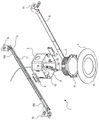
Fig. 1 shows an exploded view of an example recessed lighting system 1. The recessed lighting system 1 may comprise a junction box 2, a unitary casting 3, a rim 4, a set of hanger bars 5 and a set of hanger holders 6. In some embodiments, the unified casting 3 may contain the light source modules and drivers in a single compact unit. As will be described in further detail below, the recessed lighting system 1 provides a relatively compact and economical design that allows the light source module 3 to be moved and adjusted while complying with various building and safety codes/regulations. Each of the elements of the recessed lighting system 1 will be explained below by way of example.
The junction box 2 is a structure that separates (e.g., insulates) the internal components of the recessed lighting system 1 containing the electric wires/cables from the items inside the ceiling or low space in which the junction box 2 has been installed. In one embodiment, the junction box 2 may be a single or double junction box with a fire rating of up to two hours, as described in the National Electrical Code (NEC) and the Underwriters Laboratories (UL). The junction box 2 may receive the electrical wires 9A from an electrical system (e.g., 120VAC or 277VAC) within the building or structure in which the recessed lighting system 1 is installed. Wires 9A from the structure may be connected to corresponding wires 9B of the unified casting 3.
Although fig. 1 shows a standard "2 x2" junction box, the junction box 2 may be implemented with an external housing, such as described in co-pending U.S. patent publication No. 2016/0312987, the contents of which are incorporated herein by reference in their entirety.
The casting 3 is a shell and/or enclosure that further prevents heat from the light source module and driver from being exposed to items (e.g., insulation) inside the ceiling or low space in which the recessed lighting system 1 has been installed. Example light source modules and drivers that may be housed in the casting 3 used in the system 1 are described in more detail in co-pending U.S. patent publication No. 2015/0009676, the contents of which are incorporated herein by reference in their entirety.
In one embodiment, wires 9A received by the junction box 2 from the electrical system of the building or structure may be coupled to wires 9B of the casting 3. As shown, the wires 9A and 9B are connected together using interlocking connectors (along with the casting 3) that may be contained within the cassette 2. However, in other embodiments, the wires 9A may be coupled to the wires 9B through the use of an electrical cover or other means, and may remain outside the cassette 2 (while the casting 3 remains inside). The wires 9B of the casting 3 may terminate in a connection with a drive 8 mounted within the casting 3. When the wires 9A and 9B are connected, power may be transferred from the power system of the building or structure to the driver to enable the driver to power the light source module.
In one embodiment, the recessed lighting system 1 may comprise a bezel 4. The primary purpose of the edge strip 4 is to cover the exposed edge of the ceiling or wall in which the hole in which the recessed lighting system 1 resides, while still allowing light from the light source module 3 to be emitted into the room through the aperture 15. In doing so, the edge strip 4 helps the recessed lighting system 1 to appear seamlessly integrated into a ceiling or wall. In one embodiment, the edge strip 4 will be attached to the casting 3, while in other embodiments the edge strip 4 will be attached to the junction box 2. The edge strips 4 may be coupled to the casting 3 and/or the junction box 2 using any connection mechanism including resin, clips, screws, bolts, or clamps. In one embodiment, the edge strips 4 may contain grooves and/or slots to couple to corresponding grooves and/or slots of the casting 3 and/or the junction box 2 using a twist-lock friction connection without the use of a separate tool or other device.
In one embodiment, the recessed lighting system 1 may comprise a set of hanger bars 5 as shown in fig. 1. The hanger bar 5 may be a rigid elongate member that is connected between adjacent joists and/or cross beams in a wall or ceiling of the structure (see fig. 2). In one embodiment, each of the hanger bars 5 may be telescopic such that each hanger bar 5 may be extended or retracted to meet the gap between the joists and/or the cross beam. In this embodiment, each hanger bar 5 may include an inner bar element 16A and an outer bar element 16B. The inner rod element 16A may be inserted and then retained within a railing structure 17 formed on the outer rod element 16B. In this configuration, the inner bar element 16A can slide relative to the outer bar element 16B to change the overall length of each hanger bar 5. In one embodiment, the railing structure 17 in the outer bar element 16B may be formed by a set of guides. The guides may be bent tabs of the outer bar element 16B or tabs coupled to the outer bar element 16B. In this way, the railing structure 17 forms a channel for the inner rod element 16A.
In one embodiment, each of the hanger bars 5 may contain a set of mounting blocks 19. The mounting blocks 19 may be used to couple the hanger bar 5 to joists and/or beams in a wall or ceiling of a structure. For example, as shown in fig. 1, the mounting block 19 may include holes for receiving screws and/or nails or other fasteners that enable the hanger bar 5 to be securely attached to the building structure. Although shown in fig. 1 and described above with respect to holes and screws, in other embodiments, other attachment mechanisms may be used in conjunction with mounting block 19, including resins, clips, or clamps, to attach rod 5 to a building structure. In one embodiment, the mounting block 19 may be integrated in an indivisible structure along with the inner and outer rod elements 16A, 16B, while in other embodiments, as shown in fig. 1, the mounting block 19 may be coupled to the inner and outer rod elements 16A, 16B using one or more attachment mechanisms (e.g., screws, bolts, resin, clips, or clamps). Using the telescoping and mounting features described above, the recessed lighting system 1 can be mounted in almost all 2"X2" to 2"X16" wood joist configurations, metal stud configurations, and t-bar ceiling configurations.
In one embodiment, the recessed lighting system 1 may include a set of hanger holders 6. The hanger holders 6 may be configured to slide or otherwise move along the corresponding hanger bar 5. In one embodiment, the hanger holder 6 may include an attachment mechanism 21 for coupling with the junction box 2. The attachment mechanism 21 may be any mechanism that allows the junction box 2 to be removably connected to the hanger bar 5. For example, as shown in fig. 1, the attachment mechanism 21 may be a hole for receiving a screw or bolt therein. However, in other embodiments, the attachment mechanism 21 may include a resin, clip, and/or clamp that allows the hanger holder 6 to be coupled to the junction box 2. By being coupled to the hanger holder 6, the junction box 2 together with the light source module and the driver therein can be moved to a desired position across the hanger bar 5, as shown in fig. 2. Thus, during installation of the recessed lighting system 1, by attaching the mounting blocks 19 to the cross beams, the hanger bar 5 may be installed within the gap between the cross beams within the structure, and then the junction box 2, with the light source modules 7 and drivers 8 therein, may be moved by the installer to a desired position along the hanger bar 5 and within the gap.
According to certain aspects, the hanger holder 6 described above allows the terminal box 2 to move in a direction parallel to the longitudinal axis of the hanger bar 5. Thus, the junction box 2 can be moved to a preferred position between a set of joists or beams in the structure and then locked into place using the mechanism 21. By being configured such that the junction box 2, with the light source modules and drivers therein, is coupled to a unified set of movable elements that help position the combined structure, the recessed lighting system 1 eliminates the increased volume and size of conventional recessed lighting systems. This compact design provides a affordable design by cutting down the cost of raw materials and other components, and reduces shipping costs by reducing volume.
While the hanger bar 5 and hanger holder 6 described above in connection with the lighting system 1 provide many advantages over conventional recessed lighting systems, the applicant has recognized that there are still certain opportunities for improvement.
For example, fig. 3 is a front view of an exemplary hanger bar assembly 100 of a hanger bar 5 and a hanger holder 6, such as those components shown in fig. 1 and 2. As described above and as shown in fig. 3, hanger bar 5 and hanger holder 6 are fabricated in such a way that one of the rods 16B slides telescopically over the other rod 16A to adjust various joist spacings. The holder 6 is typically made to cover the larger of the two (16B) to allow lateral movement of the junction box (not shown). When the joist spacing is large (e.g., greater than 16 inches), any gap between the slides 16A, 16B can create vertical backlash and droop in the junction box. Also, if the junction box has to be mounted close to the joist, and the holder 6 is thus only located on one of the sheets (e.g. 16A) due to the telescopic extension between the sheets 16A and 16B, there will be a large gap between the hanger bar 5 and the holder 6 at the sheet 16A, which will lead to instability.
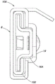
Fig. 4A is a front view of a hanger bar assembly 200 according to some inventive embodiments of the present disclosure. As shown, the hanger bar assembly 200 may include a first hanger bar 66A, a second hanger bar 66B and a hanger bar holder 56. The first hanger bar 66A can be mechanically coupled to the second hanger bar 66B such that the first hanger bar 66A slides relative to the second hanger bar 66B in a telescoping manner along the first axis. The hanger bar holder 56 may be for holding at least one of the first hanger bar 66A or the second hanger bar 66B such that the first hanger bar 66A and/or the second hanger bar 66B slides telescopically relative to the bar hanger holder 56 along the first axis. The hanger bar holder 56 may also be used to couple the hanger bar assembly 200 to various housings of a lighting system (not shown) for assembly and installation, including but not limited to a junction box, a tank housing, a light fixture frame, or a bracket.
The first hanger bar 66A and the second hanger bar 66B can each be a rail-like structure that are coupled together such that the first hanger bar 66A and the second hanger bar 66B can slide relative to each other along a first axis. The first hanger bar 66A and the second hanger bar 66B can thus be extended or retracted to accommodate various spacings between support structures (e.g., joists), which are used for attachment during installation of a lighting system coupled to the hanger bar assembly 200. As shown in fig. 4A, the first hanger bar 66A may have a cross-sectional shape of substantially uniform thickness. The uniform thickness may ease manufacturing by allowing the first hanger bar 66A to be formed from a thin sheet of material. For example, the first hanger bar 66A may be manufactured by bending a metal sheet such that a desired rail-like structure is formed. In some embodiments, the first hanger bar 66A and the second hanger bar 66B may each have a thickness that is substantially equal to each other.
As shown in fig. 4B, the cross-sectional shape of the first hanger bar 66A may be based in part on a curve 74A having a first end point 76A and a second end point 77A. A first tangent line corresponding to the first end point 76A quantifies the orientation of the surface of the first hanger bar 66A at the first end point 76A. Similarly, a second tangent vector corresponding to second end point 77A defines the orientation of the surface of first hanger bar 66A at second end point 77A. The relative angle between the first tangent vector and the second vector may vary between about 0 degrees (e.g., the first tangent vector and the second tangent vector are parallel) to about 90 degrees (e.g., the first tangent vector and the second tangent vector are perpendicular).
The cross-sectional shape of the first hanger bar 66A may include an internal passageway 68A designed to receive an interlocking structure 75B of the second hanger bar 66B, which will be discussed in greater detail below. The second hanger bar 66B can similarly include an internal passage 68B to receive the interlocking structure 75A of the first hanger bar 66A. Mechanical stops 70A and 72A may also be disposed at opposite ends of the first hanger bar 66A along the first axis. The second hanger bar 66B can similarly include mechanical stops 70B and 72B disposed at opposite ends of the second hanger bar 66B along the first axis. The mechanical stops 70A, 72A, 70B, and 72B may provide a mechanical barrier to prevent the first hanger bar 66A and the second hanger bar 66B from separating, particularly when the first hanger bar 66A is fully extended from the second hanger bar 66B. For example, mechanical stop 70A may physically contact mechanical stop 72B. Similarly, mechanical stop 70B may physically contact 72A.
The first hanger bar 66A may include an interlocking structure 75A for interlocking the first hanger bar 66A with the second hanger 66B. The interlocking structure 75A reduces unwanted lateral movement (e.g., lateral backlash or hill drop) between the first hanger bar 66A and the second hanger bar 66B, which can improve structural stability of the hanger bar assembly 200, particularly when the first hanger bar 66A extends fully from the second hanger bar 66B such that a small portion of the first hanger bar 66A overlaps the second hanger bar 66B. As an exemplary reference coordinate system, the first axis may correspond to a horizontal axis of motion; thus, lateral movement between hanger bars 66A and 66B may be reduced along a second axis (e.g., horizontal lateral movement) perpendicular to the first axis and a third axis (e.g., vertical lateral movement) perpendicular to both the first and second axes. The reduction of unwanted lateral movement can be accomplished in part by an interlocking structure 75A having structural features that physically contact multiple locations along the second hanger bar 66B such that movement between the first hanger bar 66A and the second hanger bar 66B along the second axis and the third axis is limited. The interlocking structure 75A can be integrated into the hanger bar 66A such that the first hanger bar 66A is a single continuous structure. The second hanger bar 66B can similarly include an interlocking structure 75B, which can also be used to interlock the second hanger bar 66B with the first hanger bar 66A.
For example, fig. 4A shows that the interlock structure 75A can have a C-shaped cross-section that is primarily disposed within the interior passage 68B of the second hanger bar 66B. The interlock structure 75A includes several areas that physically contact the inner wall of the second hanger bar 66B within the interior passage 68B, thereby limiting unwanted lateral movement along the second and third axes. The second hanger bar 66B can similarly include an interlocking structure 75B, which can also have a C-shaped cross-section disposed primarily within the interior passage 68A of the first hanger bar 66A. It should be appreciated that at least one of the interlocking structures 75A or 75B can be used to interlock the first hanger bar 66A and the second hanger bar 66B. However, the use of two interlocking structures 75A and 75B may also improve the structural stability of the hanger bar assembly 200 by increasing the number of areas where the first hanger bar 66A physically contacts the second hanger bar 66B.
The first hanger bar 66A physically contacts the second hanger bar 66B through the respective interlocking structures 75A and 75B and/or other areas of the first hanger bar 66A that can interface with the second hanger bar 66B, respectively, without having to provide mechanical restraint to lateral movement. In some embodiments, the first hanger bar 66A and/or the second hanger bar 66B may be shaped and sized to generate a frictional force between the first hanger bar 66A and the second hanger bar 66B along the respective regions where physical contact occurs. The frictional force may be partially used to maintain the relative position between the first hanger bar 66A and the second hanger bar 66B. For example, a user may apply a force to adjust the relative position of the first hanger bar 66A to the second hanger bar 66B during installation. The friction force can be tailored to be sufficiently large so that the relative position between the first hanger bar 66A and the second hanger bar 66B is maintained once the user no longer applies a force to the hanger bar assembly 200.
In some embodiments, the first hanger bar 66A and the second hanger bar 66B can be substantially the same or the same in shape and/or size. For such cases, the assembly of the first hanger bar 66A and the second hanger bar 66B results in a cross-sectional geometry that may include at least one plane of symmetry and/or an anti-plane of symmetry. For example, fig. 4C shows that the first hanger bar 66A and the second hanger bar 66B when assembled may include at least two anti-symmetric planes, e.g., plane 202A and plane 202B.
Various metals and plastics may be used to form the first hanger bar 66A and the second hanger bar 66B, including but not limited to aluminum, carbon steel, stainless steel, polyethylene, or any other material known to those skilled in the art. Depending on the materials used to form the first hanger bar 66A and the second hanger bar 66B, the first hanger bar 66A and the second hanger bar 66B may be manufactured using various manufacturing techniques, including but not limited to bending a sheet to form a desired cross-sectional shape, or extruding the material through a die, wherein the die defines the desired cross-sectional shape.
The hanger bar assembly 200 may also include a hanger bar holder 56 for holding at least one of the first hanger bar 66A or the second hanger bar 66B. The hanger bar holder 56 may be used to guide the first hanger bar 66A and/or the second hanger bar 66B in a telescoping manner while providing mechanical attachment to a housing (e.g., junction box, tank housing) of the lighting system as described above. The hanger bar holder 56 may include a frame 58 that forms a passage 82 that partially surrounds the first hanger bar 66A and/or the second hanger bar 66B. In some embodiments, the frame 58 may include an opening 84 that interfaces with the passageway 82. The opening 84 may span the length of the hanger bar holder 56 parallel to the first axis. The inclusion of the opening 84 improves manufacturability because a completely closed via 82 is more difficult to manufacture. Additionally, the inclusion of intermediate structural features (e.g., walls 86 in hanger bar holder 56 as shown in fig. 4D) would require an additional more complex manufacturing process, which increases the time and cost of manufacturing the hanger bar holder 56.
The frame 58 may have a cross-sectional shape of substantially uniform thickness. Similar to the first hanger bar 66A and the second hanger bar 66B, having a uniform thickness cross section may ease manufacturing by allowing the hanger bar holder 56 to be formed from a sheet. In some embodiments, the thickness of the frame 58 may be substantially equal to the respective thicknesses of the first hanger bar 66A and the second hanger bar 66B, thus allowing the hanger bar holder 56, the first hanger bar 66A and the second hanger bar 66B to all be fabricated from the same sheet of material.
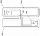
In some implementations, the hanger bar holder 56 may be subdivided into sections according to its function in the bar hanger assembly 200. For example, fig. 4D shows that the hanger bar holder 56 may be subdivided into a first section 80A, a second section 80B, and a third section 80C. The first section 80A may be used to guide at least the first hanger bar 66A along a first axis by the hanger bar holder 56. The first section 80A may also serve to constrain lateral movement of the first hanger bar 66A relative to the hanger bar holder 56 along the second and third axes as defined above. The second section 80B may be similar to the first section 80A in that the second section 80B may be used to guide the second hanger bar 66B along the first axis through the hanger bar holder 56 and constrain lateral movement of the second hanger bar 66B. The third section 80C may be used to facilitate coupling of the hanger bar holder 56 to a housing of a lighting system, as will be discussed below.
In some embodiments, the first section 80A of the frame 58 forms a first track that only guides the first hanger bar 66A, and the second section 80B of the frame 58 forms a second track that only guides the second hanger bar 66B. For example, fig. 4C shows only the first section 80A physically contacting the first hanger bar 66A. Similarly, only the second section 80B physically contacts the second hanger bar 66B. As shown, the intermediate wall 86 may overlap between the first section 80A and the second section 80B; however, a first side of intermediate wall 86 contacts only first hanger bar 66A and a second side of intermediate wall 86 contacts only second hanger bar 66B.
In some embodiments, the hanger bar holder 56 may constrain lateral movement of the first hanger bar 66A and the second hanger 66B independently of each other, such that the hanger bar holder 56 may hold only one of the first hanger bar 66A or the second hanger 66B without affecting the constraints imposed to reduce lateral movement. For example, the hanger bar holder 56 may be disposed adjacent to the first support structure. To reach adjacent the second support structure, the first hanger bar 66A and the second hanger bar 66B may need to be fully extended such that only one of the first hanger bar 66A or the second hanger bar 66B is retained within the hanger bar holder 56. As described above, a large gap is typically formed between the conventional hanger bar holder and the conventional hanger bar, resulting in instability of the hanger bar assembly. By independently constraining the lateral motion of the first hanger bar 66A and the second hanger bar 66B, the hanger bar holder 56 can substantially reduce such instability.
The hanger bar holder 56 may have a length parallel to the first axis that covers a portion of the first hanger bar 66A and/or the second hanger bar 66B. In addition, the hanger bar holder 56 may include different portions each having a different length. For example, fig. 5C shows a perspective view of the hanger bar holder 56. As shown, the portion 88A corresponding to the first section 80A may have a shorter length than the portion 88B corresponding to the second section 80B across the length of the hanger bar holder 56. The inclusion of variable length portions in the hanger bar holder 56 may allow for multiple support structures to be formed along the length of the hanger bar holder 56. For example, portion 88A may be used to form contact and guide first section 80A of first hanger bar 66A, while portion 88B allows intermediate wall 86 to be formed to contact and guide both first hanger bar 66A and second hanger bar 66B. In addition, the use of the variable length portion may also reduce the amount of material used to manufacture the hanger bar holders 56.
The hanger bar holder 56 may be a single continuous structure, which further eases manufacturing. It should be appreciated that the hanger bar holder 56 in the present disclosure does not require additional structural features for assembly and/or adjustment of the hanger bar assembly 200 as is present in conventional hanger bar holder structures. For example, the hanger bar holder 56 need not be significantly foldable and/or bendable. In another example, the hanger bar holder 56 need not include a hinge. In yet another example, the hanger bar holder 56 need not include snaps and/or snap locks to enclose the first hanger bar 66A and/or the second hanger bar 66B.
As described above, the third section 80C may be used to facilitate coupling of the hanger bar holder 56 to the housing of the lighting system. In some implementations, the hanger bar holders 56 may be integrated into the housing of the lighting system (e.g., the hanger bar holders are integrated onto the sheet metal frame of the light fixture housing). The third section 80C may include at least one coupling mechanism to mechanically couple the hanger bar holder 56 to a housing, which again may include, but is not limited to, a junction box, a tank housing, a bracket, or a light fixture frame. Various types of coupling mechanisms may be used, including but not limited to screw fasteners or rivets. For example, fig. 5C shows the hanger bar holder 56 having two coupling mechanisms 90, in this case screw holes for receiving corresponding screw fasteners.
The coupling mechanism may also include a stud (i.e., a protruding rod). The stud may be inserted into a slot on a housing of the lighting system such that the stud is adjustable along the slot. The slot may be oriented along at least one of the second axis or the third axis. For example, if the first axis is a horizontal axis, a slot oriented along a third axis would allow the hanger bar assembly 200 to be adjustable along a vertical axis. Once inserted, the stud may be secured from the opposite side by another fastener (e.g., a dished screw) to secure the hanger bar assembly 200 to a desired position along the slot on the housing.
In some embodiments, the third section 80C may protrude away from the first and second sections 80A, 80B to form a gap 92 between the frame 58 of the hanger bar holder 56 and the second hanger bar 66B. In some embodiments, the gap 92 may actually be formed between the hanger bar holder 56 and the first hanger bar 66A. Gap 92 may provide a space for accommodating at least a portion of coupling mechanism 90. For example, the gap 90 may contain the head of a screw fastener that is coupled to the housing of the lighting system before the first hanger bar 66A and the second hanger bar 66B are inserted into the passageway 82 of the hanger bar holder 56.
Various metals and plastics may be used to form the hanger bar holder 56, including but not limited to aluminum, carbon steel, stainless steel, polyethylene, or any other material known to those skilled in the art. Depending on the material used to form the hanger bar holder 56, various manufacturing techniques may be used for manufacturing, including but not limited to bending a sheet to form the desired cross-sectional shape of the frame 58, or extruding the material through a die, where the die defines the desired cross-sectional shape of the frame 58.
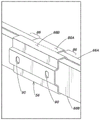
Fig. 5A shows a perspective view of the hanger bar assembly 200 with the first hanger bar 66A and the second hanger 66B held by the hanger bar holder 56. As shown, the hanger bar holder 56 may independently hold a first hanger bar 66A and a second hanger bar 66B. Additionally, the first hanger bar 66A and the second hanger bar 66B can be interlocked using interlocking structures 75A and 75B (not shown). As shown, the first hanger bar 66A and the second hanger bar 66B may extend to traverse a large spacing between support structures. Structural stability is preserved due in part to the interlocking structures 75A and 75B, which prevents backlash and drooping from gaps between the first hanger bar 66A and the second hanger bar 66B.
Fig. 5B shows a perspective view of the hanger bar assembly 200 with the hanger bar holders 56 (which may be attached to the housing of the lighting system) disposed proximate to the support structure (not shown) such that only the first hanger bar 66A is held by the hanger bar holders 56 while the second hanger bar 66B extends fully to cover the spacing between adjacent support structures. As described above, the first section 80A of the hanger bar holder 56 may constrain unwanted lateral movement between the first hanger bar 66A and the hanger bar holder 56. In this way, the hanger bar holder 56 may stably support the first hanger bar 66A during installation and/or adjustment of the hanger bar assembly 200.
It will be appreciated that the first hanger bar 66A, the second hanger bar 66B and the hanger bar holder 56 may include many of the same features described above in connection with the bar 5 and the holder 6, such as the fastening mechanism 21 and the mounting block 19. However, a repeated description of these components is omitted herein for clarity of the embodiments of the present invention.
Conclusion
While various inventive embodiments have been described and illustrated herein, those of ordinary skill in the art will readily envision a variety of other means and/or structures for performing the function and/or obtaining the results and/or one or more of the advantages described herein, and each of such variations and/or modifications is deemed to be within the scope of the inventive embodiments described herein. More generally, those skilled in the art will readily appreciate that all parameters and configurations described herein are intended to be exemplary inventive features and that other equivalents of the specific inventive embodiments described herein may be implemented. It is, therefore, to be understood that the foregoing embodiments are presented by way of example and that, within the scope of the appended claims and equivalents thereto, embodiments of the invention may be practiced otherwise than as specifically described and claimed. Inventive embodiments of the present disclosure are directed to each individual feature, system, article, and/or method described herein. In addition, any combination of two or more such features, systems, articles, and/or methods, if such features, systems, articles, and/or methods are not mutually inconsistent, is included within the scope of the present disclosure.
Moreover, various inventive concepts may be embodied as one or more methods, examples of which have been provided. The actions performed as part of the method may be ordered in any suitable way. Thus, embodiments may be constructed in which acts are performed in an order different than illustrated, which may include performing some acts concurrently, even though shown as sequential acts in illustrative embodiments.
All publications, patent applications, patents, and other references mentioned herein are incorporated by reference in their entirety.
It should be understood that all definitions, as defined and used herein, override dictionary definitions, definitions in documents incorporated by reference, and/or ordinary meanings of defined terms.
The indefinite articles "a" and "an", as used herein in the specification and in the claims, are to be understood as meaning "at least one" unless expressly indicated to the contrary.
As used herein in the specification and claims, the phrase "and/or" should be understood to mean "either or both" of the elements so combined, i.e., the elements are present in combination in some cases and separately in other cases. Various elements listed with "and/or" should be interpreted in the same manner, i.e., "one or more" of the elements so combined. In addition to the elements specifically identified by the "and/or" clause, other elements may optionally be present, whether related or unrelated to those elements specifically identified. Thus, as a non-limiting example, when used in conjunction with open-ended language such as "including," references to "a and/or B" may refer in one embodiment to a alone (optionally including elements other than B); in another embodiment, only B (optionally including elements other than a); in yet another embodiment, refer to both a and B (optionally including other elements), and so forth.
As used herein in the specification and claims, "or" should be understood to have the same meaning as "and/or" as defined above. For example, when separating items in a list, "or" and/or "should be interpreted as inclusive, i.e., including at least one of the plurality or list elements, but also including more than one of the plurality or list elements, and optionally additional unlisted items. Only terms explicitly indicated to the contrary, such as "only one of … …" or "exactly one of … …" or "consisting of … …" when used in the claims, will be referred to as including a plurality of elements or exactly one element of a list of elements. In general, the term "or" as used herein, when preceded by an exclusive term such as "either," "one of … …," "only one of … …," or "exactly one of … …," should only be construed as indicating an exclusive alternative (i.e., "one or the other but not both"). "consisting essentially of … …" when used in the claims shall have its ordinary meaning as used in the patent law field.
As used herein in the specification and claims, the phrase "at least one," when referring to a list of one or more elements, should be understood to mean at least one element selected from any one or more of the elements in the list of elements, but not necessarily including at least one of each element specifically listed in the list of elements, and not excluding any combination of elements in the list of elements. This definition also allows elements other than the element to which the specifically identified phrase "at least one" refers within the list of elements to optionally be present, whether or not related to those elements specifically identified. Thus, as a non-limiting example, "at least one of a and B" (or, equivalently, "at least one of a or B," or, equivalently "at least one of a and/or B") can refer in one embodiment to at least one, optionally including more than one, a, absent B (and optionally including elements other than B); in another embodiment, refers to at least one, optionally including more than one, B, with no a present (and optionally including elements other than a); in yet another embodiment, at least one, optionally including more than one, a, and at least one, optionally including more than one, B (and optionally including other elements), and the like.
In the claims, as well as in the specification above, all conjunctions such as "comprising," including, "" carrying, "" having, "" containing, "" involving, "" containing, "" consisting of … … and the like are to be understood as being open-ended, i.e., to mean including but not limited to. Only the transition phrases "consisting of …" and "consisting essentially of …" should be closed or semi-closed transition phrases, respectively.
Claims (7)
1. A hanger bar assembly (200), comprising:
a first hanger bar (66A);
a second hanger bar (66B) mechanically coupled to the first hanger bar such that the second hanger bar slides relative to the first hanger bar in a telescoping manner along a first axis; and
a hanger bar holder (56) to hold at least one of the first hanger bar or the second hanger bar, the hanger bar holder including a frame (58) comprising:
a first section (80A) to guide at least the first hanger bar through the hanger bar holder along the first axis and constrain lateral movement of the first hanger bar relative to the hanger bar holder along a second axis perpendicular to the first axis and a third axis perpendicular to the first and second axes; and
a second section (80B) to guide at least the second hanger bar through the hanger bar holder and constrain lateral movement of the second hanger bar relative to the hanger bar holder along the second and third axes, wherein:
the hanger bar holder is formed as a single continuous part;
said hanger bar holder is not significantly foldable or bendable;
the hanger bar holder does not include a hinge;
the hanger bar holder does not include a hasp and/or a hasp catch; and is
The first hanger bar and the second hanger bar have substantially the same or identical shape and size such that the first hanger bar is interchangeable with the second hanger bar.
2. A hanger bar assembly (200), comprising:
a first hanger bar (66A);
a second hanger bar (66B) mechanically coupled to the first hanger bar such that the second hanger bar slides relative to the first hanger bar in a telescoping manner; and
a hanger bar holder (56) to hold at least one of the first hanger bar or the second hanger bar, the hanger bar holder physically contacting the at least one of the first hanger bar or the second hanger bar to prevent lateral movement of the at least one of the first hanger bar or the second hanger bar relative to the hanger bar holder,
wherein:
the first hanger bar and the second hanger bar are shaped and dimensioned to generate a force between at least a portion of the first hanger bar and at least a portion of the second hanger bar to maintain a relative position between the first hanger bar and the second hanger bar; and is
The first hanger bar and the second hanger bar form a composite member having a cross-sectional shape with at least two planes of anti-symmetry.
3. The hanger bar assembly of claim 2, wherein the force is a friction force.
4. The hanger bar assembly of claim 2, wherein the force maintains the relative position only when no external force for adjusting the relative position between the first hanger bar and the second hanger bar is applied to the hanger bar assembly.
5. The hanger bar assembly of claim 2, wherein the first hanger bar and the second hanger bar have substantially the same shape and size.
6. The hanger bar assembly of claim 2, wherein:
the hanger bar holder has a length along the first axis; and is
The hanger bar holder comprises a first portion for holding and guiding the first hanger bar and a second portion for holding and guiding the second hanger bar, the first and second portions being co-located along at least a portion of the length of the hanger bar holder.
7. The hanger bar assembly of claim 2, wherein the hanger bar holder constrains lateral movement of the first hanger bar independent of the second hanger bar and lateral movement of the second hanger bar independent of the first hanger bar.
Applications Claiming Priority (4)
| Application Number | Priority Date | Filing Date | Title |
|---|---|---|---|
| US201762591594P | 2017-11-28 | 2017-11-28 | |
| US62/591,594 | 2017-11-28 | ||
| PCT/US2018/062868 WO2019108667A1 (en) | 2017-11-28 | 2018-11-28 | Adjustable hanger bar assembly |
| CN201880088009.9A CN111670322B (en) | 2017-11-28 | 2018-11-28 | Adjustable hanger rod assembly |
Related Parent Applications (1)
| Application Number | Title | Priority Date | Filing Date |
|---|---|---|---|
| CN201880088009.9A Division CN111670322B (en) | 2017-11-28 | 2018-11-28 | Adjustable hanger rod assembly |
Publications (1)
| Publication Number | Publication Date |
|---|---|
| CN114719211A true CN114719211A (en) | 2022-07-08 |
Family
ID=66664220
Family Applications (2)
| Application Number | Title | Priority Date | Filing Date |
|---|---|---|---|
| CN201880088009.9A Active CN111670322B (en) | 2017-11-28 | 2018-11-28 | Adjustable hanger rod assembly |
| CN202210354716.6A Pending CN114719211A (en) | 2017-11-28 | 2018-11-28 | Adjustable hanger rod assembly |
Family Applications Before (1)
| Application Number | Title | Priority Date | Filing Date |
|---|---|---|---|
| CN201880088009.9A Active CN111670322B (en) | 2017-11-28 | 2018-11-28 | Adjustable hanger rod assembly |
Country Status (4)
| Country | Link |
|---|---|
| US (2) | US10975570B2 (en) |
| CN (2) | CN111670322B (en) |
| CA (1) | CA3083359A1 (en) |
| WO (1) | WO2019108667A1 (en) |
Families Citing this family (29)
| Publication number | Priority date | Publication date | Assignee | Title |
|---|---|---|---|---|
| US11255497B2 (en) | 2013-07-05 | 2022-02-22 | DMF, Inc. | Adjustable electrical apparatus with hangar bars for installation in a building |
| US9964266B2 (en) | 2013-07-05 | 2018-05-08 | DMF, Inc. | Unified driver and light source assembly for recessed lighting |
| US10563850B2 (en) | 2015-04-22 | 2020-02-18 | DMF, Inc. | Outer casing for a recessed lighting fixture |
| US10139059B2 (en) | 2014-02-18 | 2018-11-27 | DMF, Inc. | Adjustable compact recessed lighting assembly with hangar bars |
| US11435064B1 (en) | 2013-07-05 | 2022-09-06 | DMF, Inc. | Integrated lighting module |
| US10753558B2 (en) | 2013-07-05 | 2020-08-25 | DMF, Inc. | Lighting apparatus and methods |
| US10551044B2 (en) | 2015-11-16 | 2020-02-04 | DMF, Inc. | Recessed lighting assembly |
| US11060705B1 (en) | 2013-07-05 | 2021-07-13 | DMF, Inc. | Compact lighting apparatus with AC to DC converter and integrated electrical connector |
| CA2931588C (en) | 2015-05-29 | 2021-09-14 | DMF, Inc. | Lighting module for recessed lighting systems |
| USD851046S1 (en) | 2015-10-05 | 2019-06-11 | DMF, Inc. | Electrical Junction Box |
| US10488000B2 (en) | 2017-06-22 | 2019-11-26 | DMF, Inc. | Thin profile surface mount lighting apparatus |
| WO2018237294A2 (en) | 2017-06-22 | 2018-12-27 | DMF, Inc. | Thin profile surface mount lighting apparatus |
| US11067231B2 (en) | 2017-08-28 | 2021-07-20 | DMF, Inc. | Alternate junction box and arrangement for lighting apparatus |
| CA3087187A1 (en) | 2017-12-27 | 2019-07-04 | DMF, Inc. | Methods and apparatus for adjusting a luminaire |
| USD877957S1 (en) * | 2018-05-24 | 2020-03-10 | DMF Inc. | Light fixture |
| CA3103255A1 (en) | 2018-06-11 | 2019-12-19 | DMF, Inc. | A polymer housing for a recessed lighting system and methods for using same |
| WO2020072592A1 (en) | 2018-10-02 | 2020-04-09 | Ver Lighting Llc | A bar hanger assembly with mating telescoping bars |
| USD1012864S1 (en) | 2019-01-29 | 2024-01-30 | DMF, Inc. | Portion of a plastic deep electrical junction box |
| USD966877S1 (en) * | 2019-03-14 | 2022-10-18 | Ver Lighting Llc | Hanger bar for a hanger bar assembly |
| USD950824S1 (en) | 2019-08-02 | 2022-05-03 | Brandon Cohen | Integrated lighting module |
| WO2021051101A1 (en) | 2019-09-12 | 2021-03-18 | DMF, Inc. | Miniature lighting module and lighting fixtures using same |
| USD990030S1 (en) | 2020-07-17 | 2023-06-20 | DMF, Inc. | Housing for a lighting system |
| CA3124976A1 (en) | 2020-07-17 | 2022-01-17 | DMF, Inc. | Polymer housing for a lighting system and methods for using same |
| US11585517B2 (en) | 2020-07-23 | 2023-02-21 | DMF, Inc. | Lighting module having field-replaceable optics, improved cooling, and tool-less mounting features |
| US11466849B2 (en) | 2020-10-12 | 2022-10-11 | Brandon Cohen | Integrated lighting module |
| US11739893B2 (en) | 2021-03-23 | 2023-08-29 | Amp Plus, Inc. | Light fixture |
| US11668458B2 (en) | 2021-06-30 | 2023-06-06 | Amp Plus, Inc. | Integrated lighting module |
| US11649954B2 (en) | 2021-04-30 | 2023-05-16 | Amp Plus, Inc. | Integrated lighting module and housing therefor |
| US11300259B1 (en) | 2021-06-30 | 2022-04-12 | Brandon Cohen | Downlight module with extendable lens |
Citations (5)
| Publication number | Priority date | Publication date | Assignee | Title |
|---|---|---|---|---|
| US6098945A (en) * | 1998-03-19 | 2000-08-08 | Hubbell Incorporated | Mounting bracket and supporting brace |
| CN2406574Y (en) * | 2000-01-15 | 2000-11-22 | 陈小禹 | Telescopic curtain rail |
| CN1309618A (en) * | 1999-05-21 | 2001-08-22 | 石川岛播磨重工业株式会社 | Spreader of container crane |
| CN101859057A (en) * | 2009-04-13 | 2010-10-13 | 昆山义丰板金科技有限公司 | Suspension bracket for projector |
| CN204120631U (en) * | 2014-11-18 | 2015-01-28 | 武汉大学 | A kind of scalable Convenient mosquito net |
Family Cites Families (661)
| Publication number | Priority date | Publication date | Assignee | Title |
|---|---|---|---|---|
| US1133535A (en) | 1914-08-11 | 1915-03-30 | Harvard Electric Company | Outlet-box hanger. |
| US1471340A (en) | 1921-09-15 | 1923-10-23 | Knight Julian Gordon | Outlet or junction box |
| US1856356A (en) | 1930-05-27 | 1932-05-03 | William H Owen | Adjustable outlet box header |
| US2038784A (en) | 1934-09-15 | 1936-04-28 | Dinshah P Ghadiali | Color wave projection apparatus |
| US2352913A (en) | 1938-03-07 | 1944-07-04 | Parker William Morrill | Insulated outlet receptacle and junction box and units |
| US2179161A (en) | 1938-03-24 | 1939-11-07 | Rambusch Decorating Company | Illuminating device |
| US2197737A (en) | 1939-05-24 | 1940-04-16 | Appleton Electric Co | Grounding device for connection boxes |
| US2528989A (en) | 1948-06-04 | 1950-11-07 | John G Ammells | Junction box |
| US2642246A (en) * | 1949-09-27 | 1953-06-16 | Int Projector Corp | Adjustable support stand |
| US2670919A (en) | 1950-03-29 | 1954-03-02 | Esoldi Vincent | Adjustable support for ceiling lighting fixtures |
| US2697535A (en) | 1951-06-25 | 1954-12-21 | Oscar J Olson | Outlet box |
| US2597595A (en) | 1951-07-27 | 1952-05-20 | Gen Electric | Recessed ceiling fixture having magnetically attachable and adjustable light source |
| US2758810A (en) | 1953-06-03 | 1956-08-14 | Raymond J Good | Outlet boxes and fixture studs |
| US2802933A (en) | 1955-05-31 | 1957-08-13 | Perfect Line Mfg Corp | Lighting fixture |
| US2998512A (en) | 1959-03-13 | 1961-08-29 | Special Products Company Of Te | Recessed lighting fixture |
| US3023920A (en) | 1960-01-14 | 1962-03-06 | Steel City Electric Co | Outlet boxes |
| US3057993A (en) | 1960-07-21 | 1962-10-09 | Litecraft Mfg Corp | Lighting fixture with pre-wired junction box |
| US3104087A (en) | 1961-03-21 | 1963-09-17 | Electrical Fittings Corp | Means for supporting electrical fixtures |
| US3214126A (en) * | 1962-11-02 | 1965-10-26 | Bowers Mfg Company Inc | Outlet box support |
| US3422261A (en) | 1966-11-07 | 1969-01-14 | Thomas Industries Inc | Lighting fixture |
| US3460299A (en) | 1967-09-27 | 1969-08-12 | Bertram A Wilson | Luminous sound absorbing ceiling |
| US3650046A (en) | 1969-11-10 | 1972-03-21 | Meredith Corp | Educational device with self-checking arrangement |
| US3675807A (en) | 1970-05-11 | 1972-07-11 | Markstone Mfg Co | Recessed lighting fixture housing |
| US3700885A (en) | 1970-10-01 | 1972-10-24 | Air King Corp | Architectural light and adjustment means therefor |
| US3711053A (en) * | 1970-11-18 | 1973-01-16 | Dracon Ind | Telescoping wall mounting bracket for electrical racks |
| US3773968A (en) | 1972-04-12 | 1973-11-20 | Indian Head Inc | Electrical junction and switch boxes |
| US3913773A (en) | 1972-08-28 | 1975-10-21 | Indian Head Inc | Ceiling box for electrical outlets |
| US3812342A (en) | 1973-01-22 | 1974-05-21 | Esquire Inc | Lighting fixture lens |
| US3836766A (en) | 1973-02-01 | 1974-09-17 | S Auerbach | Light fixture |
| US3874035A (en) | 1974-06-26 | 1975-04-01 | Fastway Fasteners | Hanger clip |
| US4088827A (en) | 1975-01-20 | 1978-05-09 | Raceway Components, Inc. | Insert mount and device |
| USD245905S (en) | 1976-04-08 | 1977-09-27 | Taylor Industries, Inc. | Enclosure for electrical components or the like |
| US4154219A (en) | 1977-03-11 | 1979-05-15 | E-Systems, Inc. | Prismatic solar reflector apparatus and method of solar tracking |
| US4176758A (en) | 1977-06-03 | 1979-12-04 | Earl Glick | Universal electrical outlet box and method of installing |
| US4154218A (en) | 1977-12-07 | 1979-05-15 | Hulet Alvin D | Adjustable cooking surface |
| US4280169A (en) | 1979-07-25 | 1981-07-21 | Allen Carl J | Fluorescent lamp end cap |
| US4399497A (en) | 1980-12-16 | 1983-08-16 | Prescolite | Retainer for a lamp |
| US4450512A (en) | 1982-09-13 | 1984-05-22 | Mcgraw-Edison Company | Arrangement for mounting a thermal protective device in a recess mounted lighting fixture |
| US4520435A (en) | 1983-11-04 | 1985-05-28 | General Electric Company | Orientable refractor mounting |
| US4539629A (en) | 1984-02-10 | 1985-09-03 | Gty Industries | Spa light |
| US4667840A (en) | 1984-11-16 | 1987-05-26 | Lindsey Travis C | Fire-resistant electrical junction boxes and method of manufacture |
| US4601145A (en) | 1985-08-05 | 1986-07-22 | Roger Wilcox | Adjustable room partition |
| US4754377A (en) | 1986-02-21 | 1988-06-28 | Thomas Industries, Inc. | Thermally protected recessed lighting fixture |
| US4723747A (en) | 1986-10-24 | 1988-02-09 | Capri Lighting | Bar hangers for recessed lighting fixtures |
| US4729080A (en) | 1987-01-29 | 1988-03-01 | Juno Lighting, Inc. | Sloped ceiling recessed light fixture |
| US4770311A (en) | 1987-12-14 | 1988-09-13 | Wang Paul W | Outlet box |
| US4919292A (en) | 1988-01-11 | 1990-04-24 | Hsu Tsui Chen | Reinforced junction box assembly |
| US4910651A (en) | 1988-08-23 | 1990-03-20 | Thomas Industries Inc. | High wattage insulated ceiling lighting fixture |
| CA1296077C (en) | 1988-11-25 | 1992-02-18 | Trudy M. Hudson | Light fixture connector |
| US4930054A (en) | 1988-12-09 | 1990-05-29 | Nutone, Inc. | Dual cone recessed lighting fixture |
| US4880128A (en) | 1988-12-16 | 1989-11-14 | Hubbell Incorporated | Fixture box for ceiling fan support |
| JPH02113002U (en) | 1989-02-25 | 1990-09-10 | ||
| US5044582A (en) * | 1990-03-07 | 1991-09-03 | Trade Source International | Ceiling fan support |
| DE69209073T2 (en) | 1991-06-20 | 1996-08-29 | Caradon Mk Electric Ltd | CONNECTION BOX |
| DE9109828U1 (en) | 1991-08-08 | 1992-02-13 | Klingenthaler Harmonika Gmbh, O-9650 Klingenthal, De | |
| US5239132A (en) | 1991-08-23 | 1993-08-24 | Bartow Donald W | Strap for retaining junction box |
| US5266050A (en) | 1991-12-04 | 1993-11-30 | Arlington Industries, Inc. | Quick-connect fitting for electrical junction box |
| US5222800A (en) | 1992-01-28 | 1993-06-29 | The Genlyte Group Incorporated | Recessed lighting fixture |
| US5216203A (en) | 1992-03-05 | 1993-06-01 | Gower Edward E | Electrical junction box |
| US5613338A (en) | 1992-05-11 | 1997-03-25 | Esposito; Chris | Construction arrangement including multiple panels provided with interlocking edges and related methods |
| US5250269A (en) | 1992-05-21 | 1993-10-05 | Minnesota Mining And Manufacturing Company | Catalytic converter having a metallic monolith mounted by a heat-insulating mat of refractory ceramic fibers |
| US5303894A (en) | 1992-06-02 | 1994-04-19 | Eclipse Manufacturing, Inc. | Electrical fixture hanger |
| US5382752A (en) | 1992-11-16 | 1995-01-17 | Thermocraft Industries, Inc. | Electrical junction box and method of making |
| US5420376A (en) | 1993-08-06 | 1995-05-30 | The Lamson & Sessions Co. | Plastic electrical box for installation in poured concrete |
| CN2182475Y (en) | 1993-11-30 | 1994-11-09 | 谢发庆 | Junction box structure for wall switch or socket |
| US5444606A (en) | 1994-02-10 | 1995-08-22 | Lexalite International Corporation | Prismatic reflector and prismatic lens |
| US5505419A (en) | 1994-03-28 | 1996-04-09 | Juno Lighting, Inc. | Bar hanger for a recessed light fixture assembly |
| US5580158A (en) | 1994-06-08 | 1996-12-03 | Aubrey; Truman R. | Retrofit light fixture |
| US5544870A (en) | 1994-08-19 | 1996-08-13 | Fisher-Price, Inc. | Play enclosure apparatus |
| US5465199A (en) | 1994-08-19 | 1995-11-07 | Sea Gull Lighting | System for attaching trim to lamp housing |
| US5562343A (en) | 1994-10-14 | 1996-10-08 | Lightolier Division Of The Genlyte Group Incorporated | Multifunctional recessed lighting fixture |
| US5588737A (en) | 1994-11-10 | 1996-12-31 | Thomas Industries, Inc. | Modular recessed lighting system |
| US5942726A (en) | 1995-01-12 | 1999-08-24 | Reiker; Kenneth H. | Self-attaching electrical box |
| IT238730Y1 (en) | 1995-04-05 | 2000-11-13 | Targetti Sankey Spa | ORIENTATION DEVICE OF A LIGHTING LUMINAIRE, SUCH AS PARTICULAR BUT NOT EXCLUSIVELY A RECESSED LAMP, SUITABLE |
| US5603424A (en) | 1995-08-01 | 1997-02-18 | Thomas & Betts Corporation | Wall mounting assembly attachable to an electrical box |
| US5690423A (en) | 1996-03-04 | 1997-11-25 | Nsi Enterprises, Inc. | Wire frame pan assembly for mounting recessed lighting in ceilings and the like |
| US6600175B1 (en) | 1996-03-26 | 2003-07-29 | Advanced Technology Materials, Inc. | Solid state white light emitter and display using same |
| USD381111S (en) | 1996-05-06 | 1997-07-15 | Michel Lecluze | Trim for embedded light fixture |
| US5662413A (en) | 1996-05-07 | 1997-09-02 | Cooper Industries, Inc. | Trim for recessed lighting fixture |
| US5836678A (en) | 1996-07-26 | 1998-11-17 | Nsi Enterprises, Inc. | Universal type I.C./non-type I.C. recessed downlight housing can assembly and method for marking the can assembly |
| USD387466S (en) | 1996-09-05 | 1997-12-09 | Michel Lecluze | Trim for embedded light fixture |
| USD386277S (en) | 1996-09-09 | 1997-11-11 | Michel Lecluze | Recessed lighting fixture |
| US5738436A (en) | 1996-09-17 | 1998-04-14 | M.G. Products, Inc. | Modular lighting fixture |
| US5944412A (en) | 1997-04-25 | 1999-08-31 | Juno Lighting, Inc. | Electric lighting fixture lock |
| US6174076B1 (en) | 1997-04-25 | 2001-01-16 | Juno Manufacturing, Inc. | Electric lighting fixture lock |
| GB9710921D0 (en) | 1997-05-29 | 1997-07-23 | Euro Passive Fire Protection L | Ventilated covers for electrical fittings |
| US5932844A (en) | 1997-07-29 | 1999-08-03 | Thomas & Betts Corporation | Universal octagonal outlet box |
| US6095669A (en) | 1997-08-04 | 2000-08-01 | Ilsung Moolsan Co., Ltd. | Recessed lighting fixture for sloped ceilings and baffle received therein |
| US5957573A (en) | 1997-09-05 | 1999-09-28 | Lightolier Division Of The Genlyte Group Inc. | Recessed fixture frame and method |
| US6105334A (en) | 1997-09-16 | 2000-08-22 | Logic Construction Systems, L.L.C. | Fire resistant lighting enclosure |
| US5975323A (en) | 1997-10-17 | 1999-11-02 | Turan; Scott R. | Extender for electrical box |
| US6082878A (en) | 1998-02-03 | 2000-07-04 | Cooper Industries, Inc. | Fully rotatable recessed light fixture with movable stop and adjustable length bar hanger |
| US6170965B1 (en) | 1998-09-26 | 2001-01-09 | Irwin Kotovsky | Method and apparatus for locking a yoke or gimbal ring assembly |
| US6474846B1 (en) | 1999-03-05 | 2002-11-05 | Victor Kelmelis | Flush trim collar lighting system |
| US6170685B1 (en) | 1999-04-16 | 2001-01-09 | Forrest R. Currier | Folding electrical outlet box |
| US6350046B1 (en) | 1999-07-22 | 2002-02-26 | Kenneth Lau | Light fixture |
| US6777615B1 (en) | 1999-08-13 | 2004-08-17 | Arlington Industries, Inc. | Fan rated junction box assembly |
| US6176599B1 (en) | 1999-09-17 | 2001-01-23 | Fred Farzen | Insulated ceiling type low voltage recessed housing |
| DE19947208C2 (en) | 1999-10-01 | 2003-09-25 | Audi Ag | Swiveling device |
| US6267491B1 (en) | 1999-10-25 | 2001-07-31 | Grote Industries, Inc. | Lens retention means for vehicle lamp assembly |
| US6666419B1 (en) | 1999-11-23 | 2003-12-23 | 3244 Corporation | Bracket assembly for mounting electrical box between two building studs |
| US6515313B1 (en) | 1999-12-02 | 2003-02-04 | Cree Lighting Company | High efficiency light emitters with reduced polarization-induced charges |
| JP5965095B2 (en) | 1999-12-03 | 2016-08-10 | クリー インコーポレイテッドCree Inc. | Light-emitting diode with improved light extraction by internal and external optical elements |
| US6161910A (en) | 1999-12-14 | 2000-12-19 | Aerospace Lighting Corporation | LED reading light |
| TW474382U (en) | 2000-03-07 | 2002-01-21 | Taiwan Bor Den Industry Co Ltd | Lamps and lanterns structure for sliding, suspension and decoration |
| US7114294B2 (en) | 2000-03-08 | 2006-10-03 | Hubbell Incorporated | Fire assembly for recessed electrical fixtures |
| US6364511B1 (en) | 2000-03-31 | 2002-04-02 | Amp Plus, Inc. | Universal adapter bracket and ornamental trim assembly using same for in-ceiling recessed light fixtures |
| US6402112B1 (en) | 2000-06-30 | 2002-06-11 | Genlyte Thomas Group Llc | Adjustable mechanism with locking brake |
| US6350043B1 (en) | 2000-07-21 | 2002-02-26 | Aerospace Lighting Corporation | Behind panel mount, directional lighting bracket |
| US6491413B1 (en) | 2000-07-31 | 2002-12-10 | Lusa Lighting International | High voltage (line) under-cabinet lighting fixture |
| US6461016B1 (en) | 2000-10-25 | 2002-10-08 | Hubbell Incorporated | Adjustable recessed downlight |
| US6632006B1 (en) | 2000-11-17 | 2003-10-14 | Genlyte Thomas Group Llc | Recessed wall wash light fixture |
| USD461455S1 (en) | 2001-01-05 | 2002-08-13 | William Forbes | Electrical wiring box |
| US6906352B2 (en) | 2001-01-16 | 2005-06-14 | Cree, Inc. | Group III nitride LED with undoped cladding layer and multiple quantum well |
| ITBO20010083A1 (en) | 2001-02-15 | 2002-08-16 | 3F Filippi S R L | LIGHTING LUMINAIRE, PARTICULARLY CEILING OR RECESSED IN CEILINGS, WALLS AND SIMILAR FOR INTERIOR LIGHTING |
| US6565230B2 (en) | 2001-05-15 | 2003-05-20 | Josh Ashley | Recessed light fixture converted to lower voltage halogen fixture |
| US6808283B2 (en) | 2001-05-16 | 2004-10-26 | Frank Wen-Chung Tsao | Sensitive lighting fixture for construction junction box |
| US6827229B2 (en) | 2001-05-24 | 2004-12-07 | Thomas & Betts International, Inc. | Electrical box for ceiling fans |
| US6958497B2 (en) | 2001-05-30 | 2005-10-25 | Cree, Inc. | Group III nitride based light emitting diode structures with a quantum well and superlattice, group III nitride based quantum well structures and group III nitride based superlattice structures |
| US7692182B2 (en) | 2001-05-30 | 2010-04-06 | Cree, Inc. | Group III nitride based quantum well light emitting device structures with an indium containing capping structure |
| US6889943B2 (en) * | 2001-07-06 | 2005-05-10 | Thomas & Betts International, Inc. | Hanger bar assembly |
| US6808289B2 (en) | 2001-07-20 | 2004-10-26 | RPM Optoelectronics, LLC | Method and apparatus for flexible led lamp |
| US7211833B2 (en) | 2001-07-23 | 2007-05-01 | Cree, Inc. | Light emitting diodes including barrier layers/sublayers |
| USD467229S1 (en) | 2001-08-16 | 2002-12-17 | Gary P. Heggem | Electric device box |
| JP4440637B2 (en) | 2001-09-17 | 2010-03-24 | ドナルド スティーヴン フレーザー マクノート, | Lighting devices for incorporation into walls, panels, ceilings, floors, or similar structures |
| US7426266B1 (en) | 2001-09-21 | 2008-09-16 | At&T Intellectual Property I, L.P. | Systems and methods for providing selectable options to a calling party on-hold |
| US6583573B2 (en) | 2001-11-13 | 2003-06-24 | Rensselaer Polytechnic Institute | Photosensor and control system for dimming lighting fixtures to reduce power consumption |
| US6521833B1 (en) | 2001-12-07 | 2003-02-18 | Defreitas Glennon L. | Electrical conduit junction box self-securing insert system |
| US6779908B1 (en) | 2002-01-07 | 2004-08-24 | Genlyte Thomas Group Llc | Adjustable downlight lighting fixture |
| USD468697S1 (en) | 2002-01-29 | 2003-01-14 | Joseph E. Straub, Jr. | Junction box |
| USD471657S1 (en) | 2002-01-30 | 2003-03-11 | Grand General Accessories Manufacturing Inc. | Oval decorative vehicle lighting reflector with stepped reflective surface |
| US7186008B2 (en) | 2002-02-28 | 2007-03-06 | Rsa Lighting, Llc | Ceiling lighting fixture assembly |
| US6719438B2 (en) | 2002-05-09 | 2004-04-13 | Tripar Inc. | Spring for securing trims in recessed lighting housings |
| US7036961B2 (en) | 2002-07-01 | 2006-05-02 | Hubbell Incorporated | Recessed lighting fixture with battery backup |
| US7114834B2 (en) | 2002-09-23 | 2006-10-03 | Matrix Railway Corporation | LED lighting apparatus |
| USD470970S1 (en) | 2002-09-24 | 2003-02-25 | Grand General Accessories Manufacturing Inc. | Round decorative reflector for vehicle light with multiple LED's |
| US8950908B2 (en) | 2009-12-08 | 2015-02-10 | Daniel Joseph Berman | Recessed lighting strip that interlocks between insulated roof panels |
| US6896381B2 (en) | 2002-10-11 | 2005-05-24 | Light Prescriptions Innovators, Llc | Compact folded-optics illumination lens |
| USD487600S1 (en) | 2002-10-18 | 2004-03-16 | Eric J. Fickas | Luminaire bracket |
| US6779907B2 (en) | 2002-12-20 | 2004-08-24 | Joshua Z. Beadle | Recessed wall-mounted light fixture |
| US6964501B2 (en) | 2002-12-24 | 2005-11-15 | Altman Stage Lighting Co., Ltd. | Peltier-cooled LED lighting assembly |
| US7148632B2 (en) | 2003-01-15 | 2006-12-12 | Luminator Holding, L.P. | LED lighting system |
| US7025476B2 (en) | 2003-04-25 | 2006-04-11 | Acuity Brands, Inc. | Prismatic reflectors with a plurality of curved surfaces |
| USD488583S1 (en) | 2003-05-12 | 2004-04-13 | Bazz Inc. | Lamp fitting |
| US6758578B1 (en) | 2003-06-11 | 2004-07-06 | Tsung-Yuan Chou | T type quick-lock lampholder |
| DE10334970B3 (en) | 2003-07-31 | 2005-04-28 | Insta Elektro Gmbh | lighting device |
| US7432440B2 (en) | 2003-10-07 | 2008-10-07 | The Lamson & Sessions Co. | Electrical box support |
| US7102172B2 (en) | 2003-10-09 | 2006-09-05 | Permlight Products, Inc. | LED luminaire |
| DE60341314C5 (en) | 2003-12-09 | 2023-03-23 | The Regents Of The University Of California | HIGH EFFICIENCY GALLIUM NITRIDE BASED GALLIUM NITRIDE LIGHT Emitting Emitters With roughened surface |
| US6948829B2 (en) | 2004-01-28 | 2005-09-27 | Dialight Corporation | Light emitting diode (LED) light bulbs |
| JP4511275B2 (en) | 2004-01-30 | 2010-07-28 | 三洋電機株式会社 | Projection display device |
| KR200350484Y1 (en) | 2004-02-06 | 2004-05-13 | 주식회사 대진디엠피 | Corn Type LED Light |
| US7673841B2 (en) | 2004-03-25 | 2010-03-09 | Cooper Technologies Company | Hangar bar for recessed luminaires with integral nail |
| US9696021B2 (en) | 2004-03-25 | 2017-07-04 | Cooper Technologies Company | Hanger bar for recessed luminaires |
| US7357541B2 (en) | 2004-04-05 | 2008-04-15 | Genlyte Thomas Group, Llc | Enclosure for socket cup for snap-in electrical quick connectors |
| USD537039S1 (en) | 2004-04-15 | 2007-02-20 | Rgb Systems, Inc. | Retractable and interchangeable access panel for electronic or like devices |
| DE102004019102A1 (en) | 2004-04-20 | 2005-11-24 | BSH Bosch und Siemens Hausgeräte GmbH | Pull-out system for a household appliance |
| US20050237746A1 (en) | 2004-04-26 | 2005-10-27 | Yiu Newman L M | Surface and recess mountable lighting fixture |
| US7399104B2 (en) | 2004-05-28 | 2008-07-15 | Margaret Rappaport | Universal trim for recessed lighting |
| WO2005121642A1 (en) | 2004-06-09 | 2005-12-22 | Liangju Wu | A built-in light fitting for fire preventing |
| USD516235S1 (en) | 2004-06-24 | 2006-02-28 | Hamid Rashidi | Stepped drop lens trim |
| USD509314S1 (en) | 2004-06-24 | 2005-09-06 | Hamid Rashidi | Multi-stepped drop lens trim |
| JP4456426B2 (en) | 2004-07-06 | 2010-04-28 | 富士フイルム株式会社 | Detection device |
| US7211744B2 (en) | 2004-07-09 | 2007-05-01 | Hubbell Incorporated | Snap-in cable connector |
| US7322722B2 (en) | 2004-07-14 | 2008-01-29 | Itc, Incorporated | Light fixture |
| DE102004038599A1 (en) | 2004-08-06 | 2006-03-16 | Zumtobel Staff Gmbh & Co. Kg | Luminaire with a housing and an adjustable spotlight |
| US7190126B1 (en) | 2004-08-24 | 2007-03-13 | Watt Stopper, Inc. | Daylight control system device and method |
| US6967284B1 (en) | 2004-09-20 | 2005-11-22 | Arlington Industries, Inc. | Electrical box mounting assembly |
| US7374308B2 (en) | 2004-10-25 | 2008-05-20 | Lloyd Sevack | Linear spring clip for securing lighting reflectors or housings into mounting frames |
| US7064269B2 (en) | 2004-11-23 | 2006-06-20 | Smith David W | Quick connect electrical junction box assembly |
| ITBO20040781A1 (en) | 2004-12-17 | 2005-03-17 | Gsg Int Spa | ADJUSTABLE HINGES FOR WINDOWS |
| DE102004062989A1 (en) | 2004-12-22 | 2006-07-06 | Patent-Treuhand-Gesellschaft für elektrische Glühlampen mbH | Lighting device with at least one light emitting diode and vehicle headlights |
| US7347580B2 (en) | 2005-01-07 | 2008-03-25 | American Fluorescent Corporation | Adapter device for mounting a ceiling electrical light fixture |
| US7335920B2 (en) | 2005-01-24 | 2008-02-26 | Cree, Inc. | LED with current confinement structure and surface roughening |
| USD539229S1 (en) | 2005-01-25 | 2007-03-27 | B & B Molders, Llc | Electrical conduit |
| GB2422191B (en) | 2005-01-27 | 2007-01-10 | Rd Europe Ltd | Fire-resistant lighting fitting |
| US7303314B2 (en) | 2005-03-04 | 2007-12-04 | Genlyte Thomas Group, Llc | Adjustable trim for sloped ceiling recessed downlight |
| US7255460B2 (en) | 2005-03-23 | 2007-08-14 | Nuriplan Co., Ltd. | LED illumination lamp |
| US7472875B2 (en) | 2005-03-29 | 2009-01-06 | Cooper Technologies Company | Bracket for mounting an electrical device |
| US20060221620A1 (en) | 2005-03-31 | 2006-10-05 | Philip Thomas | Replacement module for recessed light |
| USD536349S1 (en) | 2005-04-08 | 2007-02-06 | Ips Corporation | Small round ice box with nail |
| US20060250788A1 (en) | 2005-04-12 | 2006-11-09 | Michael Hodge | Adjustable downlight fixture |
| US7510159B2 (en) * | 2005-04-28 | 2009-03-31 | Genlyte Thomas Group Llc | Hanger bar centering mechanism |
| US7446345B2 (en) | 2005-04-29 | 2008-11-04 | Cree, Inc. | Light emitting devices with active layers that extend into opened pits |
| USD561373S1 (en) | 2005-05-12 | 2008-02-05 | Weifeng Yan | LED light |
| USD561372S1 (en) | 2005-05-12 | 2008-02-05 | Weifeng Yan | LED light |
| US7148420B1 (en) | 2005-05-18 | 2006-12-12 | Hubbell Incorporated | Electrical ceiling box for fixture support |
| US7766518B2 (en) | 2005-05-23 | 2010-08-03 | Philips Solid-State Lighting Solutions, Inc. | LED-based light-generating modules for socket engagement, and methods of assembling, installing and removing same |
| US7234674B2 (en) | 2005-05-23 | 2007-06-26 | Genlyte Thomas Group, Llc | 3-way adjustment mechanism for downlight fixture |
| US7297870B1 (en) | 2005-05-23 | 2007-11-20 | Genlyte Thomas Group, Llc | Unitized fixture frame and junction box and method of forming same |
| US7429025B1 (en) | 2005-06-13 | 2008-09-30 | Arlington Industries, Inc. | Adjustable bar and fixture box assembly |
| US7431482B1 (en) | 2005-06-21 | 2008-10-07 | W.A.C. Lighting Co. | Modular downlight assembly |
| US7654705B2 (en) | 2005-07-22 | 2010-02-02 | Genlyte Thomas Group Llc | Recessed fixture with hinged doors and rotatable lamp |
| USD528673S1 (en) | 2005-07-27 | 2006-09-19 | Lighting Science Group Corporation | LED light bulb |
| USD531740S1 (en) | 2005-08-02 | 2006-11-07 | Lighting Science Group Corporation | LED light bulb |
| US20070035951A1 (en) | 2005-08-12 | 2007-02-15 | Yin-Hsiu Tseng | Lighting equipment for a kitchen ventilator |
| USD552969S1 (en) | 2005-08-15 | 2007-10-16 | Juno Manufacturing, Inc. | Bar hanger |
| JP4522348B2 (en) | 2005-09-20 | 2010-08-11 | ローランド株式会社 | Speaker device |
| US7588359B2 (en) | 2005-09-26 | 2009-09-15 | Osram Sylvania Inc. | LED lamp with direct optical coupling in axial arrangement |
| JP4984471B2 (en) | 2005-09-29 | 2012-07-25 | アイシン精機株式会社 | Vehicle seat slide device |
| CA2561459C (en) | 2005-09-30 | 2013-11-05 | Hubbell Incorporated | Integral nail bar hanger for recessed luminaire |
| US7748887B2 (en) | 2005-09-30 | 2010-07-06 | Integrated Illumination Systems, Inc. | Positive locking light fixture with faceplate |
| USD532532S1 (en) | 2005-11-18 | 2006-11-21 | Lighting Science Group Corporation | LED light bulb |
| US8465175B2 (en) | 2005-11-29 | 2013-06-18 | GE Lighting Solutions, LLC | LED lighting assemblies with thermal overmolding |
| US7170015B1 (en) | 2005-11-29 | 2007-01-30 | The Lamson & Sessions Co. | Electrical box |
| US7784754B2 (en) | 2005-12-08 | 2010-08-31 | Genlyte Thomas Group Llc | Adjustable hanger bar assembly with bendable portion |
| US7213940B1 (en) | 2005-12-21 | 2007-05-08 | Led Lighting Fixtures, Inc. | Lighting device and lighting method |
| US7154040B1 (en) | 2006-01-09 | 2006-12-26 | Tompkins Philip M | Support bracket for electrical junction box |
| USD555106S1 (en) | 2006-01-20 | 2007-11-13 | Watlow Electric Manufacturing Company | Power controller housing |
| US7781713B2 (en) | 2006-02-08 | 2010-08-24 | The Regents Of The University Of California | Method for calibrating a lighting control system that facilitates daylight harvesting |
| US7488097B2 (en) | 2006-02-21 | 2009-02-10 | Cml Innovative Technologies, Inc. | LED lamp module |
| CN101390451B (en) | 2006-02-23 | 2012-07-04 | 松下电器产业株式会社 | Led illumination device |
| US20070200039A1 (en) * | 2006-02-24 | 2007-08-30 | Randy Petak | Adjustable outlet box bracket |
| JP4622985B2 (en) | 2006-03-03 | 2011-02-02 | パナソニック電工株式会社 | lighting equipment |
| US7320536B2 (en) | 2006-03-06 | 2008-01-22 | Juno Manufacturing, Inc. | Fire rated recessed lighting assembly |
| USD556144S1 (en) | 2006-03-21 | 2007-11-27 | Thomas & Betts International, Inc. | Pan type ceiling box |
| US7473005B2 (en) | 2006-05-16 | 2009-01-06 | O'brien Aaron | Combined insulation capable and non-insulation capable recessed lighting assembly |
| USD547889S1 (en) | 2006-06-03 | 2007-07-31 | Grand General Accessories Manufacturing Inc. | Pearl sealed LED marker light |
| US7478931B2 (en) | 2006-06-30 | 2009-01-20 | Ruud Lighting, Inc. | Lighting fixture service access |
| US20080019138A1 (en) | 2006-07-21 | 2008-01-24 | Schott Ag | Reflector having a prismatic structure |
| US7566154B2 (en) | 2006-09-25 | 2009-07-28 | B/E Aerospace, Inc. | Aircraft LED dome light having rotatably releasable housing mounted within mounting flange |
| US7442883B2 (en) | 2006-10-12 | 2008-10-28 | Thomas & Betts International, Inc. | Poke-through floor device with heat-isolation feature |
| CA2666343A1 (en) | 2006-10-23 | 2008-05-02 | Cree Led Lighting Solutions, Inc. | Lighting devices and methods of installing light engine housings and/or trim elements in lighting device housings |
| WO2008061084A1 (en) | 2006-11-14 | 2008-05-22 | Cree Led Lighting Solutions, Inc. | Lighting assemblies and components for lighting assemblies |
| US7748868B2 (en) | 2006-11-14 | 2010-07-06 | Focal Point, L.L.C. | Recessed luminaire |
| WO2008061082A1 (en) | 2006-11-14 | 2008-05-22 | Cree Led Lighting Solutions, Inc. | Light engine assemblies |
| TWM310984U (en) | 2006-11-28 | 2007-05-01 | Primo Lite Co Ltd | Lamp structure of light emitting diode |
| CN101627252B (en) | 2006-11-30 | 2015-07-08 | 科锐公司 | Light fixtures, lighting devices, and components for the same |
| USD563896S1 (en) | 2006-12-18 | 2008-03-11 | Greenslate Randal S | Alarm box |
| US7651238B2 (en) | 2007-01-10 | 2010-01-26 | O'brien Aaron | Fireproof trim and insulated lighting assembly |
| US7670033B2 (en) | 2007-01-11 | 2010-03-02 | Tenmat Ltd. | Fire stop for light fixture |
| US7857275B2 (en) | 2007-01-31 | 2010-12-28 | Thomas & Betts International, Inc. | Adjustable electrical box hanger bar assembly |
| US7592583B2 (en) | 2007-02-07 | 2009-09-22 | The Regents Of The University Of California | Photosensor with customizable angular-response characteristics |
| USD553267S1 (en) | 2007-02-09 | 2007-10-16 | Wellion Asia Limited | LED light bulb |
| US8727582B2 (en) | 2007-02-13 | 2014-05-20 | Abl Ip Holding Llc | Recessed lighting fixture with alignment enhancements and methods for mounting same |
| US7810775B2 (en) | 2007-03-12 | 2010-10-12 | Cordelia Lighting, Inc. | Hanger bar for recessed lighting fixtures |
| US20080232116A1 (en) | 2007-03-22 | 2008-09-25 | Led Folio Corporation | Lighting device for a recessed light fixture |
| US7967480B2 (en) | 2007-05-03 | 2011-06-28 | Cree, Inc. | Lighting fixture |
| PL2153115T3 (en) | 2007-05-04 | 2021-12-27 | Signify Holding B.V. | Led-based fixtures and related methods for thermal management |
| US7677766B2 (en) | 2007-05-07 | 2010-03-16 | Lsi Industries, Inc. | LED lamp device and method to retrofit a lighting fixture |
| WO2008146694A1 (en) | 2007-05-23 | 2008-12-04 | Sharp Kabushiki Kaisha | Lighting device |
| US8403531B2 (en) | 2007-05-30 | 2013-03-26 | Cree, Inc. | Lighting device and method of lighting |
| USD570504S1 (en) | 2007-06-18 | 2008-06-03 | Lighting Science Group Corporation | LED light bulb |
| US7874708B1 (en) | 2007-06-26 | 2011-01-25 | Genlyte Thomas Group, Llc | T-bar mounting system |
| US7686486B2 (en) | 2007-06-30 | 2010-03-30 | Osram Sylvania Inc. | LED lamp module |
| CN201059503Y (en) | 2007-07-05 | 2008-05-14 | 鹤山丽得电子实业有限公司 | Novel low pressure LED railway lamp |
| US20090034261A1 (en) | 2007-08-01 | 2009-02-05 | Douglas Grove | Led light fixture |
| USD656262S1 (en) | 2007-08-29 | 2012-03-20 | Toshiba Lighting & Technology Corporation | Recess lighting fixture |
| US7625105B1 (en) | 2007-09-18 | 2009-12-01 | Genlyte Thomas Group, Llc | Relamping cartridge assembly |
| US7993034B2 (en) | 2007-09-21 | 2011-08-09 | Cooper Technologies Company | Reflector having inflection point and LED fixture including such reflector |
| USD570505S1 (en) | 2007-09-27 | 2008-06-03 | Lighting Science Group Corporation | LED light bulb |
| US8240871B2 (en) | 2007-09-27 | 2012-08-14 | Enertron, Inc. | Method and apparatus for thermally effective removable trim for light fixture |
| US7670021B2 (en) | 2007-09-27 | 2010-03-02 | Enertron, Inc. | Method and apparatus for thermally effective trim for light fixture |
| US20090086484A1 (en) | 2007-09-28 | 2009-04-02 | Johnson Stephen G | Small form factor downlight system |
| US7637642B2 (en) | 2007-09-28 | 2009-12-29 | Ruud Lighting, Inc. | Light fixture support system |
| US7722208B1 (en) | 2007-09-30 | 2010-05-25 | Genlyte Thomas Group, Llc | Recessed luminaire trim assembly |
| US8182116B2 (en) | 2007-10-10 | 2012-05-22 | Cordelia Lighting, Inc. | Lighting fixture with recessed baffle trim unit |
| USD595452S1 (en) | 2007-10-10 | 2009-06-30 | Cordelia Lighting, Inc. | Recessed baffle trim |
| MX2010004430A (en) | 2007-10-24 | 2010-05-13 | Lsi Industries Inc | Adjustable lighting apparatus. |
| USD570012S1 (en) | 2007-11-06 | 2008-05-27 | Grand General Accessories Manufacturing | Low profile round LED sealed light with spider design |
| US7874709B1 (en) | 2007-11-14 | 2011-01-25 | Hunter Industries Incorporated | Recessed lighting fixture with multiple adjustment axes |
| TWM332793U (en) | 2007-11-28 | 2008-05-21 | Cooler Master Co Ltd | Heat radiating structure and the lighting apparatus |
| US20090141506A1 (en) | 2007-12-03 | 2009-06-04 | Shih-Chi Lan | Illumination Device for Kitchen Hood |
| TWM334274U (en) | 2007-12-04 | 2008-06-11 | Cooler Master Co Ltd | A lighting device and cover with heat conduction structure |
| TWM334272U (en) | 2007-12-04 | 2008-06-11 | Cooler Master Co Ltd | An LED lighting device |
| CN101451662B (en) | 2007-12-07 | 2011-02-09 | 富准精密工业(深圳)有限公司 | Luminescent diode embedded light |
| USD611650S1 (en) | 2008-01-11 | 2010-03-09 | Edroy Participatie B.V. | LED light |
| CN101498411B (en) | 2008-02-01 | 2013-11-06 | 吴伟权 | Convertible embedded tube lamp LED device |
| USD578677S1 (en) | 2008-02-05 | 2008-10-14 | Grand General Accessories Manufacturing | Round spyder LED light |
| EP2093478B1 (en) | 2008-02-19 | 2012-05-30 | BÄ*RO GmbH & Co. KG | Integrated lights |
| EP2095938B1 (en) | 2008-02-29 | 2015-04-22 | G+H Marine GmbH | Formaldehyde-free pipe insulation |
| US7832901B2 (en) | 2008-03-24 | 2010-11-16 | Cooper Technologies Company | Beam adjustment mechanism for an LED light fixture |
| USD633649S1 (en) | 2008-03-31 | 2011-03-01 | Cooper Technologies Company | LED light fixture |
| USD606696S1 (en) | 2008-04-03 | 2009-12-22 | Edison Opto Corporation | Thin insertion type illumination assembly |
| US10539311B2 (en) | 2008-04-14 | 2020-01-21 | Digital Lumens Incorporated | Sensor-based lighting methods, apparatus, and systems |
| US7927154B2 (en) | 2008-05-12 | 2011-04-19 | GE Lighting Solutions, LLC | Bi-pin connector and a lamp employing the same |
| US7902459B2 (en) | 2008-05-16 | 2011-03-08 | Harold Lehr | Junction box cover assembly |
| US20100110698A1 (en) | 2008-05-23 | 2010-05-06 | Usai, Llc | Universal Housing for Recessed Lighting |
| US20090290343A1 (en) | 2008-05-23 | 2009-11-26 | Abl Ip Holding Inc. | Lighting fixture |
| US8215805B2 (en) | 2008-05-26 | 2012-07-10 | Usai, Llc | Hot aimable lamp assembly with memory for adjustable recessed light |
| WO2009151647A2 (en) | 2008-06-13 | 2009-12-17 | Light Prescriptions Innovators, Llc | Reflectors made of grooves |
| US7771094B2 (en) | 2008-06-17 | 2010-08-10 | Goode John A | Mounting bracket for electrical junction box, luminaire or the like |
| USD591894S1 (en) | 2008-06-23 | 2009-05-05 | Oleg Lidberg | Housing for LED retrofit fixture |
| JP2010034020A (en) | 2008-07-01 | 2010-02-12 | Sharp Corp | Mounting auxiliary member, and lighting device |
| US20100014282A1 (en) | 2008-07-15 | 2010-01-21 | Michael Danesh | Fire-resistant and noise attenuating recessed lighting assembly |
| CN201259125Y (en) | 2008-07-28 | 2009-06-17 | 汪清汾 | Embedding lamp structure |
| GB0814255D0 (en) | 2008-08-05 | 2008-09-10 | Radiant Res Ltd | A collimated illumination system using an extended apparent source size to provide a high quality and efficient fixture |
| USD625847S1 (en) | 2008-08-07 | 2010-10-19 | Mag Instrument, Inc. | LED module |
| US9022612B2 (en) | 2008-08-07 | 2015-05-05 | Mag Instrument, Inc. | LED module |
| US8013243B2 (en) | 2008-08-08 | 2011-09-06 | Hubbell Incorporated | Add-a-depth ring and cover plate assembly |
| US7874703B2 (en) | 2008-08-28 | 2011-01-25 | Dialight Corporation | Total internal reflection lens with base |
| USD596154S1 (en) | 2008-09-02 | 2009-07-14 | Saf-T-Gard International, Inc. | Electrical equipment receptacle cover |
| US8152334B2 (en) | 2008-09-08 | 2012-04-10 | Lsi Industries, Inc. | LED lighting assembly with adjustment means |
| TWI388884B (en) | 2008-11-03 | 2013-03-11 | Au Optronics Corp | Display and method for modulating photoresist of color filter thereof |
| USD599040S1 (en) | 2008-11-19 | 2009-08-25 | Journeé Lighting, Inc. | LED light assembly |
| USD600836S1 (en) | 2008-12-01 | 2009-09-22 | Electronic Controls Company | LED lighting assembly |
| US20100148673A1 (en) | 2008-12-12 | 2010-06-17 | Glenn Stewart | LED Replacement Light For Fluorescent Lighting Fixtures |
| US8002425B2 (en) | 2008-12-31 | 2011-08-23 | Hubbell Incorporated | Lighting assembly and lamp aiming device |
| US8727583B2 (en) | 2008-12-31 | 2014-05-20 | Hubbell Incorporated | Lamp alignment assembly and lighting device |
| GB0900420D0 (en) | 2009-01-12 | 2009-02-11 | Scolmore Int Ltd | Heat resistant casing |
| US8070328B1 (en) | 2009-01-13 | 2011-12-06 | Koninkliljke Philips Electronics N.V. | LED downlight |
| JP4612120B2 (en) | 2009-02-04 | 2011-01-12 | パナソニック株式会社 | Light bulb shaped lamp and lighting device |
| US8602601B2 (en) | 2009-02-11 | 2013-12-10 | Koninklijke Philips N.V. | LED downlight retaining ring |
| US8220970B1 (en) | 2009-02-11 | 2012-07-17 | Koninklijke Philips Electronics N.V. | Heat dissipation assembly for an LED downlight |
| CN101846276A (en) | 2009-03-25 | 2010-09-29 | 富准精密工业(深圳)有限公司 | Light emitting diode recessed lamp |
| US8451116B2 (en) | 2009-03-27 | 2013-05-28 | Lutron Electronics Co., Inc. | Wireless battery-powered daylight sensor |
| US8666104B2 (en) | 2009-04-02 | 2014-03-04 | Mitek Corp., Inc. | Lighting and audio communication system |
| DE102009016876B4 (en) | 2009-04-08 | 2019-09-05 | Osram Gmbh | Lighting unit for vehicle headlights and vehicle headlights |
| US20100270903A1 (en) | 2009-04-23 | 2010-10-28 | ECOMAA LIGHTING, Inc. | Light-emitting diode (led) recessed lighting lamp |
| CA2663852C (en) | 2009-04-23 | 2018-04-10 | Allanson International Inc. | Led lighting fixture |
| WO2010129717A1 (en) | 2009-05-05 | 2010-11-11 | Abl Ip Holding, Llc | Low profile oled luminaire for grid ceilings |
| US7956546B2 (en) | 2009-05-15 | 2011-06-07 | Bridgelux, Inc. | Modular LED light bulb |
| USD616118S1 (en) | 2009-05-18 | 2010-05-18 | ElectraLED Inc. | LED light fixture |
| US8142057B2 (en) | 2009-05-19 | 2012-03-27 | Schneider Electric USA, Inc. | Recessed LED downlight |
| JP6157119B2 (en) | 2009-06-04 | 2017-07-05 | フィリップス ライティング ホールディング ビー ヴィ | Wake-up of light sensor in lighting equipment |
| USD629366S1 (en) | 2009-07-01 | 2010-12-21 | Ericson Chad M | Electrical connector protective cover |
| USD642536S1 (en) | 2009-07-13 | 2011-08-02 | Ekstrom Industries, Inc. | Electrical service socket adapter housing |
| GB0912464D0 (en) | 2009-07-17 | 2009-08-26 | Jcc Lighting Products Ltd | An electrical fitting,a cap for an electrical fitting, a kit of parts, a lamp socket and associated methods |
| CN101608781B (en) | 2009-07-20 | 2012-11-21 | 杭州亿奥光电有限公司 | High-brightness LED underwater energy saving lamp |
| KR101079269B1 (en) | 2009-07-21 | 2011-11-03 | 이이남 | Round down light using LED |
| US20110043041A1 (en) | 2009-08-18 | 2011-02-24 | Kevin Porter | Sinusoidal Alternating Current Ballast For Fluorescent Emergency Lighting |
| USD633224S1 (en) | 2009-08-27 | 2011-02-22 | Hanbeam Co., Ltd | LED lighting |
| JP2011060450A (en) | 2009-09-07 | 2011-03-24 | Taniguchi Shokai:Kk | Lighting device |
| US8727565B2 (en) | 2009-09-14 | 2014-05-20 | James L. Ecker | LED lighting devices having improved light diffusion and thermal performance |
| US8197098B2 (en) | 2009-09-14 | 2012-06-12 | Wyndsor Lighting, Llc | Thermally managed LED recessed lighting apparatus |
| US9285103B2 (en) | 2009-09-25 | 2016-03-15 | Cree, Inc. | Light engines for lighting devices |
| US8777449B2 (en) | 2009-09-25 | 2014-07-15 | Cree, Inc. | Lighting devices comprising solid state light emitters |
| US9068719B2 (en) | 2009-09-25 | 2015-06-30 | Cree, Inc. | Light engines for lighting devices |
| USD658788S1 (en) | 2009-10-02 | 2012-05-01 | Ge Lighting Solutions Llc | Light emitting diode (LED)-based light bulb |
| US8201968B2 (en) | 2009-10-05 | 2012-06-19 | Lighting Science Group Corporation | Low profile light |
| US8672518B2 (en) | 2009-10-05 | 2014-03-18 | Lighting Science Group Corporation | Low profile light and accessory kit for the same |
| USD642317S1 (en) | 2009-10-05 | 2011-07-26 | Hamid Rashidi | Light canister housing |
| USD639499S1 (en) | 2009-10-20 | 2011-06-07 | Lg Innotek Co., Ltd. | LED lamp |
| USD648476S1 (en) | 2009-10-20 | 2011-11-08 | LG Innotek | LED lamp |
| US8403541B1 (en) | 2009-11-09 | 2013-03-26 | Hamid Rashidi | LED lighting luminaire having replaceable operating components and improved heat dissipation features |
| USD640819S1 (en) | 2009-11-11 | 2011-06-28 | Ledion Lighting Inc. | Light emitting diode |
| CA2691480C (en) | 2009-11-12 | 2012-04-10 | Cordelia Lighting Inc. | Hanger bar for recessed lighting fixtures |
| KR101702695B1 (en) | 2009-11-16 | 2017-02-03 | 가부시키가이샤 오푸토 디자인 | Surface light source unit, surface illumination device, and liquid crystal display device |
| US8896207B2 (en) | 2009-11-19 | 2014-11-25 | ElectraLED Inc. | Fluorescent light fixture assembly with LED lighting element and converter modules |
| US8262255B1 (en) | 2009-11-20 | 2012-09-11 | Hamid Rashidi | Small sized LED lighting luminaire having replaceable operating components and arcuate fins to provide improved heat dissipation |
| US8235549B2 (en) | 2009-12-09 | 2012-08-07 | Tyco Electronics Corporation | Solid state lighting assembly |
| US8506127B2 (en) | 2009-12-11 | 2013-08-13 | Koninklijke Philips N.V. | Lens frame with a LED support surface and heat dissipating structure |
| USD625876S1 (en) | 2009-12-24 | 2010-10-19 | Neobulb Technologies, Inc. | LED light device |
| USD624691S1 (en) | 2009-12-29 | 2010-09-28 | Cordelia Lighting, Inc. | Recessed baffle trim |
| US20110170294A1 (en) | 2010-01-11 | 2011-07-14 | Koninklijke Philips Electronics N.V. | Modular Luminaire |
| US8408759B1 (en) | 2010-01-13 | 2013-04-02 | Hamid Rashidi | LED lighting luminaire having heat dissipating canister housing |
| USD627727S1 (en) | 2010-01-15 | 2010-11-23 | Journée Lighting, Inc. | Socket and heat sink unit for use with a removable LED light module |
| US8328382B2 (en) | 2010-02-05 | 2012-12-11 | Koninklijke Philips Electronics N.V. | Luminaire rotating frame clamping assembly |
| DE202010002676U1 (en) | 2010-02-23 | 2011-07-26 | Zumtobel Lighting Gmbh | Recessed luminaire with base body and domed reflector |
| USD691314S1 (en) | 2010-03-02 | 2013-10-08 | Hamid Rashidi | LED retrofit recessed light with lens |
| USD690864S1 (en) | 2010-03-02 | 2013-10-01 | Hamid Rashidi | LED retrofit recessed light with lens |
| USD684287S1 (en) | 2010-03-02 | 2013-06-11 | Hamid Rashidi | LED retrofit recessed light without lens |
| USD667155S1 (en) | 2010-03-02 | 2012-09-11 | Hamid Rashidi | LED retrofit recessed light |
| USD656263S1 (en) | 2010-03-08 | 2012-03-20 | Toshiba Lighting & Technology Corporation | Recessed lighting fixture |
| US8277090B2 (en) | 2010-03-18 | 2012-10-02 | Juno Manufacturing, LLC | Translating aperture adjustment for a recessed luminaire |
| US8038113B2 (en) * | 2010-03-18 | 2011-10-18 | Juno Manufacturing, LLC | Telescoping mounting system for a recessed luminaire |
| USD636903S1 (en) | 2010-04-07 | 2011-04-26 | Martijn Reinder Torenbeek | LED light |
| USD643970S1 (en) | 2010-04-07 | 2011-08-23 | Lg Innotek Co., Ltd. | LED lamp |
| USD650115S1 (en) | 2010-04-07 | 2011-12-06 | Lg Innotek Co., Ltd. | LED lamp |
| USD648477S1 (en) | 2010-04-07 | 2011-11-08 | Lg Innotek Co., Ltd. | LED lamp |
| USD671257S1 (en) | 2010-04-10 | 2012-11-20 | Lg Innotek Co., Ltd. | LED lamp |
| USD664705S1 (en) | 2010-04-10 | 2012-07-31 | Lg Innotek Co., Ltd. | LED lamp module |
| CN201636626U (en) | 2010-04-12 | 2010-11-17 | 浙江琅盛光电科技股份有限公司 | Circular LED project lamp |
| US8287160B2 (en) | 2010-04-20 | 2012-10-16 | Min-Dy Shen | LED light assembly |
| USD624692S1 (en) | 2010-04-21 | 2010-09-28 | Tri-Lite, Inc. | LED dock light head |
| US8616720B2 (en) | 2010-04-27 | 2013-12-31 | Cooper Technologies Company | Linkable linear light emitting diode system |
| US8308322B2 (en) | 2010-04-29 | 2012-11-13 | Cordelia Lighting, Inc. | Recessed can with spring loaded retainer clips |
| US8632040B2 (en) * | 2010-04-29 | 2014-01-21 | Cisco Technology, Inc. | Low profile mounting of electronic devices |
| US8376593B2 (en) | 2010-04-30 | 2013-02-19 | Osram Sylvania Inc. | Thermal trim for a luminaire |
| USD637339S1 (en) | 2010-06-14 | 2011-05-03 | Rig-A-Lite Partnership Ltd. | LED light fixture |
| USD637340S1 (en) | 2010-06-14 | 2011-05-03 | Rig-A-Lite Partnership Ltd. | LED light fixture |
| CN202598170U (en) | 2010-07-16 | 2012-12-12 | 东芝照明技术株式会社 | Lamp device and lighting device |
| US8641243B1 (en) | 2010-07-16 | 2014-02-04 | Hamid Rashidi | LED retrofit luminaire |
| USD654205S1 (en) | 2010-07-27 | 2012-02-14 | Hamid Rashidi | LED light with plain trim |
| USD659879S1 (en) | 2010-07-27 | 2012-05-15 | Elite Lighting | LED light with reflector trim |
| USD646011S1 (en) | 2010-07-27 | 2011-09-27 | Hamid Rashidi | LED light with baffle trim |
| WO2012020013A1 (en) | 2010-08-10 | 2012-02-16 | Osram Ag | Printed circuit board having at least one semiconductor light source, support for the printed circuit board, system comprising the printed circuit board and the support, and method for mounting the printed circuit board on the support |
| DE102010039120A1 (en) | 2010-08-10 | 2012-02-16 | Osram Ag | Circuit board of lamp system, has attachment element that is provided in back side and is configured as electrical transmission element for semiconductor light source |
| US8506134B2 (en) | 2010-08-18 | 2013-08-13 | Hubbell Incorporated | Retrofit mounting assembly for recessed lighting fixtures |
| JP2012064551A (en) | 2010-09-17 | 2012-03-29 | Keyence Corp | External lighting unit using led |
| DE102011114880A1 (en) | 2010-10-15 | 2012-04-19 | Ceramtec Gmbh | LED driver circuit |
| US8757852B2 (en) | 2010-10-27 | 2014-06-24 | Cree, Inc. | Lighting apparatus |
| USD683063S1 (en) | 2010-10-27 | 2013-05-21 | Cree, Inc. | Lighting fixture |
| BR112013011592A2 (en) | 2010-11-10 | 2016-08-09 | Terralux Inc | recessed ceiling luminaire lighting fixture |
| FI20106200A (en) | 2010-11-15 | 2012-05-16 | Ensto Finland Oy | Lamp |
| US10274183B2 (en) | 2010-11-15 | 2019-04-30 | Cree, Inc. | Lighting fixture |
| US9429296B2 (en) | 2010-11-15 | 2016-08-30 | Cree, Inc. | Modular optic for changing light emitting surface |
| US8573816B2 (en) | 2011-03-15 | 2013-11-05 | Cree, Inc. | Composite lens with diffusion |
| USD658802S1 (en) | 2010-11-23 | 2012-05-01 | Bo Chen | LED recessed downlight |
| US8894253B2 (en) | 2010-12-03 | 2014-11-25 | Cree, Inc. | Heat transfer bracket for lighting fixture |
| KR101676019B1 (en) | 2010-12-03 | 2016-11-30 | 삼성전자주식회사 | Light source for illuminating device and method form manufacturing the same |
| USD671668S1 (en) | 2010-12-03 | 2012-11-27 | Cree, Inc. | Lighting fixture |
| KR101230621B1 (en) | 2010-12-03 | 2013-02-06 | 서울반도체 주식회사 | Led module and lighting assembly |
| US20120162994A1 (en) | 2010-12-22 | 2012-06-28 | Cory Wasniewski | Light Fixture Assembly |
| USD690049S1 (en) | 2010-12-30 | 2013-09-17 | Hamid Rashidi | LED light with plain trim |
| USD663466S1 (en) | 2010-12-30 | 2012-07-10 | Hamid Rashidi | LED light with baffle trim |
| US8696158B2 (en) | 2011-01-14 | 2014-04-15 | Cordelia Lighting, Inc. | LED universal recessed light fixture |
| CA2814976C (en) | 2011-01-17 | 2017-01-03 | James A. Cooper | System for mounting an electrical fixture to an electrical junction box |
| USD822505S1 (en) | 2011-01-21 | 2018-07-10 | British American Tobacco (Investments) Limited | Tobacco box |
| KR101713059B1 (en) | 2011-01-25 | 2017-03-08 | 삼성전자 주식회사 | Illumination apparatus employing light emitting device |
| USD669620S1 (en) | 2011-01-27 | 2012-10-23 | Hamid Rashidi | LED light with reflective trim |
| US8403533B1 (en) | 2011-01-28 | 2013-03-26 | Cooper Technologies Company | Adjustable LED module with stationary heat sink |
| USD668809S1 (en) | 2011-02-16 | 2012-10-09 | Hamid Rashidi | Press fit retained down light including heat sink, driver and LED modules fitted with smooth reflector trim and press fit clips |
| CN202014067U (en) | 2011-02-23 | 2011-10-19 | 广东联塑科技实业有限公司 | Octagonal junction box |
| USD663888S1 (en) | 2011-03-15 | 2012-07-17 | Cooper Technologies Company | Light module |
| US9010956B1 (en) | 2011-03-15 | 2015-04-21 | Cooper Technologies Company | LED module with on-board reflector-baffle-trim ring |
| USD659862S1 (en) | 2011-03-23 | 2012-05-15 | Top Energy Saving System Corp. | LED light |
| JP5773136B2 (en) | 2011-03-25 | 2015-09-02 | 東芝ライテック株式会社 | Lamp apparatus and lighting apparatus |
| EP2695487B1 (en) | 2011-04-01 | 2020-05-13 | Ideal Industries Lighting Llc | Lighting module |
| USD683890S1 (en) | 2011-04-11 | 2013-06-04 | Cree, Inc. | Lighting fixture |
| US9078299B2 (en) | 2011-04-14 | 2015-07-07 | Suntracker Technologies Ltd | Predictive daylight harvesting system |
| US8839511B2 (en) | 2011-04-21 | 2014-09-23 | William John Krupa | Method of providing a removable overhead light |
| US8550669B2 (en) | 2011-05-09 | 2013-10-08 | Schneider Electric USA, Inc. | Adjustable slope ceiling recessed light fixture |
| US8651460B2 (en) | 2011-06-01 | 2014-02-18 | The Wiremold Company | Wall grommet for power connection |
| USD668372S1 (en) | 2011-06-02 | 2012-10-02 | Kaper Ii, Inc. | Ceiling light fixture |
| US20140233246A1 (en) | 2011-06-17 | 2014-08-21 | Koninklijke Philips N.V. | Pivoting thermal transfer joint |
| USD660814S1 (en) | 2011-07-05 | 2012-05-29 | Starlights, Inc. | G4 side pin light-emitting diode adjustable plug angle housing assembly |
| US8684569B2 (en) | 2011-07-06 | 2014-04-01 | Cree, Inc. | Lens and trim attachment structure for solid state downlights |
| US8536505B2 (en) | 2011-07-09 | 2013-09-17 | Erik Page & Associates, Inc. | Movable illuminance sensors for fixture light sources |
| JP2013030414A (en) | 2011-07-29 | 2013-02-07 | Toshiba Lighting & Technology Corp | Lamp device and lighting fixture |
| WO2013023305A1 (en) | 2011-08-18 | 2013-02-21 | Harman Rodney J | Termination collar for air duct |
| TWD158870S (en) | 2011-08-25 | 2014-02-11 | 鄭榕彬 | Led spot light |
| USD677634S1 (en) | 2011-08-25 | 2013-03-12 | Hubbell Incorporated | Universal electrical box |
| US8820985B1 (en) | 2011-08-31 | 2014-09-02 | Cooper Technologies Company | Adjustable support for lamps |
| USD663058S1 (en) | 2011-08-31 | 2012-07-03 | Shenzhen Wanjia Lighting Co., Ltd. | LED light |
| US9488324B2 (en) | 2011-09-02 | 2016-11-08 | Soraa, Inc. | Accessories for LED lamp systems |
| US9109760B2 (en) | 2011-09-02 | 2015-08-18 | Soraa, Inc. | Accessories for LED lamps |
| USD672899S1 (en) | 2011-09-02 | 2012-12-18 | Cree, Inc. | Lighting device |
| USD690866S1 (en) | 2011-10-13 | 2013-10-01 | Hamid Rashidi | LED retrofit recessed light without lens |
| USD690865S1 (en) | 2011-10-13 | 2013-10-01 | Hamid Rashidi | LED retrofit recessed light with lens |
| USD694456S1 (en) | 2011-10-20 | 2013-11-26 | Cree, Inc. | Lighting module |
| USD685507S1 (en) | 2011-10-24 | 2013-07-02 | Guohua Sun | Remote control submersible LED light |
| USD664274S1 (en) | 2011-11-07 | 2012-07-24 | Lemnis Lighting Patent Holding B.V. | LED light |
| CN202392473U (en) | 2011-11-17 | 2012-08-22 | 中山市名派照明电器有限公司 | LED lamp with built-in driving circuit |
| USD669198S1 (en) | 2011-11-17 | 2012-10-16 | Ningbo Tongtai Electronic Co., Ltd. | LED light bulb |
| USD669199S1 (en) | 2011-11-25 | 2012-10-16 | Fleda Technology Corporation | LED light bulb |
| USD695941S1 (en) | 2011-11-30 | 2013-12-17 | Hamid Rashidi | Recessed lighting fixture with heat sink incorporating friction fit friction blades with reflector trim |
| USD687587S1 (en) | 2011-11-30 | 2013-08-06 | Hamid Rashidi | Recessed lighting fixture with heat sink incorporating friction fit friction blades with baffle trim |
| USD698067S1 (en) | 2011-11-30 | 2014-01-21 | Hamid Rashidi | Recessed lighting fixture with heat sink incorporating friction fit friction blades with reflector trim |
| USD687588S1 (en) | 2011-11-30 | 2013-08-06 | Hamid Rashidi | Recessed lighting fixture with heat sink incorporating friction fit friction blades with baffle trim |
| USD687586S1 (en) | 2011-11-30 | 2013-08-06 | Hamid Rashidi | Recessed lighting fixture with heat sink incorporating friction fit friction blades with baffle trim |
| USD699384S1 (en) | 2011-11-30 | 2014-02-11 | Hamid Rashidi | Recessed lighting fixture with heat sink incorporating friction fit friction blades with reflector trim |
| US9217560B2 (en) | 2011-12-05 | 2015-12-22 | Xicato, Inc. | Reflector attachment to an LED-based illumination module |
| US8454204B1 (en) | 2011-12-27 | 2013-06-04 | Cordelia Lighting, Inc. | Recessed LED lighting fixture |
| US9429284B2 (en) | 2011-12-29 | 2016-08-30 | Koninklijke Philips N.V. | Adjustable recessed trim |
| USD691315S1 (en) | 2012-01-06 | 2013-10-08 | Mark Samson | Down light device |
| USD684719S1 (en) | 2012-01-10 | 2013-06-18 | Hamid Rashidi | Commercial LED fixture with main reflector having a smooth surface |
| USD685118S1 (en) | 2012-01-10 | 2013-06-25 | Hamid Rashidi | Commercial LED fixture with main reflector having a smooth surface |
| USD685120S1 (en) | 2012-01-11 | 2013-06-25 | Hamid Rashidi | Commercial LED fixture with main reflector having a single wall wash |
| US9291319B2 (en) | 2012-05-07 | 2016-03-22 | Cooper Technologies Company | Reflectors and reflector orientation feature to prevent non-qualified trim |
| US8845144B1 (en) | 2012-01-19 | 2014-09-30 | Cooper Technologies Company | Light-emitting diode driver case |
| US9062866B1 (en) | 2012-01-19 | 2015-06-23 | Cooper Technologies Company | Attachment mechanisms for light-emitting diode-based lighting system |
| USD687980S1 (en) | 2012-01-31 | 2013-08-13 | E. I. Du Pont De Nemours And Company | LED light |
| US9151477B2 (en) | 2012-02-03 | 2015-10-06 | Cree, Inc. | Lighting device and method of installing light emitter |
| US9151457B2 (en) | 2012-02-03 | 2015-10-06 | Cree, Inc. | Lighting device and method of installing light emitter |
| USD698120S1 (en) | 2012-02-13 | 2014-01-28 | Jenny Yoo | Dress |
| USD676263S1 (en) | 2012-02-23 | 2013-02-19 | Andreas Birke | Octagonal table |
| JP5895192B2 (en) | 2012-02-29 | 2016-03-30 | パナソニックIpマネジメント株式会社 | LED lighting fixtures |
| USD688856S1 (en) | 2012-02-29 | 2013-09-03 | Nike, Inc. | Shoe outsole |
| US8763336B2 (en) | 2012-03-01 | 2014-07-01 | Usg Interiors, Llc | Attachment clip for ceiling grid systems |
| USD673869S1 (en) | 2012-03-05 | 2013-01-08 | Ningbo Yinzhou Self Photoelectron Technology Co., Ltd. | LED strobe light |
| CN103307518A (en) | 2012-03-07 | 2013-09-18 | 苏州盟泰励宝光电有限公司 | Adjustable LED (Light-Emitting Diode) down lamp |
| US9605910B2 (en) | 2012-03-09 | 2017-03-28 | Ideal Industries, Inc. | Heat sink for use with a light source holding component |
| USD684269S1 (en) | 2012-03-13 | 2013-06-11 | Forward Electronics Co., Ltd. | LED spa light device |
| US9310038B2 (en) | 2012-03-23 | 2016-04-12 | Cree, Inc. | LED fixture with integrated driver circuitry |
| US8950911B2 (en) | 2012-04-02 | 2015-02-10 | Juno Manufacturing, LLC | Self-adjusting light-emitting diode optical system |
| USD679044S1 (en) | 2012-04-09 | 2013-03-26 | Osram Sylvania Inc. | Recessed downlight |
| US9310065B2 (en) | 2012-04-13 | 2016-04-12 | Cree, Inc. | Gas cooled LED lamp |
| US9234638B2 (en) | 2012-04-13 | 2016-01-12 | Cree, Inc. | LED lamp with thermally conductive enclosure |
| US9322543B2 (en) | 2012-04-13 | 2016-04-26 | Cree, Inc. | Gas cooled LED lamp with heat conductive submount |
| EP2650609B1 (en) | 2012-04-13 | 2016-09-14 | LG Innotek Co., Ltd. | Lighting device |
| US9395051B2 (en) | 2012-04-13 | 2016-07-19 | Cree, Inc. | Gas cooled LED lamp |
| US8757839B2 (en) | 2012-04-13 | 2014-06-24 | Cree, Inc. | Gas cooled LED lamp |
| USD693043S1 (en) | 2012-04-13 | 2013-11-05 | Tridonic Gmbh & Co Kg | LED lighting unit |
| USD700387S1 (en) | 2012-04-27 | 2014-02-25 | Cree, Inc. | Light fixture |
| USD708381S1 (en) | 2012-05-01 | 2014-07-01 | Hamid Rashidi | Universal adjustable LED retrofit lighting module single led reflector with extra ring |
| US9310052B1 (en) | 2012-09-28 | 2016-04-12 | Soraa, Inc. | Compact lens for high intensity light source |
| US8888332B2 (en) | 2012-06-05 | 2014-11-18 | Soraa, Inc. | Accessories for LED lamps |
| JP5929519B2 (en) | 2012-05-29 | 2016-06-08 | 東芝ライテック株式会社 | Lighting device |
| US9581302B2 (en) | 2012-05-31 | 2017-02-28 | Michael D. Danesh | Recessed lighting module with interchangeable trims |
| USD676814S1 (en) | 2012-06-05 | 2013-02-26 | Ivan W. Paul | Electrical junction box |
| US20130335980A1 (en) | 2012-06-13 | 2013-12-19 | Panasonic Corporation | Light emitting device and lighting fixture |
| CN202733693U (en) | 2012-07-19 | 2013-02-13 | 佛山市华全电气照明有限公司 | Embedded light-emitting diode (LED) wall lamp |
| USD688405S1 (en) | 2012-07-23 | 2013-08-20 | Posco Led Company Ltd. | Light emitting diode light fixture |
| WO2014015656A1 (en) | 2012-07-23 | 2014-01-30 | 贵州光浦森光电有限公司 | Universal-led-bulb construction method, clamping-ring-structured led bulb, and led lamp |
| US20150138779A1 (en) | 2012-08-10 | 2015-05-21 | Goldeneye, Inc. | Lightweight low profile solid state panel light source |
| US9140441B2 (en) | 2012-08-15 | 2015-09-22 | Cree, Inc. | LED downlight |
| US20140063776A1 (en) | 2012-09-04 | 2014-03-06 | Finelite Inc. | LED lighting system |
| US9188318B2 (en) | 2012-09-12 | 2015-11-17 | Cooper Technologies Company | Light-emitting diode wave guide down light retrofit fixtures |
| US8926133B2 (en) | 2012-09-13 | 2015-01-06 | Lumastream, Inc. | System, method, and apparatus for dissipating heat from a LED |
| USD695441S1 (en) | 2012-09-19 | 2013-12-10 | Cree Hong Kong Limited | Lamp |
| USD682459S1 (en) | 2012-10-01 | 2013-05-14 | Musco Corporation | Downlight fixture |
| US9035175B2 (en) | 2012-10-01 | 2015-05-19 | Hubbell Incorporated | Multi-gang adjustable electrical box |
| USD700991S1 (en) | 2012-10-17 | 2014-03-11 | Egs Electrical Group, Llc | LED lighting fixture |
| DE102012221412B4 (en) | 2012-11-23 | 2014-07-17 | Ridi - Leuchten Gmbh | recessed light |
| USD691763S1 (en) | 2012-12-13 | 2013-10-15 | Abl Ip Holding Llc | Light fixture |
| USD726949S1 (en) | 2012-12-20 | 2015-04-14 | Zumtobel Lighting Gmbh | Recessed lighting fixture |
| USD701175S1 (en) | 2013-01-04 | 2014-03-18 | Jeffrey Baldwin | Electrical box |
| USD699687S1 (en) | 2013-01-04 | 2014-02-18 | Titan3 Technology LLC | Electrical box |
| USD696448S1 (en) | 2013-01-11 | 2013-12-24 | ALTO, Co., Ltd. | Flush type ceiling lamp |
| USD696446S1 (en) | 2013-01-11 | 2013-12-24 | ALTO, Co., Ltd. | Flush type ceiling lamp |
| USD696447S1 (en) | 2013-01-11 | 2013-12-24 | ALTO, Co., Ltd. | Flush type ceiling lamp |
| GB2509772B (en) | 2013-01-15 | 2020-01-01 | Kosnic Lighting Ltd | Fire rated LED down-light that dissipates the excess heat via a front bezel trim heat-sink |
| USD705472S1 (en) | 2013-02-01 | 2014-05-20 | ALTO, Co., Ltd. | Flush type ceiling lamp |
| USD698068S1 (en) | 2013-02-21 | 2014-01-21 | Hamid Rashidi | LED downlight retrofit luminaire with double leaf spring mounting mechanism and rotating friction blades to accommodate housings |
| CN203273663U (en) | 2013-03-08 | 2013-11-06 | 深圳市俄菲照明有限公司 | LED (light emitting diode) circular truncated cone body universal lamp |
| US9039254B2 (en) | 2013-03-08 | 2015-05-26 | Michael D. Danesh | Wide angle adjustable retrofit lamp for recessed lighting |
| US9347655B2 (en) | 2013-03-11 | 2016-05-24 | Lighting Science Group Corporation | Rotatable lighting device |
| US8888326B2 (en) | 2013-03-14 | 2014-11-18 | Hatch Transformers, Inc. | Recessed LED lighting fixture |
| US9110209B2 (en) | 2013-03-15 | 2015-08-18 | Cooper Technologies Company | Edgelit LED blade fixture |
| USD750317S1 (en) | 2013-03-15 | 2016-02-23 | Cree, Inc. | Bay lighting fixture |
| US9004728B2 (en) | 2013-03-15 | 2015-04-14 | Abl Ip Holding Llc | Light assembly |
| US9062837B2 (en) | 2013-04-05 | 2015-06-23 | Cooper Technologies Company | Housings and related components for luminaires |
| US9447950B1 (en) | 2013-04-05 | 2016-09-20 | Cooper Technologies Company | Multi-piece frames |
| US8939418B2 (en) | 2013-04-05 | 2015-01-27 | Cooper Technologies Company | Adjustable hanger bar for luminaires |
| USD701466S1 (en) | 2013-04-16 | 2014-03-25 | Checkers Industrial Products, Llc | LED strobe light with heat sink chimney |
| US9476552B2 (en) | 2013-04-17 | 2016-10-25 | Pixi Lighting, Inc. | LED light fixture and assembly method therefor |
| CN203215483U (en) | 2013-04-23 | 2013-09-25 | 曹敬德 | LED ceiling lamp |
| CN103363408B (en) | 2013-04-26 | 2016-08-10 | 佛山市威得士灯饰电器有限公司 | Ceiling lamp |
| CN203297980U (en) | 2013-05-08 | 2013-11-20 | 广东恒润光电有限公司 | LED (light emitting diode) spotlight |
| EP2806209B1 (en) | 2013-05-24 | 2019-03-20 | Holophane Europe Ltd. | LED luminaire with multiple vents for promoting vertical ventilation |
| USD754078S1 (en) | 2013-06-09 | 2016-04-19 | Jeffrey Baldwin | Electrical box |
| JP2015002027A (en) | 2013-06-13 | 2015-01-05 | オーウエル株式会社 | Luminaire |
| JP2015002028A (en) | 2013-06-13 | 2015-01-05 | オーウエル株式会社 | Luminaire, and drive control method for luminaire |
| USD702867S1 (en) | 2013-06-13 | 2014-04-15 | Posco Led Company Ltd. | Light emitting diode (LED) ceiling light |
| CN103322476A (en) | 2013-06-28 | 2013-09-25 | 扬州天白科技发展有限公司 | Led ceiling lamp |
| CN103322478A (en) | 2013-07-01 | 2013-09-25 | 深圳市聚作照明股份有限公司 | Led ceiling lamp |
| US10139059B2 (en) | 2014-02-18 | 2018-11-27 | DMF, Inc. | Adjustable compact recessed lighting assembly with hangar bars |
| US10563850B2 (en) | 2015-04-22 | 2020-02-18 | DMF, Inc. | Outer casing for a recessed lighting fixture |
| US10753558B2 (en) | 2013-07-05 | 2020-08-25 | DMF, Inc. | Lighting apparatus and methods |
| US9964266B2 (en) | 2013-07-05 | 2018-05-08 | DMF, Inc. | Unified driver and light source assembly for recessed lighting |
| US10551044B2 (en) | 2015-11-16 | 2020-02-04 | DMF, Inc. | Recessed lighting assembly |
| US8967575B1 (en) * | 2013-07-17 | 2015-03-03 | Arlington Industries, Inc. | Adjustable bar hanger and electrical box |
| USD726363S1 (en) | 2013-09-13 | 2015-04-07 | Michael D. Danesh | Recessed light fixture installation frame |
| USD754605S1 (en) | 2013-09-13 | 2016-04-26 | Antonio Trigiani | Vehicle charger connector |
| TW201512596A (en) | 2013-09-18 | 2015-04-01 | 鴻海精密工業股份有限公司 | Lens and light source module having the same |
| CN203641919U (en) | 2013-10-30 | 2014-06-11 | 深圳市长运通光电技术有限公司 | Integrated LED (light-emitting diode) illumination module |
| CN104654142B (en) | 2013-11-25 | 2018-09-11 | 海洋王(东莞)照明科技有限公司 | The wiring construction and its recessed light fixture of recessed light fixture |
| CN103712135B (en) | 2013-12-03 | 2016-04-06 | 海丰通航科技有限公司 | Embedded LED airport boundary light |
| CN203628464U (en) | 2013-12-10 | 2014-06-04 | 宁波盛和灯饰有限公司 | LED furred ceiling lamp with high heat radiation efficiency |
| US9797585B2 (en) | 2013-12-24 | 2017-10-24 | Amerlux Llc | Systems and methods for retrofitting existing lighting systems |
| CA154561S (en) | 2013-12-31 | 2015-01-14 | Luminiz Inc | Cover for a recessed light fixture |
| USD743079S1 (en) | 2014-01-04 | 2015-11-10 | Herman N. Philhower | Solar powered ground light |
| US10047944B2 (en) | 2014-01-10 | 2018-08-14 | Cordelia Lighting, Inc. | Recessed LED light fixture without secondary heat sink |
| USD722296S1 (en) | 2014-01-10 | 2015-02-10 | Avigilon Corporation | Junction box |
| US9464778B2 (en) | 2014-01-21 | 2016-10-11 | Cree, Inc. | Lighting device utilizing a double fresnel lens |
| US9157609B2 (en) | 2014-02-03 | 2015-10-13 | Usai, Llc | Light fixture with tilting light and fixed heat sink |
| US9689565B2 (en) | 2014-02-27 | 2017-06-27 | Abl Ip Holding Llc | Recessed luminaire adjustment mechanism |
| US9404639B2 (en) | 2014-03-27 | 2016-08-02 | DMF, Inc. | Recessed lighting assembly with integrated interface module |
| USD718489S1 (en) | 2014-04-01 | 2014-11-25 | Cooper Technologies Company | Recessed luminaire housing top |
| USD722978S1 (en) | 2014-04-07 | 2015-02-24 | Randl Industries, Inc. | Junction box |
| USD722977S1 (en) | 2014-04-03 | 2015-02-24 | Randl Industries, Inc. | Junction box with cable management |
| USD735142S1 (en) | 2014-04-03 | 2015-07-28 | Randl Industries, Inc. | Junction box with cable keepers |
| USD735012S1 (en) | 2014-04-16 | 2015-07-28 | Marshalltown Company | Octagonal pole with reinforcing members |
| US9239149B2 (en) | 2014-04-28 | 2016-01-19 | Focal Point, Llc | Recessed luminaire |
| USD731689S1 (en) | 2014-05-19 | 2015-06-09 | Cree, Inc. | LED recessed light apparatus |
| USD762906S1 (en) | 2014-05-22 | 2016-08-02 | Osram Sylvania Inc. | Recessed downlight luminaire |
| USD769501S1 (en) | 2014-05-22 | 2016-10-18 | Ledvance Llc | Recessed downlight luminaire |
| US9447953B2 (en) | 2014-05-30 | 2016-09-20 | Generation Brands Llc | Adjustable luminaire |
| US20150362159A1 (en) | 2014-06-14 | 2015-12-17 | Bulbrite Industries, Inc. | Magnetic Trim System for Luminaires |
| USD734525S1 (en) | 2014-06-24 | 2015-07-14 | Musco Corporation | Floodlight fixture |
| US9417506B1 (en) | 2014-07-03 | 2016-08-16 | Orili Ventures Ltd. | Universal adapter for light-modifying devices |
| USD809465S1 (en) | 2014-07-22 | 2018-02-06 | Levven Automation Inc. | Light switch controller |
| CA157858S (en) | 2014-07-25 | 2015-05-06 | Ipex Technologies Inc | Electrical junction box |
| US9581322B2 (en) | 2014-09-30 | 2017-02-28 | Aeonovalite Technologies, Inc. | Heat-sink for high bay LED device, high bay LED device and methods of use thereof |
| USD764079S1 (en) | 2014-10-24 | 2016-08-16 | Jingqing Wu | LED light incense holder |
| CN204300818U (en) | 2014-10-27 | 2015-04-29 | 东莞雷笛扬照明有限公司 | Anti-dazzle down lamp |
| USD768325S1 (en) | 2014-10-30 | 2016-10-04 | Dongguan Jiasheng Lighting Technology Co., Ltd. | Down lamp |
| USD754079S1 (en) | 2014-11-03 | 2016-04-19 | Jeffrey Baldwin | Electrical box |
| US10039161B2 (en) | 2014-12-03 | 2018-07-31 | CP IP Holdings Limited | Lighting arrangement with battery backup |
| USD744431S1 (en) | 2014-12-16 | 2015-12-01 | Randl Industries, Inc. | Polymeric junction box |
| USD768326S1 (en) | 2014-12-23 | 2016-10-04 | Iguzzini Illuminazione S.P.A. | Luminaire |
| USD790102S1 (en) | 2014-12-23 | 2017-06-20 | Iguzzini Illuminazione S.P.A. | Luminaires |
| USD785228S1 (en) | 2014-12-23 | 2017-04-25 | Iguzzini Illuminazione S.P.A. | Luminaire |
| USD739355S1 (en) | 2014-12-30 | 2015-09-22 | Ramon Antonio D'Aubeterre | Hexagonal power outlet hub |
| CA2918163A1 (en) | 2015-01-19 | 2016-07-19 | Gino Cundari | Pot light assembly |
| US9752765B2 (en) | 2015-02-16 | 2017-09-05 | Elite Lighting | Fire rated recessed lighting assembly |
| US9512994B2 (en) | 2015-02-16 | 2016-12-06 | Elite Lighting | Fire rated recessed lighting assembly |
| USD770065S1 (en) | 2015-03-10 | 2016-10-25 | Gerry Tittle | SMD LED boat plug light fixture |
| AU364466S (en) | 2015-03-13 | 2015-09-29 | Zumtobel Lighting Gmbh | Luminaire |
| CA163013S (en) | 2015-03-25 | 2016-03-11 | Zhongshan Winstar Electrical Co Ltd | Cabinet lamp |
| EP3274178A4 (en) | 2015-03-26 | 2018-11-21 | Seiko Epson Corporation | Liquid ejecting head and liquid ejecting apparatus |
| USD776324S1 (en) | 2015-04-08 | 2017-01-10 | Cree, Inc. | LED recessed light apparatus |
| USD778484S1 (en) | 2015-04-10 | 2017-02-07 | Iguzzini Illuminazione S.P.A. | Recessed downlights for indoor use |
| CN204611541U (en) | 2015-04-13 | 2015-09-02 | 深圳市千百辉照明工程有限公司 | A kind of LED point-source lamp |
| US9929549B2 (en) | 2015-04-15 | 2018-03-27 | Cooper Technologies Company | Mounting bracket for electrical or communication device |
| USD774676S1 (en) | 2015-04-16 | 2016-12-20 | Koncept Technologies, Inc. | Lamp |
| CN204513161U (en) | 2015-04-22 | 2015-07-29 | 长兴泛美照明电器有限公司 | A kind of LED down easy to assembly |
| US10041638B2 (en) | 2015-05-01 | 2018-08-07 | Cooper Technologies Company | Systems for detachably mounting lighting components and for covering wiring |
| USD824494S1 (en) | 2015-05-13 | 2018-07-31 | Mmkc Innovations Inc. | Valve box insert |
| USD779100S1 (en) | 2015-05-21 | 2017-02-14 | Zumtobel Lighting Gmbh | Luminaire |
| JP2016219335A (en) | 2015-05-22 | 2016-12-22 | ローム株式会社 | Led lighting device |
| CA2931588C (en) | 2015-05-29 | 2021-09-14 | DMF, Inc. | Lighting module for recessed lighting systems |
| US10072805B2 (en) | 2015-05-29 | 2018-09-11 | DMF, Inc. | Recessed lighting unit with universal adapter |
| US9239131B1 (en) | 2015-06-05 | 2016-01-19 | Cooper Technologies Company | Adjustable hanger bars with detachment stop |
| AU365773S (en) | 2015-06-05 | 2015-12-11 | Zumtobel Lighting Gmbh | Luminaire |
| USD767199S1 (en) | 2015-06-05 | 2016-09-20 | Cooper Technologies Company | Pair of hanger bar mounting heads |
| US9732904B1 (en) | 2015-06-05 | 2017-08-15 | Cooper Technologies Company | Adjustable hanger bar assembly for luminaires |
| US9903569B2 (en) | 2015-06-05 | 2018-02-27 | Cordelia Lighting Inc. | LED module and assembly |
| US10125801B2 (en) | 2015-06-11 | 2018-11-13 | Erico International Corporation | Locking retainer for slidable supports |
| USD800957S1 (en) | 2015-06-30 | 2017-10-24 | Tridonic Gmbh & Co Kg. | Housing for LED luminaire |
| US9673597B2 (en) | 2015-07-02 | 2017-06-06 | DMF Inc. | Wall clamping junction box |
| CN204786225U (en) | 2015-07-07 | 2015-11-18 | 厦门李氏兄弟有限公司 | A adjustable jib for LED lamp |
| CN204829578U (en) | 2015-07-30 | 2015-12-02 | 苏州汉瑞森光电科技有限公司 | Hidden LED wall lamp |
| US9945548B2 (en) | 2015-08-11 | 2018-04-17 | DMF, Inc. | Recessed lighting unit with wire connector |
| USD821615S1 (en) | 2015-09-01 | 2018-06-26 | Jasco Products Company LLC | Night light |
| US9671091B2 (en) | 2015-09-02 | 2017-06-06 | Usai, Llc | Low profile lighting fixture with movable heat sink and lighting element assembly |
| JP1548661S (en) | 2015-09-16 | 2019-04-15 | ||
| USD778241S1 (en) | 2015-09-21 | 2017-02-07 | Avigilon Corporation | Junction box |
| USD851046S1 (en) | 2015-10-05 | 2019-06-11 | DMF, Inc. | Electrical Junction Box |
| USD788330S1 (en) | 2015-10-28 | 2017-05-30 | Cree, Inc. | LED lamp |
| JP2017107699A (en) | 2015-12-08 | 2017-06-15 | 茂 猪谷 | Auxiliary luminaire and lighting system |
| CA2951300C (en) | 2015-12-09 | 2019-07-16 | Abl Ip Holding Llc | Lighting assembly with light fixture mounted in electrical box |
| US10281122B2 (en) | 2015-12-09 | 2019-05-07 | Abl Ip Holding Llc | Luminaire junction box housing |
| US9803839B2 (en) | 2015-12-29 | 2017-10-31 | Number Eight Lighting Company | Airtight and IC-rated recessed light housing |
| RU2719338C2 (en) | 2016-01-07 | 2020-04-17 | Майкл МЕЙ | Modular connectors for lighting device assembly |
| US11067234B2 (en) | 2016-01-21 | 2021-07-20 | Signify Holding B.V. | Lighting device |
| USD809176S1 (en) | 2016-02-03 | 2018-01-30 | Acdc Led Limited | Luminaire |
| US9995441B2 (en) | 2016-02-08 | 2018-06-12 | Cree, Inc. | LED lamp with internal reflector |
| USD795820S1 (en) | 2016-03-14 | 2017-08-29 | Innovelis, Inc. | Cable management system |
| CA2958351A1 (en) | 2016-02-16 | 2017-08-16 | RAB Lighting Inc. | Recessed lighting fixture with orientation adjusting apparatus |
| USD791712S1 (en) | 2016-03-18 | 2017-07-11 | William H. Holton | Conical junction box cover |
| USD791709S1 (en) | 2016-03-18 | 2017-07-11 | William H. Holton | Round junction box cover |
| USD791711S1 (en) | 2016-03-18 | 2017-07-11 | William H. Holton | Octagonal junction box cover |
| CN105757618B (en) | 2016-04-15 | 2019-07-16 | 骏威企业有限公司 | Lamps and lanterns, lamp installation transition piece, lamp body and junction box assembly |
| US10006613B2 (en) | 2016-04-20 | 2018-06-26 | Tripar Inc. | Bar hanger with substantially identical members for recessed luminaires |
| CN205606362U (en) | 2016-05-05 | 2016-09-28 | 江苏明钰新能源有限公司 | Light -emitting diode (LED) ultra thin down lamp |
| CN206130742U (en) | 2016-06-16 | 2017-04-26 | 江苏明朗照明科技有限公司 | Novel bury to heat dissipation formula lamp |
| USD805660S1 (en) | 2016-06-23 | 2017-12-19 | Cree, Inc. | Portion of a LED lamp |
| AU201710110S (en) | 2016-07-27 | 2017-03-20 | Ko | LED Lighting |
| US9791111B1 (en) | 2016-08-30 | 2017-10-17 | Chicony Power Technology Co., Ltd. | LED lighting device having a prolonged life during high temperature operation |
| USD890410S1 (en) | 2016-10-03 | 2020-07-14 | Signify Holding B.V. | High-bay luminaire |
| US10415804B2 (en) | 2016-10-21 | 2019-09-17 | Eaton Intelligent Power Limited | Luminaire mounting system |
| USD836976S1 (en) | 2016-11-08 | 2019-01-01 | Ashlee Reese | Ground glass tapered joint to mason jar adaptor |
| CN110073137B (en) | 2016-11-22 | 2021-12-21 | 胡贝尔公司 | Lighting fixing device with adjustable mounting bracket for down lamp and mounting method thereof |
| CN206222112U (en) | 2016-12-01 | 2017-06-06 | 昆山恩都照明有限公司 | A kind of Down lamp shadow shield |
| US10125959B2 (en) | 2017-01-27 | 2018-11-13 | Brandon Cohen | Ceiling triggered spring clip for lighting module install |
| US20180224095A1 (en) | 2017-02-06 | 2018-08-09 | Brandon Cohen | Retrofit bracket ring |
| USD820494S1 (en) | 2017-02-15 | 2018-06-12 | Brandon Cohen | Integrated lighting module housing |
| US10295163B1 (en) | 2017-03-20 | 2019-05-21 | Brandon Cohen | Lighting assembly with junction box support |
| US11460157B2 (en) | 2017-03-20 | 2022-10-04 | Brandon Cohen | Lighting assembly junction box for adjustable ceiling installation |
| US10281131B2 (en) | 2017-03-30 | 2019-05-07 | Brandon Cohen | Heat dispersion element |
| CN107013845A (en) | 2017-04-11 | 2017-08-04 | 惠州市西顿工业发展有限公司 | A kind of low light loss Down lamp adjustment structure |
| US10488000B2 (en) | 2017-06-22 | 2019-11-26 | DMF, Inc. | Thin profile surface mount lighting apparatus |
| US10247390B1 (en) | 2017-06-29 | 2019-04-02 | DMF Inc. | Compact tiltable and rotatable recessed lighting fixture |
| CA3071829A1 (en) | 2017-08-01 | 2019-02-07 | Technical Consumer Products, Inc. | Edge-lit light fixture having capabilities for a secondary service |
| US11067231B2 (en) | 2017-08-28 | 2021-07-20 | DMF, Inc. | Alternate junction box and arrangement for lighting apparatus |
| US10408396B2 (en) | 2017-09-18 | 2019-09-10 | Cooper Technologies Company | Junction box for regressed light module |
| USD832218S1 (en) | 2017-09-18 | 2018-10-30 | Cooper Technologies Company | Junction box for regressed light engine |
| USD825829S1 (en) | 2017-09-19 | 2018-08-14 | Haifan Guo | Mini laser projector |
| USD880733S1 (en) | 2017-10-20 | 2020-04-07 | Meteor Illumination Technologies, Inc. | Light module |
| USD863661S1 (en) | 2017-10-25 | 2019-10-15 | NJZ Lighting Technology USA, Inc. | Radial light fixture |
| USD888313S1 (en) | 2017-10-31 | 2020-06-23 | Shenzhen Homi Lighting Co., Ltd. | LED panel light |
| CA3087187A1 (en) | 2017-12-27 | 2019-07-04 | DMF, Inc. | Methods and apparatus for adjusting a luminaire |
| CA3048045C (en) | 2018-03-15 | 2020-08-04 | ETi Solid State Lighting Inc. | Manually controllable led correlated color temperature light fixture |
| USD867653S1 (en) | 2018-09-10 | 2019-11-19 | General Led Opco, Llc | End cap for mounting an LED light bar frame in a sign |
| USD885648S1 (en) | 2018-09-12 | 2020-05-26 | Optosun LED Technology Company Limited | Lamp fitting assembly |
| USD885649S1 (en) | 2018-11-14 | 2020-05-26 | Aron Lighting LLC | Lighting fixture |
| USD883562S1 (en) | 2018-12-10 | 2020-05-05 | Chun Hu | LED fog light bracket |
| USD901745S1 (en) | 2019-01-25 | 2020-11-10 | Guangzhou Chengguang Electronic Technology Co., Ltd. | Bracket light |
| USD864877S1 (en) | 2019-01-29 | 2019-10-29 | DMF, Inc. | Plastic deep electrical junction box with a lighting module mounting yoke |
-
2018
- 2018-11-28 CN CN201880088009.9A patent/CN111670322B/en active Active
- 2018-11-28 CN CN202210354716.6A patent/CN114719211A/en active Pending
- 2018-11-28 CA CA3083359A patent/CA3083359A1/en active Pending
- 2018-11-28 WO PCT/US2018/062868 patent/WO2019108667A1/en active Application Filing
-
2020
- 2020-05-28 US US16/886,365 patent/US10975570B2/en active Active
-
2021
- 2021-04-13 US US17/229,668 patent/US20220064953A1/en not_active Abandoned
Patent Citations (5)
| Publication number | Priority date | Publication date | Assignee | Title |
|---|---|---|---|---|
| US6098945A (en) * | 1998-03-19 | 2000-08-08 | Hubbell Incorporated | Mounting bracket and supporting brace |
| CN1309618A (en) * | 1999-05-21 | 2001-08-22 | 石川岛播磨重工业株式会社 | Spreader of container crane |
| CN2406574Y (en) * | 2000-01-15 | 2000-11-22 | 陈小禹 | Telescopic curtain rail |
| CN101859057A (en) * | 2009-04-13 | 2010-10-13 | 昆山义丰板金科技有限公司 | Suspension bracket for projector |
| CN204120631U (en) * | 2014-11-18 | 2015-01-28 | 武汉大学 | A kind of scalable Convenient mosquito net |
Also Published As
| Publication number | Publication date |
|---|---|
| US10975570B2 (en) | 2021-04-13 |
| CN111670322A (en) | 2020-09-15 |
| US20220064953A1 (en) | 2022-03-03 |
| US20200291652A1 (en) | 2020-09-17 |
| WO2019108667A1 (en) | 2019-06-06 |
| CN111670322B (en) | 2022-04-26 |
| CA3083359A1 (en) | 2019-06-06 |
Similar Documents
| Publication | Publication Date | Title |
|---|---|---|
| CN111670322B (en) | Adjustable hanger rod assembly | |
| US20210254812A1 (en) | Polymer housing for a recessed lighting system and methods for using same | |
| US11306903B2 (en) | Polymer housing for a lighting system and methods for using same | |
| US11028982B2 (en) | Adjustable lighting assembly with hangar bars | |
| US11231154B2 (en) | Bar hanger assembly with mating telescoping bars | |
| US9379502B2 (en) | Tool-less busway take-off device for electrical busway and method of installing | |
| US10429044B2 (en) | Lighting fixture mounting systems | |
| US20220018523A1 (en) | Bar hanger assembly with crossmembers and housing assemblies using same | |
| US20240027056A1 (en) | Lighting fixture mounting systems | |
| US20090126988A1 (en) | Large capacity universal conduit bodies | |
| US20190343281A1 (en) | Bracket mechanism for pre-fabricated office enclosure beams and method of using the same | |
| US5853098A (en) | Repositioning backplate for an electrical outlet box | |
| US9054510B2 (en) | Utility meter socket and conduit and method of installation | |
| JP5777933B2 (en) | Auxiliary rail for equipment storage rack and equipment storage rack | |
| JP2018196164A (en) | Bus duct and connection structure of the same | |
| JP4889364B2 (en) | Mounting hardware | |
| CA2686576C (en) | Electrical connector | |
| CA2210011C (en) | Raceway cable retention and accomodation apparatus | |
| JP4905489B2 (en) | Adjustment bracket for separator support | |
| CA2979140A1 (en) | Lighting fixture mounting systems | |
| JP2006324607A (en) | Rack for housing apparatus |
Legal Events
| Date | Code | Title | Description |
|---|---|---|---|
| PB01 | Publication | ||
| PB01 | Publication | ||
| SE01 | Entry into force of request for substantive examination | ||
| SE01 | Entry into force of request for substantive examination |