EP2806209B1 - LED luminaire with multiple vents for promoting vertical ventilation - Google Patents
LED luminaire with multiple vents for promoting vertical ventilation Download PDFInfo
- Publication number
- EP2806209B1 EP2806209B1 EP13169233.7A EP13169233A EP2806209B1 EP 2806209 B1 EP2806209 B1 EP 2806209B1 EP 13169233 A EP13169233 A EP 13169233A EP 2806209 B1 EP2806209 B1 EP 2806209B1
- Authority
- EP
- European Patent Office
- Prior art keywords
- led
- power supply
- chassis
- luminaire
- inner perimeter
- Prior art date
- Legal status (The legal status is an assumption and is not a legal conclusion. Google has not performed a legal analysis and makes no representation as to the accuracy of the status listed.)
- Active
Links
Images


Classifications
-
- F—MECHANICAL ENGINEERING; LIGHTING; HEATING; WEAPONS; BLASTING
- F21—LIGHTING
- F21V—FUNCTIONAL FEATURES OR DETAILS OF LIGHTING DEVICES OR SYSTEMS THEREOF; STRUCTURAL COMBINATIONS OF LIGHTING DEVICES WITH OTHER ARTICLES, NOT OTHERWISE PROVIDED FOR
- F21V23/00—Arrangement of electric circuit elements in or on lighting devices
- F21V23/02—Arrangement of electric circuit elements in or on lighting devices the elements being transformers, impedances or power supply units, e.g. a transformer with a rectifier
-
- F—MECHANICAL ENGINEERING; LIGHTING; HEATING; WEAPONS; BLASTING
- F21—LIGHTING
- F21K—NON-ELECTRIC LIGHT SOURCES USING LUMINESCENCE; LIGHT SOURCES USING ELECTROCHEMILUMINESCENCE; LIGHT SOURCES USING CHARGES OF COMBUSTIBLE MATERIAL; LIGHT SOURCES USING SEMICONDUCTOR DEVICES AS LIGHT-GENERATING ELEMENTS; LIGHT SOURCES NOT OTHERWISE PROVIDED FOR
- F21K9/00—Light sources using semiconductor devices as light-generating elements, e.g. using light-emitting diodes [LED] or lasers
- F21K9/20—Light sources comprising attachment means
-
- F—MECHANICAL ENGINEERING; LIGHTING; HEATING; WEAPONS; BLASTING
- F21—LIGHTING
- F21S—NON-PORTABLE LIGHTING DEVICES; SYSTEMS THEREOF; VEHICLE LIGHTING DEVICES SPECIALLY ADAPTED FOR VEHICLE EXTERIORS
- F21S8/00—Lighting devices intended for fixed installation
- F21S8/04—Lighting devices intended for fixed installation intended only for mounting on a ceiling or the like overhead structures
- F21S8/06—Lighting devices intended for fixed installation intended only for mounting on a ceiling or the like overhead structures by suspension
-
- F—MECHANICAL ENGINEERING; LIGHTING; HEATING; WEAPONS; BLASTING
- F21—LIGHTING
- F21V—FUNCTIONAL FEATURES OR DETAILS OF LIGHTING DEVICES OR SYSTEMS THEREOF; STRUCTURAL COMBINATIONS OF LIGHTING DEVICES WITH OTHER ARTICLES, NOT OTHERWISE PROVIDED FOR
- F21V29/00—Protecting lighting devices from thermal damage; Cooling or heating arrangements specially adapted for lighting devices or systems
- F21V29/50—Cooling arrangements
- F21V29/70—Cooling arrangements characterised by passive heat-dissipating elements, e.g. heat-sinks
- F21V29/74—Cooling arrangements characterised by passive heat-dissipating elements, e.g. heat-sinks with fins or blades
-
- F—MECHANICAL ENGINEERING; LIGHTING; HEATING; WEAPONS; BLASTING
- F21—LIGHTING
- F21V—FUNCTIONAL FEATURES OR DETAILS OF LIGHTING DEVICES OR SYSTEMS THEREOF; STRUCTURAL COMBINATIONS OF LIGHTING DEVICES WITH OTHER ARTICLES, NOT OTHERWISE PROVIDED FOR
- F21V29/00—Protecting lighting devices from thermal damage; Cooling or heating arrangements specially adapted for lighting devices or systems
- F21V29/50—Cooling arrangements
- F21V29/70—Cooling arrangements characterised by passive heat-dissipating elements, e.g. heat-sinks
- F21V29/83—Cooling arrangements characterised by passive heat-dissipating elements, e.g. heat-sinks the elements having apertures, ducts or channels, e.g. heat radiation holes
-
- F—MECHANICAL ENGINEERING; LIGHTING; HEATING; WEAPONS; BLASTING
- F21—LIGHTING
- F21Y—INDEXING SCHEME ASSOCIATED WITH SUBCLASSES F21K, F21L, F21S and F21V, RELATING TO THE FORM OR THE KIND OF THE LIGHT SOURCES OR OF THE COLOUR OF THE LIGHT EMITTED
- F21Y2115/00—Light-generating elements of semiconductor light sources
- F21Y2115/10—Light-emitting diodes [LED]
Definitions
- the present invention relates to luminaires, and more particularly to LED luminaires having improved heat transfer characteristics.
- LED luminaires Light emitting diodes
- CN201748298U discloses a LED luminaire with a chassis, a power supply unit within a cavity of the chassis and a LED module mounted on the chassis.
- LED luminaires incorporate a mechanical heat sink located proximate the LED lighting unit and/or LED power supply unit to draw heat away from these components by conduction.
- the heat sink is exposed to ambient air and heat conducted to the heat sink dissipates over time. The heat removal efficiency is decreased, however, where the air above and/or below the LED luminaire is stagnant. A LED luminaire providing improved heat transfer characteristics would thus be desirable.
- WO2013058377 A1 discloses a light fitting comprising: an annular lighting part comprising a plurality of lighting units, having LEDs positioned so as to emit light downwards, connected in a ring shape; and a power supply which is positioned in the central space of the annular lighting part and which supplies power to the annular lighting part.
- the lighting units form a shape such that there is no space between adjoining lighting units when said units are connected in a ring shape, and it is possible to produce and assemble a lighting part with a variety of variations without detracting from the appearance thereof, by making slight variations to device specifications with compact manufacturing equipment.
- certain features of the invention include a LED luminaire 100 having a chassis 200, at least one LED lighting module 220 mounted to the chassis 200, and a LED power supply assembly 300.
- the chassis body 210 may have a semi-toroidal shaped (e.g., donut-shaped) configuration, with a segmented circular outer perimeter 213 and central opening 215 defining an inner perimeter 217.
- the central opening 215 can receive the LED power supply assembly 300, as described in more detail below. It will be recognized, however, that other shapes and configurations for the chassis body 210 may be used. Purely by way of example, the chassis body 210 may have an oval, square, rectangular or even triangular shape and include an opening towards the center of the chassis to receive the LED power supply assembly 300.
- At least one LED lighting module 220 is mounted to the underside of the chassis body 210.
- the at least one LED lighting module 220 may include a printed circuit board 222 populated with a plurality of LEDs 224.
- the at least one LED lighting module 220 includes a single LED lighting module.
- the at least one LED lighting module 220 includes two or more LED lighting modules.
- the at least one LED lighting module 220 includes a plurality of LED lighting modules. As shown in the non-limiting embodiment of Fig. 5 , a plurality of arc-shaped LED lighting modules 220 are arranged in a circular configuration on the chassis body 210 around the central opening 215.
- An optic 280 may be positioned over the at least one LED lighting module 220.
- the optic 280 will be described in more detail below.
- One or more gaskets 230 may be positioned between the chassis body 210 and optic 280 to seal the at least one LED lighting module 220 within the optic 280 and thereby protect it from moisture, bugs and other undesirable environmental conditions.
- the chassis 200 acts as a heat sink in the LED luminaire 100 to dissipate heat from the LED luminaire 100.
- a plurality of fins 225 are provided on the chassis body 210 to increase the available surface area for dissipation of heat generated by the at least one LED lighting module 220.
- a plurality of fins 225 may radiate outwardly along the chassis body 210, as shown in Figs. 1-3 .
- alternating pairs of adjacent fins 225 may be joined at their distal ends 227 to form openings that function as outer perimeter vents 240 that extend along the outer perimeter 213 of the chassis body 210.
- FIG. 1 shows a chassis body 210 having twenty-four (24) fins 225, each of which is joined at its distal end 227 to a distal end of an adjacent fin 225 to form twelve (12) outer perimeter vents 240. It will be recognized, however, that any number of fins 225 and outer perimeter vents 240 may be utilized, depending on desired aesthetic and performance characteristics.
- the fins 225 radiate outward from the opening 215 of the chassis 200.
- the proximal ends 229 of the fins 225 converge towards the opening 215.
- the proximal ends 229 of the fins 225 may be connected to one another by an inner ring 265 or otherwise, forming a plurality of openings that function as inner perimeter vents 260 extending along the inner perimeter 217 of the chassis body 210.
- the chassis 200 may be an integrally-formed body in that any or all of the chassis body 210, fins 225, or other structures forming vents 240, 260, may be formed integrally. However, such is certainly not required and it is contemplated that the various features of the chassis 200 could be formed separately and assembled together.
- the chassis 200 may be formed from any suitable material selected for its aesthetic and performance characteristics. Exemplary, not-limiting, examples of such materials include die-cast steel, aluminum and polymeric materials.
- the outer perimeter vents 240 and the inner perimeter vents 260 provide flow paths for air to pass through (and not just around) the LED luminaire 100.
- heat is generated by the at least one LED lighting module 220 and power supply assembly 300, causing the air around the LED luminaire to be warmer than the air above and below the LED luminaire 100.
- the cooler air below the LED luminaire 100 is naturally drawn upwards towards the warmer air within and around the LED luminaire 100. Such cooler air is permitted to pass through the LED luminaire 100 via vents 240, 260.
- the additional air flow paths formed by vents 240, 260 facilitate cooling of the LED luminaire 100 and its components by way of natural convection.
- the inner perimeter vents 260 help to thermally isolate components of the LED luminaire 100 and thereby control the temperature of such components.
- heat generated by the at least one LED lighting module 220 is conducted to the chassis 200 (acting as a heat sink).
- the gaps resulting from the inner perimeter vents 260 thermally separate and create a thermal barrier between the chassis body 210 and LED power supply assembly 300, rendering it more difficult for heat from one component to dissipate into the other component.
- the reduced material connecting the chassis body 210 and LED power supply assembly 300 and the movement of air through inner perimeter vents 260 between these two components helps to reduce the heat that is transferred from the chassis body 210 to the LED power supply assembly 300 (and vice versa), thus resulting in a lower LED power supply assembly 300 and LED power supply unit 320 temperatures, helping to prolong the service life of the at least one LED power supply unit 320.
- the LED power supply assembly 300 includes one or more LED power supply units 320, a top vent cover 340 located above the one or more LED power supply units 320 and a bottom vent cover 360 located below the one or more LED power supply units 320.
- the one or more LED power supply units 320 are mounted on a bracket 380 between the top vent cover 340 and bottom vent cover 360, and the top vent cover 340 and bottom vent cover 360 are attached to the chassis 200 within the opening 215 by way of fasteners such as screws.
- the LED power supply assembly 300 may include a housing which encloses the one or more LED power supply units 320 and to which the top vent cover 340 and bottom vent cover 360 are attached.
- the housing and thus the LED power supply assembly 300 may be attached to the chassis 200 at the inner ring 265.
- the one or more LED power supply units 320 may include a single LED power supply unit (e.g., an LED driver). It will be understood, however, that depending on the power requirements of the at least one LED lighting module 220, the LED power supply assembly 300 could include more than two LED power supply units or more than three LED power supply units. The LED power supply units could have various shapes.
- the top vent cover 340 and bottom vent cover 360 of the LED power supply assembly 300 are vented to allow air to freely pass through the LED power supply assembly 300 and remove heat generated therein.
- the vents allow air to flow in and out of the LED power supply assembly 300 with the least possible resistance because the natural direction of heated air is to rise vertically.
- placement of the entry and exit points for the air in its natural traveling direction minimizes restriction in air flow, allowing a larger volume of air to pass through the LED power supply assembly 300 than if the ventilation slots were orientated in another way.
- the LED luminaire can be operated in higher ambient temperatures than previously known LED luminaires.
- Embodiments of the invention relate to the configuration of the optic 280.
- the optic 280 is curved in a "semi-torus" shape.
- the optic provides optical distribution of light emitted by the at least one LED lighting module 220 located between the optic 280 and chassis 200. When powered, the heat generated by the at least one LED lighting module 220 is transferred to the ambient air by natural convection of air around and through the LED luminaire 100, as described above.
- the heat generated above the LED luminaire 100 draws cooler and denser air from underneath the LED luminaire 100 to accelerate the air around and through the LED luminaire (i.e., through the outer perimeter vents 240 and inner perimeter vents 260), thus applying air pressure on the surface of the optic 280 to help prevent dust particles from depositing on the optic 280 and removing those that do.
- This provides a distinct improvement over previously known LED luminaires, and in particular LED luminaires, in which the light output decreased over time due to the buildup of dust particles on the surface of the optic, thus blocking the light emitted from the lighting module(s).
- the optic 280 may be formed from any suitable material, such as but not limited to glass, prismatic glass or a clear polymeric material.
- the optic may also be frosted or have other surface features to redirect or otherwise filter the light emitted from the at least one LED lighting module 220.
- the optic 280 is shown in the figures as having three discrete sections, it will be understood that the optic could be formed in one or two sections or have more than three sections.
- various features of the present invention including but not limited to the vented LED power supply assembly 300, outer perimeter vents 240, inner perimeter vents 260 and curved optic 280, contribute to natural convection of air around and through the LED luminaire 100, which provides greatly improved heat dissipation characteristics as compared to previously known LED luminaires.
- a visual representation of temperatures and air flow around a LED luminaire incorporating features of the invention is illustrated in the simulated computational fluid dynamics ("CFD") models shown in Figs. 9-11 and 14 . In these models, lighter shading represents higher temperatures and faster fluid (air) flow velocities.
- CFD computational fluid dynamics
- FIG. 9 shows a temperature gradient for a chassis 200 according to features of the invention.
- the temperatures on the chassis are highest where the LEDs are located.
- heat is conducted through the chassis (at least partially by way of the fins) to the outer surface of the chassis body, and in particular to outer perimeter vent 240 and inner perimeter vent 260, where air flowing through and/or around these vents will remove the heat generated by the LEDs by natural convection.
- Figures 10 and 11 show relatively higher velocities around and/or through the outer perimeter vent 240 and inner perimeter vent 260 and past the LED power supply units (through the top vent cover 340 and bottom vent cover 360) and around the outside of the LED luminaire.
- Figure 11 shows how the air flows around the curved optic 280 located on the bottom of the LED luminaire.
- This curving effect is known as the Coand effect, resulting from the features of the invention described herein, including but not limited to the curved optic 280, outer perimeter vents 240 and inner perimeter vents 260.
- the Coand effect contributes to improved heat transfer from the LED luminaire to ambient air.
- the LED luminaire depicted in the simulation shown in Fig. 11 included three LED power supply units 320, with air flowing between and around each.
- Figure 10 also illustrates the circulation of air past the fins 225 on the chassis body and the Venturi effect as ambient air accelerates through the vents.
- Figure 14 shows a CFD model simulation of air flowing through a LED power supply assembly 300 and around a LED power supply unit 320 according to features of the invention.
- the air velocity past the LED power supply 320 in this simulation was approximately 240 mm/s.
- Figures 12 and 13 show CFD model simulations of comparative examples of an LED power supply assembly.
- the LED power supply assembly includes only side vents
- Figure 13 shows an LED power supply assembly including two side vents and a top vent. Air velocity through these comparative LED power supply assemblies and past the LED power supply unit was approximately 140 mm/s and 180 mm/s, respectively.
- Figs. 12-14 The results depicted in Figs. 12-14 are shown in the table provided below: Ventilation Configuration Air Velocity Past LED Driver (mm/s) Air Volumetric Flowrate Past LED Driver* (cm 3 /min) Increase as Compared to Horizontal Flow (%) Horizontal ( Fig. 12 ) 140 504 N/A Horizontal-In/ Vertical-Out ( Fig. 13 ) 180 648 29 Vertical 240 864 71 * Volume/min calculated as Air Velocity x Cross Sectional Area around LED Driver
- the LED luminaire may have various shapes, including a semi-toroidal (donut), oval, square, rectangular or even triangular shape.
- the opening towards the center of the chassis for receiving the LED power supply assembly may have a shape that is complementary and corresponds to that of the LED luminaire (e.g., round, oval, square, rectangular or triangular) or it could have a different shape than that of the overall LED luminaire (e.g., a semi-toroidal shaped LED luminaire with a square LED power supply assembly).
- the LED luminaire 100 may be configured to hang from a ceiling or other structure.
- a suspension apparatus such as, but not limited to, a wire rope assembly 290 such as but not limited to a 4-2-1 wire rope system (four wires attached to the LED luminaire, two of the wires connected to a ring (for two rings), and one attachment point to the ceiling) may be attached to the LED luminaire.
- the other end of the suspension apparatus may be attached to the ceiling.
Landscapes
- Engineering & Computer Science (AREA)
- General Engineering & Computer Science (AREA)
- Physics & Mathematics (AREA)
- Microelectronics & Electronic Packaging (AREA)
- Optics & Photonics (AREA)
- Power Engineering (AREA)
- Arrangement Of Elements, Cooling, Sealing, Or The Like Of Lighting Devices (AREA)
- Non-Portable Lighting Devices Or Systems Thereof (AREA)
Description
- The present invention relates to luminaires, and more particularly to LED luminaires having improved heat transfer characteristics.
- Light emitting diodes ("LED") used in LED luminaires generate a great deal of heat during operation, which, if not transferred from the LEDs, can detrimentally impact the efficiency of the LEDs and compromise the operation and longevity of other LED luminaire components, including the power sources and other electronic components for such LEDs.
CN201748298U discloses a LED luminaire with a chassis, a power supply unit within a cavity of the chassis and a LED module mounted on the chassis. - Known LED luminaires incorporate a mechanical heat sink located proximate the LED lighting unit and/or LED power supply unit to draw heat away from these components by conduction. The heat sink is exposed to ambient air and heat conducted to the heat sink dissipates over time. The heat removal efficiency is decreased, however, where the air above and/or below the LED luminaire is stagnant. A LED luminaire providing improved heat transfer characteristics would thus be desirable.
-
WO2013058377 A1 discloses a light fitting comprising: an annular lighting part comprising a plurality of lighting units, having LEDs positioned so as to emit light downwards, connected in a ring shape; and a power supply which is positioned in the central space of the annular lighting part and which supplies power to the annular lighting part. The lighting units form a shape such that there is no space between adjoining lighting units when said units are connected in a ring shape, and it is possible to produce and assemble a lighting part with a variety of variations without detracting from the appearance thereof, by making slight variations to device specifications with compact manufacturing equipment. - Features of the invention include:
- A) A light-emitting diode (LED) luminaire comprising:
- a. a chassis comprising a chassis body;
- b. at least one LED module mounted on the chassis body; and
- c. an LED power supply assembly comprising at least one LED power supply unit for the at least one LED lighting module,
wherein the chassis body has an inner perimeter and an outer perimeter, and the LED luminaire further comprises at least one inner perimeter vent interposed between the chassis body and the LED power supply assembly to thermally separate the chassis body from the LED power supply assembly,
wherein the at least one inner perimeter vent comprises a plurality of inner perimeter vents located around the inner perimeter of the chassis body,
wherein the chassis further comprises a plurality of outer perimeter vents extending along the outer perimeter of the chassis body, and
wherein the chassis further comprises a plurality of fins located on the chassis body, each of the plurality of fins comprising a proximal end and a distal end, wherein the inner perimeter vents are formed by connecting the proximal ends of adjacent fins and the outer perimeter vents are formed by connecting the distal ends of adjacent fins.. - B) The LED luminaire according to Feature A, wherein at least one of the outer perimeter or inner perimeter of the chassis body is circular.
- C) The LED luminaire according to any one of Features A or B, wherein the LED power supply assembly further comprises a top vent cover located above the at least one LED power supply unit and a bottom vent cover located below the at least one LED power supply unit, wherein the top vent cover and bottom vent cover are vented so as to allow natural flow of air through the LED power supply assembly.
- D) The LED luminaire according to any one of Features A to C, wherein the at least one LED lighting module comprises at least one LED mounted on a printed circuit board and wherein the at least one LED lighting module is shaped.
- E) The LED luminaire according to any one of Features A to D, further comprising an optic positioned over the at least one LED lighting module, wherein the optic comprises a semi-torus shape.
- F) The LED luminaire according to any one of Features A to E, wherein the chassis is semi-toroidal shaped and the opening is circular.
- Illustrative features of the present invention are described in detail below with reference to the following drawing figures:
-
Figure 1 is a top perspective view of a LED luminaire according to one feature of the invention. -
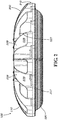
Figure 2 is a side view of the LED luminaire according toFig. 1 . -
Figure 3 is a top view of the LED luminaire according toFig. 1 . -
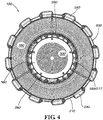
Figure 4 is bottom view of the LED luminaire according toFig. 1 . -
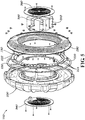
Figure 5 is an exploded side perspective view of the LED luminaire according toFig. 1 . -
Figure 6 is a side cross section view of the LED luminaire according toFig. 1 . -
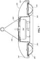
Figure 7 is side cross section view of a LED luminaire according to certain features of the invention. -
Figure 8 is another side cross section view of the LED luminaire according toFig. 7 . -
Figure 8A is partial side cross section view of the LED luminaire according toFig. 8 . -
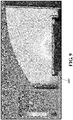
Figure 9 is a computational fluid dynamics ("CFD") model showing temperature gradients in a LED luminaire according to certain features of the invention. -
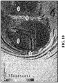
Figure 10 is a CFD model showing air flow around and though a LED luminaire according to certain features of the invention. -
Figure 11 is a CFD model showing air flow around through a LED luminaire according to certain features of the invention. -
Figure 12 is a comparative CFD model showing air flow through and around a power supply assembly utilizing horizontal ventilation. -
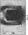
Figure 13 is a comparative CFD model showing air flow through and around a power supply assembly utilizing side and top ventilation. -
Figure 14 is a CFD model showing air flow through and around a power supply assembly utilizing vertical ventilation according to certain features of the invention. - The subject matter of features of the present invention is described here with specificity to meet statutory requirements, but this description is not necessarily intended to limit the scope of the claims. The claimed subject matter may be embodied in other ways, may include different elements or steps, and may be used in conjunction with other existing or future technologies. This description should not be interpreted as implying any particular order or arrangement among or between various steps or elements except when the order of individual steps or arrangement of elements is explicitly described.
- With reference to
Figs. 1-8A , certain features of the invention include aLED luminaire 100 having achassis 200, at least oneLED lighting module 220 mounted to thechassis 200, and a LEDpower supply assembly 300. - As shown in the figures, the
chassis body 210 may have a semi-toroidal shaped (e.g., donut-shaped) configuration, with a segmented circularouter perimeter 213 and central opening 215 defining an inner perimeter 217. The central opening 215 can receive the LEDpower supply assembly 300, as described in more detail below. It will be recognized, however, that other shapes and configurations for thechassis body 210 may be used. Purely by way of example, thechassis body 210 may have an oval, square, rectangular or even triangular shape and include an opening towards the center of the chassis to receive the LEDpower supply assembly 300. - At least one
LED lighting module 220 is mounted to the underside of thechassis body 210. The at least oneLED lighting module 220 may include a printedcircuit board 222 populated with a plurality ofLEDs 224. In some embodiments, the at least oneLED lighting module 220 includes a single LED lighting module. In other embodiments, the at least oneLED lighting module 220 includes two or more LED lighting modules. In yet other embodiments, the at least oneLED lighting module 220 includes a plurality of LED lighting modules. As shown in the non-limiting embodiment ofFig. 5 , a plurality of arc-shapedLED lighting modules 220 are arranged in a circular configuration on thechassis body 210 around the central opening 215. - An optic 280 may be positioned over the at least one
LED lighting module 220. The optic 280 will be described in more detail below. One ormore gaskets 230 may be positioned between thechassis body 210 and optic 280 to seal the at least oneLED lighting module 220 within the optic 280 and thereby protect it from moisture, bugs and other undesirable environmental conditions. - The
chassis 200 acts as a heat sink in theLED luminaire 100 to dissipate heat from theLED luminaire 100. In addition, a plurality offins 225 are provided on thechassis body 210 to increase the available surface area for dissipation of heat generated by the at least oneLED lighting module 220. By way only of example, a plurality offins 225 may radiate outwardly along thechassis body 210, as shown inFigs. 1-3 . As illustrated, alternating pairs ofadjacent fins 225 may be joined at theirdistal ends 227 to form openings that function as outer perimeter vents 240 that extend along theouter perimeter 213 of thechassis body 210. Purely by way of example, these figures show achassis body 210 having twenty-four (24)fins 225, each of which is joined at itsdistal end 227 to a distal end of anadjacent fin 225 to form twelve (12) outer perimeter vents 240. It will be recognized, however, that any number offins 225 and outer perimeter vents 240 may be utilized, depending on desired aesthetic and performance characteristics. - As shown in the figures, the
fins 225 radiate outward from the opening 215 of thechassis 200. The proximal ends 229 of thefins 225 converge towards the opening 215. The proximal ends 229 of thefins 225 may be connected to one another by an inner ring 265 or otherwise, forming a plurality of openings that function as inner perimeter vents 260 extending along the inner perimeter 217 of thechassis body 210. - The
chassis 200 may be an integrally-formed body in that any or all of thechassis body 210,fins 225, or otherstructures forming vents chassis 200 could be formed separately and assembled together. Thechassis 200 may be formed from any suitable material selected for its aesthetic and performance characteristics. Exemplary, not-limiting, examples of such materials include die-cast steel, aluminum and polymeric materials. - The outer perimeter vents 240 and the inner perimeter vents 260 provide flow paths for air to pass through (and not just around) the
LED luminaire 100. During operation of theLED luminaire 100, heat is generated by the at least oneLED lighting module 220 andpower supply assembly 300, causing the air around the LED luminaire to be warmer than the air above and below theLED luminaire 100. The cooler air below theLED luminaire 100 is naturally drawn upwards towards the warmer air within and around theLED luminaire 100. Such cooler air is permitted to pass through theLED luminaire 100 viavents vents LED luminaire 100 and its components by way of natural convection. - Furthermore, the inner perimeter vents 260 help to thermally isolate components of the
LED luminaire 100 and thereby control the temperature of such components. During operation of theLED luminaire 100, heat generated by the at least oneLED lighting module 220 is conducted to the chassis 200 (acting as a heat sink). The gaps resulting from the inner perimeter vents 260 thermally separate and create a thermal barrier between thechassis body 210 and LEDpower supply assembly 300, rendering it more difficult for heat from one component to dissipate into the other component. More specifically, the reduced material connecting thechassis body 210 and LEDpower supply assembly 300 and the movement of air through inner perimeter vents 260 between these two components helps to reduce the heat that is transferred from thechassis body 210 to the LED power supply assembly 300 (and vice versa), thus resulting in a lower LEDpower supply assembly 300 and LEDpower supply unit 320 temperatures, helping to prolong the service life of the at least one LEDpower supply unit 320. - An exemplary LED
power supply assembly 300 and related components is shown inFigs. 5-8A . In some features, the LEDpower supply assembly 300 includes one or more LEDpower supply units 320, atop vent cover 340 located above the one or more LEDpower supply units 320 and abottom vent cover 360 located below the one or more LEDpower supply units 320. In some embodiments, the one or more LEDpower supply units 320 are mounted on abracket 380 between thetop vent cover 340 andbottom vent cover 360, and thetop vent cover 340 andbottom vent cover 360 are attached to thechassis 200 within the opening 215 by way of fasteners such as screws. In other embodiments (not illustrated), the LEDpower supply assembly 300 may include a housing which encloses the one or more LEDpower supply units 320 and to which thetop vent cover 340 andbottom vent cover 360 are attached. In such features, the housing (and thus the LED power supply assembly 300) may be attached to thechassis 200 at the inner ring 265. - In certain embodiments, the one or more LED
power supply units 320 may include a single LED power supply unit (e.g., an LED driver). It will be understood, however, that depending on the power requirements of the at least oneLED lighting module 220, the LEDpower supply assembly 300 could include more than two LED power supply units or more than three LED power supply units. The LED power supply units could have various shapes. - According to embodiments of the invention, the
top vent cover 340 andbottom vent cover 360 of the LEDpower supply assembly 300 are vented to allow air to freely pass through the LEDpower supply assembly 300 and remove heat generated therein. The vents allow air to flow in and out of the LEDpower supply assembly 300 with the least possible resistance because the natural direction of heated air is to rise vertically. Thus, placement of the entry and exit points for the air in its natural traveling direction minimizes restriction in air flow, allowing a larger volume of air to pass through the LEDpower supply assembly 300 than if the ventilation slots were orientated in another way. The larger the volume of air flowing past the one or more LEDpower supply units 320, the greater the heat transfer from the one or more LEDpower supply units 320 to the ambient air via natural convection, thus prolonging the service life of the one or more LEDpower supply units 320 and resulting in greater product performance and greatly reduced maintenance intervals. In addition, because generated heat is removed more efficiently, the LED luminaire can be operated in higher ambient temperatures than previously known LED luminaires. - Embodiments of the invention relate to the configuration of the optic 280. As shown in the figures, and as best seen in
Figs. 5-7 , the optic 280 is curved in a "semi-torus" shape. The optic provides optical distribution of light emitted by the at least oneLED lighting module 220 located between the optic 280 andchassis 200. When powered, the heat generated by the at least oneLED lighting module 220 is transferred to the ambient air by natural convection of air around and through theLED luminaire 100, as described above. Specifically, the heat generated above theLED luminaire 100 draws cooler and denser air from underneath theLED luminaire 100 to accelerate the air around and through the LED luminaire (i.e., through the outer perimeter vents 240 and inner perimeter vents 260), thus applying air pressure on the surface of the optic 280 to help prevent dust particles from depositing on the optic 280 and removing those that do. This provides a distinct improvement over previously known LED luminaires, and in particular LED luminaires, in which the light output decreased over time due to the buildup of dust particles on the surface of the optic, thus blocking the light emitted from the lighting module(s). - The optic 280 may be formed from any suitable material, such as but not limited to glass, prismatic glass or a clear polymeric material. The optic may also be frosted or have other surface features to redirect or otherwise filter the light emitted from the at least one
LED lighting module 220. Further, while the optic 280 is shown in the figures as having three discrete sections, it will be understood that the optic could be formed in one or two sections or have more than three sections. - As explained above, various features of the present invention, including but not limited to the vented LED
power supply assembly 300, outer perimeter vents 240, inner perimeter vents 260 andcurved optic 280, contribute to natural convection of air around and through theLED luminaire 100, which provides greatly improved heat dissipation characteristics as compared to previously known LED luminaires. A visual representation of temperatures and air flow around a LED luminaire incorporating features of the invention is illustrated in the simulated computational fluid dynamics ("CFD") models shown inFigs. 9-11 and14 . In these models, lighter shading represents higher temperatures and faster fluid (air) flow velocities. -
Figure 9 shows a temperature gradient for achassis 200 according to features of the invention. The temperatures on the chassis are highest where the LEDs are located. As shown, however, heat is conducted through the chassis (at least partially by way of the fins) to the outer surface of the chassis body, and in particular toouter perimeter vent 240 andinner perimeter vent 260, where air flowing through and/or around these vents will remove the heat generated by the LEDs by natural convection. -
Figures 10 and11 show relatively higher velocities around and/or through theouter perimeter vent 240 andinner perimeter vent 260 and past the LED power supply units (through thetop vent cover 340 and bottom vent cover 360) and around the outside of the LED luminaire. In addition,Figure 11 shows how the air flows around thecurved optic 280 located on the bottom of the LED luminaire. This curving effect is known as the Coandeffect, resulting from the features of the invention described herein, including but not limited to the
curved optic 280, outer perimeter vents 240 and inner perimeter vents 260. The Coandeffect contributes to improved heat transfer from the LED luminaire to ambient air. It is noted the LED luminaire depicted in the simulation shown inFig. 11 included three LEDpower supply units 320, with air flowing between and around each. - In the CFD model simulation illustrated in
Fig. 11 , air started to accelerate past the optic 280, thus applying an air pressure to any dust particles which may be located thereon. -
Figure 10 also illustrates the circulation of air past thefins 225 on the chassis body and the Venturi effect as ambient air accelerates through the vents. -
Figure 14 shows a CFD model simulation of air flowing through a LEDpower supply assembly 300 and around a LEDpower supply unit 320 according to features of the invention. The air velocity past theLED power supply 320 in this simulation was approximately 240 mm/s. -
Figures 12 and13 show CFD model simulations of comparative examples of an LED power supply assembly. InFigure 12 , the LED power supply assembly includes only side vents, whileFigure 13 shows an LED power supply assembly including two side vents and a top vent. Air velocity through these comparative LED power supply assemblies and past the LED power supply unit was approximately 140 mm/s and 180 mm/s, respectively. - The results depicted in
Figs. 12-14 are shown in the table provided below:Ventilation Configuration Air Velocity Past LED Driver (mm/s) Air Volumetric Flowrate Past LED Driver* (cm3/min) Increase as Compared to Horizontal Flow (%) Horizontal ( Fig. 12 )140 504 N/A Horizontal-In/ Vertical-Out ( Fig. 13 )180 648 29 Vertical 240 864 71 * Volume/min calculated as Air Velocity x Cross Sectional Area around LED Driver - The following parameters were used for the simulations:
- Compartment size: 150 mm x 150 mm x 150 mm
- LED Driver Size: 90 mm x 90 mm x 90 mm
- Ventilation Slot Area: 7920 mm2
- Ambient Temperature: 25°C
- LED Driver Internal Heat Generation: 10W
- The results of the CFD simulations show that vertical ventilation helps to maximize the volume of available airflow in order to increase the effects of natural convection to remove the heat from the LED power supply unit/driver. Features of the invention thus provide approximately 71% more airflow volume than horizontal ventilation, resulting in a significant reduction in electronic LED power supply unit/driver temperature.
- As explained above, the LED luminaire may have various shapes, including a semi-toroidal (donut), oval, square, rectangular or even triangular shape. Further, the opening towards the center of the chassis for receiving the LED power supply assembly may have a shape that is complementary and corresponds to that of the LED luminaire (e.g., round, oval, square, rectangular or triangular) or it could have a different shape than that of the overall LED luminaire (e.g., a semi-toroidal shaped LED luminaire with a square LED power supply assembly). It may be, however, that embodiments of the invention shown in the figures and described above (a semi-toroidal shaped LED luminaire having a semi-toroidal
shaped chassis body 210, a segmented circularouter perimeter 213 and circular central opening 215 defining an inner perimeter 217) provide the most efficient and desirable circular symmetric light distribution. - The
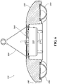
LED luminaire 100 may be configured to hang from a ceiling or other structure. In some embodiments, one end of a suspension apparatus, such as, but not limited to, awire rope assembly 290 such as but not limited to a 4-2-1 wire rope system (four wires attached to the LED luminaire, two of the wires connected to a ring (for two rings), and one attachment point to the ceiling) may be attached to the LED luminaire. The other end of the suspension apparatus may be attached to the ceiling. - Different arrangements of the components depicted in the drawings or described above, as well as components and steps not shown or described are possible. Similarly, some features and subcombinations are useful and may be employed without reference to other features and subcombinations. Features of the invention have been described for illustrative and not restrictive purposes, and alternative features will become apparent to readers of this patent. Accordingly, the present invention is not limited to the features described above or depicted in the drawings, and various features and modifications can be made without departing from the scope of the claims below.
Claims (8)
- A light emitting diode, LED, luminaire (100) comprising:a. a chassis (200), comprising a chassis body (210);b. at least one LED module (220), mounted on the chassis body (210); andc. a LED power supply assembly (300), comprising one or more LED power supply units (320) for the at least one LED module (220);wherein an opening is defined within the chassis (200) and the one or more LED power supply units (320) are positioned within the opening,
wherein the chassis body (210) has an inner perimeter (217) and an outer perimeter, and
the LED luminaire (100) further comprises at least one inner perimeter vent (260) interposed between the chassis body (210) and the LED power supply assembly (300) to thermally separate the chassis body (210) from the one or more LED power supply units (320),
wherein the at least one inner perimeter vent comprises a plurality of inner perimeter vents located around the inner perimeter of the chassis body (210),
wherein the chassis (200) further comprises a plurality of outer perimeter vents (240) extending along the outer perimeter of the chassis body (210),
wherein the chassis (200) further comprises a plurality of fins (225) located on the chassis body (210), each of the plurality of fins comprising a proximal end (229) and a distal end (227),
wherein the inner perimeter vents (260) are formed by connecting the proximal ends (229) of adjacent fins and the outer perimeter vents are formed by connecting the distal ends (227) of adjacent fins. - The LED luminaire (100) according to claim 1, wherein the at least one inner perimeter vent extends along the inner perimeter.
- The LED luminaire (100) according to either of claims 1 or 2, wherein at least one of the outer perimeter or inner perimeter of the chassis body is circular.
- The LED luminaire (100) according to any one of claims 1 to 3, wherein the at least one LED lighting module (220) comprises at least one LED mounted on a printed circuit board and wherein the at least one LED lighting module (220) is shaped.
- The LED luminaire (100) according to any one of claims 1 to 4, further comprising an optic positioned over the at least one LED lighting module (220), wherein the optic comprises a semi-torus shape.
- The LED luminaire (100) according to any one of claims 1 to 5, wherein the chassis (200) is semi-toroidal shaped and the opening is circular.
- The LED luminaire (100) according to claim 1, wherein at least one perimeter vent (240, 260) is configured to promote the natural flow of air around the LED luminaire and/or through the LED power supply assembly so as to remove heat generated by the at least one LED lighting module (220) and/or the one or more LED power supply units (320).
- The LED luminaire (100) according to claim 7, wherein the one or more LED power supply units (320) are thermally separated from the chassis (200) by the at least one inner perimeter vent (260).
Priority Applications (2)
| Application Number | Priority Date | Filing Date | Title |
|---|---|---|---|
| EP13169233.7A EP2806209B1 (en) | 2013-05-24 | 2013-05-24 | LED luminaire with multiple vents for promoting vertical ventilation |
| US14/286,022 US9732953B2 (en) | 2013-05-24 | 2014-05-23 | LED luminaire with multiple vents for promoting vertical ventilation |
Applications Claiming Priority (1)
| Application Number | Priority Date | Filing Date | Title |
|---|---|---|---|
| EP13169233.7A EP2806209B1 (en) | 2013-05-24 | 2013-05-24 | LED luminaire with multiple vents for promoting vertical ventilation |
Publications (2)
| Publication Number | Publication Date |
|---|---|
| EP2806209A1 EP2806209A1 (en) | 2014-11-26 |
| EP2806209B1 true EP2806209B1 (en) | 2019-03-20 |
Family
ID=48576212
Family Applications (1)
| Application Number | Title | Priority Date | Filing Date |
|---|---|---|---|
| EP13169233.7A Active EP2806209B1 (en) | 2013-05-24 | 2013-05-24 | LED luminaire with multiple vents for promoting vertical ventilation |
Country Status (2)
| Country | Link |
|---|---|
| US (1) | US9732953B2 (en) |
| EP (1) | EP2806209B1 (en) |
Families Citing this family (49)
| Publication number | Priority date | Publication date | Assignee | Title |
|---|---|---|---|---|
| USD728849S1 (en) | 2012-05-03 | 2015-05-05 | Lumenpulse Lighting Inc. | LED projection fixture |
| US10753558B2 (en) | 2013-07-05 | 2020-08-25 | DMF, Inc. | Lighting apparatus and methods |
| US9964266B2 (en) | 2013-07-05 | 2018-05-08 | DMF, Inc. | Unified driver and light source assembly for recessed lighting |
| US11255497B2 (en) | 2013-07-05 | 2022-02-22 | DMF, Inc. | Adjustable electrical apparatus with hangar bars for installation in a building |
| US10563850B2 (en) | 2015-04-22 | 2020-02-18 | DMF, Inc. | Outer casing for a recessed lighting fixture |
| US10551044B2 (en) | 2015-11-16 | 2020-02-04 | DMF, Inc. | Recessed lighting assembly |
| US11060705B1 (en) | 2013-07-05 | 2021-07-13 | DMF, Inc. | Compact lighting apparatus with AC to DC converter and integrated electrical connector |
| US10139059B2 (en) | 2014-02-18 | 2018-11-27 | DMF, Inc. | Adjustable compact recessed lighting assembly with hangar bars |
| US11435064B1 (en) | 2013-07-05 | 2022-09-06 | DMF, Inc. | Integrated lighting module |
| JP1523888S (en) * | 2014-08-28 | 2015-05-18 | ||
| US9677754B2 (en) | 2014-11-07 | 2017-06-13 | Chm Industries, Inc. | Rotating light emitting diode driver mount |
| US20170321874A1 (en) * | 2014-11-25 | 2017-11-09 | Christopher Michael Bryant | Low-Profile Luminaire |
| USD764094S1 (en) * | 2015-01-06 | 2016-08-16 | Foxconn Technology Co., Ltd. | LED high bay light fixture |
| USD780972S1 (en) | 2015-04-02 | 2017-03-07 | Abl Ip Holding Llc | Suspended light fixture |
| US10036534B2 (en) | 2015-04-02 | 2018-07-31 | Abl Ip Holding Llc | High bay light fixture |
| CA2931588C (en) | 2015-05-29 | 2021-09-14 | DMF, Inc. | Lighting module for recessed lighting systems |
| USD784591S1 (en) * | 2015-09-22 | 2017-04-18 | Cooper Technologies Company | High-lumen round light fixture |
| USD851046S1 (en) | 2015-10-05 | 2019-06-11 | DMF, Inc. | Electrical Junction Box |
| US10234127B2 (en) | 2016-02-08 | 2019-03-19 | Cree, Inc. | LED luminaire having enhanced thermal management |
| EP3290790B1 (en) * | 2016-08-30 | 2019-04-10 | ZG Lighting Benelux | Heatsink |
| US20180172260A1 (en) * | 2016-12-20 | 2018-06-21 | GE Lighting Solutions, LLC | Luminaire housing assembly |
| USD839469S1 (en) * | 2017-03-28 | 2019-01-29 | Dongguan Pan American Electronics Co., Ltd | Light fixture |
| USD905327S1 (en) | 2018-05-17 | 2020-12-15 | DMF, Inc. | Light fixture |
| US10488000B2 (en) | 2017-06-22 | 2019-11-26 | DMF, Inc. | Thin profile surface mount lighting apparatus |
| WO2018237294A2 (en) | 2017-06-22 | 2018-12-27 | DMF, Inc. | Thin profile surface mount lighting apparatus |
| US11067231B2 (en) | 2017-08-28 | 2021-07-20 | DMF, Inc. | Alternate junction box and arrangement for lighting apparatus |
| US10527240B2 (en) * | 2017-10-18 | 2020-01-07 | Lsi Industries, Inc. | Surface mount luminaire |
| USD859726S1 (en) * | 2017-11-06 | 2019-09-10 | Mester Led Limited | Ceiling light |
| CN111670322B (en) | 2017-11-28 | 2022-04-26 | Dmf股份有限公司 | Adjustable hanger rod assembly |
| CA3087187A1 (en) | 2017-12-27 | 2019-07-04 | DMF, Inc. | Methods and apparatus for adjusting a luminaire |
| USD877957S1 (en) | 2018-05-24 | 2020-03-10 | DMF Inc. | Light fixture |
| CA3103255A1 (en) | 2018-06-11 | 2019-12-19 | DMF, Inc. | A polymer housing for a recessed lighting system and methods for using same |
| USD903605S1 (en) | 2018-06-12 | 2020-12-01 | DMF, Inc. | Plastic deep electrical junction box |
| WO2020072592A1 (en) | 2018-10-02 | 2020-04-09 | Ver Lighting Llc | A bar hanger assembly with mating telescoping bars |
| USD925097S1 (en) | 2018-10-18 | 2021-07-13 | Lsi Industries, Inc. | Surface mount luminaire |
| CN209101141U (en) * | 2018-12-29 | 2019-07-12 | 欧普照明股份有限公司 | A kind of ceiling lamp and LED light source mould group and light source assembly |
| USD1012864S1 (en) | 2019-01-29 | 2024-01-30 | DMF, Inc. | Portion of a plastic deep electrical junction box |
| USD901398S1 (en) | 2019-01-29 | 2020-11-10 | DMF, Inc. | Plastic deep electrical junction box |
| USD864877S1 (en) | 2019-01-29 | 2019-10-29 | DMF, Inc. | Plastic deep electrical junction box with a lighting module mounting yoke |
| US11168878B2 (en) * | 2019-03-05 | 2021-11-09 | Component Hardware Group, Inc. | LED luminaire |
| USD966877S1 (en) | 2019-03-14 | 2022-10-18 | Ver Lighting Llc | Hanger bar for a hanger bar assembly |
| WO2021051101A1 (en) | 2019-09-12 | 2021-03-18 | DMF, Inc. | Miniature lighting module and lighting fixtures using same |
| US11032976B1 (en) * | 2020-03-16 | 2021-06-15 | Hgci, Inc. | Light fixture for indoor grow application and components thereof |
| USD990030S1 (en) | 2020-07-17 | 2023-06-20 | DMF, Inc. | Housing for a lighting system |
| CA3124976A1 (en) | 2020-07-17 | 2022-01-17 | DMF, Inc. | Polymer housing for a lighting system and methods for using same |
| US11585517B2 (en) | 2020-07-23 | 2023-02-21 | DMF, Inc. | Lighting module having field-replaceable optics, improved cooling, and tool-less mounting features |
| USD952225S1 (en) * | 2020-09-07 | 2022-05-17 | Zhian Liao | Solar deck light |
| CN113596487A (en) * | 2021-06-16 | 2021-11-02 | 佛山市乐成影视器材科技有限公司 | Single portable multifunctional field light sound effect device |
| CN113864735A (en) * | 2021-10-09 | 2021-12-31 | 深圳市博为光电股份有限公司 | Multifunctional lamp mounting box |
Citations (2)
| Publication number | Priority date | Publication date | Assignee | Title |
|---|---|---|---|---|
| EP2206945A1 (en) * | 2008-12-30 | 2010-07-14 | I.B.T. Lighting S.P.A | LED lighting device for outdoors and large covered areas having opitmized heat dissipation |
| US20130044478A1 (en) * | 2011-08-15 | 2013-02-21 | MaxLite, Inc. | Led illumination device with isolated driving circuitry |
Family Cites Families (44)
| Publication number | Priority date | Publication date | Assignee | Title |
|---|---|---|---|---|
| US6200007B1 (en) | 1999-01-27 | 2001-03-13 | Nsi Enterprises, Inc. | Suspended luminaire assembly |
| US6669355B2 (en) | 2000-07-28 | 2003-12-30 | Cooper Technologies Company | Housing rotation lock for a track lighting fixture |
| US6491413B1 (en) | 2000-07-31 | 2002-12-10 | Lusa Lighting International | High voltage (line) under-cabinet lighting fixture |
| JP2002367406A (en) * | 2001-06-05 | 2002-12-20 | Algol:Kk | Ring-like led lighting system |
| JP2008098020A (en) * | 2006-10-13 | 2008-04-24 | Matsushita Electric Works Ltd | Led lighting device |
| TWM310984U (en) | 2006-11-28 | 2007-05-01 | Primo Lite Co Ltd | Lamp structure of light emitting diode |
| US20080212333A1 (en) | 2007-03-01 | 2008-09-04 | Bor-Jang Chen | Heat radiating device for lamp |
| US7500760B2 (en) | 2007-03-04 | 2009-03-10 | Hunter Fan Company | Light with heater |
| PL2153115T3 (en) * | 2007-05-04 | 2021-12-27 | Signify Holding B.V. | Led-based fixtures and related methods for thermal management |
| EP2151626B1 (en) | 2007-06-07 | 2014-12-24 | Zhejiang Mingchuang Opto-electronic Technology Co., Ltd. | High power led lamp |
| TWM332793U (en) | 2007-11-28 | 2008-05-21 | Cooler Master Co Ltd | Heat radiating structure and the lighting apparatus |
| EP2235437A1 (en) | 2007-12-07 | 2010-10-06 | Osram Gesellschaft mit beschränkter Haftung | Heat sink and lighting device comprising a heat sink |
| CN201126125Y (en) * | 2007-12-17 | 2008-10-01 | 金松山 | High-power LED ceiling lamp |
| US7866850B2 (en) | 2008-02-26 | 2011-01-11 | Journée Lighting, Inc. | Light fixture assembly and LED assembly |
| US20090296387A1 (en) | 2008-05-27 | 2009-12-03 | Sea Gull Lighting Products, Llc | Led retrofit light engine |
| US20100002452A1 (en) | 2008-07-07 | 2010-01-07 | Cooper Technologies Company | Luminaire housing with separated lamp and ballast compartments |
| TWM358257U (en) | 2008-08-03 | 2009-06-01 | Ya-Li Wu | The thermal dissipation structure of steam surface LED lamp |
| US7891842B2 (en) | 2008-08-07 | 2011-02-22 | Hong Kong Applied Science And Technology Research Institute Co. Ltd. | Heat-dissipating reflector for lighting device |
| US7611264B1 (en) * | 2008-08-28 | 2009-11-03 | Li-Hong Technological Co., Ltd. | LED lamp |
| KR100910539B1 (en) | 2008-09-29 | 2009-07-31 | 화우테크놀러지 주식회사 | Explosion free lamp with led |
| US8152336B2 (en) | 2008-11-21 | 2012-04-10 | Journée Lighting, Inc. | Removable LED light module for use in a light fixture assembly |
| US8256934B2 (en) * | 2009-01-07 | 2012-09-04 | Troy-Csl Lighting, Inc. | Puck type light fixture |
| KR100919995B1 (en) | 2009-05-29 | 2009-10-05 | (주)퓨쳐 라이팅 | Led lighting device |
| US8066392B2 (en) | 2009-06-02 | 2011-11-29 | Ceramate Technical Co., Ltd. | Multi-function replaceable modular LED lamp |
| TWM372923U (en) | 2009-08-14 | 2010-01-21 | Risun Expanse Corp | Lamp structure |
| US8525395B2 (en) * | 2010-02-05 | 2013-09-03 | Litetronics International, Inc. | Multi-component LED lamp |
| US8272765B2 (en) | 2010-06-21 | 2012-09-25 | Light Emitting Design, Inc. | Heat sink system |
| KR101370920B1 (en) | 2010-06-23 | 2014-03-07 | 엘지전자 주식회사 | Lighting Device |
| US8164237B2 (en) | 2010-07-29 | 2012-04-24 | GEM-SUN Technologies Co., Ltd. | LED lamp with flow guide function |
| CN104748095A (en) | 2010-08-06 | 2015-07-01 | 普司科Ict股份有限公司 | Optical semiconductor lighting apparatus |
| CN201748298U (en) * | 2010-08-31 | 2011-02-16 | 史杰 | LED ceiling lamp light source |
| US20120057344A1 (en) * | 2010-09-08 | 2012-03-08 | Robert Wang | Led disc lamp |
| US9279543B2 (en) | 2010-10-08 | 2016-03-08 | Cree, Inc. | LED package mount |
| JP2012104476A (en) * | 2010-10-12 | 2012-05-31 | Toshiba Lighting & Technology Corp | Lighting device |
| US8905589B2 (en) | 2011-01-12 | 2014-12-09 | Kenall Manufacturing Company | LED luminaire thermal management system |
| TWM409362U (en) | 2011-03-16 | 2011-08-11 | Unity Opto Technology Co Ltd | illumination light |
| TW201303207A (en) | 2011-07-05 | 2013-01-16 | Ind Tech Res Inst | Illumination device |
| US20130010464A1 (en) * | 2011-07-07 | 2013-01-10 | BritePointe, Inc. | High intensity lighting fixture |
| KR101215598B1 (en) * | 2011-08-08 | 2012-12-26 | 아이스파이프 주식회사 | Led lighting apparatus |
| JP2013089557A (en) * | 2011-10-21 | 2013-05-13 | Sanken Electric Co Ltd | Lamp fitting |
| CN202493997U (en) * | 2012-01-04 | 2012-10-17 | 中山市世耀光电科技有限公司 | LED ceiling-mounted lamp |
| CN202432313U (en) | 2012-01-09 | 2012-09-12 | 陈鸿文 | Ultrathin LED lamp structure |
| CN202902088U (en) * | 2012-09-25 | 2013-04-24 | 陈建国 | Light-emitting diode (LED) annular lamp plate |
| US9441634B2 (en) | 2013-01-11 | 2016-09-13 | Daniel S. Spiro | Integrated ceiling device with mechanical arrangement for a light source |
-
2013
- 2013-05-24 EP EP13169233.7A patent/EP2806209B1/en active Active
-
2014
- 2014-05-23 US US14/286,022 patent/US9732953B2/en active Active
Patent Citations (2)
| Publication number | Priority date | Publication date | Assignee | Title |
|---|---|---|---|---|
| EP2206945A1 (en) * | 2008-12-30 | 2010-07-14 | I.B.T. Lighting S.P.A | LED lighting device for outdoors and large covered areas having opitmized heat dissipation |
| US20130044478A1 (en) * | 2011-08-15 | 2013-02-21 | MaxLite, Inc. | Led illumination device with isolated driving circuitry |
Also Published As
| Publication number | Publication date |
|---|---|
| EP2806209A1 (en) | 2014-11-26 |
| US20140347848A1 (en) | 2014-11-27 |
| US9732953B2 (en) | 2017-08-15 |
Similar Documents
| Publication | Publication Date | Title |
|---|---|---|
| EP2806209B1 (en) | LED luminaire with multiple vents for promoting vertical ventilation | |
| US9982879B2 (en) | LED lighting apparatus having a plurality of light emitting module sections interlocked in a circular fashion | |
| CA2736757C (en) | Lighting apparatus with heat dissipation system | |
| EP3150900A1 (en) | Lamp | |
| KR20120105352A (en) | Lamp | |
| US10900652B2 (en) | High-lumen fixture thermal management | |
| US9500357B2 (en) | LED light fixture having circumferentially mounted drivers adjacent external heat sinks | |
| MX2012011588A (en) | Lamp housing. | |
| CN109114519B (en) | Lighting module for a motor vehicle | |
| KR101011259B1 (en) | Structure of the cover which includes the heat dissipation ventilation structure of the illuminating lamp organization | |
| MX2012009039A (en) | Thermal management system for electrical components and method of producing same. | |
| CN205351012U (en) | A fixed lamps and lanterns of LED that is used for radiator of fixed lamps and lanterns of LED and contains it | |
| CN208817111U (en) | A kind of New LED heat radiation module and LED lamp | |
| JP4536695B2 (en) | Combination lamp for vehicles | |
| KR101313741B1 (en) | Led lamp | |
| CN205424618U (en) | LED lamp with good heat radiating effect | |
| CA2742670A1 (en) | Modular heat sink | |
| CN105465756A (en) | Automatic air suction type heat-dissipation lamp and heat dissipation method of lamp | |
| TWM452290U (en) | Bay lamp with heat dissipation plate |
Legal Events
| Date | Code | Title | Description |
|---|---|---|---|
| PUAI | Public reference made under article 153(3) epc to a published international application that has entered the european phase |
Free format text: ORIGINAL CODE: 0009012 |
|
| 17P | Request for examination filed |
Effective date: 20130524 |
|
| AK | Designated contracting states |
Kind code of ref document: A1 Designated state(s): AL AT BE BG CH CY CZ DE DK EE ES FI FR GB GR HR HU IE IS IT LI LT LU LV MC MK MT NL NO PL PT RO RS SE SI SK SM TR |
|
| AX | Request for extension of the european patent |
Extension state: BA ME |
|
| R17P | Request for examination filed (corrected) |
Effective date: 20150331 |
|
| RBV | Designated contracting states (corrected) |
Designated state(s): AL AT BE BG CH CY CZ DE DK EE ES FI FR GB GR HR HU IE IS IT LI LT LU LV MC MK MT NL NO PL PT RO RS SE SI SK SM TR |
|
| 17Q | First examination report despatched |
Effective date: 20160610 |
|
| RAP1 | Party data changed (applicant data changed or rights of an application transferred) |
Owner name: ABL IP HOLDING LLC |
|
| STAA | Information on the status of an ep patent application or granted ep patent |
Free format text: STATUS: EXAMINATION IS IN PROGRESS |
|
| RAP1 | Party data changed (applicant data changed or rights of an application transferred) |
Owner name: ABL IP HOLDING LLC |
|
| RAP1 | Party data changed (applicant data changed or rights of an application transferred) |
Owner name: HOLOPHANE EUROPE LTD. |
|
| RIC1 | Information provided on ipc code assigned before grant |
Ipc: F21Y 115/10 20160101ALN20180716BHEP Ipc: F21V 29/00 20060101AFI20180716BHEP Ipc: F21S 8/04 20060101ALI20180716BHEP |
|
| GRAP | Despatch of communication of intention to grant a patent |
Free format text: ORIGINAL CODE: EPIDOSNIGR1 |
|
| STAA | Information on the status of an ep patent application or granted ep patent |
Free format text: STATUS: GRANT OF PATENT IS INTENDED |
|
| RIC1 | Information provided on ipc code assigned before grant |
Ipc: F21Y 115/10 20160101ALN20180907BHEP Ipc: F21S 8/04 20060101ALI20180907BHEP Ipc: F21V 29/00 20060101AFI20180907BHEP |
|
| INTG | Intention to grant announced |
Effective date: 20181004 |
|
| GRAS | Grant fee paid |
Free format text: ORIGINAL CODE: EPIDOSNIGR3 |
|
| RIC1 | Information provided on ipc code assigned before grant |
Ipc: F21V 29/00 20150101AFI20180907BHEP Ipc: F21Y 115/10 20160101ALN20180907BHEP Ipc: F21S 8/04 20060101ALI20180907BHEP |
|
| GRAA | (expected) grant |
Free format text: ORIGINAL CODE: 0009210 |
|
| STAA | Information on the status of an ep patent application or granted ep patent |
Free format text: STATUS: THE PATENT HAS BEEN GRANTED |
|
| AK | Designated contracting states |
Kind code of ref document: B1 Designated state(s): AL AT BE BG CH CY CZ DE DK EE ES FI FR GB GR HR HU IE IS IT LI LT LU LV MC MK MT NL NO PL PT RO RS SE SI SK SM TR |
|
| REG | Reference to a national code |
Ref country code: GB Ref legal event code: FG4D |
|
| REG | Reference to a national code |
Ref country code: CH Ref legal event code: EP |
|
| REG | Reference to a national code |
Ref country code: DE Ref legal event code: R096 Ref document number: 602013052529 Country of ref document: DE |
|
| REG | Reference to a national code |
Ref country code: AT Ref legal event code: REF Ref document number: 1110926 Country of ref document: AT Kind code of ref document: T Effective date: 20190415 |
|
| REG | Reference to a national code |
Ref country code: IE Ref legal event code: FG4D |
|
| REG | Reference to a national code |
Ref country code: NL Ref legal event code: MP Effective date: 20190320 |
|
| PG25 | Lapsed in a contracting state [announced via postgrant information from national office to epo] |
Ref country code: NO Free format text: LAPSE BECAUSE OF FAILURE TO SUBMIT A TRANSLATION OF THE DESCRIPTION OR TO PAY THE FEE WITHIN THE PRESCRIBED TIME-LIMIT Effective date: 20190620 Ref country code: FI Free format text: LAPSE BECAUSE OF FAILURE TO SUBMIT A TRANSLATION OF THE DESCRIPTION OR TO PAY THE FEE WITHIN THE PRESCRIBED TIME-LIMIT Effective date: 20190320 Ref country code: LT Free format text: LAPSE BECAUSE OF FAILURE TO SUBMIT A TRANSLATION OF THE DESCRIPTION OR TO PAY THE FEE WITHIN THE PRESCRIBED TIME-LIMIT Effective date: 20190320 Ref country code: SE Free format text: LAPSE BECAUSE OF FAILURE TO SUBMIT A TRANSLATION OF THE DESCRIPTION OR TO PAY THE FEE WITHIN THE PRESCRIBED TIME-LIMIT Effective date: 20190320 |
|
| REG | Reference to a national code |
Ref country code: LT Ref legal event code: MG4D |
|
| PG25 | Lapsed in a contracting state [announced via postgrant information from national office to epo] |
Ref country code: LV Free format text: LAPSE BECAUSE OF FAILURE TO SUBMIT A TRANSLATION OF THE DESCRIPTION OR TO PAY THE FEE WITHIN THE PRESCRIBED TIME-LIMIT Effective date: 20190320 Ref country code: NL Free format text: LAPSE BECAUSE OF FAILURE TO SUBMIT A TRANSLATION OF THE DESCRIPTION OR TO PAY THE FEE WITHIN THE PRESCRIBED TIME-LIMIT Effective date: 20190320 Ref country code: RS Free format text: LAPSE BECAUSE OF FAILURE TO SUBMIT A TRANSLATION OF THE DESCRIPTION OR TO PAY THE FEE WITHIN THE PRESCRIBED TIME-LIMIT Effective date: 20190320 Ref country code: BG Free format text: LAPSE BECAUSE OF FAILURE TO SUBMIT A TRANSLATION OF THE DESCRIPTION OR TO PAY THE FEE WITHIN THE PRESCRIBED TIME-LIMIT Effective date: 20190620 Ref country code: GR Free format text: LAPSE BECAUSE OF FAILURE TO SUBMIT A TRANSLATION OF THE DESCRIPTION OR TO PAY THE FEE WITHIN THE PRESCRIBED TIME-LIMIT Effective date: 20190621 Ref country code: HR Free format text: LAPSE BECAUSE OF FAILURE TO SUBMIT A TRANSLATION OF THE DESCRIPTION OR TO PAY THE FEE WITHIN THE PRESCRIBED TIME-LIMIT Effective date: 20190320 |
|
| REG | Reference to a national code |
Ref country code: AT Ref legal event code: MK05 Ref document number: 1110926 Country of ref document: AT Kind code of ref document: T Effective date: 20190320 |
|
| PG25 | Lapsed in a contracting state [announced via postgrant information from national office to epo] |
Ref country code: EE Free format text: LAPSE BECAUSE OF FAILURE TO SUBMIT A TRANSLATION OF THE DESCRIPTION OR TO PAY THE FEE WITHIN THE PRESCRIBED TIME-LIMIT Effective date: 20190320 Ref country code: SK Free format text: LAPSE BECAUSE OF FAILURE TO SUBMIT A TRANSLATION OF THE DESCRIPTION OR TO PAY THE FEE WITHIN THE PRESCRIBED TIME-LIMIT Effective date: 20190320 Ref country code: PT Free format text: LAPSE BECAUSE OF FAILURE TO SUBMIT A TRANSLATION OF THE DESCRIPTION OR TO PAY THE FEE WITHIN THE PRESCRIBED TIME-LIMIT Effective date: 20190720 Ref country code: AL Free format text: LAPSE BECAUSE OF FAILURE TO SUBMIT A TRANSLATION OF THE DESCRIPTION OR TO PAY THE FEE WITHIN THE PRESCRIBED TIME-LIMIT Effective date: 20190320 Ref country code: CZ Free format text: LAPSE BECAUSE OF FAILURE TO SUBMIT A TRANSLATION OF THE DESCRIPTION OR TO PAY THE FEE WITHIN THE PRESCRIBED TIME-LIMIT Effective date: 20190320 Ref country code: IT Free format text: LAPSE BECAUSE OF FAILURE TO SUBMIT A TRANSLATION OF THE DESCRIPTION OR TO PAY THE FEE WITHIN THE PRESCRIBED TIME-LIMIT Effective date: 20190320 Ref country code: ES Free format text: LAPSE BECAUSE OF FAILURE TO SUBMIT A TRANSLATION OF THE DESCRIPTION OR TO PAY THE FEE WITHIN THE PRESCRIBED TIME-LIMIT Effective date: 20190320 Ref country code: RO Free format text: LAPSE BECAUSE OF FAILURE TO SUBMIT A TRANSLATION OF THE DESCRIPTION OR TO PAY THE FEE WITHIN THE PRESCRIBED TIME-LIMIT Effective date: 20190320 |
|
| PG25 | Lapsed in a contracting state [announced via postgrant information from national office to epo] |
Ref country code: SM Free format text: LAPSE BECAUSE OF FAILURE TO SUBMIT A TRANSLATION OF THE DESCRIPTION OR TO PAY THE FEE WITHIN THE PRESCRIBED TIME-LIMIT Effective date: 20190320 Ref country code: PL Free format text: LAPSE BECAUSE OF FAILURE TO SUBMIT A TRANSLATION OF THE DESCRIPTION OR TO PAY THE FEE WITHIN THE PRESCRIBED TIME-LIMIT Effective date: 20190320 |
|
| REG | Reference to a national code |
Ref country code: CH Ref legal event code: PL |
|
| PG25 | Lapsed in a contracting state [announced via postgrant information from national office to epo] |
Ref country code: AT Free format text: LAPSE BECAUSE OF FAILURE TO SUBMIT A TRANSLATION OF THE DESCRIPTION OR TO PAY THE FEE WITHIN THE PRESCRIBED TIME-LIMIT Effective date: 20190320 Ref country code: IS Free format text: LAPSE BECAUSE OF FAILURE TO SUBMIT A TRANSLATION OF THE DESCRIPTION OR TO PAY THE FEE WITHIN THE PRESCRIBED TIME-LIMIT Effective date: 20190720 |
|
| REG | Reference to a national code |
Ref country code: DE Ref legal event code: R097 Ref document number: 602013052529 Country of ref document: DE |
|
| PLBE | No opposition filed within time limit |
Free format text: ORIGINAL CODE: 0009261 |
|
| STAA | Information on the status of an ep patent application or granted ep patent |
Free format text: STATUS: NO OPPOSITION FILED WITHIN TIME LIMIT |
|
| PG25 | Lapsed in a contracting state [announced via postgrant information from national office to epo] |
Ref country code: CH Free format text: LAPSE BECAUSE OF NON-PAYMENT OF DUE FEES Effective date: 20190531 Ref country code: LI Free format text: LAPSE BECAUSE OF NON-PAYMENT OF DUE FEES Effective date: 20190531 Ref country code: DK Free format text: LAPSE BECAUSE OF FAILURE TO SUBMIT A TRANSLATION OF THE DESCRIPTION OR TO PAY THE FEE WITHIN THE PRESCRIBED TIME-LIMIT Effective date: 20190320 Ref country code: MC Free format text: LAPSE BECAUSE OF FAILURE TO SUBMIT A TRANSLATION OF THE DESCRIPTION OR TO PAY THE FEE WITHIN THE PRESCRIBED TIME-LIMIT Effective date: 20190320 |
|
| REG | Reference to a national code |
Ref country code: BE Ref legal event code: MM Effective date: 20190531 |
|
| 26N | No opposition filed |
Effective date: 20200102 |
|
| PG25 | Lapsed in a contracting state [announced via postgrant information from national office to epo] |
Ref country code: SI Free format text: LAPSE BECAUSE OF FAILURE TO SUBMIT A TRANSLATION OF THE DESCRIPTION OR TO PAY THE FEE WITHIN THE PRESCRIBED TIME-LIMIT Effective date: 20190320 Ref country code: LU Free format text: LAPSE BECAUSE OF NON-PAYMENT OF DUE FEES Effective date: 20190524 |
|
| PG25 | Lapsed in a contracting state [announced via postgrant information from national office to epo] |
Ref country code: TR Free format text: LAPSE BECAUSE OF FAILURE TO SUBMIT A TRANSLATION OF THE DESCRIPTION OR TO PAY THE FEE WITHIN THE PRESCRIBED TIME-LIMIT Effective date: 20190320 |
|
| PG25 | Lapsed in a contracting state [announced via postgrant information from national office to epo] |
Ref country code: IE Free format text: LAPSE BECAUSE OF NON-PAYMENT OF DUE FEES Effective date: 20190524 |
|
| PG25 | Lapsed in a contracting state [announced via postgrant information from national office to epo] |
Ref country code: BE Free format text: LAPSE BECAUSE OF NON-PAYMENT OF DUE FEES Effective date: 20190531 |
|
| PG25 | Lapsed in a contracting state [announced via postgrant information from national office to epo] |
Ref country code: FR Free format text: LAPSE BECAUSE OF NON-PAYMENT OF DUE FEES Effective date: 20190531 |
|
| PG25 | Lapsed in a contracting state [announced via postgrant information from national office to epo] |
Ref country code: CY Free format text: LAPSE BECAUSE OF FAILURE TO SUBMIT A TRANSLATION OF THE DESCRIPTION OR TO PAY THE FEE WITHIN THE PRESCRIBED TIME-LIMIT Effective date: 20190320 |
|
| PG25 | Lapsed in a contracting state [announced via postgrant information from national office to epo] |
Ref country code: MT Free format text: LAPSE BECAUSE OF FAILURE TO SUBMIT A TRANSLATION OF THE DESCRIPTION OR TO PAY THE FEE WITHIN THE PRESCRIBED TIME-LIMIT Effective date: 20190320 Ref country code: HU Free format text: LAPSE BECAUSE OF FAILURE TO SUBMIT A TRANSLATION OF THE DESCRIPTION OR TO PAY THE FEE WITHIN THE PRESCRIBED TIME-LIMIT; INVALID AB INITIO Effective date: 20130524 |
|
| PG25 | Lapsed in a contracting state [announced via postgrant information from national office to epo] |
Ref country code: MK Free format text: LAPSE BECAUSE OF FAILURE TO SUBMIT A TRANSLATION OF THE DESCRIPTION OR TO PAY THE FEE WITHIN THE PRESCRIBED TIME-LIMIT Effective date: 20190320 |
|
| PGFP | Annual fee paid to national office [announced via postgrant information from national office to epo] |
Ref country code: GB Payment date: 20230330 Year of fee payment: 11 |
|
| PGFP | Annual fee paid to national office [announced via postgrant information from national office to epo] |
Ref country code: DE Payment date: 20230331 Year of fee payment: 11 |