CN1139212C - Apparatus and method for controlling communications based on moving speed - Google Patents
Apparatus and method for controlling communications based on moving speed Download PDFInfo
- Publication number
- CN1139212C CN1139212C CNB981208444A CN98120844A CN1139212C CN 1139212 C CN1139212 C CN 1139212C CN B981208444 A CNB981208444 A CN B981208444A CN 98120844 A CN98120844 A CN 98120844A CN 1139212 C CN1139212 C CN 1139212C
- Authority
- CN
- China
- Prior art keywords
- unit
- control
- signal
- parameter
- movement velocity
- Prior art date
- Legal status (The legal status is an assumption and is not a legal conclusion. Google has not performed a legal analysis and makes no representation as to the accuracy of the status listed.)
- Expired - Fee Related
Links
Images


Classifications
-
- H—ELECTRICITY
- H04—ELECTRIC COMMUNICATION TECHNIQUE
- H04B—TRANSMISSION
- H04B7/00—Radio transmission systems, i.e. using radiation field
- H04B7/24—Radio transmission systems, i.e. using radiation field for communication between two or more posts
- H04B7/26—Radio transmission systems, i.e. using radiation field for communication between two or more posts at least one of which is mobile
- H04B7/2628—Radio transmission systems, i.e. using radiation field for communication between two or more posts at least one of which is mobile using code-division multiple access [CDMA] or spread spectrum multiple access [SSMA]
-
- H—ELECTRICITY
- H04—ELECTRIC COMMUNICATION TECHNIQUE
- H04B—TRANSMISSION
- H04B17/00—Monitoring; Testing
- H04B17/30—Monitoring; Testing of propagation channels
- H04B17/309—Measuring or estimating channel quality parameters
- H04B17/318—Received signal strength
Abstract
A communication control apparatus installed in a base station or a mobile station in mobile communications system estimates the relative moving speed of an opposing station, and adjusts the values of communication parameters for a searcher, a transmission power control unit, an absolute synchronous detector unit, etc. according to an obtained moving speed.
Description
The present invention relates in mobile communication system, be set to the communication control unit and the method for optimum value according to estimable motion velocity of mobile station base station communication apparatus parameter.
Always, with regard to the channel multiplexing method for use in the mobile communication system, time division multiple access (TDMA) system, frequency division multiple access (FDMA) system etc. had been developed already.Yet, wish a kind of method that can more effectively utilize frequency of exploitation, so direct sequence CDMA (DS-CDMA) system has development prospect especially because the mass communication service can be provided.
The DS-CDMA system is a kind of spread spectrum communication system.In this system, at transmit leg, data-signal sends with the frequency spectrum of expansion, and a plurality of channels use identical frequency, but for each channel data signal times a wide-band spread spectrum sign indicating number independently.The recipient, come the restore data signal by received signal being multiply by identical spreading code for each channel.The processing of multiply by spreading code the recipient is called despreading.When this DS-CDMA system was used for mobile communication, function of search, transmitting power controlled function, coherent detection function etc. all were absolutely necessary.
Function of search is meant detected transmission path and the function of separating the extended code timing of carrying out timing for despreading.The transmitting power controlled function is meant in order to overcome the instantaneous fluctuating (decline) that causes owing to the different distance problems that cause of distance between travelling carriage and the base station with owing to multipath revises the function of transmitting power.The coherent detection function is meant in order to reach desired bit error rate (BER) (BER) with lower transmitting power is adding a pilot signal again and carrying out the function of coherent detection when receiving when sending on the data-signal.
In mobile communication, require in the environment of various dynamic changes, may transfer high-speed motion state to, forward suburban environment and so on to from inactive state from urban environment as travelling carriage, can both carry out reliable and stable communication.Particularly have the reflected wave by many transmission paths and postponing in the multi-path environment of ripple, anti-interference being absolutely necessary is because this multipath interference can cause decline (instantaneous value fluctuating).In the DS-CDMA system, above-mentioned various functions also need effective anti-fading measure and cooperate.
Yet, some problems below in the mobile communication of utilizing the DS-CDMA system, existing.
In general, though some parameters have optimum value for the decline that each unit antagonism communication period of communication equipment occurs, but be not that each parameter can be set to optimum value all the time, this is to change because of the movement velocity of the fluctuating velocity of decline (or being called decline pitch fading pitch) with travelling carriage.Therefore, do not have under the optimized situation in parameter, receiving feature will variation, thereby channel capacity is reduced.
Because as mentioned above, the DS-CDMA system has function of search, transmitting power controlled function, coherent detection function etc., therefore must the parameter of these functions be revised, with the influence that reduces to decline to received signal.
The purpose of this invention is to provide a kind of in utilizing the mobile communication of DS-CDMA each parameter of communication equipment be set to the communication control unit and the method for optimum value.
Communication control unit of the present invention comprises a velocity estimation unit and an amending unit, is used for being controlled at some parameters of mobile communication between sending station and the receiving platform.
The velocity estimation unit estimation goes out the movement velocity of sending station or travelling carriage, output and estimated movement velocity control signal corresponding.Amending unit is revised the value of parameter according to this control signal.
Base station in the mobile communication can should be sending station or receiving platform mutually with travelling carriage.For example, the emissive power control command that velocity estimation unit by using receiving platform sends to sending station estimates the movement velocity of receiving platform, and utilizes the available signal power that produces at receiving platform to estimate the movement velocity of sending station.In fact, owing to be that base station or travelling carriage all have sending station and two kinds of functions of receiving platform, no matter be that base station or travelling carriage can both utilize emissive power control command or available signal power to estimate the other side's movement velocity therefore.
Amending unit changes the various parameters as sending station and receiving platform of equipment according to the control signal of velocity estimation unit output.These parameters comprise the frequency that detects spread-spectrum signal despreading search operation regularly, receive the frequency that adds up of correlation in the search operation, the number of used pilot signal and weight coefficient in the coherent detection, the observation length of observation signal during Invalid path detects, the adjusting range of performance number and frequency of amendment etc. in the transmitting power control.Just can control communication by control these parameters according to control signal, thereby improve the reception feature of receiving platform according to movement velocity.
In the accompanying drawing of this explanation:
Fig. 1 shows the principle of communication control unit of the present invention;
Fig. 2 shows the principle of transmitter;
Fig. 3 shows the principle of first kind of receiver;
Fig. 4 shows the configuration of first kind of searcher;
Fig. 5 shows the configuration of matched filter;
Fig. 6 shows a kind of spreading code;
Fig. 7 shows the peak value of some correlations;
Fig. 8 shows five estimating speed ranks;
Fig. 9 is the flow chart (No.1) that first kind of search operation is shown;
Figure 10 is the flow chart (No.2) that first kind of search operation is shown;
Figure 11 shows the principle of second kind of receiver;
Figure 12 shows the configuration of second kind of searcher;
Figure 13 is the flow chart (No.1) that second kind of search operation is shown;
Figure 14 is the flow chart (N0.2) that second kind of search operation is shown;
Figure 15 shows a kind of pilot signal;
Figure 16 shows the configuration of first kind of insert type coherent detection circuit;
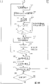
Figure 17 shows a kind of method of controlling switch;
Figure 18 shows the configuration of second kind of insert type coherent detection circuit;
Figure 19 shows a kind of weight coefficient control method;
Figure 20 shows the configuration of first kind of Invalid path detecting unit;
Figure 21 shows the configuration of second kind of Invalid path detecting unit;
Figure 22 shows the filter length control method;
Figure 23 shows the configuration of the transmitting power control unit of receiver;
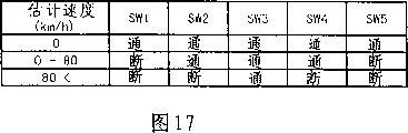
Figure 24 shows transmit power controlling method;
Figure 25 shows the configuration of the transmitting power control unit of transmitter;
Figure 26 shows the timing controlled of performance number transmission;
Figure 27 shows the velocity estimation of utilizing the TPC order;
Figure 28 shows first kind of TPC order count results;
Figure 29 shows second kind of TPC order count results;
Figure 30 shows the third TPC order count results;
Figure 31 shows the 4th kind of TPC order count results;
Figure 32 shows the first configuration example of decline pitch estimation unit;
Figure 33 shows the second configuration example of decline pitch estimation unit;
Figure 34 shows the circuit that produces the decline pitch according to count value;
Figure 35 shows the velocity amplitude meter of the accumulated value that utilizes the TPC order;
Figure 36 shows the sampling situation of accumulated value;
Figure 37 shows the 3rd configuration example of decline pitch estimation unit;
Figure 38 shows the fiducial value of TPC order accumulated value;
Figure 39 shows the 4th configuration example of decline pitch estimation unit;
Figure 40 shows the velocity estimation of utilizing available signal power;
Figure 41 shows the sampling situation that receives correlation;
Figure 42 shows sample circuit;
Figure 43 shows the synthetic situation of first kind of power;
Figure 44 shows the synthetic situation of second kind of power;
Figure 45 shows the synthetic situation of the third power;
Figure 46 shows the first configuration example of power synthesis unit;
Figure 47 shows the second configuration example of power synthesis unit;
Figure 48 shows the fiducial value of available signal power; And
Figure 49 shows two kinds of relations between the method for estimation.
Describe various embodiments of the present invention in detail below in conjunction with accompanying drawing.
Fig. 1 shows the principle of communication control unit of the present invention.Communication control unit shown in Figure 1 comprises a velocity estimation unit 1 and an amending unit 2, is used for controlling some parameters of mobile communication between sending station and the receiving platform.
In mobile communication, the base station can should be sending station or receiving platform mutually with travelling carriage.For example, the emissive power control command that velocity estimation unit 1 utilizes receiving platform to send to sending station estimates the movement velocity of receiving platform, and utilizes the desired signal power that produces at receiving platform to estimate the movement velocity of transmitting station.In fact, owing to be that base station or travelling carriage all have sending station and two kinds of functions of receiving platform, no matter be that base station or travelling carriage can both utilize emissive power control command or desired signal power to estimate the other side's movement velocity therefore.
Amending unit 2 changes the various parameters as sending station and receiving platform of equipment according to the control signal of velocity estimation unit 1 output.These parameters comprise the frequency that detects spread-spectrum signal despreading search operation regularly, receive the frequency that adds up of correlation in the search operation, the number of used pilot signal and weight coefficient in the coherent detection, the observation length of observation signal during Invalid path detects, the adjusting range of performance number and frequency of amendment etc. in the transmitting power control.By control these parameters according to control signal, just can control communication, thereby improve the receiving feature of receiving platform according to movement velocity.
For example, velocity estimation unit 1 shown in Fig. 1 is equivalent to the velocity estimation unit 61 shown in Fig. 4, begin timer 54 sum counter initial values unit 56 is set and amending unit 2 is equivalent to the search shown in Fig. 4, counter initial value shown in Figure 12 is provided with unit 114, switch control unit 136 shown in Figure 16, weight coefficient control unit 152 shown in Figure 18, filter length control unit 175 shown in Figure 21, TPC step-length shown in Figure 25 is selected control unit 225, and the timing control unit shown in Figure 26 228.
In order to make each parameters optimal of the communication equipment in the base station, must estimate the movement velocity of travelling carriage in the base station.Yet, in the DS-CDMA system, with also be the TDMA of multiplex system or FDMA system different be that a plurality of channels are stacked on the identical frequency, therefore be difficult to estimate movement velocity according to the measurement of received field strength.
So in this embodiment, movement velocity is that utilization employed TPC in DS-CDMA system emission power control (TPC) orders or the correlation of the ripple that reception is received is estimated.The value of each parameter of phase estimation unit in searcher, transmitting power control unit, the coherent detection etc. is set then, makes for the decline that is produced it is best.
The configuring condition that various parameters are set according to movement velocity at first is described, and then the configuring condition of movement velocity is estimated in explanation.Though what illustrate in following embodiment is to estimate the movement velocity of travelling carriage and the situation of the parameter of control travelling carriage by the base station, same configuration also can be used for travelling carriage.In this case, can estimate the relatively move movement velocity of platform of base station, the various parameters of equipment can be set at travelling carriage according to estimated movement velocity again.
Fig. 2 and Fig. 3 show the schematic diagram of the transmitter and receiver of DS-CDMA system respectively.In Fig. 2, need be loaded in the data that send on the carrier wave and multiply by the spreading code that produces from code generator 11 by multiplier 12, after amplifying, launches by amplifier 13 again from antenna 14.The logic of multiplier 12 can adopt logic arbitrarily, as XOR (EXOR) etc.
In Fig. 3, after amplifying, amplifier 22 is transformed into baseband signal (digital signal) from the received signal of antenna 21 by converter unit 23, revert to initial data by demodulating unit 24 again.
For the spread spectrum that makes transmit leg regularly regularly mates with recipient's despreading, disposed a searcher 25.Searcher 25 is controlled each code generator 31 according to the signal delay of output signal judgement every paths under multi-path environment of converter unit 23, and despreading is carried out with the timing consistent with every paths.Like this, just output and the consistent data of these signals of passing through mulitpath of demodulating unit 24.
The embodiment that utilizes estimated movement velocity to make the parameters optimal of searcher 25 will be described below.
Fig. 4 shows a kind of embodiment that searcher 25 adopts matched filter.In Fig. 4, matched filter 41 produces the correlation of useful signal according to input signal.Add up unit 42 adds up correlation, to improve signal to noise ratio (snr).Value after adding up deposits profiling memory (profilememory) 43 in.Extract one or more peak values active path detecting unit 44 each accumulated value in being stored in profiling memory 43 greater than certain value.So active path detecting unit 44 is regarded each peak value as one and an active path corresponding peaks, and the respective code generator 31 shown in Fig. 3 is inserted in the timing of this paths.
The motion velocity of mobile station that searcher starting timer 54 is estimated according to velocity estimation unit 61 makes the frequency of search operation reach best, will search for initiating signal according to best search rate and deliver to timing control unit 55.In this embodiment, so-called optimization is meant the control search rate, makes that search rate is also lower when movement velocity is low, and is slower because despreading at this moment regularly changes, and search rate is also higher when movement velocity is higher, because despreading at this moment regularly changes comparatively fast.
By utilizing estimated movement velocity to make the search rate optimization, just can prevent that despreading from regularly detecting and not catch up with the path and rise and fall, thereby just prevent that also search operation from too much carrying out.Therefore, the power consumption of searcher just can reduce.
In order to improve the SNR that in one search operation, receives correlation, it is also conceivable that according to movement velocity to make the accumulative frequency optimization.Decline produces when travelling carriage moves.Therefore, receive correlation even detect with certain timing, but this value is less corresponding to the concave point of decline the time, therefore reliability regularly is not high.
So accumulative frequency need be in motion or static or to be in high-speed motion still be that low-speed motion changes according to the travelling carriage of each channel, is set to a suitable number.When travelling carriage was in static (or low-speed motion), accumulative frequency was set to a less number, because the path rises and falls seldom.When the travelling carriage high-speed motion, accumulative frequency just is set to a bigger number, because there is a large amount of paths to rise and fall.In order to realize such control, the counter initial value is provided with counter 53 is revised in unit 56 according to velocity estimation unit 61 estimated movement velocitys initial value.
The following describes the configuration and the working condition of matched filter 41.Fig. 5 shows the configuration of adopting the matched filter 41 under the 3 bit spreading code situations in hypothesis, so that explanation is more simple and clear.In Fig. 5, delay cell 71 has three triggers (FF), and the serial signal that is used for importing is transformed into the parallel signal of 3 bits.Three multipliers 72 multiply each other the extended code of separating of this parallel signal and one 3 bit.Adder 73 with the output addition of these multipliers 72 after as receiving correlation output.
For example, as shown in Figure 6, when launching after transmit leg is carried out Exor with data " 1 " and spreading code " 101 ", received signal is " 010 " just.This signal is delivered to multiplier 72 from delay cell 71, is subjected to and separates the Exor operation of extended code " 101 ", so each multiplier 72 output logic " 1 " all.As a result, the correlation of adder 73 outputs is " 3 ".In fact, the spreading code of use has many bits, so matched filter 41 comprises many FF and multiplier.
When the data in delay cell 71 moved a bit, correlation just changed.Multiply by when separating extended code, form the peak value of correlation multiply by the identical timing of spreading code with emission side.Put it briefly because received signal comprises the signal that comes through mulitpath, and the time of advent of each signal since signal the path of process different and different, therefore can form a plurality of peak values as shown in Figure 7.
In Fig. 7, first peak value is corresponding to the shortest path P1 between base station and the travelling carriage, and the second and the 3rd peak value is corresponding to reflected wave or delay wave trajectory P2 and P3.Active path detecting unit 44 shown in Fig. 4 is that despreading produces respectively and the corresponding timing signal in each path by the time difference of measuring these peak values.Add up unit 42 and envelope memory 43 shown in Fig. 4 are used for making these peak values to detect can be more easy.
As shown in Figure 8, the movement velocity of travelling carriage: A (inactive state) is estimated in velocity estimation unit 61 among Fig. 4 with five velocity interval increments, B (0 to 40 kilometer/hour), C (40 to 80 kilometers/hour), D (80 to 120 kilometers/hour) and E (more than 120 kilometers/hour); To export to searcher starting timer 54 sum counter initial values with the velocity interval control signal corresponding unit 56 will be set.So searcher 25 is just carried out search operation according to control signal.
Fig. 9 and Figure 10 show the flow chart of carrying out search operation according to estimated movement velocity.When the control signal that receives from velocity estimation unit 61 (the step S1 among Fig. 9), searcher starting timer 54 sum counter initial values are provided with unit 56 and judge that whether movement velocity V is corresponding to level A (step S2).If speed V is corresponding to level A, initial value be provided with unit 56 just the initial value of counter 53 be set to 41 (step S3), and timer 54 timer cycles are set to 500 milliseconds (step S4).
If speed V is not corresponding with level A, searcher starting timer 54 sum counter initial values are provided with unit 56 and just judge that whether movement velocity V is corresponding to level B (step S5).If speed V is corresponding to level B, initial value be provided with unit 56 just the initial value of counter 53 be set to 31 (step S6), and timer 54 timer cycles are set to 250 milliseconds (step S7).
If speed V is not corresponding with level B, searcher starting timer 54 sum counter initial values are provided with unit 56 and just judge that whether movement velocity V is corresponding to level C (step S5).If speed V is corresponding to level C, initial value be provided with unit 56 just the initial value of counter 53 be set to 21 (step S9), and timer 54 timer cycles are set to 125 milliseconds (step S10).
If speed V is not corresponding with level C, searcher starting timer 54 sum counter initial values are provided with unit 56 and just judge that whether movement velocity V is corresponding to level D (step S11).If speed V is corresponding to level D, initial value be provided with unit 56 just the initial value of counter 53 be set to 11 (step S12), and timer 54 timer cycles are set to 62.5 milliseconds (step S13).
If speed V is not corresponding with level D, searcher starting timer 54 sum counter initial values are provided with unit 56 and just judge that whether movement velocity V is corresponding to level E (step S14).If speed V is corresponding to level E, initial value be provided with unit 56 just the initial value of counter 53 be set to 1 (step S15), and timer 54 timer cycles are set to 31.25 milliseconds (step S16).
Be provided with the cycle of the initial value and the timer 54 of counter 53, searcher 25 just begins to carry out search operation (the step S17 among Figure 10).At first, code generation unit 51 will be separated extended code and be inserted matched filter 41 (step S18), and profiling memory 43 begins to obtain the profiling data (a series of correlations in a period of time) (step S19) of the correlation of matched filter 41 outputs then.
At this moment, the address counter of storage address generation unit 52 begins to increase address Adr and reaches 2048 until the value of address Adr, and with the address Adr that is produced deliver to profiling memory 43 (step S20, S21).Profiling memory 43 deposits each correlation respectively in the address by address Adr appointment successively.Then, reach at 2048 o'clock at address Adr, the address counter of storage address generation unit 52 just assists to have finished the profiling data (step S22) of obtaining once-through operation.
Then, counter 53 adds 1 (step S23) with the count value N of accumulative frequency, and whether judgment value N reaches 63 (step S24) again.In this embodiment, counter 53 usefulness be the counter of one 6 bit, so end value is 63 (=2
6-1).The initial value of N is set by one of step S3, S6, S9, S12 and S15.If N is less than 63 for value, then returns step 17 and continue to repeat these operations.Add up and carry out by the unit 42 that adds up.
In this case, initial value 41,31,21,11 and 1 is 22,32,42,52 and 62 corresponding to accumulative frequency respectively.Obviously, speed V is big more, and the accumulative frequency of setting is many more.
Reach at 63 o'clock at value N, extract one or more and active path corresponding peaks the accumulation result of active path detecting unit 44 in being stored in profiling memory 43, the control signal (step S25) of the timing of each peak value of output indication.
When having finished search operation like this (step S26), come the control signal (pulse) of self-controller 53 just to start timer 54 (pause timer) (step S27), do not carry out search operation, until the 54 full times (step S28) that are provided with by one of step S4, S7, S10, S13 and S16 of timer.
Then, when the time that is provided with, meter was full, just return step S2, carry out these operations according to movement velocity continuation at this time.In this case, because speed V is big more, the circulation timei of set timer 54 is short more, so speed V is big more, and search rate is just high more.
In addition, a base station will with situation that a plurality of travelling carriages (channel) communicates by letter under, the path of these channels is regularly detected also and can be realized by making a searcher carry out one-at-a-time operation.
Figure 11 shows the schematic diagram of the receiver of carrying out this search operation.Identical among the configuration of the antenna 21 among Figure 11, amplifier 22, converter unit 23 and each demodulator 24 and working condition and Fig. 3.Each demodulating unit 24 is used respectively and is separated extended code accordingly with each channel and carry out demodulation to received signal.
In normal mode of operation, searcher 81 is followed successively by each channel with same frequency and carries out search operation.Yet because each travelling carriage can not be with the motion of identical speed, each channel is also different on the path rises and falls, so search rate should be according to the movement velocity of each travelling carriage respectively to each channel optimization.
In this case, a search rate that has than the channel of harmonic motion speed is provided with lowlyer, because despreading this moment regularly changes not quite.Simultaneously, the search rate with channel of higher motion speed just is provided with higherly, because despreading this moment regularly changes comparatively fast, situation is with the searcher shown in Fig. 3 25.
Adopt such control, can rise and fall according to the path of each channel the best search rate and the best accumulative frequency of each channel are set.Owing to be not to carry out search, therefore can reduce detection time, thereby just can guarantee search a plurality of channels with a searcher to be higher than required frequency.
Figure 12 shows searcher 81 in the configuration example that makes for each channel under the accumulative frequency optimal cases.Though this explanation be the situation of three channel CH1, CH2 and CH3, also be the same for situation more than three channels.
In Figure 12, matched filter 92 produces the correlation of desired signal from the multiplexed input signal of channel.The 93 pairs of correlations in unit that add up add up, and deposit accumulation result in profiling memory 94.Extract one or more and active path corresponding peaks the accumulation result of active path detecting unit 95 in being stored in profiling memory 94, the demodulator 24 of respective channel is delivered in the timing in these paths, as shown in Figure 11.
Code generation unit 102,103 and 104 offers matched filter 92 as multiplication coefficient according to the extended code of separating that produces channel CH1, CH2 and CH3 from the code output initiating signal of timing control unit 113 respectively.Selector 101 will be separated extended code CH1, CH2 or CH3 selectively and deliver to matched filter 92, and selector 105 is exported code initiating signal selectively and delivered to code generation unit 102,103 and 104.
Storage address generation unit 107 has an address counter.Storage address generation unit 107 produces storage address according to the address counter initiating signal from timing control unit 113, delivers to profiling memory 94 as write address.
Counter 108,109 and 110 finishes signal to the accumulated counts of CH1, CH2 and CH3 according to counting, when count value reaches certain value, detects initiating signal with one and delivers to active path detecting unit 95.Selector 111 signal that selectively counting finished is delivered to counter 108,109 or 110.
The counter initial value is provided with unit 114 and revises the initial value of counter 108,109 and 110 respectively according to estimated CH1, CH2 in velocity estimation unit 121,122 and 123 and the movement velocity of CH3.Selector 115 will be delivered to the counter initial value from the control signal of velocity estimation unit 121,122 or 123 selectively unit 114 will be set.
Channel selected cell 112 is subjected to the control of timing control unit 113, controls the break-make of selector 101,105,111 and 115.Movement velocity is estimated with five other velocity intervals of level in velocity estimation unit 121,122 and 123, output and estimated velocity interval control signal corresponding, and situation is with the velocity estimation unit 61 shown in Fig. 4.
Figure 13 and 14 is the flow chart that the search operation of searcher 81 is shown.When the control signal that receives from one of velocity estimation unit 121,122 and 123 (the step S31 among Figure 13, S32 and S33), channel selected cell 112 is just controlled selector 101,105,111 and 115, makes them select corresponding channel (step S34).
Then, the counter initial value is provided with unit 114 and judges that whether movement velocity V is corresponding to level A (step S35).If speed V is corresponding to level A, the counter initial value is provided with unit 114 and just the initial value of the counter (108,109 or 110) of respective channel is set to 41 (step S36).
If speed V is not corresponding with level A, the counter initial value is provided with unit 114 and just judges that whether movement velocity V is corresponding to level B (step S37).If speed V is corresponding to level B, the counter initial value be provided with unit 114 just the initial value of counter be set to 31 (step S38).
If speed V is not corresponding with level B, the counter initial value is provided with unit 114 and just judges that whether movement velocity V is corresponding to level C (step S39).If speed V is corresponding to level C, the counter initial value be provided with unit 114 just the initial value of counter be set to 21 (step S40).
If speed V is not corresponding with level C, the counter initial value is provided with unit 114 and just judges that whether movement velocity V is corresponding to level D (step S41).If speed V is corresponding to level D, the counter initial value be provided with unit 114 just the initial value of counter be set to 11 (step S42).
If speed V is not corresponding with level D, the counter initial value is provided with unit 114 and just judges that whether movement velocity V is corresponding to level E (step S43).If speed V is corresponding to level D, the counter initial value be provided with unit 114 just the initial value of counter be set to 1 (step S44).
After being provided with the initial value of counter like this, searcher 81 just begins search operation (the step S46 among Figure 14).At first, the code generation unit of respective channel (102,103 or 104) will be separated extended code and be inserted matched filter 92 (step S47), and profiling memory 94 begins to obtain the profiling data (step S48) of the correlation of matched filter 92 outputs then.
In this case, the address counter of storage address generation unit 107 begins to increase address Adr and reaches 2048 until the value of address Adr, and with the address Adr that is produced deliver to profiling memory 94 (step S49, S50).Profiling memory 94 deposits each correlation respectively in the address by address Adr appointment successively.Then, reach at 2048 o'clock, just finished the profiling data (step S51) of obtaining once-through operation at address Adr.
Then, the counter of respective channel adds 1 (step S52) with the count value N of accumulative frequency, judges whether count value N reaches 63 (step S53) again.The initial value of N is set by one of step S36, S38, S40, S42 and S44.If N is less than 63 for value, then returns step S46 and repeat these operations.Add up and carry out by the unit 93 that adds up.
Reach at 63 o'clock at value N, extract one or more and active path corresponding peaks the accumulation result of active path detecting unit 95 in being stored in profiling memory 94, the control signal (step S54) of the timing of each peak value of output indication.
When having finished search operation like this (step S55), channel selected cell 112 is just selected next channel (the step S45 among Figure 13), and flow process is returned step S35, repeats these operations according to movement velocity.
Though what be provided with according to movement velocity V in Fig. 9,10,13 and 14 is the initial value of counter 53,108,109 and 110, also the stop value of accumulative frequency can be set according to speed V, and the initial value of these counters all is set to 0.
To illustrate below and utilize estimated movement velocity to be used in the embodiment of parameter optimization of the pilot signal insert type absolute synchronization testing circuit of receiver.For example, when detecting unit shown in Fig. 3 33 is carried out the signal coherence detection, need carry out phase estimation.Be to utilize to carry out phase estimation in the insert type sync detection circuit as the pilot signal of known signal.
Figure 15 shows a signal that has inserted the need transmission of pilot signal.In this embodiment, before the data of N code element, insert the pilot signal of a code element, form a signal slot with N symbol data.
In general, the pilot signal number that is used for carrying out phase estimation is many more, thereby the signal to noise ratio improvement of estimated accuracy just is also just big more.But, when the motion owing to travelling carriage produces decline, in the signal phase place rotation can take place, thereby the phase correlation between a plurality of pilot signals weakens.Therefore, utilizing many separated in time pilot signals to carry out phase estimation, estimated accuracy is not high on the contrary sometimes.
Therefore, can control according to estimated movement velocity, the pilot signal that is used in phase estimation is counted optimization.Because travelling carriage is more near inactive state, phase place rotation is more little, thus travelling carriage more near inactive state, it is many more that sync detection circuit carries out the used pilot signal of phase estimation, and motion velocity of mobile station is big more, and it is few more then to carry out the used pilot signal of phase estimation.
Figure 16 shows the configuration example of this insert type absolute synchronization testing circuit.In Figure 16, pilot signal/data branching unit 131 will be shunted to data-signal and pilot signal through the input signal as shown in figure 15 of despreading.
Phase estimation unit 135 comprises a switch control unit 136, a plurality of shift register (SR) 137,138 and adders (ADD) 139 of a plurality of switch (SW1, SW2, SW3, SW4 and SW5).
Each shift register 137 for example is made up of some triggers, is used for the pilot signal from pilot/data branching unit 131 is passed a time slot.Each switch 138 is by switch control unit 136 controls.These switches 138 extract the pilot signal of output or adder 139 is delivered in the output of each shift register 137.Adder 139 will be delivered to multiplier 133 after the output addition from each switch 138.
According to this configuration, 132 outputs are as the data-signals of recognition objective (demodulation target) in the data delay unit, and switch SW 3 can be delivered to adder 139 with the pilot signal that data-signal is in same time slot.
Switch control unit 136 is for example used each switch 138 of logic control as shown in figure 17.When the control signal from velocity estimation unit 141 was 0 kilometer/hour (inactive state) corresponding to speed, switch control unit 136 was all connected all switches.As a result, five pilot signals that are inserted in before and after the digital signal as recognition objective are all delivered to adder 139.
When the control signal from velocity estimation unit 141 was 0 to 80 kilometer/hour corresponding to speed, switch control unit 136 was connected switch SW 2, SW3 and SW4, and rest switch SW1 and SW5 are disconnected.As a result, three pilot signals that are inserted in before and after the digital signal as recognition objective are delivered to adder 139.
When the control signal from velocity estimation unit 141 surpassed 80 kilometers/hour corresponding to speed, 136 of switch control units were connected switch SW 3, and remaining switch 138 is disconnected.As a result, have only and deliver to adder 139 as data-signal this pilot signal in same time slot of recognition objective.
Like this, in phase estimation unit 135, estimated movement velocity is more little, and the pilot signal of use is just many more, and estimated movement velocity is big more, and the pilot signal of use is just few more.Therefore, the precision of phase estimation can obtain optimization according to movement velocity.
In the phase estimation unit of this insert type absolute synchronization testing circuit, as several pilot signals before and after the data of recognition objective also can according to from data the time after being weighted, be used.Usually the weight coefficient of each pilot signal is changeless.
Yet, as previously described, when travelling carriage moves, can cause phase place rotation, and along with the change of movement velocity, the phase correlation between a plurality of pilot signals can rise and fall also.Therefore, hope can be according to the value of estimated each weight coefficient of movement velocity correction.In this embodiment, travelling carriage is more near inactive state, and each set weight coefficient differs more little, and movement velocity is big more, then just is arranged to more little away from the weight coefficient of pilot signal as the data of the other target of mark more.
Figure 18 shows the embodiment of this insert type absolute synchronization testing circuit.In Figure 18, the working condition of pilot/data branching unit 131, data delay unit 132, multiplier 133 and recognition unit 134 is identical with the working condition of related circuit shown in Figure 16.
Each shift register 153 will be passed a code element from the pilot signal of pilot/data branching unit 131.Each multiplier 154 multiply by some weight coefficients (K1, K2, K3, K4 and K5) that weight coefficient control unit 152 provides respectively with the pilot signal of input and the output of each shift register 153, and multiplied result is delivered to adder 155.Adder 155 is exported after with these multiplied result additions.
Weight coefficient control unit 152 is according to each weight coefficient for example is set as shown in Figure 19.If the control signal from velocity estimation unit 141 is 0 kilometer/hour (inactive state) corresponding to speed, the ownership coefficient just all is set to 1.0.As a result, five pilot signals that are inserted in before and after the digital signal as recognition objective are subjected to delivering to adder 155 after the same weighting.
If when being 0 to 80 kilometer/hour from the control signal of velocity estimation unit 141 corresponding to speed, just weight coefficient K2, K3 and K4 are set to 1.0, and remaining weight coefficient K1 and K5 are set to 0.5.The result, in five pilot signals, be to deliver to adder 155 after 1.0 the weighting through weight coefficient near those three pilot signals of data-signal as the other target of mark, all the other then deliver to adder 155 from data-signal two pilot signals far away after weight coefficient is 0.5 weighting.
If when surpassing 80 kilometers/hour from the control signal of velocity estimation unit 141 corresponding to speed, weight coefficient K3, K2 and K4, K1 and K5 are set to 1.0,0.5,0.2 respectively.The result, in five pilot signals, with data-signal as recognition objective be in a pilot signal in the same time slot, as two pilot signals in the tight forward and backward time slot of data-signal of recognition objective, remaining after weight coefficient is 1.0,0.5,0.2 weighting, delivering to adder 155 respectively as two pilot signals in the forward and backward again time slot of the data-signal of recognition objective.
Like this, in phase estimation unit 151, if estimated movement velocity is little, these weight coefficients just are arranged to the value that is more or less the same, if yet estimated movement velocity is big, be provided with more for a short time from weight coefficient as the data-signal of recognition objective pilot signal far away more.Therefore, the precision of phase estimation can obtain optimization according to movement velocity.
If some is set to 0 away from the pilot signal as the data-signal of recognition objective, the phase estimation unit 135 shown in just can image pattern 16 is revised the quantity of the pilot signal that is used for phase estimation like that.
In the receiver of DS-CDMA system, can by in despreading process with received signal along separate routes for some and the corresponding signal in path, after coherent detection, remerge and improve receiving feature.Such a function is called Rake (rake) and merges, and the merging method can adopt high specific merging etc.In this case, all signals from each paths that obtain along separate routes need not to be identical intensity, some skimble-skamble weak signals are arranged even also merged.What might have also that some cause that the despreading bad timing really produces owing to search for errors is the signal of noise entirely.
Below, at first explanation is used as the Invalid path detecting unit of the circuit of detection and the corresponding Invalid path of these signals, and then explanation makes the embodiment of the parameter optimization of Invalid path detecting unit according to estimated movement velocity.
Figure 20 shows the configuration example of the receiver with Invalid path detecting unit.Circuit shown in Figure 20 is corresponding to the demodulating unit among Fig. 3 24, is furnished with several respectively comprise a despread unit 160, an insert type synchronous detection unit 161 and an Invalid path detecting unit 162 respectively accordingly with each path assembly.Despread unit 160 is with corresponding regularly to the input signal despreading with a particular path.Insert type synchronous detection unit 161 utilizes pilot signal to carry out coherent detection, and the signal (reception correlation) that draws is delivered to Invalid path detecting unit 162.
Invalid path detecting unit 162 comprises sliding window average filter 171, identification level generation unit 172, comparator 173 and selector 174, to signal or 0 level signal of Rake merge cells 163 outputs from 161 inputs of insert type synchronous detection unit.
171 pairs of sliding window average filters are in the sliding window during this period of time input signal, and to slide window average, and 172 outputs of identification level generation unit have the signal of predetermined identification level.Comparator 173 will and come the input signal B of self-identifying level generation unit 172 to compare from the input signal A of sliding window average filter 171, according to control signal of comparative result output.
If signal A is greater than signal B, the control signal of being exported makes selector 174 can select input I1 from insert type synchronous detection unit 161, and if signal A is less than or equal to signal B, the control signal of being exported makes selector 174 can select to import I2.Input I2 is fixed as logical zero.It is its input I1 or the signal of I2 that selector 174 is exported one selectively according to control signal.
According to this Invalid path detecting unit 162,, just cut off the output of insert type synchronous detection unit 161 if the sliding window mean value of signal is less than or equal to the identification level.Therefore, the signal in low level path just can not imported Rake merge cells 163, and has only the signal input Rake merge cells 163 in good electrical level road footpath.Rake merge cells 163 will combine from the input signal in each path.Signal after recognition unit 164 is combined carries out data identification, the data that output obtains through decoding.
The observing time (observing length or filter length) that receives the observed correlation of sliding window average filter 171 is short more, just can in time refuse Invalid path more.Yet the observing time that receives the observed correlation of sliding window average filter 171 is short more, and the possibility that the detection accuracy of Invalid path descends is just big more.Therefore, should consider to detect the filter length of Invalid path according to estimated movement velocity correction.
Filter length can be thought has an optimum value for every kind of translational speed, wishes to be controlled to and can to refuse Invalid path in the shortest essential time.In this embodiment, movement velocity is more little, just filter length is provided with short more, because movement velocity is more little, the fluctuating of decline is also just more little.Simultaneously, movement velocity is big more, just filter length is provided with long more, because movement velocity is big more, the fluctuating of decline is also just big more.
Figure 21 shows the configuration example of Invalid path detecting unit.In configuration shown in Figure 21, added a filter length control unit 175 and cooperated with Invalid path detecting unit 162, a velocity estimation unit 181 also is provided.Filter length control unit 175 is according to the filter length of sliding window average filter 171 from the control signal correction of velocity estimation unit 181.
At this moment, filter length control unit 175 for example is provided with filter length as shown in figure 22 like that.If from the control signal of velocity estimation unit corresponding to speed be 0 kilometer/hour (inactive state), 0 to 80 kilometer/hour and greater than 80 kilometers/hour, filter length control unit 175 is set to 5 milliseconds, 10 milliseconds and 15 milliseconds with regard to corresponding filter length.
Like this,, short filter length just is set if estimated movement velocity is less, and if estimated movement velocity is bigger, long filter length just is set.Therefore, the accuracy of Invalid path detection just can be according to the movement velocity optimization.
In the DS-CDMA system, for example, the control of as shown in Figure 23 transmitting power is what to carry out in recipient's transmitting power control unit, to overcome because the different and caused decline of multi-path transmission of distance between base station and the travelling carriage.
In Figure 23, antenna 191, receiving element 192 and demodulating unit 193 are respectively corresponding to the demodulating unit 24 shown in the amplifier 22 shown in the antenna shown in Fig. 3 21, Fig. 3 and converter unit 23 and Fig. 3.The Rake merging back output that demodulating unit 193 is carried out despreading and each baseband signal receives correlation.The so-called signal that receives after correlation is meant despreading.
Transmitting power control unit 194 comprises SIR estimation unit 195 and comparing unit 196.SIR estimation unit 195 is according to receiving correlation estimated signal interference ratio (SIR), and comparing unit 196 compares estimated sir value and target SIR value.If estimated sir value is greater than the target SIR value, comparing unit 196 produces a TPC order that reduces transmitting power.If estimated sir value is less than the target SIR value, comparing unit 196 just produces a TPC order that increases transmitting power.Then, transmitting power control unit 194 sends to transmit leg with the TPC order, controls its transmitting power.
Figure 24 shows the TPC order that utilizes the recipient to produce and carries out the situation that transmitting power is controlled.When the transmitting power control unit 201 of transmit leg receives a TPC order from the recipient, transmitting power control unit 201 just increases according to this TPC order or reduces transmitting power, and a control signal corresponding is delivered to transmitting power amending unit 202.Transmitting power amending unit 202 comprises a variable amplifier, is used for revising the transmitting power that transmits.Transmit after amplifier 203 amplifies, send to the recipient by antenna 204.
According to such control, the transmitting power of transmit leg may be controlled to the sir value that makes the recipient can reach best.Yet adjusting range of the transmission power level in the transmitting power control unit 201 (TPC increases/reduce step-length) and correction rhythm (wide during adjustment) all are changeless usually.
Therefore but when travelling carriage moved, the fluctuating of SIR was very fast, might transmitting power utilized common TPC to increase/reduce step-length in the base station and widely when adjusting just can not control transmitting power according to the SIR of travelling carriage.Therefore, hope can make these parameter optimizations according to estimated movement velocity.It is wide when in this case, transmitting power control unit 201 increases/reduce step-length and adjustment according to the control signal correction TPC from velocity estimation unit 211.
Figure 25 illustrates the configuration example that increases/reduce the transmitting power control unit 201 of step-length according to estimated speed correction TPC.The TPC order is 1 bits command of indicating need to increase or reduce transmitting power normally.After revising unit 221,222 and 223 respectively amplify the TPC order of importing with different amplification quantity, order delivers to selector 224.
Order identical with its input of unit 221 (X1) output is revised in order, and unit 222 (X2) is revised in order makes it be output as the twice of input command, and order modification unit 223 (X3) then makes it be output as three times of input command.
Selector 224 is subjected to the control of TPC step-length selection control unit 225, and the TPC order that will import from order modification unit 221,222 or 223 is delivered to TPC and ordered the unit 226 that adds up selectively.Order the add up TPC order of input of unit 226 that adds up, the signal of indication of 227 outputs of transmission power level conversion table and accumulated value corresponding transmission power value.
For example, if "+1 " and " 1 " expression is used in the TPC order that TPC orders and reduces transmitting power that increases transmitting power respectively, the value that the TPC that TPC orders the unit 226 that adds up will import in succession successively orders adds up, and produces an order accumulated value as accumulation result.Then, the transmission power level that is directly proportional with this accumulated value from 227 outputs of transmission power level conversion table.
Movement velocity is estimated with inactive state, low-speed motion and three ranks of high-speed motion in velocity estimation unit 211, the control signal of output appropriate level.The TPC step-length selects control unit 225 can make selector 224 corresponding selections revise the input of unit 221,222 or 223 from order in control signal during corresponding to inactive state, low-speed motion or high-speed motion.
For example, if the accumulated value of TPC order "+/-" is 0.5dB corresponding to adjusting range, for a TPC order input, order amending unit 221,222 and 223 is produced as the adjusting range of 0.5dB, 1.0dB and 1.5dB respectively so.
Like this, if estimated movement velocity is less, just the adjusting range with transmission power level is provided with lessly, and if movement velocity is bigger, just the adjusting range with transmission power level is provided with greatlyyer.Therefore, even movement velocity is big, also can control transmitting power according to speed.
Widely when revising the adjustment of transmission power level also can be controlled according to movement velocity.Figure 26 shows the configuration example of the transmitting power control unit of this timing of control.
In Figure 26, timing control unit 228 is according to an adjustment of the control signal output gating signal from 211 inputs of speed estimation unit, and performance number transmission control unit 229 is revised the time interval (during adjustment wide) of output from the transmission power level of transmission power level conversion table 227 according to adjusting gating signal.
Here, estimated movement velocity is more near inactive state, widely during adjustment just is provided with greatly more.Estimated movement velocity is big more, widely during adjustment just is provided with more for a short time.Therefore, the frequency of revising transmission power level according to estimated movement velocity obtains optimization, even estimated movement velocity increases, transmitting power also can be controlled according to speed.
The configuration and the working condition of the velocity estimation unit of estimating motion velocity of mobile station will be described below.There are two kinds of methods can estimate this speed.A kind of method is to be used to the order from the TPC of travelling carriage, and another kind of method is to utilize available signal power.At first explanation utilizes the method for estimation of TPC order.
Because the TPC order changes according to the instantaneous fluctuating such as decline, if therefore detect the rate of change of TPC order, just can estimate movement velocity.Yet because under the situation of decline very at a high speed, the TPC order can not be caught up with instantaneous fluctuating, after movement velocity surpassed certain value, rate of change was just saturated constant.The saturated constant zone of TPC order change rate is depended on the adjusting range of TPC order and is wide when adjusting.
The configuration of movement velocity is estimated in the TPC order that Figure 27 shows that utilization produces in system as shown in figure 24 is used for controlling transmitting power.Decline pitch estimation unit 231 shown in Figure 27 is equivalent to the velocity estimation unit 211 shown in Figure 24, is used for detecting the variation of the TPC order of input.
As mentioned above, if TPC order be assumed to one 1 bit data (+1/-1), order with regard to two TPC more in succession decline pitch estimation unit 231, and the frequency that the data with same code is occurred continuously twice is counted, and estimates movement velocity according to count value.In general, if movement velocity is little, the code of TPC order just seldom changes.If movement velocity is big, code will often overturn.Therefore, when movement velocity reduced or increase, occurring having the data frequency of same code continuously will corresponding increase or reduce.
For example, in the TPC command string shown in Figure 28 and 29, count value (SUM) is respectively 7 and 4.Therefore, can estimate the movement velocity of the movement velocity of state shown in Figure 29 greater than state shown in Figure 28.Movement velocity also can be estimated with several ranks by the count value scope division.
Figure 30 and 31 shows the another kind of method of counting of TPC command string shown in Figure 28 and 29 respectively.Even adopt this two kinds of method of counting, also can estimate movement velocity in the same manner as described above.
Figure 32 shows the configuration example of execution decline pitch estimation unit 231 of counting operation shown in Figure 28 and 29.Configuration shown in Figure 32 comprises delay cell 241, EX-NOR door 242, sliding window average filter 243 and rate conversion memory 245.
Delay cell 241 delays the TPC order of input to export after the sampling period.Equivalence operation is carried out in the TPC order of 242 pairs of inputs of EX-NOR door and the output of delay cell 241, the TPC order of output input and " together " signal of last TPC order.Therefore, if if the value of two TPC orders in succession is identical, with regard to output logic " 1 ", otherwise, output logic " 0 ".
Sliding window average filter 243 comprises several delay cells 241 and an adder 244.The 243 output additions with EX-NOR door 242 in a period of time of sliding window average filter, the output addition result is as count value.Rate conversion memory 245 has been stored one will convert the conversion table of decline pitch from the count value of sliding window average filter 243 inputs to, utilize the value of the estimated decline pitch of this conversion table output.
Configuration shown in Figure 33 comprises an integrator of being made up of adder 246 and latch cicuit 247, is used for replacing the sliding window average filter 243 shown in Figure 32.Adder 246 repeats the output and the operation that is stored in the count value addition in the latch cicuit 247 with EX-NOR door 242 of certain number of times, and latch cicuit 247 is delivered to rate conversion memory 245 with count value.Therefore, export the estimated value of decline pitches from the average transit storage 245 of speed.
Also can utilize sort circuit as shown in figure 34 to replace rate conversion memory 245 to convert count value to the decline pitch.Circuit shown in Figure 34 comprises four comparators 251 and a decoder 252.
Each comparator 151 compares the count value A and the corresponding given thresholding (S1, S2, S3 or S4) of input.If A>B, comparator 251 output logics " 1 ", otherwise comparator 251 is with regard to output logic " 0 ".Suppose that thresholding S1, S2, S3 and S4 determine according to the relation between count value and the decline pitch in advance, and S1<S2<S3<S4.
In this speed estimation method, in the transmission frequency of TPC order because system is different not simultaneously, twice frequency appears in the same code of data have to(for) velocity estimation continuously might not be best.Therefore, this method can be extended to and N time frequency is appearred in data with same code continuously count, and estimates for the count value of system's the best and use.Recommendable is that the transmission frequency of TPC order is big more, the N value is obtained big more.
Figure 35 shows the configuration that the accumulated value that utilizes the TPC order is estimated movement velocity.Decline pitch estimation unit 262 shown in Figure 35 is equivalent to the velocity estimation unit 211 shown in Figure 24.Decline pitch estimation unit 262 receives the accumulated value of ordering the unit 226 that adds up from the TPC shown in Figure 25, estimates movement velocity in view of the above.
As shown in figure 36, sampled to the accumulated value of TPC order with certain sampling interval in decline pitch estimation unit 262, will be in a period of time the absolute value addition of the difference of successive sample values, according to gained with estimate movement velocity.
Movement velocity is big more, then this and big more because movement velocity is big more, the increase of accumulated value or reduce rapid more.Simultaneously, movement velocity is more little, then this and more little because movement velocity is more little, the increase of accumulated value or reduce slow more.Therefore, can estimate movement velocity with several ranks by the scope division of sampling value difference sum.
Figure 37 shows the configuration example of the decline pitch estimation unit 262 of carrying out this operation.Configuration shown in Figure 37 comprises delay cell 271, comparator 272, translation circuit 273, subtracter 274, adder 275, latch cicuit 276 and rate conversion memory 277.
Delay cell 271 postpones the accumulated value of input to export after a sampling period.Comparator 272 compares the accumulated value B of input and the output A of delay cell 271.If A>B, comparator 272 output logics " 1 ", otherwise, comparator 272 output logics " 0 ".
Translation circuit 273 is controlled by the output of comparator 272.If comparator 272 is output as logical one, translation circuit 273 just will be imported A and B respectively from output X and Y output, and if comparator 272 is output as logical zero, 273 of translation circuits will imports A and B exports from output Y and X respectively.Therefore, if the accumulated value B of input then has X=B and Y=A greater than the accumulated value A of last time sampling, and if the accumulated value A that the accumulated value B of input sampled less than the last time then has X=A and Y=B.
Subtracter 274 deducts output Y with the output X of translation circuit 273, the output difference.Because the output of translation circuit 273 guarantees X 〉=Y all the time, so the output of subtracter 274 is all the time more than or equal to 0.The absolute value of the difference of the accumulated value of accumulated value that this output is equivalent to import and last sampling.
Adder 275 repeat certain number of times with the output of subtracter 274 and latch cicuit 276 storage with operation addition, latch cicuit 276 will with deliver to rate conversion memory 277.Therefore, export the estimated value of decline pitches from speed transit storage 277.Also can be without rate conversion memory 277 with circuit as shown in figure 34 will with the estimated value that converts speed to.
Movement velocity also can be estimated according to the mean value of measuring the average gained of sliding window of these values with the difference addition of a period of time sampled value the time.More the fluctuating of precise motion velocity can on average be estimated by the sliding window of accurate measurement.
As shown in figure 38, pass through the frequency of certain fiducial value by the accumulated value that makes the 262 pairs of TPC orders in decline pitch estimation unit and count, also can estimate movement velocity according to count value (SUM).Accumulated value passes through fiducial value explanation accumulated value to be become greater than fiducial value or less than fiducial value.Movement velocity is big more, and count value is just big more, and movement velocity is more little, and count value is also just more little.Therefore, utilize this count value, can as the poor sum of utilizing between the sampled value, estimate movement velocity.
Figure 39 shows the configuration example of the decline pitch estimation unit 262 of carrying out this operation.Configuration shown in Figure 39 comprises fiducial value computing unit 281, comparator 282, rising edge testing circuit 283, multiplier 284, adder 285, latch cicuit 286 and rate conversion memory 277.
In this embodiment, fiducial value computing unit 281 comprises (n-1) individual delay cell 271, adder 287, a multiplier 288 and an adder 289, is used for going out fiducial value according to the average computation to n accumulated value.Adder 287 is accumulated value and (n-1) the output addition of individual delay cell 271 of input, and multiplier 288 multiply by 1/n with addition result.Adder 289 adds multiplied result certain value α again, thereby draws fiducial value.
Rate conversion memory 277 is according to the estimated value of the count value output decline pitch of input.Also can with all circuit as shown in figure 34 count value be converted to the estimated value of decline pitch without rate conversion memory 277.
When cross-over frequency was counted, can meter numerical value sliding window within a certain period of time average, movement velocity also can be estimated according to this mean value.Estimate the fluctuating of movement velocity more accurately by the sliding window average energy of accurate measurement.
Though above all these methods all are to utilize the TPC order to estimate the method for movement velocity, also have another kind of method, this method has been utilized from receiving the available signal power that correlation obtains.In the DS-CDMA system, received signal is to be in the state that frequency spectrum is expanded before despreading, and a plurality of channels are merged by multichannel.Therefore, only after despreading, just can observe the signal that is subjected to influence of fading from target MS.Yet, can extract by signal being carried out despreading, from the useful signal of target, observation decline situation is estimated movement velocity.
Figure 40 shows the configuration that utilizes available signal power to estimate movement velocity.291 utilizations of power synthesis unit receive the synthetic available signal power of correlation accordingly with the output of the demodulator 24 shown in Fig. 3.Decline pitch estimation unit 292 is equivalent to a velocity estimation unit, estimates movement velocity according to synthetic available signal power.
As shown in figure 41, decline pitch estimation unit 292 is measured and is received correlation, and the available signal power in every section certain hour is sampled.Each sampled value of available signal power (SP1, SP2 ..., SPi, SPj) all be according in succession reception correlation of n (1,2 ..., n) produce.
Figure 42 shows the embodiment of circuit of carrying out this sampling operation.Sample circuit shown in Figure 42 comprises adder 301 and latch cicuit 302 and 303, is used for producing the sampled value of available signal power.
302 couples of n of adder 301 and latch cicuit reception correlations in succession add up, and latch cicuit 302 is sampled all by the sampled signal zero clearing at every turn.Latch cicuit 303 usefulness sampled signals latch the output of latch cicuit 302 each samplings, the output sampled value.According to sort circuit, with the n reception correlation in succession of sampling at every turn and as a sampled value output.
For example, as the method that produces available signal power according to the reception correlation of the signal that comprises pilot signal as shown in figure 15, can consider three kinds of methods shown in Figure 43,44 and 45.
In Figure 43, the reception correlation of 304 outputs of Rake merge cells and the corresponding useful signal of particular channel, the reception correlation that pilot signal extraction unit 305 extracts as the pilot signal of known signal.The power that power synthesis unit 291 is carried out the reception correlation that is extracted synthesizes, and produces the sampled value of available signal power.In this embodiment, each sampled value is a n quadratic sum that receives correlation.
In Figure 44, power synthesis unit 291 is carried out the amplitude of the reception correlation that is extracted and is synthesized, and produces the sampled value of available signal power.In this embodiment, each sampled value be n average that receives correlation square.
In Figure 45, do not extract pilot signal, power synthesis unit 291 is carried out the pilot signal of Rake merge cells 304 outputs and the power of data-signal synthesizes, and produces the sampled value of available signal power.In this embodiment, each sampled value is a n quadratic sum that receives correlation.Method shown in Figure 45 can be used for arbitrary signal, and whether no matter pilot signal wherein arranged.
Figure 46 shows the configuration example of the power synthesis unit 291 shown in Figure 43.Configuration shown in Figure 46 comprises squarer 311, adder 312 and latch cicuit 313.The reception correlation of 311 pairs of inputs of squarer carries out square.Add up the in succession output of n of squarer 311 of adder 312 and latch cicuit 313, the result exports as sampled value with gained.Latch cicuit 313 when each sampling all by the sampled signal zero clearing.Power synthesis unit 291 shown in Figure 45 comprises and identical circuit shown in Figure 46.
Figure 47 shows the configuration example of the power synthesis unit 291 shown in Figure 44.Configuration shown in Figure 47 comprises adder 321, latch cicuit 322 and 323, multiplier 324 and squarer 325.
Adder 321 and the latch cicuit 322 n reception correlation in succession that adds up, latch cicuit 322 when each sampling all by the sampled signal zero clearing.Latch cicuit 323 latchs the output of the latch cicuit 322 of each sampling according to sampled signal, and multiplier 324 multiply by 1/n with the output of latch cicuit 323.The output of 325 pairs of multipliers 324 of squarer is carried out square, and result of calculation is exported as sampled value.
According to the sampled value of the available signal power of such generation, with identical mode shown in Figure 36, the decline pitch estimation unit 292 shown in Figure 40 is the absolute value addition of the difference of consecutive value in a period of time, from resulting and estimate movement velocity.In this case, decline pitch estimation unit 292 for example can adopt and identical circuit shown in Figure 37.
Movement velocity is big more, this and just big more because movement velocity is big more, the increase of available signal power or reduce also just rapid more.Equally, movement velocity is more little, this and just more little because movement velocity is more little, the increase of available signal power or reduce also just slow more.Therefore, movement velocity can be estimated with several ranks by the scope division of sampling value difference sum.Movement velocity also can be expressed as this and suitable function.
Movement velocity also can be estimated according to the mean value of measuring the average gained of sliding window of these values with the difference addition of a period of time sampled value the time.Estimate the fluctuating of movement velocity more accurately by the sliding window average energy of accurate measurement.
As shown in figure 48, pass through the frequency of certain fiducial value by the sampled value that makes decline pitch estimation unit 292 pairs of available signal powers and count, movement velocity also can according to this count value (with) estimated.Movement velocity is big more, and count value is just big more, and movement velocity is more little, and count value is just more little.Therefore, movement velocity can utilize this count value to estimate with the above-mentioned identical mode of sampling value difference sum of asking.In this case, decline pitch estimation unit 292 for example can adopt such as shown in figure 39 circuit.
When cross-over frequency was counted, can meter numerical value sliding window within a certain period of time average, movement velocity also can be estimated according to this mean value.Estimate the fluctuating of movement velocity more accurately by the sliding window average energy of accurate measurement.
Though more than illustrated and utilized TPC order and these two kinds of methods of estimation of available signal power, existed certain correlation between these two kinds of methods.In general, because when movement velocity surpassed certain value, transmitting power was not controlled in the TPC order, so the rate of change of the TPC order of recipient's generation just becomes changeless.
Therefore, in the method for utilizing the TPC order, be rendered as a constant value according to the resulting estimating speed of this rate of change in the high velocity that surpasses certain value, as shown in figure 49.Figure 49 shows the decline pitch (fdt) of decline and the relation between the estimating speed of producing.As seen, between decline pitch and the actual motion speed confidential relation is arranged.The decline pitch is big more, and movement velocity is just big more.
On the other hand, in utilizing the method for available signal power, estimating speed is rendered as a constant value in the low regime that is lower than certain value, and this is just in time opposite with the method for utilizing the TPC order.This is because when movement velocity is little, because transmitting power has been controlled in the TPC order effectively, so available signal power becomes changeless.If movement velocity increases to a certain degree, transmitting power has not been controlled effect, and available signal power just rises and falls.Therefore, movement velocity just can utilize this fluctuating to estimate.
So, preferably utilize these two kinds of methods of estimation to estimate movement velocity simultaneously.For example, in the saturated zone of the estimated value of utilizing TPC order to obtain, the estimated value of utilizing available signal power to obtain can be adopted, and in the saturated zone of the estimated value of utilizing available signal power to obtain, the estimated value of utilizing the TPC order to obtain can be adopted.By utilizing this two kinds of methods simultaneously, can remedy shortcoming separately mutually, thus the estimation range of energy extension movement speed.
In the various embodiments described above, the circuit that can use any hardware such as digital signal processor (DSP) or firmware to realize estimating the circuit of movement velocity and the various parameters of communication equipment are set.The target component of control is not limited to these parameters in function of search, transmitting power controlled function and the coherent detection function, also can comprise the parameter in any other function.
In addition, the present invention is not limited to the communication that is used for the DS-CDMA system, also can be widely used in the communication in the systems such as phase shift keying (PSK) system, personal digital cellular (PDC) system.
According to the present invention, in the communication in systems such as CDMA, can dynamically control various parameters in the communication equipment, thereby can improve receiving feature and increase channel capacity according to estimated movement velocity.
Claims (24)
1, a kind of control is used for the communication control unit of the parameter of the spread spectrum communication of mobile communication between sending station and the receiving platform, and described equipment comprises:
The velocity estimation unit is used to estimate the movement velocity of one of described sending station and receiving platform and output and estimated movement velocity control signal corresponding; And
Amending unit is used for the value according to the described parameter of described control signal correction;
Wherein
Described receiving platform comprises a searcher, is used to carry out search operation so that detect the timing of spread-spectrum signal being carried out despreading; And
Described amending unit is optimized this search operation according to the parameter value through revising by the frequency of control search operation.
2, communication control unit as claimed in claim 1, wherein:
Described amending unit comprises the timer of control search operation frequency, and this amending unit was controlled the cycle as the described timer of described parameter.
3, communication control unit as claimed in claim 1, wherein:
Described searcher detects the timing that is used for each signal despreading of a plurality of spreading channels; And
Described amending unit is according to controlling the frequency of described search operation with the estimation movement velocity control signal corresponding of each spreading channel.
4, communication control unit as claimed in claim 1, wherein:
The accumulative frequency that described amending unit is produced by searcher according to the control of described control signal as the reception correlation of the described parameter in the search operation.
5, communication control unit as claimed in claim 1, wherein:
The described sending station of described velocity estimation unit estimation is with respect to the speed of related movement of described receiving platform and estimate the speed of related movement of described receiving platform with respect to described sending station.
6, communication control unit as claimed in claim 1, wherein:
The described receiving platform of described velocity estimation unit by using sends to the emissive power control command of described sending station and estimates described movement velocity.
7, communication control unit as claimed in claim 1, wherein:
The available signal power that described velocity estimation unit by using produces in described receiving platform is estimated described movement velocity.
8, communication control unit as claimed in claim 4, wherein:
Described searcher detects the timing that is used for each signal despreading of a plurality of spreading channels; And
Described amending unit basis is controlled described accumulative frequency corresponding to the control signal of the estimation movement velocity of each channel.
9, a kind of control is used for the communication control unit of the parameter of the spread spectrum communication of mobile communication between sending station and the receiving platform, and described equipment comprises:
The velocity estimation unit is used to estimate the movement velocity of one of described sending station and receiving platform and output and estimated movement velocity control signal corresponding; And
Amending unit is used for the value according to the described parameter of described control signal correction;
Wherein
Described receiving platform comprises the coherent detection unit that is used to detect the signal that comprises pilot signal, and
Described amending unit is according to the parameter in the detecting operation by described coherent detection unit carried out of described control signal control as described parameter.
10, communication control unit as claimed in claim 9, wherein:
Described amending unit is estimated the number of used pilot signal as the described coherent detection unit excute phase of parameter described in the detecting operation according to described control signal control.
11, communication control unit as claimed in claim 9, wherein:
Described amending unit is according to the weight coefficient by described coherent detection unit excute phase estimation used pilot signal of described control signal control as parameter described in the detecting operation.
12, a kind of control is used for the communication control unit of the parameter of the spread spectrum communication of mobile communication between sending station and the receiving platform, and described equipment comprises:
The velocity estimation unit is used to estimate the movement velocity of one of described sending station and receiving platform and output and estimated movement velocity control signal corresponding; And
Amending unit is used for the value according to the described parameter of described control signal correction;
Wherein
Described receiving platform comprises and is used for the Invalid path detecting unit that detection signal level is lower than the Invalid path of certain value; And
Described amending unit is according to the parameter in the detecting operation by described Invalid path detecting unit carried out of described control signal control as described parameter.
13, as communication control unit as described in the claim 12, wherein:
Described amending unit is according to the observation length of described control signal control as the described Invalid path detecting unit observation signal of parameter described in the detecting operation.
14, communication control unit as claimed in claim 13, wherein:
Described Invalid path detecting unit comprises a filter, is used for the signal that need are observed is carried out filtering; And
Described amending unit is according to the filter length of described control signal control as the filter of parameter described in the detecting operation.
15, a kind of control is used for the communication control unit of the parameter of the spread spectrum communication of mobile communication between sending station and the receiving platform, and described equipment comprises:
The velocity estimation unit is used to estimate the movement velocity of one of described sending station and receiving platform and output and estimated movement velocity control signal corresponding; And
Amending unit is used for the value according to the described parameter of described rate signal correction;
Wherein
Described sending station comprises the transmitting power control unit that is used to revise transmitting power; And
Described amending unit is according to the parameter in the correction operation by described transmitting power control unit carried out of described control signal control as described parameter.
16, communication control unit as claimed in claim 15, wherein:
But described amending unit according to the control of described control signal as the adjusting range of revising parameter described in the operation by the performance number of described transmitting power control unit correction.
17, communication control unit as claimed in claim 16, wherein:
Described transmitting power control unit comprises the unit that adds up of the emissive power control command that sends from described receiving platform of being used to add up, and a converting unit that is used for accumulated value is converted to performance number; And
Described amending unit is controlled the accumulated value of described emissive power control command according to described control signal.
18, communication control unit as claimed in claim 15, wherein:
Described amending unit is according to the frequency of described control signal control as the transmitting power control unit corrected output value of parameter described in the correction operation.
19, a kind of receiver comprises:
The velocity estimation unit is used for estimating the movement velocity of mobile communication sending station and output and estimated movement velocity control signal corresponding;
Amending unit is used for being used for according to described control signal correction the value of parameter of the spread spectrum communication of described mobile communication; And
Searcher is used to carry out search operation so that detect the timing that is used for spread-spectrum signal is carried out despreading; Wherein
Described amending unit is optimized this search operation according to the parameter value through revising by the frequency of control search operation.
20, a kind of receiver comprises:
The velocity estimation unit is used for estimating movement velocity and the output and estimated movement velocity control signal corresponding of mobile communication sending station; And
Amending unit is used for being used for according to described control signal correction the parameter value of the spread spectrum communication of described mobile communication; Wherein
The control of described amending unit is as the parameter in following at least one or a plurality of operation of described spread spectrum parameter: be used to detect the search operation to the timing of spread-spectrum signal despreading, be used to detect the detecting operation of the signal that comprises pilot signal, and the detecting operation that is used to detect Invalid path.
21, a kind of transmitter comprises:
The velocity estimation unit is used for estimating movement velocity and the output and estimated movement velocity control signal corresponding of mobile communication receiving platform; And
Amending unit is used for being used for according to described control signal correction the parameter value of the spread spectrum communication of described mobile communication; Wherein
The control of described amending unit is as the parameter of correction operation that is used for revising transmitting power of described parameter.
22, a kind of transmitter comprises:
The velocity estimation unit is used for estimating movement velocity and the output and estimated movement velocity control signal corresponding of mobile communication receiving platform; And
Amending unit is used for being used for according to described control signal correction the value of the parameter of described mobile communication; Wherein
Described amending unit is according to following at least one or a plurality of parameter of described control signal control as described parameter: but performance number adjusting range and performance number frequency of amendment in the transmitting power control.
23, a kind of communication control method may further comprise the steps:
Carry out the mobile communication between sending station and the receiving platform;
Estimate the movement velocity of one of described sending station and described receiving platform;
The parameter value that is used for the spread spectrum communication of described mobile communication according to the movement velocity correction of estimating; And
Control is as the parameter in following at least one or a plurality of operation of described spread spectrum parameter: be used to detect the search operation to the timing of spread-spectrum signal despreading, be used to detect the detecting operation of the signal that comprises pilot signal, be used to detect the detecting operation of Invalid path, and the correction operation that is used to revise transmitting power.
24, a kind of communication control method may further comprise the steps:
Carry out the mobile communication between sending station and the receiving platform;
Estimate the movement velocity of one of described sending station and described receiving platform;
The parameter value that is used for the spread spectrum communication of described mobile communication according to estimated movement velocity correction; And
According to the movement velocity of described estimation control following at least one parameter: be used to detect frequency to the search operation of the timing of spread-spectrum signal despreading as described parameter, receive the accumulative frequency of correlation in the search operation, carry out the number of the used pilot signal of coherent detection, the weight coefficient of pilot signal, be used for detecting the observation length of observation signal at Invalid path, but the adjusting range of the performance number in the transmitting power control, and the frequency of amendment of performance number in the transmitting power control.
Applications Claiming Priority (3)
| Application Number | Priority Date | Filing Date | Title |
|---|---|---|---|
| JP2176198A JP3913879B2 (en) | 1998-02-03 | 1998-02-03 | Communication control apparatus and method based on moving speed |
| JP021761/98 | 1998-02-03 | ||
| JP021761/1998 | 1998-02-03 |
Publications (2)
| Publication Number | Publication Date |
|---|---|
| CN1225529A CN1225529A (en) | 1999-08-11 |
| CN1139212C true CN1139212C (en) | 2004-02-18 |
Family
ID=12064060
Family Applications (1)
| Application Number | Title | Priority Date | Filing Date |
|---|---|---|---|
| CNB981208444A Expired - Fee Related CN1139212C (en) | 1998-02-03 | 1998-09-29 | Apparatus and method for controlling communications based on moving speed |
Country Status (3)
| Country | Link |
|---|---|
| US (2) | US6456827B1 (en) |
| JP (1) | JP3913879B2 (en) |
| CN (1) | CN1139212C (en) |
Families Citing this family (67)
| Publication number | Priority date | Publication date | Assignee | Title |
|---|---|---|---|---|
| TW347616B (en) * | 1995-03-31 | 1998-12-11 | Qualcomm Inc | Method and apparatus for performing fast power control in a mobile communication system a method and apparatus for controlling transmission power in a mobile communication system is disclosed. |
| US6977967B1 (en) * | 1995-03-31 | 2005-12-20 | Qualcomm Incorporated | Method and apparatus for performing fast power control in a mobile communication system |
| JP3913879B2 (en) * | 1998-02-03 | 2007-05-09 | 富士通株式会社 | Communication control apparatus and method based on moving speed |
| JP2002026789A (en) * | 1998-09-11 | 2002-01-25 | Matsushita Electric Ind Co Ltd | Communication unit and directivity transmission method |
| JP4287536B2 (en) * | 1998-11-06 | 2009-07-01 | パナソニック株式会社 | OFDM transmitter / receiver and OFDM transmitter / receiver method |
| JP3741881B2 (en) * | 1998-11-16 | 2006-02-01 | 富士通株式会社 | Receiver used in CDMA communication |
| US7184462B1 (en) * | 1998-12-04 | 2007-02-27 | Telefonaktiebolaget L M Ericsson (Publ) | Method and apparatus for configuring a rake receiver |
| US6678313B1 (en) * | 1998-12-25 | 2004-01-13 | Kokusai Electric Co., Ltd. | Correlation circuit for spread spectrum communication |
| US6377618B1 (en) * | 1998-12-30 | 2002-04-23 | Agere Systems Guardian Corp. | Auto-correlation system and method for rate detection of a data communication channel |
| KR100386167B1 (en) * | 1999-04-27 | 2003-06-02 | 가부시키가이샤 요잔 | Ds-cdma receiver |
| JP3367475B2 (en) | 1999-07-06 | 2003-01-14 | 日本電気株式会社 | Wireless communication device and power consumption control method for wireless communication device |
| US6516021B1 (en) * | 1999-09-14 | 2003-02-04 | The Aerospace Corporation | Global positioning systems and inertial measuring unit ultratight coupling method |
| JP3961828B2 (en) | 1999-09-22 | 2007-08-22 | 富士通株式会社 | Transmission power control device |
| KR20010038528A (en) * | 1999-10-26 | 2001-05-15 | 조정남 | Apparatus and method for controlling a power of reverse link in CDMA system |
| JP2003516091A (en) * | 1999-11-22 | 2003-05-07 | テレフオンアクチーボラゲット エル エム エリクソン(パブル) | Estimation of relative speed using TPC command |
| JP2001211101A (en) * | 2000-01-26 | 2001-08-03 | Nec Corp | Cdma receiver with low power consumption and its power consumption reducing method |
| JP2001223671A (en) * | 2000-02-14 | 2001-08-17 | Mitsubishi Electric Corp | Fading pitch detector and portable information terminal using the same |
| JP2001285129A (en) | 2000-03-29 | 2001-10-12 | Nec Corp | Circuit and method for cdma demodulation |
| WO2001084734A2 (en) * | 2000-05-01 | 2001-11-08 | Telefonaktiebolaget L M Ericsson (Publ) | Matched filter and receiver for mobile radio communication system |
| FI118877B (en) * | 2000-06-19 | 2008-04-15 | Valtion Teknillinen | Estimation of movement |
| JP2002009734A (en) * | 2000-06-27 | 2002-01-11 | Denso Corp | Communication system employing ofdm system |
| JP3588040B2 (en) | 2000-07-26 | 2004-11-10 | 松下電器産業株式会社 | Communication terminal device and base station device |
| WO2002011479A1 (en) * | 2000-07-31 | 2002-02-07 | Mitsubishi Denki Kabushiki Kaisha | Communication traffic control method for mobile communication system |
| KR100342496B1 (en) * | 2000-09-08 | 2002-06-28 | 윤종용 | Pn hypothesis movement apparatus of high speed searcher and method therefor |
| JP3443083B2 (en) | 2000-09-12 | 2003-09-02 | 株式会社東芝 | Method of evaluating dangerous spot information of semiconductor device pattern |
| GB0022633D0 (en) * | 2000-09-15 | 2000-11-01 | Koninkl Philips Electronics Nv | Secondary station and method of operating the station |
| GB0022634D0 (en) | 2000-09-15 | 2000-11-01 | Koninkl Philips Electronics Nv | Secondary station and method of operating the station |
| US6801759B1 (en) * | 2000-09-25 | 2004-10-05 | Qualcomm, Incorporated | Method and apparatus for power control in a wireless communication system |
| US6999500B2 (en) * | 2000-11-03 | 2006-02-14 | Qualcomm Inc. | System for direct sequence spreading |
| EP1249955B1 (en) * | 2000-11-17 | 2011-01-26 | Panasonic Corporation | Ofdm communication device |
| JP3589292B2 (en) * | 2000-11-30 | 2004-11-17 | 日本電気株式会社 | Mobile communication device |
| KR100525541B1 (en) * | 2000-12-04 | 2005-10-31 | 엘지전자 주식회사 | Apparatus for estimating phase information using Matched Filter and Method thereof |
| US8199696B2 (en) * | 2001-03-29 | 2012-06-12 | Qualcomm Incorporated | Method and apparatus for power control in a wireless communication system |
| AU2002320680B9 (en) * | 2001-07-24 | 2005-08-04 | Ntt Docomo, Inc. | Transmission power control apparatus and method in a mobile communication system, mobile station, and communication apparatus |
| JP4032681B2 (en) * | 2001-08-27 | 2008-01-16 | 株式会社デンソー | Synchronous detection method and apparatus, and sensor signal detection apparatus |
| US9143255B2 (en) * | 2002-10-18 | 2015-09-22 | Microsoft Technology Licensing, Llc | Orthogonal signaling for CDMA |
| TW579636B (en) * | 2002-10-25 | 2004-03-11 | Benq Corp | Method and system for estimating movement speed of mobile phone |
| JP4470377B2 (en) * | 2003-02-28 | 2010-06-02 | 株式会社日立製作所 | Propagation path estimation method in mobile communication system |
| US7203258B2 (en) * | 2003-03-27 | 2007-04-10 | Agilent Technologies, Inc. | Acquisition algorithm in asynchronous CDMA systems |
| US7206556B1 (en) * | 2003-08-08 | 2007-04-17 | Nvidia Corporation | Wireless transmitter control lockout |
| DE10337068B4 (en) * | 2003-08-12 | 2005-09-29 | Infineon Technologies Ag | Adaptive channel estimation by varying the integration length in the despreading of spread-coded training symbol sequences |
| KR101009827B1 (en) * | 2003-09-16 | 2011-01-19 | 삼성전자주식회사 | Estimating apparatus and method of mobile station speed in a mobile communication system |
| US7352829B2 (en) * | 2004-01-12 | 2008-04-01 | Infineon Technologies Ag | Data-aided channel estimation |
| FR2865600B1 (en) * | 2004-01-26 | 2006-05-19 | Evolium Sas | DYNAMIC ADAPTATION OF DETECTION OF ACCESS DEMANDS TO A CELLULAR COMMUNICATIONS NETWORK, BASED ON THE RADIO ENVIRONMENT ASSOCIATED WITH THE APPLICANT COMMUNICATION EQUIPMENT |
| JP4770146B2 (en) * | 2004-09-14 | 2011-09-14 | 日本電気株式会社 | Information processing apparatus and information processing method |
| US7616715B2 (en) * | 2004-11-30 | 2009-11-10 | Stmicroelectronics Asia Pacific Pte. Ltd. | Method and system for estimating the speed of a mobile device in a network |
| US20060128326A1 (en) * | 2004-12-09 | 2006-06-15 | Interdigital Technology Corporation | Low complexity adaptive channel estimation |
| EP1868304B1 (en) | 2005-03-31 | 2014-03-05 | NEC Corporation | Mobile radio terminal and its moving speed detection method |
| KR100735271B1 (en) * | 2005-04-25 | 2007-07-03 | 삼성전자주식회사 | User Equipment and Method for Controlling Transmission Rate of The Same |
| WO2007001052A1 (en) * | 2005-06-29 | 2007-01-04 | Kyocera Corporation | Radio communication device, radio communication method, and radio communication program |
| JP2007020074A (en) * | 2005-07-11 | 2007-01-25 | Ntt Docomo Inc | Mobile radio station and communication parameter control method thereof |
| US8666460B2 (en) * | 2006-05-05 | 2014-03-04 | Analog Devices, Inc. | Method and apparatus for controlling a portable device |
| US20080075056A1 (en) * | 2006-09-22 | 2008-03-27 | Timothy Thome | Mobile wireless device and processes for managing high-speed data services |
| US8175562B2 (en) * | 2006-10-27 | 2012-05-08 | Agere Systems Inc. | Automatic gain control for enhanced bit error rate performance |
| JP2008172768A (en) | 2006-12-13 | 2008-07-24 | Ntt Docomo Inc | Mobile communication terminal and mobile communication method |
| WO2008103769A1 (en) * | 2007-02-20 | 2008-08-28 | Haiyun Tang | High dynamic range transceiver for cognitive radio |
| JP4836829B2 (en) * | 2007-02-26 | 2011-12-14 | 富士通株式会社 | Receiving device, path detecting device, method and computer program used in CDMA base station |
| WO2008120319A1 (en) * | 2007-03-28 | 2008-10-09 | Fujitsu Limited | Path search apparatus |
| EP3293998B1 (en) * | 2007-11-02 | 2019-04-10 | Telefonaktiebolaget LM Ericsson (publ) | Speed-dependent adaptation of mobility parameters |
| JP5075019B2 (en) * | 2008-06-04 | 2012-11-14 | 株式会社エヌ・ティ・ティ・ドコモ | Mobile communication terminal apparatus and transmission power setting method |
| US8457038B1 (en) * | 2010-10-27 | 2013-06-04 | Sprint Communications Company L.P. | Velocity based handoff determination in wireless communication system |
| TWI474728B (en) * | 2012-09-21 | 2015-02-21 | A three layer cascade adaptive neural fuzzy inference system (anfis) based cognitive engine scheme and device | |
| CN104125020B (en) * | 2013-04-23 | 2017-03-01 | 宏达国际电子股份有限公司 | Wireless signal method for searching and electronic apparatus |
| US9379789B2 (en) * | 2013-07-03 | 2016-06-28 | Qualcomm Incorporated | Antenna selection adjustment |
| US9137716B1 (en) | 2013-12-27 | 2015-09-15 | Sprint Communications Company L.P. | Mobility based frequency band selection in wireless communication systems |
| JP6331578B2 (en) * | 2014-03-28 | 2018-05-30 | 富士通株式会社 | Wireless terminal device and wireless communication system |
| CN106034351A (en) * | 2015-03-09 | 2016-10-19 | 联想(北京)有限公司 | Transmission power adjusting method and electronic equipment |
Family Cites Families (9)
| Publication number | Priority date | Publication date | Assignee | Title |
|---|---|---|---|---|
| FR2595889B1 (en) | 1986-03-14 | 1988-05-06 | Havel Christophe | TRANSMISSION POWER CONTROL DEVICE IN A RADIO COMMUNICATION TRANSCEIVER STATION |
| WO1994018756A1 (en) | 1993-02-11 | 1994-08-18 | Motorola, Inc. | Method and apparatus for controlling a power level of a subscriber unit of a wireless communication system |
| US5432822A (en) * | 1993-03-12 | 1995-07-11 | Hughes Aircraft Company | Error correcting decoder and decoding method employing reliability based erasure decision-making in cellular communication system |
| TW347616B (en) * | 1995-03-31 | 1998-12-11 | Qualcomm Inc | Method and apparatus for performing fast power control in a mobile communication system a method and apparatus for controlling transmission power in a mobile communication system is disclosed. |
| US5634206A (en) * | 1995-05-25 | 1997-05-27 | Motorola, Inc. | Method and apparatus for estimating a signal fading characteristic |
| US6026115A (en) * | 1996-08-23 | 2000-02-15 | Ntt Mobile Communications Network, Inc. | Rake receiver |
| JPH1079701A (en) * | 1996-09-03 | 1998-03-24 | Fujitsu Ltd | Mobile communication terminal and its transmission power control system |
| JP3254390B2 (en) * | 1996-10-18 | 2002-02-04 | 三菱電機株式会社 | Transmission power control device |
| JP3913879B2 (en) * | 1998-02-03 | 2007-05-09 | 富士通株式会社 | Communication control apparatus and method based on moving speed |
-
1998
- 1998-02-03 JP JP2176198A patent/JP3913879B2/en not_active Expired - Fee Related
- 1998-07-28 US US09/123,548 patent/US6456827B1/en not_active Expired - Fee Related
- 1998-09-29 CN CNB981208444A patent/CN1139212C/en not_active Expired - Fee Related
-
2002
- 2002-09-03 US US10/233,789 patent/US6711384B2/en not_active Expired - Fee Related
Also Published As
| Publication number | Publication date |
|---|---|
| US6711384B2 (en) | 2004-03-23 |
| JP3913879B2 (en) | 2007-05-09 |
| US6456827B1 (en) | 2002-09-24 |
| JPH11220774A (en) | 1999-08-10 |
| US20030003914A1 (en) | 2003-01-02 |
| CN1225529A (en) | 1999-08-11 |
Similar Documents
| Publication | Publication Date | Title |
|---|---|---|
| CN1139212C (en) | Apparatus and method for controlling communications based on moving speed | |
| CN1104116C (en) | Spread-spectrum signal receiving method and spread-spectrum signal receiving apparatus | |
| CN1111986C (en) | Method and instrument for measuring receiving SIR and transmission power controller | |
| CN1138784A (en) | Spread spectrum communication system and its transmitter and receiver | |
| CN1203623C (en) | Method and apparatus for detecting spread spectrum signal spread code synchronization | |
| CN1168252C (en) | System and method for unitedly demodulating CDMA access signals | |
| CN1272926C (en) | Method and device for measuring communication quality in CDMA system | |
| CN1167215C (en) | CDMA coupling and demodulating method | |
| CN1284312C (en) | Interference canceller | |
| CN1116612C (en) | Apparatus and method for estimating speed in mobile communication | |
| CN1228927C (en) | Aerial diversity communication device | |
| CN1137551C (en) | Method and apparatus for multipath delay estimation in direct sequence spread spectrum communication systems | |
| CN1120595C (en) | Coherent detecting method using pilot symbol and tentatively determined data symbol, mobile communication receiver and interference removing apparatus using coherent detecting method | |
| CN1187927C (en) | Wireless receiver of estimating interference power | |
| CN1202050A (en) | Spread spectrum communication method and system | |
| CN1342352A (en) | Path search method, channel estimating method and communication device | |
| CN1227920C (en) | High-speed honeycomb searching apparatus and method thereof for communication system | |
| CN101048949A (en) | Method and apparatus for parameter estimation in a generalized RAKE receiver | |
| CN1248362A (en) | Rake receiver for direct spreading CDMA transmission | |
| CN1842987A (en) | Wireless transmission system and wireless transmission method and wireless station for use therein | |
| CN1262131C (en) | Rake reception code division multiple access radio communication apparatus and power dissipation control method | |
| CN1578485A (en) | Automatic correcting frequency method for time-division radio communication system and apparatus thereof | |
| CN1208908C (en) | Path searching method and device | |
| CN1701547A (en) | Noise power estimation method and noise power estimation device | |
| CN1248830A (en) | Exdended frequency spectrum communication system and over-district switching method |
Legal Events
| Date | Code | Title | Description |
|---|---|---|---|
| C10 | Entry into substantive examination | ||
| SE01 | Entry into force of request for substantive examination | ||
| C06 | Publication | ||
| PB01 | Publication | ||
| C14 | Grant of patent or utility model | ||
| GR01 | Patent grant | ||
| CF01 | Termination of patent right due to non-payment of annual fee |
Granted publication date: 20040218 Termination date: 20140929 |
|
| EXPY | Termination of patent right or utility model |