CN113687625B - Configurable circuit module of analog channel type - Google Patents
Configurable circuit module of analog channel type Download PDFInfo
- Publication number
- CN113687625B CN113687625B CN202111243882.0A CN202111243882A CN113687625B CN 113687625 B CN113687625 B CN 113687625B CN 202111243882 A CN202111243882 A CN 202111243882A CN 113687625 B CN113687625 B CN 113687625B
- Authority
- CN
- China
- Prior art keywords
- channel
- analog
- circuit module
- circuit
- signal
- Prior art date
- Legal status (The legal status is an assumption and is not a legal conclusion. Google has not performed a legal analysis and makes no representation as to the accuracy of the status listed.)
- Active
Links
Images


Classifications
-
- G—PHYSICS
- G05—CONTROLLING; REGULATING
- G05B—CONTROL OR REGULATING SYSTEMS IN GENERAL; FUNCTIONAL ELEMENTS OF SUCH SYSTEMS; MONITORING OR TESTING ARRANGEMENTS FOR SUCH SYSTEMS OR ELEMENTS
- G05B19/00—Programme-control systems
- G05B19/02—Programme-control systems electric
- G05B19/04—Programme control other than numerical control, i.e. in sequence controllers or logic controllers
- G05B19/05—Programmable logic controllers, e.g. simulating logic interconnections of signals according to ladder diagrams or function charts
- G05B19/054—Input/output
-
- G—PHYSICS
- G05—CONTROLLING; REGULATING
- G05B—CONTROL OR REGULATING SYSTEMS IN GENERAL; FUNCTIONAL ELEMENTS OF SUCH SYSTEMS; MONITORING OR TESTING ARRANGEMENTS FOR SUCH SYSTEMS OR ELEMENTS
- G05B2219/00—Program-control systems
- G05B2219/10—Plc systems
- G05B2219/11—Plc I-O input output
- G05B2219/1109—Expansion, extension of I-O
Abstract
The invention relates to a circuit module comprising: one or more analog channels, each of the one or more analog channels configurable to a different channel type to allow a respective type of signal to pass therethrough; and a channel manager coupled to the one or more analog channels, the channel manager configured to manage a channel type for each of the one or more analog channels.
Description
Technical Field
The present invention relates to a circuit module, and more particularly, to an analog channel type configurable circuit module.
Background
In industrial applications, an analog module generally has a definite definition for a signal channel, and whether a signal channel is an input channel or an output channel is predefined when a signal channel is shipped from a factory. Once the type of an analog channel is predefined as an input channel or an output channel, the input channel can only receive analog input signals, and the output channel can only output analog signals.
For example, FIG. 1 shows a schematic diagram 100 of an analog channel configuration in the prior art, wherein a channel 103 is predefined as an input channel for sending received data signals to a control module, such as a Programmable Logic Controller (PLC) 101 (Programmable Logic Controller) commonly used in the industrial environment shown in FIG. 1 for further data processing; and channel 105 is predefined as an output channel for outputting, for example, a data signal (e.g., after digital-to-analog conversion) from PLC 101.
For industrial application, if a signal channel needs to be changed from an input channel to an output channel, a signal line needs to be moved from the input channel to the output channel.
At present, there are some techniques for implementing input/output multiplexing of digital quantity channels. However, in practical applications, due to the large difference between the digital quantity and the analog quantity in terms of data properties, it is relatively simple to implement the digital quantity channel input/output multiplexing, and the design for implementing the analog quantity channel input/output multiplexing needs to be specially designed in combination with factors such as functions and cost, so that the implementation of the analog quantity channel input/output multiplexing is technically much more complicated.
For example, utility model CN 201352313Y discloses a PLC expansion module device with multiplexed digital input/output channels. As shown in fig. 2 of the patent specification, inside the PLC expansion module, two opto-isolators U1 and U2 are simply combined on a circuit board inside the expansion module, and input or output of digital quantity is confirmed by an external wiring method and freely selected by a user on each physical channel, thereby realizing input/output multiplexing of digital quantity. In this scheme, the digital quantity input/output multiplexing circuit is actually a simple superposition of the input circuit and the output circuit, and the input signal and the output signal are actually passed through from the respective input channel and output channel. Thus, as shown in fig. 2 of the patent, this solution requires three terminals L +, X and L-. In other words, this solution is actually to integrate the digital quantity input and output functions on one circuit module, however, still has two separate digital quantity input channels and digital quantity output channels, and thus this solution does not actually realize a single channel for both the input and output of signals.
Therefore, it is technically challenging to design a circuit module that can realize the input/output multiplexing of a single analog channel and reduce the product cost.
Disclosure of Invention
The invention relates to a circuit module comprising: one or more analog channels, each of the one or more analog channels configurable to a different channel type to allow a respective type of signal to pass therethrough; and a channel manager coupled to the one or more analog channels, the channel manager configured to manage a channel type for each of the one or more analog channels.
The circuit module as described above, wherein the channel type of each of the one or more analog channels comprises an input channel or an output channel.
The circuit module as described above, wherein the channel manager configures the channel type for each of the one or more analog channels according to a configuration table.
A circuit module as above, wherein the configuration table comprises one or more of: whether to enable the one or more analog channels, a type of the analog channel, a signal range of the analog channel.
A circuit module as above, wherein the configuration table is settable by a user via a user interface.
The circuit module as described above, wherein each of the one or more analog channels includes two terminals.
The circuit module as described above, wherein two terminals of each of the one or more analog quantity channels are connected with the sensor.
The circuit module as described above, wherein the circuit module further comprises a conversion circuit coupled to the channel manager, wherein the conversion circuit comprises: an analog-to-digital conversion circuit configured to convert an analog signal received from the analog quantity channel configured as an input channel into a digital signal; and a digital-to-analog conversion circuit configured to convert the digital signal into an analog signal to be output from the analog quantity channel configured as an output channel.
The circuit module as described above, wherein the circuit module further comprises a switch coupled to the analog channel; the analog channel can be configured for an input channel when the channel manager controls the switch to connect to the analog-to-digital conversion circuit; when the channel manager controls the switch to connect to the digital-to-analog conversion circuit, the analog channel can be configured to be an output channel.
The circuit module as described above, wherein the circuit module further comprises a signal conditioning circuit coupled with the analog quantity channel, the signal conditioning circuit configured to condition a signal from the analog quantity channel to improve a quality of the signal.
The circuit module as described above, wherein the circuit module further comprises an isolation circuit configured to avoid interference of a power supply signal from a device to which the analog quantity channel is connected with a circuit on the other side to which the isolation circuit is connected.
The circuit module as described above, wherein the circuit module is an extension circuit module coupled to a PLC or the circuit module is integrated into the PLC.
Drawings
To further clarify embodiments of the present invention, a more particular description of embodiments of the present invention will be rendered by reference to the appended drawings. It is appreciated that these drawings depict only typical embodiments of the invention and are therefore not to be considered limiting of its scope as claimed.
FIG. 1 is a schematic diagram of a data channel configuration according to the prior art;
FIG. 2 is a schematic diagram of an analog channel type configurable circuit module according to an embodiment of the invention;
FIG. 3 is a simplified schematic diagram of a channel-type configurable analog channel, according to an embodiment of the invention.
FIG. 4 is a schematic diagram of a configuration table according to an embodiment of the invention.
Detailed Description
The following detailed description refers to the accompanying drawings. The drawings show, by way of illustration, specific embodiments in which the claimed subject matter may be practiced. It is to be understood that the following detailed description is intended for purposes of illustration, and is not to be construed as limiting the invention; those skilled in the art, having the benefit of this disclosure, may effect numerous modifications thereto and changes may be made without departing from the scope and spirit of the claimed subject matter.
In the following detailed description, numerous specific details are set forth in order to provide a thorough understanding of various described embodiments. It will be apparent, however, to one skilled in the art that the various embodiments described may be practiced without these specific details. Unless defined otherwise, technical and scientific terms used herein shall have the same meaning as commonly understood by one of ordinary skill in the art to which this disclosure belongs.
The terms "first," "second," and the like in the description and in the claims of the present application do not denote any order, quantity, or importance, but rather are used to distinguish one element from another. An embodiment is an example implementation or example. Reference in the specification to "an embodiment," "one embodiment," "some embodiments," "various embodiments," or "other embodiments" means that a particular feature, structure, or characteristic described in connection with the embodiments is included in at least some embodiments, but not necessarily all embodiments, of the technology. The various appearances "an embodiment," "one embodiment," or "some embodiments" are not necessarily all referring to the same embodiments. Elements or aspects from one embodiment may be combined with elements or aspects of another embodiment.
The invention will be further described with reference to the accompanying drawings.
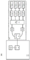
FIG. 2 is a schematic diagram 200 of an analog channel type configurable circuit module according to an embodiment of the invention. It should be understood that fig. 2 illustrates the main circuit blocks/structures, but not all circuit blocks/structures, for implementing the present invention. In actual practice, more or fewer elements than the circuit blocks/structures shown in fig. 2 may be used without departing from the concept of the invention.
The circuit module 202 according to an embodiment of the present invention may be an extended circuit module of a controller. For example, in an industrial application, the controller may be a conventional programmable logic controller, PLC 204. It is to be understood that the PLC 204 shown in fig. 2 is only one non-limiting example of a controller. In practical applications, the circuit module 202 of the present invention can be coupled to other controllers to realize the input/output multiplexing of a single analog channel. In addition, the circuit module 202 can be coupled to a certain controller as an expansion circuit module, or can be integrated into a certain controller, so as to implement the analog quantity channel type configurable technology of the present invention.
As shown in fig. 2, the circuit module 202 may include one or more analog channels. By way of example, four analog channels 201-1, 201-2, 201-3, and 201-4 are shown in the embodiment of FIG. 2. In other embodiments, more or fewer analog channels may be provided in the circuit module 202 according to the actual application. In an embodiment of the present invention, each of the one or more analog channels may be configured as a different channel type, for example, as an input channel or an output channel, according to actual requirements. The analog channels may be connected to one or more devices (not shown) such that when the analog channels are configured as input channels, analog signals measured from the devices may be transmitted through the input channels to circuitry (e.g., a controller) connected to the channels for further processing; when the analog channel is configured as an output channel, a signal from, for example, a controller circuit may be transmitted to the device through the input channel to cause the device to perform the operation indicated by the signal. As one non-limiting example, the device may be, for example, a sensor (not shown). The sensors may include various types of sensors for measuring various parameters including, but not limited to: temperature, pressure, force, flow, motion, position, PH, light intensity, etc. The invention is not limited to the type of sensor.
The circuit module 202 may include a path manager 205. The lane manager 205 may be coupled to one or more analog lanes. The channel manager 205 is configured to manage a channel type for each of the one or more analog channels. For example, the channel manager 205 may be configured to manage whether an analog channel is an input type channel or an output type channel.
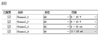
In a preferred embodiment of the present invention, the channel manager 205 may configure the type of each of the one or more analog channels according to a configuration table. The configuration table may allow a user to set the type of each analog channel. For example, the user may set the type of each analog channel in a configuration table via a user interface. The configuration table may include one or more of the following: whether one or more analog channels are enabled, the type of each analog channel, and the signal range of each analog channel.
For example, FIG. 4 is a schematic diagram of a configuration table 400 according to an embodiment of the invention. Configuration table 400 may include the names of the channels, e.g., Channel _1, Channel _2, Channel _3, Channel _4 as shown in fig. 4. By way of example and not limitation, the management and configuration of four channels is illustrated in FIG. 4. As described above, more or fewer channels may be included, as well as corresponding configuration table settings. Configuration table 400 may also include an option to configure whether one or more channels are enabled. For example, as shown in FIG. 4, a check mark may indicate that the channel has been configured to be enabled. Configuration table 400 may also include a type configuration for the channel. For example, each of the channels may be configured as an Analog Input (AI) channel, or an Analog Output (AO) channel. The user can select the corresponding channel type through a pull-down selection mode in the user interface. Configuration table 400 may also include a signal range for each analog channel. For example, when the analog channel is connected to the sensor, the signal range usually used mainly includes 0-10V, 0-20 mA or 4-20 mA. The choice of signal range is primarily related to the type and model of sensor used. Likewise, the user may select the corresponding signal range by way of a drop-down selection at the user interface.
After the user configures the corresponding parameters in the configuration table through the graphical interface tool, the parameters may be downloaded to, for example, the PLC 204 through the communication interface, and after the PLC 204 receives the configuration data, the type configuration of the channel may be completed through the corresponding driver.
In addition to one or more types of configurable analog channels and channel managers 205, the circuit module 202 may include further components or units to achieve further functionality/optimization. For example, the circuit module 202 may further include a signal conditioning circuit. Signal conditioning circuitry may be coupled between the analog channels. For example, signal conditioning circuits 203-1, 203-2, 203-3, and 203-4 are shown in FIG. 2 coupled to each analog channel 201-1, 201-2, 201-3, and 201-4, respectively. The signal conditioning circuit may be configured to condition the signal from the analog channel to improve the quality of the signal. For example, when the analog channel is connected to the sensor, the analog signal transmitted from the sensor typically has various kinds of noise. These spurious signals need to undergo a series of filtering or up-and-down processing for subsequent signal processing.
The circuit module 202 may further comprise conversion circuits 207, 209. Conversion circuitry 207, 209 may be coupled to the channel manager 205, wherein analog-to-digital conversion circuitry (ADC) 207 may be configured to convert analog signals received from an analog channel configured as an input channel into digital signals; a digital-to-analog conversion circuit (DAC) 209 may be configured to convert a digital signal to an analog signal for output from an analog channel configured as an output channel.
The circuit module 202 may further include an isolation circuit 211. The isolation circuit 211 may be configured to avoid interference of signals transmitted from one side of the isolation circuit 211 with other circuits on the other side of the connection. For example, in an embodiment where the analog channel is connected to the sensor, the isolation circuit 211 may be used to avoid power interference from the sensor end connected to the analog channel from entering the processing end.
As described above, the circuit module 202 may be an expansion circuit module coupled to the controller. For example, as shown in FIG. 2, a circuit module 202 may be coupled as an expansion circuit module to a PLC 204, which is commonly used in the industry. The PLC 204 may have a Microprogrammed Control Unit (MCU) 213. PLC 204 may also have other circuit units/components that are not shown herein for purposes of brevity. The MCU 213 may collect data from the ADC 207 via the communication bus for further processing or may output data to the DAC 209 to provide a further analog signal output. In one example, the channel manager 205 can be a combination of program and circuit hardware running on the PLC. Configuration table 215 can be provided on PLC 204. In addition, the circuit module 202 may also be integrated into the PLC 204.
FIG. 3 shows a simplified schematic diagram 300 of a channel-type configurable analog channel, according to an embodiment of the invention. As shown in fig. 3, two terminals 301 and 303 of the analog channels may be coupled with a signal conditioning circuit 305. The signal conditioning circuit 305 may further be coupled to switches a, b. Further, the ADC 307 may be coupled with two terminals c and e, and the DAC 309 may be coupled with two terminals d and f. As an example, the switch a may be connected to one of the terminals c or d, and the switch b may be connected to one of the terminals e or f, thereby connecting the analog channel to the ADC 307 or the DAC 309.
The channel manager 205 may control terminals to which the switches a, b inside the circuit block 202 are connected, thereby implementing the configuration of the analog channel as an input channel or an output channel. Specifically, when the switch a is connected to the c terminal and the switch b is connected to the e terminal, the channel may be configured as an input channel. At this time, the analog signal received from the device (e.g., sensor) connected to the terminals 301 and 303 enters the ADC 307 through the input channel, and the analog signal is converted into a digital signal for further data processing. When the switch a is connected to the d terminal and the switch b is connected to the f terminal, the analog quantity channel may be configured as an output channel. At this time, a digital quantity signal sent from a controller (for example, MCU 213 of PLC 204) is converted into an analog quantity signal by DAC 309, and is output to a connected device (for example, a sensor) via terminals 301 and 303. Thus, the present application enables a single analog channel to be used as both an input channel and an output channel. This is in contrast to the prior art of simply combining digital input channels and output channels on a single circuit board. This single analog channel of the present invention requires only two signal terminals to be connected to external devices (e.g., sensors) for data communication. In a preferred embodiment of the invention, the switches a, b may be electronic switches integrated inside the chip.
Therefore, the invention realizes the management and configuration of the types of the analog quantity channels by using software, so that a single analog quantity channel (for example, provided with two connecting terminals) can be used as an input channel and an output channel, thereby greatly improving the use flexibility of the analog quantity channel and simplifying the proportioning of the analog quantity module. When the field signal type is changed, only the configuration table needs to be modified to complete the signal type conversion, and the module does not need to be replaced again.
It will be understood that the above description of the various circuits/components is merely exemplary. In practice, one or more circuit/component parts may be integrated or further separated, and such modifications are intended to fall within the scope of the present application.
Further, the circuit unit connection relationship shown in the drawings is also merely exemplary. The respective circuit units may be connected in different connection manners as long as the corresponding functions can be realized.
The terms "connected" or "coupled" are defined herein as connected, although not necessarily directly, between two entities and may include indirect connections made through other intermediate nodes or devices.
The terms "comprising," "having," "including," and "containing" are used herein as open-ended linking verbs. Thus, a method or apparatus "comprising," "having," "including," or "containing" one or more steps or components means: the method or apparatus has those one or more steps or components, but not only those one or more steps or components, but may also include other one or more steps or components not mentioned herein.
The basic concept of the present invention has been described above. It will be apparent to those skilled in the art that the foregoing disclosure is by way of example only, and is not intended to limit the present application. Various modifications, improvements and adaptations to the present application may occur to those skilled in the art, although not explicitly described herein. Such modifications, improvements and adaptations are proposed in the present application and thus fall within the spirit and scope of the embodiments of the present application.
Claims (11)
1. A circuit module, comprising:
one or more analog channels, each of the one or more analog channels configurable to a different channel type to allow a respective type of signal to pass therethrough;
a channel manager coupled to the one or more analog channels, the channel manager configured to manage a channel type of each of the one or more analog channels, wherein the channel type of each of the one or more analog channels includes an analog input channel or an analog output channel, a single analog channel being capable of functioning as both an analog input channel and an analog output channel; and
a switch coupled to the analog channel, the channel manager further configured to configure the analog channel as an analog input channel or an analog output channel by controlling the switch.
2. The circuit module of claim 1, wherein the channel manager configures the channel type for each of the one or more analog channels according to a configuration table.
3. The circuit module of claim 2, wherein the configuration table comprises one or more of: whether to enable the one or more analog channels, a type of the analog channel, a signal range of the analog channel.
4. The circuit module of claim 2, wherein the configuration table is settable by a user via a user interface.
5. The circuit module of claim 1, wherein each of the one or more analog channels includes two terminals.
6. The circuit module of claim 5, wherein two terminals of each of the one or more analog channels are connected to a sensor.
7. The circuit module of claim 1, further comprising a conversion circuit coupled to the lane manager, wherein the conversion circuit comprises:
an analog-to-digital conversion circuit configured to convert an analog signal received from the analog quantity channel configured as an input channel into a digital signal; and
a digital-to-analog conversion circuit configured to convert a digital signal into an analog signal to be output from the analog quantity channel configured as an output channel.
8. The circuit module of claim 7, wherein the analog channel is configurable for an input channel when the channel manager controls the switch to connect to the analog-to-digital conversion circuit; when the channel manager controls the switch to connect to the digital-to-analog conversion circuit, the analog channel can be configured to be an output channel.
9. The circuit module of claim 1, further comprising a signal conditioning circuit coupled with the analog quantity channel, the signal conditioning circuit configured to condition a signal from the analog quantity channel to improve a quality of the signal.
10. The circuit module of claim 1, further comprising an isolation circuit configured to avoid interference of a power supply signal from a device to which the analog channel is connected with another side circuit to which the isolation circuit is connected.
11. The circuit module of any one of claims 1-10, wherein the circuit module is an extension circuit module coupled to a PLC or the circuit module is integrated into the PLC.
Priority Applications (1)
| Application Number | Priority Date | Filing Date | Title |
|---|---|---|---|
| CN202111243882.0A CN113687625B (en) | 2021-10-26 | 2021-10-26 | Configurable circuit module of analog channel type |
Applications Claiming Priority (1)
| Application Number | Priority Date | Filing Date | Title |
|---|---|---|---|
| CN202111243882.0A CN113687625B (en) | 2021-10-26 | 2021-10-26 | Configurable circuit module of analog channel type |
Publications (2)
| Publication Number | Publication Date |
|---|---|
| CN113687625A CN113687625A (en) | 2021-11-23 |
| CN113687625B true CN113687625B (en) | 2022-04-22 |
Family
ID=78588145
Family Applications (1)
| Application Number | Title | Priority Date | Filing Date |
|---|---|---|---|
| CN202111243882.0A Active CN113687625B (en) | 2021-10-26 | 2021-10-26 | Configurable circuit module of analog channel type |
Country Status (1)
| Country | Link |
|---|---|
| CN (1) | CN113687625B (en) |
Citations (1)
| Publication number | Priority date | Publication date | Assignee | Title |
|---|---|---|---|---|
| CN110888408A (en) * | 2019-12-11 | 2020-03-17 | 杭州和利时自动化有限公司 | Remote switching method, device and equipment for IO module channel |
Family Cites Families (13)
| Publication number | Priority date | Publication date | Assignee | Title |
|---|---|---|---|---|
| NL94177C (en) * | 1954-03-09 | |||
| DE69924475T2 (en) * | 1999-06-09 | 2006-02-16 | Texas Instruments Inc., Dallas | Multi-channel DMA with traffic planning on the outputs |
| CN201352313Y (en) * | 2009-01-16 | 2009-11-25 | 北京凯迪恩自动化技术有限公司 | PLC extension module device with multipath digital quantity input/output multiplex channels |
| CN201489512U (en) * | 2009-08-21 | 2010-05-26 | 西安迅腾科技有限责任公司 | Analog and switching value multiplex interface for data acquisition system |
| CN102650854A (en) * | 2012-04-23 | 2012-08-29 | 广州市新锘威智能科技有限公司 | Input/output passage multiplexing intelligent controller |
| CN203786481U (en) * | 2013-12-19 | 2014-08-20 | 上海新华控制技术(集团)有限公司 | Gas turbine redundancy control system analog quantity input module |
| US10506139B2 (en) * | 2017-08-03 | 2019-12-10 | Mediatek Inc. | Reconfigurable pin-to-pin interface capable of supporting different lane combinations and/or different physical layers and associated method |
| CN108108323B (en) * | 2018-01-05 | 2019-04-23 | 湖南弘睿盛智能科技有限公司 | Signal picker and its method for multiplexing interface |
| CN107992143B (en) * | 2018-01-23 | 2024-03-01 | 江苏徐工国重实验室科技有限公司 | Multiplexing acquisition port circuit, controller, analog input acquisition method and system |
| CN208421628U (en) * | 2018-05-25 | 2019-01-22 | 中车青岛四方车辆研究所有限公司 | Multiplexing automatic testing stand based on virtual instrument |
| CN111007819B (en) * | 2019-12-19 | 2020-11-27 | 杭州和利时自动化有限公司 | IO module multiplexing AI channel and DI channel |
| CN211375364U (en) * | 2019-12-30 | 2020-08-28 | 中铁二院工程集团有限责任公司 | Multichannel multi-type analog sensor access circuit |
| CN111581129B (en) * | 2020-03-24 | 2022-05-31 | 西安广和通无线通信有限公司 | Terminal mainboard circuit, terminal equipment and ADC interface multiplexing control method |
-
2021
- 2021-10-26 CN CN202111243882.0A patent/CN113687625B/en active Active
Patent Citations (1)
| Publication number | Priority date | Publication date | Assignee | Title |
|---|---|---|---|---|
| CN110888408A (en) * | 2019-12-11 | 2020-03-17 | 杭州和利时自动化有限公司 | Remote switching method, device and equipment for IO module channel |
Also Published As
| Publication number | Publication date |
|---|---|
| CN113687625A (en) | 2021-11-23 |
Similar Documents
| Publication | Publication Date | Title |
|---|---|---|
| KR20060088547A (en) | Configurable controller | |
| KR20130085810A (en) | Analog input module | |
| US7386052B2 (en) | Automation device using FSK modulation | |
| US8073005B1 (en) | Method and apparatus for configuring signal lines according to idle codes | |
| CN100520848C (en) | Automation device | |
| CN113687625B (en) | Configurable circuit module of analog channel type | |
| US7447552B2 (en) | Common transmission protocol system for an automation device | |
| US7358781B2 (en) | Automation device with stored profile | |
| CN207720114U (en) | A kind of level shifting circuit and interface multiplexing circuit | |
| US5696988A (en) | Current/voltage configurable I/O module having two D/A converters serially coupled together such that data stream flows through the first D/A to the second D/A | |
| US7930581B2 (en) | Automation device | |
| US8238379B2 (en) | Automation device | |
| CA3158770A1 (en) | Input/output apparatus and methods for monitoring and/or controlling dynamic environments | |
| US20070118686A1 (en) | Automation device | |
| US20070150626A1 (en) | Automation device | |
| CN100426268C (en) | Optical module addressing device and method thereof | |
| CN104063346A (en) | Apparatus For Rs-232c And Rs-485 Serial Communication Using Common Communication Port | |
| KR101346690B1 (en) | Multi protocol transmitter | |
| DE102018005776A1 (en) | Coupler / Fieldbus Module | |
| CN110679118B (en) | Processing process data | |
| US6693528B1 (en) | Switchgear cabinet monitoring arrangement | |
| CN116594339B (en) | Adapter plate, switching system and control system of one-to-multiple driver | |
| CN113688079B (en) | Multi-level switching circuit for realizing communication flow control | |
| CN214540443U (en) | Miniature microwave module capable of setting control parameters and miniature microwave control system | |
| CN214474974U (en) | Conversion circuit for realizing signal multiplexing |
Legal Events
| Date | Code | Title | Description |
|---|---|---|---|
| PB01 | Publication | ||
| PB01 | Publication | ||
| SE01 | Entry into force of request for substantive examination | ||
| SE01 | Entry into force of request for substantive examination | ||
| GR01 | Patent grant | ||
| GR01 | Patent grant |