CN112126248A - Color-shifting free multilayer structure and protective coating thereon - Google Patents
Color-shifting free multilayer structure and protective coating thereon Download PDFInfo
- Publication number
- CN112126248A CN112126248A CN202010927458.7A CN202010927458A CN112126248A CN 112126248 A CN112126248 A CN 112126248A CN 202010927458 A CN202010927458 A CN 202010927458A CN 112126248 A CN112126248 A CN 112126248A
- Authority
- CN
- China
- Prior art keywords
- layer
- pigment
- omnidirectional
- oxide
- color
- Prior art date
- Legal status (The legal status is an assumption and is not a legal conclusion. Google has not performed a legal analysis and makes no representation as to the accuracy of the status listed.)
- Pending
Links
Images


Classifications
-
- C—CHEMISTRY; METALLURGY
- C09—DYES; PAINTS; POLISHES; NATURAL RESINS; ADHESIVES; COMPOSITIONS NOT OTHERWISE PROVIDED FOR; APPLICATIONS OF MATERIALS NOT OTHERWISE PROVIDED FOR
- C09C—TREATMENT OF INORGANIC MATERIALS, OTHER THAN FIBROUS FILLERS, TO ENHANCE THEIR PIGMENTING OR FILLING PROPERTIES ; PREPARATION OF CARBON BLACK ; PREPARATION OF INORGANIC MATERIALS WHICH ARE NO SINGLE CHEMICAL COMPOUNDS AND WHICH ARE MAINLY USED AS PIGMENTS OR FILLERS
- C09C3/00—Treatment in general of inorganic materials, other than fibrous fillers, to enhance their pigmenting or filling properties
- C09C3/06—Treatment with inorganic compounds
- C09C3/063—Coating
-
- G—PHYSICS
- G02—OPTICS
- G02B—OPTICAL ELEMENTS, SYSTEMS OR APPARATUS
- G02B5/00—Optical elements other than lenses
- G02B5/08—Mirrors
- G02B5/0816—Multilayer mirrors, i.e. having two or more reflecting layers
- G02B5/0825—Multilayer mirrors, i.e. having two or more reflecting layers the reflecting layers comprising dielectric materials only
- G02B5/0833—Multilayer mirrors, i.e. having two or more reflecting layers the reflecting layers comprising dielectric materials only comprising inorganic materials only
-
- C—CHEMISTRY; METALLURGY
- C09—DYES; PAINTS; POLISHES; NATURAL RESINS; ADHESIVES; COMPOSITIONS NOT OTHERWISE PROVIDED FOR; APPLICATIONS OF MATERIALS NOT OTHERWISE PROVIDED FOR
- C09C—TREATMENT OF INORGANIC MATERIALS, OTHER THAN FIBROUS FILLERS, TO ENHANCE THEIR PIGMENTING OR FILLING PROPERTIES ; PREPARATION OF CARBON BLACK ; PREPARATION OF INORGANIC MATERIALS WHICH ARE NO SINGLE CHEMICAL COMPOUNDS AND WHICH ARE MAINLY USED AS PIGMENTS OR FILLERS
- C09C1/00—Treatment of specific inorganic materials other than fibrous fillers; Preparation of carbon black
- C09C1/0015—Pigments exhibiting interference colours, e.g. transparent platelets of appropriate thinness or flaky substrates, e.g. mica, bearing appropriate thin transparent coatings
-
- C—CHEMISTRY; METALLURGY
- C01—INORGANIC CHEMISTRY
- C01P—INDEXING SCHEME RELATING TO STRUCTURAL AND PHYSICAL ASPECTS OF SOLID INORGANIC COMPOUNDS
- C01P2004/00—Particle morphology
- C01P2004/01—Particle morphology depicted by an image
- C01P2004/03—Particle morphology depicted by an image obtained by SEM
-
- C—CHEMISTRY; METALLURGY
- C01—INORGANIC CHEMISTRY
- C01P—INDEXING SCHEME RELATING TO STRUCTURAL AND PHYSICAL ASPECTS OF SOLID INORGANIC COMPOUNDS
- C01P2006/00—Physical properties of inorganic compounds
- C01P2006/60—Optical properties, e.g. expressed in CIELAB-values
-
- C—CHEMISTRY; METALLURGY
- C01—INORGANIC CHEMISTRY
- C01P—INDEXING SCHEME RELATING TO STRUCTURAL AND PHYSICAL ASPECTS OF SOLID INORGANIC COMPOUNDS
- C01P2006/00—Physical properties of inorganic compounds
- C01P2006/60—Optical properties, e.g. expressed in CIELAB-values
- C01P2006/62—L* (lightness axis)
-
- C—CHEMISTRY; METALLURGY
- C01—INORGANIC CHEMISTRY
- C01P—INDEXING SCHEME RELATING TO STRUCTURAL AND PHYSICAL ASPECTS OF SOLID INORGANIC COMPOUNDS
- C01P2006/00—Physical properties of inorganic compounds
- C01P2006/60—Optical properties, e.g. expressed in CIELAB-values
- C01P2006/63—Optical properties, e.g. expressed in CIELAB-values a* (red-green axis)
-
- C—CHEMISTRY; METALLURGY
- C01—INORGANIC CHEMISTRY
- C01P—INDEXING SCHEME RELATING TO STRUCTURAL AND PHYSICAL ASPECTS OF SOLID INORGANIC COMPOUNDS
- C01P2006/00—Physical properties of inorganic compounds
- C01P2006/60—Optical properties, e.g. expressed in CIELAB-values
- C01P2006/64—Optical properties, e.g. expressed in CIELAB-values b* (yellow-blue axis)
-
- C—CHEMISTRY; METALLURGY
- C01—INORGANIC CHEMISTRY
- C01P—INDEXING SCHEME RELATING TO STRUCTURAL AND PHYSICAL ASPECTS OF SOLID INORGANIC COMPOUNDS
- C01P2006/00—Physical properties of inorganic compounds
- C01P2006/60—Optical properties, e.g. expressed in CIELAB-values
- C01P2006/65—Chroma (C*)
-
- C—CHEMISTRY; METALLURGY
- C01—INORGANIC CHEMISTRY
- C01P—INDEXING SCHEME RELATING TO STRUCTURAL AND PHYSICAL ASPECTS OF SOLID INORGANIC COMPOUNDS
- C01P2006/00—Physical properties of inorganic compounds
- C01P2006/60—Optical properties, e.g. expressed in CIELAB-values
- C01P2006/66—Hue (H*)
-
- C—CHEMISTRY; METALLURGY
- C09—DYES; PAINTS; POLISHES; NATURAL RESINS; ADHESIVES; COMPOSITIONS NOT OTHERWISE PROVIDED FOR; APPLICATIONS OF MATERIALS NOT OTHERWISE PROVIDED FOR
- C09C—TREATMENT OF INORGANIC MATERIALS, OTHER THAN FIBROUS FILLERS, TO ENHANCE THEIR PIGMENTING OR FILLING PROPERTIES ; PREPARATION OF CARBON BLACK ; PREPARATION OF INORGANIC MATERIALS WHICH ARE NO SINGLE CHEMICAL COMPOUNDS AND WHICH ARE MAINLY USED AS PIGMENTS OR FILLERS
- C09C2200/00—Compositional and structural details of pigments exhibiting interference colours
- C09C2200/40—Interference pigments comprising an outermost surface coating
- C09C2200/401—Inorganic protective coating
-
- C—CHEMISTRY; METALLURGY
- C09—DYES; PAINTS; POLISHES; NATURAL RESINS; ADHESIVES; COMPOSITIONS NOT OTHERWISE PROVIDED FOR; APPLICATIONS OF MATERIALS NOT OTHERWISE PROVIDED FOR
- C09C—TREATMENT OF INORGANIC MATERIALS, OTHER THAN FIBROUS FILLERS, TO ENHANCE THEIR PIGMENTING OR FILLING PROPERTIES ; PREPARATION OF CARBON BLACK ; PREPARATION OF INORGANIC MATERIALS WHICH ARE NO SINGLE CHEMICAL COMPOUNDS AND WHICH ARE MAINLY USED AS PIGMENTS OR FILLERS
- C09C2220/00—Methods of preparing the interference pigments
- C09C2220/10—Wet methods, e.g. co-precipitation
Abstract
The present invention relates to a color-shifting free multilayer structure and a protective coating thereon. Specifically, provided are color pigments having an omnidirectional structure of a protective coating. The pigment has a first layer of a first material and a second layer of a second material that extends across the first layer. Further, the pigment reflects a band of electromagnetic radiation having a predetermined full width at half maximum (FWHM) of less than 300nm and a predetermined color shift of less than 30 ° when the pigment is exposed to broadband electromagnetic radiation and viewed at an angle between 0 ° and 45 °. The pigment has a weatherable coating covering its outer surface and reducing the relative photocatalytic activity of the pigment by at least 50%.
Description
This application is a divisional application of chinese patent application 201510498432.4 entitled "color-shifting free multilayer structure and protective coating thereon" filed on 2015, 8, month 14.
Cross Reference to Related Applications
The present application continues as part of (CIP) us patent application serial No. 14/242,429 filed 4/1/2014, us patent application serial No. 14/242,429 is again CIP of us patent application serial No. 14/138,499 filed 12/23/2013, us patent application serial No. 14/138,499 is again CIP of us patent application serial No. 13/913,402 filed 6/8/2013, us patent application serial No. 13/913,402 is again CIP of us patent application serial No. 13/760,699 filed 2/2013, us patent application serial No. 13/760,699 is again CIP of 13/572,071 filed 10/2012, 13/572,071 is again CIP of us patent application serial No. 13/021,730 filed 5/2011, us patent application serial No. 13/021,730 is again 12/793,772 filed 6/4/2010 (us patent application serial No. 13/021,730 is again filed 4/2010 (us patent application serial No. 3 Patent 8,736,959), 12/793,772 in turn is the CIP of 12/388,395 (us patent 8,749,881) filed on 2/18/2009, 12/388,395 in turn is the CIP of us patent application serial No. 11/837,529 (us patent 7,903,339) filed on 8/12/2007. U.S. patent application serial No. 13/913,402 filed on 8/6/2013 is CIP of 13/014,398 filed on 26/1/2011 and 13/014,398 is CIP of 12/793,772 filed on 4/6/2010. United states patent application serial No. 13/014,398 filed on 26/1/2011 is CIP of 12/686,861 (U.S. patent 8,593,728) filed on 13/1/2010 and 12/686,861 is CIP of 12/389,256 (U.S. patent 8,329,247) filed on 19/2/2009, all of which are incorporated herein by reference in their entirety.
Technical Field
The present invention relates to multilayer thin film structures having protective coatings thereon, and in particular to multilayer thin film structures that exhibit minimal or no significant color shift when exposed to broadband electromagnetic radiation and the protective coatings thereon are viewed from different angles.
Background
Pigments made of multilayer structures are known. Furthermore, pigments which exhibit or provide high-chroma omnidirectional structural colors are also known. However, such prior art pigments require up to 39 thin film layers in order to obtain the desired color properties.
It is understood that the cost associated with the preparation of thin film multilayer pigments is proportional to the number of layers required. As such, the costs associated with using multi-layer dielectric material stacks to produce high chroma omnidirectional structural colors may be prohibitive. Therefore, a high chroma omnidirectional structural color that requires a minimum number of film layers may be desirable.
In addition to the above, it is understood that pigments can exhibit discoloration, color change, and the like when exposed to sunlight, and particularly ultraviolet light. Thus, a high chroma omnidirectional structured color pigment that is weather resistant would also be desirable.
Disclosure of Invention
A color pigment having an omnidirectional structure with a protective coating is provided. The pigment has a first layer of a first material and a second layer of a second material that extends across the first layer. Further, the pigment reflects a band of electromagnetic radiation having a predetermined full width at half maximum (FWHM) of less than 300nm and a predetermined color shift of less than 30 ° when the pigment is exposed to broadband electromagnetic radiation and viewed at an angle between 0 ° and 45 °. In addition, the pigment has a weatherable coating that covers its outer surface and reduces the relative photocatalytic activity of the pigment by at least 50%.
The weatherable coating can include an oxide layer, and the oxide layer is selected from the group consisting of silicon oxide, aluminum oxide, zirconium oxide, titanium oxide, and/or cerium oxide. Further, the weatherable coating can include a first oxide layer and a second oxide layer, the second oxide layer being different from the first oxide layer. Further, the second oxide layer may be a mixed oxide layer that is a combination of at least two different oxides. Finally, the pigment itself, i.e. the pigment without the protective coating, does not comprise an oxide layer.
A method for preparing an omnidirectional structured color pigment having a protective coating is also disclosed. The method includes providing a plurality of pigment particles having the structure and properties as described above, and suspending the plurality of pigment particles in a first liquid to form a pigment suspension. Further, an oxide precursor is provided comprising a second liquid and an oxide forming element such as silicon, aluminum, zirconium, titanium or cerium. Mixing the pigment suspension and oxide precursor, and which results in a weatherable oxide coating being deposited on the plurality of pigment particles, the coating reducing the relative photocatalytic activity of the pigment particles by at least 50%.
In some cases, the first liquid is a first organic solvent and the second liquid is a second organic solvent. Further, the first and second organic solvents may be organic polar solvents such as n-propanol, isopropanol, ethanol, n-butanol, and acetone. In other cases, the first organic solvent and the second organic solvent may be organic polar protic solvents.
With respect to the oxide precursor, the oxide-forming elemental silicon may be in the form of tetraethoxysilane, the oxide-forming elemental aluminum may be in the form of at least one of aluminum sulfate and aluminum tri-sec-butoxide, the oxide-forming elemental zirconium may be in the form of zirconium butoxide, the oxide-forming elemental cerium may be in the form of at least one of cerium nitrate hexahydrate, cerium sulfate, and the oxide-forming elemental titanium may be in the form of at least one of titanium ethoxide, titanium isopropoxide, and titanium butoxide.
In other cases, the first liquid is a first aqueous liquid and the second liquid is a second aqueous liquid. Further, the oxide forming elemental silicon may be in the form of sodium silicate, the oxide forming elemental aluminum may be in the form of at least one of aluminum sulfate, hydrated aluminum sulfate, and sodium aluminate, the oxide forming elemental zirconium may be in the form of zirconium oxychloride octahydrate, the oxide forming elemental cerium may be in the form of cerium nitrate hexahydrate, and the oxide forming elemental titanium may be in the form of titanium tetrachloride.
Drawings
FIG. 1A is a schematic illustration of a Dielectric Layer (DL) that reflects and transmits incident electromagnetic radiation;
FIG. 1B is a schematic illustration of a Reflector Layer (RL) that reflects incident electromagnetic radiation;
FIG. 1C is a schematic illustration of an Absorber Layer (AL) that absorbs incident electromagnetic radiation;
FIG. 1D is a schematic illustration of a Selective Absorption Layer (SAL) that reflects, absorbs, and transmits incident electromagnetic radiation;
FIG. 2 is a schematic illustration of the reflection and transmission of incident electromagnetic radiation by a first generation of omnidirectional structural color multilayer thin film made of multiple dielectric layers;
FIG. 3 is a schematic illustration of a first generation of omnidirectional structural color multilayer films made from multiple dielectric layers;
FIG. 4 is a graph showing a comparison of a range to median ratio of 0.2% for transverse magnetic and transverse electric modes of electromagnetic radiation;
FIG. 5 is a graphical representation of reflectance as a function of wavelength for case II shown in FIG. 4;
FIG. 6 is a graphical representation of the dispersion of center wavelengths in cases I, II and III shown in FIG. 4;
FIG. 7 is a schematic illustration of the reflection and absorption of incident electromagnetic radiation by a second generation omnidirectional structural color multilayer film made up of a plurality of dielectric layers and an absorber layer;
FIG. 8 is a schematic illustration of a second generation omnidirectional structural color multilayer film made from a plurality of dielectric layers and absorbing and/or reflecting layers;
fig. 9A is a schematic illustration of a second generation 5 layer omnidirectional structured color multilayer film made from a plurality of dielectric layers and absorbing/reflecting layers having a chromaticity (C) of 100 and a reflectance (Max R) of 60%;
FIG. 9B is a graphical representation of the reflectance versus wavelength for the second generation 5 layer multilayer stack film shown in FIG. 9A compared to the first generation 13 layer multilayer film and viewed from angles of 0 and 45 degrees;
FIG. 10 is a schematic illustration of a third generation omnidirectional structural color multilayer film made from a dielectric layer, a Selective Absorber Layer (SAL), and a reflector layer;
FIG. 11A is a schematic illustration of a point of zero or near zero electric field within a ZnS dielectric layer exposed to electromagnetic radiation (EMR) having a wavelength of 500 nm;
FIG. 11B is the square of the electric field intensity (| E! Y!) of the ZnS dielectric layer shown in FIG. 1A when exposed to EMR having wavelengths of 300, 400, 500, 600 and 700nm2) A graphical representation of the thickness;
FIG. 12 is a schematic illustration of a dielectric layer extending over a substrate or reflector layer and exposed to electromagnetic radiation at an angle θ relative to a normal to an outer surface of the dielectric layer;
FIG. 13 is a schematic illustration of a ZnS dielectric layer having a Cr absorber layer located at or near the zero electric field point within the ZnS dielectric layer for incident EMR at a wavelength of 434 nm;
FIG. 14 is a plot of the percent reflectance versus the wavelength of reflected EMR for a multilayer stack without a Cr absorber layer (e.g., FIG. 11A) and a multilayer stack with a Cr absorber layer (e.g., FIG. 13) exposed to white light;
fig. 15A is a graphical representation of a first harmonic and a second harmonic exhibited by a ZnS dielectric layer (e.g., fig. 11A) extending over an Al reflector layer;
FIG. 15B is a plot of the percent reflectance versus the wavelength of reflected EMR for a multilayer stack having a ZnS dielectric layer extending across an Al reflector layer plus a Cr absorber layer located within the ZnS dielectric layer (thereby absorbing the second harmonic shown in FIG. 15A);
FIG. 15C is a plot of the percent reflectance versus the wavelength of reflected EMR for a multilayer stack having a ZnS dielectric layer extending across an Al reflector layer plus a Cr absorber layer located within the ZnS dielectric layer (thereby absorbing the first harmonic shown in FIG. 15A);
FIG. 16A is a plot of the square of the electric field versus the dielectric layer thickness showing the dependence of the electric field angle of the Cr absorption layer when exposed to incident light at 0 and 45 degrees;
FIG. 16B is a graph of the percent absorption of a Cr absorber layer versus the wavelength of reflected EMR when exposed to white light at 0 and 45 relative to the normal to the outer surface (0 is normal to the surface);
fig. 17A is a schematic illustration of a red omnidirectional structural color multilayer stack according to an embodiment of the present invention;
FIG. 17B is a plot of the percent absorption of the Cu absorber layer shown in FIG. 17A versus the wavelength of reflected EMR when white light is exposed to the multilayer stack shown in FIG. 17A at incident angles of 0 and 45;
FIG. 18 is a graph of comparison between calculated/simulated data and experimental data of percent reflectance versus wavelength of reflected EMR when a conceptually verified red omnidirectional structural color multilayer stack is exposed to white light at an angle of incidence of 0;
figure 19 is a graphical representation of percent reflectance versus wavelength for an omnidirectional structural color multilayer stack in accordance with one embodiment of the present disclosure;
FIG. 20 is a graphical representation of percent reflectance versus wavelength for an omnidirectional structural color multilayer stack in accordance with one embodiment of the present invention;
figure 21 is a graphical representation of percent reflectance versus wavelength for an omnidirectional structural color multilayer stack in accordance with one embodiment of the present disclosure;
figure 22 is a graphical representation of percent reflectance versus wavelength for an omnidirectional structural color multilayer stack in accordance with one embodiment of the present invention;
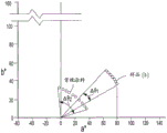
fig. 23 is a graphical representation of a portion of a b color mapping using the CIELAB color space, wherein chroma and hue shifts are compared between a conventional coating and a coating prepared from a pigment according to an embodiment of the present invention;
FIG. 24 is a schematic illustration of an omnidirectional structural color multilayer stack according to one embodiment of the present invention;
FIG. 25 is a schematic illustration of an omnidirectional structural color multilayer stack according to one embodiment of the present invention;
FIG. 26 is a schematic illustration of an omnidirectional structural color multilayer stack according to one embodiment of the present invention;
FIG. 27 is a schematic illustration of a four layer omnidirectional structure color pigment according to one embodiment of the present invention;
FIG. 28 is a schematic illustration of a seven-layer omnidirectional structure color pigment according to one embodiment of the present invention;
FIG. 29 is a schematic illustration of a seven-layer omnidirectional structured color pigment with a protective coating in accordance with one embodiment of the present invention;
FIG. 30 is a schematic illustration of a protective coating comprising two or more layers according to an embodiment of the present invention;
FIG. 31 is a graph depicting normalized relative photolytic activity of omni-directionally structured color pigments having several different protective coatings; and is
FIG. 32A is one of a pair of Scanning Electron Microscope (SEM) images of a plurality of seven-layer, omnidirectional structured color pigments without a protective coating; and fig. 32B is one of a pair of Scanning Electron Microscope (SEM) images of a plurality of seven-layer, omnidirectional structured color pigments with silica and zirconia-alumina protective coatings.
Detailed Description
An omnidirectional structural color is provided. The omnidirectional structural color is in the form of a multilayer thin film (also referred to herein as a multilayer stack) that reflects a narrow band of electromagnetic radiation within the visible spectrum and has a small or insignificant color shift when viewed from angles between 0 and 45 degrees. The multilayer films can be used as pigments in coating compositions, structurally continuous films, and the like.
The multilayer thin film includes a multilayer stack having a first layer and a second layer extending across the first layer. In some cases, the multilayer stack reflects narrow-band electromagnetic radiation having a FWHM of less than 300nm, preferably less than 200nm, and in some cases less than 150 nm. The multilayer thin film also has a color shift of less than 50nm, preferably less than 40nm, and more preferably less than 30nm, when the multilayer stack is exposed to broadband electromagnetic radiation (e.g., white light) and viewed at an angle between 0 and 45 degrees. Furthermore, the multilayer stack may or may not have a separate electromagnetic radiation reflection band in the UV range and/or IR range.
The overall thickness of the multilayer stack is less than 2 μm, preferably less than 1.5 μm, and still more preferably less than 1.0 μm. As such, the multilayer stack can be used as a coating pigment in thin film coating applications.
The first and second layers may be made of a dielectric material, or alternatively the first and/or second layers may be made of an absorbing material. The absorbing material comprises a selective absorbing material, such as Cu, Au, Zn, Sn, alloys thereof, or the like, or alternatively, a dielectric material having a color, such as Fe2O3、Cu2O, combinations thereof, and the like. The absorber material may also be a non-selective absorber material such as Cr, Ta, W, Mo, Ti-nitride, Nb, Co, Si, Ge, Ni, Pd, V, iron oxide, combinations or alloys thereof, and the like. The thickness of the absorbing layer made of selective absorbing material is between 20-80nm, while the thickness of the absorbing layer made of non-selective absorbing material is between 5-30 nm.
The multilayer stack may further comprise a reflector layer, the first and second layers extending across said reflector layer, the reflector layer being made of a metal such as Al, Ag, Pt, Cr, Cu, Zn, Au, Sn, alloys thereof or the like. The reflector layer typically has a thickness between 30-200 nm.
The multilayer stack may have reflected narrow band electromagnetic radiation in the form of symmetrical peaks in the visible spectral range. Alternatively, a narrow band of electromagnetic radiation reflected within the visible spectrum may be adjacent to the UV range, such that the reflected band portion of the electromagnetic radiation, i.e., the UV portion, is not visible to the naked eye. Alternatively, the reflection band of the electromagnetic radiation may have a portion in the IR range, such that the IR portion is also invisible to the naked eye.
Whether the reflection band of electromagnetic radiation in the visible spectral range is near the UV range, the IR range, or has symmetric peaks in the visible spectral range, the multilayer thin films disclosed herein have a narrow reflection band of electromagnetic radiation in the visible spectral range with low, small, or insignificant color shift. The low or insignificant color shift may be in the form of a small shift in the center wavelength of the reflected narrow band of electromagnetic radiation. Alternatively, the low or insignificant color shift may be in the form of a small shift of the UV side edge or IR side edge of the reflection band adjoining the IR range or UV range of electromagnetic radiation, respectively. Such small shifts in center wavelength, UV side edges, and/or IR side edges are typically less than 50nm, in some cases less than 40nm, and in other cases less than 30nm when the multilayer film is viewed from an angle between 0 and 45 degrees.
In addition to the foregoing, the omnidirectional structural color in the form of a multilayer film may be in the form of a plurality of pigment particles having a protective coating thereon. Thus, a weather resistant pigment is provided. The protective coating may include one or more oxide layers that reduce the relative photocatalytic activity of the pigment particles. The oxide layer may be any oxide layer known to those skilled in the art, including illustratively a silicon oxide layer, an aluminum oxide layer, a zirconium oxide layer, a titanium oxide layer, a cerium oxide layer, combinations thereof, and the like. In some cases, the protective coating includes a first oxide layer and a second oxide layer. Furthermore, the first oxide layer and/or the second oxide layer may be a mixed oxide layer, i.e. an oxide layer combining two different oxides. Furthermore and as mentioned above, the pigment itself may be in the form of a multilayer film that does not contain an oxide layer.
The method for preparing the omnidirectional structured color pigment may or may not include the use of an acid, an acidic compound, an acidic solution, or the like. In other words, the plurality of omnidirectional-structured color pigment particles may or may not be treated in an acidic solution. Additional teachings and details of the omnidirectional structured color pigments and methods for making the pigments are discussed later herein.
Turning now to fig. 1, fig. 1A-1D depict the basic parts of an omnidirectional structural color design. In particular, FIG. 1A depicts a dielectric layer exposed to incident electromagnetic radiation. Furthermore, the Dielectric Layer (DL) reflects a part of the incident electromagnetic radiation andtransmitting a portion thereof. Furthermore, the incident electromagnetic radiation is equal to the transmitted and reflected portions, and typically the transmitted portion is much larger than the reflected portion. The dielectric layer is made of a dielectric material such as SiO2、TiO2、ZnS、MgF2And the like.
In sharp contrast thereto, fig. 1B depicts a Reflective Layer (RL) in which all incident electromagnetic radiation is reflected and which has substantially zero transmission. The reflector layer is typically made of a material such as aluminum, gold, or the like.
Fig. 1C depicts an Absorbing Layer (AL) in which incident electromagnetic radiation is absorbed by the layer and is not reflected or transmitted. Such an absorption layer may be made of graphite, for example. Furthermore, all incident electromagnetic radiation is absorbed and the transmittance and reflectance are about zero.
FIG. 1D depicts a partially or Selectively Absorbing Layer (SAL), wherein a portion of incident electromagnetic radiation is absorbed by the layer, a portion is transmitted and a portion is reflected. As such, the amount of transmitted, absorbed, and reflected electromagnetic radiation is equal to the amount of incident electromagnetic radiation. Furthermore, such a selective absorption layer may be made of a material such as a thin chromium layer, a layer of copper, brass, bronze or the like.
The invention discloses design and preparation of a third-generation omnidirectional structural color film.
First generation
Referring now to FIG. 2, a schematic illustration of a multilayer thin film having a plurality of dielectric layers is shown. Furthermore, the reflectivity and the transmittance of the incident electromagnetic radiation are schematically shown. As mentioned above, the typical transmission of incident electromagnetic radiation is much greater than its reflectivity, and therefore many layers are required.
FIG. 3 shows a portion of a multilayer film made of dielectric layers having a first index of refraction (DL)1) And a second refractive index (DL)2). It should be understood that the double lines between the layers simply represent the interfaces between the different layers.
Without being limited by theory, one method or route to designing and making the desired multilayer stack is as follows.
When electromagnetic radiation strikes a surface of a material, the radiant wave may be reflected by the material or transmitted through the material. In addition, when the electromagnetic radiation is at an angle θ0Upon striking the first end 12 of the multilayer structure 10, the electromagnetic waves have angles of reflection θ with respect to the surfaces of the high and low refractive index layers, respectivelyHAnd thetaL. Using snell's law:
n0Sinθ0=nLSinθL=nHSinθH (1)
if the refractive index nHAnd nLIs known, then the angle θ can be determinedHAnd thetaL。
With respect to omnidirectional reflectivity, the necessary but insufficient conditions for electromagnetic radiation in the TE and TM modes require that the angle of refraction (θ) within the first layer be maximizedH,MAX) Less than the Brewster's angle (θ) at the interface between the first and second layersB). If this condition is not met, the electromagnetic wave in TM mode will not be reflected at the second and all subsequent interfaces and will thus be transmitted through the structure. Using this consideration:

and

therefore, it is required that:

except for the requirement represented by formula 4, if the electromagnetic radiation having the wavelength λ is at the angle θ0Falls on the multilayer structure and the single bilayer of the multilayer structure has a thickness dHAnd dLAnd each has a refractive index of nHAnd nLThat isCharacteristic transformation matrix (F)T) Expressed as:

it can also be expressed as:

and wherein:


and

in addition to this, the present invention is,

wherein

And

explicitly solving for the ρ of TE and TMT:

And

the viewing angle dependent band structure can be obtained from the boundary conditions of the edges of the total reflection area (also known as band edges). For the purposes of the present invention, band edges are defined as the factor of separating the lines of total reflective area and transmissive area for a given band structure.
The boundary condition for determining the band edge frequency of the high reflectivity band may be given by:
Trace|FT|=-1 (16)
thus, according to equation 3:

or expressed in an alternative way as:

combining equations 15 and 7, the following band edge equations are obtained:

wherein:
L+=nHdHCosθH+nLdLCosθL (20)
and:
L_=nHdHCosθH-nLdLCosθL (21)
the + symbol in the band-edge equation shown above represents a long wavelength (λ)long) And-sign represents a short wavelength (λ)short) The band edge of (2). Rewriting equations 20 and 21, for the TE mode:

and for the TM mode:

the approximate solution for the band edge can be determined by the expression:
L_=nHdHCosθH-nLdLCosθL~0 (24)
this approximate solution is reasonable when considering the quarter-wave design (described in more detail below) and the optical thickness of the alternating layers that are selected to be equal to each other. Furthermore, the relatively small difference in optical thickness of the alternating layers provides a cosine close to unity. Thus, equations 23 and 24 produce an approximate band-edge equation,
for the TE mode:

and for the TM mode:

L+and ρTMCan be obtained from equations 7, 8, 14, 15, 20 and 21, thereby allowing the calculation of λ in TE and TM modeslongAnd λshortAs a function of angle of incidence.
Center wavelength (λ) of omnidirectional reflectorc) Can be determined by the following relationship:
λc=2(nHdHCosθH+nLdLCosθL) (27)
the center wavelength may be an important parameter because its value indicates the electromagnetic wavelength and/or the approximate range of the color spectrum to be reflected. Another important parameter that may provide an indication about the bandwidth of the reflection band is defined as the ratio of the range of wavelengths in the omnidirectional anti-radio band to the median of the wavelengths in the omnidirectional anti-radio band. This "range to median ratio" (η) is mathematically expressed as:
for the TE mode:

and for the TM mode:

it is understood that the ratio of range to median can be expressed as a percentage and for purposes of this disclosure, the terms range to median and percentage of range to median are used interchangeably. It is also understood that the "ratio of range to median" values provided herein are provided below with the "%" symbol being a percent value of the ratio of range to median. The ratio of the range to the median of the TE mode and the TM mode can be calculated numerically according to equations 28 and 29 and plotted as a function of the high and low refractive indices.
It is understood that in order to obtain a narrow omnidirectional band, the dispersion of the center wavelength must be minimized. Thus, according to equation 27, the dispersion of the center wavelength can be expressed as:

wherein:

and a center wavelength dispersion factor FcCan be expressed as:

in view of the above, the refractive index n can be defined asLAnd one or more of the low refractive index materials having a thickness dLAnd a refractive index of nHAnd one or more high refractive index materials having a thickness dHIs designed to have a desired low center wavelength shift (Δ λ)c) The multilayer stack of (3).
In particular, fig. 4 provides a comparative illustration of the ratio of the range to the median of 0.2% of electromagnetic radiation plotted as the transverse magnetic and transverse electric modes versus the functional relationship between the high and low refractive indices. As shown in the figure, three cases are described, where case I relates to a large difference between the transverse magnetic mode and the transverse electric mode, case II relates to a smaller difference between the transverse magnetic mode and the transverse electric mode, and case III relates to a very small difference between the transverse magnetic mode and the transverse electric mode. Further, fig. 5 depicts the percent reflectivity of the reflected electromagnetic radiation versus wavelength in a case similar to case II.
As shown in fig. 5, a small dispersion of the center wavelength of the multilayer thin film corresponding to the case III is shown. Further, and referring to fig. 6, case II provides a shift in center wavelength of less than 50nm when the multilayer thin film structure is viewed between 0 and 45 degrees (case II), and case III provides a shift in center wavelength of less than 25nm when the thin film structure is exposed to electromagnetic radiation between 0 and 45 degrees.
Second generation
Referring now to FIG. 7, an illustrative architecture/design in accordance with the second generation is shown. The multilayer structure shown in fig. 7 has a plurality of dielectric layers and an underlying absorber layer. Furthermore, none of the incident electromagnetic radiation is transmitted through the structure, i.e. all of the incident electromagnetic radiation is reflected or absorbed. The structure as shown in fig. 7 allows reducing the number of dielectric layers required to obtain a suitable amount of reflectivity.
For example, fig. 8 provides a schematic illustration of a structure in which the multilayer stack has a central absorber layer made of Cr, a first layer of dielectric material (DL) extending across the Cr absorber layer1) Extending across DL1Second dielectric material layer (DL) of the layer2) And then extend across DL2Another DL of a layer1And (3) a layer. In such a design, the thicknesses of the first dielectric layer and the third dielectric layer may be the same or different.
In particular, FIG. 9A shows a structure in which the central Cr layer is made of two TiO2Layer defining the two TiO2The layer is composed of two SiO layers2Illustration of the structure defined by the layers. As shown, TiO2And SiO2The layers are not equal to each other in thickness. Further, fig. 9B shows the reflectance versus wavelength spectrum of the 5-layer structure shown in fig. 9A, and compared with a 13-layer structure designed according to the first generation. As shown in fig. 9B, a shift of less than 50nm and preferably less than 25nm center wavelength is provided when the structure is viewed between 0 and 45 degrees. This fact is also shown in fig. 9B: the 5-layer structure according to the second generation behaves substantially equivalent to the 13-layer structure of the first generation.
Third generation
Referring to FIG. 10, a third generation design is shown in which the underlying Reflector Layer (RL) has a first layer of dielectric material DL extending across the reflector layer1And extends across DL1The selective absorption layer SAL of the layer. In addition, another DL may or may not be provided1A layer extending across the selective absorption layer. Also shown in the figure is an illustration of all incident electromagnetic radiation reflected or selectively absorbed by the multilayer structure.
Such a design depicted in fig. 10 corresponds to a different method for designing and producing the desired multilayer stack. In particular, for dielectric layers, zero energy point thickness or near zero energy point thickness of the dielectric layer is used and discussed below.
For example, fig. 11A is a schematic illustration of a ZnS dielectric layer that extends across an Al reflector layer. The ZnS dielectric layer has a total thickness of 143nm and for incident electromagnetic radiation having a wavelength of 500nm, a zero or near zero energy point is present at 77 nm. In other words, for incident EMR at a wavelength of 500nm, the ZnS dielectric layer exhibits a zero or near zero electric field at a distance of 77nm from the Al reflector layer. In addition, fig. 11B provides a graphical representation of the energy field across the ZnS dielectric layer for several different incident EMR wavelengths. As shown in the figure, the dielectric layer has zero electric field at 77nm thickness for 500nm wavelength, but near zero electric field at 77nm thickness for EMR wavelengths of 300, 400, 600 and 700 nm.
With respect to the calculation of a zero or near-zero electric field point, FIG. 12 depicts a dielectric layer 4 having a total thickness "D", an incremental thickness "D", and a refractive index "n" located to exhibit a refractive index nsOn the substrate or core layer 2. Incident light strikes the outer surface 5 of the dielectric layer 4 at an angle θ with respect to a line 6 perpendicular to the outer surface 5 and is reflected from the outer surface 5 at the same angle. Incident light is transmitted through the outer surface 5 and at an angle θ relative to the line 6FInto the dielectric layer 4 and at an angle thetasImpacting the surface 3 of the substrate layer 2.
For a single dielectric layer, θs=θFAnd the energy/electric field (E) may be denoted as E (z) when z ═ d. According to Maxwell's equation, for s-polarization, the electric field can be expressed as:

and for p-polarization, can be expressed as:

wherein And λ is the desired wavelength to be reflected. In addition, α ═ nssin θsWherein "s" corresponds to the substrate in FIG. 5, and
 is the dielectric constant of the layer as a function of z. Thus, for s-polarization
|E(d)|2=|u(z)|2exp(2ikαy)|z=d (36)
And for p polarization

It is understood that the variation of the electric field in the Z-direction along the dielectric layer 4 can be estimated by calculating the unknown parameters u (Z) and v (Z), which can be shown as:

naturally, "i" is the square root of-1. Using boundary conditions uz=0=1,vz=0=qsAnd the following relationships:
for s polarization, qs=ns cosθs (39)
For p polarization, qs=ns/cosθs (40)
For s-polarization, q ═ n cos θF (41)
For p-polarization, q ═ n/cos θF (42)

u (z) and v (z) can be represented as:

and

therefore, for S-polarization of (c):

and for p-polarization:

wherein:
α=ns sinθs=n sinθF (48)

and

thus, for θFEither 0 or the simple case of normal incidence, and α ═ 0:
s-polarized | E (d) non-conducting2P-polarised

Which allows to solve the thickness "d", i.e. the position or location of the electric field in the dielectric layer to be zero.
Referring now to FIG. 13, equation 52 is used to calculate the zero or near zero electric field point in the ZnS dielectric layer shown in FIG. 11A, which is at 70nm (for a wavelength of 500nm, it is at 77nm) when exposed to EMR at a wavelength of 434 nm. In addition, a 15nm thick Cr absorber layer was inserted at 70nm thickness from the Al reflector layer to provide a zero or near zero electric field ZnS-Cr interface. Such an inventive structure allows light with a wavelength of 434nm to pass through the Cr-ZnS interface, but absorbs light without a wavelength of 434 nm. In other words, the Cr-ZnS interface has a zero or near-zero electric field with respect to light having a wavelength of 434nm, and thus 434nm light passes through the interface. However, the Cr-ZnS interface does not have a zero or near-zero electric field for light with a wavelength other than 434nm, and thus, such light is absorbed by the Cr absorber layer and/or the Cr-ZnS interface and is not reflected by the Al reflector layer.
It is understood that a certain percentage of the light in the +/-10nm range of 434nm required will pass through the Cr-ZnS interface. However, it is also understood that such narrow band reflected light, e.g., 434+/-10nm, still provides a sharp structural color to the human eye.
The results for the Cr absorber layers in the multilayer stack in fig. 13 are depicted in fig. 14, where the percent reflectivity versus reflected EMR wavelength is shown. As shown by the dashed line, which corresponds to the ZnS dielectric layer without the Cr absorber layer shown in fig. 13, a narrow reflection peak exists at about 400nm, but a much wider peak exists at about 550+ nm. In addition, in the 500nm wavelength region, a large amount of light is still reflected. As such, there is a double peak that prevents the multilayer stack from having or exhibiting a structural color.
In contrast, the solid line in fig. 14 corresponds to the structure shown in fig. 13 in which the Cr absorption layer is present. As shown in the figure, there is a sharp peak at about 434nm and a sharp drop in reflectance for wavelengths greater than 434nm is provided by the Cr absorber layer. It is understood that the sharp peaks represented by the solid lines appear visually as sharp/structural colors. Further, fig. 14 depicts the measurement of the width of a reflection peak or band, i.e. the width of the band is determined at 50% reflectivity of the maximum reflection wavelength (which is also known as full width at half maximum (FWHM)).
With regard to the omnidirectional behavior of the multilayer structure shown in fig. 13, the thickness of the ZnS dielectric layer can be designed or set such that only the first harmonic of the reflected light is provided. It is understood that this is sufficient for "blue" colors, however, the generation of "red" colors requires other conditions. For example, the control of the angular independence of the red color is difficult because a thicker dielectric layer is required, which in turn leads to a higher harmonic design, i.e. the presence of a second harmonic or possibly a third harmonic is unavoidable. Moreover, the dark red hue space is very narrow. As such, the red multilayer stack has a higher angular dispersion (angular variance).
To overcome the higher angular dispersion of the red color, the present application discloses a unique and novel design/structure that provides an angle-independent red color. For example, fig. 15A depicts a dielectric layer that exhibits a first harmonic and a second harmonic for incident white light when the outer surface of the dielectric layer is viewed from 0 and 45 degrees. As shown by the illustration, the low angle dependence (small Δ λ) is provided by the thickness of the dielectric layerc) However, such a multilayer stack has a combination of blue (first harmonic) and red (second harmonic) colors and is thus not suitable for the required "red only" color. Therefore, concepts/structures have been developed for absorbing unwanted harmonic series using absorber layers. FIG. 15A also depicts the center wavelength (λ) of the reflection band for a given reflection peakc) And the dispersion or shift of the center wavelength (Δ λ) when the sample is observed from 0 and 45 degreesc)。
Turning now to FIG. 15B, the second harmonic shown in fig. 15A is absorbed with a Cr absorber layer at the appropriate dielectric layer thickness (e.g., 72nm), and provides a sharp blue color. More importantly to the present invention, FIG. 15C depicts the provision of red color by absorption of the first harmonic with a Cr absorber at different dielectric layer thicknesses (e.g., 125 nm). However, fig. 15C also depicts that the use of Cr absorber layers not only results in the required angular dependence of the multilayer stack, i.e. the required Δ λcIs large.
It is understood that for red colors, a relatively large λ is compared to blue colorscThe shift is due to the very narrow space of the dark red hue and the fact that: the Cr absorber layer absorbs wavelengths associated with non-zero electric fields, i.e., does not absorb light when the electric field is zero or near zero. Thus, FIG. 16A illustrates that the zero or non-zero point is different for wavelengths of light at different angles of incidence. Such factors result in the angle-dependent absorption shown in fig. 16B, i.e., the difference in the absorption curves at 0 ° and 45 °. Thus, to further refine the multilayer stack design and angle independence performance, an absorber layer that absorbs blue light, for example, is used, regardless of whether the electric field is zero or non-zero.
In particular, fig. 17A shows a multilayer stack with a Cu absorber layer, instead of a Cr absorber layer, extending across the dielectric ZnS layer. The results using such "multicolored" or "selective" absorbing layers are shown in fig. 17B, which demonstrates the "tighter" clustering of the 0 ° and 45 ° absorption lines for the multilayer stack shown in fig. 17A. As such, the comparison between fig. 16B and fig. 16B describes a significant improvement in the angular independence of the absorptance when a selective absorber layer is used instead of a non-selective absorber layer.
Based on the foregoing, a concept verified multilayer stack structure was designed and prepared. In addition, the calculated/simulated results and actual experimental data of the samples for concept verification were compared. In particular, and as shown by the graph in fig. 18, a sharp red color is produced (wavelengths greater than 700nm are typically not visible to the human eye), and very good agreement is obtained between the calculations/simulations and the test light data obtained from the actual samples. In other words, the calculations/simulations may be used and/or used to simulate the results of a multi-layer stack design and/or a prior art multi-layer stack according to one or more embodiments of the present invention.
A series of simulated and/or actually prepared samples of the multilayer stack are provided in table 1 below. As shown in the table, the inventive design disclosed herein includes at least 5 different layered structures. Furthermore, samples may be simulated and/or fabricated from a variety of different materials. Samples exhibiting high chroma, low hue shift and excellent reflectance are provided. Furthermore, the three and five layer samples had a total thickness between 120-200 nm; the seven-layer sample had a total thickness between 350-600 nm; nine layers of the sample had a total thickness between 440-500 nm; and eleven layers of the sample had a total thickness between 600-660 nm.
TABLE 1

Turning now to fig. 19, a plot of the percent reflectivity of an omnidirectional reflector versus the wavelength of reflected EMR when exposed to white light at angles of 0 ° and 45 ° relative to the surface of the reflector is shown. As shown in the graph, for wavelengths greater than 500nm, both the 0 ° and 45 ° curves describe very low reflectivity, e.g., less than 20%, provided by an omnidirectional reflector. However, as shown by the curves, the reflector provides a sharp increase in the refractive index at wavelengths between 400 and 500nm and reaches a maximum of about 90% at 450 nm. It is understood that the graphical section or region on the left hand side (UV side) of the curve represents the UV portion of the reflection band provided by the reflector.
The sharp increase in reflectivity provided by the omnidirectional reflector is characterized by the IR-side edge of each curve extending from a low reflectivity portion to a high reflectivity portion (e.g., greater than 70%) at wavelengths greater than 500 nm. The linear portion 200 of the IR side edge is inclined at an angle (β) greater than 60 with respect to the x-axis, having a slope in the direction of the x-axisA length L of about 50 on the reflectance axis and a slope of 1.2. In some cases, the linear portion is inclined at an angle greater than 70 ° with respect to the x-axis, while in other cases β is greater than 75 °. Also, the reflection band has a visible FWHM of less than 200nm, and in some cases less than 150nm, and in other cases less than 100 nm. Further, the center wavelength λ of the visible reflection band to be described in fig. 19cDefined as the wavelength equidistant between the IR side edge of the reflection band of the visible FWHM and the UV edge of the UV spectrum.
It is understood that the term "visible FWHM" means the width of the reflection band between the side edge of the curve IR and the edge of the UV spectral range beyond which the reflection provided by the omnidirectional reflector is not visible to the human eye. In this manner, the inventive designs and multilayer stacks disclosed herein use the invisible UV portion of the electromagnetic radiation spectrum to provide sharp or structural colors. In other words, despite the fact that the reflector may reflect electromagnetic radiation extending to a wider band within the UV region, the omnidirectional reflectors disclosed herein utilize the invisible UV portion of the electromagnetic radiation spectrum to provide reflected visible light in a narrow band.
Turning now to fig. 20, there is shown generally symmetrical reflection bands provided by a multilayer stack according to an embodiment of the present invention and when viewed at 0 ° and 45 °. As shown in the figure, the reflection band provided by the multilayer stack has a central wavelength (λ) when viewed at 0 °c(0 °)) offset ratio when the multilayer stack was observed at 45 ° (λc(45 deg.) less than 50nm, i.e. Δ λc(0-45°)<50 nm. Furthermore, the FWHM of both the 0 ° reflection band and the 45 ° reflection band is less than 200 nm.
FIG. 21 shows a plot of the percent reflectivity versus the wavelength of reflected EMR for another omnidirectional reflector design when exposed to white light at angles of 0 and 45 relative to the surface of the reflector. Similar to fig. 19, and as shown by the graph, both the 0 ° and 45 ° curves illustrate very low reflectivity provided by the omnidirectional reflector for wavelengths less than 550nm, e.g., less than 10%. However, as shown by the curves, the reflector provides a sharp increase in reflectivity at wavelengths between 560-570nm and reaches a maximum of about 90% at 700 nm. It is understood that the graphical part or area on the right hand side (IR side) of the curve represents the IR part of the reflection band provided by the reflector.
The sharp increase in reflectivity provided by the omnidirectional reflector is characterized by the UV side edge of each curve extending from a low reflectivity portion to a high reflectivity portion (e.g., greater than 70%) at wavelengths less than 550 nm. The linear portion 200 of the UV side edge is inclined at an angle (β) greater than 60 ° with respect to the x-axis, has a length L of about 40 on the reflectance axis, and a slope of 1.4. In some cases, the linear portion is inclined at an angle greater than 70 ° with respect to the x-axis, while in other cases β is greater than 75 °. Also, the reflection band has a visible FWHM of less than 200nm, and in some cases less than 150nm, and in other cases less than 100 nm. Further, the center wavelength λ of the visible reflection band to be described in fig. 18cDefined as the wavelength equidistant between the UV side edge of the reflection band of the visible FWHM and the IR edge of the IR spectrum.
It is understood that the term "visible FWHM" means the width of the reflection band between the curve UV side edge and the edge of the IR spectral range beyond which the reflection provided by the omnidirectional reflector is not visible to the human eye. In this manner, the inventive designs and multi-layer stacks disclosed herein use the invisible IR portion of the electromagnetic radiation spectrum to provide sharp or structural colors. In other words, despite the fact that the reflector may reflect electromagnetic radiation extending to a wider frequency band within the IR region, the omnidirectional reflectors disclosed herein utilize the invisible IR portion of the electromagnetic radiation spectrum to provide reflected visible light in a narrow frequency band.
Referring now to fig. 22, a graph of percent reflectivity versus wavelength for another seven layer design omni-reflector is shown when exposed to white light at angles of 0 ° and 45 ° relative to the reflector surface. Further, a definition or characterization of the omnidirectional properties provided by the omnidirectional reflectors disclosed herein is shown.In particular, and when the reflection band provided by the inventive reflector has a maximum, i.e. peak, as shown in the figure, each curve has a central wavelength (λ)c) Defined as the wavelength at which the maximum reflectance is exhibited or experienced. The term wavelength of maximum reflection may also be used for λc。
As shown in fig. 22, when viewed from an angle of 45 ° (λ)c(45 °)) viewing the outer surface of the omnidirectional reflector, for example, when the outer surface is tilted by 45 ° with respect to the human eye viewing said surface, an angle (λ) of from 0 ° is formedc(0 °), i.e. when the surface is viewed perpendicularly to the surface, there is a λcOffset or displacement of. Such a lambdacOffset (Δ λ) ofc) A measure of the omnidirectional nature of an omnidirectional reflector is provided. Naturally, a zero offset, i.e. no offset at all, would be a perfect omnidirectional reflector. However, the omni-directional reflector disclosed herein may provide a Δ λ of less than 50nmcIt can appear to the human eye as if the surface of the reflector has not changed color, and thus from a practical point of view, the reflector is omnidirectional. In some cases, the omnidirectional reflectors disclosed herein may provide a Δ λ of less than 40nmcIn other cases, Δ λ of less than 30nm may be providedcAnd still in other cases can provide a Δ λ of less than 20nmcAnd yet in some cases can provide a Δ λ of less than 15nmc。ΔλcSuch a shift may be determined by a plot of the actual reflectivity of the reflector versus wavelength and/or, alternatively, by modeling the reflector if the material and layer thicknesses are known.
Another definition or characterization of the omnidirectional nature of the reflector may be determined by the shift of the side edges of a given set of angular reflection bands. For example, and referring to fig. 19, the same reflectivity (S) of the reflector as for viewing from 45 °IR(45 °)) reflectance (S) for an omnidirectional reflector viewed from 0 ° compared to the IR side edgeIR(0 °)) offset or displacement (Δ S) of the IR side edgeIR) A measure of the omnidirectional nature of an omnidirectional reflector is provided. In addition, makeBy Delta SIRAs a measure of the omnidirectionality, Δ λ can preferably be usedcFor example, a reflector for providing a reflectance band similar to that shown in fig. 19, i.e., a reflection band having a peak corresponding to a maximum reflection wavelength not in the visible range (see fig. 19 and 21). It is understood that the offset (Δ S) of the IR side edges is and/or can be measured at the visible FWHMIR)。
Referring to fig. 21, the reflectance (S) from the same reflector as viewed from 45 °UV(45 °)) IR side edge ratio, reflectance (S) for an omnidirectional reflector viewed from 0 ° (S)UV(0 °)) offset or displacement of the UV-side edge (Δ S)IR) A measure of the omnidirectional nature of an omnidirectional reflector is provided. It is understood that the offset (Δ S) of the UV side edges is and/or can be measured at the visible FWHMUV)。
Naturally, zero displacement, i.e. no offset at all (Δ S)i0 nm; i-IR, UV) would characterize a perfect omnidirectional reflector. However, the omni-directional reflector disclosed herein may provide a Δ S of less than 50nmLIt can appear to the human eye as if the surface of the reflector has not changed color, and thus from a practical point of view, the reflector is omnidirectional. In some cases, the omni-directional reflectors disclosed herein may provide a Δ S of less than 40nmiIn other cases, a Δ S of less than 30nm may be providediAnd still in other cases can provide a Δ S of less than 20nmiAnd yet in other cases can provide a Δ S of less than 15nmi。ΔSiSuch a shift may be determined by a plot of the actual reflectivity of the reflector versus wavelength and/or, alternatively, by modeling the reflector if the material and layer thicknesses are known.
The offset of the omni-directional reflection can also be measured by low hue offset. For example, as shown in fig. 23 (see Δ θ)1) Pigments prepared from a multilayer stack according to an embodiment of the present invention have a hue shift of 30 ° or less, and in some cases, a hue shift of 25 ° or less, preferably less than 20 °, more preferably less than 15 °, and still more preferablyPreferably less than 10. In contrast, conventional pigments exhibit a hue shift of 45 ° or more (see Δ θ)2)。
In general, a schematic illustration of an omnidirectional multilayer film according to one embodiment of the invention is shown in fig. 24, wherein a first layer 110 has a second layer 120 extending across the first layer. An optical reflector layer 100 may be included. Furthermore, symmetrical pairs of layers may be located on opposite sides of the reflector layer 100, i.e. the reflector layer 100 may have a first layer 110 arranged opposite the layer 110 shown in the figure, thereby sandwiching the reflector layer 100 between the pairs of first layers 110. Further, the second layer 120 may be disposed opposite the reflector layer 100, thereby providing a five-layer structure. Thus, it is understood that the discussion of the multilayer films provided herein also includes the possibility of mirror image structures with respect to one or more of the central layers. As such, fig. 24 may be illustrative of one half of a five-layer multi-layer stack.
The first layer 110 and the second layer 120 may be dielectric layers, i.e. made of dielectric materials. Alternatively, one of the layers may be an absorbing layer, such as a selective absorbing layer or a non-selective absorbing layer. For example, the first layer 110 may be a dielectric layer, and the second layer 120 may be an absorbing layer.
Fig. 25 depicts one half of a seven-layer design, referenced 20. The multilayer stack 20 has an additional layer 130 extending across the second layer 120. For example, the additional layer 130 may be a dielectric layer that extends across the absorbing layer 110. It is understood that layer 130 may be the same or different material as layer 110. Further, the layer 130 may be added to the multi-layer stack 20 using the same or different methods (e.g., sol-gel methods) as are used to apply the layers 100, 110, and/or 120.
Fig. 26 depicts one half of a nine layer design, indicated at 24, in which an additional layer 105 is located between the optical reflector layer 100 and the first layer 110. For example, the additional layer 105 may be an absorbing layer 105 that extends between the reflector layer 100 and the dielectric layer 110. A non-exhaustive list of materials from which the various layers may be made is shown in table 2 below.
TABLE 2


The method for making the multilayer stacks disclosed herein may be any method or process known to those skilled in the art, or one or more methods not yet known to those skilled in the art. Typical known methods include wet processes such as sol-gel processing, layer-by-layer processing, spin coating, and the like. Other known dry processes include chemical vapor deposition processes and physical vapor deposition processes such as sputtering, electron beam deposition, and the like.
The multilayer stacks disclosed herein can be used in most any color application, such as pigments for coatings, thin films applied to surfaces, and the like.
As described above, omni-directional structural color pigments with protective/weatherable coatings are provided. For example, and turning to fig. 27 and 28, exemplary pigments that can be coated are shown. In particular, fig. 27 is a schematic illustration of a 3-layer pigment 12 having a core layer 100, a first non-oxide layer 112, a selective absorbing layer 114, and an additional non-oxide layer 116 extending across the selective absorbing layer 114. Fig. 28 is a schematic illustration of pigment 12a, which is similar to pigment 12 except that layers 112a, 114a in fig. 28, and an additional non-oxide layer 116a are added. It is understood that the layers 112, 114, and/or 116 may or may not be made of the same material, and may or may not have the same thickness.
Fig. 29 provides a schematic illustration of pigment 22, which shows pigment 12a having protective coating 200 thereon. Further, the protective coating 200 depicted in fig. 30 can be a single layer, or alternatively can be two or more layers, such as a first layer 202 and a second layer 204. It is understood that the first layer 202 and/or the second layer 204 may be a single oxide layer, or alternatively may be a mixed oxide layer made of or comprising two or more oxides. For example, the protective coating 200 may be a single oxide layer, such as a single layer of silicon oxide, aluminum oxide, zirconium oxide, or cerium oxide. Alternatively, the protective coating 200 can include a first layer 202 and a second layer 204, and the first layer 202 and the second layer 204 are each a single oxide layer of silicon oxide, aluminum oxide, zirconium oxide, titanium oxide, or cerium oxide. In another alternative form, the first layer 202 may be a single oxide layer and the second layer 204 may be a mixed oxide layer that is a combination of at least two of silicon oxide, aluminum oxide, zirconium oxide, titanium oxide, and cerium oxide. In yet another alternative form, the second layer 204 may be a single oxide layer and the first layer 202 may be a mixed oxide layer that is a combination of at least two of silicon oxide, aluminum oxide, zirconium oxide, titanium oxide, and cerium oxide.
To better teach the present invention, but not to limit its scope in any way, examples of weather resistant omnidirectional structured color pigments and process schemes for preparing such pigments are discussed below.
Scheme 1Etching with phosphoric acid and coating with SiO27-layer pigment of layer
0.13ml of phosphoric acid (85%) was added to a suspension containing 10g of 7 layers of the design pigment dispersed in 110ml of acetone and stirred at room temperature for 30 minutes. The suspension was then filtered and washed twice with acetone. The solid particles were filtered and 7 layers of pigment treated with phosphoric acid were obtained. The 7-layer pigment has a structure as shown in fig. 28, which has an Al core layer, a pair of ZnS layers defining the Al core layer, a pair of Cr selective absorbing layers defining the pair of ZnS layers, and another pair of ZnS layers defining the pair of Cr layers.
The 7 layers of phosphoric acid-treated pigment were then suspended in 160ml of ethanol in a round-bottomed flask equipped with a reflux condenser. After the addition of 35g of water and 3.5g of 28% aqueous ammonia solution, the suspension is heated to 65 ℃. Next, a solution of 10g tetraethoxysilane diluted with 13ml ethanol was added in small amounts to the heated suspension while stirring. The reaction mixture was stirred at 65 ℃ for 14 hoursThe solid particles are then filtered from the liquid, washed with ethanol, and then washed with Isopropanol (IPA). After drying the solid particles at 100 ℃ for 24 hours, SiO is obtained2Seven layers of pigment were applied.
Scheme 1ACoated with SiO27-layer pigment of layer
In a round-bottomed flask equipped with a reflux condenser, 10g of 7 layers of pigment were suspended in 160ml of ethanol without first being treated with phosphoric acid as in scheme 1. After the addition of 35g of water and 3.5g of 28% aqueous ammonia solution, the suspension is heated to 65 ℃. Next, a solution of 10g tetraethoxysilane diluted with 13ml ethanol was added in small amounts to the heated suspension while stirring. This reaction mixture was stirred at 65 ℃ for 14 hours, after which the solid particles were filtered from the liquid, washed with ethanol and subsequently with Isopropanol (IPA). After drying the solid particles at 100 ℃ for 24 hours, SiO is obtained2Seven layers of pigment were applied.
Scheme 2Coating with SiO Using an aqueous solution27-layer pigment of layer
15g of 7-layer pigment were placed in a 250ml three-neck flask. Subsequently, 100ml of DI water was added and the solution was stirred in a glycol bath heated to 80 ℃. The pH of the solution was set to 7.5 by adding a few drops of 1M NaOH solution. Next, 20ml of Na was added at a constant flow rate of 0.1 ml/min using a syringe pump2SiO3(13wt%SiO2) Is added to the solution. After adding Na2SiO3At the same time, 1M HCl in water was also added to maintain pH 7.5 using an automatic pH control system. The mixture was cooled to room temperature, filtered, washed with IPA, and dried at 100 ℃ for 24 hours. The coated material may be further annealed at 200 c for 24 hours.
Scheme 3Coated with SiO2Layer and mixed SiO2-Al2O37-layer pigment of layer
Coating 2g according to scheme 1 or 1A with SiO2Is suspended in 20ml of an aqueous solution and has a pH of about 10 (adjusted by dilute NaOH solution). Suspending in a 100ml round-bottom flaskThe solution was heated to 60 ℃ while stirring was continued. Subsequently, 0.5ml of 18 wt% Na was added2SiO3Solution and 1ml of 0.5M Al2(SO4)3The solution was simultaneously titrated into the pigment suspension at a constant rate over 1 hour. The slurry pH was not controlled. After titration, the suspension was aged for 30 minutes with stirring. The mixture was filtered and the remaining solid particles were washed with DI water followed by IPA. After drying the remaining solid particles at 100 ℃ for 24 hours, a solid having SiO was obtained2Layer and Al2O3Seven layers of pigment.
Scheme 4Coated with SiO2Layer and ZrO2+Al2O37-layer pigments of mixed layers
In a 100ml round bottom flask, 3g SiO according to scheme 1 or 1A2The coated pigment was suspended in 20ml of ethanol and stirred at room temperature. In addition, 0.66g of aluminum tri-sec-butoxide and 2.47ml of zirconium butoxide were dissolved in 15ml of IPA. The aluminum tri-sec-butoxide + zirconium butoxide mixture was titrated into the pigment suspension at a constant rate over 2 hours. At the same time, 0.66ml of DI water diluted in 2ml of ethanol are metered in. After titration, the suspension was stirred for another 30 minutes. The mixture was filtered and the remaining solid particles were washed with ethanol and then with IPA. After drying the remaining solid particles at 100 ℃ for 24 hours, or alternatively, after further annealing at 200 ℃ for 24 hours, a solid particles having SiO is obtained2Layer and mixed ZrO2+Al2O3Seven layers of pigment.
Scheme 5Coated with SiO2Layer and ZrO2+Al2O37-layer pigments of mixed layers
In a 100ml round bottom flask, 3g SiO according to scheme 1 or 1A2The coated pigment was suspended in 20ml of DI water, pH 8 (adjusted by dilute NaOH solution), and heated to 50 ℃ while stirring was continued. Subsequently, 0.5ml of 5 wt% NaAlO was added2Solution and 0.5ml of 10 wt% ZrOCl2The solution was simultaneously titrated into the pigment suspension at a constant rate over 30 minutes. The pH of the slurry is controlled by addition of dilute HCl or NaOH solutionIs 8. After titration, the suspension was aged for 30 minutes with stirring. The mixture was filtered, washed with DI water and then with IPA. After drying at 100 ℃ for 24 hours or, alternatively, after further annealing at 200 ℃ for 24 hours, a coating pigment is obtained.
Scheme 6Coated with SiO2Layer, CeO2Layer and ZrO2+Al2O37-layer pigment of the mixture
Coating Silica (SiO) according to scheme 1 or 1A in a 100ml round bottom flask2) The pigment (3.5g) of (2) was suspended in 26.83ml of water and stirred at 70 ℃ for 20 minutes. Subsequently, 1.18ml of H will be present at a constant rate of 2 ml/hour20.33g Ce (NO) in O solution3)3·6H2O is titrated into the pigment suspension and after titration the mixture is stirred continuously for an additional 1.5 hours. During the reaction, the pH of the solution was kept constant at 7.0 using dilute NaOH solution. The mixture was filtered and the remaining solid particles were washed three times with water followed by three additional washes with IPA. After drying the remaining solid particles at 100 ℃ for 24 hours, a solid having SiO was obtained2Layer and CeO2Seven layers of pigment.
Next, 3g of the coated pigment was suspended in 20ml of ethanol in a 100ml round-bottom flask and stirred at room temperature. A mixture of 0.66g of aluminum tri-sec-butoxide dissolved in 15ml of IPA and 2.47ml of zirconium butoxide was titrated into the pigment suspension at a constant rate over a period of 2 hours. At the same time, 0.66ml of DI water diluted in 2ml of ethanol are metered in. After titration, the suspension was stirred for a further 30 minutes. The mixture was filtered and the remaining solid particles were washed with ethanol followed by IPA. After drying the remaining solid particles at 100 ℃ for 24 hours, a solid having SiO was obtained2Layer, CeO2Layer and ZrO2+Al2O3Seven layers of mixed layer pigments.
Scheme 7Coated with CeO2Layer and ZrO2+Al2O37-layer pigments of mixed layers
In a 100ml round-bottomed flask, 3g of 7 layers of design pigment were suspended in 20ml of IPA, and stirring at 75 ℃. Titrate 0.44g Ce (NO) dissolved in 20ml IPA at a constant rate over 1 hour3)3·6H2A solution of O. At the same time, 0.15ml of Ethylenediamine (EDA) diluted in 0.9ml of DI water was metered in. Subsequently, an additional 0.15ml of EDA diluted in 0.9ml of DI water was metered in. After titration, the suspension was stirred for an additional 15 minutes. The mixture was filtered and the remaining solid particles were washed with IPA. After drying the remaining solid particles at 100 ℃ for 5 hours, CeO was obtained2Seven layers of pigment.
CeO was then placed in a 100ml round bottom flask2The coated pigment was suspended in 20ml of ethanol and stirred at room temperature. Next, a mixture of 0.66g of aluminum tri-sec-butoxide dissolved in 15ml of IPA and 2.47ml of zirconium butoxide was titrated into the pigment suspension at a constant rate over 2 hours. At the same time, 0.66ml of DI water diluted in 2ml of ethanol are metered in. After titration, the suspension was stirred for another 30 minutes. The mixture was filtered and the remaining solid particles were washed with ethanol and then rinsed with IPA. After drying the remaining solid particles at 100 ℃ for 24 hours or, alternatively, after further annealing at 200 ℃ for 24 hours, CeO is obtained2Layer and ZrO2+Al2O3Seven layers of mixed layer pigments.
Scheme 8Is coated with ZrO2Seven-layer pigments of layer
In a 100ml round-bottom flask, 2g of 7 layers of the design pigment were suspended in 30ml of ethanol and stirred at room temperature. A solution of 2.75ml zirconium butoxide (80% 1-butanol) dissolved in 10ml ethanol was titrated at a constant rate over 1 hour. At the same time, 1ml of DI water diluted in 3ml of ethanol was metered in. After titration, the suspension was stirred for an additional 15 minutes. After filtering the remaining solid particles from the solution, washing with ethanol and drying at 100 ℃ for 5 hours, or alternatively, after further annealing at 200 ℃ for 24 hours, ZrO is obtained2Seven layers of pigment.
Scheme 9Coated with SiO2Layer and Al2O37-layer pigment of layer
In a 100ml round-bottom flask, 2g of coated SiO according to scheme 1 or 1A2Is suspended in 20ml of an aqueous solution having a pH of about 8 (adjusted by means of a dilute NaOH solution) and heated to 50 ℃ while stirring is continued. Subsequently, 0.5ml of 5 wt% NaAlO was added2The solution was titrated into the pigment suspension at a constant rate over 30 minutes. The slurry pH was controlled at 8 using 1M HCl solution. After titration, the suspension was aged for 30 minutes while stirring. The mixture was filtered, washed with DI water and then with IPA. After drying at 100 ℃ for 24 hours, a coating pigment is obtained.
Scheme 10Coated with SiO2Layer and TiO27-layer pigment of layer
A250 ml three-necked round bottom flask was placed in a glycol oil bath and the temperature was set at 80 ℃. Subsequently, 15g of the coated SiO according to variant 1 or 1A2The flakes of (2) and 100ml of DI water were added to the flask and stirred at 400 rpm. The pH of the solution was set to 2 by adding a few drops of concentrated HCl solution. Subsequently, the pre-diluted 35% TiCl was injected by means of a syringe pump4The solution was titrated into the mixture at a constant flow rate of 0.1 ml/min. To maintain the pH constant, an alkaline solution NaOH solution (8M) was titrated into the flask by an automatic pH control system. During deposition, samples of the flakes were taken at specific time intervals to determine layer thickness. The mixture was cooled to room temperature, then filtered, washed with IPA, and dried at 100 ℃ for 24 hours, or alternatively, further annealed at 200 ℃ for 24 hours.
The weather resistance properties of the coated pigments were tested in the following manner. Seven cylindrical pyrex flasks (capacity about 120mL) were used as photoreactor vessels. Each flask contained 40ml of a red fluorescent dye (eosin B) solution (1X 10)-5M) and 13.3mg of the pigment to be tested. The pigment-eosin B solution was magnetically stirred in the dark for 30 minutes and then exposed to light from a solar simulator (Oriel). Sol2ATMABA type solar simulator). For each pigment, the same type of pigment wrapped with aluminum foil was used as the straight lineControl was added. In addition, commercial TiO will be used2(Degussa P25) was used as reference substance, with which the photocatalytic activity was compared under the same test conditions. After 65 hours of light exposure, UV/visible absorption spectra were recorded to monitor the photocatalytic activity of each sample.
The test results were plotted as relative photocatalytic activity and pigment type as shown in fig. 31. Further, the 7-layer pigment without the protective coating layer was set to exhibit 100% photocatalytic activity and used as a comparison for the coated pigment samples. As shown in fig. 31, all of the coated pigment samples exhibited a reduction in photocatalytic activity compared to the uncoated samples. Furthermore, when compared to uncoated pigments, with SiO27-layer pigment (labeled P/S) of coating with SiO2Coating and mixed ZrO2+Al2O37-layer pigment of coating (marked P/S/Z-A) with SiO2Coating layer, CeO2Coating and mixed ZrO2+Al2O37-layer pigment (labeled P/S/C/Z-A) of the coating layer and having CeO2Coating and mixed ZrO2+Al2O3The 7-layer pigment of the coating layer (labeled P/C/Z-A) exhibits at leastA 50% reduction in photocatalytic activity. In contrast, with SiO2Coating and mixed SiO2+Al2O3The 7-layer pigment of the coating layer showed only a 33.8% reduction in photocatalytic activity.
The SiO coatings are shown in FIGS. 32A and 32B, respectively2Layer and ZrO2-Al2O3Scanning electron microscope images of 7 layers of pigment before and after layer (scheme 4). As shown by the image, the pigment surface is smooth and the physical shape and structural integrity of the pigment after coating is the same as the pigment before coating. In addition, the first SiO is coated on the surface of the substrate2Layer and second mixed ZrO2–Al2O3Layer (scheme 4) protective coating the EDX dot plot image of the color pigment of the 7-layer omnidirectional structure of the outer ZnS layer shows the relatively high concentrations of Zn, S, Si, Zr, and Al expected in the coating structure.
A summary of the coating, the method used to prepare the coating, the coating thickness uniformity, and the photocatalytic activity is shown in table 3 below.
TABLE 3


P7-7 layer pigment
Comparison with uncoated 7-layer pigment
In view of the foregoing, table 4 provides a list of different oxide layers, substrates that can be coated, and coating thickness ranges included in the present teachings.
TABLE 4
| Oxide layer | Base body | Coating thickness Range (nm) |
| SiO2 | Mica, P7, metals, oxides | 10-160 |
| TiO2 | Mica, P7, metals, oxides | 20-100 |
| ZrO2 | Mica, P7, metalOxides of nitrogen | 20-100 |
| Al2O3 | Mica, P7, metals, oxides | 5-30 |
| CeO2 | Mica, P7, oxides | ~5-40 |
| SiO2-Al2O3 | Mica, P7, oxides | 20-100 |
| ZrO2-Al2O3 | Mica, P7, metals, oxides | 10-50 |
In addition to the above, it is also possible to subject the omnidirectional-structured color pigment having a protective coating layer to an organosilane surface treatment. For example, one illustrative organosilane treatment protocol is to suspend 0.5g of pigment coated with one or more protective layers as described above in a 10mL ethanol/water (4:1) solution at a pH of about 5.0 (adjusted by dilute acetic acid solution) in a 100mL round-bottom flask. The slurry was sonicated for 20 seconds, followed by stirring at 500rpm for 15 minutes. Next, 0.1-0.5 vol% of an organosilane reagent was added to the slurry and the solution was stirred at 500rpm for an additional 2 hours. The slurry is then centrifuged or filtered using DI water and the remaining pigment is redispersed in 10ml ethanol/water (4:1) solution. The pigment-ethanol/water slurry was heated to 65 ℃ while reflux occurred and stirred at 500rpm for 30 minutes. The slurry is then centrifuged or filtered sequentially using DI water and IPA to prepare a cake of pigment particles. Finally, the cake was dried at 100 ℃ for 12 hours.
The organosilane scheme may use any organosilane coupling agent known to those skilled in the art, illustratively including N- (2-aminoethyl) -3-Aminopropyltrimethoxysilane (APTMS), N- [3- (trimethoxysilyl) propyl ] ethylenediamine 3-methacryloxypropyltrimethoxysilane (MAPTMS), N- [2 (vinylbenzylamino) -ethyl ] -3-aminopropyltrimethoxysilane, 3-glycidoxypropyltrimethoxysilane, and the like.
The examples and embodiments above are for illustrative purposes only and variations, changes, etc. will be apparent to those skilled in the art and are intended to fall within the scope of the invention as well. Thus, the scope of the invention is defined by the claims and all equivalents thereof.
Claims (7)
1. An omnidirectional structured color pigment having a protective coating comprising:
a pigment having a reflective layer, a dielectric layer extending across the reflective layer, and an absorbing layer extending across the dielectric layer, the pigment reflecting a band of electromagnetic radiation having a predetermined full width at half maximum (FWHM) of less than 200nm and a predetermined color shift in CIELAB color space of less than 30 ° when the pigment is exposed to broadband electromagnetic radiation and viewed at an angle between 0 ° and 45 °;
a weatherable coating covering an outer surface of the pigment and reducing the photocatalytic activity of the pigment by at least 50% as compared to a pigment without the weatherable coating.
2. The omnidirectional structured color pigment with a protective coating of claim 1, wherein the weatherable coating has an oxide layer.
3. The omnidirectional structured color pigment with a protective coating of claim 2, wherein the second oxide layer is selected from the group consisting of silicon oxide, aluminum oxide, zirconium oxide, titanium oxide, and cerium oxide.
4. The omnidirectional structured color pigment with a protective coating of claim 3, wherein the weatherable coating has a first oxide layer and a second oxide layer, the second oxide layer being different from the first oxide layer.
5. The omnidirectional structured color pigment with a protective coating of claim 4, wherein the second oxide layer is a mixed oxide layer that is a combination of two different oxides.
6. The omnidirectional multilayer structured color pigment with protective coating of claim 5, wherein the first oxide layer is silica and the second oxide layer is at least two selected from the group consisting of silica, alumina, zirconia, titania, and ceria.
7. The omnidirectional multilayer structure color pigment having a protective coating of claim 1, wherein the pigment does not comprise an oxide layer.
Applications Claiming Priority (3)
| Application Number | Priority Date | Filing Date | Title |
|---|---|---|---|
| US14/460,511 US10870740B2 (en) | 2007-08-12 | 2014-08-15 | Non-color shifting multilayer structures and protective coatings thereon |
| US14/460,511 | 2014-08-15 | ||
| CN201510498432.4A CN105974501B (en) | 2014-08-15 | 2015-08-14 | Method for producing omnidirectional-structured color pigments with protective coating |
Related Parent Applications (1)
| Application Number | Title | Priority Date | Filing Date |
|---|---|---|---|
| CN201510498432.4A Division CN105974501B (en) | 2014-08-15 | 2015-08-14 | Method for producing omnidirectional-structured color pigments with protective coating |
Publications (1)
| Publication Number | Publication Date |
|---|---|
| CN112126248A true CN112126248A (en) | 2020-12-25 |
Family
ID=55235085
Family Applications (2)
| Application Number | Title | Priority Date | Filing Date |
|---|---|---|---|
| CN202010927458.7A Pending CN112126248A (en) | 2014-08-15 | 2015-08-14 | Color-shifting free multilayer structure and protective coating thereon |
| CN201510498432.4A Active CN105974501B (en) | 2014-08-15 | 2015-08-14 | Method for producing omnidirectional-structured color pigments with protective coating |
Family Applications After (1)
| Application Number | Title | Priority Date | Filing Date |
|---|---|---|---|
| CN201510498432.4A Active CN105974501B (en) | 2014-08-15 | 2015-08-14 | Method for producing omnidirectional-structured color pigments with protective coating |
Country Status (3)
| Country | Link |
|---|---|
| JP (2) | JP7040880B2 (en) |
| CN (2) | CN112126248A (en) |
| DE (1) | DE102015112412A1 (en) |
Families Citing this family (5)
| Publication number | Priority date | Publication date | Assignee | Title |
|---|---|---|---|---|
| CN107092046A (en) * | 2017-04-26 | 2017-08-25 | 上海默奥光学薄膜器件有限公司 | A kind of high reflective mirror of wide spectrum |
| CN110958845A (en) * | 2017-09-29 | 2020-04-03 | 耐克创新有限合伙公司 | Structurally colored articles and methods for making and using same |
| US11118062B2 (en) * | 2017-12-06 | 2021-09-14 | Toyota Motor Engineering & Manufacturing North America, Inc. | LiDAR reflecting dark colored pigments and vehicles comprising the same |
| CN110543012B (en) * | 2018-05-29 | 2022-05-17 | 北京以色佳科技有限公司 | Design method of non-energy-consumption artificial intelligence filter with reflecting film and filter |
| CN115770711A (en) * | 2022-11-30 | 2023-03-10 | 厦门凌太光学有限公司 | Environment-friendly coating process for surface of spectacle lens |
Citations (13)
| Publication number | Priority date | Publication date | Assignee | Title |
|---|---|---|---|---|
| US5423912A (en) * | 1993-10-21 | 1995-06-13 | The Mearl Corporation | Weather resistant pearlescent pigments |
| US5570847A (en) * | 1979-12-28 | 1996-11-05 | Flex Products, Inc. | Methods of heat-treating miltilayer inteference platelets |
| US5624486A (en) * | 1994-02-21 | 1997-04-29 | Basf Aktiengesellschaft | Multiply coated metallic luster pigments |
| CN1217734A (en) * | 1997-02-27 | 1999-05-26 | 默克专利股份有限公司 | Multilayer interference pigment with absorbent central layer |
| CN1425046A (en) * | 1999-01-19 | 2003-06-18 | 默克专利股份公司 | Multilayer nacreous pigment |
| CN1202429C (en) * | 1998-11-24 | 2005-05-18 | 福来克斯产品公司 | Color shifting thin film pigments |
| CN1622981A (en) * | 2001-07-12 | 2005-06-01 | 默克专利股份有限公司 | Multilayer pigments based on glass flakes |
| CN101027365B (en) * | 2004-08-26 | 2012-05-30 | 埃卡特有限公司 | Coated pearlescent pigments with SiO2 and cerium oxide |
| CN102741358A (en) * | 2010-02-04 | 2012-10-17 | 巴斯夫欧洲公司 | Pigment compositions with improved sparkling effect |
| US20130119298A1 (en) * | 2010-06-30 | 2013-05-16 | Vladimir P. Raksha | Magnetic multilayer pigment flake and coating composition |
| US20130265668A1 (en) * | 2007-08-12 | 2013-10-10 | Toyota Motor Corporation | Omnidirectional structural color made from metal and dielectric layers |
| US20140211303A1 (en) * | 2007-08-12 | 2014-07-31 | Toyota Jidosha Kabushiki Kaisha | Non-color shifting multilayer structures |
| EP2910985A1 (en) * | 2012-10-19 | 2015-08-26 | Nippon Kayaku Kabushiki Kaisha | Heat-ray-shielding sheet |
Family Cites Families (17)
| Publication number | Priority date | Publication date | Assignee | Title |
|---|---|---|---|---|
| EP0668329B1 (en) * | 1994-02-21 | 1998-07-22 | BASF Aktiengesellschaft | Brilliant pigments with multiple coatings |
| DE19515988A1 (en) * | 1995-05-02 | 1996-11-07 | Basf Ag | Goniochromatic gloss pigments with a coating containing metal sulfide |
| GB9619781D0 (en) * | 1996-09-23 | 1996-11-06 | Secr Defence | Multi layer interference coatings |
| EP0984043A1 (en) * | 1998-08-31 | 2000-03-08 | Sicpa Holding S.A. | Optically variable pigments providing a colour shift between two distinct colours, coating composition comprising the same, method for producing the same and substrate coated with the coating composition |
| JP2002080749A (en) * | 2000-06-29 | 2002-03-19 | Nittetsu Mining Co Ltd | Film-coated powder, coating composition and coated article |
| US6686042B1 (en) * | 2000-09-22 | 2004-02-03 | Flex Products, Inc. | Optically variable pigments and foils with enhanced color shifting properties |
| US6569529B1 (en) * | 2000-10-10 | 2003-05-27 | Flex Product, Inc. | Titanium-containing interference pigments and foils with color shifting properties |
| US6749936B2 (en) * | 2001-12-20 | 2004-06-15 | Flex Products, Inc. | Achromatic multilayer diffractive pigments and foils |
| DE10356357B4 (en) * | 2003-11-28 | 2010-05-06 | Von Ardenne Anlagentechnik Gmbh | Heat-treatable solar and thermal insulation layer system and method for its production |
| DE102004037271A1 (en) | 2004-07-31 | 2006-03-23 | Kronos International, Inc. | Weathering stable titanium dioxide pigment and process for its preparation |
| DE102005050094A1 (en) | 2005-10-18 | 2007-04-19 | Identif Gmbh | Colored effect pigment with layer of discrete metal particles, process for its preparation and its use |
| US8951607B2 (en) | 2007-05-03 | 2015-02-10 | Tronox, Llc | Making co-precipitated mixed oxide-treated titanium dioxide pigments |
| JP2011502285A (en) * | 2007-10-30 | 2011-01-20 | スリーエム イノベイティブ プロパティズ カンパニー | Multi-laminated optical bandpass film with electromagnetic interference shielding for optical display filters |
| WO2011095326A1 (en) | 2010-02-04 | 2011-08-11 | Merck Patent Gmbh | Effect pigments |
| CN103502333B (en) * | 2011-04-14 | 2016-05-04 | 埃克阿泰克有限责任公司 | organic resin laminate |
| BR112014002667A8 (en) * | 2011-08-05 | 2017-06-20 | Construction Research & Technology Gmbh | waterproof coating system to reflect solar radiation and water based coating for decorative and reflective layer formation in the coating system |
| WO2015153043A1 (en) * | 2014-04-01 | 2015-10-08 | Toyota Motor Engineering & Manufacturing North America, Inc. | Non-color shifting multilayer structures |
-
2015
- 2015-07-29 DE DE102015112412.2A patent/DE102015112412A1/en active Pending
- 2015-08-14 CN CN202010927458.7A patent/CN112126248A/en active Pending
- 2015-08-14 CN CN201510498432.4A patent/CN105974501B/en active Active
- 2015-08-17 JP JP2015160731A patent/JP7040880B2/en active Active
-
2020
- 2020-06-18 JP JP2020105083A patent/JP7203790B2/en active Active
Patent Citations (13)
| Publication number | Priority date | Publication date | Assignee | Title |
|---|---|---|---|---|
| US5570847A (en) * | 1979-12-28 | 1996-11-05 | Flex Products, Inc. | Methods of heat-treating miltilayer inteference platelets |
| US5423912A (en) * | 1993-10-21 | 1995-06-13 | The Mearl Corporation | Weather resistant pearlescent pigments |
| US5624486A (en) * | 1994-02-21 | 1997-04-29 | Basf Aktiengesellschaft | Multiply coated metallic luster pigments |
| CN1217734A (en) * | 1997-02-27 | 1999-05-26 | 默克专利股份有限公司 | Multilayer interference pigment with absorbent central layer |
| CN1202429C (en) * | 1998-11-24 | 2005-05-18 | 福来克斯产品公司 | Color shifting thin film pigments |
| CN1425046A (en) * | 1999-01-19 | 2003-06-18 | 默克专利股份公司 | Multilayer nacreous pigment |
| CN1622981A (en) * | 2001-07-12 | 2005-06-01 | 默克专利股份有限公司 | Multilayer pigments based on glass flakes |
| CN101027365B (en) * | 2004-08-26 | 2012-05-30 | 埃卡特有限公司 | Coated pearlescent pigments with SiO2 and cerium oxide |
| US20130265668A1 (en) * | 2007-08-12 | 2013-10-10 | Toyota Motor Corporation | Omnidirectional structural color made from metal and dielectric layers |
| US20140211303A1 (en) * | 2007-08-12 | 2014-07-31 | Toyota Jidosha Kabushiki Kaisha | Non-color shifting multilayer structures |
| CN102741358A (en) * | 2010-02-04 | 2012-10-17 | 巴斯夫欧洲公司 | Pigment compositions with improved sparkling effect |
| US20130119298A1 (en) * | 2010-06-30 | 2013-05-16 | Vladimir P. Raksha | Magnetic multilayer pigment flake and coating composition |
| EP2910985A1 (en) * | 2012-10-19 | 2015-08-26 | Nippon Kayaku Kabushiki Kaisha | Heat-ray-shielding sheet |
Non-Patent Citations (1)
| Title |
|---|
| 乐志强,天津化工研究设计院: "《无机精细化学品手册》", 31 January 2001, 化学工业出版社 * |
Also Published As
| Publication number | Publication date |
|---|---|
| DE102015112412A1 (en) | 2016-02-18 |
| CN105974501B (en) | 2021-01-08 |
| CN105974501A (en) | 2016-09-28 |
| JP7203790B2 (en) | 2023-01-13 |
| JP2016047917A (en) | 2016-04-07 |
| JP7040880B2 (en) | 2022-03-23 |
| JP2020180289A (en) | 2020-11-05 |
Similar Documents
| Publication | Publication Date | Title |
|---|---|---|
| US10870740B2 (en) | Non-color shifting multilayer structures and protective coatings thereon | |
| JP7203790B2 (en) | Multilayer structure without color shift and protective coating on the structure | |
| JP7307219B2 (en) | Durable hybrid omnidirectional structural color pigments for exterior coatings | |
| CN106461834B (en) | Color-shifting free multilayer structure | |
| US10539727B2 (en) | Modifying optical properties of thin film structures using an absorbing element | |
| JP6816235B2 (en) | High chroma omnidirectional structure color multilayer structure | |
| US20150138642A1 (en) | Durable hybrid omnidirectional structural color pigments for exterior applications | |
| JP6437817B2 (en) | Red omnidirectional structural color made from metal and dielectric layers | |
| JP6817407B2 (en) | Omnidirectional high saturation red structural color with semiconductor absorber layer | |
| JP7053549B2 (en) | Omnidirectional high saturation red structural color | |
| CN106338791B (en) | Omnidirectional high chroma red structural colorants with a combination of semiconductor absorber layer and dielectric absorber layer | |
| JP6985434B2 (en) | Omnidirectional high saturation red structural color with a combination of metal absorber layer and dielectric absorber layer |
Legal Events
| Date | Code | Title | Description |
|---|---|---|---|
| PB01 | Publication | ||
| PB01 | Publication | ||
| SE01 | Entry into force of request for substantive examination | ||
| SE01 | Entry into force of request for substantive examination |