CN111265754B - Medical tube for respiratory system - Google Patents
Medical tube for respiratory system Download PDFInfo
- Publication number
- CN111265754B CN111265754B CN202010117069.8A CN202010117069A CN111265754B CN 111265754 B CN111265754 B CN 111265754B CN 202010117069 A CN202010117069 A CN 202010117069A CN 111265754 B CN111265754 B CN 111265754B
- Authority
- CN
- China
- Prior art keywords
- connector
- circuit board
- printed circuit
- wires
- tube
- Prior art date
- Legal status (The legal status is an assumption and is not a legal conclusion. Google has not performed a legal analysis and makes no representation as to the accuracy of the status listed.)
- Active
Links
Images


Classifications
-
- A—HUMAN NECESSITIES
- A61—MEDICAL OR VETERINARY SCIENCE; HYGIENE
- A61M—DEVICES FOR INTRODUCING MEDIA INTO, OR ONTO, THE BODY; DEVICES FOR TRANSDUCING BODY MEDIA OR FOR TAKING MEDIA FROM THE BODY; DEVICES FOR PRODUCING OR ENDING SLEEP OR STUPOR
- A61M16/00—Devices for influencing the respiratory system of patients by gas treatment, e.g. mouth-to-mouth respiration; Tracheal tubes
- A61M16/08—Bellows; Connecting tubes ; Water traps; Patient circuits
- A61M16/0816—Joints or connectors
-
- A—HUMAN NECESSITIES
- A61—MEDICAL OR VETERINARY SCIENCE; HYGIENE
- A61M—DEVICES FOR INTRODUCING MEDIA INTO, OR ONTO, THE BODY; DEVICES FOR TRANSDUCING BODY MEDIA OR FOR TAKING MEDIA FROM THE BODY; DEVICES FOR PRODUCING OR ENDING SLEEP OR STUPOR
- A61M16/00—Devices for influencing the respiratory system of patients by gas treatment, e.g. mouth-to-mouth respiration; Tracheal tubes
- A61M16/0003—Accessories therefor, e.g. sensors, vibrators, negative pressure
-
- A—HUMAN NECESSITIES
- A61—MEDICAL OR VETERINARY SCIENCE; HYGIENE
- A61M—DEVICES FOR INTRODUCING MEDIA INTO, OR ONTO, THE BODY; DEVICES FOR TRANSDUCING BODY MEDIA OR FOR TAKING MEDIA FROM THE BODY; DEVICES FOR PRODUCING OR ENDING SLEEP OR STUPOR
- A61M16/00—Devices for influencing the respiratory system of patients by gas treatment, e.g. mouth-to-mouth respiration; Tracheal tubes
- A61M16/08—Bellows; Connecting tubes ; Water traps; Patient circuits
- A61M16/0808—Condensation traps
-
- A—HUMAN NECESSITIES
- A61—MEDICAL OR VETERINARY SCIENCE; HYGIENE
- A61M—DEVICES FOR INTRODUCING MEDIA INTO, OR ONTO, THE BODY; DEVICES FOR TRANSDUCING BODY MEDIA OR FOR TAKING MEDIA FROM THE BODY; DEVICES FOR PRODUCING OR ENDING SLEEP OR STUPOR
- A61M16/00—Devices for influencing the respiratory system of patients by gas treatment, e.g. mouth-to-mouth respiration; Tracheal tubes
- A61M16/08—Bellows; Connecting tubes ; Water traps; Patient circuits
- A61M16/0875—Connecting tubes
-
- A—HUMAN NECESSITIES
- A61—MEDICAL OR VETERINARY SCIENCE; HYGIENE
- A61M—DEVICES FOR INTRODUCING MEDIA INTO, OR ONTO, THE BODY; DEVICES FOR TRANSDUCING BODY MEDIA OR FOR TAKING MEDIA FROM THE BODY; DEVICES FOR PRODUCING OR ENDING SLEEP OR STUPOR
- A61M16/00—Devices for influencing the respiratory system of patients by gas treatment, e.g. mouth-to-mouth respiration; Tracheal tubes
- A61M16/10—Preparation of respiratory gases or vapours
- A61M16/1075—Preparation of respiratory gases or vapours by influencing the temperature
- A61M16/1095—Preparation of respiratory gases or vapours by influencing the temperature in the connecting tubes
-
- A—HUMAN NECESSITIES
- A61—MEDICAL OR VETERINARY SCIENCE; HYGIENE
- A61M—DEVICES FOR INTRODUCING MEDIA INTO, OR ONTO, THE BODY; DEVICES FOR TRANSDUCING BODY MEDIA OR FOR TAKING MEDIA FROM THE BODY; DEVICES FOR PRODUCING OR ENDING SLEEP OR STUPOR
- A61M16/00—Devices for influencing the respiratory system of patients by gas treatment, e.g. mouth-to-mouth respiration; Tracheal tubes
- A61M16/10—Preparation of respiratory gases or vapours
- A61M16/14—Preparation of respiratory gases or vapours by mixing different fluids, one of them being in a liquid phase
- A61M16/16—Devices to humidify the respiration air
-
- A—HUMAN NECESSITIES
- A61—MEDICAL OR VETERINARY SCIENCE; HYGIENE
- A61M—DEVICES FOR INTRODUCING MEDIA INTO, OR ONTO, THE BODY; DEVICES FOR TRANSDUCING BODY MEDIA OR FOR TAKING MEDIA FROM THE BODY; DEVICES FOR PRODUCING OR ENDING SLEEP OR STUPOR
- A61M39/00—Tubes, tube connectors, tube couplings, valves, access sites or the like, specially adapted for medical use
- A61M39/10—Tube connectors; Tube couplings
-
- F—MECHANICAL ENGINEERING; LIGHTING; HEATING; WEAPONS; BLASTING
- F16—ENGINEERING ELEMENTS AND UNITS; GENERAL MEASURES FOR PRODUCING AND MAINTAINING EFFECTIVE FUNCTIONING OF MACHINES OR INSTALLATIONS; THERMAL INSULATION IN GENERAL
- F16L—PIPES; JOINTS OR FITTINGS FOR PIPES; SUPPORTS FOR PIPES, CABLES OR PROTECTIVE TUBING; MEANS FOR THERMAL INSULATION IN GENERAL
- F16L25/00—Constructive types of pipe joints not provided for in groups F16L13/00 - F16L23/00 ; Details of pipe joints not otherwise provided for, e.g. electrically conducting or insulating means
- F16L25/01—Constructive types of pipe joints not provided for in groups F16L13/00 - F16L23/00 ; Details of pipe joints not otherwise provided for, e.g. electrically conducting or insulating means specially adapted for realising electrical conduction between the two pipe ends of the joint or between parts thereof
-
- H—ELECTRICITY
- H01—ELECTRIC ELEMENTS
- H01R—ELECTRICALLY-CONDUCTIVE CONNECTIONS; STRUCTURAL ASSOCIATIONS OF A PLURALITY OF MUTUALLY-INSULATED ELECTRICAL CONNECTING ELEMENTS; COUPLING DEVICES; CURRENT COLLECTORS
- H01R13/00—Details of coupling devices of the kinds covered by groups H01R12/70 or H01R24/00 - H01R33/00
- H01R13/005—Electrical coupling combined with fluidic coupling
-
- A—HUMAN NECESSITIES
- A61—MEDICAL OR VETERINARY SCIENCE; HYGIENE
- A61M—DEVICES FOR INTRODUCING MEDIA INTO, OR ONTO, THE BODY; DEVICES FOR TRANSDUCING BODY MEDIA OR FOR TAKING MEDIA FROM THE BODY; DEVICES FOR PRODUCING OR ENDING SLEEP OR STUPOR
- A61M16/00—Devices for influencing the respiratory system of patients by gas treatment, e.g. mouth-to-mouth respiration; Tracheal tubes
- A61M16/10—Preparation of respiratory gases or vapours
- A61M16/1075—Preparation of respiratory gases or vapours by influencing the temperature
- A61M16/109—Preparation of respiratory gases or vapours by influencing the temperature the humidifying liquid or the beneficial agent
-
- A—HUMAN NECESSITIES
- A61—MEDICAL OR VETERINARY SCIENCE; HYGIENE
- A61M—DEVICES FOR INTRODUCING MEDIA INTO, OR ONTO, THE BODY; DEVICES FOR TRANSDUCING BODY MEDIA OR FOR TAKING MEDIA FROM THE BODY; DEVICES FOR PRODUCING OR ENDING SLEEP OR STUPOR
- A61M16/00—Devices for influencing the respiratory system of patients by gas treatment, e.g. mouth-to-mouth respiration; Tracheal tubes
- A61M16/10—Preparation of respiratory gases or vapours
- A61M16/14—Preparation of respiratory gases or vapours by mixing different fluids, one of them being in a liquid phase
- A61M16/16—Devices to humidify the respiration air
- A61M16/161—Devices to humidify the respiration air with means for measuring the humidity
-
- A—HUMAN NECESSITIES
- A61—MEDICAL OR VETERINARY SCIENCE; HYGIENE
- A61M—DEVICES FOR INTRODUCING MEDIA INTO, OR ONTO, THE BODY; DEVICES FOR TRANSDUCING BODY MEDIA OR FOR TAKING MEDIA FROM THE BODY; DEVICES FOR PRODUCING OR ENDING SLEEP OR STUPOR
- A61M16/00—Devices for influencing the respiratory system of patients by gas treatment, e.g. mouth-to-mouth respiration; Tracheal tubes
- A61M16/0003—Accessories therefor, e.g. sensors, vibrators, negative pressure
- A61M2016/0027—Accessories therefor, e.g. sensors, vibrators, negative pressure pressure meter
-
- A—HUMAN NECESSITIES
- A61—MEDICAL OR VETERINARY SCIENCE; HYGIENE
- A61M—DEVICES FOR INTRODUCING MEDIA INTO, OR ONTO, THE BODY; DEVICES FOR TRANSDUCING BODY MEDIA OR FOR TAKING MEDIA FROM THE BODY; DEVICES FOR PRODUCING OR ENDING SLEEP OR STUPOR
- A61M16/00—Devices for influencing the respiratory system of patients by gas treatment, e.g. mouth-to-mouth respiration; Tracheal tubes
- A61M16/0003—Accessories therefor, e.g. sensors, vibrators, negative pressure
- A61M2016/003—Accessories therefor, e.g. sensors, vibrators, negative pressure with a flowmeter
-
- A—HUMAN NECESSITIES
- A61—MEDICAL OR VETERINARY SCIENCE; HYGIENE
- A61M—DEVICES FOR INTRODUCING MEDIA INTO, OR ONTO, THE BODY; DEVICES FOR TRANSDUCING BODY MEDIA OR FOR TAKING MEDIA FROM THE BODY; DEVICES FOR PRODUCING OR ENDING SLEEP OR STUPOR
- A61M39/00—Tubes, tube connectors, tube couplings, valves, access sites or the like, specially adapted for medical use
- A61M39/02—Access sites
- A61M39/0247—Semi-permanent or permanent transcutaneous or percutaneous access sites to the inside of the body
- A61M2039/0267—Semi-permanent or permanent transcutaneous or percutaneous access sites to the inside of the body comprising sensors or electrical contacts
-
- A—HUMAN NECESSITIES
- A61—MEDICAL OR VETERINARY SCIENCE; HYGIENE
- A61M—DEVICES FOR INTRODUCING MEDIA INTO, OR ONTO, THE BODY; DEVICES FOR TRANSDUCING BODY MEDIA OR FOR TAKING MEDIA FROM THE BODY; DEVICES FOR PRODUCING OR ENDING SLEEP OR STUPOR
- A61M2205/00—General characteristics of the apparatus
- A61M2205/33—Controlling, regulating or measuring
- A61M2205/3331—Pressure; Flow
-
- A—HUMAN NECESSITIES
- A61—MEDICAL OR VETERINARY SCIENCE; HYGIENE
- A61M—DEVICES FOR INTRODUCING MEDIA INTO, OR ONTO, THE BODY; DEVICES FOR TRANSDUCING BODY MEDIA OR FOR TAKING MEDIA FROM THE BODY; DEVICES FOR PRODUCING OR ENDING SLEEP OR STUPOR
- A61M2205/00—General characteristics of the apparatus
- A61M2205/33—Controlling, regulating or measuring
- A61M2205/3368—Temperature
-
- A—HUMAN NECESSITIES
- A61—MEDICAL OR VETERINARY SCIENCE; HYGIENE
- A61M—DEVICES FOR INTRODUCING MEDIA INTO, OR ONTO, THE BODY; DEVICES FOR TRANSDUCING BODY MEDIA OR FOR TAKING MEDIA FROM THE BODY; DEVICES FOR PRODUCING OR ENDING SLEEP OR STUPOR
- A61M2205/00—General characteristics of the apparatus
- A61M2205/36—General characteristics of the apparatus related to heating or cooling
- A61M2205/3653—General characteristics of the apparatus related to heating or cooling by Joule effect, i.e. electric resistance
-
- A—HUMAN NECESSITIES
- A61—MEDICAL OR VETERINARY SCIENCE; HYGIENE
- A61M—DEVICES FOR INTRODUCING MEDIA INTO, OR ONTO, THE BODY; DEVICES FOR TRANSDUCING BODY MEDIA OR FOR TAKING MEDIA FROM THE BODY; DEVICES FOR PRODUCING OR ENDING SLEEP OR STUPOR
- A61M2207/00—Methods of manufacture, assembly or production
-
- F—MECHANICAL ENGINEERING; LIGHTING; HEATING; WEAPONS; BLASTING
- F16—ENGINEERING ELEMENTS AND UNITS; GENERAL MEASURES FOR PRODUCING AND MAINTAINING EFFECTIVE FUNCTIONING OF MACHINES OR INSTALLATIONS; THERMAL INSULATION IN GENERAL
- F16L—PIPES; JOINTS OR FITTINGS FOR PIPES; SUPPORTS FOR PIPES, CABLES OR PROTECTIVE TUBING; MEANS FOR THERMAL INSULATION IN GENERAL
- F16L53/00—Heating of pipes or pipe systems; Cooling of pipes or pipe systems
- F16L53/30—Heating of pipes or pipe systems
- F16L53/35—Ohmic-resistance heating
- F16L53/38—Ohmic-resistance heating using elongate electric heating elements, e.g. wires or ribbons
-
- H—ELECTRICITY
- H01—ELECTRIC ELEMENTS
- H01R—ELECTRICALLY-CONDUCTIVE CONNECTIONS; STRUCTURAL ASSOCIATIONS OF A PLURALITY OF MUTUALLY-INSULATED ELECTRICAL CONNECTING ELEMENTS; COUPLING DEVICES; CURRENT COLLECTORS
- H01R2201/00—Connectors or connections adapted for particular applications
- H01R2201/12—Connectors or connections adapted for particular applications for medicine and surgery
Landscapes
- Health & Medical Sciences (AREA)
- Engineering & Computer Science (AREA)
- Heart & Thoracic Surgery (AREA)
- Animal Behavior & Ethology (AREA)
- Public Health (AREA)
- Pulmonology (AREA)
- Anesthesiology (AREA)
- Biomedical Technology (AREA)
- Hematology (AREA)
- Life Sciences & Earth Sciences (AREA)
- Veterinary Medicine (AREA)
- General Health & Medical Sciences (AREA)
- Emergency Medicine (AREA)
- General Engineering & Computer Science (AREA)
- Mechanical Engineering (AREA)
- Pipe Accessories (AREA)
- Medical Preparation Storing Or Oral Administration Devices (AREA)
- Endoscopes (AREA)
- Details Of Connecting Devices For Male And Female Coupling (AREA)
- Measurement Of The Respiration, Hearing Ability, Form, And Blood Characteristics Of Living Organisms (AREA)
- External Artificial Organs (AREA)
- Measurement And Recording Of Electrical Phenomena And Electrical Characteristics Of The Living Body (AREA)
Abstract
The present invention relates to medical tubes for the respiratory system. The medical tube includes a tail portion connecting the embedded lead to the power component. The tail may include a flattened portion and an exposed portion to facilitate attachment of the medical tube to a power component. The tail portion may include a second flattened portion. One or more wires, such as heating wires or sensor wires, may be embedded in the medical tube. The medical tube may include a connector including a printed circuit board to which the one or more wires are attached. The connector may include features that support the printed circuit board, assist in assembling the one or more wires to the connector, and prevent liquids from entering the power element.
Description
Description of the divisional application
The present application is a divisional application of a chinese patent application entitled "medical tube for respiratory system" with application No. 2015, 3-17, and application No. 2015180021246.
The related application is incorporated by reference
All applications identifying their foreign or domestic priority statements in the application data sheet as filed with the present application are hereby incorporated by reference in accordance with 37cfr 1.57. In addition, the present application incorporates by reference the following applications in their entirety:
U.S. provisional patent application No. 61/726,532 (FPHCR.335 PR) filed on 11/2012/14.
U.S. provisional patent application No. 61/786,141 (FPHCR.335 PR2) filed on day 14, 3, 2013.
U.S. provisional patent application No. 61/877,736 (FPHCR.335 PR3), filed on day 13, 9, 2013.
PCT/NZ 2013/000208 submitted at 14, 11, 2013 (fphcr.335 wo).
U.S. provisional patent application No. 61/492,970 (FPHCR.273PR) filed on 3/6/2011.
U.S. provisional patent application No. 61/610,109 (FPHCR.273PR2) filed on 3/13 2012.
PCT/IB 2012/001786 submitted at 5/30 2012 (fphcr.273wo).
U.S. provisional patent application No. 61/733,360 (fphcr.273pr3), filed on 12/2012, 4.
U.S. provisional patent application No. 61/733,359 (fphcr.273pr4) filed on 12/2012, 4.
U.S. provisional patent application No. 61/877,622 (FPHCR.273PR5) filed on day 13, 9, 2013.
U.S. patent application Ser. No. 14/123,485 (FPHCR.273NP) filed on 12/2/2013.
PCT/NZ 2013/000222 (fphcr.273wo2) submitted on 12/4 2013.
U.S. provisional patent application No. 61/877,784 (FPHCR.371PR), filed on day 13, 9, 2013.
U.S. provisional patent application No. 62/024,969 (FPHCR.371PR2) filed on 7.15.2014.
PCT/NZ 2014/000201 submitted at 15, 9, 2014 (fphcr.371wo).
U.S. provisional patent application No. 61/954,230 (FPHCR.429PR) filed on day 17, 3, 2014
U.S. provisional patent application No. 62/031,666 (FPHCR.429PR2), filed on 7.31.2014.
U.S. provisional patent application No. 62/047,536 (FPHCR.429PR3), filed on 8/9/2014.
U.S. provisional patent application No. 62/131,173 (FPHCR.429PR4) filed on 3 months 10 in 2015.
Background
FIELD
The present disclosure relates generally to respiratory humidification systems. More particularly, the present disclosure relates to medical tubing for respiratory humidification systems.
Description of related Art
The respiratory system is used to provide respiratory gases to a patient. The respiratory system may include a humidification device to condition the gas provided to the patient. These gases may be heated or humidified prior to delivery. The gas is delivered to the patient via a medical tube in fluid communication with the patient interface. Examples of patient interfaces include masks, nasal catheters, tracheal masks, endotracheal tubes, or a combination of masks and nasal masks. The patient was delivered with a gas of 100% relative humidity at 37 ℃ simulating the properties of air as it was converted as it passed through the nose to the lungs. This promotes efficient gas exchange and ventilation in the lungs, aids in the defense mechanisms in the airways and increases patient comfort during treatment. Medical tubing used to deliver gases to a patient may have leads, such as heating wires, to keep the heated, humidified gases warm and prevent condensate from forming in the medical tubing, or sensor leads to transmit data from sensors in the medical tubing. Connectors may be used to form electrical and/or pneumatic connections between the medical tube and respiratory components (e.g., a humidification device or patient interface).
Summary of The Invention
While connectors exist in the prior art for connecting medical tubing to respiratory components, certain features, aspects and advantages of at least one of the embodiments disclosed herein include awareness of the problems associated with connecting medical tubing to respiratory components. The medical tube may have a wire, such as a heater wire, a sensor wire, or any other type of electrical conductor. The guide wire may be located within the medical tube, may be embedded in a wall of the medical tube, or may be located outside the medical tube. Other ways of including a guide wire in the medical tube may also be used. The medical tube may have embedded leads in the wall of the medical tube to reduce or eliminate the likelihood that the leads may be exposed to the gas flow. However, the leads may need to form an electrical connection to respiratory components through or via the connector without affecting the pneumatic connection between the medical tube and the connector. It is difficult to form a reliable connection between the medical tube and the embedded lead and connector.
The disclosed embodiments provide a medical tube configured to connect to a connector in a manner that provides a solution to the problems of the prior art. The medical tube may have one or more wires and may terminate at a connector. The connection between the medical tube and the connector may facilitate the electrical and pneumatic connection. The medical tube may include a first elongate member and a second elongate member. One or more wires may be embedded in the second elongate member. The second elongate member may terminate in a flattened portion that exposes the one or more wires so that they may be attached to a connector. In some embodiments, the second elongate member may terminate in a flattened portion that exposes the one or more wires and has a second flattened portion that may assist in attaching the one or more wires to the connector.
In some configurations, the medical tube is configured to deliver a breathing gas to a patient. The medical tube includes a first elongate member and a second elongate member. The second elongate member includes one or more embedded wires. The second elongate member terminates at the end of the tube which is the tail. The tail portion includes a flattened portion and an exposed portion. One or more wires are exposed in the exposed portion to form an electrical connection with the respiratory component.
In some configurations, the power component is a connector configured to connect the medical tube to a respiratory component.
In some configurations, the one or more wires include at least one heating wire and/or at least one sensing wire. In such configurations, the at least one sensing line is used to sense one of temperature, flow, humidity, or pressure.
In some configurations, the one or more wires comprise four wires.
In some configurations, the one or more wires include two heating wires and two sensing wires.
In some configurations, the tail includes a second flattened portion subsequent to the exposed portion.
In some configurations, the spacing of each of the one or more wires is configured for attachment to the respiratory component. For example, the one or more wires are spaced relatively more apart in the exposed portion than in the unflattened portion of the second elongate member.
In some configurations, the spacing between each of the one or more wires is configured for attachment to a printed circuit board.
In some configurations, a connector engages the end of the tube. In such configurations, the connector is at least one of a patient-end connector and a chamber-end connector.
In some configurations, the connector includes a housing connected to the end of the tube. In such configurations, the connector is configured to form an electrical or pneumatic connection between the medical tube and a respiratory component. In such configurations, the tail is connected to the connector. In such configurations, the tail is connected to the printed circuit board. The printed circuit board may be supported by the housing. In such constructions, the printed circuit board is integrated into the housing of the connector using overmolding. In such constructions, the printed circuit board spans the diameter of the passageway through the housing. In such configurations, the printed circuit board is supported by a protrusion that extends along a portion of the printed circuit board to which one or more wires are soldered.
In some configurations, a comb is positioned on a first lateral side of the printed circuit board and one or more wires are soldered adjacent to a second lateral side of the printed circuit board, the second lateral side being opposite the first lateral side of the printed circuit board. In such configurations, the second lateral side of the printed circuit board includes a recess that accommodates the one or more wires. In some configurations, the exposed portion of the one or more wires extends between the printed circuit board and the comb. In some configurations, the printed circuit board includes a plurality of pairs of notches that receive the one or more wires, each pair of notches including a notch on a first lateral side of the printed circuit board and a notch on a second lateral side of the printed circuit board, and each wire of the one or more wires is soldered to one notch of each pair of notches. In such configurations, at least one of the one or more wires is soldered to the notch on the first lateral side of the printed circuit board and at least one of the one or more wires is soldered to the notch on the second lateral side of the printed circuit board. In some configurations, the buttress extends outwardly from the boss at a location defined between the notches on the second lateral side of the printed circuit board.
In some configurations, the one or more wires include two sensing wires and two heating wires, and four attachment features are positioned on one lateral side of the printed circuit board. In such configurations, the sensing wires are welded to two inner attachment features of the four attachment features, and the heating wires are welded to two outer attachment features of the four attachment features. In some configurations, the one or more wires include at least one heater wire and at least one sensor wire, the at least one heater wire is soldered to the recess of one of the first lateral side and the second lateral side of the printed circuit board, and the at least one sensor wire is soldered to the recess of one of the first lateral side and the second lateral side of the printed circuit board. In some configurations, the one or more wires include at least one heater wire that is soldered to an attachment feature on a first side or face of the printed circuit board and at least one sensor wire that is soldered to an attachment feature on an opposite second side or face of the printed circuit board.
In some configurations, at least a portion of the tail may be positioned between the cover and a surface of the housing. In such constructions, the cover is hingedly connected to the housing. In such constructions, the cover has a curved inner surface that complements the surface of the housing. In some configurations, the cover includes one or more retaining members. In some configurations, the one or more retaining members secure the cover to the housing. In such configurations, the one or more retaining members secure the cover to the boss. In such configurations, the one or more retaining members secure the cover along an edge of the cover. In some configurations, the one or more retaining members secure the cover to the post. In some configurations, the second flattened portion of the tail is positioned between the cover and a surface of the housing.
In some configurations, the connection between the medical tube and the housing is covered with an over-molded material. In such configurations, the over-molded material also covers the electrical connection between the medical tube and the housing. In such configurations, the overmold material seals the first elongate member.
In some configurations, the overmold material at least partially melts the second elongate member.
In some configurations, the overmold material at least partially melts the first elongate member.
In some configurations, the housing includes one or more external features that guide the connection of the tube to the housing. In such configurations, the one or more external features comprise a helical rib. In some configurations, the helical rib does not completely surround the housing. In some configurations, the pitch of the helical rib corresponds to the pitch of the first elongate member and applies pressure to the first elongate member when the medical tube is connected to the housing. In such configurations, the one or more external features include a guide tab. In such configurations, the one or more external features include a drift-limiting strut.
In some configurations, the tail includes an unflattened portion between the distal end of the first elongate member and the flattened portion, and the over-molded material covers a connection between the medical tube and the housing of the connector. In such configurations, the overmold material at least partially surrounds the non-flattened portion. The connector may include a bridge, and the non-flattened portion may be configured to extend over the bridge such that the bridge is configured to lift the non-flattened portion off of the housing. In such configurations, a drift limiting post is positioned at the end of the bridge. In some configurations, the connector includes a helical rib having a first end, a second end, and a longitudinal bridge connecting the first end and the second end, and the helical rib and bridge are configured to act as a liquid barrier. In such configurations, the unflattened portion is configured to extend over the longitudinal bridge such that the bridge lifts the unflattened portion away from the housing. In some configurations, the bridge configured to lift the unflattened portion off of the housing includes a pad coupled to the housing. In some configurations, the housing includes a recessed portion, and the non-flattened portion is configured to extend over the recessed portion. In some configurations, the connector includes a channel cut axially into the housing, and the unbending portion is configured to extend over the channel.
In some configurations, an over-molded material covering the connection between the medical tube and the housing of the connector is configured to bond to the first elongate member, the second elongate member, the body of the connector, the printed surface plate, and the exposed portion of the one or more wires. In such constructions, the connector housing comprises polypropylene. The first member and the second member of the medical tube may comprise a polyolefin elastomer. In some configurations, the printed circuit board includes a plasma treated glass fiber reinforced epoxy laminate. In some configurations, the overmold material includes an ethylene copolymer and methyl acrylate.
Brief description of the drawings
These and other features, aspects, and advantages of the present disclosure will be described with reference to the following drawings, which are intended to illustrate preferred embodiments, not to limit.
Fig. 1 is a schematic diagram of a respiratory system delivering respiratory gases to a patient.
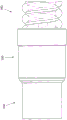
Fig. 2 is a perspective view of a medical tube.
Fig. 3 and 4 are perspective views of different embodiments of a terminating portion of a medical tube that is auxiliary connected to a respiratory component.
Fig. 5 and 6 are perspective views of various embodiments with a medical tube terminator attached to a respiratory component in an assisted manner.
Fig. 7 is a perspective view of a tube assembly employing a connection between two conduit segments, wherein the connections are established by connectors, and the outer cover is not shown for clarity.
Fig. 7A is a perspective view of a tube assembly having a single tube segment, and connectors at each end.
Figures 7B-7D illustrate one exemplary embodiment of a midpoint assembly that may be used to join two catheter sections.
Fig. 7E and 7F illustrate another exemplary embodiment of a midpoint assembly that may be used to engage a tube segment.
Fig. 8-10A are perspective views of a portion of a chamber end connector and the end of a catheter.
Fig. 11A-11C are views of another exemplary embodiment of a chamber-end connector.
Fig. 12 is a perspective view of a portion of a patient-end connector.
Fig. 13 is a cross-section of a portion of a patient-end connector.
Fig. 13A is a side view of a portion of a patient end connector.
Fig. 14A-14F are views of another exemplary embodiment of a patient-side connector.
Fig. 15 is a perspective view of a portion of one embodiment of a patient end connector including a bridge.
Fig. 16 is a perspective view of the bridge of fig. 15.
Figures 17-19 are various side views of a portion of a catheter coupled to one embodiment of a patient end connector including a channel.
Fig. 20 illustrates a portion of one exemplary embodiment of a patient-end connector having a bridge formed by adjoining recesses.
Description of The Preferred Embodiment
Fig. 1 shows a respiratory system 1 including, but not limited to, the following components: a pressurized air source 2, such as a blower or ventilator, adapted to generate an air supply to be delivered to the patient 3; a humidifying device 4 adapted to regulate the supply air; a medical tube 6 adapted to deliver gas to a patient interface 8, which then delivers gas to the patient 3; and a connector 16 adapted to connect the medical tube 6 to the humidifying device 4.
Patient interface 8 as described herein may refer to a face mask, nasal cannula, mouth mask, tracheal mask, or nasal pillow.
The humidifying device 4 as described herein may refer to any device that conditions a gas. This may include heating the gas and/or humidifying the gas.
The gas as described herein may refer to air, oxygen, carbon dioxide, or a mixture of any such gas, or a combination of such gas with one or more drugs or aerosols that may be delivered to the patient 3 via the patient interface 8.
The medical tube 6 as described herein may be referred to as a tube, catheter, tubing or hose. In fig. 2, 5 and 6, the illustrated medical tube 6 may include a first elongate member 10 and a second elongate member 12. In fig. 5 and 6, the medical tube 6 shown may include one or more wires 15. The one or more wires 15 may include at least one heating wire, at least one sensor wire, and/or any other type of electrical conductor. One or more wires 15 may be located within the medical tube 6. One or more wires 15 may be laid flat along the inner or outer surface of the medical tube 6. The one or more wires 15 may be helically wound around the medical tube 6 or within the medical tube 6 such that the one or more wires 15 may be embedded in the wall of the medical tube 6.
The medical tube 6 may be heated or unheated. The medical tube 6 may include insulation to reduce condensate formation within the medical tube 6. In some embodiments, the first elongate member 10 may have such insulation. If the heated, humidified gas within the medical tubing 6 cools during transport, condensate may form. To reduce or eliminate the formation of condensate, the medical tube 6 may be heated. Such heating may be provided by one or more wires 15 comprising one or more heating wires 14, as shown in fig. 5 and 6. In some embodiments, the second elongate member 12 can include one or more wires 15.
A terminating portion of the medical tube 6 may be provided to terminate one or more wires 15 at a connector 16 so that an electrical connection may be made between the medical tube 6 and a component of the respiratory system 1. In some embodiments, the terminating element may include a tail 20 or a tail 30, as described with respect to the medical tube 6 in fig. 5 and 6, and also as shown in the close-up views of fig. 3 and 4. The connector 16 may provide a pneumatic connection between the medical tube 6 and a component of the respiratory system 1. The components of the respiratory system 1 described herein may refer to a patient interface or a humidification device. The connector 16 may provide one or both of an electrical connection and a pneumatic connection between the medical tube 6 and a component of the respiratory system 1.
The one or more conductors 15 may also include one or more sense lines 18, as shown in fig. 5 and 6. One or more sensing lines 18 may be used to sense a gas characteristic, such as temperature, flow, humidity, or pressure. In some embodiments, one or more sense lines 18 can be used to sense temperature. In some embodiments, one or more sensing lines 18 may be connected to one or more sensors that may be used to sense one or more of these gas characteristics.
In some embodiments, as shown in fig. 5 and 6, one or more wires 15 are embedded in the medical tube 6. In some embodiments, one or more wires 15 may be embedded in the second elongate member 12. In some embodiments, one or more wires 15 may be embedded in the first elongate member 10. In some embodiments, both the one or more heating wires 14 and the one or more sensing wires 18 may be embedded in the second elongate member 12. In some embodiments, both the one or more heating wires 14 and the one or more sensing wires 18 may be embedded in the first elongate member 10. In some embodiments, at least one of the one or more heating wires 14 and the one or more sensing wires 18 can be embedded in the second elongate member 12, and at least another one of the one or more heating wires 14 and the one or more sensing wires 18 can be embedded in the first elongate member 10. In some embodiments, the heater wire 14 may be absent from the second elongate member 12. In some embodiments, sense line 18 may be absent from second elongate member 12. Any other such combination may be present.
In some embodiments, the one or more heating wires 14 may include two heating wires. In some embodiments, one or more sense lines 18 can include two sense lines. In some embodiments, one or more sense lines 18 can be located adjacent to one or more heater wires 14. In some embodiments, the one or more heating wires 14 may include a first heating wire and a second heating wire, and the one or more sensing wires 18 may be located between the first heating wire and the second heating wire.
The first elongated member 10 and the second elongated member 12 may be made of different materials. For example, the first elongate member 10 may be flexible and/or may provide thermal insulation properties to the medical tube 6. The second elongate member 12, for example, may be made of a material that provides enhanced properties and/or structural support to the medical tube 6. In some embodiments, the first elongate member 10 can provide enhanced properties and/or structural support to the medical tube 6. In some embodiments, the second elongate member 12 can be flexible and/or can provide thermal insulation properties. Different combinations may also be provided. In some embodiments, the medical tube 6 may comprise a single elongate member. In some embodiments, the medical tube 6 may include two or more first elongate members. In some embodiments, the medical tube 6 may include two or more second elongate members.
In some embodiments, the tails 20, 30 may extend from the second elongate member 12, as shown in fig. 5 and 6. In some embodiments, the tail 20, 30 may extend from the first elongate member 10. In some embodiments, the tails 20, 30 may extend from a combination of the first and second elongate members 10, 12. Similarly, if greater than the two elongate members used, the tail 20, 30 may extend from any one elongate member or more than one elongate member in the system. The tail 20, 30 as described herein refers to a terminating portion of the first and/or second elongated members 10, 12 that has been adapted to connect the first and/or second elongated members 10, 12 to an electrical component. The power component may refer to, for example, a printed circuit board or an electrical connector.
As shown in fig. 3 and 5, tail 20 may include a flattened portion 22 and an exposed portion 24. In some embodiments, tail 20 may include a transition or preliminary portion between first and/or second elongated members 10, 12 and flattened portion 22 that is not flattened or is less flattened than flattened portion 22. As shown in fig. 4 and 6, tail 30 may include a first flattened portion 32, an exposed portion 34, and a second flattened portion 36. In some embodiments, tail 30 may include a transition or preliminary portion between first elongate member 10 and/or second elongate member 12 and first flattened portion 32 that is not flattened or less flattened than first flattened portion 32. In some embodiments, the tail portions 20, 30 may include only the exposed portions 24, 34, respectively; however, flattened portion 22, first flattened portion 32, and/or second flattened portion 36 may assist in handling and connecting one or more wires 15 to the power component. Flattened portion 22 and/or first flattened portion 32 may be made of the same material as second elongate member 12. In some embodiments, width W of flattened portion 22, first flattened portion 32, and/or second flattened portion 36 may be at most 11.0mm, at most 9.0mm, or at most 8.5mm. In some embodiments, length L1 of flattened portion 22 and/or first flattened portion 32 may be at least 8.0mm. In some embodiments, the length L2 of the exposed portion 24 and/or the exposed portion 34 may be at least 8.0mm or at least 10.0mm. In some embodiments, the length L3 of the second flattened portion 36 may be at least twice the length of the exposed portion 34, at most 32.0mm, or at most 25.0mm.
Flattened section 22 depicts a portion of tail 20 and first flattened section 32 depicts a portion of tail 30 wherein one or more wires 15 may become spaced apart. Spacing as described herein may refer to separation or movement apart of one or more wires 15, and may refer to the location and positioning of one or more wires 15 at flattened portion 22, first flattened portion 32, and/or second flattened portion 36. If the one or more wires 15 include more than one wire, such as two or more heating wires, a combination of at least one heating wire and at least one sensing wire, two or more sensing wires, or any other combination of electrical conductors, the one or more wires 15 may be spaced apart relative to one another. Such spacing may assist in the attachment of one or more wires 15 to the power component. Such spacing may be determined by the width of flattened portion 22 and/or first flattened portion 32. In some embodiments, the spacing between each of the one or more wires 15 may be 2.5mm, up to 4.0mm, or at least 1.0mm. In some configurations, the distance between any two outermost wires may be less than 9.0mm or less than 8.0mm. A separation range or a pitch distance range between each of the one or more wires 15 may be used.
Once one or more wires 15 are spaced apart, flattened portion 22 and/or first flattened portion 32 may extend beyond either side of one or more wires 15. Flattened portion 22 and/or first flattened portion 32 may encase one or more wires 15. The amount of flattened portion 22 and/or first flattened portion 32 that encases one or more wires 15 may be within a range of values. In some embodiments, flattened portion 22 and/or first flattened portion 32 may extend 0.25 on either side of one or more wires 15. Flattened portion 22 and/or first flattened portion 32 may extend more or less on either side of one or more wires 15 as desired.
Flattened portion 22 and first flattened portion 32 of second elongate member 12 may be formed using known flattening techniques. The length of flattened material may be important with respect to the pitch and to maintain the pitch of one or more wires 15. If one or more wires 15 include more than one wire, the length of flattened material forming flattened portion 22 and first flattened portion 32 may help to separate each of one or more wires 15 relative to each other. Each of the one or more wires 15 may be spaced apart relative to one another prior to their exposure. In some embodiments, one or more wires 15 may be spaced apart relative to one another after their exposure. In some embodiments, each of the one or more wires 15 may be spaced apart from one another as they are exposed. The separation of each of the one or more wires 15 relative to each other may reduce the likelihood of sequential intermixing of the one or more wires 15. This may be helpful to the assembly operator in terms of usability and handling. The spacing between the wires may be as described above.
Fig. 4 and 6 illustrate an embodiment in which second flattened portion 36 may be used to facilitate attachment of second elongate member 12 to a power component. The second flattened portion 36 may be located away from or at the other end of the exposed portion 34 relative to the first flattened portion 32. The second flattened portion 36 may cover the one or more wires 15 and may extend beyond the length of the one or more wires 15. The second flattened portion 36 may be used to attach the second elongated member 12 to a power component. For example, second flattened portion 36 may facilitate wrapping tail portion 30 around a power component and/or a connector, such as connector 16. The second flattened section 36 may further maintain the spacing of the one or more wires 15 within the tail 30. The second flattened portion 36 may be made of the same material as the second elongated member 12. In some embodiments, second flattened portion 36 may be made from a different material. The second flattened portion 36 may facilitate handling of one or more wires 15. For example, each of the one or more wires 15 need not be individually treated, which may improve the efficiency of assembling the medical tube 6 to a connector, such as connector 16. In some embodiments, second flattened portion 36 may not be used. Other mechanisms or techniques may be used to maintain the positioning and spacing of the one or more wires 15.
The power components may be attached to one or more wires 15. The power component may be connected to the medical tube 6 by, for example, over-molding or adhesive, or by using a clamping mechanism. The connector 16 may form a connection between the medical tube 6 and the electrical component or another component of the respiratory system 1. In some embodiments, the connector 16 may form a connection between the medical tube 6 and the humidification device 4. In some embodiments, the connector 16 may form a connection between the medical tube 6 and the patient interface 8. The connector 16 may also be used to form a connection between the medical tube 6 and the blower 2. In some embodiments, the connector 16 may be used to form an electrical and pneumatic connection between the medical tube 6 and at least one other medical tube. The medical tube 6 may be infant, child or adult. In some embodiments, the medical tube 6 may be pneumatically coupled to at least one other medical tube. In some embodiments, one or more wires 15 may terminate at connector 16 without making a power connection. The tails 20, 30 may still be used in these embodiments to assist in connecting the medical tube 6 to the connector 16. In some embodiments, the tails 20, 30 may not be used or omitted. In some embodiments, the medical tube 6 may be attached to the connector 16 using known means. Thus, the connector 16 is not limited to the connections that it may form, and other connections between the medical tube and components of the respiratory system 1 may also be arranged and constructed in accordance with certain features, aspects, and advantages of the present disclosure.
The housing of the connector 16 may be formed of a transparent material. The transparent material may allow an operator to evaluate if one or more wires 15 have been separated and/or properly positioned on the connector 16. In some embodiments, the housing of the connector 16 may be a colored material. In some embodiments, the housing of the connector 16 may be an opaque material such that the user cannot view through the material.
Referring now to fig. 7, tube 6 is shown in a configuration defining a breathing tube 50. The illustrated breathing tube 50 has a chamber end connector 52 and a patient end connector 54. The cell-end connector 52 may be constructed as follows: PCT/NZ 2014/000201 (fphcr.371wo) submitted at 15, 9, 2014 and PCT/NZ2013/000222 (fpchr.273wo2) submitted at 4, 12, 2013, each hereby incorporated by reference in its entirety. The patient-side connector 54 may be constructed as follows: PCT/NZ 2013/000208 (fphcr.335 wo) submitted on 14 11 2013 and PCT/NZ2013/000222 (fpchr.273wo2) submitted on 4 12 2013 are each hereby incorporated by reference in their entirety. In some configurations, as in the illustrated configuration, the breathing tube 50 also includes an intermediate connector 56. The intermediate connector 56 may be constructed as follows: PCT/NZ 2013/000208 (fphcr.335 wo) submitted on 14 11 2013 and PCT/NZ2013/000222 (fpchr.273wo2) submitted on 4 12 2013 are each hereby incorporated by reference in their entirety. While shown without covers, each of the connectors 52, 54, 56 may include a suitable cover, for example, as shown and described in fig. 10A, 11C, and 14F and the associated description, to provide an aesthetic appearance to provide an ergonomic outer surface for grasping or other manipulation and to conceal the components defining the electrical, mechanical, and pneumatic connections described herein. In some configurations, the breathing tube 50 includes more than one intermediate connector 56; other configurations of the intermediate connector 56 may also be used.
In some configurations, the intermediate connector 56 engages the first tube segment 60 with the second tube segment 62. The first tube segment 60 may be connected to the chamber end connector 52 and the second tube segment 62 may be connected to the patient end connector 54. When these components are secured together, the power path extends from the chamber end connector 52 through the first tube segment 60 to the intermediate connector 56, across the intermediate connector 56, and from the intermediate connector 56 through the second tube segment 62 and to the patient end connector 54. In effect, an uninterrupted power connection extends from the chamber-side connector 52 to the patient-side connector 54. Similarly, the pneumatic path extends from the chamber end connector 52 through the first tube segment 60 to the intermediate connector 56, through the intermediate connector 56, and from the intermediate connector 56 through the second tube segment 62 and to the patient end connector 54. In effect, an uninterrupted pneumatic connection extends from the chamber-side connector 52 to the patient-side connector 54. The uninterrupted pneumatic connection may also extend from a pneumatic component (e.g., humidification chamber, not shown) connected to the chamber-side connector 52 to a pneumatic component (e.g., patient interface, not shown) connected to the patient-side connector 54. In practice, these components are joined together to define a single medical tube comprising two or more sections.
The first tube segment 60 includes a first end 64 and a second end 66. In some configurations, at least one of the first end 64 and the second end 66 includes a tail 70. In some configurations, first end 64 includes a tail 70, while second end 66 also includes a tail 72. The tail portions 70, 72 may have any suitable configuration, including any configuration embodied by the tail portions 20, 30.
Similarly, the second tube section 62 includes a first end 74 and a second end 76. In some configurations, at least one of the first end 74 and the second end 76 includes a tail 80. In some configurations, the first end 74 includes a tail 80, while the second end 76 also includes a tail 82. The tail portions 80, 82 may have any suitable configuration, including any configuration embodied by the tail portions 20, 30.
In some configurations, for example, as shown in fig. 7A, the tube 6 in a configuration defining a breathing tube 50 may include a chamber end connector 52 and a patient end connector 54, but not include an intermediate connector. In yet other embodiments, the tube 6 in a configuration defining a breathing tube 50 may include a chamber end connector 52, a patient end connector 54, and a midpoint assembly. An exemplary embodiment of a midpoint component 400 is shown in fig. 7B-7D. Additional details regarding midpoint component 400 are described below.
Referring now to FIG. 8, a portion of a chamber-end connector 52 is shown. Specifically, the chamber end connector 52 is shown without an outer cover or housing. The chamber-end connector 52 includes a plug portion 90. The plug portion 90 may support a printed circuit board or PCB 92.
The plug portion 90 includes a body 94. The body 94 may be generally cylindrical. The mounting flange 96 may extend away from the body 94. A mounting flange 96 may extend outwardly from the body 94. The mounting flange 96 may define the structure to which these covers or housings may be attached. In the illustrated configuration, the mounting flange 96 defines a passageway 98 through which the printed circuit board 92 may extend. In the illustrated configuration, the shroud 99 extends from the mounting flange 96 and generally forms an extension of the passageway 98 through which the PCB92 extends.
Adjacent to the passageway 98, a bracket tab 100 may be formed. The standoff protrusions 100 are arranged and configured to underlie the printed circuit board 92. In some configurations, the bracket tab 100 extends radially outward from the body 94. In some configurations, the bracket tab 100 is an axially extending ridge extending radially outward from the body 94. In some configurations, bracket tab 100 is connected to mounting flange 96.
In some configurations, the stent boss 100 may be reinforced by one or more buttresses 102. In the illustrated configuration, the stent boss 100 is reinforced by three buttresses 102. In the illustrated configuration, all buttresses 102 extend outwardly from a single side of bracket boss 100.
In some configurations, the bracket tab 100 may include upturned hooks 104. Upturned hooks 104 may return toward mounting flange 96. The upturned hooks 104 are arranged and configured to overlie at least a portion of the printed circuit board 92. In some configurations, a protrusion is positioned inside upturned hook 104, extends in an axial direction, and may be received within a recess defined on an axial end of printed circuit board 92. In some configurations, upturned hooks 104 have a greater lateral dimension than bracket bosses 100. In some configurations, both the upturned hooks 104 and the portion of the bracket tab 100 below the upturned hooks 104 have a greater lateral dimension than the portion of the bracket tab 100 not below the upturned hooks 104. In some configurations, upturned hooks 104 extend from an axial end of bracket boss 100.
As shown, the printed circuit board 92 includes one or more pads 106. As shown, the printed circuit board 92 may include an attachment recess 108 at least partially surrounded by the solder pad 106. The attachment recess 108 may have any suitable configuration. In the illustrated configuration, the attachment recess 108 is positioned at a location corresponding to the gap positioned between the buttresses 102. In some configurations, the attachment recess 108 is positioned in alignment with the gap defined between the buttresses 102 when the end of the printed circuit board 92 is positioned within the upturned hooks 104.
The printed circuit board 92 may also include wire alignment features such as alignment notches 110, by way of example and not limitation. In some configurations, as shown in fig. 8, the attachment recess 108 is located on one side of the printed circuit board 92 and the alignment recess 110 is located on an opposite side of the printed circuit board 92. Alignment notch 110 may accommodate the wires of tail 70. The alignment notch 110 may generally align with the location of the attachment notch 108. Alignment notch 110 may help reduce or eliminate the likelihood of wires of tail 70 crossing each other and may help maintain wire tightness of tail 70 during soldering to printed circuit board 92. In some configurations, two or more alignment notches 110 are separated by a distance greater than the separation distance between the respective attachment notches 108, resulting in wires of the tail 70 fanning out from the attachment notches 108 to the alignment notches 110 to improve the solder path and further reduce the likelihood of wires of the tail 70 crossing each other. Alignment notch 110 may be sized and configured to receive a wire of tail 70. While the alignment notch 110 is shown as part of the printed circuit board 92, the alignment notch 110 may be formed from separate components such as the bracket tab 100 or the upturned hook 104, by way of example and not limitation.
In the illustrated configuration, the upturned hooks 104 may help resist twisting of the printed circuit board 92 when the tail 70 is pulled into place such that the wires of the tail 70 are secured within the attachment recess 108 and the alignment recess 110. Additionally, buttress 102 may help reduce the likelihood of bending or curling of printed circuit board 92 during soldering of the wires of tail 70 to pads 106.
Referring now to fig. 9, the plug portion 90 is shown with a conduit 112 attached. Catheter 112 may have any suitable configuration, including any of the configurations described elsewhere herein. The catheter 112 is shown to include a first element 114 and a second element 116. In some configurations, the first element 114 may terminate before the second element 116, with the tail 70 extending from the second element 116. In other words, the tail 70 of the second element 116 may extend farther along the plug portion 90 than the first element 114. In some configurations, the tail 70 may extend from the first element 114. In some configurations, the tail 70 may extend from a combination of the first element 114 and the second element 116. In some configurations, the first element 114 and the second element 116 may be helically wound at a pitch.
The second element 116 may include a grommet coupled to one or more wires 118. The leads 118 may have any suitable configuration. In some configurations, the wire 118 may be coated to have two or more colors. In other words, in some configurations, the wires 118 may be differently coated or otherwise colored such that some of the wires 118, e.g., the outermost wires 118, may be visually distinguished from other wires 118 (e.g., the innermost wires 118). This configuration or another configuration that allows for visual distinction between the wires 118 advantageously allows for confirmation that the wires 118 are in the respective attachment notches 108 in the desired position and order prior to being soldered to the pads 106 of the printed circuit board 92.
In some configurations, tail 70 may include a first flattened region 120 and a second flattened region 122, and wire 118 may be exposed between first flattened region 120 and second flattened region 122. Thus, the tail 70 may have any suitable configuration, including any of the configurations described herein. In some configurations, second flattened region 122 may be omitted. In some configurations, first flattened region 120 and second flattened region 122 may be omitted. However, first flattened region 120 and second flattened region 122 help to reduce the likelihood of contact between wires 118 during or after fabrication. In some configurations, tail 70 may include a transition or preliminary portion between first element 114 and/or second element 116 and first flattened region 120 that is not flattened or less flattened than first flattened region 120.
Referring to fig. 8 and 9, a cover 124 may be used to limit the position of second flattened area 122 during manufacturing. The cover 124 may be integrally formed with the plug portion 90. The cover 124 may be formed separately from the plug portion 90. The separately formed cover 124 may be secured to the plug portion 90 in any suitable configuration. In the illustrated configuration, living hinge 126 may be used to secure the integrally formed cover 124 to plug portion 90. Other suitable configurations may also be used.
As shown in fig. 9, the cover 124 may include a curved inner surface 128. The curved inner surface 128 may be used to secure at least a portion of the second flattened area 122 to an outer surface 130 of the plug portion 90. In some configurations, at least a portion of the second flattened area 122 may be secured between an outer surface 130 of the plug portion 90 and a curved inner surface 128 of the cover 124. In some configurations, at least a portion of the first flattened area 120 may be secured between an outer surface 130 of the plug portion 90 and an inner surface 128 of the cover 124. In some configurations, at least a portion of the wires 118 exposed between the first flattened region 120 and the second flattened region 122 may be secured between an outer surface 130 of the plug portion 90 and an inner surface 128 of the cover 124.
The cover 124 may include one or more retaining members 132. In the illustrated configuration, two retaining members 132 are provided. Each retaining member 132 may include a hook 134. The two retaining members 132 may be separated from one another by tabs 136. The tab 136 may provide a surface for an operator to squeeze to close the cover 124 onto the plug portion 90. Tab 136 may also cover at least a portion of second flattened area 120 when cover 124 is closed over plug portion 90. Other configurations may be used that do not include tab 136, recall that it is desirable to facilitate assembly and coverage of second flattened region 120. The plug portion 90 may include one or more snaps 138. The catch 138 may be positioned on the bracket boss 100. The catch 138 may be positioned on the lower surface of the bracket boss 100. Other configurations are possible, taking into account the desire to secure cover 124 in a closed position capturing second flattened area 122. During assembly, because the second flattened area 122 is positioned along the outer surface 130 of the plug portion 90, the cover 124 may be rotated about the living hinge 126 until the retaining member 132 engages the catch 138 that restrains the second flattened area 122 between the outer surface 130 of the cover 124 and the curved inner surface 128.
In some configurations, the connection between the conduit 112 and the plug portion 90 and/or the connection between the wires 118 and the printed circuit board 92 may be overmolded. In some configurations, the cover 124 may be overmolded. In some configurations, the connections between the conduit 112 and the plug portion 90 and between the wires 118 and the printed circuit board 92, as well as the cover 124, may be overmolded.
In some configurations, as shown in fig. 10, the flow of the overmold material 142 may be restricted during the overmolding process. The overmold material 142 may be any suitable material. In some configurations, the overmold material 142 may be any material suitable for lower pressure overmolding. In some configurations, the overmold material 142 may be a thermoplastic elastomer (TPE), such as a Thermoplastic Polyurethane (TPU), a thermoplastic vulcanizate (TPV), or a polyolefin elastomer (POE), similar to or the same material used to form the tube 6. In some configurations, the overmold material 142 may be a thermoplastic polymer, such as Low Density Polyethylene (LDPE) or polypropylene (PP). In some configurations, while the plug portion 90 is polypropylene, the tube 6 (including the tails 70, 72) is a polyolefin elastomer, and the printed circuit board 92 is a fiberglass-reinforced epoxy laminate, the overmold material 142 may be an ethylene copolymer having a methyl acrylate composition that bonds to the plug portion 90, the tails 70, 72, and the printed circuit board 92, and thereby provides pneumatic leakage protection and liquid ingress protection. In some configurations, the printed circuit board 92 may be insert molded or otherwise bonded to the plug portion 90 as part of the plug portion 90, and the overmold material 142 may be a thermoplastic elastomer selected for bonding to the plug portion 90 and the tail portions 70, 72.
In some configurations, the overmold material 142 may flow into at least a portion of the first element 114. In other words, the first element 114 may be an elongated hollow element, and the overmold material 142 may flow into at least a portion of the elongated hollow element to help reduce the likelihood of leakage. In some configurations, the overmold material 142 may at least partially melt the second element 116. By at least partially melting the second element 116, the overmold material 142 and the second element 116 may help reduce the likelihood of leakage. In some configurations, the overmolding material 142 may provide protection for the power components (e.g., may effectively contain (pot) the power components).
As shown in fig. 8-10, the plug portion 90 may include a guide tab 144. The guide tab 144 may be integrally formed with the plug portion 90. The guide tab 144 may act as a positive stop for the conduit 112 during assembly of the conduit 112 to the plug portion 90. In the illustrated configuration, the plug portion 90 includes a helical rib 146. In some configurations, the helical rib 146 may be aligned with the pitch of the conduit 112. The plug portion 90 may be inserted into the conduit 112 until the guide tab 144 is positioned between the tail 70 and the conduit 112. The helical rib 146 may then help secure the conduit 112 in place on the plug portion 90 by pressing in the first element 114. In some configurations, the guide tabs 144 are bent toward the mounting flange 96, which may help guide the tail 70 toward the printed circuit board 92. Because the length of tail 70 and the length of first flattened area 120 are known, it is possible to provide a desired length between the end of first element 114 and the connection point of exposed wire 118 to pad 106 of printed circuit board 92. Other configurations are possible, taking into account the desire to properly position the terminal end of the conduit 112 relative to the printed circuit board 92.
Referring to fig. 10A, the components discussed above, including but not limited to portions of the chamber-end connector 52, portions of the conduit 112, and/or portions of the printed circuit board 92, may be enclosed by a first outer cover 148 and a second outer cover 150. The two covers 148, 150 may be secured in any suitable manner. In the illustrated configuration, the two outer covers 148, 150 may be snapped into engagement with the mounting flange 96 of the plug portion 90. Other configurations are also possible.
Fig. 11A-11C illustrate another exemplary embodiment of a chamber-end connector 352. Fig. 11A-11B illustrate a chamber end connector 352 without an outer cover or shell, and fig. 11C illustrates a chamber end connector 352 enclosed by a first outer cover 348 and a second outer cover 350 secured to each other and/or to an underlying member of the connector 352.
The chamber-end connector 352 includes a plug portion 390 that may support a printed circuit board or PCB 392. Plug portion 390 includes a body 394, which may be generally cylindrical. A mounting flange 396 may extend away from the body 394. The mounting flange 396 defines a passageway 398 through which the PCB 392 may extend. The mounting flange 396 further defines an extension 398a of the passageway 398, extending from the passageway 398, and extending from the PCB 392 as the PCB 392 extends through the passageway 398. In the embodiment shown in fig. 8, an electronic component 93, such as, but not limited to, an ID resistor, is positioned on the PCB 92 on the chamber side of the mounting flange 96, i.e., on the side of the mounting flange 96 opposite the alignment notch 110. In the embodiment of fig. 11A-11C, an electronic component 393, such as, but not limited to, an ID resistor, is positioned on the PCB 392 on the conduit side of the mounting flange 396, i.e., on the same side of the mounting flange 396 as the alignment notch 310. The placement of the electronic components 393 on the conduit side of the mounting flange 396 allows the electronic components 393 to be covered with an over-molded material as described herein to advantageously help protect the electronic components 393 from liquids. The extension 398a of the passageway 398 provides an opening for the electronic component 393 to pass through the mounting flange 396 during assembly.
The stand boss 300 may be formed adjacent to the passageway 398. The stand-off tab 300 is arranged and configured to underlie the PCB392 and support the PCB 392. In the illustrated embodiment, the stand-off tab 300 has a height of 0.02 to 0.1mm, which is higher, i.e., farther from the central axis of the plug portion 390 than the bottom of the passageway 398. This increased height causes the portion of the PCB392 on the conduit side of the mounting flange 396 to flex or lift slightly upward, i.e., away from the central axis of the plug portion 390. This in turn causes the portion of the PCB392 on the chamber side of the mounting flange 396 to deflect or bend slightly downward, i.e., closer to the central axis of the plug portion 390, which forces the chamber end of the PCB392 (i.e., the end of the PCB392 on the chamber side of the mounting flange 396) into closer contact with the lower surface of the chamber end connector 352. As shown in fig. 11C, the second outer cover 350, which is configured to encapsulate the plug portion 390 and the PCB392, includes a protrusion 351. The boss 351 is configured to underlie and support the chamber end of the PCB 392. The height of the stand-off ledge 300 pressed upward on the PCB392 portion of the conduit side of the mounting flange 396 drives downward the portion of the PCB392 on the chamber side of the mounting flange 396, which helps to promote the chamber end of the PCB392 flush or slightly below the upper surface of the ledge 351. This helps to prevent the PCB392 from possibly catching on surrounding objects and reduces the likelihood of separation between the PCB392 and the boss 351. In some configurations the boss 351 may include a recess that accommodates at least a portion of the PCB 392. In the illustrated embodiment, bracket tab 300 is reinforced by two buttresses 302. The bracket boss 300 may include upturned hooks 304 to overlie a portion of the PCB 392.
As shown, the PCB 392 includes one or more attachment recesses 308, pads 306 at least partially surrounding the attachment recesses 308, and alignment recesses 310. In this embodiment (and as best shown in fig. 11B), PCB 392 includes four attachment notches 308 at least partially surrounded by four pads 306, and corresponding alignment notches 310. The outermost two attachment notches 308a and pads 306a are positioned on a first edge of the PCB 392 and the corresponding outermost two alignment notches 310a are positioned on a second opposite edge of the PCB 392 that is aligned with the attachment notches 308 a. The inner two attachment notches 308b and pads 306b are positioned on the second edge of the PCB 392 between the outer alignment notches 310a, and the inner two alignment notches 310b are positioned on the first edge of the PCB 392 between the attachment notches 308a and aligned with the attachment notches 308 b.
In some embodiments, outer pads 306a are configured to be soldered to heater wire 14 and inner pads 306b are configured to be soldered to sense line 18. Soldering the heater wire 14 to the outer pad 306a and to the edge of the PCB 392 opposite the sense line pad 306b advantageously increases the separation between the heater wire pad 306a and the sense line pad 306 b. This helps to prevent or reduce the likelihood of liquid bridging between the heater wire pads 306a and the sense wire pads 306b and thus shorting the heater wire 14 to the sense wire 18. In the embodiment shown, PCB 392 also includes slots 395. As shown, slot 395 extends longitudinally along a portion of PCB 392 on the conduit side of PCB 392. Slit 395 is located between outer pad 306a and inner pad 306 b. During the overmolding process described herein, the overmolding material flows into slots 395, which also helps to separate heater wire pads 306a from sense wire pads 306b and helps to prevent bridging of liquid therebetween. This separation between the heater wire pads 306a and the sense line pads 306b also helps reduce the likelihood of heat transfer between the heater wire and the sense line.
The chamber-end connector 352 of fig. 11A-11C may also include a cover (not shown) configured to limit the second flattened area 122 during manufacturing. The cover may be similar to the cover 124 shown in fig. 8 and 9. However, the cover for the embodiment shown in FIGS. 11A-11C may include only one retaining member 132. In other words, the cover may be attached to only one end of the bracket convex portion 300, not to both ends of the bracket convex portion 300.
In some embodiments, portions of the plug portion 390, the wires 118, the conduit 112, and the PCB 392 and/or the connections therebetween may be overmolded, similar to the embodiment of fig. 8-10A. As described above, in the embodiment of fig. 11A-11C, the electronic components 393 may be overmolded due to the placement of the electronic components 393 on the catheter side of the PCB 392. Plug portion 390 may include a dividing wall 397 as shown in fig. 11A-11B. The partition 397 divides the space under the PCB 392 between the mounting flange 396 and the buttress 302 of the bracket boss 300. Dividing this space into two smaller spaces by dividing wall 397 advantageously helps reduce the likelihood of the overmold material forming voids or excessive shrinkage as it cools.
The plug portion 390 may include guide tabs 344 that may act as positive stops for the catheter 112 during assembly of the catheter 112 to the plug portion 390. In the illustrated embodiment, the guide tab 344 protrudes from the plug portion 390 perpendicular to the wall of the plug portion 390, rather than being angled as in the embodiment of fig. 8-10A. Plug portion 390 includes two helical ribs 346, 347. In some embodiments, the first helical rib 346 and/or the second helical rib 347 may be aligned with the pitch of the conduit 112. In the illustrated embodiment, the second helical rib 347 has a generally trapezoidal cross section that forms a sharp or sloped change from the outer surface of the plug portion 390 to the outer surface of the second helical rib 347, while the first helical rib 346 has a generally semicircular cross section that forms a smoother transition. The acute angle of the second helical rib 347 may help prevent or reduce the likelihood of liquid passing through the second helical rib 347. The plug portion 390 may be inserted into the conduit 112 until the guide tab 344 is positioned over the cut-out portion of the first element 114. The first helical rib 346 may then assist in securing the conduit 112 to the plug portion 90 by pressing in the first member 114. As shown, the guide tab 344 may extend from the first helical rib 346. The second spiral rib 347 is positioned between the first spiral rib 346 and the bracket convex portion 300. As shown in fig. 11A, the second helical rib 347 includes a longitudinal bridging section 347a such that the second helical rib 347 fully surrounds the male portion 390. The second helical rib 347 may act as a liquid barrier to inhibit the transfer of liquid from the conduit 112 toward the PCB 392.
Referring now to fig. 12, the patient end connector 54 is shown coupled to the distal end of the catheter 160. The patient-end connector 54 may include a single, integrally formed body 158. Other configurations are also possible.
As described above, the catheter 160 may have any suitable configuration, including any of the configurations described elsewhere herein. The catheter 160 is shown to include a first element 162 and a second element 164. The first member 162 may terminate before the second member 164 with a tail 82 (not visible in fig. 12) extending from the second member 164. In other words, the tail portion 82 of the second member 164 may extend farther along the body 158 of the patient-end connector 54 than the first member 162. In some configurations, tail 82 may extend from first element 162. In some configurations, tail 82 may extend from a combination of first element 162 and second element 164. In some configurations, the first and second elements 162, 164 may be helically wound at a pitch.
The second element 164 may include a grommet coupled to one or more wires 166. The leads 166 may have any suitable configuration. In some configurations, the wire 166 may be coated to have two or more colors. In other words, in some configurations, the wires 166 may be differently coated or otherwise colored such that some of the wires 166, e.g., the outermost wires 166, may be visually distinguished from other wires 166 (e.g., the innermost wires 166). This configuration or another configuration that allows visual distinction between the wires 166 advantageously allows for confirmation that the wires 166 are in the desired location and order of connection to the printed circuit board 168.
In some configurations, tail 82 may include a first flattened region 170 and a second flattened region 172 (not visible in fig. 12), and wire 166 may be exposed between first flattened region 170 and second flattened region 172. Thus, tail 82 may have any suitable configuration, including any of the configurations described elsewhere herein. In some configurations, second flattened region 172 may be omitted. In some configurations, first flattened region 170 and second flattened region 172 may be omitted. However, first flattened region 170 and second flattened region 172 help to reduce the likelihood of contact between wires 166 during or after fabrication. In some configurations, tail 82 may include a transition or preliminary portion between first element 162 and/or second element 164 and first flattened region 170 that is not flattened or flattened less than first flattened region 170.
With continued reference to FIG. 12, in some embodiments, a cover 174 may be used to limit the position of second flattened area 172 during manufacturing. The cover 174 may be integrally formed with the body 158. The cover 174 may be formed separately from the body 158. The separately formed cover 174 may be secured to the body 158 in any suitable configuration. In the illustrated configuration, living hinge 176 may be used to secure the integrally formed cover 174 to plug portion 90. In the illustrated configuration, two separate living hinges 176 have been used. Other suitable configurations may also be used. In some embodiments, the second flattened area 172 may be severed after the exposed wire 118 is soldered to the pad 106, and no cover is used.
In the illustrated configuration, the cover 174 includes a first edge 188 and a second edge 190, and includes a recess 178 that may be positioned along the first edge 188. The post 180 of the body 158 may be used to secure the cover 174 in the closed position. The posts 180 and the recesses 178 may interact to secure the cover 174 in the closed position. The spinous processes 192 may be aligned with the pitch of the conduit 160. In some configurations, the second edge 190 may be aligned with (or extend generally parallel to) the pitch of the spinous processes 192. When so aligned, the second edge 190 and the tab 192 may interact to help secure the cover 174 in the closed position by preventing movement of the recess 178 away from the post 180. As described above, cover 174 may secure second flattened area 172 and/or wire 166 in place between body 158 and cover 174.
Referring to fig. 12, body 158 may include a wire alignment feature, such as comb 182, by way of example and not limitation. The comb 182 may include a plurality of fingers that are spaced apart by gaps or alignment notches that receive the wires 166. The combs 182 may help reduce or eliminate the likelihood of the wires 166 crossing each other and may help maintain the wires 166 taut during soldering to the printed circuit board 168. In the illustrated configuration of fig. 12, the combs 182 extend generally perpendicular to the printed circuit board 168.
As shown in fig. 13, the printed circuit board 168 preferably extends entirely through the diameter of the body 158. In other words, at least a portion of the printed circuit board 168 may be exposed outside the body 158 at either or both ends of the printed circuit board 168. As shown in fig. 13, the printed circuit board 168 has a wider head portion 168b and a narrower stem portion 168a that extends through the airflow path of the body 158. At least a portion of stem 168b preferably extends beyond body 158. In some embodiments, as shown in fig. 13, at least a portion of stem 168a extends beyond body 158. In some embodiments, at least a portion of stem 168a extends into the thickness of body 158, but not beyond body 158. Within the thickness of body 158, stem 168a is joined to head 168b. In other words, at least a portion of head 168b is embedded within the wall of body 158, as shown in FIG. 13. The head 168b includes the pads 106 and embedding a portion of the head 168b in the wall of the body 158 helps the printed circuit board 168 resist flexing during assembly.
With continued reference to fig. 13, the printed circuit board 168 is shown with a thermistor 184 attached to the printed circuit board 168. The thermistor 184 may be a surface mounted thermistor. Other sensors may be mounted to the printed circuit board 168. In some embodiments, the thermistor 184 is used to sense temperature and feedback a value representative of the temperature to the printed circuit board 168 and from the printed circuit board 168 to another medical device.
The thermistor 184 and the printed circuit board 168 may be overmolded during formation of the patient end connector 54. Because of the clamping and material flow pressures that occur during the overmolding process, the orientation of these components and the bending or flexing of the printed circuit board 168 become important considerations. For this reason, the thermistor 184 is mounted longitudinally in the direction of the airflow through the patient end connector 54. Longitudinal mounting in the direction of the air flow reduces the effects of possible flexing of the printed circuit board 168 during the over-molding operation. In other words, the thermistors 184 are preferably mounted with their terminals oriented relative to one another in a direction that minimizes the amount of deflection of the printed circuit board 168.
The thermistor 184 may be positioned on an extension of the printed circuit board 168 that extends further upstream into the airflow relative to other portions of the printed circuit board 168 and the mounting of the printed circuit board 168 to the body 158. By positioning the thermistor 184 on this extension of the printed circuit board 168, the thermistor 184 will be positioned in a more laminar airflow prior to turbulence in the airflow that may be created by other portions of the printed circuit board 168 and the mounting of the printed circuit board 168 to the body 158. Additionally, it is believed that positioning of the thermistor 184 on the extended portion of the printed circuit board 168 may help reduce the stem effects (steps effects) of the reading of the thermistor 184, which may be caused by temperature variations of other electronic components and/or ambient conditions on the printed circuit board 168.
With continued reference to fig. 12, the body 158 may include a guide tab 186. The guide tab 186 may be integrally formed with the body 158. The guide tabs 186 may act as positive stops during assembly of the catheter 160 to the body 158. In the illustrated configuration, body 158 includes helical ribs 194, and helical ribs 194 may match or simulate the pitch of conduit 160. Thus, the conduit 160 may be screwed onto the body 158 (or the body 158 may be screwed into the conduit 160) until the first element 162 (e.g., the elongated hollow portion of the conduit 160) abuts the guide tab 186. In some embodiments, the guide tabs 186 may be bent away from the body of the conduit 160, which may help guide the tail 82 toward the printed circuit board 168. In some embodiments, the guide tabs 186 protrude perpendicular to the body 158. Because the length of tail 82 and the length of first flattened area 170 are known, it is possible to provide a desired length between the end of first element 162 and the connection of exposed wire 166 to pad 106 of printed circuit board 168. Other configurations are possible, taking into account the desire to properly position the terminal end of the conduit 160 relative to the printed circuit board 168.
For the chamber-end connector 52 described above, the connection between the conduit 160 and the body 158 and/or the connection between the printed circuit board 168 and the leads 166 may be overmolded. Referring to fig. 13A, an overmold material 189 is shown at the junction between the conduit 160 and the body 158. An overmold material 189 may encapsulate the printed circuit board 168 and the wires 166. The overmold material 189 may be similar or have similar features to the overmold material 142 described above. Additionally, although not shown, a cover member may be coupled to the body 158 to conceal the connection between the conduit 160 and the body 158.
In some cases, there may be a gap or space between the outer surface of the body 158 and the inner surface of the conduit 160 at the junction of the conduit 160 and the body 158. If condensate forms within the conduit 160, even a small gap may allow liquid to seep from between the conduit 160 and the body 158 and reach the printed circuit board 168 and/or exposed leads 166. To prevent or reduce the likelihood of liquid reaching the electrical components or connections, the body 158 may include features to allow the over-molding material 189 to flow into any gaps to help seal the interface between the conduit 160 and the body 158. The over-mold material 189 may thus help better protect the electrical component from condensate or other liquids. The over-mold material 189 may also help to establish an improved pneumatic seal between the conduit 160 and the body 158. Fig. 15-19 illustrate exemplary embodiments of such features.
Referring to fig. 15, in some configurations, the patient-end connector 54 includes a bridge 210. Bridge 210 may be placed on an outer surface of body 158. Bridge 210 may be positioned between an outer surface of body 158 and at least a portion of conduit 160. In some configurations, as will be discussed, the bridge 210 may be positioned between an outer surface of the body 158 and the second element 164 or stay ring of the catheter 160.
Fig. 16 shows a perspective view of the bridge 210. As shown, bridge 210 includes a pad 212, an extension 214, and a pin 216.
The extension 214 extends outwardly and upwardly from the pad 212. In the illustrated embodiment, the extension 214 is generally triangular, although other shapes or configurations are possible. The extension 214 has a side surface.
A pin 216 extends from the extension 214. In the illustrated configuration, the pin 216 extends from a side surface of the extension 214.
As shown in fig. 12 and 13, the stem portion 168a of the printed circuit board 168 extending from the body 158 includes a hole 202. The pin 216 is configured to be received in the bore 202 as shown in fig. 15. Bridge 210 is coupled to body 158 as a result of pin 216 being inserted into bore 202. In some embodiments, the stem portion 168a of the printed circuit board 168 extends or slightly widens to provide additional strength and better support for the pin 216 and bridge 210.
In the embodiment shown in fig. 15, the bridge 210 is positioned adjacent to the body 158 and proximate to the guide tab 186. The bridge 210 is positioned such that the second element 164, including the stay, extends over the pad 212 when the conduit 160 is coupled to the body 158. Thus, the pad 212 causes the second member 164 to lift off the outer surface of the body 158, thereby creating a gap between the second member 164 and the outer surface of the body 158 on each side of the pad 212 (i.e., in the circumferential direction of the connector). When the overmold material 189 is applied over the connection between the conduit 160 and the body 158, the overmold material 189 may flow into the gap formed by the bridge 210, thereby bonding the second element 164 to the outer surface of the body 158. Bonding the second element 164 to the outer surface of the body 158 may prevent or inhibit liquid from seeping between the outer surface of the body 158 and the second element 164 or collar of the conduit 160, and may therefore reduce or eliminate the likelihood of liquid reaching the electrical connection.
Fig. 20 shows an alternative embodiment in which a bridge member is formed on the body 158 by two adjacent recesses 211 positioned between the stem 168a and the tab 186. The second element 164 extends over the recess 211, allowing the overmold material to flow into the recess 211 such that the overmold surrounds the second element 164 and bonds the second element 164 to the outer surface of the body 158. Bonding the second member 164 to the outer surface of the body 158 may inhibit or prevent liquid from seeping between the outer surface of the body 158 and the second member 164 to reduce or eliminate the likelihood of liquid reaching the electrical connection.
Referring to fig. 17-19, in some configurations, the patient-end connector 54 includes a channel 220 formed in the body 158. The channel 220 allows the overmold material 189 to flow between the inner surface of the conduit 160 and the outer surface of the body 158. As shown, the channel 220 is recessed from the outer surface of the body 158 or is formed in the outer surface of the body 158 in the form of a recess.
The channel 220 may have any suitable configuration. The channel 220 may extend around at least a portion of the circumference of the body 158. In some configurations, the channel 220 may extend in a helical or partially helical fashion. The channel 220 may be positioned and formed such that the second element 164 extends over the channel 220, along the channel 220, or in the channel 220. When the overmold material 189 is applied at the junction between the conduit 160 and the body 158, the overmold material 189 may flow into the channel 220 and under the second element 164, thereby bonding the second element 164 to the outer surface of the body 158. In some configurations, the overmold material 189 incorporates the second element 164 or the conduit 160 into the recessed surface defined by the channel 220.
To facilitate the formation of a seal between conduit 160 and body 158, channel 220 and second element 164 may be positioned such that channel 220 extends to both sides of second element 164 (i.e., in the axial direction of the connector). As shown in fig. 17, at least a portion 222 of the channel 220 is proximal to the second element 164. In some configurations, the channel 220 may extend under more than one wrap of the helically wound second element 164. In some configurations, the lip or ridge 224 may be configured along or adjacent to the channel 220, and the lip or ridge 224 may be oriented to extend beyond the second element 164. The lip or ridge 224 may lift the second member 164 off the outer surface of the body 158, similar to the liner described above.
Fig. 14A-14F illustrate another exemplary embodiment of a patient-side connector 354. The patient-end connector 354 may include an integrally formed main body 358 and a printed circuit board or PCB 368. In this embodiment, after the exposed wire 118 is soldered to the pad, the second flattened area 172 of the tail 82 may be severed and thus no cover is used. The body 358 may include wire alignment features, such as combs 382. The combs 382 may include alignment notches that receive the wires 166 to help keep the wires 166 separated and taut from one another during soldering to the PCB 368.
As shown, PCB 368 extends through the diameter of main body 358 and includes a wider head portion 368b and a narrower shaft portion 368a. Head 368b includes pads 306. In the illustrated embodiment, the outer two pads 306a are positioned on one side of the head 368b facing away from the comb 382, and the inner two pads 306b are positioned on the opposite side of the head 368b, i.e., facing the comb 382. The outer two pads 306a may be configured to be soldered to the heater wire 14, and the inner two pads 306b may be configured to be soldered to the sense line 18. This arrangement advantageously increases the separation between the heater wire pads 306a and the sense wire pads 306b to help reduce the likelihood of liquid bridging therebetween and possibly causing a short circuit.
Similar to the chamber-end connector 352 described above, the patient-end connector 354 may include a first helical rib 494 that helps retain the conduit 160 to the body 358 by pressing in the first element 162 during assembly, a guide tab 386 that acts as a stop for the conduit 160 during assembly of the conduit 160 to the body 358, and a second helical rib 495 that acts as a liquid barrier to prevent liquid from the conduit 160 to the PCB 368. In the illustrated embodiment, the guide tab 386 protrudes from the main body 358 perpendicular to the main body 358. As shown in fig. 14A, the first element 162 of the catheter 160 at the end of the catheter 160 threaded onto the connector 352 may be cut in the middle of the first element 162 and the body 358 may be inserted into the catheter 160 until the guide tab 386 is positioned against the cut edge of the first element 162.
As shown in fig. 14C, second spiral rib 495 includes a longitudinal bridging section 495a such that second spiral rib 495 completely surrounds main body 358 to create a liquid barrier. The guide tab 396 is positioned on the end of the longitudinal bridge section 495a nearest the first helical rib 494. The drift limiting post 388 is positioned on the end of the longitudinal bridge section 495a opposite the guide tab 396. Tail 82 extends over longitudinal bridge section 495a as it extends onto PCB 368. The drift limiting posts 388 help prevent the tail 82 from drifting too far toward the stem portion 368a of the PCB 368 to help maintain the tail 82 in a desired position during the over-molding process. As shown in fig. 14B, the stem portion 368a of the PCB 368 is offset or not centered relative to the head portion 368B. This advantageously displaces the exposed end of the stem 368a further away from the drift limiting post 388.
As described with respect to the embodiments of the chamber- end connectors 52, 352 and the patient-end connector 54 of fig. 12-13A, the connection between the conduit 160 and the main body 358 of the patient-end connector 354 and/or the connection between the conduit 160 and the PCB 368 may be overmolded. The patient-end connector 354 may include features to allow over-molding material to flow into any gaps to better seal the interface between the catheter 160 and the main body 358. For example, as shown in fig. 14C and 14D, body 358 includes a series of bridge members that lift tail 82 off of body 358 to allow the overmold material to fully encapsulate tail 82. Longitudinal bridging section 495a of second spiral rib 495 forms the first bridge member. Two additional bridge members 389a, 389b are positioned between the longitudinal bridge section 495a and the head portion 368b of the PCB, although there may be more or fewer bridge members. Additionally or alternatively, the outer diameter of the body 358 in the area around the bridge member may be reduced. For example, as shown in fig. 14E, in the region 358a near the drift limiting leg 388 between the drift limiting leg 388 and the bridge member 389a, the outer diameter may be reduced (as compared to the diameter of the body 358, if circular, indicated by reference arc D in fig. 14E). In some configurations, the outer diameter may then gradually increase from region 358a to region 358b near head 368b of PCB 368. The reduced outer diameter portion of body 358 may also help to allow more overmold material to flow under tail 82 to more fully encapsulate tail 82. As shown in fig. 14F, the cover member 355 may also be connected to the main body 358 to conceal the connection between the conduit 160 and the main body 358.
Fig. 7B-7D illustrate an exemplary embodiment of a midpoint assembly 400 (such as the catheter segments 60 and 62 shown in fig. 7) that may be used to couple two catheter segments. The midpoint assembly 400 shown includes a body 402, a PCB404, and a power diode 401. In some configurations, midpoint assembly 400 may also include a sensor diode and a sensor, such as a thermistor. The midpoint assembly 400 may include various features similar in structure and/or function to the illustrated and described chamber-side connector 352 and patient-side connector 354, although the midpoint assembly 400 may include two of many of these features, one at each end, when the midpoint assembly 400 is configured to be coupled to a catheter at each end. For example, midpoint assembly 400 includes two alignment features, such as combs 410a, 410b. The first comb 410a extends generally perpendicular to the PCB404 on one side of the PCB404 and the second comb 410b extends generally perpendicular to the PCB404 on the other side of the PCB 404. As shown in fig. 7B and 7D, the pads 406 alternate on each side of the PCB404 to advantageously increase the separation between adjacent pads 406 on each side of the PCB404 to reduce the likelihood of shorting. Each end of the midpoint assembly 400 includes a first helical rib 412 that allows the conduit to be screwed onto the body 402, and a second helical rib 414 that acts as a liquid barrier between the conduit and the PCB404, and includes a longitudinal bridging section 414a such that the second helical rib 414 completely encircles the body 402. Each end also includes a guide tab 416 at the end of the longitudinal bridge section 414 a. Each end also includes two bridging members 420 that lift the tail portions of the tube segments away from the body 402 to allow the overmold material to completely encapsulate the tail portions.
Fig. 7E-7F illustrate another exemplary embodiment of a midpoint component. The midpoint component shown may be similar to midpoint component 400 of fig. 7B-7D. However, in the embodiment of fig. 7B-7D, the first and second helical ribs 412, 414 on the chamber end of the midpoint assembly and the first and second helical ribs 412, 414 on the patient end of the midpoint assembly begin and end sequentially (e.g., within 5 ° or 10 °) at the same circumferential position. The chamber end and patient end longitudinal bridge sections 414a of the midpoint assembly may begin and end sequentially (e.g., within 5 ° or 10 °) at the same circumferential position. In the embodiment of fig. 7E-7F, the start and end points of the first and second helical ribs 412, 414 on one of the chamber and patient ends of the midpoint assembly are offset or shifted in a circumferential direction relative to the start and end points of the first and second helical ribs 412, 414 on the other of the chamber and patient ends of the midpoint assembly. In some embodiments, the longitudinal bridge segment 414a on one of the chamber end and the patient end of the midpoint assembly is offset or displaced in a circumferential direction relative to the longitudinal bridge segment 414a on the other of the chamber end and the patient end of the midpoint assembly. As shown in the illustrated configuration, the start and finish points of the first and second helical ribs and/or longitudinal bridging segments on one of the chamber end and the patient end of the midpoint assembly are offset or shifted by 90 ° in a circumferential direction relative to the start and finish points of the first and second helical ribs and/or longitudinal bridging segments on the other of the chamber end and the patient end of the midpoint assembly. This arrangement advantageously allows the chamber end connector, midpoint assembly, and patient end connector to be placed in the assembly jig in the correct orientation during manufacture without bending one of the tube segments. In some configurations, the midpoint component may include an indicator to display the orientation of the midpoint component. For example, in the illustrated configuration, the midpoint assembly includes an arrow 403 that points toward the patient end of the midpoint assembly.
In some configurations, the wires exposed in one or more of the tails 20, 30, 70, 72, 80, 82 may be tin plated prior to soldering. In some configurations, the wires exposed in one or more of the tails 20, 30, 70, 72, 80, 82 may be tin plated and the respective second flattened portion 36 or second flattened region 122, 172 omitted. In some configurations, the wires exposed in one or more of the tails 20, 30, 70, 72, 80, 82 may be tin plated and the respective second flattened portion 36 or second flattened region 122, 172 is not omitted. Tinning of the wire may improve and simplify the soldering process. In addition, tinning of the wires may reduce the likelihood that the wires will cross or contact each other. In some configurations, the wires exposed in one or more of the tails 20, 30, 70, 72, 80, 82 may be tin plated and still use the respective covers 124, 174 to secure the one or more tails 20, 30, 70, 72, 80, 82 in place. In some configurations, the wires exposed in one or more of the tails 20, 30, 70, 72, 80, 82 may be tin plated and the respective covers 124, 174 are not used to secure the one or more tails 20, 30, 70, 72, 80, 82 in place. In some configurations, the wires exposed in one or more of the tails 20, 30, 70, 72, 80, 82 may be un-tinned and respective caps 124, 174 used to secure the one or more tails 20, 30, 70, 72, 80, 82 in place, as described above. In some configurations, the wires exposed in one or more of the tails 20, 30, 70, 72, 80, 82 may not be tinned and the respective covers 124, 174 are not used to secure the one or more tails 20, 30, 70, 72, 80, 82 in place. Other suitable configurations may also be used.
Unless the context clearly requires otherwise, the words "comprise," comprising, "and the like throughout the specification and claims should be construed in an open sense (as opposed to a closed or exhaustive sense), that is, in the sense of" including but not limited to.
The reference to any prior art in this specification is not, and should not be taken as, an acknowledgment that the prior art forms part of, or any form of suggestion that any country in the world contributes to the common general knowledge in the field of endeavour.
It should be emphasized that many variations and modifications may be made to the embodiments described herein, the elements of which are to be understood as being in other acceptable examples. All such modifications and variations are intended to be included herein within the scope of this disclosure and protected by the following claims. Furthermore, no particular feature, characteristic, or process step is intended to be required or necessary in the foregoing disclosure.
While the methods and apparatus described herein are susceptible to various modifications and alternative forms, specific examples thereof have been shown in the drawings and will be described herein in detail. It should be understood, however, that the invention is not to be limited to the particular forms or methods disclosed, but to the contrary, the invention is to cover all modifications, equivalents, and alternatives falling within the spirit and scope of the various embodiments and the appended claims. In addition, any particular feature, aspect, method, characteristic, feature, quality, attribute, element, or the like disclosed herein in connection with an implementation or embodiment may be used in all other implementations or embodiments set forth herein. Any of the methods disclosed herein need not be performed in the order listed. The methods disclosed herein may include taking certain actions by a physician; however, the methods may also include instructions, whether explicit or implicit, of any third party to the actions. The scope of the disclosure herein also includes any and all overlaps, sub-ranges, and combinations thereof. Examples of words such as "up to", "at least", "greater than", "less than", "between", and the like include the recited numbers. Numerical values are provided as examples and are not limited to these particular values; rather, the scope of the present disclosure includes values that are provided that are, in each case, reasonable, about, approximately, or within a reasonable range. In other words, to avoid mathematical rigidity of the magnitude term (e.g., a number), when a particular number is determined to be a value, it is expressly contemplated that the value includes insignificant variations that do not interfere with the function or purpose achieved by the magnitude term; phrases such as "about," "approximately" and the like should be construed to be associated with these magnitude terms and rely on the doctrine of equivalents to handle insignificant changes to these magnitude terms. Similarly, the phrase preceding the term "substantially" or "generally" includes the listed phrases and should be construed as appropriate (e.g., as reasonably possible in each case). For example, "generally vertically" includes "vertically".
Claims (35)
1. A connector for a medical tube, the connector comprising:
a printed circuit board; and
a tube connected to the connector and configured to deliver a respiratory gas to a patient, the tube comprising at least a first tube segment comprising at least one heating wire and at least one sensing wire,
wherein the at least one heating wire of the first tube segment is soldered to an attachment feature on the first face of the printed circuit board; and is also provided with
Wherein the at least one sensing wire of the first tube segment is soldered to an attachment feature located on the second face of the printed circuit board.
2. The connector of claim 1, wherein the printed circuit board includes four of the attachment features.
3. The connector of claim 1, wherein the at least one sense line of the first pipe section comprises two sense lines and the at least one heater wire of the first pipe section comprises two heater wires.
4. The connector according to claim 2, wherein pads of two of the attachment features are positioned on the first face of the printed circuit board.
5. The connector of claim 4, wherein the two external attachment features each comprise a notch on a first lateral edge of the printed circuit board.
6. The connector of claim 4, wherein a respective heater wire of the at least one heater wire of the first pipe section is attached to a corresponding one of the two external attachment features.
7. The connector according to claim 2, wherein pads of two of the attachment features internal to the attachment features are positioned on the second face of the printed circuit board.
8. The connector of claim 7, wherein the two internal attachment features each comprise a notch on both lateral edges of the printed circuit board.
9. The connector of claim 6, wherein the two external attachment features each comprise a notch on a first lateral edge of the printed circuit board.
10. The connector of claim 7, wherein a respective sense line of the at least one sense line of the first pipe section is attached to a respective one of the two internal attachment features.
11. A connector according to any one of claims 4 to 10, wherein outer and inner refer to a longitudinal direction of the tube at or near the connector.
12. The connector of claim 1, wherein each attachment feature is at least partially surrounded by a respective pad.
13. The connector of claim 12, wherein pads of the first tube segment for connection to respective heater wires are disposed on the first face of the printed circuit board and pads of the first tube segment for connection to respective sense wires are disposed on the second face of the printed circuit board.
14. The connector of claim 13, wherein the first face of the printed circuit board is opposite the second face of the printed circuit board.
15. The connector of claim 1, further comprising an alignment feature.
16. The connector of claim 15, wherein each attachment feature comprises a corresponding alignment feature.
17. The connector of claim 16, wherein at least one pad of the attachment feature and its corresponding alignment feature is positioned on a different one of the first face and the second face such that at least one alignment feature is located on the other side or face or edge of the printed circuit board opposite the pad of the corresponding attachment feature.
18. The connector of claim 16, wherein each alignment feature is positioned opposite and/or aligned with its corresponding attachment feature.
19. The connector according to claim 16, wherein the alignment features comprise corresponding notches on the printed circuit board.
20. The connector according to claim 16, wherein the alignment features are spaced apart from the printed circuit board.
21. The connector according to claim 20, wherein the alignment features are positioned closer to but spaced apart from a second face than a first face of the printed circuit board.
22. The connector according to claim 20, wherein the printed circuit board includes a wider head portion and a narrower stem portion, and the attachment features are disposed on the head portion.
23. The connector of claim 20, wherein each alignment feature comprises a notch, or the alignment features are formed of a plurality of fingers separated by gaps.
24. The connector of claim 1, wherein each attachment feature comprises a notch.
25. The connector of claim 1, wherein the tube comprises a single tube segment.
26. The connector of claim 1, wherein the tube comprises two or more tube segments that are joined together to define the tube.
27. The connector of claim 26, wherein,
each tube segment has the at least one heating wire and the at least one sensing wire,
the coupling couples two adjacent pipe sections and
the coupling includes a respective attachment feature corresponding to each pipe segment.
28. The connector according to claim 27, wherein attachment features for both of the two adjacent tube segments are provided on the same, first lateral edge of the printed circuit board, and pads for connecting the heating wires and/or sensing wires to the printed circuit board are provided on two different faces of the printed circuit board, the pads at least partially surrounding the attachment features.
29. The connector of claim 27, wherein the attachment feature for a first one of the two adjacent tube segments is disposed on a first lateral edge of the printed circuit board and the attachment feature for a second one of the two adjacent tube segments is disposed on a second lateral edge of the printed circuit board.
30. The connector of claim 29, wherein the second lateral edge of the printed circuit board is opposite the first lateral edge.
31. The connector according to claim 27, wherein pads for connecting the heating wires and/or sensing wires to the printed circuit board at least partially enclose the attachment features and alternate on the first and second faces of the printed circuit board such that pads of adjacent attachment features are disposed on different faces of the printed circuit board.
32. The connector of claim 27, wherein each attachment feature has a corresponding alignment feature, and the alignment feature for a first tube segment of the two adjacent tube segments is provided in the form of a first alignment feature or comb, and the alignment feature for a second tube segment of the two adjacent tube segments is provided in the form of a second alignment feature or comb.
33. The connector of claim 32, wherein the first alignment feature or comb extends away from the first face of the printed circuit board and the second alignment feature or comb extends away from the second face of the printed circuit board.
34. A medical tube comprising a connector according to any of the preceding claims.
35. The medical tube according to claim 34, wherein at least one of the first tube segments comprises a first elongate member and a second elongate member that are helically wound and joined to form a lumen of the tube, wherein the second elongate member comprises the at least one heater wire and the at least one sensing wire.
Priority Applications (1)
| Application Number | Priority Date | Filing Date | Title |
|---|---|---|---|
| CN202010117069.8A CN111265754B (en) | 2014-03-17 | 2015-03-17 | Medical tube for respiratory system |
Applications Claiming Priority (11)
| Application Number | Priority Date | Filing Date | Title |
|---|---|---|---|
| US201461954230P | 2014-03-17 | 2014-03-17 | |
| US61/954,230 | 2014-03-17 | ||
| US201462031666P | 2014-07-31 | 2014-07-31 | |
| US62/031,666 | 2014-07-31 | ||
| US201462047536P | 2014-09-08 | 2014-09-08 | |
| US62/047,536 | 2014-09-08 | ||
| US201562131173P | 2015-03-10 | 2015-03-10 | |
| US62/131,173 | 2015-03-10 | ||
| CN202010117069.8A CN111265754B (en) | 2014-03-17 | 2015-03-17 | Medical tube for respiratory system |
| PCT/NZ2015/050028 WO2015142192A1 (en) | 2014-03-17 | 2015-03-17 | Medical tubes for respiratory systems |
| CN201580021246.XA CN106232167B (en) | 2014-03-17 | 2015-03-17 | Medical tube for respiratory system |
Related Parent Applications (1)
| Application Number | Title | Priority Date | Filing Date |
|---|---|---|---|
| CN201580021246.XA Division CN106232167B (en) | 2014-03-17 | 2015-03-17 | Medical tube for respiratory system |
Publications (2)
| Publication Number | Publication Date |
|---|---|
| CN111265754A CN111265754A (en) | 2020-06-12 |
| CN111265754B true CN111265754B (en) | 2023-06-06 |
Family
ID=54145017
Family Applications (2)
| Application Number | Title | Priority Date | Filing Date |
|---|---|---|---|
| CN201580021246.XA Active CN106232167B (en) | 2014-03-17 | 2015-03-17 | Medical tube for respiratory system |
| CN202010117069.8A Active CN111265754B (en) | 2014-03-17 | 2015-03-17 | Medical tube for respiratory system |
Family Applications Before (1)
| Application Number | Title | Priority Date | Filing Date |
|---|---|---|---|
| CN201580021246.XA Active CN106232167B (en) | 2014-03-17 | 2015-03-17 | Medical tube for respiratory system |
Country Status (7)
| Country | Link |
|---|---|
| US (2) | US10751498B2 (en) |
| EP (3) | EP3119463B1 (en) |
| JP (4) | JP6731398B2 (en) |
| CN (2) | CN106232167B (en) |
| AU (4) | AU2015232050B2 (en) |
| DE (1) | DE112015001316T5 (en) |
| WO (1) | WO2015142192A1 (en) |
Families Citing this family (40)
| Publication number | Priority date | Publication date | Assignee | Title |
|---|---|---|---|---|
| GB2557119B (en) | 2011-06-03 | 2018-10-03 | Fisher & Paykel | Medical tubes and methods of manufacture |
| CN103857434B (en) * | 2011-06-28 | 2017-11-24 | 费雪派克医疗保健有限公司 | Improved medical tube |
| CA3176227A1 (en) | 2012-11-14 | 2014-05-22 | Fisher & Paykel Healthcare Limited | Zone heating for respiratory circuits |
| CN109550129B (en) | 2012-12-04 | 2021-12-07 | 费雪派克医疗保健有限公司 | Medical tube and method for manufacturing same |
| US10814091B2 (en) | 2013-10-24 | 2020-10-27 | Fisher & Paykel Healthcare Limited | System for delivery of respiratory gases |
| CN110947070A (en) | 2013-12-20 | 2020-04-03 | 费雪派克医疗保健有限公司 | Humidification system connection |
| CN106232167B (en) | 2014-03-17 | 2020-03-24 | 费雪派克医疗保健有限公司 | Medical tube for respiratory system |
| USD762843S1 (en) * | 2014-03-18 | 2016-08-02 | Resmed Limited | Air delivery tube |
| ES2936286T3 (en) | 2014-07-07 | 2023-03-15 | Fisher & Paykel Healthcare Ltd | Medical tubing and connectors for gas supply systems |
| GB2557475B (en) * | 2015-06-24 | 2021-11-03 | Fisher & Paykel Healthcare Ltd | Breathing assistance apparatus |
| JP7014717B2 (en) | 2015-09-09 | 2022-02-01 | フィッシャー アンド ペイケル ヘルスケア リミテッド | Area heating for breathing circuit |
| USD807995S1 (en) | 2015-09-22 | 2018-01-16 | Fisher & Paykel Healthcare Limited | Circuit kit for a humidifier |
| USD841147S1 (en) * | 2015-09-30 | 2019-02-19 | Fisher & Paykel Healthcare Limited | Circuit kit for a humidifier |
| USD805630S1 (en) * | 2016-02-02 | 2017-12-19 | Resmed Limited | Air delivery tube |
| USD809656S1 (en) | 2016-06-10 | 2018-02-06 | Fisher & Paykel Healthcare Limited | Connector for a breathing circuit |
| USD841148S1 (en) | 2016-07-21 | 2019-02-19 | Fisher & Paykel Healthcare Limited | Breathing tube |
| EP3487567A4 (en) | 2016-07-22 | 2020-06-03 | Fisher & Paykel Healthcare Limited | Sensing for respiratory circuits |
| US20190308005A1 (en) | 2016-11-23 | 2019-10-10 | Fisher & Paykel Healthcare Limited | High flow luer connector |
| USD865158S1 (en) | 2016-11-23 | 2019-10-29 | ResMed Pty Ltd | Respiratory mask |
| USD863545S1 (en) | 2016-11-30 | 2019-10-15 | ResMed Pty Ltd | Air delivery adapter for respiratory mask |
| USD882757S1 (en) | 2016-11-30 | 2020-04-28 | ResMed Pty Ltd | Respiratory mask air delivery adapter assembly |
| US11857719B2 (en) | 2016-12-09 | 2024-01-02 | Fisher & Paykel Healthcare Limited | Filter assembly |
| WO2018116187A1 (en) * | 2016-12-22 | 2018-06-28 | Fisher & Paykel Healthcare Limited | Medical tubes and methods of manufacture |
| EP3565700B1 (en) * | 2017-01-30 | 2024-05-15 | GlobalMed, Inc. | Heated respiratory hose assembly |
| WO2018217105A1 (en) | 2017-05-26 | 2018-11-29 | Fisher And Paykel Healthcare Limited | Neonatal flexible and hybrid medical tubes |
| FR3069900B1 (en) * | 2017-08-07 | 2019-08-16 | Serge Ferrari Sas | RETRACTABLE PIPE BASED ON A DOUBLE ETOFFE TEXTILE |
| USD895788S1 (en) * | 2018-01-30 | 2020-09-08 | Inovytec Medical Solutions Ltd. | Patient circuit for gas delivery |
| US20210379319A1 (en) * | 2018-10-15 | 2021-12-09 | ResMed Pty Ltd | Wire heated tube for respiratory apparatus |
| CN112714657A (en) * | 2019-02-15 | 2021-04-27 | 东莞永胜医疗制品有限公司 | Breathing circuit with embedded heating wire and temperature sensor |
| WO2020201946A1 (en) * | 2019-03-29 | 2020-10-08 | Fisher & Paykel Healthcare Limited | Surgical gas supply pressure sensing |
| USD968587S1 (en) | 2019-07-08 | 2022-11-01 | Fisher & Paykel Healthcare Limited | Breathing tube |
| CN214512211U (en) * | 2019-07-08 | 2021-10-29 | 费雪派克医疗保健有限公司 | Connector for medical tubing and medical tubing assembly |
| USD930150S1 (en) | 2019-08-21 | 2021-09-07 | ResMed Asia Pte Ltd | Patient interface |
| USD941993S1 (en) * | 2019-08-23 | 2022-01-25 | ResMed Pty Ltd | Tube headgear for patient interface |
| USD933814S1 (en) * | 2019-08-23 | 2021-10-19 | ResMed Pty Ltd | Patient interface |
| WO2021077173A1 (en) * | 2019-10-25 | 2021-04-29 | ResMed Pty Ltd | Sensor assembly for respiratory apparatus |
| USD940861S1 (en) | 2020-03-03 | 2022-01-11 | Fisher & Paykel Healthcare Limited | Connector for a respiratory system conduit |
| CN115867340A (en) * | 2020-05-15 | 2023-03-28 | 费雪派克医疗保健有限公司 | Moisture detection in gas delivery medical tubing |
| TWI773226B (en) * | 2021-03-30 | 2022-08-01 | 福展美科技有限公司 | System and medical tube for use with user interface in respiratory therapy |
| WO2024069548A1 (en) * | 2022-09-30 | 2024-04-04 | Fisher & Paykel Healthcare Limited | Medical tubes for a breathing circuit |
Citations (6)
| Publication number | Priority date | Publication date | Assignee | Title |
|---|---|---|---|---|
| GB9027822D0 (en) * | 1989-12-25 | 1991-02-13 | Hochiki Co | Heat sensor |
| DE4436547A1 (en) * | 1994-10-13 | 1996-04-18 | Telefunken Microelectron | Housing for electronic modules mounted on circuit board for insertion in motor vehicles |
| JP2003130747A (en) * | 2001-10-23 | 2003-05-08 | Nok Corp | Pressure sensor |
| US6619556B1 (en) * | 2002-07-17 | 2003-09-16 | Delphi Technologies, Inc. | Integrated switch pad and sensor holder/thermal isolator |
| WO2004105848A1 (en) * | 2003-05-30 | 2004-12-09 | E.M.E. (Electro Medical Equipment) Limited | Heaters for breathing tubes |
| CN103635221A (en) * | 2011-05-06 | 2014-03-12 | 费雪派克医疗保健有限公司 | Component for medical circuit |
Family Cites Families (317)
| Publication number | Priority date | Publication date | Assignee | Title |
|---|---|---|---|---|
| US485127A (en) | 1892-10-25 | Island | ||
| US2073335A (en) | 1935-10-05 | 1937-03-09 | Connell Karl | Breathing tube |
| US2516864A (en) | 1948-08-24 | 1950-08-01 | Gen Electric | Method of making hose from elastomeric composition |
| US2874722A (en) | 1952-10-06 | 1959-02-24 | Eva F Hamblin | Buoyant, insulated flexible tubing and method of making same |
| US2788936A (en) | 1954-12-21 | 1957-04-16 | Gen Electric | Blower connections for vacuum cleaners |
| US3117596A (en) | 1961-06-07 | 1964-01-14 | Acme Hamilton Mfg Corp | Buoyant flexible hose |
| US3163707A (en) | 1962-12-27 | 1964-12-29 | Ralph E Darling | Non-stretch flexible tube with conductors therein |
| US3283580A (en) | 1963-09-24 | 1966-11-08 | Nanmac Corp | Fast response right angle thermocouple |
| NL150210B (en) | 1964-09-14 | 1976-07-15 | Polva Nederland Bv | BENDING STRIP FOR SCREW-SHAPED WRAPPING INTO A TUBE. |
| GB1167551A (en) | 1965-12-01 | 1969-10-15 | Texas Instruments Inc | Heaters and Methods of Making Same |
| US3394954A (en) | 1966-05-06 | 1968-07-30 | Sarns Inc | Tube coupling for medical appliances |
| US3638926A (en) | 1967-09-27 | 1972-02-01 | Alfred W Melville | Humidification |
| CH489758A (en) | 1968-04-25 | 1970-04-30 | Badertscher Hans | Water evaporator |
| US3582968A (en) | 1968-12-23 | 1971-06-01 | Texas Instruments Inc | Heaters and methods of making same |
| CH507715A (en) | 1969-07-01 | 1971-05-31 | Hirtz Hans | Device for treating the respiratory tract with warm air |
| US3766914A (en) | 1970-07-29 | 1973-10-23 | H Jacobs | High pressure resuscitating and ventilating system incorporating humidifying means for the breathing mixture |
| SU379270A1 (en) | 1971-02-01 | 1973-04-20 | DRUG ADAPTER | |
| JPS4831555U (en) * | 1971-08-20 | 1973-04-17 | ||
| US4033808A (en) | 1972-06-21 | 1977-07-05 | Aristovoulos George Petzetakis | Apparatus for the production of hollow bodies, especially large-diameter ducts from thermoplastic synthetic resin |
| DE2308418B2 (en) | 1972-06-21 | 1976-04-08 | Petzetakis, Aristovoulos George, Moschaton, Piräus (Griechenland) | METHOD AND DEVICE FOR MANUFACTURING AN IN PARTICULAR LARGE-CALIBRATED TUBE FROM THERMOPLASTIC PLASTIC |
| US4051205A (en) | 1972-09-13 | 1977-09-27 | Graham Cameron Grant | Apparatus for saturated gas delivery |
| US4060576A (en) | 1972-09-13 | 1977-11-29 | Graham Cameron Grant | Method and apparatus for vapor saturated gas delivery |
| US3914349A (en) | 1973-04-23 | 1975-10-21 | Sunbeam Corp | Portable humidifier |
| GB1490974A (en) | 1973-11-12 | 1977-11-09 | Fodor I | Air humidifiers |
| NL7414546A (en) | 1973-11-15 | 1975-05-20 | Rhone Poulenc Sa | SMOOTH HEATING TUBE AND PROCESS FOR MANUFACTURING IT. |
| DE2436406C2 (en) | 1974-07-29 | 1986-04-03 | Volker O. Prof. Dr.Med. 8012 Ottobrunn Lang | Device for humidifying and heating gases, preferably breathing gases in respirators |
| US3963856A (en) | 1974-11-25 | 1976-06-15 | Steward Plastics, Inc. | Flexible, corrugated, plastic tubing having conductive helical bead |
| US4110419A (en) | 1975-04-18 | 1978-08-29 | Respiratory Care, Inc. | High-volume disposable and semi-disposable cartridge humidifier with self-contained cartridge sterilizing means, and related method |
| US4013122A (en) | 1975-05-05 | 1977-03-22 | Richard William Long | Diver's gas heater |
| US3990727A (en) | 1976-01-26 | 1976-11-09 | Stephen Franics Gallagher | Quick detachable coupler |
| CH597997A5 (en) | 1976-02-24 | 1978-04-28 | Lpa Les Produits Associes | |
| DE2609034B2 (en) | 1976-03-05 | 1981-04-30 | Drägerwerk AG, 2400 Lübeck | Connection for breathing apparatus |
| JPS5432785A (en) * | 1977-08-17 | 1979-03-10 | Hitachi Cable Ltd | Tape electric wire and its manufacturing method |
| GB2056611B (en) | 1979-08-16 | 1984-01-25 | Dayco Corp | Vacuum cleaner hose assembly and method of making same |
| US4172105A (en) | 1979-02-15 | 1979-10-23 | Respiratory Care, Inc. | Pediatric cartridge humidifier |
| FR2464819A1 (en) | 1979-09-10 | 1981-03-20 | Pont A Mousson | TUBE OF PLASTIC MATERIAL OBTAINED BY WINDING WITH A PROFILE |
| JPS56109189U (en) | 1980-01-18 | 1981-08-24 | ||
| JPS5710781U (en) * | 1980-06-20 | 1982-01-20 | ||
| US4333451A (en) | 1980-12-12 | 1982-06-08 | Paluch Bernard R | Positive pressure breathing apparatus with condensate removal |
| US4428403A (en) | 1980-12-19 | 1984-01-31 | Extracorporeal Medical Specialties, Inc. | Conduit having spirally wound monofilament material |
| US4430994A (en) | 1981-05-11 | 1984-02-14 | Clawson Burrell E | Respiratory gas heating and humidifying methods and apparatus |
| JPS5844583U (en) | 1981-09-18 | 1983-03-25 | 金尾 史朗 | Synthetic resin corrugated double pipe |
| US4553023A (en) | 1981-11-27 | 1985-11-12 | Nordson Corporation | Thermally insulated electrically heated hose for transmitting hot liquids |
| US4574188A (en) | 1982-04-16 | 1986-03-04 | Raychem Corporation | Elongate electrical assemblies |
| US4500480A (en) | 1982-08-23 | 1985-02-19 | Respiratory Care, Inc. | Pediatric cartridge humidifier |
| DE3246247A1 (en) | 1982-12-14 | 1984-06-14 | Siemens AG, 1000 Berlin und 8000 München | DOUBLE-WALLED, FLEXIBLE HOSE |
| DE3311811A1 (en) | 1983-03-31 | 1984-10-04 | Hirtz & Co, 5000 Köln | Device for treating the airways with hot air |
| US4597917A (en) | 1983-04-19 | 1986-07-01 | Lunsford Kevin S | Portable medical gas warming system |
| US4753758A (en) | 1983-05-19 | 1988-06-28 | Intertech Resources Inc. | Respiratory humidifier |
| US4490575A (en) | 1983-05-26 | 1984-12-25 | Automation Industries, Inc. | Flexible hose with external sheathed electrical conductor |
| FR2557318A1 (en) | 1983-12-26 | 1985-06-28 | A2F | ELECTRONIC DEVICE PROVIDING A UNIVERSAL INTERFACE BETWEEN SENSORS AND AN APPARATUS FOR INPUT AND SIGNAL PROCESSING FROM SUCH SENSORS |
| US4529867A (en) | 1984-02-09 | 1985-07-16 | Inspiron Corporation | Humidifier and heater |
| JPS60159931U (en) | 1984-04-02 | 1985-10-24 | シャープ株式会社 | humidifier |
| US4684786A (en) | 1984-08-01 | 1987-08-04 | Navistar International Corporation | Electrically heated fuel pick-up assembly for vehicle fuel tanks |
| CA1222300A (en) | 1984-08-21 | 1987-05-26 | Her Majesty The Queen, In Right Of Canada, As Represented By The Minister Of National Defence | Computer controlled constant concentration and size particulate aerosol generation system |
| US4621632A (en) | 1984-11-01 | 1986-11-11 | Bear Medical Systems, Inc. | Humidifier system |
| US4676237A (en) | 1985-01-29 | 1987-06-30 | Boutade Worldwide Investments Nv | Inhaler device |
| GB2173274B (en) | 1985-04-04 | 1989-02-01 | Boc Group Plc | Improvements in inhalation apparatus |
| AU581986B2 (en) | 1985-05-22 | 1989-03-09 | Fisher & Paykel Healthcare Limited | Improvements in or relating to methods of and/or apparatus for humidifying gases |
| US4722334A (en) | 1985-07-16 | 1988-02-02 | Transpirator Technologies, Inc. | Method and apparatus for pulmonary and cardiovascular conditioning of racehorses and competition animals |
| JPS6265401A (en) | 1985-09-18 | 1987-03-24 | 安田 繁之 | Regulating method for ordinary heating temperature in thermosensitive electric resistance compositiion |
| DE3629916A1 (en) | 1986-01-21 | 1987-07-23 | Venta Gmbh | DEVICE FOR PURIFYING AND / OR HUMIDIFYING AND DEHUMIDIFYING GASES, IN PARTICULAR AIR |
| JPH025799Y2 (en) | 1986-02-07 | 1990-02-13 | ||
| BE905330A (en) | 1986-08-26 | 1986-12-16 | Anthony Jean M | Humidifier and heater for medical breathing appts. - is electrically regulated and is of hygienic modular construction |
| DE3629353C1 (en) | 1986-08-28 | 1988-01-07 | Draegerwerk Ag | Ventilation device |
| DE3717418C1 (en) | 1987-05-23 | 1988-10-06 | Baston Artur Vobau | Cylindrical hollow body made of helically wound plastic profile |
| FR2617943B1 (en) | 1987-07-06 | 1990-10-05 | Inventa Ag | QUICK COUPLER FOR CONNECTING FLEXIBLE OR RIGID DUCT |
| US4941469A (en) | 1987-11-12 | 1990-07-17 | Carmeli Adahan | Portable ventilator apparatus |
| US4861523A (en) | 1987-07-13 | 1989-08-29 | Beran Anthony V | Humidification in respiratory systems |
| US5092326A (en) | 1987-11-19 | 1992-03-03 | Winn Bryan D | Apparatus and method for a ventilator system |
| US4921642A (en) | 1987-12-03 | 1990-05-01 | Puritan-Bennett Corporation | Humidifier module for use in a gas humidification assembly |
| US4911157A (en) | 1988-01-07 | 1990-03-27 | Pegasus Research Corporation | Self-regulating, heated nebulizer system |
| US4829997A (en) | 1988-02-18 | 1989-05-16 | University Of Victoria | Portable heat exchanger for inhalation rewarming |
| US4829998A (en) | 1988-02-25 | 1989-05-16 | Jackson Richard R | Delivering breathable gas |
| US4911357A (en) | 1988-04-11 | 1990-03-27 | Shibaura Electronics Company, Ltd. | Humidity controller utilizing absolute humidity |
| GB8811933D0 (en) | 1988-05-20 | 1988-06-22 | Smiths Industries Plc | Ducting |
| FI82133C (en) | 1988-08-17 | 1991-01-10 | Kwh Pipe Ab Oy | SPIRALLINDAT ROER. |
| NZ226784A (en) | 1988-09-29 | 1992-10-28 | Fisher & Paykel | Gas humidifier with microporous wall |
| US4967744A (en) | 1988-11-03 | 1990-11-06 | Airoflex Medical, Inc. | Flexible breathing circuit |
| US5164652A (en) | 1989-04-21 | 1992-11-17 | Motorola, Inc. | Method and apparatus for determining battery type and modifying operating characteristics |
| US5101820A (en) | 1989-11-02 | 1992-04-07 | Christopher Kent L | Apparatus for high continuous flow augmentation of ventilation and method therefor |
| JP2671159B2 (en) * | 1990-02-09 | 1997-10-29 | 住友電装 株式会社 | Flat multi-core electric wire and its forming method |
| US5148801A (en) | 1990-03-23 | 1992-09-22 | University Of Victoria | Electronic heater-humidifier for hypothermia treatment |
| BR9101157A (en) | 1990-03-26 | 1991-11-05 | Air Shields | INCUBATOR WETCH FOR NEWBORNS |
| US5224923A (en) | 1990-03-26 | 1993-07-06 | Air-Shields, Inc. | Infant incubator |
| US5031612A (en) | 1990-04-24 | 1991-07-16 | Devilbiss Health Care, Inc. | System and method for delivering warm humidified air |
| DE4020522A1 (en) | 1990-06-28 | 1992-01-09 | Fresenius Ag | Medical equipment system with identification of one-time use articles - uses electrical resistors with values specifying types and sizes |
| US5230331A (en) | 1990-07-19 | 1993-07-27 | R. J. Instruments | Hot wire anemometer adapted for insertion in a calibration socket of a pulmonary gas flow monitor |
| IT1243853B (en) | 1990-10-19 | 1994-06-28 | Hospital Hi Tec S R L | ALVEOLAR CONTINUOUS POSITIVE PRESSURE BREATHING EQUIPMENT. |
| DE4034611A1 (en) | 1990-10-31 | 1992-05-07 | Stiebel Eltron Gmbh & Co Kg | Two=stage throughflow electric heater - has NTC resistance in second stage avoiding abrupt temp. rise on switching to higher flow rate |
| DE4102223A1 (en) | 1991-01-23 | 1992-07-30 | Peter Dr Sc Techn Schaller | Patient hose heating for respirator - has heat exchanger heated by controlled heating element between breathing gas humidifier and inspiration hose |
| JPH04328211A (en) * | 1991-04-26 | 1992-11-17 | Hirata Kiko Kk | Flat cable its manufacture and mounting method |
| US5197895A (en) | 1991-05-10 | 1993-03-30 | Bicore Monitoring Systems | Disposable electro-fluidic connector with data storage |
| US5529060A (en) | 1991-05-22 | 1996-06-25 | Fisher & Paykel Limited | Humidifiers with control systems to prevent condensation |
| US5630806A (en) | 1991-08-13 | 1997-05-20 | Hudson International Conductors | Spiral wrapped medical tubing |
| US5213376A (en) | 1991-09-03 | 1993-05-25 | Itt Corporation | Squeeze-to-release quick connector |
| SE503089C2 (en) | 1991-09-20 | 1996-03-25 | Gibeck Respiration Ab | Apparatus for connecting a patient to a respirator comprising a humidifier heat exchanger and use of a humidifier for heat exchanger in this apparatus |
| GB2260003B (en) | 1991-09-28 | 1995-06-14 | Motorola Israel Ltd | Option board identification |
| EP0535952B1 (en) | 1991-10-04 | 1997-12-29 | FISHER & PAYKEL LIMITED | Humidifier |
| JP3463303B2 (en) | 1991-12-27 | 2003-11-05 | 日産自動車株式会社 | Heat pump type air conditioner for vehicles |
| DE9200567U1 (en) | 1992-01-18 | 1992-07-02 | Hew - Kabel Heinz Eilentropp Kg, 5272 Wipperfuerth, De | |
| DE4244493A1 (en) | 1992-01-18 | 1993-07-22 | Eilentropp Hew Kabel | |
| US5231979A (en) | 1992-02-14 | 1993-08-03 | Puritan-Bennett Corporation | Humidifier for CPAP device |
| AU3713193A (en) | 1992-04-24 | 1993-10-28 | Fisher & Paykel Limited | Humidifier apparatus and/or gases distribution chambers and/or temperature probes for the same |
| FI95219C (en) | 1992-04-30 | 1996-01-10 | Kwh Pipe Ab Oy | Welding process in the manufacture of spiral wound tube and welding head for carrying out the process |
| JP2654887B2 (en) | 1992-05-22 | 1997-09-17 | 将秀 大塚 | Humidifier with additional condensation sensor |
| US5347211A (en) | 1993-03-11 | 1994-09-13 | Innova Electronics Corporation | Selectable output power converter |
| US5544275A (en) | 1993-03-17 | 1996-08-06 | Applied Materials, Inc. | Electrically heated fluid carrying conduit having integrated heating elements and electrical conductors |
| IT229819Y1 (en) | 1993-04-19 | 1999-02-05 | Dar Spa | SPIRAL TUBE STRUCTURE FOR ARTIFICIAL VENTILATION EQUIPMENT OF PATIENTS |
| US5389004A (en) | 1993-04-23 | 1995-02-14 | Electrolux Corporation | Handle and wand system for vacuum cleaner |
| GB9309294D0 (en) | 1993-05-06 | 1993-06-16 | Smiths Ind Public Ltd | Heaters and heated devices |
| US5388443A (en) | 1993-06-24 | 1995-02-14 | Manaka; Junji | Atmosphere sensor and method for manufacturing the sensor |
| US5392770A (en) | 1993-06-29 | 1995-02-28 | Clawson; Burrell E. | Tubing circuit systems for humidified respiratory gas |
| US5346128A (en) | 1993-07-22 | 1994-09-13 | Honeywell Inc. | Humidity control system |
| GB2284356B (en) | 1993-11-22 | 1997-10-29 | Fisher & Paykel | Respiratory humidifier conduit |
| US5449234A (en) | 1993-11-29 | 1995-09-12 | Caterpillar Inc. | Air temperature sensor |
| US5759149A (en) | 1993-12-17 | 1998-06-02 | Hill-Rom, Inc. | Patient thermal support device |
| DE4403950B4 (en) | 1994-02-08 | 2007-03-01 | Vorwerk & Co. Interholding Gmbh | Plug Adapter |
| US5803770A (en) * | 1994-02-23 | 1998-09-08 | Baxter International Inc. | Connector for electrical cable and method of making |
| US5600752A (en) | 1994-03-11 | 1997-02-04 | Industrial Design Laboratories, Inc. | Flexible gas hose assembly with concentric helical tube members having reinforcement spring coils |
| US5640951A (en) | 1994-03-15 | 1997-06-24 | Fisher & Paykel Limited | Humidifier conduit |
| US5848223A (en) | 1994-05-27 | 1998-12-08 | Steward Plastics, Inc. | Double-walled flexible tubing product with helical support bead and heating conductor and apparatus and method for making |
| US5454061A (en) | 1994-05-27 | 1995-09-26 | Steward Plastics, Inc. | Apparatus and method for making flexible tubing with helically wound heating conductor |
| DE9409231U1 (en) | 1994-06-07 | 1994-11-03 | Madaus Schwarzer Medtech | Respirator for sleep medicine |
| JPH0861731A (en) | 1994-08-24 | 1996-03-08 | Matsushita Electric Ind Co Ltd | Air supply and exhaust apparatus |
| DE19534001B4 (en) | 1994-09-20 | 2006-05-18 | Fisher & Paykel, East Tamaki | humidification chamber |
| US5516466A (en) | 1994-10-27 | 1996-05-14 | Armstrong International, Inc. | Steam humidifier system |
| SE503771C2 (en) | 1994-12-01 | 1996-09-02 | Gibeck Respiration Ab | Device for moisture-heat exchanger |
| IT1272859B (en) | 1995-01-03 | 1997-07-01 | Dar Spa | STRUCTURE OF VENTILATION TUBE PERTICULARLY FOR MEDICAL EQUIPMENT |
| GB9503012D0 (en) | 1995-02-16 | 1995-04-05 | Smiths Industries Plc | Humidifier systems |
| DE29504734U1 (en) | 1995-03-20 | 1996-07-18 | Perycut Chemie Ag | Evaporator device |
| US5564415A (en) | 1995-06-07 | 1996-10-15 | Lifecare International, Inc. | Humidifier for a ventilator |
| US5988164A (en) | 1995-07-31 | 1999-11-23 | Paluch; Bernard | Breathing circuits with humidity controls |
| US6024694A (en) | 1995-09-25 | 2000-02-15 | Hill-Rom, Inc. | Humidifier for a thermal support apparatus |
| AU718139B2 (en) | 1995-11-13 | 2000-04-06 | Fisher & Paykel Healthcare Limited | Heated respiratory conduit |
| JPH09234247A (en) | 1995-12-27 | 1997-09-09 | Nikkiso Y S I Kk | Artificial respiratory apparatus and improved heating/ humidifying device |
| EP0871023B1 (en) | 1995-12-28 | 2003-10-15 | Omron Corporation | Infrared thermometer |
| CN2243015Y (en) | 1996-03-15 | 1996-12-18 | 许建新 | Sealed telescopic metal flexible tube |
| JPH09276408A (en) | 1996-04-11 | 1997-10-28 | Sanyo Denshi Kogyo Kk | Gas for respiration supply device |
| DE19621541C1 (en) | 1996-05-29 | 1997-04-10 | Draegerwerk Ag | Respirator machine humidifier with hollow fibre membrane |
| US6219490B1 (en) | 1996-06-13 | 2001-04-17 | Mallinckrodt Inc. | Ventilation tube, particularly for medical devices |
| IT240734Y1 (en) | 1996-06-13 | 2001-04-11 | Mallinckrodt Medical S P A | VENTILATION PIPE STRUCTURE PARTICULARLY FOR MEDICAL EQUIPMENT |
| JPH1028737A (en) | 1996-07-16 | 1998-02-03 | Metoran:Kk | Humidification adjusting unit and humidifier for artificial respirator and manufacture of humidification adjusting unit |
| DE19647548C2 (en) | 1996-11-16 | 1999-05-20 | Bgm Buerk Ges Fuer Vertrieb Un | Medical device for heating a breathing gas |
| US5778872A (en) | 1996-11-18 | 1998-07-14 | Medlis, Inc. | Artificial ventilation system and methods of controlling carbon dioxide rebreathing |
| CA2222830C (en) | 1996-12-02 | 2004-03-30 | Fisher & Paykel Limited | Humidifier sleep apnea treatment apparatus |
| AUPO425496A0 (en) | 1996-12-18 | 1997-01-16 | William A Cook Australia Pty Ltd | Medical humidifier |
| US5943473A (en) | 1997-05-29 | 1999-08-24 | Levine; Walter | Heated cartridge humidifier |
| US6349722B1 (en) | 1997-06-17 | 2002-02-26 | Fisher & Paykel Limited | Respiratory humidification system |
| AUPO742297A0 (en) | 1997-06-18 | 1997-07-10 | Resmed Limited | An apparatus for supplying breathable gas |
| US6189870B1 (en) | 1997-07-01 | 2001-02-20 | Gordon Withall | Dual port medical oxygen humidifier |
| JPH1133119A (en) | 1997-07-18 | 1999-02-09 | Frontier:Kk | Breath circuit |
| FR2766547B1 (en) * | 1997-07-24 | 1999-09-17 | Gessil | FLEXIBLE CONDUIT, FOR EXAMPLE HOSE FOR MEDICAL OR SURGICAL USE |
| US6138674A (en) | 1997-10-16 | 2000-10-31 | Datex-Ohmeda, Inc. | Active temperature and humidity compensator for anesthesia monitoring systems |
| US6306235B1 (en) | 1997-10-16 | 2001-10-23 | Nomaco, Inc. | Spiral formed products and method of manufacture |
| US6125847A (en) | 1997-10-22 | 2000-10-03 | Lin; Chung-Yuan | Anesthetic applicator with a temperature humidity regulating capability |
| US6594366B1 (en) | 1997-12-02 | 2003-07-15 | Siemens Information & Communication Networks, Inc. | Headset/radio auto sensing jack |
| NL1007699C2 (en) | 1997-12-04 | 1999-06-09 | Medisize Bv | Ventilation system. |
| US6038457A (en) | 1997-12-05 | 2000-03-14 | Motorola, Inc. | Apparatus and method for detecting and powering an accessory |
| US6167883B1 (en) | 1998-01-23 | 2001-01-02 | Respiratory Support Products, Inc. | Medical air hose internal flow heater |
| US6158431A (en) | 1998-02-13 | 2000-12-12 | Tsi Incorporated | Portable systems and methods for delivery of therapeutic material to the pulmonary system |
| JPH11286058A (en) | 1998-03-31 | 1999-10-19 | Takiron Co Ltd | Production of plastic corrugated pipe |
| US6095505A (en) | 1998-07-15 | 2000-08-01 | Pegasus Research Corporation | Patient-end humidifier |
| SE9803047D0 (en) | 1998-09-09 | 1998-09-09 | Siemens Elema Ab | Moisture and bacterial barrier for medical components |
| US6142974A (en) | 1998-09-18 | 2000-11-07 | Estill Medical Technologies, Incorporated | Portable I.V. fluid warming system |
| US6105649A (en) | 1998-09-30 | 2000-08-22 | Jerry C. Levingston | Pipe extrusion apparatus including winding a hollow profile |
| US6311958B1 (en) | 1998-12-01 | 2001-11-06 | Emerson Electric Co. | Humidifier with detachable fan assembly |
| SE519030C2 (en) | 1998-12-01 | 2002-12-23 | Uponor Innovation Ab | Spiral wound thermoplastic tube and process for making it |
| AUPQ102999A0 (en) | 1999-06-18 | 1999-07-08 | Resmed Limited | A connector for a respiratory mask and a respiratory mask |
| US6384755B1 (en) | 1999-04-09 | 2002-05-07 | Hewlett-Packard Company | Method and apparatus for analog to digital conversion using an impedance device as an identifier |
| US6398197B1 (en) | 1999-05-10 | 2002-06-04 | Fisher & Paykel Limited | Water chamber |
| EP1210139B1 (en) | 1999-08-05 | 2006-10-11 | MAP Medizin-Technologie GmbH | Apparatus for supplying a respiratory gas and humidifying apparatus |
| GB9919652D0 (en) | 1999-08-20 | 1999-10-20 | Smiths Industries Plc | Medico-surgical tube assemblies |
| US7933780B2 (en) | 1999-10-22 | 2011-04-26 | Telaric, Llc | Method and apparatus for controlling an infusion pump or the like |
| JP2001129091A (en) | 1999-11-09 | 2001-05-15 | Kofurotsuku Kk | Medical oxygen concentrator |
| US6463925B2 (en) | 1999-11-22 | 2002-10-15 | The United States Of America As Represented By The Secretary Of The Navy | Hot water heater for diver using hydrogen catalytic reactions |
| DE19958296C1 (en) | 1999-12-03 | 2001-09-20 | Map Gmbh | Heated breathing tube for patient has heating element formed by tube wall and consisting of layer of electrically conductive synthetic material, voltage supply line integrated into tube wall |
| US20070047733A1 (en) | 1999-12-15 | 2007-03-01 | Gordon Bremer | System and Method for Premises End Crosstalk Compensation |
| WO2001056635A1 (en) | 2000-02-01 | 2001-08-09 | Disetronic Licensing Ag | Container and device for administering a substance |
| US7163504B1 (en) | 2000-02-16 | 2007-01-16 | Advanced Cardiovascular Systems, Inc. | Multi-lumen fluted balloon radiation centering catheter |
| DE10007506B4 (en) | 2000-02-18 | 2006-02-02 | Map Medizin-Technologie Gmbh | Breathing gas hose assembly for supplying a breathing gas |
| SE0000605D0 (en) | 2000-02-24 | 2000-02-24 | Siemens Elema Ab | Conduit for connecting a fluid transfer device to a patient |
| JP2001254876A (en) | 2000-03-08 | 2001-09-21 | Totaku Kogyo Kk | Flexible hose |
| US7120354B2 (en) | 2000-03-21 | 2006-10-10 | Fisher & Paykel Healthcare Limited | Gases delivery conduit |
| US6918389B2 (en) | 2000-03-21 | 2005-07-19 | Fisher & Paykel Healthcare Limited | Breathing assistance apparatus |
| US7111624B2 (en) | 2000-03-21 | 2006-09-26 | Fisher & Paykel Healthcare Limited | Apparatus for delivering humidified gases |
| US7588029B2 (en) | 2000-03-21 | 2009-09-15 | Fisher & Paykel Healthcare Limited | Humidified gases delivery apparatus |
| DE10115282B4 (en) | 2000-03-29 | 2006-03-02 | Hitachi, Ltd. | Inlet air control device and internal combustion engine in which it is mounted |
| BR0102116B1 (en) | 2000-05-10 | 2010-09-21 | component for a breathing circuit member. | |
| JP4422293B2 (en) | 2000-05-15 | 2010-02-24 | パナソニック電工株式会社 | Storage device |
| US6367510B1 (en) * | 2000-06-02 | 2002-04-09 | Eric Carlson | Tubing product having a helical support bead with lumen and method |
| US6564011B1 (en) | 2000-08-23 | 2003-05-13 | Fmc Technologies, Inc. | Self-regulating heat source for subsea equipment |
| US6374864B1 (en) | 2000-09-07 | 2002-04-23 | Perry Philp | Helically-wound conduit |
| US6718974B1 (en) | 2000-10-06 | 2004-04-13 | Mallinckrodt, Inc. | CPAP humidifier having sliding access door |
| EP1326665B1 (en) * | 2000-10-16 | 2019-05-08 | Fisher & Paykel Healthcare Limited | Apparatus used for the humidification of gases in medical procedures |
| US6668828B1 (en) | 2000-10-16 | 2003-12-30 | Pulmonox Technologies Corporations | System and elements for managing therapeutic gas administration to a spontaneously breathing non-ventilated patient |
| ATE468874T1 (en) | 2000-12-29 | 2010-06-15 | Resmed Ltd | CHARACTERIZATION OF MASK SYSTEMS |
| EP1379291A4 (en) | 2001-02-23 | 2008-09-24 | Stryker Instr | Integrated medication delivery system |
| US7148452B2 (en) * | 2001-04-03 | 2006-12-12 | Emerson Electric Co. | Heat sink for printed circuit board components |
| US6611702B2 (en) | 2001-05-21 | 2003-08-26 | General Electric Company | Apparatus for use in neonatal magnetic resonance imaging |
| WO2002094359A1 (en) | 2001-05-23 | 2002-11-28 | Metran Co., Ltd. | Inspired air temperature measuring device in respiratory circuit |
| US6816669B2 (en) | 2001-06-08 | 2004-11-09 | Algas-Sdi International Llc | Vaporizer with capacity control valve |
| EP1579984B1 (en) | 2001-07-16 | 2008-11-05 | Massachusetts Institute of Technology | Method of forming a fiber waveguide |
| US20040244858A1 (en) | 2001-07-24 | 2004-12-09 | In-Seon Jeong | Spiral hose using polyethylene |
| GB0122097D0 (en) | 2001-09-13 | 2001-10-31 | Intersurgical Ltd | Anti-condensation sheath for breathing tube |
| EP1432475B1 (en) | 2001-09-24 | 2006-06-07 | FUKUNAGA, Atsuo F. | Breathing circuits having unconventional respiratory conduits and systems and methods for optimising utilisation of fresh gases |
| JP2003139276A (en) | 2001-11-06 | 2003-05-14 | Tomonao Ikeda | Universal pipe |
| US6910483B2 (en) | 2001-12-10 | 2005-06-28 | Resmed Limited | Double-ended blower and volutes therefor |
| US7157035B2 (en) | 2001-12-14 | 2007-01-02 | Fisher & Paykel Healthcare Limited | Method of forming a respiratory conduit |
| US7156127B2 (en) | 2001-12-17 | 2007-01-02 | Flexible Technologies, Inc. | Current carrying stretch hose |
| DE20202906U1 (en) | 2002-02-25 | 2002-05-23 | Winkler Klaus | Heated line |
| US6827109B2 (en) | 2002-03-25 | 2004-12-07 | Salem-Republic Rubber Company | Flexible hose and method of manufacture |
| US6932119B2 (en) | 2002-03-28 | 2005-08-23 | Eric Carlson | Multi-mode tubing product and method |
| AUPS192602A0 (en) | 2002-04-23 | 2002-05-30 | Resmed Limited | Nasal mask |
| US6953354B2 (en) | 2002-06-05 | 2005-10-11 | Fisher & Paykel Healthcare Limited | Connector for breathing conduits |
| PE20040074A1 (en) | 2002-07-12 | 2004-02-25 | Univ Pontificia Catolica Peru | NEONATAL ARTIFICIAL BUBBLE |
| CN1671437A (en) * | 2002-07-31 | 2005-09-21 | 菲舍尔和佩克尔保健有限公司 | Isolated temperature sensor for humidification system |
| US7291240B2 (en) | 2002-09-09 | 2007-11-06 | Fisher & Paykel Healthcare Limited | Method of forming a conduit using a wound sacrificial layer |
| AU2003244171B2 (en) | 2002-09-09 | 2007-11-15 | Fisher & Paykel Healthcare Limited | Limb for Breathing Circuit |
| CA2498201C (en) | 2002-09-11 | 2011-01-04 | Fisher & Paykel Healthcare Limited | Conduits and method of forming |
| EP1558322B1 (en) | 2002-11-01 | 2009-07-08 | Fisher & Paykel Healthcare Limited | System for sensing the delivery of gases to a patient |
| US8016752B2 (en) | 2003-01-17 | 2011-09-13 | Gore Enterprise Holdings, Inc. | Puncturable catheter |
| DE10312881B3 (en) | 2003-03-22 | 2004-05-06 | Drägerwerk AG | Respiration hose for medical respiration apparatus incorporating signal line for signal transmission between sensor device and respiration apparatus at its opposite ends |
| US20040250815A1 (en) | 2003-05-27 | 2004-12-16 | Hudson | Heated wire respiratory circuit |
| GB0320194D0 (en) | 2003-08-28 | 2003-10-01 | Eme Electro Medical Equip | Heater for ventilator conduit |
| US7396995B2 (en) | 2003-09-19 | 2008-07-08 | Fisher & Paykel Healthcare Limited | Connector |
| CN2676448Y (en) * | 2003-10-30 | 2005-02-02 | 梁宇和 | Network joint |
| US7766050B2 (en) | 2003-11-28 | 2010-08-03 | Fisher & Paykel Healthcare Limited | Conduit and method of forming |
| DE202004006484U1 (en) | 2004-04-21 | 2005-09-08 | GRÜNDLER GmbH | Heatable hose for artificial respiration, respiratory therapies and the like incorporates a temperature sensor which permanently extends into the hose interior |
| CA3093934A1 (en) | 2004-08-20 | 2006-02-23 | Fisher & Paykel Healthcare Limited | Apparatus for measuring properties of gases supplied to a patient |
| JP2008531136A (en) | 2005-03-01 | 2008-08-14 | レスメド リミテッド | Recognition system for a device that delivers breathable gas to a patient |
| GB0504915D0 (en) | 2005-03-08 | 2005-04-13 | Smiths Group Plc | Hoses |
| DE202005008156U1 (en) | 2005-05-21 | 2006-10-05 | GRÜNDLER GmbH | Disposable heated hose with integral temperature sensor for breathing/breathing therapy has hose heating, temperature sensor wires in common multi-wire connecting cable and/or common connecting element, is specified for one-time use |
| US7870857B2 (en) | 2005-05-23 | 2011-01-18 | Aeon Research And Technology, Inc. | Patient interface assemblies for use in ventilator systems to deliver medication to a patient |
| EP1741462B9 (en) * | 2005-07-06 | 2008-08-27 | Deas S.R.L. | Flexible duct with heating devices and elements for transmitting parameters sensed by sensing probes |
| US8333199B2 (en) | 2005-09-12 | 2012-12-18 | Mergenet Medical, Inc. | High flow therapy artificial airway interfaces and related methods |
| WO2008060295A2 (en) | 2005-12-14 | 2008-05-22 | Mergenet Medical Inc. | High flow therapy device |
| EP1933914A2 (en) | 2005-09-12 | 2008-06-25 | Mergenet Medical, Inc. | Nasal cannula |
| US8522782B2 (en) | 2005-09-12 | 2013-09-03 | Mergenet Medical, Inc. | High flow therapy device utilizing a non-sealing respiratory interface and related methods |
| GB0521349D0 (en) | 2005-10-20 | 2005-11-30 | Intersurgical Ltd | Improvements relating to ventilation tubes |
| WO2007051230A1 (en) | 2005-10-31 | 2007-05-10 | Resmed Ltd | Sensing cuff for breathing apparatus |
| US7189103B1 (en) * | 2005-12-07 | 2007-03-13 | Avocent Corporation | Wire comb overlying spark gap |
| DE202006007397U1 (en) | 2006-05-08 | 2007-09-20 | GRÜNDLER GmbH | Ventilation hose with different heating zones |
| US7726309B2 (en) | 2006-06-05 | 2010-06-01 | Ric Investments, Llc | Flexible connector |
| WO2008014081A1 (en) * | 2006-07-24 | 2008-01-31 | 3M Innovative Properties Company | Connector assembly including insulaton displacement elements configured for attachment to a printed circuit |
| US7607364B2 (en) | 2006-10-03 | 2009-10-27 | Alan John Duff | Method and apparatus for simplified and hygienic access to a fluid chamber |
| NZ625605A (en) | 2006-11-08 | 2016-04-29 | Resmed Ltd | Conduit for use in a respiratory apparatus |
| CN114632248A (en) * | 2006-11-08 | 2022-06-17 | 瑞思迈私人有限公司 | Catheter for use in a respiratory device |
| DE102006052997B3 (en) * | 2006-11-10 | 2008-02-07 | Dräger Medical AG & Co. KG | Respiration tube system for use during clinical practice, has heating wire running in longitudinal direction of hose in forward and backward manner, where spreading units exhibit guiding devices for accommodation of wire at inner hose wall |
| KR20080043893A (en) | 2006-11-15 | 2008-05-20 | 박재영 | Method and device for manufacturing plastic multiple-walled tube and plastic-walled thereof |
| DE102006056781B4 (en) | 2006-12-01 | 2011-02-17 | Rehau Ag + Co. | helical support |
| US8312875B2 (en) | 2007-01-11 | 2012-11-20 | Resmed Limited | Fastenable conduit for breathable gas delivery |
| DE102007003455B4 (en) | 2007-01-18 | 2009-03-05 | Schaller, Peter, Dr.-Ing.habil. | Heating system for a breathing tube |
| DE102007003454B4 (en) | 2007-01-18 | 2009-05-28 | Schaller, Peter, Dr.-Ing.habil. | Heating system for a breathing tube |
| WO2008095245A1 (en) | 2007-02-09 | 2008-08-14 | Resmed Ltd | Humidification arrangement for a respiratory apparatus |
| US8770190B2 (en) | 2007-04-25 | 2014-07-08 | Resmed Limited | Connectors for connecting components of a breathing apparatus |
| JP4966769B2 (en) * | 2007-07-10 | 2012-07-04 | ホシデン株式会社 | Cable assembly |
| WO2009015410A1 (en) | 2007-07-31 | 2009-02-05 | Resmed Ltd | Heating element, humidifier for respiratory apparatus including heating element, and respiratory apparatus |
| MX2010001827A (en) | 2007-08-14 | 2010-06-01 | Plastiflex Belgium | A respiratory system. |
| AU2008221506B2 (en) | 2007-09-20 | 2011-01-20 | ResMed Pty Ltd | Retractable Tube for CPAP |
| US7965930B2 (en) | 2007-09-25 | 2011-06-21 | Eric Carlson | Flexible tubing with imbedded helical conductors and method of making |
| US20110168287A1 (en) | 2007-09-25 | 2011-07-14 | Steward Plastics, Inc. | Flexible tubing with dual-level imbedded helical conductors and method of making |
| US8563864B2 (en) | 2007-09-25 | 2013-10-22 | Eric Carlson | Flexible tubing and novel manufacturing methods for making such a tubing |
| US8563863B2 (en) | 2007-09-25 | 2013-10-22 | Eric Carlson | Flexible tubing with improved signal transmission and method of making |
| US7983542B2 (en) | 2007-10-29 | 2011-07-19 | Smiths Medical Asd, Inc. | PID coefficient adjustment for respiratory heater closed loop control |
| US8122882B2 (en) | 2007-10-29 | 2012-02-28 | Smiths Medical Asd, Inc. | Rainout reduction in a breathing circuit |
| US8079949B2 (en) | 2007-12-05 | 2011-12-20 | Draeger Medical Systems, Inc. | Method and apparatus for providing treatment in a warming device |
| EP2075026A1 (en) | 2007-12-28 | 2009-07-01 | Deas S.R.L. | Fluid delivery conduit and manufacturing method thereof |
| US8453681B2 (en) | 2009-01-15 | 2013-06-04 | Schouenburg Hose Technology GmbH | Flexible, stretchable, crush resistant hose well suited for medical applications |
| ATE526533T1 (en) | 2008-06-10 | 2011-10-15 | Covidien Ag | HOSES WITH CONNECTORS |
| DE102008039137B3 (en) | 2008-08-21 | 2010-02-11 | Dräger Medical AG & Co. KG | Ventilator with a breathing circuit |
| CN104971416B (en) | 2008-09-10 | 2018-05-01 | 瑞思迈有限公司 | Improved power management in respiratory therapy |
| NZ620739A (en) | 2008-09-17 | 2015-08-28 | Resmed Ltd | Humidification of respiratory gases |
| CN109481813B (en) | 2008-09-17 | 2022-01-11 | 瑞思迈私人有限公司 | A case and humidifier for inserting into humidifier chamber |
| US9903371B2 (en) | 2008-09-17 | 2018-02-27 | Resmed Limited | Cuff for air delivery conduit |
| WO2010084183A2 (en) | 2009-01-22 | 2010-07-29 | Plastiflex Belgium | Heated sleeve for respiratory conduit |
| CN201440479U (en) * | 2009-05-14 | 2010-04-21 | 富士康(昆山)电脑接插件有限公司 | Cable connector assembly |
| EP2269680B1 (en) | 2009-06-30 | 2012-09-19 | Covidien AG | Respiratory gases humidification system with a uniform humidity level |
| AU2010206053B2 (en) | 2009-07-31 | 2014-08-07 | ResMed Pty Ltd | Wire Heated Tube with Temperature Control System, Tube Type Detection, and Active Over Temperature Protection for Humidifier for Respiratory Apparatus |
| US20110046494A1 (en) | 2009-08-19 | 2011-02-24 | Mindray Ds Usa, Inc. | Blood Pressure Cuff and Connector Incorporating an Electronic Component |
| BR112012009703A8 (en) | 2009-10-28 | 2017-10-10 | Koninklijke Philips Electronics Nv | PRESSURE SUPPORT SYSTEM AND METHOD FOR PROVIDING A GAS FLOW TO A PATIENT |
| BE1019107A5 (en) | 2009-10-29 | 2012-03-06 | Plastiflex Belgium | STRETCHABLE FLEXIBLE HOSE. |
| US20110108031A1 (en) * | 2009-11-11 | 2011-05-12 | Carefusion 2200 Inc. | Heated conduit for respiratory humidification |
| GB2492715B (en) | 2010-04-27 | 2016-05-04 | Fisher & Paykel Healthcare Ltd | Apparatus for supplying gases to a patient |
| CN201672170U (en) | 2010-04-27 | 2010-12-15 | 吴耕田 | Structured-wall pipe molded and wound from fibrous composite material |
| US9468733B2 (en) | 2010-06-22 | 2016-10-18 | Fisher & Paykel Healthcare Limited | Components for medical circuits |
| US8327536B2 (en) * | 2010-06-30 | 2012-12-11 | Apple Inc. | Method of manufacturing high-speed connector inserts and cables |
| CA3177429A1 (en) | 2010-10-18 | 2012-04-26 | Fisher & Paykel Healthcare Limited | A nasal cannula, conduit and securement system |
| EP2647268B1 (en) * | 2010-12-03 | 2014-12-17 | Volex PLC | Wire holder and method of terminating wire conductors |
| CA2826012C (en) | 2011-03-24 | 2018-02-06 | Eric Carlson | Flexible tubing with embedded helical conductors and method of making |
| US20120255758A1 (en) | 2011-04-07 | 2012-10-11 | Hyun Mi Lee | Extension Hose for Vacuum Cleaners |
| EP2514478B1 (en) | 2011-04-21 | 2013-07-31 | Plastiflex Group | Flexible plastic hose and method for manufacturing same |
| GB2557119B (en) | 2011-06-03 | 2018-10-03 | Fisher & Paykel | Medical tubes and methods of manufacture |
| CN103857434B (en) * | 2011-06-28 | 2017-11-24 | 费雪派克医疗保健有限公司 | Improved medical tube |
| DE102011107316A1 (en) * | 2011-07-06 | 2013-06-06 | Abb Ag | Arrangement for cooling assemblies of an automation or control system |
| US9289572B2 (en) * | 2011-09-30 | 2016-03-22 | Carefusion 207, Inc. | Humidifying gas for respiratory therapy |
| NO2597030T3 (en) | 2011-10-01 | 2017-12-30 | ||
| JP5871552B2 (en) * | 2011-10-11 | 2016-03-01 | 日本航空電子工業株式会社 | Lead frame, contact group manufacturing method, and connector manufacturing method |
| DE102011055439A1 (en) | 2011-11-17 | 2013-05-23 | Hamilton Bonaduz Ag | Hose for a ventilation system |
| US8701966B2 (en) * | 2012-01-24 | 2014-04-22 | Apple Inc. | Induction bonding |
| DE102012101795A1 (en) | 2012-03-02 | 2013-09-05 | Hamilton Bonaduz Ag | breathing tube |
| GB2541550B (en) * | 2012-03-15 | 2017-06-21 | Fisher & Paykel Healthcare Ltd | Respiratory gas humidification system |
| US20130255677A1 (en) | 2012-03-30 | 2013-10-03 | Christopher M. Varga | Disposable respiratory circuit coupled with a disposable temperature sensor |
| EP2830694B1 (en) | 2012-03-30 | 2021-12-08 | Fisher & Paykel Healthcare Limited | Humidification apparatus |
| EP3744377A1 (en) | 2012-05-02 | 2020-12-02 | Fisher & Paykel Healthcare Limited | Respiratory humidifier communication systems |
| US9272114B2 (en) * | 2012-06-18 | 2016-03-01 | Flexible Technologies, Inc. | Heated CPAP hose and fitting |
| CN113230506A (en) | 2012-08-08 | 2021-08-10 | 费雪派克医疗保健有限公司 | Breathing tube assembly with adjustable elbow |
| CA3176227A1 (en) * | 2012-11-14 | 2014-05-22 | Fisher & Paykel Healthcare Limited | Zone heating for respiratory circuits |
| CN109550129B (en) | 2012-12-04 | 2021-12-07 | 费雪派克医疗保健有限公司 | Medical tube and method for manufacturing same |
| NZ743034A (en) | 2013-02-01 | 2019-12-20 | ResMed Pty Ltd | Wire heated tube with temperature control system for humidifier for respiratory apparatus |
| US10549060B2 (en) * | 2013-06-25 | 2020-02-04 | ResMed Pty Ltd | Outlet connection assembly and method of making the same |
| EP4324505A3 (en) | 2013-06-25 | 2024-05-22 | ResMed Pty Ltd | Outlet connection assembly and method of making the same |
| WO2015038013A1 (en) | 2013-09-13 | 2015-03-19 | Fisher And Paykel Healthcare Limited | Connections for humidifcation system |
| US10814091B2 (en) | 2013-10-24 | 2020-10-27 | Fisher & Paykel Healthcare Limited | System for delivery of respiratory gases |
| CN106232167B (en) | 2014-03-17 | 2020-03-24 | 费雪派克医疗保健有限公司 | Medical tube for respiratory system |
| JP7014717B2 (en) | 2015-09-09 | 2022-02-01 | フィッシャー アンド ペイケル ヘルスケア リミテッド | Area heating for breathing circuit |
| WO2018116187A1 (en) | 2016-12-22 | 2018-06-28 | Fisher & Paykel Healthcare Limited | Medical tubes and methods of manufacture |
-
2015
- 2015-03-17 CN CN201580021246.XA patent/CN106232167B/en active Active
- 2015-03-17 EP EP15764768.6A patent/EP3119463B1/en active Active
- 2015-03-17 DE DE112015001316.4T patent/DE112015001316T5/en not_active Withdrawn
- 2015-03-17 EP EP19150552.8A patent/EP3501586B1/en active Active
- 2015-03-17 WO PCT/NZ2015/050028 patent/WO2015142192A1/en active Application Filing
- 2015-03-17 CN CN202010117069.8A patent/CN111265754B/en active Active
- 2015-03-17 AU AU2015232050A patent/AU2015232050B2/en active Active
- 2015-03-17 JP JP2017500793A patent/JP6731398B2/en active Active
- 2015-03-17 EP EP20214771.6A patent/EP3824932A1/en active Pending
- 2015-03-17 US US15/126,566 patent/US10751498B2/en active Active
-
2020
- 2020-04-22 AU AU2020202690A patent/AU2020202690A1/en not_active Abandoned
- 2020-07-06 JP JP2020116168A patent/JP7271477B2/en active Active
- 2020-07-10 US US16/926,410 patent/US20200338295A1/en active Pending
-
2021
- 2021-10-15 AU AU2021250960A patent/AU2021250960B2/en active Active
-
2023
- 2023-01-04 JP JP2023000311A patent/JP2023052204A/en active Pending
- 2023-12-13 JP JP2023210461A patent/JP2024023658A/en active Pending
- 2023-12-20 AU AU2023285780A patent/AU2023285780A1/en active Pending
Patent Citations (6)
| Publication number | Priority date | Publication date | Assignee | Title |
|---|---|---|---|---|
| GB9027822D0 (en) * | 1989-12-25 | 1991-02-13 | Hochiki Co | Heat sensor |
| DE4436547A1 (en) * | 1994-10-13 | 1996-04-18 | Telefunken Microelectron | Housing for electronic modules mounted on circuit board for insertion in motor vehicles |
| JP2003130747A (en) * | 2001-10-23 | 2003-05-08 | Nok Corp | Pressure sensor |
| US6619556B1 (en) * | 2002-07-17 | 2003-09-16 | Delphi Technologies, Inc. | Integrated switch pad and sensor holder/thermal isolator |
| WO2004105848A1 (en) * | 2003-05-30 | 2004-12-09 | E.M.E. (Electro Medical Equipment) Limited | Heaters for breathing tubes |
| CN103635221A (en) * | 2011-05-06 | 2014-03-12 | 费雪派克医疗保健有限公司 | Component for medical circuit |
Also Published As
| Publication number | Publication date |
|---|---|
| JP7271477B2 (en) | 2023-05-11 |
| AU2020202690A1 (en) | 2020-05-14 |
| US20170100556A1 (en) | 2017-04-13 |
| AU2015232050B2 (en) | 2020-01-23 |
| DE112015001316T5 (en) | 2016-12-01 |
| AU2021250960B2 (en) | 2024-01-25 |
| US10751498B2 (en) | 2020-08-25 |
| JP2020179192A (en) | 2020-11-05 |
| EP3501586A1 (en) | 2019-06-26 |
| AU2015232050A1 (en) | 2016-10-06 |
| CN106232167B (en) | 2020-03-24 |
| CN111265754A (en) | 2020-06-12 |
| JP2023052204A (en) | 2023-04-11 |
| EP3119463B1 (en) | 2019-01-09 |
| AU2021250960A1 (en) | 2021-11-11 |
| CN106232167A (en) | 2016-12-14 |
| EP3501586B1 (en) | 2021-02-17 |
| WO2015142192A1 (en) | 2015-09-24 |
| AU2023285780A1 (en) | 2024-01-18 |
| US20200338295A1 (en) | 2020-10-29 |
| EP3824932A1 (en) | 2021-05-26 |
| EP3119463A1 (en) | 2017-01-25 |
| JP2017508592A (en) | 2017-03-30 |
| EP3119463A4 (en) | 2017-11-01 |
| JP6731398B2 (en) | 2020-07-29 |
| JP2024023658A (en) | 2024-02-21 |
Similar Documents
| Publication | Publication Date | Title |
|---|---|---|
| CN111265754B (en) | Medical tube for respiratory system | |
| US11065414B2 (en) | Component for medical circuit | |
| US10792454B2 (en) | Heated respiratory hose assembly | |
| CN214512211U (en) | Connector for medical tubing and medical tubing assembly |
Legal Events
| Date | Code | Title | Description |
|---|---|---|---|
| PB01 | Publication | ||
| PB01 | Publication | ||
| SE01 | Entry into force of request for substantive examination | ||
| SE01 | Entry into force of request for substantive examination | ||
| GR01 | Patent grant | ||
| GR01 | Patent grant |