CN111098491A - Solid freeform fabrication of objects with shells - Google Patents
Solid freeform fabrication of objects with shells Download PDFInfo
- Publication number
- CN111098491A CN111098491A CN201911382655.9A CN201911382655A CN111098491A CN 111098491 A CN111098491 A CN 111098491A CN 201911382655 A CN201911382655 A CN 201911382655A CN 111098491 A CN111098491 A CN 111098491A
- Authority
- CN
- China
- Prior art keywords
- layered
- shell
- core
- shells
- polymeric structure
- Prior art date
- Legal status (The legal status is an assumption and is not a legal conclusion. Google has not performed a legal analysis and makes no representation as to the accuracy of the status listed.)
- Pending
Links
Images


Classifications
-
- B—PERFORMING OPERATIONS; TRANSPORTING
- B29—WORKING OF PLASTICS; WORKING OF SUBSTANCES IN A PLASTIC STATE IN GENERAL
- B29C—SHAPING OR JOINING OF PLASTICS; SHAPING OF MATERIAL IN A PLASTIC STATE, NOT OTHERWISE PROVIDED FOR; AFTER-TREATMENT OF THE SHAPED PRODUCTS, e.g. REPAIRING
- B29C64/00—Additive manufacturing, i.e. manufacturing of three-dimensional [3D] objects by additive deposition, additive agglomeration or additive layering, e.g. by 3D printing, stereolithography or selective laser sintering
- B29C64/10—Processes of additive manufacturing
- B29C64/106—Processes of additive manufacturing using only liquids or viscous materials, e.g. depositing a continuous bead of viscous material
- B29C64/112—Processes of additive manufacturing using only liquids or viscous materials, e.g. depositing a continuous bead of viscous material using individual droplets, e.g. from jetting heads
-
- B—PERFORMING OPERATIONS; TRANSPORTING
- B33—ADDITIVE MANUFACTURING TECHNOLOGY
- B33Y—ADDITIVE MANUFACTURING, i.e. MANUFACTURING OF THREE-DIMENSIONAL [3-D] OBJECTS BY ADDITIVE DEPOSITION, ADDITIVE AGGLOMERATION OR ADDITIVE LAYERING, e.g. BY 3-D PRINTING, STEREOLITHOGRAPHY OR SELECTIVE LASER SINTERING
- B33Y10/00—Processes of additive manufacturing
-
- B—PERFORMING OPERATIONS; TRANSPORTING
- B29—WORKING OF PLASTICS; WORKING OF SUBSTANCES IN A PLASTIC STATE IN GENERAL
- B29C—SHAPING OR JOINING OF PLASTICS; SHAPING OF MATERIAL IN A PLASTIC STATE, NOT OTHERWISE PROVIDED FOR; AFTER-TREATMENT OF THE SHAPED PRODUCTS, e.g. REPAIRING
- B29C64/00—Additive manufacturing, i.e. manufacturing of three-dimensional [3D] objects by additive deposition, additive agglomeration or additive layering, e.g. by 3D printing, stereolithography or selective laser sintering
- B29C64/10—Processes of additive manufacturing
- B29C64/106—Processes of additive manufacturing using only liquids or viscous materials, e.g. depositing a continuous bead of viscous material
- B29C64/124—Processes of additive manufacturing using only liquids or viscous materials, e.g. depositing a continuous bead of viscous material using layers of liquid which are selectively solidified
- B29C64/129—Processes of additive manufacturing using only liquids or viscous materials, e.g. depositing a continuous bead of viscous material using layers of liquid which are selectively solidified characterised by the energy source therefor, e.g. by global irradiation combined with a mask
- B29C64/135—Processes of additive manufacturing using only liquids or viscous materials, e.g. depositing a continuous bead of viscous material using layers of liquid which are selectively solidified characterised by the energy source therefor, e.g. by global irradiation combined with a mask the energy source being concentrated, e.g. scanning lasers or focused light sources
-
- B—PERFORMING OPERATIONS; TRANSPORTING
- B29—WORKING OF PLASTICS; WORKING OF SUBSTANCES IN A PLASTIC STATE IN GENERAL
- B29C—SHAPING OR JOINING OF PLASTICS; SHAPING OF MATERIAL IN A PLASTIC STATE, NOT OTHERWISE PROVIDED FOR; AFTER-TREATMENT OF THE SHAPED PRODUCTS, e.g. REPAIRING
- B29C64/00—Additive manufacturing, i.e. manufacturing of three-dimensional [3D] objects by additive deposition, additive agglomeration or additive layering, e.g. by 3D printing, stereolithography or selective laser sintering
- B29C64/30—Auxiliary operations or equipment
- B29C64/386—Data acquisition or data processing for additive manufacturing
- B29C64/393—Data acquisition or data processing for additive manufacturing for controlling or regulating additive manufacturing processes
-
- B—PERFORMING OPERATIONS; TRANSPORTING
- B33—ADDITIVE MANUFACTURING TECHNOLOGY
- B33Y—ADDITIVE MANUFACTURING, i.e. MANUFACTURING OF THREE-DIMENSIONAL [3-D] OBJECTS BY ADDITIVE DEPOSITION, ADDITIVE AGGLOMERATION OR ADDITIVE LAYERING, e.g. BY 3-D PRINTING, STEREOLITHOGRAPHY OR SELECTIVE LASER SINTERING
- B33Y50/00—Data acquisition or data processing for additive manufacturing
- B33Y50/02—Data acquisition or data processing for additive manufacturing for controlling or regulating additive manufacturing processes
-
- B—PERFORMING OPERATIONS; TRANSPORTING
- B29—WORKING OF PLASTICS; WORKING OF SUBSTANCES IN A PLASTIC STATE IN GENERAL
- B29K—INDEXING SCHEME ASSOCIATED WITH SUBCLASSES B29B, B29C OR B29D, RELATING TO MOULDING MATERIALS OR TO MATERIALS FOR MOULDS, REINFORCEMENTS, FILLERS OR PREFORMED PARTS, e.g. INSERTS
- B29K2995/00—Properties of moulding materials, reinforcements, fillers, preformed parts or moulds
- B29K2995/0012—Properties of moulding materials, reinforcements, fillers, preformed parts or moulds having particular thermal properties
- B29K2995/0015—Insulating
-
- Y—GENERAL TAGGING OF NEW TECHNOLOGICAL DEVELOPMENTS; GENERAL TAGGING OF CROSS-SECTIONAL TECHNOLOGIES SPANNING OVER SEVERAL SECTIONS OF THE IPC; TECHNICAL SUBJECTS COVERED BY FORMER USPC CROSS-REFERENCE ART COLLECTIONS [XRACs] AND DIGESTS
- Y10—TECHNICAL SUBJECTS COVERED BY FORMER USPC
- Y10T—TECHNICAL SUBJECTS COVERED BY FORMER US CLASSIFICATION
- Y10T428/00—Stock material or miscellaneous articles
- Y10T428/23—Sheet including cover or casing
Landscapes
- Chemical & Material Sciences (AREA)
- Engineering & Computer Science (AREA)
- Materials Engineering (AREA)
- Physics & Mathematics (AREA)
- Optics & Photonics (AREA)
- Manufacturing & Machinery (AREA)
- Mechanical Engineering (AREA)
Abstract
The present application relates to solid, mold-less fabrication of objects with shells. The invention discloses a method for manufacturing a laminated solid body without a mold. For each of at least several layers, the method includes dispensing and curing at least a first molding material and a second molding material to form a core region (66) and one or more envelope regions (64) at least partially surrounding the core region. In some embodiments, the ratio between the elastic moduli of adjacent regions, when hardened, is from about 1 to about 20.
Description
The application is a second divisional application of divisional application with application date of 2011, 4 and 21, application number of 201610903698.7 and the invention name of 'entity unmodeled manufacturing of a shell-equipped object', wherein the divisional application with application number of 201610903698.7 is a divisional application of chinese patent application No.201180031502.5 with application date of 2011, 4 and 21, entitled 'entity unmodeled manufacturing of a shell-equipped object'.
RELATED APPLICATIONS
This application claims priority from U.S. provisional application No. 61/327,692 filed on 25/4/2010, U.S. provisional application No. 61/327,693 filed on 25/4/2010, and U.S. provisional application No. 61/447,743 filed on 1/3/2011.
The contents of all of the above-mentioned documents are incorporated by reference as if fully set forth herein.
Technical Field
The present invention, in some embodiments thereof, relates to Solid Freeform Fabrication (SFF) and, more particularly, but not exclusively, to SFF with shell objects.
Background
SFF is a technology that enables the fabrication of arbitrary shaped structures directly from computer data through additional molding steps. The basic operation of any SFF system consists of slicing a three-dimensional computer model into thin cross sections, converting the results into two-dimensional positional data, and inputting the data into control equipment that builds a three-dimensional structure in a layered fashion.
Solid-mold-less fabrication offers many different approaches to fabrication methods, including three-dimensional printing, electron beam column melting, stereolithography, selective laser sintering, layered object fabrication, fused deposition fabrication, and the like.
For example, in a three-dimensional printing process, build material (build material) is dispensed from a dispensing head having a set of nozzles to deposit a plurality of layers on a support structure. Depending on the build material, appropriate means may then be used to cure or solidify the layers. The build material may comprise modeling material that forms the object and support material that supports the object as it is built. A variety of three-dimensional printing techniques exist and are disclosed, for example, in U.S. patent nos. 6,259,962, 6,569,373, 6,658,314, 6,850,334, 7,183,335, 7,209,797, 7,225,045, 7,300,619, and 7,500,846, and U.S. published application nos. 20050104241 and 20060054039, all of which are assigned to the same assignee, the contents of which are incorporated herein by reference.
Solid freeform fabrication is typically used in design-related areas where it is used for visual displays, graphical displays, and mechanical prototyping. Thus, SFF facilitates rapid manufacturing of functional prototypes with minimal tool and labor investment. Such rapid prototyping methods reduce product development cycle time and improve design processes by providing rapid and efficient feedback to designers. SFF may also be used for rapid manufacturing of non-functional parts, e.g. for the purpose of evaluating different aspects of the design, such as aesthetics, fitness, assembly, etc. Furthermore, SFF techniques have proven useful in the medical field where expected outcomes are modeled prior to performing an operation. It should be appreciated that many other fields may benefit from rapid prototyping techniques as well, including, but not limited to, the architectural, dental, and orthopedic fields, where visualization of particular designs and/or functions is useful.
Several SFF techniques may additionally form objects using more than one modeling material. For example, U.S. published application No. 20100191360 (the contents of which are incorporated herein by reference), assigned to the assignee of the present invention, discloses a system including a solid freeform fabrication apparatus having a plurality of dispensing heads, a build material supply apparatus configured to supply a plurality of build materials to the fabrication apparatus, and a control unit configured to control the fabrication and supply apparatus. The system has several modes of operation. In one mode, all dispense heads are active during a single build scan cycle of the manufacturing apparatus. In another mode, one or more of the dispense heads are inactive during a single build scan cycle or portion thereof.
Disclosure of Invention
According to an aspect of some embodiments of the present invention, there is provided a method of layered entity mouldless manufacturing. For each of at least several layers, the method comprises: dispensing and curing at least the first molding material and the second molding material to form a core region and one or more envelope regions at least partially surrounding the core region, thereby producing an object built up of a plurality of layers and a layered core comprised of the core region and a layered shell comprised of the envelope regions.
According to some embodiments of the invention, the one or more envelope regions comprise a plurality of envelope regions.
According to some embodiments of the invention, the ratio between the elastic moduli of the adjacent regions when hardened is from about 1 to about 20.
According to some embodiments of the invention, for at least one pair of regions in the layer, the Heat Deflection Temperature (HDT) characterizing an inner region of the pair is above 50 ℃ and the HDT characterizing an outer region of the pair is below 50 ℃.
According to some embodiments of the invention, for at least one pair of regions in the layer, the outer region of the pair has a lower modulus of elasticity than the inner region of the pair.
According to some embodiments of the invention, for at least one pair of regions in the layer, the outer region of the pair has a higher modulus of elasticity than the inner region of the pair.
According to some embodiments of the invention, for any pair of regions in the layer, the outer region of the pair has a lower modulus of elasticity than the inner region of the pair.
According to some embodiments of the invention, the core region has a Heat Deflection Temperature (HDT) of less than about 50 ℃ and the at least one envelope region has a HDT of greater than about 50 ℃. According to some embodiments of the invention, for at least one pair of envelope regions, the HDT characterizing the inner envelope region of the pair is higher than 50 ℃ and the HDT characterizing the outer envelope region of the pair is lower than 50 ℃. According to some embodiments of the invention, for at least one pair of envelope regions, the HDT characterizing the inner envelope region of the pair is above 50 ℃ and the HDT characterizing the outer envelope region of the pair is below 50 ℃. According to some embodiments of the invention, for at least one pair of regions in a layer, the characteristic HDT of the outer region of the pair is higher than the inner region of the pair.
According to some embodiments of the invention, the elongation at break value (. epsilon.) is passed during hardeningR) To characterize each of the core and envelope regions, wherein the characteristic epsilon of any envelope regionRAbove the core area. According to some embodiments of the invention, for any pair of regions in a layer, the characteristic ε of the outer regions of the pairRAbove the inner region of the pair. According to some embodiments of the invention, for at least one pair of regions in a layer, the characteristic ε of the outer regions of the pairRCharacteristic epsilon of inner region of the pairRAt least 30% higher. According to some embodiments of the invention, for at least one pair of regions in a layer, the characteristic ε of the outer regions of the pairRIs at least 30%, and the characteristic epsilon of the inner region of the pairRFrom about 2% to about 15%.
According to some embodiments of the invention, the first modeling material and the second modeling material are characterized by a glass transition temperature (Tg) of less than 10 ℃. According to some embodiments of the invention, for at least one pair of regions in a layer, the characteristic ε of the outer regions of the pairRIs at least 200%, and the characteristic epsilon of the inner region of the pairRFrom about 1% to about 100%. According to some embodiments of the invention, a characteristic tensile Tear Resistance (TR) of the core region is lower than a characteristic TR of the at least one cuff region.
According to some embodiments of the invention, upon hardening, each region is characterized by an Izod (notched) impact strength (IR) value and HDT, wherein for at least one pair of regions in the layer, an inner region of the pair is characterized by having a lower IR value and a higher DT value relative to an outer region of the pair. According to some embodiments of the invention, the inner region is characterized by an IR value of about 20J/m. According to some embodiments of the invention, the outer region is characterized by an IR value of at least 40J/m. According to some embodiments of the invention, the inner region is characterized by an HDT of at least 60 ℃. According to some embodiments of the invention, the inner region is characterized by HDT of at most 50 ℃.
According to some embodiments of the invention, the outer region is the outermost region of the pair.
According to some embodiments of the invention, the inner region is a core region.
According to some embodiments of the invention, the inner region is an envelope region.
According to some embodiments of the invention, the width across the layer envelope area is non-uniform.
According to some embodiments of the invention, the width of the envelope area is calculated separately for each layer.
According to some embodiments of the invention, the width of the envelope area is at least 10 μm.
According to some embodiments of the invention, at least one of the core region and the envelope region comprises first and second materials interleaved in a pixelated manner over the respective region, and wherein for each of the first and second materials the relative surface density of the materials in the core region is different from the relative surface density of the materials in the envelope region.
According to some embodiments of the invention, the core area comprises first and second materials interleaved in a pixelated manner over the core area, and wherein the envelope area comprises only the second material.
According to some embodiments of the invention, the method further comprises dispensing at least one of the first and second modeling materials to form at least one shell part parallel to the layer, wherein the material characteristic of the at least one shell part is different from the material characteristic of the core.
According to some embodiments of the invention, the one or more housing parts comprise at least one layer, which is dispensed after any layer having a core area and one or more envelope areas.
According to some embodiments of the invention, the one or more shell parts comprise at least one layer, the layer being dispensed before any layer having a core area and one or more envelope areas.
According to some embodiments of the invention, the one or more housing parts have a thickness less than a width of a side of the jacket.
According to some embodiments of the invention, the first material is characterized by at least one characteristic selected from the group consisting of: an impact strength of about 10J/m to about 20J/m, a heat distortion temperature at 0.45MPa of about 51 ℃ to about 150 ℃, a strain at break of about 2% to about 15%, an elastic modulus of about 2.3GPa to about 3.5GPa, and a glass transition temperature of about 70 ℃ to about 170 ℃.
According to some embodiments of the invention, the second material is characterized by at least one characteristic selected from the group consisting of: an impact strength of about 45 to 120J/m, a heat distortion temperature of about 25 to 39 ℃ at 0.45MPa, a strain at break of about 40 to 100%, an elastic modulus of about 0.5 to 1.5GPa, and a glass transition temperature of about 25 to 40 ℃.
According to some embodiments of the invention, the first material is characterized by at least one property selected from the group consisting of: a tensile strength of about 3MPa to about 5MPa, a strain at break of about 45% to about 50%, a tensile tear strength of about 8Kg/cm to about 12Kg/cm, and a glass transition temperature of about 0 ℃ to about 4 ℃.
According to some embodiments of the invention, the second material is characterized by at least one property selected from the group consisting of: a tensile strength of about 1MPa to about 2MPa, a strain at break of greater than 50%, and a glass transition temperature of about-12 ℃ to about 0 ℃.
According to some embodiments of the invention, the first material is characterized by at least one property selected from the group consisting of: a heat distortion temperature of about 45 ℃ to about 51 ℃ and an Izod (notched) impact strength value of about 20J/m to about 30J/m.
According to some embodiments of the invention, the first material is characterized by at least one property selected from the group consisting of: a heat distortion temperature of from about 34 ℃ to about 38 ℃ at 0.45MPa and an Izod impact strength value of from about 40J/m to about 50J/m.
According to some embodiments of the invention, any two adjacent ones of the regions bond to each other when hardened.
According to an aspect of some embodiments of the present invention, there is provided a computer software product, comprising a computer readable medium having stored therein program instructions, which when read by a computer controller of a solid freeform fabrication system, cause the system to perform at least some of the operations of the method described herein.
According to an aspect of some embodiments of the present invention there is provided a layered structure that may be fabricated from a thermosetting material by the solid, mouldless fabrication method described herein.
According to an aspect of some embodiments of the present invention there is provided a laminar polymeric structure manufactured from thermosetting materials by a solid, mouldless manufacturing process, comprising a laminar core at least partially surrounded by one or more laminar shells such that at least one layer of the core joins the same plane as a layer of at least one of the shells, wherein the ratio between the modulus of elasticity of the core and the shell is from about 1 to about 20.
According to some embodiments of the invention, the layered structure is characterized by at least one property selected from the group consisting of: at least 80% strain at break over a temperature range of about 25 ℃ to about 40 ℃; (ii) a tensile strength of at least 3MPa in said temperature range; and (iii) a Tg below room temperature;
according to some embodiments of the invention, the layered structure is characterized by at least one property selected from the group consisting of: at least 15% strain at break over a temperature range of about 25 ℃ to about 40 ℃; (ii) a tensile strength of at least 25MPa in said temperature range; (iii) HDT above room temperature; and (iv) an impact strength higher than 40J/m.
According to some embodiments of the invention, the one or more layered shells comprises at least a first layered shell and a second layered shell such that at least one layer of the first layered shell joins the same plane as a layer of the second layered shell, wherein the first layered shell is between the core and the second layered shell.
According to some embodiments of the invention, the core has a curl less than a curl tendency of at least one shell, wherein the HDT characterizing the core region is about 50 ℃ or less, wherein the first shell comprises a material having an HDT above 50 ℃, and wherein the second shell has an Izod impact strength greater than 40J/m.
Unless defined otherwise, all technical and/or scientific terms used herein have the same meaning as commonly understood by one of ordinary skill in the art to which this invention belongs. Although methods and materials similar or equivalent to those described herein can be used in the practice or testing of embodiments of the present invention, exemplary methods and/or materials are described below. In case of conflict, the specification, including definitions, will control. In addition, the materials, methods, and examples are illustrative only and not intended to be unnecessarily limiting.
Methods and/or systems for performing embodiments of the present invention may involve performing or completing selected tasks manually, automatically, or a combination thereof. Furthermore, according to actual instrumentation and equipment of embodiments of the method and/or system of the present invention, several selected tasks could be performed by hardware, software or firmware or a combination thereof using an operating system.
For example, hardware for performing selected tasks according to embodiments of the invention could be implemented in chip or circuit form. For software, selected tasks according to embodiments of the invention could be implemented in the form of a plurality of software instructions being executed by a computer using any suitable operating system. In an exemplary embodiment of the invention, one or more tasks according to exemplary embodiments of the method and/or system as described herein are performed by a data processor, such as a computing platform for executing a plurality of instructions. Optionally, the data processor comprises volatile and/or non-volatile storage for storing instructions and/or data, such as a magnetic hard disk and/or removable media for storing instructions and/or data. Optionally, a network connection may also be provided. A display and/or a user input device such as a keyboard or mouse are also optionally provided.
Drawings
Some embodiments of the invention are described herein, by way of example only, with reference to the accompanying drawings and figures. Referring now in detail to the drawings in detail, it should be noted that the particulars shown are by way of example and for purposes of illustrative discussion of embodiments of the present invention only. In this regard, the description together with the drawings make apparent to those skilled in the art how embodiments of the invention may be practiced.
In these figures:
FIGS. 1A-1B are schematic illustrations of representative and non-limiting examples of suitable for use in a solid, non-molding manufacturing system, according to some embodiments of the invention;
FIGS. 2A-2D are schematic diagrams of representative and non-limiting examples of structures according to some embodiments of the invention;
FIG. 3 is a schematic view of a region including interwoven molding material;
4A-4E are schematic illustrations of different types of layers, according to some embodiments of the invention;
FIG. 5 shows experimental results performed in accordance with some embodiments of the present invention to determine the relationship between Heat Distortion Temperature (HDT) and impact strength in several molding materials;
FIG. 6 is a schematic illustration of micro-surface cracks at the vertical side of a fabricated structure;
FIGS. 7A and 7B show the use as measured in experiments conducted in accordance with some embodiments of the present invention 535 fracture deflection and fracture peak load of the beam-column (beam) printed with molding material;
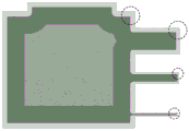
FIGS. 8A-8D are schematic illustrations of samples made in test experiments conducted in accordance with some embodiments of the invention;
FIG. 8E is a schematic diagram illustrating several orientations of structures on a print tray;
FIG. 8F shows comparative results of tensile experiments with and without the jacket structure as measured in experiments conducted in accordance with some embodiments of the present invention;
FIGS. 9A-9C are schematic diagrams (FIGS. 9A and 9C) and images (FIG. 9B) illustrating bending experiments performed according to some embodiments of the present invention;
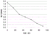
FIGS. 10A-10B show bending test results obtained according to some embodiments of the present invention for 1mm, 2mm, and 3mm structures with and without a housing;
FIG. 11 shows experimental results obtained in experiments conducted in accordance with some embodiments of the present invention to investigate the effect of high resolution print modes;
12A-12B show tensile stress as a function of tensile strain as obtained in experiments conducted in accordance with some embodiments of the present invention; and is
FIG. 13 is a schematic illustration of a layer having a thin component that can be fabricated according to some embodiments of the present invention.
Detailed Description
The present invention, in some embodiments thereof, relates to Solid Freeform Fabrication (SFF), and more particularly, but not exclusively, to SFF with shell objects.
Before explaining at least one embodiment of the invention in detail, it is to be understood that the invention is not necessarily limited in its application to the details of construction and the arrangement of the components and/or methods set forth in the following description and/or illustrated in the drawings and/or the examples. The invention is capable of other embodiments or of being practiced or carried out in various ways.
The method and system of embodiments of the present invention fabricate a three-dimensional object in a layered manner by forming a plurality of layers in a pattern of configurations corresponding to the shape of the object.
As used herein, the term "object" refers to the entire object or a portion thereof.
Each layer is formed by a solid, unmolded fabrication apparatus that scans and simulates a two-dimensional surface. When scanning, the device accesses a plurality of target locations on a two-dimensional layer or surface and determines, for each target location or group of target locations, whether the target location or group of target locations is occupied by build material, and which type of build material is to be delivered thereto. The decision is made based on a computer image of the surface.
In some embodiments of the invention, SFF comprises three-dimensional printing. In these embodiments, build material is dispensed from a dispensing head having a set of nozzles, thereby depositing the build material on the support structure in layers. Thus, the SFF device dispenses build material in the target location to be occupied and leaves the other target locations vacant. The apparatus typically includes a plurality of dispensing heads, each of which may be configured to dispense a different build material. Thus, different target locations may be occupied by different build materials. The types of build materials can be divided into two broad categories: a molding material and a support material. The support material serves as a supportive matrix or construct for supporting the body or body part during the manufacturing process and/or other purposes, e.g., providing a hollow or porous body. In addition, the supporting construct may include a modeling material element, for example, to further support strength.
The shaped material is typically a composition formulated for solid, mouldless manufacture and capable of forming three-dimensional objects on its own, i.e. without having to be mixed or combined with any other substance.
The final three-dimensional object is made from a modeling material or a combination of modeling and support materials or variants thereof (i.e., subsequent curing). All of these operations are well known to those skilled in the art of solid freeform fabrication.
In various exemplary embodiments of the invention, the object is fabricated by dispensing two or more different modeling materials, each from a different dispensing head of the SFF. These materials are optionally and preferably deposited in layers during the same pass of the print head. The materials and material combinations within the layers are selected according to the desired properties of the object.
FIGS. 1A-B illustrate representative and non-limiting examples of systems 10 suitable for use with SFFs of an object 12, according to some embodiments of the invention. The system 10 includes a solid, non-molding manufacturing apparatus 14 having a plurality of dispensing heads 21. Each head preferably includes an array of one or more nozzles 22 through which build material 24 is dispensed (as shown in fig. 1B).
Preferably, but not necessarily, the device 14 is a three-dimensional printing device, in which case the dispensing head 21 is a print head, and the building material is dispensed by inkjet technology. This is not always the case, as for some applications, a solid, unmodeled device does not have to use three-dimensional printing techniques. Representative examples of solid freeform fabrication apparatuses contemplated according to various exemplary embodiments of the present invention include, but are not limited to, binder-spray powder type apparatuses as well as fused deposition modeling apparatuses, fused material deposition apparatuses.
Optionally and preferably, each dispense head is fed by building up a material reservoir, which may optionally include a temperature control unit (e.g., a temperature sensor and/or a heating device), and a level sensor. To dispense build material, a voltage signal is applied to the dispense head to selectively deposit droplets of material through the dispense head nozzles (e.g., in piezoelectric inkjet printing technology). The dispense rate per head depends on the number of nozzles, the type of nozzles, and the applied voltage signal rate (frequency). Such dispensing heads are known to those skilled in the art of solid, non-molded fabrication.
Preferably, but not compulsorily, the total number of dispensing nozzles or nozzle arrays is chosen such that half of the dispensing nozzles are designated for dispensing the support material and half of the dispensing nozzles are designated for dispensing the moulding material, i.e. the number of nozzles ejecting the moulding material is the same as the number of nozzles ejecting the support material. In the representative embodiment of FIG. 1A, four dispensing heads 21A, 21b, 21c, and 21d are shown. Each of the heads 21a, 21b, 21c, and 21d has a nozzle array. In this embodiment, heads 21a and 21b may be designated for one or more molding materials, while heads 21c and 21d may be designated for a support material. Thus, head 21a may dispense the first modeling material, head 21b may dispense the second modeling material, and both heads 21c and 21d may dispense the support material. In an alternative embodiment, heads 21c and 21d are combined into a single head having two arrays of nozzles, for example, for depositing support material.
However, it should be understood that it is not intended to limit the scope of the present invention, and that the number of modeling material deposition heads (modeling heads) and the number of support material deposition heads (support heads) may be different. Typically, the number of molding heads, the number of support heads, and the number of nozzles in each respective head or head array are selected to provide a predetermined ratio a between the maximum dispensing rate of the support material and the maximum dispensing rate of the molding material. Preferably, the value of the predetermined ratio a is selected to ensure that the height of the modeling material in each fabrication layer is equal to the height of the support material. Typical values for a are about 0.6 to about 1.5.
As used herein, the term "about" means. + -. 10%.
For example, for a-1, when all of the molding heads and support heads are operating, the total dispense rate of the support material is generally equal to the total dispense rate of the molding material.
In a preferred embodiment, there are M molding heads each having M arrays of p nozzles and S support heads each having S arrays of q nozzles, such that M × p ═ S × q. Each of the M x M molding arrays and the S x S support arrays may be fabricated as separate physical units that can be assembled and disassembled from the array set. In this embodiment, each such array optionally and preferably contains its own temperature control unit and level sensor, and receives individually controlled voltages for its operation.
The apparatus 14 may further include one or more radiation sources 26, which may be, for example, ultraviolet or visible or infrared lamps, or other sources of electromagnetic radiation, or electron beam sources, depending on the molding material used. The radiation source 26 is used to cure or solidify the modeling material.
The dispensing head 21 and radiation source 26 are preferably mounted in a frame or block 28 which is preferably operative to reciprocate on a pallet 30 as a work surface. The tray 30 is positioned in the X-Y plane, according to convention. Preferably, the tray 30 is configured to move vertically (in the Z direction), typically downwardly. In various exemplary embodiments of the present invention, the apparatus 14 further includes one or more leveling devices 32, such as rollers 34. Leveling device 32 is used to straighten, flatten and/or determine the thickness of the newly formed layer prior to forming a continuous layer thereon. The leveling device 32 preferably includes a waste collection device 36 for collecting excess material generated during leveling. The waste collection device 36 may include any mechanism for delivering material into a canister or canister.
In use, the dispensing heads 21 move in a scanning direction (the direction referred to herein as the X direction) and selectively dispense build material in a predetermined configuration as they pass through the tray 30. The build material typically comprises one or more types of support material and one or more types of modeling material. After passing through the head 21, the one or more modeling materials are cured by a radiation source 26. When the heads 21 reverse their pass, returning to the beginning of their just-deposited layer, additional dispensing of build material may be performed according to a predetermined configuration. The layer thus formed is straightened by the level adjustment means 32 as the head 21 passes in the forward or reverse direction, which preferably follows the path of the head 21 during its forward and/or reverse movement. Once the heads 21 return to their starting point along the X direction, they can be moved to another position along the indexing direction (referred to herein as the Y direction) and continue building the same layer by reciprocating along the X direction. Alternatively, the head 21 may be moved in the Y direction between the forward and reverse movements or after more than one forward-reverse movement. The sequential scanning by the head 21 to complete a single layer is referred to herein as a single scan cycle.
Once the layer is completed, the tray 30 is lowered in the Z direction to a predetermined Z level, depending on the desired thickness of the layer to be subsequently printed. This process is repeated to form the three-dimensional object 12 in a layered fashion.
In another embodiment, the tray 30 may be moved in the Z direction between forward and reverse strokes of the head 21 within a layer. This Z movement is performed to bring the level adjustment device into contact with the surface in one direction and to prevent contact in the other direction.
As described in further detail below, embodiments of the present invention contemplate fabricating an object by dispensing different materials from different dispensing heads. Embodiments of the present invention provide, among other things, the ability to select materials from a given number of materials and determine desired combinations of the selected materials and their characteristics. According to embodiments of the present invention, the spatial locations at which each material is deposited in a layer are defined as occupying different three-dimensional spatial locations by the different materials, or by two or more different materials occupying substantially the same three-dimensional location or adjacent three-dimensional locations, such that the post-deposition spaces of the materials may be combined in the layer, thereby forming a composite material at the respective one or more locations.
Any post-deposition combination or mixing of modeling materials is also contemplated. For example, once a material is dispensed, it may retain its original characteristics. However, when other modeling materials or other dispensing materials dispensed at the same or adjacent locations are used simultaneously, a composite material is formed that has one or more properties that are different from the dispensing material.
Thus, embodiments of the present invention are capable of depositing a wide range of material combinations, and fabricating objects that may be composed of a variety of different combinations of materials in different parts of the object, depending on the characteristics desired to characterize each part of the object.
Further details regarding the principles and operation of SFF systems, such as system 10, are found in U.S. published application No. 20100191360, the contents of which are incorporated herein by reference.
Although SFF is widely practiced and has become a routine step worldwide for the manufacture of arbitrarily shaped structures, the inventors have found that it is not without certain operational limitations. For example, the inventors have found that the range of thermodynamic properties that can be obtained from currently available shaped materials is often inadequate (particularly for those shaped materials that involve UV polymerization as well as those formed from low molecular weight starting materials (such as monomers and oligomers), and especially if the starting materials are polymerized by a free radical mechanism, such as the addition reaction of acrylic functional groups).
For example, in Polyjet sold by Objet Geometries, Inc. of IsraelTMIn the system, rigid materials having a Heat Distortion Temperature (HDT) above room temperature (e.g., above 50 ℃ or higher) are obtained by formulating products that produce crosslinked polymeric materials upon UV irradiation. In contrast, in thermoplastic polymers, stiffness can be achieved by crystalline regions, polymer chain entanglement, or high average molecular weight polymers, and this does not require crosslinking. Although in principle such entanglement can occur in UV polymerized materials when high molecular weight oligomers are used (e.g. above 50,000gr/mol), these are less preferred industrially because the higher viscosity of such oligomers makes them difficult to perform in inkjet-based printing or stereolithography.
The use of shaped materials having low molecular weights (e.g., less than 5000gr/mol) tend to produce amorphous structures with mechanical properties related to the glass transition temperature (Tg) and HDT of the polymer. T isgThe value of the one or more of,further, depending on, among other things, the flexibility of the polymer backbone and the crosslink density, or more specifically, the average number of reactive groups per starting molecule. The inventors have found that when T is an amorphous materialgAs this increases, the brittleness of the material also increases and, therefore, the stress dissipation capability of the material also decreases.
In experiments carried out by the inventors, a negative correlation was found between the impact strength of the moulding material and its HDT (see fig. 5 in the examples section below). The inventors have found that the elongation at break and TgOr similar correlations between HDTs.
As a further example, consider what is typically used for PolyJetsTMRubber-like material in the system. These materials are formulated so as to have a lower viscosity, such as may be dispensed by ink jet, and so as to develop Tg(said T)gBelow room temperature, e.g., 10 ℃ or less). The latter can be obtained by formulating products with a lower degree of crosslinking and by using monomers and oligomers with intrinsically flexible molecular structures. However, PolyJet rubber-like materials tend to have lower Tear Resistance (TR) values and/or slower recovery rates after deformation when compared to rubber materials, for example.
Here, "T" isg"refers to the glass transition temperature defined as the location of the local maximum of the E" curve, where E "is the loss modulus of the material as a function of temperature.
It will be appreciated that some modeling materials, particularly UV polymerizable materials, exhibit undesirable distortion (e.g., curling) during the mold-free fabrication of objects. While the inventors of the present invention sought to solve the problem of curling, it was found that the degree of curling is directly proportional to the degree of volume shrinkage experienced by the material during the polymerization process and the temperature difference between the HDT of the material and the temperature of the system during manufacture. The inventors have found that curl is particularly pronounced for materials having higher volume shrinkage and higher HDT (e.g. in the polymerization temperature range).
The inventors have designed layered polymer bodies or structures with improved thermodynamic properties compared to other bodies manufactured by SFF.
Generally, structures according to various exemplary embodiments of the present invention are housing structures made from two or more thermosetting (e.g., UV polymerizable) molding materials. The structure typically comprises a laminar core at least partially covered by one or more laminar shells such that at least one layer of the core is in-plane with a layer of at least one of the shells. The thickness of each shell is typically at least 10 μm, as measured perpendicular to the surface of the structure. In various exemplary embodiments of the present invention, the core and the shell are different from each other in terms of their thermodynamic properties. This can be easily achieved by manufacturing the core and the shell from different molding materials or different combinations of molding materials. The core and shell thermodynamics are referred to herein as the "core thermodynamics" and the "shell thermodynamics", respectively.
Representative and non-limiting examples of structures according to some embodiments of the invention are shown in fig. 2A-2D.
Fig. 2A is a schematic diagram of a perspective view of structure 60, and fig. 2B is a cross-sectional view of structure 60 along line a-a of fig. 2A. For clarity of presentation, a cartesian coordinate system is also shown.
The structure 60 includes a plurality of layers 62 stacked along the Z-direction. Structure 60 is typically fabricated (e.g., using system 10) by SFF techniques, whereby the layers are formed in a sequential manner. Therefore, the Z direction is also referred to herein as the "build direction" of the structure. Thus, layer 62 is perpendicular to the build direction. Although the structure 60 is shown as a cylinder, this is not always the case, as the structure of embodiments of the present invention may have any shape.
The shell and core of the structure 60 are shown as 64 and 66, respectively. As shown, the layers of the core 66 and the layers of the shell 64 are coplanar. The SFF technique may simultaneously fabricate the shell 64 and the core 66, whereby for a particular formed layer, the inner portion of the layer constitutes the core layer and the perimeter of the layer, or a portion thereof, constitutes the shell layer.
The peripheral portion of the layer that contributes to the outer shell 64 is referred to herein as the "envelope region" of the layer. In the non-limiting embodiment of fig. 2A and 2B, each of the layers 62 has an envelope region. That is, each layer in fig. 2A and 2B contributes to the core and the shell. However, this is not always the case, as for some applications it may be desirable to expose the core to the environment in some areas. In these applications, at least some of the layers do not include an envelope region. A representative embodiment of such a structure is shown in the cross-sectional view of fig. 2C, showing some layers 68 that contribute to the core but not to the shell, and some layers 70 that contribute to both the core and the shell. In some embodiments, one or more layers do not include regions having core thermodynamic properties, but only regions having shell thermodynamic properties. These embodiments are particularly useful when the structure has one or more thin components, where the layers of those components forming the structure preferably lack a core region. A representative embodiment of this configuration is shown in fig. 13 and is described in more detail in the examples section below. Embodiments are also contemplated in which one or more layers do not include regions having shell thermodynamic properties, but only regions having core thermodynamic properties.
The housing may also optionally and preferably cover the structure 60 from above and/or from below, with respect to the Z-direction. In these embodiments, some of the layers of the topmost and/or bottommost portions of the structure 60 have at least one material property that is different from the core 66. In various exemplary embodiments of the present invention, the topmost and/or bottommost portion of the structure 60 has the same material properties as the housing 64. A representative example of this embodiment is shown in fig. 2D. The top/bottom shell of the structure 60 may be thinner (e.g., 2 times thinner) than the side shells (e.g., when the top or bottom shell includes layers above or below the structure) and thus have the same thickness as needed to form an object with the layers.
Preferred methods suitable for forming structures by SFF are described below.
Before providing further detailed description of the structures and methods according to some embodiments of the present invention, attention should be given to the advantages and potential applications provided thereby.
The present invention contemplates a layered fabrication SFF technique that can build objects with improved thermodynamic properties (even when any of the molding materials used to fabricate the object do not have these properties). For example, embodiments of the present invention may produce structures having high temperature resistance as well as high toughness. In the field of SFF using thermosetting materials, such as UV curable materials, any known molding material does not have such properties because a molding material having high temperature resistance is relatively brittle, while a molding material having high toughness has relatively low temperature resistance. Embodiments of the present invention may also produce structures having, for example, high temperature resistance and low curl properties. Embodiments of the present invention may also produce structures based on elastomeric materials. For example, embodiments of the present invention may build elastomeric structures with faster recovery times and increased tear resistance.
Since one or more of the shells and cores of the present invention are manufactured simultaneously, a high level of precision can be used to control the parameters of the one or more shells, such as thickness, selective coverage, variable thickness, and composition. This is in contrast to conventional post-fabrication coating techniques where it is difficult to control these parameters.
The inventors have surprisingly found that even a relatively thin outer shell (e.g., about 100 μm, as measured in a plane perpendicular to the surface of the structure) can significantly affect the thermodynamic properties of the structure compared to a shell-less structure of the same dimensions. The inventors have found that these effects are dictated by the properties of the shell and the properties of the adjacent and inner shells or cores. This effect is advantageous because it allows the construction of structures with thermodynamic properties that cannot be provided by structures fabricated in the absence of a core-shell relationship.
In some embodiments of the invention, the rigid structural shell material is characterized by an elongation at break of at least 80% over a temperature range of about 25 ℃ to about 40 ℃. In some embodiments of the invention, the shell material is characterized by a tensile strength of at least 1000MPa over a temperature range of about 25 ℃ to about 40 ℃. In some embodiments of the invention, the housing material is characterized by a Heat Distortion Temperature (HDT) of at least 25 ℃. In some embodiments of the invention, the housing material is characterized by an impact strength of about 45J/m over a temperature range of about 25 ℃ to about 40 ℃.
Any one or combination of the foregoing mechanical and thermal properties may be achieved by judicious selection of the characteristics and composition of the molding materials from which the core and shell are formed. In some embodiments of the invention, the shell has a lower stiffness than the core. In experiments conducted by the inventors, it was found that improved thermodynamic properties can be obtained by selecting a modulus of elasticity ratio between two adjacent shell materials or between a shell (covering core) material and a core material of from about 1 to about 20. In some embodiments, the ratio is about 1.3 to about 5.
When it is desired to produce a structure with enhanced toughness, it is preferred that the material with the lowest modulus be used as the outer shell material and that the material with the higher modulus be used as the inner shell or core material.
When it is desired to make a structure with enhanced heat resistance and reduced curl contribution, it is preferred that a material with a higher modulus is used as the shell, and preferably a material with a lower modulus is used as the core. Embodiments are also contemplated in which additional outermost shells are added such that the structure has a core characterized by low curl, high temperature resistance, and high toughness, respectively, as well as an intermediate shell and an outermost shell.
In some embodiments of the invention, the core has an HDT of less than 60 ℃,50 ℃ or less than 40 ℃ or less than 30 ℃ and the shell has an HDT of greater than 60 ℃ or greater than 50 ℃ or greater than 40 ℃ or greater than 30 ℃ as measured by ASTM standard methods (as described in further detail below). In these embodiments, objects can be obtained that have particularly relatively low curl and high temperature resistance, the low HDT core having a lower curl, while the high HDT of the outer shell contributes to the high temperature resistance of the manufactured object.
In some embodiments, the core and the shell of the fabricated structure differ in their Heat Distortion Temperature (HDT) and/or Izod impact strength (IR). For example, the IR characterizing the core may be lower than the IR characterizing the shell, and the HDT characterizing the core may be higher than the HDT characterizing the shell. In this embodiment, a higher HDT core results in high temperature resistance, and a higher shell IR gives toughness to the entire object produced with such core-shell structures and materials. Optionally and preferably, for the same structure, two correlations are achieved, namely a lower IR value in the core region than in the shell, but a higher HDT in the core region than in the shell.
As used herein, the term "Heat Distortion Temperature (HDT)" refers to the temperature at which a corresponding material or combination of materials deforms at certain temperatures under a predetermined load. Suitable test procedures for determining the HDT of a material or combination of materials are the ASTM D-648 series, specifically the ASTM D-648-06 and ASTM D-648-07 methods. In various exemplary embodiments of the invention, the core and the shell of the structure differ in their HDT as measured by the method of ASTM D-648-06 and their HDT as measured by the method of ASTM D-648-07. In some embodiments of the invention, the core and the shell of the structure differ in their HDT as measured by any of the methods in the ASTM D-648 series. In most of the examples herein, HDT at a pressure of 0.45MPa is used.
As used herein, the term "Izod impact strength" refers to the loss of energy per unit thickness after an impact force is applied to a corresponding material or combination of materials. A suitable test procedure for determining the Izod impact strength of a material or combination of materials is the ASTM D-256 series, specifically the ASTM D-256-06 series. In some embodiments of the invention, the core and the shell of the structure differ in their Izod impact strength values as measured by any of the methods in the ASTM D-256-06 series. It should be noted that a notch needs to be machined in the standard ASTM method. However, in many cases, this process cuts through the shell, exposing the core to the tip of the notch. Thus, this standard method is less preferred for assessing the impact strength of structures constructed according to some embodiments of the present invention. The preferred procedure for determining the impact strength will now be described. These operations are particularly useful when the SFF includes three-dimensional printing.
According to a first method, a test sample is printed with a rectangular patch made of housing material. The patch is dimensioned in such a way that after making the recess (as required by standard ASTM methods) a 0.25mm layer of the casing material remains intact.
According to the second method, the test sample is printed with a notch after the sample is printed without cutting the notch. The direction of the sample on the tray is vertical, for example in the Z-Y plane (referred to herein as "direction F").
Representative ranges of IR values suitable for use in some embodiments of the invention include, but are not limited to, about 20J/m for the core and about 40J/m for the shell. Representative ranges of heat distortion temperatures suitable for use in some embodiments of the present invention include, but are not limited to, about 50 ℃ for the core and about 70 ℃ for the shell.
In some embodiments of the invention, the core is made from a material characterized by an HDT of about 40 ℃ to about 50 ℃ at a pressure of 0.45 MPa. A typical example of a moulding material with such thermal properties is under the trade name VeroGrayTMThe following modeling materials are sold by Objet Geometries. In some embodiments of the invention, the shell is made from a material characterized by an IR value of about 40J/m to about 50J/m (e.g., about 40J/m). A representative example of a molding material having such thermal properties is under the trade name DuruswhiteTMThe following modeling materials are sold by Objet Geometries.
In some embodiments of the invention, both the core and the shell are of a rubber-like material.
As used herein, "rubber-like material" means that it is characterized by TgSignificantly below room temperature. For example, a Tg of about 10 deg.C or less.
When the core and the shell are made of a rubber-like material, the core material may have a lower elongation at break value ε than the shell materialRE.g. epsilonR>1 percent. Preferably, the core εRWith outer shell epsilonRAt least 30 percent of themOr a difference of at least 60% or at least 90% or at least 120%. For example, when a core has 50% εRAt a value, the outer shell has an epsilon of at least 30% greaterRValue, i.e.. epsilonRThe value is 80% or more. Typically, but not necessarily,. epsilon.of the housingRThe value is at least 100%.
In some embodiments of the invention, the first and second compositions are prepared by passing a TR of about 2Kg/m to about 12Kg/m (e.g., about 4Kg/m or about 10Kg/m), and about 45% to about 50% of εRValues characterizing the material to make the core. In some embodiments, the material further has one or more of the following properties: a tensile strength of from about 1MPa to about 5MPa (e.g., about 2MPa or about 4.36MPa), and a glass transition temperature of from about-12 ℃ to about 4 ℃ (e.g., about-10.7 ℃ or about 2.6 ℃). A representative example of a molding material having such thermal properties is under the trade name TangoBlackTMAnd TangoGrayTMThe following modeling materials are sold by Objet Geometries.
In some embodiments of the invention, the first and second light beams are directed from a light beam passing a TR of about 2Kg/m to about 4Kg/m (e.g., about 3Kg/m), and from about 200% to about 236% of εRA value characterizing the material to make the housing. In some embodiments, the material further has one or more of the following properties: a tensile strength of about 1MPa to about 2MPa, and a glass transition temperature of about-12 ℃ to about-8 ℃. A representative example of a molding material having such thermal properties is under the trade name TangoBlack PlusTMAnd TangoplusTMThe following modeling materials are sold by Objet Geometries.
The modeling material may be a material contained in a particular container or cartridge of a solid, non-molding fabrication apparatus or a combination of modeling materials deposited from different containers of the apparatus. The moulding material from which the core and shell of the present invention may be formed may itself have desirable thermal as well as mechanical properties according to one or more of the embodiments described above. This is not always the case, however, as the inventors of the present invention have devised techniques for obtaining desired properties from combinations of materials. This technique will now be explained.
For example, assume that it is desired to obtain a core with a desired HDT. Further assume that there is a commercially available molding material (referred to as material a) that has an HDT that is higher than the desired HDT; and another commercially available molding material (referred to as material B) having an HDT lower than the desired HDT. According to some embodiments of the present invention, a core is formed from these two materials, wherein for each layer of the structure, material a and material B are interlaced in a pixelated manner over the core area of the layer, thereby providing a combination characterized by a desired HDT. Thus, rather than pre-mixing the materials using the mixture used to form the layer, material a and material B occupy different spatial positions that are laterally displaced from each other over the core area of the layer, with the basic unit of displacement for each material being a single pixel (or voxel used to represent a three-dimensional pixel). This combination is called Digital Material (DM). A representative embodiment of digital material is shown in fig. 3, showing material a and material B interleaved in a pixelated manner over an area of the layer.
As representative examples, material a characterized by HDT of about 40 ℃ and material B characterized by HDT of about 75 ℃ are contemplated. When material a and material B are mixed as a: when deposited at a relative areal density ratio of 3:1 (i.e. three pixels of material a versus each pixel of material B), a DM characterized by an HDT of about 50 ℃ may be obtained. For any predetermined surface density ratio of the material, the digital material may be formed, for example, by ordered or random interweaving. Embodiments are also contemplated in which the interleaving is semi-random, such as a repeating pattern of sub-regions, where each sub-region contains random interleaving.
While the above embodiments have particularly focused on DM for the structural core, it should be understood that reference to the core in greater detail should not be construed as limiting the scope of the invention in any way. In particular, either one of the core and the shell may be formed of DM.
When both the core and the shell are made of DM comprising the same molding material, the relative surface density of any of the molding material in the core is different from the relative surface density of that material in the shell or envelope area. However, in some embodiments, the core is formed from DM and the shell is formed from a single molding material, or vice versa.
In various exemplary embodiments of the invention, the thickness of the casing (as measured in the X-Y plane (perpendicular to the building direction Z)) is non-uniform across the building direction. In other words, different layers of the structure may have envelope regions of different widths. For example, the thickness of the shell along a direction parallel to the X-Y plane may be calculated as a percentage of the diameter of the corresponding layer along that direction, such that the thickness is dependent on the size of the layer. In various exemplary embodiments of the invention, the thickness of the outer shell is non-uniform across a direction tangential to the outer surface of the outer shell and perpendicular to the building direction. As far as the layers of the structure are concerned, these embodiments correspond to regions of the envelope having a width that is not uniform along the periphery of the respective layer.
In some embodiments of the invention, the outer shell of the structure, or a portion thereof, is itself a "shelled" structure, not just including the envelope region. In particular, in these embodiments, the structure comprises an inner core at least partially surrounded by at least one intermediate envelope region, wherein the one or more intermediate envelopes are surrounded by an outer envelope region. The thickness of the one or more intermediate envelope regions, as measured perpendicular to the build direction, is optionally and preferably greater (e.g. 10 times greater) than the thickness of the outermost envelope region. In these embodiments, the one or more intermediate envelope regions serve as structural enclosures and thus have the characteristics of an enclosure as described in further detail above. The outermost jacket shell may also serve to protect the one or more intermediate jacket regions from breaking under load.
The inventors have found that under irregular loading on the outermost interface of the intermediate envelope region and the outermost envelope, cracks may result which extend into the shell and possibly into the core. In various exemplary embodiments of the present invention, the outermost wrapper provides a protective layer to prevent or reduce crack propagation occurring at the interface between the intermediate wrapper region and the outermost wrapper region. The outermost envelope may also serve to eliminate cracks that initiate at the outermost envelope-air interface. The inventors have also found that when the outermost layer is sealedThe ability of the envelope to resist crack initiation at the envelope-envelope interface is related to the envelope-envelope material modulus ratio, while the ability of the outermost envelope to withstand crack propagation from the envelope-air interface is related to the toughness of the outermost envelope. Therefore, the elastic modulus of the outermost wrapper is expressed as ε1And the modulus of elasticity of the envelope immediately adjacent to the outermost layer is denoted epsilon2According to some embodiments of the invention, epsilon2/ε1Is from about 1.3 to about 5 and the impact strength of the outermost envelope is at least 40J/m or at least 50J/m or at least 60J/m or at least 70J/m, such as about 80J/m or more.
As noted, the structure of embodiments of the present invention may be formed in a layered fashion, for example, using the system 10 described above. In various exemplary embodiments of the invention, a computer-implemented method automatically dynamically adapts a shell to a particular element of a structure. The method may optionally and preferably use user input to calculate the skin for each region of the structure and assign voxels of the exterior surface to the respective modeling material or combination of modeling materials. The computer-implemented method may be performed by controlling a control unit (e.g., control unit 52, see fig. 1) of the physical die-less manufacturing apparatus via a data processor (e.g., data processor 54).
Computer programs implementing methods of embodiments of the present invention may be generally distributed to users on distribution media such as, but not limited to, floppy disks, CD-ROMs, flash memory, and portable hard drives. The computer program may be copied from the distribution medium to a hard disk or similar intermediate storage medium. The computer program is run by loading computer instructions from its distribution medium or from its intermediate storage medium into the execution repository of the computer, configuring the computer to function according to the method of the invention. All of these operations are well known to those skilled in the art of computer systems.
The computer-implemented methods of embodiments of the present invention can be implemented in a variety of forms. For example, it may be embodied in tangible media, such as computers, for performing the operations of the methods. Which may be embodied on a computer readable medium, including computer readable instructions for carrying out the operations of the method. It may also be embodied in an electronic device having the capability of a digital computer arranged to run a computer program on a tangible medium or to execute instructions on a computer readable medium.
Fig. 4A shows a single layer 80 that may be formed during the fabrication process. The layer 80 includes a core region 82 and an envelope region 84 surrounding the core region 82. Thus, the area 82 contributes to the core of the structure and the area 84 contributes to the shell of the structure, since when several layers like the layer 80 are deposited on top of each other, the core area forms a laminar core area and the envelope area forms a laminar shell.
Fig. 4B shows another layer 90 that may be formed during the manufacturing process. Layer 90 includes a core region 92 and an envelope region 94 that only partially surrounds core region 92. When the structure includes one or more layers similar to layer 90, the shell is not formed to completely surround the core.
As shown in fig. 4A and 4B, the width of the envelope regions 84 and 94 is not uniform over the perimeter of the layers. A representative embodiment of a layer 100 having a uniform width surrounding the envelope region 102 of the core 104 is shown in fig. 4C. These layers are also contemplated by the inventors.
As mentioned, the width of the envelope region may vary across the build direction of the structure. Fig. 4D and 4E show two layers 110 and 120 corresponding to different positions along the build direction. Layer 110 (fig. 4D) has a core region 114 surrounded by an envelope region 112, while layer 120 (fig. 4E) has a core region 124 surrounded by an envelope region 122.
Once the layers of the structure are formed, the molding material forming the core and envelope regions is hardened, thereby bonding the core region perimeter to the perimeter of the envelope region.
In some embodiments of the invention, one or more additional outer shell layers are dispensed, thereby also forming an outer shell on the topmost and/or bottommost portion of the structure. Preferably, these layers lack the core area as they are used to coat the core from above or from below. When it is desired to coat the core from above, the additional layer or layers of the shell are dispensed on top of all other layers, and when it is desired to coat the core from below, the additional layer or layers are dispensed on the work surface (e.g., tray 30, see fig. 1) and thereafter all other layers are dispensed.
Optionally, any envelope region has a width of at least 10 μm. Preferably, all envelope regions have a width of at least 10 μm.
Either of the core and envelope regions, and optionally the topmost and/or bottommost additional layers, may be fabricated using a molding material or a combination of molding materials (e.g., digital materials) having the thermal and/or mechanical properties described above with respect to the core and shell of the structure.
Thus, in some embodiments, the ratio between the modulus of elasticity of the core and envelope regions is from about 1.3 to about 20 when hardened; in some embodiments, the characteristic T of the core regiongOr HDT below about 50 ℃ and characteristic T of the envelope regiongOr HDT above about 50 ℃; in some embodiments, the characteristic epsilon of the core region when hardenedRCharacteristic epsilon of value lower than envelope areaRA value; in some embodiments, when hardened, the characteristic TR value of the core region is lower than the characteristic TR value of the envelope region; in some embodiments, the characteristic IR value of the core area is lower than the characteristic IR value of the envelope area; and in some embodiments, the core region has a higher characteristic HDT than the envelope region.
In some embodiments of the invention, the housing is selectively fabricated in different regions of the structure, thereby changing the material properties only in selected regions without affecting the mechanical properties of other regions.
It is expected that during the life of the maturing patent from this application many relevant modeling materials for SFF may be developed and the scope of the term modeling material is intended to include all such new technologies a priori.
As used herein, the term "about" means. + -. 10%.
The word "exemplary" is used herein to mean "serving as an example, instance, or illustration. Any embodiment described as "exemplary" is not necessarily to be construed as preferred or advantageous over other embodiments and/or as not including combinations of features from other embodiments.
The word "optionally" is used herein to mean "provided in some embodiments and not provided in other embodiments". Any particular embodiment of the invention may include a plurality of "optional" features unless such features conflict.
The terms "comprising," including, "" having, "and their conjugates mean" including, but not limited to.
The term "consisting of …" means "including and limited to".
The term "consisting essentially of …" means that the composition, method, or structure may include additional elements, steps, and/or components (but only if the additional elements, steps, and/or components do not materially alter the basic and novel characteristics of the composition, method, or structure of the claims).
As used herein, the singular forms "a", "an" and "the" include plural references unless the context clearly dictates otherwise. For example, the term "a compound" or "at least one compound" may include a plurality of compounds, including mixtures thereof.
Throughout this application, various embodiments of the present invention may be presented in a range format. It should be understood that the description in range format is merely for convenience and brevity and should not be construed as an inflexible limitation on the scope of the invention. Accordingly, the description of a range should be considered to have explicitly disclosed all the possible sub-ranges as well as individual numerical values within that range. For example, a description of a range such as 1 to 6 should be considered to have specifically disclosed sub-ranges such as 1 to 3, 1 to 4, 1 to 5, 2 to 4, 2 to 6, 3 to 6, etc., as well as individual values within the stated range such as 1, 2, 3, 4, 5, and 6. This applies regardless of the breadth of the range.
Whenever a range of values is indicated herein, it is meant to include any recited value (fractional or integer) within the indicated range. The phrases "range/range is between the first indicated number and the second indicated number" and "range/range is from the first indicated number to the second indicated number" are used interchangeably herein and are meant to include the first and second indicated numbers and all fractions and integers therebetween.
It is appreciated that certain features of the invention, which are, for clarity, described in the context of separate embodiments, can also be provided in combination in a single embodiment. Conversely, various features of the invention which are, for brevity, described in the context of a single embodiment, may also be provided separately or in any suitable subcombination or in any other described embodiment of the invention. Certain features described in the context of multiple embodiments should not be considered essential features of those embodiments unless the embodiments are inoperative without those elements.
Various embodiments and aspects of the invention as defined above and as set out in the claims section below may find experimental support in the following examples.
Examples
Some embodiments of the invention will now be described, in a non-limiting manner, with reference to the following examples in conjunction with the foregoing description.
The inventors have conducted studies on the effects and properties of various molding materials.
Fig. 5 shows the results of the experiment, showing the inverse correlation between HDT and impact strength in several shaped materials. The modeling material provided in fig. 5 is a commercially available modeling material sold by Objet Geometries ltd. This relationship proves the inventors' findings: that is, there is a trade-off between these two properties, and of the commercially available materials, there is little that can be obtained a material exhibiting this predetermined combination of thermodynamic properties.
The inventors analyzed several combinations of materials in terms of three attributes (shape, fit, and function).
For rigid materials, the inventors have found that T's of this type are due togEnvironmental deformation characteristics of the material (e.g. material creep), moderate TgOr HDT and ductile materials may provide a solution for this function while compromising other properties (shape and fit). The inventors have found that a tough material may provide a solution for a robust geometry or structure that is not exposed to a warm environment, but may not provide a suitable solution for other structures. The inventors further found that high TgAnd brittle materials cannot be used in functional applications where flexibility or impact strength is required, but can provide satisfactory results with respect to shape and conformity attributes. With an even higher TgMaterials (e.g., above 50 ℃) are even more brittle and have significant curling (e.g., deformation during printing).
For rubber-like materials, the inventors have found that although materials with high elongation are already available, these materials do not have good elastomeric properties, but a combination between elastic and plastic properties. The inventors have found that other materials with more elastomeric-like properties may be too brittle (low tear strength) to be used in applications requiring standard rubber materials.
In experiments conducted by the inventors, objects with several core-shell structures have been manufactured by SFF. The structure benefits from improved characteristics. For example, the inventors have successfully made rigid structures with a combination of moderate HDT and high toughness, rigid structures with a combination of temperature tolerance (e.g., high HDT) and reduced curl, rigid structures with a combination of high HDT and significantly improved toughness, rigid structures with a combination of high HDT, reduced curl and significantly improved toughness, and rubber-like structures with a combination of high elongation at break, rapid recovery after deformation, and tunable modulus.
A rigid structural material with a combination of medium HDT and high toughness can be obtained by making a core-shell structure, where the shell has high toughness, which prevents crack propagation from the surface to the core. The core may be made of a material having a medium HDT but a relatively high brittleness. The shell thickness may be selected to reduce its effect on all mechanical properties except toughness. For example, the thickness in the direction normal to the surface of the object may be a thickness between 0.17mm and 0.34 mm.
Rigid structures having a combination of high HDT and reduced curl may be obtained by fabricating core-shell structures, wherein the shell includes a high TgOr a high HDT material. The shell can provide a high HDT as well as reduced creep (over time or at elevated temperatures) for the structure. The shell thickness depends on the HDT and crimp characteristics of the core or intermediate shell (if present), as well as the desired characteristics of the structure. Typically, but not necessarily, a material having an HDT of about 75 ℃ may be used to fabricate the housing with a thickness of 0.5mm to 1.0 mm. The core may comprise a material having a moderate HDT (typically, but not necessarily, about 45 ℃ to about 50 ℃), which does not produce significant curling during the SFF process. As explained in further detail above, each of the shell and the core may be made of a digital material. For example, the core may be manufactured using a surface density ratio of 3:1 between a molding material having 40 ℃ HDT and a molding material having 75 ℃ respectively, providing a DM having an HDT of about 50 ℃ and a curl of less than 3.5mm when printed, such as a beam column of 10 x 230 mm.
A rigid structure with a combination of high HDT and significantly improved toughness can be obtained by making a core-shell structure, wherein the shell comprises high toughness materials that protect the core and intermediate shell (if present) from breaking under load. The thickness of the shell may be chosen small enough to reduce its effect on all mechanical properties except toughness. Typically, but not necessarily, the housing thickness may be about 0.17mm to about 0.34 mm. The core may contain a high TgOr a high HDT material. The core provides high HDT for the structure as well as reduced material creep (over time or at elevated temperatures).
A structure having a core, an intermediate shell and an outermost shell may be used to obtain a rigid structure having a combination of high HDT, reduced curl and significantly improved toughness. The outermost shell may comprise a high toughness material. The purpose of this shell is to protect the intermediate shell (and therefore also the core) from damage (e.g. breakage) under load. The middle housing may include a high TgOr a high HDT material. Such a housing provides high temperature resistance to the structureAnd reduced creep (over time or at elevated temperatures). The thickness of the intermediate shell depends on the HDT and the crimp properties of the core as well as the desired properties of the structure. Typically, but not necessarily, the intermediate housing may be manufactured using a material having an HDT of about 75 ℃, such as 0.5mm to 1.0mm in thickness. The core may comprise a medium HDT material (e.g., HDT of about 45 c to about 50 c) and suitable low curl characteristics (e.g., curl below 4mm, where curl is defined as the height of the edge of a printed 10 x 230 beam column above a flat surface when a 300g load is applied to its opposite edge). The core may be formed from a DM mixture of a high HDT forming material (e.g., HDT of about 75 ℃ to about 200 ℃) and a suitable low HDT forming material (e.g., HDT of about 25 ℃ to about 45 ℃). The surface density ratio is selected according to the desired HDT and curl characteristics.
A rubber-like structure having a combination of high elongation at break, fast recovery after deformation and tunable modulus can be obtained by making a core-shell structure, wherein the shell comprises a high elongation material, which prevents or reduces crack propagation from the surface. The outer shell protects the inner core and the intermediate outer shell (if present) from damage when loaded. The thickness of the shell may be chosen to be small enough to reduce its effect on all mechanical properties except preventing crack propagation. Typically, but not necessarily, the housing thickness is about 0.17mm to about 0.34 mm. The core may comprise a material or combination of materials (e.g., a digital material) having the desired tensile and compressive moduli, faster recovery time after deformation, but lower elongation at break than the shell.
When fabricating structures by SFF, a phenomenon of inconsistent performance is often observed. The main manifestation is that when considering material toughness, it can change significantly from one manufactured structure to another and also between different areas of the same structure (like core and shell). The reason for this is the layered manufacturing process. For example, in inkjet type 3D printers, the layered manufacturing process can result in different surface morphologies in the build direction as well as in the transverse plane (parallel to the print tray). The vertical sides of the structure may contain microscopic surface cracks with sharp tips (fig. 6), which significantly reduces the toughness of the fabricated structure. At a certain pointIn these structures, mechanical parameters such as fracture deflection, maximum load at break, and strength can be reduced by a factor of 10 to 20. This is demonstrated in FIGS. 7A and 7B, which show the use 535 fracture deflection and fracture peak load of the beam column printed with the molding material. These figures show that the deflection at break ("deflection") and the maximum load ("max load") are a function of the angle between the print beam and the X-Y plane.
When a structure is manufactured while keeping the outer surface in liquid form and out of contact with any other material at some stage of the manufacturing, the attraction and wetting causes the liquid resin to flow, thereby smoothing the surface of the structure. This can be done on positive angled surfaces (upward or outward facing surfaces). For other angles (downward facing surfaces), it is necessary to add support materials or support constructions to avoid structural collapse. The inventors have found that contact between the moulding material and the support material results in a fractured surface morphology which significantly reduces the overall toughness of the structure. This roughness on the surface results in the creation of anisotropy in the properties of the structure, such as anisotropic flexural modulus or anisotropic scratch resistance. Another effect of roughness is increased brittleness, as evidenced by lower impact strength and lower elongation/deflection at break.
The following is a description of experiments conducted by the inventors to investigate the core-shell structural properties of embodiments of the present invention.
Material
A molding material available from Objet Geometries, Inc. was used in this experiment. These materials have a range of properties. For example VeroGrayTMIs a rigid molding material and is TangoPlusTM(Tango +) is a soft rubber-based molding material. Material 535(FC535) (also known as RGD535) and
 515(FC515) (also known as RGD515) broadens the range of available properties and is a number of materials Connex for Objet GeometriesTMPlatforms are specific and are often used in combination with other materials. Other materials used in this study include VeroGrayTM、DurusWhiteTM、
 970(TangoBlackTM) And
 980(TangoBlack PlusTM)。
in the experiments (where the shell was formed after printing as a comparative study), standard resins, additional manufacturing Tempering materials, epoxy resins and silicone a + B resins, such as RP testing, were usedTMCompound (Par3 technology, USA) and hand coated with FC515 (using a brush) and then cured in a UV chamber.
In the following, the term High Impact Material (HIM) is used to describe a tough material with good impact strength (e.g. FC515) and the term high TgMaterials (HTM) for describing compositions with high TgAnd high HDT rigid materials (e.g., FC 535).
Software
Software was developed to enable the design and testing of different spatial arrangements of two different modeling materials and one support material. The software may also be capable of designing different digital materials. Furthermore, the software includes a shelling feature, which can define a precise (variation of the deviation to +0.03mm to +0.08mm, depending on the spatial orientation of the particular surface) shell of a predetermined thickness. The software also includes a multi-shelled feature, which may define one or more outer shell layers.
The software also includes a random DM generator, which can generate a random bitmap (a random combination of two or more modeling materials). This provides a simple and straightforward tool for producing a series of uniform DMs, whose characteristics can be varied essentially continuously.
Solid mouldless manufacturing equipment
Using standard ConnexTM500 printers (Objet Geometries) to print all materials and structures.
Printing mode
The experiments included making rough surfaces as well as smooth surfaces.
The roughened surface is produced by printing a modeling material in contact with a support material. In this case and due to the fact that the two liquids come into contact before curing, they partially mix at the interface, so that when the support material is removed, a rough surface is obtained. The rough printing pattern results in the object being completely covered by the support material and not just in the areas that require mechanical support before curing (e.g., the areas near the voids).
A smooth surface is produced by printing a modeling material that is not in contact with any other material than air. The smooth printing mode may produce a smooth shiny smooth surface. It should be noted that while a rough surface may be obtained for the entire surface of the structure, a smooth surface may be obtained only for surfaces that do not require contact with the support material.
Testing
By printing 10X 230mm3The print distortion (curl) was quantitatively evaluated by bar and measuring the height of one sample end above the flat surface while applying a 300gr weight on the other sample end. For the present study, heights of 4mm or less were considered acceptable for most mainstream applications.
Various applicability tests have been developed to evaluate the performance of new materials. Standard ASTM methods and custom methods were performed to characterize pure components and DM structures.
Results
Structure with high thermal stability and high toughness
Developing high TgThe material is to provide a material having an HDT above 70 ℃ and exhibiting a relatively low print distortion (low curl), i.e. below 10 mm. Formulation FC535 has a T of 65 ℃gAnd HDT at 70 ℃. The FC535 characteristics are shown in table 1 below.
TABLE 1FC535 data Table


The print distortion (curl) of this material was 7.5mm, above the maximum acceptable value. The post-cure process at relatively low temperatures (below 100 ℃) increased the HDT of FC535 to about 100 ℃ without increasing distortion.
The next experiment was used to make FC535 ductile. Amorphous HTMs (such as FC535) have low impact strength and are very brittle, similar to other commercially available rigid materials. Brittleness is magnified in the portions of the structure that are in direct contact with the support material and are stressed in the perpendicular printing plane parallel to them. Such stresses actually separate the crack edges and cause damage at relatively low strains.
A series of experiments were designed to quantitatively assess the brittleness of a material and its performance.
Impact resistance
Standard notch samples, rectangular samples were printed, after which the notch was cut (ASTM D256).
(ii) printing samples with notches in different directions
Tensile test
Measuring percent elongation at break (ASTM D638)
Resistance to bending
Three point bend (flexural) tests (ASTM D695) were performed on samples printed in different directions
(ii) fixing the bending of the beam column.
Additional tests include fracture tests, cycle tests, ball and detent structure tests, and spring structure tests. The samples used for these tests are shown in FIGS. 8A-D, respectively.
Table 2 below shows the properties of 3 moulding materials used in different combinations for producing the digital material for the above tests.
TABLE 2
| FC535 | FC515 | DurusWhiteTM | |
| Impact strength (J/m) | 15 | 90 | 41 |
| HDT(℃) | 70 | 37 | 41 |
| Tensile Strength (MPa) | 70 | 21 | 30 |
| Strain at break (%) | 8 | 90 | 38 |
| Tensile modulus (MPa) | 3500 | 1100 | 1500 |
| Water absorption (%) | 1.3 | 6.6 | 1.7 |
The material located on the top of the Izod notch significantly affects the measured impact strength value. This behavior clearly occurs when a tough material, such as an FC515 sample (printed notched, smooth) with an impact strength value of 90J/m, is made from a high T with an impact strength value of about 30J/m under the same conditionsgWhen an outer shell layer made of FC535 material is printed. Surprisingly, even with the addition of the smallest possible FC535 capping layer (about 100 μm), the impact strength drops below 30J/m.
The above experiments show that the composition of the outermost surface determines the impact resistance of the structure.
Printing direction
The printing direction refers to a direction in which an object is manufactured with respect to a printing surface (printing tray). Fig. 8E shows a number of different orientations as referred to herein.
Structures made from FC535 and FC515
The shell width produced by HIM (FC515, in this example) was about 0.25mm, about 20% of the total cross-section of the structure (3 × 12.7mm), and the core was made of FC 535. Although tensile strength and tensile modulus decreased by less than 10% after the introduction of the HIM housing, the strain at break increased from about 10% to over 35%. The inventors contemplate that the HIM housing protects the object from surface damage (especially rough surfaces) which would otherwise have a destructive effect. Table 2a below summarizes the impact strength of various fabricated samples in direction F.
TABLE 2a

Fig. 8F shows the tensile test results for FC535 with a 0.25mm FC515 jacket versus FC535 without a jacket. As shown, having an FC515 shell significantly improved the toughness of the rigid material FC535, with an increase in elongation at break from about 10% to about 40%, while its elastic modulus was reduced by only about 15%.
Bending test
The bending test is mainly used to simulate the case of sudden fracture. In these cases, the thin beam column flexes and returns quickly to its original position. Thus, two relevant parameters are measured: maximum bending deflection before fracture and flexural strength (maximum load). A desirable characteristic for this type of application is rigidity with high fracture deflection. Samples for bend testing were printed in different directions, print modes, and different beam-to-column widths. The bending test and the samples tested are shown in fig. 8A and fig. 9A-C.
Tables 3 and 4 below and FIGS. 10A-10B summarize the performance of 1mm, 2mm and 3mm FC535 beams printed and tested with or without FC515 housings in three different cases.
TABLE 3
1mm, rough, E-direction beam column bending

TABLE 4
3mm, rough, E-direction beam column bending

The above results indicate that the addition of an 85 micron shell does not achieve the best results. Presumably, this is because this layer turns into a model-support mixed layer when printed in a rough manner.
A significant effect on elongation was observed when the shell thickness was increased to 170 microns. The maximum load is also increased for a 3mm beam column (synergistic effect).
For a 250 micron housing, the beam column produced has high flexibility, but the 1mm beam column becomes slightly softer.
In both beam and column widths, lightSliding FCTMThe 535 sample showed superior performance even without the outer shell. This fact emphasizes the role of surface defects. In the absence of such defects, rigid materials have good toughness. However, when defects occur, the rigid material becomes brittle, while the HIM remains tough. Surface modification using HIM prevents material defects and thus it is less sensitive to crack propagation. In other words, the surface modification retains surface defects within the HIM, thereby preventing them from propagating.
The effect of surface defects was further studied by printing beam and column test samples in different directions. The results are summarized below in fig. 5. In the E direction (where the direction of the most severe defect is parallel to the bending stress beam column direction), the elongation at break is the lowest. In the D direction, the crack is perpendicular to the stress, and thus has less influence on brittleness. Experimental data collected by the inventors showed that in the D direction, even a 1 pixel shell has a significant effect. All tests performed in direction D are better with respect to direction E and direction F.
TABLE 5
Bending of 3mm, rough beam and column


In other comparative tests, the effect of high resolution printing mode was investigated. The test was performed on a 2mm beam fabricated from brittle (FC535) and high impact material (FC515) with a housing of 0.25mm HIM sample printed in smooth and rough form in the E direction. The results are shown in FIG. 11.
The results of the cyclic fracture test and the fracture section test are summarized in tables 6 and 7 below.
TABLE 6

TABLE 7

TM TMImproving VeroGrey's toughness by a thin shell with Duruswhite
Among the currently available modeling materials of Objet Geometries, Inc., VeroGreyTM(VG) may exhibit the highest dimensional stability at elevated temperatures (lower material creep). VG, on the other hand, is the most brittle material.
Among the usable molding materials available from Objet Geometries, Inc., DuruswhiteTM(DW) possesses the highest toughness and impact strength.
The inventors have demonstrated that a combination of VGs and DW can be used to produce structures characterized by HDT similar to VG and toughness similar to DW. A synergistic effect can be observed in some configurations and the toughness of the composite, shelled portions is higher than that of pure VGs or pure DWs. The experimental data are summarized in tables 8-12.
TABLE 8
HDT test: HDT at 0.45MPa (ASTM D648)

TABLE 9
And (3) testing impact strength: the samples were printed with notches in the vertical direction and measured according to modified ASTM D256

KIC test (ASTM D5045): the shell thickness represents the initial layer before being engraved with a knife. The knife indentation depth was about 0.2 mm.

TABLE 11
Breaking test: bending an anchored 1mm beam column while measuring fracture deflection and maximum load

TABLE 12
Same table 11 except 3mm beam column

Tables 9, 10 and 11 demonstrate the synergistic effect, where Izod impact strength, KIBoth the C and peak load characteristics are higher than if any pure material was used. In particular, the Izod impact strength measured (19.1, see Table 9) was higher than that of pure VG (14.9) and pure DW (18.3), the K measuredIThe C value (1.37; 1.44, see Table 10) is higher than pure VG (0.76) and pure DW (1.15), and the measured maximum load value (19.0, see Table 11) is higher than pure VG (too low to measure) and pure DW (13.2).
Rubber digital material
By 970(TangoBlackTM) Core of manufacture and
 970(TangoGreyTM) The core is made of
 980(TangoBlack PlusTM) Manufactured outer shell and made of
 930(TangoPlusTM) The manufactured housing is enclosed. The thickness of the shell is about 0.25 mm. As shown in fig. 12A-B for tensile stress (as a function of tensile strain for the resulting structure) and pure material structural references. As shown, the resulting tape shell structure has a much higher strength than the strength of the individual components comprising it. Although it is a mixture ofHowever, the device is not suitable for use in a kitchen
 930 and
 970 core generation ratio
 930 higher elongation and higher strength, the opposite leads to very poor results. Because of the fact that
 930 ratio of
 970 has considerable more plastic properties such that it has
 930 the shell results in having a majority
 970 (core material) characteristic, without having significantly improved elongation and breaking strength.
Discussion of the related Art
Since in many cases the shell consists of only a very small percentage of the entire object volume, it can be concluded that in some embodiments the shell significantly reduces the brittleness of the core. The smaller shell thickness is sufficient to include most or all of the defects and especially the edge points of the horizontal cracks. The housing is produced without affecting the dimensional accuracy of the structure, since it is in fact part of the structure. The shell, in addition to contributing to the shell-air interface, also contributes to the shell-core (or shell-shell) interface. In severely cleaved surfaces (shell-interface), the contribution of the shell to the thermodynamic properties is particularly pronounced. Because the tough encasement material is produced simultaneously with the core, the encasement material provides a perfect interaction of the shell with the core, and wherein any irregularities in the core-shell interface are filled with the shell material, and vice versa, resulting in a good covalent bond between the shell material and the core material (or intermediate shell). This forms a model-model hybrid layer that ensures a gradual transition in material properties at the interface. The tough skin secures the edges of rigid material interface irregularities (model-model interface) and prevents them from propagating and transforming into cracks.
This study shows that the core-shell structure of the present embodiment has enhanced elastic modulus and crack resistance. While the tough housing material eliminates the weak points of the rigid material surface, it relocates the outer surface cracks into its own volume. It therefore exhibits significant crack resistance properties, providing adequate protection to the rigid core. This property can be measured by the impact strength, the basic work of rupture, KIC or other tests in which stress is applied to a pre-cracked sample. In this study, the refinement of the material was based on Izod notched impact strength values measured for vertically printed samples, where horizontal print defects were located inside the notch surface. This test results in relatively low impact strength values for all existing test materials: VeroGrayTM16J/m, FC 535-14J/m and DuruswhiteTM25J/m. It is envisaged that for good crack resistance, the core-shell structure may pass this test with an impact strength of at least 30J/m. Although this value can be easily achieved with soft materials, in materials with a modulus of elasticity higher than 1GPa and HDT above room temperature, this is an unusual property.
Using compliant materials (e.g. by tango plus black)TMVeroGray of envelopeTM) Fabricating the housing does not prevent the propagation of cracks within the rigid material because the compliant material housing does not limit the edges of the cracks. The sharp rigid transition at the model-model interface leads to stress concentrations and starts to fracture when a load is applied. In some embodiments, the shell modulus is at least one third of the core. This prevents rapid cracking of the model-model interface and is subject to stress unless cracking occurs at the shell-support interface (i.e., the outermost shell surface).
The use of one or more intermediate layers may further improve toughness. For example, the structure of this embodiment may include three shells and a core, with respective elastic moduli of about 0.2GPa, about 0.6GPa, about 1.8GPa, and about 3.5GPa, with the last modulus being that of the core and the first modulus being that of the outermost shell.
Preferably, the shell thickness is selected according to the print process characteristics. In this study, the fabrication process was combined with an interface roughness of about 150 microns. Therefore, an outer shell of at least 250 microns is preferred to achieve effective toughening. The thickness of the shell may be smaller for processes that result in a more precise interface. For thicknesses that achieve maximum toughness, increasing the shell thickness can improve structural toughness. This was confirmed by the synergistic effect observed in this study.
The advantage of the process of this embodiment is that the core and shell are manufactured simultaneously. This allows for optimal overlap and adhesion in the interface between the two materials. Different post-printing processes for producing the outer shell were tested and compared with the results obtained by the core and shell simultaneous production method.
Design method
In some embodiments of the invention, a computer-implemented method automatically dynamically adapts a housing to a particular element of a printing structure while taking into account at least one of the following parameters: spatial orientation of each surface, print mode (smooth or rough), and dispense thickness. Such a computer-implemented method may map the structure on the tray and extract the relevant parameters. It then uses the user input to calculate the corresponding shell (perimeter) structure for each region and assigns voxels of the exterior surface to the second modeling material. The computer-implemented method may be performed by controlling a control unit (e.g., control unit 52, see fig. 1) of the physical die-less manufacturing apparatus via a data processor (e.g., data processor 54).
Dimensional stability is manifested primarily in thin components that typically experience higher stresses and are therefore prone to deformation. In various exemplary embodiments of the present invention directed to thin components, the following is the descriptionThe shell thickness is reduced. Alternatively, all or a portion of the HIM may comprise a higher TgOf (e.g. FC)TM535) DM and HIM (e.g., a random 50:50 distribution of the two molding materials).
The operator may be provided with a list of component (structural area) thickness windows and their corresponding housing structures. For example, 0.5mm to 1.0mm components can accept a 0.1mm HIM housing, 1.0mm to 2.0mm components can accept a 0.2mm housing, and thicker components can accept a 0.3mm housing. The computer-implemented method may take into account the 3D geometry of the component in order to produce an appropriate shell structure according to the geometry of the specific elements of the component. A schematic of the resulting structure is shown in fig. 13. In fig. 13, the red portion is the HTM and the yellow portion (i.e., the outer envelope) is the HIM.
Experimental testing of the housing structure showed that the effectiveness of the housing was dependent on the print orientation. This is because the characteristics of the interface between the molding and support materials and the severity of surface defects vary in the x, y and z directions. The difference is mainly between the x-y plane and the z direction. In particular, when the two types of materials meet in a plane, defects at the intralayer interface between the modeling material and the support material are more prominent, and less pronounced at the interlayer interface. Thus, the horizontal surfaces of the structure (perpendicular to the build direction) may contain a thinner shell, which may still provide significantly improved toughness properties. In various exemplary embodiments of the present invention, a computer-implemented method calculates the shell thickness so as to maintain a predetermined ratio between three orthogonal directions. For example, in x: y: and z is 2: 2: 1, the computer-implemented method of this embodiment can calculate that the thickness of the housing covering a horizontal surface is 2 times thinner than the thickness of the housing covering a non-horizontal surface.
In the manufacturing process used, there is a difference in mechanical properties between smooth and rough surfaces. The test results show that even a single pixel (0.085 mm in this example) of the HIM housing can provide a brittle material with significantly improved toughness for smooth surfaces. On the other hand, for a rough surface, the experimental results show that a similar effect can be obtained using 2 pixels (0.17 mm). Thus, in some embodiments of the invention, a computer-implemented method calculates different shell thicknesses for rough and smooth surfaces. In other embodiments, the smooth surface may lack a skin and only the rough surface may have a skin.
The ability to form a multilayer housing can be exploited to design complex housing structures that provide printed components with an excellent balance between thermal stability and toughness. The computer-implemented method developed by the inventors of the present invention may define a digital material having multiple shells (e.g., from 2 to 10 shells). Each housing may have an absolute thickness and may be made of any pure material or DM, including supporting materials and DMs with supporting materials.
The inventors are aware of the fact that there are cases where the resolution of the process does not allow the deposition of two different materials with a proper resolution, and that some flaking of the housing may occur, in particular the vertical walls not surrounded by the support material. In these cases, the computer-implemented method of this embodiment calculates manufacturing parameters for manufacturing an intermediate shell that facilitates adhesion between adjacent phases (shell-shell or shell-core). Such an intermediate housing may have a thickness of about 40-200 microns and may be made of DM comprising a combination of molding materials (preferably random 50% of adjacent materials: 50% deposited). Other intermediate housings are not excluded from the scope of the present invention. In the experiments performed by the inventors, 1:4 to 4: the random mixture of 1 appears to provide significantly improved structural printing reliability. More than one DM may be used for the intermediate housing. As a representative example, three intermediate housings may be manufactured: in the following steps of 1:3 surface density ratio of DM made 85 μm shell, 1:1 DM made 85 μm shell at random surface density ratio and 3:1 surface density ratio of 85 μm housing made from DM.
In various exemplary embodiments of the present invention, a computer-implemented method calculates manufacturing parameters for manufacturing a set of shells to provide a gradual change in properties across an interface between molding materials. These housings may optionally and preferably be made of DM that includes a spatial distribution (preferably, but not necessarily, a random distribution) of different molding materials having different surface density ratios for each housing. For example, hard and brittle core materials are contemplated. Such a core may be shelled with 4 shells (e.g., 100 microns each), with the percentage of the ductile component increasing by 20% in each subsequent shell (from the outermost inward), such that the shell adjacent the core has 80% of the core material. This approach may reduce stress concentrations in the interface region.
In various exemplary embodiments of the invention, a computer-implemented method calculates manufacturing parameters for manufacturing an alternating shell. For example, a set of shells with alternating thermal and/or mechanical properties may be manufactured.
While the invention has been described in conjunction with specific embodiments thereof, it is evident that many alternatives, modifications, and variations will be apparent to those skilled in the art. Accordingly, it is intended to embrace all such changes, modifications and variations that fall within the spirit and broad scope of the appended claims.
All publications, patents and patent applications mentioned in this specification are herein incorporated in their entirety by reference into the specification, to the same extent as if each individual publication, patent or patent application was specifically and individually indicated to be incorporated herein by reference. In addition, citation or identification of any reference in this application shall not be construed as an admission that such reference is available as prior art to the present invention. They should not be construed as necessarily limiting as to the importance of the section headings used.
Claims (20)
1. A layered polymeric structure comprising a layered core at least partially surrounded by two or more layered shells, each of said layered core and each of said two or more layered shells being manufactured by three-dimensional inkjet printing such that at least one layer of said core is in plane with a layer of each of said two or more layered shells,
wherein the structure is characterized by an impact strength of at least 30J/m, and wherein at least the core is characterized by an elastic modulus above 1GPa and a Heat Distortion Temperature (HDT) above room temperature.
2. The layered polymeric structure of claim 1 wherein the layered core is characterized by a lower impact strength value and a higher HDT value relative to at least one of the two or more layered shells.
3. The layered polymeric structure of any one of claims 1 and 2 wherein the two or more layered shells comprise an intermediate layered shell and an outer layered shell, and wherein the intermediate layered shell has a thickness of from about 40 microns to about 200 microns.
4. The layered polymeric structure of claim 3 wherein the intermediate layered shell is characterized by a lower impact strength value and a higher HDT value relative to the outer layered shell.
5. The layered polymeric structure of claim 3 wherein the layered core is made of a first mold material, the outer layered shell is made of a second mold material, and the intermediate layered shell comprises both the first mold material and the second mold material.
6. The layered polymeric structure of claim 5 wherein the spatial locations occupied by the modeling materials of the intermediate layered shell are laterally displaced from each other on one or more layers of the intermediate layered shell, wherein the unit of elemental displacement for each of the modeling materials on the respective layer is a single pixel.
7. The layered polymeric structure of claim 6 wherein said occupancy is random in a ratio of about 1: 1.
8. The layered polymeric structure of any one of claims 1 and 2 wherein at least one of the layered core and the two or more layered shells comprises two or more different modeling materials that occupy spatial positions that are laterally displaced from each other on one or more layers of the at least one layered shell, wherein a substantial unit of displacement of each of the modeling materials on the respective layers is a single pixel.
9. The layered polymeric structure of claim 8 wherein the occupancy is random in a ratio of from about 1:4 to about 4: 1.
10. The layered polymeric structure of any one of claims 1 and 2, wherein said HDT characterizing said layered core is above 50 ℃ and the HDT characterizing at least one of said two or more layered shells is below 50 ℃.
11. The layered polymeric structure of any one of claims 1 and 2 wherein the characteristic elongation at break value of any one of the two or more layered shells is lower than the characteristic elongation at break value of the layered core.
12. The layered polymeric structure of any one of claims 1 and 2 wherein the layered core has a characteristic tensile tear strength that is lower than a characteristic tensile tear strength of at least one of the two or more layered shells.
13. The layered polymeric structure of any one of claims 1 and 2 wherein at least one pair of the layered core and the two or more layered shells are covalently bonded to each other.
14. The layered polymeric structure of any one of claims 1 and 2 wherein the interface between the layered core and at least one pair of the two or more layered shells has a surface irregularity, and wherein at least one of the two or more layered shells secures an edge of the surface irregularity.
15. The layered polymeric structure of claim 14 wherein the interface prevents crack propagation.
16. The layered polymeric structure of any one of claims 1 and 2, wherein an interface between the layered core and at least one pair of the two or more layered shells forms a model-model hybrid layer that ensures a gradual transition in material properties at the interface.
17. The layered polymeric structure of any one of claims 1 and 2 comprising the layered core, a first layered shell, a second layered shell, and a third layered shell, wherein the layered core is characterized by an elastic modulus of about 3.5GPa, the third layered shell is characterized by an elastic modulus of about 0.2GPa, and the first layered shell and the second layered shell are characterized by an elastic modulus of about 0.6GPa and 1.8GPa, respectively.
18. The layered polymeric structure of any one of claims 1 and 2, wherein each of the two or more layered shells is made of a different combination of modeling materials, each combination comprising two or more different modeling materials that occupy spatial positions laterally displaced from each other on one or more layers of the respective layered shell, wherein a fundamental unit of displacement of each of the modeling materials on the respective layers is a single pixel.
19. The layered polymeric structure of claim 18 wherein there are three or more layered shells.
20. The layered polymeric structure of claim 19 wherein each combination comprises two different modeling materials, wherein a combination of a first of the three or more layered shells has a modeling material ratio of 3:1, a combination of a second of the three or more layered shells has a modeling material ratio of 1:1, and a combination of a third of the three or more layered shells has a modeling material ratio of 1: 3.
Applications Claiming Priority (7)
| Application Number | Priority Date | Filing Date | Title |
|---|---|---|---|
| US32769210P | 2010-04-25 | 2010-04-25 | |
| US32769310P | 2010-04-25 | 2010-04-25 | |
| US61/327,693 | 2010-04-25 | ||
| US61/327,692 | 2010-04-25 | ||
| US201161447743P | 2011-03-01 | 2011-03-01 | |
| US61/447,743 | 2011-03-01 | ||
| CN201180031502.5A CN103025506B (en) | 2010-04-25 | 2011-04-21 | Carry the entity Non-mould shaping of outer shell object |
Related Parent Applications (1)
| Application Number | Title | Priority Date | Filing Date |
|---|---|---|---|
| CN201180031502.5A Division CN103025506B (en) | 2010-04-25 | 2011-04-21 | Carry the entity Non-mould shaping of outer shell object |
Publications (1)
| Publication Number | Publication Date |
|---|---|
| CN111098491A true CN111098491A (en) | 2020-05-05 |
Family
ID=44532962
Family Applications (3)
| Application Number | Title | Priority Date | Filing Date |
|---|---|---|---|
| CN201610903698.7A Active CN106881856B (en) | 2010-04-25 | 2011-04-21 | Solid freeform fabrication of objects with shells |
| CN201911382655.9A Pending CN111098491A (en) | 2010-04-25 | 2011-04-21 | Solid freeform fabrication of objects with shells |
| CN201180031502.5A Active CN103025506B (en) | 2010-04-25 | 2011-04-21 | Carry the entity Non-mould shaping of outer shell object |
Family Applications Before (1)
| Application Number | Title | Priority Date | Filing Date |
|---|---|---|---|
| CN201610903698.7A Active CN106881856B (en) | 2010-04-25 | 2011-04-21 | Solid freeform fabrication of objects with shells |
Family Applications After (1)
| Application Number | Title | Priority Date | Filing Date |
|---|---|---|---|
| CN201180031502.5A Active CN103025506B (en) | 2010-04-25 | 2011-04-21 | Carry the entity Non-mould shaping of outer shell object |
Country Status (5)
| Country | Link |
|---|---|
| US (3) | US9227365B2 (en) |
| EP (2) | EP3281771B1 (en) |
| JP (4) | JP6029146B2 (en) |
| CN (3) | CN106881856B (en) |
| WO (1) | WO2011135496A2 (en) |
Families Citing this family (123)
| Publication number | Priority date | Publication date | Assignee | Title |
|---|---|---|---|---|
| WO2004096527A2 (en) | 2003-05-01 | 2004-11-11 | Objet Geometries Ltd. | Rapid prototyping apparatus |
| WO2011135496A2 (en) * | 2010-04-25 | 2011-11-03 | Objet Geometries Ltd. | Solid freeform fabrication of shelled objects |
| GB201016169D0 (en) * | 2010-09-27 | 2010-11-10 | Materialise Nv | Method for reducing differential shrinkage in stereolithography |
| JP5724317B2 (en) * | 2010-11-18 | 2015-05-27 | ソニー株式会社 | 3D modeling equipment |
| ES2671252T3 (en) * | 2011-11-17 | 2018-06-05 | Stratasys Ltd. | System and method to manufacture a model of a body part using additive manufacturing with multiple materials |
| EP2783837B1 (en) * | 2013-03-28 | 2016-10-12 | Ivoclar Vivadent AG | Method and apparatus for the layered construction of a moulded part |
| US20150021832A1 (en) * | 2013-07-18 | 2015-01-22 | Mitsubishi Electric Research Laboratories, Inc. | Method and Apparatus for Additively Manufacturing of Objects Based on Tensile Strength |
| US10105901B2 (en) * | 2013-09-13 | 2018-10-23 | Microjet Technology Co., Ltd. | Rapid prototyping apparatus with page-width array printing module |
| DE102013220578A1 (en) * | 2013-10-11 | 2015-04-16 | Arburg Gmbh + Co. Kg | Three-dimensional object with self-supporting wall |
| US10843401B2 (en) * | 2013-11-01 | 2020-11-24 | Kraton Polymers U.S. Llc | Fuse molded three dimensional article and a method for making the same |
| JP6413226B2 (en) * | 2013-11-12 | 2018-10-31 | セイコーエプソン株式会社 | Manufacturing method of three-dimensional structure |
| WO2015084422A1 (en) | 2013-12-05 | 2015-06-11 | Massachusetts Institute Of Technology | Object of additive manufacture with encoded predicted shape change |
| KR20150079119A (en) * | 2013-12-31 | 2015-07-08 | 삼성전자주식회사 | Three dimensional printer and control method thereof |
| JP6387614B2 (en) | 2014-01-09 | 2018-09-12 | セイコーエプソン株式会社 | Manufacturing method of three-dimensional structure and ink set |
| CN103777911B (en) * | 2014-01-14 | 2016-08-17 | 浙江大学 | Adaptive layered method in 3D printing |
| US20170203513A1 (en) * | 2014-01-16 | 2017-07-20 | Hewlett-Packard Development Company, L.P. | Generating a three-dimensional object |
| WO2015108556A1 (en) * | 2014-01-16 | 2015-07-23 | Hewlett-Packard Development Company, L.P. | Generating three-dimensional objects |
| CN104858430A (en) * | 2014-02-25 | 2015-08-26 | 通用电气公司 | Manufacturing method of three-dimensional part |
| US9636872B2 (en) * | 2014-03-10 | 2017-05-02 | Stratasys, Inc. | Method for printing three-dimensional parts with part strain orientation |
| CN103895226B (en) * | 2014-03-24 | 2016-05-11 | 浙江大学 | Processing method and the printing equipment of the three-dimensional microflow control chip of printing based on 3D |
| JP6503375B2 (en) | 2014-05-08 | 2019-04-17 | ストラタシス リミテッド | Method and apparatus for 3D printing by selective sintering |
| US9827712B2 (en) * | 2014-06-09 | 2017-11-28 | 3D Systems, Inc. | Method of printing grayscale and full-color 3D articles |
| EP3524406B1 (en) | 2014-07-13 | 2021-03-03 | Stratasys Ltd. | Method and system for rotational 3d printing |
| WO2016057853A1 (en) | 2014-10-08 | 2016-04-14 | Massachusetts Institute Of Technology | Self-transforming structures |
| EP3256307B1 (en) | 2015-02-09 | 2018-12-19 | OCE-Technologies B.V. | Method for printing a plurality of voxels of an object |
| JP6500483B2 (en) * | 2015-02-19 | 2019-04-17 | セイコーエプソン株式会社 | Three-dimensional object formation device, control method for three-dimensional object formation device, and control program for three-dimensional object formation device |
| US10589466B2 (en) * | 2015-02-28 | 2020-03-17 | Xerox Corporation | Systems and methods for implementing multi-layer addressable curing of ultraviolet (UV) light curable inks for three dimensional (3D) printed parts and components |
| CN107206675A (en) | 2015-04-30 | 2017-09-26 | 惠普发展公司有限责任合伙企业 | Print many structure 3D objects |
| US10532511B2 (en) * | 2015-05-27 | 2020-01-14 | Makerbot Industries, Llc | Infill techniques in three-dimensional printing |
| DE102015108848A1 (en) | 2015-06-03 | 2016-12-08 | K Line Europe Gmbh | Method for producing an orthodontic correction device |
| DE102015212569A1 (en) | 2015-07-06 | 2017-01-12 | Fraunhofer-Gesellschaft zur Förderung der angewandten Forschung e.V. | Method for producing a three-dimensional object |
| WO2017009820A2 (en) * | 2015-07-13 | 2017-01-19 | Massivit 3D Printing Technologies Ltd. | Support structure |
| WO2017009831A1 (en) | 2015-07-13 | 2017-01-19 | Stratasys Ltd. | Method and system for 3d printing |
| CN107848213B (en) | 2015-07-13 | 2020-11-13 | 斯特拉塔西斯公司 | Leveling device for three-dimensional printer |
| USD812654S1 (en) | 2015-08-02 | 2018-03-13 | Stratasys Ltd. | 3D printing block base |
| USD812653S1 (en) | 2015-08-02 | 2018-03-13 | Stratasys Ltd. | 3D printing block assembly |
| KR20180036769A (en) | 2015-08-02 | 2018-04-09 | 스트라타시스 엘티디. | System for three-dimensional printing |
| US10406801B2 (en) | 2015-08-21 | 2019-09-10 | Voxel8, Inc. | Calibration and alignment of 3D printing deposition heads |
| CN108307623B (en) | 2015-12-02 | 2021-02-26 | 陶氏环球技术有限责任公司 | Additive manufactured carbon Michael addition product and preparation method thereof |
| WO2017147412A1 (en) | 2016-02-25 | 2017-08-31 | Stratasys Ltd. | Gpu material assignment for 3d printing using 3d distance fields |
| DE102016105097A1 (en) * | 2016-03-18 | 2017-09-21 | Cl Schutzrechtsverwaltungs Gmbh | Device for the additive production of a three-dimensional object |
| JP6920338B2 (en) | 2016-04-11 | 2021-08-18 | ストラタシス リミテッド | Methods and equipment for addition manufacturing with powdered materials |
| ITUA20163274A1 (en) * | 2016-05-09 | 2017-11-09 | Graf Synergy Srl | WINDOW FOR BUILDING WALLS |
| US11052597B2 (en) | 2016-05-16 | 2021-07-06 | Massachusetts Institute Of Technology | Additive manufacturing of viscoelastic materials |
| US10967562B2 (en) | 2016-05-23 | 2021-04-06 | Dow Global Technologies Llc | Method for improving the surface finish of additive manufactured articles |
| IL263376B2 (en) | 2016-05-29 | 2023-03-01 | Stratasys Ltd | Additive manufacturing of rubber-like materials |
| WO2018015192A1 (en) * | 2016-07-21 | 2018-01-25 | Philips Lighting Holding B.V. | Method and materials for improving adhesion to a printing bed for fdm printed objects |
| EP3436234A4 (en) * | 2016-07-21 | 2019-11-13 | Hewlett-Packard Development Company, L.P. | Mapping resources |
| US9987682B2 (en) | 2016-08-03 | 2018-06-05 | 3Deo, Inc. | Devices and methods for three-dimensional printing |
| KR20190058527A (en) * | 2016-09-22 | 2019-05-29 | 스트라타시스 엘티디. | Method and system for making arbitrary shape |
| JP6802368B2 (en) | 2016-09-22 | 2020-12-16 | ストラタシス リミテッド | Formulations, methods, and systems for solid free-form fabrication |
| JP2018051877A (en) * | 2016-09-28 | 2018-04-05 | 株式会社Screenホールディングス | Method for producing three-dimensional shaped article |
| JP2018065355A (en) * | 2016-10-21 | 2018-04-26 | 株式会社ミマキエンジニアリング | Three-dimensionally shaped article and method for shaping three-dimensionally shaped article |
| US10906234B2 (en) | 2016-10-26 | 2021-02-02 | Canon Kabushiki Kaisha | Method of producing three-dimensionally shaped object and three-dimensional shaping apparatus |
| US11179926B2 (en) | 2016-12-15 | 2021-11-23 | General Electric Company | Hybridized light sources |
| JP6831466B2 (en) | 2016-12-29 | 2021-02-17 | ストラタシス リミテッド | Pressure control system for printheads |
| US10549505B2 (en) | 2017-01-12 | 2020-02-04 | Massachusetts Institute Of Technology | Active lattices |
| US10633772B2 (en) | 2017-01-12 | 2020-04-28 | Massachusetts Institute Of Technology | Active woven materials |
| EP3600723B1 (en) | 2017-03-20 | 2023-03-15 | Stratasys Ltd. | Method for additive manufacturing with powder material |
| CA3059108A1 (en) | 2017-04-04 | 2018-10-11 | Massachusetts Institute Of Technology | Additive manufacturing in gel-supported environment |
| WO2018213432A1 (en) * | 2017-05-17 | 2018-11-22 | Formlabs, Inc. | Techniques for casting from additively fabricated molds and related systems and methods |
| EP3630487B1 (en) | 2017-05-29 | 2021-09-08 | Stratasys Ltd. | Method and system for additive manufacturing of peelable sacrificial structure |
| US11097488B2 (en) * | 2017-06-06 | 2021-08-24 | Hewlett-Packard Development Company, L.P. | Printer having print assembly |
| JP7289290B2 (en) * | 2017-07-28 | 2023-06-09 | ストラタシス リミテッド | Additive manufacturing processes using formulations that give liquid or liquid-like materials |
| CN111033378B (en) * | 2017-07-28 | 2024-03-19 | 斯特拉塔西斯公司 | Formulation for additive manufacturing of three-dimensional objects made of soft material |
| US11559936B2 (en) | 2017-07-28 | 2023-01-24 | Stratasys Ltd. | Additive manufacturing processes employing a material featuring properties of a soft bodily tissue |
| CN111148622A (en) | 2017-07-28 | 2020-05-12 | 斯特拉塔西斯公司 | Method and system for manufacturing objects with hard tissue properties |
| CN111148483B (en) | 2017-07-28 | 2022-11-15 | 斯特拉塔西斯公司 | Method and system for manufacturing an object with vascular properties |
| US20200238601A1 (en) * | 2017-09-29 | 2020-07-30 | Wacker Chemie Ag | 3d-printed shaped parts made from more than one silicone material |
| US11485088B2 (en) | 2017-10-03 | 2022-11-01 | Jabil Inc. | Apparatus, system and method of process monitoring and control in an additive manufacturing environment |
| US11584078B2 (en) | 2017-10-03 | 2023-02-21 | Jabil Inc. | Apparatus, system and method of operating an additive manufacturing nozzle |
| US10919221B2 (en) | 2017-10-03 | 2021-02-16 | Jabil Inc. | Apparatus, system and method for an additive manufacturing print head |
| JP6922653B2 (en) | 2017-10-27 | 2021-08-18 | 株式会社リコー | Modeling method and modeling system |
| CN107790866A (en) * | 2017-11-09 | 2018-03-13 | 攀钢集团攀枝花钢铁研究院有限公司 | Bimetallic electron beam fuse increasing material manufacturing method |
| CN109866418A (en) * | 2017-12-04 | 2019-06-11 | 三纬国际立体列印科技股份有限公司 | The 3D printer and its gradation Method of printing of graded printing |
| JP7353745B2 (en) * | 2017-12-07 | 2023-10-02 | キヤノン株式会社 | Method for manufacturing three-dimensional objects, three-dimensional printing devices, objects and recording media |
| US11565465B2 (en) | 2017-12-07 | 2023-01-31 | Canon Kabushiki Kaisha | Method for manufacturing three-dimensional shaped object, additive manufacturing apparatus, and article |
| EP3501758A1 (en) * | 2017-12-22 | 2019-06-26 | Heraeus Additive Manufacturing GmbH | Method of determining at least one printing process parameter value, computer-readable storage medium and additives manufacturing plant |
| WO2019130312A2 (en) | 2017-12-28 | 2019-07-04 | Stratasys Ltd. | Additive manufacturing employing solvent-free polyimide-containing formulations |
| US20210008793A1 (en) | 2017-12-28 | 2021-01-14 | Stratasys Ltd. | Additive manufacturing employing polyimide-containing formulations |
| EP3732015B1 (en) | 2017-12-28 | 2023-11-08 | Stratasys Ltd. | Method and system for additive manufacturing of peelable sacrificial structure |
| EP3732044A1 (en) * | 2017-12-31 | 2020-11-04 | Stratasys Ltd. | Modeling material formulations usable in additive manufacturing of three-dimensional objects at low temperatures |
| WO2019130320A1 (en) | 2017-12-31 | 2019-07-04 | Stratasys Ltd. | 3d printing of catalytic formulation for selective metal deposition |
| FR3080306B1 (en) * | 2018-04-19 | 2021-02-19 | Michelin & Cie | ADDITIVE MANUFACTURING PROCESS OF A METAL PART IN THREE DIMENSIONS |
| WO2020003301A1 (en) * | 2018-06-28 | 2020-01-02 | Stratasys Ltd. | Method and system for reducing curling in additive manufacturing |
| US11426818B2 (en) | 2018-08-10 | 2022-08-30 | The Research Foundation for the State University | Additive manufacturing processes and additively manufactured products |
| US11203156B2 (en) | 2018-08-20 | 2021-12-21 | NEXA3D Inc. | Methods and systems for photo-curing photo-sensitive material for printing and other applications |
| WO2020065653A1 (en) | 2018-09-27 | 2020-04-02 | Stratasys Ltd. | Method and system for additive manufacturing with a sacrificial structure for easy removal |
| CN112930257B (en) | 2018-09-28 | 2023-03-24 | 斯特拉塔西斯公司 | Three-dimensional inkjet printing of thermally stable objects |
| CN112955302B (en) * | 2018-09-28 | 2023-05-02 | 斯特拉塔西斯公司 | Method for manufacturing a laminate with partial curing |
| CN109203460A (en) * | 2018-09-29 | 2019-01-15 | 广州形优科技有限公司 | Increasing material manufacturing equipment and increasing material manufacturing system |
| US11208521B2 (en) | 2018-10-17 | 2021-12-28 | Inkbit, LLC | Thiol-ene printable resins for inkjet 3D printing |
| IL282910B1 (en) | 2018-11-09 | 2024-04-01 | Nexa3D Inc | Three-dimensional printing system |
| CN113164265A (en) | 2018-11-12 | 2021-07-23 | 奥索冰岛有限公司 | Medical devices comprising filament-based structures |
| WO2020136654A1 (en) | 2018-12-27 | 2020-07-02 | Stratasys Ltd. | Additive manufacturing using reinforced materials |
| CN113316510B (en) | 2018-12-31 | 2023-06-27 | 斯特拉塔西斯公司 | Method and system for three-dimensional printing |
| EP3906163A1 (en) | 2018-12-31 | 2021-11-10 | Stratasys Ltd. | Additive manufacturing using materials that form a weak gel |
| CN113329693A (en) | 2018-12-31 | 2021-08-31 | 斯特拉塔西斯公司 | Laminated manufacture of radiological prostheses |
| EP3941714B1 (en) | 2019-03-18 | 2023-03-08 | Nexa3D Inc. | Method and system for additive manufacturing |
| US20220152914A1 (en) | 2019-03-31 | 2022-05-19 | Stratasys Ltd. | Method and system for leveling a layer in freeform fabrication |
| US20220204761A1 (en) | 2019-04-01 | 2022-06-30 | Stratasys Ltd. | Additive manufacturing of an object made of a polyurea material |
| US10967573B2 (en) | 2019-04-02 | 2021-04-06 | NEXA3D Inc. | Tank assembly and components thereof for a 3D printing system |
| EP3999555A1 (en) | 2019-07-19 | 2022-05-25 | Stratasys Ltd. | Additive manufacturing of three-dimensional objects containing a transparent material |
| US11883306B2 (en) | 2019-11-12 | 2024-01-30 | Ossur Iceland Ehf | Ventilated prosthetic liner |
| WO2021220275A1 (en) | 2020-04-27 | 2021-11-04 | Stratasys Ltd. | System for improving safety in three-dimensional printing |
| JP2023535614A (en) | 2020-07-27 | 2023-08-18 | ストラタシス リミテッド | Method and system for three-dimensional printing on fabric |
| US11534959B2 (en) * | 2020-09-24 | 2022-12-27 | Inkbit, LLC | Delayed cure additive manufacturing |
| CN116600969A (en) | 2020-10-21 | 2023-08-15 | 斯特拉塔西斯公司 | Additive manufacturing of three-dimensional objects containing transparent materials |
| EP4232264A1 (en) | 2020-10-21 | 2023-08-30 | Stratasys Ltd. | Method and system for treating an additive manufactured object |
| WO2022201159A1 (en) | 2021-03-25 | 2022-09-29 | Stratasys Ltd. | Method and system for measuring a jetting characteristic |
| AR125239A1 (en) | 2021-04-02 | 2023-06-28 | Kumiai Chemical Industry Co | HETEROCYCLIC COMPOUND AND USE THEREOF |
| CN117794965A (en) | 2021-06-14 | 2024-03-29 | 斯特拉塔西斯公司 | Formulation for additive manufacturing of elastomeric materials |
| US11951679B2 (en) | 2021-06-16 | 2024-04-09 | General Electric Company | Additive manufacturing system |
| US11731367B2 (en) | 2021-06-23 | 2023-08-22 | General Electric Company | Drive system for additive manufacturing |
| US11958249B2 (en) | 2021-06-24 | 2024-04-16 | General Electric Company | Reclamation system for additive manufacturing |
| US11958250B2 (en) | 2021-06-24 | 2024-04-16 | General Electric Company | Reclamation system for additive manufacturing |
| US11826950B2 (en) | 2021-07-09 | 2023-11-28 | General Electric Company | Resin management system for additive manufacturing |
| US11813799B2 (en) | 2021-09-01 | 2023-11-14 | General Electric Company | Control systems and methods for additive manufacturing |
| CN117940268A (en) * | 2021-09-13 | 2024-04-26 | 巴斯夫欧洲公司 | Method for producing a multiphase composite 3D object |
| WO2023126943A2 (en) | 2021-12-31 | 2023-07-06 | Stratasys Ltd. | Additive manufacturing of dental prostheses |
| WO2023209711A2 (en) | 2022-04-24 | 2023-11-02 | Stratasys Ltd. | Method and system for three-dimensional printing on fabric |
| CN116945600B (en) * | 2023-08-04 | 2024-02-23 | 北京易加三维科技有限公司 | Surface treatment method for powder bed melting thermoplastic elastomer |
| CN117325305A (en) * | 2023-10-24 | 2024-01-02 | 湖南元宏特种陶瓷有限公司 | Ceramic blank chip mounter and method |
Citations (5)
| Publication number | Priority date | Publication date | Assignee | Title |
|---|---|---|---|---|
| CN1111658A (en) * | 1994-03-09 | 1995-11-15 | 三井石油化学工业株式会社 | Polymer composition and core-shell elastomer used therefor |
| JP2007045863A (en) * | 2005-08-05 | 2007-02-22 | Hokuetsu Paper Mills Ltd | Paper-containing resin composition, its molding and method for producing the same |
| CN1926470A (en) * | 2003-12-03 | 2007-03-07 | 奥布吉特几何有限公司 | Compositons and methods for use in three dimensional model printing |
| CN1974665A (en) * | 2005-11-18 | 2007-06-06 | Ems化学股份公司 | Reinforced polyamide moulding materials |
| CN101298517A (en) * | 2007-05-03 | 2008-11-05 | Ems专利股份公司 | Partially aromatic polyamide moulding masses and their applications |
Family Cites Families (24)
| Publication number | Priority date | Publication date | Assignee | Title |
|---|---|---|---|---|
| US4752352A (en) * | 1986-06-06 | 1988-06-21 | Michael Feygin | Apparatus and method for forming an integral object from laminations |
| US5209878A (en) * | 1990-10-30 | 1993-05-11 | 3D Systems, Inc. | Surface resolution in three-dimensional objects by inclusion of thin fill layers |
| US6259962B1 (en) | 1999-03-01 | 2001-07-10 | Objet Geometries Ltd. | Apparatus and method for three dimensional model printing |
| US6612824B2 (en) * | 1999-03-29 | 2003-09-02 | Minolta Co., Ltd. | Three-dimensional object molding apparatus |
| JP2000280354A (en) * | 1999-03-29 | 2000-10-10 | Minolta Co Ltd | Apparatus and method for there-dimensional shaping |
| US6658314B1 (en) | 1999-10-06 | 2003-12-02 | Objet Geometries Ltd. | System and method for three dimensional model printing |
| US6850334B1 (en) | 2000-01-18 | 2005-02-01 | Objet Geometries Ltd | System and method for three dimensional model printing |
| US20050104241A1 (en) | 2000-01-18 | 2005-05-19 | Objet Geometried Ltd. | Apparatus and method for three dimensional model printing |
| US6569373B2 (en) | 2000-03-13 | 2003-05-27 | Object Geometries Ltd. | Compositions and methods for use in three dimensional model printing |
| US20030207959A1 (en) * | 2000-03-13 | 2003-11-06 | Eduardo Napadensky | Compositions and methods for use in three dimensional model printing |
| US20030151167A1 (en) | 2002-01-03 | 2003-08-14 | Kritchman Eliahu M. | Device, system and method for accurate printing of three dimensional objects |
| US20040077745A1 (en) | 2002-10-18 | 2004-04-22 | Jigeng Xu | Curable compositions and rapid prototyping process using the same |
| AU2003286397A1 (en) | 2002-12-03 | 2004-06-23 | Objet Geometries Ltd. | Process of and apparatus for three-dimensional printing |
| US7700020B2 (en) * | 2003-01-09 | 2010-04-20 | Hewlett-Packard Development Company, L.P. | Methods for producing an object through solid freeform fabrication |
| JP2004255839A (en) * | 2003-02-28 | 2004-09-16 | Hitachi Printing Solutions Ltd | Ink jet three-dimensionally shaping device and shaping method |
| WO2004096527A2 (en) | 2003-05-01 | 2004-11-11 | Objet Geometries Ltd. | Rapid prototyping apparatus |
| GB0323462D0 (en) * | 2003-10-07 | 2003-11-05 | Fujifilm Electronic Imaging | Providing a surface layer or structure on a substrate |
| US20060159869A1 (en) * | 2005-01-14 | 2006-07-20 | Laura Kramer | Reactive materials systems and methods for solid freeform fabrication of three-dimensional objects |
| DE102005031491A1 (en) * | 2005-07-04 | 2007-01-11 | Degussa Ag | Use of a polyamide molding composition having high melt stiffness for coextrusion with a refractory polymer |
| US7688318B2 (en) * | 2007-02-02 | 2010-03-30 | Dassault Systemes Solidworks Corporation | Reusable data constructs for a modeling system |
| WO2008120183A1 (en) * | 2007-04-01 | 2008-10-09 | Objet Geometries Ltd. | Method and system for three-dimensional fabrication |
| EP2664443B1 (en) * | 2007-07-25 | 2021-08-25 | Stratasys Ltd. | Solid freeform fabrication using a plurality of modeling materials |
| WO2011135496A2 (en) * | 2010-04-25 | 2011-11-03 | Objet Geometries Ltd. | Solid freeform fabrication of shelled objects |
| JP6555187B2 (en) * | 2016-05-16 | 2019-08-07 | トヨタ自動車株式会社 | Control device for electric oil pump for vehicle |
-
2011
- 2011-04-21 WO PCT/IB2011/051750 patent/WO2011135496A2/en active Application Filing
- 2011-04-21 EP EP17184213.1A patent/EP3281771B1/en active Active
- 2011-04-21 JP JP2013506784A patent/JP6029146B2/en active Active
- 2011-04-21 US US13/642,903 patent/US9227365B2/en active Active
- 2011-04-21 CN CN201610903698.7A patent/CN106881856B/en active Active
- 2011-04-21 EP EP11723654.7A patent/EP2563568B1/en active Active
- 2011-04-21 CN CN201911382655.9A patent/CN111098491A/en active Pending
- 2011-04-21 CN CN201180031502.5A patent/CN103025506B/en active Active
-
2015
- 2015-12-31 US US14/985,465 patent/US11198245B2/en active Active
-
2016
- 2016-06-17 JP JP2016120385A patent/JP6238380B2/en active Active
-
2017
- 2017-10-26 JP JP2017207101A patent/JP6461282B2/en active Active
-
2018
- 2018-12-25 JP JP2018241273A patent/JP6744386B2/en active Active
-
2021
- 2021-12-13 US US17/548,649 patent/US20220097291A1/en active Pending
Patent Citations (5)
| Publication number | Priority date | Publication date | Assignee | Title |
|---|---|---|---|---|
| CN1111658A (en) * | 1994-03-09 | 1995-11-15 | 三井石油化学工业株式会社 | Polymer composition and core-shell elastomer used therefor |
| CN1926470A (en) * | 2003-12-03 | 2007-03-07 | 奥布吉特几何有限公司 | Compositons and methods for use in three dimensional model printing |
| JP2007045863A (en) * | 2005-08-05 | 2007-02-22 | Hokuetsu Paper Mills Ltd | Paper-containing resin composition, its molding and method for producing the same |
| CN1974665A (en) * | 2005-11-18 | 2007-06-06 | Ems化学股份公司 | Reinforced polyamide moulding materials |
| CN101298517A (en) * | 2007-05-03 | 2008-11-05 | Ems专利股份公司 | Partially aromatic polyamide moulding masses and their applications |
Also Published As
| Publication number | Publication date |
|---|---|
| CN106881856A (en) | 2017-06-23 |
| JP6461282B2 (en) | 2019-01-30 |
| EP3281771A3 (en) | 2018-05-16 |
| CN106881856B (en) | 2020-01-24 |
| US20160107383A1 (en) | 2016-04-21 |
| EP3281771B1 (en) | 2022-08-10 |
| JP6029146B2 (en) | 2016-11-24 |
| JP2017013497A (en) | 2017-01-19 |
| WO2011135496A2 (en) | 2011-11-03 |
| US20220097291A1 (en) | 2022-03-31 |
| EP2563568B1 (en) | 2017-09-13 |
| EP3281771A2 (en) | 2018-02-14 |
| CN103025506A (en) | 2013-04-03 |
| CN103025506B (en) | 2016-11-09 |
| JP6744386B2 (en) | 2020-08-19 |
| JP2013525152A (en) | 2013-06-20 |
| US11198245B2 (en) | 2021-12-14 |
| WO2011135496A3 (en) | 2012-03-01 |
| JP6238380B2 (en) | 2017-11-29 |
| JP2018052119A (en) | 2018-04-05 |
| US20130040091A1 (en) | 2013-02-14 |
| US9227365B2 (en) | 2016-01-05 |
| EP2563568A2 (en) | 2013-03-06 |
| JP2019064276A (en) | 2019-04-25 |
Similar Documents
| Publication | Publication Date | Title |
|---|---|---|
| CN106881856B (en) | Solid freeform fabrication of objects with shells | |
| Dizon et al. | Post-processing of 3D-printed polymers | |
| Rajan et al. | Fused deposition modeling: process, materials, parameters, properties, and applications | |
| CN106564186B (en) | System and method for additive manufacturing of objects | |
| CN109982827B (en) | Formulations, methods, and systems for solid freeform fabrication | |
| KR20190058527A (en) | Method and system for making arbitrary shape | |
| CN111132834A (en) | Method and system for additive manufacturing of peelable sacrificial structures | |
| EP3750689B1 (en) | Three-dimensional forming method | |
| JP7348162B2 (en) | Additive manufacturing methods using materials with soft tissue properties | |
| CN111670104B (en) | Method and system for additive manufacturing of strippable sacrificial structures | |
| JP6955510B2 (en) | Three-dimensional modeling method | |
| JP2003231183A (en) | Three-dimensional molding machine | |
| JP2015221526A (en) | Method of producing three-dimensional molded object, three-dimensional molding apparatus, program and three-dimensional molded object | |
| KR102441901B1 (en) | DLP 3D printing method for control of material property | |
| JP2012066594A (en) | Three-dimensional shaping apparatus and three-dimensional shaping method | |
| Kim et al. | A Study on Improvement of Strength by using Photopolymer Resin in the 3DP Process |
Legal Events
| Date | Code | Title | Description |
|---|---|---|---|
| PB01 | Publication | ||
| PB01 | Publication | ||
| SE01 | Entry into force of request for substantive examination | ||
| SE01 | Entry into force of request for substantive examination | ||
| REG | Reference to a national code |
Ref country code: HK Ref legal event code: DE Ref document number: 40035198 Country of ref document: HK |
|
| WD01 | Invention patent application deemed withdrawn after publication | ||
| WD01 | Invention patent application deemed withdrawn after publication |
Application publication date: 20200505 |