KR20190058527A - Method and system for making arbitrary shape - Google Patents
Method and system for making arbitrary shape Download PDFInfo
- Publication number
- KR20190058527A KR20190058527A KR1020197010849A KR20197010849A KR20190058527A KR 20190058527 A KR20190058527 A KR 20190058527A KR 1020197010849 A KR1020197010849 A KR 1020197010849A KR 20197010849 A KR20197010849 A KR 20197010849A KR 20190058527 A KR20190058527 A KR 20190058527A
- Authority
- KR
- South Korea
- Prior art keywords
- formulation
- modeling
- curable
- curing
- modeling formulation
- Prior art date
Links
- 238000000034 method Methods 0.000 title claims abstract description 107
- 239000000203 mixture Substances 0.000 claims abstract description 565
- 238000009472 formulation Methods 0.000 claims abstract description 546
- 239000000463 material Substances 0.000 claims description 487
- 239000000178 monomer Substances 0.000 claims description 89
- NIXOWILDQLNWCW-UHFFFAOYSA-N acrylic acid group Chemical group C(C=C)(=O)O NIXOWILDQLNWCW-UHFFFAOYSA-N 0.000 claims description 70
- -1 acryl Chemical group 0.000 claims description 28
- 238000013016 damping Methods 0.000 claims description 18
- 238000009826 distribution Methods 0.000 claims description 17
- 238000004132 cross linking Methods 0.000 claims description 12
- 230000008878 coupling Effects 0.000 claims description 4
- 238000010168 coupling process Methods 0.000 claims description 4
- 238000005859 coupling reaction Methods 0.000 claims description 4
- 238000010100 freeform fabrication Methods 0.000 claims description 3
- 239000007787 solid Substances 0.000 claims description 3
- 239000010410 layer Substances 0.000 description 175
- 239000011162 core material Substances 0.000 description 107
- 239000011257 shell material Substances 0.000 description 81
- 239000004566 building material Substances 0.000 description 58
- 238000007639 printing Methods 0.000 description 56
- 230000005855 radiation Effects 0.000 description 35
- 238000010438 heat treatment Methods 0.000 description 33
- 238000004519 manufacturing process Methods 0.000 description 28
- 238000007641 inkjet printing Methods 0.000 description 21
- NJPPVKZQTLUDBO-UHFFFAOYSA-N novaluron Chemical compound C1=C(Cl)C(OC(F)(F)C(OC(F)(F)F)F)=CC=C1NC(=O)NC(=O)C1=C(F)C=CC=C1F NJPPVKZQTLUDBO-UHFFFAOYSA-N 0.000 description 19
- XSQUKJJJFZCRTK-UHFFFAOYSA-N Urea Chemical compound NC(N)=O XSQUKJJJFZCRTK-UHFFFAOYSA-N 0.000 description 18
- 125000000217 alkyl group Chemical group 0.000 description 18
- NIXOWILDQLNWCW-UHFFFAOYSA-M Acrylate Chemical compound [O-]C(=O)C=C NIXOWILDQLNWCW-UHFFFAOYSA-M 0.000 description 17
- 125000004429 atom Chemical group 0.000 description 17
- 230000000930 thermomechanical effect Effects 0.000 description 17
- 125000003118 aryl group Chemical group 0.000 description 16
- 125000000753 cycloalkyl group Chemical group 0.000 description 16
- 238000006116 polymerization reaction Methods 0.000 description 15
- 230000008569 process Effects 0.000 description 15
- ZRALSGWEFCBTJO-UHFFFAOYSA-N Guanidine Chemical compound NC(N)=N ZRALSGWEFCBTJO-UHFFFAOYSA-N 0.000 description 14
- OAKJQQAXSVQMHS-UHFFFAOYSA-N Hydrazine Chemical compound NN OAKJQQAXSVQMHS-UHFFFAOYSA-N 0.000 description 14
- 125000002947 alkylene group Chemical group 0.000 description 14
- 238000003475 lamination Methods 0.000 description 13
- 125000004432 carbon atom Chemical group C* 0.000 description 12
- 125000004122 cyclic group Chemical group 0.000 description 12
- 238000000151 deposition Methods 0.000 description 12
- 230000006870 function Effects 0.000 description 12
- 125000001072 heteroaryl group Chemical group 0.000 description 12
- 230000000670 limiting effect Effects 0.000 description 12
- 125000005647 linker group Chemical group 0.000 description 12
- UMGDCJDMYOKAJW-UHFFFAOYSA-N thiourea Chemical compound NC(N)=S UMGDCJDMYOKAJW-UHFFFAOYSA-N 0.000 description 12
- 125000003827 glycol group Chemical group 0.000 description 11
- 150000007942 carboxylates Chemical class 0.000 description 10
- 239000003999 initiator Substances 0.000 description 10
- 125000005395 methacrylic acid group Chemical group 0.000 description 10
- 239000000126 substance Substances 0.000 description 10
- 125000001424 substituent group Chemical group 0.000 description 10
- 150000001412 amines Chemical class 0.000 description 9
- 238000003491 array Methods 0.000 description 9
- 229920000642 polymer Polymers 0.000 description 9
- 238000010146 3D printing Methods 0.000 description 8
- 229910052799 carbon Inorganic materials 0.000 description 8
- 150000001875 compounds Chemical class 0.000 description 8
- 230000008021 deposition Effects 0.000 description 8
- LYCAIKOWRPUZTN-UHFFFAOYSA-N ethylene glycol Natural products OCCO LYCAIKOWRPUZTN-UHFFFAOYSA-N 0.000 description 8
- CHJJGSNFBQVOTG-UHFFFAOYSA-N N-methyl-guanidine Natural products CNC(N)=N CHJJGSNFBQVOTG-UHFFFAOYSA-N 0.000 description 7
- SWSQBOPZIKWTGO-UHFFFAOYSA-N dimethylaminoamidine Natural products CN(C)C(N)=N SWSQBOPZIKWTGO-UHFFFAOYSA-N 0.000 description 7
- 230000009477 glass transition Effects 0.000 description 7
- 125000002768 hydroxyalkyl group Chemical group 0.000 description 7
- 239000003112 inhibitor Substances 0.000 description 7
- 239000000049 pigment Substances 0.000 description 7
- 150000003254 radicals Chemical class 0.000 description 7
- IJGRMHOSHXDMSA-UHFFFAOYSA-N Atomic nitrogen Chemical compound N#N IJGRMHOSHXDMSA-UHFFFAOYSA-N 0.000 description 6
- 150000004660 O-thiocarbamates Chemical class 0.000 description 6
- 125000003342 alkenyl group Chemical group 0.000 description 6
- 125000000304 alkynyl group Chemical group 0.000 description 6
- 239000004202 carbamide Substances 0.000 description 6
- 238000005094 computer simulation Methods 0.000 description 6
- 238000011960 computer-aided design Methods 0.000 description 6
- 230000000694 effects Effects 0.000 description 6
- 238000005516 engineering process Methods 0.000 description 6
- 239000000945 filler Substances 0.000 description 6
- 125000000524 functional group Chemical group 0.000 description 6
- 150000004820 halides Chemical class 0.000 description 6
- 239000001257 hydrogen Substances 0.000 description 6
- 229910052739 hydrogen Inorganic materials 0.000 description 6
- 238000011417 postcuring Methods 0.000 description 6
- 239000004094 surface-active agent Substances 0.000 description 6
- 125000005309 thioalkoxy group Chemical group 0.000 description 6
- 125000005296 thioaryloxy group Chemical group 0.000 description 6
- 125000004385 trihaloalkyl group Chemical group 0.000 description 6
- JUJWROOIHBZHMG-UHFFFAOYSA-N Pyridine Chemical compound C1=CC=NC=C1 JUJWROOIHBZHMG-UHFFFAOYSA-N 0.000 description 5
- 125000003545 alkoxy group Chemical group 0.000 description 5
- 238000004458 analytical method Methods 0.000 description 5
- 125000004104 aryloxy group Chemical group 0.000 description 5
- ISAOCJYIOMOJEB-UHFFFAOYSA-N benzoin Chemical compound C=1C=CC=CC=1C(O)C(=O)C1=CC=CC=C1 ISAOCJYIOMOJEB-UHFFFAOYSA-N 0.000 description 5
- 239000002270 dispersing agent Substances 0.000 description 5
- 238000006073 displacement reaction Methods 0.000 description 5
- 239000012990 dithiocarbamate Substances 0.000 description 5
- 239000000975 dye Substances 0.000 description 5
- 239000007788 liquid Substances 0.000 description 5
- 238000012545 processing Methods 0.000 description 5
- 238000012360 testing method Methods 0.000 description 5
- 125000005190 thiohydroxy group Chemical group 0.000 description 5
- KDCGOANMDULRCW-UHFFFAOYSA-N 7H-purine Chemical compound N1=CNC2=NC=NC2=C1 KDCGOANMDULRCW-UHFFFAOYSA-N 0.000 description 4
- KXDHJXZQYSOELW-UHFFFAOYSA-M Carbamate Chemical compound NC([O-])=O KXDHJXZQYSOELW-UHFFFAOYSA-M 0.000 description 4
- 239000004593 Epoxy Substances 0.000 description 4
- JOYRKODLDBILNP-UHFFFAOYSA-N Ethyl urethane Chemical compound CCOC(N)=O JOYRKODLDBILNP-UHFFFAOYSA-N 0.000 description 4
- VYPSYNLAJGMNEJ-UHFFFAOYSA-N Silicium dioxide Chemical compound O=[Si]=O VYPSYNLAJGMNEJ-UHFFFAOYSA-N 0.000 description 4
- GNVMUORYQLCPJZ-UHFFFAOYSA-M Thiocarbamate Chemical compound NC([S-])=O GNVMUORYQLCPJZ-UHFFFAOYSA-M 0.000 description 4
- 150000001252 acrylic acid derivatives Chemical class 0.000 description 4
- 239000012965 benzophenone Substances 0.000 description 4
- 239000003431 cross linking reagent Substances 0.000 description 4
- 239000002552 dosage form Substances 0.000 description 4
- 125000002887 hydroxy group Chemical group [H]O* 0.000 description 4
- WGCNASOHLSPBMP-UHFFFAOYSA-N hydroxyacetaldehyde Natural products OCC=O WGCNASOHLSPBMP-UHFFFAOYSA-N 0.000 description 4
- 238000005259 measurement Methods 0.000 description 4
- 239000002105 nanoparticle Substances 0.000 description 4
- BDHFUVZGWQCTTF-UHFFFAOYSA-M sulfonate Chemical compound [O-]S(=O)=O BDHFUVZGWQCTTF-UHFFFAOYSA-M 0.000 description 4
- 239000002699 waste material Substances 0.000 description 4
- KAESVJOAVNADME-UHFFFAOYSA-N 1H-pyrrole Natural products C=1C=CNC=1 KAESVJOAVNADME-UHFFFAOYSA-N 0.000 description 3
- UFHFLCQGNIYNRP-UHFFFAOYSA-N Hydrogen Chemical compound [H][H] UFHFLCQGNIYNRP-UHFFFAOYSA-N 0.000 description 3
- CERQOIWHTDAKMF-UHFFFAOYSA-M Methacrylate Chemical compound CC(=C)C([O-])=O CERQOIWHTDAKMF-UHFFFAOYSA-M 0.000 description 3
- DNIAPMSPPWPWGF-UHFFFAOYSA-N Propylene glycol Chemical compound CC(O)CO DNIAPMSPPWPWGF-UHFFFAOYSA-N 0.000 description 3
- 244000028419 Styrax benzoin Species 0.000 description 3
- 235000000126 Styrax benzoin Nutrition 0.000 description 3
- 235000008411 Sumatra benzointree Nutrition 0.000 description 3
- ZMANZCXQSJIPKH-UHFFFAOYSA-N Triethylamine Chemical compound CCN(CC)CC ZMANZCXQSJIPKH-UHFFFAOYSA-N 0.000 description 3
- 239000000654 additive Substances 0.000 description 3
- 230000000996 additive effect Effects 0.000 description 3
- QVGXLLKOCUKJST-UHFFFAOYSA-N atomic oxygen Chemical compound [O] QVGXLLKOCUKJST-UHFFFAOYSA-N 0.000 description 3
- 230000008901 benefit Effects 0.000 description 3
- 229960002130 benzoin Drugs 0.000 description 3
- RWCCWEUUXYIKHB-UHFFFAOYSA-N benzophenone Chemical compound C=1C=CC=CC=1C(=O)C1=CC=CC=C1 RWCCWEUUXYIKHB-UHFFFAOYSA-N 0.000 description 3
- 238000011088 calibration curve Methods 0.000 description 3
- 150000001721 carbon Chemical group 0.000 description 3
- 238000006243 chemical reaction Methods 0.000 description 3
- 230000001276 controlling effect Effects 0.000 description 3
- 239000011258 core-shell material Substances 0.000 description 3
- 125000004093 cyano group Chemical group *C#N 0.000 description 3
- 230000005670 electromagnetic radiation Effects 0.000 description 3
- 238000002474 experimental method Methods 0.000 description 3
- 235000019382 gum benzoic Nutrition 0.000 description 3
- RAXXELZNTBOGNW-UHFFFAOYSA-N imidazole Natural products C1=CNC=N1 RAXXELZNTBOGNW-UHFFFAOYSA-N 0.000 description 3
- 230000007246 mechanism Effects 0.000 description 3
- 125000000449 nitro group Chemical group [O-][N+](*)=O 0.000 description 3
- 229910052757 nitrogen Inorganic materials 0.000 description 3
- 229910052760 oxygen Inorganic materials 0.000 description 3
- 239000001301 oxygen Substances 0.000 description 3
- UEZVMMHDMIWARA-UHFFFAOYSA-M phosphonate Chemical compound [O-]P(=O)=O UEZVMMHDMIWARA-UHFFFAOYSA-M 0.000 description 3
- 229920001296 polysiloxane Polymers 0.000 description 3
- 230000002829 reductive effect Effects 0.000 description 3
- 230000004044 response Effects 0.000 description 3
- 238000007493 shaping process Methods 0.000 description 3
- 239000003381 stabilizer Substances 0.000 description 3
- 229940124530 sulfonamide Drugs 0.000 description 3
- 150000003462 sulfoxides Chemical class 0.000 description 3
- 229910052717 sulfur Inorganic materials 0.000 description 3
- YLQBMQCUIZJEEH-UHFFFAOYSA-N tetrahydrofuran Natural products C=1C=COC=1 YLQBMQCUIZJEEH-UHFFFAOYSA-N 0.000 description 3
- 238000012546 transfer Methods 0.000 description 3
- YIJYFLXQHDOQGW-UHFFFAOYSA-N 2-[2,4,6-trioxo-3,5-bis(2-prop-2-enoyloxyethyl)-1,3,5-triazinan-1-yl]ethyl prop-2-enoate Chemical compound C=CC(=O)OCCN1C(=O)N(CCOC(=O)C=C)C(=O)N(CCOC(=O)C=C)C1=O YIJYFLXQHDOQGW-UHFFFAOYSA-N 0.000 description 2
- VVBLNCFGVYUYGU-UHFFFAOYSA-N 4,4'-Bis(dimethylamino)benzophenone Chemical compound C1=CC(N(C)C)=CC=C1C(=O)C1=CC=C(N(C)C)C=C1 VVBLNCFGVYUYGU-UHFFFAOYSA-N 0.000 description 2
- VTYYLEPIZMXCLO-UHFFFAOYSA-L Calcium carbonate Chemical compound [Ca+2].[O-]C([O-])=O VTYYLEPIZMXCLO-UHFFFAOYSA-L 0.000 description 2
- 206010073306 Exposure to radiation Diseases 0.000 description 2
- SIKJAQJRHWYJAI-UHFFFAOYSA-N Indole Chemical compound C1=CC=C2NC=CC2=C1 SIKJAQJRHWYJAI-UHFFFAOYSA-N 0.000 description 2
- YNAVUWVOSKDBBP-UHFFFAOYSA-N Morpholine Chemical compound C1COCCN1 YNAVUWVOSKDBBP-UHFFFAOYSA-N 0.000 description 2
- 150000001204 N-oxides Chemical class 0.000 description 2
- ZCQWOFVYLHDMMC-UHFFFAOYSA-N Oxazole Chemical compound C1=COC=N1 ZCQWOFVYLHDMMC-UHFFFAOYSA-N 0.000 description 2
- GLUUGHFHXGJENI-UHFFFAOYSA-N Piperazine Chemical compound C1CNCCN1 GLUUGHFHXGJENI-UHFFFAOYSA-N 0.000 description 2
- NQRYJNQNLNOLGT-UHFFFAOYSA-N Piperidine Chemical compound C1CCNCC1 NQRYJNQNLNOLGT-UHFFFAOYSA-N 0.000 description 2
- SMWDFEZZVXVKRB-UHFFFAOYSA-N Quinoline Chemical compound N1=CC=CC2=CC=CC=C21 SMWDFEZZVXVKRB-UHFFFAOYSA-N 0.000 description 2
- NINIDFKCEFEMDL-UHFFFAOYSA-N Sulfur Chemical compound [S] NINIDFKCEFEMDL-UHFFFAOYSA-N 0.000 description 2
- WYURNTSHIVDZCO-UHFFFAOYSA-N Tetrahydrofuran Chemical compound C1CCOC1 WYURNTSHIVDZCO-UHFFFAOYSA-N 0.000 description 2
- YTPLMLYBLZKORZ-UHFFFAOYSA-N Thiophene Chemical compound C=1C=CSC=1 YTPLMLYBLZKORZ-UHFFFAOYSA-N 0.000 description 2
- AVUYXHYHTTVPRX-UHFFFAOYSA-N Tris(2-methyl-1-aziridinyl)phosphine oxide Chemical compound CC1CN1P(=O)(N1C(C1)C)N1C(C)C1 AVUYXHYHTTVPRX-UHFFFAOYSA-N 0.000 description 2
- XLOMVQKBTHCTTD-UHFFFAOYSA-N Zinc monoxide Chemical compound [Zn]=O XLOMVQKBTHCTTD-UHFFFAOYSA-N 0.000 description 2
- VEBCLRKUSAGCDF-UHFFFAOYSA-N ac1mi23b Chemical compound C1C2C3C(COC(=O)C=C)CCC3C1C(COC(=O)C=C)C2 VEBCLRKUSAGCDF-UHFFFAOYSA-N 0.000 description 2
- 150000001408 amides Chemical class 0.000 description 2
- 230000015572 biosynthetic process Effects 0.000 description 2
- IISBACLAFKSPIT-UHFFFAOYSA-N bisphenol A Chemical compound C=1C=C(O)C=CC=1C(C)(C)C1=CC=C(O)C=C1 IISBACLAFKSPIT-UHFFFAOYSA-N 0.000 description 2
- 230000008859 change Effects 0.000 description 2
- 239000003153 chemical reaction reagent Substances 0.000 description 2
- 239000002131 composite material Substances 0.000 description 2
- 239000004205 dimethyl polysiloxane Substances 0.000 description 2
- 235000013870 dimethyl polysiloxane Nutrition 0.000 description 2
- 238000010894 electron beam technology Methods 0.000 description 2
- 238000005538 encapsulation Methods 0.000 description 2
- 238000007046 ethoxylation reaction Methods 0.000 description 2
- UHESRSKEBRADOO-UHFFFAOYSA-N ethyl carbamate;prop-2-enoic acid Chemical class OC(=O)C=C.CCOC(N)=O UHESRSKEBRADOO-UHFFFAOYSA-N 0.000 description 2
- 239000012467 final product Substances 0.000 description 2
- 230000004907 flux Effects 0.000 description 2
- 125000000623 heterocyclic group Chemical group 0.000 description 2
- 150000002431 hydrogen Chemical class 0.000 description 2
- AWJUIBRHMBBTKR-UHFFFAOYSA-N isoquinoline Chemical compound C1=NC=CC2=CC=CC=C21 AWJUIBRHMBBTKR-UHFFFAOYSA-N 0.000 description 2
- 238000003754 machining Methods 0.000 description 2
- 238000012986 modification Methods 0.000 description 2
- 230000004048 modification Effects 0.000 description 2
- 125000002950 monocyclic group Chemical group 0.000 description 2
- CXQXSVUQTKDNFP-UHFFFAOYSA-N octamethyltrisiloxane Chemical compound C[Si](C)(C)O[Si](C)(C)O[Si](C)(C)C CXQXSVUQTKDNFP-UHFFFAOYSA-N 0.000 description 2
- 230000036961 partial effect Effects 0.000 description 2
- 230000002093 peripheral effect Effects 0.000 description 2
- 238000004987 plasma desorption mass spectroscopy Methods 0.000 description 2
- 229920000435 poly(dimethylsiloxane) Polymers 0.000 description 2
- 229920000728 polyester Polymers 0.000 description 2
- 239000000047 product Substances 0.000 description 2
- UMJSCPRVCHMLSP-UHFFFAOYSA-N pyridine Natural products COC1=CC=CN=C1 UMJSCPRVCHMLSP-UHFFFAOYSA-N 0.000 description 2
- 239000002994 raw material Substances 0.000 description 2
- 230000002441 reversible effect Effects 0.000 description 2
- 239000000377 silicon dioxide Substances 0.000 description 2
- 239000002356 single layer Substances 0.000 description 2
- 238000007711 solidification Methods 0.000 description 2
- 230000008023 solidification Effects 0.000 description 2
- 238000005507 spraying Methods 0.000 description 2
- 238000010561 standard procedure Methods 0.000 description 2
- 239000000758 substrate Substances 0.000 description 2
- 239000011593 sulfur Substances 0.000 description 2
- 238000010998 test method Methods 0.000 description 2
- 229920001187 thermosetting polymer Polymers 0.000 description 2
- 230000007704 transition Effects 0.000 description 2
- XLYOFNOQVPJJNP-UHFFFAOYSA-N water Substances O XLYOFNOQVPJJNP-UHFFFAOYSA-N 0.000 description 2
- JNELGWHKGNBSMD-UHFFFAOYSA-N xanthone Chemical compound C1=CC=C2C(=O)C3=CC=CC=C3OC2=C1 JNELGWHKGNBSMD-UHFFFAOYSA-N 0.000 description 2
- CKGKXGQVRVAKEA-UHFFFAOYSA-N (2-methylphenyl)-phenylmethanone Chemical compound CC1=CC=CC=C1C(=O)C1=CC=CC=C1 CKGKXGQVRVAKEA-UHFFFAOYSA-N 0.000 description 1
- MSAHTMIQULFMRG-UHFFFAOYSA-N 1,2-diphenyl-2-propan-2-yloxyethanone Chemical compound C=1C=CC=CC=1C(OC(C)C)C(=O)C1=CC=CC=C1 MSAHTMIQULFMRG-UHFFFAOYSA-N 0.000 description 1
- BQZJOQXSCSZQPS-UHFFFAOYSA-N 2-methoxy-1,2-diphenylethanone Chemical compound C=1C=CC=CC=1C(OC)C(=O)C1=CC=CC=C1 BQZJOQXSCSZQPS-UHFFFAOYSA-N 0.000 description 1
- OROGUZVNAFJPHA-UHFFFAOYSA-N 3-hydroxy-2,4-dimethyl-2H-thiophen-5-one Chemical compound CC1SC(=O)C(C)=C1O OROGUZVNAFJPHA-UHFFFAOYSA-N 0.000 description 1
- ZCYVEMRRCGMTRW-UHFFFAOYSA-N 7553-56-2 Chemical compound [I] ZCYVEMRRCGMTRW-UHFFFAOYSA-N 0.000 description 1
- HRPVXLWXLXDGHG-UHFFFAOYSA-N Acrylamide Chemical compound NC(=O)C=C HRPVXLWXLXDGHG-UHFFFAOYSA-N 0.000 description 1
- WKBOTKDWSSQWDR-UHFFFAOYSA-N Bromine atom Chemical compound [Br] WKBOTKDWSSQWDR-UHFFFAOYSA-N 0.000 description 1
- BVKZGUZCCUSVTD-UHFFFAOYSA-L Carbonate Chemical compound [O-]C([O-])=O BVKZGUZCCUSVTD-UHFFFAOYSA-L 0.000 description 1
- ZAMOUSCENKQFHK-UHFFFAOYSA-N Chlorine atom Chemical compound [Cl] ZAMOUSCENKQFHK-UHFFFAOYSA-N 0.000 description 1
- XDTMQSROBMDMFD-UHFFFAOYSA-N Cyclohexane Chemical compound C1CCCCC1 XDTMQSROBMDMFD-UHFFFAOYSA-N 0.000 description 1
- BWGNESOTFCXPMA-UHFFFAOYSA-N Dihydrogen disulfide Chemical compound SS BWGNESOTFCXPMA-UHFFFAOYSA-N 0.000 description 1
- LFQSCWFLJHTTHZ-UHFFFAOYSA-N Ethanol Chemical compound CCO LFQSCWFLJHTTHZ-UHFFFAOYSA-N 0.000 description 1
- PXGOKWXKJXAPGV-UHFFFAOYSA-N Fluorine Chemical compound FF PXGOKWXKJXAPGV-UHFFFAOYSA-N 0.000 description 1
- 101000720524 Gordonia sp. (strain TY-5) Acetone monooxygenase (methyl acetate-forming) Proteins 0.000 description 1
- 101001047746 Homo sapiens Lamina-associated polypeptide 2, isoform alpha Proteins 0.000 description 1
- 101001047731 Homo sapiens Lamina-associated polypeptide 2, isoforms beta/gamma Proteins 0.000 description 1
- 102100023981 Lamina-associated polypeptide 2, isoform alpha Human genes 0.000 description 1
- ABLZXFCXXLZCGV-UHFFFAOYSA-N Phosphorous acid Chemical compound OP(O)=O ABLZXFCXXLZCGV-UHFFFAOYSA-N 0.000 description 1
- WTKZEGDFNFYCGP-UHFFFAOYSA-N Pyrazole Chemical compound C=1C=NNC=1 WTKZEGDFNFYCGP-UHFFFAOYSA-N 0.000 description 1
- CZPWVGJYEJSRLH-UHFFFAOYSA-N Pyrimidine Chemical compound C1=CN=CN=C1 CZPWVGJYEJSRLH-UHFFFAOYSA-N 0.000 description 1
- XUIMIQQOPSSXEZ-UHFFFAOYSA-N Silicon Chemical compound [Si] XUIMIQQOPSSXEZ-UHFFFAOYSA-N 0.000 description 1
- QAOWNCQODCNURD-UHFFFAOYSA-L Sulfate Chemical compound [O-]S([O-])(=O)=O QAOWNCQODCNURD-UHFFFAOYSA-L 0.000 description 1
- LSNNMFCWUKXFEE-UHFFFAOYSA-N Sulfurous acid Chemical compound OS(O)=O LSNNMFCWUKXFEE-UHFFFAOYSA-N 0.000 description 1
- DHXVGJBLRPWPCS-UHFFFAOYSA-N Tetrahydropyran Chemical compound C1CCOCC1 DHXVGJBLRPWPCS-UHFFFAOYSA-N 0.000 description 1
- FZWLAAWBMGSTSO-UHFFFAOYSA-N Thiazole Chemical compound C1=CSC=N1 FZWLAAWBMGSTSO-UHFFFAOYSA-N 0.000 description 1
- GWEVSGVZZGPLCZ-UHFFFAOYSA-N Titan oxide Chemical compound O=[Ti]=O GWEVSGVZZGPLCZ-UHFFFAOYSA-N 0.000 description 1
- GSEJCLTVZPLZKY-UHFFFAOYSA-N Triethanolamine Chemical compound OCCN(CCO)CCO GSEJCLTVZPLZKY-UHFFFAOYSA-N 0.000 description 1
- DAKWPKUUDNSNPN-UHFFFAOYSA-N Trimethylolpropane triacrylate Chemical compound C=CC(=O)OCC(CC)(COC(=O)C=C)COC(=O)C=C DAKWPKUUDNSNPN-UHFFFAOYSA-N 0.000 description 1
- 241000237983 Trochidae Species 0.000 description 1
- 230000003213 activating effect Effects 0.000 description 1
- 150000001266 acyl halides Chemical class 0.000 description 1
- ORILYTVJVMAKLC-UHFFFAOYSA-N adamantane Chemical compound C1C(C2)CC3CC1CC2C3 ORILYTVJVMAKLC-UHFFFAOYSA-N 0.000 description 1
- 229910001573 adamantine Inorganic materials 0.000 description 1
- 238000007259 addition reaction Methods 0.000 description 1
- 125000002723 alicyclic group Chemical group 0.000 description 1
- 125000001931 aliphatic group Chemical group 0.000 description 1
- 150000001338 aliphatic hydrocarbons Chemical class 0.000 description 1
- 150000001336 alkenes Chemical class 0.000 description 1
- 150000001345 alkine derivatives Chemical class 0.000 description 1
- XAGFODPZIPBFFR-UHFFFAOYSA-N aluminium Chemical compound [Al] XAGFODPZIPBFFR-UHFFFAOYSA-N 0.000 description 1
- 229910052782 aluminium Inorganic materials 0.000 description 1
- 125000003277 amino group Chemical group 0.000 description 1
- PYKYMHQGRFAEBM-UHFFFAOYSA-N anthraquinone Natural products CCC(=O)c1c(O)c2C(=O)C3C(C=CC=C3O)C(=O)c2cc1CC(=O)OC PYKYMHQGRFAEBM-UHFFFAOYSA-N 0.000 description 1
- 239000001000 anthraquinone dye Substances 0.000 description 1
- 150000004056 anthraquinones Chemical class 0.000 description 1
- 239000003963 antioxidant agent Substances 0.000 description 1
- 239000007864 aqueous solution Substances 0.000 description 1
- 150000008365 aromatic ketones Chemical class 0.000 description 1
- 230000003190 augmentative effect Effects 0.000 description 1
- 239000000987 azo dye Substances 0.000 description 1
- 150000008366 benzophenones Chemical class 0.000 description 1
- 239000008280 blood Substances 0.000 description 1
- 210000004369 blood Anatomy 0.000 description 1
- GDTBXPJZTBHREO-UHFFFAOYSA-N bromine Substances BrBr GDTBXPJZTBHREO-UHFFFAOYSA-N 0.000 description 1
- 229910052794 bromium Inorganic materials 0.000 description 1
- 229910000019 calcium carbonate Inorganic materials 0.000 description 1
- 150000004657 carbamic acid derivatives Chemical class 0.000 description 1
- DKVNPHBNOWQYFE-UHFFFAOYSA-N carbamodithioic acid Chemical compound NC(S)=S DKVNPHBNOWQYFE-UHFFFAOYSA-N 0.000 description 1
- 125000001951 carbamoylamino group Chemical group C(N)(=O)N* 0.000 description 1
- 239000006229 carbon black Substances 0.000 description 1
- 125000002915 carbonyl group Chemical group [*:2]C([*:1])=O 0.000 description 1
- 125000003178 carboxy group Chemical group [H]OC(*)=O 0.000 description 1
- 239000000460 chlorine Substances 0.000 description 1
- 229910052801 chlorine Inorganic materials 0.000 description 1
- 239000004927 clay Substances 0.000 description 1
- 229910052570 clay Inorganic materials 0.000 description 1
- 230000015271 coagulation Effects 0.000 description 1
- 238000005345 coagulation Methods 0.000 description 1
- 238000004891 communication Methods 0.000 description 1
- 239000004020 conductor Substances 0.000 description 1
- 239000000470 constituent Substances 0.000 description 1
- 238000010276 construction Methods 0.000 description 1
- 238000001816 cooling Methods 0.000 description 1
- 239000012792 core layer Substances 0.000 description 1
- 238000005336 cracking Methods 0.000 description 1
- 238000005520 cutting process Methods 0.000 description 1
- CISNNLXXANUBPI-UHFFFAOYSA-N cyano(nitro)azanide Chemical compound [O-][N+](=O)[N-]C#N CISNNLXXANUBPI-UHFFFAOYSA-N 0.000 description 1
- 150000003950 cyclic amides Chemical class 0.000 description 1
- 230000001419 dependent effect Effects 0.000 description 1
- 238000013461 design Methods 0.000 description 1
- 238000010586 diagram Methods 0.000 description 1
- 125000000664 diazo group Chemical group [N-]=[N+]=[*] 0.000 description 1
- 239000013536 elastomeric material Substances 0.000 description 1
- 238000003379 elimination reaction Methods 0.000 description 1
- 229910052731 fluorine Inorganic materials 0.000 description 1
- 239000011737 fluorine Substances 0.000 description 1
- 239000012949 free radical photoinitiator Substances 0.000 description 1
- 239000011521 glass Substances 0.000 description 1
- 125000001188 haloalkyl group Chemical group 0.000 description 1
- 125000005843 halogen group Chemical group 0.000 description 1
- 125000005842 heteroatom Chemical group 0.000 description 1
- 125000004435 hydrogen atom Chemical group [H]* 0.000 description 1
- DOUHZFSGSXMPIE-UHFFFAOYSA-N hydroxidooxidosulfur(.) Chemical compound [O]SO DOUHZFSGSXMPIE-UHFFFAOYSA-N 0.000 description 1
- PZOUSPYUWWUPPK-UHFFFAOYSA-N indole Natural products CC1=CC=CC2=C1C=CN2 PZOUSPYUWWUPPK-UHFFFAOYSA-N 0.000 description 1
- RKJUIXBNRJVNHR-UHFFFAOYSA-N indolenine Natural products C1=CC=C2CC=NC2=C1 RKJUIXBNRJVNHR-UHFFFAOYSA-N 0.000 description 1
- 238000002347 injection Methods 0.000 description 1
- 239000007924 injection Substances 0.000 description 1
- 239000010954 inorganic particle Substances 0.000 description 1
- 239000001023 inorganic pigment Substances 0.000 description 1
- 239000011630 iodine Substances 0.000 description 1
- 229910052740 iodine Inorganic materials 0.000 description 1
- 230000001678 irradiating effect Effects 0.000 description 1
- 239000012948 isocyanate Substances 0.000 description 1
- 150000002513 isocyanates Chemical class 0.000 description 1
- 150000002540 isothiocyanates Chemical class 0.000 description 1
- 150000003951 lactams Chemical class 0.000 description 1
- 150000002596 lactones Chemical class 0.000 description 1
- 238000012886 linear function Methods 0.000 description 1
- 238000011068 loading method Methods 0.000 description 1
- 238000012423 maintenance Methods 0.000 description 1
- 239000011159 matrix material Substances 0.000 description 1
- 238000002844 melting Methods 0.000 description 1
- 230000008018 melting Effects 0.000 description 1
- FQPSGWSUVKBHSU-UHFFFAOYSA-N methacrylamide Chemical group CC(=C)C(N)=O FQPSGWSUVKBHSU-UHFFFAOYSA-N 0.000 description 1
- TWXDDNPPQUTEOV-FVGYRXGTSA-N methamphetamine hydrochloride Chemical compound Cl.CN[C@@H](C)CC1=CC=CC=C1 TWXDDNPPQUTEOV-FVGYRXGTSA-N 0.000 description 1
- CRVGTESFCCXCTH-UHFFFAOYSA-N methyl diethanolamine Chemical compound OCCN(C)CCO CRVGTESFCCXCTH-UHFFFAOYSA-N 0.000 description 1
- 238000002156 mixing Methods 0.000 description 1
- 239000012778 molding material Substances 0.000 description 1
- 125000000896 monocarboxylic acid group Chemical group 0.000 description 1
- 239000007777 multifunctional material Substances 0.000 description 1
- OTLDLKLSNZMTTA-UHFFFAOYSA-N octahydro-1h-4,7-methanoindene-1,5-diyldimethanol Chemical compound C1C2C3C(CO)CCC3C1C(CO)C2 OTLDLKLSNZMTTA-UHFFFAOYSA-N 0.000 description 1
- 230000003287 optical effect Effects 0.000 description 1
- 239000011368 organic material Substances 0.000 description 1
- 239000012860 organic pigment Substances 0.000 description 1
- 125000001181 organosilyl group Chemical group [SiH3]* 0.000 description 1
- 150000002923 oximes Chemical class 0.000 description 1
- BFYJDHRWCNNYJQ-UHFFFAOYSA-N oxo-(3-oxo-3-phenylpropoxy)-(2,4,6-trimethylphenyl)phosphanium Chemical compound CC1=CC(C)=CC(C)=C1[P+](=O)OCCC(=O)C1=CC=CC=C1 BFYJDHRWCNNYJQ-UHFFFAOYSA-N 0.000 description 1
- AUONHKJOIZSQGR-UHFFFAOYSA-N oxophosphane Chemical compound P=O AUONHKJOIZSQGR-UHFFFAOYSA-N 0.000 description 1
- 125000004430 oxygen atom Chemical group O* 0.000 description 1
- NWVVVBRKAWDGAB-UHFFFAOYSA-N p-methoxyphenol Chemical compound COC1=CC=C(O)C=C1 NWVVVBRKAWDGAB-UHFFFAOYSA-N 0.000 description 1
- 239000005022 packaging material Substances 0.000 description 1
- 125000005328 phosphinyl group Chemical group [PH2](=O)* 0.000 description 1
- 238000012708 photoinduced radical polymerization Methods 0.000 description 1
- 230000000704 physical effect Effects 0.000 description 1
- 229920001515 polyalkylene glycol Polymers 0.000 description 1
- 125000003367 polycyclic group Chemical group 0.000 description 1
- 229920002635 polyurethane Polymers 0.000 description 1
- 239000004814 polyurethane Substances 0.000 description 1
- 238000012805 post-processing Methods 0.000 description 1
- 238000002360 preparation method Methods 0.000 description 1
- 150000003141 primary amines Chemical class 0.000 description 1
- 239000000651 prodrug Substances 0.000 description 1
- 229940002612 prodrug Drugs 0.000 description 1
- 230000001681 protective effect Effects 0.000 description 1
- 125000000168 pyrrolyl group Chemical group 0.000 description 1
- 238000011084 recovery Methods 0.000 description 1
- 230000009467 reduction Effects 0.000 description 1
- 238000010992 reflux Methods 0.000 description 1
- 230000001105 regulatory effect Effects 0.000 description 1
- 230000003252 repetitive effect Effects 0.000 description 1
- 150000003839 salts Chemical class 0.000 description 1
- 229920006395 saturated elastomer Polymers 0.000 description 1
- 150000003335 secondary amines Chemical class 0.000 description 1
- SCPYDCQAZCOKTP-UHFFFAOYSA-N silanol Chemical compound [SiH3]O SCPYDCQAZCOKTP-UHFFFAOYSA-N 0.000 description 1
- 229910052710 silicon Inorganic materials 0.000 description 1
- 239000010703 silicon Substances 0.000 description 1
- 238000004088 simulation Methods 0.000 description 1
- 239000000243 solution Substances 0.000 description 1
- 239000002904 solvent Substances 0.000 description 1
- 239000007921 spray Substances 0.000 description 1
- 238000003860 storage Methods 0.000 description 1
- 125000000547 substituted alkyl group Chemical group 0.000 description 1
- 125000003107 substituted aryl group Chemical group 0.000 description 1
- 125000005346 substituted cycloalkyl group Chemical group 0.000 description 1
- OKQKDCXVLPGWPO-UHFFFAOYSA-N sulfanylidenephosphane Chemical compound S=P OKQKDCXVLPGWPO-UHFFFAOYSA-N 0.000 description 1
- 125000000475 sulfinyl group Chemical group [*:2]S([*:1])=O 0.000 description 1
- 150000003456 sulfonamides Chemical class 0.000 description 1
- 125000004434 sulfur atom Chemical group 0.000 description 1
- DHCDFWKWKRSZHF-UHFFFAOYSA-N sulfurothioic S-acid Chemical compound OS(O)(=O)=S DHCDFWKWKRSZHF-UHFFFAOYSA-N 0.000 description 1
- 238000009864 tensile test Methods 0.000 description 1
- 150000003512 tertiary amines Chemical class 0.000 description 1
- 239000003017 thermal stabilizer Substances 0.000 description 1
- 125000002813 thiocarbonyl group Chemical group *C(*)=S 0.000 description 1
- 229930192474 thiophene Natural products 0.000 description 1
- 125000000464 thioxo group Chemical group S=* 0.000 description 1
- OGIDPMRJRNCKJF-UHFFFAOYSA-N titanium oxide Inorganic materials [Ti]=O OGIDPMRJRNCKJF-UHFFFAOYSA-N 0.000 description 1
- 230000009466 transformation Effects 0.000 description 1
- 239000001003 triarylmethane dye Substances 0.000 description 1
- WVLBCYQITXONBZ-UHFFFAOYSA-N trimethyl phosphate Chemical compound COP(=O)(OC)OC WVLBCYQITXONBZ-UHFFFAOYSA-N 0.000 description 1
- 229940096522 trimethylolpropane triacrylate Drugs 0.000 description 1
- 238000012800 visualization Methods 0.000 description 1
- 239000011800 void material Substances 0.000 description 1
- 239000012463 white pigment Substances 0.000 description 1
- 229910052724 xenon Inorganic materials 0.000 description 1
- FHNFHKCVQCLJFQ-UHFFFAOYSA-N xenon atom Chemical compound [Xe] FHNFHKCVQCLJFQ-UHFFFAOYSA-N 0.000 description 1
- 239000011787 zinc oxide Substances 0.000 description 1
Images


Classifications
-
- B—PERFORMING OPERATIONS; TRANSPORTING
- B29—WORKING OF PLASTICS; WORKING OF SUBSTANCES IN A PLASTIC STATE IN GENERAL
- B29C—SHAPING OR JOINING OF PLASTICS; SHAPING OF MATERIAL IN A PLASTIC STATE, NOT OTHERWISE PROVIDED FOR; AFTER-TREATMENT OF THE SHAPED PRODUCTS, e.g. REPAIRING
- B29C64/00—Additive manufacturing, i.e. manufacturing of three-dimensional [3D] objects by additive deposition, additive agglomeration or additive layering, e.g. by 3D printing, stereolithography or selective laser sintering
- B29C64/10—Processes of additive manufacturing
- B29C64/106—Processes of additive manufacturing using only liquids or viscous materials, e.g. depositing a continuous bead of viscous material
- B29C64/118—Processes of additive manufacturing using only liquids or viscous materials, e.g. depositing a continuous bead of viscous material using filamentary material being melted, e.g. fused deposition modelling [FDM]
-
- B—PERFORMING OPERATIONS; TRANSPORTING
- B29—WORKING OF PLASTICS; WORKING OF SUBSTANCES IN A PLASTIC STATE IN GENERAL
- B29C—SHAPING OR JOINING OF PLASTICS; SHAPING OF MATERIAL IN A PLASTIC STATE, NOT OTHERWISE PROVIDED FOR; AFTER-TREATMENT OF THE SHAPED PRODUCTS, e.g. REPAIRING
- B29C64/00—Additive manufacturing, i.e. manufacturing of three-dimensional [3D] objects by additive deposition, additive agglomeration or additive layering, e.g. by 3D printing, stereolithography or selective laser sintering
- B29C64/10—Processes of additive manufacturing
- B29C64/106—Processes of additive manufacturing using only liquids or viscous materials, e.g. depositing a continuous bead of viscous material
- B29C64/112—Processes of additive manufacturing using only liquids or viscous materials, e.g. depositing a continuous bead of viscous material using individual droplets, e.g. from jetting heads
-
- B—PERFORMING OPERATIONS; TRANSPORTING
- B29—WORKING OF PLASTICS; WORKING OF SUBSTANCES IN A PLASTIC STATE IN GENERAL
- B29C—SHAPING OR JOINING OF PLASTICS; SHAPING OF MATERIAL IN A PLASTIC STATE, NOT OTHERWISE PROVIDED FOR; AFTER-TREATMENT OF THE SHAPED PRODUCTS, e.g. REPAIRING
- B29C64/00—Additive manufacturing, i.e. manufacturing of three-dimensional [3D] objects by additive deposition, additive agglomeration or additive layering, e.g. by 3D printing, stereolithography or selective laser sintering
- B29C64/10—Processes of additive manufacturing
- B29C64/106—Processes of additive manufacturing using only liquids or viscous materials, e.g. depositing a continuous bead of viscous material
-
- B—PERFORMING OPERATIONS; TRANSPORTING
- B29—WORKING OF PLASTICS; WORKING OF SUBSTANCES IN A PLASTIC STATE IN GENERAL
- B29C—SHAPING OR JOINING OF PLASTICS; SHAPING OF MATERIAL IN A PLASTIC STATE, NOT OTHERWISE PROVIDED FOR; AFTER-TREATMENT OF THE SHAPED PRODUCTS, e.g. REPAIRING
- B29C64/00—Additive manufacturing, i.e. manufacturing of three-dimensional [3D] objects by additive deposition, additive agglomeration or additive layering, e.g. by 3D printing, stereolithography or selective laser sintering
- B29C64/20—Apparatus for additive manufacturing; Details thereof or accessories therefor
- B29C64/205—Means for applying layers
- B29C64/209—Heads; Nozzles
-
- B—PERFORMING OPERATIONS; TRANSPORTING
- B29—WORKING OF PLASTICS; WORKING OF SUBSTANCES IN A PLASTIC STATE IN GENERAL
- B29C—SHAPING OR JOINING OF PLASTICS; SHAPING OF MATERIAL IN A PLASTIC STATE, NOT OTHERWISE PROVIDED FOR; AFTER-TREATMENT OF THE SHAPED PRODUCTS, e.g. REPAIRING
- B29C64/00—Additive manufacturing, i.e. manufacturing of three-dimensional [3D] objects by additive deposition, additive agglomeration or additive layering, e.g. by 3D printing, stereolithography or selective laser sintering
- B29C64/20—Apparatus for additive manufacturing; Details thereof or accessories therefor
- B29C64/264—Arrangements for irradiation
- B29C64/268—Arrangements for irradiation using laser beams; using electron beams [EB]
-
- B—PERFORMING OPERATIONS; TRANSPORTING
- B29—WORKING OF PLASTICS; WORKING OF SUBSTANCES IN A PLASTIC STATE IN GENERAL
- B29C—SHAPING OR JOINING OF PLASTICS; SHAPING OF MATERIAL IN A PLASTIC STATE, NOT OTHERWISE PROVIDED FOR; AFTER-TREATMENT OF THE SHAPED PRODUCTS, e.g. REPAIRING
- B29C64/00—Additive manufacturing, i.e. manufacturing of three-dimensional [3D] objects by additive deposition, additive agglomeration or additive layering, e.g. by 3D printing, stereolithography or selective laser sintering
- B29C64/20—Apparatus for additive manufacturing; Details thereof or accessories therefor
- B29C64/295—Heating elements
-
- B—PERFORMING OPERATIONS; TRANSPORTING
- B29—WORKING OF PLASTICS; WORKING OF SUBSTANCES IN A PLASTIC STATE IN GENERAL
- B29C—SHAPING OR JOINING OF PLASTICS; SHAPING OF MATERIAL IN A PLASTIC STATE, NOT OTHERWISE PROVIDED FOR; AFTER-TREATMENT OF THE SHAPED PRODUCTS, e.g. REPAIRING
- B29C64/00—Additive manufacturing, i.e. manufacturing of three-dimensional [3D] objects by additive deposition, additive agglomeration or additive layering, e.g. by 3D printing, stereolithography or selective laser sintering
- B29C64/30—Auxiliary operations or equipment
- B29C64/307—Handling of material to be used in additive manufacturing
- B29C64/321—Feeding
- B29C64/336—Feeding of two or more materials
-
- B—PERFORMING OPERATIONS; TRANSPORTING
- B29—WORKING OF PLASTICS; WORKING OF SUBSTANCES IN A PLASTIC STATE IN GENERAL
- B29C—SHAPING OR JOINING OF PLASTICS; SHAPING OF MATERIAL IN A PLASTIC STATE, NOT OTHERWISE PROVIDED FOR; AFTER-TREATMENT OF THE SHAPED PRODUCTS, e.g. REPAIRING
- B29C64/00—Additive manufacturing, i.e. manufacturing of three-dimensional [3D] objects by additive deposition, additive agglomeration or additive layering, e.g. by 3D printing, stereolithography or selective laser sintering
- B29C64/30—Auxiliary operations or equipment
- B29C64/386—Data acquisition or data processing for additive manufacturing
- B29C64/393—Data acquisition or data processing for additive manufacturing for controlling or regulating additive manufacturing processes
-
- B—PERFORMING OPERATIONS; TRANSPORTING
- B32—LAYERED PRODUCTS
- B32B—LAYERED PRODUCTS, i.e. PRODUCTS BUILT-UP OF STRATA OF FLAT OR NON-FLAT, e.g. CELLULAR OR HONEYCOMB, FORM
- B32B27/00—Layered products comprising a layer of synthetic resin
- B32B27/06—Layered products comprising a layer of synthetic resin as the main or only constituent of a layer, which is next to another layer of the same or of a different material
- B32B27/08—Layered products comprising a layer of synthetic resin as the main or only constituent of a layer, which is next to another layer of the same or of a different material of synthetic resin
-
- B—PERFORMING OPERATIONS; TRANSPORTING
- B32—LAYERED PRODUCTS
- B32B—LAYERED PRODUCTS, i.e. PRODUCTS BUILT-UP OF STRATA OF FLAT OR NON-FLAT, e.g. CELLULAR OR HONEYCOMB, FORM
- B32B27/00—Layered products comprising a layer of synthetic resin
- B32B27/18—Layered products comprising a layer of synthetic resin characterised by the use of special additives
-
- B—PERFORMING OPERATIONS; TRANSPORTING
- B32—LAYERED PRODUCTS
- B32B—LAYERED PRODUCTS, i.e. PRODUCTS BUILT-UP OF STRATA OF FLAT OR NON-FLAT, e.g. CELLULAR OR HONEYCOMB, FORM
- B32B27/00—Layered products comprising a layer of synthetic resin
- B32B27/30—Layered products comprising a layer of synthetic resin comprising vinyl (co)polymers; comprising acrylic (co)polymers
- B32B27/308—Layered products comprising a layer of synthetic resin comprising vinyl (co)polymers; comprising acrylic (co)polymers comprising acrylic (co)polymers
-
- B—PERFORMING OPERATIONS; TRANSPORTING
- B32—LAYERED PRODUCTS
- B32B—LAYERED PRODUCTS, i.e. PRODUCTS BUILT-UP OF STRATA OF FLAT OR NON-FLAT, e.g. CELLULAR OR HONEYCOMB, FORM
- B32B3/00—Layered products comprising a layer with external or internal discontinuities or unevennesses, or a layer of non-planar shape; Layered products comprising a layer having particular features of form
- B32B3/02—Layered products comprising a layer with external or internal discontinuities or unevennesses, or a layer of non-planar shape; Layered products comprising a layer having particular features of form characterised by features of form at particular places, e.g. in edge regions
- B32B3/04—Layered products comprising a layer with external or internal discontinuities or unevennesses, or a layer of non-planar shape; Layered products comprising a layer having particular features of form characterised by features of form at particular places, e.g. in edge regions characterised by at least one layer folded at the edge, e.g. over another layer ; characterised by at least one layer enveloping or enclosing a material
-
- B—PERFORMING OPERATIONS; TRANSPORTING
- B32—LAYERED PRODUCTS
- B32B—LAYERED PRODUCTS, i.e. PRODUCTS BUILT-UP OF STRATA OF FLAT OR NON-FLAT, e.g. CELLULAR OR HONEYCOMB, FORM
- B32B5/00—Layered products characterised by the non- homogeneity or physical structure, i.e. comprising a fibrous, filamentary, particulate or foam layer; Layered products characterised by having a layer differing constitutionally or physically in different parts
- B32B5/14—Layered products characterised by the non- homogeneity or physical structure, i.e. comprising a fibrous, filamentary, particulate or foam layer; Layered products characterised by having a layer differing constitutionally or physically in different parts characterised by a layer differing constitutionally or physically in different parts, e.g. denser near its faces
-
- B—PERFORMING OPERATIONS; TRANSPORTING
- B33—ADDITIVE MANUFACTURING TECHNOLOGY
- B33Y—ADDITIVE MANUFACTURING, i.e. MANUFACTURING OF THREE-DIMENSIONAL [3-D] OBJECTS BY ADDITIVE DEPOSITION, ADDITIVE AGGLOMERATION OR ADDITIVE LAYERING, e.g. BY 3-D PRINTING, STEREOLITHOGRAPHY OR SELECTIVE LASER SINTERING
- B33Y10/00—Processes of additive manufacturing
-
- B—PERFORMING OPERATIONS; TRANSPORTING
- B33—ADDITIVE MANUFACTURING TECHNOLOGY
- B33Y—ADDITIVE MANUFACTURING, i.e. MANUFACTURING OF THREE-DIMENSIONAL [3-D] OBJECTS BY ADDITIVE DEPOSITION, ADDITIVE AGGLOMERATION OR ADDITIVE LAYERING, e.g. BY 3-D PRINTING, STEREOLITHOGRAPHY OR SELECTIVE LASER SINTERING
- B33Y30/00—Apparatus for additive manufacturing; Details thereof or accessories therefor
-
- B—PERFORMING OPERATIONS; TRANSPORTING
- B33—ADDITIVE MANUFACTURING TECHNOLOGY
- B33Y—ADDITIVE MANUFACTURING, i.e. MANUFACTURING OF THREE-DIMENSIONAL [3-D] OBJECTS BY ADDITIVE DEPOSITION, ADDITIVE AGGLOMERATION OR ADDITIVE LAYERING, e.g. BY 3-D PRINTING, STEREOLITHOGRAPHY OR SELECTIVE LASER SINTERING
- B33Y50/00—Data acquisition or data processing for additive manufacturing
- B33Y50/02—Data acquisition or data processing for additive manufacturing for controlling or regulating additive manufacturing processes
-
- B—PERFORMING OPERATIONS; TRANSPORTING
- B33—ADDITIVE MANUFACTURING TECHNOLOGY
- B33Y—ADDITIVE MANUFACTURING, i.e. MANUFACTURING OF THREE-DIMENSIONAL [3-D] OBJECTS BY ADDITIVE DEPOSITION, ADDITIVE AGGLOMERATION OR ADDITIVE LAYERING, e.g. BY 3-D PRINTING, STEREOLITHOGRAPHY OR SELECTIVE LASER SINTERING
- B33Y70/00—Materials specially adapted for additive manufacturing
-
- B—PERFORMING OPERATIONS; TRANSPORTING
- B33—ADDITIVE MANUFACTURING TECHNOLOGY
- B33Y—ADDITIVE MANUFACTURING, i.e. MANUFACTURING OF THREE-DIMENSIONAL [3-D] OBJECTS BY ADDITIVE DEPOSITION, ADDITIVE AGGLOMERATION OR ADDITIVE LAYERING, e.g. BY 3-D PRINTING, STEREOLITHOGRAPHY OR SELECTIVE LASER SINTERING
- B33Y80/00—Products made by additive manufacturing
-
- C—CHEMISTRY; METALLURGY
- C08—ORGANIC MACROMOLECULAR COMPOUNDS; THEIR PREPARATION OR CHEMICAL WORKING-UP; COMPOSITIONS BASED THEREON
- C08F—MACROMOLECULAR COMPOUNDS OBTAINED BY REACTIONS ONLY INVOLVING CARBON-TO-CARBON UNSATURATED BONDS
- C08F220/00—Copolymers of compounds having one or more unsaturated aliphatic radicals, each having only one carbon-to-carbon double bond, and only one being terminated by only one carboxyl radical or a salt, anhydride ester, amide, imide or nitrile thereof
- C08F220/02—Monocarboxylic acids having less than ten carbon atoms; Derivatives thereof
- C08F220/10—Esters
- C08F220/12—Esters of monohydric alcohols or phenols
- C08F220/16—Esters of monohydric alcohols or phenols of phenols or of alcohols containing two or more carbon atoms
- C08F220/18—Esters of monohydric alcohols or phenols of phenols or of alcohols containing two or more carbon atoms with acrylic or methacrylic acids
-
- B—PERFORMING OPERATIONS; TRANSPORTING
- B29—WORKING OF PLASTICS; WORKING OF SUBSTANCES IN A PLASTIC STATE IN GENERAL
- B29K—INDEXING SCHEME ASSOCIATED WITH SUBCLASSES B29B, B29C OR B29D, RELATING TO MOULDING MATERIALS OR TO MATERIALS FOR MOULDS, REINFORCEMENTS, FILLERS OR PREFORMED PARTS, e.g. INSERTS
- B29K2033/00—Use of polymers of unsaturated acids or derivatives thereof as moulding material
- B29K2033/04—Polymers of esters
- B29K2033/12—Polymers of methacrylic acid esters, e.g. PMMA, i.e. polymethylmethacrylate
-
- B—PERFORMING OPERATIONS; TRANSPORTING
- B29—WORKING OF PLASTICS; WORKING OF SUBSTANCES IN A PLASTIC STATE IN GENERAL
- B29K—INDEXING SCHEME ASSOCIATED WITH SUBCLASSES B29B, B29C OR B29D, RELATING TO MOULDING MATERIALS OR TO MATERIALS FOR MOULDS, REINFORCEMENTS, FILLERS OR PREFORMED PARTS, e.g. INSERTS
- B29K2105/00—Condition, form or state of moulded material or of the material to be shaped
- B29K2105/0002—Condition, form or state of moulded material or of the material to be shaped monomers or prepolymers
-
- B—PERFORMING OPERATIONS; TRANSPORTING
- B29—WORKING OF PLASTICS; WORKING OF SUBSTANCES IN A PLASTIC STATE IN GENERAL
- B29K—INDEXING SCHEME ASSOCIATED WITH SUBCLASSES B29B, B29C OR B29D, RELATING TO MOULDING MATERIALS OR TO MATERIALS FOR MOULDS, REINFORCEMENTS, FILLERS OR PREFORMED PARTS, e.g. INSERTS
- B29K2995/00—Properties of moulding materials, reinforcements, fillers, preformed parts or moulds
- B29K2995/0012—Properties of moulding materials, reinforcements, fillers, preformed parts or moulds having particular thermal properties
-
- B—PERFORMING OPERATIONS; TRANSPORTING
- B29—WORKING OF PLASTICS; WORKING OF SUBSTANCES IN A PLASTIC STATE IN GENERAL
- B29K—INDEXING SCHEME ASSOCIATED WITH SUBCLASSES B29B, B29C OR B29D, RELATING TO MOULDING MATERIALS OR TO MATERIALS FOR MOULDS, REINFORCEMENTS, FILLERS OR PREFORMED PARTS, e.g. INSERTS
- B29K2995/00—Properties of moulding materials, reinforcements, fillers, preformed parts or moulds
- B29K2995/0037—Other properties
- B29K2995/0077—Yield strength; Tensile strength
-
- B—PERFORMING OPERATIONS; TRANSPORTING
- B29—WORKING OF PLASTICS; WORKING OF SUBSTANCES IN A PLASTIC STATE IN GENERAL
- B29K—INDEXING SCHEME ASSOCIATED WITH SUBCLASSES B29B, B29C OR B29D, RELATING TO MOULDING MATERIALS OR TO MATERIALS FOR MOULDS, REINFORCEMENTS, FILLERS OR PREFORMED PARTS, e.g. INSERTS
- B29K2995/00—Properties of moulding materials, reinforcements, fillers, preformed parts or moulds
- B29K2995/0037—Other properties
- B29K2995/0089—Impact strength or toughness
-
- B—PERFORMING OPERATIONS; TRANSPORTING
- B32—LAYERED PRODUCTS
- B32B—LAYERED PRODUCTS, i.e. PRODUCTS BUILT-UP OF STRATA OF FLAT OR NON-FLAT, e.g. CELLULAR OR HONEYCOMB, FORM
- B32B2307/00—Properties of the layers or laminate
- B32B2307/50—Properties of the layers or laminate having particular mechanical properties
- B32B2307/51—Elastic
Landscapes
- Chemical & Material Sciences (AREA)
- Engineering & Computer Science (AREA)
- Materials Engineering (AREA)
- Manufacturing & Machinery (AREA)
- Optics & Photonics (AREA)
- Physics & Mathematics (AREA)
- Mechanical Engineering (AREA)
- Health & Medical Sciences (AREA)
- Polymers & Plastics (AREA)
- Organic Chemistry (AREA)
- Medicinal Chemistry (AREA)
- Chemical Kinetics & Catalysis (AREA)
- Plasma & Fusion (AREA)
- Toxicology (AREA)
- Diaphragms For Electromechanical Transducers (AREA)
- Manufacture, Treatment Of Glass Fibers (AREA)
- Crystals, And After-Treatments Of Crystals (AREA)
Abstract
3차원 대상물의 층별 제조 방법과 이에 의하여 수득된 대상물을 제공한다. 본 방법은 적어도 제 1 모델링 제형 및 제 2 모델링 제형을 분배하여, 상기 제 1 모델링 제형 및 제 2 모델링 제형 모두를 사용하여, 코어 영역, 상기 제 2 모델링 제형을 사용하지는 않으나, 상기 제 1 모델링 제형을 사용하여, 상기 코어 영역을 적어도 부분적으로 둘러싸는 내측 엔벨로프 영역 및 상기 제 1 모델링 제형을 사용하지는 않으나, 상기 제 2 모델링 제형을 사용하여, 상기 내측 엔벨로프 영역을 적어도 부분적으로 둘러싸는 외측 엔벨로프 영역을 형성하는 단계; 및 상기 층을 경화 에너지에 노출하여, 상기 대상물을 제조하여 수행된다. 상기 제 1 모델링 제형과 제 2 모델링 제형은 경화시, 열 변형 온도, 아이조드 내충격성, Tg 및 탄성 모듈러스 중 적어도 하나에 의해 서로 상이하도록 선택된다.Dimensional object and a subject obtained thereby. The method includes dispensing at least a first modeling formulation and a second modeling formulation to produce a first modeling formulation and a second modeling formulation using both the first modeling formulation and the second modeling formulation, An inner envelope region at least partially surrounding the core region and an outer envelope region at least partially surrounding the inner envelope region using the second modeling formulation but not using the first modeling formulation, ; And exposing the layer to curing energy to produce the object. The first modeling formulation and the second modeling formulation are selected to differ from one another by at least one of thermal strain temperature, Izod impact resistance, Tg and elastic modulus upon curing.
Description
본 발명은 일부 실시형태에서 대상물의 적층 가공(additive manufacturing, AM)에 관한 것으로서, 보다 상세하게는, 이에 한정되는 것은 아니지만, 적층물의 적층 가공 방법 및 시스템에 관한 것이다.The present invention relates to additive manufacturing (AM) of objects in some embodiments, and more particularly, but not exclusively, to a method and system for stacking stacks.
적층 가공은 일반적으로 3 차원(3D) 물체를 그 물체에 대한 컴퓨터 모델을 이용하여 제조하는 공정이다. 이러한 공정은 시각화, 시연 및 기계적 프로토타입 제작 목적 뿐만 아니라, 쾌속 가공(rapid manufacturing, RM)을 위한 디자인 관련 분야와 같은 다양한 분야에서 사용된다.Lamination is generally a process of manufacturing a three-dimensional (3D) object using a computer model of the object. These processes are used in a variety of fields such as design related to rapid manufacturing (RM) as well as visualization, demonstration and mechanical prototyping purposes.
임의의 AM 시스템의 기본 작동은 3 차원 컴퓨터 모델을 얇은 단면으로 슬라이싱하여, 결과물을 2 차원 위치 데이터로 변환하고, 그 데이터를 층별로 3 차원 구조를 제조하는 제어 장비에 공급하는 것으로 구성된다.The basic operation of any AM system consists of slicing a three-dimensional computer model into thin sections, converting the result into two-dimensional position data, and supplying the data to control equipment for producing a three-dimensional structure for each layer.
다양한 AM 기술은 광조형 기술(stereolithography), 디지털 광 처리(DLP) 및 3 차원 (3D) 프린팅, 특히 3D 잉크젯 프린팅에 존재한다. 이러한 기술은 일반적으로 층별 증착(layer by layer deposition) 및 하나 이상의 빌딩(building) 재료, 일반적으로 광중합성(광경화성) 물질의 응고에 의해 수행된다.Various AM technologies exist in stereolithography, digital optical processing (DLP), and three-dimensional (3D) printing, especially 3D inkjet printing. This technique is generally performed by layer-by-layer deposition and by coagulation of one or more building materials, typically photopolymerizable (photo-curable) materials.
예를 들어, 광조형 기술은 액체 UV 경화성 빌딩 재료와 UV 레이저를 사용하는 적층 가공 공정이다. 이러한 공정에서, 빌딩 재료 각각의 분배된 층에 대해, 레이저 빔이 분배된 액체 빌딩 재료의 표면상의 부품 패턴의 단면을 따라 진행된다. UV 레이저 광에 노출되면, 빌딩 재료의 패턴이 경화되고 응고되어, 하부층과 결합된다. 빌드 후, 여분의 빌딩 재료를 세정하기 위해, 형성된 부품은 화학 조(chemical bath)에 침지되고, 후속적으로 자외선 오븐에서 경화된다.For example, stereolithography is a lamination process using liquid UV curable building materials and UV lasers. In this process, for each dispensed layer of building material, the laser beam travels along a cross section of the component pattern on the surface of the dispensed liquid building material. Upon exposure to UV laser light, the pattern of the building material is cured, solidified, and bonded to the underlying layer. After the build, to clean the excess building material, the formed parts are immersed in a chemical bath and subsequently cured in an ultraviolet oven.
예를 들어, 3 차원 잉크젯 프린팅 공정에서, 빌딩 재료는 노즐 세트를 구비한 분배 헤드로부터 분배되어, 층이 지지체 상에 도포된다. 그 후, 빌딩 재료에 따라, 적합한 기기를 사용하여, 층을 경화시키거나 응고시킬 수 있다.For example, in a three-dimensional inkjet printing process, the building material is dispensed from a dispense head with a set of nozzles, and the layer is applied onto a support. The layer can then be cured or solidified, using suitable equipment, depending on the building material.
다양한 3 차원 잉크젯 프린팅 기술이 존재하며, 예를 들어, 동일한 양수인(assignee)의 미국 특허 제 6,259,962호, 6,569,373호, 6,658,314호, 6,850,334호, 7,183,335호, 7,209,797호, 7,225,045호, 7,300,619호, 7,479,510호, 7,500,846호, 7,962,237호, 9,031,680호 및 미국 공개 번호 2015/0210010호에 개시되어 있다.There are a variety of three-dimensional inkjet printing techniques available, for example, in US Patent Nos. 6,259,962, 6,569,373, 6,658,314, 6,850,334, 7,183,335, 7,209,797, 7,225,045, 7,300,619, 7,479,510, 7,500,846, 7,962,237, 9,031,680, and U.S. Publication No. 2015/0210010.
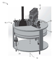
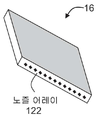
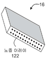
적층 가공에 사용되는 프린팅 시스템은 수용 매체 및 하나 또는 그 이상의 프린팅 헤드를 포함할 수 있다. 수용 매체는, 예를 들어, 프린팅 헤드로부터 분배 된 재료를 운반하기 위한 수평 표면을 포함할 수 있는 제조 트레이일 수 있다. 프린팅 헤드는, 예를 들어, 프린팅 헤드의 길이 방향 축을 따라, 하나 또는 그 이상의 열(row)의 어레이로 배열된 복수의 분배 노즐을 구비한 잉크 제트 헤드일 수 있다. 프린팅 헤드는 그 길이 방향 축이 인덱싱 방향(indexing direction)에 실질적으로 평행하도록 위치될 수 있다. 프린팅 시스템은 미리 정의된 스캐닝 플랜(예를 들어, 광조형 기술(STL) 포맷으로 변환되고, 제어기에 프로그램된 CAD 구성)에 따라, 프린팅 헤드의 이동을 포함하는, 프린팅 공정을 제어하는 마이크로 프로세서(microprocessor)와 같은 제어기를 추가로 포함할 수 있다. 프린팅 헤드는 복수의 분사 노즐을 포함할 수 있다. 분사 노즐은 3D 대상물의 단면을 나타내는 층을 생성하기 위해 재료를 수용 매체 상에 분배한다.The printing system used in the lamination process may comprise a receiving medium and one or more printing heads. The receiving medium may be, for example, a manufacturing tray that may include a horizontal surface for conveying the dispensed material from the printing head. The printing head can be, for example, an ink jet head with a plurality of dispense nozzles arranged in an array of one or more rows along the longitudinal axis of the printing head. The printing head may be positioned such that its longitudinal axis is substantially parallel to the indexing direction. The printing system includes a microprocessor (e. G., A microprocessor) that controls the printing process, including movement of the printing head, in accordance with a predefined scanning plan (e. G., A CAD configuration programmed into the controller and converted to stereolithography a microprocessor may be further included. The printing head may include a plurality of spray nozzles. The injection nozzle dispenses material onto the receiving medium to create a layer representing a cross-section of the 3D object.
프린팅 헤드 이외에, 분배된 빌딩 재료를 경화시키기 위한 경화 에너지 소스가 있을 수 있다. 경화 에너지는 전형적으로 방사선이며, 예를 들어 UV 방사선이다.In addition to the printing head, there may be a curing energy source for curing the dispensed building material. The curing energy is typically radiation, for example UV radiation.
또한, 프린팅 시스템은 후속 층을 증착하기 전에, 증착 및 적어도 부분 응고 후에 각 층의 높이를 레벨링하거나 및/또는 형성하기 위한 레벨링 장치를 포함할 수 있다.The printing system may also include a leveling device for leveling and / or forming the height of each layer after deposition and at least partial solidification, prior to depositing the subsequent layer.
빌딩 재료는 각각 빌드되는 바와 같이, 대상물과 대상물을 지지하는 임시 지지체 구조물를 형성하는 모델링 물질과 지지체 물질을 포함할 수 있다.The building material may comprise a modeling material and a support material, which, as each is built, forms a temporary support structure supporting the object and the object.
모델링 물질(하나 또는 그 이상의 물질을 포함할 수 있음)은 원하는 대상물(들)을 제조하기 위해 증착되고, 지지체 물질(하나 또는 그 이상의 물질을 포함할 수 있음)은 모델링 물질 성분의 유무에 관계없이, 예를 들어, 대상물이 굴곡된 기하학 구조, 음각 구조, 공극 등과 같은 돌출된 특징 또는 형상을 구비하는 경우에, 빌드 중 대상물의 구체적인 영역을 위한 지지체 구조물을 제공하고, 후속 대상 층의 적절한 수직 배치를 보장한다.The modeling material (which may include one or more materials) is deposited to produce the desired object (s), and the support material (which may include one or more materials) Providing a support structure for a specific area of an object during a build, for example, when the object has a protruding feature or shape such as a bent geometry, an engraved structure, a cavity, etc., .
모델링 물질 및 지지체 물질 모두는 바람직하게는, 분배되는 때의 작업 온도에서는 액체이고, 후속적으로 필요한 층 모양을 형성하기 위해 일반적으로 경화 에너지(예를 들어, UV 경화)에 노출시, 경화된다. 프린팅이 완료된 후, 지지체 구조물을 제거하면, 3D 대상물의 최종 형상이 나타난다.Both the modeling material and the support material are preferably liquid at the operating temperature when dispensed and are cured upon exposure to generally curing energy (e.g., UV cure) to form the required layer shape subsequently. After the printing is completed, when the support structure is removed, the final shape of the 3D object appears.
몇몇 적층 가공 공정을 통해 하나 또는 그 이상의 모델링 재료를 사용하여 대상물을 추가로 형성할 수 있다. 예를 들어, 본 양수인의 미국 특허 공개 번호 제 2010/0191360호는 복수의 분배 헤드, 복수의 빌딩 재료를 제조 장치에 공급하도록 구성된 빌딩 재료 공급 장치 및 상기 제조 장치 및 공급 장치를 제어하기 위한 제어 유닛을 구비한 임의 형상 제작 장치(solid freeform fabrication apparatus)를 포함한 시스템을 개시한다. 본 시스템은 여러 가지 작동 모드를 갖는다. 일 모드에서, 모든 분배 헤드는 제조 장치의 단일 빌딩 스캔 사이클 동안 작동한다. 다른 모드에서, 하나 또는 그 이상의 분배 헤드는 단일 빌딩 스캔 사이클 또는 그 사이클의 일부 동안에 작동하지 않는다.One or more modeling materials may be used to further form the object through some lamination process. For example, U. S. Patent Publication No. < RTI ID = 0.0 > 2010/0191360 < / RTI > of the present assignee discloses a system for controlling a plurality of distribution heads, a building material supply apparatus configured to supply a plurality of building materials to a manufacturing apparatus, And a solid freeform fabrication apparatus having a substrate. The system has several modes of operation. In one mode, all dispense heads operate during a single building scan cycle of the manufacturing apparatus. In another mode, the one or more dispense heads do not operate during a single building scan cycle or part of that cycle.
PolyjetTM(Stratasys Ltd., Israel)과 같은 3D 잉크젯 프린팅 공정에서, 빌딩 재료는 하나 또는 그 이상의 프린팅 헤드로부터 선택적으로 분사되고 소프트웨어 파일(software file)에 의해 정의된 바와 같은 사전 결정된 구성에 따라 연속적인 층으로 제조 트레이 상에 증착된다.In a 3D inkjet printing process, such as Polyjet TM (Stratasys Ltd., Israel), the building material is selectively ejected from one or more printing heads and ejected in succession according to a predetermined configuration as defined by a software file Layer on the production tray.
경화된 강성 모델링 물질이 최종 대상물로 형성될 때, 경화된 물질은 바람직하게는 사용성을 보장하기 위해 실온보다 높은 열 변형 온도(HDT)를 나타내야 한다. 일반적으로 경화된 모델링 물질은 적어도 35 ℃의 HDT를 나타내야 한다. 가변 조건에서 안정된 대상물을 위하여, HDT가 높은 것이 바람직하다.When the cured stiffness modeling material is formed into the final object, the cured material should preferably exhibit a heat distortion temperature (HDT) higher than room temperature to ensure usability. Typically, the cured modeling material should exhibit an HDT of at least 35 ° C. For stable objects under variable conditions, high HDT is preferred.
본 양수인에 의한 미국 특허 공개 번호 제 2013/0040091호는 복수의 층과 코어 영역을 구성하는 적층된 코어(core) 및 엔벨로프(envelope) 영역을 구성하는 적층된 쉘로 구성된 쉘 대상물의 임의 형상 제작 방법 및 시스템을 개시한다.U.S. Patent Publication No. 2013/0040091 by the present assignee discloses a method for making arbitrary shapes of a shell object composed of a laminated core constituting a plurality of layers and a core region and a laminated shell constituting an envelope region, System.
본 발명의 일부 실시형태의 일 측면에 따르면, 3 차원 대상물의 층별 제조 방법으로서, 상기 방법은 적어도 일부 층 각각을 위해: According to an aspect of some embodiments of the present invention, there is provided a layered method of manufacturing a three-dimensional object, the method comprising:
적어도 제 1 모델링 제형 및 제 2 모델링 제형을 분배하여, 상기 제 1 모델링 제형 및 제 2 모델링 제형 모두를 사용하여 코어 영역을, 상기 제 2 모델링 제형을 제외하고 상기 제 1 모델링 제형을 사용하여, 상기 코어 영역을 적어도 부분적으로 둘러싸는 내측 엔벨로프 영역을, 및 상기 제 1 모델링 제형을 제외하고 상기 제 2 모델링 제형을 사용하여, 상기 내측 엔벨로프 영역을 적어도 부분적으로 둘러싸는 외측 엔벨로프 영역을 형성하는 단계;Dispensing at least a first modeling formulation and a second modeling formulation to produce a core region using both the first modeling formulation and the second modeling formulation using the first modeling formulation except for the second modeling formulation, Forming an inner envelope region that at least partially surrounds the core region, and an outer envelope region that at least partially surrounds the inner envelope region using the second modeling formulation except for the first modeling formulation;
상기 층을 경화 에너지에 노출하여, 상기 대상물을 제조하는 단계를 포함하며, And exposing the layer to curing energy to produce the object,
상기 제 1 모델링 제형과 제 2 모델링 제형 각각은 적어도 하나의 UV-경화성 물질을 포함하고, 상기 제 1 모델링 제형과 제 2 모델링 제형은 경화시, 열 변형 온도(HDT), 아이조드 내 충격성(Izod Impact resistance), Tg 및 탄성 모듈러스 중 적어도 하나에 의해 서로 상이한 방법을 제공한다.Wherein each of the first modeling formulation and the second modeling formulation comprises at least one UV-curable material, wherein the first modeling formulation and the second modeling formulation exhibit at least one of a thermal deformation temperature (HDT), Izod Impact resistance, Tg, and elastic modulus.
본 명세서에 기술된 일부 임의의 실시형태에 따르면, 상기 제 1 모델링 물질 제형의 경화시 HDT는 상기 제 2 모델링 물질 제형의 경화시 HDT보다 높다.According to some optional embodiments described herein, the HDT during curing of the first modeling material formulation is higher than the HDT during curing of the second modeling material formulation.
본 명세서에서 설명되는 임의의 실시형태의 일부에 따르면, 상기 제 2 모델링 물질 제형의 경화시 HDT는 50 ℃ 보다 낮고, 상기 제 1 모델링 물질 제형의 경화시 HDT는 50 ℃보다 높다.According to some of the embodiments described herein, the HDT is less than 50 캜 when curing the second modeling material formulation and the HDT is greater than 50 캜 when curing the first modeling material formulation.
본 명세서에서 설명되는 일부 임의의 실시형태에 따르면, 상기 제 2 모델링 물질 제형의 경화시 아이조드 내충격성은 상기 제 1 모델링 물질 제형의 경화시 아이조드 내충격성 보다 높다. According to some optional embodiments described herein, the Izod impact resistance during curing of the second modeling material formulation is higher than the Izod impact resistance during curing of the first modeling material formulation.
본 명세서에서 설명되는 일부 임의의 실시형태에 따르면, 상기 제 1 모델링 물질 제형의 경화시 탄성 모듈러스와 상기 제 2 모델링 물질 제형의 경화시 탄성 모듈러스의 비율은 1 내지 20, 1 내지 10, 1 내지 5, 2 내지 5, 2 내지 3, 2.5 내지 3 또는 2.7 내지 2.9의 범위이다. According to some optional embodiments described herein, the ratio of the elastic modulus during curing of the first modeling material formulation to the elastic modulus during curing of the second modeling material formulation is in the range of 1 to 20, 1 to 10, 1 to 5 , 2 to 5, 2 to 3, 2.5 to 3 or 2.7 to 2.9.
본 명세서에서 설명되는 일부 임의의 실시형태에 따르면, 상기 제 1 모델링 물질 제형은 각각의 실시형태의 어느 하나에서 설명되는 바와 같은, 경화시 Tg가 적어도 50 ℃인 적어도 하나의 경화성 물질을 포함한다. According to some optional embodiments described herein, the first modeling material formulation comprises at least one curable material having a Tg of at least 50 ° C at the time of curing, as described in any one of the embodiments.
본 명세서에서 설명되는 일부 임의의 실시형태에 따르면, 상기 제 1 모델링 물질 제형은 각각의 실시형태의 어느 하나에서 설명되는 바와 같은, 적어도 두 개의 경화성 물질을 포함하며, 상기 경화성 물질의 적어도 하나는 경화시 Tg가 적어도 80 ℃이다. According to some optional embodiments described herein, the first modeling material formulation comprises at least two curable materials, as described in any one of the embodiments, wherein at least one of the curable materials is cured Lt; 0 > C.
본 명세서에서 설명되는 일부 임의의 실시형태에 따르면, 상기 제 1 모델링 물질 제형은 각각의 실시형태의 어느 하나에서 설명되는 바와 같은, 적어도 두 개의 경화성 물질을 포함하며, 상기 경화성 물질의 적어도 하나는 경화시 Tg가 적어도 100 ℃ 또는 적어도 150 ℃이다.According to some optional embodiments described herein, the first modeling material formulation comprises at least two curable materials, as described in any one of the embodiments, wherein at least one of the curable materials is cured Lt; 0 > C or at least 150 < 0 > C.
본 명세서에서 설명되는 일부 임의의 실시형태에 따르면, 상기 제 1 모델링 물질 제형은: 각각의 실시형태의 어느 하나에서 설명되는 바와 같은, 적어도 하나의 경화성 (메트)아크릴 모노머; 적어도 하나의 경화성 (메트)아크릴 올리고머; 및 선택적으로, 경화시 Tg가 0 ℃ 보다 낮은 적어도 하나의 경화성 (메트)아크릴 모노머를 포함한다. According to some optional embodiments described herein, the first modeling material formulation comprises: at least one curable (meth) acrylic monomer as described in any one of the embodiments; At least one curable (meth) acryl oligomer; And optionally, at least one curable (meth) acrylic monomer having a Tg of less than 0 占 폚 at the time of curing.
본 명세서에서 설명되는 일부 임의의 실시형태에 따르면, 상기 제 1 모델링 물질 제형은: 각각의 실시형태의 어느 하나에서 설명되는 바와 같은, 경화시 Tg가 적어도 85 ℃인 적어도 하나의 경화성 (메트)아크릴 모노머; 경화시 Tg가 적어도 150 ℃인 적어도 하나의 경화성 (메트)아크릴 모노머; 경화시 Tg가 적어도 50 ℃인 적어도 하나의 경화성 (메트)아크릴 올리고머머; 및 선택적으로, 경화시 Tg가 0 ℃ 미만* 적어도 하나의 경화성 (메트)아크릴 모노머를 포함한다.According to some optional embodiments described herein, the first modeling material formulation comprises: at least one curable (meth) acrylate having a Tg of at least 85 캜 at the time of curing, as described in any one of the embodiments. Monomers; At least one curable (meth) acrylic monomer having a Tg of at least 150 캜 upon curing; At least one curable (meth) acryl oligomer having a Tg of at least 50 캜 upon curing; And optionally, at least one curable (meth) acrylic monomer having a Tg of less than 0 占 폚 at the time of curing.
본 명세서에서 설명되는 일부 임의의 실시형태에 따르면, 상기 제 2 모델링 물질 제형은 각각의 실시형태의 어느 하나에서 설명되는 바와 같은, 적어도 두 개의 경화성 물질을 포함하며, 상기 경화성 물질의 적어도 하나는 경화시 Tg가 -20 ℃ 미만인 (메트)아크릴 모노머이다.According to some optional embodiments described herein, the second modeling material formulation comprises at least two curable materials, as described in any one of the embodiments, wherein at least one of the curable materials is cured (Meth) acrylic monomer having a Tg of less than -20 < 0 > C.
본 명세서에서 설명되는 일부 임의의 실시형태에 따르면, 상기 제 2 모델링 물질 제형은 각각의 실시형태의 어느 하나에서 설명되는 바와 같은, 경화시 Tg가 적어도 70 ℃인 적어도 하나의 경화성 메트(아크릴) 모노머를 추가로 포함한다.According to some optional embodiments described herein, the second modeling material formulation may comprise at least one curable meta (acrylic) monomer having a Tg of at least 70 DEG C at the time of curing, as described in any one of the embodiments. .
본 명세서에서 설명되는 일부 임의의 실시형태에 따르면, 상기 제 2 모델링 물질 제형은 각각의 실시형태의 어느 하나에서 설명되는 바와 같은, 경화시 Tg가 적어도 10 ℃인 적어도 하나의 경화성 메트(아크릴) 올리고머를 추가로 포함한다.According to some optional embodiments described herein, the second modeling material formulation comprises at least one curable meth (acryl) oligomer having a Tg of at least 10 DEG C at the time of curing, as described in any one of the embodiments. .
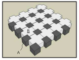
본 명세서에서 설명되는 일부 임의의 실시형태에 따르면, 상기 코어 영역은 상기 제 1 모델링 제형과 제 2 모델링 제형 사이의 복셀 결합(voxelated combination)을 포함한다.According to some optional embodiments described herein, the core region comprises a voxelated combination between the first modeling formulation and the second modeling formulation.
본 명세서에서 설명되는 일부 임의의 실시형태에 따르면, 상기 층의 평면내 및 상기 대상물의 표면에 대해 수직으로 측정된 상기 내측 엔벨로프 영역의 두께는 바람직하게는 약 0.1 mm 내지 약 4 mm이다. According to some optional embodiments described herein, the thickness of the inner envelope region measured in a plane of the layer and perpendicular to the surface of the object is preferably from about 0.1 mm to about 4 mm.
본 명세서에서 설명되는 일부 임의의 실시형태에 따르면, 상기 층의 평면내 및 상기 대상물의 표면에 대해 수직으로 측정된 상기 외측 엔벨로프 영역의 두께는 약 150 마이크론 내지 약 600 마이크론이다. According to some optional embodiments described herein, the thickness of the outer envelope region measured in a plane of the layer and perpendicular to the surface of the object is from about 150 microns to about 600 microns.
본 명세서에서 설명되는 일부 임의의 실시형태에 따르면, 상기 분배가 실시되어, 상기 내측 엔벨로프 영역과 상기 외측 엔벨로프 영역 사이에 적어도 하나의 추가 엔벨로프 영역을 형성한다.According to some optional embodiments described herein, the distribution is performed to form at least one additional envelope area between the inner envelope area and the outer envelope area.
본 명세서에서 설명되는 일부 임의의 실시형태에 따르면, 상기 추가 엔벨로프 영역의 분배는 상기 제 1 모델링 제형과 상기 제 2 모델링 제형 모두를 사용한다.According to some optional embodiments described herein, the distribution of the additional envelope region uses both the first modeling formulation and the second modeling formulation.
본 명세서에서 설명되는 일부 임의의 실시형태에 따르면, 상기 층의 평면내 및 상기 대상물의 표면에 대해 수직으로 측정된 상기 추가 엔벨로프 영역의 두께는 상기 내측 엔벨로프 영역의 두께보다 작고 또한 상기 외측 엔벨로프 영역의 두께보다 작다. According to some optional embodiments described herein, the thickness of the additional envelope area, measured in a plane of the layer and perpendicular to the surface of the object, is less than the thickness of the inner envelope area, and the thickness of the outer envelope area Is less than the thickness.
본 명세서에서 설명되는 일부 임의의 실시형태에 따르면, 상기 층의 평면내 및 상기 대상물의 표면에 대해 수직으로 측정된 상기 추가 엔벨로프 영역의 두께는 약 70 마이크론 내지 약 100 마이크론이다.According to some optional embodiments described herein, the thickness of the additional envelope region measured in a plane of the layer and perpendicular to the surface of the object is from about 70 microns to about 100 microns.
본 명세서에서 설명되는 일부 임의의 실시형태에 따르면, 상기 제 1 모델링 제형에 의해 점유되는 상기 추가 엔벨로프 영역 내의 복셀(voxel)의 수와 상기 제 2 모델링 제형에 의해 점유되는 상기 추가 엔벨로프 영역 내의 복셀의 수의 비율은 약 1이다.According to some optional embodiments described herein, the number of voxels in the additional envelope region occupied by the first modeling formulation and the number of voxels in the additional envelope region occupied by the second modeling formulation The ratio of the number is about 1.
본 명세서에서 설명되는 일부 임의의 실시형태에 따르면, 복수의 하부층을 분배하여, 상기 대상물의 하부 섹션을 형성하는 단계를 추가로 포함하며, 상기 복수의 하부층은 상기 제 1 모델링 제형을 제외한 상기 제 2 모델링 제형으로 제조된 적어도 하나의 외측 하부층 및 상기 제 2 모델링 제형을 제외한 상기 제 1 모델링 제형으로 제조된 적어도 하나의 내측 하부층을 포함한다.According to some optional embodiments described herein, the method further comprises dispensing a plurality of sublayers to form a lower section of the object, wherein the plurality of sublayers comprise the second modeling formulation, except for the first modeling formulation, At least one outer lower layer made of a modeling formulation and at least one inner lower layer made of the first modeling formulation except for the second modeling formulation.
본 명세서에서 설명되는 일부 임의의 실시형태에 따르면, 상기 적어도 하나의 외측 하부층의 상기 대상물의 빌드 방향을 따른 전체 두께는 상기 외측 엔벨로프 영역에 결합된 평면내 및 상기 대상물의 표면에 수직으로 측정된 상기 외측 엔벨로프 영역의 두께와 대략적으로 동일하다.According to some optional embodiments described herein, the total thickness along the build direction of the object in the at least one outer underlayer is greater than the total thickness in the plane coupled to the outer envelope area, Is approximately equal to the thickness of the outer envelope region.
본 명세서에서 설명되는 일부 임의의 실시형태에 따르면, 상기 복수의 하부층은 상기 적어도 하나의 내측 하부층과 상기 적어도 하나의 외측 하부층 사이에 적어도 하나의 중간 하부층을 포함하고, 상기 중간 하부층은 상기 제 1 모델링 제형과 상기 제 2 모델링 제형 모두로 제조된다.According to some optional embodiments described herein, the plurality of lower layers include at least one intermediate lower layer between the at least one inner lower layer and the at least one outer lower layer, Both the formulation and the second modeling formulation are made.
본 명세서에서 설명되는 일부 임의의 실시형태에 따르면, 복수의 상부층을 분배하여, 상기 대상물의 상부 섹션을 형성하는 단계를 추가로 포함하고, 상기 복수의 상부층은 상기 제 1 모델링 제형을 제외한 상기 제 2 모델링 제형으로 제조된 적어도 하나의 외측 상부층 및 상기 제 2 모델링 제형을 제외한 상기 제 1 모델링 제형으로 제조된 적어도 하나의 내측 상부층을 포함한다.According to some optional embodiments described herein, the method further comprises distributing a plurality of upper layers to form an upper section of the object, wherein the plurality of upper layers comprise the second modeling formulation, excluding the first modeling formulation, At least one outer upper layer made of a modeling formulation and at least one inner upper layer made of the first modeling formulation except for the second modeling formulation.
본 명세서에서 설명되는 일부 임의의 실시형태에 따르면, 상기 적어도 하나의 외측 상부층의 상기 대상물의 형성 방향을 따른 전체 두께는 상기 외측 엔벨로프 영역에 결합된 평면내 및 상기 대상물의 표면에 수직으로 측정된 상기 외측 엔벨로프 영역의 두께와 대략적으로 동일하다.According to some optional embodiments described herein, the total thickness of the at least one outer upper layer along the forming direction of the object is greater than the total thickness of the at least one outer upper layer in the plane coupled to the outer envelope region, Is approximately equal to the thickness of the outer envelope region.
본 명세서에서 설명되는 일부 임의의 실시형태에 따르면, 상기 복수의 상부층은 상기 적어도 하나의 내측 상부층과 상기 적어도 하나의 외측 상부층 사이에 적어도 하나의 중간 상부층을 포함하고, 상기 중간 상부층은 상기 제 1 모델링 제형과 상기 제 2 모델링 제형 모두로 제조된다.According to some optional embodiments described herein, the plurality of upper layers include at least one intermediate upper layer between the at least one inner upper layer and the at least one outer upper layer, Both the formulation and the second modeling formulation are made.
본 명세서에서 설명되는 일부 임의의 실시형태에 따르면, 상기 제 1 제형을 특징으로 하는 적어도 하나의 파라미터가 선택되어, 상기 코어를 위한 소정의 댐핑(damping)을 제공한다.According to some optional embodiments described herein, at least one parameter featuring the first formulation is selected to provide a predetermined damping for the core.
본 명세서에서 설명되는 일부 임의의 실시형태에 따르면, 상기 적어도 하나의 파라미터는 상기 모델링 제형의 가교 결합 정도(extent)를 포함한다.According to some optional embodiments described herein, the at least one parameter comprises a degree of crosslinking of the modeling formulation.
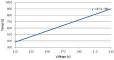
본 명세서에서 설명되는 일부 임의의 실시형태에 따르면, 상기 적어도 하나의 파라미터는 경화시 제 1 모델링 제형 내에 포함된 중합체 재료의 개별적인 Tg 수치를 합하여 계산된, 상기 제 1 제형의 계산된 총 Tg를 포함한다.According to some optional embodiments described herein, the at least one parameter comprises a calculated total Tg of the first formulation, calculated by summing the individual Tg values of the polymeric materials contained in the first modeling formulation upon curing do.
본 명세서에서 설명되는 일부 임의의 실시형태에 따르면, 상기 제 1 제형 및 상기 제 2 제형의 상대적인 양이 선택되어, 상기 코어를 위한 소정의 댐핑을 제공한다.According to some optional embodiments described herein, the relative amounts of the first and second formulations are selected to provide a predetermined damping for the core.
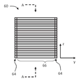
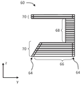
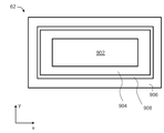
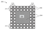
본 발명의 일부 실시형태의 일 측면에 따르면, 층별 임의 형상 제작(layerwise solid freeform fabrication)으로 수득한 3D 대상물로서, 상기 대상물은 복수의 층을 포함하고, 적어도 하나의 층은:According to an aspect of some embodiments of the present invention there is provided a 3D object obtained by layerwise solid freeform fabrication, the object comprising a plurality of layers, wherein at least one layer comprises:
제 1 모델링 제형과 제 2 모델링 제형으로 형성된 제 1 경화된 모델링 물질로 적어도 일부가 제조된 코어 영역, 상기 제 2 모델링 제형을 제외한 제 1 모델링 제형으로 형성된 제 2 경화된 모델링 물질로 적어도 일부가 제조되고, 상기 코어 영역을 적어도 일부분 둘러싸는 내측 엔벨로프 영역, 및 상기 제 1 모델링 제형을 제외한 제 2 모델링 제형으로 형성된 제 3 경화된 모델링 물질로 적어도 일부가 제조되고, 상기 내측 엔벨로프 영역을 적어도 일부분 둘러싸는 외측 엔벨로프 영역을 포함하고,A core region at least partially made of a first cured modeling material formed of a first modeling formulation and a second modeling formulation, a second cured modeling material formed of a first modeling formulation other than the second modeling formulation, At least a portion of which is made at least partially of an inner envelope region surrounding at least a portion of the core region and a third cured modeling material formed of a second modeling formulation except for the first modeling formulation, An outer envelope region,
상기 제 1 모델링 제형과 상기 제 2 모델링 제형 각각은 적어도 하나의 UV-경화성 물질을 포함하고, 상기 제 1 모델링 제형과 제 2 모델링 제형은 경화시, 열 변형 온도, 아이조드 내충격성 및 탄성 모듈러스 중 적어도 하나에 의해 서로 상이한 대상물을 제공한다.Wherein each of the first modeling formulation and the second modeling formulation comprises at least one UV-curable material, wherein the first and second modeling formulations have at least one of thermal strain temperature, Izod impact resistance and elastic modulus One by one to provide objects different from each other.
본 명세서에서 설명되는 일부 임의의 실시형태에 따르면, 상기 코어 영역은 상기 제 1 모델링 제형으로 형성된 경화된 물질과 제 2 모델링 제형으로 형성된 경화된 물질 사이의 복셀 결합을 포함한다.According to some optional embodiments described herein, the core region comprises voxel coupling between a cured material formed of the first modeling formulation and a cured material formed of a second modeling formulation.
본 명세서에서 설명되는 일부 임의의 실시형태에 따르면, 상기 내측 엔벨로프 영역과 상기 외측 엔벨로프 영역 사이에 적어도 하나의 추가 엔벨로프 영역을 추가로 포함한다.According to some optional embodiments described herein, at least one additional envelope region is further included between the inner envelope region and the outer envelope region.
본 명세서에서 설명되는 일부 임의의 실시형태에 따르면, 상기 추가 엔벨로프 영역은 상기 제 1 모델링 제형과 상기 제 2 모델링 제형 모두로 형성된 제 4 경화 모델링 물질로 적어도 일부가 제조된다. According to some optional embodiments described herein, the additional envelope region is at least partially fabricated with a fourth curing modeling material formed of both the first modeling formulation and the second modeling formulation.
본 명세서에서 설명되는 일부 임의의 실시형태에 따르면, 상기 제 1 모델링 제형으로 형성된 경화된 물질에 의해 점유되는 상기 추가 엔벨로프 영역 내의 복셀의 수와 상기 제 2 모델링 제형으로 형성된 경화된 물질에 의해 점유되는 상기 추가 엔벨로프 영역 내의 복셀의 수의 비율은 약 1이다.According to some optional embodiments described herein, the number of voxels in the additional envelope area occupied by the cured material formed in the first modeling formulation and the number of voxels occupied by the cured material formed in the second modeling formulation The ratio of the number of voxels in the additional envelope region is about one.
본 명세서에서 설명되는 일부 임의의 실시형태에 따르면, 상기 대상물의 하부 섹션을 형성하는 복수의 하부층을 추가로 포함하고, 상기 복수의 하부층은 상기 제 1 모델링 제형이 아닌 상기 제 2 모델링 제형으로 형성된 경화된 재료로 제조된 적어도 하나의 외측 하부층 및 상기 제 2 모델링 제형이 아닌 상기 제 1 모델링 제형으로 형성된 경화된 재료로 제조된 적어도 하나의 내측 하부층을 포함한다.According to some optional embodiments described herein, the method further comprises a plurality of lower layers forming a lower section of the object, wherein the plurality of lower layers are hardened by the second modeling formulation, not the first modeling formulation, And at least one inner lower layer made of a hardened material formed of the first modeling formulation other than the second modeling formulation.
본 명세서에서 설명되는 일부 임의의 실시형태에 따르면, 상기 적어도 하나의 외측 하부층의 상기 대상물의 성형 방향을 따른 전체 두께는 상기 외측 엔벨로프 영역에 결합된 평면내 및 상기 대상물의 표면에 수직으로 측정된 상기 외측 엔벨로프 영역의 두께와 대략적으로 동일하다.According to some optional embodiments described herein, the total thickness along the forming direction of the object of the at least one outer lower layer is within a plane coupled to the outer envelope region and within the plane perpendicular to the surface of the object Is approximately equal to the thickness of the outer envelope region.
본 명세서에서 설명되는 일부 임의의 실시형태에 따르면, 상기 복수의 하부층은 상기 적어도 하나의 내측 하부층과 상기 적어도 하나의 외측 하부층 사이에 적어도 하나의 중간 하부층을 포함하고, 상기 중간 하부층은 상기 제 1 모델링 제형과 상기 제 2 모델링 제형 모두로 형성된 경화된 물질로 제조된다.According to some optional embodiments described herein, the plurality of lower layers include at least one intermediate lower layer between the at least one inner lower layer and the at least one outer lower layer, And is made of a cured material formed of both the formulation and the second modeling formulation.
본 명세서에서 설명되는 일부 임의의 실시형태에 따르면, 상기 대상물의 상부 섹션을 형성하는 복수의 상부층을 추가로 포함하고, 상기 복수의 상부층은 상기 제 1 모델링 제형이 아닌 상기 제 2 모델링 제형으로 형성된 경화 모델링 물질로 제조된 적어도 하나의 외측 상부층 및 상기 제 2 모델링 제형이 아닌 상기 제 1 모델링 제형으로 형성된 경화 모델링 물질로 제조된 적어도 하나의 내측 상부층을 포함한다.According to some optional embodiments described herein, the apparatus further comprises a plurality of upper layers forming an upper section of the object, wherein the plurality of upper layers are hardened by the hardening formed in the second modeling formulation, At least one outer upper layer made of a modeling material and at least one inner upper layer made of a hardened modeling material formed of the first modeling formulation other than the second modeling formulation.
본 명세서에서 설명되는 일부 임의의 실시형태에 따르면, 상기 적어도 하나의 외측 상부층의 상기 대상물의 성형 방향을 따른 전체 두께는 상기 외측 엔벨로프 영역에 결합된 평면내 및 상기 대상물의 표면에 수직으로 측정된 상기 외측 엔벨로프 영역의 두께와 대략적으로 동일하다.According to some optional embodiments described herein, the total thickness along the shaping direction of the object of the at least one outer upper layer may be within a plane coupled to the outer envelope region, and within a plane perpendicular to the surface of the object Is approximately equal to the thickness of the outer envelope region.
본 명세서에서 설명되는 일부 임의의 실시형태에 따르면, 상기 복수의 상부층은 상기 적어도 하나의 내측 상부층과 상기 적어도 하나의 외측 상부층 사이에 적어도 하나의 중간 상부층을 포함하고, 상기 중간 상부층은 상기 제 1 모델링 제형과 상기 제 2 모델링 제형 모두로 형성된 경화된 재료로 제조된다.According to some optional embodiments described herein, the plurality of upper layers include at least one intermediate upper layer between the at least one inner upper layer and the at least one outer upper layer, And is made of a cured material formed of both the formulation and the second modeling formulation.
본 명세서에서 설명되는 일부 임의의 실시형태에 따르면, 상기 제 1 모델링 물질 제형과 상기 제 2 모델링 물질 제형은 각각의 실시형태의 어느 하나 및 그들의 임의의 조합에서 설명되는 바와 같다.According to some optional embodiments described herein, the first modeling material formulation and the second modeling material formulation are as described in any one of the embodiments and any combination thereof.
다르게 정의되지 않는 한, 본 명세서에서 사용되는 모든 기술 용어 및/또는 과학 용어는 본 발명이 속하는 기술 분야의 당업자에 의해 일반적으로 이해되는 것과 동일한 의미를 갖는다. 본 명세서에서 기재된 것과 유사한 또는 동등한 방법 및 물질이 본 발명의 실시형태를 실시하거나 또는 시험하는데 사용될 수 있지만, 예시적인 방법 및/또는 물질은 하기에 기재된다. 상충하는 경우에는 정의를 포함한 특허 명세서가 우선될 것이다. 또한, 물질, 방법 및 실시형태는 단지 예시적인 것이며, 반드시 제한하려는 의도는 아니다.Unless otherwise defined, all technical and / or scientific terms used herein have the same meaning as commonly understood by one of ordinary skill in the art to which this invention belongs. Exemplary methods and / or materials are described below, although methods or materials similar or equivalent to those described herein can be used to practice or test embodiments of the present invention. In case of conflict, the patent specification, including definitions, will prevail. In addition, the materials, methods, and embodiments are illustrative only and not intended to be limiting.
본 발명의 실시형태의 방법 및/또는 시스템의 구현은 선택된 작업을 수동, 자동 또는 이들의 조합으로 수행하거나 완료하는 것을 포함할 수 있다. 또한, 본 발명의 방법 및/또는 시스템의 실시형태의 실제 기기 및 장비에 따라, 몇몇 선택된 작업은 하드웨어에 의해, 소프트웨어에 의해 또는 펌웨어에 의해 또는 운영 체제를 사용하여 이들의 조합에 의해 구현될 수 있다.Implementations of the methods and / or systems of embodiments of the present invention may include performing or completing selected tasks manually, automatically, or a combination thereof. Further, depending on the actual equipment and equipment of the method and / or system embodiment of the present invention, some selected tasks may be implemented by hardware, by software, or by firmware, or by a combination thereof using an operating system have.
예를 들어, 본 발명의 실시형태에 따라 선택된 작업을 수행하기 위한 하드웨어는 칩 또는 회로로서 구현될 수 있다. 소프트웨어로서, 본 발명의 실시형태에 따라 선택된 작업은 임의의 적합한 운영 시스템을 사용하여 컴퓨터에 의해 실행되는 복수의 소프트웨어 명령어로서 구현될 수 있다. 본 발명의 예시적인 실시형태에서, 본 명세서에서 설명된 방법 및/또는 시스템의 예시적인 실시형태에 따른 하나 또는 그 이상의 작업은 복수의 명령어를 실행하기 위한 컴퓨팅 플랫폼과 같은 데이터 프로세서에 의해 수행된다. 선택적으로, 데이터 프로세서는 명령어 및/또는 데이터를 저장하기 위한 휘발성 메모리, 및/또는 명령어 및/또는 데이터를 저장하기 위한 자기 하드 디스크 및/또는 제거 가능한 매체와 같은 비-휘발성 스토리지를 포함한다. 선택적으로, 네트워크 연결도 제공된다. 디스플레이 및/또는 키보드 또는 마우스와 같은 사용자 입력 장치가 선택적으로 또한 제공된다.For example, hardware for performing a selected task in accordance with an embodiment of the present invention may be implemented as a chip or a circuit. As software, operations selected in accordance with embodiments of the present invention may be implemented as a plurality of software instructions executed by a computer using any suitable operating system. In an exemplary embodiment of the invention, one or more tasks in accordance with exemplary embodiments of the methods and / or systems described herein are performed by a data processor, such as a computing platform, for executing a plurality of instructions. Optionally, the data processor includes volatile memory for storing instructions and / or data, and / or non-volatile storage such as magnetic hard disks and / or removable media for storing instructions and / or data. Optionally, a network connection is also provided. A user input device such as a display and / or a keyboard or a mouse is optionally also provided.
본 발명의 일부 실시형태는 본 명세서에서 첨부된 도면을 참조하여, 예시로서만 설명된다. 이제 도면을 상세하게 참조하여, 도시된 세부 사항은 예시로서 및 본 발명의 실시형태에 대한 설명을 목적으로 한 것임을 강조한다. 이와 관련하여, 도면과 함께 제공된 설명을 통해, 본 발명의 실시형태가 실시될 수 있는 방법을 당업자에게 명백하게 한다.
도면에서:
도 1a 내지 도 1g는 모델링 제형 내의 균열에 기인한 응력 분포를 분석하기 위한 본 발명의 일부 실시형태에 따라 수행된 컴퓨터 시뮬레이션 결과를 도시하고,
도 2는 다양한 프린팅된 대상물의 HDT에서, 코어에서 제형의 다양한 농도의 효과를 도시하며;
도 3은 본 발명의 일부 실시형태에 따른 적층 가공 시스템의 개략도이고;
도 4a 및 4b는 본 발명의 일부 실시형태에 따른 회전 운동을 사용하는 적층 가공 시스템의 개략적인 평면도(도 4a) 및 측면도(도 4b)이며;
도 5는 본 발명의 일부 실시형태에 따른 회전 운동을 사용하는 적층 가공 시스템의 개략적인 등각 투상도이고;
도 6a 내지 6c는 본 발명의 일부 실시형태에 따른 프린팅 헤드의 개략도이며;
도 7은 시스템이 열 스크린을 포함하는 본 발명의 실시형태에서 적층 가공 시스템의 개략도이고;
도 8은 적외선 소스에 인가된 전압에 대한 온도의 일반적인 선형 의존성을 나타내는 그래프이며;
도 9a 내지 9f는 본 발명의 일부 실시형태에 따른 쉘 구조의 개략도이며;
도 10a 및 도 10b는 본 발명의 일부 실시형태에 따른 받침대 상에 형성된 대상물의 개략도이며;
도 11은 본 발명의 일부 실시형태에 따른 코어 영역이 없는 부분을 갖는 쉘 구조의 개략도이고;
도 12는 본 발명의 일부 실시형태에 따른 인터레이스 모델링 물질을 포함하는 영역의 개략도이며; 및
도 13a 내지 도 13e는 본 발명의 일부 실시형태에 따라 제조된 대상물을 분석하기 위해 수행된 동적 기계적 분석 결과를 도시한다.Some embodiments of the present invention are described herein by way of example only, with reference to the accompanying drawings. DETAILED DESCRIPTION OF THE PREFERRED EMBODIMENTS Reference will now be made in detail to the drawings, emphasizing that the illustrations shown are by way of example and for purposes of explanation of the embodiments of the invention. In this regard, it will be clear to those skilled in the art how the embodiments of the present invention may be practiced, by way of explanation provided with the drawings.
In the drawing:
Figures 1a-1g show computer simulation results performed in accordance with some embodiments of the present invention for analyzing the stress distribution due to cracks in a modeling formulation,
Figure 2 shows the effect of various concentrations of the formulation in the core, in HDT of various printed objects;
Figure 3 is a schematic view of a stack processing system according to some embodiments of the present invention;
Figures 4a and 4b are a schematic plan view (Figure 4a) and a side view (Figure 4b) of a lamination machining system using rotational motion in accordance with some embodiments of the present invention;
Figure 5 is a schematic isometric view of a lamination machining system using rotational motion in accordance with some embodiments of the present invention;
6A to 6C are schematic views of a printing head according to some embodiments of the present invention;
Figure 7 is a schematic view of a lamination system in an embodiment of the present invention in which the system comprises a thermal screen;
8 is a graph showing the general linear dependence of temperature on the voltage applied to the infrared source;
9A-9F are schematic diagrams of a shell structure according to some embodiments of the present invention;
10A and 10B are schematic views of objects formed on a pedestal in accordance with some embodiments of the present invention;
11 is a schematic view of a shell structure having a portion without a core region according to some embodiments of the present invention;
12 is a schematic illustration of a region containing an interlace modeling material in accordance with some embodiments of the present invention; And
Figures 13A-13E illustrate dynamic mechanical analysis results performed to analyze objects made in accordance with some embodiments of the present invention.
본 발명은 일부 실시형태에서 대상물의 적층 가공(AM)에 관한 것으로서, 보다 상세하게는, 이에 한정되는 것은 아니지만, 적층물의 적층 가공 방법 및 시스템에 관한 것이다.The present invention relates to stacking (AM) of objects in some embodiments, and more particularly, but not exclusively, to a method and system for stacking stacks.
본 발명의 적어도 하나의 실시형태를 상세히 설명하기 전에, 본 발명은 그 응용에서, 이하의 설명에서 제시되거나 및/또는 도면 및/또는 예시에서 설명된 구조 및 구성요소 및/또는 방법의 배열의 세부 사항으로 반드시 제한되는 것은 아님이 이해되어야 한다. 본 발명은 다른 실시형태가 가능하거나 다양한 방법으로 실시되거나 수행될 수 있다.Before describing in detail one or more embodiments of the present invention, the present invention may be embodied in its application in the form of details, structures and / or arrangements of elements and / or methods presented in the following description and / or described in the drawings and / It is to be understood that this is not necessarily limitative. The invention is capable of other embodiments or of being practiced or of being carried out in various ways.
본 실시형태의 방법 및 시스템은 대상물의 형상에 대응하도록 구성된 패턴으로 복수의 층을 형성함으로써, 컴퓨터 객체 데이터에 기초한 3 차원 대상물을 층별로 제조한다. 컴퓨터 객체 데이터는 이에 한정되는 것은 아니지만 STL(Standard Tessellation Language) 또는 SLC(StereoLithography Contour) 포맷, VRML (Virtual Reality Modeling Language), AMF(Additive Manufacturing File) 포맷, DXF(Drawing Exchange Format), PLY(Polygon File Format) 또는 CAD(Computer-Aided Design)에 적합한 임의의 다른 포맷을 포함한 임의의 공지의 포맷을 사용할 수 있다.The method and system of the present embodiment produce a three-dimensional object layered on the basis of computer object data by forming a plurality of layers in a pattern configured to correspond to the shape of the object. Computer object data may include, but is not limited to, Standard Tessellation Language (STL) or Stereolithography Contour (SLC), Virtual Reality Modeling Language (VRML), Additive Manufacturing File (AMF), Drawing Exchange Format (DXF), Polygon File Format) or any other format suitable for CAD (Computer-Aided Design).
본 명세서에서 사용되는 용어 "대상물"은 대상물 전체 또는 일부를 의미한다.As used herein, the term " object " means all or part of an object.
각 층은 2 차원 표면을 스캔하여 패턴화하는 적층 가공 장치에 의해 형성된다. 스캐닝 동안, 본 장치는 2 차원 층 또는 표면상의 복수의 목표 위치에 도달하고, 각각의 목표 위치 또는 목표 위치의 그룹에 대해, 목표 위치 또는 목표 위치의 그룹이 빌딩 재료에 의해 점유되어야 하는지와 어떤 유형의 빌딩 재료가 거기에 전달되어야 하는지를 결정한다. 본 결정은 표면의 컴퓨터 이미지에 따라 이루어진다.Each layer is formed by a lamination apparatus that scans and patterns the two-dimensional surface. During scanning, the apparatus reaches a plurality of target locations on the two-dimensional layer or surface and, for each target location or group of target locations, determines whether the target location or group of target locations should be occupied by the building material, ≪ / RTI > of the building material should be transferred to it. This decision is made according to the computer image of the surface.
본 발명의 바람직한 실시형태에서, AM은 3 차원 프린팅, 보다 바람직하게는 3 차원 잉크젯 프린팅을 포함한다. 이들 실시형태에서, 빌딩 재료는 지지체 구조물 상의 층에 빌딩 재료를 제어 가능하게 분배하기 위한 회로를 구비한 분배 헤드로부터 분배된다. 일반적으로, 각각의 분배 헤드는 선택적으로 및 바람직하게는 지지체 구조물 상의 층에 빌딩 재료를 적층하기 위한 노즐 세트를 구비한다. 따라서, AM 장치는 점유될 목표 위치에 빌딩 재료를 분배하고, 다른 목표 위치는 공백(void)으로 남긴다. 본 장치는 일반적으로 각각 다른 빌딩 재료를 분배하도록 구성될 수 있는 복수의 분배 헤드를 포함한다. 따라서, 상이한 목표 위치는 상이한 빌딩 재료에 의해 점유될 수 있다. 빌딩 재료의 유형은 모델링 물질과 지지체 재료라는 두 가지 주요 카테고리로 분류할 수 있다. 지지체 물질은 제조 공정 및/또는 다른 목적, 예를 들어 중공 또는 다공성 대상물을 제공하는 동안 대상물 또는 대상물의 부품을 지지하기 위한 지지체 매트릭스 또는 구조물로서 작용한다. 지지체 구조물은 예를 들어 추가 지지 강도를 위해 추가로 모델링 물질 요소를 포함할 수 있다.In a preferred embodiment of the present invention, AM comprises three-dimensional printing, more preferably three-dimensional ink-jet printing. In these embodiments, the building material is dispensed from a dispensing head having circuitry for controllably dispensing building material to a layer on the support structure. Generally, each dispensing head optionally and preferably comprises a set of nozzles for depositing building material in a layer on the support structure. Thus, the AM device distributes the building material to the target location to be occupied, leaving the other target locations void. The apparatus generally includes a plurality of dispensing heads that can be configured to dispense respective different building materials. Thus, different target locations can be occupied by different building materials. Types of building materials can be categorized into two main categories: modeling materials and support materials. The support material acts as a support matrix or structure for supporting the object or part of the object during the manufacturing process and / or for other purposes, e.g., providing a hollow or porous object. The support structure may, for example, further comprise a modeling material element for additional support strength.
모델링 물질은 일반적으로 적층 가공에 사용하기 위하여 제형화되고, 일단 경화되면 3 차원 대상물 그 자체로, 즉, 임의의 다른 물질과 혼합되거나 결합될 필요없이 형성되는 하나 또는 그 이상의 제형으로 형성된다.The modeling material is generally formed into one or more formulations that are formulated for use in a lamination process and once cured, are formed into the three-dimensional object per se, i.e., without the need to be mixed or coupled with any other material.
최종 3 차원 대상물은 모델링 물질, 모델링 물질의 조합, 모델링 및 지지체 물질의 조합 또는 그 변형(예를 들어, 후 경화)으로 만들어진다. 이러한 모든 작업은 임의 형상 제작 분야의 당업자에게 잘 알려져 있다.The final three-dimensional object is made up of a modeling material, a combination of modeling materials, a combination of modeling and support materials, or a variation thereof (e.g., post-curing). All of these operations are well known to those skilled in the art of arbitrary shape fabrication.
본 발명의 일부 예시적인 실시형태에서, 대상물은 AM의 상이한 분배 헤드로부터 각각의 제형으로서, 둘 또는 그 이상의 상이한 모델링 물질 제형를 포함하는 빌딩 재료(미경화)를 분배하여 제조된다. 제형은 선택적으로 및 바람직하게는 분배 헤드가 동일하게 통과하는 동안 층에 증착된다. 층 내의 제형 및 제형의 조합은 대상물의 목적하는 물성에 따라 선택된다.In some exemplary embodiments of the present invention, the object is manufactured by dispensing a building material (uncured) comprising two or more different modeling material formulations, each as a formulation from a different dispense head of AM. The formulations are optionally and preferably deposited on the layers while the dispensing heads are equally passable. The combination of formulations and formulations in the layer is selected according to the desired physical properties of the object.
본 발명의 일부 실시형태에 따른 대상물(112)의 AM에 적합한 시스템(110)의 대표적이며 비-제한적인 예시를 도 3에 도시한다. 시스템(110)은 복수의 분배 헤드를 포함하는 분배 유닛(16)을 구비한 적층 가공 장치(114)를 포함한다. 각각의 헤드는 바람직하게는 하기에서 설명되는 도 6a 내지 도 6c에 도시된 바와 같이, 액체(미경화) 빌딩 재료(124)가 관통하여 분배되는 하나 또는 그 이상의 노즐(122)의 어레이를 포함한다.A representative, non-limiting example of a
필수적이지는 않지만, 바람직하게는 장치(114)는 3 차원 프린팅 장치이고, 이 경우, 분배 헤드는 프린팅 헤드이고 빌딩 재료(미경화)는 잉크젯 기술을 통해 분배된다. 일부 응용 분야에서, 적층 가공 장치가 3 차원 프린팅 기술을 적용할 필요가 없을 수도 있기 때문에, 이와 같은 경우가 반드시 필요한 것은 아니다. 본 발명의 다양한 예시적인 실시형태에 따라 고려되는 적층 가공 장치의 대표적인 예는 융착 모델링 장치 및 융착 재료 증착 장치를 포함하지만 이에 제한되지 않는다.Preferably, but not necessarily, the
각각의 분배 헤드는 선택적으로 및 바람직하게는 온도 조절 장치(예를 들어, 온도 센서 및/또는 가열 장치) 및 재료 레벨 센서를 선택적으로 포함할 수 있는 빌딩 재료 저장소를 통해 공급된다. 빌딩 재료(미경화)를 분배하기 위해, 전압 신호가 분배 헤드에 인가되어, 예를 들어 압전 잉크젯 프린팅 기술에서와 같이, 분배 헤드 노즐을 통해 재료의 액적을 선택적으로 증착시킨다. 각 헤드의 분배 속도는 노즐 수, 노즐 유형 및 인가 전압 신호 속도(주파수)에 의존한다. 이러한 분배 헤드는 임의 형상 제작 분야의 당업자에게 잘 알려진 것이다.Each dispensing head is optionally and preferably supplied through a building material reservoir which may optionally include a temperature regulating device (e.g., a temperature sensor and / or a heating device) and a material level sensor. To dispense the building material (uncured), a voltage signal is applied to the dispense head to selectively deposit droplets of material through the dispense head nozzle, such as, for example, in piezoelectric inkjet printing techniques. The dispense speed of each head depends on the number of nozzles, the nozzle type, and the applied voltage signal speed (frequency). Such a dispensing head is well known to those skilled in the art of forming any shape.
필수적이지는 않지만, 바람직하게는 분배 노즐 또는 노즐 어레이의 전체 개수는 선택되어, 분배 노즐의 절반이 지지체 물질 제형을 분배하도록 지정되고, 분배 노즐의 절반이 모델링 물질 제형(들)을 분배하도록 지정되며, 즉, 모델링 물질 제형(들)을 분사하는 노즐의 수는 지지체 물질 제형을 분사하는 노즐의 수와 동일하다. 도 3의 대표적인 예에서, 4 개의 분배 헤드(16a, 16b, 16c, 16d)가 도시되어 있다. 각각의 헤드(16a, 16b, 16c, 16d)는 노즐 어레이를 갖는다. 이러한 예시에서, 헤드(16a 및 16b)는 모델링 물질을 위해 지정될 수 있고, 헤드(16c 및 16d)는지지체 물질을 위해 지정될 수 있다. 따라서, 헤드(16a)는 제 1 모델링 물질 제형을 분배할 수 있고, 헤드(16b)는 제 2 모델링 물질 제형을 분배할 수 있으며, 헤드 (16c, 16d) 모두는 지지체 물질 제형을 분배할 수 있다. 대안적인 실시형태에서, 예를 들어, 헤드(16c, 16d)는 지지체 물질 제형을 증착하기 위한 2 개의 노즐 어레이를 구비한 단일 헤드로 결합될 수 있다.Preferably, but not necessarily, the total number of dispensing nozzles or array of nozzles is selected so that half of the dispensing nozzles are designated to dispense the support material formulation, and half of the dispense nozzles are designated to dispense the modeling material formulation (s) I.e., the number of nozzles injecting the modeling material formulation (s) is equal to the number of nozzles injecting the support material formulation. In the exemplary embodiment of FIG. 3, four dispensing
그러나, 본 발명의 범위를 제한하고자 하는 것이 아니며, 모델링 물질 제형 증착 헤드(모델링 헤드)의 수 및 지지체 물질 제형 증착 헤드(지지체 헤드)의 수가 다를 수 있다는 것은 이해되어야 한다. 일반적으로, 각각의 헤드 또는 헤드 어레이에서의 모델링 헤드의 수, 지지체 헤드의 수 및 노즐의 수는 지지체 물질 제형의 최대 분배 속도와 모델링 물질 제형의 최대 분배 속도 사이의 소정의 비율(a)을 제공하도록 선택된다. 소정의 비율(a)의 값은 바람직하게는 각각의 형성된 층에서 분배된 모델링 물질 제형(들)의 높이가 분배된 지지체 물질 제형(들)의 높이와 동일하게 되도록 선택된다. α에 대한 일반적인 수치는 약 0.6 내지 약 1.5이다.However, it is not intended to limit the scope of the invention, and it should be understood that the number of modeling material formulation deposition heads (modeling heads) and the number of support material formulation deposition heads (support heads) may vary. In general, the number of modeling heads, the number of support heads, and the number of nozzles in each head or head array provide a predetermined ratio (a) between the maximum distribution rate of the support material formulation and the maximum distribution rate of the modeling material formulation . The value of the predetermined ratio (a) is preferably selected such that the height of the modeling material formulation (s) dispensed in each formed layer is equal to the height of the dispensed support material formulation (s). Typical values for a are about 0.6 to about 1.5.
본 명세서 전체에서 사용된 바와 같이, 용어 "약"은 ± 10 % 또는 ± 5 %를 지칭한다.As used throughout this specification, the term " about " refers to +/- 10% or +/- 5%.
예를 들어, a = 1 인 경우, 지지체 물질 제형의 전체 분배 속도는 일반적으로 모든 모델링 헤드 및 지지체 헤드가 작동할 때의 모델링 물질 제형(들)의 전체 분배 속도와 동일하다.For example, if a = 1, the total dispense rate of the support material formulation is generally equal to the total dispense rate of the modeling material formulation (s) when all modeling heads and support heads are operating.
바람직한 실시형태에서, M×m×p = S×s×q 가 되도록, p 개의 노즐의 m 개의 어레이를 각각 갖는 M 개의 모델링 헤드와 q 개의 노즐의 s 개의 어레이를 각각 갖는 M 개의 지지체 헤드가 존재한다. M×m 모델링 어레이와 S×s 지지체 어레이는 별도의 물리적 유닛으로 제조할 수 있다. 이러한 실시형태에서, 이러한 각각의 어레이는 선택적으로 및 바람직하게는 온도 제어 유닛 및 그 자체의 물질 레벨 센서를 포함하고, 그 작동을 위해 개별적으로 제어된 전압을 수신한다.In a preferred embodiment there are M modeling heads each having m arrays of p nozzles and M support heads each having s arrays of q nozzles such that M x m x p = S x s x q do. The M × m modeling array and the S × s support array can be fabricated as separate physical units. In this embodiment, each of these arrays selectively and preferably includes a temperature control unit and its own material level sensor, and receives an individually controlled voltage for its operation.
장치(114)는 추가로 경화 장치(324)를 더 포함할 수 있으며, 경화 장치(324)는 증착된 물질(분배된 제제)이 경화되도록 할 수 있는 빛, 열 등을 방출하도록 구성된 임의의 장치를 포함할 수 있다. 예를 들어, 경화 장치(324)는 하나 또는 그 이상의 방사선 소스를 포함할 수 있으며, 방사선 소스는 사용되는 모델링 물질 제형 또는 지지체 물질 제형에 따라, 예를 들어, 자외선 또는 가시 광선 또는 적외선 램프, 또는 전자기 방사선의 다른 소스 또는 전자 빔 소스일 수 있다. 본 발명의 일부 실시형태에서, 경화 장치(324)는 제형(들) 내의 경화성 물질(들)을 경화 또는 응고시키는 역할을 한다.The
분배 헤드 및 방사선 소스는 바람직하게 작업 표면으로서 작용하는 트레이(360) 상에서 왕복 운동하도록 바람직하게는 작동하는 프레임 또는 블록(128)에 장착된다. 본 발명의 일부 실시형태에서, 방사선 소스는 블록에 장착되며, 분배 헤드를 따라가면서, 분배 헤드에 의해 바로 분배된 경화성 물질을 적어도 부분적으로 경화시키거나 응고시킨다. 트레이(360)는 수평으로 위치된다. 일반적인 종래기술에 따르면, X-Y-Z 데카르트 좌표계는 X-Y 평면이 트레이(360)에 평행하도록 선택된다. 트레이(360)는 바람직하게는 수직 방향(Z 방향을 따라)으로, 일반적으로 하향으로 이동하도록 구성된다. 본 발명의 다양한 예시적인 실시형태에서, 장치(114)는 하나 또는 그 이상의 레벨링 장치(132), 예를 들어 롤러(326)를 더 포함한다. 레벨링 장치(326)는 그 위에 연속적인 층을 형성하기 전에, 새로 형성된 층의 두께를 직선화, 레벨링화 및/또는 형성하는 역할을 한다. 레벨링 장치(326)는 바람직하게는 레벨링하는 동안 형성된 여분의 물질을 수집하기 위한 폐기물 수집 장치(136)를 포함한다. 폐기물 수집 장치(136)는 물질을 폐기물 탱크 또는 폐기물 카트리지로 전달하는 임의의 메카니즘을 포함할 수 있다.The dispensing head and radiation source are preferably mounted to a frame or block 128 that preferably operates to reciprocate on a
사용시, 유닛(16)의 분배 헤드는 본 명세서에서 X 방향으로 지칭되는 스캐닝 방향으로 이동하고, 트레이(360)를 지나가는 과정 동안 소정의 구성으로 빌딩 재료(미경화)를 선택적으로 분배한다. 빌딩 재료는 일반적으로 하나 또는 그 이상의 유형의 지지체 물질 제형(들) 및 하나 또는 그 이상의 유형의 모델링 물질 제형(들)을 포함한다. 유닛(16)의 분배 헤드의 통과 후 방사선 소스(126)에 의해 분배 된 모델링 물질 제형(들)의 경화가 이어진다. 헤드의 출발점으로 돌아가는 역방향 경로에서, 방금 증착된 층에 대해서, 소정의 구성에 따라, 빌딩 재료(미경화)의 추가 분배가 실시될 수 있다. 분배 헤드의 전방향 및/또는 역방향 경로에서, 이에 따라 층은 레벨링 장치(326)에 의해 직선화될 수 있으며, 레벨링 장치(326)는 바람직하게는 전방향 및/또는 역방향 운동시 분배 헤드의 경로를 따라 간다. 분배 헤드가 X 방향을 따라 출발점으로 복귀하면, 이들은 본 명세서에서 Y 방향으로 지칭되는 인덱싱 방향을 따라 다른 위치로 이동할 수 있고, X 방향을 따른 왕복 운동에 의해 동일한 층을 계속 형성할 수 있다. 대안적으로, 분배 헤드는 전방향 및 역방향 이동 사이 또는 하나 이상의 전방향-역방향 이동 후에 Y 방향으로 이동할 수 있다. 본 명세서에서는 단일 층을 완성하기 위한 분배 헤드에 의해 수행되는 일련의 스캔을 단일 스캔 사이클이라고 한다.In use, the dispense head of the
일단, 층이 완성되면, 이후에 프린팅될 층의 원하는 두께에 따라, 트레이(360)는 Z 방향으로 소정의 Z 레벨로 낮아진다. 이러한 절차는 3 차원 대상물(112)을 형성하기 위해 층별로 반복된다.Once the layer is complete, depending on the desired thickness of the layer to be printed thereafter, the
다른 실시형태에서, 트레이(360)는 층 내에서 유닛(16)의 분배 헤드의 전방향 및 역방향 경로 사이에서 Z 방향으로 변위될 수 있다. 이러한 Z 변위가 수행되어, 레벨링 장치는 일 방향으로는 그 표면과 접촉하게 되고, 다른 방향으로는 접촉을 방지하게 된다.In another embodiment, the
시스템(110)은 선택적으로 및 바람직하게는 빌딩 재료 공급 시스템(330)을 포함하고, 빌딩 재료 공급 시스템(330)은 빌딩 재료 용기 또는 카트리지를 포함하고, 복수의 빌딩 재료를 제작 장치(114)에 공급한다.The
제어 유닛(340)은 제작 장치(114)를 제어하고, 선택적으로 및 바람직하게는 공급 시스템(330)을 또한 제어한다. 제어 유닛(340)은 일반적으로 제어 작업을 수행하도록 구성된 전자 회로를 포함한다. 제어 유닛(340)은 바람직하게는 데이터 프로세서(154)와 통신하고, 데이터 프로세서(154)는 컴퓨터 객체 데이터, 예를 들어, STL(Standard Tessellation Language) 포맷 등의 형태로 컴퓨터 판독 가능한 매체 상에 표시된 CAD 구성에 기초한 제작 명령서에 관한 디지털 데이터를 전송한다. 일반적으로, 제어 유닛(340)은 각 분배 헤드 또는 노즐 어레이에 인가되는 전압 및 각각의 프린팅 헤드 내의 빌딩 재료의 온도를 제어한다.The control unit 340 controls the
일단 제조 데이터가 제어 유닛(340)에 로드되면, 이는 사용자의 개입없이도 작동할 수 있다. 일부 실시형태에서, 제어 유닛(340)은 예를 들어 데이터 프로세서 (154)를 사용하거나 유닛(340)과 통신하는 사용자 인터페이스(116)를 사용하여, 작업자부터 추가적인 입력을 수신한다. 사용자 인터페이스(116)는 이에 한정되는 것은 아니지만, 키보드, 터치 스크린 등과 같이 당 업계에 공지된 임의의 유형일 수 있다. 예를 들어, 제어 유닛(340)은 추가의 입력으로서, 이에 한정되는 것은 아니지만, 색상, 특징적 변위 및/또는 전이 온도, 점도, 전기적 특성, 자기적 특성과 같은 하나 또는 그 이상의 빌딩 재료 유형 및/또는 속성을 수신할 수 있다. 다른 속성 및 속성 그룹도 고려된다.Once the manufacturing data is loaded into the control unit 340, it can operate without user intervention. In some embodiments, the control unit 340 receives additional input from the operator, for example, using the
본 발명의 일부 실시형태에 따른 대상물의 AM에 적합한 시스템(10)의 다른 대표적이고 비제한적인 예시를 도 4a 내지 4b 및 도 5에 도시한다. 도 4a 내지 도 4b는 시스템(10)의 평면도(도 4a) 및 측면도(도 4b)이고, 도 5는 시스템(10)의 개략적인 등각 투상도이다. Other representative and non-limiting examples of a
본 실시형태에서, 시스템(10)은 트레이(12) 및 복수의 잉크젯 프린팅 헤드 (16)를 포함하며, 각각의 잉크젯 프린팅 헤드(16)는 복수의 분리된 노즐을 구비한다. 트레이(12)는 디스크 형태이거나 환형일 수 있다. 수직 축을 중심으로 회전할 수 있으면 비-둥근 형상도 고려된다.In this embodiment, the
트레이(12)와 헤드(16)는 선택적으로 및 바람직하게는 트레이(12)와 헤드 (16) 사이의 상대 회전 운동을 허용하도록 장착된다. 이는 (i) 트레이(12)를 헤드(16)에 대해 수직축(14)을 중심으로 회전시키는 구성, (ii) 헤드(16)를 트레이(12)에 대해 수직축(14)을 중심으로 회전시키는 구성 또는 (iii) 트레이(12) 및 헤드(16) 모두를 수직축(14)을 중심으로 회전시키지만 상이한 회전 속도(예를 들어, 반대 방향으로의 회전)로 회전시키는 구성에 의하여 달성될 수 있다. 이하의 실시형태는 트레이가 헤드(16)에 대해 수직축(14)을 중심으로 회전하도록 구성된 회전 트레이인 구성 (i)을 특히 강조하면서 설명되지만, 본 출원은 구성 (i) 및 (iii) 또한 고려하는 것은 이해되어야 한다. 본 명세서에서 설명된 실시형태 중 어느 하나는 구성 (ⅱ) 및 (ⅲ) 중 임의의 것에 적용되도록 조정될 수 있으며, 본 명세서에 설명된 세부 사항이 제공되면, 당업자는 그러한 조정을 하는 방법을 인지할 것이다.The
이하의 설명에서, 트레이(12)에 평행하고, 축(14)으로부터 외측을 향하는 방향은 방사상 방향(r)으로 지칭되고, 트레이(12)에 평행하고, 방사상 방향(r)에 수직인 방향은 본 명세서에서 방위각 방향(φ)으로 지칭되며, 트레이(12)에 수직한 방향은 본 명세서에서 수직 방향(z)이다.The direction parallel to the
본 명세서에서 사용된 용어 "반경 위치"는 축(14)으로부터 특정 거리에 있는 트레이(12) 상의 또는 위에 있는 위치를 의미한다. 이 용어가 프린팅 헤드와 관련하여 사용되면, 이 용어는 축(14)으로부터 특정 거리에 있는 헤드의 위치를 지칭한다. 이 용어가 트레이(12) 상의 하나의 점과 관련하여 사용되면, 이 용어는 축 (14)으로부터 특정 거리인 반경을 가지며, 축(14)에 중심이 위치된 원(circle)의 점들의 궤적에 속하는 임의의 점에 상응한다. The term " radial position " as used herein refers to a position on or above the
본 명세서에서 사용된 용어 "방위각 위치"는 소정의 기준점에 대한 특정 방위각에서 트레이(12) 상의 또는 위에 있는 위치를 나타낸다. 따라서, 반사성 위치는 기준점에 대해 특정 방위각을 형성하는 직선인 점의 궤적에 속하는 임의의 점을 지칭한다.The term " azimuth position " as used herein refers to a position on or above the
본 명세서에서 사용된 용어 "수직 위치"는 특정 지점에서 수직축(14)과 교차하는 평면 위의 위치를 지칭한다.The term " vertical position " as used herein refers to a position on a plane that intersects the
트레이(12)는 3 차원 프린팅을 위한 지지 구조로 사용된다. 하나 또는 복수의 대상물이 프린팅되는 작업 영역(working area)은 필수적이지는 않지만, 일반적으로 트레이(12)의 총 면적보다 작다. 본 발명의 일부 실시형태에서, 작업 영역은 환형이다. 작업 영역은 도면 부호 26으로 나타낸다. 본 발명의 일부 실시형태에서, 트레이(12)는 대상물의 형성 전체에서, 동일한 방향으로 연속적으로 회전하고, 본 발명의 일부 실시형태에서, 트레이는 대상물의 형성 중 적어도 한번 회전 방향을 역으로 바꾼다(예를 들어, 진동 방식). 트레이(12)는 선택적으로 및 바람직하게는 제거될 수 있다. 트레이(12)를 제거하는 것은 시스템(10)의 유지 보수를 위해, 또는 필요하다면 새로운 대상물을 프린팅하기 전에 트레이를 교체하기 위한 것일 수있다. 본 발명의 일부 실시형태에서, 시스템(10)은 하나 또는 그 이상의 상이한 교체 트레이(예를 들어, 교체 트레이의 키트)를 구비하며, 둘 또는 그 이상의 트레이는 상이한 대상물 유형(예를 들어, 상이한 중량), 상이한 작업 모드(예를 들어, 상이한 회전 속도) 등을 위하여 지정된다. 트레이(12)의 교체는 필요에 따라 수동 또는 자동으로 될 수 있다. 자동 교체가 적용되면, 시스템(10)은 트레이(12)를 헤드 (16) 아래의 위치로부터 제거하고, 그것을 교체 트레이(미도시)로 교체하도록 구성된 트레이 교체 장치(36)를 포함한다. 도 4a의 대표적인 설명에서, 트레이 교체 장치(36)는 트레이(12)를 당기도록 구성된 이동형 암(40)을 구비한 구동 장치(38)로서 도시되어 있지만, 다른 유형의 트레이 교체 장치도 고려된다.The
프린팅 헤드(16)에 대한 예시적인 실시형태를 도 6a 내지 도 6c에 도시한다. 이들 실시형태는 제한없이 시스템(110) 및 시스템(10)을 포함하는, 전술된 임의의 AM 시스템에 사용될 수 있다.Exemplary embodiments of the
도 6a 내지 도 6b는 하나의 노즐 어레이(22)(도 6a) 및 두 개의 노즐 어레이 (도 6b)를 구비한 프린팅 헤드(16)를 도시한다. 어레이 내의 노즐은 바람직하게는 직선을 따라 선형으로 정렬된다. 특정 프린팅 헤드가 둘 또는 그 이상의 선형 노즐 어레이를 갖는 실시형태에서, 노즐 어레이는 선택적으로 및 바람직하게는 서로 평행할 수 있다.Figures 6A-6B illustrate a
시스템(110)과 유사한 시스템이 채용될 때, 모든 프린팅 헤드(16)는 선택적으로 및 바람직하게는 스캐닝 방향에 따른 그들의 위치가 서로 오프셋되어 인덱싱 방향을 따라 배향된다.When a system similar to the
시스템 (10)과 유사한 시스템이 채용될 때, 모든 프린팅 헤드(16)는 선택적으로 및 바람직하게는 방위각 위치가 서로 오프셋되어 방사상으로(방사상 방향에 평행) 배향된다. 따라서, 이들 실시형태에서, 상이한 프린팅 헤드의 노즐 어레이는 서로 평행하지 않고, 오히려 각 헤드 사이의 방위각 오프셋과 대략 동일한 각도로 서로 각도를 이룬다. 예를 들어, 하나의 헤드는 방사상으로 배향될 수 있고 방위각 φ1에 배치될 수 있고, 다른 헤드는 방사상으로 배향될 수 있고 방위각 φ 2에 배치될 수 있다. 이러한 예시에서 두 헤드 간의 방위각 오프셋은 φ1-φ2이며, 두 헤드의 선형 노즐 어레이 사이의 각도도 φ1-φ2이다.When a system similar to
일부 실시형태에서, 둘 또는 그 이상의 프린팅 헤드는 프린팅 헤드의 블록으로 조립될 수 있으며, 그 경우 블록의 프린팅 헤드는 일반적으로 서로 평행하다. 몇몇 잉크젯 프린팅 헤드(16a, 16b, 16c)를 포함하는 블록을 도 6c에 도시한다.In some embodiments, two or more printing heads may be assembled into blocks of a printing head, in which case the printing heads of the blocks are generally parallel to one another. A block including several
일부 실시형태에서, 시스템(10)은 헤드(16) 아래에 위치된 지지체 구조물(30)을 포함하여, 트레이(12)는 지지체 구조물(30)과 헤드(16) 사이에 위치한다. 지지체 구조물(30)은 잉크젯 프린팅 헤드(16)가 작동하는 동안, 발생할 수 있는 트레이(12)의 진동을 방지하거나 감소하도록 작용할 수 있다. 프린팅 헤드(16)가 축(14)을 중심으로 회전하는 구성에서, 지지체 구조물(30)은 바람직하게는 또한 회전하여, 지지체 구조물(30)이 항상 헤드(16) 바로 아래에 위치한다(헤드(16) 사이의 트레이(12) 및 트레이(12)를 구비).In some embodiments, the
트레이(12) 및/또는 프린팅 헤드(16)는 선택적으로 및 바람직하게는 수직축(14)에 평행한 수직 방향(z)을 따라 이동하도록 구성되어, 트레이(12)와 프린팅 헤드(16) 사이의 수직 거리를 변화시킨다. 수직 방향을 따라 트레이(12)를 이동시킴으로써, 수직 거리가 변화되는 구성에서, 지지체 구조물(30)은 바람직하게는 트레이(12)와 함께 수직으로 또한 이동한다. 고정된 트레이(12)의 수직 위치를 유지하면서, 수직 방향을 따라 헤드(16)에 의해 수직 거리가 변화되는 구성에서, 지지체 구조물(30)은 항상 고정된 수직 위치로 유지된다.The
수직 운동은 수직 구동부(28)에 의해 형성될 수 있다. 일단, 층이 완성되면, 트레이(12)와 헤드(16) 사이의 수직 거리는 후속하여 프린팅될 층의 원하는 두께에 따라, 소정의 수직 단계(vertical step) 만큼 증가될 수 있다 (예를 들어, 트레이(12)가 헤드(16)에 비해 낮아진다). 이러한 절차를 반복하여, 층별로 3 차원 대상물을 형성한다.The vertical motion can be formed by the
잉크젯 프린팅 헤드(16)의 작동과 선택적으로 및 바람직하게는 시스템(10)의 하나 또는 그 이상의 다른 구성 요소의 작동, 예를 들어, 트레이(12)의 운동은 제어기(20)에 의해 제어된다. 제어기는 전자 회로 및 회로에 의해 판독가능한 비-휘발성 메모리 매체를 구비할 수 있으며, 메모리 매체는 프로그램 명령어를 저장하고, 프로그램 명령어는, 회로에 의해 판독될 때, 회로가 추가로 하기에서 설명되는 바와 같은 제어 작동을 수행하도록 한다. The operation of the
제어기(20)는 컴퓨터 객체 데이터, 예를 들어, STL(Standard Tessellation Language) 또는 SLC(StereoLithography Contour) 포맷, VRML( Virtual Reality Modeling Language), AMF(Additive Manufacturing File) 포맷, DXF(Drawing Exchange Format), PLY(Polygon File Format) 또는 CAD(Computer-Aided Design)에 적합한 임의의 다른 포맷에 기초한 제작 명령어에 관한 디지털 데이터를 전송하는 호스트 컴퓨터와도 통신한다. 객체 데이터 포맷은 일반적으로 좌표 데카르트 시스템에 따라 구조화된다. 이러한 경우, 컴퓨터(24)는 바람직하게는 컴퓨터 객체 데이터 내의 각 슬라이스의 좌표를 데카르트 시스템 좌표로부터 극좌표 시스템으로 변환하는 절차를 실행한다. 컴퓨터(24)는 선택적으로 및 바람직하게는 좌표의 변환 된 시스템에 관한 제작 명령어를 전송한다. 대안적으로, 컴퓨터(24)는 컴퓨터 객체 데이터에 의해 제공되는 좌표의 원래 시스템에 관한 제작 명령어를 전송할 수 있으며, 이 경우 좌표의 변환은 제어기(20)의 회로에 의해 실행된다.The
좌표의 변환은 회전하는 트레이에 3 차원 프린팅을 허용한다. 종래의 3 차원 프린팅에서, 프린팅 헤드는 직선을 따라 고정된 트레이 위에서 왕복 운동을 한다. 이러한 종래의 시스템에서, 헤드의 분배 속도가 균일하다면, 프린팅 해상도는 트레이의 임의의 지점에서 동일하다. 종래의 3 차원 프린팅과 달리, 헤드 포인트의 모든 노즐이 동시에 트레이(12)에 대해 동일한 거리를 두는 것은 아니다. 좌표의 변환은 선택적으로 및 바람직하게는 상이한 반경 위치에서 여분의 재료의 양을 동일하게 보장하도록 실행된다.Conversion of the coordinates allows three-dimensional printing on the rotating tray. In conventional three-dimensional printing, the printing head reciprocates on a fixed tray along a straight line. In this conventional system, if the dispensing speed of the head is uniform, the printing resolution is the same at any point in the tray. Unlike conventional three-dimensional printing, not all the nozzles of the head point simultaneously have the same distance to the
일반적으로, 제어기(20)는 제작 명령어에 기초하고, 후술되는 바와 같은 저장된 프로그램 명령어에 기초하여 시스템(10)의 각 구성요소에 인가된 전압을 제어한다.In general, the
일반적으로, 제어기(20)는 프린팅 헤드(16)를 제어하여, 3 차원 대상물을 트레이(12) 상에 프린팅하는 것과 같이, 트레이(12)가 회전하는 동안, 빌딩 재료의 액적을 층에 분배한다.Generally, the
시스템(10)은 선택적으로 및 바람직하게는 하나 또는 그 이상의 방사선 소스(18)를 포함하고, 이는 예를 들어 사용되는 모델링 재료에 따라 자외선 또는 가시 광선 또는 적외선 램프, 또는 전자기 방사선의 다른 소스 또는 전자빔 소스일 수 있다. 방사선 소스는 제한없이, 발광 다이오드(LED), 디지털 광 처리(DLP) 시스템, 저항성 램프 등을 포함하는 임의 유형의 방사선 방출 장치를 포함할 수 있다. 방사선 소스(18)는 분배된 모델링 물질 제형(들) 및/또는 지지체 물질 제형(들)을 경화시키거나 응고시키거나 강화시키는 역할을 한다. 본 발명의 다양한 예시적인 실시형태에서, 방사선 소스(18)의 작동은 방사선 소스(18)를 활성화 및 비활성화시킬 수 있고, 선택적으로 방사선 소스(18)에 의해 생성되는 방사선의 양도 제어할 수 있는 제어기(20)에 의해 제어될 수 있다.The
본 발명의 일부 실시형태에서, 시스템(10)은 롤러 또는 블레이드로서 제조될 수 있는 하나 또는 그 이상의 레벨링 장치(32)를 추가로 포함한다. 레벨링 장치(32)는 그 위에 연속층을 형성하기 전에 새로 형성된 층을 레벨링하는 역할을 한다. 일부 실시형태에서, 레벨링 장치(32)는 원추형 롤러의 형상을 가지며, 이의 대칭축(34)은 트레이(12)의 표면에 대해 기울어지고, 이의 표면은 트레이의 표면에 평행하다. 이러한 실시형태는 시스템(10)의 측면도에 도시되어 있다(도 4b).In some embodiments of the present invention, the
원추형 롤러는 원뿔 또는 원뿔형 절두체(conical frustum)의 형상을 가질 수 있다.The conical roller may have the shape of a conical or conical frustum.
원추형 롤러의 개방각은 바람직하게는 그 축(34)을 따라 임의의 위치에서의 원뿔의 반경과 그 위치와 축(14) 사이의 거리 사이의 일정한 비로 선택된다. 이 실시형태는 롤러가 회전하는 동안, 롤러의 표면 상의 임의의 지점 p가 그 지점 p의 수직 아래 지점에서 트레이의 선 속도에 비례(예, 동일)하는 선 속도를 갖기 때문에, 롤러(32)가 층을 효율적으로 편평하게 한다. 일부 실시형태에서, 롤러는 높이 h, 축(14)으로부터 가장 가까운 거리에서 반경 R1, 및 축(14)으로부터 가장 먼 거리에서의 반경 R2을 갖는 원뿔형 절두체의 형상을 가지며, 파라미터 h, R1 및 R2는 R1/R2 = (R-h)/h의 관계를 충족하고, R은 축(14)으로부터 롤러의 가장 먼 거리이다 (예를 들어, R은 트레이(12)의 반경일 수 있다).The opening angle of the conical roller is preferably selected to be a constant ratio between the radius of the cone at any position along its
레벨링 장치(32)의 작동은 선택적으로 및 바람직하게는 레벨링 장치(32)를 활성화 및 비활성화할 수 있고, 선택적으로 및 바람직하게는 수직 방향(축(14)에 평행한) 및/또는 방사상 방향(트레이(12)에 평행한)을 따라 그의 위치 또한 제어하여, 축(14)을 향하거나 축(14)으로부터 멀어지도록 제어하는 제어기(20)에 의해 제어될 수 있다.The operation of the leveling
본 발명의 일부 실시형태에서, 프린팅 헤드(16)는 방사상 방향 r을 따라 트레이에 대해 왕복 운동하도록 구성된다. 이들 실시형태는 헤드(16)의 노즐 어레이(22)의 길이가 트레이(12) 상의 작업 영역(26)의 방사상 방향을 따른 너비보다 짧은 경우에 유용하다. 방사상 방향을 따른 헤드(16)의 운동은 선택적으로 및 바람직하게는 제어기(20)에 의해 제어된다.In some embodiments of the present invention, the
일부 실시형태는 상이한 분배 헤드로부터, 예를 들어, 상이한 경화성 물질을 포함하는 상이한 제형을 분배하여, 대상물을 제조하는 것을 고려한다. 이들 실시형태는 특히, 주어진 다수의 물질로부터 경화성 물질 또는 경화성 물질의 조합을 선택하고, 선택된 경화성 물질 및 그 특성의 원하는 조합을 특정하는 능력을 제공한다. 본 실시형태에 따르면, 층에서 각 경화성 물질 또는 경화성 물질의 조합의 증착의 공간적 위치가 특정되어, 상이한 물질 또는 상이한 물질의 조합에 의해 상이한 3 차원 공간적 위치를 효과적으로 점유하거나, 둘 또는 그 이상의 상이한 경화성 물질 또는 상이한 경화성 물질의 조합에 의해 실질적으로 동일한 3 차원 위치 또는 인접한 3 차원 위치를 효과적으로 점유하여, 증착 후, 층 내의 물질의 공간적 결합을 허용함으로써, 각 위치 또는 위치들에서 복합 물질을 형성할 수 있다.Some embodiments contemplate dispensing different formulations, including, for example, different curable materials, from different dispense heads to produce an object. These embodiments provide, inter alia, the ability to select a curable material or combination of curable materials from a given number of materials and to specify the desired combination of selected curable materials and their properties. According to this embodiment, the spatial location of deposition of each curable material or combination of curable materials in the layer is specified, effectively occupying different three-dimensional spatial locations by different materials or combinations of different materials, or two or more different curable By virtue of the combination of materials or different curable materials, it is possible to effectively occupy substantially the same three-dimensional position or adjacent three-dimensional positions, thereby allowing the spatial combination of the materials in the layer after deposition to form a composite material at each location or locations have.
모든 증착 후 모델링 물질 제형의 조합 또는 혼합이 고려된다. 예를 들어, 특정 모델링 물질이 분배되면, 원래의 특성을 유지할 수 있다. 그러나, 그것이 동일하거나 가까운 위치에서 분배되는 다른 모델링 물질 제형 또는 다른 분배된 (경화성) 물질과 동시에 분배되면, 분배된 물질과 상이한 특성 또는 특성들을 갖는 복합 물질이 형성된다.Combinations or blends of all post-deposition modeling material formulations are contemplated. For example, when a particular modeling material is dispensed, the original properties can be maintained. However, if it is dispensed simultaneously with other modeling material formulations or other dispensed (curable) materials that are dispensed at the same or near locations, a composite material having different properties or characteristics from the dispensed material is formed.
따라서, 본 실시형태는 넓은 범위의 물질 조합의 증착을 가능하게 하고, 대상물의 각 부분을 특징화하기 위해 요구되는 특성에 따라, 대상물의 상이한 부분에서, 다수의 상이한 물질 조합으로 이루어질 수 있는 대상물의 제조를 가능하게 한다.Thus, this embodiment allows for the deposition of a wide range of combinations of materials and, depending on the properties required to characterize each part of the object, .
본 실시형태에 적합한 AM 시스템의 원리 및 작동에 대한 더 상세한 설명은 미국 특허출원 공개 제 20100191360호 및 국제 특허출원 공개 WO2016/009426호에 개시되어 있으며, 그 내용은 본 명세서에 참고로 포함된다.A more detailed description of the principles and operation of an AM system for this embodiment is set forth in U.S. Patent Application Publication No. 20100191360 and International Patent Application Publication No. WO2016 / 009426, the contents of which are incorporated herein by reference.
본 실시형태의 시스템(시스템(10) 및 시스템(110))은 선택적으로 및 바람직하게는 열 스크린이 보강되어, 분배 헤드 또는 프린팅 헤드의 회로를 헤드와 트레이 사이의 공간으로부터 열적으로 분리한다. 이 실시형태의 대표적인 개략도를 도 7에 도시한다. 도 7은 트레이와 헤드 사이의 선형 상대 운동에 대한 시스템을 도시하지만, 본 명세서에 기재된 세부 사항이 제공되는 경우, 당업자는 상대 운동이 회전하는 경우에 대해 도면을 조정하는 방법을 알 것이다(예를 들어, 트레이(360)를 트레이(12)로 교체하고, 프린팅 블록(128)을 프린팅 헤드(16), 방사선 소스(18) 및 레벨링 장치(32) 중 적어도 하나에 의해 교체). 명료한 설명을 위해, 공급 장치, 사용자 인터페이스 및 제어기와 같은 시스템의 몇몇 특징구조는 도 7에서 생략한다.The system (
트레이(360) 및 프린팅 블록(128)을 구비한 프린팅 챔버(700)를 도 7에 도시한다. 블록(128)은 제한없이 프린팅 헤드, 레벨링 장치 및 경화 장치를 포함하여 빌딩 재료를 분배하고 경화시키는데 사용되는 모든 부재를 나타낸다. 블록(128)의 전자 회로(예를 들어, 프린팅 헤드, 레벨링 장치 및/또는 경화 장치의 전자 회로)는 블록(128)의 상부에 위치되고, 도면부호 704로 집합적으로 나타낸다. 블록의 하부는 프린팅 헤드의 노즐(122), 레벨링 장치(326)의 기계 파트 및 경화 장치(324)의 출력부를 포함할 수 있다.A
열 스크린(702)는 챔버(700)의 상부(700a)와 하부(700b)를 구분하여, 전자 회로(704)를 포함하는 블록(128)의 상부는 열 스크린(702) 위에 위치하고, 블록(128)의 하부는 열 스크린(702) 아래에 위치한다. 이는 전자 회로(704)가 빌딩 재료를 분배하거나 그렇지 않으면 빌딩 재료과 상호 작용하는 블록(128)의 부품으로부터 열적으로 분리되도록 보장한다. 이 실시형태는 시스템이 사용되어 본 명세서에 기재된 제 1 모델링 제형 및/또는 제 2 모델링 제형을 분배하는 경우에 유용하고, 특히, 예를 들어 컬링 효과(curling effect)를 감소시키기 위해 제형에 열을 인가하는 경우에 유용하다. The
열 스크린(702)은 선택적으로 및 바람직하게는 접을 수 있고 확장 가능하며, 블록(128)의 운동 중에 블록(128)의 일측에서 동시에 접히고 블록(128)의 대향측에서 팽창하도록 위치된다. 예를 들어, 스크린(702)은 아코디언 폴딩 스크린 또는 텔레스코픽 스크린, 예를 들어, 점차 치수가 감소하는, 일련의 중첩되고 축방향으로 연동되는 중공 구조물의 동심 커플링과 같은 구조일 수 있다. 스크린(702)은 열 반사 물질로 제조되거나 코팅될 수있다.The
본 발명의 일부 실시형태에서, 시스템(110)(또는 시스템 (10))은 히팅 시스템(706)을 포함하고, 챔버(700)의 하부(700b), 특히, 프린팅 헤드와 트레이 사이의 공간을 가열한다. 히팅 시스템(706)은 하나 또는 그 이상의 방식으로 구현될 수 있다. 본 발명의 일부 실시형태에서, 히팅 시스템(706)은 트레이(360)의 후면과 열 접촉하는 트레이 히터(708)를 포함하며, 열 전도에 의해 트레이의 전방 측 상에 분배된 모델링 물질에 열을 전달한다.In some embodiments of the present invention, the system 110 (or system 10) includes a
트레이 히터(708)는 저항 필라멘트를 갖는 하나 또는 그 이상의 히팅 패널을 포함할 수 있다. 트레이 히터(708)가 사용될 때, 트레이(360)는 금속, 예를 들어, 알루미늄과 같은 열전도성 물질로 제조된다. 일반적으로, 필수적이지는 않지만, 이에 한정되는 것은 아니지만, 실리콘 캡슐화 등과 같은 캡슐화에 의해 코팅되거나 내장될 수 있다. 히팅 패널(들)은 바람직하게는 트레이(360)의 작업 영역의 전체 후면을 덮도록 배치된다. 히터(708)의 온도는 이에 한정되는 것은 아니지만, PID(proportional-integral-derivative) 제어기와 같은 온도 제어 회로(714)에 의해 제어될 수 있다. 온도 제어 회로(714)는 이에 한정되는 것은 아니지만, 히터(708)와 접촉되도록 배치된 열전대(thermocouple)와 같은 온도 센서(716)로부터 온도 데이터를 수신할 수 있고, 수신된 온도 데이터와 주 제어기(미도시, 도 3의 도면부호 152 및 도 4a의 도면부호 20 참조)로부터 수신된 제어 신호에 응답하여 저항 필라멘트 상의 전압을 제어할 수 있다. The
트레이 히터(708)의 일반적인 작동 파라미터는 이에 한정되는 것은 아니지만, 온도 범위는 40 ℃ 내지 100 ℃이고, 최대 플럭스는 약 1 W/㎠ 내지 약 2 W/㎠, 예를 들어, 약 1.5 W/㎠이며, 최대 인가 전압은 약 360 볼트 내지 약 400 볼트, 예를 들어, 약 380 볼트 또는 약 150 볼트 내지 약 230 볼트이다.Typical operating parameters of the
본 발명의 일부 실시형태에서, 히팅 시스템(706)은 방사선 소스(718)를 포함하며, 방사선(예를 들어, 적외선 방사)에 의해 분배된 모델링 물질 제형(들)에 열을 전달한다. 복사 가열(radiative heat) 선택적으로 및 바람직하게는 트레이의 상부면으로부터 인가되어 트레이로부터 먼 분배된 물질을 가열하도록 한다. 예를 들어, 소스(718)는 블록(128) 상에 (예를 들어, 장치(324)와 함께) 장착되어, 트레이 위에서 왕복으로 운동할 수 있다. 방사선 소스(718)는 이에 한정되는 것은 아니지만, 소스(718) 상에 장착된 온도 센서(미도시)로부터 온도 데이터를 수신하고 주 제어기(미도시, 도 3의 도면부호 152 및 도 4a의 도면부호 20 참조)로부터 수신된 제어 신호에 응답하여 전압 펄스를 소스로 제공하는 (PID) 제어기와 같은 온도 제어 회로(720)에 의해 제어될 수 있다. 대안적으로, 개방 루프 제어가 사용될 수 있으며, 이 경우 온도 데이터에 기초하여 전압을 동적으로 제어하지 않으면서, 일정한 전압 레벨이 소스에 인가된다.In some embodiments of the present invention, the
적외선 소스(718)의 일반적인 작동 파라미터는 이에 한정되는 것은 아니지만, 온도 범위는 40 ℃ 내지 900 ℃이고, 파장 범위는 2 ㎛ 내지 10 ㎛이며, 최대 플럭스는 6 W/㎠ 내지 7 W/㎠, 예를 들어, 약 6.4 W/㎠이며, 전압은 150 볼트 내지 400 볼트, 예를 들어, 약 180 볼트이다. 도 8은 소스(718)에 인가되는 전압의 함수로서, 적외선 소스(718) 내부의 온도의 전형적인 선형 의존성을 도시하는 그래프이다.Typical operating parameters of the
본 발명의 일부 실시형태에서, 히팅 시스템(706)은 챔버 히터(712)를 포함하며, 열 전도에 의해 트레이의 전방 측 상에 분배된 모델링 재료에 열을 전달한다. 본 발명의 일부 실시형태에서, 히팅 시스템(706)은 블록(128)과 트레이(360) 사이의 공간 외부(예를 들어, 트레이 아래)에 배치된 송풍기 및/또는 팬(710)을 포함하여, 대류에 의해 분배된 모델링 물질에 열을 전달한다. 열 대류(예를 들면, 공기)는 일반적으로 블록 화살표로 표시된다. 챔버 히터(712)를 선택적으로 및 바람직하게는 송풍기 및/또는 팬(710)과 함께 사용하면, 프린팅된 대상물의 측벽 및 상부도 가열할 수 있기 때문에 유리하다. 바람직하게는, 챔버 히터(712)는 빌딩 재료의 분배가 시작되기 전(예를 들어, 10 분 내지 60 분 전에)에 활성화된다.In some embodiments of the present invention, the
히팅 챔버(712) 및/또는 송풍기 및/또는 팬(710)은 이에 한정되는 것은 아니지만, 블록(128)과 트레이(360) 사이의 공간에 장착된 온도 센서(724)로부터 온도 데이터를 수신하고 주 제어기(미도시, 도 3의 도면부호 152 및 도 4a의 도면부호 20 참조)로부터 수신된 제어 신호에 응답하여 히팅 챔버(712)의 온도 및/또는 송풍기 및/또는 팬(710)의 팬 속도를 제어하는 (PID) 제어기와 같은 온도 제어 회로(722)에 의해 제어되거나 제어될 수 있다. 히터(712)의 최대 온도는 이에 한정되는 것은 아니지만, 600 ℃ 내지 700 ℃, 예를 들어, 약 650 ℃이며, 송풍기 또는 팬(710)에 의해 생성되는 최대 공기 흐름은 이에 한정되는 것은 아니지만, 250 l/min 내지 350 l/min, 예를 들어, 약 300 l/min이다.The
바람직하게는, 히팅 시스템(706)은 둘 또는 그 이상의 전술한 부품을 포함하여, 시스템(706)이 열 전도, 열 대류 및 방사선으로 구성된 그룹으로부터 선택된 둘 또는 그 이상의 메커니즘에 의해 열을 전달할 수 있도록 한다. 본 발명의 일부 실시형태에서, 제어기(미도시, 도 3의 도면부호 152 및 도 4a의 도면부호 20 참조)는 사용자 인터페이스로부터 히팅 모드를 수신하고, 수신된 모드에 따라 히팅 시스템을 작동시킨다. 이러한 모드는 소정의 히팅 모드 리스트로부터 선택될 수 있다. 예를 들어, 하나의 히팅 모드에서, 트레이 히터, 적외선 방사, 챔버 히터 및 송풍기 또는 팬이 작동된다. 다른 히팅 모드에서는, 트레이 히터, 적외선 및 챔버 히터가 작동하지만, 송풍기 또는 팬은 작동되지 않는다. 다른 히팅 모드에서는, 트레이 히터와 적외선이 작동하지만, 챔버 히터와 송풍기 또는 팬이 작동되지 않는다. 다른 히팅 모드에서는, 트레이 히터, 적외선 방사 및 송풍기 또는 팬이 작동되지만 챔버 히터가 작동되지 않는다. 다른 히팅 모드에서는, 트레이 히터 및 챔버 히터가 작동되지만 적외선 방사 및 송풍기 또는 팬이 작동되지 않는다. 다른 히팅 모드에서는 트레이 히터, 챔버 히터가 작동되고 송풍기 또는 팬이 작동되지만 적외선 방사가 작동되지 않는다. 반드시 필요한 것은 아니지만, 일반적으로 사용자 인터페이스는 이 모드 리스트를 사용자에게 표시하고, 사용자가 원하는 모드를 선택할 수 있도록 한다.Preferably, the
잉크젯 프린팅이 널리 시행되고 있으며, 전 세계에 걸쳐 임의 성형 구조물을 제작하기 위한 일반적인 절차가 되어 왔지만, 특정한 작동상의 제한이 없는 것은 아니다. 예를 들어, 현재 이용 가능한 모델링 물질로부터 얻을 수 있는 열-기계적 특성의 범위는 특히, UV 중합과 관련되고 저 분자량 원료(예를 들어, 모노머 및 올리고머)로 형성된 모델링 재료에 대해서는 불충분할 수 있으며, 특히 원료가 라디칼 메카니즘, 예를 들어 아크릴 작용기의 부가 반응에 의해 중합되는 경우에 그러하다.Inkjet printing has been widely practiced and has been a common procedure for making arbitrary forming structures throughout the world, but there is no specific operational limitation. For example, the range of thermo-mechanical properties obtainable from currently available modeling materials may be insufficient, especially for modeling materials associated with UV polymerization and formed from low molecular weight raw materials (e. G., Monomers and oligomers) Especially when the raw material is polymerized by a radical mechanism, for example an addition reaction of an acrylic functional group.
본 발명자들은 AM을 통해 제작된 다른 대상물과 비교하여, 개선된 열-기계적 성질을 갖는 적층(예를 들어, 중합체) 대상물 또는 구조물을 고안하였다.The inventors have devised a laminate (e.g., polymer) object or structure with improved thermo-mechanical properties as compared to other objects made through AM.
일반적으로, 본 발명의 다양한 실시형태에 따른 구조물은 둘 또는 그 이상의 모델링 제형(예를 들어, UV- 중합성 또는 UV- 경화성 모델링 제형)로 이루어진 적층 쉘 구조이다. 이 구조물은 일반적으로 하나 또는 그 이상의 적층된 쉘로 적어도 일부가 코팅된 적층 코어를 포함하여, 코어의 적어도 하나의 층이 쉘의 적어도 하나의 층과 동일한 평면으로 결합한다. 구조물의 표면에 수직으로 측정한 각각의 쉘 두께는 반드시 필요한 것은 아니지만, 일반적으로 적어도 10 ㎛이다. 본 발명의 다양한 실시형태에서, 코어와 쉘은 열-기계적 성질이 서로 상이하다. 이는 상이한 모델링 제형 또는 모델링 제형의 상이한 조합으로부터 코어 및 쉘을 제작함으로써, 용이하게 달성된다. 코어 및 쉘의 열-기계적 특성은 본 명세서에서 각각 "코어 열-기계적 특성" 및 "쉘 열-기계적 특성"으로 지칭된다.In general, structures according to various embodiments of the present invention are laminated shell structures composed of two or more modeling formulations (e.g., UV-polymerizable or UV-curable modeling formulations). The structure generally includes a laminated core coated at least in part with one or more laminated shells such that at least one layer of the core is coplanar with at least one layer of the shell. The thickness of each shell measured perpendicular to the surface of the structure is not necessarily required, but is generally at least 10 [mu] m. In various embodiments of the present invention, the core and shell are different in thermo-mechanical properties. This is easily accomplished by fabricating the core and shell from different combinations of different modeling formulations or modeling formulations. The thermo-mechanical properties of the core and shell are referred to herein as "core thermo-mechanical properties" and "shell thermo-mechanical properties," respectively.
본 발명의 일부 실시형태에 따른 구조물의 대표적이고 비-제한적인 예시를 도 9a 내지 도 9d에 도시한다.Representative, non-limiting examples of structures in accordance with some embodiments of the present invention are shown in Figures 9a-9d.
도 9a는 구조물(60)의 개략적인 사시도이며, 도 9b는 도 9a의 라인 A-A를 따른 구조물(60)의 단면도이다. 명확한 설명을 위하여, 데카르트 좌표계도 도시된다.9A is a schematic perspective view of the
구조물(60)은 z 방향을 따라 적층된 복수의 층(62)을 포함한다. 구조물(60)은 일반적으로, 예를 들어 시스템(10)을 사용하는 AM 기술에 의해 제작되며, 이에 의해, 층들은 순차적인 방식으로 형성된다. 따라서, z 방향은 본 명세서에서 구조물의 "빌딩 방향(building direction)"이라고도 한다. 따라서, 층(62)은 빌딩 방향에 수직한다. 구조물(60)이 원통형으로 도시되어 있지만, 본 실시형태의 구조물은 임의의 형상을 가질 수 있기 때문에, 반드시 원통형일 필요는 없다.The
구조물(60)의 쉘 및 코어는 각각 도면부호 64 및 66으로 도시한다. 도시된 바와 같이, 코어(66)의 층과 쉘(64)의 층은 동일 평면 상에 있다. AM 기술이 쉘(64) 및 코어(66)의 동시 제조를 가능하게 하여, 특정하게 형성된 층을 위해, 층의 내부 부분이 코어 층을 구성하고, 층 또는 그 일부의 주변부가 쉘 층을 구성한다.The shell and core of the
쉘(64)에 기여하는 층의 주변 섹션은 본 명세서에서 층의 "엔벨로프 영역"으로 지칭된다. 도 9a 및 도 9b의 비-제한적인 예시에서, 각 층(62)은 엔벨로프 영역을 갖는다. 즉, 도 9a 및 도 9b의 각 층은 코어 및 쉘 모두에 기여한다. 그러나, 일부 응용 분야에서, 코어가 일부 영역에서 환경에 노출되도록 하는 것이 바람직할 수 있기 때문에, 이것이 반드시 필요한 것은 아니다. 이러한 응용 분야의 경우, 층의 적어도 일부는 엔벨로프 영역을 포함하지 않는다. 이러한 구성의 대표적인 예시를 도 9c의 단면도로 도시하며, 도 9c는 코어에 기여하지만, 쉘에는 기여하지 않는 일부 층(68)을 나타내고, 코어와 쉘 모두에 기여하는 일부 층(70)을 나타낸다. 일부 실시형태에서, 하나 또는 그 이상의 층은 코어의 열-기계적 특성을 갖는 영역을 포함하지 않고, 쉘의 열-기계적 특성을 갖는 영역만을 포함한다. 이들 실시형태는 구조물이 하나 또는 그 이상의 얇은 부분을 갖는 경우에 특히 유용하며, 구조물의 그러한 부분을 형성하는 층은 바람직하게는 코어 영역을 포함하지 않는다. 그러한 구조물의 대표적인 예시를 후술하는 도 11에 도시한다. 또한, 하나 또는 그 이상의 층이 쉘 열-기계적 특성을 갖는 영역을 포함하지 않고, 코어 열-기계적 특성을 갖는 영역만을 포함하는 실시형태가 고려된다.The peripheral section of the layer that contributes to the
쉘은 선택적으로 및 바람직하게는 z 방향에 대해 위로 및/또는 아래로부터 구조물(60)을 또한 커버한다. 이들 실시형태에서, 구조물(60)의 최상부 대부분 및/또는 최하부 대부분의 일부 층은 코어(66)와 상이한 적어도 하나의 물질 특성을 갖는다. 본 발명의 다양한 예시적인 실시형태에서, 구조물(60)의 최상부 대부분 및/또는 최하부 대부분은 쉘(64)과 동일한 물질 특성을 갖는다. 이 실시형태의 대표적인 예시를 도 9d에 도시한다. 구조물(60)의 상부/하부 쉘은 측면 쉘보다 얇을 수 있으며(예를 들어, 2 배 더 얇을 수 있음), 상부 쉘 또는 하부 쉘이 구조물의 위 또는 아래의 층을 포함하면, 따라서, 대상물을 형성하는 층에 대해 요구되는 두께와 동일한 두께를 갖는다.The shell optionally and preferably also covers the
본 발명의 일부 실시형태에 적합한 층(62)의 대표적인 예시를 도 9e에 도시한다. 도 9e의 개략도는 한정적인 것으로 고려되지 않으며, 층(62)은 코어 영역 (902), 적어도 부분적으로, 보다 바람직하게는 완전히 코어 영역(902)을 둘러싸는 내측 엔벨로프 영역(904) 및 적어도 부분적으로, 보다 바람직하게는 완전히 내측 엔벨로프 영역(904)을 둘러싸는 외측 엔벨로프 영역(906)을 구비한다. 반드시 필수적인 것은 아니지만 바람직하게는, 외측 엔벨로프 영역(906)은 층(62)의 최외측 영역이다. A representative example of a
코어 영역(902)은 바람직하게는 적어도 2 개의 모델링 제형의 조합을 포함한다. 이 조합은 선택적으로 및 바람직하게는 복셀 방식으로 구현되며, 영역(902)을 형성하는 일부 복셀은 모델링 물질 제형 중 하나로 제조되고, 다른 복셀은 모델링 물질 제형 중 다른 하나로 제조된다. 본 발명의 다양한 예시적인 실시형태에서, 코어 영역(902)은 후술되는 바와 같이, 제 1 모델링 제형과 제 2 모델링 제형 사이의 복셀 결합으로 제조된다. 복셀 결합은 제 1 제형에 의해 점유된 복셀은 이에 한정되는 것은 아니지만, 무작위 분포와 같은 제 2 제형에 의해 점유된 복셀 내에서 인터레이스되는 임의의 분포에 따라 이루어질 수 있다. The
제 1 모델링 제형에 의해 점유되는 영역(902) 내의 복셀의 수와 제 2 모델링 제형에 의해 점유되는 영역(902) 내의 복셀의 수 사이의 비율은 선택적으로 약 0.25 내지 약 0.45, 약 0.25 내지 약 0.4 또는 약 0.3 내지 약 0.4, 예를 들어, 약 0.33이다. 다른 비율들, 예를 들어, 제 1 모델링 제형에 의해 점유된 영역(902) 내의 복셀의 수가 제 2 모델링에 의해 점유되는 영역 (902) 내의 복셀의 수와 동일하거나 큰 비율(예를 들면, 1.5 배 크거나, 2 배 크거나, 2.5 배 크거나 또는 3 배 크거나) 또한 일부 실시형태에서 고려된다. 본 발명의 임의의 실시형태에서, 전술한 비율을 포함하는 임의의 실시형태를 포함하고, 영역(902)은 선택적으로 및 바람직하게는 본 명세서에서 설명된 제 1 제형 및 제 2 제형 이외의 임의의 물질을 포함하지 않는다. The ratio between the number of voxels in the
제 1 모델링 물질 제형과 제 2 모델링 물질 제형 사이의 비율과 관련된 추가 실시형태가 하기에 제공된다.Additional embodiments relating to the ratio between the first modeling material formulation and the second modeling material formulation are provided below.
내측 엔벨로프 영역(904)은 바람직하게는 단일 모델링 제형, 예를 들어, 후술하는 제 1 모델링 제형으로 제조된다. 외측 엔벨로프 영역(906)은 바람직하게는 단일 모델링 제형, 예를 들어, 후술하는 제 2 모델링 제형으로 제조된다. The
층(62)의 평면내 및 구조물(60)의 표면에 수직으로 측정된 영역(904)의 두께는 바람직하게는 약 0.1 mm 내지 약 4 mm, 약 0.1 mm 내지 약 3.5 mm, 약 0.1 mm 내지 약 3 mm, 약 0.1 mm 내지 약 2.5 mm, 약 0.1 mm 내지 약 2 mm, 약 0.2 mm 내지 약 1.5 mm, 약 0.3 mm 내지 약 1.5 mm, 약 0.4 mm 내지 약 1.5 mm, 약 0.4 mm 내지 약 1.4 mm, 약 0.4 mm 내지 약 1.3 mm, 약 0.4 mm 내지 약 1.2 mm 또는 약 0.4 mm 내지 약 1.1 mm이다. 층(62)의 평면내 및 구조물(60)의 표면에 수직으로 측정된 영역(906)의 두께는 바람직하게는 약 150 마이크론 내지 약 600 마이크론, 약 150 미크론 내지 약 550 미크론, 약 150 마이크론 내지 약 500 마이크론, 약 150 마이크론 내지 약 450 마이크론 또는 약 150 마이크론 내지 약 400 복셀 결합으로 제조된다. 이에 한정되는 것은 아니지만, 일반적으로 영역(908)은 모델링 제형화 영역(904)(상기 예시에서 제 1 모델링 제형) 및 모델링 제형화 영역(906)(상기 예t시에서 제 2 모델링 제형)을 포함하는 복셀 결합으로 제조된다. 본 발명의 발명자들은 영역(908)이 영역(906)을 영역(904)에 결합시키는 스티칭 영역(stitching region)으로서의 역할을 하는 것을 발견하였다.The thickness of the
제 1 모델링 제형에 의해 점유되는 영역(908) 내의 복셀의 수와 제 2 모델링 제형에 의해 점유되는 영역(902) 내의 복셀의 수 사이의 비율은 바람직하게는 약 0.9 내지 약 1.1, 예를 들면 약 1이다. 이러한 비율을 포함하는 임의의 실시형태를 포함하는 본 발명의 실시형태에서, 영역(908)은 선택적으로 및 바람직하게는 본 명세서에 기재된 제 1 제형 및 제 2 제형 이외의 임의의 물질을 포함하지 않는다. 층(62)의 평면내 및 구조물(60)의 표면에 수직으로 측정된 영역(908)의 두께는 바람직하게는 영역(904)의 두께보다 작고, 또한 영역(906)의 두께보다 작다. 예를 들어, 영역(908)의 두께가 약 70 마이크론 내지 약 100 마이크론, 약 75 마이크론 내지 약 95 마이크론 또는 약 80 마이크론 내지 약 90 마이크론일 수 있다.The ratio between the number of voxels in
일부 실시형태에서, 하나 또는 그 이상의 층은 코어 영역을 포함하지 않고, 엔벨로프 영역만을 포함한다. 이들 실시형태는 구조물이 하나 또는 그 이상의 얇은 부분을 갖는 경우에 특히 유용하며, 구조물의 부분을 형성하는 층은 바람직하게는 코어 영역을 포함하지 않는다. 그러한 구조물의 대표적인 예시를 도 11에 도시한다. 도 11에서, 점선 원으로 표시된 영역에는 코어(902)가 존재하지 않는다.In some embodiments, the one or more layers do not include a core region, but only an envelope region. These embodiments are particularly useful when the structure has one or more thin portions, and the layer forming the portion of the structure preferably does not include a core region. A representative example of such a structure is shown in Fig. 11, the
도 9f는 본 발명의 실시형태에서 구조물(60)의 개략적인 사시도이며, 구조물(60)의 층(62) 중 적어도 일부는 코어 영역(902), 엔벨로프 영역(904, 906) 및 선택적으로 영역(904, 906) 사이의 추가 엔벨로프 영역(908)을 포함한다. 이러한 실시형태에서, 구조물(60)은 선택적으로 및 바람직하게는 하부 섹션(910) 및/또는 상부 섹션(920)을 포함하고, 각각은 선택적으로 및 바람직하게는 복수의 층을 포함한다. Figure 9f is a schematic perspective view of a
섹션(910, 920)의 층은 상부 섹션(920)의 최상층(922) 중 하나 또는 그 이상과 하부 섹션(910)의 최하층(912) 중 하나 또는 그 이상이 전술한 엔벨로프 영역(906)에서 동일한 제형으로 제조되도록 배열될 수 있다. 대안적으로, 또는 보다 바람직하게는, 섹션(910, 920)의 층은 상부 섹션(920)의 최하층(924) 중 하나 또는 그 이상과 하부 섹션(910)의 최상층(914) 중 하나 또는 그 이상이 전술한 엔벨로프 영역(906)에서 동일한 제형으로 제조되도록 배열될 수 있다. 본 발명의 일부 실시형태에서, 하부 섹션(910) 및 상부 섹션(920) 중 적어도 하나는 전술한 영역(908)과 동일한 또는 유사한 조합의 제형으로 제조된 하나 또는 그 이상의 중간층 (각각 도면부호 918, 928로 나타냄)을 포함한다.The layers of
명확한 설명을 위해, 도 9f는 층(912, 914, 918, 922, 924 및 928)의 각각에 대한 단일 층을 도시하지만, 일부 응용 분야에 있어서, 이들 층 중 적어도 하나는 층들의 스택으로서 구현되므로, 이러한 경우가 반드시 필요한 것은 아니다. 각각의 스택 내의 층의 수는 바람직하게는 스택의 성형 방향(본 예시에서 z 방향)을 따른 두께가 각각의 엔벨로프 영역의 두께와 근사하게 같도록 선택된다. 구체적으로, 스택(912, 922)의 층의 수는 바람직하게는 성형 방향을 따른 이들 스택의 전체 두께가 층(62)의 평면내 및 구조물(60)의 표면에 수직하게 측정된, 외측 엔벨로프 영역(906)의 두께와 거의 동일(예를 들어, 10 % 이내)하도록 선택된다. 스택(914, 924)의 층의 수는 바람직하게는 성형 방향을 따른 이들 스택의 전체 두께가, 층(62)의 평면내 및 구조물(60)의 표면에 수직하게 측정된, 내측 엔벨로프 영역(904)의 두께와 거의 동일(예를 들어, 10 % 이내)하도록 선택된다. 스택(918, 928)의 층의 수는 바람직하게는 성형 방향을 따른 이들 스택의 전체 두께가, 층(62)의 평면내 및 구조물(60)의 표면에 수직하게 측정된, 추가 엔벨로프 영역(908)의 두께와 거의 동일(예를 들어, 10 % 이내)하도록 선택된다.9F shows a single layer for each of the
따라서, 본 실시형태는 3 차원 대상물의 층별 제조 방법을 제공하며, 층의 적어도 몇 개(예를 들어, 적어도 2 개 또는 적어도 3 개 또는 적어도 10 개 또는 적어도 20 개 또는 적어도 40 개 또는 적어도 80 개) 또는 모든 층에 대해, 둘 또는 그 이상의 모델링 제형을 포함하는 빌딩 재료가 선택적으로 및 바람직하게는 시스템(10) 또는 시스템(110)을 사용하여 분배된다. 각각의 실시형태 중 임의의 것에 기재된 바와 같이, 본 실시형태에 따른 빌딩 재료는 적어도 제 1 모델링 물질 제형 및 제 2 모델링 물질 제형을 포함하고, 이들이 분배되며, 제 1 모델링 물질 제형 및 제 2 모델링 물질 제형 모두를 사용하여, 코어 영역을 형성하고, 제 2 모델링 물질 제형을 사용하지는 않으나, 제 1 모델링 물질 제형을 사용하여, 코어 영역을 적어도 부분적으로 둘러싸는 내측 엔벨로프 영역을 형성하며, 제 1 모델링 물질 제형을 사용하지는 않으나, 제 2 모델링 물질 제형을 사용하여, 내측 엔벨로프 영역을 적어도 부분적으로 둘러싸는 외측 엔벨로프 영역을 형성한다. 각 모델링 제형은 바람직하게는 프린팅 헤드(예를 들어, 프린팅 헤드(16))의 복수의 노즐로부터 분사되어 분배된다. 이 분배는 선택적으로 및 바람직하게는 복셀 방식으로 수행된다. Accordingly, this embodiment provides a layered method of manufacturing a three-dimensional object, wherein at least some (e.g., at least two, or at least three, or at least ten, or at least twenty, or at least thirty, ) Or for all layers, building materials comprising two or more modeling formulations are optionally and preferably dispensed using the
코어 영역은 선택적으로 및 바람직하게는 각각의 실시형태 중 임의의 것에 기재된 바와 같이, 제 1 모델링 제형뿐만 아니라 제 2 모델링 제형으로부터 형성된다. 이는 필수적이지는 않지만, 선택적으로 및 바람직하게는 제 1 모델링 제형의 복셀 및 제 2 모델링 제형의 복셀을 소정의 복셀 비율에 따라 코어 내에서 인터레이스함으로써 달성된다. 본 발명의 일부 실시형태에서, 코어 영역에서의 제 1 모델링 제형의 양은 코어 영역의 총 중량의 25 %, 25 % 초과, 26 % 초과, 27 % 초과, 28 % 초과, 29 % 초과 또는 30 % 초과이다. 본 발명의 일부실시형태에서, 코어 영역에서의 제 1 모델링 제형의 중량과 코어 영역에서의 제 2 모델링 제형의 중량 사이의 비율은 약 0.1 내지 약 10, 약 0.2 내지 약 5, 약 0.2 내지 약 2, 약 0.2 내지 약 1, 약 0.2 내지 약 0.5, 약 1 내지 약 10, 약 2 내지 약 10, 또는 약 5 내지 약 10이다.The core region is optionally and preferably formed from the first modeling formulation as well as from the second modeling formulation, as described in any of the embodiments. This is accomplished, though not necessarily, by selectively and preferably interlacing the voxels of the first modeling formulation and the voxels of the second modeling formulation within the core according to a predetermined voxel ratio. In some embodiments of the invention, the amount of the first modeling formulation in the core region is greater than 25%, greater than 25%, greater than 26%, greater than 27%, greater than 28%, greater than 29%, or greater than 30% to be. In some embodiments of the invention, the ratio between the weight of the first modeling formulation in the core region and the weight of the second modeling formulation in the core region is from about 0.1 to about 10, from about 0.2 to about 5, from about 0.2 to about 2 From about 0.2 to about 1, from about 0.2 to about 0.5, from about 1 to about 10, from about 2 to about 10, or from about 5 to about 10.
일단 형성되면, 2 개의 모델링 제형을 포함하는 층은 바람직하게는 제형을 경화 조건(예를 들어, 경화 에너지)에 노출시켜, 제형을 경화한다. 이는 선택적으로 및 바람직하게는 경화 장치(324) 또는 방사선 소스(18)를 사용하여 실행된다. 대안적으로, 경화 조건은 환경 및/또는 화학 시약에 노출될 수 있다.Once formed, the layer comprising the two modeling formulations preferably exposes the formulation to curing conditions (e. G., Curing energy) to cure the formulation. Which is optionally and preferably carried out using a
본 명세서에 기재된 일부 임의의 실시형태에서, 빌딩 재료는 지지체 물질 제형을 추가로 포함한다.In some optional embodiments described herein, the building material further comprises a support material formulation.
본 명세서에 기재된 일부 임의의 실시형태에서, 빌딩 재료 제형(미경화 성형재료)을 분배하는 단계는 경화 에너지의 적용시 지지체 물질 형성하는 지지체 물질 제형(들)을 분배하는 단계를 추가로 포함한다.In some optional embodiments described herein, the step of dispensing the building material formulation (uncured molding material) further comprises the step of dispensing the support material formulation (s) forming the support material upon application of the curing energy.
지지체 물질 제형을 분배하는 단계는 일부 실시형태에서 모델링 물질을 형성하는 제 1 조성물 및 제 2 조성물(및 다른 조성물)을 분배하는데 사용되는 잉크젯 프린팅 헤드 이외의 잉크젯 프린팅 헤드에 의해 수행된다.The step of dispensing the support material formulation is performed by an inkjet printing head other than the inkjet printing head used to dispense the first composition and the second composition (and other compositions) to form the modeling material in some embodiments.
일부 실시형태에서, 분배된 빌딩 재료를 경화 조건(예를 들어, 경화 에너지)에 노출시키는 단계는 지지체 물질 제형의 경화에 영향을 주는 경화 조건(예를 들어, 경화 에너지)을 인가하여 경화된 지지체 물질을 수득하는 단계를 포함한다.In some embodiments, exposing the distributed building material to curing conditions (e. G., Curing energies) may be accomplished by applying curing conditions (e. G., Curing energies) that affect curing of the support material formulation Thereby obtaining a material.
본 명세서에 기재된 일부 임의의 실시형태에서, 분배된 빌딩 재료가 경화되면, 상기 방법은 경화된 지지체 물질을 제거하는 단계를 추가로 포함한다. 모델링 물질 및 지지체 물질을 형성하는 재료에 따라, 지지체 물질을 제거하는데 사용할 수 있는 임의의 방법이 사용될 수 있다. 이러한 방법은 예를 들어, 경화된 지지체 물질을 기계적으로 제거하거나 및/또는 경화된 지지체 물질을 용해가능한 용액(예를 들어, 알칼리성 수용액)과 접촉시킴으로써, 경화된 지지체 물질을 화학적으로 제거하는 방법을 포함한다.In some optional embodiments described herein, once the distributed building material is cured, the method further comprises removing the cured support material. Depending on the material forming the modeling material and the support material, any method that can be used to remove the support material can be used. Such methods include, for example, a method of chemically removing the cured support material by mechanically removing the cured support material and / or by contacting the cured support material with a soluble solution (e.g., an alkaline aqueous solution) .
본 명세서에서 사용된 바와 같이, 용어 "경화(curing)"는 제형이 경화되거나 응고되는 공정을 의미하며, 본 명세서에서 "경화(hardening)"로도 지칭된다. 이 용어는 모노머(들) 및/또는 올리고머(들)의 중합 및/또는 고분자 사슬(경화 이전에 존재하는 중합체 또는 모노머 또는 올리고머의 중합에서 형성된 중합체 물질 중 하나)의 교차 결합을 포함한다. 이 용어는 대안적으로 중합 및/또는 가교 결합을 포함하지 않는 제형의 응고를 포함한다.As used herein, the term " curing " means a process in which the formulation is cured or solidified and is also referred to herein as " hardening ". This term includes the cross-linking of the monomer (s) and / or the oligomer (s) and / or the polymer chains (one of the polymeric materials formed in the polymerization of monomers or oligomers prior to cure). The term alternatively encompasses solidification of formulations that do not comprise polymerization and / or crosslinking.
경화 반응의 생성물은 일반적으로 중합체 물질이고, 일부 경우에는 가교 결합된 중합체 물질이다. 본 명세서에서 사용되는 이 용어는 부분 경화, 예를 들어 제형의 적어도 20 %, 적어도 30 %, 적어도 40 %, 적어도 50 %, 적어도 60 % 또는 적어도 70 %의 경화 뿐만 아니라 100 %의 경화도 포함한다.The product of the curing reaction is generally a polymeric material, in some cases a crosslinked polymeric material. As used herein, the term includes partial cure, e.g., at least 20%, at least 30%, at least 40%, at least 50%, at least 60%, or at least 70% cure as well as 100% cure .
"경화 에너지"는 전형적으로 본 명세서에 기재된 바와 같이 방사선의 적용 또는 열의 적용을 포함한다.&Quot; Curing energy " typically includes application of radiation or application of heat as described herein.
전자기 방사선에 노출시 경화되는 경화성 재료 또는 제형은 본 명세서에서 상호 교환적으로 "광중합성" 또는 "광활성화성" 또는 "광경화성"으로 지칭된다.Curable materials or formulations that are cured upon exposure to electromagnetic radiation are referred to herein interchangeably as "photopolymerizable" or "photoactivatable" or "photocurable".
UV 방사선에 노출시 경화되는 경화성 재료 또는 제형은 본 명세서에서 상호 교환 적으로 "UV-경화성" 또는 "UV-중합성"으로 지칭된다.Curable materials or formulations that are cured upon exposure to UV radiation are referred to herein interchangeably as "UV-curable" or "UV-polymerizable".
경화 에너지가 열을 포함 할 때, 경화는 본 명세서 및 당업계에서 "열 경화"로도 지칭되며, 열 에너지의 적용을 포함한다. 열 에너지의 인가는, 예를 들어, 본 명세서에 기재된 바와 같이, 층들이 분배되는 수용 매체 또는 수용 매체를 호스팅하는 챔버를 가열함으로써 달성될 수 있다. 일부 실시형태에서, 가열은 저항성 히터를 사용하여 수행된다.When the curing energy includes heat, the curing is also referred to herein and in the art as " thermoset " and includes the application of thermal energy. Application of thermal energy can be accomplished, for example, by heating a chamber that hosts a receiving medium or receiving medium to which the layers are to be dispensed, as described herein. In some embodiments, heating is performed using a resistive heater.
일부 실시형태에서, 가열은 열-유도 방사선을 분배된 층에 조사함으로써 수행된다. 이러한 조사는 예를 들어, 증착된 층 위에 방사선을 방출하도록 작동되는 IR 램프 또는 Xenon 램프에 의해 수행될 수 있다.In some embodiments, heating is performed by irradiating heat-induced radiation onto the dispensed layer. This irradiation can be performed, for example, by an IR lamp or Xenon lamp which is operated to emit radiation onto the deposited layer.
본 명세서에 기재된 일부 임의의 실시형태에서, 본 방법은 지지체 물질 제형이 빌딩 재료에 포함된다면, 경화된 지지체 물질을 제거하기 전이나 후에, 경화되거나 응고된 모델링 물질을 후-처리 조건에 노출시키는 단계를 포함한다. 후-처리 조건은 일반적으로 경화된 모델링 물질을 더욱 경화시키는 것을 목표로 한다. 일부 실시형태에서, 후-처리는 부분적으로 경화된 물질을 경화시켜, 완전히 경화된 물질을 수득한다.In some optional embodiments described herein, the method includes exposing the cured or solidified modeling material to post-treatment conditions before or after removing the cured support material, if a support material formulation is included in the building material . Post-treatment conditions generally aim at further curing the cured modeling material. In some embodiments, post-treatment cures the partially cured material to obtain a fully cured material.
일부 실시형태에서, 후-처리는 본 명세서의 임의의 각 실시형태에 기재된 바와 같이 열 또는 방사선에 노출시킴으로써 수행된다. 일부 실시형태에서, 그 조건이 열일 때, 후-처리는 수 분(예를 들어, 10 분) 내지 수 시간(예를 들어, 1 시간 내지 24 시간) 범위의 시간동안 수행될 수 있다.In some embodiments, post-processing is performed by exposure to heat or radiation as described in any of the embodiments of the present disclosure. In some embodiments, when the condition is heat, the post-treatment may be performed for a period of time ranging from a few minutes (e.g., 10 minutes) to several hours (e.g., 1 hour to 24 hours).
후-처리 조건은 본 명세서에서 후 경화처리(post curing)의 후 경화처리(post hardening)로도 지칭된다.Post-treatment conditions are also referred to herein as post hardening after post curing.
본 발명의 일부 실시형태에서, 층이 형성되고, 경화되면, 층은 후-경화처리된다. 바람직하게는, 후 경화처리는 열처리이고, 보다 바람직하게는 가열이다. 바람직한 실시형태에서, 후 경화처리는 적어도 1 시간의 기간 동안 적어도 120 ℃의 온도를 유지하는 것을 포함한다.In some embodiments of the invention, when a layer is formed and cured, the layer is post-cured. Preferably, the post-curing treatment is a heat treatment, more preferably heating. In a preferred embodiment, the post-curing treatment comprises maintaining a temperature of at least 120 캜 for a period of at least one hour.
본 명세서에서 용어 "후-처리(post-treatment)"는 "후 경화처리(post-curing treatment)" 또는 간단히 "후 경화(post-curing)" 또는 "후 경화 처리(post-hardening treatment)"로도 불린다.The term " post-treatment " is used herein to mean either a "post-curing treatment" or simply "post-curing" or "post-hardening treatment" It is called.
본 발명의 일부 실시형태에서, 제형이 분배되는 동안 및/또는 경화 에너지에 노출되는 동안, 층은 열에 노출된다. 이는 히팅 시스템(706)을 사용하여 실행될 수있다. 가열은 바람직하게는 제 1 모델링 제형의 HDT 미만의 온도, 예를 들어, 제 1 제형의 HDT보다 적어도 10 ℃ 낮은 온도이다. 가열은 제 2 모델링 제형의 HDT 초과인 온도일 수 있다. 보다 바람직하게, 상기 가열은 제 1 모델링 제형의 HDT 미만 (예를 들어, 적어도 10 ℃ 이하) 및 제 2 모델링 제형의 HDT 초과의 온도이다.In some embodiments of the invention, the layer is exposed to heat while the formulation is dispensed and / or while exposed to curing energy. Which may be executed using the
층이 가열되는 일반적인 온도는 제한없이 적어도 40 ℃ 또는 약 40 ℃ 내지 약 60 ℃를 포함한다.Typical temperatures at which the layer is heated include, without limitation, at least 40 캜 or from about 40 캜 to about 60 캜.
본 명세서에 기재된 일부 임의의 실시형태에 따라, 각 모델링 물질 제형은 하나 또는 그 이상의 경화성 물질을 포함한다.According to some optional embodiments described herein, each modeling material formulation comprises one or more curable materials.
본 명세서 전체에 걸쳐, "경화성 물질" 또는 "응고성 물질"은 본 명세서에 기재된 바와 같은 경화 조건(예를 들어, 경화 에너지)에 노출될 때, 응고되거나 경화되어, 본 명세서에 기재된 바와 같은 경화된 모델링 물질을 형성하는 화합물(예를 들어, 모노머 또는 올리고머 또는 중합체 화합물)이다. 경화성 물질은 일반적으로 적당한 에너지 소스에 노출시, 중합 및/또는 가교 결합을 일으키는 중합성 물질이다.Throughout this specification, a "curable material" or "coagulable material" can be solidified or cured when exposed to curing conditions (eg, curing energies) as described herein, (E. G., Monomers or oligomers or polymer compounds) that form the < / RTI > Curable materials are polymeric materials that generally undergo polymerization and / or crosslinking upon exposure to a suitable energy source.
본 명세서에 기재된 일부 임의의 실시형태에서, 경화성 물질은 본 명세서에 기재된 바와 같이, 방사선에 노출시, 중합되거나 가교 결합을 수행하는 광중합성 재료이고, 일부 실시형태에서, 경화성 물질은 본 명세서에 기재된 바와 같이, UV-가시광선에 노출시, 중합되거나 가교 결합을 수행하는 UV-경화성 재료이다.In some optional embodiments described herein, a curable material is a photopolymerizable material that is polymerized or crosslinked upon exposure to radiation, as described herein, and in some embodiments, the curable material is a photopolymerizable material as described herein Is a UV-curable material that undergoes polymerization or cross-linking upon exposure to UV-visible light.
일부 실시형태에서, 본 명세서에서 기재된 경화성 물질은 광-유도 라디칼 중합에 의해 중합되는 중합성 재료이다.In some embodiments, the curable materials described herein are polymeric materials that are polymerized by photo-induced radical polymerization.
본 명세서에 기재된 일부 임의의 실시형태에서, 경화성 물질은 모노머, 올리고머 또는 단사슬 중합체일 수 있으며, 각각은 본 명세서 기재된 바와 같이 중합성이다. In some optional embodiments described herein, the curable material can be a monomeric, oligomeric, or single-chain polymer, each of which is polymerizable as described herein.
본 명세서에 기재된 일부 임의의 실시형태에서, 경화성 물질이 경화 에너지 (예를 들어, 방사선)에 노출되는 경우, 경화성 물질은 사슬 연신 및 가교 결합 중 임의의 하나 또는 이들의 조합에 의해 중합된다.In some optional embodiments described herein, when a curable material is exposed to curing energy (e.g., radiation), the curable material is polymerized by any one or a combination of chain extension and crosslinking.
본 명세서에 기재된 일부 임의의 실시형태에서, 경화성 물질은 중합 반응이 일어나는 경화 에너지에 노출될 때, 중합 반응시 중합체 모델링 물질을 형성할 수있는 모노머 또는 모노머의 혼합물이다. 이러한 경화성 물질은 본 명세서에서 모노머 경화성 물질로도 지칭된다.In some optional embodiments described herein, a curable material is a mixture of monomers or monomers capable of forming a polymeric modeling material during a polymerization reaction when exposed to curing energy at which polymerization occurs. Such a curable material is also referred to herein as a monomer curable material.
본 명세서에 기재된 일부 임의의 실시형태에서, 경화성 물질은 중합 반응이 일어나는 경화 에너지에 노출될 때, 중합 반응시 중합체 모델링 물질을 형성할 수있는 올리고머 또는 올리고머의 혼합물이다. 이러한 경화성 물질은 본 명세서에서 올리고머 경화성 물질로도 지칭된다.In some optional embodiments described herein, a curable material is a mixture of oligomers or oligomers capable of forming a polymeric modeling material during a polymerization reaction when exposed to curing energy at which polymerization occurs. Such a curable material is also referred to herein as an oligomeric curable material.
본 명세서에 기재된 일부 임의의 실시형태에서, 경화성 물질은 중합 반응이 일어나는 경화 에너지에 노출될 때, 중합 반응시 중합체 모델링 물질을 형성할 수있는 하나 또는 그 이상의 모노머 및 하나 또는 그 이상의 올리고머의 혼합물이다.In some optional embodiments described herein, the curable material is a mixture of one or more monomers and one or more oligomers capable of forming a polymeric modeling material during polymerization, when exposed to the curing energy at which the polymerization reaction occurs .
본 명세서에 기재된 일부 임의의 실시형태에서, 경화성 물질은 모노머 및/또는 올리고머가 단관능성 경화성 물질 또는 다관능성 경화성 물질일 수 있다.In some optional embodiments described herein, the curable material may be a monomer and / or oligomer that is a monofunctional curable material or a polyfunctional curable material.
본 명세서에서, 단관능성 경화성 물질은 경화 에너지(예를 들어, 방사선)에 노출될 때 중합될 수 있는 하나의 작용기를 포함한다.As used herein, a monofunctional curable material includes one functional group that can be polymerized when exposed to curing energy (e.g., radiation).
다관능성 경화성 물질은 경화 에너지에 노출될 때 중합될 수 있는 둘 또는 그 이상, 예를 들어 2, 3, 4 또는 그 이상의 작용기를 포함한다. 다관능성 경화성 물질은 예를 들어, 각각 중합될 수 있는 2, 3 또는 4 개의 기를 포함하는 2-관능, 3-관능, 4-관능 경화성 재료일 수 있다. 다관능성 경화성 재료에서 둘 또는 그 이상의 작용기는 일반적으로 연결 부위(moiety)에 의해 서로 연결된다. 연결 부위가 올리고머 부위이면, 다관능성 기는 올리고머 다관능성 경화성 물질이다.Multifunctional curable materials include two or more, such as 2, 3, 4, or more functional groups that can be polymerized upon exposure to curing energy. The polyfunctional curable material may be, for example, a 2-functional, 3-functional, 4-function curable material comprising 2, 3 or 4 groups, each of which can be polymerized. In a multifunctional curable material, two or more functional groups are generally linked together by a linking moiety. If the connecting site is an oligomeric site, the multifunctional group is an oligomeric, multifunctional, curable material.
다관능성 경화성 물질은 전형적으로, 예를 들어, 단관능성 또는 다관능성 경화성 물질로 형성된 중합체 사슬의 교차 결합을 일으키므로, 가교 결합제로서 작용할 수 있다. 본 명세서에 기술된 경화성 제형(예를 들어, 제 1 모델링 제형 및/또는 제 2 모델링 제형)은 그러한 경화성 가교 결합제 또는 대안적으로 또는 추가로 비-경화성 가교 결합제를 포함할 수 있음을 알아야한다.Multifunctional curable materials typically act as cross-linking agents, for example, because they cause cross-linking of the polymer chains formed of monofunctional or polyfunctional curable materials. It should be understood that the curable formulations described herein (e. G., The first modeling formulation and / or the second modeling formulation) may comprise such a curable cross-linking agent or alternatively or additionally a non-curable cross-linking agent.
일부 실시형태에서, 제 1 제형 및 제 2 제형 각각의 경화성 물질의 적어도 일부 또는 각각은 (메트)아크릴 물질이다.In some embodiments, at least some or each of the curable materials of each of the first and second dosage forms is a (meth) acrylic material.
본 명세서 전체에서, 용어 "(메트)아크릴" 또는 "(메트)아크릴레이트" 및 이의 변형은 아크릴 및 메타크릴 물질 모두를 포함한다.Throughout this specification, the term "(meth) acrylic" or "(meth) acrylate" and variations thereof include both acrylic and methacrylic materials.
아크릴 및 메타크릴 물질은 하나 또는 그 이상의 아크릴레이트, 메타크릴레이트, 아크릴아미드 및/또는 메타크릴아미드 기를 갖는 물질을 포함한다.The acrylic and methacrylic materials include materials having one or more acrylate, methacrylate, acrylamide and / or methacrylamide groups.
경화성 물질 각각은 독립적으로 모노머, 올리고머 또는 중합체(예를 들어, 경화 될 때, 가교될 수 있음)일 수 있다.Each of the curable materials can be independently a monomer, oligomer or polymer (e.g., which, when cured, can be crosslinked).
경화성 물질 각각은 독립적으로 단관능성 또는 다관능성 물질일 수 있다.Each of the curable materials may be independently a monofunctional or multifunctional material.
본 명세서에 기술된 제 1 제형 및 제 2 제형에 포함된 경화성 물질은 경화될 때 각각의 물질에 의해 제공되는 특성에 의해 정의될 수 있다. 즉, 물질이 경화 에너지에 노출시, 즉 중합시 형성되는 물질의 특성에 의해 정의된다. 이러한 특성들 (예를 들어, Tg)은 전술된 경화성 물질들 중 임의의 것을 단독으로 경화시 형성된 중합성 물질이다.The curable materials included in the first and second formulations described herein can be defined by the properties provided by the respective materials when cured. That is, the material is defined by the properties of the material that is formed upon exposure to the curing energy, i. These properties (e.g., Tg) are polymeric materials formed upon curing alone any of the above-described curable materials.
본 실시형태는 각각의 실시형태 중 임의의 실시형태에서 기술된 바와 같이, 대상물의 층을 형성하도록 분배되는 제 1 모델링 제형과 제 2 모델링 제형 각각에 대한 몇 가지 유형의 제형을 고려한다. 본 발명의 일부 실시형태에 따른 모델링 제형에 대한 보다 상세한 설명을 제공하기 전에, 그에 의해 제공되는 장점 및 잠재적 응용 분야에 주목한다.This embodiment contemplates several types of formulations for each of the first modeling formulation and the second modeling formulation, which are dispensed to form a layer of an object, as described in any of the embodiments. Before providing a more detailed description of a modeling formulation in accordance with some embodiments of the present invention, attention is drawn to the advantages and potential applications provided thereby.
본 발명자들은 대상물을 제작하기 위하여 사용된 모델링 제형 중 어느 하나에 의해 그 특성이 유지되지 않는 경우에도, 개선된 열-기계적 특성을 갖는 빌딩 대상물을 제조할 수 있는 적층형 제조 AM 기술을 고안하였다. 예를 들어, 본 발명의 실시형태는 AM 구조물을 제공하고, 바람직하게는 높은 온도 저항 뿐만 아니라 높은 인성을 갖는 3 D 잉크젯 프린팅 기술을 통해 2 개의 모델링 제형을 분사함으로써 제조된 구조물을 제공한다. 본 발명의 실시형태는 또한 예를 들어 고 내열성 뿐만 아니라 낮은 컬링(curling)을 갖는 구조물을 제조할 수 있게 한다.The present inventors have devised a stacked manufacturing AM technique capable of producing a building object with improved thermo-mechanical properties even if the properties are not maintained by any of the modeling formulations used to make the object. For example, embodiments of the present invention provide structures made by providing AM structures, and preferably by spraying two modeling formulations through a 3 D inkjet printing technique with high toughness as well as high temperature resistance. Embodiments of the present invention also make it possible to produce structures with low curling as well as high heat resistance, for example.
따라서, 본 실시형태는 바람직하게는 AM, 보다 바람직하게는 3 D 잉크젯 프린팅 기술에 의해 제조되고, 적어도 100 ℃, 적어도 130 ℃ 또는 적어도 140 ℃의 HDT를 특징으로 하는 대상물을 제공한다. 본 실시형태는 바람직하게는 AM, 보다 바람직하게는 3D 잉크젯 프린팅 기술에 의해 제조되고, 적어도 100 J/m, 적어도 110 J/m 또는 적어도 120 J/m의 아이조드 노치 내충격성(Izod notch impact resistance)을 특징으로 하는 대상물을 제공할 수 있다. 본 실시형태는 바람직하게는 AM, 보다 바람직하게는 3D 잉크젯 프린팅 기술에 의해 제조되고, 4 mm 미만 또는 3 mm 미만의 컬링을 특징으로 하는 대상물을 제공할 수 있다.Thus, the present embodiment provides an object which is preferably produced by AM, more preferably by 3D inkjet printing technology, and characterized by an HDT of at least 100 캜, at least 130 캜 or at least 140 캜. This embodiment is preferably manufactured by AM, more preferably a 3D inkjet printing technique and has an Izod notch impact resistance of at least 100 J / m, at least 110 J / m or at least 120 J / The object can be provided. This embodiment is preferably manufactured by AM, more preferably 3D ink jet printing technology, and can provide an article characterized by curling less than 4 mm or less than 3 mm.
본 명세서에 기술된 임의의 방법과 시스템 및 그에 의해 형성된 대상물에서, 적어도 제 1 모델링 물질 제형 및 제 2 모델링 물질 제형이 이용된다.In any of the methods and systems described herein and objects formed thereby, at least a first modeling material formulation and a second modeling material formulation are utilized.
본 발명자들은 본 명세서에 기술된 바와 같은 임의의 각각의 실시형태에서, 특정한 특성을 갖는 제 1 모델링 물질 제형 및 제 2 모델링 물질 제형을 선택하고, 적층 구조물을 사용하여, 수득된 대상물의 적어도 원하는 강성 및 강도를 제공할 수 있다. 예를 들어, 코어 영역에서 제 1 제형의 함량을 증가시켜, HDT를 증가시키지 않고, 제조된 대상물의 강도 및 강성을 증가시킬 수 있다. 다른 예에서, 코어 영역에서 제 1 제형의 함량을 증가시키고 및/또는 (본 명세서에 정의된 바와 같이) 높은 Tg 합계를 특징으로 하는 제 1 모델링 제형을 선택하여, 코어 및 선택적으로 및 바람직하게는 제조된 대상물의 댐핑을 증가시킬 수 있다.The present inventors have found that, in any of the embodiments described herein, a first modeling material formulation and a second modeling material formulation having specific properties are selected, and using the lamination structure, at least the desired stiffness And strength. For example, the content of the first formulation in the core region may be increased to increase the strength and stiffness of the manufactured article without increasing the HDT. In another example, a first modeling formulation is selected that increases the content of the first formulation in the core region and / or is characterized by a high Tg sum (as defined herein), such that the core and optionally and preferably The damping of the manufactured object can be increased.
본 발명자들은 대상물을 제작하기 위하여 사용된 모델링 제형 중 어느 하나에 의해 그 특성이 유지되지 않는 경우에도, 개선된 열-기계적 특성을 갖는 빌딩 대상물을 제조할 수 있는 적층형 제조 SFF 기술을 고안하였다. 예를 들어, 본 발명의 실시형태는 높은 온도 저항 뿐만 아니라 높은 인성을 갖는 구조물을 제작 가능하게 한다. 열경화성 물질(예를 들어, UV 경화성 물질)을 사용하는 SFF 분야에서는 높은 온도 저항을 갖는 모델링 물질이 상대적으로 부서지기 쉬운 반면에, 높은 인성을 갖는 모델링 물질은 상대적으로 낮은 온도 저항을 갖기 때문에, 공지된 임의의 모델링 물질은 이러한 특성을 유지하지 않는다. 또한, 본 발명의 실시형태는 예를 들어, 높은 온도 저항 뿐만 아니라 낮은 컬링을 갖는 구조물의 제작을 가능하게 한다. 또한, 본 발명의 실시형태는 엘라스토머 물질을 기본으로 하는 구조물의 제조를 허용한다. 예를 들어, 본 발명의 실시형태는 증가된 인열 저항(tear resistance)(TR)뿐만 아니라 비교적 빠른 복귀 시간을 갖는 엘라스토머 구조의 제작을 가능하게 한다.The inventors have devised a stacked manufacturing SFF technique capable of producing a building object with improved thermo-mechanical properties even when the properties are not maintained by any of the modeling formulations used to make the object. For example, embodiments of the present invention enable fabrication of structures having high toughness as well as high temperature resistance. While modeling materials with high temperature resistance are relatively fragile in the SFF field using thermosets (e.g. UV curable materials), modeling materials with high toughness have a relatively low temperature resistance, Any modeling material that has been made does not retain this property. Embodiments of the present invention also enable fabrication of structures with low curling as well as high temperature resistance, for example. Embodiments of the present invention also allow for the fabrication of structures based on elastomeric materials. For example, embodiments of the present invention enable fabrication of elastomeric structures with increased tear resistance (TR) as well as relatively fast return times.
모델링 물질은 임의 형상 제작 장치의 특정 용기 또는 카트리지에 포함된 물질 또는 장치의 상이한 용기로부터 증착된 모델링 물질의 조합일 수 있다. 본 실시형태의 코어 및 쉘이 형성되는 모델링 물질은 그 자체로 전술한 하나 또는 그 이상의 실시형태예에 따라 원하는 열적 및 기계적 성질을 가질 수 있다. 그러나, 이는 반드시 그러한 것은 아니며, 본 발명의 발명자들은 물질의 조합으로부터 원하는 특성을 얻기 위한 기술을 고안했기 때문이다. 이러한 기술을 이제 설명한다.The modeling material may be a specific container of an arbitrary configuration apparatus or a combination of modeling materials deposited from different containers of the material or apparatus contained in the cartridge. The modeling material from which the core and shell of this embodiment are formed may itself have the desired thermal and mechanical properties in accordance with one or more embodiments described above. However, this is not necessarily so, and the inventors of the present invention have devised a technique for obtaining desired properties from a combination of materials. These techniques are now explained.
예를 들어, 원하는 HDT를 갖는 코어를 구비하는 것이 바람직하다고 가정한다. 추가로, 원하는 HDT 보다 큰 HDT를 갖는 제형 A로 표시된 시판용 모델링 물질 제형이 존재하고, 원하는 HDT 보다 적은 HDT를 갖는 제형 B로 표시된 또 다른 시판용 모델링 물질 제형이 존재한다고 가정한다. 본 발명의 일부 실시형태에 따르면, 코어는 이들 모델링 제형 모두로부터 형성되며, 구조물의 각 층에 대해, 제형 A 및 제형 B는 복셀 방식으로 층의 코어 영역 위에 인터레이스되어, 원하는 HDT에 의해 특징짖는 조합을 제공한다. 따라서, 제형을 구성하는 재료를 혼합하는 대신에, 층을 형성하는 혼합물을 미리 이용하여, 제형 A 및 제형 B는 층의 코어 영역을 넘어 서로 측 방향으로 변위되는 상이한 공간적 위치를 점유하여, 각 물질의 기초 변위 단위(elementary displacement unit)는 단일 복셀이다. 그러한 조합을 디지털 물질(DM)이라고 지칭한다. 디지털 물질의 대표적인 예시를 도 12에 도시한다. 도 12는 복셀 방식으로 층의 영역 위로 인터레이스된 모델링 제형 A 및 제형 B를 도시한다.For example, it is assumed that it is desirable to have a core with the desired HDT. In addition, it is assumed that there is a commercially available modeling material formulation indicated as Formulation A with an HDT greater than the desired HDT, and that there is another commercially available modeling material formulation indicated as Formulation B with an HDT less than the desired HDT. According to some embodiments of the present invention, the core is formed from all of these modeling formulations, and for each layer of the structure, Formulation A and Formulation B are interlaced over the core region of the layer in a voxel fashion, . Thus, instead of mixing the materials that make up the formulation, using the mixture forming the layer in advance, Formulation A and Formulation B occupy different spatial positions that are laterally displaced from each other over the core region of the layer, The elementary displacement unit of a voxel is a single voxel. Such a combination is referred to as a digital material (DM). A representative example of the digital material is shown in Fig. Figure 12 shows modeling Formulation A and Formulation B interlaced over the area of the layer in a voxel fashion.
대표적인 예시로서, 약 40 ℃의 HDT(경화시)로 특성화된 제형 A와 약 75 ℃의 HDT(경화시)로 특성화된 제형 B를 고려한다. 제형 A와 제형 B가 A : B = 3 : 1의 상대 표면 밀도 비율, 즉, 제형 B의 각 픽셀에 대해 제형 A의 3 개 픽셀로, 증착되면, 약 50 ℃의 HDT에 의해 특성화된 DM을 수득할 수 있다. 물질의 소정의 표면 밀도 비율에 대해, 디지털 물질은 예를 들어 순서화되거나 또는 랜덤한 인터레이싱에 의해 형성될 수 있다. 또한, 인터레이스가 세미-랜덤, 예를 들어, 각각의 서브-영역이 랜덤한 인터레이스를 포함하는 서브-영역의 반복적인 패턴을 갖는 실시형태가 고려된다.As a representative example, Formulation A characterized by HDT (curing) at about 40 占 폚 and Formulation B characterized by HDT (curing) at about 75 占 폚 are considered. When Formulation A and Formulation B were deposited at a relative surface density ratio of A: B = 3: 1, i.e., three pixels of Formulation A for each pixel of Formulation B, the DM characterized by HDT at about 50 DEG C . For a given surface density ratio of material, the digital material may be formed, for example, by sequential or random interlacing. It is also contemplated that the interlace has a repetitive pattern of sub-regions that are semi- random, e.g., each sub-region includes a random interlace.
전술한 실시형태에서 구조물의 코어를 위한 DM이 특히 강조되어 기술되었지만, 코어에 대한 보다 상세한 참조가 본 발명의 범위를 어떤 방식으로든 제한하는 것으로 해석되어서는 안된다. 구체적으로, 임의의 코어 및 셸은 DM으로 형성할 수있다.Although the DM for a core of a structure has been specifically highlighted in the above embodiments, a more detailed reference to a core should not be construed as limiting the scope of the invention in any way. Specifically, any core and shell may be formed from DM.
본 발명의 일부 선택적 실시형태에서, x-y 평면(성형 방향 z에 대해 수직으로)에서 측정된 쉘의 두께는 성형 방향을 가로 질러 불균일하다. 즉, 구조물의 상이한 층은 선택적으로 상이한 폭의 엔벨로프 영역을 가질 수 있다. 예를 들어, x-y 평면에 평행한 방향을 따른 쉘의 두께는 선택적으로 그 방향을 따르는 각 층의 직경의 백분율로서 계산될 수 있으며, 이에 따라, 층의 크기에 의존하는 두께를 제조한다. 본 발명의 일부 선택적 실시형태에서, 쉘의 두께는 쉘의 외부 표면에 접하고 빌딩 방향에 수직인 방향을 가로 질러 불균일하다. 구조물의 층에 관하여, 이들 선택적인 실시형태는 각각의 층의 주변부를 따라 불균일한 너비를 갖는 엔벨로프 영역에 대응한다.In some alternative embodiments of the present invention, the thickness of the shell measured in the x-y plane (perpendicular to the forming direction z) is non-uniform across the shaping direction. That is, different layers of the structure may optionally have different width envelope regions. For example, the thickness of the shell along a direction parallel to the x-y plane may optionally be calculated as a percentage of the diameter of each layer along that direction, thereby producing a thickness dependent on the size of the layer. In some alternative embodiments of the present invention, the thickness of the shell is non-uniform across the direction that is perpendicular to the building direction and abuts the outer surface of the shell. With respect to the layers of the structure, these alternative embodiments correspond to the envelope regions having a non-uniform width along the periphery of each layer.
본 발명의 일부 선택적 실시형태에서, 구조물의 쉘 또는 그 일부분은 그 자체로 엔벨로프 영역보다 많은 부분을 포함하는 쉘 구조물이다. 특히, 이러한 선택적 실시형태에서, 구조물은 적어도 하나의 중간 엔벨로프 영역에 의해 적어도 부분적으로 둘러싸인 내측 코어를 포함하며, 중간 엔벨로프(들)은 외측 엔벨로프 영역에 의해 둘러싸인다. 성형 방향에 수직으로 측정된 중간 엔벨로프 영역(들)의 두께는 선택적으로 및 바람직하게는 최외측 엔벨로프 영역의 두께보다 크다(예를 들어, 10 배 더 크다). 이들 실시형태에서, 중간 엔벨로프 영역(들)은 구조의 쉘로서 작용하며, 따라서, 추가적으로 상세하게 전술된 쉘의 성질을 갖는다. 최외측 엔벨로프는 선택적으로 또한 부하시 파단으로부터 중간 엔벨로프(들)를 보호하는 역할을 할 수 있다.In some alternative embodiments of the invention, the shell of the structure, or portion thereof, is a shell structure that itself includes more than the envelope region. In particular, in this alternative embodiment, the structure includes an inner core that is at least partially surrounded by at least one intermediate envelope region, and the middle envelope (s) is surrounded by an outer envelope region. The thickness of the intermediate envelope area (s) measured perpendicular to the shaping direction is optionally (and, preferably, greater than the thickness of the outermost envelope area, e.g., 10 times greater). In these embodiments, the intermediate envelope region (s) act as a shell of the structure and thus have the properties of the shell described above in further detail. The outermost envelope may optionally also serve to protect the intermediate envelope (s) from breakage during loading.
본 발명자들은 중간 엔벨로프 영역과 최외측 엔벨로프의 최외측 계면에서의 불규칙성은 하중 하에서, 균열의 출현을 야기할 수 있으며, 그러한 균열은 쉘 및 가능하게는 코어로 전파됨을 확인하였다. 본 발명의 일부 선택적 실시형태에서, 최외측 엔벨로프는 보호 덮개를 제공하여, 중간 엔벨로프 영역과 최외측 엔벨로프 영역 사이의 계면에서의 외관 균열의 전파를 방지하거나 또는 감소시킨다. 최외측 엔벨로프는 선택적으로 최외측 엔벨로프-공기 계면에서 시작하는 균열을 분산시키는 기능을 할 수도 있다. 또한, 본 발명자들은 엔벨로프-엔벨로프 계면에서 균열의 출현을 방지하기 위한 최외측 엔벨로프의 능력은 엔벨로프-엔벨로프 재료의 모듈 비와 관련되지만, 엔벨로프-공기 계면에서의 균열 전파를 견디기 위한 최외측 엔벨로프의 능력은 최외측 엔벨로프의 인성과 관련된다. 따라서, 본 발명의 일부 선택적인 실시형태에 따라, 최외측 엔벨로프의 탄성 모듈러스를 ε1로 나타내고, 그 다음 외측 엔벨로프의 탄성 모듈러스를 ε2로 나타낼 때, ε2/ε1 비율은 약 1.3 내지 약 5이고, 최외측 엔벨로프의 충격 내성은 적어도 약 40 J/m, 적어도 약 50 J/m, 적어도 약 60 J/m, 또는 적어도 약 70 J/m, 예를 들어, 약 80 J/m 이상이다.The present inventors have confirmed that irregularities at the outermost interfaces of the middle envelope region and the outermost envelope can cause the appearance of cracks under load and that such cracks propagate to the shell and possibly to the core. In some alternative embodiments of the invention, the outermost envelope provides a protective cap to prevent or reduce the propagation of the outward crack at the interface between the middle envelope region and the outermost envelope region. The outermost envelope may optionally serve to disperse cracks originating from the outermost envelope-air interface. The inventors have also found that the ability of the outermost envelope to prevent the appearance of cracks at the envelope-envelope interface is related to the modulus ratio of the envelope-envelope material, but the ability of the outermost envelope to withstand crack propagation at the envelope- Is related to the toughness of the outermost envelope. Thus, according to some alternative embodiments of the present invention, when the elastic modulus of the outermost envelope is denoted by
전술한 선택적 기계적 특성 및 열적 특성 중 임의의 하나 또는 조합은 코어 및 쉘이 형성되는 모델링 재료의 특성 및 구성을 적절하게 선택하여 달성할 수 있다.Any one or combination of the above-described selective mechanical properties and thermal properties can be achieved by appropriately selecting the characteristics and configuration of the modeling material in which the core and the shell are formed.
본 발명의 일부 선택적 실시형태에서, 쉘은 코어보다 낮은 강성을 갖는다. 본 발명자들이 수행한 일부 실험에서, 개선된 열-기계적 특성은 2 개의 인접한 쉘 재료 사이 또는 쉘(코어를 덮는) 물질과 코어 물질 사이의 탄성 모듈러스 비율을 선택함으로써 수득할 수 있고, 그 탄성 모듈러스 비율은 약 1 내지 약 20임이 확인되었다. 일부 실시형태에서, 상기 비율은 약 1.3 내지 약 5이다.In some alternative embodiments of the present invention, the shell has a lower stiffness than the core. In some experiments performed by the present inventors, the improved thermo-mechanical properties can be obtained by selecting the modulus of elastic modulus between two adjacent shell materials or between the shell (covering the core) material and the core material, Was found to be from about 1 to about 20. In some embodiments, the ratio is from about 1.3 to about 5.
향상된 인성을 갖는 구조물을 제작하는 것이 요구되는 경우, 가장 낮은 모듈러스를 갖는 물질은 선택적으로 외측 쉘 물질로서 사용되며, 높은 모듈러스를 갖는 재료는 선택적으로 내측 쉘 또는 코어 물질로서 사용된다.When it is desired to produce a structure with improved toughness, the material with the lowest modulus is optionally used as the outer shell material, and the material with high modulus is optionally used as the inner shell or core material.
향상된 내열성 및 컬링에 대한 기여도가 감소된 구조물을 제작하는 것이 요구되는 경우, 높은 모듈러스를 갖는 물질은 선택적으로 쉘로서 사용되며, 낮은 모듈러스를 갖는 물질은 선택적으로 코어로서 사용된다. 추가 최외측 쉘이 추가된 선택적 실시형태가 또한 고려되며, 그러한 구조물은 코어, 중간 쉘 및 최외측 쉘을 포함하며, 낮은 컬링, 높은 온도 저항 및 높은 인성을 각각 갖는 것을 특징으로 한다.When it is desired to fabricate structures with reduced heat resistance and reduced contribution to curling, materials with high modulus are used selectively as shells, and materials with low modulus are optionally used as cores. An optional embodiment with the addition of an additional outermost shell is also contemplated, which comprises a core, an intermediate shell and an outermost shell, and is characterized by having low curling, high temperature resistance and high toughness, respectively.
본 발명의 일부 실시형태에 따르면, 제 1 모델링 물질 제형 및 제 2 모델링 물질 제형은 경화시 적어도 하나의 열-기계적 특성에 의해 서로 상이하도록 선택된다. 각각의 실시형태 중 임의의 실시형태에서 본 명세서에 기술된 적층 구조물 내에서 경화시 하나 또는 그 이상의 열-기계적 특성에 의해 서로 상이한 모델링 물질 제형 조합을 사용하여, 제어 가능한 방식으로 바람직한 특성을 특징으로 하는 최종 대상물을 얻을 수 있다.According to some embodiments of the present invention, the first modeling material formulation and the second modeling material formulation are selected to differ from each other by at least one thermo-mechanical property upon curing. Using any combination of modeling material formulations different from each other by one or more thermo-mechanical properties during curing in the laminate structures described herein in any of the embodiments of the present invention, Can be obtained.
제 1 모델링 제형 및 제 2 모델링 제형은 본 명세서에서 기술된 바와 같이 열 변형 온도(HDT), 아이조드 내충격성, Tg 합계 및 탄성 모듈러스 또는 다른 인장 특성 중 적어도 하나에 의해 서로 상이할 수 있다.The first modeling formulation and the second modeling formulation may be different from each other by at least one of heat distortion temperature (HDT), Izod impact resistance, Tg sum and elastic modulus or other tensile properties as described herein.
본 명세서에서 사용된 바와 같이, HDT는 일부 특정 온도에서 소정의 하중 하에서 각각의 제형 또는 제형의 조합이 변형되는 온도를 지칭한다. 제형 또는 제형의 조합의 HDT를 결정하기 위한 적합한 시험 절차는 ASTM D-648 시리즈, 특히 ASTM D-648-06 및 ASTM D-648-07 방법이다. 본 발명의 다양한 실시형태에서, 구조물의 코어 및 쉘은 ASTM D-648-06 방법에 의해 측정된 HDT가 상이할 뿐만 아니라 ASTM D-648-07 방법에 의해 측정된 HDT도 상이하다. 본 발명의 일부 실시형태에서, 구조물의 코어 및 쉘은 ASTM D-648 시리즈의 임의의 방법에 의해 측정된 HDT가 상이하다. 본 명세서의 실시예의 대부분에서, 0.45 MPa의 압력에서 HDT가 사용되었다.As used herein, HDT refers to the temperature at which each formulation or combination of formulations is modified under a given load at some specified temperature. Suitable test procedures for determining the HDT of a formulation or combination of formulations are ASTM D-648 series, especially ASTM D-648-06 and ASTM D-648-07. In various embodiments of the present invention, the core and shell of the structure differ not only in the HDT measured by the ASTM D-648-06 method, but also in the HDT measured by the ASTM D-648-07 method. In some embodiments of the present invention, the core and shell of the structure are different from the HDTs measured by any method of the ASTM D-648 series. In most of the embodiments of the present disclosure, HDT was used at a pressure of 0.45 MPa.
본 명세서에서 사용되는 용어 "아이조드 내충격성"은 각각의 제형 또는 제형의 조합에 인가되는 충격력 이후의 단위 두께 당 에너지 손실을 의미한다. 제형 또는 제형의 조합의 아이조드 내충격성을 결정하기 위한 적합한 시험 절차는 ASTM D-256 시리즈, 특히 ASTM D-256-06 시리즈이다. 본 발명의 일부 실시형태에서, 구조물의 코어 및 쉘은 ASTM D-256-06 시리즈의 임의의 방법에 의해 측정된 아이조드 내충격성 값이 상이하다. 표준 ASTM 방법에서는 노치를 기계 가공해야 한다. 그러나 대부분의 경우, 이 절차에서 쉘이 절단되고, 코어가 노치 끝에 노출된다. 따라서, 본 표준 방법은 본 발명의 일부 실시형태에 따라 형성된 구조물의 내충격성을 평가하기에 바람직하지 않다. 내충격성을 결정하기 위한 바람직한 방법을 이제 설명한다. 이 절차는 AM이 3 차원 프린팅을 포함하는 경우에 특히 유용하다.The term " Izod impact resistance " as used herein means energy loss per unit thickness after impact force applied to each formulation or combination of formulations. A suitable test procedure for determining the Izod impact resistance of a formulation or combination of formulations is the ASTM D-256 series, in particular the ASTM D-256-06 series. In some embodiments of the present invention, the core and shell of the structure have different Izod impact resistance values as measured by any method of the ASTM D-256-06 series. The standard ASTM method requires that the notch be machined. However, in most cases, the shell is cut in this procedure, and the core is exposed at the notch end. Therefore, this standard method is not preferable for evaluating the impact resistance of a structure formed according to some embodiments of the present invention. A preferred method for determining impact resistance will now be described. This procedure is particularly useful when the AM includes three-dimensional printing.
제 1 절차에 따르면, 시험편은 쉘 제형 또는 제형의 조합으로 제조된 직사각형 패치로 프린팅된다. 패치의 치수는 노치 준비 후 (표준 ASTM 절차에서 요구되는 바와 같이) 쉘 제형 또는 제형의 조합의 0.25mm 층이 완전하게 남아있는 방식으로 계산된다.According to a first procedure, the test piece is printed with a rectangular patch made of a shell formulation or a combination of formulations. The dimensions of the patches are calculated in a manner that the 0.25 mm layer of the shell formulation or combination of formulations remains completely after notch preparation (as required in standard ASTM procedures).
제 2 절차에 따르면, 시험편을 프린팅한 후에 노치를 절단하는 대신 시험편에 노치로 프린팅한다. 트레이 상의 시험편의 방향은 예를 들어 Z-Y 평면(본 명세서에서 "배향 F"라고 지칭함)에서 수직이다.According to the second procedure, after printing the test specimen, instead of cutting the notch, the test specimen is printed with a notch. The orientation of the specimen on the tray is perpendicular, for example, in the Z-Y plane (referred to herein as " orientation F ").
본 명세서에 기술된 인장 특성 (예를 들어, 탄성 모듈러스, 파단시 신장, 복원)은 ASTM 국제 표준(예, ASTM D638)에 따라 결정된다. 인장 시험은 물질의 인장 응력(원래 길이의 백분율로서, 인장 응력으로 인한 길이 증가)의 함수로 시험된 물질에 인가되는 인장 응력의 양을 특성화한다.The tensile properties described herein (e.g., elastic modulus, elongation at break, restoration) are determined according to the ASTM International Standard (e.g., ASTM D638). The tensile test characterizes the amount of tensile stress applied to a material tested as a function of the tensile stress of the material (the percentage of original length, the length due to tensile stress).
본 명세서 전체에서, 용어 "탄성 모듈러스"는 인장 응력의 인가에 대한 재료의 응답에 의해 결정되는 영 모듈러스(Young's modulus)를 의미한다.Throughout this specification, the term " elastic modulus " refers to Young's modulus determined by the response of the material to the application of tensile stress.
탄성 모듈러스는 응력과 변형의 범위에 따른 변형률의 함수로서 응력의 구배로 결정되며, 응력은 변형률의 선형 함수이다(예를 들어, 응력과 변형률이 0 부터 탄성 비례 한도까지, 선택적으로 응력 0 부터 파괴시 연신율의 50 % 이하의 응력까지).The elastic modulus is determined by the gradient of the stress as a function of the strain according to the range of stress and strain, and the stress is a linear function of the strain (for example, stress and strain vary from 0 to elastic proportional limit, 0.0 > 50% < / RTI >
본 명세서 및 당업계에서 파단 연신율(elongation at break)(εR)로 지칭되는 파괴 연신율(elongation at failure)은 시험 재료의 파단이 발생(예를 들어, 파열 또는 네킹)하기 전(최대 인장 강도와 동일한 인장 응력의 인가시)에 발생할 수 있는 최대 변형률(연신율)로서 결정된다.The elongation at failure, referred to herein and in the art, referred to as the elongation at break (epsilon R), can be measured before fracture of the test material occurs (e.g., tearing or necking) (Elongation) at the time of application of tensile stress).
복원(recovery)은 재료(예를 들어, 탄성 층)가 파괴시의 연신율과 거의 같은 이전의 변형률을 겪은 후에, 이전의 변형률에 대한 길이 감소의 비율로서, 시험된 재료에 인장 응력을 풀어서 결정한다(선택적으로 파괴시 연신율의 약 90 %, 선택적으로 파괴시 연신율의 약 95 %, 선택적으로 파괴시 연신율의 약 98 %, 선택적으로 파괴시 연신율의 약 99 %이며, 여기서 파괴시 연신율은 동등한 샘플을 사용하여 결정할 수 있음). 그래서, 예를 들어, 200 %로 파괴시 연신율이 연장되고, 인장 응력의 방출시 원래 길이에 비하여 20 %의 변형율로 특징되는 물질은 90 %(즉, 200 % - 20 % 를 200 %로 나눈 값)의 복원률을 갖는 것으로서 특징지어질 것이다. Recovery is determined by tensioning the tested material as a percentage of the length reduction to the previous strain after the material (e.g., the elastic layer) undergoes a previous strain that is approximately equal to the elongation at break (Optionally, about 90% of the elongation at break, about 95% of elongation at break, optionally about 98% of elongation at break, and about 99% of elongation at break optionally, where the elongation at fracture is equal to Can be determined by using). Thus, for example, a material that is characterized by an elongation at break at 200% and a strain at 20% of its original length at the time of release of tensile stress is 90% (i.e., 200% -20% divided by 200% ). ≪ / RTI >
본 명세서에서, "Tg"는 E "곡선의 국부적 최대 값의 위치로서 정의되는 유리 전이 온도를 나타내며, 여기서, "E"는 온도의 함수로서 물질의 손실 계수이다. 대체로, Tg 온도를 포함하는 온도 범위 내에서 온도가 상승함에 따라, 재료, 특히 중합체 물질의 상태는 유리 상태에서 고무 상태로 점진적으로 변한다.Herein, " E " is the loss coefficient of the material as a function of the temperature. In general, " Tg " refers to the glass transition temperature defined as the location of the local maximum of the E " As the temperature rises within the range, the state of the material, especially the polymeric material, gradually changes from a glassy state to a rubbery state.
본 명세서에서, "Tg 범위"는 상기 정의된 Tg 온도에서, "E" 값이 그의 값의 적어도 절반(예를 들어, 그 값까지 될 수 있음)이 되는 온도 범위이다.As used herein, the term " Tg range " is the temperature range at which the " E " value is at least half of its value (e.g.
임의의 특정 이론에 한정되는 것은 아니지만, 중합체 물질의 상태는 상기 정의된 Tg 범위 내에서 유리 상태로부터 고무 상태로 점진적으로 변하는 것으로 가정된다. Tg 범위의 최저 온도는 본 명세서에서 Tg(low)로 지칭하고, Tg 범위의 최고 온도는 본 명세서에서 Tg(high)로 지칭한다.Without being limited to any particular theory, it is assumed that the state of the polymeric material gradually changes from a free state to a rubbery state within the defined Tg range. The lowest temperature in the Tg range is referred to herein as Tg (low), and the highest temperature in the Tg range is referred to herein as Tg (high).
본 명세서에 기재된 임의의 실시형태에서, 용어 "Tg보다 높은 온도"는 Tg 온도보다 높은 온도, 또는 보다 바람직하게는 Tg(high)보다 높은 온도를 의미한다.In any of the embodiments described herein, the term "temperature above Tg" means a temperature above the Tg temperature, or more preferably above Tg (high).
본 명세서에서, "Tg 합계"는 제형의 중합체 성분의 개별적인 Tg 값을 합산함으로써 계산된 제형(예를 들어, 모델링 제형)의 계산된 총 Tg를 나타낸다. 합계는 선택적으로 및 바람직하게는 각각의 Tg 값에 제 1 모델링 제형 중 각각의 중합체 성분의 상대적인 양(예를 들어, 중량 %)을 곱한 중량의 합이다. 중합체 성분은 Tg를 특징으로 하는 중합체 성분 또는 제형에 첨가된 비경화성 중합체 성분을 제공하는 각각의 경화성 성분일 수 있다.As used herein, "Tg sum" refers to the calculated total Tg of a formulation (eg, a modeling formulation) calculated by summing the individual Tg values of the polymer components of the formulation. The sum is optionally and preferably the sum of the weight of each Tg multiplied by the relative amount (e.g.,% by weight) of each polymer component of the first modeling formulation. The polymeric component may be a polymeric component characterized by Tg or a respective curable component that provides an uncured polymeric component added to the formulation.
본 명세서에 기술된 임의의 실시형태에 따르면, 제 1 모델링 물질 제형의 경화시 HDT는 제 2 모델링 물질 제형의 경화시 HDT보다 높다.According to any of the embodiments described herein, the HDT during curing of the first modeling material formulation is higher than the HDT during curing of the second modeling material formulation.
제 1 모델링 물질 제형의 HDT는 제 2 모델링 물질 제형의 HDT보다 적어도 10 ℃, 적어도 20 ℃, 적어도 30 ℃, 적어도 40 ℃, 적어도 50 ℃, 적어도 60 ℃, 적어도 70 ℃, 적어도 80 ℃, 적어도 90 ℃ 또는 적어도 100 ℃ 높을 수 있으며, 이들 범위는 이들 수치 사이의 임의의 중간 값을 포함하고 임의의 하부 범위를 포함한다.The HDT of the first modeling material formulation is at least 10 占 폚, at least 20 占 폚, at least 30 占 폚, at least 40 占 폚, at least 50 占 폚, at least 60 占 폚, at least 70 占 폚, at least 80 占 폚, at least 90 Lt; 0 > C or at least 100 [deg.] C, and these ranges include any intermediate values between these values and include any subranges.
일부 실시형태에서, 제 2 모델링 물질 제형의 경화시 HDT는 50 ℃ 보다 낮고, 예를 들어, 임의의 값은 약 30 ℃ 내지 약 45 ℃ 또는 약 35 ℃ 내지 약 45 ℃의 범위일 수 있다. In some embodiments, the HDT at curing of the second modeling material formulation is lower than 50 캜, for example, any value can range from about 30 캜 to about 45 캜 or from about 35 캜 to about 45 캜.
일부 실시형태에서, 제 1 모델링 물질 제형의 경화시 HDT는 50 ℃ 보다 높으며, 예를 들어, 60 ℃ 초과, 70 ℃ 초과, 또는 80 ℃ 초과, 바람직하게는 90 ℃ 초과, 90 ℃ 초과, 100 ℃ 초과, 100 ℃ 초과 또는 심지어 이보다 클 수 있다.In some embodiments, the HDT at curing of the first modeling material formulation is higher than 50 占 폚, for example greater than 60 占 폚, greater than 70 占 폚, or greater than 80 占 폚, preferably greater than 90 占 폚, greater than 90 占 폚, , ≪ RTI ID = 0.0 > 100 C, < / RTI > or even greater.
일부 실시형태에서, 제 2 모델링 재료 제제의 HDT는 경화시 50 ℃ 보다 낮고, 제 1 모델링 물질 제형의 경화시 HDT는 50 ℃ 보다 높다.In some embodiments, the HDT of the second modeling material formulation is lower than 50 占 폚 during curing and the HDT during curing of the first modeling material formulation is higher than 50 占 폚.
일부 실시형태에서, 제 2 모델링 물질 제형의 경화시 아이조드 내충격성은 제 1 모델링 물질 제형의 경화시 아이조드 내충격성보다 높다.In some embodiments, the cured Izod impact resistance of the second modeling material formulation is higher than the Izod impact resistance upon curing of the first modeling material formulation.
제 2 모델링 물질 제형의 경화시 아이조드 내충격성은 제 1 모델링 물질 제형의 경화시 아이조드 내충격성보다 예를 들어 적어도 5 J/m, 적어도 10 J/m, 적어도 15 J/m, 적어도 20 J/m, 적어도 25 J/m, 적어도 30 J/m, 적어도 35 J/m, 적어도 40 J/m, 적어도 45 또는 적어도 50 J/m 또는 심지어 그 이상 클 수 있으며, 이들 범위는 이들 수치 사이의 임의의 중간 값을 포함하고 임의의 하부 범위를 포함한다.The Izod impact resistance during curing of the second modeling material formulation is at least 5 J / m, at least 10 J / m, at least 15 J / m, at least 20 J / m, At least 25 J / m, at least 30 J / m, at least 35 J / m, at least 40 J / m, at least 45 or at least 50 J / m or even more, Values and includes any sub-ranges.
일부 실시형태에서, 제 2 모델링 물질 제형의 경화시 아이조드 내충격성은 20 J/m 초과, 25 J/m 초과, 30 J/m 초과, 35 J/m 초과, 40 J/m 초과, 45 J/m 초과, 또는 심지어 그 이상 클 수 도 있으며, 예를 들어, 40 J/m 내지 120 J/m의 범위일 수 있으며, 이 범위는 이들 수치 사이의 임의의 중간 값을 포함하고 임의의 하부 범위를 포함한다.In some embodiments, the Izod impact resistance during curing of the second modeling material formulation is greater than 20 J / m, greater than 25 J / m, greater than 30 J / m, greater than 35 J / m, greater than 40 J / m, less than 45 J / m Or even greater, and may range, for example, from 40 J / m to 120 J / m, which range includes any intermediate values between these numbers and includes any subranges do.
일부 실시형태에서, 제 1 모델링 물질 제형의 경화시 아이조드 내충격성은 10 J/m 내지 40 J/m, 10 J/m 내지 30 J/m 또는 10 J/m 내제 20 J/m의 범위이며, 이 범위는 이들 수치 사이의 임의의 중간 값과 임의의 하부 범위를 포함한다.In some embodiments, the Izod impact resistance during curing of the first modeling material formulation is in the range of 10 J / m to 40 J / m, 10 J / m to 30 J / m or 10 J / m and 20 J / m, The range includes any intermediate value between these numbers and any subrange.
일부 실시형태에서, 제 1 모델링 물질 제형과 제 2 모델링 물질 제형은 경화시 제 1 모델링 물질 제형의 탄성 모듈러스와 경화시 제 2 모델링 물질 제형의 탄성 모듈러스의 비율이 1 내지 20, 1 내지 10, 1 내지 5, 2 내지 5, 2 내지 3, 2.5 내지 3 또는 2.7 내지 2.9의 범위를 갖는다.In some embodiments, the first modeling material formulation and the second modeling material formulation have a ratio of the elastic modulus of the first modeling material formulation at cure to the elastic modulus of the second modeling material formulation at cure of from 1 to 20, 1 to 10, 1 To 5, 2 to 5, 2 to 3, 2.5 to 3 or 2.7 to 2.9.
본 발명의 일부 실시형태에 따르면, 제 1 모델링 물질 제형은 경화시 약 10 J/m 내지 약 20 J/m의 내충격성, 0.45 MPa에서 약 51 ℃ 내지 약 150 ℃ 열 변위 온도, 약 2 % 내지 약 15 %의 파단시 변형률, 약 2.3 GPa 내지 약 3.5 GPa의 탄성 모듈러스 및 약 70 ℃ 내지 약 170 ℃의 유리 전이 온도로 이루어진 그룹으로부터 선택된 적어도 하나의 특성을 갖는다. According to some embodiments of the present invention, the first modeling material formulation has an impact resistance of from about 10 J / m to about 20 J / m at cure, a thermal displacement temperature of from about 51 ° C to about 150 ° C at 0.45 MPa, At least one characteristic selected from the group consisting of a strain at break of about 15%, an elastic modulus of from about 2.3 GPa to about 3.5 GPa, and a glass transition temperature of from about 70 [deg.] C to about 170 [deg.] C.
본 발명의 일부 실시형태에 따르면, 제 2 모델링 물질 제형은 약 45 J/m 내지 약 120 J/m의 내충격성, 0.45 MPa에서 약 25 ℃ 내지 약 39 ℃의 열 변위 온도, 약 40 % 내지 약 100 %의 파단시 변형률, 약 0.5 GPa 내지 약 1.5 GPa의 탄성 모듈러스 및 약 25 ℃ 내지 약 40 ℃의 유리 전이 온도로 이루어진 그룹으로부터 선택된 적어도 하나의 특성을 갖는다.According to some embodiments of the present invention, the second modeling material formulation has an impact resistance of about 45 J / m to about 120 J / m, a thermal displacement temperature of about 25 ° C to about 39 ° C at 0.45 MPa, At least one property selected from the group consisting of a strain at break of 100%, an elastic modulus of from about 0.5 GPa to about 1.5 GPa, and a glass transition temperature of from about 25 占 폚 to about 40 占 폚.
본 발명의 일부 실시형태에 따르면, 제 1 모델링 물질 제형은 약 3 MPa 내지 약 5 MPa의 인장 강도, 약 45 % 내지 약 50 %의 파단시 변형률, 약 8 Kg/cm 내지 약 12 ㎏/cm의 인장 인내 저항 및 약 0 ℃ 내지 약 4 ℃의 유리 전이 온도로 이루어진 그룹으로부터 선택된 적어도 하나의 특성을 갖는다.According to some embodiments of the present invention, the first modeling material formulation has a tensile strength of from about 3 MPa to about 5 MPa, a strain at break of from about 45% to about 50%, a tensile strength of from about 8 kg / cm to about 12 kg / cm A tensile strength resistance and a glass transition temperature of from about 0 캜 to about 4 캜.
본 발명의 일부 실시형태에 따르면, 제 2 모델링 물질 제형은 약 1 MPa 내지 약 2 MPa의 인장 강도, 50 % 초과의 파단시 변형률 및 약 -12 ℃ 내지 약 0 ℃의 유리 전이 온도로 이루어진 그룹으로부터 선택된 적어도 하나의 특성을 갖는다.According to some embodiments of the present invention, the second modeling material formulation is prepared from a group consisting of a tensile strength of from about 1 MPa to about 2 MPa, a strain at break of greater than 50% and a glass transition temperature of from about -12 < And has at least one characteristic selected.
본 발명의 일부 실시형태에 따르면, 제 1 모델링 물질 제형은 0.45MPa에서 약 45 ℃ 내지 약 51 ℃의 열 변형 온도 및 약 20 J/m 내지 약 30J/m의 아이조드 내충격성으로 이루어진 그룹으로부터 선택된 적어도 하나의 특성을 갖는다.According to some embodiments of the present invention, the first modeling material formulation may comprise at least one material selected from the group consisting of a heat distortion temperature of from about 45 DEG C to about 51 DEG C at 0.45 MPa and an Izod impact resistance of from about 20 J / m to about 30 J / It has one characteristic.
본 발명의 일부 실시형태에 따르면, 제 1 모델링 물질 제형은 0.45MPa에서 약 34 ℃ 내지 약 38 ℃의 열 변형 온도 및 약 40 J/m 내지 약 50J/m의 아이조드 내충격성으로 이루어진 그룹으로부터 선택된 적어도 하나의 특성을 갖는다.According to some embodiments of the present invention, the first modeling material formulation may comprise at least one material selected from the group consisting of a heat distortion temperature of from about 34 DEG C to about 38 DEG C at 0.45 MPa and an Izod impact resistance of from about 40 J / m to about 50 J / It has one characteristic.
본 발명의 일부 실시형태에서, 제 1 모델링 제형은 경화시 적어도 90 ℃의 HDT의 특징을 가지며, 본 발명의 일부 실시형태에서, 제 2 모델링 제형은 경화시 적어도 45 J/m의 아이조드 내충격성(IR) 값의 특성을 가지며, 본 발명의 일부 실시형태에서, 제 2 모델링 제형은 경화시 50 ℃ 미만 또는 45 ℃ 미만의 HDT의 특징을 가지며, 본 발명의 일부 실시형태에서, 경화시 제 1 모델링 제형의 탄성 모듈러스와 경화시 제 2 모델링 제형의 탄성 모듈러스의 비율은 약 2.7 내지 약 2.9이다.In some embodiments of the present invention, the first modeling formulation has a HDT character of at least 90 DEG C upon curing, and in some embodiments of the invention, the second modeling formulation has an Izod impact resistance of at least 45 J / IR) values, and in some embodiments of the present invention, the second modeling formulation is characterized by an HDT of less than 50 DEG C or less than 45 DEG C upon curing, and in some embodiments of the invention, the first modeling The ratio of the elastic modulus of the formulation to the elastic modulus of the second modeling formulation upon curing is from about 2.7 to about 2.9.
본 명세서에 기술된 일부 임의의 실시형태에서, 제 1 모델링 제형은 경화시 적어도 90 ℃의 열 변형 온도(HDT)의 특징을 갖거나 그러한 특징을 갖도록 선택된다.In some optional embodiments described herein, the first modeling formulation is selected to have or have a feature of a heat distortion temperature (HDT) of at least 90 DEG C upon curing.
본 명세서에 기술된 일부 임의의 실시형태에서, 제 2 모델링 제형은 경화시 적어도 45 J/m의 아이조드 내충격성(IR) 값의 특징을 갖거나 그러한 특징을 갖도록 선택된다. In some optional embodiments described herein, the second modeling formulation is selected to have or have characteristics of an Izod impact resistance (IR) value of at least 45 J / m upon curing.
본 명세서에 기술된 일부 임의의 실시형태에서, 제 1 모델링 제형은 경화시 적어도 90 ℃의 열 변형 온도(HDT)의 특징을 갖거나 그러한 특징을 갖도록 선택되고, 제 2 모델링 제형은 경화시 적어도 45 J/m의 아이조드 내충격성(IR) 값의 특징을 갖거나 그러한 특징을 갖도록 선택된다. In some optional embodiments described herein, the first modeling formulation is selected to have or be characterized by a thermal deformation temperature (HDT) of at least 90 C when cured, and the second modeling formulation is at least 45 (IR) value of J / m < 2 >.
일부 실시형태에서, 제 1 제형의 경화시 HDT는 적어도 100 ℃, 적어도 110 ℃, 적어도 120 ℃, 적어도 130 ℃, 적어도 135 ℃ 또는 적어도 140 ℃, 또는 그 이상이다. In some embodiments, the HDT for curing the first formulation is at least 100 캜, at least 110 캜, at least 120 캜, at least 130 캜, at least 135 캜, or at least 140 캜, or higher.
일부 실시형태에서, 제 2 제형의 내충격성(아이조드 내충격성)은 적어도 47 J/m, 적어도 48 J/m, 적어도 49 J/m, 적어도 50 J/m, 적어도 51 J/m, 적어도 52 J/m, 적어도 53 J/m, 적어도 54 J/m 또는 적어도 55 J/m, 또는 그 이상이다. In some embodiments, the impact resistance (Izod impact resistance) of the second formulation is at least 47 J / m, at least 48 J / m, at least 49 J / m, at least 50 J / / m, at least 53 J / m, at least 54 J / m, or at least 55 J / m, or greater.
본 명세서에 기술된 일부 임의의 실시형태에서, 제 2 모델링 제형은 경화시 50 ℃ 미만 또는 45 ℃ 미만의 HDT의 특징을 갖거나 그러한 특징을 갖도록 선택된다.In some optional embodiments described herein, the second modeling formulation is selected to have or be characterized by an HDT of less than 50 캜 or less than 45 캜 during curing.
일부 실시형태에서, 제 2 제형의 경화시 HDT는 30 ℃ 내지 50 ℃, 35 ℃ 내지 50 ℃, 38 ℃ 내지 50 ℃, 40 ℃ 내지 50 ℃, 40 ℃ 내지 48 ℃, 40 ℃ 내지 45 ℃, 30 ℃ 내지 45 ℃ 또는 35 ℃ 내지 45 ℃의 범위이고, 이 범위는 이들 사이의 임의의 중간 값과 하부 범위를 포함한다. In some embodiments, the HDT in the curing of the second formulation is at a temperature ranging from 30 占 폚 to 50 占 폚, 35 占 폚 to 50 占 폚, 38 占 폚 to 50 占 폚, 40 占 폚 to 50 占 폚, 40 占 폚 to 48 占 폚, Lt; 0 > C to 45 < 0 > C or 35 [deg.] C to 45 [deg.] C, and this range includes any intermediate value and subrange therebetween.
본 명세서에 기술된 일부 임의의 실시형태에서, 제 1 제형 및 제 2 제형은 경화시 3 미만의 탄성 모듈러스 비율의 특징을 갖거나 그러한 특징을 갖도록 선택된다.In some of the optional embodiments described herein, the first and second formulations are characterized having or characterized by an elastic modulus ratio of less than 3 upon curing.
일부 실시형태에서, 상기 비율은 2.7 내지 2.9 범위이다.In some embodiments, the ratio is in the range of 2.7 to 2.9.
본 발명자들은 제작된 대상물의 점탄성 특성이 모델링 제형의 적절한 선택 및/또는 대상물의 다양한 영역, 특히 코어 영역에서 제 1 모델링 제형과 제 2 모델링 제형 사이의 비율에 의해 제어될 수 있음을 확인하였다. 예를 들어, 코어, 쉘 또는 전체 대상물의 소정의 댐핑 범위는 코어에서 제 1 모델링 제형의 중량 백분율을 특징짓는 하나 또는 그 이상의 파라미터를 선택함으로써 및/또는 제 1 제형을 특징짓는 하나 또는 그 이상의 파라미터를 선택함으로써 획득될 수 있다. 댐핑 범위는 예를 들어, 특정 온도 범위에서 코어, 쉘 또는 전체 대상물 사이의 응력과 변형율의 위상 지연(δ)을 사용하여 표현할 수 있다.The present inventors have found that the viscoelastic properties of the fabricated object can be controlled by appropriate selection of the modeling formulation and / or by the ratio between the first modeling formulation and the second modeling formulation in various regions of the object, particularly in the core region. For example, the predetermined damping range of the core, shell, or total object may be determined by selecting one or more parameters characterizing the weight percentage of the first modeling formulation in the core and / or by selecting one or more parameters . ≪ / RTI > The damping range can be expressed, for example, by using the phase delay (delta) of stress and strain between the core, shell or the entire object, over a certain temperature range.
본 명세서에 기술된 일부 임의의 실시형태에서, 제 1 제형과 제 2 제형은 경화시 각 구조물(코어, 쉘 또는 전체 대상물)의 응력과 변형율 사이의 위상 지연의 탄젠트(tangent)가 약 70 ℃ 내지 약 90 ℃의 온도 범위에서 약 0.25이고, 약 90 ℃ 내지 약 110 ℃의 온도 범위에서 약 0.20이고, 약 110 ℃ 내지 약 160 ℃의 온도 범위에서 약 0.15이고, 약 130 ℃ 내지 약 160 ℃의 온도 범위에서 약 0.15인 특징을 갖거나 그러한 특징을 갖도록 선택된다.In some optional embodiments described herein, the first and second dosage forms have a tangent of phase delay between the stress and deformation rate of each structure (core, shell, or entire object) About 0.25 for a temperature range of about 90 DEG C to about 0.20 for a temperature range of about 90 DEG C to about 110 DEG C, about 0.15 for a temperature range of about 110 DEG C to about 160 DEG C, a temperature of about 130 DEG C to about 160 DEG C And is selected to have such a characteristic.
선택된 특성 파라미터는 제 1 제형의 가교 결합 정도(예를 들어, 제 1 제형 내에 가교 결합 성분(예를 들어, 다과능성 경화성 성분)의 상대적 양에 의해 표현됨)일 수 있다. 선택된 특성 파라미터는 대안적으로 또는 추가적으로 제 1 제형의 화학적 구성요소의 개별적 Tg 수치를 합하여 계산된, 제 1 제형의 계산된 총 Tg일 수 있다. 합계는 선택적으로 및 바람직하게는 각각의 Tg 값에 제 1 모델링 제형 중 각각의 화학적 성분의 상대적인 양(예를 들어, 중량 %)을 곱한 중량의 합이다.The selected characteristic parameter may be the degree of crosslinking of the first formulation (e. G., Represented by the relative amount of crosslinking component (e. G., A polyfunctional curing component) in the first formulation). The selected characteristic parameter may alternatively or additionally be the calculated total Tg of the first formulation calculated by summing the individual Tg values of the chemical constituents of the first formulation. The sum is optionally and preferably the sum of the weight of each Tg multiplied by the relative amount (e.g., wt%) of each chemical component of the first modeling formulation.
특성 파라미터(들)를 선택하는 것은, 예를 들어, 복수의 엔트리를 갖는 룩업 테이블(look-up table)에 의해 달성될 수 있으며, 각각은 댐핑(예를 들어, 위상 δ의 탄젠트)을 나타내는 값 및 댐핑에 대응하는 파라미터 또는 파라미터 세트(코어에서의 제 1 모델링 제형의 중량 퍼센트, 가교 결합 정도, 계산된 총 Tg 등)를 포함할 수 있다. 특성 파라미터(들)를 선택하는 것은 대안적으로 또는 추가적으로 각각의 파라미터의 함수로서 댐핑을 나타내는 값을 나타내는 하나 또는 그 이상의 캘리브레이션 곡선에 의해 달성될 수 있다. 그러한 캘리브레이션 곡선의 대표적인 예시는 하기의 실시예 섹션에 제공된다(도 13a 내지 도 13c 참조).The selection of the characteristic parameter (s) may be accomplished, for example, by a look-up table with a plurality of entries, each of which may be a value representing a damping (e.g., a tangent of phase delta) And the parameter or parameter set corresponding to the damping (weight percentage of the first modeling formulation at the core, degree of cross-linking, calculated total Tg, etc.). Selecting the characteristic parameter (s) may alternatively or additionally be accomplished by one or more calibration curves representing values representative of damping as a function of each parameter. Representative examples of such calibration curves are provided in the following example section (see Figures 13A-13C).
본 발명의 다양한 예시적인 실시형태에서, 선택은 데이터 프로세서, 예를 들어, 데이터 프로세서(24 또는 154)에 의해 수행된다. 예를 들어, 작업자는 사용자 인터페이스를 통해, 원하는 댐핑 또는 댐핑 범위를 입력할 수 있고, 프로세서는 룩업 테이블 또는 캘리브레이션 곡선의 디지털 표현을 저장하는 메모리 매체에 접근할 수 있으며, 원하는 댐핑 또는 댐핑 범위를 제공하는 파라미터 또는 파라미터 세트를 디스플레이하거나 자동으로 선택할 수 있다. 선택은 선택적으로 및 바람직하게는 제작 시스템에 로딩되는 모델링 제형의 유형(예를 들어, 공급 장치(330) 내의 모델링 제형의 유형)에 기초하여, 데이터 프로세서가 시스템 내에 이미 로딩된 모델링 제형에 적용 가능한 파라미터만을 선택한다. 대안적으로, 작업자는 사용자 인터페이스를 통해, 원하는 모델링 제형을 입력할 수 있으며, 이 경우 데이터 프로세서는 작업자에 의해 입력된 모델링 제형에 적용 가능한 파라미터만을 선택한다.In various exemplary embodiments of the invention, the selection is performed by a data processor, for example, a data processor (24 or 154). For example, an operator may enter a desired damping or damping range through a user interface, and the processor may access a memory medium storing a digital representation of a look-up table or calibration curve and provide a desired damping or damping range Or display a parameter set or a set of parameters to be automatically selected. The selection is optionally and preferably based on the type of modeling formulation (e.g., the type of modeling formulation in the supply device 330) that is loaded into the production system so that the data processor is capable of being applied to a modeling formulation already loaded in the system Select only the parameters. Alternatively, the operator may enter a desired modeling formulation through the user interface, in which case the data processor only selects parameters applicable to the modeling formulation entered by the operator.
본 발명의 일부 실시형태에서, 제 1 모델링 제형의 계산된 총 Tg 수치는 약 100 ℃ 내지 약 115 ℃, 예를 들어, 약 107 ℃이다. In some embodiments of the invention, the calculated total Tg value of the first modeling formulation is from about 100 캜 to about 115 캜, for example, about 107 캜.
본 발명의 일부 실시형태에서, 제 1 모델링 제형의 계산된 총 Tg 수치는 약 120 ℃ 내지 약 135 ℃, 예를 들어, 약 127 ℃이다. In some embodiments of the invention, the calculated total Tg value of the first modeling formulation is from about 120 캜 to about 135 캜, for example, about 127 캜.
본 발명의 일부 실시형태에서, 제 1 모델링 제형의 계산된 총 Tg 수치는 약 140 ℃ 내지 약 152 ℃, 예를 들어, 약 146 ℃이다. In some embodiments of the invention, the calculated total Tg value of the first modeling formulation is from about 140 캜 to about 152 캜, for example, about 146 캜.
본 발명의 일부 실시형태에서, 제 1 모델링 제형은 하나 또는 그 이상의 단관능성 경화성 물질을 포함하며, 각각은 상대적으로 높은 Tg를 특징으로 하며(예를 들어, 80 ℃ 초과, 85 ℃ 초과, 90 ℃ 초과 또는 100 ℃ 초과 또는 그 이상), 제 1 모델링 제형은 적어도 하나의 다관능성 경화성 물질을 포함하며, 일반적으로 상대적으로 낮은 Tg를 특징으로 한다(예를 들어, 0 ℃ 미만 또는 -10 ℃, -20 ℃, -30 ℃ 미만).In some embodiments of the present invention, the first modeling formulation comprises one or more monofunctional curable materials, each characterized by a relatively high Tg (e.g., greater than 80 DEG C, greater than 85 DEG C, 90 DEG C The first modeling formulation comprises at least one polyfunctional curable material and is generally characterized by a relatively low Tg (e.g., less than 0 ° C or -10 ° C, - 10 ° C, or more) 20 ° C, below -30 ° C).
본 발명의 일부 실시형태에서, 하나 또는 그 이상의 단관능성 경화성 물질(들)과 다관능성 경화성 물질의 총 함량(예를 들어, 중량 퍼센트) 사이의 비율은 약 2 내지 약 2.8 또는 약 2.2 내지 약 2.6, 예를 들어, 약 2.4이다.In some embodiments of the present invention, the ratio between the one or more monofunctional curable material (s) and the total content (e.g., weight percent) of the multi-functional curable material is from about 2 to about 2.8 or from about 2.2 to about 2.6 For example, about 2.4.
본 발명의 일부 실시형태에서, 하나 또는 그 이상의 단관능성 경화성 물질(들)과 다관능성 경화성 물질의 총 함량(예를 들어, 중량 퍼센트) 사이의 비율은 약 5 내지 약 6 또는 약 5.2 내지 약 5.8, 예를 들어, 약 5.5이다.In some embodiments of the present invention, the ratio between the one or more monofunctional curable material (s) and the total content (e.g., weight percent) of the multi-functional curable material is from about 5 to about 6 or from about 5.2 to about 5.8 For example, about 5.5.
본 명세서에 기술된 일부 임의의 실시형태에서, 제 1 모델링 제형은 경화시 적어도 50 ℃의 Tg로 특징되는 하나 또는 그 이상의 경화성 (메트)아크릴 재료(예를 들어, 모노머 및/또는 올리고머)를 포함한다. In some optional embodiments described herein, the first modeling formulation comprises one or more curable (meth) acrylic materials (e.g., monomers and / or oligomers) characterized by a Tg of at least 50 ° C do.
본 명세서에 기술된 일부 임의의 실시형태에서, 제 1 모델링 제형은 경화시 적어도 80 ℃의 Tg로 특징되는 하나 또는 그 이상의 경화성 (메트)아크릴 재료(예를 들어, 모노머 및/또는 올리고머)를 포함한다. In some optional embodiments described herein, the first modeling formulation comprises one or more curable (meth) acrylic materials (e.g., monomers and / or oligomers) characterized by a Tg of at least 80 ° C do.
본 명세서에 기술된 일부 임의의 실시형태에서, 제 1 모델링 물질 제형은 적어도 하나가 경화시 적어도 80 ℃의 Tg로 특징되는 둘 또는 그 이상의 경화성 물질을 포함한다. In some optional embodiments described herein, the first modeling material formulation comprises two or more curable materials, at least one of which is characterized by a Tg of at least 80 DEG C upon curing.
본 명세서에 기술된 일부 임의의 실시형태에서, 제 1 모델링 제형은 경화시 높은 Tg, 예를 들어 적어도 100 ℃, 적어도 110 ℃, 적어도 120 ℃, 적어도 130 ℃, 적어도 140 ℃ 또는 적어도 150 ℃로 특징되는 하나 또는 그 이상의 경화성 (메트)아크릴 재료(예를 들어, 모노머 및/또는 올리고머)를 포함한다. In some optional embodiments described herein, the first modeling formulation is characterized by a high Tg during curing, such as at least 100 캜, at least 110 캜, at least 120 캜, at least 130 캜, at least 140 캜, or at least 150 캜 (Meth) acrylic materials (e. G., Monomers and / or oligomers).
본 명세서에 기술된 일부 임의의 실시형태에서, 제 1 모델링 물질 제형은 적어도 하나가 본 명세서에서 기술된 바와 같이 경화시 높은 Tg로 특징되는 둘 또는 그 이상의 경화성 (메트)아크릴 재료를 포함한다. In some optional embodiments described herein, the first modeling material formulation includes two or more curable (meth) acrylic materials, at least one of which is characterized by a high Tg upon curing as described herein.
이러한 일부 실시형태에서, 높은 Tg와 같은 특징을 갖는 경화성 물질은 모노머이며, 일부 실시형태에서, 이는 2-관능성 모노머이다.In some such embodiments, the curable material having a characteristic such as high Tg is a monomer, and in some embodiments, it is a 2-functional monomer.
일부 실시형태에서, 높은 Tg와 같은 특징을 갖는 경화성 물질은 메타크릴레이트 모노머이다.In some embodiments, the curable material having such characteristics as high Tg is a methacrylate monomer.
경화시 150 ℃ 보다 높은 Tg 및/또는 본 명세서에 기술된 경화 속도의 특징을 갖는 비제한적이고 예시적인 메타크릴 모노머는 SR 843(트리시클로데칸디메탄올 디메타크릴레이트(TCDDMDMA))이다. 그러한 재료의 추가적인 예시는 SR-423D라는 상표명으로 판매된다. 예를 들어, 표 1을 참조한다.A non-limiting exemplary methacrylic monomer having a Tg greater than 150 캜 and / or a cure rate as described herein upon curing is SR 843 (tricyclodecane dimethanol dimethacrylate (TCDDMDMA)). A further example of such a material is sold under the trade name SR-423D. For example, see Table 1.
본 명세서에 기술된 일부 임의의 실시형태에서, 제 1 모델링 물질 제형은: 경화시 적어도 50 ℃의 Tg로 특징되는 경화성 (메트)아크릴 재료(예를 들어, 모노머 또는 올리고머); 경화시 적어도 80 ℃의 Tg로 특징되는 경화성 (메트)아크릴 재료(예를 들어, 모노머 또는 올리고머); 및 경화시 높은 Tg, 예를 들어, 적어도 100 ℃, 적어도 110 ℃, 적어도 120 ℃, 적어도 130 ℃, 적어도 140 ℃ 또는 적어도 150 ℃로 특징되는 경화성 (메트)아크릴 재료(예를 들어, 모노머 또는 올리고머)를 포함한다.In some optional embodiments described herein, the first modeling material formulation comprises: a curable (meth) acrylic material (e.g., a monomer or oligomer) characterized by a Tg of at least 50 캜 when cured; A curable (meth) acrylic material (e.g., a monomer or oligomer) characterized by a Tg of at least 80 캜 upon curing; And a curable (meth) acrylic material (e.g., a monomer or oligomer) that is characterized by a high Tg, such as at least 100 캜, at least 110 캜, at least 120 캜, at least 130 캜, at least 140 캜, ).
본 명세서에 기술된 일부 임의의 실시형태에서, 제 1 모델링 물질 제형은 경화시 적어도 85 ℃의 Tg로 특징되는 경화성 (메트)아크릴 모노머;In some optional embodiments described herein, the first modeling material formulation comprises a curable (meth) acrylic monomer characterized by a Tg of at least 85 캜 upon curing;
제 1 모델링 물질 제형은 경화시 적어도 150 ℃의 Tg로 특징되는 경화성 (메트)아크릴 모노머; 및The first modeling material formulation comprises a curable (meth) acrylic monomer characterized by a Tg of at least 150 C when cured; And
제 1 모델링 물질 제형은 경화시 적어도 50 ℃의 Tg로 특징되는 경화성 (메트)아크릴 올리고머를 포함한다.The first modeling material formulation comprises a curable (meth) acryl oligomer characterized by a Tg of at least 50 캜 during curing.
본 명세서에 기술된 일부 임의의 실시형태에서, 제 1 모델링 물질 제형은: 적어도 하나의 경화성 (메트)아크릴 모노머; 적어도 하나의 경화성 (메트)아크릴 올리고머; 및 선택적으로, 경화시 0 ℃ 미만 또는 그보다 작은 Tg로 특징되는 적어도 하나의 경화성 (메트)아크릴 모노머를 포함한다.In some optional embodiments described herein, the first modeling material formulation comprises: at least one curable (meth) acrylic monomer; At least one curable (meth) acryl oligomer; And optionally at least one curable (meth) acrylic monomer characterized by a Tg of less than or equal to 0 C when cured.
본 명세서에 기술된 일부 임의의 실시형태에서, 제 1 모델링 물질 제형은: 경화시 적어도 85 ℃의 Tg로 특징되는 적어도 하나의 경화성 (메트)아크릴 모노머; 경화시 적어도 150 ℃의 Tg로 특징되는 적어도 하나의 경화성 (메트)아크릴 올리고머; 및 선택적으로, 경화시 0 ℃ 미만 또는 그보다 작은 Tg로 특징되는 적어도 하나의 경화성 (메트)아크릴 모노머를 포함한다.In some optional embodiments described herein, the first modeling material formulation comprises: at least one curable (meth) acrylic monomer characterized by a Tg of at least 85 캜 upon curing; At least one curable (meth) acryl oligomer characterized by a Tg of at least 150 캜 upon curing; And optionally at least one curable (meth) acrylic monomer characterized by a Tg of less than or equal to 0 C when cured.
제 1 모델링 물질 제형이 둘 또는 그 이상(예를 들어, 3 가지)의 유형의 경화성 물질을 포함하는 일부 실시형태에서, 제형 내 경화성 재료 각각의 농도는 개별적으로 제 1 제형 총 중량의 10 중량 % 내지 60 중량 % 범위이다.In some embodiments in which the first modeling material formulation comprises two or more (e.g., three) types of curable materials, the concentration of each of the curable materials in the formulation is individually greater than or equal to 10% To 60% by weight.
일부 실시형태에서, 경화시 85 ℃ 초과의 Tg로 특징되는 아크릴 모노머는 단관능성, 2-관능성, 다른 다관능성 아크릴레이트 모노머 및 이들의 임의의 혼합을 포함한다. 일부 실시형태에서, 아크릴레이트 모노머의 Tg는 86 ℃ 내지 약 300 ℃ 범위이다.In some embodiments, the acrylic monomer that is characterized by a Tg of greater than 85 占 폚 at curing includes monofunctional, 2-functional, other polyfunctional acrylate monomers and any mixtures thereof. In some embodiments, the Tg of the acrylate monomer is in the range of from 86 캜 to about 300 캜.
Tg와 같이 특징되는 아클릴레이트 모노머는 예를 들어 일반적으로 사용되는 ACMO 및 IBOA와 같은 단관능성 아크릴레이트 모노머; 예를 들어, 상표명 SE368로 시판중인 트리스(2-히드록시에틸) 이소시아누레이트 트리아크릴레이트(THEICTA)와 같은 다관능성 아크릴레이트 모노머; 예를 들어, DPGDA (SR508이라는 명칭으로 시판 중)와 같은 단사슬 알킬렌 글리콜-함유 (에톡시화된) 2-관능성 및 3-관능성 아크릴레이트 모노머; SR454이라는 명칭으로 시판중인 에톡시화 3 트리메틸올프로판 트리아크릴레이트(TMP3EOTA); 및 R833S이라는 명칭으로 시판중인 트리시클로데칸디 메탄올 디아크릴레이트(TCDDMDA)와 같은 장사슬 또는 고-탄소 고리 다관능성 아크릴레이트 모노머일 수 있다. Acrylate monomers characterized as Tg include, for example, monofunctional acrylate monomers such as commonly used ACMO and IBOA; For example, multifunctional acrylate monomers such as tris (2-hydroxyethyl) isocyanurate triacrylate (THEICTA) available under the trade name SE368; Monoalkyleneglycol-containing (ethoxylated) 2-functional and 3-functional acrylate monomers such as, for example, DPGDA (commercially available under the name SR508); Ethoxylated 3 trimethylol propane triacrylate (TMP3EOTA) marketed under the name SR454; And tricyclodecane dimethanol diacrylate (TCDDMDA), which is commercially available under the trade name R833S.
경화시 85 ℃ 초과의 Tg로 특징되는 아크릴 모노머의 예시는 이에 한정되는 것은 아니지만, 하기 표 1에 나타내는 것을 포함한다. 나타낸 Tg로 특징되는 임의의 다른 아크릴 모노머가 고려된다. 당업자는 85 ℃보다 높은 Tg로 특징되는 추가 아크릴레이트 모노머를 용이하게 인식할 것이다.Examples of acrylic monomers characterized by a Tg of more than 85 deg. C at the time of curing include, but are not limited to, those shown in Table 1 below. Any other acrylic monomer characterized by the indicated Tg is contemplated. Those skilled in the art will readily recognize additional acrylate monomers that are characterized by a Tg greater than < RTI ID = 0.0 > 85 C. < / RTI >
경화시 나타낸 Tg로 특징되는 아크릴 모노머는 둘 또는 그 이상의 그러한 모노머의 혼합물일 수 있다.The acrylic monomer characterized by the Tg shown at the time of curing may be a mixture of two or more such monomers.
일부 실시형태에서, (메트)아크릴 올리고머는 경화시 적어도 50 ℃로 특징되고, 아크릴 올리고머를 포함하고, 또는 대안적으로 둘 또는 그 이상의 아크릴 모노머의 혼합물 또는 하나 또는 그 이상의 아크릴 모노머와 하나 또는 그 이상의 메타크릴 모노머의 혼합물을 포함한다.In some embodiments, the (meth) acryl oligomer is characterized by at least 50 캜 when cured and comprises an acrylic oligomer, or alternatively a mixture of two or more acrylic monomers or one or more acrylic monomers and one or more Methacrylic < / RTI > monomer.
그러한 올리고머의 예시는, 이에 한정되는 것은 아니지만, 폴리에스테르 우레탄 아크릴레이트, 에폭시 아크릴레이트, 개질된 (예를 들어, 아민으로 개질된) 에폭시 아크릴레이트 등을 포함한다. 나타낸 Tg로 특징되는 임의의 다른 아크릴 올리고머가 고려된다. 당업자는 50 ℃보다 높은 Tg로 특징되는 추가 아크릴레이트 올리고머를 용이하게 인식할 것이다.Examples of such oligomers include, but are not limited to, polyester urethane acrylates, epoxy acrylates, modified (e.g., amine modified) epoxy acrylates, and the like. Any other acrylic oligomer characterized by the indicated Tg is contemplated. Those skilled in the art will readily recognize additional acrylate oligomers that are characterized by a Tg greater than 50 < 0 > C.
일부 실시형태에서, 제 1 모델링 제형은 추가로 적어도 하나의 경화성 (메트)아크릴 모노머를 포함하며, 이는 경화시 0 ℃ 미만, -10 ℃ 미만 또는 -20 ℃ 미만의 Tg로 특징되는 가요성 물질을 제공한다. In some embodiments, the first modeling formulation further comprises at least one curable (meth) acrylic monomer, which when cured is a flexible material characterized by a Tg of less than 0 DEG C, less than -10 DEG C, or less than -20 DEG C to provide.
일부 실시형태에서, 경화시 0 ℃ 미만 또는 -10 ℃ 미만의 Tg로 특징되는 (메트)아크릴 모노머는 아크릴 모노머를 포함하고, 또는 대안적으로 둘 또는 그 이상의 아크릴 모노머의 혼합물 또는 하나 또는 그 이상의 아크릴 모노머와 하나 또는 그 이상의 메타크릴 모노머의 혼합물을 포함한다.In some embodiments, the (meth) acrylic monomer that is characterized by a Tg of less than 0 ° C or less than -10 ° C upon curing comprises an acrylic monomer, or alternatively, a mixture of two or more acrylic monomers or one or more acrylic And mixtures of monomers and one or more methacrylic monomers.
이러한 낮은 Tg로 특징되는 아크릴 및 메타크릴 모노머는 본 명세서에 기술된 임의의 각각의 실시형태에서, 예를 들어, 에톡시화된 단관능성 또는 바람직하게는 다관능성(예를 들어, 2-관능성 또는 3-관능성)을 포함한다.The acrylic and methacrylic monomers characterized by this low Tg can be, for example, ethoxylated monofunctional or preferably multifunctional (e.g., two-functional or multifunctional) monomers, in any of the embodiments described herein, 3-functional).
이러한 가요성 아크릴 모노머의 예시는 하기 표 1에 나타낸다. 임의의 다른가요성 아크릴(또는 메타크릴) 모노머가 고려된다. 당업자는 나타낸 낮은 Tg로 특징되는 추가 아크릴레이트 모노머를 용이하게 인식할 것이다.Examples of such flexible acrylic monomers are shown in Table 1 below. Any other flexible acrylic (or methacrylic) monomer is contemplated. Those skilled in the art will readily recognize additional acrylate monomers characterized by the lower Tg shown.
본 명세서에서, "에톡시화" 물질은 본 명세서에서 정의된 바와 같이, 하나 또는 그 이상의 알킬렌 글리콜 기 또는 바람직하게는 하나 또는 그 이상의 알킬렌 글리콜 사슬을 포함하는 아크릴 또는 메타크릴 화합물을 나타낸다. 에톡시화 (메트)아크릴레이트 물질은 단관능성, 또는 바람직하게는 다관능성, 즉, 2-관능성, 3-관능성, 4-관능성 등일 수 있다.As used herein, an "ethoxylated" material refers to an acrylic or methacrylic compound comprising one or more alkylene glycol groups, or preferably one or more alkylene glycol chains, as defined herein. The ethoxylated (meth) acrylate material may be monofunctional, or preferably multifunctional, i.e., 2-functional, 3-functional, 4-functional, and the like.
다관능성 물질에서, 일반적으로 각각의 (메트)아크릴레이트 기는 알킬렌 글리콜 기 또는 사슬과 연결되고, 알킬렌 글리콜 기 또는 사슬은 예를 들어, 분지형 알킬, 시클로알킬, 아릴(예를 들어, 비스페놀 A) 등과 같은 분지형 단위를 통해 서로 연결된다. In polyfunctional materials, generally each (meth) acrylate group is linked to an alkylene glycol group or chain, and the alkylene glycol group or chain is, for example, a branched alkyl, cycloalkyl, aryl (e.g., A) or the like.
일부 실시형태에서, 에톡시화 물질은 적어도 5 개의 에톡시화 기, 즉, 적어도 5 개의 알킬렌 글리콜 부위 또는 기를 포함한다. 일부 또는 전부의 알킬렌 글리콜 기는 서로 연결되어, 알킬렌 글리콜 사슬을 형성할 수 있다. 예를 들어, 30 개의 에톡시화 기를 포함하는 에톡시화 물질은 30 개의 알킬렌 글리콜 기가 서로 연결된 하나의 사슬, 2 개의 사슬 각각은, 예를 들어 15 개의 알킬렌 글리콜 부위가 서로 연결되고, 두 개의 사슬이 분지형 부위를 통해 서로 연결된 사슬, 또는 3 개의 사슬 각각은 예를 들어, 10 개의 알킬렌 글리콜 부위가 서로 연결되고, 두 개의 사슬이 분지형 부위를 통해 서로 연결된 사슬을 포함할 수 있다. 더 짧은 사슬과 더 긴 사슬 또한 고려된다. In some embodiments, the ethoxylation material comprises at least five ethoxylation groups, i. E., At least five alkylene glycol moieties or groups. Some or all of the alkylene glycol groups may be connected to each other to form an alkylene glycol chain. For example, an ethoxylated material comprising thirty ethoxylated groups may have one chain of 30 alkylene glycol groups linked together, each of the two chains, for example, 15 alkylene glycol moieties linked together, Each of the chains, or three chains, connected to each other through this branching site may comprise, for example, a chain in which ten alkylene glycol moieties are connected to each other and two chains are connected to each other through a branched moiety. Shorter chains and longer chains are also considered.
일부 실시형태에서, 에톡시화 물질은 적어도 8 개, 적어도 10 개, 적어도 12 개, 적어도 15 개, 적어도 18 개, 적어도 20 개, 적어도 25 개 또는 적어도 30 개의 에톡시화 (알킬렌 글리콜) 기를 포함한다. 에톡시화 물질은 알킬렌 글리콜 기의 총 수가 지시된 바와 같으면, 임의의 길이의 1 개, 2 개 또는 그 이상의 폴리(알킬 렌 글리콜) 사슬을 포함할 수 있다.In some embodiments, the ethoxylated material comprises at least 8, at least 10, at least 12, at least 15, at least 18, at least 20, at least 25, or at least 30 ethoxylated (alkylene glycol) groups . The ethoxylated material may comprise one, two or more poly (alkylene glycol) chains of any length as long as the total number of alkylene glycol groups is indicated.
일부 실시형태에서, 제 1 제형 내에 포함된다면, 가요성 (메트)아크릴 모노머의 농도는 제형의 총 중량 중 4 중량 퍼센트 내지 30 중량 퍼센트, 4 중량 퍼센트 내지 25 중량 퍼센트, 4 중량 퍼센트 내지 20 중량 퍼센트, 4 중량 퍼센트 내지 15 중량 퍼센트 또는 4.5 중량 퍼센트 내지 13.5 중량 퍼센트의 범위이며, 이 범위는 이들 사이의 임의의 중간값과 하부 범위를 포함한다.In some embodiments, if included in the first formulation, the concentration of the flexible (meth) acrylic monomer is from 4 weight percent to 30 weight percent, from 4 weight percent to 25 weight percent, from 4 weight percent to 20 weight percent, , From 4 weight percent to 15 weight percent, or from 4.5 weight percent to 13.5 weight percent, including any intermediate values between them and the lower range.
일부 실시형태에서, 가요성 모노머는 본 명세서에 기술된 다관능성 에톡시화 모노머이며, 각각의 (메트)아크릴레이트 기는 알킬렌 글리콜 기 또는 사슬에 연결되고, 알킬렌 글리콜 기 또는 사슬은 예를 들어, 하기 추가로 상세히 기술되는 바와 같이, 분지형 알킬, 시클로알킬, 아릴(예를 들어, 비스페놀 A) 등과 같은 분지형 단위를 통해 서로 연결된다.In some embodiments, the flexible monomers are the multifunctional ethoxylated monomers described herein, wherein each (meth) acrylate group is connected to an alkylene glycol group or chain, and the alkylene glycol group or chain is, for example, Are connected to each other through a branched unit such as branched alkyl, cycloalkyl, aryl (e.g., bisphenol A), etc., as described in further detail below.
일부 실시형태에서, 제 1 모델링 제형은 추가로 경화시 0 ℃ 미만, -10 ℃ 미만 또는 -20 ℃ 미만의 Tg로 특징되는 가요성 물질을 제공하는 추가의 경화성 (메트)아크릴 모노머를 포함한다. In some embodiments, the first modeling formulation further comprises additional curable (meth) acrylic monomers that provide a flexible material characterized by a Tg of less than 0 DEG C, less than -10 DEG C, or less than -20 DEG C upon curing.
일부 실시형태에서, 추가 가요성 모노머는 2-관능성 모노머를 포함하고, 이는 양 말단에서 아크릴레이트 또는 메타크릴 레이트 기로 종결되는 알킬렌 글리콜 사슬(본 명세서에서 정의된 폴리(알킬렌 글리콜))을 포함한다.In some embodiments, the additional flexible monomer comprises a 2-functional monomer, which includes an alkylene glycol chain (a poly (alkylene glycol) as defined herein) terminated at either end with an acrylate or methacrylate group .
일부 실시형태에서, 폴리(알킬렌 글리콜) 사슬은 적어도 5 개, 바람직하게는 적어도 10 개, 예를 들어, 10 개 내지 15 개의 알킬렌 글리콜 기로 특징된다.In some embodiments, the poly (alkylene glycol) chain is characterized by at least 5, preferably at least 10, such as from 10 to 15 alkylene glycol groups.
일부 실시형태에서, 추가 가요성 모노머의 농도는 제형의 총 중량의 5 중량 퍼센트 내지 20 중량 퍼센트 또는 5 중량 퍼센트 내지 15 중량 퍼센트의 범위이고, 이 범위는 이들 사이의 임의의 중간값과 하부 범위를 포함한다.In some embodiments, the concentration of the additional flexible monomer ranges from 5 weight percent to 20 weight percent or 5 weight percent to 15 weight percent of the total weight of the formulation, .
본 명세서에 기술된 임의의 각각의 실시형태에서, 제 1 제형은 본 명세서에서 지시되는 바와 같은 낮은 Tg를 갖는 가요성 모노머로서, 본 명세서에서 기술된 "추가 가요성 모노머"와 같은 물질만을 포함한다.In any of the embodiments described herein, the first formulation is a flexible monomer having a low Tg as indicated herein, including only such materials as the " additional flexible monomers " described herein .
일부 실시형태에서, 제 1 제형은 본 명세서에서 정의된 바와 같이, 경화시 내충격성 수치 및/또는 HDT로 특징되는 임의의 제 2 제형과 조합되어 사용된다. In some embodiments, the first formulation is used in combination with any of the second formulations characterized by impact resistance values and / or HDT upon curing, as defined herein.
일부 실시형태에서, 제 2 모델링 제형은 하나 또는 그 이상의 경화성 물질을 포함하고, 경화성 물질의 적어도 하나는 가요성 경화성 (메트)아크릴 물질(예를 들어, 모노머 또는 올리고머)이고, 바람직하게는 본 명세서에서 기술된 바와 같은, 경화시 0 ℃ 미만, -10 ℃ 미만, 또는 -20 ℃ 미만의 Tg로 특징되는 아크릴 모노머이다.In some embodiments, the second modeling formulation comprises one or more curable materials and at least one of the curable materials is a flexible curable (meth) acrylic material (e.g., a monomer or oligomer) Less than 0 ° C, less than -10 ° C, or less than -20 ° C as cured, as described in US Pat.
일부 실시형태에서, 제 2 모델링 물질 제형은 적어도 하나의 경화성 (메트)아크릴 물질을 포함하고, 바람직하게는 경화시 적어도 50 ℃, 적어도 60 ℃, 또는 적어도 60 ℃의 Tg로 특징되는 아크릴 올리고머를 포함한다.In some embodiments, the second modeling material formulation comprises at least one curable (meth) acrylic material and preferably comprises an acrylic oligomer characterized by a Tg of at least 50 캜, at least 60 캜, or at least 60 캜 at the time of curing do.
일부 실시형태에서, 제 2 모델링 물질 제형은 적어도 하나의 경화성 (메트)아크릴 물질을 포함하고, 바람직하게는 경화시 적어도 10 ℃의 Tg로 특징되는 아크릴 올리고머를 포함한다.In some embodiments, the second modeling material formulation comprises at least one curable (meth) acrylic material, and preferably comprises an acrylic oligomer that is characterized by a Tg of at least 10 C when cured.
일부 실시형태에서, 제 2 모델링 물질 제형은 적어도 두 개의 경화성 물질을 포함하고, 경화성 물질의 적어도 하나는 경화시 -20 ℃ 미만의 Tg로 특징되는 (메트)아크릴 모노머이다.In some embodiments, the second modeling material formulation is a (meth) acrylic monomer that comprises at least two curable materials and at least one of the curable materials is characterized by a Tg of less than -20 캜 upon curing.
일부 실시형태에서, 제 2 모델링 물질 제형은 추가로 경화시 적어도 70 ℃의 Tg로 특징되는 적어도 하나의 경화성 (메트)아크릴 올리고머를 포함한다. 일부 실시형태에서, 제 2 모델링 제형은: 본 명세서에서 기술된 바와 같이,In some embodiments, the second modeling material formulation further comprises at least one curable (meth) acryl oligomer characterized by a Tg of at least 70 [deg.] C upon curing. In some embodiments, the second modeling formulation comprises: as described herein,
적어도 하나의 경화성 (메트)아크릴 모노머, 바람직하게는 경화시 적어도 50 ℃, 적어도 60 ℃ 또는 적어도 70 ℃의 Tg로 특징되는 아크릴 모노머;At least one curable (meth) acrylic monomer, preferably an acrylic monomer characterized by a Tg of at least 50 캜, at least 60 캜 or at least 70 캜 when cured;
적어도 하나의 경화성 (메트)아크릴 올리고머, 바람직하게는 경화시 적어도 10 ℃의 Tg로 특징되는 아크릴 올리고머; 및At least one curable (meth) acryl oligomer, preferably an acrylic oligomer characterized by a Tg of at least 10 C when cured; And
적어도 하나의 가요성 경화성 (메트)아크릴 모노머, 바람직하게는 0 ℃ 미만, -10 ℃ 미만 또는 -20 ℃ 미만의 Tg로 특징되는 아크릴 모노머를 포함한다.Acrylic monomer characterized by at least one flexible curable (meth) acrylic monomer, preferably a Tg of less than 0 占 폚, less than -10 占 폚, or less than -20 占 폚.
본 명세서에 기술된 임의의 각각의 실시형태에서, 제 2 제형은 본 명세서에서 기술된 적어도 하나의 가요성 경화성 물질; 적어도 하나의 경화성 (메트)아크릴 모노머, 바람직하게는 경화시 적어도 50 ℃, 적어도 60 ℃ 또는 적어도 70 ℃의 Tg로 특징되는 아크릴 모노머; 및 적어도 하나의 경화성 (메트)아크릴 올리고머, 바람직하게는 경화시 적어도 10 ℃의 Tg로 특징되는 아크릴 올리고머를 포함한다.In any of the embodiments described herein, the second formulation may comprise at least one flexible curable material as described herein; At least one curable (meth) acrylic monomer, preferably an acrylic monomer characterized by a Tg of at least 50 캜, at least 60 캜 or at least 70 캜 when cured; And at least one curable (meth) acryl oligomer, preferably an acrylic oligomer characterized by a Tg of at least 10 DEG C upon curing.
일부 실시형태에서, 경화성 (메트) 아크릴 모노머, 바람직하게는 경화시 적어도 50 ℃의 Tg로 특징되는 아크릴 모노머는 경화시 적어도 85 ℃의 Tg로 특징되고, 본 명세서에서 기술된 단관능성 모노머 및 다관능성 모노머 및 이러한 모노머의 임의의 혼합물을 포함한다. In some embodiments, the acrylic monomers that are characterized by a curable (meth) acrylic monomer, preferably a Tg of at least 50 캜 upon curing, are characterized by a Tg of at least 85 캜 upon curing, and the monofunctional monomers and multifunctional Monomers and any mixture of such monomers.
경화시 적어도 10 ℃의 Tg로 특징되는 경화성 (메트)아크릴 올리고머는 단기 올리고머 및 바람직하게는, 이에 한정되는 것은 아니지만, 폴리에스테르 우레탄 아크릴레이트, 에폭시 아크릴레이트, 개질된 에폭시 아크릴레이트 등과 같은 다관능성 올리고머를 포함한다. 당업자는 나타낸 Tg로 특징되는 올리고머를 용이하게 인식할 것이다.Curable (meth) acryl oligomers characterized by a Tg of at least 10 C when cured include short-term oligomers and preferably multifunctional oligomers such as, but not limited to, polyester urethane acrylates, epoxy acrylates, modified epoxy acrylates, . One of ordinary skill in the art will readily recognize oligomers that are characterized by the indicated Tg.
일부 실시형태에서, 제 2 제형이 둘 또는 그 이상의 유형의 경화성 물질을 포함하면, 각각의 경화성 물질의 농도는 독립적으로 제 2 모델링 제형의 총 중량의 10 중량 % 내지 50 중량 %이다.In some embodiments, if the second formulation comprises two or more types of curable materials, the concentration of each of the curable materials is independently 10% to 50% by weight of the total weight of the second modeling formulation.
본 명세서에서 기술된 열-기계적 특성을 갖는 모델링 물질 제형은 시판용 제형과 지시된 열-기계적 특성을 갖도록 설계된 제형을 포함한다.The modeling material formulations having the thermo-mechanical properties described herein include commercially available formulations and formulations designed to have indicated thermo-mechanical properties.
분 발명의 일부 실시형태에서, 제 1 모델링 물질과 제 2 모델링 물질은 본 명세서에 기술된 임의의 각각의 실시형태와 같이 적층 구조물을 형성하기 위하여 사용될 때, 본 명세서에서 추가로 상세하게 설명된 바와 같이, ASTM 표준 방법에 의하여 측청된 바와 같이, 코어는 60 ℃ 미만, 50 ℃ 미만, 40 ℃ 미만 또는 40 ℃ 미만의 HDT를 구비하며, 쉘은 60 ℃ 초과, 50 ℃ 초과, 40 ℃ 초과 또는 40 ℃ 초과의 HDT를 구비한다. 일부 실시형태에서 상대적으로 낮은 컬링과 높은 온도 저항성을 갖는 대상물을 수득할 수 있으며, 낮은 HDT 코어는 낮은 컬링 경향성을 제공하고, 쉘의 높은 HDT는 제작된 대상물의 높은 온도 저항성에 기여한다.In some embodiments of the invention, when the first modeling material and the second modeling material are used to form a laminate structure as in any of the embodiments described herein, Likewise, as enumerated by the ASTM standard method, the core has an HDT of less than 60 DEG C, less than 50 DEG C, less than 40 DEG C, or less than 40 DEG C, and the shell has a melting point greater than 60 DEG C, greater than 50 DEG C, Lt; 0 > C. In some embodiments, objects with relatively low curling and high temperature resistance can be obtained, the low HDT cores provide low curling tendency, and the high HDT of the shell contributes to the high temperature resistance of the fabricated article.
일부 실시형태에서, 제작된 구조물의 코어 및 쉘은 그들의 열 변형 온도 (HDT) 및/또는 아이조드 내충격성(IR)이 상이하다. 예를 들어, 코어를 특성화하는 IR은 쉘을 특성화하는 IR보다 낮을 수 있으며, 코어를 특성화하는 HDT는 쉘을 특성화하는 HDT보다 높을 수 있다. 이러한 실시형태에서, 높은 HDT 코어는 높은 온도 저항성을 유도하고, 쉘의 높은 IR은 이러한 코어-쉘 구조물 및 물질로 제조된 전체 대상물에 인성을 부여한다. 선택적으로 및 바람직하게는 동일한 구조물에 대해 두 관계가 충족된다. 즉, IR 수치가 쉘보다 코어 영역에서 더 낮지만, HDT는 쉘보다 코어 영역에서 더 높다.In some embodiments, the core and shell of the fabricated structure are different in their heat distortion temperature (HDT) and / or Izod impact resistance (IR). For example, the IR characterizing the core may be lower than the IR characterizing the shell, and the HDT characterizing the core may be higher than the HDT characterizing the shell. In this embodiment, high HDT cores lead to high temperature resistance, and the high IR of the shell imparts toughness to the entire object made of such core-shell structures and materials. Optionally and preferably both relationships are met for the same structure. That is, although IR values are lower in the core region than in the shell, HDT is higher in the core region than in the shell.
본 발명의 일부 실시형태에서, 코어는 0.45MPa의 압력에서 약 40 ℃ 내지 약 50 ℃의 HDT로 특징되는 물질로 제조된다. 이러한 열적 특성을 갖는 모델링 물질의 대표적인 예는 Objet Geometries에 의해 시판되는 상표명 VeroGrayTM의 모델링 물질이다. 본 발명의 일부 실시형태에서, 쉘은 약 40 J/m 내지 약 50 J/m, 예를 들어, 약 40 J/m의 IR 값으로 특징되는 물질로 제조된다. 이러한 열적 특성을 갖는 모델링 물질의 대표적인 예는 Objet Geometries에 의해 시판되는 상표명 DurusWhiteTM의 모델링 재료이다.In some embodiments of the present invention, the core is made of a material characterized by HDT at a temperature of about 40 캜 to about 50 캜 at a pressure of 0.45 MPa. A representative example of a modeling material having such thermal properties is the modeling material of the brand name VeroGray TM , marketed by Objet Geometries. In some embodiments of the present invention, the shell is made of a material characterized by an IR value of from about 40 J / m to about 50 J / m, for example, about 40 J / m. A representative example of a modeling material having such thermal properties is the modeling material of the DurusWhite TM trade name, marketed by Objet Geometries.
본 발명의 일부 실시형태에서, 코어 및 쉘 모두는 고무-유사 중합체 물질 (예를 들어, 엘라스토머 물질)을 제공하는 제형 또는 제형의 조합이거나, 이를 포함한다.In some embodiments of the present invention, both the core and the shell are or comprise a formulation or combination of formulations that provide a rubber-like polymeric material (e.g., an elastomeric material).
본 명세서에 사용되는 용어 "고무-유사 물질"은 실온보다 현저히 낮은 Tg로 특징되는 물질을 의미한다. 예를 들어, Tg는 약 10 ℃ 미만이다.The term " rubber-like material " as used herein means a material characterized by a Tg that is significantly lower than room temperature. For example, the Tg is less than about 10 < 0 > C.
코어 및 쉘이 고무-유사 물질로 제조되면, 코어 물질은 쉘 물질보다 파단시 낮은 연신율, 예를 들어, εR > 1%의 연신율을 가질 수 있다. 바람직하게는, 코어의 εR 과 쉘의 εR 사이의 차이는 적어도 30 %, 적어도 60 %, 적어도 90 % 또는 적어도 120 %이다. 예를 들어, 코어의 εR 값이 50 %이면, 셸의 εR 값은 적어도 30 %를 초과하는 값, 즉 εR 값이 80 % 이상이다. 일반적으로, 쉘의 εR 값은 반드시 필수적이지는 않지만 적어도 100 %이다.If the core and shell are made of a rubber-like material, the core material may have a lower elongation at fracture than the shell material, e.g., an elongation of? R> 1%. Preferably, the difference between epsilon R of the core and epsilon R of the shell is at least 30%, at least 60%, at least 90% or at least 120%. For example, if the core? R value is 50%, the shell? R value is at least 30%, that is, the? R value is at least 80%. Generally, the εR value of the shell is not necessarily essential, but is at least 100%.
본 발명의 일부 실시형태에서, 코어는 약 2 ㎏/㎝ 내지 약 12 ㎏/㎝, 예를 들어 약 4 ㎏/㎝ 또는 약 10 ㎏/㎝의 TR 및 약 45 % 내지 약 50 %의 εR 값으로 특징되는 물질로 제조된다. 일부 실시형태에서, 그 물질은 또한 하기와 같은 특성 중 하나 또는 그 이상을 갖는다: 약 1 MPa 내지 약 5 MPa, 예를 들어, 약 2 MPa 또는 약 4.36 MPa의 인장 강도 및 약 -12 ℃ 내지 약 4 ℃, 예를 들어, 약 -10.7 ℃ 또는 약 2.6 ℃의 유리 전이 온도, 이러한 열적 특성을 갖는 모델링 물질의 대표적인 예는 Objet Geometries가 시판하는 상표명 TangoBlackTM 및 TangoGrayTM의 모델링 물질이다.In some embodiments of the present invention, the core has a TR of from about 2 kg / cm to about 12 kg / cm, such as about 4 kg / cm or about 10 kg / cm, and an 竜 R value from about 45% to about 50% Is made of a material which is characterized. In some embodiments, the material also has one or more of the following properties: a tensile strength of from about 1 MPa to about 5 MPa, such as, for example, about 2 MPa or about 4.36 MPa; 4 ℃, for example, a representative example of about -10.7 ℃ or modeling materials of glass of about 2.6 ℃ transition with temperature, these thermal properties is a modeling material Objet Geometries are trade names, available TangoBlack TangoGray TM and TM.
본 발명의 일부 실시형태에서, 쉘은 약 2 ㎏/㎝ 내지 약 4 ㎏/㎝, 예를 들어 약 3 ㎏/㎝의 TR 및 약 200 % 내지 약 236 %의 εR 값으로 특징되는 물질로 제조된다. 일부 실시형태에서, 그 물질은 또한 하기와 같은 특성 중 하나 또는 그 이상을 갖는다: 약 1 MPa 내지 약 2 MPa의 인장 강도 및 약 -12 ℃ 내지 약 -8 ℃의 유리 전이 온도, 이러한 열적 특성을 갖는 모델링 물질의 대표적인 예는 Objet Geometries가 시판하는 상표명 TangoBlackPlusTM 및 Tango PlusTM의 모델링 물질이다.In some embodiments of the present invention, the shell is made of a material characterized by a TR of from about 2 kg / cm to about 4 kg / cm, e.g., about 3 kg / cm, and an eR value of from about 200% to about 236% . In some embodiments, the material also has one or more of the following properties: a tensile strength of from about 1 MPa to about 2 MPa and a glass transition temperature of from about -12 ° C to about -8 ° C, A representative example of a modeling material that has been used is the modeling material of TangoBlackPlus TM and Tango Plus TM , both marketed by Objet Geometries.
층 내의 적어도 한 쌍의 영역에 대한 본 발명의 일부 실시형태에 따르면, 상기 쌍의 내측 영역을 특성화하는 열 변형 온도(HDT)는 50 ℃ 이상이며, 상기 쌍의 외측 영역을 특성화하는 HDT는 50 ℃ 미만이다.According to some embodiments of the present invention for at least one pair of regions in the layer, the heat distortion temperature (HDT) characterizing the inner region of the pair is at least 50 DEG C, and the HDT characterizing the outer region of the pair is at 50 DEG C .
층 내의 적어도 한 쌍의 영역에 대한 본 발명의 일부 실시형태에 따르면, 상기 쌍의 외측 영역은 상기 쌍의 내측 영역보다 낮은 탄성 모듈러스를 갖는다.According to some embodiments of the invention for at least one pair of regions in the layer, the outer region of the pair has a lower elastic modulus than the inner region of the pair.
층 내의 적어도 한 쌍의 영역에 대한 본 발명의 일부 실시형태에 따르면, 상기 쌍의 외측 영역은 상기 쌍의 내측 영역보다 높은 탄성 모듈러스를 갖는다.According to some embodiments of the present invention for at least one pair of regions in the layer, the outer region of the pair has a higher elastic modulus than the inner region of the pair.
층 내의 적어도 한 쌍의 영역에 대한 본 발명의 일부 실시형태에 따르면, 상기 쌍의 외측 영역은 상기 쌍의 내측 영역보다 높은 탄성 모듈러스를 갖는다.According to some embodiments of the present invention for at least one pair of regions in the layer, the outer region of the pair has a higher elastic modulus than the inner region of the pair.
층 내의 임의의 한 쌍의 영역에 대한 본 발명의 일부 실시형태에 따르면, 상기 쌍의 외측 영역은 상기 쌍의 내측 영역보다 낮은 탄성 모듈러스를 갖는다.According to some embodiments of the invention for any pair of regions in the layer, the outer region of the pair has a lower elastic modulus than the inner region of the pair.
본 발명의 일부 실시형태에 따르면, 코어 영역을 특성화하는 열 변형 온도(HDT)는 약 50 ℃ 미만이고, 엔벨로프 영역의 적어도 하나를 특성화하는 HDT는 약 50 ℃를 초과한다. 적어도 한 쌍의 엔벨로프 영역에 대한 본 발명의 일부 실시형태에 따르면, 상기 쌍의 내측 엔벨로프 영역을 특성화하는 열 변형 온도(HDT)는 약 50 ℃를 초과하고, 상기 쌍의 외측 엔벨로프 영역의 적어도 하나를 특성화하는 HDT는 약 50 ℃ 미만이다.According to some embodiments of the present invention, the heat distortion temperature (HDT) characterizing the core region is less than about 50 캜, and the HDT characterizing at least one of the envelope regions exceeds about 50 캜. According to some embodiments of the present invention for at least one pair of envelope regions, the heat distortion temperature (HDT) characterizing the inner envelope region of the pair is greater than about 50 DEG C, and at least one of the pair of outer envelope regions The characterizing HDT is less than about 50 캜.
적어도 한 쌍의 엔벨로프 영역에 대한 본 발명의 일부 실시형태에 따르면, 상기 쌍의 내측 엔벨로프 영역을 특성화하는 HDT는 약 50 ℃를 초과하고, 상기 쌍의 외측 엔벨로프 영역을 특성화하는 HDT는 약 50 ℃ 미만이다. 층 내의 적어도 한 쌍의 영역에 대한 본 발명의 일부 실시형태에 따르면, 특성 HDT는 상기 쌍의 내측 영역에 대한 것보다 상기 쌍의 외측 영역에 대해 더 높다.According to some embodiments of the present invention for at least one pair of envelope regions, the HDT characterizing the inner envelope region of the pair is greater than about 50 캜 and the HDT characterizing the outer envelope region of the pair is less than about 50 캜 to be. According to some embodiments of the present invention for at least one pair of regions in the layer, the characteristic HDT is higher for the outer region of the pair than for the inner region of the pair.
본 발명의 일부 실시형태에 따르면, 코어 영역 및 엔벨로프 영역 각각은 경화시 파단-연신율(εR)에 의해 특성화되고, 특성 εR은 코어 영역에 대한 것보다 임의의 엔벨로프 영역에 대한 것이 높다. 층 내의 임의의 쌍의 영역에 대한 본 발명의 일부 실시형태에 따르면, 특성 εR은 상기 쌍의 내측 영역에 대한 것보다 상기 쌍의 외측 영역에 대한 것이 높다. 층 내의 임의의 쌍의 영역에 대한 본 발명의 일부 실시형태에 따르면, 상기 쌍의 외측 영역의 특성 εR은 상기 쌍의 내측 영역의 특성 εR 보다 적어도 30 % 높다. 층 내의 임의의 쌍의 영역에 대한 본 발명의 일부 실시형태에 따르면, 상기 쌍의 외측 영역의 특성 εR은 적어도 30 %이고, 상기 쌍의 내측 영역의 특성 εR은 약 2 % 내지 약 15 %이다.According to some embodiments of the present invention, each of the core region and the envelope region is characterized by a rupture-elongation [epsilon] R on curing, and the characteristic [epsilon] R is higher for any envelope region than for the core region. According to some embodiments of the present invention for any pair of regions in the layer, the characteristic [epsilon] R is higher for the outer region of the pair than for the inner region of the pair. According to some embodiments of the present invention for any pair of regions in the layer, the characteristic epsilon R of the outer region of the pair is at least 30% higher than the characteristic epsilon R of the inner region of the pair. According to some embodiments of the present invention for any pair of regions in the layer, the characteristic epsilon R of the outer region of the pair is at least 30% and the characteristic epsilon R of the inner region of the pair is from about 2% to about 15%.
본 발명의 일부 실시형태에 따르면, 제 1 모델링 물질과 제 2 모델링 물질은 유리 전이 온도(Tg)에 의해 특성화되고, 이는 10 ℃ 미만이다. 층 내의 적어도 한 쌍의 영역에 대한 본 발명의 일부 실시형태에 따르면, 상기 쌍의 외측 영역의 특성 εR은 적어도 200 %이고, 상기 쌍의 내측 영역의 특성 εR은 약 1 % 내지 약 100 %이다. 본 발명의 일부 실시형태에 따르면, 코어 영역의 특성 인장 인열 저항(TR)은 엔벨로프 영역의 적어도 하나의 특성 TR 보다 낮다.According to some embodiments of the present invention, the first modeling material and the second modeling material are characterized by a glass transition temperature (Tg), which is less than 10 占 폚. According to some embodiments of the present invention for at least one pair of regions in the layer, the characteristic epsilon R of the outer region of the pair is at least 200% and the characteristic epsilon R of the pair of inner regions is from about 1% to about 100%. According to some embodiments of the present invention, the characteristic tensile tear resistance (TR) of the core region is lower than at least one characteristic TR of the envelope region.
본 발명의 일부 실시형태에 따르면, 각각의 영역은 경화시 아이조드 내충격성(IR) 및 HDT에 의해서 특징되며, 층 내의 적어도 한 쌍의 영역에 대해, 상기 쌍의 내측 영역은 상기 쌍의 외측 영역과 비교하여 낮은 IR 수치 및 높은 HDT 수치로 특징된다. 본 발명의 일부 실시형태에 따르면, 내측 영역은 약 20 J/m의 IR 수치로 특징된다. 본 발명의 일부 실시형태에 따르면, 외측 영역은 적어도 40 J/m의 IR 수치로 특징된다. 본 발명의 일부 실시형태에 따르면, 내측 영역은 적어도 60 ℃의 HDT로 특징된다. 본 발명의 일부 실시형태에 따르면, 내측 영역은 최대 50 ℃의 HDT로 특징된다. According to some embodiments of the present invention, each region is characterized by Izod impact resistance (IR) and HDT upon curing, and for at least one pair of regions in the layer, the inner region of the pair is defined by the outer region of the pair And are characterized by low IR values and high HDT values. According to some embodiments of the present invention, the inner region is characterized by an IR number of about 20 J / m. According to some embodiments of the present invention, the outer region is characterized by an IR value of at least 40 J / m. According to some embodiments of the present invention, the inner region is characterized by an HDT of at least 60 占 폚. According to some embodiments of the present invention, the inner region is characterized by an HDT of up to 50 占 폚.
층 내의 적어도 한 쌍의 영역에 대한 본 발명의 일부 실시형태에 따르면, 상기 쌍의 내측 영역은 상기 쌍의 외측 영역과 비교하여 높은 IR 수치 및 높은 HDT 수치로 특징된다. According to some embodiments of the invention for at least one pair of regions in the layer, the inner region of the pair is characterized by a high IR number and a high HDT number compared to the outer region of the pair.
층 내의 적어도 한 쌍의 영역에 대한 본 발명의 일부 실시형태에 따르면, 상기 쌍의 내측 영역은 상기 쌍의 외측 영역과 비교하여 높은 IR 수치 및 낮은 HDT 수치로 특징된다. According to some embodiments of the present invention for at least one pair of regions in the layer, the inner region of the pair is characterized by a high IR number and a low HDT number compared to the outer region of the pair.
본 명세서에 기술된 임의의 일부 실시형태에서, 제 1 모델링 물질 제형과 제 2 모델링 물질 제형 각각은 독립적으로 광개시제를 포함하며, 이는 경화 에너지(예를 들어 방사선)에 노출시 중합화 및 가교 결합(경화)를 개시한다.In some of the embodiments described herein, each of the first modeling material formulation and the second modeling material formulation independently comprises a photoinitiator, which upon polymerization (e. G., Radiation) Curing).
일부 실시형태에서, 광개시제는 자유 라디칼 개시제(free-radical initiator)이다.In some embodiments, the photoinitiator is a free-radical initiator.
자유 라디칼 개시제는 자외선 또는 가시 광선과 같은 방사선 노출시 자유 라디칼을 생성하여, 중합 반응을 개시하는 임의의 화합물일 수 있다.The free radical initiator may be any compound that generates free radicals upon exposure to radiation, such as ultraviolet or visible light, to initiate a polymerization reaction.
적합한 광개시제의 비 제한적인 예는 벤조페논, 메틸 벤조페논, 미클러 (Michler) 케톤 및 크산톤과 같은 벤조페논(방향족 케톤); 2,4,6-트리메틸벤조일디 페닐 포스핀 옥사이드(TMPO), 2,4,6-트리메틸벤조일에톡시페닐 포스핀 옥사이드 (TEPO), 모노아실 포스핀 옥사이드(MAPO's) 및 비스아실포스핀 옥사이드 (BAPO's) 등의 아실포스핀 옥사이드계 광개시제; 벤조인, 벤조인 메틸 에테르, 및 벤조인 이소프로필 에테르 등의 벤조인 및 벤조인 알킬 에테르 등을 포함한다. 광개시제의 예시는 알파-아미노 케톤, 알파-히드록시 케톤, 모노아실 포스핀 옥사이드(MAPO's) 및 비스아실포스핀 옥사이드(BAPO's)이다.Non-limiting examples of suitable photoinitiators include benzophenones (aromatic ketones) such as benzophenone, methylbenzophenone, Michler ketone and xanthone; (TMPO), 2,4,6-trimethylbenzoylethoxyphenylphosphine oxide (TEPO), monoacylphosphine oxide (MAPO's), and bisacylphosphine oxide ( BAPO '); photoinitiators such as acylphosphine oxide-based photoinitiators; Benzoin and benzoin alkyl ethers such as benzoin, benzoin methyl ether, and benzoin isopropyl ether, and the like. Examples of photoinitiators are alpha-aminoketones, alpha-hydroxy ketones, monoacylphosphine oxides (MAPO's) and bisacylphosphine oxides (BAPO's).
자유 라디칼 광개시제는 단독으로 사용될 수 있으며, 또는 보조 개시제와 조합으로 사용될 수 도 있다. 보조 개시제는 UV-시스템에서 활성인 라디칼을 생성하기 위해 제 2 분자를 필요로 하는 개시제와 함께 사용된다. 벤조페논은 아민과 같은 제 2 분자를 필요로 하는 광개시제의 예로서, 경화성 라디칼을 생성한다. 방사선을 흡수한 후, 벤조페논은 수소 제거 반응에 의해 3차 아민과 반응하여, 아크릴 레이트의 중합을 개시하는 알파-아미노 라디칼을 생성한다. 보조-개시제의 부류의 비 제한적 예시는 예를 들어, 트리에틸아민, 메틸디에탄올아민 및 트리에탄올 아민과 같은 알카놀아민이다.The free radical photoinitiator may be used alone or in combination with an auxiliary initiator. An assistant initiator is used with an initiator that requires a second molecule to produce a radical that is active in the UV-system. Benzophenone is an example of a photoinitiator requiring a second molecule such as an amine, which produces a curable radical. After absorbing the radiation, the benzophenone reacts with the tertiary amine by a hydrogen elimination reaction to produce an alpha-amino radical which initiates polymerization of the acrylate. Non-limiting examples of classes of co-initiators are alkanolamines such as, for example, triethylamine, methyldiethanolamine and triethanolamine.
일부 실시형태에서, 제 1 모델링 물질 제형과 제 2 모델링 물질 제형내의 개시제는 독립적으로 각각의 제형의 총 중량의 0.5 중량% 내지 5 중량%, 1 중량% 내지 5 중량% 또는 2 중량% 내지 5 중량%의 범위이다. In some embodiments, the initiator in the first modeling material formulation and the second modeling material formulation is independently present in an amount ranging from 0.5 wt% to 5 wt%, 1 wt% to 5 wt%, or 2 wt% to 5 wt% %.
본 명세서에서 기술된 일부 임의의 실시형태에서, 제 1 모델링 물질 제형 및/또는 제 2 모델링 물질 제형내의 개시제는 독립적으로 하나 또는 그 이상의 추가 물질을 추가로 포함하고, 이는 본 명세서에서 비-반응성 물질(비-경화성 물질)로 지칭된다. In some of the embodiments described herein, the initiator in the first modeling material formulation and / or the second modeling material formulation further comprises one or more additional materials independently, which is referred to herein as a non-reactive material (Non-curable material).
이러한 제제는 예를 들어 계면 활성 제제(계면 활성제), 억제제, 항산화제, 충전제, 안료, 염료 및/또는 분산제를 포함한다.Such formulations include, for example, surfactants (surfactants), inhibitors, antioxidants, fillers, pigments, dyes and / or dispersants.
계면활성제가 사용되어 제형의 분사 공정 또는 프린팅 공정에서 요구되는 수치의 표면 장력을 감소시키며, 이는 일반적으로 약 30 dyne/cm이다. 이러한 제제는 실리콘 물질, 예를 들어, 시판되는 BYK 유형 계면 활성제 등의 PDMS 및 유도체와 같은 유기 폴리실록산이다.Surfactants are used to reduce the surface tension of the levels required in the spraying or printing process of the formulation, which is generally about 30 dyne / cm. Such formulations are organic materials, for example, organic polysiloxanes such as PDMS and derivatives such as commercially available BYK type surfactants.
적절한 분산제(분산 제제) 또한, 실리콘 물질이고, 예를 들어, 시판되는 BYK 유형 계면 활성제 등의 PDMS 및 유도체와 같은 유기 폴리실록산이다.Suitable dispersing agents (dispersing agents) are also silicone materials and are organopolysiloxanes such as, for example, PDMS and derivatives such as commercially available BYK type surfactants.
적절한 안정화제(안정화 제제)는 예를 들어 고온에서 제형을 안정화시키는 열 안정화제를 포함한다.Suitable stabilizers (stabilizers) include, for example, thermal stabilizers that stabilize the formulation at elevated temperatures.
용어 "충전제"는 중합체 물질의 성질을 변경시키며 및/또는 최종 생성물의 품질을 조절하는 불활성 물질을 의미한다. 충전제는 무기 입자, 예를 들어 탄산 칼슘, 실리카 및 점토일 수 있다.The term " filler " means an inert material that alters the properties of the polymeric material and / or controls the quality of the final product. The filler may be inorganic particles, for example calcium carbonate, silica and clay.
충전제는 모델링 제형에 첨가되어, 중합 중 또는 냉각 중 수축을 감소시켜, 예를 들어, 열 팽창 계수를 감소시키고, 강도를 증가시키며, 열 안정성을 증가시키고, 비용을 감소시키며, 및/또는 유동학적 특성을 채택한다. 나노 입자 충전제는 전형적으로 잉크젯 응용 분야와 같이 낮은 점도를 필요로 하는 응용 분야에 유용하다.Fillers can be added to the modeling formulations to reduce shrinkage during polymerization or cooling, for example, to reduce thermal expansion coefficients, increase strength, increase thermal stability, reduce cost, and / It adopts the characteristic. Nanoparticle fillers are typically useful in applications requiring low viscosity, such as ink jet applications.
일부 실시형태에서, 포함된다면, 계면활성제 및/또는 분산제 및/또는 안정화제 및/또는 충전제 각각의 농도는 각각의 제형의 총 중량의 0.01 중량% 내지 0.1 중량% 또는 0.01 중량% 내지 1 중량%의 범위이다. 분산제는 일반적으로 각각의 제형의 총 중량의 0.01 중량% 내지 0.1 중량% 또는 0.01 중량% 내지 0.05 중량% 범위의 농도로 사용된다.In some embodiments, the concentration of each of the surfactant and / or dispersant and / or stabilizer and / or filler, if included, is from 0.01% to 0.1% by weight or from 0.01% to 1% by weight of the total weight of each formulation Range. The dispersing agent is generally used in a concentration ranging from 0.01% by weight to 0.1% by weight or 0.01% by weight to 0.05% by weight of the total weight of each formulation.
일부 실시형태에서, 제 1 제형 및/또는 제 2 제형은 억제제를 추가로 포함한다. 억제제는 포함되어, 경화 에너지에 노출되기 전에 경화를 방지하거나 또는 감소시킨다. 적절한 억제제는 예를 들어, Genorad 유형으로서 또는 MEHQ로서 시판되는 억제제를 포함한다. 임의의 다른 적절한 억제제가 고려된다.In some embodiments, the first and / or second formulations further comprise an inhibitor. Inhibitors are included to prevent or reduce cure before exposure to curing energy. Suitable inhibitors include, for example, inhibitors commercially available as Genorad type or as MEHQ. Any other suitable inhibitor is contemplated.
안료는 유기 및/또는 무기 및/또는 금속 안료일 수 있고, 일부 실시형태에서 안료는 나노 입자를 포함하는 나노 스케일 안료이다.The pigments may be organic and / or inorganic and / or metallic pigments, and in some embodiments the pigments are nanoscale pigments comprising nanoparticles.
무기 안료의 예시는 티타늄 옥사이드 및/또는 징크 옥사이드 및/또는 실리카의 나노 입자를 포함한다. 유기 안료의 예시는 나노 크기의 카본 블랙을 포함한다.Examples of inorganic pigments include titanium oxide and / or nanoparticles of zinc oxide and / or silica. Examples of organic pigments include nano-sized carbon black.
일부 실시형태에서, 안료의 농도는 각각의 제형의 총 중량의 0.1 중량% 내지 2 중량% 또는 0.1 중량% 내지 0.5 중량% 범위이다.In some embodiments, the concentration of the pigment ranges from 0.1 wt% to 2 wt% or 0.1 wt% to 0.5 wt% of the total weight of each formulation.
일부 실시형태에서, 제 1 제형은 안료를 포함한다.In some embodiments, the first formulation comprises a pigment.
일부 실시형태에서, 백색 안료 및 염료의 조합은 착색된 경화성 물질을 제조하는데 사용된다.In some embodiments, a combination of a white pigment and a dye is used to prepare a colored curable material.
염료는 광범위한 부류의 용매 가용성 염료 중 임의의 것일 수 있다. 일부 비 제한적인 예는 황색, 오렌지색, 갈색 및 적색인 아조 염료; 녹색 및 청색인 안트라 퀴논 및 트리아릴메탄 염료; 및 흑색 아진 염료이다.The dye may be any of a wide variety of solvent soluble dyes. Some non-limiting examples are azo dyes which are yellow, orange, brown and red; Green and blue anthraquinone and triarylmethane dyes; And black azine dyes.
각각의 실시형태와 이들의 임의의 조합 중 어느 하나에서 본 명세서에서 기술된 제 1 제형 및/또는 제 2 제형 중 어느 하나는 키트 내에 제공될 수 있으며, 여기서 제 1 제형 및 제 2 제형은 개별적으로 포장된다. Any of the first and / or second formulations described herein in any of the embodiments and any combination thereof may be provided in a kit, wherein the first and second dosage forms are individually Packaged.
일부 실시형태에서, 각각 제형의 모든 성분은 함께 포장된다. 이들 실시형태 중 일부에서, 제형은 제형을 광 또는 임의의 다른 방사선에 노출시키는 것을 방지하는 포장 물질 내에 포장되며, 및/또는 억제제를 포함한다. In some embodiments, each component of the formulation is packaged together. In some of these embodiments, the formulations are packaged in a packaging material that prevents exposing the formulation to light or any other radiation, and / or contain an inhibitor.
일부 실시형태에서, 개시제는 각각의 제형의 다른 성분과 별도로 포장되며, 키트는 각각의 제형에 개시제를 첨가하기 위한 지침을 포함한다.In some embodiments, the initiator is packaged separately from the other components of each formulation, and the kit includes instructions for adding the initiator to each formulation.
본 발명자들은 컬링 효과를 더욱 감소시키는 기술을 고안하였다. 이 기술에서, 본 명세서에서 "받침대(pedestal)"로 지칭되는 구조물은 트레이 상에 직접 분배되고, 이후에 대상물을 구성하는 층이 받침대 상에 분배된다. 이런한 실시형태를 도 10a 및 도 10b에 도시한다.The inventors have devised a technique for further reducing the curling effect. In this technique, a structure referred to herein as a " pedestal " is dispensed directly onto the tray, and then the layer that constitutes the object is dispensed onto the pedestal. Such an embodiment is shown in Figs. 10A and 10B.
도 10a는 트레이(360)상의 받침대(202)의 측면도를 도시하며, 여기서 대상물(200)의 층이 받침대(202) 상에 분배된다. 대상물(200)은 추가적으로 상술된 바와 같이 제 1 모델링 제형과 제 2 모델링 제형으로 제조된 쉘 구조물(예를 들어, 구조물(60))을 포함하거나 쉘 구조물일 수 있다. 대안적으로, 대상물(200)은 시판용 모델링 제형과 같은 다른 모델링 제형으로 제조된 비-쉘 구조물 또는 쉘 구조물(예를 들어, 구조물(60))일 수 있다.10A shows a side view of the
받침대(202)는 선택적으로 및 바람직하게는 프린팅 트레이로부터 대상물을 용이하게 제거하는 역할을 하고 이를 통해 수동 또는 기계적 손상에 의한 변형을 방지하는데 도움을 준다. 받침대(202)는 또한 Z 방향(높이)에서 대상물의 정확도를 향상시킬 수 있으며 및/또는 X-Y 방향에서 대상물의 정확도를 향상시킬 수 있다.The
받침대(202)는 바람직하게는 지지체 물질을 포함하는 지지체 제형을 포함한다. 바람직하게는 지지체 제형은 액체, 예를 들어 물에 가용성이다. 본 발명의 다양한 예시적인 실시형태에서, 받침대(202)는 지지체 제형 및 모델링 제형(예를 들어, 본 명세서에 기술된 제 1 모델링 제형 및 제 2 모델링 제형 중 임의의 것)의 조합을 포함한다. 바람직하게는, 받침대(202) 내의 모델링 제형은 낮은 아이조드 내충격성, 예를 들어 40 J/m 미만이다. 이러한 실시형태의 이점은 받침대가 트레이로부터 상승하는 경향을 감소시킨다는 것이다.The
프린팅된 대상물의 최하층에서 Z의 부정확성이 발생할 수 있다. 이는 Z 시작 레벨(프린팅이 시작될 때, 트레이의 Z 레벨)에서 트레이의 상부 표면이, 레벨링 장치가 가장 낮은 지점에 될 수 있을 때, 레벨링 장치가 도달하여, 프린팅 공정 중 증착된 제 1 층을 평탄화하는 정확한 높이가 아니기 때문이다(예를 들어, 트레이의 조정 및/또는 불완전한 평탄도 및 수평선의 부정확성으로 인함). 결과적으로, 물체(200)의 하부층은 레벨링 장치에 의해 평탄화되지 않을 수 있고, 따라서 이들의 두께는 설계된 층 두께보다 클 수 있으며, 따라서 설계된 대상물과 대비하여 프린팅된 대상물(200)의 높이가 증가된다. 대상물의 가장 낮은 지점 아래에서 받침대(202)를 사용하여, 실제 대상물의 프린팅 시작 높이가 받침대 자체가 레벨링 장치에 의해 상당히 평탄화될 수 있는 높이일 수 있다는 것을 명시함으로써, 이러한 문제를 해결한다. Z inaccuracies may occur at the bottom of the printed object. This means that when the top surface of the tray at the Z start level (Z level of the tray at the start of printing) can be at the lowest point of the leveling device, the leveling device arrives to planarize the deposited first layer during the printing process (E.g. due to tray misalignment and / or incomplete flatness and inaccuracy of the horizon). As a result, the lower layer of the
본 발명의 다양한 예시적인 실시형태에서, 받침대(202)은 코어-쉘 구조물을 가지며, 쉘은 모델링 제형의 이격된 기둥(pillar)과 이들 사이의 지지체 제형을 포함하고, 코어는 가용성(예를 들어, 수용성) 지지체 제형만을 포함하고, 받침대(202)는 비-가용성 모델링 제형을 포함하지 않는다. 이들 실시형태는 도 10b에 도시한다. 도 10b는 받침대 코어(도 10b에서 코어 영역(208)의 도시됨)와 받침대 쉘(도 10b에서 엔벨로프 영역(210)의 도시됨)을 구비한 받침대(202)의 일반적인 층을 도시하는 평면도이다. 지지체 제형은 도면부호 204(패턴형 충전물)로 도시하고, 모델링 제형 기둥은 도면부로 206(백색 충전물)으로 도시한다.In various exemplary embodiments of the present invention, the
상기 정의된 바와 같이, 코어-쉘 구조물을 갖는 받침대를 형성하는 이점은 Z의 부정확성 및 컬링 문제를 해결하면서, 일반적으로 보다 고가이고, 대상물(200)의 바닥에서 가시적으로 잔여물이 남는 경향이 있는 모델링 제형의 사용을 최소화한다.The advantage of forming a pedestal with a core-shell structure, as defined above, is that it is generally more expensive and tends to remain visible visibly at the bottom of the
명확한 설명을 위해 별도의 실시형태와 관련하여 기술된 본 발명의 특정 특징 또한 단일 실시형태에서 조합되어 제공될 수 있다. 반대로, 간략화를 위해, 단일 실시형태와 관련하여 기술된 본 발명의 다양한 특징 또한 개별적으로 또는 임의의 적절한 하부 조합으로 또는 본 발명의 임의의 다른 설명된 실시형태에 적절하게 제공될 수 있다. 다양한 실시형태와 관련하여 설명된 특정 특징들은 그 실시형태가 이들 요소 없이 작동되지 않는 한, 그러한 실시형태의 본질적인 특징으로 간주되어서는 안된다.For purposes of clarity, certain features of the invention described in connection with the separate embodiments may also be provided in combination in a single embodiment. Conversely, for simplicity, various features of the invention described in connection with a single embodiment may also be provided individually or in any suitable subcombination, or as appropriate to any other described embodiments of the invention. Certain features described in connection with the various embodiments should not be considered essential features of such embodiments unless the embodiment is operated without these elements.
본 명세서 전반에 걸쳐 용어 "대상물"은 적층 가공의 최종 제품을 의미한다. 이 용어는 지지체 물질이 빌딩 재료의 일부로서 사용된 경우, 지지체 물질을 제거한 후에 본 명세서에서 기술된 방법에 의해서 수득된 생성물을 의미한다. 따라서, "대상물"은 본질적으로 경화된(hardened)(예를 들어, 경화된(cured)) 모델링 물질로(적어도 95 중량%) 구성된다.Throughout this specification the term " object " means the final product of the lamination process. The term refers to the product obtained by the process described herein after removal of the support material, if the support material is used as part of the building material. Thus, an " object " is composed of (at least 95% by weight) a modeling material that is essentially hardened (e.g. cured).
본 명세서 전반에 걸쳐 사용된 용어 "대상물"은 전체 대상물 또는 대상물의 일부를 지칭한다.The term " object " used throughout this specification refers to the entire object or a portion of an object.
본 명세서 전반에 걸쳐, 문구 "빌딩 재료 제제", "미경화된 빌딩 재료", "미 경화된 빌딩 재료 제형", "빌딩 재료" 및 다른 변형은 따라서 본 명세서에 기재된 바와 같이 층을 순차적으로 형성하도록 분배되는 재료를 집합적으로 의미한다. 이 문구는 대상물을 형성하도록 분배된 미경화된 물질, 즉 하나 또는 그 이상의 미경화된 모델링 물질 제형(들)과 지지체를 형성하도록 분배된 미경화된 물질, 즉 미경화된 지지체 물질 제형을 포함한다.Throughout this specification, the phrases "building material formulation", "uncured building material", "uncured building material formulation", "building material" and other variations can thus form the layers sequentially as described herein Collectively " means < / RTI > This phrase includes an uncured material, i.e., an uncured, support material formulation dispensed to form a support with an uncured material dispensed to form an object, i.e., one or more uncured modeling material formulation (s) .
본 명세서 전반에 걸쳐, 문구 "경화된(cured) 모델링 물질" 또는 "경화된(hardened) 모델링 물질"은 분배된 빌딩 재료를 경화되도록 노출시 및 선택적으로 지지체 재료가 분배된 경우, 본 명세서에서 기술된 바와 같이 경화된 지지체 물질을 제거시에도, 본 명세서에서 정의된 바와 같이, 대상물을 형성하는 빌딩 재료의 부분을 의미한다. 경화된 모델링 물질은 본 명세서에서 기술된 바와 같은 방법에서 사용된 모델링 물질 제형에 따라 단일의 경화된 물질이거나 둘 또는 그 이상의 경화된 물질의 혼합물일 수 있다.Throughout this document, the phrase " cured modeling material " or " hardened modeling material " refers to a modeling material that, when exposed to cure the dispensed building material, &Quot; as used herein, refers to the portion of the building material that forms the object, as defined herein, even when the cured substrate material is removed. The cured modeling material may be a single cured material or a mixture of two or more cured materials, depending on the modeling material formulation used in the method as described herein.
문구 "경화된 모델링 물질" 또는 "경화된 모델링 물질 제형"은 빌딩 재료가 모델링 물질 제형만으로 (지지체 물질 제형이 포함되지 않음) 구성된 경화된 빌딩 재료로 간주될 수 있다. 즉, 이 문구는 최종 대상물을 제공하기 위해 사용된 빌딩 재료의 부분을 지칭한다.The phrase " cured modeling material " or " cured modeling material formulation " may be considered a cured building material in which the building material is composed solely of modeling material formulations (not including support material formulations). That is, this phrase refers to the portion of the building material used to provide the final object.
본 명세서 전반에 걸쳐, "모델링 제형", "모델 제형", "모델 물질 제형" 또는 단순히 "제형"으로도 본 명세서에서 상호교환적으로 지칭되는 문구 "모델링 물질 제형"은 본 명세서에 기술된 바와 같이, 대상물을 형성하도록 분배된 빌딩 재료의 일부 또는 전부를 의미한다. 모델링 물질 제형은 (달리 명시하지 않는 한) 경화 에너지에 노출시, 대상물 또는 대상물의 일부를 형성하는 미경화된 모델링 제형이다.Throughout this specification, the phrase " modeling material formulations " referred to interchangeably herein as " modeling formulations ", " model formulations ", " model material formulations ", or simply " formulations " As well as some or all of the building material distributed to form the object. A modeling material formulation is an uncured modeling formulation that forms an object or part of an object upon exposure to curing energy (unless otherwise specified).
본 발명의 일부 실시형태에서, 모델링 물질 제형은 3 차원 잉크젯 프린팅에 사용되도록 제형화되고, 그 자체로, 즉 임의의 다른 물질과 혼합되거나 결합될 필요없이 3 차원 대상물을 형성할 수 있다.In some embodiments of the invention, the modeling material formulation is formulated for use in three-dimensional inkjet printing and can form a three-dimensional object by itself, i.e., without the need to be mixed or coupled with any other material.
본 명세서 및 당 분야에서 사용되는 문구 "디지털 물질"은 미세한 스케일 또는 복셀 레벨 상의 둘 또는 그 이상의 물질의 조합을 의미하고, 특정 물질의 프린팅된 구역이 소수의 복셀 레벨 또는 복셀 블록의 레벨이 된다. 이러한 디지털 물질은 물질의 유형의 선택 및/또는 둘 또는 그 이상의 물질의 비율 및 상대적 공간 분포에 영향을 받는 새로운 속성을 나타낼 수 있다.The phrase " digital material " as used herein and in the art refers to a combination of two or more materials on a microscopic scale or voxel level, with the printed area of a particular material being a small number of voxel or voxel block levels. Such a digital material may represent a new attribute that is influenced by the choice of the type of material and / or the ratio and relative spatial distribution of two or more materials.
예시적인 디지털 재료에서, 경화시 수득된 각 복셀 또는 복셀 블록의 모델링 물질은 경화시 수득된 이웃하는 복셀 또는 복셀 블록의 모델링 물질과는 독립적이므로, 각 복셀 또는 복셀 블록은 상이한 모델 물질이고 전체 부분의 새로운 특성은 여러 상이한 모델 물질의 복셀 레벨에서의 공간적 조합의 결과이다.In the exemplary digital material, the modeling material of each voxel or voxel block obtained upon curing is independent of the modeling material of the neighboring voxel or voxel block obtained during cure, so that each voxel or voxel block is a different model material and the entire part The new properties are the result of spatial combinations at the voxel level of several different model materials.
본 명세서 전반에 걸쳐, 표현 "복셀 레벨에서"가 다른 물질 및/또는 특성에 관하여 사용될 때마다, 이는 복셀 블록 사이의 차이 뿐만 아니라 복셀 사이 또는 몇 개의 복셀의 그룹 사이의 차이도 포함하는 것을 의미한다. 바람직한 실시형태에서, 전체 부분의 특성은 복셀 블록 레벨에서 몇몇 상이한 모델 물질의 공간적 조합의 결과이다.Throughout this specification, whenever the expression " at voxel level " is used with respect to other materials and / or properties, it means that it includes differences between voxel blocks as well as between voxels or groups of several voxels . In a preferred embodiment, the properties of the entire portion are the result of spatial combinations of several different model materials at the voxel block level.
본 명세서에서 사용된 용어 "분지형 유닛"은 다중 라디칼, 바람직하게는 지방족 또는 지환족 부분 및 선택적으로는 아릴 또는 헤테로 아릴 부분을 의미한다. "다중 라디칼"은 분지형 유닛이 둘 또는 그 이상의 부착점을 포함하여, 둘 또는 그 이상의 원자 및/또는 기 또는 부위 사이를 연결하는 것을 의미한다.The term "branched unit" as used herein refers to multiple radicals, preferably an aliphatic or alicyclic moiety, and optionally an aryl or heteroaryl moiety. By " multiple radicals " is meant that the bridging unit comprises two or more attachment points, connecting two or more atoms and / or groups or moieties.
즉, 분지형 유닛은 물질의 단일 위치, 기 또는 원자에 부착되면 단일 위치, 기 또는 원자에 연결된 둘 또는 그 이상의 관능기를 생성하여, 단일의 관능을 둘 또는 그 이상의 관능으로 "분지"하는 화학적 부위이다.That is, when attached to a single position, group or atom of a substance, a branched unit can produce two or more functional groups linked to a single position, group or atom to form a chemical moiety that "bridges" to be.
일부 실시형태에서, 분지형 유닛은 2 개, 3 개 또는 그 이상의 관능기를 갖는 화학적 부위로부터 유도된다. 일부 실시형태에서, 분지형 유닛은 본 명세서에 기술된 바와 같은 분지된 알킬 또는 분지형 결합 부위이다.In some embodiments, the branched unit is derived from a chemical moiety having two, three, or more functional groups. In some embodiments, the branched unit is a branched alkyl or branched binding moiety as described herein.
여기서 사용되는 용어 "약"은 ±10% 또는 ±5%를 말한다.The term " about " as used herein refers to ± 10% or ± 5%.
용어 "포함한다", "포함하는", "함유하다", "함유하는", "갖는" 및 이들의 조합은 "포함하지만 이에 제한되지 않는"을 의미한다.The terms " comprising, " " including, " " including, " " including, " " having " and combinations thereof mean " including,
용어 "~로 구성되는"은 "포함하고 이에 제한되는"을 의미한다.The term " consisting of " means " including and limiting ".
용어 "~로 필수적으로 구성되는"은 조성물, 방법 또는 구조물이 추가 성분, 단계 및/또는 부품을 포함할 수 있지만, 추가 성분, 단계 및/또는 부품이 청구된 조성물, 방법 또는 구조물의 기본적이고 신규한 특성을 실질적으로 변경하지 않는 경우만을 의미한다.The term " consisting essentially of " means that a composition, method, or structure may include additional components, steps, and / or parts, but that additional components, steps and / But only if it does not substantially change one characteristic.
본 명세서에서 사용된 바와 같이, 단수 형태 "일", "하나" 및 "어떤"은 명확하게 달리 기재되지 않는 한, 복수 형태를 포함한다. 예를 들어, 용어 "일 화합물" 또는 "적어도 하나의 화합물"은 복수의 화합물을 포함하고 그 혼합물도 포함할 수 있다.As used herein, the singular forms " a ", " one " and " some " include plural forms unless expressly stated otherwise. For example, the term " one compound " or " at least one compound " includes a plurality of compounds and may also include mixtures thereof.
본 명세서의 전반에 걸쳐, 본 발명의 다양한 실시형태가 범위 형태로 기재될 수 있다. 범위 형태의 기재는 편리함 및 간결함을 위함일 뿐이고 본 발명의 범위에 대한 신축성 없는 제한으로서 해석되지 않아야 함이 이해되어야 한다. 따라서, 범위의 기재는 모든 가능한 하위-범위뿐만 아니라, 그 범위 내의 개별 수치를 구체적으로 개시하는 것으로 고려되어야 한다. 예를 들어, 1 내지 6과 같은 범위의 기재는 1 내지 3, 1 내지 4, 1 내지 5, 2 내지 4, 2 내지 6, 3 내지 6 등과 같은 하위-범위뿐만 아니라, 그 범위 내의 개별 수치, 예를 들어, 1, 2, 3, 4, 5 및 6을 구체적으로 개시하는 것으로 고려되어야 한다. 이것은 범위의 폭과 관계없이 적용된다.Throughout this specification, various embodiments of the invention may be described in the broad sense. It is to be understood that the description of the scope form is merely for convenience and brevity and should not be construed as imposing limitations on the scope of the invention. Thus, the description of a range should be considered to specifically disclose not only all possible sub-ranges but also individual values within that range. For example, a range of bases such as 1 to 6 may include sub-ranges such as 1 to 3, 1 to 4, 1 to 5, 2 to 4, 2 to 6, 3 to 6, For example, 1, 2, 3, 4, 5 and 6 should be specifically disclosed. This applies irrespective of the width of the range.
본 명세서에서 수치 범위가 기재될 경우, 그것은 기재된 범위 내에 어떠한 인용된 수치(분수 또는 정수)도 포함하는 것을 의미한다. 첫 번째 표시 숫자와 두 번째 표시 숫자 "사이의 범위" 및 첫번째 표시 숫자"로부터" 두 번째 표시 숫자"까지의 범위"는 본 명세서에서 상호 교환적으로 사용되며, 첫 번째 표시 숫자와 두 번째 표시 숫자를 포함하고, 그들 사이의 분수 및 정수를 포함하는 것을 의미한다.Where numerical ranges are recited herein, they are meant to include any recited numerical values (fractions or integers) within the stated ranges. The range from " the range between " the first displayed number and the second displayed number, and the range from the first displayed number to the second displayed number is used interchangeably herein, and the first displayed number and the second displayed number And includes fractions and integers between them.
여기서 사용된 바와 같이, 용어 “아민”은 -NR'R'' 기 및 -NR'- 기를 모두 말하고, R' 및 R''는 각각 독립적으로 수소, 알킬, 시클로알킬, 아릴이며, 이들 용어는 이하에서 특정된다.As used herein, the term "amine" refers to both the -NR'R "group and the -NR'- group, and R 'and R" are each independently hydrogen, alkyl, cycloalkyl, aryl, Is specified below.
따라서, 아민기는 1차 아민일 수 있고, R' 및 R'' 모두는 수소, 2차 아민이며, R'는 수소이고 R''는 알킬, 시클로알킬 또는 아릴, 또는 3차 아민이며, R' 및 R'' 각각은 독립적으로 알킬, 시클로알킬 또는 아릴이다.Thus, an amine group can be a primary amine, and both R 'and R "are hydrogen, a secondary amine, R' is hydrogen and R" is alkyl, cycloalkyl or aryl, And R " are independently alkyl, cycloalkyl, or aryl.
대안적으로, R' 및 R''는 각각 독립적으로 히드록시알킬, 트리할로알킬, 시클로알킬, 알케닐, 알키닐, 아릴, 헤테로아릴, 헤테로알리사이클릭, 아민, 할라이드, 설포네이트, 설폭사이드, 포스포네이트, 히드록시, 알콕시, 아릴옥시, 티오히드록시, 티오알콕시, 티오아릴옥시, 시아노, 니트로, 아조, 설폰아미드, 카르보닐, C-카르복실레이트, O-카르복실레이트, N-티오카르바메이트, O-티오카르바메이트, 우레아, 티오우레아, N-카르바메이트, O-카르바메이트, C-아미드, N-아미드, 구아닐, 구아니딘 및 히드라진일 수 있다.Alternatively, R 'and R " are each independently selected from the group consisting of hydroxyalkyl, trihaloalkyl, cycloalkyl, alkenyl, alkynyl, aryl, heteroaryl, heteroalicyclic, amine, halide, sulfonate, A carboxylate, an O-carboxylate, a carboxylate, a carboxylate, a carboxylate, a carboxylate, a carboxylate, a carboxylate, N-thiocarbamate, O-thiocarbamate, urea, thiourea, N-carbamate, O-carbamate, C-amide, N-amide, guanyl, guanidine and hydrazine.
용어 "아민"은 이하에서 특정되는 바와 같이 아민이 말단 기일 경우 -NR'R'' 기를 말하는 것으로, 본 명세서에서 아민이 연결 기이거나 연결 부위 또는 그 일부일 경우 -NR'- 기를 말하는 것으로 사용된다.The term " amine " refers to the group -NR'R '' when the amine is a terminal group, as specified below, and is used herein to refer to the group -NR'- when the amine is a linking group or a linking moiety or part thereof.
용어 "알킬"은 직선형 사슬 및 분지형 사슬기를 포함하는 포화 지방족 탄화수소를 말한다. 바람직하게는, 알킬기는 1 개 내지 30 개 또는 1 개 내지 20 개의 탄소 원자를 갖는다. 수치 범위; 예를 들어, "1-20"이 본 명세서에서 기재될 경우, 알킬기인 경우라면, 기는 1개 탄소 원자, 2개 탄소 원자, 3개 탄소 원자 등, 20개 탄소 원자까지를 포함할 수 있음을 의미한다. 알킬기는 치환되거나 비치환될 수 있다. 치환된 알킬은 하나 또는 그 이상의 치환기를 가질 수 있고, 이에 따라 각 치환기는 독립적으로 예를 들어 히드록시알킬, 트리할로알킬, 시클로알킬, 알케닐, 알키닐, 아릴, 헤테로아릴, 헤테로알리사이클릭, 아민, 할라이드, 설포네이트, 설폭사이드, 포스포네이트, 히드록시, 알콕시, 아릴옥시, 티오히드록시, 티오알콕시, 티오아릴옥시, 시아노, 니트로, 아조, 설폰아미드, C-카르복실레이트, O-카르복실레이트, N-티오카르바메이트, O-티오카르바메이트, 우레아, 티오우레아, N-카르바메이트, O-카르바메이트, C-아미드, N-아미드, 구아닐, 구아니딘 및 히드라진일 수 있다. The term " alkyl " refers to saturated aliphatic hydrocarbons including straight chain and branched chain groups. Preferably, the alkyl group has from 1 to 30 or from 1 to 20 carbon atoms. Numerical range; For example, when " 1-20 " is an alkyl group, a group may include up to 20 carbon atoms, such as one carbon atom, two carbon atoms, three carbon atoms, it means. The alkyl group may be substituted or unsubstituted. Substituted alkyl may have one or more substituents and thus each substituent is independently selected from the group consisting of, for example, hydroxyalkyl, trihaloalkyl, cycloalkyl, alkenyl, alkynyl, aryl, heteroaryl, A heterocyclic ring selected from the group consisting of alkyl, alkoxy, aryloxy, thiohydroxy, thioalkoxy, thioaryloxy, cyano, nitro, azo, sulfonamido, C-carboxylate , O-carboxylate, N-thiocarbamate, O-thiocarbamate, urea, thiourea, N-carbamate, O-carbamate, C-amide, N-amide, guanyl, guanidine And hydrazine.
이 용어가 상기에서 특정된 바와 같이, 알킬기는 말단 기일 수 있고, 이 용어가 상기에서 특정된 바와 같이, 단일의 인접 원자, 또는 연결 기에 부착되어, 그 사슬에서 적어도 2개의 탄소를 통해 2개 이상의 부위를 연결한다. 알킬이 연결 기일 경우, 그것은 본 명세서에서 "알킬렌" 또는 "알킬렌 사슬"로도 불린다.As this term is specified above, the alkyl group may be a terminal group, and the term is attached to a single adjacent atom, or linking group, as specified above, to form two or more Connect the site. When alkyl is a linking group, it is also referred to herein as " alkylene " or " alkylene chain ".
본 명세서에서 정의된 바와 같이, 친수성 기로 치환된 C(1-4)알킬은 본 명세서에서 용어"친수성 기"에 포함된다.As defined herein, C (1-4) alkyl substituted with a hydrophilic group is included in the term " hydrophilic group " herein.
본 명세서에서 사용되는 알켄 및 알킨은 본 명세서에서 특정된 바와 같이, 각각 하나 또는 그 이상의 이중 결합 또는 삼중 결합을 포함한다.As used herein, alkenes and alkynes, as specified herein, each include one or more double or triple bonds.
용어 "시클로알킬"은 모든 탄소 모노사이클릭 고리 또는 융합 고리(즉, 인접 쌍의 탄소 원자를 공유하는 고리)기를 말하고, 하나 또는 그 이상의 고리는 완전한 공액 파이-전자(conjugated pi-electron) 시스템을 갖지 않는다. 예는, 제한 없이, 시클로헥산, 아다만틴, 노르보닐, 이소보닐 등을 포함한다. 시클로알킬기는 치환되거나 비-치환될 수 있다. 치환된 시클로알킬은 하나 또는 그 이상의 치환기를 가질 수 있고, 이에 따라 각 치환기는 독립적으로 예를 들어 히드록시알킬, 트리할로알킬, 시클로알킬, 알케닐, 알키닐, 아릴, 헤테로아릴, 헤테로알리사이클릭, 아민, 할라이드, 설포네이트, 설폭사이드, 포스포네이트, 히드록시, 알콕시, 아릴옥시, 티오히드록시, 티오알콕시, 티오아릴옥시, 시아노, 니트로, 아조, 설폰아미드, C-카르복실레이트, O-카르복실레이트, N-티오카르바메이트, O-티오카르바메이트, 우레아, 티오우레아, N-카르바메이트, O-카르바메이트, C-아미드, N-아미드, 구아닐, 구아니딘 및 히드라진일 수 있다. 이 용어가 상기에서 특정된 바와 같이, 시클로알킬기는 말단 기일 수 있고, 이 용어가 상기에서 특정된 바와 같이, 단일의 인접 원자, 또는 연결 기에 부착되어, 그 둘 또는 그 이상의 위치에서 둘 또는 그 이상의 부위를 연결한다.The term " cycloalkyl " refers to all carbon monocyclic rings or fused rings (i.e., rings that share an adjacent pair of carbon atoms) groups, and one or more rings may form a complete conjugated pi-electron system I do not have. Examples include, without limitation, cyclohexane, adamantine, norbonyl, isobonyl, and the like. The cycloalkyl group may be substituted or non-substituted. Substituted cycloalkyl may have one or more substituents, whereby each substituent is independently selected from, for example, hydroxyalkyl, trihaloalkyl, cycloalkyl, alkenyl, alkynyl, aryl, heteroaryl, The compounds of formula I can be selected from cyclic, amine, halide, sulfonate, sulfoxide, phosphonate, hydroxy, alkoxy, aryloxy, thiohydroxy, thioalkoxy, thioaryloxy, cyano, nitro, Or a pharmaceutically acceptable salt or prodrug thereof, wherein the compound is selected from the group consisting of an N-oxide, an N-oxide, a carboxylate, an O-carboxylate, an N-thiocarbamate, an O-thiocarbamate, a urea, a thiourea, Guanidine and hydrazine. As this term is specified above, a cycloalkyl group can be a terminal group, and the term is attached to a single adjacent atom, or linking group, as specified above, to form two or more Connect the site.
본 명세서에서 정의된 바와 같이, 둘 또는 그 이상의 친수성 기로 치환된 1-6 탄소 원자를 갖는 시클로알킬은 본 명세서에서 용어 "친수성 기"에 포함된다.As defined herein, cycloalkyl having 1-6 carbon atoms substituted with two or more hydrophilic groups is included in the term " hydrophilic group " herein.
용어 "헤테로알리사이클릭"은 고리에서 질소, 산소 및 황과 같은 하나 또는 그 이상의 원자를 갖는 모노사이클릭 또는 융합 고리기를 말한다. 고리는 또한 하나 또는 그 이상의 이중 결합을 가질 수 있다. 그러나 고리는 완전한 공액 파이-전자 시스템을 갖지 않는다. 대표적인 예는 피페리딘, 피페라진, 테트라히드로푸란, 테트라히드로피란, 모르폴린, 옥살리딘 등이다. The term " heteroalicyclic " refers to a monocyclic or fused ring group having one or more atoms such as nitrogen, oxygen and sulfur in the ring. The rings may also have one or more double bonds. However, the ring does not have a perfect conjugated pi-electron system. Representative examples are piperidine, piperazine, tetrahydrofuran, tetrahydropyran, morpholine, oxalidine, and the like.
헤테로알리사이클릭은 치환되거나 비-치환될 수 있다. 치환된 헤테로알리사이클릭은 하나 또는 그 이상의 치환기를 가질 수 있고, 이에 따라 각 치환기는 독립적으로 예를 들어 히드록시알킬, 트리할로알킬, 시클로알킬, 알케닐, 알키닐, 아릴, 헤테로아릴, 헤테로알리사이클릭, 아민, 할라이드, 설포네이트, 설폭사이드, 포스포네이트, 히드록시, 알콕시, 아릴옥시, 티오히드록시, 티오알콕시, 티오아릴옥시, 시아노, 니트로, 아조, 설폰아미드, C-카르복실레이트, O-카르복실레이트, N-티오카르바메이트, O-티오카르바메이트, 우레아, 티오우레아, O-카르바메이트, N-카르바메이트, C-아미드, N-아미드, 구아닐, 구아니딘 및 히드라진일 수 있다. 이 용어가 상기에서 정의된 바와 같이, 헤테로알리사이클릭 기는 말단 기일 수 있고, 이 용어가 상기에서 정의된 바와 같이, 단일의 인접 원자, 또는 연결 기에 부착되어, 그의 둘 또는 그 이상의 위치에서 둘 또는 그 이상의 부위를 연결한다.The heteroalicyclic may be substituted or non-substituted. Substituted heteroalicyclic may have one or more substituents and thus each substituent is independently selected from, for example, hydroxyalkyl, trihaloalkyl, cycloalkyl, alkenyl, alkynyl, aryl, heteroaryl, A thioalkoxy, a thioaryloxy, a cyano, a nitro, an azo, a sulfonamide, a C-COOH, a COOH, Carbamates, N-carbamates, C-amides, N-amides, N-carbamates, Guanidine, and hydrazine. As this term is defined above, a heteroalicyclic group can be a terminal group, and the term is attached to a single adjacent atom, or a linking group, as defined above, to form two or more Connect more sites.
헤테로알리사이클릭 기는 질소 및 산소와 같은 하나 또는 그 이상의 전자-공여 원자를 포함하며, 헤테로원자에 대한 탄소 원자의 비율은 5:1 또는 그 미만이고, 본 명세서에서 용어 "친수성 기"에 포함된다.Heteroalicyclic groups include one or more electron-donor atoms such as nitrogen and oxygen, and the ratio of carbon atoms to heteroatoms is 5: 1 or less and is included in the term " hydrophilic group " .
용어 "아릴"은 완전한 공액 파이-전자 시스템을 갖는 모든 탄소 모노사이클릭 또는 융합-고리 폴리사이클릭(즉, 인접 쌍의 탄소 원자를 공유하는 고리)기를 말한다. 아릴기는 치환되거나 비-치환될 수 있다. 치환된 아릴은 하나 또는 그 이상의 치환기를 가질 수 있고, 이에 따라 각 치환기는 독립적으로 예를 들어 히드록시알킬, 트리할로알킬, 시클로알킬, 알케닐, 알키닐, 아릴, 헤테로아릴, 헤테로알리사이클릭, 아민, 할라이드, 설포네이트, 설폭사이드, 포스포네이트, 히드록시, 알콕시, 아릴옥시, 티오히드록시, 티오알콕시, 티오아릴옥시, 시아노, 니트로, 아조, 설폰아미드, C-카르복실레이트, O-카르복실레이트, N-티오카르바메이트, O-티오카르바메이트, 우레아, 티오우레아, N-카르바메이트, O-카르바메이트, C-아미드, N-아미드, 구아닐, 구아니딘 및 히드라진일 수 있다. 이 용어가 상기에서 특정된 바와 같이, 아릴기는 말단 기일 수 있고, 이 용어가 상기에서 특정된 바와 같이, 단일의 인접 원자, 또는 연결 기에 부착되어, 그 둘 또는 그 이상의 위치에서 둘 또는 그 이상의 부위를 연결한다.The term " aryl " refers to all carbon monocyclic or fused-ring polycyclic (i.e., rings that share adjacent pairs of carbon atoms) groups with a complete conjugated pi-electron system. The aryl group may be substituted or non-substituted. Substituted aryl may have one or more substituents, whereby each substituent is independently selected from, for example, hydroxyalkyl, trihaloalkyl, cycloalkyl, alkenyl, alkynyl, aryl, heteroaryl, A heterocyclic ring selected from the group consisting of alkyl, alkoxy, aryloxy, thiohydroxy, thioalkoxy, thioaryloxy, cyano, nitro, azo, sulfonamido, C-carboxylate , O-carboxylate, N-thiocarbamate, O-thiocarbamate, urea, thiourea, N-carbamate, O-carbamate, C-amide, N-amide, guanyl, guanidine And hydrazine. As this term is specified above, the aryl group may be a terminal group and the term is attached to a single adjacent atom, or linking group, as specified above, to form two or more moieties at two or more positions Lt; / RTI >
용어 "헤테로아릴"은 고리에서 예를 들어 질소, 산소 및 황과 같은 하나 이상의 원자를 갖고, 또한 완전한 공액 파이-전자 시스템을 갖는 모노사이클릭 또는 융합 고리(즉, 인접 쌍의 원자를 공유하는 고리)기를 말한다. 헤테로아릴기의 예는, 제한 없이, 피롤, 푸란, 티오펜, 이미다졸, 옥사졸, 티아졸, 피라졸, 피리딘, 피리미딘, 퀴놀린, 이소퀴놀린 및 푸린을 포함한다. 헤테로아릴기는 치환되거나 비-치환될 수 있다. 치환된 헤테로아릴은 하나 또는 그 이상의 치환기를 가질 수 있고, 이에 따라 각 치환기는 독립적으로 예를 들어 히드록시알킬, 트리할로알킬, 시클로알킬, 알케닐, 알키닐, 아릴, 헤테로아릴, 헤테로알리사이클릭, 아민, 할라이드, 설포네이트, 설폭사이드, 포스포네이트, 히드록시, 알콕시, 아릴옥시, 티오히드록시, 티오알콕시, 티오아릴옥시, 시아노, 니트로, 아조, 설폰아미드, C-카르복실레이트, O-카르복실레이트, N-티오카르바메이트, O-티오카르바메이트, 우레아, 티오우레아, O-카르바메이트, N-카르바메이트, C-아미드, N-아미드, 구아닐, 구아니딘 및 히드라진일 수 있다. 이 용어가 상기에서 특정된 바와 같이, 헤테로아릴기는 말단 기일 수 있고, 이 용어가 상기에서 특정된 바와 같이, 단일의 인접 원자, 또는 연결 기에 부착되어, 그 둘 또는 그 이상의 위치에서 둘 또는 그 이상의 부위를 연결한다. 대표적인 예는 피리딘, 피롤, 옥사졸, 인돌, 푸린 등이다.The term " heteroaryl " refers to a monocyclic or fused ring having one or more atoms, such as nitrogen, oxygen and sulfur, in the ring and having a complete conjugated pi-electron system (i.e., ). Examples of heteroaryl groups include, without limitation, pyrrole, furan, thiophene, imidazole, oxazole, thiazole, pyrazole, pyridine, pyrimidine, quinoline, isoquinoline and purine. The heteroaryl group may be substituted or non-substituted. Substituted heteroaryl may have one or more substituents and thus each substituent is independently selected from, for example, hydroxyalkyl, trihaloalkyl, cycloalkyl, alkenyl, alkynyl, aryl, heteroaryl, The compounds of formula I can be selected from cyclic, amine, halide, sulfonate, sulfoxide, phosphonate, hydroxy, alkoxy, aryloxy, thiohydroxy, thioalkoxy, thioaryloxy, cyano, nitro, Amide, N-amide, guanyl, thiocarbamate, thiocarbamate, urea, thiourea, O-carbamate, N-carbamate, Guanidine and hydrazine. As this term is specified above, a heteroaryl group can be a terminal group, and the term is attached to a single adjacent atom, or linking group, as specified above, to form two or more Connect the site. Representative examples are pyridine, pyrrole, oxazole, indole, purine, and the like.
용어 "할라이드" 및 "할로"는 불소, 염소, 브롬 또는 요오드를 말한다.The terms " halide " and " halo " refer to fluorine, chlorine, bromine or iodine.
용어 "할로알킬"은 상기 정의된 바와 같고, 추가로 하나 또는 그 이상의 할라이드로 치환된 알킬을 말한다.The term " haloalkyl " is as defined above and further refers to alkyl substituted with one or more halides.
용어 "설페이트"는 이 용어가 상기에서 특정된 바와 같이 -O-S(=O)2-OR' 말단기, 또는 이 용어가 상기에서 정의된 바와 같이 -O-S(=O)2-O- 연결기를 말하고, R'는 상기 정의된 바와 같다.The term " sulfate " refers to an -OS (═O) 2 -OR 'terminal group, as the term is defined above, or an -OS (═O) 2 -O- , R 'are as defined above.
용어 "티오설페이트"는 이들 용어가 상기 정의된 바와 같이 -O-S(=S)(=O)-OR' 말단 기 또는 -O-S(=S)(=O)-O- 연결기를 말하고, R'는 상기 정의된 바와 같다.The term " thiosulfate " refers to an -OS (= S) (= O) -OR 'end group or -OS (= S) (= O) Lt; / RTI >
용어 "설파이트"는 이들 용어가 상기 정의된 바와 같이 -O-S(=O)-O-R' 말단기 또는 -O-S(=O)-O- 연결기를 말하고, R'는 상기 정의된 바와 같다.The term " sulfite " refers to -O-S (= O) -O-R 'end group or -O-S (= O) -O- linking group as defined above and R' is as defined above.
용어 "티오설파이트"는 이들 용어가 상기 정의된 바와 같이 -O-S(=S)-O-R' 말단기 또는 -O-S(=S)-O- 연결기를 말하고, R'는 상기 정의된 바와 같다.The term " thiosulfite " refers to -O-S (= S) -O-R 'end group or -O-S (= S) -O- linkage group, as defined above, and R' is as defined above.
용어 "설피네이트"는 이들 용어가 상기 정의된 바와 같이 -S(=O)-OR' 말단기 또는 -S(=O)-O- 연결기를 말하고, R'는 상기 정의된 바와 같다.The term " sulfinate " refers to the -S (= O) -OR 'end group or the -S (= O) -O- linkage group as defined above, and R' is as defined above.
용어 "설폭사이드" 또는 "설피닐"은 이들 용어가 상기 정의된 바와 같이 -S(=O)R' 말단기 또는 -S(=O)- 연결기를 말하고, R'는 상기 정의된 바와 같다.The term " sulfoxide " or " sulfinyl " refers to a -S (= O) R 'end group or a -S (= O) - linkage group, and R' is as defined above, as these terms are defined above.
용어 "설포네이트"는 이들 용어가 상기 정의된 바와 같이 -S(=O)2-R' 말단기 또는 -S(=O)2- 연결기를 말하고, R'는 상기 정의된 바와 같다.The term " sulfonate " refers to a -S (= O) 2 -R 'end group or -S (= O) 2 -connecting group, wherein R' is as defined above, as these terms are defined above.
용어 "S-설폰아미드"는 이들 용어가 상기 정의된 바와 같이 -S(=O)2-NR'R'' 말단기 또는 -S(=O)2-NR'- 연결기를 말하고, R' 및 R''는 본 명세서에서 정의된 바와 같다. The term " S-sulfonamide " refers to the -S (= O) 2 -NR'R "end group or the -S (═O) 2 -NR'- linkage group, R " is as defined herein.
용어 "N-설폰아미드"는 이들 용어가 상기 정의된 바와 같이 R'S(=O)2-NR''- 말단기 또는 -S(=O)2-NR'- 연결기를 말하고, R' 및 R''는 본 명세서에서 정의된 바와 같다.The term " N-sulfonamide " refers to the R'S (= O) 2 -NR "-terminal group or -S (= O) 2 -NR'- Are as defined herein.
용어 "디설파이드"는 이들 용어가 상기 정의된 바와 같이 -S-SR' 말단기 또는 -S-S- 연결기를 말하고, R'는 본 명세서에서 정의된 바와 같다.The term " disulfide " refers to -S-SR 'end group or -S-S- linkage group, as defined above, and R' is as defined herein.
용어 "포스포네이트"는 이들 용어가 상기 정의된 바와 같이 -P(=O)(OR')(OR'') 말단기 또는 -P(=O)(OR')(O)- 연결기를 말하고, R' 및 R''는 본 명세서에서 정의된 바와 같다.The term "phosphonate" refers to a -P (═O) (OR ') (OR ") end group or a -P (═O) (OR') (O) , R 'and R " are as defined herein.
용어 "티오포스포네이트"는 이들 용어가 상기 정의된 바와 같이 -P(=S)(OR')(OR'') 말단기 또는 -P(=S)(OR')(O)- 연결기를 말하고, R' 및 R''는 상기 정의된 바와 같다.The term " thiophosphonate " refers to a group -P (= S) (OR ') (OR ") end group or -P (= S) (OR') (O) R ' and R " are as defined above.
용어 "포스피닐"은 이들 용어가 상기 정의된 바와 같이 -PR'R'' 말단기 또는 -PR'- 연결기를 말하고, R' 및 R''는 상기 정의된 바와 같다.The term " phosphinyl " refers to a -PR'R "end group or a -PR'-linkage group in which these terms are defined above, and R 'and R" are as defined above.
용어 "포스핀 옥사이드"는 이들 용어가 상기 정의된 바와 같이 -P(=O)(R')(R'') 말단기 또는 -P(=O)(R')- 연결기를 말하고, R' 및 R''는 본 명세서에서 정의된 바와 같다.The term " phosphine oxide " refers to a -P (= O) (R ') (R ") end group or a -P (= O) And R " are as defined herein.
용어 "포스핀 설파이드"는 이들 용어가 상기 정의된 바와 같이 -P(=S)(R')(R'') 말단기 또는 -P(=S)(R')- 연결기를 말하고, R' 및 R''는 본 명세서에서 정의된 바와 같다.The term " phosphine sulfide " refers to a -P (= S) (R ') (R ") end group or a -P (= S) (R') - And R " are as defined herein.
용어 "포스파이트"는 이들 용어가 상기 정의된 바와 같이 -O-PR'(=O)(OR'') 말단 기 또는 -O-PR'(=O)(O)- 연결 기를 말하고, R' 및 R''는 여기서 정의된 바와 같다.The term " phosphite " refers to an -O-PR '(= O) (OR ") end group or -O-PR' (= O) And R " are as defined herein.
본 명세서에서 사용되는 용어 "카르보닐" 또는 "카르보네이트"는 이들 용어가 상기 정의된 바와 같이 -C(=O)-R' 말단기 또는 -C(=O)- 연결기를 말하고, R'는 본 명세서에서 정의된 바와 같다.The term "carbonyl" or "carbonate" as used herein refers to a -C (═O) -R 'end group or a -C (═O) Are as defined herein.
본 명세서에서 사용되는 용어 "티오카르보닐"은 이들 용어가 상기 정의된 바와 같이 -C(=S)-R' 말단기 또는 -C(=S)- 연결기를 말하고, R'는 본 명세서에서 정의된 바와 같다.The term " thiocarbonyl " as used herein refers to a -C (= S) -R 'end group or a -C (= S) - linkage group in which these terms are defined above, and R' Respectively.
본 명세서에서 사용되는 용어 "옥소"는 (=O) 기를 말하고, 산소 원자는 표시된 위치에서 원자(예를 들어, 탄소 원자)에 이중 결합으로 연결된다.The term " oxo " as used herein refers to the group (= O) and the oxygen atom is connected to the atom (e.g., carbon atom) at the indicated position as a double bond.
본 명세서에서 사용되는 용어 "티오옥소"는 (=S) 기를 말하고, 황 원자는 표시된 위치에서 원자(예를 들어, 탄소 원자)에 이중 결합으로 연결된다.As used herein, the term " thioxo " refers to the group (= S) and the sulfur atom is connected by a double bond to an atom (e.g., a carbon atom) at the indicated position.
용어 "옥심"은 이들 용어가 상기 정의된 바와 같이 =N-OH 말단기 또는 =N-O- 연결기를 말한다.The term " oxime " refers to the = N-OH end group or = N-O-linkage group, as these terms are defined above.
용어 "히드록실"은 -OH 기를 말한다The term " hydroxyl " refers to the -OH group
용어 "알콕시"는 본 명세서에서 정의된 바와 같은 -O-알킬 및 -O-시클로알킬기를 모두 말한다.The term " alkoxy " refers to both -O-alkyl and -O-cycloalkyl groups as defined herein.
용어 "아릴옥시"는 본 명세서에서 정의된 바와 같은 -O-아릴 및 -O-헤테로아릴기를 모두 말한다.The term " aryloxy " refers to both -O-aryl and -O-heteroaryl groups as defined herein.
용어 "티오히드록시"는 -SH 기를 말한다.The term " thiohydroxy " refers to the -SH group.
용어 "티오알콕시"는 본 명세서에서 정의된 바와 같은 -S-알킬기 및 -S-시클로알킬기를 모두 말한다.The term " thioalkoxy " refers to both -S-alkyl and -S-cycloalkyl groups as defined herein.
용어 "티오아릴옥시"는 본 명세서에서 정의된 바와 같은 -S-아릴 및 -S-헤테로아릴기를 모두 말한다.The term " thioaryloxy " refers to both-S-aryl and-S-heteroaryl groups as defined herein.
용어 "히드록시알킬"은 본 명세서에서 "알코올"로도 불리며, 본 명세서에서 정의된 바와 같이 히드록시기로 치환된 알킬을 말한다.The term " hydroxyalkyl ", also referred to herein as " alcohol, " refers to an alkyl substituted with a hydroxy group, as defined herein.
용어 "시아노"는 -C≡기를 말한다.The term " cyano " refers to a -C [identical to] group.
용어 "이소시아네이트"는 -N=C=O 기를 말한다.The term " isocyanate " refers to the group -N = C = O.
용어 "이소티오시아네이트"는 -N=C=S 기를 말한다.The term " isothiocyanate " refers to the group -N = C = S.
용어 "니트로"는 -NO2 기를 말한다.The term " nitro " refers to the group -NO 2 .
용어 "아실 할라이드"는 -(C=O)R'''' 기를 말하고, R''''는 상기 정의된 바와 같은 할라이드이다.The term " acyl halide " refers to the group - (C = O) R '' '' and R '' '' is a halide as defined above.
용어 "아조" 또는 "디아조"는 이들 용어가 상기 정의된 바와 같이 -N=NR' 말단기 또는 -N=N- 연결기를 말하고, R'는 상기 정의된 바와 같다.The term " azo " or " diazo " refers to an -N = NR 'end group or an -N = N- linkage group, and R' is as defined above, as these terms are defined above.
용어 "퍼옥소"는 이들 용어가 상기 정의된 바와 같이 -O-OR' 말단 기 또는 -O-O- 연결 기를 말하고, R'는 상기 정의된 바와 같다.The term " peroxo " refers to an -O-OR ' terminal group or an-O-O-linkage group, wherein R ' is as defined above.
본 명세서에서 사용되는 용어 "카르복실레이트"는 C-카르복실레이트 및 O-카르복실레이트를 포함한다.The term " carboxylate " as used herein includes C-carboxylate and O-carboxylate.
용어 "C-카르복실레이트"는 이들 용어가 상기 정의된 바와 같이 -C(=O)-OR' 말단기 또는 -C(=O)-O- 연결기를 말하고, R'는 본 명세서에서 정의된 바와 같다.The term " C-carboxylate " refers to a -C (= O) -OR 'end group or a -C (= O) -O- linking group as these terms are defined above and R' Same as.
용어 "O-카르복실레이트"는 이들 용어가 상기 정의된 바와 같이 -OC(=O)R' 말단기 또는 -OC(=O)- 연결기를 말하고, R'는 본 명세서에서 정의된 바와 같다.The term " O-carboxylate " refers to -OC (= O) R 'end group or -OC (= O) - linkage group in which these terms are defined above and R' is as defined herein.
카르복실레이트는 선형 또는 고리형일 수 있다. 고리형일 경우, C-카르복실레이트에서 R' 및 탄소 원자는 함께 연결되어 고리를 형성하고, 이 기는 락톤으로도 불린다. 대안적으로, O-카르복실레이트에서 R' 및 O는 함께 연결되어 고리를 형성한다. 사이클릭 카르복실레이트는 예를 들어 형성된 고리에서의 원자가 다른 기에 연결될 경우, 연결 기로서 기능을 할 수 있다.The carboxylate may be linear or cyclic. When cyclic, in the C-carboxylate, R 'and the carbon atoms are linked together to form a ring, which is also referred to as a lactone. Alternatively, R ' and O in the O-carboxylate are linked together to form a ring. The cyclic carboxylate can serve as a linking group, for example when the atoms in the ring formed are connected to other groups.
본 명세서에서 사용되는 용어 "티오카르복실레이트"는 C-티오카르복실레이트 및 O-티오카르복실레이트를 포함한다.The term " thiocarboxylate " as used herein includes C-thiocarboxylate and O-thiocarboxylate.
용어 "C-티오카르복실레이트"는 이들 용어가 상기 정의된 바와 같이 -C(=S)-OR' 말단기 또는 -C(=S)-O- 연결기를 말하며, R'는 본 명세서에서 정의된 바와 같다.The term " C-thiocarboxylate " refers to a -C (= S) -OR 'end group or a -C (= S) -O- linkage group in which these terms are defined above and R' Respectively.
용어 "O-티오카르복실레이트"는 이들 용어가 상기 정의된 바와 같이 -OC(=S)R' 말단기 또는 -OC(=S)- 연결기를 말하며, R'는 본 명세서에서 정의된 바와 같다.The term " O-thiocarboxylate " refers to a -OC (= S) R 'end group or -OC (= S) - linkage group, wherein these terms are defined above, and R' .
티오카르복실레이트는 선형 또는 고리형일 수 있다. 고리형일 경우, C-티오카르복실레이트에서 R' 및 탄소 원자는 함께 연결되어 고리를 형성하고, 이 기는 티오락톤으로도 불린다. 대안적으로, O-티오카르복실레이트에서 R' 및 O는 함께 연결되어 고리를 형성한다. 사이클릭 티오카르복실레이트는 예를 들어 형성된 고리에서의 원자가 다른 기에 연결될 경우, 연결기로서 기능을 할 수 있다.The thiocarboxylate may be linear or cyclic. When cyclic, in the C-thiocarboxylate, R 'and the carbon atoms are linked together to form a ring, which is also called thiolactone. Alternatively, in the O-thiocarboxylate, R 'and O are linked together to form a ring. The cyclic thiocarboxylate can serve as a linking group, for example when the atoms in the ring formed are connected to other groups.
본 명세서에서 사용되는 용어 "카르바메이트"는 N-카르바메이트 및 O-카르바메이트를 포함한다.The term " carbamate " as used herein includes N-carbamate and O-carbamate.
용어 "N-카르바메이트"는 이들 용어가 상기 정의된 바와 같이 R''OC(=O)-NR'- 말단기 또는 -OC(=O)-NR'- 연 기를 말하고, R' 및 R''는 본 명세서에서 정의된 바와 같다.The term " N-carbamate " refers to R''OC (= O) -NR'-end groups or -OC (= O) -NR'- '' Are as defined herein.
용어 "O-카르바메이트"는 이들 용어가 상기 정의된 바와 같이 -OC(=O)-NR'R'' 말단기 또는 -OC(=O)-NR'- 연결기를 말하고, R' 및 R''는 본 명세서에서 정의된 바와 같다.Refers to a -OC (= O) -NR'R "end group or -OC (= O) -NR'-linkage group in which these terms are defined above and R 'and R '' Are as defined herein.
카르바메이트는 선형 또는 고리형일 수 있다. 고리형일 경우, O-카르바메이트에서 R' 및 탄소 원자는 함께 연결되어 고리를 형성한다. 대안적으로, N-카르바메이트에서 R' 및 O는 함께 연결되어 고리를 형성한다. 사이클릭 카르바메이트는 예를 들어 형성된 고리에서의 원자가 다른 기에 연결될 경우, 연결기로서 기능을 할 수 있다.The carbamate may be linear or cyclic. When cyclic, R 'and the carbon atoms in the O-carbamate are linked together to form a ring. Alternatively, R ' and O in the N-carbamate are linked together to form a ring. Cyclic carbamates can function as linking groups, for example when the atoms in the ring formed are connected to other groups.
본 명세서에서 사용되는 용어 "카르바메이트"는 N-카르바메이트 및 O-카르바메이트를 포함한다.The term " carbamate " as used herein includes N-carbamate and O-carbamate.
본 명세서에서 사용되는 용어 "티오카르바메이트"는 N-티오카르바메이트 및 O-티오카르바메이트를 포함한다.The term " thiocarbamate " as used herein includes N-thiocarbamate and O-thiocarbamate.
용어 "O-티오카르바메이트"는 이들 용어가 상기 정의된 바와 같이 -OC(=S)-NR'R'' 말단기 또는 -OC(=S)-NR'- 연결기를 말하고, R' 및 R''는 본 명세서에서 정의된 바와 같다.The term " O-thiocarbamate " refers to the -OC (= S) -NR'R '' end group or the -OC (= S) -NR'- linkage group, R " is as defined herein.
용어 "N-티오카르바메이트"는 이들 용어가 상기 정의된 바와 같이 R''OC(=S)NR'- 말단기 또는 -OC(=S)NR'- 연결기를 말하고, R' 및 R''는 본 명세서에서 정의된 바와 같다.The term " N-thiocarbamate " refers to the group R''OC (= S) NR'-end or -OC (= S) NR'- Are as defined herein.
티오카르바메이트는 카르바메이트에 대해 본 명세서에서 기술된 바와 같이, 선형 또는 고리형일 수 있다.The thiocarbamate may be linear or cyclic, as described herein for carbamate.
본 명세서에서 사용되는 용어 "디티오카르바메이트"는 S-디티오카르바메이트 및 N-디티오카르바메이트를 포함한다.The term " dithiocarbamate " as used herein includes S-dithiocarbamate and N-dithiocarbamate.
용어 "S-디티오카르바메이트"는 이들 용어가 상기 정의된 바와 같이 -SC(=S)-NR'R'' 말단 기 또는 -SC(=S)NR'- 연결 기를 말하고, R' 및 R''는 본 명세서에서 정의된 바와 같다.The term " S-dithiocarbamate " refers to the -SC (= S) -NR'R '' end group or the -SC (= S) NR'- linkage group, R " is as defined herein.
용어 "N-디티오카르바메이트"는 이들 용어가 상기 정의된 바와 같이 R''SC(=S)NR'- 말단기 또는 -SC(=S)NR'- 연결기를 말하고, R' 및 R''는 본 명세서에서 정의된 바와 같다.The term " N-dithiocarbamate " refers to R''SC (= S) NR'-end groups or -SC (= S) NR'- '' Are as defined herein.
용어 "우레아"는 여기서 "우레이도"로도 불리고, 이들 용어가 상기 정의된 바와 같이 -NR'C(=O)-NR''R''' 말단기 또는 -NR'C(=O)-NR''- 연결기를 말하며, R' 및 R''는 본 명세서에서 정의된 바와 같고, R'''는 본 명세서에서 R' 및 R''에 대해 정의된 바와 같다.The term " urea " is also referred to herein as " ureido ", and these terms are defined as -NR'C (= O) -NR'R '' 'end groups or -NR'C '' -Connecting group, R 'and R' 'are as defined herein and R' '' is as defined herein for R 'and R ".
용어 "티오우레아"는 여기서 "티오우레이도"로도 불리고, -NR'-C(=S)-NR''R''' 말단 기 또는 -NR'-C(=S)-NR''- 연결 기를 말하며, R', R'' 및 R'''는 본 명세서에서 정의된 바와 같다.The term " thiourea " is also referred to herein as " thioureido ", and refers to the group -NR'-C (= S) -NR''R ' And R ', R "and R'" are as defined herein.
본 명세서에서 사용되는 용어 "아미드"는 C-아미드 및 N-아미드를 포함한다.The term " amide " as used herein includes C-amide and N-amide.
용어 "C-아미드"는 이들 용어가 상기 정의된 바와 같이 -C(=O)-NR'R'' 말단기 또는 -C(=O)-NR'- 연결기를 말하고, R' 및 R''는 본 명세서에서 정의된 바와 같다.Refers to a -C (= O) -NR'R "end group or a -C (= O) -NR'-linkage group in which these terms are defined above and R 'and R" Are as defined herein.
용어 "N-아미드"는 이들 용어가 상기 정의된 바와 같이 R'C(=O)-NR''- 말단기 또는 R'C(=O)-N- 연결기를 말하고, R' 및 R''는 본 명세서에서 정의된 바와 같다.The term " N-amide " refers to an R'C (= O) -NR''-end group or an R'C (= O) -N- linkage group, Are as defined herein.
아미드는 선형 또는 고리형일 수 있다. 고리형일 경우, C-아미드에서 R' 및 탄소 원자는 함께 연결되어 고리를 형성하고, 이 기는 락탐으로도 불린다. 사이클릭 아미드는 예를 들어 형성된 고리에서의 원자가 다른 기에 연결될 경우, 연결기로서 기능을 할 수 있다.The amide may be linear or cyclic. When cyclic, R 'and the carbon atoms in the C-amide are linked together to form a ring, which is also called lactam. The cyclic amide can function as a linkage, for example when the atoms in the ring formed are connected to other groups.
용어 "구아닐"은 이들 용어가 상기 정의된 바와 같이 R'R''NC(=N)- 말단기 또는 -R'NC(=N)- 연결기를 말하고, R' 및 R''는 본 명세서에서 정의된 바와 같다.The term " guanyl " refers to the group R'R''NC (= N) -terminal or -R'NC (= N) -connected as these terms are defined above, and R 'and R " Lt; / RTI >
용어 "구아니딘"은 이들 용어가 상기 정의된 바와 같이 -R'NC(=N)-NR''R''' 말단기 또는 -R'NC(=N)-NR''- 연결기를 말하고, R', R'' 및 R'''는 본 명세서에서 정의된 바와 같다.The term " guanidine " refers to a -R'NC (= N) -NR''R '' 'end group or -R'NC (= N) -NR & ', R' 'and R' '' are as defined herein.
용어 "히드라진"은 이들 용어가 상기 정의된 바와 같이 -NR'-NR''R''' 말단기 또는 -NR'-NR''- 연결기를 말하고, R', R'' 및 R'''는 본 명세서에서 정의된 바와 같다.The term " hydrazine " refers to -NR'-NR''R '' 'end groups or -NR'-NR "-linking groups as these terms are defined above and R', R" Are as defined herein.
본 명세서에서 사용되는 용어 "히드라지드"는 이들 용어가 상기 정의된 바와 같이 -C(=O)-NR'-NR''R''' 말단기 또는 -C(=O)-NR'-NR''- 연결기를 말하고, R', R'' 및 R'''는 본 명세서에서 정의된 바와 같다.The term " hydrazide ", as used herein, refers to a group -C (= O) -NR'-NR''R ' '' -Connecting group, and R ', R' 'and R' '' are as defined herein.
본 명세서에서 사용되는 용어 "티오히드라지드"는 이들 용어가 상기 정의된 바와 같이 -C(=S)-NR'-NR''R''' 말단기 또는 -C(=S)-NR'-NR''- 연결기를 말하고, R', R'' 및 R'''는 본 명세서에서 정의된 바와 같다.The term " thiohydrazide ", as used herein, refers to the group -C (= S) -NR'-NR''R ' NR " -linking group, and R ', R " and R "' are as defined herein.
본 명세서에서 사용되는 용어 "알킬렌 글리콜"은 -O-[(CR'R'')z-O]y-R''' 말단기 또는 -O-[(CR'R'')z-O]y- 연결기를 말하고, R', R'' 및 R'''는 본 명세서에서 정의된 바와 같으며, z는 1 내지 10, 바람직하게는 2 내지 6, 더욱 바람직하게는 2 또는 3의 정수이고, y는 1 이상의 정수이다. 바람직하게는 R' 및 R''는 모두 수소이다. z가 2이고 y가 1일 경우, 이 기는 에틸렌 글리콜이다. z가 3이고 y가 1일 경우, 이 기는 프로필렌 글리콜이다. y가 2 내지 4일 경우, 본 명세서에서 올리고(알킬렌 글리콜)로 지칭된다.The term "alkylene glycol" as used herein is -O - [(CR'R '') z -O] y -R ''' terminal group or -O - [(CR'R'') z -O ] y - say a connecting group, R ', R''andR''' are as defined herein, z is 1 to 10, preferably 2 to 6, more preferably 2 or 3 constant of And y is an integer of 1 or more. Preferably, R 'and R " are all hydrogen. When z is 2 and y is 1, this group is ethylene glycol. When z is 3 and y is 1, this group is propylene glycol. When y is 2 to 4, it is referred to herein as an oligo (alkylene glycol).
y가 4보다 클 경우, 알킬렌 글리콜은 본 명세서에서 폴리(알킬렌 글리콜)로 불린다. 본 발명의 일부 실시형태에서, 폴리(알킬렌 글리콜)기 또는 부위는 10 내지 200개 반복되는 알킬렌 글리콜 단위를 가질 수 있고, 이에 따라 z는 10 내지 200, 바람직하게는 10 내지 100, 더욱 바람직하게는 10 내지 50이다.When y is greater than 4, alkylene glycols are referred to herein as poly (alkylene glycols). In some embodiments of the present invention, the poly (alkylene glycol) group or moiety may have from 10 to 200 repeating alkylene glycol units, whereby z is from 10 to 200, preferably from 10 to 100, Lt; / RTI >
용어 "실란올"은 -Si(OH)2R' 기 또는 -Si(OH)3 기를 말하고, R' 및 R''은 본 명세서에서 정의된 바와 같다.The term "silanol" is -Si (OH) 2 R 'group, or a -Si (OH) 3 groups to say, R' and R '' are as defined herein.
용어 "실릴"은 -SiR'R''R''' 기를 말하고, 상술한 바와 같이 R', R'' 및 R'''은 본 명세서에서 정의된 바와 같다.The term " silyl " refers to the group -SiR'R " R " ', wherein R', R '' and R '' 'are as defined herein.
본 명세서에서 사용된 바와 같이, 용어 "우레탄" 또는 "우레탄 부위" 또는 "우레탄 기"는 Rx-O-C(=O)-NR'R'' 말단기 또는 -Rx-O-C(=O)-NR'- 연길기를 말하며, R' 및 R''은 본 명세서에서 정의한 바와 같고, Rx는 알킬, 시클로알킬, 아릴, 알킬렌, 글리콜 또는 이들의 임의의 조합이다. 바람직하게는 R' 및 R''은 모두 수소이다.As used herein, the term "urethane" or "urethane moiety" or "urethane group" refers to an Rx-OC (═O) -NR'R "end group or -Rx- R 'and R "are as defined herein and Rx is alkyl, cycloalkyl, aryl, alkylene, glycol, or any combination thereof. Preferably, R 'and R " are both hydrogen.
용어 "폴리우레탄" 또는 "올리고우레탄"은 이의 반복된 백본 단위에서 본 명세서 설명한 바와 같은 적어도 하나의 우레탄 기 또는 이의 반복된 백본 단위에서 적어도 하나의 우레탄 결합, -O-C(=O)-NR'- 를 포함하는 부위를 말한다.The term " polyurethane " or " oligourethane " refers to at least one urethane group or at least one urethane bond in its repeated backbone units, -OC (═O) -NR'- . ≪ / RTI >
본 출원으로부터 성숙된 특허의 수명 동안, 본 명세서에 기술된 특성(예를 들어, 경화시 Tg)을 특징으로 하는 많은 관련 경화성 물질이 개발될 것이며, 각각의 경화성 물질의 범위는 이러한 모든 신규성을 포함하도록 선험적으로(a priori) 의도된다.During the lifetime of the matured patent from this application, many related curable materials will be developed that characterize the properties described herein (e.g., Tg upon curing), and the range of each curable material includes all such novelties A priori .
상기 상술되고 하기 청구 범위 섹션에서 청구된 바와 같은 본 발명의 다양한 실시형태 및 태양은 하기 실시예에서 실험적 지지를 갖는다.Various embodiments and aspects of the invention as claimed in the foregoing and subsequent claims section have experimental support in the following examples.
(( 실시예Example ))
이하의 실시예를 참고하여, 상기 설명과 함께 본 발명의 일부 실시형태를 비-제한적인 방식으로 설명한다.With reference to the following examples, some embodiments of the invention are described in a non-limiting manner with the above description.
재료 및 방법Materials and methods
쉘 구조물의 3D 잉크젯 프린팅은 미국 특허출원 공개 번호 제 2013/0040091 호에 기재된 방법에 따라, DM 모드(예를 들어, DM 5160 또는 5130으로 지칭되는 DM 모드)에서 Objet C2, C3 Systems를 사용하여 수행된다. 일반적으로, 모든 프린팅된 대상물은 적층 구조물에 대한 본 명세서 기술된 바와 같이, 지시된 비율의 제 1 제형(RF, 파트 A)과 제 2 제형(DLM, 파트 B)으로 제조된 코어 및 하나의 쉘이 제 1 제형을 포함하고, 다른 쉘이 제 2 제형을 포함하는 2개의 쉘로 구성된다.The 3D inkjet printing of the shell structure is performed using Objet C2, C3 Systems in DM mode (DM mode, for example, DM 5160 or 5130) according to the method described in U.S. Patent Application Publication No. 2013/0040091 do. Generally, all printed objects are coated with the indicated proportions of the first formulation (RF, Part A) and the core made of the second formulation (DLM, Part B) and one shell The second shell comprises the first formulation, and the other shell comprises the second shell comprising the second formulation.
HDT 측정은 ASTM D-648-06에 따라 Ceast vicat/HDT 장비로 수행된다.HDT measurement is performed with Ceast vicat / HDT equipment according to ASTM D-648-06.
프린팅 변형(컬링)은 230 x 10 x 10mm로 프린팅된 바를 사용하여 정량적으로 평가된다. 프린팅시 바는 프린팅 시스템 내, 닫힌 캐비닛에서 1 시간 동안 방치된 후 실온에서 24 시간 동안 보관된다. 이 후 바를 평평한 평면(평평한 테이블)에 놓고, 바의 한쪽 면에 무게를 가하고, 평면으로부터 바의 가장자리의 높이를 mm로 측정하여, 컬링을 측정한다. 이 연구에서 4 mm 이하의 상승은 대부분의 주(mainstrean) 응용 분야에서 수용 가능한 것으로 간주한다.The printing deformation (curling) was quantitatively evaluated using a bar printed at 230 x 10 x 10 mm. At the time of printing, the bar is left in the printing system for 1 hour in a closed cabinet and then at room temperature for 24 hours. The bar is placed on a flat surface (flat table), weight is applied to one side of the bar, and the height of the edge of the bar from the plane is measured in mm. In this study, a rise of less than 4 mm is considered acceptable in most mainstream applications.
트레이 온도는 데이터 로거(logger) 장치에 연결된 열전대(Thermocouple)를 사용하여 직접 측정한다.The tray temperature is measured directly using a thermocouple connected to a data logger device.
다른 특성의 측정은 달리 명시하지 않는 한 표준 프로토콜에 따라 수행되었다.Measurements of other properties were performed according to standard protocols unless otherwise specified.
모델링 물질 제형을 포함하는 모든 시약 및 물질은 공지된 공급 업체로부터 수득하였다.All reagents and materials, including modeling material formulations, were obtained from known suppliers.
(( 실시예Example 1) One)
예시적인 Illustrative 모델링modelling 물질 제형 Material formulation
하기 제형은 임의의 각각의 실시형태에서 본 명세서에 기재된 바와 같은 적층 구조물을 특징으로 하는 적층 대상물의 AM에서 성공적으로 실시된 예시적인 제형을 나타낸다.The following formulations illustrate exemplary formulations that have been successfully implemented in an AM of a lamination object that features a laminate structure as described herein in any of the embodiments.
제 11st 제형 Formulation
하기 표 1은 본 발명의 일부 실시형태에 따라 제 1 (파트 A, RF) 제형에 포함되는 적합한 예시적인 물질을 나타낸다:Table 1 below shows suitable exemplary materials included in the first (Part A, RF) formulations according to some embodiments of the present invention:
[표 1][Table 1]

하기 표 2 및 표 3은 RGD531 (표 2) 및 GR-71-black2 또는 RF71 (표 3a)로도 지칭되는 제 1 제형(RF)으로서 사용하기에 적합한 예시적인 제형의 화학적 조성물을 나타낸다. 하기 표 3b는 본 명세서에서 RF71로 지칭된 제형 90 중량 %와 예시적인 추가 가요성 모노머로서 SR-610이 10 중량% 첨가되어 구성된 예시적인 RF 제형의 화학적 조성물을 나타내며, 본 명세서에서 RF71*이라고 지칭된다.Tables 2 and 3 below show chemical formulations of exemplary formulations suitable for use as the first formulation (RF), also referred to as RGD531 (Table 2) and GR-71-black2 or RF71 (Table 3a). Table 3b below shows a chemical composition of an exemplary RF formulation consisting of 90 wt% of a formulation referred to herein as RF71 and 10 wt% of SR-610 as an exemplary additional flexible monomer, referred to herein as RF71 * do.
[표 2][Table 2]

[표 3a][Table 3a]

[표 3b][Table 3b]

하기 표 4는 추가 예시적인 파트 A 제형(RF4w)의 화학적 조성물을 나타낸다.Table 4 below shows the chemical composition of a further exemplary Part A formulation (RF4w).
[표 4][Table 4]

제 2Second 제형 Formulation
하기 표 5는 본 발명의 일부 실시형태에 따른 제 2 (파트 B, DLM) 제형에 포함되는 적합한 예시적인 물질을 나타낸다:Table 5 below shows suitable exemplary materials included in the second (Part B, DLM) formulation according to some embodiments of the present invention:
[표 5][Table 5]

하기 표 6은 제 2 제형(파트 B)에 포함되는 적합한 에폭시화 물질과 그들의 특성을 나타낸다:Table 6 below shows suitable epoxidized materials included in the second formulation (Part B) and their properties:
[표 6][Table 6]

탄성 모듈러스 비율: Elastic modulus ratio :
본 발명의 일부 실시형태에서, 제 1 모델링 제형과 제 2 모델링 제형은 그들의 특성 탄성 모듈러스에 따라 선택된다. 컴퓨터 시뮬레이션이 수행되어, 두 모델링 제형의 탄성 모듈러스 사이의 바람직한 비율을 결정하였다. 컴퓨터 시뮬레이션이 다양한 조합에 대하여 수행되었으며, 제 1 모델링 제형은 3000 MPa의 탄성 모듈러스를 가지며, 상표명 RGD531의 시판용 제형이었다. 7 가지 유형의 제형을 제 2 제형으로서 테스트하였다. 이들은 Soft-30, Soft-16, RGD515, M-1, M-2, M-3 및 M-4라고 지칭한다.In some embodiments of the present invention, the first modeling formulation and the second modeling formulation are selected according to their characteristic elastic modulus. Computer simulations were performed to determine the preferred ratio between the elastic moduli of the two modeling formulations. Computer simulations were performed for various combinations, the first modeling formulation having a modulus of elasticity of 3000 MPa, and a commercial formulation of the trade name RGD531. Seven types of formulations were tested as second formulations. These are referred to as Soft-30, Soft-16, RGD515, M-1, M-2, M-3 and M-4.
컴퓨터 시뮬레이션은 제 2 모델링 제형에서 균열로 인한 응력 분포 분석을 포함하였다. 시뮬레이션의 결과는 표 7 및 도 1a 내지 도 1g에 도시하며, 하부층은 제 1 모델링 제형(RGD531)에 해당하고, 상부층은 각각의 제 2 모델링 제형(각각 Soft-30, Soft-16, RGD515, M-1, M-2, M-3 및 M-4)에 해당한다. The computer simulation involved analysis of the stress distribution due to cracking in the second modeling formulation. The results of the simulation are shown in Table 7 and Figs. 1A to 1G, wherein the lower layer corresponds to the first modeling formulation RGD 531 and the upper layer corresponds to each of the second modeling formulations (Soft-30, Soft-16, RGD 515, M -1, M-2, M-3 and M-4).
[표 7][Table 7]

표 7은 응력 분포가 최적인 탄성 모듈러스 사이의 비율을 증명한다. 본 실시예에서, 최적의 응력 분포는 탄성 모듈러스 사이의 비율이 2.7 내지 3.0에 대응하는 제 2 모델링 제형의 탄성 모듈러스가 약 1000 내지 약 1330 일 때 달성된다.Table 7 demonstrates the ratio between the elastic moduli with the optimal stress distribution. In this embodiment, the optimal stress distribution is achieved when the modulus of elasticity of the second modeling formulation corresponding to a ratio between elastic moduli from 2.7 to 3.0 is from about 1000 to about 1330.
코어 내 RF 농도의 효과:Effect of RF concentration in the core:
또한, 코어 및 최종 대상물의 HDT에 대한 코어 영역내 제 1 제형(파트 A, RF)의 농도 효과를 테스트하였다.In addition, the concentration effect of the first formulation (Part A, RF) in the core region for HDT of the core and final object was tested.
예시적인 측정에서, 본 명세서에서 RF71로 지칭되는 파트 A 제형은 본 명세서에서 DI-69로 지칭되는 파트 B 제형과 조합되어 사용되었다.In an exemplary measurement, the Part A formulation referred to herein as RF71 was used in combination with the Part B formulation, referred to herein as DI-69.
두께가 6.35 mm 인 샘플을 하기와 같이 프린팅하였다:A sample having a thickness of 6.35 mm was printed as follows:
DM-ABS : 풀 DM 5160 구조물DM-ABS: Full DM 5160 Structure
DM-ABS PC : 열처리 후-경화와 동일DM-ABS PC: after heat treatment - same as hardening
RND : 코어 구조물만, 랜덤 DMRND: core structure only, random DM
RND PC : 열처리 후-경화와 동일RND PC: after heat treatment - same as hardening
도 2는 두께 6.35 mm의 다양한 프린팅된 대상물의 HDT에서 코어내 다양한 농도의 RF71 효과를 나타낸다.Figure 2 shows various concentrations of RF71 effects in the core in HDT of various printed objects of thickness 6.35 mm.
도 2에 도시된 바와 같이, 코어 영역에서 파트 A 제형의 양을 증가시키면 코어의 HDT가 증가한다. 그러나, 본 명세서에 기술된 적층 구조물를 수득하는 ABS DM 모드에서는, 코어가 본 명세서에 기술된 바와 같이 내측 엔벨로프 및 외측 엔벨로프 영역에 의해 둘러싸일 때, 코어 내 제 1 모델링 제형의 백분율에 상관없이 전체 HDT는 일반적으로 동일하며, 이는 샘플의 HDT가 코어 내 파트 A의 상대적 양에 영향을 받지 않음을 나타낸다.As shown in Figure 2, increasing the amount of Part A formulation in the core region increases the HDT of the core. However, in the ABS DM mode to obtain the laminate structure described herein, when the core is surrounded by the inner envelope and the outer envelope regions as described herein, the total HDT, regardless of the percentage of the first modeling formulation in the core, Is generally the same, indicating that the HDT of the sample is not affected by the relative amount of Part A in the core.
(실시예 2)(Example 2)
대상물의 점탄성 특성 제어Control of viscoelastic properties of object
대상물의 점탄성 특성을 제어하기 위한 목적으로, 제 1 모델링 제형의 3 가지 유형과 제 1 및 제 2 모델링 제형의 양(본 실시 예에서는 중량) 사이의 몇 가지 비율을 본 실시예에서 실험하였다. 이 실험에서, 잉크젯 프린팅 시스템에 의해, 전체 두께 3 mm, 전체 길이 30 mm, 2 개의 고정구(스팬) 사이 17 mm, 너비 13 mm의 직사각형을 제조하였다. 각 층의 두께는 32㎛이었다. 각각의 층은 각각의 제 1 모델링 제형과 제 2 모델링 제형의 랜덤 인터레이스에 의해 프린팅되어 디지털 물질을 형성하였다. 각각의 제 1 모델링 제형은 경화시 제 2 모델링 제형에 의해 제공되는 경화된 물질보다 경화시 더 단단한 경화된 물질을 제공하도록 선택되고, 각각의 제 1 모델링 제형은 제 2 모델링 제형의 임의의 구성성분 보다 높은 Tg를 갖는 구성요소를 갖는다. "구성요소"는 경화시 지시된 Tg를 특징으로 하는 중합체 물질을 형성하는 비-경화성 중합체 물질 또는 경화성 물질을 의미한다.For the purpose of controlling the viscoelastic properties of the object, some ratios between the three types of the first modeling formulation and the amounts of the first and second modeling formulations (in this embodiment, weight) were tested in this example. In this experiment, a rectangle with a total thickness of 3 mm, a total length of 30 mm, a width of 17 mm between two fixtures (span), and a width of 13 mm was produced by an inkjet printing system. The thickness of each layer was 32 탆. Each layer was printed by random interlacing of the first modeling formulation and the second modeling formulation to form a digital material. Each first modeling formulation is selected to provide a cured material that is harder at curing than the cured material provided by the second modeling formulation at curing, and each first modeling formulation is selected to provide an optional component of the second modeling formulation And has a component with a higher Tg. &Quot; Component " means a non-curable polymeric material or curable material that forms a polymeric material characterized by a Tg indicated upon curing.
이 실험에 사용된 3 가지 유형의 제 1 모델링 제형은 본 명세서에서 RF4w, RF535 및 RF71로 표시된다. 이들 3 가지 유형의 제 1 모델링 제형의 계산된 총 Tg 수치(각각의 모델링 제형에서, 각 중량 퍼센트에 가중치가 부여된 각 구성요소의 개별적 Tg 수치의 합에 의하여 얻어짐)는 127 ℃, 107 ℃ 및 146 ℃이다. The three types of first modeling formulations used in this experiment are referred to herein as RF4w, RF535 and RF71. The calculated total Tg values of these three types of first modeling formulations (obtained by summing the individual Tg values of each component weighted for each weight percent in each modeling formulation) were 127 [deg.] C, 107 [deg.] C And 146 [deg.] C.
제형 RF 4w는 각각 경화시 (SR-834 및 SR-833 등으로 제한되지는 않음) 상대적으로 높은 Tg를 특징으로 하는 단관능성 올리고머 경화성 메타크릴 물질 및 단관능성 올리고머 경화성 아크릴 물질과 이에 한정되는 것은 아니지만, 이들 중 가교결합제로서 기능하는 SR-9036 (실시예 1 참조)과 같은 낮은 Tg를 특징으로 하는 2-관능성 올리고머 경화성 아크릴 물질을 포함하며, 단관능성 경화성 물질과 다관능성 물질 사이의 비율은 약 2.4였다. 제형 RF 71은 높은 Tg를 특징으로 하는 단관능성 경화성 물질과 다관능성 경화성 물질의 동일 조합을 포함하며, 단관능성 경화성 물질과 다관능성 경화성 물질의 총량 사이의 비는 약 5.5였다. 제형 RF 535는 메타크릴 단관능성 경화성 물질과 2-관능성 경화성 물질을 포함하지 않으며, 낮은 Tg를 특징으로 하는 다른 단관능성 매타크릴 경화성 물질(예를 들어, IBOMA; CAS No. 7534-94-3)과 조합으로, 다른 제형으로서, 단관능성 아크릴 경화성 물질을 포함하였다. 따라서, RF 535는 RF 4w과 RF 71에 비하여 가교결합이 적다.
제작된 적층된 코어에 대해 동적 기계적 분석을 수행하였다. 동적 기계적 분석은 삼각 함수 tan(δ)을 제공하였으며, 여기서 δ는 응력(σ)와 변형율(ε) 사이의 상(pahse)이다. 함수 tan(δ)는 각각의 제형의 댐핑과 관련된 점탄성 특성, 또는 보다 구체적으로는 기계적 에너지를 열로 변환하여 기계적 에너지를 분산시키는 각 제형의 능력을 의미한다. 이러한 측정은 델라웨어 주 뉴 캐슬의 TA Instruments, Inc.로부터 이용가능한 디지털 기계 분석(DMA) 시스템인 모델 Q800을 사용하여 수행되었다. DMA 시스템은 단일 캔틸레버 모드, 진동 모드, 온도 램프, 주파수 1Hz 및 가열 속도 3 ℃/min에서 작동되었다.Dynamic mechanical analysis was performed on the fabricated laminated cores. Dynamic mechanical analysis provides the trigonometric function tan (δ), where δ is the phase between stress (σ) and strain (ε) (pahse). The function tan (delta) means the viscoelastic characteristic associated with the damping of each formulation, or more specifically the ability of each formulation to disperse mechanical energy by converting mechanical energy into heat. These measurements were performed using Model Q800, a digital mechanical analysis (DMA) system available from TA Instruments, Inc. of New Castle, Delaware. The DMA system was operated at a single cantilever mode, vibration mode, temperature ramp,
그 결과를 도 13a 내지 도 13e에 도시한다.The results are shown in Figs. 13A to 13E.
도 13a 및 13b는 코어에서 25, 50, 70 및 90 중량 %의 제 1 모델링 제형에 대하여, 온도에 대한 함수로서 tan(δ)을 도시한다. 도 13a의 제 1 모델링 제형은 RF 4w이며, 도 13b는 RF 535이다. 도 13c는 RF 71 및 적층 코어내 25, 50 및 90 중량 %의 제 1 모델링 제형에 관한 것을 제외하고, 도 13a 및 도 13b과 동일하다. 도 13a, 도 13b 및 도 13c에 도시한 바와 같이, 제 1 모델링 제혈의 3 가지 유형 모두에 있어서, 온도의 함수로서의 tan(δ)의 피크 위치와 폭은 제 1 모델링 제형의 중량 퍼센트가 증가할 때 고르고 단조롭게 변화한다.Figures 13a and 13b show tan (delta) as a function of temperature for a first modeling formulation of 25, 50, 70 and 90% by weight in the core. The first modeling formulation of Figure 13A is
도 13d는 제 1 모델링 제형과 제 2 모델링 제형 사이의 비율이 25/75 중량 퍼센트에서, 3 가지 유형의 제 1 모델링 제형, RF 4w, RF 535 및 RF 71에 대하여, 온도의 함수로서 tan(δ)을 나타낸다. 도 13e는 50/50 중량 퍼센트 비율을 제외하고, 도 13d와 동일하다. 도 13d 및 도 13e에 도시한 바와 같이, 제형 RF 535는 25/75 비율 및 50/50 비율 모두에서, 더 낮은 온도에서 더 높은 피크를 나타낸다.Figure 13d shows that for a first type of modeling formulation,
이러한 실시예는 제 1 제형을 특징 짓는 하나 또는 그 이상의 파라미터 및/또는 제 1 제형과 제 2 제형의 상대적 양은 제작된 대상물의 댐핑을 강화시키거나 감소시키도록 선택된다. 예를 들어, 댐핑을 강화하기 위한 제 1 제형 및/또는 비율을 선택하여, 에너지를 소산시킬수 있으며, 내부 응력과 균열 전파에 덜 민감한 대상물을 제공한다. 제 1 제형을 특징 짓는 선택된 파라미터는 제 1 제형의 가교 결합의 정도(예를 들어, 다관능성 경화성 물질의 상대적 양), 중합체 구성요소의 개별적 Tg 수치를 합하여 계산된 제 1 제형의 총 계산된 Tg 등일 수 있다. This embodiment is selected to enhance or reduce the damping of one or more of the parameters that characterize the first formulation and / or the damping of the fabricated article of the first and second dosage forms. For example, a first formulation and / or ratio to enhance damping may be selected to dissipate energy and provide an object that is less sensitive to internal stresses and crack propagation. The selected parameters characterizing the first formulation include the total calculated Tg of the first formulation calculated by summing the degree of cross-linking of the first formulation (e.g., the relative amount of polyfunctional curable material), the individual Tg values of the polymer components And so on.
본 발명이 특정 실시형태와 관련하여 기술되었지만, 많은 대안, 수정 및 변형이 자명하다는 것이 당업자에게 명백하다. 따라서, 첨부된 청구 범위의 사상 및 넓은 범위 내에 있는 그러한 모든 대안, 수정 및 변형을 포함하고자 한다.Although the present invention has been described in connection with specific embodiments thereof, it is evident to those skilled in the art that many alternatives, modifications, and variations are obvious. Accordingly, it is intended to embrace all such alternatives, modifications and variations that fall within the spirit and broad scope of the appended claims.
본 명세서에서 언급된 모든 간행물, 특허 및 특허 출원은, 각각의 개별 간행물, 특허 또는 특허 출원이 구체적으로 및 개별적으로 참조로 본 명세서에 포함되는 것으로 표시된 것과 동일한 정도로, 본 명세서에 참조로서 전체적으로 통합된다. 또한, 본 출원에서 임의의 참조 문헌을 인용하거나 또는 인식하여도, 그러한 참조가 본 발명의 선행 기술로서 이용 가능하다는 것을 인정하는 것으로 해석되어서는 안된다. 섹션의 표제가 사용되더라도, 그러한 표제가 반드시 제한적인 것으로 해석되어서는 안된다.All publications, patents, and patent applications mentioned in this specification are herein incorporated by reference to the same extent as if each individual publication, patent or patent application was specifically and individually indicated to be incorporated by reference herein . In addition, citation or recognition of any reference in this application should not be construed as an admission that such reference is available as prior art to the present invention. Even if the section headings are used, such headings should not necessarily be construed as limiting.
Claims (43)
적어도 제 1 모델링 제형 및 제 2 모델링 제형을 분배하여, 상기 제 1 모델링 제형 및 제 2 모델링 제형 모두를 사용하여 코어 영역을, 상기 제 2 모델링 제형을 제외한 상기 제 1 모델링 제형을 사용하여 상기 코어 영역을 적어도 부분적으로 둘러싸는 내측 엔벨로프(envelope) 영역을, 및 상기 제 1 모델링 제형을 제외한 상기 제 2 모델링 제형을 사용하여 상기 내측 엔벨로프 영역을 적어도 부분적으로 둘러싸는 외측 엔벨로프 영역을 형성하는 단계;
상기 층을 경화 에너지에 노출하여, 상기 대상물을 제조하는 단계를 포함하며,
상기 제 1 모델링 제형과 제 2 모델링 제형 각각은 적어도 하나의 UV-경화성 물질을 포함하고, 상기 제 1 모델링 제형과 제 2 모델링 제형은 경화시: 열 변형 온도(HDT), 아이조드 내충격성(Izod Impact resistance), Tg 및 탄성 모듈러스 중 적어도 하나에 의해 서로 상이한 방법.A method of producing a layered three-dimensional object, the method comprising:
Distributing at least a first modeling formulation and a second modeling formulation to form a core region using both the first modeling formulation and the second modeling formulation and the core region using the first modeling formulation except for the second modeling formulation, Forming an outer envelope region that at least partially surrounds the inner envelope region using the second modeling formulation except for the first modeling formulation; and forming an inner envelope region at least partially surrounding the inner envelope region,
And exposing the layer to curing energy to produce the object,
Wherein each of the first modeling formulation and the second modeling formulation comprises at least one UV-curable material, wherein the first modeling formulation and the second modeling formulation exhibit at least one of: heat distortion temperature (HDT), Izod Impact resistance, Tg and elastic modulus.
적어도 하나의 경화성 (메타)아크릴 모노머;
적어도 하나의 경화성 (메타)아크릴 올리고머; 및
선택적으로, 경화시 Tg가 0 ℃ 보다 낮은 적어도 하나의 경화성 (메타)아크릴 모노머를 포함하는 방법. 9. The method of any one of claims 6 to 8, wherein the first modeling material formulation comprises:
At least one curable (meth) acrylic monomer;
At least one curable (meth) acryl oligomer; And
Optionally, the cure comprises at least one curable (meth) acrylic monomer having a Tg lower than 0 占 폚.
경화시 Tg가 적어도 85 ℃인 적어도 하나의 경화성 (메타)아크릴 모노머;
경화시 Tg가 적어도 150 ℃인 적어도 하나의 경화성 (메타)아크릴 모노머;
경화시 Tg가 적어도 50 ℃인 적어도 하나의 경화성 (메타)아크릴 올리고머머; 및
선택적으로, 경화시 Tg가 0 ℃ 보다 낮은 적어도 하나의 경화성 (메타)아크릴 모노머를 포함하는 방법.10. The method of any one of claims 6 to 9, wherein the first modeling material formulation comprises:
At least one curable (meth) acrylic monomer having a Tg of at least 85 캜 upon curing;
At least one curable (meth) acrylic monomer having a Tg of at least 150 캜 upon curing;
At least one curable (meth) acryl oligomer having a Tg of at least 50 ° C at the time of curing; And
Optionally, the cure comprises at least one curable (meth) acrylic monomer having a Tg lower than 0 占 폚.
상기 복수의 하부층은 상기 제 1 모델링 제형을 제외한 상기 제 2 모델링 제형으로 제조된 적어도 하나의 외측 하부층 및 상기 제 2 모델링 제형을 제외한 상기 제 1 모델링 제형으로 제조된 적어도 하나의 내측 하부층을 포함하는 방법.22. The method of any one of claims 1 to 21, further comprising dispensing a plurality of lower layers to form a lower section of the object,
Wherein the plurality of lower layers comprises at least one outer lower layer made of the second modeling formulation except for the first modeling formulation and at least one inner lower layer made of the first modeling formulation except for the second modeling formulation .
상기 중간 하부층은 상기 제 1 모델링 제형과 상기 제 2 모델링 제형 모두로 제조된 방법.24. The method of claim 22 or 23, wherein the plurality of lower layers comprise at least one intermediate lower layer between the at least one inner lower layer and the at least one outer lower layer,
Wherein the intermediate lower layer is made of both the first modeling formulation and the second modeling formulation.
상기 복수의 상부층은 상기 제 1 모델링 제형을 제외한 상기 제 2 모델링 제형으로 제조된 적어도 하나의 외측 상부층 및 상기 제 2 모델링 제형을 제외한 상기 제 1 모델링 제형으로 제조된 적어도 하나의 내측 상부층을 포함하는 방법.25. The method of any one of claims 1 to 24, further comprising dispensing a plurality of upper layers to form an upper section of the object,
Wherein the plurality of upper layers comprises at least one outer upper layer made of the second modeling formulation except for the first modeling formulation and at least one inner upper layer made of the first modeling formulation except for the second modeling formulation .
상기 중간 상부층은 상기 제 1 모델링 제형과 상기 제 2 모델링 제형 모두로 제조된 방법.26. The method of claim 25 or 26, wherein the plurality of upper layers includes at least one intermediate upper layer between the at least one inner upper layer and the at least one outer upper layer,
Wherein the intermediate top layer is made of both the first modeling formulation and the second modeling formulation.
제 1 모델링 제형과 제 2 모델링 제형으로 형성된 제 1 경화 모델링 물질로 적어도 일부가 제조된 코어 영역,
상기 제 2 모델링 제형을 제외한 제 1 모델링 제형으로 형성된 제 2 경화 모델링 물질로 적어도 일부가 제조되고, 상기 코어 영역을 적어도 일부분 둘러싸는 내측 엔벨로프 영역, 및
상기 제 1 모델링 제형을 제외한 제 2 모델링 제형으로 형성된 제 3 경화 모델링 물질로 적어도 일부가 제조되고, 상기 내측 엔벨로프 영역을 적어도 일부분 둘러싸는 외측 엔벨로프 영역을 포함하고,
상기 제 1 모델링 제형과 상기 제 2 모델링 제형 각각은 적어도 하나의 UV-경화성 물질을 포함하고, 상기 제 1 모델링 제형과 제 2 모델링 제형은 경화시, 열 변형 온도, 아이조드 내충격성 및 탄성 모듈러스 중 적어도 하나에 의해 서로 상이한 대상물.A 3D object obtained by layerwise solid freeform fabrication, said object comprising a plurality of layers, wherein at least one layer comprises:
A core region at least partially made of a first curing modeling material formed of the first modeling formulation and the second modeling formulation,
An inner envelope region at least partially made of a second curing modeling material formed of a first modeling formulation other than the second modeling formulation and surrounding at least a portion of the core region,
An outer envelope region at least partially made of a third curing modeling material formed of a second modeling formulation other than the first modeling formulation and surrounding at least a portion of the inner envelope region,
Wherein each of the first modeling formulation and the second modeling formulation comprises at least one UV-curable material, wherein the first and second modeling formulations have at least one of thermal strain temperature, Izod impact resistance and elastic modulus Objects different from each other by one.
상기 복수의 하부층은 상기 제 1 모델링 제형을 제외한 상기 제 2 모델링 제형으로 형성된 경화 물질로 제조된 적어도 하나의 외측 하부층 및 상기 제 2 모델링 제형을 제외한 상기 제 1 모델링 제형으로 형성된 경화 물질로 제조된 적어도 하나의 내측 하부층을 포함하는 대상물.37. The apparatus of any one of claims 32-36, further comprising a plurality of lower layers forming a lower section of the object,
Wherein the plurality of lower layers comprises at least one outer lower layer made of a hardening material formed of the second modeling formulation other than the first modeling formulation and at least one outer lower layer made of a hardening material formed of the hardening material formed of the first modeling formulation except for the second modeling formulation An object comprising one inner lower layer.
상기 중간 하부층은 상기 제 1 모델링 제형과 상기 제 2 모델링 제형 모두로 형성된 경화 물질로 제조된 대상물.39. The method of claim 37 or 38, wherein the plurality of lower layers comprises at least one intermediate lower layer between the at least one inner lower layer and the at least one outer lower layer,
Wherein the intermediate lower layer is made of a cured material formed of both the first modeling formulation and the second modeling formulation.
상기 복수의 상부층은 상기 제 1 모델링 제형을 제외한 상기 제 2 모델링 제형으로 형성된 경화된 모델링 물질로 제조된 적어도 하나의 외측 상부층 및 상기 제 2 모델링 제형을 제외한 상기 제 1 모델링 제형으로 형성된 경화된 모델링 물질로 제조된 적어도 하나의 내측 상부층을 포함하는 대상물.40. The apparatus of any one of claims 32-39, further comprising a plurality of upper layers forming an upper section of the object,
Wherein the plurality of upper layers comprises at least one outer upper layer made of a hardened modeling material formed of the second modeling formulation except for the first modeling formulation and a hardened modeling material formed of the first modeling formulation except for the second modeling formulation ≪ / RTI > and at least one inner upper layer made of at least one material.
상기 중간 상부층은 상기 제 1 모델링 제형과 상기 제 2 모델링 제형 모두로 형성된 경화 물질로 제조된 대상물.42. The method of claim 40 or claim 41, wherein the plurality of upper layers includes at least one intermediate upper layer between the at least one inner upper layer and the at least one outer upper layer,
Wherein the intermediate top layer is made of a cured material formed of both the first modeling formulation and the second modeling formulation.
43. The object of any one of claims 32 to 42, wherein the first modeling material formulation and the second modeling material formulation are as defined in any one of claims 1 to 14.
Applications Claiming Priority (3)
| Application Number | Priority Date | Filing Date | Title |
|---|---|---|---|
| US201662397952P | 2016-09-22 | 2016-09-22 | |
| US62/397,952 | 2016-09-22 | ||
| PCT/IB2017/055692 WO2018055521A1 (en) | 2016-09-22 | 2017-09-20 | Method and system for solid freeform fabrication |
Publications (1)
| Publication Number | Publication Date |
|---|---|
| KR20190058527A true KR20190058527A (en) | 2019-05-29 |
Family
ID=60081111
Family Applications (1)
| Application Number | Title | Priority Date | Filing Date |
|---|---|---|---|
| KR1020197010849A KR20190058527A (en) | 2016-09-22 | 2017-09-20 | Method and system for making arbitrary shape |
Country Status (7)
| Country | Link |
|---|---|
| US (2) | US10994475B2 (en) |
| EP (1) | EP3515686A1 (en) |
| JP (1) | JP2019529182A (en) |
| KR (1) | KR20190058527A (en) |
| CN (1) | CN109996665A (en) |
| IL (1) | IL265544B2 (en) |
| WO (1) | WO2018055521A1 (en) |
Families Citing this family (23)
| Publication number | Priority date | Publication date | Assignee | Title |
|---|---|---|---|---|
| KR102079669B1 (en) | 2016-09-22 | 2020-02-20 | 스트라타시스 엘티디. | Formulations, methods and systems for fabricating arbitrary shapes |
| KR20190058527A (en) | 2016-09-22 | 2019-05-29 | 스트라타시스 엘티디. | Method and system for making arbitrary shape |
| US10647028B2 (en) * | 2017-05-17 | 2020-05-12 | Formlabs, Inc. | Techniques for casting from additively fabricated molds and related systems and methods |
| US11345091B2 (en) * | 2017-07-10 | 2022-05-31 | Hewlett-Packard Development Company, L.P. | Nested segments in object models for additive manufacturing |
| EP3606727A4 (en) * | 2017-07-10 | 2020-11-25 | Hewlett-Packard Development Company, L.P. | Nested segments in object models for additive manufacturing |
| US11526150B2 (en) | 2017-07-10 | 2022-12-13 | Hewlett-Packard Development Company, L.P. | Inferring object attributes |
| CN111836723B (en) | 2017-12-31 | 2023-05-23 | 斯特拉塔西斯公司 | Model material formulation useful for additive manufacturing of three-dimensional objects at low temperatures |
| US20200338834A1 (en) | 2017-12-31 | 2020-10-29 | Stratasys Ltd. | Support material formulations usable in additive manufacturing of three-dimensional objects at low temperatures |
| CN112272609A (en) * | 2018-06-04 | 2021-01-26 | 惠普发展公司,有限责任合伙企业 | Thermal property control in a build material |
| WO2020003301A1 (en) * | 2018-06-28 | 2020-01-02 | Stratasys Ltd. | Method and system for reducing curling in additive manufacturing |
| JP7491910B2 (en) | 2018-09-28 | 2024-05-28 | ストラタシス リミテッド | Three-dimensional inkjet printing of thermally stable objects. |
| IL281855B (en) | 2018-09-28 | 2022-07-01 | Stratasys Ltd | Method for additive manufacturing with partial curing |
| US11712851B2 (en) | 2018-10-16 | 2023-08-01 | Hewlett-Packard Development Company, L.P. | Material dispensing apparatus |
| US20220111585A1 (en) | 2018-12-27 | 2022-04-14 | Stratasys Ltd. | Additive manufacturing using reinforced materials |
| JP2022518362A (en) | 2018-12-31 | 2022-03-15 | ストラタシス リミテッド | Laminated modeling of radioactive phantom |
| BR112021024186A2 (en) | 2019-05-30 | 2022-03-03 | Polynt Composites Usa Inc | Compositions and additive manufacturing methods |
| JP2022540557A (en) | 2019-07-19 | 2022-09-16 | ストラタシス リミテッド | Additive manufacturing of three-dimensional objects containing transparent materials |
| EP4232285A1 (en) | 2020-10-21 | 2023-08-30 | Stratasys Ltd. | Additive manufacturing of three-dimensional objects containing a transparent material |
| JP2022155679A (en) * | 2021-03-31 | 2022-10-14 | 東レエンジニアリング株式会社 | Three-dimensional molding method |
| WO2022264139A1 (en) | 2021-06-14 | 2022-12-22 | Stratasys Ltd. | Formulations for additive manufacturing of elastomeric materials |
| EP4363199A1 (en) | 2021-06-30 | 2024-05-08 | Stratasys Ltd. | Water-soluble support material formulation usable in additive manufacturing |
| CN117940268A (en) * | 2021-09-13 | 2024-04-26 | 巴斯夫欧洲公司 | Method for producing a multiphase composite 3D object |
| WO2023126943A2 (en) | 2021-12-31 | 2023-07-06 | Stratasys Ltd. | Additive manufacturing of dental prostheses |
Family Cites Families (23)
| Publication number | Priority date | Publication date | Assignee | Title |
|---|---|---|---|---|
| US6259962B1 (en) | 1999-03-01 | 2001-07-10 | Objet Geometries Ltd. | Apparatus and method for three dimensional model printing |
| US6645412B2 (en) | 1999-04-20 | 2003-11-11 | Stratasys, Inc. | Process of making a three-dimensional object |
| US6658314B1 (en) | 1999-10-06 | 2003-12-02 | Objet Geometries Ltd. | System and method for three dimensional model printing |
| US6850334B1 (en) | 2000-01-18 | 2005-02-01 | Objet Geometries Ltd | System and method for three dimensional model printing |
| US7300619B2 (en) | 2000-03-13 | 2007-11-27 | Objet Geometries Ltd. | Compositions and methods for use in three dimensional model printing |
| US6569373B2 (en) | 2000-03-13 | 2003-05-27 | Object Geometries Ltd. | Compositions and methods for use in three dimensional model printing |
| US20030207959A1 (en) | 2000-03-13 | 2003-11-06 | Eduardo Napadensky | Compositions and methods for use in three dimensional model printing |
| US20030151167A1 (en) | 2002-01-03 | 2003-08-14 | Kritchman Eliahu M. | Device, system and method for accurate printing of three dimensional objects |
| ATE370832T1 (en) | 2003-05-01 | 2007-09-15 | Objet Geometries Ltd | RAPID PROTOTYPING APPARATUS |
| WO2009013751A2 (en) | 2007-07-25 | 2009-01-29 | Objet Geometries Ltd. | Solid freeform fabrication using a plurality of modeling materials |
| US7962237B2 (en) | 2008-08-06 | 2011-06-14 | Objet Geometries Ltd. | Method and apparatus for optimizing a scanning plan in three-dimensional printing |
| US9227365B2 (en) * | 2010-04-25 | 2016-01-05 | Stratasys Ltd. | Solid freeform fabrication of shelled objects |
| US9636868B2 (en) * | 2012-08-16 | 2017-05-02 | Stratasys, Inc. | Additive manufacturing system with extended printing volume, and methods of use thereof |
| WO2015056232A1 (en) | 2013-10-17 | 2015-04-23 | Xjet Ltd. | Support ink for three dimensional (3d) printing |
| EP3119588B1 (en) * | 2014-03-21 | 2019-06-05 | Laing O'Rourke Australia Pty Limited | Method and apparatus for fabricating a composite object |
| EP3166774B1 (en) | 2014-07-13 | 2019-05-22 | Stratasys Ltd. | Method and system for rotational 3d printing |
| JP6720476B2 (en) | 2014-10-16 | 2020-07-08 | 株式会社リコー | Liquid set for three-dimensional modeling, method for manufacturing three-dimensional model, and three-dimensional model |
| US10875145B2 (en) * | 2014-10-17 | 2020-12-29 | Applied Materials, Inc. | Polishing pads produced by an additive manufacturing process |
| WO2016125170A1 (en) | 2015-02-05 | 2016-08-11 | Stratasys Ltd. | Digitally-controlled three-dimensional printing of polymerizable materials |
| JP6775760B2 (en) | 2015-07-06 | 2020-10-28 | 株式会社リコー | Liquid set for 3D modeling, manufacturing method of 3D model, manufacturing device of 3D model, and hydrogel model |
| CN109071981B (en) * | 2016-03-08 | 2022-10-11 | 3D系统公司 | Non-isocyanate polyurethane inks for 3D printing |
| KR20190058527A (en) | 2016-09-22 | 2019-05-29 | 스트라타시스 엘티디. | Method and system for making arbitrary shape |
| KR102079669B1 (en) | 2016-09-22 | 2020-02-20 | 스트라타시스 엘티디. | Formulations, methods and systems for fabricating arbitrary shapes |
-
2017
- 2017-09-20 KR KR1020197010849A patent/KR20190058527A/en unknown
- 2017-09-20 IL IL265544A patent/IL265544B2/en unknown
- 2017-09-20 CN CN201780072042.8A patent/CN109996665A/en active Pending
- 2017-09-20 JP JP2019515816A patent/JP2019529182A/en active Pending
- 2017-09-20 EP EP17783586.5A patent/EP3515686A1/en active Pending
- 2017-09-20 US US16/335,305 patent/US10994475B2/en active Active
- 2017-09-20 WO PCT/IB2017/055692 patent/WO2018055521A1/en unknown
-
2021
- 2021-04-05 US US17/221,872 patent/US11958236B2/en active Active
Also Published As
| Publication number | Publication date |
|---|---|
| IL265544B (en) | 2022-12-01 |
| US20200016822A1 (en) | 2020-01-16 |
| EP3515686A1 (en) | 2019-07-31 |
| US20210221047A1 (en) | 2021-07-22 |
| IL265544A (en) | 2019-05-30 |
| CN109996665A (en) | 2019-07-09 |
| US11958236B2 (en) | 2024-04-16 |
| US10994475B2 (en) | 2021-05-04 |
| IL265544B2 (en) | 2023-04-01 |
| WO2018055521A1 (en) | 2018-03-29 |
| JP2019529182A (en) | 2019-10-17 |
Similar Documents
| Publication | Publication Date | Title |
|---|---|---|
| KR20190058527A (en) | Method and system for making arbitrary shape | |
| JP6802368B2 (en) | Formulations, methods, and systems for solid free-form fabrication | |
| CN109476148B (en) | Method for producing rubber-like material by lamination | |
| CN112955302B (en) | Method for manufacturing a laminate with partial curing | |
| CN111836723B (en) | Model material formulation useful for additive manufacturing of three-dimensional objects at low temperatures | |
| US20220134640A1 (en) | Additive manufacturing of three-dimensional objects containing a transparent material | |
| JP7221969B2 (en) | Additive Manufacturing Using Solvent-Free Polyimide-Containing Formulations | |
| US20230391998A1 (en) | Additive manufacturing of three-dimensional objects containing a transparent material | |
| WO2023126943A2 (en) | Additive manufacturing of dental prostheses |