CN111051885A - Detection system and production method - Google Patents
Detection system and production method Download PDFInfo
- Publication number
- CN111051885A CN111051885A CN201880055872.4A CN201880055872A CN111051885A CN 111051885 A CN111051885 A CN 111051885A CN 201880055872 A CN201880055872 A CN 201880055872A CN 111051885 A CN111051885 A CN 111051885A
- Authority
- CN
- China
- Prior art keywords
- membrane
- medium
- electrode
- detector portion
- channel
- Prior art date
- Legal status (The legal status is an assumption and is not a legal conclusion. Google has not performed a legal analysis and makes no representation as to the accuracy of the status listed.)
- Pending
Links
- 238000001514 detection method Methods 0.000 title claims abstract description 55
- 238000004519 manufacturing process Methods 0.000 title claims abstract description 20
- 239000012528 membrane Substances 0.000 claims abstract description 100
- 238000000034 method Methods 0.000 claims abstract description 29
- 239000011148 porous material Substances 0.000 claims description 32
- 238000005259 measurement Methods 0.000 claims description 29
- 238000007306 functionalization reaction Methods 0.000 claims description 28
- 239000012491 analyte Substances 0.000 claims description 25
- 239000003792 electrolyte Substances 0.000 claims description 25
- 108091023037 Aptamer Proteins 0.000 claims description 20
- 102000007066 Prostate-Specific Antigen Human genes 0.000 claims description 16
- 108010072866 Prostate-Specific Antigen Proteins 0.000 claims description 16
- 239000012790 adhesive layer Substances 0.000 claims description 14
- 230000035945 sensitivity Effects 0.000 claims description 7
- 238000006243 chemical reaction Methods 0.000 claims description 4
- 230000001965 increasing effect Effects 0.000 claims description 4
- 150000001412 amines Chemical class 0.000 claims description 3
- 125000003178 carboxy group Chemical group [H]OC(*)=O 0.000 claims description 3
- 230000002862 amidating effect Effects 0.000 claims description 2
- 238000005370 electroosmosis Methods 0.000 claims description 2
- 238000001962 electrophoresis Methods 0.000 claims description 2
- 238000010438 heat treatment Methods 0.000 claims description 2
- 238000002847 impedance measurement Methods 0.000 claims description 2
- 238000010030 laminating Methods 0.000 claims description 2
- 239000010410 layer Substances 0.000 description 36
- 239000002985 plastic film Substances 0.000 description 14
- 229920006255 plastic film Polymers 0.000 description 14
- 239000000758 substrate Substances 0.000 description 14
- 150000002500 ions Chemical class 0.000 description 11
- LMDZBCPBFSXMTL-UHFFFAOYSA-N 1-ethyl-3-(3-dimethylaminopropyl)carbodiimide Chemical compound CCN=C=NCCCN(C)C LMDZBCPBFSXMTL-UHFFFAOYSA-N 0.000 description 10
- 239000003446 ligand Substances 0.000 description 9
- 230000008569 process Effects 0.000 description 8
- 206010060862 Prostate cancer Diseases 0.000 description 7
- 208000000236 Prostatic Neoplasms Diseases 0.000 description 7
- 230000010354 integration Effects 0.000 description 7
- 239000012530 fluid Substances 0.000 description 6
- VYZAMTAEIAYCRO-UHFFFAOYSA-N Chromium Chemical compound [Cr] VYZAMTAEIAYCRO-UHFFFAOYSA-N 0.000 description 5
- 239000000853 adhesive Substances 0.000 description 5
- 230000001070 adhesive effect Effects 0.000 description 5
- 238000004458 analytical method Methods 0.000 description 5
- 230000008901 benefit Effects 0.000 description 5
- 229910052804 chromium Inorganic materials 0.000 description 5
- 239000011651 chromium Substances 0.000 description 5
- 230000008878 coupling Effects 0.000 description 5
- 238000010168 coupling process Methods 0.000 description 5
- 238000005859 coupling reaction Methods 0.000 description 5
- 239000007788 liquid Substances 0.000 description 4
- 239000002090 nanochannel Substances 0.000 description 4
- 229920002120 photoresistant polymer Polymers 0.000 description 4
- 206010028980 Neoplasm Diseases 0.000 description 3
- BQCADISMDOOEFD-UHFFFAOYSA-N Silver Chemical compound [Ag] BQCADISMDOOEFD-UHFFFAOYSA-N 0.000 description 3
- 201000011510 cancer Diseases 0.000 description 3
- 125000002843 carboxylic acid group Chemical group 0.000 description 3
- 230000008859 change Effects 0.000 description 3
- 238000005530 etching Methods 0.000 description 3
- 239000011521 glass Substances 0.000 description 3
- PCHJSUWPFVWCPO-UHFFFAOYSA-N gold Chemical compound [Au] PCHJSUWPFVWCPO-UHFFFAOYSA-N 0.000 description 3
- 229910052737 gold Inorganic materials 0.000 description 3
- 239000010931 gold Substances 0.000 description 3
- 239000000463 material Substances 0.000 description 3
- 229910052709 silver Inorganic materials 0.000 description 3
- 239000004332 silver Substances 0.000 description 3
- 239000000126 substance Substances 0.000 description 3
- 238000012360 testing method Methods 0.000 description 3
- 108091008102 DNA aptamers Proteins 0.000 description 2
- 239000004593 Epoxy Substances 0.000 description 2
- 230000004913 activation Effects 0.000 description 2
- 239000003905 agrochemical Substances 0.000 description 2
- 239000003242 anti bacterial agent Substances 0.000 description 2
- 229940088710 antibiotic agent Drugs 0.000 description 2
- 239000000427 antigen Substances 0.000 description 2
- 108091007433 antigens Proteins 0.000 description 2
- 102000036639 antigens Human genes 0.000 description 2
- 239000007864 aqueous solution Substances 0.000 description 2
- 210000004369 blood Anatomy 0.000 description 2
- 239000008280 blood Substances 0.000 description 2
- 150000001732 carboxylic acid derivatives Chemical class 0.000 description 2
- 230000007423 decrease Effects 0.000 description 2
- 230000001419 dependent effect Effects 0.000 description 2
- 238000010586 diagram Methods 0.000 description 2
- 239000005556 hormone Substances 0.000 description 2
- 229940088597 hormone Drugs 0.000 description 2
- 150000002484 inorganic compounds Chemical class 0.000 description 2
- 229910010272 inorganic material Inorganic materials 0.000 description 2
- 238000002032 lab-on-a-chip Methods 0.000 description 2
- 238000000691 measurement method Methods 0.000 description 2
- 239000002581 neurotoxin Substances 0.000 description 2
- 150000002894 organic compounds Chemical class 0.000 description 2
- 244000045947 parasite Species 0.000 description 2
- 238000005240 physical vapour deposition Methods 0.000 description 2
- 102000004169 proteins and genes Human genes 0.000 description 2
- 108090000623 proteins and genes Proteins 0.000 description 2
- 210000002966 serum Anatomy 0.000 description 2
- 230000001225 therapeutic effect Effects 0.000 description 2
- GVJXGCIPWAVXJP-UHFFFAOYSA-N 2,5-dioxo-1-oxoniopyrrolidine-3-sulfonate Chemical compound ON1C(=O)CC(S(O)(=O)=O)C1=O GVJXGCIPWAVXJP-UHFFFAOYSA-N 0.000 description 1
- 241000894006 Bacteria Species 0.000 description 1
- 108091008103 RNA aptamers Proteins 0.000 description 1
- RTAQQCXQSZGOHL-UHFFFAOYSA-N Titanium Chemical compound [Ti] RTAQQCXQSZGOHL-UHFFFAOYSA-N 0.000 description 1
- 241000700605 Viruses Species 0.000 description 1
- 230000003213 activating effect Effects 0.000 description 1
- 238000004026 adhesive bonding Methods 0.000 description 1
- 230000009435 amidation Effects 0.000 description 1
- 238000007112 amidation reaction Methods 0.000 description 1
- 125000003277 amino group Chemical group 0.000 description 1
- 238000013459 approach Methods 0.000 description 1
- 230000004888 barrier function Effects 0.000 description 1
- 238000010923 batch production Methods 0.000 description 1
- 210000001124 body fluid Anatomy 0.000 description 1
- 239000010839 body fluid Substances 0.000 description 1
- 125000003262 carboxylic acid ester group Chemical class [H]C([H])([*:2])OC(=O)C([H])([H])[*:1] 0.000 description 1
- 239000002800 charge carrier Substances 0.000 description 1
- 239000011248 coating agent Substances 0.000 description 1
- 238000000576 coating method Methods 0.000 description 1
- 238000010276 construction Methods 0.000 description 1
- 238000007796 conventional method Methods 0.000 description 1
- 238000000151 deposition Methods 0.000 description 1
- 230000008021 deposition Effects 0.000 description 1
- 238000003745 diagnosis Methods 0.000 description 1
- 201000010099 disease Diseases 0.000 description 1
- 208000037265 diseases, disorders, signs and symptoms Diseases 0.000 description 1
- 238000013399 early diagnosis Methods 0.000 description 1
- 230000005684 electric field Effects 0.000 description 1
- 238000002848 electrochemical method Methods 0.000 description 1
- 238000005868 electrolysis reaction Methods 0.000 description 1
- 231100000317 environmental toxin Toxicity 0.000 description 1
- 230000032050 esterification Effects 0.000 description 1
- 238000005886 esterification reaction Methods 0.000 description 1
- 150000002148 esters Chemical class 0.000 description 1
- 235000013305 food Nutrition 0.000 description 1
- 230000002068 genetic effect Effects 0.000 description 1
- 102000035122 glycosylated proteins Human genes 0.000 description 1
- 108091005608 glycosylated proteins Proteins 0.000 description 1
- 230000035876 healing Effects 0.000 description 1
- 238000009396 hybridization Methods 0.000 description 1
- 238000003384 imaging method Methods 0.000 description 1
- 230000001939 inductive effect Effects 0.000 description 1
- 238000007689 inspection Methods 0.000 description 1
- 238000003698 laser cutting Methods 0.000 description 1
- 229920002521 macromolecule Polymers 0.000 description 1
- 239000011159 matrix material Substances 0.000 description 1
- 230000007246 mechanism Effects 0.000 description 1
- 231100000618 neurotoxin Toxicity 0.000 description 1
- 108020004707 nucleic acids Proteins 0.000 description 1
- 150000007523 nucleic acids Chemical class 0.000 description 1
- 102000039446 nucleic acids Human genes 0.000 description 1
- 125000002924 primary amino group Chemical group [H]N([H])* 0.000 description 1
- 210000002307 prostate Anatomy 0.000 description 1
- 238000009877 rendering Methods 0.000 description 1
- 229910052710 silicon Inorganic materials 0.000 description 1
- 239000010703 silicon Substances 0.000 description 1
- RPENMORRBUTCPR-UHFFFAOYSA-M sodium;1-hydroxy-2,5-dioxopyrrolidine-3-sulfonate Chemical compound [Na+].ON1C(=O)CC(S([O-])(=O)=O)C1=O RPENMORRBUTCPR-UHFFFAOYSA-M 0.000 description 1
- 238000004544 sputter deposition Methods 0.000 description 1
- 210000001519 tissue Anatomy 0.000 description 1
- 229910052719 titanium Inorganic materials 0.000 description 1
- 239000010936 titanium Substances 0.000 description 1
- 239000003053 toxin Substances 0.000 description 1
- 231100000765 toxin Toxicity 0.000 description 1
- 108700012359 toxins Proteins 0.000 description 1
- 230000026683 transduction Effects 0.000 description 1
- 238000010361 transduction Methods 0.000 description 1
- 238000007039 two-step reaction Methods 0.000 description 1
- 150000003672 ureas Chemical class 0.000 description 1
- 238000007487 urography Methods 0.000 description 1
- 238000007740 vapor deposition Methods 0.000 description 1
- 238000004832 voltammetry Methods 0.000 description 1
- 238000004457 water analysis Methods 0.000 description 1
- 238000009736 wetting Methods 0.000 description 1
Images


Classifications
-
- G—PHYSICS
- G01—MEASURING; TESTING
- G01N—INVESTIGATING OR ANALYSING MATERIALS BY DETERMINING THEIR CHEMICAL OR PHYSICAL PROPERTIES
- G01N33/00—Investigating or analysing materials by specific methods not covered by groups G01N1/00 - G01N31/00
- G01N33/48—Biological material, e.g. blood, urine; Haemocytometers
- G01N33/50—Chemical analysis of biological material, e.g. blood, urine; Testing involving biospecific ligand binding methods; Immunological testing
- G01N33/53—Immunoassay; Biospecific binding assay; Materials therefor
- G01N33/543—Immunoassay; Biospecific binding assay; Materials therefor with an insoluble carrier for immobilising immunochemicals
-
- B—PERFORMING OPERATIONS; TRANSPORTING
- B01—PHYSICAL OR CHEMICAL PROCESSES OR APPARATUS IN GENERAL
- B01L—CHEMICAL OR PHYSICAL LABORATORY APPARATUS FOR GENERAL USE
- B01L3/00—Containers or dishes for laboratory use, e.g. laboratory glassware; Droppers
- B01L3/50—Containers for the purpose of retaining a material to be analysed, e.g. test tubes
- B01L3/502—Containers for the purpose of retaining a material to be analysed, e.g. test tubes with fluid transport, e.g. in multi-compartment structures
- B01L3/5027—Containers for the purpose of retaining a material to be analysed, e.g. test tubes with fluid transport, e.g. in multi-compartment structures by integrated microfluidic structures, i.e. dimensions of channels and chambers are such that surface tension forces are important, e.g. lab-on-a-chip
- B01L3/502707—Containers for the purpose of retaining a material to be analysed, e.g. test tubes with fluid transport, e.g. in multi-compartment structures by integrated microfluidic structures, i.e. dimensions of channels and chambers are such that surface tension forces are important, e.g. lab-on-a-chip characterised by the manufacture of the container or its components
-
- B—PERFORMING OPERATIONS; TRANSPORTING
- B01—PHYSICAL OR CHEMICAL PROCESSES OR APPARATUS IN GENERAL
- B01L—CHEMICAL OR PHYSICAL LABORATORY APPARATUS FOR GENERAL USE
- B01L3/00—Containers or dishes for laboratory use, e.g. laboratory glassware; Droppers
- B01L3/50—Containers for the purpose of retaining a material to be analysed, e.g. test tubes
- B01L3/502—Containers for the purpose of retaining a material to be analysed, e.g. test tubes with fluid transport, e.g. in multi-compartment structures
- B01L3/5027—Containers for the purpose of retaining a material to be analysed, e.g. test tubes with fluid transport, e.g. in multi-compartment structures by integrated microfluidic structures, i.e. dimensions of channels and chambers are such that surface tension forces are important, e.g. lab-on-a-chip
- B01L3/50273—Containers for the purpose of retaining a material to be analysed, e.g. test tubes with fluid transport, e.g. in multi-compartment structures by integrated microfluidic structures, i.e. dimensions of channels and chambers are such that surface tension forces are important, e.g. lab-on-a-chip characterised by the means or forces applied to move the fluids
-
- B—PERFORMING OPERATIONS; TRANSPORTING
- B81—MICROSTRUCTURAL TECHNOLOGY
- B81B—MICROSTRUCTURAL DEVICES OR SYSTEMS, e.g. MICROMECHANICAL DEVICES
- B81B1/00—Devices without movable or flexible elements, e.g. microcapillary devices
- B81B1/006—Microdevices formed as a single homogeneous piece, i.e. wherein the mechanical function is obtained by the use of the device, e.g. cutters
-
- B—PERFORMING OPERATIONS; TRANSPORTING
- B81—MICROSTRUCTURAL TECHNOLOGY
- B81C—PROCESSES OR APPARATUS SPECIALLY ADAPTED FOR THE MANUFACTURE OR TREATMENT OF MICROSTRUCTURAL DEVICES OR SYSTEMS
- B81C1/00—Manufacture or treatment of devices or systems in or on a substrate
- B81C1/00015—Manufacture or treatment of devices or systems in or on a substrate for manufacturing microsystems
- B81C1/00023—Manufacture or treatment of devices or systems in or on a substrate for manufacturing microsystems without movable or flexible elements
- B81C1/00119—Arrangement of basic structures like cavities or channels, e.g. suitable for microfluidic systems
-
- B—PERFORMING OPERATIONS; TRANSPORTING
- B81—MICROSTRUCTURAL TECHNOLOGY
- B81C—PROCESSES OR APPARATUS SPECIALLY ADAPTED FOR THE MANUFACTURE OR TREATMENT OF MICROSTRUCTURAL DEVICES OR SYSTEMS
- B81C1/00—Manufacture or treatment of devices or systems in or on a substrate
- B81C1/00015—Manufacture or treatment of devices or systems in or on a substrate for manufacturing microsystems
- B81C1/00206—Processes for functionalising a surface, e.g. provide the surface with specific mechanical, chemical or biological properties
-
- G—PHYSICS
- G01—MEASURING; TESTING
- G01N—INVESTIGATING OR ANALYSING MATERIALS BY DETERMINING THEIR CHEMICAL OR PHYSICAL PROPERTIES
- G01N15/00—Investigating characteristics of particles; Investigating permeability, pore-volume or surface-area of porous materials
- G01N15/06—Investigating concentration of particle suspensions
- G01N15/0656—Investigating concentration of particle suspensions using electric, e.g. electrostatic methods or magnetic methods
-
- G—PHYSICS
- G01—MEASURING; TESTING
- G01N—INVESTIGATING OR ANALYSING MATERIALS BY DETERMINING THEIR CHEMICAL OR PHYSICAL PROPERTIES
- G01N27/00—Investigating or analysing materials by the use of electric, electrochemical, or magnetic means
- G01N27/26—Investigating or analysing materials by the use of electric, electrochemical, or magnetic means by investigating electrochemical variables; by using electrolysis or electrophoresis
- G01N27/416—Systems
- G01N27/447—Systems using electrophoresis
- G01N27/44704—Details; Accessories
- G01N27/44717—Arrangements for investigating the separated zones, e.g. localising zones
- G01N27/44739—Collecting the separated zones, e.g. blotting to a membrane or punching of gel spots
-
- G—PHYSICS
- G01—MEASURING; TESTING
- G01N—INVESTIGATING OR ANALYSING MATERIALS BY DETERMINING THEIR CHEMICAL OR PHYSICAL PROPERTIES
- G01N27/00—Investigating or analysing materials by the use of electric, electrochemical, or magnetic means
- G01N27/26—Investigating or analysing materials by the use of electric, electrochemical, or magnetic means by investigating electrochemical variables; by using electrolysis or electrophoresis
- G01N27/416—Systems
- G01N27/447—Systems using electrophoresis
- G01N27/44756—Apparatus specially adapted therefor
- G01N27/44791—Microapparatus
-
- G—PHYSICS
- G01—MEASURING; TESTING
- G01N—INVESTIGATING OR ANALYSING MATERIALS BY DETERMINING THEIR CHEMICAL OR PHYSICAL PROPERTIES
- G01N33/00—Investigating or analysing materials by specific methods not covered by groups G01N1/00 - G01N31/00
- G01N33/48—Biological material, e.g. blood, urine; Haemocytometers
- G01N33/483—Physical analysis of biological material
- G01N33/487—Physical analysis of biological material of liquid biological material
- G01N33/48707—Physical analysis of biological material of liquid biological material by electrical means
- G01N33/48721—Investigating individual macromolecules, e.g. by translocation through nanopores
-
- G—PHYSICS
- G01—MEASURING; TESTING
- G01N—INVESTIGATING OR ANALYSING MATERIALS BY DETERMINING THEIR CHEMICAL OR PHYSICAL PROPERTIES
- G01N33/00—Investigating or analysing materials by specific methods not covered by groups G01N1/00 - G01N31/00
- G01N33/48—Biological material, e.g. blood, urine; Haemocytometers
- G01N33/50—Chemical analysis of biological material, e.g. blood, urine; Testing involving biospecific ligand binding methods; Immunological testing
- G01N33/53—Immunoassay; Biospecific binding assay; Materials therefor
- G01N33/543—Immunoassay; Biospecific binding assay; Materials therefor with an insoluble carrier for immobilising immunochemicals
- G01N33/54366—Apparatus specially adapted for solid-phase testing
- G01N33/54373—Apparatus specially adapted for solid-phase testing involving physiochemical end-point determination, e.g. wave-guides, FETS, gratings
- G01N33/5438—Electrodes
-
- G—PHYSICS
- G01—MEASURING; TESTING
- G01N—INVESTIGATING OR ANALYSING MATERIALS BY DETERMINING THEIR CHEMICAL OR PHYSICAL PROPERTIES
- G01N33/00—Investigating or analysing materials by specific methods not covered by groups G01N1/00 - G01N31/00
- G01N33/48—Biological material, e.g. blood, urine; Haemocytometers
- G01N33/50—Chemical analysis of biological material, e.g. blood, urine; Testing involving biospecific ligand binding methods; Immunological testing
- G01N33/53—Immunoassay; Biospecific binding assay; Materials therefor
- G01N33/574—Immunoassay; Biospecific binding assay; Materials therefor for cancer
- G01N33/57407—Specifically defined cancers
- G01N33/57434—Specifically defined cancers of prostate
-
- B—PERFORMING OPERATIONS; TRANSPORTING
- B01—PHYSICAL OR CHEMICAL PROCESSES OR APPARATUS IN GENERAL
- B01L—CHEMICAL OR PHYSICAL LABORATORY APPARATUS FOR GENERAL USE
- B01L2200/00—Solutions for specific problems relating to chemical or physical laboratory apparatus
- B01L2200/12—Specific details about manufacturing devices
-
- B—PERFORMING OPERATIONS; TRANSPORTING
- B01—PHYSICAL OR CHEMICAL PROCESSES OR APPARATUS IN GENERAL
- B01L—CHEMICAL OR PHYSICAL LABORATORY APPARATUS FOR GENERAL USE
- B01L2300/00—Additional constructional details
- B01L2300/06—Auxiliary integrated devices, integrated components
- B01L2300/0627—Sensor or part of a sensor is integrated
- B01L2300/0645—Electrodes
-
- B—PERFORMING OPERATIONS; TRANSPORTING
- B01—PHYSICAL OR CHEMICAL PROCESSES OR APPARATUS IN GENERAL
- B01L—CHEMICAL OR PHYSICAL LABORATORY APPARATUS FOR GENERAL USE
- B01L2300/00—Additional constructional details
- B01L2300/06—Auxiliary integrated devices, integrated components
- B01L2300/0681—Filter
-
- B—PERFORMING OPERATIONS; TRANSPORTING
- B01—PHYSICAL OR CHEMICAL PROCESSES OR APPARATUS IN GENERAL
- B01L—CHEMICAL OR PHYSICAL LABORATORY APPARATUS FOR GENERAL USE
- B01L2300/00—Additional constructional details
- B01L2300/08—Geometry, shape and general structure
- B01L2300/0809—Geometry, shape and general structure rectangular shaped
- B01L2300/0816—Cards, e.g. flat sample carriers usually with flow in two horizontal directions
-
- B—PERFORMING OPERATIONS; TRANSPORTING
- B01—PHYSICAL OR CHEMICAL PROCESSES OR APPARATUS IN GENERAL
- B01L—CHEMICAL OR PHYSICAL LABORATORY APPARATUS FOR GENERAL USE
- B01L2400/00—Moving or stopping fluids
- B01L2400/04—Moving fluids with specific forces or mechanical means
- B01L2400/0403—Moving fluids with specific forces or mechanical means specific forces
- B01L2400/0415—Moving fluids with specific forces or mechanical means specific forces electrical forces, e.g. electrokinetic
-
- B—PERFORMING OPERATIONS; TRANSPORTING
- B81—MICROSTRUCTURAL TECHNOLOGY
- B81B—MICROSTRUCTURAL DEVICES OR SYSTEMS, e.g. MICROMECHANICAL DEVICES
- B81B2201/00—Specific applications of microelectromechanical systems
- B81B2201/05—Microfluidics
-
- B—PERFORMING OPERATIONS; TRANSPORTING
- B81—MICROSTRUCTURAL TECHNOLOGY
- B81B—MICROSTRUCTURAL DEVICES OR SYSTEMS, e.g. MICROMECHANICAL DEVICES
- B81B2203/00—Basic microelectromechanical structures
- B81B2203/03—Static structures
- B81B2203/0323—Grooves
- B81B2203/0338—Channels
-
- B—PERFORMING OPERATIONS; TRANSPORTING
- B81—MICROSTRUCTURAL TECHNOLOGY
- B81B—MICROSTRUCTURAL DEVICES OR SYSTEMS, e.g. MICROMECHANICAL DEVICES
- B81B2203/00—Basic microelectromechanical structures
- B81B2203/04—Electrodes
Landscapes
- Health & Medical Sciences (AREA)
- Life Sciences & Earth Sciences (AREA)
- Chemical & Material Sciences (AREA)
- Engineering & Computer Science (AREA)
- Immunology (AREA)
- Molecular Biology (AREA)
- Biomedical Technology (AREA)
- Physics & Mathematics (AREA)
- Analytical Chemistry (AREA)
- General Health & Medical Sciences (AREA)
- Hematology (AREA)
- Urology & Nephrology (AREA)
- Biochemistry (AREA)
- General Physics & Mathematics (AREA)
- Pathology (AREA)
- Medicinal Chemistry (AREA)
- Food Science & Technology (AREA)
- Dispersion Chemistry (AREA)
- Manufacturing & Machinery (AREA)
- Chemical Kinetics & Catalysis (AREA)
- Cell Biology (AREA)
- Microbiology (AREA)
- Biotechnology (AREA)
- Microelectronics & Electronic Packaging (AREA)
- Electrochemistry (AREA)
- Biophysics (AREA)
- Clinical Laboratory Science (AREA)
- Spectroscopy & Molecular Physics (AREA)
- Nanotechnology (AREA)
- Hospice & Palliative Care (AREA)
- Oncology (AREA)
- Computer Hardware Design (AREA)
- Investigating Or Analyzing Materials By The Use Of Electric Means (AREA)
- Apparatus Associated With Microorganisms And Enzymes (AREA)
- Automatic Analysis And Handling Materials Therefor (AREA)
Abstract
The invention relates to a method for producing a detection system for biomolecules (114) in a medium (50). The method comprises the following steps: providing (S110) a first detector portion (210) having a first channel area (215) and a second detector portion (220) having a second channel area (225); providing (S120) a membrane (120) having at least one aperture (110); and arranging (S130) a first detector section (210) and a second detector section (220) on opposite sides of the membrane (120) such that at least a part of the first channel area (215) and the second channel area (225) are separated by the membrane (120) and such that the first channel area (215) and the second channel area (225) are connected to each other forming a channel system to form a flow path (130) for the medium (50) through the at least one aperture (110) of the membrane (120). Along a flow path (130) through the membrane, biological receptors (112) bind and/or couple to the membrane (120) to determine the concentration of biomolecules (114) in the medium (50) by measuring the flow rate along the flow path (130).
Description
Technical Field
The present invention relates to a detection system and a method for its production, more specifically to the detection of (bio) molecules (analytes, ligands, etc.) in non-biological and biological systems.
Background
Despite numerous biomedical studies, the mortality rate of cancer remains high. In addition, each cancer represents a therapeutic and diagnostic challenge for the treating physician. Unfortunately, reliable prediction of the degree of progression of the disease process in the context of the therapeutic measures used is still fraught with high error rates. In this case, early diagnostic measurement methods are of great importance.
For example, prostate cancer (PCa) is the most common cancer in men in the western world. In germany alone, approximately 63,000 new cases are diagnosed each year. Rapid on-site diagnosis, which accurately yields meaningful results, should greatly increase the chances of healing the PCa patient and, in many cases, can save lives. The concentration of Prostate Specific Antigen (PSA) can be used for early detection of PCa. This is a glycosylated protein that can be detected in serum. In conventional practice, PSA detection is based primarily on antibody-based detection methods, which, in addition to being costly, often produce false positive results. This fact is the starting point for finding an alternative measurement method for PSA detection.
One approach is based on nucleic acid bio-macromolecules, such as aptamers, which are able to specifically recognize PSA and bind with high affinity. They can be used in a convenient sensor system to measure PSA concentrations in blood to detect possible prostate cancer. If such aptamers are immobilized on the inner wall of the filter membrane nanopore/channel, a simple sensor for PSA detection can be created.
An example of such a test can be found in publications: ali M, Nasir S, Ensinger w.: "rectification of bioconjugate-induced ionic current in single cylindrical wells modified with aptamer (bioconjugated-induced ionic current transduction in aptamer-modified single cylindrical wells)"; ChemCommon 2015, 51: 3454-. In order to generate a measurable ionic current, a potential difference is generated across the plastic film. If the serum contains biomolecules to be detected, these molecules will bind to the aptamers in the well, resulting in a narrowing of the cross-sectional area of the well. This increases the resistance of individual wells, depending on the concentration of aptamer complex. Thus, from measuring the decrease in ionic current, the concentration of the biofilm can be directly inferred.
In the production of these sensors, aptamers are applied to the porous membrane, particularly in the area of the pores. This step is called functionalization, since the membrane thus produced is intended to determine a specific function (detection of a biomolecule). In the fabrication methods used so far, the membrane is first functionalized, then cut and finally placed in the desired detection area. This so-called "pick and place" process is complicated and can only be automated to a limited extent. The functionalized membrane may be damaged during the integration process (mounting) and thus lose its functionality again. Thus, functionalization of the etched film after its integration provides advantages.
Therefore, there is a need to improve the production process of these sensors. There is also a need for improved aptamers that are highly sensitive to PSA and that significantly improve the results.
Disclosure of Invention
At least part of the above problems are solved by a method of producing a detection system according to claim 1, a detection system according to claim 10 and the use of a detection system according to claim 15. The dependent claims define further advantageous embodiments of the object of the independent claims.
The present invention relates to a method for producing a biomolecule detection system in a medium. The method comprises the following steps:
-providing a first detector portion having a first channel area and a second detector portion having a second channel area;
-providing a membrane having at least one aperture; and
-arranging the first detector part and the second detector part on opposite sides of the membrane such that at least a part of the first channel area and the second channel area are separated by the membrane and the first channel area and the second channel area are connected to each other to form a flow path for the medium, through the at least one aperture of the membrane,
wherein biological receptors are formed on the membrane (e.g. in the area of the pores) along a flow path through the membrane, so that by measuring the flow rate along the flow path, the concentration of the biomolecules in the medium can be determined.
The term "biomolecule" is to be interpreted broadly within the scope of the present invention, including inter alia ligands, analytes etc. The medium used may be any body fluid (in particular blood). The system can also be used in water analysis, food industry, pharmaceutical industry, etc. to detect specific substances. The film may be formed in one or more portions, and thus the term "film" shall also include various films. Likewise, the term "aperture" should be interpreted broadly, referring to any opening or channel, as long as the opening/channel allows fluid. In particular, the holes should not be limited to a particular aspect of ratio (length to diameter).
Optionally, the step of setting comprises: placing a membrane on the first detector portion or the second detector portion; the portion of the membrane outside the detection region is then removed. For example, the membrane may first be applied over the entire area to one detector section and then configured (e.g. cut to size) so that it is only placed in one detection area between the first channel area and the second channel area.
Optionally, the method further comprises forming a tie layer in contact with the film. In this way the adhesive layer can be brought into contact with the membrane such that at least some of the pores are closed by the adhesive layer, thereby increasing the sensitivity of the membrane by reducing the number of pores used for flow measurement of the medium. For example, an adhesive layer may be used to selectively close (seal) some of the pores.
Optionally, the method further comprises attaching the biological receptor to the membrane by functionalization, the functionalization being performed before or after placement of the first detector portion and the second detector portion on opposite sides of the membrane. It is understood that linking also includes coupling and/or binding of receptors. The functionalization may comprise, for example, at least the following functionalization steps: activating the carboxyl end group to obtain an intermediate for the amine reaction; and amidating the amine reacted intermediate to form the desired biological receptor on the membrane.
Functionalization can occur in the same manner in all regions of the membrane. However, during the functionalization of different regions of the membrane, it is also possible to form (or couple or bind) different biological receptors in the pores, rendering the membrane sensitive to different biomolecules in different regions. Furthermore, various functionalization steps can be performed on a single membrane. However, it is also possible that the membrane has multiple parts or multiple membranes for detection, which will be functionalized differently.
Optionally, the method further comprises laminating the membrane to the first detector portion and/or the second detector portion.
The first detector portion and the second detector portion may be connected to each other at opposite sides of the membrane by a heat treatment at a temperature of at least 50 ℃ or at least 65 ℃. In this way a sufficient barrier property can be obtained. It is also possible to obtain a watertight connection without a temperature treatment, for example by gluing.
Alternatively, the concentration of the biomolecule in the medium may be determined by at least one of the following measurements: (i) flow measurement through the at least one aperture, (ii) impedance measurement, and (iii) electrokinetic measurement, in particular electrophoretic or electroosmotic measurement. In the simplest case, a resistance measurement can be made which is proportional to the flow of the medium through the orifice. In this way, the current intensity through the pore per unit time and the number of charge carriers (i.e. ions in the medium) can be measured.
Alternatively, the biomolecule includes Prostate Specific Antigen (PSA) and biological receptor aptamers. In particular, the aptamer used may be one of the following:
a)NH2-C6-CCGUCAGGUCACGGCAGCGAAGCUCUAGGCGCG
GCCAGUUGC-OH;
b)NH2-C6-TTTTTAATTAAAGCTCGCCATCAAATAGCTTT-OH;
c)NH2-C6-ACGCTCGGATGCCACTACAGGTTGGGGTCGGGCATGCGTC
CGGAGAAGGGCAAACGAGAGGTCACCAGCACGTCCATGAG-OH.
the invention also relates to a system for detecting biomolecules in a medium. The detection system comprises: a first channel region and a second channel region into which a medium may be introduced, and a membrane having at least one hole and separating the first channel region from the second channel region. Further, along the flow direction of the medium on the opposite side of the membrane, a first electrode and a second electrode are formed. A biological receptor is formed or coupled or linked to or in a well and comprises at least one of the following aptamers:
(i)NH2-C6-CCGUCAGGUCACGGCAGCGAAGCUCUAGGCGCG
GCCAGUUGC-OH;
(ii)NH2-C6-TTTTTAATTAAAGCTCGCCATCAAATAGCTTT-OH;
(iii)NH2-C6-ACGCTCGGATGCCACTACAGGTTGGGGTCGG
GCATGCGTCCGGAGAAGGGCAAACGAGAGGTCAC
CAGCACGTCCATGAG-OH.
thus, the PSA concentration in the medium can be measured by a resistance measurement along the flow path of the medium between the first electrode and the second electrode. In the simplest case, the resistance of the electrolysis flow can be measured (by applying a voltage between the electrodes).
At least one of the holes in the membrane may have a conical or cylindrical profile along the flow path.
Optionally, the membrane comprises different receptors or different aptamers in different regions, so as to be able to detect different biomolecules simultaneously.
Optionally, the first channel region and/or the second channel region has a maximum channel width perpendicular to the flow path of 50 microns or at most 10 microns. This makes it possible to effectively realize a single-pore membrane by wetting the membrane (e.g. if the pore density in the membrane is chosen accordingly), thereby increasing the sensitivity. The channel width may also be up to 1 mm. The lower limit of the material used is typically 1 micron, but if silicon or other material is used, the lower limit may become lower.
Optionally, the detection system further comprises an electrolyte inlet at the second electrode, and an analyte inlet at the first electrode, so that the medium and electrolyte in the analyte inlet can be introduced into the electrolyte inlet. As a result, the amount of medium required for detection can be reduced.
The invention also relates to the use or method of one of said detection systems for detecting biomolecules in a medium, the detection being performed by measuring an electrical variable dependent on the electrical resistance between an electrode and a second electrode.
Thus, exemplary embodiments are directed, inter alia, to electrochemical sensors for detecting biological and non-biological ligands (biomolecules). These include any molecule, any kind of organic and inorganic compound, environmental toxins, agrochemicals, hormones, proteins, antibiotics, neurotoxins. This also includes bacteria, viruses and parasites, which may be part of an organism.
An advantage of the exemplary embodiments is that a more cost-effective alternative with higher selectivity and sensitivity than the prior art can thereby be achieved. The present invention also enables the integration of nanosensors into microfluidic systems that can be used in a variety of applications as portable mobile analyzer systems, such as those described above. Due to the wide range of possible uses of the exemplary embodiments, the invention can also be used in particular in applications which hitherto could not be analyzed or could only be analyzed in a very complex manner.
Furthermore, the functionalization is highly selective, so that only the PSA can be coupled/connected to the aperture.
In particular, the exemplary embodiments enable a significantly simplified, and thus facilitated, early diagnosis of prostate cancer (PCa).
Drawings
The exemplary embodiments of the invention will be best understood from the following detailed description of various embodiments and the accompanying drawings, which are not to be construed as limiting the disclosure to the specific exemplary embodiments, but are for explanation and understanding only.
Fig. 1 shows a flow diagram of a method for producing a biomolecule detection system according to an exemplary embodiment of the present invention.
Fig. 2 shows the basic measurement principle using a membrane with at least one hole.
Fig. 3A, B shows an exemplary detection system and measurement value acquisition based on the measurement principle derived from fig. 2.
Fig. 4 shows an exemplary functionalization of a membrane.
Fig. 5 shows a detection system according to an exemplary embodiment of the present invention.
Fig. 6A-M illustrate a process flow for creating an inspection system according to an exemplary embodiment of the present invention.
FIG. 7A, B illustrates a detection system completed according to the process flow of FIG. 6 according to a further exemplary embodiment of the present invention.
Detailed Description
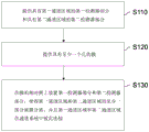
Fig. 1 shows a flow diagram of a method for producing a detection system for biomolecules according to an exemplary embodiment of the present invention. The method comprises the following steps:
-providing S110 a first detector portion having a first channel area and a second detector portion having a second channel area;
-providing an S120 membrane having at least one pore; and
-arranging S130 the first detector section and the second detector section on opposite sides of the membrane such that at least a part of the first channel area and the second channel area are separated by the membrane and such that the first channel area and the second channel area are connected to each other to form a channel system, thereby forming a flow route for the medium through the at least one aperture of the membrane.
It should be understood that this list is not meant to be in any order. The above-described production steps can be carried out independently of one another or in parallel. Membrane bioreceptors are formed on the membrane along a flow path, and the concentration of biomolecules in a medium is determined by measuring the flow (e.g., resistance) along the flow path.
Fig. 2 shows the basic measurement principle using a membrane 120 with at least one aperture 110. For example, the pores 110 are nanochannels (e.g., may be only a few nanometers or less than 100nm) having (maximum) diameters of less than 1 micron. For example, the film 120 is a single-hole plastic film.
A cross-sectional view through the aperture 110 is shown on the left side of fig. 2, wherein biological receptors 112 are attached or formed within the aperture 110. These bioreceptors 112 are designed such that the molecules 114 (biomolecules or analyte molecules) to be detected bind or bind to them when an ionic current 130 is formed through the membrane 120 (see the right side of fig. 2). For example, the ion current 130 may be generated by an electric field acting on charged ions in the ion current 130. By coupling and/or binding biomolecules 114 to biological receptors 112, the resistance of the ionic current 130 passing through the pore 110 changes. This change can be measured by electrical measurement.
Fig. 3A shows an exemplary detection system based on the measurement principle described in fig. 2, wherein by way of example the structure of an electrochemical measurement cell with a single-hole plastic film 120 is shown. The current-voltage characteristic (I/U characteristic) that can be measured in this manner is shown in fig. 3B, the change in the characteristic being caused by the analyte concentration in the medium 50. Thus, the binding of analyte/ligand molecules 112+114 to functionalized nanopore 110 can be determined using (qualitative) I/U measurements.
Specifically, the detection system includes a first channel region 215 and a second channel region 225 between which the membrane 120 is disposed (see fig. 3A). Although the present invention is not intended to be so limited, it should be understood that the first and second channel regions 215,225 typically represent portions of a channel system through which the media 50 moves. For example, the medium may be an electrolyte (e.g. 0.1M KCl, M ═ mol/L), with or without biomolecules. The measurement device may also include an electrolyte reservoir that is divided into two halves 215,225 by the membrane 120. The membrane 120 may comprise one or more nanochannels 110 as pores, which may be derivatized on a surface with covalently bound receptor molecules 112. The covalently bound receptor molecules 112 may alternatively (almost) be present anywhere on the membrane 120. The receptor 112 is capable of selectively and high affinity binding of a biomolecule (analyte, ligand) 114, whereby the electrical resistance of the nanochannel 110 increases as a function of the concentration of the ligand molecule 114.
The medium 50 contains ions (e.g., as part of an electrolyte) and biomolecules 114 to be detected, which may also be (but need not be) ions. There is also a first electrode 315 in the first channel region 215 and a second electrode 325 in the second channel region 225. By applying a voltage U between the first electrode 315 and the second electrode 325, a current I flows through the nanochannel 110 (see fig. 2). The current I causes the biomolecule 114 to bind to the receptor molecule 112 in the pore 110 and, as described above, changes the resistance, which is based on the number of biomolecules 114. The more biomolecules 114 present, the more potentially remaining in the pores 110, thereby reducing their cross-section, which is available for the ion current 130.
The change in resistance can be determined by measuring the current voltage. The corresponding characteristic is shown in fig. 3B. Two characteristic curves are shown as examples. The first characteristic curve 310 shows the measured current I as a function of the applied voltage U when no biomolecules 114 are present in the medium 50. The second characteristic 320 shows the current-voltage dependence when there are more biomolecules 114 in the medium 50. As shown, the current I decreases at a given voltage U as a result of the biomolecules 114, which is a result of the increased resistance through the pores 110.
As mentioned initially, a corresponding functionalization of the membrane is required, wherein the corresponding biological receptors 112 are attached within the pores 110, so that the membrane is highly sensitive to the specific molecule to be detected. The hole(s) themselves may also be created during the functionalization process.
Fig. 4 illustrates an exemplary functionalization. First, the generation of carboxylic acid/carboxylic acid end groups is performed on the pore surfaces by irradiation and etching processes. This can be carried out, for example, in the three steps (i) to (iii) shown. For example, in a first step (i), the membrane 120 is irradiated with heavy ions, so that the ions are able to enter the membrane 120 and penetrate the entire membrane 120, thereby creating openings or at least breaking chemical bonds there. The second step (ii) is an etching step which causes the ion trajectories to widen and causes the tapered holes 110. Finally, a carboxylic acid end group may be formed on the surface of the pore 110, which is sensitive to the molecule 114 to be detected, or which serves or may serve as an anchor point for a receptor linked to the molecule 114 to be detected.
The surface properties can be modulated by covalent attachment of different receptor molecules 112, such as aptamers (DNA/RNA). According to Ali et al (Ali M, Nasir S, Ensinger W.2015.bioconjugation-induced inductive coupling in aptamer-modified single cylindrical nanopores. chem Commun51:3454-3459), coupling can be carried out by a two-step reaction with 1-ethyl-3- (3-dimethylaminopropyl) carbodiimide (EDC) and sulfo-NHS (N-hydroxysulfosuccinimide). The mechanism of the reaction for linking biological receptors 112 (e.g., aptamers) to surface carboxylic acid/carboxylic acid groups via EDC/NHS coupling chemistry can be achieved as follows:

according to an exemplary embodiment of the present invention, the reaction takes place in a microfluidic system, the construction and production of which is explained in more detail below.
First step (activation): here the carboxyl end groups were activated by esterification of NHS with EDC. An O-acylated urea intermediate is initially formed, which is converted to the amine-reacted NHS ester. For this purpose, the membrane 120 is integrated into a microfluidic system. The system was then filled with a freshly prepared aqueous solution (pH 7) of 0.2mM EDC and 0.4mM NHS. Activation of the surface of the pores 110 is completed after one hour.
Second step (amidation): this is where the functionalization with the receptor molecule 112 (aptamer) takes place, whose chemical structure comprises at least one primary amino group (-NH)2). The amino group reacts with the activated carboxylic acid ester at room temperature to form an amide bond (- (C ═ O) -NH-). For this purpose, the microfluidic system was filled with 0.1mM aqueous solution of the receptor molecule 112 (aptamer) and allowed to stand overnight.
Successful functionalization was confirmed by measuring the current-voltage characteristic, since the current intensity is different at the same potential for the non-functionalized and functionalized pores 110. This sensing principle has been explained with figures 2 and 3.
The following molecules will be used as PSA-specific aptamers as biological receptors 112:
RNA aptamer (ref: Jeong S, Han SR, Lee YJ, Lee SW.2010.selection of RNAampramers specific to active protate-specific antigen.Biotechnol Lett 32:379-385) sequence (5 '-3'): NH (NH)2-C6-CCGUCAGGUCACGGCAGCGAAGCUCUAGGCGCGGCCAGUUGC-OH
DNA aptamer-01 (ref: Savory N, Abe K, Sode K, Ikebukuro K.2010.selection of DNA aptamer against protein specific antigen using genetic algorithm and application to sensing. biosensors Bioelectron 26: 1386-: NH (NH)2-C6-TTTTTAATTAAAGCTCGCCATCAAATAGCTTT-OH
DNA aptamer-02 (ref: Duan M, Long Y, Yang C, Wu X, Sun Y, Li J, Hu X, LinW, Han D, Zhao Y, Liu J, Ye M, Tan W.2016.selection and transfer-hybridization of DNA aptamer for measuring pro state registration and tissue imaging. Oncotarget 7:36436-36446) sequence (5 '-3'): NH (NH)2-C6-ACGCTCGGATGCCACTACAGGTTGGGGTCGG GCATGCGTCCGGAGAAGGGCAAACGAGAGGTCACCAGCACGTCCATGAG-OH
The sensing properties of the functionalized (single-hole) plastic film 120 may be tested in macro cells. For this purpose, an exemplary single-hole plastic film 120 may be used, which is manually clamped between the two liquid chambers 215,225 before each test. The advantageous single-hole plastic film 120 is difficult to produce. In contrast, the apertured plastic film may be mass produced. However, they are less sensitive than single wells.
To combine the advantages of both membranes, the wetted area of the porous membrane 120 is reduced to such an extent that the individual pores remain in contact with the liquid. This is achieved by integration into a microsystem, thereby enabling untrained users to use the detection system.
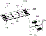
Fig. 5 shows one possible embodiment of a detection system comprising two detector areas 500A and 500B, which may be used for different analyses (detection of different biomolecules). Each of the two detector regions 500A,500B includes three connecting electrodes 510, one electrolyte inlet 520, and two analyte inlets 530. For example, the analyte is the medium 50 to be tested with the biomolecule 114 (analyte), and the electrolyte may be any liquid that contains ions (to support an electrical current) and does not falsify the result.
In the microfluidic system of fig. 5, between the channels for electrolyte molecules and biomolecules 114, a porous plastic film 120 is integrated. All the individual parts are bonded together by an adhesive layer. The microfluidic system may be integrated into an electronic measurement system in the form of a bench-top device.
The right side of fig. 5 shows an enlarged second detector area 500B, forming a membrane 120 between two analyte inlets 530 and a channel 521 leading to an associated electrolyte inlet 520. It goes without saying that all inlets may also be outlets. All that is required is reverse flow. Thus, analyte inlet 530 and electrolyte inlet 520 may also represent respective outlets. The present invention is not intended to be limited to a particular flow direction. For example, there is a fluid connection between two analyte inlets 530 and one side of the membrane 120. For example, the opposite side of the membrane 120 may be fluidly connected with the electrolyte inlet 520. In addition, electrodes are formed in analyte inlet 530, each of which is connected to one of connecting electrodes 510. Electrodes are also formed in the electrolyte inlet 520 and connected to one of the connection electrodes 510. Between an electrode in the electrolyte inlet 520 and one of the electrodes in the analysis inlet 530, a voltage is applied in a targeted manner, resulting in a current flow of the analyte 50+114 from the respective inlet 530 to the electrolyte inlet 520.
The membrane 120 is designed such that, for example in a horizontal direction, analyte flow from one of the analyte inlets 530 occurs, for example in a vertical direction, across the membrane 120 to the channel 521, which leads to the electrolyte inlet 520. Such a flow can be generated vertically downward or vertically upward by applying a voltage to the respective electrodes. The mode of operation of the detection system is further explained below by means of a representation of the product. Due to the multiple analyte inlets 530, different measurements (e.g., for different biomolecules 114) may be performed in parallel or in series. In this way, different analyte inlets 530 may be directed to different regions of the membrane 120, with different regions being functionalized differently, thereby allowing for parallel analysis of different biomolecules 114.
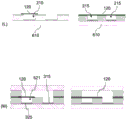
Fig. 6A through 6M illustrate various production steps of an exemplary detection system, as shown in fig. 5.
Fig. 6A to 6C first show the production of the electrode. For this purpose, a photoresist layer 620 is applied in segments on a substrate 610, for example a glass substrate. Subsequently, an intermediate layer (e.g., chromium layer) 630 and an electrode layer 640 (e.g., silver layer) are deposited on the photoresist layer 620 and the exposed glass substrate portion 610. The deposition may be performed by Physical Vapor Deposition (PVD), such as by sputtering or vapor deposition. Finally, the photoresist layer 620 is removed along with the exemplary chromium and silver layers formed thereon to form a glass substrate 610 with structured electrodes 315, 325, as shown in fig. 6C. The electrodes may represent, for example, the first electrode 315 and/or the second electrode 325.
Fig. 6D to 6F show another method of forming an electrode. Here, too, an exemplary intermediate layer 630 (e.g., a chromium layer) is first applied to the substrate 610 and an electrode layer 640, which in this exemplary embodiment may comprise gold, is applied thereon. These layers may be applied on the substrate 610 in regions. Structuring is then performed, i.e., the exemplary gold and chromium layers 630, 640 are removed in different areas, leaving only the electrodes 315, 325 in sequence.
The electrode structure produced in this way can also be seen in fig. 5, where various connecting electrodes 510 are connected to electrodes in respective inlets 520, 530 for electrolyte and analyte. The electrodes may in turn represent the first electrode 315 and/or the second electrode 325.
Fig. 6G to 6M show the generation of the detection system. According to an exemplary embodiment, the first detector portion 210 and the second detector portion 220 are created (see FIG. 6I) and then combined together to form a detection system. For this purpose, channel structures are formed in the first detector portion 210 and the second detector portion 220, which ultimately represent channels for analytes and/or electrolytes.
In fig. 6G, the substrate 610 with the first electrode 315 and the second electrode 325 formed thereon can first be seen as an embodiment on the left, which is how it is generated can be seen in the steps of 6A to 6F. This may later become the first detector portion 210. The second detector portion 220 is created on the right side of fig. 6G, with the substrate 610 again shown first. Next, a bonded dielectric layer 660 is formed over the illustrated portion. For example, the bonded dielectric layer 660 may be of a titanium material and may have an exemplary thickness of 0.5 microns.
In the production step of fig. 6H, a mask layer 670 (e.g., a dry resist made of epoxy) is applied on the structure of fig. 6G.
In a subsequent production step of fig. 6I, the mask layer 670 is structured, the mask layer 670 being removed at the location of the electrodes 315, 325 in the first detector portion 210 and in a central region of the second detector portion 220. As a result, the first and second electrodes 315 and 325 in the first detector portion 210 and the substrate 610 in the second detector portion 220 are exposed. The properties of the resulting channel, in particular the hydrophilicity, can be modified by the coating.
The results are shown in the spatial representation of fig. 6J. Thus, for example, as shown in FIG. 5, a plurality of electrodes are formed in the first detector portion 210.
In fig. 6K, a bonding layer 680 (e.g., an adhesive dielectric layer or laminate layer, particularly a dry epoxy laminate layer) is implemented in the structure of fig. 6I as an example.
In the following step (see fig. 6L), a film 120 is applied to the structure resulting from fig. 6K. According to an embodiment, the film 120 may be applied, for example, over the entire area and thermally laminated (at about T ═ 65 ℃); see the right side of fig. 6L. It also only needs to be partially applied (see left side of fig. 6L) with the porous membrane 120 located between the channels or channel extents and then heat laminated.
If the film 120 is applied over the entire area of the structure of fig. 6K (see right side of fig. 6L), the film 120 will then be structured or removed, for example at those segment locations where the first detector portion 210 and the second detector portion 220 (see fig. 6M) should then be connected between the channel regions (e.g., the first and second channel regions 215, 225). Finally, the first detector portion 210 and the second detector portion 220 are placed on top of each other, such that the (structured) film 120 is arranged between the first detector portion 210 and the second detector portion 220. Finally, the resulting detector can be laminated to connect all layers together and seal them impermeably.
The channel regions 215,225 shown in fig. 6M represent, for example, a fluid connection between the analyte inlet 530, through the membrane 120, to the electrolyte inlet 520 through the channel 521 (see fig. 5). For example, the first electrode 315 is formed below the analyte inlet 530 in fig. 5, and for example, the second electrode 325 is an intermediate electrode that leads to the electrolyte inlet 520 via a channel 521.
According to an exemplary embodiment, the above-described functionalization of the membrane 120 is performed (e.g., during the production step of fig. 6M).
Fig. 7A, B show a complete detection system according to an exemplary embodiment of the present invention.
The exemplary embodiment in fig. 7A shows a detection system with a membrane 120 formed between a first detector portion 210 and a second detector portion 220, in particular (e.g. more than 50% or more than 80%) in only one detection region 125, where it separates a first channel region 215 and a second channel region 225 (except for the support surface for fixation).
As illustrated in fig. 6, the first detector portion 210 and the second detector portion 220 each include a substrate 610a, 610b with all additional layers formed therebetween. The second detector portion 220 may also be produced without a substrate. Starting from the first detector portion 210, an adhesive dielectric layer 660a is first formed on the corresponding substrate 610a (see fig. 6G-6I), a mask layer 670a is formed on the adhesive dielectric layer, and an adhesive layer 680a is formed thereon. Under the substrate 610b of the second detector section 220, an adhesive dielectric layer 660b is first applied in sequence, including a mask layer 670b to which an adhesive layer 680b is applied in sequence.
In addition, the first electrode 315 and the second electrode 325 are formed on the substrate 610a of the first detector portion 210 (see fig. 6A-C). Thus, by forming the flow path 130 through the membrane 120 between the first electrode 315 and the second electrode 325, which triggers a current when a voltage is applied between the first electrode 315 and the second electrode 325, the resistance through the pores (not shown in FIG. 7A) can be measured and used to determine the concentration of the biomolecule 114 in the medium 50.
The only difference between the exemplary embodiment of fig. 7B and the exemplary embodiment of fig. 7A is that the membrane 120 is removed (when it is disposed) between the first detector portion 210 and the second detector portion 220 only at the point where the flow path 130 starts from the first electrode 315 towards the membrane 120 out of the first detector portion 210 and into the second detector portion 220. In addition, the film 120, particularly between the adhesive layers 680a, b formed as part of the first and second detector portions 210,220, remains.
Thus, in the exemplary embodiment of fig. 7B, the first adhesive layer 680a is at least partially or predominantly separated from the second adhesive layer 680B by the membrane 120-in particular also outside the detection zone 125.
Advantageous aspects of exemplary embodiments of the present invention relate in particular to the following:
a large/full-surface aperture plastic film 120 integrated in the lab-on-a-chip system between the two fluidic channels 215,225 (e.g. in a batch process).
Removal of the membrane 120 in the region of the fluid channels 215,225 by laser cutting, X-ray urography (xrurograph) or etching (see right side of fig. 6L, 6M).
The used hole membrane 120 comprises a conical hole 110 with a reproducible geometry.
The adhesive layer 680 is used to integrate the aperture 110 and the dysfunctional (closed) aperture. Statistically, only one hole is in contact with the electrolyte. By means of the perforated plastic film, a high sensitivity of the single-hole plastic film 120 is achieved.
The functionalization of the wells 110 is performed after the production of the chip, but can also be performed before the functionalization.
Compared with pre-functionalized pores, functionalization after chip production has the following advantages:
after integration, only a small number of receptor molecules 112 are required for the functionalization of the porous plastic film 120.
By integrating pre-functionalized pores, it is possible to contaminate or block the pores.
The exemplary embodiments also provide the following advantages:
new systems have the potential to be extended to micro total analysis systems (μ TAS). This makes it possible to detect several ligand molecules 114 simultaneously.
The sensitivity of the microsystem is comparable to a single well measurement.
The conventional adhesive layer is a liquid UV adhesive. This can lead to clogging of the pores and thus is not suitable for pore integration or functionalization. With the aid of these conventional methods, the impermeability of the system cannot be guaranteed. The functionalization of the membrane is also destroyed by exposure to UV. In contrast, in the exemplary embodiment of the present invention, the perforated plastic film 120 is thermally integrated (at T ═ 65 ℃).
The perforated plastic film used can be functionalized both before and after integration. The yield of the method can reach 100%.
A channel width of 50 microns, which corresponds to 2,500 μm, can be used2The wetted area of (c). The wetted area can be further reduced to 100 μm2. In the conventional process, only 31416 μm is obtained2The wetted area of (c).
The functional principle described so far is based on voltammetry. Other measurement principles are used in further exemplary embodiments.
These are, for example:
(i) flow measurement through the orifice 110;
(ii) measuring impedance; and
(iii) electric measurement (electrophoresis, electroosmosis, etc.)
Ultimately, however, these measurement principles also measure the resistance that impedes passage of the biomolecules 114 through the pores 110. Only the measured variable changes under the following conditions: in (i) the fluid velocity of the medium 50; in (ii) electrical impedance; in (iii) electrokinetic amount.
Exemplary embodiments of the present invention enable concentration measurements with greater selectivity and sensitivity than currently available analytical methods, as compared to current methods that detect individual analyte/ligand molecules in a complex manner. Different ligands in biological and non-biological systems can be detected with it. The biological feed comprises the following organisms and components thereof:
low molecular weight organic and inorganic compounds of any kind
-environmental toxins
-agrochemicals
-hormones
-proteins
-antibiotics
-neurotoxins
-bacteria
-viruses
Parasites of formula (I)
The present invention makes it possible to integrate nanosensors into a mass-producible lab-on-a-chip system that can be used as a small, portable analytical system for the above-mentioned applications. This enables the measurement to be completed in a few minutes, which in the case of choice can save lives. The detection system may be used as a disposable microfluidic system for use once per individual test. Thus, the system can be mass produced.
The features of the invention disclosed in the description, the claims and the drawings may be essential for the realization of the invention alone or in any combination.
List of reference numerals
50 medium
110 holes
112 biological receptors
114 biomolecules
120 film
125 detection Range
130 fluid route
210,220 detector section
215,225 channel region
310,320 voltage characteristics
315 first electrode
325 second electrode
500A,500B detector area
510 connecting electrode
520 electrolyte inlet
521 channel
530 analyte entry port
610 matrix
620 photoresist layer
630 middle layer (for example chromium)
640 electrode layer (made of silver or gold, for example)
660 bonded dielectric layer
670 mask layer
680 bonding layer
Claims (15)
1. Method for producing a detection system for biomolecules (114) in a medium (50), comprising the steps of:
providing (S110) a first detector portion (210) having a first channel area (215) and a second detector portion (220) having a second channel area (225);
providing (S120) a membrane (120) having at least one aperture (110); and
arranging (S130) a first detector part (210) and a second detector part (220) on opposite sides of a membrane (120) such that at least a part of a first channel area (215) and a second channel area (225) are separated by the membrane (120) and such that the first channel area (215) and the second channel area (225) are connected to each other forming a channel system to form a flow path (130) for a medium (50) through at least one aperture (110) of the membrane (120),
wherein bioreceptors (112) are formed on the membrane (120) along a flow path (130) through the membrane, and the concentration of biomolecules (114) in the medium (50) is determined by measuring the flow along the flow path (130).
2. The method of claim 1, wherein the step of setting (S130) comprises:
-providing a membrane (120) on the first detector portion (210) or the second detector portion (220); then the
-removing a portion of the membrane (120) outside the detection area (125).
3. The method of claim 1 or 2, further comprising forming an adhesive layer (680) in contact with the membrane (120), the adhesive layer (680) being in contact with the membrane (120) in a manner such that at least some of the pores (110) are enclosed by the adhesive layer (680), thereby increasing the sensitivity of the membrane (120) by reducing the number of pores (110) used for flow measurement of the medium (50).
4. The method of any of the preceding claims, further comprising:
the biological receptors (112) are attached to the membrane (120) by functionalization, which is performed before or after the first detector portion (210) and the second detector portion (220) are disposed on opposite sides of the membrane (120).
5. The method according to claim 4, wherein said functionalization comprises at least the following functionalization steps:
-activating the carboxyl end groups to obtain an intermediate of the amine reaction; and
amidating the amine-reacted intermediate to form the desired biological receptor (112) on the membrane (120),
wherein the functionalization occurs in the same way in all areas of the membrane (120) or, during the functionalization, different bioreceptors (112) are formed in the pores (110) in different areas, so that the membrane (120) is sensitive to different biomolecules (114).
6. The method of any of the above claims, further comprising laminating a membrane (120) on the first detector portion (210) and/or the second detector portion (220).
7. The method according to any of the preceding claims, wherein the first detector portion (210) and the second detector portion (220) are connected to each other at opposite sides of the membrane (120) by performing a heat treatment at a temperature of at least 50 ℃ or at least 65 ℃.
8. The method according to any one of the preceding claims, wherein the concentration of the biomolecule (114) in the medium (50) is determined by at least one of the following measurements: (i) flow measurement through the at least one aperture (110), (ii) impedance measurement, and (iii) electrokinetic measurement, in particular electrophoresis or electroosmosis measurement.
9. The method according to any one of the preceding claims, wherein the biomolecule (114) comprises Prostate Specific Antigen (PSA) and the bioreceptor (112) comprises an aptamer, in particular one of the following aptamers:
d)NH2-C6-CCGUCAGGUCACGGCAGCGAAGCUCUAGGCGCG
GCCAGUUGC-OH;
e)NH2-C6-TTTTTAATTAAAGCTCGCCATCAAATAGCTTT-OH;
f)NH2-C6-ACGCTCGGATGCCACTACAGGTTGGGGTCGGGCATGCGTC
CGGAGAAGGGCAAACGAGAGGTCACCAGCACGTCCATGAG-OH。
10. detection system for biomolecules (114) in a medium (50), comprising:
a first channel region (215) and a second channel region (225) into which a medium (50) can be introduced, having a first electrode (315) and a second electrode (325);
a membrane (120) comprising at least one aperture (110) and separating a first channel region (215) from a second channel region (225) and being fluidly arranged between a first electrode (315) and a second electrode (325),
wherein the biological receptor (112) is formed on or in the well (110) and comprises in addition one of the following aptamers:
(iv)NH2-C6-CCGUCAGGUCACGGCAGCGAAGCUCUAGGCGCG
GCCAGUUGC-OH;
(v)NH2-C6-TTTTTAATTAAAGCTCGCCATCAAATAGCTTT-OH;
(vi)NH2-C6-ACGCTCGGATGCCACTACAGGTTGGGGTCGG
GCATGCGTCCGGAGAAGGGCAAACGAGAGGTCAC
CAGCACGTCCATGAG-OH,
such that the concentration of PSA in the medium (50) can be measured by measuring the resistance along the flow path (130) of the medium (50) between the first electrode (315) and the second electrode (325).
11. The detection system according to claim 10, wherein the at least one aperture (110) in the membrane (120) has a conical or cylindrical profile along the flow path (130).
12. The detection system according to claim 10 or 11, wherein the membrane comprises different receptors (112) or aptamers in different regions to enable simultaneous detection of different biomolecules (114).
13. The detection system according to any one of claims 10 to 12, wherein the first channel region (215) and/or the second channel region (225) has a maximum channel width perpendicular to the flow path (130) of up to 1mm or up to 50 microns or up to 10 microns.
14. The detection system according to any one of claims 10 to 13, further comprising an electrolyte inlet (520) at the second electrode (325) and an analyte inlet (530) at the first electrode (315) so as to enable introduction of the medium (50) in the analyte inlet (530), and an electrolyte into the electrolyte inlet (520) to reduce the amount of medium (50) required for detection.
15. Use of a detection system according to any one of claims 10 to 14 in the detection of a biomolecule (114) in a medium (50) measuring an electrical variable, wherein the electrical variable is based on the electrical resistance between an electrode (315) and a second electrode (325).
Applications Claiming Priority (3)
| Application Number | Priority Date | Filing Date | Title |
|---|---|---|---|
| DE102017114349.1A DE102017114349A1 (en) | 2017-06-28 | 2017-06-28 | Detection system and method for its production |
| DE102017114349.1 | 2017-06-28 | ||
| PCT/EP2018/065542 WO2019001952A1 (en) | 2017-06-28 | 2018-06-12 | Detection system and method for producing same |
Publications (1)
| Publication Number | Publication Date |
|---|---|
| CN111051885A true CN111051885A (en) | 2020-04-21 |
Family
ID=62620862
Family Applications (1)
| Application Number | Title | Priority Date | Filing Date |
|---|---|---|---|
| CN201880055872.4A Pending CN111051885A (en) | 2017-06-28 | 2018-06-12 | Detection system and production method |
Country Status (6)
| Country | Link |
|---|---|
| US (1) | US20210114023A1 (en) |
| EP (1) | EP3646029B1 (en) |
| JP (1) | JP2020525795A (en) |
| CN (1) | CN111051885A (en) |
| DE (1) | DE102017114349A1 (en) |
| WO (1) | WO2019001952A1 (en) |
Cited By (1)
| Publication number | Priority date | Publication date | Assignee | Title |
|---|---|---|---|---|
| CN114551952A (en) * | 2021-12-31 | 2022-05-27 | 南开大学 | Single-chamber MFC reactor with ultra-micro air cathode and manufacturing method |
Families Citing this family (2)
| Publication number | Priority date | Publication date | Assignee | Title |
|---|---|---|---|---|
| CN113552332B (en) * | 2021-09-22 | 2022-04-22 | 成都齐碳科技有限公司 | Device and apparatus for sensing an analyte contained in a liquid |
| WO2024029557A1 (en) * | 2022-08-02 | 2024-02-08 | テルモ株式会社 | Separating device and separating method |
Citations (6)
| Publication number | Priority date | Publication date | Assignee | Title |
|---|---|---|---|---|
| WO2005031300A2 (en) * | 2003-06-27 | 2005-04-07 | Purdue Research Foundation | Device for detecting biological and chemical particles |
| US20050284762A1 (en) * | 2002-12-19 | 2005-12-29 | Capture Device Ab | Method and device for capturing charged molecules traveling in a flow stream |
| US20090066347A1 (en) * | 2007-09-11 | 2009-03-12 | Fraunhofer-Gesellschaft Zur Foerderung Der Angewandten Forschung E.V. | Biosensor and a method of measuring a concentration of an analyte within a medium |
| US20100243449A1 (en) * | 2009-03-27 | 2010-09-30 | Oliver John S | Devices and methods for analyzing biomolecules and probes bound thereto |
| US20110165557A1 (en) * | 2008-09-10 | 2011-07-07 | Electronics And Telecommunications Research Institute | Apparatus and method for detecting biomolecules |
| US20170108485A1 (en) * | 2014-05-22 | 2017-04-20 | University Of Notre Dame Du Lac | Integrated membrane sensor for rapid molecular detection |
Family Cites Families (8)
| Publication number | Priority date | Publication date | Assignee | Title |
|---|---|---|---|---|
| US6863833B1 (en) * | 2001-06-29 | 2005-03-08 | The Board Of Trustees Of The Leland Stanford Junior University | Microfabricated apertures for supporting bilayer lipid membranes |
| WO2006137891A2 (en) * | 2004-09-29 | 2006-12-28 | University Of Florida Research Foundation, Inc. | Membrane with nanochannels for detection of molecules |
| US8592225B2 (en) * | 2006-09-28 | 2013-11-26 | The Board Of Trustees Of The Leland Stanford Junior University | Array-based bioactivated nanopore devices |
| EP2484630B1 (en) * | 2011-02-04 | 2019-11-06 | Ecole Polytechnique | A Method for detecting and quantifying charged molecules by using in situ stripping voltammetry and use of a nanosensor |
| US9347929B2 (en) * | 2011-03-01 | 2016-05-24 | The Regents Of The University Of Michigan | Controlling translocation through nanopores with fluid wall |
| DE102011112638B4 (en) * | 2011-09-05 | 2013-11-14 | Karlsruher Institut für Technologie | Microfluidic chip with microfluidic channel system |
| DE102014209193B4 (en) * | 2014-05-15 | 2015-12-31 | Robert Bosch Gmbh | A microfluidic device for detecting cells from a fluid, method of operating such a device and methods of making such a device |
| US20180074006A1 (en) * | 2015-05-11 | 2018-03-15 | Hitachi, Ltd. | Analysis device and analysis method |
-
2017
- 2017-06-28 DE DE102017114349.1A patent/DE102017114349A1/en not_active Withdrawn
-
2018
- 2018-06-12 EP EP18731411.7A patent/EP3646029B1/en active Active
- 2018-06-12 CN CN201880055872.4A patent/CN111051885A/en active Pending
- 2018-06-12 US US16/627,181 patent/US20210114023A1/en not_active Abandoned
- 2018-06-12 JP JP2019572624A patent/JP2020525795A/en active Pending
- 2018-06-12 WO PCT/EP2018/065542 patent/WO2019001952A1/en unknown
Patent Citations (6)
| Publication number | Priority date | Publication date | Assignee | Title |
|---|---|---|---|---|
| US20050284762A1 (en) * | 2002-12-19 | 2005-12-29 | Capture Device Ab | Method and device for capturing charged molecules traveling in a flow stream |
| WO2005031300A2 (en) * | 2003-06-27 | 2005-04-07 | Purdue Research Foundation | Device for detecting biological and chemical particles |
| US20090066347A1 (en) * | 2007-09-11 | 2009-03-12 | Fraunhofer-Gesellschaft Zur Foerderung Der Angewandten Forschung E.V. | Biosensor and a method of measuring a concentration of an analyte within a medium |
| US20110165557A1 (en) * | 2008-09-10 | 2011-07-07 | Electronics And Telecommunications Research Institute | Apparatus and method for detecting biomolecules |
| US20100243449A1 (en) * | 2009-03-27 | 2010-09-30 | Oliver John S | Devices and methods for analyzing biomolecules and probes bound thereto |
| US20170108485A1 (en) * | 2014-05-22 | 2017-04-20 | University Of Notre Dame Du Lac | Integrated membrane sensor for rapid molecular detection |
Non-Patent Citations (1)
| Title |
|---|
| MARIO EI KHOURY AND ET AL.: "Integration of Nanochannels for Lab-on-Chip-Systems,and Mikro-Nano-Integration" * |
Cited By (1)
| Publication number | Priority date | Publication date | Assignee | Title |
|---|---|---|---|---|
| CN114551952A (en) * | 2021-12-31 | 2022-05-27 | 南开大学 | Single-chamber MFC reactor with ultra-micro air cathode and manufacturing method |
Also Published As
| Publication number | Publication date |
|---|---|
| EP3646029B1 (en) | 2022-05-25 |
| JP2020525795A (en) | 2020-08-27 |
| DE102017114349A1 (en) | 2019-01-03 |
| US20210114023A1 (en) | 2021-04-22 |
| EP3646029A1 (en) | 2020-05-06 |
| WO2019001952A1 (en) | 2019-01-03 |
Similar Documents
| Publication | Publication Date | Title |
|---|---|---|
| KR101709762B1 (en) | Biomolecular preconcentrator integrative electrical sensor and fabrication method thereof | |
| Roychoudhury et al. | A decoupler-free simple paper microchip capillary electrophoresis device for simultaneous detection of dopamine, epinephrine and serotonin | |
| JP2006516721A (en) | Multi-layered electrochemical microfluidic sensor containing reagent on porous layer | |
| Trojanowicz | Recent developments in electrochemical flow detections—a review: part I. Flow analysis and capillary electrophoresis | |
| Xu et al. | Integration of electrochemistry in micro-total analysis systems for biochemical assays: Recent developments | |
| US20090178935A1 (en) | Miniaturised Biosensor with Optimized Amperometric Detection | |
| US7777476B2 (en) | Dynamic modulation for multiplexation of microfluidic and nanofluidic based biosensors | |
| JP4809983B2 (en) | Apparatus and method for detecting interaction between biopolymer and ligand | |
| Rahong et al. | Recent developments in nanowires for bio-applications from molecular to cellular levels | |
| Lin et al. | Urine analysis in microfluidic devices | |
| JP2005501231A (en) | Microfluidic chemical assay apparatus and method | |
| JP2008519969A (en) | Microfluidic device with minimization of ohmic resistance | |
| JP2006516721A5 (en) | ||
| KR101575056B1 (en) | Protein preconcentration device using capillary and fabrication method thereof | |
| CN111051885A (en) | Detection system and production method | |
| Bohn | Nanoscale control and manipulation of molecular transport in chemical analysis | |
| KR101710885B1 (en) | Protein preconcentration device using capillary and fabrication method thereof | |
| KR101218987B1 (en) | Biochip and manufacturing method thereof and method for detecting analyzed material using the biochip | |
| CN111031896A (en) | Biological fluid sensing device with PH buffered EAB sensor | |
| KR101853602B1 (en) | Single layer biomolecular preconcentrating device and fabrication method thereof | |
| KR101770557B1 (en) | Biomolecular preconcentrating device | |
| US20160178649A1 (en) | Method and system for sensing and detecting a target molecule | |
| KR101789043B1 (en) | Origami-based biosample concentration device | |
| KR101718951B1 (en) | Biomolecular preconcentration device and fabrication method thereof | |
| KR101830758B1 (en) | Sample separation device |
Legal Events
| Date | Code | Title | Description |
|---|---|---|---|
| PB01 | Publication | ||
| PB01 | Publication | ||
| SE01 | Entry into force of request for substantive examination | ||
| SE01 | Entry into force of request for substantive examination | ||
| WD01 | Invention patent application deemed withdrawn after publication | ||
| WD01 | Invention patent application deemed withdrawn after publication |
Application publication date: 20200421 |