CN110290591B - Base station, communication device, communication method, and integrated circuit - Google Patents
Base station, communication device, communication method, and integrated circuit Download PDFInfo
- Publication number
- CN110290591B CN110290591B CN201910715914.9A CN201910715914A CN110290591B CN 110290591 B CN110290591 B CN 110290591B CN 201910715914 A CN201910715914 A CN 201910715914A CN 110290591 B CN110290591 B CN 110290591B
- Authority
- CN
- China
- Prior art keywords
- bsr
- data
- uplink
- base station
- transmitted
- Prior art date
- Legal status (The legal status is an assumption and is not a legal conclusion. Google has not performed a legal analysis and makes no representation as to the accuracy of the status listed.)
- Active
Links
Images


Classifications
-
- H—ELECTRICITY
- H04—ELECTRIC COMMUNICATION TECHNIQUE
- H04W—WIRELESS COMMUNICATION NETWORKS
- H04W72/00—Local resource management
- H04W72/20—Control channels or signalling for resource management
- H04W72/21—Control channels or signalling for resource management in the uplink direction of a wireless link, i.e. towards the network
-
- H—ELECTRICITY
- H04—ELECTRIC COMMUNICATION TECHNIQUE
- H04W—WIRELESS COMMUNICATION NETWORKS
- H04W76/00—Connection management
- H04W76/10—Connection setup
- H04W76/14—Direct-mode setup
-
- H—ELECTRICITY
- H04—ELECTRIC COMMUNICATION TECHNIQUE
- H04W—WIRELESS COMMUNICATION NETWORKS
- H04W72/00—Local resource management
- H04W72/50—Allocation or scheduling criteria for wireless resources
- H04W72/54—Allocation or scheduling criteria for wireless resources based on quality criteria
- H04W72/543—Allocation or scheduling criteria for wireless resources based on quality criteria based on requested quality, e.g. QoS
Landscapes
- Engineering & Computer Science (AREA)
- Computer Networks & Wireless Communication (AREA)
- Signal Processing (AREA)
- Quality & Reliability (AREA)
- Mobile Radio Communication Systems (AREA)
Abstract
The present invention relates to a base station, a communication method, a communication apparatus, and an integrated circuit, the base station including: a receiver to receive a direct link buffer status report, BSR, from a communication device for device-to-device, D2D, communication, wherein a direct link BSR is an amount of D2D data to be transmitted from the communication device to a destination user equipment with a message to notify the base station of the amount; and a transmitter to transmit a D2D grant to the communication device, the D2D grant scheduling D2D resources for D2D data, wherein an uplink BSR is a higher priority in resource scheduling than the direct link BSR, the uplink BSR being a message informing the base station of an amount of uplink data to be transmitted from the communication device to the base station.
Description
The application is a divisional application of an invention patent application with the application date of 2015, 01, 22 and the application number of 201580013251.6 and the name of the invention being a scheduling request process of D2D communication.
Technical Field
The present invention relates to a system and method for performing a scheduling request procedure in a device-to-device communication system. The present invention also provides user equipment for performing the methods described herein.
Background
Long Term Evolution (LTE)
Currently, third generation mobile systems (3G) based on WCDMA radio access technology are being widely deployed worldwide. The first step in improving or evolving this technology requires the introduction of High Speed Downlink Packet Access (HSDPA) and improved uplink, also known as High Speed Uplink Packet Access (HSUPA), resulting in a very competitive radio access technology.
In order to prepare for further increasing user demands and to maintain competitiveness against new radio access technologies, 3GPP introduces a new mobile communication system called Long Term Evolution (LTE). LTE is designed to meet the carrier needs for high-speed data and media delivery and high-capacity voice support for the next decade. The ability to provide high bit rates is a key metric for LTE.
Work Item (WI) specifications on Long Term Evolution (LTE) called evolved UMTS Terrestrial Radio Access (UTRA) and UMTS Terrestrial Radio Access Network (UTRAN) are eventually completed as release 8(LTE release 8). LTEThe system represents an efficient packet-based radio access and radio access network that provides full IP-based functionality with low latency and low overhead. 3GPP, TR 25.913 ("Requirements for Evolved UTRA and Evolved UTRAN)",www.3gpp.org) Detailed system requirements are given in). In LTE, scalable multiple transmission bandwidths are specified, e.g., 1.4, 3.0, 5.0, 10.0, 15.0, and 20.0MHz, to achieve flexible system deployment using a given spectrum. In the downlink, Orthogonal Frequency Division Multiplexing (OFDM) -based radio frequency access is employed due to its inherent immunity to multipath interference (MPI) due to low symbol rates, the use of Cyclic Prefix (CP), and its affinity for different transmission bandwidth configurations. Single carrier frequency division multiple access (SC-FDMA) -based radio frequency access is employed in the uplink because of the improvement in wide area coverage over peak data rates provided in view of the limited transmission power of the User Equipment (UE). A number of key radio access technologies are used, including multiple-input multiple-output (MIMO) channel transmission technologies, and efficient control signaling structures are implemented in release 8 LTE.
T _ UTRAN architecture
The general architecture is depicted in fig. 1, and a more detailed representation of the T _ UTRAN architecture is given in fig. 2. The T _ UTRAN consists of one or more enodebs providing T _ UTRAN user plane (PDCP/RLC/MAC/PHY) and control plane (RRC) protocol termination to the UE. An enodeb (enb) hosts the Physical (PHY), Medium Access Control (MAC), Radio Link Control (RLC), and Packet Data Control Protocol (PDCP) layers including user plane header compression and ciphering functions. It also provides Radio Resource Control (RRC) functions corresponding to the control plane. It performs a variety of functions including radio frequency resource management, admission control (admission control), scheduling, enforcement of negotiated uplink quality of service (UL QoS), cell information broadcast, encryption/decryption of user and control plane data, and compression/decompression of downlink/uplink user plane packet headers. The enodebs are connected to each other via an X2 interface.
The eNodeB is also connected to the EPC (evolved packet core) through the S1 interface, more specifically, to the MME (mobility management entity) through the S1-MME, and to the serving gateway (S-GW) through the S1-U. The S1 interface supports a many-to-many relationship between MME/serving gateway and eNodeB. The SGW routes and forwards user data packets, while also acting as a mobility anchor for the user plane (mobility anchor) during inter-eNB handovers and as an anchor for mobility between LTE and other 3GPP technologies (terminating the S4 interface and relaying traffic between the 2G/3G system and the PDN GW). For idle state UEs, the S-GW terminates the downlink data path and triggers paging when downlink data arrives for the user equipment. Which manages and stores user equipment context, e.g. parameters of IP bearer services, network internal routing information. In case of lawful interception, it also performs replication of user traffic.
The MME is a key control node of the LTE access network. It is responsible for idle mode ue tracking and paging procedures, including retransmissions. The bearer activation/deactivation process involves the MME, which is also responsible for selecting the S-GW for the user equipment, both at initial attach and at intra-LTE handover involving Core Network (CN) node relocation. Which is responsible for authenticating the user (through interaction with the HSS). The non-access stratum (NAS) signaling terminates at the MME and is also responsible for generation of temporary identities and allocation to user equipments. It checks the authentication of the UE to camp on the Public Land Mobile Network (PLMN) of the service provider and enforces user equipment roaming restrictions. The MEE is the end point in the network for ciphering/integrity protection of NAS signaling and for security key management. The MME also supports lawful interception of signaling. The MME also provides control plane functionality for mobility between LTE and 2G/3G access networks with S3 interfaces terminating from SGSN to MME. The MME also terminates the S6a interface to the home hss (home hss) for roaming user equipment.
Component carrier structure in LTE
The downlink component carriers of the 3GPP LTE system are further divided in the time-frequency domain in so-called subframes. In 3GPP LTE, each subframe is divided into two downlink slots (slots), as shown in fig. 3, where the first isThe uplink slot contains a control channel region (PDCCH region) in the first OFDM symbol. Each subframe consists of a given number of OFDM symbols in the time domain (12 or 14 OFDM symbols in 3GPP LTE (release 8)), where each OFDM symbol spans the entire bandwidth of the component carrier. Thus, as also shown in FIG. 4, each OFDM symbol is represented by a symbol in the corresponding A plurality of modulation symbols transmitted on subcarriers.
Assuming, for example, that a multi-carrier communication system uses OFDM (e.g., as used in 3GPP Long Term Evolution (LTE)), the smallest unit of resources that a scheduler can assign is a "resource block. Defining physical resource blocks as time domain One continuous OFDM symbol and in the frequency domain
 A number of consecutive sub-carriers as exemplarily depicted in fig. 4. Thus, in 3GPP LTE (release 8), physical resource blocks are composed of
 The resource unit compositions correspond to 180kHz in the time domain and in the frequency domain (see, for example, 3GPP TS 36.211, "Evolved Universal Radio Access (E-UTRA); Physical Channels and Modulation (Release 8)," Release 8.9.0 or 9.0.0, section 6.2, available from http:// www.3gpp.org, which is incorporated herein by reference).
The term "component carrier" refers to a combination of several resource blocks. In future releases of LTE, the term "component carrier" is no longer used, instead this term is changed to "cell", which refers to a combination of downlink and optionally uplink resources. The link between the carrier frequency of the downlink resource and the carrier frequency of the uplink resource is indicated in the system information transmitted on the downlink resource.
Further improvements of LTE (LTE-A)
The frequency spectrum of IMT-Advanced was determined at world conference on radio frequency communication 2007 (WRC-07). Although the total frequency spectrum of IMT-Advanced is determined, the actually available frequency bandwidth differs from region to region or country to country. However, after determining the available frequency spectrum profile, standardization of the radio interface has started again in the third generation partnership project (3 GPP). At the conference 3GPP TSG RAN #39, in 3GPP, a study item description of "further improvement of E-UTRA (LTE-Advanced)" was approved. This research project covers various technical aspects considered for the evolution of E-UTRA, e.g. to meet the requirements regarding IMT-Advanced. The following describes two main technical aspects currently considered for LTE-a.
Carrier aggregation in LTE-A supporting wider bandwidths
The bandwidth that the LTE-Advanced system can support is 100MHz, and the LTE system can support only 20 MHz. At present, the lack of radio frequency spectrum has become a bottleneck for the development of wireless networks, so it is difficult to find a sufficiently wide spectrum band for the LTE-Advanced system. Therefore, it is desirable to find a way to obtain a wider radio frequency spectrum band, wherein the possible answer is the carrier aggregation function.
In carrier aggregation, two or more Component Carriers (CCs) are aggregated to support a wider transmission bandwidth up to 100 MHz. Several cells in an LTE system are aggregated into one wider channel in an LTE-Advanced system, which is wide enough for 100MHz, although the cells in LTE are in different frequency bands. A UE may receive or transmit on one or more CCs simultaneously, depending on its capabilities:
a release 10UE with reception and/or transmission capability for CA is capable of receiving and/or transmitting simultaneously on a plurality of CCs corresponding to a plurality of serving cells;
release 8/9 UEs are only able to receive on a single cell CC and transmit on a single CC corresponding to the serving cell.
Carrier Aggregation (CA) is supported for both adjacent and non-adjacent CCs, where the mathematics of release 8/9 is used, each CC being limited to a maximum of 110 resource blocks in the frequency domain.
The UE can be configured to aggregate different numbers of CCs originating from the same eNB and possibly having different bandwidths in UL and DL.
A 3GPP LTE-a (release 10) compatible with user equipment can be configured to aggregate different numbers of component carriers originating from the same eNodeB (base station) and possibly having different bandwidths in the uplink and downlink. The number of downlink component carriers that can be configured depends on the downlink aggregation capability of the UE. Conversely, the number of uplink component carriers that can be configured depends on the uplink aggregation capability of the UE. Mobile terminals with more uplink component carriers than downlink component carriers cannot be configured.
In a typical TDD deployment, the number and bandwidth of each component carrier in the uplink and downlink are the same. Component carriers originating from the same eNodeB need not provide the same coverage.
The component carriers should be LTE release 8/9 compatible. However, existing mechanisms (e.g., barring) may also be used to avoid camping of a certain component carrier by a release 8/9 UE.
The spacing between the center frequencies of adjacent aggregated component carriers should be a multiple of 300 kHz. This is for compatibility with the 100kHz frequency raster of 3GPP LTE (release 8/9), while maintaining orthogonality with subcarriers having a 15kHz spacing. Inserting a small number of unused subcarriers between adjacent component carriers helps to form an n × 300kHz spacing, depending on the aggregation situation.
Only aggregated characteristics of the multiple carriers are exposed to the MAC layer. For both uplink and downlink, there is one HARQ entity required in the MAC for each aggregated component carrier. There is at most one transport block per component carrier (in case SU-MIMO for uplink does not exist). It is necessary to map the transport block and its possible HARQ retransmissions to the same component carrier.
The layer 2 structure with activated carrier aggregation is described in fig. 5 and 6 for the downlink and uplink, respectively. Transport channels are described between MAC and layer 1 and logical channels are described between MAC and RLC.
When Carrier Aggregation (CA) is configured, the UE has only one RRC connection with the network. One serving cell provides NAS mobility information (e.g., TAI) at RRC connection setup/re-setup/handover and one serving cell provides security input at RRC connection re-setup/handover. This cell is called the primary cell (PCell). In the downlink, a carrier corresponding to the PCell is a downlink primary component carrier (DL PCC), and in the uplink, it is an uplink primary component carrier (UL PCC).
Depending on the UE capabilities, secondary cells (scells) may be configured to form a set of serving cells with the PCell. In the downlink, the carrier corresponding to the SCell is a downlink secondary component carrier (DL SCC), and in the uplink, it is an uplink secondary component carrier (UL SCC).
Thus, a set of serving cells configured for a UE always consists of one PCell and one or more scells:
for each SCell, the UE may configure the use of uplink resources in addition to downlink resources (hence the number of DL SCCs configured is always greater than or equal to the number of UL SCCs, and for the case of using only uplink resources, the SCell cannot be configured);
from the UE perspective, each uplink resource belongs to only one serving cell;
the number of serving cells that can be configured depends on the aggregation capability of the UE;
the PCell can only be changed by handover procedures (i.e. by security key change and RACH procedures);
-using PCell for transmission of PUCCH;
-unlike SCell, PCell cannot be deactivated;
-triggering re-establishment when PCell experiences rayleigh fading (RLF), and not triggering re-establishment when SCell experiences RLF;
-acquiring non-access stratum (NAS) information from a downlink PCell;
the RRC may perform configuration and reconfiguration of the component carriers. Activation and deactivation is achieved via the MAC control element. At intra-LTE handover, RRC may also add, remove, or reconfigure scells for use in the target cell. The reconfiguration, addition, and removal of scells may be performed by RRC. The RRC may also add, remove, or reconfigure scells used with the target PCell at intra-LTE handover. When a new SCell is added, all required system information for the SCell is sent using dedicated RRC signaling, i.e., when in connected mode, the UE does not need to acquire broadcasted system information directly from the SCell.
When configuring a user equipment using carrier aggregation, there is a pair of always active uplink and downlink component carriers. The downlink component carriers in the pair may also be referred to as "DL anchor carriers". The same applies to the uplink.
When carrier aggregation is configured, the user equipment may be scheduled simultaneously over multiple component carriers, but at most one random access procedure will be running at any time. Cross-carrier scheduling allows a PDCCH of a component carrier to schedule resources on another component carrier. For this purpose, one component carrier identification field (referred to as CIF) is introduced in each DCI format.
When there is non-cross-carrier scheduling, the linking between uplink and downlink component carriers allows the identification of the uplink component carrier to which it is granted. One-to-one linking of downlink component carriers to uplink component carriers is not necessarily required. In other words, more than one downlink component carrier may be linked to the same uplink component carrier. Meanwhile, one downlink component carrier can be linked to only one uplink component carrier.
LTE RRC state
Two main states in LTE will be mainly described below: "RRC _ idle" and "RRC _ connected".
In RRC _ idle, the radio is not active, but the network assigns an ID to it and keeps track of it. More specifically, the mobile terminal in RRC _ idle performs cell selection and reselection-in other words, it decides which cell to camp on. The cell (re) selection process takes into account the priority of each available frequency, the radio link quality, and the cell condition (i.e., whether a cell is barred or reserved) for each available Radio Access Technology (RAT). The RRC _ idle mobile terminal monitors a paging channel to detect an incoming call and acquires system information. The system information mainly consists of parameters according to which the network (E-UTRAN) can control the cell (re) selection process. RRC specifies control signaling, i.e., paging and system information, that can be used for the mobile terminal in RRC _ idle. The behaviour of RRC _ idle mobile terminals is specified in TS 25.912, e.g. chapter 8.4.2, which is incorporated herein by reference.
In RRC _ connection, the mobile terminal has the ability to use active radio frequency operation in the environment in the eNodeB. The E-UTRAN allocates radio frequency resources to the mobile terminals to facilitate the delivery of (unicast) data via the shared data channel. To support this operation, the mobile terminal monitors an associated control channel indicating a dynamic allocation of shared transmission resources in terms of time and frequency. The mobile terminal provides its buffer status, downlink channel quality, and reports of neighbor cell measurement information to the network to enable the E-UTRAN to select the most appropriate cell for the mobile terminal. These measurement reports include cells using other frequencies or RATs. The UE also receives system information, which is mainly composed of information required to use a transmission channel. To extend its battery life, a UE in RRC _ connected may be equipped with one Discontinuous Reception (DRX) cycle. RRC is the protocol by which E-UTRAN controls the UE behavior in RRC _ connection.
Logical and transport channels
The MAC layer provides a data transfer service to the RLC layer through a logical channel. The logical channel is a control logical channel carrying control data such as RRC signaling or a traffic logical channel carrying user plane data. Broadcast Control Channel (BCCH), Paging Control Channel (PCCH), Common Control Channel (CCCH), Multicast Control Channel (MCCH), and Dedicated Control Channel (DCCH) are all control logical channels. Dedicated Traffic Channels (DTCH) and Multicast Traffic Channels (MTCH) are traffic logical channels.
Data from the MAC layer is exchanged with the physical layer through a transport channel. Depending on how the data is transmitted wirelessly, the data is multiplexed to the transport channel. The transport channels are classified as downlink or uplink as follows. The Broadcast Channel (BCH), downlink shared channel (DL-SCH), Paging Channel (PCH) and Multicast Channel (MCH) are downlink transport channels, and the uplink shared channel (UL-SCH) and Random Access Channel (RACH) are uplink transport channels.
Thus, multiplexing is performed between logical channels and transport channels in the downlink and uplink, respectively.
To inform the scheduled users of their allocation status, transport format, and other data related information (e.g., HARQ information, Transmit Power Control (TPC) commands), L1/L2 control signaling is transmitted on the downlink along with the data. Assuming that the user allocation can be changed on a subframe-by-subframe basis, downlink data is multiplexed in the subframe together with L1/L2 control signaling. It should be noted that the user allocation may also be performed in TTIs (transmission time intervals), where the TTI length is a multiple of a subframe. The TTI length may be fixed for all users in a service area, may be set differently for different users, or may even be set dynamically for each user. In general, L1/L2 control signaling need only be transmitted once per TTI.
L1/L2 control signaling is transmitted on the Physical Downlink Control Channel (PDCCH). The PDCCH carries a message as Downlink Control Information (DCI), which includes resource assignment and other control information for a mobile terminal or a group of UEs, and a plurality of PDCCHs may be transmitted in one sub-frame.
It should be noted that in 3GPP LTE, an assignment for uplink data transmission (also referred to as an uplink scheduling grant or uplink resource assignment) is also transmitted on the PDCCH.
For scheduling grants, information transmitted on L1/L2 control signaling can be classified into the following two classes, Shared Control Information (SCI) carrying Cat 1 information and Downlink Control Information (DCI) carrying Cat 2/3 information.
Shared Control Information (SCI) carrying Cat 1 information
The shared control information part of the L1/L2 control signaling contains information (indication information) related to resource allocation. Generally, the shared control information contains the following information:
-a user identity indicating the user of the allocated resource.
-RB allocation information indicating the resources (resource blocks (RBs)) according to which users are allocated.
The duration of the assignment (optional), if an assignment over multiple sub-frames (or TTIs) is possible.
The shared control information may also contain information such as ACK/NACK information for uplink transmission, uplink scheduling information, information on DCI (resource, MCS, etc.) depending on the setting of other channels, and depending on the setting of Downlink Control Information (DCI) (see description below).
Downlink Control Information (DCI) carrying Cat 2/3 information
The downlink control information part of the L1/L2 control signaling contains information related to the transmission format of data transmitted to the scheduled user indicated by the Cat 1 information (Cat 2 information). When (hybrid) ARQ is used as the retransmission protocol, Cat 2 information carries HARQ (Cat 3) information. The users scheduled according to Cat 1 only need to decode the downlink control information. In general, downlink control information contains information on:
-Cat 2 information: modulation scheme, transport block (payload) size or coding rate, MIMO (multiple input multiple output) related information, and the like. The transport block (or payload size) or code rate may be signaled. In any case, these parameters can be mutually calculated using modulation scheme information and resource information (the number of allocated resource blocks)
-Cat 3 information: HARQ-related information, e.g. hybrid ARQ process number, redundancy version, retransmission sequence number
Downlink control information appears in a variety of formats, which vary in overall size and also in the information contained in its fields. The different DCI formats currently defined for LTE are as follows and are described in detail in 3GPP TS 36.212 ("Multiplexing and channel coding", section 5.3.3.1 (available from http:// www.3gpp.org, and incorporated herein by reference)).
Format 0: DCI format 0 for transmission of resource grants for PUSCH
For further information on The DCI format and specific information transmitted in The DCI, please refer to technical standards or LTE-The UMTS Long Term Evolution-From thermal to Practice, written by Stefania Sesia, Issam Toufik, Matthew Baker, chapter 9.3, which is incorporated herein by reference.
Downlink & uplink data transmission
For downlink data transmission, L1/L2 control signaling is transmitted along with downlink packet data transmission on a separate physical channel (PDCCH). Generally, this L1/L2 control signaling contains information about:
physical resources on which data (e.g. subcarriers or subcarrier blocks in the case of OFDM, codes in the case of CDMA) is transmitted. This information allows the mobile terminal (receiver) to identify the resources on which to transmit data.
-when the user equipment is configured to have a Carrier Indication Field (CIF) in the L1/L2 control signaling, this information identifies the component carrier for which specific control signaling information is desired. This enables an assignment to be sent on one component carrier that is desired to be sent on another component carrier ("cross-carrier scheduling"). For example, the other, cross-carrier scheduled component carrier, may be a component carrier with less PDCCH, i.e., a cross-scheduled component carrier that does not carry any L1/L2 control signaling.
-a transport format for transmission. Which may be a transport block size (payload size, information bit size) of data, MCS (modulation and coding scheme) level, spectral efficiency, code rate, etc. This information, typically accompanied by resource allocation (e.g., number of resource blocks assigned to the user equipment), allows the user equipment (receiver) to identify information bit size, modulation scheme, and code rate to begin the demodulation, rate reduction matching, and decoding processes. The modulation scheme may be explicitly signaled.
Hybrid arq (harq) information:
■ HARQ process number: the user equipment is allowed to identify the HARQ process through which the data is mapped.
■ sequence number or New Data Indicator (NDI): allowing the user equipment to identify whether the transmission is a new packet or a retransmitted packet. If soft combining is implemented with the HARQ protocol, the sequence number or new data indicator plus the HARQ process number can enable soft combining for transmission of the PDU prior to decoding.
■ redundancy and/or constellation version: the user equipment is told which hybrid ARQ redundancy version (required for rate-reduction matching) was used and/or which modulation constellation version (required for demodulation) was used.
-UE identity (UE ID): telling the L1/L2 which user equipment the control signaling is directed to. In typical implementations, this information is used to mask the CRC of the L1/L2 control signaling to prevent other user equipment from reading this information.
To enable uplink packet data transmission, L1/L2 control signaling is transmitted on the downlink (PDCCH) to inform the user equipment about the transmission details. Generally, this L1/L2 control signaling contains information about:
physical resources on which the user equipment will transmit data (e.g. subcarriers or subcarrier blocks in case of OFDM, codes in case of CDMA).
-when the user equipment is configured with a Carrier Indication Field (CIF) in the L1/L2 control signaling, this information identifies the component carrier for which the specific control signaling information is intended. This enables an assignment to be sent on one component carrier for another component carrier. For example, the other, i.e., cross-scheduled component carrier may be a component carrier with less PDCCH, i.e., the cross-scheduled component carrier does not carry any L1/L2 control signaling.
-if several DL component carriers are linked to the same UL component carrier, sending L1/L2 control signaling for an uplink grant on the DL component carrier linked to the uplink component carrier or on one of the DL component carriers.
-a transport format which the user equipment shall use for transmission. Which may be a transport block size (payload size, information bit size) of data, MCS (modulation and coding scheme) level, spectral efficiency, code rate, etc. This information, typically accompanied by resource allocation (e.g., number of resource blocks assigned to the user equipment), allows the user equipment (transmitter) to identify information bit size, modulation scheme, and code rate to begin the demodulation, rate reduction matching, and decoding processes. In some cases, the modulation scheme may be explicitly signaled.
-hybrid ARQ information:
■ HARQ process number: telling the user equipment from which ARQ process the data should be selected.
■ sequence number or new data indicator: telling the user equipment to transmit a new packet or to retransmit a packet. If soft combining is implemented in the HARQ protocol, the sequence number or new data indicator plus the HARQ process number enable soft combining for transmission of a Protocol Data Unit (PDU) prior to decoding.
■ redundancy and/or constellation version: the user equipment is told which hybrid ARQ redundancy version (required for rate matching) was used and/or which modulation constellation version (required for demodulation) was used.
UE identity (UE ID): telling which user equipment should transmit data. In typical implementations, this information is used to mask the CRC of the L1/L2 control signaling to prevent other user equipment from reading this information.
There are many different possibilities how to accurately transmit the above mentioned information segments in uplink and downlink data transmission. Also, in uplink and downlink, the L1/L2 control information may also contain additional information, or may omit certain information, such as:
in case of a synchronous HARQ protocol, no HARQ process number may be needed, i.e. not signaled.
If chase combining (always the same redundancy and/or constellation version) is used or if a sequence of redundancy and/or constellation versions is predefined, the redundancy and/or constellation versions may not be needed and thus not signaled.
Power control information may also be additionally included in the control signaling.
MIMO related control information such as precoding may also be additionally included in the control signaling.
In case of a multi-codeword MIMO transmission, transport format and/or HARQ information for multiple codewords may be included.
For uplink resource assignments signaled on PDCCH in LTE (on Physical Uplink Shared Channel (PUSCH)), the L1/L2 control information does not contain HARQ process numbers, since the synchronous HARQ protocol is used for LTE uplink. HARQ processes for uplink transmission are given in time sequence. In addition, it should be noted that Redundancy Version (RV) information is encoded together with the transport format information, i.e., the RV information is embedded in the Transport Format (TF) field. For example, a Modulation and Coding Scheme (MCS) field corresponding to a Transport Format (TF) has a size of 5 bits, which corresponds to 32 items. To indicate Redundancy Version (RV)1, 2 or 3, 3 TF/MCS entries are reserved. The remaining MCS entries are used to signal the MCS level (TBS) implicitly representing RV 0. The CRC field of the PDCCH has a size of 16 bits.
For downlink assignment (PDSCH) signaled on PDCCH in LTE, Redundancy Version (RV) is signaled separately in two-bit fields. In addition, the modulation order information is encoded together with the transport format information. Similar to the uplink case, there is a 5-bit MCS field signaled on the PDCCH. Of which 3 entries are reserved to signal the modulation order, no transport format (transport block) information is provided. For the remaining 29 items, the modulation order and transport block size are signaled.
Uplink access scheme for LTE
For uplink transmission, power efficient user terminal transmission is necessary to maximize coverage. Single carrier transmission combined with FDMA with dynamic bandwidth allocation has been selected as an evolved UTRA uplink transmission scheme. The main reasons for the preference for single carrier transmission are the lower peak-to-average power ratio (PARR) compared to multi-carrier signals (OFDMA), and the corresponding improved power amplifier efficiency and assumed improved coverage (higher data rate for a given terminal peak power). During each time interval, the node B assigns unique time/frequency resources to the users for transmitting user data to ensure intra-cell orthogonality. Orthogonal access in the uplink ensures improved spectral efficiency by eliminating intra-cell interference. Interference due to multipath propagation is handled at the base station (node B) by the insertion of a cyclic prefix in the transmitted signal.
The basic physical resource for data transmission is sized BW by the time interval (e.g., 0.5ms subframe) over which the encoded information bits are mapped grant Frequency resource composition of (1). It should be noted that a subframe (also referred to as a Transmission Time Interval (TTI)) is the minimum time interval for transmission of user data. However, over a time period longer than TTI, the frequency resource BW is assigned to the user by concatenation of sub-frames grant Is possible.
Uplink scheduling scheme for LTE
The uplink scheme allows both scheduled access (i.e., controlled by the eNB) and contention-based access.
In case of scheduled access, for uplink data transmission, a certain frequency resource (i.e., time/frequency resource) for a certain time is allocated to the UE. However, certain time/frequency resources may also be allocated for contention-based access in which the UE is able to transmit without being scheduled first. For example, one case in which a UE performs contention-based access is random access, i.e., when the UE performs initial access to a cell or requests uplink resources.
For scheduled access, the node B scheduler assigns unique frequency/time resources to users for uplink data transmission. More specifically, the scheduler determines
Which UE(s) are allowed to transmit,
which physical channel resources (frequencies),
the transport format (modulation coding scheme (MCS)) used by the mobile terminal for transmission.
The allocation information is signaled to the UE via a scheduling grant sent on the L1/L2 control channel. For simplicity, the channel may also be referred to below as an uplink grant channel. The scheduling grant message contains at least information of which part of the frequency band the UE is allowed to use, the validity period of the grant, and the transport format the UE has to use for the upcoming uplink transmission. The shortest validity period is one subframe. Depending on the chosen scheme, more information may also be included in the authorization message. Only "per UE" grants are used for the right to grant transmission on the UL-SCH (i.e., there is no "per UE per RB" grant). Therefore, the UE needs to distribute the allocated resources among the radio bearers according to certain rules. Unlike in HSUPA, there is no UE-based transport format selection. The eNB decides the transport format according to certain information (e.g., reported scheduling information and QoS information) and the UE must follow the selected transport format. In HSUPA, the node B assigns the maximum uplink resources, and thus, the UE selects the actual transport format for data transmission.
Since scheduling of radio frequency resources is the most important function in determining quality of service in shared channel access networks, there are some requirements that an UL scheduling scheme for LTE should meet in order to allow efficient QoS management.
Starvation of low priority services should be avoided;
the scheduling scheme should support explicit QoS differentiation of radio bearers/services;
UL reporting should allow fine buffer status reporting (e.g. per radio bearer or per radio bearer group) to allow the eNB scheduler to identify for which radio bearer/service data is transmitted;
it should be possible to make explicit QoS differentiation between services of different users;
it should be able to provide a minimum bit rate per radio carrier.
As can be seen from the above list, an important aspect of the LTE scheduling scheme is to provide mechanisms by which some operators can control the splitting of their aggregated cell capacity between radio bearers of different QoS classes. As previously described, the QoS class of the radio bearer is identified by the QoS profile of the corresponding SAE bearer signaled from the AGW to the eNB. The operator can then allocate a certain amount of its aggregated cell capacity to the aggregated traffic associated with the radio bearers of a certain QoS class. The main purpose of using this class-based scheme is to be able to distinguish the handling of packets according to the QoS class to which they belong.
Buffer status reporting/scheduling request procedure for uplink scheduling
The usual mode of scheduling is dynamic scheduling, i.e. by a downlink assignment message for allocation of downlink transmission resources and an uplink grant message for allocation of uplink transmission resources; these are usually valid for a particular single subframe. They are transmitted on the PDCCH using the C-RNTI of the UE already mentioned above. Dynamic scheduling is effective for service types where traffic is suddenly bursty and the rate dynamically changes (e.g., TCP).
In addition to dynamic scheduling, persistent scheduling is also defined, which enables semi-statically configuring and allocating radio frequency resources to UEs with a time period longer than one sub-frame, thereby avoiding the need for specific downlink assignment messages and uplink grant messages on the PDCCH for each sub-frame. Persistent scheduling is useful for services such as VoIP where data packets are small, periodic and semi-static in size. Thus, the overhead of the PDCCH is significantly reduced compared to the case of dynamic scheduling.
Buffer status reports (BSs) from the UE to the eNodeB are used to assist the eNodeB in allocating uplink resources, i.e. uplink scheduling. For the downlink case, it is clear that the eNB scheduler knows the amount of data delivered to each UE, however, for the uplink direction, since the scheduling decisions are made at the eNB and the buffer of data is in the UE, a BSR must be sent from the UE to the eNB to represent the amount of data that needs to be transmitted over the UL-SCH.
There are basically two types of buffer status report MAC control elements (BSRs) defined for LTE: long BSR (with 4 buffer size fields corresponding to LCG IDs # 0-3) or short BSR (with one LCG ID field and one corresponding buffer size field). The buffer size field indicates the total amount of data available across all logical channels of the logical channel group and is expressed in number of bytes encoded as an index to the different buffer size levels (see also 3GPP TS 36.321, release 10.5.0, chapter 6.1.3.1, which is incorporated herein by reference). In addition, there is another type of buffer status report to use truncated data, where the buffer status report is 2 bytes long.
The UE decides which of the short or long BSRs to transmit depending on the available transmission resources in the transport block, how many logical channel groups have non-empty buffers, and whether a specific event is triggered at the UE. The long BSR reports the amount of data of 4 logical channel groups, and the short BSR indicates the amount of data buffered only for the highest logical channel group.
The reason for introducing the logical channel group concept is that although the UE may have more than 4 configured logical channels, reporting the buffer status for each single logical channel would result in excessive signaling overhead. Thus, the eNB assigns each logical channel to a logical channel group. Preferably, logical channels with the same/similar QoS requirements should be allocated in the same logical channel group.
For example, the BSR may be triggered for the following events:
-each time data arrives on a logical channel having a higher priority than a logical channel whose buffer is not empty;
-whenever data becomes available for any logical channel when there was previously no data available for transmission;
-whenever the retransmission BSR time expires;
-whenever a periodic BSR report expires, i.e. the periodic BSR timer time expires;
whenever there is room in a transport block that can accommodate one BSR.
To be able to strongly combat transmission failures, there is a BSR retransmission mechanism defined for LTE. The retransmission BSR timer is started or restarted each time the uplink grant is restarted. The UE triggers another BSR if no uplink grant is received before the retransmission BSR timer expires.
If the UE does not have uplink resources allocated for including the BSR in the Transport Block (TB), the UE transmits a Scheduling Request (SR) on a Physical Uplink Control Channel (PUCCH), if configured, when the BSR is triggered. For the case where there is no D-SR (dedicated scheduling request) resource on the configured PUCCH, the EU will initiate a random access procedure (RACH procedure) to request UL-SCH resources for transmission of BSR information to the eNB. It should be noted, however, that for the case where a periodic BSR is to be transmitted, the UE will not trigger SR transmission.
In addition, improvements to SR transmission have been introduced for specific scheduling patterns, where resources are allocated continuously with a defined periodicity to save L1/L2 control signaling overhead for transmission grants, referred to as semi-persistent scheduling (SPS). One example of a service that has been primarily considered for semi-persistent scheduling is VoIP. During talk spurt, one VoIP packet is generated every 20ms at Codec. The eNB can then allocate uplink resources continuously every 20ms or downlink resources accordingly, which are then used for the transmission of VoIP packets. Generally, SPS is beneficial for services with predictable traffic behavior (i.e., constant bit rate), where packet arrival times are periodic. For the case where SPS is configured for the uplink direction, the eNB may turn off SR triggering/transmission for specifically configured logical channels, i.e., BSR triggering due to data arrival on those specifically configured logical channels will not trigger SR. The motivation for this improvement is that reporting SR for those logical channels that will use semi-persistently allocated resources (logical channels carrying VoIP packets) is worthless for eNB scheduling and should therefore be avoided.
More detailed information about the BSR, in particular the triggering, is explained in 3GPP TS 36.321, release V10.5, chapter 5.4.5 (which is incorporated herein by reference).
Logical channel prioritization
The UE has an uplink rate control function that manages uplink resource sharing between radio frequency bearers. Hereinafter, the uplink rate control function is also referred to as a logical channel prioritization procedure. When a new transfer is performed, a Logical Channel Prioritization (LCP) procedure is used, i.e. a transport block needs to be generated. There has been a proposal for allocating capacity by assigning resources to each bearer in order of priority until each bearer has received an allocation equivalent to the minimum data rate for that bearer, and then allocating any additional capacity to the bearers, for example in order of priority.
As will be apparent from the description of the LCP procedure given below, the implementation of the LCP procedure residing in the UE is based on the token bucket model, which is well known in the IP field. The basic function of the model is as follows. Tokens representing the right to transmit a given amount of data are periodically added to the bucket at a given rate. When the UE is an authorized resource, the data is allowed to be transmitted until the number represented by the tokens in the bucket is reached. When transmitting data, the UE removes the number of tokens equal to the amount of data transmitted. In the case where the bucket is full, any further tokens are discarded. For the addition of tokens it can be assumed that the period of repetition of this process will be every TTI, but it can easily be extended so that only one token is added per second. Basically, instead of adding tokens to the bucket every 1ms, 1000 tokens can be added per second. Hereinafter, the logical channel prioritization procedure used in release 8 is described.
More detailed information on LCP procedures is explained in 3GPP TS 36.321, release 8, section 5.4.3.1 (which is incorporated herein by reference).
RRC: priority, wherein an increasing priority value represents a low priority level; a Prioritized Bit Rate (PBR) set by a Prioritized Bit Rate (PBR); bucketSizeDuration, which sets a Bucket Size Duration (BSD) to control scheduling of uplink data. The idea behind prioritized bit rates is support for each bearer, including low priority non-GBR bearers, minimum bit rate, to avoid potential starvation. Each bearer should at least get enough resources to achieve a prioritized bit rate (PRB).
The UE will maintain a variable Bj for each logical channel j. When the associated logical channel is established, Bj will be initialized to 0 and incremented for each TTI by the product PBR × duration of TTI, where PBR is the prioritized bit rate of logical channel j. However, the value of Bj can never exceed the bucket size, and if the value of Bj is greater than the bucket size of logical channel j, it is set to the bucket size. The size of the bucket of logical channels is equal to PBR × BSD, where PBR and BSD are configured by upper layers.
When a new transmission is performed, the UE will perform the following logical channel prioritization procedure:
the UE will allocate resources to logical channels in the following steps:
-step 1: all logical channels with Bj >0 are allocated resources in descending priority order. If the PBR of the radio bearer is set to "infinite", the UE will allocate resources for all data available for transmission on the radio bearer before the PBR of the low priority radio bearer is satisfied;
-step 2: the UE should reduce Bj by the entire size of the MAC SDU serving logical channel j in step 1
At this time, it must be noted that the value of Bj may be negative.
-step 3: if there are still any remaining resources, all logical channels (whichever occurs first) are served in strictly decreasing priority order (regardless of the value of Bj) until the data for that logical channel or UL grant is exhausted, whichever is exhausted first. Logical channels assigned equal priority will be served equally.
During the above scheduling procedure, the UE will also follow the following rules:
-the UE does not segment the RLC PDU (or partially transmitted SDU or retransmitted RLC PDU) if the entire SDU (or partially transmitted SDU or retransmitted RLC PDU) fits into the remaining resources;
-if the UE segments RLC PDUs from a logical channel, it will maximize the size of the segmentation to meet the grant as much as possible;
the UE should maximize the transmission of data.
For the logical channel prioritization procedure, the UE will consider the following relative priorities in descending order:
-MAC control element for C-RNTI or data from UL-CCCH;
-MAC control element for BSR, except BSR included for padding;
-a MAC control element for PHR;
-data from any logical channel, except data from UL-CCCH;
-for the MAC control element included for padding.
For the case of carrier aggregation, which is described in the following section, steps 1-3 and associated rules may be applied independently for each grant or the sum of granted capacities when the UE is required to transmit multiple MAC PDUs in one TTI. In addition, the order in which grants are processed is also left to the UE implementation. When the UE is required to transmit multiple MAC PDUs in one TTI, the decision to include the MAC control element in which MAC PDU is implemented by the UE.
Uplink power control
Uplink power control in a mobile communication system serves an important purpose: which balances the need for sufficient energy transmitted per bit to achieve the required quality of service (QoS) with the need to minimize interference to other users of the system and to maximize battery life of the mobile terminal. In achieving this, the role of Power Control (PC) becomes crucial to providing the required SINR while controlling the generated interference to neighboring cells. The idea of the conventional PC scheme in the uplink is that all users receive the same SINR as a well-known overall compensation. Instead, 3GPP has adopted the use of partial power control (FPC) for LTE. This new functionality enables users with higher path loss to operate at lower SINR requirements so that they will be more likely to generate less interference to neighboring cells.
In LTE, detailed power control equations (section 5.1 in TS 36.213) are defined for a Physical Uplink Shared Channel (PUSCH), a Physical Uplink Control Channel (PUCCH), and an acoustic reference signal (SRS). The formulation of each of these uplink signals follows the same basic principle, and in all cases they can be considered as the sum of two main terms: basic open loop operating points derived from static or semi-static parameters signaled by the eNode, and dynamic offsets that are updated on a subframe-by-subframe basis.
The basic open loop operating point for transmit power per resource block depends on a variety of factors including inter-cell interference and cell loading. It can be further divided into two parts, semi-static reference level P0, further consisting of a common power level (measured in dBm) for all UEs in the cell and a UE-specific offset; and an open loop path loss compensation section. The dynamic offset part of the power per resource block can also be further divided into two parts, depending on the part of the MCS used and the explicit transmission power control (TP) commands.
This MCS-dependent part (referred to as Δ in the LTE specification) TF Where TF stands for 'transport format') allows adapting the transmitted power per RB according to the transmitted information data rate.
Another part of the dynamic offset is the UE-oriented TPC commands. These commands can operate in two different modes: cumulative TPC commands (available for PUSCH, PUCCH, and SRS) and absolute TCP commands (available for PUSCH only). For PUSCH, the transition between the two modes is semi-statically configured for each UE through RRC signaling-i.e., the modes cannot be changed dynamically. Using the accumulated TPC commands, each TPC command signals a power step relative to the previous level.
Power headroom reporting
In order to help the eNodeB schedule uplink transmission resources to different UEs in a suitable way, it is important that the UEs are able to report their available power headroom to the eNodeB.
The eNodeB may use the power headroom report to determine how much more uplink bandwidth the UE can use per subframe. This helps to avoid allocating uplink transmission resources to UEs that are not able to use them, to avoid waste of resources.
The power headroom report ranges from +40 to-23 dB. The negative part of the range enables the UE to signal to the eNodeB that it has received a range of UL grants that would require more transmission power than the UE has available. This will enable the eNodeB to reduce the size of the subsequent grants, thereby enabling the vacation of transmission resources for allocation to other UEs.
The power headroom report may only be sent in subframes where the UE has UL grants. The report relates to the subframe in which it is sent. A number of criteria for triggering a power headroom report are defined. These criteria include:
-significant change in estimated path loss since last power headroom report
-a time more than a configured time has elapsed since a previous power headroom report
-the UE has implemented more closed-loop TCP commands than the configured number of closed-loop TCP commands
The eNodeB may configure the parameters controlling each of these triggers according to the requirements of the system loading and its scheduling algorithm. More specifically, the RRC controls the power headroom report by configuring two timers periodicPHR-Timer and prohibitpyr-Timer and by signaling dl-pathchange, which sets the change of the measured downlink path loss to trigger the power headroom report.
The power headroom report is transmitted as a MAC control element. It consists of a single 8-bit group, where the 2 highest bits are reserved and the 6 lowest bits represent the above-mentioned dB value in 1dB steps. The structure of the MAC control element is depicted in fig. 7.
The power headroom PH valid for subframe i is defined as:
PH(i)=P CMAX -{10log 10 (M PUSCH (i))+P O_PUSCH (j)+α(j)·PL+Δ TF (i)+f(i)} [dB]
the power margin will be rounded off in steps of 1dB to the range [ 40; -23] of the most recent value.
P cmax The maximum UE transmission power (Tx power) is the UE's power at a given range P CMAX_L And P CMAX_H To the selected one value.
P CMAX_L ≤P CMAX ≤P CMAX_H Wherein, in the step (A),
P CMAX_L =MIN{P EMAX -ΔT C ,P PowerClass -MPR-A - MPR-ΔT C are multiplied by
P CMAX_H =MIN{P EMAX ,P PowerClass };
And wherein P EMAX A signaled value for the network.
The MPR is a power reduction value for controlling adjacent channel leakage power ratio (ACLR) associated with various modulation schemes and transmission bandwidths.
The a-MPR is an additional maximum power reduction. It is band specific and is used when configured by the network. Thus, P CMAX Is UE-oriented and thus not known to the eNB.
The references to Δ T are described in 3GPP TS 36.101, Release 12.0.0, section 6.2.5 (which is incorporated herein by reference) C For example, more detailed information.
LTE device-to-device (D2D) proximity services
Proximity-based applications and services represent an emerging socio-technological trend. The identified areas include services of interest to operators and users related to business services and public safety. The introduction of proximity services (ProSe) capability in LTE will allow the 3GPP industry to serve this developing market, while at the same time will serve the pressing needs of the various public safety bodies that are co-entrusted to LTE.
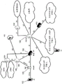
Device-to-device (D2D) communication is a technology branch for LTE-release 12. Device-to-device (D2D) communication technology allows D2D to be the basis of cellular networks to improve spectral efficiency. For example, if the cellular network is LTE, then SC-FDMA is used for D2D signaling with all data carrying physical channels. In D2D communications, User Equipments (UEs) use cellular resources to transmit data signals to each other over a direct link, rather than through a base station. A possible scenario in a D2D compliant communication system is depicted in fig. 9.
D2D communication in LTE
"D2D communication in LTE" focuses mainly on two aspects: discovery and communication, and the present invention relates primarily to the communications portion. Therefore, in the following "technical background", the communication section will be mainly described.
Device-to-device (D2D) communication is a branch of technology for LTE-a. In D2D communication, UEs transmit data signals to each other through a direct link, rather than through the BS, using cellular resources. The D2D user communicates directly while remaining under the control of the BS, i.e., at least when in the coverage of the eNB. Thus, D2D can improve system performance by reusing cellular resources.
It is assumed that D2D operates in the uplink LTE spectrum (in case of FDD) or in the uplink subframe of a cell of a given coverage (in case of TDD, except when in coverage). Additionally, D2D transmission/reception does not use full duplex on a given carrier. From a single UE perspective, it is possible that D2D signal reception and LTE uplink transmission do not use full duplex, i.e., no simultaneous D2D signal reception and LTE UL transmission, on a given carrier.
In D2D communications, when UE1 is in the transmitting role (transmitting user equipment), UE1 transmits data and UE2 (receiving user equipment) receives the data. UE1 and UE2 may change their transmit and receive roles. One or more UEs, such as UE2, may receive transmissions from UE 1.
For the user plane protocol, from the perspective of D2D communication, in the following of protocol [3GPP TS 36.843, release 12.0.0, section 9.2 ], it is reported:
-PDCP:
1. about.1: the communication data (i.e., IP packets) should be broadcast as standard user plane data processing M D2D.
Header compression/decompression in o PDCP applies to 1: m D2D broadcast communications.
■ for public safety D2D broadcast operation, U-Mode is used for header compression in PDCP.
-RLC:
Use RLC UM for 1: m D2D broadcast communications.
RLC UM supports segmentation and reassembly on L2.
Each time a companion UE is transmitted, the receiving UE needs to maintain at least one RLC UM entity.
No RLC UM receiver entity needs to be configured prior to reception of the first RLC UM data unit.
So far, for user plane data transmission, there is no need to identify RLC AM or RLC TM for D2D communication.
-MAC:
For 1: m D2D broadcast communications, assuming no HARQ feedback.
The receiving UE needs to know the source ID to identify the receiver RLC UM entity.
The MAC header contains the L2 target ID that allows the packet to be filtered out at the MAC layer.
The o L2 target ID may be a broadcast, multicast, or unicast address.
■ L2 multicast/unicast: the L2 target ID carried in the MAC header allows the received RLC UM PDU to be discarded even before it is submitted to the RLC receiver entity.
■ L2 broadcast: the receiving UE will process all received RLC PDUs from all transmitters and aim to reassemble and submit IP packets to the upper layers.
The MAC subheader contains LCID (to distinguish multiple logical channels).
For D2D, at least multiplexing/demultiplexing, priority processing, and padding are useful.
Resource allocation
In 3GPP TS 36.843, release 12.0.0, section 9.2.3 (which is incorporated herein by reference), resource allocation for D2D communication is discussed and described in its current form.
From the perspective of transmitting the UE, the UE may operate in two resource allocation modes:
-mode 1: eNodeB or Release 10 Relay node schedules the exact resources used by the UE to transmit direct data and direct control information
-mode 2: UE independently selects resources from a resource pool to transmit direct data and direct control information
A UE capable of D2D communication will support mode 1 at least for in-coverage. A UE capable of D2D communication will be directed at least to coverage edge and/or out-of-coverage support mode 2.
The in-coverage and out-of-coverage UEs need to know the resource pool (time/frequency) received for D2D communication.
All UEs (mode 1 ("scheduled") and mode 2 ("autonomous")) are configured with a pool of resources (time and frequency) in which they attempt to receive scheduling assignments.
In mode 1, the UE requests transmission resources from the eNodeB. The eNodeB schedules transmission resources for scheduling assignments and transmission of data.
The UE sends a scheduling request (D-SR or RA) to the eNodeB, which then follows a BSR from which the eNodeB can conclude that the UE wants to perform D2D transmission and the requested amount of resources.
In mode 1, the UE needs to be RRC connected to transmit D2D communications.
For mode 2, the UEs are provided with a pool of resources (time and frequency) from which they attempt to select resources for transmitting D2D communications.
Fig. 8 schematically illustrates upper (LTE) and lower (underly) (D2D) transmission and/or reception resources. The eNodeB controls the UE, deciding whether it can use mode 1 or mode 2 transmission. Once the UE knows the resources (which may transmit (or receive) D2D communications), it will only use the corresponding resources for corresponding transmission/reception, in the example of fig. 8, only D2D subframes will be used to receive or transmit D2D signals. Since the UE, as a D2D device, will operate in half duplex mode, it is able to receive or transmit D2D signals at any time. Similarly, in this figure, other subframes may also be used for LTE (upper) transmission and/or reception.
D2D discovery is a process/process to identify other devices in the vicinity that are capable of D2D communication and are of interest. To do so, a D2D device wishing to be discovered will send some discovery signal (on a particular network resource) and the receiving UE of interest in the discovery signal will be aware of such a transmitting D2D device. Chapter 8 of 3GPP TS 36.843 describes the available details of the D2D discovery mechanism. The following two types of discovery processes are defined:
type 1: a discovery procedure in which resources for discovery signal transmission are not allocated for a specific UE;
type 2: a discovery procedure in which resources for discovery signal transmission are allocated per specific UE;
omicron type 2A: allocating resources for each specific transmission instance of the discovery signal;
type 2B: resources are allocated semi-persistently for discovery signal transmission.
The current discussion of scheduling schemes for allocating D2D resources focuses mainly on how to incorporate SR/BSR signaling related to D2D into LTE-a systems, i.e., whether to reuse the LTE SR/BSR mechanism and resources (e.g., D-SR on PUCCH or PRACH resources) for D2D communication purposes. According to one scheme considered in practice, the eNodeB configures dedicated or contention-based resources in the D2D subframe or the area for performing the scheduling procedure. In other words, Scheduling Requests (SRs) and/or Buffer Status Reports (BSRs) related to D2D transmissions are sent to the eNodeB on dedicated resources on subframes dedicated for D2D transmissions. The user equipment will then only use resources in the D2D subframe/region for all D2D related transmissions, including the message for performing the scheduling procedure, i.e. SR or BSR.
This solution has the following drawbacks: radio resource management can become quite complex when the eNodeB must support resources such as PUCCH resources for dedicated scheduling requests (D-SRs) and RACH resources (contention-based SRs) in a D2D subframe or region.
Therefore, these resources also need to be signaled to the D2D capable UEs and cannot be used for D2D data discovery transmission, resulting in loss of data transmission performance. In addition, if a new PUCCH resource is to be configured in the D2D subframe, other modifications to the LTE standard (RAN 4) would be required.
Finally, to receive D-SR/PRACH/BSR from D2D UEs, the eNodeB would be required to monitor and/or receive D2D resources. Therefore, this scheme will result in overload of the eNodeB.
Summary of The Invention
To integrate D2D communication into an LTE system, certain aspects of the LTE system, e.g., procedures, spectrum for data communication, etc., need to be taken over. For example, in uplink communications, the uplink spectrum of the LTE system is also used for device-to-device communications.
The object of the present invention is to develop a method and a system that enables integration of device-to-device (D2D) communication in an LTE system in a way that requires as little changes as possible to the current system. More particularly, the present invention is directed to developing a system and method that incorporates scheduling request and Buffer Status Reporting (BSR) procedures for device-to-device communication into an LTE system.
This object is achieved by the subject matter of the independent claims. Advantageous embodiments belong to the dependent claims.
According to an aspect of the present invention, there is provided a base station including: a receiver to receive a direct link buffer status report, BSR, from a communication device for device-to-device, D2D, communication, wherein a direct link BSR is an amount of D2D data to be transmitted from the communication device to a destination user equipment with a message to notify the base station of the amount; and a transmitter to transmit a D2D grant to the communication device, the D2D grant scheduling D2D resources for D2D data, wherein an uplink BSR has a higher priority in resource scheduling than the direct link BSR, the uplink BSR being a message informing the base station of an amount of uplink data to be transmitted from the communication device to the base station.
According to an aspect of the present invention, there is provided a communication method including: receiving a direct link Buffer Status Report (BSR) from a communication device, wherein the BSR is a message informing the base station of an amount of D2D data to be transmitted from the communication device to a destination user equipment; sending a D2D grant, scheduling D2D resources for D2D data; and wherein an uplink BSR has a higher priority in resource scheduling than the direct link BSR, the uplink BSR being a message informing the base station of an amount of uplink data to be transmitted from the communication device to the base station.
According to an aspect of the present invention, there is provided a communication apparatus including: a transmitter to transmit a direct link buffer status report, BSR, for device-to-device, D2D, communication to a base station, wherein a direct link BSR is a message informing the base station of an amount of D2D data to be transmitted from the communication device to a destination communication device; and a receiver to receive a D2D grant from the base station, the D2D grant scheduling D2D resources for D2D data, wherein an uplink BSR is a higher priority in resource scheduling than the direct link BSR, the uplink BSR being a message informing the base station of an amount of uplink data to be transmitted from the communication device to the base station.
According to an aspect of the present invention, there is provided a communication method including: transmitting a direct link Buffer Status Report (BSR) to a base station, wherein the BSR is a message informing the base station of an amount of D2D data to be transmitted from a communication device to a destination communication device; receiving a D2D grant scheduling D2D resources for D2D data; and wherein an uplink BSR has a higher priority in resource scheduling than the direct link BSR, the uplink BSR being a message informing the base station of an amount of uplink data to be transmitted from the communication device to the base station.
According to an aspect of the invention, there is provided an integrated circuit comprising: circuitry to control reception of a direct link Buffer Status Report (BSR) from a communication device, wherein the BSR is a message informing the base station of an amount of D2D data to be transmitted from the communication device to a destination user equipment; sending a D2D grant, scheduling D2D resources for D2D data; and wherein an uplink BSR has a higher priority in resource scheduling than the direct link BSR, the uplink BSR being a message informing the base station of an amount of uplink data to be transmitted from the communication device to the base station.
According to an aspect of the invention, there is provided an integrated circuit comprising: circuitry to control transmission of a direct link Buffer Status Report (BSR) to a base station, wherein the BSR is a message that informs the base station of an amount of D2D data to be transmitted from a communication device to a destination communication device; receiving a D2D grant scheduling D2D resources for D2D data; and wherein an uplink BSR has a higher priority in resource scheduling than the direct link BSR, the uplink BSR being a message informing the base station of an amount of uplink data to be transmitted from the communication device to the base station.
According to a first aspect of the present invention, a transmitting user equipment capable of D2D communication, which needs to transmit data to a receiving user equipment over a direct link data channel, uses the services of the eNodeB in order to have the resources allocated for the transmission of said data. To this end, the UE sends scheduling information to the eNB using resources dedicated to subframes of standard uplink communications through the eNodeB, rather than using resources on subframes dedicated to D2D data transmissions. In order to allow the eNB to distinguish whether the received scheduling request requires allocation of resources for transmission of data over the direct link channel or over the eNB, the UE may also transmit identification information associated with the scheduling information along with the scheduling information.
Advantageously, the user equipment may send the buffer status report to the eNodeB on an uplink data channel (e.g., PUSCH) and on one frame for LTE data transfer and scheduling message processing.
According to another aspect of the present invention, in case no resources are available for the UE to transmit the scheduling information, the UE may transmit a scheduling request to the eNB for requesting allocation of resources for transmitting the scheduling information to the eNB for an uplink data channel before transmitting the scheduling information. Two events may trigger the transmission of a scheduling request. The first trigger condition comprises the presence of data to be transmitted in a transmission buffer of the transmitting user equipment. The second trigger condition foresees that the data in the transmission buffer has changed by a predefined amount since the last transmission of scheduling information. Advantageously, the data in the transmission buffer may be increased by a predetermined amount relative to the amount of data in the transmission buffer at the time of triggering or sending the last scheduling information. According to a further advantageous implementation, the second trigger condition may alternatively be decided if the data in the transmission buffer exceeds a predefined limit.
According to a first aspect described above, there is provided a transmitting user equipment adapted to transmit data to a receiving user equipment over a direct link connection in a communication system. The transmitting user equipment is further adapted to request resources in the communication system and comprises a transmitting unit configured to transmit direct link scheduling information to the base station, the direct link scheduling information being used for allocating resources for transmitting data to the receiving user equipment over the direct link connection. Direct link scheduling information is transmitted to the base station on an uplink data channel to transmit data to the base station.
Additionally or alternatively, according to a further development, in the transmitting user equipment, the direct link scheduling information is transmitted in a MAC control element. The transmission unit is further adapted to transmit an identification number associated with the direct link scheduling information to the base station on an uplink data channel, the identification number identifying the MAC control element. Advantageously, according to a further development, the MAC control element for the direct link scheduling information is stored in a data unit which also contains data for LTE logical channels and/or uplink scheduling information for LTE traffic. The data unit may be an LTE MAC protocol data unit including D2D MAC CE and LTE data packet (MAC SUD) and/or LTE MAC CE.
Additionally or alternatively, the transmitting user equipment further comprises a transmission buffer adapted to temporarily store data transmitted to the receiving user equipment over the direct link connection, wherein the direct link scheduling packet comprises a value associated with the data stored in the transmission buffer.
Additionally or alternatively, the direct link scheduling information may have a higher priority than uplink scheduling information transmitted to the base station on an uplink data channel, the uplink scheduling information being used for resource allocation for uplink data transmission by the base station. Advantageously, the direct link scheduling information and the uplink scheduling information are transmitted in MAC protocol data units for LTE transmission.
Additionally or alternatively, in the direct link scheduling information, the value associated with the data stored in the transmission buffer may be the total number of bits/bytes transmitted over the direct link connection to the receiving user equipment.
Additionally or alternatively, the direct link scheduling information also includes information about the type of data transmitted over the direct link connection.
According to another aspect of the invention described above, in addition or as an alternative to what was described previously, the transmitting user equipment may further comprise a memory adapted to store the first trigger condition and the second trigger condition. A first trigger condition requires the arrival of new data in the transmission buffer, wherein the new data is intended to be transmitted to the receiving user equipment over the direct link connection. The second trigger condition requires that a value associated with data in the transmission buffer changes by a predefined value. The transmitting user equipment further comprises a processing unit adapted to determine whether a first trigger condition is fulfilled and, if the first trigger condition is fulfilled, to determine whether a second trigger condition is fulfilled. In case the processing unit concludes that the second trigger condition is fulfilled, the transmission unit is further adapted to transmit a direct link scheduling request for requesting an allocation of uplink resources for transmission of direct link scheduling information to the base station.
Advantageously, the amount of data in the transmission buffer may be changed by a predetermined amount with respect to the amount of data in the transmission buffer when the previous scheduling information is transmitted to the base station. Alternatively, if the change in the amount of data in the transmission buffer exceeds a certain threshold, the change in the amount of data in the transmission buffer may be determined.
Additionally or alternatively, a direct link scheduling request may be transmitted to the base station on an uplink control channel or on a random access channel. In addition, the value associated with the data in the transmission buffer may be the amount of data in said transmission buffer and the transmission of the direct link scheduling information is triggered if said data in said transmission buffer has changed by a predefined value since the previous transmission of the direct link scheduling information.
According to another aspect of the present invention described above, there is provided a communication method of a transmitting user equipment requesting resources in a communication system in which data is transmitted from a transmitting user equipment to a receiving user equipment through a direct link. The method comprises the following steps: at a transmitting user equipment, transmitting direct link scheduling information to a base station, the direct link scheduling information for allocating resources for transmitting data to a receiving user equipment over a direct link connection. The direct link scheduling information may be transmitted to the base station on an uplink data channel used to transmit data to the base station.
Additionally or alternatively, the direct link scheduling information is transmitted in a MAC control element, and the step of transmitting the direct link scheduling information comprises transmitting an identification number associated with the direct link scheduling information to the base station on an uplink data channel, the identification number identifying the MAC control element. Advantageously, according to a further development, the MAC control element for the direct link scheduling information is stored in a MAC data unit, which may also contain data for LTE logical channels and/or uplink scheduling information for LTE traffic. The data unit may be an LTE MAC protocol data unit.
Additionally or alternatively, the direct link scheduling information comprises a value associated with data stored in a transmission buffer in the transmitting user equipment, the transmission buffer being adapted to temporarily store data transmitted to the receiving user equipment over the direct link connection.
Additionally or alternatively, the direct link scheduling information may have a higher priority than uplink scheduling information transmitted to the base station on an uplink data channel, the uplink scheduling information being used for resource allocation for uplink data transmission by the base station.
Additionally or alternatively, in the direct link scheduling information, the value associated with the data stored in the transmission buffer is the total number of bits transmitted over the direct link connection to the receiving user equipment.
Additionally or alternatively, the direct link scheduling information also includes information about the type of data transmitted over the direct link connection.
According to another aspect, the method described above includes defining a first trigger condition and a second trigger condition. A first trigger condition requires the arrival of new data in a transmission buffer, wherein the new data is transmitted to a receiving user equipment over a direct link connection. The second trigger condition requires that a value associated with data in the transmission buffer changes by a predefined value. The transmission method further comprises, at the transmitting user equipment, determining whether a first trigger condition is met, and if the first trigger condition is met, the transmitting user equipment determining whether a second trigger condition is met. Transmitting, at the transmitting user equipment, a direct link scheduling request requesting allocation of uplink resources for transmission of the direct link scheduling information to the base station in case the processing unit concludes that the second trigger condition is satisfied.
Additionally or alternatively, a direct link scheduling request is transmitted to the base station on an uplink control channel or on a random access channel.
In addition, the value associated with the data in the transmission buffer may be the amount of data in said transmission buffer and the transmission of direct link control information is triggered if said data in said transmission buffer has changed by a predefined value since a previous transmission of direct link control information.
Advantageously, data transmitted by the transmitting user equipment and according to the above method via the direct link connection is sent directly to the receiving user equipment, bypassing the mobile station.
Advantageously, the transmission unit and the above-described method allow transmitting data to the receiving user equipment on resources dedicated for data transmission via direct link communication and transmitting data at the base station to the base station on resources dedicated for uplink data transmission.
Drawings
The invention is described in more detail below with reference to the accompanying drawings. Similar or corresponding details in the figures are marked with the same reference numerals.
Fig. 1 shows an exemplary architecture of a 3GPP LTE system;
FIG. 2 shows an exemplary overview of the overall E-UTRAN architecture for 3GPP LTE;
fig. 3 shows exemplary subframe boundaries on a downlink component carrier as defined for 3GPP LTE (release 8/9);
fig. 4 shows an exemplary downlink resource grid for a downlink time slot defined for 3GPP LTE (release 8/9);
fig. 5 and 6 show layer 2 structures of 3GPP LTE-a (release 10) with activated carrier aggregation for downlink and uplink, respectively;
FIG. 7 illustrates the structure of a MAC control element;
fig. 8 is a diagram illustrating upper (overlay) (LTE) and lower (underlay) (D2D) transmission and reception resources in a D2D subframe;
FIG. 9 is a schematic diagram illustrating a system including a D2D communication enabled user device;
FIG. 10 is a diagram illustrating messages exchanged between a transmitting user equipment (UE1) and a base station (eNB) and data exchange between a transmitting user equipment (UE1) and a receiving user equipment (UE2) for scheduling purposes according to a first implementation of the present invention;
fig. 11 illustrates a composition of a MAC Protocol Data Unit (PDU) according to an implementation of a scheduling method and system according to the present invention;
FIG. 12 is a diagram illustrating messages exchanged between a transmitting user equipment (UE1) and a base station (eNB) and data exchange between a transmitting user equipment (UE1) and a receiving user equipment (UE2) for scheduling purposes according to a second implementation of the present invention;
FIG. 13 is a flow chart illustrating messages exchanged between a transmitting user equipment (UE1) and a base station (eNB) for scheduling purposes and data exchange between the transmitting user equipment (UE1) and a receiving user equipment (UE2) according to a second implementation of the present invention;
fig. 14 is a flow chart describing the reception of a D2D discovery signal;
fig. 15 is a schematic diagram illustrating neighbor discovery.
Detailed Description
The following sections will describe various embodiments of the present invention. Most of the embodiments related to radio frequency access schemes according to 3GPP LTE (release 8/9) and LTE-a (release 10/11/12) mobile communication systems, which have been partly discussed in the "background" section above, have only been exemplarily and schematically described. It should be noted that the present invention can be advantageously used in a mobile communication system such as the 3GPP LTE-a (release 10/11/12) communication system described in the "background" section above, for example, although the invention is not limited to its application in this particular exemplary communication network.
The term "direct link" as used in the claims and the description is to be understood as a communication link (communication channel) between two D2D user equipments, which allows direct exchange of data without network participation. In other words, a communication channel is established between two user equipments in a communication system, which is very close to exchanging data directly bypassing the eNodeB (base station). This term is used in contrast to "LTE link" or "LTE (uplink) traffic), which refers to data traffic between user equipments managed by the eNodeB.
The term "transmitting user equipment" as used in the claims and the description is to be understood as a mobile device capable of transmitting and receiving data. The adjective "transmitting" is intended to mean only temporarily operating. The term "receiving user equipment" is used in contrast to "receiving user equipment" to refer to a mobile device that temporarily performs operations to receive data.
The term "new data" as used in the claims and the description is to be understood as data arriving/stored in the transmission buffer, which data was not previously in the transmission buffer. The data (data packets) is received from higher layers, e.g. from the IP layer, and put into a transmission buffer. The term "old data" is used in contrast to "old data" which refers to data held in the transmission buffer as long as the transmission protocol ensures that the data can be correctly received at the receiving side.
The term "arriving" as used in the claims and the description with respect to data and transmission buffers is to be understood as data to be transmitted by a user equipment being "entered" or "put in" or "temporarily stored" in a transmission buffer corresponding to a logical channel used for transmission.
Hereinafter, several embodiments of the present invention will be explained in detail. The explanation should not be regarded as a limitation of the present invention, but merely as an example for better understanding of the embodiments of the present invention. Those skilled in the art will appreciate that the generic principles of the invention as set forth in the claims can be applied in different contexts and in ways not explicitly described herein. Accordingly, the following assumed for the purpose of explaining various embodiments will not constitute a limitation of the present invention as such.
The present invention is primarily directed to scheduling procedures for device-to-device (D2D) communication in LTE systems. User equipment capable of D2D communication may operate in two resource allocation modes. According to a first mode of operation (mode 1), the eNodeB schedules the precise resources used by the transmitting user equipment to transmit data to the receiving user equipment over the direct link channel. In particular, the transmitting user equipment sends a request to the eNodeB requiring resource allocation, according to which the latter schedules the precise resources (scheduled mode of operation) required by the transmitting user equipment to transmit data directly to the receiving user equipment.
The second mode of operation (mode 2) is a conflict-based scheme. According to this scheme, each user device has been provided with a set of D2D time/frequency resources, also referred to as a resource pool, for D2D communication. The transmitting user equipment may autonomously select resources from a pool of resources for transmitting data and control information directly to the receiving user equipment over the direct link communication channel (autonomous mode of operation).
In the scheduled mode of operation (mode 1), scheduling information is transmitted to the eNodeB on the uplink data channel. The scheduling information may be a buffer status report in a MAC BSR control element, which is sent to the eNodeB on a physical uplink shared control channel (PUSCH).
A first embodiment of the present invention will be explained in conjunction with fig. 10, which fig. 10 illustrates the messages exchanged between a transmitting user equipment (UE1) and a base station (eNB) for scheduling purposes and the data exchange between the transmitting user equipment (UE1) and a receiving user equipment (UE 2). The transmitting user equipment (UE1) transmits buffer status information to the eNodeB over the LTE uplink data channel (PUSCH) to request resources and transmits data to the receiving user equipment over the direct link communication channel. Although the buffer status information relates to D2D data transmission (i.e., data of the D2D bearer transmitted over the direct link (also referred to as the PC5 interface)), the buffer status information is transmitted in the LTE uplink time/frequency resources, not in the time/frequency resources corresponding to the D2D sub-frame. In particular, once the eNB receives the BSR, it will allocate resources (e.g., direct link channels) from the time/frequency resources reserved for D2D data communications to allow the transmitting user equipment (UE1) to transmit data to the receiving user equipment (UE 2). It should be noted that the corresponding grant allocating D2D transmission resources may be different for resource allocation of D2D data communications compared to LTE uplink grants. For example, a longer time frame may be allocated to the D2D resource, rather than one TTI. In general, a D2D resource allocation grant is expected to use a new downlink control format (DCI). The DCI may also be hybrid coded with a new R-NTI, i.e., a D2D RNTI different from the C-RNTI used for the LTE uplink grant. If the granted resources are not sufficient to transmit all data to the receiving user equipment (UE2), the eNB will continue to grant resources of the direct link channel until the transmitting user equipment (UE1) has completely transmitted the data to the receiving user equipment (UE 2). In other words, once allocation of resources to a transmitting user equipment has been granted, the transmitting user equipment (UE1) and the receiving user equipment (UE2) may communicate with each other without involving, i.e. bypassing, the network: there is a direct communication channel between two mobile stations. Thus, first, data is transmitted to the eNodeB without using uplink resources (e.g. on the PUSCH), and then the eNodeB transmits the data to the user equipment via the LTE core network.
As can be seen from fig. 10, the scheduling request procedure can be considered as normal LTE traffic, where the transmitting user equipment (UE1) can contact the eNodeB to request resource allocation for transmission of data stored in a data buffer or on the user equipment (not shown), i.e. data stored for D2D bearers. Thereafter, once the eNodeB has assigned the D2D time/frequency resources for transmitting data, the user equipment may begin data transmission on the D2D resources (i.e., also referred to as direct link data channels). From this point in time, the communication between the transmitting user equipment (UE1) and the receiving user equipment (UE2) will take place without intervention from, i.e. bypassing, the eNodeB.
In addition or alternatively, the scheduling request may be transmitted via a resource of PUCCH allocated by the eNB (also referred to as a dedicated scheduling request (D-SR)), or may be transmitted using a RACH procedure. If not otherwise indicated, in the following we will assume that such resources of the PUCCH, normally allocated periodically by the eNB, are available for the UE to transmit a scheduling request as long as it is triggered. However, the invention is also applicable when the RACH procedure is used instead. Typically, the dedicated scheduling request is 1 bit long, and the corresponding periodic PUCCH resource allows transmission of the scheduling request but is not sufficient to transmit more data such as buffer status reports of the transmission buffer or actual data. As described in the "background" section, in LTE, a scheduling request is triggered for PUSCH resources for which buffer status reporting has been triggered, but for which there are no transmissions available for buffer status reports. In other words, the purpose of the scheduling request is to request the eNB to allocate PUSCH resources to enable the UE to transmit buffer status reports, thereby enabling the eNB to allocate sufficient resources for the transmission of uplink data.
According to one embodiment of the invention, a transmitting UE capable of D2D communication transmits a Scheduling Request (SR) on PUCCH (D-SR) or performs a RACH procedure (contention based scheduling request) when there is a buffer status report triggered for the D2D bearer, e.g. when new data arrives on the D2D bearer. The scheduling request is transmitted in the conventional LTE uplink time/frequency resources, rather than on the time/frequency resources reserved for D2D. Upon receiving the scheduling request, the eNB will allocate PUSCH resources to the D2D transmitting UE. Next, as already described above, the D2D transmission UE will transmit the buffer status information related to D2D in this PUSCH resource. According to the detailed buffer status information, the eNB will allocate D2D time/frequency resources for D2D data communication. For the allocation of PUSCH resources, when a scheduling request is received, a conventional LTE uplink grant/DCI procedure is used, i.e. the uplink grant relates to the C-RNTI, PDCCH/PUSCH timing relationship. As mentioned above, i.e. when buffer status information relating to D2D has been received, the second uplink grant/resource allocation may use a different resource allocation format/DCI, e.g. relating to D2D RNTI.
A more detailed description of the triggering of a scheduling request will be given below with reference to fig. 12.
User equipment (not shown) capable of D2D communication is adapted to transmit data on the LTE uplink data channel as well as on the direct communication data channel reserved for D2D communication. To this end, the corresponding time/frequency resources of certain subframes will be reserved for LTE uplink traffic, while the corresponding time/frequency resources of other subframes are reserved for D2D transmissions, i.e., this may be D2D discovery signaling and/or D2D data communications. Preferably, predefined slots will be allocated to each sub-frame in an interleaved manner following the TDM scheme. For example, a longer time period may be allocated to a signal requiring more resources while shortening the time period allocated to a signal requiring less resources by reserving more consecutive time slots for one of the above-mentioned subframes of the two subframe types.
Fig. 11 depicts the formation of MAC Protocol Data Units (PDUs) according to an implementation of the scheduling method and system described with reference to fig. 10. According to the scheduling method described in connection with fig. 10, the MAC protocol data unit referred to in the buffer status reporting procedure incorporates a control element for performing D2D related signaling. Preferably, the scheduling information for D2D communication may be a D2D dedicated buffer status report, which may be implemented by a MAC control element for D2D communication. Thus, in addition to MAC control elements such as MAC/BSR/PHR CEs (denoted MAC CE1 and MAC CE2 in fig. 11) for performing scheduling in uplink LTE traffic, a MAC protocol data unit transmitted on PUSCH may also include one or more D2D MAC control elements that will be used to perform scheduling of resources for transmitting data from a transmitting user equipment to a receiving user equipment on a direct link channel.
The D2D MAC control element in the MAC PDU may be further associated with an identification number. For example, the identification number may be a reserved logical channel ID, which may be stored in a header (i.e., a MAC subheader) of the MAC PDU. Advantageously, the identification number may be stored in the R/R/E/LCID subheader corresponding to the D2D MAC CE. The eNodeB would then be able to distinguish which buffer status report in the MAC PDU has to be used for the scheduling procedure of D2D data transmission over the direct link connection or for scheduling LTE cellular uplink traffic. According to an embodiment of the invention, the logical channel ID is one of the reserved logical channel IDs (lcids) specified in 3GPP tables 6.2.1-2 (which are incorporated herein by reference).
The D2D communication method described with reference to fig. 10 may also include a new improved Logical Channel Prioritization (LCP) procedure for LTE uplink transmissions on PUSCH. Generally, the LCP procedure is responsible for distributing data transmitted on different channels to MAC PDUs. Each D2D-capable user equipment may include a multiplexing unit in the MAC layer (not shown) for multiplexing data of different logical channels and MAC control elements into one MAC PDU. For example, the MAC control element will carry scheduling related information for performing scheduling of LTE uplink traffic as well as D2D direct communication.
The LCP procedure defines a relative priority order according to which the user equipment can establish MAC PDUs. Advantageously, the LCP procedure for LTE uplink transmission may define the location or order of the data parts that make up the MAC PDU. As an illustrative example only, one may consider the case: of these, 100 bytes are available for the MAC PDU, and data to be multiplexed into the MAC PDU is composed of 200 bytes. According to the LCP procedure, the user equipment will be able to decide which of the 200 bytes can be transmitted in the MAC PDU and in what order. The remaining 100 bytes of data will then be transferred in the next MAC PDU in a predefined order according to the priority defined in the LCP procedure. It will be apparent to those skilled in the art that the above examples are merely illustrative and the present invention is not limited to implementations in which 100 bytes may be used for a MAC PDU. On the contrary, more than 100 bytes or less than 100 bytes can be used for the MAC PDU according to the present invention. The number of bytes available for the MAC PDU is a design option and will be set differently depending on the situation, depending on the hardware characteristics of the device such as the user equipment.
According to an advantageous configuration, the MAC PDUs transmitted on the PUSCH may be organized in decreasing order defined in the LCP procedure according to the following priorities:
-MAC control elements for C-RNTI or data from UL-CCCH;
-MAC control element for D2D BSR;
-MAC control element for BSR, except for the included BSR for padding;
-a MAC control element for a PHR or extended PHR;
-data from any logical channel except data from UL-CCCH;
-MAC control element for included BSR for padding.
According to the priority order defined by the LCP procedure described above, the D2D buffer status report has a higher priority than the buffer status report used to perform the scheduling procedure for LTE cellular uplink traffic.
It is clear that the above sequence is only an illustrative example. According to a further advantageous configuration, LTE traffic is given more importance by giving higher priority to buffer status reports corresponding to LTE uplink traffic. Thus, the LCP procedure for a D2D communication capable UE may define the following priorities in descending order:
-MAC control element for C-RNTI or data from UL-CCCH;
-MAC control element for BSR, except for the included BSR for padding;
-MAC control element for D2D BSR;
-a MAC control element for a PHR or extended PHR;
-data from any logical channel except for data from UL-CCCH;
-MAC control element for included BSR for padding.
Again, the above examples of LCP procedure are only two of several possible options defined by relative priorities, which must not be considered as limiting the invention. Obviously, other priority orders may be defined according to network configuration and communication specifications.
Common buffer status reports in LTE systems may be 1 or 4 bytes long (relatively short or long BSR). In addition, a truncated BSR of 2 bytes as described in the introductory part "buffer status report/scheduling request procedure for uplink scheduling" may also be used.
In case of D2D communication, the communication settings are not managed/configured by the eNodeB, but by a separate entity (e.g. by a D2D server in the core network or, respectively, by a D2D management entity in the UE). The D2D management entity, which may also be referred to as ProSe Management Entity (PME), resides in the UE and is equipped with configuration parameters such as protocol/bearer configuration used during D2D communication. In the case of network coverage, the provisioning is done according to a pre-configuration by signaling between the PME and the D2D function/server in the core network. To support D2D communication over a "D2D bearer," the PME next configures layer 2 and physical layers according to pre-provisioned configuration parameters. Quality of service (QoS) control from a network perspective to ensure LTE traffic for D2D data communications is not provided since the eNodeB does not know the detailed configuration parameters for data transfer over the D2D direct link connection, e.g., which D2D bearer the user equipment uses for data transfer. Since the detailed D2D bearer configuration may not be known to the eNB, advantageously, the D2D buffer status report may only include the amount of data in the buffer for all D2D bearers. This will be different from the BSR for LTE traffic/bearers organized on a logical channel group level.
In addition to the amount of data of the D2D bearer stored in the transmission buffer, the D2D BSR MAC CE may advantageously include some further information that allows the eNB to more efficiently schedule D2D data communications. For example, according to another embodiment of the present invention, the D2D buffer status report may include indication information of D2D traffic or bearers for which the eNB should allocate D2D time/frequency resources. Advantageously, the D2D BSR MAC CE may include one or more type flags indicating the type of traffic or bearer. For example, the type flag may include information about whether the data transmitted on the D2D direct link channel is voice data or other non-session type data such as video data.
The eNodeB can schedule resources more efficiently based on the type flag carrying information about the traffic bearer type. For example, according to the type flag, the eNodeB may derive: the transmitted data is voice data, such as VOIP data. The eNodeB can then assign resource priorities in the usual manner taken for voice data transmission on the LTE uplink data channel. In particular, the eNodeB can periodically allocate resources for transmitting a certain amount of bits. For example, for a voice signal that is a periodic signal, the eNodeB may allocate resources every 20ms for transmission over the D2D direct link data channel resources.
In contrast, if the type flag indicates that the data transmitted over the D2D direct link data channel is a non-conversational service, e.g., video data, the eNodeB may allocate resources on an aperiodic, one-time allocation according to the type flag information in the BSR.
In summary, for LTE communications, the traffic is controlled by the network, so, for example, the eNodeB has information about which QoS different bearers need to support. However, the eNodeB cannot retrieve this information for D2D data traffic, as the latter occurs without network intervention. Therefore, the user must provide information to the eNodeB along with the buffer status report for D2D communication. To this end, the type flag information in the BSR may advantageously provide the eNodeB with information about the bearer and data traffic on the D2D direct link channel (which cannot be obtained directly by the eNodeB). The eNB may then also use this information to prioritize D2D resource allocation among multiple D2D transmitting UEs. For example, when the eNB receives buffer status information related to D2D corresponding to multiple scheduling requests, the eNB needs to prioritize resource allocation. For example, according to a further alternative embodiment, the prioritization may be based on certain priority information included in the D2D buffer status MAC CE. For example, priority information may be retrieved from the PME configuring layer 2 and the physical layer according to pre-provisioned configuration parameters (as set forth above). For example, for each D2D bearer, the PME may associate a priority value similar to the logical channel priority for the LTE bearer. When the D2D transmits that the UE wishes to transmit D2D data, for example, it may include a priority value for the highest priority D2D bearer for which the UE requests transmission resources.
The user equipment is provided with a transmission buffer memory for data of each logical channel for temporarily storing uplink data until successful transmission of the uplink data to the eNodeB over the radio frequency link. In addition, the UE does not have uplink resources available for transmitting data or buffer status reports to the base station, so it needs to transmit a scheduling request to the eNB, which the first embodiment of the present invention will improve.
In the configuration explained in connection with fig. 10, when data of the D2D bearer to be transmitted through the D2D direct link data channel is temporarily stored in a transmission buffer of the transmitting user equipment, the transmitting user equipment transmits a buffer status report related to D2D to the eNB.
In addition, the triggering of the scheduling request may follow the triggering of the D2D buffer status report, provided that no uplink shared channel resources (UL-SCH) are available for transmitting the triggered buffer status report.
As explained above, the scheduling request may be transmitted via the resources of the PUCCH allocated by the eNodeB, as well as using the RACH procedure. If not otherwise indicated, we shall assume below that the resources of such PUCCH (typically periodically allocated by the eNodeB) are available for the UE to transmit a scheduling request (as long as it is triggered). However, the invention can also be used when the RACH procedure is instead used. The scheduling request is typically 1 bit long, and the corresponding periodic PUCCH resource allows transmission of the scheduling request but is not sufficient to transmit further data such as a buffer status report of the buffer or actual data of the buffer. In addition, from the scheduling request, the eNB does not know whether the UE requests transmission resources for direct link transmission (D2D data transmission) or LTE uplink transmission. Based only on the buffer status reports set forth above, the eNB can distinguish whether the request is for D2D transmissions or LTE uplink transmissions.
Fig. 12 illustrates a transmission buffer at a user equipment and messages exchanged with a base station requesting resources for transmission on a D2D direct link data channel. In addition, fig. 12 also depicts buffer status reports on the uplink data channel, scheduling requests to the eNodeB, and transmission of data to the receiving user equipment. Fig. 13 illustrates processing at a user equipment for performing the message and data exchange described in fig. 12.
According to the configuration illustrated in fig. 12, the triggering of buffer status reports/scheduling requests for D2D data communication may depend on different conditions than the triggering of the standard. For example, a D2D buffer status report/schedule request can only be triggered when a certain amount of data has been accumulated in the corresponding buffer. Deferring buffer status reporting/scheduling requests allows more data to reach the transmit buffer so that uplink transmissions can transmit more data in a shorter time. Accordingly, the triggering of the buffer status report/scheduling request is performed when there is enough data in the transmission buffer, and is not performed immediately when new data arrives at the empty transmission buffer. Transmitting larger transport block sizes is more efficient than transmitting smaller transport block sizes.
The configuration of fig. 12 may be implemented in the following exemplary manner. The triggering of the buffer status report in the user equipment depends on two conditions, which should both be fulfilled. Both trigger conditions relate to the transmission of buffer status reports in the context of an LTE implementation, but this directly leads to the transmission of a scheduling request, since it is assumed that no resources are available for the user equipment to transmit the triggered buffer status report, so to speak the trigger condition is also defined for the transmission of the scheduling request.
The first trigger condition requires that new data become available in the transmission buffer, which means that data from higher layers will be transmitted to the receiving user equipment (UE2) over the direct link data channel, entering it into the transmission buffer of the transmitting user equipment (UE 1). It should be noted that the fulfilment of the first trigger condition is independent of whether the transmission buffer is empty and independent of the priority of the new data as long as new data becomes available in the transmission buffer.
This is depicted in fig. 13, where the transmitting user equipment (UE1) checks whether new data has arrived in its transmit buffer.
The second trigger condition is primarily responsible for deferring the triggering of buffer status/scheduling requests. It requires that there is enough data in the transmit buffer of the UE 1. Accordingly, typically the data in the transmission buffer will exceed a predetermined threshold.
For the second trigger condition, for example, the user equipment will check: whether the amount of data in the transmission buffer has changed by a predetermined value Δ d compared to the amount of data stored in the transmission buffer when the previous buffer status report was triggered/sent to the eNodeB.
In fig. 13, it is assumed that the transmitting user equipment checks a second trigger condition that requires the amount of data to change by a predetermined value. Although it would seem logical to check the first and second trigger conditions in the order illustrated in fig. 13, i.e., first check the first trigger condition and then check the second trigger condition, this is not necessary. The user equipment may also check the second trigger condition first and then the first trigger condition.
It should also be noted that if the second trigger condition is met (requiring the amount of data to change by a predefined value), this automatically requires that the first trigger condition is met. In other words, if new data arrives in the transmission buffer, which corresponds to the requirement of the first trigger condition, the amount of data in the transmission buffer changes abruptly by a predetermined amount of data only at that time. Thus, alternatively, it is not necessary to check the first trigger condition. When the amount of data in the transmission buffer exceeds a certain threshold, only the second trigger condition is checked to be sufficient to trigger the BSR/SR.
In the example described above, transmission of a BSR is triggered by a predetermined amount of change in the amount of data in the transmission buffer relative to the amount of data in the transmission buffer at the time of the previous BSR trigger/transmission. However, instead of the triggering scheme described above, other triggering schemes may also be used. Alternatively, the transmission of the BSR may be triggered if the amount of data in the transmission buffer of the transmitting user equipment exceeds a certain threshold.
Another aspect of the invention relates to the rule of including/multiplexing D2D BSR in/on MAC PDUs transmitted on PUSCH. According to the current LTE specifications (release 8/9/10/11), the UE is only allowed to include at most one BSR MAC CE in a MAC PDU. However, according to an embodiment of the present invention, the D2D capable UEs are allowed to multiplex one D2D BSR MAC CE and one LTE BSR MAC CE in a MAC PDU transmitted on PUSCH to eNB. This ensures that the normal LTE uplink scheduling procedure is not delayed or affected by the D2D scheduling procedure.
In an alternative implementation of the system and method described above, the restriction of including at most one BSR MAC in a MAC PDU may be maintained. An alternative implementation would use a structure of MAC PDU similar to that one would have understood for a standard LTE system, except that the MAC PDU may include D2D BSR MAC CE instead of LTE BSR MAC CE. This configuration will result in a delay in the transmission of either the LTE BSR MAC CE or the D2D BSR MAC CE. In addition, since only one of the LTE BSR MAC CE or the D2D BSR MAC CE is included in the MAC PDU, a new prioritization rule will need to be defined.
Another aspect of the invention relates to a cancellation procedure for buffer status reporting. According to the normal buffer status reporting procedure specified in TS 36.321, release 11.2.0, section 5.4.5 (which is incorporated herein by reference), all triggered BSRs may be cancelled when included in a MAC PDU for transmission. According to another embodiment of the present invention, when the D2D buffer status report is included in the MAC PDU for transmission, the D2D-capable UE may not cancel the conventional "LTE buffer status report". This scheme ensures that the introduction of D2D buffer status reports does not affect the normal uplink scheduling/buffer status reporting procedure.
Similarly, according to another aspect of the present invention, the Scheduling Request (SR) prohibit timer may not be started when a scheduling request is triggered simply due to the triggering of the D2D buffer status report. According to another embodiment of the present invention, for the case where only the SR is transmitted to request a transmission resource for D2D communication, the D2D-capable UE may not start the SR prohibit timer when the SR has been transmitted on the PUCCH. Similar to the embodiments described immediately above, the D2D BSR may not delay LTE data transmission, i.e. especially the transmission of high priority LTE data like RRC signaling.
Another aspect of the present invention relates to the selection of resource allocation modes for D2D data communications, as described above, there are two modes in which the UE can perform resource selection operations for D2D data communications, namely a scheduled mode of operation (mode 1) and an autonomous mode of operation (mode 2). According to one embodiment of the invention, the general principle should be: the eNB controls the resource allocation pattern operated by the UEs capable of D2D communication. According to one advantageous implementation, the D2D communication capable UEs that have to transmit data of the D2D bearer can always operate in mode 1, i.e. establish an RRC connection to the eNB (for the RRC _ idle _ UE case) and send a buffer status report/scheduling request to the eNB, as described in the previous embodiments.
If, for example, the UE does not receive any resource allocation from the eNB for D2D transmissions within a predefined time window, or alternatively if no explicit signaling indication is received from the eNB indicating that the UE autonomously selects D2D time/frequency resources from the resource pool for D2D data transmissions, the UE will fall back to mode 2 operation. Alternatively, the eNB may signal that scheduled mode operation is not supported in the cell through System Information Broadcast (SIB). For example, a flag indicating mode 1 availability in the cell may be broadcast. According to the flag, a transmitting UE capable of D2D communication will first attempt mode 1 type of operation (when the flag indicates mode 1 is operating in the cell) or immediately use mode 2 for resource allocation for D2D transmissions. Another scheme may be: certain specific access categories reserved for D2D purposes may be introduced and, depending on these access categories, the eNB may control which D2D UEs are allowed to request resources directly from the eNB for D2D data transmissions, i.e. using mode 1 type of operation. Basically, each D2D UE will be assigned an access class, and some signaling from the eNB will indicate which classes are allowed to use mode 1 for resource allocation.
Another aspect of the present invention relates to LCP procedures in UEs capable of supporting device-to-device communication. The user equipment may have an LTE channel or bearer that transports data over the uplink data channel and D2D bearer. In such a case, data of the D2D bearer may be transmitted only in the D2D subframe, in other words, data of the D2D bearer may be transmitted only on resources configured for D2D transmission through the direct link data channel. Similarly, data of the LTE bearer may be transmitted only in time/frequency resources corresponding to the LTE dedicated subframe. In addition, a logical channel prioritization procedure may also be performed that takes into account the UE capabilities for transmissions over the LTE uplink data channel and over the direct link channel.
In an advantageous implementation, a common LCP procedure may be developed for LTE and D2D bearers. Thus, in LTE subframes, the data of the D2D bearer will not be considered for LCP procedures. In other words, the D2D bearers may be considered to be suspended for the LCP procedure in the corresponding time/frequency resources of the LTE subframe. Similarly, LTE bearers may be suspended for LCP operation in the D2D subframe. The complexity of management of D2D and LTE bearers can be reduced if there is a common LCP procedure for D2D and for LTE communications.
Alternatively, there may be two separate LCP processes: one for D2D data transfer over the direct link channel and one for LTE data traffic. Thus, dedicated LCP procedures for the D2D bearer may be invoked for the D2D subframes, while LCP defined for LTE is invoked in those subframes reserved for LTE-only transmissions. Since there is no QoS support for the D2D bearer, there is no need to set the Prioritized Bit Rate (PBR), and the D2D LCP process in this scheme may not need to use the token bucket model. A scheme in which two separate LCP procedures are given for D2D and LTE may have the advantage of: the D2D LCP process can have an easier configuration.
Another aspect of the invention relates to uplink transmission timing of discovery signals. Typically, the transmission timing in D2D data transmission will be different from the transmission timing in LTE uplink data transmission. This is because in LTE the timing of the user equipment is always controlled by the network, i.e. by the eNodeB. In particular, the network controls: the uplink signals from all the user equipments are received simultaneously under the control of the eNodeB to avoid interference. In a system capable of device-to-device communication, a transmitting user equipment transmitting data to a receiving user equipment over a direct link data channel must negotiate a certain timing with the receiving user equipment (or group of receiving user equipments). The negotiated timing of the transmitting and receiving user equipment may be different from the network controlled timing for LTE uplink data traffic. According to a first scheme, the RRC _ connected D2D transmitting user equipment transmits discovery signals according to a downlink reference timing also for D2D communications. In LTE systems, the uplink timing is defined as the downlink reference timing plus an offset that is a correction to the downlink timing. This offset is referred to as the Timing Alignment (TA) factor, the value of which is controlled by the eNodeB. According to the first scheme, then, the uplink correction value would be 0 for D2D in FDD (T2 ═ 0). In RRC _ connected and RRC _ idle D2D, the transmitting user equipment may transmit the discovery signal according to an offset of 624 Ts. Thus, the downlink timing would be T2-624 Ts.
Given the two different timings for LTE and D2D discovery/communication, all user equipments in RRC _ connected state can have two independent, unrelated timing calibration functions residing at the MAC layer, including timing calibration values and/or timing calibration timers: i.e. one for D2D and one for LTE.
Advantageously, the uplink timing function for D2D may only be activated for D2D subframes. In other words, there will be an uplink timing hop between the LTE uplink subframe and the D2D transmission. In addition, N found for D2D can be assigned TA_Ref_D2D Is set to 0.
According to another advantageous aspect that can be used with or as an alternative to the previously described aspects, autonomous uplink timing adjustment (tracking DL reference timing) may be applied to D2D transmissions during D2D subframes.
Finally, for D2D communication, the user equipment will not receive a Timing Advance (TA) command from the eNodeB. Thus, according to another advantageous aspect that can be used with or as an alternative to the previously described aspects, a timing advance timer for D2D may be presented. For example, the TA timer for D2D communication may be set to infinity and started before the first D2D discovery or transmission occurs.
Another aspect of the invention relates to a discovery process for proximity services corresponding to device-to-device communication. Outside the coverage, there is no network available, and therefore, the dedicated/common resource allocation from the network side cannot be used for transmission/reception of discovery resources. Another embodiment of the present invention solves the above problems. Thus, a UE capable of D2D communication that is not in network coverage (i.e., also referred to as out-of-coverage) may transmit a fixed sequence at a fixed frequency that repeats periodically with a fixed periodicity. The above-described procedure may be implemented by transmitting a D2D master synchronization signal with no device identification or with a ProSe UE identification on a fixed frequency regardless of its actual operating frequency. Such an implementation allows other D2D UEs to detect in a very simple manner.
The discovery procedure between idle mode UEs and connected mode UEs (i.e., UEs that have established an RRC connection to the network) may be different for UEs in network coverage that are capable of D2D communication (i.e., also referred to as in-coverage UEs). These two modes will be described below.
Idle UE
According to the first in-coverage discovery procedure, both type 1 resources and type 2 resources may be broadcast in the current cell for D2D discovery message reception (Rx pool) in the system information. In addition, the current cell may also broadcast a pool of Tx from neighboring cells that may be on the same or different frequencies (and possibly also from a pool of out-of-coverage Tx). Then, the discovery message reception is given as follows:
rx pool-Tx pool of current cell + Tx pool of neighbor cell + Tx pool outside coverage
Alternatively, in some deployments, the Tx pool of the neighbor cell and/or the Tx pool outside the coverage cannot be broadcasted by the current cell, because the operator may choose to save the broadcast and/or because the neighbor cells may belong to different PLMNs, etc. In such a case, the current cell may at least indicate that the broadcasted Rx pool in the current cell may not contain all of the concerned Tx pools from outside the cell. In its simplest form, it may be 1 bit of indication information in the D2D system information block (illustrated as attention 1 in the following figures).
In addition, the receiving UE needs to determine whether there are other D2D devices outside the cell, and its discovery message may also be of interest to the receiving UE. Thus, the information may be transmitted by higher layers, such as NAS applications (e.g., based on Prose servers). When it is concluded that some D2D devices/findings of interest are not available in that cell, the UE will be able to discover possible neighboring cells in which such D2D devices/findings of interest may occur.
Fig. 14 illustrates the method for receiving the D2D discovery signal described above.
Depending on the implementation of the communication system capable of D2D communication, neighboring cells that support D2D discovery (i.e., that have been allocated resources for particular type 1 and/or type 2 resources) may be at different frequencies. In such a case, the PCI and frequency of the neighbor cell are both well indicated in the system information broadcast of the current cell.
Fig. 15 schematically illustrates such a case: wherein the D2D communication capable UE performs discovery operations in the neighboring cell. The discovery transmission is limited to the maximum Tx power of the transmitting UE, so the discovery transmission in the far cell will not be received by the D2D device.
Thus, according to further implementations, a D2D device waiting to receive a discovery message from a neighbor cell may not need to search/acquire all possible neighbor cells, but only the neighbor cells in proximity thereto. For example, as shown in the following figure, the D2D device does not attempt to detect/acquire the D2D resource of neighbor cell 2 because any possible transmissions from the D2D device in neighbor cell 2 are too far/unreachable. Advantageously, the UE can attempt to detect/acquire the D2D resource of the neighbor cell x only when certain conditions are met. Advantageously, the UE may decide to detect or acquire D2D resources of neighbor cell x (cell x) if:
current _ cell _ quality-cell _ x _ quality < threshold 1; or
Cell _ x _ quality > -current _ cell _ quality
Connection mode
The information on the Rx pool can be signaled to the UE in connected mode through dedicated signaling (e.g., RRC information). The Rx pool may include information on the Tx pool of the neighboring cell and/or the out-of-coverage Tx pool. Alternatively, the UE may also obtain the information discussed above in connection with idle mode.
In addition, connected mode UEs may also require gap-mode acquisition (a) detection of inter-frequency neighboring cells and their D2D SI; (b) discovery messages regarding inter-frequency resources.
Such a UE may then request a gap pattern from the serving eNB, which may include information about possible gaps (gap length, replica length, offset, etc.). Alternatively, such a UE may use autonomous gaps.
Since the previous embodiments mainly focused on the reception operation found by D2D, the transmission operation found for D2D will be described below according to an exemplary embodiment of the present invention.
A UE capable of D2D communication may need to decide which type of resource it should use to transmit a D2D discovery signal/message. Depending on this decision, it may then need to request resources at the eNB (e.g. request type 2B resources), and it may therefore need to establish an RRC connection for this (if the UE is in idle mode).
According to an advantageous implementation, the decision on the type of resource used for transmitting D2D discovery signals or messages may be based on the following criteria:
1) type of discovery, i.e. triggering discovery transmission upon application
The mapping between discovery resource types and applications can be specified, pre-configured, indicated by a (Pro-se) discovery server or the like
2) The last successful discovery transmission (e.g., for the same discovery application);
3) idle mode mobility state.
Advantageously, in one implementation, a low speed or stable UE may always require a particular resource type (e.g., type 2B); for example, a mobile UE (e.g., medium mobility) will use type 1. The following sections will explain the types of requests mentioned above.
Requesting type 2B resources
If the UE decides to use type 2B resources, it will request the eNB to grant these type 2B resources. This can be achieved by the following procedure:
use of special RACH resources (e.g., preamble, RACH transmission resources);
new cause value (RRC connection request) in msg 3-request D2D type 2B Tx resource.
Since the UE does not intend to establish an LTE bearer (e.g. termination in LTE CN), the Light RRC protocol may be used for this purpose, e.g. there may be no need to establish a secure environment, no measurement configuration/reporting, etc.;
NAS signalling
UE NAS informs MME, MME decides and instructs/requests eNB to use type 2B; the eNB grants type 2B resources to the UE (in RRC reconfiguration). The application for the resource image is fixed, and the Pro-se server/application/CN then decides the type of resource to be used, e.g., during validation of the D2D service.
In addition, the UE may indicate an estimated length of type 2B resource usage while requesting such resources. If the request is not honored (e.g., the UE receives a 2B resource reject message/RRC connection release or no response within a certain period of time), the UE starts using type 1.
Mobility (handover, re-establishment)
Mobility will not ensure that the previously allocated D2D resource is still available for use. Then, during mobility, there is the following handling of the allocated D2D resource:
keep its original state
-negotiating about X2; for example, the neighbors reserve the same physical resources for D2D discovery transmissions;
reconfigured by the target in the HO Command/Reconfiguration message + Reconfiguration message;
as a result of receiving the HO command, deconfigure/release;
the UE requests the same resources after handover in the target cell (the target eNB may allocate the same resources as in the previous cell or new resources).
Release of discovery resource type 2B
According to an advantageous implementation, the UE may release the dedicated resource (type B) when it is no longer required (i.e. the UE will not transmit D2D discovery). Alternatively, the eNB may request resource reclamation (e.g., to avoid congestion in LTE cellular communications). Such release may be performed as follows:
implicit Release
When the timer (configured/specified) times out
If the UE wishes to further reserve it (type B resources), it needs to send "keep alive" signaling to the eNB.
When moving (handover, re-establishment): the UE simply relinquishes the type 2B resource used in the source cell.
-when RRC connection release (already decided in RAN # 85): the UE simply relinquishes the type 2B resource used in the source cell
Explicit Release
New signalling (RRC, MAC CE, etc.)
When the UE no longer needs it, slave UE (start release);
in case of blocking in LTE (upper) network, from UE (start release).
When the network initiates the release of type 2B resources, the UE may start using type 1 resources if it still needs to transmit discovery messages/signals.
System Information Broadcast (SIB) associated with D2D
The D2D SIB is a broadcast of information about D2D discovery in the underlying network. This information may not be used/only available for UEs of interest in an over (LTE) network. The network may broadcast information regarding D2D in independent System Information Blocks (SIBs), referred to as D2D SIBs. The same or different SIBs may indicate D2D resources for receiving the inter-cell discovery message.
Receiving resource in current cell ═ transmission resource in current cell + transmission resource from adjacent cell
Change of D2D SIB
A new call message (new D2D P-RNTI) carrying the relevant D2D SIB modifications may be used. Alternatively, a timer-based mechanism (not changing more frequently than 'x' milliseconds) may also be used, such that the D2D device of interest (only) has to reacquire the D2D SIB when the timer times out. As another alternative, the D2D SIB modification may affect the value marking in the current SIB1, even with its own value marking.
According to an aspect of the present invention, there is provided a transmitting user equipment for transmitting data to a receiving user equipment over a direct link connection in a communication system, the transmitting user equipment being adapted to request resources in the communication system and comprising: a transmission unit configured to transmit direct link scheduling information to a base station, the direct link scheduling information being used for allocation of resources for transmitting data to the receiving user equipment over the direct link connection, wherein the direct link scheduling information is transmitted to the base station on an uplink data channel for transmitting data to the base station.
The transmitting user equipment as described in the preceding, wherein the direct link scheduling information is transmitted in a MAC control element, the transmitting unit further adapted to transmit an identification number associated with the direct link scheduling information to the base station on the uplink data channel, the identification number identifying the MAC control element.
The aforementioned transmitting user equipment further comprises: a transmission buffer adapted to temporarily store data to be transmitted to the receiving user equipment over the direct link connection, wherein the direct link scheduling information comprises a value associated with the data stored in the transmission buffer.
The transmitting user equipment as recited in the preceding, wherein the direct link scheduling information has a higher priority than uplink scheduling information transmitted to the base station on the uplink data channel, the uplink scheduling information being used for resource allocation for uplink data transmission by the base station.
The transmitting user equipment as described above, wherein the direct link scheduling information further comprises information on the type of data to be transmitted over the direct link connection.
The foregoing transmitting user equipment further comprises: a memory adapted to store a first trigger condition and a second trigger condition, wherein the first trigger condition requires arrival of new data in the transmission buffer, the new data to be transmitted to the receiving user equipment over the direct link connection, and the second trigger condition requires a value associated with the data in the transmission buffer to change by a predefined value; a processing unit adapted to determine whether the first trigger condition is fulfilled and, if the first trigger condition is fulfilled, to determine whether the second trigger condition is fulfilled, and in case the processing unit determines that the second trigger condition is fulfilled, the transmission unit is further adapted to transmit the direct link scheduling request for requesting allocation of uplink resources for transmission of the direct link scheduling information to the base station.
The transmitting user equipment as described above, wherein the direct link scheduling request is transmitted to the base station on an uplink control channel or on a random access channel.
According to one aspect of the present invention, there is provided a communication method for a transmitting user equipment requesting resources in a communication system in which data is transmitted from the transmitting user equipment to a receiving user equipment via a direct link, the method comprising the steps of: transmitting, at the transmitting user equipment, direct link scheduling information to a base station for allocation of resources for transmitting data to the receiving user equipment over a direct link connection, wherein the direct link scheduling information is transmitted to the base station on an uplink data channel for transmitting data to the base station.
The method as in the preceding, wherein transmitting the direct link scheduling information on a MAC control element, and transmitting the direct link scheduling information comprises transmitting an identification number associated with the direct link scheduling information to the base station on the uplink data channel, the identification number identifying the MAC control element.
The method as in the preceding, wherein the direct link scheduling information comprises a value associated with data stored in a transmission buffer in the transmitting user equipment, the transmission buffer being adapted to temporarily store data to be transmitted over the direct link to the receiving user equipment.
The method as in the preceding, wherein the direct link scheduling information has a higher priority than uplink scheduling information transmitted to the base station on the uplink data channel, the uplink scheduling information being used for resource allocation for uplink data transmission by the base station.
The method as in the previous, wherein the direct link scheduling information further comprises information about the type of data to be transmitted over the direct link connection.
The method according to the preceding, wherein a first trigger condition and a second trigger condition are defined, the first trigger condition requiring the arrival of new data in the transmission buffer, wherein the new data is to be transmitted to the receiving user equipment over the direct link connection, and the second trigger condition requiring a value associated with the data in the transmission buffer to change by a predefined value, the transmission method further comprising the steps of: at the transmitting user equipment, determining whether the first trigger condition is met, if the first trigger condition is met, the transmitting user equipment determining whether the second trigger condition is met, and at the transmitting user equipment, transmitting the direct link scheduling request requesting allocation of uplink resources for transmission of the direct link scheduling information to the base station, in case the processing unit determines that the second trigger condition is met.
The method as in the previous, wherein the direct link scheduling request is transmitted to the base station on an uplink control channel or on a random access channel.
The method as in the previous, wherein the value associated with the data in the transmission buffer is the amount of data in the transmission buffer, and the transmission of direct link control information is triggered if the data in the transmission buffer has changed by a predefined value since a previous transmission of direct link control information.
Hardware and software implementations of the invention
Another aspect of the invention relates to the implementation of the various embodiments and aspects described above using hardware and software. In this regard, the present invention provides a user equipment (mobile terminal) and an eNodeB (base station). The user equipment is adapted to perform the method described herein, and further the eNodeB comprises a mechanism to: the eNodeB can be enabled to estimate the IPMI setting quality of each user equipment based on the IPMI setting quality information received from the user equipment, and take into account the IPMI setting quality of different user equipments in the process of scheduling the different user equipments by its scheduler.
It should also be appreciated that various embodiments of the invention may be implemented or performed using a computing device (processor). For example, the computing device or processor may be a general purpose processor, a Digital Signal Processor (DSP) Application Specific Integrated Circuit (ASIC), a Field Programmable Gate Array (FPGA) or other programmable logic device, etc. Various embodiments of the invention may also be performed or embodied by a combination of these devices.
In addition, various embodiments of the invention may also be implemented by software modules executed by a processor or directly in hardware. Also, a combination of software modules and hardware implementations may be possible. The software modules may be stored on any kind of computer readable storage medium, e.g. on RAM, EPROM, EEPROM, flash memory, registers, hard disk, CD-ROM, DVD, etc.
It should also be noted that the unique features of the different embodiments of the invention can be combined separately or arbitrarily into another inventive subject-matter.
Those skilled in the art will appreciate that various changes and/or modifications may be made to the invention as described in the specific embodiments without departing from the spirit and scope of the invention as broadly described, and therefore, the embodiments are to be considered in all respects as illustrative and not restrictive.
Claims (26)
1. A base station, comprising:
a receiver to receive a direct link buffer status report, BSR, from a communication device for device-to-device, D2D, communication, wherein a direct link BSR is a message informing the base station of an amount of D2D data to be transmitted from the communication device to a destination user equipment; and
a transmitter to transmit a D2D grant to the communication device, the D2D grant scheduling D2D resources for D2D data,
wherein an uplink BSR is a higher priority in resource scheduling than the direct-link BSR, the uplink BSR being a message informing the base station of an amount of uplink data to be transmitted from the communication device to the base station.
2. The base station of claim 1, wherein a direct link BSR is transmitted in a direct link BSR MAC control element having an index identifying the type of D2D data and/or a MAC header including a logical channel ID.
3. The base station of claim 1, wherein the D2D resource is a set of subframes for D2D communications.
4. The base station of claim 1, wherein the direct link BSR includes an amount of D2D data and one or more additional information related to the D2D communication.
5. The base station according to claim 1, wherein the receiver receives a scheduling request, SR, from the communication device requesting resources for the direct link BSR.
6. The base station of claim 1, wherein the direct-link BSR is a first type of direct-link BSR or a second type of direct-link BSR having a data length shorter than the first type of direct-link BSR.
7. The base station of claim 1, wherein at most one direct-link BSR MAC control element including the direct-link BSR and one BSR MAC control element including the uplink BSR are transmitted in a MAC Protocol Data Unit (PDU).
8. The base station of claim 1, wherein the direct link BSR is transmitted on uplink shared channel (UL-SCH) resources, which are different from the D2D resources.
9. The base station of claim 1, wherein the uplink BSR is transmitted in a MAC Protocol Data Unit (PDU) even when both the uplink BSR and the direct-link BSR are triggered.
10. The base station of claim 1, wherein one uplink BSR and one direct link BSR are transmitted in MAC protocol data units PDU even when both the uplink BSR and the direct link BSR are triggered.
11. The base station according to claim 1, wherein the direct-link BSR has a higher priority in resource scheduling than data from any logical channel except data from an uplink common control channel, UL-CCCH.
12. A method of communication, comprising:
receiving a direct link Buffer Status Report (BSR) from a communication device, wherein the BSR is a message informing a base station of an amount of D2D data to be transmitted from the communication device to a destination user equipment;
sending a D2D grant, scheduling D2D resources for D2D data; and
wherein an uplink BSR is a higher priority in resource scheduling than the direct-link BSR, the uplink BSR being a message informing the base station of an amount of uplink data to be transmitted from the communication device to the base station.
13. A communication device, comprising:
a transmitter to transmit a direct link buffer status report, BSR, to a base station for device-to-device, D2D, communication, wherein a direct link BSR is a message to inform the base station of an amount of D2D data to be transmitted from the communication device to a destination communication device; and
a receiver to receive a D2D grant from the base station, the D2D grant scheduling D2D resources for D2D data,
wherein an uplink BSR is a higher priority in resource scheduling than the direct-link BSR, the uplink BSR being a message informing the base station of an amount of uplink data to be transmitted from the communication device to the base station.
14. The communications apparatus of claim 13, wherein a direct link BSR is transmitted in a direct link BSR MAC control element having an index identifying a type of D2D data and/or a MAC header including a logical channel ID.
15. The communications apparatus of claim 13, wherein the D2D resources are a set of subframes for D2D communications.
16. The communications apparatus of claim 13, wherein the direct link BSR includes an amount of D2D data and one or more additional information related to the D2D communications.
17. The communication apparatus of claim 13, wherein the transmitter transmits a scheduling request SR to the base station requesting resources for the direct link BSR.
18. The communication device of claim 13, wherein the direct link BSR is a first type of direct link BSR or a second type of direct link BSR having a shorter data length than the first type of direct link BSR.
19. The communications apparatus of claim 13, wherein at most one direct link BSR MAC control element that includes the direct link BSR and one BSR MAC control element that includes the uplink BSR are transmitted in a MAC protocol data unit PDU.
20. The communications apparatus of claim 13, wherein the direct link BSR is transmitted on uplink shared channel (UL-SCH) resources that are different from the D2D resources.
21. The communications apparatus of claim 13, wherein the uplink BSR is transmitted in a MAC protocol data unit, PDU, even when both the uplink BSR and the direct link BSR are triggered.
22. The communications apparatus of claim 13, wherein one uplink BSR and one direct-link BSR are transmitted in a MAC protocol data unit PDU even when both the uplink BSR and the direct-link BSR are triggered.
23. The communications apparatus of claim 13, wherein the direct-link BSR has a higher priority in resource scheduling than data from any logical channel other than data from an uplink common control channel, UL-CCCH.
24. A method of communication, comprising:
transmitting a direct link Buffer Status Report (BSR) to a base station, wherein the BSR is a message informing the base station of an amount of D2D data to be transmitted from a communication device to a destination communication device;
receiving a D2D grant scheduling D2D resources for D2D data; and
wherein an uplink BSR is a higher priority in resource scheduling than the direct-link BSR, the uplink BSR being a message informing the base station of an amount of uplink data to be transmitted from the communication device to the base station.
25. An integrated circuit, comprising:
circuit, control
Receiving a direct link Buffer Status Report (BSR) from a communication device, wherein the direct link Buffer Status Report (BSR) is a message informing a base station of the data amount of D2D to be transmitted from the communication device to a destination user equipment;
sending a D2D grant, scheduling D2D resources for D2D data; and
wherein an uplink BSR is a higher priority in resource scheduling than the direct-link BSR, the uplink BSR being a message informing the base station of an amount of uplink data to be transmitted from the communication device to the base station.
26. An integrated circuit, comprising:
circuit, control
Transmitting a direct link Buffer Status Report (BSR) to a base station, wherein the BSR is a message informing the base station of an amount of D2D data to be transmitted from a communication device to a destination communication device;
receiving a D2D grant scheduling D2D resources for D2D data; and
wherein an uplink BSR is of higher priority in resource scheduling than the direct-link BSR, the uplink BSR being a message that informs the base station of an amount of uplink data to be transmitted from the communication device to the base station.
Applications Claiming Priority (4)
| Application Number | Priority Date | Filing Date | Title |
|---|---|---|---|
| EP14001053.9A EP2922360B1 (en) | 2014-03-21 | 2014-03-21 | Scheduling request procedure for d2d communication |
| EP14001053.9 | 2014-03-21 | ||
| PCT/EP2015/051231 WO2015139862A1 (en) | 2014-03-21 | 2015-01-22 | Scheduling request procedure for d2d communication |
| CN201580013251.6A CN106068670B (en) | 2014-03-21 | 2015-01-22 | Scheduling request procedure for D2D communication |
Related Parent Applications (1)
| Application Number | Title | Priority Date | Filing Date |
|---|---|---|---|
| CN201580013251.6A Division CN106068670B (en) | 2014-03-21 | 2015-01-22 | Scheduling request procedure for D2D communication |
Publications (2)
| Publication Number | Publication Date |
|---|---|
| CN110290591A CN110290591A (en) | 2019-09-27 |
| CN110290591B true CN110290591B (en) | 2022-09-13 |
Family
ID=50396831
Family Applications (2)
| Application Number | Title | Priority Date | Filing Date |
|---|---|---|---|
| CN201580013251.6A Active CN106068670B (en) | 2014-03-21 | 2015-01-22 | Scheduling request procedure for D2D communication |
| CN201910715914.9A Active CN110290591B (en) | 2014-03-21 | 2015-01-22 | Base station, communication device, communication method, and integrated circuit |
Family Applications Before (1)
| Application Number | Title | Priority Date | Filing Date |
|---|---|---|---|
| CN201580013251.6A Active CN106068670B (en) | 2014-03-21 | 2015-01-22 | Scheduling request procedure for D2D communication |
Country Status (16)
| Country | Link |
|---|---|
| US (4) | US10314072B2 (en) |
| EP (3) | EP2922360B1 (en) |
| JP (3) | JP6534104B2 (en) |
| KR (1) | KR102314675B1 (en) |
| CN (2) | CN106068670B (en) |
| CA (1) | CA2938617A1 (en) |
| DK (1) | DK2922360T3 (en) |
| ES (1) | ES2717429T3 (en) |
| HU (1) | HUE042226T2 (en) |
| MX (1) | MX365538B (en) |
| MY (1) | MY176399A (en) |
| PL (1) | PL2922360T3 (en) |
| PT (1) | PT2922360T (en) |
| RU (1) | RU2676869C2 (en) |
| TW (1) | TWI678085B (en) |
| WO (1) | WO2015139862A1 (en) |
Families Citing this family (103)
| Publication number | Priority date | Publication date | Assignee | Title |
|---|---|---|---|---|
| WO2012097870A1 (en) * | 2011-01-19 | 2012-07-26 | Telefonaktiebolaget L M Ericsson (Publ) | Local data bi-casting between core network and radio access network |
| EP3422784B1 (en) * | 2014-03-21 | 2020-07-22 | Sony Corporation | D2d scheduling based on priorities |
| US10292191B2 (en) * | 2014-03-25 | 2019-05-14 | Futurewei Technologies, Inc. | Systems and methods for control plane for D2D communications |
| CN106165517B (en) * | 2014-03-28 | 2020-03-03 | Lg 电子株式会社 | Method for transmitting and receiving signal in wireless communication system supporting device-to-device communication and apparatus therefor |
| US10136462B2 (en) * | 2014-04-17 | 2018-11-20 | Lg Electronics Inc. | Method for determining resource for transmitting signal in wireless communications system and apparatus therefor |
| US9913310B2 (en) * | 2014-04-24 | 2018-03-06 | Lg Electronics Inc. | Method for establishing layer-2 entities for D2D communication system and device therefor |
| WO2015167287A1 (en) * | 2014-04-30 | 2015-11-05 | 엘지전자 주식회사 | Method for transmitting and receiving signal for device-to-device communication in wireless communication system and apparatus for same |
| US10225810B2 (en) | 2014-08-06 | 2019-03-05 | Samsung Electronics Co., Ltd. | Method and apparatus for transmitting/receiving synchronization signal in device-to-device communication system |
| EP3200556B1 (en) * | 2014-09-25 | 2020-09-02 | Kyocera Corporation | User terminal, service control device, and base station |
| KR102304089B1 (en) | 2014-09-25 | 2021-09-23 | 삼성전자 주식회사 | Method and apparatus for device to device harq process management |
| EP3198956B1 (en) | 2014-09-25 | 2022-04-06 | Samsung Electronics Co., Ltd. | Synchronization procedure and resource control method and apparatus for communication in d2d system |
| WO2016119160A1 (en) * | 2015-01-29 | 2016-08-04 | 华为技术有限公司 | Data transmission method and device |
| EP3254506B1 (en) | 2015-02-06 | 2022-09-28 | Samsung Electronics Co., Ltd. | Method and apparatus for transmitting and supporting the transmission of signals in communication system supporting device to device scheme |
| KR102427451B1 (en) * | 2015-03-25 | 2022-08-01 | 삼성전자주식회사 | Apparatus and method for transmitting device to device discovery message in communication system supporting device to device scheme |
| US10231157B2 (en) * | 2015-04-08 | 2019-03-12 | Lg Electronics Inc. | Selective prioritization method of frequency executed by terminal in wireless communication system, and terminal using same method |
| US10334610B2 (en) * | 2015-04-09 | 2019-06-25 | Lg Electronics Inc. | Method, carried out by user equipment, for transmitting priority information in wireless communication system and user equipment utilizing the method |
| WO2016171471A1 (en) * | 2015-04-20 | 2016-10-27 | 엘지전자 주식회사 | Method for d2d operation performed by terminal in wireless communication system, and terminal using same |
| US10027729B2 (en) * | 2015-05-22 | 2018-07-17 | Qualcomm Incorporated | Unicast support in prose direct device-to-device communication |
| US10701692B2 (en) | 2015-08-10 | 2020-06-30 | Qualcomm Incorporated | Techniques for managing uplink transmissions in a shared radio frequency spectrum band and a dedicated radio frequency spectrum band |
| EP3145269A1 (en) * | 2015-09-16 | 2017-03-22 | Alcatel Lucent | Method, devices and system for a hybrid bearer service |
| CN107005993B (en) * | 2015-09-24 | 2019-12-13 | 华为技术有限公司 | Data transmission device, method and system |
| EP3920625A1 (en) | 2015-11-06 | 2021-12-08 | Sun Patent Trust | Multiple sidelink control transmission during a sidelink control period |
| US9930513B2 (en) * | 2015-11-23 | 2018-03-27 | Qualcomm Incorporated | Resource allocation for the relaying of device-to-device discovery messages |
| WO2017171251A1 (en) * | 2016-03-29 | 2017-10-05 | 엘지전자(주) | Method for allocating pc5 resources in wireless communication system, and device therefor |
| WO2017166141A1 (en) * | 2016-03-30 | 2017-10-05 | 广东欧珀移动通信有限公司 | Data sending method and apparatus, and base station |
| EP3422781B1 (en) * | 2016-03-31 | 2021-09-15 | Huawei Technologies Co., Ltd. | Paging methods and related devices |
| DE112016006812T5 (en) * | 2016-04-28 | 2019-02-14 | Intel Corporation | SUB-FRAMEWORK STRUCTURE FOR COMMUNICATION IN INFRASTRUCTURE-FREE NETWORKS |
| JP2019134196A (en) * | 2016-05-12 | 2019-08-08 | 株式会社Nttドコモ | User device and signal transmission method |
| US10645631B2 (en) | 2016-06-09 | 2020-05-05 | Qualcomm Incorporated | Device detection in mixed static and mobile device networks |
| CN107635249B (en) * | 2016-07-18 | 2022-06-07 | 中兴通讯股份有限公司 | Method, device and system for updating retransmission data packet buffer zone status report |
| JP6823166B2 (en) * | 2016-09-29 | 2021-01-27 | エルジー エレクトロニクス インコーポレイティド | Uplink transmission based on UL grants with specific logical channel priorities |
| EP3301986A1 (en) * | 2016-09-30 | 2018-04-04 | Panasonic Intellectual Property Corporation of America | Improved uplink resource allocation among different ofdm numerology schemes |
| CN107959623B (en) * | 2016-10-18 | 2020-10-16 | 腾讯科技(深圳)有限公司 | Multichannel disaster recovery method and device |
| KR20190082742A (en) * | 2016-11-03 | 2019-07-10 | 파나소닉 인텔렉츄얼 프로퍼티 코포레이션 오브 아메리카 | A first communication device, a communication method, a second communication device, and an integrated circuit |
| US10667267B2 (en) | 2016-12-22 | 2020-05-26 | Qualcomm Incorporated | Traffic-priority-based transmission power fallback for interference mitigation |
| KR20190100243A (en) * | 2016-12-30 | 2019-08-28 | 광동 오포 모바일 텔레커뮤니케이션즈 코포레이션 리미티드 | Data transmission method and device |
| CN108401226B (en) * | 2017-02-04 | 2021-11-30 | 中兴通讯股份有限公司 | Information transmission and processing method and device, equipment, terminal and system |
| KR102398842B1 (en) * | 2017-03-23 | 2022-05-17 | 삼성전자 주식회사 | Method and apparatus for changing communication path in a wireless communication system |
| CN108631953B (en) * | 2017-03-24 | 2022-06-28 | 中兴通讯股份有限公司 | Data sending and feedback method and device |
| CN108633079A (en) * | 2017-03-24 | 2018-10-09 | 中兴通讯股份有限公司 | A kind of method and apparatus of priority of logical channels processing |
| US10588047B2 (en) * | 2017-04-10 | 2020-03-10 | Qualcomm Incorporated | Transmission of buffer status reports on multiple component carriers |
| US10993252B2 (en) * | 2017-04-14 | 2021-04-27 | Qualcomm Incorporated | Scheduling request multiplexing based on reliability and latency objectives |
| JP6980810B2 (en) * | 2017-04-25 | 2021-12-15 | オッポ広東移動通信有限公司Guangdong Oppo Mobile Telecommunications Corp., Ltd. | How to allocate resources to logical channels, terminal devices and network devices |
| JP7178108B2 (en) * | 2017-04-27 | 2022-11-25 | ザ・ジョンズ・ホプキンス・ユニバーシティー | Dendrimer composition for use in angiography |
| MX2019012565A (en) * | 2017-04-28 | 2019-12-02 | Guangdong Oppo Mobile Telecommunications Corp Ltd | D2d communication method, remote user equipment, and relay user equipment. |
| US11219054B2 (en) * | 2017-05-05 | 2022-01-04 | Qualcomm Incorporated | Relaying in a device-to-device communication system |
| EP3493633B1 (en) * | 2017-05-05 | 2020-12-30 | Guangdong Oppo Mobile Telecommunications Corp., Ltd. | Method for allocating logical channel resources and terminal device |
| US10912114B2 (en) | 2017-05-05 | 2021-02-02 | Qualcomm Incorporated | Relaying in a device-to-device communication system |
| US10893557B2 (en) | 2017-05-05 | 2021-01-12 | Qualcomm Incorporated | Relaying in a device-to-device communication system |
| WO2018214052A1 (en) * | 2017-05-24 | 2018-11-29 | Qualcomm Incorporated | Uplink small data transmission in inactive state |
| CN108988983B (en) * | 2017-06-01 | 2020-12-25 | 上海朗帛通信技术有限公司 | Method and device used in user equipment and base station for wireless communication |
| CN108988995B (en) * | 2017-06-02 | 2020-07-24 | 华为技术有限公司 | Data transmission method and device |
| CN109548080B (en) * | 2017-08-11 | 2023-05-16 | 夏普株式会社 | Related method, user equipment and base station for media access control layer packet |
| US20190082443A1 (en) * | 2017-09-12 | 2019-03-14 | Apple Inc. | Communication of Persistent or Predictive Scheduling Information |
| US10965424B2 (en) * | 2018-02-09 | 2021-03-30 | Qualcomm Incorporated | Uplink control information transmission in autonomous uplink |
| CN111052816A (en) | 2018-02-09 | 2020-04-21 | Oppo广东移动通信有限公司 | Method, apparatus and computer storage medium for transmitting synchronization signal |
| US11147112B2 (en) * | 2018-03-09 | 2021-10-12 | Qualcomm Incorporated | EV2X mode 3 operation based on eNB tunneling |
| KR102632780B1 (en) * | 2018-05-10 | 2024-02-02 | 삼성전자주식회사 | Apparatus and method for providing service in wireless communication system |
| CN110519854B (en) * | 2018-05-21 | 2022-12-09 | 中国移动通信集团有限公司 | Uplink frequency selection scheduling method and device, electronic equipment and storage medium |
| CN110662229B (en) * | 2018-06-29 | 2023-03-24 | 华硕电脑股份有限公司 | Method and apparatus for multi-hop integrated access and backhaul system |
| KR20200017780A (en) | 2018-08-09 | 2020-02-19 | 삼성전자주식회사 | Apparatus and method for uplink data report and control channel synchronization in wireless communication system |
| WO2020029188A1 (en) * | 2018-08-09 | 2020-02-13 | Zte Corporation | Method and apparatus for data transmission on common resources |
| CN110830955B (en) * | 2018-08-14 | 2024-01-05 | 夏普株式会社 | Control method of user equipment, control method of base station and user equipment |
| CN110839284B (en) * | 2018-08-16 | 2024-03-12 | 大唐移动通信设备有限公司 | Scheduling request resource determining and configuring method, equipment and device |
| EP3845024A4 (en) * | 2018-08-29 | 2022-04-06 | Nokia Solutions and Networks Oy | Scheduling downlink data and uplink data based on received resource requirements |
| EP3849275A4 (en) * | 2018-09-05 | 2022-07-27 | Ntt Docomo, Inc. | User device and base station device |
| KR20200030000A (en) * | 2018-09-10 | 2020-03-19 | 아서스테크 컴퓨터 인코포레이션 | Method and apparatus of source indication for sidelink transmission in a wireless communication system |
| JP7208763B2 (en) * | 2018-10-29 | 2023-01-19 | キヤノン株式会社 | COMMUNICATION DEVICE, COMMUNICATION DEVICE CONTROL METHOD, AND PROGRAM |
| CN111132312B (en) * | 2018-10-30 | 2022-05-17 | 大唐移动通信设备有限公司 | Resource allocation method and device |
| CN111107655B (en) * | 2018-11-02 | 2024-03-22 | 维沃移动通信有限公司 | SR and configuration information transmission method and device |
| CN111148281B (en) * | 2018-11-02 | 2022-06-28 | 大唐移动通信设备有限公司 | Retransmission request method, terminal and network side equipment of Internet of vehicles |
| US10652728B1 (en) * | 2018-11-13 | 2020-05-12 | Microsoft Technology Licensing, Llc | eSIM profile discovery |
| US11184446B2 (en) * | 2018-12-05 | 2021-11-23 | Micron Technology, Inc. | Methods and apparatus for incentivizing participation in fog networks |
| TWI785291B (en) * | 2018-12-24 | 2022-12-01 | 華碩電腦股份有限公司 | Method and apparatus for supporting one-to-one sidelink communication in a wireless communication system |
| US11013043B2 (en) | 2019-01-08 | 2021-05-18 | Micron Technology, Inc. | Methods and apparatus for routine based fog networking |
| CN111294751B (en) * | 2019-01-11 | 2022-09-09 | 展讯通信(上海)有限公司 | Data transmission method and device, storage medium and terminal |
| US11812483B2 (en) * | 2019-02-12 | 2023-11-07 | Qualcomm Incorporated | Support of proprietary features in wireless communications networks |
| US11256778B2 (en) | 2019-02-14 | 2022-02-22 | Micron Technology, Inc. | Methods and apparatus for checking the results of characterized memory searches |
| US10957416B2 (en) | 2019-02-14 | 2021-03-23 | Micron Technology, Inc. | Methods and apparatus for maintaining characterized memory devices |
| EP3925305B1 (en) * | 2019-02-14 | 2023-11-29 | Telefonaktiebolaget LM Ericsson (publ) | Controlling the reporting of early measurements and connected mode measurements based on traffic volume and other conditions |
| CN111585722B (en) * | 2019-02-15 | 2022-05-24 | 大唐移动通信设备有限公司 | Transmission method, terminal and network equipment of physical uplink shared channel |
| RU2698668C1 (en) * | 2019-03-21 | 2019-08-29 | Сан Пэтент Траст | Controlling multiple transmissions of direct connection during direct connection control period |
| CN111294756B (en) * | 2019-03-29 | 2022-02-01 | 北京紫光展锐通信技术有限公司 | Resource allocation method and device for V2X service, storage medium, terminal and base station |
| BR112021019008A2 (en) * | 2019-04-04 | 2021-11-30 | Guangdong Oppo Mobile Telecommunications Corp Ltd | Method for wireless communication and terminal device |
| WO2020211025A1 (en) * | 2019-04-18 | 2020-10-22 | 深圳大学 | Cellular communication system based on duplex d2d communication, and communication mode selection method therefor |
| CN111615190B (en) * | 2019-04-23 | 2023-01-10 | 维沃移动通信有限公司 | Processing method and device |
| CN111867099B (en) * | 2019-04-30 | 2024-04-05 | 株式会社Kt | Method and device for transmitting and receiving HARQ feedback information of side chain |
| US10867655B1 (en) | 2019-07-08 | 2020-12-15 | Micron Technology, Inc. | Methods and apparatus for dynamically adjusting performance of partitioned memory |
| WO2021007852A1 (en) * | 2019-07-18 | 2021-01-21 | Lenovo (Beijing) Limited | Method and apparatus for controlling sidelink and uplink transmissions of nr supporting v2x |
| RU2712434C1 (en) * | 2019-08-08 | 2020-01-28 | Сан Пэтент Траст | Controlling multiple transmissions of direct connection during direct connection control period |
| CN111800866B (en) * | 2019-08-15 | 2023-09-19 | 维沃移动通信有限公司 | Resource request method, resource allocation method, device, equipment and medium |
| CN113491151B (en) * | 2019-08-15 | 2023-08-29 | Oppo广东移动通信有限公司 | Method and apparatus for wireless communication |
| WO2021062708A1 (en) * | 2019-09-30 | 2021-04-08 | Oppo广东移动通信有限公司 | Wireless communication method and terminal device |
| JP7444977B2 (en) * | 2019-10-02 | 2024-03-06 | オッポ広東移動通信有限公司 | Wireless communication method and terminal device |
| KR102283839B1 (en) * | 2019-10-31 | 2021-07-30 | 에스케이텔레콤 주식회사 | Method and Apparatus for Sending Dynamic Scheduling Request for Uplink Data Transmission |
| US11449577B2 (en) | 2019-11-20 | 2022-09-20 | Micron Technology, Inc. | Methods and apparatus for performing video processing matrix operations within a memory array |
| US11853385B2 (en) | 2019-12-05 | 2023-12-26 | Micron Technology, Inc. | Methods and apparatus for performing diversity matrix operations within a memory array |
| CN111343727B (en) * | 2020-03-03 | 2022-07-08 | 西南医科大学附属中医医院 | Diagnosis and treatment classification information transmission method and system for otolaryngological department |
| CN111417102A (en) * | 2020-03-31 | 2020-07-14 | 倪航标 | Method and system for transmitting intelligent household security alarm information in real time |
| US20210409263A1 (en) * | 2020-06-29 | 2021-12-30 | Asustek Computer Inc. | Method and apparatus for handling sidelink radio link failure in a wireless communication system |
| CN111935833B (en) * | 2020-07-28 | 2023-05-23 | 杭州电子科技大学 | D2D communication in cellular network frequency spectrum multiplexing method of system |
| CN113329377B (en) * | 2021-05-31 | 2022-08-23 | 浙江大华技术股份有限公司 | Bandwidth resource scheduling method and device, electronic device and computer equipment |
| US20230075395A1 (en) * | 2021-09-07 | 2023-03-09 | Qualcomm Incorporated | Power headroom reporting over sidelinks |
Family Cites Families (24)
| Publication number | Priority date | Publication date | Assignee | Title |
|---|---|---|---|---|
| US8169944B2 (en) | 2002-10-25 | 2012-05-01 | Qualcomm Incorporated | Random access for wireless multiple-access communication systems |
| US20070081484A1 (en) | 2004-07-29 | 2007-04-12 | Wang Michael M | Methods and apparatus for transmitting a frame structure in a wireless communication system |
| JP4463780B2 (en) | 2005-06-14 | 2010-05-19 | 株式会社エヌ・ティ・ティ・ドコモ | Transmitting apparatus and transmitting method |
| KR101137345B1 (en) | 2005-07-03 | 2012-04-23 | 엘지전자 주식회사 | method for transmitting and receiving signal having spread training symbol in mobile communication system |
| US8184541B2 (en) | 2008-07-24 | 2012-05-22 | Mediatek Inc. | Method and system for link layer scheduling in a multiple access communication system |
| WO2010049801A1 (en) | 2008-10-29 | 2010-05-06 | Nokia Corporation | Apparatus and method for dynamic communication resource allocation for device-to-device communications in a wireless communication system |
| WO2010082084A1 (en) * | 2009-01-16 | 2010-07-22 | Nokia Corporation | Apparatus and method ofscheduling resources for device-to-device communications |
| US8107883B2 (en) | 2009-03-23 | 2012-01-31 | Nokia Corporation | Apparatus and method for interference avoidance in mixed device-to-device and cellular environment |
| US8418709B2 (en) | 2009-03-24 | 2013-04-16 | Edar Everyone Deserves A Roof Inc. | Temporary shelter and mobile cart |
| US9225503B2 (en) | 2011-05-02 | 2015-12-29 | Lg Electronics Inc. | Method for transmitting/receiving data in wireless communication system and base station for same |
| CN102883457B (en) | 2011-07-15 | 2016-06-22 | 华为技术有限公司 | Ensure the method for upstream service quality, base station and subscriber equipment |
| CN103002578B (en) | 2011-09-08 | 2016-06-22 | 中国移动通信集团公司 | Realize the method for D2D data transmission, Apparatus and system in cellular networks |
| CN103139764B (en) * | 2011-12-01 | 2015-09-09 | 华为技术有限公司 | Business scheduling method and device |
| KR20130065193A (en) * | 2011-12-09 | 2013-06-19 | 한국전자통신연구원 | Method of device-to-device communication based on cellular communication system |
| GB2499418A (en) * | 2012-02-15 | 2013-08-21 | Renesas Mobile Corp | Transmitting a message comprising information related to device to device communication from a User Equipment to a Network Entity |
| KR20130109781A (en) * | 2012-03-28 | 2013-10-08 | 한국전자통신연구원 | Method of allocating radio resources for device-to-device communication in cellular telecommunication system |
| WO2013170175A2 (en) | 2012-05-11 | 2013-11-14 | Kyocera Corporation | Management of device-to-device communication resources using macrocell communication resources |
| WO2013182422A1 (en) * | 2012-06-05 | 2013-12-12 | Alcatel Lucent | Scheduling and controlling device-to-device communication |
| CN103546970A (en) | 2012-07-09 | 2014-01-29 | 财团法人工业技术研究院 | Control method for communication between devices, central control device and mobile device |
| US9648638B2 (en) * | 2012-07-20 | 2017-05-09 | Lg Electronics Inc. | Method and apparatus for transmitting device-to-device related information in wireless communication system |
| CN104718773B (en) * | 2012-08-27 | 2018-09-21 | 爱立信(中国)通信有限公司 | Link circuit self-adapting for device-to-device communication |
| US9392615B2 (en) | 2013-08-20 | 2016-07-12 | Google Technology Holdings LLC | Methods and devices for allocating resources in device-to-device communication |
| EP3120607B1 (en) | 2014-03-19 | 2019-09-11 | LG Electronics Inc. | Method and apparatus for configuring buffer status report for public safety transmission in wireless communication system |
| MX360342B (en) | 2014-03-19 | 2018-10-30 | Lg Electronics Inc | Method and apparatus for determining priorities of buffer status reports in wireless communication system. |
-
2014
- 2014-03-21 HU HUE14001053A patent/HUE042226T2/en unknown
- 2014-03-21 PT PT14001053T patent/PT2922360T/en unknown
- 2014-03-21 ES ES14001053T patent/ES2717429T3/en active Active
- 2014-03-21 DK DK14001053.9T patent/DK2922360T3/en active
- 2014-03-21 EP EP14001053.9A patent/EP2922360B1/en active Active
- 2014-03-21 EP EP20205476.3A patent/EP3793304B1/en active Active
- 2014-03-21 EP EP18211608.7A patent/EP3471487B1/en active Active
- 2014-03-21 PL PL14001053T patent/PL2922360T3/en unknown
-
2015
- 2015-01-22 CN CN201580013251.6A patent/CN106068670B/en active Active
- 2015-01-22 CN CN201910715914.9A patent/CN110290591B/en active Active
- 2015-01-22 WO PCT/EP2015/051231 patent/WO2015139862A1/en active Application Filing
- 2015-01-22 KR KR1020167025141A patent/KR102314675B1/en active IP Right Grant
- 2015-01-22 MY MYPI2016702743A patent/MY176399A/en unknown
- 2015-01-22 US US15/121,016 patent/US10314072B2/en active Active
- 2015-01-22 MX MX2016011772A patent/MX365538B/en active IP Right Grant
- 2015-01-22 CA CA2938617A patent/CA2938617A1/en active Pending
- 2015-01-22 JP JP2016556823A patent/JP6534104B2/en active Active
- 2015-01-22 RU RU2016136184A patent/RU2676869C2/en active
- 2015-03-06 TW TW104107246A patent/TWI678085B/en active
-
2019
- 2019-04-16 US US16/385,996 patent/US10993253B2/en active Active
- 2019-05-17 JP JP2019093525A patent/JP6685004B2/en active Active
-
2020
- 2020-03-12 JP JP2020042626A patent/JP6902744B2/en active Active
-
2021
- 2021-03-24 US US17/211,426 patent/US11723031B2/en active Active
-
2023
- 2023-06-16 US US18/336,514 patent/US20230328740A1/en active Pending
Also Published As
Similar Documents
| Publication | Publication Date | Title |
|---|---|---|
| US11723031B2 (en) | Scheduling request procedure for D2D communication | |
| US11722876B2 (en) | Resource allocation for D2D discovery transmission |
Legal Events
| Date | Code | Title | Description |
|---|---|---|---|
| PB01 | Publication | ||
| PB01 | Publication | ||
| SE01 | Entry into force of request for substantive examination | ||
| SE01 | Entry into force of request for substantive examination | ||
| GR01 | Patent grant | ||
| GR01 | Patent grant |