CN109643098B - System, method and medium for tracking use of a drilling rig - Google Patents
System, method and medium for tracking use of a drilling rig Download PDFInfo
- Publication number
- CN109643098B CN109643098B CN201780050641.XA CN201780050641A CN109643098B CN 109643098 B CN109643098 B CN 109643098B CN 201780050641 A CN201780050641 A CN 201780050641A CN 109643098 B CN109643098 B CN 109643098B
- Authority
- CN
- China
- Prior art keywords
- tool
- design
- computer
- working member
- location
- Prior art date
- Legal status (The legal status is an assumption and is not a legal conclusion. Google has not performed a legal analysis and makes no representation as to the accuracy of the status listed.)
- Active
Links
- 238000000034 method Methods 0.000 title claims description 157
- 238000005553 drilling Methods 0.000 title claims description 16
- 238000013461 design Methods 0.000 claims abstract description 333
- 239000003550 marker Substances 0.000 claims description 71
- 230000033001 locomotion Effects 0.000 claims description 66
- 230000015654 memory Effects 0.000 claims description 42
- 230000004044 response Effects 0.000 claims description 36
- 238000013507 mapping Methods 0.000 abstract description 37
- 238000004519 manufacturing process Methods 0.000 abstract description 27
- 238000005259 measurement Methods 0.000 abstract description 23
- 230000000694 effects Effects 0.000 abstract description 11
- 239000000463 material Substances 0.000 description 354
- 238000005520 cutting process Methods 0.000 description 162
- 239000000523 sample Substances 0.000 description 106
- 230000009471 action Effects 0.000 description 36
- 238000012545 processing Methods 0.000 description 34
- 230000008569 process Effects 0.000 description 32
- 239000000428 dust Substances 0.000 description 30
- 239000000758 substrate Substances 0.000 description 30
- 238000003860 storage Methods 0.000 description 29
- 238000004891 communication Methods 0.000 description 26
- 230000000875 corresponding effect Effects 0.000 description 26
- 238000010586 diagram Methods 0.000 description 26
- 238000003801 milling Methods 0.000 description 26
- 230000008859 change Effects 0.000 description 25
- 239000010408 film Substances 0.000 description 25
- 238000001514 detection method Methods 0.000 description 24
- 239000013077 target material Substances 0.000 description 24
- 239000002023 wood Substances 0.000 description 23
- 230000006870 function Effects 0.000 description 19
- 230000003287 optical effect Effects 0.000 description 18
- 239000002245 particle Substances 0.000 description 16
- 230000007246 mechanism Effects 0.000 description 15
- 230000000007 visual effect Effects 0.000 description 12
- 230000001133 acceleration Effects 0.000 description 10
- 238000004590 computer program Methods 0.000 description 10
- 238000011960 computer-aided design Methods 0.000 description 9
- 230000001276 controlling effect Effects 0.000 description 9
- 239000000976 ink Substances 0.000 description 9
- 239000002184 metal Substances 0.000 description 9
- 229910052751 metal Inorganic materials 0.000 description 9
- 239000011120 plywood Substances 0.000 description 9
- 238000006073 displacement reaction Methods 0.000 description 8
- 125000006850 spacer group Chemical group 0.000 description 8
- 241000699666 Mus <mouse, genus> Species 0.000 description 7
- 238000012937 correction Methods 0.000 description 7
- 239000003086 colorant Substances 0.000 description 6
- 238000003708 edge detection Methods 0.000 description 6
- 239000000123 paper Substances 0.000 description 6
- 229920003023 plastic Polymers 0.000 description 6
- 239000004033 plastic Substances 0.000 description 6
- 230000008093 supporting effect Effects 0.000 description 6
- 238000012986 modification Methods 0.000 description 5
- 230000004048 modification Effects 0.000 description 5
- 239000000047 product Substances 0.000 description 5
- 238000007514 turning Methods 0.000 description 5
- 238000002604 ultrasonography Methods 0.000 description 5
- 238000004804 winding Methods 0.000 description 5
- 230000003245 working effect Effects 0.000 description 5
- 239000000956 alloy Substances 0.000 description 4
- 229910045601 alloy Inorganic materials 0.000 description 4
- 230000008878 coupling Effects 0.000 description 4
- 238000010168 coupling process Methods 0.000 description 4
- 238000005859 coupling reaction Methods 0.000 description 4
- 238000005516 engineering process Methods 0.000 description 4
- 238000011156 evaluation Methods 0.000 description 4
- 238000000605 extraction Methods 0.000 description 4
- 230000004807 localization Effects 0.000 description 4
- 238000003754 machining Methods 0.000 description 4
- 230000009467 reduction Effects 0.000 description 4
- 238000012546 transfer Methods 0.000 description 4
- 230000001960 triggered effect Effects 0.000 description 4
- 125000000391 vinyl group Chemical group [H]C([*])=C([H])[H] 0.000 description 4
- 229920002554 vinyl polymer Polymers 0.000 description 4
- 239000011800 void material Substances 0.000 description 4
- 230000003190 augmentative effect Effects 0.000 description 3
- 230000005540 biological transmission Effects 0.000 description 3
- 238000004422 calculation algorithm Methods 0.000 description 3
- 238000004364 calculation method Methods 0.000 description 3
- 230000002596 correlated effect Effects 0.000 description 3
- 210000003128 head Anatomy 0.000 description 3
- 238000003384 imaging method Methods 0.000 description 3
- 230000003993 interaction Effects 0.000 description 3
- 230000000644 propagated effect Effects 0.000 description 3
- 238000013515 script Methods 0.000 description 3
- 230000000087 stabilizing effect Effects 0.000 description 3
- 230000001360 synchronised effect Effects 0.000 description 3
- 238000001429 visible spectrum Methods 0.000 description 3
- XEEYBQQBJWHFJM-UHFFFAOYSA-N Iron Chemical compound [Fe] XEEYBQQBJWHFJM-UHFFFAOYSA-N 0.000 description 2
- 229910000831 Steel Inorganic materials 0.000 description 2
- 238000009825 accumulation Methods 0.000 description 2
- 239000000853 adhesive Substances 0.000 description 2
- 230000001070 adhesive effect Effects 0.000 description 2
- 229910052782 aluminium Inorganic materials 0.000 description 2
- XAGFODPZIPBFFR-UHFFFAOYSA-N aluminium Chemical compound [Al] XAGFODPZIPBFFR-UHFFFAOYSA-N 0.000 description 2
- 238000003491 array Methods 0.000 description 2
- 230000005670 electromagnetic radiation Effects 0.000 description 2
- 230000001976 improved effect Effects 0.000 description 2
- 230000000670 limiting effect Effects 0.000 description 2
- 239000004973 liquid crystal related substance Substances 0.000 description 2
- 238000012423 maintenance Methods 0.000 description 2
- 239000003973 paint Substances 0.000 description 2
- 238000010422 painting Methods 0.000 description 2
- 238000003909 pattern recognition Methods 0.000 description 2
- 230000002829 reductive effect Effects 0.000 description 2
- 238000005070 sampling Methods 0.000 description 2
- 239000004065 semiconductor Substances 0.000 description 2
- 239000007787 solid Substances 0.000 description 2
- 230000005236 sound signal Effects 0.000 description 2
- 230000003068 static effect Effects 0.000 description 2
- 239000010959 steel Substances 0.000 description 2
- 239000008207 working material Substances 0.000 description 2
- 235000018185 Betula X alpestris Nutrition 0.000 description 1
- 235000018212 Betula X uliginosa Nutrition 0.000 description 1
- 230000005355 Hall effect Effects 0.000 description 1
- 241000699670 Mus sp. Species 0.000 description 1
- 235000014676 Phragmites communis Nutrition 0.000 description 1
- 239000004809 Teflon Substances 0.000 description 1
- 229920006362 Teflon® Polymers 0.000 description 1
- 238000013459 approach Methods 0.000 description 1
- 230000008901 benefit Effects 0.000 description 1
- 239000006227 byproduct Substances 0.000 description 1
- 230000010267 cellular communication Effects 0.000 description 1
- 238000010276 construction Methods 0.000 description 1
- 239000013078 crystal Substances 0.000 description 1
- 230000000994 depressogenic effect Effects 0.000 description 1
- 238000009826 distribution Methods 0.000 description 1
- 238000010410 dusting Methods 0.000 description 1
- 238000004880 explosion Methods 0.000 description 1
- 239000004744 fabric Substances 0.000 description 1
- 210000000887 face Anatomy 0.000 description 1
- 230000001815 facial effect Effects 0.000 description 1
- 239000000835 fiber Substances 0.000 description 1
- 239000011152 fibreglass Substances 0.000 description 1
- 238000001914 filtration Methods 0.000 description 1
- 239000012530 fluid Substances 0.000 description 1
- 239000006260 foam Substances 0.000 description 1
- 239000011888 foil Substances 0.000 description 1
- 230000004927 fusion Effects 0.000 description 1
- 239000011521 glass Substances 0.000 description 1
- 230000005484 gravity Effects 0.000 description 1
- 238000000227 grinding Methods 0.000 description 1
- 230000020169 heat generation Effects 0.000 description 1
- 229920001903 high density polyethylene Polymers 0.000 description 1
- 239000004700 high-density polyethylene Substances 0.000 description 1
- 238000005286 illumination Methods 0.000 description 1
- 238000007689 inspection Methods 0.000 description 1
- 229910052742 iron Inorganic materials 0.000 description 1
- 230000013011 mating Effects 0.000 description 1
- 239000011159 matrix material Substances 0.000 description 1
- 230000009347 mechanical transmission Effects 0.000 description 1
- 230000001404 mediated effect Effects 0.000 description 1
- 239000012528 membrane Substances 0.000 description 1
- 238000007639 printing Methods 0.000 description 1
- 230000001902 propagating effect Effects 0.000 description 1
- 238000002310 reflectometry Methods 0.000 description 1
- 230000029058 respiratory gaseous exchange Effects 0.000 description 1
- 230000000717 retained effect Effects 0.000 description 1
- 230000002441 reversible effect Effects 0.000 description 1
- 238000005096 rolling process Methods 0.000 description 1
- 230000001953 sensory effect Effects 0.000 description 1
- 230000035939 shock Effects 0.000 description 1
- 238000009987 spinning Methods 0.000 description 1
- 238000012360 testing method Methods 0.000 description 1
- 239000010409 thin film Substances 0.000 description 1
- 238000012876 topography Methods 0.000 description 1
- 238000013519 translation Methods 0.000 description 1
- XLYOFNOQVPJJNP-UHFFFAOYSA-N water Substances O XLYOFNOQVPJJNP-UHFFFAOYSA-N 0.000 description 1
Images


Classifications
-
- G—PHYSICS
- G05—CONTROLLING; REGULATING
- G05B—CONTROL OR REGULATING SYSTEMS IN GENERAL; FUNCTIONAL ELEMENTS OF SUCH SYSTEMS; MONITORING OR TESTING ARRANGEMENTS FOR SUCH SYSTEMS OR ELEMENTS
- G05B19/00—Programme-control systems
- G05B19/02—Programme-control systems electric
- G05B19/18—Numerical control [NC], i.e. automatically operating machines, in particular machine tools, e.g. in a manufacturing environment, so as to execute positioning, movement or co-ordinated operations by means of programme data in numerical form
- G05B19/19—Numerical control [NC], i.e. automatically operating machines, in particular machine tools, e.g. in a manufacturing environment, so as to execute positioning, movement or co-ordinated operations by means of programme data in numerical form characterised by positioning or contouring control systems, e.g. to control position from one programmed point to another or to control movement along a programmed continuous path
- G05B19/21—Numerical control [NC], i.e. automatically operating machines, in particular machine tools, e.g. in a manufacturing environment, so as to execute positioning, movement or co-ordinated operations by means of programme data in numerical form characterised by positioning or contouring control systems, e.g. to control position from one programmed point to another or to control movement along a programmed continuous path using an incremental digital measuring device
- G05B19/25—Numerical control [NC], i.e. automatically operating machines, in particular machine tools, e.g. in a manufacturing environment, so as to execute positioning, movement or co-ordinated operations by means of programme data in numerical form characterised by positioning or contouring control systems, e.g. to control position from one programmed point to another or to control movement along a programmed continuous path using an incremental digital measuring device for continuous-path control
-
- G—PHYSICS
- G05—CONTROLLING; REGULATING
- G05B—CONTROL OR REGULATING SYSTEMS IN GENERAL; FUNCTIONAL ELEMENTS OF SUCH SYSTEMS; MONITORING OR TESTING ARRANGEMENTS FOR SUCH SYSTEMS OR ELEMENTS
- G05B19/00—Programme-control systems
- G05B19/02—Programme-control systems electric
- G05B19/18—Numerical control [NC], i.e. automatically operating machines, in particular machine tools, e.g. in a manufacturing environment, so as to execute positioning, movement or co-ordinated operations by means of programme data in numerical form
- G05B19/19—Numerical control [NC], i.e. automatically operating machines, in particular machine tools, e.g. in a manufacturing environment, so as to execute positioning, movement or co-ordinated operations by means of programme data in numerical form characterised by positioning or contouring control systems, e.g. to control position from one programmed point to another or to control movement along a programmed continuous path
-
- B—PERFORMING OPERATIONS; TRANSPORTING
- B23—MACHINE TOOLS; METAL-WORKING NOT OTHERWISE PROVIDED FOR
- B23Q—DETAILS, COMPONENTS, OR ACCESSORIES FOR MACHINE TOOLS, e.g. ARRANGEMENTS FOR COPYING OR CONTROLLING; MACHINE TOOLS IN GENERAL CHARACTERISED BY THE CONSTRUCTION OF PARTICULAR DETAILS OR COMPONENTS; COMBINATIONS OR ASSOCIATIONS OF METAL-WORKING MACHINES, NOT DIRECTED TO A PARTICULAR RESULT
- B23Q15/00—Automatic control or regulation of feed movement, cutting velocity or position of tool or work
- B23Q15/007—Automatic control or regulation of feed movement, cutting velocity or position of tool or work while the tool acts upon the workpiece
- B23Q15/013—Control or regulation of feed movement
- B23Q15/06—Control or regulation of feed movement according to measuring results produced by two or more gauging methods using different measuring principles, e.g. by both optical and mechanical gauging
-
- B—PERFORMING OPERATIONS; TRANSPORTING
- B23—MACHINE TOOLS; METAL-WORKING NOT OTHERWISE PROVIDED FOR
- B23P—METAL-WORKING NOT OTHERWISE PROVIDED FOR; COMBINED OPERATIONS; UNIVERSAL MACHINE TOOLS
- B23P17/00—Metal-working operations, not covered by a single other subclass or another group in this subclass
- B23P17/04—Metal-working operations, not covered by a single other subclass or another group in this subclass characterised by the nature of the material involved or the kind of product independently of its shape
-
- B—PERFORMING OPERATIONS; TRANSPORTING
- B27—WORKING OR PRESERVING WOOD OR SIMILAR MATERIAL; NAILING OR STAPLING MACHINES IN GENERAL
- B27C—PLANING, DRILLING, MILLING, TURNING OR UNIVERSAL MACHINES FOR WOOD OR SIMILAR MATERIAL
- B27C5/00—Machines designed for producing special profiles or shaped work, e.g. by rotary cutters; Equipment therefor
-
- G—PHYSICS
- G05—CONTROLLING; REGULATING
- G05B—CONTROL OR REGULATING SYSTEMS IN GENERAL; FUNCTIONAL ELEMENTS OF SUCH SYSTEMS; MONITORING OR TESTING ARRANGEMENTS FOR SUCH SYSTEMS OR ELEMENTS
- G05B19/00—Programme-control systems
- G05B19/02—Programme-control systems electric
- G05B19/18—Numerical control [NC], i.e. automatically operating machines, in particular machine tools, e.g. in a manufacturing environment, so as to execute positioning, movement or co-ordinated operations by means of programme data in numerical form
- G05B19/401—Numerical control [NC], i.e. automatically operating machines, in particular machine tools, e.g. in a manufacturing environment, so as to execute positioning, movement or co-ordinated operations by means of programme data in numerical form characterised by control arrangements for measuring, e.g. calibration and initialisation, measuring workpiece for machining purposes
-
- G—PHYSICS
- G05—CONTROLLING; REGULATING
- G05B—CONTROL OR REGULATING SYSTEMS IN GENERAL; FUNCTIONAL ELEMENTS OF SUCH SYSTEMS; MONITORING OR TESTING ARRANGEMENTS FOR SUCH SYSTEMS OR ELEMENTS
- G05B19/00—Programme-control systems
- G05B19/02—Programme-control systems electric
- G05B19/18—Numerical control [NC], i.e. automatically operating machines, in particular machine tools, e.g. in a manufacturing environment, so as to execute positioning, movement or co-ordinated operations by means of programme data in numerical form
- G05B19/402—Numerical control [NC], i.e. automatically operating machines, in particular machine tools, e.g. in a manufacturing environment, so as to execute positioning, movement or co-ordinated operations by means of programme data in numerical form characterised by control arrangements for positioning, e.g. centring a tool relative to a hole in the workpiece, additional detection means to correct position
-
- G—PHYSICS
- G05—CONTROLLING; REGULATING
- G05B—CONTROL OR REGULATING SYSTEMS IN GENERAL; FUNCTIONAL ELEMENTS OF SUCH SYSTEMS; MONITORING OR TESTING ARRANGEMENTS FOR SUCH SYSTEMS OR ELEMENTS
- G05B19/00—Programme-control systems
- G05B19/02—Programme-control systems electric
- G05B19/418—Total factory control, i.e. centrally controlling a plurality of machines, e.g. direct or distributed numerical control [DNC], flexible manufacturing systems [FMS], integrated manufacturing systems [IMS] or computer integrated manufacturing [CIM]
- G05B19/4183—Total factory control, i.e. centrally controlling a plurality of machines, e.g. direct or distributed numerical control [DNC], flexible manufacturing systems [FMS], integrated manufacturing systems [IMS] or computer integrated manufacturing [CIM] characterised by data acquisition, e.g. workpiece identification
-
- G—PHYSICS
- G05—CONTROLLING; REGULATING
- G05B—CONTROL OR REGULATING SYSTEMS IN GENERAL; FUNCTIONAL ELEMENTS OF SUCH SYSTEMS; MONITORING OR TESTING ARRANGEMENTS FOR SUCH SYSTEMS OR ELEMENTS
- G05B19/00—Programme-control systems
- G05B19/02—Programme-control systems electric
- G05B19/418—Total factory control, i.e. centrally controlling a plurality of machines, e.g. direct or distributed numerical control [DNC], flexible manufacturing systems [FMS], integrated manufacturing systems [IMS] or computer integrated manufacturing [CIM]
- G05B19/41865—Total factory control, i.e. centrally controlling a plurality of machines, e.g. direct or distributed numerical control [DNC], flexible manufacturing systems [FMS], integrated manufacturing systems [IMS] or computer integrated manufacturing [CIM] characterised by job scheduling, process planning, material flow
- G05B19/4187—Total factory control, i.e. centrally controlling a plurality of machines, e.g. direct or distributed numerical control [DNC], flexible manufacturing systems [FMS], integrated manufacturing systems [IMS] or computer integrated manufacturing [CIM] characterised by job scheduling, process planning, material flow by tool management
-
- G—PHYSICS
- G05—CONTROLLING; REGULATING
- G05B—CONTROL OR REGULATING SYSTEMS IN GENERAL; FUNCTIONAL ELEMENTS OF SUCH SYSTEMS; MONITORING OR TESTING ARRANGEMENTS FOR SUCH SYSTEMS OR ELEMENTS
- G05B2219/00—Program-control systems
- G05B2219/30—Nc systems
- G05B2219/37—Measurements
- G05B2219/37095—Digital handheld device with data interface
-
- G—PHYSICS
- G05—CONTROLLING; REGULATING
- G05B—CONTROL OR REGULATING SYSTEMS IN GENERAL; FUNCTIONAL ELEMENTS OF SUCH SYSTEMS; MONITORING OR TESTING ARRANGEMENTS FOR SUCH SYSTEMS OR ELEMENTS
- G05B2219/00—Program-control systems
- G05B2219/30—Nc systems
- G05B2219/37—Measurements
- G05B2219/37212—Visual inspection of workpiece and tool
-
- G—PHYSICS
- G05—CONTROLLING; REGULATING
- G05B—CONTROL OR REGULATING SYSTEMS IN GENERAL; FUNCTIONAL ELEMENTS OF SUCH SYSTEMS; MONITORING OR TESTING ARRANGEMENTS FOR SUCH SYSTEMS OR ELEMENTS
- G05B2219/00—Program-control systems
- G05B2219/30—Nc systems
- G05B2219/40—Robotics, robotics mapping to robotics vision
- G05B2219/40294—Portable robot can be fixed, attached to different workplaces, stations
-
- G—PHYSICS
- G05—CONTROLLING; REGULATING
- G05B—CONTROL OR REGULATING SYSTEMS IN GENERAL; FUNCTIONAL ELEMENTS OF SUCH SYSTEMS; MONITORING OR TESTING ARRANGEMENTS FOR SUCH SYSTEMS OR ELEMENTS
- G05B2219/00—Program-control systems
- G05B2219/30—Nc systems
- G05B2219/45—Nc applications
- G05B2219/45127—Portable, hand drill
-
- G—PHYSICS
- G05—CONTROLLING; REGULATING
- G05B—CONTROL OR REGULATING SYSTEMS IN GENERAL; FUNCTIONAL ELEMENTS OF SUCH SYSTEMS; MONITORING OR TESTING ARRANGEMENTS FOR SUCH SYSTEMS OR ELEMENTS
- G05B2219/00—Program-control systems
- G05B2219/30—Nc systems
- G05B2219/45—Nc applications
- G05B2219/45234—Thin flat workpiece, sheet metal machining
-
- G—PHYSICS
- G05—CONTROLLING; REGULATING
- G05B—CONTROL OR REGULATING SYSTEMS IN GENERAL; FUNCTIONAL ELEMENTS OF SUCH SYSTEMS; MONITORING OR TESTING ARRANGEMENTS FOR SUCH SYSTEMS OR ELEMENTS
- G05B2219/00—Program-control systems
- G05B2219/30—Nc systems
- G05B2219/50—Machine tool, machine tool null till machine tool work handling
- G05B2219/50139—Calibration, setting tool after measurement on tool
-
- Y—GENERAL TAGGING OF NEW TECHNOLOGICAL DEVELOPMENTS; GENERAL TAGGING OF CROSS-SECTIONAL TECHNOLOGIES SPANNING OVER SEVERAL SECTIONS OF THE IPC; TECHNICAL SUBJECTS COVERED BY FORMER USPC CROSS-REFERENCE ART COLLECTIONS [XRACs] AND DIGESTS
- Y02—TECHNOLOGIES OR APPLICATIONS FOR MITIGATION OR ADAPTATION AGAINST CLIMATE CHANGE
- Y02P—CLIMATE CHANGE MITIGATION TECHNOLOGIES IN THE PRODUCTION OR PROCESSING OF GOODS
- Y02P90/00—Enabling technologies with a potential contribution to greenhouse gas [GHG] emissions mitigation
- Y02P90/80—Management or planning
Landscapes
- Engineering & Computer Science (AREA)
- Manufacturing & Machinery (AREA)
- Physics & Mathematics (AREA)
- General Physics & Mathematics (AREA)
- Automation & Control Theory (AREA)
- Human Computer Interaction (AREA)
- Mechanical Engineering (AREA)
- General Engineering & Computer Science (AREA)
- Quality & Reliability (AREA)
- Life Sciences & Earth Sciences (AREA)
- Wood Science & Technology (AREA)
- Forests & Forestry (AREA)
- Machine Tool Sensing Apparatuses (AREA)
- Numerical Control (AREA)
- Manipulator (AREA)
- Length Measuring Devices With Unspecified Measuring Means (AREA)
- Constituent Portions Of Griding Lathes, Driving, Sensing And Control (AREA)
- Finish Polishing, Edge Sharpening, And Grinding By Specific Grinding Devices (AREA)
Abstract
A position sensing tool for enabling topographical measurements of a work surface is provided. The tool includes sensors for mapping the tool environment and for locating the tool in the environment. The tool enables the tracking of tool activity within the environment. The tool enables design and manufacturing collaboration with other computer systems. The tool uses tool positioning, user location, and tool environment awareness to achieve user and tool environment security. Certain embodiments of the tool allow for automatic booting of tasks in a tool environment.
Description
Cross Reference to Related Applications
The present application claims priority rights to U.S. provisional patent application No.62/377,482 filed on 2016, 19, 8, 2017, U.S. provisional patent application No.62/509,159 filed on 21, 5, 2017, and U.S. provisional patent application No.62/509,162 filed on 21, 5, 2017, all three of which are hereby incorporated by reference in their entirety.
Background
Visual guides drawn on the material may be difficult for a user to follow manually. Furthermore, it may be difficult to determine the position of the tool on the material.
Disclosure of Invention
The devices, systems, and methods of the present disclosure facilitate guiding a tool. In some embodiments, the system includes a drill or frame having a table that can be positioned on a surface of a piece of material, such as wood. The tool may be electrically or mechanically coupled to the frame, and the frame together with the tool may be passed over the material. The system may include sensors, cameras, or positioning logic to determine the position of the tool on the material and to accurately move (or provide instructions for user movement) the frame, table, or tool to the desired coordinates on the material.
The manufacturing or production operation may include working on or with a piece of material having at least one plane, such as cutting a shape from a piece of plywood. However, it can be challenging for the tool to determine the location of the edges of a plane, which may be rectangular, such as in plywood, or may be a smooth contour, such as the edges of a 2D template. The system, method and apparatus of the present solution relate to a system for detecting the shape and/or position of an edge.
The tool may be configured with one or more techniques to facilitate guiding a working member or bit of the tool. For example, the tool may include a probe and be configured with a lateral probing technique that measures the surface of the material or workpiece, or establishes a reference point on or relative to the workpiece. The tool may detect one or more points of the workpiece profile to digitize the template. The tool may probe one or more points of the profile to scan the edge of the work material before and after flipping to align the plan for double-sided machining (plan). The tool may probe one or more points of the contour to generate a grid overlay.
In some embodiments, the system may include a handheld tool coupled with a digital processor. The hand held tool may include a physical element, such as a probe, of known or approximately known geometry. In addition to being used as a probe, such as a drill bit, the probe may also be part of a tool used in some other capability than for probing. Using one or more sensors, the system can determine the 3D position or location of the probe in any coordinate system and store that position. The system may determine the position by detecting the position of the tool frame and using the offset from the tool frame to the probe, or the system may detect the position directly.
In some embodiments, the system may detect the edge of the material by moving the handheld tool to a position where the probe geometry contacts the edge. The system may receive an indication that the probe geometry is in contact with the material edge. The indication may be via an interface of the tool, such as a button, or the system may automatically detect that the probe is in contact with the edge. The system may store the contact points in memory. The system or tool may sample one or more contact points or edges of the material. The handheld tool may also move along the 3D path, during which the handheld tool is in contact with the edge for some time ranges and not in contact with the edge for other time ranges.
In some embodiments, the surface of the material may be marked with location marks that facilitate detecting the location of the tool, working member, or sensor relative to the surface of the material. The location markers may be designed or configured to facilitate simple, fast and reliable detection by the sensors of the tool. In some embodiments, the location markers may comprise binary images or be constructed in a manner that can be easily converted to binary images. For example, the location markers may include fiducial markers that can be detected with minimal computational power, such as a black and white image that can represent domino.
In some embodiments, the present disclosure relates to a system, method, or apparatus for directing or extracting swarf that may be generated while performing tasks on a material surface. For example, when a cutting tool is cutting a material such as wood, sawdust may be generated that may make it difficult for the tool to detect markings that may be placed on the surface of the material. The tool of the present disclosure includes a cavity in which swarf generated by cutting material may be directed. For example, the cavity may include a void in the tool frame, and a fan of the tool may direct debris toward the cavity. Furthermore, a vacuum cleaner may be coupled to the tool such that debris may be extracted via the channel.
In some embodiments, the present disclosure relates to a system, method, or apparatus for determining a position of a tool relative to a work surface. The system, method, or apparatus may determine a change in the force applied by the tip of the tool (e.g., a cutting bit) in order to determine when the tip of the cutting tool contacts or presses against the surface of the material. For example, the tip of the tool may be in a first position that does not contact the work surface. The tip may be gradually moved to a second position contacting the surface of the material. The system, method, or apparatus may determine a change in force as the tip of the tool is moved to the second position, which may indicate that the tool tip is contacting the material surface. For example, the force exerted on the tool base may be small because the tip of the tool is removing some force from the base.
At least one aspect of the present disclosure relates to a system for calibrating position detection of a tool. The system may include a base coupled to the tool. The base may be in contact with a work surface. The system may include a computing device having one or more processors. The system may include a sensor communicatively coupled to a computing device. The system may include a motor controlled by the computing device. The computing device may identify, via the sensor, a first value of a parameter indicative of an amount of force exerted by a portion of the base on the work surface. The computing device may instruct the motor to extend the working member toward the working surface. The computing device may identify a second value of the parameter via the sensor while the working member is in contact with the working surface. The computing device may compare the first value of the parameter to the second value of the parameter to generate a difference between the first value and the second value. The computing device may determine a z-axis position of the working member relative to the working surface in response to a difference between the first value and the second value being greater than a threshold.
At least one aspect of the present disclosure relates to a method of evaluating a position of a working member of a tool. The method may include a sensor communicatively coupled to a computing device including one or more processors that detects a first value of a parameter indicative of an amount of force exerted by a portion of a base of a tool on a work surface. The method may include a motor controlled by one or more processors of the tool that extends the working member toward the working surface. The base may be at least partially in contact with the work surface. The method may include the sensor detecting a second value of the parameter when the working member is in contact with the working surface. The second value of the parameter may be less than the first value of the parameter. The method may include the computing device determining a z-axis position of the working member relative to the working surface in response to a difference between the first value and the second value being greater than a threshold.
At least one aspect relates to a system for positioning a working member of a tool. The system may include a base coupled to the tool. The system may include a computing device including one or more processors. The system may include a sensor communicatively coupled to a computing device. The system may include a motor controlled by the computing device. The system may include a computing device configured to identify, via a sensor, a first value of a parameter indicative of an amount of force applied by a portion of a base toward a work surface. The computing device may instruct the motor to extend the working member toward the working surface. The computing device may identify a second value of the parameter via the sensor with the working member in contact with the work surface. The computing device may compare the first value of the parameter to the second value of the parameter to identify a difference between the first value and the second value. The computing device may determine a z-axis position of the working member relative to the working surface based on a difference between the first value and the second value being greater than a threshold.
At least one aspect relates to a method of positioning a working member of a tool. The method may include detecting, by a sensor communicatively coupled to a computing device including one or more processors, a first value of a parameter of a first vertical position of a base of a tool. The method may include extending a working member toward a working surface by a motor controlled by a computing device. The method may include detecting, via the sensor, a second value of the parameter indicative of a second vertical position of the base of the tool with the working member in contact with the working surface. The method may include comparing, by the computing device, the first value of the parameter to the second value of the parameter to determine a change in the vertical position of the base of the tool. The method may include determining, by the computing device, a z-axis position of the working member relative to the working surface based on a change in a vertical position of a base of the tool.
At least one aspect relates to a system for positioning a working member of a tool. The system may include a base coupled to the tool. The system may include a computing device including one or more processors. The system may include one or more sensors communicatively coupled to a computing device. The system may include one or more motors controlled by the computing device. The computing device may determine a z-axis position of the working member via one or more sensors. The computing device may provide motor control information to control the one or more motors to move the working member from the first location to the second location based at least in part on the z-axis position of the working member, the tool advancing in a direction within an adjustment range (e.g., compensation radius, compensation range) adjacent to a predetermined path of the working member of the tool.
At least one aspect relates to a system for positioning a working member of a tool. The system may include a base coupled to the tool. The system may include a computing device including one or more processors. The system may include one or more sensors communicatively coupled to a computing device. The system may include one or more motors controlled by the computing device. The system may include a cavity of the tool to move particles of material removed from the working surface by the working member. The computing device may determine a first location of the working member based on first information received via the one or more sensors. The computing device may compare the first location of the working member to the predetermined path to determine a second location of the working member of the tool corresponding to the path. The computing device may provide motor control information based on the second location to control the one or more motors to move the working member from the first location to the second location, the tool advancing in a direction within an adjustment range adjacent to a predetermined path of the working member of the tool, the cavity configured to move particles of the material in a direction opposite to the direction in which the tool advances.
Embodiments of the present disclosure include tracking use of a drill having one or more actuators to move an adapter for holding a working member. Systems, methods, and computer-readable media described herein: receiving a digital design from a first computer system; determining a desired path of a component of a drilling rig based on the digital design; obtaining positional information of the component as the working member moves relative to the working surface; the tracking data is sent to the second computer system based on the location information.
Embodiments of the present disclosure include using a drill with one or more actuators to move an adapter for holding a working member to achieve cooperation. Systems, methods, and computer-readable media described herein: obtaining information relating to a work surface; sending the collected information to the first computer system; receiving second information from a second computer system, wherein the second information is based on the first information; and determining a desired path for a component of the drilling rig based at least in part on the second information.
Embodiments of the present disclosure include determining information related to a work surface using a drilling rig. Systems, methods, and computer-readable media described herein: obtaining first data relating to the work surface, obtaining second data relating to the work surface with the working member in contact with the edge of the work surface; determining a position of a component of a drilling rig; and determining the location of the edge of the work surface.
Embodiments of the present disclosure include controlling a drill having one or more actuators to move an adapter for holding a working member. Systems, methods, and computer-readable media described herein: collecting first data relating to a work surface, determining a position of a component of a drilling rig; evaluating one or more trigger rules using the location of the component; and triggering one or more actions based on the evaluation.
Embodiments of the present disclosure include facilitating use of a drill having one or more actuators to move an adapter holding a working member. Systems, methods, and computer-readable media described herein: capturing an image of the film on the work surface; determining a desired path of the adapter based on an edge of the membrane in the captured image; and providing actuator control information to move the adapter in a first direction when the user moves in a second direction on the right side, wherein the first direction is different from the second direction, and the desired path determines movement of the adapter.
Drawings
Fig. 1 is an illustrative example of an embodiment of an apparatus for automatically guiding a tool.
FIG. 2 is an illustrative example of an embodiment of an apparatus for an automated guidance tool that follows a target path region and performs a task according to a plan design.
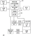
FIG. 3 is an illustrative block diagram of an embodiment of a system for automated guidance of a tool.
FIG. 4 is an illustrative flow diagram of an embodiment of a method for automatically booting a tool.
FIG. 5 is an illustrative flow diagram of an embodiment of a method for automatically booting a tool.
Fig. 6 is a block diagram illustrating the overall architecture of a computer system that may be used to implement various elements of the systems, apparatuses, and methods disclosed herein, according to an embodiment.
Fig. 7A-7B are illustrative diagrams of location markers that may be used to implement various elements of the systems, devices, and methods disclosed herein, according to embodiments.
Fig. 8A-8B are illustrative examples of embodiments of an apparatus for directing or extracting dust particles that may be used to implement various elements of the systems, apparatuses, and methods disclosed herein, according to embodiments.
9A-9B are illustrative examples of top perspective views of embodiments of substrates for directing or extracting dust particles that may be used to implement various elements of the systems, devices, and methods disclosed herein, according to embodiments.
Fig. 9C is an illustrative example of a bottom perspective view of an embodiment of a substrate for directing or extracting dust particles that may be used to implement various elements of the systems, devices, and methods disclosed herein, according to an embodiment.
Fig. 9D is an illustrative example of a top perspective view of an embodiment of a substrate for directing or extracting dust particles that may be used to implement various elements of the systems, devices, and methods disclosed herein, according to an embodiment.
Fig. 10A-10B are illustrative examples of embodiments of systems for determining a location of a tool tip that may be used to implement various elements of the systems, apparatuses, and methods disclosed herein, according to embodiments.
Fig. 10C-10D are illustrative examples of embodiments of force sensors positioned on a device for determining a location of a tool tip that may be used to implement various elements of the systems, devices, and methods disclosed herein, according to embodiments.
11A-11B are illustrative examples of directing or extracting dust particles using various elements of the systems, devices, and methods disclosed herein, according to embodiments.
FIG. 12 is an illustrative example depicting a block diagram of a method of locating a working member of a tool, in accordance with embodiments.
Fig. 13 depicts a front view of a tool according to an embodiment.
Fig. 14 depicts a front view of a tool without an attached working member, under an embodiment.
Fig. 15 provides a side view of a tool with a working member attached thereto, under an embodiment.
Fig. 16 provides a side view of the tool without the working member attached, under an embodiment.
Fig. 17 provides a rear view of a tool with a working member attached thereto, under an embodiment.
Fig. 18 provides a rear view of the tool without the working member attached, under an embodiment.
Fig. 19 provides a top view of a tool with a working member attached thereto, under an embodiment.
Fig. 20 provides a top view of a tool without an attached working member, under an embodiment.
Fig. 21 provides a bottom view of an inner table and pivot member of a tool according to an embodiment.
Fig. 22 depicts a system for guiding a tool according to an embodiment.
Fig. 23 depicts a flow diagram for guiding a tool according to an embodiment.
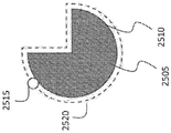
Fig. 24 is a diagram illustrating edge detection according to an embodiment.
Fig. 25 is a diagram illustrating edge detection according to an embodiment.
Fig. 26 is a diagram illustrating edge detection according to an embodiment.
Fig. 27 is a diagram illustrating a spiral tool path generated by the system, according to an embodiment.
28A-D are diagrams illustrating tools according to embodiments.
Fig. 29 is an exemplary log in an auto-boot system and an exemplary log in a computer system, according to an embodiment.
30A-30D are a series of diagrams illustrating the use of a thin film to define a template according to an embodiment.
FIG. 31 is an exemplary network connection diagram of 6 computer systems, according to an embodiment.
Detailed Description
The present disclosure relates generally to systems and methods for working on surfaces such as carpentry or printing. In some embodiments, the present disclosure relates to determining a location of a tool relative to a surface of a material and using the location to guide, adjust, or automatically calibrate the tool along a predetermined path or design scheme (such as, for example, a cutting or drawing path). In some embodiments, the reference location may correspond to a design or solution obtained from a remote computer system.
The manufacturing or production operation may include working on or with a piece of material having at least one plane, such as cutting a shape from a piece of plywood. However, it can be challenging for the tool to determine the location of the edges of a plane, which may be rectangular, such as in plywood, or may be a smooth contour, such as the edges of a 2D template. The system, method and apparatus of the present solution relate to a system for detecting the shape and/or position of an edge.
The tool may be configured with one or more techniques to facilitate guiding a working member or bit of the tool. For example, the tool may include a probe and be configured with a lateral probing technique that measures the surface of the material or workpiece, or establishes a reference point on or relative to the workpiece. The tool may detect one or more points of the workpiece profile to digitize the template. The tool may detect one or more points of the profile to scan the edge of the work material before and after flipping to align the recipe for double-sided processing. The tool may detect one or more points of the contour to generate a grid overlay.
In some embodiments, the system may include a handheld tool coupled with a digital processor. The hand held tool may include a physical element, such as a probe, of known or approximately known geometry. In addition to being used as a probe, such as a drill bit, the probe may also be part of a tool used in some other capability than for probing. Using one or more sensors, the system can determine the 3D position or location of the probe in any coordinate system and store that position. The system may determine the position by detecting the position of the tool frame and using the offset from the tool frame to the probe, or the system may detect the position directly.
In some cases, the present disclosure may facilitate assessing a position of a working member of a tool. Evaluating the position of the working member may include, for example, determining the geometry of the cutting tool or determining the geometry of the workpiece (e.g., working surface).
Determining the geometry of the tool may include or refer to determining the position of the tool tip (e.g., the working member) relative to a reference frame of the tool. Determining the geometry of the tool may comprise or refer to determining the diameter of the cutting tool. The tool geometry information may be used to automatically determine the length of the cutting slot of the working member and the angle of the cutter (e.g., V-carve bit or helix angle).
Determining the geometry of the workpiece may include either referencing or measuring the thickness of the material to be cut, or creating a topographical map of the surface by repeated probing with the tool tip. The tool may determine the location of a feature of interest, such as a hole in a workpiece.
The present disclosure may use one or more techniques to determine the position of the working member or tool tip relative to the reference frame of the tool (e.g., the tool height). For example, the tool may include a tool tip or working member and a base. The base of the tool may rest on and be in contact with the work surface. Techniques to determine the position of the tool tip may include extending or lowering the tool tip onto a work surface (or a convenient flat surface such as a table) while measuring the weight on the base of the tool. When the tool tip is in contact with the work surface, weight may be transferred onto the tool tip and away from the base of the device as additional downward movement of the cutting tool occurs. The tool may detect a reduction in weight on the base via a weight sensor in the base. This technique may provide improved accuracy in determining the position of the tool tip, as the tool tip position may be determined within a fraction of the tool travel required to lift the base of the apparatus off the work surface. In some cases, where the tool tip may be very sharp, the tool tip may sink or enter a distance into the work surface (e.g., wood) before generating sufficient force to lift the apparatus. However, since the weight sensor may be configured to detect even small force reductions (e.g., 1%, 2%, 3%, 5%, 0.5%, 0.1%, or 10% of the force exerted on the material by the tool or base before the tool tip contacts the work surface), the tool may detect changes in the force as the tool tip contacts the work surface even if the tool tip is to at least partially enter the work surface.
Further, the tool may utilize this technique to determine the position of the tool tip without performing an absolute calibration of the weight sensor, as the tool may determine the position based on detecting a change in force. Thus, inexpensive and uncalibrated force sensors may be used to determine the position of the tool tip. Examples of force sensors may include force sensitive resistors, capacitive force sensors, high-pass sensors, or piezoresistive sensors.
The tool may detect when the tool tip or working member is in contact with or becomes in contact with the work surface by detecting, noting, determining or otherwise identifying the elevation of the base. The elevation of the base may be a relatively small elevation (e.g., a reduction in force on the force sensor of 0.1%, 0.5%, 1%, 2%, 5%, 10%, 15%, 20%, or some other percentage based on the resolution or granularity of the force sensor). In some cases, the implement may detect lift based on the tilt of the base (e.g., 1 degree angle, 2 degrees, 5 degrees, 10 degrees, 15 degrees, 25 degrees, or some other tilt that may be detected). The tool may use a camera, visual information, or inertial measurement unit (IMU, including one or more accelerometers, gyroscopes, or magnetometers) to detect tilt. For example, the camera may determine a shift in the captured image that corresponds to a tilt resulting from the base lift. The camera may take a first picture or image before the tool brings the tool tip into contact with the work surface, and then a second image when the tool tip is in contact with the work surface. The camera may compare the first image to the second image to identify a tilt or change between the two images. The IMU may indicate tilt in response to movement or sudden movement caused by base lifting. In some embodiments, the tool may include a force sensor in the tool holder to directly measure the force on the tip of the cutting tool.
The tool may determine or detect additional information about the tool, including tip or working member position, diameter, or tool geometry. For example, the tool may include a beam break-beam sensor (e.g., a laser beam break sensor, an infrared beam break sensor, a photosensor, or an optical sensor). The working member may fall into the line of action of the sensor and the tool may detect the position of the working member when the working member interrupts the light. In some cases, the axes of the light beam may be pre-calibrated with respect to the coordinate system of the tool. However, accurately detecting the tip position using this technique can be challenging based on the tip geometry (e.g., if the tip shape is not flat).
The tool may use a capacitive sensor or an electromagnetic sensor to determine the proximity of the tool tip to the work surface. For example, an electromagnetic sensor may sense or detect a change in inductance of a sensing coil near a tool tip or working member comprising metal by sensing eddy currents induced in the metal.
Another approach is to use a vision camera aimed at the tool to determine the position of the working member or tool tip. The vision camera may be pre-calibrated to the tool coordinate system to detect the tool tip. In some cases, the vision camera may include a linear charge-coupled device (CCD) sensor or other image sensor. The linear CCD sensor may detect the tool tip using less processing than a visual camera.
The tool may use one or more of these techniques to measure the tool diameter. The tool may move the tool tip around while measuring or determining the position of the tool tip. By moving the tool tip, the tool can detect the tool diameter by passing the tool through the sensor from left to right using a single beam break sensor. Lateral movement of the tool can cause a first interruption and then unblock the light to provide a measurement of the tool diameter. Because the milling bit may have helical flutes, the tool may perform multiple measurements along the length of the tool to determine the diameter. The tool may use eddy currents or capacitive sensing with one-dimensional sensors to determine diameter to gather multi-dimensional information about tool geometry by correlating sensor data with tool position. The tool may determine additional information about the tool tip, such as the tip angle in the case of a V-shaped cutting bit. Further, the tool may include a visual camera to detect geometric characteristics of the tool.
The tool may measure the geometry of the work surface by correlating the tool tip position with the device position in the plane of the work surface. To do so, a tool (e.g., a cylindrical tool with a conical or spherical tip) may first be correlated to a reference frame of the tool by detecting the position of the tool tip. Once the position of the tool tip is known relative to the tool's frame of reference, the tool can be positioned laterally on a surface of interest (e.g., a work surface) to determine the vertical position of the work surface. The vertical position of the working surface may refer to a groove, void, dent or depression in a piece of wood to a depth of interest. The tool tip may then be inserted, extended, lowered, plunged or otherwise moved until the tool tip contacts the bottom of the recess. Additional displacement of the tool tip beyond the top portion of the surface where the tool tip first contacts the working surface indicates the depth of the groove. If the surface profile of the groove is of interest, the tool can be moved around the groove to a number of points. The tool may determine a depth at each of a plurality of points. The tool may record the depth and lateral position of the tool (e.g., x, y, and z coordinates, where x and y coordinates may refer to lateral position and z coordinate may refer to depth). The lateral movement may be accomplished automatically using a built-in positioning table, or manually by a user, or a combination of both.
Another potential application may be to find the center position of a hole on a work surface. A tool with a tapered tip may be fitted into the device. The tool can then be positioned over about the center of the hole (e.g., within 5%, 10%, 15%, 20%, 25%, 30%, 50%, 75%, or 90% of the diameter of the hole) and plunged until the tip contacts the circle of the hole. Because the tool tip may be tapered, the tool tip may center the tool on the hole. The tool may then determine the location of the hole using, for example, a vision system to determine the lateral position (e.g., x and y coordinates).
The tool may determine the thickness of the work surface or other piece of material. Using the determined thickness of the working surface, the tool may automatically set a cutting depth or update a cutting path that may depend on the thickness of the material (e.g., a cassette joint where the length of the fingers is to correspond to the thickness of the mating material). The tool may determine or measure the thickness of the material, suspend or place the tool or a portion thereof over a work surface or edge of the material, and then extend the tool tip until it contacts the surface of the supporting material. The depth to which the tool tip extends beyond the top of the working surface so as to contact the surface supporting the working surface may be indicative of the thickness of the working surface.
The tool may use location markers, which may include contour trees, binary images, fiducial markers, or domino tiles, to determine the position of the tool or tool tip relative to the surface of the working material. The present disclosure facilitates directing and extracting debris from a portion of a tool by generating an airflow that directs the debris via one or more channels in the portion of the tool. The present disclosure facilitates determining a height of a tip of a tool using a force sensor that detects a reduction in force when the tip of the tool contacts a material.
Using the determined information, the tool may be configured to direct a working member of the tool to perform a task on a target material (e.g., a working surface). In some embodiments, the system may automatically direct the tool to perform the task. For example, in some embodiments, the present disclosure provides a handheld system that is capable of identifying the location of a tool or a drill containing the tool relative to a material being processed. In some embodiments, the device may be non-handheld; for example, the device may be located on a movable platform, such as a remote control platform, a robotic platform, or other types of movable platforms that may or may not be controlled. The system may adjust the location of the tool (or provide instructions for adjusting the location of the tool) based on or in response to the current location of the tool and the desired location corresponding to the design. In some embodiments, the system includes a handheld device having a manually operable work instrument that can make fine adjustments to a work instrument location based on spatial position to provide an accurate path of travel for the work instrument.
In some embodiments, the systems and methods disclosed herein may include a location detection system or perform one or more location detection techniques that may detect the current location or position of a tool on a target material accurately, robustly, or with low latency. For example, a video or still image camera coupled to the tool and accompanying control circuitry may be used to scan the surface of the material and process the scan data or scan image data to generate a digital map of the material surface prior to performing a task on the material. When the tool is brought into proximity with the material surface during performance of a task on the material, the camera may take a second image and compare the second image to the digital map to detect the location of the tool relative to the material.
In some embodiments, various location detection techniques may be used, including, for example, integrated wireless position sensing techniques such as RF, near field communication, bluetooth, laser tracking and sensing, or other suitable methods for determining tool position. And facilitate guiding or adjusting the position of the tool to perform the task. In some embodiments, the system may include a hybrid location detection system that employs two or more location detection techniques to determine the location of the tool. For example, each site detection technique may include orthogonal strengths and weaknesses, but when combined, may detect sites with high accuracy and low latency. For example, a first location detection technique may be high accuracy but low frequency (e.g., a sensor configured to obtain data once per second that accurately determines position but has high latency). The first location detection technique may be combined with a second location detection technique that includes sensors that provide location information at high frequency and high accuracy but limited information (e.g., an optical mouse sensor that provides high frequency and high accuracy but only dead-reckoning including direction and speed of movement, but does not provide a location of the tool in a global environment). In an illustrative example, the hybrid location detection system may use a camera to obtain an image to accurately determine the position of the tool on the surface of the material, and then use an optical mouse sensor to track changes in position until the next frame of the image arrives. In this example, the second location detection technique using an optical mouse sensor cannot provide all location tracking, as integrating speed to determine location may accumulate errors over time, or if the device is picked up and placed in a different location, the device will not be able to determine location.
In some embodiments, to generate a map prior to a cutting or drawing operation, a user may scan the surface of the material with a camera until the camera has obtained an entire image, substantially the entire image, or a portion of the image of the surface of the material or a desired portion thereof. The system may take these images and stitch them together to produce a joint map. Generating the digital map image and detecting the location may include, for example, one or more of image processing techniques, pattern recognition techniques, pointing (localization) techniques, computer vision techniques. For example, the system may identify that points a and B in the first image correspond to points C and D in the second image, and stitch the two images accordingly. For example, on a wood surface, the system may identify changes in the image, bright spots, color changes, markings, fiducial marks, binarized images, or wood grains, and compare them to a digital map to determine locations. In another example, the system may also use corners, sides, lighting patterns, or other signals that can identify a location.
The material may be marked to facilitate mapping of the surface of the material or to detect the location of a tool on or near the material. For example, the surface of a material such as metal or plastic may not contain sufficient identifying indicia to accurately detect a location. Distinctive markings or indicia may be added to the material to facilitate location detection techniques, such as pattern recognition or image processing. The indicia may include any type of material, ink, tape, light, laser, engraving, carving, temperature gradient, invisible ink (e.g., ink visible only under ultraviolet or other wavelengths of light) capable of facilitating location detection techniques. In some embodiments, the indicia comprises a strip that can be applied to at least a portion of the surface of the target material. For example, the strip may include symbols such as, for example, unique bar codes, designs, patterns, colors, engravings, raised bumps or depressions. In some embodiments, the marking may include a random marking on the target material by the user with a pen, pencil, ink, invisible ink, paint, crayon, or any other marking or writing instrument.
In addition to generating a digital image of the material surface, in some embodiments, the system may identify a cut or drawing design on the material surface. The design may include any cut or drawing desired by a user of the system. For example, the design solution may include a freehand design, a tracing, a picture, an image, a design generated using computer aided design ("CAD") software, a purchased design, or a purchased electronic design. The design may be a design of an object that the tool may create by performing an operation on a material, such as a design of a table that may be cut from at least one piece of wood.
The system may merge or otherwise relate the design with a map image of the material surface or overlay the design on the map image. In some embodiments, the design may be drawn on the surface of the material before or after the initial map of the material is generated (e.g., using a special pen whose ink may be detected by the system using ultraviolet or other wavelengths). For example, if the surface of the material includes a design (e.g., a cut design or a drawing design) at an initial mapping stage, the system may process the image to identify the design and include it in a digital map of the surface of the material. If the design is drawn or otherwise marked on the surface of the material after the initial map is generated, the system may obtain an image of the material with the design by rescanning or taking a new image of the material using the camera. If the design is drawn or otherwise marked on the surface of the material prior to generating the initial map, the system may identify the design as a cut or draw design or the user may indicate to the system that the identified design is a cut or draw design.
In some embodiments, a digital design may be added to a digital map of a material surface without physically adding the design to the surface of the material or otherwise marking the actual material with the design. For example, the digital design may be generated on a computer and may include a CAD drawing, a vector drawing (e.g., SVG, DXF), or any other type of drawing (e.g., JPEG, BMP, or GIF). For example, using CAD software, a user can modify a map image by adding a design solution. Any other suitable software may be used to incorporate the design into a map image or otherwise relate the design to a map of the surface of the material (e.g., data indicating the location of the design to facilitate performing a task on the material). After registering the design on the digital map or digital map image, the system may provide the corresponding digital map data or digital image data with the design solution to the tool. In some embodiments, the system may display a map image with the design on a display device of the tool to facilitate a user performing a task on the material. In some embodiments, the tool may perform the task according to the design without displaying the design (e.g., the tool may automatically perform an aspect of the task, or the tool may not include a display device).
In some embodiments, the digital design may be specified using vector drawing (e.g., Scalable Vector Graphics (SVG) files, DXF files). In some embodiments, the design features may be paths or basic shapes used in the SVG format. In some embodiments, the path of the cutting bit may be generated using a digital design in the SVG format, where the path also uses the SVG format-including in some embodiments the path or base shape used in the SVG format.
During cutting or drawing operations, a user may place a tool on or near the surface of the material. The camera may rescan or take an image of a portion of the surface of the material while the tool is placed on the surface. The image may correspond to a portion of the material at a different location than the cutting or drawing tool. The system may determine the location of the tool relative to the material surface or design by comparing the identifying mark in the new image to the identifying mark in the map image generated prior to performing the task on the material. The camera may be mounted or otherwise coupled to the tool such that an image capture aspect of the camera (e.g., lens) is directed at the surface of the material at a fixed and known vector from the cutting tool (e.g., drill bit). By focusing the camera away from the cutting tool, the system can obtain an image that is relatively free of cutting-induced debris that may obscure the markings for the detection locations.
The system may compare the new image to a digital map of the material surface to determine the precise location of the tool. For example, the portion of the digital map corresponding to the upper right corner may include a set of identifying marks. After obtaining a new image, the system may identify those same identifying markers and determine that those markers correspond to the upper right corner of the map image. The system may then determine the precise location of the cutting or drawing tool based on the camera vector offset.
In some embodiments, the system may display the precise location of the cutting or mapping tool in real-time on a display device (e.g., a display device of the tool or a remote display device communicatively coupled to the system or tool). The system may indicate the location on the display by an "X", a circle, a dot, an icon, or using any other indication to signal the current location of the tool. In some embodiments, the tool may override the design or an indication of the current position on the cutting path (e.g., the predetermined path). In some embodiments, the tool may overlay an indication of the current location on the map image. In some embodiments, the tool may overlay an indication of the current location on the map image including the overlay of the design.
In some embodiments, the system may include a positioning system that adjusts or moves the tool based on the detected tool location and design. In some embodiments, the system may use various location detection techniques to detect the location of the tool and use various positioning techniques to move or adjust the location of the tool. For example, the system may include a hybrid positioning system that includes two or more positioning systems to position the tool. After determining the location of the tool and the desired location of the tool, the first positioning system may be configured to move, adjust, or position the tool within a relatively large range (e.g., to move the tool anywhere on the work area or material surface), but with relatively low accuracy. The second positioning system may be configured to move, adjust, or position the tool within a relatively short range (e.g., within a 5 inch radius of the current location of the tool), but with high accuracy. In some embodiments, a first (e.g., coarse or coarse) positioning system may include a person positioning a tool on a surface of a material, and a second (e.g., fine or fine) positioning system may include positioning the tool using, for example, a servo motor, a stepper motor, an actuation mechanism, or an eccentric. In such embodiments, the tool adjustment range is short-range. In some embodiments, the tool adjustment range may be a circular region, an elliptical region, a polygonal shape, or the like. The first positioning system may include a non-human positioning system such as, for example, a robotic system, a remote control system, or a global positioning system ("GPS") enabled device.
For example, the first positioning system may include a remote low accuracy positioning mechanism configured to move, adjust, or correct the position of the tool based on the design. The second positioning system may include a short range, high accuracy positioning mechanism that may move, adjust, or correct the position of the tool more precisely than the first positioning mechanism within a maximum range based on the design. In an illustrative and non-limiting example, the first positioning system may include a maximum range, such as a range that includes the entire working area (e.g., a region that includes the surface of the material on which the task is to be performed), and includes an accuracy of +/-0.25 ". The second positioning system may include a maximum range of, for example, 0.5 "with an accuracy of +/-0.01". The maximum range and accuracy of the first and second positioning systems may include other range and accuracy values of the systems and methods that facilitate hybrid positioning. In various embodiments, range and accuracy may refer to one-dimensional accuracy (e.g., along the X-axis), two-dimensional accuracy (e.g., the X-Y axis), or three-dimensional accuracy (e.g., the X-Y-Z axis).
The first positioning system may be less accurate and include positioning systems in which the maximum range is much higher than the maximum range of the second positioning system. For example, a first positioning system may move the tool from anywhere on the surface of the material to within +/-0.25 inches of the desired location, while a second positioning system may be configured to move the tool up to 5 inches from the current position, but with an accuracy of 0.01 inches. In some embodiments, a hybrid positioning system may include multiple positioning systems, each configured to accurately determine a location and then position a tool within a range of distances, such that when the positioning systems are used together, the systems may accurately determine the location and position or adjust the tool accordingly. In some embodiments, the maximum range of each subsequent positioning system may be equal to or greater than the accuracy of the previous positioning system. In an illustrative example, the first positioning system may be capable of positioning the tool on the surface of the material, e.g., with a maximum range corresponding to the size of the material surface, and with an accuracy of +/-1 inch. The second positioning system may be capable of positioning the tool on the surface of the material to an accuracy of +/-0.1 inches over a maximum range of 2 inches. The third positioning system may be capable of positioning the tool anywhere within a maximum range of 0.2 inches with an accuracy of +/-0.01 inches. Thus, in this example, by using all three positioning systems together, the hybrid positioning system can accurately position the tool within a maximum range of the entire surface, including the material or work area, with an accuracy of +/-0.01 inches.
In some embodiments, the system may include automatic tuning, guidance, or error correction according to a design to facilitate performing the task. The system may use various types of adjustment, guidance, or correction mechanisms including, for example, eccentrics, servos, stepper motors, control loops, feedback loops, actuators, nuts and bolts-type mechanisms. For example, the system may include an eccentric or a servo motor coupled to the frame, and the cutting tool is configured to adjust a position of the cutting tool relative to the frame. After determining the current position of the cutting tool, the system may compare the current position to a desired position. The system may then guide the tool according to the design. In some embodiments, when the system determines that there is a discrepancy between the current position and the desired position, or that the current position or trajectory deviates from the design, the system may adjust the cutting tool according to the design. For example, the system may identify a cutting path or vector of the tool and the design and adjust the cutting tool so that the next cut conforms to the design.
The system may utilize various automatic correction mechanisms. In some embodiments, the system may include an eccentric configured to adjust a position of the cutting tool. For example, using two eccentrics, the system can adjust the position of the cutting tool in two dimensions. The eccentric may comprise any small circular component that rotates asymmetrically about an axis. For example, the eccentric may comprise a circle that rotates about a non-central axis. The eccentric may be coupled to the cutting tool and the frame and configured to adjust a position of the cutting tool relative to the frame, which may adjust a position of the cutting tool relative to the surface of the material. In some embodiments, the system may utilize a screw with a nut to change the rotational motion to linear displacement to correct or adjust the tool positioning.
In some embodiments, the system may include orientation control based on the type of cutting tool. For example, if the cutting tool is a saber saw (saber saw) that cannot be adjusted vertically, the system may adjust the orientation or angle of the saber saw according to design. The system may include an actuator configured to adjust the tilt or angle of the saw.
The system may control the z-axis of the cutting or mapping tool. The system may determine the position of the tip of the cutting tool relative to the work surface. By controlling the z-axis of the cutting or mapping tool (e.g., an axis substantially orthogonal to the surface of the material; a perpendicular axis; an axis parallel to the axis along which the working member is lowered or raised to or from the surface of the working member or cutting tool), the system can start and stop cutting or mapping according to design. For example, if the cutting tool is beyond a design correctable distance (e.g., outside of an auto-compensating radius), the system may stop cutting by adjusting the z-axis position of the cutting tool (e.g., lifting the cutting bit or the milling machine bit off of the wood). When the user brings the cutting tool back within the automatically adjusted radius, the system may automatically adjust the z-axis position of the cutting tool so that cutting begins again (e.g., lowering the drill bit into the wood). The radius or range of compensation may correspond to a positioning (positioning) system of a fixed point (localization) system. For example, if the pointing system comprises a hybrid positioning system including a wide-range and a short-range positioning system, the radius of compensation may correspond to the short-range positioning system. In some embodiments, controlling the z-axis position of the tool may facilitate a 2.5 dimensional design. For example, the design may indicate z-axis information corresponding to the surface of the material. Thus, the system may use the determined z-axis position of the working member or cutting tool or its tip to control the motor to move the working member to a second location or position (e.g., an x, y or z-axis position).
The system may control the motor to move the working member to a given (x, y, z) position based on the information indicated in the design. In some embodiments, the system may control one or more motors to move the working member to a given (x, y, z) position based on a desired path determined based at least in part on the design. In some embodiments, the system may control one or more motors to move an adapter for holding the working member to a given (x, y, z) position based on a desired path determined based at least in part on the design. In some embodiments, the desired path of the working member and the desired path of the adapter holding the working member may be related by an offset (e.g., a displacement from a tip of the adapter to a tip of the working member) between the adapter and the working member. For example, if the system is similar to a conventional milling machine and the adapter and working member are axially aligned, the desired path of the adapter and the desired path of the working member will be offset in z (the direction perpendicular to the working surface).
In some embodiments, the system may indicate to the user that the cutting tool is on a desired path (e.g., a predetermined path) or within a compensation range so that the system may correct the position of the cutting tool. In some embodiments, the system may indicate to the user that the cut is not on the desired path or within the compensation range. The system may also indicate to the user the direction to correct the position of the cutting tool or to move the cutting tool to be on the desired path or within the compensation range. The system may visually provide one or more indications via the display device using a light emitting diode or other light source, an audio signal, a beep, a chirp, or a vibration. In some embodiments, the indication that the tool deviates from the desired path beyond an acceptable range may include automatically turning off the cutter or adjusting the z-axis of the cutting or mapping tool so that it stops performing tasks on the material. In some embodiments, the system may indicate the desired path on the surface material itself by, for example, illuminating a light beam that indicates to the user where the desired path is and where to proceed. For example, in determining the error, the system may illuminate a light beam indicating to the user how much the tool should be adjusted in order to bring the position of the tool within the range of the automatic compensation or on the desired path.
In some embodiments, multiple cutting or mapping tools may be used with the system, including, for example, a saber saw, a jig saw, a milling machine, or a drill bit. The system may be configured such that a user may use aspects of the present disclosure with various cutting or drawing tools without any adjustment or small/temporary adjustment to the tools. For example, a system may include a frame, a camera, a display device, and a computing device. The frame may be configured such that the cutting tool may be placed in the frame. The camera may be coupled to the frame or may be attached to the cutting tool. After placing the camera, the system may be automatically or manually calibrated so that the system obtains a vector offset between the camera and a cutting or mapping tool (e.g., a cutting bit or a milling bit).
In some embodiments, the system may include a standalone device configured to perform mapping and pointing functions and to indicate to a user a current location of the device. In some embodiments, the stand-alone device may be attached to a cutting tool or a mapping tool. In some embodiments, the stand-alone device may not provide auto-calibration functionality. In some embodiments, the stand-alone device may include a display. In some embodiments, the standalone device may include one or more sensors (e.g., one or more cameras for mapping and positioning). In some embodiments, the standalone appliance may determine the desired path and detect when the tool leaves the desired path. The separate device may indicate the error by, for example, a display, shining light on the surface of the material, an audio signal, or a voice narration.
Referring to FIG. 1, an illustrative example of an embodiment of an apparatus for directing a tool to perform a task is shown. In some embodiments, the apparatus includes a frame and a tool (e.g., a milling machine in the example of fig. 1) mounted within the frame. The frame may be manually positioned by a user. The device can adjust the position of the tool within the frame to guide or adjust the tool according to a design or to correct errors in the rough positioning of the user. The device may also include a display and be configured to map the target material and display the target material on the display. In some embodiments, indicia (e.g., a sticker) on the target material may facilitate generating a map of the target material by providing a distinguishing feature. The device may obtain the design or solution by downloading from an online store. The device may display a map of the target material with a design indicating a desired cutting pattern.
Referring to FIG. 2, an illustrative example of an apparatus for automatically guiding a tool to follow a target path region and perform a task according to a planned design is shown. In some embodiments, to follow a complex path, a user of the device may only need to move the frame in a rough approximation of the path. In this example, the dashed line shows the path that the tool would take if the tool position was not adjusted; the solid line is its actual path, e.g., the outline of the southeast united states. In this example, the user may grasp the frame and guide the tool generally along the dashed lines, and the tool may self-adjust to cut along the solid lines. In some embodiments, the apparatus automatically adjusts the drill bit or other cutting tool based on the position of the cutting tool (e.g., one or more of an x-axis position, a y-axis position, or a z-axis position) and the desired position of the cutting tool. The x-axis and y-axis may intersect to form an x-y plane that is substantially parallel (e.g., within 45 degrees) to the surface of the material, while the z-axis is substantially perpendicular (e.g., 45 degrees perpendicular) or orthogonal to the horizontal plane formed by the x-y axis. In some embodiments, a user of the device can move the device along dashed line 1210 in fig. 2 (or path 406 of fig. 23) while the device automatically adjusts the cutting tool (e.g., x, y, or z position) according to a desired design, such as design 1205 of fig. 2. For example, the device may identify or detect the current position of the cutting tool relative to the target surface using the design. The device may then compare the current location to the desired location of the design or map and adjust the cutting tool. For example, if the working member or cutting tool tip is determined to be 1 inch above the surface of the material, the system may determine to lower the cutting member tip to contact the surface of the material. In another example, if the design dictates drilling a 0.5 inch deep hole in the material, the system may determine the z-axis position of the tip and insert the tip 0.5 inch into the material based on the determined z-axis position. For example, the system may instruct the motor to extend the working member or cutting tool 0.5 inches beyond the surface of the material.
Referring to fig. 3, an illustrative block diagram of an embodiment of a system for automated guidance of a tool is shown. In some embodiments, system 680 includes a smart device 681. The smart device 681 may include at least one central processing unit ("CPU") or processor 683, and may include software code 685 to perform one or more processes, at least one memory 687, or at least one display 689. The smart device 681 may include a self-contained unit, or the smart device 681 may include non-self-contained or separate components. For example, the display 689 may be tethered to the smart device 681 or integrated into a housing of the smart device 681. In some embodiments, the smart device 681 may be integrated as part of the system 680 such that the system is a self-contained portable unit. In some embodiments, system 680 may include one or more communication interfaces (not shown) to allow communication with other computer systems (e.g., to send and receive manufacturing data (e.g., information about cuts made on a work surface), to send and receive digital designs or designs) via a network. In some embodiments, system 680 may include one or more other interfaces (not shown), such as an input interface.
In some embodiments, the drill may include a motor (e.g., 210, 220), an actuator assembly (e.g., table 690, pivot 694), and an adapter (e.g., clamp, chuck) for holding a working member. In some embodiments, a computing device without a display or camera may be removably coupled with a component on a drill rig. The computing device may include one or more memories operatively coupled to one or more processors, wherein one of the one or more memories may have instructions stored thereon that, when executed by one of the processors, cause a system (including the computing device and the drilling rig) to perform one or more of the disclosed embodiments. In some embodiments, the display may be operatively coupled to one of the one or more processors in the computing device. In some embodiments, the computing device may include a display. In some embodiments, one or more sensors (e.g., cameras, ultrasound sensors) may be operably coupled to one of the one or more processors in the computing device. In some embodiments, the computing device may include one or more sensors (e.g., cameras, ultrasound sensors).
In various embodiments, the system 680 may include one or more sensors to facilitate determining the location of the tool (e.g., IR, laser, ultrasonic ranging, etc.). For example, and in some embodiments, the system 680 may include a camera 682, which camera 682 may be used in conjunction with a smart device 681 to construct a map 684 of the material to work on. The camera 682 may be coupled or attached to any tool 699 to provide positioning of the tool 699. In some embodiments, camera 682 is coupled with display 689 and CPU 683. For example, the camera 682 may be part of a computer or smart device 681 that may be attached or coupled to any tool 699. The software application or code 685 may be installed on a mobile smartphone and may utilize the smartphone's camera, CPU, memory and display. In some embodiments, one or more aspects of the software or processing may be performed by a field programmable array device ("FPGA") or a digital signal processor ("DSP").
In some embodiments, camera 682 may take images with a high frame rate. For example, a camera may scan the surface of a material to obtain scan data or scan image data. In some embodiments, the camera may scan the surface of the material, and the processor may process the scan to generate scan data indicative of a map of the surface of the material. This may facilitate the fixed point function or mapping function disclosed herein. The camera 682 may also take images at a relatively low frame rate, and the camera 682 may be coupled with one or more optical sensors (e.g., sensors in an optical computer mouse). The optical sensor may provide low latency dead reckoning information. These optical sensors may be used in conjunction with camera 682. For example, the camera 682 may provide accurate global position information several times per second with significant lag, and an optical sensor may be used to provide dead reckoning information with low lag that fills in the time since the last image was taken. In some embodiments, the IMU may be used for dead reckoning. The system 680 may use multiple cameras to increase the accuracy or range covered in scanning, or to provide depth information.
In some embodiments, system 680 is configured to build, generate, or otherwise receive map 684. In some embodiments, the map 684 may be constructed using computer vision ("CV") or sensor technology. For example, CV techniques may be used to construct photo mosaics. Photo mosaic processing may include taking multiple photographs of different parts of the same object and stitching at least two photographs together to make at least one overall image that covers some or all of the object.
In some embodiments, the system 680 or processor may be configured to evaluate scan data using techniques including simultaneous fix and map ("SLAM"). SLAM may include using sensors and related software 685 communicatively coupled with processor 683 to construct a map 684 of the material (or "target material") operating thereon, while (e.g., simultaneously) determining the location of tool 699 relative to map 684. For example, after at least a portion of the map is constructed, camera 682 may capture an image of the material being processed. The images may be fed to the intelligent device 681 and processed by the intelligent device 681 to determine the location of the tool 699 or drill. The system 680 may analyze the captured image based on the map 684 to determine the location of the camera 681 relative to the material. After determining the location of the camera 682, in some embodiments, the system 680 may identify that the location of the rig, to which the camera 682 may be rigidly attached, is a known or determinable offset from the location of the camera 682.
In some embodiments, to construct the map, one or more processors (e.g., CPU/processor 683) of the system (e.g., system 680) use one or more cameras (e.g., camera 682) to capture one or more images of the work surface. In some embodiments, the one or more processors may analyze each captured image to identify markings or indicia on the work surface. In some embodiments, the marking may be associated with a feature (e.g., a wood grain pattern) of the workpiece. In some embodiments, the marker may be placed on the work surface by the user. For example, a user may apply a strip with location indicia (e.g., indicia with domino pattern, indicia with barcode, indicia with 2D code, indicia with binary image, fiducial marks) having a pattern of known dimensions (e.g., length, width, pattern spacing, spacing) printed along the length of the strip. In some embodiments, each pattern may have an encoded ID that may be decoded by one or more processors using an image and image processing algorithm of the pattern. The coded ID of each tag may not be unique. For example, a tape with location markers may contain 100 repeated unique IDs. In this example, if the user uses a long section of tape or a non-continuous section of tape, the work surface may have two marks with the same encoded ID. In some cases, the coded ID of a marker may be decoded incorrectly by one or more processors (e.g., based on debris overlaying the coded pattern), which may result in both markers having the same ID.
In some embodiments, to generate a map using a set of captured images, one or more processors analyze each image to identify markers/markers. For each image in the set of captured images, data corresponding to an image ID of the image and marker/marker information is determined, including a marker/marker ID and location information for each marker/marker in the image. In some embodiments, the marker ID may be based on the encoding ID of the encoding pattern. In some embodiments, the tag ID may be based on the characteristics of the tag (e.g., based on color if the tag is a wood grain pattern). In some embodiments, the data (including image ID and image-level marker/marker information) for all images in the set of captured images is analyzed together, using feature mapping CV or SLAM techniques to determine marker/marker locations, subject to constraints derived from the images in which the markers/markers appear (e.g., relating to the location of each marker/marker in each image). In some embodiments, the resulting marker/marker locations and corresponding marker/marker IDs are used to generate a global list of markers/markers (e.g., using IDs and locations for each marker/marker), where "global" is used to indicate that this list of markers/markers is not specific to any one captured image, that this list may contain information for markers/markers that are only present in some captured images, and that none of the captured images may contain all of the markers/markers in the list. As used herein, a "list" can be any format (e.g., structured, unstructured, a combination of structured and unstructured) data related to a list element.
In some embodiments, the position of each marker/marker may be expressed using six or less than six degrees of freedom. In some embodiments, the position of each marker/marker is given as an X-coordinate, a Y-coordinate, and an orientation angle relative to the X-axis (assuming that the markers/markers all lie in a 2D plane). In some embodiments, in addition to using the dimensions or spacing of the markers, if known in advance (e.g., if they are known patterns printed on the tape), the one or more processors may use one or more measurements of features included in the work surface (e.g., made by a user) to adjust the dimensional scaling of the marker/marker locations along one or more dimensions.
In some embodiments, the system may use a global list of labels/tags as a map. In a subsequent process of determining the camera location using the map, the camera may capture a new image of the work surface. The captured image may be analyzed by one or more processors (e.g., CPU/processor 683) to identify the markers/markers included in the new image. In some embodiments, a new list of markers/tags is generated based on the markers/tags identified in the new image (e.g., using, for each marker/tag, a marker/tag ID and information about where the marker/tag appears in the image). In some embodiments, if a location marker is used, a list of sub-features is generated that make up the marker identified in the new image (e.g., for each sub-feature, a sub-feature ID and the position of the sub-feature in the new image are used). For example, if the marker is marker 708 as shown in fig. 7B, the number of sub-features in the marker will be 10 based on 10 white blobs in the marker. Assuming that the new image includes the set of markers shown in fig. 7B, the sub-feature list will include all white blobs across all 55 markers.
In some embodiments, if location tagging is used, the one or more processors may identify a candidate tag list from the global list as a match for tags in the new list based on a match of one or more tag IDs between the two lists. In some embodiments, if the tag IDs of the tags in the new list match the tag IDs of the tags in the global list, the one or more processors may compare the tag IDs of the nearby tags. In some embodiments, one or more processors (e.g., CPU/processor 683) for identifying a list of candidate tokens from the global list as matches to tokens in the new list may execute instructions stored on one or more memories (e.g., memory 687) that implement mathematical modeling (e.g., RANSAC), pattern search, or graph traversal algorithms. In some embodiments, after the tag list in the global list matches the tag list in the new list, a global list of sub-features is generated for the matching tag list in the global list (e.g., for each sub-feature, a sub-feature ID and a location of the sub-feature are used). In some embodiments, the sub-feature IDs in the global list of sub-features are based on the tag IDs in the global list of tags. In some embodiments, the sub-feature location in the global list of sub-features is based on the tag ID and the tag location in the global list of tags. In some embodiments, the one or more processors may use the list of sub-features and the global list of sub-features and one or more mapping algorithms (e.g., a method that solves the perspective n-point problem) to determine the location of the camera when taking a new image.
In some embodiments, a photo mosaic or a single image showing the work surface (e.g., taken with a DSLR camera, taken with camera 682 of system 680) may be used as a map. In some embodiments, a new image of the work surface captured by a camera (e.g., camera 682 of system 680) may be compared to the photo-mosaic to determine the location of the camera. In some embodiments, the combination of the photo-mosaic and the global list of markers/markers may be used as a map for determining the location of a camera (e.g., camera 682 of system 680) based on an image (including one or more markers/markers) of the work surface taken with the camera. In some embodiments, a new image of the work surface captured by a camera (e.g., camera 682 of system 680) may be compared to the single image to determine the location of the camera. In some embodiments, a single image taken with a camera and a global list of markers/markers may be used to determine the location of the camera (e.g., camera 682 of system 680). In such an embodiment, a global list of labels/tags is used as a map.
Various embodiments may use various other fixed point processing and determination techniques including, for example, integrated wireless position sensing techniques such as RF, near field communication, bluetooth, laser tracking and sensing, or other suitable methods for determining the position of the tool 699 on top of the workpiece. For example, ultrasound, IR ranging, or laser light may be used to detect the location of the tool relative to a work area or surface of the material. According to an embodiment, the detected tool location may be provided to any other component of the system 680 to facilitate guiding or adjusting the position of the tool.
In some embodiments, the system 680 may be configured to calculate the position of the tool 699 relative to the drill using the current orientation of the motor shaft. For example, the system 680 may identify the orientation of the motor shaft by homing (homing) the motor shaft and then tracking one or more actions taken since the homing process. In some embodiments, the system 680 may use encoders that may be used instead of homing, as the encoders will be able to tell the orientation of the shaft directly. Through the offset and calculation, the system 680 may identify the location of the tool 699 or drill relative to the material being processed. The captured images that may be analyzed with respect to the map 684 may include, for example, characteristics of the material, such as wood grain and deformations, or may include markings placed on the material. Various aspects of the mapping and pointing techniques are described in more detail below.
In some embodiments, the system 680 may receive a design 686 or template. For example, the smart device 681 can be configured to receive a design 686 or template from a user of the system 680. The smart device 681 can include or have access to various input/output devices configured to receive the design 686. In some embodiments, system 680 may receive design 686 via a network. In some embodiments, a user or system 680 may modify or adjust the design 686 based on a map 684. For example, the user may resize the design 686 relative to the map 684 of the material in order to generate a desired work path on the material being processed. In some embodiments, the system 680 may automatically adjust or optimize the dimensions of the design based on the dimensions of the material.
The network may include a computer network such as the internet, a local area network, a metropolitan area network or a wide area network, an intranet, and other communication networks such as a mobile telephone network. The network may be used to access web pages, online stores, computers or data of retail stores that may be displayed on or used by at least one user device, system 680, or system 100, such as, for example, a laptop, desktop, tablet, personal digital assistant, smartphone, or portable computer.
The system 680 may be configured to create, capture, or load the design 686 in a variety of ways. In some embodiments, the design may be downloaded or otherwise obtained. For example, a user may generate a design on a computing device and transfer or otherwise communicate the design to system 680. In another example, system 680 may receive a design from a third party entity. For example, a user may purchase a design online via a network and upload the design to a smart device or computer 681. In some embodiments, the system 680 may facilitate capturing a map of a surface and a map of a design 686 on the surface. This may help set up the system 680 to follow a particular line or display to the user an image of the surface of the material under a large tool that obstructs the view, or a surface with the drawing scheme in its original state before the surface is covered with debris or the surface on which the drawing scheme is cut away. In some embodiments, the design 686 may be designed, altered, or manipulated on the device 681 from its original form by a menu driven interface that allows the user to enter distances, angles, and shapes, or to draw freely manually on a touch sensitive pad or display.
In some embodiments, as the user moves the system or rig 680 along the target material, the smart device 681 processes the captured images from the camera 682, determines the location of the rig 680, or provides the user with a desired path on the display 689. Once the user places the drill 680 near the desired path, the drill or system 680 may automatically adjust the position of the tool 699 according to the loaded design 686 to achieve the desired working path. As described herein, the terms "drilling rig" and "system" may be used interchangeably. In some implementations, the drilling rig includes physical equipment and its accessories, and the system includes the physical equipment, its accessories, and related technology and software code embedded or included in some physical elements.
In some embodiments, the system 680 constructs the map 684 based on images captured by the camera along arbitrary paths of the target material up to and covering the entire region of interest. For example, the user may sweep the camera 300 in an arbitrary path over the surface of the material until the entire region of interest is covered. In some embodiments, the system 680 may be configured such that the camera 682 may be removed from the drill 680 to sweep or pass through an area of material. System 680 may stitch together images obtained by camera 682. For example, the system 680 may use the image mosaic software code 685 to form a map 684 of a region of interest of the material surface. The system 680 may store the map 684 in a memory 687. Upon receiving the image of the mapping material captured by camera 682, system 680 may compare the image to map 684, which is maintained in memory 687, and may also determine location and orientation. For example, the system 680 may determine the position of a tool, bit, system, cutting member, table, or drill based on the comparison.
In some embodiments, the system 680 may allow a user to create and load a design 686 after assembling a map 684. For example, after the map 684 has been assembled on a smart device 681 (such as a computer), the user can create the design 686 on the computer by drawing it directly on the generated map 684. For example, a user may mark a location on a piece of wood where drilling is desired. The techniques and features of the software code 685, including computer-aided design and manufacturing, may be employed to create a design with accurate measurements. Then, when the user returns to the material, the location of the camera 682 on the map 684 may be displayed to the user on a screen or display 689 with the design 686 overlaid on the map 684. For example, the system 680 may display a map image overlaid with an indication of a location relative to the surface of the material (e.g., a location of a sensor, a device, a cutting tool, or a mapping tool) on a display device. In some embodiments, the system 680 may identify the location of the tool relative to the map. For example, a camera 682 may be attached to the drill and used to determine the exact location of the drill relative to the target drill site specified in the design 686, thereby facilitating more accurate alignment of the drill by the user.
In some embodiments, system 680 is configured to use visual features of the target material to construct a map and track the position of the camera. In some embodiments, the software 685 includes instructions to construct a map and track camera positions using visible features of the material, such as particles, imperfections, or markings. The target material may be changed to facilitate the mapping and tracking functions. For example, a solid color plastic may be too indiscriminate for system 680 to effectively map or track. Thus, a user may, for example, change the surface of the material in some way to add features that may be tracked. In another example, system 680 can indicate that a marker arbitrarily adds a feature that can be tracked. For example, features that may be added may include inks of materials that are not normally visible, but are visible in the non-visible spectrum or visible spectrum when UV or other light is applied, allowing the camera to track the pattern of invisible ink while not displaying any visible indicia once the job is complete. In some embodiments, the user may apply a sticker with a mark that may be later removed. Features may also be projected onto the material, such as using a projector. In some embodiments, non-visible light (e.g., infrared, UV) may be used to pattern the projection features. In some embodiments, a sensor sensitive to non-visible light (e.g., an infrared camera) may be used to scan the work surface to capture the non-visible light projection features. Alternatively, if the user is to paint on the material later or otherwise not concerned about the appearance of the material, the user may simply mark the material with a pencil or mark.
In some embodiments, the marking tape or sticker may include a unique barcode sequence throughout the length of the tape. In some embodiments, the marker band may be thin so that the device may pass over the marker band without jamming or interference. In some embodiments, the belt may be designed and constructed so that it will remain down as the apparatus moves over the belt, but may also be easily removed when the project is completed. The marker band material may include, for example, vinyl or any other suitable material. In some embodiments, a marker band (e.g., a band with location markers) may include a pattern that may be detected using a sensor that is sensitive to non-visible light (e.g., an infrared camera). In some embodiments, a marker band (e.g., a band with location markers) may include a pattern that fluoresces in response to illumination by light of a certain wavelength.
In the event that the camera is unable to track the material, or is unable to track the material accurately enough, or the material is not suitable for tracking (e.g., due to an uneven surface), or for any other reason that prevents the camera from directly tracking the surface, the camera may track other markers off of the material. For example, a user may place a wall with a particular feature or designation above, below, or around the side of the material being processed. Features or markings on the surrounding surface may enable the camera to determine its position on or relative to the material. In various embodiments, different types of positioning techniques or devices may be used to position the tool 699 or the table 690, possibly in combination with a camera 682 that is used primarily to record the visual appearance of the material without the need to perform a tracking function. The localization techniques may include, for example, ultrasound, IR ranging, or laser.
The system 680 may adjust the precise location of the tool 699 by adjusting the location of the table 690 or a movable platform to which the tool 699 is attached. The table 690 may be connected to an eccentric coupled to the motor shaft. When the motor shaft moves in a circular path, the eccentric causes the table 690 to move in a complex arc and path. The pivot 694 can be connected to a table and also to an eccentric that is coupled to a second or pivot motor shaft. The pivot 694 may be configured to pull or push the table 690 to enable controlled movement of the table over a 360 degree range. By controlling the rotation of the eccentric, the system 680 can position the table in almost any XY position within the range.
In some embodiments, system 680 facilitates guiding the tool using a reference look-up table. For example, the reference look-up table may include motor coordinates associated with a desired table position. In some embodiments, the system 680 may calculate calculations that may be used to adjust motors that move the table 690 and a cutting bit of the tool 699 connected to the table 690 to a desired position. In some embodiments, the system 680 may move the tool 699 360 degrees in a two-dimensional plane by positioning the table 690 and the pivot 694. For example, the cutting implement of the tool may be moved anywhere within the 360 degree window of the target range 408.
In some embodiments, the electric motor may move, position, or adjust the table 690 and the pivot 694. The table motor controller 691 may control the table motor 210. Pivot motor controller 695 may control pivot motor 220. Table motor controller 691 and pivot motor controller 695 may receive information including desired locations or coordinates from intelligent device 681. Based on the received information, the table motor controller 691 and pivot motor controller 695 can activate and control their respective motors 210, 220 to place the table 690 and pivot 694 in the correct or desired position to position the tool in the desired location.
In some embodiments, the smart device 681 can communicate with the tool 699, receive information from the tool 699, and control the tool 699. For example, the smart device 681 can send instructions to turn power on or off or increase or decrease speed. In some embodiments, the instructions may signal when to engage the target material by, for example, adjusting the depth of the tool 699 when the user is sufficiently close or near the desired path on the material.
FIG. 4 provides an illustrative flow diagram of an embodiment of a method 600 for performing a task on a target material. For example, the method 600 may use a milling machine based embodiment to facilitate cutting the work surface. In some embodiments, at act 602, a user may find or create a design that they want to cut from a material. In some embodiments, a task may include multiple tasks (e.g., a first task and a second task that may be a subset of the entire task). For example, the task of cutting the design from the material may include a first task of cutting a first portion of the design and a second task of cutting a second portion of the design. In some embodiments, the first and second tasks may be substantially similar (e.g., the same type of cutting or mapping tool), while in other embodiments, the first and second tasks may be different (e.g., different drill bits or mapping tools, different types of cutting tools, different user devices, different regions of material, etc.).
Before or after identifying the design, the user may map the surface of the material or sheet of material. If the material has sufficient indicia, the user can use the material itself. However, in act 604, if the material has a flat surface or limited markings, the user may place the markings on the material. The indicia may include, for example, a printer label strip or other type of suitable identification that can be readily identified.
In some embodiments, at act 606, the sensor may scan the material to obtain scan data. For example, a camera scans material and various markers to create a map. The CPU may process images captured by the sensor or camera and generate maps or scan data. The size and shape of the map can be suitably manipulated into the preferred configuration. In some embodiments, at act 608, the design is registered or otherwise correlated with a map to create a cutting plan.
In some embodiments, at act 610, a cutting tool is prepared to perform a task. For example, a user may load, adjust, or secure a drill bit, mount it to a drill and turn on a milling machine. In some embodiments, the system may open the milling machine via a software-initiated process in response to one or more parameters (including, for example, motion sensing by a user moving system 680 in a particular direction).
In some embodiments, at act 612, the system may receive various settings. For example, the user may set the bit width of the cutting tool, the range (e.g., area) of desired range modification of the tool, the size of the crosshair, or the speed of the cutting tool. Thereafter, instructions may be provided to the software to begin a task.
In some embodiments, at act 614, the drill is placed near the desired path so that the system can automatically adjust the position of the tool to the starting adjustment range position along the desired path. The user may then follow the constant speed strategy as described herein, for example, with respect to fig. 3. In some embodiments, once the tool has fully advanced around the protocol (act 616), the user may remove the device and work product from the material.
Fig. 5 shows an illustrative flow diagram of an embodiment of a method 650 for a constant velocity strategy. The process in fig. 3 assumes that the user has attached the mill to the drill and has mapped its material and loaded its design. In some embodiments, at act 651, the user begins the process of cutting the material. The process can include moving the tool to a point within a plane or path on the material (act 653). For example, the user may move the tool or may remotely control the tool.
In some embodiments, the process includes determining whether there is a point on the recipe that is within the adjustment range of the drill based on the position of the tool (act 655). In the absence of a point within range, the process may include sending a notification (e.g., via a display, audio, vibration, light, or LED) and waiting until the user moves the device within the adjustment range (act 657).
In some embodiments, if there are points within the adjustment range, the process includes setting the point on the plane closest to the tool as the target point at act 659. In some embodiments, the process may include moving the tool to a target point and cutting the material (act 661).
In some embodiments, the process includes creating a second goal by determining whether the new goal is within the adjustment range (act 663). If a second target exists, the process may include setting the second target point as a new target (act 665). The device may continue to move in a clockwise direction cutting from the old target point to the new target point. In some embodiments, the process may include identifying a next target point within the adjustment range as the tool or milling machine cuts from the old target point to the new target point (act 663). For example, the determination of the best or desired second target may be continuous and based on the image or images detected from the camera and processed by the system.
In some embodiments, if there is no target point within the range, the process includes clearing the target point (act 667) and beginning at act 655 determining if there is a point on the plane that is within the adjustment range. In some embodiments, the process continues until the tool has traversed all or part of the protocol in a particular direction (such as clockwise).
In some embodiments, the mapping stage may be bypassed if the material dimensions are larger than the design. For example, the user may determine a starting point corresponding to an area on the design (i.e., the upper right corner) and the system 800 may begin drawing the image.
The embodiments discussed so far have focused on drilling machines adapted for tools attached to a work table, and the work table is moved or controlled by one or more motors. The linear design depicts a milling machine moved by a motor, wherein the milling machine is connected to a linear table. In this case, the milling machine is attached or mounted as a separate unit. However, the system may be designed as a unit with the table, the motor that moves the table, the controller, and all within the same housing and within the same power system as the housing and power of the tool. For example, the mill housing would be enlarged to fit the table and motor, and may include a display integrated into the housing. With such an embodiment, the form factor can be improved to look like a one-piece tool.
The examples given herein are not meant to be exhaustive. Other embodiments are possible using the concepts described herein. In addition, the components of these embodiments may be implemented in a variety of different ways. For example, a linear table, or a hinged joint, or an electromagnetic slide, or another positioning mechanism may be used to adjust the tool or the table on which the tool is located in response to its detected position and its expected position.
For example, the systems and methods described herein may be used with drills, nail guns, and other tools that operate in a fixed position. In such embodiments, the tools and software may be modified such that the solution includes one or more target points rather than a complete design. The user may move the device so that the target location is within the adjustment range. The software can then move the tool to the correct target location. The user may then use the tool to drill, nail, or perform other operations.
In some embodiments, the tool may facilitate performing tasks without providing automatic adjustments. For example, the table, pivot, motor, and eccentric may be removed. The tool may be attached to the lower table housing. The software may be modified such that the plan includes one or more target points. The user may move the device so that the tool is directly above the target location. The user may perform accurate positioning using position feedback provided on the display.
In some embodiments, the present disclosure facilitates guiding or positioning a jigsaw (jigsaw). The jigsaw blade may rotate and move in the direction of the blade but not perpendicular to the blade, otherwise it will jam. The present disclosure may include a rotary table that may be placed on top of the positioning table. A jigsaw may be attached to the rotary table. The software can be modified to cause the jigsaw to follow the protocol and rotate to the correct orientation and to ensure that the jigsaw does not move perpendicular to the blade. In some embodiments, a saber saw may be substituted for a jigsaw to achieve the same effect. The cutting tool may be manipulated by rotating the rotary table and may be moved in the cutting direction by moving the positioning table. In this embodiment, the working movement of the jigsaw blade is a vertical cutting movement along the long axis of the jigsaw blade.
In some embodiments, the system may support rotation but not translation. For example, the system may automatically orient the blade in a rolling jigsaw (e.g., a jigsaw with a blade that may rotate independently of the body). In this embodiment, the software may manipulate the blade to aim it at the correct route and the user may be responsible for controlling its position.
In some embodiments, the system may position the scroll saw. For example, a camera may be coupled to a scroll saw, and a user may move the material. The upper and lower arms of the scroll saw may be motorized so that they can be moved independently by computer control. The user may then move the material so that the plan is within the adjustment range of the scroll saw, and the software will adjust the scroll saw to follow the plan. In some embodiments, the upper and lower arms may be moved to the same position, or independently moved to form a cut that is not perpendicular to the material.
In some embodiments, the position correction device may be mounted to a mobile platform. For example, the device may be placed on a material and caused to drive itself around. The apparatus may also be used in alternative embodiments where two moving platforms stretch a cutting blade or wire between them. For example, each platform may be independently controlled, allowing the cutting line to be arbitrarily moved in 3D, for example to cut foam.
In some embodiments, the system may be coupled or otherwise attached to a vehicle or work equipment, such as a bulldozer in which a position correction mechanism is mounted on the vehicle. For example, some embodiments of a hybrid positioning system may include a vehicle including a first position correction system accurate to within a first range and a second position correction system accurate to a second range that is more accurate than the first range. The vehicle may be driven on a sheet of material, such as a steel plate located on the ground, and a cutting tool, such as a plasma cutter, may be used to cut the material. In some embodiments, the present disclosure may facilitate a drawing device or painting device, such as laying lines or marking a construction site on a soccer field. For example, the vehicle may include an industrial vehicle, such as a forklift-type vehicle, configured to include a cutter or other tool, a camera, and control circuitry described herein to determine the location of the vehicle (or tool) on the material, identify where to cut or mark the material, and adjust the tool to cut or mark the material at the appropriate location.
FIG. 6 is a block diagram of a computer system 600 in accordance with an illustrative implementation. Computer system 600 may be used to implement system 680. Computing system 600 includes a bus 605 or other communication mechanism for communicating information, and a processor 610 or processing circuit coupled to bus 605 for processing information. Computing system 600 may also include one or more processors 610 or processing circuits coupled to the bus for processing information. Computing system 600 also includes main memory 615, such as a Random Access Memory (RAM) or other dynamic storage device, coupled to bus 605 for storing information and instructions to be executed by processor 610. Main memory 615 also may be used for storing location information, temporary variables, or other intermediate information during execution of instructions by processor 610. Computing system 600 may also include a Read Only Memory (ROM)1220 or other static storage device coupled to bus 605 for storing static information and instructions for processor 610. A storage device 625, such as a solid state device, magnetic disk or optical disk, is coupled to bus 605 for persistently storing information and instructions. In some embodiments, the system 600 may include one or more communication interfaces (not shown, coupled to the bus 605) to allow communication with other computer systems (e.g., to send and receive manufacturing data (e.g., information about cuts made on a work surface), to send and receive digital designs or design solutions) via a network.
The computing system 600 may be coupled via the bus 605 to a display 635, such as a liquid crystal display or active matrix display, for displaying information to a user. An input device 630, such as a keyboard including alphanumeric and other keys, may be coupled to bus 605 for communicating information and command selections to processor 610. In another implementation, the input device 630 has a touch screen display 635. Input device 630 may include a cursor control, such as a mouse, a trackball, or cursor direction keys for communicating direction information and command selections to processor 610 and for controlling cursor movement on display 635.
According to various implementations, the processes described herein may be implemented by the computing system 600 in response to the processor 610 executing an arrangement of instructions contained in main memory 615. Such instructions may be read into main memory 615 from another computer-readable medium, such as the storage device 625. Execution of the arrangement of instructions contained in main memory 615 causes the computing system 600 to perform the illustrative processes described herein. One or more processors in a multi-processing arrangement may also be employed to execute the instructions contained in main memory 615. In alternative implementations, hard-wired circuitry may be used in place of or in combination with software instructions to implement the illustrative implementations. Thus, implementations are not limited to any specific combination of hardware circuitry and software.
While an example computing system has been described in fig. 6, implementations of the subject matter and the functional operations described in this specification can be implemented in other types of digital electronic circuitry, or in computer software, firmware, or hardware, including the structures disclosed in this specification and their structural equivalents, or in combinations of one or more of them.
Implementations of the subject matter and the operations described in this specification can be implemented in digital electronic circuitry, or in computer software, firmware, or hardware, including the structures disclosed in this specification and their structural equivalents, or in combinations of one or more of them. The subject matter described in this specification can be implemented as one or more computer programs, i.e., one or more circuits of computer program instructions, encoded on one or more computer storage media that are executed by, or control the operation of, data processing apparatus. Alternatively or additionally, the program instructions may be encoded on an artificially generated propagated signal, e.g., a machine-generated electrical, optical, or electromagnetic signal, that is generated to encode information for transmission to suitable receiver apparatus for execution by the data processing apparatus. The computer storage medium may be or be included in a computer-readable storage device, a computer-readable storage substrate, a random or serial access memory array or device, or a combination of one or more of them. Further, although the computer storage medium is not a propagated signal, the computer storage medium can be a source or destination of computer program instructions encoded in an artificially generated propagated signal. The computer storage medium may also be or be included in one or more separate components or media (e.g., multiple CDs, disks, or other storage devices). Thus, computer storage media is both tangible and non-transitory.
The operations described in this specification may be performed by data processing apparatus on data stored on one or more computer-readable storage devices or received from other sources.
The term "data processing apparatus" or "computing device" includes various devices, apparatuses and machines for processing data, including by way of example a programmable processor, a computer, a system on a chip, or a plurality or combination of the foregoing. An apparatus may comprise special purpose logic circuitry, e.g., an FPGA (field programmable gate array) or an ASIC (application-specific integrated circuit). The apparatus can include, in addition to hardware, code that creates an execution environment for the computer program in question, e.g., code that constitutes processor firmware, a protocol stack, a database management system, an operating system, a cross-platform runtime environment, a virtual machine, or a combination of one or more of them. The apparatus and execution environment may implement a variety of different computing model infrastructures, such as web services, distributed computing, and grid computing infrastructures.
A computer program (also known as a program, software application, script, or code) can be written in any form of programming language, including compiled or interpreted languages, declarative or procedural languages, and it can be deployed in any form, including as a stand-alone program or as a circuit, component, subroutine, object, or other unit suitable for use in a computing environment. A computer program may, but need not, correspond to a file in a file system. A program can be stored in a portion of a file that holds other programs or data (e.g., one or more scripts stored in a markup language document), in a single file dedicated to the program in question, or in multiple coordinated files (e.g., files that store one or more circuits, sub-programs, or portions of code). A computer program can be deployed to be executed on one computer system or on multiple computer systems that are located at one site or distributed across multiple sites and interconnected by a communication network.
Processors suitable for the execution of a computer program include, by way of example, both general and special purpose microprocessors, and any one or more processors of any kind of digital computer. Generally, a processor will receive instructions and data from a read-only memory or a random access memory or both. The essential elements of a computer are a processor for performing actions in accordance with the instructions and one or more memory devices for storing instructions and data. Generally, a computer will also include, or be operatively coupled to receive data from or transfer data to, or both, one or more mass storage devices for storing data, e.g., magnetic, magneto-optical disks, or optical disks. However, a computer need not have such devices. Moreover, a computer may be embedded in another device, e.g., a mobile telephone, a Personal Digital Assistant (PDA), a mobile audio or video player, a game console, a Global Positioning System (GPS) receiver, or a portable storage device (e.g., a Universal Serial Bus (USB) flash drive), to name a few. Devices suitable for storing computer program instructions and data include all forms of non-volatile memory, media and memory devices, including by way of example semiconductor memory devices, e.g., EPROM, EEPROM, and flash memory devices; magnetic disks, e.g., internal hard disks or removable disks; magneto-optical disks; and CD ROM and DVD-ROM disks. The processor and the memory can be supplemented by, or incorporated in, special purpose logic circuitry.
To provide for interaction with a user, implementations of the subject matter described in this specification can be implemented on a computer having a display device, e.g., a CRT (cathode ray tube) monitor, an LCD (liquid crystal display) monitor, an augmented reality heads-up display, or a virtual reality heads-up display, for displaying information to the user and a keyboard and a pointing device, e.g., a mouse or a trackball, by which the user can provide input to the computer. Other types of devices may also be used to provide for interaction with a user; for example, feedback provided to the user can be any form of sensory feedback, e.g., visual feedback, auditory feedback, or tactile feedback; and input from the user may be received in any form, including acoustic, speech, or tactile input.
Referring to FIG. 7A, an illustrative example of a design and an embodiment of a marking material 702 is shown. The placement of the marking material 704 may facilitate mapping of the target material. For example, the target material may not contain sufficient distinguishing indicia. Adding differential markings (e.g., stickers, inks, pencils) to the target material can help the system 680 map the target material and track the positioning of the cutting tool during the cutting process. In this example, the design takes the form of a country/region. Marker material may be placed on the surface of the target material to facilitate mapping the target material and tracking the location and adjusting the location according to the design.
Referring to FIG. 7B, an illustrative example of an embodiment of a place marker 706 is shown. The location indicia 706 may be included as part of the design or may refer to one type of marking material 702 used to form the design. The location marker 706 can be placed on the target material and used by the system 680 to map the target material and track the position of the cutting tool relative to the surface of the material.
The location markers 706 can be designed, constructed, or configured so that they are easily detected and read (e.g., via a camera or sensor 682) by the system 680. For example, the location tag 706 may include a domino representing a binarized image. The binarized image may include an image having two values, such as an image having two colors. In some embodiments, two colors may be selected such that a first color of the two colors contrasts with a second color of the two colors. For example, the two colors may include white and black, red and white, orange and blue, green and purple, and so forth. Domino-based location indicia 706 can be easily and quickly read by system 680. By using the location markers 706 and a predetermined number of features (e.g., blobs 710), the location markers 706 can be quickly read from the binarized image contour tree. In addition, each domino can include a number that helps track multiple dominos. Further, the system 680 can easily determine the sub-pixel accuracy of each circle 710. In some embodiments, a corner circle (e.g., 710) may be present in each of the plurality of domino tiles 706. The presence of the corner circle 710 in each domino facilitates reading the location indicia 706 and may allow the system 680 to read the location indicia at an increased distance because the features are of uniform size. Features having a uniform size prevent a subset of the features from disappearing from the binarized image before all the features disappear. For example, if all of the features 710 have the same size, the system 680 may either detect all of the features or not detect any of the features if the location marker 708 is outside of detection range.
In some embodiments, the location markers 706 may include fiducial markers 708. A fiducial marker may refer to a marker that is detectable by system 680 with minimal computational power. In some embodiments, the system 680 may detect the location marker 700 directly from the input as a black and white image (possibly as a binarization of an image with more data, e.g., grayscale or panchromatic).
In some embodiments, the system 680 may use the contour tree of the binarized image to detect the location markers 706. The contour tree may refer to a plaque tree. The patches may refer to areas of the same color. The outline may refer to or include the border of the blob or the region of the same color. The blobs may have a shape such as a circle, square, triangle, polygon, oval, ellipse, rectangle, pentagon, outline, or other shape that allows the system 680 to detect location markers.
In some embodiments, the blobs may be organized in the tree such that each node in the tree corresponds to a blob. Further, if the parent blob contains a child blob, the node may be a child of another node. For example, in an image of the capital letter "B", there are four patches: white background, black of the letter and two white patches inside of B. They are organized in a tree such that the letters are child patches of the background and both interior patches are child patches of the letters.
In some embodiments, the location indicia may include domino as shown in fig. 7B. Although a rectangular domino is shown in fig. 7B, other indicia with patterns or other shaped patches may be used. For example, rather than a rectangular marker 708, the marker may be a polygon, circle, oval, square, triangle, pentagon, and the like. The plaque 710 may be circular or other shape. The set or plurality of markers may be referred to as a scene 706 or a plurality of markers 706 or a plurality of candidate location markers 706. Marker 708 may be a candidate marker in that system 680 may perform initial processing to identify an image and determine whether the image is a location marker based on a threshold test or satisfaction of a criterion (e.g., whether plaque is present in a predetermined location, whether a pattern is present, or other signature indicating that the image corresponds to location marker 708).
The location marker may include: one or more rows 712 including one or more markers 708; and one or more columns 714 including one or more markers 708. In some embodiments, the plurality of location markers 706 or the scene 706 may be symmetrical (e.g., the same number of rows and columns). In some embodiments, the plurality of location markers 706 or the scene 706 may not be symmetrical (e.g., different numbers of rows and columns).
Each domino 706 can include an identifiable signature in the contour tree. For example, domino can include 10 white plaques within a black plaque. White patches may be free of sub-patches. The domino configuration may include a contour tree with ten white subspecks that are leaves of a black background tree. Thus, if the system 680 detects this configuration (e.g., black patch with 10 white patches), the system 680 may take the black patch and treat it as a fiducial marker. This additional processing may eventually refuse to mark domino, or accept domino as a place mark. This possibility extends to any identifiable signature in the contour tree, which may involve a variable number of sub-blobs, as long as it is sufficiently unique that it can be identified from the contour alone with good probability to be a marker and spend additional computational resources to study it more deeply.
Accordingly, system 680 may be configured to perform an initial evaluation of the detected image using an initial image processing technique. During the initial processing technique, the system 680 identifies the contour tree to determine if the contour tree matches or satisfies the initial filtering. For example, if system 680 detects black and 10 white blobs (e.g., as shown by domino 708), system 680 may determine that the image may include location markers and forward the image for further processing. By performing the initial evaluation, the system 680 can pre-screen the images and select a subset of the images for further, more computationally intensive processing. Accordingly, system 680 may improve efficiency and reduce the amount of computing resources used to determine the location of a tool relative to a work surface.
In some embodiments, the markers can be detected very quickly by binarizing the input image, computing the contour/blob tree, or looking for a known signature. In some embodiments, binarizing the image may refer to converting the image to black and white color. In some embodiments, the location markers may encode data into each fiducial marker (e.g., 708) and be easily detected. For example, the fiducial marker 708 may encode a number that allows the system 680 to track (manage, maintain, identify, or determine) a plurality of fiducial markers present in the scene (e.g., the scene may refer to the location marker 706). The number of fiducial markers 708 may or may not be unique in the scene 706. In some embodiments, indicia such as each domino 708 includes a pattern of white patches in binary-coded numbers.
In some embodiments, marker 708 may include plaque (e.g., 710) located at a predetermined location. The marker 708 may include a patch in each of the four corners, allowing the system 680 to determine not only the presence of the fiducial marker 708, but also its layout (such as the position and orientation of the marker relative to the camera 682). Including patches in predetermined locations may improve the ability of system 680 to decode messages encoded in the tag itself. For example, if the blobs are arranged in a grid, identifying corners provides a layout of the grid and allows the system 680 to map each grid square to a 1 or 0 to represent the presence or absence of blobs. In some embodiments, the system 680 may use the patches in the predetermined locations of the markers to detect the placement of the domino or markers 708, but then parse some of the encoded data in another way, which may or may not be encoded in the binarized image/contour tree.
In some embodiments, the markers 708 may include patches that are shaped and then can be resolved with sub-pixel accuracy by referring back to a full color (or grayscale) image. For example, system 680 may identify blobs as circles (or be pre-configured to identify blobs as circles). System 680 can determine the bounding box for each blob in the binarized image. The system 680 can then fit an ellipse (viewed as a circle in perspective) to the pixel using the corresponding grayscale pixel in the grayscale image, giving sub-pixel accuracy. The system 680 may more accurately detect the position and orientation of the fiducial marker 708 relative to the camera by using this sub-pixel accurate detection of the blob. The position and orientation may then be fed forward in system 680 for further processing, such as pointing a camera in 3D space.
Referring now to fig. 8A-8B, systems, methods, and apparatus for directing and extracting debris are shown. Dust extraction may refer to the evacuation of material particles removed from a bulk workpiece (surface of material, working surface) during a machining process such as milling, grinding, etc. In the woodworking field, the dust may be saw dust. The efficient extraction of dust helps to maintain a clean working environment, safe and dust-free breathing air, and prevents the accumulation of dust in the vicinity of the tool, which could otherwise impede the cutting action of the tool and cause excessive heat generation. Furthermore, the accumulation of wood chips creates an explosion risk. Furthermore, for an automated guidance tool (such as system 680) that utilizes optics (e.g., camera 682) to position points, debris can interfere with the tool's ability to determine the location of the tool relative to the surface of the material. The system, method and apparatus of the present disclosure efficiently drain debris from the working area of the tool. In some embodiments, the swarf may be milled out of the working area in a controlled direction without a vacuum source.
Fig. 8A illustrates a tool 800 configured to direct and exhaust debris, in accordance with an embodiment. The tool 800 includes a rotary cutter 1 (or tool tip, or cutting member, or working member) that shears a material 2 as the rotary cutter 1 moves axially, laterally, or a combination thereof through the material 2. The tool 800 comprises a tool frame 3. The tool frame 3 may comprise a cavity formed by a void in the tool frame 3. The cavity 3 may further be formed by a space 4, wherein a portion of the working material 2 has been removed or cut away. The cutting member or milling bit or tip of the tool may extend through the cavity 3. The cavity 3 may form one or more channels or a part of a channel. The channel directs the airflow 6. The channels are further illustrated in fig. 9A-9B. The tool may include a camera 10, and the camera 10 may include one or more functions of the camera 682. The camera 10 may include or be referred to as a sensor, such as an image sensor, an infrared sensor, or a laser sensor. In this embodiment, the working movement of the rotary cutter 1 is spinning along the axis of the rotary cutter 1.
In some embodiments, the rotational power of rotary cutter 1 may be generated by a milling machine 5 or spindle 5 (e.g., a woodworking decorative milling machine, or a metal cutting tool, or a plastic cutting tool, etc.) that includes an integral fan 802. The fan 802 may be a separate fan integrated into the spindle 5, or the fan 802 may refer to the airflow generated as a byproduct of the spindle 5 of the rotary cutting tool 1. In some embodiments, the fan 802 may be external to the tool, such as external to the spindle 5. The fan 802 may include one or more blades or blades arranged to generate an airflow when rotated. The fan 802 may generate a downward air flow 6 which drives dust out of a collection chamber formed by the tool frame 3 and the space 4 and along a passage in the tool floor 7. These channels direct dust toward the front of the tool 8, which holds the dust from accumulating to the rear of the tool 9 where the optical positioning system 10 (e.g., camera 682) can be aimed. In some embodiments, the front 8 of the tool 800 may refer to a portion of the tool that faces away from the direction in which the tool is cutting or a portion of the tool that is closer to the user of the tool. In some embodiments, the rear portion 9 of the tool 800 may refer to a portion of the tool facing in the direction in which the tool is cutting or a portion of the tool away from the user of the tool. In some embodiments, the rear portion 9 of the tool refers to the portion of the tool 800 in which the camera 10 is aimed. The tool 800 may include a vacuum port 11, the vacuum port 11 opening into one of the channels formed by the voids 3 and 4 receiving the gas flow 6.
Fig. 8B illustrates an embodiment of a tool 801 that includes a vacuum source 12 attached to a vacuum port 11 similar to tool 800. The vacuum source 12 biases the gas flow toward the vacuum source 13. This can be drawn through the connecting channel formed by the voids 3 and 4 in the substrate 7 and into the vacuum source 12. In this configuration, dust can be efficiently removed from the tool without entering the surrounding environment (e.g., the rear of the tool 9).
The channel formed by the chambers 3 and 4 allows the airflow 6 generated by the fan 802 of the tool spindle 5 and the airflow generated by the vacuum source 12 to act along a common path to remove debris. This provides an efficient dust extraction system because the vacuum source 12 does not resist the airflow generated by the integrated spindle fan 802.
Fig. 9A illustrates a top perspective view of an apparatus 900 for directing and extracting debris. The apparatus 900 may be coupled to, may be part of, or formed by one or more components of the system or apparatus 800 or 801. In some embodiments, the apparatus 900 includes the substrate 7 of the tool 800. The substrate 7 includes channels 904a-b formed by voids or cavities 3 in the substrate 7. A portion of the substrate 7 faces the material 2 or rests on the material 2 or is opposite the material 2. The fan 802 generates an airflow 6 that flows down towards the material 2. The vacuum source 12 generates a flow of gas 13 towards the vacuum source 12 and the vacuum port 11. The direction of the gas flow 6 towards the material 2 is indicated by X, while the gas flow 13 shown towards the vacuum port 11 is indicated by a dot in a circle.
In some embodiments, the channels 904a-b formed in the substrate 7 are V-shaped. In some embodiments, there may be two channels 904a and 904b extending from the cavity 3. In some embodiments, there may be one channel (e.g., only channel 904 a). In some embodiments, there may be multiple channels (e.g., two or more channels). One of the plurality of channels may include a vacuum port 11 coupled to a vacuum source 12. Channels 904a and 904b may form a U-shape. The channels 804 may include a third channel extending perpendicular to the channels 904a and 904b via the cavity 3.
The channels 904a-b may include a channel depth. The channel depth may be the same for channel 904a and channel 904b, or may be different between different channels. The channel depth may be greater than zero. The channel depth may be a value in the range from 0.02 inches to 2 inches. The depth may be smaller or larger based on the type of tool or the type of material being cut. For example, the size of the particles being directed or extracted may determine the channel depth (e.g., a shallower channel depth for smaller particles and a deeper channel for larger particles).
In some embodiments, a first component of the airflow 6 and 13 generated from the fan 802 may be greater than a second component of the airflow 6 and 13 generated from the vacuum source 12. In some embodiments, the first component of the airflow 6 and 13 generated from the fan 802 may be less than or equal to the second component of the airflow 6 and 13 generated from the vacuum source 12.
In some embodiments, the airflow generated from the vacuum source 12 may be determined such that the airflow holds the tool 800 (or apparatus 900) to the material 2. This may increase the friction between the parts of the tool that contact the material, which may increase the stability when cutting or performing tasks on the material 2.
Fig. 9B illustrates an arrangement 902 for directing or extracting dust from the rear 9 of the tool. FIG. 9B illustrates a top perspective view of the device 902 or substrate 7 including channels 904 a-B. The apparatus 902 may be similar to or include one or more components of the apparatus 900. In some embodiments, device 902 includes vacuum port 11, but is not coupled to a vacuum source (e.g., as shown in device 900). Although the apparatus 902 may not be coupled to a vacuum source at the vacuum port 11, the apparatus 902 may still direct and extract debris via the passageway 804 and the airflow 6 generated by the fan (e.g., fan 802).
Fig. 9C illustrates a bottom perspective view of the base plate 910. The chassis 910 may correspond to the chassis 7. Backplane 910 includes channels 912a-b, which channels 912a-b may correspond to channels 904 a-b. The substrate 910 includes a cavity 916, which may correspond to cavity 3. The substrate 910 includes a vacuum port 914 in the channel 912, which may correspond to the vacuum port 11. The vacuum port 914 may or may not be connected to a vacuum source.
The substrate 910 may be made of any material that facilitates operation of the system 680 or the tool 800. The material may be a metal, plastic, alloy, or other material that provides sufficient structural support and friction for the tool 800 to allow the tool to slide over a surface while providing some stability.
Fig. 9D is a top perspective view of a substrate 920, the substrate 920 may correspond to an embodiment of the substrate 902 of fig. 9B. The base plate 920 includes a cavity 922, and the tip of the cutting member or tool may extend through the cavity 922. The substrate 920 may include a vacuum port 924.
In some embodiments, a portion of the airflow generated by the fan, a portion of the airflow generated by the motor driving the working member, or a portion of the airflow generated by the vacuum may be directed to cool one or more electrical components (e.g., power source, heat sink) of the tool (e.g., tool 800).
Referring to FIG. 10A, a system, method and apparatus for determining the position of a tool tip relative to a work surface or material is shown. The system, method and apparatus can calibrate position sensing of a tool. In some embodiments, the system 680 may be configured, designed or constructed to determine the position of the tool tip relative to the work surface. The system 1000 (or tool 1000) may move, position, or control the motion of the tool tip 24 in one or more directions (e.g., fig. 10B shows the tool tip 24 contacting the surface of the material 2). The control may be activated manually or automatically. In some embodiments, the tool 1000 may include or be configured with automatic control of the height of the rotary cutter 24 relative to the surface of the workpiece or material 2. The system 1000 may include one or more functions or components of the systems or devices of fig. 1-9 and 11A-11B.
The system 1000 (or tool 1000) may calibrate the position detection of the tool. The system 1000 may include a base 18 coupled to the tool 1000. The base 18 may be in contact with the work surface 2. In some cases, the base 18 may include a pad 22. For example, the base 18 may include a pad 22 such that the base 18 is in contact with the work surface 2 via the pad 22. Thus, in some embodiments, the base 18 may refer to both the base 18 and the pad 22. In some embodiments, the base 18 may not be in contact with the work surface. The base 18 may be in contact with the sensor 23, the sensor 23 is in contact with the pad 22, and the pad 22 may be in contact with the work surface or workpiece or material 2.
The system 1000 may include one or more sensors 23 communicatively coupled to a computing device. The system 1000 may include a motor 19 controlled by a computing device to extend the tool tip 24 toward the work surface 2 and retract it from the work surface 2. The motor 19 may control or include or refer to one or more components of the system 1000 configured to extend or retract the tool tip 24 including, for example, the movable carriage 15.
The system 1000 may identify, via the one or more sensors 23, a first value of a parameter indicative of an amount of force exerted by a portion of the base on the work surface. For example, the sensor 23 may include a force sensor 23. The system 1000 may determine the first value as a first force value that indicates a default or initial force exerted by the base 23 on the material 2. This may indicate the weight of the tool. Force may be measured or determined in newtons or pounds. The sensor 23 may repeatedly detect or measure the value of the parameter based on a time interval (e.g., every 0.1 second, 0.5 second, 1 second, 2 seconds, 3 seconds, 5 seconds, or some other time interval). The sensor 23 may compare the first value or the first measurement value with a second or subsequent measurement value. The sensor 23 may repeatedly compare the measurement values to subsequent measurement values until the sensor detects a change or difference between the measurement values (e.g., a change of 0.5%, 1%, 2%, 3%, or an absolute change such as 1N, 0.5N, 0.25N, 0.1N, 0.05N, or 2N). The difference may refer to a difference of a predetermined threshold. The threshold may be fixed or dynamic. The threshold may be based on the resolution of the sensor 23.
The system 1000 (or computing device) may identify a first value of a parameter based on a portion of the base 18 of the tool in contact with the work surface 2. In response to motor 19 bringing working member 24 into contact with work surface 2, system 1000 may identify a second value of the parameter via sensor 23 based on the portion of the tool base that is not in contact with the work surface (e.g., partially in contact or exerting less force on the surface than the previously-applied force). For example, non-contact may refer to or include a small force exerted by a portion of the base 18. In some cases, system 1000 may instruct motor 19 to contact work surface 2 to tilt at least a portion of base 18. Tilting the base 18 may refer to distributing the force applied by the base 18 such that a first portion of the base 18 exerts a greater force on the material 2 than a second portion of the base 18. Tilting the base 18 may refer to changing the distribution of force applied by portions of the base 18. System 1000 may determine a z-axis position of work member 24 relative to work surface 2 in response to work member 24 tilting base 18 of the tool in response to work member 24 contacting work surface 2.
The system 1000 may compare the first value of the parameter to the second value of the parameter to generate a difference between the first value and the second value. The system 1000 may determine an absolute difference (e.g., a difference in the amount of force) or simply determine that there is a difference because the two values are not equal to each other. System 1000 may determine that if the first and second values of a particular sensor 22 are not equal, this is due to tool tip 24 contacting material 24 and deflecting or distributing the force applied by base 18 onto material 2. The system 1000 may determine the z-axis position in response to the first force value being greater than the second force value due to the lesser force that may be applied to the material 2 by the mount 18.
In response to detecting this difference, system 1000 can determine that tool tip 24 has contacted the material and use this information to determine the z-axis position of the working member relative to the working surface. For example, the system 1000 may determine that this is a baseline or default position of the tool tip 24. The system 1000 may calibrate the position of the tool tip 24 so that this is a zero position. As the system 1000 retracts the tool tip 24 from the material, the system 1000 may monitor or track the distance of the tool tip 24 from a calibrated zero position corresponding to the surface of the material 2. For example, the system 1000 may control or instruct the motor 19 to retract or move the tool tip 24 a distance (e.g., 1 millimeter, 5 millimeters, 1 centimeter, 5 centimeters, or 10 centimeters) away from a calibrated zero position that may correspond to a surface of the material. In some cases, the system 1000 may instruct or control the motor 19 to insert the tool tip 24 a certain distance into the material 2. For example, the system 1000 may instruct or control the motor 19 to insert the tool tip 24 one centimeter beyond the calibrated zero position, which may insert the tool tip 24 one centimeter into the material 2. For example, the system 1000 may use a calibrated zero position to form a one centimeter hole in a material.
Thus, to facilitate controlling the height of the rotary cutter 24, the tool may determine a reference or "zero" point such that the tool 1000 (e.g., via the cutting member 24) may be positioned to remove a quantity of material 2. For example, the tool 1000 may plunge the rotary cutter 24 into the workpiece 2 to a specified depth before the rotary cutter 24 is moved laterally to form the flutes. The tool may use a method to accurately determine the position of the tool tip relative to the work surface. In some embodiments, the tool 1000 uses a low cost sensor 23, such as a force sensor, that detects an increase or change in the force exerted on the material 2 by a portion of the tool 1000. In some cases, sensor 23 may include a capacitive sensor, a photoelectric sensor, an electromagnetic sensor, a load cell, a strain gauge load cell, a piezoelectric crystal, a hydraulic load cell, or a pneumatic load cell.
As the tip 24 moves toward the material 2 and contacts the material 2, the force applied by the foot 18 may be reduced as the force is unloaded to the tip of the tool 24. Detecting such a change in force may indicate that the tip of the tool is contacting the surface of the material 2 and allow the tool to configure or set or initialize the position to a zero position. This may be useful for hand-held power tools including automatic guided tools, and may also be applied to fully automatic machine tools.
In some embodiments, the tool 1000 includes a milling machine bit 1 mounted in a spindle 14 of a milling machine 5 (e.g., a woodworking decorative milling machine). The milling machine 5 may be fixed in a movable carriage 15, the carriage 15 sliding on a guide rail 16. The guide rail 16 may be mounted to a structural column 17. The structural column 17 may be secured to the base 18 of the tool 1000. A motor 19 may be secured to the base 18 of the tool 1000 to rotate the lead screw 20. Lead screw 20 may pass through nut 21 on movable carriage 15. The lead screw 20 may include a square thread, a trapezoidal thread, or a buttress thread. When motor 19 rotates, movable carriage 15 translates in proportion to the pitch of lead screw 20.
In some embodiments, the movable carriage 15 may be mounted to a moving stage that is constrained by the frame in the Z-direction. In some embodiments, the Z column or rail 16 may be mounted to a moving XY table that is constrained in the Z direction by the frame of the apparatus 1000. For example, the tool or apparatus 1000 may include a drill or frame having a table that may be positioned on a surface of a piece of material, such as wood. The tool may be electrically or mechanically coupled to the frame, and the frame together with the tool may be passed over the material. The tool may move (or provide instructions for user movement) the frame, table or tool to a desired XY or Z coordinate on the material. For example, the tool may include one or more components of the system described in U.S. patent application publication No.2015/0094836 (e.g., a drill, a tool, a table, etc.). U.S. patent application publication No.2015/0094836 is incorporated by reference herein in its entirety.
In some embodiments, the tool 1000 may use one or more other configurations or techniques to move the tip 24 of the tool 1000 relative to the work surface. Other configurations may include power screws, translating screws, ball screws, roller screws, fluid power, tear trains (tetraars), worm drives, rack and pinion drives, electromagnetic actuation, piezoelectric actuation, hydraulic elevators, electric elevators, rotary elevators, pneumatic elevators, mechanical elevators, levers, gears, and the like.
The base 18 of the tool (or apparatus) 1000 may be separated from the work surface 2 by a pad 22 on which the apparatus 1000 rests. In some embodiments, one or more force sensors 23 may be positioned between the pad 22 and the base 18 of the device 1000. When the device 1000 rests on the work surface 2, the gravitational force created by the weight of the device 1000 partially or completely passes through the one or more force sensors 23.
To position the tip 24 of the cutting tool 1000, the system or apparatus 1000 may move the carriage 15 closer to the work surface 2, which moves the tip 24 toward the work surface. As the motion is performed, the force through the force sensor 23 may be measured (e.g., in response to the motion measurement, periodically, based on time interval measurements such as every millisecond, 10 milliseconds, 1 second, etc.). Once the tip 24 of the cutting tool is in contact with the work surface 2, the additional movement causes a small portion of the weight of the device 1000 to be transferred through the tool tip 24 to the work surface 2, and the force through the sensor 23 is correspondingly reduced. The system detects a change in force on one or more sensors 23 and can stop the movement of the carriage. The position of the carriage 15 is recorded and the position of the carriage 15 may correspond to the point at which the tool tip is positioned at the surface of the workpiece. Because the tool tip and working surface may be rigid, detectable weight transfer occurs over very small distances, and using an 1/4 "carbide mill drill on the birch plywood surface, the error of this method may correspond to less than 0.0005".
The system 1000 may repeatedly extend or retract the tool tip 24 toward or away from the material 2 or surface supporting the material 2 (e.g., a table, stand, floor, or other support structure). System 1000 may repeatedly extend and retract tool tip 24 to generate or create a three-dimensional map of material 2.
In some cases, system 1000 may extend tool tip 24 adjacent an edge of material 2. The system 1000 may extend the tool tip 24 adjacent the edge of the material 2 until the tool tip 24 contacts the surface of the support material 2. System 1000 may determine the thickness of the material by determining the distance that tool tip 24 extends beyond the surface of material 2 so as to contact the surface of support material 2. The system may use the force sensor 23 to detect when the tool tip 24 contacts the material 2 or the surface of the support material to determine these positions. For example, system 1000 (or motor 19) may extend working member 24 toward a surface supporting a work surface. A portion of the base 18 of the tool may be in contact with the work surface 2 while a portion of the base 18 of the tool may be moved away from the material 2. Alternatively, in some cases, the base 18 may be in contact with the material 2, and the material may be shaped or configured such that it may contact a surface of the support material 2 opposite the surface when the tool tip 24 is extended; or the tool tip 24 may extend through a hole in the material 2 to contact the surface of the support material 2. The system 1000 (e.g., via the sensor 23) may detect that the working member 24 contacts a surface supporting a working surface. For example, the system 1000 may detect a third value of the parameter (e.g., force) and determine the thickness of the working surface 2 in response to a second difference between the first value and the third value being greater than a threshold (e.g., the difference may be greater than 1%, 2%, 5%, 10% of one of the first value or the third value, or the difference may be greater than a force value of, for example, 1 newton, 0.5 newton, 0.01 newton, 2 newton, 5 newton, or 10 newton).
The system 1000 may measure the geometry of the work surface 2 by correlating the position of the tool tip 24 with the position of the device (e.g., tool 1000) in the plane of the work surface 2. To do so, the tool tip 24 (e.g., a cylindrical tool with a conical or spherical tip) may first be correlated to the reference frame of the tool 1000 by detecting the position of the tool tip 24. Once the position of the tool tip 24 is known relative to the reference frame of the tool, the tool can be positioned laterally on the surface of interest (e.g., work surface 2) to determine the vertical position of the work surface. The vertical position of the working surface may refer to the surface of the material of the working surface. In some cases, the vertical position may indicate a groove, void, dent, or depressed portion of a depth of interest in a piece of wood. In some cases, the vertical position may indicate a raised portion, bump, protrusion, or bulge of depth of interest in a piece of wood. The tool tip may then be inserted, extended, lowered, plunged, or otherwise moved until the tool tip contacts a surface (e.g., a groove or protrusion) of the material portion. Additional displacement of the tool tip beyond the top portion of the surface where the tool tip first contacts the working surface may indicate the depth of the groove. Similarly, a decrease in the displacement of the tool tip over the portion of the surface where the tool tip first contacts the working surface may indicate the height of the protrusion. If the surface profile of the groove is of interest, the tool can be moved around the groove to a plurality of points. The tool may determine the depth at each of a plurality of points. The tool may record the depth and lateral position of the tool (e.g., x, y, and z coordinates, where x and y coordinates may refer to lateral position and z coordinate may refer to depth). The lateral movement may be accomplished automatically using a built-in positioning stage, or manually by a user, or a combination of both.
The system 1000 may identify or determine the center position of the hole on the work surface 2. For example, a tool 1 with a tapered tip 24 may be fitted into the system. The tool 1 may then be positioned over about the center of the hole (e.g., within 5%, 10%, 15%, 20%, 25%, 30%, 50%, 75%, or 90% of the diameter of the hole) and plunged into a circle until the tip 24 contacts the hole. Because the tool tip 24 may be tapered, the tool tip 24 may center the tool on the hole. The tool may then determine the lateral position (e.g., x and y coordinates) using, for example, a vision system with camera 10 to determine the location of the hole.
In some embodiments, the tool may use a camera, visual information, or IMU to detect tilt. The tool may include a camera 10 (also shown in fig. 8A) or other sensor. Camera 10 may include one or more components or functions of camera 682. The camera 10 may determine a shift in the captured image that corresponds to the tilt resulting from the base lift. The camera 10 may take a first picture or image before the tool brings the tool tip 24 into contact with the work surface 2, and then a second image when the tool tip contacts the work surface. The camera 10 may repeatedly take images based on a time interval (e.g., every 1 second, 2 seconds, 3 seconds, 0.5 seconds, or 5 seconds) and compare the first image with subsequent images to identify tilt. The camera 10 may take a series of images and then compare the images to each other to detect when the tool tip contacts the surface causing a tilt. In some cases, each image in the series of images may be associated with a timestamp. Each image may also be associated with, marked with, or otherwise correspond to the position of the tool tip. The system may determine which image in the series of images indicates the tilt first (e.g., when the tool tip contacts the material 2, the object in the image taken by the camera 10 may appear closer when the tool 1000 is tilted towards the rear of the tool). In some cases, the system 1000 may determine a difference or misalignment of pixels between the first image and the subsequent image. In response to detecting a misalignment in the pixels, the system 1000 may determine that the tool tip contacts the material 2 when having a timestamp corresponding to a subsequent or second image with misaligned pixels relative to the first image or the previous image. The camera may compare the first image to the second image to identify a tilt or change between the two images.
In some embodiments, system 1000 may determine when working member 24 is in contact with a known surface (e.g., the top surface of base 18). Once the working member 24 is clear of the known surface, the system 1000 may cause the working member 24 to first contact the working surface 2 by extending the working member 24 downward by a known offset amount equal to the height between the known surface and the working surface 2. This method of determining contact between a working member and a working surface may be used if the working member can penetrate the working surface and thus obscure detection of contact between the working member and the working surface.
In some embodiments, contact between the working member and the working surface may be determined by detecting power consumption of an actuator that drives motion along an axis (e.g., a motor that drives a z-axis). Once the working member contacts the working surface, the power consumption of the actuator increases due to the increasing load on the shaft as the working member is pushed towards the working surface. In some embodiments, the power consumption of the shaft actuator may be measured using an in-line current sensor in the actuator voltage supply. In some embodiments, contact between the working member and the working surface may be determined by measuring the deviation between the actuator step position and the actuator shaft encoder reading-the deviation increases once the working member contacts the working surface.
In some embodiments, one or more processors in a tool (e.g., system 1000) may monitor signals from one or more of the following: a force sensor, a camera, a current sensor that powers an actuator, an encoder that monitors motion along a shaft, or an IMU that simultaneously detects contact of a working member (e.g., a tool tip) with a surface (e.g., a working surface, a surface in a tool). In some embodiments, the one or more processors may analyze the one or more monitored signals to determine contact of the working member with the surface. In some embodiments, the contact of the working member with the surface may be determined based on the signal providing the best signal-to-noise ratio. In some embodiments, the contact of the working member with the surface may be determined based on two or more signals confirming that the working member has contacted the surface.
The sensor 10 may comprise an image sensor or a camera. The parameter may comprise a pixel. A pixel may have a location in the image. System 1000 can capture (e.g., via an image sensor) a first image including pixels having a first value (e.g., a binary value, a 256-bit value, a red, green blue value, a grayscale value, a luminance value, or a numerical value). The system 1000 may capture a second image including a second value of the pixel. The second value may be for the same pixel as the first value. A pixel may be a location in an image. The system 1000 may compare a first image including the first value to a second image including the second value to identify a difference between the first value and the second value. The system may compare one or more pixels in the first image to one or more pixels in the second image to detect the difference. The system may compare the two captured images to determine that they are misaligned. The images may be misaligned due to the base being tilted at an angle, which tilt may cause the camera to capture a second image at a different angle or from a different perspective than the first image. Thus, the system may attribute misalignment to the tool tip 24 contacting the surface of the work material and tilting the base.
The tool may use a capacitive sensor 50 or an electromagnetic sensor 60 to determine the proximity of the tool tip 24 to the work surface 2. For example, electromagnetic sensor 60 may sense or detect changes in inductance of a sensing coil near tool tip 24 or working member 24 comprising metal by sensing eddy currents induced in the metal.
In some cases, the tool 1000 may include an IMU. For example, the sensor 23 or the sensor 10 may comprise an IMU, such as a 3-axis accelerometer or gyroscope. The IMU may indicate tilt in response to movement or sudden movement caused by base lifting. For example, the IMU may determine a first value indicative of acceleration of a base of the tool when the tool tip is not in contact with the surface. For example, the first value may be zero because the base may rest on the work surface. The IMU may determine the second value when the tool tip touches or contacts the surface. The second value or second acceleration value may be indicative of an acceleration, shock, movement, force, or other displacement of the base caused by the tool tip contacting the work surface and moving the base mechanically coupled to the tool tip. The computing device may compare the first value to the second value to identify an acceleration of the base of the tool based on contact of the working member with the working surface. In some cases, the computing device may determine that the first value and the second value are not equal or substantially equal (e.g., within 1%, 2%, or 5%), and determine that the tool tip is in contact with the work surface based on the difference in acceleration.
The tool may determine or detect additional information about the tool, including tip or working member position, diameter, or tool geometry. Determining the geometry of the tool may include or refer to determining the diameter of the cutting tool. The tool geometry information may be used to automatically determine the length of the cutting flutes and the angle of the cutter (e.g., V-carve bit or helix angle) of the working member. For example, the tool may include a camera 10 or beam break sensor 10 (e.g., a laser beam break sensor, an infrared beam break sensor, a photosensor, or an optical sensor) proximate the tool tip 24. The working member 24 may fall into the line of action of the sensor 10 and the tool may detect the position of the working member 24 when the working member 24 interrupts the light beam formed by the sensor 10. In some cases, the axes of the light beam may be pre-calibrated with respect to the coordinate system of the tool.
In some cases, the system may include one or more vision cameras 10 aimed at tool tip 24 or tool member 1 to determine the position of working member 1 or tool tip 24. The vision camera 10 may be pre-calibrated to the tool coordinate system to detect the tool tip 24. In some cases, the vision camera may include a linear charge-coupled device (CCD) sensor or other image sensor. The linear CCD sensor may detect the tool tip using less processing than a visual camera.
The system 1000 may include or be configured with a hybrid positioning system to position the working members of the tool. For example, the system may include a table. The system may include a sliding pad adjacent the table to facilitate movement of the table. The system may comprise at least one motor adapted to move the table. The system may include at least one motor controller controlling the at least one motor. The system may include a computing device or processor in combination with one or more software applications for processing data and providing information to at least one motor controller. The system may include a first sensor configured to capture first information of a surface of a material to construct a map of the surface. The first information may comprise an image of the surface. The system may include a second sensor communicatively coupled to the processor. The second sensor may capture second information of the surface for determining at least one of a location of the working member and an orientation of the working member relative to the surface. The computing device or processor may construct a map of the surface using the first information captured by the first sensor. A computing device or processor may receive a design corresponding to a map of a surface constructed using first information. The processor may display the design overlaid on the map via the display screen. The system may receive second information of the surface via a second sensor. The system may determine at least one of a location of the working member and an orientation of the working member relative to the surface based on the second information of the surface and based on the map. The system may display the location of the work member overlaid on the map via the display screen. The system may determine a desired location of the working member based on the registered design and at least one of the location and the orientation on the map. The system may provide motor control information to control the at least one motor to move the table and the work member to a desired location while the tool is advanced in a first direction within a selected range substantially adjacent to the design profile. The system may automatically realign the tool to the designed boundary edge in the second direction as the tool advances in the first direction.
For example, system 1000 may use the determined z-axis position of the working member to provide motor control information for controlling one or more motors to move the working member from a first location to a second location based at least in part on the z-axis position of the working member. The motor control information may include one or more of x-axis information, y-axis information, or z-axis information. The tool may be advanced in a direction within a range adjacent to the predetermined path of the working member of the tool.
In some cases, the system 1000 may receive first information from the first sensor and determine at least one of a first location of a working member of the tool (e.g., an x-y coordinate or an x-y-z coordinate) and an orientation of the working member relative to the surface using a map of the surface based on the first information of the surface of the material. The system may indicate, via a display screen of the tool, a first location of a working member of the tool relative to a map of the surface. The system may retrieve a design corresponding to a map of the surface to identify a path of a working member of the tool. The system may compare the first location of the working member of the tool to the design to determine a second location of the working member of the tool that corresponds to the path of the working member of the tool. The system may provide motor control information based on at least one of the second location and the orientation to control the at least one motor to move the table and the work member to the second location. The tool may be advanced in a direction within a range adjacent to a path of a working member of the tool.
The system may implement a constant speed technique to provide motor control information to control the at least one motor to move the table and the work member to a plurality of subsequent locations while the tool is advanced in a corresponding plurality of subsequent directions. As the tool advances in the fourth direction, the system may automatically realign the tool to the designed boundary edge in the third direction. The system may display a target range window presenting a graphical representation of the reference point of the tool, the intended cutting path, and the desired path of tool movement. The expected cutting path may indicate a position in an x-y coordinate system and a z-axis depth.
The sensor may receive or capture a real-time feed of image data. The system may receive a live feed of image data captured by the sensor and use the live feed image data to compare a previous location on the design (e.g., x-y coordinates or x-y-z coordinates) to a next location on the design (e.g., x-y coordinates or x-y-z coordinates) that is preferred to automatically realign the position of the tool.
Although fig. 10A-10B illustrate determining the position of the rotary cutting tool 24 relative to the work surface 2, the method may be applied to a painting pen, a vinyl cutter, a pipette tip, a vacuum nozzle for a pick and place machine, or any other system to determine the zero position of the working member 24 relative to the work material 2.
Fig. 10C illustrates a force sensor 23 adjacent to a pad according to an embodiment. The force sensor 23 may be temporarily placed there to perform a calibration procedure to determine the zero position. The force sensor 23 may be removed after the calibration process is completed.
Fig. 10D illustrates the force sensor 23 positioned or placed on top of the substrate 920. One or more force sensors 23 may be positioned anywhere on the tool 1000 such that the force sensors 23 may detect changes in force corresponding to the tool tip 24 contacting the surface of the material 2. The change in force may be a decrease in the detected force because some of the force is transmitted to the material via the tool tip 24 rather than through the force sensor 23.
Fig. 11A and 11B illustrate a tool 1100 having a substrate 1105. Tool 1100 may include one or more components of tool 1000, and substrate 1105 may correspond to substrate 910. Fig. 11A illustrates dust or particles that remain on the material when the dusting and indexing technique is not used, while fig. 11B illustrates how the dust indexing and extraction technique described herein can remove dust from the material (e.g., via airflow generated by a fan and/or by a vacuum source remote from the channel at the rear of the tool or via a vacuum port). The tool 1100 may move particles of material removed from the working surface by the working member via a cavity or channel of a substrate of the tool. The tool 1100 may draw particles away from the working member via the cavity by vacuum.
FIG. 12 illustrates a block diagram of a method of position detection of a calibration tool, according to an embodiment. Briefly, the method 1200 includes a tool that detects a first value of a parameter at 1205. At step 1210, the tool extends the working member toward a working surface. At 1210, the tool detects a second value of the parameter. At 1220, the tool determines the position of the working member relative to the working surface. Method 1200 may be performed by one or more components or modules of one or more systems depicted in fig. 1-11B.
Still referring to FIG. 12, and in further detail, the tool detects a first value of a parameter at 1205. The tool (e.g., via a sensor) may detect a first value of a parameter. The sensors are communicatively coupled to a computing device that includes one or more processors. The parameter or first value thereof may be indicative of the amount of force exerted by a portion of the base of the tool on or towards the work surface. The tool may detect the first value of the parameter with a portion of a base of the tool in contact with the work surface. For example, a portion of the base may rest or rest on a work surface or material. In some cases, the base may include a pad in contact with the work surface.
At step 1210, the tool extends the working member toward a working surface. The tool (e.g., via a motor controlled by a computing device) may extend the working member toward the working surface. The base may be at least partially in contact with the work surface when the work member contacts the work surface. For example, the working member may contact the working surface and at least partially lift or tilt a portion of the base. This portion of the base may or may not be in contact with the surface depending on the degree to which the tool tip in contact with the material surface lifts or tilts the base. In some cases, the base may still be in contact with the surface, but the amount of force exerted by the base on the work surface may be less. The smaller amount of force may correspond to a second value of the parameter.
At 1210, the tool detects a second value of the parameter. The tool (e.g., via the sensor) may detect when the working member contacts the working surface by identifying a second value of the parameter that is less than the first value of the parameter. The second value may be less than the first value because the force applied by a portion of the base may be less due to the tool tip distributing the force applied by the base. The force may be distributed such that the tool tip applies some force to the material, or such that another portion of the base applies a greater force than the first portion of the base. For example, the tool tip may tilt the base such that a first portion of the base applies less force than a second portion of the base. For example, in response to the motor contacting the working member to the working surface, the tool may detect the second value of the parameter without a portion of the base of the tool contacting the working surface. The tool may determine a z-axis position of the working member relative to the working surface in response to the working member tilting the base in response to the working member contacting the working surface.
At 1220, the tool determines the position of the working member relative to the work surface. The tool (e.g., via a computing device) may determine a z-axis position or depth of the working member relative to the working surface in response to a difference between the first value and the second value being greater than a threshold. The tool may calibrate the tool's position detection system based on these detected z-axis positions. For example, the tool may set the position to zero, an initial or default position. The system may then determine the z-axis coordinate or position of the tool tip relative to the calibrated zero position. In some cases, the tool may not calibrate the detected surface to a zero position, but may record the absolute distance of the spindle. Since the tool tip length may vary based on the type of working member or tool, the tool may predetermine the location of the tip of the spindle because it is not interchangeable.
The form and structure of an embodiment of the present disclosure for use with a cutting tool is provided and depicted in fig. 13-21. The embodiment depicted in fig. 13-21 provides a system or drill 100 configured for use with a milling machine 500. The system 100 includes two support legs 104 attached at a lower end to a base housing 130 and terminating at an upper end at an equipment stand 122. The device holder 122 includes left and right display clips 124 to clip or lock the monitor or smart device 570 into the device holder 122. The device 570 includes a display 572 for the user to view the cutting path for that particular use. The base 130 also has left and right handles or grips 106 attached by grasping the support arms 108.
The lower end of the base 130 has a bottom plate 139 that surrounds the table 150 and the lower table slide 151. The base 130 and the bottom plate 139 are fastened to each other, such as by machining screws. As shown in fig. 20, bottom plate 139 has bottom slide pad 141 attached to the bottom. Bottom slide pad 141 is used to assist drill 100 in moving along the surface of the material being worked. Bottom slide pad 141 may be made of high density polyethylene, teflon, or other suitable material that is both durable and suitable for sliding along the material.
The mill 500 is added to the drill 100 by attaching the mill base plate 510 to the table 150. As shown in fig. 21, the table 150 has several tool attachment points 164 for attaching the mill base 510 to the table 150. The mill base 510 has a plurality of mill base support legs 508 that form a cage around the mill bit 512. The milling machine 500 also has a power cord 506 and an on-off switch 504. The drilling rig 100 may be implemented as a self-contained portable unit that includes an onboard power source, such as a battery power source.
The smart unit or monitor 570 may have an input cable 574 with a cable termination or jack 576. If the device is a smart unit, the CPU, software and memory will be on the device itself. If the device 570 is simply a monitor, the cable 574 and the receptacle 576 would be connected to the CPU unit.
As shown in fig. 14-19, the system 100 may include a table motor 210 and a pivot motor 220. The table motor 210 is used to control the movement of the table 150. The pivot motor 220 is used to control the movement of the pivot arm 156, and the pivot arm 156 pulls or pushes the table 150 to convert the rotational motion of the motors 210, 220 into relative linear motion. The table motor 210 and the pivot motor 220 each have their own motor covers 212, 222, respectively.
The motors 210, 220 may be controlled by a table motor driver 253 and a pivot motor driver 254 connected to the printed circuit board 250 and the microcontroller board 252. The microcontroller 252 processes low-level instructions from the smart device or CPU unit (i.e., laptop). The instruction would be an instruction to move the motors 210, 220 to the set positions in the correct step command (i.e., positions 150, 125) to drive the motors to those positions. The orientation of the motor is tracked by returning the motor to the zero position once and then tracking all subsequent steps taken. Alternatively, the system may use a rotary encoder to track the state of the orientation of the motor shaft. The motors 210, 220 and motor drivers 253, 254 are powered by connecting a power plug socket 255 to a power source.
As shown in fig. 15-16, the rear of the drill 100 includes a camera support 190. The camera support 190 may be one or more support members that are connected to the upper table housing 130 and terminate at the top of the drill 100 in which the camera 300 is mounted. The camera 300 and lens 304 are placed in a relatively downward position to capture images of the material being processed and its surrounding area.
Eccentrics may be used to convert the rotational motion of the motor into linear motion. An eccentric is a disc that rotates about an eccentric shaft. When the shafts rotate, they produce a linear motion in a collar that wraps around the eccentric discs. The eccentric can maintain the same low backlash accuracy of the precision linear stage while being cheaper. 1/2 "is well within the capability of the eccentric. The tool may comprise two eccentrics mounted on a frame and connected to a table that can slide on its base. The eccentrics may be rotated by stepper motors and by rotating them the table may be moved within the frame. The size and shape of the various eccentrics may be varied to provide greater or lesser relative movement of the tool 699 with respect to the workspace.
To constrain the table, one eccentric may be directly connected to the table through a ball bearing coupling, while the other eccentric is connected through a coupling and a hinge. This connecting rod design results in a non-linear relationship between the eccentric orientation and the table position. Near the center of the range, moderate rotation of the eccentric produces moderate motion of the table. In contrast, near the edge of the range, much greater rotation is required to move the stage a fixed amount. In some examples, the stage displacement is limited to about 95% of maximum range to avoid positions with extreme non-linearity. This linkage design also allows for backdriving, as the force on the tool can rotate the cam away from its target position. However, the present disclosure utilizes a fully powered motor with sufficient power to prevent back drive even in the presence of significant force.
As shown in fig. 21, the upper table housing 130 may be a one-piece unit with the spacers 131, 133, 135 machined or formed into the upper table housing 130. The spacers 131, 133, 135 provide space for the table 150 and pivot arm 156 to move. The front spacer 131, the side spacers 133, and the rear spacer 135 need not be formed as one unit. Instead, the front spacer 131, the side spacers 133, and the rear spacer 135 may be separate pieces attached to the upper table housing 130. Upper table housing 130 also houses a number of upper table slide pads 137. Upper table slide pad 137 allows table stabilizing arm 152 to move along pad 137 with minimal friction.
The table 150 is desirably made of a lightweight, yet durable and strong material, such as aluminum or some other alloy. The table 150 is likely to be machined to include one or more stabilizing arms 152, a table eccentric arm member 154, a tool attachment point 168, and an opening 160 in which a tool extends through the table 150. Further, the pivot arm 156 is likely machined from the same alloy or material as the table 150.
In operation, the table motor 210 moves in response to rotation of the table motor shaft 184. The table eccentric cam member 174 is attached to a table motor shaft 184. When the table motor shaft 184 rotates, the table eccentric cam 174 rotates and the cam design causes the table arm member 154 connected to the cam 174 to move the table 150 about the cam 174. A bearing ring may be used between the cam 174 and the table arm member 154.
Additionally, as the pivot motor 220 moves, the pivot motor shaft 186 rotates. The pivot eccentric cam member 176 is attached to a pivot motor shaft 186. When the pivot motor shaft 186 rotates, the pivot eccentric cam 176 rotates and the cam design causes the pivot arm member 154 connected to the cam 176 and surrounding the cam 176 to move the pivot arm 156 back and forth, which causes the table 150 to move relative to the pivot arm 156. A bearing ring may be used between the cam 176 and the pivot arm 156.
As table 150 and pivot arm 154 move, table stabilizing arm 152 moves along upper and lower table slide pads 151 (e.g., as in fig. 13) to stabilize table 150 during movement. In addition, the table eccentric 174 and the pivot eccentric 176 may include bosses. The bosses provide some additional material for the eccentrics 174, 176 to accommodate set screws that clip onto the table motor shaft 184 or pivot motor shaft 186, thereby securely attaching them to the respective eccentrics 174, 176. The pivot eccentric boss 187 can be seen in fig. 21. Since the table 150 and pivot arm 156 operate in different planes, the table eccentric boss is inverted relative to the pivot boss 187, and thus is not shown in the figures.
Fig. 22 depicts a system for guiding a tool. The manufacturing or production operation may include working on or with a piece of material having at least one plane, such as cutting a shape from a piece of plywood. However, it can be challenging for the tool to determine the location of the edges of a plane, which may be rectangular, as in plywood, or a smooth contour, such as the edges of a 2D template. The system, method and apparatus of the present solution relate to a system for detecting the shape and/or position of an edge.
The system 2200 may be configured with one or more techniques to facilitate guiding a working member or bit of a tool. For example, the tool may include a probe and be configured with a lateral probing technique that measures the surface of the material or workpiece, or establishes a reference point on or relative to the workpiece. The tool may detect one or more points of the workpiece profile to digitize the template. The tool may detect one or more points of the profile to scan the edge of the work material before and after flipping to align the recipe for double-sided processing. The tool may probe one or more points of the contour to generate a grid overlay.
In some embodiments, the system may include a handheld tool coupled with a digital processor. The hand held tool may include a physical element, such as a probe, of known or approximately known geometry. In addition to being used as a probe, the probe may also be part of a tool, such as a drill bit, used in some other capability than probing. Using one or more sensors, the system can determine the 3D position or location of the probe in any coordinate system and store that position. The system may determine the position by detecting the position of the tool frame and using the offset from the tool frame to the probe, or the system may detect the position directly.
The system 2200 may include one or more components or functions of the system or tool 100, 680, 600, 800, 801, 1000, or 2800. The system 2200 may be integrated with or included with one or more components or elements of the system or tool 100, 680, 600, 800, 801, 1000, or 2800. The system 2200 may include one or more functions or components of the systems or devices of fig. 1-9 and 11A-11B. For example, the system may include a tool 1000 and a base 18 or pad 22 coupled to the tool 1000. System 2200 may include one or more processors (e.g., CPU 683), computing devices (e.g., 600), or memories (e.g., memory 687) designed and configured to facilitate booting the tool. The system 2200 may include an interface 2205. The interface 2205 may include a touch interface, buttons, toggle switches, a motion interface, or a graphical user interface. The interface 2205 may comprise a dynamic interface 2205 manipulated by one or more processors of the system 2200. The interface 2205 may include an input/output interface, such as a touch screen, keyboard, mouse, or buttons.
The system 2200 may receive instructions or directives via the interface 2205. The instructions may include instructions to initiate or continue probing or mapping operations. For example, the instruction may be a mapping material or a workpiece. The user may enter instructions via interface 2205. The interface 2205 may receive various instructions or directives. For example, the interface may receive an indication that the probe is in contact with an edge of the material. Interface 2205 may receive instructions or instructions to lower or raise the probe. The interface 2205 may receive an indication to initiate, continue or terminate mapping material. In response to receiving the instructions, the interface 2205 may provide or transmit the instructions to the motor 19 (e.g., via one or more processors or computing devices). For example, the computing device may receive an indication via the interface 2205 and, in response to the indication, may instruct the motor 19 to raise or lower the probe (e.g., the tool tip 24).
In some cases, interface 2205 may receive instructions or indications of a default or initial depth or length of the probe. For example, the user may input that the length of the probe is 0.25 inches, 0.5 inches, 0.75 inches, 1 inch, or other length in another unit. After probe 2215 is lowered, the user can input the amount by which probe 2215 extends beyond the base or beyond the surface of the material.
The system 2200 may include a motor 19. The motor 19 may include one or more components or functions of the motor 19 depicted in the system 1000. The motor 19 may control movement of the probe 2215 to raise or lower the probe 2215 (e.g., a working member, drill bit, or other protrusion) along an axis. Motor 19 may include one or more mechanical elements (e.g., gears, springs, coils, magnetic members, chains, pulleys, or levers) to raise and lower probe 2215. The motor 19 can move the probe along a z-axis that is orthogonal or perpendicular to the plane of the tool base (such as the base plate 7 or the table 690).
The system 2200 may include one or more sensors 2210. The one or more sensors 2210 may include a camera, such as camera 682 or other sensor 22 or 23. The sensors 2210 may include force sensors, proximity sensors, touch sensors, or motion sensors. The sensor 2220 may include an IMU to detect orientation.
Sensor 2220 may obtain an image of the material or workpiece. The sensor 2220 may obtain images continuously or in response to instructions or instructions. The sensor 2220 may receive an indication that the probe is in contact with the edge of the material, e.g., via interface 2205. In response to the indication, the sensor 2220 may obtain an image or capture other data regarding the material or the position of the probe 2215 or tool relative to the material.
In some embodiments, sensor 2220 may automatically determine when probe 2215 contacts the edge of the material. For example, the sensor 2220 may detect a force or pulse in response to the probe being pushed against the edge of the material. In response to detecting the force, one or more sensors or cameras may capture an image or scan the surface of the material.
The system 2200 can include a map generator component 2225. The map generator component 2225 may include or be executed by a computing device, such as computing device 600. The map generator component 2225 can determine the position of the probe 2215 relative to the material based on identifying the contact of the probe 2215 with the edge of the material.
In some cases, system 2200 may obtain or identify three-dimensional (3D) data to determine location. The three-dimensional position data may include X, Y and Z coordinates. The system 2200 may use, for example, markers on the surface of the material to determine the X-Y coordinates. The system 2200 may use the depth of the probe to obtain Z-axis data. System 2200 may use the accumulated 3D position data and known probe 2215 geometry to determine information about the material edges.
The map generator component 2225 can obtain and generate a map or outline as shown in FIG. 24. Fig. 24 is a diagram illustrating edge detection according to an embodiment. For example, the system can identify or determine the geometry of probe 2215 as cylindrical. The user may move a hand-held tool (e.g., tool 1000 integrated with system 2200) so that probe 2215 makes contact at a point along the edge of material 2405. For example, probes 2215 may contact the edge of the material at contact points 2410, 2415, and 2420. The user may repeatedly move the handheld tool to contact edge points 2410, 2415, and 2420. In some cases, the user may continuously move the handheld tool to edge points 2410, 2415, and 2420 or another edge contact point. The system 2200 may combine the determined locations 2410, 2415, and 2520 to generate an outline of the digital or electronic map or material and store the electronic map or outline in the storage device 2235.
The system 2200 can determine where the edge points 2410, 2415, or 2420 are located on the material 2405. The system 2200 may determine that the edge points 2410 and 2415 are located on the edges of the rectangular material 2405. For example, the user may input an indication that edge points 2410 and 2415 are located on the edge of material 2405. The user may also enter a point 2420 on the adjacent edge of the material 2405.
The system 2205 may also determine the orientation of the tool. For example, the system 2205 can determine or be configured with information indicating that the tool has an orientation relative to a plane (e.g., a base plate, table, or frame of the tool) such that the major axis of the cylinder of the probe 2215 is perpendicular to the plane. System 2200 may be configured with this information because the hand held tool may have a flat surface on which it rests on a flat material plane that implements the orientation. From this data, the system can determine the 3D plane in which the rectangular detection edge 2410, 2415, or 2420 lies. The system may determine the 3D plane using calculations involving the probe geometry, for example, by offsetting the probe center at the inspection site by the radius of a cylindrical probe.
The system 2200 may generate a map or profile of the material or template by sliding the probe 2215 along the continuous edge. The system 2200 may generate a map of the at least partially curved material or template. System 2200 can generate a map that includes the entire outline of the template or material detected by probe 2215.
Fig. 25 is a diagram illustrating edge detection according to an embodiment. Fig. 25 illustrates a material, workpiece, or template 2505. Material 2505 may have edge 2510. Probe 2215 may contact edge 2510 of the material at contact point 2515. When the probe 2215 contacts the edge point 2515, the center of the probe, e.g., a cylindrical probe, may be located on the path 2520. Probe 2215 can be moved along path 2520. As probe 2215 moves along path 2520, system 2200 may detect, or continuously detect, the position of probe 2215 as corresponding to path 2520. System 2200 can continuously (e.g., based on a sampling rate of at least 1Hz, 2Hz, 5Hz, 10Hz, 25Hz, 50Hz, or 100 Hz) detect the position of probe 2215 as probe 2215 moves along path 2515 adjacent to edge 2510. Path 2520 may offset the radius of probe 2215 from the edge of material 2510. System 2200 may correct the offset to determine the shape of material 2505 to correspond to edge 2510.
The system may calculate a derived value using a determined attribute associated with an edge (e.g., 2510, 2520, 2610, or 2615) of a piece of material (e.g., 2605 or 2505). System 2200 can use the edge data to form a grid to determine a cartesian coordinate system having an origin and X and Y axes registered to the surface of the material. The system 2200 may use the grid to align the digital design with the edges of the material, or "snap" the digital design to a certain orientation, or "snap" a newly created shape to the grid. The system 2200 may overlay a grid on the surface of the material or overlay a grid on a digital representation of the material. The system 2200 may capture a shape or a newly created shape or design to a grid. The system 2200 may capture the input points to generate a shape, e.g., two opposing corners of a rectangle to be drawn. The mesh may be used while creating the shape on the system 2200 or tool 1000. The location of the active capture point relative to the established origin may be displayed on the display screen of the tool 1000. Grid spacing or other dimensions may be adjusted.
The graphs produced or captured (e.g., via probes) on the system 2200 or tool 1000 can be stored in a storage device or other memory and later recalled or transmitted (e.g., over a network or wired communication) to other computing devices or servers.
Creation on tool 1000 or system 2200 may be used to draw other types of shapes, such as polygons or circles. The system 2200 can run a script to generate a shape programmatically or based on a vector-based shape based on a parameter (e.g., number of edges, dimension, angle, or length) input.
The system 2200 can use the edge data to create a new digital design that can later be reproduced or followed by a digital manufacturing device. For example, a user may provide a 2D wooden template, such as template 2605. Probes 2215 can follow the edges of template 2605 to generate a digital design. Then, when making an object containing the shape, the system 2200 may use a digital design instead of the physical template 2605.
The system 2200 may determine edge data for a piece of material at multiple instances and use the relationship between two pieces of material to determine how the piece of material moves. For example, a digital cut may be initiated on a piece of material that may be moved later before the digital cut is completed. The system 2200 may then update the numerical specification of the cut to account for the action of completing the cut.
The system 2200 may capture or obtain edge data from multiple sides of the material. For example, a piece of flat material may be inverted. The system 2200 may obtain or capture edge data from the first side of the material and the second side of the material to align the second edge capture with the first edge capture. Accordingly, the system 2200 may align the digital cut to perform double-sided machining. In some cases, system 2200 may obtain edge data for each side via lateral probing techniques, while in some cases system 2200 may obtain at least some edge data from other aspects via other means.
In some embodiments, the system 2200 may be configured with visual alignment techniques. For example, the system 2200 may create a top-down image of at least a portion of the material. The system 2200 may create the top-down image while performing position tracking, capturing an image, generating a grid, or using another technique. If the material has a mark or other drawing (e.g., if a user draws on a piece of material where they want to cut the material), the drawing will appear in a top-down image that may be presented on a display or interface (e.g., display screen 572) of the system 2200 or tool 1000. The system 2200 may be configured with an on-device shape creation tool or predetermined template to allow the user to perform the cut at the desired location.
For example, a user may place an object on a surface of a material. The user may trace or outline the object with a marker, pen or pencil. The system 2200 may scan the surface of the material with the object removed. The scan may include a trajectory or contour of the object, but not the object itself. The system 2200 may include a pen tool on the device (e.g., an interface 2205 that a user may use to digitally or electronically track contours in a scan). Thus, the system 2200 may create a numerical equivalent of the same shape, which the system 2220 may then use to guide the work member to cut from the material.
The system 2200 may be configured to perform various operations based on referencing a drawing that appears on a surface of a piece of material. The system 2200 may perform these operations using the top-down image as a reference to create a digital outline or trajectory on the system 2200 or the tool 1000 itself.
In some cases, system 2200 may use computer vision to automatically detect and digitize the drawing. For example, the system 2200 may scan the surface of the material to create a top-down image or scan with the object still on the material. The system 2200 may use computer vision techniques to automatically identify the object. The system 2200 may automatically generate a contour or trajectory of the object using computational imaging or vision techniques. The system 2200 may present the automatically created track on a display. The system 2200 may receive instructions from a user via the interface 2205 to perform an operation on a portion or all of the contour, such as cutting along one or more lines or paths of the automatically created trajectory or contour of the object.
Fig. 23 depicts a flow diagram for guiding a tool according to an embodiment. The method 2300 may be performed by one or more components of the system 2200 or the tool 1000. The method can include, at 2305, receiving a tool for mapping material. The tool may receive instructions from a user or a remote device via an interface. The tool may receive additional information about parameters of the tool, material, or probe used to map the material, such as geometric or dimensional information.
At 2310, the tool may instruct the motor to lower the probe. The tool may lower the probe in response to instructions to generate the map. The tool may lower the probe before receiving instructions to generate a map. The tool may lower the probe so that at least a portion of the probe extends beyond the base of the tool. The probe may be lowered so that it extends beyond the surface of the material on which the tool base rests. The probe may be lowered so that it is adjacent or near the edge of the material to be mapped.
At 2315, the tool may identify that the probe is in contact with the edge of the material. The tool may include one or more sensors, such as force or pressure sensors, that detect contact of the probe with the edge of the material. The tool may receive an indication via the interface that the probe is in contact with the edge of the material, or that the probe is otherwise located at a point.
At 2320, the tool may determine the position of the probe. The tool may determine the location in response to or based on the identification probe contacting the edge of the material. The tool may determine a position relative to a surface or edge of the material. The tool may use an image or scan of the material surface to determine the location in response to an indication that the probe is in contact with the edge of the material. The tool may use the tool's position information or orientation to determine the 3-dimensional position of the probe. For example, the sensor may comprise an IMU.
The tool may determine the position of the probe relative to the material based on the radius of the probe. The radius of the probe may be used to program the tool, or the tool may receive the radius of the probe or other geometry information via the interface. The tool may determine multiple locations of the probe to identify multiple contact points along the edge of the material and combine the edge data (e.g., two-dimensional or three-dimensional location data) to generate a map or profile of the material.
The system 2200 may be configured to generate different types of tool paths or cutting paths. System 2200 can include a spiral path generator component 2230. For example, the cutting path may be a straight cutting path, or refer to the movement of the cutting tip or working member of the tool 1000. In some cases, the system 2200 or the tool 1000 may automatically generate a spiral tool path generation based on a desired edge shape or cutting shape. The system 2200 or the tool 1000 may generate the spiral tool path in real time, which may refer to when the tool 1000 is cutting a material or immediately (e.g., within 0.5, 1, 2, 5, 10, or 30 seconds).
When cutting a hole from a piece of material, the system 2200 may drive the cutting bit in an approximately helical tool path. The helical tool path, as opposed to, for example, a circular shape that repeats at multiple depths, may provide continuous motion without sudden acceleration, which may provide better edge quality and may result in better performance from the drill bit. The helical tool path may facilitate cutting a circular hole or other type of shape in the material.
The system 2200 or tool 1000 can receive and process a digital design that identifies or defines content to be cut. The digital design may comprise, for example, a Computer Aided Design (CAD) file. For example, a digital design may specify a circular hole cut 0.3 inches in diameter, 0.5 inches deep into the material. The system 2200, tool 1000, or spiral path generator component 2230 is configured with Computer Aided Manufacturing (CAM) techniques to generate a tool path from a digital design. By configuring the system 2200 or the tool 1000 using CAM technology, the system 2200 or 1000 can generate a spiral tool path when cutting.
The spiral path generator component 2230 can generate a spiral tool path that starts at an offset of the bit radius from the desired hole perimeter and spirals down to the target depth in a single continuous motion. Thus, digital hand tool 1000 integrated with system 2200 can generate and implement a helical tool path on the same device on the fly or in real time. Real-time may refer to a point in time after a user provides an indication or instruction to begin cutting a material. For example, real-time may respond to a user moving the tool near the target circular hole and then providing a command to begin cutting via interface 2205. In response to receiving a command to start cutting, the spiral path generator component 2230 can generate a spiral starting from a point on the target circle closest to the current position of the tool.
Fig. 27 is a diagram illustrating a spiral tool path generated by system 2200, according to an embodiment. System 2200 may cut hole 2702 using drill 2701. The system 2200 may generate a helical tool path in which the drill bit 2701 moves (e.g., via motor 19) to the nearest portion 2703 of the bore 2702, then drives down to the surface of the material 2700, then drives down into the helix 2704, then moves back to the center of the bore 2702, then retracts 2705. This illustration of a helical tool path is non-limiting, as system 2200 may generate other types of helical tool paths in real-time or on-the-fly.
Fig. 28A-28D are diagrams illustrating a tool according to an embodiment. Table 1 lists the components of the system 2800 shown in fig. 28A-28D. In some embodiments, system 100, system 680, system 1000, or system 2200 may include one or more of the components or functions shown in fig. 28A-28D. System 2800 may include one or more components or functions of system 100, system 680, system 1000, or system 2200. In some embodiments, system 2800 may include one or more communication interfaces to allow communication with other computer systems (e.g., to send and receive manufacturing data (e.g., information about cutting on a work surface), to send and receive digital designs or design solutions) via a network.


Table 1: parts and reference lists for the tool shown in fig. 28A-28D.
In some embodiments, linear or torsional springs may be connected to components of the z-axis positioning stage (e.g., clamp 2820) to prevent, slow, or reverse the downward motion of the z-axis stage (supporting the weight of spindle motor 2818) in the event that power to the z-axis motor is turned off. In some embodiments, a torsion spring may be coupled to the z-axis motor shaft to apply a mechanical torque to the motor shaft even when the motor is not energized. In some embodiments, a torsion spring coupled to the z-axis motor shaft may be pre-tensioned to maintain the applied mechanical torque within a fixed range within the z-axis range of travel.
Fig. 28A illustrates a milling machine comprised of elements including an electromechanical table that moves the clamp 2820 in X, Y and Z directions under automated control. The spindle motor 2818 may be secured to the carriage by a circumferential clamping force in clamp 2820. This arrangement may allow the fixture to accommodate manufacturing variations in spindle motor diameters. The milling machine may include a finger guard and dust guard 2806 that may be retained by a magnetic latch 2819; handles 2808 and 2810 with control buttons 2809 and 2811 that allow a user to interact with code running on one or more processors; a vacuum port 2807 for interfacing with a dust hose; a touch screen display 2802 that allows a user to interact with code running on one or more processors; a structural tower 2803 that also houses electronics; an electronics cover 2804; a shield 2805 for protecting internal components including the motor; and a base housing 2801. Dust cap 2806 and vacuum port 2807 may be shaped to improve capture of cutting debris and to direct cutting debris to vacuum port 2807 from a tool aperture 2821 where the cutting debris is generated by the cutting tool.
In some embodiments, one or both handles (e.g., 2808, 2810) of system 2800 may include one or more of the following: control buttons (e.g., 2809, 2811), a scroll wheel, multi-level buttons, indicator LEDs, D-pads, joysticks, touch pads, grip sensors, triggers, biometric (e.g., fingerprint, iris, facial recognition) sensors, or other input devices. For example, a right handle may have two control buttons and three indicator LEDs, and a left handle may have a touchpad and a scroll wheel. In some embodiments, the control buttons may be programmed to perform one or more of the following based on the current state of the system 2800 (e.g., design selection mode, design registration mode, cutting mode): opening a working action of the working member (e.g., turning on spindle motor 2818 if system 2800 is in a cutting mode, lowering a drawing instrument to contact a work surface if system 2800 is a drawing tool), closing a working action of the working member (e.g., turning off spindle motor 2818), switching on and off of a working action of the working member, sinking the working member into a work surface, or retracting the working member from a work surface. In some embodiments, the scroll wheel may be programmed to perform one or more of the following based on the current state of the system 2800: changing a rate of work action of the work member (e.g., changing a speed of a spindle motor 2818 in the system 2800), changing content displayed on a display connected to the system 2800 (e.g., changing a magnification of a view displayed on a touch screen display 2802 in the system 2800, changing a location of display data in an ARD or VRD connected to the system 2800), scrolling a menu in a UI displayed on a display connected to the system 2800 (e.g., if the system 2800 is in a design selection mode), or changing a z-position of the work member. In some embodiments, the indicator LED may indicate one or more of the following: a work member power status (e.g., red indicating that spindle motor 2818 is on and green indicating that spindle motor 2818 is off), a rate of work motion of a work member (e.g., changing from green to yellow to red indicating that spindle motor 2818 speed changes from off to low to high), or a work member status (e.g., green indicating retraction from a work surface and red indicating plunge into a work surface). In some embodiments, the D-pad, joystick, or touchpad may be programmed to perform one or more of the following based on the current state of the system 2800: navigating in a UI shown on a display connected to the system 2800, moving a working member within an adjustment range of the system 2800, or extending or retracting a working member from a working surface. In some embodiments, the grip sensor may detect a pattern of a user's grip on the handle or a pressure of the user's grip on the handle. In some embodiments, the grip sensor may detect the user's grip using one or more optical, force, capacitance, resistance, pressure, or any other sensing mechanism. In some embodiments, a depressible trigger-type input device on the handle can be used to control the rate of working action of the working member (e.g., control spindle motor 2818 motor speed). In some embodiments, the biometric sensor (e.g., on the handle, on the tool body) may restrict the use or limit the functionality available to one or more users (e.g., users registered on the tool, users registered on a computer system that manages user access to the tool).
In some embodiments, the system 2800 may be programmed to confirm that each hand of the user is gripping two grip sensors (one on each handle) before enabling the function of the tool (e.g., before turning on the spindle motor 2818). In some embodiments, the handle may be shaped differently for working on different work surfaces (e.g., one handle design when system 2800 is used for working on horizontal surfaces and another different handle design when system 2800 is used for working on vertical surfaces).
In some embodiments, system 2800 may be designed to allow for swapping handles to allow for additional or different functionality. In some embodiments, the system 2800 may have electrical (e.g., using connectors on a PCB) and mechanical interfaces designed to connect with different handles. In some embodiments, the system 2800 may communicate with the handle using I2C, USB, bluetooth, or other communication protocols. In some embodiments, the handle may be mechanically attached to the tool using mounting holes in the base housing 2801. In some embodiments, the handle may be hot-pluggable (e.g., may connect or disconnect from the system 2800 when the system 2800 is powered on). In some embodiments, one or more processors may execute instructions stored on one or more memories to cause system 2800 to enable or disable functionality associated with one or more input devices on a handle, or to cause system 2800 to enable or disable functionality by detecting capabilities contained on a connected handle. In some embodiments, one or more processors on system 2800 may load software onto additional processors located in the interchangeable handle to change or upgrade the functionality of the handle.
In some embodiments, the finger guard and dust cover 2806 may mechanically trigger one or more switches (e.g., hall effect switches, reed switches) to detect removal or improper positioning of the finger guard and dust cover 2806. In some embodiments, the state of one or more switches detects the positioning of the finger guard and dust cover 2806. In some embodiments, the state of one or more switches may be used to enable or disable one or more functions of system 2800. In some embodiments, the finger guard and dust cover 2806 may trip one or more switches to indicate a new function (e.g., fan, camera, vent) associated with the finger guard and dust cover 2806.
Fig. 28B illustrates an implement having a lifting handle 2812; a USB port 2813 for interfacing with one or more processors; a movable chip tray 2814 (e.g., fig. 28D) that enables a user to easily remove any cutting debris that accumulates behind the moving elements of the motion stage in the chip gap region 2817.
Fig. 28C shows additional elements of the tool, including an LED array 2815 for illuminating the workpiece, and a camera 2816 for use in normal operation of the device. In some embodiments, the LED array 2815 can illuminate the workpiece with visible light (e.g., white light). In some embodiments, the LED array 2815 may illuminate the workpiece using non-visible wavelengths (e.g., UV, IR).
Fig. 28D shows a chip gap region 2817 with the chip tray 2814 removed.
In some embodiments, a triac (triac) in the spindle electronics may use a phase angle control to control the speed of the spindle motor 2818 (e.g., brushed AC/DC universal motor). Specifically, in some embodiments, the triac turns on and off the AC power supplied to the main shaft winding based on a specific timing. The triac may "pulse" the AC power in a pattern that is imperceptible to humans. The spindle current consumption is measured using circuitry and the pulse pattern used to rotate the spindle 2818 motor at startup can be detected by one or more processors in the system 2800. In some embodiments, the rotor and stator windings of the spindle motor are configured based on the expected AC voltage supplied to the motor to achieve the desired power and speed ratings. In some embodiments, the winding configuration is different for a spindle motor designed to drive at approximately 120V AC, as compared to a spindle motor designed to drive at approximately 230V AC. In some embodiments, the detected pulse pattern provides an indication of the rotor and stator windings of the spindle motor. In some embodiments, using the indicated winding information and the measured AC wall voltage supplied to the system 2800, one or more processors in the system 2800 may determine whether the motor voltage design specification of the spindle motor 2818 matches the AC wall voltage supplied to the spindle motor 2818 (measured using voltage measurement circuitry). In some embodiments, if the voltage design specification of spindle motor 2818 does not match the AC wall voltage supplied to spindle motor 2818, one or more processors in system 2800 may trigger one or more actions. In some embodiments, the triggering action may include: turning off power to spindle motor 2818, causing a display (e.g., touch screen display 2802) to indicate a notification to a user, or changing the speed of spindle motor 2818.
In some embodiments, a system (e.g., system 2800) may display information about an augmented reality display ("ARD"), including a transmissive mixed reality display, such as an augmented reality heads-up display (e.g., Google Glass), a mixed reality heads-up display (e.g., Microsoft HoloLens), or a virtual reality display ("VRD"), such as a virtual reality heads-up display (e.g., Vive, Facebook eyes, Sony PlayStation VR), coupled to one or more processors in the system. In some embodiments, the ARD may be used to display a top view of the area around the working member. In some embodiments, the ARD may indicate the working member adjustment range. In some embodiments, the ARD may indicate a portion of the working member path or a portion of the design. In some embodiments, the ARD may indicate the entire working member path or the entire design. In some embodiments, the ARD may indicate the current position of the working member using an "X", a circle, a dot, an icon, or using any other signaled indication. In some embodiments, the current position of the working member may be indicated relative to the working member adjustment range, working member path, or design. In some embodiments, data related to the system (e.g., working member adjustment range, a portion of the working member path, a portion of the design, an indication of the current position of the working member) may be fixed or "localized" at a location related to the position of the system when the wearer of the ARD moves the ARD (e.g., moves his or her head with the head-mounted ARD). In some embodiments, data related to the system may be fixed or "pinned" to the work surface as the wearer of the ARD moves the ARD (e.g., moves his or her head with the head-mounted ARD). In some embodiments, as the wearer of the ARD moves his or her head, the data related to the system may move relative to the position of the system. In some embodiments, in the above description, a VRD is used instead of an ARD.
Instead of using a computer to create a design, some users may want to take measurements on a work surface and create a template that defines the design. In some embodiments, system 680 may define a design using a user-generated template on a work surface. First, as shown in fig. 30A-D, a user may begin by laying film 3020 on top of work surface 3010. In some embodiments, the film may have an adhesive backing and may be adhered to the work surface. A user may take measurements on the work surface 3010 and cut in the film 3020 to define a template for the design. For example, a user may cut a square shape in film 3020, remove an interior portion of film 3020 to form a square shape 3030 in film 3020, and create a template for the design shown in fig. 30B. If the user wants to change the template, for example, if the template should be rectangular instead of square, the user can add additional films on top and modify the template, as shown in FIG. 30C. In this example, the user adds a film 3040 to mask a portion of the template 3030 formed in fig. 30B. Fig. 30D shows the final template 3050 after the user makes additional cuts in the film 3040 to form a rectangular template for the design. In fig. 30D, edges A, B and C of film 3020 and edges D, E and F of film 3040 define the shape of final template 3050. The area where the films (3020 and 3040) have been removed is marked as area 3060 (shown in white).
In some embodiments, the template for the design solution may be created after the map of the work surface has been created. In some embodiments, if a map is created using markings or indicia on the work surface, the film may be partially transparent to allow the system 680 to be positioned with the markings or indicia after the film is applied to the work surface. If a map has been created, one or more cameras are used to capture images of the work surface including the film and the template. In some embodiments, the captured image is analyzed based on one or more edges of the template (e.g., template 3050 in fig. 30D) to identify the desired path. In some embodiments, the captured image is analyzed based on one or more edges of the template (e.g., template 3050 in fig. 30D) to identify the design. In some embodiments, the desired path of the adapter for holding the working member is determined based on the design. In some embodiments, the desired path may be based in part on the physical geometry of the adapter holding the working member (e.g., based on the position of the working member relative to the adapter). In some embodiments, the desired path may be based in part on the physical dimensions of the working member (e.g., the width of the cutting bit). In some embodiments, the desired path may be based in part on input from the user, for example, input indicating that the user wants the work member center to be located on the edge of the template, or input indicating that the user wants the work member edge to be located adjacent to the template edge, where the work member is in the interior white space 3060 of FIG. 30D. In some embodiments, the desired path is registered or otherwise related to the map.
In some embodiments, the map of the work surface may be created after the user has created the template. In some embodiments, the user may add markings or indicia (e.g., patterned tape, stickers) to the work surface. In some embodiments, indicia or markings (e.g., a coding pattern) may be printed or included in the film. One or more cameras may be used to capture images of the work surface including the template and any markings/indicia present. The captured image may be used to create a map of the work surface. The captured image may be used to determine a desired path for an adapter holding the working member. In some embodiments, the desired path is registered or otherwise related to the map.
In some embodiments, the film has been cut to correspond to the shape and size of the template. For example, a manufacturer of a product may provide a precut film (e.g., a cut-out form) for installing its product (e.g., a recessed light in a ceiling or wall). In another example, a user installing the same product may delegate the task of making a film template to a third party, typically based on product dimensions. In some embodiments, the reflectivity, color, or pattern of the film may be selected to enhance visibility or contrast relative to the workpiece surface or the markings/indicia on the workpiece surface. In some embodiments, the film may include a high contrast, non-repeating pattern, such that the pattern may be used to create a map of the work surface. Then, by matching the pattern information in the image with the pattern information in the map, the image of a portion of the pattern can be used to determine the position of the camera when the image was captured. In some embodiments, the film may be made of one or more layers of material (e.g., vinyl, paper), and may include an adhesive backing. In some embodiments, the film may include a grid pattern with a grid spacing (e.g., 1 inch, 0.5 inch, 0.25 inch, 0.125 inch, 0.0625 inch) to allow a user to measure distance using the grid pattern. In some embodiments, a grid pattern may use two or more line thicknesses (e.g., thick lines for 1 inch markings and thinner lines for 0.125 inch markings).
Some users may want to simply place the printed design on a work surface to indicate that they desire to work on the design at that location using a system (e.g., system 680). In some embodiments, a camera on the system may scan the printed design to generate a design solution based on the printed design. Alternatively, in some embodiments, a user may place a design mark having a pattern with encoded information (e.g., a barcode, a 2D code, a QR code) on a work surface to indicate placement of a design at a location on the work surface (e.g., relative to the location of the design mark included in the encoded information) (e.g., using a design ID included in the encoded information). In some embodiments, the system may also use the design markers as markers for mapping or localization. In some embodiments, a user may print out a sheet of paper having design indicia and a corresponding design to see where the design will be located relative to the design indicia, and to see the design referenced in the design indicia. In some embodiments, a user may place a printed sheet of paper having design indicia and a design on a work surface.
In some embodiments, a camera in a system (e.g., system 680) may capture an image of a design mark on a work surface. In some embodiments, a processor in the system may analyze the captured image to identify the design indicia and decode the design indicia pattern to determine a design ID and a corresponding design solution location based on the location of the design indicia on the work surface. In some embodiments, a processor in the system may analyze the captured image to identify the design indicia and decode the design indicia pattern to determine a design ID and corresponding design solution location based on the position of the printed design (if present) relative to the printed design indicia. In some embodiments, the information encoded in the design indicia may include a location (and access information) from which the system may retrieve the design identified by the design ID (e.g., from memory in the system, from a web server with a given URL, from a server using the provisioned credentials, and a server address). In some embodiments, the design ID may define the design using a naming format (e.g., the design ID "Circle _ r 8" corresponds to a Circle of the design having a radius of 8 inches). In some embodiments, the system may generate a desired path for an adapter holding a working member based on the design ID or design solution.
In some embodiments, the design markers may be used to configure a coordinate system used by a system (e.g., system 680) for mapping and positioning. In some embodiments, a user may place a design mark having a pattern with encoded information (e.g., a barcode, a 2D code, a QR code) at a given location on a work system to inform the system that the user wants to use the location of the design mark as the origin of the mapping and positioning coordinate system. The information encoded in the design mark will indicate that the design mark also specifies the origin of coordinates location. In some embodiments, a user may place a design marker having a pattern with encoded information (e.g., a barcode, a 2D code, a QR code) at a given location on a work system to inform the system that the user wants to use a particular orientation of coordinate axes for mapping and positioning. The information encoded in the design indicia will indicate that the design indicia also specifies the orientation of the coordinate axis.
The disclosed embodiments allow a user the flexibility to work in real space (e.g., with or on a work surface) or in design space (e.g., work in a design environment using a design solution (e.g., using drawings, CAD, or similar programs)). In some embodiments, system 2800 may include software code in memory that, when executed by one or more processors, allows a user to work in a design environment on the system. In some embodiments, one or more processors in system 2800 may store log tracking system activities, where the log and any reference data are stored in one or more memories in system 2800 or in one or more memories in a computer system other than system 2800. In some embodiments, the log allows the user to make corresponding changes in the design space (e.g., locations corresponding to edges of a cut made on the work surface) using information generated in the real space (e.g., locations of cuts made on the work surface), and vice versa. As used herein, a "log" may refer to a record of data stored in any format (e.g., structured, unstructured, a combination of structured and unstructured) for processing by a computer system. For example, a log may be a structured record that includes data corresponding to items (e.g., events, actions), which is stored in a given format and includes information for each item. In another example, a log may be a collection of data corresponding to items stored in a computer system. In some embodiments, a log ID may be used to track log data for a given item.
In some embodiments, the one or more processors may start storing data in the log based on the system 2800. In some embodiments, the one or more processors may store the data in a log based on scanning the work surface to generate the map. In some embodiments, the record map generated data may have additional data associated with it (e.g., a list of markers (e.g., location and orientation of a global list of markers on the work surface), an image showing a scan area of the work surface, dimensions of the scan area). In some embodiments, the association data may be stored in a log or separately (where the log includes references to stored data). The reference may be a name (e.g., a map name, a design name), a link (e.g., a hyperlink), a path (e.g., a file system location), and so forth. In some embodiments, the reference may identify the location of the additional information (e.g., in local memory, in local storage, in remote storage).
In some embodiments, one or more processors in system 2800 may store data in a log based on registering the design to the map, where the data includes references to additional information (e.g., the design, location information specifying where the design is placed relative to the map or work surface). In some embodiments, the one or more processors may store data in the log based on the generation of the path based on the design, where the data includes a reference to additional information (e.g., a path ID (if the design includes multiple paths), the design, physical dimensions of a work member used to generate the path, user input specifying a position of the work member relative to the design, a location of the path relative to the map, a location of the path relative to the work surface).
In some embodiments, one or more processors in system 2800 may store data in a log based on work (e.g., cuts, drawings, markings, probes) done on a work surface (e.g., based on paths), where the data includes references to additional information (e.g., path ID (if the design includes multiple paths), design, depth of cut of work member, offset between work member and adapter, operating parameters of the work member or adapter relative to the rig, map, or work surface (e.g., rotational speed, kinematic data (e.g., position, speed, acceleration, or related data)), parameters related to the motion of the rig (e.g., kinematic data relative to the map or work surface (e.g., position, speed, acceleration, or related data), orientation of the rig relative to the map or work surface)). In some embodiments, the operating parameters of the working member or parameters related to the movement of the drill are stored according to the time when the work is completed (e.g., when the cut is completed).
In some embodiments, one or more processors in system 2800 may utilize the information in the log or data referenced by the log to update the system state (e.g., display an image of the work surface where the registered design or cut is indicated to have been completed) or to generate a particular UI element available to the user (e.g., enable the option to create a path if the log shows that the design has been registered to a map). In some embodiments, one or more processors in system 2800 can transfer data (e.g., portions of a log or data referenced by a log) to an external computer system (e.g., by transferring data to a removable storage device, by transferring data via a communication interface operatively coupled to a processor in system 2800). In some embodiments, one or more processors in system 2800 can receive data (e.g., portions of a log or data referenced by a log) from a remote computer system (e.g., another tool).
Fig. 31 shows a network connection diagram of 6 computer systems (3 tools Tool 13110, Tool 23120 and Tool 33130 and 3 computer systems computerised system 13140, computerised system 23150 and computerised system 33160) connected to each other via a network 3170. In some embodiments, access to one or more of the tools and computer systems shown in fig. 31 may be restricted based on one or more of user-level, system-level, or other (e.g., business entity-based) credentials (e.g., password-based access, hardware-based authentication). In some embodiments, a given Tool (e.g., Tool 13110) may communicate directly with one or more other systems (e.g., Tool 23120, computerised system 33160) to transmit or receive data (e.g., a portion of a log, data referenced in a log, a design solution). In some embodiments, a first computer system (e.g., Tool 13110) and a second computer system (e.g., Tool 23120) may transmit or receive data through an intermediate computer system (e.g., computer system 23150, Tool 33130). In some embodiments, a given computer system (e.g., Tool 13110) may receive first data from a first computer system (e.g., computerised system 13140, Tool 23120) and send second data to a second computer system (e.g., computerised system 23150, Tool 33130). In an exemplary embodiment, Tool 13110, Tool 23120, and ComputerSystem 23150 may all store data on ComputerSystem 13140. In this embodiment, its own data, data stored by other parties, and data stored on the computerised system 13140 by the computerised system 23150 may be accessed based on the access policy enforced by the computerised system 13140, Tool 13110 and Tool 23120. However, the ComputerSystem 23150 may only have access to its own data and the data stored by Tool 23120 on the ComputerSystem 13140.
The storage of system activity allows for tracking of design changes made during manufacturing. In particular, changes made during manufacturing (e.g., to accommodate part assembly based on manufacturing samples) may be stored in a log. The stored changes may be processed by one or more processors in system 2800, or by one or more processors in another computer system, to update the design based on the changes made during manufacturing to successfully manufacture the actual part. In some embodiments, one or more processors in system 2800 may store data in a log based on the modifications to the original design to create a modified design. In some embodiments, one or more processors in system 2800 may store data in a log based on determining a modified path based on a modified design. In some embodiments, one or more processors in system 2800 can store data in a log based on determining an original path based on an original design. In some embodiments, one or more processors in system 2800 can store data in a log based on modifying an original path to create a modified original path. In some embodiments, system 2800 or another computer system may use stored information from the log to update a local or remote copy of the original design based on changes to the original design record, based on recorded data for the modified path, or based on changes to the original path record.
In some instances, if a user wants to change or move the original path, a user of system 2800 may initiate the generation of a new path. In some embodiments, data related to the recorded new path or the cutting of the record based on the new path may be used by one or more processors in system 2800, or by one or more processors in another computer system to update the design corresponding to the original path. In some embodiments, the updated design may replace the original design. In some embodiments, the updated design may be stored as a new design. In some embodiments, data related to the recorded new path or the cutting based on the recording of the new path may be used by one or more processors in system 2800, or by one or more processors in another computer system, to update a corresponding design solution (e.g., drawing, CAD, or similar program) in the design environment. In some embodiments, the design environment may output data (e.g., logs or associated data related to changes made in the design environment, design solutions in one or more formats (e.g., using different design solution formats based on tool manufacturer specifications)). In some embodiments, output data from the design environment may be used by other computer systems. In some embodiments, the design used by system 2800 includes data related to the design environment (e.g., design environment name, design environment version number).
In some embodiments, if a user makes a manual cut on a work surface (e.g., cuts on a work surface as with a conventional (non-automatically guided) handheld tool), one or more processors in system 2800 may store data describing the manual cut (e.g., cut path shape, cut width, cut path location on the work surface) in one or more memories in system 2800. In some embodiments, if a user cuts a work surface based on a design registered to the work surface, one or more processors in system 2800 may store data describing the desired path cut (e.g., design name, desired path shape, desired path cut width, desired path cut location on the work surface) in one or more memories in system 2800. In some embodiments, if a user drills a series of holes on a work surface based on manual measurements, one or more processors in system 2800 may store data describing each drill hole drawn by the user (e.g., hole dimensions, hole locations on the work surface). In some embodiments, one or more processors in system 2800 may store data related to the position of system 2800 as system 2800 is moved over a work surface by a user (e.g., position data is captured by tracking a pattern on the work surface). In some embodiments, one or more processors in system 2800 may store data related to the location of system 2800 as system 2800 moves over a work surface to capture data to generate a map. In some embodiments, cameras and maps (e.g., using location markers on a work surface, using location markers outside a work surface) are used to track the location of system 2800 components (e.g., sensors, cameras, work members, adapters). In some embodiments, the location of a component (e.g., a sensor, a camera, a work member, an adapter) of system 2800 is tracked using one or more positioning techniques (e.g., mapping location markers using one or more cameras, ranging (e.g., using a laser, using ultrasound)). In some embodiments, the system 2800 can use data stored in one or more memories to generate a log based on the data.
In some embodiments, a design environment executing on one or more processors in system 2800 may create objects in the design environment using data stored on one or more memories in system 2800. In some embodiments, the object may be a design. In some embodiments, the stored data may include one or more entries in the log, including information referenced in the log. In some embodiments, one or more processors in system 2800 may create objects in the design environment based on measured material contours, measured material shapes, measurement templates on the material, trajectories generated based on analyzing the objects, or trajectories drawn by the user. In some embodiments, the objects created in the design environment may include work surface location information (e.g., the location of one or more markers on the work surface relative to one or more designs described in the design, the location of one or more designs described in the design relative to a map of the work surface). In some embodiments, objects created in the design environment may be exported as a design and stored in one or more memories in system 2800. In some embodiments, objects created in the design environment may be exported and stored in one or more memories in system 2800 in a data format compatible with commercial design programs (e.g., Adobe Illustrator, Autodesk Fusion 360). In some embodiments, output from the design environment (e.g., design-specific data) may be transferred to another computer system (e.g., by transferring the design to a removable storage device, by transferring the design via a communication interface operatively coupled to one or more processors in system 2800). In some embodiments, other computer systems may use the output from the system 2800 design environment in a design environment. In some embodiments, another computer may make output from the system 2800 design environment available to other computer systems.
To facilitate collaboration, in some embodiments, one or more processors in system 2800 may generate log data describing a work surface of a workpiece based on one or more of a measured profile of the work surface, data collected during mapping of the work surface, or data collected from probing the work surface. In some embodiments, the data describing the work surface of the workpiece may include 3D data collected by probing the work surface using system 2800. In some embodiments, the data describing the work surface of the workpiece may include image data displaying a portion of the work surface (e.g., based on a photo mosaic created from an image of the work surface).
In some embodiments, one or more processors in system 2800 or one or more processors in another computer system may generate a model (e.g., based on data describing a work surface) using the recorded data (e.g., describing a work surface of the workpiece). In some embodiments, the model may be generated in a design environment. In some embodiments, the model may display portions of the working surface based on the image data included in the log (e.g., if the working surface is made of wood, a pattern of particles or knots in the wood is displayed, thereby displaying indicia on the working surface, if present). In some embodiments, the model may display the shape of the work surface based on the measured edges of the work surface. In some embodiments, the model may display the topography of the work surface based on data collected from probing the work surface. In some embodiments, the model includes dimensional data related to the work surface based on a system 2800 map.
In some embodiments, the model may be presented on a display operatively coupled to one or more processors in system 2800. In some embodiments, the model may be displayed on a display that is operatively coupled to one or more processors in a computer system (e.g., a desktop computer) other than system 2800. In some embodiments, a user may use the model view to place one or more designs at a particular location on the work surface. For example, the user may choose to place a design, cut a portion of the work surface, where the model shows that knots are present in the wood making up the work surface. In some embodiments, the user may use the dimensions of the model to choose one or more designs that maximize the use of the available work surface. In some embodiments, a user may add features or annotations to the model that may be recorded for use on system 2800. In some embodiments, using the model, a user may design real-world information about a work surface in a design environment. Once the user has machined the model (e.g., selected or created the design and its placement), the user may send data back to the system 2800 or another computer system. In some embodiments, other computer systems may send data to system 2800. In some embodiments, data transferred from the design environment to the system 2800 may reference a map of a work surface used on the system 2800. In some embodiments, the data transmitted to the system 2800 may include annotations, designs, or location information to register the designs to the map. In some embodiments, the system 2800 may use data from the design environment to generate a desired path for a working component or adapter. In some embodiments, the system 2800 may work on the work surface based on the generated expected path.
In some embodiments, a user of system 2800 may work with a user of a remote computer system such that system 2800 receives data from the remote computer system (e.g., data describing the placement of the above-described design, the design, or changes made to the design by the user of the remote computer system). In some embodiments, a remote computer system may receive data from system 2800 (e.g., a design or a change in design made by a user of system 2800, data describing work done by system 2800 (e.g., cuts or measurements made on a work surface, map data related to a work surface)). In this manner, two users may collaborate in design and manufacture using their respective systems. In some embodiments, the computer system and system 2800 may communicate with each other using a communication interface (e.g., WiFi, bluetooth, USB). In some embodiments, computer system and system 2800 may communicate through one or more other computer systems in communication with computer system and system 2800.
In some embodiments, a user of a program on a computer system may make changes to a design recorded on the computer system or stored in a computer system remote from the computer system. The computer system log tracks changes made to the design so that the changes can be stored in the original design or can be stored in a new design based on the original design (e.g., as a revision of the original design). In some embodiments, a portion of the log on a computer system is transferred directly from the computer system to the system 2800 or to another computer system before being transferred to the system 2800. In some embodiments, system 2800 may download a portion of a log from a computer system from another computer system. In some embodiments, system 2800 may update a local copy of the design based on a portion of the log from the computer system. In some embodiments, system 2800 may download an updated design from another computer system, where the updated design includes changes made by the other computer system based on portions of the log from the computer system.
In some embodiments, a design synchronization application on a computer system (e.g., system 2800) may process one or more portions of a log from one or more computer systems to generate a design solution revision based on the log data. In some embodiments, the user tracking application may process one or more portions of the log from one or more computer systems to generate a summary of the user activity (e.g., design generation activity, cutting productivity) of one or more users. In some embodiments, the tool tracking application may process one or more portions of the log from one or more tools to generate a tool-based summary (e.g., track tool usage (e.g., for tool service, work member replacement)). In some embodiments, the build analytics application may process one or more portions of the log from one or more tools to generate a build summary of work done by the one or more tools. For example, building an analytics application may allow an application user to query details of items (e.g., type of drill bit used, size of drill bit used) completed by a given tool. In another example, a build analytics application may allow an application user to compare as built details (e.g., cutting paths) with the intended design details (e.g., dimensions in a digital design) of a project completed by a given tool. In some embodiments, an application may combine one or more of the functionalities of the applications described above. Any of the above-described applications may be a stand-alone application executing on a computer system (e.g., system 2800), or may be executed in another application (e.g., in a design program) on a computer system (e.g., system 2800).
In some embodiments, the computer systems may receive system activity information (e.g., a portion of the log for each computer system or a portion of the data referenced in the log for the computer system) from one or more tools. In some embodiments, one or more tools may communicate their system activity information to a computer system using a communication interface (e.g., an 802.11 communication adapter, a cellular communication adapter, a bluetooth communication adapter). In some embodiments, a computer system may maintain a list of tasks to be completed by one or more tools. In some embodiments, the computer system may track the completion status of one or more tasks based on system activity information received from each tool. In some embodiments, the computer system may track the usage of each tool to schedule maintenance and service. In some embodiments, a computer system may track user productivity based on system activity information from a given user's tools. For example, using a computer system, a leader may view: the completion status of job site tasks, the maintenance and service requirements of job site tools, or the productivity of individual workers at the job site (based on their tool usage).
FIG. 29 shows an exemplary tool log 2910 from ToolUnit 123. Entry 2911 in tool log 2910 contains a log ID, a timestamp, and information about the current user of the tool, design information indicating that the design "electrical box-division 2. svg" was received from serverumtdef, tool internet connection information, and the approximate location of the tool based on the IP address. An entry 2912 in the tool log 2910 contains a log ID, a timestamp, and describes the mapping and associated information of the working surface. The entry 2913 in the tool log 2910 contains a log ID, a timestamp, and describes the correlation of the design "electrical box-division 2. svg" with the map as Instance1 and associated information. Entry 2914 in tool log 2910 contains a log ID, a timestamp, and describes the changes made to Edge3 and associated information in the design "electrical box-division 2. svg" of Instance 1. Entry 2915 in tool log 2910 contains the log ID, timestamp, and describes the selection of the bit radius and the generation of the desired path of the working member. Entry 2916 in tool log 2910 contains the log ID, timestamp, and describes the desired path and associated information related to Edge3 cut at Instance 1. Entry 2916 describes the cutting accuracy based on the measurement accuracy of guiding the working member along the desired path. Accuracy is related to comparing the measured position of the work member (e.g., based on a map and image data with location markers on the work surface) to the desired path. An entry 2917 in the tool log 2910 contains a log ID, a timestamp, and describes a user logoff and sends the tool log 2910 to the computer system servunit 789 (synchronization). In some embodiments, the desired path may specify movement of an adapter holding the working member. In some embodiments, the desired path may specify the location of one or more sensors that capture data for determining the location using a map. In some embodiments, changes to Edge3 at Instance1 may be omitted. In some embodiments, the ToolUnit123 may send the tool log 2910 to ServerUnitDEF (sync).
FIG. 29 shows an exemplary computer log 2920 from computerised unit 456. In this example, computer log 2920 shows activity related to a CAD session (CADSessionABC). Entry 2911 in computer log 2920 contains the log ID, timestamp, and information about the current user, the computer system internet connection information, and the approximate location of the computer system based on the IP address. Entry 2922 in computer log 2920 contains a log ID, a timestamp, and describes the creation of the design "electrical box. Entry 2923 in computer log 2920 contains the log ID, the timestamp, and describes a revision of the design "electrical box. svg" to create the design "electrical box-division 2. svg". Entry 2924 in computer log 2920 contains a log ID, a timestamp, and describes a revision of the design "electrical box-division 2. svg" to create the design "electrical box-division 3. svg". Entry 2925 in computer log 2920 contains a log ID, a timestamp, and describes the data synchronization between computerised unit456 and serverised unit 789. In some embodiments, synchronization is initiated by the user, as shown in entry 2925 in FIG. 29. In some embodiments, data synchronization may occur without any user input. In some embodiments, the synchronization of data may automatically update the data on the computer system being synchronized. In some embodiments, as shown in this example, the user may be prompted to accept the changes based on the updated data. Entry 2925 describes creating a design solution "ElectroCalBor-division 2-division A.svg" based on applying changes from ToolUnit123 "ElectroCalBor-division 2. svg" Instance1-Edge3 (see tool log 2910 entry 2916) to the design "ElectroCalBor-division 2. svg" (see computer log 2920 entry 2923) created on ComputReUnit 456. Entry 2925 also describes creating a design "ElectroCalbBox-division 3-division A. svg" based on applying changes from ToolUnit123 "ElectroCalbBox-division 2. svg" Instance1-Edge3 (see tool log 2910 entry 2916) to the updated design "ElectroCalbBox-division 3. svg" (see computer log 2920 entry 2924) created on ComputUnit 456. Entry 2926 in computer log 2920 contains a log ID, a timestamp, and describes the user's logout from cadcessionabc on computerisunit 456.
The structures of the tool log 2910 and the computer log 2920 shown in fig. 29 are exemplary. In some embodiments, the first computer system (e.g., computerised unit456) may retrieve portions of the log directly from the second computer system (e.g., ToolUnit123), and vice versa. In some embodiments, the application for synchronizing data may be executed on a tool (e.g., ToolUnit123), where the tool receives data from a computer system (e.g.,
computerisunit 456) retrieves the log. In some embodiments, a computer system (e.g., servunit 789) may receive a first log (e.g., computer log 2920) from a first computer system (e.g., computerised unit456), a second log (e.g., tool log 2910) from a second computer system (e.g., ToolUnit123), and run an application to synchronize data based on information contained in the first and second logs.
In some embodiments, one or more computer systems may communicate data (e.g., design solutions) with each other using a peer-to-peer or server-mediated system. For example, in FIG. 29, the "ElectroCalbBox-division 2. svg" design created in entry 2923 in computer log 2920 may be synchronized from computer unit456 to the computer system (ServerUnit789), and ToolUnit123 may retrieve "ElectroCalbBox-division 2. svg" from the computer system (ServerUnit789), as shown in entry 2911 of tool log 2910. In another example, "ElectroCallBox-division 2. svg" created in entry 2923 in computer log 2920 may be synchronized from computerUnit456 to ToolUnit123 (e.g., as shown in entry 2911 of tool log 2910). In some embodiments, although not shown in computer log 2920 in FIG. 29, synchronization of the design may be stored in the log by a computer system (e.g., computerised unit 456).
In some embodiments, system 2800 may use one or more trigger rules to evaluate information, commands, or inputs related to the location of one or more components to trigger one or more actions. In some embodiments, the location of the component may be determined by mapping the work surface using one or more sensors and determining the location of the component based on data from the one or more sensors and the map. In some embodiments, the system 2800 can use one or more trigger rules to evaluate information, commands, or input related to the user (e.g., user position relative to the tool, user contact with the tool) to trigger one or more actions.
In some embodiments, one or more processors in system 2800 may analyze one or more of the following: (1) information about the location of one or more components (e.g., the location of a cutting bit, the location of a sensor (e.g., a camera)), (2) input from one or more sensors (e.g., input from a grip sensor on a handle of the system, input from a microphone (e.g., based on commands or sounds from a user of the system or other individuals in the vicinity of the system), input from a force sensor in a base of the system, input from an IMU in the system, input from a work surface component sensor (e.g., to prevent cutting of fiberglass material), input from a switch triggered by removal of a finger guard and dust cover 2806), (3) input from a user (e.g., user interaction on a touch screen display UI), (4) a command from a remote computer system (e.g., system shut down triggered by a lead shift using a computer system remote from the system 2800), (5) information about the location of the system (e.g., the position of the system relative to the edge of the workpiece, the geographic location of the system (e.g., a workplace location), the location of the system in a structure (e.g., a gas water heater)), (6) information about the location of the user or a user's body part (e.g., face, hand, eyes) relative to one or more components of the system (e.g., a work piece) or relative to the system itself (e.g., using a stereo camera, a time-of-flight camera, an ultrasonic sensor, a capacitive sensor, a beam-break sensor, LIDAR), or (7) information about the user (e.g., detecting whether the user is wearing goggles) to trigger one or more actions. In some embodiments, any combination of the information, commands, or inputs listed above may be analyzed in evaluating one or more trigger rules by one or more processors in the system. In some embodiments, based on the evaluation, one or more processors in the system trigger one or more actions.
In some embodiments, one or more processors in the system may evaluate the rules based on changes in relative position between the one or more sensors and the work surface. For example, if the one or more processors detect that the height of the camera relative to the work surface indicates that the system base is tilted relative to the work surface or is no longer in contact with the work surface, the one or more processors in the system may trigger one or more actions. In some embodiments, one or more processors in the system may evaluate the rules to generate a map based on the position of the system relative to the scanned area (e.g., determined based on the camera position relative to the map). For example, if the system moves outside of the scanning area, one or more processors in the system may trigger one or more actions. In some embodiments, one or more processors in the system may evaluate the rule based on the sensor indicating that at least a portion of the system base is tilted relative to the work surface or is no longer in contact with the work surface. For example, if the sensor measures the system tilt beyond (e.g., 1 degree angle, 2 degrees, 5 degrees, 10 degrees, 15 degrees, or 25 degrees), one or more processors in the system may trigger one or more actions. In another example, one or more processors in the system may trigger one or more actions if the force sensor detects a change or difference between measurements (e.g., 0.5%, 1%, 2%, 3%, or an absolute change such as 1N, 0.5N, 0.25N, 0.1N, 0.05N, or 2N).
In some embodiments, one or more processors in the system may evaluate the rule based on detecting a signal from the at least one grip sensor indicating that the user is not in contact with the grip sensor (e.g., on the handle). For example, if the user does not contact the grip sensor as desired, one or more processors in the system may trigger one or more actions. In some embodiments, one or more processors in the system may evaluate the rule based on audible commands or sounds detected by the microphone. For example, if the system detects data related to one or more words/phrases (e.g., "stop") or sounds (e.g., screech) while processing signals (e.g., speech recognition) from a microphone in the system, one or more processors in the system may trigger one or more actions. In some embodiments, one or more processors in the system may evaluate the rule based on a work member work action sound detected by a microphone in the system. For example, if one or more processors in the system detect a change in the working member working action sound by processing signals from a microphone in the system (e.g., a change in the cutting sound emitted by the system if the working member is interrupted), one or more actions may be triggered by the one or more processors in the system.
In some embodiments, one or more processors in the system may evaluate the rules based on the location of the user relative to the system. For example, if one or more processors in the system detect data from one or more sensors indicating that the user is not properly positioned with respect to the system (e.g., holding the system 2800 handles 2808 and 2810 from the side of the camera 2816, rather than holding the system 2800 handles 2808 and 2810 from the side of the spindle 2818), one or more actions may be triggered by the one or more processors in the system. In some embodiments, one or more processors in the system may evaluate the rules based on detecting a working component damage or breakage. For example, if one or more processors in the system detect that a working member is damaged or broken (e.g., using a beam break sensor), the one or more processors in the system may trigger one or more actions. In some embodiments, one or more processors in the system may evaluate the rule based on a watchdog function. For example, if one or more processors in the system detect: (1) data from internal sensors or processors does not arrive on time, or (2) the data from internal sensors or processors is not in the correct format (e.g., indicating a failure), one or more processors in the system may trigger one or more actions.
In some embodiments, as described above, one or more processors in the system may evaluate the rules based on a positional relationship between the desired path and the system adjustment range. For example, if one or more processors detect that the working member fails to reach at least one point on the desired path due to the location of the system and the size of the system adjustment range, the one or more processors in the system may trigger one or more actions. In some embodiments, one or more processors in the system may evaluate the rule based on the one or more processors detecting that the work member position is near an edge of the system adjustment range. For example, one or more processors in the system may monitor one or more of the working member position, velocity, acceleration, or related parameters (e.g., derivatives of acceleration) relative to the edges of the system adjustment range to predict the movement of the working member. One or more processors in the system may trigger one or more actions if the predicted movement of the working member indicates that the working member will reach the edge of the adjustment range within the time required for the working member to retract from the working surface.
In some embodiments, as described above, one or more processors in the system may evaluate the rules based on a positional relationship between the desired path and the system adjustment range. For example, if one or more processors detect that due to the location of the system, the desired path only overlaps a predetermined portion of the system adjustment range (e.g., within a given area of the system adjustment range from an outer edge of the system adjustment range), one or more processors in the system may trigger one or more actions. In this example, if the system adjustment range is circular, the predetermined portion may be an annular region other than a portion (e.g., 50%, 60%, 70%, 80%, or 90%) of the system adjustment range region in the center. In this example, if the desired path only overlaps the predetermined portion, one or more processors in the system may trigger retraction of the working member from the working surface (e.g., into the body of the system). In the above identified configuration, system displacement where the user moves the desired path outside of the adjustment range may result in an accidental cut to the work surface.
In some embodiments, the one or more triggering actions involve setting the system to a safe state (e.g., retracting the working member from the working surface (e.g., into the system body), stopping the cutting bit from rotating). In some embodiments, the one or more triggering actions involve alerting the user using the system (e.g., alerting the user that a working member in the system is broken). In some embodiments, the trigger action may be selected from one or more of the following: retracting the working member from the working surface, stopping the movement of the working member (e.g., cutting power to a spindle 2902 motor that rotates the cutting bit), slowing the movement of the working member (e.g., reducing the cutting bit rotational speed), sounding an audible alert (e.g., using a speaker connected to one or more processors in the system), storing an alert notification (e.g., storing the alert notification in a log located in a memory in the system, storing the alert notification in a computer system remote from the system), or triggering a visual indicator (e.g., a flashing light on the system).
While various actions are described herein in terms of example methods of the disclosure, it will be understood that some actions described herein may be omitted, and other actions may be added, without departing from the scope of the disclosure.
It will be appreciated by those skilled in the art that changes or modifications may be made to the embodiments described above without departing from the broad concepts of the disclosure. Elements or features of one or more embodiments may be combined with elements or features of other embodiments without departing from the scope of the disclosure. It is understood, therefore, that this disclosure is not limited to the particular embodiments described, but is intended to cover all modifications and variations within the scope and spirit of the disclosure.
The systems described herein may provide any one of these components or multiple components of each component, and these components may be provided on separate machines or, in some embodiments, on multiple machines in a distributed system. The systems and methods described herein may be implemented as a method, apparatus or article of manufacture using programming or engineering techniques to produce software, firmware, hardware, or any combination thereof. Further, the systems and methods described herein may be provided as one or more computer readable programs embodied on or in one or more articles of manufacture. The term "article of manufacture" as used herein is intended to encompass code or logic accessible from and embedded in one or more computer-readable devices, firmware, programmable logic, memory devices (e.g., EEPROM, ROM, PROM, RAM, SRAM), hardware (e.g., integrated circuit chips, Field Programmable Gate Arrays (FPGA), Application Specific Integrated Circuits (ASIC)), electronic devices, computer-readable non-volatile memory units (e.g., CD-ROM, floppy disks, hard drives). The article of manufacture may be accessed from a file server that provides access to the computer readable program via a network transmission line, wireless transmission media, signals propagating through space, radio waves or infrared signals. The article of manufacture may be a flash memory card or a magnetic tape. The article of manufacture comprises hardware logic and software or programmable code embedded in a computer readable medium that is executed by a processor. Generally, the computer readable program may be implemented in any programming language, such as LISP, PERL, C + +, C #, PROLOG, or in any bytecode language, such as JAVA. The software programs may be stored on or in one or more articles of manufacture as object code.
Having described certain embodiments for a method and system for virtualizing audio hardware for one or more virtual machines, it should now be apparent to those of ordinary skill in the art that other embodiments incorporating the concepts of the present disclosure may be used.
Although various embodiments have been described and illustrated herein, those of ordinary skill in the art will readily envision a variety of other means or structures for performing the function or obtaining the results or one or more of the advantages described herein, and each of such variations or modifications is deemed to be within the scope of the embodiments described herein. More generally, those skilled in the art will readily appreciate that all parameters, dimensions, materials, and configurations described herein are exemplary and that the actual parameters, dimensions, materials, or configurations will depend upon the specific application for which the present teachings is used. Those skilled in the art will recognize, or be able to ascertain using no more than routine experimentation, equivalents to the specific embodiments described herein. It is, therefore, to be understood that the foregoing embodiments are presented by way of example only and that, within the scope of the appended claims and equivalents thereto, the embodiments may be practiced otherwise than as specifically described and claimed. Embodiments of the present disclosure are directed to each individual feature, system, article, material, kit, or method described herein. In addition, any combination of two or more such features, systems, articles, materials, kits, or methods, if such features, systems, articles, materials, kits, or methods are not mutually inconsistent, is included within the scope of the present disclosure.
The above-described embodiments may be implemented in any of a variety of ways. For example, embodiments may be implemented using hardware, software, or a combination thereof. When implemented in software, the software code can be executed on any suitable processor or collection of processors, whether provided in a single computer system or distributed among multiple computer systems.
In addition, a computer may have one or more input and output devices. These devices may be used to present a user interface, among other things. Examples of output devices that may be used to provide a user interface include printers or display screens for visual presentation of output and speakers or other sound generating devices for audible presentation of output. Examples of input devices that may be used for a user interface include keyboards, and pointing devices, such as mice, touch pads, and digitizing tablets. As another example, a computer may receive input information through speech recognition or other audible format.
The computers may be interconnected IN any suitable form by one or more networks, including a local area network or a wide area network, such as an enterprise network, and an Intelligent Network (IN) or the Internet. Such networks may be based on any suitable technology and may operate according to any suitable protocol and may include wireless networks, wired networks, or fiber optic networks.
A computer used to implement at least a portion of the functionality described herein may include one or more memories, one or more processing units (also referred to herein simply as "processors"), one or more communication interfaces, one or more display units, and one or more user input devices. The memory may include any computer-readable medium and may store computer instructions (also referred to herein as "processor-executable instructions") for implementing the various functions described herein. The processing unit(s) may be used to execute instructions. The communication interface(s) may be coupled to a wired or wireless network, bus, or other communication means, and thus may allow the computer to send and receive communications to and from other devices. For example, display unit(s) may be provided to allow a user to view various information related to execution of instructions. For example, user input device(s) may be provided to allow a user to manually adjust, make selections, enter data or various other information during execution of instructions, or interact with the processor in any of a variety of ways.
The various methods or processes outlined herein may be coded as software that is executable on one or more processors that employ any one of a variety of operating systems or platforms. Further, such software may be written using any of a number of suitable programming languages or programming or scripting tools, and may also be compiled as executable machine language code or intermediate code that is executed on a framework or virtual machine.
The concepts described herein may be implemented as a computer-readable storage medium (or multiple computer-readable storage media) (e.g., a computer memory, one or more floppy discs, compact discs, optical discs, magnetic tapes, flash memories, circuit configurations in field programmable gate arrays or other semiconductor devices, or other non-transitory or tangible computer storage medium) encoded with one or more programs that, when executed on one or more computers or other processors, perform methods that implement the various embodiments described herein. The computer readable medium may be transportable, such that the program stored thereon can be loaded onto one or more different computers or other processors to implement the various aspects and embodiments described herein.
As used herein, "working member" may refer to a drill bit, a carving drill bit, a circular saw blade, a cutting drill bit, a cutting member, a cutting tip, a cutting tool tip, a drill bit, a saw blade (e.g., for a jigsaw, saber saw, scroll saw), a probe, a milling machine drill bit, a tool tip, a V-shaped cutting drill bit, or similar to those components used in conventional hand held tools. As used herein, "working member" may refer to a pipette tip, a vacuum nozzle for picking and placing tools, a vinyl cutter, a writing instrument (e.g., pencil, pen, plotter pen), or the like.
As used herein, "work surface" refers to a surface on which a work member may perform an action (e.g., cut, plot, probe, contact). In some embodiments, the material on which the working member acts includes a working surface having a thickness (e.g., a piece of 4 'x 8' plywood having a thickness of 1/2 inches). In some embodiments, a workpiece (e.g., a rectangular box having dimensions 1 ' x2 ' x3 ', a piece of 4 ' x8 ' plywood having a thickness of 1/2 inches) includes more than one working surface (e.g., 6 different faces of the rectangular box) on which a working member can act. In some embodiments, the working surface may include one or more of the following: exposed portions of the workpiece (e.g., wood exposed in the case where the workpiece is made of wood), markings made on the workpiece (e.g., patterns made with a writing instrument), markings placed on the workpiece (e.g., stickers, films, tapes, place markings), paper (e.g., laid on or adhered to the workpiece), drawing templates, and the like.
As used herein, "actuator" may refer to a DC servomotor, an AC motor, a stepper motor, a solenoid, or any position or orientation adjustment mechanism using one or more of hydraulic, pneumatic, electric, magnetic, thermal, or mechanical transmissions.
As used herein, "camera" may refer to an image capture system, including a conventional digital camera (using an image sensor and one or more lenses), a light field camera, an imaging array (e.g., a planar fourier capture array), or similar system.
As used herein, "sensor" may refer to a camera, an ultrasonic sensor, a light sensor (e.g., laser sensor, infrared sensor), a time-of-flight sensor, an inertial sensor, a phase sensor, an optical sensor, a hybrid sensor (combining one or more sensors), or any similar sensor (e.g., position sensor, ultrasonic ranging sensor, laser ranging sensor).
The terms "program" or "software" are used herein in a generic sense to refer to any type of computer code or set of computer-executable instructions that can be employed to program a computer or other processor to implement various aspects of the embodiments described above. Furthermore, according to one aspect, one or more computer programs that when executed perform the methods or operations described herein need not reside on a single computer or processor, but may be distributed in a modular fashion amongst a number of different computers or processors to implement various aspects or embodiments described herein.
Computer-executable instructions may be in many forms, such as program modules, executed by one or more computers or other devices. Generally, program modules include routines, programs, objects, components, or data structures that perform particular tasks or implement particular abstract data types. Typically, the functionality of the program modules may be combined or distributed as desired in various embodiments.
The data structures may be stored in any suitable form on a computer readable medium. For simplicity of illustration, the data structure may be shown as having fields that are related by location in the data structure. Such relationships may also be implemented by allocating storage for fields that have places in a computer-readable medium that convey relationships between the fields. Any suitable mechanism may be used to establish relationships between information in fields of a data structure, including through the use of pointers, tags, or other mechanisms that establish relationships between data elements.
The concepts described herein may be implemented as one or more methods, examples of which have been provided. Unless otherwise indicated, the steps performed as part of the method may be ordered in any suitable manner. Thus, even though shown as sequential steps in exemplary embodiments, embodiments may be constructed in which steps are performed in an order different than shown, which may include performing some steps simultaneously.
As used herein, the terms "light," "optical," and related terms should not be understood to refer only to electromagnetic radiation in the visible spectrum, but generally to electromagnetic radiation in the ultraviolet (about 10nm to 390nm), visible (390nm to 750nm), near infrared (750nm to 1400nm), mid infrared (1400nm to 15,000nm), and far infrared (15,000nm to about 1 mm).
The indefinite articles "a" and "an" as used in this specification and in the claims should be understood to mean "at least one" unless expressly specified to the contrary.
References to "or" may be interpreted as inclusive, such that any term described using "or" may indicate any of a single, more than one, and all of the described terms.
In the claims, as well as in the specification above, all transitional phrases such as "comprising," including, "" carrying, "" having, "" containing, "" involving, "" holding, "" consisting of,. or the like, are to be construed as open-ended, i.e., to mean including but not limited to.
Claims (21)
1. A system for tracking use of a drill having one or more actuators to move an adaptor for holding a working member, the system comprising:
One or more processors;
one or more sensors operatively coupled to at least one of the one or more processors; and
one or more memories operatively coupled to at least one of the one or more processors and having instructions stored thereon that, when executed by at least one of the one or more processors, cause the system to:
receiving a digital design from a first computer system;
determining a desired path for the component based at least in part on the digital design, wherein the position of the component is related to the position of the working member;
aligning the component with the desired path in response to movement of the drill relative to the work surface, wherein aligning comprises:
obtaining first data relating to a work surface using at least one sensor of the one or more sensors; and
determining position data for a component based at least in part on the first data, wherein the position data for the component is related to the movement of the working member; and
transmitting tracking data to a second computer system based at least in part on the position data collected during the movement of the working member.
2. The system of claim 1, wherein the tracking data includes a reference associated with the digital design.
3. The system of any of claims 1-2, wherein the digital design is modified prior to determining the desired path.
4. The system of any of claims 1-2, wherein the first data comprises information related to a place marker placed on a work surface.
5. The system of any of claims 1-2, wherein the first computer system and the second computer system are the same.
6. The system of any one of claims 1-2, wherein the component is an adapter.
7. The system of any one of claims 1-2, wherein the component is a working member.
8. A computer-implemented method of tracking use of a drilling rig having one or more actuators to move an adapter for holding a working member, the method comprising:
receiving a digital design from a first computer system;
determining a desired path for the component based at least in part on the digital design, wherein the position of the component is related to the position of the working member;
aligning the component with the desired path in response to movement of the drill relative to the work surface, wherein aligning comprises:
Obtaining first data relating to a work surface using at least one sensor of the one or more sensors; and
determining position data for a component based at least in part on the first data, wherein the position data for the component is related to the movement of the working member; and
transmitting tracking data to a second computer system based at least in part on the position data collected during the movement of the working member.
9. The computer-implemented method of claim 8, wherein the tracking data comprises a reference associated with the digital design.
10. The computer-implemented method of any of claims 8-9, wherein the digital design is modified prior to determining the desired path.
11. The computer-implemented method of any of claims 8-9, wherein the first data comprises information related to a place marker placed on a work surface.
12. The computer-implemented method of any of claims 8-9, wherein the first computer system and the second computer system are the same.
13. The computer-implemented method of any of claims 8-9, wherein the component is an adapter.
14. The computer-implemented method of any of claims 8-9, wherein the component is a work member.
15. One or more computer-readable media storing instructions for tracking use of a drilling rig having one or more actuators to move an adapter for holding a working member, wherein the instructions, when executed by one or more computing devices, cause at least one of the one or more computing devices to:
receiving a digital design from a first computer system;
determining a desired path for the component based at least in part on the digital design, wherein the position of the component is related to the position of the working member;
aligning the component with the desired path in response to movement of the drill relative to the work surface, wherein aligning comprises:
obtaining first data relating to a work surface using at least one sensor of the one or more sensors; and
determining position data for a component based at least in part on the first data, wherein the position data for the component is related to the movement of the working member; and
transmitting tracking data to a second computer system based at least in part on the position data collected during the movement of the working member.
16. The computer-readable medium of claim 15, wherein the tracking data includes a reference associated with the digital design.
17. The computer readable medium of any of claims 15-16, wherein the digital design is modified prior to determining the desired path.
18. The computer-readable medium of any of claims 15-16, wherein the first data comprises information related to a place marker placed on a work surface.
19. The computer-readable medium of any of claims 15-16, wherein the first computer system and the second computer system are the same.
20. The computer-readable medium of any of claims 15-16, wherein the component is an adapter.
21. The computer-readable medium of any of claims 15-16, wherein the component is a working member.
Priority Applications (1)
| Application Number | Priority Date | Filing Date | Title |
|---|---|---|---|
| CN202210543368.7A CN114879598A (en) | 2016-08-19 | 2017-08-18 | System, method, and apparatus for sharing tool manufacturing and design data |
Applications Claiming Priority (7)
| Application Number | Priority Date | Filing Date | Title |
|---|---|---|---|
| US201662377482P | 2016-08-19 | 2016-08-19 | |
| US62/377,482 | 2016-08-19 | ||
| US201762509162P | 2017-05-21 | 2017-05-21 | |
| US201762509159P | 2017-05-21 | 2017-05-21 | |
| US62/509,159 | 2017-05-21 | ||
| US62/509,162 | 2017-05-21 | ||
| PCT/US2017/047682 WO2018035499A2 (en) | 2016-08-19 | 2017-08-18 | Systems, methods and apparatus for sharing tool fabrication and design data |
Related Child Applications (1)
| Application Number | Title | Priority Date | Filing Date |
|---|---|---|---|
| CN202210543368.7A Division CN114879598A (en) | 2016-08-19 | 2017-08-18 | System, method, and apparatus for sharing tool manufacturing and design data |
Publications (2)
| Publication Number | Publication Date |
|---|---|
| CN109643098A CN109643098A (en) | 2019-04-16 |
| CN109643098B true CN109643098B (en) | 2022-06-03 |
Family
ID=61197127
Family Applications (2)
| Application Number | Title | Priority Date | Filing Date |
|---|---|---|---|
| CN201780050641.XA Active CN109643098B (en) | 2016-08-19 | 2017-08-18 | System, method and medium for tracking use of a drilling rig |
| CN202210543368.7A Pending CN114879598A (en) | 2016-08-19 | 2017-08-18 | System, method, and apparatus for sharing tool manufacturing and design data |
Family Applications After (1)
| Application Number | Title | Priority Date | Filing Date |
|---|---|---|---|
| CN202210543368.7A Pending CN114879598A (en) | 2016-08-19 | 2017-08-18 | System, method, and apparatus for sharing tool manufacturing and design data |
Country Status (9)
| Country | Link |
|---|---|
| US (2) | US11537099B2 (en) |
| EP (2) | EP3500894B1 (en) |
| JP (1) | JP7306986B2 (en) |
| KR (1) | KR102424132B1 (en) |
| CN (2) | CN109643098B (en) |
| AU (1) | AU2017313211B2 (en) |
| CA (1) | CA3033683A1 (en) |
| RU (1) | RU2748005C2 (en) |
| WO (1) | WO2018035499A2 (en) |
Families Citing this family (20)
| Publication number | Priority date | Publication date | Assignee | Title |
|---|---|---|---|---|
| US9026242B2 (en) | 2011-05-19 | 2015-05-05 | Taktia Llc | Automatically guided tools |
| JP6301314B2 (en) * | 2012-04-26 | 2018-03-28 | シェイパー ツールズ, インク.Shaper Tools, Inc. | System and method for performing work on a material or locating a device relative to the surface of a material |
| EP3657279B1 (en) | 2015-05-13 | 2023-03-29 | Shaper Tools, Inc. | Systems, methods and apparatus for guided tools |
| EP3500894B1 (en) | 2016-08-19 | 2024-05-15 | Shaper Tools, Inc. | Apparatus and method for guiding a tool positioned on the surface of a piece of material |
| US20190149785A1 (en) * | 2017-05-15 | 2019-05-16 | Aaron Munk | Novel Artistic Display and Method of Display |
| US11609544B2 (en) | 2018-01-29 | 2023-03-21 | Shaper Tools, Inc. | Systems, methods and apparatus for guided tools with multiple positioning systems |
| WO2019236588A1 (en) | 2018-06-04 | 2019-12-12 | The Research Foundation For The State University Of New York | System and method associated with expedient determination of location of one or more object(s) within a bounded perimeter of 3d space based on mapping and navigation to a precise poi destination using a smart laser pointer device |
| JP6608006B1 (en) * | 2018-07-12 | 2019-11-20 | Dmg森精機株式会社 | Machine Tools |
| US20200064817A1 (en) * | 2018-08-27 | 2020-02-27 | Ascend Robotics LLC | Automated construction robot systems and methods |
| US11209261B2 (en) | 2019-08-22 | 2021-12-28 | Innovmetric Logiciels Inc. | Methods and systems for producing traceable measurements |
| DE102020206756A1 (en) * | 2019-09-02 | 2021-03-04 | Robert Bosch Gesellschaft mit beschränkter Haftung | Machine tool device |
| CN110682163B (en) * | 2019-09-20 | 2020-10-02 | 华中科技大学 | Shear angle on-line measurement system and method |
| JP7424800B2 (en) * | 2019-11-06 | 2024-01-30 | ファナック株式会社 | Control device, control method, and control system |
| JPWO2021100308A1 (en) * | 2019-11-20 | 2021-12-02 | Dmg森精機株式会社 | Machine tools, log output methods, and log output programs |
| US11613039B2 (en) * | 2020-04-06 | 2023-03-28 | A. G. Stacker Inc. | Bundle breaker platen having air bladders and bundle breaker including the platen |
| DE102020116524A1 (en) | 2020-06-23 | 2021-12-23 | Rittal Gmbh & Co. Kg | Arrangement for the processing of flat parts of a switch cabinet housing as well as a corresponding method |
| CN112734588A (en) * | 2021-01-05 | 2021-04-30 | 新代科技(苏州)有限公司 | Augmented reality processing auxiliary system and use method thereof |
| TWI773075B (en) * | 2021-01-05 | 2022-08-01 | 新代科技股份有限公司 | Augmented reality processing auxiliary system and the usage method thereof |
| JP2023017417A (en) * | 2021-07-26 | 2023-02-07 | 株式会社日立製作所 | Positional deviation calculating apparatus and positional deviation calculating method |
| WO2023168370A2 (en) * | 2022-03-03 | 2023-09-07 | Shaper Tools, Inc. | Methods and systems for exchanging information with tools |
Citations (4)
| Publication number | Priority date | Publication date | Assignee | Title |
|---|---|---|---|---|
| JP2001075624A (en) * | 1999-07-01 | 2001-03-23 | Mori Seiki Co Ltd | Tool path data generating device for nc machine tool and numerical controller equipped with the same device |
| CN102221883A (en) * | 2010-05-27 | 2011-10-19 | 微软公司 | Active calibration of natural user interface |
| CN102725480A (en) * | 2010-01-26 | 2012-10-10 | 阿特拉斯科普柯克雷柳斯有限公司 | Method and device for working rock |
| CN105190703A (en) * | 2012-12-28 | 2015-12-23 | 微软技术许可有限责任公司 | Using photometric stereo for 3D environment modeling |
Family Cites Families (310)
| Publication number | Priority date | Publication date | Assignee | Title |
|---|---|---|---|---|
| DE2739533C2 (en) | 1977-09-02 | 1985-09-05 | Dronsek, Max Günter, Dipl.-Ing., 8891 Klingen | Device for adjusting the length of the work spindle on a numerically controlled machine tool |
| US4199814A (en) | 1977-10-12 | 1980-04-22 | Digitcom, Inc. | Computer numerical control machine tool |
| JPS5911407B2 (en) | 1980-08-08 | 1984-03-15 | 敏夫 南谷 | A device that allows a manual rigid band saw to operate as an automatic band saw. |
| US4412121A (en) | 1981-08-28 | 1983-10-25 | S R I International | Implement positioning apparatus and process |
| US5506682A (en) | 1982-02-16 | 1996-04-09 | Sensor Adaptive Machines Inc. | Robot vision using targets |
| JPS58155147A (en) | 1982-03-04 | 1983-09-14 | Mitsubishi Electric Corp | Numerical control processing system |
| EP0093288A1 (en) | 1982-05-03 | 1983-11-09 | Werkzeugmaschinenfabrik Oerlikon-Bührle AG | Apparatus to automatically adjust the radial position of a planing slide of a planing head for a metal cutting machine |
| JPS597546A (en) | 1982-07-06 | 1984-01-14 | Toshiba Mach Co Ltd | Measuring method of tool length |
| US4605886A (en) | 1983-09-02 | 1986-08-12 | Inoue-Japax Research Incorporated | Feed-deviation preventive path-controlled machining method and apparatus |
| US4752160A (en) | 1984-03-19 | 1988-06-21 | Ltv Aerospace & Defense Company | Automated tool positioning system |
| JPS60207742A (en) | 1984-03-30 | 1985-10-19 | Mitsubishi Heavy Ind Ltd | On-machine measurement correcting apparatus for machine tool |
| US4598380A (en) | 1984-08-13 | 1986-07-01 | Cincinnati Milacron Inc. | Method and apparatus for controlling manipulator and workpiece positioner |
| JPS61184610A (en) | 1985-02-12 | 1986-08-18 | Fanuc Ltd | System for plotting moving locus |
| US4998206A (en) * | 1988-07-29 | 1991-03-05 | The Boeing Company | Automated method and apparatus for fabricating sheet metal parts and the like using multiple manufacturing stations |
| JP2685071B2 (en) | 1986-03-10 | 1997-12-03 | 三菱電機株式会社 | Numerical control unit |
| JP2531148B2 (en) | 1986-09-04 | 1996-09-04 | ソニー株式会社 | Free curved surface processing information generation method |
| JPS63102853A (en) | 1986-10-21 | 1988-05-07 | Fanuc Ltd | Nc programming method for pocket machining |
| JPH0757479B2 (en) | 1987-06-15 | 1995-06-21 | 株式会社芝浦製作所 | Cutting machine |
| US4907169A (en) | 1987-09-30 | 1990-03-06 | International Technical Associates | Adaptive tracking vision and guidance system |
| US4912625A (en) | 1987-09-30 | 1990-03-27 | The Boeing Company | Graphics verification system for numerical control programs |
| EP0314853A1 (en) | 1987-11-06 | 1989-05-10 | Adalberto Nerbano | Self-propelled machine for separating solid or fibrous deposits from sands and the like, specifically designed for cleaning beach sands |
| JPH01146642A (en) | 1987-12-03 | 1989-06-08 | Fanuc Ltd | Stop control device for cutting tool |
| US4965499A (en) | 1987-12-31 | 1990-10-23 | Westinghouse Electric Corp | Parametric path modeling for an optical automatic seam tracker and real time robotic control system |
| DE3836263C1 (en) | 1988-10-25 | 1990-06-07 | Mtu Muenchen Gmbh | |
| JP2523004B2 (en) | 1988-11-25 | 1996-08-07 | オ−クマ株式会社 | Graphic display method of machining status in numerical control grinding machine |
| DE3942901A1 (en) | 1989-12-23 | 1991-06-27 | Licentia Gmbh | Hand-held electrical power tool - avoids saw-blade wear affecting cut direction using setting device as guide to rotate linearly-oscillating piston carrying saw-blade |
| US5243665A (en) | 1990-03-07 | 1993-09-07 | Fmc Corporation | Component surface distortion evaluation apparatus and method |
| US5172326A (en) | 1990-03-19 | 1992-12-15 | Forcam, Incorporated | Patterned web cutting method and system for operation manipulation of displayed nested templates relative to a displayed image of a patterned web |
| US5010652A (en) | 1990-03-19 | 1991-04-30 | Miletich David J | Optically guided power sabre saw |
| US5255199A (en) | 1990-12-14 | 1993-10-19 | Martin Marietta Energy Systems, Inc. | Cutting tool form compensaton system and method |
| JPH04240261A (en) | 1991-01-24 | 1992-08-27 | Hitachi Ltd | Image-recognition apparatus and pattern-machining and cutting appapratus |
| US5333111A (en) | 1991-05-02 | 1994-07-26 | Gerber Garment Technology, Inc. | Garment cutting system having computer assisted pattern alignment |
| US5139376A (en) | 1991-10-23 | 1992-08-18 | Excellon Automation | Method and apparatus for controlled penetration drilling |
| US5686960A (en) | 1992-01-14 | 1997-11-11 | Michael Sussman | Image input device having optical deflection elements for capturing multiple sub-images |
| JP2773517B2 (en) | 1992-02-27 | 1998-07-09 | 三菱電機株式会社 | Program display device |
| JP2857540B2 (en) | 1992-06-22 | 1999-02-17 | ファナック株式会社 | CAD / CAM method and apparatus for automatically re-creating a cutter path |
| GB9216643D0 (en) | 1992-08-05 | 1992-09-16 | Univ Loughborough | Automatic operations on materials |
| DE4230926A1 (en) | 1992-09-16 | 1994-03-17 | Bosch Gmbh Robert | Process for optimizing the work process of an electric hand tool |
| JPH06183194A (en) | 1992-11-17 | 1994-07-05 | Nissan Altia Co Ltd | Image processor for automatic lithography equipment |
| US5448146A (en) | 1993-01-29 | 1995-09-05 | Board Of Regents, The University Of Texas System | Method for applying constant force with nonlinear feedback control and constant force device using same |
| JPH06324733A (en) | 1993-05-12 | 1994-11-25 | Fanuc Ltd | Method and device for controlling robot with sensor |
| US6161055A (en) | 1993-05-17 | 2000-12-12 | Laser Measurement International Inc. | Method of determining tool breakage |
| US5436027A (en) | 1993-12-23 | 1995-07-25 | The Boeing Company | Method of applying a coating design |
| US5406494A (en) | 1994-03-17 | 1995-04-11 | Creative Technology Corporation | Numerical control system with operator controlled cutting |
| JPH07295619A (en) | 1994-04-25 | 1995-11-10 | Mitsubishi Electric Corp | Numerical controller for machine tool |
| JPH0816221A (en) | 1994-06-28 | 1996-01-19 | Fanuc Ltd | Method for changing teaching route for robot using laser sensor |
| US5465215A (en) | 1994-07-07 | 1995-11-07 | Cincinnati Milacron Inc. | Numerical control method and apparatus |
| DE4431845A1 (en) | 1994-09-07 | 1996-03-14 | Komet Stahlhalter Werkzeug | Method and device for the detection and compensation of joining and wear errors during fine boring |
| JPH08227035A (en) | 1995-02-21 | 1996-09-03 | Sony Corp | Optical axis adjusting tool for camera |
| US5575099A (en) | 1995-05-03 | 1996-11-19 | Gerber Scientific Products, Inc. | Method and apparatus for producing signs with prismatic letters and graphic images |
| US5780805A (en) | 1995-05-03 | 1998-07-14 | Gerber Garment Technology, Inc. | Pattern shifting laser cutter |
| US6697748B1 (en) * | 1995-08-07 | 2004-02-24 | Immersion Corporation | Digitizing system and rotary table for determining 3-D geometry of an object |
| US5831857A (en) | 1995-09-08 | 1998-11-03 | Gerber Garment Technology, Inc. | Pattern alignment and cutting system |
| DE69618606T2 (en) | 1995-09-19 | 2002-09-12 | Yaskawa Denki Kitakyushu Kk | PROCESSOR FOR ROBOT LANGUAGE |
| US5777880A (en) | 1996-02-21 | 1998-07-07 | Albani Bayeux, Inc. | Method and apparatus for correctively guiding a cutting device on a predetermined path along a sheet material |
| IL126283A (en) | 1996-03-26 | 2002-09-12 | Toyota Motor Co Ltd | System for generating machine tool movement path data for three-dimensional surfaces |
| JPH1094945A (en) | 1996-09-19 | 1998-04-14 | Fanuc Ltd | Machining limit area designating method and manual machining method in numerical control device |
| US5815683A (en) | 1996-11-05 | 1998-09-29 | Mentor Graphics Corporation | Accessing a remote cad tool server |
| JP3154946B2 (en) | 1996-11-11 | 2001-04-09 | ファナック株式会社 | Thermal displacement compensation method for machine tools |
| US5807449A (en) | 1997-01-08 | 1998-09-15 | Hooker; Jeffrey A. | Workpiece treating apparatus and method of treating same |
| US6044308A (en) | 1997-06-13 | 2000-03-28 | Huissoon; Jan Paul | Method and device for robot tool frame calibration |
| US5987217A (en) | 1997-07-11 | 1999-11-16 | Century Furniture Industries, Inc. | Robotic furniture texturing |
| US6075223A (en) | 1997-09-08 | 2000-06-13 | Thermark, Llc | High contrast surface marking |
| WO1999022904A2 (en) | 1997-10-31 | 1999-05-14 | Jiawei Hong | Method and system for computer assisted manual machine tool control |
| CA2251526C (en) | 1997-11-07 | 2006-12-05 | Simonds Industries, Inc. | Method for variably controlling work feed rate for cutting wood, metal and other materials |
| US6073058A (en) | 1997-11-15 | 2000-06-06 | Cossen; Edward J | Computer generated graphic depiction of manual machining operations |
| JPH11248432A (en) | 1998-02-27 | 1999-09-17 | Toshiba Mach Co Ltd | 3-dimension shape measuring device |
| DE19821557A1 (en) * | 1998-05-14 | 1999-11-18 | Heidenhain Gmbh Dr Johannes | Non linear representation of NC machining paths, for NC machine tools and robots |
| JP2000084794A (en) | 1998-09-14 | 2000-03-28 | Makino Milling Mach Co Ltd | Machining device |
| US5959425A (en) | 1998-10-15 | 1999-09-28 | Fanuc Robotics North America, Inc. | Vision guided automatic robotic path teaching method |
| US6292715B1 (en) | 1998-10-27 | 2001-09-18 | Perry Investments, Inc. | Robotic process planning method and apparatus using templates |
| US6763281B2 (en) | 1999-04-19 | 2004-07-13 | Applied Materials, Inc | Apparatus for alignment of automated workpiece handling systems |
| US6536536B1 (en) | 1999-04-29 | 2003-03-25 | Stephen F. Gass | Power tools |
| US6397124B1 (en) | 1999-05-11 | 2002-05-28 | Falcon Machine Tools Co., Ltd. | Interactive system between machine tool and operator |
| SI20048A2 (en) | 1999-06-04 | 2000-02-29 | Jože Balič | Device for step milling |
| US6304050B1 (en) | 1999-07-19 | 2001-10-16 | Steven B. Skaar | Means and method of robot control relative to an arbitrary surface using camera-space manipulation |
| US6430472B1 (en) | 1999-12-20 | 2002-08-06 | Servo-Robot Inc. | Robot feature tracking devices and methods |
| JP2001195111A (en) | 2000-01-13 | 2001-07-19 | Mori Seiki Co Ltd | Method for displaying shape of stock/product in machining simulation |
| EP1136897A3 (en) | 2000-02-01 | 2004-09-22 | Faro Technologies | Method, system and storage medium for providing an executable program to a coordinate measurement system |
| JP4398044B2 (en) | 2000-02-03 | 2010-01-13 | 東芝機械株式会社 | Numerical control device and control method for machine tool |
| JP3566166B2 (en) | 2000-02-10 | 2004-09-15 | 株式会社新川 | Tool position measuring method, offset measuring method, reference member and bonding device |
| US6829371B1 (en) | 2000-04-29 | 2004-12-07 | Cognex Corporation | Auto-setup of a video safety curtain system |
| JP3916375B2 (en) | 2000-06-02 | 2007-05-16 | 株式会社荏原製作所 | Polishing method and apparatus |
| US6447223B1 (en) | 2000-06-07 | 2002-09-10 | Parametric Technology Corporation | Control for high speed cutting tool |
| US6606528B1 (en) | 2000-06-21 | 2003-08-12 | The Boeing Company | Method for creating computer-aided design (CAD) solid models from numerically controlled (NC) machine instructions |
| EP1174212A1 (en) | 2000-07-19 | 2002-01-23 | BAE SYSTEMS plc | Tool positioning system |
| US6718854B2 (en) | 2000-08-14 | 2004-04-13 | Sanjeev Bedi | PC-controllable material shaping machine |
| DE60136555D1 (en) | 2000-10-16 | 2008-12-24 | Makino Milling Machine | MEASURING METHOD AND DEVICE, WITH SUCH A PROCESSING METHOD |
| JP2002200540A (en) | 2000-12-28 | 2002-07-16 | Mazda Motor Corp | Control method for machine tool, control system therefor and control medium therefor |
| US20020133264A1 (en) | 2001-01-26 | 2002-09-19 | New Jersey Institute Of Technology | Virtual reality system for creation of design models and generation of numerically controlled machining trajectories |
| GB0102245D0 (en) | 2001-01-29 | 2001-03-14 | Acrobot Company The Ltd | Systems/Methods |
| US6466841B2 (en) | 2001-02-14 | 2002-10-15 | Xerox Corporation | Apparatus and method for determining a reference position for an industrial robot |
| US7170076B2 (en) | 2001-02-22 | 2007-01-30 | Robotoolz Limited | Tools with orientation detection |
| US6597967B2 (en) | 2001-02-28 | 2003-07-22 | Board Of Trustees Operating Michigan State University | System and method for planning a tool path along a contoured surface |
| US20020129485A1 (en) | 2001-03-13 | 2002-09-19 | Milling Systems And Concepts Pte Ltd | Method and apparatus for producing a prototype |
| JP2002277981A (en) | 2001-03-19 | 2002-09-25 | Fuji Photo Film Co Ltd | Image recording device and automatic development processor |
| US6474378B1 (en) | 2001-05-07 | 2002-11-05 | S-B Power Tool Company | Plunge router having electronic depth adjustment |
| JP3782679B2 (en) | 2001-05-09 | 2006-06-07 | ファナック株式会社 | Interference avoidance device |
| DE10131833A1 (en) | 2001-06-30 | 2003-01-16 | Bhs Corr Masch & Anlagenbau | Skew compensation device for corrugated cardboard |
| GB0118307D0 (en) | 2001-07-26 | 2001-09-19 | Gsi Lumonics Ltd | Automated energy beam positioning |
| ITVE20010036A1 (en) | 2001-08-08 | 2003-02-08 | Fpt Ind Spa | METHOD FOR AUTOMATICALLY CORRECTING SYSTEMATIC ERRORS IN MEASURING MACHINES AND IN OPERATING MACHINES AND APPLIANCES |
| WO2003019523A1 (en) | 2001-08-23 | 2003-03-06 | Fei Company | Graphical automated machine control and metrology |
| US6766216B2 (en) | 2001-08-27 | 2004-07-20 | Flow International Corporation | Method and system for automated software control of waterjet orientation parameters |
| US6803925B2 (en) | 2001-09-06 | 2004-10-12 | Microsoft Corporation | Assembling verbal narration for digital display images |
| JP4210056B2 (en) | 2001-12-25 | 2009-01-14 | 株式会社日立製作所 | Tool path creation apparatus and method |
| US6873880B2 (en) | 2001-12-26 | 2005-03-29 | Lockheed Martin Corporation | Machine for performing machining operations on a workpiece and method of controlling same |
| EP1472052A2 (en) | 2002-01-31 | 2004-11-03 | Braintech Canada, Inc. | Method and apparatus for single camera 3d vision guided robotics |
| JP2003251464A (en) | 2002-03-01 | 2003-09-09 | Koike Sanso Kogyo Co Ltd | Cutter |
| US7831292B2 (en) | 2002-03-06 | 2010-11-09 | Mako Surgical Corp. | Guidance system and method for surgical procedures with improved feedback |
| JP2003271211A (en) | 2002-03-15 | 2003-09-26 | Union Denshi Kogyo:Kk | Machining center support system |
| US6757582B2 (en) | 2002-05-03 | 2004-06-29 | Carnegie Mellon University | Methods and systems to control a shaping tool |
| NO317898B1 (en) | 2002-05-24 | 2004-12-27 | Abb Research Ltd | Procedure and system for programming an industrial robot |
| US6716723B2 (en) | 2002-06-05 | 2004-04-06 | Intel Corporation | Wafer cutting using laser marking |
| US20030226438A1 (en) | 2002-06-11 | 2003-12-11 | Adams Steven L. | Automatic workpiece cutting apparatus |
| ATE416390T1 (en) | 2002-07-03 | 2008-12-15 | Ericsson Telefon Ab L M | METHOD AND SYSTEM FOR TRIANGULATING AN OBJECT |
| WO2004010807A1 (en) | 2002-07-26 | 2004-02-05 | Shima Seiki Manufacturing, Ltd. | Automatic cutting machine teaching device |
| US8050521B2 (en) | 2002-07-27 | 2011-11-01 | Archaio, Llc | System and method for simultaneously viewing, coordinating, manipulating and interpreting three-dimensional and two-dimensional digital images of structures for providing true scale measurements and permitting rapid emergency information distribution |
| JP4076417B2 (en) | 2002-09-24 | 2008-04-16 | 株式会社リコー | Multiple light beam writing alignment apparatus and image forming apparatus using the same |
| AU2003298491A1 (en) | 2002-10-22 | 2004-05-13 | Artoolworks | Tracking a surface in a 3-dimensional scene using natural visual features of the surface |
| JP3929384B2 (en) | 2002-10-23 | 2007-06-13 | オリンパス株式会社 | Viewfinder, photographing apparatus, marker presenting member, and photographing method for calibration |
| US7194385B2 (en) | 2002-11-12 | 2007-03-20 | Arm Limited | Performance level setting of a data processing system |
| SE525108C2 (en) | 2002-12-30 | 2004-11-30 | Abb Research Ltd | Method and system for programming an industrial robot, computer program product, computer-readable medium and use |
| US7287939B2 (en) | 2003-01-29 | 2007-10-30 | Josef Koch | Method for controlling relative displacements of a tool against a workpiece |
| CN1747814A (en) | 2003-02-07 | 2006-03-15 | 皇家飞利浦电子股份有限公司 | Grinding machine |
| DE10305384A1 (en) | 2003-02-11 | 2004-08-26 | Kuka Roboter Gmbh | Method and device for visualizing computer-aided information |
| US20050142525A1 (en) | 2003-03-10 | 2005-06-30 | Stephane Cotin | Surgical training system for laparoscopic procedures |
| US8064684B2 (en) | 2003-04-16 | 2011-11-22 | Massachusetts Institute Of Technology | Methods and apparatus for visualizing volumetric data using deformable physical object |
| WO2005113206A1 (en) | 2003-04-29 | 2005-12-01 | Coe Newnes/Mcgehee Ulc | Optimized planermill system and method |
| US7609289B2 (en) | 2003-09-25 | 2009-10-27 | Omnitek Partners, Llc | Methods and apparatus for capturing images with a multi-image lens |
| JP2005108144A (en) | 2003-10-02 | 2005-04-21 | Fanuc Ltd | Device for confirming correction data of robot |
| US7131372B2 (en) | 2003-12-01 | 2006-11-07 | Lockheed Martin Corporation | Miniature fluid dispensing end-effector for geometrically constrained areas |
| CN100361816C (en) | 2003-12-22 | 2008-01-16 | 雅马哈株式会社 | System and method for printing image pattern on object |
| US7236854B2 (en) | 2004-01-05 | 2007-06-26 | Abb Research Ltd. | Method and a system for programming an industrial robot |
| GB0403479D0 (en) | 2004-02-17 | 2004-03-24 | Airbus Uk Ltd | Alignment device |
| US7241981B2 (en) | 2004-03-05 | 2007-07-10 | Lap Laser Llc | Systems and methods for displaying images and processing work pieces |
| JP4390596B2 (en) | 2004-03-10 | 2009-12-24 | 株式会社リコー | Vibration mirror module |
| DE202004005478U1 (en) | 2004-04-02 | 2004-07-15 | Atlas Copco Electric Tools Gmbh | Electrically powered padsaw blade is fixed in variable azimuth -position swivel mount linked to sensor and detector components |
| DE102004017939A1 (en) | 2004-04-14 | 2005-11-03 | Robert Bosch Gmbh | Guided machine tool and method for operating a guided machine tool |
| US20050241774A1 (en) | 2004-04-30 | 2005-11-03 | Kimberly-Clark Worldwide, Inc. | Apparatus and process for aligning materials during a splice |
| JP2006004128A (en) | 2004-06-17 | 2006-01-05 | Mori Seiki Co Ltd | Interference confirmation device |
| JP2006004275A (en) | 2004-06-18 | 2006-01-05 | Fanuc Ltd | Numerical control device |
| US7107694B2 (en) | 2004-06-29 | 2006-09-19 | Hysitron, Incorporated | Method for observation of microstructural surface features in heterogeneous materials |
| DE102004033119A1 (en) | 2004-07-08 | 2006-02-02 | Siemens Ag | Control method for a machine tool with numerical control, machine tool, and machining head and tool holder |
| US9723866B2 (en) * | 2004-08-11 | 2017-08-08 | Cornell University | System and method for solid freeform fabrication of edible food |
| US7698010B2 (en) | 2004-09-29 | 2010-04-13 | Haeger, Inc. | Methods, systems and computer program products for altering video images to aid an operator of a fastener insertion machine |
| US7720570B2 (en) | 2004-10-01 | 2010-05-18 | Redzone Robotics, Inc. | Network architecture for remote robot with interchangeable tools |
| US7946905B2 (en) | 2004-12-04 | 2011-05-24 | Charles M Thomas | Bit sharpening apparatus and method of using |
| US7386394B2 (en) | 2005-01-06 | 2008-06-10 | Doubleshot, Inc. | Navigation and inspection system |
| EP1841570A1 (en) | 2005-01-26 | 2007-10-10 | Abb Ab | Device and method for calibrating the center point of tool mounted on a robot by means of a camera |
| US7405388B2 (en) | 2005-02-22 | 2008-07-29 | Reilley Peter V | Video centerscope for machine alignment |
| US20060206233A1 (en) | 2005-03-09 | 2006-09-14 | Carpenter David A | Method and apparatus for cutting a workpiece |
| CA2747239C (en) | 2005-03-23 | 2016-02-23 | Hurco Companies, Inc. | Method of performing additive lookahead for adaptive cutting feedrate control |
| US9421019B2 (en) | 2005-04-07 | 2016-08-23 | Omnilife Science, Inc. | Robotic guide assembly for use in computer-aided surgery |
| JP2006293537A (en) | 2005-04-07 | 2006-10-26 | Fanuc Ltd | Numerical control apparatus |
| JP4843254B2 (en) | 2005-05-24 | 2011-12-21 | 日立工機株式会社 | Router |
| DE102005039094B4 (en) | 2005-08-08 | 2009-03-19 | Carl Zeiss Industrielle Messtechnik Gmbh | Method and device for guiding a machine part along a defined trajectory over a workpiece surface |
| EP1919660B1 (en) | 2005-09-02 | 2009-04-08 | Monnin SA | Device for adjusting the position of tools in an automatic lathe |
| US20070073437A1 (en) | 2005-09-12 | 2007-03-29 | Lms-Walt, Inc. | Method to monitor proper fastening of an article of assembly at more than one location |
| US7463146B2 (en) | 2005-09-22 | 2008-12-09 | Rsi Video Technologies, Inc. | Integrated motion-image monitoring method and device |
| US7962192B2 (en) | 2005-09-30 | 2011-06-14 | Restoration Robotics, Inc. | Systems and methods for aligning a tool with a desired location or object |
| US8095233B1 (en) | 2005-10-11 | 2012-01-10 | American Grid, Inc. | Interconnected premises equipment for energy management |
| DE102005050209A1 (en) | 2005-10-20 | 2007-04-26 | Ott, Reinhold, Waterloo | Video signal feeding device for e.g. television set, has control unit for controlling video signal source depending on presence signal that is delivered by presence detect unit, which detects presence of person at area of feeding device |
| US7337700B2 (en) | 2006-01-12 | 2008-03-04 | Lawrence Livermore National Security, Llc | Precision tool holder with flexure-adjustable, three degrees of freedom for a four-axis lathe |
| US20070157782A1 (en) | 2006-01-12 | 2007-07-12 | Hetcher Jason D | Saw such as a miter saw with digital readout and related measurement devices |
| US8239083B2 (en) | 2006-01-18 | 2012-08-07 | I-Guide Robotics, Inc. | Robotic vehicle controller |
| CN101007410B (en) | 2006-01-26 | 2010-05-12 | 苏州宝时得电动工具有限公司 | Electric wood milling machine |
| WO2007094407A1 (en) | 2006-02-16 | 2007-08-23 | Nikon Corporation | Exposure apparatus, exposing method, and device manufacturing method |
| EP1986826B1 (en) | 2006-02-24 | 2009-10-21 | Ferrobotics Compliant Robot Technology GmbH | Robot arm |
| US8200354B2 (en) | 2006-04-21 | 2012-06-12 | The Boeing Company | Assembly task verification system and method |
| AU2007242075A1 (en) | 2006-04-26 | 2007-11-01 | Demain Technology Pty Ltd | Power tool |
| JP2009537230A (en) | 2006-05-19 | 2009-10-29 | マコ サージカル コーポレーション | System and method for verifying calibration of a surgical device |
| JP5114026B2 (en) | 2006-06-28 | 2013-01-09 | 三洋電機株式会社 | Demand control device |
| JP4838647B2 (en) | 2006-07-05 | 2011-12-14 | 株式会社森精機製作所 | Machine tool controller |
| US20080027580A1 (en) | 2006-07-28 | 2008-01-31 | Hui Zhang | Robot programming method and apparatus with both vision and force |
| JP5049976B2 (en) | 2006-09-01 | 2012-10-17 | 株式会社森精機製作所 | 3D model data confirmation method and 3D model data confirmation apparatus |
| DE102007039565A1 (en) | 2006-09-04 | 2008-04-10 | Robert Bosch Gmbh | Machine tool monitoring device |
| US20080060535A1 (en) | 2006-09-08 | 2008-03-13 | Electronics For Imaging, Inc. | Method for inline die cutting that compensates for image variances |
| US7769222B2 (en) | 2006-10-27 | 2010-08-03 | Mitutoyo Corporation | Arc tool user interface |
| DE102006052808A1 (en) | 2006-11-09 | 2008-05-15 | Robert Bosch Gmbh | hand-held jigsaw |
| US7984657B2 (en) | 2006-11-17 | 2011-07-26 | General Electric Company | Method for operating a torque system configured to tighten a series of fasteners |
| JP5022045B2 (en) | 2007-01-24 | 2012-09-12 | 富士通株式会社 | System, work cell, method, product manufacturing method, and marker for specifying work position |
| US8131008B2 (en) | 2007-01-31 | 2012-03-06 | Building Component Verification Systems, Inc. | Methods, apparatuses, and systems for image-based measurement and inspection of pre-engineered structural components |
| CN101610719B (en) | 2007-02-07 | 2014-02-26 | 皇家飞利浦电子股份有限公司 | Motion estimation in treatment planning |
| EP2143038A4 (en) | 2007-02-20 | 2011-01-26 | Philip L Gildenberg | Videotactic and audiotactic assisted surgical methods and procedures |
| US8060299B2 (en) | 2007-02-28 | 2011-11-15 | Caterpillar Inc. | Machine with automated steering system |
| WO2008112925A2 (en) | 2007-03-13 | 2008-09-18 | Voxelogix Corporation | Direct manufacture of dental and medical devices |
| US20080229589A1 (en) | 2007-03-23 | 2008-09-25 | Danny Bone | Power tool having improved visibility of the cutting area |
| NZ554197A (en) | 2007-03-28 | 2009-07-31 | Caterpillar Trimble Control | Method and model for planning the path of a contour-shaping machine |
| US8006362B2 (en) | 2007-04-06 | 2011-08-30 | The Boeing Company | Method and apparatus for installing fasteners |
| US20080252726A1 (en) | 2007-04-10 | 2008-10-16 | Eastway Fair Company Limited | Video aid system |
| US7884834B2 (en) | 2007-04-13 | 2011-02-08 | Apple Inc. | In-context paint stroke characteristic adjustment |
| US7894689B2 (en) | 2007-05-31 | 2011-02-22 | Seiko Epson Corporation | Image stitching |
| US20080302226A1 (en) | 2007-06-07 | 2008-12-11 | Credo Technology Corporation | Power tool having imaging device and display device |
| US8620473B2 (en) | 2007-06-13 | 2013-12-31 | Intuitive Surgical Operations, Inc. | Medical robotic system with coupled control modes |
| US20080319570A1 (en) | 2007-06-25 | 2008-12-25 | Van Schoiack Michael M | System and method for fastener installation |
| GB2452091B (en) | 2007-08-24 | 2013-01-02 | Zeeko Ltd | Computer controlled work tool apparatus and method |
| JP4501973B2 (en) | 2007-08-29 | 2010-07-14 | 富士ゼロックス株式会社 | Image forming apparatus and process cartridge |
| EP2191457B1 (en) | 2007-09-11 | 2014-12-10 | Magna Electronics | Imaging system for vehicle |
| WO2009035489A1 (en) | 2007-09-14 | 2009-03-19 | Dvuv, Llc | Method for laser etching and /or laser embossing and powder coating a substrate |
| US8315689B2 (en) | 2007-09-24 | 2012-11-20 | MRI Interventions, Inc. | MRI surgical systems for real-time visualizations using MRI image data and predefined data of surgical tools |
| US7703669B2 (en) | 2007-10-31 | 2010-04-27 | The Boeing Company | Intelligent fastener installation system |
| JP4959508B2 (en) | 2007-11-05 | 2012-06-27 | 三菱重工業株式会社 | Work processing method and behavior measuring device of machine tool |
| US20100268363A1 (en) | 2007-11-28 | 2010-10-21 | Naimul Karim | Digitally-machined smc dental articles |
| KR100926760B1 (en) | 2007-12-17 | 2009-11-16 | 삼성전자주식회사 | Location recognition and mapping method of mobile robot |
| US7894930B2 (en) | 2008-02-07 | 2011-02-22 | Dp Technology, Corp. | Method and device for composite machining based on tool-path pattern types with tool axis orientation rules |
| US8265790B2 (en) * | 2008-03-25 | 2012-09-11 | Orthosoft, Inc. | Method and system for planning/guiding alterations to a bone |
| US8896597B2 (en) | 2008-04-14 | 2014-11-25 | Siemens Product Lifecycle Management Software Inc. | System and method for modifying geometric relationships in a solid model |
| DE102008001479A1 (en) | 2008-04-30 | 2009-11-05 | Robert Bosch Gmbh | Power tool |
| DE102008001757A1 (en) | 2008-05-14 | 2009-11-19 | Robert Bosch Gmbh | Machine tool, in particular hand-held machine tool |
| DE102008001809A1 (en) | 2008-05-15 | 2009-11-19 | Robert Bosch Gmbh | Working method for a machine tool, in particular a hand-held machine tool |
| US9256220B1 (en) | 2008-06-25 | 2016-02-09 | The Boeing Company | System and method for monitoring completed manufacturing operations |
| DE102008040064A1 (en) | 2008-07-02 | 2010-01-07 | Robert Bosch Gmbh | Motorized working device |
| DE102008040774A1 (en) | 2008-07-28 | 2010-02-04 | Robert Bosch Gmbh | Hand held power tool |
| US20100023157A1 (en) | 2008-07-28 | 2010-01-28 | Steven Michael Burgess | Methods and systems for fabricating a component |
| DE102008041088A1 (en) | 2008-08-07 | 2010-02-11 | Robert Bosch Gmbh | Method for operating a machine tool, and machine tool therefor |
| US9307165B2 (en) | 2008-08-08 | 2016-04-05 | Qualcomm Technologies, Inc. | In-camera panorama image stitching assistance |
| CN101376194B (en) | 2008-08-19 | 2011-02-16 | 东莞华中科技大学制造工程研究院 | On-line measurement compensating mechanism for laser beam welding |
| JP2010052067A (en) | 2008-08-27 | 2010-03-11 | Kawasaki Heavy Ind Ltd | Automatic finishing apparatus and control method thereof |
| EP2346650A1 (en) | 2008-08-29 | 2011-07-27 | ABB Research Ltd. | Compliant apparatus for the tool at the end of an arm of an industrial robot |
| US8050788B2 (en) | 2008-09-03 | 2011-11-01 | Fives Cinetic Inc. | Apparatus and method for optimizing an assembly process with local positioning using inertial guidance capabilities |
| DE102009029061A1 (en) | 2008-09-05 | 2010-03-11 | Mori Seiki Co., Ltd., Yamatokoriyama-shi | Method and device for processing status check |
| DE102009029064A1 (en) | 2008-09-05 | 2010-04-01 | Mori Seiki Co., Ltd., Yamatokoriyama-shi | Method and device for processing status monitoring |
| KR101503903B1 (en) | 2008-09-16 | 2015-03-19 | 삼성전자 주식회사 | Apparatus and method for building map used in mobile robot |
| CN102209941B (en) | 2008-09-18 | 2015-05-06 | Flir系统贸易比利时有限公司 | Systems and methods for machining materials |
| US8295972B2 (en) | 2008-10-07 | 2012-10-23 | Celeritive Technologies, Inc. | High performance milling |
| JP5591466B2 (en) | 2008-11-06 | 2014-09-17 | 株式会社名南製作所 | 3D shape measuring apparatus and method for raw wood |
| US20100125790A1 (en) | 2008-11-17 | 2010-05-20 | Lockheed Martin Corporation | Method, system and program for interactive assembly of a product |
| EP2348982B1 (en) | 2008-12-03 | 2020-03-25 | St. Jude Medical, Atrial Fibrillation Division, Inc. | System for determining the positioin of the tip of a medical catheter within the body of a patient |
| US8190272B2 (en) | 2008-12-16 | 2012-05-29 | The Boeing Company | Geometric inspection of machined objects |
| CN101771379B (en) | 2009-01-04 | 2015-02-04 | 苏州宝时得电动工具有限公司 | Control method of electric tool and electric tool executing same |
| TWI346595B (en) | 2009-01-13 | 2011-08-11 | Univ Chung Yuan Christian | System for positioning micro tool of micro machine and method thereof |
| US8048250B2 (en) | 2009-01-16 | 2011-11-01 | Genie Lens Technologies, Llc | Method of manufacturing photovoltaic (PV) enhancement films |
| US8706300B2 (en) | 2009-02-03 | 2014-04-22 | Fanuc Robotics America, Inc. | Method of controlling a robotic tool |
| US7921889B2 (en) | 2009-02-13 | 2011-04-12 | Robert Bosch Gmbh | Modular router with base sensor |
| WO2010096783A1 (en) | 2009-02-20 | 2010-08-26 | The Trustees Of Columbia University In The City Of New York | Dynamic contingency avoidance and mitigation system |
| US8109391B2 (en) | 2009-02-24 | 2012-02-07 | Thermwood Corporation | Method and means for facilitating material handling |
| WO2010126864A1 (en) | 2009-04-27 | 2010-11-04 | Echelon Laser Systems, Lp | Staggered laser-etch line graphic system, method and articles of manufacture |
| US20100332438A1 (en) | 2009-06-29 | 2010-12-30 | Weyerhaeuser Nr Company | Methods for Predicting Warp of a Wood Product Produced from a Log |
| JP4648471B2 (en) | 2009-07-14 | 2011-03-09 | ファナック株式会社 | Tool trajectory display device for machine tools |
| US20110023280A1 (en) | 2009-08-03 | 2011-02-03 | Gm Global Technology Operations, Inc. | Torque monitoring assembly gun with integral vision system |
| JP4689745B2 (en) | 2009-08-19 | 2011-05-25 | ファナック株式会社 | Tool vector display device for machine tools |
| KR20120089707A (en) | 2009-10-06 | 2012-08-13 | 페시스 투도만예게템 | Method, computer system and computer program product for machining simulation and for visually presenting such simulation |
| US8319823B2 (en) | 2009-11-03 | 2012-11-27 | Jadak, Llc | System and method for panoramic image stitching |
| US8805570B2 (en) | 2009-11-10 | 2014-08-12 | Mitsubishi Heavy Industries, Ltd. | Workpiece measuring device, collision preventing device, and machine tool |
| DE102009054112A1 (en) | 2009-11-20 | 2011-05-26 | Kuka Roboter Gmbh | Method and device for planning and / or controlling a robot application |
| US7966856B1 (en) | 2009-12-15 | 2011-06-28 | General Electric Company | Robotic peening apparatus |
| DE102009054709A1 (en) | 2009-12-16 | 2011-06-22 | Robert Bosch GmbH, 70469 | Machine tool, in particular hand-held machine tool |
| JP4837110B2 (en) | 2010-02-18 | 2011-12-14 | ファナック株式会社 | Numerical control device with tool path display function |
| US8116902B2 (en) | 2010-02-26 | 2012-02-14 | National Formosa University | Method of detecting a dynamic path of a five-axis machine tool and dectecting assembly for the same |
| KR101126808B1 (en) | 2010-03-02 | 2012-03-23 | 경북대학교 산학협력단 | Error estimation method and device for multi-axis controlled machines |
| EP2363772B1 (en) | 2010-03-05 | 2017-05-31 | FIDIA S.p.A. | Method for moving a tool of a CNC machine over a surface |
| TWI400591B (en) | 2010-03-12 | 2013-07-01 | Ind Tech Res Inst | Tool machine for on-line vibration detection and adjustment |
| TW201201940A (en) | 2010-05-14 | 2012-01-16 | Asahi Glass Co Ltd | Cutting method and cutting device |
| US8763720B2 (en) | 2010-05-18 | 2014-07-01 | Jason Lee Moore | Interactive tools |
| JP2011254975A (en) | 2010-06-09 | 2011-12-22 | Nakashima Medical Co Ltd | Surgery support system |
| US20110311328A1 (en) | 2010-06-21 | 2011-12-22 | William Alexander Barr | Locating Device for Use with Power Tools |
| JP5014471B2 (en) | 2010-06-30 | 2012-08-29 | ファナック株式会社 | Numerical controller for multi-axis machines |
| CA2815998C (en) | 2010-08-11 | 2016-09-13 | Certusview Technologies, Llc | Methods, apparatus and systems for facilitating generation and assessment of engineering plans |
| JP5340486B2 (en) | 2010-08-25 | 2013-11-13 | 三菱電機株式会社 | Trajectory control device |
| US8405522B2 (en) | 2010-09-30 | 2013-03-26 | Ford Global Technologies, Llc | Lane departure haptic warning with compensation for road-caused vibration |
| KR20120042440A (en) | 2010-10-25 | 2012-05-03 | 한국전자통신연구원 | Apparatus and method for visualizing assembly process |
| BR112013011303A2 (en) | 2010-11-10 | 2020-07-07 | Interactive Machine Systems Pty Limited | assistance system for controlling a machine tool, method for controlling a machine tool, machine tool and software |
| US8639393B2 (en) | 2010-11-30 | 2014-01-28 | Caterpillar Inc. | System for automated excavation planning and control |
| US8715184B2 (en) | 2010-12-16 | 2014-05-06 | Siemens Medical Solutions Usa, Inc. | Path parametric visualization in medical diagnostic ultrasound |
| JP4975872B1 (en) | 2011-02-25 | 2012-07-11 | ファナック株式会社 | Numerical control device with speed control function for multi-axis machines |
| US20120230550A1 (en) | 2011-03-10 | 2012-09-13 | Jacob Kraut | Method and Apparatus for Generating a Map from Landmarks |
| DE102011006447A1 (en) | 2011-03-30 | 2012-10-04 | Trumpf Laser- Und Systemtechnik Gmbh | Method for machining workpieces by means of a numerically controlled workpiece machining device and workpiece machining device |
| US9026242B2 (en) * | 2011-05-19 | 2015-05-05 | Taktia Llc | Automatically guided tools |
| JP5710391B2 (en) | 2011-06-09 | 2015-04-30 | 株式会社日立製作所 | Processing abnormality detection device and processing abnormality detection method for machine tools |
| US9221506B1 (en) | 2011-07-18 | 2015-12-29 | The Boeing Company | Location tracking and motion control of automated marking device |
| DE102011082276A1 (en) | 2011-09-07 | 2013-03-07 | Robert Bosch Gmbh | Supporting device for portable machine tool, particularly router, has basic body unit, which has supporting surface for supporting on workpiece and conducting reces, through which insertion tool is passed for processing of workpiece |
| US9060794B2 (en) | 2011-10-18 | 2015-06-23 | Mako Surgical Corp. | System and method for robotic surgery |
| US10552551B2 (en) | 2011-11-18 | 2020-02-04 | Nike, Inc. | Generation of tool paths for shore assembly |
| CN104105455B (en) | 2011-12-03 | 2017-04-19 | 皇家飞利浦有限公司 | Robotic guidance of ultrasound probe in endoscopic surgery |
| JP5249452B1 (en) | 2011-12-28 | 2013-07-31 | ファナック株式会社 | Trajectory display device considering correction data |
| US9639156B2 (en) | 2011-12-29 | 2017-05-02 | Mako Surgical Corp. | Systems and methods for selectively activating haptic guide zones |
| US9540879B2 (en) | 2012-01-05 | 2017-01-10 | Merlin Technology, Inc. | Directional drilling target steering apparatus and method |
| EP2802976A4 (en) | 2012-01-11 | 2015-08-19 | Smart Technologies Ulc | Calibration of an interactive light curtain |
| US9342632B2 (en) | 2012-03-02 | 2016-05-17 | Massachusetts Institute Of Technology | Methods and apparatus for handheld tool |
| RU2528923C2 (en) | 2012-03-11 | 2014-09-20 | Федеральное Государственное Бюджетное Образовательное Учреждение Высшего Профессионального Образования "Саратовский Государственный Университет Имени Н.Г. Чернышевского" | Article adaptive machining at nc machines |
| RU122935U1 (en) | 2012-03-16 | 2012-12-20 | Российская Федерация, от имени которой выступает Министерство промышленности и торговли РФ (МИНПРОМТОРГ РОССИИ) | ROBOTIC TECHNOLOGICAL COMPLEX FOR APPLICATION OF STRENGTHENING COATINGS |
| JP6301314B2 (en) | 2012-04-26 | 2018-03-28 | シェイパー ツールズ, インク.Shaper Tools, Inc. | System and method for performing work on a material or locating a device relative to the surface of a material |
| US9862077B2 (en) | 2012-04-30 | 2018-01-09 | The Boeing Company | System, an apparatus and a method for laser projection-assisted fastener installation |
| US20140005807A1 (en) | 2012-06-29 | 2014-01-02 | Black & Decker Inc. | System for Enhancing Operation of Power Tools |
| US20160046010A1 (en) | 2012-06-29 | 2016-02-18 | Black & Decker Inc. | System for enhancing operation of power tools |
| WO2014025305A1 (en) | 2012-08-08 | 2014-02-13 | Ortoma Ab | Method and system for computer assisted surgery |
| ES2626301T3 (en) | 2012-09-28 | 2017-07-24 | Fayteq Ag | Procedure and image processing equipment to determine the parameters of a camera |
| JP6098120B2 (en) | 2012-11-01 | 2017-03-22 | 富士通株式会社 | Assembly sequence generation program, assembly sequence generation apparatus, and manufacturing method |
| US9644942B2 (en) | 2012-11-29 | 2017-05-09 | Mitsubishi Hitachi Power Systems, Ltd. | Method and apparatus for laser projection, and machining method |
| US9720398B2 (en) | 2012-12-19 | 2017-08-01 | The Boeing Company | Method and apparatus for customizing tool paths for aircraft parts |
| EP2950984A4 (en) | 2013-02-01 | 2016-10-05 | Husqvarna Ab | Power equipment with inertia based measurement and guidance |
| US9056396B1 (en) | 2013-03-05 | 2015-06-16 | Autofuss | Programming of a robotic arm using a motion capture system |
| CN105051626B (en) | 2013-03-15 | 2019-03-15 | J·艾伯蒂 | Force-responsive power tool |
| US20160125339A1 (en) | 2013-06-26 | 2016-05-05 | Mitsubishi Electric Corporation | Demand-supply planning device, demand-supply planning method, demand-supply planning program, and recording medium |
| US9675419B2 (en) | 2013-08-21 | 2017-06-13 | Brachium, Inc. | System and method for automating medical procedures |
| JP6067602B2 (en) | 2014-02-14 | 2017-01-25 | 三菱電機ビルテクノサービス株式会社 | Demand control apparatus and program |
| US9591273B1 (en) | 2014-02-17 | 2017-03-07 | The Boeing Company | Method and system for monitoring and verifying a manufacturing process |
| US10058934B2 (en) | 2014-06-18 | 2018-08-28 | Kyocera Sgs Precision Tools, Inc. | Rotary cutting tool with honed edges |
| US10265137B2 (en) | 2014-07-09 | 2019-04-23 | Neil Glossop | Systems, methods, and devices for assisting or performing guided interventional procedures using custom templates |
| DE102014217568A1 (en) | 2014-08-18 | 2016-02-18 | Robert Bosch Gmbh | Arrangement and method for monitoring a position of a hand tool |
| US10065318B2 (en) | 2014-09-15 | 2018-09-04 | The Boeing Company | Methods and systems of repairing a structure |
| US11253967B2 (en) | 2014-10-02 | 2022-02-22 | Springa S.R.L. | Machine tool |
| US10427239B2 (en) | 2015-04-02 | 2019-10-01 | Illinois Tool Works Inc. | Systems and methods for tracking weld training arc parameters |
| EP3657279B1 (en) | 2015-05-13 | 2023-03-29 | Shaper Tools, Inc. | Systems, methods and apparatus for guided tools |
| GB201518652D0 (en) | 2015-10-21 | 2015-12-02 | F Robotics Acquisitions Ltd | Domestic robotic system and method |
| US9815204B2 (en) | 2016-01-22 | 2017-11-14 | The Boeing Company | Apparatus and method to optically locate workpiece for robotic operations |
| KR101861176B1 (en) | 2016-08-16 | 2018-05-28 | 주식회사 고영테크놀러지 | Surgical robot for stereotactic surgery and method for controlling a stereotactic surgery robot |
| EP3500894B1 (en) | 2016-08-19 | 2024-05-15 | Shaper Tools, Inc. | Apparatus and method for guiding a tool positioned on the surface of a piece of material |
| US20190231436A1 (en) | 2016-09-30 | 2019-08-01 | Koninklijke Philips N.V. | Anatomical model for position planning and tool guidance of a medical tool |
| US10913125B2 (en) | 2016-11-07 | 2021-02-09 | Lincoln Global, Inc. | Welding system providing visual and audio cues to a welding helmet with a display |
-
2017
- 2017-08-18 EP EP17842243.2A patent/EP3500894B1/en active Active
- 2017-08-18 JP JP2019506527A patent/JP7306986B2/en active Active
- 2017-08-18 CA CA3033683A patent/CA3033683A1/en not_active Abandoned
- 2017-08-18 CN CN201780050641.XA patent/CN109643098B/en active Active
- 2017-08-18 WO PCT/US2017/047682 patent/WO2018035499A2/en unknown
- 2017-08-18 EP EP24168850.6A patent/EP4375773A2/en active Pending
- 2017-08-18 KR KR1020197007394A patent/KR102424132B1/en active IP Right Grant
- 2017-08-18 CN CN202210543368.7A patent/CN114879598A/en active Pending
- 2017-08-18 AU AU2017313211A patent/AU2017313211B2/en active Active
- 2017-08-18 RU RU2019107116A patent/RU2748005C2/en active
- 2017-08-18 US US16/326,218 patent/US11537099B2/en active Active
-
2022
- 2022-08-30 US US17/823,416 patent/US20230074668A1/en active Pending
Patent Citations (4)
| Publication number | Priority date | Publication date | Assignee | Title |
|---|---|---|---|---|
| JP2001075624A (en) * | 1999-07-01 | 2001-03-23 | Mori Seiki Co Ltd | Tool path data generating device for nc machine tool and numerical controller equipped with the same device |
| CN102725480A (en) * | 2010-01-26 | 2012-10-10 | 阿特拉斯科普柯克雷柳斯有限公司 | Method and device for working rock |
| CN102221883A (en) * | 2010-05-27 | 2011-10-19 | 微软公司 | Active calibration of natural user interface |
| CN105190703A (en) * | 2012-12-28 | 2015-12-23 | 微软技术许可有限责任公司 | Using photometric stereo for 3D environment modeling |
Also Published As
| Publication number | Publication date |
|---|---|
| EP3500894A2 (en) | 2019-06-26 |
| WO2018035499A2 (en) | 2018-02-22 |
| NZ750419A (en) | 2021-09-24 |
| CN114879598A (en) | 2022-08-09 |
| AU2017313211B2 (en) | 2023-01-12 |
| EP3500894B1 (en) | 2024-05-15 |
| EP3500894A4 (en) | 2020-03-18 |
| RU2748005C2 (en) | 2021-05-18 |
| CN109643098A (en) | 2019-04-16 |
| US11537099B2 (en) | 2022-12-27 |
| WO2018035499A3 (en) | 2018-03-15 |
| CA3033683A1 (en) | 2018-02-22 |
| JP2019526855A (en) | 2019-09-19 |
| KR20190045217A (en) | 2019-05-02 |
| JP7306986B2 (en) | 2023-07-11 |
| EP4375773A2 (en) | 2024-05-29 |
| US20190196438A1 (en) | 2019-06-27 |
| US20230074668A1 (en) | 2023-03-09 |
| AU2017313211A1 (en) | 2019-02-28 |
| KR102424132B1 (en) | 2022-07-22 |
| RU2019107116A3 (en) | 2020-11-11 |
| RU2019107116A (en) | 2020-09-21 |
Similar Documents
| Publication | Publication Date | Title |
|---|---|---|
| CN109643098B (en) | System, method and medium for tracking use of a drilling rig | |
| US11865659B2 (en) | Systems, methods and apparatus for guided tools | |
| US11609544B2 (en) | Systems, methods and apparatus for guided tools with multiple positioning systems | |
| US20240083062A1 (en) | Systems and methods for performing a task on a material, or locating the position of a device relative to the surface of the material | |
| NZ750419B2 (en) | Systems, methods and apparatus for sharing tool fabrication and design data |
Legal Events
| Date | Code | Title | Description |
|---|---|---|---|
| PB01 | Publication | ||
| PB01 | Publication | ||
| SE01 | Entry into force of request for substantive examination | ||
| SE01 | Entry into force of request for substantive examination | ||
| GR01 | Patent grant | ||
| GR01 | Patent grant |