CN109008941B - Correction values for IOL power estimates - Google Patents
Correction values for IOL power estimates Download PDFInfo
- Publication number
- CN109008941B CN109008941B CN201810941555.4A CN201810941555A CN109008941B CN 109008941 B CN109008941 B CN 109008941B CN 201810941555 A CN201810941555 A CN 201810941555A CN 109008941 B CN109008941 B CN 109008941B
- Authority
- CN
- China
- Prior art keywords
- eye
- optical power
- iol
- power
- eyes
- Prior art date
- Legal status (The legal status is an assumption and is not a legal conclusion. Google has not performed a legal analysis and makes no representation as to the accuracy of the status listed.)
- Active
Links
Images

Classifications
-
- A—HUMAN NECESSITIES
- A61—MEDICAL OR VETERINARY SCIENCE; HYGIENE
- A61B—DIAGNOSIS; SURGERY; IDENTIFICATION
- A61B3/00—Apparatus for testing the eyes; Instruments for examining the eyes
- A61B3/0016—Operational features thereof
- A61B3/0025—Operational features thereof characterised by electronic signal processing, e.g. eye models
-
- A—HUMAN NECESSITIES
- A61—MEDICAL OR VETERINARY SCIENCE; HYGIENE
- A61B—DIAGNOSIS; SURGERY; IDENTIFICATION
- A61B3/00—Apparatus for testing the eyes; Instruments for examining the eyes
- A61B3/10—Objective types, i.e. instruments for examining the eyes independent of the patients' perceptions or reactions
- A61B3/1005—Objective types, i.e. instruments for examining the eyes independent of the patients' perceptions or reactions for measuring distances inside the eye, e.g. thickness of the cornea
-
- A—HUMAN NECESSITIES
- A61—MEDICAL OR VETERINARY SCIENCE; HYGIENE
- A61B—DIAGNOSIS; SURGERY; IDENTIFICATION
- A61B3/00—Apparatus for testing the eyes; Instruments for examining the eyes
- A61B3/10—Objective types, i.e. instruments for examining the eyes independent of the patients' perceptions or reactions
- A61B3/1015—Objective types, i.e. instruments for examining the eyes independent of the patients' perceptions or reactions for wavefront analysis
Landscapes
- Health & Medical Sciences (AREA)
- Life Sciences & Earth Sciences (AREA)
- Engineering & Computer Science (AREA)
- Medical Informatics (AREA)
- Surgery (AREA)
- Biophysics (AREA)
- Biomedical Technology (AREA)
- Heart & Thoracic Surgery (AREA)
- Physics & Mathematics (AREA)
- Molecular Biology (AREA)
- Ophthalmology & Optometry (AREA)
- Animal Behavior & Ethology (AREA)
- General Health & Medical Sciences (AREA)
- Public Health (AREA)
- Veterinary Medicine (AREA)
- Signal Processing (AREA)
- Prostheses (AREA)
- Eye Examination Apparatus (AREA)
Abstract
An ophthalmic method of determining a relationship for calculating intraocular lens (IOL) power correction values is disclosed. The method may involve obtaining estimates of the postoperative optical power of a plurality of eyes undergoing IOL implantation surgery. Measurements of the postoperative optical power and measurements of one or more characteristics (e.g., axial length) of the eye may also be obtained. The eyes may be divided into groups based on their axial length. For each of the plurality of groups, a mathematical relationship for calculating an IOL power correction value is determined based on the measured characteristics. When the mathematical relationship is applied to corresponding estimates of post-operative optical power, the prediction error of the respective eyes in each group may be reduced. Methods and systems for using the IOL power correction values are also disclosed.
Description
The present application is a divisional application of the chinese invention patent application having an application date of 2014, month 10 and 8, application number of 201480055492.2, entitled "correction value for IOL power estimate".
Any priority application incorporated by reference
This application claims priority from us provisional patent application 61/889,477 entitled "CORRECTION FACTOR FOR IOL POWER appliances", filed on 10/2013, the entire contents of which are incorporated by reference.
Technical Field
The technical field of the present invention relates to ophthalmic systems and processes. In particular, the technical field of the present invention relates to the determination and/or improvement of intraocular lens (IOL) power values.
Background
Cataracts are areas of dark shadows that can occur in the natural lens of the eye. Cataracts can be reached from a slightly dark image to complete opacity. Generally, the formation of cataracts in the human eye is an age-related process. If left untreated, cataracts can lead to blindness. Surgical procedures have been developed for cataract treatment by replacing the natural lens with an artificial lens. Typically, an incision is made in the eye and the natural lens is removed. An artificial implant called an intraocular lens (IOL) is then inserted, for example, into the capsular bag of the eye, replacing the natural lens. The spherical and/or astigmatic optical power of the IOL can be selected to provide the eye with a desired amount of postoperative optical power. For example, the power of the IOL may be selected to bring the eye as close to emmetropic as possible when combined with the power of the cornea of the eye.
Disclosure of Invention
An ophthalmic method for calculating a relationship of intraocular lens (IOL) power correction values is disclosed. In some embodiments, the method comprises: obtaining estimates of postoperative optical power of a plurality of eyes undergoing IOL implantation surgery; obtaining measurements of postoperative optical power of the plurality of eyes; obtaining measurements of one or more characteristics of the plurality of eyes, the one or more characteristics including an axial length of an eye; dividing the plurality of eyes into a plurality of groups based on their axial lengths; and for each of the plurality of groups, determining a mathematical relationship for calculating an IOL power correction value based on the one or more characteristics, the mathematical relationship reducing a prediction error for the respective plurality of eyes in each group when applied to the corresponding estimate of postoperative optical power, the prediction error being based on a respective difference between the estimate and the measured value of postoperative optical power for the plurality of eyes in each group.
An optical instrument is disclosed. In some embodiments, the ophthalmic instrument includes a measurement device for measuring an aphakic optical power of a patient's eye and a processor for performing a method comprising: receiving an indication of an aphakic optical power of a patient's eye from the measurement device, determining an intraocular lens (IOL) power value based at least in part on the aphakic optical power of the patient's eye, receiving a measured eye axis length value of the patient's eye, selecting one of a plurality of possible relationships for calculating an IOL power correction value, the selected relationship being based on the eye axis length value, determining, with the processor, an IOL power correction value, the IOL power correction value being determined according to the selected relationship and according to one or more characteristics of the patient's eye, and applying the IOL power correction value.
An ophthalmic method is disclosed. In some embodiments, the method comprises: receiving a measured eye axis length value for a patient's eye; selecting one of a plurality of possible relationships for calculating an IOL power correction value, the selected relationship being based on the eye axis length value; determining, with a processor, an IOL power correction value, the IOL power correction value determined from the selected relationship and from one or more characteristics of the patient's eye; applying the IOL power correction value.
Drawings
For purposes of summarizing the disclosure, certain aspects, advantages, and features of the invention have been described herein. It is to be understood that not necessarily all such advantages may be achieved in accordance with any particular embodiment of the invention. Thus, the invention may be embodied or carried out in a manner that achieves or optimizes one advantage or group of advantages as taught herein without necessarily achieving other advantages as may be taught or suggested herein. Certain embodiments are shown in the drawings and are for illustrative purposes only.
FIG. 1 is a graph plotting prediction error for intraocular lens (IOL) power estimates for a set of eyes as a function of axial length for those eyes;
FIG. 2 is a flow diagram of an embodiment of a method for determining a relationship that may be used to calculate an IOL power correction value that reduces the error in an IOL power estimate; and
FIG. 3 is a flow chart illustrating an embodiment of a method for enhancing an estimate of the optical power of an intraocular lens (IOL) to be inserted into a patient's eye.
Detailed Description
In a typical cataract surgery, a surgeon removes the natural lens from the patient's eye and implants an intraocular lens (IOL) in its place. By selecting an IOL having an appropriate amount of spherical and/or cylindrical power, an eye that was preoperatively myopic, hyperopic, and astigmatic, for example, can be brought to an emmetropic condition or as close to an emmetropic condition as possible. Determining the appropriate amount of IOL optical power for a given application is a key aspect in achieving satisfactory surgical results for the patient.
Various factors may be considered when calculating a suitable power estimate for an IOL and/or when determining a correction value for an IOL power estimate, such as 1) the axial length of the eye, as measured, for example, from the cornea to the retina of the eye; 2) the total optical power of the cornea (including its anterior and posterior surfaces); 3) theoretical aphakic optical power (spherical and/or cylindrical); 4) corneal horizontal diameter (white to white WTW distance); 5) the Effective Lens Position (ELP) of an IOL, which can be understood as the distance from, for example, the corneal surface of an eye to the post-operative position of the IOL (e.g., the distance from the corneal vertex of the eye to the center of the IOL in the seated position); 6) direct measurement of the aphakic optical power (spherical and/or cylindrical) of the eye performed intraoperatively; and 7) the desired post-operative optical power (e.g., 0.0 diopter (D) at emmetropic defocus).
Pre-operative biometric measurements may be used to measure the axial length of the eye, the curvature of the anterior surface of the cornea, and the horizontal diameter of the cornea. The axial length of the eye can be measured, for example, by ultrasound means or by Optical Coherence Tomography (OCT), while the curvature of the anterior surface of the cornea can be measured, for example, by keratometry (e.g., K values measured in orthogonal meridians passing through the corneal apex or anatomical center of the cornea and expressed in terms of radius of curvature or as the refractive power of the cornea along these orthogonal meridians) or corneal topographer (simulated K values). The total optical power of the cornea can then be estimated from the corneal curvature K value. In addition, the aphakic refractive power of the patient's eye depends on the total corneal refractive power and the axial length of the patient's eye. In fact, the theoretical aphakic power value can be calculated from the corneal power and the axial length data.
The ELP of an IOL affects the total power of the postoperative eye because it causes a difference in the amount of astigmatism in the eye that depends on the spatial position of the IOL between the cornea and the retina. For example, an IOL of 20 diopters axially displaced only 0.5mm from the predicted ELP would result in a post-operative refraction error of 1.0 diopters. ELP can be determined, for example, according to the method described in U.S. patent 8,764,187, entitled "detection OF THE EFFECTIVE LENS POSITION OF AN intratemporal LENS USING APHAKIC REFRACTIVE POWER," published 7/1/2014, which is incorporated herein by reference in its entirety. Other methods may also be used to predict ELP.
In some embodiments, intraoperative direct measurements of the power of the aphakic eye are made using a wavefront aberrometer (e.g., Talbot-Moire, Shack-Hartmann, or others). The wavefront aberrometer can be mounted and optically aligned with a surgical microscope for use by a surgeon to perform cataract surgery. Such a device is described in us patent 7,883,505 entitled "INTEGRATED SURGICAL MICROSCOPE AND WAVEFRONT SENSOR," published on 8.2.2011, which is incorporated by reference herein in its entirety. One type of wavefront aberrometer suitable for performing intraoperative measurements of the types described herein is the Talbot-Moire wavefront aberrometer, such as that published on 5, 18/2004 under the name "OPHTHALIC Wavef front SENSOR "in us patent 6,736,510.
In short, the Talbot-moire wavefront aberrometer functions by introducing a probe laser beam into the eye of a patient. For example, the detection laser beam may be aligned to coincide with the visual axis of the patient's eye. The probe laser beam passes through the cornea (including the anterior and posterior surfaces) of the eye and is incident on the retina. The probe beam is scattered by the retina, for example, in a manner to behave like a point source at the retina. The scattered probe beam light passes back through the eye (including the cornea). The optical wavefront of the probe beam changes according to the refractive properties of the eye (e.g., according to the shape of the anterior and posterior surfaces of the cornea of the eye). The altered wavefront can then be analyzed to determine the optical power of the eye, including, for example, spherical power, astigmatic power, and astigmatic axis.
As the technology related to cataract surgery continues to improve, more and more patients desire to avoid wearing glasses after cataract surgery. In order to achieve an emmetropic outcome for a patient (or as close to emmetropic as possible), the IOL power estimate needs to be improved. Systems and methods for estimating IOL power and/or improving IOL power estimates for a patient undergoing surgery to implant an IOL are described herein.
In some embodiments, cataract surgery is performed by removing the natural lens from the patient's eye. In some embodiments, pre-operative biometric measurements of, for example, eye axis length, eye corneal curvature (K), and/or white-to-white (WTW) distance may be made. The aphakic refractive power of the eye may be calculated intraoperatively directly and/or may be theoretically based on preoperative biometric measurements. The ELP of the IOL may be estimated from the aphakic eye refractive power (e.g., spherical refractive power, cylindrical refractive power, spherical equivalent refractive power, etc.) and/or from pre-operative biometric measurements. The IOL power estimate may then be determined by the processing electronics using an IOL power formula that is a function of, for example, an aphakic Spherical Equivalent (SE) power (SE ═ spherical value +1/2 cylindrical value) and the ELP estimate. The IOL power formula may also be a function of the K measurement.
In some embodiments, IOL power estimates may be calculated according to the following refractive vergence formula, where "Desired _ PostRx" is the Desired post-operative refractive power and "V" in each term is the vertex distance (e.g., 0mm for "Aphakic _ SE" and 13mm for "Desired _ PostRx"):

other methods and formulas for determining an IOL power estimate may also be used. Once the IOL power estimate has been determined, the surgeon may select an appropriate IOL, implant it into the eye (e.g., into the capsular bag), and complete the surgery.
An estimate of the postoperative optical power of the eye can be determined, for example, by solving the above equation for Desired _ PostRx as a function of the IOL power. An estimate of the postoperative optical power of the eye is then determined by evaluating as a function of the specific power at which the selected IOL is implanted. To determine the amount of error in the estimate of the postoperative optical power, a postoperative actual measurement of the postoperative optical power of the eye may be performed. Mathematical techniques, such as regression analysis, may then be used to identify mathematical relationships between various eye characteristics and estimation errors to improve future patient outcomes.
From a given set of data from which reliable post-operative Spherical Equivalent (SE) optical power measurements can be derived (e.g., more than 100 eyes per IOL model and/or per post-operative refractive group), a prediction error for estimating post-operative SE optical power can be calculated. In some embodiments, the prediction error may be an average absolute error between the estimated post-operative optical power and the measured post-operative optical power for a set of eyes. In other embodiments, the prediction error may be a percentage of eyes for which the measured post-operative optical power falls within or does not fall within a desired range (e.g., a percentage of eyes for which the post-operative SE is less than a selected threshold, such as +/-0.50D).
Regression analysis using values of certain characteristics associated with the eye and/or implanted IOL may be performed to determine if there is a set of coefficients that, when applied to the values of these characteristics, may alter the estimated post-operative SE optical power estimate such that the overall prediction error of the data set is reduced or minimized. In some embodiments, a linear regression method may be used to minimize or reduce the prediction error and generate the associated regression coefficients. However, higher order regression and other techniques (e.g., neural networks, random trees, etc.) may also be used.
In some embodiments, the characteristics used in the regression analysis include eye axis length, white-to-white (WTW) distance, directly measured intra-operative aphakic optical power (e.g., aphakic SE), theoretically calculated aphakic optical power (based on pre-operative measurements), corneal curvature (e.g., mean K), and the like. In some embodiments, the regression analysis provides coefficients that when multiplied by corresponding values of the characteristics of the patient's eye and then summed together, the result is a correction value that can be added, for example, to the postoperative optical power of the patient's eye to reduce the error between the predicted postoperative optical power and the measured postoperative optical power. The surgeon may use the adjusted postoperative optical power estimate to determine which IOL power should be selected for the patient's eye. In some cases, the adjusted postoperative optical power estimate may result in the surgeon selecting a different IOL power than he or she would otherwise select in the absence of a corrected estimate of the postoperative optical power.
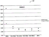
The inventors have observed that the prediction error of the estimated value of the postoperative optical power of the eye varies depending on the ocular axial length of the eye. This is illustrated in fig. 1, where the graph 100 of fig. 1 plots the prediction error for intraocular lens (IOL) power estimates for a set of eyes as a function of the axial length of those eyes. Data were obtained from a group of eyes implanted with an SN6AD1 model IOL. The set of eyes is divided into six groups based on the axial length of the eyes. In this case, the groups are divided at uniform eye axis length intervals. The first group includes all those eyes whose axial length is less than 22 mm. The second group includes all those eyes whose axial length is from 22mm to less than 23 mm. The third group includes all those eyes whose axial length is from 23mm to less than 24 mm. The fourth group includes all those eyes whose axial length is from 24mm to less than 25 mm. The fifth group includes all those eyes whose axial length is from 25mm to less than 26 mm. Finally, the sixth group includes all those eyes whose axial length is greater than 26 mm.
When the prediction errors for the six eye axis length groups are calculated using regression coefficients derived from the entire data set, the result is a difference in time between the prediction errors for each of the six eye axis length groups when the regression coefficients derived from only the eyes in the respective group are used to calculate the prediction errors for each of the six eye axis length groups separately. In the graph 100, an asterisk (—) indicates the prediction error (in this case, the mean absolute error) for each eye group in the case where regression analysis was performed using all eyes in all six groups. In contrast, a plus (+) sign indicates a prediction error of each eye group in the case where regression analysis is performed on each group separately using only eyes that are members of the respective groups. As shown in the graph 100, the prediction error obtained by performing the regression analysis separately for each group is smaller in each case than when the prediction error obtained by performing the regression analysis for all the eyes together regardless of the different axial lengths of the eyes.
The segmented method of generating regression coefficients is therefore an improved method, especially for shorter and longer eyes. In some embodiments, to apply this piecewise regression approach, a minimum of about 50 cases are used in each cohort (although in other embodiments more or fewer cases may be used in each cohort). Having 50 cases in the <22mm axial length group will generally involve a relatively large data set because such eyes are relatively rare. Therefore, it may be difficult to obtain the data necessary to perform such a pattern of piecewise regression and analysis for each eye-axis length interval.
As a result, rather than dividing the eyes into groups at generally uniform axial length intervals, the eyes may instead be divided into groups at non-uniform intervals, which results in groups having a generally uniform number of eyes in each group. This approach will be referred to as uniform grouping or clustering. In this method, one or more parameters used in the regression analysis are separated into one or more relatively uniformly sized groups (as opposed to predefined axial length intervals). In some embodiments, this approach allows the benefits of segmentation analysis, but does not use a limiting element that requires a certain number of cases in each interval of ocular axis length (such as an interval less than 22 mm). Groups covering more sparse eye lengths may cover a larger span of eye axis length values than groups covering more common eye lengths. For example, a group may be formed by eyes having an axial length in the range of 20.5mm to 23mm, with the same number of data points as other groups that may span a shorter axial length range.
As with the segmentation method at regular eye axis length intervals, in the uniform clustering method, regression may be used to generate coefficients for each eye group. In some embodiments, the minimum group or cluster size is about 50 data points. Additionally, in some embodiments, up to about 20 groups may be formed (although in some embodiments, fewer or more data points and fewer or more groups may also be used). In embodiments using at least 50 data points per group, for example, a total of 2 groups would be formed from a data set comprising 100 data points. A data set with over 1000 members may have 20 groups (assuming 50 data points per group). In some embodiments, the clustering rules may be as follows: the number of groups (N) — (data point)/50. In some embodiments, N may range from 2 to 20. Rounding-down operations may be included so that a data set with, for example, 268 or 290 members will result in 5 groups (268/50 ═ 5.36 → 5 and 290/50 ═ 5.8 → 5). The above is one example of how to plan a group, but many other ways are possible.
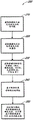
Figure 2 is a flow diagram of an embodiment of a method 200 for determining a relationship that may be used to calculate an IOL power correction value that reduces the error in an IOL power estimate. In block 210, estimates of the postoperative optical power of a set of eyes are obtained. In some embodiments, the eyes are eyes that have all been subjected to IOL implantation surgery using the same IOL commercially available model. In some embodiments, the eyes are eyes that have all previously undergone the same or similar refractive surgery (such as LASIK or RK). The IOL power estimate may be determined for each eye prior to or during surgery. The IOL power estimate for each eye may be used as a basis for selecting the power of the IOL for implantation in the eye. For a selected IOL power, the estimated postoperative optical power may be calculated using the dioptric vergence formula, as described above. In some embodiments, the estimate of post-operative optical power is a spherical equivalent power value, although other measures of optical power may also be used.
In block 220, an actual measurement of the postoperative optical power of the eye may be obtained. These measurements may be performed using, for example, an automatic diopter machine, a phoropter, or other suitable instrument. In some embodiments, the measure of post-operative optical power is a spherical equivalent power value, although other measures of optical power may also be used. These post-operative optical power measurements can be used to determine the error present in the estimate of post-operative optical power. In some embodiments, an error value is determined for each eye in the data set, a prediction error value for the data set as a whole may be determined, or a prediction error value is determined for a sub-portion of the data set, as discussed further herein. In some embodiments, the prediction error value is the average absolute error of the eyes in the data set. In some embodiments, the prediction error value is the median absolute error of the eyes in the data set. In other embodiments, the prediction error value is the percentage of eyes with postoperative optical power outside of a desired range (e.g., the percentage of eyes that do not achieve +/-0.50D of postoperative SE optical power).
In block 230, measurements of various characteristics of the eye in the data set may be obtained. As discussed herein, these characteristics may include, for example, eye axis length, WTW distance, aphakic SE power (whether measured directly intraoperatively or calculated theoretically based on preoperative measurements), average corneal curvature, and the like. In some embodiments, one of the characteristics is a composite of two or more other characteristics. For example, delta aphakic optical power, which may be defined as theoretical aphakic SE-measured aphakic SE, is used. The inventors have found that this delta aphakic optical power value can advantageously be more strongly correlated with prediction error than a theoretical aphakic power value alone or a measured aphakic power value.
In block 240, the eyes in the data set may be divided into groups based on their eye axis length values. As discussed herein, the separation may be performed by forming the groups at regular axial length intervals such that the groups span a generally uniform range of axial lengths. Alternatively, separation may be performed by forming groups that span a non-uniform axial length range of the eye but include a substantially uniform number of eyes. An example algorithm for performing this type of uniform clustering is now given.
The goal of this uniform clustering algorithm is to divide the R-dimensional data set into groups of roughly equal members. As a simple example, assume a 1-dimensional set of 10 values and want to divide it into two equal partitions. (Note that allow for multiple values.)
| 20 |
| 2 |
| 10 |
| 8 |
| 19 |
| 18 |
| 19 |
| 17 |
| 15 |
| 11 |
First, data may be sorted. The data may then be split into two groups a and B, each group being 5-10/2-the size (number of values)/(number of partitions).
| 2 | A |
| 8 | A |
| 10 | A |
| 11 | A |
| 15 | A |
| 17 | B |
| 18 | B |
| 19 | B |
| 19 | B |
| 20 | B |
Is defined as follows: n is the number of values (integer) and M is the number of partitions (integer). Now, the following integer-valued regio-separator indices s (M) (M ═ 0 to M-1) can be calculated.

If the sorted data is referred to as x [ N ] (N ═ 0 to N-1), the true value area separator value c (M) (M ═ 0 to M-1) is given by:
c(m)=x[s(m)]
for the above example data, c [0] is 2 and c [1] is 17. These regions are marked using an M index (M-0 to M-1). Given value z, the index mark of the corresponding region can be calculated using the following equation.

As a second example of using the original data, now assume that M is 3. The bin separator index is:
s(0)=Round(0)=0
s(1)=Round(10/3)=Round(3.333)=3
s(2)=Round(2*10/3)=Round(6.666)=7
the regionalizer values are:
c(0)=x[0]=2
c(1)=x[3]=11
c(2)=x[7]=19
a small number of given z-values and corresponding index markers are:
| Z | m |
| -1 | 0 |
| 1 | 0 |
| 10 | 0 |
| 11 | 1 |
| 18 | 1 |
| 19 | 2 |
| 20 | 2 |
| 22 | 2 |
to extend this clustering concept to higher dimensions, the number of intervals M [ J ] (J0 to J-1) per dimension is chosen, where J is the number of dimensions. The above equation may then be applied for each dimension. Note that M [ i ] ═ M [ j ] (for i ≠ j) is not required.
To use such clustering in the context of IOL power estimates and correction values, the input data may be grouped according to the clustering scheme above (e.g., based on the axial length of the eyes in the data set). A linear predictor may then be applied to each data group, as discussed further herein. The above equation for calculating the index marker may be applied to each dimension to give the J-dimensional index of the linear predictor used during IOL outcome prediction.
In block 250 of fig. 2, a relationship may be determined for calculating an IOL power correction value that reduces the prediction error for the eyes in each respective group determined in block 240. As already mentioned, in some embodiments, this may be performed using regression analysis. Regression analysis may be performed separately for each eye axis length group of the eyes in the data set. Regression analysis may be used to model mathematical relationships between various ocular characteristics discussed herein (and/or characteristics of IOLs implanted in these eyes) and the predicted error for a selected group of ocular axial lengths of the eyes or parameters directly associated with manufacturing errors.
Regression analysis may be used to improve or optimize the target parameters. The target parameter may be a prediction error associated with the selected group of eye axis lengths or other parameter directly associated with the prediction error. For example, eye characteristics may be regressed for known prediction errors to obtain, for example, a 0.00 average prediction error for the eye in a selected eye axis length interval. This results in a set of coefficients that when used to correct the IOL power estimates for the eyes in the selected group of axial lengths of the eyes results in a 0.00 mean prediction error for that group of eyes. These coefficients may be used to correct IOL power estimates for future patients by applying coefficients corresponding to the group of axial lengths to which the eyes of these future patients belong. In another example, eye characteristics may be regressed for prediction error to increase or maximize the percentage of eyes in the selected group of axial lengths that have a post-operative optical power less than a desired threshold (e.g., less than +/-0.50D).
In some embodiments, the data corresponding to each eye in the group of eye axis lengths is factored into the resulting regression coefficients. For example, if a particular axial length group of eyes includes a set of 500 eyes of data, the regression analysis may determine regression information using all 500 data points in an attempt to minimize or reduce the prediction error. However, in other embodiments, it may be advantageous to use only data corresponding to a subset of representative eyes in each eye axis length group. This can be done using, for example, the random sample consensus (RANSAC) algorithm.
RANSAC is a computational algorithm that attempts to estimate one or more parameters of a computational model using an observed set of data. The algorithm is designed to tolerate relatively large ratios of outlier (outlers) data that should be ignored, while it fits the rest of the good data in the training set. The RANSAC algorithm assumes that the data in each eye axis length group contains normal values (inliers), the distribution of which can be considered relatively well by the relationship between the selected eye characteristics and the prediction error. However, the RANSAC algorithm also assumes that the data in each eye axis length group contains outliers that do not fit the model. In applications where intraocular lens (IOL) case history is optimized to improve prediction of post-operative refractive error, outlier data may be due to incorrectly recorded data, biometric measurement errors, or abnormal optical outcomes due to unknown causes. The RANSAC algorithm may determine the regression coefficients based primarily on normal values (rather than abnormal values). By empirically evaluating many large IOL data sets, algorithm parameters, error metrics, and termination criteria can be established to arrive at a robust and effective estimate.
The RANSAC algorithm does not use all data to determine the regression coefficients. Alternatively, the algorithm may randomly select a subset of the eyes in each axial length group. In some embodiments, the number of selected eyes may be a multiple of the number of eye characteristics considered in the regression analysis. For example, if the regression analysis is to consider four eye characteristics (e.g., eye axis length, WTW distance, delta aphakic optical power, and mean K), the number of randomly selected eyes may be a multiple of 4. In some embodiments, the algorithm randomly selects a number of eyes corresponding to 2 times the number of eye characteristics being considered. Thus, for an axial length group of eyes comprising 500 medical records, the algorithm randomly selects only eight data sets at a time for analysis (although other numbers of eyes/data sets may be used).
The algorithm then performs a linear regression analysis to identify a set of coefficients for improving or optimizing the prediction error of the selected subset of eyes. These regression coefficients may then be applied to the entire eye axis length group and the resulting prediction error determined. The algorithm then randomly selects a new set of 8 eyes from the axial length group and computes a new set of coefficients, which are then applied to the entire axial length group of eyes. If the new set of coefficients results in a better prediction error than the coefficients calculated from the first set of randomly selected eyes, the first set of coefficients is discarded. This process is repeated iteratively (e.g., tens of thousands) until the resulting prediction error improves or optimizes satisfactorily.
By not using all the data to calculate the regression coefficients for each eye axis length group, the algorithm effectively removes bad or extreme data that would "pull" the coefficients away from the more optimal solution. Although this (bad or extreme) data is not used in the RANSAC regression analysis, this data is used to calculate the resulting prediction error (mean error) for the eye axis length cohort. All data can also be used to calculate statistical measures such as standard deviation and median. Thus, the algorithm does not filter out "bad" data points, but simply does not use them for regression. Alternatively, the regression coefficients for each eye axis length group are based on a specific subset of randomly selected eyes within the group, which results in improved or optimized prediction error for the entire group.
Furthermore, the algorithm need not be used to refine or optimize only a single measure of prediction error (such as the average error). Alternatively, the algorithm may be used to improve or optimize any desired measure of prediction error. For example, a surgeon may have difficulty understanding that a mean error of 0.33+/-0.25 is much better than a mean error of 0.38 +/-0.32. However, they understand that 85% of the eyes have a postoperative SE less than only 75% +/-0.50D. Thus, the regression algorithm can improve or optimize the percentage of eyes with postsurgical SE < +/-0.50D in each axial length group. Regression analysis results in a data curve that is not typically bell-shaped, but rather has a relatively wide top and a relatively narrow bottom with similar mean values. The algorithm improves or optimizes this goal by finding a data set within the eye axis length group so that there is more data going into the "sweet spot" that is less than +/-0.50D prediction error.
If the data set includes 20 axial length groups of 50 eyes each (1000 eyes in total) and the regression coefficients for each group were calculated using only 8 of the 50 eyes, the above technique would result in 20 sets of regression coefficients generated using 160 of the 1000 eyes. Because there are different regression coefficients for each eye axis length group, there will likely be discontinuities between the coefficients of adjacent eye axis length groups. In some embodiments, it may be advantageous to avoid such discontinuities between groups of eye axis lengths. For example, it is expected that the IOL power correction calculated for an eye having an axial length of 23.99mm will be substantially similar to the correction for an eye having an axial length of 24.01 mm. To achieve this, blending zones may be defined between each pair of adjacent eye axis length groups and blending zone coefficients may be determined for each such blending zone.
The blending zone may be composed of 1/8, for example, the width of each eye-axis length group at its boundary (although other ratios of the widths of the eye-axis length groups may also be used). Thus, if the axial length of the eye for which an IOL power correction value is to be calculated falls somewhere in the middle 6/8 of the group of axial lengths, then the regression coefficients corresponding to that group will be applied. However, if the new data point is within 1/8 of the boundary between the two eye axis length groups, then the regression coefficients corresponding to the blending zone will be used for that data point. The 1/8 value may be a variable ranging from 1/2 to 1/8 depending on the number of data points in the set at optimization. Other scores may also be used. To determine the regression coefficients for each blending zone, a linear blend of the regression coefficients of two adjacent clusters may be calculated. Other methods of blending the regression coefficients of adjacent axial length groups may also be used. If blend zone coefficients are implemented, this will result in an additional N-2 sets of regression coefficients, where N is equal to the total number of eye axis length groups. Thus, in these embodiments, the total number of sets of regression coefficients would be 2N-2.
FIG. 3 is a flow chart illustrating an embodiment of a method 300 for improving an estimate of the optical power of an intraocular lens (IOL) to be inserted into a patient's eye. In block 310, an estimate of the IOL power of the patient's eye is calculated. In some embodiments, the IOL power estimate is calculated based at least in part on an aphakic optical power value of the patient's eye. As discussed herein, the aphakic optical power value may be measured intraoperatively using a wavefront aberrometer. As discussed herein, the wavefront aberrometer can be integrated with a surgical microscope. The IOL power estimate may be calculated using, for example, the refractive vergence formula set forth herein. However, other techniques may also be used.
In block 320, an eye length value for the patient's eye is obtained. The eye length value may be measured using any conventional technique.
In block 330, the processor selects a relationship for calculating an IOL power correction value based on the eye axis length value of the patient's eye. As discussed herein, the regression coefficients are targeted to each of a plurality of eye axis length groups. The processor may determine to which eye axis length group the patient's eye belongs and may select a regression coefficient corresponding to the eye axis length group.
In block 340, the processor calculates an IOL power correction value. This may be done, for example, by multiplying each of the respective regression coefficients by a value of a corresponding characteristic of the patient's eye. As discussed herein, these characteristics may include the axial length of the eye, the WTW distance, the theoretical aphakic optical power, the measured aphakic optical power, the difference between the theoretical aphakic optical power and the measured aphakic optical power, and the average corneal curvature of the eye. In some embodiments, the IOL power correction value is calculated as a (axial length of the eye) + B (WTW distance) + C (theoretical aphakic optical power-measured aphakic optical power) + D (mean corneal curvature), where A, B, C and D represent regression coefficients corresponding to the group of axial lengths to which the patient's eye belongs.
Finally, in block 350, the IOL power correction values are applied. For example, in some embodiments, an IOL power correction value is applied to an estimate of the postoperative optical power of the patient's eye for a given IOL power value. In some embodiments, this may be done by simply adding the IOL power correction value to the estimated value of the postoperative optical power. However, in other embodiments, the IOL power correction value may be applied according to some other mathematical relationship with the estimate of the postoperative optical power. The resulting estimate of adjusted postoperative optical power may provide the surgeon with a more accurate representation of what the patient's postoperative optical power will be for a given IOL power value. As a result, the surgeon may more accurately select the power of the IOL to be implanted in the patient's eye.
The above embodiments have been described in sufficient detail to enable those of ordinary skill in the art to make and use the devices, systems, methods, etc., described herein. However, a wide variety of variations are possible. For example, components, elements, and/or steps may be changed, added, removed, or rearranged.
The systems and methods described herein may be advantageously implemented using, for example, computer software, hardware, firmware, or any combination of software, hardware, and firmware. The software modules may include computer executable code for performing the functions described herein. In some embodiments, the computer-executable code is executed by one or more general-purpose computers. However, those of ordinary skill in the art will appreciate that any module that can be implemented using software to execute on a general purpose computer in accordance with the present disclosure can also be implemented using different combinations of hardware, software, or firmware. For example, this module may be implemented entirely in hardware using a combination of integrated circuits. Alternatively or additionally, this module may be implemented in whole or in part using a special purpose computer, rather than a general purpose computer, designed to perform the specific functions described herein. Additionally, if methods are described as being at least partially executed or being executable by computer software, it should be understood that the methods can be provided on a computer readable medium (e.g., an optical disk such as a CD or DVD, a hard drive, a flash memory, a diskette, etc.) that, when read by a computer or other processing device, causes it to perform the methods.
It will also be appreciated by those of ordinary skill in the art that a plurality of distributed computing devices may be substituted for any of the computing devices shown herein in accordance with the present disclosure. In these distributed embodiments, the functionality of one computing device is distributed such that some functionality is performed on each of the distributed computing devices.
While certain embodiments have been described explicitly, other embodiments will become apparent to those of ordinary skill in the art based on this disclosure. The scope of the invention is therefore intended to be defined by reference to the claims, rather than merely by taking the explicitly described embodiments into account.
Claims (10)
1. An ophthalmic instrument, comprising:
a measurement device for measuring an aphakic optical power of a patient's eye; and
a processor for accessing a computer-readable medium having computer-executable code stored thereon, the computer-executable code executable by the processor to:
receiving an indication of the aphakic optical power of the patient's eye from the measurement device,
determining an intraocular lens IOL power estimate based at least in part on an aphakic optical power of the patient's eye,
receiving a measured eye axis length value for the patient's eye,
selecting a mathematical relationship for calculating an IOL power correction value based on one or more characteristics of the patient's eye and regression coefficients corresponding to one or more characteristics of the patient's eye corresponding to the group of eye axis lengths to which the patient's eye belongs, by dividing each of a plurality of groups of the plurality of eyes based on their eye axis lengths, wherein a prediction error of the respective plurality of eyes in each group is reduced when applying the IOL power correction value to the corresponding estimated value of postoperative optical power, the prediction error being based on a respective difference between the estimated value and the measured value of postoperative optical power of the plurality of eyes in each group, the regression coefficients being generated using a segmentation method,
selecting an IOL for the patient's eye based on the estimated value of postoperative optical power adjusted by the IOL power correction value.
2. The ophthalmic instrument of claim 1, wherein the measurement device comprises a wavefront aberrometer and the aphakic optical power comprises a direct measurement of aphakic optical power.
3. The ophthalmic apparatus of claim 2, wherein the wavefront aberrometer comprises a Talbot-moir wavefront aberrometer.
4. The ophthalmic instrument of claim 1, wherein the one or more characteristics of the plurality of eyes comprise an axial length of the eye, a measured aphakic optical power, a theoretical aphakic optical power, a corneal power, or a white-to-white distance.
5. The ophthalmic instrument of claim 4, wherein one of the one or more characteristics comprises a difference between a theoretical aphakic optical power and a measured aphakic optical power.
6. An ophthalmic method, comprising:
receiving a measured eye axis length value for a patient's eye;
selecting a mathematical relationship for calculating an IOL power correction value for each of a plurality of groups resulting from dividing the plurality of eyes based on their axial lengths, wherein the mathematical relationship is based on one or more characteristics of the patient's eye and regression coefficients corresponding to the one or more characteristics of the patient's eye corresponding to the group of axial lengths to which the patient's eye belongs, the prediction error for the respective plurality of eyes in each group being reduced when the IOL power correction value is applied to the corresponding estimated value of postoperative optical power, the prediction error being based on the respective difference between the estimated value and the measured value of postoperative optical power for the plurality of eyes in each group, the regression coefficients being generated using a segmentation method;
selecting an IOL for the patient's eye based on the estimated value of postoperative optical power adjusted by the IOL power correction value.
7. The ophthalmic method of claim 6, wherein the one or more characteristics of the plurality of eyes comprise axial length of the eye, measured aphakic optical power, theoretical aphakic optical power, corneal power, or white-to-white distance.
8. The ophthalmic method of claim 6, wherein one of the one or more characteristics comprises a difference between theoretical aphakic optical power and measured aphakic optical power.
9. The ophthalmic method of claim 6, wherein applying the IOL power correction value to the corresponding estimate of postoperative optical power comprises adding the IOL power correction value to the estimate of postoperative optical power of the patient's eye.
10. The ophthalmic method of claim 6, wherein the estimate of the postoperative optical power is determined using a dioptric vergence formula.
Applications Claiming Priority (3)
| Application Number | Priority Date | Filing Date | Title |
|---|---|---|---|
| US201361889477P | 2013-10-10 | 2013-10-10 | |
| US61/889,477 | 2013-10-10 | ||
| CN201480055492.2A CN105813543B (en) | 2013-10-10 | 2014-10-08 | Corrected value for IOL refractive power estimated values |
Related Parent Applications (1)
| Application Number | Title | Priority Date | Filing Date |
|---|---|---|---|
| CN201480055492.2A Division CN105813543B (en) | 2013-10-10 | 2014-10-08 | Corrected value for IOL refractive power estimated values |
Publications (2)
| Publication Number | Publication Date |
|---|---|
| CN109008941A CN109008941A (en) | 2018-12-18 |
| CN109008941B true CN109008941B (en) | 2021-08-24 |
Family
ID=52809390
Family Applications (2)
| Application Number | Title | Priority Date | Filing Date |
|---|---|---|---|
| CN201810941555.4A Active CN109008941B (en) | 2013-10-10 | 2014-10-08 | Correction values for IOL power estimates |
| CN201480055492.2A Active CN105813543B (en) | 2013-10-10 | 2014-10-08 | Corrected value for IOL refractive power estimated values |
Family Applications After (1)
| Application Number | Title | Priority Date | Filing Date |
|---|---|---|---|
| CN201480055492.2A Active CN105813543B (en) | 2013-10-10 | 2014-10-08 | Corrected value for IOL refractive power estimated values |
Country Status (7)
| Country | Link |
|---|---|
| US (1) | US9622655B2 (en) |
| EP (1) | EP3038514A4 (en) |
| JP (1) | JP6620293B2 (en) |
| CN (2) | CN109008941B (en) |
| AU (1) | AU2014331833B2 (en) |
| CA (1) | CA2923648C (en) |
| WO (1) | WO2015054521A1 (en) |
Families Citing this family (22)
| Publication number | Priority date | Publication date | Assignee | Title |
|---|---|---|---|---|
| JP6434015B2 (en) * | 2013-07-25 | 2018-12-05 | オプティメディカ コーポレイション | In situ calculation of the refractive index of an object |
| US10667680B2 (en) | 2016-12-09 | 2020-06-02 | Microsoft Technology Licensing, Llc | Forecasting eye condition progression for eye patients |
| IL258706A (en) * | 2017-04-25 | 2018-06-28 | Johnson & Johnson Vision Care | Ametropia treatment tracking methods and system |
| US11890184B2 (en) * | 2017-09-29 | 2024-02-06 | John Gregory LADAS | Systems, apparatuses, and methods for intraocular lens selection using artificial intelligence |
| EP3501376A1 (en) * | 2017-12-22 | 2019-06-26 | Essilor International | Methods and systems for determining a refraction of at least an eye of a person |
| JP2021509299A (en) * | 2018-01-05 | 2021-03-25 | アルコン インコーポレイティド | Systems and methods for selecting an intraocular lens |
| CN108538389B (en) * | 2018-03-27 | 2022-04-29 | 季书帆 | Method and system for predicting diopter adjustment value in SMILE refractive surgery |
| US10888380B2 (en) * | 2018-07-12 | 2021-01-12 | Alcon Inc. | Systems and methods for intraocular lens selection |
| CA3121802A1 (en) | 2018-12-06 | 2020-06-11 | Advanced Euclidean Solutions, Llc | Apparatus and method for intraocular lens selection using post-operative measurements |
| CN109645956B (en) * | 2018-12-25 | 2021-08-06 | 重庆远视科技有限公司 | Eye diopter measuring device |
| US11564839B2 (en) | 2019-04-05 | 2023-01-31 | Amo Groningen B.V. | Systems and methods for vergence matching of an intraocular lens with refractive index writing |
| US11529230B2 (en) * | 2019-04-05 | 2022-12-20 | Amo Groningen B.V. | Systems and methods for correcting power of an intraocular lens using refractive index writing |
| US11583388B2 (en) | 2019-04-05 | 2023-02-21 | Amo Groningen B.V. | Systems and methods for spectacle independence using refractive index writing with an intraocular lens |
| US11678975B2 (en) | 2019-04-05 | 2023-06-20 | Amo Groningen B.V. | Systems and methods for treating ocular disease with an intraocular lens and refractive index writing |
| US11944574B2 (en) | 2019-04-05 | 2024-04-02 | Amo Groningen B.V. | Systems and methods for multiple layer intraocular lens and using refractive index writing |
| US11583389B2 (en) | 2019-04-05 | 2023-02-21 | Amo Groningen B.V. | Systems and methods for correcting photic phenomenon from an intraocular lens and using refractive index writing |
| CN110123488B (en) * | 2019-05-27 | 2023-12-29 | 中国计量科学研究院 | Intraocular lens diopter verification lens and value fixing method |
| CN111134613B (en) * | 2019-11-21 | 2022-04-05 | 明灏科技(北京)有限公司 | Image recognition-based orthokeratology lens fitting method and system |
| CN111259743B (en) * | 2020-01-09 | 2023-11-24 | 中山大学中山眼科中心 | Training method and system for myopia image deep learning recognition model |
| CN111513917B (en) * | 2020-05-22 | 2022-03-22 | 杭州明视康眼科医院有限公司 | Transposition adjusting method for astigmatism type ICL postoperative residual astigmatism and method for estimating diopter after transposition adjustment |
| CN112102940B (en) * | 2020-09-08 | 2024-04-16 | 南方科技大学 | Refraction detection method, refraction detection device, computer equipment and storage medium |
| CN117238514B (en) * | 2023-05-12 | 2024-05-07 | 中山大学中山眼科中心 | Intraocular lens refractive power prediction method, system, equipment and medium |
Family Cites Families (11)
| Publication number | Priority date | Publication date | Assignee | Title |
|---|---|---|---|---|
| US6634751B2 (en) * | 2001-09-10 | 2003-10-21 | Bausch & Lomb Incorporated | Intraocular lens derivation system |
| US6736510B1 (en) | 2003-02-04 | 2004-05-18 | Ware Tec Vision Systems, Inc. | Ophthalmic talbot-moire wavefront sensor |
| US7556378B1 (en) * | 2003-04-10 | 2009-07-07 | Tsontcho Ianchulev | Intraoperative estimation of intraocular lens power |
| US7476248B2 (en) * | 2004-04-06 | 2009-01-13 | Alcon, Inc. | Method of calculating the required lens power for an opthalmic implant |
| EP1737372B1 (en) | 2004-04-20 | 2014-08-06 | WaveTec Vision Systems, Inc. | Integrated surgical microscope and wavefront sensor |
| JP4492858B2 (en) * | 2004-07-20 | 2010-06-30 | 株式会社ニデック | Ophthalmic apparatus and intraocular refractive power distribution calculation program |
| US8862447B2 (en) * | 2010-04-30 | 2014-10-14 | Amo Groningen B.V. | Apparatus, system and method for predictive modeling to design, evaluate and optimize ophthalmic lenses |
| US8480659B2 (en) * | 2008-07-25 | 2013-07-09 | Lensar, Inc. | Method and system for removal and replacement of lens material from the lens of an eye |
| EP2334223A1 (en) * | 2008-09-11 | 2011-06-22 | IOL Innovations APS | System and method for determining and predicting iol power in situ |
| JP5837489B2 (en) * | 2009-07-14 | 2015-12-24 | ウェーブテック・ビジョン・システムズ・インコーポレイテッドWavetec Vision Systems, Inc. | Ophthalmic equipment |
| EP2453822B1 (en) * | 2009-07-14 | 2014-08-20 | WaveTec Vision Systems, Inc. | Determination of the effective lens position of an intraocular lens using aphakic refractive power |
-
2014
- 2014-10-08 AU AU2014331833A patent/AU2014331833B2/en active Active
- 2014-10-08 CA CA2923648A patent/CA2923648C/en active Active
- 2014-10-08 EP EP14852221.2A patent/EP3038514A4/en active Pending
- 2014-10-08 CN CN201810941555.4A patent/CN109008941B/en active Active
- 2014-10-08 WO PCT/US2014/059943 patent/WO2015054521A1/en active Application Filing
- 2014-10-08 CN CN201480055492.2A patent/CN105813543B/en active Active
- 2014-10-08 JP JP2016521301A patent/JP6620293B2/en active Active
- 2014-10-09 US US14/511,003 patent/US9622655B2/en active Active
Also Published As
| Publication number | Publication date |
|---|---|
| CA2923648C (en) | 2022-02-01 |
| EP3038514A1 (en) | 2016-07-06 |
| US20150103313A1 (en) | 2015-04-16 |
| CA2923648A1 (en) | 2015-04-16 |
| CN109008941A (en) | 2018-12-18 |
| JP2016533781A (en) | 2016-11-04 |
| JP6620293B2 (en) | 2019-12-18 |
| WO2015054521A1 (en) | 2015-04-16 |
| US9622655B2 (en) | 2017-04-18 |
| CN105813543A (en) | 2016-07-27 |
| AU2014331833B2 (en) | 2018-10-04 |
| CN105813543B (en) | 2018-09-14 |
| EP3038514A4 (en) | 2018-05-02 |
Similar Documents
| Publication | Publication Date | Title |
|---|---|---|
| CN109008941B (en) | Correction values for IOL power estimates | |
| AU2014331833A1 (en) | Correction values for IOL power estimates | |
| US10136805B2 (en) | Apparatus, system, and method for intraocular lens power calculation using a regression formula incorporating corneal spherical aberration | |
| US9554697B2 (en) | Determination of the effective lens position of an intraocular lens using aphakic refractive power | |
| US8696119B2 (en) | Systems and methods for determining intraocular lens power | |
| JP2018083126A (en) | Method for automatic optimization of calculation of intraocular lens to be implanted | |
| US9271829B2 (en) | Method for the pre-operative selection of an intraocular lens to be implanted in an eye | |
| Corbelli et al. | Comparative analysis of visual outcome with 3 intraocular lenses: monofocal, enhanced monofocal, and extended depth of focus | |
| US8696120B2 (en) | Systems and methods for determining intraocular lens power | |
| Kawamorita et al. | Effect of pupil size on visual acuity in a laboratory model of pseudophakic monovision | |
| US20120245484A1 (en) | Determining intraocular lens power and postoperative refraction for pediatric patients | |
| RU2814629C1 (en) | Method for calculating optical power of intraocular lens based on personalized eye simulation | |
| Zapata-Diaz | Mathematical Modelling of the Depth-of-Field of the Eye | |
| CN115171879A (en) | Diopter prediction method after artificial lens implantation, storage medium and electronic equipment |
Legal Events
| Date | Code | Title | Description |
|---|---|---|---|
| PB01 | Publication | ||
| PB01 | Publication | ||
| SE01 | Entry into force of request for substantive examination | ||
| SE01 | Entry into force of request for substantive examination | ||
| TA01 | Transfer of patent application right | ||
| TA01 | Transfer of patent application right |
Effective date of registration: 20200417 Address after: Fribourg Applicant after: ALCON, Inc. Address before: Basel Applicant before: NOVARTIS AG |
|
| GR01 | Patent grant | ||
| GR01 | Patent grant |