CN108968890B - Master-slave flexible robotic endoscope system - Google Patents
Master-slave flexible robotic endoscope system Download PDFInfo
- Publication number
- CN108968890B CN108968890B CN201810433861.7A CN201810433861A CN108968890B CN 108968890 B CN108968890 B CN 108968890B CN 201810433861 A CN201810433861 A CN 201810433861A CN 108968890 B CN108968890 B CN 108968890B
- Authority
- CN
- China
- Prior art keywords
- endoscope
- tendon
- instrument
- robotic
- brake assemblies
- Prior art date
- Legal status (The legal status is an assumption and is not a legal conclusion. Google has not performed a legal analysis and makes no representation as to the accuracy of the status listed.)
- Expired - Fee Related
Links
- 210000002435 tendon Anatomy 0.000 claims abstract description 197
- 238000013519 translation Methods 0.000 claims abstract description 65
- 238000003032 molecular docking Methods 0.000 claims abstract description 34
- 230000033001 locomotion Effects 0.000 claims abstract description 33
- 238000005096 rolling process Methods 0.000 claims abstract description 31
- 230000007246 mechanism Effects 0.000 claims abstract description 29
- 239000012636 effector Substances 0.000 claims description 83
- 230000000712 assembly Effects 0.000 claims description 44
- 238000000429 assembly Methods 0.000 claims description 44
- 238000006073 displacement reaction Methods 0.000 claims description 23
- 230000000694 effects Effects 0.000 claims description 17
- 230000008878 coupling Effects 0.000 claims description 10
- 238000010168 coupling process Methods 0.000 claims description 10
- 238000005859 coupling reaction Methods 0.000 claims description 10
- 230000013011 mating Effects 0.000 claims description 4
- 238000006243 chemical reaction Methods 0.000 claims description 2
- 238000002788 crimping Methods 0.000 abstract description 5
- 238000003384 imaging method Methods 0.000 description 126
- 238000000034 method Methods 0.000 description 57
- 230000007704 transition Effects 0.000 description 18
- 230000008569 process Effects 0.000 description 16
- 238000010586 diagram Methods 0.000 description 15
- 238000012545 processing Methods 0.000 description 12
- 230000004044 response Effects 0.000 description 11
- 238000004891 communication Methods 0.000 description 10
- 238000001839 endoscopy Methods 0.000 description 9
- 230000006870 function Effects 0.000 description 8
- 239000000523 sample Substances 0.000 description 8
- 238000002674 endoscopic surgery Methods 0.000 description 7
- 238000004804 winding Methods 0.000 description 6
- 238000004873 anchoring Methods 0.000 description 4
- 238000013500 data storage Methods 0.000 description 4
- 230000009977 dual effect Effects 0.000 description 4
- 230000002040 relaxant effect Effects 0.000 description 4
- 230000008901 benefit Effects 0.000 description 3
- 230000002262 irrigation Effects 0.000 description 3
- 238000003973 irrigation Methods 0.000 description 3
- 230000001360 synchronised effect Effects 0.000 description 3
- 230000009471 action Effects 0.000 description 2
- 239000000853 adhesive Substances 0.000 description 2
- 230000001070 adhesive effect Effects 0.000 description 2
- 238000005452 bending Methods 0.000 description 2
- 230000008859 change Effects 0.000 description 2
- 238000005286 illumination Methods 0.000 description 2
- 238000004519 manufacturing process Methods 0.000 description 2
- 238000012544 monitoring process Methods 0.000 description 2
- 230000003287 optical effect Effects 0.000 description 2
- 230000000717 retained effect Effects 0.000 description 2
- 230000003068 static effect Effects 0.000 description 2
- 230000004075 alteration Effects 0.000 description 1
- 238000011161 development Methods 0.000 description 1
- 238000009826 distribution Methods 0.000 description 1
- 230000007717 exclusion Effects 0.000 description 1
- 238000002474 experimental method Methods 0.000 description 1
- 230000003116 impacting effect Effects 0.000 description 1
- 230000006872 improvement Effects 0.000 description 1
- 238000003780 insertion Methods 0.000 description 1
- 230000037431 insertion Effects 0.000 description 1
- 238000009434 installation Methods 0.000 description 1
- 230000003993 interaction Effects 0.000 description 1
- 238000010801 machine learning Methods 0.000 description 1
- 239000000463 material Substances 0.000 description 1
- 238000005259 measurement Methods 0.000 description 1
- 238000012986 modification Methods 0.000 description 1
- 230000004048 modification Effects 0.000 description 1
- 239000013307 optical fiber Substances 0.000 description 1
- 230000008520 organization Effects 0.000 description 1
- 230000003534 oscillatory effect Effects 0.000 description 1
- 229920006395 saturated elastomer Polymers 0.000 description 1
- 230000035939 shock Effects 0.000 description 1
- 238000004904 shortening Methods 0.000 description 1
- 239000007787 solid Substances 0.000 description 1
- 238000007619 statistical method Methods 0.000 description 1
- 238000001356 surgical procedure Methods 0.000 description 1
- 238000002627 tracheal intubation Methods 0.000 description 1
- 238000012546 transfer Methods 0.000 description 1
Images


Classifications
-
- A—HUMAN NECESSITIES
- A61—MEDICAL OR VETERINARY SCIENCE; HYGIENE
- A61B—DIAGNOSIS; SURGERY; IDENTIFICATION
- A61B1/00—Instruments for performing medical examinations of the interior of cavities or tubes of the body by visual or photographical inspection, e.g. endoscopes; Illuminating arrangements therefor
- A61B1/005—Flexible endoscopes
- A61B1/0051—Flexible endoscopes with controlled bending of insertion part
- A61B1/0052—Constructional details of control elements, e.g. handles
- A61B1/0053—Constructional details of control elements, e.g. handles using distributed actuators, e.g. artificial muscles
-
- A—HUMAN NECESSITIES
- A61—MEDICAL OR VETERINARY SCIENCE; HYGIENE
- A61B—DIAGNOSIS; SURGERY; IDENTIFICATION
- A61B1/00—Instruments for performing medical examinations of the interior of cavities or tubes of the body by visual or photographical inspection, e.g. endoscopes; Illuminating arrangements therefor
- A61B1/005—Flexible endoscopes
- A61B1/0051—Flexible endoscopes with controlled bending of insertion part
- A61B1/0052—Constructional details of control elements, e.g. handles
-
- A—HUMAN NECESSITIES
- A61—MEDICAL OR VETERINARY SCIENCE; HYGIENE
- A61B—DIAGNOSIS; SURGERY; IDENTIFICATION
- A61B1/00—Instruments for performing medical examinations of the interior of cavities or tubes of the body by visual or photographical inspection, e.g. endoscopes; Illuminating arrangements therefor
- A61B1/00131—Accessories for endoscopes
- A61B1/00133—Drive units for endoscopic tools inserted through or with the endoscope
-
- A—HUMAN NECESSITIES
- A61—MEDICAL OR VETERINARY SCIENCE; HYGIENE
- A61B—DIAGNOSIS; SURGERY; IDENTIFICATION
- A61B34/00—Computer-aided surgery; Manipulators or robots specially adapted for use in surgery
- A61B34/30—Surgical robots
- A61B34/37—Master-slave robots
-
- A—HUMAN NECESSITIES
- A61—MEDICAL OR VETERINARY SCIENCE; HYGIENE
- A61B—DIAGNOSIS; SURGERY; IDENTIFICATION
- A61B34/00—Computer-aided surgery; Manipulators or robots specially adapted for use in surgery
- A61B34/70—Manipulators specially adapted for use in surgery
- A61B34/71—Manipulators operated by drive cable mechanisms
-
- A—HUMAN NECESSITIES
- A61—MEDICAL OR VETERINARY SCIENCE; HYGIENE
- A61B—DIAGNOSIS; SURGERY; IDENTIFICATION
- A61B17/00—Surgical instruments, devices or methods, e.g. tourniquets
- A61B2017/00477—Coupling
-
- A—HUMAN NECESSITIES
- A61—MEDICAL OR VETERINARY SCIENCE; HYGIENE
- A61B—DIAGNOSIS; SURGERY; IDENTIFICATION
- A61B34/00—Computer-aided surgery; Manipulators or robots specially adapted for use in surgery
- A61B34/30—Surgical robots
- A61B2034/301—Surgical robots for introducing or steering flexible instruments inserted into the body, e.g. catheters or endoscopes
-
- A—HUMAN NECESSITIES
- A61—MEDICAL OR VETERINARY SCIENCE; HYGIENE
- A61B—DIAGNOSIS; SURGERY; IDENTIFICATION
- A61B34/00—Computer-aided surgery; Manipulators or robots specially adapted for use in surgery
- A61B34/70—Manipulators specially adapted for use in surgery
- A61B34/71—Manipulators operated by drive cable mechanisms
- A61B2034/715—Cable tensioning mechanisms for removing slack
Landscapes
- Health & Medical Sciences (AREA)
- Life Sciences & Earth Sciences (AREA)
- Surgery (AREA)
- Engineering & Computer Science (AREA)
- Animal Behavior & Ethology (AREA)
- Veterinary Medicine (AREA)
- Biomedical Technology (AREA)
- Heart & Thoracic Surgery (AREA)
- Medical Informatics (AREA)
- Molecular Biology (AREA)
- Nuclear Medicine, Radiotherapy & Molecular Imaging (AREA)
- General Health & Medical Sciences (AREA)
- Public Health (AREA)
- Robotics (AREA)
- Physics & Mathematics (AREA)
- Biophysics (AREA)
- Optics & Photonics (AREA)
- Pathology (AREA)
- Radiology & Medical Imaging (AREA)
- Endoscopes (AREA)
- Manipulator (AREA)
Abstract
A flexible robotic endoscopic slave system comprising an endoscope body and a flexible elongate shaft extending from the body into which at least one tendon driven robotic endoscopic instrument is insertable; a docking station to which the endoscope body is releasably docked; and a translation mechanism for selectively moving the endoscopic instrument longitudinally within the flexible elongate shaft when the endoscope body is docked. The translation mechanism may carry and selectively replace an actuator that drives each robotic endoscopic instrument through tendons. At least one degree of freedom (DOF) of movement of the robotic instrument is controlled by a pair of actuators and a corresponding pair of tendons. Actuating the engagement structure releasably couples the actuator to an adapter structure for driving each endoscopic instrument. Tendon pretension can occur automatically under programmable control. A rolling joint without tendon crimping structures may be used in robotic endoscopic instruments to reduce tendon wear and rolling joint space volume.
Description
This application is a divisional application of the chinese patent application having application number CN 201580024954.9, application date 2015, 03, 19 and the entire content of the original parent application is incorporated herein by reference.
Technical Field
A slave system of a master-slave flexible robotic endoscope system includes an endoscope body and a flexible elongate shaft extending from the body, at least one tendon driven robotic endoscope instrument insertable into the body or elongate shaft; a docking station for releasably docking the endoscope body; and a conversion mechanism operable to selectively longitudinally place the endoscopic instrument into the flexible elongate shaft when the endoscope body is parked. An actuation structure releasably connects the motor cartridge actuator to an adapter structure for driving each endoscopic instrument. For at least some of the DOFs of spatial motion, two actuators and two corresponding tendons can control instrument motion for each DOF. Tendon stretching can occur automatically under programmable control. A rolling joint without tendon crimping structure can be applied to a machine endoscopic instrument to reduce tendon wear and the space volume of the rolling joint.
Background
Various master-slave robotic flexible endoscope systems have been proposed or are under development. For example, in the master-slave robotic flexible endoscope systems described in international patent application No. PCT/SG2013/000408 and international patent publication No. WO 2010/138083, a tendon-driven robotic arm and corresponding end effector may be inserted into an endoscope body having a flexible elongate shaft extending therefrom such that the robotic arm and end effector may extend out of the end of the flexible elongate shaft to perform an endoscopic procedure. Tendons driving robotic arms and their end effectors have a sheath structure, such as a helical coil sheath.
Components of a flexible robotic endoscope system, including a carrying robotic arm and corresponding end effector, are intended for insertion into a flexible elongate shaft of a human body requiring a minimum size. Unfortunately, the intracorporeal introduction portions of some existing flexible robotic endoscope systems have a larger diameter or cross-sectional area than is necessary relative to the environment in which they are intended to be deployed inside the body.
During an endoscopic procedure, the robotic arm and end effector carried by the flexible elongate shaft must be precisely manipulated at any time in response to control signals generated by the surgeon. The flexibility of the flexible robotic endoscope system allows the flexible elongate shaft to be inserted into a natural body orifice, which then follows a tortuous or highly tortuous path to a target site where a surgeon may perform an endoscopic procedure. However, such flexibility may itself create difficulties with respect to ensuring that the robotic arms and their end effectors remain precisely controlled as the flexible elongate shaft extends along the tortuous path. More specifically, depending on the path followed by the tendons, the tensions of the tendons as they are manipulated in space by the robotic arms and end effects can vary significantly, causing tendon slack or tendon bounce that reduces the consistency and high precision control of the robotic arms and their end effectors.
There is therefore a need for a flexible robotic endoscopy system that overcomes these problems.
Disclosure of Invention
According to an aspect of the present disclosure, a master-slave endoscope system includes: an endoscope comprises a main body and a flexible slender shaft extending out of the main body, wherein the flexible slender shaft spans the length between the near end and the far end of the flexible slender shaft, and a plurality of channels are arranged in the flexible slender shaft along the length direction of the flexible slender shaft and comprise a first channel, a second channel and a third channel; the mechanical driving brake assembly is detachably inserted into the first channel and comprises a robot arm connected with a mechanical driving end effector and a plurality of tendons used for spatially controlling the robot arm and the end effector when the robot arm is stressed; an imaging endoscope removably inserted into the second slot; and the manual driving brake assembly is detachably inserted into the third groove, and the manual driving formulating combination is connected with a manually operated endoscope instrument.
The first set of brakes may be connected to the mechanically actuated brake assembly and used to apply force to the plurality of tendons.
The imaging endoscope can form part of an imaging endoscope assembly that includes an adapter by which the imaging endoscope can be connected to a brake for providing impact displacement to the imaging endoscope. The imaging endoscope combination further includes a plurality of tendons carried therein by way of the adapters to a second set of actuators for providing at least one of heave, roll and pitch motion to the imaging endoscope.
The mechanically actuated brake assembly further includes an adapter removably coupled to the first set of brakes and configured for movement in accordance with a predetermined number of degrees of freedom (DOF), and the first set of actuators includes two actuators corresponding to at least one DOF.
According to an aspect of the present disclosure, a master-slave endoscope system includes: (a) an endoscope having a body from which extends a flexible elongate shaft spanning a length between proximal and distal ends thereof, the flexible elongate shaft having a set of channels disposed therein along a length thereof through which a set of actuation assemblies are insertable, the plurality of channels including a first channel and a second channel; (b) a set of flexible robotic actuating brake assemblies carried by the set of channels, each robotic actuating brake assembly comprising: a robotic arm having a robot-driven end effector coupled thereto; and a plurality of tendons coupled to the robotic arm and configured to control motion of the robotic arm and its end effector according to a predetermined number of degrees of freedom (DOF), wherein two tendons control each degree of freedom of the robotic arm; (c) a set of actuators corresponding to each robotic drive brake assembly, each actuator controllable by a set of input devices with which a surgeon may interact, each actuator for selectively applying torque to tendons of its corresponding robotic drive brake assembly in response to surgeon input to the set of input devices; wherein two actuators control each degree of freedom of the robotic arm; and (d) a processing unit for executing a tendon pre-tensioning or re-tensioning procedure to automatically establish tension levels for a plurality of tendons of each robot-actuated brake assembly by: (i) applying torque to each actuator of the robot driven brake assembly according to a pre-stored torque parameter associated with a representative bending configuration corresponding to the bending of the robot driven brake assembly along its routing path; or (ii) for each tendon of the robot drive brake assembly: dynamically determining a torque transition point between a relaxed state and a non-relaxed state of the tendon; a torque is applied to an actuator corresponding to the tendon (e.g., one to which the tendon is fixed or mounted) at a torque level determined by the torque transition point.
Prior to performing endoscopic surgery, or after inserting each robotic drive brake assembly into a channel of a flexible elongate shaft, applying a torque to each tendon of the robotic drive brake assembly according to a stored torque parameter associated with the representative flexion configuration, outside an operating room.
Dynamically determining a torque transition point between the relaxed state and the relaxed state for each tendon occurs immediately prior to or during the performance of the endoscopic procedure. Dynamically determining a torque transition point between the relaxed state and the unrelaxed state for each tendon comprises: measuring a tendon tension distribution corresponding to the tendon; and calculating a first and/or second derivative of the tendon tension profile.
The system also includes an instrument adapter corresponding to each robotic drive brake assembly, the instrument adapter removably coupled to the set of actuators for selectively coupling the plurality of tendons of the mechanical drive combination to the set of actuators, wherein the instrument adapter is to maintain tension applied to each tendon of the robotic drive brake assembly when separated from the set of actuators.
According to an aspect of the present disclosure, a master-slave endoscope system comprises: (a) a set of robot actuated brake assemblies, each robot actuated brake assembly comprising: a robotic arm having a robot-driven end effector connected thereto; and a plurality of tendons configured to control movement of the robotic arm and the end effector according to a predetermined number of degrees of freedom (DOF); and an instrument adapter corresponding to each robot drive brake assembly and coupled to a tendon thereof, the instrument adapter coupleable to a set of mechanical elements for selectively connecting the plurality of tendons of the robot drive brake assembly to a set of actuators, the instrument adapter comprising: a rotatable shaft corresponding to each tendon of the robotic drive actuation assembly, the rotatable shaft having a longitudinal axis along which the tendon is wrapped circumferentially; and a first tension maintaining element and a second tension maintaining element corresponding to each rotatable shaft, wherein the first tension maintaining element is displaceable relative to the second tension maintaining element for selective engagement and disengagement with the second ratchet element, and wherein the first tension maintaining element is configured for cooperative engagement with the second tension maintaining element when the instrument adapter is disengaged from the set of mechanical elements to prevent rotation of the shafts to maintain a level of tension in the tendons. The first and second tension maintaining elements each include one of a ratchet element and a friction plate.
The instrument adapter further includes a resilient biasing element that maintains the first tension maintaining element and the second tension maintaining element in an engaged state when the instrument adapter is disengaged from the set of mechanical elements. When the instrument adapter is coupled to the set of mechanical elements, the resilient biasing element is movable relative to the shaft to disengage the first tension maintaining element from the second tension maintaining element such that the shaft is rotatable.
The actuator set includes two actuators corresponding to at least one degree of freedom, and for each degree of freedom, the instrument adapter includes a first rotatable shaft along which a first tendon is wrapped circumferentially and a second rotatable shaft along which a second tendon is wrapped circumferentially to control movement of a robotic arm and an end effector of a robotic drive actuation assembly.
According to an aspect of the present disclosure, a master-slave endoscope system comprises: (a) an endoscope having a body and a flexible elongate shaft extending from the body, the flexible elongate shaft spanning a length between a proximal end and a distal end thereof, the flexible elongate shaft having a set of channels disposed therein along a length thereof, a set of actuation assemblies insertable therein along the length of the set of channels, the plurality of channels including a first channel and a second channel; (b) a set of robot driven actuation assemblies, each robot driven actuation assembly comprising: a robotic arm having a robot-driven end effector connected thereto; a plurality of tendons coupled to the robotic arm and configured to control motion of the robotic arm and the end effector according to a predetermined number of degrees of freedom (DOF); and an outer sleeve surrounding the plurality of tendons; (c) a first instrument adapter corresponding to each robotic driven actuation assembly and coupled to tendons thereof, the first instrument adapter coupleable to a set of mechanical elements for selectively manipulating a plurality of tendons of the robotic driven actuation assembly with a set of robotic arm/end effector manipulation actuators; and (d) a translation mechanism configured for independently translating each robot-driven actuation assembly along a predetermined fraction of the length of the flexible elongate shaft to effect an impact displacement of the robot-driven actuation assembly, the translation mechanism comprising one of: (i) a collar carried by each outer sleeve of the set of robotically driven actuation assemblies; and a translation unit including: a receiver configured to receive an outer sleeve of a robotic driven actuation assembly; and a linear actuator corresponding to each receiver and configured for selectively translating the receiver along a predetermined fraction of the length of the flexible elongate shaft; (ii) a second instrument adapter matingly engageable with each first instrument adapter for coupling tendons of the robotic drive actuation assembly corresponding to the first instrument adapter with the set of robotic arm/end effector manipulation actuators; and a translation unit configured to carry each first instrument adapter and a second instrument adapter matingly engageable therewith and to displace each first instrument adapter and each second instrument adapter in mating engagement to effect a predetermined fraction of impact displacements of the individual robotically-driven actuation assemblies along the length of the flexible elongate shaft; and (iii) a translation unit configured to move the respective sets of robotic arm/end effector manipulation actuators and each first instrument adapter coupled thereto to effect a predetermined fraction of impact displacements of the individual robotic drive actuation assemblies along the length of the flexible elongate shaft.
Each second instrument adapter is coupled to the set of robotic arm/end effector manipulation actuators by a tether having a plurality of tendons.
The system also includes a docking station to which a portion of the body of the endoscope is removably engaged, wherein the translation mechanism is carried by the docking station.
The system further comprising a set of carriages carrying the translation mechanism, wherein each carriage of the set of carriages corresponds to a separate robotic drive actuation assembly, and each carriage of the set of carriages is coupled to a rolling motion actuator configured to individually rotate the carriage and its corresponding robotic drive actuation assembly about a rolling axis to provide rolling motion to the robotic arm and end effector of the robotic drive actuation assembly. A portion of the body of the endoscope is removably engaged to the docking station, wherein the docking station carries the translation mechanism and the set of carriages.
According to an aspect of the disclosure, a tendon-controlled robotic arm comprises: a roll joint comprising a drum structure having a central axis therethrough, the roll joint configured to rotate a portion of the robotic arm about the central axis in response to actuation of a tendon carried thereby, the roll joint not including a tendon crimping termination thereon for anchoring a tendon to the roll joint.
The drum structure includes an outer surface, and the rolling joint includes: a clockwise actuating pulley carried by the outer surface and having a channel through which the clockwise actuating tendon extends to rotate the rolling joint in a clockwise direction; and a counterclockwise actuating pulley carried by the outer surface and having a channel through which the counterclockwise actuating tendon extends for rotating the rolling joint in a counterclockwise direction.
The drum structure comprises at least one omega-or U-shaped section providing a corresponding omega-or U-shaped channel, passage or groove, respectively, through which the rotation for controlling the rolling joint is routable.
A set of eyelets is formed in the drum structure through which the tendons may pass such that the tendons are disposed on each of an outer surface of the drum structure and an inner surface of the drum structure. The drum structure carries tendons along tendon routing paths from an outside of the drum, into and through a thickness of the drum to an inside of the drum, and back through the thickness of the drum to an outside of the drum. An adhesive can secure an outer surface of the tendon to a portion of the roller.
Drawings
Fig. 1A and 1B are schematic diagrams of a master-slave flexible robotic endoscopy system according to an embodiment of the present disclosure.
Fig. 2 is a schematic diagram of a host system according to an embodiment of the present disclosure.
Fig. 3 is a schematic diagram of a slave system according to an embodiment of the present disclosure.
Fig. 4A-4D are schematic views of a representative transport endoscope, first and second actuation assemblies, and imaging endoscope assembly, respectively, according to embodiments of the present disclosure.
Fig. 5 is a schematic illustration of a pair of robotic arms and corresponding end effectors carried thereby and an imaging endoscope positioned in an environment beyond a distal end of a transport endoscope according to an embodiment of the disclosure.
Fig. 6A is a representative cross-sectional view of a transport endoscope shaft according to an embodiment of the present disclosure.
Fig. 6B is a representative cross-sectional view of a transport endoscope shaft according to another embodiment of the present disclosure.
Figures 7A-7C are schematic diagrams illustrating an imaging endoscope assembly inserted into a transport endoscope, an imaging connector assembly connected to an imaging subsystem, an imaging input adapter connected to an imaging output adapter of a motor cabinet, and an endoscope support function connector assembly connected to a valve control unit, according to embodiments of the present disclosure.
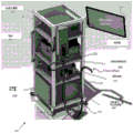
Fig. 8A-8B are schematic diagrams illustrating docking of a transport endoscope to a docking station, with portions of an external sleeve/coil of an actuation assembly and an external sleeve of an imaging endoscope assembly inserted into the transport endoscope, and such external sleeve securely coupled to a translation unit of the docking station.
Fig. 8C is a schematic diagram showing a representative translation unit carried by a docking station, wherein collar elements corresponding to the actuation assembly and imaging endoscope assembly are retained by the translation unit in a representative manner.
Fig. 9 is a schematic diagram illustrating the connection of an instrument input adapter of each actuation assembly to a respective instrument output adapter corresponding to a motor cabinet according to an embodiment of the present disclosure.
Fig. 10 is a perspective cut-away view illustrating a representative interior portion of an instrument input adapter mounted to an instrument output adapter of a motor cabinet according to an embodiment of the present disclosure.
FIG. 11 is a respective cross-sectional view illustrating representative internal portions of an instrument adapter and an instrument output adapter when coupled together or matingly engaged in accordance with an embodiment of the present disclosure.
Fig. 12A-12D are cross-sectional views showing representative interior portions of an actuation engagement structure of an instrument input adapter and the positions of elements therein, corresponding to schematic illustrations of particular stages of engagement and disengagement of the instrument input adapter with the instrument input adapter and the instrument, according to embodiments of the present disclosure.
FIG. 13A illustrates a docking station and corresponding translation unit of an alternative embodiment of the present disclosure.
FIG. 13B illustrates a docking station and corresponding translation unit according to yet another embodiment of the present disclosure.
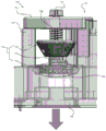
Fig. 13C provides a cross-sectional front view through a portion of a docking station configured to carry a set of carriages or drum structures rotatably coupled to an actuator by which roll motion may be individually provided to one or more actuation assemblies and/or imaging endoscopes.
Fig. 14A shows a representative single actuator/motor per DOF configuration, and the potential bounce effects that may be associated therewith.
Fig. 14B illustrates a representative dual actuator/motor per DOF configuration, and such a configuration results in reduced or minimized bounce effects, in accordance with an embodiment of the present disclosure.
Fig. 15 is an illustration of an offline/online fixed tensioning technique, procedure or process according to an embodiment of the disclosure.
Fig. 16A is an illustration of an active pretensioning technique, flow or process, and fig. 16B is a representative graph of actuator/motor positions and torques corresponding thereto, in accordance with an embodiment of the present disclosure.
Fig. 16C-16F are graphs indicating the measured motor position, the measured motor speed, the measured motor torque, and the first derivative of the measured motor torque, respectively, for the first actuator/motor of the time-specific actuator/motor pair during execution of the active pretensioning technique of fig. 16A.
Fig. 16G-16J are graphs indicating the measured motor position, measured motor speed, measured motor torque, and the first derivative of the measured motor torque, respectively, for the second actuator/motor of the actuator/motor pair at times during execution of the active pretensioning technique of fig. 16A.
Fig. 17 and 18 are schematic diagrams illustrating portions of a non-crimp pulley-based rolling joint or rolling joint element according to embodiments of the present disclosure.
Detailed Description
In the present disclosure, a description of a given element or a consideration or use of a particular element or reference to corresponding descriptive material in one figure may include the same, equivalent or similar element or element symbol identified in another figure. The use of "/" in the figures or related text is understood to mean "and/or" unless otherwise indicated. Recitation of specific values or ranges of values herein are understood to include or be a list of approximate values or ranges of values, such as within +/-20%, +/-15%, +/-10%, or +/-5%.
As used herein, the term "set" corresponds to or is defined as a non-empty finite organization of elements that mathematically exhibit a cardinality of at least 1 (i.e., a set as defined herein may correspond to a unit, or a single-element set or a multi-element set), according to known mathematical definitions (e.g., "11 chapters: the attributes of a finite set" (e.g., as shown on page 140), Peter J. Exxok, Cambridge university Press (1998)) in a manner corresponding to the mathematical reasoning: numbers, sets and functions. In general, an element of a collection may comprise or be a system, apparatus, device, structure, object, process, physical parameter or value depending on the type of collection under consideration.
Embodiments of the present disclosure relate to master-slave flexible robotic endoscopy systems that include a master-side system and a slave-side system that is controllable or controlled by the master-side system. According to embodiment details, one or more portions of a master-slave flexible robotic endoscopy system according to the present disclosure may correspond to, be similar to, or include one or more types of elements, structures, and/or devices described in (a) international patent application nos. PCT/SG 2013/000408; and/or (b) International patent publication No. PCT/SG 2013/000408.
Fig. 1A and 1B are schematic diagrams of a master-slave flexible robotic endoscopy system 10, according to an embodiment of the present disclosure. In one embodiment, the system 10 includes a master system or master-side system 100 having master-side elements associated therewith, and a slave system or slave-side system 200 having slave-side elements associated therewith. With further reference to fig. 5, in various embodiments, the master system 100 and the slave system 200 are configured in signal communication with one another such that the master system 100 can issue commands to the slave system 200, and the slave system 200 can precisely control, manipulate, position, and/or manipulate (a) a set of robotic arms 400a, b and their respective end effectors 410a, b carried or supported by an endoscope 300 (also referred to as a transport endoscope 300) of the slave system 200, and possibly (b) an imaging endoscope or imaging probe member 460 carried or supported by the transport endoscope 300 in response to master system inputs.
In various embodiments, the imaging endoscope or imaging probe member 460 is generally configured for at least a percussive displacement and possibly a rolling motion (e.g., about a center or longitudinal axis of the imaging endoscope or imaging probe member 460) in response to control signals received from a set of controls carried by the host system 100 and/or the transport endoscope 300. In some embodiments, the imaging endoscope/imaging probe member 460 is configured for heave, roll and/or pitch motion, such as by way of internally carried tendons, in which case the imaging endoscope/imaging probe member 460 may be referred to as a robotically controlled imaging endoscope/imaging probe member 460. Control signals for spatially manipulating the robotically-controlled imaging endoscope 460/imaging probe member 460 may be generated by the master system 100 and/or controlled by a set of slave systems, such as control buttons, switches, joysticks, and the like carried by the transport endoscope 300.
The master system 100 and the slave system 200 may also be configured such that the slave system 200 may dynamically provide haptic/tactile feedback signals (e.g., force feedback signals) to the master system 100 when the robotic arms 410a, b and/or the end effectors 420a-b coupled thereto are positioned, manipulated, or operated. Such haptic/tactile feedback signals relate to or correspond to forces exerted on the robotic arms 410a, 410b and/or end effectors 420a-b within the environment in which the robotic arms 410a, b and end effectors 420a, b are located.
Various embodiments according to the present disclosure relate to surgical situations or environments, such as, for example, natural aperture endoscopic surgery (NOTES) procedures performed on a patient or subject while the patient or subject is on an operating table or platform 20. In such embodiments, at least a portion of the slave system 200 is configured to reside within an operating room (OT) OR an Operating Room (OR). Depending on embodiment details, the host system 100 may reside within OR outside (e.g., near OR remote from) the OT/OR. Communication between the master system 100 and the slave system 200 may occur directly (e.g., via a set of local communication lines and/or local wireless communication) or indirectly via one or more networks (e.g., a Local Area Network (LAN), a Wide Area Network (WAN), and/or the internet).
Fig. 2 is a schematic diagram of a host system 100 according to an embodiment of the present disclosure. In one embodiment, the host system 100 includes a frame or console structure 102 carrying a left tactile input device 110a and a right tactile input device 110 b; a set of additional/auxiliary manually operated input devices/buttons 115; a set of foot-operated controls or pedals 120 a-d; a display device 130; and a processing module 150. The frame/console structure 102 may include a set of wheels 104 to allow the host system 100 to be easily portable/positionable in an intended use environment (e.g., OT/OR, either outside OR remote from a room); and a set of arm supports 112. During a representative endoscopic procedure, the surgeon positions or seats himself relative to the host system 100 such that their left and right hands may hold or interact with the left and right tactile input devices 110a and 110b and their feet may interact with the pedals 120 a-d. The processing module 150 processes signals received from the tactile input devices 110a, b, the additional/auxiliary hand-operated input device 115 and the pedals 120a-d and issues corresponding commands to the slave system 200 to steer/position/control the robotic arms 410a, b and their corresponding end effectors 420a, b, and possibly the imaging endoscope 460. The processing module 150 may also receive haptic/tactile feedback signals from the slave system 200 and transmit such haptic/tactile feedback signals to the haptic input devices 110a, b. The processing module 150 includes computing/processing and communication resources (e.g., one or more processing units, memory/data storage resources including Random Access Memory (RAM) Read Only Memory (ROM) and possibly one or more types of disk drives, and a serial communication unit and/or a network communication unit) in a manner readily understood by one of ordinary skill in the relevant art.
Fig. 3 is a schematic diagram of a slave system 200 according to one embodiment of the present disclosure. In one embodiment, the slave system 200 includes an endoscope or transport endoscope 300 having a flexible elongate shaft 312; a docking station 500 to which the transport endoscope 300 can be selectively/selectively coupled (e.g., mounted/docked and demounted/undocked); an imaging subsystem 210; an endoscopy support function subsystem 250 and associated valve control unit 270; an actuation unit or motor case 600; and a main control unit 800. In several embodiments, the slave system 200 additionally includes a patient side cart, cradle, or support 202 configured to carry at least some of the slave system elements. The patient side cart 202 typically includes wheels 204 to facilitate portability and positioning of the slave system 200 (e.g., at a desired location within the OT/OR).
Briefly, the imaging subsystem 210 facilitates providing or delivering illumination to the imaging endoscope 460, as well as processing and presenting light signals captured by the imaging endoscope 460. The imaging subsystem 210 includes an adjustable display device 220 configured to present (e.g., based on real-time) images captured by an imaging endoscope 460 in a manner readily understood by one of ordinary skill in the relevant art. Endoscopy support function subsystem 250 associated with valve control unit 270 facilitates the selective control of the provision of insufflation or positive pressure, suction or negative/vacuum pressure and irrigation to transport endoscope 300, as will also be readily understood by those of ordinary skill in the art. The actuation unit/motor cabinet 600 provides a plurality of actuators or motors configured to drive the robotic arms 410a, b and end effectors 420a, b under the control of a master control unit 800 that includes a set of motor controllers.
The master control unit 800 additionally manages communication between the master system 100 and the slave system 200 and processes input signals received from the master system 100 to operate the robotic arms 410a, b and end effectors 420a, b in a manner that corresponds directly to surgeon manipulation of the tactile input devices 110a, b of the master system with precision. In various embodiments, the main control unit 800 also generates the above-described haptic/tactile feedback signals and transmits them to the main system 100 in real time. In some embodiments, the haptic/tactile feedback signal may be generated by a sensor disposed near the shaft 312 and/or body 310 of the transport endoscope (e.g., a sensor residing in the motor cabinet 600) without the use or exclusion of a sensor carried within or at the end of the shaft 312 and/or body 310 of the transport endoscope (e.g., a sensor carried on, near or substantially adjacent to the robotic arm 410 or end effector 420). The main control unit 800 includes signal/data processing, memory/data storage, and signal communication resources (e.g., one or more microprocessors, RAM, ROM, disk drives, which may be solid state or other types, and serial communication units and/or network interface units), in a manner readily understood by one of ordinary skill in the relevant art.
As further shown in fig. 4A-4D, the transport endoscope 300 includes a body or housing 310 and a flexible elongate shaft 312 extending therefrom. The transport endoscope 300 also includes an endoscope support function connector assembly 370 by which the transport endoscope body 310 may be coupled to the endoscope support function subsystem 250 in a manner readily understood by one of ordinary skill in the relevant art.
The body 310 defines a proximal portion, boundary, surface or end of the transit endoscope 300 and provides a plurality of apertures, openings or ports through which a channel or passage extending within and along the transit endoscope shaft 312 may be accessed. In some embodiments, the body 310 also provides a control interface for transporting the endoscope 300 through which the endoscope can exert navigational control over the shaft 312 of the transporting endoscope. For example, the body 310 may include a plurality of control elements, such as one or more buttons, knobs, switches, levers, joysticks, and/or other control elements, for endoscopic control of the transport endoscopic procedure in a manner readily understood by one of ordinary skill in the relevant art.
The shaft 312 terminates at a distal end 314 of the transport endoscope 300, and the channel/passageway within the shaft 312 terminates at an opening or aperture disposed at or near the shaft distal end 314. In various embodiments, the channels/passageways provided by the transport endoscope 300 include a set of instrument channels, additional channels to allow inflation or positive pressure, suction or vacuum pressure, and irrigation to be delivered to the environment in which the distal end of the shaft 312 is located.
The set of instrument channels includes at least one channel configured to carry a portion of the flexible actuation assembly 400 that can be inserted into and withdrawn from the transport endoscope 300. Each actuation assembly 400 includes a robotic arm 410 and an end effector 420 corresponding thereto; a flexible control element, tendon element or tendon, which enables the robotic arm 410 and end effector 420 to be positioned or manipulated according to a predetermined number of DOF; and an interface or adapter through which the flexible tendons of the actuation assembly may be mechanically coupled to and decoupled from specific actuators within motor bucket 600. In various embodiments, each tendon is located within a respective flexible sheath (e.g., helical coil). A given tendon and its corresponding sheath may be defined as a tendon/sheath element. In various embodiments, the actuation assembly 400 may be disposable.
In the embodiment shown in fig. 4A-4B, a given actuation assembly 400a, B includes a robotic arm 410a, B and its corresponding end effector 420a, B; a flexible elongate outer sleeve and/or coil 402a, b carrying a plurality of tendon/sheath elements inside such that tension or mechanical force can be selectively applied to particular tendon elements to precisely manipulate and control the robotic arms 410a, b and/or end effectors 420a, b; and instrument input adapters 710a, b by which the outer sleeves 402a, b may be mechanically coupled to corresponding actuators within the motor casing 600, as described in further detail below.
Portions of the robotic arms 410a, b, end effectors 420a, b, and outer sleeves/coils 402a, b may be inserted into instrument channels of the transport endoscope shaft 312 such that the robotic arms 410a, b and end effectors 420a, b reach or approximately reach and may extend a predetermined distance beyond the distal end 314 of the shaft 312. As described in detail below, the outer sleeves/coils 402a, b of the actuation assembly, and thus the robotic arms 410a, b and end effectors 420a, b, may be selectively longitudinally translated or oscillated (e.g., distally or proximally offset relative to the distal end 314 of the transport endoscope shaft 312) by way of a translation module, unit, table, or mechanism such that the proximal-distal portions of the robotic arms 410a, b and end effectors 420a, b relative to the distal end 314 of the shaft 312 may be adjusted within an environment beyond the distal end 314 of the shaft 312 until a predetermined maximum distance from the distal end 314 of the shaft 312 for performing an endoscopic procedure.
In certain embodiments, the actuation assemblies 400a, b include a collar element, collet or band 430a, b that surrounds at least a portion of the outer sleeve/coil 402a, b a predetermined distance away from the distal tip of the end effector 420a, b. As described in detail below, the collar elements 430a, b are designed to matingly engage with the receivers of the translation mechanism such that longitudinal/surging translation of the collar elements 430a, b relative to the distal end of the shaft 312 across a given distance results in corresponding longitudinal/surging translation of the robotic arms 410a, b and end effectors 420a, b.
In some embodiments, the channel/channel disposed within the transport endoscope shaft 312 also includes an imaging endoscope channel configured to carry portions of a flexible imaging endoscope assembly 450 that may be inserted into and withdrawn from the transport endoscope 300, wherein the flexible imaging endoscope assembly 450 corresponds to or includes at least a portion of an imaging endoscope/imaging probe member 460. In a manner similar or substantially similar to the actuation assemblies 400a, b described above, in one embodiment, the imaging endoscope assembly 450 includes a flexible outer sleeve, coil or shaft 452 that surrounds or forms an outer surface 460 of the flexible imaging endoscope; a possible imaging input adapter 750 through which a set of tendons corresponding to or within the imaging endoscope 460 may be mechanically coupled to respective actuators within the motor cabinet 600 such that a distal portion of the imaging endoscope 460 may be selectively manipulated or positioned according to one or more DOF (e.g., heave and/or sway motions) within the environment proximate and/or external to, at the distal end 314 of the transport endoscope shaft 312; and an imaging connector assembly 470 by which electronic and/or optical elements (e.g., optical fibers) of the imaging endoscope 460 can be electronically and/or optically coupled to the image processing unit of the imaging subsystem 210, respectively. For example, in some embodiments, the imaging endoscope 460 may include or be coupled to tendons such that a distal end or face of the imaging endoscope 460 may selectively/selectably capture antegrade and retrograde images, b, of the robotic arms 410a, 410b and end effectors 420a, 420 b. In some embodiments, the imaging endoscope assembly 450 may be disposable.
In the same, substantially the same, or similar manner as actuation assemblies 400a, b, the outer sleeve 452 of the imaging endoscope assembly 450 and the distal end of the imaging endoscope 460 are selectively translated/fluctuated by a translation mechanism relative to the distal end 314 of the transport endoscope shaft 312 such that the longitudinal or proximal-distal position of the imaging endoscope 460 may span a predetermined proximal-distal distance range associated with an endoscopic procedure at, near, and/or beyond the distal end of the shaft 312. In various embodiments, the imaging endoscope assembly 400 includes a collar element 430c that surrounds at least a portion of an outer sleeve 452 of the imaging endoscope assembly at a predetermined distance from the distal end of the imaging endoscope 450. The collar element 430c is for mating engagement with a receiver of the translation mechanism such that a longitudinal/fluctuating displacement of the collar element 430c by a given distance relative to the distal end of the transit endoscope shaft 312 results in a corresponding longitudinal translational/fluctuating displacement of the distal end of the imaging endoscope 460.
As described above, the actuation assemblies 400a, b and the imaging endoscope assembly 450 are configured to be inserted into and withdrawn from the instrument channel and the imaging endoscope channel, respectively, of the transport endoscope 300. When the actuation assemblies 400a, b and the imaging endoscope assembly 450 have been fully inserted into the transport endoscope 300 prior to their operation in the environment external to the distal end 314 of the transport endoscope shaft 312 during an endoscopic procedure, each collar element 430a-c remains external to and at least slightly distal from the transport endoscope shaft 312, and in various embodiments, outside of and at least slightly distal from the transport endoscope body 310, such that longitudinal translation or fluctuation of a given collar element 430a-c can occur freely by the translation unit across a predetermined proximal-distal distance range without interference from the transport endoscope shaft 312 and/or body 310.
Thus, the outer sleeve/coil 402a, b of each actuation assembly 400a, b must extend distally away from the distal edge of its collar element 430a, b a sufficient length so that the end effector 420a, b reaches or substantially reaches the end 314 of the transit endoscope shaft 312 when the collar element 430a, b is in a proximal-most position relative to the translation unit. Similarly, the outer sleeve 452 of the imaging endoscope assembly must extend distally away from its collar element 430c a sufficient length so that the imaging endoscope 460 is positioned at, near, or adjacent to the end of the transit endoscope shaft 312 when the collar element 430c is in a proximal-most position relative to the translation unit.
In various embodiments, the transport endoscope 300 is configured to carry two actuation assemblies 400a, b, plus a single imaging endoscope assembly 450, each actuation assembly 400a, b generally corresponds to a given type of endoscopic tool. For example, in a representative embodiment, a first actuation assembly 400a may carry a first robotic arm 410a having a grasper or similar type of end effector 420 a; and the second actuation assembly 400b may carry a second robotic arm 410b having a cauterizing blade or similar type of cauterizing end effector 420 b.
In certain embodiments, the transport endoscope 300 can be configured to carry another number of actuation assemblies 400. Further, the cross-sectional dimensions of the transport endoscope 300, the channels/passageways therein, the one or more actuation assemblies 400 and/or the imaging endoscope assembly 450 may be determined, selected or specified in accordance with a given type of surgical/endoscopic procedure and/or transport endoscope shaft dimension/dimension constraints under consideration.
Fig. 6A is a representative cross-sectional view of a transport endoscope shaft 312 according to another embodiment of the present disclosure, wherein the channel/aisle includes a main instrument channel 330 having a large or maximum cross-sectional area/diameter to accommodate a high/maximum DOF robotic arm/end effector 410, 420; a secondary instrument channel 360 having a smaller or significantly smaller cross-sectional area/diameter than the primary instrument channel 330, which may be configured for accommodating a manually-operated conventional endoscopic instrument/tool, such as a conventional grasper (e.g., in such embodiments, the robotic actuation assembly 400 and the conventional/manual actuation assembly may be inserted into respective ports in the transport endoscope body 310); and an imaging endoscope channel 335 for receiving an imaging endoscope 460.
Fig. 6B is a representative cross-sectional view of a transport endoscope shaft 312 in accordance with yet another embodiment of the present disclosure, wherein the channel/passageway includes first and second instrument channels 332a, B having a smaller (cross) cross-section than the transport endoscope shaft of the embodiment of fig. 6A for accommodating the reduced/limited DOF robot arm/end effector 410a, B, 420a, B cross-sectional area or diameter; and an imaging endoscope channel 335 configured for receiving an imaging endoscope 460.
The rod embodiment of the transit endoscope as shown in fig. 6A and 6B may produce a smaller total cross-sectional area than the transit endoscope shaft 312 described elsewhere herein in a manner readily understood by one of ordinary skill in the art to facilitate a given type of endoscopic procedure and/or to improve intubation.
Representative program settings and interfaces are coupled to the motor cabinet
Fig. 7A-9 illustrate a portion of a representative setup procedure by which an imaging endoscope assembly 450 and a pair of actuation assemblies 400a, b may be inserted into a transport endoscope 300 and coupled or joined with other portions of a slave system 200 including an electrical chassis 600.
As shown in fig. 7A, the portion of the outer sleeve 452 of the imaging endoscope assembly distal from its corresponding collar element 430c may be inserted into an intended or appropriately sized opening or port formed in the transport endoscope body 310 such that the imaging endoscope 460 may be advanced distally along the transport endoscope shaft 312 to an initially intended, default or parked position relative to its distal end 314. As previously described, collar element 430c, which is coupled to outer sleeve 452 of the imaging endoscope assembly, remains outside of shaft 312 of the transport endoscope. More specifically, in the illustrated embodiment, collar element 430c remains outside of transit endoscope body 310 such that collar element 430c is located a given distance near the port that receives outer sleeve 452 of imaging endoscope assembly 450. The imaging connector assembly 470 may be coupled to the imaging subsystem 210, for example, in the manner shown in fig. 7A, such that the imaging endoscope 460 may output illumination and capture images, as will be readily understood by one of ordinary skill in the relevant art.
As further shown in fig. 7B, the imaging input adapter 750 of the imaging endoscope assembly may be coupled to a corresponding imaging output adapter 650 of the motor cabinet 600. With this adapter-to-adapter connection, a set of tendons inside outer sleeve 452 of the imaging endoscope assembly are mechanically coupled or linked to one or more actuators or motors within motor cabinet 600. Such tendons are configured for positioning or steering the imaging endoscope 460 according to one or more degrees of freedom. Thus, as a result of the selective application of tension to the tendons of the imaging endoscope assembly by one or more actuators within the motor housing 600 associated with imaging endoscope position control, the motor housing 600 associated with imaging endoscope position control of the imaging endoscope 460 may be selectively positioned or manipulated in a particular manner relative to the distal end 314 of the shaft 312 of the transport endoscope.
In addition to the above-described structures, the support function connector assembly 370 of the transport endoscope may be coupled to the endoscopy support function subsystem 270, for example, in the manner shown in fig. 7C, to provide insufflation or positive pressure, suction or negative/vacuum pressure, and irrigation in a manner readily understood by one of ordinary skill in the relevant art.
As shown in fig. 8A, the transport endoscope body 310 may be docked or mounted to the docking station 500, and the collar element 430c of the imaging endoscope assembly may be inserted into or matingly engaged with a receiver or clip 530c provided by a translation unit 510 associated with the docking station 500. Once the collar element 430c of the imaging endoscope assembly is secured by its respective clip 530c, the sleeve 452 of the imaging endoscope assembly may be selectively/selectively longitudinally translated or surged by the translation unit 510 across a predetermined proximal-distal distance range, as described in further detail below, e.g., in response to tactile input devices 110a, b or other controls (e.g., foot pedals) manipulated by the surgeon at the host system 100 and/or endoscopic operation of control elements on the transport endoscope body 310 (e.g., where the surgeon inputs may override endoscopic inputs directed to the longitudinally translating/impacting imaging endoscope 460).
With further reference to fig. 8B, in a manner similar to that described above, a portion of each actuation assembly 400a, B distal from the respective actuation assembly collar element 430a, B may be inserted into a desired/appropriately sized port within the body 310 of the transport endoscope 300. Thus, each robotic arm 410a, b and end effector 420a, b may be advanced distally along the shaft 312 of the transport endoscope toward and toward an initial intended, default, or parked position relative to the distal end 314 of the shaft. The collar elements 430a, b carried by the outer sleeves/coils 402a, b of each actuation assembly remain outside of the transport endoscope shaft 312 and, in several embodiments, outside of the transport endoscope body 310 such that each collar element 430a, b is proximate to the port of the actuation assembly 400a, b that receives the outer sleeve/coil 402a, b by a predetermined distance.
In a manner similar to that used to image the endoscope assembly 450, the collar element 430a, b of each actuation assembly may be inserted into or matingly engaged with a corresponding receiver or clip 530a, b provided by the translation unit 510. Once each such collar element 430a, b is secured by its respective clip 530a, b, the translation unit 510 may selectively/selectively translate or oscillate one or both of the actuation assemblies 400a, b longitudinally (e.g., in an independent manner) across a predetermined proximal-distal distance, e.g., in response to manipulation of one or both of the tactile input devices 110a, b by the surgeon at the master station 100.
Fig. 8C is a schematic diagram showing a representative translation unit 510 associated with or carried by docking station 500, and in a representative manner corresponding to actuation assemblies 400a, b and collar elements 430a-C of imaging endoscope assembly 450 being secured by respective translation unit clips 530 a-C. The translation unit 510 may comprise an independently adjustable/displaceable translation stage corresponding to each actuation assembly 400a, b and the imaging endoscope assembly 450. In a representative embodiment, a given translation stage may include or may be a ball screw or linear actuator configured to provide longitudinal/impact displacement to a corresponding clamp 530 across a predetermined maximum distance range in a manner readily understood by one of ordinary skill in the relevant art.
Fig. 9 is a schematic diagram illustrating the instrument input adapters 710a, b of each actuation assembly being coupled with the corresponding instrument output adapters 610a, b of the motor cabinet 600 according to an embodiment of the present disclosure. With this adapter-to-adapter coupling, the tendons inside the outer sleeve/coil 402a, b of each actuation assembly can be mechanically coupled or linked to a specific actuator or motor within the motor casing 600. For any given actuation assembly 400, such tendons are configured to position or manipulate robotic arms 410a, b and corresponding end effectors 420a, b according to predetermined DOF. Thus, as tension is selectively applied to tendons within the actuation assemblies by one or more actuators/motors within motor cabinet 600 associated with robotic arm/end effector position control, robotic arms 410a, b and end effectors 402a, b of each actuation assembly may be selectively positioned or manipulated 400a, b relative to distal end 314 of transport endoscope shaft 312. Moreover, such adapter-to-adapter coupling enables tendon tension levels to be established, re-established or verified in tendons within each actuation assembly 400a, b prior to the start of an endoscopic procedure, and in some embodiments, established or adjusted in real time during endoscopic surgery. Further, in various embodiments, when instrument input adapters 710a, b are not engaged, such adapter-to-adapter coupling enables a given or predetermined tension level (e.g., a predetermined minimum tension level) in the actuator assembly tendons to be maintained when instrument input adapters 710a, b are not connected or disconnected from the instrument input adapters 610a, b as described in detail below.
Representative input and output adapter structures and couplings
Fig. 10 is a perspective cut-away view showing a representative interior portion of an actuation assembly instrument input adapter 710 mounted to an instrument output adapter 610 of a motor bucket 600 according to an embodiment of the present disclosure. FIG. 11 is a respective cross-sectional view illustrating representative internal portions of instrument adapter 710 and instrument output adapter 610 coupled together or matingly engaged according to an embodiment of the present disclosure. Fig. 12A-12D are cross-sectional views illustrating representative internal portions of the actuation engagement structure 720 provided by the instrument input adapter 710 and the positions of elements therein, corresponding to various stages of coupling of the instrument input adapter 710 to the instrument output adapter 610 and decoupling of the instrument input adapter 710 from the instrument output adapter 610 according to embodiments of the present disclosure.
Referring to fig. 10, in one embodiment, instrument input adapter 710 includes a plurality of actuation engagement structures 720, such as a separate actuation engagement structure 720 for each motor case actuator/motor 620, configured to control the robotic arm/end effector 410,420 of the particular brake assembly 400 associated with the instrument input adapter.
In certain embodiments, motor cabinet 600 includes a single actuator/motor for controlling each degree of freedom of robotic arm/end effector 410,420, in which case instrument input adapter 710 includes a single actuation engagement structure 720 corresponding to each such degree of freedom. In such embodiments, any given degree of freedom corresponds to a single tendon (which is located within its particular sheath).
In various embodiments, motor cabinet 600 includes dual or paired actuators/motors 620 for controlling each degree of freedom provided by robotic arm/end effector 410,420 of the actuation assembly. In such embodiments, any given degree of freedom corresponds to a pair of tendons (e.g., a first tendon located within a first sheath, and a second tendon located within a second sheath). In this case, the two actuators/motors within motor cabinet 600 are actuated synchronously with respect to each other such that a given pair of tendons (e.g., a first tendon and a second tendon) control a given degree of freedom of robotic arm/end effector 410, 420.
Accordingly, instrument input adapter 710 accordingly includes a pair of actuation engagement structures 720 corresponding to the DOF of each robotic arm/end effector. In a representative embodiment in which robotic arm/end effector 410,420 is positionable/manipulable with respect to six degrees of freedom, motor cabinet 600 includes twelve actuators/motors 600a-1 for controlling the robotic arm/end effector 410,420, and instrument input adapter 710 includes twelve actuation interface structures 720 a-1. The instrument input adapter 710 is mounted to the motor cabinet 600 such that a particular pair of actuation engagement structures 720 (e.g., actuation engagement structures 720 arranged side-by-side with respect to each other along the length of the instrument input adapter 710) correspond to and are mechanically coupled to a corresponding pair of actuators/motors 620a-1 within the motor cabinet 600 for providing robotic arm/end effector maneuverability/positionability with respect to a particular robotic arm/end effector's degree of freedom.
As shown in fig. 11 and 12A-12D, in one embodiment, actuation engagement structure 720 includes (a) a frame member 722 having a plurality of arm members 723 that support a frame member platform 724 defining an upper boundary of frame member 722, wherein frame member platform 724 is perpendicular or transverse to such arm members 723; (b) an elongated input shaft 726 that extends upwardly through a center or central region of the platform 724 of the frame member and downwardly toward the output disc 626 of the motor case output adapter 610 such that it can be engaged thereby and that is movable along a longitudinal axis (e.g., in a vertical direction parallel to its length); (c) a drum structure 730 mounted to the input shaft 726 and disposed circumferentially around the input shaft 726, including (i) a conical drum 732 having an upper surface, an outer surface, and a bottom surface, and (ii) a first ratchet element 734 carried perpendicular or transverse to the input shaft 726 at a predetermined distance from the bottom surface of the drum 732; (d) a resilient biasing element or spring 728 disposed circumferentially about the input shaft 726 between an underside of the platform 724 of the frame member and an upper surface of the drum 732; and (e) a second ratchet element 744 that is perpendicular or transverse to the input shaft 726 and is disposed circumferentially about the input shaft 726 and is disposed below the first ratchet element 734 at a predetermined distance from the underside of the platform 724 of the frame member. In various embodiments, the second ratchet element 744 is positionally fixed, immovable, or non-displaceable relative to the input shaft 726.
The drum structure includes a flange portion 733 defining a spatial gap between a bottom surface of the drum 732 and an upper surface of the first ratchet element 734. The proximal end of the tendon may be coupled, connected or fixed to a portion of the drum structure 730 (e.g., a crimp fixture/abutment carried on the upper surface of the first ratchet element 734) and the tendon may be tightly wrapped around the circumference of the flange portion 733 of the drum structure such that the flange portion 733 carries the plurality or plurality of tendon windings therearound. In a direction toward its opposite/distal end, the tendon wrapped around flange portion 722733 may be directed away from drum structure 730, into and along the length of outer sleeve/coil 402 of the actuator assembly until a given position on robotic arm 410 of the actuator assembly is reached (e.g., a particular position relative to a robotic arm joint or joint element).
Rotation of the drum structure 730 or corresponding rotation of the input shaft 726 causes further winding of the tendon around the flange portion 733 of the drum structure, or unwinding of the tendon from a portion of the flange portion 733, depending on the direction of rotation of the drum structure 730. The wrapping of the tendon around the flange portion 733 results in an increase in tendon tension and may reduce the length of the tendon residing within the outer sleeve/coil 402 of the actuator assembly; and unwinding the tendon from the flange portion 733 results in a decrease in tendon tension and may increase the length of the tendon residing within the outer sleeve/coil 402 of the actuation assembly in a manner readily understood by a person of ordinary skill in the pertinent art. Thus, selective winding/unwinding of tendons facilitates or enables precise manipulation/positioning of robotic arms/end effectors 410,420 relative to a particular DOF.
More specifically, in embodiments providing dual motor control for each DOF, synchronized winding/unwinding of pairs of tendons corresponding to a particular DOF results in manipulation/positioning of the robotic arm/end effector 410,420 according to that DOF by synchronized rotation of the corresponding drum structure 730. Such synchronous drum structure rotation may selectively/selectively occur via a pair of actuators/motors 620 and corresponding output discs 626 to which an actuation engagement structure input shaft 726 may be rotationally coupled, as described in further detail below.
When the instrument input adapter 710 is either not engaged with the instrument output adapter 610 of the motor cabinet 600 or has been disengaged from the instrument output adapter 610 of the motor cabinet 600, the spring 728 of the actuation engagement structure biases or urges the drum structure 730 of the actuation engagement structure downward to a first or default position such that the first ratchet element 734 is securely matingly engaged with the second ratchet element 744. Fig. 6 illustrates such engagement of first ratchet element 734 with second ratchet element 744 as spring 728 presses drum structure 730 downward. Due to this engagement of the first and second ratchet elements 734,744, the drum structure 730 is prevented from rotating, and thus the tension in the tendons corresponding to the drum structure 730 is maintained or retained (e.g., the tension in the tendons cannot change or significantly change).
As described above, the input shaft 726 of the actuation engagement structure may move parallel to or along its longitudinal axis. When the instrument input adapter 710 is mounted or installed onto the instrument output adapter 610 of the motor case 600 (e.g., via one or more snap-fit couplings), the bottom surface of a lower plate 728 carried by the input shaft 726 that is below the second ratchet element 744 contacts a set of projections carried by the upper surface of the output disk 628 associated with the particular actuator/motor 620. Thus, as shown in fig. 12B, the spring 728 is compressed and the input shaft 726 and, hence, the drum structure 730, are displaced upwardly such that the distance between the upper surface of the drum 732 and the underside of the platform 724 of the frame member is reduced. This upward displacement of the drum structure 730 causes the first ratchet element 734 to disengage the second ratchet element 744. This may correspond to the case where the instrument input adapter 710 is mounted or mounted on the instrument output adapter of the motor casing 600, but the input shaft 726 has not yet been rotationally rotatably coupled with the output disc 626 of the actuator/motor 620.
Upon installation of the instrument input adapter 710 onto the instrument output adapter 610 of the motor cabinet 600, or once the instrument input adapter 710 is fully/securely mounted onto the instrument output adapter 610 (e.g., by a set of sensors), corresponding to the situation where the input shaft 726 and the drum structure 730 have been vertically displaced upward and the first and second ratchet elements have disengaged from each other, the actuator/motor 620 within the motor cabinet 600 begins an initialization process (e.g., under the direction of the control unit 800). During the initialization process, each actuator/motor 620 rotates its corresponding output disk 628 until a set of protrusions carried by the output disk 628 engage or matingly engage corresponding recesses in the bottom surface of the lower plate 728 of the input shaft.
Once the protrusions carried by the output disc 628 snap or matingly engage with corresponding notches formed in the lower plate 728 of the input shaft, the input shaft 726 is rotationally coupled to the intended actuator/motor 620 in the manner shown in fig. 12C. When such output tray projections and lower plate recesses are rotationally coupled, actuator/motor 620 can selectively precisely control the wrapping and unwrapping of tendons around collar portion 733 of drum structure 730 and/or precisely control tendon tension to manipulate/position the robotic arm/end effector 410,420 in a desired manner in response to surgeon input received at the master station 100.
When the instrument input adapter 710 is disengaged, detached or otherwise separated from the instrument output adapter 610, the resilience of the spring 728 pushes the upper surface of the drum structure 730 downward such that the first ratchet element 734 is in mating engagement with the second ratchet element 744 in the manner shown in fig. 12D. Thus preventing rotation of the input shaft 726 and disk structure 730, and thus maintaining tendon tension in a manner substantially the same as or similar to that described above with respect to fig. 12A.
In alternative embodiments, the first and second ratchet elements 734,744 can be replaced or implemented by first and second friction plates 734,744 or other types of securely engageable/releasable structures (e.g., discs with corresponding male and female engagement elements) configured to securely hold or retain a tensioned tendon when engaged (e.g., securely preventing the tendon from winding/unwinding until disengaged with respect to the longitudinal axis of the input shaft). Such first and second elements 734,744 configured to reliably maintain or maintain tendon tension upon engagement, and thus may be referred to as tendon tension maintaining elements or anti-rotation elements.
Representative various docking station/translation unit configurations
A translation unit 510 carried by docking station 500 or incorporated into docking station 500 enables longitudinal/shock displacement of each actuation assembly 400a, b and imaging endoscope assembly 450 (e.g., on an individual basis). In the above embodiments, the translation unit 510 includes receivers or clips 530a-c configured to matingly engage with corresponding collars 430a-c carried by outer sleeves 402a-c of the actuation assembly 400a, b or imaging endoscope assembly 450. In addition, the instrument input adapter 710 and the imaging input adapter 750 described above, as well as the instrument output adapter 610 and the imaging output adapter 650 of the motor cabinet 600, are located at a position remote from the docking station 500.
FIG. 13A illustrates an alternative embodiment of a docking station 500 according to the present disclosure, wherein the docking station 500 and its translation unit 510 are configured to carry a set of instrument output adapter 610 and an imaging output adapter 650, on which instrument input adapter 710 and imaging input adapter 750 may be mounted or mounted. In such embodiments, the actuation stage of the translation unit 510 may independently move each instrument output adapter 610, and thus each instrument input adapter 710 connected thereto, proximally-distally; and an imaging output adapter 650, thereby coupled to the imaging input adapter 750 thereon, such that the robotic arms/end effectors 410a, b, 420a, b and the imaging endoscope 460 may be longitudinally displaced/swung, respectively. In some embodiments, each instrument output adapter 610 and imaging output adapter 650 may be coupled to the motor cabinet 600 by a set of tethers 502, e.g., which are coupled or linked to a set of additional or secondary output adapter structures carried by the motor cabinet 600. As will be understood by one of ordinary skill in the relevant art in view of the description herein, each tether 502 includes or carries a set of tendons configured for transferring mechanical forces.
Fig. 13B illustrates yet another embodiment of a docking station 500 according to the present disclosure, wherein docking station 500 is configured for carrying a motor cabinet 600, and translation unit 510 is configured for moving groups of actuators/motors 620 proximally-distally (e.g., moving the actuator/motor 620 corresponding to a particular or selected individual actuation assembly 400) and each instrument output adapter 610 and instrument input adapter 710 coupled thereto, plus imaging output adapter 650 and imaging input adapter 750 (if present), to independently move/swing each robotic arm/end effector 410a, B, 420a, B and imaging endoscope 460 longitudinally.
Thus, in the embodiment shown in fig. 13B, the translation unit 510 carries actuators/motors 620 to which each instrument input adapter 710 and imaging input adapter 750 can be coupled/coupled, wherein these actuators/motors 620 are configured for enabling selective non-oscillatory spatial positioning/manipulation of each robotic arm 410a, B and its corresponding end effector 420a, B, and in those embodiments in support thereof, of the imaging endoscope 460 during endoscopic surgery. The translation unit 510 is configured to selectively move a particular group or subset of actuators/motors 620 (and, correspondingly, the instrument adapter 710 or imaging input adapter 750 engaged therewith) to displace/oscillate a given robotic arm/end effector 410a, b, 420a, b within or across a maximum surging displacement distance (e.g., up to about 10-15 cm). An actuator/motor 620 corresponding to each robotic arm/end effector 410a, b, 420a, b may be carried and selectively translated to effect a robotic arm/translation unit 510, such as a ball screw or linear actuator, to effect an impact movement of the robotic arm/end effector, via an associated linear translation stage, mechanism or device. Similarly, an actuator/motor 620 corresponding to the imaging endoscope 460 may be carried and selectively translated to effect percussive displacement of the imaging endoscope by another linear translation stage, mechanism or device (e.g., a ball screw or linear actuator) of the translation unit 510.
As with the embodiment shown in fig. 13A-13B, the amount of tendon recoil can be reduced by shortening the distance between the distal end of each tendon and the actuator/motor 620 within motor casing 600, and thus the desired/predictable level or range of tendon tension can be more accurately maintained. Such as the embodiment shown in fig. 13B, may result in a system 100 having a highly consistent/predictable tendon tension level/range and significantly reduced or minimized/minimized tendon backlash.
In some embodiments, in addition to carrying a set of impact displacement/proximal-distal translation mechanisms 500, docking station 500 is configured for carrying a set of mechanisms or devices, some or each of actuation assemblies 400a, b and/or imaging endoscope 460 may be selectively individually rotatable about their longitudinal or central axes, thereby allowing selective individual rolling movement of actuation assemblies 400a, 400b and/or imaging endoscope 460, respectively. In such embodiments, the actuation assemblies 400a, b and/or the imaging endoscope assembly 450 need not include the internal roll motion mechanism itself (e.g., one or more internal roll joints). Rather, the roll motion may be provided to the actuation assemblies 400a, 400b and/or the imaging endoscope 460 by a mechanism or device external to the actuation assemblies 400a, b and/or the imaging endoscope 460, respectively.
As a representative example, fig. 13C provides a cross-sectional front view through a portion of docking station 500, docking station 500 being configured to carry a set of carriages or drum structures 520a-C rotatably coupled to corresponding roll motion actuators/motors 525a, b and/or precision discs, rollers or gears associated therewith, which roll motion can be individually provided to each actuation assembly 400a, b and imaging endoscope 460. In the illustrated embodiment, the first support 520a carries a first translation mechanism 510a (e.g., a linear actuator) configured to selectively provide impact displacement/proximal-distal translation to a first actuation assembly 400a, such as that shown in fig. 4B, the first instrument adapter 710a including a first instrument adapter 710a corresponding thereto. More specifically, the first translation mechanism 510a carries a first instrument input adapter 610a (and its actuator 620), the first instrument input adapter 710a (and its actuation engagement structure 720) being engageable/engageable to the first instrument output adapter 610a in a manner similar to that previously described.
The first bracket 520a rotatably couples or engages the first roll motion actuator 525a and possibly an associated set of roll motion disks, rollers and/or gears by which the first bracket 520a may be rotated precisely within a predetermined angular range, e.g., +/-180 degrees, in response to actuation of the first roll motion actuator 525 a. The axis of rotation of the first bracket 520a is parallel to the axis along which impact displacement may be provided by the first actuation assembly 400a and the axis along which the outer sleeve 402 of the first actuation assembly 400a engages the first instrument adapter 710 a.
Similarly, second bracket 520b carries a second translation mechanism 520b configured to selectively provide impact displacement/proximal-distal translation to second actuation assembly 400b as shown in fig. 4C, second actuation assembly 400b including a second instrument adapter 710b corresponding thereto. More specifically, the second translation mechanism 510b carries a second instrument output adapter 610b (and its actuator 620) to which a second instrument input adapter 710b (and its actuation engagement structure 720) may be engageable/coupled in the same or similar manner as described above. The second carrier 520b is rotatably coupled or engaged with a second roll motion actuator 525b and possibly a set of associated roll motion disks, rollers and/or gears by which the second carrier 520b can be precisely rotated through a predetermined angular range (e.g., +/-180 degrees) in the same or similar manner as described above. The axis of rotation of the second bracket 520b is parallel to the axis along which impact displacement to the second actuation assembly 400b may be provided, and the axis along which the outer sleeve 402 of the second actuation assembly 400b engages the second instrument adapter 710 b.
Finally, the third support 520c carries a third translation mechanism 510c configured to provide impact displacement/proximal-distal translation to the imaging endoscope 460, such as the imaging endoscope 460 excluding or omitting tendons or other types of internal control elements to control or provide heave, roll, and/or pitch motion. The proximal end of the imaging endoscope 460 can be coupled to an imaging translation adapter 472, the imaging translation adapter 472 removably engaged or engaged with the third translation mechanism 510c, and the electronic and/or optical elements can be coupled/coupled to the imaging subsystem 210 through the imaging endoscope 460. The third bracket 520c rotatably couples or engages the third roll motion actuator 525c and possibly a set of associated roll motion discs, rollers and/or gears by which the third bracket 520c may be rotated precisely within a predetermined angular range +/-180 degrees) in the same or similar manner as described above. The axis of rotation of the second bracket 520b is parallel to the axis along which impact displacement to the second actuation assembly 400b may be provided, and the axis along which the outer sleeve 402 of the second actuation assembly 400b engages the second instrument adapter 710 b.
According to embodiment details, the first, second and third roll motion actuators 525a-c may be individually actuated in response to a control signal generated by the host system 100 and/or a set of controls carried by the transport endoscope body 310.
Representative aspects of tendon pretension/retightening
Fig. 14A shows a representative single actuator/motor per DOF configuration, and potentially bounce-like effects that may be associated therewith. Fig. 14B illustrates a representative dual actuator/motor per DOF configuration in accordance with an embodiment of the present disclosure. As shown in fig. 14B, undesirable/unwanted tendon slack and bounce-like effects may be reduced (e.g., significantly reduced) when two actuators/motors are used to control each robot arm/end effector DOF.
Each tendon is present within a respective sheath. Proper and precise tendon pre-tensioning ensures that the tendons can be controlled in a more precise and repeatable manner during endoscopic surgery. In various embodiments, the sheath exhibits a coiled structure (e.g., a helical coiled structure), and thus the sheath has a spring or spring-like property. Without knowing the tortuosity of the path along which the tendon and its surrounding sheath extend, the interaction between the tendon and its respective sheath cannot be reliably predicted (e.g., due to sheath friction). Thus, the tension to which any given tendon is subjected immediately prior to the commencement of an endoscopic procedure depends on the degree of curvature of the tendon and its respective sheath along its path for the performance of the procedure.
Unlike earlier master-slave flexible robotic endoscopy systems, systems according to embodiments of the present disclosure do not require the time forward from actuation assembly manufacture to establish and maintain precise tendon tension. In contrast, in various embodiments, an initial minimum acceptable tendon pretension level or range may be established as part of the manufacture of actuator assembly 400 (e.g., approximately 1.0-30.0N depending on tendon length), and precise tendon pretension or re-tensioning may be generated by adjusting the actuator/motor position prior to performing an endoscopic procedure.
Depending on embodiment details, tendon pretensioning may occur by a fixed pretensioning technique involving the application of a fixed or predetermined motor parameter (e.g., a torque parameter) or an active/dynamic pretensioning technique involving the dynamic determination of a motor torque parameter, such that a correct or approximately correct amount of tension may be applied to the tendon prior to the beginning of, or possibly during, the endoscopic surgery.
Fig. 15 is a diagram illustrating a representative offline/online fixed pretensioning technique, process, or portion of a process, according to an embodiment of the present disclosure. This process can be performed "off-line," e.g., before a clinical procedure and outside of the OT/OR; OR "in-line," such as in the OT/OR after the actuation assembly 400 is inserted into the flexible elongate shaft 312, and the robotic arms 410a, b and end effectors 420a, b are disposed at their distal ends immediately prior to an endoscopic procedure.
In several embodiments, for a given pair of actuators 620 defined by actuator a and actuator B that control a particular degree of freedom of a selected robotic arm 410a/410B and its end effector 420a/420B via a pair of tendons (e.g., tendon a corresponding actuator a, tendon B corresponding actuator B), this fixed pretensioning technique involves the following sequence of actions, operations, or steps:
1. moving the distal end of the end effector 420a/420B away from the mechanical limits of the brake B.
2. Close actuator B and begin monitoring the position sensor of the corresponding actuator B (e.g., the encoder of actuator B).
3. Torque is applied to brake a, gradually increasing the torque applied to brake a until the position sensor of brake B indicates that the position of brake B is changing.
4. The applied torque of brake a is recorded, minus the static friction of brake B if necessary.
5. Releasing the tension on both tendons (i.e., tendons a and B).
6. Steps 1-5 are repeated one or more times (e.g. 2-10 times or more) and half of the average recorded applied torque of actuator a is taken to determine or define the pretension torque parameter of actuator a.
7. Steps 1-6 are repeated for brake B accordingly, while brake a is closed.
8. After determining the pretension torque parameters for actuator a and actuator B, the tension on the two tendons (e.g., tendons a and B) is released and torque is applied to actuator a using the calculated pretension torque parameters for actuator a and to actuator B using the calculated pretension torque parameters for actuator B.
In one embodiment, the offline fixed pretensioning technique comprises running preliminary experiments at various representative tortuosity configurations; measuring actuator/motor torque values corresponding to such representative tendon/sheath curvature configurations; calculating an average of the measured torque values corresponding to the one or more tortuosity profiles; and storing (e.g., in memory or on a data storage device) one or more sets of average torque values corresponding to the particular tortuosity configuration. Depending on the nature of the endoscopic procedure under consideration and the expected tendon/sheath tortuosity associated therewith, an appropriate set of average torque values may be derived (e.g., from memory or data storage media) and applied to the tendons within actuation assembly 400 by way of actuator/motor 620, actuation assembly 400 being coupled to actuator/motor 620 prior to the beginning of the endoscopic procedure. This technique may also be applied online or on the fly, for example immediately prior to endoscopic surgery. In the on-line case, the meandering of the path is already set, so that the pretension is optimized for this particular path.
Fig. 16A is a diagrammatic view of an active pretension/re-tension technique, process or portion of a process, and fig. 16B is a representative graph of actuator/motor positions and torques corresponding thereto, in accordance with an embodiment of the present disclosure. Active pretensioning techniques include determining a transition point for non-relaxation, for example by calculating a first and/or second derivative of a measured tension profile or curve. For a given tendon, the transition point of non-relaxation can be automatically identified in real time, and an appropriate pre-tension or strain can be applied to the tendon. The active pre-tensioning/re-tensioning technique may be performed in the OT/OR after the actuation assembly 400 is inserted into the flexible elongate shaft 312, with the robotic arms 410a, b and end effectors 420a, b disposed at their distal ends, prior to an endoscopic procedure; or during an endoscopic procedure. Applying the correct amount of tension is important to ensure efficient proximal-to-distal force transfer. If the applied tension is too small, there is tendon relaxation, which can produce a recoil effect. If too much tension is applied, friction between the tendon and the sheath is increased, which may also create a recoil effect.
In some embodiments, for a given pair of actuators 620 defined by actuator a and actuator B, which control a particular DOF of a selected robotic arm 410a/410B and its end effector 420a/420B via a pair of tendons (e.g., tendon a for actuator a, tendon B for actuator B), the active pretensioning technique includes the following sequence of actions, operations or steps:
1. the distal tip of the end effector 420a/420b is moved away from its mechanical constraint.
2. Releasing tension on the two tendons (i.e., tendons a and B) and creating slack therein.
3. Applying torque to actuator a and actuator B simultaneously pulls both tendons (i.e., tendons a and B) at the same speed while monitoring the position and torque of actuator a and the position and torque of actuator B.
4. Based on the sensor data, a non-relaxing transition point for each of actuator a and actuator B is identified, for example by calculating a first and/or second derivative of the monitored position and/or torque of actuator a and actuator B.
5. While (i) establishing a pretension of tendon a by applying torque to actuator a at a torque level corresponding to or defined by the non-slack transition point determined for actuator a, and (ii) establishing a pretension of tendon B by applying torque to actuator B at a torque level corresponding to or defined by the non-slack transition point determined for actuator B.
The active pretensioning process may be repeated multiple times (e.g., 2-10 times or more) to obtain an average slack-free transition point for actuator a and an average slack-free transition point for actuator B in a manner that is readily understood by one of ordinary skill in the relevant art.
Fig. 16C-16F are graphs or curves respectively indicating the measured motor position, the measured motor speed, the measured motor torque, and the first derivative of the measured motor torque for the first actuator/motor (e.g., motor a) of the time-specific actuator/motor pair during execution of the active pretensioning technique of fig. 16A. Fig. 16G-16J are graphs or curves indicating, respectively, the measured motor position, the measured motor speed, the measured motor torque, and the first derivative of the measured motor torque for the second actuator/motor (e.g., motor B) of the actuator/motor pair at times during execution of the active pretensioning technique of fig. 16A. In both sets of graphs, the signals are normalized and/or filtered as needed to effectively process the data.
For motor a, the slack-free transition point occurs at T-2.0, corresponding to a reduced motor a speed and a corresponding position error. This is apparent from the graph of the measured motor torque and the first derivative of the measured motor torque. For motor B, the unrelaxed transition point occurs at T-1.7. Similar or analogous features may be identified for motor a and motor B from a series of measurements or graphs thereof. In fig. 16C-16F, T is at 3.9; and in fig. 16G-16J, a large transition occurs at T ═ 3.5. This large transition is due to saturated motor torque and is independent of the non-relaxing transition point of each actuator/motor. Each non-relaxing transition point may be automatically identified under control of program instructions, such as by the processing unit executing one or more algorithms associated with signal processing (e.g., corresponding to a set of program instructions stored in memory or other computer-readable medium), statistical analysis, and/or machine learning, and so forth. One or more such algorithms may be executed multiple times to more accurately identify non-relaxing transition points.
Representative pulley-based rolling joint elements and crimp-free tendon anchors
In some embodiments, the robotic arm 410 may include a roll joint or roll joint element, and one or more portions of the robotic arm may rotate or roll about a center or longitudinal axis of the roll joint/roll joint element. In a rolling joint/rolling joint element, it is desirable to be able to reduce or minimize tendon wear due to friction/wear associated with tendon actuation of the rolling joint/joint element. In various embodiments, such as those corresponding to surgical procedures, it is further desirable to minimize the amount of space occupied by the roll joint/roll joint elements.
Certain shafts of robotic surgical instruments have size limitations that do not facilitate or prevent the use of conventional/traditional tendon crimping terminations to anchor tendons to actuating elements. In some embodiments according to the present disclosure, a roll joint/roll joint element eliminates a conventional/traditional tendon crimp termination for anchoring a tendon to the roll joint/roll joint element. In contrast, tendon actuating elements such as rolling joint/rolling joint elements according to embodiments of the present disclosure may include crimp-free tendon anchoring structures that provide tendon anchoring by friction along (a) a winding or curved path or channel through which tendon bundles travel, and/or (b) through the thickness of the actuating element itself (e.g., from a first or outer side of the actuating element, into and through the thickness of the actuating element to a second or inner side of the actuating element, and back through the thickness of the actuating element to the first/outer side of the actuating element).
Fig. 17 and 18 are schematic diagrams illustrating portions of a non-crimp pulley-based rolling joint or rolling joint element 900 according to embodiments of the present disclosure that may reduce or minimize tendon wear caused by friction/wear, and minimize the volume of space required for operation of the rolling joint/rolling joint element 900. In one embodiment, the rolling joint element 900 comprises a barrel or barrel structure, drum or drum structure 910, having a central or longitudinal axis therethrough; a set of collars 920a, b for carrying the drum 910; and a plurality of pulleys 930a, b, such as clockwise actuating pulley 930a and counterclockwise actuating pulley 430b disposed above the outer surface of drum 910, around which pulleys 930a clockwise actuating tendon 405a and counterclockwise actuating tendon 405b may be wrapped, and the rolling joint element 900 may be rotated in either a clockwise or counterclockwise direction about its center/longitudinal axis, respectively. The pulleys 930 may be supported off of the outer surface of the drum 910 by a set of arm members (not shown) that receive a central shaft 932a, b corresponding to each pulley 930 and that extend between the first and second collars 920a, 920b in a manner readily understood by one of ordinary skill in the relevant art. The outer surface of the drum 910 is a smooth, non-abrasive, polished and/or lubricated surface; and the inner surface of each collar 920a, b is a low friction surface.
Fig. 18 shows a crimp-free tendon anchor element 1000 in accordance with an embodiment of the present disclosure. In one embodiment, the crimp-less tendon anchor element 1000 may be carried or formed by a given actuation element, such as a rolling joint drum 910, and includes at least one omega-or U-shaped segment that provides a corresponding omega-and/or U-shaped channel, or slot through which a given tendon 405 may pass. Crimp-free tendon anchor elements 1000 according to embodiments of the present disclosure, such as the omega-shaped crimp-free tendon anchor element 1000 shown in fig. 17, include multi-bend/multi-bend, intertwined and/or tortuous tendon paths that provide sufficient friction points in response to increased or changing tendon tensions for preventing tendon slippage. That is, a crimp-free tendon anchor element in accordance with embodiments of the present disclosure exhibits a total static friction level that is sufficiently greater than or greater than the applied tendon actuation force to avoid tendon slippage during tendon actuation, and tendon 405 is effectively anchored in place without or in the absence of a conventional tendon crimping element. In certain embodiments, the crimp-free tendon anchor element 1000 may additionally include one or more regions, portions or lengths where the adhesive secures the outer surface of the tendon 405 into or along the inner surface of the tendon anchor element.
Additionally or alternatively to the foregoing, a crimp-less tendon anchor element may include a plurality of openings or "eyelets" through the actuating element through which a given tendon 405 may pass such that the tendon 405 is disposed on or along/across an outer surface/side of the actuated element and an inner surface of the actuated element.
Aspects of particular embodiments of the present disclosure address at least one aspect, problem, limitation and/or disadvantage associated with exiting master-slave flexible robotic endoscope systems and devices. While features, aspects, and/or advantages associated with certain embodiments have been described in the present disclosure, other embodiments may also exhibit such features, aspects, and/or advantages, and not all embodiments need necessarily exhibit such features, aspects, and/or advantages to fall within the scope of the present disclosure. One of ordinary skill in the art will appreciate that several of the above-disclosed systems, components, processes, or alternatives thereof, may be desirably combined into other different systems, components, processes, and/or applications. In addition, various modifications, alterations and/or improvements to the various embodiments disclosed by those skilled in the art are intended to be within the scope of this disclosure.
Claims (6)
1. A master-slave endoscope system comprising:
an endoscope having a body from which extends a flexible elongate shaft spanning a length between a proximal end and a distal end thereof, the flexible elongate shaft having a set of channels disposed therein along the length of the flexible elongate shaft, the set of channels including a first channel and a second channel;
a set of mechanically actuated brake assemblies insertable within the set of channels of the flexible elongate shaft, each of the set of mechanically actuated brake assemblies comprising:
a robotic arm having a mechanically driven end effector connected to the robotic arm;
a plurality of tendons coupled to the robotic arm and configured to control motion of the robotic arm and the end effector according to a predetermined number of degrees of freedom (DOF) greater than 1; and
an outer sleeve surrounding the plurality of tendons;
a set of first instrument adapters, each of the set of first instrument adapters corresponding to one of the set of robotic drive brake assemblies and coupled to a tendon of each of the set of robotic drive brake assemblies, the set of first instrument adapters couplable to a set of mechanical elements for selectively coupling a plurality of tendons of each of the set of robotic drive brake assemblies with one of a plurality of sets of robotic arm/end effector manipulation actuators; and
a translation mechanism configured to independently translate each of the set of mechanically actuated brake assemblies along a predetermined fraction of the length of the flexible elongate shaft to effect an impact displacement of the one of the mechanically actuated brake assemblies, the translation mechanism comprising one of:
(a) a collar carried by the outer sleeve of each of the set of mechanically actuated brake assemblies; and
a conversion unit comprising:
a receiver configured to matingly receive the outer sleeve of each of the set of mechanically actuated brake assemblies and matingly engage the collar corresponding thereto; and
a linear actuator corresponding to each receiver and configured to selectively translate the receiver along a predetermined fraction of the length of the flexible elongate shaft to effect an impact displacement of a plurality of mechanical drive brake assemblies of the set of mechanical drive brake assemblies cooperatively coupled to the receiver along the predetermined fraction of the length of the flexible elongate shaft;
(b) a set of second instrument adapters, wherein each of the set of second instrument adapters is matingly engageable with a corresponding one of the set of first instrument adapters for coupling tendons of one of the set of mechanically driven brake assemblies corresponding to one of the set of first instrument adapters with a corresponding one of the set of robotic arm/end effector manipulation actuators; and
a translation unit configured to carry each of the set of first instrument adapters and the one of the set of second instrument adapters matingly engageable with the set of first instrument adapters and to displace each of the set of first instrument adapters and the one of the set of second instrument adapters in mating engagement to effect an impact displacement of a plurality of the set of individual mechanically-actuated brake assemblies along a predetermined fraction of a length of the flexible elongate shaft; and
(c) a translation unit configured to move each of the plurality of sets of robotic arm/end effector manipulation actuators and each of the set of first instrument adapters coupled to the plurality of sets of robotic arm/end effector manipulation actuators to effect a predetermined fraction of impact displacement of one of the set of individual mechanically driven brake assemblies along a length of the flexible elongate shaft, each of the set of first instrument adapters having a drum structure, an input shaft, and a resilient biasing element disposed circumferentially about the input shaft.
2. The system of claim 1, wherein each of the set of second instrument adapters is coupled to one of the sets of robotic arm/end effector manipulation actuators by a tether having a plurality of tendons therein.
3. The system of claim 1 or 2, further comprising a docking station to which a portion of the body of the endoscope is removably engaged, wherein the translation mechanism is carried by the docking station.
4. The system of claim 3, further comprising a patient side cart carrying the docking station.
5. The system of claim 1, further comprising a set of carriages carrying the translation mechanism, wherein each carriage of the set of carriages corresponds to a separate one of the set of robotically driven brake assemblies, and each carriage of the set of carriages is coupled to a rolling motion actuator configured for separately rotating the carriage and the corresponding one of the set of robotically driven brake assemblies about a rolling axis to provide rolling motion to the robotic arm and the robotically driven end effector of the one of the set of robotically driven brake assemblies.
6. The system of claim 5, further comprising a docking station to which a portion of the body of the endoscope is removably engaged, wherein the docking station carries the translation mechanism and the set of carriages.
Applications Claiming Priority (3)
| Application Number | Priority Date | Filing Date | Title |
|---|---|---|---|
| US201461955232P | 2014-03-19 | 2014-03-19 | |
| US61/955,232 | 2014-03-19 | ||
| CN201580024954.9A CN106455916A (en) | 2014-03-19 | 2015-03-19 | Master-slave flexible robotic endoscopy system |
Related Parent Applications (1)
| Application Number | Title | Priority Date | Filing Date |
|---|---|---|---|
| CN201580024954.9A Division CN106455916A (en) | 2014-03-19 | 2015-03-19 | Master-slave flexible robotic endoscopy system |
Publications (2)
| Publication Number | Publication Date |
|---|---|
| CN108968890A CN108968890A (en) | 2018-12-11 |
| CN108968890B true CN108968890B (en) | 2021-10-12 |
Family
ID=54145078
Family Applications (5)
| Application Number | Title | Priority Date | Filing Date |
|---|---|---|---|
| CN201580024954.9A Pending CN106455916A (en) | 2014-03-19 | 2015-03-19 | Master-slave flexible robotic endoscopy system |
| CN201810433833.5A Expired - Fee Related CN108968889B (en) | 2014-03-19 | 2015-03-19 | Master-slave flexible robotic endoscope system |
| CN201810433861.7A Expired - Fee Related CN108968890B (en) | 2014-03-19 | 2015-03-19 | Master-slave flexible robotic endoscope system |
| CN201810664294.6A Expired - Fee Related CN108836234B (en) | 2014-03-19 | 2015-03-19 | Master-slave flexible robotic endoscope system |
| CN201810663145.8A Pending CN108836233A (en) | 2014-03-19 | 2015-03-19 | MS master-slave flexible robot's endoscopic system |
Family Applications Before (2)
| Application Number | Title | Priority Date | Filing Date |
|---|---|---|---|
| CN201580024954.9A Pending CN106455916A (en) | 2014-03-19 | 2015-03-19 | Master-slave flexible robotic endoscopy system |
| CN201810433833.5A Expired - Fee Related CN108968889B (en) | 2014-03-19 | 2015-03-19 | Master-slave flexible robotic endoscope system |
Family Applications After (2)
| Application Number | Title | Priority Date | Filing Date |
|---|---|---|---|
| CN201810664294.6A Expired - Fee Related CN108836234B (en) | 2014-03-19 | 2015-03-19 | Master-slave flexible robotic endoscope system |
| CN201810663145.8A Pending CN108836233A (en) | 2014-03-19 | 2015-03-19 | MS master-slave flexible robot's endoscopic system |
Country Status (6)
| Country | Link |
|---|---|
| US (2) | US20170127911A1 (en) |
| EP (1) | EP3119263A4 (en) |
| JP (7) | JP2017515615A (en) |
| CN (5) | CN106455916A (en) |
| SG (1) | SG11201607930TA (en) |
| WO (1) | WO2015142290A1 (en) |
Families Citing this family (55)
| Publication number | Priority date | Publication date | Assignee | Title |
|---|---|---|---|---|
| US9339342B2 (en) | 2008-09-30 | 2016-05-17 | Intuitive Surgical Operations, Inc. | Instrument interface |
| US9259274B2 (en) | 2008-09-30 | 2016-02-16 | Intuitive Surgical Operations, Inc. | Passive preload and capstan drive for surgical instruments |
| CN109247987B (en) | 2013-08-15 | 2021-07-23 | 直观外科手术操作公司 | Preloaded surgical instrument interface |
| KR102313240B1 (en) * | 2013-08-15 | 2021-10-18 | 인튜어티브 서지컬 오퍼레이션즈 인코포레이티드 | Robotic instrument driven element |
| US10076348B2 (en) | 2013-08-15 | 2018-09-18 | Intuitive Surgical Operations, Inc. | Rotary input for lever actuation |
| US10550918B2 (en) | 2013-08-15 | 2020-02-04 | Intuitive Surgical Operations, Inc. | Lever actuated gimbal plate |
| EP3597135B1 (en) | 2013-08-15 | 2021-12-15 | Intuitive Surgical Operations, Inc. | Variable instrument preload mechanism controller |
| CN114587606A (en) | 2013-08-15 | 2022-06-07 | 直观外科手术操作公司 | Actuator interface to instrument sterile adapter |
| JP6513670B2 (en) | 2013-08-15 | 2019-05-15 | インテュイティブ サージカル オペレーションズ, インコーポレイテッド | Instrument sterilization adapter drive configuration |
| CN108784838B (en) | 2013-08-15 | 2021-06-08 | 直观外科手术操作公司 | Instrument sterile adapter drive interface |
| US10011018B2 (en) | 2014-08-15 | 2018-07-03 | Intuitive Surgical Operations, Inc. | Entry guide manipulator with a roll system and an instrument manipulator positioning system |
| US9949749B2 (en) | 2015-10-30 | 2018-04-24 | Auris Surgical Robotics, Inc. | Object capture with a basket |
| US9955986B2 (en) | 2015-10-30 | 2018-05-01 | Auris Surgical Robotics, Inc. | Basket apparatus |
| US10639108B2 (en) | 2015-10-30 | 2020-05-05 | Auris Health, Inc. | Process for percutaneous operations |
| KR102442442B1 (en) | 2016-02-05 | 2022-09-08 | 보드 오브 리전츠 오브 더 유니버시티 오브 텍사스 시스템 | Surgical apparatus |
| CA3004201C (en) | 2016-02-05 | 2023-01-10 | Board Of Regents Of The University Of Texas System | Steerable intra-luminal medical device |
| CN113854934A (en) * | 2016-06-01 | 2021-12-31 | 恩达马斯特有限公司 | Adapter |
| EP3484397A4 (en) | 2016-07-14 | 2020-07-22 | Intuitive Surgical Operations Inc. | Multi-cable medical instrument |
| EP3484406B1 (en) | 2016-07-14 | 2024-02-28 | Intuitive Surgical Operations, Inc. | Instrument flushing system |
| WO2018013316A1 (en) | 2016-07-14 | 2018-01-18 | Intuitive Surgical Operations, Inc. | Geared roll drive for medical instrument |
| WO2018013187A1 (en) | 2016-07-14 | 2018-01-18 | Intuitive Surgical Operations, Inc. | Instrument release |
| US11007024B2 (en) | 2016-07-14 | 2021-05-18 | Intuitive Surgical Operations, Inc. | Geared grip actuation for medical instruments |
| CN106175849B (en) * | 2016-08-31 | 2019-03-01 | 北京术锐技术有限公司 | A kind of single hole endoscope-assistant surgery system based on flexible operation tool |
| EP3541315A4 (en) | 2016-11-21 | 2020-07-01 | Intuitive Surgical Operations Inc. | Cable length conserving medical instrument |
| US11154373B2 (en) | 2017-02-08 | 2021-10-26 | Intuitive Surgical Operations, Inc. | Control of computer-assisted tele-operated systems |
| US10357321B2 (en) | 2017-02-24 | 2019-07-23 | Intuitive Surgical Operations, Inc. | Splayed cable guide for a medical instrument |
| IT201700041980A1 (en) * | 2017-04-14 | 2018-10-14 | Medical Microinstruments Spa | ROBOTIC ASSEMBLY FOR MICROSURGERY |
| US11026758B2 (en) | 2017-06-28 | 2021-06-08 | Auris Health, Inc. | Medical robotics systems implementing axis constraints during actuation of one or more motorized joints |
| CN111065352B (en) | 2017-09-08 | 2023-09-01 | 柯惠Lp公司 | High precision instrument control mode of robotic surgical system |
| EP3706657A4 (en) | 2017-11-10 | 2020-12-23 | Intuitive Surgical Operations Inc. | Tension control in actuation of jointed instruments |
| US10271964B1 (en) * | 2018-01-26 | 2019-04-30 | Allosource | System and methods of use for preparing and testing pre-sutured tendon constructs |
| US11497567B2 (en) | 2018-02-08 | 2022-11-15 | Intuitive Surgical Operations, Inc. | Jointed control platform |
| US11118661B2 (en) | 2018-02-12 | 2021-09-14 | Intuitive Surgical Operations, Inc. | Instrument transmission converting roll to linear actuation |
| EP4331525A3 (en) | 2018-02-20 | 2024-03-13 | Intuitive Surgical Operations, Inc. | Systems and methods for control of end effectors |
| CN108451608B (en) * | 2018-05-02 | 2019-12-24 | 中国人民解放军陆军军医大学第一附属医院 | Clean puncture outfit of lens in peritoneoscope chamber |
| CN109567927B (en) * | 2018-11-22 | 2021-06-29 | 清华大学 | Intracavity operation tool |
| CN113365572B (en) * | 2019-01-31 | 2023-06-09 | 香港大学 | Compact dental robotic system |
| EP3927269A1 (en) * | 2019-02-22 | 2021-12-29 | W.L. Gore & Associates, Inc. | Actuation line storage systems and methods |
| KR102281120B1 (en) * | 2019-04-10 | 2021-07-26 | 주식회사 이지엔도서지컬 | Endoscope module and modular endoscope device comprising thereof |
| WO2020263949A1 (en) | 2019-06-28 | 2020-12-30 | Auris Health, Inc. | Medical instruments including wrists with hybrid redirect surfaces |
| US11896330B2 (en) | 2019-08-15 | 2024-02-13 | Auris Health, Inc. | Robotic medical system having multiple medical instruments |
| GB2586998B (en) * | 2019-09-11 | 2022-07-13 | Prec Robotics Limited | A driver module |
| CN111123448A (en) * | 2019-12-25 | 2020-05-08 | 精微视达医疗科技(武汉)有限公司 | Socket for plugging and unplugging probe and pluggable probe |
| US11439419B2 (en) | 2019-12-31 | 2022-09-13 | Auris Health, Inc. | Advanced basket drive mode |
| JP7370007B2 (en) | 2020-02-21 | 2023-10-27 | 国立大学法人 長崎大学 | Endoscope operation support system and endoscope system |
| JP7401075B2 (en) * | 2020-06-05 | 2023-12-19 | 学校法人産業医科大学 | Endoscope operation system |
| WO2022099981A1 (en) * | 2020-11-13 | 2022-05-19 | 北京术锐技术有限公司 | Connection adapter, connection assembly, and surgical robot system |
| USD1022197S1 (en) | 2020-11-19 | 2024-04-09 | Auris Health, Inc. | Endoscope |
| KR102378015B1 (en) * | 2021-05-28 | 2022-03-24 | 주식회사 엔도로보틱스 | Tendon-sheath driving apparatus and robot arm driving apparatus |
| DE102021114429A1 (en) | 2021-06-04 | 2022-12-08 | Deutsches Zentrum für Luft- und Raumfahrt e.V. | Robotic system for minimally invasive surgery |
| IT202100015896A1 (en) * | 2021-06-17 | 2022-12-17 | Medical Microinstruments Inc | Conditioning method of a surgical instrument of a robotic system for surgery, with pre-stretching cycles of movement transmission tendons |
| IT202100015902A1 (en) * | 2021-06-17 | 2022-12-17 | Medical Microinstruments Inc | Teleoperation preparation method in a teleoperated robotic system for surgery |
| DE102022118388A1 (en) | 2022-07-22 | 2024-01-25 | Deutsches Zentrum für Luft- und Raumfahrt e.V. | Surgical system for minimally invasive robotic surgery |
| CN115554551B (en) * | 2022-10-08 | 2024-05-14 | 中国科学院自动化研究所 | Tracheal intubation robot and control method thereof |
| CN115944397B (en) * | 2023-03-10 | 2023-06-06 | 北京云力境安科技有限公司 | Endoscope adapter |
Family Cites Families (35)
| Publication number | Priority date | Publication date | Assignee | Title |
|---|---|---|---|---|
| JP3628743B2 (en) * | 1995-02-22 | 2005-03-16 | オリンパス株式会社 | Medical manipulator |
| JP3610110B2 (en) * | 1995-02-23 | 2005-01-12 | オリンパス株式会社 | Medical manipulator |
| US5710870A (en) * | 1995-09-07 | 1998-01-20 | California Institute Of Technology | Decoupled six degree-of-freedom robot manipulator |
| JP3578375B2 (en) * | 1997-03-17 | 2004-10-20 | 技術研究組合医療福祉機器研究所 | Robot arm drive and robot hand |
| JP4503725B2 (en) * | 1999-05-17 | 2010-07-14 | オリンパス株式会社 | Endoscopic treatment device |
| ATE412372T1 (en) * | 2001-05-06 | 2008-11-15 | Stereotaxis Inc | CATHETER ADVANCEMENT SYSTEM |
| JP4266582B2 (en) * | 2002-07-15 | 2009-05-20 | オリンパス株式会社 | Surgical instruments and surgical systems |
| WO2005087128A1 (en) * | 2004-03-05 | 2005-09-22 | Hansen Medical, Inc. | Robotic catheter system |
| US8439828B2 (en) * | 2006-01-13 | 2013-05-14 | Olympus Medical Systems Corp. | Treatment endoscope |
| JP2007319954A (en) * | 2006-05-30 | 2007-12-13 | Merry B:Kk | Movable shaft driving device and robot device |
| US20080065101A1 (en) * | 2006-06-13 | 2008-03-13 | Intuitive Surgical, Inc. | Minimally invasive surgical apparatus with side exit instruments |
| JP4914735B2 (en) * | 2007-02-14 | 2012-04-11 | オリンパスメディカルシステムズ株式会社 | Endoscope system for controlling the position of the treatment tool |
| JP5160549B2 (en) * | 2007-09-11 | 2013-03-13 | オリンパス株式会社 | Endoscope device |
| JP4580973B2 (en) * | 2007-11-29 | 2010-11-17 | オリンパスメディカルシステムズ株式会社 | Treatment instrument system |
| JP2009195489A (en) * | 2008-02-21 | 2009-09-03 | Olympus Medical Systems Corp | Manipulator operation system |
| US8727966B2 (en) * | 2008-03-31 | 2014-05-20 | Intuitive Surgical Operations, Inc. | Endoscope with rotationally deployed arms |
| JP5336760B2 (en) * | 2008-05-01 | 2013-11-06 | オリンパスメディカルシステムズ株式会社 | Endoscope system |
| US20090281378A1 (en) * | 2008-05-09 | 2009-11-12 | Kazuo Banju | Medical system |
| US8343034B2 (en) * | 2008-05-13 | 2013-01-01 | Olympus Medical Systems Corp. | Electric medical instrument fitting which is attached to a medical instrument holding device |
| JP5452813B2 (en) * | 2008-05-28 | 2014-03-26 | 国立大学法人東京工業大学 | Maneuvering system with haptic function |
| US8864652B2 (en) * | 2008-06-27 | 2014-10-21 | Intuitive Surgical Operations, Inc. | Medical robotic system providing computer generated auxiliary views of a camera instrument for controlling the positioning and orienting of its tip |
| JP5407036B2 (en) * | 2008-09-02 | 2014-02-05 | オリンパスメディカルシステムズ株式会社 | Treatment endoscope |
| WO2010055745A1 (en) * | 2008-11-14 | 2010-05-20 | オリンパスメディカルシステムズ株式会社 | Medical system |
| JP5323578B2 (en) * | 2009-04-28 | 2013-10-23 | テルモ株式会社 | Medical robot system |
| WO2010138083A1 (en) * | 2009-05-29 | 2010-12-02 | Nanyang Technological University | Robotic system for flexible endoscopy |
| ES2388867B1 (en) * | 2009-10-27 | 2013-09-18 | Universitat Politècnica De Catalunya | MINIMALLY INVASIVE LAPAROSCOPIC SURGERY CLAMPS. |
| WO2011058893A1 (en) * | 2009-11-10 | 2011-05-19 | オリンパスメディカルシステムズ株式会社 | Multi-joint manipulator device and endoscope system having the same |
| CN102573600B (en) * | 2009-11-18 | 2014-10-08 | 奥林巴斯医疗株式会社 | Medical device |
| US8644988B2 (en) * | 2010-05-14 | 2014-02-04 | Intuitive Surgical Operations, Inc. | Drive force control in medical instrument providing position measurements |
| US8672837B2 (en) * | 2010-06-24 | 2014-03-18 | Hansen Medical, Inc. | Methods and devices for controlling a shapeable medical device |
| CN102821705B (en) * | 2010-10-28 | 2015-04-01 | 奥林巴斯医疗株式会社 | Treatment tool |
| US20130035537A1 (en) * | 2011-08-05 | 2013-02-07 | Wallace Daniel T | Robotic systems and methods for treating tissue |
| FR2987734B1 (en) * | 2012-03-08 | 2014-04-11 | Univ Strasbourg | MOTORIZED AND MODULABLE INSTRUMENTATION DEVICE AND ENDOSCOPE SYSTEM COMPRISING SUCH A DEVICE |
| JP5948168B2 (en) * | 2012-07-03 | 2016-07-06 | オリンパス株式会社 | Medical manipulator |
| JP6140950B2 (en) * | 2012-08-30 | 2017-06-07 | オリンパス株式会社 | Medical system |
-
2015
- 2015-03-19 CN CN201580024954.9A patent/CN106455916A/en active Pending
- 2015-03-19 SG SG11201607930TA patent/SG11201607930TA/en unknown
- 2015-03-19 CN CN201810433833.5A patent/CN108968889B/en not_active Expired - Fee Related
- 2015-03-19 CN CN201810433861.7A patent/CN108968890B/en not_active Expired - Fee Related
- 2015-03-19 EP EP15765801.4A patent/EP3119263A4/en not_active Withdrawn
- 2015-03-19 CN CN201810664294.6A patent/CN108836234B/en not_active Expired - Fee Related
- 2015-03-19 WO PCT/SG2015/050044 patent/WO2015142290A1/en active Application Filing
- 2015-03-19 CN CN201810663145.8A patent/CN108836233A/en active Pending
- 2015-03-19 JP JP2017500797A patent/JP2017515615A/en active Pending
- 2015-03-19 US US15/127,397 patent/US20170127911A1/en not_active Abandoned
-
2018
- 2018-12-20 US US16/228,634 patent/US20190191967A1/en not_active Abandoned
-
2019
- 2019-12-19 JP JP2019228850A patent/JP2020072935A/en active Pending
- 2019-12-19 JP JP2019228849A patent/JP7019662B2/en active Active
- 2019-12-19 JP JP2019228848A patent/JP7019661B2/en active Active
-
2021
- 2021-11-29 JP JP2021193412A patent/JP2022033844A/en active Pending
- 2021-11-29 JP JP2021193409A patent/JP2022050387A/en active Pending
-
2022
- 2022-06-08 JP JP2022092981A patent/JP2022133289A/en active Pending
Also Published As
| Publication number | Publication date |
|---|---|
| JP2022033844A (en) | 2022-03-02 |
| SG11201607930TA (en) | 2016-12-29 |
| JP2020075143A (en) | 2020-05-21 |
| JP2022133289A (en) | 2022-09-13 |
| CN108968889A (en) | 2018-12-11 |
| JP2017515615A (en) | 2017-06-15 |
| JP2020072935A (en) | 2020-05-14 |
| JP7019661B2 (en) | 2022-02-15 |
| US20190191967A1 (en) | 2019-06-27 |
| CN108968889B (en) | 2022-03-22 |
| EP3119263A4 (en) | 2018-06-27 |
| CN106455916A (en) | 2017-02-22 |
| CN108968890A (en) | 2018-12-11 |
| CN108836234A (en) | 2018-11-20 |
| EP3119263A1 (en) | 2017-01-25 |
| CN108836234B (en) | 2021-02-05 |
| JP7019662B2 (en) | 2022-02-15 |
| US20170127911A1 (en) | 2017-05-11 |
| JP2022050387A (en) | 2022-03-30 |
| JP2020062418A (en) | 2020-04-23 |
| WO2015142290A1 (en) | 2015-09-24 |
| CN108836233A (en) | 2018-11-20 |
Similar Documents
| Publication | Publication Date | Title |
|---|---|---|
| CN108968890B (en) | Master-slave flexible robotic endoscope system | |
| US11871914B2 (en) | Operating self-antagonistic drives of medical instruments | |
| US11523732B2 (en) | Surgical device actuated using asymmetric spring system | |
| US20210228063A1 (en) | Methods and Apparatus to Shape Flexible Entry Guides for Minimally Invasive Surgery | |
| JP2017515615A5 (en) | ||
| CN107613832B (en) | Enhanced flexible robotic endoscopy device | |
| JP2022068337A (en) | Endoscopy system components | |
| JP6894647B2 (en) | Flexible extended robot endoscopy device | |
| KR102223768B1 (en) | Endoscope apparatus |
Legal Events
| Date | Code | Title | Description |
|---|---|---|---|
| PB01 | Publication | ||
| PB01 | Publication | ||
| SE01 | Entry into force of request for substantive examination | ||
| SE01 | Entry into force of request for substantive examination | ||
| TA01 | Transfer of patent application right | ||
| TA01 | Transfer of patent application right |
Effective date of registration: 20201110 Address after: Shinka ha Applicant after: Endomaster Pte. Ltd. Address before: No.2 wenletai, no.04-01, building 2, gangpan, Singapore Applicant before: Endomaster Pte. Ltd. Applicant before: TAG Heuer |
|
| GR01 | Patent grant | ||
| GR01 | Patent grant | ||
| CF01 | Termination of patent right due to non-payment of annual fee | ||
| CF01 | Termination of patent right due to non-payment of annual fee |
Granted publication date: 20211012 |