CN108601611B - External adjustment device for a tensioning device - Google Patents
External adjustment device for a tensioning device Download PDFInfo
- Publication number
- CN108601611B CN108601611B CN201680079755.2A CN201680079755A CN108601611B CN 108601611 B CN108601611 B CN 108601611B CN 201680079755 A CN201680079755 A CN 201680079755A CN 108601611 B CN108601611 B CN 108601611B
- Authority
- CN
- China
- Prior art keywords
- magnet
- axis
- rotation
- external
- external magnet
- Prior art date
- Legal status (The legal status is an assumption and is not a legal conclusion. Google has not performed a legal analysis and makes no representation as to the accuracy of the status listed.)
- Active
Links
- 230000004907 flux Effects 0.000 claims description 154
- 230000003247 decreasing effect Effects 0.000 claims description 10
- 230000033001 locomotion Effects 0.000 claims description 8
- 230000008859 change Effects 0.000 claims description 7
- 230000004044 response Effects 0.000 claims description 4
- 210000003813 thumb Anatomy 0.000 abstract description 5
- 239000007943 implant Substances 0.000 description 50
- 230000005355 Hall effect Effects 0.000 description 32
- 238000005259 measurement Methods 0.000 description 25
- 230000000694 effects Effects 0.000 description 23
- 210000000988 bone and bone Anatomy 0.000 description 22
- 238000000034 method Methods 0.000 description 19
- 230000007423 decrease Effects 0.000 description 17
- 206010039722 scoliosis Diseases 0.000 description 13
- 239000011436 cob Substances 0.000 description 11
- 230000004927 fusion Effects 0.000 description 11
- 208000022567 adolescent idiopathic scoliosis Diseases 0.000 description 9
- 230000009286 beneficial effect Effects 0.000 description 8
- 230000002829 reductive effect Effects 0.000 description 8
- 230000008569 process Effects 0.000 description 7
- 238000001356 surgical procedure Methods 0.000 description 7
- 230000008602 contraction Effects 0.000 description 6
- 230000008878 coupling Effects 0.000 description 6
- 238000010168 coupling process Methods 0.000 description 6
- 238000005859 coupling reaction Methods 0.000 description 6
- 230000003068 static effect Effects 0.000 description 6
- 239000000463 material Substances 0.000 description 5
- 238000013459 approach Methods 0.000 description 4
- 238000003491 array Methods 0.000 description 4
- 230000008901 benefit Effects 0.000 description 4
- 230000012010 growth Effects 0.000 description 4
- 230000011164 ossification Effects 0.000 description 4
- 230000002441 reversible effect Effects 0.000 description 4
- 210000000689 upper leg Anatomy 0.000 description 4
- RTAQQCXQSZGOHL-UHFFFAOYSA-N Titanium Chemical compound [Ti] RTAQQCXQSZGOHL-UHFFFAOYSA-N 0.000 description 3
- 238000010586 diagram Methods 0.000 description 3
- 210000003414 extremity Anatomy 0.000 description 3
- 210000003811 finger Anatomy 0.000 description 3
- 230000006870 function Effects 0.000 description 3
- 238000002595 magnetic resonance imaging Methods 0.000 description 3
- 230000009467 reduction Effects 0.000 description 3
- 230000001360 synchronised effect Effects 0.000 description 3
- 210000000115 thoracic cavity Anatomy 0.000 description 3
- 239000010936 titanium Substances 0.000 description 3
- 208000032544 Cicatrix Diseases 0.000 description 2
- 241001465754 Metazoa Species 0.000 description 2
- 239000003086 colorant Substances 0.000 description 2
- 238000013461 design Methods 0.000 description 2
- 230000001627 detrimental effect Effects 0.000 description 2
- 238000011161 development Methods 0.000 description 2
- 230000018109 developmental process Effects 0.000 description 2
- 238000003745 diagnosis Methods 0.000 description 2
- 239000013536 elastomeric material Substances 0.000 description 2
- 208000015181 infectious disease Diseases 0.000 description 2
- 230000000670 limiting effect Effects 0.000 description 2
- 230000001105 regulatory effect Effects 0.000 description 2
- 231100000241 scar Toxicity 0.000 description 2
- 230000037387 scars Effects 0.000 description 2
- 210000002303 tibia Anatomy 0.000 description 2
- 229910052719 titanium Inorganic materials 0.000 description 2
- 206010005949 Bone cancer Diseases 0.000 description 1
- 208000020084 Bone disease Diseases 0.000 description 1
- 208000018084 Bone neoplasm Diseases 0.000 description 1
- 206010007710 Cartilage injury Diseases 0.000 description 1
- 206010008723 Chondrodystrophy Diseases 0.000 description 1
- 206010010356 Congenital anomaly Diseases 0.000 description 1
- 206010013883 Dwarfism Diseases 0.000 description 1
- 229910001200 Ferrotitanium Inorganic materials 0.000 description 1
- 206010023230 Joint stiffness Diseases 0.000 description 1
- 241000283973 Oryctolagus cuniculus Species 0.000 description 1
- 208000020221 Short stature Diseases 0.000 description 1
- 208000002847 Surgical Wound Diseases 0.000 description 1
- 208000027418 Wounds and injury Diseases 0.000 description 1
- 208000008919 achondroplasia Diseases 0.000 description 1
- 239000000853 adhesive Substances 0.000 description 1
- 230000001070 adhesive effect Effects 0.000 description 1
- 230000003698 anagen phase Effects 0.000 description 1
- 230000004596 appetite loss Effects 0.000 description 1
- 238000005452 bending Methods 0.000 description 1
- 230000002457 bidirectional effect Effects 0.000 description 1
- 210000004556 brain Anatomy 0.000 description 1
- 238000010276 construction Methods 0.000 description 1
- 230000001054 cortical effect Effects 0.000 description 1
- 239000002537 cosmetic Substances 0.000 description 1
- 230000001934 delay Effects 0.000 description 1
- 230000000994 depressogenic effect Effects 0.000 description 1
- 201000010099 disease Diseases 0.000 description 1
- 208000037265 diseases, disorders, signs and symptoms Diseases 0.000 description 1
- 230000005672 electromagnetic field Effects 0.000 description 1
- 238000005516 engineering process Methods 0.000 description 1
- 210000003195 fascia Anatomy 0.000 description 1
- 238000007499 fusion processing Methods 0.000 description 1
- 230000035876 healing Effects 0.000 description 1
- 230000036541 health Effects 0.000 description 1
- 210000002758 humerus Anatomy 0.000 description 1
- 238000002513 implantation Methods 0.000 description 1
- 208000014674 injury Diseases 0.000 description 1
- 230000003601 intercostal effect Effects 0.000 description 1
- 230000005865 ionizing radiation Effects 0.000 description 1
- 210000001847 jaw Anatomy 0.000 description 1
- 210000003127 knee Anatomy 0.000 description 1
- 210000004749 ligamentum flavum Anatomy 0.000 description 1
- 230000007774 longterm Effects 0.000 description 1
- 235000021266 loss of appetite Nutrition 0.000 description 1
- 208000019017 loss of appetite Diseases 0.000 description 1
- 210000004072 lung Anatomy 0.000 description 1
- 238000002653 magnetic therapy Methods 0.000 description 1
- 230000005415 magnetization Effects 0.000 description 1
- 230000036244 malformation Effects 0.000 description 1
- 210000004373 mandible Anatomy 0.000 description 1
- 238000004519 manufacturing process Methods 0.000 description 1
- 230000035800 maturation Effects 0.000 description 1
- 229910052751 metal Inorganic materials 0.000 description 1
- 239000002184 metal Substances 0.000 description 1
- 238000002324 minimally invasive surgery Methods 0.000 description 1
- 238000012986 modification Methods 0.000 description 1
- 230000004048 modification Effects 0.000 description 1
- 210000003205 muscle Anatomy 0.000 description 1
- 230000003287 optical effect Effects 0.000 description 1
- 210000000056 organ Anatomy 0.000 description 1
- 201000008968 osteosarcoma Diseases 0.000 description 1
- 230000010363 phase shift Effects 0.000 description 1
- 239000004033 plastic Substances 0.000 description 1
- 229920003023 plastic Polymers 0.000 description 1
- 229920002635 polyurethane Polymers 0.000 description 1
- 239000004814 polyurethane Substances 0.000 description 1
- 230000001681 protective effect Effects 0.000 description 1
- 230000008672 reprogramming Effects 0.000 description 1
- 238000007493 shaping process Methods 0.000 description 1
- 230000035939 shock Effects 0.000 description 1
- 239000007779 soft material Substances 0.000 description 1
- 229910001220 stainless steel Inorganic materials 0.000 description 1
- 239000010935 stainless steel Substances 0.000 description 1
- 238000012360 testing method Methods 0.000 description 1
- 210000001519 tissue Anatomy 0.000 description 1
- 238000012549 training Methods 0.000 description 1
- 230000000007 visual effect Effects 0.000 description 1
- 230000003442 weekly effect Effects 0.000 description 1
Images


Classifications
-
- A—HUMAN NECESSITIES
- A61—MEDICAL OR VETERINARY SCIENCE; HYGIENE
- A61B—DIAGNOSIS; SURGERY; IDENTIFICATION
- A61B17/00—Surgical instruments, devices or methods, e.g. tourniquets
- A61B17/56—Surgical instruments or methods for treatment of bones or joints; Devices specially adapted therefor
- A61B17/58—Surgical instruments or methods for treatment of bones or joints; Devices specially adapted therefor for osteosynthesis, e.g. bone plates, screws, setting implements or the like
- A61B17/68—Internal fixation devices, including fasteners and spinal fixators, even if a part thereof projects from the skin
- A61B17/70—Spinal positioners or stabilisers ; Bone stabilisers comprising fluid filler in an implant
- A61B17/7001—Screws or hooks combined with longitudinal elements which do not contact vertebrae
- A61B17/7002—Longitudinal elements, e.g. rods
- A61B17/7014—Longitudinal elements, e.g. rods with means for adjusting the distance between two screws or hooks
- A61B17/7016—Longitudinal elements, e.g. rods with means for adjusting the distance between two screws or hooks electric or electromagnetic means
-
- A—HUMAN NECESSITIES
- A61—MEDICAL OR VETERINARY SCIENCE; HYGIENE
- A61B—DIAGNOSIS; SURGERY; IDENTIFICATION
- A61B17/00—Surgical instruments, devices or methods, e.g. tourniquets
- A61B17/56—Surgical instruments or methods for treatment of bones or joints; Devices specially adapted therefor
- A61B17/58—Surgical instruments or methods for treatment of bones or joints; Devices specially adapted therefor for osteosynthesis, e.g. bone plates, screws, setting implements or the like
- A61B17/68—Internal fixation devices, including fasteners and spinal fixators, even if a part thereof projects from the skin
- A61B17/72—Intramedullary pins, nails or other devices
- A61B17/7216—Intramedullary pins, nails or other devices for bone lengthening or compression
-
- H—ELECTRICITY
- H01—ELECTRIC ELEMENTS
- H01F—MAGNETS; INDUCTANCES; TRANSFORMERS; SELECTION OF MATERIALS FOR THEIR MAGNETIC PROPERTIES
- H01F7/00—Magnets
- H01F7/02—Permanent magnets [PM]
- H01F7/0205—Magnetic circuits with PM in general
-
- H—ELECTRICITY
- H01—ELECTRIC ELEMENTS
- H01F—MAGNETS; INDUCTANCES; TRANSFORMERS; SELECTION OF MATERIALS FOR THEIR MAGNETIC PROPERTIES
- H01F7/00—Magnets
- H01F7/06—Electromagnets; Actuators including electromagnets
- H01F7/064—Circuit arrangements for actuating electromagnets
-
- A—HUMAN NECESSITIES
- A61—MEDICAL OR VETERINARY SCIENCE; HYGIENE
- A61B—DIAGNOSIS; SURGERY; IDENTIFICATION
- A61B17/00—Surgical instruments, devices or methods, e.g. tourniquets
- A61B2017/00017—Electrical control of surgical instruments
- A61B2017/00022—Sensing or detecting at the treatment site
- A61B2017/00039—Electric or electromagnetic phenomena other than conductivity, e.g. capacity, inductivity, Hall effect
-
- A—HUMAN NECESSITIES
- A61—MEDICAL OR VETERINARY SCIENCE; HYGIENE
- A61B—DIAGNOSIS; SURGERY; IDENTIFICATION
- A61B17/00—Surgical instruments, devices or methods, e.g. tourniquets
- A61B2017/00017—Electrical control of surgical instruments
- A61B2017/00022—Sensing or detecting at the treatment site
- A61B2017/00057—Light
-
- A—HUMAN NECESSITIES
- A61—MEDICAL OR VETERINARY SCIENCE; HYGIENE
- A61B—DIAGNOSIS; SURGERY; IDENTIFICATION
- A61B17/00—Surgical instruments, devices or methods, e.g. tourniquets
- A61B2017/00017—Electrical control of surgical instruments
- A61B2017/00199—Electrical control of surgical instruments with a console, e.g. a control panel with a display
-
- A—HUMAN NECESSITIES
- A61—MEDICAL OR VETERINARY SCIENCE; HYGIENE
- A61B—DIAGNOSIS; SURGERY; IDENTIFICATION
- A61B17/00—Surgical instruments, devices or methods, e.g. tourniquets
- A61B2017/00017—Electrical control of surgical instruments
- A61B2017/00212—Electrical control of surgical instruments using remote controls
-
- A—HUMAN NECESSITIES
- A61—MEDICAL OR VETERINARY SCIENCE; HYGIENE
- A61B—DIAGNOSIS; SURGERY; IDENTIFICATION
- A61B17/00—Surgical instruments, devices or methods, e.g. tourniquets
- A61B2017/00017—Electrical control of surgical instruments
- A61B2017/00221—Electrical control of surgical instruments with wireless transmission of data, e.g. by infrared radiation or radiowaves
-
- A—HUMAN NECESSITIES
- A61—MEDICAL OR VETERINARY SCIENCE; HYGIENE
- A61B—DIAGNOSIS; SURGERY; IDENTIFICATION
- A61B17/00—Surgical instruments, devices or methods, e.g. tourniquets
- A61B2017/00367—Details of actuation of instruments, e.g. relations between pushing buttons, or the like, and activation of the tool, working tip, or the like
- A61B2017/00389—Button or wheel for performing multiple functions, e.g. rotation of shaft and end effector
- A61B2017/00393—Button or wheel for performing multiple functions, e.g. rotation of shaft and end effector with means for switching between functions
-
- A—HUMAN NECESSITIES
- A61—MEDICAL OR VETERINARY SCIENCE; HYGIENE
- A61B—DIAGNOSIS; SURGERY; IDENTIFICATION
- A61B17/00—Surgical instruments, devices or methods, e.g. tourniquets
- A61B2017/00367—Details of actuation of instruments, e.g. relations between pushing buttons, or the like, and activation of the tool, working tip, or the like
- A61B2017/00398—Details of actuation of instruments, e.g. relations between pushing buttons, or the like, and activation of the tool, working tip, or the like using powered actuators, e.g. stepper motors, solenoids
-
- A—HUMAN NECESSITIES
- A61—MEDICAL OR VETERINARY SCIENCE; HYGIENE
- A61B—DIAGNOSIS; SURGERY; IDENTIFICATION
- A61B17/00—Surgical instruments, devices or methods, e.g. tourniquets
- A61B2017/00367—Details of actuation of instruments, e.g. relations between pushing buttons, or the like, and activation of the tool, working tip, or the like
- A61B2017/00411—Details of actuation of instruments, e.g. relations between pushing buttons, or the like, and activation of the tool, working tip, or the like actuated by application of energy from an energy source outside the body
-
- A—HUMAN NECESSITIES
- A61—MEDICAL OR VETERINARY SCIENCE; HYGIENE
- A61B—DIAGNOSIS; SURGERY; IDENTIFICATION
- A61B17/00—Surgical instruments, devices or methods, e.g. tourniquets
- A61B17/56—Surgical instruments or methods for treatment of bones or joints; Devices specially adapted therefor
- A61B17/58—Surgical instruments or methods for treatment of bones or joints; Devices specially adapted therefor for osteosynthesis, e.g. bone plates, screws, setting implements or the like
- A61B17/68—Internal fixation devices, including fasteners and spinal fixators, even if a part thereof projects from the skin
- A61B2017/681—Alignment, compression, or distraction mechanisms
-
- A—HUMAN NECESSITIES
- A61—MEDICAL OR VETERINARY SCIENCE; HYGIENE
- A61B—DIAGNOSIS; SURGERY; IDENTIFICATION
- A61B34/00—Computer-aided surgery; Manipulators or robots specially adapted for use in surgery
- A61B34/20—Surgical navigation systems; Devices for tracking or guiding surgical instruments, e.g. for frameless stereotaxis
- A61B2034/2046—Tracking techniques
- A61B2034/2051—Electromagnetic tracking systems
-
- A—HUMAN NECESSITIES
- A61—MEDICAL OR VETERINARY SCIENCE; HYGIENE
- A61B—DIAGNOSIS; SURGERY; IDENTIFICATION
- A61B34/00—Computer-aided surgery; Manipulators or robots specially adapted for use in surgery
- A61B34/20—Surgical navigation systems; Devices for tracking or guiding surgical instruments, e.g. for frameless stereotaxis
- A61B2034/2046—Tracking techniques
- A61B2034/2059—Mechanical position encoders
-
- A—HUMAN NECESSITIES
- A61—MEDICAL OR VETERINARY SCIENCE; HYGIENE
- A61B—DIAGNOSIS; SURGERY; IDENTIFICATION
- A61B90/00—Instruments, implements or accessories specially adapted for surgery or diagnosis and not covered by any of the groups A61B1/00 - A61B50/00, e.g. for luxation treatment or for protecting wound edges
- A61B90/08—Accessories or related features not otherwise provided for
- A61B2090/0807—Indication means
- A61B2090/0811—Indication means for the position of a particular part of an instrument with respect to the rest of the instrument, e.g. position of the anvil of a stapling instrument
-
- A—HUMAN NECESSITIES
- A61—MEDICAL OR VETERINARY SCIENCE; HYGIENE
- A61B—DIAGNOSIS; SURGERY; IDENTIFICATION
- A61B90/00—Instruments, implements or accessories specially adapted for surgery or diagnosis and not covered by any of the groups A61B1/00 - A61B50/00, e.g. for luxation treatment or for protecting wound edges
- A61B90/08—Accessories or related features not otherwise provided for
-
- A—HUMAN NECESSITIES
- A61—MEDICAL OR VETERINARY SCIENCE; HYGIENE
- A61B—DIAGNOSIS; SURGERY; IDENTIFICATION
- A61B90/00—Instruments, implements or accessories specially adapted for surgery or diagnosis and not covered by any of the groups A61B1/00 - A61B50/00, e.g. for luxation treatment or for protecting wound edges
- A61B90/90—Identification means for patients or instruments, e.g. tags
- A61B90/92—Identification means for patients or instruments, e.g. tags coded with colour
-
- A—HUMAN NECESSITIES
- A61—MEDICAL OR VETERINARY SCIENCE; HYGIENE
- A61B—DIAGNOSIS; SURGERY; IDENTIFICATION
- A61B90/00—Instruments, implements or accessories specially adapted for surgery or diagnosis and not covered by any of the groups A61B1/00 - A61B50/00, e.g. for luxation treatment or for protecting wound edges
- A61B90/90—Identification means for patients or instruments, e.g. tags
- A61B90/98—Identification means for patients or instruments, e.g. tags using electromagnetic means, e.g. transponders
Landscapes
- Health & Medical Sciences (AREA)
- Orthopedic Medicine & Surgery (AREA)
- Surgery (AREA)
- Life Sciences & Earth Sciences (AREA)
- Engineering & Computer Science (AREA)
- Neurology (AREA)
- Electromagnetism (AREA)
- Physics & Mathematics (AREA)
- Heart & Thoracic Surgery (AREA)
- Public Health (AREA)
- Nuclear Medicine, Radiotherapy & Molecular Imaging (AREA)
- Medical Informatics (AREA)
- Molecular Biology (AREA)
- Animal Behavior & Ethology (AREA)
- General Health & Medical Sciences (AREA)
- Biomedical Technology (AREA)
- Veterinary Medicine (AREA)
- Power Engineering (AREA)
- Orthopedics, Nursing, And Contraception (AREA)
- Surgical Instruments (AREA)
- Magnetic Treatment Devices (AREA)
- Fittings On The Vehicle Exterior For Carrying Loads, And Devices For Holding Or Mounting Articles (AREA)
- Prostheses (AREA)
Abstract
An external adjustment device includes at least one permanent magnet configured for rotation about an axis, a first handle extending linearly at a first end of the device and a second handle at a second end of the device, the second handle extending in a direction generally offset from the axis of the first handle. The external adjustment device further includes a motor mounted inside the first handle, and a first button positioned adjacent to one of the first or second handles, the first button configured to be operated by a thumb of a hand gripping the one of the first or second handles. The first button is configured to actuate the motor to rotate the at least one permanent magnet about the axis in a first direction.
Description
Cross Reference to Related Applications
This application claims priority and benefit from U.S. provisional patent application serial No. 62/265,430 filed 12/10/2015 and No. 62/276,196 filed 1/2016.
Technical Field
The field of the invention generally relates to medical devices for treating diseases of the skeletal system.
Background
Scoliosis is the general term for the lateral (transverse) curvature of the spine, which is usually located in the thoracic or thoracolumbar region. Scoliosis is generally divided into different treatment groups: adolescent idiopathic scoliosis, early-onset scoliosis, and adult scoliosis.
Adolescent Idiopathic Scoliosis (AIS) generally affects children between the ages of 10 and 16, and the rapid and long term that occurs during physical development becomes most severe. One to two percent of children between the ages of 10 and 16 have some degree of scoliosis. Two to five children out of 1000 developed a curve severe enough to require treatment. The degree of scoliosis is generally described by the posterior convex malformation (Cobb) angle, which is determined by choosing the most inclined vertebrae above and below the apex of the curvature and measuring the angle between the intersection lines drawn perpendicular to the top of the top vertebrae and perpendicular to the bottom of the bottom vertebrae, and by determining the Cobb angle from the x-ray images. The term "ad hoc" relates to the fact that: the exact cause of this bending is not known. Some conclude that scoliosis occurs during the rapid growth phase when the ligamentum flavum of the spine is too tight and prevents symmetrical growth of the spine. For example, when the anterior portion of the spine elongates faster than the posterior portion, the thoracic spine begins to straighten up until it bends laterally, often with rotation. In more severe cases, this rotation actually causes a significant deformity, in which one shoulder is lower than the other. Currently, some school districts perform external visual assessment of the spine in, for example, all five-year class students. For those students whose "S" or "C" shape is identified rather than "I" shape, it is recommended that the spine be examined by a physician and follow-up, typically by means of regular spinal X-ray.
Typically, patients with Cobb angles of 20 ° or less are not treated, but continue to be followed (often with continuous x-rays). Patients with Cobb angles of 40 ° or greater are often recommended for fusion surgery. It should be noted that some patients do not receive this spinal assessment for various reasons. Some school districts do not make this assessment, and some children do not often see the physician, and thus tend to develop curves quickly and severely. There are numerous adults with untreated scoliosis, in extreme cases Cobb angles up to 90 ° or more. While some of these adults do not have the pain associated with this deformity and have had a relatively normal life, they often have limited range of activity and motor ability. In AIS, the proportion of females to males is approximately one to one for bends below 10 °, whereas for angles above 30 °, the number of females exceeds males by as much as eight to one. The fusion procedure may be performed for AIS patients or adult scoliosis patients. In a typical posterior fusion procedure, an incision is made down the length of the back and a titanium or stainless steel straightening rod is placed along the curved portion. These rods are usually fixed to the vertebral bodies in such a way as to enable the spine to be straightened, for example by means of hooks or bone screws or more specifically pedicle screws. Typically, at the portion where fusion is desired, the intervertebral disc is removed and bone graft material is placed to create the fusion. If the bone graft material is autologous, the bone is obtained from the hip via a separate incision.
Alternatively, the fusion procedure may be performed anteriorly. A transverse and anterior incision is made to serve as an access portal. Typically, a piece of the lung is deflated to allow access to the spine from this anterior approach. In a minimally invasive version of the anterior procedure, instead of a single long incision, approximately five incisions are made in several intercostal spaces (between the ribs) on one side of the patient, each incision being approximately three to four centimeters long. In one version of this minimally invasive procedure, the cord and bone screws are placed and secured to the vertebrae on the curved anterior protrusion. Clinical trials using staples instead of the cord/bone screw combination are currently underway. One advantage of this procedure over the anterior approach is that scars from the incision, while still in the visible area, are not visible when, for example, the swimsuit is worn. Staples have presented certain difficulties in clinical trials. The staples tend to pull away from the bone when a critical stress level is reached.
In some cases, after surgery, the patient will wear a protective brace for several months while the fusion process takes place. Once the patient reaches spinal maturity, it is difficult to remove the rod and associated hardware in subsequent procedures, as the fusion of the vertebrae typically incorporates the rod itself. It is standard practice to leave this implant in place for life. With either of these two surgical approaches, after fusion, the patient's spine is upright and straight, but depending on how many vertebrae are fused, there are often limitations on flexibility, both in terms of bowing and twisting. As these fused patients mature, the fused portions may place significant stress on the adjacent unfused vertebrae, and other problems including pain may often occur in these areas, sometimes requiring further surgery. This is often located in the thoracic region of the spine, and is prone to problems in older patients. Some physicians are now concerned with non-fusion procedures for scoliosis that can eliminate some of the drawbacks of fusion.
A group of patients with extraordinarily growing vertebras is a small mass called Early Onset Scoliosis (EOS), which usually occurs in children five years old ago, and occurs more often in boys than in girls. This is a very rare condition, occurring in only about one to two of 10,000 children, but can be severe, sometimes affecting normal development of organs. Due to the fact that the spine of these children will still grow substantially after treatment, non-fusion distraction devices known as growing rods and devices known as EPTR vertically extendable titanium ribs ("titanium ribs") have been developed. These devices are usually adjusted approximately every six months to accommodate the growth of children until they are at least eight years old, and sometimes until they are 15 years old. Each adjustment requires a surgical incision to access the adjustable portion of the device. This treatment may require extensive surgery, as the patient may receive the device as early as six months of age. These patients have a rather high propensity for infection due to multiple surgeries.
Returning to AIS patients, treatment methods for those AIS patients with Cobb angles between 20 ° and 40 ° are controversial. Some physicians reject braces (e.g., Boston braces), and patients must wear braces on their body and under clothing 18 to 23 hours a day until the maturity of their bones (e.g., to 16 years of age). Because these patients all experience adolescence where their social requirements are high, it is a very serious sight to be forced by or wear a somewhat cumbersome brace that covers most of the upper body, perform surgery that may leave scars and also restrict movement, or choose to do nothing but risk being disfigured and possibly disabled. It is generally understood that some patients sometimes hide their braces (e.g., in a bush outside of school) in order to escape any related embarrassment. Patient compliance brace wear is so problematic that a special brace is constructed that senses the patient's body and records the amount of time the brace is worn each day. The patient even knows to place an object into such a brace that is not worn in order to fool the sensor. With the patient's inadaptation for brace use, some physicians feel that braces, even when used properly, are not at all effective in curing scoliosis. These physicians may acknowledge that wearing the brace may be able to slow or even temporarily halt the progression of the curvature (Cobb angle), but they believe that as soon as the treatment session is terminated and the brace is no longer worn, scoliosis often progresses rapidly to a more severe Cobb angle than when treatment is initiated. Some conclude that the reason why the brace is suspected to be ineffective is that the brace only works on part of the torso and not the entire spine. Currently, a future clinical trial of 500 randomized patients called BrAIST (with braces in adolescent idiopathic scoliosis trials) recruits patients, of which 50% are treated with stents and 50% will only be observed. The Cobb angle data will be measured continuously until bone maturation, or until a Cobb angle of 50 ° is reached, at which time the patient may undergo surgery. Some physicians find that the BrAIST test will indicate that the brace is completely ineffective. If so, the confusion about how to treat AIS patients with Cobb angles between 20 ° and 40 ° would only become more significant. It should be noted that "20 ° to 40 °" patient count is almost ten times more than "40 ° and greater" patient count.
Stretch osteogenesis (also known as stretch distraction and bone distraction) has been successfully used to lengthen long bones of the body. Normally, if the bone is not fractured, it is deliberately fractured by means of a cortical osteotomy and the two segments of the bone are gradually drawn apart, which enables new bone to form in the gap. If the stretch ratio is too high, there is a risk that the bones will not join, and if the ratio is too low, there is a risk that the two segments will completely fuse with each other before the end of the stretch period. When the desired length of bone is reached with this procedure, the bone is allowed to merge. Distraction osteogenesis applications are primarily directed to the growth of the femur or tibia, but may also include the humerus, jaw bone (mandible) or other bones. The causes of bone lengthening or growth are diverse, and applications include, but are not limited to: posterior osteogenic sarcoma bone cancer; prolongation of cosmetic capacity in short stature or dwarfism/achondroplasia (both femur and/or tibia); lengthening one limb to be equal to the other (congenital, post-injury, posterior bone disease, knee prosthesis); the bones are not joined.
Distraction osteogenesis using external fixators has been performed for many years, but external fixators may be awkward for the patient. Stretch bone formation with external fixators can also be painful and patients are at risk for nail path infections, joint stiffness, loss of appetite, depression, cartilage damage, and other side effects. Setting the external fixator in place also delays the onset of healing.
As a disadvantage of external fixator distraction, intramedullary distraction nails are surgically implanted, which are completely housed in the bone. Some intramedullary distraction nails are automatically lengthened by repeated rotation of the patient's limb. This can sometimes be painful for the patient and often does so in an uncontrolled manner. Thus, it makes it difficult to follow a strict daily or weekly extended routine intensive training that avoids bone not-joining (if too fast) or too early-joining (if too slow). Low limb stretch ratios are about one millimeter a day. Other intramedullary nails have been developed which have an implanted motor and are remotely controlled by means of an antenna. Thus, these devices are designed to elongate in a controlled manner, but may not be manufactured as affordable products due to their complexity. Others have proposed intramedullary distractors containing and implanted magnets that allow the distraction to be driven electromagnetically by means of an outer stator. Due to the complexity and size of the outer stator, this technology has not been reduced to such a simple and cost effective device that can be taken home to allow the patient to perform the daily extended operation.
Disclosure of Invention
In one embodiment, the external adjustment device comprises at least one permanent magnet configured for rotation about an axis. The external adjustment device further comprises a first handle extending linearly at a first end of the device and a second handle arranged at a second end of the device, the second handle extending in an angled direction relative to the first handle. The external adjustment device includes a motor mounted inside a first handle, and further includes a first button positioned adjacent one of the first or second handles, the first button configured to be operated by a thumb of a hand gripping the one of the first or second handles. The first button is configured to actuate the motor to rotate the at least one permanent magnet about the axis in a first direction.
In another embodiment, the external adjustment device includes at least one permanent magnet configured for rotation about an axis, and further includes a motor configured for rotating the at least one permanent magnet about the axis. The external adjustment device comprises a first handle extending linearly at a first end of the device and a second handle arranged at a second end of the device, the second handle extending in a direction of a generally offset axis relative to the first handle, wherein one of the first and second handles comprises an annular shape. A first actuation button is positioned adjacent one of the first and second handles, the first actuation button configured to be operated by a thumb of a hand gripping the one of the first or second handles. The first button is configured to actuate the motor to rotate the at least one permanent magnet about the axis in a first direction.
Drawings
FIG. 1 illustrates an external adjustment device configured to operate a distraction device.
Fig. 2 shows a detailed view of the display control panel of the external adjustment device.
Figure 3 shows the lower or underside of the external adjustment means.
FIG. 4 shows a cross-sectional view of the external adjustment device taken along line 4-4 of FIG. 3.
FIG. 5 shows a cross-sectional view of the external adjustment device taken along line 5-5 of FIG. 3.
Figure 6 schematically illustrates the orientation of the magnet of the external adjustment device when driving the implanted magnet of the distraction device.
Fig. 7 shows the individual sensors connected to the printed circuit board of the external regulating device.
FIG. 8 shows a view of the clock position of a Hall effect sensor located on the printed circuit board of an external adjustment device.
FIG. 9A illustrates a specific configuration of a Hall effect sensor according to one embodiment.
Fig. 9B shows the output voltage of the hall effect sensor of the configuration in fig. 9A.
Fig. 9C shows the configuration of fig. 9A with the magnets in a non-synchronized state.
Fig. 9D shows the output voltage of the hall effect sensor of the configuration in fig. 9C.
FIG. 10A shows a specific configuration of a Hall effect sensor according to another embodiment.
Fig. 10B shows the output voltage of the hall effect sensor of the configuration in fig. 10A.
Fig. 11 shows the orientation of the two external magnets of the external adjustment device relative to the internal implant magnet.
Fig. 12A to 12C show pairs of external magnets of the external adjustment device having different inter-magnet gaps.
Fig. 13A to 13B show diagrams of magnetic field lines around an external magnet of an external adjustment device.
Fig. 14 shows a graph of magnetic flux density plotted against gap distance for two external magnets with various intra-magnet gaps.
Fig. 15 shows a graph of magnetic flux density plotted against gap distance for two different pairs of two external magnet systems in which the magnet inner gap is different from the rotational offset.
Fig. 16A to 16D show the orientation of the two external magnets of the external adjustment device with various positive unidirectional rotational offsets.
Fig. 17A to 17D show the orientation of the two external magnets of the external adjustment device with various negative unidirectional rotational offsets.
Fig. 18 shows a graph of implant torque plotted against a single square angle of rotation.
Fig. 19A to 19D show the orientation of the two external magnets of the external adjustment device with various positive bi-directional rotational offsets.
Fig. 20A-20D illustrate the orientation of the two external magnets of the external adjustment device with various negative bi-directional rotational offsets.
Fig. 21A-21E show diagrammatic views of magnetic field lines around an external magnet of an external adjustment device in a reference orientation and at various bi-directional rotational offsets.
Fig. 22A-22B show graphs of implant torque plotted against bi-directional angle of rotation.
Fig. 23 shows a graph of flux density plotted against gap distance for external magnets with various rotational offsets.
Fig. 24 shows the orientation of the three external magnets of the external adjustment device with respect to the internal implant magnet.
Fig. 25A to 25C show various orientations of the three external magnets of the external adjustment device.
Fig. 26A to 26C show various cylindrical magnets having a magnetic field of a specific shape.
Fig. 27 shows a magnetic flux diagram for a two magnet system.
Fig. 28A shows a schematic of a three magnet system.
Fig. 28B-28C show flux diagrams for a three magnet system.
Detailed Description
Fig. 1-3 illustrate an external adjustment device 700 configured for adjusting a distraction device 1000. Distraction device 1000 can include any number of distraction devices such as those disclosed in U.S. patent applications No. 12/121,355, 12/250,442, 12/391,109, 11/172,678, which are incorporated herein by reference. The distraction device 1000 generally includes a rotationally mounted, internal permanent magnet 1010 that rotates in response to a magnetic field applied by the external adjustment device 700. Rotation of the magnet 1010 in one direction causes tension, while rotation of the magnet 1010 in the opposite direction causes contraction. The external adjustment device 700 may be powered by a rechargeable battery or power cord 711. The external adjustment device 700 includes a first handle 702 and a second handle 704. The second handle 704 is ring-shaped and may be used to carry the external adjustment device 700. The second handle 704 may also be used to stabilize the external adjustment device 700 in use. In general terms, the first handle 702 extends linearly from a first end of the outer adjustment device 700, while the second handle 704 is located at a second end of the outer adjustment device 700 and extends generally off-axis or at an angle to the first handle 702. In one embodiment, the second handle 704 may be oriented generally perpendicular to the first handle 702, however in addition, the first handle 702 contains a motor 705 that drives a first external magnet 706 and a second external magnet 708 as best seen in fig. 3 via a gear arrangement, a belt, or the like. A selectable orientation image 804 is located on the first handle 702, the selectable orientation image including a body contour 806 and a selectable orientation arrow 808 showing the correct position of the external adjustment device 700 to be placed on the patient's body so that the distraction device is operated in the correct direction. The operator presses the stretch button 722, which has a stretch logo 717 and is a first color (e.g., green), with his thumb while holding the first handle 702. This distracts the distraction device 1000. If the distraction device 1000 is over-distracted and it is desired to contract the distraction device 1000 or to reduce the distraction of the device 1000, the operator presses with his thumb the contraction button 724, which has contraction indicia 719.
The tension causes the magnets 706, 708 to rotate in one direction and the contraction causes the magnets 706, 708 to rotate in the opposite direction. The magnets 706, 708 have stripes 809 that can be seen in the window 811. This makes it easy to tell whether the magnets 706, 708 are stationary or rotating and in which direction the magnets 706, 708 are rotating. This enables the problem to be solved quickly by the operator of the device. The operator can determine the point on the patient where the magnet of the distraction device 1000 is implanted, and can then place the external adjustment device 700 in the correct position relative to the distraction device 1000 by marking the corresponding portion of the patient's skin, and then view this site via the alignment window 716 of the external adjustment device 700.
The control panel 812 includes a number of buttons 814, 816, 818, 820 and a display 715. The buttons 814, 816, 818, 820 are soft keys and can be programmed for a large number of different functions. In one configuration, the buttons 814, 816, 818, 820 have respective legends that appear in the display. To set the length of stretch to be performed on the stretch device 1000, the target stretch length 830 is adjusted using the increase button 814 and the decrease button 816. The legend with the green plus sign graphic 822 corresponds to the increase button 814 and the legend with the red minus sign graphic 824 corresponds to the decrease button 816. It should be understood that the particular colors mentioned herein for particular features should be considered exemplary. Colors other than those specifically enumerated herein may be used in association with the inventive concepts described herein. Each time the increase button 814 is pressed, the target distraction length 830 is increased by 0.1 mm. Each time the decrease button 816 is depressed, the target distraction length 830 is decreased by 0.1 mm. Of course, other reductions than 0.1 mm may be used. When the desired target distraction length 830 is displayed and the external adjustment device 700 is properly positioned on the patient, the operator depresses the distraction button 722 so that the external adjustment device 700 operates, rotating the magnets 706, 708 until the target distraction length 830 is reached. Thereafter, the external adjustment device 700 is stopped. During distraction, the actual distraction length 832 is displayed, starting at 0.0 mm and increasing until the target distraction length 830 is reached. As the actual distraction length 832 increases, a distraction process graphic 834 is displayed. For example, black light box 833 is filled from left to right. In fig. 2, the target stretch length 830 is 3.5 millimeters, and a stretch of 2.1 millimeters has occurred. Box 833 showing 60% of the stretch process graphic 834. A reset button 818 corresponding to the reset graphic 826 may be pressed to reset one or both of the numbers back to zero. Additional buttons 820 may be assigned for other functions (help, data, etc.). This button may have its own corresponding graphic 828. Alternatively, a touch screen, such as capacitive or resistive touch keys, may be used. In this embodiment, the graphics/ legends 822, 824, 826, 828 may also be touch keys instead of or in addition to the buttons 814, 816, 818, 820. In one particular embodiment, the touch keys at 822, 824, 826, 828 perform the functions of buttons 814, 816, 818, 820, respectively, and buttons 814, 816, 818, 820 are omitted.
The two handles 702, 704 may be held in several ways. For example, the first handle 702 can be held with the palm facing up while viewing the position of the implant magnet of the distraction device 1000 on the patient. The fingers encircle the handle 702 and the tips and midpoints of the four fingers press slightly upward on the handle 702, slightly balancing the handle 702. This allows for a very sensitive feel that enables the magnetic field between the magnets in the distraction device 1000 and the magnets 706, 708 of the external adjustment device 700 to be more pronounced. During distraction of the patient, the first handle 702 can be held with the palm facing down, thereby enabling the operator to push the device down firmly onto the patient to minimize the distance between the magnets 706, 708 of the external adjustment device and the magnet 1010 of the distraction device 1000, thus maximizing the torque coupling. This is particularly suitable when the patient is tall or slightly obese. The second handle 704 may be held palm up or palm down during the magnet sensing operation as well as the distraction operation, depending on the preference of the operator.
Fig. 3 shows a bottom or lower surface of the external adjustment device 700. At the bottom of external adjustment device 700, contact surface 836 may be formed of a soft material such as an elastomeric material (e.g., or polyurethane). This enables shock resistance to protect the
 device 700 when the device 700 is dropped. Moreover, such materials do not quickly absorb heat from the patient when the device is placed on the patient's bare skin, so that the patient does not feel as cold as hard plastic or metal. The handles 702, 704 may also be covered with a similar material to act as a slip-resistant clamp.
Figure 3 also shows a children's fun graphic 837 including a smiley face option. Alternatively, this may be an animal face such as a teddy bear, horse or rabbit baby. A set of multiple faces may be removable and interchangeable to suit the preferences of various young patients. Further, the location of the face on the bottom surface of the device allows the operator to show the face to younger children, while hiding it from older children who may be less naughty. Alternatively, sock dolls or decorative covers may be produced that highlight human, animal or other features so that they may be used to thinly cover the device without affecting the operation of the device, but otherwise may be sent to a young patient after the distraction process is performed. This is expected to help keep the child more interested in proceeding again with the subsequent procedure.
Fig. 4 and 5 are cross-sectional views illustrating the internal components of the external adjustment device 700 taken along various centerlines. FIG. 4 is a cross-sectional view of the external adjustment device 700 taken along line 4-4 of FIG. 3. FIG. 5 is a cross-sectional view of the external adjustment device 700 taken along line 5-5 of FIG. 3. The external adjustment device 700 includes a first housing 868, a second housing 838, and a central magnet portion 725. The first and second handles 702, 704 include a clamp 703 (shown on the first handle 702). The clip 703 may be made of an elastomeric material and may have a soft touch when gripped by hand. The material may also have a tacky feel to aid in a secure grip. Power is supplied via the power cord 711, which is held to the second housing 838 by the strain relief 844. The electrical wires 727 connect various electrical components including a motor 840 that rotates the magnets 706, 708 via a gear box 842, an output gear 848, a central gear 870, respectively, the central gear 870 rotating two magnet gears 852, one magnet gear 852 on each magnet 706, 708 (one such gear 852 is shown in fig. 5). The output gear 848 is attached to the motor output via a coupling 850, and both the motor 840 and the output gear 848 are fixed to the second housing 838 via mount 846. The magnets 706, 708 are held within the magnet cup 862. The magnets and gears are attached to bearings 872, 874, 856, 858, which facilitate low friction rotation. The motor 840 is controlled by a motor Printed Circuit Board (PCB)854 and the display is controlled by a display Printed Circuit Board (PCB)866 (fig. 4). A display PCB866 is attached to frame 864.
Fig. 6 shows the orientation of the poles of the first external magnet 706 and the second external magnet 708 and the implanted magnet 1010 of the distraction device 1000 during distraction. For the purposes of description, the orientation will be described with respect to a number on a clock. The first external magnet 706 rotates in synchronization with the second external magnet 708 (via gearing, a belt, etc.) such that the north pole 902 of the first external magnet 706 points at the twelve o 'clock position when the south pole 904 of the second external magnet 708 points at the twelve o' clock position. Thus, in this orientation, the south pole 906 of the first external magnet 706 points at the six o 'clock position when the north pole 908 of the second external magnet 708 points at the six o' clock position. Both the first external magnet 706 and the second external magnet 708 rotate in a first direction as indicated by respective arrows 914, 916. The rotating magnetic field exerts a torque on the implant magnet 1010, causing the implant magnet 1010 to rotate in a second direction indicated by arrow 918. An exemplary orientation of the north pole 1012 and the south pole 1014 of the implant magnet 1010 during torque delivery is shown in fig. 6. When the first external magnet 706 and the second external magnet 708 are rotated in a direction opposite to that shown, the implant magnet 1010 will be rotated in a direction opposite to that shown. The orientation of the first external magnet 706 and the second external magnet 708 relative to each other is used to optimize torque delivery to the implant magnet 1010. During operation of the external adjustment device 700, it is often difficult to confirm that the two external magnets 706, 708 are driven synchronously as desired. Turning to fig. 7 and 8, to ensure that the external adjustment device 700 is functioning properly, the motor printed circuit board 854 includes one or more encoder systems (e.g., photointerrupters 920, 922) and/or hall effect sensors 924, 926, 928, 930, 932, 934, 936, 938. Photointerrupters 920, 922 each include an emitter and a detector. A radially striped ring 940 may be attached to one or both of the external magnets 706, 708, allowing the photointerrupter to optically code the angular motion. Light 921, 923 is schematically shown between the radial fringe ring 940 and photointerrupters 920, 922.
The hall effect sensors 924, 926, 928, 930, 932, 934, 936, 938 can be used independently as non-optical encoders to track rotation of one or both of the external magnets 706, 708. While eight (8) such hall effect sensors are shown in fig. 7, it should be understood that fewer or more such sensors may be employed. The hall effect sensor is connected to the motor printed circuit board 854 at a location that enables the hall effect sensor to sense changes in the magnetic field as the external magnets 706, 708 rotate. Each hall effect sensor 924, 926, 928, 930, 932, 934, 936, 938 outputs a voltage that corresponds to an increase or decrease in magnetic field. Fig. 9A shows one basic arrangement of hall effect sensors with respect to sensors 924, 938. The first hall effect sensor 924 is positioned at a nine o' clock position relative to the first external magnet 706. The second hall effect sensor 938 is positioned in a three o' clock position relative to the second external magnet 708. When the magnets 706, 708 are rotating properly in a synchronous motion, as seen in fig. 9B, which plots the voltage for the entire period of rotation of the external magnets 706, 708, the first voltage output 940 of the first hall effect sensor 924 has the same pattern as the second voltage output 942 of the second hall effect sensor 938. The graph shows a sinusoidal variation of the output voltage but peak clipping occurs due to the saturation of the signal. Even if the hall effect sensor used in this design produces this effect, there is still sufficient signal over time to compare the first voltage output 940 with the second voltage output 942. If either of the two hall effect sensors 924, 938 does not output a sinusoidal signal during operation of the external adjustment device 700, this demonstrates that the respective external magnet has stopped rotating, e.g., due to adhesive failure, gear disengagement, etc. Fig. 9C shows a situation where the two external magnets 706, 708 are rotating at about the same angular velocity but the north poles 902, 908 are not exactly synchronized. Thus, the first voltage output 940 and the second voltage output 942 are now out of phase and exhibit a phase shift of (0). The processor 915 processes the signals and an error warning is displayed on the display 715 of the external adjustment device 700 so that the device can be resynchronized.
If separate stepper motors are used, the synchronization process may be only a reprogramming operation, but if the two external magnets 706, 708 are coupled together by means of, for example, a gear arrangement or a belt, mechanical rework may be required. An alternative to the hall effect sensor configuration of fig. 9A is shown in fig. 10A. In this embodiment, the third hall effect sensor 928 is positioned at the twelve o 'clock position relative to the first external magnet 706 and the fourth hall effect sensor 934 is positioned at the twelve o' clock position relative to the second external magnet 708. With this configuration, when the south pole 904 of the second external magnet 708 is directed toward the fourth hall effect sensor 934, the north pole 902 of the first external magnet 706 should be directed toward the third hall effect sensor 928. With this arrangement, the third hall effect sensor 928 outputs a third output voltage 944 and the fourth hall effect sensor 934 outputs a fourth output voltage 946 (fig. 10B). The third output voltage 944 is out of phase with the fourth output voltage 946, depending on the design. An advantage of the hall effect sensor configuration of fig. 9A is that each sensor has a larger distance between the sensor and the opposing magnet (e.g., the first hall effect sensor 924 is compared to the second external magnet 708) so that interference is less likely to be present. An advantage of the hall effect sensor configuration of fig. 10A is that it may be possible to make a more compact external adjustment device 700 (smaller width). The out-of-phase pattern of fig. 10B can also be analyzed to confirm magnet synchronization.
Returning to fig. 7 and 8, additional hall effect sensors 926, 930, 932, 936 are shown. These additional sensors provide additional precision in the feedback of the rotational angle of the external magnets 706, 708 of the external adjustment device 700. Further, the specific number and orientation of the hall effect sensors can vary. A magneto-resistive encoder may also be used in place of the hall effect sensor.
In yet another embodiment, additional information may be processed by processor 915 and may be displayed on display 715. For example, distraction using the external adjustment device 700 may be performed by medical personnel at a doctor's office or by the patient or a family member of the patient at home. In either case, it may be desirable to store information from each stretch segment, which can be accessed later. Such as the exact date and time of each stretch, and the amount of stretch attempted and the amount of stretch achieved. This information may be stored in the processor 915 or in one or more memory modules (not shown) associated with the processor 915. Further, the physician may be able to input stretch length limits, e.g., maximum amount that can be stretched per session, maximum amount per day, maximum amount per week, etc. The physician can enter these limits with the keys or buttons of the device using the secure portal, which the patient will not be able to access.
Returning to fig. 1, in some patients, it may be desirable to position the first end 1018 of the distraction device 1000 proximally or cephalad on the patient and the second end 1020 of the distraction device 1000 distally or foot on the patient. This orientation of the distraction device 1000 can be referred to as anterograde. In other patients, it may be desirable to orient the distraction device 1000 with the second end 1020 located proximal to the patient and the first end 1018 located distal to the patient. In this case, this orientation of the distraction device 1000 can be called reverse. In a distraction device 1000 in which the magnet 1010 is rotated to turn the screw within the nut, the anterograde or retrograde orientation of the distraction device 1000 on the patient may mean that the external adjustment device 700 will have to be positioned according to the orientation image 804 when the distraction device 1000 is positioned anterograde, but will have to be positioned opposite the orientation image 804 when the distraction device 1000 is positioned retrograde. Alternatively, the software may be programmed such that the processor 915 recognizes whether the distraction device 1000 has been implanted in the forward or reverse direction, and then rotates the magnets 706, 708 in the appropriate direction when the distraction button 722 is positioned.
For example, the motor 705 will be commanded to rotate the magnets 706, 708 in a first direction when a forward positioned distraction device 1000 is distracted, and to rotate the magnets 706, 708 in a second, opposite direction when a reverse positioned distraction device 1000 is distracted. The physician may, for example, be prompted by the display 715 to input using the control panel 812 whether the distraction device 1000 is to be positioned in the forward or reverse direction. The physician may then continue to use the same external adjustment device 700 to ensure that motor 705 is rotating in the proper direction for both distraction and contraction. Alternatively, the distraction device may incorporate a Radio Frequency Identification (RFID) chip 1022 that can be read or written by means of an antenna 1024 located on the external adjustment device 700. The location of the distraction device 1000 on the patient (anterograde or retrograde) is written to the RFID chip 1022 and can therefore be read by the antenna 1024 of either external adjustment device 700, thereby enabling the patient to obtain the correct distraction or contraction regardless of which external adjustment device 700 is used.
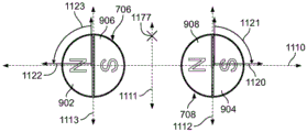
Figure 11 shows the orientation of the poles of the two external magnets (first external magnet 706 and second external magnet 708 of the external adjustment device) with respect to the internal implant magnet 1010, for example, located in an implanted distraction device. As with fig. 6 above, the orientation of the individual magnets may be described with respect to the numbers on the clock. The first external magnet 706 has a north pole 902 and a south pole 906. Likewise, the second external magnet 708 has a south pole 904 and a north pole 908. Each external magnet is physically defined by a diameter and a length (i.e., forms a substantially right cylinder): the first external magnet 706 has a first magnet diameter 1134 and the second external magnet 708 has a second magnet diameter 1132. In some embodiments, the first magnet diameter 1134 is equal to the second magnet diameter 1132. However, this need not always be the case. In other embodiments, the first magnet diameter 1134 is larger than the second magnet diameter 1132. And in further embodiments, the second magnet diameter 1132 is larger than the first magnet diameter 1134.
Fig. 11 is included to primarily show the first external magnet 706 and the second external magnet 708, and the implant magnet 1010 is included primarily for reference. However, the implant magnet 1010 has north 1012 and south 1014, which are nearly identical to the first external magnet 706 and the second external magnet 708. The implant magnet 1010 may also be defined by an internal magnet diameter 1136 and a length (i.e., the implant magnet 1010 may also be substantially right cylindrical). It should be understood that any of the first external magnet 706, the second external magnet 708, and the implant magnet 1010 may be a magnet other than a substantially straight post.
As explained above, with respect to fig. 6, the external magnet 706 is configured to rotate about a first elongated axis of rotation. In fig. 6 and 11, the first elongated axis of rotation is a line through the center of the first external magnet 706 that extends through the center of the first external magnet 706 into the page. Likewise, the second external magnet 708 is configured to rotate about a second elongated axis of rotation. Additionally, in fig. 6 and 11, the second elongated axis of rotation is a line through the center of the second external magnet 708 that extends through the center of the second external magnet 708 into the page. Because the first and second elongated axes of rotation are actually points, the two points define a line between the first and second external magnets 706, 708. The line in which the two points are located is shown in fig. 11 as the horizontal axis 1110.
Each of the first external magnet 706 and the second external magnet 708 defines its own vertical axis that is perpendicular to the horizontal axis 1110 and passes through the elongate axis of rotation of the magnets. The first external magnet 706 has a first magnet vertical axis 1113 that is perpendicular to the horizontal axis 1110 and intersects the first elongate axis of rotation (i.e., the horizontal axis 1110 intersects the first magnet vertical axis 1113 at the center of a circle defined by any plane perpendicular to the longitudinal axis of the first external magnet 706). Likewise, the second external magnet 708 has a second magnet vertical axis 1112 that is perpendicular to the horizontal axis 1110 and intersects the second elongate axis of rotation (i.e., the horizontal axis 1110 intersects the second magnet vertical axis 1112 at the center of a circle defined by any plane perpendicular to the longitudinal axis of the second external magnet 708).
The first external magnet 706 and the second external magnet 708 are separated by an intra-magnet gap 1130 defined as the distance along the horizontal axis 1110 between the rightmost edge of the first external magnet 706 and the leftmost edge of the second external magnet 708. The central vertical axis 1111 bisects the horizontal axis 1110 perpendicular to the horizontal axis 1110 at the center of the magnet inner gap 1130. Thus, the distance from the center of the first external magnet 706 (i.e., the first elongated axis of rotation) to the center of the second external magnet 708 (i.e., the second elongated axis of rotation) is equal to half the first magnet diameter 1134 plus half the second magnet diameter 1132 plus the magnet inner gap 1130. When the first magnet diameter 1134 of the first external magnet 706 is equal to the second magnet diameter 1132 of the second external magnet 708, as shown in fig. 11, the first and second elongated rotational axes are equidistant from the central vertical axis 1111. However, while some embodiments include the first external magnet 706 and the second external magnet 708 being the same size, this is not true for all embodiments. Thus, not all possible pairs of first and second elongated rotational axes are equidistant from the central vertical axis 1111.
The ideal reference position for the implanted magnet 1010 is on the central vertical axis 1111. With the first magnet diameter 1134 and the second magnet diameter 1132 equal, the first external magnet 706 and the second external magnet 708 generate equal magnetic fields. Thus, any point along the central vertical axis 1111 will experience the same effect of the first external magnet 706 as well as the second external magnet 708. The distance between the lowermost edge of the external magnets (i.e., first external magnet 706 and second external magnet 708) and the uppermost edge of the implant magnet 1010 is defined as a gap distance 1138. It should be understood that it is conceptually helpful with respect to the reference position of the implant magnet 1010 on the central vertical axis 1111, but the implant magnet 1010 may also be held at a distance from the central vertical axis 1111.
Turning to fig. 12A-12C, a series of external magnet pairs with different intra-magnet gaps 1130 are shown. Fig. 12A shows the first external magnet 706 and the second external magnet 708 separated by a first exemplary magnet gap 1130', both the first external magnet 706 and the second external magnet 708 being located on a horizontal axis 1110. Fig. 12B shows the first external magnet 706 and the second external magnet 708 separated by a second exemplary magnet gap 1130 ", both the first external magnet 706 and the second external magnet 708 being located on a horizontal axis 1110. The second example magnet gap 1130 "of fig. 12B is generally smaller than the first example magnet gap 1130' of fig. 12A. Fig. 12C shows the first external magnet 706 and the second external magnet 708 separated by a third exemplary magnet gap 1130 "', both the first external magnet 706 and the second external magnet 708 being located on a horizontal axis 1110. The third example magnet gap 1130 ' ″ is generally smaller than both the second example magnet gap 1130 ' and the first example magnet gap 1130 '. It should be understood that any intra-magnet gap 1130 between the first external magnet 706 and the second external magnet 708 may be used.
The intra-magnet gap 1130 may have an effect on the magnetic flux density achieved along the central vertical axis 1111. Magnetic flux density of about 1/r3(inverse of the cube) decreases. Thus, a very small gap distance may achieve a relatively high flux density along the central vertical axis 1111. In contrast, with a medium intra-magnet gap 1130 and a large intra-magnet gap 1130, the flux density is reducedThis is fast, reaching the lower limit of flux density relatively quickly. Fig. 13A shows a schematic of magnetic field lines surrounding the first external magnet 706 and the second external magnet 708. The intra-magnet gap 1130 between the first external magnet 706 and the second external magnet 708 is relatively small. It can be seen that the flux lines along the central vertical axis 1111 (particularly in the vicinity along the central vertical axis 1111 and/or between the first external magnet 706 and the second external magnet 708) are relatively dense. In contrast, fig. 13B shows a schematic of the magnetic field lines around the first external magnet 706 and the second external magnet 708 separated by an in-magnet gap 1130 that is much larger than the in-magnet gap shown in fig. 13A. The flux lines along the central vertical axis 1111 of fig. 13B are significantly less dense than the flux lines along the central vertical axis 1111 of fig. 13A. This is simply due to the increase in the gap 1130 in the magnet.
Fig. 14 shows a plot of the magnetic flux density produced by the first external magnet 706 and the second external magnet 708 versus the gap distance 1138. Typical flux densities are measured at the reference point as the reference point along the central vertical axis 1111 moves further away from the bottom of the first and second external magnets 706, 708 (i.e., as the gap distance 1138 increases from the zero reference point). The first line 1410 of fig. 14 shows a plot of magnetic flux density versus gap distance 1138 for the first external magnet 706 and the second external magnet 708 with an in-magnet gap 1130 of 50.8 millimeters (i.e., 2 inches). The second line 1420 shows a plot of magnetic flux density versus gap distance 1138 for the first external magnet 706 and the second external magnet 708 with an in-magnet gap 1130 of 55.88 millimeters (i.e., 2.2 inches). A third line 1430 shows a plot of magnetic flux density versus gap distance 1138 for the first external magnet 706 and the second external magnet 708 with an in-magnet gap 1130 of 60.96 millimeters (i.e., 2.4 inches). A fourth line 1440 shows a plot of magnetic flux density versus gap distance 1138 for the first external magnet 706 and the second external magnet 708 with an in-magnet gap 1130 of 66.04 millimeters (i.e., 2.6 inches). A fifth line 1450 shows a plot of magnetic flux density versus gap distance 1138 for the first external magnet 706 and the second external magnet 708 having an in-magnet gap 1130 of 71.12 millimeters (i.e., 2.8 inches). And, finally, a sixth line 1460 shows a plot of magnetic flux density versus gap distance 1138 for the first external magnet 706 and the second external magnet 708 having an in-magnet gap 1130 of 76.2 millimeters (i.e., 3.0 inches). The lines of fig. 14 show that reducing the intra-magnet gap 1130 at a small gap distance 1138 (e.g., zero gap distance 1138) increases the flux density achieved. In fact, at zero gap distance 1138, a 50.8 millimeter in-magnet gap 1130 has a flux density that is about 135% higher than a 76.2 millimeter in-magnet gap 1130 at the same gap distance. However, only under the condition that the gap distance 1138 is considerably small, there is a case where a gain is obtained by reducing the intra-magnet gap 1130. The lines of fig. 14 show the approximate convergence points of the first, second, third, fourth, fifth, and sixth lines 1410, 1420, 1430, 1440, 1450, and 1460 at approximately 25 millimeters. After about 25 millimeters, there was little difference between the flux densities along the central vertical axis 1111 with respect to the different intra-magnet gaps 1130.
Turning again to fig. 12A-12C, in view of the lines of fig. 14, it can be appreciated that for small gap distances, the system shown in fig. 12A with the larger first exemplary magnet inner gap 1130 'will have a smaller flux density than the system shown in fig. 12B with the smaller second exemplary magnet inner gap 1130 ", and the system with the second exemplary magnet inner gap 1130" will have a smaller flux density than the system shown in fig. 12C with the smallest third exemplary magnet inner gap 1130 "'. In some cases, a large magnetic flux density is desired. However, in other cases, a reduced magnetic flux density is desired. The desired different magnetic flux densities will be discussed in additional detail below.
As can be appreciated, in applications where a small gap distance is possible or desirable, the intra-magnet gap can be altered to increase or decrease flux density. If a higher flux density is beneficial or desired (e.g., when a higher torque is beneficial or desired), the intra-magnet gap can be reduced while keeping the gap distance constant, i.e., the first external magnet 706 can be brought closer together with the second external magnet 708 at the horizontal axis 1110. In contrast, if a lower flux density is beneficial or desired (e.g., when a higher torque is not required or may be detrimental), the intra-magnet gap may be increased while keeping the gap distance constant, i.e., the first external magnet 706 may be moved apart from the second external magnet 708 on the horizontal axis 1110. Of course, both the gap and the gap distance within the magnet may be varied.
In some embodiments, the external adjustment device 700 may be "intelligent" and capable of altering the inter-magnet gap based on one or more factors such as, but not limited to, user input and sensed parameters. Thus, such an intelligent "external adjustment device 700 can manipulate the gap within the magnet to increase or decrease flux density as desired. For example, the user may input several parameters that enable the external adjustment device to select the appropriate inter-magnet gap distance for a given application. Such variables may include implant location, patient age, patient weight, patient Body Mass Index (BMI), gap distance, and the like. In contrast to the input parameters, the "smart" external adjustment device 700 can use sensed parameters such as gap-to-magnetic coupling slip, generated torque, generated force, and the like.
The gap within the magnet may be adjusted in response to one or more of these user inputs and sensed parameters. In some embodiments, the external adjustment device 700 may notify the user to: a given modulation may improve the efficacy of the treatment. In such a case, the user may increase the inter-magnet gap using any of several tools, systems, and methods. Alternatively, the "intelligent" external adjustment device 700 may process user input and/or sensed parameters, determine that a change (increase or decrease) in flux density or torque production would be beneficial, and automatically adjust the in-magnet gap to an optimal in-magnet gap that remains within system capabilities (i.e., due to physical constraints, there are both lower and upper limits of the in-magnet gap).
As explained with reference to fig. 6, the first external magnet 706 rotates in synchronization with the second external magnet 708 (via gearing, a belt, etc.) such that the north pole 902 of the first external magnet 706 points at the twelve o 'clock position when the south pole 904 of the second external magnet 708 points at the twelve o' clock position. Thus, in this orientation, the south pole 906 of the first external magnet 706 points at the six o 'clock position when the north pole 908 of the second external magnet 708 points at the six o' clock position. Both the first external magnet 706 and the second external magnet 708 may rotate in a first direction (e.g., in a clockwise direction). The rotating magnetic field exerts a torque on the implant magnet 1010, causing the implant magnet 1010 to rotate in a second direction (e.g., in a counterclockwise direction). When the first external magnet 706 and the second external magnet 708 are rotated in opposite directions (i.e., counterclockwise), the implant magnet 1010 will also be rotated in opposite directions (i.e., clockwise).
Fig. 6 shows a reference configuration of the first external magnet 706 and the second external magnet 708. The first external magnet 706 is positioned such that the center of the north pole 902 points upward and the center of the south pole 906 points downward. Likewise, the second external magnet 708 is positioned such that the center of south pole 904 points upward and the center of north pole 908 points downward. Thereafter, in fig. 6, the two magnets are rotated at a fixed angle positioned relative to each other. Thus, the north pole 902 of the first external magnet 706 is always located at the same angular position as the south pole 904 of the second external magnet 708. Also, the south pole 906 of the first external magnet 706 and the north pole 908 of the second external magnet 708 are always at the same angular position.
Turning again to fig. 11, the first external magnet 706 has a first central magnetic axis 1122 that extends through the center of the north pole 902 of the first external magnet 706, through the center of the first external magnet 706 to intersect the first elongated axis of rotation, and through the center of the south pole 906 of the first external magnet 706. The first central magnetic axis 1122 is discussed with respect to the orientation of the north pole 902 of the first external magnet 706. Likewise, the second external magnet 708 has a second central magnetic axis 1120 that extends through the center of the south pole 904 of the second external magnet 708, through the center of the second external magnet 708 to intersect the second elongated axis of rotation, and through the center of the north pole 908 of the second external magnet 708. The second central magnetic axis 1120 is discussed with respect to the orientation of the south pole 904 of the second external magnet 708.
In accordance with the reference orientation of first central magnetic axis 1122 shown in both fig. 6 and 11, first central magnetic axis 1122 is exactly aligned with first magnet vertical axis 1113. This aligned orientation has no angular offset (i.e., the angular offset of first external magnet 706 is 0 °). The rotation of the first external magnet 706 and the second external magnet 708 is discussed with reference to the position of the implant magnet 1010. As described in fig. 11 with the implant magnet 1010 "above" the first external magnet 706 and the second external magnet 708, rotation of the first external magnet 706 in the counterclockwise direction about the first elongated axis of rotation is noted as positive, while rotation of the first external magnet 706 in the clockwise direction about the first elongated axis of rotation is noted as negative. In contrast, in fig. 11 where the implant magnet 1010 is located "above" the second external magnet 708, rotation of the second external magnet 708 in the clockwise direction about the second elongated axis of rotation is noted as positive, while rotation of the second external magnet 708 in the counterclockwise direction about the second elongated axis of rotation is noted as negative.
Fig. 6 shows two magnets that can rotate in unison. For example, the first external magnet 706 may rotate in synchronization with the second external magnet 708 (via gearing, a belt, etc.) such that the north pole 902 of the first external magnet 706 points at the twelve o 'clock position when the south pole 904 of the second external magnet 708 points at the twelve o' clock position. By extension, the south pole 906 of the first external magnet 706 and the north pole 908 of the second external magnet 708 both point at the six o' clock position. As shown in fig. 6, the two external magnets may rotate in a first direction as indicated by respective arrows 914, 916. The rotating magnetic field exerts a torque on the implant magnet 1010, causing the implant magnet 1010 to rotate in a second direction indicated by arrow 918. When the first external magnet 706 and the second external magnet 708 are rotated in a direction opposite to that shown, the implant magnet 1010 will be rotated in a direction opposite to that shown. While the magnet may rotate with a zero angular offset as just described, the magnet may also rotate with a positive angular offset.
The first external magnet 706 may be rotated to the example first central magnetic axis 1122' at a first rotational angle 1123. In some embodiments, as just mentioned, the first rotational angle 1123 is positive, and in some embodiments the first rotational angle 1123 is negative. The first rotational angle 1123 may rotate the first central magnetic axis 1122 from 0 to 360 in the positive direction. Additionally, the first rotational angle 1123 may rotate the first central magnetic axis 1122 from 0 ° to-360 ° in a negative direction. Rotation of the first external magnet 706 causes the first central magnetic axis 1122 to be rotationally offset by a first rotational angle 1123 of > 0 ° to < 180 °, which is the only positive rotational offset. Likewise, rotation of the first external magnet 706 causes the first central magnetic axis 1122 to be rotationally offset by a first rotational angle 1123 of < 0 ° - > -180 °, which is the only negative rotational offset. As will be readily appreciated, a first rotational angle 1123 of the first external magnet 706 rotated by > 180 ° to < 360 ° corresponds to a first rotational angle 1123 of the first external magnet 706 rotated by < 0 ° to > -180 °, and a first rotational angle 1123 of the first external magnet 706 rotated by < -180 ° to < -360 ° corresponds to a first rotational angle 1123 of the first external magnet 706 rotated by > 0 ° to < 180 °. The first external magnet 706 rotates by a first rotational angle 1123 of > 0 deg. to < 180 deg., such rotation being the only positive rotational offset, referred to as "up-rotation" or "up-offset". In contrast, the first external magnet 706 rotates by a first rotational angle 1123 of < 0 ° -180 °, such rotation being the only negative rotational offset, which is referred to as "rotation down" or "offset down".
The second external magnet 708 may also have a rotational offset. The second external magnet 708 may be rotated to an exemplary second central magnetic axis 1120' at a second rotational angle 1121. In some embodiments, the second rotational angle 1121 is positive, and in some embodiments the second rotational angle 1121 is negative. The second external magnet 708, including the second central magnetic axis 1120, may be rotated in a positive direction from 0 ° to 360 ° by a second rotational angle 1121. In addition, the second outer magnet 708, including the second central magnetic axis 1120, may be rotated in a negative direction from 0 ° to-360 ° by a second rotational angle 1121. Rotation of the second outer magnet 708 causes the second central magnetic axis 1120 to be rotationally offset by a second rotational angle 1121 of > 0 ° to < 180 °, which is the only positive rotational offset. Likewise, rotation of the second outer magnet 708 causes the second central magnetic axis 1120 to be rotationally offset by a second rotational angle 1121 of < 0 ° to > -180 °, which is the only negative rotational offset. As discussed with respect to the first external magnet 706, the second rotational angle 1121 of the second external magnet 708 rotation > 180 DEG to < 360 DEG corresponds to the second rotational angle 1121 of the second external magnet 708 rotation < 0 DEG to > -180 DEG, and the second rotational angle 1121 of the second external magnet 708 rotation < -180 DEG to < -360 DEG corresponds to the second rotational angle 1121 of the second external magnet 708 rotation > 0 DEG to < 180 deg. The second external magnet 708 rotates by a second rotational angle 1121 of > 0 deg. to < 180 deg., such rotation being the only positive rotational offset, which is referred to as "upward rotation" or "upward offset". In contrast, the second outer magnet 708 is rotated by a second rotational angle 1121 of < 0 ° to > -180 °, such rotation being the only negative rotational offset, which is referred to as "downward rotation" or "downward offset".
Either or both magnets may be rotationally offset. In some implementations, only the first external magnet 706 rotates in one of the positive and negative directions (i.e., rotates up or rotates down). In other implementations, only the second external magnet 708 rotates in one of the positive and negative directions (i.e., rotates up or rotates down). In other embodiments, both magnets rotate. Either arrangement of the two magnet rotations is possible: both the first external magnet 706 and the second external magnet 708 are rotated upward (by the same amount or by different amounts); both the first external magnet 706 and the second external magnet 708 are rotated downward (by the same amount or by different amounts); the first external magnet 706 rotates upward and the second external magnet 708 rotates downward (by the same amount or a different amount); and the first external magnet 706 rotates downward and the second external magnet 708 rotates upward (by the same amount or a different amount). When both the first external magnet 706 and the second external magnet 708 are rotated equally upward, the rotational offset of the system is the sum of the two offsets. For example, when the first external magnet 706 is rotated 40 ° upward and the second external magnet 708 is rotated 40 °, the rotation of the system is referred to as "80 ° upward" or "80 ° upward", for example. Likewise, if the first external magnet 706 is rotated down-15 ° and the second external magnet 708 is rotated down-15 °, then the rotation of the system is referred to as "30 ° down" or "30 ° down," for example.
Varying the rotational offset of one or both of the first external magnet 706 and the second external magnet 708 may either increase or decrease the flux density achieved for a given gap distance 1138, depending on the point on the central vertical axis 1111. For example, as will be discussed in more detail below, an upward rotational offset (i.e., > 0 ° to < 180 °) generally increases flux density on the central vertical axis 1111 at a given gap distance 1138. In contrast, a downward offset (i.e., < 0 to > -180) generally reduces flux density on central vertical axis 1111 for a given gap distance 1138 (however, a downward offset may increase flux density on central vertical axis 1111 for a small gap distance 1138). Once the first and second external magnets 706, 708 are rotated out of phase in either the upward or downward direction, either unidirectionally or bidirectionally, the first and second external magnets 706, 708 may be locked in rotation relative to each other and rotated as described above (e.g., at the same angular rate).
Fig. 16A-16D illustrate unidirectional rotational offset of a single magnet when the other magnet is held at zero reference. Note that each of fig. 16A-16D shows the flux reference/measurement point 1177 located "above" the magnet. Fig. 16A shows the second central magnetic axis 1120 of the second external magnet 708 having an upward rotation of about 20 ° relative to the flux reference/measurement point 1177. The figure also shows a first central magnetic axis 1122 of the first external magnet 706 that is always held at the zero reference point. Fig. 16B shows the second central magnetic axis 1120 of the second external magnet 708 having an upward rotation of about 45 ° relative to the flux reference/measurement point 1177. The figure also shows a first central magnetic axis 1122 of the first external magnet 706 that is always held at the zero reference point. Fig. 16C shows the second central magnetic axis 1120 of the second external magnet 708 having an upward rotation of about 90 ° relative to the flux reference/measurement point 1177. The figure also shows a first central magnetic axis 1122 of the first external magnet 706 that is always held at the zero reference point. Fig. 16D shows the second central magnetic axis 1120 of the second external magnet 708 having an upward rotation of about 135 ° relative to the flux reference/measurement point 1177. The figure also shows a first central magnetic axis 1122 of the first external magnet 706 that is always held at the zero reference point.
Fig. 17A-17D illustrate unidirectional rotational offset of a single magnet when the other magnet is held at zero reference. Each of fig. 17A-17D shows the flux reference/measurement point 1177 located "above" the magnet. Fig. 17A shows a second central magnetic axis 1120 of the second external magnet 708 having a downward rotation of about-20 ° relative to the flux reference/measurement point 1177. The figure also shows a first central magnetic axis 1122 of the first external magnet 706 that is always held at the zero reference point. Fig. 17B shows the second central magnetic axis 1120 of the second external magnet 708 having a downward rotation of about-45 ° relative to the flux reference/measurement point 1177. The figure also shows a first central magnetic axis 1122 of the first external magnet 706 that is always held at the zero reference point. Fig. 17C shows the second central magnetic axis 1120 of the second external magnet 708 having a downward rotation of about-90 ° relative to the flux reference/measurement point 1177. The figure also shows a first central magnetic axis 1122 of the first external magnet 706 that is always held at the zero reference point. Fig. 17D shows a second central magnetic axis 1120 of the second external magnet 708 having a downward rotation of about-135 ° relative to the flux reference/measurement point 1177. The figure also shows a first central magnetic axis 1122 of the first external magnet 706 that is always held at the zero reference point.
Fig. 18 shows a plot of implant torque (which is directly proportional to magnetic flux density) generated by the first and second external magnets 706, 708 versus a unidirectional rotational angle (i.e., where only one of the first and second external magnets 706, 708 is rotationally offset while the other is rotationally offset, as shown in fig. 16A-16D and 17A-17D).
Fig. 19A-19D illustrate equal bi-directional rotational offset of two magnets (first external magnet 706 and second external magnet 708). Further, each of fig. 19A-19D shows a flux reference/measurement point 1177 located "above" the magnet. Fig. 19A shows that the first central magnetic axis 1122 of the first external magnet 706 and the second central magnetic axis 1120 of the second external magnet 708 each have an upward rotation of about 20 ° relative to the flux reference/measurement point 1177. The system shown in fig. 19A has a rotational offset of 40 ° upward. Fig. 19B shows that the first central magnetic axis 1122 of the first external magnet 706 and the second central magnetic axis 1120 of the second external magnet 708 each have an upward rotation of about 45 ° relative to the flux reference/measurement point 1177. The system shown in fig. 19B has a rotational offset of 80 ° upward. Fig. 19C shows that the first central magnetic axis 1122 of the first external magnet 706 and the second central magnetic axis 1120 of the second external magnet 708 each have an upward rotation of about 90 ° relative to the flux reference/measurement point 1177. The system shown in fig. 19C has a rotational offset of 180 ° upward. And, finally, fig. 19D shows that the first central magnetic axis 1122 of the first external magnet 706 and the second central magnetic axis 1120 of the second external magnet 708 each have an upward rotation of about 135 ° relative to the flux reference/measurement point 1177. The system shown in fig. 19D has a rotational offset of 270 ° upward.
Fig. 20A-20D show equal bi-directional rotational offset of two magnets (first external magnet 706 and second external magnet 708). Each of fig. 20A-20D shows the flux reference/measurement point 1177 located "above" the magnet. Fig. 20A shows that the first central magnetic axis 1122 of the first external magnet 706 and the second central magnetic axis 1120 of the second external magnet 708 each have a downward rotation of about-20 ° relative to the flux reference/measurement point 1177. The system shown in fig. 20A has a rotational offset of 40 ° downward. Fig. 20B shows that the first central magnetic axis 1122 of the first external magnet 706 and the second central magnetic axis 1120 of the second external magnet 708 each have a downward rotation of about-45 ° relative to the flux reference/measurement point 1177. The system shown in fig. 20B has a rotational offset of 90 ° downward. Fig. 20C shows that the first central magnetic axis 1122 of the first external magnet 706 and the second central magnetic axis 1120 of the second external magnet 708 each have a downward rotation of about-90 ° relative to the flux reference/measurement point 1177. The system shown in fig. 20C has a rotational offset of 180 deg. downward. And, finally, fig. 20D shows that the first central magnetic axis 1122 of the first external magnet 706 and the second central magnetic axis 1120 of the second external magnet 708 each have a downward rotation of about-135 ° relative to the flux reference/measurement point 1177. The system shown in fig. 20D has a rotational offset of 270 ° downward.
Fig. 21A shows a schematic of magnetic field lines around the first external magnet 706 and the second external magnet 708 in a reference configuration. The north pole 902 of the first external magnet 706 is oriented at a zero reference position and the south pole 904 of the second external magnet 708 is also oriented at a zero reference position. Or a flux reference/measurement point 1177 located "above" the magnet. In contrast to fig. 21A, fig. 21B shows a schematic of the magnetic field lines around the first external magnet 706 and the second external magnet 708 with a system rotational offset of 40 ° up. That is, the north pole 902 of the first external magnet 706 and the south pole 904 of the second external magnet 708 are both rotated by about 20 ° (20 degrees upward). Or a flux reference/measurement point 1177 located "above" the magnet. The flux lines above the magnets and along the central vertical axis 1111 in fig. 21B are denser than the flux lines above the magnets and along the central vertical axis 1111 in fig. 21A. As previously mentioned, for a given gap distance 1138, the upward rotation tends to increase the flux density. Fig. 21C shows a schematic of the magnetic field lines around the first external magnet 706 and the second external magnet 708 with a system rotational offset of 80 ° up. That is, the north pole 902 of the first external magnet 706 and the south pole 904 of the second external magnet 708 are both rotated by about 40 ° (40 degrees upward). Or a flux reference/measurement point 1177 located "above" the magnet. The flux lines above the magnets and along the central vertical axis 1111 in fig. 21C are significantly denser than the flux lines above the magnets and along the central vertical axis 1111 in fig. 21A. As previously mentioned, for a given gap distance 1138, the upward rotation tends to increase the flux density. Fig. 21D shows a schematic of the magnetic field lines around the first external magnet 706 and the second external magnet 708 with a system rotational offset of 40 ° down. That is, the north pole 902 of the first external magnet 706 and the south pole 904 of the second external magnet 708 are both rotated about-20 (20 degrees down). Or a flux reference/measurement point 1177 located "above" the magnet. The flux lines above the magnets and along the central vertical axis 1111 in fig. 21D are less intense than the flux lines above the magnets and along the central vertical axis 1111 in fig. 21A (in fig. 21A, the first and second external magnets 706 and 708 are in their reference configuration). It should be noted, however, that these flux lines are even less dense than the flux lines above the magnets and along the central vertical axis 1111 shown in fig. 21C (in fig. 21C, the first external magnet 706 has an upward 80 ° rotational offset from the second external magnet 708). For a given gap distance 1138, the downward rotation tends to reduce the flux density (except for the condition of a small gap distance 1138, which may (even significantly) increase the flux density). Thus, a downward rotation will produce a lower flux density than the reference system, and a lower flux density than a system with an upward offset/rotation. Finally, fig. 21E shows a schematic of the magnetic field lines around the first external magnet 706 and the second external magnet 708 with a system rotational offset of 80 ° down. That is, the north pole 902 of the first external magnet 706 and the south pole 904 of the second external magnet 708 are both rotated about-40 (40 degrees downward). The flux reference/measurement point located "above" the magnet is chosen 1177. As can be seen, the flux lines in fig. 21E above the magnets and along the central vertical axis 1111 are very dense at a small gap distance 1138, possibly even denser than that obtained by the 80 ° offset up. However, as the gap distance 1138 increases, the flux density decreases rapidly.
Fig. 22A-22B show graphs of implant torque (which is directly proportional to magnetic flux density) versus bi-directional rotational angle (i.e., where both the first external magnet 706 and the second external magnet 708 are equally rotationally offset, as shown in fig. 19A-19D and fig. 20A-20D) produced by the first external magnet 706 and the second external magnet 708.
In comparison to fig. 22A-22B, fig. 23 shows a plot of flux density versus gap distance for several scenarios without rotation. Referring to fig. 11, the plot included in fig. 23 is a plot of the static magnetic field strength experienced along central vertical axis 1111 extending outward (still on central vertical axis 1111) from the edge of the magnet (i.e., where gap distance 1138 is zero) to a gap distance 1138 of about 5 inches.
The first line 2310 is a plot of magnetic flux density versus gap distance for a two magnet system (a system with the first external magnet 706 and the second external magnet 708) in which the magnets have a 0.75 inch magnet inner gap and no angular offset (i.e., neither of the first external magnet 706 and the second external magnet 708 are rotated out of phase). An exemplary flux map for this system is shown in fig. 21A. Thus, the first line 2310 may be conceptualized as a flux density along a vertical line (e.g., the central vertical axis 1111) located directly between the two magnets. A first point on the first line 2310 is at the intersection of the lines connecting the first external magnet 706 with the outermost horizontal edge of the second external magnet 708. Fig. 21A shows the gradually decreasing flux density value, and in fig. 21A, the flux lines become smaller as the distance from the magnet increases. The first line 2310 may be considered a reference line for which the "increased" and/or "decreased" flux density is evaluated.
The second line 2320 is a plot of magnetic flux density versus gap distance for a two magnet system (a system with the first external magnet 706 and the second external magnet 708) in which the magnets have a 0.75 inch magnet inner gap and a system angular offset 40 ° upward (i.e., each of the first external magnet 706 and the second external magnet 708 are rotated 20 degrees upward). An exemplary flux map for this system is shown in fig. 21B. Here, the second line 2320 may be conceptualized as a flux density along a vertical line (e.g., the central vertical axis 1111) located directly between the two magnets shown in fig. 21B. A first point on the second line 2320 is located at the intersection of the line connecting the first external magnet 706 with the outermost horizontal edge of the second external magnet 708. The value of the flux density with respect to the second line 2320 falls off faster than the value of the flux density with respect to the reference line (the first line 2310).
A third line 2330 is a plot of magnetic flux density versus gap distance for a two magnet system (a system with the first external magnet 706 and the second external magnet 708) in which the magnets have a 0.75 inch magnet inner gap and a system angular offset 40 degrees down (i.e., each of the first external magnet 706 and the second external magnet 708 is rotated 20 degrees down). An exemplary flux map for this system is shown in fig. 21D. As described with respect to the first line 2310 and the second line 2320, the third line 2330 may be understood as a flux density along the central vertical axis 1111. The flux density begins to be slightly lower than the reference flux density (i.e., the flux density of the first line 2310), however, the flux density remains higher than the reference flux density for gap distances greater than about 15 mm. Such a configuration may be beneficial in systems where higher torque or flux densities are desired.
Finally, a fourth line 2340 is a plot of magnetic flux density versus gap distance for a two-magnet system (a system with the first external magnet 706 and the second external magnet 708) in which the magnets have an internal magnet gap of 0.75 inches and a system angular offset 80 degrees downward (i.e., each of the first external magnet 706 and the second external magnet 708 are rotated 40 degrees downward). An exemplary flux map for this system is shown in fig. 21E. As described with respect to the first line 2310, the second line 2320, and the third line 2330, the fourth line 2340 may be understood as the flux density of the central vertical axis 1111. Here, the flux density starts low compared to those lines, but falls slower than the other lines. Such a configuration may be beneficial in applications requiring a large gap distance (e.g., in the range of 50 mm to 100 mm), but still requiring a relatively high torque.
Fig. 15 shows flux density (measured in tesla) plotted against gap distance for two different two-magnet systems, where two variables vary: magnet inner gap and rotational offset. The first line 1510 and the second line 1520 show flux density plots produced by a two magnet system with zero rotational offset. That is, both magnets are located at the reference position. In contrast, third and fourth lines 1530, 1540 show a flux density plot produced by a two magnet system with a rotational offset of 80 degrees down the system. That is, the first external magnet 706 and the second external magnet 708 are each rotated downward by 40 degrees. First, a first line 1510 is compared with a second line 1520.
As just mentioned, the two magnet system that produces the first line 1510 and the second line 1520 has a zero degree rotational offset. However, the first two magnet system that produces the first line 1510 has an inner magnet gap of about 0.2 inches and the second two magnet system that produces the second line 1520 has an inner magnet gap of about 0.75 inches. The flux density of a system with magnets closer together is initially significantly higher than that of a system with magnets further apart, in fact, about 30% higher with zero gap distance. The graph shows that gain through a small intra-magnet gap is only achieved under relatively short gap distances. The first line 1510 and the second line 1520 meet approximately at about 30 millimeters, after which they remain approximately equal. This is exactly the same as fig. 14 showing the different inter-magnet gaps. Further, fig. 14 shows that the magnetic flux density approaches the limit (with respect to any given two magnets) when the gap distance is zero and when the intra-magnet gap is zero. As the gap in the magnet increases, the flux density decreases (the flux density decreases even when the gap distance is maintained at a constant zero). Furthermore, at least for a relatively small increase in the in-magnet gap, the effect of the in-magnet gap is no longer felt at about 25 mm (regardless of the in-magnet gap). That is, the flux density plots produced by the system with only the gap in the magnet varying all meet at about 25 millimeters, at which point they continue to follow each other in time (dropping to limit zero at approximately the inverse of the cube).
As discussed above, the two magnet system that produces the third line 1530 and fourth line 1540 has a rotational offset 80 degrees down of the system compared to the zero rotational offset system just discussed. However, the first two magnet system producing the third line 1530 has an inner magnet gap of about 0.2 inches and the second two magnet system producing the fourth line 1540 has an inner magnet gap of about 0.75 inches. The flux density of a system with magnets closer together is initially significantly higher than that of a system with magnets further apart, in fact, about 70% higher with zero gap distance. The graph shows that gain through small intra-magnet gaps is achieved over a very wide range of gap distances in a system with a downward rotational offset compared to a system without a rotational offset. As mentioned above, systems without rotational offset only maintain increased flux density at gap distances below about 25 millimeters. By contrast, a system with a downward 80 degree rotational offset still experiences increased flux density at about 50 millimeters (twice) gap distance. The rotational offset systems meet at about 50 millimeters, at which point they last reasonably well. However, they are still located above the system without rotational offset.
Fig. 15 shows an embodiment of systems in which both the inter-magnet gap and the gap distance are manipulated to achieve different results. It is to be understood that there are some applications where a small clearance distance is possible. One example of such an application is a magnetically adjustable rod for implantation in a child. These rods often abut just below the skin above the posterior portion of the spine, such devices being disclosed in U.S. patent nos. 8,197,490, 8,057,472, 8,343,192 and 9,179,938, the entire contents of which are incorporated herein by reference. In applications such as these devices (where the gap distance is small), the amount of torque required must be determined. But when a high level of torque is required, as shown by fig. 15, a small in-magnet gap may be desirable (a gradually decreasing in-magnet gap generally increases the magnetic flux) and a downward rotational offset (which tends to reduce the flux density with a small to medium gap distance) may not be desirable. However, high levels of torque may not be required or even detrimental. In these cases, a large intra-magnet gap may be desired (progressively larger intra-magnet gaps generally reduce the magnetic flux). If an even further/greater reduction in torque is desired, a downward rotational offset may be used.
It is also to be understood that there are applications where small gap distances are not common, if not impossible, and thus medium to large gap distances must be addressed. An example of such an application is in magnetically adjustable femoral intramedullary nails. Such a nail is placed in the intramedullary canal of the femur, with the result that fat, fascia and muscles may be compressed to some extent, but the gap distance is substantially increased due to the tissue overlying the femur. Some embodiments of such devices are disclosed in U.S. patent nos. 8,449,543 and 8,852,187, which are hereby incorporated by reference in their entirety. As explained above, the downward rotational offset generally increases flux density as the gap distance increases. Thus, in these applications, the systems that are rotationally offset downward may be more efficient than their aligned counterparts. For systems with a downward rotational offset of 80 degrees, any increase in flux density due to reduced in-magnet gap is generally substantially lost at about 50 millimeters. Thus, if an application desiring increased torque (and therefore increased flux density) has a gap distance greater than about 50 millimeters, reducing the gap within the magnet will have very little effect on increasing torque. However, if the clearance distance is less than about 50 millimeters, reducing the clearance distance significantly increases the possible torque. While any femoral intramedullary nail does not always experience a small gap distance, if the gap distance is less than about 25 millimeters, the downward rotational offset reduces the ability of the system to generate higher torque. In this case, a rotationally aligned system with a small gap distance would be better. It should be noted that the effects of rotational offset and the gap within the magnet are discussed only in a very limited context and for purposes of example only. As discussed herein, there are additional ranges and variables that can be altered to increase or decrease the magnetic flux density experienced at a given point.
Fig. 24 shows another magnet system similar to that shown in fig. 11, except that a third external magnet 2408 is added to further form the magnetic field generated by the system. Similar to the first external magnet 706 and the second external magnet 708, the third external magnet 2408 has a south pole 2406, a north pole 2404, a third magnet diameter 2432, and a third elongated axis of rotation. Although the third external magnet 2408 is shown here as having a third magnet diameter 2432 that is smaller than the second magnet diameter 1132 or the first magnet diameter 1134, it should be understood that this is for illustration purposes only. The third magnet diameter 2432 may be smaller or larger than, or the same as, the second magnet diameter 1132 and/or the first magnet diameter 1134, depending on the flux shaping goals of any given system.
With continued reference to fig. 24, the third elongated axis of rotation (similar to the first elongated axis of rotation and the second elongated axis of rotation) is a line through the center of the third external magnet 2408 that extends into the page through the center of the third external magnet 2408. While the first external magnet 706 has its first magnet vertical axis 1113 and the second external magnet 708 has its second magnet vertical axis 1112, the third external magnet 2408 is shown directly on the central vertical axis 1111, which bisects the magnet inner gap 1130. Positioning the third external magnet 2408 on the central vertical axis 1111 may facilitate a uniform system across the central vertical axis 1111. However, it should also be understood that the third external magnet 2408 may be disposed in any position relative to the first external magnet 706 and the second external magnet 708. As shown in fig. 24, the position of the third external magnet 2408 is also defined by a third magnet vertical offset 1139, which is the distance along the central vertical axis 1111 from the horizontal axis 1110 to the third magnet horizontal axis 2410 of the third external magnet 2408.
The third external magnet 2408 may be rotated a third rotational angle 2425 to a third central magnetic axis 2424 (shown in fig. 24). The third external magnet 2408 has such a reference configuration. The architecture of reference with respect to the third external magnet 2408 is the same as that with respect to the second external magnet 708. That is, rotation of the third external magnet 2408 in a clockwise direction about the third elongated axis of rotation is noted as positive, while rotation of the third external magnet 2408 in a counterclockwise direction about the third elongated axis of rotation is noted as negative. The third external magnet 2408, like the first external magnet 706 and the second external magnet 708, may also have a rotational offset. Third rotational angle 2425 is positive in some embodiments, and third rotational angle 2425 is negative in some embodiments. A third external magnet 2408, including a third central magnetic axis 2424, may rotate a third rotational angle 2425 in a positive direction from 0 ° to 360 °. Additionally, a third external magnet 2408, including a third central magnetic axis 2424, may be rotated in a negative direction from 0 to-360 by a third rotational angle 2425. Similar to the second external magnet 708, rotation of the third external magnet 2408 that rotationally offsets the third central magnetic axis 2424 by a third rotational angle 2425 of > 0 ° to < 180 ° is the only positive rotational offset. Likewise, rotation of the third external magnet 2408 by a third rotational angle 2425 that rotationally offsets the third central magnetic axis 2424 by < 0 ° to > -180 ° is the only negative rotational offset. As will be readily appreciated, a third angle of rotation 2425 of the third external magnet 2408 rotated > 180 ° to < 360 ° corresponds to a third angle of rotation 2425 of the third external magnet 2408 rotated < 0 ° to > -180 °, and a third angle of rotation 2425 of the third external magnet 2408 rotated < "180 ° to <" 360 ° corresponds to a third angle of rotation 2425 of the third external magnet 2408 rotated > 0 ° to < 180 °. The third external magnet 2408 rotates by a third rotational angle 2425 > 0 ° to < 180 °, such rotation being the only positive rotational offset, which is referred to as "up rotation" or "up offset". In contrast, the third external magnet 2408 rotates by a third rotational angle 2425 of < 0 ° to > -180 °, such rotation being the only negative rotational offset, which is referred to as "rotation down" or "offset down".
Although fig. 24 shows the third magnet horizontal axis 2410 of the third external magnet 2408 to be between the horizontal axis 1110 and the implant magnet 1010, other arrangements are possible. Fig. 25A-25C illustrate various embodiments of locations where a third external magnet 2408 may be positioned. In fig. 25A-25C, the position of the implant magnet 1010 is determined by the orientation direction 2480: although the implant magnet 1010 in fig. 24 is shown as being "above" the first, second, and third external magnets 706, 708, 2408, the implant magnet 1010 is "below" the first, second, and third external magnets 706, 708, 2408 in fig. 25A-25C.
Fig. 25A shows a three magnet system in which the third magnet vertical offset 1139 is positive such that the third external magnet 2408 is positioned above the horizontal axis 1110, the first external magnet 706, and the second external magnet 708. The third magnet vertical offset 1139 may have any positive value, which is magnetically significant. Because the magnetic field decreases by approximately the inverse of the cube as the third magnet vertical offset 1139 increases (as shown in fig. 25A), the effect of the third external magnet 2408 will decrease quickly. In fig. 25A, both the first external magnet 706 and the second external magnet 708 are closer to the implant magnet 1010 (or defined by a center-to-center distance). Thus, as long as the diameter of the first external magnet 706 and the second external magnet 708 is larger than the diameter of the third external magnet 2408, the effect from the third external magnet 2408 perceived by the implanted magnet 1010 will be less than the effect from the first external magnet 706 or the second external magnet 708 perceived by the implanted magnet 1010. Of course, if the third magnet diameter 2432 is sufficiently increased, the third external magnet 2408 will have a sufficiently strong magnetic field, and if the third magnet diameter 2432 is sufficiently decreased, the third external magnet 2408 will have a very weak magnetic field. For the same reason, the parameters may be optimized such that each of the three magnets affects the implanted magnet 1010 equally.
Fig. 25B shows a second three magnet system in which the third magnet vertical offset 1139 is zero (i.e., the third magnet horizontal axis 2410 is collinear or collinear with the horizontal axis 1110). In fig. 25B, the third external magnet 2408 will always be closer to the implant magnet (when placed along the central vertical axis 1111 and defined by the center-to-center distance). Thus, to have an equivalent effect as the first external magnet 706 and the second external magnet 708, the third magnet diameter 2432 may be less than the second magnet diameter 1132 and/or the first magnet diameter 1134 (at the threshold diameter). However, rather than being expected to have an equivalent effect, it may be expected that the third external magnet 2408 has a stronger effect than either the first external magnet 706 or the second external magnet 708. In such an example, the third magnet diameter 2432 may increase above the threshold diameter. Of course, in some embodiments, it is desirable that the third magnet diameter 2432 produce a smaller effect than the effect perceived from either the first external magnet 706 or the second external magnet 708. In those examples, the third magnet diameter 2432 may be reduced below the threshold diameter.
Fig. 25C shows a third magnet system in which the third magnet vertical offset 1139 is negative such that the third external magnet 2408 is positioned below the horizontal axis 1110, the first external magnet 706, and the second external magnet 708. The third magnet vertical offset 1139 may have any negative value, which is magnetically meaningful. Because the magnetic field decreases by approximately the inverse of the cube as the third magnet vertical offset 1139 increases progressively negatively, the effect of the first external magnet 706 and the second external magnet 708 (along the central vertical axis 1111) will decrease rapidly. Fig. 25C shows a third external magnet 2408 having a third magnet diameter 2432 that is smaller than the first magnet diameter 1134 and the second magnet diameter 1132. Because the third external magnet 2408 is lower on the central vertical axis 1111 (e.g., closer to the theoretical implant magnet 1010), the effect of the third external magnet 2408 on the flux density in the orientation direction 2480 may be more pronounced than the first external magnet 706 or the second external magnet 708. However, as described above, the diameter of each magnet may be varied to balance or highlight the magnetic input of one magnet relative to the other, depending on system requirements (although the first external magnet 706 and the second external magnet 708 may generally have the same diameter, they may have different diameters). For example, the third magnet diameter 2432 can be increased to highlight the effect of the third external magnet 2408. Alternatively, one or more of the first and second magnet diameters 1134, 1132 may be increased (while the third magnet diameter 2432 may be decreased) to increase the effect of the first and second external magnets 706, 708 relative to the third external magnet 2408.
In addition to simple magnets such as compasses, U-shaped magnets, or even cylindrical magnets with rotating poles (e.g., first external magnet 706 and second external magnet 708), complex magnets can be created in which the flux direction of each pole can be chosen at will. Refrigerator tiles are a common example of complex magnets where there is only a magnetic force on one side (the back of the magnet would stick to the refrigerator and the front would not stick to the refrigerator). This phenomenon is due to the selective orientation of the flux direction during the magnet construction process, which causes the magnetic field to exist only on one side of the magnet. This phenomenon is known as the Halbach (Halbach) effect and the arrangement is known as a Halbach array. A flat magnet can be created in a Halbach array by simply arranging the north-south polarized pieces side by side so that the north pole of each successive piece rotates a quarter turn from the previous magnet so that the magnetic field is only present on one side. Once aligned as described, the direction of magnetization will rotate in unison when proceeding in a particular direction.
Typically, a Halbach array is an arrangement of permanent magnets that is capable of expanding the magnetic field on one side of the Halbach array while canceling out the magnetic field on the other side of the Halbach array to near zero or substantially near zero. For example, the magnetic field at the bottom side of the Halbach array may be enhanced and the magnetic field at the top side (single-sided flux) of the Halbach array may be cancelled. The quarter-turn pattern of rotation of the permanent magnets can be infinitely continuous and have the same effect. Increasingly complex Halbach arrays can be used to form the magnetic field of any magnet, including cylindrical magnets.
Fig. 26A to 26C show various cylindrical magnets whose magnetic flux directions of the respective poles can be manipulated. Fig. 26A shows a two-pole magnet 2610 having a first pole 2611 and a second pole 2612, each pole having a magnetic flux field 2626. Using a Halbach array, the flux field 2626 may "point" in either direction. For example, the magnetic field may be created substantially only on one side of the magnet. Fig. 26B shows a quadrupole magnet 2620 having a first pole 2621, a second pole 2622, a third pole 2623, and a fourth pole 2624, each pole having a magnetic flux field 2626. As described with respect to fig. 26A, the individual magnetic flux fields 2626 can "point" in either direction. Finally, fig. 26C shows an eight-pole magnet 2630 having a first pole 2631, a second pole 2632, a third pole 2633, a fourth pole 2634, a fifth pole 2635, a sixth pole 2636, and an eighth pole 2638, each having a magnetic flux field 2626. Using the principle of Halbach arrays with progressively increasing pole counts, complex magnets with beneficial properties can be created. For example, a cylindrical magnet can be created with a single tightly concentrated field located to one side of the magnet. In contrast, it is possible to create a cylindrical magnet with four weaker fields separated by magnetic dead zones (i.e., zones where there is little magnetic flux). These complex magnets may be advantageously applied to implants such as implant magnet 1010. An implant magnet with a more tightly concentrated magnetic field can produce a higher coupling torque. Alternatively, rather than increasing the torque, the size of the implant magnet 1010 may be reduced. For example, a concentrated magnetic field on a smaller complex implant magnet 1010 (with one or more Halbach arrays) can produce a coupling torque equal to or greater than a standard two-pole magnet with a relatively unconcentrated magnetic field. Such complex magnets may also be incorporated into the external adjustment device 700. Furthermore, one or more Halbach arrays may allow for a reduction in magnet size, an increase in coupling torque, or even both. The effect may be enhanced if complex magnets are used in both the implant magnet 1010 and the external adjustment device 700.
Fig. 27 shows a magnetic flux plot for a two magnet system as shown in fig. 11. Compared to fig. 11, the two magnets are rotated by 90 degrees in the clockwise direction. Thus, north pole 902 of first external magnet 706 faces exactly north pole 908 of south pole 904. This flux plot is very similar to the flux plot shown in FIG. 13B.
Fig. 28A shows a schematic view of a three-magnet system similar to that shown in fig. 24 and fig. 25A-25C. In fig. 28A, the implant magnet is "below" the three magnet system, such that the smaller of the three magnets is on the same side of the horizontal axis 1110 as the implant magnet 1010. Fig. 28A shows one possible configuration of a three magnet system. The larger two of the three magnets are configured exactly as shown in fig. 27. However, the smaller of the three magnets (similar to the third external magnet 2408 of fig. 24) has a south pole that is 90 degrees offset from the larger magnet. That is, the line separating the north pole from the south pole on the small magnet is perpendicular to the line separating the south pole from the north pole (parallel line) of the larger magnet. It has been observed that this configuration can shape the magnetic field in the direction of the implant magnet to provide an increased magnetic field density at that location. In at least one embodiment, this configuration (depending on the distance between the magnets, magnet size, gap distance, etc.) can provide 50% more magnetic flux density and thus 50% more force than a two magnet system (such as the two magnet system shown in fig. 27).
Fig. 28B shows a flux plot for a three-magnet system similar to that shown in fig. 28A. The north poles of the two larger magnets are also directed towards the vertical line separating the two magnets. In addition, the north pole of the smaller third magnet points downward toward the implanted magnet. In this way, the magnetic flux density on the implanted magnet side of the three-magnet system can be increased. Fig. 28B shows the increased density of the magnetic flux density lines. In contrast, fig. 28C shows: a larger magnet located at the same position, but a smaller magnet has a north pole pointing up and away from the implant magnet. In this configuration, the system reduces the flux density achieved by the implant magnet. Depending on the distance between the magnets, magnet size, gap distance, etc., this configuration can provide a magnetic flux density that is 50% less (reduced) than a two magnet system (such as the two magnet system shown in fig. 27) and thus provides 50% less force.
The international commission on non-ionizing radiation protection has issued guidelines on limiting exposure to time-varying electromagnetic, magnetic and electromagnetic fields (up to 300 gigahertz) and guidelines on limiting exposure to static magnetic fields. The entire contents of both sets of guidelines are incorporated herein by reference. These guidelines limit exposure to both time-varying magnetic fields as well as static magnetic fields to protect health. However, the limits differ for different regions of the body. For example, a finger may have a higher limit than the brain. Two variables are particularly important in terms of the time-varying magnetic field limit: field strength and field movement speed (e.g., relative to the body). A weak magnetic field can generally move relatively quickly around the body while remaining within prescribed limits. In contrast, a very strong magnet may need to move very slowly around the body to stay within prescribed limits. This is one reason why patients undergoing Magnetic Resonance Imaging (MRI) scans are told not to move, being subjected to extremely strong magnetic fields. A large amount of movement of a person located in an MRI machine will likely exceed regulatory limits. The static field limit is primarily related to the field strength, as compared to the time-varying magnetic field limit. However, guidelines indicate a static field "exposure not to be applied to patients undergoing medical diagnosis or treatment". If a static field is applied to the exposure of a patient undergoing medical diagnosis or treatment, it is almost certain that the MRI machine will fall outside the limits.
In view of the guidelines discussed above, it can be appreciated that a magnetic therapy device should ideally use the weakest possible magnetic field in the slowest possible manner to still achieve the desired clinical efficacy. Several such systems disclosed herein, including the external adjustment device 700 shown in fig. 1, have some fixed parameters including magnet size, gap within the magnet, and the like. With such an external adjustment device 700, there are no many ways to reduce the time-varying magnetic field exposure. Some ways in which time-varying magnetic field exposure may be reduced include increasing the gap distance (which may be difficult to increase when stability may be beneficial to the patient) and decreasing the rotational speed of the first external magnet 706 and the second external magnet 708.
Parameters that can be changed in the external adjustment device 700 either by the user or by the "intelligent" external adjustment device 700 itself include: a gap in the magnet; a gap distance; rotational offset (unidirectional and bidirectional); and a magnet rotation rate. Selectively altering one or more of these variables may enable a user or "intelligent" external adjustment device 700 to optimize the system to have the lowest flux (weakest magnetic field) that still has clinical efficacy.
Although the present invention has been disclosed in the context of certain preferred embodiments and examples, it will be understood by those skilled in the art that the present invention extends beyond the specifically disclosed embodiments to other alternative embodiments and/or uses of the invention and obvious modifications and equivalents thereof. In addition, while several variations of the invention have been shown and described in detail, other variations, which are within the scope of this invention, will be apparent to those of ordinary skill in the art based on this disclosure. It is also contemplated that aspects of the embodiments and specific features may be variously combined or re-combined and still fall within the scope of the invention. Thus, it should be understood that various features and aspects of the disclosed embodiments can be combined with or substituted for one another in order to form varying modes of the disclosed inventions. Accordingly, the scope of the invention disclosed herein is not intended to be limited by the particular disclosed embodiments described above, but is intended to be determined only by a fair reading of the claims that follow.
Similarly, this method of disclosure is not to be interpreted as reflecting an intention that the claimed invention requires more features than are expressly recited in each claim. Rather, as the following claims reflect, inventive aspects lie in less than all features of any single foregoing disclosed embodiment. Thus, the claims following the detailed description are hereby expressly incorporated into this detailed description, with each claim standing on its own as a separate embodiment.
Claims (19)
1. A controller for magnetically generating rotational motion in a remote device, the controller comprising:
a first driver magnet having a first elongate axis of rotation, a north pole on a first side of the first elongate axis of rotation, a south pole on a second side of the first elongate axis of rotation, and a first central magnetic axis extending transverse to the first elongate axis of rotation and passing through a center of the north pole and a center of the south pole;
a second driver magnet having a second elongated axis of rotation, a north pole on a first side of the second elongated axis of rotation, a south pole on a second side of the second elongated axis of rotation, and a second central magnetic axis extending transverse to the second elongated axis of rotation and passing through a center of the north pole of the second driver magnet and a center of the south pole of the second driver magnet; and
a drive system for synchronously rotating the first and second driver magnets about the first and second elongated axes of rotation;
wherein a gap distance between the first driver magnet and the second driver magnet is variable, and an angle at which the first central magnetic axis and the second central magnetic axis are oriented relative to each other is variable in a range from about 5 degrees to about 90 degrees, such that a flux density is increased or decreased by the change in the gap distance and the change in the angle.
2. The controller of claim 1, wherein at least one of the first driver magnet and the second driver magnet is a permanent magnet.
3. The controller of claim 1, wherein at least one of the first driver magnet and the second driver magnet is an electromagnet.
4. The controller of claim 1, further comprising a control device for adjusting the angle between the first central magnetic axis and the second central magnetic axis.
5. A controller according to claim 4, wherein the control means is manually adjustable.
6. A controller according to claim 4, wherein the control means is automatically adjustable.
7. The controller of claim 6, wherein the control device is automatically adjustable in response to a signal communicated from the remote device.
8. The controller of claim 1, further comprising a third magnet.
9. The controller of claim 8, wherein the third magnet is vertically offset from the first and second driver magnets.
10. The controller of claim 9, wherein the first, second, and third driver magnets are arranged in a halbach array.
11. A controller for magnetically generating rotational motion in a remote device, the controller comprising:
a first driver magnet having a first elongate axis of rotation, a north pole on a first side of the first elongate axis of rotation, a south pole on a second side of the first elongate axis of rotation, and a first central magnetic axis extending transverse to the first elongate axis of rotation and passing through a center of the north pole and a center of the south pole;
a second driver magnet having a second elongated axis of rotation, a north pole on a first side of the second elongated axis of rotation, a south pole on a second side of the second elongated axis of rotation, and a second central magnetic axis extending transverse to the second elongated axis of rotation and passing through a center of the north pole of the second driver magnet and a center of the south pole of the second driver magnet;
a third driver magnet vertically offset from the first and second driver magnets; and
a drive system for synchronously rotating the first and second driver magnets about the first and second elongated axes of rotation;
wherein the first central magnetic axis and the second central magnetic axis are oriented to maintain a bi-directionally asymmetric magnetic flux density to form a magnetic field generated by the first driver magnet and the second driver magnet, and
wherein a gap distance between the first driver magnet and the second driver magnet is variable, and an angle at which the first central magnetic axis and the second central magnetic axis are oriented relative to each other is variable, such that the flux density is increased or decreased by the change in the gap distance and the change in the angle.
12. The controller of claim 11, wherein the first, second, and third driver magnets are arranged in a halbach array.
13. An adjustable flux field controller for magnetically generating rotational motion in a remote device, the adjustable flux field controller comprising:
a first magnet and a second magnet that together produce a three-dimensional flux field around the magnets, each of the first and second magnets being rotatable about respective first and second axes of rotation, wherein the first magnet has a north pole on a first side of the first axis of rotation, a south pole on a second side of the first axis of rotation, and a first central magnetic axis, the first central magnetic axis extends transverse to the first axis of rotation and passes through a center of the north pole and a center of the south pole, and the second magnet has a north pole on a first side of the second axis of rotation, a south pole on a second side of the second axis of rotation, and a second central magnetic axis, a second central magnetic axis extending transverse to the second axis of rotation and passing through a center of the north pole of the second magnet and a center of the south pole of the second magnet; and
control means for adjusting the relative rotational orientation of at least one of the first central magnetic axis and the second central magnetic axis with respect to the other of the first central magnetic axis and the second central magnetic axis, whereby the relative rotational orientation of the first central magnetic axis and the second central magnetic axis can be changed and the gap distance between the first magnet and the second magnet can be changed, whereby the flux density can be increased or decreased by the change in the gap distance and the change in the relative rotational orientation;
wherein adjusting the relative rotational orientation changes the shape of the three-dimensional flux field.
14. The controller of claim 13, wherein at least one of the first magnet and the second magnet is a permanent magnet.
15. The controller of claim 13, wherein at least one of the first magnet and the second magnet is an electromagnet.
16. A controller according to claim 13, further comprising control means for adjusting the angle between the first and second axes of rotation.
17. A controller as claimed in claim 16, wherein the control means is manually adjustable.
18. A controller according to claim 16, wherein the control means is automatically adjustable.
19. The controller of claim 18, wherein the control device is automatically adjustable in response to a signal communicated from the remote device.
Applications Claiming Priority (5)
| Application Number | Priority Date | Filing Date | Title |
|---|---|---|---|
| US201562265430P | 2015-12-10 | 2015-12-10 | |
| US62/265,430 | 2015-12-10 | ||
| US201662276196P | 2016-01-07 | 2016-01-07 | |
| US62/276,196 | 2016-01-07 | ||
| PCT/US2016/066179 WO2017100774A1 (en) | 2015-12-10 | 2016-12-12 | External adjustment device for distraction device |
Publications (2)
| Publication Number | Publication Date |
|---|---|
| CN108601611A CN108601611A (en) | 2018-09-28 |
| CN108601611B true CN108601611B (en) | 2021-11-02 |
Family
ID=57714679
Family Applications (1)
| Application Number | Title | Priority Date | Filing Date |
|---|---|---|---|
| CN201680079755.2A Active CN108601611B (en) | 2015-12-10 | 2016-12-12 | External adjustment device for a tensioning device |
Country Status (7)
| Country | Link |
|---|---|
| US (3) | US10835290B2 (en) |
| EP (2) | EP3386405B1 (en) |
| JP (3) | JP6953409B2 (en) |
| KR (1) | KR20180093988A (en) |
| CN (1) | CN108601611B (en) |
| AU (3) | AU2016368167B2 (en) |
| WO (1) | WO2017100774A1 (en) |
Families Citing this family (10)
| Publication number | Priority date | Publication date | Assignee | Title |
|---|---|---|---|---|
| EP3386405B1 (en) * | 2015-12-10 | 2023-11-01 | NuVasive Specialized Orthopedics, Inc. | External adjustment device for distraction device |
| JP7177494B2 (en) | 2016-05-19 | 2022-11-24 | アークタス サージカル インク | spinal curvature adjustment system |
| US11589901B2 (en) * | 2019-02-08 | 2023-02-28 | Nuvasive Specialized Orthopedics, Inc. | External adjustment device |
| EP3923837A4 (en) * | 2019-02-13 | 2022-11-30 | The Trustees of the University of Pennsylvania | Systems and methods for a smart, implantable cranio-maxillo-facial distractor |
| CN112653249B (en) * | 2019-10-10 | 2023-06-06 | 北京小米移动软件有限公司 | Wireless charging system, charging area determining method and device and electronic equipment |
| CN111641019B (en) * | 2020-06-11 | 2022-10-28 | 福州德亿电子科技有限公司 | Antenna is from bullet and portable position mark of indicating of balanced type AIS |
| US11737787B1 (en) | 2021-05-27 | 2023-08-29 | Nuvasive, Inc. | Bone elongating devices and methods of use |
| WO2022271550A1 (en) | 2021-06-25 | 2022-12-29 | Nuvasive Specialized Orthopedics, Inc. | Adjustable implant, system and methods |
| US20230041121A1 (en) | 2021-08-03 | 2023-02-09 | Nuvasive Specialized Orthopedics, Inc. | Adjustable implant |
| RU209391U1 (en) * | 2021-08-27 | 2022-03-15 | Александр Петрович Сайфуллин | Magnetically controlled spinal rod |
Family Cites Families (861)
| Publication number | Priority date | Publication date | Assignee | Title |
|---|---|---|---|---|
| DE213290C (en) | ||||
| US1599538A (en) | 1919-12-06 | 1926-09-14 | Mintrop Ludger | Geological testing method |
| US2702031A (en) | 1953-09-25 | 1955-02-15 | Wenger Herman Leslie | Method and apparatus for treatment of scoliosis |
| US3111945A (en) | 1961-01-05 | 1963-11-26 | Solbrig Charles R Von | Bone band and process of applying the same |
| US3377576A (en) | 1965-05-03 | 1968-04-09 | Metcom Inc | Gallium-wetted movable electrode switch |
| US3397928A (en) | 1965-11-08 | 1968-08-20 | Edward M. Galle | Seal means for drill bit bearings |
| SE344275B (en) | 1966-02-10 | 1972-04-10 | R Gruenert | |
| US3372476A (en) | 1967-04-05 | 1968-03-12 | Amp Inc | Method of making permanent connections between interfitting parts |
| US3866510A (en) | 1967-06-05 | 1975-02-18 | Carl B H Eibes | Self-tapping threaded bushings |
| FR1556730A (en) | 1967-06-05 | 1969-02-07 | ||
| USRE28907E (en) | 1967-06-05 | 1976-07-20 | Self-tapping threaded bushings | |
| US3512901A (en) | 1967-07-28 | 1970-05-19 | Carrier Corp | Magnetically coupled pump with slip detection means |
| CH492447A (en) | 1968-06-17 | 1970-06-30 | Xavier Halloran William | Fixation device for broken bones |
| US3527220A (en) | 1968-06-28 | 1970-09-08 | Fairchild Hiller Corp | Implantable drug administrator |
| FR2086747A5 (en) | 1970-04-07 | 1971-12-31 | Cotton De Bennetot M | |
| US3655968A (en) | 1970-06-29 | 1972-04-11 | Kermath Mfg Corp | X-ray examination chair |
| US3726279A (en) | 1970-10-08 | 1973-04-10 | Carolina Medical Electronics I | Hemostatic vascular cuff |
| US3810259A (en) | 1971-01-25 | 1974-05-14 | Fairchild Industries | Implantable urinary control apparatus |
| US3750194A (en) | 1971-03-16 | 1973-08-07 | Fairchild Industries | Apparatus and method for reversibly closing a natural or implanted body passage |
| US3840018A (en) | 1973-01-31 | 1974-10-08 | M Heifetz | Clamp for occluding tubular conduits in the human body |
| DE2314573C2 (en) | 1973-03-23 | 1986-12-18 | Werner Dipl.-Ing. 8000 München Kraus | Device for promoting healing processes |
| GB1467248A (en) | 1973-07-30 | 1977-03-16 | Horstmann Magnetics Ltd | Electric motors |
| CH581988A5 (en) | 1974-04-09 | 1976-11-30 | Messerschmitt Boelkow Blohm | |
| US3900025A (en) | 1974-04-24 | 1975-08-19 | Jr Walter P Barnes | Apparatus for distracting or compressing longitudinal bone segments |
| FI53062C (en) | 1975-05-30 | 1978-02-10 | Erkki Einari Nissinen | |
| US4010758A (en) | 1975-09-03 | 1977-03-08 | Medtronic, Inc. | Bipolar body tissue electrode |
| US4068821A (en) | 1976-09-13 | 1978-01-17 | Acf Industries, Incorporated | Valve seat ring having a corner groove to receive an elastic seal ring |
| SU715082A1 (en) | 1977-01-24 | 1980-02-15 | Всесоюзный научно-исследовательский и испытательный институт медицинской техники | Surgical suturing apparatus |
| US4118805A (en) | 1977-02-28 | 1978-10-10 | Codman & Shurtleff, Inc. | Artificial sphincter |
| CH625384B (en) | 1977-12-20 | Ebauches Electroniques Sa | STEP MOTOR NON-ROTATION DETECTION DEVICE FOR CLOCKWORK PART AND LOST STEPS CATCHING UP. | |
| US4222374A (en) | 1978-06-16 | 1980-09-16 | Metal Bellows Corporation | Septum locating apparatus |
| US4286584A (en) | 1978-06-16 | 1981-09-01 | Infusaid Corporation | Septum locating apparatus |
| US4235246A (en) | 1979-02-05 | 1980-11-25 | Arco Medical Products Company | Epicardial heart lead and assembly and method for optimal fixation of same for cardiac pacing |
| US4256094A (en) | 1979-06-18 | 1981-03-17 | Kapp John P | Arterial pressure control system |
| US4357946A (en) | 1980-03-24 | 1982-11-09 | Medtronic, Inc. | Epicardial pacing lead with stylet controlled helical fixation screw |
| DE3035670A1 (en) | 1980-09-22 | 1982-04-29 | Siemens AG, 1000 Berlin und 8000 München | DEVICE FOR INFUSING LIQUIDS IN HUMAN OR ANIMAL BODIES |
| US4386603A (en) | 1981-03-23 | 1983-06-07 | Mayfield Jack K | Distraction device for spinal distraction systems |
| US4448191A (en) | 1981-07-07 | 1984-05-15 | Rodnyansky Lazar I | Implantable correctant of a spinal curvature and a method for treatment of a spinal curvature |
| FR2514250A1 (en) | 1981-10-08 | 1983-04-15 | Artus | HANDPIECE WITH INTEGRATED MOTOR |
| FR2523232B1 (en) | 1982-03-09 | 1985-09-20 | Thomson Csf | TELESCOPIC COLUMN WITH CYLINDRICAL TUBES |
| CH648723GA3 (en) | 1982-09-10 | 1985-04-15 | ||
| DE3340596A1 (en) | 1982-11-16 | 1984-05-24 | Tokyo Electric Co., Ltd., Tokyo | MATRIX PRINTER |
| IL67773A (en) | 1983-01-28 | 1985-02-28 | Antebi E | Tie for tying live tissue and an instrument for performing said tying operation |
| DE3306657C2 (en) | 1983-02-25 | 1986-12-11 | Fa. Heinrich C. Ulrich, 7900 Ulm | Spine correction implant with a distraction rod |
| US4501266A (en) | 1983-03-04 | 1985-02-26 | Biomet, Inc. | Knee distraction device |
| US4595007A (en) | 1983-03-14 | 1986-06-17 | Ethicon, Inc. | Split ring type tissue fastener |
| FR2551350B1 (en) | 1983-09-02 | 1985-10-25 | Buffet Jacques | FLUID INJECTION DEVICE, SUITABLE FOR IMPLANTATION |
| US4522501A (en) | 1984-04-06 | 1985-06-11 | Northern Telecom Limited | Monitoring magnetically permeable particles in admixture with a fluid carrier |
| US4573454A (en) | 1984-05-17 | 1986-03-04 | Hoffman Gregory A | Spinal fixation apparatus |
| SE448812B (en) | 1985-02-01 | 1987-03-23 | Astra Meditec Ab | SURGICAL DEVICE FOR CONNECTING THE TAGS OF A PATIENT |
| DE8515687U1 (en) | 1985-05-29 | 1985-10-24 | Aesculap-Werke Ag Vormals Jetter & Scheerer, 7200 Tuttlingen | Distraction device for extension osteotomy |
| US4592339A (en) | 1985-06-12 | 1986-06-03 | Mentor Corporation | Gastric banding device |
| US4642257A (en) | 1985-06-13 | 1987-02-10 | Michael Chase | Magnetic occluding device |
| US4696288A (en) | 1985-08-14 | 1987-09-29 | Kuzmak Lubomyr I | Calibrating apparatus and method of using same for gastric banding surgery |
| EP0267959A1 (en) | 1986-05-30 | 1988-05-25 | BUMPUS, John | Distraction rods |
| US4700091A (en) | 1986-08-22 | 1987-10-13 | Timex Corporation | Bipolar stepping motor rotor with drive pinion and method of manufacture |
| SE460301B (en) | 1986-10-15 | 1989-09-25 | Sandvik Ab | CUTTING ROD FOR STOCKING DRILLING MACHINE |
| US4760837A (en) | 1987-02-19 | 1988-08-02 | Inamed Development Company | Apparatus for verifying the position of needle tip within the injection reservoir of an implantable medical device |
| DE8704134U1 (en) | 1987-03-19 | 1987-07-16 | Zielke, Klaus, Dr.Med., 3590 Bad Wildungen, De | |
| DE3711091A1 (en) | 1987-04-02 | 1988-10-13 | Kluger Patrick | DEVICE FOR SETTING UP A SPINE WITH A DAMAGED SPINE |
| DE3728686A1 (en) | 1987-08-27 | 1989-03-09 | Draenert Klaus | PREDICTABLE SURGICAL NETWORK |
| EP0359793A4 (en) | 1988-02-03 | 1990-10-10 | Inc. Biomet | Variable length fixation device |
| US4940467A (en) | 1988-02-03 | 1990-07-10 | Tronzo Raymond G | Variable length fixation device |
| FR2632514B1 (en) | 1988-06-09 | 1990-10-12 | Medinov Sarl | PROGRESSIVE CENTRO-MEDULAR NAIL |
| US4998013A (en) | 1988-12-27 | 1991-03-05 | Hewlett-Packard Company | Optical encoder with inactive photodetectors |
| US4904861A (en) | 1988-12-27 | 1990-02-27 | Hewlett-Packard Company | Optical encoder using sufficient inactive photodetectors to make leakage current equal throughout |
| US5180380A (en) | 1989-03-08 | 1993-01-19 | Autogenesis Corporation | Automatic compression-distraction-torsion method and apparatus |
| US4973331A (en) | 1989-03-08 | 1990-11-27 | Autogenesis Corporation | Automatic compression-distraction-torsion method and apparatus |
| JPH0620466B2 (en) | 1989-03-31 | 1994-03-23 | 有限会社田中医科器械製作所 | Spinal column correction device |
| US5092889A (en) | 1989-04-14 | 1992-03-03 | Campbell Robert M Jr | Expandable vertical prosthetic rib |
| US5053047A (en) | 1989-05-16 | 1991-10-01 | Inbae Yoon | Suture devices particularly useful in endoscopic surgery and methods of suturing |
| US5222976A (en) | 1989-05-16 | 1993-06-29 | Inbae Yoon | Suture devices particularly useful in endoscopic surgery |
| DE3921972C2 (en) | 1989-07-04 | 1994-06-09 | Rainer Dr Med Baumgart | Intramedullary nail |
| US5176618A (en) | 1989-08-10 | 1993-01-05 | George Freedman | System for preventing closure of passageways |
| US4978323A (en) | 1989-08-10 | 1990-12-18 | George Freedman | System and method for preventing closure of passageways |
| IT1236172B (en) | 1989-11-30 | 1993-01-11 | Franco Mingozzi | EXTERNAL FIXER FOR THE TREATMENT OF LONG BONE FRACTURES OF THE LIMBS. |
| US5142407A (en) | 1989-12-22 | 1992-08-25 | Donnelly Corporation | Method of reducing leakage current in electrochemichromic solutions and solutions based thereon |
| SE464558B (en) | 1990-03-22 | 1991-05-13 | Hepar Ab | IMPLANTABLE DEVICE FOR SUSPENSION OF A CHANNEL IN THE BODY OF A LIVE BEING |
| US5030235A (en) | 1990-04-20 | 1991-07-09 | Campbell Robert M Jr | Prosthetic first rib |
| US5290289A (en) | 1990-05-22 | 1994-03-01 | Sanders Albert E | Nitinol spinal instrumentation and method for surgically treating scoliosis |
| US5156605A (en) | 1990-07-06 | 1992-10-20 | Autogenesis Corporation | Automatic internal compression-distraction-method and apparatus |
| US5074868A (en) | 1990-08-03 | 1991-12-24 | Inamed Development Company | Reversible stoma-adjustable gastric band |
| US5133716A (en) | 1990-11-07 | 1992-07-28 | Codespi Corporation | Device for correction of spinal deformities |
| US5226429A (en) | 1991-06-20 | 1993-07-13 | Inamed Development Co. | Laparoscopic gastric band and method |
| US5360407A (en) | 1991-08-29 | 1994-11-01 | C. R. Bard, Inc. | Implantable dual access port with tactile ridge for position sensing |
| US5399168A (en) | 1991-08-29 | 1995-03-21 | C. R. Bard, Inc. | Implantable plural fluid cavity port |
| JP3068683B2 (en) | 1991-10-21 | 2000-07-24 | マグネット製造株式会社 | Non-magnetic metal separator |
| US5433721A (en) | 1992-01-17 | 1995-07-18 | Ethicon, Inc. | Endoscopic instrument having a torsionally stiff drive shaft for applying fasteners to tissue |
| US5632744A (en) | 1992-06-08 | 1997-05-27 | Campbell, Jr.; Robert M. | Segmental rib carriage instrumentation and associated methods |
| US5437266A (en) | 1992-07-02 | 1995-08-01 | Mcpherson; William | Coil screw surgical retractor |
| DE4221692A1 (en) | 1992-07-02 | 1994-01-05 | Siemens Ag | Method and device for determining a mixture proportion of a gas mixture |
| US5676651A (en) | 1992-08-06 | 1997-10-14 | Electric Boat Corporation | Surgically implantable pump arrangement and method for pumping body fluids |
| US5601224A (en) | 1992-10-09 | 1997-02-11 | Ethicon, Inc. | Surgical instrument |
| US5381943A (en) | 1992-10-09 | 1995-01-17 | Ethicon, Inc. | Endoscopic surgical stapling instrument with pivotable and rotatable staple cartridge |
| US5466261A (en) | 1992-11-19 | 1995-11-14 | Wright Medical Technology, Inc. | Non-invasive expandable prosthesis for growing children |
| US5306275A (en) | 1992-12-31 | 1994-04-26 | Bryan Donald W | Lumbar spine fixation apparatus and method |
| US5498262A (en) | 1992-12-31 | 1996-03-12 | Bryan; Donald W. | Spinal fixation apparatus and method |
| US5336223A (en) | 1993-02-04 | 1994-08-09 | Rogers Charles L | Telescoping spinal fixator |
| US5356424A (en) | 1993-02-05 | 1994-10-18 | American Cyanamid Co. | Laparoscopic suturing device |
| US5429638A (en) | 1993-02-12 | 1995-07-04 | The Cleveland Clinic Foundation | Bone transport and lengthening system |
| US5626579A (en) | 1993-02-12 | 1997-05-06 | The Cleveland Clinic Foundation | Bone transport and lengthening system |
| US5356411A (en) | 1993-02-18 | 1994-10-18 | Spievack Alan R | Bone transporter |
| US5536269A (en) | 1993-02-18 | 1996-07-16 | Genesis Orthopedics | Bone and tissue lengthening device |
| US5449368A (en) | 1993-02-18 | 1995-09-12 | Kuzmak; Lubomyr I. | Laparoscopic adjustable gastric banding device and method for implantation and removal thereof |
| US5516335A (en) | 1993-03-24 | 1996-05-14 | Hospital For Joint Diseases Orthopaedic Institute | Intramedullary nail for femoral lengthening |
| US5364396A (en) | 1993-03-29 | 1994-11-15 | Robinson Randolph C | Distraction method and apparatus |
| US5334202A (en) | 1993-04-06 | 1994-08-02 | Carter Michael A | Portable bone distraction apparatus |
| US5527309A (en) | 1993-04-21 | 1996-06-18 | The Trustees Of Columbia University In The City Of New York | Pelvo-femoral fixator |
| US5403322A (en) | 1993-07-08 | 1995-04-04 | Smith & Nephew Richards Inc. | Drill guide and method for avoiding intramedullary nails in the placement of bone pins |
| FR2709246B1 (en) | 1993-08-27 | 1995-09-29 | Martin Jean Raymond | Dynamic implanted spinal orthosis. |
| US5468030A (en) | 1994-01-04 | 1995-11-21 | Caterpillar Inc. | Tube clamp and coupling |
| AU1011595A (en) | 1994-01-13 | 1995-07-20 | Ethicon Inc. | Spiral surgical tack |
| US5762599A (en) | 1994-05-02 | 1998-06-09 | Influence Medical Technologies, Ltd. | Magnetically-coupled implantable medical devices |
| AU4089697A (en) | 1994-05-25 | 1998-03-19 | Roger P Jackson | Apparatus and method for spinal fixation and correction of spinal deformities |
| US7255851B2 (en) | 1994-07-01 | 2007-08-14 | The Board Of Trustees Of The Leland Stanford Junior University | Non-invasive localization of a light-emitting conjugate in a mammal |
| US6217847B1 (en) | 1994-07-01 | 2001-04-17 | The Board Of Trustees Of The Leland Stanford Junior University | Non-invasive localization of a light-emitting conjugate in a mammal |
| BR9508231A (en) | 1994-07-11 | 1997-12-23 | Dacomed Corp | Occlusive device for reversibly occluding a fluid carrier in the body |
| US5620445A (en) | 1994-07-15 | 1997-04-15 | Brosnahan; Robert | Modular intramedullary nail |
| US5509888A (en) | 1994-07-26 | 1996-04-23 | Conceptek Corporation | Controller valve device and method |
| IT1268313B1 (en) | 1994-07-28 | 1997-02-27 | Orthofix Srl | MECHANICAL EQUIPMENT FOR CENTERING BLIND HOLES FOR BONE SCREWS OF INTRAMIDOLLAR NAILS |
| US5582616A (en) | 1994-08-05 | 1996-12-10 | Origin Medsystems, Inc. | Surgical helical fastener with applicator |
| US5573012A (en) | 1994-08-09 | 1996-11-12 | The Regents Of The University Of California | Body monitoring and imaging apparatus and method |
| US5549610A (en) | 1994-10-31 | 1996-08-27 | Smith & Nephew Richards Inc. | Femoral intramedullary nail |
| DE69507333T2 (en) | 1994-11-16 | 1999-09-02 | Soubeiran | DEVICE FOR SLIDING TWO BODIES TOGETHER |
| US5659217A (en) | 1995-02-10 | 1997-08-19 | Petersen; Christian C. | Permanent magnet d.c. motor having a radially-disposed working flux gap |
| US5874796A (en) | 1995-02-10 | 1999-02-23 | Petersen; Christian C. | Permanent magnet D.C. motor having a radially-disposed working flux gap |
| FR2730406B1 (en) | 1995-02-13 | 1997-08-14 | Medinov Sa | IMPROVED LENGTHENING DEVICE FOR LONG BONES |
| US5575790A (en) | 1995-03-28 | 1996-11-19 | Rensselaer Polytechnic Institute | Shape memory alloy internal linear actuator for use in orthopedic correction |
| US5536296A (en) | 1995-05-03 | 1996-07-16 | Alumax Inc. | Process for treating molten aluminum with chlorine gas and sulfur hexafluoride to remove impurities |
| US5626613A (en) | 1995-05-04 | 1997-05-06 | Arthrex, Inc. | Corkscrew suture anchor and driver |
| US5628888A (en) | 1996-03-28 | 1997-05-13 | Rscecat, Usa, Inc. | Apparatus for electrochemical treatment of water and/or water solutions |
| US5662683A (en) | 1995-08-22 | 1997-09-02 | Ortho Helix Limited | Open helical organic tissue anchor and method of facilitating healing |
| JP3338944B2 (en) | 1995-08-25 | 2002-10-28 | 有限会社田中医科器械製作所 | Spinal deformity correction device |
| US5771903A (en) | 1995-09-22 | 1998-06-30 | Kirk Promotions Limited | Surgical method for reducing the food intake of a patient |
| US6102922A (en) | 1995-09-22 | 2000-08-15 | Kirk Promotions Limited | Surgical method and device for reducing the food intake of patient |
| SE505513C2 (en) | 1995-11-14 | 1997-09-08 | Elekta Ab | Device for repositioning a patient |
| CA2191405C (en) | 1995-12-01 | 2003-03-25 | David Walker | Telescopic bone plate for use in bone lengthening by distraction osteogenesis |
| US5672177A (en) | 1996-01-31 | 1997-09-30 | The General Hospital Corporation | Implantable bone distraction device |
| WO1998050309A1 (en) | 1996-03-27 | 1998-11-12 | Bakhir Vitold M | Apparatus for electrochemical treatment of water and/or water solutions |
| US5704938A (en) | 1996-03-27 | 1998-01-06 | Volunteers For Medical Engineering | Implantable bone lengthening apparatus using a drive gear mechanism |
| US5985110A (en) | 1996-03-28 | 1999-11-16 | Bakhir; Vitold M. | Apparatus for electrochemical treatment of water and/or water solutions |
| US5704939A (en) | 1996-04-09 | 1998-01-06 | Justin; Daniel F. | Intramedullary skeletal distractor and method |
| US5979456A (en) | 1996-04-22 | 1999-11-09 | Magovern; George J. | Apparatus and method for reversibly reshaping a body part |
| US5954915A (en) | 1996-05-24 | 1999-09-21 | Voorwood Company | Surface finishing apparatus |
| US5700263A (en) | 1996-06-17 | 1997-12-23 | Schendel; Stephen A. | Bone distraction apparatus |
| AU735276B2 (en) | 1996-06-17 | 2001-07-05 | Lucent Medical Systems, Inc. | Medical tube for insertion and detection within the body of a patient |
| DE19626230A1 (en) | 1996-06-29 | 1998-01-02 | Inst Physikalische Hochtech Ev | Device for determining the position of magnetic marker through Magen-Darm tract |
| US6835207B2 (en) | 1996-07-22 | 2004-12-28 | Fred Zacouto | Skeletal implant |
| US6500110B1 (en) | 1996-08-15 | 2002-12-31 | Neotonus, Inc. | Magnetic nerve stimulation seat device |
| US5810815A (en) | 1996-09-20 | 1998-09-22 | Morales; Jose A. | Surgical apparatus for use in the treatment of spinal deformities |
| US5830221A (en) | 1996-09-20 | 1998-11-03 | United States Surgical Corporation | Coil fastener applier |
| US6058323A (en) | 1996-11-05 | 2000-05-02 | Lemelson; Jerome | System and method for treating select tissue in a living being |
| US5743910A (en) | 1996-11-14 | 1998-04-28 | Xomed Surgical Products, Inc. | Orthopedic prosthesis removal instrument |
| DE19652608C1 (en) | 1996-12-18 | 1998-08-27 | Eska Implants Gmbh & Co | Prophylaxis implant against fractures of osteoporotically affected bone segments |
| NL1004873C2 (en) | 1996-12-23 | 1998-06-24 | Univ Twente | Device for moving two objects together. |
| DE19700225A1 (en) | 1997-01-07 | 1998-07-09 | Augustin Prof Dr Betz | Distraction device for moving two parts of a bone apart |
| IT1293934B1 (en) | 1997-01-21 | 1999-03-11 | Orthofix Srl | ENDOMIDOLLAR NAIL FOR THE TREATMENT OF HIP FRACTURES |
| US5997490A (en) | 1997-02-12 | 1999-12-07 | Exogen, Inc. | Method and system for therapeutically treating bone fractures and osteoporosis |
| US5827286A (en) | 1997-02-14 | 1998-10-27 | Incavo; Stephen J. | Incrementally adjustable tibial osteotomy fixation device and method |
| DE19708279C2 (en) | 1997-02-28 | 1999-10-14 | Rainer Baumgart | Distraction system for a long bone |
| US6034296A (en) | 1997-03-11 | 2000-03-07 | Elvin; Niell | Implantable bone strain telemetry sensing system and method |
| US6033412A (en) | 1997-04-03 | 2000-03-07 | Losken; H. Wolfgang | Automated implantable bone distractor for incremental bone adjustment |
| FR2761876B1 (en) | 1997-04-09 | 1999-08-06 | Materiel Orthopedique En Abreg | INSTRUMENTATION OF LUMBAR OSTEOSYNTHESIS FOR CORRECTION OF SPONDYLOLISTHESIS BY POSTERIOR PATHWAY |
| US5938669A (en) | 1997-05-07 | 1999-08-17 | Klasamed S.A. | Adjustable gastric banding device for contracting a patient's stomach |
| DE19751733A1 (en) | 1997-06-09 | 1998-12-10 | Arnold Dipl Ing Dr Med Pier | Gastric band that can be used laparoscopically |
| GB9713018D0 (en) | 1997-06-20 | 1997-08-27 | Secr Defence | Optical fibre bend sensor |
| KR100527072B1 (en) | 1997-07-16 | 2005-11-08 | 신젠타 리미티드 | Herbicidal compositions of tetrazolinone herbicides and antidotes therefor |
| DE19741757A1 (en) | 1997-09-22 | 1999-03-25 | Sachse Hans E | Implantable hydraulic bone expansion device |
| US6138681A (en) | 1997-10-13 | 2000-10-31 | Light Sciences Limited Partnership | Alignment of external medical device relative to implanted medical device |
| DE19745654A1 (en) | 1997-10-16 | 1999-04-22 | Hans Peter Prof Dr Med Zenner | Port for subcutaneous infusion |
| GB9723194D0 (en) | 1997-11-03 | 1998-01-07 | Isis Innovation | Electromechanical transducer |
| FR2771280B1 (en) | 1997-11-26 | 2001-01-26 | Albert P Alby | RESILIENT VERTEBRAL CONNECTION DEVICE |
| US5935127A (en) | 1997-12-17 | 1999-08-10 | Biomet, Inc. | Apparatus and method for treatment of a fracture in a long bone |
| JP2002500063A (en) | 1998-01-05 | 2002-01-08 | オーソダイン・インコーポレーテッド | Intramedullary skeletal distractor and distraction method |
| US6336929B1 (en) | 1998-01-05 | 2002-01-08 | Orthodyne, Inc. | Intramedullary skeletal distractor and method |
| US5945762A (en) | 1998-02-10 | 1999-08-31 | Light Sciences Limited Partnership | Movable magnet transmitter for inducing electrical current in an implanted coil |
| US6331744B1 (en) | 1998-02-10 | 2001-12-18 | Light Sciences Corporation | Contactless energy transfer apparatus |
| US7468060B2 (en) | 1998-02-19 | 2008-12-23 | Respiratory Diagnostic, Inc. | Systems and methods for treating obesity and other gastrointestinal conditions |
| DE19807663A1 (en) | 1998-02-24 | 1999-09-09 | Baur | Connection means for releasably connecting a first component and a second component and method for releasing a connection of a first component and a second component |
| US6343568B1 (en) | 1998-03-25 | 2002-02-05 | Mcclasky David R. | Non-rotating telescoping pole |
| US6009837A (en) | 1998-03-25 | 2000-01-04 | Mcclasky; David R. | Purple martin birdhouse and telescoping pole |
| GB9806999D0 (en) | 1998-04-02 | 1998-06-03 | Univ Birmingham | Distraction device |
| US6074341A (en) | 1998-06-09 | 2000-06-13 | Timm Medical Technologies, Inc. | Vessel occlusive apparatus and method |
| US6283156B1 (en) | 1998-06-17 | 2001-09-04 | Halliburton Energy Services, Inc. | Expandable O-ring seal, method of sealing and apparatus having such seals |
| DE29811479U1 (en) | 1998-06-26 | 1998-09-03 | Orto Maquet Gmbh & Co Kg | Plate arrangement for osteosynthesis |
| DE19829523A1 (en) | 1998-07-02 | 2000-01-05 | Michael Butsch | Distraction device for moving apart a one- or two-part, possibly separate bone |
| US6126660A (en) | 1998-07-29 | 2000-10-03 | Sofamor Danek Holdings, Inc. | Spinal compression and distraction devices and surgical methods |
| US6067991A (en) | 1998-08-13 | 2000-05-30 | Forsell; Peter | Mechanical food intake restriction device |
| US6210347B1 (en) | 1998-08-13 | 2001-04-03 | Peter Forsell | Remote control food intake restriction device |
| US6460543B1 (en) | 1998-08-13 | 2002-10-08 | Obtech Medical Ag | Non-injection port food intake restriction device |
| FR2783153B1 (en) | 1998-09-14 | 2000-12-01 | Jerome Dargent | GASTRIC CONSTRICTION DEVICE |
| US6494879B2 (en) | 1998-10-15 | 2002-12-17 | Scimed Life Systems, Inc. | Treating urinary retention |
| DE19856062A1 (en) | 1998-12-04 | 2000-06-15 | Wittenstein Gmbh & Co Kg | Distraction device |
| US6139316A (en) | 1999-01-26 | 2000-10-31 | Sachdeva; Rohit C. L. | Device for bone distraction and tooth movement |
| US6315784B1 (en) | 1999-02-03 | 2001-11-13 | Zarija Djurovic | Surgical suturing unit |
| DE19906423A1 (en) | 1999-02-16 | 2000-08-17 | Wittenstein Gmbh & Co Kg | Active marrow spike for drawing out sections of bone consists of two elements moving against each other and electrically operated driving element to supply spike with electrical energy via detachable plug-in element. |
| IL129032A (en) | 1999-03-17 | 2006-12-31 | Moshe Dudai | Gastric band |
| US6162223A (en) | 1999-04-09 | 2000-12-19 | Smith & Nephew, Inc. | Dynamic wrist fixation apparatus for early joint motion in distal radius fractures |
| US6299613B1 (en) | 1999-04-23 | 2001-10-09 | Sdgi Holdings, Inc. | Method for the correction of spinal deformities through vertebral body tethering without fusion |
| US6325805B1 (en) | 1999-04-23 | 2001-12-04 | Sdgi Holdings, Inc. | Shape memory alloy staple |
| US6296643B1 (en) | 1999-04-23 | 2001-10-02 | Sdgi Holdings, Inc. | Device for the correction of spinal deformities through vertebral body tethering without fusion |
| US7008425B2 (en) | 1999-05-27 | 2006-03-07 | Jonathan Phillips | Pediatric intramedullary nail and method |
| FR2794357B1 (en) | 1999-06-01 | 2001-09-14 | Frederic Fortin | DISTRACTION DEVICE FOR BONES OF CHILDREN HAVING HANGING AND ADJUSTMENT MEANS FOR TRACKING GROWTH |
| US6221074B1 (en) | 1999-06-10 | 2001-04-24 | Orthodyne, Inc. | Femoral intramedullary rod system |
| US7018380B2 (en) | 1999-06-10 | 2006-03-28 | Cole J Dean | Femoral intramedullary rod system |
| US6358283B1 (en) | 1999-06-21 | 2002-03-19 | Hoegfors Christian | Implantable device for lengthening and correcting malpositions of skeletal bones |
| ATE397802T1 (en) | 1999-06-21 | 2008-06-15 | Fisher & Paykel Appliances Ltd | LINEAR MOTOR |
| US6626899B2 (en) | 1999-06-25 | 2003-09-30 | Nidus Medical, Llc | Apparatus and methods for treating tissue |
| JP4576521B2 (en) | 1999-06-25 | 2010-11-10 | ハンセン メディカル, インコーポレイテッド | Apparatus and method for treating tissue |
| US7160312B2 (en) | 1999-06-25 | 2007-01-09 | Usgi Medical, Inc. | Implantable artificial partition and methods of use |
| US20050192629A1 (en) | 1999-06-25 | 2005-09-01 | Usgi Medical Inc. | Methods and apparatus for creating and regulating a gastric stoma |
| US6587719B1 (en) | 1999-07-01 | 2003-07-01 | Cyberonics, Inc. | Treatment of obesity by bilateral vagus nerve stimulation |
| US6409175B1 (en) | 1999-07-13 | 2002-06-25 | Grant Prideco, Inc. | Expandable joint connector |
| EP1072282A1 (en) | 1999-07-19 | 2001-01-31 | EndoArt S.A. | Flow control device |
| AUPQ202699A0 (en) | 1999-08-04 | 1999-08-26 | University Of Melbourne, The | Prosthetic device for incontinence |
| US6234956B1 (en) | 1999-08-11 | 2001-05-22 | Hongping He | Magnetic actuation urethral valve |
| US6454698B1 (en) | 1999-08-12 | 2002-09-24 | Obtech Medical Ag | Anal incontinence treatment with energy transfer device |
| EP1211988B1 (en) | 1999-08-12 | 2010-02-17 | Potencia Medical AG | Stoma opening forming apparatus |
| US6464628B1 (en) | 1999-08-12 | 2002-10-15 | Obtech Medical Ag | Mechanical anal incontinence |
| US6471635B1 (en) | 2000-02-10 | 2002-10-29 | Obtech Medical Ag | Anal incontinence disease treatment with controlled wireless energy supply |
| US6482145B1 (en) | 2000-02-14 | 2002-11-19 | Obtech Medical Ag | Hydraulic anal incontinence treatment |
| EP1217972B1 (en) | 1999-08-12 | 2007-12-12 | Potencia Medical AG | Medical implant apparatus with wireless energy transmission |
| US6454701B1 (en) | 1999-08-12 | 2002-09-24 | Obtech Medical Ag | Heartburn and reflux disease treatment apparatus with energy transfer device |
| US6454699B1 (en) | 2000-02-11 | 2002-09-24 | Obtech Medical Ag | Food intake restriction with controlled wireless energy supply |
| US6461292B1 (en) | 1999-08-12 | 2002-10-08 | Obtech Medical Ag | Anal incontinence treatment with wireless energy supply |
| US6453907B1 (en) | 1999-08-12 | 2002-09-24 | Obtech Medical Ag | Food intake restriction with energy transfer device |
| US6673079B1 (en) | 1999-08-16 | 2004-01-06 | Washington University | Device for lengthening and reshaping bone by distraction osteogenesis |
| FR2799118B1 (en) | 1999-10-01 | 2002-07-12 | Medical Innovation Dev | ADJUSTABLE GASTRIC IMPLANT |
| WO2001024697A1 (en) | 1999-10-06 | 2001-04-12 | Orthodyne, Inc. | Device and method for measuring skeletal distraction |
| US6926719B2 (en) | 1999-10-21 | 2005-08-09 | Gary W. Sohngen | Modular intramedullary nail |
| AU1233301A (en) | 1999-10-26 | 2001-05-08 | H. Randall Craig | Helical suture instrument |
| US6573706B2 (en) | 1999-11-18 | 2003-06-03 | Intellijoint Systems Ltd. | Method and apparatus for distance based detection of wear and the like in joints |
| US20030208212A1 (en) | 1999-12-07 | 2003-11-06 | Valerio Cigaina | Removable gastric band |
| IT1315260B1 (en) | 1999-12-07 | 2003-02-03 | Valerio Cigaina | REMOVABLE GASTRIC BANDAGE |
| FR2802407B1 (en) | 1999-12-21 | 2002-12-13 | Rc Medical | DESERRABLE GASTROPLASTY RING |
| FR2802406B1 (en) | 1999-12-21 | 2002-12-13 | Rc Medical | PNEUMATIC CLOSING GASTROPLASTY RING |
| US6702732B1 (en) | 1999-12-22 | 2004-03-09 | Paracor Surgical, Inc. | Expandable cardiac harness for treating congestive heart failure |
| US6386083B1 (en) | 1999-12-23 | 2002-05-14 | Ber-Fong Hwang | Vertically movable foam sponge cutting apparatus |
| US7507252B2 (en) | 2000-01-31 | 2009-03-24 | Edwards Lifesciences Ag | Adjustable transluminal annuloplasty system |
| US6527702B2 (en) | 2000-02-01 | 2003-03-04 | Abbeymoor Medical, Inc. | Urinary flow control device and method |
| EP1267733A4 (en) | 2000-02-03 | 2005-06-01 | Alphatec Mfg Inc | Intramedullary interlock screw |
| US6353949B1 (en) | 2000-02-04 | 2002-03-12 | Michael G. Falbo | Tilt table for disease diagnosis |
| US6454700B1 (en) | 2000-02-09 | 2002-09-24 | Obtech Medical Ag | Heartburn and reflux disease treatment apparatus with wireless energy supply |
| ATE364364T1 (en) | 2000-02-10 | 2007-07-15 | Potencia Medical Ag | MECHANICAL DEVICE FOR TREATING IMPOTENCY |
| CN1195463C (en) | 2000-02-10 | 2005-04-06 | 波滕西亚医疗公司 | Anal incontinence treatment apparatus with wireless energy supply |
| US6470892B1 (en) | 2000-02-10 | 2002-10-29 | Obtech Medical Ag | Mechanical heartburn and reflux treatment |
| IL151136A0 (en) | 2000-02-10 | 2003-04-10 | Obtech Medical Ag | Controlled heartburn and reflux disease treatment apparatus |
| US6463935B1 (en) | 2000-02-10 | 2002-10-15 | Obtech Medical Ag | Controlled heartburn and reflux disease treatment |
| ATE304337T1 (en) | 2000-02-10 | 2005-09-15 | Potencia Medical Ag | TREATING ANAL INCONTINENCE WITH CONTROLLED WIRELESS POWER SUPPLY |
| WO2001045486A2 (en) | 2000-02-11 | 2001-06-28 | Potencia Medical Ag | Urinary incontinence treatment apparatus |
| US6450946B1 (en) | 2000-02-11 | 2002-09-17 | Obtech Medical Ag | Food intake restriction with wireless energy transfer |
| US6475136B1 (en) | 2000-02-14 | 2002-11-05 | Obtech Medical Ag | Hydraulic heartburn and reflux treatment |
| DE60110392T2 (en) | 2000-02-14 | 2006-03-09 | Potencia Medical Ag | HYDRAULIC DEVICE FOR THE TREATMENT OF HARNINE CONTINENCE |
| US7601171B2 (en) | 2003-10-23 | 2009-10-13 | Trans1 Inc. | Spinal motion preservation assemblies |
| US7938836B2 (en) | 2003-10-23 | 2011-05-10 | Trans1, Inc. | Driver assembly for simultaneous axial delivery of spinal implants |
| US7776068B2 (en) | 2003-10-23 | 2010-08-17 | Trans1 Inc. | Spinal motion preservation assemblies |
| US20070260270A1 (en) | 2000-02-16 | 2007-11-08 | Trans1 Inc. | Cutter for preparing intervertebral disc space |
| FR2805451B1 (en) | 2000-02-29 | 2002-04-19 | Arnaud Andre Soubeiran | IMPROVED DEVICE FOR MOVING TWO BODIES IN RELATION TO ONE ANOTHER, PARTICULARLY FOR REALIZING IMPLANTABLE SYSTEMS IN THE HUMAN BODY |
| US20030220644A1 (en) | 2002-05-23 | 2003-11-27 | Thelen Sarah L. | Method and apparatus for reducing femoral fractures |
| JP2003526448A (en) | 2000-03-10 | 2003-09-09 | パラコー サージカル インコーポレイテッド | Inflatable cardiac harness for treating congestive heart failure |
| US6423061B1 (en) | 2000-03-14 | 2002-07-23 | Amei Technologies Inc. | High tibial osteotomy method and apparatus |
| US6309391B1 (en) | 2000-03-15 | 2001-10-30 | Sdgi Holding, Inc. | Multidirectional pivoting bone screw and fixation system |
| GB0009107D0 (en) * | 2000-04-13 | 2000-05-31 | Univ London | Surgical distraction device |
| US6510345B1 (en) | 2000-04-24 | 2003-01-21 | Medtronic, Inc. | System and method of bridging a transreceiver coil of an implantable medical device during non-communication periods |
| US7241300B2 (en) | 2000-04-29 | 2007-07-10 | Medtronic, Inc, | Components, systems and methods for forming anastomoses using magnetism or other coupling means |
| US20020072758A1 (en) | 2000-12-13 | 2002-06-13 | Reo Michael L. | Processes for producing anastomotic components having magnetic properties |
| US6802847B1 (en) | 2000-04-29 | 2004-10-12 | Ventrica, Inc. | Devices and methods for forming magnetic anastomoses and ports in vessels |
| US20050080439A1 (en) | 2000-04-29 | 2005-04-14 | Carson Dean F. | Devices and methods for forming magnetic anastomoses and ports in vessels |
| US8518062B2 (en) | 2000-04-29 | 2013-08-27 | Medtronic, Inc. | Devices and methods for forming magnetic anastomoses between vessels |
| US7232449B2 (en) | 2000-04-29 | 2007-06-19 | Medtronic, Inc. | Components, systems and methods for forming anastomoses using magnetism or other coupling means |
| US6656135B2 (en) | 2000-05-01 | 2003-12-02 | Southwest Research Institute | Passive and wireless displacement measuring device |
| HU223454B1 (en) | 2000-07-21 | 2004-07-28 | László Bodó | Strain-setting device for tendonrekonstruction or replacement and introductionspipe for implant a tension-adjusting device |
| US7114501B2 (en) | 2000-08-14 | 2006-10-03 | Spine Wave, Inc. | Transverse cavity device and method |
| US6554831B1 (en) | 2000-09-01 | 2003-04-29 | Hopital Sainte-Justine | Mobile dynamic system for treating spinal disorder |
| FR2813786B1 (en) | 2000-09-11 | 2003-03-14 | Medical Innovation Dev | METHOD AND DEVICE FOR CONTROLLING THE INFLATION OF AN INFLATABLE PROSTHETIC BODY AND PROSTHESIS USING THE SAME |
| US6432040B1 (en) | 2000-09-14 | 2002-08-13 | Nizam N. Meah | Implantable esophageal sphincter apparatus for gastroesophageal reflux disease and method |
| DE10142544B4 (en) | 2000-09-15 | 2010-05-27 | Heidelberger Druckmaschinen Ag | Gear transmission stage with tensioning moment |
| US8784482B2 (en) | 2000-09-20 | 2014-07-22 | Mvrx, Inc. | Method of reshaping a heart valve annulus using an intravascular device |
| US8956407B2 (en) | 2000-09-20 | 2015-02-17 | Mvrx, Inc. | Methods for reshaping a heart valve annulus using a tensioning implant |
| US20050222489A1 (en) | 2003-10-01 | 2005-10-06 | Ample Medical, Inc. | Devices, systems, and methods for reshaping a heart valve annulus, including the use of a bridge implant |
| WO2004030568A2 (en) | 2002-10-01 | 2004-04-15 | Ample Medical, Inc. | Device and method for repairing a native heart valve leaflet |
| WO2004030570A2 (en) | 2002-10-01 | 2004-04-15 | Ample Medical, Inc. | Devices for retaining native heart valve leaflet |
| US20090287179A1 (en) | 2003-10-01 | 2009-11-19 | Ample Medical, Inc. | Devices, systems, and methods for reshaping a heart valve annulus, including the use of magnetic tools |
| US20080091264A1 (en) | 2002-11-26 | 2008-04-17 | Ample Medical, Inc. | Devices, systems, and methods for reshaping a heart valve annulus, including the use of magnetic tools |
| US6527701B1 (en) | 2000-09-29 | 2003-03-04 | Precision Medical Devices, Inc. | Body fluid flow control device |
| US7011621B2 (en) | 2000-09-29 | 2006-03-14 | Precision Medical Devices, Inc. | Body fluid flow control method and device |
| US6537196B1 (en) | 2000-10-24 | 2003-03-25 | Stereotaxis, Inc. | Magnet assembly with variable field directions and methods of magnetically navigating medical objects |
| DE10054236A1 (en) | 2000-11-02 | 2002-07-25 | Okin Ges Fuer Antriebstechnik | telescopic arm |
| DE10055519A1 (en) | 2000-11-09 | 2002-06-06 | Wittenstein Gmbh & Co Kg | distraction |
| US6582313B2 (en) | 2000-12-22 | 2003-06-24 | Delphi Technologies, Inc. | Constant velocity stroking joint having recirculating spline balls |
| US6609025B2 (en) | 2001-01-02 | 2003-08-19 | Cyberonics, Inc. | Treatment of obesity by bilateral sub-diaphragmatic nerve stimulation |
| JP3910020B2 (en) | 2001-03-08 | 2007-04-25 | 敏行 ▲高▼木 | Artificial sphincter |
| GB0106588D0 (en) | 2001-03-16 | 2001-05-09 | Finsbury Dev Ltd | Tissue distracter |
| US6802844B2 (en) | 2001-03-26 | 2004-10-12 | Nuvasive, Inc | Spinal alignment apparatus and methods |
| SE523852C2 (en) | 2001-04-10 | 2004-05-25 | Azad Al-Najjar | Heart prosthesis |
| US7787958B2 (en) | 2001-04-13 | 2010-08-31 | Greatbatch Ltd. | RFID detection and identification system for implantable medical lead systems |
| US6565573B1 (en) | 2001-04-16 | 2003-05-20 | Smith & Nephew, Inc. | Orthopedic screw and method of use |
| FR2823663B1 (en) | 2001-04-18 | 2004-01-02 | Cousin Biotech | DEVICE FOR TREATING MORBID OBESITY |
| US20040173222A1 (en) | 2001-04-24 | 2004-09-09 | Kim Young D. | Magnetic pellets and external electromagnetic device for assisting left ventricular contraction, method of pellet insertion, and method of ventricular electromagnetic assistance |
| WO2002094113A1 (en) | 2001-05-23 | 2002-11-28 | Orthogon Technologies 2003 Ltd. | Magnetically-actuable intramedullary device |
| EP1260188B1 (en) | 2001-05-25 | 2014-09-17 | Zimmer GmbH | Femoral bone nail for implantation in the knee |
| US8439926B2 (en) | 2001-05-25 | 2013-05-14 | Conformis, Inc. | Patient selectable joint arthroplasty devices and surgical tools |
| US6558400B2 (en) | 2001-05-30 | 2003-05-06 | Satiety, Inc. | Obesity treatment tools and methods |
| US7083629B2 (en) | 2001-05-30 | 2006-08-01 | Satiety, Inc. | Overtube apparatus for insertion into a body |
| FR2825264B1 (en) | 2001-06-01 | 2004-04-02 | Surgical Diffusion | GASTROPLASTY RING |
| US7041105B2 (en) | 2001-06-06 | 2006-05-09 | Sdgi Holdings, Inc. | Dynamic, modular, multilock anterior cervical plate system having detachably fastened assembleable and moveable segments |
| US6511490B2 (en) | 2001-06-22 | 2003-01-28 | Antoine Jean Henri Robert | Gastric banding device and method |
| CA2494237C (en) | 2001-06-28 | 2008-03-25 | Halliburton Energy Services, Inc. | Drill tool shaft-to-housing locking device |
| SE0102313D0 (en) | 2001-06-28 | 2001-06-28 | Obtech Medical Ag | Intestine dysfunction treatment apparatus |
| US6627206B2 (en) | 2001-07-25 | 2003-09-30 | Greg A. Lloyd | Method and apparatus for treating obesity and for delivering time-released medicaments |
| FR2827756B1 (en) | 2001-07-25 | 2005-01-14 | Patrick Rat | IMPROVED LAKES AND ASSOCIATED APPLICATORS USED IN ENDOSCOPIC SURGERY |
| US6375682B1 (en) | 2001-08-06 | 2002-04-23 | Lewis W. Fleischmann | Collapsible, rotatable and expandable spinal hydraulic prosthetic device |
| JP2003059558A (en) | 2001-08-09 | 2003-02-28 | Tokai Rika Co Ltd | Connector for printed circuit board |
| EP1435884A1 (en) | 2001-09-05 | 2004-07-14 | Potencia Medical AG | Stoma opening forming apparatus with connection device |
| US20040172040A1 (en) | 2001-10-19 | 2004-09-02 | Heggeness Michael H. | Bone compression devices and systems and methods of contouring and using same |
| WO2003032848A2 (en) | 2001-10-19 | 2003-04-24 | Baylor College Of Medicine | Bone compression devices and systems and methods of contouring and using same |
| US7194297B2 (en) | 2001-11-13 | 2007-03-20 | Boston Scientific Scimed, Inc. | Impedance-matching apparatus and construction for intravascular device |
| WO2003041611A2 (en) | 2001-11-14 | 2003-05-22 | White Michael R | Apparatus and methods for making intraoperative orthopedic measurements |
| DE10156316A1 (en) | 2001-11-19 | 2003-06-05 | Wittenstein Ag | distraction |
| DE10158545B4 (en) | 2001-11-29 | 2004-05-19 | Gkn Driveline Deutschland Gmbh | Longitudinal displacement unit with hollow profile pin |
| US7601156B2 (en) | 2001-12-05 | 2009-10-13 | Randolph C. Robinson | Limb lengthener |
| US6852113B2 (en) | 2001-12-14 | 2005-02-08 | Orthopaedic Designs, Llc | Internal osteotomy fixation device |
| US20030114731A1 (en) | 2001-12-14 | 2003-06-19 | Cadeddu Jeffrey A. | Magnetic positioning system for trocarless laparoscopic instruments |
| FR2834631B1 (en) | 2002-01-15 | 2004-10-22 | Cie Euro Etude Rech Paroscopie | GASTROPLASTY RING IN VARIABLE HARDNESS ELASTOMERIC MATERIAL |
| US20040019353A1 (en) | 2002-02-01 | 2004-01-29 | Freid James M. | Spinal plate system for stabilizing a portion of a spine |
| US9101422B2 (en) | 2002-02-01 | 2015-08-11 | Zimmer Spine, Inc. | Spinal plate system for stabilizing a portion of a spine |
| US7105029B2 (en) | 2002-02-04 | 2006-09-12 | Zimmer Spine, Inc. | Skeletal fixation device with linear connection |
| US7678136B2 (en) | 2002-02-04 | 2010-03-16 | Spinal, Llc | Spinal fixation assembly |
| FR2835734B1 (en) | 2002-02-11 | 2004-10-29 | Scient X | CONNECTION SYSTEM BETWEEN A SPINAL ROD AND A CROSS BAR |
| US7163538B2 (en) | 2002-02-13 | 2007-01-16 | Cross Medical Products, Inc. | Posterior rod system |
| US20040006342A1 (en) | 2002-02-13 | 2004-01-08 | Moti Altarac | Posterior polyaxial plate system for the spine |
| UA75048C2 (en) | 2002-02-18 | 2006-03-15 | Товариство З Обмеженою Відповідальністю "Кримський Центр Травматології І Ортопедії Імені О.І. Блискунова-"Абас" | Blyskunov's device for extending long bones |
| US6607363B1 (en) | 2002-02-20 | 2003-08-19 | Terumo Cardiovascular Systems Corporation | Magnetic detent for rotatable knob |
| US7311690B2 (en) | 2002-02-25 | 2007-12-25 | Novashunt Ag | Implantable fluid management system for the removal of excess fluid |
| US7011658B2 (en) | 2002-03-04 | 2006-03-14 | Sdgi Holdings, Inc. | Devices and methods for spinal compression and distraction |
| EP1343112A1 (en) | 2002-03-08 | 2003-09-10 | EndoArt S.A. | Implantable device |
| US20100168751A1 (en) | 2002-03-19 | 2010-07-01 | Anderson D Greg | Method, Implant & Instruments for Percutaneous Expansion of the Spinal Canal |
| US6774624B2 (en) | 2002-03-27 | 2004-08-10 | Ge Medical Systems Global Technology Company, Llc | Magnetic tracking system |
| ATE487444T1 (en) | 2002-03-30 | 2010-11-15 | Infinity Orthopaedics Company | MEDICAL INTERVERTEBRAL DEVICE |
| US6761503B2 (en) | 2002-04-24 | 2004-07-13 | Torque-Traction Technologies, Inc. | Splined member for use in a slip joint and method of manufacturing the same |
| US7445010B2 (en) | 2003-01-29 | 2008-11-04 | Torax Medical, Inc. | Use of magnetic implants to treat issue structures |
| US6749556B2 (en) | 2002-05-10 | 2004-06-15 | Scimed Life Systems, Inc. | Electroactive polymer based artificial sphincters and artificial muscle patches |
| US20030220643A1 (en) | 2002-05-24 | 2003-11-27 | Ferree Bret A. | Devices to prevent spinal extension |
| FR2840193B1 (en) | 2002-05-31 | 2005-02-11 | Textile Hi Tec | GASTRIC BAND |
| US20050165440A1 (en) | 2002-06-13 | 2005-07-28 | Richard Cancel | System for treating obesity and implant for a system of this type |
| US7175589B2 (en) | 2002-07-02 | 2007-02-13 | The Foundry Inc. | Methods and devices for luminal and sphincter augmentation |
| DE60334459D1 (en) | 2002-07-10 | 2010-11-18 | Orthodata Inc | LOAD MEASURING SYSTEM |
| US7357037B2 (en) | 2002-07-10 | 2008-04-15 | Orthodata Technologies Llc | Strain sensing system |
| US7060075B2 (en) | 2002-07-18 | 2006-06-13 | Biosense, Inc. | Distal targeting of locking screws in intramedullary nails |
| US20040133219A1 (en) | 2002-07-29 | 2004-07-08 | Peter Forsell | Multi-material constriction device for forming stoma opening |
| ATE551971T1 (en) | 2002-08-13 | 2012-04-15 | Allergan Inc | REMOTELY ADJUSTABLE GASTRIC BANDING DEVICE |
| US7338433B2 (en) | 2002-08-13 | 2008-03-04 | Allergan, Inc. | Remotely adjustable gastric banding method |
| FR2843538B1 (en) | 2002-08-13 | 2005-08-12 | Frederic Fortin | DEVICE FOR DISTRACTING AND DAMPING ADJUSTABLE TO THE GROWTH OF THE RACHIS |
| EP1389453B1 (en) | 2002-08-16 | 2007-03-07 | AMI Agency for Medical Innovations GmbH | Band to produce an artificial reduction in the gastrointestinal tract |
| US6667725B1 (en) | 2002-08-20 | 2003-12-23 | The United States Of America As Represented By The Administrator Of The National Aeronautics And Space Administration | Radio frequency telemetry system for sensors and actuators |
| CN100457057C (en) | 2002-08-25 | 2009-02-04 | 香港大学 | Device for correcting spinal deformities |
| DK1553878T3 (en) | 2002-08-28 | 2010-05-31 | Allergan Inc | Fatigue resistant gastric banding device |
| US7297150B2 (en) | 2002-08-29 | 2007-11-20 | Mitralsolutions, Inc. | Implantable devices for controlling the internal circumference of an anatomic orifice or lumen |
| US8758372B2 (en) | 2002-08-29 | 2014-06-24 | St. Jude Medical, Cardiology Division, Inc. | Implantable devices for controlling the size and shape of an anatomical structure or lumen |
| FR2843875B1 (en) | 2002-08-30 | 2004-10-08 | Arnaud Andre Soubeiran | IMPLANTABLE DEVICE FOR TRANSFORMING ON DEMAND ALTERNATE COUPLES APPLIED BY MUSCLE FORCE BETWEEN TWO WORKPIECES IN A MOVEMENT OF TWO BODIES RELATIVELY TO ONE ANOTHER |
| US7901419B2 (en) | 2002-09-04 | 2011-03-08 | Allergan, Inc. | Telemetrically controlled band for regulating functioning of a body organ or duct, and methods of making, implantation and use |
| DE60221828T2 (en) | 2002-09-04 | 2008-05-08 | Endoart S.A. | Surgical ring with remote control device for reversible diameter changes |
| US7972346B2 (en) | 2002-09-04 | 2011-07-05 | Allergan Medical S.A. | Telemetrically controlled band for regulating functioning of a body organ or duct, and methods of making, implantation and use |
| EP1396242B1 (en) | 2002-09-04 | 2007-11-14 | Endoart S.A. | Closure system for surgical ring |
| US7188627B2 (en) | 2002-09-06 | 2007-03-13 | Apneon, Inc. | Magnetic force devices, systems, and methods for resisting tissue collapse within the pharyngeal conduit |
| US7360542B2 (en) | 2002-09-06 | 2008-04-22 | Apneon, Inc. | Devices, systems, and methods to fixate tissue within the regions of body, such as the pharyngeal conduit |
| US8074654B2 (en) | 2002-09-06 | 2011-12-13 | Koninklijke Philips Electronics N.V. | Implantable devices, systems, and methods for maintaining desired orientations in targeted tissue regions |
| AU2003270368A1 (en) | 2002-09-06 | 2004-03-29 | Apneon, Inc. | Magnetic force devices, systems, and methods for resisting tissue collapse within the pharyngal conduit |
| US20060289014A1 (en) | 2002-09-06 | 2006-12-28 | Apneon, Inc. | Devices, systems, and methods using magnetic force systems in or on tissue in an airway |
| US8522790B2 (en) | 2002-09-06 | 2013-09-03 | Koninklijke Philips N.V. | Stabilized magnetic force devices, systems and methods |
| US7216648B2 (en) | 2002-09-06 | 2007-05-15 | Apneon, Inc. | Systems and methods for moving and/or restraining tissue in the upper respiratory system |
| US20120312307A1 (en) | 2002-09-06 | 2012-12-13 | Koninklijke Philips Electronics N.V. | Implantable devices, systems, and methods for maintaining desired orientations in targeted tissue regions |
| US20080066764A1 (en) | 2002-09-06 | 2008-03-20 | Apneon, Inc. | Implantable devices, systems, and methods for maintaining desired orientations in targeted tissue regions |
| US20070256693A1 (en) | 2002-09-06 | 2007-11-08 | Apneon, Inc. | Devices, systems, and methods using magnetic force systems in or on soft palate tissue |
| US8707959B2 (en) | 2002-09-06 | 2014-04-29 | Koninklijke Philips N.V. | Implantable devices, systems, and methods for maintaining desired orientations in targeted tissue regions |
| US7845356B2 (en) | 2002-09-06 | 2010-12-07 | Koninklijke Philips Electronics N.V. | Implantable devices, systems, and methods for maintaining desired orientations in targeted tissue regions |
| US7441559B2 (en) | 2002-09-06 | 2008-10-28 | Koninklijke Philips Electronics N.V. | Devices, systems, and methods to fixate tissue within the regions of body, such as the pharyngeal conduit |
| ATE385831T1 (en) | 2002-09-20 | 2008-03-15 | Potencia Medical Ag | HARMLESS WIRELESS ENERGY TRANSFER TO AN IMPLANT |
| US20040055610A1 (en) | 2002-09-25 | 2004-03-25 | Peter Forsell | Detection of implanted wireless energy receiving device |
| US20040064030A1 (en) | 2002-10-01 | 2004-04-01 | Peter Forsell | Detection of implanted injection port |
| AU2003299542B2 (en) | 2002-10-03 | 2009-01-15 | Virginia Tech Intellectual Properties, Inc. | Magnetic targeting device |
| US20100249782A1 (en) | 2002-10-03 | 2010-09-30 | Durham Alfred A | Intramedullary nail targeting device |
| US7837669B2 (en) | 2002-11-01 | 2010-11-23 | Valentx, Inc. | Devices and methods for endolumenal gastrointestinal bypass |
| US7794447B2 (en) | 2002-11-01 | 2010-09-14 | Valentx, Inc. | Gastrointestinal sleeve device and methods for treatment of morbid obesity |
| US9060844B2 (en) | 2002-11-01 | 2015-06-23 | Valentx, Inc. | Apparatus and methods for treatment of morbid obesity |
| US6656194B1 (en) | 2002-11-05 | 2003-12-02 | Satiety, Inc. | Magnetic anchoring devices |
| US20040098121A1 (en) | 2002-11-07 | 2004-05-20 | Nmt Medical, Inc. | Patent foramen ovale (PFO) closure with magnetic force |
| US8187324B2 (en) | 2002-11-15 | 2012-05-29 | Advanced Cardiovascular Systems, Inc. | Telescoping apparatus for delivering and adjusting a medical device in a vessel |
| WO2004052443A1 (en) | 2002-12-11 | 2004-06-24 | Christoph Miethke Gmbh & Co Kg | Adjustable hydrocephalus valve |
| US6918910B2 (en) | 2002-12-16 | 2005-07-19 | John T. Smith | Implantable distraction device |
| KR100498951B1 (en) | 2003-01-02 | 2005-07-04 | 삼성전자주식회사 | Method of Motion Estimation for Video Coding in MPEG-4/H.263 Standards |
| US20070270631A1 (en) | 2003-01-22 | 2007-11-22 | Apneon, Inc. | Magnetic force devices, systems, and methods for resisting tissue collapse within the pharyngeal conduit |
| US6752754B1 (en) | 2003-02-04 | 2004-06-22 | Imagine Enterprise, Inc. | Artificial rectum and related method |
| US20040158254A1 (en) | 2003-02-12 | 2004-08-12 | Sdgi Holdings, Inc. | Instrument and method for milling a path into bone |
| US20070043376A1 (en) | 2003-02-21 | 2007-02-22 | Osteobiologics, Inc. | Bone and cartilage implant delivery device |
| US7618435B2 (en) | 2003-03-04 | 2009-11-17 | Nmt Medical, Inc. | Magnetic attachment systems |
| US20040193266A1 (en) | 2003-03-31 | 2004-09-30 | Meyer Rudolf Xaver | Expansible prosthesis and magnetic apparatus |
| IL155222A0 (en) | 2003-04-03 | 2003-11-23 | Hadasit Med Res Service | An implant for treating idiopathic scoliosis and a method for using the same |
| US6961553B2 (en) | 2003-04-11 | 2005-11-01 | Motorola, Inc. | Bidirectional distributed amplifier |
| DE10317776A1 (en) | 2003-04-16 | 2004-11-04 | Wittenstein Ag | Device for lengthening bones or parts of bones |
| US7713287B2 (en) | 2003-05-02 | 2010-05-11 | Applied Spine Technologies, Inc. | Dynamic spine stabilizer |
| US8652175B2 (en) | 2003-05-02 | 2014-02-18 | Rachiotek, Llc | Surgical implant devices and systems including a sheath member |
| US20050182400A1 (en) | 2003-05-02 | 2005-08-18 | Jeffrey White | Spine stabilization systems, devices and methods |
| US20050177164A1 (en) | 2003-05-02 | 2005-08-11 | Carmen Walters | Pedicle screw devices, systems and methods having a preloaded set screw |
| JP2006525098A (en) | 2003-05-02 | 2006-11-09 | イェール・ユニバーシティ | Dynamic spine stabilizer |
| US7615068B2 (en) | 2003-05-02 | 2009-11-10 | Applied Spine Technologies, Inc. | Mounting mechanisms for pedicle screws and related assemblies |
| US20050182401A1 (en) | 2003-05-02 | 2005-08-18 | Timm Jens P. | Systems and methods for spine stabilization including a dynamic junction |
| US20050171543A1 (en) | 2003-05-02 | 2005-08-04 | Timm Jens P. | Spine stabilization systems and associated devices, assemblies and methods |
| JP4391762B2 (en) | 2003-05-08 | 2009-12-24 | オリンパス株式会社 | Surgical instrument |
| AT413475B (en) | 2003-06-04 | 2006-03-15 | Ami Gmbh | DEVICE FOR GENERATING ARTIFICIAL FENCING IN THE GASTRO-INTESTINAL TRACT |
| US8715243B2 (en) | 2003-06-16 | 2014-05-06 | Ethicon Endo-Surgery, Inc. | Injection port applier with downward force actuation |
| US7862546B2 (en) | 2003-06-16 | 2011-01-04 | Ethicon Endo-Surgery, Inc. | Subcutaneous self attaching injection port with integral moveable retention members |
| US20050131352A1 (en) | 2003-06-16 | 2005-06-16 | Conlon Sean P. | Subcutaneous injection port for applied fasteners |
| US7561916B2 (en) | 2005-06-24 | 2009-07-14 | Ethicon Endo-Surgery, Inc. | Implantable medical device with indicator |
| US7553298B2 (en) | 2003-12-19 | 2009-06-30 | Ethicon Endo-Surgery, Inc. | Implantable medical device with cover and method |
| US7374557B2 (en) | 2003-06-16 | 2008-05-20 | Ethicon Endo-Surgery, Inc. | Subcutaneous self attaching injection port with integral fasteners |
| EP1648341A4 (en) | 2003-06-25 | 2009-01-14 | Georgia Tech Res Inst | Annuloplasty chain |
| US7494459B2 (en) | 2003-06-26 | 2009-02-24 | Biophan Technologies, Inc. | Sensor-equipped and algorithm-controlled direct mechanical ventricular assist device |
| US7951067B2 (en) | 2003-06-27 | 2011-05-31 | Ethicon Endo-Surgery, Inc. | Implantable band having improved attachment mechanism |
| US20050002984A1 (en) | 2003-06-27 | 2005-01-06 | Byrum Randal T. | Implantable band with attachment mechanism having dissimilar material properties |
| US7218232B2 (en) | 2003-07-11 | 2007-05-15 | Depuy Products, Inc. | Orthopaedic components with data storage element |
| WO2005018507A2 (en) | 2003-07-18 | 2005-03-03 | Ev3 Santa Rosa, Inc. | Remotely activated mitral annuloplasty system and methods |
| US20090259236A2 (en) | 2003-07-28 | 2009-10-15 | Baronova, Inc. | Gastric retaining devices and methods |
| US9498366B2 (en) | 2003-07-28 | 2016-11-22 | Baronova, Inc. | Devices and methods for pyloric anchoring |
| US8048169B2 (en) | 2003-07-28 | 2011-11-01 | Baronova, Inc. | Pyloric valve obstructing devices and methods |
| US9700450B2 (en) | 2003-07-28 | 2017-07-11 | Baronova, Inc. | Devices and methods for gastrointestinal stimulation |
| US7794476B2 (en) | 2003-08-08 | 2010-09-14 | Warsaw Orthopedic, Inc. | Implants formed of shape memory polymeric material for spinal fixation |
| US8037871B2 (en) | 2003-08-12 | 2011-10-18 | Cameron International Corporation | Seal assembly for a pressurized fuel feed system for an internal combustion engine |
| US7371244B2 (en) | 2003-08-25 | 2008-05-13 | Ethicon, Inc. | Deployment apparatus for suture anchoring device |
| DE10340025A1 (en) | 2003-08-28 | 2005-03-24 | Wittenstein Ag | Surgical device for bone extension, comprising planetary gear acting on outer sleeve serving as ring gear |
| EP1677692A1 (en) | 2003-08-28 | 2006-07-12 | Wittenstein AG | Planetary roll system, in particular for a device for extending bones |
| JP4731482B2 (en) | 2003-09-04 | 2011-07-27 | ウォーソー・オーソペディック・インコーポレーテッド | Anterior spinal instrument |
| EP1514518A1 (en) | 2003-09-11 | 2005-03-16 | SDGI Holdings, Inc. | Impulsive percussion instruments for endplate preparation |
| BRPI0414415A (en) | 2003-09-15 | 2006-11-14 | Inamed Medical Products Corp | implantable device locking system and methods of use |
| US8278941B2 (en) | 2003-09-16 | 2012-10-02 | Cardiomems, Inc. | Strain monitoring system and apparatus |
| US8026729B2 (en) | 2003-09-16 | 2011-09-27 | Cardiomems, Inc. | System and apparatus for in-vivo assessment of relative position of an implant |
| US20050070937A1 (en) | 2003-09-30 | 2005-03-31 | Jambor Kristin L. | Segmented gastric band |
| US7255714B2 (en) | 2003-09-30 | 2007-08-14 | Michel H. Malek | Vertically adjustable intervertebral disc prosthesis |
| US7485149B1 (en) | 2003-10-06 | 2009-02-03 | Biomet Manufacturing Corporation | Method and apparatus for use of a non-invasive expandable implant |
| US20050090823A1 (en) | 2003-10-28 | 2005-04-28 | Bartimus Christopher S. | Posterior fixation system |
| US20050261779A1 (en) | 2003-11-17 | 2005-11-24 | Meyer Rudolf X | Expansible rod-type prosthesis and external magnetic apparatus |
| EP2433593B1 (en) | 2003-11-20 | 2020-07-15 | Koninklijke Philips N.V. | Devices, systems and methods to fixate tissue within the regions of body, such as the pharyngeal conduit |
| US7775099B2 (en) | 2003-11-20 | 2010-08-17 | Schlumberger Technology Corporation | Downhole tool sensor system and method |
| US7862586B2 (en) | 2003-11-25 | 2011-01-04 | Life Spine, Inc. | Spinal stabilization systems |
| US7429259B2 (en) | 2003-12-02 | 2008-09-30 | Cadeddu Jeffrey A | Surgical anchor and system |
| US20050120479A1 (en) | 2003-12-03 | 2005-06-09 | Innovision Medica Technologies, Llc | Body positioning mattress |
| AU2004235622A1 (en) | 2003-12-17 | 2005-07-07 | Ethicon Endo-Surgery, Inc. | Mechanically adjustable gastric band |
| US8162897B2 (en) | 2003-12-19 | 2012-04-24 | Ethicon Endo-Surgery, Inc. | Audible and tactile feedback |
| US7833228B1 (en) | 2004-01-05 | 2010-11-16 | Biomet Manufacturing Corp. | Method and instrumentation for performing minimally invasive hip arthroplasty |
| US7789912B2 (en) | 2004-01-08 | 2010-09-07 | Spine Wave, Inc. | Apparatus and method for injecting fluent material at a distracted tissue site |
| FR2865129B1 (en) | 2004-01-16 | 2006-05-19 | Medical Innovation Dev | GASTRIC BELT |
| US20050159754A1 (en) | 2004-01-21 | 2005-07-21 | Odrich Ronald B. | Periosteal distraction bone growth |
| US20050159755A1 (en) | 2004-01-21 | 2005-07-21 | Odrich Ronald B. | Bone growth via periosteal distraction |
| ES2399951T3 (en) | 2004-01-23 | 2013-04-04 | Allergan, Inc. | Adjustable gastric band of a piece that can be fixed releasably |
| EP2260773B2 (en) | 2004-01-23 | 2014-08-13 | Apollo Endosurgery, Inc. | Implantable device fastening system |
| US7442196B2 (en) | 2004-02-06 | 2008-10-28 | Synvasive Technology, Inc. | Dynamic knee balancer |
| US8758355B2 (en) | 2004-02-06 | 2014-06-24 | Synvasive Technology, Inc. | Dynamic knee balancer with pressure sensing |
| US8328854B2 (en) | 2004-02-10 | 2012-12-11 | Atlas Spine, Inc. | Cervical plate ratchet pedicle screws |
| US8002809B2 (en) | 2004-02-10 | 2011-08-23 | Atlas Spine, Inc. | Dynamic cervical plate |
| US8636802B2 (en) | 2004-03-06 | 2014-01-28 | DePuy Synthes Products, LLC | Dynamized interspinal implant |
| US7458981B2 (en) | 2004-03-09 | 2008-12-02 | The Board Of Trustees Of The Leland Stanford Junior University | Spinal implant and method for restricting spinal flexion |
| US20050272976A1 (en) | 2004-03-15 | 2005-12-08 | Olympus Corporation | Endoscope insertion aiding device |
| US20050234448A1 (en) | 2004-03-19 | 2005-10-20 | Mccarthy James | Implantable bone-lengthening device |
| DK1613388T3 (en) | 2004-03-27 | 2008-03-25 | Christoph Miethke Gmbh & Co Kg | Adjustable hydrocephalus valve |
| US7909852B2 (en) | 2004-03-31 | 2011-03-22 | Depuy Spine Sarl | Adjustable-angle spinal fixation element |
| US7993397B2 (en) | 2004-04-05 | 2011-08-09 | Edwards Lifesciences Ag | Remotely adjustable coronary sinus implant |
| US7489495B2 (en) | 2004-04-15 | 2009-02-10 | Greatbatch-Sierra, Inc. | Apparatus and process for reducing the susceptibility of active implantable medical devices to medical procedures such as magnetic resonance imaging |
| US7531002B2 (en) | 2004-04-16 | 2009-05-12 | Depuy Spine, Inc. | Intervertebral disc with monitoring and adjusting capabilities |
| US7678139B2 (en) | 2004-04-20 | 2010-03-16 | Allez Spine, Llc | Pedicle screw assembly |
| FR2869218B1 (en) | 2004-04-21 | 2006-06-09 | Europlak Sa | GASTRIC CERCLING DEVICE OR MOTORIZED "GASTRIC RING" HAVING AT LEAST ONE RECEIVED ANTENNA FOR DELIVERY, REMOTE CONTROL AND DATA SENDING BY INDUCTION |
| US7763080B2 (en) | 2004-04-30 | 2010-07-27 | Depuy Products, Inc. | Implant system with migration measurement capacity |
| US7333013B2 (en) | 2004-05-07 | 2008-02-19 | Berger J Lee | Medical implant device with RFID tag and method of identification of device |
| US20080091059A1 (en) | 2004-05-14 | 2008-04-17 | Ample Medical, Inc. | Devices, systems, and methods for reshaping a heart valve annulus, including the use of a bridge implant having an adjustable bridge stop |
| US7314372B2 (en) | 2004-05-19 | 2008-01-01 | Orthovisage, Inc. | System and method to bioengineer facial form in adults |
| US7909839B2 (en) | 2004-05-26 | 2011-03-22 | Bariatec Corporation | Gastric bypass band and surgical method |
| US7481763B2 (en) | 2004-05-28 | 2009-01-27 | Ethicon Endo-Surgery, Inc. | Metal bellows position feedback for hydraulic control of an adjustable gastric band |
| US7351240B2 (en) | 2004-05-28 | 2008-04-01 | Ethicon Endo—Srugery, Inc. | Thermodynamically driven reversible infuser pump for use as a remotely controlled gastric band |
| US7390294B2 (en) | 2004-05-28 | 2008-06-24 | Ethicon Endo-Surgery, Inc. | Piezo electrically driven bellows infuser for hydraulically controlling an adjustable gastric band |
| US7351198B2 (en) | 2004-06-02 | 2008-04-01 | Ethicon Endo-Surgery, Inc. | Implantable adjustable sphincter system |
| ZA200700096B (en) | 2004-06-07 | 2008-05-28 | Synthes Gmbh | Orthopaedic implant with sensors |
| US7243719B2 (en) | 2004-06-07 | 2007-07-17 | Pathfinder Energy Services, Inc. | Control method for downhole steering tool |
| US7191007B2 (en) | 2004-06-24 | 2007-03-13 | Ethicon Endo-Surgery, Inc | Spatially decoupled twin secondary coils for optimizing transcutaneous energy transfer (TET) power transfer characteristics |
| US20070135913A1 (en) | 2004-06-29 | 2007-06-14 | Micardia Corporation | Adjustable annuloplasty ring activation system |
| US7776091B2 (en) | 2004-06-30 | 2010-08-17 | Depuy Spine, Inc. | Adjustable posterior spinal column positioner |
| US7481841B2 (en) | 2004-06-30 | 2009-01-27 | Depuy Products, Inc. | Adjustable orthopaedic prosthesis and associated method |
| DE102004032012B4 (en) | 2004-07-01 | 2008-09-18 | Siemens Ag | Device for placing a patient |
| US7955357B2 (en) | 2004-07-02 | 2011-06-07 | Ellipse Technologies, Inc. | Expandable rod system to treat scoliosis and method of using the same |
| WO2006010037A2 (en) | 2004-07-08 | 2006-01-26 | Deborah Schenberger | Strain monitoring system and apparatus |
| US7285087B2 (en) | 2004-07-15 | 2007-10-23 | Micardia Corporation | Shape memory devices and methods for reshaping heart anatomy |
| WO2006019520A2 (en) | 2004-07-15 | 2006-02-23 | Micardia Corporation | Magnetic devices and methods for reshaping heart anatomy |
| US7402134B2 (en) | 2004-07-15 | 2008-07-22 | Micardia Corporation | Magnetic devices and methods for reshaping heart anatomy |
| US7875033B2 (en) | 2004-07-19 | 2011-01-25 | Synthes Usa, Llc | Bone distraction apparatus |
| GB0417005D0 (en) | 2004-07-29 | 2004-09-01 | Finsbury Dev Ltd | Auto-extensible device |
| US8114158B2 (en) | 2004-08-03 | 2012-02-14 | Kspine, Inc. | Facet device and method |
| WO2006017641A2 (en) | 2004-08-03 | 2006-02-16 | Vertech Innovations, L.L.C. | Spinous process reinforcement device and method |
| US20060036259A1 (en) | 2004-08-03 | 2006-02-16 | Carl Allen L | Spine treatment devices and methods |
| US7658753B2 (en) | 2004-08-03 | 2010-02-09 | K Spine, Inc. | Device and method for correcting a spinal deformity |
| US20060036323A1 (en) | 2004-08-03 | 2006-02-16 | Carl Alan L | Facet device and method |
| US20060036251A1 (en) | 2004-08-09 | 2006-02-16 | Reiley Mark A | Systems and methods for the fixation or fusion of bone |
| US8414648B2 (en) | 2004-08-09 | 2013-04-09 | Si-Bone Inc. | Apparatus, systems, and methods for achieving trans-iliac lumbar fusion |
| US8425570B2 (en) | 2004-08-09 | 2013-04-23 | Si-Bone Inc. | Apparatus, systems, and methods for achieving anterior lumbar interbody fusion |
| US8444693B2 (en) | 2004-08-09 | 2013-05-21 | Si-Bone Inc. | Apparatus, systems, and methods for achieving lumbar facet fusion |
| US8470004B2 (en) | 2004-08-09 | 2013-06-25 | Si-Bone Inc. | Apparatus, systems, and methods for stabilizing a spondylolisthesis |
| US8388667B2 (en) | 2004-08-09 | 2013-03-05 | Si-Bone, Inc. | Systems and methods for the fixation or fusion of bone using compressive implants |
| US9717537B2 (en) | 2004-08-30 | 2017-08-01 | Globus Medical, Inc. | Device and method for treatment of spinal deformity |
| US7763053B2 (en) | 2004-08-30 | 2010-07-27 | Gordon Jeffrey D | Implant for correction of spinal deformity |
| US7255682B1 (en) | 2004-09-09 | 2007-08-14 | Bartol Jr Robert J | Spot locator device |
| US7887566B2 (en) | 2004-09-16 | 2011-02-15 | Hynes Richard A | Intervertebral support device with bias adjustment and related methods |
| US7302858B2 (en) | 2004-09-24 | 2007-12-04 | Kevin Walsh | MEMS capacitive cantilever strain sensor, devices, and formation methods |
| US7776061B2 (en) | 2004-09-28 | 2010-08-17 | Garner Dean L | Fluid adjustable band |
| US8142454B2 (en) | 2004-09-29 | 2012-03-27 | The Regents Of The University Of California, San Francisco | Apparatus and method for magnetic alteration of anatomical features |
| US20060079897A1 (en) | 2004-09-29 | 2006-04-13 | Harrison Michael R | Apparatus and methods for magnetic alteration of anatomical features |
| US8915915B2 (en) | 2004-09-29 | 2014-12-23 | The Regents Of The University Of California | Apparatus and methods for magnetic alteration of anatomical features |
| US8043290B2 (en) | 2004-09-29 | 2011-10-25 | The Regents Of The University Of California, San Francisco | Apparatus and methods for magnetic alteration of deformities |
| US20060271107A1 (en) | 2004-09-29 | 2006-11-30 | Harrison Michael R | Apparatus and methods for magnetic alteration of anatomical features |
| US8439915B2 (en) | 2004-09-29 | 2013-05-14 | The Regents Of The University Of California | Apparatus and methods for magnetic alteration of anatomical features |
| US8623036B2 (en) | 2004-09-29 | 2014-01-07 | The Regents Of The University Of California | Magnamosis |
| US7559951B2 (en) | 2004-09-30 | 2009-07-14 | Depuy Products, Inc. | Adjustable, remote-controllable orthopaedic prosthesis and associated method |
| US20100331883A1 (en) | 2004-10-15 | 2010-12-30 | Schmitz Gregory P | Access and tissue modification systems and methods |
| US20100004654A1 (en) | 2008-07-01 | 2010-01-07 | Schmitz Gregory P | Access and tissue modification systems and methods |
| US20070239159A1 (en) | 2005-07-22 | 2007-10-11 | Vertiflex, Inc. | Systems and methods for stabilization of bone structures |
| US8267969B2 (en) | 2004-10-20 | 2012-09-18 | Exactech, Inc. | Screw systems and methods for use in stabilization of bone structures |
| US8226690B2 (en) | 2005-07-22 | 2012-07-24 | The Board Of Trustees Of The Leland Stanford Junior University | Systems and methods for stabilization of bone structures |
| JP2008518658A (en) | 2004-10-28 | 2008-06-05 | アクシアル・バイオテック・インコーポレーテッド | Apparatus and method for inflating concave scoliosis |
| US7105968B2 (en) | 2004-12-03 | 2006-09-12 | Edward William Nissen | Magnetic transmission |
| US20060136062A1 (en) | 2004-12-17 | 2006-06-22 | Dinello Alexandre | Height-and angle-adjustable motion disc implant |
| US20060142767A1 (en) | 2004-12-27 | 2006-06-29 | Green Daniel W | Orthopedic device and method for correcting angular bone deformity |
| US7601162B2 (en) | 2005-01-14 | 2009-10-13 | Ethicon Endo-Surgery, Inc. | Actuator for an implantable band |
| US8496662B2 (en) | 2005-01-31 | 2013-07-30 | Arthrex, Inc. | Method and apparatus for forming a wedge-like opening in a bone for an open wedge osteotomy |
| US7927357B2 (en) | 2005-02-02 | 2011-04-19 | Depuy Spine, Inc. | Adjustable length implant |
| US7942908B2 (en) | 2005-02-02 | 2011-05-17 | Depuy Spine, Inc. | Adjustable length implant |
| EP1845887A2 (en) | 2005-02-11 | 2007-10-24 | Micardia Corporation | Dynamically adjustable gastric implants and methods of treating obesity using dynamically adjustable gastric implants |
| US7927354B2 (en) | 2005-02-17 | 2011-04-19 | Kyphon Sarl | Percutaneous spinal implants and methods |
| US20070276373A1 (en) | 2005-02-17 | 2007-11-29 | Malandain Hugues F | Percutaneous Spinal Implants and Methods |
| US20070276372A1 (en) | 2005-02-17 | 2007-11-29 | Malandain Hugues F | Percutaneous Spinal Implants and Methods |
| US8034080B2 (en) | 2005-02-17 | 2011-10-11 | Kyphon Sarl | Percutaneous spinal implants and methods |
| US8096995B2 (en) | 2005-02-17 | 2012-01-17 | Kyphon Sarl | Percutaneous spinal implants and methods |
| US20070276493A1 (en) | 2005-02-17 | 2007-11-29 | Malandain Hugues F | Percutaneous spinal implants and methods |
| US20060184248A1 (en) | 2005-02-17 | 2006-08-17 | Edidin Avram A | Percutaneous spinal implants and methods |
| US20060195102A1 (en) | 2005-02-17 | 2006-08-31 | Malandain Hugues F | Apparatus and method for treatment of spinal conditions |
| US8029567B2 (en) | 2005-02-17 | 2011-10-04 | Kyphon Sarl | Percutaneous spinal implants and methods |
| US7998174B2 (en) | 2005-02-17 | 2011-08-16 | Kyphon Sarl | Percutaneous spinal implants and methods |
| US20070055237A1 (en) | 2005-02-17 | 2007-03-08 | Edidin Avram A | Percutaneous spinal implants and methods |
| US7993342B2 (en) | 2005-02-17 | 2011-08-09 | Kyphon Sarl | Percutaneous spinal implants and methods |
| US8092459B2 (en) | 2005-02-17 | 2012-01-10 | Kyphon Sarl | Percutaneous spinal implants and methods |
| US8097018B2 (en) | 2005-02-17 | 2012-01-17 | Kyphon Sarl | Percutaneous spinal implants and methods |
| US8157841B2 (en) | 2005-02-17 | 2012-04-17 | Kyphon Sarl | Percutaneous spinal implants and methods |
| US8057513B2 (en) | 2005-02-17 | 2011-11-15 | Kyphon Sarl | Percutaneous spinal implants and methods |
| US7988709B2 (en) | 2005-02-17 | 2011-08-02 | Kyphon Sarl | Percutaneous spinal implants and methods |
| KR101119264B1 (en) | 2005-02-17 | 2012-04-12 | 키폰 에스에이알엘 | Percutaneous spinal implants and methods |
| US8038698B2 (en) | 2005-02-17 | 2011-10-18 | Kphon Sarl | Percutaneous spinal implants and methods |
| US8100943B2 (en) | 2005-02-17 | 2012-01-24 | Kyphon Sarl | Percutaneous spinal implants and methods |
| US7998208B2 (en) | 2005-02-17 | 2011-08-16 | Kyphon Sarl | Percutaneous spinal implants and methods |
| WO2006090380A2 (en) | 2005-02-22 | 2006-08-31 | Orthogon Technologies 2003 Ltd. | Device and method for vertebral column distraction and oscillation |
| WO2008024937A2 (en) | 2006-08-23 | 2008-02-28 | Pioneer Surgical Technology, Inc. | Minimally invasive surgical system |
| US7699770B2 (en) | 2005-02-24 | 2010-04-20 | Ethicon Endo-Surgery, Inc. | Device for non-invasive measurement of fluid pressure in an adjustable restriction device |
| US7775215B2 (en) | 2005-02-24 | 2010-08-17 | Ethicon Endo-Surgery, Inc. | System and method for determining implanted device positioning and obtaining pressure data |
| US20070021644A1 (en) | 2005-03-02 | 2007-01-25 | Woolson Steven T | Noninvasive methods, apparatus, kits, and systems for intraoperative position and length determination |
| JP2006250178A (en) | 2005-03-08 | 2006-09-21 | Nsk Ltd | Bearing unit for supporting wheel and method for manufacturing the same |
| US7189005B2 (en) | 2005-03-14 | 2007-03-13 | Borgwarner Inc. | Bearing system for a turbocharger |
| JP5149150B2 (en) | 2005-03-25 | 2013-02-20 | ミトラル・ソリューションズ・インコーポレイテッド | Method and apparatus for controlling the inner circumference of an anatomical orifice or lumen |
| US8864823B2 (en) | 2005-03-25 | 2014-10-21 | StJude Medical, Cardiology Division, Inc. | Methods and apparatus for controlling the internal circumference of an anatomic orifice or lumen |
| DE102005014573A1 (en) | 2005-03-31 | 2006-10-12 | Stryker Trauma Gmbh | Data transmission system in connection with an implant |
| JP4647365B2 (en) | 2005-03-31 | 2011-03-09 | 日本シャーウッド株式会社 | Medical connection device |
| US20060235424A1 (en) | 2005-04-01 | 2006-10-19 | Foster-Miller, Inc. | Implantable bone distraction device and method |
| EP1871306A4 (en) | 2005-04-01 | 2012-03-21 | Univ Colorado | A graft fixation device and method |
| WO2006107901A1 (en) | 2005-04-04 | 2006-10-12 | Micardia Corporation | Dynamic reinforcement of the lower esophageal sphincter |
| US7708762B2 (en) | 2005-04-08 | 2010-05-04 | Warsaw Orthopedic, Inc. | Systems, devices and methods for stabilization of the spinal column |
| US9848993B2 (en) | 2005-04-12 | 2017-12-26 | Nathan C. Moskowitz | Zero-profile expandable intervertebral spacer devices for distraction and spinal fusion and a universal tool for their placement and expansion |
| US7972363B2 (en) | 2005-04-12 | 2011-07-05 | Moskowitz Ahmnon D | Bi-directional fixating/locking transvertebral body screw/intervertebral cage stand-alone constructs and posterior cervical and lumbar interarticulating joint stapling guns and devices for spinal fusion |
| US8257370B2 (en) | 2005-04-12 | 2012-09-04 | Moskowitz Ahmnon D | Posterior cervical and lumbar interarticulating joint staples, stapling guns, and devices for spinal fusion |
| US7846188B2 (en) | 2005-04-12 | 2010-12-07 | Moskowitz Nathan C | Bi-directional fixating transvertebral body screws, zero-profile horizontal intervertebral miniplates, total intervertebral body fusion devices, and posterior motion-calibrating interarticulating joint stapling device for spinal fusion |
| US7704279B2 (en) | 2005-04-12 | 2010-04-27 | Moskowitz Mosheh T | Bi-directional fixating transvertebral body screws, zero-profile horizontal intervertebral miniplates, expansile intervertebral body fusion devices, and posterior motion-calibrating interarticulating joint stapling device for spinal fusion |
| US7942903B2 (en) | 2005-04-12 | 2011-05-17 | Moskowitz Ahmnon D | Bi-directional fixating transvertebral body screws and posterior cervical and lumbar interarticulating joint calibrated stapling devices for spinal fusion |
| US8251888B2 (en) | 2005-04-13 | 2012-08-28 | Mitchell Steven Roslin | Artificial gastric valve |
| US20060235299A1 (en) | 2005-04-13 | 2006-10-19 | Martinelli Michael A | Apparatus and method for intravascular imaging |
| US20060241746A1 (en) | 2005-04-21 | 2006-10-26 | Emanuel Shaoulian | Magnetic implants and methods for reshaping tissue |
| US7799080B2 (en) | 2005-04-22 | 2010-09-21 | Doty Keith L | Spinal disc prosthesis and methods of use |
| US7361192B2 (en) | 2005-04-22 | 2008-04-22 | Doty Keith L | Spinal disc prosthesis and methods of use |
| US7811328B2 (en) | 2005-04-29 | 2010-10-12 | Warsaw Orthopedic, Inc. | System, device and methods for replacing the intervertebral disc with a magnetic or electromagnetic prosthesis |
| US7727141B2 (en) | 2005-05-04 | 2010-06-01 | Ethicon Endo-Surgery, Inc. | Magnetic resonance imaging (MRI) safe remotely adjustable artifical sphincter |
| US20060249914A1 (en) | 2005-05-06 | 2006-11-09 | Dulin Robert D | Enhanced reliability sealing system |
| US20070264605A1 (en) | 2005-05-19 | 2007-11-15 | Theodore Belfor | System and method to bioengineer facial form in adults |
| US7390007B2 (en) | 2005-06-06 | 2008-06-24 | Ibis Tek, Llc | Towbar system |
| WO2006138439A2 (en) | 2005-06-14 | 2006-12-28 | Fell Barry M | System and method for joint restoration by extracapsular means |
| US7918844B2 (en) | 2005-06-24 | 2011-04-05 | Ethicon Endo-Surgery, Inc. | Applier for implantable medical device |
| US7651483B2 (en) | 2005-06-24 | 2010-01-26 | Ethicon Endo-Surgery, Inc. | Injection port |
| IL176810A (en) | 2005-07-12 | 2011-02-28 | Intramed Systems Ltd | Intramedullar distraction device with user actuated distraction |
| US8182411B2 (en) | 2005-07-15 | 2012-05-22 | Ethicon Endo-Surgery, Inc. | Gastric band with mating end profiles |
| US7364542B2 (en) | 2005-07-15 | 2008-04-29 | Ethicon Endo-Surgery, Inc. | Gastric band suture tab extender |
| US7615001B2 (en) | 2005-07-15 | 2009-11-10 | Ethicon Endo-Surgery, Inc. | Precurved gastric band |
| US7367937B2 (en) | 2005-07-15 | 2008-05-06 | Ethicon Endo-Surgey, Inc. | Gastric band |
| US8298133B2 (en) | 2005-07-15 | 2012-10-30 | Ethicon Endo-Surgery, Inc. | Gastric band composed of different hardness materials |
| US20070015955A1 (en) | 2005-07-15 | 2007-01-18 | Mark Tsonton | Accordion-like gastric band |
| US7416528B2 (en) | 2005-07-15 | 2008-08-26 | Ethicon Endo-Surgery, Inc. | Latching device for gastric band |
| US8523865B2 (en) | 2005-07-22 | 2013-09-03 | Exactech, Inc. | Tissue splitter |
| EP1906830B1 (en) | 2005-07-26 | 2013-09-04 | Ram Weiss | Extending intrabody capsule |
| US7766815B2 (en) | 2005-07-28 | 2010-08-03 | Ethicon Endo-Surgery, Inc. | Electroactive polymer actuated gastric band |
| US7353747B2 (en) | 2005-07-28 | 2008-04-08 | Ethicon Endo-Surgery, Inc. | Electroactive polymer-based pump |
| US20100228167A1 (en) | 2005-08-01 | 2010-09-09 | Mordechay Ilovich | Implantable Magnetically Activated Actuator |
| US20070031131A1 (en) | 2005-08-04 | 2007-02-08 | Mountain Engineering Ii, Inc. | System for measuring the position of an electric motor |
| US7495537B2 (en) * | 2005-08-10 | 2009-02-24 | Stereotaxis, Inc. | Method and apparatus for dynamic magnetic field control using multiple magnets |
| JP5258153B2 (en) | 2005-08-17 | 2013-08-07 | 柴田科学株式会社 | Organic synthesizer |
| US8486070B2 (en) | 2005-08-23 | 2013-07-16 | Smith & Nephew, Inc. | Telemetric orthopaedic implant |
| US20070050030A1 (en) | 2005-08-23 | 2007-03-01 | Kim Richard C | Expandable implant device with interchangeable spacer |
| US20070055368A1 (en) | 2005-09-07 | 2007-03-08 | Richard Rhee | Slotted annuloplasty ring |
| DE102005045070A1 (en) | 2005-09-21 | 2007-04-05 | Siemens Ag | Femur implant, comprises magnetically operated mechanism for moving holding elements |
| US9028550B2 (en) | 2005-09-26 | 2015-05-12 | Coalign Innovations, Inc. | Selectively expanding spine cage with enhanced bone graft infusion |
| US7985256B2 (en) | 2005-09-26 | 2011-07-26 | Coalign Innovations, Inc. | Selectively expanding spine cage, hydraulically controllable in three dimensions for enhanced spinal fusion |
| US8070813B2 (en) | 2005-09-26 | 2011-12-06 | Coalign Innovations, Inc. | Selectively expanding spine cage, hydraulically controllable in three dimensions for vertebral body replacement |
| WO2007037380A1 (en) * | 2005-09-30 | 2007-04-05 | Hitachi Metals, Ltd. | Magnetic field control method and magnetic field generation device |
| US20070123989A1 (en) | 2005-10-21 | 2007-05-31 | Synthes (U.S.A.) | Method and instruments to treat spondylolisthesis by an anterior minimally invasive approach of the spine |
| FR2892617B1 (en) | 2005-11-02 | 2008-09-26 | Frederic Fortin | DAMPING DISPLACEMENT DEVICE AND CORRECTION ADJUSTABLE TO THE GROWTH OF THE RACHIS |
| DE602006006394D1 (en) | 2005-11-16 | 2009-06-04 | Micardia Corp | Magnetic attachment of a catheter to an implant |
| EP1973494A2 (en) | 2005-11-17 | 2008-10-01 | Calypso Medical Technologies, INC. | Apparatus and methods for using an electromagnetic transponder in orthopedic procedures |
| US20070173837A1 (en) | 2005-11-18 | 2007-07-26 | William Marsh Rice University | Bone fixation and dynamization devices and methods |
| US8494805B2 (en) | 2005-11-28 | 2013-07-23 | Orthosensor | Method and system for assessing orthopedic alignment using tracking sensors |
| US7749224B2 (en) | 2005-12-08 | 2010-07-06 | Ebi, Llc | Foot plate fixation |
| US7525309B2 (en) * | 2005-12-30 | 2009-04-28 | Depuy Products, Inc. | Magnetic sensor array |
| US7798954B2 (en) | 2006-01-04 | 2010-09-21 | Allergan, Inc. | Hydraulic gastric band with collapsible reservoir |
| US8043206B2 (en) | 2006-01-04 | 2011-10-25 | Allergan, Inc. | Self-regulating gastric band with pressure data processing |
| WO2007081304A2 (en) | 2006-01-04 | 2007-07-19 | Allergan, Inc. | Self-regulating gastric band |
| AU2007204975A1 (en) | 2006-01-10 | 2007-07-19 | Life Spine, Inc. | Pedicle screw constructs and spinal rod attachment assemblies |
| US20070179493A1 (en) * | 2006-01-13 | 2007-08-02 | Kim Richard C | Magnetic spinal implant device |
| US20070185374A1 (en) | 2006-01-17 | 2007-08-09 | Ellipse Technologies, Inc. | Two-way adjustable implant |
| WO2007089739A2 (en) | 2006-01-27 | 2007-08-09 | Stryker Corporation | Low pressure delivery system and method for delivering a solid and liquid mixture into a target site for medical treatment |
| US7776075B2 (en) | 2006-01-31 | 2010-08-17 | Warsaw Orthopedic, Inc. | Expandable spinal rods and methods of use |
| US9173661B2 (en) | 2006-02-27 | 2015-11-03 | Biomet Manufacturing, Llc | Patient specific alignment guide with cutting surface and laser indicator |
| US8241293B2 (en) | 2006-02-27 | 2012-08-14 | Biomet Manufacturing Corp. | Patient specific high tibia osteotomy |
| US8323290B2 (en) | 2006-03-03 | 2012-12-04 | Biomet Manufacturing Corp. | Tensor for use in surgical navigation |
| US7431692B2 (en) | 2006-03-09 | 2008-10-07 | Edwards Lifesciences Corporation | Apparatus, system, and method for applying and adjusting a tensioning element to a hollow body organ |
| US20070213751A1 (en) | 2006-03-13 | 2007-09-13 | Scirica Paul A | Transdermal magnetic coupling gastric banding |
| US8298240B2 (en) | 2006-04-06 | 2012-10-30 | Synthes (Usa) | Remotely adjustable tissue displacement device |
| EP2997916B1 (en) | 2006-04-06 | 2022-08-03 | Synthes GmbH | Remotely adjustable tissue displacement device |
| US20070255088A1 (en) | 2006-04-11 | 2007-11-01 | Jacobson Andrew D | Implantable, magnetic actuator |
| US8734519B2 (en) | 2006-04-12 | 2014-05-27 | Spinalmotion, Inc. | Posterior spinal device and method |
| US7691103B2 (en) | 2006-04-29 | 2010-04-06 | Board Of Regents, The University Of Texas System | Devices for use in transluminal and endoluminal surgery |
| US7708779B2 (en) | 2006-05-01 | 2010-05-04 | Warsaw Orthopedic, Inc. | Expandable intervertebral spacers and methods of use |
| FR2900563B1 (en) | 2006-05-05 | 2008-08-08 | Frederic Fortin | ADJUSTABLE SCOLIOSIS RECTIFIER DEVICE |
| US8147517B2 (en) | 2006-05-23 | 2012-04-03 | Warsaw Orthopedic, Inc. | Systems and methods for adjusting properties of a spinal implant |
| US20070276369A1 (en) | 2006-05-26 | 2007-11-29 | Sdgi Holdings, Inc. | In vivo-customizable implant |
| US7727143B2 (en) | 2006-05-31 | 2010-06-01 | Allergan, Inc. | Locator system for implanted access port with RFID tag |
| US7780590B2 (en) | 2006-05-31 | 2010-08-24 | Allergan, Inc. | Method for locating an implanted fluid access port |
| US20070288024A1 (en) | 2006-06-06 | 2007-12-13 | Sohrab Gollogly | Bone fixation |
| WO2007146075A2 (en) | 2006-06-07 | 2007-12-21 | Cherik Bulkes | Analog signal transition detector |
| FR2901991B1 (en) | 2006-06-13 | 2021-07-09 | Arnaud Andre Soubeiran | INTRACORPAL EXTENSION DEVICE MOUNTED IN TENSILE SCREW |
| JP2009540937A (en) | 2006-06-22 | 2009-11-26 | エーエムエス リサーチ コーポレイション | Tension adjustable incontinence sling assembly and its usage |
| US20100179601A1 (en) | 2006-06-29 | 2010-07-15 | Jung Edward K Y | Threadless position augmenting mechanism |
| US20080033431A1 (en) | 2006-06-29 | 2008-02-07 | Searete Llc, A Limited Liability Corporation Of The State Of Delaware | Position augmenting mechanism |
| US8372078B2 (en) | 2006-06-30 | 2013-02-12 | Howmedica Osteonics Corp. | Method for performing a high tibial osteotomy |
| GB0613240D0 (en) | 2006-07-04 | 2006-08-09 | Univ Birmingham | Distraction device |
| US20080015577A1 (en) | 2006-07-11 | 2008-01-17 | Alexander Loeb | Spinal Correction Device |
| US8475499B2 (en) | 2006-07-14 | 2013-07-02 | DePuy Synthes Products, LLC. | Rod to rod connectors and methods of adjusting the length of a spinal rod construct |
| US20080021454A1 (en) | 2006-07-21 | 2008-01-24 | Depuy Spine, Inc. | Sacral or iliac connector |
| US20080021455A1 (en) | 2006-07-21 | 2008-01-24 | Depuy Spine, Inc. | Articulating Sacral or Iliac Connector |
| US20080021456A1 (en) | 2006-07-21 | 2008-01-24 | Depuy Spine, Inc. | Sacral or iliac cross connector |
| WO2008015679A2 (en) | 2006-08-03 | 2008-02-07 | Intellimedi Ltd. | System and method for monitoring displacements of in vivo objects |
| US20080051784A1 (en) | 2006-08-03 | 2008-02-28 | Sohrab Gollogly | Bone repositioning apparatus and methodology |
| US8403958B2 (en) | 2006-08-21 | 2013-03-26 | Warsaw Orthopedic, Inc. | System and method for correcting spinal deformity |
| US20080086128A1 (en) | 2006-09-07 | 2008-04-10 | David Warren Lewis | Method and apparatus for treatment of scoliosis |
| US8685091B2 (en) | 2006-09-29 | 2014-04-01 | DePuy Synthes Products, LLC | System, method, and device for monitoring orthopaedic implant data over a cellular network |
| FR2906453B1 (en) | 2006-10-03 | 2009-03-06 | Arnaud Andre Soubeiran | INTRA-BODY LIFTING DEVICE WITH PERMANENT MAGNET. |
| US8246533B2 (en) | 2006-10-20 | 2012-08-21 | Ellipse Technologies, Inc. | Implant system with resonant-driven actuator |
| US7862502B2 (en) * | 2006-10-20 | 2011-01-04 | Ellipse Technologies, Inc. | Method and apparatus for adjusting a gastrointestinal restriction device |
| US20100145462A1 (en) | 2006-10-24 | 2010-06-10 | Trans1 Inc. | Preformed membranes for use in intervertebral disc spaces |
| US8043299B2 (en) | 2006-11-06 | 2011-10-25 | Janet Conway | Internal bone transport |
| US20080108995A1 (en) | 2006-11-06 | 2008-05-08 | Janet Conway | Internal bone transport |
| CA2568078C (en) | 2006-11-14 | 2014-03-18 | Unifor S.P.A. | Telescopic table support |
| US20100286791A1 (en) | 2006-11-21 | 2010-11-11 | Goldsmith David S | Integrated system for the ballistic and nonballistic infixion and retrieval of implants |
| US20140163664A1 (en) | 2006-11-21 | 2014-06-12 | David S. Goldsmith | Integrated system for the ballistic and nonballistic infixion and retrieval of implants with or without drug targeting |
| US7793583B2 (en) | 2006-12-06 | 2010-09-14 | Schaeffler Kg | Mechanical tappet in particular for a fuel pump of an internal combustion engine |
| US20080177319A1 (en) | 2006-12-09 | 2008-07-24 | Helmut Schwab | Expansion Rod, Self-Adjusting |
| DE102006059225A1 (en) | 2006-12-13 | 2008-06-26 | Wittenstein Ag | Medical device for determining the position of intracorporeal implants |
| US8068648B2 (en) * | 2006-12-21 | 2011-11-29 | Depuy Products, Inc. | Method and system for registering a bone of a patient with a computer assisted orthopaedic surgery system |
| US20080167685A1 (en) | 2007-01-05 | 2008-07-10 | Warsaw Orthopedic, Inc. | System and Method For Percutanously Curing An Implantable Device |
| US8435268B2 (en) | 2007-01-19 | 2013-05-07 | Reduction Technologies, Inc. | Systems, devices and methods for the correction of spinal deformities |
| US20080177326A1 (en) | 2007-01-19 | 2008-07-24 | Matthew Thompson | Orthosis to correct spinal deformities |
| US8523866B2 (en) | 2007-02-09 | 2013-09-03 | Christopher G. Sidebotham | Modular tapered hollow reamer for medical applications |
| US20080255615A1 (en) | 2007-03-27 | 2008-10-16 | Warsaw Orthopedic, Inc. | Treatments for Correcting Spinal Deformities |
| US8469908B2 (en) | 2007-04-06 | 2013-06-25 | Wilson T. Asfora | Analgesic implant device and system |
| US7611540B2 (en) | 2007-05-01 | 2009-11-03 | Moximed, Inc. | Extra-articular implantable mechanical energy absorbing systems and implantation method |
| US8709090B2 (en) | 2007-05-01 | 2014-04-29 | Moximed, Inc. | Adjustable absorber designs for implantable device |
| US8123805B2 (en) | 2007-05-01 | 2012-02-28 | Moximed, Inc. | Adjustable absorber designs for implantable device |
| US20080275567A1 (en) | 2007-05-01 | 2008-11-06 | Exploramed Nc4, Inc. | Extra-Articular Implantable Mechanical Energy Absorbing Systems |
| US8100967B2 (en) | 2007-05-01 | 2012-01-24 | Moximed, Inc. | Adjustable absorber designs for implantable device |
| US9907645B2 (en) | 2007-05-01 | 2018-03-06 | Moximed, Inc. | Adjustable absorber designs for implantable device |
| US20080272928A1 (en) | 2007-05-03 | 2008-11-06 | Shuster Gary S | Signaling light with motion-sensing light control circuit |
| WO2008140756A2 (en) | 2007-05-09 | 2008-11-20 | Vertiflex, Inc. | Systems and methods for posterior dynamic stabilization of the spine |
| FR2916622B1 (en) | 2007-05-28 | 2009-09-04 | Arnaud Andre Soubeiran | IMPLANTABLE DISTRACTOR WITH MODIFIABLE LENGTH WITHOUT REOPERATION IN J-SHAPE |
| CA2689965A1 (en) | 2007-06-06 | 2008-12-18 | Kspine, Inc. | Medical device and method to correct deformity |
| US8366628B2 (en) | 2007-06-07 | 2013-02-05 | Kenergy, Inc. | Signal sensing in an implanted apparatus with an internal reference |
| US7753915B1 (en) | 2007-06-14 | 2010-07-13 | August Eksler | Bi-directional bone length adjustment system |
| US9204908B2 (en) | 2007-07-26 | 2015-12-08 | Dynamic Spine, Llc | Segmental orthopedic device for spinal elongation and for treatment of scoliosis |
| US8790380B2 (en) | 2007-07-26 | 2014-07-29 | Dynamic Spine, Llc | Segmental orthopaedic device for spinal elongation and for treatment of scoliosis |
| US20090076597A1 (en) | 2007-09-19 | 2009-03-19 | Jonathan Micheal Dahlgren | System for mechanical adjustment of medical implants |
| US20090082815A1 (en) | 2007-09-20 | 2009-03-26 | Zimmer Gmbh | Spinal stabilization system with transition member |
| ES2672107T3 (en) | 2007-09-25 | 2018-06-12 | Neosync, Inc. | Device with two permanent rotating magnets for application to the head of a subject |
| US20090088803A1 (en) | 2007-10-01 | 2009-04-02 | Warsaw Orthopedic, Inc. | Flexible members for correcting spinal deformities |
| US8177789B2 (en) | 2007-10-01 | 2012-05-15 | The General Hospital Corporation | Distraction osteogenesis methods and devices |
| US20090093890A1 (en) | 2007-10-04 | 2009-04-09 | Daniel Gelbart | Precise control of orthopedic actuators |
| US20090093820A1 (en) | 2007-10-09 | 2009-04-09 | Warsaw Orthopedic, Inc. | Adjustable spinal stabilization systems |
| US20090192514A1 (en) | 2007-10-09 | 2009-07-30 | Feinberg Stephen E | Implantable distraction osteogenesis device and methods of using same |
| US20090112262A1 (en) | 2007-10-30 | 2009-04-30 | Scott Pool | Skeletal manipulation system |
| AU2008318535B2 (en) | 2007-10-31 | 2014-06-19 | Wright Medical Technology, Inc. | Orthopedic device |
| DE102007053362B4 (en) | 2007-11-06 | 2014-06-05 | Universität Rostock | Magnetically stored artificial joint |
| US8241331B2 (en) | 2007-11-08 | 2012-08-14 | Spine21 Ltd. | Spinal implant having a post-operative adjustable dimension |
| US7983763B2 (en) | 2007-11-20 | 2011-07-19 | Greatbatch Ltd. | Implanted lead sleeve having RFID tag |
| EP2231030B1 (en) | 2007-12-21 | 2019-02-27 | MicroVention, Inc. | System and method for locating detachment zone of a detachable implant |
| US20090171356A1 (en) | 2008-01-02 | 2009-07-02 | International Business Machines Corporation | Bone Repositioning Apparatus and System |
| US20090177203A1 (en) | 2008-01-04 | 2009-07-09 | Inbone Technologies, Inc. | Devices, systems and methods for re-alignment of bone |
| US8092499B1 (en) | 2008-01-11 | 2012-01-10 | Roth Herbert J | Skeletal flexible/rigid rod for treating skeletal curvature |
| US8425608B2 (en) | 2008-01-18 | 2013-04-23 | Warsaw Orthopedic, Inc. | Lordotic expanding vertebral body spacer |
| WO2009097485A1 (en) | 2008-02-01 | 2009-08-06 | Smith & Nephew, Inc. | System and method for communicating with an implant |
| AU2009212126A1 (en) | 2008-02-07 | 2009-08-13 | K2M, Inc. | Automatic lengthening bone fixation device |
| FI123247B (en) | 2008-03-19 | 2013-01-15 | Aalto Korkeakoulusaeaetioe | Intracorporeal bone distribution device |
| KR101045933B1 (en) | 2008-05-02 | 2011-07-01 | 김가브리엘민 | Calibration device |
| US8211149B2 (en) | 2008-05-12 | 2012-07-03 | Warsaw Orthopedic | Elongated members with expansion chambers for treating bony members |
| US9060810B2 (en) | 2008-05-28 | 2015-06-23 | Kerflin Orthopedic Innovations, Llc | Fluid-powered elongation instrumentation for correcting orthopedic deformities |
| WO2010005467A2 (en) | 2008-07-09 | 2010-01-14 | Micropoint Bioscience Inc | Analytical cartridge with fluid flow control |
| US8328807B2 (en) | 2008-07-09 | 2012-12-11 | Icon Orthopaedic Concepts, Llc | Ankle arthrodesis nail and outrigger assembly |
| US8414584B2 (en) | 2008-07-09 | 2013-04-09 | Icon Orthopaedic Concepts, Llc | Ankle arthrodesis nail and outrigger assembly |
| US8585742B2 (en) | 2008-08-15 | 2013-11-19 | Ao Technology Ag | Bone fixation device |
| US20100057127A1 (en) | 2008-08-26 | 2010-03-04 | Mcguire Brian | Expandable Laminoplasty Fixation System |
| EP3009067A1 (en) | 2008-09-02 | 2016-04-20 | Innovative In Vivo Sensing, LLC | Biomems sensor and apparatuses and methods thereof |
| DE102008050233A1 (en) | 2008-10-02 | 2010-04-08 | Copf jun., Franz, Dr. | Instrument for measuring the distraction pressure between vertebral bodies |
| US8790343B2 (en) | 2008-10-11 | 2014-07-29 | Epix Orthopaedics, Inc. | Intramedullary rod with pivotable and fixed fasteners and method for using same |
| US20100094302A1 (en) | 2008-10-13 | 2010-04-15 | Scott Pool | Spinal distraction system |
| US7987241B2 (en) | 2008-10-15 | 2011-07-26 | Xerox Corporation | Sharing EIP service applications across a fleet of multi-function document reproduction devices in a peer-aware network |
| US8095317B2 (en) | 2008-10-22 | 2012-01-10 | Gyrodata, Incorporated | Downhole surveying utilizing multiple measurements |
| US20100100185A1 (en) | 2008-10-22 | 2010-04-22 | Warsaw Orthopedic, Inc. | Intervertebral Disc Prosthesis Having Viscoelastic Properties |
| US8623056B2 (en) | 2008-10-23 | 2014-01-07 | Linares Medical Devices, Llc | Support insert associated with spinal vertebrae |
| US20100106193A1 (en) | 2008-10-27 | 2010-04-29 | Barry Mark A | System and method for aligning vertebrae in the amelioration of aberrant spinal column deviation conditions in patients requiring the accomodation of spinal column growth or elongation |
| US20100106192A1 (en) | 2008-10-27 | 2010-04-29 | Barry Mark A | System and method for aligning vertebrae in the amelioration of aberrant spinal column deviation condition in patients requiring the accomodation of spinal column growth or elongation |
| WO2010050891A1 (en) | 2008-10-31 | 2010-05-06 | Teslux Holding S.A. | Device and method for bone adjustment operating with wireless transmission energy |
| US20100114103A1 (en) | 2008-11-06 | 2010-05-06 | The Regents Of The University Of California | Apparatus and methods for alteration of anatomical features |
| US8828058B2 (en) | 2008-11-11 | 2014-09-09 | Kspine, Inc. | Growth directed vertebral fixation system with distractible connector(s) and apical control |
| EG25692A (en) | 2008-11-11 | 2012-05-20 | Hazem Bayoumi Elsebaie | Self expandable vertebral instrumentation system with apical deformity control |
| US8147549B2 (en) | 2008-11-24 | 2012-04-03 | Warsaw Orthopedic, Inc. | Orthopedic implant with sensor communications antenna and associated diagnostics measuring, monitoring, and response system |
| US20100137872A1 (en) | 2008-12-03 | 2010-06-03 | Linvatec Corporation | Drill guide for cruciate ligament repair |
| US8043338B2 (en) | 2008-12-03 | 2011-10-25 | Zimmer Spine, Inc. | Adjustable assembly for correcting spinal abnormalities |
| US20100147314A1 (en) | 2008-12-16 | 2010-06-17 | Kevin Lees | System and method for providing body treatment |
| US8133280B2 (en) | 2008-12-19 | 2012-03-13 | Depuy Spine, Inc. | Methods and devices for expanding a spinal canal |
| US8556911B2 (en) | 2009-01-27 | 2013-10-15 | Vishal M. Mehta | Arthroscopic tunnel guide for rotator cuff repair |
| WO2010088621A1 (en) | 2009-02-02 | 2010-08-05 | Simpirica Spine, Inc. | Sacral tether anchor and methods of use |
| US8221420B2 (en) | 2009-02-16 | 2012-07-17 | Aoi Medical, Inc. | Trauma nail accumulator |
| US8197490B2 (en) * | 2009-02-23 | 2012-06-12 | Ellipse Technologies, Inc. | Non-invasive adjustable distraction system |
| DE102009011661A1 (en) | 2009-03-04 | 2010-09-09 | Wittenstein Ag | growing prosthesis |
| WO2010104975A1 (en) | 2009-03-10 | 2010-09-16 | Simpirica Spine, Inc. | Surgical tether apparatus and methods of use |
| WO2010104935A1 (en) | 2009-03-10 | 2010-09-16 | Simpirica Spine, Inc. | Surgical tether apparatus and methods of use |
| JP5681122B2 (en) | 2009-03-10 | 2015-03-04 | シンピライカ スパイン, インコーポレイテッド | Surgical tether device and method of use |
| US8357182B2 (en) | 2009-03-26 | 2013-01-22 | Kspine, Inc. | Alignment system with longitudinal support features |
| WO2010114853A1 (en) | 2009-03-30 | 2010-10-07 | Simpirica Spine, Inc. | Methods and apparatus for improving shear loading capacity of a spinal segment |
| EP2413832A1 (en) | 2009-04-02 | 2012-02-08 | Avedro, INC. | Eye therapy system |
| WO2010117572A2 (en) | 2009-04-08 | 2010-10-14 | Virginia Commonwealth University | Combining predictive capabilities of transcranial doppler (tcd) with electrocardiogram (ecg) to predict hemorrhagic shock |
| US9095436B2 (en) | 2009-04-14 | 2015-08-04 | The Invention Science Fund I, Llc | Adjustable orthopedic implant and method for treating an orthopedic condition in a subject |
| US8939924B1 (en) * | 2009-05-18 | 2015-01-27 | The Lonnie and Shannon Paulos Trust | Magnet assisted orthotic brace |
| US20100318129A1 (en) | 2009-06-16 | 2010-12-16 | Kspine, Inc. | Deformity alignment system with reactive force balancing |
| US8394124B2 (en) | 2009-06-18 | 2013-03-12 | The University Of Toledo | Unidirectional rotatory pedicle screw and spinal deformity correction device for correction of spinal deformity in growing children |
| FR2947170B1 (en) | 2009-06-24 | 2011-07-22 | Jean Marc Guichet | ELONGATION NUTS FOR LONG OR SIMILAR BONES |
| US8105360B1 (en) | 2009-07-16 | 2012-01-31 | Orthonex LLC | Device for dynamic stabilization of the spine |
| ES2522822T3 (en) | 2009-08-13 | 2014-11-18 | Cork Institute Of Technology | Intramedullary nails for long bone fracture reduction |
| WO2014040013A1 (en) | 2012-09-10 | 2014-03-13 | Cotera, Inc. | Method and apparatus for treating canine cruciate ligament disease |
| US8597362B2 (en) | 2009-08-27 | 2013-12-03 | Cotera, Inc. | Method and apparatus for force redistribution in articular joints |
| US9668868B2 (en) | 2009-08-27 | 2017-06-06 | Cotera, Inc. | Apparatus and methods for treatment of patellofemoral conditions |
| US9278004B2 (en) | 2009-08-27 | 2016-03-08 | Cotera, Inc. | Method and apparatus for altering biomechanics of the articular joints |
| US8657856B2 (en) | 2009-08-28 | 2014-02-25 | Pioneer Surgical Technology, Inc. | Size transition spinal rod |
| GB0915382D0 (en) | 2009-09-03 | 2009-10-07 | Dalmatic As | Expansion devices |
| US20110057756A1 (en) | 2009-09-04 | 2011-03-10 | Electron Energy Corporation | Rare Earth Composite Magnets with Increased Resistivity |
| RU2016101629A (en) | 2009-09-04 | 2018-12-04 | Нувэйсив Спешилайзд Ортопэдикс, Инк. | DEVICE AND METHOD FOR BONE EXTENSION |
| FR2949662B1 (en) | 2009-09-09 | 2011-09-30 | Arnaud Soubeiran | INTRA-BODY DEVICE FOR MOVING TISSUE |
| US9168071B2 (en) | 2009-09-15 | 2015-10-27 | K2M, Inc. | Growth modulation system |
| PL215752B1 (en) | 2009-09-28 | 2014-01-31 | Lfc Spolka Z Ograniczona Odpowiedzialnoscia | Equipment for surgical vertebra movement |
| MX2009010782A (en) | 2009-10-05 | 2010-05-03 | Ruben Fernando Sayago | Remote control hydraulic internal distractor for correcting backbone deformities or for lengthening of long human bones. |
| US20110098748A1 (en) | 2009-10-26 | 2011-04-28 | Warsaw Orthopedic, Inc. | Adjustable vertebral rod system and methods of use |
| US8211151B2 (en) | 2009-10-30 | 2012-07-03 | Warsaw Orthopedic | Devices and methods for dynamic spinal stabilization and correction of spinal deformities |
| US8470003B2 (en) | 2009-10-30 | 2013-06-25 | DePuy Synthes Products, LLC | Laminoplasty plates and methods of expanding the spinal canal |
| BR112012012498B1 (en) | 2009-11-24 | 2020-09-24 | Spine21 Ltd. | SPINAL IMPLANT |
| JP2013512040A (en) | 2009-11-25 | 2013-04-11 | スパイン21エル・ティー・ディー | Spinal rod with adjustable dimensions after surgery |
| JP6073137B2 (en) | 2009-12-01 | 2017-02-01 | ジンテス ゲゼルシャフト ミット ベシュレンクテル ハフツング | Non-union scoliosis expandable spinal rod |
| US8556901B2 (en) | 2009-12-31 | 2013-10-15 | DePuy Synthes Products, LLC | Reciprocating rasps for use in an orthopaedic surgical procedure |
| US8506569B2 (en) | 2009-12-31 | 2013-08-13 | DePuy Synthes Products, LLC | Reciprocating rasps for use in an orthopaedic surgical procedure |
| US8585740B1 (en) | 2010-01-12 | 2013-11-19 | AMB Surgical, LLC | Automated growing rod device |
| US8632547B2 (en) | 2010-02-26 | 2014-01-21 | Biomet Sports Medicine, Llc | Patient-specific osteotomy devices and methods |
| US8758347B2 (en) | 2010-03-19 | 2014-06-24 | Nextremity Solutions, Inc. | Dynamic bone plate |
| US8777947B2 (en) * | 2010-03-19 | 2014-07-15 | Smith & Nephew, Inc. | Telescoping IM nail and actuating mechanism |
| RU2604708C2 (en) | 2010-03-19 | 2016-12-10 | Смит Энд Нефью, Инк. | Telescoping im nail and actuating mechanism |
| FR2957776B1 (en) | 2010-03-23 | 2013-02-15 | Arnaud Andre Soubeiran | DEVICE FOR MOVING TISSUES INSIDE THE ORGANISM, ESPECIALLY BONE TISSUES, WITH FIXED TRACTION SCREWS AND ROTATING NUT |
| WO2011119873A2 (en) | 2010-03-24 | 2011-09-29 | Board Of Regents Of The University Of Texas System | Ultrasound guided automated wireless distraction osteogenesis |
| GB201006173D0 (en) | 2010-04-14 | 2010-06-02 | Depuy Ireland | A distractor |
| US20110284014A1 (en) | 2010-05-19 | 2011-11-24 | The Board Of Regents Of The University Of Texas System | Medical Devices That Include Removable Magnet Units and Related Methods |
| FI123991B (en) | 2010-05-24 | 2014-01-31 | Synoste Oy | Intrinsic treatment device |
| US8641723B2 (en) | 2010-06-03 | 2014-02-04 | Orthonex LLC | Skeletal adjustment device |
| FR2960766B1 (en) | 2010-06-07 | 2012-06-15 | Tornier Sa | MODULAR PROSTHESIS AND SURGICAL KIT COMPRISING AT LEAST ONE SUCH MODULAR PROSTHESIS |
| CN103200887B (en) | 2010-06-07 | 2015-08-26 | 卡波菲克斯整形有限公司 | Composite material bone implant |
| US8771272B2 (en) | 2010-06-18 | 2014-07-08 | Kettering University | Easily implantable and stable nail-fastener for skeletal fixation and method |
| US8287540B2 (en) | 2010-06-18 | 2012-10-16 | Kettering University | Easily implantable and stable nail-fastener for skeletal fixation and method |
| FR2961386B1 (en) | 2010-06-21 | 2012-07-27 | Arnaud Soubeiran | INTRA-MEDALLIC DEVICE FOR THE RELATIVE MOVEMENT OF TWO LOCKED BONE PORTIONS BY THE MEDULLARY CHANNEL. |
| US9248043B2 (en) * | 2010-06-30 | 2016-02-02 | Ellipse Technologies, Inc. | External adjustment device for distraction device |
| US20120019341A1 (en) | 2010-07-21 | 2012-01-26 | Alexandr Gabay | Composite permanent magnets made from nanoflakes and powders |
| US20120019342A1 (en) | 2010-07-21 | 2012-01-26 | Alexander Gabay | Magnets made from nanoflake precursors |
| US20120271353A1 (en) | 2010-08-16 | 2012-10-25 | Mark Barry | System and method for aligning vertebrae in the amelioration of aberrant spinal column deviation conditions in patients requiring the accomodation of spinal column growth or elongation |
| DE102010047738A1 (en) | 2010-08-26 | 2012-03-01 | Wittenstein Ag | Actuator for scoliosis correction |
| US20120088953A1 (en) | 2010-10-08 | 2012-04-12 | Jerry King | Fractured Bone Treatment Methods And Fractured Bone Treatment Assemblies |
| US8282671B2 (en) | 2010-10-25 | 2012-10-09 | Orthonex | Smart device for non-invasive skeletal adjustment |
| US20120109207A1 (en) | 2010-10-29 | 2012-05-03 | Warsaw Orthopedic, Inc. | Enhanced Interfacial Conformance for a Composite Rod for Spinal Implant Systems with Higher Modulus Core and Lower Modulus Polymeric Sleeve |
| EP3069675B1 (en) | 2010-11-22 | 2017-12-20 | Synthes GmbH | Non-fusion scoliosis expandable spinal rod |
| US8636771B2 (en) | 2010-11-29 | 2014-01-28 | Life Spine, Inc. | Spinal implants for lumbar vertebra to sacrum fixation |
| DE202010018144U1 (en) | 2010-12-10 | 2014-05-06 | Celgen Ag | Universal Disarctor for Bone Regeneration |
| WO2012083101A1 (en) | 2010-12-17 | 2012-06-21 | Synthes Usa, Llc | Methods and systems for minimally invasive posterior arch expansion |
| US9168076B2 (en) | 2011-01-25 | 2015-10-27 | Bridging Medical, Llc | Bone compression screw |
| US8585595B2 (en) | 2011-01-27 | 2013-11-19 | Biomet Manufacturing, Llc | Method and apparatus for aligning bone screw holes |
| US8486076B2 (en) | 2011-01-28 | 2013-07-16 | DePuy Synthes Products, LLC | Oscillating rasp for use in an orthopaedic surgical procedure |
| US9782206B2 (en) | 2011-02-08 | 2017-10-10 | Stryker European Holdings I, Llc | Implant system for bone fixation |
| US8715282B2 (en) | 2011-02-14 | 2014-05-06 | Ellipse Technologies, Inc. | System and method for altering rotational alignment of bone sections |
| US8591549B2 (en) | 2011-04-08 | 2013-11-26 | Warsaw Orthopedic, Inc. | Variable durometer lumbar-sacral implant |
| PL218347B1 (en) | 2011-05-12 | 2014-11-28 | Lfc Spółka Z Ograniczoną Odpowiedzialnością | Intervertebral implant for positioning of adjacent vertebrae |
| CA2836065C (en) | 2011-05-16 | 2019-07-09 | Smith & Nephew, Inc. | Measuring skeletal distraction |
| US9572910B2 (en) | 2011-05-19 | 2017-02-21 | Northwestern University | pH responsive self-healing hydrogels formed by boronate-catechol complexation |
| AU2012261983B2 (en) | 2011-06-03 | 2015-10-08 | K2M, Inc. | Spinal correction system actuators |
| BR112013033358A2 (en) | 2011-06-22 | 2017-02-07 | Synthes Gmbh | tc ultrasound recording for positioning |
| US9308089B2 (en) | 2011-06-27 | 2016-04-12 | University Of Cape Town | Endoprosthesis |
| US20130013066A1 (en) | 2011-07-06 | 2013-01-10 | Moximed, Inc. | Methods and Devices for Joint Load Control During Healing of Joint Tissue |
| EP2729081A4 (en) | 2011-07-07 | 2015-09-09 | Samy Abdou | Devices and methods to prevent or limit spondlylolisthesis and other aberrant movements of the vertebral bones |
| US8636770B2 (en) | 2011-08-08 | 2014-01-28 | Zimmer Spine, Inc. | Bone anchoring device |
| DE102011053638A1 (en) | 2011-09-15 | 2013-03-21 | Wittenstein Ag | Mark Nagel |
| US8920422B2 (en) | 2011-09-16 | 2014-12-30 | Stryker Trauma Gmbh | Method for tibial nail insertion |
| US8968402B2 (en) | 2011-10-18 | 2015-03-03 | Arthrocare Corporation | ACL implants, instruments, and methods |
| BR112014009818A2 (en) | 2011-10-21 | 2017-04-25 | Innovative Surgical Designs Inc | implant to expand a spinal canal |
| US9022917B2 (en) | 2012-07-16 | 2015-05-05 | Sophono, Inc. | Magnetic spacer systems, devices, components and methods for bone conduction hearing aids |
| US10016226B2 (en) | 2011-12-12 | 2018-07-10 | Children's Hospital Medical Center Of Akron | Noninvasive device for adjusting fastener |
| CA2859166C (en) | 2011-12-12 | 2021-02-16 | Austen Bioinnovation Institute In Akron | Noninvasive device for adjusting fastener |
| US8617220B2 (en) | 2012-01-04 | 2013-12-31 | Warsaw Orthopedic, Inc. | System and method for correction of a spinal disorder |
| US9848894B2 (en) | 2012-01-05 | 2017-12-26 | Pivot Medical, Inc. | Flexible drill bit and angled drill guide for use with the same |
| US9662066B2 (en) | 2012-02-07 | 2017-05-30 | Io Surgical, Llc | Sensor system, implantable sensor and method for remote sensing of a stimulus in vivo |
| US20140052134A1 (en) | 2012-02-08 | 2014-02-20 | Bruce Orisek | Limb lengthening apparatus and methods |
| US9561062B2 (en) | 2012-03-19 | 2017-02-07 | Alphatec Spine, Inc. | Spondylolisthesis reduction system |
| US20130253587A1 (en) | 2012-03-20 | 2013-09-26 | Warsaw Orthopedic, Inc. | Spinal systems and methods for correction of spinal disorders |
| US9339197B2 (en) | 2012-03-26 | 2016-05-17 | Medtronic, Inc. | Intravascular implantable medical device introduction |
| CN202505467U (en) | 2012-04-05 | 2012-10-31 | 郑华 | Self-locking intramedullary needle |
| US8945188B2 (en) | 2012-04-06 | 2015-02-03 | William Alan Rezach | Spinal correction system and method |
| US8870881B2 (en) | 2012-04-06 | 2014-10-28 | Warsaw Orthopedic, Inc. | Spinal correction system and method |
| AU2013249305B2 (en) | 2012-04-17 | 2017-05-11 | Aurora Spine, Llc | A dynamic and non-dynamic interspinous fusion implant and bone growth stimulation system |
| US20130325006A1 (en) | 2012-05-30 | 2013-12-05 | Acumed Llc | Articulated intramedullary nail |
| US20130325071A1 (en) | 2012-05-30 | 2013-12-05 | Marcin Niemiec | Aligning Vertebral Bodies |
| US9072606B2 (en) | 2012-07-17 | 2015-07-07 | Clemson University Research Foundation | Lockable knee implants and related methods |
| US20140058450A1 (en) | 2012-08-22 | 2014-02-27 | Warsaw Orthopedic, Inc. | Spinal correction system and method |
| US9044281B2 (en) | 2012-10-18 | 2015-06-02 | Ellipse Technologies, Inc. | Intramedullary implants for replacing lost bone |
| US20140155946A1 (en) | 2012-10-29 | 2014-06-05 | Ellipse Technologies, Inc. | Adjustable devices for treating arthritis of the knee |
| US9339300B2 (en) | 2012-11-05 | 2016-05-17 | University of Medical Center of Johannes Guten University Mainz | Dynamic stabilizing device for bones |
| US8790409B2 (en) | 2012-12-07 | 2014-07-29 | Cochlear Limited | Securable implantable component |
| US9179938B2 (en) | 2013-03-08 | 2015-11-10 | Ellipse Technologies, Inc. | Distraction devices and method of assembling the same |
| US9126010B2 (en) * | 2013-03-14 | 2015-09-08 | Medtronic Xomed, Inc. | Device and method for finding the center and reading the setting of an implantable medical device |
| US9532804B2 (en) | 2013-03-15 | 2017-01-03 | Moximed, Inc. | Implantation approach and instrumentality for an energy absorbing system |
| US9439797B2 (en) | 2013-04-08 | 2016-09-13 | Elwha Llc | Apparatus, system, and method for controlling movement of an orthopedic joint prosthesis in a mammalian subject |
| US10137024B2 (en) | 2013-04-08 | 2018-11-27 | Elwha Llc | Apparatus, system, and method for controlling movement of an orthopedic joint prosthesis in a mammalian subject |
| US20140358150A1 (en) | 2013-05-29 | 2014-12-04 | Children's National Medical Center | Surgical distraction device with external activation |
| US10751094B2 (en) | 2013-10-10 | 2020-08-25 | Nuvasive Specialized Orthopedics, Inc. | Adjustable spinal implant |
| KR102357811B1 (en) | 2013-10-15 | 2022-02-03 | 스팬도르소, 인코퍼레이티드 | Actuated positioning device for arthroplasty and methods of use |
| EP3137000B1 (en) * | 2014-04-28 | 2023-08-23 | NuVasive Specialized Orthopedics, Inc. | System for informational magnetic feedback in adjustable implants |
| CN204744374U (en) | 2015-06-26 | 2015-11-11 | 陈伟 | Pelvis fracture marrow internal fixation device of wicresoft |
| EP3386405B1 (en) * | 2015-12-10 | 2023-11-01 | NuVasive Specialized Orthopedics, Inc. | External adjustment device for distraction device |
-
2016
- 2016-12-12 EP EP16822323.8A patent/EP3386405B1/en active Active
- 2016-12-12 AU AU2016368167A patent/AU2016368167B2/en active Active
- 2016-12-12 JP JP2018530529A patent/JP6953409B2/en active Active
- 2016-12-12 KR KR1020187019275A patent/KR20180093988A/en not_active Application Discontinuation
- 2016-12-12 WO PCT/US2016/066179 patent/WO2017100774A1/en active Application Filing
- 2016-12-12 EP EP23198182.0A patent/EP4275631A3/en active Pending
- 2016-12-12 CN CN201680079755.2A patent/CN108601611B/en active Active
-
2018
- 2018-06-08 US US16/004,099 patent/US10835290B2/en active Active
-
2020
- 2020-10-08 US US17/066,338 patent/US11504162B2/en active Active
-
2021
- 2021-07-21 AU AU2021206823A patent/AU2021206823B2/en active Active
- 2021-09-29 JP JP2021159424A patent/JP7250876B2/en active Active
-
2022
- 2022-10-18 US US18/047,449 patent/US20230059518A1/en active Pending
-
2023
- 2023-03-22 JP JP2023045403A patent/JP2023068110A/en active Pending
- 2023-05-31 AU AU2023203420A patent/AU2023203420A1/en active Pending
Also Published As
| Publication number | Publication date |
|---|---|
| US20230059518A1 (en) | 2023-02-23 |
| AU2023203420A1 (en) | 2023-06-29 |
| JP7250876B2 (en) | 2023-04-03 |
| US10835290B2 (en) | 2020-11-17 |
| AU2021206823A1 (en) | 2021-08-12 |
| JP2019506193A (en) | 2019-03-07 |
| JP2022008637A (en) | 2022-01-13 |
| WO2017100774A1 (en) | 2017-06-15 |
| AU2016368167A1 (en) | 2018-07-05 |
| JP6953409B2 (en) | 2021-10-27 |
| US11504162B2 (en) | 2022-11-22 |
| EP4275631A2 (en) | 2023-11-15 |
| CN108601611A (en) | 2018-09-28 |
| KR20180093988A (en) | 2018-08-22 |
| EP3386405B1 (en) | 2023-11-01 |
| EP3386405A1 (en) | 2018-10-17 |
| EP4275631A3 (en) | 2024-02-28 |
| US20210100588A1 (en) | 2021-04-08 |
| AU2021206823B2 (en) | 2023-04-20 |
| EP3386405C0 (en) | 2023-11-01 |
| JP2023068110A (en) | 2023-05-16 |
| AU2016368167B2 (en) | 2021-04-22 |
| US20180353215A1 (en) | 2018-12-13 |
Similar Documents
| Publication | Publication Date | Title |
|---|---|---|
| CN108601611B (en) | External adjustment device for a tensioning device | |
| US11497530B2 (en) | External adjustment device for distraction device | |
| US20220133460A1 (en) | System for informational magnetic feedback in adjustable implants | |
| US20210251665A1 (en) | System for informational magnetic feedback in adjustable implants | |
| WO2016175893A1 (en) | System for informational magnetic feedback in adjustable implants |
Legal Events
| Date | Code | Title | Description |
|---|---|---|---|
| PB01 | Publication | ||
| PB01 | Publication | ||
| SE01 | Entry into force of request for substantive examination | ||
| SE01 | Entry into force of request for substantive examination | ||
| GR01 | Patent grant | ||
| GR01 | Patent grant |