JP5681122B2 - Surgical tether device and method of use - Google Patents
Surgical tether device and method of use Download PDFInfo
- Publication number
- JP5681122B2 JP5681122B2 JP2011554162A JP2011554162A JP5681122B2 JP 5681122 B2 JP5681122 B2 JP 5681122B2 JP 2011554162 A JP2011554162 A JP 2011554162A JP 2011554162 A JP2011554162 A JP 2011554162A JP 5681122 B2 JP5681122 B2 JP 5681122B2
- Authority
- JP
- Japan
- Prior art keywords
- prosthesis
- spinal
- spinal segment
- adjacent
- spinous process
- Prior art date
- Legal status (The legal status is an assumption and is not a legal conclusion. Google has not performed a legal analysis and makes no representation as to the accuracy of the status listed.)
- Active
Links
- 238000000034 method Methods 0.000 title claims description 213
- 230000008569 process Effects 0.000 claims description 120
- 230000000452 restraining effect Effects 0.000 claims description 97
- 210000001519 tissue Anatomy 0.000 claims description 41
- 125000006850 spacer group Chemical group 0.000 claims description 35
- 238000005452 bending Methods 0.000 claims description 34
- 230000008439 repair process Effects 0.000 claims description 30
- 238000011282 treatment Methods 0.000 claims description 27
- 230000006641 stabilisation Effects 0.000 claims description 21
- 238000011105 stabilization Methods 0.000 claims description 21
- 210000002517 zygapophyseal joint Anatomy 0.000 claims description 18
- 210000000988 bone and bone Anatomy 0.000 claims description 15
- 230000006378 damage Effects 0.000 claims description 10
- 239000000463 material Substances 0.000 claims description 9
- 239000003814 drug Substances 0.000 claims description 8
- 229940124597 therapeutic agent Drugs 0.000 claims description 8
- 239000000945 filler Substances 0.000 claims description 7
- 206010016654 Fibrosis Diseases 0.000 claims description 4
- 230000004761 fibrosis Effects 0.000 claims description 4
- 230000033001 locomotion Effects 0.000 description 44
- 239000007943 implant Substances 0.000 description 18
- 210000000278 spinal cord Anatomy 0.000 description 18
- 230000035876 healing Effects 0.000 description 14
- 230000007935 neutral effect Effects 0.000 description 12
- 206010041569 spinal fracture Diseases 0.000 description 11
- 238000002513 implantation Methods 0.000 description 9
- 238000001356 surgical procedure Methods 0.000 description 9
- 208000008035 Back Pain Diseases 0.000 description 8
- 208000002193 Pain Diseases 0.000 description 8
- 238000013459 approach Methods 0.000 description 8
- 210000003041 ligament Anatomy 0.000 description 8
- 230000035515 penetration Effects 0.000 description 8
- 239000002639 bone cement Substances 0.000 description 7
- 230000007850 degeneration Effects 0.000 description 7
- 230000003902 lesion Effects 0.000 description 7
- 230000000087 stabilizing effect Effects 0.000 description 7
- 230000008901 benefit Effects 0.000 description 6
- 230000004927 fusion Effects 0.000 description 6
- 208000037265 diseases, disorders, signs and symptoms Diseases 0.000 description 5
- 238000002560 therapeutic procedure Methods 0.000 description 5
- 102000007350 Bone Morphogenetic Proteins Human genes 0.000 description 4
- 108010007726 Bone Morphogenetic Proteins Proteins 0.000 description 4
- 229940112869 bone morphogenetic protein Drugs 0.000 description 4
- 230000007547 defect Effects 0.000 description 4
- 238000010586 diagram Methods 0.000 description 4
- 208000035475 disorder Diseases 0.000 description 4
- 230000000694 effects Effects 0.000 description 4
- 210000004705 lumbosacral region Anatomy 0.000 description 4
- 230000000399 orthopedic effect Effects 0.000 description 4
- 208000003618 Intervertebral Disc Displacement Diseases 0.000 description 3
- 208000029033 Spinal Cord disease Diseases 0.000 description 3
- 230000002411 adverse Effects 0.000 description 3
- 230000015572 biosynthetic process Effects 0.000 description 3
- 230000003412 degenerative effect Effects 0.000 description 3
- 230000036961 partial effect Effects 0.000 description 3
- 208000010392 Bone Fractures Diseases 0.000 description 2
- 206010017076 Fracture Diseases 0.000 description 2
- 208000012659 Joint disease Diseases 0.000 description 2
- 206010041541 Spinal compression fracture Diseases 0.000 description 2
- 230000008859 change Effects 0.000 description 2
- 239000002131 composite material Substances 0.000 description 2
- 230000008878 coupling Effects 0.000 description 2
- 238000010168 coupling process Methods 0.000 description 2
- 238000005859 coupling reaction Methods 0.000 description 2
- 230000006837 decompression Effects 0.000 description 2
- 238000005516 engineering process Methods 0.000 description 2
- 238000001125 extrusion Methods 0.000 description 2
- 239000000835 fiber Substances 0.000 description 2
- 230000000642 iatrogenic effect Effects 0.000 description 2
- 238000011065 in-situ storage Methods 0.000 description 2
- 230000001965 increasing effect Effects 0.000 description 2
- 238000011221 initial treatment Methods 0.000 description 2
- 208000014674 injury Diseases 0.000 description 2
- 238000002684 laminectomy Methods 0.000 description 2
- 230000000670 limiting effect Effects 0.000 description 2
- 238000000968 medical method and process Methods 0.000 description 2
- 208000024891 symptom Diseases 0.000 description 2
- 208000006820 Arthralgia Diseases 0.000 description 1
- 206010019909 Hernia Diseases 0.000 description 1
- 206010061218 Inflammation Diseases 0.000 description 1
- 206010022562 Intermittent claudication Diseases 0.000 description 1
- 206010061246 Intervertebral disc degeneration Diseases 0.000 description 1
- 208000007623 Lordosis Diseases 0.000 description 1
- 208000008930 Low Back Pain Diseases 0.000 description 1
- 208000001294 Nociceptive Pain Diseases 0.000 description 1
- 208000001132 Osteoporosis Diseases 0.000 description 1
- 208000020307 Spinal disease Diseases 0.000 description 1
- 208000007103 Spondylolisthesis Diseases 0.000 description 1
- 208000027418 Wounds and injury Diseases 0.000 description 1
- 230000006978 adaptation Effects 0.000 description 1
- 238000004026 adhesive bonding Methods 0.000 description 1
- 210000003484 anatomy Anatomy 0.000 description 1
- 238000004873 anchoring Methods 0.000 description 1
- 239000003242 anti bacterial agent Substances 0.000 description 1
- 229940088710 antibiotic agent Drugs 0.000 description 1
- 239000008280 blood Substances 0.000 description 1
- 210000004369 blood Anatomy 0.000 description 1
- 208000035269 cancer or benign tumor Diseases 0.000 description 1
- 239000003795 chemical substances by application Substances 0.000 description 1
- 230000001684 chronic effect Effects 0.000 description 1
- 208000024980 claudication Diseases 0.000 description 1
- 230000007012 clinical effect Effects 0.000 description 1
- 150000001875 compounds Chemical class 0.000 description 1
- 230000007423 decrease Effects 0.000 description 1
- 230000005786 degenerative changes Effects 0.000 description 1
- 230000002939 deleterious effect Effects 0.000 description 1
- 238000004925 denaturation Methods 0.000 description 1
- 230000036425 denaturation Effects 0.000 description 1
- 201000010099 disease Diseases 0.000 description 1
- 230000002708 enhancing effect Effects 0.000 description 1
- 230000001815 facial effect Effects 0.000 description 1
- 230000006872 improvement Effects 0.000 description 1
- 208000015181 infectious disease Diseases 0.000 description 1
- 230000004054 inflammatory process Effects 0.000 description 1
- 238000002347 injection Methods 0.000 description 1
- 239000007924 injection Substances 0.000 description 1
- 230000007246 mechanism Effects 0.000 description 1
- 238000002324 minimally invasive surgery Methods 0.000 description 1
- 230000004048 modification Effects 0.000 description 1
- 238000012986 modification Methods 0.000 description 1
- 210000005036 nerve Anatomy 0.000 description 1
- 230000001272 neurogenic effect Effects 0.000 description 1
- 230000001575 pathological effect Effects 0.000 description 1
- 230000037361 pathway Effects 0.000 description 1
- 230000035479 physiological effects, processes and functions Effects 0.000 description 1
- 239000002243 precursor Substances 0.000 description 1
- 238000004321 preservation Methods 0.000 description 1
- 230000002829 reductive effect Effects 0.000 description 1
- 238000002271 resection Methods 0.000 description 1
- 210000004872 soft tissue Anatomy 0.000 description 1
- 239000000243 solution Substances 0.000 description 1
- 208000005198 spinal stenosis Diseases 0.000 description 1
- 208000011580 syndromic disease Diseases 0.000 description 1
- 238000003786 synthesis reaction Methods 0.000 description 1
- 230000001225 therapeutic effect Effects 0.000 description 1
- 230000008467 tissue growth Effects 0.000 description 1
- 230000001052 transient effect Effects 0.000 description 1
- 230000008733 trauma Effects 0.000 description 1
- 238000003466 welding Methods 0.000 description 1
Images


Classifications
-
- A—HUMAN NECESSITIES
- A61—MEDICAL OR VETERINARY SCIENCE; HYGIENE
- A61B—DIAGNOSIS; SURGERY; IDENTIFICATION
- A61B17/00—Surgical instruments, devices or methods, e.g. tourniquets
- A61B17/56—Surgical instruments or methods for treatment of bones or joints; Devices specially adapted therefor
- A61B17/58—Surgical instruments or methods for treatment of bones or joints; Devices specially adapted therefor for osteosynthesis, e.g. bone plates, screws, setting implements or the like
- A61B17/68—Internal fixation devices, including fasteners and spinal fixators, even if a part thereof projects from the skin
- A61B17/70—Spinal positioners or stabilisers ; Bone stabilisers comprising fluid filler in an implant
- A61B17/7062—Devices acting on, attached to, or simulating the effect of, vertebral processes, vertebral facets or ribs ; Tools for such devices
- A61B17/7067—Devices bearing against one or more spinous processes and also attached to another part of the spine; Tools therefor
-
- A—HUMAN NECESSITIES
- A61—MEDICAL OR VETERINARY SCIENCE; HYGIENE
- A61B—DIAGNOSIS; SURGERY; IDENTIFICATION
- A61B17/00—Surgical instruments, devices or methods, e.g. tourniquets
- A61B17/56—Surgical instruments or methods for treatment of bones or joints; Devices specially adapted therefor
- A61B17/58—Surgical instruments or methods for treatment of bones or joints; Devices specially adapted therefor for osteosynthesis, e.g. bone plates, screws, setting implements or the like
- A61B17/68—Internal fixation devices, including fasteners and spinal fixators, even if a part thereof projects from the skin
- A61B17/70—Spinal positioners or stabilisers ; Bone stabilisers comprising fluid filler in an implant
- A61B17/7053—Spinal positioners or stabilisers ; Bone stabilisers comprising fluid filler in an implant with parts attached to bones or to each other by flexible wires, straps, sutures or cables
-
- A—HUMAN NECESSITIES
- A61—MEDICAL OR VETERINARY SCIENCE; HYGIENE
- A61B—DIAGNOSIS; SURGERY; IDENTIFICATION
- A61B17/00—Surgical instruments, devices or methods, e.g. tourniquets
- A61B17/56—Surgical instruments or methods for treatment of bones or joints; Devices specially adapted therefor
- A61B17/58—Surgical instruments or methods for treatment of bones or joints; Devices specially adapted therefor for osteosynthesis, e.g. bone plates, screws, setting implements or the like
- A61B17/68—Internal fixation devices, including fasteners and spinal fixators, even if a part thereof projects from the skin
- A61B17/70—Spinal positioners or stabilisers ; Bone stabilisers comprising fluid filler in an implant
- A61B17/7055—Spinal positioners or stabilisers ; Bone stabilisers comprising fluid filler in an implant connected to sacrum, pelvis or skull
-
- A—HUMAN NECESSITIES
- A61—MEDICAL OR VETERINARY SCIENCE; HYGIENE
- A61B—DIAGNOSIS; SURGERY; IDENTIFICATION
- A61B17/00—Surgical instruments, devices or methods, e.g. tourniquets
- A61B17/56—Surgical instruments or methods for treatment of bones or joints; Devices specially adapted therefor
- A61B17/58—Surgical instruments or methods for treatment of bones or joints; Devices specially adapted therefor for osteosynthesis, e.g. bone plates, screws, setting implements or the like
- A61B17/68—Internal fixation devices, including fasteners and spinal fixators, even if a part thereof projects from the skin
- A61B17/70—Spinal positioners or stabilisers ; Bone stabilisers comprising fluid filler in an implant
- A61B17/7062—Devices acting on, attached to, or simulating the effect of, vertebral processes, vertebral facets or ribs ; Tools for such devices
- A61B17/7064—Devices acting on, attached to, or simulating the effect of, vertebral facets; Tools therefor
-
- A—HUMAN NECESSITIES
- A61—MEDICAL OR VETERINARY SCIENCE; HYGIENE
- A61B—DIAGNOSIS; SURGERY; IDENTIFICATION
- A61B17/00—Surgical instruments, devices or methods, e.g. tourniquets
- A61B17/56—Surgical instruments or methods for treatment of bones or joints; Devices specially adapted therefor
- A61B17/58—Surgical instruments or methods for treatment of bones or joints; Devices specially adapted therefor for osteosynthesis, e.g. bone plates, screws, setting implements or the like
- A61B17/68—Internal fixation devices, including fasteners and spinal fixators, even if a part thereof projects from the skin
- A61B17/70—Spinal positioners or stabilisers ; Bone stabilisers comprising fluid filler in an implant
- A61B17/7097—Stabilisers comprising fluid filler in an implant, e.g. balloon; devices for inserting or filling such implants
-
- A—HUMAN NECESSITIES
- A61—MEDICAL OR VETERINARY SCIENCE; HYGIENE
- A61B—DIAGNOSIS; SURGERY; IDENTIFICATION
- A61B17/00—Surgical instruments, devices or methods, e.g. tourniquets
- A61B17/56—Surgical instruments or methods for treatment of bones or joints; Devices specially adapted therefor
- A61B2017/564—Methods for bone or joint treatment
Landscapes
- Health & Medical Sciences (AREA)
- Orthopedic Medicine & Surgery (AREA)
- Life Sciences & Earth Sciences (AREA)
- Neurology (AREA)
- Surgery (AREA)
- Heart & Thoracic Surgery (AREA)
- Engineering & Computer Science (AREA)
- Biomedical Technology (AREA)
- Nuclear Medicine, Radiotherapy & Molecular Imaging (AREA)
- Medical Informatics (AREA)
- Molecular Biology (AREA)
- Animal Behavior & Ethology (AREA)
- General Health & Medical Sciences (AREA)
- Public Health (AREA)
- Veterinary Medicine (AREA)
- Neurosurgery (AREA)
- Prostheses (AREA)
- Surgical Instruments (AREA)
Description
(1.技術分野) 本発明は、概して、医療方法および装置に関する。より具体的には、本発明は、脊髄分節の屈曲を制限するために使用される方法および装置に関する。本明細書で開示される方法および装置は、単独で、または脊髄障害がある患者を治療することを目的としている手技等の他の整形外科手技と組み合わせて、使用されてもよい。例示的な脊髄障害は、背痛ならびに関節障害、脊椎骨折、椎間板、髄核、および線維輪障害を含むが、それらに限定されない。 1. TECHNICAL FIELD The present invention relates generally to medical methods and devices. More specifically, the present invention relates to methods and devices used to limit spinal segment flexion. The methods and devices disclosed herein may be used alone or in combination with other orthopedic procedures such as procedures intended to treat patients with spinal cord disorders. Exemplary spinal cord disorders include but are not limited to back pain and joint disorders, vertebral fractures, intervertebral discs, nucleus pulposus, and annulus fibrosus disorders.
しばしば移動性組織および/または背痛をもたらす、多数の脊椎の症状が存在する。慢性腰痛の主な原因は、椎間板内破裂としても称される、椎間板起因の疼痛である。椎間板起因の疼痛は、比較的機能障害になる可能性があり、一部の患者では、労働および生活を満喫する能力に影響を及ぼす可能性がある。椎間板起因の疼痛を罹患する患者は、若年であるか、さもなければ、背部に局限した疼痛を呈する健康な個人である傾向がある。椎間板起因の疼痛は、通常、脊椎のL4−L5またはL5−S1の接合部に位置する椎間板で生じる。疼痛は、患者が腰椎を屈曲させた時に(すなわち、座位または前屈によって)悪化し、腰椎を伸展させた時に(すなわち、立位または後屈によって)緩和する傾向がある。屈曲および伸展は、腰部の機械的荷重パターンを変化させることが知られている。腰部が伸展状態にある時に、腰部によって負担される軸荷重は、椎間板および面関節によって共有される(荷重の約30%が面関節によって負担される)。屈曲時に、分節荷重は、ほぼ完全に椎間板によって負担される。さらに、屈曲時に、核は後方に移行し、(神経支配される)線維輪の後方部分への荷重を変化させ、その線維に張力および剪断力を受けさせる可能性が高い。次いで、分節屈曲は、椎間板によって負担される荷重を増大させるとともに、より有痛性の方法で荷重を負担させる。したがって、椎間板および隣接する組織への荷重を低減または修正する方法および装置を提供することが望ましいであろう。 There are a number of spinal conditions that often result in migrating tissue and / or back pain. The main cause of chronic low back pain is intervertebral disc pain, also referred to as intradiscal rupture. Intervertebral disc pain can be relatively dysfunctional and in some patients can affect the ability to enjoy work and life. Patients with intervertebral disc pain tend to be younger or otherwise healthy individuals with localized pain in the back. Intervertebral disc pain usually occurs in the intervertebral disc located at the L4-L5 or L5-S1 junction of the spine. Pain tends to worsen when the patient flexes the lumbar spine (ie, due to sitting or anteflexion) and relieves when the lumbar spine is extended (ie, due to standing or posterior flexion). Bending and stretching are known to change the mechanical load pattern of the waist. When the lumbar part is in the extended state, the axial load borne by the lumbar part is shared by the intervertebral disc and the facet joint (about 30% of the load is carried by the facet joint). During flexion, the segmental load is almost entirely borne by the intervertebral disc. In addition, during flexion, the nucleus migrates posteriorly, changing the load on the posterior portion of the annulus (innervated), and is likely to subject the fibers to tension and shear. Segmental flexion then increases the load borne by the intervertebral disc and loads the load in a more painful manner. Accordingly, it would be desirable to provide a method and apparatus that reduces or corrects loads on the intervertebral disc and adjacent tissue.
背痛および脊椎移動性に対処するために、いくつかの治療が存在する。これらのうちのいくつかは、人工椎間板の使用、人工髄核置換、線維修復、脊椎骨折の椎体形成治療、同時固定を伴う、または伴わない脊髄分節の器具の使用、および面関節置換を含む。これらの治療のうちの多くが有望であるが、場合によっては、潜在的欠点も有する。例えば、脊椎固定術が行われる時に、脊髄分節の過剰な運動または荷重が結果的に生じる場合がある。しばしば、過剰な運動または荷重および結果として生じる効果は、固定に隣接する高さで発生する(隣接分節変性または接合部症候群と呼ばれる)。これは、運動分節のさらなる変性をもたらし得る。したがって、これは、脊髄分節の隣接する高さでの屈曲が制限され、それにより、過剰な運動およびさらなる変性を低減または排除する場合に望ましいであろう。 There are several treatments to deal with back pain and spinal mobility. Some of these include the use of artificial discs, artificial nucleus pulposus replacement, fiber repair, vertebroplasty treatment of vertebral fractures, use of spinal segmental instruments with or without simultaneous fixation, and facet joint replacement . Many of these treatments are promising, but in some cases also have potential drawbacks. For example, when spinal fusion is performed, excessive movement or loading of the spinal segment may result. Often, excessive movement or loading and the resulting effect occurs at a height adjacent to fixation (referred to as adjacent segmental degeneration or junction syndrome). This can lead to further degeneration of the motor segment. Thus, this would be desirable when the flexion at the adjacent height of the spinal segment is limited, thereby reducing or eliminating excessive movement and further degeneration.
椎間板置換、髄核置換、線維輪修復、面関節修復、および脊椎骨折修復等の他の治療も、治療領域付近の制限された屈曲から便益を得ることができる。例えば、過剰な屈曲は、人工面関節デバイスを固着する椎弓根ネジをトグルで留めること等による、解剖学的構造への補綴のてこ動作を緩める場合がある。治療領域付近の屈曲を制限することは、これらのインプラントによって、または周辺組織によって負担される荷重を修正し、したがって、組織への医原性損傷を低減、排除、または軽減し、ならびに任意の補綴および隣接する組織によって負担される荷重を低減し、さらに、付加的な屈曲安定性を提供する。 Other therapies such as disc replacement, nucleus pulposus replacement, annulus repair, facet joint repair, and vertebral fracture repair can also benefit from limited flexion near the treatment area. For example, excessive bending may relax the prosthetic leverage to the anatomy, such as by toggling the pedicle screw that secures the prosthetic device. Limiting the bending near the treatment area modifies the load borne by these implants or by surrounding tissue, thus reducing, eliminating or reducing iatrogenic damage to the tissue, as well as any prosthesis And reduces the load borne by adjacent tissue and provides additional flex stability.
したがって、前述の理由により、脊髄手術で使用されるインプラントによって負担される荷重を修正する方法および装置を提供することが有利であろう。また、そのような方法および装置が、外科的に治療された領域付近の組織によって負担される荷重も修正し、付加的な屈曲安定性も提供するならば望ましいであろう。さらに、患者が移動性を維持し、非生理的荷重に起因する力によって引き起こされる有害な臨床効果を最小化または回避することを可能にするよう、屈曲安定性を提供する装置および方法が、患者の自然な運動および生理機能を保存するならば望ましいであろう。さらに、そのような方法および装置が、患者にとって低侵襲性であり、費用効果的であり、使いやすいならば望ましいであろう。さらに、そのような方法および装置が、体内の反復荷重条件を超えて損傷または破損に抵抗性があるならば望ましいであろう。 Therefore, for the reasons described above, it would be advantageous to provide a method and apparatus for correcting the load borne by implants used in spinal surgery. It would also be desirable if such a method and apparatus would also modify the load borne by the tissue near the surgically treated area and provide additional flex stability. Further, an apparatus and method that provides flexural stability to allow the patient to maintain mobility and to minimize or avoid adverse clinical effects caused by forces due to non-physiological loads It would be desirable to preserve the natural movement and physiology of the body. Furthermore, it would be desirable if such a method and apparatus would be minimally invasive, cost effective and easy to use for the patient. Furthermore, it would be desirable if such methods and devices were resistant to damage or breakage beyond the repeated loading conditions in the body.
(2.背景技術の記述) 関心の特許および公開出願は、特許文献1、特許文献2、特許文献3、特許文献4、特許文献5、特許文献6、特許文献7、特許文献8、特許文献9、特許文献10、米国特許第5,415,658号、同第5,415,661号、同第5,449,361号、同第5,456,722号、同第5,462,542号、同第5,496,318号、同第5,540,698号、同第5,562,737号、同第5,609,634号、同第5,628,756号、同第5,645,599号、同第5,725,582号、同第5,902,305号、Re.第36,221号、同第5,928,232号、同第5,935,133号、同第5,964,769号、同第5,989,256号、同第6,053,921号、同第6,248,106号、同第6,312,431号、同第6,364,883号、同第6,378,289号、同第6,391,030号、同第6,468,309号、同第6,436,099号、同第6,451,019号、同第6,582,433号、同第6,605,091号、同第6,626,944号、同第6,629,975号、同第6,652,527号、同第6,652,585号、同第6,656,185号、同第6,669,729号、同第6,682,533号、同第6,689,140号、同第6,712,819号、同第6,689,168号、同第6,695,852号、同第6,716,245号、同第6,761,720号、同第6,835,205号、同第7,029,475号、同第7,163,558号、米国特許出願公開第2002/0151978号、同第2004/0024458号、同第2004/0106995号、同第2004/0116927号、同第2004/0117017号、同第2004/0127989号、同第2004/0172132号、同第2004/0243239号、同第2005/0033435号、同第2005/0049708号、第2005/0192581号、第2005/0216017号、同第2006/0069447号、同第2006/0136060号、同第2006/0240533号、同第2007/0213829号、同第2007/0233096号、第2008/0009866号、第2008/0108993号、国際公開第01/28442A1号、同第02/03882A2号、同第02/051326A1号、同第02/071960A1号、同第03/045262A1号、同第2004/052246A1号、同第2004/073532A1号、同第2008/051806号、同第2008/051423号、同第2008/051801号、同第2008/051802号、および公開外国出願である欧州特許第0322334A1号、および仏国特許出願公開第2681525A1号を含む。脊髄分節に適用される可撓性拘束の機械的性質は、非特許文献1、非特許文献2、非特許文献3、非特許文献4、非特許文献5、非特許文献6、非特許文献7、非特許文献8、非特許文献9、非特許文献10、およびVoydevilleらの(1992)Orthop Traumatol 2、259−264において説明されている。
(2. Description of Background Art) Patents of interest and published applications include Patent Document 1, Patent Document 2, Patent Document 3, Patent Document 4, Patent Document 5, Patent Document 6, Patent Document 7, Patent Document 8, and Patent Document. 9, US Pat. No. 5,415,658, US Pat. No. 5,415,661, US Pat. No. 5,449,361, US Pat. No. 5,456,722, US Pat. No. 5,462,542 No. 5,496,318, No. 5,540,698, No. 5,562,737, No. 5,609,634, No. 5,628,756, No. 5 , 645,599, 5,725,582, 5,902,305, Re. 36,221, 5,928,232, 5,935,133, 5,964,769, 5,989,256, 6,053,921 No. 6,248,106, No. 6,312,431, No. 6,364,883, No. 6,378,289, No. 6,391,030, No. 6, No. 468,309, No. 6,436,099, No. 6,451,019, No. 6,582,433, No. 6,605,091, No. 6,626,944, 6,629,975, 6,652,527, 6,652,585, 6,656,185, 6,669,729, 6,682 No. 533, No. 6,689,140, No. 6,712,819, No. 6,689,168 6,695,852, 6,716,245, 6,761,720, 6,835,205, 7,029,475, 7,163 , 558, U.S. Patent Application Publication Nos. 2002/0151978, 2004/0024458, 2004/0106995, 2004/0116927, 2004/0117017, 2004/0127989, No. 2004/0172132, No. 2004/0243339, No. 2005/0033435, No. 2005/0049708, No. 2005/0192581, No. 2005/0216017, No. 2006/0069447, No. 2006 / No. No. 0136060, No. 2006/0240533, No. 2007/02 No. 3829, No. 2007/0233096, No. 2008/0009866, No. 2008/0108993, International Publication No. 01 / 284442A1, No. 02 / 03882A2, No. 02 / 051326A1, No. 02 / 071960A1. No. 03 / 045262A1, No. 2004 / 052246A1, No. 2004 / 073532A1, No. 2008/051806, No. 2008/051423, No. 2008/051801, No. 2008/051802, And European Patent No. 0322334A1, which is a published foreign application, and French Patent Application No. 2681525A1. The mechanical properties of the flexible restraint applied to the spinal cord segment are as follows: Non-patent document 1, Non-patent document 2, Non-patent document 3, Non-patent document 4, Non-patent document 5, Non-patent document 6, Non-patent document 7 Non-Patent Document 8, Non-Patent Document 9,
本発明は、例えば、以下を提供する:
(項目1)
第1の補綴を患者の中に埋め込むことであって、該第1の補綴は、該患者の脊髄分節の少なくとも一部分と係合される、ことと、
拘束デバイスを該患者の中に埋め込むことであって、該拘束デバイスは、上部テザー部分と、下部テザー部分と、その間に連結されるコンプライアンス部材とを有し、該拘束デバイスの上部分は、上棘突起と係合され、該拘束デバイスの下部分は、下棘突起または仙骨と係合される、ことと、
該テザー部分およびコンプライアンス部材の構成が該脊髄分節の屈曲に抵抗する力を提供するように、該拘束デバイスの長さまたは張力を調整することと
を含み、該拘束デバイスは、該第1の補綴またはそれに隣接する組織によって負担される荷重を修正する、手術方法。
(項目2)
前記拘束デバイスは、前記第1の補綴またはそれに隣接する組織によって負担される荷重を間接的に修正する、項目1に記載の方法。
(項目3)
前記第1の補綴は、隣接する椎骨の間に埋め込まれる人工椎間板を備える、項目1に記載の方法。
(項目4)
前記第1の補綴を埋め込むことは、後方アプローチから前記椎間板を埋め込むことを含む、項目3に記載の方法。
(項目5)
前記隣接する組織は、椎間板を備える、項目1に記載の方法。
(項目6)
前記第1の補綴は、人工面関節を備える、項目1に記載の方法。
(項目7)
前記第1の補綴を埋め込むことは、前記脊髄分節に器具を取り付けることを含む、項目1に記載の方法。
(項目8)
前記第1の補綴は、骨移植片を備える、項目1に記載の方法。
(項目9)
前記第1の補綴は、椎弓根ネジを備える、項目7に記載の方法。
(項目10)
前記第1の補綴は、隣接する椎骨の間に配置される安定化ロッドを備える、項目7に記載の方法。
(項目11)
前記第1の補綴または前記拘束デバイスのうちの少なくとも1つは、前記脊髄分節の中の組織を修正するように適合される治療薬を備える、項目1に記載の方法。
(項目12)
前記治療薬は、骨形成タンパク質を備える、項目11に記載の方法。
(項目13)
2つの隣接する椎骨をともに固定することをさらに含み、
前記第1の補綴を埋め込むことは、該2つの固定される椎骨のうちの上椎骨に、実質的に非弾性のテザーを連結することを含み、該実質的に非弾性のテザーおよび下部テザー部分の構成は、該2つの固定された椎骨の間の屈曲を制限し、
該実質的に非弾性のテザーは、該上部と下部テザー部分との間に配置される、項目1に記載の方法。
(項目14)
前記実質的に非弾性のテザーは、少なくとも部分的に中間棘突起の上面の周囲に配置され、該中間棘突起は、前記上棘突起と前記下棘突起または前記仙骨との間に配置される、項目13に記載の方法。
(項目15)
前記第1の補綴を埋め込むことは、1対の隣接する棘突起の間にスペーサを設置することを含み、該1対の隣接する棘突起は、前記上棘突起、前記下棘突起、または前記仙骨のうちの少なくとも1つよりも上位にあり、該スペーサは、前記脊髄分節の少なくとも一部分の伸展を阻止し、
前記力は、該スペーサよりも下位にある該脊髄分節の一部分の屈曲に抵抗する、項目1に記載の方法。
(項目16)
前記第1の補綴を埋め込むことは、1対の隣接する棘突起の間にスペーサを設置することを含み、該1対の隣接する棘突起は、前記上棘突起または前記下棘突起のうちの少なくとも1つよりも下位に配置され、該スペーサは、前記脊髄分節の少なくとも一部分の伸展を阻止し、
前記力は、該スペーサよりも上位にある該脊髄分節の一部分の屈曲に抵抗する、項目1に記載の方法。
(項目17)
前記第1の補綴を埋め込むことは、隣接する椎骨の間に配置される椎間板に人工髄核を挿入することを含む、項目1に記載の方法。
(項目18)
前記拘束デバイスの長さまたは張力を調整することは、前記人工髄核の移動または放出を阻止することを含む、項目17に記載の方法。
(項目19)
第2の別個の手順で前記拘束デバイスの長さまたは張力を再調整することをさらに含む、項目1に記載の方法。
(項目20)
長さまたは張力を調整することは、経皮的に行われる、項目1に記載の方法。
(項目21)
前記脊髄分節の隣接する椎骨の間の椎間板物質の完全または部分椎間板切除術をさらに含む、項目17に記載の方法。
(項目22)
前記拘束デバイスは、椎間板腔への荷重を修正する、項目1に記載の方法。
(項目23)
前記拘束デバイスは、椎間板切除術後の前記椎間板の再ヘルニア形成を阻止する、項目21に記載の方法。
(項目24)
前記第1の補綴は、前記脊髄分節の線維輪への損傷を修復または補償するように構成される環状修復デバイスを備える、項目1に記載の方法。
(項目25)
前記第1の補綴を埋め込むことは、後方アプローチから前記環状修復デバイスを埋め込むことを含む、項目24に記載の方法。
(項目26)
前記拘束デバイスは、前記線維輪からの前記環状修復デバイスの移動または放出を阻止する、項目24に記載の方法。
(項目27)
前記第1の補綴を埋め込むことは、充填材を椎骨に注入することを含む、項目1に記載の方法。
(項目28)
前記充填材は、骨セメントを備える、項目27に記載の方法。
(項目29)
前記第1の補綴を埋め込むことは、椎体形成術または椎骨形成術によって骨折した椎骨を治療することを含む、項目1に記載の方法。
(項目30)
前記拘束デバイスは、前記椎骨への荷重を修正する、項目29に記載の方法。
(項目31)
前記拘束デバイスを埋め込むことは、
前記上棘突起の上面より上位に貫通を形成するように、棘間靱帯を穿刺することと、
該貫通を通して前記上部テザー部分を前進させることと
を含む、項目1に記載の方法。
(項目32)
前記拘束デバイスを埋め込むことは、
前記下棘突起の下面より下位に貫通を形成するように、棘間靱帯を穿刺することと、
該貫通を通して前記下部テザー部分を前進させることと
を含む、項目1に記載の方法。
(項目33)
前記拘束デバイスを埋め込むことは、
前記上棘突起と隣接する棘突起との間の間隙であって、そこからの棘間靱帯の外科的除去によって作成される間隙を通して、前記上部テザー部分を前進させることを含む、項目1に記載の方法。
(項目34)
前記拘束デバイスを埋め込む前記ステップは、
前記下棘突起と隣接する棘突起との間の間隙であって、そこからの棘間靱帯の外科的除去によって作成される間隙を通して、前記下部テザー部分を前進させるステップを含む、項目1に記載の方法。
(項目35)
前記拘束デバイスの長さまたは張力を調整することは、前記脊髄分節の治療中、および該脊髄分節の治癒中または治癒後に、該長さまたは張力を複数回調整することを含む、項目1に記載の方法。
(項目36)
前記長さまたは前記張力は、経皮的に調整される、項目35に記載の方法。
(項目37)
前記拘束デバイスの長さまたは張力を調整することは、該長さまたは張力を所望の値に調整することを含む、項目1に記載の方法。
(項目38)
前記上棘突起の下面と前記下棘突起の上面との間に直接延在する領域は、補綴を含まない状態のままである、項目1に記載の方法。
(項目39)
患者の脊髄分節の1対の隣接する椎骨をともに固定することと、
該1対の隣接する椎骨に器具を取り付けることであって、該取り付けることは、その間に配置される複数の椎弓根ネジおよび少なくとも1つの安定化ロッドを用いる、ことと、
拘束デバイスを患者に埋め込むことであって、該拘束デバイスは、該器具を取り付けられた1対の椎骨の少なくとも一部分より上位または下位にあり、該拘束デバイスは、コンプライアンス部材を備え、該拘束デバイスの一部分は、該椎弓根ネジのうちの少なくとも1つと動作可能に連結される、ことと、
該拘束デバイスの長さまたは張力を調整し、それにより、該脊髄分節の屈曲に抵抗する力を提供し、該器具を取り付けられた隣接する椎骨およびそれに隣接する組織によって負担される荷重を修正することと
を含む、手術方法。
(項目40)
前記拘束デバイスは、少なくとも部分的に上棘突起の周囲に配置される上部テザー部分を備える、項目39に記載の方法。
(項目41)
前記コンプライアンス部材の一部分は、締結具によって動作可能に連結され、該締結具は、前記脊髄分節の前記器具を取り付けられた領域より上位または下位にある椎弓根と連結される、項目39に記載の方法。
(項目42)
前記締結具は、椎弓根ネジを備える、項目41に記載の方法。
(項目43)
上部テザー部分と、下部テザー部分と、その間に連結されるコンプライアンス部材とを有する拘束デバイスであって、該上部テザー部分は、患者の脊髄分節の上棘突起と連結され、該下部テザー部分は、該脊髄分節の下棘突起または仙骨と連結され、該拘束デバイスの長さまたは張力は、該テザー部分および該コンプライアンス部材の構成が該脊髄分節の屈曲に抵抗する力を提供するように調整可能である、拘束デバイスと、
該脊髄分節と連結される第1の補綴であって、該拘束デバイスは、該補綴によって、またはそれに隣接する組織によって負担される荷重を修正する、第1の補綴と
を備える、脊椎治療システム。
(項目44)
前記第1の補綴は、隣接する椎骨の間に埋め込まれる人工椎間板を備える、項目43に記載のシステム。
(項目45)
前記隣接する組織は、椎間板を備える、項目43に記載のシステム。
(項目46)
前記第1の補綴は、人工面関節置換を備える、項目43に記載のシステム。
(項目47)
前記第1の補綴は、椎弓根ネジと、脊椎安定化ロッドとを備え、該椎弓根ネジは、前記脊髄分節の椎弓根と螺合可能に係合され、該脊椎安定化ロッドは、隣接する椎骨の間に配置される、項目43に記載のシステム。
(項目48)
前記第1の補綴または前記拘束デバイスのうちの少なくとも1つは、前記脊髄分節の中の組織を修正するように適合される治療薬を備える、項目43に記載のシステム。
(項目49)
前記治療薬は、骨形成タンパク質を備える、項目48に記載のシステム。
(項目50)
前記第1の補綴は、2つの隣接する椎骨の間に配置される骨移植材料を備え、該骨移植材料は、前記脊髄分節の該2つの隣接する椎骨の固定を促進するように適合され、
該第1の補綴は、ともに固定される該2つの椎骨のうちの上椎骨と連結される実質的に非弾性のテザーを備え、
該実質的に非弾性のテザーおよび前記拘束デバイスは、ともに固定される該2つの椎骨の間の屈曲を制限し、
該実質的に非弾性のテザーは、該上部テザー部分と該下部テザー部分との間に配置される、項目43に記載のシステム。
(項目51)
前記実質的に非弾性のテザーは、少なくとも部分的に中間棘突起の上面を覆って配置され、該中間棘突起は、前記上棘突起と前記下棘突起または前記仙骨との間に配置される、項目50に記載のシステム。
(項目52)
前記第1の補綴は、1対の隣接する棘突起の間に配置されるスペーサを備え、該1対の隣接する棘突起は、前記上棘突起、前記下棘突起、または前記仙骨のうちの少なくとも1つより上位に配置され、該スペーサは、前記脊髄分節の少なくとも一部分の伸展を阻止し、
前記力は、該スペーサよりも下位にある該脊髄分節の一部分の屈曲に抵抗する、項目43に記載のシステム。
(項目53)
前記第1の補綴は、1対の隣接する棘突起の間に配置されるスペーサを備え、該1対の隣接する棘突起は、前記上棘突起または前記下棘突起のうちの少なくとも1つより下位に配置され、該スペーサは、前記脊髄分節の少なくとも一部分の伸展を阻止し、
前記力は、該スペーサよりも上位にある該脊髄分節の一部分の屈曲に抵抗する、項目43に記載のシステム。
(項目54)
前記第1の補綴は、少なくとも部分的に前記椎間板の中に配置される人工髄核を備え、該椎間板は、少なくとも部分的に1対の隣接する椎骨の間に配置される、項目43に記載のシステム。
(項目55)
前記拘束デバイスの長さまたは張力の調整は、前記椎間板から離れた前記人工髄核の移動を阻止する、項目54に記載のシステム。
(項目56)
前記拘束デバイスは、前記人工髄核への荷重を修正する、項目54に記載のシステム。
(項目57)
前記第1の補綴は、前記脊髄分節の線維輪への損傷を修復または補償するように構成される環状修復デバイスを備える、項目43に記載のシステム。
(項目58)
前記第1の補綴は、少なくとも部分的に椎骨の中に配置される充填材を備える、項目43に記載のシステム。
(項目59)
前記充填材は、骨セメントを備える、項目58に記載のシステム。
(項目60)
前記拘束デバイスは、前記椎骨への荷重を修正する、項目58に記載のシステム。
(項目61)
前記拘束デバイスの前記長さまたは張力は、経皮的に調整可能である、項目43に記載のシステム。
(項目62)
前記上棘突起の下面と前記下棘突起の上面との間に直接延在する領域は、補綴を含まない状態のままである、項目43に記載のシステム。
(項目63)
複数の椎弓根ネジと、少なくとも1つの脊椎安定化ロッドとを備える第1の補綴であって、該第1の補綴は、ともに固定される1対の椎骨に器具を取り付けるように適合され、該1対の椎骨は、患者の脊髄分節の中に配置され、少なくとも1つの椎弓根ネジは、該1対の椎骨のうちの少なくとも1つの各々と螺合可能に係合され、該安定化ロッドは、該少なくとも1つの椎弓根ネジと連結され、該安定化ロッドは、該1対の椎骨をわたって配置される、第1の補綴と、
コンプライアンス部材を備える拘束デバイスであって、該1対の椎骨の少なくとも一部分より上位にある、拘束デバイスと
を備え、該拘束デバイスの下部分は、該椎弓根ネジのうちの少なくとも1つと動作可能に連結され、
該拘束デバイスの長さまたは張力は、該1対の椎骨より上位にある該脊髄分節の屈曲に抵抗する力を提供するように調整可能であり、該拘束デバイスは、該第1の補綴およびそれに隣接する組織によって負担される荷重を修正する、脊椎治療システム。
(項目64)
前記拘束デバイスは、少なくとも部分的に上棘突起の周囲に配置される上部テザー部分を備える、項目63に記載のシステム。
(項目65)
前記コンプライアンス部材の上部分は、前記脊髄分節の器具を取り付けた領域より上位にある椎弓根と連結される締結具によって動作可能に連結される、項目63に記載のシステム。
(項目66)
前記締結具は、椎弓根ネジを備える、項目65に記載のシステム。
本発明は、概して、医療方法および装置に関する。より具体的には、本発明は、脊髄分節の屈曲を制限するために使用される方法および装置に関する。本明細書で開示される方法および装置は、単独で、または脊髄障害がある患者を治療することを目的としている手技等の他の整形外科手技と組み合わせて、使用されてもよい。例示的な脊髄障害は、背痛ならびに関節障害、脊椎骨折、椎間板、線維輪、および髄核障害を含むが、それらに限定されない。
The present invention provides, for example:
(Item 1)
Implanting a first prosthesis into a patient, wherein the first prosthesis is engaged with at least a portion of a spinal segment of the patient;
Implanting a restraint device into the patient, the restraint device having an upper tether portion, a lower tether portion, and a compliance member coupled therebetween, wherein the upper portion of the restraint device is Engaged with the spinous process, and the lower portion of the restraining device is engaged with the inferior spinous process or sacrum;
Adjusting the length or tension of the restraining device such that the configuration of the tether portion and the compliance member provides a force that resists flexion of the spinal cord segment;
A surgical method, wherein the restraining device modifies a load borne by the first prosthesis or tissue adjacent thereto.
(Item 2)
The method of item 1, wherein the constraining device indirectly modifies a load borne by the first prosthesis or tissue adjacent thereto.
(Item 3)
The method of claim 1, wherein the first prosthesis comprises an artificial disc that is implanted between adjacent vertebrae.
(Item 4)
4. The method of item 3, wherein implanting the first prosthesis includes implanting the intervertebral disc from a posterior approach.
(Item 5)
The method of claim 1, wherein the adjacent tissue comprises an intervertebral disc.
(Item 6)
The method of claim 1, wherein the first prosthesis comprises an artificial facet joint.
(Item 7)
The method of claim 1, wherein implanting the first prosthesis comprises attaching an instrument to the spinal segment.
(Item 8)
The method of claim 1, wherein the first prosthesis comprises a bone graft.
(Item 9)
8. The method of item 7, wherein the first prosthesis comprises a pedicle screw.
(Item 10)
8. The method of item 7, wherein the first prosthesis comprises a stabilizing rod disposed between adjacent vertebrae.
(Item 11)
The method of claim 1, wherein at least one of the first prosthesis or the constraining device comprises a therapeutic agent adapted to modify tissue in the spinal cord segment.
(Item 12)
(Item 13)
Further comprising fixing together two adjacent vertebrae,
Implanting the first prosthesis includes coupling a substantially inelastic tether to an upper vertebra of the two fixed vertebrae, the substantially inelastic tether and lower tether portions. The configuration limits the flexion between the two fixed vertebrae,
The method of claim 1, wherein the substantially inelastic tether is disposed between the upper and lower tether portions.
(Item 14)
The substantially inelastic tether is disposed at least partially around the upper surface of the intermediate spinous process, the intermediate spinous process being disposed between the upper and lower spinous processes or the sacrum. The method according to item 13.
(Item 15)
Implanting the first prosthesis includes placing a spacer between a pair of adjacent spinous processes, the pair of adjacent spinous processes comprising the upper spinous process, the lower spinous process, or the Higher than at least one of the sacrum, the spacer prevents extension of at least a portion of the spinal segment,
The method of claim 1, wherein the force resists bending of a portion of the spinal segment below the spacer.
(Item 16)
Implanting the first prosthesis includes placing a spacer between a pair of adjacent spinous processes, wherein the pair of adjacent spinous processes is one of the upper spinous process or the lower spinous process. Disposed below at least one, the spacer prevents extension of at least a portion of the spinal segment,
The method of claim 1, wherein the force resists bending of a portion of the spinal segment above the spacer.
(Item 17)
The method of claim 1, wherein implanting the first prosthesis includes inserting an artificial nucleus pulposus into an intervertebral disc disposed between adjacent vertebrae.
(Item 18)
18. The method of item 17, wherein adjusting the length or tension of the constraining device includes preventing movement or release of the artificial nucleus pulposus.
(Item 19)
The method of item 1, further comprising readjusting the length or tension of the restraining device in a second separate procedure.
(Item 20)
Item 2. The method according to Item 1, wherein adjusting the length or tension is performed transcutaneously.
(Item 21)
18. The method of item 17, further comprising a complete or partial discectomy of disc material between adjacent vertebrae of the spinal segment.
(Item 22)
The method of item 1, wherein the restraining device modifies the load on the disc space.
(Item 23)
22. A method according to item 21, wherein the restraining device prevents reherniation of the disc after discectomy.
(Item 24)
The method of claim 1, wherein the first prosthesis comprises an annular repair device configured to repair or compensate for damage to the spinal segment annulus fibrosis.
(Item 25)
25. The method of item 24, wherein implanting the first prosthesis includes implanting the annular repair device from a posterior approach.
(Item 26)
25. The method of item 24, wherein the constraining device prevents movement or release of the annular repair device from the annulus fibrosis.
(Item 27)
The method of claim 1, wherein implanting the first prosthesis includes injecting a filler material into the vertebra.
(Item 28)
28. A method according to item 27, wherein the filler comprises bone cement.
(Item 29)
The method of claim 1, wherein implanting the first prosthesis includes treating a fractured vertebra by vertebroplasty or kyphoplasty.
(Item 30)
30. The method of item 29, wherein the restraining device modifies a load on the vertebra.
(Item 31)
Embedding the restraining device includes
Puncturing the interspinous ligament so as to form a penetration above the upper surface of the superior spinous process;
Advancing the upper tether portion through the penetration;
The method according to item 1, comprising:
(Item 32)
Embedding the restraining device includes
Puncturing the interspinous ligament so as to form a penetration below the lower surface of the inferior spinous process;
Advancing the lower tether portion through the penetration;
The method according to item 1, comprising:
(Item 33)
Embedding the restraining device includes
Item 1. The method includes advancing the upper tether portion through a gap between the superior spinous process and an adjacent spinous process created by surgical removal of the interspinous ligament therefrom. the method of.
(Item 34)
The step of embedding the restraining device comprises:
Item 1. The method includes advancing the lower tether portion through a gap between the lower spinous process and an adjacent spinous process created by surgical removal of an interspinous ligament therefrom. the method of.
(Item 35)
Adjusting the length or tension of the constraining device includes adjusting the length or tension multiple times during treatment of the spinal segment and during or after healing of the spinal segment. the method of.
(Item 36)
36. A method according to item 35, wherein the length or the tension is adjusted transcutaneously.
(Item 37)
The method of item 1, wherein adjusting the length or tension of the constraining device comprises adjusting the length or tension to a desired value.
(Item 38)
The method of item 1, wherein the region extending directly between the lower surface of the upper spinous process and the upper surface of the lower spinous process remains free of prosthesis.
(Item 39)
Fixing together a pair of adjacent vertebrae of a patient's spinal segment;
Attaching an instrument to the pair of adjacent vertebrae, the attachment using a plurality of pedicle screws and at least one stabilizing rod disposed therebetween;
Implanting a restraining device in a patient, the restraining device being above or below at least a portion of a pair of vertebrae to which the instrument is attached, the restraining device comprising a compliance member, A portion is operably coupled to at least one of the pedicle screws;
Adjust the length or tension of the constraining device, thereby providing a force that resists flexion of the spinal segment and modifies the load borne by the adjacent vertebra and the adjacent tissue to which the instrument is attached And
Surgical methods including.
(Item 40)
40. The method of item 39, wherein the restraining device comprises an upper tether portion disposed at least partially around the superior spinous process.
(Item 41)
40. Item 39, wherein a portion of the compliance member is operably coupled by a fastener, the fastener being coupled to a pedicle that is above or below the region of the spinal segment where the instrument is attached. the method of.
(Item 42)
42. The method of item 41, wherein the fastener comprises a pedicle screw.
(Item 43)
A constraining device having an upper tether portion, a lower tether portion, and a compliance member coupled therebetween, wherein the upper tether portion is coupled to an upper spinous process of a patient's spinal segment, and the lower tether portion is Coupled with the inferior spinous process or sacrum of the spinal segment, the length or tension of the restraint device is adjustable so that the configuration of the tether portion and the compliance member provides a force that resists bending of the spinal segment A restraining device,
A first prosthesis coupled to the spinal segment, wherein the restraining device modifies a load borne by the prosthesis or tissue adjacent thereto;
A spinal treatment system comprising:
(Item 44)
44. The system of item 43, wherein the first prosthesis comprises an artificial disc that is implanted between adjacent vertebrae.
(Item 45)
44. The system of item 43, wherein the adjacent tissue comprises an intervertebral disc.
(Item 46)
45. A system according to item 43, wherein the first prosthesis comprises artificial facet joint replacement.
(Item 47)
The first prosthesis includes a pedicle screw and a spinal stabilization rod, the pedicle screw is threadably engaged with the pedicle of the spinal segment, and the spinal stabilization rod is 45. The system of item 43, wherein the system is disposed between adjacent vertebrae.
(Item 48)
44. The system of item 43, wherein at least one of the first prosthesis or the constraining device comprises a therapeutic agent adapted to modify tissue in the spinal segment.
(Item 49)
49. The system of item 48, wherein the therapeutic agent comprises a bone morphogenetic protein.
(Item 50)
The first prosthesis comprises a bone graft material disposed between two adjacent vertebrae, wherein the bone graft material is adapted to facilitate fixation of the two adjacent vertebrae of the spinal segment;
The first prosthesis comprises a substantially inelastic tether connected to the upper vertebra of the two vertebrae secured together;
The substantially inelastic tether and the restraint device limit flexion between the two vertebrae fixed together;
44. The system of item 43, wherein the substantially inelastic tether is disposed between the upper tether portion and the lower tether portion.
(Item 51)
The substantially inelastic tether is disposed at least partially over the upper surface of the intermediate spinous process, and the intermediate spinous process is disposed between the upper and lower spinous processes or the sacrum. The system according to Item 50.
(Item 52)
The first prosthesis includes a spacer disposed between a pair of adjacent spinous processes, wherein the pair of adjacent spinous processes is one of the upper spinous process, the lower spinous process, or the sacrum. Positioned above at least one, and the spacer prevents extension of at least a portion of the spinal segment;
44. The system of item 43, wherein the force resists bending of a portion of the spinal segment below the spacer.
(Item 53)
The first prosthesis includes a spacer disposed between a pair of adjacent spinous processes, the pair of adjacent spinous processes from at least one of the upper spinous process or the lower spinous process Disposed below, the spacer prevents extension of at least a portion of the spinal segment,
44. A system according to item 43, wherein the force resists bending of a portion of the spinal segment above the spacer.
(Item 54)
44. The item 43, wherein the first prosthesis comprises an artificial nucleus pulposus disposed at least partially within the intervertebral disc, the intervertebral disc disposed at least partially between a pair of adjacent vertebrae. System.
(Item 55)
55. The system of item 54, wherein adjustment of the length or tension of the restraining device prevents movement of the artificial nucleus pulposus away from the intervertebral disc.
(Item 56)
55. The system of item 54, wherein the restraining device modifies a load on the artificial nucleus pulposus.
(Item 57)
44. The system of item 43, wherein the first prosthesis comprises an annular repair device configured to repair or compensate for damage to the spinal segment annulus fibrosis.
(Item 58)
44. The system of item 43, wherein the first prosthesis comprises a filler disposed at least partially within the vertebra.
(Item 59)
59. The system of item 58, wherein the filler comprises bone cement.
(Item 60)
59. The system of item 58, wherein the restraining device modifies a load on the vertebra.
(Item 61)
44. A system according to item 43, wherein the length or tension of the restraining device is adjustable percutaneously.
(Item 62)
44. The system of item 43, wherein the region extending directly between the lower surface of the upper spinous process and the upper surface of the lower spinous process remains free of prosthesis.
(Item 63)
A first prosthesis comprising a plurality of pedicle screws and at least one spinal stabilization rod, the first prosthesis adapted to attach an instrument to a pair of vertebrae fixed together; The pair of vertebrae are disposed in a patient's spinal segment and at least one pedicle screw is threadably engaged with each of at least one of the pair of vertebrae to stabilize the stabilization. A first prosthesis coupled to the at least one pedicle screw and the stabilizing rod positioned across the pair of vertebrae;
A constraining device comprising a compliance member, wherein the constraining device is superior to at least a portion of the pair of vertebrae;
A lower portion of the restraining device is operably coupled to at least one of the pedicle screws;
The length or tension of the restraining device is adjustable to provide a force that resists bending of the spinal segment above the pair of vertebrae, the restraining device comprising the first prosthesis and the A spinal treatment system that modifies the load imposed by adjacent tissue.
(Item 64)
64. The system of item 63, wherein the restraining device comprises an upper tether portion disposed at least partially around the superior spinous process.
(Item 65)
64. The system of item 63, wherein the upper portion of the compliance member is operably connected by a fastener that is connected to a pedicle above the area where the spinal segment instrument is attached.
(Item 66)
68. The system of item 65, wherein the fastener comprises a pedicle screw.
The present invention generally relates to medical methods and apparatus. More specifically, the present invention relates to methods and devices used to limit spinal segment flexion. The methods and devices disclosed herein may be used alone or in combination with other orthopedic procedures such as procedures intended to treat patients with spinal cord disorders. Exemplary spinal disorders include, but are not limited to, back pain and joint disorders, vertebral fractures, intervertebral discs, annulus fibrosus, and nucleus pulposus disorders.
本発明の第1の側面では、手術方法は、第1の補綴を患者に埋め込むステップを含み、第1の補綴は、患者の脊髄分節の少なくとも一部分と係合される。方法はまた、拘束デバイスを患者に埋め込むステップも含み、拘束デバイスは、上部テザー部分と、下部テザー部分と、その間に連結されるコンプライアンス部材とを有する。拘束デバイスの上部分は、上棘突起と係合され、拘束デバイスの下部分は、下棘突起または仙骨と係合される。拘束デバイスの長さまたは張力は、テザー部分およびコンプライアンス部材の構成が脊髄分節の屈曲に抵抗する力を提供するように調整される。長さまたは張力は、所望の値に調整されてもよい。また、拘束デバイスは、第1の補綴またはそれに隣接する組織によって負担される荷重を修正する。拘束デバイスは、これらの荷重を間接的に修正する。第1の補綴は、骨移植片を備える。 In a first aspect of the invention, a surgical method includes implanting a first prosthesis in a patient, the first prosthesis engaged with at least a portion of the patient's spinal segment. The method also includes the step of implanting a restraining device in the patient, the restraining device having an upper tether portion, a lower tether portion, and a compliance member coupled therebetween. The upper part of the restraining device is engaged with the superior spinous process and the lower part of the restraining device is engaged with the inferior spinous process or sacrum. The length or tension of the restraining device is adjusted so that the configuration of the tether portion and the compliance member provides a force that resists bending of the spinal segment. The length or tension may be adjusted to a desired value. The restraining device also modifies the load borne by the first prosthesis or adjacent tissue. The restraining device indirectly corrects these loads. The first prosthesis comprises a bone graft.
本発明の別の側面では、脊椎治療システムは、上部テザー部分と、下部テザー部分と、その間に連結されるコンプライアンス部材とを有する、拘束デバイスを備える。上部テザー部分は、患者の脊髄分節の上棘突起と連結され、下部テザー部分は、脊髄分節の下棘突起または仙骨と連結される。拘束デバイスの長さまたは張力は、コンプライアンス部材およびテザーの構成が脊髄分節の屈曲に抵抗する力を提供するように、調整可能である。システムはまた、脊髄分節と連結される第1の補綴も含み、拘束デバイスは、補綴によって、またはそれに隣接する組織によって負担される荷重を修正する。 In another aspect of the invention, a spinal treatment system includes a restraining device having an upper tether portion, a lower tether portion, and a compliance member coupled therebetween. The upper tether portion is connected to the upper spinous process of the patient's spinal segment and the lower tether portion is connected to the lower spinous process or sacrum of the spinal segment. The length or tension of the restraining device can be adjusted so that the compliance member and tether configuration provides a force that resists bending of the spinal segment. The system also includes a first prosthesis coupled to the spinal segment, and the restraining device modifies the load imposed by the prosthesis or tissue adjacent thereto.
本発明のさらに別の側面では、脊椎治療システムは、複数の椎弓根ネジと、少なくとも1つの脊椎安定化ロッドとを備える、第1の補綴を備える。第1の補綴は、ともに固定される1対の椎骨に器具を取り付けるように適合される。1対の椎骨は、患者の脊髄分節の中に配置され、少なくとも1つの椎弓根ネジは、固定される椎骨のうちの少なくとも1つずつと螺合可能に係合される。安定化ロッドは、少なくとも1つの椎弓根ネジと連結され、また、安定化ロッドは、固定される1対の椎骨を横断して配置される。拘束デバイスは、コンプライアンス部材を備え、拘束デバイスは、固定される1対の椎骨の少なくとも一部分より上位にある。拘束デバイスの下部分は、椎弓根ネジのうちの少なくとも1つと動作可能に連結され、拘束デバイスの長さまたは張力は、固定される椎骨より上位にある脊髄分節の屈曲に抵抗する力を提供するよう調整可能である。代替として、拘束デバイスの下部分は、固定された椎骨の棘突起を取り囲むこと等によって、固定された椎骨のうちの1つと直接、動作可能に連結されてもよい。拘束デバイスの長さまたは張力は、所望の値に調整されてもよい。拘束デバイスはまた、第1の補綴およびそれに隣接する組織によって負担される荷重を修正する。拘束デバイスは、少なくとも部分的に上棘突起の周囲に配置される上部テザー部分を備えてもよく、またはコンプライアンス部材の上部分は、脊髄分節の器具を取り付けた領域より上位にある椎弓根と螺合可能に係合される、椎弓根ネジと動作可能に連結されてもよい。代替実施形態では、上記で説明される実施形態は、拘束デバイスが固定される1対の椎骨の少なくとも一部分より下位にあってもよいように、反転させられてもよい。 In yet another aspect of the present invention, a spinal treatment system includes a first prosthesis comprising a plurality of pedicle screws and at least one spinal stabilization rod. The first prosthesis is adapted to attach the instrument to a pair of vertebrae that are secured together. A pair of vertebrae is disposed in the patient's spinal segment and at least one pedicle screw is threadably engaged with at least one of the vertebrae to be secured. The stabilization rod is coupled with at least one pedicle screw, and the stabilization rod is disposed across a pair of vertebrae to be secured. The restraining device comprises a compliance member, the restraining device being superior to at least a portion of the pair of vertebrae to be secured. The lower portion of the restraining device is operably coupled with at least one of the pedicle screws, and the length or tension of the restraining device provides a force that resists bending of the spinal segment above the vertebra to be secured It can be adjusted to Alternatively, the lower portion of the constraining device may be operatively coupled directly to one of the fixed vertebrae, such as by surrounding the spinous process of the fixed vertebra. The length or tension of the restraining device may be adjusted to a desired value. The restraining device also modifies the load borne by the first prosthesis and adjacent tissue. The restraining device may comprise an upper tether portion disposed at least partially around the superior spinous process, or the upper portion of the compliance member may include a pedicle overlying the region of the spinal segment instrument attached. It may be operably coupled with a pedicle screw that is threadably engaged. In alternative embodiments, the embodiments described above may be inverted so that they may be below at least a portion of the pair of vertebrae to which the restraint device is secured.
時には、第1の補綴は、隣接する椎骨の間に埋め込まれる人工椎間板を備えてもよい。椎間板は、後方、前方、側方、または他のアプローチから埋め込まれてもよく、隣接する組織は、人工椎間板に隣接してもよい、椎間板、椎体、終板、または面関節を備えてもよい。いくつかの実施形態では、第1の補綴は、人工面関節を備えてもよい。 Sometimes the first prosthesis may comprise an artificial disc that is implanted between adjacent vertebrae. The intervertebral disc may be implanted from posterior, anterior, lateral, or other approaches, and the adjacent tissue may comprise an intervertebral disc, vertebral body, endplate, or facet joint that may be adjacent to the artificial disc. Good. In some embodiments, the first prosthesis may comprise an artificial facet joint.
時には、第1の補綴または拘束デバイスの少なくとも1つは、脊髄分節の中の組織を修正するように適合される治療薬を備えてもよい。治療薬は、骨形成タンパク質、またはその前駆物質のうちの1つ、あるいは効果が脊髄分節の荷重負担特性を修正することである別の薬剤を備えてもよい。 Sometimes, at least one of the first prosthesis or restraint device may comprise a therapeutic agent adapted to modify tissue in the spinal cord segment. The therapeutic agent may comprise a bone morphogenetic protein, or one of its precursors, or another agent whose effect is to modify the load bearing properties of the spinal segment.
方法はさらに、2つの隣接する椎骨を骨移植材料とともに固定するステップを含んでもよく、第1の補綴を埋め込むステップは、ともに固定されている、または固定される2つの椎骨のうちの上椎骨に、実質的に非弾性のテザーを連結するステップを含んでもよく、実質的に非弾性のテザーおよび下部テザー部分の構成は、ともに固定されている、または固定される2つの椎骨の間の屈曲を制限する。拘束デバイスの構成はまた、上位隣接または下位隣接運動分節あるいは1対の椎骨の屈曲に抵抗する力を提供する。実質的に非弾性のテザーはまた、上部および下部テザー部分の間に配置されてもよい。実質的に非弾性のテザーは、少なくとも部分的に中間棘突起の上面の周囲に配置されてもよい。非弾性のテザーはまた、中間棘突起の切り込みまたは穴を通して配置されてもよい。棘突起に切り込みを入れる、または開口を作成することについての付加的な開示は、2009年2月2日出願の米国仮出願第61/149,224号(代理人整理番号第026398−001200US)および国際出願第PCT/US2010/022767号(代理人整理番号第026398−001210PC)に開示されており、その内容全体は、参照することによって本明細書に組み込まれる。中間棘突起は、上棘突起と下棘突起または仙骨との間に配置されてもよい。 The method may further include the step of fixing two adjacent vertebrae with the bone graft material, wherein the step of implanting the first prosthesis is performed on the upper vertebrae of the two vertebrae that are fixed or fixed together. Coupling the substantially inelastic tether, the configuration of the substantially inelastic tether and the lower tether portion being fixed together or bending between the two vertebrae to be fixed Restrict. The configuration of the restraining device also provides a force that resists flexion of the upper or lower adjacent motion segment or pair of vertebrae. A substantially inelastic tether may also be disposed between the upper and lower tether portions. A substantially inelastic tether may be disposed at least partially around the upper surface of the intermediate spinous process. An inelastic tether may also be placed through an incision or hole in the intermediate spinous process. Additional disclosures about incising the spinous process or creating an opening include US Provisional Application No. 61 / 149,224 (Attorney Docket No. 026398-001200US) filed Feb. 2, 2009 and International Application No. PCT / US2010 / 022767 (Attorney Docket No. 026398-001210PC), the entire contents of which are hereby incorporated by reference. The intermediate spinous process may be located between the superior and inferior spinous processes or the sacrum.
時には、第1の補綴を埋め込むステップは、1対の隣接する棘突起の間にスペーサを設置するステップを含む。その間にスペーサが埋め込まれる、1対の隣接する棘突起は、上棘突起、下棘突起、または仙骨のうちの少なくとも1つよりも上位に配置されてもよく、スペーサは、それが埋め込まれる脊髄分節の少なくとも一部分の伸展を阻止してもよい。コンプライアンス部材およびテザーの構成によって提供される力は、スペーサよりも下位にある脊髄分節の一部分の屈曲に抵抗してもよい。他の実施形態では、第1の補綴を埋め込むステップは、上棘突起または下棘突起のうちの少なくとも1つよりも下位に配置される、1対の隣接する棘突起の間にスペーサを設置するステップを含んでもよい。スペーサは、それが埋め込まれる脊髄分節の少なくとも一部分の伸展を阻止し、コンプライアンス部材およびテザーの構成によって提供される力は、スペーサよりも上位にある脊髄分節の屈曲に抵抗してもよい。 Sometimes, implanting the first prosthesis includes placing a spacer between a pair of adjacent spinous processes. A pair of adjacent spinous processes between which a spacer is implanted may be positioned above at least one of the upper spinous process, the lower spinous process, or the sacrum, and the spacer is a spinal cord in which it is implanted. Extension of at least a portion of the segment may be prevented. The force provided by the compliance member and tether configuration may resist bending of a portion of the spinal segment below the spacer. In other embodiments, the step of implanting the first prosthesis places a spacer between a pair of adjacent spinous processes disposed below at least one of the upper or lower spinous processes. Steps may be included. The spacer prevents extension of at least a portion of the spinal segment in which it is implanted, and the force provided by the compliance member and tether configuration may resist bending of the spinal segment above the spacer.
第1の補綴を埋め込むステップは、隣接する椎骨の間に配置される椎間板に人工髄核を挿入するステップを含んでもよい。分節屈曲中に、椎骨終板の楔着は、人工髄核を背側に押し進めてもよい。拘束デバイスの長さまたは張力を調整することは、椎間板の中心から離れた人工髄核の移動または放出を阻止してもよい。拘束デバイスの張力は、経皮的に、または第2の外科的手順で修正または再調整されてもよい。これは、より大きい分節剛性が望ましい時の髄核埋込後の初期期間中に、最初に拘束デバイスがより高い張力に調整されることを可能にする。より高い初期剛性は、軟組織治癒を促進し、また、椎間板から髄核が早期に移動する危険性を最小化する。初期治癒期間後に、分節剛性を減少させるために、張力は、より低い値等の所望の値に再調整されてもよい。方法はさらに、椎間板を完全に除去するステップ、または脊髄分節の隣接する椎骨の間の椎間板物質を部分的に除去するステップを含んでもよい。拘束デバイスは、椎間板腔、配置される人工髄核、または領域、および任意の残存椎間板物質への荷重を修正してもよい。拘束デバイスは、椎間板切除術後の椎間板の再ヘルニア形成を阻止してもよい。第1の補綴は、脊髄分節の線維輪への損傷を修復または補償するように構成される、環状修復デバイスを備えてもよい。第1の補綴を埋め込むステップは、後方アプローチから環状修復デバイスを埋め込むステップを含んでもよい。拘束デバイスは、線維輪からの環状修復デバイスの移動または放出を阻止してもよい。 Implanting the first prosthesis may include inserting an artificial nucleus pulposus into an intervertebral disc disposed between adjacent vertebrae. During segment flexion, the vertebral endplate wedge may push the prosthetic nucleus to the dorsal side. Adjusting the length or tension of the restraining device may prevent movement or release of the prosthetic nucleus away from the center of the disc. The tension of the restraining device may be corrected or readjusted percutaneously or in a second surgical procedure. This allows the constraining device to be initially adjusted to a higher tension during the initial period after nucleus pulposus implantation when greater segmental stiffness is desired. Higher initial stiffness promotes soft tissue healing and minimizes the risk of early movement of the nucleus pulposus from the disc. After the initial healing period, the tension may be readjusted to a desired value, such as a lower value, to reduce segmental stiffness. The method may further comprise the step of completely removing the intervertebral disc or partially removing disc material between adjacent vertebrae of the spinal segment. The restraining device may modify the load on the disc space, the prosthetic nucleus or region to be placed, and any remaining disc material. The restraining device may prevent disc herniation after discectomy. The first prosthesis may comprise an annular repair device configured to repair or compensate for damage to the spinal segmental annulus. Implanting the first prosthesis may include implanting an annular repair device from a posterior approach. The restraining device may prevent movement or release of the annular repair device from the annulus.
第1の補綴を埋め込むステップは、骨セメント等の充填材を椎骨に注入するステップを含んでもよい。第1の補綴を埋め込むステップは、椎体形成術または椎骨形成術で骨折した椎骨を治療するステップを含んでもよい。拘束デバイスは、椎骨への荷重を修正してもよい。 Implanting the first prosthesis may include injecting a filler such as bone cement into the vertebra. Implanting the first prosthesis may include treating a fractured vertebra with vertebroplasty or kyphoplasty. The restraining device may modify the load on the vertebra.
拘束デバイスを埋め込むステップは、上棘突起の上面より上位で貫通を形成するように、棘間靱帯を穿刺するステップと、貫通を通して上部テザー部分を前進させるステップとを含んでもよい。拘束デバイスを埋め込むステップはまた、下棘突起の下面より下位で貫通を形成するように、棘間靱帯を穿刺するステップと、貫通を通して下部テザー部分を前進させるステップとを含んでもよい。他の実施形態では、拘束デバイスは、参照することにより本明細書に以前に組み込まれた、米国仮出願第61/149,224号(代理人整理番号第026398−001200US)および国際出願第PCT/US2010/022767号(代理人整理番号第026398−001210US)で開示されているように、上または下棘突起のいずれか一方の切り込みまたは開口を通して前進させられてもよい。代替として、拘束デバイスは、上棘突起と隣接する棘突起との間の間隙、または下棘突起と隣接する棘突起との間の間隙を通して前進させられてもよい。間隙は、減圧術または他の手技中に、そこからの棘間靱帯の外科的除去によって作成されてもよい。拘束デバイスの長さまたは張力を調整するステップは、脊髄分節の治療中、および脊髄分節の治癒中または治癒後に、長さまたは張力を複数回調整するステップを含んでもよい。長さまたは張力を調整するステップはさらに、初期埋込手技が完了した後の経皮的調整を含んでもよい。時には、上棘突起の下面と下棘突起の上面との間に直接延在する領域は、補綴を含まないままであってもよい。 Implanting the restraining device may include puncturing the interspinous ligament to form a penetration above the upper surface of the superior spinous process and advancing the upper tether portion through the penetration. Implanting the restraining device may also include piercing the interspinous ligament to form a penetration below the lower surface of the inferior spinous process and advancing the lower tether portion through the penetration. In other embodiments, the constraining device may include US Provisional Application No. 61 / 149,224 (Attorney Docket No. 026398-001200US) and International Application No. PCT / US, previously incorporated herein by reference. It may be advanced through an incision or opening in either the upper or lower spinous process, as disclosed in US 2010/022767 (Attorney Docket No. 026398-001210 US). Alternatively, the constraining device may be advanced through the gap between the superior and adjacent spinous processes, or the gap between the inferior and adjacent spinous processes. The gap may be created by surgical removal of the interspinous ligament therefrom during decompression or other procedures. Adjusting the length or tension of the constraining device may include adjusting the length or tension multiple times during treatment of the spinal segment and during or after healing of the spinal segment. Adjusting the length or tension may further include percutaneous adjustment after the initial implantation procedure is completed. Sometimes, the region extending directly between the lower surface of the superior spinous process and the upper surface of the inferior spinous process may remain free of prosthesis.
いくつかの実施形態では、方法はさらに、患者の脊髄分節の1対の隣接する椎骨をともに固定するステップを含んでもよい。1対の隣接する椎骨を固定するステップはさらに、その間に配置される複数の椎弓根ネジおよび少なくとも1つの安定化ロッドを用いて、1対の隣接する椎骨に器具を取り付けるステップを含んでもよい。方法はまた、拘束デバイスを患者に埋め込むステップを含んでもよく、拘束デバイスは、典型的には固定された1対の椎骨より直接上位にあるが、潜在的には直接下位にある、固定された1対の椎骨に隣接する椎骨に係合する。拘束デバイスは、コンプライアンス部材を備えてもよく、拘束デバイスの一部分は、椎弓根ネジシステムと動作可能に連結される、または固定された椎骨のうちの1つに直接連結される。方法はまた、拘束デバイスの長さまたは張力を調整し、それにより、脊髄分節の屈曲に抵抗する力を提供し、器具を取り付けられた隣接する椎骨およびそれに隣接する組織によって負担される荷重を修正するステップを含んでもよい。長さまたは張力は、所望の値に調整されてもよい。 In some embodiments, the method may further include fixing a pair of adjacent vertebrae of the patient's spinal segment together. Fixing the pair of adjacent vertebrae may further include attaching the instrument to the pair of adjacent vertebrae using a plurality of pedicle screws and at least one stabilizing rod disposed therebetween. . The method may also include the step of implanting the restraining device into the patient, the restraining device typically being directly superior to the fixed pair of vertebrae, but potentially directly inferior. Engage with vertebrae adjacent to a pair of vertebrae. The restraining device may comprise a compliance member, and a portion of the restraining device is operatively coupled to the pedicle screw system or directly coupled to one of the fixed vertebrae. The method also adjusts the length or tension of the constraining device, thereby providing a force that resists flexion of the spinal segment and modifies the load imposed by the instrumented adjacent vertebra and adjacent tissue The step of performing may be included. The length or tension may be adjusted to a desired value.
拘束デバイスは、少なくとも部分的に上棘突起の周囲に、またはそれを通して配置される上部テザー部分を備えてもよい。代替として、コンプライアンス部材の上部分は、脊髄分節の器具を取り付けられた領域より上位にある椎弓根と連結される、締結具によって動作可能に連結されてもよい。締結具は、椎弓根ネジを備えてもよい。代替実施形態では、拘束デバイスはまた、下隣接分節に取り付けられてもよい。したがって、拘束デバイスは、少なくとも部分的に下棘突起または仙骨の周囲に、あるいはそれを通して配置される下部テザー部分を備えてもよい。代替として、コンプライアンス部材の下部分は、脊髄分節の器具を取り付けられた領域より下位にある椎弓根と連結されるか、または固定された椎骨の下位にある脊髄分節に直接連結される、椎弓根ネジ等の締結具によって動作可能に連結されてもよい。 The constraining device may comprise an upper tether portion disposed at least partially around or through the superior spinous process. Alternatively, the upper portion of the compliance member may be operatively connected by a fastener that is connected to the pedicle above the area where the spinal segmental instrument is attached. The fastener may comprise a pedicle screw. In an alternative embodiment, the constraining device may also be attached to the lower adjacent segment. Thus, the constraining device may comprise a lower tether portion disposed at least partially around or through the inferior spinous process or sacrum. Alternatively, the lower portion of the compliance member is connected to the pedicle below the area where the spinal segmental instrument is attached, or directly to the spinal segment below the fixed vertebra. It may be operably connected by a fastener such as a pedicle screw.
これらおよび他の実施形態を添付図面に関連する以下の説明においてさらに詳細に説明する。 These and other embodiments are described in further detail in the following description, taken in conjunction with the accompanying drawings.
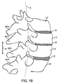
図1Aは、棘突起(SP)、面関節(FJ)、層(L)、横突起(TP)、および仙骨(S)を含む、脊椎の腰部を図示する、概略図である。図1Bは、矢状面に沿って得られた脊椎の腰部の一部分を示す概略図であり、本開示でしばしば使用される「中立位置」、「屈曲」、および「伸展」という用語を定義するために有用である。 FIG. 1A is a schematic diagram illustrating the lumbar portion of the spine including the spinous process (SP), facet joint (FJ), layer (L), transverse process (TP), and sacrum (S). FIG. 1B is a schematic diagram showing a portion of the lumbar portion of the spine obtained along the sagittal plane, which defines the terms “neutral position”, “flexion”, and “extension” as often used in the present disclosure. Useful for.
本明細書で使用されるように、「中立位置」は、患者の脊椎が弛緩立位で静止する位置を指す。「中立位置」は、患者によって異なるであろう。通常、そのような中立位置は、脊椎がわずかな前方凸性、およびわずかな後方凹性を有する、腰椎のわずかな曲率または脊柱前弯症によって特徴付けられるであろう。場合によっては、本発明の拘束の存在は、中立位置を修正してもよく、例えば、デバイスは、未治療の脊椎のいくらかの伸展を有する「新しい」中立位置を画定する、初期力を印加してもよい。そのようなものとして、「中立位置」という用語の使用は、デバイスの存在または不在との関連で解釈されるものである。本明細書で使用されるように、「脊髄分節の中立位置」は、脊椎が中立位置にある時の脊髄分節の位置を指す。 As used herein, “neutral position” refers to the position where the patient's spine rests in a relaxed standing position. The “neutral position” will vary from patient to patient. Typically, such a neutral position will be characterized by a slight curvature of the lumbar spine or lordosis, with the spine having a slight anterior convexity and a slight posterior concave. In some cases, the presence of the restraint of the present invention may modify the neutral position, e.g., the device applies an initial force that defines a "new" neutral position with some extension of the untreated spine. May be. As such, use of the term “neutral position” is to be interpreted in the context of the presence or absence of a device. As used herein, “neutral position of spinal segment” refers to the position of the spinal segment when the spine is in the neutral position.
さらに、本明細書で使用されるように、「屈曲」は、患者が前屈する時の脊髄分節の隣接する椎骨間の運動を指す。図1Bを参照すると、患者が脊椎の中立位置から、すなわち、湾曲軸Aに対して右に前屈すると、椎骨板間Dの前方部分が圧縮されるように、前方側面の個々の椎骨L間の距離は、減少する。対照的に、個々の後方側面の個々の棘突起SPは、矢印Bによって示される方向に離れる。したがって、屈曲は、患者が図1Bで図示される中立位置から前屈する際の隣接する椎骨間の相対的移動を指す。 Further, as used herein, “flexion” refers to movement between adjacent vertebrae of the spinal segment when the patient bends forward. Referring to FIG. 1B, when the patient bends forward from the neutral position of the spine, i.e., to the right with respect to the curve axis A, the anterior portion of the intervertebral disc D is compressed so that the individual vertebra L between the anterior lateral surfaces The distance of decreases. In contrast, the individual spinous processes SP on the individual posterior sides separate in the direction indicated by arrow B. Thus, bending refers to the relative movement between adjacent vertebrae as the patient bends forward from the neutral position illustrated in FIG. 1B.
加えて、本明細書で使用されるように、「伸展」は、患者が後屈し、脊椎が図1Bに図示される中立位置から延在する際の個々の椎骨Lの運動を指す。患者が後屈すると、個々の椎骨の前端が離れる。隣接する椎骨上の個々の棘突起SPは、矢印Bによって示される方向とは反対の方向に相互により接近して移動する。 In addition, as used herein, “extension” refers to the movement of individual vertebra L as the patient bends backward and the spine extends from the neutral position illustrated in FIG. 1B. When the patient is bent back, the front ends of the individual vertebrae are separated. Individual spinous processes SP on adjacent vertebrae move closer together in a direction opposite to the direction indicated by arrow B.
背痛は、脊髄分節と関連付けられるいくつかの症状によって引き起こされる場合があり、多くの異なる種類の脊椎介入および補綴が、そのような症状に対処するように開発されてきた。背痛および関連問題を軽減しようとして投与される治療の実施例は、椎間板または椎間板髄核の置換または修正、線維輪の修復、椎体形成術または椎骨形成術を用いた脊椎骨折の修復、面関節置換術、および脊椎固定術を含む。これらの治療は、有望であるが、状況によっては欠点を有する場合がある。例えば、脊椎補綴または外科手技が、脊柱の荷重を不利に修正し、過剰な荷重またはそうでなければ不利な荷重を、補綴によって、または治療された組織あるいは隣接する組織によって負担させる場合がある。そのような荷重は、補綴の弛緩、移動、または放出、人工椎間板、小関節面、髄核、または環状修復デバイスの有意な危険性、また、従来の固定ハードウェアの危険性をもたらす場合がある。加えて、そのような荷重は、治療された部位が依然として治癒しており、機械的損傷を受けやすい時に、それを損傷し、医原的に損傷された組織をもたらす場合があり、これは、特に椎体形成術に当てはまる。経時的に、そのような荷重は、脊椎固定術に隣接する分節について観察されているように、治療部位に隣接する組織の変性につながる場合がある。さらに、そのような荷重は、補綴の増加した摩耗または断裂をもたらし、そのような補綴の有用寿命を減少させ、潜在的にデバイス故障につながる場合がある。例えば、人工椎間板の場合、椎間板の縁がしばしば、相互に影響を及ぼし、それにより、亀裂、摩耗、組織炎症、ならびに他のデバイス故障モードを引き起こす。しばしば、これらの不利な荷重は、分節屈曲時に最大であるか、または有意に悪化する。屈曲は、椎間可動域の最大構成要素であり、最も頻繁に発揮される。前述のように、屈曲は、椎間板腔への荷重を増加させ、一般的な脊髄の病変と関連付けられる。したがって、過剰な荷重を低減することに役立つため、および付加的な屈曲安定性を提供するために、単独で、または他の脊椎治療と併せて使用することができる、方法および装置を提供することが望ましいであろう。 Back pain can be caused by a number of symptoms associated with the spinal segment, and many different types of spinal interventions and prostheses have been developed to address such symptoms. Examples of treatments administered to reduce back pain and related problems include intervertebral disc or intervertebral disc nucleus replacement or correction, annulus fibrosus repair, spinal fracture repair using vertebroplasty or vertebroplasty, face Includes joint replacement and spinal fusion. These treatments are promising, but may have drawbacks in some situations. For example, a spinal prosthesis or surgical procedure may unfavorably correct the spinal column load and cause an overload or otherwise unfavorable load to be borne by the prosthesis or by treated or adjacent tissue. Such loads can pose a significant risk of prosthetic relaxation, movement or release, prosthetic discs, articular surfaces, nucleus pulposus or annular repair devices, as well as conventional fixation hardware risks. . In addition, such loads may damage the treated site when it is still healed and susceptible to mechanical damage, resulting in iatrogenic damaged tissue, This is especially true for vertebroplasty. Over time, such loading may lead to degeneration of tissue adjacent to the treatment site, as has been observed for segments adjacent to spinal fusion. Furthermore, such loads can result in increased wear or tear of the prosthesis, reducing the useful life of such a prosthesis and potentially leading to device failure. For example, in the case of an artificial disc, the disc edges often interact with each other, thereby causing cracks, wear, tissue inflammation, and other device failure modes. Often, these unfavorable loads are maximal or significantly worse during segment flexion. Bending is the largest component of the intervertebral range of motion and is most often exerted. As described above, flexion increases the load on the disc space and is associated with common spinal cord lesions. Accordingly, to provide a method and apparatus that can be used alone or in conjunction with other spinal treatments to help reduce excessive loads and to provide additional flex stability. Would be desirable.
脊椎安定化は、典型的には、椎弓根ネジおよび安定化ロッド等の器具類を用いて達成される。そのような従来の器具類の配置は、多くの場合、有意な手術罹患率および長い治癒期間を伴う大手術を必要とし、有痛性となり得て、患者の移動性を制限する場合があり、器具自体ならびに隣接する骨および他の組織への望ましくない摩耗および断裂を引き起こし得る。直接安定化および直接荷重負担器具類に依存するよりもむしろ、本明細書で開示される本アプローチは、屈曲を拘束し、脊髄分節の運動を、それが本質的により安定している伸展に優先的に付勢することによる、罹患脊髄分節の間接的除荷および間接的安定化を利用する。脊髄分節は、屈曲に抵抗する可変力を提供する、調整可能な拘束デバイスを使用して、この位置に付勢される。脊椎の安定性を増強するために間接的アプローチを使用することにより、埋め込まれた脊椎デバイス、外科的に治療された組織、および隣接する組織に対する機械的荷重環境を向上させるための独特の方法を提供する。 Spine stabilization is typically achieved using instruments such as pedicle screws and stabilizing rods. Such conventional instrument arrangements often require significant surgery with significant surgical morbidity and long healing periods, can be painful and can limit patient mobility, Undesirable wear and tear on the instrument itself and adjacent bone and other tissues can occur. Rather than relying on direct stabilization and direct load bearing devices, the presently disclosed approach constrains flexion and prioritizes spinal segment movement over extension where it is inherently more stable Take advantage of indirect unloading and indirect stabilization of the affected spinal cord segments by energizing them. The spinal segment is biased to this position using an adjustable restraint device that provides a variable force that resists flexion. Using an indirect approach to enhance spinal stability, a unique method for improving the mechanical loading environment for implanted spinal devices, surgically treated tissue, and adjacent tissue provide.
本デバイスおよび方法を使用することの別の主要な利点は、引張荷重以外の荷重が拘束デバイスに伝達されないことであり、したがって、拘束デバイスは、有意な複合荷重がネジおよびロッドに伝達される従来の器具類よりも少ない故障モードを体験する可能性が高い。したがって、本拘束デバイスが、治療有効性を最大限化しようとするだけでなく、故障を最小化しようとする一方で、ほとんどの既存の脊椎器具類は、荷重負担を最大限化し、結果として、高い機械的故障の割合を有する。 Another major advantage of using the present device and method is that loads other than tensile loads are not transmitted to the constraining device, and therefore the constraining device is traditionally capable of transmitting significant compound loads to the screws and rods. There is a high probability of experiencing fewer failure modes than other appliances. Thus, while this constraining device not only seeks to maximize therapeutic effectiveness, but also attempts to minimize failure, most existing spinal instruments maximize load carrying and, as a result, Has a high rate of mechanical failure.
本方法および装置の他の利点がある。例えば、椎弓根ネジおよび安定化ロッドを伴う従来の器具類は、手術野に圧力をかけ、標的領域への外科医のアクセスを制限し得る。加えて、そのような器具類は、他のデバイス、特に、ネジで脊髄分節に連結されなければならないデバイスの埋込のために利用可能な空間を制限する。本安定化方法は、好ましくは、ネジの使用を回避するが、ネジが使用されてもよく、必要であれば他のネジベースのデバイスの埋込を可能にする。加えて、従来の器具類と比べて、本デバイスおよび方法を埋め込むために、より少ない組織切除が必要とされ、より少ない失血、より短い手技時間、より速い治癒、およびより低い治療費を含む、複数の対応する臨床および経済的有益性を伴う低侵襲手技を提供する。 There are other advantages of the method and apparatus. For example, conventional instruments with pedicle screws and stabilizing rods can place pressure on the surgical field and limit the surgeon's access to the target area. In addition, such instruments limit the space available for implantation of other devices, particularly devices that must be connected to the spinal cord segment with screws. The stabilization method preferably avoids the use of screws, but screws may be used, allowing the implantation of other screw-based devices if necessary. In addition, less tissue resection is required to implant the device and method compared to conventional instruments, including less blood loss, shorter procedure time, faster healing, and lower treatment costs. Provide minimally invasive procedures with multiple corresponding clinical and economic benefits.
加えて、椎弓根ネジおよびロッド等の従来の器具類が使用される時に、脊髄分節は、いったん器具が取り付けられると、所与の位置に係止される。動的安定化ロッドを用いても、限定された運動しか許可されない。したがって、ロッドおよびネジアプローチは、脊髄分節に器具を取り付ける前に、脊髄分節の最適な位置を判定することに外科医の技能に依存する。本デバイスおよび方法は、脊髄分節を剛体位置に「係止」しないため有利である。本デバイスおよび方法は、原位置で調整可能であり、埋込後の脊髄分節のいくらかの移動を可能にし、埋込が発生する前に単一の最適な位置を確立する必要性を低減する。この調整可能性が、デバイスと周辺組織との間のより一貫した嵌合に貢献する場合、デバイスの周囲および周辺組織の中の治癒は、より自然に発生してもよい。本デバイスはまた、初期埋込後の以降の手技で調整されてもよく、したがって、剛体器具類システムと比較して経時的な変化にうまく適応する可能性が高い。 In addition, when conventional instruments such as pedicle screws and rods are used, the spinal cord segment is locked in place once the instrument is installed. Even with a dynamic stabilizing rod, only limited movement is allowed. Thus, the rod and screw approach relies on the surgeon's skill to determine the optimal position of the spinal segment prior to attaching the instrument to the spinal segment. The devices and methods are advantageous because they do not “lock” the spinal cord segment in a rigid position. The device and method can be adjusted in situ, allowing some movement of the spinal segment after implantation, reducing the need to establish a single optimal position before implantation occurs. If this tunability contributes to a more consistent fit between the device and the surrounding tissue, healing around the device and in the surrounding tissue may occur more naturally. The device may also be adjusted in subsequent procedures after the initial implantation and is therefore likely to adapt better to changes over time compared to rigid instrument systems.
ロッドおよびネジ等の従来の器具類と関連付けられる別の主要な課題は、剪断、屈伸、回転、弛緩等によりデバイスが故障する可能性である。本デバイスは、剛体ではなく、これらの種類の運動に適応することができ、したがって、稼働中に故障する可能性が低い。その潜在的により低い故障率により、本デバイスは、より少ない安全性の懸念およびより低い合併症発生率を生成するべきである。 Another major challenge associated with conventional instrumentation such as rods and screws is the possibility of device failure due to shear, flexion, rotation, relaxation, and the like. The device is not rigid and can adapt to these types of movements and is therefore less likely to fail during operation. Due to its potentially lower failure rate, the device should generate fewer safety concerns and lower complication rates.
本デバイスおよび方法はまた、脊髄分節のより自然な運動を保存し、他の剛体または「可撓性」器具類デバイスと比較して、独特の運動学的特性を有する。椎弓根ネジおよびロッド器具類と違って、本デバイスおよび方法は、小関節面の係合を促す傾向がある。これは、付加的な脊髄分節安定性を提供してもよい、軸回転のいくらかの間接的制限をもたらす。本明細書で開示される本デバイスは、伸展荷重に関する問題を回避することに役立つ後方運動(伸展)を意図的に可能にし、患者の脊柱の平衡を保つことに役立ってもよい。ほとんどの他の器具類デバイスまたはシステムは、脊髄分節の後方運動を許可しない。 The devices and methods also preserve the more natural movement of the spinal segment and have unique kinematic properties compared to other rigid or “flexible” instrument devices. Unlike pedicle screws and rod instruments, the devices and methods tend to encourage small articular surface engagement. This results in some indirect limitation of axial rotation that may provide additional spinal segment stability. The devices disclosed herein may intentionally allow posterior movement (extension) to help avoid problems with extension loads and may help to balance the patient's spine. Most other instrument devices or systems do not allow posterior movement of the spinal segment.
したがって、多くの既存の背痛治療および安定化方法と関連付けられる課題に基づいて、過剰な荷重を低減することに役立つため、および付加的な屈曲安定性を提供するために、単独で、または他の脊椎治療と併せて使用することができる、方法および装置を提供することが望ましいであろう。図2は、その内容全体が参照することにより本明細書に組み込まれる、現在は米国特許第7,458,981号である、関連米国特許出願公開第2005/02161017A1号で説明されている種類の脊椎インプラントを示す。図2の拘束デバイスは、患者に埋め込まれた補綴によって負担される、または治療領域に隣接する組織によって負担される荷重を修正し、それにより、治癒を促進し、摩耗および断裂を低減するために、単独で、または他の脊椎治療と併せて使用されてもよい。また、拘束デバイスは、脊髄分節により多大な安定性を提供するために使用されてもよい。 Thus, based on the challenges associated with many existing back pain treatments and stabilization methods, either alone or others to help reduce excessive loads and provide additional flexural stability It would be desirable to provide a method and apparatus that can be used in conjunction with the spinal therapy. FIG. 2 is of the type described in the related US Patent Application Publication No. 2005 / 02161017A1, now US Pat. No. 7,458,981, which is hereby incorporated by reference in its entirety. Figure 3 shows a spinal implant. The restraining device of FIG. 2 modifies the load borne by the prosthesis implanted in the patient or by the tissue adjacent to the treatment area, thereby facilitating healing and reducing wear and tear. May be used alone or in conjunction with other spinal therapies. The restraint device may also be used to provide greater stability to the spinal cord segment.
本明細書で説明される拘束から便益を得ることができる補綴および手技の多くは、特定の病変が介入によって直接治療されるように、自給自足となるように設計された。実施例は、環状修復デバイスを用いた線維輪の欠陥の治療、および椎体形成術または椎骨形成術を用いた脊椎圧迫骨折の治療を含む。これらの介入は、病変に直接対処する一方で、上記で説明されるように、それらが引き起こす副次的または一過性効果に対処しない。そのようなものとして、多くの独立型介入に優る改良のさらなる必要性が存在する。補助的な安定化が、1次補綴または手順と同時に埋め込まれてもよく、または1次補綴または隣接する組織の不利な荷重と関連付けられる退行性変化に対処するように後日埋め込まれてもよいことが留意されるべきである。 Many of the prostheses and procedures that can benefit from the restraints described herein were designed to be self-sufficient so that specific lesions are treated directly by intervention. Examples include the treatment of annulus fibrosus defects using an annular repair device, and the treatment of spinal compression fractures using vertebroplasty or kyphoplasty. While these interventions address the lesions directly, they do not address the side effects or transient effects they cause, as explained above. As such, there is a further need for improvement over many independent interventions. Auxiliary stabilization may be implanted at the same time as the primary prosthesis or procedure, or it may be implanted at a later date to address degenerative changes associated with adverse loading of the primary prosthesis or adjacent tissue Should be noted.
複数の病変に同時に対処するように運動保存アプローチを組み合わせる、限定数のインプラントが知られている。例えば、Disc Motion TechnologiesによるPDSは、小関節面置換デバイスおよび完全椎間板置換補綴の組み合わせである。しかしながら、そのような複合デバイスは、組み合わせて発生する2つの独立した原発性病変に対処することを目的としており、例えば、複合椎間板置換および小関節面置換デバイスは、面関節および椎間板の複合病変に対処する。1次治療の生体力学を増強および修正することによって、1次治療の結果を向上させる手段を提供することが有利であろう。さらに、補助療法または拘束が低侵襲性であること、既知の関連合併症および罹患率により、椎弓根ネジの使用を回避すること、および1次運動保存治療の意図と協調して生理学的荷重および運動を可能にすることが有利であろう。 A limited number of implants are known that combine a motion conservation approach to deal with multiple lesions simultaneously. For example, PDS by Disc Motion Technologies is a combination of a facet replacement device and a complete disc replacement prosthesis. However, such composite devices are aimed at addressing two independent primary lesions that occur in combination, for example, composite disc replacement and small joint surface replacement devices are used for complex lesions of face joints and discs. deal with. It would be advantageous to provide a means to improve the results of primary treatment by enhancing and modifying the primary treatment biomechanics. In addition, the adjunct therapy or restraint is minimally invasive, avoids the use of pedicle screws due to known associated complications and morbidity, and physiological loads in coordination with the intention of primary exercise preservation therapy It would be advantageous to allow and exercise.
図2で図示されるように、インプラント10は、典型的には、1対のコンプライアンス部材16によって接合される、上ストラップ構成要素12および下ストラップ構成要素14を有する、テザー構造を備える。上ストラップ12が、L4の棘突起SP4の最上部を覆って配置されて示されている一方で、下ストラップ14は、L5の棘突起SP5の底部を覆って延在して示されている。コンプライアンス部材16は、典型的には、棘突起SP4およびSP5が屈曲中に離れると、ストラップが、「弾性的」または「従順に」に引き離されてもよいような方法で、ストラップ12および14に取り付けられる、バネまたはゴムブロック等の内部要素を含む。このようにして、インプラントは、屈曲に抵抗する力である、棘突起上の弾性張力を提供する。力は、突起がさらに離れるにつれて増加する。通常、ストラップ自体は、弾性またはコンプライアンスの度合が、コンプライアンス部材16のみによって制御され、提供されてもよいように、本質的に非従順となる。インプラント10は、低侵襲的に脊髄分節に連結されてもよい。典型的には、上棘突起より上位にあり、また下棘突起の下位にある棘間靱帯(図示せず)に、小さい穿孔が作成される。次いで、上下ストラップが、これらの穿刺を通して前進させられてもよく、端が、閉ループを形成するようにともに連結されてもよい。インプラント10および使用方法についての付加的な詳細は、米国仮特許出願第61/093,922号(代理人整理番号第026398−000900US号)、同第61/059,543号(代理人整理番号第026398−000800US号)、同第61/059,538号(代理人整理番号第026398−000700US)号、米国特許出願第12/106,103号(代理人整理番号第026398−000410US号)、米国特許出願公開第2010/0023060号(代理人整理番号第026398−000710US号)、および同第2008/0262549号(代理人整理番号第026398−000151US号)、米国特許第7,458,981号(代理人整理番号第026398−000210US号)、および国際出願第PCT/US2009/055914号(代理人整理番号第026398−00910PC号)、および同第PCT/US2009/046492号(代理人整理番号第026398−000810PC号)で開示されており、それぞれの内容全体は、参照することによりその全体で本明細書に組み込まれる。他の脊椎治療と組み合わせて拘束デバイスが使用される、いくつかの例示的実施形態を以下で開示する。本明細書で開示される拘束デバイスは、参照することにより組み込まれる参考文献で説明されている特徴のうちのいずれかを含んでもよい。拘束デバイスの種々の実施形態からの特徴はまた、本明細書で開示される他の実施形態からの特徴と組み合わせられるか、または置換されてもよい。
As illustrated in FIG. 2, the
図3A−3Bは、人工椎間板または人工面関節置換デバイスとの拘束デバイスの使用を図示する。図3Aでは、天然椎間板Dは、2つの隣接する椎骨Vの間で正常に配置されている。しかしながら、疾患または変性により、損傷された椎間板が人工椎間板302と置換されてもよい。人工椎間板が当技術分野で周知であり、例示的な商用デバイスは、Depuy Spine、Johnson & Johnson CompanyからのCharite人工椎間板、ならびにSynthesおよびMedtronic Sofamor Danekからの他のデバイスを含む。人工椎間板302は、天然椎間板Dに取って代わり、2つの椎骨Vの間の適正な整列および間隔を修復し、2つの椎骨Vの間の平滑な相対運動を可能にする。
3A-3B illustrate the use of a restraint device with an artificial disc or artificial facet joint replacement device. In FIG. 3A, the natural disc D is normally positioned between two adjacent vertebrae V. However, due to disease or degeneration, an injured disc may be replaced with an
図3Bは、単独で、または人工椎間板インプラントと組み合わせて使用されてもよい、人工置換面関節306の埋込を図示する。Facet Solutions,Inc.によって提供されるAcadia等の面関節置換も当技術分野で周知である。一部の患者では、面関節は、病的な有痛性関節を排除し、正常な運動を修復し、脊髄分節の安定化を提供するために、人工関節で修復または置換される。また、面関節インプラントは、固定の代わりに、部分椎弓切除術、椎弓切開術、神経減圧術、および脊椎関節突起切除術の補助として使用されてもよい。面関節インプラントはしばしば、小関節面の変性疾患、不安定性を伴う小関節面の変性疾患、変性脊椎すべり症、および脊髄狭窄症を含む、腰椎の不安定性または変形を治療するために使用される。 FIG. 3B illustrates the implantation of an artificial replacement facet joint 306 that may be used alone or in combination with an artificial disc implant. Facet Solutions, Inc. Surface joint replacements such as Acadia provided by are also well known in the art. In some patients, facet joints are repaired or replaced with artificial joints to eliminate pathological painful joints, restore normal movement, and provide spinal segment stabilization. The facet joint implant may also be used as an adjunct to partial laminectomy, laminectomy, nerve decompression, and spinal arthrotomy instead of fixation. Facial joint implants are often used to treat lumbar instability or deformity, including small joint surface degenerative disorders, small joint surface degenerative disorders with instability, degenerative spondylolisthesis, and spinal stenosis .
人工椎間板も、面関節置換デバイスも、典型的には、脊髄分節の屈曲に対する弾性抵抗を提供しない。これらの補綴は、摩擦を最小化するように設計されている荷担面を有し、移動を制限する「硬質停止部」を備えてもよい。したがって、隣接棘突起SPの周囲に拘束デバイス304を適用することは、脊髄分節の屈曲を制限することに役立つ。拘束デバイス304は、概して、図2に図示された拘束デバイスと同じ形態を成し、上部テザー部分と、下部テザー部分と、1対のコンプライアンス部材(図3の側面図では1つしか図示されていない)とを含む。上部テザー部分は、上棘突起の上面の周囲に配置され、下部テザー部分は、下棘突起の下面の周囲に配置される。拘束デバイスを適用するための方法は、米国特許出願公開第2008/0262549号でより詳細に開示されており、拘束デバイスについての付加的な開示は、全て参照することにより本明細書に以前に組み込まれた、米国特許出願第12/106,103号および米国特許第7,458,981号で見出されてもよい。拘束デバイスを埋め込むための方法は、本明細書で開示される実施形態のうちのいずれかに適用されてもよく、本明細書で開示される拘束デバイスのうちのいずれかは、拘束デバイス304の形態を成してもよい。また、屈曲を制限することによって、人工椎間板または人工面関節および隣接する組織に印加される荷重のうちのいくらかが修正される。椎間板については、この荷重の変化は、椎間板縁の衝突を最小化し、縁の衝突を制限する特徴を伴うより複雑な人工椎間板の必要性を低減する。荷重は、より均等に分配されるか、または軽減さえされる。したがって、拘束デバイスを適用することは、脊髄分節のより自然な生体力学を修復することに役立つ。
Neither artificial discs nor facet joint replacement devices typically provide elastic resistance to spinal segment flexion. These prostheses may have a bearing surface designed to minimize friction and may include a “hard stop” that limits movement. Therefore, applying the constraining
図4A−4Cは、図2の拘束デバイスが、どのようにして脊髄分節の固定と併せて使用されてもよいかを図示する。図4Aでは、隣接する椎骨は、当技術分野で周知の方法を使用して、ともに固定されている。固定領域Fはしばしば、固定の高さでの運動を防止するように、椎弓根ネジ402および脊椎安定化ロッド404が取り付けられるが、内部固定を伴わずに原位置固定が行われてもよい。この手技は、有望であるが、潜在的な欠点も有する場合がある。例えば、脊椎固定術が実現された後に、過剰な運動が、隣接する高さ(例えば、固定領域Fより上側および下側の脊髄分節領域)で生じる場合がある。これは、固定分節における可撓性の損失に対する補償によるものであり、運動分節のさらなる変性を生じ得る。したがって、隣接する高さ(例えば、固定より上側または下側)での分節の屈曲が制限され、それにより、さらなる変性を低減または排除するならば望ましいであろう。図4Aでは、図2で図示されたもの等の拘束デバイス406は、固定領域より上位にある運動分節に適用されている。拘束デバイスは、固定器具から完全に独立しているように脊髄分節に固定される。ここで、拘束デバイスは、固定より上位にある上棘突起の上面の周囲に、また、下棘突起の下面の周囲にも配置され、下棘突起は、固定された脊髄分節の上領域の一部である。したがって、この実施形態では、器具を取り付けられた領域に沿った運動は、固定過程を促進するために実質的に阻止され、拘束デバイスは、固定領域に上位隣接する脊髄分節の屈曲を制限する。これは、固定器具ならびに隣接する組織、特に隣接椎間板に印加される荷重をより均等に分配し、おそらくは軽減することに役立つ。それはまた、過剰な運動を低減し、固定されていない運動分節のさらなる変性の可能性を軽減する。
4A-4C illustrate how the constraining device of FIG. 2 may be used in conjunction with spinal segment fixation. In FIG. 4A, adjacent vertebrae are fixed together using methods well known in the art. The fixation region F is often fitted with a
図4Bは、図4Bでは、拘束デバイスが固定器具と連結されているという主な違いを伴う、図4Aと同様の実施形態を図示する。図4Bでは、下部椎骨が別の椎骨(図示せず)と固定されている。次いで、固定領域Fは、固定された椎骨の間での運動を防止するように、椎弓根ネジ402および脊椎安定化ロッド404が取り付けられる。次いで、拘束デバイス408が、固定された分節に上位隣接して適用される。この実施形態では、拘束デバイス408は、上棘突起の上面の周囲に配置される上部テザー410と、脊髄分節の屈曲に抵抗する力を提供する1対のコンプライアンス部材412とを含む。ここで、各コンプライアンス部材412の底部は、椎弓根ネジ402および安定化ロッド404と固着される。したがって、拘束デバイス408は、固定領域Fに上位隣接する脊髄分節の屈曲を制限する。代替実施形態では、コンプライアンス部材412の上部分は、上部テザー410を使用する代わりに、椎弓根ネジまたは他の締結具414と連結される、透視で図示された連結棒416を含んでもよい。代替実施形態では、拘束は、拘束デバイスが固定領域より下位にあり、コンプライアンス部材の最上部分が椎弓根ネジと連結されるように、方向転換させることができる。
FIG. 4B illustrates an embodiment similar to FIG. 4A with the main difference that in FIG. 4B the constraining device is coupled to the anchoring device. In FIG. 4B, the lower vertebra is fixed with another vertebra (not shown). The fixation region F is then fitted with
図4Cは、屈曲に対する抵抗を提供し、ならびに固定された脊髄分節の運動を防止するように修正されてもよい、図2と同様の拘束デバイスの代替実施形態の側面図および後面図を図示する。図4Cでは、後側方固定術Fが、隣接する椎骨、ここでは、L4とL5との間で行われている。拘束デバイス420は、上部テザー部分422と、下部テザー部分426とを含む。拘束デバイス420は、上部テザー部分422が、固定領域に隣接する椎骨の上棘突起の上面の周囲に配置され、下部テザー部分426が、固定領域の下部分上の下棘突起の下面の周囲に配置されるように、脊髄分節と連結される。中間テザー424は、中間棘突起の上面の周囲に配置され、中間テザー424の端は、下部テザー部分424に固定される。中間棘突起は、拘束デバイスが連結される上下棘突起の間に配置され、この例示的実施形態では、中間棘突起は、上部固定椎骨の一部である。この実施形態では、上部、下部、および中間テザー部分422、424、426は、実質的に非弾性であり、したがって、下棘突起と中間棘突起との間の運動は、テザー部分424、426の張力または長さに基づいて制御される。したがって、固定分節において運動が許可されないか、または非常に限定された運動が許可されるように、中間テザー部分および下部テザー部分を調整することが望ましいであろう。加えて、上部テザー部分422、下部テザー部分426、およびコンプライアンス部材408の構成は、上位隣接分節の屈曲を抑制する。当業者であれば、代替実施形態では、固定領域より下位にある脊髄分節の屈曲が制限されるように、拘束デバイスを使用できることも理解するであろう。
FIG. 4C illustrates a side view and a rear view of an alternative embodiment of a restraint device similar to FIG. 2 that may be modified to provide resistance to flexion and prevent movement of a fixed spinal segment. . In FIG. 4C, posterior lateral fixation F is performed between adjacent vertebrae, here L4 and L5. The restraining
本明細書で開示される実施形態の多くでは、いずれのインプラントも拘束デバイスの間に配置されない。したがって、拘束デバイスが上棘突起の上面および下棘突起の下面と連結される時に、上棘突起の下面と下棘突起の上面との間に直接延在する領域はしばしば、いずれのスペーサまたは他のインプラントも含まないままである。 In many of the embodiments disclosed herein, no implant is placed between the restraining devices. Thus, when the constraining device is coupled to the upper surface of the superior spinous process and the lower surface of the inferior spinous process, the region extending directly between the lower surface of the superior spinous process and the upper surface of the inferior spinous process is often any spacer or other The remaining implants are not included.
棘突起の間に何も配置されない、以前の実施形態とは違って、図5では、脊髄分節の伸展および屈曲を制限するために、拘束デバイスと組み合わせて棘間スペーサが使用されている。図5では、St.Francis Medical Technologies,Inc.(Kyphon,Inc.によって買収され、現在はMedtronicの一部)によって提供されているX Stop等のスペーサ502が、L3およびL4で棘突起SPの間に配置される。スペーサは、隣接する椎骨の間の伸展を制限し、それにより、小関節面荷重を潜在的に低減し、脊柱管および椎孔の面積を増加させる。これは、神経原性跛行および疼痛等の患者の体系を緩和することに役立つ。拘束デバイス504はまた、屈曲を制限するために脊髄分節に適用されてもよい。図5では、拘束デバイス504は、上部テザー部分506と、コンプライアンス部材508と、下部テザー部分510とを含む。この実施形態の上部テザー部分は、スペーサ502と直接連結されて示されている。それは、接着、溶接、固定、開口に通過させること等を含む、いくつかの方法でスペーサに取り付けられてもよい。代替実施形態では、上部テザー部分は、スペーサと連結される必要はない。代わりに、テザーは、以前に論議された図2、3、および4A−4Cの実施形態と同様に、上棘突起の上面の周囲に配置されてもよい。下部テザー部分510は、下棘突起の下面の周囲に配置される。したがって、屈曲は、スペーサより下位の分節で制限され、テザーおよびコンプライアンス部材508の構成は、屈曲に抵抗する力を提供する。当業者であれば、スペーサが脊髄分節に沿っていずれか2つの棘突起の間に配置されてもよく、したがって、拘束デバイスの位置は、必要に応じて脊髄分節に沿って移動させられてもよいことを理解するであろう。
Unlike previous embodiments, where nothing is placed between the spinous processes, in FIG. 5 an interspinous spacer is used in combination with a restraining device to limit spinal segment extension and flexion. In FIG. Francis Medical Technologies, Inc. A
椎間板変性が初期または中間段階であり、椎間板線維輪が依然として有能であり、十分な拘束を提供する時に、完全椎間板補綴の代わりに、人造または人工髄核が使用されてもよい。髄核のみを置換することによって、線維輪および終板等の残存椎間板組織が、それらの機能とともに保存される。髄核を置換するための外科手技は、完全椎間板置換術よりも単純であってもよい。図6Aでは、人造髄核602が、椎骨Vの間に配置されている残存椎間板線維輪Aに埋め込まれている。人工髄核602は、線維輪を再膨張させ、荷重の一部分を携持することによって圧縮荷重を緩和する。しかしながら、髄核602は、分節屈曲による望ましくない移動、放出、摩耗、または他の悪影響を受ける場合がある。図6Aは、髄核602の部分押出を図示する。屈曲を制限する、図2と同様の拘束デバイスは、髄核の押出を防止することに役立ってもよい。図6Bでは、拘束デバイス604は、人造髄核602を包囲する椎骨の上下の棘突起に適用されている。拘束デバイス604は、概して、以前に説明された拘束デバイスと同じ形態を成す。例えば、拘束デバイス604は、上部テザー部分606と、下部テザー部分610と、1対のコンプライアンス部材608(図6Bの側面図では1つしか示されてない)とを含む。上部テザー部分606は、上棘突起の上面の周囲に配置され、下部テザー部分610は、下棘突起の下面の周囲に配置される。拘束デバイス604は、人造髄核を包囲する脊髄分節の屈曲に抵抗し、したがって、人造髄核および周辺組織上でより均等に力を分配し、それにより、髄核の損傷および放出を防止する。
An artificial or artificial nucleus pulposus may be used instead of a full disc prosthesis when disc degeneration is in the early or intermediate stages and the disc annulus is still competent and provides sufficient restraint. By replacing only the nucleus pulposus, the remaining intervertebral disc tissue, such as the annulus fibrosus and endplate, is preserved along with their function. Surgical procedures for replacing the nucleus pulposus may be simpler than complete disc replacement. In FIG. 6A, the
図7A−7Dは、椎体形成術と併せた拘束デバイスの使用を図示する。しばしば、骨粗鬆症、癌または良性腫瘍の結果である、脊椎圧迫骨折とも呼ばれる脊椎骨折を有する患者では、椎体形成術が適切な低侵襲治療であってもよい。図7Aは、椎骨Vにおける脊椎骨折702を図示する。図7Bは、椎体形成術での主要なステップを図示する。椎体形成術では、骨折した骨702の中へ狭い経路を作成するために、中空器具が使用される。次いで、整形外科用バルーン704が、経路を通して骨折した椎体702に挿入される。しばしば、治療中により良好な支持を骨に提供するために、椎体の両側に1つずつ、2つのバルーンが使用される(図7Bは側面図であり、したがって1つのバルーンしか図示しない)。次いで、バルーン704は、崩壊した椎体を持ち上げ、それを正常な位置に戻すために膨張させられる。バルーンを膨張させることはまた、骨に空洞を作成し、いったんバルーンが収縮されると、空洞は骨セメント706または骨セメント類似体で充填され、それにより、定位置で椎体を担持する内部ギプスを形成する。再度、これは有望な治療であるが、図7Cの矢印によって示されるような屈曲運動が、修復された椎骨の前方部分により高い圧縮荷重を及ぼす場合がある。これらの荷重は、修復された骨折708に伝達される場合があり、疼痛、骨折した骨の癒着不能、および他の治癒不具合を潜在的に引き起こす。加えて、骨セメントおよびほとんどの骨セメント代用品の弾性係数が正常な骨の弾性係数よりも大きいため、修復された椎体の剛性は、天然椎骨の剛性よりも大きくてもよく、そのようなものとして、骨セメント・骨界面において、過剰な摩耗および断裂があり得る。屈曲を制限する拘束デバイスの適用は、修復された骨折および隣接する組織708から除荷することに役立ち、それにより、これらの有害な合併症を低減してもよい。図7Dでは、図2と同様の拘束デバイスが、椎体形成術で治療された脊髄分節に適用されている。拘束デバイス710は、概して、上記で以前に説明されたのと同じ形態を成す。拘束デバイス710は、脊椎骨折に隣接する棘突起の周囲に配置される、上部および下部テザー部分712、716を含む。この実施形態では、上部テザー部分712は、上棘突起の上面の周囲に配置され、下部テザー部分716は、骨折した椎骨の下棘突起の下部分の周囲に配置される。テザーおよび1対のコンプライアンス部材714(図7Dの側面図では1つしか図示されていない)の構成は、治療された脊髄分節の屈曲に抵抗する力を提供する。他の実施形態は、椎骨形成術(椎体形成術用バルーンの拡張を伴わない充填材の注入)を含むがそれに限定されない、椎体形成術の変化例、およびインプラント(例えば、ステント状またはメッシュ状デバイスの埋込)を含んでもよい。
7A-7D illustrate the use of a restraint device in conjunction with vertebroplasty. Vertebroplasty may be an appropriate minimally invasive treatment for patients with vertebral fractures, also called spinal compression fractures, often as a result of osteoporosis, cancer or benign tumors. FIG. 7A illustrates a
図8A−8Bは、環状修復デバイスとの拘束デバイスの使用を図示する。環状修復デバイスは、特に椎間板ヘルニアによる、線維輪の欠陥、病変、断裂、または他の損傷を修繕または修復するために使用される。図8Aは、隣接する椎骨Vの間の椎間板の環状欠陥804を図示する。環状修復デバイス802は、椎間板ヘルニアまたは髄核放出を防止するために、線維輪と連結される。ヘルニア形成はしばしば、矢印によって図8Aで示される屈曲と急性的に関連付けられ、また、治癒を阻止し、再ヘルニア形成を誘発する場合もある。同様に、屈曲運動は、環状修復デバイスにより多くの要求を課し、したがって、それらの有効性に影響を及ぼす場合がある。屈曲運動を制限する拘束デバイスは、再ヘルニア形成の発生率を低減し、環状修復デバイス、特に低侵襲デバイスで治療された患者の転帰を向上させることに役立つ。
8A-8B illustrate the use of a restraining device with an annular repair device. Annular repair devices are used to repair or repair annulus defects, lesions, tears, or other injuries, particularly due to herniated discs. FIG. 8A illustrates an
図8Bは、環状修復デバイス802と併せた、図2で見られるもの等の拘束デバイスの使用を図示する。拘束デバイスは、概して、上記で以前に説明されたものと同じ形態を成す。拘束デバイス806は、上部および下部テザー部分808、812と、1対のコンプライアンス部材810(図8Bの側面図では1つしか見えない)とを含む。上部テザー部分は、上棘突起の上面の周囲に配置され、下部テザー部分は、下棘突起の下面の周囲に配置される。テザーおよびコンプライアンス部材810の構成は、脊髄分節の屈曲を制限する力を提供する。これはまた、線維輪後部の張力を低減することに役立ち、環状欠陥804を閉じておく。
FIG. 8B illustrates the use of a restraining device such as that seen in FIG. 2 in conjunction with an
上記で開示される実施形態のうちのいずれかでは、屈曲に対する抵抗がどれだけ提供されるかを制御するために、拘束デバイスの張力および/または長さが調整されてもよい。拘束デバイスは、付加的な手術が回避されるように、経皮的に調整されることを含んで、埋込の前、間、または後に調整されてもよい。これはまた、治癒が発生するにつれて、デバイスが調整されることも可能にする。例えば、屈曲に対するより多大な抵抗を提供する、より緊密な拘束デバイスが、治癒の初期段階中に提供されてもよく、屈曲に対するより小さい抵抗を提供する、あまり緊密ではない拘束デバイスが、治癒が進行するにつれて必要とされてもよい。種々の調整および係止機構が、参照することにより本明細書に以前に組み込まれた、米国仮特許出願第61/059,543号および同第61/059,538号、ならびに本明細書で組み込まれた他の特許出願で開示されている。さらに、本明細書で開示される実施形態のうちのいずれかはまた、治癒過程を促進する治療薬を携持し、送達するために使用されてもよい。例えば、抗生物質が、感染症を予防することに役立つように拘束デバイスによって携持されてもよく、骨形成タンパク質も、骨または他の組織成長を刺激するために使用されてもよい。加えて、本明細書で開示される実施形態の多くは、インプラントまたは治療の高さで、あるいはインプラントまたは治療の高さより上位で、脊髄分節の屈曲を制限する拘束デバイスを示す。当業者であれば、インプラントまたは治療の高さより下側で屈曲を制限するよう、拘束デバイスが脊髄分節に適用されてもよいことを理解するであろう。加えて、状況によっては、拘束デバイスの下部分は、下棘突起の代わりに仙骨と連結されてもよい。仙骨取付方法は、米国仮特許出願第61/149,224号(代理人整理番号第026398−001200US)、国際出願第PCT/US2010/022767号(代理人整理番号第026398−001210PC)、および米国特許出願第11/827,980号(代理人整理番号第026398−000120US)でより詳細に開示されており、その内容全体は、参照することによって本明細書に組み込まれる。上記で説明される実施形態では、拘束構造は、第1の補綴または手技と同時に、または別の時に行われる別個の手技で埋め込まれてもよい。 In any of the embodiments disclosed above, the tension and / or length of the restraining device may be adjusted to control how much resistance to bending is provided. The restraint device may be adjusted before, during, or after implantation, including percutaneously adjusted so that additional surgery is avoided. This also allows the device to be adjusted as healing occurs. For example, a tighter restraint device that provides greater resistance to flexion may be provided during the early stages of healing, while a less tight restraint device that provides less resistance to flexion may provide healing. It may be needed as it progresses. Various adjustment and locking mechanisms are incorporated herein by reference, U.S. Provisional Patent Application Nos. 61 / 059,543 and 61 / 059,538, previously incorporated herein by reference. In other published patent applications. Furthermore, any of the embodiments disclosed herein may also be used to carry and deliver therapeutic agents that promote the healing process. For example, antibiotics may be carried by the restraint device to help prevent infections, and bone morphogenetic proteins may also be used to stimulate bone or other tissue growth. In addition, many of the embodiments disclosed herein show constraining devices that limit spinal segment flexion at or above the implant or treatment height. One skilled in the art will appreciate that a constraining device may be applied to the spinal cord segment to limit flexion below the height of the implant or treatment. In addition, in some situations, the lower portion of the constraining device may be coupled with the sacrum instead of the inferior spinous process. Sacral attachment methods include US provisional patent application No. 61 / 149,224 (Attorney Docket No. 026398-001200US), International Application No. PCT / US2010 / 022767 (Attorney Docket No. 026398-001210PC), and US Patents. Application 11 / 827,980 (Attorney Docket No. 026398-000120 US) is disclosed in greater detail, the entire contents of which are hereby incorporated by reference. In the embodiments described above, the restraining structure may be implanted at the same time as the first prosthesis or procedure or in a separate procedure performed at another time.
理解を明確にするために、かつ一例として、例示的実施形態をいくらか詳細に説明してきたが、いくつかの修正、変更、および適合が実装されてもよく、および/または当業者に明白となるであろう。よって、本発明の範囲は、独立請求項のみによって限定される。 While the exemplary embodiments have been described in some detail for purposes of clarity of understanding and by way of example, several modifications, changes and adaptations may be implemented and / or will be apparent to those skilled in the art. Will. Accordingly, the scope of the invention is limited only by the independent claims.
Claims (15)
該脊髄分節と連結される第1の補綴であって、該拘束デバイスは、該補綴によって、または該拘束デバイスに隣接する組織によって負担される荷重を修正する、第1の補綴と
を備える、脊椎治療システム。 A constraining device having an upper tether portion, a lower tether portion, and a compliance member coupled therebetween, wherein the upper tether portion and the lower tether portion are joined by the compliance member, the upper tether portion being Coupled to the upper spinous process of the patient's spinal segment, the lower tether portion is coupled to the lower spinous process or sacrum of the spinal segment, and the length or tension of the restraining device is determined by the tether portion and A constraining device, wherein the configuration is adjustable to provide a force that resists flexion of the spinal segment;
A first prosthesis coupled to the spinal segment, the constraining device comprising: a first prosthesis that modifies a load borne by the prosthesis or by tissue adjacent to the constraining device ; Treatment system.
該第1の補綴は、ともに固定される該2つの椎骨のうちの上椎骨と連結される実質的に非弾性のテザーを備え、
該実質的に非弾性のテザーおよび前記拘束デバイスは、ともに固定される該2つの椎骨の間の屈曲を制限し、
該実質的に非弾性のテザーは、該上部テザー部分と該下部テザー部分との間に配置される、請求項1に記載のシステム。 The first prosthesis comprises a bone graft material disposed between two adjacent vertebrae, wherein the bone graft material is adapted to facilitate fixation of the two adjacent vertebrae of the spinal segment;
The first prosthesis comprises a substantially inelastic tether connected to the upper vertebra of the two vertebrae secured together;
The substantially inelastic tether and the restraint device limit flexion between the two vertebrae fixed together;
The system of claim 1, wherein the substantially inelastic tether is disposed between the upper tether portion and the lower tether portion.
前記力は、該スペーサよりも下位にある該脊髄分節の一部分の屈曲に抵抗する、請求項1に記載のシステム。 The first prosthesis includes a spacer disposed between a pair of adjacent spinous processes, wherein the pair of adjacent spinous processes is one of the upper spinous process, the lower spinous process, or the sacrum. Positioned above at least one, and the spacer prevents extension of at least a portion of the spinal segment;
The system of claim 1, wherein the force resists bending of a portion of the spinal segment below the spacer.
前記力は、該スペーサよりも上位にある該脊髄分節の一部分の屈曲に抵抗する、請求項1に記載のシステム。 The first prosthesis includes a spacer disposed between a pair of adjacent spinous processes, the pair of adjacent spinous processes from at least one of the upper spinous process or the lower spinous process Disposed below, the spacer prevents extension of at least a portion of the spinal segment,
The system of claim 1, wherein the force resists bending of a portion of the spinal segment that is above the spacer.
Applications Claiming Priority (3)
| Application Number | Priority Date | Filing Date | Title |
|---|---|---|---|
| US15889209P | 2009-03-10 | 2009-03-10 | |
| US61/158,892 | 2009-03-10 | ||
| PCT/US2010/026859 WO2010104975A1 (en) | 2009-03-10 | 2010-03-10 | Surgical tether apparatus and methods of use |
Publications (3)
| Publication Number | Publication Date |
|---|---|
| JP2012520135A JP2012520135A (en) | 2012-09-06 |
| JP2012520135A5 JP2012520135A5 (en) | 2013-03-28 |
| JP5681122B2 true JP5681122B2 (en) | 2015-03-04 |
Family
ID=45218068
Family Applications (1)
| Application Number | Title | Priority Date | Filing Date |
|---|---|---|---|
| JP2011554162A Active JP5681122B2 (en) | 2009-03-10 | 2010-03-10 | Surgical tether device and method of use |
Country Status (3)
| Country | Link |
|---|---|
| US (6) | US9107706B2 (en) |
| EP (1) | EP2405840B1 (en) |
| JP (1) | JP5681122B2 (en) |
Families Citing this family (26)
| Publication number | Priority date | Publication date | Assignee | Title |
|---|---|---|---|---|
| US7955357B2 (en) | 2004-07-02 | 2011-06-07 | Ellipse Technologies, Inc. | Expandable rod system to treat scoliosis and method of using the same |
| US7862502B2 (en) | 2006-10-20 | 2011-01-04 | Ellipse Technologies, Inc. | Method and apparatus for adjusting a gastrointestinal restriction device |
| US11202707B2 (en) | 2008-03-25 | 2021-12-21 | Nuvasive Specialized Orthopedics, Inc. | Adjustable implant system |
| US8382756B2 (en) | 2008-11-10 | 2013-02-26 | Ellipse Technologies, Inc. | External adjustment device for distraction device |
| JP5681122B2 (en) | 2009-03-10 | 2015-03-04 | シンピライカ スパイン, インコーポレイテッド | Surgical tether device and method of use |
| US9622792B2 (en) | 2009-04-29 | 2017-04-18 | Nuvasive Specialized Orthopedics, Inc. | Interspinous process device and method |
| US9248043B2 (en) | 2010-06-30 | 2016-02-02 | Ellipse Technologies, Inc. | External adjustment device for distraction device |
| WO2012112396A2 (en) | 2011-02-14 | 2012-08-23 | Ellipse Technologies, Inc. | Device and method for treating fractured bones |
| US10743794B2 (en) | 2011-10-04 | 2020-08-18 | Nuvasive Specialized Orthopedics, Inc. | Devices and methods for non-invasive implant length sensing |
| WO2013066946A1 (en) | 2011-11-01 | 2013-05-10 | Ellipse Technologies, Inc. | Adjustable magnetic devices and methods of using same |
| WO2014032118A1 (en) | 2012-08-31 | 2014-03-06 | Newsouth Innovations Pty Limited | Bone stabilization device and methods of use |
| RU2626961C2 (en) | 2012-10-29 | 2017-08-02 | Нувэйсив Спешилайзд Ортопэдикс, Инк. | Adjustable devices for knee arthritis treatment |
| CN105592811B (en) | 2013-08-30 | 2018-06-22 | 新南创新公司 | Spinal stabilization device |
| FR3010628B1 (en) | 2013-09-18 | 2015-10-16 | Medicrea International | METHOD FOR REALIZING THE IDEAL CURVATURE OF A ROD OF A VERTEBRAL OSTEOSYNTHESIS EQUIPMENT FOR STRENGTHENING THE VERTEBRAL COLUMN OF A PATIENT |
| US10751094B2 (en) | 2013-10-10 | 2020-08-25 | Nuvasive Specialized Orthopedics, Inc. | Adjustable spinal implant |
| FR3012030B1 (en) | 2013-10-18 | 2015-12-25 | Medicrea International | METHOD FOR REALIZING THE IDEAL CURVATURE OF A ROD OF A VERTEBRAL OSTEOSYNTHESIS EQUIPMENT FOR STRENGTHENING THE VERTEBRAL COLUMN OF A PATIENT |
| AU2015253313B9 (en) | 2014-04-28 | 2020-09-10 | Nuvasive Specialized Orthopedics, Inc. | System for informational magnetic feedback in adjustable implants |
| ES2908064T3 (en) | 2014-12-26 | 2022-04-27 | Nuvasive Specialized Orthopedics Inc | distraction systems |
| FR3031666B1 (en) * | 2015-01-20 | 2017-01-27 | Implanet | DEVICE AND METHOD FOR FASTENING A FLAT STRIP ON A BONE PART. |
| US10238427B2 (en) | 2015-02-19 | 2019-03-26 | Nuvasive Specialized Orthopedics, Inc. | Systems and methods for vertebral adjustment |
| KR20180067632A (en) | 2015-10-16 | 2018-06-20 | 누베이시브 스페셜라이즈드 오소페딕스, 인크. | An adjustable device for treating arthritis of the knee |
| KR20180093988A (en) | 2015-12-10 | 2018-08-22 | 누베이시브 스페셜라이즈드 오소페딕스, 인크. | External adjustment device for distraction device |
| DK3407812T3 (en) | 2016-01-28 | 2020-09-21 | Nuvasive Specialized Orthopedics Inc | Bone transport system |
| WO2017139785A1 (en) * | 2016-02-12 | 2017-08-17 | Nuvasive, Inc. | Post-operatively adjustable spinal fixation devices |
| US10918422B2 (en) * | 2017-12-01 | 2021-02-16 | Medicrea International | Method and apparatus for inhibiting proximal junctional failure |
| US11344337B2 (en) * | 2018-02-19 | 2022-05-31 | Zimmer Biomet Spine, Inc. | Systems for attenuation of increased spinal flexion loads post-fusion and associated methods |
Family Cites Families (174)
| Publication number | Priority date | Publication date | Assignee | Title |
|---|---|---|---|---|
| US5021A (en) * | 1847-03-20 | Jambs haworth | ||
| US3648691A (en) | 1970-02-24 | 1972-03-14 | Univ Colorado State Res Found | Method of applying vertebral appliance |
| US4246660A (en) | 1978-12-26 | 1981-01-27 | Queen's University At Kingston | Artificial ligament |
| US4643178A (en) | 1984-04-23 | 1987-02-17 | Fabco Medical Products, Inc. | Surgical wire and method for the use thereof |
| US4743260A (en) | 1985-06-10 | 1988-05-10 | Burton Charles V | Method for a flexible stabilization system for a vertebral column |
| US4708132A (en) | 1986-01-24 | 1987-11-24 | Pfizer-Hospital Products Group, Inc. | Fixation device for a ligament or tendon prosthesis |
| US4776851A (en) | 1986-07-23 | 1988-10-11 | Bruchman William C | Mechanical ligament |
| US4794916A (en) | 1986-11-20 | 1989-01-03 | Porterfield James A | Lumbar stabilizer |
| US4772286A (en) | 1987-02-17 | 1988-09-20 | E. Marlowe Goble | Ligament attachment method and apparatus |
| FR2623085B1 (en) | 1987-11-16 | 1992-08-14 | Breard Francis | SURGICAL IMPLANT TO LIMIT THE RELATIVE MOVEMENT OF VERTEBRES |
| FR2625097B1 (en) | 1987-12-23 | 1990-05-18 | Cote Sarl | INTER-SPINOUS PROSTHESIS COMPOSED OF SEMI-ELASTIC MATERIAL COMPRISING A TRANSFILING EYE AT ITS END AND INTER-SPINOUS PADS |
| US4870957A (en) | 1988-12-27 | 1989-10-03 | Marlowe Goble E | Ligament anchor system |
| US4966600A (en) | 1989-01-26 | 1990-10-30 | Songer Robert J | Surgical securance method |
| US5116340A (en) | 1989-01-26 | 1992-05-26 | Songer Robert J | Surgical securance apparatus |
| FR2642645B1 (en) | 1989-02-03 | 1992-08-14 | Breard Francis | FLEXIBLE INTERVERTEBRAL STABILIZER AND METHOD AND APPARATUS FOR CONTROLLING ITS VOLTAGE BEFORE PLACEMENT ON THE RACHIS |
| USRE36221E (en) | 1989-02-03 | 1999-06-01 | Breard; Francis Henri | Flexible inter-vertebral stabilizer as well as process and apparatus for determining or verifying its tension before installation on the spinal column |
| US4955910A (en) | 1989-07-17 | 1990-09-11 | Boehringer Mannheim Corporation | Fixation system for an elongated prosthesis |
| US5002574A (en) | 1989-08-18 | 1991-03-26 | Minnesota Mining And Manufacturing Co. | Tensioning means for prosthetic devices |
| US5108433A (en) | 1989-08-18 | 1992-04-28 | Minnesota Mining And Manufacturing Company | Tensioning means for prosthetic devices |
| ATE95409T1 (en) | 1990-04-20 | 1993-10-15 | Sulzer Ag | IMPLANT, ESPECIALLY INTERVERBAL PROSTHESES. |
| FR2666981B1 (en) | 1990-09-21 | 1993-06-25 | Commarmond Jacques | SYNTHETIC LIGAMENT VERTEBRAL. |
| FR2681525A1 (en) | 1991-09-19 | 1993-03-26 | Medical Op | Device for flexible or semi-rigid stabilisation of the spine, in particular of the human spine, by a posterior route |
| FR2693364B1 (en) | 1992-07-07 | 1995-06-30 | Erpios Snc | INTERVERTEBRAL PROSTHESIS FOR STABILIZING ROTATORY AND FLEXIBLE-EXTENSION CONSTRAINTS. |
| GB9217578D0 (en) | 1992-08-19 | 1992-09-30 | Surgicarft Ltd | Surgical implants,etc |
| US5540703A (en) | 1993-01-06 | 1996-07-30 | Smith & Nephew Richards Inc. | Knotted cable attachment apparatus formed of braided polymeric fibers |
| US5456722A (en) | 1993-01-06 | 1995-10-10 | Smith & Nephew Richards Inc. | Load bearing polymeric cable |
| US5496318A (en) | 1993-01-08 | 1996-03-05 | Advanced Spine Fixation Systems, Inc. | Interspinous segmental spine fixation device |
| US5415661A (en) | 1993-03-24 | 1995-05-16 | University Of Miami | Implantable spinal assist device |
| US5449361A (en) | 1993-04-21 | 1995-09-12 | Amei Technologies Inc. | Orthopedic cable tensioner |
| US5540698A (en) | 1993-04-21 | 1996-07-30 | Amei Technologies Inc. | System and method for securing a medical cable |
| FR2709246B1 (en) | 1993-08-27 | 1995-09-29 | Martin Jean Raymond | Dynamic implanted spinal orthosis. |
| US5395374A (en) | 1993-09-02 | 1995-03-07 | Danek Medical, Inc. | Orthopedic cabling method and apparatus |
| FR2712481B1 (en) | 1993-11-18 | 1996-01-12 | Graf Henry | Improvements to flexible inter-vertebral stabilizers. |
| US5415658A (en) | 1993-12-14 | 1995-05-16 | Pioneer Laboratories, Inc. | Surgical cable loop connector |
| FR2714591B1 (en) | 1994-01-06 | 1996-03-01 | Euros Sa | Prosthetic element for the lumbosacral joint. |
| US5462542A (en) | 1994-01-24 | 1995-10-31 | United States Surgical Corporation | Sternum buckle with serrated strap |
| CA2141911C (en) | 1994-02-24 | 2002-04-23 | Jude S. Sauer | Surgical crimping device and method of use |
| FR2717675B1 (en) | 1994-03-24 | 1996-05-03 | Jean Taylor | Interspinous wedge. |
| US5458601A (en) | 1994-03-28 | 1995-10-17 | Medical University Of South Carolina | Adjustable ligament anchor |
| FR2722980B1 (en) | 1994-07-26 | 1996-09-27 | Samani Jacques | INTERTEPINOUS VERTEBRAL IMPLANT |
| WO1996014801A1 (en) | 1994-11-16 | 1996-05-23 | Advanced Spine Fixation Systems, Incorporated | Segmental lamina grapple hooks |
| US5645084A (en) | 1995-06-07 | 1997-07-08 | Danek Medical, Inc. | Method for spinal fusion without decortication |
| EP0873718A3 (en) | 1995-04-28 | 1998-11-04 | Gazzani, Romolo Igino | Devices for osteosynthesis |
| US5707379A (en) | 1995-10-20 | 1998-01-13 | Coral Medical | Method and apparatus for intracorporeal suturing |
| US5797915A (en) | 1996-04-17 | 1998-08-25 | Pierson, Iii; Raymond H. | Cerclage system |
| DE19627864C2 (en) | 1996-07-11 | 2003-05-08 | Aesculap Ag & Co Kg | Surgical jig |
| US6835207B2 (en) | 1996-07-22 | 2004-12-28 | Fred Zacouto | Skeletal implant |
| KR100189371B1 (en) | 1996-08-23 | 1999-06-01 | 전주범 | An interpolator of digital decoder |
| AU4480097A (en) | 1996-09-20 | 1998-04-14 | Medicinelodge, Inc. | Adjustable length strap and footing for ligament mounting and method for its use |
| US7201751B2 (en) | 1997-01-02 | 2007-04-10 | St. Francis Medical Technologies, Inc. | Supplemental spine fixation device |
| US6068630A (en) | 1997-01-02 | 2000-05-30 | St. Francis Medical Technologies, Inc. | Spine distraction implant |
| US6451019B1 (en) | 1998-10-20 | 2002-09-17 | St. Francis Medical Technologies, Inc. | Supplemental spine fixation device and method |
| US6712819B2 (en) | 1998-10-20 | 2004-03-30 | St. Francis Medical Technologies, Inc. | Mating insertion instruments for spinal implants and methods of use |
| ES2253809T5 (en) | 1997-02-11 | 2009-05-25 | Zimmer Spine, Inc. | SYSTEM FOR PLACEMENT OF PREVIOUS CERVICAL PLATES. |
| US6828357B1 (en) | 1997-07-31 | 2004-12-07 | Metabolix, Inc. | Polyhydroxyalkanoate compositions having controlled degradation rates |
| US5964769A (en) | 1997-08-26 | 1999-10-12 | Spinal Concepts, Inc. | Surgical cable system and method |
| US6053921A (en) | 1997-08-26 | 2000-04-25 | Spinal Concepts, Inc. | Surgical cable system and method |
| US6322279B1 (en) | 1997-11-04 | 2001-11-27 | Sports Carriers, Inc. | Adjustable attachment device |
| US6395018B1 (en) | 1998-02-09 | 2002-05-28 | Wilfrido R. Castaneda | Endovascular graft and process for bridging a defect in a main vessel near one of more branch vessels |
| FR2775183B1 (en) | 1998-02-20 | 2000-08-04 | Jean Taylor | INTER-SPINOUS PROSTHESIS |
| US6241769B1 (en) * | 1998-05-06 | 2001-06-05 | Cortek, Inc. | Implant for spinal fusion |
| US6224630B1 (en) | 1998-05-29 | 2001-05-01 | Advanced Bio Surfaces, Inc. | Implantable tissue repair device |
| US6652527B2 (en) | 1998-10-20 | 2003-11-25 | St. Francis Medical Technologies, Inc. | Supplemental spine fixation device and method |
| US5989256A (en) | 1999-01-19 | 1999-11-23 | Spineology, Inc. | Bone fixation cable ferrule |
| US6296643B1 (en) | 1999-04-23 | 2001-10-02 | Sdgi Holdings, Inc. | Device for the correction of spinal deformities through vertebral body tethering without fusion |
| US6436099B1 (en) | 1999-04-23 | 2002-08-20 | Sdgi Holdings, Inc. | Adjustable spinal tether |
| US6299613B1 (en) | 1999-04-23 | 2001-10-09 | Sdgi Holdings, Inc. | Method for the correction of spinal deformities through vertebral body tethering without fusion |
| FR2799640B1 (en) | 1999-10-15 | 2002-01-25 | Spine Next Sa | IMPLANT INTERVETEBRAL |
| US6378289B1 (en) | 1999-11-19 | 2002-04-30 | Pioneer Surgical Technology | Methods and apparatus for clamping surgical wires or cables |
| US6558389B2 (en) | 1999-11-30 | 2003-05-06 | Ron Clark | Endosteal tibial ligament fixation with adjustable tensioning |
| GB9929599D0 (en) | 1999-12-15 | 2000-02-09 | Atlantech Medical Devices Limi | A graft suspension device |
| US6629975B1 (en) | 1999-12-20 | 2003-10-07 | Pioneer Laboratories, Icn. | Multiple lumen crimp |
| US6899716B2 (en) | 2000-02-16 | 2005-05-31 | Trans1, Inc. | Method and apparatus for spinal augmentation |
| US6248106B1 (en) | 2000-02-25 | 2001-06-19 | Bret Ferree | Cross-coupled vertebral stabilizers |
| US6402750B1 (en) | 2000-04-04 | 2002-06-11 | Spinlabs, Llc | Devices and methods for the treatment of spinal disorders |
| US6312431B1 (en) * | 2000-04-24 | 2001-11-06 | Wilson T. Asfora | Vertebrae linking system |
| US6605091B1 (en) | 2000-06-30 | 2003-08-12 | Pioneer Laboratories, Inc. | Surgical cable assembly and method |
| FR2811543B1 (en) | 2000-07-12 | 2003-07-04 | Spine Next Sa | INTERSOMATIC IMPLANT |
| FR2811540B1 (en) | 2000-07-12 | 2003-04-25 | Spine Next Sa | IMPORTING INTERVERTEBRAL IMPLANT |
| US6277120B1 (en) * | 2000-09-20 | 2001-08-21 | Kevin Jon Lawson | Cable-anchor system for spinal fixation |
| EP1192908A3 (en) | 2000-10-02 | 2004-05-26 | Howmedica Osteonics Corp. | System and method for spinal reconstruction |
| US6468309B1 (en) | 2000-10-05 | 2002-10-22 | Cleveland Clinic Foundation | Method and apparatus for stabilizing adjacent bones |
| CA2405023A1 (en) | 2000-10-24 | 2002-05-16 | The Spineology Group, Llc | Tension band clip |
| FR2817461B1 (en) | 2000-12-01 | 2003-08-15 | Henry Graf | INTERVERTEBRAL STABILIZATION DEVICE |
| US6752831B2 (en) | 2000-12-08 | 2004-06-22 | Osteotech, Inc. | Biocompatible osteogenic band for repair of spinal disorders |
| FR2818530B1 (en) | 2000-12-22 | 2003-10-31 | Spine Next Sa | INTERVERTEBRAL IMPLANT WITH DEFORMABLE SHIM |
| US6364883B1 (en) | 2001-02-23 | 2002-04-02 | Albert N. Santilli | Spinous process clamp for spinal fusion and method of operation |
| US6652585B2 (en) | 2001-02-28 | 2003-11-25 | Sdgi Holdings, Inc. | Flexible spine stabilization system |
| FR2822051B1 (en) | 2001-03-13 | 2004-02-27 | Spine Next Sa | INTERVERTEBRAL IMPLANT WITH SELF-LOCKING ATTACHMENT |
| US6582433B2 (en) | 2001-04-09 | 2003-06-24 | St. Francis Medical Technologies, Inc. | Spine fixation device and method |
| GB0114783D0 (en) | 2001-06-16 | 2001-08-08 | Sengupta Dilip K | A assembly for the stabilisation of vertebral bodies of the spine |
| FR2828398B1 (en) | 2001-08-08 | 2003-09-19 | Jean Taylor | VERTEBRA STABILIZATION ASSEMBLY |
| US6736815B2 (en) | 2001-09-06 | 2004-05-18 | Core Medical, Inc. | Apparatus and methods for treating spinal discs |
| US6695852B2 (en) | 2001-10-31 | 2004-02-24 | Spineology, Inc. | Tension tools for tension band clip |
| US7285121B2 (en) | 2001-11-05 | 2007-10-23 | Warsaw Orthopedic, Inc. | Devices and methods for the correction and treatment of spinal deformities |
| FR2832917B1 (en) | 2001-11-30 | 2004-09-24 | Spine Next Sa | ELASTICALLY DEFORMABLE INTERVERTEBRAL IMPLANT |
| US6669729B2 (en) | 2002-03-08 | 2003-12-30 | Kingsley Richard Chin | Apparatus and method for the replacement of posterior vertebral elements |
| FR2844179B1 (en) | 2002-09-10 | 2004-12-03 | Jean Taylor | POSTERIOR VERTEBRAL SUPPORT KIT |
| US7608094B2 (en) | 2002-10-10 | 2009-10-27 | U.S. Spinal Technologies, Llc | Percutaneous facet fixation system |
| US7909853B2 (en) | 2004-09-23 | 2011-03-22 | Kyphon Sarl | Interspinous process implant including a binder and method of implantation |
| US20040210310A1 (en) | 2002-12-10 | 2004-10-21 | Trieu Hai H. | Implant system and method for intervertebral disc augmentation |
| US7101398B2 (en) | 2002-12-31 | 2006-09-05 | Depuy Acromed, Inc. | Prosthetic facet joint ligament |
| US20050055096A1 (en) * | 2002-12-31 | 2005-03-10 | Depuy Spine, Inc. | Functional spinal unit prosthetic |
| FR2850009B1 (en) | 2003-01-20 | 2005-12-23 | Spine Next Sa | TREATMENT ASSEMBLY FOR THE DEGENERATION OF AN INTERVERTEBRAL DISC |
| WO2007035884A2 (en) | 2005-09-20 | 2007-03-29 | Pioneer Surgical Technology, Inc. | Spinal fixation systems |
| FR2851154B1 (en) | 2003-02-19 | 2006-07-07 | Sdgi Holding Inc | INTER-SPINOUS DEVICE FOR BRAKING THE MOVEMENTS OF TWO SUCCESSIVE VERTEBRATES, AND METHOD FOR MANUFACTURING THE SAME THEREOF |
| KR20080057332A (en) | 2003-05-02 | 2008-06-24 | 예일 유니버시티 | Dynamic spine stabilizer |
| EP1628563B1 (en) | 2003-05-23 | 2009-09-23 | Globus Medical, Inc. | Spine stabilization system |
| FR2858546B1 (en) | 2003-08-04 | 2006-04-28 | Spine Next Sa | INTERVERTEBRAL DISC PROSTHESIS |
| WO2005037150A1 (en) | 2003-10-16 | 2005-04-28 | Osteotech, Inc. | System and method for flexible correction of bony motion segment |
| US7591837B2 (en) | 2003-10-28 | 2009-09-22 | Pyramid Spine, Llc | Facet triangle spinal fixation device and method of use |
| US8632570B2 (en) * | 2003-11-07 | 2014-01-21 | Biedermann Technologies Gmbh & Co. Kg | Stabilization device for bones comprising a spring element and manufacturing method for said spring element |
| US8133500B2 (en) | 2003-12-04 | 2012-03-13 | Kensey Nash Bvf Technology, Llc | Compressed high density fibrous polymers suitable for implant |
| US7553320B2 (en) * | 2003-12-10 | 2009-06-30 | Warsaw Orthopedic, Inc. | Method and apparatus for replacing the function of facet joints |
| US20050192581A1 (en) | 2004-02-27 | 2005-09-01 | Molz Fred J. | Radiopaque, coaxial orthopedic tether design and method |
| US8523904B2 (en) | 2004-03-09 | 2013-09-03 | The Board Of Trustees Of The Leland Stanford Junior University | Methods and systems for constraint of spinous processes with attachment |
| US7458981B2 (en) | 2004-03-09 | 2008-12-02 | The Board Of Trustees Of The Leland Stanford Junior University | Spinal implant and method for restricting spinal flexion |
| US20050267518A1 (en) | 2004-04-07 | 2005-12-01 | Tiax, Llc | Tourniquet and method of using same |
| US7452351B2 (en) * | 2004-04-16 | 2008-11-18 | Kyphon Sarl | Spinal diagnostic methods and apparatus |
| US7524324B2 (en) * | 2004-04-28 | 2009-04-28 | Kyphon Sarl | System and method for an interspinous process implant as a supplement to a spine stabilization implant |
| US20050267470A1 (en) | 2004-05-13 | 2005-12-01 | Mcbride Duncan Q | Spinal stabilization system to flexibly connect vertebrae |
| US20080033552A1 (en) | 2004-05-17 | 2008-02-07 | Canon Kasushiki Kaisha | Sensor Device |
| US20060036324A1 (en) | 2004-08-03 | 2006-02-16 | Dan Sachs | Adjustable spinal implant device and method |
| FR2874167B1 (en) | 2004-08-12 | 2006-11-10 | Philippe Mengus | INTER SPINE DAMPER |
| US20060084976A1 (en) | 2004-09-30 | 2006-04-20 | Depuy Spine, Inc. | Posterior stabilization systems and methods |
| US7766940B2 (en) | 2004-12-30 | 2010-08-03 | Depuy Spine, Inc. | Posterior stabilization system |
| US7559951B2 (en) | 2004-09-30 | 2009-07-14 | Depuy Products, Inc. | Adjustable, remote-controllable orthopaedic prosthesis and associated method |
| US7918875B2 (en) | 2004-10-25 | 2011-04-05 | Lanx, Inc. | Interspinous distraction devices and associated methods of insertion |
| US8241330B2 (en) * | 2007-01-11 | 2012-08-14 | Lanx, Inc. | Spinous process implants and associated methods |
| US20060106381A1 (en) | 2004-11-18 | 2006-05-18 | Ferree Bret A | Methods and apparatus for treating spinal stenosis |
| WO2006066053A1 (en) | 2004-12-15 | 2006-06-22 | Stryker Spine | Spinal rods having segments of different elastic properties and methods of using them |
| US20060195102A1 (en) | 2005-02-17 | 2006-08-31 | Malandain Hugues F | Apparatus and method for treatment of spinal conditions |
| FR2884136B1 (en) | 2005-04-08 | 2008-02-22 | Spinevision Sa | INTERVERTEBRAL SURGICAL IMPLANT FORMING BALL |
| US7862590B2 (en) | 2005-04-08 | 2011-01-04 | Warsaw Orthopedic, Inc. | Interspinous process spacer |
| US7780709B2 (en) * | 2005-04-12 | 2010-08-24 | Warsaw Orthopedic, Inc. | Implants and methods for inter-transverse process dynamic stabilization of a spinal motion segment |
| US20060271055A1 (en) | 2005-05-12 | 2006-11-30 | Jeffery Thramann | Spinal stabilization |
| US20080045949A1 (en) | 2005-06-17 | 2008-02-21 | Hunt Margaret M | Method of treating degenerative spinal disorders |
| US8273088B2 (en) | 2005-07-08 | 2012-09-25 | Depuy Spine, Inc. | Bone removal tool |
| US20070083200A1 (en) * | 2005-09-23 | 2007-04-12 | Gittings Darin C | Spinal stabilization systems and methods |
| US20080183209A1 (en) | 2005-09-23 | 2008-07-31 | Spinal Kinetics, Inc. | Spinal Stabilization Device |
| US7837711B2 (en) | 2006-01-27 | 2010-11-23 | Warsaw Orthopedic, Inc. | Artificial spinous process for the sacrum and methods of use |
| US20070233096A1 (en) | 2006-02-13 | 2007-10-04 | Javier Garcia-Bengochea | Dynamic inter-spinous device |
| US8105357B2 (en) | 2006-04-28 | 2012-01-31 | Warsaw Orthopedic, Inc. | Interspinous process brace |
| US20070299445A1 (en) | 2006-06-22 | 2007-12-27 | Shadduck John H | Spine treatment devices and methods |
| US7862569B2 (en) | 2006-06-22 | 2011-01-04 | Kyphon Sarl | System and method for strengthening a spinous process |
| US20080021466A1 (en) | 2006-07-20 | 2008-01-24 | Shadduck John H | Spine treatment devices and methods |
| US20080051784A1 (en) | 2006-08-03 | 2008-02-28 | Sohrab Gollogly | Bone repositioning apparatus and methodology |
| US20080097431A1 (en) | 2006-09-22 | 2008-04-24 | Paul Peter Vessa | Flexible spinal stabilization |
| US8187307B2 (en) | 2006-10-19 | 2012-05-29 | Simpirica Spine, Inc. | Structures and methods for constraining spinal processes with single connector |
| US8162982B2 (en) | 2006-10-19 | 2012-04-24 | Simpirica Spine, Inc. | Methods and systems for constraint of multiple spine segments |
| US20080262549A1 (en) * | 2006-10-19 | 2008-10-23 | Simpirica Spine, Inc. | Methods and systems for deploying spinous process constraints |
| WO2008051801A2 (en) | 2006-10-19 | 2008-05-02 | Simpirica Spine, Inc. | Structures and methods for constraining spinal processes with single connector |
| US8029541B2 (en) | 2006-10-19 | 2011-10-04 | Simpirica Spine, Inc. | Methods and systems for laterally stabilized constraint of spinous processes |
| US20080177298A1 (en) | 2006-10-24 | 2008-07-24 | St. Francis Medical Technologies, Inc. | Tensioner Tool and Method for Implanting an Interspinous Process Implant Including a Binder |
| US20080114357A1 (en) | 2006-11-15 | 2008-05-15 | Warsaw Orthopedic, Inc. | Inter-transverse process spacer device and method for use in correcting a spinal deformity |
| US8109978B2 (en) | 2006-11-28 | 2012-02-07 | Anova Corporation | Methods of posterior fixation and stabilization of a spinal segment |
| AR064204A1 (en) | 2006-12-10 | 2009-03-18 | Paradigm Spine Llc | BACK DYNAMIC STABILIZATION SYSTEM |
| US9173686B2 (en) | 2007-05-09 | 2015-11-03 | Ebi, Llc | Interspinous implant |
| EP1994901A1 (en) | 2007-05-24 | 2008-11-26 | Bio Medical S.r.L. | Intervertebral support device |
| WO2009002594A1 (en) | 2007-06-22 | 2008-12-31 | Simpirica Spine, Inc. | Methods and devices for controlled flexion restriction of spinal segments |
| US20100036424A1 (en) | 2007-06-22 | 2010-02-11 | Simpirica Spine, Inc. | Methods and systems for increasing the bending stiffness and constraining the spreading of a spinal segment |
| US8696714B2 (en) | 2007-11-02 | 2014-04-15 | The Board Of Trustees Of The Leland Stanford Junior University | Intervertebral stabilization devices |
| EP2273953A4 (en) * | 2008-03-28 | 2012-12-19 | Spineology Inc | Method and device for interspinous process fusion |
| EP2296566A4 (en) | 2008-06-06 | 2013-01-02 | Simpirica Spine Inc | Methods and apparatus for deploying spinous process constraints |
| WO2009149407A1 (en) | 2008-06-06 | 2009-12-10 | Simpirica Spine, Inc. | Methods and apparatus for locking a band |
| WO2009149414A1 (en) | 2008-06-06 | 2009-12-10 | Simpirica Spine, Inc. | Methods and apparatus for locking a band |
| ES2523801T3 (en) | 2008-09-03 | 2014-12-01 | Simpirica Spine, Inc. | Apparatus for coupling a prosthesis to a segment of the spine |
| EP2395931A4 (en) | 2009-02-02 | 2013-10-30 | Simpirica Spine Inc | Sacral tether anchor and methods of use |
| JP2012520131A (en) | 2009-03-10 | 2012-09-06 | シンピライカ スパイン, インコーポレイテッド | Surgical tether device and method of use |
| JP5681122B2 (en) | 2009-03-10 | 2015-03-04 | シンピライカ スパイン, インコーポレイテッド | Surgical tether device and method of use |
| US8562653B2 (en) | 2009-03-10 | 2013-10-22 | Simpirica Spine, Inc. | Surgical tether apparatus and methods of use |
| WO2010114853A1 (en) | 2009-03-30 | 2010-10-07 | Simpirica Spine, Inc. | Methods and apparatus for improving shear loading capacity of a spinal segment |
| FR2978658B1 (en) * | 2011-08-02 | 2013-09-06 | Gilles Dubois | INTERVERTEBRAL DYNAMIC FASTENING IMPLANT |
| US11344337B2 (en) * | 2018-02-19 | 2022-05-31 | Zimmer Biomet Spine, Inc. | Systems for attenuation of increased spinal flexion loads post-fusion and associated methods |
-
2010
- 2010-03-10 JP JP2011554162A patent/JP5681122B2/en active Active
- 2010-03-10 EP EP10751375.6A patent/EP2405840B1/en active Active
-
2013
- 2013-09-11 US US14/024,456 patent/US9107706B2/en active Active
-
2015
- 2015-07-10 US US14/796,874 patent/US20150313649A1/en not_active Abandoned
-
2016
- 2016-02-25 US US15/053,688 patent/US20160199105A1/en not_active Abandoned
-
2017
- 2017-01-06 US US15/400,745 patent/US10314623B2/en active Active
-
2019
- 2019-05-02 US US16/401,921 patent/US20200121371A1/en not_active Abandoned
-
2021
- 2021-11-05 US US17/519,640 patent/US20220323120A1/en not_active Abandoned
Also Published As
| Publication number | Publication date |
|---|---|
| JP2012520135A (en) | 2012-09-06 |
| US20150313649A1 (en) | 2015-11-05 |
| US20140012326A1 (en) | 2014-01-09 |
| US20170231668A1 (en) | 2017-08-17 |
| US20160199105A1 (en) | 2016-07-14 |
| EP2405840A1 (en) | 2012-01-18 |
| EP2405840A4 (en) | 2013-12-11 |
| US10314623B2 (en) | 2019-06-11 |
| US20220323120A1 (en) | 2022-10-13 |
| EP2405840B1 (en) | 2024-02-21 |
| US20200121371A1 (en) | 2020-04-23 |
| US9107706B2 (en) | 2015-08-18 |
Similar Documents
| Publication | Publication Date | Title |
|---|---|---|
| JP5681122B2 (en) | Surgical tether device and method of use | |
| US8562653B2 (en) | Surgical tether apparatus and methods of use | |
| US8529606B2 (en) | Surgical tether apparatus and methods of use | |
| US8668719B2 (en) | Methods and apparatus for improving shear loading capacity of a spinal segment | |
| US8114158B2 (en) | Facet device and method | |
| US20090118833A1 (en) | In-situ curable interspinous process spacer | |
| US20070299445A1 (en) | Spine treatment devices and methods | |
| US20070288014A1 (en) | Spine treatment devices and methods | |
| US20080021466A1 (en) | Spine treatment devices and methods | |
| JP2012520135A5 (en) | ||
| US10575880B2 (en) | Lateral spine stabilization devices and methods | |
| US20120239089A1 (en) | Interspinous process implant and method of implantation | |
| US20150100090A1 (en) | Implantable apparatus for modulation of skeletal growth | |
| US10898237B2 (en) | Method and apparatus for altering biomechanics of the spine | |
| RU2703385C1 (en) | Method of dorsal spinal-fusion care |
Legal Events
| Date | Code | Title | Description |
|---|---|---|---|
| A521 | Request for written amendment filed |
Free format text: JAPANESE INTERMEDIATE CODE: A523 Effective date: 20130205 |
|
| A621 | Written request for application examination |
Free format text: JAPANESE INTERMEDIATE CODE: A621 Effective date: 20130205 |
|
| A131 | Notification of reasons for refusal |
Free format text: JAPANESE INTERMEDIATE CODE: A131 Effective date: 20140121 |
|
| A601 | Written request for extension of time |
Free format text: JAPANESE INTERMEDIATE CODE: A601 Effective date: 20140410 |
|
| A602 | Written permission of extension of time |
Free format text: JAPANESE INTERMEDIATE CODE: A602 Effective date: 20140417 |
|
| A521 | Request for written amendment filed |
Free format text: JAPANESE INTERMEDIATE CODE: A523 Effective date: 20140718 |
|
| TRDD | Decision of grant or rejection written | ||
| A01 | Written decision to grant a patent or to grant a registration (utility model) |
Free format text: JAPANESE INTERMEDIATE CODE: A01 Effective date: 20141113 |
|
| A601 | Written request for extension of time |
Free format text: JAPANESE INTERMEDIATE CODE: A601 Effective date: 20141215 |
|
| A602 | Written permission of extension of time |
Free format text: JAPANESE INTERMEDIATE CODE: A602 Effective date: 20141224 |
|
| A61 | First payment of annual fees (during grant procedure) |
Free format text: JAPANESE INTERMEDIATE CODE: A61 Effective date: 20150108 |
|
| R150 | Certificate of patent or registration of utility model |
Ref document number: 5681122 Country of ref document: JP Free format text: JAPANESE INTERMEDIATE CODE: R150 |
|
| R250 | Receipt of annual fees |
Free format text: JAPANESE INTERMEDIATE CODE: R250 |
|
| R250 | Receipt of annual fees |
Free format text: JAPANESE INTERMEDIATE CODE: R250 |
|
| R250 | Receipt of annual fees |
Free format text: JAPANESE INTERMEDIATE CODE: R250 |
|
| R250 | Receipt of annual fees |
Free format text: JAPANESE INTERMEDIATE CODE: R250 |
|
| R250 | Receipt of annual fees |
Free format text: JAPANESE INTERMEDIATE CODE: R250 |
|
| R250 | Receipt of annual fees |
Free format text: JAPANESE INTERMEDIATE CODE: R250 |
|
| R250 | Receipt of annual fees |
Free format text: JAPANESE INTERMEDIATE CODE: R250 |