CN108377329B - Image pickup apparatus and control method thereof - Google Patents
Image pickup apparatus and control method thereof Download PDFInfo
- Publication number
- CN108377329B CN108377329B CN201810087655.5A CN201810087655A CN108377329B CN 108377329 B CN108377329 B CN 108377329B CN 201810087655 A CN201810087655 A CN 201810087655A CN 108377329 B CN108377329 B CN 108377329B
- Authority
- CN
- China
- Prior art keywords
- touch
- size
- predetermined item
- display unit
- distance
- Prior art date
- Legal status (The legal status is an assumption and is not a legal conclusion. Google has not performed a legal analysis and makes no representation as to the accuracy of the status listed.)
- Active
Links
Images


Classifications
-
- H—ELECTRICITY
- H04—ELECTRIC COMMUNICATION TECHNIQUE
- H04N—PICTORIAL COMMUNICATION, e.g. TELEVISION
- H04N23/00—Cameras or camera modules comprising electronic image sensors; Control thereof
- H04N23/60—Control of cameras or camera modules
- H04N23/62—Control of parameters via user interfaces
-
- G—PHYSICS
- G06—COMPUTING; CALCULATING OR COUNTING
- G06F—ELECTRIC DIGITAL DATA PROCESSING
- G06F3/00—Input arrangements for transferring data to be processed into a form capable of being handled by the computer; Output arrangements for transferring data from processing unit to output unit, e.g. interface arrangements
- G06F3/01—Input arrangements or combined input and output arrangements for interaction between user and computer
- G06F3/048—Interaction techniques based on graphical user interfaces [GUI]
- G06F3/0484—Interaction techniques based on graphical user interfaces [GUI] for the control of specific functions or operations, e.g. selecting or manipulating an object, an image or a displayed text element, setting a parameter value or selecting a range
- G06F3/0485—Scrolling or panning
-
- G—PHYSICS
- G06—COMPUTING; CALCULATING OR COUNTING
- G06F—ELECTRIC DIGITAL DATA PROCESSING
- G06F3/00—Input arrangements for transferring data to be processed into a form capable of being handled by the computer; Output arrangements for transferring data from processing unit to output unit, e.g. interface arrangements
- G06F3/01—Input arrangements or combined input and output arrangements for interaction between user and computer
- G06F3/048—Interaction techniques based on graphical user interfaces [GUI]
- G06F3/0484—Interaction techniques based on graphical user interfaces [GUI] for the control of specific functions or operations, e.g. selecting or manipulating an object, an image or a displayed text element, setting a parameter value or selecting a range
- G06F3/04847—Interaction techniques to control parameter settings, e.g. interaction with sliders or dials
-
- G—PHYSICS
- G06—COMPUTING; CALCULATING OR COUNTING
- G06F—ELECTRIC DIGITAL DATA PROCESSING
- G06F3/00—Input arrangements for transferring data to be processed into a form capable of being handled by the computer; Output arrangements for transferring data from processing unit to output unit, e.g. interface arrangements
- G06F3/01—Input arrangements or combined input and output arrangements for interaction between user and computer
- G06F3/048—Interaction techniques based on graphical user interfaces [GUI]
- G06F3/0487—Interaction techniques based on graphical user interfaces [GUI] using specific features provided by the input device, e.g. functions controlled by the rotation of a mouse with dual sensing arrangements, or of the nature of the input device, e.g. tap gestures based on pressure sensed by a digitiser
- G06F3/0488—Interaction techniques based on graphical user interfaces [GUI] using specific features provided by the input device, e.g. functions controlled by the rotation of a mouse with dual sensing arrangements, or of the nature of the input device, e.g. tap gestures based on pressure sensed by a digitiser using a touch-screen or digitiser, e.g. input of commands through traced gestures
-
- H—ELECTRICITY
- H04—ELECTRIC COMMUNICATION TECHNIQUE
- H04N—PICTORIAL COMMUNICATION, e.g. TELEVISION
- H04N23/00—Cameras or camera modules comprising electronic image sensors; Control thereof
- H04N23/60—Control of cameras or camera modules
- H04N23/63—Control of cameras or camera modules by using electronic viewfinders
- H04N23/631—Graphical user interfaces [GUI] specially adapted for controlling image capture or setting capture parameters
-
- H—ELECTRICITY
- H04—ELECTRIC COMMUNICATION TECHNIQUE
- H04N—PICTORIAL COMMUNICATION, e.g. TELEVISION
- H04N23/00—Cameras or camera modules comprising electronic image sensors; Control thereof
- H04N23/60—Control of cameras or camera modules
- H04N23/67—Focus control based on electronic image sensor signals
Landscapes
- Engineering & Computer Science (AREA)
- Human Computer Interaction (AREA)
- General Engineering & Computer Science (AREA)
- Theoretical Computer Science (AREA)
- Multimedia (AREA)
- Signal Processing (AREA)
- General Physics & Mathematics (AREA)
- Physics & Mathematics (AREA)
- Studio Devices (AREA)
- Automatic Focus Adjustment (AREA)
- User Interface Of Digital Computer (AREA)
- Viewfinders (AREA)
- Camera Bodies And Camera Details Or Accessories (AREA)
- Indication In Cameras, And Counting Of Exposures (AREA)
Abstract
The invention relates to an imaging apparatus and a control method thereof. The image pickup apparatus controls the image pickup apparatus such that, when the specified area has a second size larger than the first size in a case where the subject image can be viewed via the viewfinder, a moving distance of a predetermined item indicating the specified area on the display unit within the viewfinder and viewable via the viewfinder with respect to a first moving distance of the touch position on the touch panel is larger than a moving distance in a case where the specified area has the first size. By moving the touch position, operability of the user can be increased in the case of moving an item of variable size.
Description
Technical Field
The present invention relates to an image pickup apparatus and a control method thereof, and more particularly to a technique of moving an item by an operation made to a touch panel.
Background
A touch input device capable of detecting a contact position or movement of a touch of a stylus or a finger on a touch-sensitive (touch-sensitive) surface facilitates an intuitive input operation, and is thus widely used. Recently, many image pickup apparatuses such as digital cameras also include a touch input device such as a touch display or the like.
Japanese patent laid-open No. 2012-203143 discloses an image pickup apparatus that includes a look-through type (look-through) viewfinder and enables movement and selection of an AF object and instruction to perform an AF operation by an operation made to a touch display.
Japanese patent laid-open No. 2012 and 118192 discloses that in an image pickup apparatus using both a see-through type viewfinder and a touch panel, AF frames of different sizes are selected centering on a touched position according to the intensity of touch.
In the case of the method of performing a touch operation while viewing the viewfinder described in japanese patent laid-open No. 2012-203143, for example, when the AF frame is largely moved from one end to the other end of the display screen, the user needs to perform a touch movement from one end to the other end of the display screen or repeat the touch movement a plurality of times. Then, if it is set to be configured to move the AF frame greatly by a small touch movement distance (the amount of the touched position moved by the touch movement), the display position may change greatly with a small amount of operation. However, in the case where the size of the AF frame is variable as in japanese patent laid-open No. 2012-118192, when the AF frame is small, it may be difficult for a user who wants to adjust the AF position with respect to a small subject to finely adjust the AF position.
Disclosure of Invention
The present invention has been made in view of the above problems in the conventional art. The present invention improves the operability of a user in the case of moving a variable-sized item by moving a touch position.
According to an aspect of the present invention, there is provided an image pickup apparatus including: a touch detection unit for detecting a touch operation made to the touch panel; and a control unit configured to control the image pickup device to move a predetermined item when a touch position on the touch panel is moved in a case where the subject image can be viewed via the viewfinder, wherein the predetermined item indicates a specified area on the first display unit within the viewfinder and can be viewed via the viewfinder, wherein the control unit performs control to make a moving distance of the predetermined item for a first moving distance of the touch position larger than a moving distance in a case where the specified area has a second size larger than the first size.
According to another aspect of the present invention, there is provided an image pickup apparatus including: a touch detection unit for detecting a touch operation made to the touch panel; and a control unit for controlling the image pickup apparatus such that a movement distance of a predetermined item on the display unit for a first movement distance of the touched position on the touch panel when the designated area has a second size larger than the first size is larger than a movement distance when the designated area has the first size in a relative coordinate mode that is a mode of: the predetermined item indicating the designated area is not displayed at a position on the display unit corresponding to a position where the touch of the touch panel is started, and the predetermined item is displayed at a position to which the predetermined item is moved from the position of the predetermined item on the display unit before the touch movement is detected according to the touch movement amount.
According to still another aspect of the present invention, there is provided an image pickup apparatus including: a touch detection unit for detecting a touch operation made to the touch panel; and a control unit configured to control such that, in a case where an area of the touch panel, which is capable of accepting a touch operation for moving a predetermined item indicating the designated area, has a size smaller than a predetermined size, when the designated area has a second size larger than the first size, a moving distance of the predetermined item with respect to a first moving distance of the touch position on the touch panel is larger than a moving distance when the designated area has the first size.
According to another aspect of the present invention, there is provided an image pickup apparatus including: a touch detection unit for detecting a touch operation made to the touch panel; and a control unit configured to control the image pickup device so that a predetermined item indicating a specified area on the first display unit within the viewfinder and viewable via the viewfinder is moved when the touch position on the touch panel is moved, wherein the control unit controls, in a case where the specified area has a second size larger than the first size, so that a movement distance of the predetermined item for a first movement distance of the touch position is larger than a movement distance in a case where the specified area has the first size.
According to still another aspect of the present invention, a control method of an image pickup apparatus, the control method comprising the steps of: detecting, by a touch detection unit, a touch operation made to a touch panel, and controlling an image pickup device to move a predetermined item when a touch position on the touch panel is moved in a case where an object image can be viewed via a viewfinder, wherein the predetermined item indicates a specified area on a first display unit within the viewfinder and viewable via the viewfinder, wherein in the controlling, in a case where the specified area has a second size larger than a first size, a moving distance of the predetermined item for a first moving distance of the touch position is made larger than a moving distance in a case where the specified area has the first size.
According to another aspect of the present invention, there is provided a control method of an image pickup apparatus, the method comprising: detecting, by a touch detection unit, a touch operation made to the touch panel, and controlling the image pickup device such that a predetermined item movement distance for a first movement distance of the touch position on the touch panel when the designated area has a second size larger than the first size is larger than a movement distance when the designated area has the first size in a relative coordinate mode, the relative coordinate mode being a mode in which: the predetermined item indicating the designated area is not displayed at a position on the display unit corresponding to a position where the touch of the touch panel is started, and the predetermined item is displayed at a position to which the predetermined item is moved from the position of the predetermined item on the display unit before the touch movement is detected according to the touch movement amount.
According to still another aspect of the present invention, there is provided a control method of an image pickup apparatus, the method comprising the steps of: the method includes detecting, by a touch detection unit, a touch operation made to a touch panel, and controlling the image pickup device such that, in a case where an area of the touch panel, which is capable of accepting the touch operation for moving a predetermined item, has a size smaller than a predetermined size, a moving distance of the predetermined item with respect to a first moving distance of a touch position is larger than a moving distance when the designated area has the first size when the designated area has a second size larger than the first size.
According to another aspect of the present invention, a control method of an image pickup apparatus, the control method comprising the steps of: detecting a touch operation made to the touch panel; and controlling the image pickup device such that a moving distance of a predetermined item for a first moving distance of the touched position on the touch panel in a case where the designated area has a second size larger than the first size is larger than a moving distance in a case where the designated area has the first size, the predetermined item being for designating a subject on the display unit within the viewfinder and viewable via the viewfinder.
According to still another aspect of the present invention, there is provided a computer-readable storage medium storing a program for executing the method according to the present invention.
Further features of the invention will become apparent from the following description of exemplary embodiments with reference to the attached drawings.
Drawings
Fig. 1A and 1B are perspective views showing an example of an appearance of a digital camera according to an embodiment of the present invention.
Fig. 2 is a block diagram showing an example of a functional configuration of a digital camera according to the embodiment.
Fig. 3 is a flowchart of main processing regarding the digital camera according to the embodiment.
Fig. 4A to 4D are schematic views regarding a touch operation according to an embodiment.
Fig. 5 is a flowchart for details regarding step S303 in fig. 3.
Fig. 6A and 6B are schematic diagrams regarding an absolute coordinate mode according to an embodiment.
Fig. 7 is a flowchart for details regarding step S304 in fig. 3.
Fig. 8A to 8D are schematic diagrams regarding movement and size change of an AF frame according to an embodiment.
Fig. 9A to 9C are schematic views of modifications relating to the embodiment.
Detailed Description
Exemplary embodiments of the present invention will be described in detail below with reference to the accompanying drawings.
It should be noted that the following exemplary embodiment is only one example for implementing the present invention, and may be modified or changed as appropriate depending on individual structures and various conditions of an apparatus to which the present invention is applied. Therefore, the present invention is by no means limited to the following exemplary embodiments.
Exemplary embodiments of the present invention will be described in detail with reference to the accompanying drawings. Note that although an embodiment in which the present invention is applied to the digital camera 100 will be described below, the present invention is applicable to any image pickup apparatus including a display apparatus and a touch input device. Note that the image pickup apparatus includes not only an image pickup apparatus having an integrated lens and a so-called mirror-less, an interchangeable lens image pickup apparatus, but also an electronic device having an image pickup function. Such electronic devices include, but are not limited to, smart phones, personal computers, tablet terminals, game consoles, and the like.
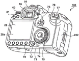
Fig. 1A and 1B are perspective views showing an example of the appearance of a digital camera 100 according to the present embodiment. Fig. 1A shows the appearance of the front and upper faces, and fig. 1B shows the appearance of the rear and bottom faces.
The display unit 28 displays a viewfinder image (live view image), various information (setting values and the like) about the digital camera 100, a reproduced image, a GUI display screen, and the like. The display unit 28 is a touch display incorporating a touch panel 28a, and can detect a touch operation (on/off, position, movement, intensity, and the like) made on the display unit 28. The touch panel 28a may also be a touch panel provided separately from the display unit 28 so that a touch can be detected.
The shutter button 61 inputs a shooting preparation start instruction and a shooting start instruction to the digital camera 100 according to the amount of pressing. The mode change switch 60 sets an operation mode corresponding to the position of the digital camera 100 after the mode change switch 60 is rotated. The end cap 40 is openable and protects a connector for connection with an external device via a cable. The main electronic dial 71 is rotatable, and is used, for example, to change the setting values of the shutter speed, the diaphragm, and the like.
The power switch 72 turns on and off the power of the digital camera 100. The sub-electronic dial 73 is rotatable, and is rotated to, for example, switch an item to be selected from selectable items, and change an image to be reproduced. For example, the cross key 74 may be pressed at upper, lower, left, and right portions thereof, and used to select an item corresponding to the pressed portion from among items in the menu screen. The SET button 75 is mainly used to determine an item to be selected.
The multi-controller 76 enables input in a total of eight directions, i.e., up, down, left, right, upper right, lower right, upper left, and lower left directions. A Live View (LV) button 81 is used to switch between ON (ON) and OFF (OFF) of display of a live view image ON the display unit 28. In the moving image shooting mode, the LV button 81 is used to give instructions to start and stop shooting (recording) of a moving image. A zoom-in button 77 is used to switch between ON and OFF of the zoom display of the live view image, and to increase the magnification during the zoom display. In the reproduction mode, the enlargement button 77 is also used to switch between ON and OFF of the enlarged display of the reproduced image, and to increase the enlargement rate during the enlarged display. In contrast to the zoom-in button 77, a zoom-out button 78 is used to reduce the magnification of the displayed magnified image. The reproduction button 79 is used to switch between a shooting mode and a reproduction mode of the digital camera 100. When the reproduction button 79 is pressed while the digital camera 100 is operating in the shooting mode, the digital camera 100 switches to the reproduction mode, and displays the latest image among the images recorded in the recording medium on the display unit 28.
The quick-return mirror 12 (hereinafter simply referred to as mirror 12) can be raised and lowered by an actuator and raised at the time of shooting. The terminal 10 is used to supply power to and communicate with a lens unit (interchangeable lens) attached to the digital camera 100.
The viewfinder 16 is used to observe an optical image of a subject through an interchangeable lens and determine a composition of shooting. An eyepiece sensor 91 serving as a proximity detection unit is provided near the viewfinder 16, and is used to detect an object that is in proximity to the eyepiece portion (a state in which the user is looking at the viewfinder).
The cover 202 protects a slot for accommodating a removable recording medium such as a memory card. The grip portion 90 containing the battery is formed in a shape that enables the digital camera 100 to be easily gripped.
Fig. 2 is a block diagram showing an exemplary functional configuration of the digital camera 100 shown in fig. 1A and 1B, and fig. 2 has the same reference numerals as those assigned to the structures shown in fig. 1A and 1B.
In the lens unit 150, the photographing lens 103 is generally configured by a plurality of lenses, but is drawn by only one lens. The diaphragm 1 is driven by a diaphragm drive circuit 2. The focus lens included in the photographing lens 103 is driven by the AF drive circuit 3. The terminal 6 is in contact with the terminal 10 when the lens unit 150 is attached to the digital camera 100, and serves to receive power supply from the digital camera 100 and communicate with the digital camera 100. More specifically, the lens system control circuit 4 in the lens unit 150 and the system control unit 50 in the digital camera 100 communicate with each other through the terminals 6 and 10. For example, the lens system control circuit 4 controls the diaphragm 1 via the diaphragm drive circuit 2 according to an instruction from the system control unit 50, and also controls the focus position of the photographing lens 103 via the AF drive circuit 3.
The AE sensor 17 acquires luminance information on an optical object image formed on the focusing screen by the lens unit 150. The focus detection unit 11 is a phase difference sensor, and outputs defocus information on a predetermined focus detection area to the system control unit 50. The system control unit 50 performs automatic focus detection (AF, autofocus) by determining the movement amount and movement direction of the focus lens based on the defocus information and driving the focus lens through the lens system control circuit 4. Note that AF may also be performed using a contrast detection method, an image plane phase difference detection method, or the like.
In the case where the viewfinder 16 is an optical viewfinder, the user observes an image formed as a result of display in which an optical image of an object formed on the focusing screen 13 is superimposed on the in-viewfinder display unit 41. For this reason, the user can check the position and size of the focus detection area by checking the indicator of the AF frame (item) superimposed on the optical image of the subject. Note that the viewfinder 16 may also be an electronic viewfinder. In this case, the user observes the photographed live view image (through-the-lens image). In the case where the viewfinder 16 is an electronic viewfinder, the user can check the position and size of the focus detection area as a result of the display unit within the viewfinder 16 displaying the live view image and the AF frame in a superimposed manner.
In the case of an optical viewfinder, a state in which an optical image can be viewed can be switched to a state in which the optical path is blocked and the optical image cannot be viewed in the viewfinder 16 by switching the mirror 12 from the lower state to the upper state. The subject can also be checked by acquiring an image from the image capturing unit 22 while the mirror 12 is in the up state and displaying the acquired image (live view image) on the display unit 28. On the other hand, in the case of an electronic viewfinder, it is possible to switch whether to display a captured image acquired by the imaging unit 22 on a display unit within the viewfinder or to display a captured image on a display unit 28 disposed outside the viewfinder.
The shutter 101 is a focal plane shutter that is turned on and off as controlled by the system control unit 50, and exposes the image pickup unit 22 for a predetermined time. The image pickup unit 22 is, for example, a CCD or CMOS image sensor, and converts an optical image formed by the lens unit 150 into an electric signal (analog image signal) using a group of two-dimensionally arranged photoelectric conversion elements. The a/D converter 23 converts the analog image signal output from the image pickup unit 22 into a digital image signal (image data).
The image processing unit 24 applies predetermined image processing such as pixel interpolation (demosaic), white balance adjustment, various corrections, resizing, color conversion, encoding, and decoding, and the like to the image data supplied from the a/D converter 23 or the memory control unit 15. In the case of performing AF processing based on information obtained by the image capturing unit 22, the image processing unit 24 calculates AF evaluation values such as defocus information and contrast information, and outputs the calculated AF evaluation values to the system control unit 50. Further, the image processing unit 24 also calculates information such as luminance information to be used in automatic exposure control (AE), and outputs the calculated information to the system control unit 50.
The image data output by the a/D converter 23 is processed as necessary by the image processing unit 24, and then written into the memory 32 through the memory control unit 15. The memory 32 functions as a buffer for image data obtained during shooting, image data read out from the recording medium 200, and the like, and also functions as a video memory of the display unit 28.
The D/a converter 19 converts the display image data read out from the video storage area in the memory 32 into an analog signal, and supplies the analog signal to the display unit 28. The display unit 28 drives a display device such as an LCD based on the analog signal supplied from the D/a converter 19, and displays an image based on the analog signal.
In the case of displaying a live view image on the display unit 28, a moving image is captured by the imaging unit 22 with the mirror 12 held in the up state, and frames are sequentially displayed on the display unit 28 through the a/D converter 23, the image processing unit 24, the memory control unit 15, the memory 32, and the D/a converter 19.
The in-finder display unit 41 displays an indicator (e.g., a frame indicator) of the position and size of the current focus detection area, and setting values and numerical values and icons indicating shooting conditions (shutter speed, f-number, numerical values and icons of ISO and the like) and the like via the in-finder display unit drive circuit 42. Note that the focus detection area is also referred to as an AF frame or an AF area.
A Liquid Crystal Display (LCD) unit 43 is disposed outside the viewfinder. The LCD unit 43 displays setting values and numerical values, icons, and the like indicating shooting conditions via the drive circuit 44 of the LCD unit 43.
The system control unit 50 has, for example, one or more programmable processors, and controls the operation of the digital camera 100, for example, by loading a program stored in the nonvolatile memory 56 into the system memory 52 and executing the program with the programmable processors. The system control unit 50 also controls the operation of the attached lens unit 150. Further, the system control unit 50 also controls the display operation of the digital camera 100 by controlling the memory 32, the D/a converter 19, the display unit 28, and the like.
The nonvolatile memory 56 is, for example, an EEPROM, and stores programs to be executed by the system control unit 50, various constants, setting values, GUI data, and the like. The system timer 53 is a time measuring unit for measuring time to be used in various controls and acquiring time of a built-in clock.
The shutter button 61 has a first shutter switch 62 and a second shutter switch 64, and the first shutter switch 62 is turned on when the shutter button 61 is half-pressed, and the second shutter switch 64 is turned on when it is fully pressed. The system control unit 50 interprets the ON state of the first shutter switch 62 as a shooting preparation start instruction, and interprets the ON state of the second shutter switch 64 as a shooting start instruction. The shooting preparation processing includes AF (auto focus) processing, AE (auto exposure) processing, AWB (auto white balance) processing, EF (flash pre-illumination) processing, and the like. The shooting process refers to a series of processes ranging from exposure and readout of signals by the image pickup unit 22 to writing of image data to the recording medium 200.
The operation unit 70 is an input device group that is provided on the digital camera 100 and can be operated by a user, and includes switches, buttons, and dials described using fig. 1A and 1B. The mode change switch 60, the shutter button 61, and the touch panel 28a, which are independently described for convenience, also constitute a part of the operation unit 70.
The power supply control unit 80 is constituted by a battery detection circuit, a DC-DC converter, a switching circuit for switching blocks to be energized, and the like, and detects whether a battery is attached, the type of battery, the remaining amount of battery, and the like. The power supply control unit 80 also controls the DC-DC converter based on the detection result and an instruction from the system control unit 50, and supplies necessary voltages to the respective units.
The power supply unit 30 may be a battery, an AC adapter, or the like. The recording medium I/F18 is an interface for the recording medium 200 as a memory card, a hard disk, or the like.
The communication unit 54 is a communication interface for external devices, and supports communication conforming to one or more wired and/or wireless communication standards. The communication unit 54 includes a connector, an antenna, and the like corresponding to a communication standard.
The attitude detecting unit 55, which is, for example, an acceleration sensor or a gyro sensor, detects the attitude and motion of the digital camera 100, and notifies the system control unit 50 of the detected attitude and motion. The system control unit 50 can determine the posture of the captured image and realize a hand shake correction function based on the posture and motion detected by the posture detection unit 55.
As described above, in the present embodiment, the touch panel 28a incorporated into the display unit 28 is provided as an example of a touch input device. Note that the touch input device may also be provided in a region other than the display unit 28 in the housing of the digital camera 100.
The system control unit 50 may detect the following touch operation or the following state thereof on the touch panel 28 a:
a new touch, i.e., a start touch (hereinafter referred to as "touch-down") with the touch panel 28 a;
a state of continuing to touch the touch panel 28a (hereinafter referred to as "touch-on");
moving the touch position on the touch panel 28a (hereinafter referred to as "touch-move");
disappearance of the touch with the touch panel 28a, i.e., ending of the touch (hereinafter referred to as "touch release touch-up"); and
a state in which the touch panel 28a is not touched (hereinafter referred to as "no touch-off").
Although it is assumed here for convenience that there is one touch position, a plurality of touch operations or states may be detected at once. In addition, the strength of the touch may also be detected. Depending on the system of the touch panel 28a, a finger or stylus near the surface of the touch panel 28a, rather than in physical contact therewith, may also be detected as a touch.
When touch landing is detected, touch is simultaneously detected. After touch landing is detected, the touch is typically continued to be detected unless a touch release is detected. When touch movement is detected, a touch is also detected. Meanwhile, even if touch is detected, if the touch position does not move, touch movement is not detected. If no touch is detected, no touch is detected. For example, if a touch release is detected for all detected touches, then no touch is detected.
The system control unit 50 is periodically notified of the touch position (coordinates) on the touch panel 28a from the touch panel 28a through an internal bus. The system control unit 50 detects the aforementioned touch operation and the state of the touch panel 28a based on information about the touch position notified by the system control unit 50. Note that if a touch movement is detected, the system control unit 50 may detect the direction of the touch position movement and the speed thereof for each of the vertical component and the horizontal component of the coordinates, for example, based on the temporal change in the touch position.
The system control unit 50 may also detect a touch operation made up of a specific combination of the above-described basic touch operation and the touch panel state. For example, if the touch movement is detected and the distance by which the touch position is moved is greater than or equal to a predetermined distance, the system control unit 50 determines that the slide (or drag) operation is performed. And, if a touch release is detected after a touch movement of a distance shorter than a predetermined distance is performed for a time shorter than a predetermined time, the system control unit 50 determines that a flicking operation is performed. Further, if the touch movement is not detected after the touch landing is detected, and the touch release is detected within a predetermined time or less, the system control unit 50 determines that a tapping operation is performed.
In the case where the touch panel 28a can independently detect a plurality of touches, if a touch movement is detected at a plurality of (e.g., two) touch positions and the touch positions are brought close to each other, the system control unit 50 determines that a pinch-in operation is performed. Similarly, if a touch movement is detected at a plurality of (e.g., two) touch positions and the touch positions are moved to be away from each other, the system control unit 50 determines that a pinch-out operation is performed. The pinch operation and the pinch-off operation are collectively referred to as a pinch operation.
Next, the operation performed during the shooting standby of the digital camera 100 having the above-described configuration will be specifically described mainly using the flowchart shown in fig. 3, focusing particularly on the operation in response to the touch operation. The operations of the respective steps in the flowchart are realized as a result of a programmable processor provided in the system control unit 50 loading a program stored in the nonvolatile memory 56 into the system memory 52 and executing the program.
Although it is assumed in the following description that the item whose position and size can be changed by the touch operation is a focus detection area (AF frame), the present invention may also be similar to a light metering area (AE frame), an enlarged display area, or the like. Note that these areas are conceptual areas used in internal processing of the digital camera 100, and cannot be actually viewed. For this reason, the positions and sizes of these areas are generally indicated using indicators displayed in a superimposed manner on the live view image displayed on the display unit 28 or within the viewfinder 16. Therefore, for the user, the change in the position and size of the area such as the AF frame has the same meaning as the change in the display position and size of the indicator indicating the area. In the following description, for ease of understanding, the indicator indicating the area is described as an item whose position and size are to be changed by a touch operation, and the position and size of the indicator on the image are converted into coordinates within the image read out from the image capturing unit 22 when the indicator is processed within the digital camera 100.
The processing (main processing) shown in fig. 3 is, for example, processing started after the power of the digital camera 100 is turned on by the power switch 72 and the digital camera 100 enters a shooting standby state. In the shooting standby state, the system control unit 50 continuously performs moving image shooting with the mirror 12 raised, monitors the devices (including the touch panel 28a) constituting the operation unit 70, and at the same time performs an operation of generating a live view image and continuously displaying the live view image on the display unit 28.
In step S301, the system control unit 50 reads out parameters associated with the touch operation from the nonvolatile memory 56 to the system memory 52. The parameters read out here include, for example, the position and size of an effective area (an area where the detected touch operation is regarded as effective (or accepted)), a position specification mode (an absolute coordinate mode or a relative coordinate mode), information on the correspondence relationship between the touch operation and the user instruction, and the like. Note that the absolute coordinate mode is a mode in which the coordinates within the effective area of the touch panel 28a and the coordinates of the display unit within the viewfinder 16 or the display area of the display unit 28 are processed in association with each other. That is, in the absolute coordinate mode, the corresponding coordinates in the display unit within the viewfinder 16 or in the display unit 28 are specified in accordance with the start of touch (touch on the screen), regardless of the originally specified coordinate position. In the case of the display unit 28, the coordinates of the touched position are specified. The relative coordinate mode is a mode in which coordinates in the effective area of the touch panel 28a and coordinates in the display area of the display unit within the viewfinder 16 are handled without regarding them as being directly associated with each other. That is, in the relative coordinate mode, the corresponding coordinates in the display unit within the viewfinder 16 (or the touch position in the display unit 28) are not specified according to the start of the touch, and the specified coordinates are moved by the amount of touch position movement from the originally set coordinates. Note that, unless otherwise specified, the system control unit 50 makes a touch operation determination only for a touch operation detected within the effective area. The user can also set an absolute coordinate mode or a relative coordinate mode on the menu screen.
In step S302, the system control unit 50 determines whether the position specification mode of the touch panel 28a is the absolute coordinate mode or the relative coordinate mode, and if the determination result is the absolute coordinate mode, advances the process to step S303, and if the determination result is the relative coordinate mode, advances the process to step S304.
In step S303, the system control unit 50 performs touch operation processing in the absolute coordinate mode. Details will be described later using fig. 5.
In step S304, the system control unit 50 performs touch operation processing in the relative coordinate mode. Details will be described later using fig. 7.
In step S305, the system control unit 50 determines whether a touch operation (size change operation) associated with a change in the item size is detected, and if it is determined that the touch operation is detected, the processing proceeds to step S306, otherwise, the processing proceeds to step S308. There is no particular limitation on the size changing operation. As shown in fig. 4B, here, the size changing operation may also be a double-click operation (two consecutive flick operations performed at predetermined time intervals or less), a touch hold operation (a touch operation held for a predetermined time or more; a touch continues to be detected for a predetermined time or more, for example, 1.5 seconds or 2 seconds or more after touching the screen). Further, the size changing operation may also be a touch-popping operation (an operation of strongly pressing the touch panel with a predetermined pressure or stronger). In addition, a configuration may also be adopted in which the size of the AF frame can be set on the menu screen. Note that, as schematically illustrated in fig. 4A, when a touch on the screen is detected in step S305, the system control unit 50 displays a frame-shaped indicator indicating the position and size of the currently set AF frame in a manner superimposed on the subject image.
Note that if it is determined that the user is looking at the viewfinder 16 (i.e., if it is determined that the output of the eyepiece sensor 91 is ON), the system control unit 50 displays an indicator ON the in-viewfinder display unit 41 to superimpose the indicator ON the subject image. In a case where the viewfinder 16 is an electronic viewfinder, or in a case where it is not determined that the user is looking at the viewfinder 16 (i.e., if it is determined that the output of the eyepiece sensor 91 is OFF), the system control unit 50 displays the indicator on the display unit 28 in a manner superimposed on the live view image. Therefore, the manner in which the indicator is displayed differs depending on whether or not the user is looking at the viewfinder 16, but will not be particularly distinguished below.
By changing the size of the AF frame according to the size of the object to be focused, a photograph can be easily taken with a desired object in focus. For example, if a small subject is to be focused, if the AF frame is large, the background may be focused instead of the desired subject, and thus it is useful if the AF frame can be made small.
In step S306, the system control unit 50 changes the size of the indicator. Note that it is assumed that the size is changed in a manner of gradually increasing (decreasing) the size each time a size change operation is detected, and is restored to the minimum (maximum) size when the maximum (minimum) size is reached. However, this may not be the case. Note that it is assumed that the size of the indicator is changed while maintaining the center coordinates and the aspect ratio.
In step S307, the system control unit 50 changes a threshold (touch movement distance threshold) for determining a touch movement distance (the amount of the touch position moved due to the touch movement) in the relative coordinate mode according to the changed size of the AF frame. Specifically, the system control unit 50 makes the threshold value in the case where the size of the AF frame is the second size smaller than the first size larger than the threshold value in the case where the size of the AF frame is the first size. It is assumed that the relationship between the size of the AF frame and the threshold value is defined in advance and is saved in the nonvolatile memory 56. The larger the threshold value, the easier it is to finely adjust the position, and therefore the threshold value is increased if the size of the AF frame is small. Such dynamic change of the threshold value can increase the operability by making the sensitivity or responsibility for the distance the item is moved to the touch movement smaller (larger) when the size of the AF frame is small (larger) than in the case where the AF frame is large (smaller). Note that the same threshold may also be set for a plurality of adjacent levels of size; for example, the same threshold value may be set for the smallest size and the larger size.
Note that in step S307, the position specifying mode of the touch panel 28a may also be changed according to the changed size of the AF frame. Specifically, if the size of the AF frame after the change is equal to or smaller than a predetermined lower limit size or equal to or larger than a predetermined upper limit size, the system control unit 50 determines the position specification mode of the touch panel 28 a. The system control unit 50 changes the position specifying mode to the relative coordinate mode if the size of the AF frame after the change in the absolute coordinate mode is smaller than or equal to the lower limit size. The system control unit 50 changes the position specifying mode to the absolute coordinate mode if the size of the AF frame after the change in the relative coordinate mode is larger than or equal to the upper limit size. The relative coordinate mode facilitates fine position adjustment, and the absolute coordinate mode facilitates large changes in position. Therefore, if the size of the AF frame is changed, usability can be improved by changing the position specification mode to a mode suitable for the changed size.
In the case where the focusing operation (servo operation) is continued on the current AF frame in the standby state, if the size of the AF frame becomes too small, there is a possibility that an undesired object is brought into focus. For this reason, a configuration may also be adopted in which if the size of the AF frame after the change is smaller than or equal to a predetermined lower limit size, the servo operation is temporarily suspended. Note that the lower limit size of the AF frame serving as a condition for suspending the servo operation may also be different from the aforementioned lower limit size serving as a condition for changing the position specification mode.
In step S308, the system control unit 50 determines whether an instruction to move the AF frame is input through a predetermined operation member other than the touch panel 28a, and if it is determined that the movement instruction is input, advances the process to step S309, otherwise advances the process to step S310. One or more operation members other than the touch panel 28a constituting the operation unit 70 may be designated as operation members to which an instruction to move the AF frame can be input. Here, as an example, it is assumed that the main electronic dial 71, the sub electronic dial 73, the cross key 74, and the multi-controller 76 are specified as operation members that can input an instruction to move the AF frame (i.e., can be used to move the AF frame). Therefore, in step S308, the system control unit 50 determines whether any one of the main electronic dial 71, the sub electronic dial 73, the cross key 74, and the multi-controller 76 is operated, or none of them is operated.
In step S309, the system control unit 50 moves the position at which the AF frame is displayed in accordance with the direction of the operation detected in step S308. That is, in the case of operation with the dial or the cross key, the amount of movement in response to a predetermined operation is the same regardless of the size of the AF frame. For example, regardless of the size of the AF frame, the distance that the AF frame moves in response to a predetermined angle is the same in the case of the dial, and the distance that the AF frame moves in response to one press is the same in the case of the cross key. Note that each time the system control unit 50 detects input of a movement instruction in step S308, the system control unit 50 moves the AF frame by a predetermined amount. However, the amount of movement may be different depending on the type of the operating member. For example, the amount of movement (first amount of movement) in response to an operation made to the first operation member may be a predetermined amount irrespective of the size of the AF frame, and the amount of movement (second amount of movement) in response to an operation made to the second operation member may be an amount depending on the size of the AF frame. For example, similar to the touch movement distance threshold in the aforementioned relative coordinate mode, when the size of the AF frame is a second size smaller than the first size, the second movement amount is made smaller than the movement amount when the size of the AF frame is the first size. Therefore, for example, if a small AF frame is to be moved largely, an operation in which the first operation member is operated first to roughly adjust the position and then the second operation member is operated to finely adjust the position can be easily performed. Note that an operation member may also be provided to which an input of a movement instruction to directly move the AF frame to a preset position with one operation is assigned instead of an input of a movement instruction to gradually change the position. Further, the input of these movement instructions may also be assigned to a specific operation (other than a touch movement or a size change operation) made to the touch panel 28 a.
In step S310, the system control unit 50 determines whether the first shutter switch 62 is on, and if the first shutter switch 62 is on, advances the process to step S311, otherwise advances the process to step S312.
In step S311, the system control unit 50 starts a still image shooting preparation operation (AF and AE operations, etc.) and waits for the second shutter switch 64 to be turned on. When the second shutter switch 64 is turned on, shooting processing for recording is performed, and shot image data is included in a data file in a predetermined format and recorded in the recording medium 200. Since the processing for capturing and recording a still image can be realized by processing similar to that performed in a conventional digital camera, details thereof will be omitted. If the recording is ended, or if the first shutter switch 62 is turned off before the second shutter switch 64 is turned on, the system control unit 50 advances the process to step S312.
In step S312, the system control unit 50 determines whether the current state matches a predetermined end condition, ends the processing if it is determined that the current state matches the end condition, and returns the processing to step S302 and continues the above processing otherwise. For example, the end condition may be a case where an instruction to turn off the power of the digital camera 100 is made by the power switch 72, a case where the reproduction mode is selected by the mode change switch 60, or the like, but is not limited to these cases.
Next, the absolute coordinate mode operation will be described using fig. 5. The processing in fig. 5 is started upon reaching step S303 in fig. 3. The operations of the respective steps in the flowchart are realized as a result of the programmable processor provided in the system control unit 50 loading the program stored in the nonvolatile memory 56 into the system memory 52 and executing the program.
In step S401, the system control unit 50 determines whether touch landing is detected on the touch panel 28a, and if it is determined that touch landing is detected, the processing proceeds to step S402, otherwise, the processing is ended.
In step S402, the system control unit 50 determines whether the coordinates of the touch landing detected in step S401 are within the effective area of the touch panel 28a, and if it is determined that the coordinates are within the effective area, proceeds the process to step S403, otherwise ends the process. Note that in the case of the absolute coordinate mode, the effective area of the touch operation may be the entire surface of the touch panel 28a, and the determination in step S402 may not be made.
In step S403, the system control unit 50 performs display to notify the user that a touch is detected. For example, as shown in fig. 6A, a frame-shaped touch position indicator 801 surrounding the coordinates (touch position) at which touch landing is detected is displayed. Note that in the case where the identifier is displayed on the in-finder display unit 41, the coordinates on the touch panel 28a are converted into coordinates in the display area of the in-finder display unit 41 to be displayed. This will also apply to the following description, and the description thereof will not be repeated.
Further, in step S403, the system control unit 50 displays an item indicator 802 indicating the position and size of the current AF frame together. Note that it is assumed here that the coordinates of the live view image (finder image) corresponding to the center of the current AF frame (i.e., the center coordinates of the item indicator 802) are (X1, Y1). The touch position indicator 801 has the same size as the item indicator 802 and is visually distinguishable from the item indicator 802.
In step S404, the system control unit 50 determines whether touch movement is detected on the touch panel 28a, and if it is determined that touch movement is detected, the processing proceeds to step S405, otherwise the processing proceeds to step S407.
In step S405, the system control unit 50 determines whether the current touch position coordinates are within the effective area, and if it is determined that the coordinates are within the effective area, the process proceeds to step S406, otherwise the process proceeds to step S407.
In step S406, the system control unit 50 moves the touch position indicator 801 to a display position centered on the current touch position (coordinates (X2, Y2) in fig. 6A).
In step S407, the system control unit 50 determines whether touch release is detected on the touch panel 28a, ends the processing if it is determined that touch release is detected, and returns the processing to step S404 otherwise. Note that if it is determined that touch release is detected, the system control unit 50 changes the position at which the AF frame is set to the position of the moved touch position indicator 801 and deletes the item indicator 802. The touch position indicator 801 then serves as the changed item indicator. Note that a configuration may also be adopted in which when touch release is detected, the focus detection processing is performed similarly to the case where the first shutter switch 62 is turned on for the AF frame at this time. In the case where the focus detection processing is performed when touch release is detected, if the size of the AF frame is a predetermined size or less, the time taken until the focus detection processing is started is longer than that in the case where the AF frame is larger than the predetermined size.
Note that if the coordinates of the touched screen are detected to be within the current AF frame in step S401, the system control unit 50 may display a touched-position indicator corresponding to the position and size of the current AF frame, and may not display an item indicator. If the touch movement is detected in this state, the system control unit 50 moves the position of the current AF frame through the processing in the above-mentioned steps S404 to S406. For example, FIG. 6B shows the display of the touch position indicator 803 in the case where touch down is detected at coordinates within the current AF frame (having center coordinates (X2, Y2)), then touch movement is detected, and touch release is detected at coordinates (X3, Y3). In this case, the distance ((X3, Y3) - (X2, Y2)) by which the touch position is moved corresponds to the distance by which the touch position indicator 803 is moved due to the absolute coordinate mode. Note that the change in the size of the AF frame between fig. 6A and 6B has no particular meaning.
Next, the relative coordinate mode operation will be described using fig. 7. The processing in fig. 7 is started upon reaching step S304 in fig. 3. The operations of the respective steps in the flowchart are realized as a result of the programmable processor provided in the system control unit 50 loading the program stored in the nonvolatile memory 56 into the system memory 52 and executing the program.
The processing in steps S501 to S505 is the same as that in steps S401 to S405, and thus description thereof will be omitted. However, unlike the case of the absolute coordinate mode, when a touch landing is detected within the effective area in step S503, the item indicator is displayed without displaying the touch position indicator. If a touch movement is detected within the effective area in step S505, an indicator (leading indicator) indicating the position and size of the AF frame after the change (set) is started to be displayed according to the distance and direction of the touch movement.
In step S506, the system control unit 50 acquires the touch movement distance as the distance from the start coordinate to the current touch position coordinate. Note that the start coordinates are first the coordinates at which touchdown is detected, and then updated to the coordinates after movement each time the AF frame is moved (S508).
In step S507, the system control unit 50 determines whether the touch movement distance acquired in step S506 is greater than or equal to a touch movement distance threshold, and if it is determined that the acquired touch movement distance is greater than or equal to the touch movement distance threshold, then the process proceeds to step S508, otherwise returns to step S504. The touch movement distance threshold used here is a value set based on the size of the AF frame (i.e., the value changed in step S307 in FIG. 3).
In step S507, it is determined whether the size of the auto-focus frame is large, medium, or small, and a threshold is acquired according to the size, that is, if the size is large, medium, or small, respectively, a threshold α 1(< α 2), a threshold α 2(< α 3), and a threshold α 3 are acquired, and further, it is determined whether the touch movement distance acquired in step S506 exceeds the acquired threshold, that is, whether the touch position is moved to move the AF frame by a predetermined distance.
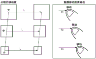
FIG. 4C schematically shows an exemplary relationship between the size of the AF frame and the touch movement distance threshold value, FIG. 4C depicts the difference in touch movement distance required to move AF frames having different sizes by a unit distance L, it is assumed that the distance moved by the AF frame is the distance between the center coordinates before and after the AF frame is moved, in the example shown in FIG. 4C, the touch movement distance threshold values α 1 to α 3 increase as the size of the AF frame becomes smaller.
In the determination at step S507, instead of moving the AF frame by a predetermined distance in the case where the touch-movement distance is equal to or greater than a threshold value corresponding to the size of the current AF frame, the ratio of the AF frame moved with respect to the touch-movement distance may also be changed according to the size of AF. That is, a configuration may also be employed in which, when touch movement of the distance A is performed, the distance that the AF frame is moved increases as the size of the AF frame becomes larger. As shown in FIG. 4D, the distance moved by the AF frame at each touch moving distance A may be L1 when the AF size is large, L2(< L1) when the AF size is middle, and L3(< L2) when the AF size is small. In this case, in step S307, the coefficient for determining the AF frame movement amount corresponding to the touch movement distance is changed according to the size of the AF frame, not according to the touch movement distance threshold.
Note that the touch movement distance threshold value may also be obtained as follows. In the case where the length of the touch panel 28a in the X-axis direction is Xp and the length of the display unit in the viewfinder 16 in the X-axis direction is Xf, the touch movement distance required to move the distance L in the display unit in the AF frame viewfinder 16 is set to L (Xp/Xf). Therefore, the touch movement distance required to change the AF position by the predetermined distance is set to be the same in the relative coordinate mode and the absolute coordinate mode. If the threshold value of the AF frame of the middle size among the sizes of several AF frames is set as described above, in the case of the middle size, the user can operate with the same feeling as the usual operation (operation in a state of viewing the panel). If the size of the AF frame is larger than the middle size, the AF frame is moved in a smaller operation than in the case of the middle size, and if the size of the AF frame is smaller than the middle size, the AF frame can be adjusted more finely. Therefore, an intuitive operation suitable for the size of the AF frame can be performed.
In step S508, the system control unit 50 moves the display position of the guide indicator by a predetermined amount in the direction of the touch movement (e.g., the straight direction moving from the start point to the current touch position).
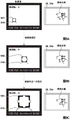
Fig. 8A to 8D show the touch operation and the corresponding display within the viewfinder 16 in the case where the AF frame is moved and changed in size by the touch operation made to the touch panel 28A in the relative coordinate mode while looking at the viewfinder 16. Fig. 8A to 8D depict a case where the entire surface of the touch panel 28A is an active area.
Fig. 8A shows a state in which the AF frame is displayed on the in-finder display unit 41, and shows a state in which a touch on screen operation is detected in the effective area (step S503 in fig. 7). To notify the user of the detection of the touch, the system control unit 50 displays an item indicator 701 indicating the position and size of the current AF frame on the in-finder display unit 41. In the relative coordinate mode, the AF frame is not moved to the touched position, so that the touched position indicator is not displayed. At this time, the system control unit 50 converts the coordinates of the AF frame into coordinates in the in-finder display unit 41, and displays an indicator (at the corresponding position).
The distance Lf in the subject image in the viewfinder 16 shown in fig. 8A corresponds to the distance Lp in the display unit 28 shown in fig. 6A. That is, in the case where the AF frame is moved by the distance Lf on the in-finder display unit 41 and in the case where the AF frame is moved by Lp on the display unit 28, if the position of the AF frame that is originally set is the same, the set value for AF processing after the movement is the same. Therefore, the setting is configured such that the amount of change in the AF position set by the operation of moving the AF frame by the distance Lf on the display unit within the viewfinder 16 is the same as the amount of change in the AF position set by the operation of moving the AF frame by the distance Lp on the display unit 28 (touch panel 28 a).
At the position shown in fig. 8A, the AF frame is set to have a size and position such that the AF frame substantially circumscribes the crown of the right flower, as indicated by an item indicator 701. Now, consider a case where the setting of the AF frame is changed from this state to the setting of the AF frame on the insects on the petals of the left flower.
In this case, first, in order to move the AF frame almost to the vicinity of the left flower, the user moves the finger touching the screen to the left while keeping the touch. This touch operation is detected as a touch movement within the effective area, and the system control unit 50 performs processing in step S506 and subsequent steps in fig. 7. Upon detecting the touch movement, the system control unit 50 starts displaying the guidance indicator.
It is assumed here that the touch movement distance threshold is reached a plurality of times during the touch movement distance β 1, and then the AF frame is displayed at the position moved by the distance Lf. As a result of this touch movement, the display position of the guide indicator 702 is as shown in FIG. 8B. then the user checks that the display position of the guide indicator 702 has moved to a desired position, and separates the finger from the touch panel 28a (FIG. 8℃) this touch operation is detected as touch release, and the system control unit 50 stops displaying the item indicator 701 indicating the AF frame before being changed, and ends the touch operation processing in the relative coordinate mode (S304). at this time, the guide indicator 702 serves as an item indicator.
Next, when the user performs an operation of changing the size of the AF frame so that the size of the AF frame matches the size of the insect, the operation is detected in step S305, and the system control unit 50 performs the processing in steps S306 and S307. It is assumed here that the size of the AF frame is changed to the size depicted by the item indicator 703 in FIG. 8D.
It is assumed here that, as shown in FIG. 8D, the touch movement distance is β 2, and the distance between the item indicator 703 before movement and the guide indicator 704 after movement is Lf'.
The touch movement distance β 1 required to move the displayed AF frame by the distance Lf and the touch movement distance β 2 (shown in FIG. 8D) required to move the displayed AF frame by the distance Lf' on the display unit within the viewfinder 16 in FIG. 8B satisfy the following relationship:
(Lf/β1)>(Lf’/β2)
that is, in the case of the movement in FIG. 8B in which the size of the AF frame is large, the amount by which the AF frame is moved per unit touch movement distance is large.
Note that in the case where the direction in which the item can be moved is limited, the item may also be moved in the direction of the largest component among the components of the direction in which the item can be moved representing the straight line (the straight line connecting the start point and the current touch position) of the touch movement. For example, if an item can only move in the x-direction and the y-direction, the item moves in the direction of the larger one of the x-direction component and the y-direction component of the straight line representing the touch movement. After moving the display position of the guide indicator, the system control unit 50 sets the touch movement distance to 0 and updates the start point of the touch movement to the current touch position.
In step S509, similar to step S407, the system control unit 50 determines whether or not touch release is detected on the touch panel 28a, ends the processing if it is determined that touch release is detected, and returns the processing to step S504 otherwise. Note that if it is determined that the touch release is detected, the system control unit 50 changes the AF frame set position and size to the position and size of the guide indicator at the time of touch release. Similar to the case where the first shutter switch 62 is turned on for the AF frame at this time, a configuration may also be adopted in which the focus detection processing is performed when touch release is detected. In the case where the focus detection processing is performed when touch release is detected, if the size of the AF frame is a predetermined size or less, the time taken until the focus detection processing is started is longer than that in the case where the AF frame is larger than the predetermined size.
The above embodiment describes that the absolute coordinate setting or the relative coordinate setting may be constructed on the menu for the determination in step S302. However, the determination in step S302 is not limited thereto, and the following configuration may also be employed. That is, in step S302, the determination may be made based on whether or not the eye is detected to be close to the viewfinder 16 and based on the size of the effective area. Further, the following configuration may also be adopted: the relative coordinate mode is set if it is detected that the eye is close to the viewfinder 16, and the absolute coordinate mode is set if it is not detected that the eye is close to the viewfinder 16. Also, in the case of the relative coordinate mode, the touch effective area may be a part, and in the case of the absolute coordinate mode, the touch effective area may be the entire surface. The touch-active area may also be a part if it is detected that an eye is close to the viewfinder 16, and the touch-active area may be the entire surface if it is not detected that an eye is close to the viewfinder 16. The combination is not limited to the above-described combination.
First, a description will be given of the following case: if it is detected that the eye is close to the viewfinder 16, the process proceeds from S302 to S304, otherwise, from S302 to S303. That is, in the case where it is detected that the eye is close to the viewfinder 16, as the AF frame becomes larger, the touch moving distance when the display position of the AF frame is moved by a predetermined distance is reduced. On the other hand, in the case where it is not detected that the eye is approaching the viewfinder 16, the touch movement distance when the display position of the AF frame is moved by a predetermined distance is constant regardless of the size of the AF frame. When the user is looking at the viewfinder 16, even if the effective area is not made small, the range in which the user can perform the touch operation (i.e., the range in which the absolute coordinates can be specified) is greatly limited. Further, when the user is looking at the viewfinder 16, it is more difficult for the user to see his/her hand (finger) than when not looking at the viewfinder 16, and therefore, it is difficult to specify a position in the absolute coordinate mode. Even if the absolute coordinate mode is set, the operability of the user can be improved if the position specification mode is switched to the relative coordinate mode when the output of the eyepiece sensor 91 is ON.
In addition, a configuration may also be adopted in which after the position specification mode is determined in step S302, it is determined whether the output of the eyepiece sensor 91 is ON or OFF, and regardless of the determination result of the position specification mode, if the output of the eyepiece sensor 91 is OFF, the processing proceeds to step S303, and if the output of the eyepiece sensor 91 is ON, the processing proceeds to step S304.
Next, a description will be given of the case where: if the size of the effective area is smaller than the predetermined size, the process proceeds from step S302 to the case of step S304, and if the size of the effective area is larger than the predetermined size, the process proceeds from S302 to S303.
In the case where the relative coordinate setting is configured for the touch operation input method and the effective area is small, the following situation occurs. That is, in the case where the touch movement distance is fixed relative to the amount by which the AF frame is moved in the touch panel 28a regardless of the size of the effective area, since the effective area is small, it is necessary to repeat the touch movement over and over again to move the AF frame by a predetermined distance.
On the other hand, if the amount by which the AF frame is moved with respect to the touch movement distance increases in inverse proportion to the size of the effective area, the AF frame is largely moved with a small touch movement as the effective area decreases. Therefore, in the case where the effective area is smaller than the predetermined size, the touch movement distance required when moving the display position of the AF frame by the predetermined distance when the AF frame is large is made smaller than that when the AF frame is small, so that the operability of the user can be increased. That is, when the touch effective area is smaller than the predetermined size and the AF frame is large, the AF frame is largely moved with a small operation. Then, when the AF frame is moved largely, only a small touch movement distance is required. When the AF frame is small, the user may wish to finely set the AF frame position. Therefore, the display position of the AF frame is not moved greatly with a small operation, and the AF frame is moved a small distance at a time as compared with the case where the AF frame is large. As a result, fine adjustment is facilitated.
In the case of performing an operation while looking at the viewfinder 16, the face of the user is located near the touch panel 28a, and therefore, the range of the touch panel 28a that the user can actually touch with good operability is limited. Further, in a state of viewing the viewfinder, a nose, a cheek, or the like may come into contact with the touch panel 28 a. For this reason, if it is determined that the user is looking at the viewfinder 16 (i.e., if the eyepiece sensor 91 detects an object approaching the viewfinder 16; in a state where the output of the eyepiece sensor 91 is ON), the size of the effective area of the touch panel 28a may also be set smaller than a predetermined size.
For example, if the output of the eyepiece sensor 91 is OFF, the entire surface of the touch panel 28a may be an effective area, and if the output of the eyepiece sensor 91 is ON, half the surface of the touch panel 28a may be an effective area. In addition, a configuration may also be adopted in which the user can set the size of the effective area for touch operation while viewing the viewfinder. For example, the user can also select the range of the effective area (area setting) when viewing the viewfinder from among the entire surface, the right half, the left half, and the upper-right quarter on the menu screen.
That is, in the example of fig. 4C, a configuration may also be adopted in which the thresholds α 1 to α 3 are set equal if the effective area is the largest, and the thresholds α 01 to α 13 are set such that α 21< α 32< α 43 if the effective area is halved, note that a configuration may also be adopted in which, if the size of the touch effective area is the entire surface to half, α 51 to α 63 are set equal, and the size of the touch effective area is less than half, α 1 to α 3 are set such that α 1< α 2< α 3 or α 1 ═ α 2< α 3. in this case, the determination in step S302 is made such that the process proceeds to step S303 if the touch effective area set by the user is the entire surface, and the process proceeds to step S304 if the touch effective area set by the user is the half surface.
Note that even in the case of the absolute coordinate mode, or in the case where it is determined that the user is not looking at the viewfinder 16, if the size of the effective area changes depending on the size of the AF frame, the following may occur. In the case of the absolute coordinate mode, the absolute coordinate mode in which the touched position matches the position of the AF frame will not be established any more. In the case where the user does not look at the viewfinder, the offset between the finger position and the AF frame position increases every time the touch movement is performed due to the size of the frame. That is, when the AF frame is large (in the absolute coordinate mode and the relative coordinate mode), the AF frame is further moved in response to the finger operation, but the AF frame is not moved so much when the AF frame is small, which makes it difficult for the user to see.
Note that the above embodiment describes that if it is determined that the user is not looking at the viewfinder 16, a live view image is displayed on the display unit 28. However, an AF position setting screen showing a list of positions at which the AF frame can be set may also be displayed on the display unit 28.
Even in the case where the configuration of the user who views the viewfinder 16 is not detected, whether or not the user is allowed to view the subject image through the viewfinder 16 may be configured to be switchable. For example, a configuration may also be adopted in which the user can perform operations of raising and lowering the mirror and operations of switching where the live view image is displayed.
Further, a configuration may also be adopted in which, even in the case of the relative coordinate mode, the user can set the AF frame position at a position corresponding to the position where the touch operation is performed by double-clicking or long-time touching the touch panel 28 a. That is, even in the case where the AF frame is moved from the originally set position according to the touch moving distance instead of being moved based on the touch start position in general, if a double click or a long-time touch is made, the AF frame is set at the position (absolute coordinates) corresponding to the touched position regardless of the originally set position.
Modification examples
Fig. 9A to 9C schematically show examples of cases where the item subjected to the moving operation is an object tracking area (object tracking frame, tracking position). Here, the face area of the person 910 is set as the subject tracking frame, and a case is depicted in which the size of the face area gradually increases within the display screen as a result of the person 910 approaching the digital camera 100. Note that a similar case may occur also in a case where the optical zoom ratio (electronic zoom ratio) of the trimming area in the lens unit 150 or the image pickup unit 22 is gradually changed.
Even in a case where an item whose size changes in time series is thus subjected to a moving operation, when the item size is large (small), an idea of reducing (increasing) the touch movement distance threshold value compared to the case when the item size is small (large) can be applied. By dividing the item size into a plurality of ranges and associating each size range with a touch movement distance threshold, the movement operation can be performed similarly to the case of the AF frame.
For example, the range of the size of the subject tracking frame allowed in the digital camera 100 from the minimum size to the maximum size is divided into a plurality of size areas (e.g., large, medium, and small) in advance. If it is detected in step S305 that the size of the subject tracking frame has changed, the system control unit 50 determines a size zone (size zone) corresponding to the current subject tracking frame size in step S306, and sets a touch movement distance threshold corresponding to the corresponding size zone in step S307. Note that, in order to determine the subject tracking frame size at a more strict timing, the determination of the subject tracking frame size and the change (setting) of the touch movement distance threshold may also be performed when a touch landing is detected within the effective area during the processing in step S304. Note that, similar to the case where the item is an AF frame, if the subject tracking frame size becomes less than or equal to a predetermined lower limit size, the subject tracking operation may be temporarily stopped.
Assuming that touch movement distances required to move the object tracking frames by a specific amount γ for the respective size bands are β 3, β 4, and β 5, the system control unit 50 sets the touch movement distance threshold to satisfy the relational expression β 3> β 4> β 5, assuming that the sizes of the object tracking frames 901 to 903 match the size bands "small", "medium", and "large", respectively.
It is conceivable that a small subject tracking frame size is associated with a small subject, similar to the AF frame. For this reason, if the sensitivity of the movement distance with respect to the touch movement is high, the operability may be lowered or the tracking performance may be lowered. For this reason, when the subject tracking frame size is a second size smaller than the first size, the touch movement distance required to move the subject tracking frame by the predetermined amount is made larger than that in the case of the first size, thereby increasing operability and suppressing a decrease in tracking performance.
According to the present embodiment, in an image pickup apparatus in which the position of an item can be changed by an operation of moving the touched position, the moving distance of the touched position required to move the item by a predetermined distance is changed according to the size of the item. Specifically, when the item size is a second size smaller than the first size, the movement distance of the touch position required to move the item by a predetermined distance is made larger than the touch movement distance when the item size is the first size. Therefore, when an item such as an AF frame, a photometric frame, or a subject tracking frame is moved, operability can be improved, and a decrease in performance of AF or subject tracking due to the item being moved to an undesired position can be suppressed.
Note that the above embodiments describe moving the AF frame by touch movement. However, the above-described embodiment is also applicable to the case of dial operation and cross key operation in addition to touch movement. That is, when the user is looking at the viewfinder, the distance that the AF frame moves in accordance with one rotation of the dial or one operation of the cross key is changed depending on the size of the AF frame. Note that in the case where the AF frame position is not set by the touch operation, even when the user is not looking at the viewfinder, the distance that the AF frame moves in accordance with one operation of the dial or cross key can be changed depending on the AF frame.
Further, the above-described embodiments describe determining whether the user is looking at the viewfinder by detecting that the eye is close to the viewfinder. However, the determination may also be made based on which of the viewfinder and the display unit 28 is set by the user so that the subject image can be viewed. That is, if the viewfinder is of an optical type, the determination may also be made based on whether the user lowers the mirror (i.e., the user's eye is close to the viewfinder), or the live view image is displayed on the display unit 28 (i.e., the user's eye is not close to the viewfinder). If the viewfinder is an electronic viewfinder, it may also be based on whether the user has live view images displayed on a display unit within the viewfinder 16 (i.e., the user's eyes are close to the viewfinder) or on the display unit 28.
Further, the touch panel 28a may not be provided integrally with the display unit 28, and for example, the touch panel 28a may also be provided as a touch panel. In this case, the touch movement distance threshold corresponding to the size of the AF frame may also be changed based on whether the subject image can be viewed through the viewfinder or the live view image is displayed on the display unit 28.
Although the AF frame is displayed as a large, medium or small size in the above description, a frame having a predetermined size to be displayed may be changed. That is, in the case of an optical viewfinder or the like, the number of frames having a predetermined size to be lit may be changed, for example, from 1 to 4, 9, or 36. The lighting area is a set area for specifying a subject for AF, AE, or the like (i.e., an area indicating that processing such as AF, AE, or the like is to be performed).
Note that various controls described as being performed by the system control unit 50 may be performed by one piece of hardware, or may be distributed to a plurality of pieces of hardware to control the entire apparatus.
The embodiments are not limited to the above-described embodiments, and various modes without departing from the gist of the present invention are also included in the present invention. Further, the above embodiments have described only one embodiment of the present invention, and the embodiments may be appropriately combined.
The above-described embodiment considers a case where the present invention is applied to the digital camera 100 as an example. However, the present invention is also applicable to any type of image pickup apparatus that can change a variable-sized item by moving a touched position in a state where a user is looking at a viewfinder. That is, the present invention is applicable to a viewfinder-equipped cellular phone terminal and a portable image viewer, as well as a viewfinder-equipped printer, a digital photo frame, a music player, a game machine, an electronic book reader, and the like.
Other embodiments
Embodiments of the present invention may also be implemented by a computer of a system or apparatus that reads and executes computer-executable instructions (e.g., one or more programs) recorded on a storage medium (also more fully referred to as "non-transitory computer-readable storage medium") to perform the functions of one or more of the above-described embodiments, and/or includes one or more circuits (e.g., Application Specific Integrated Circuits (ASICs)) for performing the functions of one or more of the above-described embodiments, and methods may be utilized by a computer of a system or apparatus, for example, that reads and executes computer-executable instructions from a storage medium to perform the functions of one or more of the above-described embodiments, and/or controls one or more circuits to perform the functions of one or more of the above-described embodiments, to implement embodiments of the present invention. The computer may include one or more processors (e.g., Central Processing Unit (CPU), Micro Processing Unit (MPU)) and may include a separate computer or a network of separate processors to read out and execute computer-executable instructions. The computer-executable instructions may be provided to the computer, for example, from a network or a storage medium. The storage medium may include, for example, a hard disk, Random Access Memory (RAM), Read Only Memory (ROM), memory of a distributed computing system, an optical disk such as a Compact Disk (CD), Digital Versatile Disk (DVD), or blu-ray disk (BD)TM) A flash memory device, a memory card, and the like.
The embodiments of the present invention can also be realized by a method in which software (programs) that perform the functions of the above-described embodiments are supplied to a system or an apparatus through a network or various storage media, and a computer or a Central Processing Unit (CPU), a Micro Processing Unit (MPU) of the system or the apparatus reads out and executes the methods of the programs.
While the present invention has been described with reference to exemplary embodiments, it is to be understood that the invention is not limited to the disclosed exemplary embodiments. The scope of the claims is to be accorded the broadest interpretation so as to encompass all such modifications and equivalent structures and functions.
Claims (29)
1. An image pickup apparatus, comprising:
a touch detection unit for detecting a touch operation made to the touch panel; and
a control unit for controlling the image pickup device to move a predetermined item from a position where the predetermined item is displayed before the predetermined item is moved based on the movement of the touch position in a case where the subject image can be viewed via a viewfinder different from the touch panel,
wherein the predetermined item indicates a specified region of the subject image, and is displayed on a first display unit in the viewfinder and can be viewed via the viewfinder,
wherein a moving distance of the predetermined item on the first display unit from a position of the predetermined item on the first display unit displayed before the touch position is moved to a position of the predetermined item on the first display unit displayed after the touch position is moved is a moving distance based on the moving distance of the touch position on the touch panel,
wherein the control unit performs control such that the predetermined item is moved on the first display unit by a first distance according to the touch position on the touch panel in a case where the designated area has a first size, and the predetermined item is moved on the first display unit by a second distance greater than the first distance according to the touch position on the touch panel in a case where the designated area has a second size greater than the first size.
2. The image pickup apparatus according to claim 1,
wherein, in a case where the live view image and the predetermined item are displayed on the second display unit outside the viewfinder and the predetermined item indicates a preparation area of the live view image, the control unit controls such that the predetermined item moves by the same distance on the second display unit according to movement of the first distance of the touch position on the touch panel in a case where the preparation area has a first size or in a case where the preparation area has a second size.
3. The image pickup apparatus according to claim 2, further comprising:
an approach detection unit for detecting an approach of an object to the viewfinder,
wherein if the approach detection unit detects that the object approaches the viewfinder, the control unit controls such that a moving distance of the predetermined item on the first display unit with respect to a first moving distance of the touch position on the touch panel is larger when the predetermined item has the second size than when the predetermined item has the first size,
the control unit controls the image pickup device such that a moving distance of the predetermined item on the second display unit outside the viewfinder for a first moving distance of the touch position on the touch panel is the same in a case where the predetermined item has the first size or in a case where the predetermined item has the second size, if the approach detection unit does not detect that the object approaches the viewfinder.
4. The image pickup apparatus according to claim 3,
wherein the control unit controls such that the image pickup device displays the live view image on the second display unit if the approach detection unit does not detect that the object approaches the viewfinder.
5. The image pickup apparatus according to any one of claims 1 to 4,
wherein the control unit controls the image pickup device in accordance with a predetermined touch operation performed on the touch panel so that a predetermined item is displayed at a position on the first display unit, the position corresponding to a position at which the predetermined touch operation is performed, in a case where the subject image can be viewed via the viewfinder.
6. The image pickup apparatus according to claim 5,
wherein the predetermined touch operation is one of a double click and a long-time touch.
7. The image pickup apparatus according to any one of claims 1 to 4, further comprising:
an area setting unit for setting a touch effective area on the touch panel, wherein the predetermined item moves on the first display unit according to a touch operation in the touch effective area and does not move on the first display unit according to a touch operation in an area different from the touch effective area,
wherein, in a case where the subject image can be viewed via the viewfinder, the touch effective area on the touch panel has a size smaller than a predetermined size, and
in a case where a live view image is displayed on the second display unit outside the viewfinder, a predetermined item displayed on the first display unit moves according to a touch operation in an area larger than a predetermined size on the touch panel.
8. The image pickup apparatus according to claim 7,
wherein the touch panel and the second display unit outside the viewfinder are integrally provided.
9. The image pickup apparatus according to any one of claims 1 to 4,
wherein a size of the designated area is selectable at least from among a first size, a second size, and a third size larger than the second size, and
in a case where the subject image can be viewed via the viewfinder and the size of the predetermined item is the second size, the movement of the predetermined item on the first display unit within the viewfinder for the first movement distance of the touch position on the touch panel is the same as the movement of the predetermined item on the second display unit outside the viewfinder for the first movement distance of the touch position on the touch panel in a case where the live view image is displayed on the second display unit outside the viewfinder.
10. The image pickup apparatus according to any one of claims 1 to 4,
wherein the specified area is an area indicating a position at which auto-focusing is to be performed.
11. The image pickup apparatus according to any one of claims 1 to 4,
wherein the specified area is an area indicating a position where automatic exposure is to be performed.
12. The image pickup apparatus according to any one of claims 1 to 4,
wherein the viewfinder is an electronic viewfinder.
13. The image pickup apparatus according to any one of claims 1 to 4,
wherein the viewfinder is an optical viewfinder.
14. The image pickup apparatus according to any one of claims 1 to 4, further comprising:
a changing unit for enabling a size of a predetermined item to be changed to at least the first size and the second size.
15. The image pickup apparatus according to claim 14,
wherein the changing unit changes the size of the predetermined item according to one of the following operations: a strong pressing operation of the touch panel, a double-click operation, an operation of touching the touch panel for a predetermined time or longer.
16. The image pickup apparatus according to any one of claims 1 to 4,
wherein the control unit controls the image pickup device so that a predetermined item is displayed in a currently set size on the first display unit within the viewfinder according to the touch panel being started.
17. The image pickup apparatus according to any one of claims 1 to 4,
wherein the predetermined item is an item indicating a tracking position, and a size of the predetermined item is changed according to a size of an object to be tracked.
18. The image pickup apparatus according to any one of claims 1 to 4, further comprising:
an accepting unit capable of accepting an operation made on an operation member for enabling a predetermined item to move, and provided separately from the touch panel,
wherein if an operation is made to the operation member, the control unit does not change the movement distance of the predetermined item on the first display unit based on the size of the designated area.
19. An image pickup apparatus, comprising:
a touch detection unit for detecting a touch operation made to the touch panel; and
a control unit for controlling the image pickup device such that the image pickup device is operated in the relative coordinate mode
When the designated area has a first size, a movement distance of the predetermined item from a position on the display unit where the predetermined item is displayed before the touch position is moved to a position on the display unit where the predetermined item is displayed after the touch position is moved is a first distance on the display unit according to the movement of the first distance of the touch position on the touch panel,
when the designated area has a second size larger than the first size, a movement distance of the predetermined item from a position on the display unit where the predetermined item is displayed before the touch position is moved to a position on the display unit where the predetermined item is displayed after the touch position is moved is a second distance larger than the first distance on the display unit according to the movement of the first distance of the touch position on the touch panel,
wherein the relative coordinate mode is a mode of: the predetermined item indicating the designated area is not displayed at a position on the display unit corresponding to a position where the touch of the touch panel is started, but is displayed at a position where the predetermined item is moved according to the touch movement amount from a position where the predetermined item was displayed before the touch movement.
20. The image pickup apparatus according to claim 19,
wherein, in the case of the absolute coordinate mode, the control unit controls the image pickup device such that, in the case where the designated area has the first size or the second size, the moving distances of the predetermined item from the position on the display unit where the predetermined item is displayed before the touch position is moved to the position on the display unit where the predetermined item is displayed after the touch position is moved according to the movement of the first distance of the touch position on the touch panel are the same,
wherein the absolute coordinate mode is a mode in which a predetermined item is displayed at a position corresponding to a position where a touch is started.
21. The image pickup apparatus according to claim 19 or 20, further comprising:
an accepting unit capable of accepting an operation made on an operation member for enabling a predetermined item to move, and provided separately from the touch panel,
wherein if an operation is made to the operation member, the control unit does not change the moving distance of the predetermined item based on the size of the specified area.
22. An image pickup apparatus, comprising:
a touch detection unit for detecting a touch operation made to the touch panel; and
a control unit for controlling the image pickup apparatus such that, in a case where an area of the touch panel, which is capable of accepting a touch operation for moving a predetermined item indicating the designated area, has a size smaller than a predetermined size, a movement distance of the predetermined item from a position on the display unit before the touch position is moved to a position on the display unit after the touch position is moved according to a movement of a first distance of the touch position on the touch panel is larger when the designated area has a second size larger than the first size,
wherein, in a case where the area capable of accepting the touch operation for moving the predetermined item has a size larger than a predetermined size, the control unit controls the image pickup device such that the moving distances of the predetermined item with respect to the first moving distance of the touch position on the touch panel are the same in a case where the designated area has the first size or in a case where the designated area has the second size.
23. The image capture device of claim 22, further comprising:
an accepting unit capable of accepting an operation made on an operation member for enabling a predetermined item to move, and provided separately from the touch panel,
wherein if an operation is made to the operation member, the control unit does not change the moving distance of the predetermined item based on the size of the specified area.
24. An image pickup apparatus, comprising:
a touch detection unit for detecting a touch operation made to the touch panel; and
a control unit for controlling the image pickup device so that a predetermined item is moved from a position where the predetermined item is displayed on the display unit before the touch position is moved to a position where the predetermined item is displayed on the display unit after the touch position is moved, in accordance with movement of a first distance of the touch position on the touch panel, wherein the predetermined item is used to specify a target area and is displayed on a first display unit that is within the viewfinder and that is viewable via a viewfinder other than the touch panel,
wherein the control unit controls a moving distance of the predetermined item according to the movement of the first distance of the touch position on the touch panel to be a first distance on the first display unit in a case where the target area has a first size, and a moving distance of the predetermined item according to the movement of the first distance of the touch position on the touch panel to be a second distance on the first display unit to be greater than the first distance in a case where the target area has a second size greater than the first size.
25. A control method of an image pickup apparatus, the control method comprising the steps of:
detecting a touch operation made to the touch panel by the touch detection unit, an
Controlling an image pickup device to move a predetermined item from a position where the predetermined item is displayed before the touch position is moved based on the movement of the touch position in a case where the subject image can be viewed via a viewfinder different from the touch panel,
wherein the predetermined item indicates a specified region of the subject image, and is displayed on a first display unit in the viewfinder and can be viewed via the viewfinder,
wherein a moving distance of the predetermined item on the first display unit from a position of the predetermined item on the first display unit displayed before the touch position is moved to a position of the predetermined item on the first display unit displayed after the touch position is moved is a moving distance based on the moving distance of the touch position on the touch panel,
wherein the control unit performs control such that the predetermined item is moved on the first display unit by a first distance according to the touch position on the touch panel in a case where the designated area has a first size, and the predetermined item is moved on the first display unit by a second distance greater than the first distance according to the touch position on the touch panel in a case where the designated area has a second size greater than the first size.
26. A control method of an image pickup apparatus, the control method comprising the steps of:
detecting, by a touch detection unit, a touch operation made to a touch panel; and
controlling the image pickup device such that the relative coordinate mode is satisfied
When the designated area has a first size, a movement distance of the predetermined item from a position on the display unit where the predetermined item is displayed before the touch position is moved to a position on the display unit where the predetermined item is displayed after the touch position is moved is a first distance on the display unit according to the movement of the first distance of the touch position on the touch panel,
when the designated area has a second size larger than the first size, a movement distance of the predetermined item from a position on the display unit where the predetermined item is displayed before the touch position is moved to a position on the display unit where the predetermined item is displayed after the touch position is moved is a second distance larger than the first distance on the display unit according to the movement of the first distance of the touch position on the touch panel,
wherein the relative coordinate mode is a mode of: the predetermined item indicating the designated area is not displayed at a position on the display unit corresponding to a position where the touch of the touch panel is started, but is displayed at a position where the predetermined item is moved according to the touch movement amount from a position where the predetermined item was displayed before the touch movement.
27. A control method of an image pickup apparatus, the control method comprising the steps of:
detecting a touch operation made to the touch panel by the touch detection unit, an
Controlling the image-taking device to take an image,
such that, in a case where an area of the touch panel, which is capable of accepting a touch operation for moving a predetermined item indicating the designated area, has a size smaller than a predetermined size, when the designated area has a second size larger than the first size, a moving distance of the predetermined item according to a movement of a first distance of the touched position on the touch panel from a position on the display unit before the touched position is moved to a position on the display unit after the touched position is moved is larger,
wherein, in a case where the area capable of accepting the touch operation for moving the predetermined item has a size larger than a predetermined size, the control unit controls the image pickup device such that the moving distances of the predetermined item with respect to the first moving distance of the touch position on the touch panel are the same in a case where the designated area has the first size or in a case where the designated area has the second size.
28. A control method of an image pickup apparatus, the control method comprising the steps of:
detecting a touch operation made to the touch panel; and
controlling the image pickup device so that a predetermined item is moved from a position where the predetermined item is displayed on the display unit before the touch position is moved to a position where the predetermined item is displayed on the display unit after the touch position is moved, in accordance with the movement of the first distance of the touch position on the touch panel, wherein the predetermined item is used to specify the target area and is displayed on a first display unit that is within the viewfinder and that can be viewed via a viewfinder other than the touch panel,
wherein the control unit controls a moving distance of the predetermined item according to the movement of the first distance of the touch position on the touch panel to be a first distance on the first display unit in a case where the target area has a first size, and a moving distance of the predetermined item according to the movement of the first distance of the touch position on the touch panel to be a second distance on the first display unit to be greater than the first distance in a case where the target area has a second size greater than the first size.
29. A computer-readable storage medium storing a program for executing the control method according to any one of claims 25 to 28.
Applications Claiming Priority (2)
| Application Number | Priority Date | Filing Date | Title |
|---|---|---|---|
| JP2017-014515 | 2017-01-30 | ||
| JP2017014515A JP6757268B2 (en) | 2017-01-30 | 2017-01-30 | Imaging device and its control method |
Publications (2)
| Publication Number | Publication Date |
|---|---|
| CN108377329A CN108377329A (en) | 2018-08-07 |
| CN108377329B true CN108377329B (en) | 2020-07-07 |
Family
ID=62843013
Family Applications (1)
| Application Number | Title | Priority Date | Filing Date |
|---|---|---|---|
| CN201810087655.5A Active CN108377329B (en) | 2017-01-30 | 2018-01-30 | Image pickup apparatus and control method thereof |
Country Status (4)
| Country | Link |
|---|---|
| US (1) | US10873696B2 (en) |
| JP (1) | JP6757268B2 (en) |
| CN (1) | CN108377329B (en) |
| DE (1) | DE102018101904B4 (en) |
Families Citing this family (10)
| Publication number | Priority date | Publication date | Assignee | Title |
|---|---|---|---|---|
| JP6788518B2 (en) * | 2016-03-22 | 2020-11-25 | キヤノン株式会社 | Electronic devices and their control methods, as well as imaging devices |
| JP2018207309A (en) * | 2017-06-05 | 2018-12-27 | オリンパス株式会社 | Imaging apparatus, imaging method and program |
| JP6880326B2 (en) | 2018-06-27 | 2021-06-02 | 富士フイルム株式会社 | Imaging device, imaging method, and program |
| JP7466304B2 (en) | 2019-04-04 | 2024-04-12 | キヤノン株式会社 | Imaging device, control method thereof, program, and storage medium |
| EP3720113B1 (en) * | 2019-04-04 | 2022-06-22 | Canon Kabushiki Kaisha | Image capture apparatus, method for controlling the same, program, and storage medium |
| JP7309466B2 (en) * | 2019-06-11 | 2023-07-18 | キヤノン株式会社 | Electronic equipment and its control method |
| JP7362394B2 (en) * | 2019-09-27 | 2023-10-17 | キヤノン株式会社 | Imaging device and method of controlling the imaging device |
| JP7467071B2 (en) * | 2019-10-24 | 2024-04-15 | キヤノン株式会社 | Electronic device, electronic device control method, program, and storage medium |
| JP7446845B2 (en) | 2020-02-13 | 2024-03-11 | キヤノン株式会社 | Imaging control device, control method for the imaging control device, program, and storage medium |
| US11115600B1 (en) * | 2020-06-12 | 2021-09-07 | Qualcomm Incorporated | Dynamic field of view compensation for autofocus |
Citations (2)
| Publication number | Priority date | Publication date | Assignee | Title |
|---|---|---|---|---|
| CN101212574A (en) * | 2006-12-27 | 2008-07-02 | 佳能株式会社 | Image reproducing apparatus and control method |
| CN102215344A (en) * | 2010-04-08 | 2011-10-12 | 佳能株式会社 | Image pickup apparatus and control method thereof |
Family Cites Families (14)
| Publication number | Priority date | Publication date | Assignee | Title |
|---|---|---|---|---|
| JPH11355617A (en) * | 1998-06-05 | 1999-12-24 | Fuji Photo Film Co Ltd | Camera with image display device |
| JP4991621B2 (en) * | 2008-04-17 | 2012-08-01 | キヤノン株式会社 | Imaging device |
| JP2011028345A (en) * | 2009-07-22 | 2011-02-10 | Olympus Imaging Corp | Condition change device, camera, mobile apparatus and program |
| JP5613005B2 (en) * | 2010-10-18 | 2014-10-22 | オリンパスイメージング株式会社 | camera |
| JP5858610B2 (en) | 2010-11-30 | 2016-02-10 | キヤノン株式会社 | Imaging device |
| JP5872783B2 (en) | 2011-03-24 | 2016-03-01 | オリンパス株式会社 | Display device, display method, and display program |
| JP2013080996A (en) * | 2011-09-30 | 2013-05-02 | Fujifilm Corp | Imaging device and method of controlling the same |
| JP2013247508A (en) * | 2012-05-25 | 2013-12-09 | Canon Inc | Control device for automatic-tracking camera and automatic-tracking camera with the control device |
| US20130329114A1 (en) * | 2012-06-08 | 2013-12-12 | Samsung Electronics Co., Ltd. | Image magnifier for pin-point control |
| JP2014183425A (en) * | 2013-03-19 | 2014-09-29 | Sony Corp | Image processing method, image processing device and image processing program |
| US20150077381A1 (en) * | 2013-09-19 | 2015-03-19 | Qualcomm Incorporated | Method and apparatus for controlling display of region in mobile device |
| KR102254169B1 (en) * | 2014-01-16 | 2021-05-20 | 삼성전자주식회사 | Dispaly apparatus and controlling method thereof |
| JP6001111B2 (en) | 2015-02-17 | 2016-10-05 | オリンパス株式会社 | Imaging apparatus, imaging method, and program |
| US9686463B2 (en) * | 2015-03-10 | 2017-06-20 | Qualcomm Incorporated | Systems and methods for continuous auto focus (CAF) |
-
2017
- 2017-01-30 JP JP2017014515A patent/JP6757268B2/en active Active
-
2018
- 2018-01-24 US US15/878,842 patent/US10873696B2/en active Active
- 2018-01-29 DE DE102018101904.1A patent/DE102018101904B4/en active Active
- 2018-01-30 CN CN201810087655.5A patent/CN108377329B/en active Active
Patent Citations (2)
| Publication number | Priority date | Publication date | Assignee | Title |
|---|---|---|---|---|
| CN101212574A (en) * | 2006-12-27 | 2008-07-02 | 佳能株式会社 | Image reproducing apparatus and control method |
| CN102215344A (en) * | 2010-04-08 | 2011-10-12 | 佳能株式会社 | Image pickup apparatus and control method thereof |
Also Published As
| Publication number | Publication date |
|---|---|
| US10873696B2 (en) | 2020-12-22 |
| US20180220062A1 (en) | 2018-08-02 |
| CN108377329A (en) | 2018-08-07 |
| DE102018101904A1 (en) | 2018-08-02 |
| JP6757268B2 (en) | 2020-09-16 |
| DE102018101904B4 (en) | 2024-05-29 |
| JP2018125612A (en) | 2018-08-09 |
Similar Documents
| Publication | Publication Date | Title |
|---|---|---|
| CN108377329B (en) | Image pickup apparatus and control method thereof | |
| US10623647B2 (en) | Image capturing apparatus and control method for changing a setting based on a touch operation on a display | |
| US9036073B2 (en) | Imaging apparatus and for controlling an automatic focus (AF) area and an enlargement area in a live view | |
| US10911663B2 (en) | Electronic apparatus and method for controlling the same | |
| US10715719B2 (en) | Image capturing apparatus and control method thereof | |
| US20180184006A1 (en) | Imaging control apparatus and method for controlling the same | |
| JP2018133674A (en) | Imaging apparatus and control method of the same | |
| US9992405B2 (en) | Image capture control apparatus and control method of the same | |
| US10750081B2 (en) | Electronic apparatus and method for selecting an organ from an image | |
| US9177395B2 (en) | Display device and display method for providing image display in first color mode and second color mode | |
| CN113364945A (en) | Electronic apparatus, control method, and computer-readable medium | |
| JP7423248B2 (en) | Electronic devices, control methods for electronic devices, programs and storage media | |
| JP6768449B2 (en) | Imaging control device, control method and program of imaging device | |
| US11212458B2 (en) | Display control apparatus, display control method, and storage medium | |
| US10924680B2 (en) | Image capture control apparatus and method of controlling the same | |
| JP2018054762A (en) | Imaging control device, control method thereof, program and recording medium | |
| JP7027207B2 (en) | Display control device, its control method and program | |
| US10356328B2 (en) | Display control apparatus and display control method | |
| CN112040095A (en) | Electronic device, control method of electronic device, and storage medium | |
| JP6779777B2 (en) | Imaging control device and its control method | |
| US11438512B2 (en) | Electronic apparatus and control method thereof | |
| US11330187B2 (en) | Electronic apparatus, method of controlling electronic apparatus, and storage medium | |
| US20230300461A1 (en) | Apparatus and method executed by apparatus | |
| US20240179406A1 (en) | Apparatus and method executed by apparatus | |
| JP6851788B2 (en) | Focus control device, control method and program of focus control device |
Legal Events
| Date | Code | Title | Description |
|---|---|---|---|
| PB01 | Publication | ||
| PB01 | Publication | ||
| SE01 | Entry into force of request for substantive examination | ||
| SE01 | Entry into force of request for substantive examination | ||
| GR01 | Patent grant | ||
| GR01 | Patent grant |