CN108369484B - System and method for guiding hand-written graph input - Google Patents
System and method for guiding hand-written graph input Download PDFInfo
- Publication number
- CN108369484B CN108369484B CN201680074443.2A CN201680074443A CN108369484B CN 108369484 B CN108369484 B CN 108369484B CN 201680074443 A CN201680074443 A CN 201680074443A CN 108369484 B CN108369484 B CN 108369484B
- Authority
- CN
- China
- Prior art keywords
- text
- hand
- drawn
- input
- readable medium
- Prior art date
- Legal status (The legal status is an assumption and is not a legal conclusion. Google has not performed a legal analysis and makes no representation as to the accuracy of the status listed.)
- Active
Links
Images


Classifications
-
- G—PHYSICS
- G06—COMPUTING; CALCULATING OR COUNTING
- G06F—ELECTRIC DIGITAL DATA PROCESSING
- G06F3/00—Input arrangements for transferring data to be processed into a form capable of being handled by the computer; Output arrangements for transferring data from processing unit to output unit, e.g. interface arrangements
- G06F3/01—Input arrangements or combined input and output arrangements for interaction between user and computer
- G06F3/048—Interaction techniques based on graphical user interfaces [GUI]
- G06F3/0487—Interaction techniques based on graphical user interfaces [GUI] using specific features provided by the input device, e.g. functions controlled by the rotation of a mouse with dual sensing arrangements, or of the nature of the input device, e.g. tap gestures based on pressure sensed by a digitiser
- G06F3/0488—Interaction techniques based on graphical user interfaces [GUI] using specific features provided by the input device, e.g. functions controlled by the rotation of a mouse with dual sensing arrangements, or of the nature of the input device, e.g. tap gestures based on pressure sensed by a digitiser using a touch-screen or digitiser, e.g. input of commands through traced gestures
- G06F3/04883—Interaction techniques based on graphical user interfaces [GUI] using specific features provided by the input device, e.g. functions controlled by the rotation of a mouse with dual sensing arrangements, or of the nature of the input device, e.g. tap gestures based on pressure sensed by a digitiser using a touch-screen or digitiser, e.g. input of commands through traced gestures for inputting data by handwriting, e.g. gesture or text
-
- G—PHYSICS
- G06—COMPUTING; CALCULATING OR COUNTING
- G06F—ELECTRIC DIGITAL DATA PROCESSING
- G06F3/00—Input arrangements for transferring data to be processed into a form capable of being handled by the computer; Output arrangements for transferring data from processing unit to output unit, e.g. interface arrangements
- G06F3/01—Input arrangements or combined input and output arrangements for interaction between user and computer
- G06F3/048—Interaction techniques based on graphical user interfaces [GUI]
- G06F3/0481—Interaction techniques based on graphical user interfaces [GUI] based on specific properties of the displayed interaction object or a metaphor-based environment, e.g. interaction with desktop elements like windows or icons, or assisted by a cursor's changing behaviour or appearance
- G06F3/04817—Interaction techniques based on graphical user interfaces [GUI] based on specific properties of the displayed interaction object or a metaphor-based environment, e.g. interaction with desktop elements like windows or icons, or assisted by a cursor's changing behaviour or appearance using icons
-
- G—PHYSICS
- G06—COMPUTING; CALCULATING OR COUNTING
- G06F—ELECTRIC DIGITAL DATA PROCESSING
- G06F3/00—Input arrangements for transferring data to be processed into a form capable of being handled by the computer; Output arrangements for transferring data from processing unit to output unit, e.g. interface arrangements
- G06F3/01—Input arrangements or combined input and output arrangements for interaction between user and computer
- G06F3/048—Interaction techniques based on graphical user interfaces [GUI]
- G06F3/0481—Interaction techniques based on graphical user interfaces [GUI] based on specific properties of the displayed interaction object or a metaphor-based environment, e.g. interaction with desktop elements like windows or icons, or assisted by a cursor's changing behaviour or appearance
- G06F3/0482—Interaction with lists of selectable items, e.g. menus
-
- G—PHYSICS
- G06—COMPUTING; CALCULATING OR COUNTING
- G06F—ELECTRIC DIGITAL DATA PROCESSING
- G06F40/00—Handling natural language data
- G06F40/10—Text processing
- G06F40/166—Editing, e.g. inserting or deleting
-
- G—PHYSICS
- G06—COMPUTING; CALCULATING OR COUNTING
- G06F—ELECTRIC DIGITAL DATA PROCESSING
- G06F40/00—Handling natural language data
- G06F40/10—Text processing
- G06F40/166—Editing, e.g. inserting or deleting
- G06F40/171—Editing, e.g. inserting or deleting by use of digital ink
-
- G—PHYSICS
- G06—COMPUTING; CALCULATING OR COUNTING
- G06V—IMAGE OR VIDEO RECOGNITION OR UNDERSTANDING
- G06V30/00—Character recognition; Recognising digital ink; Document-oriented image-based pattern recognition
- G06V30/10—Character recognition
- G06V30/32—Digital ink
-
- G—PHYSICS
- G06—COMPUTING; CALCULATING OR COUNTING
- G06V—IMAGE OR VIDEO RECOGNITION OR UNDERSTANDING
- G06V30/00—Character recognition; Recognising digital ink; Document-oriented image-based pattern recognition
- G06V30/10—Character recognition
- G06V30/32—Digital ink
- G06V30/36—Matching; Classification
- G06V30/387—Matching; Classification using human interaction, e.g. selection of the best displayed recognition candidate
-
- G—PHYSICS
- G06—COMPUTING; CALCULATING OR COUNTING
- G06V—IMAGE OR VIDEO RECOGNITION OR UNDERSTANDING
- G06V30/00—Character recognition; Recognising digital ink; Document-oriented image-based pattern recognition
- G06V30/10—Character recognition
Landscapes
- Engineering & Computer Science (AREA)
- Theoretical Computer Science (AREA)
- General Engineering & Computer Science (AREA)
- Physics & Mathematics (AREA)
- General Physics & Mathematics (AREA)
- Human Computer Interaction (AREA)
- Health & Medical Sciences (AREA)
- Artificial Intelligence (AREA)
- Audiology, Speech & Language Pathology (AREA)
- Computational Linguistics (AREA)
- General Health & Medical Sciences (AREA)
- Multimedia (AREA)
- Computer Vision & Pattern Recognition (AREA)
- Character Discrimination (AREA)
- User Interface Of Digital Computer (AREA)
Abstract
A system for guiding hand-drawn diagrams including textual and non-textual elements on a computing device is disclosed, the computing device including a processor and at least one non-transitory computer-readable medium for detecting and recognizing hand-drawn diagram element input under control of the processor, the at least one non-transitory computer-readable medium configured to cause display of a guide element associated with at least one diagram element of the displayed hand-drawn diagram input on an interactive display of the computing device, the guide element configured to depict the at least one diagram element in recognized form.
Description
Cross Reference to Related Applications
The present application claims priority from european application No.15290270.6 filed on 19/10/2015 and us application No.14/955,198 filed on 1/12/2015, which claims priority from european application No.15290270.6, the entire contents of which are incorporated herein by reference.
Technical Field
The present disclosure relates generally to the field of user input handwriting computing device interfaces capable of recognizing various graphics and text. In particular, the present disclosure provides systems and methods for directing hand-drawn input of diagram elements to produce a digital diagram document and interaction with the document.
Background
Computing devices are becoming increasingly common in everyday life. They are represented in the following form: desktop computers, laptop computers, tablet computers, electronic book readers, mobile phones, smart phones, wearable computers, Global Positioning System (GPS) units, Enterprise Digital Assistants (EDAs), Personal Digital Assistants (PDAs), game consoles, and the like. In addition, computing devices are included in vehicles and devices, such as automobiles, trucks, farm equipment, manufacturing equipment, building environmental controls (e.g., lighting, HVAC), and household and commercial appliances.
A computing device typically consists of at least one processing element, such as a Central Processing Unit (CPU), some form of memory, and output devices. Various computing devices and their subsequent use require various interfaces and input devices. One such input device is a touch-sensitive surface (e.g., a touchscreen or touchpad) in which user input is received through contact between a user's finger or an instrument (e.g., a pen or stylus) and the touch-sensitive surface. Another input device is an input surface that senses gestures made by a user on the input surface. Another input device is a position detection system that detects the relative position of a touch or non-touch interaction with a non-touch surface. Any of these input methods can be commonly used for handwriting or hand-drawing input of drawings and text that are interpreted using a handwriting recognition system or method.
One application of handwriting recognition in a computing device is to create a drawing that is hand drawn on the computing device to be converted into a typographical version. The figures are diagrams illustrating or showing the layout and relationships (of the components). A diagram generally includes shapes having arbitrary or particular meanings and text having relationships to the shapes. There are many types of diagrams such as flow charts, organizational charts, conceptual charts, spider charts, block/architecture charts, thought charts, block diagrams, wien charts, and pyramids. The graph generally includes: defining shapes of different types of tiles or containers (e.g., oval, rectangular, diamond, nested relationship with containers within containers); different types of connectors (e.g., straight lines, curved lines, straight arrows, curved arrows, branch lines) that connect or specify relationships between tiles; and text contained in the container, associated with the connector, or defined in a text block without an associated shape or container. These myriad possible variations of combining the basic components of shapes and text in a figure (connected with or without containers) can present problems for accurately recognizing these elements as inputs for hand-drawn or handwritten content on a computing device.
The diagrams are particularly useful in educational and business environments where a user of a computing device creates a diagram to obtain a concept, problem, or solution in question, such as during a lecture or meeting. This is typically accomplished by a user launching a handwriting drawing or sketch application on the computing device that receives and interprets the handwriting input on the touch-sensitive surface or surfaces monitored by the relative position detection system, either locally in the device or remotely via a communication link of the device.
Often, such handwritten drawing applications are limited in their ability to handle the complexity of the drawing described above, and often constrain the user to take actions that do not reflect the user's original intent or accept such compromises. Thus, some conventional handwriting drawing applications force the user to navigate menus to select and draw shapes, and insert text related to the shapes. Therefore, the user cannot draw shapes and connectors naturally or freely. Other conventional handwriting drawing applications rely on the order in which the user draws the different strokes in order to guide the recognition interpretation to conform to the desired behavior. For example, a user may need to draw two blocks/boxes first and then be able to define a connector between the boxes, or may have to draw a box first and then add text to it. However, this is difficult for users because they need to learn and implement the required drawing/writing order, which may need to be relearned if the application is used infrequently, and is non-intuitive, thereby resulting in no support for the ability to quickly capture a drawing. For example, a user may wish to carry a portable computing device (e.g., a tablet computer) with them to prepare a presentation, or the user may wish to note down a flow chart that their teacher drawn in a classroom on a computing device (e.g., a laptop with a touch screen), so the user needs to be able to draw a clear picture with mixed content without needing to be an expert in specialized, cumbersome software.
Making the handwriting drawing application more intelligent can help support the user. That is, the application is able to distinguish between different shapes (e.g., distinguishing between tiles and connectors) as well as between shapes and text, thereby providing more freedom to the user when creating the graph. Even in conventional applications, hand-drawn shapes and handwritten text are well recognized while providing the user with the appropriate freedom to create, but in general, the ability to change the drawn diagram (e.g., edit elements of the diagram to add, omit, or replace elements) is limited by only certain operations being available and only the typeset version of the diagram being available, whereas handwritten input (so-called digital ink) is not available, and/or requires learning gestures or making selections via menus as described above.
Typically, when using drawing applications, users wish to obtain real-time feedback on the recognition of shapes and text during writing. Some conventional applications provide such feedback mechanisms to the user, but these feedback mechanisms are often inefficient or cumbersome to design. For example, available drawing applications provide feedback by automatically (e.g., instantly) composing handwritten input. However, these systems often distract the user from the input stream because the user must wait for composition to execute before drawing. Other available handwritten note taking applications provide feedback by listing recognition candidates, etc. during input. This is also distracting to the user.
Disclosure of Invention
Examples of the present disclosure described below provide systems, methods, and computer program products for implementing creating a diagram on a computing device through handwriting input. The computer program product has a non-transitory computer readable medium embodying computer readable program code adapted to be executed to implement a method.
The computing device is connected to an input device in the form of an input surface. A user can provide input by applying pressure to or gesturing on the input surface using his or her finger or a tool, such as a stylus or pen. The present system and method monitors input strokes.
The computing device has a processor and at least one application for detecting and recognizing handwritten input under control of the processor. The at least one system application is configured to: causing display, on an interactive display of the computing device, of a guide element associated with at least one graph element of the displayed handwritten graph input, the guide element configured to depict the at least one graph element in recognized form.
Another aspect of the disclosed systems and methods provides for the guide element to include a dynamic reminder item that dynamically displays the at least one graph element depiction upon entry of the handwriting. The dynamic reminder item includes at least one interactive reminder item element, the at least one non-transitory computer-readable medium configured to display an action menu in response to receiving an interaction with the at least one interactive reminder item element.
Another aspect of the disclosed systems and methods provides for displaying depictions of non-textual elements in the form of icons. The non-text elements may be form elements of a figure, where the icons depict shapes.
Another aspect of the disclosed systems and methods provides for displaying depictions of text elements in typeset ink.
In some implementations, the present disclosure provides a system for directing hand-drawing of a diagram including textual elements and non-textual elements on a computing device. The computing device includes a processor and at least one non-transitory computer-readable medium for detecting and recognizing freehand drawing element input under control of the processor. The at least one non-transitory computer-readable medium is configured to cause display of a guide element associated with at least one graph element of the displayed handwritten graph input on an interactive display of the computing device. The guide element is configured to depict the at least one graph element in an identifying form.
The guide element may include a dynamic cue item that dynamically displays the at least one graph element depiction as the handwriting is entered.
The dynamic reminder item may include at least one interactive reminder item element, and the at least one non-transitory computer-readable medium may be configured to display an action menu in response to receiving an interaction with the at least one interactive reminder item element.
The at least one non-transitory computer-readable medium may be configured to display the depiction of the non-textual elements in the form of an icon.
The non-text elements may be form elements of a figure, where the icons depict shapes.
The at least one non-transitory computer-readable medium may be configured to display the depiction of the text element in typeset ink.
In some implementations, the present disclosure provides a method for directing hand-drawing a diagram including textual elements and non-textual elements on a computing device. The computing device includes a processor and at least one non-transitory computer-readable medium for detecting and recognizing freehand drawing element input under control of the processor. The method includes displaying, on an interactive display of the computing device, a guide element associated with at least one graph element of the displayed handwritten graph input, the guide element configured to depict the graph element in recognized form.
The guide element may include a dynamic cue item that dynamically displays the at least one graph element depiction as the handwriting is entered.
The dynamic reminder item may include at least one interactive reminder item element, and the at least one non-transitory computer-readable medium may be configured to display an action menu in response to receiving an interaction with the at least one interactive reminder item element.
The method may include displaying the depiction of the non-textual elements in the form of an icon.
The non-text elements may be form elements of a figure, where the icons depict shapes.
The method may include displaying a depiction of the text element in typeset ink.
In some implementations, the present disclosure provides a non-transitory computer-readable medium having computer-readable program code embodied therein. The computer readable program code is adapted to be executed to implement a method for directing hand-drawing of a diagram including textual elements and non-textual elements on a computing device. The computing device includes a processor and at least one non-transitory computer-readable medium for detecting and recognizing freehand drawing element input under control of the processor. The method includes displaying, on an interactive display of the computing device, a guide element associated with at least one graph element of the displayed handwritten graph input, the guide element configured to depict the graph element in recognized form.
The guide element may include a dynamic cue item that dynamically displays the at least one graph element depiction as the handwriting is entered.
The dynamic reminder item can include at least one interactive reminder item element, the at least one non-transitory computer-readable medium configured to display an action menu in response to receiving an interaction with the at least one interactive reminder item element.
The method may include displaying the depiction of the non-textual elements in the form of an icon.
The non-text elements may be form elements of a figure, where the icons depict shapes.
The method may include displaying a depiction of the text element in typeset ink.
Drawings
The present systems and methods will be more fully understood from the following detailed description of embodiments thereof, taken together with the accompanying drawings. In the drawings, like reference numerals designate like elements. In the drawings:
FIG. 1 illustrates a block diagram of a computing device in accordance with examples of the present systems and methods;
FIG. 2 illustrates a block diagram of an example handwriting recognition system in accordance with the present systems and methods;
FIG. 3 shows a block diagram illustrating details of the handwriting recognition system of FIG. 2, in accordance with examples of the present systems and methods;
FIG. 4 illustrates an example hand drawing depicting a guide element;
FIG. 5 illustrates the entry of a first hand-drawn text element in an exemplary diagram of an associated component with a guide element;
FIG. 6 illustrates a subsequent input of a hand-drawn form element in an exemplary diagram of an associated component with a guide element;
FIG. 7 illustrates the diagram state of FIG. 6 with an associated component of a guide element depicting selection of a text element;
FIG. 8 illustrates a subsequent input of a hand drawn form element associated with the text element of FIG. 7 in an exemplary diagram of an association component with a guide element;
FIG. 9 illustrates a subsequent input of a hand-drawn form element in an exemplary diagram of an associated component with a guide element;
FIG. 10 illustrates an alternative (to the input of FIG. 9) subsequent input of the hand drawn element in the exemplary diagram of the associated component with the guide element;
FIG. 11 illustrates the diagram state of FIG. 10 depicting a menu displayed in accordance with selection of a component of the guide element for an element;
FIG. 12 shows the diagram state of FIG. 10 depicting another menu displayed in accordance with selection of another component of the guide element for the element;
FIG. 13 illustrates the diagram state of FIG. 9 depicting selection of a combined form factor input of FIGS. 8 and 9, an associated component with a guide element;
FIG. 14 shows the diagram state of FIG. 13 depicting a menu displayed in accordance with a selection of a component of a guide element for a combined form element;
FIG. 15 shows the diagram state of FIG. 13 depicting another menu displayed in accordance with a selection of another component of the guide element for the combined form element;
FIG. 16 illustrates the entry of another hand drawn text element in the exemplary diagram of an associated component with a guide element;
FIG. 17 illustrates an alternative (to the input of FIG. 16) subsequent input of another hand drawn shape and text element in the exemplary diagram of an associated component with a guide element;
FIG. 18 illustrates the diagram state of FIG. 17 depicting a menu displayed in accordance with selection of a component of the guide element for the form element;
FIG. 19 illustrates a subsequent input of the hand-drawn form element in the exemplary diagram of the associated component with the guide element;
FIG. 20 illustrates the diagram state of FIG. 19 with an associated component of the guide element depicting selection of the shape and text element input of FIGS. 16 and 19;
FIG. 21A illustrates the diagram state of FIG. 16 with an associated component of the guide element depicting selection of the text element input of FIG. 16;
FIG. 21B illustrates an alternative (to the inputs of FIGS. 16 and 19) subsequent input of the hand-drawn form element with an associated component of the guide element in an exemplary diagram depicting selection of the hand-drawn form element;
FIG. 22 illustrates an example diagram displayed in typeset ink;
FIG. 23 illustrates the diagram state of FIG. 19 depicting selection of the shape and text element input of FIGS. 16 and 19 with an associated component of a guide element;
FIG. 24 illustrates the diagram state of FIG. 23 depicting a menu displayed in accordance with selection of a component of the guide element for the selected element;
FIG. 25 shows the diagram state of FIG. 23 depicting another menu displayed in accordance with selection of another component of the guide element for the selected element;
FIG. 26 shows the diagram state of FIG. 23 depicting another menu displayed in accordance with selection of another component of the guide element for the selected element;
FIG. 27 shows the diagram state of FIG. 22 with associated components of the guide element depicting multiple selections of shape and text elements;
FIG. 28 illustrates the diagram state of FIG. 27 depicting a menu displayed in accordance with selection of a component of the guide element for a multiple-selected element;
FIG. 29 illustrates another input of the hand-drawn freeform form element in the example diagram of FIG. 22 with an associated component of a guide element;
FIG. 30 illustrates the diagram state of FIG. 29 with the associated components of the guide element depicting selection of a free form element; and
FIG. 31 shows the diagram state of FIG. 30 depicting a menu displayed in accordance with selection of a component of the guide element for the selected free-form element.
Detailed Description
In the following detailed description, numerous specific details are set forth by way of examples in order to provide a thorough understanding of the relevant teachings. It will be apparent, however, to one skilled in the art that the present teachings may be practiced without these specific details. In other instances, well-known methods, procedures, components, and/or circuits have been described only at a relatively high-level, without detail, in order to avoid unnecessarily obscuring aspects of the present teachings.
References and discussions of directional features (e.g., up, down, above, below, lowest, highest, horizontal, vertical, etc.) are made with respect to a cartesian coordinate system as applied to an input surface on which an input to be recognized is made. Further, terms such as left and right are relative to the reader's frame of reference when viewing the drawings. Further, the term "text" as used in this description should be understood to include all alphanumeric characters and strings thereof and common non-alphanumeric characters (e.g., symbols) in any written language used in written text. Furthermore, the term "non-text" in this description is understood to include free-form handwritten or hand-drawn content and rendered text and image data, as well as non-alphanumeric characters and character strings thereof, and alphanumeric characters and character strings thereof, used in non-textual contexts. Further, the examples shown in these figures are in a language environment written from left to right, so any reference to position may apply to written language having a different directional format.
Various technologies described herein generally relate to capturing, processing, and managing hand-drawn and hand-written content on portable and non-portable computing devices in a manner that allows the content to be converted into a faithful typeset or beautified version while preserving the style of the input content. The systems and methods described herein may recognize natural writing and drawing styles that are input to a user of a computing device via an input surface (e.g., a touch sensitive screen) connected to or in the computing device, or via an input device (e.g., a digital pen or mouse) connected to the computing device, or via a surface monitored by a position detection system. Although various examples are described with respect to recognizing handwritten input using so-called online recognition techniques, it should be understood that other forms of input recognition may be applied, such as offline recognition that recognizes images rather than digital ink. The terms hand-drawing and handwriting are used interchangeably herein to define digital content that a user manipulates directly on digital media or digitally connected media using his/her hands or created via an input tool, such as a hand-held stylus. The term "hand" is used herein to provide a brief description of the input technique, however, the use of other parts of the user's body (e.g., feet, mouth, and eyes) for similar inputs is also included in this definition.
Fig. 1 illustrates a block diagram of an example computing device 100. The computing device may be a desktop computer, a laptop computer, a tablet computer, an e-book reader, a mobile phone, a smartphone, a wearable computer, a digital watch, an interactive whiteboard, a Global Positioning System (GPS) unit, an Enterprise Digital Assistant (EDA), a Personal Digital Assistant (PDA), a gaming console, and so forth. The computing device 100 includes the following components: at least one processing element, some form of memory, and input and/or output (I/O) devices. These components communicate with each other through inputs and outputs implemented, for example, by connectors, lines, buses, cables, buffers, electromagnetic links, networks, modems, transducers, IR ports, antennas, or other devices known to those of ordinary skill in the art.
The computing device 100 has at least one display 102 for outputting data (e.g., images, text, and video) from the computing device. The display 102 may use LCD, plasma, LED, iOLED, CRT or any other suitable technology known to those of ordinary skill in the art to be touch sensitive or non-touch sensitive. The display 102 may be co-located with the at least one input surface 104 or remotely connected to the at least one input surface 104. The input surface 104 may employ techniques to receive user input in the form of a touch-sensitive surface or a proximity-sensitive surface: such as resistive, surface acoustic wave, capacitive, infrared grid, infrared acrylic projection, optical imaging, dispersive signal technology, acoustic pulse recognition, or any other suitable technology known to one of ordinary skill in the art. The input surface 104 may be defined by a permanent or video-generated boundary that clearly identifies its boundaries. The input surface 104 may be a non-touch sensitive surface monitored by a position detection system.
In addition to input surface 104, computing device 100 may include one or more additional I/O devices (or peripherals) that are communicatively coupled via a local interface. Additional I/O devices may include input devices such as a keyboard, mouse, scanner, microphone, touch pad, bar code reader, laser reader, radio frequency device reader, or any other suitable technology known to those of ordinary skill in the art. Further, the I/O devices may include output devices such as printers, barcode printers, or any other suitable technology known to those of ordinary skill in the art. Further, an I/O device may include a communication device that communicates both input and output, such as a modulator/demodulator (modem; for accessing another device, system, or network), a Radio Frequency (RF) transceiver or other transceiver, a telephony interface, a bridge, a router, or any other suitable technology known to one of ordinary skill in the art. The local interface may have additional elements for enabling communication, such as controllers, buffers (caches), drivers, repeaters, and receivers, which are omitted for simplicity and are well known to those skilled in the art. Further, the local interface may include address, control, and/or data connections to enable appropriate communications among the other computer components.
The computing device 100 also includes a processor 106, the processor 106 being a hardware device for executing software, particularly software stored in the memory 108. The processor may be any custom made or commercially available general purpose processor, Central Processing Unit (CPU), semiconductor based microprocessor (in the form of a microchip or chip set), macroprocessor, microcontroller, Digital Signal Processor (DSP), Application Specific Integrated Circuit (ASIC), Field Programmable Gate Array (FPGA) or other programmable logic device, discrete gate or transistor logic, discrete hardware components, state machine, or any combination thereof designed to perform software instructions known to one of ordinary skill in the art. Examples of suitable commercially available microprocessors are as follows: PA-RISC family of microprocessors from Hewlett-Packard, 80x86 or Pentium family of microprocessors from Intel, PowerPC microprocessors from IBM, Sparc microprocessors from Sun Microsystems, Inc., 68xxx family of microprocessors, DSP, or ARM microprocessors from Motorola.
The memory 108 may include any one or combination of the following: volatile memory elements (e.g., random access memory (RAM, such as DRAM, SRAM, or SDRAM) and non-volatile memory elements (e.g., ROM, EPROM, flash PROM, EEPROM, a hard disk, a magnetic or optical disk, storage registers, CD-ROM, WORM, DVD, a Redundant Array of Inexpensive Disks (RAID), another Direct Access Storage Device (DASD)). moreover, the memory 108 may comprise electronic, magnetic, optical, and/or other types of storage media-the memory 108 may have a distributed architecture in which various components are remote from one another, but may still be accessed by the processor 106-additionally, the memory 108 may be remote from the device (e.g., at a server or cloud-based system), but the memory 108 may be remotely accessed by the computing device 100. the memory 108 is coupled to the processor 106 such that the processor 106 may read information from, and write information to the memory 108. in the alternative, the memory 108 may be integral to the processor 106. In another example, both the processor 106 and the memory 108 may reside in a single ASIC or other integrated circuit.
The software in the memory 108 includes an operating system 110 and applications 112. Optionally, the software also includes handwriting recognition (HWR) systems 114, and the handwriting recognition (HWR) systems 114 may each include one or more separate computer programs. Each of these programs has an ordered listing of executable instructions for implementing logical functions. The operating system 110 controls the execution of the applications 112 (and the HWR system 114). The operating system 110 may be any proprietary or commercially available operating system, such as WEBOS, MAC and
 LINUX and ANDROID. It should be understood that other operating systems may be utilized.
The application 112 includes one or more processing elements (discussed in detail later) related to the detection, management, and processing of freehand shapes and handwritten text entered by a user. The software may also include one or more other applications related to handwriting recognition, different functions, or both. Some examples of other applications include text editors, telephone dialers, contact directories, instant messaging facilities, computer-aided design (CAD) programs, email programs, word processing programs, web browsers, and cameras. Applications 112 and other applications include programs that are provided with computing device 100 at the time of manufacture, and may also include programs that are uploaded to or downloaded into computing device 100 after manufacture.
The present systems and methods utilize the HWR system 114 to recognize handwritten input to the device 100, and the HWR system 114, including handwritten text and hand-drawn shapes (e.g., non-text) with support and compatibility capabilities, may be a source program, executable program (object code), script, application, or any other entity having a set of instructions to be executed. In the case of a source program, the program needs to be translated via a compiler, assembler, interpreter, or the like, which may or may not be included within the memory, in order to operate properly in conjunction with the operating system. Further, a handwriting recognition system with support and compatibility capabilities can be written as: (a) an object-oriented programming language having classes of data and methods; (b) program programming languages having routines, subroutines, and/or functions, such as, but not limited to, C, C + +, Pascal, Basic, Fortran, Cobol, Perl, Java, Objective C, Swift, and Ada; or (c) a functional programming language such as, but not limited to, Hope, Rex, Common Lisp, Scheme, Clojere, Racket, Erlang, OCamll, Haskell, Prolog, and F #. Alternatively, the HWR system 114 may be a method and system for communicating with a handwriting recognition system that is remote from the device (e.g., at a server or cloud-based system), but may be accessed remotely by the computing device 100 over a communication link using the aforementioned communication I/O devices of the computing device 100. Further, the application 112 and the HWR system 114 may operate together to access information stored in the memory 108 and processed in the memory 108, such as by each system, or combined into a single application.
Strokes entered on the input surface 104 or via the input surface 104 are processed by the processor 106 into digital ink. A user may input strokes with a finger or some other tool suitable for use with an input surface, such as a pen or stylus. If techniques are being used that sense motion near the input surface 104, the user may also enter strokes by making gestures above the input surface 104, or using a peripheral device of the computing device 100 (e.g., a mouse or joystick). A stroke is characterized by at least a stroke start position, a stroke end position, and a path connecting the stroke start position and the stroke end position. Because different users naturally write the same object (e.g., letters, shapes, or symbols) with slight variations, the HWR system accommodates various ways in which objects may be identified as correct or intended while each object is being entered.
Fig. 2 is a schematic diagram of an example of the HWR system 114 in local (i.e., loaded on the device 100) or remote (i.e., remotely accessible by the device 100) form. The HWR system 114 includes stages such as preprocessing 116, recognition 118, and output 120. The pre-processing stage 116 processes the digital ink to achieve greater accuracy and reduce processing time during the recognition stage 118. The pre-processing may include: the path connecting the stroke start position and the stroke end position is normalized by applying size normalization and/or a method such as B-spline approximation to smooth the input. The pre-processed strokes are then passed to the recognition stage 118, and the recognition stage 118 processes the pre-processed strokes to recognize the objects formed thereby. The recognized objects are then output 120 to the memory 108 and display 102 as digital ink or typeset ink versions of handwritten elements/characters and hand-drawn shapes.
The recognition stage 118 may include different processing elements or experts. Fig. 3 is a schematic illustration of the example of fig. 2 showing schematic details of the recognition stage 118. Three experts, segmentation expert 122, recognition expert 124, and language expert 126, are shown, which cooperate through dynamic programming to produce output 120.
The segmentation expert 122 defines different ways to segment the input stroke into constituent hypotheses (e.g., alphanumeric characters and mathematical operators, text characters, unique shapes or sub-expressions) to form a representation (e.g., a word, mathematical formula or group of shapes). For example, the segmentation expert 122 may form element hypotheses by grouping consecutive strokes of the original input to obtain a segmentation graph in which each node corresponds to at least one element hypothesis and adjacency constraints between the elements are handled by node connection. Alternatively, the segmentation expert 122 may employ separate experts for different input types (e.g., text, drawings, equations, and musical symbols).
The recognition expert 124 provides a classification of the features extracted by the classifier 128 and outputs a list of element candidates with likelihood or recognition scores for each node of the segmentation graph. There are many types of classifiers that can be used to solve this recognition task, such as support vector machines, hidden markov models, or neural networks (e.g., multilayer perceptrons, deep convolutional or recurrent neural networks). The choice depends on the complexity, accuracy and speed required for the task.
The language expert 126 uses a language model (e.g., grammar or semantics) to generate linguistic meanings for different paths in the segmentation graph. The expert 126 examines the candidates suggested by other experts based on the linguistic information 130. The linguistic information 130 may include dictionaries, regular expressions, and the like. The linguistic experts 126 aim to find the optimal recognition path. In one example, the linguistic experts 126 accomplish this by exploring a language model, such as a final state automaton (determinant FSA) that represents the content of the linguistic information 130. In addition to dictionary constraints, the linguistic expert 126 may use statistical modeling to determine how often a given sequence of elements appears in a given language or is used by a particular user to evaluate the linguistic likelihood of interpretation of a given path of the piecewise graph.
The applications 112 provided by the present systems and methods allow users (e.g., students, academic and work professionals) to create handwritten diagrams and faithfully recognize those diagrams using the HWR system 114 regardless of the type of diagram being created (e.g., flow diagrams, organizational architecture diagrams, conceptual diagrams, spider diagrams, block/architecture diagrams, thought diagrams, block diagrams, venn diagrams and pyramids). This list is non-exhaustive and other types or non-types of graphs are possible. For example, different elements of a hand drawing may be identified separately, and any spatial and contextual relationships between the elements also identified, regardless of the type of drawing. As previously mentioned, these chart elements include shape and text elements. Shape or drawing elements are elements that define a graphic or geometry of a linear or non-linear configuration, including containers, connectors, and freeform drawings. The text element is an element that contains text characters and includes a text block and a label for the text block and a shape element. Both the text blocks and the labels may contain text of one or more characters, words, sentences, or paragraphs provided along one or more vertical lines. The text blocks may be contained by the container (inner text blocks) or may be located outside the container (outer text blocks). The external text block may be unrelated to the container or other element of the diagram or may be directly related to some other diagram element.
Further, the application 112 provided by the present system and method allows users to hand-draw what they think about as on paper (freely, without being slowed by technology), while benefiting from the capabilities of digital tools. Example uses include:
creation: advanced recognition and differentiation of shapes and text allows users to draw shapes and written text, without the need to select or use pre-assigned tools when switching between drawing shapes and written text,
edit: recognition of shapes and text features enables manipulation of shapes to change connections or shape types, as well as processing editing gestures,
typesetting: when the graph is created, the user is provided with an option for immediately identifying the feedback.
These and other features of the present systems and methods will now be described in detail.
By detecting and distinguishing between the input of different handwritten objects of shape and text, the application 112 utilizes suitable recognition techniques to direct the HWR system 114 to process the different object types, e.g., to process strokes of detected shapes using a shape language model and to process strokes of detected text using a text language model. The present systems and methods use this differentiation to provide real-time (i.e., substantially real-time) recognition feedback to the user as different objects are hand-drawn. However, since many handwritten shapes and text characters may share common features (e.g., circles and letters "o", arrow heads and letters "v"), this guidance also provides the user with the ability to correct erroneous discrimination decisions, as will be described in detail later.
By disambiguating, handwritten input, including mixed content of text and non-text (i.e., shapes), is recognized and converted to beautified digital ink and typeset ink automatically (e.g., on-the-fly) or as needed. Digital ink is formed by formatting handwritten input into a digital image format. Aesthetic (digital) ink is formed by making digital ink appear more neatly drawn than the original handwriting, while maintaining a similar style or look and feel. The typeset ink is formed by converting digital ink into a typeset or typewritten (fontified) image format. The beautified typeset ink is formed by changing the typeset ink in the input position and style. The preprocessing stage 116 of the HWR system 114 is configured to perform disambiguation processing. The preprocessor 116 does this by classifying elements of digital ink into different categories or categories (non-text (i.e., shapes), text, and a mixture of shapes and text). This is done using simple heuristics (e.g., thresholds, writing speed, and time between strokes) or (alternatively or additionally) more complex heuristics as described in the following patents (e.g., grouping strokes to compare with spatial and temporal thresholds and language model information): european patent application No. 15290271.4 entitled "System and Method of handing recording in diagnostics" filed in the name of the applicant and assignee; U.S. patent application entitled "System and Method of handling Recognition in diagnostics" filed concurrently with the present application in the name of the applicant and assignee, the entire contents of both of which are incorporated herein by reference. The disambiguation system and method may be performed on handwriting that has been entered, or step-by-step as the handwriting input is made. The classified digital ink is then parsed into a recognizer 118 for appropriate recognition processing according to the classification.
For example, when processing digital ink classified as text, the recognizer 118 employs the segmentation expert 122 to segment the individual strokes of the text to determine a segmentation graph, the recognition expert 124 to assign probabilities to graph nodes using the classifier 128, and the language expert 126 to find the best path through the graph using a text-based dictionary, such as linguistic information 130. On the other hand, when processing digital ink classified as non-text, the recognizer 118 employs the segmentation expert 122 to segment strokes of a shape, employs the recognition expert 124 to determine a segmentation graph using the classifier 128, and employs the linguistic expert 126 to find an optimal path through the graph using a shape-based dictionary of linguistic information 130. The mixed content classification is considered "spam" and will result in a low probability of recognition when parsed to the recognizer 118. A shape that is resolved to the recognizer and is not recognized because, for example, it does not belong to a dictionary shape is regarded as graffiti, which is an unrecognizable content (described later).
Handwriting operations (e.g., overwriting, erasing, and layout control) may be performed on non-text and text of the digital ink and typeset ink at the time of editing. For example, overwriting includes changing a shape from one type or form to another (e.g., changing a rectangle to an ellipse by hand drawing an ellipse over the rectangle), adding decorations on the connectors, and creating a shape around the text. The erasing can be performed using known handwriting gestures (e.g., scratch-out or cut-out gestures) on the shape and text. Layout control may be performed to move and resize shapes, align graphics and text with each other, or assign graphics and text to each other. Detection of at least some of these operations, as well as others, is enhanced by disambiguation processing.
With such classified hand-drawn input, the present systems and methods provide a mechanism for guiding the user's handwriting input to optimize recognition and digital map creation. This mechanism may also be used to provide real-time recognition feedback to the user, which does not distract the handwritten input, but rather enhances the handwritten input. This is achieved by providing a guide element comprising a dynamic reminder item. The hint terms are used to dynamically display object class recognition (e.g., non-text or text, and for shapes, indications of recognized shapes, and for text, the last specific number of characters/symbols/words of recognized text) as typeset ink. The guide elements may also include dynamic scales configured to provide horizontal demarcations of the handwriting and grow dynamically as the handwritten strokes and/or typeset ink is presented in the hint items. The guide elements of the present system and method will now be described with respect to the example hand drawings shown in fig. 4-31.
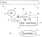
Fig. 4 illustrates an example hand drawing 400 input via a UI 402 of an application 112, for example, at the user interface 104 of the computing device 100. The description of the UI 402 and any of its components is merely an example, and other forms are possible. The entered graph 400 includes a number of graph elements that are displayed by the application 112 as digital ink objects, including: a container 404 containing text, a container 408 containing text 410, a connector 412 connecting containers 404 and 408, and a container 414 containing text 416. As previously described, content and element types are detected and identified so that the application 112 processes the graph elements based on their type (e.g., text, non-text, and spam (or unrecognized non-text)). Guide element 4000 is shown for container 408 and contained text 410 displayed thereon, guide element 4000 slightly overlapping container 408. Such a presentation and positioning of the guide element is only an example and different presentations and/or positioning are possible, preferably constrained such that displayed in the vicinity of the figure element to which the guide element belongs, has the least distracting appearance, and also has the least impact on free hand input, as described below.
The guide element 4000 is displayed to have a prompt item having a guide component adapted to the detection and recognition contents of the drawing element to which the guide element belongs, and a control component. For example, in fig. 4, the guide element 4000 has a cue item 4002 including a shape component 4004 and a text component 4006, and a control component 4008.
The shape component 4004 is displayed as an icon or label depicting a representation of the shape (e.g., rectangle) of the container 404 identified by the HWR system 114. However, a general shape icon may also be displayed. In this manner, recognition feedback can be provided to the user informing them that a hand-drawn shape has been detected and the type of shape has been recognized, without having to convert the shape in the digital ink map, partially or fully, into typeset ink, such as through menu or gesture selections. Thus, the user can continue to create or edit the drawings in digital ink form and, unless desired, the layout need not be performed.
The text component 4006 is displayed as a single horizontal line of typeset ink text recognized by the HWR system 114 from the handwritten text 410. In this way, recognition feedback is provided to the user informing them that handwritten text has been detected and that the text content has been recognized, without the need to convert some or all of the text in the digital ink map to typeset ink.
To position the guide element in proximity to the diagram element to which it belongs, the present systems and methods may be performed with reference to an alignment grid under the display interface, which may also be used to define one or more ranges and positions of the diagram element itself. Fig. 5 to 28 illustrate different display formats of the guide element 4000 and interactions performed on the guide element 4000 with respect to an example of a sequence of handwriting input of the shape and text of the diagram 400.
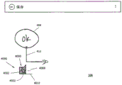
Fig. 5 shows the entry of a text element 406 as the first hand-drawn element of the diagram 400. Upon detecting the start of the input and the presentation of corresponding digital ink on the interface 104, the present systems and methods begin displaying the guide element 4000 as a text prompt 4010 having a horizontal line or bar 4012 adjacent to and above the handwritten character of the text 406 (e.g., as set by the alignment grid), a text component 4006 including typeset ink text 4014 identified from the text 406 (i.e., the word "Ok") above the horizontal bar 4012. The horizontal bar 4012 is configured to grow dynamically as text characters are entered and the identified content is displayed in the text prompt 4010. However, this growth is limited and effects such as automatic scrolling to the left of the text prompt item of the already displayed recognized text can be made to ensure that the newly recognized content is displayed in the text prompt item 4010.
Thus, substantially real-time content recognition feedback is provided through the text prompt 4010 during text entry. A control element 4008 is also displayed in the text prompt 4010, to the right of the text component 4006, and above the horizontal bar 4012. However, in order not to distract the user's attention during content input, the control icons may be displayed only when no input is performed, e.g., the "more" icons are left invisible during writing and gradually become fully visible after writing (i.e., after a stop input event (e.g., a finger/pen up event) is detected and a predefined period of time (e.g., about one half second to about one second) has elapsed).
Further, in order not to distract from user input, the text prompt item 4010 (and the "more" icon 4008) is displayed in a light-shade presentation, for example in light blue or at least in a different shade (shade) of color (i.e., between visible and faded) for the graphic element numbers and/or typeset ink display. In this way, the guide elements are noticeable but unobtrusive so as to guide handwriting input without distracting the graph creation itself. Further, the display of the guide element remains until the application 112 receives a different input, or ends at a predefined time period (e.g., about half a second to about 1 second) after the input stop event, and no other input is detected for the element to which the guide element belongs during which time the guide element is faded out of view.
FIG. 6 illustrates a subsequent input of a form factor 404 drawn as a container containing entered text 406. At this point, due to the relative positions and characteristics of the inputs 414 and 416, the form factor 414 may be identified as a container containing the identified word 416. The container and the text it contains are associated with each other so that some action performed on one of these elements will react to the other element. For example, when the user selects and moves a container, the contained text will move with the container, and when the user selects and enlarges or adds text, the container is sized to accommodate a larger text size or chunk.
Upon detecting the start of input and the rendering of corresponding digital ink on the interface 104, the present systems and methods, for example, omit displaying the text prompt item 4010 (and control element 4008), and initiate displaying the guide element 4000 over the hand-drawn shape 404 (e.g., as set by the alignment grid) as a shape prompt item 4016, the shape prompt item 4016 having a shape component 4002 that includes a circular graphic 4018 identified from the shape 404. Thus, substantially real-time content recognition feedback is provided at the shape input. In order not to distract the user's input, the shape prompt item 4016 is displayed in the same or similar light color rendering as the text prompt item 4010 and remains displayed in a similar manner.
Fig. 7 shows the container 404 and contained text 406 of fig. 6, where the shape prompt item 4016 is omitted from the display and the text prompt item 4010 is redisplayed so as to partially overlap the circle 404. This redisplay occurs because a selection gesture (e.g., a single point gesture such as a single tap, or a multi-point gesture such as a double tap) is detected for the digital ink text 406. Thus, for example, a user can interact with hand-drawn content to determine an identification state of the content. The display of the guide element for the selected content remains until the application 112 receives a new input (e.g., handwriting or gesture) or no interaction with the guide element or the content to which the guide element belongs is detected within a predefined period of time (e.g., about 5 seconds), at which time the guide element is faded to invisible.
Fig. 8 shows a subsequent input of a portion 412a of the form factor 412 drawn as a curved line below the circle 404. Form element 412 is an arrow, defined as being formed from a straight or curved "stem" terminating at one or both open (e.g., V-shaped) or closed (e.g., triangular) "arrow heads", as seen in fig. 4. Portion 412a constitutes the stem of arrow 412. Upon detecting the start of input and the rendering of corresponding digital ink on the interface 104, the present systems and methods initiate the display of the guide element 4000 alongside the hand-drawn shape 412a (e.g., as set by the alignment grid) as a shape prompt 4016, the shape prompt 4016 having a shape component 4002 that includes a linear graphic 4020 (i.e., a line) that is recognized from the shape 412 a. It is to be noted that the line pattern described in fig. 8 is a generalized line; however, in this example, the graphic may be a curved line, such as identified curved line 412 a.
At this point, line 412a may be identified as a connector of circle 404 due to the relative positions of inputs 1101 and 412a (e.g., application 112 using a pre-set spatial interval threshold where the interval between the ends of the linear shape and the non-linear shape is below the threshold representing a high likelihood of a connection, a spatial threshold may be defined as the distance in pixels between the average points or centroids of the strokes, e.g., set to about 5 pixels to about 100 pixels) and characteristics (e.g., one end of the line is near or adjacent to a container representing a high likelihood of a connection; near a distance range defined as similar to the spatial threshold). Shape objects (e.g., containers) and connectors connected thereto are associated with each other such that some action performed on one of the elements will react to another element. For example, when the user selects and moves a container, the connector moves with the container.
Fig. 9 shows a subsequent input of a portion 412b of the form factor 412, which is drawn as a rotated V-shape at the end of the line 412a that is not proximate to the circle 404. Portion 412b constitutes an arrow head of arrow 412. When it is detected and recognized that the part 412b is an arrow head of the arrow 412 composed of the curved line 412a and the arrow head 412b, the recognized shape figure in the shape cue item 4016 is changed to the arrow figure 4022 without repositioning the shape cue item 4016, but repositioning is also possible. Note that the graph depicted in fig. 9 is a generalized arrow; however, in this example, the graphic may be a curved arrow, such as identified curved arrow 412.
The application 112 determines the later drawn shape 412b and the earlier drawn shape 412a as belonging to a single shape 412 based on the probability scores. That is, strokes 412a and 412b of arrow 412 are drawn within a relatively long time interval, such as more than 1 second (e.g., greater than a preset and resettable time interval threshold used by application 112 below which the time interval between drawing strokes indicates a high likelihood that the strokes are part of a single shape), such that stroke 412a is resolved to recognizer 1l8 alone and recognized as a curved line, as described with respect to fig. 9. However, correct recognition of the complete connector arrow 412 is provided by a total probability score calculated from the spatial and temporal scores and metrics or characteristics of the input strokes. That is, although the temporal scores at which strokes 412a and 412b are part of the same object are lower, the combination of the higher spatial scores at which strokes 412a and 412b are part of the same object (as returned by the grouping and characteristics performed by the disambiguation system and method (e.g., the rotated chevrons at the ends of the lines)) yields a higher overall probability that strokes 412a and 412b belong to one shape. For example, if the application 112 classifies an arrow as having a higher likelihood of being a connector, the determination of the arrow head added to the line 412a may be used to confirm the connector state of the form element 412.
Fig. 10 shows an alternative input to a portion 412 b' of the form factor 412, drawn as a rotated v-shape similar to the portion 412b shown in fig. 9, differing from the portion 412b shown in fig. 9 by a distance from the end of the line 412 a. In rendering digital ink, the guide element 4000, as a text prompt 4010, is displayed with a text component 4006, the text component 4006 including typeset ink text 4024, i.e., the symbol ">, as identified according to the portion 412 b'. Because the relatively large distance between portion 412a and portion 412b 'produces a higher probability score that input 412 b' belongs to a separate object, portion 412b 'is identified as text rather than as part of shape 412, and thus the disambiguation system and method is able to classify portion 412 b' as text rather than as non-text. However, the present system and method provides the user with the ability to change the results of such recognition, as described below.
Each of the shape, text, and control components of the guide element 4000 are interactive in either a concurrent display (i.e., as in fig. 10) or a post-display (i.e., as in fig. 7) mode of the guide element 4000. With respect to the display mode (e.g., concurrent or post) of the guide elements, such interactivity may be accessed by selecting with a selection gesture (e.g., a single point gesture such as a single tap or long press) of a component detected by the application 112 and thereby enabling an assigned action for the component. Thus, for example, a user can interact with hand-drawn content to determine an identification state of the content. FIG. 11 shows the input stage of FIG. 10 with a menu 4026 displayed in response to detecting a selection gesture to recognized text 4024 in text prompt 4010. The text menu 4026 has two display areas 4026a and 4026 b.
In the menu region 4026a, a text recognition candidate list is displayed. These candidates are the most likely recognition candidates that the HWR system 114 outputs with respect to the recognition process for portion 412 b'. In fig. 18, four best candidates are shown, but more or less than four candidates may be shown. Each candidate displayed in the area 4026a is individually interactive, in which selection is made by a selection gesture (such as a single-point gesture, such as a single click or long press) of the candidate detected by the application 112, thereby changing the recognized text 4024 in the text prompt 4010 to the selected candidate, and the selected candidate is displayed when the layout part 412 b' is laid out. In the menu region 4026b, a manual sort action is displayed for which the text menu is "text to shape". Similarly, this action of region 4026b is interactive, with the selection causing the recognized text 412 b' to be reclassified as non-text and the corresponding re-recognition to occur. In this process, the disambiguation system and method re-evaluates the now classified shape 412b ' with other classified proximate form factors (i.e., lines 412a) to determine whether the grouping of the shape 412b ' with those other form factors resulted in the shape 412b ' being likely part of a larger form factor (i.e., form factor 412) for the recognizer 118 to perform a corresponding recognition. The acts shown are merely examples, and more, fewer, or different acts may be shown.
FIG. 12 shows the input stage of FIG. 10 with a different menu 4028 displayed in response to detecting a selection gesture to the "more" icon 4008 in the text prompt 4010. The text control menu 4028 has two display areas 4028a and 4026 b. In the menu region 4028a, actions related to content conversion are displayed, and the actions are a "text-to-shape" action, a "rearrangement" action, and a "layout" action with respect to the text control menu. These actions of the region 4028b are individually interactive, in that selection of the "text-to-shape" action causes the manual reclassification described above, selection of the "re-order" action causes the digital or typeset ink text to be re-arranged over multiple lines for the text control menu 4028, and selection of the "typeset" action causes the displayed digital ink text to be typeset for the text control menu 4028. In the menu area 4028b, interactive actions related to standard operations are displayed, and the actions are cut, copy, delete, export, and attribute/setting for a text control menu. These illustrated operations are merely examples, and more, fewer, or different operations may be displayed (except for manual reclassification).
Fig. 13 shows the connector 412 of fig. 6 with the shape prompt item 4016 omitted from display, but with the connector prompt item 4030 of the guide element 4000 in the vicinity of the connector 412 (e.g., as provided by the alignment grid). Because the application 112 detects a selection gesture (e.g., a single point gesture such as a single tap or a long press) to the connector 412, a connector prompt is displayed. The selected connectors 412 are displayed in a selection mode presentation that includes a comp version of the shape overlaid on the digital ink and a selection control A for resizing the connectors, wherein the presentation of the digital ink is de-emphasized (e.g., displayed lighter) and the comp ink is emphasized (e.g., displayed in color or ink weighted more heavily than the normal ink display). The connector prompt 4030 has a connector component 4032 that includes an arrow graphic 4022 identified from the shape 412. Also displayed in the connector prompt item 4030, to the right of the connector assembly 4032 and above the horizontal bar 4012 is a control element 4008.
When a connector alert item is displayed in response to a user interaction with a connector, the connector alert item 4030 is displayed with a more obvious presentation than the shape and text alert item because it may be desirable to interact with the connector alert item. The display of the connector prompt item is maintained until deselection of the selected connector is detected, or until a predefined period of time (e.g., about five seconds) has elapsed within which no interaction with the connector prompt item or the content to which it belongs is detected, or the application 112 receives a different input, at which time the guide element is faded out of view.
As with the text prompt, the connector prompt is also interactive. FIG. 14 illustrates the input phase of FIG. 13 with a menu 4034 displayed in response to detection of a selection gesture 4035 to a connector icon 4032 in a connector prompt item 4030. The connector menu 4034 has two display areas 4034a and 4034 b. In menu area 4034a list of alternative connector arrow types is displayed, which are also individually interactive. These alternatives are displayed based on the type of connector (an arrow in this example) that is interacting. For the line type connector of fig. 8, a different list of alternative connector types is displayed in the connector menu. In menu area 4034b, separate interactive and content-transformation related actions are displayed, including a "set to text" action and a "set to graffiti" action for the connector menu, wherein selection of "set to text" causes manual reclassification as described above, and selection of the "set to graffiti" action causes the recognition of shape 412 as a connector to be changed to graffiti, thereby removing the connector state reclassified as graffiti, which removal exhibits the corresponding effects described above on digital ink even after layout of diagram 400. These illustrated acts are merely examples, and more, fewer, or different acts may be illustrated.
FIG. 15 shows the input stage of FIG. 13 with menu 4036 displayed in response to detection of a selection gesture to the "more" icon 4008 in the connector prompt item 4030. The connector menu 4036 has two display areas 4036a and 4036 b. In the menu area 4036a, the above-described interactive actions related to the standard operation are displayed. In the menu area 4036b, a "typeset" content conversion action is displayed. These illustrated acts are merely examples, and more, fewer, or different acts may be illustrated.
FIG. 16 shows diagram 400 after subsequent entry of container 408 and contained text 410, and subsequent entry of text element 416. Upon detecting the start of the input and the presentation of corresponding digital ink on interface 104, the present systems and methods initiate the display of guide element 4000 as a text prompt 4010, the text prompt 4010 having a text component 4006 that includes a typeset ink word 4014 (i.e., the word "Operation") identified from text 416 above a horizontal bar 4012.
FIG. 17 shows an alternative input of a text element 416 having a portion 416a (the letter "O") and a portion 416b (the letter "perration"), where portion 416a and portion 416b are spaced a distance from each other. In the presentation of digital ink, guide element 4000 is displayed as shape prompt 4016 over portion 416a and text prompt 4010 over portion 416 b. This is because portion 416a is recognized as a shape (i.e., a displayed circle with a circular graphic 4018) rather than text, and portion 412 b' is correctly recognized as text. This is because the relatively large distance between portions 416a and 416b results in a high probability score that inputs 412b and 416b belong to separate objects, and thus the disambiguation system and method is able to classify portion 416a as non-text, rather than text. As described earlier, the recognition result can be changed by interacting with the shape prompt item 4016 to start a menu.
FIG. 18 shows the input stage of FIG. 17 with menu 4038 displayed in response to detection of a selection gesture to shape component 4004 in shape prompt item 4016. The shape menu 4038 has two display areas 4038a and 4038 b. In the menu area 4038a, a list of shape recognition candidates is displayed. These candidates are the most likely recognition candidates that the HWR system 114 outputs with respect to the recognition process for portion 416 a. In fig. 18, four best candidates are shown, but more or less than four candidates may be shown. Each candidate item displayed in the area 4038a is individually interactive in that it is selected by a selection gesture (e.g., a single point gesture such as a single tap or long press) of the candidate item detected by the application 112, thereby changing the shape graphic 4018 in the shape prompt 4016 to the selected candidate item, and the selected candidate item is displayed when the section 416a is laid out. In menu area 4038b, a manual sort action is displayed for which the shape menu is "shape to text". Similarly, this action of region 4038b is interactive, with the selection causing the recognized shape 416a to be reclassified as text and correspondingly re-recognized. In this process, the disambiguation system and method re-evaluates the now-classified shape 416a with other classified proximate text elements (i.e., text 416b) to determine whether the grouping of the text 416a with those other text elements results in the text 416a being likely part of a larger text element (i.e., text element 416) for the recognizer 118 to perform a corresponding recognition. The acts shown are merely examples, and more, fewer, or different acts may be shown.
FIG. 19 shows a subsequent input of a form element 414 (input following from the input of FIG. 16), which is the last element of the diagram 400 drawn as a container containing text 416 that has been input. At this point, due to the relative positions and characteristics of the inputs 414 and 416, the form factor 414 may be identified as a container containing the identified word 416. Upon detecting the start of input and the rendering of corresponding digital ink on the interface 104, the present systems and methods, for example, omit displaying the text prompt item 4010, and initiate a guide element 4000 that is displayed over the hand-drawn shape 414 (e.g., as set by the alignment grid) as a shape prompt item 4016, the shape prompt item 4016 having a shape component 4002 that includes an elliptical graphic 4018 that is recognized from the shape 414.
FIG. 20 illustrates the container 414 and contained text 416 of FIG. 19 displayed in the aforementioned selection mode rendering including, for example, a selected typeset of the shape and a selected digital ink version of the text resulting from the detection of the selection gesture to the container 414. In response, a full guide element 4000 comprising a shape prompt 4016, a text prompt 4010 and a control element 4008 is displayed, so that the container and the entire selection diagram element containing the text can be interacted with via the "more" icon, or the shape and text elements can be interacted with separately via the respective prompt items.
Fig. 21A and 21B illustrate an alternative scenario for such selection, where the text element 416 and the shape element 414 are entered separately and individually, respectively. In this case, selection of an individual element results in a selection mode display of that element and a display of a corresponding guide element prompt (including a control element).
FIG. 22 illustrates a completed diagram 400 displayed in typeset ink, for example, in response to a user interaction with the application 112 for performing the typeset. That is, the diagram elements are displayed as a layout container 404b containing a layout text 406b, a layout container 408b containing a layout text 410b, a layout connector 412c connecting the layout containers 404b and 408b, and a layout container 414b containing a layout text 416 b.
FIG. 23 illustrates a comp graph 400 having a comp container 414b and contained text 416b displayed in the selection mode presentation described above, including, for example, a selected comp version of the shape and text resulting from the detection of a selection gesture to the container 414 b. In response, as before, the complete guide element 4000 is displayed including the shape prompt item 4016, the text prompt item 4010, and the control element 4008.
Fig. 24, 25, and 26 show shape, text, and control menus 4038, 4026, and 4028, respectively, having the above-described interactive actions displayed when a selection gesture is detected for the shape prompt item 4016, the text prompt item 4010, and the control element 4008, respectively.
FIG. 27 illustrates a comp graph 400 having a comp container 408b and contained text 410b and a comp container 414b and contained text 416b presented for display in the selection mode described above, and a selection box 4040 surrounding all selection elements as a result of a multi-selection gesture detected by the application 112 (e.g., a single point gesture (e.g., a long press) to one of the containers 408b and 414b and thereafter another single point gesture (e.g., a short press) to the other container). In response, a guide element 4000 comprising a multi-element reminder 4042 and a control element 4008 is displayed. Multi-element reminder item 4042 is also interactive, as are other reminder items and components of the guide element.
FIG. 28 illustrates the selection mode of FIG. 27 with menu 4044 displayed in response to detecting selection gesture 418 of multi-element prompt item 4042. The multi-element menu 4044 displays a list of manual sort actions including the "set to text" action, "set to shape" action, and "set to graffiti" action described above. Each action of menu 4044 is individually interactive, with selection being made by a selection gesture (e.g., a single point gesture such as a single tap or long press) for each action detected by application 112. Selecting these actions causes all of the multiple choice elements to be reclassified and re-identified accordingly. In the multiple selection mode, selection of the control element 4008 activates the control menu 4028 having the aforementioned interactive elements.
As previously described, input shapes that are resolved to a recognizer but are not recognized, for example, because they do not belong to a dictionary shape (out-of-lexicon) are considered graffiti and therefore are not rendered in typeset ink in the typeset drawing. Such non-recognition occurs in the event that the recognizer 118 is configured to only return a recognition output if it is determined that a candidate above a particular probability score threshold is returned. Example graffiti input to diagram 400 is now described with reference to fig. 29-31.
Fig. 29 shows the input of the form element 420 drawn as a free-form shape above the layout container 408 b. The new inputs to the layout scheme 400 are displayed as digital ink unless the new inputs are set to be laid out step by step. At this point, the disambiguation system and method recognizes the form element 404 as non-text, but the recognizer 118 does not recognize the form element 404 because it does not belong to a dictionary shape. To provide feedback to the user of this failed recognition, upon detecting the start of the input and the presentation of corresponding digital ink on the interface 104, the present systems and methods initiate the display of the guide element 4000 over the hand-drawn shape 420 (e.g., as set by the alignment grid) as a free-form reminder 4046, the free-form reminder 4046 having a free-form component 4048 that includes a graffiti graphic 4050. In order not to distract the user input, the free form reminder item 4046 is displayed in the same or similar light color presentation as the other reminder items, and remains displayed in a similar manner.
FIG. 30 illustrates a comp graph 400 having a digital ink shape 420 displayed rendered in the selection mode described above, and a selection box 4040 surrounding the selected element as a result of detecting a selection gesture (e.g., a single point gesture such as a short press) to the shape by the application 112. In response, a guide element 4000 comprising a free form cue 4046 and a control element 4008 is displayed. Free form alert item 4046 is also interactive, as are other alert items and components of the guide element.
FIG. 31 illustrates the selection mode of FIG. 30 with menu 4052 displayed in response to detecting the selection gesture 422 of the free-form component 4048. The graffiti menu 4052 displays a list of manual sort actions including the "set to text" action and the "set to shape" action described above. Each action of menu 4052 is individually interactive, with selection being made by a selection gesture (e.g., a single point gesture such as a single tap or long press) for each action detected by application 112. The selection of these actions causes the selected unidentified free-form elements to be reclassified and thus re-identified (e.g., such manual reclassification may cause the recognizer 118 to return the best candidate for a free-form shape below a probability score threshold).
While the foregoing has described what are considered to be the best mode and/or other examples, it is understood that: various modifications may be made in the present invention, and the subject matter disclosed herein may be implemented in various forms and examples, and the contents of the best mode and/or other examples may be applied in numerous other applications, combinations and environments, only some of which are described herein. Those of ordinary skill in the art will recognize that the disclosed aspects can be altered or modified without departing from the true spirit and scope of the present subject matter. Therefore, the subject matter is not limited to the specific details, illustrations, and examples in this specification. It is intended herein to cover any and all modifications and variations that fall within the true scope of the advantageous concepts disclosed herein.
Claims (18)
1. A system for directing hand-drawing a diagram including text elements and non-text elements on a computing device, the computing device comprising a processor and at least one non-transitory computer-readable medium for detecting and recognizing hand-drawing element input under control of the processor, the at least one non-transitory computer-readable medium configured to:
causing display, on an interactive display of the computing device:
a recognition form of the hand-drawn non-text graphic element overlaid on the digital ink of the hand-drawn non-text graphic element, and
a dynamic hint item dynamically displaying at least one depiction of the hand-drawn non-textual diagram element and configured in an identified form of the hand-drawn non-textual diagram element;
wherein the recognized form of the hand-drawn non-textual graph element is initially determined based on a probability score calculated from at least one of: the spatial score, temporal score, and input characteristics of the freehand non-textual graph elements.
2. The system of claim 1, wherein the dynamic reminder item dynamically displays at least one depiction of a hand-drawn text diagram element as the hand-drawing is entered.
3. The system of claim 1, wherein the dynamic reminder item includes at least one interactive reminder item element, the at least one non-transitory computer-readable medium configured to display an action menu in response to receiving an interaction with the at least one interactive reminder item element.
4. The system of claim 1, the at least one non-transitory computer-readable medium configured to display the depiction of the non-textual elements in the form of an icon.
5. The system of claim 4, wherein the non-text element is a form element of the graph, the icon depicting the shape.
6. The system of claim 1, the at least one non-transitory computer-readable medium configured to display the depiction of the text element in typeset ink.
7. A method for directing hand-drawing a diagram including text elements and non-text elements on a computing device, the computing device including a processor and at least one non-transitory computer-readable medium for detecting and recognizing hand-drawing element input under control of the processor, the method comprising:
displaying, on an interactive display of the computing device:
a recognition form of the hand-drawn non-text graphic element overlaid on the digital ink of the hand-drawn non-text graphic element, and
a dynamic hint item dynamically displaying at least one depiction of the hand-drawn non-textual diagram element and configured in an identified form of the hand-drawn non-textual diagram element;
wherein the recognized form of the hand-drawn non-textual graph element is initially determined based on a probability score calculated from at least one of: the spatial score, temporal score, and input characteristics of the freehand non-textual graph elements.
8. The method of claim 7, wherein the dynamic reminder item dynamically displays at least one depiction of a hand-drawn text diagram element as the hand-drawing is entered.
9. The method of claim 7, wherein the dynamic reminder item includes at least one interactive reminder item element, the at least one non-transitory computer-readable medium configured to display an action menu in response to receiving an interaction with the at least one interactive reminder item element.
10. The method of claim 7, comprising: the depiction of the non-text elements is displayed in the form of icons.
11. The method of claim 10, wherein the non-text element is a form element of the graph, the icon depicting the shape.
12. The method of claim 7, comprising: the depiction of the text elements is displayed in typeset ink.
13. A non-transitory computer readable medium having a computer readable program code embodied therein, the computer readable program code adapted to be executed to implement a method for directing hand-drawing of a diagram including text elements and non-text elements on a computing device, the computing device including a processor and at least one non-transitory computer readable medium for detecting and recognizing hand-drawing element input under control of the processor, the method comprising:
displaying, on an interactive display of the computing device:
a recognition form of the hand-drawn non-text graphic element overlaid on the digital ink of the hand-drawn non-text graphic element, and
a dynamic hint item dynamically displaying at least one depiction of the hand-drawn non-textual diagram element and configured in an identified form of the hand-drawn non-textual diagram element;
wherein the recognized form of the hand-drawn non-textual graph element is initially determined based on a probability score calculated from at least one of: the spatial score, temporal score, and input characteristics of the freehand non-textual graph elements.
14. The non-transitory computer-readable medium of claim 13, wherein the dynamic hint item dynamically displays at least one graph element as the hand-drawn is input.
15. The non-transitory computer-readable medium of claim 13, wherein the dynamic reminder item includes at least one interactive reminder item element, the at least one non-transitory computer-readable medium configured to display an action menu in response to receiving an interaction with the at least one interactive reminder item element.
16. The non-transitory computer-readable medium of claim 13, wherein the method comprises displaying the depiction of the non-textual elements in the form of an icon.
17. The non-transitory computer-readable medium of claim 16, wherein the non-text element is a form element of the graph, the icon depicting the shape.
18. The non-transitory computer readable medium of claim 13, wherein the method comprises displaying the depiction of the text element in typeset ink.
Applications Claiming Priority (5)
| Application Number | Priority Date | Filing Date | Title |
|---|---|---|---|
| EP15290270.6 | 2015-10-19 | ||
| EP15290270 | 2015-10-19 | ||
| US14/955,198 US10976918B2 (en) | 2015-10-19 | 2015-12-01 | System and method of guiding handwriting diagram input |
| US14/955,198 | 2015-12-01 | ||
| PCT/EP2016/001723 WO2017067654A1 (en) | 2015-10-19 | 2016-10-18 | System and method of guiding handwriting diagram input |
Publications (2)
| Publication Number | Publication Date |
|---|---|
| CN108369484A CN108369484A (en) | 2018-08-03 |
| CN108369484B true CN108369484B (en) | 2021-07-27 |
Family
ID=54396796
Family Applications (1)
| Application Number | Title | Priority Date | Filing Date |
|---|---|---|---|
| CN201680074443.2A Active CN108369484B (en) | 2015-10-19 | 2016-10-18 | System and method for guiding hand-written graph input |
Country Status (6)
| Country | Link |
|---|---|
| US (2) | US10976918B2 (en) |
| EP (1) | EP3365765B1 (en) |
| JP (1) | JP7065023B2 (en) |
| KR (1) | KR102392537B1 (en) |
| CN (1) | CN108369484B (en) |
| WO (1) | WO2017067654A1 (en) |
Families Citing this family (19)
| Publication number | Priority date | Publication date | Assignee | Title |
|---|---|---|---|---|
| US8924335B1 (en) | 2006-03-30 | 2014-12-30 | Pegasystems Inc. | Rule-based user interface conformance methods |
| US10469396B2 (en) | 2014-10-10 | 2019-11-05 | Pegasystems, Inc. | Event processing with enhanced throughput |
| US11500535B2 (en) * | 2015-10-29 | 2022-11-15 | Lenovo (Singapore) Pte. Ltd. | Two stroke quick input selection |
| US10698599B2 (en) * | 2016-06-03 | 2020-06-30 | Pegasystems, Inc. | Connecting graphical shapes using gestures |
| US10402740B2 (en) * | 2016-07-29 | 2019-09-03 | Sap Se | Natural interactive user interface using artificial intelligence and freeform input |
| US10956765B2 (en) * | 2016-08-19 | 2021-03-23 | Sony Corporation | Information processing device and information processing method |
| US10970476B2 (en) * | 2017-05-17 | 2021-04-06 | Microsoft Technology Licensing, Llc | Augmenting digital ink strokes |
| US10679049B2 (en) * | 2017-09-29 | 2020-06-09 | Konica Minolta Laboratory U.S.A., Inc. | Identifying hand drawn tables |
| US10761719B2 (en) * | 2017-11-09 | 2020-09-01 | Microsoft Technology Licensing, Llc | User interface code generation based on free-hand input |
| US11048488B2 (en) | 2018-08-14 | 2021-06-29 | Pegasystems, Inc. | Software code optimizer and method |
| US11392659B2 (en) * | 2019-02-28 | 2022-07-19 | Adobe Inc. | Utilizing machine learning models to generate experience driven search results based on digital canvas gesture inputs |
| KR102610481B1 (en) | 2019-05-06 | 2023-12-07 | 애플 인크. | Handwriting on electronic devices |
| EP3754537B1 (en) * | 2019-06-20 | 2024-05-22 | MyScript | Processing text handwriting input in a free handwriting mode |
| JP6992795B2 (en) * | 2019-11-28 | 2022-01-13 | ブラザー工業株式会社 | Chart creation program and information processing device with chart creation function |
| US20210349627A1 (en) | 2020-05-11 | 2021-11-11 | Apple Inc. | Interacting with handwritten content on an electronic device |
| US11567945B1 (en) | 2020-08-27 | 2023-01-31 | Pegasystems Inc. | Customized digital content generation systems and methods |
| US11733861B2 (en) * | 2020-11-20 | 2023-08-22 | Trimble Inc. | Interpreting inputs for three-dimensional virtual spaces from touchscreen interface gestures to improve user interface functionality |
| CN112711362B (en) * | 2020-12-24 | 2022-02-18 | 北京华宇信息技术有限公司 | Method and device for generating hand-drawn flow chart icon in standardized manner |
| US11663761B2 (en) * | 2021-08-25 | 2023-05-30 | Sap Se | Hand-drawn diagram recognition using visual arrow-relation detection |
Citations (3)
| Publication number | Priority date | Publication date | Assignee | Title |
|---|---|---|---|---|
| CN103399698A (en) * | 2013-07-31 | 2013-11-20 | 中国船舶重工集团公司第七〇九研究所 | Pen type interactive method based on free-hand sketch and gesture input judging and processing |
| CN104317421A (en) * | 2014-10-21 | 2015-01-28 | 苏州乐聚一堂电子科技有限公司 | Key and hand Chinese character input method for cellphones |
| CN104794107A (en) * | 2015-02-16 | 2015-07-22 | 北京道明科技有限公司 | Handwriting editing method |
Family Cites Families (23)
| Publication number | Priority date | Publication date | Assignee | Title |
|---|---|---|---|---|
| JP2749020B2 (en) | 1991-11-14 | 1998-05-13 | 日立ソフトウエアエンジニアリング株式会社 | Diagram recognition system |
| JP3388524B2 (en) | 1994-06-30 | 2003-03-24 | カシオ計算機株式会社 | Image input device |
| US20030215145A1 (en) | 2002-05-14 | 2003-11-20 | Microsoft Corporation | Classification analysis of freeform digital ink input |
| US7079713B2 (en) * | 2002-06-28 | 2006-07-18 | Microsoft Corporation | Method and system for displaying and linking ink objects with recognized text and objects |
| US20040090439A1 (en) * | 2002-11-07 | 2004-05-13 | Holger Dillner | Recognition and interpretation of graphical and diagrammatic representations |
| US7848573B2 (en) * | 2003-12-03 | 2010-12-07 | Microsoft Corporation | Scaled text replacement of ink |
| US20050273761A1 (en) | 2004-06-07 | 2005-12-08 | The Mathworks, Inc. | Freehand system and method for creating, editing, and manipulating block diagrams |
| US7929767B2 (en) | 2004-09-22 | 2011-04-19 | Microsoft Corporation | Analyzing subordinate sub-expressions in expression recognition |
| US7512273B2 (en) * | 2004-10-21 | 2009-03-31 | Microsoft Corporation | Digital ink labeling |
| US8014607B2 (en) | 2007-03-23 | 2011-09-06 | Palo Alto Research Center Incorporated | Method and apparatus for creating and editing node-link diagrams in pen computing systems |
| US7725493B2 (en) * | 2007-03-23 | 2010-05-25 | Palo Alto Research Center Incorporated | Optimization method and process using tree searching operation and non-overlapping support constraint requirements |
| US8116570B2 (en) | 2007-04-19 | 2012-02-14 | Microsoft Corporation | User interface for providing digital ink input and correcting recognition errors |
| US20100171754A1 (en) * | 2009-01-07 | 2010-07-08 | Microsoft Corporation | Converting digital ink to shapes and text |
| US8718375B2 (en) * | 2010-12-03 | 2014-05-06 | Massachusetts Institute Of Technology | Sketch recognition system |
| CN102750552B (en) * | 2012-06-18 | 2015-07-22 | 北京捷通华声语音技术有限公司 | Handwriting recognition method and system as well as handwriting recognition terminal |
| KR101929301B1 (en) * | 2012-08-20 | 2019-03-12 | 삼성전자 주식회사 | Method and apparatus for control actuating function through recognizing user's writing gesture in portable terminal |
| JP5342052B1 (en) * | 2012-10-17 | 2013-11-13 | 株式会社東芝 | Electronic apparatus and method |
| JP2014081818A (en) | 2012-10-17 | 2014-05-08 | Toshiba Tec Corp | Merchandise sales data processor and portable terminal |
| US9329726B2 (en) * | 2012-10-26 | 2016-05-03 | Qualcomm Incorporated | System and method for capturing editable handwriting on a display |
| JP5377743B1 (en) | 2012-11-28 | 2013-12-25 | 株式会社東芝 | Electronic device and handwritten document processing method |
| US20140210829A1 (en) * | 2013-01-31 | 2014-07-31 | Kabushiki Kaisha Toshiba | Electronic apparatus and handwritten document processing method |
| JP6054547B2 (en) | 2013-12-09 | 2016-12-27 | 株式会社東芝 | Electronic device and method for processing handwritten document information |
| JP2015138494A (en) * | 2014-01-24 | 2015-07-30 | 株式会社東芝 | Electronic device and method |
-
2015
- 2015-12-01 US US14/955,198 patent/US10976918B2/en active Active
-
2016
- 2016-10-18 CN CN201680074443.2A patent/CN108369484B/en active Active
- 2016-10-18 KR KR1020187014271A patent/KR102392537B1/en active IP Right Grant
- 2016-10-18 EP EP16790264.2A patent/EP3365765B1/en active Active
- 2016-10-18 WO PCT/EP2016/001723 patent/WO2017067654A1/en active Application Filing
- 2016-10-18 JP JP2018520079A patent/JP7065023B2/en active Active
-
2021
- 2021-03-18 US US17/205,246 patent/US11740783B2/en active Active
Patent Citations (3)
| Publication number | Priority date | Publication date | Assignee | Title |
|---|---|---|---|---|
| CN103399698A (en) * | 2013-07-31 | 2013-11-20 | 中国船舶重工集团公司第七〇九研究所 | Pen type interactive method based on free-hand sketch and gesture input judging and processing |
| CN104317421A (en) * | 2014-10-21 | 2015-01-28 | 苏州乐聚一堂电子科技有限公司 | Key and hand Chinese character input method for cellphones |
| CN104794107A (en) * | 2015-02-16 | 2015-07-22 | 北京道明科技有限公司 | Handwriting editing method |
Also Published As
| Publication number | Publication date |
|---|---|
| KR20180096590A (en) | 2018-08-29 |
| US11740783B2 (en) | 2023-08-29 |
| US10976918B2 (en) | 2021-04-13 |
| KR102392537B1 (en) | 2022-04-28 |
| EP3365765A1 (en) | 2018-08-29 |
| WO2017067654A1 (en) | 2017-04-27 |
| US20170109032A1 (en) | 2017-04-20 |
| US20210278965A1 (en) | 2021-09-09 |
| EP3365765B1 (en) | 2022-01-19 |
| CN108369484A (en) | 2018-08-03 |
| JP2018536926A (en) | 2018-12-13 |
| JP7065023B2 (en) | 2022-05-11 |
Similar Documents
| Publication | Publication Date | Title |
|---|---|---|
| CN108369484B (en) | System and method for guiding hand-written graph input | |
| US11157732B2 (en) | System and method of handwriting recognition in diagrams | |
| US11402991B2 (en) | System and method for note taking with gestures | |
| CN108700994B (en) | System and method for digital ink interactivity | |
| US20180114059A1 (en) | System and method for managing digital ink typesetting | |
| CN108475325B (en) | System, method, and computer-readable medium for identifying handwritten pattern connectors | |
| CN108369637B (en) | System and method for beautifying digital ink | |
| US11687618B2 (en) | System and method for processing text handwriting in a free handwriting mode | |
| CN114365075B (en) | Method for selecting a graphical object and corresponding device | |
| US11429259B2 (en) | System and method for selecting and editing handwriting input elements | |
| US20240134507A1 (en) | Modifying digital content including typed and handwritten text | |
| US20240078377A1 (en) | Completing typeset characters using handwritten strokes | |
| EP4047465A1 (en) | Modifying digital content |
Legal Events
| Date | Code | Title | Description |
|---|---|---|---|
| PB01 | Publication | ||
| PB01 | Publication | ||
| SE01 | Entry into force of request for substantive examination | ||
| SE01 | Entry into force of request for substantive examination | ||
| GR01 | Patent grant | ||
| GR01 | Patent grant |