CN108475325B - System, method, and computer-readable medium for identifying handwritten pattern connectors - Google Patents
System, method, and computer-readable medium for identifying handwritten pattern connectors Download PDFInfo
- Publication number
- CN108475325B CN108475325B CN201680074089.3A CN201680074089A CN108475325B CN 108475325 B CN108475325 B CN 108475325B CN 201680074089 A CN201680074089 A CN 201680074089A CN 108475325 B CN108475325 B CN 108475325B
- Authority
- CN
- China
- Prior art keywords
- connector
- elements
- point
- graph
- identified
- Prior art date
- Legal status (The legal status is an assumption and is not a legal conclusion. Google has not performed a legal analysis and makes no representation as to the accuracy of the status listed.)
- Active
Links
Images


Classifications
-
- G—PHYSICS
- G06—COMPUTING; CALCULATING OR COUNTING
- G06V—IMAGE OR VIDEO RECOGNITION OR UNDERSTANDING
- G06V30/00—Character recognition; Recognising digital ink; Document-oriented image-based pattern recognition
- G06V30/10—Character recognition
- G06V30/32—Digital ink
- G06V30/36—Matching; Classification
-
- G—PHYSICS
- G06—COMPUTING; CALCULATING OR COUNTING
- G06F—ELECTRIC DIGITAL DATA PROCESSING
- G06F3/00—Input arrangements for transferring data to be processed into a form capable of being handled by the computer; Output arrangements for transferring data from processing unit to output unit, e.g. interface arrangements
- G06F3/01—Input arrangements or combined input and output arrangements for interaction between user and computer
- G06F3/048—Interaction techniques based on graphical user interfaces [GUI]
- G06F3/0487—Interaction techniques based on graphical user interfaces [GUI] using specific features provided by the input device, e.g. functions controlled by the rotation of a mouse with dual sensing arrangements, or of the nature of the input device, e.g. tap gestures based on pressure sensed by a digitiser
- G06F3/0488—Interaction techniques based on graphical user interfaces [GUI] using specific features provided by the input device, e.g. functions controlled by the rotation of a mouse with dual sensing arrangements, or of the nature of the input device, e.g. tap gestures based on pressure sensed by a digitiser using a touch-screen or digitiser, e.g. input of commands through traced gestures
- G06F3/04883—Interaction techniques based on graphical user interfaces [GUI] using specific features provided by the input device, e.g. functions controlled by the rotation of a mouse with dual sensing arrangements, or of the nature of the input device, e.g. tap gestures based on pressure sensed by a digitiser using a touch-screen or digitiser, e.g. input of commands through traced gestures for inputting data by handwriting, e.g. gesture or text
-
- G—PHYSICS
- G06—COMPUTING; CALCULATING OR COUNTING
- G06V—IMAGE OR VIDEO RECOGNITION OR UNDERSTANDING
- G06V10/00—Arrangements for image or video recognition or understanding
- G06V10/20—Image preprocessing
- G06V10/22—Image preprocessing by selection of a specific region containing or referencing a pattern; Locating or processing of specific regions to guide the detection or recognition
- G06V10/235—Image preprocessing by selection of a specific region containing or referencing a pattern; Locating or processing of specific regions to guide the detection or recognition based on user input or interaction
-
- G—PHYSICS
- G06—COMPUTING; CALCULATING OR COUNTING
- G06V—IMAGE OR VIDEO RECOGNITION OR UNDERSTANDING
- G06V10/00—Arrangements for image or video recognition or understanding
- G06V10/40—Extraction of image or video features
- G06V10/44—Local feature extraction by analysis of parts of the pattern, e.g. by detecting edges, contours, loops, corners, strokes or intersections; Connectivity analysis, e.g. of connected components
- G06V10/457—Local feature extraction by analysis of parts of the pattern, e.g. by detecting edges, contours, loops, corners, strokes or intersections; Connectivity analysis, e.g. of connected components by analysing connectivity, e.g. edge linking, connected component analysis or slices
-
- G—PHYSICS
- G06—COMPUTING; CALCULATING OR COUNTING
- G06V—IMAGE OR VIDEO RECOGNITION OR UNDERSTANDING
- G06V30/00—Character recognition; Recognising digital ink; Document-oriented image-based pattern recognition
- G06V30/10—Character recognition
- G06V30/14—Image acquisition
- G06V30/142—Image acquisition using hand-held instruments; Constructional details of the instruments
- G06V30/1423—Image acquisition using hand-held instruments; Constructional details of the instruments the instrument generating sequences of position coordinates corresponding to handwriting
-
- G—PHYSICS
- G06—COMPUTING; CALCULATING OR COUNTING
- G06V—IMAGE OR VIDEO RECOGNITION OR UNDERSTANDING
- G06V30/00—Character recognition; Recognising digital ink; Document-oriented image-based pattern recognition
- G06V30/10—Character recognition
- G06V30/22—Character recognition characterised by the type of writing
-
- G—PHYSICS
- G06—COMPUTING; CALCULATING OR COUNTING
- G06V—IMAGE OR VIDEO RECOGNITION OR UNDERSTANDING
- G06V30/00—Character recognition; Recognising digital ink; Document-oriented image-based pattern recognition
- G06V30/40—Document-oriented image-based pattern recognition
- G06V30/42—Document-oriented image-based pattern recognition based on the type of document
- G06V30/422—Technical drawings; Geographical maps
Landscapes
- Engineering & Computer Science (AREA)
- Theoretical Computer Science (AREA)
- Physics & Mathematics (AREA)
- General Physics & Mathematics (AREA)
- Multimedia (AREA)
- Computer Vision & Pattern Recognition (AREA)
- Artificial Intelligence (AREA)
- General Engineering & Computer Science (AREA)
- Human Computer Interaction (AREA)
- User Interface Of Digital Computer (AREA)
- Character Discrimination (AREA)
- Processing Or Creating Images (AREA)
Abstract
A system for hand-drawing a connection of a diagram including text elements and non-text elements on a computing device, the computing device including a processor and at least one non-transitory computer-readable medium for detecting and recognizing hand-drawn diagram element input under control of the processor, the at least one non-transitory computer-readable medium configured to: causing display of a plurality of input diagram elements in interactive ink on a display device associated with a computing device; identifying at least one graph element as a connector connecting a plurality of graph elements; determining a geometric characteristic of the identified at least one connector; and redisplaying the elements based on the received one or more interactions of the interactive ink with the identified at least one connector or one or more of the plurality of elements connected by the connector, and in accordance with the determined geometric characteristic.
Description
Cross Reference to Related Applications
The present application claims priority from european application No.15290269.8 filed on 19/10/2015 and us application No.14/955,174 filed on 1/12/2015, which claims priority from european application No.15290269.8, the entire contents of which are incorporated herein by reference.
Technical Field
The present disclosure relates generally to the field of user input handwriting computing device interfaces capable of recognizing various shapes and characters. In particular, the present disclosure provides systems and methods for processing editing operations that cause display of connectors between input handwritten pattern elements.
Background
Computing devices are becoming increasingly common in everyday life. They are represented in the following form: desktop computers, laptop computers, tablet computers, electronic book readers, mobile phones, smart phones, wearable computers, Global Positioning System (GPS) units, Enterprise Digital Assistants (EDAs), Personal Digital Assistants (PDAs), game consoles, and the like. In addition, computing devices are included in vehicles and devices, such as automobiles, trucks, farm equipment, manufacturing equipment, building environmental controls (e.g., lighting, HVAC), and household and commercial appliances.
A computing device typically consists of at least one processing element, such as a Central Processing Unit (CPU), some form of memory, and output devices. Various computing devices and their subsequent use require various interfaces and input devices. One such input device is a touch-sensitive surface (e.g., a touchscreen or touchpad) in which user input is received through contact between a user's finger or an instrument (e.g., a pen or stylus) and the touch-sensitive surface. Another input device is an input surface that senses gestures made by a user on the input surface. Another input device is a position detection system that detects the relative position of a touch or non-touch interaction with a non-touch surface. Any of these input methods can be commonly used for handwriting or hand-drawing input of drawings and text that are interpreted using a handwriting recognition system or method.
One application of handwriting recognition in a computing device is to create a drawing that is hand drawn on the computing device to be converted into a typographical version. The figures are diagrams illustrating or showing the layout and relationships (of the components). A diagram generally includes shapes having arbitrary or particular meanings and text having relationships to the shapes. There are many types of diagrams such as flow charts, organizational charts, conceptual charts, spider charts, block/architecture charts, thought charts, block diagrams, wien charts, and pyramids. Some typographical and handwritten representations of some examples of possible diagrams are shown in fig. 1-6.
Fig. 1A and 1B illustrate an example conceptual diagram 10 of typesetting and handwriting, respectively, having different shapes, defining tiles or containers 12 in different ways and different types of connectors 14 (e.g., straight arrows, curved arrows) connecting or specifying relationships between the tiles 12. Further, in FIG. 1B, container 12 contains text 16. Generally in a conceptual diagram, the connections between blocks define conceptually related or dependent elements or topics defined by the text in the blocks. The blocks themselves may not be present in the conceptual diagram, but rather text (e.g., defined in text blocks that do not have an associated shape or container) may be connected by connectors.
FIGS. 2A and 2B illustrate example mind maps 20 for typesetting and handwriting, respectively, having different shapes that define tiles or containers 12 differently, different types of connectors 14 (e.g., lines, curves) that connect or specify relationships between tiles 12, and paths 18 to certain features or states of the mind map. Further, in FIG. 2B, the container 12 and path 18 have associated text 16. Typically in a mind map, the connections between blocks define possible alternative states that start from a central element or topic defined by the text in the blocks, and paths define key features for each alternative state defined by the text on the paths. The blocks themselves may not be present in the thought-guide graph, but rather text may be connected by connectors (e.g., defined in text blocks that do not have an associated shape or container).
Fig. 3A and 3B illustrate example flowcharts 30 of typesetting and handwriting, respectively, having different shapes, differently defining different types of tiles or containers 12 (e.g., ellipses, rectangles, diamonds) and different types of connectors 14 (e.g., straight arrows, curved arrows, branch lines) connecting or specifying relationships between tiles 12. Further, in FIG. 3B, container 12 contains text 16; text may also be associated with the connectors. Generally in flow charts, the connections between blocks define programmatically related or dependent elements or steps defined by text in those blocks. The blocks themselves may not be present in the flowchart, but rather text (e.g., defined in text blocks that do not have an associated shape or container) may be connected by connectors.
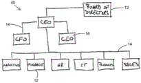
Fig. 4A and 4B illustrate example org-chart 40 of typesets and handwriting, respectively, having different shapes, differently defining tiles or containers 12 and different types of connectors 14 (e.g., straight lines, curved lines, branch lines) connecting or specifying relationships between tiles 12. Further, in fig. 4B, the container 12 contains text 16. Typically in an org-chart, the connections between blocks define a hierarchical relationship of members or functions of an organization or community defined by the text in the blocks. The blocks themselves may not be present in the org-chart, but rather text may be connected by connectors (e.g., defined in text blocks that do not have an associated shape or container).
FIGS. 5A and 5B illustrate typeset and handwritten example block/architecture diagrams 50, respectively, having different shapes, defining tiles or containers 12 having nested relationships (e.g., container 12 within other container 12), and connectors 14 that connect or specify relationships between tiles 12 (including nested blocks). Further, in FIG. 5B, the container 12 and the connector have associated text 16. Typically in an architectural diagram, nested blocks define the layout or ownership (permissions) of a device or processing component, and connections between blocks define the functional relationships between blocks defined by the text in those blocks.
Fig. 6A and 6B illustrate a spider graph 60 of typeset and handwriting examples, respectively, having different shapes, defining tiles or containers 12 and connectors 14 that connect or specify relationships between the tiles 12. Further, in FIG. 6B, the container 12 and the connector have associated text 16. Typically in spider graphs, connections between blocks and/or text define dependencies or states that begin with a central element or topic defined by the text.
The diagrams shown in fig. 1-6 are merely examples, and other or different elements, or different types or forms of the depicted elements themselves, may additionally or alternatively appear in the diagrams in addition to the elements depicted in each of the diagram types. In addition, other definitions of these graph types and combinations thereof are possible. These myriad possible variations of combining the basic components of shapes and text in a figure (connected with or without containers) can present problems for accurately recognizing these elements as inputs for hand-drawn or handwritten content on a computing device. The diagrams are particularly useful in educational and business environments where a user of a computing device creates a diagram to obtain a concept, problem, or solution in question, such as during a lecture or meeting. This is typically accomplished by a user launching a handwriting drawing or sketch application on the computing device that receives and interprets the handwriting input on the touch-sensitive surface or surfaces monitored by the relative position detection system, either locally in the device or remotely via a communication link of the device.
Often, such handwritten drawing applications are limited in their ability to handle the complexity of the drawing described above, and often constrain the user to take actions that do not reflect the user's original intent or accept such compromises. Thus, some conventional handwriting drawing applications force the user to navigate menus to select and draw shapes, and insert text related to the shapes. Therefore, the user cannot draw shapes and connectors naturally or freely. Some conventional applications better recognize hand-drawn shapes and handwritten text and provide the user with appropriate authoring freedom. However, the ability to change a drawn graph (e.g., edit elements of a graph to add, omit, or replace elements, modify a graph to an evolving concept, convert the type of graph, etc.) is limited by: only for certain operations, and only for composing versions of the diagram (especially manipulating the relative positions of diagram elements while maintaining recognized relationships (e.g., connected containers, etc.)), and not for handwriting input (so-called digital ink); and/or a selection that requires a gesture to be learned or via a menu as described above. For example, U.S. patent No.8,014,607 describes an inference mode protocol that allows certain editing operations to act directly on digital ink. However, the described operation is very limited. Further, there is no solution provided that is capable of manipulating the relative positions of the drawing elements in the digital ink while maintaining the identified relationship.
U.S. patent No.7,394,935 describes the associated manipulation of digital ink with respect to resizing and repositioning operations. However, in these operations, the digital ink is merely scaled according to the operation, which would require the user to perform further interaction to bring the digital ink back to its original drawn size, e.g., moving a container away from the container to which it is connected would cause the connector to extend in both the x and y dimensions, or "re-sort" the connector by recalculating the skeleton lines (horizontal and vertical) that approximate the digital ink of the connector when the connector is resized or changed to a different form (e.g., straight to curved). This requires the re-production of digital ink, which can be done by normalizing the connector ink by segmentation at high curvature points (cusps), as described in related U.S. patent No.7,324,691. Thus, the resulting manipulated digital ink may be quite different from the originally rendered ink, requiring user intervention.
Disclosure of Invention
Examples of the present disclosure described below provide systems, methods, and computer program products for implementing creating a diagram on a computing device through handwriting input. The computer program product has a non-transitory computer readable medium embodying computer readable program code adapted to be executed to implement a method.
The computing device is connected to an input device in the form of an input surface. A user can provide input by applying pressure to or gesturing on the input surface using his or her finger or a tool, such as a stylus or pen. The present system and method monitors input strokes.
The computing device has a processor and at least one application for detecting and recognizing handwritten input under control of the processor. The at least one system application is configured to: causing display of a plurality of input diagram elements in interactive ink on a display device associated with the computing device; identifying at least one graph element as a connector connecting a plurality of graph elements; determining a geometric characteristic of the identified at least one connector; and redisplaying the elements based on the received one or more interactions of the interactive ink with the identified at least one connector or one or more of the plurality of elements connected by the connector, and in accordance with the determined geometric characteristic.
Another aspect of the disclosed systems and methods provides for identifying at least one connector based on characteristics of the connector and a positional relationship between the graph elements.
Another aspect of the disclosed systems and methods provides a geometric characteristic of the identified at least one connector that is related to a connection path between geometric features of the connected graph elements. The geometric feature comprises the center of the geometry of the connected graph elements.
Another aspect of the disclosed systems and methods provides a geometric characteristic of the identified at least one connector, the geometric characteristic including a relationship between the identified at least one connector and a connection point of the connected graph element.
Another aspect of the disclosed systems and methods provides a connection path that is offset from the center of the geometry of the connected graph elements based on the connection point.
Another aspect of the disclosed systems and methods provides interactive ink as digital ink.
In some implementations, the present disclosure provides a system for hand-drawing a connection of a diagram including textual elements and non-textual elements on a computing device. The computing device includes a processor and at least one non-transitory computer-readable medium for detecting and recognizing freehand drawing element input under control of the processor. At least one non-transitory computer-readable medium configured to: causing display of a plurality of input diagram elements in interactive ink on a display device associated with the computing device; identifying at least one graph element as a connector connecting a plurality of graph elements; determining a geometric characteristic of the identified at least one connector; and redisplaying the elements based on the received one or more interactions of the interactive ink with the identified at least one connector or one or more of the plurality of elements connected by the connector, and in accordance with the determined geometric characteristic.
At least one connector may be identified based on a characteristic of the connector and a positional relationship between the graph elements.
The geometric characteristic of the identified at least one connector may be related to a connection path between geometric features of the connected graph elements.
The geometric feature may comprise a center of a geometric figure of the connected graph elements.
The identified geometric characteristic of the at least one connector may include a relationship between the at least one connector and a connection point of the connected graph element.
The connection path may be offset from the center of the geometry of the connected graph element based on the connection point.
The interactive ink may be digital ink.
In some implementations, the present disclosure provides a method for hand-drawing a diagram including textual elements and non-textual elements on a computing device. The computing device includes a processor and at least one non-transitory computer-readable medium for detecting and recognizing freehand drawing element input under control of the processor. The method comprises the following steps: displaying a plurality of input diagram elements in interactive ink on a display device associated with the computing device; identifying at least one graph element as a connector connecting a plurality of graph elements; determining a geometric characteristic of the identified at least one connector; and redisplaying the elements based on the received one or more interactions of the interactive ink with the identified at least one connector or one or more of the plurality of elements connected by the connector, and in accordance with the determined geometric characteristic.
The method may include: at least one connector is identified based on the characteristics of the connector and the positional relationship between the graph elements.
The geometric characteristic of the identified at least one connector may be related to a connection path between geometric features of the connected graph elements.
The geometric feature may comprise a center of a geometric figure of the connected graph elements.
The identified geometric characteristic of the at least one connector may include a relationship between the at least one connector and a connection point of the connected graph element.
The connection path may be offset from the center of the geometry of the connected graph element based on the connection point.
The interactive ink may be digital ink.
In some implementations, the present disclosure provides a non-transitory computer-readable medium having computer-readable program code embodied therein. The computer readable program code is adapted to be executed to implement a method for hand-drawing a diagram including textual elements and non-textual elements on a computing device. The computing device includes a processor and at least one non-transitory computer-readable medium for detecting and recognizing freehand drawing element input under control of the processor. The method comprises the following steps: displaying a plurality of input diagram elements in interactive ink on a display device associated with the computing device; identifying at least one graph element as a connector connecting a plurality of graph elements; determining a geometric characteristic of the identified at least one connector; and redisplaying the elements based on the received one or more interactions of the interactive ink with the identified at least one connector or one or more of the plurality of elements connected by the connector, and in accordance with the determined geometric characteristic.
The non-transitory computer readable medium may include: at least one connector is identified based on the characteristics of the connector and the positional relationship between the graph elements.
The identified geometric characteristic of the at least one connector may include a connection path between geometric features of the connected graph elements.
The geometric feature may comprise a center of a geometric figure of the connected graph elements.
The identified geometric characteristic of the at least one connector may include a relationship between the at least one connector and a connection point of the connected graph element.
The connection path may be offset from the center of the geometry of the connected graph element based on the connection point.
The interactive ink may be digital ink.
Drawings
The present systems and methods will be more fully understood from the following detailed description of embodiments thereof, taken together with the accompanying drawings. In the drawings, like reference numerals designate like elements. In the drawings:
FIGS. 1A and 1B illustrate exemplary conceptual diagrams of typesetting and handwriting, respectively;
FIGS. 2A and 2B illustrate example mind maps for typesetting and handwriting, respectively;
FIGS. 3A and 3B illustrate example flowcharts of typesetting and handwriting, respectively;
FIGS. 4A and 4B illustrate example organizational diagrams for typesetting and handwriting, respectively;
FIGS. 5A and 5B illustrate example block/architecture diagrams for typesetting and handwriting, respectively;
FIGS. 6A and 6B illustrate exemplary spider graphs for typesetting and handwriting, respectively;
FIG. 7 illustrates a block diagram of a computing device in accordance with examples of the present systems and methods;
FIG. 8 illustrates a block diagram of an example handwriting recognition system in accordance with the present systems and methods;
FIG. 9 shows a block diagram illustrating details of the handwriting recognition system of FIG. 8, in accordance with examples of the present systems and methods;
FIGS. 10A and 10B illustrate example hand drawings before and after, respectively, a move operation on a form element connected to other form elements with a connector;
FIG. 11A illustrates a move operation on a digital ink shape and an exemplary resulting effect on a digital ink connector in an exemplary hand drawing;
FIG. 11B illustrates a move operation on the digital ink connector in the diagram of FIG. 11A;
FIG. 11C shows the diagram of FIG. 11B after a move operation;
FIG. 12A shows an example hand drawing presented in digital ink;
FIG. 12B illustrates a move operation on a form element in the diagram of FIG. 12A, and an example resulting impact on an associated connector;
FIGS. 13A and 13B illustrate the diagrams of FIGS. 12A and 12B, respectively, presented in typeset ink;
FIGS. 14A and 14B illustrate example hand drawings before and after, respectively, a move operation on a form element connected to another form element with parallel connectors;
15A and 15B illustrate example hand drawings before and after, respectively, a move operation on a form element connected to another form element with parallel connectors;
FIG. 16A shows an example hand drawing presented in digital ink;
FIG. 16B illustrates a move operation on a form element in the diagram of FIG. 16A, and an example resulting impact on an associated cross-connector;
FIG. 16C illustrates another move operation on a form element in the diagram of FIG. 16B, and an example resulting effect on a connector;
fig. 17A to 17C respectively show the diagrams of fig. 16A to 16C rendered in typeset ink.
Detailed Description
In the following detailed description, numerous specific details are set forth by way of examples in order to provide a thorough understanding of the relevant teachings. It will be apparent, however, to one skilled in the art that the present teachings may be practiced without these specific details. In other instances, well-known methods, procedures, components, and/or circuits have been described only at a relatively high-level, without detail, in order to avoid unnecessarily obscuring aspects of the present teachings.
References and discussions of directional features (e.g., up, down, above, below, lowest, highest, horizontal, vertical, etc.) are made with respect to a cartesian coordinate system as applied to an input surface on which an input to be recognized is made. Further, terms such as left and right are relative to the reader's frame of reference when viewing the drawings. Further, the term "text" as used in this description should be understood to include all alphanumeric characters and strings thereof and common non-alphanumeric characters (e.g., symbols) in any written language used in written text. Furthermore, the term "non-text" in this description is understood to include free-form handwritten or hand-drawn content and rendered text and image data, as well as non-alphanumeric characters and character strings thereof, and alphanumeric characters and character strings thereof, used in non-textual contexts. Further, the examples shown in these figures are in a language environment written from left to right, so any reference to position may apply to written language having a different directional format.
Various technologies described herein generally relate to capturing, processing, and managing hand-drawn and hand-written content on portable and non-portable computing devices in a manner that allows the content to be converted into a faithful typeset or beautified version while preserving the style of the input content. The systems and methods described herein may recognize natural writing and drawing styles that are input to a user of a computing device via an input surface (e.g., a touch sensitive screen) connected to or in the computing device, or via an input device (e.g., a digital pen or mouse) connected to the computing device, or via a surface monitored by a position detection system. Although various examples are described with respect to recognizing handwritten input using so-called online recognition techniques, it should be understood that other forms of input recognition may be applied, such as offline recognition that recognizes images rather than digital ink. The terms hand-drawing and handwriting are used interchangeably herein to define digital content that a user manipulates directly on digital media or digitally connected media using his/her hands or created via an input tool, such as a hand-held stylus. The term "hand" is used herein to provide a brief description of the input technique, however, the use of other parts of the user's body (e.g., feet, mouth, and eyes) for similar inputs is also included in this definition.
Fig. 7 illustrates a block diagram of an example computing device 100. The computing device may be a desktop computer, a laptop computer, a tablet computer, an e-book reader, a mobile phone, a smartphone, a wearable computer, a digital watch, an interactive whiteboard, a Global Positioning System (GPS) unit, an Enterprise Digital Assistant (EDA), a Personal Digital Assistant (PDA), a gaming console, and so forth. The computing device 100 includes the following components: at least one processing element, some form of memory, and input and/or output (I/O) devices. These components communicate with each other through inputs and outputs implemented, for example, by connectors, lines, buses, cables, buffers, electromagnetic links, networks, modems, transducers, IR ports, antennas, or other devices known to those of ordinary skill in the art.
The computing device 100 has at least one display 102 for outputting data (e.g., images, text, and video) from the computing device. The display 102 may use LCD, plasma, LED, iOLED, CRT or suitable technologies known to those of ordinary skill in the art as being touch sensitive or non-touch sensitive. The display 102 may be co-located with the at least one input surface 104 or remotely connected to the at least one input surface 104. The input surface 104 may employ techniques to receive user input in the form of a touch-sensitive surface or a proximity-sensitive surface: such as resistive, surface acoustic wave, capacitive, infrared grid, infrared acrylic projection, optical imaging, dispersive signal technology, acoustic pulse recognition, or any other suitable technology known to one of ordinary skill in the art. The input surface 104 may be defined by a permanent or video-generated boundary that clearly identifies its boundaries. The input surface 104 may be a non-touch sensitive surface monitored by a position detection system.
In addition to input surface 104, computing device 100 may include one or more additional I/O devices (or peripherals) that are communicatively coupled via a local interface. Additional I/O devices may include input devices such as a keyboard, mouse, scanner, microphone, touch pad, bar code reader, laser reader, radio frequency device reader, or any other suitable technology known to those of ordinary skill in the art. Further, the I/O devices may include output devices such as printers, barcode printers, or any other suitable technology known to those of ordinary skill in the art. Further, an I/O device may include a communication device that communicates both input and output, such as a modulator/demodulator (modem; for accessing another device, system, or network), a Radio Frequency (RF) transceiver or other transceiver, a telephony interface, a bridge, a router, or any other suitable technology known to one of ordinary skill in the art. The local interface may have additional elements for enabling communication, such as controllers, buffers (caches), drivers, repeaters, and receivers, which are omitted for simplicity and are well known to those skilled in the art. Further, the local interface may include address, control, and/or data connections to enable appropriate communications among the other computer components.
The computing device 100 also includes a processor 106, the processor 106 being a hardware device for executing software, particularly software stored in the memory 108. The processor may be any custom made or commercially available general purpose processor, Central Processing Unit (CPU), semiconductor based microprocessor (in the form of a microchip or chip set), macroprocessor, microcontroller, Digital Signal Processor (DSP), Application Specific Integrated Circuit (ASIC), Field Programmable Gate Array (FPGA) or other programmable logic device, discrete gate or transistor logic, discrete hardware components, state machine, or any combination thereof designed to perform software instructions known to one of ordinary skill in the art. Examples of suitable commercially available microprocessors are as follows: PA-RISC family of microprocessors from Hewlett-Packard, 80x86 or Pentium family of microprocessors from Intel, PowerPC microprocessors from IBM, Sparc microprocessors from Sun Microsystems, Inc., 68xxx family of microprocessors, DSP, or ARM microprocessors from Motorola.
The memory 108 may include any one or combination of the following: volatile memory elements (e.g., random access memory (RAM, such as DRAM, SRAM, or SDRAM) and non-volatile memory elements (e.g., ROM, EPROM, flash PROM, EEPROM, a hard disk, a magnetic or optical disk, storage registers, CD-ROM, WORM, DVD, a Redundant Array of Inexpensive Disks (RAID), another Direct Access Storage Device (DASD)). moreover, the memory 108 may comprise electronic, magnetic, optical, and/or other types of storage media-the memory 108 may have a distributed architecture in which various components are remote from one another, but may still be accessed by the processor 106-additionally, the memory 108 may be remote from the device (e.g., at a server or cloud-based system), but the memory 108 may be remotely accessed by the computing device 100. the memory 108 is coupled to the processor 106 such that the processor 106 may read information from, and write information to the memory 108. in the alternative, the memory 108 may be integral to the processor 106. In another example, both the processor 106 and the memory 108 may reside in a single ASIC or other integrated circuit.
The software in the memory 108 includes an operating system 110 and applications 112. Optionally, the software also includes handwriting recognition (HWR) systems 114, and the handwriting recognition (HWR) systems 114 may each include one or more separate computer programs. Each of these programs has an ordered listing of executable instructions for implementing logical functions. The operating system 110 controls the execution of the applications 112 (and the HWR system 114). The operating system 110 may be any proprietary or commercially available operating system, such as WEBOS, MAC and
 LINUX and ANDROID. It should be understood that other operating systems may be utilized.
The application 112 includes one or more processing elements (discussed in detail later) related to the detection, management, and processing of freehand shapes and handwritten text entered by a user. The software may also include one or more other applications related to handwriting recognition, different functions, or both. Some examples of other applications include text editors, telephone dialers, contact directories, instant messaging facilities, computer-aided design (CAD) programs, email programs, word processing programs, web browsers, and cameras. Applications 112 and other applications include programs that are provided with computing device 100 at the time of manufacture, and may also include programs that are uploaded to or downloaded into computing device 100 after manufacture.
The present systems and methods utilize the HWR system 114 to recognize handwritten input to the device 100, and the HWR system 114, including handwritten text and hand-drawn shapes (e.g., non-text) with support and compatibility capabilities, may be a source program, executable program (object code), script, application, or any other entity having a set of instructions to be executed. In the case of a source program, the program needs to be translated via a compiler, assembler, interpreter, or the like, which may or may not be included within the memory, in order to operate properly in conjunction with the operating system. Further, a handwriting recognition system with support and compatibility capabilities can be written as: (a) an object-oriented programming language having classes of data and methods; (b) program programming languages having routines, subroutines, and/or functions, such as, but not limited to, C, C + +, Pascal, Basic, Fortran, Cobol, Perl, Java, Objective C, Swift, and Ada; or (c) a functional programming language such as, but not limited to, Hope, Rex, Common Lisp, Scheme, Clojere, Racket, Erlang, OCamll, Haskell, Prolog, and F #. Alternatively, the HWR system 114 may be a method and system for communicating with a handwriting recognition system that is remote from the device (e.g., at a server or cloud-based system), but may be accessed remotely by the computing device 100 over a communication link using the aforementioned communication I/O devices of the computing device 100. Further, the application 112 and the HWR system 114 may operate together to access information stored in the memory 108 and processed in the memory 108, such as by each system, or combined into a single application.
Strokes entered on the input surface 104 or via the input surface 104 are processed by the processor 106 into digital ink. A user may input strokes with a finger or some other tool suitable for use with an input surface, such as a pen or stylus. If techniques are being used that sense motion near the input surface 104, the user may also enter strokes by making gestures above the input surface 104, or using a peripheral device of the computing device 100 (e.g., a mouse or joystick). A stroke is characterized by at least a stroke start position, a stroke end position, and a path connecting the stroke start position and the stroke end position. Because different users naturally write the same object (e.g., letters, shapes, or symbols) with slight variations, the HWR system accommodates the various ways in which each object may be entered and identified as the correct or intended object.
Fig. 8 is a schematic diagram of an example of the HWR system 114 in local (i.e., loaded on the device 100) or remote (i.e., remotely accessible by the device 100) form. The HWR system 114 includes stages such as preprocessing 116, recognition 118, and output 120. The pre-processing stage 116 processes the digital ink to achieve greater accuracy and reduce processing time during the recognition stage 118. The pre-processing may include: the path connecting the stroke start position and the stroke end position is normalized by applying size normalization and/or a method such as B-spline approximation to smooth the input. The pre-processed strokes are then passed to the recognition stage 118, and the recognition stage 118 processes the pre-processed strokes to recognize the objects formed thereby. The recognized objects are then output 120 to the memory 108 and display 102 as digital ink or typeset ink versions of handwritten elements/characters and hand-drawn shapes.
The recognition stage 118 may include different processing elements or experts. Fig. 9 is a schematic illustration of the example of fig. 8 showing schematic details of the recognition stage 118. Three experts, segmentation expert 122, recognition expert 124, and language expert 126, are shown, which cooperate through dynamic programming to produce output 120.
The segmentation expert 122 defines different ways to segment the input stroke into constituent hypotheses (e.g., alphanumeric characters and mathematical operators, text characters, unique shapes or sub-expressions) to form a representation (e.g., a word, mathematical formula or group of shapes). For example, the segmentation expert 122 may form element hypotheses by grouping consecutive strokes of the original input to obtain a segmentation graph in which each node corresponds to at least one element hypothesis and adjacency constraints between the elements are handled by node connection. Alternatively, the segmentation expert 122 may employ separate experts for different input types (e.g., text, drawings, equations, and musical symbols).
The recognition expert 124 provides a classification of the features extracted by the classifier 128 and outputs a list of element candidates with likelihood or recognition scores for each node of the segmentation graph. There are many types of classifiers that can be used to solve this recognition task, such as support vector machines, hidden markov models, or neural networks (e.g., multilayer perceptrons, deep convolutional or recurrent neural networks). The choice depends on the complexity, accuracy and speed required for the task.
The language expert 126 uses a language model (e.g., grammar or semantics) to generate linguistic meanings for different paths in the segmentation graph. The expert 126 examines the candidates suggested by other experts based on the linguistic information 130. Linguistic information 130 may include dictionaries, regular expressions, and the like. The linguistic experts 126 aim to find the optimal recognition path. In one example, the linguistic experts 126 accomplish this by exploring a language model, such as a final state automaton (determinant FSA) that represents the content of the linguistic information 130. In addition to dictionary constraints, the linguistic expert 126 may use statistical modeling to determine how often a given sequence of elements appears in a given language or is used by a particular user to evaluate the linguistic likelihood of interpretation of a given path of the piecewise graph.
The applications 112 provided by the present systems and methods allow users (e.g., students, academic and work professionals) to create handwritten diagrams and faithfully recognize those diagrams using the HWR system 114 regardless of the type of diagram being created (e.g., flow diagrams, organizational architecture diagrams, conceptual diagrams, spider diagrams, block/architecture diagrams, thought diagrams, block diagrams, venn diagrams and pyramids). This list is non-exhaustive and other types or non-types of graphs are possible. For example, the different elements of the hand drawings shown in fig. 1B, 2B, 3B, 4B, 5B, and 6B may be identified separately, and also identify any spatial and contextual relationships between these elements, regardless of the type of drawing. As previously mentioned, these chart elements include shape and text elements. Shape or drawing elements are elements that define a graphic or geometry of a linear or non-linear configuration, including containers, connectors, and freeform drawings. The text element is an element that contains text characters and includes a text block and a label for the text block and a shape element. Both the text blocks and the labels may contain text of one or more characters, words, sentences, or paragraphs provided along one or more vertical lines. The text blocks may be contained by the container (inner text blocks) or may be located outside the container (outer text blocks). The external text block may be unrelated to the container or other element of the diagram or may be directly related to some other diagram element.
Further, the application 112 provided by the present system and method allows users to freely hand-draw such shapes and text as on paper without being slowed by the technology, while benefiting from the ability of digital tools to allow capture of editing operations on created figures. In particular, editing is supported, which enables movement and manipulation of shapes to create space for new creatives, change connections or shape types, and handle editing gestures. The processing of editing operations performed on connectors by the present systems and methods will now be described in connection with the exemplary diagrams illustrated in fig. 10-17.
FIG. 11A illustrates a move operation on a digital ink box and an example resulting impact of a digital ink connector associated with the digital ink box in an adversary drawing. In fig. 10A, a frame 1000 is selected by a selection gesture 1001, and the frame 1000 is moved in the direction of an arrow a. The selected box is shown in a selection mode that presents the selection currently being selected. The box has two associated connectors, a curved arrow connector 1002 and a straight arrow connector 1003. The adjusted display upon completion of the move operation is shown in FIG. 10B, where connectors 1002 and 1003 are displayed as adjusted connectors 1002 'and 1003', respectively. The curved connector 1002 is adjusted with its separate arms (i.e., connected at the "bend" of the curved connector) elongated near the bend.
The connector 1003, which is shown as substantially vertical in fig. 10A, is adjusted to shorten and is shown at an oblique angle to the vertical, as the adjusted connector 1003' in fig. 10B. The angle of the connector is changed to keep the geometry of the connector unchanged, e.g., the adjusted connector 1003' appears substantially straight as the original connector 1003 and does not become curved due to the movement of the frame 1000. Such bending may be required, for example, if the connection or anchor point of connector 1003 to box 1000 and another box 1004 is kept stationary for adjusted connector 1003'. However, the connection points are adjusted to maintain the geometry of the connector and provide a reasonable redisplay during and after the move operation. This can be achieved by considering the center of the geometry of each connection shape.
As can be seen in FIG. 10A, the application 112 determines the center of the geometry connecting blocks 1000 and 1004 and other connecting blocks 1005 and 1006, as indicated by cross-reference B. A connection path between the center of each geometry and the associated connector that takes into account the geometry of the connector is also determined, e.g., dashed line 1007 shown for connector 1002 between blocks 1000 and 1005 that curves at the bend of curved connector 1002. As the box 1000 is moved, the determined connection path between the centers of the geometry of the connection boxes is adjusted to remain between the centers of the geometry while keeping the geometry of the path unchanged, e.g., as shown in fig. 10B, the connection path 1007 maintains its curved geometry and the connection path 1008 of the straight connector 1003 maintains its straight geometry between the centers of gravity of the boxes 1000 and 1004, such that the connection path 1008 becomes angled from the vertical. Thus, adjusted curved connector 1002 'is presented along adjusted connection path 1007 and adjusted connector 1003' is presented along adjusted connection path 1008.
FIG. 11 illustrates a move operation on a digital ink box and digital ink connectors, and an example resulting effect on digital ink connectors in an hand drawing. In fig. 11A, a frame 1100 is selected by a selection gesture 1101, and the frame 1100 is moved in the direction of an arrow C. The boxes have associated straight line connectors 1102. Connector 1102 is a branch of branch connector 1103. A branch connector is a complex (multi-) connector with sub-connectors, formed by a trunk and branches extending from the trunk. The trunks and branches themselves may also be multi-connectors, such as curved or branched connectors. The adjusted display upon completion of the move operation is shown in FIG. 11B, where the connector 1102 is displayed as an adjusted connector 1102'. The connector 1102, which is shown as being substantially horizontal in FIG. 11A, is adjusted to be elongated and is shown at an oblique angle to the horizontal, as is the adjusted connector 1102' in FIG. 11B.
The point of connection of the (branch) connector 1102 to the (backbone) connector 1103 is not adjusted in order to preserve the original relationship of the user-created graph, and also because the application 112 does not know whether the position of the box 1100 in the hierarchy of boxes connected via the backbone of branch connectors is changed to the same level (e.g., directly connected to the backbone) or a lower level (e.g., connected to one of the other boxes). Alternatively, if an intent to move can be determined, the connection point can be automatically adjusted. Further, in fig. 11B, the adjusted connector 1102 'is selected by the selection gesture 1104, and the adjusted connector 1102' is moved in the direction of arrow D. The selected adjusted connector is shown in a selection mode that presents the current selection being selected. The adjusted display upon completion of the move operation is shown in FIG. 11B, where the adjusted connector 1102' is displayed as the adjusted connector 1102 ".
As can be seen, the application 112 determines the center of the geometry of the box 1100, as indicated by the cross-over marker B. In FIG. 11A, the connection path from the center of the geometry and the trunk connector 1103 is shown as dashed line 1105. When moving block 1100, this determined connection path is adjusted to be shown by dashed line 1105' such that connector 1102 remains on the connection path from the center of the geometry, as shown in FIG. 11B. When the connector 1103 is moved, this determined connection path is adjusted to be shown by the dashed line 1105 ″ so that the connector 1102 remains on the connection path starting from the center of the geometry, as shown in fig. 11C. Thus, adjusted connector 1102 'is presented along connection path 1105', which causes the connection point of connector 1102 to the boundary of box 1100 to move from point i in FIG. 11A to point ii in FIG. 11B. As a result, connector 1102 moves around corner 1100a of box 1100. Thus, adjusted connector 1102 "is presented along connection path 1105", which causes the connection point of connector 1102 with the boundary of box 1100 to move from point ii in FIG. 11B back to point i in FIG. 11C. As a result, the connector 1102 moves back around the corner 1100a of the box 1100.
In fig. 10 and 11, the connection point of the connection shape to the connector is shifted with respect to the center of the geometry of the shape and the connection path between the centers. Thus, in the examples of fig. 10 and 11, the center of the geometry is considered as the anchor point for the connector. This is in contrast to conventional techniques, where the connection points themselves are considered as anchor points on the container boundary. While this process is not problematic in many editing operations, it can lead to undesirable results in many other situations that require the user to interact again with the diagram elements to move the connection point. On the other hand, the adjustment of the connection point of the present system and method is consistent with the user's editing object intent (e.g., moving objects and resizing objects) because the connection itself is followed rather than the parameters of the connection. While anchoring connectors directly using the center of the geometry provides good results in many cases, more complex changes in object position require more complex adjustments of the connections. For example, the use of the center of the geometry (directly) is generally applicable to connectors where the connection point is located approximately at the center of the boundary line connecting the objects, but is less applicable to objects with offset connection points or multiple connectors flanking them. An example of the techniques of the present systems and methods to handle such a transformation of a connector scene is now described.
FIG. 12 illustrates a move operation on a digital ink box and an example resulting impact of a digital ink connector associated with the digital ink box in an adversary drawing 1200. In fig. 12A, diagram 1200 includes a box 1202 and a box 1204 connected by a connector 1206. In FIG. 12B, block 1204 is moved relative to block 1202, whereby the display of the connectors is adjusted to the adjusted connectors 1206'. It can be seen that the connection point i of the connector 1206 to the box 1202 and the connection point ii of the connector 1206 to the box 1024 are adjusted to the connection points iii and iv of the adjusted connector 1206' near the corners 1202a and 1204a, respectively, which is similar to fig. 11. However, unlike the connector in the example diagram 1100 of FIG. 11, the connector 1206 of the diagram 1200 does not have a connection point that is centered on the boundary line of the boxes 1202 and 1204, and therefore is not anchored directly to the center of the geometry of the boxes. Nonetheless, the adjusted connectors appear to appear natural and respect the user's intended edits to diagram 1200. To illustrate the manner in which a connector having a connection point that is not centered is successfully adjusted during a move operation with reference to FIG. 13, FIG. 13 shows the move operation of FIG. 12 in the typeset form of diagram 1200. The typeset version of the figures herein is for clarity of description only, and the techniques described below are also applicable to the digital ink version.
In fig. 13A, the frame 1202 is displayed as a layout frame 1202B, the frame 1204 is displayed as a layout frame 1204B, and the connector 1206 is displayed as a layout connector 1206B, and in fig. 13B, the adjusted connector 1206 'is displayed as a layout connector 1206B'. FIG. 13A illustrates geometric features of primitive pixel relationships for join point adjustment determined and used by the present systems and methods. These features include: the centers B of the geometry of the boxes 1202 and 1204, the extension (imaginary) line 1208 into the box from either end of the connector 1206, the (imaginary) line 1210 passing through the center of the geometry of each box perpendicular to the extension line 1208, thereby forming the extension lines as a connection path starting from a point E located on normal lines 1210 parallel to each other. It should be noted that the pictorial labels for the center and the relationship line of the geometry are provided in the figures for illustrative purposes only, and the application 112 typically does not display these pictorial labels to the user. However, the UI of the application 112 may provide the user with the ability to display such indicia for reference, for example during an editing operation.
In fig. 13B, these markers are shown in relation to the adjusted display of fig. 1200. It can be seen that when adjusted due to the movement of block 1204, adjusted connector 1206 b' is presented on connection path 1208. In making this adjustment, the normal 1210 remains passing through the center B of the geometry, but rotates according to the new relative positions x and y of blocks 1202 and 1204. With this rotation, point E is kept on normal 1210, as are distances F and G between point E and the center B of the geometry, for blocks 1202 and 1204, respectively.
Thus, with the techniques of the examples of fig. 12 and 13, the connection path is determined for non-centrally located connectors that are offset from the center of the geometry of the connection object, and thus adjustment of the location of the connection point is done indirectly with reference to the center of the geometry. The geometric features for this transition technique apply to the single connector example of fig. 12 and 13. However, cases involving multiple connectors may require consideration of additional or different geometric features.
FIG. 14 illustrates a move operation on a digital ink box and an example resulting effect of parallel digital ink connectors associated with the digital ink box in an adversary drawing. In FIG. 14A, box 1400 is selected in response to detecting selection gesture 1401, and box 1400 is moved in the direction of arrow H. The box has two associated connectors, a first connector 1402 and a second connector 1403, both of which have a substantially rectilinear geometry and are substantially parallel to each other. The adjusted display upon completion of the move operation is shown in fig. 14B, in which the connectors 1402 and 1403 are displayed as adjusted connectors 1402 'and 1403'. The connectors 1402 and 1403 shown as being generally horizontal in fig. 14A are adjusted to be elongated and are shown at an oblique angle to the horizontal (as shown by adjusted connectors 1402 'and 1403') while maintaining generally parallel alignment.
Unlike the example of fig. 10, the path from center B of the geometry of block 1400 to center B of the geometry of connection block 1404 does not pass through parallel aligned connectors 1402 and 1403. Thus, in a move operation, the generally parallel alignment of the connectors is observed by determining a common connection path for the parallel connectors, the common connection path extending generally parallel to the connectors generally midway between the parallel connectors. As block 1400 is moved, the common connection path is adjusted to remain between the centers of the geometries while keeping the geometry of the path unchanged, e.g., as shown in fig. 14B, common connection path 1405 maintains its straight-line geometry between the centers of the geometries of blocks 1400 and 1404, whereby it becomes angled to the horizontal. The adjusted connectors 1402 'and 1403' are presented along an adjusted common connection path 1405 to maintain the parallel separation of the original connectors 1402 and 1403 from each other.
Like the examples of fig. 10 and 11, the parallel connectors of fig. 14 are located approximately at the center of the connected objects, thus anchoring the center of the geometry directly, as previously discussed, although a common connection path through the building to the center of the geometry is suitable. FIG. 15 illustrates example resulting effects on a move operation for a typeset ink frame, and on parallel typeset ink connectors associated with the typeset ink frame in the typeset freehand drawing 1500.
In fig. 15A, the layout frames 1502 and 1504 are connected by the layout parallel connectors 1506 and 1508, and in fig. 15B, the frame 1504 is moved relative to the frame 1502, and thus the connectors 1506 and 1508 are adjusted to the adjusted layout connectors 1506 'and 1508'. It can be seen that parallel connectors 1506 and 1508 are offset from box 1502 by tie point i, and from tie point ii, of box 1504 by the center of the box's geometry. As with the example of FIG. 14, the application 112 determines a common connection path 1510 for the parallel connectors 1506 and 1508; however, using the techniques of fig. 12 and 13, the common path 1510 is offset from the center B of the geometry of blocks 1502 and 1504. Thus, in the move operation of block 1504, the generally parallel alignment of connectors is observed, where the common connection path 1510 is adjusted according to the offset, and adjusted connectors 1506 'and 1508' are presented along the adjusted path to maintain the parallel separation of the original connectors 1506 and 1508 from each other, and to offset the adjusted connection points iii and iv from blocks 1502 and 1504, respectively.
More complex multi-connector scenarios can also be handled by modifying the above-described adjustment techniques. FIG. 16 illustrates movement operations on a digital ink box and example resulting effects of digital ink connectors associated with the digital ink box in a hand drawing 1600, and FIG. 17 illustrates these movement operations in the typeset form of FIG. 1600. In FIG. 16A, diagram 1600 includes blocks 1602 and 1604 connected by connectors 1606 and 1608. It can be seen that connectors 1606 and 1608 are not parallel as in the exemplary diagram of fig. 15, but they are crossed. In FIG. 16B, block 1604 is moved relative to block 1602, whereby the display of connectors is adjusted to maintain the crossed adjusted connectors 1606 'and 1608'. In FIG. 16C, block 1604 is moved further relative to block 1602, whereby the display of the adjusted connectors is adjusted to adjusted connectors 1606 "and 1608" that still remain crossed. The arrangement of the cross-connectors in FIG. 1600 is more complex than the overall move operations performed with respect to FIGS. 16A-16C, as described below with reference to FIG. 17, where FIG. 17 illustrates the move operations of FIG. 16 in the laid out form of FIG. 1600.
In fig. 17A, the frame 1602 is displayed as a layout frame 1602b, the frame 1604 is displayed as a layout frame 1604b, the connector 1606 is displayed as a layout connector 1606b, and the connector 1608 is displayed as a layout connector 1608 b. In FIG. 17B, adjusted connector 1606 'is shown as composition connector 1606B' and adjusted connector 1608 'is shown as composition connector 1608B'. In FIG. 17C, adjusted connector 1606 "is shown as composition connector 1606 b" and adjusted connector 1608 "is shown as composition connector 1608 b".
FIG. 17A illustrates geometric features of primitive pixel relationships for join point adjustment determined and used by the present systems and methods. These features include: center B of the geometry of boxes 1602 and 1604; connection point I on the boundary of block 1602 from connector 16061(dashed) line 1710 projected to connector 1606 in block 1602; connection point J on the boundary of block 1602 from connector 16081A (dashed) line 1712 of connector 1608 projected into box 1602 that is parallel to projection line 1710; a (imaginary) line 1714 orthogonal to projection lines 1710 and 1712 and passing through center B of the geometry of block 1602 and point E on projection lines 1710 and 1712; connection point I on the boundary of block 1604 from connector 16062Overhang (dashed) line 1716 projected to connector 1606 in box 1604; slave connector1608 connection point J on the boundary of box 16042A (dashed) line 1718 of connector 1608 projected into box 1604 that is parallel to projected line 1706; a (imaginary) line 1720 perpendicular to projection lines 1716 and 1718 and parallel to normal 1714 through center B of the geometry of block 1604 and point E on projection lines 1716 and 1718.
The direction of the projection line is determined based on the angle at which the connected connector closest to the center of the geometry of the box is connected to the box, from which the parallel normals can be determined. Different criteria may be used to set the reference direction, e.g. as shown, the (double) angle between the line connecting the center B of the geometry (the connection path) and the line 1714. In the example of fig. 16 and 17, connector 1606 is used as a reference because connector 1606 is connected closest to the center of the geometry of box 1602. Therefore, an angle K with the boundary line of the frame 1602 is used, as shown in fig. 17A. Alternatively, a (double) corner is used, which separates these parameters from the shape of the frame, which may be circular or irregular. The direction of projection line 1712 (and thus projection lines 1710, 1716 and 1718) is set to the same angle K as (imaginary) line 1722, line 1722 being at connection point J1Perpendicular to connector 1606.
In fig. 17B, these feature labels are shown in relation to the adjusted display of fig. 1600. As shown, adjusted connector 1606 b' is presented as connected at connection point I with blocks 1602 and 1604, respectively3And I4Here, and adjusted connector 1608 b' is presented as being connected at connection point J with blocks 1602 and 1604, respectively3And J4To (3). In making this adjustment, the normals 1714 and 1720 remain passing through the center B of the geometric image, but are rotated according to the new relative positions x and y of blocks 1602 and 1604. As set forth above or by maintaining the angle between the connecting path between normal 1714 and the centerline B of the geometry, by this rotation, the perpendicular orientation of projection lines 1710, 1712, 1716, and 1718 to normals 1714 and 1720 is maintained, as well as the distances L and M between points E in boxes 1602 and 1604, respectively.
FIG. 17C shows the adjusted display of FIG. 1600These feature labels are generated. As shown, adjusted connector 1606b "is presented as connected at connection point I with blocks 1602 and 1604, respectively5And I6Here, and adjusted connector 1608b "is presented as being connected at connection point J with blocks 1602 and 1604, respectively5And J6To (3). In making this adjustment, the normal 1714 remains passing through the center B of the geometric image of block 1602, but is rotated according to the new relative positions x and y of blocks 1602 and 1604. However, during this rotation, point E of projection line 1710 will be outside of block 1602. Thus, point E of projection line 1710 is shifted to point E ' on normal 1714, resulting in shortening distance L to distance L ' between points E and E ' in box 1602. Point E of projection line 1716 at the other end of connector 1606 is shifted to point E' by a proportional amount in order to preserve the relative geometry of connectors 1606 and 1608. That is, the distance M is shortened to a distance M 'between points E and E' in block 1604. The proportion of the shift is determined based on the relative sizes of the blocks 1602 and 1604 (e.g., the width of the blocks in the y-direction). It should be noted that normal 1720 is not shown passing through the center of the geometry of block 1604, however, since normals 1714 and 1720 remain parallel, the same geometry will be obtained even though normal 1720 passes through the center. By such rotation, the perpendicular orientation of projection lines 1710, 1712, 1716, and 1718 to normals 1714 and 1720 is maintained, either as set forth above or by maintaining the angle between the connection path between normal 1714 and the centerline B of the geometry.
Thus, with the exemplary techniques of fig. 16 and 17, the connection path is determined for non-centrally located cross-connectors that are offset from the center of the geometry of the connection object, and thus adjustment of the location of the connection point is done indirectly with reference to the center of the geometry. Furthermore, the connection point is shifted according to the offset in order to make the connector connect to the object properly, thereby allowing the user to move the object completely freely. In fact, it will be appreciated that the technique is similar for the case of centered connectors, where the offset of the connector on the connection path is zero for the centered case, and non-centered for the case of non-centered positions, where the offset on the connection path generated with respect to the center of the geometry is not zero.
While the foregoing has described what are considered to be the best mode and/or other examples, it is understood that: various modifications may be made in the present invention, and the subject matter disclosed herein may be implemented in various forms and examples, and the contents of the best mode and/or other examples may be applied in numerous other applications, combinations and environments, only some of which are described herein. Those of ordinary skill in the art will recognize that the disclosed aspects can be altered or modified without departing from the true spirit and scope of the present subject matter. Therefore, the subject matter is not limited to the specific details, illustrations, and examples in this specification. It is intended herein to cover any and all modifications and variations that fall within the true scope of the advantageous concepts disclosed herein.
Claims (21)
1. A system for hand-drawing a connection of a diagram including text elements and non-text elements on a computing device, the computing device comprising a processor and at least one non-transitory computer-readable medium for detecting and recognizing hand-drawn diagram element input under control of the processor, the at least one non-transitory computer-readable medium configured to:
causing display of a plurality of input diagram elements in interactive ink on a display device associated with the computing device;
identifying at least one graph element as an off-center or cross-connector connecting a plurality of graph elements, each graph element having a geometric center, the off-center or cross-connector defining a connection path offset from the geometric center of the connected graph element having a non-zero offset;
determining at least one of a projection line, a point, and a direction associated with the identified at least one non-centric or intersecting connector; and
redisplaying the graph elements based on the received one or more interactions with interactive ink for the identified at least one non-centric or intersecting connector or one or more of the plurality of graph elements that the connector connects, and in accordance with the non-zero offset and the determined location of the at least one projection line, point, and direction, the determined location of the at least one projection line, point, and direction being updated when the graph elements are redisplayed,
wherein a direction of at least one of a projection line, a point, and a direction associated with the identified at least one non-central or intersecting connector is determined based on an angle formed by a reference connector, and wherein the reference connector is most closely connected to a geometric center of the at least one of the plurality of graph elements.
2. The system of claim 1, wherein the at least one non-centric or intersecting connector is identified based on a characteristic of the at least one non-centric or intersecting connector and a positional relationship between the graph elements.
3. The system of claim 1, wherein at least one projection line, point, and direction associated with the identified at least one non-centric or intersecting connector is related to a connection path between geometric features of the connected graph elements.
4. The system of claim 3, wherein the geometric center is one of the geometric features of the connected graph elements.
5. The system according to claim 4, wherein the at least one non-transitory computer-readable medium is configured to determine at least one projection line, point, and direction associated with the identified at least one non-centric or intersecting connector to include a relationship between the at least one non-centric or intersecting connector and a connection point of the connected graph element.
6. The system of claim 5, wherein the connection path is offset from a geometric center of the connected graph element based on the connection point.
7. The system of claim 1, wherein the interactive ink is digital ink.
8. A method for hand-drawing a diagram including text elements and non-text elements on a computing device, the computing device including a processor and at least one non-transitory computer-readable medium for detecting and recognizing hand-drawn diagram element input under control of the processor, the method comprising:
displaying a plurality of input diagram elements in interactive ink on a display device associated with the computing device;
identifying at least one graph element as an off-center or cross-connector connecting a plurality of graph elements, each graph element having a geometric center, the off-center or cross-connector defining a connection path offset from the geometric center of the connected graph element having a non-zero offset;
determining at least one of a projection line, a point, and a direction associated with the identified at least one non-centric or intersecting connector; and
redisplaying the graph elements based on the received one or more interactions with the interactive ink of the identified at least one non-central or cross connector or one or more of the plurality of graph elements to which the connector connects and in accordance with the non-zero offset and the determined location of the at least one projection line, point and direction, the determined location of the at least one projection line, point and direction being updated when the graph elements are redisplayed,
wherein a direction of at least one of a projection line, a point, and a direction associated with the identified at least one non-central or intersecting connector is determined based on an angle formed by a reference connector, and wherein the reference connector is most closely connected to a geometric center of the at least one of the plurality of graph elements.
9. The method of claim 8, comprising: identifying the at least one non-centric or intersecting connector based on a characteristic of the at least one non-centric or intersecting connector and a positional relationship between the graph elements.
10. The method of claim 8, wherein at least one projection line, point and direction associated with the identified at least one non-centric or intersecting connector is related to a connection path between geometric features of the connected graph elements.
11. The method of claim 10, wherein the geometric center is one of the geometric features of the connected graph elements.
12. The method of claim 11, wherein at least one projection line, point, and direction associated with the identified at least one non-centric or intersecting connector is determined to include a relationship between the at least one non-centric or intersecting connector and a connection point of the connected graph element.
13. The method of claim 12, wherein the connection path is offset from a geometric center of the connected graph element based on the connection point.
14. The method of claim 8, wherein the interactive ink is digital ink.
15. A non-transitory computer readable medium having a computer readable program code embodied therein, the computer readable program code adapted to be executed to implement a method for hand-drawing a diagram including text elements and non-text elements on a computing device, the computing device including a processor and at least one non-transitory computer readable medium for detecting and recognizing hand-drawn diagram element input under control of the processor, the method comprising:
displaying a plurality of input diagram elements in interactive ink on a display device associated with the computing device;
identifying at least one graph element as an off-center or cross-connector connecting a plurality of graph elements, each graph element having a geometric center, the off-center or cross-connector defining a connection path offset from the geometric center of the connected graph element having a non-zero offset;
determining at least one of a projection line, a point, and a direction associated with the identified at least one non-centric or intersecting connector; and
redisplaying the graph elements based on the received one or more interactions with the interactive ink of the identified at least one non-central or cross connector or one or more of the plurality of graph elements to which the connector connects and in accordance with the non-zero offset and the determined location of the at least one projection line, point and direction, the determined location of the at least one projection line, point and direction being updated when the graph elements are redisplayed,
wherein a direction of at least one of a projection line, a point, and a direction associated with the identified at least one non-central or intersecting connector is determined based on an angle formed by a reference connector, and wherein the reference connector is most closely connected to a geometric center of the at least one of the plurality of graph elements.
16. The non-transitory computer-readable medium of claim 15, comprising: identifying the at least one non-centric or intersecting connector based on a characteristic of the at least one non-centric or intersecting connector and a positional relationship between the graph elements.
17. The non-transitory computer-readable medium of claim 15, wherein the at least one projection line, point, and direction associated with the identified at least one non-central or cross connector comprises a connection path between geometric features of the connected graph elements.
18. The non-transitory computer-readable medium of claim 17, wherein the geometric center is one of the geometric features of the connected graph elements.
19. The non-transitory computer-readable medium of claim 18, wherein at least one projected line, point, and direction associated with the identified at least one non-centric or intersecting connector is determined to include a relationship between the at least one non-centric or intersecting connector and a connection point of the connected graph element.
20. The non-transitory computer-readable medium of claim 19, wherein the connection path is offset from a geometric center of the connected graph element based on the connection point.
21. The non-transitory computer-readable medium of claim 15, wherein the interactive ink is digital ink.
Applications Claiming Priority (5)
| Application Number | Priority Date | Filing Date | Title |
|---|---|---|---|
| EP15290269 | 2015-10-19 | ||
| EP15290269.8 | 2015-10-19 | ||
| US14/955,174 | 2015-12-01 | ||
| US14/955,174 US10417491B2 (en) | 2015-10-19 | 2015-12-01 | System and method for recognition of handwritten diagram connectors |
| PCT/EP2016/001722 WO2017067653A1 (en) | 2015-10-19 | 2016-10-18 | System and method for recognition of handwritten diagram connectors |
Publications (2)
| Publication Number | Publication Date |
|---|---|
| CN108475325A CN108475325A (en) | 2018-08-31 |
| CN108475325B true CN108475325B (en) | 2022-04-12 |
Family
ID=54477975
Family Applications (1)
| Application Number | Title | Priority Date | Filing Date |
|---|---|---|---|
| CN201680074089.3A Active CN108475325B (en) | 2015-10-19 | 2016-10-18 | System, method, and computer-readable medium for identifying handwritten pattern connectors |
Country Status (6)
| Country | Link |
|---|---|
| US (1) | US10417491B2 (en) |
| EP (1) | EP3365835A1 (en) |
| JP (1) | JP6820919B2 (en) |
| KR (1) | KR102428704B1 (en) |
| CN (1) | CN108475325B (en) |
| WO (1) | WO2017067653A1 (en) |
Families Citing this family (9)
| Publication number | Priority date | Publication date | Assignee | Title |
|---|---|---|---|---|
| US10956765B2 (en) * | 2016-08-19 | 2021-03-23 | Sony Corporation | Information processing device and information processing method |
| US20180173688A1 (en) * | 2016-12-15 | 2018-06-21 | Myscript | System and method for management of handwritten diagram connectors |
| CA2999099C (en) * | 2017-11-07 | 2023-02-14 | Tata Consultancy Services Limited | Method and system for extracting information from hand-marked industrial inspection sheets |
| CN109726015B (en) * | 2018-12-19 | 2021-05-04 | 福建天泉教育科技有限公司 | Multi-end drawing board synchronization method based on state machine and terminal |
| EP3675063A1 (en) * | 2018-12-29 | 2020-07-01 | Dassault Systèmes | Forming a dataset for inference of solid cad features |
| EP3828685B1 (en) | 2019-11-29 | 2022-09-28 | MyScript | Gesture stroke recognition in touch-based user interface input |
| CN112598092B (en) * | 2020-12-18 | 2022-10-18 | 湖南特能博世科技有限公司 | Primitive identification matching method and device, computer equipment and readable storage medium |
| US20230343002A1 (en) * | 2021-01-08 | 2023-10-26 | Pricewaterhousecoopers Llp | Automated flow chart generation and visualization system |
| EP4086744B1 (en) | 2021-05-04 | 2024-02-21 | MyScript | Gesture stroke recognition in touch-based user interface input |
Citations (1)
| Publication number | Priority date | Publication date | Assignee | Title |
|---|---|---|---|---|
| CN103400109A (en) * | 2013-07-10 | 2013-11-20 | 西安交通大学 | Free-hand sketch offline identification and reshaping method |
Family Cites Families (15)
| Publication number | Priority date | Publication date | Assignee | Title |
|---|---|---|---|---|
| JP2749020B2 (en) | 1991-11-14 | 1998-05-13 | 日立ソフトウエアエンジニアリング株式会社 | Diagram recognition system |
| JPH0652243A (en) * | 1992-07-30 | 1994-02-25 | Toshiba Corp | Drawing input processor |
| EP0667567B1 (en) | 1993-12-30 | 2001-10-17 | Xerox Corporation | Apparatus and method for supporting the implicit structure of freeform lists, outlines, text, tables, and diagrams in a gesture-based input system and editing system |
| US7330184B2 (en) | 2002-06-12 | 2008-02-12 | Smart Technologies Ulc | System and method for recognizing connector gestures |
| US7324691B2 (en) | 2003-09-24 | 2008-01-29 | Microsoft Corporation | System and method for shape recognition of hand-drawn objects |
| US7352902B2 (en) | 2003-09-24 | 2008-04-01 | Microsoft Corporation | System and method for detecting a hand-drawn object in ink input |
| US7394935B2 (en) | 2004-09-21 | 2008-07-01 | Microsoft Corporation | System and method for editing a hand-drawn chart in ink input |
| US7440616B2 (en) * | 2004-09-21 | 2008-10-21 | Microsoft Corporation | System and method for recognition of a hand-drawn chart in ink input |
| US7904810B2 (en) | 2004-09-21 | 2011-03-08 | Microsoft Corporation | System and method for editing a hand-drawn list in ink input |
| US7400771B2 (en) | 2004-09-21 | 2008-07-15 | Microsoft Corporation | System and method for connected container recognition of a hand-drawn chart in ink input |
| US8014607B2 (en) | 2007-03-23 | 2011-09-06 | Palo Alto Research Center Incorporated | Method and apparatus for creating and editing node-link diagrams in pen computing systems |
| US8600164B2 (en) * | 2008-03-28 | 2013-12-03 | Smart Technologies Ulc | Method and tool for recognizing a hand-drawn table |
| US20140313216A1 (en) | 2013-04-18 | 2014-10-23 | Baldur Andrew Steingrimsson | Recognition and Representation of Image Sketches |
| US9183467B2 (en) * | 2013-05-03 | 2015-11-10 | Microsoft Technology Licensing, Llc | Sketch segmentation |
| US9524440B2 (en) * | 2014-04-04 | 2016-12-20 | Myscript | System and method for superimposed handwriting recognition technology |
-
2015
- 2015-12-01 US US14/955,174 patent/US10417491B2/en active Active
-
2016
- 2016-10-18 EP EP16790263.4A patent/EP3365835A1/en active Pending
- 2016-10-18 WO PCT/EP2016/001722 patent/WO2017067653A1/en active Application Filing
- 2016-10-18 JP JP2018520187A patent/JP6820919B2/en active Active
- 2016-10-18 KR KR1020187014103A patent/KR102428704B1/en active IP Right Grant
- 2016-10-18 CN CN201680074089.3A patent/CN108475325B/en active Active
Patent Citations (1)
| Publication number | Priority date | Publication date | Assignee | Title |
|---|---|---|---|---|
| CN103400109A (en) * | 2013-07-10 | 2013-11-20 | 西安交通大学 | Free-hand sketch offline identification and reshaping method |
Also Published As
| Publication number | Publication date |
|---|---|
| KR20180098533A (en) | 2018-09-04 |
| WO2017067653A1 (en) | 2017-04-27 |
| EP3365835A1 (en) | 2018-08-29 |
| US20170109579A1 (en) | 2017-04-20 |
| KR102428704B1 (en) | 2022-08-02 |
| US10417491B2 (en) | 2019-09-17 |
| JP6820919B2 (en) | 2021-01-27 |
| CN108475325A (en) | 2018-08-31 |
| JP2018536928A (en) | 2018-12-13 |
Similar Documents
| Publication | Publication Date | Title |
|---|---|---|
| US11157732B2 (en) | System and method of handwriting recognition in diagrams | |
| US11740783B2 (en) | System and method of guiding handwriting diagram input | |
| CN108475325B (en) | System, method, and computer-readable medium for identifying handwritten pattern connectors | |
| CN109690462B (en) | System and method for managing handwriting graph connectors | |
| CN108700994B (en) | System and method for digital ink interactivity | |
| JP7388645B2 (en) | Method and corresponding device for selecting graphic objects | |
| CN108369637B (en) | System and method for beautifying digital ink | |
| CN108701215B (en) | System and method for identifying multi-object structures | |
| US10579868B2 (en) | System and method for recognition of objects from ink elements | |
| US11429259B2 (en) | System and method for selecting and editing handwriting input elements | |
| US20240134507A1 (en) | Modifying digital content including typed and handwritten text | |
| WO2018109084A1 (en) | System and method for management of handwritten diagram connectors | |
| WO2022180016A1 (en) | Modifying digital content including typed and handwritten text |
Legal Events
| Date | Code | Title | Description |
|---|---|---|---|
| PB01 | Publication | ||
| PB01 | Publication | ||
| SE01 | Entry into force of request for substantive examination | ||
| SE01 | Entry into force of request for substantive examination | ||
| GR01 | Patent grant | ||
| GR01 | Patent grant |