CN107949411B - Mechanical inspiration-expiration - Google Patents
Mechanical inspiration-expiration Download PDFInfo
- Publication number
- CN107949411B CN107949411B CN201680049725.7A CN201680049725A CN107949411B CN 107949411 B CN107949411 B CN 107949411B CN 201680049725 A CN201680049725 A CN 201680049725A CN 107949411 B CN107949411 B CN 107949411B
- Authority
- CN
- China
- Prior art keywords
- gas
- subject
- cough
- flow rate
- pressure
- Prior art date
- Legal status (The legal status is an assumption and is not a legal conclusion. Google has not performed a legal analysis and makes no representation as to the accuracy of the status listed.)
- Active
Links
Images


Classifications
-
- A—HUMAN NECESSITIES
- A61—MEDICAL OR VETERINARY SCIENCE; HYGIENE
- A61M—DEVICES FOR INTRODUCING MEDIA INTO, OR ONTO, THE BODY; DEVICES FOR TRANSDUCING BODY MEDIA OR FOR TAKING MEDIA FROM THE BODY; DEVICES FOR PRODUCING OR ENDING SLEEP OR STUPOR
- A61M16/00—Devices for influencing the respiratory system of patients by gas treatment, e.g. mouth-to-mouth respiration; Tracheal tubes
- A61M16/021—Devices for influencing the respiratory system of patients by gas treatment, e.g. mouth-to-mouth respiration; Tracheal tubes operated by electrical means
- A61M16/022—Control means therefor
- A61M16/024—Control means therefor including calculation means, e.g. using a processor
-
- A—HUMAN NECESSITIES
- A61—MEDICAL OR VETERINARY SCIENCE; HYGIENE
- A61B—DIAGNOSIS; SURGERY; IDENTIFICATION
- A61B5/00—Measuring for diagnostic purposes; Identification of persons
- A61B5/08—Detecting, measuring or recording devices for evaluating the respiratory organs
- A61B5/0823—Detecting or evaluating cough events
-
- A—HUMAN NECESSITIES
- A61—MEDICAL OR VETERINARY SCIENCE; HYGIENE
- A61M—DEVICES FOR INTRODUCING MEDIA INTO, OR ONTO, THE BODY; DEVICES FOR TRANSDUCING BODY MEDIA OR FOR TAKING MEDIA FROM THE BODY; DEVICES FOR PRODUCING OR ENDING SLEEP OR STUPOR
- A61M16/00—Devices for influencing the respiratory system of patients by gas treatment, e.g. mouth-to-mouth respiration; Tracheal tubes
- A61M16/0051—Devices for influencing the respiratory system of patients by gas treatment, e.g. mouth-to-mouth respiration; Tracheal tubes with alarm devices
-
- A—HUMAN NECESSITIES
- A61—MEDICAL OR VETERINARY SCIENCE; HYGIENE
- A61M—DEVICES FOR INTRODUCING MEDIA INTO, OR ONTO, THE BODY; DEVICES FOR TRANSDUCING BODY MEDIA OR FOR TAKING MEDIA FROM THE BODY; DEVICES FOR PRODUCING OR ENDING SLEEP OR STUPOR
- A61M16/00—Devices for influencing the respiratory system of patients by gas treatment, e.g. mouth-to-mouth respiration; Tracheal tubes
- A61M16/0057—Pumps therefor
- A61M16/0066—Blowers or centrifugal pumps
- A61M16/0069—Blowers or centrifugal pumps the speed thereof being controlled by respiratory parameters, e.g. by inhalation
-
- G—PHYSICS
- G16—INFORMATION AND COMMUNICATION TECHNOLOGY [ICT] SPECIALLY ADAPTED FOR SPECIFIC APPLICATION FIELDS
- G16H—HEALTHCARE INFORMATICS, i.e. INFORMATION AND COMMUNICATION TECHNOLOGY [ICT] SPECIALLY ADAPTED FOR THE HANDLING OR PROCESSING OF MEDICAL OR HEALTHCARE DATA
- G16H40/00—ICT specially adapted for the management or administration of healthcare resources or facilities; ICT specially adapted for the management or operation of medical equipment or devices
- G16H40/60—ICT specially adapted for the management or administration of healthcare resources or facilities; ICT specially adapted for the management or operation of medical equipment or devices for the operation of medical equipment or devices
- G16H40/63—ICT specially adapted for the management or administration of healthcare resources or facilities; ICT specially adapted for the management or operation of medical equipment or devices for the operation of medical equipment or devices for local operation
-
- A—HUMAN NECESSITIES
- A61—MEDICAL OR VETERINARY SCIENCE; HYGIENE
- A61M—DEVICES FOR INTRODUCING MEDIA INTO, OR ONTO, THE BODY; DEVICES FOR TRANSDUCING BODY MEDIA OR FOR TAKING MEDIA FROM THE BODY; DEVICES FOR PRODUCING OR ENDING SLEEP OR STUPOR
- A61M16/00—Devices for influencing the respiratory system of patients by gas treatment, e.g. mouth-to-mouth respiration; Tracheal tubes
- A61M16/0057—Pumps therefor
- A61M16/0066—Blowers or centrifugal pumps
-
- A—HUMAN NECESSITIES
- A61—MEDICAL OR VETERINARY SCIENCE; HYGIENE
- A61M—DEVICES FOR INTRODUCING MEDIA INTO, OR ONTO, THE BODY; DEVICES FOR TRANSDUCING BODY MEDIA OR FOR TAKING MEDIA FROM THE BODY; DEVICES FOR PRODUCING OR ENDING SLEEP OR STUPOR
- A61M16/00—Devices for influencing the respiratory system of patients by gas treatment, e.g. mouth-to-mouth respiration; Tracheal tubes
- A61M16/0057—Pumps therefor
- A61M16/0072—Tidal volume piston pumps
-
- A—HUMAN NECESSITIES
- A61—MEDICAL OR VETERINARY SCIENCE; HYGIENE
- A61M—DEVICES FOR INTRODUCING MEDIA INTO, OR ONTO, THE BODY; DEVICES FOR TRANSDUCING BODY MEDIA OR FOR TAKING MEDIA FROM THE BODY; DEVICES FOR PRODUCING OR ENDING SLEEP OR STUPOR
- A61M16/00—Devices for influencing the respiratory system of patients by gas treatment, e.g. mouth-to-mouth respiration; Tracheal tubes
- A61M16/0057—Pumps therefor
- A61M16/0075—Bellows-type
-
- A—HUMAN NECESSITIES
- A61—MEDICAL OR VETERINARY SCIENCE; HYGIENE
- A61M—DEVICES FOR INTRODUCING MEDIA INTO, OR ONTO, THE BODY; DEVICES FOR TRANSDUCING BODY MEDIA OR FOR TAKING MEDIA FROM THE BODY; DEVICES FOR PRODUCING OR ENDING SLEEP OR STUPOR
- A61M16/00—Devices for influencing the respiratory system of patients by gas treatment, e.g. mouth-to-mouth respiration; Tracheal tubes
- A61M16/0003—Accessories therefor, e.g. sensors, vibrators, negative pressure
- A61M2016/0015—Accessories therefor, e.g. sensors, vibrators, negative pressure inhalation detectors
-
- A—HUMAN NECESSITIES
- A61—MEDICAL OR VETERINARY SCIENCE; HYGIENE
- A61M—DEVICES FOR INTRODUCING MEDIA INTO, OR ONTO, THE BODY; DEVICES FOR TRANSDUCING BODY MEDIA OR FOR TAKING MEDIA FROM THE BODY; DEVICES FOR PRODUCING OR ENDING SLEEP OR STUPOR
- A61M16/00—Devices for influencing the respiratory system of patients by gas treatment, e.g. mouth-to-mouth respiration; Tracheal tubes
- A61M16/0003—Accessories therefor, e.g. sensors, vibrators, negative pressure
- A61M2016/0027—Accessories therefor, e.g. sensors, vibrators, negative pressure pressure meter
-
- A—HUMAN NECESSITIES
- A61—MEDICAL OR VETERINARY SCIENCE; HYGIENE
- A61M—DEVICES FOR INTRODUCING MEDIA INTO, OR ONTO, THE BODY; DEVICES FOR TRANSDUCING BODY MEDIA OR FOR TAKING MEDIA FROM THE BODY; DEVICES FOR PRODUCING OR ENDING SLEEP OR STUPOR
- A61M16/00—Devices for influencing the respiratory system of patients by gas treatment, e.g. mouth-to-mouth respiration; Tracheal tubes
- A61M16/0003—Accessories therefor, e.g. sensors, vibrators, negative pressure
- A61M2016/003—Accessories therefor, e.g. sensors, vibrators, negative pressure with a flowmeter
- A61M2016/0033—Accessories therefor, e.g. sensors, vibrators, negative pressure with a flowmeter electrical
- A61M2016/0036—Accessories therefor, e.g. sensors, vibrators, negative pressure with a flowmeter electrical in the breathing tube and used in both inspiratory and expiratory phase
-
- A—HUMAN NECESSITIES
- A61—MEDICAL OR VETERINARY SCIENCE; HYGIENE
- A61M—DEVICES FOR INTRODUCING MEDIA INTO, OR ONTO, THE BODY; DEVICES FOR TRANSDUCING BODY MEDIA OR FOR TAKING MEDIA FROM THE BODY; DEVICES FOR PRODUCING OR ENDING SLEEP OR STUPOR
- A61M16/00—Devices for influencing the respiratory system of patients by gas treatment, e.g. mouth-to-mouth respiration; Tracheal tubes
- A61M16/10—Preparation of respiratory gases or vapours
- A61M16/1005—Preparation of respiratory gases or vapours with O2 features or with parameter measurement
- A61M2016/102—Measuring a parameter of the content of the delivered gas
-
- A—HUMAN NECESSITIES
- A61—MEDICAL OR VETERINARY SCIENCE; HYGIENE
- A61M—DEVICES FOR INTRODUCING MEDIA INTO, OR ONTO, THE BODY; DEVICES FOR TRANSDUCING BODY MEDIA OR FOR TAKING MEDIA FROM THE BODY; DEVICES FOR PRODUCING OR ENDING SLEEP OR STUPOR
- A61M2205/00—General characteristics of the apparatus
- A61M2205/33—Controlling, regulating or measuring
- A61M2205/332—Force measuring means
-
- A—HUMAN NECESSITIES
- A61—MEDICAL OR VETERINARY SCIENCE; HYGIENE
- A61M—DEVICES FOR INTRODUCING MEDIA INTO, OR ONTO, THE BODY; DEVICES FOR TRANSDUCING BODY MEDIA OR FOR TAKING MEDIA FROM THE BODY; DEVICES FOR PRODUCING OR ENDING SLEEP OR STUPOR
- A61M2205/00—General characteristics of the apparatus
- A61M2205/33—Controlling, regulating or measuring
- A61M2205/3368—Temperature
-
- A—HUMAN NECESSITIES
- A61—MEDICAL OR VETERINARY SCIENCE; HYGIENE
- A61M—DEVICES FOR INTRODUCING MEDIA INTO, OR ONTO, THE BODY; DEVICES FOR TRANSDUCING BODY MEDIA OR FOR TAKING MEDIA FROM THE BODY; DEVICES FOR PRODUCING OR ENDING SLEEP OR STUPOR
- A61M2205/00—General characteristics of the apparatus
- A61M2205/35—Communication
- A61M2205/3546—Range
- A61M2205/3553—Range remote, e.g. between patient's home and doctor's office
-
- A—HUMAN NECESSITIES
- A61—MEDICAL OR VETERINARY SCIENCE; HYGIENE
- A61M—DEVICES FOR INTRODUCING MEDIA INTO, OR ONTO, THE BODY; DEVICES FOR TRANSDUCING BODY MEDIA OR FOR TAKING MEDIA FROM THE BODY; DEVICES FOR PRODUCING OR ENDING SLEEP OR STUPOR
- A61M2205/00—General characteristics of the apparatus
- A61M2205/35—Communication
- A61M2205/3546—Range
- A61M2205/3561—Range local, e.g. within room or hospital
-
- A—HUMAN NECESSITIES
- A61—MEDICAL OR VETERINARY SCIENCE; HYGIENE
- A61M—DEVICES FOR INTRODUCING MEDIA INTO, OR ONTO, THE BODY; DEVICES FOR TRANSDUCING BODY MEDIA OR FOR TAKING MEDIA FROM THE BODY; DEVICES FOR PRODUCING OR ENDING SLEEP OR STUPOR
- A61M2205/00—General characteristics of the apparatus
- A61M2205/35—Communication
- A61M2205/3576—Communication with non implanted data transmission devices, e.g. using external transmitter or receiver
- A61M2205/3584—Communication with non implanted data transmission devices, e.g. using external transmitter or receiver using modem, internet or bluetooth
-
- A—HUMAN NECESSITIES
- A61—MEDICAL OR VETERINARY SCIENCE; HYGIENE
- A61M—DEVICES FOR INTRODUCING MEDIA INTO, OR ONTO, THE BODY; DEVICES FOR TRANSDUCING BODY MEDIA OR FOR TAKING MEDIA FROM THE BODY; DEVICES FOR PRODUCING OR ENDING SLEEP OR STUPOR
- A61M2205/00—General characteristics of the apparatus
- A61M2205/35—Communication
- A61M2205/3576—Communication with non implanted data transmission devices, e.g. using external transmitter or receiver
- A61M2205/3592—Communication with non implanted data transmission devices, e.g. using external transmitter or receiver using telemetric means, e.g. radio or optical transmission
-
- A—HUMAN NECESSITIES
- A61—MEDICAL OR VETERINARY SCIENCE; HYGIENE
- A61M—DEVICES FOR INTRODUCING MEDIA INTO, OR ONTO, THE BODY; DEVICES FOR TRANSDUCING BODY MEDIA OR FOR TAKING MEDIA FROM THE BODY; DEVICES FOR PRODUCING OR ENDING SLEEP OR STUPOR
- A61M2205/00—General characteristics of the apparatus
- A61M2205/50—General characteristics of the apparatus with microprocessors or computers
- A61M2205/502—User interfaces, e.g. screens or keyboards
-
- A—HUMAN NECESSITIES
- A61—MEDICAL OR VETERINARY SCIENCE; HYGIENE
- A61M—DEVICES FOR INTRODUCING MEDIA INTO, OR ONTO, THE BODY; DEVICES FOR TRANSDUCING BODY MEDIA OR FOR TAKING MEDIA FROM THE BODY; DEVICES FOR PRODUCING OR ENDING SLEEP OR STUPOR
- A61M2230/00—Measuring parameters of the user
- A61M2230/40—Respiratory characteristics
- A61M2230/42—Rate
-
- A—HUMAN NECESSITIES
- A61—MEDICAL OR VETERINARY SCIENCE; HYGIENE
- A61M—DEVICES FOR INTRODUCING MEDIA INTO, OR ONTO, THE BODY; DEVICES FOR TRANSDUCING BODY MEDIA OR FOR TAKING MEDIA FROM THE BODY; DEVICES FOR PRODUCING OR ENDING SLEEP OR STUPOR
- A61M2230/00—Measuring parameters of the user
- A61M2230/40—Respiratory characteristics
- A61M2230/43—Composition of exhalation
-
- A—HUMAN NECESSITIES
- A61—MEDICAL OR VETERINARY SCIENCE; HYGIENE
- A61M—DEVICES FOR INTRODUCING MEDIA INTO, OR ONTO, THE BODY; DEVICES FOR TRANSDUCING BODY MEDIA OR FOR TAKING MEDIA FROM THE BODY; DEVICES FOR PRODUCING OR ENDING SLEEP OR STUPOR
- A61M2230/00—Measuring parameters of the user
- A61M2230/50—Temperature
-
- G—PHYSICS
- G16—INFORMATION AND COMMUNICATION TECHNOLOGY [ICT] SPECIALLY ADAPTED FOR SPECIFIC APPLICATION FIELDS
- G16H—HEALTHCARE INFORMATICS, i.e. INFORMATION AND COMMUNICATION TECHNOLOGY [ICT] SPECIALLY ADAPTED FOR THE HANDLING OR PROCESSING OF MEDICAL OR HEALTHCARE DATA
- G16H20/00—ICT specially adapted for therapies or health-improving plans, e.g. for handling prescriptions, for steering therapy or for monitoring patient compliance
- G16H20/40—ICT specially adapted for therapies or health-improving plans, e.g. for handling prescriptions, for steering therapy or for monitoring patient compliance relating to mechanical, radiation or invasive therapies, e.g. surgery, laser therapy, dialysis or acupuncture
Landscapes
- Health & Medical Sciences (AREA)
- Engineering & Computer Science (AREA)
- Life Sciences & Earth Sciences (AREA)
- Biomedical Technology (AREA)
- Pulmonology (AREA)
- Public Health (AREA)
- General Health & Medical Sciences (AREA)
- Veterinary Medicine (AREA)
- Animal Behavior & Ethology (AREA)
- Heart & Thoracic Surgery (AREA)
- Hematology (AREA)
- Anesthesiology (AREA)
- Emergency Medicine (AREA)
- Medical Informatics (AREA)
- General Business, Economics & Management (AREA)
- Epidemiology (AREA)
- Business, Economics & Management (AREA)
- Primary Health Care (AREA)
- Physiology (AREA)
- Physics & Mathematics (AREA)
- Biophysics (AREA)
- Pathology (AREA)
- Molecular Biology (AREA)
- Surgery (AREA)
- Measurement Of The Respiration, Hearing Ability, Form, And Blood Characteristics Of Living Organisms (AREA)
Abstract
The present disclosure relates to methods and systems configured for cough synchronization in a mechanical inhalation-exhalation system. The system is configured to synchronize the transition from the inhalation mode to the exhalation mode with a patient-initiated cough by detecting a patient's cough effort, e.g., at the end of an inhalation phase (712). The detection of cough efforts by the patient is based on one or more parameters associated with gas in the system. Upon detecting that the patient is initiating a cough, the system automatically switches the inhalation mode to the exhalation mode to assist the patient in generating an effective cough.
Description
Technical Field
The present disclosure relates to a mechanical inhalation-exhalation configured to synchronize a patient-initiated cough with the transition from an inhalation cycle to an exhalation cycle.
Background
US 2007/0199566 discloses a breathing apparatus capable of performing mechanical ventilation and/or mechanical inhalation and exhalation. The respiratory device can include a mechanical medical ventilator, a sensor, a display, and a processor. The mechanical medical ventilator assists the patient with the breathing cycle. The sensor is capable of measuring an intrathoracic respiratory parameter during the respiratory cycle. The display is capable of displaying a graphical representation of at least one of a lung or a chest cavity of the patient dynamically delineated by the breathing cycle in real-time during the breathing cycle based on the intrathoracic breathing parameter. The processor is capable of updating the graphical representation on the display in real-time based on the breathing parameter. The processor updates the graphical representation to depict at least one of an expansion or a contraction of at least one of the lung or the chest cavity during the respiratory cycle. The inspiratory-expiratory machine is used to simulate a natural cough to remove secretions in the lungs and airways of a patient.
US 2011/0220107 discloses a system and method of inhaling-exhaling a subject to enable monitoring and/or controlling a set of respiratory parameter enhancements during inspiration/expiration. The system and/or method may include automatically triggering and/or notifying the caregiver of inhalation-exhalation. The subject's inhalation-exhalation front may be a secretion loosening routine that loosens secretions in the subject's airway without dislodging the loosened secretions from the airway.
US 2012/0111329 discloses a device for assisting a cough based on oscillating pressure. The oscillating pressure causes a periodic oscillating airflow in the pulmonary system, and the periodic oscillating airflow includes an oscillating expiratory airflow and an oscillating inspiratory airflow. The apparatus includes a control unit, and the control unit includes: a first determination unit for determining whether an inhalation of the pulmonary system is complete in order to control a valve to be closed to isolate the pulmonary system from an external environment; a second determination unit for determining whether an internal air pressure in the pulmonary system is greater than a predefined pressure threshold; and a detection unit for detecting the onset of the oscillating expiratory gas flow in order to control a valve to be opened to initiate a cough.
Mechanical inspiratory-expiratory (M I-E) is a vital tool for invasive and non-invasive secretion management in pulmonary critical and/or re-inhabited environments. To improve M I-E treatment efficacy and patient comfort, clinicians direct patients with a complete cough reflex response to actively cough when the M I-E device switches from an inspiratory phase to an expiratory phase. The primary method of synchronizing the patient's cough effort with the switching of the M I-E device is verbal guidance, in which the clinician instructs the patient to cough immediately before the M I-E device is ready to switch from an inspiratory phase to an expiratory phase. Some patients struggle to follow verbal instruction to synchronize the cough due to slow and/or varying reflections of laryngeal movement required to generate an effective cough.
There is currently no effective way to synchronize the patient's cough efforts with the M I-E device's transition from the inspiratory phase to the expiratory phase. Most clinicians rely on the ability of patients to follow verbal commands for coughing, which often results in less success or failure. Some M I-E devices provide an audible beep before switching to an expiratory phase; however, feedback from the clinician indicates that the audible beep is ineffective because the patient is unable to coordinate laryngeal movement with the audible beep.
Disclosure of Invention
Accordingly, there is a need to provide an improved solution that helps patients cough immediately when the M I-E device switches from an inspiratory phase to an expiratory phase. The invention is defined by the independent claims. The dependent claims define advantageous embodiments.
The present disclosure relates to methods and systems for dynamically synchronizing a patient's cough with the M I-E device transition from an inspiratory phase to an expiratory phase by, for example, monitoring the patient's cough effort during and/or after the inspiratory phase. In addition to the ability to operate between inhalation and exhalation phases according to a fixed interval configuration, a cough sync mode is provided to automatically switch the M I-E device from inhalation to exhalation phases upon detection of a patient's cough effort. The cough trigger based exhalation of the present invention improves patient comfort and treatment efficacy due to improved synchronicity.
Accordingly, one or more aspects of the present disclosure relate to a system configured for cough synchronization. The system includes a pressure generator, a subject interface, one or more sensors, and one or more processors. The pressure generator is configured to generate a pressurized flow of breathable gas for delivery to the airway of the subject, the pressure generator configured to operate in an inspiratory mode and an expiratory mode. The subject interface is configured to place the pressure generator in fluid communication with the airway of the subject. The one or more sensors are operatively coupled to the subject interface and configured to generate one or more output signals related to one or more parameters associated with the gas in the subject interface. The one or more processors are operatively connected to the one or more sensors to receive the output signals and configured by machine-readable instructions to: comparing the one or more parameters associated with the gas in the subject interface to one or more reference values indicative of a cough effort by the subject; determining an initiation of a cough by the subject based on the comparison; synchronizing a transition of the pressure generator from the inhalation phase to the exhalation phase with the initiation of the cough by the subject; and control the pressure generator to generate the pressurized flow of breathable gas for delivery to the airway to exhale the subject.
Another aspect of the present disclosure relates to a method for cough synchronization in a system. The system includes a pressure generator, a subject interface, one or more sensors, and one or more processors. The processor includes a control component, a parameter analysis component, a decision component, and a synchronization component. The method comprises the following steps: generating a pressurized flow of breathable gas for delivery to the airway of the subject with the pressure generator, the pressure generator configured to operate in an inspiratory mode and an expiratory mode; communicating the pressurized flow of breathable gas with the airway of the subject with the subject interface; generating, with the one or more sensors, output signals related to one or more parameters associated with gas in the subject interface; executing, with the one or more processors, machine-readable instructions, wherein the machine-readable instructions comprise: comparing the one or more parameters associated with the gas in the subject interface to one or more reference values indicative of a cough effort by the subject; determining an initiation of a cough by the subject based on the comparison; synchronizing a transition of the pressure generator from the inhalation phase to the exhalation phase with the initiation of the cough by the subject; and control the pressure generator to generate the pressurized flow of breathable gas for delivery to the airway to exhale the subject.
These and other objects, features, and characteristics of the present disclosure, as well as the methods of operation and functions of the related elements of structure and the combination of parts and economies of manufacture, will become more apparent upon consideration of the present invention and the appended claims with reference to the accompanying drawings, all of which form a part of this specification, wherein like reference numerals designate corresponding parts in the various figures. It is to be expressly understood, however, that the drawings are for the purpose of illustration and description only and are not intended as a definition of the limits of the disclosure.
Drawings
FIG. 1 illustrates an exemplary embodiment of a system configured to synchronize a cough of a subject with an M I-E exhalation cycle;
fig. 2 illustrates an exemplary embodiment of cough synchronization based on a pressure waveform associated with breathable gas in a subject interface communicated to an airway of a subject;
fig. 3 illustrates an exemplary embodiment of cough synchronization based on a flow waveform associated with breathable gas in a subject interface communicated to an airway of a subject;
fig. 4 illustrates an exemplary embodiment of cough synchronization based on a volume waveform associated with breathable gas in a subject interface communicated to an airway of a subject;
fig. 5 illustrates an exemplary embodiment of cough synchronization based on a pressure waveform slope associated with breathable gas in a subject interface communicated to an airway of a subject;
fig. 6 illustrates an exemplary embodiment of cough synchronization based on a flow waveform slope associated with breathable gas in a subject interface communicated to an airway of a subject;
FIG. 7 illustrates an exemplary flow chart of a process for cough synchronization; and is
Fig. 8 illustrates another exemplary flow chart of a process for cough synchronization.
Detailed Description
As used herein, the singular forms "a," "an," and "the" include plural referents unless the context clearly dictates otherwise. The statement that two or more parts or components are "coupled" as used herein shall mean that the parts are joined together or work together either directly or indirectly (i.e., through one or more intermediate parts or components, so long as a connection occurs).
As used herein, the statement that two or more parts or components "engage" one another shall mean that the parts exert a force on one another either directly or through one or more intermediate parts or components. The term "plurality" as used herein shall mean one or an integer greater than one (i.e., a plurality).
Directional phrases used herein, such as, but not limited to, top, bottom, left, right, upper, lower, front, rear, and derivatives thereof, relate to the orientation of the elements shown in the drawings and are not limiting upon the claims unless expressly recited therein.
Fig. 1 illustrates an exemplary embodiment of a system 10 configured to synchronize a cough of a subject with an M I-E exhalation cycle. In some embodiments, system 10 includes a pressure generator 14, a subject interface 16, one or more sensors 18, one or more processors 20, a user interface 22, one or more electronic storage devices 24, and/or other components. System 10 is configured to monitor gas in subject interface 16 that is communicated to the airway of subject 12 and determine whether subject 12 is attempting to cough. System 10 is further configured to automatically switch from an inhalation mode to an exhalation mode to exhale subject 12 upon determining a cough effort by subject 12. The system 10 is configured to control cough synchronization over one or more therapy cycles without manually configuring and/or reconfiguring the general settings of the pressurized flow, e.g., pressure amplitude, frequency range, and/or other parameters of the pressure waveform.
Although subject interface 16 is illustrated in fig. 1 as a single-limb interface for delivering a pressurized flow of gas to the airway of subject 12, this is not intended to be limiting. The scope of the present disclosure includes a dual-limb configuration in which one limb of the dual-limb configuration provides a pressurized flow of gas to the airway of the subject, while the other limb of the dual-limb configuration exhausts gas from the subject.
The processor 20 is configured to receive the output signals from the sensors 18 and process real-time measurements related to one or more parameters read from the output signals. The processor 20 may include one or more of the following: a digital processor, an analog processor, a digital circuit designed to process information, an analog circuit designed to process information, a state machine, a transmitter, a receiver, and/or other mechanisms for electronically processing information. Although processor 20 is shown in fig. 1 as a single entity, this is for illustration purposes only. In some implementations, processor 20 includes one or more processing units. The one or more processing units may be physically located within the same device, or processor 20 may represent processing functionality of multiple devices operating in coordination.
As shown in fig. 1, processor 20 may be configured to execute one or more computer-programmed components. The one or more computer-programmed components may include a control component 40, a parameter analysis component 42, a decision component 50, a synchronization component 52, a data processing component 26, a communication component 28, a reference component 34, and/or other components. The parameter analysis component 42 may also include a flow analysis component 44, a pressure analysis component 46, and a volume analysis component 48. Processor 20 may be configured to execute components 26, 28, 34, 40, 42, 44, 46,48, 50, and 52 via software, hardware, firmware, some combination of software, hardware, and/or firmware, and/or other mechanisms for configuring processing capabilities on processor 20.
Each of the one or more computer-programmed components includes a set of algorithms implemented on the processor 20 that issue instructions to the processor 20 to perform one or more operations related to inhalation-exhalation therapy, cough synchronization, and/or other therapy. For example, control component 40 includes an algorithm implemented on processor 20 that issues instructions to processor 20 to execute to control pressure generator 14 to generate the pressurized flow of gas. Parameter analysis component 42 comprises an algorithm implemented on processor 20 that issues instructions to processor 20 to analyze information related to real-time measurements of one or more parameters associated with the gas in subject interface 16. Decision component 50 comprises an algorithm implemented on processor 20 that issues instructions to processor 20 to determine whether subject 12 has initiated a cough based on one or more comparison results from parameter analysis component 42.
It should be appreciated that although components 26, 28, 34, 40, 42, 44, 46,48, 50, and 52 are illustrated in fig. 1 as being co-located within a single processing unit, in embodiments in which processor 20 includes multiple processing units, one or more of these components may be located remotely from the other components. The description of the functionality provided by the different components 26, 28, 34, 40, 42, 44, 46,48, 50, and 52 described below is for illustrative purposes, and is not intended to be limiting, as any of the components 26, 28, 34, 40, 42, 44, 46,48, 50, and 52 may provide more or less functionality than is described. For example, one or more of the components 26, 28, 34, 40, 42, 44, 46,48, 50, and 52 may be eliminated, and some or all of its functionality may be provided by other ones of the components 26, 28, 34, 40, 42, 44, 46,48, 50, and 52. As another example, processor 20 may be configured to execute one or more additional components that may perform some or all of the functionality attributed below to one of components 26, 28, 34, 40, 42, 44, 46,48, 50, and 52.
In some embodiments, control component 42 may control pressure generator 14 such that the pressure support provided to the subject via the gas flow includes therapy in addition to inhalation-exhalation. Therapies in addition to and/or in place of inhalation-exhalation include, for example, continuous positive pressure ventilation (CPAP), bi-level positive pressure ventilation, rate positive pressure ventilation, and/or other types of pressure support therapies.
In some embodiments, the pressure analysis component 46 may be configured to measure the speed of the pressure level change at the end of the inspiratory phase and compare the speed of the pressure level change to a pressure waveform slope threshold. Once the rate of change of the pressure level exceeds the pressure waveform slope threshold, the comparison is sent to decision component 50. In some embodiments, the flow analysis component 44 may be configured to measure the speed of the flow rate change at the end of the inspiratory phase and compare the speed of the flow rate change to a flow rate waveform slope threshold. Once the rate of change of the flow rate exceeds the flow rate waveform slope threshold, the comparison is sent to the decision component 50. In some embodiments, the flow analysis component 44 may measure the duration of the observed flow rate change at the end of the inspiratory phase and compare the duration to a time threshold.
In some embodiments, the pressure analysis component 46 may measure a duration of the observed pressure level change at the end of the inspiratory phase and compare the duration to a time threshold to determine whether the subject initiated a cough. In some embodiments, the volume analysis component 48 may measure the duration of the observed volume level change at the end of the inspiratory phase and compare the duration to a time threshold. It should be appreciated that the functions of the flow analysis component 44, the pressure analysis component 46, and the volume analysis component 48 described above are for illustrative purposes and are not intended to be limiting. The flow analysis component 44, pressure analysis component 46, and volume analysis component 48 may be configured to analyze all aspects of flow rate, pressure level, and volume level according to treatment requirements. In some embodiments, the flow analysis component 44, the pressure analysis component 46, and the volume analysis component 48 may be configured to continuously monitor measurements associated with one or more parameters of the gas throughout, at the end of, and after the inhalation phase.
The one or more parameters analyzed by parameter analysis component 42 may include, for example, one or more of: flow rate, pressure, volume, humidity, temperature, acceleration, velocity, respiration rate, tidal volume, and/or other parameters. It should be appreciated that the parameter analysis component 42 is not limited to including components 44, 46, and 48; one or more other components configured to analyze information related to measurements of one or more other parameters associated with the gas in subject interface 16 may also be included. Although components 44, 46, and 48 are illustrated in fig. 1 as separate components, these components may be integrated into one functional component capable of performing analysis on parameters associated with the gas in subject interface 16. The description of the functionality of components 44, 46, and 48 set forth above is for illustrative purposes, and is not intended to be limiting, as any of components 44, 46, and 48 may provide more or less functionality than is described, and may be modified and/or upgraded to include newly developed functionality. It should be appreciated that whether the subject initiates a cough is not limited to being based on a single parameter, such as flow rate, pressure level, volume level, and/or other parameters associated with the gas in subject interface 16; a combination of one or more comparison results with respect to one or more parameters may be used to determine whether subject 12 initiated a cough. For example, a decision is made whether subject 12 has initiated a cough based on the results of the comparison from flow analysis component 44 and pressure analysis component 46.
The synchronization unit 52 is configured to send a cough synchronization signal to the control unit 40 based on the decision signal received from the decision unit 50. For example, if the received decision signal is "1" (which indicates a positive detection of a cough effort by subject 12), synchronization component 52 generates a cough sync signal that instructs control component 40 to control pressure generator 14 to immediately switch from the inhalation mode to the exhalation mode. In some embodiments, if a positive decision signal is not received from decision component 50, synchronization component 52 periodically communicates with control component 40 to maintain pressure generator 14 in the inspiratory phase. The above-described functions of the synchronization component 52 are for illustration purposes and are not intended to be limiting. Synchronization component 52 may be configured to generate one or more other signals to adjust the operation of pressure generator 14 and/or other components of system 10 according to one or more policies used by decision component 50.
The data processing component 26 is configured to receive the output signals from the sensors 18 and process the data read out from the output signals so that reliable information is forwarded to the parameter analysis component 42. The data collected from the sensors 18 may sometimes include one or more types of noise signals from the surrounding environment and/or from other sources that affect the accuracy of the information read from the output signals. For example, the noise signal may amplify the measured pressure level at the end of the inspiratory phase, thereby triggering the synchronization signal earlier than the actual cough of subject 12. Thus, when subject 12 is not preparing for a cough, the transition from the inspiratory phase to the expiratory phase draws air out of the airway of subject 12, causing discomfort to subject 12. The data processing component 26 may be configured to filter out the added noise signal based on one or more algorithms such that the data after filtering provides more accurate information regarding real-time measurements of one or more parameters.
The communication component 28 is configured to perform communications within one or more components of the processor 20 and between the processor 20 and other components of the system 10 and/or other network components. In some embodiments, communications component 28 communicates with a server 38 remotely connected to network 56 and downloads one or more software packages from electronic storage 24 to modify and/or upgrade the functionality of one or more components of processor 20. In some embodiments, communications component 28 communicates with electronic storage device 24, which is connected locally to processor 20 or remotely to network 56, to retrieve past therapy-related historical information associated with a plurality of subjects, and provide the historical information to user 36 to determine and/or adjust one or more parameters associated with the pressurized flow of gas. This disclosure contemplates any technique for communication, including but not limited to hardwired communication and wireless communication.
The electronic storage device 24 is configured to electronically store information in an electronic storage medium. The electronic storage device 24 may include one or more of the following: optically readable storage media (e.g., optical disks, etc.), magnetically readable storage media (e.g., magnetic tape, magnetic hard drive, floppy drive, etc.), electrical charge-based storage media (e.g., EPROM, RAM, etc.), solid-state storage media (e.g., flash drive, etc.), and/or other electronically readable storage media. The electronic storage media of electronic storage 24 may include one or both of system memory that is provided integrally (i.e., substantially non-removable) with system 10 and/or removable memory that is removably connectable to system 10 via, for example, a port (e.g., a USB port, a firewire port, etc.) or a drive (e.g., a disk drive, etc.). Electronic storage 24 may store software algorithms, information determined by processor 20, information received via user interface 22, and/or other information that enables system 10 to function properly.
The network 56 is configured to transmit information between a plurality of network components. For example, network 56 receives input from user 36 at user interface 22 and transmits the input to processor 20 for further processing, the input relating to the configuration of one or more parameters associated with the gas for the treatment cycle. In some embodiments, a request input via the user interface 22 is received at the server 38 via the network 56 to retrieve historical information related to past treatments for a plurality of subjects for analysis. The network 56 forwards instructions from the server 38 to retrieve from the electronic storage device 24 historical information of requests related to past treatments for a plurality of subjects. The network 56 may be a single network or a combination of networks. For example, the network 56 may be a Local Area Network (LAN), a Wide Area Network (WAN), a public network, a private network, a Public Switched Telephone Network (PSTN), the internet, a wireless communication network, a virtual network, and/or any combination thereof.
Fig. 2 illustrates an exemplary embodiment of cough synchronization based on a pressure waveform associated with breathable gas in a subject interface communicated to an airway of a subject. The inspiratory cycle begins at time 202. Accordingly, the pressure level associated with the gas in subject interface 16 begins to increase and reaches a plateau at the end of the inspiratory cycle. If at the end of the inhalation cycle, an increase in pressure level is observed at time 204 (which may indicate a short inflow to the airway of subject 12), patient cough detection automatically begins. When the pressure level increases to exceed the pressure level threshold at time 206, cough synchronization is triggered and pressure generator 14 in fig. 1 automatically switches to an expiratory cycle to assist the patient in coughing.
Fig. 3 illustrates an exemplary embodiment of cough synchronization based on a flow waveform associated with breathable gas in a subject interface communicated to an airway of a subject. As illustrated in fig. 3, the flow rate slowly decreases to near zero at the end of the inspiratory period. If a rapid decrease is observed at the end of the inspiratory cycle at time 304 (which may be indicative of an outflow generated in subject interface 16), patient cough detection automatically begins. When the magnitude of the flow rate decrease exceeds the flow rate threshold at time 306, cough sync is triggered and pressure generator 14 automatically switches to a breathing cycle to assist the patient with a cough.
Fig. 4 illustrates an exemplary embodiment of cough synchronization based on a volume waveform associated with breathable gas in a subject interface communicated to the airway of a subject. As illustrated in fig. 4, the total volume level associated with the gas in subject interface 16 approaches a maximum at the end of the inspiratory cycle. If a drop in volume level is observed at time 404 at the end of the inhalation cycle (which may indicate that the subject is making a cough effort), cough detection automatically begins. When the volume level drops below the volume level threshold at time 406, cough sync is triggered and pressure generator 14 automatically switches to an expiratory cycle to assist the patient in coughing.
Fig. 5 illustrates an exemplary embodiment of cough synchronization based on a pressure waveform slope associated with breathable gas in a subject interface communicated to an airway of a subject. As illustrated in fig. 5, the patient cough detection begins at time 504 when an increase in pressure level is observed. The system 10 continuously measures the rate at which the pressure level increases. Once the velocity of the pressure level exceeds the pressure waveform slope threshold at time 506, cough synchronization is automatically triggered and the breathing cycle begins.
Fig. 6 illustrates an exemplary embodiment of cough synchronization based on a flow waveform slope associated with breathable gas in a subject interface communicated to an airway of a subject. As illustrated in fig. 6, the patient cough detection begins at time 604 when a decrease in flow rate is observed. The system 10 measures the rate at which the flow rate is decreasing. Cough synchronization is automatically triggered once the velocity of the flow rate exceeds the flow waveform slope threshold at time 506.
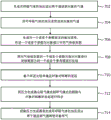
Fig. 7 illustrates an exemplary flow chart of a process for cough synchronization implemented on the system 10. The operations of the illustrated processes presented below are intended to be illustrative. In some embodiments, the process may be accomplished with one or more additional operations not described, or without one or more of the operations discussed. Additionally, the order of the operations of the process illustrated in FIG. 7 and described below is not intended to be limiting.
At operation 702, a pressurized flow of breathable gas is generated for delivery to the airway of a subject. In some embodiments, operation 702 is performed by a pressure generator that is the same as or similar to pressure generator 14 (shown in fig. 1 and described herein).
At operation 704, the pressurized flow of breathable gas is delivered to the airway of the subject. In some embodiments, operation 704 is performed by an object interface that is the same as or similar to object interface 16 (shown in fig. 1 and described herein).
At operation 706, an output signal is generated that relates to one or more parameters associated with the gas in the subject interface. In some embodiments, operation 706 is performed by a sensor that is the same as or similar to sensor 18 (shown in fig. 1 and described herein).
At operation 708, one or more parameters associated with the gas in the subject interface are compared to one or more reference values indicative of a cough effort made by the subject. In some embodiments, operation 708 is performed by a parameter analysis component that is the same as or similar to parameter analysis component 42 (shown in fig. 1 and described herein).
At operation 710, an onset of a cough by the subject is determined based on the comparison. In some embodiments, operation 710 is performed by a decision component that is the same as or similar to decision component 50 (shown in fig. 1 and described herein).
At operation 712, the transition of the pressure generator from the inhalation mode to the exhalation mode is synchronized with the initiation of a cough by the subject. In some embodiments, operation 712 is performed by a synchronization component that is the same as or similar to synchronization component 52 (shown in fig. 1 and described herein).
At operation 714, the pressure generator is controlled to generate the pressurized flow of breathable gas for delivery to the airway to exhale the subject. In some embodiments, operation 714 is performed by a control component that is the same as or similar to control component 40 (shown in fig. 1 and described herein).
Fig. 8 illustrates another exemplary flow chart of a process for cough synchronization. It should be appreciated that the operations of the illustrated process presented below are intended to be illustrative. In some embodiments, the process may be accomplished with one or more additional operations not described, or without one or more of the operations discussed. Additionally, the order of the operations of the process illustrated in FIG. 8 and described below is not intended to be limiting.
At operation 802, a cough sync mode is enabled. In some embodiments, operation 802 is performed according to input received at a user interface that is the same as or similar to user interface 22 (shown in fig. 1 and described herein), and operation 802 is processed by a control component that is the same as or similar to control component 40 (shown in fig. 1 and described herein).
At operation 804, a triggering method and one or more preset values are selected. In some embodiments, operation 804 is performed in accordance with input received at a user interface that is the same as or similar to user interface 22 (shown in fig. 1 and described herein), and operation 802 is processed by a control component that is the same as or similar to control component 40 (shown in fig. 1 and described herein).
At operation 806, an inspiratory cycle is initiated. In some embodiments, operation 806 is performed by a pressure generator that is the same as or similar to pressure generator 14 (shown in fig. 1 and described herein).
At operation 808, a time interval of 500 milliseconds is imposed at the end of the inspiration period to prevent false triggering of cough synchronization. In some embodiments, operation 808 is performed by a control component that is the same as or similar to control component 40 (shown in fig. 1 and described herein).
At operation 810, a decision is made whether the subject initiated a cough based on a comparison of a pressure level associated with gas in the subject interface to a preset pressure level value. In some embodiments, operation 810 is performed by a pressure analysis component that is the same as or similar to pressure analysis component 46 (shown in fig. 1 and described herein).
At operation 812, a decision is made whether the subject initiated a cough based on a comparison of the flow rate associated with the gas in the subject interface to a preset flow rate value. In some embodiments, operation 812 is performed by a traffic analysis component that is the same as or similar to traffic analysis component 44 (shown in fig. 1 and described herein).
At operation 814, a decision is made whether the subject initiated a cough based on a comparison of the volume level associated with the gas in the subject interface to a preset volume level value. In some embodiments, operation 814 is performed by a volume analysis component that is the same as or similar to volume analysis component 48 (shown in fig. 1 and described herein).
At operation 816, a decision is made whether the subject initiated a cough based on a comparison of the pressure level associated with the gas in the subject interface to a preset pressure level value and a comparison of the flow rate associated with the gas in the subject interface to a preset flow rate value. In some embodiments, operation 816 is performed by a pressure analysis component that is the same as or similar to pressure analysis component 46 (shown in fig. 1 and described herein) and a flow analysis component that is the same as or similar to flow analysis component 44.
At operation 818, a decision is made whether the subject initiated a cough based on a comparison of a pressure waveform slope associated with gas in the subject interface to a preset pressure waveform slope value. In some embodiments, operation 810 is performed by a pressure analysis component that is the same as or similar to pressure analysis component 46 (shown in fig. 1 and described herein).
At operation 820, a decision is made whether the subject initiated a cough based on a comparison of a flow rate slope associated with the gas in the subject interface to a preset flow slope value. In some embodiments, operation 812 is performed by a traffic analysis component that is the same as or similar to traffic analysis component 44 (shown in fig. 1 and described herein).
At operation 822, a decision is made whether the subject initiated a cough based on whether the duration of the observed change in the measurements related to one or more parameters associated with the gas in the subject interface exceeds a preset time value. In some embodiments, operation 822 is performed by one or more of a flow analysis component, a pressure analysis component, and a volume analysis component that are the same as or similar to flow analysis component 44, pressure analysis component 46, and volume analysis component 48 (shown in fig. 1 and described herein), respectively.
At operation 824, an inspiratory cycle is initiated. In some embodiments, operation 806 is performed by a pressure generator that is the same as or similar to pressure generator 14 (shown in fig. 1 and described herein).
In the claims, any reference signs placed between parentheses shall not be construed as limiting the claim. The word "comprising" or "comprises", does not exclude the presence of elements or steps other than those listed in a claim. In a device claim enumerating several means, several of these means may be embodied by one and the same item of hardware. Although specific elements are recited in mutually different dependent claims, this does not indicate that a combination of these elements cannot be used.
Although the description provided above is for the purpose of providing details for the purpose of illustration based on what is currently considered to be the most preferred and practical embodiments, it is to be understood that such details are solely for that purpose and that the disclosure is not limited to the specifically disclosed embodiments, but, on the contrary, is intended to cover modifications and equivalent arrangements that are within the scope of the appended claims. For example, it is to be understood that the present disclosure contemplates that, to the extent possible, one or more features of any embodiment can be combined with one or more features of any other embodiment.
Claims (11)
1. A mechanical inhale-exhale system (10), the system comprising:
a pressure generator (14) configured to generate a pressurized flow of breathable gas for delivery to the airway of a subject (12), the pressure generator (14) configured to operate in an inspiratory mode and an expiratory mode;
one or more sensors (18) configured to generate output signals related to one or more parameters associated with gas in the system, and the system is characterized by:
one or more processors (20) operatively connected to the one or more sensors to receive the output signals and configured to:
determining, during the inhalation mode, an initiation of a cough by the subject based on a comparison of the one or more parameters associated with the gas to one or more thresholds;
synchronizing a transition of the pressure generator from the inhalation mode to the exhalation mode with the initiation of the cough by the subject without manual configuration; and is
Controlling generation of the pressurized flow of breathable gas and delivery of the pressurized flow of breathable gas to the airway of the subject in the expiratory mode to exhale the subject.
2. The system of claim 1, wherein the one or more processors (20) are further configured (812) to:
comparing the flow rate of the gas to a flow rate threshold; and is
Determining that the subject initiated a cough when the flow rate of the gas exceeds the flow rate threshold.
3. The system of claim 1, wherein the one or more processors (20) are further configured (810) to:
comparing the pressure level of the gas to a pressure level threshold; and is
Determining that the subject initiated a cough when the pressure level of the gas exceeds the pressure level threshold.
4. The system of claim 1, wherein the one or more processors (20) are further configured (814) to:
comparing the volume level of the gas to a volume level threshold; and is
Determining that the subject initiated a cough when the volume level of the gas is less than the volume level threshold.
5. The system according to claim 1, wherein the one or more processors (20) are further configured (816) to:
comparing the pressure level of the gas to a pressure level threshold;
comparing the flow rate of the gas to a flow rate threshold; and is
Determining that the subject initiated a cough when the pressure level of the gas exceeds the pressure level threshold and the flow rate of the gas exceeds the flow rate threshold.
6. The system according to claim 1, wherein the one or more processors (20) are further configured to: determining the onset of cough by the subject based on a duration of time for which a change relating to one or more parameters associated with the gas exceeds a preset time value.
7. A method of cough synchronization in a mechanical inhale-exhale system (10), the method comprising:
generating (702) a pressurized flow of breathable gas to be delivered to the airway of a subject in an inspiratory mode and an expiratory mode;
generating (706) an output signal related to one or more parameters associated with a gas in the system;
determining (710), during the inhalation mode, an onset of a cough by the subject based on a comparison of the one or more parameters associated with the gas to one or more thresholds; and is
Synchronizing (712) a transition of pressure generation from the inhalation mode to the exhalation mode with the initiation of the cough by the subject without manual configuration.
8. The method of claim 7, further comprising:
comparing (812) the flow rate of the gas to a flow rate threshold; and is
Determining that the subject initiated a cough when the flow rate of the gas exceeds the flow rate threshold.
9. The method of claim 7, further comprising:
comparing (810) a pressure level of the gas to a pressure level threshold; and is
Determining that the subject initiated a cough when the pressure level of the gas exceeds the pressure level threshold.
10. The method of claim 7, further comprising:
comparing (814) the volume level of the gas to a volume level threshold; and is
Determining that the subject initiated a cough when the volume level of the gas is less than the volume level threshold.
11. The method of claim 7, further comprising:
comparing (816) a pressure level of the gas to a pressure level threshold;
comparing the flow rate of the gas to a flow rate threshold; and is
Determining that the subject initiated a cough when the pressure level of the gas exceeds the pressure level threshold and the flow rate of the gas in the subject interface exceeds the flow rate threshold.
Applications Claiming Priority (5)
| Application Number | Priority Date | Filing Date | Title |
|---|---|---|---|
| US201562210111P | 2015-08-26 | 2015-08-26 | |
| US62/210,111 | 2015-08-26 | ||
| EP15188078 | 2015-10-02 | ||
| EP15188078.8 | 2015-10-02 | ||
| PCT/EP2016/070209 WO2017032882A1 (en) | 2015-08-26 | 2016-08-26 | Mechanical in-exsufflation |
Publications (2)
| Publication Number | Publication Date |
|---|---|
| CN107949411A CN107949411A (en) | 2018-04-20 |
| CN107949411B true CN107949411B (en) | 2021-05-28 |
Family
ID=54256621
Family Applications (1)
| Application Number | Title | Priority Date | Filing Date |
|---|---|---|---|
| CN201680049725.7A Active CN107949411B (en) | 2015-08-26 | 2016-08-26 | Mechanical inspiration-expiration |
Country Status (5)
| Country | Link |
|---|---|
| US (1) | US11433200B2 (en) |
| EP (1) | EP3341061B1 (en) |
| JP (1) | JP6960905B2 (en) |
| CN (1) | CN107949411B (en) |
| WO (1) | WO2017032882A1 (en) |
Families Citing this family (9)
| Publication number | Priority date | Publication date | Assignee | Title |
|---|---|---|---|---|
| KR101606681B1 (en) * | 2016-01-13 | 2016-03-28 | (주)서일퍼시픽 | Portable cough stimulating device |
| DE102016013138B4 (en) * | 2016-11-07 | 2018-09-27 | Drägerwerk AG & Co. KGaA | Medical device and method for determining operating situations in a medical device |
| WO2019096714A1 (en) | 2017-11-17 | 2019-05-23 | Koninklijke Philips N.V. | Cough detection in a respiratory support system |
| CN111888596B (en) * | 2018-05-02 | 2022-04-05 | 北京雅果科技有限公司 | Noninvasive ventilator |
| CN110038198B (en) * | 2019-05-07 | 2021-09-21 | 濡新(北京)科技发展有限公司 | Closed-loop expectoration method and system for automatically titrating expectoration pressure |
| CN110038199B (en) * | 2019-05-07 | 2021-09-24 | 濡新(北京)科技发展有限公司 | Online synchronous expectoration method and system |
| CN110101945B (en) * | 2019-05-07 | 2022-09-02 | 濡新(北京)科技发展有限公司 | Synchronous automatic expectoration method and system |
| FR3125969B1 (en) * | 2021-08-04 | 2023-07-21 | Eove | Cough device with display of insufflated and target gas volumes |
| CN113763985B (en) * | 2021-10-15 | 2024-04-02 | 广州蓝仕威克医疗科技有限公司 | Device based on voice recognition physiological phenomenon |
Citations (10)
| Publication number | Priority date | Publication date | Assignee | Title |
|---|---|---|---|---|
| US20050034721A1 (en) * | 2003-08-11 | 2005-02-17 | Lutz Freitag | Tracheal catheter and prosthesis and method of respiratory support of a patient |
| CN1849150A (en) * | 2003-09-08 | 2006-10-18 | J.H.埃默森公司 | Insufflation-exsufflation system with percussive assist for removal of broncho-pulmonary secretions |
| CN1901959A (en) * | 2003-12-29 | 2007-01-24 | 雷斯梅德有限公司 | Mechanical ventilation in the presence of sleep disordered breathing |
| US20070199566A1 (en) * | 2006-02-02 | 2007-08-30 | Be Eri Eliezer | Respiratory apparatus |
| US20080110461A1 (en) * | 2004-10-20 | 2008-05-15 | Resmed Limited | Method and Apparatus For Detecting Ineffective Inspiratory Efforts and Improving Patient-Ventilator Interaction |
| CN102481426A (en) * | 2009-07-24 | 2012-05-30 | 皇家飞利浦电子股份有限公司 | Device and method for assisting a cough |
| CN103282072A (en) * | 2010-12-21 | 2013-09-04 | 皇家飞利浦电子股份有限公司 | System and method for inexsufflating a subject |
| CN103619392A (en) * | 2011-06-29 | 2014-03-05 | 皇家飞利浦有限公司 | Method and apparatus for assisting airway clearance |
| CN103933648A (en) * | 2014-03-26 | 2014-07-23 | 北京雅果科技有限公司 | Diaphragm muscle stimulation inspiration and expiration system |
| CN104334080A (en) * | 2012-05-22 | 2015-02-04 | 皇家飞利浦有限公司 | Cough assistance and measurement system and method cross-reference to related applications |
Family Cites Families (11)
| Publication number | Priority date | Publication date | Assignee | Title |
|---|---|---|---|---|
| US5277196A (en) * | 1992-03-31 | 1994-01-11 | The United States Of America As Represented By The Department Of Health And Human Services | Portable spirometer with improved accuracy |
| US7104962B2 (en) * | 2003-06-24 | 2006-09-12 | Buxco Electronics, Inc. | Cough/sneeze analyzer and method |
| EP1933912B1 (en) | 2005-09-26 | 2013-07-24 | Innovent Medical Solutions, Inc. | Combined ventilator inexsufflator |
| JP2007105161A (en) * | 2005-10-12 | 2007-04-26 | Konica Minolta Medical & Graphic Inc | Cough detector and cough detection method |
| JP5702732B2 (en) * | 2008-11-19 | 2015-04-15 | コーニンクレッカ フィリップス エヌ ヴェ | Blow-in delivery system |
| US8539952B2 (en) | 2011-05-13 | 2013-09-24 | Hill-Rom Services Pte. Ltd. | Mechanical insufflation/exsufflation airway clearance apparatus |
| WO2013118061A1 (en) * | 2012-02-08 | 2013-08-15 | Koninklijke Philips N.V. | Method and apparatus for increasing cough flow |
| US10137262B2 (en) | 2012-08-20 | 2018-11-27 | Koninklijke Philips N.V. | Synchronizing mechanical in-exsufflation and diaphragmatic pacing |
| US9795752B2 (en) * | 2012-12-03 | 2017-10-24 | Mhs Care-Innovation, Llc | Combination respiratory therapy device, system, and method |
| US9901299B2 (en) * | 2013-12-09 | 2018-02-27 | Yeda Research And Development Co. Ltd. | Activating functional electrical stimulation of abdominal muscles to assist coughing |
| JP6644778B2 (en) * | 2014-10-31 | 2020-02-12 | コーニンクレッカ フィリップス エヌ ヴェKoninklijke Philips N.V. | Pressure control during increased cough flow |
-
2016
- 2016-08-26 JP JP2018507705A patent/JP6960905B2/en active Active
- 2016-08-26 EP EP16758148.7A patent/EP3341061B1/en active Active
- 2016-08-26 US US15/754,643 patent/US11433200B2/en active Active
- 2016-08-26 WO PCT/EP2016/070209 patent/WO2017032882A1/en active Application Filing
- 2016-08-26 CN CN201680049725.7A patent/CN107949411B/en active Active
Patent Citations (10)
| Publication number | Priority date | Publication date | Assignee | Title |
|---|---|---|---|---|
| US20050034721A1 (en) * | 2003-08-11 | 2005-02-17 | Lutz Freitag | Tracheal catheter and prosthesis and method of respiratory support of a patient |
| CN1849150A (en) * | 2003-09-08 | 2006-10-18 | J.H.埃默森公司 | Insufflation-exsufflation system with percussive assist for removal of broncho-pulmonary secretions |
| CN1901959A (en) * | 2003-12-29 | 2007-01-24 | 雷斯梅德有限公司 | Mechanical ventilation in the presence of sleep disordered breathing |
| US20080110461A1 (en) * | 2004-10-20 | 2008-05-15 | Resmed Limited | Method and Apparatus For Detecting Ineffective Inspiratory Efforts and Improving Patient-Ventilator Interaction |
| US20070199566A1 (en) * | 2006-02-02 | 2007-08-30 | Be Eri Eliezer | Respiratory apparatus |
| CN102481426A (en) * | 2009-07-24 | 2012-05-30 | 皇家飞利浦电子股份有限公司 | Device and method for assisting a cough |
| CN103282072A (en) * | 2010-12-21 | 2013-09-04 | 皇家飞利浦电子股份有限公司 | System and method for inexsufflating a subject |
| CN103619392A (en) * | 2011-06-29 | 2014-03-05 | 皇家飞利浦有限公司 | Method and apparatus for assisting airway clearance |
| CN104334080A (en) * | 2012-05-22 | 2015-02-04 | 皇家飞利浦有限公司 | Cough assistance and measurement system and method cross-reference to related applications |
| CN103933648A (en) * | 2014-03-26 | 2014-07-23 | 北京雅果科技有限公司 | Diaphragm muscle stimulation inspiration and expiration system |
Also Published As
| Publication number | Publication date |
|---|---|
| US20180243521A1 (en) | 2018-08-30 |
| EP3341061B1 (en) | 2022-10-12 |
| EP3341061A1 (en) | 2018-07-04 |
| WO2017032882A1 (en) | 2017-03-02 |
| JP2018525110A (en) | 2018-09-06 |
| CN107949411A (en) | 2018-04-20 |
| JP6960905B2 (en) | 2021-11-05 |
| US11433200B2 (en) | 2022-09-06 |
Similar Documents
| Publication | Publication Date | Title |
|---|---|---|
| CN107949411B (en) | Mechanical inspiration-expiration | |
| JP6416110B2 (en) | Respiratory disorder detection | |
| JP5873021B2 (en) | A suction system for removing secretions from the respiratory tract of ventilator wearers | |
| EP2654867B1 (en) | System for inexsufflating a subject | |
| EP2854918B1 (en) | In-exsufflation therapy auto-adjustment | |
| US10758157B2 (en) | Determining if airway clearance is required during respiratory therapy | |
| EP2827930B1 (en) | System for controlling insufflation pressure during inexsufflation | |
| US10881817B2 (en) | Secretion loosening and cough segmenting therapy | |
| EP2654866B1 (en) | Respiration-rate dependent respiratory assistance | |
| AU2011346629A1 (en) | System and method for inexsufflating a subject | |
| JP2015534496A (en) | Adaptive patient circuit compensation by pressure sensors in mask appliances | |
| JP2015514465A (en) | Starting pressure for the respiratory treatment device | |
| JP2016523586A (en) | Pressure support system for respiratory accumulation therapy | |
| WO2013068918A1 (en) | Systems and methods for intra-pulmonary percussive ventilation integrated in a ventilator | |
| JP6384965B2 (en) | Method and apparatus for increasing expiratory airflow | |
| US10814081B2 (en) | Detecting a malfunction during spontaneous mechanical ventilation | |
| EP3212260B1 (en) | Controlling insufflation volume during in-exsufflation |
Legal Events
| Date | Code | Title | Description |
|---|---|---|---|
| PB01 | Publication | ||
| PB01 | Publication | ||
| SE01 | Entry into force of request for substantive examination | ||
| SE01 | Entry into force of request for substantive examination | ||
| GR01 | Patent grant | ||
| GR01 | Patent grant |