JP6644778B2 - Pressure control during increased cough flow - Google Patents
Pressure control during increased cough flow Download PDFInfo
- Publication number
- JP6644778B2 JP6644778B2 JP2017522642A JP2017522642A JP6644778B2 JP 6644778 B2 JP6644778 B2 JP 6644778B2 JP 2017522642 A JP2017522642 A JP 2017522642A JP 2017522642 A JP2017522642 A JP 2017522642A JP 6644778 B2 JP6644778 B2 JP 6644778B2
- Authority
- JP
- Japan
- Prior art keywords
- subject
- pressure
- interface
- subject interface
- mode
- Prior art date
- Legal status (The legal status is an assumption and is not a legal conclusion. Google has not performed a legal analysis and makes no representation as to the accuracy of the status listed.)
- Active
Links
- 206010011224 Cough Diseases 0.000 title claims description 72
- 230000004044 response Effects 0.000 claims description 21
- 238000004891 communication Methods 0.000 claims description 13
- 239000012530 fluid Substances 0.000 claims description 6
- 238000000034 method Methods 0.000 description 18
- 238000012545 processing Methods 0.000 description 11
- 210000002345 respiratory system Anatomy 0.000 description 11
- 230000001276 controlling effect Effects 0.000 description 9
- 230000008878 coupling Effects 0.000 description 9
- 238000010168 coupling process Methods 0.000 description 9
- 238000005859 coupling reaction Methods 0.000 description 9
- 210000004072 lung Anatomy 0.000 description 9
- 230000029058 respiratory gaseous exchange Effects 0.000 description 8
- 230000028327 secretion Effects 0.000 description 8
- 230000007704 transition Effects 0.000 description 8
- NJPPVKZQTLUDBO-UHFFFAOYSA-N novaluron Chemical compound C1=C(Cl)C(OC(F)(F)C(OC(F)(F)F)F)=CC=C1NC(=O)NC(=O)C1=C(F)C=CC=C1F NJPPVKZQTLUDBO-UHFFFAOYSA-N 0.000 description 7
- 230000006870 function Effects 0.000 description 6
- 230000000977 initiatory effect Effects 0.000 description 6
- 238000004519 manufacturing process Methods 0.000 description 5
- 230000008569 process Effects 0.000 description 5
- 230000003434 inspiratory effect Effects 0.000 description 4
- 210000003097 mucus Anatomy 0.000 description 4
- 230000001105 regulatory effect Effects 0.000 description 4
- 230000000241 respiratory effect Effects 0.000 description 4
- 238000001514 detection method Methods 0.000 description 3
- 230000007246 mechanism Effects 0.000 description 3
- 238000012544 monitoring process Methods 0.000 description 3
- 210000000214 mouth Anatomy 0.000 description 3
- 201000003883 Cystic fibrosis Diseases 0.000 description 2
- 206010036790 Productive cough Diseases 0.000 description 2
- 238000007664 blowing Methods 0.000 description 2
- 238000004590 computer program Methods 0.000 description 2
- 238000005516 engineering process Methods 0.000 description 2
- 210000004704 glottis Anatomy 0.000 description 2
- 230000004118 muscle contraction Effects 0.000 description 2
- 230000010355 oscillation Effects 0.000 description 2
- 238000002360 preparation method Methods 0.000 description 2
- 230000002685 pulmonary effect Effects 0.000 description 2
- 208000023504 respiratory system disease Diseases 0.000 description 2
- 208000034309 Bacterial disease carrier Diseases 0.000 description 1
- 208000006545 Chronic Obstructive Pulmonary Disease Diseases 0.000 description 1
- 208000000059 Dyspnea Diseases 0.000 description 1
- 206010013975 Dyspnoeas Diseases 0.000 description 1
- 206010033799 Paralysis Diseases 0.000 description 1
- 230000002159 abnormal effect Effects 0.000 description 1
- 230000002776 aggregation Effects 0.000 description 1
- 238000004220 aggregation Methods 0.000 description 1
- 208000006673 asthma Diseases 0.000 description 1
- 230000008901 benefit Effects 0.000 description 1
- 230000004397 blinking Effects 0.000 description 1
- 238000009530 blood pressure measurement Methods 0.000 description 1
- 230000008859 change Effects 0.000 description 1
- 230000001419 dependent effect Effects 0.000 description 1
- 239000013536 elastomeric material Substances 0.000 description 1
- 230000005713 exacerbation Effects 0.000 description 1
- 230000001771 impaired effect Effects 0.000 description 1
- 230000010365 information processing Effects 0.000 description 1
- 238000005259 measurement Methods 0.000 description 1
- 238000012986 modification Methods 0.000 description 1
- 230000004048 modification Effects 0.000 description 1
- 230000000737 periodic effect Effects 0.000 description 1
- 230000002269 spontaneous effect Effects 0.000 description 1
- 210000003802 sputum Anatomy 0.000 description 1
- 208000024794 sputum Diseases 0.000 description 1
- 238000003860 storage Methods 0.000 description 1
- 239000000126 substance Substances 0.000 description 1
- 229940006076 viscoelastic substance Drugs 0.000 description 1
- 239000003190 viscoelastic substance Substances 0.000 description 1
- XLYOFNOQVPJJNP-UHFFFAOYSA-N water Substances O XLYOFNOQVPJJNP-UHFFFAOYSA-N 0.000 description 1
Images


Classifications
-
- A—HUMAN NECESSITIES
- A61—MEDICAL OR VETERINARY SCIENCE; HYGIENE
- A61B—DIAGNOSIS; SURGERY; IDENTIFICATION
- A61B5/00—Measuring for diagnostic purposes; Identification of persons
- A61B5/48—Other medical applications
- A61B5/4836—Diagnosis combined with treatment in closed-loop systems or methods
-
- A—HUMAN NECESSITIES
- A61—MEDICAL OR VETERINARY SCIENCE; HYGIENE
- A61B—DIAGNOSIS; SURGERY; IDENTIFICATION
- A61B5/00—Measuring for diagnostic purposes; Identification of persons
- A61B5/08—Detecting, measuring or recording devices for evaluating the respiratory organs
- A61B5/0823—Detecting or evaluating cough events
-
- A—HUMAN NECESSITIES
- A61—MEDICAL OR VETERINARY SCIENCE; HYGIENE
- A61B—DIAGNOSIS; SURGERY; IDENTIFICATION
- A61B5/00—Measuring for diagnostic purposes; Identification of persons
- A61B5/08—Detecting, measuring or recording devices for evaluating the respiratory organs
- A61B5/087—Measuring breath flow
-
- A—HUMAN NECESSITIES
- A61—MEDICAL OR VETERINARY SCIENCE; HYGIENE
- A61M—DEVICES FOR INTRODUCING MEDIA INTO, OR ONTO, THE BODY; DEVICES FOR TRANSDUCING BODY MEDIA OR FOR TAKING MEDIA FROM THE BODY; DEVICES FOR PRODUCING OR ENDING SLEEP OR STUPOR
- A61M16/00—Devices for influencing the respiratory system of patients by gas treatment, e.g. mouth-to-mouth respiration; Tracheal tubes
- A61M16/0003—Accessories therefor, e.g. sensors, vibrators, negative pressure
- A61M16/0006—Accessories therefor, e.g. sensors, vibrators, negative pressure with means for creating vibrations in patients' airways
-
- A—HUMAN NECESSITIES
- A61—MEDICAL OR VETERINARY SCIENCE; HYGIENE
- A61M—DEVICES FOR INTRODUCING MEDIA INTO, OR ONTO, THE BODY; DEVICES FOR TRANSDUCING BODY MEDIA OR FOR TAKING MEDIA FROM THE BODY; DEVICES FOR PRODUCING OR ENDING SLEEP OR STUPOR
- A61M16/00—Devices for influencing the respiratory system of patients by gas treatment, e.g. mouth-to-mouth respiration; Tracheal tubes
- A61M16/0051—Devices for influencing the respiratory system of patients by gas treatment, e.g. mouth-to-mouth respiration; Tracheal tubes with alarm devices
-
- A—HUMAN NECESSITIES
- A61—MEDICAL OR VETERINARY SCIENCE; HYGIENE
- A61M—DEVICES FOR INTRODUCING MEDIA INTO, OR ONTO, THE BODY; DEVICES FOR TRANSDUCING BODY MEDIA OR FOR TAKING MEDIA FROM THE BODY; DEVICES FOR PRODUCING OR ENDING SLEEP OR STUPOR
- A61M16/00—Devices for influencing the respiratory system of patients by gas treatment, e.g. mouth-to-mouth respiration; Tracheal tubes
- A61M16/0057—Pumps therefor
- A61M16/0066—Blowers or centrifugal pumps
- A61M16/0069—Blowers or centrifugal pumps the speed thereof being controlled by respiratory parameters, e.g. by inhalation
-
- A—HUMAN NECESSITIES
- A61—MEDICAL OR VETERINARY SCIENCE; HYGIENE
- A61M—DEVICES FOR INTRODUCING MEDIA INTO, OR ONTO, THE BODY; DEVICES FOR TRANSDUCING BODY MEDIA OR FOR TAKING MEDIA FROM THE BODY; DEVICES FOR PRODUCING OR ENDING SLEEP OR STUPOR
- A61M16/00—Devices for influencing the respiratory system of patients by gas treatment, e.g. mouth-to-mouth respiration; Tracheal tubes
- A61M16/021—Devices for influencing the respiratory system of patients by gas treatment, e.g. mouth-to-mouth respiration; Tracheal tubes operated by electrical means
- A61M16/022—Control means therefor
- A61M16/024—Control means therefor including calculation means, e.g. using a processor
-
- A—HUMAN NECESSITIES
- A61—MEDICAL OR VETERINARY SCIENCE; HYGIENE
- A61M—DEVICES FOR INTRODUCING MEDIA INTO, OR ONTO, THE BODY; DEVICES FOR TRANSDUCING BODY MEDIA OR FOR TAKING MEDIA FROM THE BODY; DEVICES FOR PRODUCING OR ENDING SLEEP OR STUPOR
- A61M16/00—Devices for influencing the respiratory system of patients by gas treatment, e.g. mouth-to-mouth respiration; Tracheal tubes
- A61M16/20—Valves specially adapted to medical respiratory devices
- A61M16/201—Controlled valves
- A61M16/202—Controlled valves electrically actuated
-
- A—HUMAN NECESSITIES
- A61—MEDICAL OR VETERINARY SCIENCE; HYGIENE
- A61M—DEVICES FOR INTRODUCING MEDIA INTO, OR ONTO, THE BODY; DEVICES FOR TRANSDUCING BODY MEDIA OR FOR TAKING MEDIA FROM THE BODY; DEVICES FOR PRODUCING OR ENDING SLEEP OR STUPOR
- A61M16/00—Devices for influencing the respiratory system of patients by gas treatment, e.g. mouth-to-mouth respiration; Tracheal tubes
- A61M16/20—Valves specially adapted to medical respiratory devices
- A61M16/208—Non-controlled one-way valves, e.g. exhalation, check, pop-off non-rebreathing valves
- A61M16/209—Relief valves
-
- A—HUMAN NECESSITIES
- A61—MEDICAL OR VETERINARY SCIENCE; HYGIENE
- A61B—DIAGNOSIS; SURGERY; IDENTIFICATION
- A61B5/00—Measuring for diagnostic purposes; Identification of persons
- A61B5/08—Detecting, measuring or recording devices for evaluating the respiratory organs
- A61B5/091—Measuring volume of inspired or expired gases, e.g. to determine lung capacity
-
- A—HUMAN NECESSITIES
- A61—MEDICAL OR VETERINARY SCIENCE; HYGIENE
- A61M—DEVICES FOR INTRODUCING MEDIA INTO, OR ONTO, THE BODY; DEVICES FOR TRANSDUCING BODY MEDIA OR FOR TAKING MEDIA FROM THE BODY; DEVICES FOR PRODUCING OR ENDING SLEEP OR STUPOR
- A61M16/00—Devices for influencing the respiratory system of patients by gas treatment, e.g. mouth-to-mouth respiration; Tracheal tubes
- A61M16/20—Valves specially adapted to medical respiratory devices
- A61M16/208—Non-controlled one-way valves, e.g. exhalation, check, pop-off non-rebreathing valves
-
- A—HUMAN NECESSITIES
- A61—MEDICAL OR VETERINARY SCIENCE; HYGIENE
- A61M—DEVICES FOR INTRODUCING MEDIA INTO, OR ONTO, THE BODY; DEVICES FOR TRANSDUCING BODY MEDIA OR FOR TAKING MEDIA FROM THE BODY; DEVICES FOR PRODUCING OR ENDING SLEEP OR STUPOR
- A61M16/00—Devices for influencing the respiratory system of patients by gas treatment, e.g. mouth-to-mouth respiration; Tracheal tubes
- A61M16/0003—Accessories therefor, e.g. sensors, vibrators, negative pressure
- A61M2016/0027—Accessories therefor, e.g. sensors, vibrators, negative pressure pressure meter
-
- A—HUMAN NECESSITIES
- A61—MEDICAL OR VETERINARY SCIENCE; HYGIENE
- A61M—DEVICES FOR INTRODUCING MEDIA INTO, OR ONTO, THE BODY; DEVICES FOR TRANSDUCING BODY MEDIA OR FOR TAKING MEDIA FROM THE BODY; DEVICES FOR PRODUCING OR ENDING SLEEP OR STUPOR
- A61M2205/00—General characteristics of the apparatus
- A61M2205/33—Controlling, regulating or measuring
- A61M2205/3331—Pressure; Flow
- A61M2205/3334—Measuring or controlling the flow rate
-
- A—HUMAN NECESSITIES
- A61—MEDICAL OR VETERINARY SCIENCE; HYGIENE
- A61M—DEVICES FOR INTRODUCING MEDIA INTO, OR ONTO, THE BODY; DEVICES FOR TRANSDUCING BODY MEDIA OR FOR TAKING MEDIA FROM THE BODY; DEVICES FOR PRODUCING OR ENDING SLEEP OR STUPOR
- A61M2205/00—General characteristics of the apparatus
- A61M2205/33—Controlling, regulating or measuring
- A61M2205/3365—Rotational speed
-
- A—HUMAN NECESSITIES
- A61—MEDICAL OR VETERINARY SCIENCE; HYGIENE
- A61M—DEVICES FOR INTRODUCING MEDIA INTO, OR ONTO, THE BODY; DEVICES FOR TRANSDUCING BODY MEDIA OR FOR TAKING MEDIA FROM THE BODY; DEVICES FOR PRODUCING OR ENDING SLEEP OR STUPOR
- A61M2205/00—General characteristics of the apparatus
- A61M2205/50—General characteristics of the apparatus with microprocessors or computers
- A61M2205/502—User interfaces, e.g. screens or keyboards
-
- A—HUMAN NECESSITIES
- A61—MEDICAL OR VETERINARY SCIENCE; HYGIENE
- A61M—DEVICES FOR INTRODUCING MEDIA INTO, OR ONTO, THE BODY; DEVICES FOR TRANSDUCING BODY MEDIA OR FOR TAKING MEDIA FROM THE BODY; DEVICES FOR PRODUCING OR ENDING SLEEP OR STUPOR
- A61M2230/00—Measuring parameters of the user
- A61M2230/40—Respiratory characteristics
Landscapes
- Health & Medical Sciences (AREA)
- Life Sciences & Earth Sciences (AREA)
- Pulmonology (AREA)
- General Health & Medical Sciences (AREA)
- Veterinary Medicine (AREA)
- Biomedical Technology (AREA)
- Heart & Thoracic Surgery (AREA)
- Public Health (AREA)
- Engineering & Computer Science (AREA)
- Animal Behavior & Ethology (AREA)
- Surgery (AREA)
- Physics & Mathematics (AREA)
- Biophysics (AREA)
- Pathology (AREA)
- Medical Informatics (AREA)
- Molecular Biology (AREA)
- Hematology (AREA)
- Anesthesiology (AREA)
- Emergency Medicine (AREA)
- Physiology (AREA)
- Measurement Of The Respiration, Hearing Ability, Form, And Blood Characteristics Of Living Organisms (AREA)
- Safety Valves (AREA)
- Magnetically Actuated Valves (AREA)
Description
関連出願の相互参照
[1] 本出願は、2014年10月31日に出願された米国仮特許出願第62/073,487号についての米国特許法第119条(e)による優先権の利益を主張しており、この仮特許出願の内容は、参照により本明細書に援用される。
Cross-reference of related applications
[1] This application claims the benefit of priority under 35 U.S.C. 119 (e) to U.S. Provisional Patent Application No. 62 / 073,487, filed October 31, 2014, The contents of this provisional patent application are incorporated herein by reference.
[2] 本開示は、被験体の咳嗽流の増大の間の圧力を制御するための方法及び装置に関する。 [2] The present disclosure relates to methods and apparatus for controlling pressure during an increase in cough flow in a subject.
[3] いくつかの呼吸器疾患(例えば、慢性閉塞性肺疾患(COPD)、喘息、嚢胞性線維症(CF)など)は、患者の呼吸器系への流体又は粘弾性物質(すなわち、粘液又は分泌物)の蓄積によって特徴付けられる。呼吸器系における粘液量の増加(過分泌及び/又は肺から分泌物を取り除く能力の低下による)は、多くの場合、呼吸困難と関係し、呼吸器系の気胞の完全な閉塞に繋がり得る。過分泌の臨床的結果は、ガス交換の低下及び粘液クリアランスの障害であり、細菌のコロニー化及び関連する悪化を増大する。分泌物の過剰分は、咳嗽又は咽喉からの痰の喀出により取り除かれ得る。 [3] Some respiratory diseases (eg, chronic obstructive pulmonary disease (COPD), asthma, cystic fibrosis (CF), etc.) cause fluid or viscoelastic substances (ie, mucus) to the patient's respiratory system. Or secretions). Increased mucus mass in the respiratory system (due to hypersecretion and / or reduced ability to clear secretions from the lungs) is often associated with dyspnea and can lead to complete obstruction of air bubbles in the respiratory system. The clinical consequences of hypersecretion are reduced gas exchange and impaired mucus clearance, increasing bacterial colonization and associated exacerbations. Excess secretions can be removed by coughing or expectoration of sputum from the throat.
[4] そのような肺粘液を追い出すための自然現象が咳である。咳嗽は、吸息相、声門の閉鎖、筋収縮による肺内の圧力の増加、その後に続く呼息相からなり、呼息相において声門が開放され、気道壁上に存在するあらゆる物質を拾い、それを口腔に向かって上方に進ませることが意図される、高速の気流を結果としてもたらす。数多くの状況において、自然咳嗽は、これらの分泌物を喀出するには不十分である。例えば、咳嗽は、十分な咳嗽流を生成することができないこと、肺内の分泌物の異常特性、又はその両方の組み合わせのため、依然として効果がない。多くの呼吸器疾患において、気流を発生させることができないことは、咳嗽運動の間の気道の虚脱と関係がある。 [4] A natural phenomenon that drives out such pulmonary mucus is cough. Cough consists of an inspiratory phase, closing of the glottis, an increase in pressure in the lungs due to muscle contraction, followed by an expiratory phase, during which the glottis is opened, picking up any substances present on the airway walls, The result is a high velocity air stream intended to advance it upwards into the oral cavity. In many situations, spontaneous cough is insufficient to expectorate these secretions. For example, cough is still ineffective due to its inability to produce sufficient cough flow, abnormal properties of secretions in the lungs, or a combination of both. In many respiratory diseases, the inability to generate airflow is associated with airway collapse during coughing exercise.
[5] 患者が分泌物を喀出するのを助ける補助手段が開発されてきた。例えば、機械的強制吸息(insufflation)及び強制呼息(exsufflation)により患者の咳嗽流を増加させるための様々なシステムが知られている。従来の強制呼息は、一般的に、被験体の単一の呼息の間に単一の強制呼息事象を用いて成し遂げられる。呼吸回路がデバイスにより加圧され得、その後、デバイスが気道に負圧を印加し、大きな呼息流を生じさせる。被験体の気道内で徐々に増加する分泌物が、ガスと共に追い出される。 [5] Aids have been developed to help patients expectorate secretions. For example, various systems are known for increasing a patient's cough flow by mechanical insufflation and exsufflation. Conventional forced expiration is typically accomplished using a single forced expiration event during a single exhalation of the subject. The breathing circuit may be pressurized by the device, after which the device applies a negative pressure to the airways, creating a large expiratory flow. A gradually increasing secretion in the subject's airways is expelled with the gas.
[6] 患者の咳嗽流を増加させるための別のシステムは、例えば、単一の咳嗽が、呼気路内に位置決めされた弁の間欠的な開閉によって複数の小規模な咳嗽に分割されることとなるように、呼息の間において圧力振動を生成することを意図した受動可変流れ抵抗器を使用する。例えば、そのようなシステムは、咳嗽流を周期的に遮断し、咳嗽の間の気道内の圧力を周期的に高め、気道が開いたままであることを可能にし、咳嗽体積が最大化されることを可能にするように構成される。 [6] Another system for increasing a patient's cough flow is, for example, that a single cough is divided into multiple small coughs by intermittent opening and closing of a valve positioned in the respiratory tract Use a passive variable flow resistor intended to generate pressure oscillations during expiration. For example, such a system would periodically block cough flow, periodically increase airway pressure during coughing, allow the airway to remain open, and maximize cough volume Is configured to allow for
そのようなシステムにおいては、弁が閉じると肺又は呼吸器系内の圧力が咳嗽の間の継続的な筋収縮により急速に上昇し得、弁が開くと肺圧力が周囲圧力近くまで急速に低下し得る。 In such a system, pressure in the lungs or respiratory system can increase rapidly due to continuous muscle contraction during coughing when the valve closes, and pulmonary pressure drops rapidly to near ambient pressure when the valve opens. I can do it.
[7] したがって、本開示の1つ以上の態様は、被験体の咳嗽流の増大の間の圧力を制御するように構成されたシステムに関する。当該システムは、被験体の気道と連通するように構成された被験体インターフェースと;(i)ガスが実質的に全く被験体インターフェースを介して被験体の気道とやりとりされなくなるように被験体インターフェースが閉鎖される第1のモードと、(ii)被験体の気道から被験体インターフェースを通ってガスが排出されることを可能にするために被験体インターフェースが開放される第2のモードとにおいて動作する、被験体インターフェースを介して流れを選択的に制御するように構成された圧力調整器と;被験体の個々の呼息ごとに一連の強制呼息事象を生じさせるために、被験体の個々の呼息の間において圧力調整器が第1のモードと第2のモードとの間でトグル式に切り換えられることとなるように圧力調整器を操作するように構成された制御器と;被験体インターフェースと関係づけられ、咳嗽流の増大の間において被験体インターフェース内の圧力を所望の範囲内に維持するように被験体インターフェース内の圧力が所定の閾値を超えたことに応じて被験体インターフェースを開放し、そこからガスを放出するように構成された圧力除去弁とを含む。 [7] Accordingly, one or more aspects of the present disclosure relate to a system configured to control pressure during an increase in a subject's cough flow. The system includes a subject interface configured to communicate with a subject's airway; and (i) a subject interface such that substantially no gas is exchanged with the subject's airway via the subject interface. Operate in a first mode in which the subject interface is closed and (ii) a second mode in which the subject interface is opened to allow gas to escape from the subject's airways through the subject interface. A pressure regulator configured to selectively control the flow through the subject interface; and an individual of the subject to cause a series of forced expiratory events for each individual exhalation of the subject. Operating the pressure regulator such that during exhalation the pressure regulator will be toggled between a first mode and a second mode. A configured controller; associated with the subject interface, wherein the pressure within the subject interface exceeds a predetermined threshold to maintain the pressure within the subject interface within a desired range during increased cough flow. A pressure relief valve configured to open the subject interface responsively to release gas therefrom.
[8] 本開示のさらに別の態様は、被験体の咳嗽流の増大の間の圧力を制御するための方法に関する。当該方法は、被験体インターフェースで被験体の気道と連結することと;制御器により、ガスが実質的に全く被験体インターフェースを介して被験体の気道とやりとりされなくなるように被験体インターフェースが閉鎖される第1のモードで圧力調整器を操作することと;咳嗽流の増大の間において被験体インターフェース内の圧力を所望の範囲内に維持するように被験体インターフェース内の圧力が所定の閾値を超えたことに応じて被験体インターフェースを開放し、そこからガスを放出するように圧力除去弁を操作することと;被験体による被験体インターフェースの加圧を示す情報を受信することと;単一の呼息の間に一連の強制呼息事象を生み出すために第1のモードと第2のモードとの間で圧力調整器をトグル式に切り換えることにより、一連の強制呼息事象によって被験体に強制呼息させる(exsufflate)こととを含み、第2のモードでは、被験体インターフェースは、被験体の気道から被験体インターフェースを通ってガスが排出されることを可能にするために開放される。 [8] Yet another aspect of the present disclosure relates to a method for controlling pressure during an increase in cough flow in a subject. The method includes coupling to the subject's airway at the subject interface; the controller closing the subject interface such that substantially no gas is exchanged with the subject's airway through the subject interface. Operating the pressure regulator in a first mode, wherein the pressure in the subject interface exceeds a predetermined threshold to maintain the pressure in the subject interface within a desired range during an increase in cough flow. Opening the subject interface and operating the pressure relief valve to release gas therefrom; receiving information indicative of subject pressurization of the subject interface; Toggle the pressure regulator between a first mode and a second mode to produce a series of forced expiratory events during expiration Extruding the subject with a series of forced expiratory events, wherein in the second mode the subject interface is evacuated of gas from the subject's airways through the subject interface. Opened to allow you to
[9] 本開示のなお別の態様は、被験体の咳嗽流の増大の間の圧力を制御するように構成されたシステムに関する。当該システムは、被験体の気道と連結するための手段と;(i)ガスが実質的に全く連結するための手段を介して被験体の気道とやりとりされなくなるように連結するための手段が閉鎖される第1のモードと、(ii)連結するための手段を通って被験体の気道からガスが排出されることを可能にするために連結するための手段が開放される第2のモードとにおいて動作する、連結するための手段を介して流れを選択的に制御するための手段と;所定の閾値を超えた連結するための手段内の圧力に応じて連結するための手段を開放し、そこからガスを放出する、連結するための手段内の圧力を所望の範囲内に維持するための手段と;被験体が連結するための手段を加圧したか否かを示す情報を受信するための手段と;被験体の個々の呼息ごとに一連の強制呼息事象を生じさせるために、被験体の個々の呼息の間において流れを選択的に制御するための手段が第1のモードと第2のモードとの間でトグル式に切り換えられることとなるように、流れを選択的に制御するための手段の動作を制御するための手段とを含む。 [9] Yet another aspect of the present disclosure relates to a system configured to control pressure during an increase in a subject's cough flow. The system includes means for connecting to a subject's airway; and (i) means for connecting such that gas is not communicated with the subject's airway via the means for substantially completely connecting the gas. A second mode in which the means for coupling are opened to allow gas to be exhausted from the airway of the subject through the means for coupling; Opening at the means for selectively controlling the flow via the means for coupling, operating at the means for coupling in response to the pressure in the means for coupling above a predetermined threshold; Means for maintaining the pressure in the coupling means within a desired range for releasing gas therefrom; and for receiving information indicating whether the subject has pressurized the coupling means. Means; for each individual exhalation of the subject Means for selectively controlling flow between individual exhalations of the subject are toggled between a first mode and a second mode to produce a series of forced expiration events. Means for controlling the operation of the means for selectively controlling the flow.
[10] 本開示のこれら及び他の目的、特徴及び特性、並びに操作方法、関連構成要素の機能、部分の組み合わせ、及び製造経済性は、添付の図面を参照して以下の説明及び添付の特許請求の範囲を考慮することでより明らかになるだろう。これらの図面の全てが本明細書の一部を構成し、同じ参照番号は、その様々な図において対応する部分を示す。しかしながら、これらの図面は、例示及び説明のみを目的としており、本開示の範囲を規定するものとして意図されるものではないことが明確に理解されるべきである。 [10] These and other objects, features and characteristics of the present disclosure, as well as methods of operation, functions of related components, combinations of parts, and manufacturing economics, are described below with reference to the accompanying drawings and attached patents. It will become clearer when considering the claims. All of these drawings form part of the present specification, and like reference numerals indicate corresponding parts in the various figures. However, it should be clearly understood that these drawings are for illustration and description only, and are not intended to define the scope of the present disclosure.
[17] 本明細書で使用される場合、「a」、「an」及び「the」という単数形は、文脈が明らかに別のことを指示しない限り、複数の指示対象を含む。本明細書で使用される場合、2つ以上の部分又は構成部分が「結合」されたという記載は、これらの部分が、直接的又は間接的(すなわち、つながりが生じる限りにおいて、1つ以上の中間部分又は構成部分を介して)のいずれかで接続されている又は一緒に動作することを意味するものとする。本明細書で使用される場合、「直接結合された」とは、2つの要素が互いに直接接触していることを意味する。本明細書で使用される場合、「固定的に結合された」又は「固定された」とは、2つの構成部分が、互いに対して一定の向きを維持しつつ一体となって動くように結合されていることを意味する。 [17] As used herein, the singular forms "a", "an", and "the" include plural referents unless the context clearly dictates otherwise. As used herein, a statement that two or more parts or components are "coupled" means that the parts are directly or indirectly (i.e., one or more than one (Via an intermediate part or a component) or operate together. As used herein, "directly connected" means that the two elements are in direct contact with each other. As used herein, “fixedly coupled” or “fixed” refers to the coupling of two components such that they move together while maintaining a fixed orientation relative to each other. Means that it is.
[18] 本明細書で使用される場合、「単体の」という語は、構成部分が単一の部品又はユニットとして作られることを意味する。すなわち、別個に作られ、次いで1つのユニットとして一緒に結合される部品を含む構成部分は、「単体の」構成部分又は物体ではない。本明細書で用いられる場合、2つ以上の部分又は構成部分が互いに「係合する」という記載は、それらの部分が直接又は1つ以上の中間部分若しくは構成部分を介してのいずれかで互いに力を加え合うことを意味するものとする。本明細書で用いられる場合、「数」という用語は、1又は1より大きな整数(すなわち、複数)を意味するものとする。 [18] As used herein, the term "unitary" means that the components are made as a single part or unit. That is, a component that includes components that are made separately and then joined together as a unit is not a “single” component or object. As used herein, a statement that two or more parts or components "engage" with each other means that the parts are mutually connected, either directly or through one or more intermediate parts or components. It means adding forces. As used herein, the term “number” shall mean one or an integer greater than one (ie, a plurality).
[19] 本明細書で使用される方向を示す語句(例えば、限定するものではないが、上、下、左、右、上方、下方、前方、後方、及びそれらの派生語など)は、図面に示される要素の向きに関するものであり、特許請求の範囲に明示的に記載されていない限り特許請求の範囲を限定するものではない。 [19] Directional phrases (eg, but not limited to, up, down, left, right, up, down, forward, backward, and their derivatives, etc.) as used herein are in the drawings And does not limit the claims unless expressly stated in the claims.
[20] 図1は、被験体12の咳嗽流の増大の間の圧力を制御するように構成されたシステム10の例示的な実施形態を概略的に図示している。
[20] FIG. 1 schematically illustrates an exemplary embodiment of a
[21] システム10は、被験体12の呼吸器系内の圧力が所定の閾値を超えたことに応じて被験体12の呼吸器系からガスを放出することにより、咳嗽流の増大の間において被験体12の呼吸器系内の圧力を所望の範囲内に維持するように構成される。システム10は、被験体12の呼吸器系内の圧力を除去するように、システム10の流路を通って流れるガスを、必要に応じて周囲雰囲気中に排気する又は追い出すように構成される。例えば、システム10は、被験体12の個々の呼息の間に一連の強制呼息事象を生じさせるように構成されている強制呼息弁システムに加えて二次弁システムを含む。二次弁システムにより、所定の範囲内での被験体12の呼吸器系内の圧力変化が可能になる。二次弁システムにより、空気導管により強制呼息弁システムに結合された圧力除去弁25を介して被験体12の呼吸器系内の圧力流を制御することが可能になる。二次弁システムは、咳嗽流の増大の間の被験体12の内圧を調整するように構成される。
[21] The
[22] システム10はまた、とりわけ被験体12の気道虚脱を抑えることにより、強制呼息の間の流れを増大する。システム10は、患者努力を利用してシステム10を加圧し、被験体12の個々の呼息の間に一連の強制呼息事象を生じさせる。強制呼息事象は短いパルスであり、その間に、空気が被験体12の肺から流出することが可能にされる。強制呼息の一連の強制呼息事象への分割は、呼息の間の流量を増加させる傾向があり得、且つ/又は、有効性の向上を伴って分泌物を解放し得る及び/若しくは追い出し得る。
[22] The
[23] 一部の実施形態において、システム10は、被験体12、ユーザ制御インターフェース14、被験体インターフェース16、1つ以上のセンサ18、圧力調整器20、圧力除去弁25、制御器22、及び/又は他の構成部分のうちの1つ以上を含む。
[23] In some embodiments, the
[24] ユーザ制御インターフェース14は、システム10と被験体12との間のインターフェースを提供するように構成され、これを介して、被験体12は、システム10に情報を提供し、且つシステム10から情報を受信する。これは、総称して「情報」と呼ばれるデータ、結果、及び/又は命令、並びに任意の他の伝達可能な品目が、被験体12と、被験体インターフェース16及び/又は制御器22のうちの1つ以上との間でやりとりされることを可能にする。ユーザ制御インターフェース14に含めるのに好適なインターフェースデバイスの例としては、キーパッド、ボタン、スイッチ、キーボード、つまみ、レバー、表示画面、タッチスクリーン、スピーカー、マイクロホン、表示灯、可聴警報、プリンター、触覚フィードバックデバイス、ジェスチャー認識デバイス、及び/又は他のインターフェースデバイスが挙げられる。例えば、一部の実施において、被験体12は、被験体インターフェース16内で圧力が高められていることを制御器22に連絡するためにボタンを押す。一実施形態において、ユーザ制御インターフェース14は、複数の別個のインターフェースを含む。例えば、システム10は、上述の押しボタン、及び/又は四肢の完全な物理的制御を有していないかもしれない被験体(例えば、完全又は部分麻痺の被験体)による使用のためのジェスチャー(例えば、瞬きをするなどの顔面動作)認識デバイスを用いて構成され得る。
[24] The
[25] 配線接続又は無線のいずれかの他の通信技術もまた、ユーザ制御インターフェース14として本開示により企図されることが理解されるべきである。例えば、本開示は、ユーザ制御インターフェース14が遠隔制御装置であることを企図している。この例において、被験体ユーザインターフェースの加圧を示す情報が、システム10により制御される分割された強制呼息プロセスを被験体12が開始することを可能にする制御器22に無線で送信される。ユーザ制御インターフェース14としてシステム10との使用のために適合される他の例示的な入力デバイス及び技術としては、RS−232ポート、RFリンク、IRリンク、モデム(電話、ケーブルなど)が挙げられるが、これらに限定されない。要するに、システム10と情報をやりとりするための任意の技術が、ユーザ制御インターフェース14として本開示により企図される。
[25] It should be understood that other communication technologies, either hardwired or wireless, are also contemplated by the present disclosure as
[26] 被験体インターフェース16は、被験体12の気道と連結するように構成される。被験体インターフェース16は、被験体12の気道との流体連通をもたらすように構成される。そのようなものとして、被験体インターフェース16は、導管24及び/又はインターフェース取付具26を含む。導管24は、インターフェース取付具26へ及び/又はインターフェース取付具26からガス(例えば、空気)を運び、インターフェース取付具26は、導管24を被験体12の気道と連通した状態に置く。一部の実施形態において、被験体インターフェース16は、非侵襲的である。そのようなものとして、インターフェース取付具26は、被験体12に非侵襲的に係合する。非侵襲的な係合は、被験体12の気道と被験体インターフェース16との間でガスをやりとりするために、被験体12の気道の1つ以上の外部開口部(例えば、外鼻孔及び/又は口)を囲む領域(1つ又は複数)に着脱自在に係合することを含む。非侵襲的インターフェース取付具26の一部の例としては、例えば、送風チューブ、鼻カニューレ、鼻マスク、鼻/口マスク、フルフェイスマスク、トータルフェイスマスク、又は被験体の気道とガスの流れをやりとりする他のインターフェース取付具が挙げられ得る。
[26] The
[27] センサ18は、被験体インターフェース16内のガスの1つ以上のガスパラメータに関する情報を伝達する出力信号を生成するように構成される。この1つ以上のガスパラメータは、流量、体積、圧力、温度、湿度、速度、及び/又は他のガスパラメータを含む。ガスパラメータセンサ18は、そのようなパラメータを直接(例えば、被験体インターフェース16内のガスの流れとの流体連通により)測定する1つ以上のセンサを含み得る。ガスパラメータセンサ18は、ガスの流れの1つ以上のパラメータに関する出力信号を間接的に生成する1つ以上のセンサを含み得る。例えば、センサ18のうちの1つ以上は、圧力調整器20の操作パラメータ(例えば、弁ドライバ又はモーター電流、電圧、回転速度、及び/又は他の操作パラメータ)及び/又は他のセンサに基づき出力を生成し得る。ガスパラメータセンサ18は、インターフェース取付具26と圧力調整器20との間の導管24内の(又はそれと連通している)単一の場所に図示されているが、これは、決して限定することが意図されるものではない。ガスパラメータセンサ18は、複数の場所(例えば、圧力調整器20内、インターフェース取付具26内(又はそれと連通した状態)、被験体インターフェース16上の任意の場所、及び/又はシステム10の他の場所など)に配置されたセンサを含み得る。
[27] The
[28] 圧力調整器20は、被験体インターフェース16を介して流れを選択的に制御するように構成される。圧力調整器20は、第1のモード、第2のモード、及び/又は他のモードで動作するように構成される。第1のモードでは、被験体インターフェース16は、ガスが実質的に全くそれを介して被験体12の気道とやりとりされなくなるように閉鎖される。第2のモードでは、被験体インターフェース16は、被験体12の気道から被験体インターフェース16を通ってガスが排出されることを可能にするために開放される。
[28] The
[29] 圧力調整器20の第1の動作モードにおいて、被験体12の気道と流体連通しているインターフェース取付具26と圧力調整器20との間に圧力除去弁25によって閉鎖流路が形成される。圧力調整器20の第2の動作モードにおいて、圧力調整器20は、強制呼息流路によってその閉鎖流路を周囲雰囲気に曝露するように構成される。強制呼息流路は、圧力調整器20による被験体インターフェース16から出て周囲雰囲気に向かう流路である。強制呼息流路は、被験体12の個々の呼息の間に生じさせる一連の強制呼息事象の間において、被験体12の肺から空気が流出することを可能にする。
[29] In the first mode of operation of the
[30] 一実施形態において、圧力調整器20は、吸息時間及び/又は吸息体積に基づき動作するように構成される。例えば、一実施形態において、圧力調整器20は、より長い吸息期間に応答して開くように構成される。別の実施形態において、圧力調整器20は、より短い吸息期間におけるより大きな吸息流量体積に応答して開くように構成される。
[30] In one embodiment, the
[31] 一部の実施において、圧力調整器20は、弁及び/又は別の圧力調整デバイスのうちの1つ以上を含み得る。一実施形態において、圧力調整器20は、1つ以上の弁を直列及び/又は並列に含み得る。圧力調整器20に含めるのに好適な弁及び/又は他の圧力調整デバイスの例としては、プラグ弁、ボール弁、逆止め弁、蝶形弁、ソレノイド、及び/又は他の圧力調整デバイスが挙げられ得る。上述の圧力調整デバイス及び/又は圧力調整器20に含まれ得る他の圧力調整デバイスは、液圧により、空気圧により、電気モーターにより、並びに/又は弁及び/若しくは他の圧力制御デバイスを開放及び/若しくは閉鎖するように構成された別の制御モードにより制御され得る。
[31] In some implementations, the
[32] 一部の実施において、圧力調整器20は、システム10内の1つ以上の場所に位置し得る。例えば、一実施形態において、圧力調整器20は、被験体インターフェース16のインターフェース取付具26と反対側の一端に位置し得る。第2の実施形態において、圧力調整器20は、インターフェース取付具26と導管24との間に位置し得る。
[32] In some implementations, the
[33] 圧力除去弁25は、被験体インターフェース16と関係づけられ、咳嗽流の増大の間において被験体インターフェース16内の圧力を所定の圧力範囲内に維持するように被験体インターフェース16内の圧力が所定の閾値を超えたことに応じて被験体インターフェース16を開放し、そこからガスを放出するように構成される。
[33] The
[34] 圧力除去弁25は、閉鎖された密閉位置及び開放された放出位置で動作するように構成される。圧力除去弁25は、圧力調整器20がそれの第1の動作モードにあるときに開放位置と閉鎖位置との間で動作するように構成される。具体的には、圧力調整器20がそれの第1の動作モードにあるとき、被験体インターフェース16内の圧力が所定の圧力閾値又はそれ以下にあるときは、圧力除去弁25は閉鎖位置にあるように構成され、被験体インターフェース16内の圧力が所定の圧力閾値より上にあるときは、圧力除去弁25は開放位置にあるように構成される。圧力除去弁25はまた、圧力調整器20がそれの第2の動作モードにあるときは、閉鎖位置にあるように構成される。
[34] The
[35] 圧力除去弁25は、圧力調整器20がそれの第1の動作モードにあり且つ閉鎖流路内(すなわち、被験体12の気道と流体連通しているインターフェース取付具26と圧力調整器20との間)の圧力が所定の圧力閾値よりも上にあるときに、二次流路を介して閉鎖流路を周囲雰囲気に曝露するために開くように構成される。圧力除去弁25は、それの開放された放出位置にあるときは、閉鎖流路内を流れるガスを二次流路により周囲雰囲気中に放出するように構成される。圧力除去弁25は、圧力調整器20による周囲雰囲気に向かういかなる流路又は被験体インターフェース16から出るいかなる流路とも異なる周囲雰囲気に向かう二次流路を開放する。例えば、圧力除去弁25の二次流路は、圧力調整器20の強制呼息流路(上述)とは異なっている。圧力除去弁25は、それの閉鎖された密閉位置にあるときは、ガスが閉鎖流路から二次流路により周囲雰囲気に流入するのを妨げるように構成される。
[35] The
[36] 一実施形態において、圧力除去弁25は、圧力調整器20と物理的に別個になっており、圧力調整器20と構成部分を共有しない。一部の実施において、圧力除去弁25は、システム10内の1つ以上の場所に位置し得る。例えば、一実施形態において、圧力除去弁25は、図1に示されるように、圧力調整器20の近くの被験体インターフェース16上に位置し得る。圧力除去弁25は、圧力除去弁25が被験体インターフェース16を通って流れるガスと連通している限りにおいて、被験体インターフェース16上の他の所に位置し得ることが理解されるべきである。別の実施形態において、除去弁25は、インターフェース取付具26と圧力調整器20との間の被験体インターフェース16上の任意の場所に位置している。
[36] In one embodiment, the
[37] 一実施形態において、所定の圧力閾値は、水のセンチメートル単位(cmH2O)で測定される25の圧力を含み得る。別の実施形態において、所定の閾値は、40cmH2Oの圧力を含み得る。さらに別の実施形態において、所定の閾値は、60cmH2Oの圧力を含み得る。一実施形態において、所定の圧力範囲は、20〜100cmH2Oの間であり得る。別の実施形態において、所定の圧力範囲は、20〜60cmH2Oの間であり得る。
[37] In one embodiment, the predetermined pressure threshold may include a pressure of 25 measured in water centimeters (
[38] 所定の閾値又は所定の圧力範囲は、システム10のメモリ内に記憶され得る。所定の閾値又は所定の圧力範囲は、被験体12が設定可能であり得、製造時に予め規定され得、被験体12による先の呼吸に基づき動的に決定され得、及び/又は他の様式で決定され得る。所定の閾値又は所定の圧力範囲は、ユーザ制御インターフェース14を用いて与えられ得、被験体12により変更され得る。一実施形態において、所定の圧力閾値は、圧力センサ18の動作耐圧又はそれ以下であり得る。一実施形態において、所定の圧力閾値は、許容範囲に余裕を与えるように、圧力センサ18の動作耐圧よりも小さい値に設定され得る。この構成は、圧力センサ18の電子回路を保護するために圧力が圧力センサ18の動作耐圧よりも下になるように、圧力除去弁25が被験体インターフェース16内の圧力を低下させることを可能にする。別の実施形態において、圧力除去弁25が機械的に動作するように構成される(すなわち、圧力除去弁25の動作が制御器22及び/又はセンサ18と関係づけられない)場合、所定の閾値又は所定の圧力範囲は、製造業者によって設定され得る、又は圧力除去弁25の機械調整により患者によって調整され得る。
[38] The predetermined threshold or predetermined pressure range may be stored in the memory of the
[39] 図2は、システム10の圧力調整器20と別個になっている圧力除去弁25の一実施形態を示している。圧力除去弁25は、導管により圧力調整器20に接続される。圧力除去弁25は、圧力調整器20がそれの第1の動作モードにあり且つ閉鎖流路内の圧力が所定の閾値よりも上にあるときに、圧力調整器20による周囲雰囲気に向かういかなる流路又は被験体インターフェース16から出るいかなる流路とも異なる周囲雰囲気に向かう二次流路を開放する。
[39] FIG. 2 illustrates one embodiment of a
[40] 図3は、通常は閉鎖されている機械式ポペット弁の形態を取る圧力除去弁25の一実施形態を示している。ポペット弁25は、ガスがそれを通過するのを妨げる閉鎖位置及びガスがそれを通過することを可能にする開放位置にあり得る。圧力除去弁25は、圧力除去弁25にガスが流入するための開口部60を有するハウジングと、ハウジングの内部に配置されたばね66と、圧力除去弁25を閉鎖及び開放するためのポペット64と、ポペット64に接続された心棒68と、圧力除去弁25がそれの閉鎖位置にあるときにポペット64に接する台座62とを含み得る。圧力除去弁25は、圧力除去弁25がそれの開放位置にあるときに被験体インターフェース16内部の圧力を低下させるためにガスがそれを通過するための出口(二次流路)を含む。ばね66は、ガスが圧力除去弁25に流入するのを妨げるために、圧力除去弁25の開口部60を密閉するように、閉鎖位置にあるポペット64を通常は台座62に押し付け得る。
[40] FIG. 3 illustrates one embodiment of a
[41] ガスの圧力は、ポペット64を台座62から遠ざかるように押し得、そうして圧力除去弁25をそれの開放位置に移動させる。すなわち、ガスの圧力は、Aの方向にポペット64を押し得るのに対して、ばね66は、Aの方向へのポペット64の動きに逆らうように構成される。台座62は、ガスがそれに流入するのを妨げるように、ポペット64が台座62との密閉を形成することを可能にするエラストマー材料でできたものであり得る。ばねの特性(例えば、ばね力及び/又は弾性)は、圧力除去弁25が開放され得る所望の所定の閾値圧力に応じて変えられ得る。すなわち、所望の所定の閾値(被験体インターフェース16内の圧力がその閾値を超えたときに圧力除去弁25が開き得る)がばねの力と関係づけられ得る。ばねの力は、例えば、フックの法則に基づいて変えられ得る。
[41] The pressure of the gas may push the
[42] 圧力調整器がそれの第1の動作モードにあるときの被験体インターフェース16内の圧力を低下させるように、圧力除去弁25は、被験体インターフェース16内の圧力が所定の閾値を超えたことに応じて圧力を除去する(開く)ように構成される。図3に示される圧力除去弁25の実施形態において、圧力は、ポペット64を、ばね66の力に逆らって台座62から遠ざかるようにAの方向に押し上げ得、そうしてガスが開口部60を通って圧力除去弁25に流入することを可能にし、次いで、ガスを周囲雰囲気中に出力し得る。圧力が十分に低下した後に、ばね66は、圧力除去弁25を閉鎖するように、ポペット64を再び台座62に押し付け得る。
[42] To relieve the pressure in the
[43] 圧力除去弁25は、他の実施形態においては他の構成を有し得る又は他の形態を取り得ることが理解されるべきである。圧力除去弁25は、機械弁であってよいが、制御器22により操作される電子弁であってもよい。例えば、圧力除去弁25は、被験体インターフェース16内の圧力が所定の圧力閾値以上であると制御器22が判断したときに制御器22により開放されるように構成される、通常は閉鎖されているパイロットソレノイド弁であり得る。しかしながら、これらの例は限定することが意図されるものではなく、圧力除去弁25は他の実施形態においては他の構成を有し得ることが理解されるべきである。
[43] It should be understood that the
[44] 例えば、図4及び図5は、システム10の圧力調整器20と一体化された圧力除去弁25の一実施形態を示している。一体化された圧力調整器及び除去弁システムは、周囲雰囲気への2つの別個の開口と、周囲雰囲気への開口を選択的に開閉するようにその一体化された圧力調整器及び除去弁システムを制御するソレノイド80とを含み得る。周囲雰囲気への第1の開口は、被験体12の強制呼息の間において被験体12の気道から被験体インターフェース16を通ってガスが排出されることを可能にする。周囲雰囲気への第2の開口は、被験体インターフェース16内の圧力が所定の閾値を超えたことに応じて被験体インターフェース16内の圧力を除去するように、被験体12の強制呼息の前に被験体12の気道から被験体インターフェース16を介してガスを放出する。
For example, FIGS. 4 and 5 illustrate one embodiment of a
[45] 非通電状態にあるとき、ソレノイド80は、被験体インターフェース16を介した被験体12の強制呼息後に周囲雰囲気への第1の開口を閉鎖するように構成される。この位置において、被験体インターフェース16内の圧力が所定の圧力閾値を超えていると判断されれば、ソレノイド80は、被験体12の気道から被験体インターフェース16を通ってガスが放出されることを可能にするために周囲雰囲気への第2の開口を開放する。ソレノイド80は、咳嗽トリガ事象が検出されると周囲雰囲気への第2の開口を閉鎖するように構成される。この位置において、ソレノイド80は、被験体12の強制呼息の間において被験体12の気道から被験体インターフェース16を通ってガスが排出されることを可能にするために周囲雰囲気への第1の開口を開放する。
[45] When in a non-energized state, the
[46] 再び図1を参照すると、制御器22は、システム10において情報処理能力を提供するように構成される。そのようなものとして、制御器22は、デジタルプロセッサ、アナログプロセッサ、情報を処理するように設計されたデジタル回路、情報を処理するように設計されたアナログ回路、ステートマシン、及び/又は情報を電子的に処理するための他の機構のうちの1つ以上を含み得る。図1において制御器22は単一のエンティティとして示されているが、これは、例示を目的としているにすぎない。一部の実施において、制御器22は、複数の処理ユニットを含む。これらの処理ユニットは、物理的に同じデバイス内に位置し得る、又は制御器22が、協調して動作する複数のデバイスの処理機能を代表し得る。一部の実施において、制御器及び/又はセンサ(1つ又は複数)18の間の通信は、無線で又は電線を介して行われる。
[46] Referring again to FIG. 1, the
[47] 図1に示されるように、制御器22は、1つ以上のコンピュータプログラムモジュールを実行するように構成され得る。この1つ以上のコンピュータプログラムモジュールは、加圧モジュール28、咳嗽開始モジュール30、咳嗽終了モジュール31、制御モジュール32、圧力調整モジュール33及び/又は他のモジュールのうちの1つ以上を含む。制御器22は、ソフトウェア;ハードウェア;ファームウェア;ソフトウェア、ハードウェア、及び/若しくはファームウェアの何らかの組み合わせ;並びに/又は制御器22上の処理能力を構成するための他の機構によって、モジュール28、30、31、32及び/又は33を実行するように構成され得る。
[47] As shown in FIG. 1, the
[48] モジュール28、30、31、32及び33は図1において共に単一の処理ユニット内に位置するものとして図示されているが、制御器22が複数の処理ユニットを含む実施においては、モジュール28、30、31、32及び/又は33のうちの1つ以上が、その他のモジュールから遠隔に位置し得ることが理解されるべきである。以下に記載される異なるモジュール28、30、31、32及び/又は33により提供される機能の説明は、例示を目的としたものであり、限定することが意図されるものではない。というのは、モジュール28、30、31、32及び/又は33はいずれも、記載されるよりも多くの又は少ない機能を提供し得るからである。例えば、モジュール28、30、31、32及び/又は33のうちの1つ以上が省かれ得、それの機能の一部又は全部が、モジュール28、30、31、32及び/又は33のうちの他のものによって提供され得る。別の例として、制御器22は、以下でモジュール28、30、31、32及び/又は33のうちの1つのものであるとされる機能の一部又は全部を行い得る1つ以上の追加のモジュールを実行するように構成され得る。
[48] Although
[49] 加圧モジュール28は、被験体12の呼吸努力(例えば、補助なし呼吸努力)が被験体インターフェース16を加圧したか否かを示す情報を受信するように構成される。受信した情報に基づき、加圧モジュール28は、被験体インターフェース16が加圧されているか否かを判断する。一部の実施形態において、加圧モジュール28は、被験体12が被験体インターフェース16を加圧したか否かを示す情報がユーザ制御インターフェース14への被験体12による入力を含むこととなるように構成される。例えば、被験体12は、圧力調整器20が第1のモード(閉鎖)にある中でインターフェース取付具26に息を吹きかけることにより被験体インターフェース16を加圧する。加圧後に、被験体12は、被験体インターフェース16内で圧力が高められていることを示すためにユーザ制御インターフェース14のボタンを押す(又は別のやり方でユーザ制御インターフェース14の何らかの要素に係合する)。
[49] The
[50] 一部の実施形態において、加圧モジュール28は、ユーザが被験体インターフェース16を加圧したか否かを示す情報がセンサ18の出力信号を含むこととなるように構成される。例えば、被験体12は、圧力調整器20が第1のモード(閉鎖)にある中でインターフェース取付具26に息を吹きかけることにより被験体インターフェース16を加圧する。そのような実施形態において、加圧モジュール28は、出力信号により情報が伝達される1つ以上のガスパラメータに基づき被験体インターフェース16が適切に加圧されているか否かを判断する。例えば、ガスパラメータのレベルが閾値レベルを突破したことに応じて、加圧モジュール28は、被験体インターフェース16が加圧されていると判断する。咳嗽開始モジュール30は、被験体インターフェース16を介した被験体12の通常の呼吸の間において咳嗽トリガ事象を検出するように構成される。一実施形態において、圧力調整器20が閉鎖されている場合には、咳嗽開始モジュール30は、咳嗽努力の開始によって咳嗽トリガ事象を検出するようにも構成される。この呼吸は、被験体12が被験体インターフェース16を介して自由に吸息及び呼息し得るように圧力調整器20が第2のモードで動作している間に行われる。一部の実施形態において、咳嗽トリガ事象を示す情報は、1つ以上のガスパラメータ(例えば、圧力、流量、及び/又は他のガスパラメータ)を含み、このガスパラメータに関して、情報が、センサ18の出力信号により伝達される。
[50] In some embodiments, the
[51] 咳嗽トリガ事象は、被験体12による咳嗽の準備における吸息を示す出力信号を含み得る。そのような吸息は、準備吸息(preparatory inhalation)と呼ばれ得る。準備吸息は被験体12による他の吸息よりも鋭く(例えば、より大きな規模の流量又はより低い圧力を有する)且つ/又は深い(例えば、より大きな流量体積を有する)ものであり得るという点で、準備吸息は、被験体インターフェース16を介する被験体12の他の吸息と区別され得る。一実施形態において、準備吸息は、被験体12による他の吸息よりも短い期間でより大きな流量体積を有し得る。別の実施形態において、準備吸息は、被験体12による他の吸息よりも長い吸息期間を有し得る。一部の実施形態において、咳嗽開始モジュール30は、1つ以上のガスパラメータが閾値レベルを突破したこと(例えば、圧力及び/又は流量が閾値を突破したこと)に基づき咳嗽トリガ事象を検出するように構成される。閾値レベルは、ユーザ(例えば、被験体12、医師、介護者、研究者、及び/又は他のユーザ)が設定可能であり得、製造時に予め規定され得、被験体12による先の呼吸に基づき動的に決定され得、及び/又は他の様式で決定され得る。
[51] The cough trigger event may include an output signal indicating inspiration in preparation for coughing by the subject 12. Such inspiration may be referred to as preparatory inhalation. The provisional inspiration may be sharper (e.g., having a greater magnitude of flow or lower pressure) and / or deeper (e.g., having a greater flow volume) than other inhalations by the subject 12. At this point, the prepared inspiration can be distinguished from other inspirations of the subject 12 via the
[52] 咳嗽終了モジュール31は、被験体インターフェース16を介した被験体12の強制呼息後の咳嗽終了を検出するように構成される。咳嗽終了の検出は、被験体12から受信される入力(例えば、ユーザが咳嗽を終えたことを示すユーザ制御インターフェース14を介した入力)に基づいて、センサ18の出力信号に基づいて、及び/又は他のパラメータに基づいて行われる。センサ18の出力信号に基づく咳嗽終了の検出は、咳嗽が終了しつつあること又は終了したこと(例えば、被験体12の肺内の空気が消耗されたこと)を示す被験体インターフェース16内の1つ以上のガスパラメータへの変化の徴候について出力信号をモニタリングすることにより行われる。これは、個々の強制呼息事象及び/又は強制呼息事象群の間(例えば、咳嗽全体の間、n個の直近の事象のスライディングウィンドウの間、など)、圧力、流量、体積及び/又は他のパラメータのうちの1つ以上をモニタリングすることを含み得る。
[52] The
[53] 非限定的な例として、咳嗽終了は、咳嗽の期間の間の総呼息体積に基づき検出され得る。総呼息体積が閾値量に達したことに応じて、咳嗽終了が検出され得る。この閾値量は、咳嗽前の吸息における吸息体積に基づき決定され得、ユーザが設定可能な設定に基づき決定され得、被験体12による先の咳嗽に基づき決定され得、及び/又は他のやり方で決定され得る。 [53] As a non-limiting example, cough termination can be detected based on total expiratory volume during the period of cough. The end of cough may be detected in response to the total expiration volume reaching the threshold amount. This threshold amount may be determined based on inspiratory volume in the inhalation prior to coughing, may be determined based on a user-configurable setting, may be determined based on prior coughing by subject 12, and / or Can be determined in a manner.
[54] 別の非限定的な例として、個々の強制呼息事象の圧力、流量及び/又は体積のうちの1つ以上が、咳嗽終了を検出するためにモニタリングされる。強制呼息事象の間にこれらのパラメータのうちの1つ以上が閾値レベルを突破した(例えば、最低圧力レベルに達していない、最低流量規模に達していない、最低体積に達していない、など)ことに応じて咳嗽終了が検出され得る。一部の実施形態において、個々の強制呼息事象ではなく、強制呼息事象のスライディングウィンドウがモニタリングされ得る。そのような実施形態において、スライディングウィンドウ内の個々の強制呼息事象の間に得られた測定値の集計(例えば、合計、平均、加重平均、など)が、対応する閾値レベルと比較される。この閾値は、ユーザが設定可能な設定に基づき決定され得る、被験体インターフェース16を介した被験体12による先の呼吸に基づき決定され得る、製造時に予め決定され得る、及び/又は他のやり方で決定され得る。
[54] As another non-limiting example, one or more of the pressure, flow, and / or volume of an individual forced expiratory event is monitored to detect end of cough. One or more of these parameters has exceeded a threshold level during a forced expiration event (eg, not reaching a minimum pressure level, not reaching a minimum flow magnitude, not reaching a minimum volume, etc.). The end of the cough can be detected accordingly. In some embodiments, a sliding window of a forced expiration event, rather than an individual forced expiration event, may be monitored. In such an embodiment, an aggregation of measurements (eg, sum, average, weighted average, etc.) obtained during each forced expiration event within the sliding window is compared to a corresponding threshold level. This threshold may be determined based on a user-configurable setting, may be determined based on prior breathing by subject 12 via
[55] さらに別の非限定的な例として、咳嗽終了の検出は、時間の経過に基づき行われる。咳嗽トリガ事象及び/又は最初の強制呼息事象からいくらかの時間量後に、咳嗽終了が検出され得る。この時間量は、ユーザが設定可能な設定に基づき決定され得る、被験体インターフェース16を介した被験体12による先の呼吸に基づき決定され得る、製造時に予め決定され得る、及び/又は他のやり方で決定され得る。
[55] As yet another non-limiting example, detection of cough termination is based on the passage of time. After some amount of time from the cough trigger event and / or the first forced expiration event, the end of the cough may be detected. This amount of time may be determined based on a user-configurable setting, may be determined based on prior breathing by subject 12 via
[56] 制御モジュール32は、被験体12に強制呼息させるように第1のモード(閉鎖)と第2のモード(開放)との間で圧力調整器20の動作を制御するように構成される。強制呼息は、被験体12の肺からの強制的なガスの放出である。制御モジュール32は、被験体12が咳嗽トリガ事象を経験したとの咳嗽開始モジュール30による判断まで圧力調整器20を第2の(開放)モードに置くことにより、被験体12に強制呼息させるように構成される。制御モジュール32は、そのような判断に応じて圧力調整器20を第1のモードに置くように構成される。圧力調整器20が第1のモードで操作されているとき、被験体インターフェース16内への被験体12による呼吸努力は、被験体インターフェース16を加圧する。この加圧は、上に記載したように、加圧モジュール28によりモニタリングされる。制御モジュール32は、被験体12が咳嗽に十分に被験体インターフェース16を加圧したとの加圧モジュール28による判断に応じて被験体12の個々の呼息の間に一連の分割された強制呼息事象を生じさせるように構成される。この強制呼息は、被験体インターフェース16を介して行われる。強制呼息事象は、個々の呼息の間に第1のモードと第2のモードとの間で圧力調整器20をトグル式に切り換えることにより生み出される。制御モジュール32は、咳嗽が終了したとの咳嗽終了モジュール31による判断に応じて圧力調整器20を第2の(開放)モードに置くように構成され、被験体12は、通常の呼吸に戻り得る。
[56] The
[57] 圧力調整モジュール33は、圧力調整器20が第1のモードにあるときに被験体インターフェース16からガスを選択的に放出するように圧力除去弁25の動作を制御するように構成される。圧力調整モジュール33は、被験体インターフェース16内の圧力が所定の閾値を超えたときの開放位置と被験体インターフェース16内の圧力が所定の閾値より低いときの閉鎖位置との間で圧力除去弁25の動作を制御する。圧力調整モジュール33は、被験体インターフェース16内の圧力が所定の閾値を超えているとのセンサ18による判断まで、圧力除去弁25を閉鎖位置に維持するように構成される。圧力調整モジュール33は、そのような判断に応じて圧力除去弁25を放出/開放位置に置くように構成される。圧力除去弁25が開放位置で操作されているときは、被験体インターフェース16内のガスは、周囲雰囲気中に放出される。被験体インターフェース16内の圧力が所定の閾値又はそれ以下であるとのセンサ18による判断に応じて、圧力調整モジュール33は、圧力除去弁25を閉鎖位置に置き、被験体インターフェース16が咳嗽のために加圧することを可能にするように構成される。よって、圧力調整器20が第1のモードにあるとき、被験体インターフェース16内の圧力は、必要に応じて閉鎖位置と開放位置との間で圧力除去弁25をトグル式に切り換えることにより除去される。
[57] The
[58] 別の実施形態において、制御モジュール32は、圧力調整器20及び圧力除去弁25の両方を操作するように構成され得る。そのような実施形態において、システム10は、別個の圧力調整モジュールを含まない。さらに別の実施形態において、圧力除去弁25は、制御モジュール32及び/又は圧力調整モジュール33からのいかなる入力もなしに動作するように構成されている機械弁である。
[58] In another embodiment, the
[59] 例示として、図6は、圧力除去弁25を有するシステム10を用いての被験体12の咳嗽流の増大の間の被験体インターフェース16内の圧力測定値のグラフ図を示している。X軸は、秒単位で測定された時間であり、Y軸は、cmH2O単位で測定された被験体インターフェース16内の圧力である。所定の閾値を25cmH2Oに設定した。圧力除去弁25がなければ、被験体インターフェース16内の圧力は、無制御に上昇し得、100cmH2Oを容易に越え得る。しかしながら、図6のグラフから明確に分かり得るように、圧力除去弁25は、25cmH2Oの所定の閾値又はその辺りに被験体インターフェース16内の圧力を維持するために、それの開放位置と閉鎖位置との間を移動する。
[59] By way of example, FIG. 6 shows a graphical illustration of pressure measurements within the
[60] 図1に戻ると、制御モジュール32は、分割された強制呼息における強制呼息事象の1つ以上のパラメータを制御する。この1つ以上の強制呼息パラメータは、個々の強制呼息事象についての、第1のモードにある時間、第2のモードにある時間、第1のモードから第2のモードへの移行(例えば、移行のタイミング)、第2のモードから第1のモードへの移行(例えば、移行のタイミング)、及び/又は他のパラメータのうちの1つ以上を含み得る。一実施形態において、制御モジュール32は、第1のモードから第2のモードへの移行及び/又は第2のモードから第1のモードへの移行が所定のタイミングに基づき開始されることとなるように構成される。所定のタイミングは、周期頻度又は周期長、第1のモードの標準的な長さ、第2のモードの標準的な長さ、及び/又は他の周期タイミングに基づき得る。所定のタイミングは、呼息の間に変えられ得る(例えば、呼息の開始時の強制呼息事象はより長く、呼息の終了時の強制呼息事象はより短い)。これらのタイミングは、ユーザ(例えば、被験体12、介護者、研究者、及び/又は他のユーザ)が設定可能なものであり得る。例えば、1つ以上のユーザ設定が、そのようなタイミングを設定するためにユーザ制御インターフェース14を介してユーザが設定可能なものであり得る。
[60] Returning to FIG. 1, the
[61] 一実施形態において、制御モジュール32は、第1のモードから第2のモードへの移行及び/又は第2のモードから第1のモードへの移行がセンサ18により生成される出力信号に基づき開始されることとなるように構成される。例えば、制御モジュール32は、最初の強制呼息事象に続いて圧力調整器20を第1の動作モードに置くように構成され得、それにより、被験体インターフェース16を閉鎖する。圧力調整器20は、被験体インターフェース14の閉鎖に逆らう被験体12による呼吸努力のせいで1つ以上のガスパラメータが閾値レベルを突破する(例えば、圧力が突破圧力閾値より上に上昇する)まで、第1の動作モードのままであり得る。一実施形態において、突破圧力閾値は、1cmH2Oである。別の実施形態において、突破圧力閾値は、2cmH2Oである。さらに別の実施形態において、突破圧力閾値は、5cmH2Oである。さらに別の実施形態において、突破圧力閾値範囲は、1〜6cmH2Oの間である。さらに別の実施形態において、突破圧力閾値範囲は、10cmH2O未満である。
[61] In one embodiment, the
[62] これに応じて、制御モジュール32は、圧力調整器20を第1の動作モードから第2の動作モードに切り換えることにより、次の強制呼息事象を開始し得る。別の例として、圧力調整器20が第2のモードで操作されている間、制御モジュール30は、1つ以上のガスパラメータが閾値レベルを突破したこと(例えば、圧力及び/又は流量が閾値より下に下がったこと)を示すセンサ18の出力信号に応じて、そのような操作を第1のモードに切り換え得る。閾値レベルは、ユーザ(例えば、被験体12、介護者、研究者、及び/又は他のユーザ)が調整可能なものであり得る。例えば、1つ以上のユーザ設定が、そのような閾値を設定するためにユーザ制御インターフェース14を介してユーザが設定可能なものであり得る。
[62] In response,
[63] 電子式制御器22及び/又はそれのモジュール28、30、32による圧力調整器20の動作の説明は、限定することが意図されるものではないことが理解されよう。被験体インターフェース16の加圧に応じて圧力調整器20を開放するため、及び/又は個々の呼息の間に複数の強制呼息事象を生じさせるために第1のモードと第2のモードとの間で圧力調整器20をトグル式に切り換えるための他の制御器が、本開示の範囲内に入る。例えば、1つ以上の弾性部材(例えば、ばね、バンド、及び/又は他の弾性部材)(図示せず)が、個々の呼息(例えば、間に起こる吸息なしにガスが被験体12の肺から排出される期間)の間に第1のモードと第2のモードとの間で圧力調整器20の振動を生じさせるように動作し得る。他の機械式制御器もまた企図される。
[63] It will be appreciated that the description of the operation of the
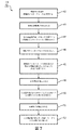
[64] 図7は、被験体の咳嗽流の増大の間の圧力をモニタリング及び制御する方法40を例示している。以下に提示される方法40の動作は、例示であることが意図される。一部の実施形態において、方法40は、記載されていない1つ以上の追加の動作を伴って及び/又は述べられている動作のうちの1つ以上を伴わずに成し遂げられ得る。さらに、方法40の動作を図7に例示し且つ以下で説明する順序は、限定することが意図されるものではない。
[64] FIG. 7 illustrates a
[65] 一部の実施形態において、方法40は、1つ以上の処理デバイス(例えば、デジタルプロセッサ、アナログプロセッサ、情報を処理するように設計されたデジタル回路、情報を処理するように設計されたアナログ回路、ステートマシン、及び/又は情報を電子的に処理するための他の機構)において実施され得る。この1つ以上の処理デバイスは、電子記憶媒体上に電子的に記憶された命令に応答して方法40の動作の一部又は全部を実行する1つ以上のデバイスを含み得る。この1つ以上の処理デバイスは、方法40の動作のうちの1つ以上の実行のために特別に設計されるようにハードウェア、ファームウェア、及び/又はソフトウェアを通じて構成された1つ以上のデバイスを含み得る。
[65] In some embodiments, the
[66] 動作42において、被験体インターフェースが、被験体の気道と連結する。一部の実施形態において、動作42は、被験体インターフェース16及び/又はインターフェース取付具26(図1に示され、本明細書で説明される)と同じ又は類似の被験体インターフェース及び/又はインターフェース取付具によって行われる。
[66] At
[67] 動作43において、咳嗽トリガ事象を示す情報が検出される。一部の実施形態において、動作43は、制御器22(図1に示され、本明細書で説明される)と同じ又は類似の制御器によって行われる。
[67] In an
[68] 動作44において、圧力調整器が、第1のモードで動作する。第1のモードでは、被験体インターフェース16は閉鎖されている。一部の実施形態において、動作44は、圧力調整器20(図1に示され、本明細書で説明される)と同じ又は類似の圧力調整器によって行われる。
[68] At
[69] 動作45において、圧力除去弁が、咳嗽流の増大の間において被験体インターフェース16内の圧力を所定の圧力範囲内に維持するように、被験体インターフェース16内の圧力が所定の閾値を超えたことに応じて被験体インターフェース16からガスを放出するように動作する。圧力除去弁25は、圧力調整器20が第1のモードにあるときに動作する。一部の実施形態において、動作45は、圧力除去弁25(図1に示され、本明細書で説明される)と同じ又は類似の圧力除去弁によって行われる。
[69] In
[70] 動作46において、被験体インターフェース16が、被験体12により加圧される。被験体12は、被験体インターフェース16に空気圧を加えることにより被験体インターフェース16を加圧する。一部の実施形態において、動作46は、被験体インターフェース16(図1に示され、本明細書で説明される)と同じ又は類似の被験体インターフェースによって行われる。
[70] In
[71] 動作48において、被験体12による被験体インターフェース16の加圧を示す情報が検出される。一部の実施形態において、動作48は、制御器22(図1に示され、本明細書で説明される)と同じ又は類似の制御器によって行われる。
[71] At an
[72] 動作50において、圧力調整器は、第1の閉鎖モードと第2の開放モードとの間でトグル式に切り換わる。第2のモードでは、被験体インターフェース16は、被験体12の気道からガスが排出されることを可能にするために開放される。第1のモードと第2のモードとの間のトグル式の切り換えが、単一の呼息の間において一連の分割された強制呼息事象によって被験体12に強制呼息させる。一部の実施形態において、動作50は、圧力調整器20(図1に示され、本明細書で説明される)と同じ又は類似の圧力調整器によって行われる。
[72] In
[73] 動作51において、咳嗽終了を示す情報が検出される。一部の実施形態において、動作51は、制御器22(図1に示され、本明細書で説明される)と同じ又は類似の制御器によって行われる。
[73] In an
[74] 動作52において、圧力調整器が、第2の(開放)モードにトグル式に切り換わる。一部の実施形態において、動作52は、圧力調整器20(図1に示され、本明細書で説明される)と同じ又は類似の圧力調整器によって行われる。
[74] At
[75] 特許請求の範囲において、括弧に挟まれたいずれの参照記号も、クレームを限定するものとして解釈されないものとする。「含む(comprising)」又は「含む(including)」という語は、クレームに列挙されるもの以外の要素又は工程の存在を除外しない。いくつかの手段を列挙するデバイスクレームにおいて、これらの手段のうちのいくつかは、ハードウェアの同一の品目によって具現化され得る。要素に先立つ「a」又は「an」という語は、複数のそのような要素の存在を除外しない。いくつかの手段を列挙する任意のデバイスクレームにおいて、これらの手段のうちのいくつかは、ハードウェアの同一の品目によって具現化され得る。ある特定の要素が互いに異なる従属クレームに記載されているということだけでは、これらの要素が組み合わせで使用され得ないということを示すことにならない。 [75] In the claims, any reference signs placed between parentheses shall not be construed as limiting the claim. The word "comprising" or "including" does not exclude the presence of elements or steps other than those listed in a claim. In the device claim enumerating several means, several of these means may be embodied by one and the same item of hardware. The word "a" or "an" preceding an element does not exclude the presence of a plurality of such elements. In any device claim enumerating several means, several of these means may be embodied by one and the same item of hardware. The mere fact that certain elements are recited in mutually different dependent claims does not indicate that these elements cannot be used in combination.
[76] 上で提供された説明は、最も実用的で好ましい実施形態であると現在考えられているものに基づき例示を目的として詳細を提供しているが、そのような詳細は、それだけを目的としたものであること、並びに本開示は、明示的に開示された実施形態に限定されるものではなく、逆に、添付の特許請求の範囲の趣旨及び範囲内にある修正及び同等の構成を対象として含むことが意図されることが理解されるべきである。例えば、本開示は、任意の実施形態の1つ以上の特徴が任意の他の実施形態の1つ以上の特徴と可能な限り組み合わされ得ることを企図することが理解されるべきである。 [76] Although the description provided above provides details for purposes of illustration based on what is currently believed to be the most practical and preferred embodiments, such details are for purposes of illustration only. And the present disclosure is not limited to the explicitly disclosed embodiments, but rather contemplates modifications and equivalent arrangements within the spirit and scope of the appended claims. It should be understood that they are intended to be included. For example, it should be understood that the present disclosure contemplates that one or more features of any embodiment may be combined as much as possible with one or more features of any other embodiment.
Claims (6)
前記被験体の気道と連通する被験体インターフェースと;
前記被験体インターフェースを介して流れを選択的に制御する圧力調整器であって、(i)前記被験体の前記気道と周囲雰囲気との間で前記被験体インターフェースを介してガスが実質的に全くやりとりされなくなるように前記被験体インターフェースが閉鎖される第1のモードと、(ii)前記被験体の前記気道から前記被験体インターフェースを通ってガスが排出されることを可能にするために前記被験体インターフェースが開放される第2のモードとにおいて動作する、圧力調整器と;
前記被験体の個々の呼息ごとに一連の強制呼息事象を生じさせるために、前記被験体の前記個々の呼息の間において前記圧力調整器が前記第1のモードと前記第2のモードとの間でトグル式に切り換えられることとなるように前記圧力調整器を操作する制御器と;
前記被験体インターフェースを通って流れるガスと流体連通する1つ以上のガスパラメータセンサと
を含む、システムにおいて、前記システムが、
前記被験体インターフェースと関係づけられる圧力除去弁であって、前記咳嗽流の間において前記被験体インターフェース内の圧力を所望の範囲内に維持するように、前記圧力調整器が前記第1のモードで動作する間には、前記被験体インターフェース内の圧力が所定の閾値を超えたことに応じて前記被験体インターフェースを開放し、そこからガスを放出し、前記圧力調整器が前記第2のモードで動作する間には、閉鎖したままである、圧力除去弁をさらに含むことを特徴とする、システム。 A system for controlling pressure during a subject's cough flow, the system comprising:
A subject interface in communication with the subject's airway;
A pressure regulator for selectively controlling the flow through said subject interface, (i) before SL through the subject interface between the airway and the surrounding atmosphere of the subject gas is substantially A first mode in which the subject interface is closed such that no communication occurs; and (ii) the subject interface is configured to allow gas to be evacuated from the airway of the subject through the subject interface. A pressure regulator operating in a second mode in which the subject interface is open;
The pressure regulator controls the first mode and the second mode during the individual exhalation of the subject to cause a series of forced expiratory events for each individual exhalation of the subject. A controller for operating said pressure regulator so as to be toggled between;
One or more gas parameter sensors in fluid communication with the gas flowing through the subject interface, wherein the system comprises:
A pressure relief valve associated with the subject interface, wherein the pressure regulator is in the first mode to maintain pressure within the subject interface during the coughing flow within a desired range. During operation, the subject interface is opened in response to the pressure in the subject interface exceeding a predetermined threshold and gas is released therefrom, and the pressure regulator is operated in the second mode. The system, further comprising a pressure relief valve that remains closed during operation.
Applications Claiming Priority (3)
| Application Number | Priority Date | Filing Date | Title |
|---|---|---|---|
| US201462073487P | 2014-10-31 | 2014-10-31 | |
| US62/073,487 | 2014-10-31 | ||
| PCT/IB2015/057909 WO2016067147A1 (en) | 2014-10-31 | 2015-10-15 | Controlling pressure during enhanced cough flow |
Publications (3)
| Publication Number | Publication Date |
|---|---|
| JP2017533751A JP2017533751A (en) | 2017-11-16 |
| JP2017533751A5 JP2017533751A5 (en) | 2019-07-04 |
| JP6644778B2 true JP6644778B2 (en) | 2020-02-12 |
Family
ID=54364408
Family Applications (1)
| Application Number | Title | Priority Date | Filing Date |
|---|---|---|---|
| JP2017522642A Active JP6644778B2 (en) | 2014-10-31 | 2015-10-15 | Pressure control during increased cough flow |
Country Status (5)
| Country | Link |
|---|---|
| US (1) | US10667748B2 (en) |
| EP (1) | EP3212261B1 (en) |
| JP (1) | JP6644778B2 (en) |
| CN (1) | CN107106019B (en) |
| WO (1) | WO2016067147A1 (en) |
Families Citing this family (17)
| Publication number | Priority date | Publication date | Assignee | Title |
|---|---|---|---|---|
| US10881817B2 (en) | 2014-12-26 | 2021-01-05 | Koninklijke Philips N.V. | Secretion loosening and cough segmenting therapy |
| US11247015B2 (en) | 2015-03-24 | 2022-02-15 | Ventec Life Systems, Inc. | Ventilator with integrated oxygen production |
| US10315002B2 (en) | 2015-03-24 | 2019-06-11 | Ventec Life Systems, Inc. | Ventilator with integrated oxygen production |
| JP6960905B2 (en) * | 2015-08-26 | 2021-11-05 | コーニンクレッカ フィリップス エヌ ヴェKoninklijke Philips N.V. | Mechanical air supply and exhaust |
| DE102016007336B4 (en) * | 2016-06-16 | 2023-08-10 | Drägerwerk AG & Co. KGaA | Medical device and method for organizing alarms |
| US10773049B2 (en) | 2016-06-21 | 2020-09-15 | Ventec Life Systems, Inc. | Cough-assist systems with humidifier bypass |
| SG10202101558PA (en) * | 2016-08-16 | 2021-03-30 | Fisher & Paykel Healthcare Ltd | Pressure regulating valve |
| US11529224B2 (en) | 2016-10-05 | 2022-12-20 | Pulmonx Corporation | High resistance implanted bronchial isolation devices and methods |
| WO2018203188A1 (en) * | 2017-05-03 | 2018-11-08 | Trudell Medical International | Combined oscillating positive expiratory pressure therapy and huff cough simulation device |
| US11191915B2 (en) | 2018-05-13 | 2021-12-07 | Ventec Life Systems, Inc. | Portable medical ventilator system using portable oxygen concentrators |
| CN110101945B (en) * | 2019-05-07 | 2022-09-02 | 濡新(北京)科技发展有限公司 | Synchronous automatic expectoration method and system |
| AU2021315472A1 (en) * | 2020-07-28 | 2023-03-02 | Pulmonx Corporation | High resistance implanted bronchial isolation devices and methods |
| CA3231347A1 (en) * | 2021-09-21 | 2023-03-30 | Zak Jake FLINTOFF | Valve |
| WO2023111914A1 (en) * | 2021-12-17 | 2023-06-22 | Fisher & Paykel Healthcare Limited | Measurement device and system for breathing assistance apparatus and/or performing diagnostics |
| CN114392451B (en) * | 2022-03-07 | 2023-11-10 | 广州市番禺区中心医院 | Respiratory mask for preventing cross infection of respiratory infectious disease patient |
| DE102022112209A1 (en) | 2022-05-16 | 2023-11-16 | Dietmar Enk | Ventilator, valve device and method for operating a ventilator |
| US20230405249A1 (en) * | 2022-06-21 | 2023-12-21 | Loewenstein Medical Technology S.A. | Device and system for respiratory therapy |
Family Cites Families (25)
| Publication number | Priority date | Publication date | Assignee | Title |
|---|---|---|---|---|
| SE389020B (en) * | 1973-11-13 | 1976-10-25 | Aga Ab | DEVICE FOR VENTILATION OF A PATIENT THROUGH A LUNG FAN |
| DD274358A1 (en) | 1988-07-27 | 1989-12-20 | Medizin Und Labor Technik Leip | VENTILATOR FOR REANIMATION AND SHORT TERM VENTILATION |
| US5345930A (en) * | 1992-02-10 | 1994-09-13 | National Research Council Canada Intellectual Property Services Office | Method and apparatus for assisting expulsional movement of pulmonary secretions via supramaximal flows |
| SE9603249D0 (en) | 1996-09-06 | 1996-09-06 | Siemens Elema Ab | Device for compensating flow resistance at fan / ventilator |
| US6615831B1 (en) | 1999-07-02 | 2003-09-09 | Respironics, Inc. | Pressure support system and method and a pressure control valve for use in such system and method |
| US6581596B1 (en) | 1999-09-24 | 2003-06-24 | Respironics, Inc. | Apparatus and method of providing high frequency variable pressure to a patient |
| SE522948C2 (en) | 2001-03-14 | 2004-03-16 | Bjoern Flodin | Device for a respirator |
| US7007692B2 (en) * | 2003-10-29 | 2006-03-07 | Airmatrix Technologies, Inc. | Method and system of sensing airflow and delivering therapeutic gas to a patient |
| US8460223B2 (en) | 2006-03-15 | 2013-06-11 | Hill-Rom Services Pte. Ltd. | High frequency chest wall oscillation system |
| GB2441583A (en) | 2006-09-05 | 2008-03-12 | South Bank Univ Entpr Ltd | Breathing device |
| CN101337101B (en) | 2007-07-06 | 2011-04-20 | 深圳迈瑞生物医疗电子股份有限公司 | Aerating system of anesthesia apparatus and respirator and pressure monitoring method |
| KR100971118B1 (en) | 2008-06-25 | 2010-07-20 | 연세대학교 산학협력단 | A cough assist apparatus which includes a suction function |
| CN101642598B (en) * | 2008-08-05 | 2012-12-12 | 北京谊安医疗系统股份有限公司 | Airway pressure relief valve |
| US20140144445A1 (en) * | 2009-01-08 | 2014-05-29 | Hancock Medical | Substantially Constant Positive Airway Pressure Systems and Methods for Treating Sleep Apnea, Snoring, and Other Respiratory Disorders |
| BR112012001413B1 (en) * | 2009-07-24 | 2021-05-18 | Koninklijke Philips N.V. | device to help cough |
| WO2011058470A1 (en) | 2009-11-13 | 2011-05-19 | Koninklijke Philips Electronics N.V. | Method and device for airway clearance |
| CN102946933B (en) * | 2010-06-22 | 2016-09-14 | 皇家飞利浦电子股份有限公司 | Respiratory interface device |
| KR100983023B1 (en) * | 2010-07-07 | 2010-09-17 | 한국해양연구원 | A method of extracting triglyceride or fatty acid methyl esters from microalgal lipid of microalgae of heterokontophyta or haptophyta, and manufacturing biodiesel using it's extracts |
| CN103384541B (en) * | 2010-12-21 | 2016-01-20 | 皇家飞利浦电子股份有限公司 | There is the ventilator of integrated aerator |
| US20140150801A1 (en) | 2011-04-28 | 2014-06-05 | MichaelJ. Rusher | Airway pressure control devices with flutter valve |
| EP2726127B1 (en) * | 2011-06-29 | 2017-02-15 | Koninklijke Philips N.V. | Apparatus for assisting airway clearance |
| FI125130B (en) | 2012-01-27 | 2015-06-15 | Kone Corp | Hardware for securing lift hoisting machinery and attachment arrangement |
| WO2013118061A1 (en) * | 2012-02-08 | 2013-08-15 | Koninklijke Philips N.V. | Method and apparatus for increasing cough flow |
| CN105007977B (en) | 2013-03-07 | 2019-01-29 | 皇家飞利浦有限公司 | Valve |
| CN203663191U (en) | 2013-10-28 | 2014-06-25 | 同济大学 | Cough auxiliary device |
-
2015
- 2015-10-15 JP JP2017522642A patent/JP6644778B2/en active Active
- 2015-10-15 US US15/522,083 patent/US10667748B2/en active Active
- 2015-10-15 WO PCT/IB2015/057909 patent/WO2016067147A1/en active Application Filing
- 2015-10-15 EP EP15787684.8A patent/EP3212261B1/en active Active
- 2015-10-15 CN CN201580059038.9A patent/CN107106019B/en active Active
Also Published As
| Publication number | Publication date |
|---|---|
| EP3212261B1 (en) | 2019-07-03 |
| CN107106019B (en) | 2020-06-05 |
| EP3212261A1 (en) | 2017-09-06 |
| US20170325735A1 (en) | 2017-11-16 |
| US10667748B2 (en) | 2020-06-02 |
| CN107106019A (en) | 2017-08-29 |
| WO2016067147A1 (en) | 2016-05-06 |
| JP2017533751A (en) | 2017-11-16 |
Similar Documents
| Publication | Publication Date | Title |
|---|---|---|
| JP6644778B2 (en) | Pressure control during increased cough flow | |
| EP2812059B1 (en) | Device for increasing cough flow | |
| EP2451517B1 (en) | System and method for entraining the breathing of a subject | |
| EP2588176B1 (en) | System for performing respiratory diagnostics | |
| US20070199566A1 (en) | Respiratory apparatus | |
| US9987444B2 (en) | System and method for limited flow respiratory therapy | |
| JP6165632B2 (en) | System and method for providing forced inspiration-expiration to a subject | |
| JP6302892B2 (en) | Starting pressure for the respiratory treatment device | |
| EP2827930B1 (en) | System for controlling insufflation pressure during inexsufflation | |
| JP2014506163A5 (en) | ||
| EP2844327A1 (en) | System and method for controlling flow during exhalation in a respiratory support system | |
| JP2018525110A (en) | Mechanical air exhaust | |
| US8646453B2 (en) | Extendable airflow restriction system | |
| JP6384965B2 (en) | Method and apparatus for increasing expiratory airflow | |
| JP6855384B2 (en) | Systems and methods for improving cough segmentation | |
| JP6017442B2 (en) | Exhalation synchronization | |
| EP2691136B1 (en) | Methods to transition adjacent to or in conjunction with a secondary airway pressure therapy | |
| CN110101945A (en) | It is a kind of to synchronize automatic expectoration method and system |
Legal Events
| Date | Code | Title | Description |
|---|---|---|---|
| A521 | Request for written amendment filed |
Free format text: JAPANESE INTERMEDIATE CODE: A523 Effective date: 20181011 |
|
| A621 | Written request for application examination |
Free format text: JAPANESE INTERMEDIATE CODE: A621 Effective date: 20181011 |
|
| A521 | Request for written amendment filed |
Free format text: JAPANESE INTERMEDIATE CODE: A523 Effective date: 20190528 |
|
| A871 | Explanation of circumstances concerning accelerated examination |
Free format text: JAPANESE INTERMEDIATE CODE: A871 Effective date: 20190528 |
|
| A975 | Report on accelerated examination |
Free format text: JAPANESE INTERMEDIATE CODE: A971005 Effective date: 20190808 |
|
| A977 | Report on retrieval |
Free format text: JAPANESE INTERMEDIATE CODE: A971007 Effective date: 20190809 |
|
| A131 | Notification of reasons for refusal |
Free format text: JAPANESE INTERMEDIATE CODE: A131 Effective date: 20190819 |
|
| A521 | Request for written amendment filed |
Free format text: JAPANESE INTERMEDIATE CODE: A523 Effective date: 20191025 |
|
| TRDD | Decision of grant or rejection written | ||
| A01 | Written decision to grant a patent or to grant a registration (utility model) |
Free format text: JAPANESE INTERMEDIATE CODE: A01 Effective date: 20191210 |
|
| A61 | First payment of annual fees (during grant procedure) |
Free format text: JAPANESE INTERMEDIATE CODE: A61 Effective date: 20200108 |
|
| R150 | Certificate of patent or registration of utility model |
Ref document number: 6644778 Country of ref document: JP Free format text: JAPANESE INTERMEDIATE CODE: R150 |
|
| R250 | Receipt of annual fees |
Free format text: JAPANESE INTERMEDIATE CODE: R250 |
|
| R250 | Receipt of annual fees |
Free format text: JAPANESE INTERMEDIATE CODE: R250 |