CN107258046B - Resonator equalization in wireless power transfer systems - Google Patents
Resonator equalization in wireless power transfer systems Download PDFInfo
- Publication number
- CN107258046B CN107258046B CN201580048080.0A CN201580048080A CN107258046B CN 107258046 B CN107258046 B CN 107258046B CN 201580048080 A CN201580048080 A CN 201580048080A CN 107258046 B CN107258046 B CN 107258046B
- Authority
- CN
- China
- Prior art keywords
- windings
- winding
- inductance
- resonator
- coil
- Prior art date
- Legal status (The legal status is an assumption and is not a legal conclusion. Google has not performed a legal analysis and makes no representation as to the accuracy of the status listed.)
- Active
Links
- 238000012546 transfer Methods 0.000 title claims abstract description 84
- 238000004804 winding Methods 0.000 claims abstract description 411
- 238000009826 distribution Methods 0.000 claims abstract description 20
- 230000008878 coupling Effects 0.000 claims description 91
- 238000010168 coupling process Methods 0.000 claims description 91
- 238000005859 coupling reaction Methods 0.000 claims description 91
- 238000005259 measurement Methods 0.000 claims description 51
- 239000011159 matrix material Substances 0.000 claims description 49
- 238000000034 method Methods 0.000 claims description 37
- 239000000696 magnetic material Substances 0.000 claims description 20
- 239000004020 conductor Substances 0.000 claims description 19
- 230000004048 modification Effects 0.000 claims description 12
- 238000012986 modification Methods 0.000 claims description 12
- 230000001939 inductive effect Effects 0.000 claims description 9
- 230000006870 function Effects 0.000 description 80
- 239000003990 capacitor Substances 0.000 description 68
- 238000010586 diagram Methods 0.000 description 58
- 229910052782 aluminium Inorganic materials 0.000 description 33
- XAGFODPZIPBFFR-UHFFFAOYSA-N aluminium Chemical compound [Al] XAGFODPZIPBFFR-UHFFFAOYSA-N 0.000 description 33
- 238000006073 displacement reaction Methods 0.000 description 27
- 229910000859 α-Fe Inorganic materials 0.000 description 23
- 229910000831 Steel Inorganic materials 0.000 description 10
- 239000010959 steel Substances 0.000 description 10
- 238000003860 storage Methods 0.000 description 8
- 238000005457 optimization Methods 0.000 description 6
- 229910052727 yttrium Inorganic materials 0.000 description 6
- 238000006243 chemical reaction Methods 0.000 description 5
- 238000004891 communication Methods 0.000 description 5
- 230000000694 effects Effects 0.000 description 5
- 239000000463 material Substances 0.000 description 5
- 238000012545 processing Methods 0.000 description 5
- 238000004519 manufacturing process Methods 0.000 description 4
- 230000005855 radiation Effects 0.000 description 4
- 230000008859 change Effects 0.000 description 3
- 230000004907 flux Effects 0.000 description 3
- 230000001965 increasing effect Effects 0.000 description 3
- RYGMFSIKBFXOCR-UHFFFAOYSA-N Copper Chemical compound [Cu] RYGMFSIKBFXOCR-UHFFFAOYSA-N 0.000 description 2
- XEEYBQQBJWHFJM-UHFFFAOYSA-N Iron Chemical compound [Fe] XEEYBQQBJWHFJM-UHFFFAOYSA-N 0.000 description 2
- PXHVJJICTQNCMI-UHFFFAOYSA-N Nickel Chemical compound [Ni] PXHVJJICTQNCMI-UHFFFAOYSA-N 0.000 description 2
- BQCADISMDOOEFD-UHFFFAOYSA-N Silver Chemical compound [Ag] BQCADISMDOOEFD-UHFFFAOYSA-N 0.000 description 2
- 230000005540 biological transmission Effects 0.000 description 2
- 238000009529 body temperature measurement Methods 0.000 description 2
- 239000000919 ceramic Substances 0.000 description 2
- 239000002131 composite material Substances 0.000 description 2
- 229910052802 copper Inorganic materials 0.000 description 2
- 239000010949 copper Substances 0.000 description 2
- 238000013461 design Methods 0.000 description 2
- PCHJSUWPFVWCPO-UHFFFAOYSA-N gold Chemical compound [Au] PCHJSUWPFVWCPO-UHFFFAOYSA-N 0.000 description 2
- 229910052737 gold Inorganic materials 0.000 description 2
- 239000010931 gold Substances 0.000 description 2
- 230000017525 heat dissipation Effects 0.000 description 2
- 238000010438 heat treatment Methods 0.000 description 2
- WJZHMLNIAZSFDO-UHFFFAOYSA-N manganese zinc Chemical compound [Mn].[Zn] WJZHMLNIAZSFDO-UHFFFAOYSA-N 0.000 description 2
- 238000012544 monitoring process Methods 0.000 description 2
- QELJHCBNGDEXLD-UHFFFAOYSA-N nickel zinc Chemical compound [Ni].[Zn] QELJHCBNGDEXLD-UHFFFAOYSA-N 0.000 description 2
- 230000003287 optical effect Effects 0.000 description 2
- 230000008569 process Effects 0.000 description 2
- 230000004044 response Effects 0.000 description 2
- 229910052709 silver Inorganic materials 0.000 description 2
- 239000004332 silver Substances 0.000 description 2
- 239000011800 void material Substances 0.000 description 2
- 229910001369 Brass Inorganic materials 0.000 description 1
- 239000000853 adhesive Substances 0.000 description 1
- 230000001070 adhesive effect Effects 0.000 description 1
- PNEYBMLMFCGWSK-UHFFFAOYSA-N aluminium oxide Inorganic materials [O-2].[O-2].[O-2].[Al+3].[Al+3] PNEYBMLMFCGWSK-UHFFFAOYSA-N 0.000 description 1
- 230000002547 anomalous effect Effects 0.000 description 1
- 238000003491 array Methods 0.000 description 1
- 230000008901 benefit Effects 0.000 description 1
- 239000010951 brass Substances 0.000 description 1
- 238000004364 calculation method Methods 0.000 description 1
- 239000003985 ceramic capacitor Substances 0.000 description 1
- 230000000295 complement effect Effects 0.000 description 1
- 238000004590 computer program Methods 0.000 description 1
- 238000010276 construction Methods 0.000 description 1
- PMHQVHHXPFUNSP-UHFFFAOYSA-M copper(1+);methylsulfanylmethane;bromide Chemical compound Br[Cu].CSC PMHQVHHXPFUNSP-UHFFFAOYSA-M 0.000 description 1
- 238000012937 correction Methods 0.000 description 1
- 238000006880 cross-coupling reaction Methods 0.000 description 1
- 238000013500 data storage Methods 0.000 description 1
- 238000001514 detection method Methods 0.000 description 1
- 239000003989 dielectric material Substances 0.000 description 1
- 230000005611 electricity Effects 0.000 description 1
- -1 for example Substances 0.000 description 1
- 230000014509 gene expression Effects 0.000 description 1
- 231100001261 hazardous Toxicity 0.000 description 1
- 229910052742 iron Inorganic materials 0.000 description 1
- 239000004973 liquid crystal related substance Substances 0.000 description 1
- 230000007246 mechanism Effects 0.000 description 1
- 229910052751 metal Inorganic materials 0.000 description 1
- 239000002184 metal Substances 0.000 description 1
- 230000000116 mitigating effect Effects 0.000 description 1
- 229910052759 nickel Inorganic materials 0.000 description 1
- 230000010355 oscillation Effects 0.000 description 1
- 238000013021 overheating Methods 0.000 description 1
- 238000004806 packaging method and process Methods 0.000 description 1
- 230000035699 permeability Effects 0.000 description 1
- 239000004033 plastic Substances 0.000 description 1
- 230000009467 reduction Effects 0.000 description 1
- 239000007787 solid Substances 0.000 description 1
- 230000009466 transformation Effects 0.000 description 1
- 230000000007 visual effect Effects 0.000 description 1
- 238000012800 visualization Methods 0.000 description 1
Images


Classifications
-
- H—ELECTRICITY
- H01—ELECTRIC ELEMENTS
- H01F—MAGNETS; INDUCTANCES; TRANSFORMERS; SELECTION OF MATERIALS FOR THEIR MAGNETIC PROPERTIES
- H01F38/00—Adaptations of transformers or inductances for specific applications or functions
- H01F38/14—Inductive couplings
-
- B—PERFORMING OPERATIONS; TRANSPORTING
- B60—VEHICLES IN GENERAL
- B60L—PROPULSION OF ELECTRICALLY-PROPELLED VEHICLES; SUPPLYING ELECTRIC POWER FOR AUXILIARY EQUIPMENT OF ELECTRICALLY-PROPELLED VEHICLES; ELECTRODYNAMIC BRAKE SYSTEMS FOR VEHICLES IN GENERAL; MAGNETIC SUSPENSION OR LEVITATION FOR VEHICLES; MONITORING OPERATING VARIABLES OF ELECTRICALLY-PROPELLED VEHICLES; ELECTRIC SAFETY DEVICES FOR ELECTRICALLY-PROPELLED VEHICLES
- B60L53/00—Methods of charging batteries, specially adapted for electric vehicles; Charging stations or on-board charging equipment therefor; Exchange of energy storage elements in electric vehicles
- B60L53/10—Methods of charging batteries, specially adapted for electric vehicles; Charging stations or on-board charging equipment therefor; Exchange of energy storage elements in electric vehicles characterised by the energy transfer between the charging station and the vehicle
- B60L53/12—Inductive energy transfer
- B60L53/122—Circuits or methods for driving the primary coil, e.g. supplying electric power to the coil
-
- B—PERFORMING OPERATIONS; TRANSPORTING
- B60—VEHICLES IN GENERAL
- B60L—PROPULSION OF ELECTRICALLY-PROPELLED VEHICLES; SUPPLYING ELECTRIC POWER FOR AUXILIARY EQUIPMENT OF ELECTRICALLY-PROPELLED VEHICLES; ELECTRODYNAMIC BRAKE SYSTEMS FOR VEHICLES IN GENERAL; MAGNETIC SUSPENSION OR LEVITATION FOR VEHICLES; MONITORING OPERATING VARIABLES OF ELECTRICALLY-PROPELLED VEHICLES; ELECTRIC SAFETY DEVICES FOR ELECTRICALLY-PROPELLED VEHICLES
- B60L53/00—Methods of charging batteries, specially adapted for electric vehicles; Charging stations or on-board charging equipment therefor; Exchange of energy storage elements in electric vehicles
- B60L53/10—Methods of charging batteries, specially adapted for electric vehicles; Charging stations or on-board charging equipment therefor; Exchange of energy storage elements in electric vehicles characterised by the energy transfer between the charging station and the vehicle
- B60L53/12—Inductive energy transfer
- B60L53/126—Methods for pairing a vehicle and a charging station, e.g. establishing a one-to-one relation between a wireless power transmitter and a wireless power receiver
-
- H—ELECTRICITY
- H01—ELECTRIC ELEMENTS
- H01F—MAGNETS; INDUCTANCES; TRANSFORMERS; SELECTION OF MATERIALS FOR THEIR MAGNETIC PROPERTIES
- H01F27/00—Details of transformers or inductances, in general
- H01F27/28—Coils; Windings; Conductive connections
- H01F27/2871—Pancake coils
-
- H02J5/005—
-
- H—ELECTRICITY
- H02—GENERATION; CONVERSION OR DISTRIBUTION OF ELECTRIC POWER
- H02J—CIRCUIT ARRANGEMENTS OR SYSTEMS FOR SUPPLYING OR DISTRIBUTING ELECTRIC POWER; SYSTEMS FOR STORING ELECTRIC ENERGY
- H02J50/00—Circuit arrangements or systems for wireless supply or distribution of electric power
- H02J50/005—Mechanical details of housing or structure aiming to accommodate the power transfer means, e.g. mechanical integration of coils, antennas or transducers into emitting or receiving devices
-
- H—ELECTRICITY
- H02—GENERATION; CONVERSION OR DISTRIBUTION OF ELECTRIC POWER
- H02J—CIRCUIT ARRANGEMENTS OR SYSTEMS FOR SUPPLYING OR DISTRIBUTING ELECTRIC POWER; SYSTEMS FOR STORING ELECTRIC ENERGY
- H02J50/00—Circuit arrangements or systems for wireless supply or distribution of electric power
- H02J50/10—Circuit arrangements or systems for wireless supply or distribution of electric power using inductive coupling
- H02J50/12—Circuit arrangements or systems for wireless supply or distribution of electric power using inductive coupling of the resonant type
-
- H—ELECTRICITY
- H02—GENERATION; CONVERSION OR DISTRIBUTION OF ELECTRIC POWER
- H02J—CIRCUIT ARRANGEMENTS OR SYSTEMS FOR SUPPLYING OR DISTRIBUTING ELECTRIC POWER; SYSTEMS FOR STORING ELECTRIC ENERGY
- H02J50/00—Circuit arrangements or systems for wireless supply or distribution of electric power
- H02J50/70—Circuit arrangements or systems for wireless supply or distribution of electric power involving the reduction of electric, magnetic or electromagnetic leakage fields
-
- H—ELECTRICITY
- H02—GENERATION; CONVERSION OR DISTRIBUTION OF ELECTRIC POWER
- H02J—CIRCUIT ARRANGEMENTS OR SYSTEMS FOR SUPPLYING OR DISTRIBUTING ELECTRIC POWER; SYSTEMS FOR STORING ELECTRIC ENERGY
- H02J50/00—Circuit arrangements or systems for wireless supply or distribution of electric power
- H02J50/80—Circuit arrangements or systems for wireless supply or distribution of electric power involving the exchange of data, concerning supply or distribution of electric power, between transmitting devices and receiving devices
-
- H—ELECTRICITY
- H02—GENERATION; CONVERSION OR DISTRIBUTION OF ELECTRIC POWER
- H02J—CIRCUIT ARRANGEMENTS OR SYSTEMS FOR SUPPLYING OR DISTRIBUTING ELECTRIC POWER; SYSTEMS FOR STORING ELECTRIC ENERGY
- H02J7/00—Circuit arrangements for charging or depolarising batteries or for supplying loads from batteries
- H02J7/0029—Circuit arrangements for charging or depolarising batteries or for supplying loads from batteries with safety or protection devices or circuits
- H02J7/00309—Overheat or overtemperature protection
-
- H02J7/025—
-
- B—PERFORMING OPERATIONS; TRANSPORTING
- B60—VEHICLES IN GENERAL
- B60L—PROPULSION OF ELECTRICALLY-PROPELLED VEHICLES; SUPPLYING ELECTRIC POWER FOR AUXILIARY EQUIPMENT OF ELECTRICALLY-PROPELLED VEHICLES; ELECTRODYNAMIC BRAKE SYSTEMS FOR VEHICLES IN GENERAL; MAGNETIC SUSPENSION OR LEVITATION FOR VEHICLES; MONITORING OPERATING VARIABLES OF ELECTRICALLY-PROPELLED VEHICLES; ELECTRIC SAFETY DEVICES FOR ELECTRICALLY-PROPELLED VEHICLES
- B60L2210/00—Converter types
- B60L2210/10—DC to DC converters
-
- B—PERFORMING OPERATIONS; TRANSPORTING
- B60—VEHICLES IN GENERAL
- B60L—PROPULSION OF ELECTRICALLY-PROPELLED VEHICLES; SUPPLYING ELECTRIC POWER FOR AUXILIARY EQUIPMENT OF ELECTRICALLY-PROPELLED VEHICLES; ELECTRODYNAMIC BRAKE SYSTEMS FOR VEHICLES IN GENERAL; MAGNETIC SUSPENSION OR LEVITATION FOR VEHICLES; MONITORING OPERATING VARIABLES OF ELECTRICALLY-PROPELLED VEHICLES; ELECTRIC SAFETY DEVICES FOR ELECTRICALLY-PROPELLED VEHICLES
- B60L2210/00—Converter types
- B60L2210/30—AC to DC converters
-
- B—PERFORMING OPERATIONS; TRANSPORTING
- B60—VEHICLES IN GENERAL
- B60L—PROPULSION OF ELECTRICALLY-PROPELLED VEHICLES; SUPPLYING ELECTRIC POWER FOR AUXILIARY EQUIPMENT OF ELECTRICALLY-PROPELLED VEHICLES; ELECTRODYNAMIC BRAKE SYSTEMS FOR VEHICLES IN GENERAL; MAGNETIC SUSPENSION OR LEVITATION FOR VEHICLES; MONITORING OPERATING VARIABLES OF ELECTRICALLY-PROPELLED VEHICLES; ELECTRIC SAFETY DEVICES FOR ELECTRICALLY-PROPELLED VEHICLES
- B60L2210/00—Converter types
- B60L2210/40—DC to AC converters
-
- B—PERFORMING OPERATIONS; TRANSPORTING
- B60—VEHICLES IN GENERAL
- B60L—PROPULSION OF ELECTRICALLY-PROPELLED VEHICLES; SUPPLYING ELECTRIC POWER FOR AUXILIARY EQUIPMENT OF ELECTRICALLY-PROPELLED VEHICLES; ELECTRODYNAMIC BRAKE SYSTEMS FOR VEHICLES IN GENERAL; MAGNETIC SUSPENSION OR LEVITATION FOR VEHICLES; MONITORING OPERATING VARIABLES OF ELECTRICALLY-PROPELLED VEHICLES; ELECTRIC SAFETY DEVICES FOR ELECTRICALLY-PROPELLED VEHICLES
- B60L2270/00—Problem solutions or means not otherwise provided for
- B60L2270/10—Emission reduction
- B60L2270/14—Emission reduction of noise
- B60L2270/147—Emission reduction of noise electro magnetic [EMI]
-
- Y—GENERAL TAGGING OF NEW TECHNOLOGICAL DEVELOPMENTS; GENERAL TAGGING OF CROSS-SECTIONAL TECHNOLOGIES SPANNING OVER SEVERAL SECTIONS OF THE IPC; TECHNICAL SUBJECTS COVERED BY FORMER USPC CROSS-REFERENCE ART COLLECTIONS [XRACs] AND DIGESTS
- Y02—TECHNOLOGIES OR APPLICATIONS FOR MITIGATION OR ADAPTATION AGAINST CLIMATE CHANGE
- Y02T—CLIMATE CHANGE MITIGATION TECHNOLOGIES RELATED TO TRANSPORTATION
- Y02T10/00—Road transport of goods or passengers
- Y02T10/60—Other road transportation technologies with climate change mitigation effect
- Y02T10/70—Energy storage systems for electromobility, e.g. batteries
-
- Y—GENERAL TAGGING OF NEW TECHNOLOGICAL DEVELOPMENTS; GENERAL TAGGING OF CROSS-SECTIONAL TECHNOLOGIES SPANNING OVER SEVERAL SECTIONS OF THE IPC; TECHNICAL SUBJECTS COVERED BY FORMER USPC CROSS-REFERENCE ART COLLECTIONS [XRACs] AND DIGESTS
- Y02—TECHNOLOGIES OR APPLICATIONS FOR MITIGATION OR ADAPTATION AGAINST CLIMATE CHANGE
- Y02T—CLIMATE CHANGE MITIGATION TECHNOLOGIES RELATED TO TRANSPORTATION
- Y02T10/00—Road transport of goods or passengers
- Y02T10/60—Other road transportation technologies with climate change mitigation effect
- Y02T10/7072—Electromobility specific charging systems or methods for batteries, ultracapacitors, supercapacitors or double-layer capacitors
-
- Y—GENERAL TAGGING OF NEW TECHNOLOGICAL DEVELOPMENTS; GENERAL TAGGING OF CROSS-SECTIONAL TECHNOLOGIES SPANNING OVER SEVERAL SECTIONS OF THE IPC; TECHNICAL SUBJECTS COVERED BY FORMER USPC CROSS-REFERENCE ART COLLECTIONS [XRACs] AND DIGESTS
- Y02—TECHNOLOGIES OR APPLICATIONS FOR MITIGATION OR ADAPTATION AGAINST CLIMATE CHANGE
- Y02T—CLIMATE CHANGE MITIGATION TECHNOLOGIES RELATED TO TRANSPORTATION
- Y02T10/00—Road transport of goods or passengers
- Y02T10/60—Other road transportation technologies with climate change mitigation effect
- Y02T10/72—Electric energy management in electromobility
-
- Y—GENERAL TAGGING OF NEW TECHNOLOGICAL DEVELOPMENTS; GENERAL TAGGING OF CROSS-SECTIONAL TECHNOLOGIES SPANNING OVER SEVERAL SECTIONS OF THE IPC; TECHNICAL SUBJECTS COVERED BY FORMER USPC CROSS-REFERENCE ART COLLECTIONS [XRACs] AND DIGESTS
- Y02—TECHNOLOGIES OR APPLICATIONS FOR MITIGATION OR ADAPTATION AGAINST CLIMATE CHANGE
- Y02T—CLIMATE CHANGE MITIGATION TECHNOLOGIES RELATED TO TRANSPORTATION
- Y02T90/00—Enabling technologies or technologies with a potential or indirect contribution to GHG emissions mitigation
- Y02T90/10—Technologies relating to charging of electric vehicles
- Y02T90/12—Electric charging stations
-
- Y—GENERAL TAGGING OF NEW TECHNOLOGICAL DEVELOPMENTS; GENERAL TAGGING OF CROSS-SECTIONAL TECHNOLOGIES SPANNING OVER SEVERAL SECTIONS OF THE IPC; TECHNICAL SUBJECTS COVERED BY FORMER USPC CROSS-REFERENCE ART COLLECTIONS [XRACs] AND DIGESTS
- Y02—TECHNOLOGIES OR APPLICATIONS FOR MITIGATION OR ADAPTATION AGAINST CLIMATE CHANGE
- Y02T—CLIMATE CHANGE MITIGATION TECHNOLOGIES RELATED TO TRANSPORTATION
- Y02T90/00—Enabling technologies or technologies with a potential or indirect contribution to GHG emissions mitigation
- Y02T90/10—Technologies relating to charging of electric vehicles
- Y02T90/14—Plug-in electric vehicles
Landscapes
- Engineering & Computer Science (AREA)
- Power Engineering (AREA)
- Computer Networks & Wireless Communication (AREA)
- Transportation (AREA)
- Mechanical Engineering (AREA)
- Physics & Mathematics (AREA)
- Electromagnetism (AREA)
- Charge And Discharge Circuits For Batteries Or The Like (AREA)
- Electric Propulsion And Braking For Vehicles (AREA)
- Current-Collector Devices For Electrically Propelled Vehicles (AREA)
Abstract
The disclosure features a system for wireless power transfer including a resonator featuring a coil having at least two windings and at least one inductor having an inductance value, wherein the at least one inductor is connected in series to the at least one winding and the inductance value is selected such that when the coil carries current during operation of the system, the at least one inductor maintains a current distribution between the at least two windings such that, for each of the at least two windings, an actual current in the winding differs from a target current of the winding by 10% or less.
Description
Cross Reference to Related Applications
This application claims priority from U.S. provisional patent application No. 62/022,133, filed on 8/7/2014 and U.S. provisional patent application No. 62/051,647, filed on 17/9/2014, which are incorporated herein by reference in their entirety.
Technical Field
The present disclosure relates to wireless power transfer systems and methods.
Background
Various known techniques, such as radiation (far field) techniques, may be used to transfer energy from a power source to a receiving device. For example, a radiation technique using a low-directivity antenna can transmit a small portion of supplied radiation power, that is, a portion that is in the direction of and overlaps with a receiving device for reception. In this example, most of the energy is radiated in directions other than the direction of the receiving device, and typically the energy delivered is insufficient to power or charge the receiving device. In another example of a radiating technique, a directional antenna is used to confine and preferentially direct the radiated energy to the receiving device. In this case, uninterrupted line of sight and potentially complex tracking and steering mechanisms are used.
Another way is to use non-radiative (near-field) techniques. For example, the technique known as the conventional inductive scheme does not (intentionally) radiate power, but uses an oscillating current through a primary coil to generate an oscillating magnetic near field that induces a current in a nearby receiving or secondary coil. Conventional inductive schemes can deliver moderate to large amounts of power for very short distances. In these schemes, the offset tolerance between the power supply and the receiving device is very small. Electrical transformers and proximity chargers use these conventional inductive schemes.
Disclosure of Invention
In general, in a first aspect, the disclosure features a system for wireless power transfer, the system comprising: a resonator comprising a coil having at least two windings, each of the at least two windings characterized by comprising a plurality of loops formed of an electrically conductive material and extending in a plane, wherein respective portions of each of the at least two windings are oriented in parallel, a length of at least one of the at least two windings is different from a length of another of the at least two windings, and the at least two windings are electrically connected in parallel; and at least one inductor having an inductance value, wherein the at least one inductor is connected in series to at least one of the at least two windings, wherein the inductance value is selected such that when the coil carries current during operation of the system, the at least one inductor maintains a current distribution between the at least two windings such that, for each of the at least two windings, an actual current in that winding differs from a target current for that winding by 10% or less.
Embodiments of the system can include any one or more of the following features.
The at least one inductor may comprise an adjustable inductance value. The respective portions of each of the at least two windings may be oriented in parallel along at least 80% of a length of at least one of the at least two windings. The loops of each winding may be interleaved. The loops of each winding may be concentric and form a helix.
The system may also include an electronic processor coupled to the at least two windings and configured to control current in each winding based on a target current for the at least two windings. The electronic processor may be configured to control the current in each winding by: determining a target inductance value for the at least one inductor based on a figure of merit associated with the target current; and adjusting an inductance value of the at least one inductor to match the target inductance value. The electronic processor can be configured to determine the target inductance value by: (i) for each winding: determining a self-inductance value for the winding based on a measurement of the inductance of the winding when electrically disconnected from all other windings, and determining a plurality of mutual inductance values for the winding, wherein each mutual inductance value is based on a measurement of the inductance of the winding when electrically disconnected from another winding; (ii) determining a target current for each winding based on the self-inductance value and the mutual-inductance value; and (iii) determining a target inductance value based on the target current for each winding. The electronic processor may be configured to determine the target current by: constructing an inductance matrix based on the self-inductance value and the mutual inductance value of each winding; calculating an adjusted inductance matrix by adding an inductance modification matrix including elements corresponding to changes in inductance of the windings due to the at least one inductor to the inductance matrix; calculating an inverse matrix of the adjusted inductance matrix; and determining the target current based on the inverse matrix. The inductance modification matrix may be a diagonal matrix and diagonal elements of the inductance modification matrix may be inductance values of components of the at least one inductor connected to a winding.
In another aspect, the disclosure features a method that includes: controlling a current in each of at least two windings of a resonator coil for wireless power transfer, wherein each of the at least two windings comprises a plurality of loops formed of an electrically conductive material and extending in a plane, each of the at least two windings is oriented in parallel, a length of at least one of the at least two windings is different from a length of another of the at least two windings, and the at least two windings are electrically connected in parallel, at least one inductor having an inductance value being connected in series to at least one of the at least two windings; and maintaining a current distribution between the at least two windings while the coil is carrying current such that for each of the at least two windings, an actual current in the winding differs from a target current for the winding by 10% or less.
Embodiments of the method may include any one or more of the following features.
The respective portions of each of the at least two windings may be oriented in parallel along at least 80% of a length of at least one of the at least two windings. The loops of each winding may be interleaved. The loops of each winding may be concentric and form a helix.
The method may further comprise controlling the current in each winding to maintain the current profile by: determining a target inductance value for the at least one inductor based on a figure of merit associated with the target current; and adjusting an inductance value of the at least one inductor to match the target inductance value. The method may further include determining the target inductance value by: (i) for each winding: determining a self-inductance value for the winding based on a measurement of the inductance of the winding when electrically disconnected from all other windings, and determining a plurality of mutual inductance values for the winding, wherein each mutual inductance value is based on a measurement of the inductance of the winding when electrically disconnected from another winding; (ii) determining a target current for each winding based on the self-inductance value and the mutual-inductance value; and (iii) determining a target inductance value based on the target current for each winding.
The method may further include determining the target current by: constructing an inductance matrix based on the self-inductance value and the mutual inductance value of each winding; calculating an adjusted inductance matrix by adding an inductance modification matrix including elements corresponding to changes in inductance of the windings due to the at least one inductor to the inductance matrix; calculating an inverse matrix of the adjusted inductance matrix; and determining the target current based on the inverse matrix. The inductance modification matrix may be a diagonal matrix and diagonal elements of the inductance modification matrix may be inductance values of components of the at least one inductor connected to a winding.
In yet another aspect, the present disclosure features a resonator coil for wireless power transfer, the coil comprising: a member formed of a magnetic material; and at least two windings electrically connected in parallel, each of the at least two windings comprising a plurality of loops formed from an electrically conductive material, wherein the loops of each of the at least two windings are interleaved such that a respective portion of each of the at least two windings is oriented in parallel along at least 80% of a length of at least one of the at least two windings, and each of the at least two windings spatially overlaps at least one other winding at one or more points along the length of the winding.
Embodiments of the coil may include any one or more of the following features.
The loops of each winding may be oriented in a plane. The loops of all windings may be oriented in a common plane. The loops of each winding may be concentric and form a helix. The loops of all windings may form loops of concentric spirals.
The coil may further include at least one inductor having an adjustable inductance, the at least one inductor being connected in series to at least one of the at least two windings. The coil may further comprise at least one inductor having an adjustable inductance, the at least one inductor being connected in series to each of the at least two windings. Each of the at least two windings may spatially overlap each of the other windings at one or more points along the length of the winding. For each winding, the points at which the winding overlaps at least some of the other windings may be equally spaced along the circumference of the winding.
The at least two windings may include n windings, each of the n windings may spatially overlap with each of n-1 other windings along a length of the winding, each of the n windings may include n-1 overlap points with the other windings, each point corresponding to an overlap of the winding with a different one of the other windings. The number n may be greater than 2 (e.g., greater than 3).
The at least two windings may include n windings, and at least one of the n windings may include more than n-1 overlap points with other windings such that the at least one winding spatially overlaps at least some of the n-1 other windings more than once. The at least two windings may include n windings, and at least one winding of the n windings may include less than n-1 overlap points with other windings such that the at least one winding does not spatially overlap all of the n-1 other windings.
Embodiments of the systems, methods, and coils can also include any of the other features disclosed herein, including features disclosed in connection with different embodiments, in any combination, as appropriate.
Unless defined otherwise, all technical and scientific terms used herein have the same meaning as commonly understood by one of ordinary skill in the art to which this disclosure belongs. In case of conflict with publications, patent applications, patents, and other references mentioned or incorporated by reference herein, the present disclosure, including definitions, will control. Any of the above features may be used alone or in combination without departing from the scope of the present disclosure. Other features, objects, and advantages of the systems and methods disclosed herein will be apparent from the detailed description and drawings that follow.
Drawings
Fig. 1A is a schematic diagram of an embodiment of a wireless power transfer system.
Fig. 1B is a schematic diagram of a resonator for wireless power transfer.
Fig. 2A-2C are schematic diagrams of a wireless power transfer system integrated into a vehicle.
Fig. 3A and 3B are schematic diagrams showing a source resonator coil in the vicinity of a magnetic material.
Fig. 4 is a schematic diagram of a source resonator.
Fig. 5A and 5B are schematic diagrams of an apparatus configured to wirelessly receive power.
Fig. 6A and 6B are graphs showing measurements for the coupling k between the source resonator and the receiver resonator as a function of the relative displacement of the resonators.
Fig. 7A and 7B are graphs showing figure-of-merit for a function of relative displacement between a source resonator and a receiver resonator.
Fig. 8A and 8B are graphs showing measurements for coupling k as a function of relative displacement between the source resonator and the receiver resonator.
Fig. 9A and 9B are graphs showing figure of merit as a function of relative displacement between the source resonator and the receiver resonator.
Fig. 10A and 10B are graphs showing measurements for the coupling k between the source and receiver resonators as a function of the relative displacement of the resonators.
Fig. 11A and 11B are graphs showing figure of merit as a function of relative displacement between a source resonator and a receiver resonator.
Fig. 12A and 12B are graphs showing measurements for the coupling k between the source and receiver resonators as a function of the relative displacement of the resonators.
Fig. 13A and 13B are graphs showing figure of merit as a function of relative displacement between a source resonator and a receiver resonator.
Fig. 14A and 14B are graphs showing measurements for the coupling k between the source and receiver resonators as a function of the relative displacement of the resonators.
Fig. 15A and 15B are graphs showing quality factor as a function of relative displacement between the source resonator and the receiver resonator.
Fig. 16A and 16B are graphs showing figure of merit as a function of relative displacement between the source resonator and the receiver resonator.
Fig. 17A and 17B are schematic diagrams of impedance matching networks.
Fig. 18A and 18B are graphs of device side load impedance as a function of output voltage.
Fig. 19A and 19B are graphs of amplifier-cell efficiency as a function of output voltage.
Fig. 20A and 20B are graphs of power dissipated in the source and device as a function of output voltage.
Fig. 21A and 21B are graphs of the voltage measured across one or more capacitors in an impedance matching network.
Fig. 22A and 22B are graphs of the magnetic field amplitude in the magnetic member of the source resonator.
Fig. 23 is a schematic circuit diagram of an embodiment of the device electronics.
Fig. 24A and 24B are graphs of DC-DC boost conversion ratio as a function of output voltage.
Fig. 25A and 25B are graphs of amplifier-to-converter efficiency as a function of output voltage.
Fig. 26A and 26B are graphs of the power dissipated in the source as a function of the output voltage.
Fig. 27A and 27B are graphs of the voltage measured across one or more matching network capacitors in the source.
Fig. 28A and 28B are diagrams of magnetic fields in a magnetic member attached to a source.
Fig. 29A-29D are schematic diagrams illustrating embodiments of resonators used for wireless power transfer.
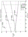
Fig. 30A is a graph of coupling ratio as a function of source resonator coil winding length.
Fig. 30B is a graph of figure of merit as a function of source resonator coil winding length.
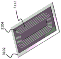
Fig. 31A to 31D are schematic diagrams of the resonator coil.
Fig. 32A is a graph of coupling ratio as a function of resonator coil winding gap-edge distance and span.
Figure 32B is a graph of figure of merit as a function of resonator coil winding gap-edge distance and span.
Fig. 33A and 33B are graphs of the coupling between the source resonator and the device resonator as a function of the offset between the resonators.
Fig. 34A and 34B are graphs of the figure of merit of a wireless power transfer system as a function of the offset between the source resonator and the device resonator.
Fig. 35A and 35B are schematic diagrams of impedance matching networks.
Fig. 36 is a diagram showing the minimum number of capacitors used by different impedance matching networks.
Fig. 37 is a schematic diagram of an impedance matching network.
Fig. 38 is a graph of figure of merit as a function of output voltage in an impedance matched device.
Fig. 39 is a graph of power dissipated in impedance matched source and receiver resonators.
Fig. 40 is a graph of the maximum magnetic field in the source resonator and the device resonator as a function of output voltage.
Fig. 41 is a graph of the voltage across one or more capacitors of the impedance matching networks in the source and receiver resonators.
Fig. 42 is a schematic view showing an embodiment of a magnetic member.
Fig. 43 is an image of an embodiment of a resonator.
Fig. 44 is an image of an embodiment of a source resonator coil fixed to a magnetic member.
Fig. 45A is a schematic view of an embodiment of a magnetic member.
Fig. 45B is an image of an embodiment of a magnetic member.
Figure 46 is an image of an embodiment of a device receiver resonator coil.
Fig. 47A is a schematic diagram of an embodiment of a source resonator coil.
Fig. 47B is a schematic diagram of an embodiment of a device resonator coil.
Fig. 48A and 48B are schematic diagrams of an embodiment of a source resonator coil fixed to a magnetic member.
Figure 49 is an image of an embodiment of a resonator coil with parallel windings.
Fig. 50 is a diagram of the magnetic field in the magnetic member of the source resonator.
Fig. 51 is a diagram of a magnetic field in a magnetic member of a source resonator.
Fig. 52 is a diagram of the magnetic field in the magnetic member of the source resonator.
Fig. 53 is a diagram of the magnetic field in the magnetic member of the device resonator.
Fig. 54A and 54B are diagrams of magnetic fields above a source resonator.
FIG. 55 is a graph of the magnetic fields of FIGS. 54A and 54B on a logarithmic scale.
Fig. 56 is an image of a coil with parallel windings.
Fig. 57A and 57B are schematic diagrams showing inductors connected in series with parallel windings of a coil.
Fig. 57C is a schematic diagram of a single inductor connected in series with one of the multiple parallel windings of the coil.
Fig. 58A and 58B are images showing temperature measurement for parallel windings in a coil.
Fig. 59 is a graph showing the current carried in each parallel winding of the coil as a function of time.
Fig. 60A and 60B are graphs showing the measurement of the coupling k between the source and receiver resonators as a function of the relative displacement of the resonators.
Fig. 61A and 61B are graphs showing measurements for the coupling k between the source resonator and the receiver resonator as a function of the relative displacement of the resonators.
Fig. 62 is a schematic diagram of a receiver resonator.
Fig. 63 is a graph of the Q-factor of a source resonator and a receiver resonator as a function of the side length of the shield.
Fig. 64A and 64B are graphs of peak current through the diodes of the rectifier in the impedance matching network.
Fig. 65A and 65B are graphs of peak current through the diodes of the rectifier in the impedance matching network.
Fig. 66A and 66B are graphs showing the number of capacitors in the impedance matching network of a device as a function of the device inductance.
Fig. 67 is a schematic diagram of an impedance matching network.
Fig. 68 is a graph of figure of merit as a function of output voltage of an impedance matching network.
FIG. 69 is a graph of power dissipation in various components of a source.
Fig. 70 is a diagram of power dissipation in various components of a device.
FIG. 71 is a graph of magnetic field in a magnetic member as a function of output voltage.
Fig. 72 is a graph of voltage across a capacitor in an impedance matching network as a function of output voltage.
Fig. 73 is a graph of current through the source resonator coil and the device resonator coil as a function of output voltage.
Fig. 74 is a flow chart including a series of steps for current division and equalization between parallel windings of a coil.
FIG. 75 is a schematic diagram of an electronic controller.
Detailed Description
The wireless power transfer systems disclosed herein use one or more source resonators to generate an oscillating magnetic field. The oscillating magnetic field is captured by one or more receiving resonators and induces a current and a voltage in the one or more receiving resonators. The receive resonator may be coupled to a load and may use the current and voltage to drive the load to do useful work. The receiving resonator may also function as a relay resonator to further wirelessly transfer power by generating an additional oscillating magnetic field.
Wireless power transfer systems may be integrated into a variety of devices and used for a wide range of power demand applications. For example, such systems may be integrated into electric vehicles and used to power and/or charge the vehicle. Such systems may also be used to power electronic devices including stationary portable devices, and may be integrated into a wide variety of structures including furniture (e.g., desks, tables) and structural features (e.g., floors, walls, posts, streets). Such systems can provide very little to a large amount of power for high power applications. For example, the systems disclosed herein may provide greater than 1kW, 3kW, 5kW, 10kW, 20kW, 50kW, or more, of power from one or more source resonators to one or more receive resonators connected to an electrical device.
Introduction to
Fig. 1A shows a schematic diagram of an embodiment of a wireless power transfer system 100 including a wireless power source 101 and a device 107. The wireless power source 101 includes a source resonator 102 coupled to source electronics 104, wherein the source electronics 104 are connected to a power source 106. The source electronics 104 may include various components including AC/DC converters, amplifiers, and impedance matching networks. The power source 106 may include one or more of an AC power source, a solar panel, and one or more batteries. Not all components of the power supply 101 need be present for operation, and in some embodiments, some of the components shown in fig. 1A may be integrated (e.g., the source electronics 104 and the power supply 106 may be integrated into a single component).
The device 107 includes a device resonator 108 coupled to device electronics 110 to provide power to a load 112. Device electronics 110 may include various components, such as a rectifier and/or an impedance matching network, among others. The load 112 generally corresponds to any of a variety of power dissipating electrical components, such as batteries and/or electromechanical devices. Not all of the components of the device 107 need be present for operation, and in some embodiments, some of the components shown in fig. 1A may be integrated (e.g., the device electronics 110 and the load 112 may be integrated into a single component).
Further aspects and features of wireless power transfer systems are disclosed, for example, in the following patent documents, which are incorporated herein by reference in their entirety: U.S. patent application publication No. 2012/0119569; U.S. patent application publication No. 2015/0051750; U.S. patent No. 8,772,973; U.S. patent application publication No. 2010/0277121; and U.S. patent No. 8,598,743.
In some embodiments, the processor 105 may direct the power source 106 to provide power to the source resonator 102. For example, the processor 105 may increase the power output of the power source 106, thereby increasing the power delivered to the source resonator 102. The power output is delivered at an operating frequency corresponding to the frequency of the oscillating magnetic field generated by the source resonator 102.
In some embodiments, the processor 105 (and/or the processor 111) may tune the resonant frequency of the source resonator 102 and/or the resonant frequency of the device resonator 108. By tuning the resonant frequencies of the source resonator and the device resonator relative to the operating frequency of the power source 106, the efficiency of power transfer from the power source 106 to the load 112 may be controlled. For example, the processor 105 (and/or the processor 111) may tune the resonant frequencies of the source resonator 102 and/or the device resonator 108 to be approximately the same (e.g., within 0.5%, within 1%, within 2%) to increase the efficiency of power transfer.
In some embodiments, processors 105 and/or 111 may tune the resonant frequency by adjusting capacitance values of components in source resonator 102 and/or source electronics 104. The resonant frequency may also be tuned by adjusting capacitance values of components in the device resonator 108 and/or the device electronics 110. For example, to tune the resonant frequency of the source resonator 102, the processor 105 may adjust the capacitance of a capacitor connected to a coil in the source resonator 102. The adjustment may be based on measurements of the resonant frequency by the processor 105 and/or based on communication signals transmitted (e.g., wirelessly transmitted) from the source resonator 102 and/or the device resonator 108 to the processor 105. In certain embodiments, the processor 105 may tune the resonant frequency of the source resonator 102 to be approximately the same (e.g., within 0.5%, within 1%, within 2%) as the operating frequency of the power supply 106. In some embodiments, processor 105 may tune the resonant frequency of source resonator 102 to be 7% to 13% (e.g., 10% to 15%, 13% to 19%) different from the operating frequency. Similar considerations apply to the tuning of the resonant frequency of the device resonator 108 (e.g., by the processor 111 and/or the processor 105 pair).
In some embodiments, processors 105 and/or 111 may control impedance matching networks in system 100 to adjust impedance matching conditions in the system to control the efficiency of power transfer. For example, the processor 105 may tune a capacitance of a capacitor or a capacitor network in an impedance matching network connected between the power source 106 and the source resonator 102 (e.g., as part of the source electronics 104). Alternatively or additionally, the processor 105 may tune an inductor or an inductance of an inductor network in the impedance matching network. The optimal impedance condition may be calculated by the processor 105 and/or may be received from an external device.
Similarly, in certain embodiments, processor 111 may control the impedance matching condition by tuning the capacitance and/or inductance of a capacitor and/or inductor in an impedance matching network connected between device resonator 108 and load 112 (e.g., as part of device electronics 110), respectively. Additional aspects of frequency tuning and impedance matching networks are disclosed, for example, in U.S. patent application publication No. 2005/0051750, which is incorporated herein by reference in its entirety.
In this disclosure, "wireless energy transfer" from one coil (e.g., a resonator coil) to another coil (e.g., another resonator coil) refers to transferring energy to do useful work (e.g., electrical work, mechanical work, etc.), such as powering electronic devices and vehicles, lighting a light bulb, or charging a battery, etc. Similarly, "wireless power transfer" from one coil (e.g., a resonator coil) to another resonator (e.g., another resonator coil) refers to transferring power to do useful work (e.g., electrical work, mechanical work, etc.), such as powering electronic devices and vehicles, lighting light bulbs, or charging batteries, etc. Wireless energy transfer and wireless power transfer both refer to the transfer (or equivalently, transmission) of energy to provide operating power that would otherwise be provided through a wired connection to an electrical power source, such as a connection to a main voltage source, or the like. With the above understanding, the two expressions "wireless energy transfer" and "wireless power transfer" are used interchangeably in this disclosure. It should also be understood that "wireless power transfer" and "wireless energy transfer" may accompany the transfer of information; that is, information may be transferred via electromagnetic signals along with energy or electricity to do useful work.
FIG. 1B is a schematic diagram illustrating a portion of a resonator 150 used for wireless power transfer, the resonator 150 including a coil 152, a magnetic member 154, and a shield 156, the coil 152 including one or more loops and may be connected to one or more capacitors and/or inductors and other electrical components (not shown). the coil 152 is formed from one or more conductive materials such as copper, silver, gold, and litz wire (L itz wire).
The magnetic member 154 is located between the coil 152 and the shield 156. In fig. 1A, the coil 152 is located on one side of the magnetic member 154, and the shield 156 is located on the other side of the magnetic member 154. Generally, the magnetic member 154 directs magnetic flux induced by current flowing in the loop of the coil 152. The presence of the magnetic member 154 may cause the magnetic flux density generated by the coil 152 in a region adjacent to the coil 152 (i.e., in a plane above or below the plane of the coil 152) to increase relative to the magnetic flux density in the absence of the magnetic member 154 as the oscillating current circulates in the coil 152.
In some embodiments, the magnetic member 154 may include one or more magnetic elements formed of a magnetic material such as manganese-zinc (MnZn) and/or nickel-zinc (NiZn) ferrite. In the case where the member 154 is formed of a plurality of magnetic elements, a gap between the elements (not shown in fig. 1B) may be filled with a dielectric material such as an adhesive or the like.
For example, automotive battery charging applications may use magnetic members with large area sizes (e.g., 30cm × cm) to transmit high power of 1kW or more (e.g., 2kW or more, 3kW or more, 5kW or more, 6kW or more). where such materials are available, magnetic members characterized as a single monolithic material may be utilized.
To overcome theseIn some embodiments, multiple magnetic elements may be included in a composite of thermally and electrically conductive materials (e.g., plastic, steel, brass, etc.) and a plurality of such materials may be joined together to form a larger composite magnetic member Alumina, aluminum nitride, etc.),
a shield 156, generally corresponding to a sheet of conductive material, is generally located proximate to the coil 152. The shield 156 may be formed from one or more conductive materials, which may be the same or different from the conductive material used to form the coil 152. For example, the shield 156 may be formed from a thin sheet of material such as copper, silver, gold, iron, steel, nickel, and/or aluminum. The shield 156 is used to shield the coil 152 from loss-inducing species (e.g., metal). Furthermore, in some embodiments, the shield 156 may increase the coupling of the resonator 150 to another resonator by directing magnetic field lines near the resonator. For example, by using the shield 156 to direct the magnetic field lines away from the loss-sponsors, the energy loss to the loss-sponsors caused by anomalous coupling can be reduced.
Fig. 2A to 2C are schematic diagrams illustrating the wireless power transfer system 204 integrated into the vehicle 202. Fig. 2A shows a side view of vehicle 202 in an X-Z coordinate plane, fig. 2B shows a top view of vehicle 202 in an X-Y coordinate plane, and fig. 2C shows a front view of vehicle 202 in a Y-Z coordinate plane. For purposes of the following discussion, the X-axis corresponds to the "fore-aft" direction of the vehicle, the Y-axis corresponds to the "left-right" direction of the vehicle, and the Z-axis corresponds to the "up-down" direction of the vehicle.
For wireless power transfer in vehicular applications, the source resonator and the device resonator may be relatively large to accommodate large scale power transfer between the resonators. In some embodiments, for example, the maximum dimension of the source resonator in the X-Y plane may be 30cm or greater (e.g., 40cm or greater, 50cm or greater, 60cm or greater, 70cm or greater, 80cm or greater, 90cm or greater, 100cm or greater). In certain embodiments, the device resonator may have a maximum dimension in the X-Y plane of 20cm or greater (e.g., 30cm or greater, 40cm or greater, 50cm or greater, 60cm or greater, 70cm or greater, 80cm or greater, 90cm or greater, 100cm or greater). In some embodiments, the maximum dimension of the source resonator may be 10cm or more (e.g., 15cm or more, 20cm or more, 30cm or more) smaller than the maximum dimension of the device resonator.
The source resonator and the device resonator may each have a variety of different cross-sectional shapes, including square, rectangular, circular, elliptical, and more generally, a regular polygon. In some embodiments, the resonators may have different shapes. For example, the source resonator may have a square cross-sectional shape, while the device resonator may have a rectangular cross-sectional shape.
The resonators (e.g., source resonator, receive resonator, repeater resonator) used in the wireless power transfer system disclosed herein may have a resonant frequency f ═ ω/2 pi, an intrinsic loss ratio, and a Q factor Q ═ ω/(2) (also referred to as an "intrinsic" Q factor in this disclosure), where ω is the angular resonant frequency. The resonance frequency f of a source resonator or a receiver resonator is typically determined by the capacitance and inductance values of the resonators.
In some embodiments, any of the source, receiver, and/or repeater resonators may have a Q factor that is a high Q factor, where Q >100 (e.g., Q >100, Q >200, Q >300, Q >500, Q > 1000). For example, a wireless power transfer system may include a power source with one or more source resonators, and at least one of the source resonators may have a Q factor of Q1>100 (e.g., Q1>00, Q1>200, Q1>300, Q1>500, Q1> 1000). A wireless power transfer system may include a power receiver having one or more receiver resonators, and at least one of the receiver resonators may have a Q factor of Q2>100 (e.g., Q2>100, Q2>200, Q2>300, Q2>500, Q2> 1000). The system may include at least one repeater resonator having a Q factor of Q3>100 (e.g., Q3>100, Q3>200, Q3>300, Q3>500, Q3> 1000).
The use of high Q-factor resonators may allow for large energy coupling between some or all of the resonators in a wireless power transfer system. A high Q factor may make the coupling between the resonators strong, whereby the "coupling time" between the resonators is shorter than the "loss time" of the resonators. As a result, energy can be efficiently transferred between resonators at a faster rate than the rate of energy loss due to losses (e.g., heating losses, radiation losses) of the resonators. In certain embodiments, the geometric mean May be greater than 100 (e.g.
 ) Where i and j refer to a source-receiver resonator, a source-repeater resonator, or a repeater-receiver resonator pair (e.g., i-1, j-2, or i-1, j-3, or i-2, j-3). Additional aspects of high Q resonators are described, for example, in U.S. patent No. 8,461,719, which is incorporated herein by reference in its entirety.
Resonator arrangement
The degree of coupling between two resonators in a wireless power transfer system and the efficiency of wireless power transfer depend on a variety of different structural features of the resonators. Thus, different resonator configurations achieve different power transfer efficiencies and rates; thus, different configurations are suitable for different types of power transfer applications. In the following sections, a number of different resonator configurations are shown, and the effect of different structural features on wireless power transfer performance will be discussed.
3A-3B are schematic diagrams illustrating the source resonator coil 302 in the vicinity of the magnetic material 304 with a gap between the magnetic material 304 and the conductive shield 306 in FIG. 3A, there is no gap between the magnetic material 304 and the shield 306 in FIG. 3B, there is a 40mm gap 308 between the magnetic material 304 and the shield 306 (aluminum shield), an offset in the Z direction for a source resonator having a dimension of 60cm × 60cm in the X-Y plane and for a device resonator having a dimension of 25cm × 50cm (not shown in FIGS. 3A-3B) (where the offset with respect to the device resonator is defined by a set of coordinates (X, Y, Z) ═ 0,0,15) cm), for the source resonator 302 shown in FIG. 3A, the coupling ratio k is measured at about 0.077, and for the source resonator 302 shown in FIG. 3B, the coupling ratio k is measured at about 0.083.
In general, the thickness of the magnetic material 304 near (or even attached to) a resonator can be varied to adjust the coupling k to another resonator table 1 summarizes measurements of the coupling ratio k for a wireless transmission system that includes a source resonator coil 402 that is 60cm × 60cm in size in the X-Y plane, as shown in fig. 4, the offset of the source resonator coil 402 relative to a device resonator coil 404 that is 25cm × 50cm in size in the X-Y plane being defined by a set of coordinates (X, Y, Z) ═ 10,150 cm, as previously discussed in fig. 3B, the source resonator coil and magnetic material are separated by a gap of 40mm from the aluminum shield.
Table 1
| With or without vehicle chassis | Thickness of ferrite | Coupling k |
| Presence of chassis | 5mm | 0.060 |
| Without the presence of a chassis | 5mm | 0.075 |
| Without the presence of a chassis | 12mm | 0.083 |
In some embodiments, a device configured to wirelessly receive power may house both the device resonator and the device electronics in an integrated manner. Fig. 5A is a schematic diagram illustrating an embodiment of an apparatus configured to wirelessly receive power in which an apparatus resonator coil 502, a magnetic material 504, and a conductive (e.g., aluminum) shield 506 are stacked on top of one another. Fig. 5B shows a schematic diagram of another embodiment of an apparatus configured to wirelessly receive power. The device of fig. 5B has a "top hat" configuration in which the central portion of the magnetic material 508 is stepped in the Z-direction to form a void region between the magnetic material 508 and the shield 506. Device electronics 510 are located within the void region and coil 502 surrounds the stepped edge of magnetic material 508. By packaging the device electronics 510 within the device resonator as shown in fig. 5B, the compactness of the device may be greatly increased.
The coupling k between the source resonator and the receiver resonator in a vehicle wireless power transfer system depends in part on the presence and nature of the vehicle chassis in the vicinity of the receiver resonator. Fig. 6A and 6B are graphs showing measurements of the coupling k between the source and receiver resonators 604 as a function of the relative displacement between the resonator centers in the X and Z directions. The receiver resonator is similar to the resonator shown in fig. 5A, and the source resonator is similar to the resonator shown in fig. 3B. The graph in fig. 6A shows the measurement of the coupling k in the absence of a vehicle chassis, while the graph in fig. 6B shows the measurement in the presence of an aluminum vehicle chassis. As can be seen from fig. 6A and 6B, the vehicle chassis reduces the value of coupling k by about 20%.
Fig. 7A and 7B are graphs showing the figure of merit (U) as a function of the relative displacement between the centers of the source resonator 602 and the receiver resonator 604 in the X and Z directions0) A measured graph. The receiver resonator is similar to the resonator shown in fig. 5A, and the source resonator is similar to the resonator shown in fig. 3B. The graph in FIG. 7A shows U without the vehicle chassis0And the graph in fig. 7B shows the measurement in the presence of an aluminum vehicle chassis. In fig. 7A, the quality factor of the source resonator is about 1000, while the quality factor of the receiver resonator is about 380. In fig. 7B, the quality factor of the source resonator is about 1000, and the quality factor of the receiver resonator is about 460.
Fig. 8A and 8B are graphs showing measurements of coupling k as a function of relative displacement between the centers of the source resonator 602 and the receiver resonator 604 in the Y and Z directions. The receiver resonator is similar to the resonator shown in fig. 5A, and the source resonator is similar to the resonator shown in fig. 3B. The graph in fig. 8A shows the measurement of k in the absence of a vehicle chassis, while the graph in fig. 8B shows the measurement in the presence of an aluminum vehicle chassis. Clearly, the vehicle chassis reduces coupling k by about 20%.
Fig. 9A and 9B are graphs showing figure of merit (U) as a function of relative displacement between the centers of the source resonator 602 and the receiver resonator 604 in the Y and Z directions0) A measured graph. The receiver resonator is similar to the resonator shown in fig. 5A, and the source resonator is similar to the resonator shown in fig. 3B. The graph in FIG. 9A shows U without the vehicle chassis0And the graph in fig. 9B shows the measurement in the presence of an aluminum vehicle chassis.
Fig. 10A and 10B are graphs showing measurements of coupling k as a function of relative displacement between the centers of the source resonator 602 and the receiver resonator 604 in the X and Z directions. The receiver resonator is similar to the resonator shown in fig. 5B (i.e., a "top hat" configuration), and the source resonator is similar to the resonator shown in fig. 3B. The graph in fig. 10A shows the measurement of k in the absence of a vehicle chassis, while the graph in fig. 10B shows the measurement in the presence of an aluminum vehicle chassis. The measured values of k in fig. 10A and 10B are not substantially different from the measured values shown in the graphs of fig. 6A and 6B, respectively.
Fig. 11A and 11B are graphs showing the figure of merit (U) as a function of the relative displacement between the centers of the source resonator 602 and the receiver resonator 604 in the X and Z directions0) A measured graph. The receiver resonator is similar to the resonator shown in fig. 5B (i.e., a "top hat" configuration), and the source resonator is similar to the resonator shown in fig. 3B. The graph in FIG. 11A shows U without the vehicle chassis0And the graph in fig. 11B shows the measurement in the presence of an aluminum vehicle chassis. The quality factor Q of the source resonator is 1000 and the quality factor Q of the receiver resonator is 450.
Fig. 12A and 12B are graphs showing measurements of coupling k as a function of relative displacement between the centers of the source resonator 602 and the receiver resonator 604 in the Y and Z directions. The receiver resonator is similar to the resonator shown in fig. 5B (i.e., a "top hat" configuration), and the source resonator is similar to the resonator shown in fig. 3B. The graph in fig. 12A shows the measurement of k in the absence of a vehicle chassis, while the graph in fig. 12B shows the measurement in the presence of an aluminum vehicle chassis.
Fig. 13A and 13B are graphs showing figure of merit (U) as a function of relative displacement between the centers of the source resonator 602 and the receiver resonator 604 in the Y and Z directions0) A measured graph. The receiver resonator is similar to the resonator shown in fig. 5B (i.e., a "top hat" configuration), and the source resonator is similar to the resonator shown in fig. 3B. The graph in FIG. 13A shows U without the vehicle chassis0And the graph in fig. 13B shows the measurement in the presence of an aluminum vehicle chassis. The quality factor Q of the source resonator is 1000 and the quality factor Q of the receiver resonator is 450.
Fig. 14A and 14B are graphs showing measurements of coupling k as a function of relative displacement between the centers of the source resonator 602 and the receiver resonator 604 in the X and Z directions. The receiver resonator is similar to the resonator shown in fig. 5B (i.e., a "top hat" configuration), and the source resonator is similar to the resonator shown in fig. 3B. The graph in fig. 14A shows the measured value of k in the presence of an aluminum vehicle chassis, while the graph in fig. 14B shows the measurement of k in the presence of a steel (e.g., ST1008 steel) vehicle chassis. As can be seen in fig. 14A and 14B, replacing the aluminum chassis with a steel chassis has no significant effect on coupling k.
Fig. 15A and 15B are graphs showing the quality factor Q as a function of the relative displacement between the centers of the source resonator 602 and the receiver resonator 604 in the X and Z directions0A graph of the measurement results of (1). The receiver resonator is similar to the resonator shown in fig. 5B (i.e., a "top hat" configuration), and the source resonator is similar to the resonator shown in fig. 3B. The diagram in fig. 15A shows the source resonator Q in the presence of a steel vehicle chassis0,srcAnd (6) measuring. The diagram in FIG. 15B shows the receiver ("device") resonator Q in the presence of a steel vehicle chassis0,devAnd (6) measuring. The source resonator Q is compared with the measurement in the presence or absence of an aluminum vehicle chassis0,srcAnd a receiver resonator Q0,devAre significantly reduced.
Fig. 16A and 16B are graphs showing figure of merit (U) as a function of relative displacement between the centers of the source resonator 602 and the receive resonator 604 in the X and Z directions0) A measured graph. The receiver resonator is similar to the resonator shown in fig. 5B (i.e., a "top hat" configuration), and the source resonator is similar to the resonator shown in fig. 3B. The diagram in fig. 16A shows U in the presence of an aluminum vehicle chassis0Measured, and the graph in FIG. 16B shows U in the presence of a steel ("ST 1008") vehicle chassis0And (6) measuring.
As is apparent from the foregoing discussion, the coupling k between the source resonator and the device resonator can be significantly affected by the presence or absence of the automobile chassis. Fig. 60A and 60B are graphs showing measured values of coupling k between a source resonator and a device resonator similar to those shown in fig. 44 and 46, respectively, as a function of relative displacement between the centers of the resonators in the X and Y directions. The source resonator and the device resonator are spaced 15cm apart from each other in the Z-direction. The graph in fig. 60A shows the measurement of k in the case where the vehicle chassis is present, and the values in fig. 60B show the measurement of k in the case where the vehicle chassis is not present. The presence of the vehicle chassis reduces the coupling k by 10% to 15%. The maximum offset in the X and Y directions is allowed to be 10cm (so that the maximum offset between the resonators corresponds to the set of coordinates (X, Y, Z) — (10,10,15) cm), so the system should match the minimum coupling k well to 0.07.
Fig. 61A and 61B are graphs showing the measurement of the coupling k between the source resonator and the device resonator as in the source resonator and the device resonator in fig. 60A and 60B as a function of the relative displacement between the resonator centers in the X and Y directions. The source resonator and the device resonator are spaced 10cm apart from each other in the Z-direction. The graph in fig. 61A shows the measurement of k in the case where the vehicle chassis is present, and the graph in fig. 61B shows the measurement of k in the case where the vehicle chassis is not present. The presence of the vehicle chassis reduces the coupling k by 1% to 8%.
Fig. 62 shows a schematic diagram of a receiver resonator including a resonator coil 6202, a magnetic member 6204, a first conductive shield 6206, and a second conductive shield 6208. The receiver resonator is located adjacent a vehicle chassis 6210 formed of steel (e.g., ST 1008). The second conductive shield 6208 is formed of aluminum, and the shape of the second conductive shield 6208 is a square having a side length 6212.
To investigate the size of the second shield 6208 versus mitigating coupling loss due to the chassis 6210, the side length 6212 of the second shield 6208 was changed from 50cm to 150cm, and the values of the Q-factors of both the source resonator and the receiver resonator in the wireless power transfer system were measured. The source and receiver resonators are similar to those shown in fig. 44 and 46. Fig. 63 is a graph showing the measured Q factor value for the source resonator (curve 6302) and the measured Q factor value for the receiver resonator (curve 6304) as a function of the side length 6212 of the second shield 6208. The displacement of the source resonator and the receiver resonator relative to each other is 10cm in the X and Y directions and 10cm in the Z direction, where 10cm is the relative offset where the vehicle chassis has the greatest effect on the source resonator. As can be seen in fig. 63, the side length 6212 of the second shield 6208 is preferably 80cm or greater to mitigate the lossy effects of the steel vehicle chassis 6210.
Impedance matching network and electronic component
Various impedance matching networks and configurations may be used in the wireless power transfer system disclosed herein to ensure efficient transfer of power between the source resonator and the receiver resonator. Various features and aspects of impedance matching networks are discussed, for example, in U.S. patent application publication No. 2012/0242225, which is incorporated by reference herein in its entirety.
Fig. 17A is a schematic diagram showing an example of an impedance matching network for a source resonator implementing the "balanced L C L" matching scheme fig. 17B is a schematic diagram showing an example of an impedance matching network for a receiver resonator implementing the "balanced series" matching scheme fig. these impedance matching networks may be used, for example, at power levels greater than 3kW or even greater than 7 kW.
In some embodiments, a wireless power transfer system may include a quality factor Q0,srcSource resonator and quality factor Q of about 10000,devA receiver resonator of approximately 450. The maximum coupling k value of the system may be about 0.12. The minimum coupling k value of the source resonator and the receiver resonator of the wireless power transfer system (refer to fig. 6A to 6B, 7A to 7B, 10A to 10B, 11A to 11B, and 14A to 14B) in the X-Z plane may be about 0.08. The minimum coupling k value of the source resonator and the receiver resonator of the wireless power transfer system in the Y-Z plane (refer to fig. 8A to 8B, 9A to 9B, 12A to 12B, and 13A to 13B) may be about 0.06.
In certain embodiments, the impedance matching point of the receiver resonator may be selected such that the maximum power dissipated in the device comprising the impedance matching network and the diode is less than 300W (e.g., less than 275W, less than 250W, less than 225W, less than 200W).
The impedance matching network may generally include a variety of different electronic components. For example, some impedance matching networks may include a nominal approximately 2000V (peak voltage) and a quality factor QA ceramic capacitor having a cap equal to about 2500 (e.g., a capacitor from the 800E series under the flags of American Technical Ceramics corp., Huntington Station, NY.) in some embodiments, the capacitor voltage rating may determine a target inductance for the resonator coil1a=C1b=C2263nF source resonator coil, with an inductance of L100 muh and a capacitance of C1a=C1bThe receiver resonator coil corresponds to 70.1 nF. In some embodiments, other types of less expensive capacitors, including, for example, film capacitors, may also be used.
Fig. 18A and 18B are graphs of the measured device-side load impedance as a function of output voltage for a device having a receiver resonator as shown in fig. 5B in the presence of an aluminum vehicle chassis. Fig. 18A shows the measured apparatus-side load impedance for a power level of 3.7kW, and fig. 18B shows the measured apparatus-side load impedance for a power level of 7.4 kW.
Fig. 19A and 19B are graphs of amplifier-battery efficiency as a function of output voltage for the device with the receiver resonator shown in fig. 5B in the presence of an aluminum vehicle chassis. Fig. 19A shows the efficiency of the amplifier-cell for the case of coupling k values of 0.12 (curve 1902), 0.08 (curve 1904) and 0.06 (curve 1906) for a power level of 3.7 kW. Fig. 19B shows the efficiency of the amplifier-battery for the case of coupling k values of 0.12 (curve 1908), 0.08 (curve 1910) and 0.06 (curve 1912) for a power level of 7.4 kW. In some embodiments, efficiency rates at lower coupling k values may be improved by matching with lower figure of merit Ud.
Fig. 20A and 20B are graphs of power dissipated in a source (with a resonator corresponding to the source resonator shown in fig. 3B) and a device (with a receiver resonator corresponding to the receiver resonator shown in fig. 5B) as a function of output voltage in the presence of an aluminum vehicle chassis. Fig. 20A shows a plot of the power dissipated in the device (curve 2008) at a power level of 3.7kW and the power dissipated in the source for coupling k values of 0.12 (curve 2002), 0.08 (curve 2004), 0.06 (curve 2006). Fig. 20B shows a plot of the power dissipated in the device (curve 2016) at a power level of 7.4kW and the power dissipated in the source for coupling k values of 0.12 (curve 2010), 0.08 (curve 2012), 0.06 (curve 2014).
Fig. 21A and 21B are graphs of the voltage (Vrms) measured across one or more capacitors in an impedance matching network used in a system including a source (with a resonator corresponding to the source resonator shown in fig. 3B) and a device (with a receiver resonator corresponding to the receiver resonator shown in fig. 5B) as a function of output voltage in the presence of an aluminum vehicle chassis. The voltages in FIGS. 21A and 21B are across the capacitor C shown in FIGS. 17A and 17B1aAnd C1bTo be measured. Figure 21A shows the RMS voltage across the capacitor C1 for the source for the device (curve 2102) and for the coupling k values of 0.12 (curve 2104), 0.08 (curve 2106) and 0.06 (curve 2108) at the 3.7kW power level. Fig. 21B shows the RMS voltage across capacitor C1 for the source for the device (curve 2110) and for the case of coupling k values of 0.12 (curve 2112), 0.08 (curve 2114) and 0.06 (curve 2116) at a power level of 7.4 kW.
Fig. 22A and 22B are magnetic fields (mT) as a function of output voltage measured in a magnetic member attached to a resonator in a wireless power transfer system (i.e., to a source resonator such as the resonator shown in fig. 3B, and to a receiver resonator as shown in fig. 5B) in the presence of an aluminum vehicle chassis. For the measurement shown in fig. 22A and 22B, the magnetic member was formed of ferrite of 5 mm. Fig. 22A shows the magnetic field in the magnetic member of the receiver resonator (curve 2202) and the magnetic field in the magnetic member of the source resonator for coupling k values of 0.12 (curve 2204), 0.08 (curve 2206) and 0.06 (curve 2208) at a power level of 3.7 kW. Fig. 22B shows the magnetic field in the magnetic structure of the receiver resonator (curve 2210) at a power level of 7.4kW and the magnetic field in the magnetic structure of the source resonator for coupling k values of 0.12 (curve 2212), 0.08 (curve 2214) and 0.06 (curve 2216).
Fig. 23 shows a schematic circuit diagram of an embodiment of the device electronics 110. The device electronics includes a device resonator coil 2302 having series tuning represented by series capacitors 2304 and 2306. The device electronics may include a half-wave or full-wave rectification stage 2310, one or more filters 2312, and/or a DC-DC converter 2314. The DC-DC converter may be used to tune the load impedance seen by the device to achieve improved and/or optimal impedance matching values. The load 112 may correspond to various electronic devices such as a battery 2316. In some embodiments, the DC-DC converter 2314 may be used to convert the voltage across the capacitor C1aAnd C1bIs minimized. In some embodiments, the DC-DC converter 2314 may be a buck converter to reduce losses in the rectifier diodes.
Fig. 24A and 24B are graphs showing DC-DC boost conversion ratio as a function of output voltage for a device having a receiver resonator (such as the receiver resonator shown in fig. 5B) in the presence of an aluminum vehicle chassis. Fig. 24A shows DC-DC conversion ratios of the device with the receiver resonator for the cases where coupling k values are 0.12 (curve 2402), 0.08 (curve 2404), and 0.06 (curve 2406) at a power level of 3.7 kW. Fig. 24B shows DC-DC conversion ratios of the devices with receiver resonators with coupling k values of 0.12 (curve 2402), 0.08 (curve 2404), and 0.06 (curve 2406) at a power level of 7.4 kW. In some embodiments, a DC-DC boost conversion ratio of about 4:1 may be optimal for 3.7kW and 7.4kW of operation for various positional offsets between the source resonator and the device resonator and output voltages.
Fig. 25A and 25B are graphs showing amplifier-to-converter efficiency as a function of output voltage for a device having a receiver resonator, such as the receiver resonator shown in fig. 5B, in the presence of an aluminum vehicle chassis. Fig. 25A shows the efficiency of the device with the receiver resonator for the case of coupling k values of 0.12 (curve 2502), 0.08 (curve 2504) and 0.06 (curve 2506) at a power level of 3.7 kW. Fig. 25B shows the efficiency of the device with the receiver resonator for the case of coupling k values of 0.12 (curve 2502), 0.08 (curve 2504) and 0.06 (curve 2506) at a power level of 7.4 kW.
Fig. 26A and 26B are graphs showing power dissipated in a source including a source resonator (such as the source resonator shown in fig. 3B) and in a device including a receiver resonator (such as the receiver resonator shown in fig. 5B) as a function of output voltage in the presence of an aluminum vehicle chassis. Fig. 26A shows the power dissipated in the source for coupling k values of 0.12 (curve 2602), 0.08 (curve 2604) and 0.06 (curve 2606) and the power dissipated in the device for coupling k values of 0.12 (curve 2608), 0.08 (curve 2610) and 0.06 (curve 2612) at a power level of 3.7 kW. Fig. 26B shows the power dissipated in the source for coupling k values of 0.12 (curve 2614), 0.08 (curve 2616), and 0.06 (curve 2618), and the power dissipated in the device for coupling k values of 0.12 (curve 2620), 0.08 (curve 2622), and 0.06 (curve 2624) at a power level of 7.4 kW.
Fig. 27A and 27B are graphs showing the voltage measured across one or more matching network capacitors in a source including a source resonator (such as the source resonator shown in fig. 3B) and in a device including a receiver resonator (such as the receiver resonator shown in fig. 5B) as a function of output voltage in the presence of an aluminum vehicle chassis. Fig. 27A shows the voltage across one or more matching network capacitors in the source for coupling k values of 0.12 (curve 2702), 0.08 (curve 2704), and 0.06 (curve 2706), and across one or more matching network capacitors in the device for coupling k values of 0.12 (curve 2708), 0.08 (curve 2710), and 0.06 (curve 2712) at a power level of 3.7 kW. Fig. 27B shows the voltage across one or more matching network capacitors in the source for coupling k values of 0.12 (curve 2714), 0.08 (curve 2716), and 0.06 (curve 2718), and the voltage across one or more matching network capacitors in the device for coupling k values of 0.12 (curve 2720), 0.08 (curve 2722), and 0.06 (curve 2724) at a power level of 7.4 kW.
Fig. 28A and 28B are graphs of the magnetic field (mT) measured in a magnetic member attached to a source resonator and a receiver resonator in a wireless power transfer system as a function of output voltage in the presence of an aluminum vehicle chassis, where the source resonator is similar to the resonator shown in fig. 3B and the receiver resonator is similar to the resonator shown in fig. 5B. Fig. 28A shows the magnetic field measured in the magnetic component of the source for coupling k values of 0.12 (curve 2802), 0.08 (curve 2804) and 0.06 (curve 2806) and the magnetic field measured in the magnetic component of the apparatus for coupling k values of 0.12 (curve 2808), 0.08 (curve 2810) and 0.06 (curve 2812) at a power level of 3.7 kW. Fig. 28B shows the magnetic field measured in the magnetic member of the source for coupling k values of 0.12 (curve 2814), 0.08 (curve 2816), and 0.06 (curve 2818) and the magnetic field measured in the magnetic member of the device for coupling k values of 0.12 (curve 2820), 0.08 (curve 2822), and 0.06 (curve 2824) at a power level of 7.4 kW.
In some embodiments, the wireless power transfer system may include a switchable multi-tap transformer to variably tune the impedance of the source resonator and/or the receiver resonator. In some embodiments, the wireless power transfer system may include a DC-DC converter to modulate the output impedance.
Resonator arrangement
A wide variety of different resonator configurations may be used in a wireless power transfer system. In this section, examples of these configurations and certain performance characteristics of these configurations will be discussed.
Fig. 29A-29D are schematic diagrams illustrating exemplary embodiments of resonator coils used in wireless power transfer systems, in each of fig. 29A-29D, the resonator winding length 2914 and the span 2916 are different, in each of fig. 29A-29D, the magnetic member 2904 is sized 50cm × 50cm × 5mm, the shield 2902 is sized 60cm × 60 cm. of the magnetic member 2904 is formed of ferrite, and the shield 2902 is formed of aluminum, fig. 29A illustrates a resonator coil 2906 having a minimum length of 400mm and a minimum span of 50mm, fig. 29B illustrates a resonator coil 2908 having a maximum length of 500mm and a minimum span of 50mm, fig. 29C illustrates a resonator coil 2910 having a minimum length of 400mm and a maximum span of 175mm, fig. 29D illustrates a resonator coil 2912 having a maximum length of 500mm and a maximum span of 175mm, the resonator shown in fig. 29A-29D may be used as a source for a resonator (such as the resonator source span shown in fig. 3B).
FIG. 30A is a graph of coupling ratio k as a function of source resonator coil winding length and span, where the coupling ratio k is measured at an offset of about (X, Y, Z) ═ 10,10,15) cm relative to the receiver resonator coil, and the Z offset is measured between the coil surfaces, the receiver resonator size is 25mm × 50mm in FIG. 30A, the darker region 3002 where coupling k is greater represents a 500mm winding length and 130mm winding span such that coupling is higher for certain source resonator coil sizes, FIG. 30B is a figure of merit U as a function of source resonator coil winding length and span for the same source and receiver resonators as in FIG. 30A, FIG. 30B is a plot of the same source and receiver resonators as in FIG. 30A0Wherein the figure of merit U0Is measured at an offset of about (X, Y, Z) ═ 10,10,15) cm relative to the receiver resonator coil, and the Z offset is measured between the coil surfaces.
Fig. 31A-31D are schematic diagrams illustrating exemplary embodiments of resonator coils used in a wireless power transfer system, in each of fig. 31A-31D, a winding gap-edge distance 3114 and a span 3116 are different, in fig. 31A-31D, a magnetic member 3104 is sized to be 20cm × 45cm × 5mm, a shield 3102 is sized to be 25cm × 50 cm., the magnetic member 3104 is formed of ferrite, and the shield 3102 is formed of aluminum, fig. 31A illustrates a resonator coil 3106 having a minimum gap-edge distance of 0mm and a minimum span of 25mm, fig. 31B illustrates a resonator coil 3108 having a maximum gap-edge distance of 20mm and a minimum span of 25mm, fig. 31C illustrates a resonator coil 3110 having a minimum gap-edge distance of 0mm and a maximum span of 50mm, fig. 31D illustrates a resonator coil 3112 having a maximum gap-edge distance of 20mm and a maximum span of 50mm, and the resonator coils 3110 shown in fig. 31A-31D may be used, for example, as a receiver in a resonator.
Figure 32A is a graph of coupling k as a function of resonator coil winding gap-edge distance and span for the resonators of figures 31A-31D. The highest coupling is achieved for a resonator coil with a winding gap-edge distance of 0mm and a span of 50 mm. FIG. 32B isFigure of merit U as a function of resonator coil winding gap-edge distance and span for the resonators of figures 31A-31D0The figure (a).
Fig. 33A and 33B are diagrams of the coupling k between a source resonator of the type shown in fig. 29A-29D and a device resonator of the type shown in fig. 31A-31D as a function of the relative offset between the resonators in the X and Y directions. Fig. 33A shows the coupling k for a relative offset of 10cm between the resonators in the Z direction, and fig. 33B shows the coupling k for a relative offset of 15cm between the resonators in the Z direction.
FIGS. 34A and 34B are figures of merit U of a wireless power transfer system as a function of relative offset between resonators in the X and Y directions0Wherein the wireless power transfer system includes a source resonator of the type shown in fig. 29A-29D and a device resonator of the type shown in fig. 31A-31D. FIG. 34A shows the figure of merit U for a relative offset of 10cm between resonators in the Z direction0And fig. 34B shows the figure of merit U of the relative shift of 15cm between the resonators in the Z direction0。
Additional impedance matching network topology
In addition to the impedance matching networks discussed above, additional impedance matching network topologies may be used in the wireless power systems disclosed herein. Fig. 35A and 35B are schematic diagrams of matching networks used in device electronics 110. Fig. 35A shows a triangular (delta) capacitor matching network 3502, and fig. 35B shows a star capacitor matching network 3504. The two capacitor networks are equivalent to each other by a "delta-star" transformation. A delta and star network that matches the device to an effective impedance that remains relatively flat as the battery voltage and output power vary is desired. Thus, the wireless power transfer system may include a matching network of either topology. In some embodiments, implementing a triangular or star matching network is guided by a network that uses the fewest capacitors with a given voltage rating, such that the network is the one of the triangular or star matching network that is implemented at a lower cost.
FIG. 36 is a drawingA plot of the total minimum number of capacitors used by the triangular (3602) and star (3604) impedance matching networks in the device. Device matching point UdMay affect overall efficiency and determine how dissipated power is distributed between the source and the device. Higher UdThe value means that less power is dissipated in the device and more power is dissipated in the source. Triangular and/or star matching networks may be used to match the UdIn some embodiments, point 3606 (L) may be selected on triangular network 3602 such that approximately equal power is consumed in the source and the device at the maximum relative offset between the resonatorsd37.5 muh) to minimize the number of capacitors and inductors. The lower inductance may reduce the voltage across the winding.
FIG. 37 is a schematic diagram illustrating an embodiment of an impedance matching network topology used in device electronics 110 in FIG. 37, as an example, various circuit component locations may have values of L3a=L3b=25μH;Ca=24.8nF;Cb1=Cb239 nF; and Cc71.8 nF. This topology provides additional degrees of freedom in impedance matching of the device compared to topologies with fewer component locations. Note that position Cb1And Cb2The components at (a) provide equalization of the impedance matching network shown in fig. 35A. Additional aspects of the impedance matching network topology shown in fig. 37 are disclosed, for example, in U.S. patent No. 8,461,719, which is incorporated herein by reference in its entirety.
Fig. 38 is a graph of the figure of merit U as a function of output voltage in a device including a receiving resonator with a triangular impedance matching network (as shown in fig. 35A). Curve 3802 shows a figure of merit U as the resistive component of the device matching impedance for a 7.0kW power outputdR. Curve 3804 shows a figure of merit U as a resistive component of the device matching impedance for a power output of 3.5kWdR. Curve 3806 shows a figure of merit U as the reactive component of the device matching impedance for a power output of 7.0kWdX. Curve 3808 shows the device matching resistance as for a power output of 3.5kWFigure of merit U of reactive component of reactancedX. The reactive component of the device matching impedance is generally smaller than the resistive component, so the device resonator is not significantly detuned from resonance. Furthermore, under these conditions, the current in the source does not increase excessively to drive the non-resonant device resonator.
Fig. 39 is a graph showing the power dissipated in a source resonator and a receiver resonator matched using a triangular impedance matching network as a function of output voltage. The system of source and receiver resonators has a coupling k of 0.08. Curve 3902 shows the power dissipated in the source resonator coil and one or more capacitors of the matching network at a power output of 7.0 kW. Curve 3904 shows the power dissipated in the source resonator coil and one or more capacitors of the matching network at a power output of 3.5 kW. Curve 3906 shows the power dissipated in the receiver resonator coil and one or more source side capacitors of the matching network at a power output of 7.0 kW. Curve 3908 shows the power dissipated in the receiver resonator coil and one or more device side capacitors of the matching network at a power output of 3.5 kW.
Fig. 40 is a graph showing the maximum magnetic field in the source resonator and the device resonator as a function of the output voltage for a wireless power transfer system including the source resonator and the device resonator having a coupling k of 0.08. Curve 4002 shows the maximum magnetic field in the source resonator at a power output of 7.0 kW. Curve 4004 shows the maximum magnetic field in the source resonator at a power output of 3.5 kW. Curve 4006 shows the maximum magnetic field in the device resonator at a power output of 7.0 kW. Curve 4008 shows the maximum magnetic field in the device resonator at a power output of 3.5 kW.
FIG. 41 is a graph showing the voltage across one or more capacitors of a cross-triangular matching network in a receiver resonator (curves 4102-4112) and a source resonator (curves 4114-4116) of a device as a function of output voltage. Curve 4102 shows capacitor C in FIG. 37 at a power output of 7.0kWaThe voltage across the terminals. Curve 4104 shows capacitor C in FIG. 37 at a power output of 3.5kWaThe voltage across the terminals. Curve 4106 showsCapacitor C in FIG. 37 at a power output of 7.0kWbThe voltage across the terminals. Curve 4108 shows capacitor C in FIG. 37 at a power output of 3.5kWbThe voltage across the terminals. Curve 4110 shows capacitor C in FIG. 37 at a power output of 7.0kWcThe voltage across the terminals. Curve 4112 shows capacitor C in FIG. 37 at a power output of 3.5kWcThe voltage across the terminals. Curve 4114 shows the voltage across the source capacitor at a power output of 7.0 kW. Curve 4116 shows the voltage across the source capacitor at a power output of 3.5 kW.
For example, referring to the triangular matching network shown in FIG. 35A, the one component selected is the inductance value L3If L3Too small, the diodes in the rectifier may only conduct for a small fraction of the oscillation period, so in order to deliver a fixed amount of power, the peak current through the diodes would have to be higher, resulting in more power dissipation in the diodes3Will also peak higher and have more harmonic content, resulting in losses in the inductor, in contrast to greater L3The value may add too much esr to the impedance matching network, therefore, the value of L3 is chosen to balance these competing effects.
FIGS. 64A and 64B illustrate a pass diode and inductor L3To transfer 6.6kW to VdcPeak current plot for load of 420V for L 320 muh capacitor (fig. 64A), peak current 34.5a for L3The peak current was 26.7A for a 50 μ H capacitor (fig. 64B).
FIGS. 65A and 65B illustrate a pass diode and inductor L3To transfer 3.3kW to VdcPeak current plot for load of 420V for L3Capacitor 20 muh (fig. 65A), peak current 19.9a for L a3The peak current was 15.3A for a 50 μ H capacitor (fig. 65B).
As described above, once the configuration of the impedance matching network is determined, the network configuration is optimized. Typically, the device matching point UdAffecting the overall efficiency of wireless power transfer and how power is dissipated between the source and the device. Higher UdThe value means that more power is dissipated in the source and less power is dissipated in the device. The impedance matching network may be optimized to satisfy the condition U at the maximum offset between the source resonator and the device resonator (i.e., at k-0.07)d50 (i.e., power dissipation in the source and device is equal). The optimal configuration of the impedance matching network is typically one that uses a minimum number of capacitors while meeting the optimization conditions within acceptable tolerances.
Fig. 66A and 66B are graphs showing the number of capacitors in the impedance matching network of the device as a function of the inductance of the receiving resonator coil inductance of the device for the 800E series of capacitors (fig. 66A) (under American Technical Ceramics corp. Each figure shows the results for both the triangular and star matching networks. FIG. 66A corresponds to target UdA peak voltage of 2000V of 50 and a capacitor of 6.6 kW. FIG. 66B corresponds to the target UdA 600V RMS voltage of 50 and a capacitor of 6.6 kW.
After selecting the type of capacitor to be used (i.e. 800E series capacitors) and the inductance of the receiver resonator coil (43.5 muh, which can be implemented with 8 loops of conductive material), the number and capacitance values of the different capacitors in the impedance matching network are selected, subject to an anti-matching condition (U) that is subject tod50) and is further constrained by the number of capacitors that should be used to achieve this impedance matching condition should be as small as possible.
FIG. 67 is a schematic diagram of an optimized device impedance matching network in the optimized network, L3a=L3b=25μH、Ca28.6nF (implemented with an 800E capacitor of 5 × 5.1.1 nF +1 × 3.0.0 nF), Cb1=Cb236.8nF (implemented with an 800E series capacitor of 7 × 5.1.1 nF +1 × 1.0.0 nF), C351.0nF (implemented with an 800E series of capacitors of 10 × 5.1.1 nF.) the total number of capacitors used in the optimized network is 32. the optimized network is small enough in geometry that the network fits into that of the "top hat" resonator shown in fig. 5BEmpty volume.
FIG. 68 is a graph showing the figure of merit U as a function of output voltage for an optimized impedance matching network at a coupling k value of 0.07dThe figure (a). At 3.3kW output (curve 6802) and 6.6kW output (curve 6804) for UdBetween 300V and 400V (and specifically at about 350V) achieves a target U d50, but not for U at 6.6kW output (curve 6806) or 3.3kW output (curve 6808)dBetween 300V and 400V (and in particular, at about 350V) achieves a target Ud=50。
Fig. 69 is a graph showing the amount of power dissipated in various components of the source for a wireless power transfer system with an optimized device impedance matching network with a coupling value k-0.07 between the source resonator and the receiver resonator. Curves 6902, 6904, 6906 and 6908 show the power dissipated in the resonator coil windings, shields, ferrite magnetic members and capacitors of the source at an output power of 7.0 kW. Curves 6910, 6912, 6914 and 6916 show the power dissipated in the resonator coil windings, shields, ferrite magnetic members and capacitors of the source at 3.5kW output power.
Fig. 70 is a graph showing the amount of power dissipated in various components of a device for a wireless power transfer system with an optimized device impedance matching network with a coupling value k of 0.07 between the source and receiver resonators. Curves 7002, 7004, 7006 and 7008 show the power dissipated in the receiver coil windings, shields, ferrite magnetic members and capacitors of the device at an output power of 7.0 kW. Curves 7010, 7012, 7014 and 7016 show the power dissipated in the receiver coil windings, shields, ferrite magnetic members and capacitors of the device at 3.5kW output power.
Fig. 71 is a graph showing the magnetic field in a ferrite magnetic member as a function of output voltage for a wireless power transfer system with an optimized device impedance matching network with a coupling value between the source and receiver resonators of k 0.07. Curves 7102 and 7104 show the magnetic field in the magnetic member of the source resonator at power outputs of 6.6kW and 3.3kW, respectively. Curves 7106 and 7108 show the magnetic field in the magnetic member of the receiver resonator of the device at the power output of 6.6kW and 3.3kW, respectively.
Fig. 72 is a graph showing the voltage across a capacitor as a function of output voltage for a wireless power transfer system with an optimized device impedance matching network with a coupling value between the source and receiver resonators of k 0.07. Curves 7202 and 7204 show C at output powers of 6.6kW and 3.3kW, respectivelyaThe voltage across the terminals. Curves 7206 and 7208 show C at output powers of 6.6kW and 3.3kW, respectivelybThe voltage across the terminals. Curves 7210 and 7212 show C at output powers of 6.6kW and 3.3kW, respectivelycThe voltage across the terminals.
Fig. 73 is a graph showing current through a source resonator coil and a receiver resonator coil of a device as a function of output voltage for a wireless power transfer system with an optimized device impedance matching network with a coupling value k-0.07 between the source resonator and the receiver resonator. Curves 7302 and 7304 show the current through the source resonator coil at output powers of 6.6kW and 3.3kW, respectively. Curves 7306 and 7308 show the current through the receiver resonator coil of the device at output powers of 6.6kW and 3.3kW, respectively.
Additional resonator configuration
FIG. 42 is a schematic diagram illustrating an embodiment of a magnetic member formed from an array of blocks 4202 of magnetic material (e.g., ferrite). in some embodiments, the ferrite blocks 4202 may have a size of approximately 150mm × 100mm and a thickness of approximately 5mm or 8mm or greater. in certain embodiments, the ferrite blocks 4202 may be arranged such that there is an equal gap of approximately 0.4mm between adjacent blocks. in some embodiments, the largest dimension of the magnetic member may be approximately 500mm × mm.
Typically, the central region of the magnetic member may be left empty (as shown in fig. 42) or filled with additional magnetic material. In some embodiments, as shown in fig. 43, the magnetic member may be spaced approximately 40mm from the aluminum shield 4302 in the resonator. The magnetic construction shown in fig. 42 and 43 is typically used in a source resonator.
FIG. 44 shows an image of an embodiment of a source resonator coil 4402 wherein the source resonator coil 4402 is secured to a magnetic member 4202 that is positioned above and spaced apart from an aluminum shield 4302 in FIG. 44, the source resonator coil has similar outer dimensions as the magnetic member (i.e., about 500mm × 500mm), the resonator coil winding 4404 is about 130mm, and the coil windings have a pitch of about 240mm2The inner dimension 4406.
Generally, higher resonator Q-values can be achieved by winding multiple resonator coils in parallel within the resonator. In fig. 44, three coils are wound in parallel with a minimum of 5 loops in each coil to achieve the target inductance value.
45A and 45B are schematic and image, respectively, showing an embodiment of a magnetic member formed from an array of ferrite blocks 4502 in some embodiments, ferrite blocks 4502 may have a size of about 150mm × 100mm and a thickness of about 5mm or 8mm or greater in some embodiments ferrite blocks 4502 may be arranged such that there is an equal gap of about 0.4mm between the blocks in some embodiments the maximum dimension of the magnetic member may be about 200mm × 450mm the magnetic member shown in FIGS. 45A and 45B is typically used in a receiver resonator of a device.
Fig. 46 is an image of an embodiment of the device receiver resonator coil 4602 secured to a magnetic member 4502 in fig. 46, the device receiver resonator coil has similar external dimensions to the magnetic member shown in fig. 42 (i.e., about 200mm × 450 mm.) the receiver resonator coil in fig. 42 includes a single wire forming seven loops on the surface of the magnetic member of fig. 45 the inductance of the receiver resonator coil 4602 is about 33.1 muh and the quality factor of the receiver resonator coil 4602 is about 591.
Fig. 47A is a schematic diagram of an embodiment of a source resonator coil 4706 secured to a magnetic member 4704 in some embodiments, for example, the magnetic member 4704 may have a dimension of about 50cm × 50cm and a thickness of about 5mm, about 8mm, or greater, the coil 4706 and the magnetic member 4704 are positioned above the shield 4702 and spaced apart from the shield 4702. in some embodiments, for example, the shield 4702 is formed from a conductive material such as aluminum and the like and has a dimension of about 60cm × 60cm in some embodiments, the gap 4708 between the magnetic member 4704 and the shield 4702 may be about 50 mm. in some embodiments, the inductance of the coil 4706 may be about 19.9 μ H and the quality factor of the coil 4706 may be about 1150. in some embodiments, the coil 4706 may include at least three sets of coil windings wound in parallel, where each set may be formed from a different wire or conductive material.
Fig. 47B is a schematic diagram illustrating an embodiment of a device receiver resonator coil 4716 secured to a magnetic member 4712. in some embodiments, the magnetic member 4712 may have a dimension of about 45cm × 20cm and a thickness of about 5mm, about 8mm, or greater. in some embodiments, as shown in fig. 5B, a central region of the magnetic member 4712 may be stepped such that the central region protrudes into an area inside the coil 4716. in some embodiments, the thickness of the magnetic material at the center of the resonator coil may be less than the thickness of the magnetic material elsewhere.
The coil 4716 and the magnetic member 4712 are secured to a shield 4710 formed of an electrically conductive material (e.g., aluminum) and having a size of, for example, about 50cm × 25cm in some embodiments, the inductance of the coil 4716 may be 33.3 μ H and the quality factor of the coil 4716 may be about 443.
For the source resonator and the device resonator shown in fig. 47A and 47B, the coupling k value for the maximum relative shift between coils (X, Y, Z) ═ 10,10,15 can be: for a source resonator fixed to a magnetic member with a thickness of 5mm, k is 0.0707; and for a source resonator fixed to a magnetic member having a thickness of 8mm, k is 0.0710.
Figure 48A is a schematic diagram showing an embodiment of a source resonator fixed to a magnetic member 4802, where the magnetic member 4802 is formed of ferrite blocks having a size of about 10cm × 10cm at each corner and a block having a size of about 15cm × 10cm outside the corner, the quality factor of the resonator is about 1220.
Figure 48B is a schematic diagram illustrating an embodiment of a source resonator fixed to a magnetic member 4804, where the magnetic member 4804 is formed from a ferrite block having a size of about 15cm × 10cm the quality factor of the resonator is about 1050.
Resonator coil with parallel windings
Fig. 49 is an image showing an embodiment of a source resonator 4902, wherein the source resonator 4902 includes three parallel windings 4904, 4906, and 4908 wound in a coil shape over a magnetic member and electrically connected in parallel. In an embodiment, the windings may be electrically connected in parallel rather than in series to reduce the total voltage that may be present across the coil. Although three windings are shown in fig. 49, more generally, any number of windings may be wound in parallel to form a coil and electrically connected in parallel. The windings may have the same or different wire diameters and the overall shape of the coil formed by the parallel windings may be any of the different shapes disclosed herein. For purposes of this disclosure, two sets of loops, each corresponding to a coil winding, are physically "parallel" if the two sets of loops have complementary and corresponding shapes, and the distance between the conductive material forming one set of loops and the conductive material forming the other set of loops is the same between the respective portions of the two sets of loops along more than 80% of the length of the conductive material. Two windings may be considered to be physically parallel if the magnetic coupling between the loops of the two windings is greater than 90%. In some embodiments, sets of shunt loops are often staggered such that respective portions of the conductors forming the loop are parallel to each other.
In some embodiments, where the coil includes multiple sets of loops (e.g., windings) in parallel, excess current may flow in the innermost coil winding. This may occur, for example, because the innermost winding typically has a shorter total length within the coil than the middle and outer windings. This is due to the geometry of the winding within the coil (the innermost winding) because the innermost winding typically has a smaller average loop diameter and a shorter overall length than the other windings, and therefore a smaller overall resistance and inductance than the other windings. As a result, an excessive current may flow in the innermost coil winding relative to the other windings. More generally, since the windings are typically of different lengths, the currents flowing in the windings are different, and some (or even all) of these currents may exceed design specifications and/or safety guidelines.
In general, excessive current in any one coil winding may cause a reduction in efficiency during wireless power transfer due to greater heat dissipation in the winding with the excessive current. In general, heat dissipation increases in proportion to the square of the current in each parallel coil winding. In this section, various methods are disclosed for equalizing currents in multiple parallel windings. The basic overall objective of these methods is to control the current in the multiple coil windings such that the actual current flowing in the windings is equal to a predetermined or selected current profile within an acceptable tolerance. Typically, the predetermined current profile is expressed as a percentage of the total current through the windings that make up the coil. For example, for a coil comprising three parallel windings, the predetermined current profile may correspond to 33.3% (i.e., one third) of the total current carried by the coil through the windings.
In some embodiments, the predetermined current profile corresponds to an aliquot of the total current between the windings. Thus, for a coil having, for example, four parallel windings, the predetermined current profile corresponds to a division of 25% of the total coil current carried by each of the four windings.
In some embodiments, the predetermined distribution does not correspond to an aliquot of current between the windings. This may be advantageous in order to achieve certain functions, for example, to divide the total coil current unequally between the parallel windings of the coil. The methods and systems disclosed herein can be flexibly employed to achieve equal and unequal predetermined current distributions among the parallel windings of the coil.
In some embodiments, the coil windings may be twisted "cross" with each other in order to equalize (i.e., nominally equal) the currents in the coil windings. Fig. 49 shows three such twists at locations 4910, 4912, and 4914. The coil windings are crossed in the following manner: at position 4910, winding 4908 crosses winding 4906; at position 4912, winding 4908 crosses winding 4904; and at position 4914, winding 4906 crosses winding 4904. In some embodiments, three such twists may be sufficient to substantially equalize the current flow through the coil. More generally, however, the windings of the three coils may be crossed or twisted (e.g., including any number of crosses or twists) throughout the coils to further equalize the currents in the windings and ensure that the wires have similar lengths. In some embodiments, for a coil having three coil windings, such as 4904, 4906, and 4908 in fig. 49, the twists in the windings may each be separated by 1/3 of the distance around the coil. More generally, for a coil having n coil windings, the windings may be spaced at 1/n of the total length of a single winding loop as measured along the loop.
Typically, the crossover between windings is used to substantially equalize the length of the windings. By equalizing the winding lengths, the windings have similar resistance and inductance values, and therefore, a substantially equal portion of the total coil current flows through the windings.
Fig. 50 is a diagram showing a magnetic field in a magnetic member of a source resonator (such as the source resonator shown in fig. 47A). In fig. 50, the magnetic member is formed of ferrite having a thickness of 5 mm. With a current of 198A, the maximum magnetic field is 170 mT.
Fig. 51 is a diagram showing a magnetic field in a magnetic part of a source resonator (such as the source resonator shown in fig. 47A). In fig. 51, the magnetic member is formed of ferrite having a thickness of 8 mm. At a current of 198A, the maximum magnetic field is 107 mT.
FIG. 52 is a graph showing the magnetic field in the magnetic component of a source resonator (such as the source resonator shown in FIG. 47A. in FIG. 52, the magnetic component is formed from a ferrite block having the size 15cm × 10cm × 8 mm. with a current of 198A, the maximum magnetic field is 101 mT.
Fig. 53 is a diagram illustrating a magnetic field in a magnetic component of a device resonator (such as the device resonator illustrated in fig. 47B). In fig. 53, the magnetic member is formed of ferrite having a thickness of 8 mm.
Fig. 54A and 54B are diagrams illustrating a magnetic field at a distance of 1cm above the source resonator having the configuration illustrated in fig. 47A. Fig. 55 is a diagram showing a magnetic field at a distance of 1cm above the source resonator having the configuration shown in fig. 47A, plotted on a logarithmic scale.
As described above, in some embodiments, the current in the parallel windings forming the resonator coil may be equalized by crossing the windings at points along the length of the windings (e.g., using twisting). Other methods may also be used to equalize the currents in the multiple parallel coil windings. Specifically, referring to fig. 56, for example, one or more inductors can be used to equalize the current in each of the parallel windings 5602, 5604, 5606. Fig. 57A and 57B show schematic circuit diagrams of a set of inductors 5702, 5704, 5706 connected in series and used to equalize current in a resonator coil having parallel windings 5602, 5604, and 5606. In some embodiments, as shown in fig. 57B, one or more (or even all) of the inductors 5702, 5704, 5706 can be tunable. Typically, a series connected inductor adds inductance to the respective winding to which it is connected. By adding an appropriate amount of inductance to some or all of the windings, the effective inductance of each winding can be adjusted to achieve a predetermined or target current distribution between the windings of the coil.
To equalize the currents in the parallel windings 5602, 5604, and 5606 (hereinafter referred to as windings 1, 2, and 3, respectively, or innermost, middle, and outermost windings, respectively), the inductances of the respective parallel windings may be measured, and the inductors 5702, 5704, and 5706 may be adjusted based on the measured inductances to equalize the currents in the parallel windings. In the discussion that follows, inductors 5702, 5704, and 5706 may be referred to as inductors 5706, respectively And
And in general, various adjustable inductors can be used as the
 inductors 5702, 5704, and 5706. For example, a suitable tunable inductor is disclosed in U.S. patent application publication No. 2015/0051750, which is incorporated herein by reference in its entirety.
The method discussed below may be performed during a manufacturing stage of the resonator so that an inductor having a suitable inductance value may be included in the resonator upon processing. That is, the method may be performed with the aim of selecting and/or adjusting an inductor connected in series with the parallel coil windings, such that at the completion of the resonator manufacture, the inductance of the coil windings has been adjusted to achieve a certain predetermined division of the total coil current between the windings. As described above, this division may correspond to a nominally equal distribution of current between windings, but may also correspond to an unequal distribution of current.
These methods may also be performed post-fabrication by an electronic processor that is part of or connected to the resonator. The electronic processor can be configured to determine the appropriate inductance value of the adjustable inductor at a time in a single optimization sequence. Optionally, the processor may be configured to repeat the steps discussed below multiple times (e.g., at predetermined time intervals and/or in response to user signals) for purposes such as calibration and recalibration in response to changes in the operating environment and/or parameters of the resonator. The following discussion describes various steps that an electronic processor may perform. It should be understood that these steps may be performed before and/or after the processing of the resonator coil, and that certain steps may be performed manually during the design phase.
In a wireless power transfer system, the current equalization steps and methods may be performed by one or more electronic processors (e.g., processors 105 and/or 111) during operation of the system. Fig. 74 is a flowchart 7400 including a series of steps for equalizing currents in parallel windings of a resonator coil. In the discussion of fig. 74 below, reference is made to the above three parallel windings 1, 2 and 3. More generally, however, it should be understood that the methods disclosed herein may be used to equalize currents in any number of parallel windings forming a resonator coil.
In a first step 7402, the electronic processor determines an inductance matrix L of the three connected windings from the inductance value L1、L2And L3In some embodiments, L1<L2<L3To accommodate parallel windings of which L1Is the innermost winding, L2Is an intermediate winding, and L3It is the outermost winding the components of the inductance matrix L may be obtained directly by measuring the coupling between the windings (e.g., using an inductance sensor connected to an electronic processor, not shown in fig. 56.) the electronic processor is configured to receive coupling (i.e., inductance) measurements from the sensors and determine the values of the diagonal elements in the matrix L based on these measurementsi,jWhile obtaining other elements Li,j=Lj,iThis is due to:

in the case where a sinusoidal voltage of amplitude V that oscillates at an angular frequency ω is applied to the windings connected in parallel, the amplitudes of the currents flowing in the three windings are determined by the following equation:

for example, for L1=21.9μH、L2=23.0μH、L3=23.7μH、l1,2=5.24μH、l1,36.35 μ H and l2,35.61 μ H. In this example, the electronic processor uses the inductance measurements received by the processor to determine the following inductance matrix:

the corresponding current repartitioning in the presence of a common voltage V across the parallel- connected windings 1, 2 and 3 is:

this current repartitioning corresponds to the following relative repartitioning of the total current between the three windings: (48.45%, 25.36%, 26.19%). Thus, without an equalizing current in such a coil, the current I1Is almost I2Or I3Twice as much.
In step 7404, the electronic processor determines a desired or target current repartition between the windings. The target current repartition may be a set of stored values retrieved from a memory or data storage unit, a set of values provided by a user or a hard-coded or fixed implementation in the circuit. The target current repartitioning represents a performance condition that the electronic processor attempts to achieve by adjusting the individual inductances coupled to the coil windings. As described above, in some embodiments, the target repartition corresponds to an equal division of the total current between windings. This example will be discussed in more detail below. More generally, however, the methods and systems disclosed herein may achieve any targeted repartitioning of the total current between windings.
Then, in step 7406, the electronic processor determines L respectively1And L2Series-added correction inductor And
And to achieve, for example, uniformly divided current repartitioning (i.e., I) with a minimum amount of additional inductance before the processing ends at
 step 74081=I2=I3)。 And
And given by:


in the previous example, this results in And
And and the corrected current repartitioning becomes:

as previously mentioned, the foregoing discussion of flowchart 7400 relates by way of example to three windings 1, 2 and 3 and uniform current repartitioning. More generally, however, the method for current balancing shown in flowchart 7400 may be applied to a coil having any number (n) of parallel windings, and with the goal of desired current repartitioning between these windings. Thus, for a coil having n parallel windings electrically connected in parallel, the electronic processor may perform the following steps to equalize the currents in the windings.
First, in step 7402, the electronic processor determines an inductance matrix L of the n windings, the component of L may be obtained directly by measuring the coupling (i.e., inductance) between the windings, the diagonal elements in the matrix L are the measured inductances of the connected windings when the other windings are open, the off-diagonal matrix elements Li,j=Lj,iIs determined by the electronic processor by measuring the inductance of each winding i while short-circuiting winding j, because:

then, in step 7404, the electronic processor determines a desired or targeted repartition of the total current in the coil windings. Next, in step 7406, the electronic processor adds from any series relative to windings 1 through nCombination of (i-1 to n) determining an appropriate inductance value of the inductor to achieve the target current repartitioning in the n windings. Added inductance
 Since there is no cross-coupling, inductances are added along the opposite corners of the L matrix
 The other elements of the remainder L are unchanged, the repartition is determined by the electronic processor by computing an inverse matrix:

this results in a corresponding current amplitude And (3) repartitioning:

where V is the common voltage across the parallel connected windings.
The electronic processor determines a combination of inductances that minimizes a figure of merit

Wherein i-1 to n, and wherein n equals the number of connected coils。
In some embodiments, it is easier to find combinations of inductances that cause the current to be divided approximately equally among the n windings An increased inductor value is added. In the case where there are no other constraints,
 some large values of (a) may naturally minimize the figure of merit:

for example, in some embodiments, the added inductance May be much larger than the inductance of the winding. As an example of this, the following is given,
 an ideal current repartition between the windings will result. Similarly, if an inductance is added
 Much larger than the strongest inductive winding, a near-ideal current split can result. However, from a practical point of view, this may not be helpful. For practical reasons, during optimization, the electronic processor may take into account such considerations as space constraints, limiting additional losses, limiting the amount of magnetic material added, limiting the total added inductance that is undesirable, and limiting additional complexity in the wireless power transfer system. For example, the number of windings n may be limited due to space limitations imposed on the overall size of the source resonator coil. In some embodiments, the method can be used for
 The range of values is limited to be less than or equal to the scaled inductance of the winding:

where a is the scaling amount of zero and the difference between the maximum inductance of the winding and the minimum inductance of the winding.
In some embodiments, the number of windings, m, to which the additional inductance is added may be determined by an electronic processor. The number of windings to which the additional inductance is added may be limited to less than or equal to the total number of windings n. In some embodiments, the number of windings, m, to which additional inductance is added may be determined before optimizing the current distribution for the n windings. In some embodiments, different combinations of the number m of windings to which additional inductance is added may be iteratively selected during current distribution optimization.
In some embodiments, if m-n-1, the one winding to which no inductor is added is the winding with the largest inductance. Conversely, if m < n-1, an inductor may be added to the winding with the lowest inductance and the remaining n-m windings with the largest inductance do not add additional inductors for current balancing. In some embodiments, the electronic processor may control the increase of the inductor based on a change in the sequence of inductances of the windings that depends on external factors (presence or absence of the device, presence or absence of lossy material, etc.).
For example, for a winding with n-3 and m-1, the electronic processor may perform three different optimizations, as described below, in each of which two of the three inductance values of the additional inductor are set to zero:


electronic processor may be superiorCombination of additional inductors To minimize the following:

wherein This results in three optimized configurations and corresponding current distributions in the three windings. The electronic processor can then compare the three configurations to determine which additional inductor to use
 Or
Or The best results are obtained in terms of current distribution (or another metric).
In some embodiments, a single inductor 5702 may be used to achieve substantially equal current repartitioning among multiple parallel coil windings, as shown in fig. 57C. For example, a single inductor connected to winding 5602 (innermost winding) (i.e. the
 ) Current repartitioning can be significantly improved, with predicted distributions of about 33.5% -34.6% -31.9%. These results are within 5% of the target of a substantially equal current distribution (e.g., 33.3%) in each winding. In some embodiments, the electronic processor may iteratively optimize until the current distribution in each winding is within 20% of a target current distribution (e.g., within 15%, within 10%, within 5%), wherein the target current distribution may be (but is not necessarily) an equal current distribution between windings. The process shown in
 flowchart 7400 then ends at step 7408.
In certain embodiments, a slightly reduced current in the outermost winding 5606 (winding 3) may be advantageous because the longer length of winding 5606 results in a resistance that may be about 8% higher than the resistance of the other windings. In some embodiments, a particular current profile may be desired, and the electronic processor may minimize a more general figure of merit:

wherein s isiIs a target fraction of the total current flowing in winding i (hence ). For example, one of the windings may be cooled more efficiently than the other windings, and thus the current repartitioning may be changed accordingly. In another example, some windings may have different resistances or inductances than expected at the time of manufacture, and the electronic processor may be able to compensate for these differences.
In some embodiments, the inductor May include pairs of cores formed of magnetic material. For example, an inductor having a planar E-core formed of ferrite may be used. For an inductor with a gap of 2mm and 4 turns of 4200/44 litz wire, at the source current value Is=140ARMSThe inductor dissipation may be about 3.2W. The same litz wire as the innermost winding (winding 5602) can be used to wind the inductor
 The connection can be simplified. In some embodiments, an inductor is added
 In the case of (2), the overall inductance measurement yields:

in case a voltage V is applied across three windings connected in parallel, the following relation is obtained:

the current repartition between windings can be calculated by summing the elements in the above vector (1.56+1.68+ 1.52-4.76) and dividing each element by the sum. This indicates that the innermost winding can carry 32.8% of the current, the middle winding 35.2% of the current, and the outermost winding 32.0% of the current.
For example, for a signal at 27.8ARMSWireless power transfer system with total current in the source coil (with three parallel windings) tested at an output of 2.5kW, the following current repartitioning was achieved:
the innermost winding: 8.4ARMS(30.2%),
Intermediate winding: 9.9ARMS(35.7%),
The outermost winding: 9.5ARMS(34.1%)。
The current repartitioning is close to the expected current repartitioning based on low power measurements.
In the present embodiment, windings carrying larger currents may reach higher operating temperatures and/or dissipate maximum power. Fig. 58A and 58B are images showing temperature measurements for windings in a coil carrying a total of 10A of current during operation. The middle winding 5604 heats to a temperature slightly greater than the temperatures of the innermost winding 5602 and the outermost winding 5606 (see fig. 58B, measurement at position 5804) (see fig. 58A, measurement at position 5802), consistent with the above prediction. Fig. 59 is a graph showing the current carried in each winding 5602 (curve 5902), 5604 (curve 5904), and 5606 (curve 5906) as a function of time. As shown, the current carried in the middle winding (winding 5604) is greater than the current carried in the innermost and outermost windings, which accounts for the greater heating of the middle winding.
Hardware and software implementation
FIG. 75 illustrates an example of an electronic controller 7503 that can be used with the systems and methods described herein. As previously described, any of the control and/or calculation functions disclosed herein may be performed using an electronic controller (more particularly, an electronic processor of the electronic controller, such as processor 105 and/or 111, etc.), including controlling power transfer of the wireless power transfer system, for example, by changing the power output of the power source, adjusting the operating and/or resonant frequency, and adjusting the impedance matching network. Electronic controller 7503 can be used to control the direction, magnitude, and phase of the current of the different coils relative to the other coils. In some embodiments, the electronic controller 7503 can be directly connected to or wirelessly communicate with the various elements of the system.
The electronic controller 7503 can include a processor 7502 (e.g., corresponding to processors 105 and/or 111), a memory 7504, a storage 7506, and an interface 7508 for interconnection. The processor 7502 can process instructions for execution within the electronic controller 7503, wherein such instructions include instructions stored in the memory 7504 or on the storage device 7506. For example, the instructions may instruct the processor 7502 to determine parameters of the system, such as efficiency of power transfer, operating frequency, resonant frequency of the resonator, and impedance matching conditions. The electronic controller 7503 can determine the type, size, and alignment of the power receiving device based on detection signals from one or more sensors. In certain embodiments, the processor 7502 is configured to issue control signals to various elements (e.g., power source, power transmitting device, power receiving device, power relaying device, impedance matching network) to adjust the determined parameters. For example, the control signal may be used to tune the capacitance value of a capacitor in the impedance matching network. In some embodiments, the control signal may be used to adjust the operating frequency of the power source. The control signal may change the capacitance value of a capacitor in the resonator to tune the resonant frequency of the resonator and/or change the inductance value of a tunable inductor to repartition the current between parallel windings in the resonator coil.
The memory 7504 may store information related to optimization parameters of the system. For example, the information may include optimized impedance matching conditions for various levels of power output from the power source. In certain embodiments, the memory 7504 can store information such as the resonant frequency of the resonator and the magnetic properties of the magnetic components in the system (e.g., permeability depending on power level), which the processor 7502 can use to determine signals to be emitted to control various elements in the system. The memory may also store a set of values corresponding to the target current repartitioning.
In some embodiments, the electronic controller 7503 may include a graphics processing unit to display graphical information (e.g., using a GUI or text interface) on an external input/output device such as the display 7516. the graphical information may be displayed by a display device (e.g., a CRT (cathode ray tube) or L CD (liquid crystal display) monitor) for displaying the information.
In some embodiments, the electronic controller 7503 can monitor the system for hazardous conditions. For example, the electronic controller 7503 can detect overheating in the system and provide an alert (e.g., a visual and/or audible alert) to the user via a graphical display or audio device of the system.
In certain embodiments, the electronic controller 7503 can be used to control the magnitude and phase of the current flowing in one or more coils of the wireless power transfer system. For example, the processor 7502 may calculate and determine the amplitude and phase of the current to be supplied to the coil in the power transmitting device. The determination may be based on the monitored power transfer efficiency and information stored in memory 7504 or storage unit 7506.
The feedback signal may be received and processed by the electronic controller 7503. For example, the electronic controller 7503 can include a wireless communication device (e.g., a radio frequency, bluetooth receiver) to receive information from one or both of the power transmitting device and/or the power receiving device (which can have their own wireless communication device). In some embodiments, the received information may be processed by processor 7502, and processor 7502 may further issue control signals to adjust parameters of the system as described above. For example, the control signal may be used to adjust the magnitude and phase of current flowing in one or more resonator coils in the system to increase power transfer efficiency.
As used herein, the term "computer-readable medium" refers to any computer program product, device, and/or apparatus (e.g., magnetic discs, optical disks, memory, programmable logic device (P L D)) used to provide machine instructions and/or data to a programmable processor, including a machine-readable medium that receives machine instructions, and/or data.
Generally, electronic controller 7503 can be implemented in a computing system to implement the above-described operations. For example, the computing system can include a back-end component (e.g., as a data server), or a middleware component (e.g., an application server), or a front-end component (e.g., a client computer having a graphical user interface), or any combination thereof, for enabling a user to utilize the operations of electronic controller 7503.
The electronic controller 7503, or one or more elements thereof, can be integrated into the vehicle. Electronic controller 7503 may be used to control and/or monitor wireless power charging of a battery installed in the vehicle. In some embodiments, as described with respect to fig. 75, the display 7516 may be mounted adjacent to the drive wheels of the vehicle so that a user may monitor the condition of the power charge and/or control parameters of the power charge. The display 7516 may also visualize traffic information and road maps based on information from the Global Positioning System (GPS). Any elements such as the processor 7502, memory 7504, and storage 7506 may be mounted in space behind the display 7516 that enables the visualization of the data processing performed by these elements.
OTHER EMBODIMENTS
While this disclosure contains many specific implementation details, these should not be construed as limitations on the scope of the disclosure, but rather as descriptions of features relevant to the embodiments. Features which are described in the context of separate embodiments may also generally be implemented in combination in a single embodiment. In contrast, various features that are described in the context of a single embodiment can also be implemented in multiple embodiments separately or in any suitable subcombination. Furthermore, although features may be described above as acting in certain combinations and even initially claimed as such, one or more features from a claimed combination can in general be excised from the combination, and the claimed combination may be directed to a subcombination or variation of a subcombination.
In addition to the embodiments explicitly disclosed herein, other embodiments are also within the scope of the present disclosure.
Claims (27)
1. A system for wireless power transfer, comprising:
a resonator comprising a coil having at least two windings, each of the at least two windings comprising a plurality of loops formed of an electrically conductive material and extending in a plane, wherein respective portions of each of the at least two windings are oriented in parallel, a length of at least one of the at least two windings is different from a length of another of the at least two windings, and the at least two windings are electrically connected in parallel;
at least one adjustable inductor having an inductance value, wherein the at least one adjustable inductor is connected in series to at least one of the at least two windings; and
an electronic processor connected to the resonator and to the at least one adjustable inductor, and configured to determine, during operation of the system, an adjustment of an inductance of one or more of the at least two windings based on coupling between the at least two windings, and adjust the at least one adjustable inductor such that, when the coil carries current during operation of the system, the at least one adjustable inductor maintains a current distribution between the at least two windings such that, for each of the at least two windings, an actual current in the winding differs from a target current for that winding by 10% or less.
2. The system of claim 1, wherein the respective portions of each of the at least two windings are oriented in parallel along at least 80% of a length of at least one of the at least two windings.
3. The system of claim 1, wherein the loops of each winding are interleaved.
4. The system of claim 1, wherein the loops of each winding are concentric and form a spiral.
5. The system of claim 1, wherein the electronic processor is configured to control current in each winding based on a target current for the at least two windings.
6. The system of claim 5, wherein the electronic processor is configured to
Determining the inductance adjustment based on a figure of merit associated with the target current.
7. The system of claim 6, wherein the electronic processor is configured to:
i. for each winding:
determining a self-inductance value of the winding based on a measurement of the inductance of the winding when the winding is electrically disconnected from all other windings, an
Determining a plurality of mutual inductance values for the winding, wherein each mutual inductance value is based on a measurement of an inductance of the winding when the winding is electrically disconnected from another winding;
determining a target current for each winding based on the self-inductance value and the mutual-inductance value; and
determining the inductance adjustment based on a target current for each winding.
8. The system of claim 7, wherein the electronic processor is configured to determine the target current by:
constructing an inductance matrix based on the self-inductance values and the mutual-inductance values of the windings;
calculating an adjusted inductance matrix by adding an inductance modification matrix comprising elements corresponding to changes in inductance of the windings due to the at least one adjustable inductor to the inductance matrix;
calculating an inverse matrix of the adjusted inductance matrix; and
determining the target current based on the inverse matrix.
9. The system of claim 8, wherein the inductance modification matrix is a diagonal matrix and diagonal elements of the inductance modification matrix are inductance values of components of the at least one adjustable inductor connected to a winding.
10. A method for wireless power transfer, comprising the steps of:
determining an inductance adjustment of one or more of at least two windings of a resonator coil for wireless power transfer based on a coupling between the at least two windings, wherein each of the at least two windings comprises a plurality of loops formed of an electrically conductive material and extending in a plane, respective portions of each of the at least two windings are oriented in parallel, a length of at least one of the at least two windings is different from a length of another one of the at least two windings, and the at least two windings are electrically connected in parallel, at least one inductor connected in series to at least one of the at least two windings has an adjustable inductance value;
adjusting the at least one inductor having an adjustable inductance value;
controlling the current in each of the at least two windings to maintain a current distribution between the at least two windings such that, for each of the at least two windings, the actual current in that winding differs from the target current for that winding by 10% or less.
11. The method of claim 10, wherein the respective portions of each of the at least two windings are oriented in parallel along at least 80% of a length of at least one of the at least two windings.
12. The method of claim 10, wherein the loops of each winding are interleaved.
13. The method of claim 10, wherein the loops of each winding are concentric and form a spiral.
14. The method of claim 10, further comprising:
determining the inductance adjustment based on a figure of merit associated with the target current.
15. The method of claim 14, further comprising determining the inductance adjustment by:
i. for each winding:
determining a self-inductance value of the winding based on a measurement of the inductance of the winding when the winding is electrically disconnected from all other windings, an
Determining a plurality of mutual inductance values for the winding, wherein each mutual inductance value is based on a measurement of an inductance of the winding when the winding is electrically disconnected from another winding;
determining a target current for each winding based on the self-inductance value and the mutual-inductance value; and
determining the inductance adjustment based on a target current for each winding.
16. The method of claim 15, further comprising determining the target current by:
constructing an inductance matrix based on the self-inductance values and the mutual-inductance values of the windings;
calculating an adjusted inductance matrix by adding an inductance modification matrix including elements corresponding to changes in inductance of the windings due to the at least one inductor to the inductance matrix;
calculating an inverse matrix of the adjusted inductance matrix; and
determining the target current based on the inverse matrix.
17. The method of claim 16, wherein the inductance modification matrix is a diagonal matrix and diagonal elements of the inductance modification matrix are inductance values of components of the at least one inductor connected to a winding.
18. A resonator coil for wireless power transfer, the coil comprising:
a member formed of a magnetic material; and
three windings electrically connected in parallel, each of the three windings comprising a plurality of loops formed from a conductive material and an inductive element connected in series, the inductive element configured to receive a signal from an electronic processor to adjust an inductance of the inductive element between a zero and a positive inductance value to adjust a combined inductance of the windings and the inductive element,
wherein the loops of each of the three windings are interleaved such that a respective portion of each of the three windings is oriented parallel along at least 80% of a length of at least one of the three windings, an
Each of the three windings spatially overlaps at least one other winding at one or more points along the length of the winding.
19. The coil of claim 18, wherein the loops of each winding are oriented in a plane.
20. The coil of claim 19, wherein the loops of all windings are oriented in a common plane.
21. The coil of claim 18, wherein the loops of each winding are concentric and form a spiral.
22. The coil of claim 21, wherein the loops of all windings form concentric spiral loops.
23. The coil of claim 18, wherein each of the three windings spatially overlaps each of the other windings at one or more points along the length of the winding.
24. The coil of claim 18, wherein, for each winding, the points at which the winding overlaps at least some of the other windings are equally spaced along the circumference of the winding.
25. The coil of claim 23, further comprising additional windings such that a total number of windings in the coil is n, wherein each of the n windings spatially overlaps each of n-1 other windings along a length of the winding, and each of the n windings comprises n-1 overlap points with other windings, each point corresponding to an overlap of the winding with a different one of the other windings.
26. The coil of claim 18, further comprising additional windings such that a total number of windings in the coil is n, wherein at least one winding of the n windings comprises more than n-1 overlap points with other windings such that the at least one winding spatially overlaps at least some of the n-1 other windings more than once.
27. The coil of claim 18, further comprising additional windings such that a total number of windings in the coil is n, wherein at least one winding of the n windings comprises less than n-1 overlap points with other windings such that the at least one winding does not spatially overlap all n-1 other windings.
Applications Claiming Priority (5)
| Application Number | Priority Date | Filing Date | Title |
|---|---|---|---|
| US201462022133P | 2014-07-08 | 2014-07-08 | |
| US62/022,133 | 2014-07-08 | ||
| US201462051647P | 2014-09-17 | 2014-09-17 | |
| US62/051,647 | 2014-09-17 | ||
| PCT/US2015/039612 WO2016007674A1 (en) | 2014-07-08 | 2015-07-08 | Resonator balancing in wireless power transfer systems |
Publications (2)
| Publication Number | Publication Date |
|---|---|
| CN107258046A CN107258046A (en) | 2017-10-17 |
| CN107258046B true CN107258046B (en) | 2020-07-17 |
Family
ID=53673321
Family Applications (1)
| Application Number | Title | Priority Date | Filing Date |
|---|---|---|---|
| CN201580048080.0A Active CN107258046B (en) | 2014-07-08 | 2015-07-08 | Resonator equalization in wireless power transfer systems |
Country Status (5)
| Country | Link |
|---|---|
| US (1) | US9842688B2 (en) |
| EP (1) | EP3167532B1 (en) |
| JP (1) | JP6518316B2 (en) |
| CN (1) | CN107258046B (en) |
| WO (1) | WO2016007674A1 (en) |
Families Citing this family (22)
| Publication number | Priority date | Publication date | Assignee | Title |
|---|---|---|---|---|
| US10114120B2 (en) | 2014-04-16 | 2018-10-30 | The Regents Of The University Of Michigan | Unidirectional near-field focusing using near-field plates |
| US9793720B2 (en) | 2014-04-16 | 2017-10-17 | The Regents Of The University Of Michigan | Wireless power transfer using multiple near-field plates |
| US9837860B2 (en) * | 2014-05-05 | 2017-12-05 | Witricity Corporation | Wireless power transmission systems for elevators |
| JP6172185B2 (en) * | 2015-03-11 | 2017-08-02 | トヨタ自動車株式会社 | Power receiving device and power transmitting device |
| JP2017034029A (en) * | 2015-07-30 | 2017-02-09 | 日本特殊陶業株式会社 | Resonator |
| TWI565187B (en) * | 2015-09-15 | 2017-01-01 | 至美科技股份有限公司 | Llc charger and controlling method thereof, and tx-rx transformer |
| US10714960B2 (en) * | 2015-12-22 | 2020-07-14 | Intel Corporation | Uniform wireless charging device |
| KR101847256B1 (en) * | 2016-01-11 | 2018-05-28 | 한국전자통신연구원 | Wireless power receiver, system having the same and method for controlling automatically load resistance transformation ratio |
| US9837923B2 (en) * | 2016-04-27 | 2017-12-05 | General Electric Company | Integrated power converter and transformer |
| JP6532086B2 (en) * | 2016-04-28 | 2019-06-19 | 昭和飛行機工業株式会社 | Externally shielded non-contact power supply |
| WO2017199361A1 (en) * | 2016-05-18 | 2017-11-23 | 日産自動車株式会社 | Coil unit |
| WO2018097739A1 (en) | 2016-11-25 | 2018-05-31 | Auckland Uniservices Limited | Current distribution and thermal regulation in inductive power transfer coupling structures |
| US10984946B2 (en) | 2016-12-20 | 2021-04-20 | Witricity Corporation | Reducing magnetic flux density proximate to a wireless charging pad |
| CN110603736B (en) | 2017-03-17 | 2021-12-21 | 宜普电源转换公司 | Large area scalable highly resonant wireless power coil |
| US10469119B2 (en) * | 2017-05-25 | 2019-11-05 | Spigen Korea Co., Ltd. | Magnetic mount for electronic devices |
| US11282638B2 (en) | 2017-05-26 | 2022-03-22 | Nucurrent, Inc. | Inductor coil structures to influence wireless transmission performance |
| US10819156B2 (en) | 2017-12-05 | 2020-10-27 | Witricity Corporation | Flush-mount wireless charging power-transfer system |
| US10855118B2 (en) * | 2018-06-22 | 2020-12-01 | Apple Inc. | Electric shielding structures |
| US11283303B2 (en) | 2020-07-24 | 2022-03-22 | Nucurrent, Inc. | Area-apportioned wireless power antenna for maximized charging volume |
| CN112260540B (en) * | 2020-10-19 | 2021-10-08 | 山东大学 | Parallel current sharing method and system for resonant direct current converter |
| US11695302B2 (en) * | 2021-02-01 | 2023-07-04 | Nucurrent, Inc. | Segmented shielding for wide area wireless power transmitter |
| US20230261570A1 (en) * | 2022-02-11 | 2023-08-17 | Applied Materials, Inc. | Tunable integrated voltage regulator |
Citations (3)
| Publication number | Priority date | Publication date | Assignee | Title |
|---|---|---|---|---|
| CN102640379A (en) * | 2009-07-24 | 2012-08-15 | 捷通国际有限公司 | Power supply |
| CN102883525A (en) * | 2012-09-25 | 2013-01-16 | 清华大学 | Double-layered snail-shaped PCB coil for wireless energy transfer and design method thereof |
| CN103208866A (en) * | 2013-04-23 | 2013-07-17 | 中国科学院电工研究所 | Method for designing wireless power transmission device |
Family Cites Families (581)
| Publication number | Priority date | Publication date | Assignee | Title |
|---|---|---|---|---|
| US645576A (en) | 1897-09-02 | 1900-03-20 | Nikola Tesla | System of transmission of electrical energy. |
| US787412A (en) | 1900-05-16 | 1905-04-18 | Nikola Tesla | Art of transmitting electrical energy through the natural mediums. |
| GB190508200A (en) | 1905-04-17 | 1906-04-17 | Nikola Tesla | Improvements relating to the Transmission of Electrical Energy. |
| US1119732A (en) | 1907-05-04 | 1914-12-01 | Nikola Tesla | Apparatus for transmitting electrical energy. |
| US2133494A (en) | 1936-10-24 | 1938-10-18 | Harry F Waters | Wirelessly energized electrical appliance |
| US3535543A (en) | 1969-05-01 | 1970-10-20 | Nasa | Microwave power receiving antenna |
| US3517350A (en) | 1969-07-07 | 1970-06-23 | Bell Telephone Labor Inc | Energy translating device |
| GB1303835A (en) | 1970-01-30 | 1973-01-24 | ||
| US3871176A (en) | 1973-03-08 | 1975-03-18 | Combustion Eng | Large sodium valve actuator |
| US4088999A (en) | 1976-05-21 | 1978-05-09 | Nasa | RF beam center location method and apparatus for power transmission system |
| US4095998A (en) | 1976-09-30 | 1978-06-20 | The United States Of America As Represented By The Secretary Of The Army | Thermoelectric voltage generator |
| JPS5374078A (en) | 1976-12-14 | 1978-07-01 | Bridgestone Tire Co Ltd | Device for warning pressure reducing of inner pressure of tire |
| US4280129A (en) | 1978-09-09 | 1981-07-21 | Wells Donald H | Variable mutual transductance tuned antenna |
| US4450431A (en) | 1981-05-26 | 1984-05-22 | Hochstein Peter A | Condition monitoring system (tire pressure) |
| US4588978A (en) | 1984-06-21 | 1986-05-13 | Transensory Devices, Inc. | Remote switch-sensing system |
| ES2008655T3 (en) | 1987-07-31 | 1994-02-01 | Texas Instruments Deutschland Gmbh | TRANSMISSION-RESPONSE PROVISION (TRANSPONDER). |
| DE3815114A1 (en) | 1988-05-04 | 1989-11-16 | Bosch Gmbh Robert | DEVICE FOR TRANSMITTING AND EVALUATING MEASURING SIGNALS FOR THE TIRE PRESSURE OF MOTOR VEHICLES |
| DE3824972A1 (en) | 1988-07-22 | 1989-01-12 | Roland Hiering | Illumination of christmas trees, decorations and artwork |
| JPH0297005A (en) | 1988-10-03 | 1990-04-09 | Tokyo Cosmos Electric Co Ltd | Variable inductance |
| JP2820706B2 (en) | 1989-03-02 | 1998-11-05 | 株式会社日本自動車部品総合研究所 | Power supply device having coil for electromagnetic coupling |
| US5034658A (en) | 1990-01-12 | 1991-07-23 | Roland Hierig | Christmas-tree, decorative, artistic and ornamental object illumination apparatus |
| US5027709A (en) | 1990-04-26 | 1991-07-02 | Slagle Glenn B | Magnetic induction mine arming, disarming and simulation system |
| JPH04265875A (en) | 1991-02-21 | 1992-09-22 | Seiko Instr Inc | Plane type gradiometer |
| US5293308A (en) | 1991-03-26 | 1994-03-08 | Auckland Uniservices Limited | Inductive power distribution system |
| US6738697B2 (en) | 1995-06-07 | 2004-05-18 | Automotive Technologies International Inc. | Telematics system for vehicle diagnostics |
| US5118997A (en) | 1991-08-16 | 1992-06-02 | General Electric Company | Dual feedback control for a high-efficiency class-d power amplifier circuit |
| NL9101590A (en) | 1991-09-20 | 1993-04-16 | Ericsson Radio Systems Bv | SYSTEM FOR CHARGING A RECHARGEABLE BATTERY FROM A PORTABLE UNIT IN A RACK. |
| US5341083A (en) | 1991-09-27 | 1994-08-23 | Electric Power Research Institute, Inc. | Contactless battery charging system |
| GB2262634B (en) | 1991-12-18 | 1995-07-12 | Apple Computer | Power connection scheme |
| US5216402A (en) | 1992-01-22 | 1993-06-01 | Hughes Aircraft Company | Separable inductive coupler |
| US5229652A (en) | 1992-04-20 | 1993-07-20 | Hough Wayne E | Non-contact data and power connector for computer based modules |
| ES2163409T3 (en) | 1992-05-10 | 2002-02-01 | Auckland Uniservices Ltd | SYSTEM OF DISTRIBUTION OF ENERGY UNPROVISED OF CONTACTS. |
| US5437057A (en) | 1992-12-03 | 1995-07-25 | Xerox Corporation | Wireless communications using near field coupling |
| US5287112A (en) | 1993-04-14 | 1994-02-15 | Texas Instruments Incorporated | High speed read/write AVI system |
| GB9310545D0 (en) | 1993-05-21 | 1993-07-07 | Era Patents Ltd | Power coupling |
| JP3207294B2 (en) | 1993-06-02 | 2001-09-10 | 株式会社安川電機 | Free hydraulic system |
| JP3409145B2 (en) | 1993-07-26 | 2003-05-26 | 任天堂株式会社 | Small electrical equipment |
| US5541604A (en) | 1993-09-03 | 1996-07-30 | Texas Instruments Deutschland Gmbh | Transponders, Interrogators, systems and methods for elimination of interrogator synchronization requirement |
| US5821638A (en) | 1993-10-21 | 1998-10-13 | Auckland Uniservices Limited | Flux concentrator for an inductive power transfer system |
| US5408209A (en) | 1993-11-02 | 1995-04-18 | Hughes Aircraft Company | Cooled secondary coils of electric automobile charging transformer |
| US5565763A (en) | 1993-11-19 | 1996-10-15 | Lockheed Martin Corporation | Thermoelectric method and apparatus for charging superconducting magnets |
| US5493691A (en) | 1993-12-23 | 1996-02-20 | Barrett; Terence W. | Oscillator-shuttle-circuit (OSC) networks for conditioning energy in higher-order symmetry algebraic topological forms and RF phase conjugation |
| US5957956A (en) | 1994-06-21 | 1999-09-28 | Angeion Corp | Implantable cardioverter defibrillator having a smaller mass |
| US6459218B2 (en) | 1994-07-13 | 2002-10-01 | Auckland Uniservices Limited | Inductively powered lamp unit |
| EP0786165A1 (en) | 1994-07-13 | 1997-07-30 | Auckland Uniservices Limited | Inductively powered lighting |
| US5522856A (en) | 1994-09-20 | 1996-06-04 | Vitatron Medical, B.V. | Pacemaker with improved shelf storage capacity |
| JPH08191259A (en) | 1995-01-11 | 1996-07-23 | Sony Chem Corp | Transmitter-receiver for contactless ic card system |
| US5710413A (en) | 1995-03-29 | 1998-01-20 | Minnesota Mining And Manufacturing Company | H-field electromagnetic heating system for fusion bonding |
| US5697956A (en) | 1995-06-02 | 1997-12-16 | Pacesetter, Inc. | Implantable stimulation device having means for optimizing current drain |
| CN1068530C (en) | 1995-06-16 | 2001-07-18 | 大赛璐化学工业株式会社 | Method for discriminating between used and unused gas generators for air bags during car scrapping |
| US5703461A (en) | 1995-06-28 | 1997-12-30 | Kabushiki Kaisha Toyoda Jidoshokki Seisakusho | Inductive coupler for electric vehicle charger |
| US5703950A (en) | 1995-06-30 | 1997-12-30 | Intermec Corporation | Method and apparatus for controlling country specific frequency allocation |
| US5630835A (en) | 1995-07-24 | 1997-05-20 | Cardiac Control Systems, Inc. | Method and apparatus for the suppression of far-field interference signals for implantable device data transmission systems |
| EP0782214B1 (en) | 1995-12-22 | 2004-10-06 | Texas Instruments France | Ring antennas for resonant cicuits |
| JPH09182323A (en) | 1995-12-28 | 1997-07-11 | Rohm Co Ltd | Non-contact type electric power transmission device |
| EP0788212B1 (en) | 1996-01-30 | 2002-04-17 | Sumitomo Wiring Systems, Ltd. | Connection system and connection method for an electric automotive vehicle |
| US6066163A (en) | 1996-02-02 | 2000-05-23 | John; Michael Sasha | Adaptive brain stimulation method and system |
| US6108579A (en) | 1996-04-15 | 2000-08-22 | Pacesetter, Inc. | Battery monitoring apparatus and method for programmers of cardiac stimulating devices |
| JPH09298847A (en) | 1996-04-30 | 1997-11-18 | Sony Corp | Non-contact charger |
| US5959245A (en) | 1996-05-30 | 1999-09-28 | Commscope, Inc. Of North Carolina | Coaxial cable |
| US5821728A (en) | 1996-07-22 | 1998-10-13 | Schwind; John P. | Armature induction charging of moving electric vehicle batteries |
| JPH1092673A (en) | 1996-07-26 | 1998-04-10 | Tdk Corp | Non-contact power transmission device |
| US5836943A (en) | 1996-08-23 | 1998-11-17 | Team Medical, L.L.C. | Electrosurgical generator |
| US6832735B2 (en) | 2002-01-03 | 2004-12-21 | Nanoproducts Corporation | Post-processed nanoscale powders and method for such post-processing |
| US6569397B1 (en) | 2000-02-15 | 2003-05-27 | Tapesh Yadav | Very high purity fine powders and methods to produce such powders |
| US5742471A (en) | 1996-11-25 | 1998-04-21 | The Regents Of The University Of California | Nanostructure multilayer dielectric materials for capacitors and insulators |
| JPH10164837A (en) | 1996-11-26 | 1998-06-19 | Sony Corp | Power supply |
| AU752159B2 (en) | 1997-05-06 | 2002-09-05 | Auckland Uniservices Limited | Inductive power transfer across an extended gap |
| US7068991B2 (en) | 1997-05-09 | 2006-06-27 | Parise Ronald J | Remote power recharge for electronic equipment |
| US6176433B1 (en) | 1997-05-15 | 2001-01-23 | Hitachi, Ltd. | Reader/writer having coil arrangements to restrain electromagnetic field intensity at a distance |
| DE69836468T2 (en) | 1997-08-08 | 2007-09-13 | Meins, Jürgen, Prof. Dr. Ing. | METHOD AND DEVICE FOR CONTACTLESS POWER SUPPLY |
| JPH1175329A (en) | 1997-08-29 | 1999-03-16 | Hitachi Ltd | Non-contact type ic card system |
| US6167309A (en) | 1997-09-15 | 2000-12-26 | Cardiac Pacemakers, Inc. | Method for monitoring end of life for battery |
| US5993996A (en) | 1997-09-16 | 1999-11-30 | Inorganic Specialists, Inc. | Carbon supercapacitor electrode materials |
| NZ329195A (en) | 1997-11-17 | 2000-07-28 | Auckland Uniservices Ltd | Loosely coupled inductive power transfer using resonant pickup circuit, inductor core chosen to saturate under overload conditions |
| JPH11188113A (en) | 1997-12-26 | 1999-07-13 | Nec Corp | Power transmission system, power transmission method and electric stimulation device provided with the power transmission system |
| JPH11285156A (en) | 1998-03-30 | 1999-10-15 | Nippon Electric Ind Co Ltd | Non-contact charger |
| US5999308A (en) | 1998-04-01 | 1999-12-07 | Massachusetts Institute Of Technology | Methods and systems for introducing electromagnetic radiation into photonic crystals |
| US5891180A (en) | 1998-04-29 | 1999-04-06 | Medtronic Inc. | Interrogation of an implantable medical device using audible sound communication |
| US5986895A (en) | 1998-06-05 | 1999-11-16 | Astec International Limited | Adaptive pulse width modulated resonant Class-D converter |
| US6047214A (en) | 1998-06-09 | 2000-04-04 | North Carolina State University | System and method for powering, controlling, and communicating with multiple inductively-powered devices |
| US6255635B1 (en) | 1998-07-10 | 2001-07-03 | Ameritherm, Inc. | System and method for providing RF power to a load |
| EP1138051B1 (en) | 1998-12-05 | 2006-04-19 | Energy Storage Systems Pty, Ltd | A charge storage device |
| US6615074B2 (en) | 1998-12-22 | 2003-09-02 | University Of Pittsburgh Of The Commonwealth System Of Higher Education | Apparatus for energizing a remote station and related method |
| AU3866600A (en) | 1999-03-24 | 2000-10-09 | Second Sight Medical Products, Inc. | Retinal color prosthesis for color sight restoration |
| FR2792135B1 (en) | 1999-04-07 | 2001-11-02 | St Microelectronics Sa | VERY CLOSE COMPLAGE OPERATION OF AN ELECTROMAGNETIC TRANSPONDER SYSTEM |
| FR2792134B1 (en) | 1999-04-07 | 2001-06-22 | St Microelectronics Sa | DISTANCE DETECTION BETWEEN AN ELECTROMAGNETIC TRANSPONDER AND A TERMINAL |
| US6252762B1 (en) | 1999-04-21 | 2001-06-26 | Telcordia Technologies, Inc. | Rechargeable hybrid battery/supercapacitor system |
| US6127799A (en) | 1999-05-14 | 2000-10-03 | Gte Internetworking Incorporated | Method and apparatus for wireless powering and recharging |
| JP2003502993A (en) | 1999-06-11 | 2003-01-21 | アーベーベー・リサーチ・リミテッド | Method and apparatus for powering multiple actuators without using wires, actuators and primary windings for this purpose, and systems for machines with multiple actuators |
| JP2003502992A (en) | 1999-06-11 | 2003-01-21 | アーベーベー・リサーチ・リミテッド | System for a device with multiple proximity sensors, and also proximity sensor and primary winding for this purpose |
| US7522878B2 (en) | 1999-06-21 | 2009-04-21 | Access Business Group International Llc | Adaptive inductive power supply with communication |
| US6673250B2 (en) | 1999-06-21 | 2004-01-06 | Access Business Group International Llc | Radio frequency identification system for a fluid treatment system |
| US6731071B2 (en) | 1999-06-21 | 2004-05-04 | Access Business Group International Llc | Inductively powered lamp assembly |
| US7612528B2 (en) | 1999-06-21 | 2009-11-03 | Access Business Group International Llc | Vehicle interface |
| US7385357B2 (en) | 1999-06-21 | 2008-06-10 | Access Business Group International Llc | Inductively coupled ballast circuit |
| US7518267B2 (en) | 2003-02-04 | 2009-04-14 | Access Business Group International Llc | Power adapter for a remote device |
| US6436299B1 (en) | 1999-06-21 | 2002-08-20 | Amway Corporation | Water treatment system with an inductively coupled ballast |
| US7126450B2 (en) | 1999-06-21 | 2006-10-24 | Access Business Group International Llc | Inductively powered apparatus |
| US7212414B2 (en) | 1999-06-21 | 2007-05-01 | Access Business Group International, Llc | Adaptive inductive power supply |
| US6825620B2 (en) | 1999-06-21 | 2004-11-30 | Access Business Group International Llc | Inductively coupled ballast circuit |
| US6232841B1 (en) | 1999-07-01 | 2001-05-15 | Rockwell Science Center, Llc | Integrated tunable high efficiency power amplifier |
| US6207887B1 (en) | 1999-07-07 | 2001-03-27 | Hi-2 Technology, Inc. | Miniature milliwatt electric power generator |
| US6803744B1 (en) | 1999-11-01 | 2004-10-12 | Anthony Sabo | Alignment independent and self aligning inductive power transfer system |
| DE19958265A1 (en) | 1999-12-05 | 2001-06-21 | Iq Mobil Electronics Gmbh | Wireless energy transmission system with increased output voltage |
| US6650227B1 (en) | 1999-12-08 | 2003-11-18 | Hid Corporation | Reader for a radio frequency identification system having automatic tuning capability |
| US6450946B1 (en) | 2000-02-11 | 2002-09-17 | Obtech Medical Ag | Food intake restriction with wireless energy transfer |
| WO2001065694A2 (en) | 2000-03-02 | 2001-09-07 | Abb Research Ltd. | Proximity sensor and modular system for producing proximity sensors |
| EP1261844B1 (en) | 2000-03-09 | 2004-07-07 | ABB Research Ltd. | System for generating electric energy from a magnetic field |
| US6184651B1 (en) | 2000-03-20 | 2001-02-06 | Motorola, Inc. | Contactless battery charger with wireless control link |
| US6561975B1 (en) | 2000-04-19 | 2003-05-13 | Medtronic, Inc. | Method and apparatus for communicating with medical device systems |
| JP4140169B2 (en) | 2000-04-25 | 2008-08-27 | 松下電工株式会社 | Non-contact power transmission device |
| DE10029147A1 (en) | 2000-06-14 | 2001-12-20 | Ulf Tiemens | Installation for supplying toys with electrical energy, preferably for production of light, comprises a sender of electromagnetic waves which is located at a small distance above a play area with the toys |
| JP4135299B2 (en) | 2000-06-27 | 2008-08-20 | 松下電工株式会社 | Non-contact power transmission device |
| US6452465B1 (en) | 2000-06-27 | 2002-09-17 | M-Squared Filters, Llc | High quality-factor tunable resonator |
| CA2419116A1 (en) | 2000-08-11 | 2002-02-21 | Escort Memory Systems | Rfid passive repeater system and apparatus |
| GB2370509A (en) | 2000-08-29 | 2002-07-03 | Don Edward Casey | Subcutaneously implanted photovoltaic power supply |
| US6591139B2 (en) | 2000-09-06 | 2003-07-08 | Advanced Bionics Corporation | Low-power, high-modulation-index amplifier for use in battery-powered device |
| DE20016655U1 (en) | 2000-09-25 | 2002-02-14 | Ic Haus Gmbh | System for wireless energy and data transmission |
| JP3851504B2 (en) | 2000-11-16 | 2006-11-29 | 矢崎総業株式会社 | Automotive sliding door feeder |
| CN1217357C (en) | 2001-03-02 | 2005-08-31 | 皇家菲利浦电子有限公司 | Inductive coupling system with capacitive parallel compensation of mutual self-inductance between primary and secondary windings |
| US7282889B2 (en) | 2001-04-19 | 2007-10-16 | Onwafer Technologies, Inc. | Maintenance unit for a sensor apparatus |
| JP3629553B2 (en) | 2001-05-08 | 2005-03-16 | インターナショナル・ビジネス・マシーンズ・コーポレーション | Power supply system, computer apparatus, battery, abnormal charging protection method, and program |
| WO2002093248A1 (en) | 2001-05-15 | 2002-11-21 | Massachussets Institute Of Technology | Mach-zehnder interferometer using photonic band gap crystals |
| SE519705C2 (en) | 2001-08-22 | 2003-04-01 | Ericsson Telefon Ab L M | A tunable ferroelectric resonator device |
| EP1294074A2 (en) | 2001-09-15 | 2003-03-19 | ABB Research Ltd. | Magnetic field generating system and device for cableless supply of a plurality of sensors and/or actuators |
| JP4478366B2 (en) | 2001-12-11 | 2010-06-09 | ソニー株式会社 | Contactless communication system |
| CN1636424A (en) | 2002-02-19 | 2005-07-06 | 通达商业集团国际公司 | Starter assembly for a gas discharge lamp |
| US6847190B2 (en) | 2002-02-26 | 2005-01-25 | Linvatec Corporation | Method and apparatus for charging sterilizable rechargeable batteries |
| AU2003209961A1 (en) | 2002-03-01 | 2003-09-16 | The Provost, Fellows And Scholars Of The College Of The Holy And Undivided Trinity Of Queen Elizabet | A semiconductor photodetector |
| JP3671919B2 (en) | 2002-03-05 | 2005-07-13 | 日立電線株式会社 | Coaxial cable and coaxial multi-core cable |
| US7340304B2 (en) | 2002-03-15 | 2008-03-04 | Biomed Soutions, Llc | Biothermal power source for implantable devices |
| US20040093041A1 (en) | 2002-03-15 | 2004-05-13 | Macdonald Stuart G. | Biothermal power source for implantable devices |
| US6683256B2 (en) | 2002-03-27 | 2004-01-27 | Ta-San Kao | Structure of signal transmission line |
| JP3719510B2 (en) | 2002-04-08 | 2005-11-24 | アルプス電気株式会社 | Storage room with contactless charger |
| WO2003096512A2 (en) | 2002-05-13 | 2003-11-20 | Splashpower Limited | Contact-less power transfer |
| GB2388716B (en) | 2002-05-13 | 2004-10-20 | Splashpower Ltd | Improvements relating to contact-less power transfer |
| US6906495B2 (en) | 2002-05-13 | 2005-06-14 | Splashpower Limited | Contact-less power transfer |
| US7239110B2 (en) | 2002-05-13 | 2007-07-03 | Splashpower Limited | Primary units, methods and systems for contact-less power transfer |
| GB0210886D0 (en) | 2002-05-13 | 2002-06-19 | Zap Wireless Technologies Ltd | Improvements relating to contact-less power transfer |
| DE10221484B4 (en) | 2002-05-15 | 2012-10-11 | Hans-Joachim Laue | Device for powering a data acquisition and data transfer unit and data acquisition and transfer unit |
| US6844702B2 (en) | 2002-05-16 | 2005-01-18 | Koninklijke Philips Electronics N.V. | System, method and apparatus for contact-less battery charging with dynamic control |
| EP1508236B1 (en) | 2002-05-24 | 2007-07-11 | Telefonaktiebolaget LM Ericsson (publ) | Method for authenticating a user to a service of a service provider |
| US7471062B2 (en) | 2002-06-12 | 2008-12-30 | Koninklijke Philips Electronics N.V. | Wireless battery charging |
| US6960968B2 (en) | 2002-06-26 | 2005-11-01 | Koninklijke Philips Electronics N.V. | Planar resonator for wireless power transfer |
| SG112842A1 (en) | 2002-06-28 | 2005-07-28 | Tunity Pte Ltd | Passive range extender/booster for rfid tag/reader |
| US20040026998A1 (en) | 2002-07-24 | 2004-02-12 | Henriott Jay M. | Low voltage electrified furniture unit |
| US7147604B1 (en) | 2002-08-07 | 2006-12-12 | Cardiomems, Inc. | High Q factor sensor |
| WO2004015885A1 (en) | 2002-08-12 | 2004-02-19 | Mobilewise, Inc. | Wireless power supply system for small devices |
| US6856291B2 (en) | 2002-08-15 | 2005-02-15 | University Of Pittsburgh- Of The Commonwealth System Of Higher Education | Energy harvesting circuits and associated methods |
| US6772011B2 (en) | 2002-08-20 | 2004-08-03 | Thoratec Corporation | Transmission of information from an implanted medical device |
| US6609023B1 (en) | 2002-09-20 | 2003-08-19 | Angel Medical Systems, Inc. | System for the detection of cardiac events |
| US6858970B2 (en) | 2002-10-21 | 2005-02-22 | The Boeing Company | Multi-frequency piezoelectric energy harvester |
| DE10393604T5 (en) | 2002-10-28 | 2005-11-03 | Splashpower Ltd. | Improvements in non-contact power transmission |
| WO2004045090A2 (en) | 2002-11-13 | 2004-05-27 | Vectron International | Oscillator module incorporating looped-stub resonator |
| JP2004166459A (en) | 2002-11-15 | 2004-06-10 | Mitsui Eng & Shipbuild Co Ltd | Non-contact feeding device |
| US20090072782A1 (en) | 2002-12-10 | 2009-03-19 | Mitch Randall | Versatile apparatus and method for electronic devices |
| US6791500B2 (en) | 2002-12-12 | 2004-09-14 | Research In Motion Limited | Antenna with near-field radiation control |
| GB0229141D0 (en) | 2002-12-16 | 2003-01-15 | Splashpower Ltd | Improvements relating to contact-less power transfer |
| JP3643581B2 (en) | 2002-12-20 | 2005-04-27 | 東光株式会社 | Multi-output power supply transformer |
| US20040189246A1 (en) | 2002-12-23 | 2004-09-30 | Claudiu Bulai | System and method for inductive charging a wireless mouse |
| JP2004229144A (en) | 2003-01-24 | 2004-08-12 | Citizen Electronics Co Ltd | Surface mounting antenna |
| CN1922700A (en) | 2003-02-04 | 2007-02-28 | 通达商业集团国际公司 | Inductive coil assembly |
| DE10304584A1 (en) | 2003-02-05 | 2004-08-19 | Abb Research Ltd. | Communication of power and data to sensors and actuators in a process uses field transmission and avoids wiring |
| US20070176840A1 (en) | 2003-02-06 | 2007-08-02 | James Pristas | Multi-receiver communication system with distributed aperture antenna |
| DE10312284B4 (en) | 2003-03-19 | 2005-12-22 | Sew-Eurodrive Gmbh & Co. Kg | Transducer head, system for contactless energy transmission and use of a transmitter head |
| KR100488524B1 (en) | 2003-04-09 | 2005-05-11 | 삼성전자주식회사 | Charging equipment for robot |
| FI115264B (en) | 2003-04-17 | 2005-03-31 | Ailocom Oy | Wireless power transmission |
| US20050004637A1 (en) | 2003-05-16 | 2005-01-06 | Ruchika Singhal | Explantation of implantable medical device |
| JP2004348496A (en) | 2003-05-23 | 2004-12-09 | Hitachi Ltd | Communication system |
| US6967462B1 (en) | 2003-06-05 | 2005-11-22 | Nasa Glenn Research Center | Charging of devices by microwave power beaming |
| US7243509B2 (en) | 2003-06-06 | 2007-07-17 | David Lam Trinh | Thermal therapeutic method |
| SE0301786D0 (en) | 2003-06-16 | 2003-06-16 | Abb Ab | Industrial Robot |
| US6798716B1 (en) | 2003-06-19 | 2004-09-28 | Bc Systems, Inc. | System and method for wireless electrical power transmission |
| WO2005004754A2 (en) | 2003-06-30 | 2005-01-20 | Js Vascular, Inc. | Subcutaneous implantable non-thrombogenic mechanical devices |
| US7613497B2 (en) | 2003-07-29 | 2009-11-03 | Biosense Webster, Inc. | Energy transfer amplification for intrabody devices |
| JP3874744B2 (en) | 2003-08-01 | 2007-01-31 | 三井化学株式会社 | Small high sensitivity antenna |
| AU2003904086A0 (en) | 2003-08-04 | 2003-08-21 | Cochlear Limited | Implant battery short circuit protection |
| US7737359B2 (en) | 2003-09-05 | 2010-06-15 | Newire Inc. | Electrical wire and method of fabricating the electrical wire |
| GB0320960D0 (en) | 2003-09-08 | 2003-10-08 | Splashpower Ltd | Improvements relating to improving flux patterns of inductive charging pads |
| GB2406730A (en) | 2003-09-30 | 2005-04-06 | Ocuity Ltd | Directional display. |
| US7233137B2 (en) | 2003-09-30 | 2007-06-19 | Sharp Kabushiki Kaisha | Power supply system |
| JP3982476B2 (en) | 2003-10-01 | 2007-09-26 | ソニー株式会社 | Communications system |
| US20050075696A1 (en) | 2003-10-02 | 2005-04-07 | Medtronic, Inc. | Inductively rechargeable external energy source, charger, system and method for a transcutaneous inductive charger for an implantable medical device |
| JP4676437B2 (en) | 2003-10-06 | 2011-04-27 | エヌエックスピー ビー ヴィ | Resonator structure and method of manufacturing the same |
| US6839035B1 (en) | 2003-10-07 | 2005-01-04 | A.C.C. Systems | Magnetically coupled antenna range extender |
| EP1673851A4 (en) | 2003-10-17 | 2011-03-16 | Powercast Corp | Method and apparatus for a wireless power supply |
| US7379774B2 (en) | 2003-10-17 | 2008-05-27 | Alfred E. Mann Foundation For Scientific Research | Method and apparatus for efficient power/data transmission |
| US7084605B2 (en) | 2003-10-29 | 2006-08-01 | University Of Pittsburgh | Energy harvesting circuit |
| JP4501416B2 (en) | 2003-11-17 | 2010-07-14 | Tdk株式会社 | IC card charger and pass case |
| US7872444B2 (en) | 2003-12-11 | 2011-01-18 | Symbol Technologies, Inc. | Opportunistic power supply charge system for portable unit |
| US7378817B2 (en) | 2003-12-12 | 2008-05-27 | Microsoft Corporation | Inductive power adapter |
| US7375493B2 (en) | 2003-12-12 | 2008-05-20 | Microsoft Corporation | Inductive battery charger |
| US7375492B2 (en) | 2003-12-12 | 2008-05-20 | Microsoft Corporation | Inductively charged battery pack |
| SE0303445L (en) | 2003-12-17 | 2005-06-18 | Abb Research Ltd | Tools for an industrial robot |
| US20050151511A1 (en) | 2004-01-14 | 2005-07-14 | Intel Corporation | Transferring power between devices in a personal area network |
| US8432167B2 (en) | 2004-02-09 | 2013-04-30 | Baker Hughes Incorporated | Method and apparatus of using magnetic material with residual magnetization in transient electromagnetic measurement |
| US7288918B2 (en) | 2004-03-02 | 2007-10-30 | Distefano Michael Vincent | Wireless battery charger via carrier frequency signal |
| US7035076B1 (en) | 2005-08-15 | 2006-04-25 | Greatbatch-Sierra, Inc. | Feedthrough filter capacitor assembly with internally grounded hermetic insulator |
| NO320439B1 (en) | 2004-04-30 | 2005-12-05 | Geir Olav Gyland | Device and method for contactless energy transfer |
| USD541322S1 (en) | 2004-05-05 | 2007-04-24 | Russell Finex Limited | Resonator |
| US7642557B2 (en) | 2004-05-11 | 2010-01-05 | Los Alamos National Security, Llc | Non-contact pumping of light emitters via non-radiative energy transfer |
| GB2414120B (en) | 2004-05-11 | 2008-04-02 | Splashpower Ltd | Controlling inductive power transfer systems |
| EP1751834B1 (en) | 2004-05-11 | 2009-12-02 | Access Business Group International LLC | Controlling inductive power transfer systems |
| DE102004023815A1 (en) | 2004-05-13 | 2005-12-08 | Vacuumschmelze Gmbh & Co. Kg | Antenna arrangement and use of the antenna arrangement |
| US7239918B2 (en) | 2004-06-10 | 2007-07-03 | Ndi Medical Inc. | Implantable pulse generator for providing functional and/or therapeutic stimulation of muscles and/or nerves and/or central nervous system tissue |
| JP4611127B2 (en) | 2004-06-14 | 2011-01-12 | パナソニック株式会社 | Electromechanical signal selection element |
| US20050288740A1 (en) | 2004-06-24 | 2005-12-29 | Ethicon Endo-Surgery, Inc. | Low frequency transcutaneous telemetry to implanted medical device |
| US20050288739A1 (en) | 2004-06-24 | 2005-12-29 | Ethicon, Inc. | Medical implant having closed loop transcutaneous energy transfer (TET) power transfer regulation circuitry |
| US7599744B2 (en) | 2004-06-24 | 2009-10-06 | Ethicon Endo-Surgery, Inc. | Transcutaneous energy transfer primary coil with a high aspect ferrite core |
| US7599743B2 (en) | 2004-06-24 | 2009-10-06 | Ethicon Endo-Surgery, Inc. | Low frequency transcutaneous energy transfer to implanted medical device |
| US7191007B2 (en) | 2004-06-24 | 2007-03-13 | Ethicon Endo-Surgery, Inc | Spatially decoupled twin secondary coils for optimizing transcutaneous energy transfer (TET) power transfer characteristics |
| US20060001509A1 (en) | 2004-06-30 | 2006-01-05 | Gibbs Phillip R | Systems and methods for automated resonant circuit tuning |
| DE102004035851B4 (en) | 2004-07-23 | 2006-11-16 | Bruker Biospin Ag | Resonator system for generating a high-frequency magnetic field |
| KR20040072581A (en) | 2004-07-29 | 2004-08-18 | (주)제이씨 프로텍 | An amplification relay device of electromagnetic wave and a radio electric power conversion apparatus using the above device |
| US7151357B2 (en) | 2004-07-30 | 2006-12-19 | Kye Systems Corporation | Pulse frequency modulation for induction charge device |
| US7462951B1 (en) | 2004-08-11 | 2008-12-09 | Access Business Group International Llc | Portable inductive power station |
| JP2006074848A (en) | 2004-08-31 | 2006-03-16 | Hokushin Denki Kk | Non-contact power transmission system |
| WO2006029007A2 (en) | 2004-09-02 | 2006-03-16 | E-Soc | Device for brain stimulation using rf energy harvesting |
| US20060066443A1 (en) | 2004-09-15 | 2006-03-30 | Tagsys Sa | Self-adjusting RF assembly |
| US20090038623A1 (en) | 2004-09-21 | 2009-02-12 | Pavad Medical, Inc. | Inductive power transfer system for palatal implant |
| US7156201B2 (en) | 2004-11-04 | 2007-01-02 | Advanced Ultrasonic Solutions, Inc. | Ultrasonic rod waveguide-radiator |
| SE0402945D0 (en) | 2004-11-30 | 2004-11-30 | Abb Research Ltd | Industrial robot |
| US20060132045A1 (en) | 2004-12-17 | 2006-06-22 | Baarman David W | Heating system and heater |
| US20060185809A1 (en) | 2005-02-23 | 2006-08-24 | Abb. | Actuator system for use in control of a sheet or web forming process |
| JP2008532468A (en) | 2005-02-24 | 2008-08-14 | パワーキャスト コーポレイション | Power transmission method, apparatus and system |
| US7262700B2 (en) | 2005-03-10 | 2007-08-28 | Microsoft Corporation | Inductive powering surface for powering portable devices |
| ATE441933T1 (en) | 2005-03-14 | 2009-09-15 | Koninkl Philips Electronics Nv | SYSTEM, INDUCTIVE POWER SUPPLY DEVICE, POWERABLE LOAD AND METHOD FOR ENABLED WIRELESS POWER TRANSFER |
| KR100554889B1 (en) | 2005-03-21 | 2006-03-03 | 주식회사 한림포스텍 | No point of contact charging system |
| US20060214626A1 (en) | 2005-03-25 | 2006-09-28 | Nilson Lee A | Battery charging assembly for use on a locomotive |
| US8042631B2 (en) | 2005-04-04 | 2011-10-25 | Delphi Technologies, Inc. | Electric vehicle having multiple-use APU system |
| US7963941B2 (en) | 2005-04-12 | 2011-06-21 | Wilk Peter J | Intra-abdominal medical method and associated device |
| US20060238365A1 (en) | 2005-04-24 | 2006-10-26 | Elio Vecchione | Short-range wireless power transmission and reception |
| US7376407B2 (en) | 2005-04-28 | 2008-05-20 | Microtune (Texas), L.P. | System and method for dynamic impedance tuning to minimize return loss |
| US20080012569A1 (en) | 2005-05-21 | 2008-01-17 | Hall David R | Downhole Coils |
| KR20080022106A (en) | 2005-05-24 | 2008-03-10 | 파워캐스트 코포레이션 | Power transmission network |
| JP2008544730A (en) | 2005-06-08 | 2008-12-04 | パワーキャスト コーポレイション | Power supply device using RF energy harvesting |
| US7321290B2 (en) | 2005-10-02 | 2008-01-22 | Visible Assets, Inc. | Radio tag and system |
| CA2511051A1 (en) | 2005-06-28 | 2006-12-29 | Roger J. Soar | Contactless battery charging apparel |
| AU2006269336A1 (en) | 2005-07-08 | 2007-01-18 | Powercast Corporation | Power transmission system, apparatus and method with communication |
| WO2007008646A2 (en) | 2005-07-12 | 2007-01-18 | Massachusetts Institute Of Technology | Wireless non-radiative energy transfer |
| US7825543B2 (en) | 2005-07-12 | 2010-11-02 | Massachusetts Institute Of Technology | Wireless energy transfer |
| US20070016089A1 (en) | 2005-07-15 | 2007-01-18 | Fischell David R | Implantable device for vital signs monitoring |
| US7528725B2 (en) | 2005-07-15 | 2009-05-05 | Allflex U.S.A., Inc. | Passive dynamic antenna tuning circuit for a radio frequency identification reader |
| US20070021140A1 (en) | 2005-07-22 | 2007-01-25 | Keyes Marion A Iv | Wireless power transmission systems and methods |
| WO2007016191A2 (en) | 2005-07-27 | 2007-02-08 | Flaugher David J | Battery chargers and methods for extended battery life |
| DE102005036290B4 (en) | 2005-08-02 | 2009-04-30 | Gebrüder Frei GmbH & Co. KG | operating system |
| KR100691255B1 (en) | 2005-08-08 | 2007-03-12 | (주)제이씨 프로텍 | A Small and Light Wireless Power Transmitting and Receiving Device |
| US20070042729A1 (en) | 2005-08-16 | 2007-02-22 | Baaman David W | Inductive power supply, remote device powered by inductive power supply and method for operating same |
| US8838215B2 (en) | 2006-03-01 | 2014-09-16 | Angel Medical Systems, Inc. | Systems and methods of medical monitoring according to patient state |
| JP4155408B2 (en) | 2005-09-29 | 2008-09-24 | ソニー・エリクソン・モバイルコミュニケーションズ株式会社 | Charging device and charging system |
| EP1933705A1 (en) | 2005-10-07 | 2008-06-25 | Koninklijke Philips Electronics N.V. | Ear-thermometer with ear identification |
| US7382636B2 (en) | 2005-10-14 | 2008-06-03 | Access Business Group International Llc | System and method for powering a load |
| JP4852970B2 (en) | 2005-10-26 | 2012-01-11 | パナソニック電工株式会社 | Power supply system |
| US8233985B2 (en) | 2005-11-04 | 2012-07-31 | Kenergy, Inc. | MRI compatible implanted electronic medical device with power and data communication capability |
| US7798817B2 (en) | 2005-11-04 | 2010-09-21 | Georgia Tech Research Corporation | Integrated circuit interconnects with coaxial conductors |
| CN101317322A (en) | 2005-11-21 | 2008-12-03 | 鲍尔卡斯特公司 | Radio-frequency (RF) power portal |
| WO2007063500A2 (en) | 2005-12-02 | 2007-06-07 | Koninklijke Philips Electronics N.V. | Coupling system |
| US7521890B2 (en) | 2005-12-27 | 2009-04-21 | Power Science Inc. | System and method for selective transfer of radio frequency power |
| WO2007084717A2 (en) | 2006-01-18 | 2007-07-26 | Nigel Power Llc. | Method and apparatus for delivering energy to an electrical or electronic device via a wireless link |
| US8447234B2 (en) | 2006-01-18 | 2013-05-21 | Qualcomm Incorporated | Method and system for powering an electronic device via a wireless link |
| US9130602B2 (en) | 2006-01-18 | 2015-09-08 | Qualcomm Incorporated | Method and apparatus for delivering energy to an electrical or electronic device via a wireless link |
| US8169185B2 (en) | 2006-01-31 | 2012-05-01 | Mojo Mobility, Inc. | System and method for inductive charging of portable devices |
| KR100792308B1 (en) | 2006-01-31 | 2008-01-07 | 엘에스전선 주식회사 | A contact-less power supply, contact-less charger systems and method for charging rechargeable battery cell |
| US7952322B2 (en) | 2006-01-31 | 2011-05-31 | Mojo Mobility, Inc. | Inductive power source and charging system |
| JP2007266892A (en) | 2006-03-28 | 2007-10-11 | Sumida Corporation | Coil antenna |
| US7738965B2 (en) | 2006-04-28 | 2010-06-15 | Medtronic, Inc. | Holster for charging pectorally implanted medical devices |
| DE102007014712B4 (en) | 2006-05-30 | 2012-12-06 | Sew-Eurodrive Gmbh & Co. Kg | investment |
| US7795708B2 (en) | 2006-06-02 | 2010-09-14 | Honeywell International Inc. | Multilayer structures for magnetic shielding |
| WO2007150070A2 (en) | 2006-06-23 | 2007-12-27 | Securaplane Technologies, Inc. | Wireless electromagnetic parasitic power transfer |
| US7916092B2 (en) | 2006-08-02 | 2011-03-29 | Schlumberger Technology Corporation | Flexible circuit for downhole antenna |
| US9129741B2 (en) | 2006-09-14 | 2015-09-08 | Qualcomm Incorporated | Method and apparatus for wireless power transmission |
| CN101517666B (en) | 2006-09-18 | 2012-01-04 | 皇家飞利浦电子股份有限公司 | An apparatus, a system and a method for enabling electromagnetic energy transfer |
| DE102006044057A1 (en) | 2006-09-20 | 2008-04-10 | Abb Patent Gmbh | Wireless power supply system for multiple electronic devices e.g. sensors, actuators has at least one field reinforcement or deflection unit that is brought into magnetic field such that resonance is adjusted |
| EP2084637A2 (en) | 2006-10-24 | 2009-08-05 | Medapps, Inc. | Systems and methods for adapter-based communication with a medical device |
| KR100836634B1 (en) | 2006-10-24 | 2008-06-10 | 주식회사 한림포스텍 | Non-contact charger available of wireless data and power transmission, charging battery-pack and mobile divice using non-contact charger |
| US7880337B2 (en) | 2006-10-25 | 2011-02-01 | Laszlo Farkas | High power wireless resonant energy transfer system |
| CN101529688A (en) | 2006-10-26 | 2009-09-09 | 皇家飞利浦电子股份有限公司 | Floor covering and inductive power system |
| CN101529691A (en) | 2006-10-26 | 2009-09-09 | 皇家飞利浦电子股份有限公司 | Inductive power system and method of operation |
| US7960854B2 (en) | 2006-11-15 | 2011-06-14 | Pilkington Automotive Deutschland Gmbh | Electrical connector configured to form coupling region in automotive glazing |
| US8339096B2 (en) | 2006-11-20 | 2012-12-25 | Semiconductor Energy Laboratory Co., Ltd. | Wireless power receiving device |
| US8320991B2 (en) | 2006-12-01 | 2012-11-27 | Medtronic Navigation Inc. | Portable electromagnetic navigation system |
| US20080154331A1 (en) | 2006-12-21 | 2008-06-26 | Varghese John | Device for multicentric brain modulation, repair and interface |
| KR101441873B1 (en) | 2007-01-12 | 2014-11-04 | 코핀 코포레이션 | Head mounted monocular display device |
| US8503968B2 (en) | 2007-01-19 | 2013-08-06 | Samsung Electronics Co., Ltd. | Method and system for power saving in wireless communications |
| JP4308858B2 (en) | 2007-02-16 | 2009-08-05 | セイコーエプソン株式会社 | Power transmission control device, power reception control device, non-contact power transmission system, power transmission device, power reception device, and electronic equipment |
| JP4413236B2 (en) | 2007-02-16 | 2010-02-10 | セイコーエプソン株式会社 | Power reception control device, power transmission control device, non-contact power transmission system, power reception device, power transmission device, and electronic device |
| JP4930093B2 (en) | 2007-02-21 | 2012-05-09 | セイコーエプソン株式会社 | Power transmission control device, power reception control device, non-contact power transmission system, power transmission device, power reception device, and electronic equipment |
| US9774086B2 (en) | 2007-03-02 | 2017-09-26 | Qualcomm Incorporated | Wireless power apparatus and methods |
| JP4649430B2 (en) | 2007-03-20 | 2011-03-09 | セイコーエプソン株式会社 | Non-contact power transmission device |
| US20080255901A1 (en) | 2007-03-26 | 2008-10-16 | John Stuart Carroll | Kiosk systems and methods |
| FR2914512A1 (en) | 2007-03-27 | 2008-10-03 | Delachaux Sa Sa | ELECTRICAL POWER SUPPLY SYSTEM AND DATA TRANSMISSION WITHOUT ELECTRICAL CONTACT. |
| CN101682216B (en) | 2007-03-27 | 2013-06-26 | 麻省理工学院 | Wireless energy transfer |
| US7602142B2 (en) | 2007-04-02 | 2009-10-13 | Visteon Global Technologies, Inc. | System for inductive power transfer |
| US20080272860A1 (en) | 2007-05-01 | 2008-11-06 | M/A-Com, Inc. | Tunable Dielectric Resonator Circuit |
| CA2941147A1 (en) | 2007-05-10 | 2008-11-20 | Auckland Uniservices Limited | Multi power sourced electric vehicle |
| US20080300657A1 (en) | 2007-05-31 | 2008-12-04 | Mark Raymond Stultz | Therapy system |
| TWI339548B (en) | 2007-06-01 | 2011-03-21 | Ind Tech Res Inst | Inductor devices |
| US8805530B2 (en) | 2007-06-01 | 2014-08-12 | Witricity Corporation | Power generation for implantable devices |
| US9124120B2 (en) | 2007-06-11 | 2015-09-01 | Qualcomm Incorporated | Wireless power system and proximity effects |
| US8106739B2 (en) | 2007-06-12 | 2012-01-31 | Advanced Magnetic Solutions United | Magnetic induction devices and methods for producing them |
| US9634730B2 (en) | 2007-07-09 | 2017-04-25 | Qualcomm Incorporated | Wireless energy transfer using coupled antennas |
| KR100819753B1 (en) | 2007-07-13 | 2008-04-08 | 주식회사 한림포스텍 | Non-contact charger system of wireless power transmision for battery and control method thereof |
| US20090033564A1 (en) | 2007-08-02 | 2009-02-05 | Nigel Power, Llc | Deployable Antennas for Wireless Power |
| US20090188396A1 (en) | 2007-08-06 | 2009-07-30 | Hofmann Matthias C | Oven with wireless temperature sensor for use in monitoring food temperature |
| CN103187629B (en) | 2007-08-09 | 2016-08-24 | 高通股份有限公司 | Increase the Q factor of resonator |
| JP2010537496A (en) | 2007-08-13 | 2010-12-02 | クゥアルコム・インコーポレイテッド | Long range low frequency resonators and materials |
| US20090067198A1 (en) | 2007-08-29 | 2009-03-12 | David Jeffrey Graham | Contactless power supply |
| JP4561796B2 (en) | 2007-08-31 | 2010-10-13 | ソニー株式会社 | Power receiving device and power transmission system |
| US7999414B2 (en) | 2007-09-01 | 2011-08-16 | Maquet Gmbh & Co. Kg | Apparatus and method for wireless energy and/or data transmission between a source device and at least one target device |
| WO2009033043A2 (en) | 2007-09-05 | 2009-03-12 | University Of Florida Research Foundation, Inc. | Planar near-field wireless power charger and high-speed data communication platform |
| US8461817B2 (en) | 2007-09-11 | 2013-06-11 | Powercast Corporation | Method and apparatus for providing wireless power to a load device |
| KR20120102173A (en) | 2007-09-13 | 2012-09-17 | 퀄컴 인코포레이티드 | Antennas for wireless power applications |
| JP2010539821A (en) | 2007-09-13 | 2010-12-16 | クゥアルコム・インコーポレイテッド | Maximizing the power generated from wireless power magnetic resonators |
| JP5054113B2 (en) | 2007-09-17 | 2012-10-24 | 秀雄 菊地 | Inductive power transmission circuit |
| EP2201641A1 (en) | 2007-09-17 | 2010-06-30 | Qualcomm Incorporated | Transmitters and receivers for wireless energy transfer |
| EP2195905A4 (en) | 2007-09-17 | 2017-03-22 | Qualcomm Incorporated | High efficiency and power transfer in wireless power magnetic resonators |
| CN101803110A (en) | 2007-09-19 | 2010-08-11 | 高通股份有限公司 | Maximizing power yield from wireless power magnetic resonators |
| EP2195716A1 (en) | 2007-09-26 | 2010-06-16 | Governing Dynamics, LLC. | Self-charging electric vehicles and aircraft, and wireless energy distribution system |
| JP2009081943A (en) | 2007-09-26 | 2009-04-16 | Seiko Epson Corp | Transmission controller, transmitter, apparatus on transmission side, and no-contact power transmitting system |
| US20100256481A1 (en) | 2007-09-27 | 2010-10-07 | Mareci Thomas H | Method and Apparatus for Providing a Wireless Multiple-Frequency MR Coil |
| US7973635B2 (en) | 2007-09-28 | 2011-07-05 | Access Business Group International Llc | Printed circuit board coil |
| JP5362733B2 (en) | 2007-10-11 | 2013-12-11 | クゥアルコム・インコーポレイテッド | Wireless power transfer using a magneto-mechanical system |
| US8825173B2 (en) | 2007-10-16 | 2014-09-02 | Peter Forsell | Method and apparatus for supplying energy to a medical device |
| US8193769B2 (en) | 2007-10-18 | 2012-06-05 | Powermat Technologies, Ltd | Inductively chargeable audio devices |
| JP4453741B2 (en) | 2007-10-25 | 2010-04-21 | トヨタ自動車株式会社 | Electric vehicle and vehicle power supply device |
| US8175660B2 (en) | 2007-10-30 | 2012-05-08 | Qualcomm Incorporated | Wireless energy transfer |
| US7868586B2 (en) | 2007-10-31 | 2011-01-11 | Intermec Ip Corp. | System, devices, and method for selectively wirelessly energizing passive wireless data communications devices |
| US8228025B2 (en) | 2007-11-09 | 2012-07-24 | City University Of Hong Kong | Electronic control method for a planar inductive battery charging apparatus |
| US7843288B2 (en) | 2007-11-15 | 2010-11-30 | Samsung Electronics Co., Ltd. | Apparatus and system for transmitting power wirelessly |
| US8729734B2 (en) | 2007-11-16 | 2014-05-20 | Qualcomm Incorporated | Wireless power bridge |
| WO2009070730A2 (en) | 2007-11-27 | 2009-06-04 | University Of Florida Research Foundation, Inc. | Method and apparatus for high efficiency scalable near-field wireless power transfer |
| KR101411826B1 (en) | 2007-11-28 | 2014-06-24 | 퀄컴 인코포레이티드 | Wireless power range increase using parasitic antennas |
| JP4974171B2 (en) | 2007-12-07 | 2012-07-11 | ソニーモバイルコミュニケーションズ株式会社 | Non-contact wireless communication device, method for adjusting resonance frequency of non-contact wireless communication antenna, and portable terminal device |
| TWI361540B (en) | 2007-12-14 | 2012-04-01 | Darfon Electronics Corp | Energy transferring system and method thereof |
| US20090160261A1 (en) | 2007-12-19 | 2009-06-25 | Nokia Corporation | Wireless energy transfer |
| US9293927B2 (en) | 2007-12-21 | 2016-03-22 | Cynetic Designs Ltd. | Inductively coupled power and data transmission system |
| US20090161078A1 (en) | 2007-12-21 | 2009-06-25 | Oculon Optoelectronics, Inc. | Projector, and mobile device and computer device having the same |
| JP2009158598A (en) | 2007-12-25 | 2009-07-16 | Panasonic Electric Works Co Ltd | Planar coil and non-contact power transfer device using the same |
| JP5529756B2 (en) | 2008-01-07 | 2014-06-25 | アクセス ビジネス グループ インターナショナル リミテッド ライアビリティ カンパニー | Induction power supply with duty cycle control |
| US9128687B2 (en) | 2008-01-10 | 2015-09-08 | Qualcomm Incorporated | Wireless desktop IT environment |
| US8294300B2 (en) | 2008-01-14 | 2012-10-23 | Qualcomm Incorporated | Wireless powering and charging station |
| JP4604094B2 (en) | 2008-01-23 | 2010-12-22 | トヨタ自動車株式会社 | Vehicle power supply device and vehicle window material |
| US8487479B2 (en) | 2008-02-24 | 2013-07-16 | Qualcomm Incorporated | Ferrite antennas for wireless power transfer |
| US8344552B2 (en) | 2008-02-27 | 2013-01-01 | Qualcomm Incorporated | Antennas and their coupling characteristics for wireless power transfer via magnetic coupling |
| US8855554B2 (en) | 2008-03-05 | 2014-10-07 | Qualcomm Incorporated | Packaging and details of a wireless power device |
| JP5188211B2 (en) | 2008-03-07 | 2013-04-24 | キヤノン株式会社 | Power supply apparatus and power supply method |
| US8421267B2 (en) | 2008-03-10 | 2013-04-16 | Qualcomm, Incorporated | Packaging and details of a wireless power device |
| AU2009223084A1 (en) | 2008-03-13 | 2009-09-17 | Access Business Group International Llc | Inductive power supply system with multiple coil primary |
| US9337902B2 (en) * | 2008-03-17 | 2016-05-10 | Powermat Technologies Ltd. | System and method for providing wireless power transfer functionality to an electrical device |
| US8629576B2 (en) | 2008-03-28 | 2014-01-14 | Qualcomm Incorporated | Tuning and gain control in electro-magnetic power systems |
| JP2009251895A (en) | 2008-04-04 | 2009-10-29 | Sony Corp | Power exchange device, power exchange method, program, and power exchange system |
| US7999506B1 (en) | 2008-04-09 | 2011-08-16 | SeventhDigit Corporation | System to automatically recharge vehicles with batteries |
| WO2009126963A2 (en) | 2008-04-11 | 2009-10-15 | University Of Florida Research Foundation, Inc. | Power control duty cycle throttling scheme for planar wireless power transmission system |
| CN102017361B (en) | 2008-04-21 | 2016-02-24 | 高通股份有限公司 | wireless power transfer system and method |
| US9603512B2 (en) | 2008-04-25 | 2017-03-28 | Karl Storz Imaging, Inc. | Wirelessly powered medical devices and instruments |
| US8457547B2 (en) | 2008-04-28 | 2013-06-04 | Cochlear Limited | Magnetic induction signal repeater |
| JP4544339B2 (en) | 2008-04-28 | 2010-09-15 | ソニー株式会社 | Power transmission device, power transmission method, program, and power transmission system |
| JP4544338B2 (en) | 2008-04-28 | 2010-09-15 | ソニー株式会社 | Power transmission device, power reception device, power transmission method, program, and power transmission system |
| KR101094253B1 (en) | 2008-04-28 | 2011-12-19 | 정춘길 | Non-contact power receier, non-contact power trasmitter related to the same and non-contact power transmitting and receiving system |
| US8193766B2 (en) | 2008-04-30 | 2012-06-05 | Medtronic, Inc. | Time remaining to charge an implantable medical device, charger indicator, system and method therefore |
| US20090273242A1 (en) | 2008-05-05 | 2009-11-05 | Nigelpower, Llc | Wireless Delivery of power to a Fixed-Geometry power part |
| JP4557045B2 (en) | 2008-05-12 | 2010-10-06 | ソニー株式会社 | Power transmission device, power transmission method, program, and power transmission system |
| US8878393B2 (en) | 2008-05-13 | 2014-11-04 | Qualcomm Incorporated | Wireless power transfer for vehicles |
| US9178387B2 (en) | 2008-05-13 | 2015-11-03 | Qualcomm Incorporated | Receive antenna for wireless power transfer |
| AU2009246310B9 (en) | 2008-05-14 | 2015-04-02 | Massachusetts Institute Of Technology | Wireless energy transfer, including interference enhancement |
| TW200950257A (en) | 2008-05-20 | 2009-12-01 | Darfon Electronics Corp | Wireless charging module and electronic apparatus |
| KR100976231B1 (en) | 2008-05-23 | 2010-08-17 | 고려대학교 산학협력단 | Wireless power providing control system |
| WO2009155000A2 (en) | 2008-05-27 | 2009-12-23 | University Of Florida Research Foundation, Inc. | Method and apparatus for producing substantially uniform magnetic field |
| US20090299918A1 (en) | 2008-05-28 | 2009-12-03 | Nigelpower, Llc | Wireless delivery of power to a mobile powered device |
| WO2009149464A2 (en) | 2008-06-06 | 2009-12-10 | University Of Florida Research Foundation, Inc. | Method and apparatus for contactless power transfer |
| JP4725604B2 (en) | 2008-06-25 | 2011-07-13 | セイコーエプソン株式会社 | Power transmission control device, power transmission device, power reception control device, power reception device, and electronic device |
| US8466654B2 (en) | 2008-07-08 | 2013-06-18 | Qualcomm Incorporated | Wireless high power transfer under regulatory constraints |
| US8212414B2 (en) | 2008-07-10 | 2012-07-03 | Lockheed Martin Corporation | Resonant, contactless radio frequency power coupling |
| US9853488B2 (en) | 2008-07-11 | 2017-12-26 | Charge Fusion Technologies, Llc | Systems and methods for electric vehicle charging and power management |
| US7835417B2 (en) | 2008-07-15 | 2010-11-16 | Octrolix Bv | Narrow spectrum light source |
| EP2319125A1 (en) | 2008-07-17 | 2011-05-11 | QUALCOMM Incorporated | Adaptive matching and tuning of hf wireless power transmit antenna |
| US20100015918A1 (en) | 2008-07-18 | 2010-01-21 | Ferro Solutions, Inc. | Wireless transfer of information using magneto-electric devices |
| US8278784B2 (en) | 2008-07-28 | 2012-10-02 | Qualcomm Incorporated | Wireless power transmission for electronic devices |
| US20100034238A1 (en) | 2008-08-05 | 2010-02-11 | Broadcom Corporation | Spread spectrum wireless resonant power delivery |
| US8111042B2 (en) | 2008-08-05 | 2012-02-07 | Broadcom Corporation | Integrated wireless resonant power charging and communication channel |
| US7893564B2 (en) | 2008-08-05 | 2011-02-22 | Broadcom Corporation | Phased array wireless resonant power delivery system |
| US8901880B2 (en) | 2008-08-19 | 2014-12-02 | Qualcomm Incorporated | Wireless power transmission for portable wireless power charging |
| US8446045B2 (en) | 2008-08-20 | 2013-05-21 | Intel Corporation | Flat, asymmetric, and E-field confined wireless power transfer apparatus and method thereof |
| US8299652B2 (en) | 2008-08-20 | 2012-10-30 | Intel Corporation | Wireless power transfer apparatus and method thereof |
| US20100081379A1 (en) | 2008-08-20 | 2010-04-01 | Intel Corporation | Wirelessly powered speaker |
| US8432070B2 (en) | 2008-08-25 | 2013-04-30 | Qualcomm Incorporated | Passive receivers for wireless power transmission |
| JP2012501500A (en) | 2008-08-26 | 2012-01-19 | クゥアルコム・インコーポレイテッド | Parallel wireless power transfer and near field communication |
| JP4911148B2 (en) | 2008-09-02 | 2012-04-04 | ソニー株式会社 | Contactless power supply |
| US8947041B2 (en) | 2008-09-02 | 2015-02-03 | Qualcomm Incorporated | Bidirectional wireless power transmission |
| US8581542B2 (en) | 2008-09-08 | 2013-11-12 | Qualcomm Incorporated | Receive antenna arrangement for wireless power |
| US8232793B2 (en) | 2008-09-12 | 2012-07-31 | University Of Florida Research Foundation, Inc. | Method and apparatus of load detection for a planar wireless power system |
| US8836589B2 (en) | 2008-09-12 | 2014-09-16 | Advanced Automotive Antennas, S.L. | Flush-mounted low-profile resonant hole antenna |
| US8532724B2 (en) | 2008-09-17 | 2013-09-10 | Qualcomm Incorporated | Transmitters for wireless power transmission |
| JP4743244B2 (en) | 2008-09-18 | 2011-08-10 | トヨタ自動車株式会社 | Non-contact power receiving device |
| CN102160254B (en) | 2008-09-19 | 2013-11-13 | 丰田自动车株式会社 | Noncontact power receiving device and vehicle equipped with the same |
| US8946938B2 (en) | 2008-09-27 | 2015-02-03 | Witricity Corporation | Safety systems for wireless energy transfer in vehicle applications |
| US8947186B2 (en) | 2008-09-27 | 2015-02-03 | Witricity Corporation | Wireless energy transfer resonator thermal management |
| US20120248887A1 (en) | 2008-09-27 | 2012-10-04 | Kesler Morris P | Multi-resonator wireless energy transfer for sensors |
| US9318922B2 (en) | 2008-09-27 | 2016-04-19 | Witricity Corporation | Mechanically removable wireless power vehicle seat assembly |
| US9577436B2 (en) | 2008-09-27 | 2017-02-21 | Witricity Corporation | Wireless energy transfer for implantable devices |
| US20120112536A1 (en) | 2008-09-27 | 2012-05-10 | Aristeidis Karalis | Wireless energy transfer for vehicles |
| US9106203B2 (en) | 2008-09-27 | 2015-08-11 | Witricity Corporation | Secure wireless energy transfer in medical applications |
| US9065423B2 (en) | 2008-09-27 | 2015-06-23 | Witricity Corporation | Wireless energy distribution system |
| US20120313742A1 (en) | 2008-09-27 | 2012-12-13 | Witricity Corporation | Compact resonators for wireless energy transfer in vehicle applications |
| US20100277121A1 (en) | 2008-09-27 | 2010-11-04 | Hall Katherine L | Wireless energy transfer between a source and a vehicle |
| US20170053736A9 (en) | 2008-09-27 | 2017-02-23 | Witricity Corporation | Wireless energy transfer converters |
| US20120091796A1 (en) | 2008-09-27 | 2012-04-19 | Kesler Morris P | Wireless powered projector |
| US20120235501A1 (en) | 2008-09-27 | 2012-09-20 | Kesler Morris P | Multi-resonator wireless energy transfer for medical applications |
| US20120086867A1 (en) | 2008-09-27 | 2012-04-12 | Kesler Morris P | Modular upgrades for wirelessly powered televisions |
| US8907531B2 (en) | 2008-09-27 | 2014-12-09 | Witricity Corporation | Wireless energy transfer with variable size resonators for medical applications |
| US9184595B2 (en) | 2008-09-27 | 2015-11-10 | Witricity Corporation | Wireless energy transfer in lossy environments |
| US8937408B2 (en) | 2008-09-27 | 2015-01-20 | Witricity Corporation | Wireless energy transfer for medical applications |
| US20120235504A1 (en) | 2008-09-27 | 2012-09-20 | Kesler Morris P | Tunable wireless energy transfer for sensors |
| US9093853B2 (en) | 2008-09-27 | 2015-07-28 | Witricity Corporation | Flexible resonator attachment |
| US8569914B2 (en) | 2008-09-27 | 2013-10-29 | Witricity Corporation | Wireless energy transfer using object positioning for improved k |
| US8461721B2 (en) | 2008-09-27 | 2013-06-11 | Witricity Corporation | Wireless energy transfer using object positioning for low loss |
| US8587155B2 (en) | 2008-09-27 | 2013-11-19 | Witricity Corporation | Wireless energy transfer using repeater resonators |
| US20120228954A1 (en) | 2008-09-27 | 2012-09-13 | Kesler Morris P | Tunable wireless energy transfer for clothing applications |
| US20120119569A1 (en) | 2008-09-27 | 2012-05-17 | Aristeidis Karalis | Multi-resonator wireless energy transfer inside vehicles |
| US8552592B2 (en) | 2008-09-27 | 2013-10-08 | Witricity Corporation | Wireless energy transfer with feedback control for lighting applications |
| US9105959B2 (en) | 2008-09-27 | 2015-08-11 | Witricity Corporation | Resonator enclosure |
| US8912687B2 (en) | 2008-09-27 | 2014-12-16 | Witricity Corporation | Secure wireless energy transfer for vehicle applications |
| US8643326B2 (en) | 2008-09-27 | 2014-02-04 | Witricity Corporation | Tunable wireless energy transfer systems |
| US20120228953A1 (en) | 2008-09-27 | 2012-09-13 | Kesler Morris P | Tunable wireless energy transfer for furniture applications |
| US20120062345A1 (en) | 2008-09-27 | 2012-03-15 | Kurs Andre B | Low resistance electrical conductor |
| US9035499B2 (en) | 2008-09-27 | 2015-05-19 | Witricity Corporation | Wireless energy transfer for photovoltaic panels |
| US9601261B2 (en) | 2008-09-27 | 2017-03-21 | Witricity Corporation | Wireless energy transfer using repeater resonators |
| US20120256494A1 (en) | 2008-09-27 | 2012-10-11 | Kesler Morris P | Tunable wireless energy transfer for medical applications |
| US20120091797A1 (en) | 2008-09-27 | 2012-04-19 | Kesler Morris P | Energized tabletop |
| US8304935B2 (en) | 2008-09-27 | 2012-11-06 | Witricity Corporation | Wireless energy transfer using field shaping to reduce loss |
| US20110074346A1 (en) | 2009-09-25 | 2011-03-31 | Hall Katherine L | Vehicle charger safety system and method |
| US8692412B2 (en) | 2008-09-27 | 2014-04-08 | Witricity Corporation | Temperature compensation in a wireless transfer system |
| US8669676B2 (en) | 2008-09-27 | 2014-03-11 | Witricity Corporation | Wireless energy transfer across variable distances using field shaping with magnetic materials to improve the coupling factor |
| US8324759B2 (en) | 2008-09-27 | 2012-12-04 | Witricity Corporation | Wireless energy transfer using magnetic materials to shape field and reduce loss |
| US20120091819A1 (en) | 2008-09-27 | 2012-04-19 | Konrad Kulikowski | Computer that wirelessly powers accessories |
| US8400017B2 (en) | 2008-09-27 | 2013-03-19 | Witricity Corporation | Wireless energy transfer for computer peripheral applications |
| US20120228952A1 (en) | 2008-09-27 | 2012-09-13 | Hall Katherine L | Tunable wireless energy transfer for appliances |
| US20120242159A1 (en) | 2008-09-27 | 2012-09-27 | Herbert Toby Lou | Multi-resonator wireless energy transfer for appliances |
| US20120248888A1 (en) | 2008-09-27 | 2012-10-04 | Kesler Morris P | Wireless energy transfer with resonator arrays for medical applications |
| US8692410B2 (en) | 2008-09-27 | 2014-04-08 | Witricity Corporation | Wireless energy transfer with frequency hopping |
| US8461720B2 (en) | 2008-09-27 | 2013-06-11 | Witricity Corporation | Wireless energy transfer using conducting surfaces to shape fields and reduce loss |
| US8461719B2 (en) | 2008-09-27 | 2013-06-11 | Witricity Corporation | Wireless energy transfer systems |
| US8629578B2 (en) | 2008-09-27 | 2014-01-14 | Witricity Corporation | Wireless energy transfer systems |
| US8686598B2 (en) | 2008-09-27 | 2014-04-01 | Witricity Corporation | Wireless energy transfer for supplying power and heat to a device |
| US8497601B2 (en) | 2008-09-27 | 2013-07-30 | Witricity Corporation | Wireless energy transfer converters |
| US20120086284A1 (en) | 2008-09-27 | 2012-04-12 | Capanella Andrew J | Wireless transmission of solar generated power |
| US8441154B2 (en) | 2008-09-27 | 2013-05-14 | Witricity Corporation | Multi-resonator wireless energy transfer for exterior lighting |
| US20120112691A1 (en) | 2008-09-27 | 2012-05-10 | Kurs Andre B | Wireless energy transfer for vehicles |
| US9160203B2 (en) | 2008-09-27 | 2015-10-13 | Witricity Corporation | Wireless powered television |
| US8410636B2 (en) | 2008-09-27 | 2013-04-02 | Witricity Corporation | Low AC resistance conductor designs |
| US8487480B1 (en) | 2008-09-27 | 2013-07-16 | Witricity Corporation | Wireless energy transfer resonator kit |
| US20120091820A1 (en) | 2008-09-27 | 2012-04-19 | Campanella Andrew J | Wireless power transfer within a circuit breaker |
| US8723366B2 (en) | 2008-09-27 | 2014-05-13 | Witricity Corporation | Wireless energy transfer resonator enclosures |
| US20120112535A1 (en) | 2008-09-27 | 2012-05-10 | Aristeidis Karalis | Wireless energy transfer for vehicles |
| US20120248981A1 (en) | 2008-09-27 | 2012-10-04 | Aristeidis Karalis | Multi-resonator wireless energy transfer for lighting |
| US8933594B2 (en) | 2008-09-27 | 2015-01-13 | Witricity Corporation | Wireless energy transfer for vehicles |
| US20120091794A1 (en) | 2008-09-27 | 2012-04-19 | Campanella Andrew J | Wirelessly powered laptop and desktop environment |
| US8476788B2 (en) | 2008-09-27 | 2013-07-02 | Witricity Corporation | Wireless energy transfer with high-Q resonators using field shaping to improve K |
| US20120091949A1 (en) | 2008-09-27 | 2012-04-19 | Campanella Andrew J | Wireless energy transfer for energizing power tools |
| US20120235502A1 (en) | 2008-09-27 | 2012-09-20 | Kesler Morris P | Multi-resonator wireless energy transfer for implanted medical devices |
| US9246336B2 (en) | 2008-09-27 | 2016-01-26 | Witricity Corporation | Resonator optimizations for wireless energy transfer |
| US8901779B2 (en) | 2008-09-27 | 2014-12-02 | Witricity Corporation | Wireless energy transfer with resonator arrays for medical applications |
| US8461722B2 (en) | 2008-09-27 | 2013-06-11 | Witricity Corporation | Wireless energy transfer using conducting surfaces to shape field and improve K |
| US20120112538A1 (en) | 2008-09-27 | 2012-05-10 | Kesler Morris P | Wireless energy transfer for vehicle applications |
| US8957549B2 (en) | 2008-09-27 | 2015-02-17 | Witricity Corporation | Tunable wireless energy transfer for in-vehicle applications |
| US20120119698A1 (en) | 2008-09-27 | 2012-05-17 | Aristeidis Karalis | Wireless energy transfer for vehicles |
| US20100259110A1 (en) | 2008-09-27 | 2010-10-14 | Kurs Andre B | Resonator optimizations for wireless energy transfer |
| US8772973B2 (en) | 2008-09-27 | 2014-07-08 | Witricity Corporation | Integrated resonator-shield structures |
| US20120248886A1 (en) | 2008-09-27 | 2012-10-04 | Kesler Morris P | Multi-resonator wireless energy transfer to mobile devices |
| US8587153B2 (en) | 2008-09-27 | 2013-11-19 | Witricity Corporation | Wireless energy transfer using high Q resonators for lighting applications |
| US20120235566A1 (en) | 2008-09-27 | 2012-09-20 | Aristeidis Karalis | Tunable wireless energy transfer for lighting applications |
| US8466583B2 (en) | 2008-09-27 | 2013-06-18 | Witricity Corporation | Tunable wireless energy transfer for outdoor lighting applications |
| US8482158B2 (en) | 2008-09-27 | 2013-07-09 | Witricity Corporation | Wireless energy transfer using variable size resonators and system monitoring |
| US20110043049A1 (en) | 2008-09-27 | 2011-02-24 | Aristeidis Karalis | Wireless energy transfer with high-q resonators using field shaping to improve k |
| US8901778B2 (en) | 2008-09-27 | 2014-12-02 | Witricity Corporation | Wireless energy transfer with variable size resonators for implanted medical devices |
| US8928276B2 (en) | 2008-09-27 | 2015-01-06 | Witricity Corporation | Integrated repeaters for cell phone applications |
| US8598743B2 (en) | 2008-09-27 | 2013-12-03 | Witricity Corporation | Resonator arrays for wireless energy transfer |
| US8471410B2 (en) | 2008-09-27 | 2013-06-25 | Witricity Corporation | Wireless energy transfer over distance using field shaping to improve the coupling factor |
| US8922066B2 (en) | 2008-09-27 | 2014-12-30 | Witricity Corporation | Wireless energy transfer with multi resonator arrays for vehicle applications |
| US8963488B2 (en) | 2008-09-27 | 2015-02-24 | Witricity Corporation | Position insensitive wireless charging |
| US8362651B2 (en) | 2008-10-01 | 2013-01-29 | Massachusetts Institute Of Technology | Efficient near-field wireless energy transfer using adiabatic system variations |
| KR101025743B1 (en) | 2008-10-13 | 2011-04-04 | 한국전자통신연구원 | The artificial retina driving apparatus using middle-distance wireless power transfer technology |
| JP5375032B2 (en) | 2008-11-04 | 2013-12-25 | 株式会社豊田自動織機 | Non-contact power transmission device and design method of non-contact power transmission device |
| US8947042B2 (en) | 2008-11-13 | 2015-02-03 | Qualcomm Incorporated | Wireless power and data transfer for electronic devices |
| JP5308127B2 (en) | 2008-11-17 | 2013-10-09 | 株式会社豊田中央研究所 | Power supply system |
| KR101440591B1 (en) | 2008-11-17 | 2014-09-17 | 삼성전자 주식회사 | Apparatus of wireless power transmission using high Q near magnetic field resonator |
| US8810194B2 (en) | 2008-11-20 | 2014-08-19 | Qualcomm Incorporated | Retrofitting wireless power and near-field communication in electronic devices |
| US8929957B2 (en) | 2008-11-21 | 2015-01-06 | Qualcomm Incorporated | Reduced jamming between receivers and wireless power transmitters |
| CN103227513B (en) | 2008-12-12 | 2016-07-06 | 英特尔公司 | Contactless power transmission device |
| KR101455825B1 (en) | 2008-12-18 | 2014-10-30 | 삼성전자 주식회사 | Resonator for wireless power transmission |
| US8054039B2 (en) | 2008-12-19 | 2011-11-08 | GM Global Technology Operations LLC | System and method for charging a plug-in electric vehicle |
| JP5285418B2 (en) | 2008-12-24 | 2013-09-11 | 株式会社豊田自動織機 | Resonant non-contact power supply device |
| JP5135204B2 (en) | 2008-12-26 | 2013-02-06 | 株式会社日立製作所 | Non-contact power transmission system and load device in the non-contact power transmission system |
| US9136914B2 (en) | 2009-01-22 | 2015-09-15 | Qualcomm Incorporated | Impedance change detection in wireless power transmission |
| US8497658B2 (en) | 2009-01-22 | 2013-07-30 | Qualcomm Incorporated | Adaptive power control for wireless charging of devices |
| EP2382715A4 (en) | 2009-01-22 | 2012-08-29 | Techtronic Power Tools Tech | Wireless power distribution system and method for power tools |
| US20100194207A1 (en) | 2009-02-04 | 2010-08-05 | Graham David S | Wireless power transfer with lighting |
| WO2010090538A1 (en) | 2009-02-05 | 2010-08-12 | Auckland Uniservices Limited | Inductive power transfer apparatus |
| KR101948276B1 (en) | 2009-02-05 | 2019-02-14 | 오클랜드 유니서비시즈 리미티드 | Inductive power transfer apparatus |
| US9130394B2 (en) | 2009-02-05 | 2015-09-08 | Qualcomm Incorporated | Wireless power for charging devices |
| US8427100B2 (en) | 2009-02-06 | 2013-04-23 | Broadcom Corporation | Increasing efficiency of wireless power transfer |
| US20100201310A1 (en) | 2009-02-06 | 2010-08-12 | Broadcom Corporation | Wireless power transfer system |
| US8427330B2 (en) | 2009-02-06 | 2013-04-23 | Broadcom Corporation | Efficiency indicator for increasing efficiency of wireless power transfer |
| JP2010183814A (en) | 2009-02-09 | 2010-08-19 | Toyota Industries Corp | Non-contact power transmitter |
| JP5262785B2 (en) | 2009-02-09 | 2013-08-14 | 株式会社豊田自動織機 | Non-contact power transmission device |
| US20100201312A1 (en) | 2009-02-10 | 2010-08-12 | Qualcomm Incorporated | Wireless power transfer for portable enclosures |
| US20100201201A1 (en) | 2009-02-10 | 2010-08-12 | Qualcomm Incorporated | Wireless power transfer in public places |
| US9312924B2 (en) | 2009-02-10 | 2016-04-12 | Qualcomm Incorporated | Systems and methods relating to multi-dimensional wireless charging |
| US9407327B2 (en) | 2009-02-13 | 2016-08-02 | Qualcomm Incorporated | Wireless power for chargeable and charging devices |
| US8682261B2 (en) | 2009-02-13 | 2014-03-25 | Qualcomm Incorporated | Antenna sharing for wirelessly powered devices |
| CN102439669B (en) | 2009-02-13 | 2015-11-25 | 韦特里西提公司 | Damage the wireless energy transfer in environment |
| US8760113B2 (en) | 2009-02-24 | 2014-06-24 | Qualcomm Incorporated | Wireless power charging timing and charging control |
| JP4849142B2 (en) | 2009-02-27 | 2012-01-11 | ソニー株式会社 | Power supply device and power transmission system |
| JP4815499B2 (en) | 2009-02-27 | 2011-11-16 | 東光株式会社 | Non-contact power transmission circuit |
| US20100225270A1 (en) | 2009-03-08 | 2010-09-09 | Qualcomm Incorporated | Wireless power transfer for chargeable devices |
| EP2406655B1 (en) | 2009-03-09 | 2019-01-30 | NuCurrent, Inc. | System and method for wireless power transfer in implantable medical devices |
| US9873347B2 (en) | 2009-03-12 | 2018-01-23 | Wendell Brown | Method and apparatus for automatic charging of an electrically powered vehicle |
| US8338991B2 (en) | 2009-03-20 | 2012-12-25 | Qualcomm Incorporated | Adaptive impedance tuning in wireless power transmission |
| US8803474B2 (en) | 2009-03-25 | 2014-08-12 | Qualcomm Incorporated | Optimization of wireless power devices |
| JP5521665B2 (en) | 2009-03-26 | 2014-06-18 | セイコーエプソン株式会社 | Coil unit, power transmission device and power reception device using the same |
| US8686684B2 (en) | 2009-03-27 | 2014-04-01 | Microsoft Corporation | Magnetic inductive charging with low far fields |
| US8452235B2 (en) | 2009-03-28 | 2013-05-28 | Qualcomm, Incorporated | Tracking receiver devices with wireless power systems, apparatuses, and methods |
| JP5621203B2 (en) | 2009-03-30 | 2014-11-12 | 富士通株式会社 | Wireless power supply system and wireless power supply method |
| JP5365306B2 (en) | 2009-03-31 | 2013-12-11 | 富士通株式会社 | Wireless power supply system |
| JP5689587B2 (en) | 2009-03-31 | 2015-03-25 | 富士通株式会社 | Power transmission equipment |
| JP5417942B2 (en) | 2009-03-31 | 2014-02-19 | 富士通株式会社 | Power transmission device, power transmission / reception device, and power transmission method |
| JP5515368B2 (en) | 2009-03-31 | 2014-06-11 | 富士通株式会社 | Wireless power supply method and wireless power supply system |
| JP5353376B2 (en) | 2009-03-31 | 2013-11-27 | 富士通株式会社 | Wireless power device and wireless power receiving method |
| JP5417941B2 (en) | 2009-03-31 | 2014-02-19 | 富士通株式会社 | Power transmission equipment |
| JP5556044B2 (en) | 2009-03-31 | 2014-07-23 | 富士通株式会社 | Wireless power transmission system, wireless power receiving device, and wireless power transmitting device |
| US8536736B2 (en) | 2009-04-03 | 2013-09-17 | International Business Machines Corporation | Wireless power infrastructure |
| US8970180B2 (en) | 2009-04-07 | 2015-03-03 | Qualcomm Incorporated | Wireless power transmission scheduling |
| JP2010252468A (en) | 2009-04-14 | 2010-11-04 | Sony Corp | Power transmission device and method, power receiving device and method, and power transmission system |
| US9013141B2 (en) | 2009-04-28 | 2015-04-21 | Qualcomm Incorporated | Parasitic devices for wireless power transfer |
| US20100276995A1 (en) | 2009-04-29 | 2010-11-04 | Thomas Louis Marzetta | Security for wireless transfer of electrical power |
| KR101083630B1 (en) | 2009-05-22 | 2011-11-17 | 정춘길 | Control module layout for battery charging of wireless type |
| US8655272B2 (en) * | 2009-07-07 | 2014-02-18 | Nokia Corporation | Wireless charging coil filtering |
| JP2011050140A (en) | 2009-08-26 | 2011-03-10 | Sony Corp | Non-contact electric power feeding apparatus, non-contact power electric receiver receiving apparatus, non-contact electric power feeding method, non-contact electric power receiving method and non-contact electric power feeding system |
| JP5484843B2 (en) | 2009-09-24 | 2014-05-07 | パナソニック株式会社 | Contactless charging system |
| US8575944B2 (en) | 2009-11-03 | 2013-11-05 | Robert Bosch Gmbh | Foreign object detection in inductive coupled devices |
| KR101706616B1 (en) | 2009-11-09 | 2017-02-14 | 삼성전자주식회사 | Load Impedance Selecting Device, Wireless Power Transmission Device and Wireless Power Transmission Method |
| US8547057B2 (en) | 2009-11-17 | 2013-10-01 | Qualcomm Incorporated | Systems and methods for selective wireless power transfer |
| KR101393758B1 (en) | 2009-11-17 | 2014-05-12 | 애플 인크. | Wireless power utilization in a local computing environment |
| US8427101B2 (en) | 2009-11-18 | 2013-04-23 | Nokia Corporation | Wireless energy repeater |
| JP5580333B2 (en) | 2009-11-18 | 2014-08-27 | 株式会社東芝 | Wireless power transmission device |
| CN102714430A (en) | 2009-11-19 | 2012-10-03 | 捷通国际有限公司 | Multiple use wireless power systems |
| TWM384453U (en) | 2010-03-02 | 2010-07-11 | Winharbor Technology Co Ltd | Pull-resistant illuminating/heat generating structure capable of being charged in wireless manner |
| EP3252962B1 (en) | 2010-03-10 | 2019-03-06 | WiTricity Corporation | Wireless energy transfer converters |
| JP5750583B2 (en) | 2010-04-07 | 2015-07-22 | パナソニックIpマネジメント株式会社 | Wireless power transmission system |
| US9561730B2 (en) | 2010-04-08 | 2017-02-07 | Qualcomm Incorporated | Wireless power transmission in electric vehicles |
| US10343535B2 (en) | 2010-04-08 | 2019-07-09 | Witricity Corporation | Wireless power antenna alignment adjustment system for vehicles |
| US20110278943A1 (en) | 2010-05-11 | 2011-11-17 | Searete Llc, A Limited Liability Corporation Of The State Of Delaware | System including wearable power receiver and wearable power-output device |
| EP2590299A4 (en) | 2010-06-30 | 2018-01-10 | Panasonic Intellectual Property Management Co., Ltd. | Electric power generator and electric power generating system |
| IT1400748B1 (en) | 2010-06-30 | 2013-07-02 | St Microelectronics Srl | SYSTEM FOR WIRELESS TRANSFER OF ENERGY BETWEEN TWO DEVICES AND SIMULTANEOUS DATA TRANSFER. |
| WO2012037279A1 (en) | 2010-09-14 | 2012-03-22 | Witricity Corporation | Wireless energy distribution system |
| US8551163B2 (en) | 2010-10-07 | 2013-10-08 | Everheart Systems Inc. | Cardiac support systems and methods for chronic use |
| JP5710220B2 (en) * | 2010-11-15 | 2015-04-30 | 株式会社シバタ | Non-contact power transmission device, and power feeding device, power receiving device and electromagnetic induction coil used therefor |
| US9094055B2 (en) | 2011-04-19 | 2015-07-28 | Qualcomm Incorporated | Wireless power transmitter tuning |
| AU2012268613B2 (en) | 2011-06-06 | 2015-11-26 | Witricity Corporation | Wireless energy transfer for implantable devices |
| US20130007949A1 (en) | 2011-07-08 | 2013-01-10 | Witricity Corporation | Wireless energy transfer for person worn peripherals |
| WO2013013235A2 (en) | 2011-07-21 | 2013-01-24 | Witricity Corporation | Wireless power component selection |
| US20130038402A1 (en) | 2011-07-21 | 2013-02-14 | Witricity Corporation | Wireless power component selection |
| CN108418314A (en) | 2011-08-04 | 2018-08-17 | 韦特里西提公司 | Tunable radio source framework |
| AU2012305688B2 (en) | 2011-09-09 | 2017-06-01 | Witricity Corporation | Foreign object detection in wireless energy transfer systems |
| US20130062966A1 (en) | 2011-09-12 | 2013-03-14 | Witricity Corporation | Reconfigurable control architectures and algorithms for electric vehicle wireless energy transfer systems |
| US20130069753A1 (en) | 2011-09-16 | 2013-03-21 | Witricity Corporation | High frequency pcb coils |
| US9728997B2 (en) * | 2011-09-21 | 2017-08-08 | Samsung Electronics Co., Ltd. | Wireless power transmission system |
| US9318257B2 (en) | 2011-10-18 | 2016-04-19 | Witricity Corporation | Wireless energy transfer for packaging |
| CA2852924A1 (en) | 2011-10-18 | 2013-04-25 | Witricity Corporation | Wireless energy transfer for photovoltaic panels |
| WO2013067484A1 (en) | 2011-11-04 | 2013-05-10 | Witricity Corporation | Wireless energy transfer modeling tool |
| US9270342B2 (en) | 2011-12-16 | 2016-02-23 | Qualcomm Incorporated | System and method for low loss wireless power transmission |
| US20130175874A1 (en) | 2012-01-09 | 2013-07-11 | Witricity Corporation | Wireless energy transfer for promotional items |
| JP2015508987A (en) | 2012-01-26 | 2015-03-23 | ワイトリシティ コーポレーションWitricity Corporation | Wireless energy transmission with reduced field |
| WO2013142840A1 (en) | 2012-03-23 | 2013-09-26 | Witricity Corporation | Integrated repeaters for cell phone applications |
| JP6309517B2 (en) | 2012-06-27 | 2018-04-11 | ワイトリシティ コーポレーションWitricity Corporation | Wireless energy transfer for rechargeable batteries |
| US9343922B2 (en) | 2012-06-27 | 2016-05-17 | Witricity Corporation | Wireless energy transfer for rechargeable batteries |
| US9472338B2 (en) | 2012-09-11 | 2016-10-18 | Qualcomm Incorporated | Wireless power transfer system coil arrangements and method of operation |
| US9376026B2 (en) | 2012-10-19 | 2016-06-28 | Qualcomm Incorporated | System and method for inductance compensation in wireless power transfer |
| KR101987315B1 (en) * | 2013-12-24 | 2019-09-30 | 삼성전자주식회사 | Wireless power transfer device and energy charging device |
| JP6588190B2 (en) * | 2014-03-28 | 2019-10-09 | 株式会社デンソー | Wireless power feeder |
-
2015
- 2015-07-08 CN CN201580048080.0A patent/CN107258046B/en active Active
- 2015-07-08 JP JP2017501225A patent/JP6518316B2/en active Active
- 2015-07-08 US US14/794,714 patent/US9842688B2/en active Active
- 2015-07-08 EP EP15738810.9A patent/EP3167532B1/en active Active
- 2015-07-08 WO PCT/US2015/039612 patent/WO2016007674A1/en active Application Filing
Patent Citations (3)
| Publication number | Priority date | Publication date | Assignee | Title |
|---|---|---|---|---|
| CN102640379A (en) * | 2009-07-24 | 2012-08-15 | 捷通国际有限公司 | Power supply |
| CN102883525A (en) * | 2012-09-25 | 2013-01-16 | 清华大学 | Double-layered snail-shaped PCB coil for wireless energy transfer and design method thereof |
| CN103208866A (en) * | 2013-04-23 | 2013-07-17 | 中国科学院电工研究所 | Method for designing wireless power transmission device |
Also Published As
| Publication number | Publication date |
|---|---|
| JP6518316B2 (en) | 2019-05-22 |
| CN107258046A (en) | 2017-10-17 |
| US20160012967A1 (en) | 2016-01-14 |
| EP3167532B1 (en) | 2018-10-17 |
| JP2017526323A (en) | 2017-09-07 |
| WO2016007674A1 (en) | 2016-01-14 |
| US9842688B2 (en) | 2017-12-12 |
| EP3167532A1 (en) | 2017-05-17 |
Similar Documents
| Publication | Publication Date | Title |
|---|---|---|
| CN107258046B (en) | Resonator equalization in wireless power transfer systems | |
| US20160013661A1 (en) | Resonators for wireless power transfer systems | |
| US10186373B2 (en) | Wireless power transfer systems with shield openings | |
| US9842687B2 (en) | Wireless power transfer systems with shaped magnetic components | |
| JP6633857B2 (en) | Power transmission device and wireless power transmission system | |
| US8598747B2 (en) | Wireless power utilization in a local computing environment | |
| US20170163079A1 (en) | Method and apparatus for controlling wireless power transmission | |
| US9457676B2 (en) | Contactless power transfer apparatus | |
| JP5172050B2 (en) | Wireless power transmission device | |
| JP5405694B1 (en) | Power transmission device, electronic device and wireless power transmission system | |
| JPWO2014038148A1 (en) | Contactless power supply system and contactless extension plug | |
| JP6172607B2 (en) | Wireless power transmission device | |
| JP2015228785A (en) | Non-contact power supply system and power reception device | |
| JP2017005790A (en) | Wireless power transmission system | |
| KR20170041706A (en) | Wireless electric field power transmission system, transmitter and receiver therefor and method of wirelessly transferring power | |
| US20150380154A1 (en) | Power supplying side coil and contactless power supplying apparatus | |
| KR20150122739A (en) | Wireless power transmission apparatus, supply power control method for wireless power transmission apparatus, and manufacturing method for wireless power transmission apparatus | |
| WO2015121977A1 (en) | Non-contact power supply apparatus | |
| JP6171726B2 (en) | Manufacturing method of non-contact power feeding device | |
| JP2013247718A (en) | Wireless power transmission device | |
| WO2016013195A1 (en) | System and method for wireless transfer of energy and artificial magnetic conductor (amc) for wireless energy transfer | |
| KR20190068909A (en) | Apparatus for transmitting device wireless power based on electric resonance | |
| JP2012023930A (en) | Power transmission system |
Legal Events
| Date | Code | Title | Description |
|---|---|---|---|
| PB01 | Publication | ||
| PB01 | Publication | ||
| SE01 | Entry into force of request for substantive examination | ||
| SE01 | Entry into force of request for substantive examination | ||
| GR01 | Patent grant | ||
| GR01 | Patent grant |