CN1050762A - The method of air conditioning and device - Google Patents
The method of air conditioning and device Download PDFInfo
- Publication number
- CN1050762A CN1050762A CN90108235A CN90108235A CN1050762A CN 1050762 A CN1050762 A CN 1050762A CN 90108235 A CN90108235 A CN 90108235A CN 90108235 A CN90108235 A CN 90108235A CN 1050762 A CN1050762 A CN 1050762A
- Authority
- CN
- China
- Prior art keywords
- air
- temperature
- space
- drier
- control
- Prior art date
- Legal status (The legal status is an assumption and is not a legal conclusion. Google has not performed a legal analysis and makes no representation as to the accuracy of the status listed.)
- Pending
Links
Images


Classifications
-
- F—MECHANICAL ENGINEERING; LIGHTING; HEATING; WEAPONS; BLASTING
- F24—HEATING; RANGES; VENTILATING
- F24F—AIR-CONDITIONING; AIR-HUMIDIFICATION; VENTILATION; USE OF AIR CURRENTS FOR SCREENING
- F24F3/00—Air-conditioning systems in which conditioned primary air is supplied from one or more central stations to distributing units in the rooms or spaces where it may receive secondary treatment; Apparatus specially designed for such systems
- F24F3/044—Systems in which all treatment is given in the central station, i.e. all-air systems
-
- F—MECHANICAL ENGINEERING; LIGHTING; HEATING; WEAPONS; BLASTING
- F24—HEATING; RANGES; VENTILATING
- F24F—AIR-CONDITIONING; AIR-HUMIDIFICATION; VENTILATION; USE OF AIR CURRENTS FOR SCREENING
- F24F11/00—Control or safety arrangements
- F24F11/70—Control systems characterised by their outputs; Constructional details thereof
- F24F11/72—Control systems characterised by their outputs; Constructional details thereof for controlling the supply of treated air, e.g. its pressure
- F24F11/74—Control systems characterised by their outputs; Constructional details thereof for controlling the supply of treated air, e.g. its pressure for controlling air flow rate or air velocity
- F24F11/77—Control systems characterised by their outputs; Constructional details thereof for controlling the supply of treated air, e.g. its pressure for controlling air flow rate or air velocity by controlling the speed of ventilators
-
- F—MECHANICAL ENGINEERING; LIGHTING; HEATING; WEAPONS; BLASTING
- F24—HEATING; RANGES; VENTILATING
- F24F—AIR-CONDITIONING; AIR-HUMIDIFICATION; VENTILATION; USE OF AIR CURRENTS FOR SCREENING
- F24F11/00—Control or safety arrangements
- F24F11/70—Control systems characterised by their outputs; Constructional details thereof
- F24F11/80—Control systems characterised by their outputs; Constructional details thereof for controlling the temperature of the supplied air
- F24F11/83—Control systems characterised by their outputs; Constructional details thereof for controlling the temperature of the supplied air by controlling the supply of heat-exchange fluids to heat-exchangers
- F24F11/84—Control systems characterised by their outputs; Constructional details thereof for controlling the temperature of the supplied air by controlling the supply of heat-exchange fluids to heat-exchangers using valves
-
- F—MECHANICAL ENGINEERING; LIGHTING; HEATING; WEAPONS; BLASTING
- F24—HEATING; RANGES; VENTILATING
- F24F—AIR-CONDITIONING; AIR-HUMIDIFICATION; VENTILATION; USE OF AIR CURRENTS FOR SCREENING
- F24F11/00—Control or safety arrangements
- F24F11/30—Control or safety arrangements for purposes related to the operation of the system, e.g. for safety or monitoring
-
- F—MECHANICAL ENGINEERING; LIGHTING; HEATING; WEAPONS; BLASTING
- F24—HEATING; RANGES; VENTILATING
- F24F—AIR-CONDITIONING; AIR-HUMIDIFICATION; VENTILATION; USE OF AIR CURRENTS FOR SCREENING
- F24F3/00—Air-conditioning systems in which conditioned primary air is supplied from one or more central stations to distributing units in the rooms or spaces where it may receive secondary treatment; Apparatus specially designed for such systems
- F24F3/044—Systems in which all treatment is given in the central station, i.e. all-air systems
- F24F2003/0446—Systems in which all treatment is given in the central station, i.e. all-air systems with a single air duct for transporting treated air from the central station to the rooms
-
- F—MECHANICAL ENGINEERING; LIGHTING; HEATING; WEAPONS; BLASTING
- F24—HEATING; RANGES; VENTILATING
- F24F—AIR-CONDITIONING; AIR-HUMIDIFICATION; VENTILATION; USE OF AIR CURRENTS FOR SCREENING
- F24F3/00—Air-conditioning systems in which conditioned primary air is supplied from one or more central stations to distributing units in the rooms or spaces where it may receive secondary treatment; Apparatus specially designed for such systems
- F24F3/12—Air-conditioning systems in which conditioned primary air is supplied from one or more central stations to distributing units in the rooms or spaces where it may receive secondary treatment; Apparatus specially designed for such systems characterised by the treatment of the air otherwise than by heating and cooling
- F24F3/14—Air-conditioning systems in which conditioned primary air is supplied from one or more central stations to distributing units in the rooms or spaces where it may receive secondary treatment; Apparatus specially designed for such systems characterised by the treatment of the air otherwise than by heating and cooling by humidification; by dehumidification
- F24F2003/144—Air-conditioning systems in which conditioned primary air is supplied from one or more central stations to distributing units in the rooms or spaces where it may receive secondary treatment; Apparatus specially designed for such systems characterised by the treatment of the air otherwise than by heating and cooling by humidification; by dehumidification by dehumidification only
-
- F—MECHANICAL ENGINEERING; LIGHTING; HEATING; WEAPONS; BLASTING
- F24—HEATING; RANGES; VENTILATING
- F24F—AIR-CONDITIONING; AIR-HUMIDIFICATION; VENTILATION; USE OF AIR CURRENTS FOR SCREENING
- F24F11/00—Control or safety arrangements
- F24F11/0001—Control or safety arrangements for ventilation
- F24F2011/0002—Control or safety arrangements for ventilation for admittance of outside air
-
- F—MECHANICAL ENGINEERING; LIGHTING; HEATING; WEAPONS; BLASTING
- F24—HEATING; RANGES; VENTILATING
- F24F—AIR-CONDITIONING; AIR-HUMIDIFICATION; VENTILATION; USE OF AIR CURRENTS FOR SCREENING
- F24F2110/00—Control inputs relating to air properties
- F24F2110/10—Temperature
-
- F—MECHANICAL ENGINEERING; LIGHTING; HEATING; WEAPONS; BLASTING
- F24—HEATING; RANGES; VENTILATING
- F24F—AIR-CONDITIONING; AIR-HUMIDIFICATION; VENTILATION; USE OF AIR CURRENTS FOR SCREENING
- F24F2110/00—Control inputs relating to air properties
- F24F2110/20—Humidity
-
- F—MECHANICAL ENGINEERING; LIGHTING; HEATING; WEAPONS; BLASTING
- F24—HEATING; RANGES; VENTILATING
- F24F—AIR-CONDITIONING; AIR-HUMIDIFICATION; VENTILATION; USE OF AIR CURRENTS FOR SCREENING
- F24F2110/00—Control inputs relating to air properties
- F24F2110/30—Velocity
-
- F—MECHANICAL ENGINEERING; LIGHTING; HEATING; WEAPONS; BLASTING
- F24—HEATING; RANGES; VENTILATING
- F24F—AIR-CONDITIONING; AIR-HUMIDIFICATION; VENTILATION; USE OF AIR CURRENTS FOR SCREENING
- F24F2110/00—Control inputs relating to air properties
- F24F2110/40—Pressure, e.g. wind pressure
-
- F—MECHANICAL ENGINEERING; LIGHTING; HEATING; WEAPONS; BLASTING
- F24—HEATING; RANGES; VENTILATING
- F24F—AIR-CONDITIONING; AIR-HUMIDIFICATION; VENTILATION; USE OF AIR CURRENTS FOR SCREENING
- F24F2120/00—Control inputs relating to users or occupants
- F24F2120/10—Occupancy
- F24F2120/14—Activity of occupants
-
- G—PHYSICS
- G05—CONTROLLING; REGULATING
- G05B—CONTROL OR REGULATING SYSTEMS IN GENERAL; FUNCTIONAL ELEMENTS OF SUCH SYSTEMS; MONITORING OR TESTING ARRANGEMENTS FOR SUCH SYSTEMS OR ELEMENTS
- G05B2219/00—Program-control systems
- G05B2219/20—Pc systems
- G05B2219/26—Pc applications
- G05B2219/2642—Domotique, domestic, home control, automation, smart house
Landscapes
- Engineering & Computer Science (AREA)
- Chemical & Material Sciences (AREA)
- Combustion & Propulsion (AREA)
- Mechanical Engineering (AREA)
- General Engineering & Computer Science (AREA)
- Physics & Mathematics (AREA)
- Fluid Mechanics (AREA)
- Air Conditioning Control Device (AREA)
Abstract
Conditioned space of cooling in a narrow target area (shown on the psychrometric chart), the inhabitation mankind that regulate the space in this district will feel thermal comfort, wherein, the factor that comprises resident's clothes heat transmission resistance and physical exertion degree is determined this target area, method comprises revises the controlled humidity of regulating the space, by control efficient drying device size, keep the low surface velocity of air and the high flow rate of cooling agent to come controlled humidity by the light of nature simultaneously, but when humidity ratio is lower than every kg air 4 gram water or is higher than 13 grams, change the drier size and the gas temperature that leaves in any one or two.
Description
The present invention relates to a kind of method of air conditioning and the device of control air regulator, adopt dim Refrigeration ﹠ Air-Conditioning IEEE so that in the scope of controlled condition broad, realize being in close proximity to the ASHRAE(U.S. of human living thermal environment condition) standard or other heat condition that proposes based on the similar standard of " comfort level equation ".
Exercise question has proposed following for the design reference parameter for the ASHRAE standard 55-1981 of " human living thermal environment condition ":
Control temperature (general range of the building that most of permanent residents live depends on humidity, but temperature difference is about 3.5 ℃ in entire scope, 22 ℃~27 ℃ of summers, 20 ℃-23 ℃ of winters)
Humidity (4.2-12g/Kg humidity ratio)
Air movement (being no more than 0.25m/sec. summer),
(being no more than 0.15m/sec. winter)
(the control temperature is generally the mean value of air themperature and mean radiant temperature to mean radiant temperature
Clothes heat insulation
The average metabolic rate of resident (relevant) with active level.
A kind of correction of this standard is called AINSI/ASHRAE standard 55-81R and has published for public examination, and this standard has proposed tighter restriction, and regulation relative humidity should be between 60% to 30%, and makes temperature range dwindle about 0.5 ℃.
The present invention advises adopting all above-mentioned parameters, in addition, has also proposed to require minimum air flow speed to pass through the air-distribution adjuster so that the air-conditioning requirement of air-supplied suitable diffusion.Though there is not other listed in direct proposition standard parameter, such as the asymmetry of unstable and uneven temperature, radiation and floor temperature etc., yet, provide a kind of apparatus and method to measure the effect of heat insulation of control temperature and popular clothes, and make the space of regulating remain on the 5th page of psychrometric chart of ASHRAE standard thus in illustrated " suitable district " scope of special case state, must guarantee that the described relative air velocity of ASHRAE benchmark 1985 the 8th chapter Figure 17 requires to be met all the time.
Changing the volume that infeeds the adjusting air usually makes variable air volume (VAV) system be better than constant volume of air (CAV) system with the ability that the compensation regional area shows load, in system, keep the variation that the method for its volume flow adapts to apparent load by changing the air-supplied temperature of regulating.All there is incomplete shortcoming in two systems, and when the load of measuring when control system reduced, promptly when showing load and reduce, these shortcomings were just more obvious.In the VAV system, the volume of sending into the vent air in minimum load district usually is not enough to avoid suffocating; The shortage air flows and has more increased the weight of the uncomfortable and dissatisfied sensation that the resident felt.Do not reaching under the full load situation, the humidity of air also may be elevated to can not received degree.The CAV system avoided suffocating, dirty air defective, but usually causes the humidity of more unacceptable degree.
The present invention can be used for existing and new VAV or two kinds of systems of CAV.
Can be with reference to Australian Patent 530554 and 597757 and United States Patent (USP) 4942740.These patents relate to a series ofly grant patent, in the patent application to be examined some, they have described the evolution of some air conditioning methods, and it is mutually combined, and have just become known low superficial velocity/high coolant velocity (LFV/HCV) method.Present invention includes the feature of described patent, and relate to a kind of apparatus and method, can realize making the temperature conditions of human comfort thus more approx, this is the main purpose of this concrete invention.As mentioned above, this method can be used with constant volume of air (CAV) and two kinds of systems of variable air volume (VAV), and is suitable for mutually with all conventional cooling agents that use.In certain limit, the present invention also can be irrelevant with those and the early stage invention that is proposed but the conventional system of the invention coupling of the easiest and described patent 597757 and 4942470 is suitable mutually.
Propose some physical empirical equations and described thermal balance between human body and the environment.The influence of each parameters on human rate of heat dispation discussed above all is incorporated into one and is called in the equation of " comfort level equation ".It is " hot comfort " (Bruel ﹠amp that this long equation and physics thereof and experiential basis are summarised in exercise question briefly by B.W.Olesen; Kjaer Technical Review No.2,1982) in the article, more detailed description is arranged in text.Can estimate the various gain of heat and the heat radiation of human body quantitatively based on physical " comfort level equation ", but not show the reaction of human body these gain of heat and heat radiation.Hot comfort is defined as " the sensation condition that the people is satisfied with to temperature environment ".By in the environmental test chamber of complete outfit, testing the reaction of hundreds and thousands of people to specified conditions, professor P.O.Fanger of Denmark polytechnical university has determined the reaction that the human body most probable takes place, and with its with " comfort level equation " in the various influences that comprise to the gain of heat and heat radiation associate.The mode that he did is can be by separating " predicting average ballot paper (PMV) " that " comfort level equation " comes the inference people that their temperature environment most probable is taked.People's such as the result of Fanger and U.S. professor A.P.Gagge result is consistent, and the personnel that have been studied confirm and promote in other many countries.These results are gathered, just formed the basis of human living temperature environment condition ASHRAE standard 55-81.This standard is an advisory.It has shown the temperature conditions that the designer should aim at, and feels thermal comfort to guarantee most of residents, that is to say, and is not too hot, not too cold, not too wet, not too dry.
Importantly be noted that the human comfortable other factors that comprises outside the thermal comfort.The influence of illumination degree and color, noise level and spectrum, body and mind shape, foul smell, thoughts and feelings, gentle breeze and other people's interference, if can not accept, just can cause discomfort, so that make the effort of seeking gratifying heat comfort condition that The present invention be more particularly directed to invalid.
By " comfort level equation " body plan numerous form and curve map, table that neither one is independent or figure are enough to comprise the influence of all above-mentioned variablees.However, by checking several such charts, showed the principal element that influences human comfort.The above-mentioned article of B.W.Olesen is pointed out, for all aspects of " comfort level equation " are described, needs 28 different charts or figure.
Energy balance between comfort level The Representation Equation individual and its environment, prerequisite is to suppose to have set up the stable state balance.Utilize the registration of ASHRAE benchmark handbook (1989), people's total energy output rating under stable state equals metabolic rate.Wherein some energy consumption is being carried out in the physics work done, and for example lift a weight, go upstairs, but the remaining heat that shows as.If people's body temperature will remain unchanged, and a large amount of thermal conditionings reactions of perspiring do not take place when day too hot, or do not shudder (in order to increase metabolic rate) when too cold, these heat have to be dissipated in the surrounding environment.Therefore, the clean rate of heat dissipation of human body per unit area skin surface is the wattage of (M-W) every square metre.
The mechanism of heat radiation is to transmit Qsk and transmit Qres by lung (being respiration) by skin.
Can be subdivided into that sensible heat by convection current C and radiation R scatters and disappears and by the latent heat of the skin volatilization moisture Esk that scatters and disappears by the heat radiation of skin.
Respiratory heat loss is main.It can be divided into heat loss through convection Cres and volatilization heat radiation Eres.
All amounts are unit representation with the wattage of every square metre of skin surface.When stipulating that being called " Dubois surface area " is " standard " body surface area, for the ease of comparing, metabolic rate can " met " be unit representation, here, and 1met=58.2w/m
2=50
Kilocalorie/ (hour m
2) be the adult of the health metabolism when sitting quietly.
Can determine the surface area of skin to an exposed human body, and survey its skin temperature at representational point.In addition, can determine convection current and radiation heat transfer coefficient, thereby determine and the sensible heat exchange of environment and the speed that moisture volatilizees from skin.Similarly, use the empirical equation of releasing by professor Fanger, can draw the sensible heat and the moisture loss of lung.Like this, can determine all parameters of comfort level equation to bare people.
The effect of clothes is that parts of body is added the last layer thermal insulation layer.It is the individual layer of an identical homogeneous that this thermal insulation layer can be described as seemingly on the whole human body.Insulation value is unit representation with " clo ", here, and 1clo=0.155m
2℃/W.Clothes has also changed the surface area that carries out heat exchange and moisture content exchange with environment, therefore must carry out a little correction to the Dubois surface area.Gone out the clo value of the clothes of the wide region from the underwear to the furry coat in the various reference books with tabular, above-mentioned ASHRAE standard then gathers it.
P.O.Fanger is the best seller " thermal comfort " by Krieger publishing company (being arranged in Florida) publication in nineteen eighty-two, has considered all factors, has proposed a simple equation that is commonly referred to " comfort level equation " now most.The written form of this equation is as described below.In the present invention, in theory, it is to find the solution as an algorithm in the control system, perhaps, in the simplest reality, its separate be by the tabulation data estimation so that combine with other data later, set up a zone thermometer artificially.
The comfort level equation of Fanger is
(M-W)=3.96×10
-8fcl[tcl+273)
4-(tr+273)
4]
-fclhc(tcl-ta)
+3.05[5.73-0.007(M-W)-Pa]
+0.42[(M-W)-58.15]
+0.0173M(5.87-Pa)
+0.0014M(34-ta)
Tcl=35.7-0.0275(M-W in the formula)
-KIcl[(M-W)
-3.05[5.73-0.007(M-W)-Pa]
-0.42[M-W)-58.15]-0.0173M(5.87-Pa)
-0.0014M(34-ta)]
With M=metabolic energy productivity ratio, W/m
2
The extraneous work done of W=, W/m
2
The Fcl=human body is worn the clothes afterwards and the ratio of bare surface area
The temperature of tcl=garment surface, ℃
The mean radiant temperature that the tr=human body is accepted, ℃
The hc=convective heat-transfer coefficient, w/m
2k
Ta=regulates the air themperature in space, ℃
The airborne steam partial pressure of Pa=, KPa
K=0.155m
2℃ (clo.w)=one reduced unit
The intrinsic clothes of Icl=is heat insulation
Hc and fcl value are as follows:
2.38(tcl-ta)
0.25[2.38(tcl-ta)
0.25>12.1
 The time]
hc=
12.1V [2.38(tcl-ta)
0.25<12.1
The time]
When 1.00+0.2Icl 0.5clo (Icl<)
fcl=
When 1.05+0.1Icl 0.5clo (Icl>)
The relative velocity of V=air in the formula, m/s.
Difference between comfort level equation left hand and the right-hand side is the thermic load on the human body.Thermic load L be defined as in ASHRAE 1989 benchmark handbooks that people supposition remains under the comfortable skin temperature and during to the thermal conditioning of actual activity degree, hidropoiesis speed its internal heat generate and poor between the heat radiation of actual environment.
Fanger has designed a kind of comfort level ballot notation and has determined the means of a big group people to the average ballot paper of the prediction of given environment (PMV), and this counting yardstick is:
+ 3 heat
+ 2 is dim
+ 1 is dim slightly
0 is moderate
-1 is cool slightly
-2 colds
-3 is cold
Find that average ballot paper of prediction and following formula are very identical:
PMV=[0.303exp(-0.036M)+0.028]L
The thermic load L here is by being determined by the comfort level equation as upper type.
Percentage to the dissatisfied people of given temperature environment can be associated with the average ballot paper of prediction, find, if
-0.5≤PMV≤+0.5,
Unsatisfied resident will be no more than 10%, and promptly 90% people is satisfied.
These boundaries have been determined the condition and range of the temperature environment of the present invention's control.Even being noted that the average ballot paper of prediction is zero, also there is 5% resident can not be satisfied with.
Must emphasize that this is an only criterion that can be used for determining to accept the temperature environment condition.What sought here is to set up the method that realizes human thermal comfort, rather than is used for measuring the concrete criterion of hot comfort.
Though most of designers can successfully satisfy hot comfortable standard under the maximum load condition, few people can also satisfy this standard and not rely on high cost ground mistake cold-peace to add hot-air again under all operating loads.This unsuccessful suggestion of many designers that make regardless of above-mentioned standard.This has facilitated the development of " ill building syndrome " again successively.This problem is because serious inharmonious caused between the control device of the suggestion of standard and conventional air-conditioning system.
The objective of the invention is to eliminate this incoordination, under all service conditions of air-conditioning system, can both satisfy the resident demand for thermal comfort.For this reason, the comfort zone of the broadness of being drawn in the above-mentioned ASHRAE psychrometric chart must be subdivided into a series of arrowbands, and the control " target " that covers its operating load condition and the characteristic relevant with the resident is provided for each narrowband region.
The comings and goings scope that various clothes, the resident motionless from sitting quietly (met=1) that this narrow " target area " must comprise the wide region that the conditioned space resident wears in control in the time changes to very active (met=3), relative air velocity (with respect to adjusting space resident's air velocity), air dry-bulb temperature, radiation temperature and the control temperature of needs consideration, rate of volume flow, sensible heat and total heat duties and the humidity ratio of air.If considered these items, only by adjusting to another target area from a narrow target area, can reach the human comfort degree of present pursuit, in fact, narrow " moving comfortable target area " is determined in the ASHRAE of broad standard comfort zone.Because relevant with the resident and with system relevant condition the control time all in variation, this moving target district will occupy different positions in the figure of air humidity or air humidity type.
Yet the applicant finds out that at this under most of weather conditions, the humidity that LFV/HCV air-conditioning system (theme of aforesaid U.S. Patent 4942740) can suppress the space, place by the light of nature is not raised to more than the boundary of above-mentioned standard recommendation.Among the present invention, the control of air velocity, air feed dry-bulb temperature and drier size can reach desired design condition in the extremely narrow target area that is in total comfort zone relatively.The position of target area itself can be artificially or automatically (or both in conjunction with) " moving " to psychrometric chart, method is the set point that changes control, to adapt to the variation of resident's clothes or movable variation, direct sunshine or other heat radiation degree change and environmental condition.As long as the building design has been avoided injecting the just adjustment that does not need every day from the undue directly daylight of window.
In the present invention, (shown on the air humidity type map) cooling air conditioning space in a narrow comfortable target area, heat transmission resistance and physical exertion degree comprising resident's clothes are determined this target area in interior factor, method comprises regulates space control temperature, the mutual compensation and the inductive compensation of relative air velocity and humidity, effective size controlled humidity by the light of nature by the control drier, keep the low surface velocity of air and the high flow rate of cooling agent stream simultaneously, if but humidity gradient then increases one of drier size and surface temperature or both below every kilogram of dry air 4.2 gram water.
Wish to use a kind of electronic controller, this controller can be directly or indirectly to air-supplied current control and the variation that air conditioner unit controller indicating target district requires, so that they carry out suitable adjustment.Surrounding air also can be measured in the place that requires economic cycling easily with the enthalpy difference of regulating the space.
The preset parameter comprises the activity of regulating clothes and resident, also has air velocity in some cases.Obviously, tangible advantage is arranged when utilizing aforementioned patent of invention theme, the theme of described patent, particularly interrelate with variable air volume, owing to increased desorption of moisture, thereby can be used for maximum load, reason is to reduce by the air velocity of air conditioner unit drier coil pipe to have widened greatly in the same scope that loads of the zones of different that can regulate; But, as described below, if the difference that requires of chummery is not little, if and/or the CAV system can change the air flow volume step by step, the CAV system also can utilize the present invention with obvious advantage.
Below with reference to accompanying drawing, specific embodiments of the present invention is described in more detail.Wherein:
Fig. 1 is a psychrometric chart, there is shown the contrast properties of VAV system commonly used and integrated system of the present invention;
Fig. 2 is the air humidity type map, thin clothes (0.5clo) of expression and middle clothes (1.0clo) are to the influence of the position, worker target area of sitting quietly, and being illustrated in the air relative velocity in≤0.1m/s to the 1.5m/s scope, high active level is to the influence of human body temperature sensation;
Fig. 3 is with ASHRAE standard 55(1981) boundary figure expands 80% the people who mainly does the work of sitting quietly on the statistics to and can feel in the scope of thermal comfort, promptly the scope that combines to a clothes insulation and control temperature add Various Seasonal clothes in a year variation and with must keep regulating the space and satisfying control corresponding temperature range in 80% people's tolerance interval.(the ASHRAE draft standard points out that the limit accepted shown in Figure 3 is applicable to 90% resident);
Fig. 4 is the part of psychrometric chart, be illustrated in when resident's general clothes change during cold year, the relative velocity line between the highest and minimum load condition with the moving range of control temperature.Also represent wide standard comfort zone, and revised the humidity bound of ASHRAE suggestion;
Fig. 5 A and 5B represent not or the existing comfortable influence that adds fashionable relative velocity of the present invention are arranged.For clarity sake, abscissa indicates the control temperature scale;
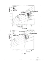
Fig. 6 A and 6B are the schematic diagrames that embodies conditioner of the present invention, and Fig. 6 A represents the constant volume of air system for single regional usefulness, and Fig. 6 B represents multi-region variable air volume system;
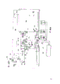
Fig. 7 is the schematic diagram of drier, and the configuration of seven coil pipes that progressively reduce the drier effective dimensions is described, so that provide series of steps to keep high coolant velocity when thermic load reduces;
Fig. 8 is the logic chart of local control, wherein combines the technology in this specification in the VAV system; With
Fig. 9 is the logic chart of local control, wherein combines this technology in the CAV system.
Fig. 1 is the comparison diagram of air humidity of the present invention (solid line) expression and conventional VAV system air humidity (dotted line).
As described in the specification of the United States Patent (USP) 4942740 of LFV-HCV, balance cylinder's condition 3 of conventional VAV system ' than LFV-HCV chamber condition indoor humidity than high.Shown in this example, the equilibrium condition of conventional system can be elevated to be positioned at and exceed the moisture that can accept the comfort level zone.
Though LFV-HCV indoor conditions (point 3) is positioned at the comfort level scope of can accepting, stricter detection shows that indoor condition may be not necessarily comfortable.Article one standard of ASHRAE standard 55-1981 is that at least 80% resident feels thermal comfort.As described in prosthomere, many factors all influence this judgement or " the sensation condition of brains ".Think that " comfort zone " that this standard is pointed out is very to need, this is a kind of illusion.Even comfort zone only is a legend, the mean radiant temperature supposition equals air dry-bulb temperature in the example.In fact, an abundant and necessary condition of determining to satisfy thermal comfort first standard than much smaller zone shown in Figure 1 is arranged.This zone is determined by described other variable of the past.
The accurate method that can be used to determine human optimal comfort condition at present is to utilize the empirical equation that has produced many publication charts.This is the method for preferentially selecting for use, though the present invention does not rely on used concrete grammar, as long as it can satisfy the standard accepted of human comfort.In order to simplify description of the invention, with the chart that adopts by these equation body plans with limit applicability.
Fig. 2 represents the importance of air relative motion and active level.Be decorated with three arrowbands, respectively have four curves to pass.One group four curves (solid line) of first band and right-hand side expression clothes every value be 0.5clo, relative air velocity be respectively 1.5m/s, 0.5m/s, 0.2m/s and≤0.1m/s and main at office building from sit quietly worker's heat comfort condition of height, these people's metabolic rate is 1met.Second band and one group four curves (dotted line) are also represented lined dress (1.0clo) comfort conditions of (1met) when sitting quietly, and left hand band and one group of chain-dotted line are represented the comfort conditions of high strength activity (3met) and thin clothing (0.5clo)." target area " is about 26 ℃ of temperature in the band of right side, the about 0.5clo of clothes insulation value, and relative velocity is between≤0.1m/s and 0.25m/s, and relative humidity is between 30% and 60%.When relative velocity surpassed 0.25m/s, though the occupant can feel thermal comfort, they can find the direct influence that relative velocity disturbs.
Clear activity of these curve tables and dress ornament are to the tremendous influence of required control temperature.For example, a border date of changing according to the season, for given relative velocity, 24 ℃ of controls under the temperature wear lined dress (1.0clo) quiet can the worker and the thin clothing (0.5clo) of wearing under 14 ℃ of control temperature carry out the aggravating activities person and feel same satisfactory.Similarly, in (two sets of curves in right side and left side in the date in summer of heat, suppose that the occupant is installed with thin clothes), 26 ℃, 19 ℃ and 14 ℃ all is the control temperature conditions of comfortable, this is respectively for (26 ℃) and the aggravating activities person of sitting quietly, wherein relate to very high air velocity (1.5m/s) 19 ℃ the time, relate in the time of 14 ℃≤air velocity of 0.1m/s.(figure of 1.5m/s well beyond the suggestion of ASHRAE, but the influence of speed is described) with it.
In all charts, the effective area of optimal comfort has been dwindled in the variation of air velocity.Authoritative ASHRAE standard A SHRAE 55-1981 regulation:
" summer: the average air motion in resident zone should not surpass 0.25m/s ".
" winter: the average air motion in resident zone should not surpass 0.15m/s ".
Note, the residential block allows when maximum (flat) all air movement be lower than in summer in winter.Also point out, just do not have the minimum air movement of what thermal comfort in the ASHRAE standard if temperature and humidity can be accepted.
In normal air-conditioning practice, in summer, regional temperature is higher than 26 ℃ and seems to think comfortable.Yet the comfortable allowable temperature in critical field is increased to 28 ℃, and condition is for 1 ℃ of the every increase of regional temperature, will corresponding increase air movement 0.27m/s.In this case, the increase of air movement has improved occupant's rate of heat transfer, with the high temperature air in the compensated chamber, thereby can keep the skin temperature and the skin moisturizing degree of comfortable.
In order to show the maximum relative velocity of winter and summer ASHRAE 55-1981 standard state,
" loose paper, hair and other light object are about the 0.8m/s(160 feet per minute) air movement under promptly begin to be blown afloat ".
When having emphasized design of air conditioning, above-mentioned consideration guarantees that air-supplied and diffuser is placed and the importance of design, even it is indoor that it is sent into air in a suitable manner, make near the occupant relative velocity be positioned at the scope of ASHRAE 55-1981 design standard regulation or suitable therewith.It is considered herein that, utilize best actual design method can realize this point, when the air distribution system of design peak load operation, the relative velocity of indoor any set point is directly proportional to indoor volume flow with air.By the excursion of reduced volume flow between the highest and least part load, the present invention itself will help to satisfy this hypothesis.
Most of data that document is reported comfort conditions relate to the velocity air motion.For example, the table 1 of standard 55-1981 report " 80% heat acceptable control temperature range is based on the air movement of 0.15m/s ".Make the heat insulation conduct of clothes under 50% relative humidity, sit quietly activity control temperature function and Fig. 1 of the standard of drawing also is based on≤relative velocity of 0.15m/s.
Evaluate the scope that the air-conditioning system that meets the human comfort principle exists, will be thought of as the design performance of actual variable air volume (VAV) system of the office tower design of Australia's big Li Laiya West Coast temperate climate.Can use the air-conditioning system of many types.Determined that the LFV-HCV system is keeping the excellent properties that temperature display degree and humidity ratio always are positioned at comfort zone scope shown in Figure 1, and confirmed by practice.Now the performance with this high low energy multi-region LFV-HCV system compares with the system that combines comfortable adduction of the present invention in design.
Before carrying out this contrast, introduce the overview of LFV-HCV-VAV multi-region system.
The following each side that has kept conventional VAV system in the LFV-HCV method:
Keep constant feed air temperature, the control coolant flow speed is to keep the constant of feed air temperature, there is thermostat that control air regulator regulates in every district keeping regional dry-bulb temperature, with the volume flow of one of several common methods adjusting fan so that coordinate mutually with the adduction effect of the adjustment of the air regulator of zones of different.
Yet the LFV-HCV method is different from conventional VAV system aspect following:
System operates under quite low superficial velocity,
Coolant velocity is higher, particularly under the sub-load condition, during this period, reduces the effective dimensions of drier,
Fin density, loop and coolant temperature are the optimized significant design factors of whole operation range performance,
This system have bigger capacity with adapt to simultaneously the multi-region range and
This system uses less energy.
Be below in using the LFV-HCV system of VAV with the method for utilizing, combine our the described device patent that is suitable for demonstrating here:
Select a coil pipe, make its designing requirement of satisfying air conditioner unit, so that provide some zones the high-riser that is positioned at temperate climate.When guaranteeing the system coupling of humidity in comfort zone shown in Fig. 4 (for example referring to Fig. 1) with one, 24 ℃ dry-bulb temperature in indoor summer can be thought good design.In Fig. 4, the drawn happy suitable zone of a standard of with dashed lines and hatching.The best actual design during except this and following design air compartment system, do not pay special attention to the human comfort principle.
Under peak load, this selection provides the indoor conditions of 24 ℃ and 48% relative humidity, and the microclimate design condition has been compensated 0.87 indoor sensible heat ratio.
Under 65% indoor apparent load, the indoor conditions of selecting to provide is 24 ℃ and 57% relative humidity, and the indoor sensible heat ratio that gentle but moist sub-load design condition is compensated is 0.67, to call the sub-load design condition that this condition is a humidity in the following text.
Under the maximum load condition, the building resident mostly wears thin clothes.Like this, the curve map of Fig. 5 A has just suitably shown the performance of LFV-HCV system under the maximum load with open loop, and does not have comfortable adduction.Under the sub-load condition of humidity (this usually takes place in the fall), general clothes are thickening a little, the curve map of available Fig. 5 B.There is not the sub-load condition of comfortable adduction to represent with an open loop once more.
At first, with reference to the maximum load performance, 24 ℃, the indoor conditions of 48% relative humidity are positioned at the comfortable relative velocity below that indicates " less than 0.1m/s " far away.Therefore, the air velocity that 80% resident is felt comfortably cool must be less than 0.1m/s.It is unimportant that they must be far smaller than this fact of 0.1m/s, because if the control temperature and humidity is satisfactory, just the minimum air movement without any regulation is that thermal comfort is necessary.Therefore, if air distribution system can reach such low speed, this performance is just in " can accept " scope.
The indoor conditions that is reached drops in the comfort zone of Fig. 4 definitely.But unlikelyly compensate maximum load simultaneously and satisfy air-conditioning requirement and do not have higher air velocity.The designer always wants to increase feed air temperature and increase volume of air with higher fan expense.But this can increase the weight of to regulate the problem that space humidity increases during the operation at part load of humidity.Therefore, this scheme should be rejected.Unless ceiling is higher than a lot of rice in floor, otherwise the very difficult air of introducing volume required flow designs desired low relative velocity and keep maximum load simultaneously.And during operation at part load, this air movement will further reduce in the VAV system.Therefore, 24 ℃ is not the indoor dry-bulb temperature of the practicality of maximum load operation.Even at first glance seem to satisfy as shown in Figure 3 the human comfort condition of " comfort zone " representative, in fact, when satisfying maximum load, during the desired low air movement of comfort level, just be difficult to satisfy the air-conditioning requirement of thermic load and regulation, and dirty erosion state will when sub-load, occur.The minimum ventilation standard that requires is 7.5 liters of everyone per seconds.
With reference now to 24 ℃ that during the operation at part load of humidity, are reached indoor conditions: this selects with peak value on thermodynamics is consistent with 57% relative humidity, invent according to LFV, HCV, the method that realizes is to reduce the range of operation of drier coil pipe, increase coolant flow speed, with compensation showing and dive and load during recurrent 0.67 low indoor sensible heat ratio under the sub-load condition by the residue operation.But (Fig. 5 A and 5B) comfortable desired relative velocity is higher than 0.4m/s under the indoor conditions of design, and this is obviously on the maximum relative velocity of ASHRE standard recommendation.This and maximum load condition also are inconsistent, wherein only to the indoor air that infeeds seldom, but require air movement to want big several times.Therefore, under sub-load,, keep indoor comfortable humidity ratio simultaneously, can't keep suitable relative velocity though this system suitably compensates sensible heat and latent heat load with correct ratio.If this system is conventional VAV system, and do not have the improvement of LFV-HCV, comfortable required relative velocity even can be bigger is so that indoor conditions 3 in the compensation image 1 ' represented bigger humidity.
Motion all is the same to air distribution system with moist sub-load for maximum load, and its latter only needs 65% of the former required air flow volume.Comfortable required performance under Fig. 5 maximum load that A is shown in and moist or other any part loading condiction like this, just can not be provided.Can not transmit the required air of compensated part load by identical air supply system mode of relative velocity when causing greater than maximum load.
Though last example is a kind of special application, the result is the typical case of existing best practices.As can directly or indirectly seeing, this best practices and human living temperature environment condition standard A SHRAE 55-1981 are not matched, with the described human comfort principle of ASHRAE1985 benchmark the 8th chapter be not suitable, especially the experiment with the P.O.Fanger of the heating of Denmark polytechnical university and air-conditioning and air conditioning labor is inconsistent.
The research of Fig. 5 A and 5B chart clearly illustrates that the control temperature of conditioned space should in no way limit and is constant numerical value, and should make it with indoor concrete moment load and change with the clothes of seasonal adaptation.In above-mentioned room temperature was predefined for 24 ℃ example, very clear, at busy hour, this dry-bulb temperature was too low, and is when sub-load, too high again for comfortable for actual design reached.
Above-mentioned the analysis showed that, the indoor dry-bulb temperature that is maintained fixed at All Ranges simultaneously without any a kind of logical method can satisfy comfort standard.In the example of quoting, find to keep satisfying the relative velocity of ASHRAE comfort standard.This conclusion is counted as depending on the degree of reliability of Fig. 5 curve map.In order to make these curve maps, equal mean radiant temperature by the supposition air themperature and reduced difficult target dimension problem.On the other hand, ASHRAE " zone of comfort " (Fig. 4) represents with " control temperature ".At 3.9 joints of ASHRAE standard 55-1981, definition human comfort thermal environment scope " control temperature " is air and the approximate simple average value of mean radiant temperature.Certainly, if air themperature is not equal to mean radiant temperature,, should satisfy this definition as at the low temperature room area at sunshine.Because they are usually unequal, just can only regard as qualitatively by the conclusion that Fig. 5 A and 5B release.Based on adopting the analysis showed that in more detail of " comfort level equation " (having proposed the commerce-change that Figure 4 and 5 are specialized) completely by this equation, on behalf of mean radiant temperature, these qualitative conclusions still be different from the actual conditions of dry-bulb temperature, as most of edge interval findable.
Curve values used among Fig. 4 promptly uses " control temperature " to make abscissa, when the insulation value at designed " summer " clothes is not 0.5clo, also will deviation be arranged with the actual value that is drawn by comfort level equation completely.ASHRAE 55-1981 has advised that every 0.1clo is-0.6 ℃ a correction factor.Like this, 24 ℃ and the boundary condition of 65% sub-load using for designing institute in the example, for the variation from 0.5clo to 0.9clo, under the condition of Fig. 4 and Fig. 5 (supposing that here air themperature equals mean radiant temperature), the control temperature will need zone of comfort is moved to the left 2.4 ℃.
Obviously, using the present invention when measuring its real-valued control system, this point is preferentially selected for use, uses basic equation then rather than utilizes curve values.Can compensate the variation of season and every day by this way in chummery not or zone.
By contrast, propose following to requirement of the present invention:
Point out that the human comfort principle is not demonstrated fully by existing air-conditioning system in more than analyzing.Though the designer still thinks by mistake, as long as it is comfortable to keep indoor conditions can guarantee in Fig. 4 institute target area boundary, does not design these systems that satisfy human comfort.These discoveries have and help to explain the dissatisfied of resident, and this is the theme that academia argues in technical papers and open debate meeting always.
The purpose of this invention is to provide a kind of can with human comfort be suitable for the air-conditioning new method that air-treatment combines; That is to say, propose a kind of can by means of free all can require corresponding to means to realize the method and system of air-treatment with all of thermal comfort.For illustrating that this method will continue to adopt the LFV-HCV-VAV system of United States Patent (USP) 4942740.Yet as mentioned above, by improving, the inventive method also can expand in the design of other type air-conditioning system.
For invention and numerous advantage thereof are described, will determine to have the performance that the LFV-HCV-VAV of comfortable adduction designs by the thermal design specification requirement identical with the existing good system of above-mentioned analysis.This can become the reasonable contrast of new system and present best real system, and will support this phenomenon, promptly in the present invention the human comfort principle be combined with the performance of air-conditioning system.As the ASHRAE standard 55-1981 " human living thermal environment condition " on Fig. 3 basis Fig. 1 control temperature range that 80% resident feels comfortably cool when having pointed out that if humidity and air movement are also in allowed band.For the condition in summer, suppose the heat insulation 0.5clo of being about of clothes, this scope is 22.8 ℃ to 26.1 ℃.In the moist sub-load condition that produces autumn, when pledging clothes the heat insulation 1.0clo of being about, this scope is 19.5 ℃ to 23.2 ℃.Therefore, being set at 26 ℃ for the indoor control temperature of peak load operation, is 23 ℃ for moist sub-load condition enactment, and these two temperature are all in 80% tolerance interval separately.These scopes are not enforceable, but for the ease of comparing just selected with ASHRAE standard 55-1981.Should be noted that they can improve as described below like that.
Among Fig. 3, changed temperature range, to consider mixing in common usually thinner clothes of being worn of Australia and adaptation weight that the resident is worn the clothes.This has dwindled among Fig. 3 ' A ', ' B ' and ' C ' institute how represent accept to control temperature range:
Summer, scope ' A ' supposed not take off or 80% can accept to control temperature range when putting on jacket.
Marginal range ' B ' is the comfort standard in spring and autumn type qualification.
Winter, scope ' C ' was the comfort standard that limits for the heating type.
Whenever put on (at the lower limit place) or take off (at upper limit place) insulation value 0.1clo clothes, these scopes just enlarge 0.6 ℃ in each direction.A thin jacket adds 0.22clo, and a no button shirt upper garment adds 0.15clo.
The following describes the LFV-HCV-VAV system design of human comfort:
For the design of considering here, Fig. 4 gets the bid and understands the scope of ASHRAE standard 55-1981, figure line in it is satisfied with peak load, and (area on the right, 0.5clo) and for moist sub-load condition (area on the left side 1.0clo) descends present putative human comfort condition.Marked one four edge regions, the border of selected relative velocity for<0.1m/s represented on the left side, and it is the border of 0.25m/s that relative velocity represent on the right, with the definite scope that can accept relative velocity.In order to be positioned at the ASHRAE boundary, this regional top margin should be represented that the base is represented by 2.7 ℃ dew-point temperature by 16.6 ℃ dew-point temperature.Yet when considering the correction of standard, the bound of scope shown in Figure 4 has adopted 60% and 30% relative humidity line respectively.Fig. 4 represents the mutual appearance zone of every kind of operating condition with fine and closely woven hatching.In order to follow the ASHRAE standard and to meet the human comfort heat condition, the designer has to be controlled in the very little zone that fine and closely woven hatching limits when selecting indoor control temperature.In this case, Fig. 4 represents the peak load and the moist operation at part load condition that allow indoor control temperature to have certain flexibility to reach.Two kinds of conditions all drop in the condition and range that 80% resident feels comfortably cool.Continuous target area is not shown, in this district, must in the gamut of air-conditioning system operation, satisfies thermal comfort by the condition between the minimum and maximum lotus shown in the line.
The left side column of this specification institute subordinate list 1 represents to have the possible characteristic of room thermostat system, and when showing load by its peak change, this thermostat progressively changes it and regulates temperature.Listed the systematic function under the apparent load of 56% and 50% peak in the table.
Fig. 5 A and 5B have shown the LFV-HCV-VAV system, and in the gamut of 65% sub-load condition, this system all requires consistent fully with Air-conditioner design load and human thermal comfort at maximum load.If this system forwards 50% sub-load condition to, the relative velocity line of curve map also will move left slightly, to adapt to the thicker clothes that may wear.It is when showing load 22.8 ℃ of 50% maximum that control temperature 23 ℃ during only from 65% sub-load in chamber on the figure change to sub-load.
In the The whole control scope, the 0.12m/s when required optimal comfort relative velocity will change to 65% sub-load from the 0.14m/s under the maximum load condition, the 0.09m/s when changing to 50% sub-load again.If indoor relative velocity with infeed indoor volume of air flow be varied to direct ratio ground change, and room temperature and feed air temperature remain unchanged, then the relative velocity under 65% loading condiction is 0.09m/s, and is 0.07m/s under 50% condition.Be no more than comfort standard if humidity may increase, then the little deviation between Zui Jia relative velocity and the relative velocity that reached can be eliminated by improving feed air temperature slightly.This forms a sharp contrast with the inconsistent performance to unified technical specification in the precedent design, and the there has been found when sub-load than higher this impossible situation of the comfortable required relative velocity of busy hour.
The left side column of table 1 reflected this method in the compensation thermic load, satisfy ventilation and realize that air feed requires the premium properties aspect the uniformity with comfortable required relative velocity, like this, has just satisfied simultaneously performance and many human comfort principles of knowing best.
More than discussion and example can be summarized as follows:
The controlled condition that falls into comfort zone that ASHRAESFUW55-81 defines may be essential for producing " state that thermal environment is satisfied with sensuously ", but under most of situation, they are not all to be sufficient under all operating load conditions.Under every kind of operating load, also must satisfy the restriction that the relative velocity limit of ASHRAE standard 55-1981 regulation is proposed.But the relative velocity limit is limited to acceptable conditions in the interior narrow band of general comfort zone, can see in last example, and with the variation of peak load to the minimum load condition, this arrowband laterally moves from right to left corresponding to air-conditioning system.Adjustment of the present invention be exactly this move.Purpose is to require the utmost point to add effectively in the design that is combined in air-conditioning system load, ventilation and human comfort simultaneously.
Present Parameter Map 6A, 6B and 7 represented systems.
In Fig. 6 A, the air-conditioner of constant volume of air comprises that driving air passes through drier 102 conduits 103 and regulate the fan 101 of space 104 usefulness.Air is through conduit 105 and state filter 106 return fans 101.The air that returns of part is flowed out by one or more controls or the ventilating opening 107 do not controlled, and this part air is by being replaced by control or the adjusting valve 108 the do not controlled fresh air from extraneous suction.Supply with cooling agent by the cooling device (not shown) to drier.
Ambient air temperature ... thermometer 111
Feed air temperature (choosing wantonly) ... thermometer 112
Direct or indirect adjusting
Space control temperature ... radiation thermometer 113
Regulate space humidity (choosing wantonly) ... humidity sensor 126
Return temperature ... thermometer 114
Air feed volume flow rate (choosing wantonly) ... pressure or velocity sensor 115
In Fig. 6 B, the air-conditioner of variable air volume comprises fan 101, and fan is from drier 102 suction airs, and with air pressed manage 103 and damper 109 to regulating space 104, air thus through manage 105 and filter 106 return drier 102.Identical with the CAV system of Fig. 6 A, the part air is flowed out by one or more controls or the ventilating opening do not controlled 107, and the experience of replacing is made the damper 108 the do not controlled fresh air from extraneous suction.Also can a ventilating fan 131 and/or return fan 132 be set in the air backward channel optionally and/or return controlled atmosphere joint air door 133.Air feed damper 125 also can be used for changing the volume of air that fan is sent into.This change preferably realizes by the rotating speed that changes fan electromotor with speed change driver 134.
Control function shown in Fig. 6 B is separated between regional area VAV controller 120 and air conditioner unit (AHU) controller 110.Two controllers can be merged into a unit, but for the sake of clarity, for the big system that comprises several districts, can be easily in some districts setting area controller 120,220,320 etc., and utilize local area network (AN) 140 or similarly join the road device to take place or accept its information to the air conditioner unit controller.
The following signal that zone VAV controller 120 is accepted from sensor:
This distinguishes feed air temperature ... thermometer 112
Direct or indirect conditioned space
The control temperature ... radiation thermometer 113
Zone and return temperature ... thermometer 114
The air feed volume flow ... with pressure or velocity sensor 115
Zone air feed air door is regulated ... angle 109
Humidity (choosing wantonly) RH or DP ... 126
In addition, regional VAV controller 120 can receive the information of being measured and being processed by AHU controller 110, for example about the information of environmental condition.
Under the simplest situation, regional VAV controller can be a thermostat commonly used, and it can be by the resident in this district by means of different time, active level, the angle of the sun and the design list of the weather forecast of every day in 1 year are manually readjusted.In more complicated application, above-mentioned parameter is directly to measure, or by calculating or being that stored data is determined by the memory of controller 110 and 120.
The AHU controller receives column signal down by sensor:
Ambient air temperature ... temperature 111
Leave the feed air temperature of AHU ... temperature 122
Enter the mixture temperature of AHU ... temperature 123
Return the enthalpy difference of gas and environment ... enthalpy difference 124
The fan motor rotating speed ... tachometer 134
The adjustment of air feed air door (if any) ... angle 125
The cooling agent choke valve is adjusted ... angle or mobile 117
The drier rotary valve ... state 116
Ventilating fan (if any) ... state 131
Return fan (if any) ... state 132
Return the gas air door adjust (if any) ... angle 133
Exhaust damper is adjusted (if movable) ... angle 107
Ventilation air door adjustment (if movable) ... angle 108
Artificial input signal ... alphanumeric 121.
In addition, the AHU controller also to send and received signal from different zone controller, and keep UNICOMs by building local's Local Area Network (LAN) 140 and central building system controller 118.
Fig. 7 represents the configuration that drier 102 may be selected for use, and why the effective cooling coil of summation intersects the gamut of air stream, even have minimum effective dimensions too.Flow by (bypass pipe 135) by walking around some coil pipe, can keep high coolant flow speed (patent US4942740).
The following describes control system:
Please refer to Fig. 8 and 9:
There is a local control in each zone that air conditioner unit is used for, but had better not be program control type entirely.In minimum control level, one of needs can be by the artificial zone thermometer of adjusting of adjustment form.Following description relates to uses a cyclelog when directly not measuring humidity.Can separate complete comfort level equation and obtain the average ballot paper of prediction with moisture measurement, as this specification detailed earlier herein.
Require two class factors as signal by the control system input; Promptly relevant physics/environmental factor and human factor with the resident.First kind factor can be measured with conventional means.The second class factor then can be by means of the inferred from input data of tabulation.
Regional area control functional requirement
(a) measure the zone and show load,
(b) measure the interior working control temperature in zone,
(c) calculate optimum value and the tolerance interval of controlling temperature,
(d) " compensation " between definite (b) and the optimum value,
(e) begin starting so that in tolerance interval, carry out " compensation ".
Above-mentioned functions is embodied in the Region control logic chart of Fig. 8 VAV system.In the most preferred embodiment, the best temperature in zone is that the comfort level equation of L=0 directly calculates by the result.For this embodiment, must be equipped with humidity and average radiation sensor.
We consider each aspect of above-mentioned control requirement now successively:
(a) by the volume flow qs(that measures air feed by measure through certain compression pipe pressure reduction or by because the known flow dynamic characteristic is measured supply gas pressure as the function of air feed joint door angle learns) and measure the feed air temperature that enters and leave this district and rise, obtain the zone and show and load.Then by Qs=PsqsCp(ta-ts) the apparent load in zoning, Ps is the density of air feed here, and Cp is the specific heat of air, and ta, ts are respectively the temperature of returning (indoor) gas and air feed.This expression formula also can be generally acknowledged similarity relation formula Qs=mCp △ t, and m is the mass velocity of air here, and △ t is the temperature difference between load.
(b) the working control temperature approximates the mean value of mean radiant temperature tr and indoor air temperature ta greatly.Indoor air temperature can directly be measured with common method.Mean radiant temperature tr is the uniform temperature on radiation black enclosure wall surface, the uniform temperature on the enclosure wall surface, and in enclosure wall, the resident will carry out and the radiation heat transfer of uneven indoor same quantity actually.If the temperature of the geometry of chamber and all surface is known, can calculate it.This data seldom is known, therefore must ask approximation.But, can derive mean radiant temperature by relative velocity V and " radiation temperature " tg that measures air themperature, air movement.The latter (tg) is the temperature of measuring at the non-reflection sphere of the thin-walled center of diameter 6 inches (0.15m).Then, calculate mean radiant temperature by following formula:
tr=tg+k
(tg-ta)
In the formula temperature in degree centigrade, speed is in m/s, k=2.2.
Have been found that in test free convection has a lower limit to speed V.Therefore, above-mentioned equation has a restrictive condition " V 〉=0.05m/s ".
If the diameter d of radiation thermometer heading is not 0.15m.Should adjust the K value by following formula:
Kd=K(0.15/d)
0.4
A.P.Gagge, GMRappe and J.D.Hardy(ASHRAE Inc.1967 May, 63 pages) explanation once, if the outer surface of normal glass ball is coated with the last layer skin-color, the temperature surveyed of the heart just more approaches to control temperature therein.But the time constant of this sensor is about 30 minutes, and except its noticeable volume, this makes it be unsuitable for being used as the control sensor in actual air-conditioning system.A part of control system of the present invention is to use unobtrusive miniature direct measurement and control or the radiation temperature transducer with short-time constant.At system's run duration, measure the relative velocity of tiny balls position.In this way, can obtain mean radiant temperature approximation preferably.In fact in whole district, extract the sample that mean radiant temperature distributes with several tiny balls.ASHRAE standard 55-1981 has stipulated the position that measure.
(c) the Optimal Control temperature is under given relative temperature and given relative velocity condition, in the given indoor control temperature that most is worn the garment-like resident that satisfies.Tolerance interval to the definite control temperature of these objects is various, but ASHRAE standard 55-1981 stipulates acceptability condition zone at last, and 80% resident is cold slightly, moderate or warm slightly in this district.By calculate with " comfort level equation " and with reference to as described earlier in this article, participate in experimenters' the resulting statistics of response situation by many aspirations, might determine this zone.In the correction standard of suggestion (being designated as 55-1981R), the standard of can accepting has risen to 90%.This embodiment has further proposed the clothes scope that resident's most probable is worn in preset time.
(d) calculating control temperature and Optimal Control temperature " making up the difference " is by simply asking poor formula to obtain.Then this difference is compared with " tolerance interval " of control temperature.
(e) if this is made up the difference not in tolerance interval, control system just begins to change the corrective action of temperature in the district.This will comprise that usually the air that increases or reduce to the zone flows, and this can be realized by the air feed air door that opens or closes in the passage that leads to given zone.
Note project (b) and (c) need know the insulation value of the particular room or the clothes scope that regional interior resident's most probable is worn in the building in or building.It is contemplated that several means of determining or estimating this value.For example, some zone in the building, the resident may all require to wear a kind of specific uniform or protective garment in free.Insulating value is that unit is measured with clo, here 1clo=0.155m
2K/w can measure insulation value exactly, becomes a kind of distinctive value then in calculating.For this a kind of situation, can accept temperature range for maximum.
On the contrary, in the building or the department store, the clothes that people wore usually are various in general office.When the employee comes to work, can allow an entrance guard determine the habited scope of people with well-trained eyes.Then this information translation is become the clo value of certain limit.The clo value scope of regulating adaptation is wide more, and acceptable temperature range is narrow more.
A kind of selection scheme of utilizing entrance guard's observational technique is to evaluate the clothes scope that most probable is worn.Type, the time in year and the weather forecast early in the morning of local culture, activity depended in the selection of clothes.When the Activity Type of given culture, in the time of can determining year by the clock in computer or the controller, the variation of garment type is as depending on outdoor environment temperature to a great extent during this year, and this temperature can directly be measured.Can be to the approximate extents of specific date assessment clo value.Method is preferably, carry out this when estimation in cold period and produce error to a high end because the people who wears thickly slough a coat or jacket manage than the people who is thinly clothed warming easier usually.
Except regional area control, the operation of air conditioner unit is also by a controller control.By better simply situation, this controller is that (it drives one or several valve to regulate the coolant flow by the drier coil pipe to an exhaust thermostat, thereby keep the delivery temperature constant) and measure and the usual means of control VAV system air feed volume, in the determined adjustment point retaining zone of usefulness CAV system realm controller temperature.Better the controller example is a cyclelog, it receives data by each zone controller, and by for particular system in advance " performance map " of compiled program determine the flow best of breed of operating point of fan, effective coil area, coolant flow and (under direct expansion (DX) system situation) compressor speed of air.
Control system described here keeps the result of former action and these actions is at present carried out record.These data can be used to upgrade and improve above-mentioned performance map.
With reference now to the VAV system logic figure of Fig. 8,, air flow volume qs is directly proportional with △ P, is calculated as follows by controller:
qs=K
1 
In the formula, K
1It is the proportionality constant of determining during the design and running.In addition, qs also can be by mobile Vs air door angle correction calculation.
By measuring qs, can obtain mcp=Cpqs, in the formula, m=mass air flow rate, the specific heat of PsCp=air, the density of Ps=air feed.
This amount multiply by the difference of leaving regional temperature ta and being fed to regional temperature ts and promptly obtains regional sensible heat load Qs, as mentioned previously.
Owing to know in when design and determine or the thermal characteristics and the measures ambient temperature of the building of on-site measurement, can estimate because the part sensible heat load Qs that is caused by the local heat transmission that also has roof of wall, window and some.Therefore,
Qstrans=K
3(tamb-ta)
In the formula, K
3It is the correlation factor of architectural character.If necessary can revise to the direct irradiation of wall and roof the sun.
The hot material that should be noted that fabric structure makes the only variation of response environment or room temperature lentamente of building.Therefore, any preset time Qstrans actual value will be definite by tamb and the ta value of early and common different time.Owing to this reason, these values are stored, and recover after delay a period of time of being determined by the building time constant again.Store the Qstrans value similarly to be used for determining in the district apparent load as function of time generation.When making a plan for the building custodian, this information uses.And in the building of light structures such as present many office blocks, the building time constant is very short, and the influence that Inside Air Temperature changes only can cause the change of the apparent load that is transmitted after the short time.In these environment, suitable is to predict variation by the following sensible heat load that makes new advances that calculates:
The old Qstrans of the old Qsinternal+ of old Qs=
The new new Qstrans of the new Qsinternal+ of Qs=
Because the new Qsinternal of old Qsinternal=
Thereby the new new Qstrans of the old Qstrans+ of the old Qs-of Qs=
Old Qs-K
3(tarqd-ta)
Here tarqd is the air themperature of new demand, and ta is existing air themperature.
By new Qs, available following formula calculates the air demand that needs:
(mCp) the new Qs/(tarqd-ta of rqd=)
Or qsrqd=(old Qs)/(PsCp(tarqd-ta))-K
3/ PsCp
Then can the control band air door and send information to the AHU controller.
Control system with many bigger volume type described here is an example, and the available action logical computer is reported actual air door angle (φ) and controller rapidly and determined deviation between the angle.Can transfer and establish limit alarm, and the mode that can be understood easily accurately writes down and report operating cost.
Another feature as control measure of the present invention, when being used in combination the air-conditioning method of U.S. Pat 4942740 (there AHU service area evening occupation rate be zero), Adjustment System is moved a period of time under the highest drying cycles, with dry all pipelines, carpet, fabric and low opening.This also can realize by moving under minimum load with the highest coolant velocity in the part coil pipe, and reduce superficial velocity (thereby reducing air flow volume) to being not more than 0.5 meter of per second.This method has been eliminated in pipeline, the possibility of mould and bacterial growth on the fabric structure and on the equipment.
Air conditioner unit (AHU) receives the signal from all local controls (Fig. 8), the volume of air of sensible heat load and requirement is added to together, needs based on the minimum load district are adjusted ventilation, and the best combination of calculating efficient drying device size, coolant flow, rotation speed of the fan and main air feed damper positions, to satisfy the air feed needs of conditioned area.Hysteresis a period of time has guaranteed ability control band air door after adjusting the AHU parameter.For a DX system, compressor rotary speed (pressure of inspiration(Pi)) is also wanted optimization.
When radiation was important, temperature was not equal to the control temperature, round the clock between and changes of seasons need to measure mean radiant temperature in theory, or direct measurement and control temperature is as the input signal of control system, as mentioned above.However, the also result that can be improved with more cheap scheme, likely only determine room temperature, or with the most cheap scheme of all schemes, promptly according to tabulating or putting in order the thermostat adjusting device in each district or room by the wage adjustment of comfort level equation calculated value armrest with showing load.
The control logic circuit of Fig. 9 CAV system is only in the VAV system that is different from Fig. 8 aspect the control action of taking.Role is to adjust the air door angle and report data to the AHU controller in the VAV system, and the temperature of CAV control system (it is the indispensable part of AHU control system normally) in AHU controller report district is so that reach required control temperature.This AHU controller determines that by the requirement of other district's (if there is) best feed air temperature is to reduce the heating again of whole system.
Introduce constant volume of air (CAV) system that has the comfort level adduction below:
Have and do not have in the comparative analysis of comfort level adduction above, concentrated discussion LFV-HCV-VAV.This be because the representative at present of such system be " best implementation system " because it combines the multi-region capacity of low energy consumption and broad.Yet, though may not have much variations in required air capacity of any part while of day-night cycle, because the requirement in single district is different in the multi-region VAV system, this special factor also may be reduced to the air pace of change at some low load region and be lower than the degree that must ventilate.There is not this problem in constant volume of air (CAV) system.
In the CAV of routine air-conditioning system, the air mass flow of all service areas is remained unchanged, all zones are very similar, just as handling in a single district.Coolant flow throttling with the reduction of load, as the situation of VAV system, different with the VAV system is can be risen to keep a fixing indoor dry-bulb temperature by the dry-bulb temperature that coil pipe leaves.This specific character of CAV system has adverse influence to operation at part load.Coil pipe condition slope of a curve reduces under the sub-load condition that causes in the desiccation by the unit cooling and reduces; Exactly, this just hangs down the opposite of sensible heatization with needing compensate for slower.Just because of this reason, the CAV system in past usually used cold adapting to latent heat load, and utilized post bake to come balance sensible heat load again.Acting on several zones with a drier coil pipe and respectively distinguishing under the very big situation of difference, when air is added each other district, putting into practice and satisfied zone required minimum feed air temperature and post bake gas, distinguishing desired air conditions to satisfy that.If the level of comfort of realizing with this system is good, it will think that to other concrete application be unacceptable speed consumed energy now with the designer that major part is responsible for.
When comfort level adduction of the present invention is used for a CAV system, should there be differentiation in different regions on this Systems Theory, with different to adapt to apparent load by the temperature display degree that changes air feed, when at first reset indoor or zone thermometer or controller with the compensation load with as far as possible near when reaching required control temperature, originally feed air temperature and dryer capacity remain unchanged basically, if obtain inadequate control in this way, and the coil pipe size is fixed, and then changes ANALYSIS OF COOLANT FLOW by drier so that cause the variation of feed air temperature.This measure has more effectively kept drying capacity than conventional embodiment.If there is differentiation in different regions, then adjustment member load chamber or zone are to keep below the temperature of maximum load chamber.Like this, terminal heats and need be reduced to " balance adjustment ".
Under the situation in several zones, according to good PRACTICE OF DESIGN, these zones should have accepts identical thermic load condition characteristic very much at a constant volume of air systemic effect.Under situation about changing, the zone with constant minimum thermal load can be used as the primary standard district in all districts of decision same system, and determines the temperature display degree adjusted value in " primary standard " district at this.Yet, also to provide heat(ing) coil again, so that room temperature is adjusted to identical indoor apparent adjusted value to other relevant similar district.When there is different mean radiant temperatures these other chambers, variable room temperature thermostat must be arranged, so that at given mean radiant temperature with control season under the temperature conditions and to determine suitable indoor wet adjusted value.
At the room area of little load, known mean radiant temperature equals indoor temperature display degree, and in this case, suitable control temperature also equals " primary standard " district temperature display degree adjusted value, does not need separately to measure mean radiant temperature.If comprise some neighboring areas, only an area measure radiation temperature, with to deviation predetermined information and the general suitable tabulation of controlling temperature season round the clock, can determine required indoor temperature display degree adjusted value automatically (or artificial), and not need other radiation thermometer.By control quench water choke valve, determine required indoor temperature display degree.The valve of operating temperature adjusting device and controller control makes the temperature range of regulating the space between determined 22 ℃ to 27 ℃ of comfort level equation by this way.
Though finish same work volume, described system uses more energy than VAV system, and they save manyly than the CAV system of routine, the latter system must all rooms are remained unchanged indoor dry-bulb temperature.Conventional CAV system is that with the important difference with CAV system of comfort level adduction originally coil pipe condition curve becomes steeper when the load reduction in the latter, so just can compensate potential load, and do not need to resemble the conventional system requirement serious cold excessively.
The present invention has following advantage: except successfully satisfying thermic load and realizing that the assay of table 1 has also reflected following several advantages that the inventive method had the optimum reelability quality.Here, for same designing requirement,, have and the same air-conditioning system HFV-HCV-VAV that is provided with the comfort level adduction contrasts for same office block.
(a) the air conditioner unit air supply fan is little.In the present invention, only select the air propeller of 4800LPS for use, by contrast, do not have the system of comfort level adduction to need 6000LPS.This has reduced fixed cost and operating cost.The air supply fan size reduce to be because temperature difference increase between the chamber that ASHRAE55-1981 allows causes since under maximum load condition the less temperature difference between the indoor and outdoor conditions, also reduced to indoor heat transmission.Under the situation of table 1 example, indoor between the temperature difference of duty ratio line by [24 ℃-12.4 ℃]=16.6 ℃~[26 ℃-12.4 ℃]=13.6 ℃, the 6000LPS condition is reduced to 11.6/13.6 * 6000=5118LPS.
(b) improved the multi-region capacity of VAV system.How the general multizone that is applicable to is loaded for air conditioner unit of the present invention is described, investigate a multi-region unit under Synchronization Design maximum load condition.For simplicity, only investigate three districts, recent design one nine sound zone system, every district is furnished with the device of separately selecting insulation value of clothing.
In the above-mentioned comparison of the table 1 of representing the human comfort condition that the inventive method provides, only considered the performance in single district.Proposed three controlled conditions, supposed that each condition relates to the Disengagement zone by separately special-purpose air conditioner unit effect.Yet the peak load performance of Synchronization Design has determined to be used for the selection of the air conditioner unit coil pipe and the fan in several districts actually just.Therefore this synchronous peak load that comprises all districts is lacked than required element material and the energy of sum total that satisfies each district's peak load always less than the sum total of single district peak load, and this is known characteristics of designer.In order to select air conditioner unit, suppose that for ease of explanation three sections listed in the table 1 coil pipes exist simultaneously, and be adjusted at the highest synchronously design load simultaneously.We suppose that also each maximum load energy that different time exists in each district in three districts equates.People can observe, and air conditioner unit has reached synchronous peak load at 4 in the afternoon of day in midsummer.Represent western area according to 100% load section shown in the general appearance supposition table 1 of skyscraper, consume 55% of total air conditioner unit energy in this district, north, south and the east are merged into one second district, afternoons 4 point, this second district moves under the mean value of its peak load 60%, finds the energy of its consumption air conditioner unit 35%.The inside in building is the 3rd district, and it moves under the state of the almost stable of its consumption air conditioner unit 10% energy at synchronous busy hour.
In table 1, suppose that two sub-load districts of 65% and 50% occurred in the date of spring and autumn weather, at this moment, the resident will dress lined dress.Consider that now this two parts load designs in the date in the summer of maximum load simultaneously, therefore, the time in the known time is 36 ℃ (seeing the lower left corner of Fig. 8 control chart) with having measured environment temperature (tamb), and control system has just been determined comfortable clo value scope.Adjust the control temperature to its optimum value of 24.5 ℃ with it then.Provide comfortable environment (in the example in front, the control temperature in this district only is 23 ℃, and this difference is thicker cause because the resident wears the clothes) so that wear the resident of thin clothes for this district under the spring and autumn weather.Table 2 expression sync peaks performance.The volume flow rate that the comfort level adduction is required and then be reduced to 4136LPS.In order to contrast, need there be the LFV-HCV-VAV system of comfort level adduction, contrast same sync peaks design, the air feed of adjusting is 4965LPS, in this case, this compares found similar with 1 the ratio of two kinds of requirements.Should point out emphatically, this example is a kind of special imaginary situation, and numerical value has bigger variation.Therefore, following comparison should only be regarded as qualitatively:
(a) peak load of Jiang Diing means less cooler, cooling tower, pipeline and Channel Engineering.
(b) has advantage in the drier design.The volume flow that reduces air feed means the coil pipe of available littler surface area.In addition, if peak load is combined with low sensible heat ratio, in the seashore and the torrid zone, further the advantage of reduction by the superficial velocity on big coils surface can be used in and select for use among the 4136LPS as the U.S., to obtain the steeper slope of coil pipe condition curve, strengthen desiccation thus.In this case, may reduce row's number of coil pipe level sometimes.
Greater flexibility is arranged when (c) designing.Increasing the comfort level adduction in this system provides wideer multi-region performance range, and wherein each room has it to control temperature and its relative velocity preferably preferably.Therefore need air conditioner unit still less.
(d) when underload, kept " wall attachment effect " of slot type distribution air throttle.When existing a kind of owing to lose the danger of wall attachment effect from being up to for example 50% when showing the scope of load in one by the low-flow of air throttle with the VAV system, this can cause cold empty air feed " drainage " with ensue mutually uncomfortable.As shown in table 1, the volume ratio between maximum and 50% operation at part load is 0.5 for the system that does not have the comfort level adduction, but is 0.64 to what the comfort level adduction was arranged.It may be difficult dropping to 3000LPS from 6000LPS, influences wall attachment effect (seeing Table 1) but drop to not conference of 3080LPS from 4800LPS.
(e) eliminated of the waste of the poor efficiency fan of auxiliary VAV unit to energy.VAV unit auxiliary blower is used for increasing air demand to keep wall attachment effect and to increase air movement when underload, return gas and regulate air feed by mixing a certain proportion of heat, obtains post bake to a certain degree.This PRACTICE OF DESIGN has increased the cost of VAV unit, has also increased operating cost, because small fan is a poor efficiency, and when particularly in this district copying machines or smoker being arranged, the air that returns that does not filter may be antihygienic (Fanger, 1987).In this " comfort level adduction " system, reduce maximum air flow speed and combine with increasing minimum air flow speed, eliminated needs to this costliness and inapplicable scheme.
(f) improved the ventilation of air-conditioned room.This is to increase the fringe benefit that the air feed volume flow ratio brings between sub-load chamber and the peak load chamber.Even outside air was to the overall ratio that returns gas by air conditioner unit during conventional VAV system had increased spring and autumn weather, the outside air that lacks than more high load capacity chamber volume simultaneously will be received in minimum sub-load chamber.
(g) at the spring and autumn weather feed air temperature is improved at the heat pump performance of those systems of eminence adjustment more.In order to increase, to readjust the feed air temperature that leaves the drier coil pipe usually to air feed volume than lower part load room.In any case temperature all is a key factor, this is a kind of relatively poor actual conditions, because than on the lower part load room characteristic lower sensible heat ratio being arranged, therefore require more desiccation.The higher surface temperature of feed air temperature and drier of upwards resetting combines, and has just reduced desiccation.And them can not offset in the room that load increases during upwards transferring again.Utilize comfort level adduction of the present invention, feed air temperature remains unchanged, and its control temperature reduces automatically in the room of utmost point underload, the result, and they obtain more air feed, and can reach required degree of drying.
Table 1
Perth city, western australia work in high level
The region performance that designs in the Building Design
Have of the present invention do not have of the present invention
Comfort level adduction comfort level adduction
Overall pipeline section (when 100% load)
Chamber dry-bulb temperature ℃ 26 24
Air feed dry-bulb temperature ℃ 12.4 12.4
Indoor moisture (g/Kg) 9.28 9
Indoor relative humidity % 44 48
Similar air feed LPS 4,800 6000
Chamber humidity load KW 79 83
Indoor sensible heat ratio 0.87 0.87
Total cooling capacity KW 110 116
Total water LPS 3.6 4.0
Part coil pipe section (65% load)
Chamber dry-bulb temperature ℃
★23 24
Air feed dry-bulb temperature ℃ 12.4 12.4
Indoor moisture g/Kg 10.6 10.6
Indoor phase humidity ratio % 60 57
Air feed volume LPS 4,000 3900
The chamber shows load KW 51.0 54.3
Indoor sensible heat ratio 0.65 0.67
Total cooling 88.4 90.2
Total water LPS 4.5 4.5
Peak load is to 65% sub-load
Air feed volume ratio 1.2 1.54
Part coil pipe section (50%)
Indoor dry-bulb temperature ℃ 22.8 24
Air feed dry-bulb temperature ℃ 12.4 12.4
Indoor moisture g/Kg 11.3 11.5
Indoor relative humidity % 64 61
Air feed volume LPS 3,080 3000
The chamber can show load KW 39.6 42.0
Chamber sensible heat ratio 0.60 0.60
Total cooling KW 7.10 74.9
Total water PLS 2.8 3.0
Peak load is to 50% sub-load
Air feed volume ratio 1.56 2.00
★ supposes air dry-bulb temperature ta=mean radiant temperature tr shown in Fig. 3 curve.
Table 2
The design performance of air conditioner unit under the sync peaks
There is the comfort level adduction not have the comfort level adduction
KW LPS KW LPS
Westbound 60.5 2,640 63.8 3300 under the 55%A.H.U. load
East, South Area, north 31.0 1,232 31.5 1365 under the 35%A.H.U. load
Inner region 7.0 264 7.6 300 under the 10%A.H.U. load
Amount to 98.5 4,136 102.9 4965
Claims (25)
1, a kind of method by air-conditioning method cooling space, described space is as the narrower comfort level target area shown on the air humidity type map, itself is usually at the standard comfort zone of broad, the factor of determining described narrow target area comprises the heat transmission resistance of occupant's clothes and the degree of physical exertion, this method comprises a kind of in the control temperature of determining air dry-bulb temperature and mean radiant temperature and described adjusting space and control:
(a) enter the feed air temperature in described space and leave at least a in two kinds of temperature of dry bulb temperature in described space;
(b) effective dimensions of described drier keeps being equivalent between 1~2.2 meter cooling water of per second by the coolant velocity of described drier simultaneously; With
(c) humidity ratio that makes described adjusting space is between every kilogram of dry air 4~13 gram water vapours, and measure is to change at least a among the effective dimensions of the feed air temperature that left by drier, drier and the Qi Nei coolant flow speed three.
2, the described method of claim 1, it is characterized in that controlling the control temperature in described adjusting space by definite described mean radiant temperature and described air dry-bulb temperature, regulate air dry-bulb temperature to being lower than the control temperature, its difference is identical with the amount that mean radiant temperature surpasses described control temperature.
3, the described method of claim 1, it is characterized in that determining the mean radiant temperature in described adjusting space, and comprise that control is enough cold to the feed air temperature of regulatory region, to compensate the influence of sensible heat load and mean radiant temperature to described space resident's thermal comfort, with control to resident's relative air velocity, make it consistent with the required control temperature of thermal comfort.
4, the described method of claim 1, it is characterized in that described drier comprises a plurality of coil portions, a plurality of coil pipe valve that links to each other with coil portions, a plurality of coil pipe bypass pipe and a choke valve, described coil portions, coil pipe valve and coil pipe bypass pipe structurally are adjustable, so that change effective cooling size of drier; Described method comprises control panel pipe valve effectively, optionally bypass is mobile by the coil pipe bypass pipe so that from the drier coil portions, thereby when load reduces, reduce effective cooling capacity of drier, but remain the amount of coolant that is equivalent to 1~2.2 meter of per second by the coil portions flowing coolant.
5, the described method of claim 4, it is characterized in that air-conditioner comprises a fan that air is flowed by drier, described method comprises that the qualification air velocity is very low, is no more than every kilogram of dry air 13 gram water so that regulate the humidity ratio in space, but is no less than every kilogram 4 gram water.
6, the described method of claim 4, it is characterized in that air-conditioner comprises that one makes air pass through the fan that many row's drier coil pipes flow, the profile of described coil portions is such, promptly when carrying out described coil pipe break-through, remaining effective coil portions spreads all over air and passes through in the mobile whole passage of a few row's drier coil pipes.
7, the described method of claim 1, also comprise the volume of air flow of determining by described adjusting space, in the radiation thermometer temperature and the environment temperature of regulating the space critical positions, calculate the control temperature, the control temperature of calculating is compared with the temperature of described narrow comfortable target area, regulate on demand claim 1 step (a) and (b) and (c) at least one step, to keep described space in described narrow comfortable target area.
8, the described method of claim 1, also comprise the volume of air flow determined by described adjusting space, the radiation thermometer temperature (radiation temperature is different from air themperature here) of regulating the space critical positions, ambient air temperature, and relative humidity, dew point and the humidity ratio in adjusting space at least a; At least one resident who regulates the space is calculated thermal energy balance, the balance temperature when reaching thermal balance with definite resident and this space environment; With adjust described temperature to this equilibrium valve, keep simultaneously humidity ratio between every kilogram of dry air 4.2~12 gram water and relative humidity at least a in two kinds of conditions between 30~60%.
9, the method for a conditioned space of a kind of cooling comprises:
(a) cooling coil that makes air pass through the air-conditioner drier flows;
(b) determine among speed air flow and the volume of air flow at least one;
(c) when temperature and radiation temperature not simultaneously, measure the dry-bulb temperature in described adjusting space and in the radiation thermometer temperature of regulating space at least a portion;
(d) measures ambient temperature;
(e) provide a controller that has from (b), (c) and input data (d);
(f) calculate air feed volume and control temperature with described controller, and will compare with the human comfort target area of describing relative air velocity and the combination of control temperature to resident's the relative air velocity and the control temperature of calculating, this target area is determined by separating the heat energy equilibrium equation, comprising the heat transmission resistance and the physical exertion degree of resident's clothes, and the energy exchange of the convection current of resident and its environment, radiation and evaporated form;
(g) at least a in the air feed in the described space of adjusting and the feed air temperature, to keep described space in described narrow target area.
10, the described method of claim 1 also comprises and carries out described control, and the air-flow ratio of the air-flow of the conditional request variable air volume system that makes described adjusting space during to 50% maximum sensible heat load during to maximum sensible heat load is not less than 0.65.
11, the described method of claim 4, it is characterized in that regulating this space with a constant volume of air system, comprise by originally keeping feed air temperature and drier device capacity air drying temp constant and that readjust described adjusting space to carry out described control, till the approaching limit of described narrow comfort zone of the temperature in described space, control described coil pipe valve then to change the size of described drier.
12, a kind of method of Cooling Air-conditioning System comprises near the information of determining resident's activity, and comprises following information:
(a) air feed and return gas dry bulb temperature,
It is (b) at least a in radiation temperature and the control temperature,
(c) measure and appraisal relative humidity in one at least,
(d) at least one item in air feed volume flow, gas speed, available flow area and the pressure reduction,
(e) the following data of date, time and definition:
(f) under representational season and environmental condition, regulate the clothes scope that space resident's most probable is worn,
(g) scope of garment type insulation value,
(h) metabolisable energy release rate and the representative movable external work of being done;
And select suitable generation to penetrate energy release rate, external work output and insulation value of clothing, by clean metabolic heat that produces the resident and the balance between the heat transfer rate at described space and environment, calculate the required adjusting space dry bulb temperature and the variation of relative humidity, so that equal the clean metabolic heat that produces little allowed band resident with environment exchange speed, this scope through with reference to human to the thermal environment reaction result of study and determine; With the action that begins to change described temperature and relative humidity, promptly change among several persons of effective dimensions, coolant flow speed and feed air temperature of gas supply flow and drier at least one, to keep regulating the space in described allowed band.
13, the described method of claim 12, comprise the variation of calculating at the sensible heat load of regulating the space, this variation is because the thermic load of transmitting changes and remove due to the speed of reducing phlegm and internal heat changes from equipment and resident, the latter is again caused by the change of described space temperature and relative humidity, and uses described calculating to determine to carry out the best measure of described variation.
14, the described method of claim 13 comprises that also the change of carrying out relative air velocity is to keep this adjusting space in described permission band.
15, the described method of claim 13 also comprises described enquirement of record and calculated data.
16, the described method of claim 13, it is characterized in that the comfort level equation of deriving with P.O.Fanger, upward announce at ASHRAE benchmark handbook (1989) calculates clean metabolic heat and the balance between described adjusting space and environment heat exchange rate that the resident produces, with the allowable error in this condition equalization of assessment, promptly be called prediction balance ballot paper and the amount announced by described ASHRAE handbook should be less than-0.5 or size+0.5.
17, a kind of air-conditioner of regulating the space that cools off, this space is in the narrower comfortable target area shown on the air humidity type map, the latter is usually in the standard comfort zone of broad, the factor of determining this target area comprises the heat exchange resistance and the volume active level of resident's clothes, air-conditioner comprises: the drier that a plurality of coil portions are arranged, an assembling promotes the fan that air flows by described coil portions, a temperature sensing device (it comprises that is used for measuring a described adjusting space average radiation temperature and control temperature thermometer one of at least), the humidity sensing device in described adjusting space and
(a) pneumatic control device, the relative air velocity of controlling residential area, described space are 0.05~0.30 meter of per second, but are no more than 3 meters of per seconds by the air velocity of air regulator drier,
(b) temperature control equipment is controlled the feed air temperature and the dry bulb air themperature in described space,
(c) cooling agent control valve device is controlled the effective dimensions of described drier, keep simultaneously coolant velocity by described drier be equivalent to 1~2.2 meter of per second and
(d) humidity conditioner, with connect mutually one of in described humidity sensor and described at least temperature control equipment and the cooling agent control valve, with the humidity ratio of controlling described adjusting space is every kilogram of dry air 4~13 gram water vapours, when described humidity ratio approaches described every kilogram 4 when gram, change from feed air temperature, drier effective dimensions and coolant flow speed three that drier leaves at least one.
18, the described space of claim 17 device, it is characterized in that described temperature sensing device comprises to regulating the space air feed and returning dry bulb thermometer the gas from what it left, also comprise air velocity sensing device, ambient air temperature sensing device, with an electronic controller that connects mutually with described sensing device and control device, with the minimum and the maximal humidity in dry-bulb temperature, feed air temperature, efficient drying device size and the described space of controlling described relative air velocity, described space.
19, the described air-conditioner of claim 18, it is characterized in that described pneumatic control device comprises damper between drier and adjusting space and the motor that is complementary with air door, with the air stream that control is passed through, described electronic controller is 0.05~0.30 meter per second when being limited in relative air velocity by the adjusting space.
20, the described air-conditioner of claim 18, it is characterized in that described temperature control equipment comprises described cooling agent control valve device, described electronic controller changes the number of the effective coil portions of described drier, is 1~2.2 meter of per second to keep the coolant velocity by described effective coil pipe.
21, the described air-conditioner of claim 18, when it is characterized in that humidity gradient arrives every kilogram of dry air 4 gram water vapours, described controller increases the temperature of leaving of air feed.
22, the described air-conditioner of claim 18 is characterized in that described pneumatic control device comprises the rotation speed of fan control device that works by the contact between described air flow control apparatus and the electronic-controlled installation.
23, the described air-conditioner of claim 17, it is characterized in that described control device is the member of air conditioner unit, described conditioned space comprises a plurality of districts that separate, in each district in some district at least, other described sensing device is arranged, between described other sensing device and described air conditioner unit, communication device is arranged.
24, the described air-conditioner of claim 18, it is characterized in that fan matches with pneumatic control device, so that provide ventilation to regulating the space with the speed that is not less than each 7.5 liters of ventilation, described ventilation is the air feed part f by suction outside the building, and mixes mutually with recirculation air before by drier at it.
25, the described air-conditioner of claim 13, it is characterized in that described electronic controller is composed of program, be not more than 0.5 meter of per second so that the air velocity by dryer surface is reduced to, and make cooling agent to be not less than 1.0 meters of per seconds but the speed that is not more than 2.2 meters of per seconds to the small part pipe, flowing a period of time at least at drier, during this regulatory region nobody take, this program allows the humidity ratio of air to reduce to minimum of a value and the unrestraint effect, come all connate waters of dry air compartment system like this, to reduce the moisture of regulating space building structure and facility.
Applications Claiming Priority (2)
| Application Number | Priority Date | Filing Date | Title |
|---|---|---|---|
| AUPJ6035 | 1989-08-30 | ||
| AUPJ603589 | 1989-08-30 |
Publications (1)
| Publication Number | Publication Date |
|---|---|
| CN1050762A true CN1050762A (en) | 1991-04-17 |
Family
ID=3774145
Family Applications (1)
| Application Number | Title | Priority Date | Filing Date |
|---|---|---|---|
| CN90108235A Pending CN1050762A (en) | 1989-08-30 | 1990-08-30 | The method of air conditioning and device |
Country Status (7)
| Country | Link |
|---|---|
| US (1) | US5058388A (en) |
| EP (1) | EP0415747A3 (en) |
| JP (1) | JPH0399150A (en) |
| KR (1) | KR910005004A (en) |
| CN (1) | CN1050762A (en) |
| CA (1) | CA2024221A1 (en) |
| NZ (1) | NZ235064A (en) |
Cited By (9)
| Publication number | Priority date | Publication date | Assignee | Title |
|---|---|---|---|---|
| CN102192569A (en) * | 2010-03-11 | 2011-09-21 | 珠海格力电器股份有限公司 | Method for controlling air conditioner based on heat comfort zone |
| CN102374618A (en) * | 2010-08-10 | 2012-03-14 | 株式会社山武 | Air conditioning controlling device and method |
| CN104406256A (en) * | 2014-12-10 | 2015-03-11 | 安徽金鑫实验设备科技有限公司 | Laboratory air purification system |
| CN107166636A (en) * | 2017-04-26 | 2017-09-15 | 北京小米移动软件有限公司 | Air conditioner control method and device |
| CN107462390A (en) * | 2016-06-06 | 2017-12-12 | 苏州中尧节能环保设备有限公司 | A kind of dual flow path Multifunctional mobile and heat exchange test device |
| CN107560082A (en) * | 2017-09-11 | 2018-01-09 | 珠海格力电器股份有限公司 | A kind of adaptive air conditioner and intelligent control method |
| WO2019144937A1 (en) * | 2018-01-26 | 2019-08-01 | 青岛海尔空调器有限总公司 | Warm and cold sensation air conditioner control method based on compensation of clothes worn, and air conditioner |
| WO2019144939A1 (en) * | 2018-01-26 | 2019-08-01 | 青岛海尔空调器有限总公司 | Thermal sensation-based air conditioner control method and air conditioner |
| CN112859973A (en) * | 2021-02-02 | 2021-05-28 | 邱子轩 | Method and device for cooling and dehumidifying environment in protective clothing |
Families Citing this family (176)
| Publication number | Priority date | Publication date | Assignee | Title |
|---|---|---|---|---|
| US5436852A (en) * | 1990-09-21 | 1995-07-25 | Yamatake-Honeywell Co., Ltd. | Method and apparatus for calculating predicted mean thermal sensitivity |
| WO1992020973A1 (en) * | 1991-05-24 | 1992-11-26 | Luminis Pty. Ltd. | Air conditioning for humid climates |
| US5351855A (en) * | 1992-04-02 | 1994-10-04 | Honeywell Inc. | Humidistat reset control |
| US5303561A (en) * | 1992-10-14 | 1994-04-19 | Copeland Corporation | Control system for heat pump having humidity responsive variable speed fan |
| DE4330646C2 (en) * | 1993-09-10 | 1995-08-03 | Meyer Fa Rud Otto | Method for controlling the temperature and humidity of air in rooms by means of a ventilation system |
| US5446677A (en) * | 1994-04-28 | 1995-08-29 | Johnson Service Company | Diagnostic system for use in an environment control network |
| US5555195A (en) * | 1994-07-22 | 1996-09-10 | Johnson Service Company | Controller for use in an environment control network capable of storing diagnostic information |
| US5682329A (en) * | 1994-07-22 | 1997-10-28 | Johnson Service Company | On-line monitoring of controllers in an environment control network |
| GB2308679B (en) * | 1995-12-23 | 2000-06-21 | Honeywell Control Syst | Control apparatus and method |
| DE19719792B4 (en) * | 1997-05-10 | 2004-03-25 | Behr Gmbh & Co. | Method and device for regulating the temperature of a medium |
| US6059652A (en) * | 1997-12-16 | 2000-05-09 | Summit Polymers, Inc. | Register for a vehicle |
| BR0007811B1 (en) | 1999-01-12 | 2009-01-13 | Steam compression system and Method to operate the system. | |
| CZ20012527A3 (en) | 1999-01-12 | 2002-07-17 | Xdx, Llc | Steam compression system and operating mode thereof |
| US6185958B1 (en) | 1999-11-02 | 2001-02-13 | Xdx, Llc | Vapor compression system and method |
| US6314747B1 (en) | 1999-01-12 | 2001-11-13 | Xdx, Llc | Vapor compression system and method |
| US6505475B1 (en) | 1999-08-20 | 2003-01-14 | Hudson Technologies Inc. | Method and apparatus for measuring and improving efficiency in refrigeration systems |
| US6401470B1 (en) | 2000-09-14 | 2002-06-11 | Xdx, Llc | Expansion device for vapor compression system |
| US6393851B1 (en) | 2000-09-14 | 2002-05-28 | Xdx, Llc | Vapor compression system |
| US6324854B1 (en) * | 2000-11-22 | 2001-12-04 | Copeland Corporation | Air-conditioning servicing system and method |
| US6415617B1 (en) * | 2001-01-10 | 2002-07-09 | Johnson Controls Technology Company | Model based economizer control of an air handling unit |
| US6892546B2 (en) | 2001-05-03 | 2005-05-17 | Emerson Retail Services, Inc. | System for remote refrigeration monitoring and diagnostics |
| US6668240B2 (en) | 2001-05-03 | 2003-12-23 | Emerson Retail Services Inc. | Food quality and safety model for refrigerated food |
| AU2002365545B2 (en) * | 2001-11-30 | 2008-08-14 | National University Of Singapore | Single-coil twin-fan variable-air volume (VAV) system for energy-efficient conditioning of independent fresh and return air streams |
| GB2387669B (en) * | 2002-04-16 | 2006-04-26 | Honeywell Control Syst | Improvements in temperature control systems |
| US6889173B2 (en) | 2002-10-31 | 2005-05-03 | Emerson Retail Services Inc. | System for monitoring optimal equipment operating parameters |
| US8463441B2 (en) | 2002-12-09 | 2013-06-11 | Hudson Technologies, Inc. | Method and apparatus for optimizing refrigeration systems |
| DK1664638T3 (en) | 2003-08-25 | 2009-08-17 | Computer Process Controls Inc | Cooling control system |
| WO2005065355A2 (en) * | 2003-12-30 | 2005-07-21 | Copeland Corporation | Compressor protection and diagnostic system |
| US7412842B2 (en) | 2004-04-27 | 2008-08-19 | Emerson Climate Technologies, Inc. | Compressor diagnostic and protection system |
| US20060010891A1 (en) * | 2004-07-15 | 2006-01-19 | York International Corporation | HVAC&R humidity control system and method |
| US7275377B2 (en) | 2004-08-11 | 2007-10-02 | Lawrence Kates | Method and apparatus for monitoring refrigerant-cycle systems |
| EP1851959B1 (en) | 2005-02-21 | 2012-04-11 | Computer Process Controls, Inc. | Enterprise control and monitoring system |
| US7665315B2 (en) | 2005-10-21 | 2010-02-23 | Emerson Retail Services, Inc. | Proofing a refrigeration system operating state |
| US7594407B2 (en) | 2005-10-21 | 2009-09-29 | Emerson Climate Technologies, Inc. | Monitoring refrigerant in a refrigeration system |
| US7752853B2 (en) | 2005-10-21 | 2010-07-13 | Emerson Retail Services, Inc. | Monitoring refrigerant in a refrigeration system |
| US7752854B2 (en) | 2005-10-21 | 2010-07-13 | Emerson Retail Services, Inc. | Monitoring a condenser in a refrigeration system |
| US7596959B2 (en) | 2005-10-21 | 2009-10-06 | Emerson Retail Services, Inc. | Monitoring compressor performance in a refrigeration system |
| DE102005057454B4 (en) * | 2005-12-01 | 2007-09-13 | Black Box Gmbh & Co.Kg | Airtight settlement agreement |
| US8590325B2 (en) | 2006-07-19 | 2013-11-26 | Emerson Climate Technologies, Inc. | Protection and diagnostic module for a refrigeration system |
| US20080216494A1 (en) | 2006-09-07 | 2008-09-11 | Pham Hung M | Compressor data module |
| US7584021B2 (en) * | 2006-11-08 | 2009-09-01 | Hewlett-Packard Development Company, L.P. | Energy efficient CRAC unit operation using heat transfer levels |
| KR20090104063A (en) * | 2007-01-17 | 2009-10-05 | 다이킨 고교 가부시키가이샤 | Air conditioning control system |
| US20080217419A1 (en) * | 2007-03-06 | 2008-09-11 | Ranco Incorporated Of Delaware | Communicating Environmental Control System |
| US7774102B2 (en) * | 2007-06-22 | 2010-08-10 | Emerson Electric Co. | System including interactive controllers for controlling operation of climate control system |
| GB2450893A (en) * | 2007-07-10 | 2009-01-14 | Philip J Davies | Method of controlling a space forced convection cooling or heating system |
| US20090037142A1 (en) | 2007-07-30 | 2009-02-05 | Lawrence Kates | Portable method and apparatus for monitoring refrigerant-cycle systems |
| US7908117B2 (en) | 2007-08-03 | 2011-03-15 | Ecofactor, Inc. | System and method for using a network of thermostats as tool to verify peak demand reduction |
| US8019567B2 (en) | 2007-09-17 | 2011-09-13 | Ecofactor, Inc. | System and method for evaluating changes in the efficiency of an HVAC system |
| US7848900B2 (en) | 2008-09-16 | 2010-12-07 | Ecofactor, Inc. | System and method for calculating the thermal mass of a building |
| US8393169B2 (en) | 2007-09-19 | 2013-03-12 | Emerson Climate Technologies, Inc. | Refrigeration monitoring system and method |
| US9140728B2 (en) | 2007-11-02 | 2015-09-22 | Emerson Climate Technologies, Inc. | Compressor sensor module |
| US8160827B2 (en) | 2007-11-02 | 2012-04-17 | Emerson Climate Technologies, Inc. | Compressor sensor module |
| KR100830095B1 (en) * | 2007-11-12 | 2008-05-20 | 충남대학교산학협력단 | Prediction method for cooling load |
| US7821218B2 (en) * | 2008-04-22 | 2010-10-26 | Emerson Electric Co. | Universal apparatus and method for configurably controlling a heating or cooling system |
| CN101965492B (en) | 2008-05-15 | 2015-02-25 | Xdx创新制冷有限公司 | Surged vapor compression heat transfer system with reduced defrost |
| US8010237B2 (en) | 2008-07-07 | 2011-08-30 | Ecofactor, Inc. | System and method for using ramped setpoint temperature variation with networked thermostats to improve efficiency |
| US8180492B2 (en) | 2008-07-14 | 2012-05-15 | Ecofactor, Inc. | System and method for using a networked electronic device as an occupancy sensor for an energy management system |
| US9261888B2 (en) | 2008-10-27 | 2016-02-16 | Lennox Industries Inc. | System and method of use for a user interface dashboard of a heating, ventilation and air conditioning network |
| US9152155B2 (en) | 2008-10-27 | 2015-10-06 | Lennox Industries Inc. | Device abstraction system and method for a distributed-architecture heating, ventilation and air conditioning system |
| US8855825B2 (en) | 2008-10-27 | 2014-10-07 | Lennox Industries Inc. | Device abstraction system and method for a distributed-architecture heating, ventilation and air conditioning system |
| US8442693B2 (en) | 2008-10-27 | 2013-05-14 | Lennox Industries, Inc. | System and method of use for a user interface dashboard of a heating, ventilation and air conditioning network |
| US9432208B2 (en) | 2008-10-27 | 2016-08-30 | Lennox Industries Inc. | Device abstraction system and method for a distributed architecture heating, ventilation and air conditioning system |
| US8548630B2 (en) | 2008-10-27 | 2013-10-01 | Lennox Industries, Inc. | Alarm and diagnostics system and method for a distributed-architecture heating, ventilation and air conditioning network |
| US8977794B2 (en) | 2008-10-27 | 2015-03-10 | Lennox Industries, Inc. | Communication protocol system and method for a distributed-architecture heating, ventilation and air conditioning network |
| US8774210B2 (en) * | 2008-10-27 | 2014-07-08 | Lennox Industries, Inc. | Communication protocol system and method for a distributed-architecture heating, ventilation and air conditioning network |
| US8725298B2 (en) | 2008-10-27 | 2014-05-13 | Lennox Industries, Inc. | Alarm and diagnostics system and method for a distributed architecture heating, ventilation and conditioning network |
| US8352081B2 (en) | 2008-10-27 | 2013-01-08 | Lennox Industries Inc. | Communication protocol system and method for a distributed-architecture heating, ventilation and air conditioning network |
| US8437878B2 (en) | 2008-10-27 | 2013-05-07 | Lennox Industries Inc. | Alarm and diagnostics system and method for a distributed architecture heating, ventilation and air conditioning network |
| US9678486B2 (en) | 2008-10-27 | 2017-06-13 | Lennox Industries Inc. | Device abstraction system and method for a distributed-architecture heating, ventilation and air conditioning system |
| US8744629B2 (en) | 2008-10-27 | 2014-06-03 | Lennox Industries Inc. | System and method of use for a user interface dashboard of a heating, ventilation and air conditioning network |
| US8798796B2 (en) | 2008-10-27 | 2014-08-05 | Lennox Industries Inc. | General control techniques in a heating, ventilation and air conditioning network |
| US8564400B2 (en) | 2008-10-27 | 2013-10-22 | Lennox Industries, Inc. | Communication protocol system and method for a distributed-architecture heating, ventilation and air conditioning network |
| US8463442B2 (en) | 2008-10-27 | 2013-06-11 | Lennox Industries, Inc. | Alarm and diagnostics system and method for a distributed architecture heating, ventilation and air conditioning network |
| US8874815B2 (en) | 2008-10-27 | 2014-10-28 | Lennox Industries, Inc. | Communication protocol system and method for a distributed architecture heating, ventilation and air conditioning network |
| US8994539B2 (en) | 2008-10-27 | 2015-03-31 | Lennox Industries, Inc. | Alarm and diagnostics system and method for a distributed-architecture heating, ventilation and air conditioning network |
| US8463443B2 (en) | 2008-10-27 | 2013-06-11 | Lennox Industries, Inc. | Memory recovery scheme and data structure in a heating, ventilation and air conditioning network |
| US8600559B2 (en) | 2008-10-27 | 2013-12-03 | Lennox Industries Inc. | Method of controlling equipment in a heating, ventilation and air conditioning network |
| US9377768B2 (en) | 2008-10-27 | 2016-06-28 | Lennox Industries Inc. | Memory recovery scheme and data structure in a heating, ventilation and air conditioning network |
| US9651925B2 (en) | 2008-10-27 | 2017-05-16 | Lennox Industries Inc. | System and method for zoning a distributed-architecture heating, ventilation and air conditioning network |
| US8255086B2 (en) | 2008-10-27 | 2012-08-28 | Lennox Industries Inc. | System recovery in a heating, ventilation and air conditioning network |
| US8560125B2 (en) | 2008-10-27 | 2013-10-15 | Lennox Industries | Communication protocol system and method for a distributed-architecture heating, ventilation and air conditioning network |
| US8655491B2 (en) | 2008-10-27 | 2014-02-18 | Lennox Industries Inc. | Alarm and diagnostics system and method for a distributed architecture heating, ventilation and air conditioning network |
| US8452456B2 (en) | 2008-10-27 | 2013-05-28 | Lennox Industries Inc. | System and method of use for a user interface dashboard of a heating, ventilation and air conditioning network |
| US9325517B2 (en) | 2008-10-27 | 2016-04-26 | Lennox Industries Inc. | Device abstraction system and method for a distributed-architecture heating, ventilation and air conditioning system |
| US8615326B2 (en) | 2008-10-27 | 2013-12-24 | Lennox Industries Inc. | System and method of use for a user interface dashboard of a heating, ventilation and air conditioning network |
| US8655490B2 (en) | 2008-10-27 | 2014-02-18 | Lennox Industries, Inc. | System and method of use for a user interface dashboard of a heating, ventilation and air conditioning network |
| US8437877B2 (en) | 2008-10-27 | 2013-05-07 | Lennox Industries Inc. | System recovery in a heating, ventilation and air conditioning network |
| US8295981B2 (en) | 2008-10-27 | 2012-10-23 | Lennox Industries Inc. | Device commissioning in a heating, ventilation and air conditioning network |
| US8762666B2 (en) | 2008-10-27 | 2014-06-24 | Lennox Industries, Inc. | Backup and restoration of operation control data in a heating, ventilation and air conditioning network |
| US9268345B2 (en) | 2008-10-27 | 2016-02-23 | Lennox Industries Inc. | System and method of use for a user interface dashboard of a heating, ventilation and air conditioning network |
| US8661165B2 (en) | 2008-10-27 | 2014-02-25 | Lennox Industries, Inc. | Device abstraction system and method for a distributed architecture heating, ventilation and air conditioning system |
| US8239066B2 (en) | 2008-10-27 | 2012-08-07 | Lennox Industries Inc. | System and method of use for a user interface dashboard of a heating, ventilation and air conditioning network |
| US8694164B2 (en) | 2008-10-27 | 2014-04-08 | Lennox Industries, Inc. | Interactive user guidance interface for a heating, ventilation and air conditioning system |
| US8802981B2 (en) | 2008-10-27 | 2014-08-12 | Lennox Industries Inc. | Flush wall mount thermostat and in-set mounting plate for a heating, ventilation and air conditioning system |
| US9632490B2 (en) | 2008-10-27 | 2017-04-25 | Lennox Industries Inc. | System and method for zoning a distributed architecture heating, ventilation and air conditioning network |
| US8352080B2 (en) | 2008-10-27 | 2013-01-08 | Lennox Industries Inc. | Communication protocol system and method for a distributed-architecture heating, ventilation and air conditioning network |
| US8788100B2 (en) | 2008-10-27 | 2014-07-22 | Lennox Industries Inc. | System and method for zoning a distributed-architecture heating, ventilation and air conditioning network |
| US8543243B2 (en) | 2008-10-27 | 2013-09-24 | Lennox Industries, Inc. | System and method of use for a user interface dashboard of a heating, ventilation and air conditioning network |
| US8892797B2 (en) | 2008-10-27 | 2014-11-18 | Lennox Industries Inc. | Communication protocol system and method for a distributed-architecture heating, ventilation and air conditioning network |
| US8433446B2 (en) | 2008-10-27 | 2013-04-30 | Lennox Industries, Inc. | Alarm and diagnostics system and method for a distributed-architecture heating, ventilation and air conditioning network |
| US8452906B2 (en) | 2008-10-27 | 2013-05-28 | Lennox Industries, Inc. | Communication protocol system and method for a distributed-architecture heating, ventilation and air conditioning network |
| US8600558B2 (en) | 2008-10-27 | 2013-12-03 | Lennox Industries Inc. | System recovery in a heating, ventilation and air conditioning network |
| US9562700B2 (en) * | 2009-02-20 | 2017-02-07 | Mitsubishi Electric Corporation | Use-side unit and air conditioner |
| US8903553B1 (en) | 2009-05-01 | 2014-12-02 | Comverge, Inc. | Method and system for controlling unitary air conditioners for reducing peak loads |
| US8498753B2 (en) | 2009-05-08 | 2013-07-30 | Ecofactor, Inc. | System, method and apparatus for just-in-time conditioning using a thermostat |
| US8740100B2 (en) | 2009-05-11 | 2014-06-03 | Ecofactor, Inc. | System, method and apparatus for dynamically variable compressor delay in thermostat to reduce energy consumption |
| US8596550B2 (en) | 2009-05-12 | 2013-12-03 | Ecofactor, Inc. | System, method and apparatus for identifying manual inputs to and adaptive programming of a thermostat |
| BRPI1014993A8 (en) | 2009-05-29 | 2016-10-18 | Emerson Retail Services Inc | system and method for monitoring and evaluating equipment operating parameter modifications |
| US8239068B1 (en) | 2009-06-26 | 2012-08-07 | Comverge, Inc. | Method and system for cooperative powering of unitary air conditioners |
| USD648642S1 (en) | 2009-10-21 | 2011-11-15 | Lennox Industries Inc. | Thin cover plate for an electronic system controller |
| USD648641S1 (en) | 2009-10-21 | 2011-11-15 | Lennox Industries Inc. | Thin cover plate for an electronic system controller |
| CN102356282B (en) * | 2010-01-13 | 2016-01-20 | Gtr技术有限公司 | Ventilated control system and method |
| US8260444B2 (en) | 2010-02-17 | 2012-09-04 | Lennox Industries Inc. | Auxiliary controller of a HVAC system |
| US8556188B2 (en) | 2010-05-26 | 2013-10-15 | Ecofactor, Inc. | System and method for using a mobile electronic device to optimize an energy management system |
| US10584890B2 (en) | 2010-05-26 | 2020-03-10 | Ecofactor, Inc. | System and method for using a mobile electronic device to optimize an energy management system |
| US8090477B1 (en) * | 2010-08-20 | 2012-01-03 | Ecofactor, Inc. | System and method for optimizing use of plug-in air conditioners and portable heaters |
| US9906029B2 (en) | 2010-12-16 | 2018-02-27 | Lennox Industries Inc. | Priority-based energy management |
| JP5561196B2 (en) | 2011-02-08 | 2014-07-30 | 株式会社デンソー | Vehicle air conditioner with seat air conditioner |
| WO2012118830A2 (en) | 2011-02-28 | 2012-09-07 | Arensmeier Jeffrey N | Residential solutions hvac monitoring and diagnosis |
| US8700227B2 (en) * | 2011-03-11 | 2014-04-15 | Honeywell International Inc. | Room thermal comfort monitor |
| TWI432681B (en) * | 2011-04-01 | 2014-04-01 | Delta Electronics Inc | Air-conditioning apparatus with manual dehumidifying function and method for operating the same |
| DK2511617T3 (en) * | 2011-04-08 | 2014-10-13 | Zehnder Group Int Ag | Method of controlling the volume flow of a fan |
| US8964338B2 (en) | 2012-01-11 | 2015-02-24 | Emerson Climate Technologies, Inc. | System and method for compressor motor protection |
| WO2013105087A1 (en) * | 2012-01-12 | 2013-07-18 | Lncon Systems Ltd. | Chiller control |
| US9892472B2 (en) * | 2012-02-27 | 2018-02-13 | Siemens Corporation | Cost optimization for buildings with hybrid ventilation systems |
| US10048706B2 (en) | 2012-06-14 | 2018-08-14 | Ecofactor, Inc. | System and method for optimizing use of individual HVAC units in multi-unit chiller-based systems |
| US9480177B2 (en) | 2012-07-27 | 2016-10-25 | Emerson Climate Technologies, Inc. | Compressor protection module |
| US9310439B2 (en) | 2012-09-25 | 2016-04-12 | Emerson Climate Technologies, Inc. | Compressor having a control and diagnostic module |
| CN103182645B (en) * | 2013-03-01 | 2015-05-20 | 杭州沃镭科技有限公司 | Automobile air dryer assembling and testing production line |
| US9551504B2 (en) | 2013-03-15 | 2017-01-24 | Emerson Electric Co. | HVAC system remote monitoring and diagnosis |
| US9803902B2 (en) | 2013-03-15 | 2017-10-31 | Emerson Climate Technologies, Inc. | System for refrigerant charge verification using two condenser coil temperatures |
| AU2014229103B2 (en) | 2013-03-15 | 2016-12-08 | Emerson Electric Co. | HVAC system remote monitoring and diagnosis |
| AU2014248049B2 (en) | 2013-04-05 | 2018-06-07 | Emerson Climate Technologies, Inc. | Heat-pump system with refrigerant charge diagnostics |
| KR102157072B1 (en) * | 2013-12-03 | 2020-09-17 | 삼성전자 주식회사 | Apparatus and method for controlling a comfort temperature in air conditioning device or system |
| US9714770B2 (en) * | 2014-04-01 | 2017-07-25 | Hoffman Enclosures, Inc. | Fresh air cooling device |
| JP5879516B2 (en) * | 2014-04-04 | 2016-03-08 | パナソニックIpマネジメント株式会社 | Air conditioner |
| BR112017021842A2 (en) | 2014-11-20 | 2018-07-10 | Univ Arizona State | systems and methods for generating liquid water from the air |
| FR3035709B1 (en) * | 2015-04-30 | 2019-04-05 | Thermor | METHOD FOR REGULATING A HEATING AND / OR AIR CONDITIONING APPARATUS BASED ON ACTIVITY LEVEL AND ASSOCIATED HEATING AND / OR AIR CONDITIONING APPARATUS |
| US10166841B2 (en) * | 2015-09-09 | 2019-01-01 | International Truck Intellectual Property Company, Llc | Vehicle climate control system |
| US10161662B2 (en) | 2015-11-30 | 2018-12-25 | Lennox Industries LLC | Method and apparatus for reheat dehumidification with variable speed outdoor fan |
| US10386089B2 (en) * | 2015-11-30 | 2019-08-20 | Lennox Industries Inc. | Method and apparatus for re-heat dehumidification utilizing a variable speed compressor system |
| US10337755B2 (en) | 2015-11-30 | 2019-07-02 | Lennox Industries LLC | Method and apparatus for reheat dehumidification with variable air volume |
| EP3208561A1 (en) | 2016-02-16 | 2017-08-23 | Lennox Industries Inc. | Method and apparatus for re-heat dehumidification utilizing a variable speed compressor system |
| TWI718284B (en) | 2016-04-07 | 2021-02-11 | 美商零質量純水股份有限公司 | Solar thermal unit |
| TWI817925B (en) | 2016-05-20 | 2023-10-11 | 美商資源環球公司 | Systems and methods for water extraction control and water generation network |
| US10295217B2 (en) | 2016-06-09 | 2019-05-21 | Lennox Industries Inc. | Method and apparatus for optimizing latent capacity of a variable speed compressor system |
| US10072862B2 (en) | 2016-06-09 | 2018-09-11 | Lennox Industries Inc. | Method and system for optimizing a speed of at least one of a variable speed compressor and a variable speed circulation fan to improve latent capacity |
| CN106678991B (en) * | 2017-03-07 | 2022-05-10 | 重庆大学 | Fresh air handling unit regulation and control system suitable for radiation air conditioner and control method thereof |
| WO2019014599A2 (en) | 2017-07-14 | 2019-01-17 | Zero Mass Water, Inc. | Systems for controlled treatment of water with ozone and related methods therefor |
| CA3069531A1 (en) | 2017-07-14 | 2019-01-17 | Ebtron, Inc. | Airstream sensor devices, systems and methods |
| MX2020002482A (en) | 2017-09-05 | 2021-02-15 | Zero Mass Water Inc | Systems and methods for managing production and distribution of liquid water extracted from air. |
| US11384517B2 (en) | 2017-09-05 | 2022-07-12 | Source Global, PBC | Systems and methods to produce liquid water extracted from air |
| AU2018346803B2 (en) | 2017-10-06 | 2024-03-14 | Source Global, PBC | Systems for generating water with waste heat and related methods therefor |
| CA3023404A1 (en) | 2017-11-09 | 2019-05-09 | William D. Carson | Environmental control system for plant growth management |
| AU2018380168B2 (en) | 2017-12-06 | 2023-11-02 | Source Global, PBC | Systems for constructing hierarchical training data sets for use with machine-learning and related methods therefor |
| US11160223B2 (en) | 2018-02-18 | 2021-11-02 | Source Global, PBC | Systems for generating water for a container farm and related methods therefor |
| JP7062475B2 (en) * | 2018-03-14 | 2022-05-06 | 株式会社東芝 | Air conditioning control device, air conditioning system, air conditioning control method and program |
| CN108644955B (en) * | 2018-04-12 | 2020-07-14 | 东南大学 | Space humidity control method of floor cooling composite replacement ventilation system |
| US11268729B2 (en) * | 2018-05-07 | 2022-03-08 | Johnson Controls Tyco IP Holdings LLP | Building management system with apparent indoor temperature and comfort mapping |
| AU2019265024A1 (en) | 2018-05-11 | 2020-12-03 | Source Global, PBC | Systems for generating water using exogenously generated heat, exogenously generated electricity, and exhaust process fluids and related methods therefor |
| EP3578887A1 (en) * | 2018-06-07 | 2019-12-11 | Koninklijke Philips N.V. | An air quality control system and method |
| AU2019359894A1 (en) | 2018-10-19 | 2021-06-10 | Source Global, PBC | Systems and methods for generating liquid water using highly efficient techniques that optimize production |
| US20200124566A1 (en) | 2018-10-22 | 2020-04-23 | Zero Mass Water, Inc. | Systems and methods for detecting and measuring oxidizing compounds in test fluids |
| AU2020262259A1 (en) | 2019-04-22 | 2021-12-16 | Source Global, PBC | Water vapor adsorption air drying system and method for generating liquid water from air |
| CN110375406B (en) * | 2019-07-29 | 2021-11-26 | 江苏碳元绿色建筑科技有限公司 | Radiation air conditioning system |
| CN110596181B (en) * | 2019-09-26 | 2022-04-05 | 安徽高梵电子商务有限公司 | Down jacket thermal insulation performance detection acceptance method |
| EP4051967A1 (en) * | 2019-10-31 | 2022-09-07 | Carrier Corporation | Hvac performance monitoring method |
| KR20220113719A (en) * | 2019-12-23 | 2022-08-16 | 베스텔 일렉트로닉 사나이 베 티카레트 에이에스 | Devices and household appliances for self-cooling |
| US11692729B2 (en) * | 2020-07-01 | 2023-07-04 | Haier Us Appliance Solutions, Inc. | Single-package air conditioner and methods of operation |
| CN112797493B (en) * | 2021-01-13 | 2023-12-22 | 青岛海信日立空调系统有限公司 | Fresh air conditioner and control method thereof |
| US11814820B2 (en) | 2021-01-19 | 2023-11-14 | Source Global, PBC | Systems and methods for generating water from air |
| CN113446712A (en) * | 2021-06-09 | 2021-09-28 | 海信(山东)空调有限公司 | Control method and device of air conditioner, air conditioner and computer readable storage medium |
| CN113606755B (en) * | 2021-07-30 | 2022-08-30 | 浙江容大电力工程有限公司 | Air conditioner management method based on demand response |
| CN113932418A (en) * | 2021-11-16 | 2022-01-14 | 广东百朗新风系统有限公司 | Fresh air conditioner dehumidifier and control method thereof |
| US11815275B2 (en) * | 2022-01-18 | 2023-11-14 | Radiant Innovation Inc. | Portable electronic device for providing graphical information obtained by combining temperature humidity index with comfortability index |
| CN114893890B (en) * | 2022-05-07 | 2024-01-30 | 合肥美的暖通设备有限公司 | Air conditioner, control method and device thereof, assembly and computer equipment |
Family Cites Families (5)
| Publication number | Priority date | Publication date | Assignee | Title |
|---|---|---|---|---|
| US2828464A (en) * | 1953-10-21 | 1958-03-25 | Stone J & Co Ltd | Control of air-conditioning apparatus |
| JPS5478850A (en) * | 1977-12-07 | 1979-06-23 | Hitachi Ltd | Temperature control circuit for air conditioner |
| AU530554B2 (en) * | 1979-03-28 | 1983-07-21 | Luminis Pty Limited | Method of air conditioning |
| AU597757B2 (en) * | 1986-11-24 | 1990-06-07 | Luminis Pty Limited | Air conditioner and method of dehumidifier control |
| US4841733A (en) * | 1988-01-07 | 1989-06-27 | Dussault David R | Dri-Pc humidity and temperature controller |
-
1990
- 1990-08-27 US US07/573,233 patent/US5058388A/en not_active Expired - Fee Related
- 1990-08-28 NZ NZ235064A patent/NZ235064A/en unknown
- 1990-08-29 CA CA002024221A patent/CA2024221A1/en not_active Abandoned
- 1990-08-30 JP JP2229539A patent/JPH0399150A/en active Pending
- 1990-08-30 KR KR1019900013478A patent/KR910005004A/en not_active Application Discontinuation
- 1990-08-30 CN CN90108235A patent/CN1050762A/en active Pending
- 1990-08-30 EP EP19900309473 patent/EP0415747A3/en not_active Withdrawn
Cited By (12)
| Publication number | Priority date | Publication date | Assignee | Title |
|---|---|---|---|---|
| CN102192569A (en) * | 2010-03-11 | 2011-09-21 | 珠海格力电器股份有限公司 | Method for controlling air conditioner based on heat comfort zone |
| CN102192569B (en) * | 2010-03-11 | 2013-08-07 | 珠海格力电器股份有限公司 | Method for controlling air conditioner based on heat comfort zone |
| CN102374618A (en) * | 2010-08-10 | 2012-03-14 | 株式会社山武 | Air conditioning controlling device and method |
| CN102374618B (en) * | 2010-08-10 | 2014-06-18 | 阿自倍尔株式会社 | Air conditioning controlling device and method |
| CN104406256A (en) * | 2014-12-10 | 2015-03-11 | 安徽金鑫实验设备科技有限公司 | Laboratory air purification system |
| CN107462390A (en) * | 2016-06-06 | 2017-12-12 | 苏州中尧节能环保设备有限公司 | A kind of dual flow path Multifunctional mobile and heat exchange test device |
| CN107166636A (en) * | 2017-04-26 | 2017-09-15 | 北京小米移动软件有限公司 | Air conditioner control method and device |
| CN107166636B (en) * | 2017-04-26 | 2019-10-08 | 北京小米移动软件有限公司 | Air conditioner control method and device |
| CN107560082A (en) * | 2017-09-11 | 2018-01-09 | 珠海格力电器股份有限公司 | A kind of adaptive air conditioner and intelligent control method |
| WO2019144937A1 (en) * | 2018-01-26 | 2019-08-01 | 青岛海尔空调器有限总公司 | Warm and cold sensation air conditioner control method based on compensation of clothes worn, and air conditioner |
| WO2019144939A1 (en) * | 2018-01-26 | 2019-08-01 | 青岛海尔空调器有限总公司 | Thermal sensation-based air conditioner control method and air conditioner |
| CN112859973A (en) * | 2021-02-02 | 2021-05-28 | 邱子轩 | Method and device for cooling and dehumidifying environment in protective clothing |
Also Published As
| Publication number | Publication date |
|---|---|
| CA2024221A1 (en) | 1991-03-01 |
| EP0415747A3 (en) | 1992-01-15 |
| KR910005004A (en) | 1991-03-29 |
| NZ235064A (en) | 1993-02-25 |
| EP0415747A2 (en) | 1991-03-06 |
| US5058388A (en) | 1991-10-22 |
| JPH0399150A (en) | 1991-04-24 |
Similar Documents
| Publication | Publication Date | Title |
|---|---|---|
| CN1050762A (en) | The method of air conditioning and device | |
| Humphreys et al. | An Adaptive Guideline for UK Office Temperatures: UK Adaptive Temperature Guideline | |
| CN1090735C (en) | Apparatus and method for automatic climate control | |
| WO2020258779A1 (en) | Air conditioner control method and control system | |
| CN105241035B (en) | Based on the comfortable air conditioner control system of Dynamic Thermal and its control method | |
| CN1278339A (en) | Environmental condition control and energy management system and method | |
| Revd | Thermal comfort temperatures world-wide-the current position | |
| CN105157170A (en) | Method for controlling variable frequency air conditioner | |
| CN101421561A (en) | Method and system for controlling the climate in a house | |
| JP5334097B2 (en) | Ventilation combined radiation air conditioning system | |
| CA2588422A1 (en) | Auto-balancing damper control | |
| CN110986315B (en) | Indoor temperature dynamic regulation and control method based on centralized air-conditioning system | |
| Fang et al. | Monetization of thermal comfort in residential buildings | |
| CN1145762C (en) | Method for controlling air conditioner | |
| Chew et al. | Adaptive thermal comfort model for air-conditioned lecture halls in Malaysia | |
| Markov | Standards in thermal comfort | |
| WO2021227430A1 (en) | Air conditioner and control method therefor | |
| KR102070889B1 (en) | Valve controller for heating system | |
| JPH06159780A (en) | Under-floor air conditioning method | |
| CN1525108A (en) | Fixed point jet flow air supply system | |
| Hariyanto | Thermal comfort study of an air-conditioned design studio in tropical Surabaya | |
| Prozuments et al. | Indoor air stratification in warm air supply systems | |
| CN210601903U (en) | Arrangement structure of energy-saving station air conditioning system in bedroom | |
| CN113757938B (en) | Control method of central air conditioner | |
| CN210602165U (en) | High travelling comfort station air conditioning system of bedroom lays structure |
Legal Events
| Date | Code | Title | Description |
|---|---|---|---|
| C06 | Publication | ||
| PB01 | Publication | ||
| C10 | Entry into substantive examination | ||
| SE01 | Entry into force of request for substantive examination | ||
| C01 | Deemed withdrawal of patent application (patent law 1993) | ||
| WD01 | Invention patent application deemed withdrawn after publication |