CN104675538B - Method and measuring device for determining a fresh air mass flow - Google Patents
Method and measuring device for determining a fresh air mass flow Download PDFInfo
- Publication number
- CN104675538B CN104675538B CN201410716196.4A CN201410716196A CN104675538B CN 104675538 B CN104675538 B CN 104675538B CN 201410716196 A CN201410716196 A CN 201410716196A CN 104675538 B CN104675538 B CN 104675538B
- Authority
- CN
- China
- Prior art keywords
- flow
- pressure
- mass flow
- value
- flow resistance
- Prior art date
- Legal status (The legal status is an assumption and is not a legal conclusion. Google has not performed a legal analysis and makes no representation as to the accuracy of the status listed.)
- Active
Links
- 238000000034 method Methods 0.000 title claims abstract description 17
- 238000002485 combustion reaction Methods 0.000 claims abstract description 28
- 238000005259 measurement Methods 0.000 claims abstract description 15
- 238000004590 computer program Methods 0.000 claims abstract description 5
- 230000001105 regulatory effect Effects 0.000 claims abstract description 4
- 239000007789 gas Substances 0.000 description 20
- MWUXSHHQAYIFBG-UHFFFAOYSA-N Nitric oxide Chemical compound O=[N] MWUXSHHQAYIFBG-UHFFFAOYSA-N 0.000 description 9
- 230000015654 memory Effects 0.000 description 4
- 230000032683 aging Effects 0.000 description 2
- 238000010276 construction Methods 0.000 description 2
- 239000004071 soot Substances 0.000 description 2
- 239000000969 carrier Substances 0.000 description 1
- 239000003054 catalyst Substances 0.000 description 1
- 239000000567 combustion gas Substances 0.000 description 1
- 230000001419 dependent effect Effects 0.000 description 1
- 238000010586 diagram Methods 0.000 description 1
- 239000002283 diesel fuel Substances 0.000 description 1
- 230000009977 dual effect Effects 0.000 description 1
- 239000000446 fuel Substances 0.000 description 1
- 230000006870 function Effects 0.000 description 1
- 239000002245 particle Substances 0.000 description 1
- 230000008054 signal transmission Effects 0.000 description 1
Images
Classifications
-
- F—MECHANICAL ENGINEERING; LIGHTING; HEATING; WEAPONS; BLASTING
- F02—COMBUSTION ENGINES; HOT-GAS OR COMBUSTION-PRODUCT ENGINE PLANTS
- F02D—CONTROLLING COMBUSTION ENGINES
- F02D41/00—Electrical control of supply of combustible mixture or its constituents
- F02D41/02—Circuit arrangements for generating control signals
- F02D41/18—Circuit arrangements for generating control signals by measuring intake air flow
-
- F—MECHANICAL ENGINEERING; LIGHTING; HEATING; WEAPONS; BLASTING
- F02—COMBUSTION ENGINES; HOT-GAS OR COMBUSTION-PRODUCT ENGINE PLANTS
- F02D—CONTROLLING COMBUSTION ENGINES
- F02D2200/00—Input parameters for engine control
- F02D2200/02—Input parameters for engine control the parameters being related to the engine
- F02D2200/04—Engine intake system parameters
- F02D2200/0402—Engine intake system parameters the parameter being determined by using a model of the engine intake or its components
-
- F—MECHANICAL ENGINEERING; LIGHTING; HEATING; WEAPONS; BLASTING
- F02—COMBUSTION ENGINES; HOT-GAS OR COMBUSTION-PRODUCT ENGINE PLANTS
- F02D—CONTROLLING COMBUSTION ENGINES
- F02D2200/00—Input parameters for engine control
- F02D2200/02—Input parameters for engine control the parameters being related to the engine
- F02D2200/04—Engine intake system parameters
- F02D2200/0406—Intake manifold pressure
-
- F—MECHANICAL ENGINEERING; LIGHTING; HEATING; WEAPONS; BLASTING
- F02—COMBUSTION ENGINES; HOT-GAS OR COMBUSTION-PRODUCT ENGINE PLANTS
- F02D—CONTROLLING COMBUSTION ENGINES
- F02D2200/00—Input parameters for engine control
- F02D2200/70—Input parameters for engine control said parameters being related to the vehicle exterior
- F02D2200/703—Atmospheric pressure
Landscapes
- Engineering & Computer Science (AREA)
- Chemical & Material Sciences (AREA)
- Combustion & Propulsion (AREA)
- Mechanical Engineering (AREA)
- General Engineering & Computer Science (AREA)
- Combined Controls Of Internal Combustion Engines (AREA)
- Exhaust-Gas Circulating Devices (AREA)
- Testing Of Engines (AREA)
Abstract
The invention provides a method for determining a fresh air mass flow for regulating an exhaust gas circuit in an intake manifold (12) of an auto-ignition internal combustion engine (2), comprising the following steps: a pressure drop measurement over the flow resistance is detected with a pressure sensor (22) arranged downstream of the flow resistance in the flow direction (S) and used to determine a fresh air mass flow. A measuring device and a computer program are likewise subject matter of the invention.
Description
Technical Field
The invention relates to a method for determining a fresh air mass flow, to a measuring device and to a computer program.
Background
External exhaust gas recirculation (AGR) is the primary measure used to reduce nitrogen oxide (NOx) emissions from diesel engines. However, if too much exhaust gas is led back, the soot emissions increase drastically.
Exhaust gas legislation is increasingly strengthened worldwide, requiring low tolerance regulation of exhaust gas recirculation throughout the fleet and throughout the life of the vehicle. For this purpose, it is known to use a hot-film air flow meter (HFM) in the fresh air supply of the internal combustion engine and to measure the intake fresh air quantity. Regulating this fresh air quantity by opening and closing the exhaust gas recirculation valve allows targeted reduction of nitrogen oxide emissions without an impermissible increase in soot emissions.
Systems of non-thermal film air flow meters are known in gasoline engines, like for example four-stroke engines. In these systems, the throttle is always closed sufficiently to maintain a minimum pressure ratio across the throttle during active exhaust gas recirculation. From this pressure drop and the known throttle position, the fresh air quantity can be derived. In contrast, auto-ignition internal combustion engines such as diesel engines often do not have a throttle. However, installing a throttle into a diesel engine to enable use of a system of a gasoline engine's hot film-free air flow meter is more expensive (HFM) than installing a hot film air flow meter. Furthermore, diesel engines are usually operated unthrottled. Throttling can unnecessarily increase fuel consumption and, in turn, operating costs.
It is therefore necessary to obtain a fresh air amount without using an air flow meter in an auto-ignition internal combustion engine.
Disclosure of Invention
According to the invention, a method for determining a fresh air mass flow, a measuring device and a computer program are provided with the features of the independent claims. Advantageous embodiments are the subject matter of the dependent claims and the following description.
One main aspect of the invention is that the following steps are carried out in a method for determining a fresh air mass flow for regulating an exhaust gas circuit in an intake manifold of a self-igniting internal combustion engine: a pressure drop measurement is recorded on the flow resistance with a pressure sensor arranged downstream of the flow resistance in the flow direction, and the fresh air mass flow is determined using said pressure drop measurement. The pressure sensor can be a relative pressure sensor that obtains a pressure value relative to ambient pressure. This allows the fresh air quantity to be determined on the basis of the pressure drop across the flow resistance without an air flow meter, in particular without a hot-film air flow meter. Furthermore, the self-igniting internal combustion engine can have a particularly simple, unthrottled construction.
According to one embodiment, an air filter is used as a flow resistance in the intake pipe. This makes it possible to dispense with the use of additional components, but to provide the already existing components with a dual function, namely on the one hand to filter the inflowing air and on the other hand to act as a flow resistance.
According to another embodiment, the flow velocity is determined from the pressure drop measurement and the flow resistance value of the flow resistance. This makes it possible to determine the flow rate of the inflowing air. This value can be used to improve the regulation of the exhaust gas recirculation.
According to another embodiment, an ambient pressure value and an air temperature value are obtained, and an air density value is determined from the ambient pressure value and the air temperature value. This makes it possible to determine the fresh air mass flow of the inlet air. This value can be used to improve the regulation of the exhaust gas recirculation.
According to another embodiment, an updated flow resistance value is determined. This makes it possible to detect and compensate for flow resistances, aging processes such as, for example, changes or drifts in the flow resistance of the air filter. Thus maintaining a high measurement accuracy permanently.
According to another embodiment, the updated flow resistance value is determined when the exhaust gas recirculation valve is closed, and the motor mass flow of the self-igniting internal combustion engine is determined. This allows the motor mass flow to be determined by means of the engine exhaust method. This is well known to the skilled person and should not be continued further here.
According to another embodiment, the pressure drop value is detected at the closing of the exhaust gas recirculation valve. This achieves that the motor mass flow and the fresh air mass flow are identical in this operating state. The current flow resistance value can thus be determined as the value of the pressure drop over the flow resistance.
According to a further embodiment, a motor speed and/or a pressure value and/or a temperature value of the self-igniting internal combustion engine are/is detected. This makes it possible to determine the motor mass flow with very low tolerances.
Another aspect of the invention relates to a measuring device for determining a fresh air mass flow for exhaust gas recirculation in an intake manifold of an auto-ignition internal combustion engine, having a pressure sensor arranged downstream of a flow resistance in the flow direction for detecting a measured value of a pressure drop across the flow resistance; and the pressure sensor further has a controller configured to determine a fresh air mass flow using the pressure drop measurement.
The implementation of the method in software is also advantageous, since this results in particularly low costs, in particular when the controller that is executed is also used for other tasks and is therefore always present. Suitable data carriers for supplying the computer program are, inter alia, floppy disks, hard disks, flash memories, EEPROMs, CD-ROMs, DVDs and the like. The program can also be downloaded via a computer network (internet, intranet, etc.).
Further advantages and embodiments of the invention emerge from the description and the drawing.
It is to be understood that the features mentioned above and those yet to be explained below can be used not only in the respectively indicated combination but also in other combinations or alone without leaving the scope of the present invention.
Drawings
The invention is schematically illustrated in the drawings according to one embodiment and is described in detail below with reference to the drawings.
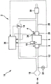
Fig. 1 shows a schematic diagram of an internal combustion engine with a controller.
Detailed Description
Fig. 1 schematically shows a self-igniting internal combustion engine 2, in the present exemplary embodiment a diesel engine of a motor vehicle. The self-igniting internal combustion engine 2 usually has a plurality of cylinders, of which, however, only one is shown in fig. 1 with the reference numeral 4.
The combustion chamber 6 of the cylinder 4 can be connected to an intake pipe 12 via an intake valve 8.
In the present embodiment, the amount of air flowing in the intake pipe 12 flows through an air cleaner 18 that separates particles from the inflowing air.
In the present exemplary embodiment, during operation of the self-igniting internal combustion engine 2, diesel fuel is injected into the cylinder 4 by means of the injector 10. The hot combustion gases then pass out of the combustion chamber 6 through the exhaust valve 26 into the exhaust pipe 28. In the exhaust pipe, a catalyst 30 is disposed.
The self-igniting internal combustion engine 2 has a known exhaust gas recirculation valve 14 for external exhaust gas recirculation.
A controller 36 (ECU) is provided for operation of the auto-ignition internal combustion engine 2. For this purpose, the controller 36 is provided with a microprocessor, wherein a program is stored in a memory medium, in particular in a read-only memory (ROM), which program is suitable for this purpose, i.e. for carrying out the overall control and/or regulation of the self-igniting internal combustion engine 2. The controller 36 is provided for carrying out the method according to the invention as explained later.
The control unit 36 is supplied with input signals which represent the operating parameters of the self-igniting internal combustion engine 2 measured by means of the sensors. For example, controller 36 may be connected to an accelerator pedal sensor (not shown) for transmitting an input signal.
The controller 36 processes the input signals and generates output signals during operation, with which the characteristics of the internal combustion engine 2 can be influenced by the actuators in accordance with the desired control and/or regulation. The control unit 36 is connected to the injectors 10, the inlet valves 8, the outlet valves 26, the exhaust gas recirculation valve 14, etc., for example, via control circuits for transmitting control signals and generates signals required for the control thereof. Not all connections shown in fig. 1 are described here.
Furthermore, in the present exemplary embodiment, downstream in the flow direction S, downstream of the air filter 18, a pressure sensor 22 is arranged in the intake manifold 12 as part of the measuring device 16 for the detected fresh air mass flow. In the present exemplary embodiment, the pressure sensor 22 is designed as a relative pressure sensor which measures the pressure difference between the pressure at the measuring point downstream of the air filter 18 and the ambient pressure. For this purpose, the pressure sensor 22, which is designed as a counter-pressure sensor, is connected to the measurement point with one pressure measuring connection, while the other pressure measuring connection is left empty. This allows a mechanically simple and inexpensive construction which still transmits high-quality measurement signals. In the present embodiment, the pressure sensor 22 is connected to the controller 36 for input signal transmission.
The control unit 36 is designed to determine a value for the fresh air mass flow in the intake pipe 12 from the pressure difference detected by the pressure sensor 22. For this purpose, an air filter 18 is used as a flow resistance. If the fresh air mass flow in the intake pipe 12 increases, the flow speed of the air rises. The result is a pressure drop in the flow direction S after the air filter 18 acting as a flow resistance. The pressure drop taken is a measure for the flow velocity in the flow direction S after the air filter 18, which acts as a flow resistance. Together with the value for the ambient pressure and the fresh air temperature, the air density can be determined. The fresh air mass flow can then be determined with the air density and the characteristic cross-sectional area.
In addition, the control unit 36 controls the exhaust gas recirculation (AGR) in the operation of the self-igniting internal combustion engine 2 by opening and closing the exhaust gas recirculation valve 14 as follows:
in a first step, an updated flow resistance value is determined. For this purpose, the control unit 36 controls the exhaust gas recirculation valve 14 of the self-igniting internal combustion engine 2 into a closed state in order to determine the motor mass flow of the diesel engine. For this purpose, the control unit 36 receives the motor speed of the self-igniting internal combustion engine 2 and the pressure and temperature values of the air and processes these values. When the exhaust gas recirculation valve 14 is closed, the motor mass flow corresponds to the fresh air mass flow. Thus, the mass flow is known at this time. The determination of the updated flow resistance value can be carried out at predefined intervals in order to detect a drift of the flow resistance value, for example due to aging processes. Alternatively, operating states can be used in which the AGR valve is always closed (e.g. high load, high motor speed, etc.).
In addition, the controller 36 uses the pressure sensor 22 to detect the pressure drop across the air filter 18. The control 36 determines the current flow resistance value of the air filter 18 together with the fresh air mass flow. The current flow resistance value of the air filter 18 is now stored in the memory 38 of the controller. In other words, a reference value is now available which relates the current flow resistance value of the air filter 18 to the value for the fresh air mass flow. A correction value or coefficient can thus now be determined with which the drift can be compensated. The controller 36 can furthermore be configured to extrapolate the drift into the future in order to improve the accuracy at times within the interval mentioned above.
In a further step, a fresh air mass flow is currently determined during operation of the self-igniting internal combustion engine 2 when the exhaust gas recirculation valve 14 is open. For this purpose, a pressure sensor 22 detects the pressure difference. To correct for this drift, the current flow resistance value or correction value or factor of the air filter 18 is now used. Furthermore, values for the ambient pressure and the air temperature are recorded and the air density is determined from these values. The fresh air mass flow is then determined by the air density, the pressure difference across the air filter and the effective cross-sectional area.
Claims (7)
1. Method for determining a fresh air mass flow for regulating the exhaust gas recirculation in an intake pipe (12) of an auto-ignition internal combustion engine (2), having the following steps:
-taking a pressure drop measurement over the flow resistance with a pressure sensor (22) arranged after the flow resistance in the flow direction (S), wherein the pressure sensor (22) is configured as a relative pressure sensor measuring a pressure difference between a pressure at a measurement point downstream of the air filter (18) and an ambient pressure,
-determining a motor mass flow of the auto-ignited internal combustion engine (2) when the exhaust gas recirculation valve (14) is closed, and determining an updated flow resistance value from the motor mass flow and the pressure drop measurement, and
-determining a flow velocity from the pressure drop measurement and the updated value of the flow resistance, and determining a fresh air mass flow from the flow velocity.
2. A method according to claim 1, wherein an air filter (18) is used as a flow resistance in the inlet line (12).
3. The method according to claim 1, wherein an ambient pressure value and an air temperature value are acquired and an air density value for determining the fresh air mass flow is determined from the ambient pressure value and the air temperature value.
4. The method as claimed in claim 1, wherein the pressure drop value is detected at the flow resistance when the exhaust gas recirculation valve (14) is closed.
5. A measuring device (16) for determining a fresh air mass flow for exhaust gas recirculation in an intake pipe (12) of an auto-ignition internal combustion engine (2), having a pressure sensor (22) arranged in the flow direction (S) downstream of a flow resistance for acquiring a pressure drop measurement value over the flow resistance, wherein the pressure sensor (22) is designed as a relative pressure sensor which measures a pressure difference between a pressure at a measuring point downstream of an air filter (18) and an ambient pressure; and the measuring device further having a controller (36) which is designed to carry out the method according to one of the preceding claims,
wherein a motor mass flow of the self-igniting internal combustion engine (2) is determined when the exhaust gas recirculation valve (14) is closed, and an updated flow resistance value is determined from the motor mass flow and the pressure drop measurement, wherein a flow speed is determined from the pressure drop measurement and the updated flow resistance value of the flow resistance, and a fresh air mass flow is determined from the flow speed.
6. A machine-readable storage medium having stored thereon a computer program having a program code which causes a computing unit to implement the method according to any one of claims 1 to 4.
7. The machine-readable storage medium according to claim 6, wherein the computing unit is a measuring device (16) according to claim 5.
Applications Claiming Priority (2)
| Application Number | Priority Date | Filing Date | Title |
|---|---|---|---|
| DE102013224766.4 | 2013-12-03 | ||
| DE102013224766.4A DE102013224766A1 (en) | 2013-12-03 | 2013-12-03 | Method and measuring arrangement for determining a fresh air mass flow |
Publications (2)
| Publication Number | Publication Date |
|---|---|
| CN104675538A CN104675538A (en) | 2015-06-03 |
| CN104675538B true CN104675538B (en) | 2022-03-01 |
Family
ID=53058545
Family Applications (1)
| Application Number | Title | Priority Date | Filing Date |
|---|---|---|---|
| CN201410716196.4A Active CN104675538B (en) | 2013-12-03 | 2014-12-02 | Method and measuring device for determining a fresh air mass flow |
Country Status (3)
| Country | Link |
|---|---|
| CN (1) | CN104675538B (en) |
| DE (1) | DE102013224766A1 (en) |
| IN (1) | IN2014DE02668A (en) |
Families Citing this family (6)
| Publication number | Priority date | Publication date | Assignee | Title |
|---|---|---|---|---|
| DE102016205680A1 (en) * | 2016-04-06 | 2017-10-12 | Robert Bosch Gmbh | Method and device for determining a fresh air mass flow in an internal combustion engine |
| DE102016226003A1 (en) * | 2016-12-22 | 2018-06-28 | Robert Bosch Gmbh | Method and device for correcting an air mass flow sensor |
| DE102017218109A1 (en) * | 2017-10-11 | 2019-04-11 | Robert Bosch Gmbh | Method for determining an air mass flow of an internal combustion engine |
| CN109268158A (en) * | 2018-09-27 | 2019-01-25 | 安徽江淮汽车集团股份有限公司 | A kind of modified method and system of air input of engine by air |
| DE102018220391A1 (en) * | 2018-11-28 | 2020-05-28 | Robert Bosch Gmbh | Method for determining an air mass flow for an internal combustion engine |
| CN110671216A (en) * | 2019-09-29 | 2020-01-10 | 潍柴动力股份有限公司 | Method and device for acquiring intake flow value of engine and electronic control unit |
Citations (5)
| Publication number | Priority date | Publication date | Assignee | Title |
|---|---|---|---|---|
| DE102004038733A1 (en) * | 2004-08-10 | 2006-02-23 | Robert Bosch Gmbh | Method and device for operating an internal combustion engine |
| US20090112440A1 (en) * | 2007-10-30 | 2009-04-30 | Lycoming Engines, A Division Of Avco Corporation | Techniques for delivering fuel to a piston aircraft engine |
| CN102317606A (en) * | 2009-02-17 | 2012-01-11 | 本田技研工业株式会社 | Device for calculating the intake air volume in a cylinder |
| JP2012251509A (en) * | 2011-06-06 | 2012-12-20 | Nissan Motor Co Ltd | Exhaust gas recirculation system for internal combustion engine |
| CN103221662A (en) * | 2010-11-22 | 2013-07-24 | 丰田自动车株式会社 | Air-quantity estimation device for internal combustion engine with supercharger |
-
2013
- 2013-12-03 DE DE102013224766.4A patent/DE102013224766A1/en active Pending
-
2014
- 2014-09-16 IN IN2668DE2014 patent/IN2014DE02668A/en unknown
- 2014-12-02 CN CN201410716196.4A patent/CN104675538B/en active Active
Patent Citations (5)
| Publication number | Priority date | Publication date | Assignee | Title |
|---|---|---|---|---|
| DE102004038733A1 (en) * | 2004-08-10 | 2006-02-23 | Robert Bosch Gmbh | Method and device for operating an internal combustion engine |
| US20090112440A1 (en) * | 2007-10-30 | 2009-04-30 | Lycoming Engines, A Division Of Avco Corporation | Techniques for delivering fuel to a piston aircraft engine |
| CN102317606A (en) * | 2009-02-17 | 2012-01-11 | 本田技研工业株式会社 | Device for calculating the intake air volume in a cylinder |
| CN103221662A (en) * | 2010-11-22 | 2013-07-24 | 丰田自动车株式会社 | Air-quantity estimation device for internal combustion engine with supercharger |
| JP2012251509A (en) * | 2011-06-06 | 2012-12-20 | Nissan Motor Co Ltd | Exhaust gas recirculation system for internal combustion engine |
Also Published As
| Publication number | Publication date |
|---|---|
| DE102013224766A1 (en) | 2015-06-03 |
| IN2014DE02668A (en) | 2015-06-26 |
| CN104675538A (en) | 2015-06-03 |
Similar Documents
| Publication | Publication Date | Title |
|---|---|---|
| CN104675538B (en) | Method and measuring device for determining a fresh air mass flow | |
| EP2198141B1 (en) | Exhaust-gas recirculation apparatus and exhaust-gas recirculation flow rate estimation method for internal combustion engines | |
| US7715975B2 (en) | Engine control system and control method thereof | |
| US10323583B2 (en) | Method for determining the oxygen concentration O2 in a gas flow | |
| US6805095B2 (en) | System and method for estimating and controlling cylinder air charge in a direct injection internal combustion engine | |
| US8392098B2 (en) | Abnormality diagnosis device of internal combustion engine | |
| US8302378B2 (en) | Degradation diagnosis device for catalyst | |
| EP1705359B1 (en) | Method of feedforward controlling a multi-cylinder internal combustion engine and relative feedforward fuel injection control system | |
| KR102004545B1 (en) | Method and device for adapting signals of an oxygen sensor in the air supply channel of an internal combustion engine | |
| US20060235604A1 (en) | Method of feedforward controlling a multi-cylinder internal combustion engine and associated feedforward fuel injection control system | |
| US11112333B2 (en) | Sensor failure diagnostic apparatus | |
| CN111022206A (en) | Control device and control method for vehicle drive device, in-vehicle electronic control unit, learned model, and machine learning system | |
| US11143134B2 (en) | Engine controller, engine control method, and memory medium | |
| US6971358B2 (en) | Intake system for internal combustion engine and method of controlling internal combustion engine | |
| US7769526B2 (en) | Diesel transient combustion control based on intake carbon dioxide concentration | |
| CN109707521B (en) | Method for determining cylinder air charge of internal combustion engine with variable valve stroke device | |
| JP2011252785A (en) | Air intake volume correction method for internal combustion engines | |
| US8315782B2 (en) | Method and device for operating an internal combustion engine | |
| KR102350839B1 (en) | Method for cylinder balancing of an internal combustion engine | |
| JP7206625B2 (en) | Control device for internal combustion engine | |
| JP7177385B2 (en) | engine controller | |
| GB2497293A (en) | Operation of a Fuel Injection System for an Internal Combustion Engine | |
| JP2021006776A (en) | Temperature detecting device | |
| US20190040837A1 (en) | Systems and methods of controlling pre-primary ignition of an internal combustion engine | |
| JP2018173067A (en) | Control device of internal combustion engine |
Legal Events
| Date | Code | Title | Description |
|---|---|---|---|
| C06 | Publication | ||
| PB01 | Publication | ||
| C10 | Entry into substantive examination | ||
| SE01 | Entry into force of request for substantive examination | ||
| GR01 | Patent grant | ||
| GR01 | Patent grant |