CN102973237A - Portable imaging system employing a miniature endoscope - Google Patents
Portable imaging system employing a miniature endoscope Download PDFInfo
- Publication number
- CN102973237A CN102973237A CN2012104228959A CN201210422895A CN102973237A CN 102973237 A CN102973237 A CN 102973237A CN 2012104228959 A CN2012104228959 A CN 2012104228959A CN 201210422895 A CN201210422895 A CN 201210422895A CN 102973237 A CN102973237 A CN 102973237A
- Authority
- CN
- China
- Prior art keywords
- fibre
- handle
- optical probe
- image
- optical
- Prior art date
- Legal status (The legal status is an assumption and is not a legal conclusion. Google has not performed a legal analysis and makes no representation as to the accuracy of the status listed.)
- Pending
Links
Images


Classifications
-
- A—HUMAN NECESSITIES
- A61—MEDICAL OR VETERINARY SCIENCE; HYGIENE
- A61B—DIAGNOSIS; SURGERY; IDENTIFICATION
- A61B1/00—Instruments for performing medical examinations of the interior of cavities or tubes of the body by visual or photographical inspection, e.g. endoscopes; Illuminating arrangements therefor
- A61B1/00002—Operational features of endoscopes
- A61B1/00059—Operational features of endoscopes provided with identification means for the endoscope
-
- A—HUMAN NECESSITIES
- A61—MEDICAL OR VETERINARY SCIENCE; HYGIENE
- A61B—DIAGNOSIS; SURGERY; IDENTIFICATION
- A61B1/00—Instruments for performing medical examinations of the interior of cavities or tubes of the body by visual or photographical inspection, e.g. endoscopes; Illuminating arrangements therefor
- A61B1/00131—Accessories for endoscopes
- A61B1/00135—Oversleeves mounted on the endoscope prior to insertion
-
- A—HUMAN NECESSITIES
- A61—MEDICAL OR VETERINARY SCIENCE; HYGIENE
- A61B—DIAGNOSIS; SURGERY; IDENTIFICATION
- A61B1/00—Instruments for performing medical examinations of the interior of cavities or tubes of the body by visual or photographical inspection, e.g. endoscopes; Illuminating arrangements therefor
- A61B1/00142—Instruments for performing medical examinations of the interior of cavities or tubes of the body by visual or photographical inspection, e.g. endoscopes; Illuminating arrangements therefor with means for preventing contamination, e.g. by using a sanitary sheath
-
- A—HUMAN NECESSITIES
- A61—MEDICAL OR VETERINARY SCIENCE; HYGIENE
- A61B—DIAGNOSIS; SURGERY; IDENTIFICATION
- A61B1/00—Instruments for performing medical examinations of the interior of cavities or tubes of the body by visual or photographical inspection, e.g. endoscopes; Illuminating arrangements therefor
- A61B1/00163—Optical arrangements
- A61B1/00165—Optical arrangements with light-conductive means, e.g. fibre optics
-
- A—HUMAN NECESSITIES
- A61—MEDICAL OR VETERINARY SCIENCE; HYGIENE
- A61B—DIAGNOSIS; SURGERY; IDENTIFICATION
- A61B1/00—Instruments for performing medical examinations of the interior of cavities or tubes of the body by visual or photographical inspection, e.g. endoscopes; Illuminating arrangements therefor
- A61B1/06—Instruments for performing medical examinations of the interior of cavities or tubes of the body by visual or photographical inspection, e.g. endoscopes; Illuminating arrangements therefor with illuminating arrangements
- A61B1/0607—Instruments for performing medical examinations of the interior of cavities or tubes of the body by visual or photographical inspection, e.g. endoscopes; Illuminating arrangements therefor with illuminating arrangements for annular illumination
-
- A—HUMAN NECESSITIES
- A61—MEDICAL OR VETERINARY SCIENCE; HYGIENE
- A61B—DIAGNOSIS; SURGERY; IDENTIFICATION
- A61B1/00—Instruments for performing medical examinations of the interior of cavities or tubes of the body by visual or photographical inspection, e.g. endoscopes; Illuminating arrangements therefor
- A61B1/06—Instruments for performing medical examinations of the interior of cavities or tubes of the body by visual or photographical inspection, e.g. endoscopes; Illuminating arrangements therefor with illuminating arrangements
- A61B1/0638—Instruments for performing medical examinations of the interior of cavities or tubes of the body by visual or photographical inspection, e.g. endoscopes; Illuminating arrangements therefor with illuminating arrangements providing two or more wavelengths
-
- A—HUMAN NECESSITIES
- A61—MEDICAL OR VETERINARY SCIENCE; HYGIENE
- A61B—DIAGNOSIS; SURGERY; IDENTIFICATION
- A61B1/00—Instruments for performing medical examinations of the interior of cavities or tubes of the body by visual or photographical inspection, e.g. endoscopes; Illuminating arrangements therefor
- A61B1/06—Instruments for performing medical examinations of the interior of cavities or tubes of the body by visual or photographical inspection, e.g. endoscopes; Illuminating arrangements therefor with illuminating arrangements
- A61B1/07—Instruments for performing medical examinations of the interior of cavities or tubes of the body by visual or photographical inspection, e.g. endoscopes; Illuminating arrangements therefor with illuminating arrangements using light-conductive means, e.g. optical fibres
-
- A—HUMAN NECESSITIES
- A61—MEDICAL OR VETERINARY SCIENCE; HYGIENE
- A61B—DIAGNOSIS; SURGERY; IDENTIFICATION
- A61B5/00—Measuring for diagnostic purposes; Identification of persons
- A61B5/0059—Measuring for diagnostic purposes; Identification of persons using light, e.g. diagnosis by transillumination, diascopy, fluorescence
- A61B5/0082—Measuring for diagnostic purposes; Identification of persons using light, e.g. diagnosis by transillumination, diascopy, fluorescence adapted for particular medical purposes
- A61B5/0084—Measuring for diagnostic purposes; Identification of persons using light, e.g. diagnosis by transillumination, diascopy, fluorescence adapted for particular medical purposes for introduction into the body, e.g. by catheters
-
- G—PHYSICS
- G02—OPTICS
- G02B—OPTICAL ELEMENTS, SYSTEMS OR APPARATUS
- G02B23/00—Telescopes, e.g. binoculars; Periscopes; Instruments for viewing the inside of hollow bodies; Viewfinders; Optical aiming or sighting devices
- G02B23/24—Instruments or systems for viewing the inside of hollow bodies, e.g. fibrescopes
- G02B23/2407—Optical details
- G02B23/2461—Illumination
- G02B23/2469—Illumination using optical fibres
-
- G—PHYSICS
- G02—OPTICS
- G02B—OPTICAL ELEMENTS, SYSTEMS OR APPARATUS
- G02B23/00—Telescopes, e.g. binoculars; Periscopes; Instruments for viewing the inside of hollow bodies; Viewfinders; Optical aiming or sighting devices
- G02B23/24—Instruments or systems for viewing the inside of hollow bodies, e.g. fibrescopes
- G02B23/2476—Non-optical details, e.g. housings, mountings, supports
-
- G—PHYSICS
- G02—OPTICS
- G02B—OPTICAL ELEMENTS, SYSTEMS OR APPARATUS
- G02B27/00—Optical systems or apparatus not provided for by any of the groups G02B1/00 - G02B26/00, G02B30/00
- G02B27/0025—Optical systems or apparatus not provided for by any of the groups G02B1/00 - G02B26/00, G02B30/00 for optical correction, e.g. distorsion, aberration
Landscapes
- Health & Medical Sciences (AREA)
- Life Sciences & Earth Sciences (AREA)
- Surgery (AREA)
- Physics & Mathematics (AREA)
- Optics & Photonics (AREA)
- General Health & Medical Sciences (AREA)
- Animal Behavior & Ethology (AREA)
- Veterinary Medicine (AREA)
- Public Health (AREA)
- Engineering & Computer Science (AREA)
- Biomedical Technology (AREA)
- Heart & Thoracic Surgery (AREA)
- Medical Informatics (AREA)
- Molecular Biology (AREA)
- Pathology (AREA)
- Biophysics (AREA)
- Nuclear Medicine, Radiotherapy & Molecular Imaging (AREA)
- Radiology & Medical Imaging (AREA)
- Astronomy & Astrophysics (AREA)
- General Physics & Mathematics (AREA)
- Endoscopes (AREA)
- Instruments For Viewing The Inside Of Hollow Bodies (AREA)
Abstract
A cart or man-portable system and method for performing endoscopic procedures is provided. A portable display device, such as a laptop computer, is coupled to a handle comprising a miniature camera and fiber optic illumination subsystem. A sterile disposable portion is fitted over the illumination subsystem and inserted into a target area on a patient. Images of the target area are conveyed from the camera to the display device while an endoscopic procedure is performed, thus facilitating real-time diagnosis during the procedure.
Description
The application is that the application number of submitting on March 8th, 2006 is 200680010519.1, and denomination of invention is divided an application for " using the portable imaging system of miniature endoscope "
Related application
The application be as the part continuation application of No. the 10/042nd, 126, the U.S. Patent application of October 19 calendar year 2001 application in the part continuation application of No. the 11/075th, 827, the U.S. Patent application of examining of application on March 8th, 2005.The priority that No. the 11/072nd, 685, the U.S. Patent application that this part application requirement is given on March 4th, 2005 and applied for for topic take " Miniature Endoscope With Imaging FiberSystem ".The full content of above-mentioned application is all incorporated into by quoting as proof at this.
Background technology
Endoscope can the interior structure of macroscopy cavity.At medical domain, using of endoscope is allowed for diagnosing, check surgical site, gathers tissue sample or other surgical apparatus of safe manoeuvring become checking as the organ of purpose easily.
For instance, peritoneoscope is for checking that the organ in the abdomen area is particularly useful.Peritoneoscope generally include to throw light on zone to be seen light guide, at least one is used for focusing on and relaying the lens subassembly of illuminated object images and for tissue injury being minimized the housing of the whole assembly that consists of during surgical procedure.Light guide can comprise the throwing light on optical fiber element at this position.The peritoneoscope housing comprises the distal section that can be inserted in body cavity the inside and comprises near the proximal section that user can be firmly grasped it make the handle that far-end locates surgical site.
Existing endoscope can comprise imaging device, for example, and charge-coupled image sensor (CCD).This can device can catch the image of being checked object and it is sent to display device, for example, and monitor.For operation improving feature and manufacturability, continuation need to improve imaging capability and reduce the risk-taking endoscopic system of patient.
Summary of the invention
The present invention relates to ruggedness, resolution and the visual field improved minor diameter imaging probe or endoscope are arranged.In a preferred embodiment of the invention, the far-end that comprises the probe of disposable shield sleeve can inject tissue when checking.This probe has the diameter less than 3 millimeters, preferably has the diameter less than 2 millimeters, with the damage that reduces the insertion point and the path that leads to the position that endoscopic procedure otherwise do not arrive is provided whereby.
In preferred embodiments, there is the fibre-optic waveguide that image is transferred to near-end from far-end in endoscope.Lens combination is placed on the far-end of fibre-optic waveguide.The near-end optical coupled of imaging device and fibre-optic waveguide.Sheath extends around fibre-optic waveguide, and this sheath comprises lighting fiber.Although preferred embodiment utilizes external diameter at the probe below 2 millimeters and jacket assembly, specific application will adapt to the larger larger-diameter utensil of optical image fibers number to provide resolution higher image.These application can utilize scope at the external diameter of 2-4 millimeter.
In one embodiment, lens combination has first lens element, the second lens element and aperture diaphragm.Lens combination makes from the light of any given position on the object and numerous coupling fiber, so that the conduct of the numerical aperture of light is with respect to the function change of the angle of the longitudinal axis of this lens combination.This provides and the more effective coupling of fiber optic aperture.This is to use non-telecentric lens system to realize.
The preferred embodiment of this lens combination comprises a pair of lens and aperture diaphragm.The collection of lens boundary ambient light is shaped lens in order to improve endways.This whole visual field at this device provides more clearly image.Aperture diaphragm is to locate for providing with the efficient coupling of fiber array.
This imaging device may be that charge-coupled image sensor (CCD), cmos imaging device or other have the solid state imaging sensor of the two-dimensional array of pixel element.Imaging sensor is installed on the circuit board of Handleset.This sensor can catch the image of being checked object, and the image processing circuit that is installed on this circuit board is transferred to computer to this view data at vision cable in order to store, process and/or show.
For instance, miniature endoscope system can be used for orthopedic, Rheumatism Dept., general laparoscopically, gynecological or ear, nose, larynx audit program; Size joint, heart, oncology, pulmonary, breast, brain GI and veterinary's application.Although many application need little diameter to reduce wound, the specific application can adapt to larger diameter.Probe can be included as insertion uncovered pipeline of preparing of other operation element in sheath or imaging probe, so that with this position of fluid flushing, light or other the energy are guided into therapentic part or taken out tissue sample.
Jacket assembly can comprise the concentric arry that connects the lighting fiber that card extends on the sheath hub assembly.As an alternative, lighting fiber can with probe assembly in connect card via the direct-coupled optical fiber of fiber optic cables that extends from handle to light source shell and be coupled.This housing can comprise writes video disk CD writer on the disk to image.For specific application, primary beam can be placed on the probe the inside like this, so that sheath is thinner or can adapts to larger service pipe.
The advantageous applications that present system has four kinds of suitable plastic surgery to use: after clinic diagnosis, operating room surgery excision/program, the operation in the clinic assessment with drug delivery definite their treatment usage of tram under the condition of directly seeing simultaneously in the joint.
Except it used in the clinic, this system can be used for the arthroscope that operating room replaces standard.By removing the needs that use arthroscope flush fluid or large-bore camera, the misery that the arthroscopy program is brought and swelling with do not remove this needs and compare and will be greatly reduced.Patient's second day just can be got back to clinic or sports ground.
For there not being now possibility to use tissue and the bond graft procedures of traditional mr imaging technique, this system is used to the postoperative evaluation that rehabilitation is processed.Example comprises: the assessment of fragmentation minimizing, ligament integrity and other usage of rebuilding articular cartilage surface program, meniscal repairs, lip curb reparation, rotator cuff repair, articular surface.
This system comprises computer (perhaps other checks system), video camera, light source, do not need to process disposable sterile barrier and lens composition with regard to reusable handle and single patient use again between each program.This system cancellation space requirement, again treatment facility expense, with the endoscope of time-sensitive is sterilized again relevant manpower and expense.
Description of drawings
Above-mentioned and other purpose, feature and the interests more specifically description by following the preferred embodiments of the invention to the accompanying drawing illustrated of the present invention will become apparent, and reference marks similar in these accompanying drawings represents same parts everywhere at different views.These accompanying drawings needn't be drawn to scale, but emphasize to illustrate principle of the present invention.
Fig. 1 illustrates the sketch map according to miniature endoscope system of the present invention;
Fig. 2 is the cutaway view of intubate;
Fig. 3 is the cutaway view at the trocar of intubate the inside;
Fig. 4 is the perspective view of miniature endoscope;
Fig. 5 is that once sheath covers the cutaway view of the miniature endoscope of intubate;
Fig. 6 A is the cutaway view of disposable shield sleeve/lighting unit;
Fig. 6 B is the far-end amplification view of disposable shield sleeve;
Fig. 7 A is the near-end cutaway view of disposable shield sleeve/lighting unit of obtaining along Fig. 6 A center line 7A-7A;
Fig. 7 B is the front view of the disposable shield sleeve far-end that obtained by band along Fig. 6 A and Fig. 6 B center line 7B-7B;
Fig. 8 is the side view of disposable shield sleeve/lighting unit, the display lighting lead-in wire;
Fig. 9 is the cutaway view of the image-generating unit of miniature endoscope;
Figure 10 A is the magnification field of the far-end of the image-generating unit pointed out with the part of 10A definition in Fig. 9;
Figure 10 B is the front view of the image-generating unit far-end that obtains of the line 10B-10B in Figure 10 A;
Figure 11 is the local amplification view of signal of the image-generating unit that obtains along Figure 10 A center line 11-11;
Figure 12 is the zoomed-in view of distal lens system;
Figure 13 is for the sine of the maximum light angle of the different lens combination of the endoscope distal end curve chart with the normalized images height change;
Figure 14 is the zoomed-in view of another embodiment of distal lens system;
Figure 15 is the cutaway view of another embodiment of endoscope;
Figure 16 A is the cutaway view of the endoscope that obtains of the line 16A-16A along Figure 15;
Figure 16 B is the cutaway view of the endoscope that obtains of the line 16B-16B along Figure 15;
Figure 16 C is the amplification view of the image-generating unit pointed out with the part of 10C definition in Figure 16 B;
Figure 17 A is the cutaway view of another embodiment of endoscope;
Figure 17 B is endoscope's cutaway view that the line 17B-17B along Figure 17 A obtains;
Figure 18 is the side view of two-piece type disposable shield sleeve/lighting unit;
Figure 19 is the sketch map for the control unit of the preferred embodiments of the invention;
Figure 20 illustrates the use the preferred method of the present invention;
Figure 21 illustrates the preferred embodiment of portable endoscopic system according to the present invention;
Figure 22 illustrates the preferred embodiment of endoscope according to the present invention;
Figure 23 is the end-view of sheath;
Figure 24 is the sketch map of preferred endoscope apparatus; And
Figure 25 is the sketch map of another kind of preferred endoscope apparatus.
Specific implementation method
Embodiment of the present invention are illustrational with the Fig. 1 that shows miniature endoscope 20.There are image-generating unit 22 and sheath/illumination unit 24 in endoscope 20.There is image transmission path in endoscope 20, for example, is used for checking the numerous optical fiber 26 of inspected object in the extension pipe 28 of the bar tip 29, can be clear that optical fiber 146 in Figure 11 and 12.Optical fiber 26 in handle 32 with imaging device 30 (charge-coupled image sensor of for example, in Fig. 9, seeing or other pixelation flat panel sensor) optical coupled.The disposable shield sleeve 34 of sheath/illumination unit 24 covers the extension pipe 28 of the bar tip 29 dress optical fiber 26.Disposable shield sleeve 34 is fixed to handle 32 upper bed-plates 35 in the useful installation mechanism 36 of near-end.In one embodiment, the disposable shield sleeve 34 of sheath/illumination unit 24 has numerous optical fiber far-end and the far-end probe 29 of light transmission to disposable shield sleeve 34.The far-end of disposable shield sleeve/lighting unit 24 has adapter 38 to be connected with light source 40.
As explaining in more detail below, image-generating unit 22 does not need sterilization, because image-generating unit 22 body contact or be directly exposed in the health not.In order to form sterile barrier, sheath/illumination unit 24 has and is fixed to the disposable shield sleeve 34 that the base 35 on the image-generating unit 22 carries as thimble assembly 52 usefulness and covers extension pipes 28.In addition, sheath/illumination unit 24 remainder that has its position on the base 35 of sheath/illumination unit of being installed in 24 to be fit to cover image-generating unit 22 provides the aseptic door curtain made of cloth 52 of gnotobasis.
Endoscope and once the endoscope of sheath be at the PCT application PCT/US00/25107 of JIUYUE in 2000 application on the 13rd and described No. the 09/518th, 954, the U.S. Patent application of application on March 6th, 2000.The full content of above-mentioned application is all incorporated into by quoting as proof at this.
Before further discussing endoscope 20 in detail, in order to use endoscope 20, endoscope 20 need to be placed in the health in order to check the position of expection.A kind of such method is that intubate 60 is injected health and makes endoscope 20 pass intubate 60.Then a kind of health that first intubate 60 injected is described below uses intubate 60 endoscope 20 to be injected the method for health.
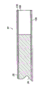
During the insertion program, at first intubate 60 (intubate of for example, seeing) is injected certain position of health in Fig. 2.Intubate 60 has base 62 and pipe 64.Pipe 64 has the axle 66 that extends to the space 70 the base 62 from far-end 68.In one embodiment, pipe 64 is to make with flexible material (for example, plastics or thin-wall stainless steel).The spiral joint 72 that intubate 60 has suitable medicine or fluid injection or aspirator to adhere to.
For intubate 60 is injected health, use the stiff shaft 78 of the trocar 76 within the axle 66 that is contained in intubate 60 with the trocar 76 (as what in Fig. 3, see) reeve intubate 60.The stiff shaft 78 of the trocar 76 slightly stretches out and the stylet 80 that thrusts when needed tissue at surgical site is arranged from the far-end of the pipe 64 of intubate 60.In case intubate 60 is placed on surgical site, just the trocar 76 is taken out from intubate 60, then endoscope 20 is installed.Intubate 60 is with the hands of user the sensation of position to be located.
Although intubate 60 and the trocar 76 be comparatively speaking cost minimization and also can after sterilization, be reused or after using, lost, but because some parts of endoscope 20, for example, the parts in the image-generating unit 22 do not want to lose whole endoscope 20.Endoscope 20 uses disposable sleeve or sheath 34 to reuse front sterilization demand to help keeping gnotobasis and minimizing or cancellation.
Before described and endoscope 20 has been injected intubate 60 far-end of endoscope 20 is placed the method for suitable position, endoscope 20 had been described in further detail now.With reference to Fig. 4, this figure shows the perspective view of endoscope 20.There is reusable image-generating unit 22 in endoscope 20 and used the sheath/illumination unit 24 that just abandons.Disposable shield sleeve/lighting unit 24 has to cover and around the extension pipe of the extension pipe 28 of image-generating unit 22.The Packed far-end 84 of the extension pipe of sheath/illumination unit 24, and some embodiments comprise illumination is transferred to the optical fiber of far-end 84 from external light source 40, as shown in Figure 1.The bases 35 that are fixed to the mechanism of installing 36 on the image-generating unit 22 of endoscope 20 at the near-end of sheath/illumination unit 24.Optical lead 88 is stretched out from base 35, in order to be connected with light source 40.In addition, sheath/illumination unit 24 has the door curtain made of cloth 52 on the handle 32 that is installed on the base 35 and extends to image-generating unit 22.As describing in further detail below with reference to Fig. 9-11, the handle 32 of image-generating unit 22 holds optics and imaging device 32 in order to receive image by optical fiber 26 transmission among the extension pipe 28 that is positioned at image-generating unit 22.
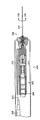
Fig. 5 is the cutaway view that includes the miniature endoscope 20 of the reusable image-generating unit 22 of optical image fibers 26 and disposable shield sleeve/lighting unit 24.The disposable shield sleeve 34 that intubate 60 is shown as with sheath/illumination unit 24 covers, and this sheath covers the probe 29 of image-generating unit 22.
As shown in Figure 5, the reusable image-generating unit 22 of endoscope 20 by aseptic disposable shield sleeve/lighting unit 24 around.Disposable shield sleeve/lighting unit 24 is sheath 34 once, and this sheath is in far-end 84 sealing and around carrying the extension pipe 28 of the optical fiber 26 of image-generating unit 22 with encirclement.On the installation mechanism 36 on the base 35 of sheath/illumination unit 24 is fixed to installation mechanism 92 on the image-generating unit 22.
Disposable shield sleeve/lighting unit 24 has the door curtain made of cloth 52 of the handle that surrounds image-generating unit 22.In addition, sheath/illumination unit 24 has the illumination pigtail that is connected with the light source 40 of seeing in Fig. 1.Fiber optics coupling in illumination pigtail 88 and the sheath is as explaining in more detail below.
With reference to Fig. 6 A, this figure shows the side view of sheath/illumination unit 24.Sheath unit 24 is sheath 34 once, and the outer protective sleeve 98 that wherein lengthens extends to far-end 84 from base 35.Illumination pigtail 88 from base stretch out and with Fig. 7 the lighting fiber optical coupled of sheath 34 the insides seen.The base 35 of sheath/illumination unit 24 carries the door curtain made of cloth 52 that covers the handle 35 of image-generating unit 22 in the time of two unit 22 and 24 combination.
Fig. 6 B is the zoomed-in view of far-end 84 of the disposable shield sleeve 34 of sheath/illumination unit 24.Disposable shield sleeve 34 has and stretches out (as shown in Figure 6A) in the base 35 and serve as the protection overcover of sheath unit 24 and the outer protective sleeve 98 of sterile barrier.Separate with outer protective sleeve 98 and conllinear be the inner tube 100 of disposable shield sleeve 34.Inner tube 100 defines the cylindrical space of the extension pipe 28 of the probe 29 that is used for accepting image-generating unit 22 in space 102.Inner tube 100 extends to the base 35 of sheath/illumination unit 22 equally from the far-end 84 of disposable shield sleeve 34.Inner tube 100 is compared further with outer protective sleeve 98 and is stretched out, and is contained in the pipeline 106 of the numerous lighting fiber 108 that is clear that among Fig. 6 A and the 7A with formation.Window 110 is positioned at the far-end of inner tube 100, is fixed on the inner tube 100, forms sterile barrier 84 between the outer layer segment of the space 102 of the extension pipe 28 that is used for accepting elementary area 22 and sheath/illumination unit 24 and Body contact.
In preferred embodiments, the outer protective sleeve 98 of the disposable shield sleeve 34 of sheath/illumination unit 24 be with the stainless steel material manufacturing and also about 0.038 inch external diameter arranged.Inner tube 100 is made with stainless steel material equally.Lighting fiber 108 usefulness glass or plastic optical fiber are made.According to the size of this device, come fill pipe 106 with the lighting fiber 108 of maximum number.In an example, disposable shield sleeve 34 stretches out 2.246 inches from the base 35 of sheath/illumination unit 24.
Be inserted between outer protective sleeve 98 and the inner tube is the numerous lighting fiber 108 around inner tube 100 that is clear that in Fig. 7 A and 7B.Fig. 7 A is the cutaway view that passes the base 35 of disposable shield sleeve 24.Outer protective sleeve 98 is to show with the latter half of Fig. 7 A, and with the first half segmentation of Fig. 7 A before finish.Yet the inner tube 100 in space 102 that the extension pipe 28 of image-generating unit 22 is held in definition extends to receiving chamber 114 as shown in Figure 6A, so be illustrated among up and down two parts of Fig. 7 A.Light is transferred to the transmission unit 118 of seeing from illumination pigtail 88 through the optical fiber 108 of seeing in the first half of Fig. 7 A among Fig. 6 A, this transmission unit adjacency is at the outer protective sleeve 98 of the disposable shield sleeve 34 of sheath/illumination unit 24 and the lighting fiber 108 between the inner tube 100.
Fig. 7 B shows the far-end 84 of disposable shield sleeve/lighting unit 24.The space 102 that window 110 covers and sealing is held image-generating unit 22 and surrounded by inner tube 100.Be inserted between outer protective sleeve 98 and the inner tube 100 is numerous lighting fiber 108.In illustrated embodiment, the far-end of lighting fiber 108 is not protected and exposed among the health.
Fig. 8 and Fig. 6 category-A seemingly because its shows disposable shield sleeve/lighting unit 24.In addition, Fig. 8 is illustrated in the whole illumination pigtail of giving up among Fig. 6 A.
With reference to Fig. 9, this figure shows the cutaway view of the image-generating unit of endoscope 20.Image-generating unit 22 has the probe 29 of the extension pipe 28 that band stretches out from handle 32.Near-end at handle 32 is imaging device.In this embodiment, charge-coupled image sensor (CCD) 30B that optical imagery is converted to electrical image is installed among the separable housing 120A of handle 32.Be inserted in extension pipe 28 between the optical fiber that extends or optical fiber 26 and the CCD30B is that numerous being used for projects lens 122A on the CCD30B to the image of the near-end 124 of optical fiber or optical fiber 26.Glass window 122B is attached to shell 120B and provides sealing for this scope.It also protects lens to make it to avoid to pollute.
Image-generating unit 22 will amplify from the image of the end of optical fiber 26 and it and charge-coupled image sensor 30B are coupled.As pointing out previously, charge-coupled image sensor and electronic memory and/or display device (computer 44 that is connected with monitor 46 of for example, seeing in Fig. 1) connect.
The handle 32 of image-generating unit 22 has the installation mechanism 36 installation mechanism 128 that are connected with sheath illuminator unit 24.The slit 130 that mechanism 128 has to accept to be positioned at the pin on the mechanism of installation 36 is installed.In addition, mechanism 128 is installed ridge 134, outwards outstanding from this ridge by the probe 29 that the receiving chamber 114 of the sheath/illumination unit 24 shown in Fig. 6 A is accommodated.
Figure 10 A shows the enlarged drawing of the far-end of image-generating unit 22.The extension pipe 28 that the bar tip 29 of image-generating unit 22 has from far-end 126 to handle 32 housing 120 extend.In addition, at the far-end 126 of the bar tip 29, have from far-end 126 and stretch out certain slight distance and just surpass the pipe 138 of certain slight distance of the end of optical fiber or optical image fibers 26.Pipe 138 is commonly called long tube 138, because stretching out to far-end 126 with the diameter of long tube 138 conllinear pipe less and that lack 140 plant long tube 138 the insides and with lens combination 142.Extension pipe or outer tube 128, long tube 138 and tubule 140 are to install like this, thus their far-end be flush and also use the binding agent such as medical grade epoxy to fix.The below is with the lens combination 142 that the describes in further detail end at the extension pipe 28 of image-generating unit 22.The extension pipe 28 of image-generating unit 22 is housed within disposable shield sleeve/lighting unit 24, so do not need sterilization before using first.
Figure 10 B is the end-view of the far-end 126 of image-generating unit 22.Lens combination 142, tubule 140, long tube 138 and outer tube or the extension pipe 28 of showing whole conllinear.
With reference to Figure 11, this figure shows the cutaway view of the image-generating unit 22 of endoscope 20.The probe 29 of image-generating unit 22 has the numerous optical fiber 146 that is used for image is transferred to from the far-end 126 of the bar tip 29 handle 32.What surround optical fiber 146 at the far-end of the bar tip 29 is the long tube 138 that the optical fiber 146 in the optical image fibers 26 is remained on the appropriate location.Outer tube or extension pipe 28 are around long tube 138 and near the starting point the far-end 126 of the bar tip 29 to the optical fiber 146 of protecting optical image fibers 26 at the other end of handle 32 the insides.Usually there is the optical fiber 146 shown in thousands of chromosomes 11 to be merged.The image that enters them loads to be finished with distal lens system 142, this distal lens system as the following describes according to the intensity level to the relation arrangement image of the position of optical image fibers bundle 26.
In addition, these optical fiber disorder pack method.When optical image fibers bundle 26 when extending to the proximal fibers that are positioned at handle 32 near the far-end 126 of image-generating unit 22, this out-of-sequence packet pack limited images/light transmits to another lens from lens 142.The unordered packing of optical fiber is by changing as treating that the optical fiber of region probed mixes up realization.
With reference to Figure 12, this figure is illustrated in the cutaway view of far-end of the bar tip 29 of image-generating unit 22 of disposable shield sleeve 34 the insides of sheath/illumination unit 24.Disposable shield sleeve 34 has the outer protective sleeve 98 with inner tube 100 conllinear.Be inserted between outer protective sleeve 98 and the inner tube 100 is the numerous lighting fiber 108 that is used for illumination of clearly seeing in Fig. 7 B.Far-end at disposable shield sleeve is window, and this window is fixed on the space of the bar tip 29 that holds image-generating unit 22 or the internal pipeline 102 by the method such as cementing and forms the border.Image-generating unit 22 has as shown in Figure 9 from far-end 126 and extends to extension pipe or outer tube 28 within the handle 32.Be positioned at the bar tip 29 far-end 126 be two additional pipes or sleeve pipe, short inner sleeve is called as tubule 140, possesses the lens element with stationary remote lens combination 142.More greatly and long sleeve pipe is called as long tube 138, around the starting point of the optical fiber 146 in tubule 140 and the optical image fibers 26.
Light tracing 160 among Figure 12 illustrates image and breaks away from this page and throw to the right with this width of cloth image with suitable focal length and how move to numerous optical fiber 146 in the optical image fibers 26 by aperture diaphragm 154 and lens 152,150.These lens combination right and wrong heart far away.
With reference to Figure 13, this figure shows that the sine of maximum light angle of three kinds of different lens combinations that the prior art lens combination is included is with the curve chart of normalized images height change.As discussed below, lens configuration is depended in the visual field.Curve chart among Figure 13 is showed about line of the maximum sinusoidal of the light angle of 50 degree lens combinations with about the second line of the maximum sinusoidal of the light angle of 70 degree lens combinations.In 70 degree systems, maximum sine approximately is 0.32.So the N.A. of optical fiber (numerical aperture) approximately is same numerical value.Otherwise 50 degree field of view system have that to be approximately 0.25 maximum light angle sinusoidal.Therefore, optical fiber has this numerical aperture.For instance, this system can provide the visual field with any selected level in 30-80 degree scope.
In one embodiment, there are 10000 optical fiber elements in endoscope 20.In this embodiment, each optical fiber element 146 has 4.4 microns diameter.The overall diameter of optical fiber 26 is 0.46 installation mechanism.The extension pipe of image-generating unit or outer tube 28 usefulness rustless steels are made.People will admit that this optical viewer can be made by many kinds of sizes, and following table is the illustration of the optical viewer of various size between two parties.

As can from upper table see, the front is self-focusing grin lenses about the succedaneum of the achromats that Figure 12 and 13 describes.Figure 14 shows the alternate embodiment with the bar tip 29 of the image-generating unit 22 of the endoscope 20 of grin lens 168.Grin lens 168 shown in Figure 14 is single element gradient index lens.The bar tip 29 of elementary area 22 shown in Figure 14 has extension pipe or the outer tube 28 that 32 (not showing) extended from far-end 126 to handle among Figure 14.In addition, with Figure 10 category-A seemingly, pipe 138 stretches out slight distance from far-end 126.This root pipe 138 is commonly called long tube, and it only surpasses the end of optical image fibers 26 slightly.Opposite with the embodiment shown in Figure 10 A, because lens 170 are simple lenses, so do not need to keep the tubule 140 of lens combination various element.
Figure 15 is the cutaway view of alternative endoscope 170.In this embodiment of endoscope 170, illumination pigtail 172 is that therefore the part of the handle 174 of image-generating unit 176 is not the part of disposable shield sleeve/lighting unit 178 also.Fibre bundle 180 is used to illumination light from 172 handle interfaces 182 that are transferred to handle 184 that go between, and light is transferred to the optical interface 184 on sheath/illumination unit 178 there, so that light is transferred to disposable shield sleeve 186 from handle 184.
Figure 16 A is the cutaway view of showing this interface.Figure 16 A is the cutaway view of the base 188 of disposable/sheath illuminator unit 178.The first half of Figure 16 A is showed the door curtain made of cloth 52 that separates with base 188.Base 188 has the optical interface 184 of accepting from the light that is contained in the handle interface 182 on the handle 174.
In addition, in the embodiment of the endoscope 170 shown in Figure 16 A-16C, one of lighting fiber 190 of sheath/illumination unit 178 is replaced by pipe or pipeline 192.The pipe 192 of seeing in Figure 15 and Figure 16 A-16C can hold laser fiber.User passes the far-end that pipe 190 is routed to lighting unit with laser fiber from the near-end of the lighting unit 178 of base shown in Figure 15 188, so that user can use laser fiber to finish certain program when checking image by optical image fibers and CCD.
The latter half of Figure 16 A is showed the cutaway view by the base 188 of sheath/illumination unit 178, shows and passes the pipe 192 that base puts in the looping pit that lighting fiber 190 is housed.Similar with shown in Fig. 7 A, Figure 16 A display lighting optical fiber 190 is positioned at the inner tube 194 around it.The space that the probe 29 of the image-generating unit 176 of inner tube 194 definition endoscopies 170 passes.
Figure 16 B is the cutaway view of showing the disposable shield sleeve 186 of the outer tube 196 of disposable shield sleeve 186 and surround illumination optical fiber 190 and signal hypotube 192.Inner tube 194 is surrounded the space 102 of the probe 29 that holds image-generating unit 176.Figure 16 C is enlarged drawing, shows hypotube 192, and its opening accepts to be contained in the laser fiber in the annular array of the lighting fiber 190 between inner tube 194 and the outer protective sleeve 196.
Although Figure 15-Figure 16 C does not show intubate 60, people will admit that in the great majority of endoscope 20 or 170 were used, intubate 60 can be as the Additional Protection of endoscope 20 or 170.
With reference to Figure 17 A, this figure shows the cutaway view of alternative endoscope 200.There are image-generating unit 202 and sheath unit 204 in endoscope 200.Opposite with previous embodiment, this disposable shield sleeve 204 does not comprise any part of lighting unit.With reference to Figure 17 A, light source 40 is by being connected with the handle 206 of image-generating unit 202 with the similar illumination pigtail 208 of illumination pigtail shown in Figure 15.But, not coupling, thus light is sent to disposable shield sleeve 204.But as seeing among Figure 17 A, illumination pigtail 208 is parts of the handle 206 of image-generating unit 202.Optical fiber 210 is used for illumination light from 208 interfaces 212 that are transferred to the handle 206 that go between.Interface 212 is positioned within the handle 206 and light is transferred to the annular ring 214 that is comprised of numerous lighting fiber 216.
With reference to Figure 17 B, probe 218 has outer tube 220 and inner tube 222.Be inserted between pipe 220 and 222 is the annular space of admitting that numerous lighting fiber 216.Optical image fibers bundle 26 is positioned among the extension pipe 28 similar inner tubes 222 with the first embodiment.This fibre bundle 26 separates with inner tube 222.Extending to the long tube 224 that only surpasses the terminal slight distance of optical image fibers bundle 26 from far-end 126 is clipped between optical fiber 26 and the inner tube 222.
Because sheath does not need illumination is taken to the far-end of the bar tip 218 in the embodiment shown in Figure 17 B, so this sheath 204 has single skin 226.For fear of retroeflection and crooked window is fixed on this single far-end of outer 226.
With reference to Figure 18, this figure shows split type disposable shield sleeve/lighting unit 230.Endoscope have split type disposable shield sleeve/lighting unit 230 first module 232, be installed to installation and cover unit 232 on the handle 32 of image-generating unit 22.Installation and cover unit 232 have the door curtain made of cloth 52 that extends in handle 32 and the illumination pigtail 88 of image-generating unit 22 in use.In order to support the door curtain made of cloth 52, this door curtain made of cloth 52 was retained on the disposable sleeve 234 before handle 32 location.The second unit 236 of disposable shield sleeve/lighting unit 230, disposable shield sleeve 236 comprises the extension pipe that covers probe 29.This second unit 236 has installation mechanism 238 fixing on the first module 232.Therefore, remove disposable shield sleeve, second unit 236 and the door curtain made of cloth 52 that it keeps being installed on installation and the cover unit 232 simultaneously with new replacement are possible at handle.
Figure 19 is the sketch map of the control unit 250 of endoscope.This control unit 250 has power supply output 252, is used for input 254 and light source 256 from the image of CCD.
Except being used for the processing unit 260 of image data processing, there is recording equipment 258 (for example, CD writer) this unit, keeps the data of patient's raw data and so on to produce storable medium.
Endoscope is used to the processing sequence 270 of Figure 20 usually as shown in the figure.The patient comes user/doctor's clinic.Doctor or technical staff use the dual glove technology of wearing that two secondary sterile glove are applied to every of the doctor on hand.The doctor holds with a hands not to be had sterile handle/lighting unit and protects sterile sheath/illumination unit with the another hands.Then, the doctor picks up light conduits and this light conduits is fixed on the lead-in wire on disposable shield sleeve/lighting unit.Power take-off and output end of image are similarly received on the control unit.By endoscope is received on the control unit, the door curtain made of cloth part of jacket assembly is in the handle extension and hang down into length such on the cable 272 so that aseptic area to be provided.When finishing this operation, the doctor takes off the first glove and is ready to start program.
After to this position medication, will be with the intubate reeve health of the trocar by the exploration technology of standard with doctor's hands.In case intubate arrives suitable position, the trocar just is removed 274, then puts the top of endoscope into intubate.Use screw or other adhesion mechanism that endoscope is fixed on the intubate.Start this system 276, and begin video, intubate will be used for checking the probe location of expection position or supervision so that the doctor can move up and down.The doctor can use at this position other utensil (for example, laser scalpel or cautery tool, electrosurgical tool and/or operation pipeline) to finish in probe or jacket assembly and process 278.Whole inspection or operative procedure can be recorded on video disc or other storage device 280.Finish this program, then this jacket assembly can be disposed 282, and pop one's head in upper 284 for another program jacket assembly that another is aseptic is attached to.
Preferred embodiment provides the multiple spectra imaging capability.This embodiment comprises with wavelength provides image in 700 nanometers to light source and detector in 1200 nanometer range.This allows user to see through the blood tissues observed.
Another embodiment is used ultraviolet (UV) section (10 nanometers are to 380 nanometers) of the electromagnetic spectrum that can process tissue.Ultraviolet luminous energy in the 325-250 nanometer range is worked in concert to finish and is burnt.Laser instrument or conventional broadband light sources can be used for light is offered illuminator.The optical image fibers bundle also can be used for illumination, the beam splitter in the handle make from the light in one or more sources individually or side by side with this fiber bundle coupling.
Embodiment of the present invention can be used for finishing the setting based on the clinic of the diagnosing image on body interior surface.As used herein " based on the clinic " refer to except the position outside the aseptic in essence environment (for example, hospital operating room, hospitalize chamber, near the room of disinfection apparatus (for example, autoclave), etc.).The example of position, clinic is, but is not limited to, and adjoins training house, ambulance, dwelling house, field hospital, hospital corridor, inspection chamber, emergency room, office block, the shop of dressing cubicle in the inspection chamber of doctor clinic, the sports buildings, etc.
By making the contiguous all surface that inserts the patient skin at position of direct contact all become the scene sterilization that single use portion can be avoided whole miniature endoscope 20.Single use portion is stored in the aseptic packaging, until they are used to certain program.Use disposable parts to allow to follow generally acknowledged medical care guilding principle standard (for example, be used for routine joint anaplastic those) and use miniature endoscope 20.
In addition, although if need to use fluid, miniature endoscope 20 is as without fluid system work.Without fluid system refer to the fact do not have liquid medium, flushing or expansion fluid (for example, saline solution) must be in adjacent objects zone the place in (that is, with the zone of using the present invention to check) inject patient body.In other words, the target area be inserted and be used for checking to miniature endoscope can by patient skin simply, and do not need instrument, injection device, the consumptive material that adds and except single use portion, do not produce too much harmful waste, for example, if being injected the target area, flush fluid then discharges therefrom the refuse that will produce.
In embodiments of the invention, provide highly portable miniature endoscope imaging system.System shown in Figure 21 is of portable form, because it can be carried or be carried by the people.Figure 21 illustrates the imitated embodiment of portable endoscopic system 291, comprising miniature endoscope 20, handle 32, image-generating unit 22, cable 290 and kneetop computer 292.In Figure 21, endoscopic unit is connected with image-generating unit and directly is connected with kneetop computer 292 via cable 290.For instance, image-generating unit 22 possibility outputting video signals, this video signal is sent to the video socket of kneetop computer 292.Then, kneetop computer 292 is used for inputting patient information, dialogue details and is used for showing real-time view data when this program is finished.
The embodiment of portable endoscopic system uses PCMCIA (personal computer memory card international association) (PCMCIA) card to make the coupling of view data and kneetop computer 292 become easy.Pcmcia card may be technical known industry standard card, and namely it may be particularly suitable for miniature endoscope.The pcmcia card of particularly suitable may comprise receiving and process the hardware of the video signal of receiving from image-generating unit.The output of pcmcia card 294 may be the industrial standard data format that treated view data is sent to the display that is associated with kneetop computer.
Portable endoscopic system 291 comprises data are sent to image-generating unit or interface box 32 and the interface box cable 290 of kneetop computer 292.Interface box may comprise that specific energy is used in the pcmcia card 294 or directly is used in more complicated imaging, image processing and data communication hardware and/or the software of kneetop computer 292 the insides.Interface box 296 may be to dispose for the data of receiving by the far-end of miniature endoscope 20 being finished real-time figure image intensifying.The figure image intensifying may be used for producing the image that is fit to finish diagnosis when lower-cost parts are used for miniature endoscope 20.As an example, grin lens may be used to miniature endoscope 20, and view data is offered interface box.Interface box may improve the picture quality that the grin lens edge produces with image processing algorithm.Then, interface box may be sent to kneetop computer 292 with industry standard format with view data via cable.This system also can be included in the equipment that transports on the handbarrow 298, for example, and display 295 and light-source system 296.This system also can comprise for the standard lamp of visual light imaging and be used for imaging or the infrared or ultraviolet source for the treatment of.
The common architecture that can use comprises the central processing unit (CPU) that usually is comprised of the microprocessor that is associated with random access memory (RAM) and read only memory (ROM).Usually, CPU also has cache memory and programmable FlashROM.Interface between microprocessor and various types of CPU memorizer often is called as local bus, but also may be more generally or Industry Standard Architecture.The executable instruction of machine-readable or function that the patient data server of the application program of CPU processing and explanation and operating system, User Exploitation, diagnostic tool, hospital, health status supplier's computer and the computer relevant with distant place expert are associated.Graphic user interface (GUI) can be used for input and show patient data and check image.
Many computing platforms (for example also have memory drives, hard disk drive (HDD), floppy disk, CD drive (CD, CD-R, CD-RW, DVD, DVD-R, etc.)) and special disk tape drive (for example, Iomega Zip
TMAnd Jaz
TM, etc.).In addition, some memory drives can be on computer network scope, for example, take the stocking system of network as the basis.RAM can store operation be used for processing and shows the requisite machine-readable instruction of software application and the information of the view data of receiving from miniature endoscope.
The function that many computing platforms are wanted according to this computing platform has one or more communication interfaces.For instance, personal computer, kneetop computer or wearable computer (belt-wearable computer) often have high speed serial port (RS-232, RS-422, etc.), enhancement mode LPT (EPP) and one or more USB (universal serial bus) (USB) mouthful.Computing platform also may have LAN (LAN) interface (for example, second is network interface card too) and other high-speed interface (for example, high performance serial bus IEEE-1394).
Computing platform such as the PDA of radio telephone and Wireless Networking also may have radio frequency (RF) interface with antenna.In some cases, computing platform also may have infrared data arrangement (IrDA) interface.
Computing platform often is equipped with one or more internal expansion slots, for example, industrial standard architectures (ISA), Enhanced Industry Standard Architecture (EISA), Peripheral Component Interconnect (PCI), PC memory Card Internation Association (PCMCIA) or be used for adding the special purpose interface groove of other hardware (for example, sound card, storage card and graphics accelerator).
In addition, many unit as laptop computer and personal digital assistant (PDA) have one or more external expansion slots and allow user have the ability easily installation and removal hardware expanding device (pcmcia card, SmartMedia card) and various special module (for example, hard disk drive, CD driver and floppy disk).
Memory drives, communication interface, internal expansion slots and external expansion slots are often via standard or industrial open bus structure (for example, ISA, EISA or PCI) and CPU interconnection.
Computing platform has one or more user input equipment usually, for example, and keyboard or key zone, mouse or indicator device and/or touch-screen display.In the situation of personal computer, full size keyboard is often together with mouse or indicator device (for example, tracking ball or TrackPoint
TM) provide together.In the situation that radio telephone can be surfed the Net, simple key zone may provide with one or more special function keys.In the situation of PDA, the touch screen that the handwriting recognition ability is often arranged is provided usually, and in the situation of kneetop computer, may provides keypad and touch-sensitive display.
In addition, the microphone microphone of wireless telephonic microphone or personal computer (for example, network) provides with computing platform.This microphone can be used for inputting user's selection, for example, and the Voice Navigation of website, with operation miniature endoscope 20, transmit the custom menu that data or auto dialing are associated to remote location.Usually the speech recognition capabilities that is software form can be used for making voice-based human computer conversation to become easy.
Many computing platforms also are equipped with and can make the people that finishes endoscopic procedure and may be instruct in real time in essence cooperation between the ground far away expert of this program and the explanation results easy camera head that becomes by the display device of networking, for example, digital camera or full motion image DV.
One or more user's output devices (for example, display) also provide with most of computing platforms.Display may be taked various ways, comprise cathode ray tube (CRT), thin flat transistor (TFT) array, one group of simple light emitting diode (LED), liquid crystal display (LCD) indicator, intelligence (that is, need not usefulness) display or projection display.
One or more speakers and/or alarm often also are associated with computing platform.Speaker can be used for the producing sound instruction.Alarm may be taked common simple bleep emitter or the buzzer form that finds at the specific device such as PDA and PIM.Alarm may be used for the system for prompting operator error and occur.These user's input and output devices may via dedicated bus structure and/or interface directly with the CPU interconnection, perhaps they may pass through one or more industrial open bus (for example, ISA, EISA, PCI, etc.) and interconnect.Computing platform also has one or more softwares and firmware program, realizes that the computing platform of expection is functional.
General software firmware architecture is on this computing platform scope.Can provide one or more operating systems (OS) local application in computing platform, for example, the custom menu of operating system is followed the tracks of, is used for to word processor, spreadsheet, contact administrative utility, address book, calendar, client email, patient, etc.In addition, may provide one or more and must use the local platform of OS--special-purpose interpretive program (for example, Java
TMScript and program) explain portable or with device-independent program.
Computing platform has toward contact also may comprise one or more expansions to browser (for example, browser plug-in) and for making transmission and the reception web browser or the microbrowser that become certain form that easily dispose of view data on network.
Accountant often has operating system, for example, and Microsoft Windows
TM,
 IBM OS/2
TM,
LINUX, MAC OS
TM, Sun Solaris
TMOr other platform-specific operating system.Less device (for example, PDA and radio telephone) may be equipped with the operating system of other form, for example, and the PalmOS of real time operating system (PTOS) or Palm palm PC
TM
IBM OS/2
TM,
LINUX, MAC OS
TM, Sun Solaris
TMOr other platform-specific operating system.Less device (for example, PDA and radio telephone) may be equipped with the operating system of other form, for example, and the PalmOS of real time operating system (PTOS) or Palm palm PC
TM
One group of basic input/output function (BIOS) and hardware device drivers 356 are often for allowing the specific hardware capability interface that this operating system and some programs and computing platform provide and controlling that those specific hardware capabilitys provide.In addition, the many computing platforms that carry at random or that " embedding " microprocessor is carried out that are used as peripheral hardware part (for example, microcontroller or hard disk drive, communication processor, NIC, sound card or graphics card) of one or more embedded firmware agent 358 general outfits.
Can use various hardware compositions, software and the firmware program of computing platform miscellaneous (including but not limited to personal computer, kneetop computer, work station, server, the networking phone utensil similar with other).The person familiar with the technology will be easy to recognize following method and process and can partly or wholly be realized selectively as hardware capability in the situation that does not break away from the spirit and scope of the present invention.
System exemplary uses the portable system that operates together with network.Doctor's office is equipped with portable system, network, the health insurance supplier of related data memorizer is arranged, the data storage hospital server arranged, far expert's computer and based on network stocking system.
Doctor's office uses portable system to finish one or more patients' diagnostic assessment.The view data that obtains from conversing can be stored on the kneetop computer and via network and be sent to one or more positions far away.Network can be the network of any type of carrying out the procotol of any type.As an example, network may be the intranet of within enterprise campus or campus, working (for example, city net (MAN) or the wide area network such as world wide web (WAN) of LAN (LAN)), within certain region (for example, city and peripheral suburb thereof), working.In addition, network may be carried out the procotol of any type, for example, transmission control protocol and internet protocol (TCP/IP), asynchronous transfer mode (ATM), synchronous optical network (Sonet), frame relay, Integrated Service Digital Network(ISDN) (ISDN), ospf (OSPF), etc.Network may use each network element of numerous link connection and position.These links may be comprised of hard wired links and/or Radio Link.The example of hard wired links is, but is not limited to, coaxial cable, twisted-pair cable, optical fiber, etc.; And the example of Radio Link is, but is not limited to, and take the link of radio frequency (RF) as the basis, for example, IEEE 802.11, or the Free Space Optics link.Network also may comprise gateway and/or fire wall in order to provide the access of network and provide protection to take precautions against unwelcome Network, for example, and Denial of Service attack and comprise the Network of malicious code such as computer anthelmintic and virus.
The data that are sent to network from portable system may be pointed to the health insurance supplier.Health insurance supplier can be filed the data of receiving via link in the future at data storage.The expert that health insurance supplier may employ it examines the data that obtain during the endoscopic procedure of the present invention using by oneself or with automatic analysis system in combination again.Portable system also may send data to the server of hospital.Hospital server may further comprise the data storage by link and its coupling.Hospital server can be used as the data that shared resource is kept patient associated with it.As an example, if needs of patients operates with the basis that is diagnosed as of using portable system to obtain, this view data may be before operation or intra-operative again examined by the surgeon, to guarantee implementing suitable comprehensive treatment in effective mode.
The data of using portable system to obtain may further be sent to remote expert computer via network.Use the ground far away expert of remote expert computer may be afterwards or quasi real time again examine the view data mail.Remote may arrange to provide the second view before the stronger program of invasive, and perhaps Remote may provide tentative diagnosis skilled operator finishes the situation of this program with miniature endoscope 20 under.For instance, the personnel of relieving the people in stricken areas may finish diagnotor to the disaster victim at remote scene.Remote may just check that the free space satellite network view data of receiving in real time is in order to just diagnose the program-guide Field Force.Then, Remote may indicate the Field Force to make the on position mark with it victim/patient, introduces needle guard, and then operation endoscope 20, can use real time data recommending the correct Therapeutic Method of victim and needn't be at the scene.Data from portable system may further be sent to based on network stocking system.Based on network stocking system can be used as the backup of memory of the safety that resides in the view data in the kneetop computer.In addition, based on network stocking system may be used for view data is kept at than the position that these data only is kept at easier access in the kneetop computer in order to reset.This system and other remote entity can use portable system to communicate by letter with it in the situation that does not break away from spirit of the present invention.
Use the method for optimizing of miniature endoscope 20 to finish diagnotor together with portable system.Transport to and to finish there inspection chamber or other position of program with handbarrow.Then with video camera with check system, coupled.Next, prepare on position with it the patient.The preparation of this on position may comprise except other thing uses the medical writing implement get permission to mark to this position, should the zone with the sterilizing solvent clean, etc.Disposable needle guard may with imaging and check system, coupled that.As previously herein discussing, only have the single use portion contact patient of miniature endoscope 20, do not process so do not need to carry out at the scene special sterilization.Then, the needle guard of miniature endoscope 20 is injected patient's target area.After the pin mark adjacent objects, can start imaging and check system.During diagnotor, use kneetop computer to check and recording image data.Finish diagnosis the time, pin is recalled from the target area.After recalling pin, can use stitching thread, get permission the liquid adhesive, butterfly sealing for local wound wrapping or wrap up this on position such as minor cut or wound binder of the quasi-tradition of gauze or binder.
The view data of recording can be examined again for diagnostician, and the patient that can show in therapeutic room.After again examining, the data of recording can be filed on kneetop computer, movable storage medium or file via based on network stocking system on the spot.In addition, view data can use network to send to one or more positions far away together with alphanumeric and/or voice note.Then, portable system can be got back to its deposit position, and because do not need complicated anesthesia, so the patient can go home after this program at once.
Although described before this and for example understand the embodiment of imitating of the present invention, the present invention is not limited to this.In view of this part discloses, in the situation that does not break away from spirit of the present invention, many alternate embodiment are possible with implementing.For instance, portable system may be disposed by distributed architecture, user, patient and comprise that element 20,21 and 22 miniature endoscope are positioned at the first geographical position, and the kneetop computer display is positioned at remote position and via wireless network and miniature endoscope coupling.In another alternate embodiment, the present invention may differentiate for the battlefield wounded and classifies and/or be used for responding calamity in remote and rugged position by reinforcing configuration deployment.In other embodiments, portable endoscopic system may be incorporated among the mechanized conveyances such as train, ambulance, aircraft, boats and ships, vehicle.In the other embodiment, the image that uses portable endoscopic system to produce may be reproduced and be used for training purpose.Because accept view data, in further embodiment, portable endoscopic system may be included in the wearable computer that handle has the short distance wideband link.In this embodiment, handle may comprise the power supply of providing for oneself, for example, and rechargeable battery.This embodiment may further be utilized the intelligent display that is worn on the user head.Such configuration offers user with motility and the minimum weight of maximum.This belt-wearable embodiment may be further via Radio Link and network service.
In other alternate embodiment, the blood processor according to the customization of client's needs that kneetop computer can be had the configuration of any form factor and user interface in essence replaces.For instance, it may be desirable having the dedicated processes module of only having the ON/OFF switch.When opening, this blood processor according to client's needs customizations can be collected with the store images data for the position of again examining later on or automatically less radio-frequency or Free Space Optics link are sent to data in a distant place.
Figure 22 illustrates another preferred embodiment according to the portable endoscope 400 of the handle 402 that the present invention includes camara module 404, optical coupler 406, processor 408, wireless communication module 410, wireless aerial 412, battery 414 and power governor 416.The light source 418 of handle 402 the insides is also included among this portable system.Light source 418 preferably includes the LED assembly, for example, from Edmund Optics, Barrington, the EOS that NJ. buys
TMThe LED optical fiber lighting device.This light source also can comprise the combination of one or more laser diodes or laser diode and LED, and spectrum can be used for causing the fluorescence that is used for diagnostic purpose or burns at laser instrument or the laser diode of ultraviolet portion in tissue.Handle can have control panel 409, and user is with automatically controlled this handle of the button on the panel.
The disposable 420 of previously herein describing has to make light to be coupled to port 422 at the optical fibre illumination bundle of bonder 424 the insides of disposable from light source.The far-end of sheath may have can insert and imaging during the cutting element 425 that places among the alcove and can be cut down tissue sample interested zone inside the health by electric wire or the activation of other device for mechanical ground.
Handle 402 also can comprise can identify Bar code reader 442 or other device that is attached to the disposable composition above it uniquely.Bar code 440 can be imprinted on the near-end of disposable bonder 424 shown in Figure 23.This bar code can have the array of radial or rectangle.In the time of bonder 424 usefulness handles 402 precession latched position, can cross card reader 442 scanning radial array.As an alternative, can use some other electronic recognition and recording equipment (for example, such as RF identification (RFID) system) or can be placed on the sequenced chip in the disposable.This can be used for the purpose of safety and record/inventory.
Wireless module is providing the image from the handle to the receptor to send with desk-top or laptop computer communication aspects.Cable 405 also can be optionally be connected to provide with handle 402 is connected connection to computer with related display.Display 450 is checked for user among also being integrated directly into handle 402.The image that obtains with video camera or rest image also can be recorded on the removable medium such as compact flash, CD, DVD, mini DVD or SD card.Compact dielectric can be inserted within the slit in the handle 402.
For specific application, it also may be desirable using the imaging waveguide that light is delivered to tissue.The beam splitter of handle the inside can be used for this purpose as previously described.
Handle 402 also can be configured to and can transmit and receive the image of self processor 408 and the base unit 460 of data to dock with wireless set 462.Base 460 also can use and can comprise the telecommunication circuit that connects for network or internet connection, picture unit or standard telephone data as the charger of battery 414.
Disposable also can be included in the lens of far-end or prism or the mirror that application is checked in suitable side.This disposable can have length between 20 millimeters and 2500 millimeters according to application.Use less length for joint little such as hands or foot or skeleton.For the application of buttocks and so on, can use nearly 2500 millimeters long length.For the imaging applications of breast or brain and so on, the imaging of visible spectrum part can be replenished by the imaging of near-infrared or infrared spectrum part.This can be used for replenishing breast film making generaI investigation.If necessary, tissue biopsy also can be used for collection organization's sample.Dyestuff or organize autofluorescence also can with for instance under the wavelength of scope from 300 nanometers to 500 nanometers luminous narrow-band light source (for example, laser diode) use together.Gallium nitride diode lasers can be used for this purpose.
The preferred embodiment that Figure 24 display lighting optical fiber 502 is attached on the handle 500 rigidly.Disposable 510 usefulness connectors 512 are connected with handle and can comprise lens 520 or reflecting mirror or the prism 540 that is fit to angulation or observes from the side.
Figure 25 illustrates the embodiment that beam splitter 554 in the handle 550 makes light source 552 and imaging device and single fibre bundle optical coupled.
In view of the instruction that above comprises, the person familiar with the technology can be to making many changes in this description and illustrational part aspect details, material and the arrangement.Therefore, the claim that it will be understood that Quan Shuzhong is not limited to the embodiment in this announcement, they can comprise be different from described clearly those practice and obtain and equally explaining widely that law is allowed.
Claims (25)
1. one kind is used for the fibre-optical probe observed in the moving object of suckling, comprising:
Handle, this handle has and has the imaging device of optical coupler with the imaging fiber probe optical coupling that connects card, this handle has control panel to be handled imaging device, is connected to host-processor and the memorizer of imaging device with electricity, and this imaging fiber probe has the lens of far-end and the imaging fiber passage that is coupled by image amplifying lens and imaging device; And
Surround the disposable tubular sheath of imaging fiber probe, this sheath is connected with described handle and diameter less than 3 millimeters is arranged with the described card that connects, this disposable tubular sheath has the lighting fiber concentric arry and is positioned at the bonder of the near-end of disposable tubular sheath, described bonder is connected to disposable tubular sheath on the handle, like this so that the port on the bonder lighting fiber concentric arry light is connected on the light source, like this so that light source can removably be coupled on the lighting fiber concentric arry.
2. according to claim 1 fibre-optical probe, wherein said imaging device is configured in the one chip packing, and this one chip comprises image processor.
3. according to claim 2 fibre-optical probe, wherein said memorizer is included in electronics SRAM memorizer or the mobile recording medium of described one chip packing the inside, and this recording medium can be inserted in the slit of described handle.
4. according to claim 3 fibre-optical probe further comprises a plurality of light emitting diodes (LED) that are coupled on the lighting fiber concentric arry.
5. according to claim 1 fibre-optical probe further comprises the door curtain made of cloth that is connected on the disposable tubular sheath, and this door curtain made of cloth extends at handle.
6. according to claim 5 fibre-optical probe, wherein laser instrument comprises gallium nitride diode lasers.
7. according to claim 1 fibre-optical probe, wherein said wireless transmitter is given control unit transmission of video images.
8. according to claim 7 fibre-optical probe further comprises the cable that described handle is connected to base unit.
9. according to claim 1 fibre-optical probe further comprises wireless receiver.
10. according to claim 1 fibre-optical probe, wherein lighting fiber concentric arry concentric ring is around described imaging fiber passage.
11. fibre-optical probe according to claim 1, wherein the imaging fiber probe further comprises the optical image fibers bundle that is connected with handle, the near-end of this optical image fibers bundle and described optical coupler optical coupled.
12. fibre-optical probe according to claim 11 further comprises a plurality of lens, its far-end at the optical image fibers bundle provides chromatic aberration correction.
13. fibre-optical probe according to claim 1, wherein said disposable tubular sheath is detachably connected on the handle, and is inserted into the intubate with spiral joint.
14. fibre-optical probe according to claim 1, wherein the imaging fiber probe is plastic surgery's imaging device, and wherein disposable tubular sheath can be inserted into plastic surgery's joint, and does not need expansion fluid.
15. fibre-optical probe according to claim 1 further comprises the base unit that can be connected with handle, wherein base unit comprises battery charger.
16. fibre-optical probe according to claim 15, wherein base unit comprises wireless receiver.
17. fibre-optical probe according to claim 15, wherein handle is connected with computer.
18. fibre-optical probe according to claim 17, its Computer comprises kneetop computer and display.
19. fibre-optical probe according to claim 1, wherein imaging device comprises the cmos imaging device.
20. fibre-optical probe according to claim 1 further comprises the affirmation circuit of identifying disposable tubular sheath.
21. fibre-optical probe according to claim 20, wherein said affirmation circuit is installed on the handle.
22. fibre-optical probe according to claim 1 further comprises transporting the handbarrow of computer display and described imaging fiber probe.
23. fibre-optical probe according to claim 1, wherein disposable tubular sheath has the length between 50 millimeters and 2500 millimeters.
24. fibre-optical probe according to claim 1 further comprises medicine or image-forming dye are delivered to the fluid delivery pipeline in interested zone in body cavity.
25. fibre-optical probe according to claim 1 further is included in the display device on the handle.
Applications Claiming Priority (2)
| Application Number | Priority Date | Filing Date | Title |
|---|---|---|---|
| US11/075,827 US8038602B2 (en) | 2001-10-19 | 2005-03-08 | Portable imaging system employing a miniature endoscope |
| US11/075,827 | 2005-03-08 |
Related Parent Applications (1)
| Application Number | Title | Priority Date | Filing Date |
|---|---|---|---|
| CN2006800105191A Division CN101208037B (en) | 2005-03-08 | 2006-03-08 | Portable imaging system employing a miniature endoscope |
Publications (1)
| Publication Number | Publication Date |
|---|---|
| CN102973237A true CN102973237A (en) | 2013-03-20 |
Family
ID=36954019
Family Applications (2)
| Application Number | Title | Priority Date | Filing Date |
|---|---|---|---|
| CN2006800105191A Expired - Fee Related CN101208037B (en) | 2005-03-08 | 2006-03-08 | Portable imaging system employing a miniature endoscope |
| CN2012104228959A Pending CN102973237A (en) | 2005-03-08 | 2006-03-08 | Portable imaging system employing a miniature endoscope |
Family Applications Before (1)
| Application Number | Title | Priority Date | Filing Date |
|---|---|---|---|
| CN2006800105191A Expired - Fee Related CN101208037B (en) | 2005-03-08 | 2006-03-08 | Portable imaging system employing a miniature endoscope |
Country Status (6)
| Country | Link |
|---|---|
| US (1) | US8038602B2 (en) |
| EP (2) | EP1855580A4 (en) |
| JP (5) | JP2008532641A (en) |
| CN (2) | CN101208037B (en) |
| CA (1) | CA2600443A1 (en) |
| WO (1) | WO2006096797A2 (en) |
Cited By (4)
| Publication number | Priority date | Publication date | Assignee | Title |
|---|---|---|---|---|
| CN103919522A (en) * | 2014-05-13 | 2014-07-16 | 厦门大学 | Ad-hoc network wireless video image laryngoscope system |
| CN103932658A (en) * | 2014-04-25 | 2014-07-23 | 中国人民解放军总医院海南分院 | Endoscope video signal wireless transmission system |
| CN104188615A (en) * | 2014-08-29 | 2014-12-10 | 广州耀远实业有限公司 | Mobile endoscope image system and remote endoscope system |
| CN109937071A (en) * | 2016-11-17 | 2019-06-25 | 一般财团法人生物动力学研究所 | Photoradiation treatment based on endoscope uses up irradiation probe |
Families Citing this family (148)
| Publication number | Priority date | Publication date | Assignee | Title |
|---|---|---|---|---|
| US8038602B2 (en) * | 2001-10-19 | 2011-10-18 | Visionscope Llc | Portable imaging system employing a miniature endoscope |
| US20070167681A1 (en) | 2001-10-19 | 2007-07-19 | Gill Thomas J | Portable imaging system employing a miniature endoscope |
| US10595710B2 (en) * | 2001-10-19 | 2020-03-24 | Visionscope Technologies Llc | Portable imaging system employing a miniature endoscope |
| CA2498578C (en) * | 2002-09-13 | 2011-11-22 | Karl Storz Imaging, Inc. | Video recording and image capture device |
| FR2899087B1 (en) * | 2006-04-03 | 2008-06-20 | V I M S Video Interventionnell | PROTECTION FOR ENDOSCOPE AND CORRESPONDING ENDOSCOPE |
| US8147482B2 (en) * | 2006-06-20 | 2012-04-03 | MEDIMETRICS Personalized Drug Delivery B.V. | Electronic capsule for treating gastrointestinal disease |
| JP5395671B2 (en) | 2006-11-16 | 2014-01-22 | ストライカー・コーポレーション | Wireless endoscope camera |
| DE102007015230A1 (en) * | 2007-03-29 | 2008-10-02 | Siemens Ag | Bildverarbeitungssytem for an X-ray system or the like |
| DE102007026234A1 (en) * | 2007-05-31 | 2008-12-04 | Karl Storz Gmbh & Co. Kg | Videoscope |
| US8360964B2 (en) * | 2007-12-10 | 2013-01-29 | Stryker Corporation | Wide angle HDTV endoscope |
| WO2010014538A1 (en) * | 2008-07-28 | 2010-02-04 | Spine View, Inc. | Penetrating member with direct visualization |
| US20100121139A1 (en) | 2008-11-12 | 2010-05-13 | Ouyang Xiaolong | Minimally Invasive Imaging Systems |
| US20100217080A1 (en) * | 2009-02-24 | 2010-08-26 | Visionscope Technologies, Llc | Disposable Sheath for Use with an Imaging System |
| JP2010213950A (en) * | 2009-03-18 | 2010-09-30 | Fujifilm Corp | Endoscope auxiliary device and endoscope system using the same |
| US20100284580A1 (en) * | 2009-05-07 | 2010-11-11 | Ouyang Xiaolong | Tissue visualization systems and methods for using the same |
| US11864734B2 (en) | 2009-06-18 | 2024-01-09 | Endochoice, Inc. | Multi-camera endoscope |
| US10130246B2 (en) | 2009-06-18 | 2018-11-20 | Endochoice, Inc. | Systems and methods for regulating temperature and illumination intensity at the distal tip of an endoscope |
| US11547275B2 (en) | 2009-06-18 | 2023-01-10 | Endochoice, Inc. | Compact multi-viewing element endoscope system |
| US10165929B2 (en) | 2009-06-18 | 2019-01-01 | Endochoice, Inc. | Compact multi-viewing element endoscope system |
| US10524645B2 (en) | 2009-06-18 | 2020-01-07 | Endochoice, Inc. | Method and system for eliminating image motion blur in a multiple viewing elements endoscope |
| US9901244B2 (en) | 2009-06-18 | 2018-02-27 | Endochoice, Inc. | Circuit board assembly of a multiple viewing elements endoscope |
| US9101268B2 (en) | 2009-06-18 | 2015-08-11 | Endochoice Innovation Center Ltd. | Multi-camera endoscope |
| US9554692B2 (en) | 2009-06-18 | 2017-01-31 | EndoChoice Innovation Ctr. Ltd. | Multi-camera endoscope |
| US9706903B2 (en) | 2009-06-18 | 2017-07-18 | Endochoice, Inc. | Multiple viewing elements endoscope system with modular imaging units |
| US9101287B2 (en) | 2011-03-07 | 2015-08-11 | Endochoice Innovation Center Ltd. | Multi camera endoscope assembly having multiple working channels |
| US9492063B2 (en) | 2009-06-18 | 2016-11-15 | Endochoice Innovation Center Ltd. | Multi-viewing element endoscope |
| US9402533B2 (en) | 2011-03-07 | 2016-08-02 | Endochoice Innovation Center Ltd. | Endoscope circuit board assembly |
| US9642513B2 (en) | 2009-06-18 | 2017-05-09 | Endochoice Inc. | Compact multi-viewing element endoscope system |
| US9872609B2 (en) | 2009-06-18 | 2018-01-23 | Endochoice Innovation Center Ltd. | Multi-camera endoscope |
| US9474440B2 (en) | 2009-06-18 | 2016-10-25 | Endochoice, Inc. | Endoscope tip position visual indicator and heat management system |
| US9713417B2 (en) | 2009-06-18 | 2017-07-25 | Endochoice, Inc. | Image capture assembly for use in a multi-viewing elements endoscope |
| US8926502B2 (en) | 2011-03-07 | 2015-01-06 | Endochoice, Inc. | Multi camera endoscope having a side service channel |
| US11278190B2 (en) | 2009-06-18 | 2022-03-22 | Endochoice, Inc. | Multi-viewing element endoscope |
| NZ603879A (en) | 2010-05-04 | 2014-06-27 | Ethicon Llc | Laser cutting system and methods for creating self-retaining sutures |
| US10226167B2 (en) | 2010-05-13 | 2019-03-12 | Beaver-Visitec International, Inc. | Laser video endoscope |
| US20120265010A1 (en) * | 2011-04-12 | 2012-10-18 | Endo Optiks, Inc. | Laser Video Endoscope |
| US20160095507A1 (en) | 2010-05-13 | 2016-04-07 | Beaver-Visitec International, Inc. | Laser video endoscope |
| DE102010022430A1 (en) * | 2010-06-01 | 2011-12-01 | Karl Storz Gmbh & Co. Kg | Field of view device for an endoscope |
| EP2586358A1 (en) * | 2010-06-25 | 2013-05-01 | Konica Minolta Advanced Layers, Inc. | Probe, diagnosis device, and method for using the diagnosis device |
| US9560953B2 (en) | 2010-09-20 | 2017-02-07 | Endochoice, Inc. | Operational interface in a multi-viewing element endoscope |
| EP3718466B1 (en) | 2010-09-20 | 2023-06-07 | EndoChoice, Inc. | Endoscope distal section comprising a unitary fluid channeling component |
| EP3540495A1 (en) * | 2010-10-28 | 2019-09-18 | EndoChoice Innovation Center Ltd. | Optical systems for multi-sensor endoscopes |
| US9706908B2 (en) | 2010-10-28 | 2017-07-18 | Endochoice, Inc. | Image capture and video processing systems and methods for multiple viewing element endoscopes |
| US10663714B2 (en) | 2010-10-28 | 2020-05-26 | Endochoice, Inc. | Optical system for an endoscope |
| DE102010053814B4 (en) * | 2010-12-08 | 2018-03-22 | Markus Friedrich | Endoscope for medical purposes |
| EP2648603B1 (en) | 2010-12-08 | 2020-02-05 | The Board of Regents of the University of Nebraska | Portable laparoscope system |
| US11889986B2 (en) | 2010-12-09 | 2024-02-06 | Endochoice, Inc. | Flexible electronic circuit board for a multi-camera endoscope |
| EP3420886B8 (en) | 2010-12-09 | 2020-07-15 | EndoChoice, Inc. | Flexible electronic circuit board multi-camera endoscope |
| JP6054874B2 (en) | 2010-12-09 | 2016-12-27 | エンドチョイス イノベーション センター リミテッド | Flexible electronic circuit board for multi-camera endoscope |
| CN103491854B (en) | 2011-02-07 | 2016-08-24 | 恩多卓斯创新中心有限公司 | Multicomponent cover for many cameras endoscope |
| US10517464B2 (en) | 2011-02-07 | 2019-12-31 | Endochoice, Inc. | Multi-element cover for a multi-camera endoscope |
| CN102122067A (en) * | 2011-03-17 | 2011-07-13 | 天津市圣威科技发展有限公司 | Hand-held endoscope with liquid substance transmission channel and rotatable display |
| WO2012170401A2 (en) | 2011-06-06 | 2012-12-13 | Percuvision, Llc | Sensing catheter emitting radiant energy |
| US10342416B2 (en) | 2011-10-13 | 2019-07-09 | Koninklijke Philips N.V. | Medical probe with multi-fiber lumen |
| EP2604172B1 (en) | 2011-12-13 | 2015-08-12 | EndoChoice Innovation Center Ltd. | Rotatable connector for an endoscope |
| EP3659491A1 (en) | 2011-12-13 | 2020-06-03 | EndoChoice Innovation Center Ltd. | Removable tip endoscope |
| US10064554B2 (en) | 2011-12-14 | 2018-09-04 | The Trustees Of The University Of Pennsylvania | Fiber optic flow and oxygenation monitoring using diffuse correlation and reflectance |
| CN103181747A (en) * | 2011-12-30 | 2013-07-03 | 上海市第七人民医院 | Portable wireless endoscope display |
| CN102727164A (en) * | 2012-01-18 | 2012-10-17 | 广州宝胆医疗器械科技有限公司 | Wireless bronchoscope system |
| CN102697472A (en) * | 2012-01-18 | 2012-10-03 | 广州宝胆医疗器械科技有限公司 | Wireless protoscope system |
| CN102697480A (en) * | 2012-01-18 | 2012-10-03 | 广州宝胆医疗器械科技有限公司 | Wireless arthroscope system |
| CN102697447A (en) * | 2012-01-18 | 2012-10-03 | 广州宝胆医疗器械科技有限公司 | Wireless hysteroscopy system |
| CN102697478A (en) * | 2012-01-18 | 2012-10-03 | 广州宝胆医疗器械科技有限公司 | Wireless cholecystoscope system |
| CN102697477A (en) * | 2012-01-18 | 2012-10-03 | 广州宝胆医疗器械科技有限公司 | Wireless ventriculoscope system |
| CN102727165A (en) * | 2012-01-18 | 2012-10-17 | 广州宝胆医疗器械科技有限公司 | Wireless bronchoscope system |
| CN102727167A (en) * | 2012-01-18 | 2012-10-17 | 广州宝胆医疗器械科技有限公司 | Wireless esophagoscope system |
| CN102727170A (en) * | 2012-01-18 | 2012-10-17 | 广州宝胆医疗器械科技有限公司 | Wireless colonoscope system |
| CN102727168A (en) * | 2012-01-18 | 2012-10-17 | 广州宝胆医疗器械科技有限公司 | Wireless vaginoscope system |
| CN102727169A (en) * | 2012-01-18 | 2012-10-17 | 广州宝胆医疗器械科技有限公司 | Wireless cystoscope system |
| CN102697464A (en) * | 2012-01-18 | 2012-10-03 | 广州宝胆医疗器械科技有限公司 | Wireless percutaneous nephroscope system |
| CN103239198A (en) * | 2012-02-03 | 2013-08-14 | 恒景科技股份有限公司 | Endoscope and wireless transmission system thereof |
| EP2849627B1 (en) * | 2012-05-19 | 2020-07-08 | Capso Vision, Inc. | Optical wireless docking system for capsule camera |
| US9560954B2 (en) | 2012-07-24 | 2017-02-07 | Endochoice, Inc. | Connector for use with endoscope |
| AU2013346684A1 (en) * | 2012-11-19 | 2015-06-11 | Academisch Medisch Centrum | Arthroscopic instrument assembly, and method of localizing musculoskeletal structures during arthroscopic surgery |
| US20140200402A1 (en) | 2013-01-16 | 2014-07-17 | Phillip Jack Snoke | Medical Device Introduction Systems and Methods |
| US20160278615A1 (en) * | 2013-02-05 | 2016-09-29 | Scopernicus, LLC | Wireless endoscopic surgical device |
| US20140221740A1 (en) * | 2013-02-05 | 2014-08-07 | Paul John Kawula | Wireless endoscopic surgical device |
| US11382492B2 (en) | 2013-02-05 | 2022-07-12 | Scopernicus, LLC | Wireless endoscopic surgical device |
| US9993142B2 (en) | 2013-03-28 | 2018-06-12 | Endochoice, Inc. | Fluid distribution device for a multiple viewing elements endoscope |
| US9986899B2 (en) | 2013-03-28 | 2018-06-05 | Endochoice, Inc. | Manifold for a multiple viewing elements endoscope |
| US10595714B2 (en) | 2013-03-28 | 2020-03-24 | Endochoice, Inc. | Multi-jet controller for an endoscope |
| US9636003B2 (en) | 2013-06-28 | 2017-05-02 | Endochoice, Inc. | Multi-jet distributor for an endoscope |
| DE102013207109A1 (en) * | 2013-04-19 | 2014-11-06 | Henke-Sass, Wolf Gmbh | Endoscope with a rigid curved shaft and method for producing such an endoscope |
| CN105358043B (en) | 2013-05-07 | 2018-12-21 | 恩多巧爱思股份有限公司 | The white balance shell being used together with more observation element endoscopes |
| US10499794B2 (en) | 2013-05-09 | 2019-12-10 | Endochoice, Inc. | Operational interface in a multi-viewing element endoscope |
| US9949623B2 (en) | 2013-05-17 | 2018-04-24 | Endochoice, Inc. | Endoscope control unit with braking system |
| US9538909B2 (en) * | 2013-07-08 | 2017-01-10 | Omnivision Technologies, Inc. | Self-illuminating CMOS imaging package |
| US9510739B2 (en) * | 2013-07-12 | 2016-12-06 | Gyrus Acmi, Inc. | Endoscope small imaging system |
| US10064541B2 (en) | 2013-08-12 | 2018-09-04 | Endochoice, Inc. | Endoscope connector cover detection and warning system |
| EP3007635B1 (en) * | 2013-08-23 | 2016-12-21 | Stryker European Holdings I, LLC | Computer-implemented technique for determining a coordinate transformation for surgical navigation |
| CN104517985B (en) * | 2013-09-26 | 2017-10-10 | 上海澳华光电内窥镜有限公司 | The cutting method for packing and endoscope-use image device of a kind of endoscope-use image device |
| US9943218B2 (en) | 2013-10-01 | 2018-04-17 | Endochoice, Inc. | Endoscope having a supply cable attached thereto |
| US9968242B2 (en) | 2013-12-18 | 2018-05-15 | Endochoice, Inc. | Suction control unit for an endoscope having two working channels |
| US9370295B2 (en) | 2014-01-13 | 2016-06-21 | Trice Medical, Inc. | Fully integrated, disposable tissue visualization device |
| US10342579B2 (en) | 2014-01-13 | 2019-07-09 | Trice Medical, Inc. | Fully integrated, disposable tissue visualization device |
| US11547446B2 (en) | 2014-01-13 | 2023-01-10 | Trice Medical, Inc. | Fully integrated, disposable tissue visualization device |
| WO2015112747A2 (en) | 2014-01-22 | 2015-07-30 | Endochoice, Inc. | Image capture and video processing systems and methods for multiple viewing element endoscopes |
| CN104880816B (en) * | 2014-02-27 | 2018-03-20 | 北京威斯顿亚太光电仪器有限公司 | A kind of detachable optics hard tube mirror based on optical fibre illumination |
| CN106455940B (en) * | 2014-04-09 | 2020-06-05 | 皇家飞利浦有限公司 | Intravascular device use and reuse device, system, and method for authentication |
| US11234581B2 (en) | 2014-05-02 | 2022-02-01 | Endochoice, Inc. | Elevator for directing medical tool |
| US10702128B2 (en) | 2014-07-02 | 2020-07-07 | Xenocor, Inc. | Medical borescopes and related tip assemblies |
| US9943214B2 (en) | 2014-07-02 | 2018-04-17 | Xenocor, Inc. | Medical borescopes and related methods and systems |
| EP3171752B1 (en) | 2014-07-21 | 2019-12-11 | EndoChoice, Inc. | Multi-focal, multi-camera endoscope systems |
| JP2016029961A (en) * | 2014-07-25 | 2016-03-07 | 一般社団法人メディカル・イメージング・コンソーシアム | Endoscope apparatus |
| US10542877B2 (en) | 2014-08-29 | 2020-01-28 | Endochoice, Inc. | Systems and methods for varying stiffness of an endoscopic insertion tube |
| CN104217382A (en) * | 2014-09-15 | 2014-12-17 | 张克民 | Novel intelligent orthopaedic system |
| US20160081749A1 (en) * | 2014-09-24 | 2016-03-24 | Ams Research, Llc | Surgical laser systems and laser lithotripsy techniques |
| US10429627B2 (en) | 2014-11-24 | 2019-10-01 | University Of Utah Research Foundation | Computational microscopy through a cannula |
| US10123684B2 (en) | 2014-12-18 | 2018-11-13 | Endochoice, Inc. | System and method for processing video images generated by a multiple viewing elements endoscope |
| EP3242584B1 (en) | 2015-01-05 | 2020-07-22 | EndoChoice, Inc. | Tubed manifold of a multiple viewing elements endoscope |
| US10376181B2 (en) | 2015-02-17 | 2019-08-13 | Endochoice, Inc. | System for detecting the location of an endoscopic device during a medical procedure |
| US10078207B2 (en) | 2015-03-18 | 2018-09-18 | Endochoice, Inc. | Systems and methods for image magnification using relative movement between an image sensor and a lens assembly |
| WO2016148751A1 (en) * | 2015-03-18 | 2016-09-22 | A.M. Surgical, Inc. | Video assisted surgery device |
| US10401611B2 (en) | 2015-04-27 | 2019-09-03 | Endochoice, Inc. | Endoscope with integrated measurement of distance to objects of interest |
| CN107529972B (en) * | 2015-04-30 | 2020-04-21 | 索尼奥林巴斯医疗解决方案公司 | Signal processing device and medical observation system |
| WO2016187124A1 (en) | 2015-05-17 | 2016-11-24 | Endochoice, Inc. | Endoscopic image enhancement using contrast limited adaptive histogram equalization (clahe) implemented in a processor |
| US20170042408A1 (en) | 2015-08-11 | 2017-02-16 | Trice Medical, Inc. | Fully integrated, disposable tissue visualization device |
| US20170119474A1 (en) | 2015-10-28 | 2017-05-04 | Endochoice, Inc. | Device and Method for Tracking the Position of an Endoscope within a Patient's Body |
| CN105361842A (en) * | 2015-10-28 | 2016-03-02 | 李京 | 3D endoscope breast augmentation technique |
| AU2016361331B2 (en) | 2015-11-24 | 2021-10-28 | Endochoice, Inc. | Disposable air/water and suction valves for an endoscope |
| EP3419497B1 (en) | 2016-02-24 | 2022-06-01 | Endochoice, Inc. | Circuit board assembly for a multiple viewing element endoscope using cmos sensors |
| KR101782722B1 (en) * | 2016-03-08 | 2017-09-27 | 주식회사 메디칼파크 | Disposable intubation device |
| WO2017160792A1 (en) | 2016-03-14 | 2017-09-21 | Endochoice, Inc. | System and method for guiding and tracking a region of interest using an endoscope |
| US11096557B2 (en) | 2016-03-14 | 2021-08-24 | Eyelum Ltd. | Endoscopy system having a miniature closed head |
| WO2017222716A1 (en) | 2016-06-21 | 2017-12-28 | Endochoice, Inc. | Endoscope system with multiple connection interfaces to interface with different video data signal sources |
| KR101796773B1 (en) * | 2016-09-09 | 2017-11-10 | 순천향대학교 산학협력단 | Lighting unit for laparoscopic surgery and laparoscopic surgery system having thereof |
| CN109589459B (en) * | 2016-12-27 | 2021-08-27 | 中南大学湘雅三医院 | Bladder positioning catheterization device for cesarean section operation of obstetrical department |
| CN110461204B (en) | 2017-03-28 | 2021-05-18 | 富士胶片株式会社 | Measurement support device, endoscope system, and processor |
| CN110418596B (en) * | 2017-03-28 | 2021-12-24 | 富士胶片株式会社 | Measurement support device, endoscope system, and processor |
| US10413167B2 (en) | 2017-05-30 | 2019-09-17 | Synaptive Medical (Barbados) Inc. | Micro-optical surgical probes and micro-optical probe tips and methods of manufacture therefor |
| EP3681366B1 (en) | 2017-09-11 | 2023-12-27 | Eyelum Ltd. | Disposable miniature endoscopy system |
| US20200237200A1 (en) * | 2017-09-18 | 2020-07-30 | Veena Moktali | A digital device facilitating body cavity screening and diagnosis |
| KR102038073B1 (en) * | 2017-09-20 | 2019-10-29 | 순천향대학교 산학협력단 | Manufacturing method of optical fiber tube and lighting unit for laparoscopic surgery |
| US10758214B2 (en) * | 2017-11-13 | 2020-09-01 | UVision360, Inc. | Biopsy device and method |
| US11622753B2 (en) | 2018-03-29 | 2023-04-11 | Trice Medical, Inc. | Fully integrated endoscope with biopsy capabilities and methods of use |
| DE102018110095A1 (en) * | 2018-04-26 | 2019-10-31 | avateramedical GmBH | Sterile endoscope cover |
| CN108968888B (en) * | 2018-05-02 | 2021-01-29 | 中国人民解放军第二军医大学第二附属医院 | Portable neuroendoscopy system suitable for marine naval vessel uses |
| US20210386278A1 (en) * | 2018-11-05 | 2021-12-16 | Mediators Inc. | Endoscope fluorescence inspection device |
| WO2020096888A1 (en) | 2018-11-05 | 2020-05-14 | Medivators Inc. | Endoscope cleaning and inspection system and method |
| USD908161S1 (en) | 2019-01-15 | 2021-01-19 | Moleculight, Inc. | Handheld imaging device |
| USD910182S1 (en) | 2019-01-17 | 2021-02-09 | Sbi Alapharma Canada, Inc. | Handheld multi-modal imaging device |
| CN113573630A (en) * | 2019-01-17 | 2021-10-29 | Sbi 艾拉制药加拿大有限公司 | Modular endoscopic system for visualization of disease |
| USD908881S1 (en) | 2019-01-17 | 2021-01-26 | Sbi Alapharma Canada, Inc. | Handheld endoscopic imaging device |
| US11259694B2 (en) | 2019-01-31 | 2022-03-01 | Canon U.S.A., Inc. | Window assembly for endoscopic probe |
| US10863886B2 (en) | 2019-05-03 | 2020-12-15 | UVision360, Inc. | Rotatable introducers |
| EP4153023A1 (en) * | 2020-05-20 | 2023-03-29 | Arthrex, Inc. | Endoscopic camera sheath |
| KR102346311B1 (en) * | 2020-10-12 | 2022-01-03 | 주식회사 밀알 | Laparoscopic |
| KR20220112402A (en) * | 2021-02-04 | 2022-08-11 | 주식회사 메디칼파크 | Disposable endoscope and disposable intubation device with endoscope function |
Citations (5)
| Publication number | Priority date | Publication date | Assignee | Title |
|---|---|---|---|---|
| CN1283086A (en) * | 1997-11-04 | 2001-02-07 | 赛特莱恩技术有限公司 | Video rectoscope |
| WO2001019235A1 (en) * | 1999-09-13 | 2001-03-22 | Visionscope, Inc. | Miniature endoscope system |
| WO2001028407A1 (en) * | 1999-10-18 | 2001-04-26 | Universal Technologies International, Inc. | Hand-held, portable camera with adaptable lens system |
| US20010052930A1 (en) * | 1997-10-06 | 2001-12-20 | Adair Edwin L. | Reduced area imaging device incorporated within wireless endoscopic devices |
| WO2003034905A2 (en) * | 2001-10-19 | 2003-05-01 | Visionscope, Inc. | Miniature endoscope with imaging fiber system |
Family Cites Families (153)
| Publication number | Priority date | Publication date | Assignee | Title |
|---|---|---|---|---|
| US3261349A (en) * | 1963-08-29 | 1966-07-19 | American Cystoscope Makers Inc | Endoscope |
| US3902880A (en) * | 1974-01-16 | 1975-09-02 | American Optical Corp | Method of making a fiber optic illuminating halo |
| US3941121A (en) * | 1974-12-20 | 1976-03-02 | The University Of Cincinnati | Focusing fiber-optic needle endoscope |
| US4254762A (en) * | 1979-10-23 | 1981-03-10 | Inbae Yoon | Safety endoscope system |
| JPS58103430A (en) | 1981-08-05 | 1983-06-20 | オリンパス光学工業株式会社 | Cover glass attaching apparatus of endoscope |
| JPS592005A (en) * | 1982-06-26 | 1984-01-07 | Sumitomo Electric Ind Ltd | Optical fiber for sensor |
| US4610242A (en) | 1984-04-18 | 1986-09-09 | Codman & Shurtleff, Inc. | Endoscope insertion cannula assembly |
| US4641912A (en) * | 1984-12-07 | 1987-02-10 | Tsvi Goldenberg | Excimer laser delivery system, angioscope and angioplasty system incorporating the delivery system and angioscope |
| US4607622A (en) * | 1985-04-11 | 1986-08-26 | Charles D. Fritch | Fiber optic ocular endoscope |
| JPH07111500B2 (en) | 1986-05-22 | 1995-11-29 | オリンパス光学工業株式会社 | Endoscope objective lens |
| US4790295A (en) | 1986-12-16 | 1988-12-13 | Olympus Optical Co., Ltd. | Endoscope having transparent resin sealing layer |
| US4802461A (en) * | 1987-08-26 | 1989-02-07 | Candela Laser Corporation | Rigid endoscope with flexible tip |
| US4854302A (en) * | 1987-11-12 | 1989-08-08 | Welch Allyn, Inc. | Video equipped endoscope with needle probe |
| JPH01244732A (en) * | 1988-03-28 | 1989-09-29 | Asahi Optical Co Ltd | Endoscope with sheath |
| DE68918751T2 (en) * | 1988-05-23 | 1995-03-02 | Sumitomo Electric Industries | Image acquisition and processing device. |
| US5172685A (en) | 1988-05-27 | 1992-12-22 | The University Of Connecticut | Endoscope and video laser camera system therefor |
| US4904246A (en) * | 1988-07-19 | 1990-02-27 | Snyder Laboratories, Inc. | Cannula assembly |
| DE8814573U1 (en) * | 1988-11-18 | 1990-01-11 | Effner Gmbh, 1000 Berlin, De | |
| EP0369937B1 (en) * | 1988-11-18 | 1993-09-01 | Effner Biomet GmbH | Endoscope, in particular an arthroscope |
| US4878485A (en) * | 1989-02-03 | 1989-11-07 | Adair Edwin Lloyd | Rigid video endoscope with heat sterilizable sheath |
| US4921326A (en) * | 1989-03-23 | 1990-05-01 | Victor F. Wild | Fiber optic probe |
| JPH03136630A (en) * | 1989-10-24 | 1991-06-11 | Olympus Optical Co Ltd | Endoscope guide tube |
| US4979498A (en) | 1989-10-30 | 1990-12-25 | Machida Incorporated | Video cervicoscope system |
| US5074642A (en) | 1989-11-14 | 1991-12-24 | Hicks John W | Multifiber endoscope with fibers having different indices of refraction |
| JPH03101903U (en) * | 1990-02-01 | 1991-10-23 | ||
| JPH0422711U (en) | 1990-06-15 | 1992-02-25 | ||
| US5168863A (en) | 1990-08-27 | 1992-12-08 | Medical Concepts, Inc. | Sterile endoscopic system |
| US5207213A (en) * | 1991-02-01 | 1993-05-04 | Circon Corporation | Laparoscope having means for removing image impeding material from a distal lens |
| US5323767A (en) * | 1991-02-04 | 1994-06-28 | Citation Medical Corporation | Portable arthroscope with periscope optics |
| US5329936A (en) * | 1991-02-04 | 1994-07-19 | Citation Medical Corporation | Portable arthroscope with periscope optics |
| ATE155024T1 (en) * | 1991-05-06 | 1997-07-15 | Martin M D Uram | LASER VIDEO ENDOSCOPE |
| US5121740A (en) * | 1991-05-06 | 1992-06-16 | Martin Uram | Laser video endoscope |
| US5237984A (en) * | 1991-06-24 | 1993-08-24 | Xomed-Treace Inc. | Sheath for endoscope |
| WO1993011699A1 (en) * | 1991-12-19 | 1993-06-24 | Meditron Devices, Inc. | Arthroscope having five functions |
| CA2075267A1 (en) | 1991-12-24 | 1993-06-25 | Michael Lafferty | Portable arthroscope with periscope optics |
| US5341240A (en) * | 1992-02-06 | 1994-08-23 | Linvatec Corporation | Disposable endoscope |
| US5892630A (en) * | 1992-02-10 | 1999-04-06 | Linvatec Corporation | Disposable endoscope |
| CA2094633A1 (en) * | 1992-06-01 | 1993-12-02 | John Bradley Clayton | Endoscope with internal light source |
| US5476090A (en) | 1992-07-15 | 1995-12-19 | Fuji Photo Optical Co., Ltd. | Hard enclosure and sheath for same |
| US5274500A (en) | 1992-07-23 | 1993-12-28 | Kansas City Medical, Inc. | Video camera drape with lens |
| US5406938A (en) * | 1992-08-24 | 1995-04-18 | Ethicon, Inc. | Glare elimination device |
| US5402768A (en) * | 1992-09-01 | 1995-04-04 | Adair; Edwin L. | Endoscope with reusable core and disposable sheath with passageways |
| US5704892A (en) * | 1992-09-01 | 1998-01-06 | Adair; Edwin L. | Endoscope with reusable core and disposable sheath with passageways |
| US5347990A (en) * | 1992-10-08 | 1994-09-20 | Wendell V. Ebling | Endoscope with sterile sleeve |
| US5569161A (en) * | 1992-10-08 | 1996-10-29 | Wendell V. Ebling | Endoscope with sterile sleeve |
| US5575757A (en) | 1992-10-09 | 1996-11-19 | Smith & Nephew Endoscopy Inc. | Endoscope with focusing mechanism |
| WO1994009694A1 (en) * | 1992-10-28 | 1994-05-11 | Arsenault, Dennis, J. | Electronic endoscope |
| US5337734A (en) * | 1992-10-29 | 1994-08-16 | Advanced Polymers, Incorporated | Disposable sheath with optically transparent window formed continuously integral therewith |
| JPH0638902U (en) * | 1992-11-05 | 1994-05-24 | オリンパス光学工業株式会社 | Endoscope catheter |
| US5369525A (en) * | 1992-12-02 | 1994-11-29 | United States Surgical Corporation | Ring lens assembly for an optical viewing device |
| US5423312A (en) | 1992-12-18 | 1995-06-13 | Schott Fiber Optics, Inc. | Rigid endoscope having modified high refractive index tunnel rod for image transmission and method of manufacture thereof |
| JP3220538B2 (en) | 1992-12-24 | 2001-10-22 | オリンパス光学工業株式会社 | Stereoscopic endoscope and stereoscopic endoscope device |
| US5751341A (en) * | 1993-01-05 | 1998-05-12 | Vista Medical Technologies, Inc. | Stereoscopic endoscope system |
| US5458132A (en) * | 1993-03-15 | 1995-10-17 | Olympus Optical Co., Ltd. | Endoscope cover-sheathed endoscope system |
| US5817015A (en) * | 1993-06-22 | 1998-10-06 | Adair; Edwin L. | Endoscope with reusable core and disposable sheath with passageways |
| US5496259A (en) * | 1993-09-13 | 1996-03-05 | Welch Allyn, Inc. | Sterile protective sheath and drape for video laparoscope and method of use |
| US5478338A (en) * | 1993-09-24 | 1995-12-26 | Reynard; Michael | Fiber optic sleeve for surgical instruments |
| US5573493A (en) | 1993-10-08 | 1996-11-12 | United States Surgical Corporation | Endoscope attachment for changing angle of view |
| WO1995011624A2 (en) * | 1993-10-29 | 1995-05-04 | Feld Michael S | A raman endoscope |
| US5408992A (en) | 1993-11-05 | 1995-04-25 | British Technology Group Usa Inc. | Endoscopic device for intraoral use |
| US5387044A (en) * | 1993-12-15 | 1995-02-07 | Accardo; Thomas A. | Screen filler applicator for the screen printing industry |
| US5483951A (en) * | 1994-02-25 | 1996-01-16 | Vision-Sciences, Inc. | Working channels for a disposable sheath for an endoscope |
| WO1995024857A1 (en) * | 1994-03-15 | 1995-09-21 | Hibbard Erich M N | Autoclavable rigid endoscope |
| US5788628A (en) * | 1994-05-26 | 1998-08-04 | Asahi Kogaku Kogyo Kabushiki Kaisha | Endoscope |
| CA2195075C (en) * | 1994-07-14 | 2000-12-12 | Washington Research Foundation | Method and apparatus for detecting barrett's metaplasia of the esophagus |
| US5630788A (en) * | 1994-08-12 | 1997-05-20 | Imagyn Medical, Inc. | Endoscope with curved end image guide |
| JP3051035B2 (en) | 1994-10-18 | 2000-06-12 | 富士写真光機株式会社 | Objective lens for endoscope |
| US5463712A (en) * | 1994-12-05 | 1995-10-31 | Cawood; Charles D. | Fiberoptic casing for endoscopes and method of making |
| US5591192A (en) | 1995-02-01 | 1997-01-07 | Ethicon Endo-Surgery, Inc. | Surgical penetration instrument including an imaging element |
| US5919130A (en) * | 1995-03-14 | 1999-07-06 | Welch Allyn, Inc. | Video otoscope |
| US5711755A (en) * | 1995-04-14 | 1998-01-27 | Vipera Systems, Inc. | Endoscopic diagnostic systems and associated methods employing infrared radiation |
| JP3461974B2 (en) * | 1995-05-31 | 2003-10-27 | 株式会社町田製作所 | Endoscope |
| US6411835B1 (en) * | 1997-01-13 | 2002-06-25 | Medispectra, Inc. | Spectral volume microprobe arrays |
| US5947958A (en) * | 1995-09-14 | 1999-09-07 | Conceptus, Inc. | Radiation-transmitting sheath and methods for its use |
| DE69633411T2 (en) | 1995-10-13 | 2005-10-20 | Transvascular, Inc., Menlo Park | METHOD AND DEVICE FOR PREVENTING ARTERIAL ATTRACTIONS AND / OR FOR CARRYING OUT OTHER TRANSVASCULAR INTERVENTIONS |
| JP3468952B2 (en) * | 1995-11-17 | 2003-11-25 | 株式会社町田製作所 | Medical endoscope |
| JPH09285443A (en) * | 1996-04-25 | 1997-11-04 | Fuji Photo Optical Co Ltd | Electronic endoscope apparatus |
| US5928137A (en) | 1996-05-03 | 1999-07-27 | Green; Philip S. | System and method for endoscopic imaging and endosurgery |
| JP3667455B2 (en) * | 1996-06-14 | 2005-07-06 | 株式会社町田製作所 | Endoscope fluid supply apparatus and endoscope apparatus |
| US6013025A (en) * | 1996-07-11 | 2000-01-11 | Micro Medical Devices, Inc. | Integrated illumination and imaging system |
| US5879289A (en) * | 1996-07-15 | 1999-03-09 | Universal Technologies International, Inc. | Hand-held portable endoscopic camera |
| US5702348A (en) | 1996-07-24 | 1997-12-30 | Vision-Sciences, Inc. | Disposable endoscopic sheath support and positioning assembly |
| US5685822A (en) * | 1996-08-08 | 1997-11-11 | Vision-Sciences, Inc. | Endoscope with sheath retaining device |
| US6322498B1 (en) | 1996-10-04 | 2001-11-27 | University Of Florida | Imaging scope |
| US5941817A (en) | 1996-11-14 | 1999-08-24 | Vista Medical Technologies, Inc. | Endoscope wherein electrical components are electrically isolated from patient-engaging components |
| DE19743431B4 (en) * | 1997-10-01 | 2011-02-17 | Karl Storz Gmbh & Co. Kg | Endoscope with composite window |
| US6826422B1 (en) | 1997-01-13 | 2004-11-30 | Medispectra, Inc. | Spectral volume microprobe arrays |
| US5960145A (en) * | 1997-01-21 | 1999-09-28 | Sanchez; Jorge O. | Optical fiber image conduit and method using same |
| WO1998035607A1 (en) * | 1997-02-13 | 1998-08-20 | Matsushita Electric Industrial Co., Ltd. | Endoscope, method of manufacturing the same, and inserting member |
| US5827177A (en) * | 1997-02-18 | 1998-10-27 | Vision-Sciences, Inc. | Endoscope sheath assembly with isolating fabric sleeve |
| US6059720A (en) * | 1997-03-07 | 2000-05-09 | Asahi Kogaku Kogyo Kabushiki Kaisha | Endoscope system with amplification of fluorescent image |
| JP3422213B2 (en) * | 1997-03-24 | 2003-06-30 | 富士写真光機株式会社 | Endoscope guide device |
| US6393431B1 (en) * | 1997-04-04 | 2002-05-21 | Welch Allyn, Inc. | Compact imaging instrument system |
| JPH1156774A (en) * | 1997-06-09 | 1999-03-02 | Matsushita Electric Ind Co Ltd | Imaging device |
| US6086542A (en) * | 1997-07-01 | 2000-07-11 | Linvatec Corporation | Pressure sensing input/output scope sheath |
| US5984861A (en) | 1997-09-29 | 1999-11-16 | Boston Scientific Corporation | Endofluorescence imaging module for an endoscope |
| IL121450A0 (en) * | 1997-08-01 | 1998-02-08 | Smollett Neil | Ophthalmic surgical equipment |
| US6086528A (en) * | 1997-09-11 | 2000-07-11 | Adair; Edwin L. | Surgical devices with removable imaging capability and methods of employing same |
| US6043839A (en) * | 1997-10-06 | 2000-03-28 | Adair; Edwin L. | Reduced area imaging devices |
| US6310642B1 (en) * | 1997-11-24 | 2001-10-30 | Micro-Medical Devices, Inc. | Reduced area imaging devices incorporated within surgical instruments |
| JPH11192207A (en) * | 1997-11-07 | 1999-07-21 | Matsushita Electric Ind Co Ltd | Video scope and portable storage case |
| DE19800312A1 (en) * | 1998-01-07 | 1999-07-08 | Wolf Gmbh Richard | Diagnostic device for imaging of fluorescent biological tissue areas |
| US5882295A (en) * | 1998-04-13 | 1999-03-16 | Spectrum Medical Industries, Inc. | Video camera drape |
| GB2339922A (en) | 1998-05-08 | 2000-02-09 | Smiths Industries Plc | Endoscope with removable sheath |
| US6086554A (en) * | 1998-06-04 | 2000-07-11 | Cabot Technology Corporation | Surgical suction/irrigation probe assembly with a rotatable adaptor |
| US6487440B2 (en) | 1998-07-08 | 2002-11-26 | Lifespex, Inc. | Optical probe having and methods for difuse and uniform light irradiation |
| US6478730B1 (en) * | 1998-09-09 | 2002-11-12 | Visionscope, Inc. | Zoom laparoscope |
| JP3739592B2 (en) * | 1998-12-02 | 2006-01-25 | 株式会社モリタ製作所 | Laparoscopic device |
| US6350231B1 (en) * | 1999-01-21 | 2002-02-26 | Vision Sciences, Inc. | Apparatus and method for forming thin-walled elastic components from an elastomeric material |
| US6530881B1 (en) * | 1999-01-21 | 2003-03-11 | Vision Sciences, Inc. | Sheath apparatus for endoscopes and methods for forming same |
| US6432047B1 (en) * | 1999-02-25 | 2002-08-13 | Micro Medical Devices, Inc. | Endoscopic surgical procedures and endoscopic apparatus comprising segmented fiber optic cables |
| US6527704B1 (en) * | 1999-03-10 | 2003-03-04 | Stryker Corporation | Endoscopic camera system integrated with a trocar sleeve |
| US6179776B1 (en) * | 1999-03-12 | 2001-01-30 | Scimed Life Systems, Inc. | Controllable endoscopic sheath apparatus and related method of use |
| JP4276741B2 (en) * | 1999-07-28 | 2009-06-10 | オリンパス株式会社 | Endoscope device |
| US20020087047A1 (en) * | 1999-09-13 | 2002-07-04 | Visionscope, Inc. | Miniature endoscope system |
| US6549794B1 (en) * | 1999-09-24 | 2003-04-15 | Cytometrics, Llc | Single use disposable protective cap |
| US6419654B1 (en) * | 2000-02-01 | 2002-07-16 | Jeffrey S. Kadan | Diagnostic needle arthroscopy and lavage system |
| US6808505B2 (en) * | 2000-02-01 | 2004-10-26 | Kadan Jeffrey S | Diagnostic needle arthroscopy and lavage system |
| US7039453B2 (en) * | 2000-02-08 | 2006-05-02 | Tarun Mullick | Miniature ingestible capsule |
| JP2001309884A (en) * | 2000-02-21 | 2001-11-06 | Asahi Optical Co Ltd | Endoscopic equipment and video camera for endoscope |
| JP2001257913A (en) * | 2000-03-14 | 2001-09-21 | Victor Co Of Japan Ltd | Image pickup system |
| JP2001286440A (en) * | 2000-04-10 | 2001-10-16 | Asahi Optical Co Ltd | Television equipment for portable endoscope |
| JP2001353124A (en) * | 2000-04-10 | 2001-12-25 | Olympus Optical Co Ltd | Endoscopic apparatus |
| IL135571A0 (en) | 2000-04-10 | 2001-05-20 | Doron Adler | Minimal invasive surgery imaging system |
| US6561973B1 (en) * | 2000-07-25 | 2003-05-13 | John L. Bala | Micro-endoscopic system |
| US6679838B2 (en) * | 2000-07-25 | 2004-01-20 | Micro-Invasive Technology, Inc. | Micro-endoscopic system |
| US6761684B1 (en) * | 2000-08-10 | 2004-07-13 | Linvatec Corporation | Endoscope tip protection system |
| JP2002102142A (en) * | 2000-09-27 | 2002-04-09 | Asahi Optical Co Ltd | Fluorescent endoscope instrument and system |
| US6643538B1 (en) * | 2000-10-20 | 2003-11-04 | Southeastern Universities Research Assn. | Directional intraoperative probe |
| US6730019B2 (en) * | 2000-10-24 | 2004-05-04 | Karl Storz Gmbh & Co. Kg | Endoscope with LED illumination |
| US7057639B2 (en) * | 2001-02-28 | 2006-06-06 | Eastman Kodak Company | Intra-oral camera with integral display |
| US6712757B2 (en) * | 2001-05-16 | 2004-03-30 | Stephen Becker | Endoscope sleeve and irrigation device |
| JP2002360513A (en) * | 2001-06-08 | 2002-12-17 | Fuji Photo Film Co Ltd | Endoscope apparatus |
| JP2003070722A (en) | 2001-09-06 | 2003-03-11 | Pentax Corp | Probe and fluorescence diagnostic system |
| US6692431B2 (en) * | 2001-09-07 | 2004-02-17 | Smith & Nephew, Inc. | Endoscopic system with a solid-state light source |
| JP4754743B2 (en) * | 2001-09-18 | 2011-08-24 | オリンパス株式会社 | Endoscope device |
| JP3706326B2 (en) * | 2001-10-17 | 2005-10-12 | オリンパス株式会社 | Endoscope device |
| US8038602B2 (en) * | 2001-10-19 | 2011-10-18 | Visionscope Llc | Portable imaging system employing a miniature endoscope |
| US6695772B1 (en) * | 2001-11-26 | 2004-02-24 | Visionary Biomedical, Inc. | Small diameter cannula devices, systems and methods |
| US6740030B2 (en) * | 2002-01-04 | 2004-05-25 | Vision Sciences, Inc. | Endoscope assemblies having working channels with reduced bending and stretching resistance |
| US20030163030A1 (en) * | 2002-02-25 | 2003-08-28 | Arriaga Moises A. | Hollow endoscopy |
| EP1519675A1 (en) * | 2002-06-06 | 2005-04-06 | Optiscope Technologies Ltd. | Optical device for endoscope |
| US6899672B2 (en) * | 2002-11-08 | 2005-05-31 | Scimed Life Systems, Inc. | Endoscopic imaging system including removable deflection device |
| US6955644B2 (en) * | 2003-03-06 | 2005-10-18 | Precision Optics Corporation | Autoclavable endoscope |
| US20040210107A1 (en) * | 2003-03-31 | 2004-10-21 | Pentax Corporation | Endoscope system for fluorescent observation |
| JP4007937B2 (en) * | 2003-04-07 | 2007-11-14 | オリンパス株式会社 | Mouthpiece and oral imaging apparatus using the mouthpiece |
| JP4395330B2 (en) * | 2003-06-09 | 2010-01-06 | ファイバーテック株式会社 | Endoscope |
| US20050113641A1 (en) * | 2003-11-22 | 2005-05-26 | Bala John L. | Endoscopic imaging and intervention system |
| WO2005077435A1 (en) * | 2004-01-19 | 2005-08-25 | Atul Kumar | A system for distending body tissue cavities by continuous flow irrigation |
| US7500947B2 (en) * | 2004-01-29 | 2009-03-10 | Cannonflow, Inc. | Atraumatic arthroscopic instrument sheath |
| JP2005287723A (en) * | 2004-03-31 | 2005-10-20 | Terumo Corp | Medical tubular instrument and energy irradiation apparatus with the same |
| US7708689B2 (en) | 2004-05-12 | 2010-05-04 | Linvatec Corporation | Endoscope and related system |
| JP3108837U (en) * | 2004-11-12 | 2005-04-28 | 一 村上 | Small camera radio system for tracheal intubation |
-
2005
- 2005-03-08 US US11/075,827 patent/US8038602B2/en not_active Expired - Fee Related
-
2006
- 2006-03-08 WO PCT/US2006/008342 patent/WO2006096797A2/en active Application Filing
- 2006-03-08 EP EP06737509A patent/EP1855580A4/en not_active Ceased
- 2006-03-08 CA CA002600443A patent/CA2600443A1/en not_active Abandoned
- 2006-03-08 EP EP20120161806 patent/EP2502551A1/en not_active Withdrawn
- 2006-03-08 CN CN2006800105191A patent/CN101208037B/en not_active Expired - Fee Related
- 2006-03-08 JP JP2008500898A patent/JP2008532641A/en active Pending
- 2006-03-08 CN CN2012104228959A patent/CN102973237A/en active Pending
-
2013
- 2013-09-13 JP JP2013190212A patent/JP2014036868A/en not_active Withdrawn
-
2015
- 2015-11-02 JP JP2015215533A patent/JP2016052533A/en not_active Withdrawn
-
2017
- 2017-11-06 JP JP2017213777A patent/JP2018038847A/en active Pending
-
2019
- 2019-09-17 JP JP2019168222A patent/JP2020022761A/en active Pending
Patent Citations (5)
| Publication number | Priority date | Publication date | Assignee | Title |
|---|---|---|---|---|
| US20010052930A1 (en) * | 1997-10-06 | 2001-12-20 | Adair Edwin L. | Reduced area imaging device incorporated within wireless endoscopic devices |
| CN1283086A (en) * | 1997-11-04 | 2001-02-07 | 赛特莱恩技术有限公司 | Video rectoscope |
| WO2001019235A1 (en) * | 1999-09-13 | 2001-03-22 | Visionscope, Inc. | Miniature endoscope system |
| WO2001028407A1 (en) * | 1999-10-18 | 2001-04-26 | Universal Technologies International, Inc. | Hand-held, portable camera with adaptable lens system |
| WO2003034905A2 (en) * | 2001-10-19 | 2003-05-01 | Visionscope, Inc. | Miniature endoscope with imaging fiber system |
Cited By (5)
| Publication number | Priority date | Publication date | Assignee | Title |
|---|---|---|---|---|
| CN103932658A (en) * | 2014-04-25 | 2014-07-23 | 中国人民解放军总医院海南分院 | Endoscope video signal wireless transmission system |
| CN103919522A (en) * | 2014-05-13 | 2014-07-16 | 厦门大学 | Ad-hoc network wireless video image laryngoscope system |
| CN103919522B (en) * | 2014-05-13 | 2016-05-11 | 厦门大学 | A kind of MANET formula wireless video image laryngoscope system |
| CN104188615A (en) * | 2014-08-29 | 2014-12-10 | 广州耀远实业有限公司 | Mobile endoscope image system and remote endoscope system |
| CN109937071A (en) * | 2016-11-17 | 2019-06-25 | 一般财团法人生物动力学研究所 | Photoradiation treatment based on endoscope uses up irradiation probe |
Also Published As
| Publication number | Publication date |
|---|---|
| WO2006096797A3 (en) | 2007-12-13 |
| WO2006096797A2 (en) | 2006-09-14 |
| JP2014036868A (en) | 2014-02-27 |
| JP2008532641A (en) | 2008-08-21 |
| CN101208037B (en) | 2012-11-28 |
| CA2600443A1 (en) | 2006-09-14 |
| EP1855580A2 (en) | 2007-11-21 |
| JP2020022761A (en) | 2020-02-13 |
| JP2016052533A (en) | 2016-04-14 |
| JP2018038847A (en) | 2018-03-15 |
| CN101208037A (en) | 2008-06-25 |
| US8038602B2 (en) | 2011-10-18 |
| EP2502551A1 (en) | 2012-09-26 |
| US20050283048A1 (en) | 2005-12-22 |
| EP1855580A4 (en) | 2009-11-04 |
Similar Documents
| Publication | Publication Date | Title |
|---|---|---|
| CN101208037B (en) | Portable imaging system employing a miniature endoscope | |
| US20210007585A1 (en) | Portable imaging system employing a miniature endoscope | |
| US11484189B2 (en) | Portable imaging system employing a miniature endoscope | |
| US6863651B2 (en) | Miniature endoscope with imaging fiber system | |
| US9033870B2 (en) | Pluggable vision module and portable display for endoscopy | |
| US8858425B2 (en) | Disposable endoscope and portable display | |
| US5239984A (en) | Hand-held opto-diagnostic instrument system | |
| CN101621957A (en) | The arthroscopy of no cable | |
| JPH05253167A (en) | Arthroscope | |
| Mueller et al. | An accessible laparoscope for surgery in low-and middle-income countries | |
| US20170127909A1 (en) | Apparatus for Clinical Use | |
| Rocha et al. | Iterative prototyping based on lessons learned from the falloposcope in vivo pilot study experience |
Legal Events
| Date | Code | Title | Description |
|---|---|---|---|
| C06 | Publication | ||
| PB01 | Publication | ||
| C10 | Entry into substantive examination | ||
| SE01 | Entry into force of request for substantive examination | ||
| C05 | Deemed withdrawal (patent law before 1993) | ||
| WD01 | Invention patent application deemed withdrawn after publication |
Application publication date: 20130320 |