CN102801595A - High data rate interface - Google Patents
High data rate interface Download PDFInfo
- Publication number
- CN102801595A CN102801595A CN2012102625380A CN201210262538A CN102801595A CN 102801595 A CN102801595 A CN 102801595A CN 2012102625380 A CN2012102625380 A CN 2012102625380A CN 201210262538 A CN201210262538 A CN 201210262538A CN 102801595 A CN102801595 A CN 102801595A
- Authority
- CN
- China
- Prior art keywords
- data
- groups
- grouping
- field
- client computer
- Prior art date
- Legal status (The legal status is an assumption and is not a legal conclusion. Google has not performed a legal analysis and makes no representation as to the accuracy of the status listed.)
- Pending
Links
Images


Classifications
-
- H—ELECTRICITY
- H04—ELECTRIC COMMUNICATION TECHNIQUE
- H04L—TRANSMISSION OF DIGITAL INFORMATION, e.g. TELEGRAPHIC COMMUNICATION
- H04L12/00—Data switching networks
- H04L12/28—Data switching networks characterised by path configuration, e.g. LAN [Local Area Networks] or WAN [Wide Area Networks]
- H04L12/40—Bus networks
- H04L12/40052—High-speed IEEE 1394 serial bus
-
- H—ELECTRICITY
- H04—ELECTRIC COMMUNICATION TECHNIQUE
- H04L—TRANSMISSION OF DIGITAL INFORMATION, e.g. TELEGRAPHIC COMMUNICATION
- H04L69/00—Network arrangements, protocols or services independent of the application payload and not provided for in the other groups of this subclass
- H04L69/30—Definitions, standards or architectural aspects of layered protocol stacks
- H04L69/32—Architecture of open systems interconnection [OSI] 7-layer type protocol stacks, e.g. the interfaces between the data link level and the physical level
-
- H—ELECTRICITY
- H04—ELECTRIC COMMUNICATION TECHNIQUE
- H04L—TRANSMISSION OF DIGITAL INFORMATION, e.g. TELEGRAPHIC COMMUNICATION
- H04L12/00—Data switching networks
- H04L12/28—Data switching networks characterised by path configuration, e.g. LAN [Local Area Networks] or WAN [Wide Area Networks]
- H04L12/40—Bus networks
-
- H—ELECTRICITY
- H04—ELECTRIC COMMUNICATION TECHNIQUE
- H04L—TRANSMISSION OF DIGITAL INFORMATION, e.g. TELEGRAPHIC COMMUNICATION
- H04L47/00—Traffic control in data switching networks
- H04L47/10—Flow control; Congestion control
- H04L47/28—Flow control; Congestion control in relation to timing considerations
- H04L47/283—Flow control; Congestion control in relation to timing considerations in response to processing delays, e.g. caused by jitter or round trip time [RTT]
-
- H—ELECTRICITY
- H04—ELECTRIC COMMUNICATION TECHNIQUE
- H04L—TRANSMISSION OF DIGITAL INFORMATION, e.g. TELEGRAPHIC COMMUNICATION
- H04L65/00—Network arrangements, protocols or services for supporting real-time applications in data packet communication
- H04L65/60—Network streaming of media packets
- H04L65/65—Network streaming protocols, e.g. real-time transport protocol [RTP] or real-time control protocol [RTCP]
-
- H—ELECTRICITY
- H04—ELECTRIC COMMUNICATION TECHNIQUE
- H04L—TRANSMISSION OF DIGITAL INFORMATION, e.g. TELEGRAPHIC COMMUNICATION
- H04L65/00—Network arrangements, protocols or services for supporting real-time applications in data packet communication
- H04L65/60—Network streaming of media packets
- H04L65/75—Media network packet handling
- H04L65/756—Media network packet handling adapting media to device capabilities
-
- H—ELECTRICITY
- H04—ELECTRIC COMMUNICATION TECHNIQUE
- H04L—TRANSMISSION OF DIGITAL INFORMATION, e.g. TELEGRAPHIC COMMUNICATION
- H04L69/00—Network arrangements, protocols or services independent of the application payload and not provided for in the other groups of this subclass
- H04L69/03—Protocol definition or specification
-
- H—ELECTRICITY
- H04—ELECTRIC COMMUNICATION TECHNIQUE
- H04L—TRANSMISSION OF DIGITAL INFORMATION, e.g. TELEGRAPHIC COMMUNICATION
- H04L69/00—Network arrangements, protocols or services independent of the application payload and not provided for in the other groups of this subclass
- H04L69/10—Streamlined, light-weight or high-speed protocols, e.g. express transfer protocol [XTP] or byte stream
-
- H—ELECTRICITY
- H04—ELECTRIC COMMUNICATION TECHNIQUE
- H04L—TRANSMISSION OF DIGITAL INFORMATION, e.g. TELEGRAPHIC COMMUNICATION
- H04L69/00—Network arrangements, protocols or services independent of the application payload and not provided for in the other groups of this subclass
- H04L69/18—Multiprotocol handlers, e.g. single devices capable of handling multiple protocols
-
- H—ELECTRICITY
- H04—ELECTRIC COMMUNICATION TECHNIQUE
- H04L—TRANSMISSION OF DIGITAL INFORMATION, e.g. TELEGRAPHIC COMMUNICATION
- H04L69/00—Network arrangements, protocols or services independent of the application payload and not provided for in the other groups of this subclass
- H04L69/30—Definitions, standards or architectural aspects of layered protocol stacks
- H04L69/32—Architecture of open systems interconnection [OSI] 7-layer type protocol stacks, e.g. the interfaces between the data link level and the physical level
- H04L69/322—Intralayer communication protocols among peer entities or protocol data unit [PDU] definitions
- H04L69/324—Intralayer communication protocols among peer entities or protocol data unit [PDU] definitions in the data link layer [OSI layer 2], e.g. HDLC
-
- H—ELECTRICITY
- H04—ELECTRIC COMMUNICATION TECHNIQUE
- H04M—TELEPHONIC COMMUNICATION
- H04M1/00—Substation equipment, e.g. for use by subscribers
- H04M1/72—Mobile telephones; Cordless telephones, i.e. devices for establishing wireless links to base stations without route selection
- H04M1/724—User interfaces specially adapted for cordless or mobile telephones
- H04M1/72403—User interfaces specially adapted for cordless or mobile telephones with means for local support of applications that increase the functionality
- H04M1/72409—User interfaces specially adapted for cordless or mobile telephones with means for local support of applications that increase the functionality by interfacing with external accessories
-
- H—ELECTRICITY
- H04—ELECTRIC COMMUNICATION TECHNIQUE
- H04L—TRANSMISSION OF DIGITAL INFORMATION, e.g. TELEGRAPHIC COMMUNICATION
- H04L69/00—Network arrangements, protocols or services independent of the application payload and not provided for in the other groups of this subclass
- H04L69/30—Definitions, standards or architectural aspects of layered protocol stacks
- H04L69/32—Architecture of open systems interconnection [OSI] 7-layer type protocol stacks, e.g. the interfaces between the data link level and the physical level
- H04L69/322—Intralayer communication protocols among peer entities or protocol data unit [PDU] definitions
- H04L69/323—Intralayer communication protocols among peer entities or protocol data unit [PDU] definitions in the physical layer [OSI layer 1]
-
- H—ELECTRICITY
- H04—ELECTRIC COMMUNICATION TECHNIQUE
- H04M—TELEPHONIC COMMUNICATION
- H04M1/00—Substation equipment, e.g. for use by subscribers
- H04M1/72—Mobile telephones; Cordless telephones, i.e. devices for establishing wireless links to base stations without route selection
- H04M1/724—User interfaces specially adapted for cordless or mobile telephones
- H04M1/72403—User interfaces specially adapted for cordless or mobile telephones with means for local support of applications that increase the functionality
- H04M1/72409—User interfaces specially adapted for cordless or mobile telephones with means for local support of applications that increase the functionality by interfacing with external accessories
- H04M1/72412—User interfaces specially adapted for cordless or mobile telephones with means for local support of applications that increase the functionality by interfacing with external accessories using two-way short-range wireless interfaces
-
- Y—GENERAL TAGGING OF NEW TECHNOLOGICAL DEVELOPMENTS; GENERAL TAGGING OF CROSS-SECTIONAL TECHNOLOGIES SPANNING OVER SEVERAL SECTIONS OF THE IPC; TECHNICAL SUBJECTS COVERED BY FORMER USPC CROSS-REFERENCE ART COLLECTIONS [XRACs] AND DIGESTS
- Y02—TECHNOLOGIES OR APPLICATIONS FOR MITIGATION OR ADAPTATION AGAINST CLIMATE CHANGE
- Y02D—CLIMATE CHANGE MITIGATION TECHNOLOGIES IN INFORMATION AND COMMUNICATION TECHNOLOGIES [ICT], I.E. INFORMATION AND COMMUNICATION TECHNOLOGIES AIMING AT THE REDUCTION OF THEIR OWN ENERGY USE
- Y02D30/00—Reducing energy consumption in communication networks
- Y02D30/70—Reducing energy consumption in communication networks in wireless communication networks
Landscapes
- Engineering & Computer Science (AREA)
- Computer Networks & Wireless Communication (AREA)
- Signal Processing (AREA)
- Computer Security & Cryptography (AREA)
- Multimedia (AREA)
- Human Computer Interaction (AREA)
- Communication Control (AREA)
- Mobile Radio Communication Systems (AREA)
- Two-Way Televisions, Distribution Of Moving Picture Or The Like (AREA)
- Controls And Circuits For Display Device (AREA)
- Information Transfer Systems (AREA)
Abstract
A data Interface for transferring digital data between a host and a client over a communication path using packet structures linked together is disclosed. The packet structures are linked together to form a communication protocol for communicating a pre-selected set of digital control and presentation data. The signal protocol is used by link controllers configured to generate, transmit, and receive packets forming the communications protocol, and to form digital data into one or more types of data packets, with at least one residing in the host device and being coupled to the client through the communications path. The interface provides a cost-effective, low power, bi-directional, high-speed data transfer mechanism over a short-range "serial" type data link, which lends itself to implementation with miniature connectors and thin flexible cables which are especially useful in connecting display elements such as wearable micro-displays to portable computers and wireless communication devices.
Description
The application is to be on October 15th, 2004 applying date, is entitled as " high data rate interface ", and application number is dividing an application of 200480037405.7 patent application.
The cross reference of related application
Present patent application requires to submit on October 15th, 2003; Title is " Switchable Threshold Differential Interface (a changeable threshold value differential interface) "; Transfer the 60/494th of this assignee; The priority of No. 983 temporary patent applications is incorporated it here into way of reference at this clearly.
Technical field
Embodiments of the invention relate to and are used between main process equipment and client devices carrying out a kind of digital signal agreement and the processing procedure that signal transmission or signal transmit with high data rate in the present disclosure.More particularly; Present disclosure relates to a kind of technology; This technology is used has low-power, the high data rate transfer mechanism that inside and outside equipment is used; Be sent to client devices to the digital signal of multimedia and other type from main frame or controller equiment, so that appear or be shown to the end user.
Background technology
In recent years; Computer, electronic game Related product and various video technique (for example DVD and high definition VCR) have obtained significant progress; Thereby static, the video that can provide that resolution improves constantly, video request program and graph image, even also comprise the text of some type to the end user of this device.These progress require to adopt more high-resolution electronics evaluation equipment, for example high definition video monitor, HDTV monitor or special image projection element then.Combine this visual image with high definition or high-quality voice data; For example; The situation of using audio reproduction, DVD, the surround sound of CD type and having the miscellaneous equipment of associate audio signal output equally;, be to be used for producing multimedia impression more true to nature, that content is abundanter or more vivid into the end user.In addition, the high mobility such as the MP3 player, high-quality sound system and music transmission mechanism have been developed, so that present simple audio frequency to the end user.This has caused from the computer to the TV even the typical user of this commercial electronic equipment of phone, more and more is accustomed to and more and more expects the output of high-quality or high-quality.
Appear in the situation at typical video, the video data that relates to electronic product normally transmits to the speed of tens of kilobit orders of magnitude with per second one with current techniques, and this speed is called at a slow speed or middling speed rightly.Then, perhaps be stored in these metadata caches in interim or the long term memory equipment, broadcast so that on desired evaluation equipment, postpone (after a while).For example; Can utilize the program on the computer that resides in internet connection apparatus with modulator-demodulator or other types; " through " or use the internet to come transmitted image, so that receive or be sent in the useful data in the image of digital form performance.Wireless device use such as the portable computer that is equipped with radio modem, wireless personal digital assistant (PDA) or the radio telephone also can similarly transmit.
In case just there are data in memory component, circuit or the equipment in the data of receiving in this locality, for example are stored in RAM or the flash memory, comprise also being stored in inside or the External memory equipment that for example, the small size hard disk is so that carry out playback.According to data volume and image resolution ratio, playback can comparatively fast begin or present playback again after the delay for a long time.That is to say; In some cases; For not needing mass data or use for the little image or low-resolution image of certain buffer memory, image presents permission real-time playback to a certain degree, has therefore passed through after the less delayed; Some contents show, and more contents are then also in transport process.Suppose to transmit link any interruption does not take place; Perhaps not from respect to the other system of the transfer channel that is using or user's interference; So in a single day, present beginning, for the end user of this evaluation equipment suitable (reasonable) is transparent in this transmission.Certainly, when the single communication path of multiple users share, for example wired transmission may be interrupted because of the spy connects, and is perhaps slow than what expect.
The data that are used to produce rest image or sport video often use one of several well-known technology to compress; Such as those technology, to quicken the transmission of data on the communication link by well-known other normal structure or Corporation Instructions in JPEG (JPEG), Motion Picture Experts Group (MPEG) and medium, computer and the communications industry.These technology use the bit of lesser amt to transmit given amount of information, thereby allow transmitted image or data quickly.
In case be sent to " this locality " equipment such as computer or other receiver apparatus to data, wherein, computer has memory mechanism; Like memory; Perhaps magnetic or optical memory element just decompress the information that obtains (perhaps using special decoding player plays), if desired; Then decode, and based on corresponding available appear resolution and controlling element be suitable appear ready.For example, with typical computer video resolution that X * Y pixel screen resolution is represented usually from low to 480 * 640 pixels to 600 * 800 again to 1024 * 1024, certainly as required or requirement, generally also have various other resolutions.
With regard to some pre-color grade or color density (being used to generate the position of each pixel of color) and intensity and any overhead bit of being adopted, image presents the influence of the ability that also receives picture material and given Video Controller steers image.For example, typical computer presents the every pixel of expection about 8 to 32 or multidigit more, thereby performance shades of colour (deep or light and tone) also can run into other value certainly.
Can find out from above-mentioned value, from minimum on the highest typical resolution and range of concentrations, given screen picture will require to transmit respectively the data from 2.45 megabits (Mb) to about 33.55Mb.When watching the image of video or type of sports with the speed of 30 frame per seconds, about 73.7 to 1, the 006 megabit data per seconds (Mbps) of needed data volume, perhaps about 9.21 to 125.75 megabyte per seconds (MBps).In addition, people also possibly hope voice data and image are appeared together, and for example multimedia appears, and perhaps hope voice data is appeared as high definition audio independently, for example the music of CD quality.Can also adopt the extra signal of handling interactive command, control or signal.Each has all increased more transferred data in these options.In addition, the transmission technology of renewal that relates to high definition (HD) TV and film record also possibly increase more data and control information.Under any circumstance; When people hope to transmit high-quality or high resolution image data and high quality audio information or data-signal so that when producing abundant in content experiencing to the end user, presenting element and be configured to provide the link of the high data transfer rate of needs between source or the main process equipment of this data.
Usually, the data rate about 115 kilobytes per seconds (kBps) or 920 kilobits per seconds (kbps) can be handled by modern serial line interface.Can support to transmit like other interface of USB serial line interface, as use the sort of specialized high-speed transmission of IEEE (IEEE) 1394 standard configurations then can carry out with the speed of 100 to the 400MBps orders of magnitude up to the data of 12MBps speed.Regrettably; These speed fail to reach desired above-mentioned high data rate; The purpose of these desired speed is to supply wireless data apparatus in the future and other services to use, so that provide high-resolution, abundant in content output signal to drive portable video display or audio frequency apparatus.This comprises that business computer and other present game station or the like.In addition, these interface requirements use a considerable amount of main frames or system and client software to come work.Their software protocol stack also produces a large amount of expenses of not expecting, and is particularly more outstanding under the situation of considering mobile wireless device or phone application.This equipment has strict memory and power consumption constraints, and the computing capability that over-burden.In addition, some this interfaces have used the cable of big volume or have utilized complicated connector, for requirement for height mobile application attractive in appearance; The cable of these big volumes is too heavy; Can not be satisfactory, and these complicated connectors have increased cost, perhaps are that power consumption is too big really.
Also have other known interface, for example analog video EGA (VGA), digital video interactive (DVI) or kilomegabit video interface (GVIF).Preceding two in these interfaces is the interface of parallel type, be used for coming deal with data with higher transfer rate, but they also adopts heavy cable and consume a large amount of power, nearly several watts magnitude.These characteristic neither ones can supply portable consumer electronic device to use.Even the 3rd interface also consumes too many power and uses expensive or bulky connector.
For in the above-mentioned interface some, and other unusual high data rate system/agreement, perhaps transmit the transfer mechanism that is associated with the data of hard-wired computer equipment, there is another major defect.In order to support needed data transfer rate, also need sizable power and/or with big current work.Do the availability that has greatly reduced the high mobility product that this technology is used to satisfy the needs of consumers like this.
Generally speaking; Use such as the connection of fiber type and the substitute the conveying element in order to support this message transmission rate; Also need a large amount of extra transducer and elements; Compare with the demand of the commercial product that really satisfies the needs of consumers, these transducers and element have been introduced more complexity and have been increased cost.Up to the present, except the general all very expensive person's character of optical system, they have hindered them in the widespread usage aspect light, low-power, the portable use to the requirement and their complexity of power equally.
Portable, wireless or mobile application industry lacked is a kind of like this technology, that is: the end user to high mobility provides high-quality to present impression, and no matter it be based on audio frequency, video still is multimedia.That is to say that when using portable computer, radio telephone, PDA or other high mobility communication equipment or installing, current video that is using and audio frequency present system or equipment can't transmit output with desired high quality level at all.Feel that the shortage of quality can't obtain to transmit the result that high-quality presents the needed high data rate of data often.This comprise to more effectively, external equipment advanced or that be full of characteristic transmits so that appear to the end user; Perhaps transmit between the inner client computer of this portable set at main frame with like computer, game machine, and at main frame with comprise between the wireless device such as mobile phone and transmitting.
In the latter case; Adding more and more high-resolution interior video screen and other specialty input and/or output equipment; And be connected to wireless device and so-called laptop computer aspect, strided forward major step such as so-called third generation phone.Yet; Internal data bus can comprise that with being connected bridge joint rotates or the structure of slide hinge or hinge-like, and the main shell that main frame and/or various other control element and output block have been installed is installed or be connected to these structures with video screen or other element.It is very difficult using prior art to construct high-throughput data transmission interface, and much more for example in radio telephone, prior art requires up to 90 leads, perhaps to realize desired throughput.Be made in like this about there are many difficult problems in manufacturing, cost restriction and reliability aspect and wait to solve.
In fixed position device, also can see these problems and requirement, for example, communication or compute type equipment are added into home appliance and other subscriber equipmenies, are connected to provide senior data capacity, internet and data to transmit, or embed amusement function.Other examples are that aircraft and the automobile that individual video and audio frequency present screen has been installed on backrest.Yet, in these cases, utilize an interconnecting link or channel, settling primary storage, processing or Control on Communication element to come presentation information apart from the place of visual screen or audio frequency output certain distance, it is convenient more, effectively and be easy to provide service to tend to.This link will be handled a considerable amount of data to realize the throughput of aforesaid expectation.
Therefore, the main process equipment that needs a kind of new transfer mechanism to improve data are provided and present the client computer display apparatus of output or the data throughout between the element to the end user.
At application number is 10/020; 520 and 10/236,657, title is " Generating and Implementing A Communication Protocol and Interface for High Data Rate Signal Transfer "; In the U.S. Patent application of having authorized at present; The applicant has proposed this new transfer mechanism, and these two pieces of applications have transferred assignee of the present invention, and with way of reference it are incorporated into here.In addition, also having application number is 10/860116, and exercise question is the patent application of " Generating and Implementing a Signal Protocol and Interface for Higher Data Rates ".The technology of in these applications, discussing can greatly improve the transfer rate of mass data in the high speed digital signals.Yet to improving constantly data rate, the demand that particularly relates to the speed that video appears constantly increases.Even other progress of utilizing the data-signal technical field developing still need be further to accelerate transfer rate, improve communication link efficient, and make communication link more powerful and keep punching.Therefore, still need develop the new or improved transfer mechanism that is used for improving data throughout between main frame and the client devices.
Summary of the invention
Pass through embodiments of the invention; Existing above-mentioned and other defective in said field will be able to solve; In an embodiment of the present invention, developed the New Deal and data transmission means, method and mechanism that is used between main process equipment and recipient's client devices transmitting data with high data rate.
Embodiments of the invention are devoted to a kind of mobile data digital interface (Mobile Data Digital Interface that between main process equipment and client devices, transmits numerical data via communication path with two-forty; MDDI); The packet configuration that it adopts a plurality of or a series of links to get up forms communication protocol, so that between main frame and client devices, transmit digital control and the pre-candidate set that presents data.Signal communication agreement or link layer are used by the physical layer of main frame or client link controller.Reside at least one link controller in the main process equipment via communication path or link couples to client devices; And be configured to generate, transmit and receive the grouping that forms this communication protocol, and numeral is presented the packet that data form one or more types.Said interface provides the two-way transmission of information between main frame and client computer, said main frame and client computer can be present in the public monolithic case or supporting construction.
Except differential driver and receiver; Said implementation all is digitized in itself usually; Wherein said driver and receiver are easy to just can on the digital CMOS chip, realize; They need a few signal, like 6 signals, and almost can be with any very easily data rate work for the system planner.This simple physics and link layer protocol make it easy to integrated, and this simplicity adds that resting state makes this portable system have low-down system power dissipation.
In order to help to use and accept, said interface will increase few equipment cost, can when using standard cell voltage to show via said interface power supply, allow to consume few power, and equipment had can pack into the factor of pocket.Said interface is upgradeable, so that support the resolution that HDTV is above, this interface is also supported the synchronous three-dimensional video-frequency and 7.1 audio frequency of display apparatus, and any screen area is carried out renewal with good conditionsi and two-way support numerous types of data.
According to embodiments of the invention on the other hand, at least one client link controller or client computer receiver are set in the client devices, and via communication path or link couples to said main process equipment.Said client link controller also is configured to generate, transmit and receive the grouping that forms communication protocol, and numeral is presented the packet that data form one or more types.Generally speaking; Packet in the signal preparation that main frame or link controller adopt state machine to handle to be used in order or some type and the query processing, but it also can use slower general processor to come manipulation data and some the grouping of complicacy so that is used for said communication protocol.Said console controller comprises one or more differential line drivers; And the client computer receiver comprises one or more differential line receivers that are coupled to said communication path.
Said grouping is combined in the dielectric frame, and the predetermined number that these dielectric frame utilizations with predefine regular length have different variable-lengths is grouped between main frame and the client devices communicates by letter.Said grouping includes block length field, one or more packet data field and cyclic redundancy check field.The subframe header packet is transmitted or is positioned at the beginning from other transmission of dividing into groups of host link controller.Said communication protocol uses one or more video flowing types to divide into groups and the audio stream type packet, respectively transmits video flowing type data and audio stream categorical data via forward link to client computer from main frame, thereby appears to the client devices user.Said communication protocol uses one or more reverse link encapsulated types to divide into groups, and is sent to the host link controller to data from client devices.In certain embodiments, these transmission comprise and are sent to the interior video screen to data from the internal controller with at least one MDDI equipment.Other embodiment comprises to inner sound system transmission, and transmits to inner main process equipment from the various input equipments that comprise game paddle and sophisticated keypads.
Generate the filler type packet by said host link controller, so that occupy the cycle of the forward link transmission that does not have data.Said communication protocol uses a plurality of other to divide into groups to transmit video information.These groupings comprise that color map, blit, bitmap region are filled, bitmap pattern is filled and transparent color is launched type packet.Said communication protocol uses user-defined stream type to divide into groups to transmit interface-user-defined data.Said communication protocol uses keyboard data and indicating equipment data type to divide into groups to transmit data or outgoi8ng data from these equipment to the user input device that is associated with said client devices.Said communication protocol uses the link-down type packet to stop transmitting along the data of any one direction via said communication path.
Said communication path generally includes or adopts the cable with a series of four or more leads and shieldings.In addition, as required, can use printed wire or lead, wherein have some circuits or lead to reside on the flexible substrate.
The request of said host link controller can be supported the data and the data rate of what type from the display capabilities information of client devices so that confirm said client computer via said interface.Said client link controller uses at least one display capabilities type packet to show or appear ability to the transmission of host link controller.Said communication protocol is used a plurality of transfer modes, and each transfer mode all allows the different data bit of parallel convey maximum number on the preset time section, and each pattern all can be selected through the negotiation between main frame and the client link controller.These transfer modes can dynamically adjustment during data transmit, and needn't use on the reverse link with forward link on the identical pattern of employed transfer mode.
In the others of certain embodiments of the invention, said main process equipment comprises Wireless Telecom Equipment, perhaps has the portable computer that wherein is provided with radio modem such as radio telephone, wireless PDA.Typical client devices comprises the portable video display, and such as microdisplay device, and/or portable audio presents system.In addition, main frame can use storage device or element to present to the appearing or multi-medium data of user of client devices to store transferred waiting.
Aspect other of some embodiment; Said main process equipment comprises having the following controller or the communication link control appliance that are present in the driver in the portable electric appts; Said portable electric appts is such as Wireless Telecom Equipment, such as radio telephone, wireless PDA or portable computer.The typical customers machine equipment of this configuration comprises client computer circuit, integrated circuit or module; It is coupled to main frame and resides in it in the same equipment; And be coupled to like mobile phone and/or portable audio and present system, perhaps the interior video display of the input system of some optional types or the high-resolution screen in the equipment and so on.
Description of drawings
Specify other features and advantages of the present invention with reference to accompanying drawing below, and the structure of various embodiments of the invention and operation.In these accompanying drawings, the general expression of identical label is identical, similar elements or treatment step on the similar and/or structure on the function, and the accompanying drawing that element occurs is first represented with leftmost numeral in the label.
Figure 1A illustrates the basic environment that embodiments of the invention can be worked, and comprises the microdisplay device that is used in combination with portable computer or other data processing equipments or the use of projecting apparatus.
Figure 1B illustrates the basic environment that embodiments of the invention can be worked, and comprises the use that the microdisplay device that is used in combination with wireless transceiver or projecting apparatus and audio frequency present element.
Fig. 1 C illustrates the basic environment that embodiments of the invention can be worked, comprise be used in portable computer in internal display or audio frequency display device.
Fig. 1 D shows the basic environment that embodiments of the invention can be worked, and is included in the use of using internal display or audio frequency to present element in the wireless transceiver.
Fig. 2 illustrates the general conception of the mobile digital data-interface with main frame and client computer interconnection.
Fig. 3 illustrates the packet configuration that is used to realize the data transmission from the client devices to the main process equipment.
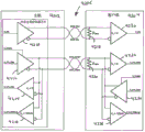
Fig. 4 illustrates the use of MDDI link controller, and the signal type that between main frame and client computer, transmits via the physical data lead of Class1 interface.
Fig. 5 illustrates the use of MDDI link controller, and the signal type that between main frame and client computer, transmits via the physical data lead of type 2,3,4 type interfaces.
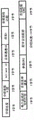
Fig. 6 illustrates and is used to realize the frame of said interface protocol and the frame structure of subframe.
Fig. 7 illustrates the universal architecture of the grouping that is used to realize said interface protocol.
Fig. 8 illustrates the form of subframe header packet.
Fig. 9 illustrates the format and content that filler divides into groups.
Figure 10 explains the form of stream of video packets.
The format and content of the video data format descriptor symbol that uses among Figure 11 A-11E explanation Figure 10.
The use of the form packing of Figure 12 declarative data and that do not pack.
Figure 13 illustrates the form that audio stream divides into groups.
Figure 14 illustrates the use by the PCM form of byte alignment and packing of data.
Figure 15 illustrates the form of user-defined stream packets.
Figure 16 illustrates the form that color map is divided into groups.
Figure 17 illustrates the form of reverse link encapsulating packets.
Figure 18 illustrates the form that client capabilities is divided into groups.
Figure 19 illustrates the form that keyboard data divides into groups.
Figure 20 illustrates the form of indicating equipment packet.
Figure 21 illustrates the form that link-down divides into groups.
Figure 22 illustrates the form of client requests and status packet.
Figure 23 illustrates the form that blit divides into groups.
Figure 24 illustrates bitmap region and fills the form that divides into groups.
Figure 25 illustrates bitmap pattern and fills the form that divides into groups.
Figure 26 illustrates the form of communicating link data channel packet.
Figure 27 illustrates the form that the interface type handoff request is divided into groups.
Figure 28 illustrates the form that interface type is confirmed grouping.
Figure 29 illustrates and carries out the form that type is switched grouping.
Figure 30 illustrates the form that the forward voice-grade channel is launched grouping.
Figure 31 illustrates the form that reverse audio sample rates is divided into groups.
Figure 32 illustrates the form that the digital content protection expense is divided into groups.
Figure 33 illustrates the form that transparent color is launched grouping.
Figure 34 illustrates the form that the round trip delay measurements divides into groups.
The sequential of incident during Figure 35 illustrates the round trip delay measurements and divides into groups.
Figure 36 illustrates the exemplary implementation that is used to realize CRC maker of the present invention and checker.
The sequential of CRC signal when Figure 37 A illustrates device shown in Figure 36 and sends packet.
The sequential of CRC signal when Figure 37 B illustrates device shown in Figure 36 and receives packet.
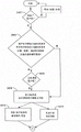
Figure 38 illustrates the exemplary service processing of request step that does not have competition.
Figure 39 is illustrated in link and restarts sequence and keep the treatment step that is at war with between exemplary service request and the link startup of (assert) after beginning.
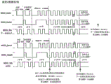
Figure 40 illustrates and how to use DATA-STB to encode to transmit data sequence.
Figure 41 illustrates to be used in the main frame and generates DATA and STB signal, the circuit of restore data in client computer then according to the input data.
Figure 42 illustrates driver and the terminal resistance that can be used for realizing an embodiment.
Figure 43 illustrates by client computer and adopts so that guarantee the safety from the service of main frame, and by main frame the step and the signal level of this service is provided.
Figure 44 illustrates the relative spacing between each transformation of transition (transition) on Data0, other data wire (DataX) and the select lines (Stb).
Figure 45 illustrates when main frame transmits when dividing into groups to forbid host driver afterwards the delay that exists in the response can occur.
Figure 46 illustrates when main frame is launched host driver transmission grouping the delay that exists as response can occur.
Figure 47 illustrate before and after sequential and the strobe pulse of the data that main frame receiver input transmitting along between relation.
Switching characteristic that the reverse data sequential that illustrates Figure 48 causes and corresponding client computer output delay.
Figure 49 illustrates and can realize the synchronous signal processing step and the senior chart of condition by the user mode machine.
Figure 50 is illustrated in the typical delay amount that signal processing runs on the forward path and reverse path in the system that adopts MDDI.
Figure 51 illustrates critical round trip delay measurements.
Figure 52 illustrates the variation of reverse link data rate.
Figure 53 has drawn the diagrammatic representation of the value of reverse rate divisor with the forward link data rate variation.
Figure 54 A and 54B illustrate the step of carrying out in the interface operation.
Figure 55 illustrates the overview of handling the interface arrangement that divides into groups.
Figure 56 illustrates the form that forward link divides into groups.
Figure 57 illustrates the propagation delay and the representative value that departs from (skew) in the LI(link interface) of Class1.
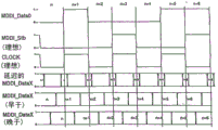
Figure 58 illustrates for handling via the exemplary signal of said interface, and the Data on the Class1 link (data), Stb (gating) and Clock (clock) recover sequential.
The representative value that Figure 59 illustrates propagation delay in type 2,3 or 4 LI(link interface)s and departs from.
Figure 60 A, 60B and 60C illustrate the different possibilities of relative timing between two data-signals and the MDDI_Stb, correspond respectively to ideal situation, do sth. in advance situation and postponement situation.
Figure 61 illustrates the interface pin of the used exemplary connector of Class1/type 2 interfaces and distributes.
Figure 62 A and 62B illustrate Class1 and possible MDDI_Data and the MDDI_Stb waveform of type 2 interfaces respectively.
Figure 63 illustrates and can realize the synchronous optional signal processing step and the senior chart of condition by the user mode machine.
Figure 64 illustrates a series of clock cycle and the sequential of various reverse link grouping position and the relative timing between the divider value.
The exemplary error code that illustrates Figure 65 transmits and handles.
Figure 66 illustrates and can be used for the device that error code transmits processing.
The error code that is used for the code heavy duty that illustrates Figure 67 A transmits and handles.
Figure 67 B illustrates and is used for the error code transmission processing that code receives.
Figure 68 A illustrates the treatment step that wakes up of host-initiated.
Figure 68 B illustrates the treatment step that wakes up that client computer starts.
Figure 68 C illustrates the treatment step that wakes up that the main frame that has competition and client computer start.
Figure 69 illustrates the form that request VCP characteristic is divided into groups.
Figure 70 illustrates the form of VCP characteristic acknowledgment packet.
Figure 71 illustrates the form of VCP characteristic answer List.
Figure 72 illustrates the form that the VCP characteristic is divided into groups is set
Figure 73 illustrates the form that the request actual parameter divides into groups.
Figure 74 illustrates the form of actual parameter acknowledgment packet.
Figure 75 illustrates the form that Alpha's cursor glyph ability is divided into groups.
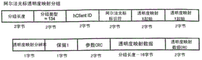
Figure 76 illustrates the form that the mapping of Alpha's cursor transparency is divided into groups.
Figure 77 illustrates the form that the skew of Alpha's cursor glyph is divided into groups.
Figure 78 illustrates the form of Alpha's cursor stream of video packets.
Figure 79 illustrates the form that the scalable video streams ability is divided into groups.
Figure 80 illustrates the form that scalable video streams is provided with grouping.
Figure 81 illustrates the form that scalable video streams is confirmed grouping.
Figure 82 illustrates the form of scalable video stream packets.
Figure 83 illustrates the form that the request particular state is divided into groups.
Figure 84 illustrates the form that the effective status answer List is divided into groups.
Figure 85 A illustrates the form that the packet processing delay parameter is divided into groups.
Figure 85 B illustrates the form of packetization delay Argument List list item.
Figure 86 illustrates the form that individual display capabilities is divided into groups.
Figure 87 A illustrates the form that the client computer error reporting divides into groups.
Figure 87 B illustrates the form of error reporting list items.
Figure 88 illustrates the form that client identifying divides into groups.
Figure 89 illustrates the form that the selectable display ability is divided into groups.
Figure 90 illustrates the form that register access divides into groups.
Figure 91 A-91C illustrates and uses two display buffer to reduce visual non-natural sign (visible artifacts).
Figure 92 illustrates and shows two buffers that refresh faster than the image transmission.
Figure 93 illustrates demonstration and refreshes two buffers that are slower than the image transmission.
Figure 94 illustrates and shows to refresh than image and transmit much fast two buffers.
Figure 95 illustrates and shows three buffers that refresh faster than the image transmission.
Figure 96 illustrates demonstration and refreshes three buffers that are slower than the image transmission.
Figure 97 illustrates and shows a buffer that refreshes faster than the image transmission.
Main frame-client computer that Figure 98 illustrates via daisy chain (daisy-chain) and hub is connected.
Figure 99 illustrates the client devices that is connected via hub and daisy chain.
Figure 100 illustrates color map.
Figure 101 illustrates the leakage current analysis.
Embodiment
I. general introduction
General purpose of the present invention is to provide a kind of mobile display digital interface (MDDI; Mobile Display Digital Interface); Be described below; It can access or provide have cost benefit, the transfer mechanism of low-power consumption, this transfer mechanism uses the data link or the passage of " serial " type, can realize at a high speed at main process equipment with on like the close range communication links between this client devices of display device or the transmission of data very at a high speed.This mechanism is suitable for utilizing miniature connector and soft cable to realize; These miniature connectors and soft cable are particularly suitable for being connected to central controller to inner (to shell or support) display device or input equipment, perhaps are connected to portable computer, Wireless Telecom Equipment or amusement equipment to external display element or equipment like wearable miniscope (goggles or projecting apparatus) and so on.
Although term moves and shows it is that name with said agreement is relevant, should be appreciated that this only is to understand for the ease of the those skilled in the art that make these standard name can be utilized this interface and agreement work at an easy rate.Yet; What after browsing the following embodiment that provides, be readily appreciated that is; The application that many and non-moving property is relevant with non-demonstration also can have benefited from using this agreement and the interface structure that obtains, and MDDI mark and do not mean that any restriction to characteristic of the present invention or purposes or embodiment.
An advantage of embodiments of the invention is for data transmit a kind of technology to be provided, and its complexity is low, cost is low, reliability is high, is very suitable for environment for use, and highly stable, has kept very high flexibility simultaneously.
Can embodiments of the invention be used for various situation, so that perhaps be sent to client computer display or display device to the mass data that is generally used for audio frequency, video or multimedia application with two-forty from main frame or the source device transmission that generates or store this data.A typical application of discussing below is to transmit from portable computer, radio telephone or the modulator-demodulator data to visual display unit equipment; Wherein visual display unit equipment for example is miniature video screen or wearable miniscope articles for use (micro-display appliance); Such as the goggles form or comprise the helmet form of lenses for compact projection and screen, perhaps in this parts from the data transmission of main frame to client devices.That is to say, from the processor to the inner screen or other present element, and from various inner input equipments or the external input device that adopts client computer to built-in (and putting in same device housings or supporting construction) main frame.
The characteristic of MDDI or attribute do not rely on concrete demonstration or present technology.The no matter internal structure of data, or the function aspects of the order of data or its execution how, and MDDI is the high flexibility mechanism that is used for transmitting with two-forty data.The sequential that it allows to regulate the grouping that is transmitting is to adapt to the characteristic of particular client device; For example the uniqueness to some equipment shows demand characteristics; Perhaps be the characteristic that satisfies the requirement of some A-V system in combination Voice & Video, perhaps be directed against the characteristic of some input equipment that resembles game paddle, touch dish or the like.What this interface need not understood employing is what display device or client devices, as long as they follow selected agreement.In addition; Total serial link data or data rate can change on several magnitude, and this just makes the designer of communication system or main process equipment to be optimized the complexity of cost, power requirement, client devices and the renewal rate of client devices.
This data-interface is mainly used in via " wired " signal link or mini-cable and transmits a large amount of high data rates.Yet; Some application also can utilize Radio Link; Comprise link based on light; As long as these link configuration are become to be used for the same packets and the data structure of this interface protocol exploitation, and can realize desired transmission level, so that keep practicality with enough low power consumption or complexity.
II. environment
In Figure 1A and 1B, can see typical application, wherein show respectively and display apparatus 104 and 106 and the portable or laptop computer 100 and radio telephone or PDA equipment 102 of audio reproducing system 108 and 112 Data transmission.In addition, Figure 1A shows with bigger display or screen 114 or the potential of image projector 116 and is connected, and for clear, only shown in the figure, but it also can link to each other with wireless device 102.Wireless device might receive data or in memory element or equipment, stored a certain amount of multimedia type data in advance at present, watches and/or listens attentively to so that wait a moment the end user who presents to wireless device.Because most of time uses typical wireless device to carry out communicating by letter of voice and plain text,, it comes to transmit information to the user of equipment 102 with simple audio system (loud speaker) so having quite little display screen.
Doing the appearing of data that is not enough to make complicacy more perhaps " to enrich " like this provides useful or pleasant impression.Therefore, the sector is being developed other mechanism and equipment and is being come to end user's presentation information and the floor level that desired enjoyment is provided or experiences purely.
As previous described, the display apparatus of having developed or developed at present several types comes the end user's presentation information to equipment 100.For example, one or more companies have developed many groups of wearable goggles, are used for eyes front projection image the equipment user so that present visual display.In the time of correct the location, this equipment is " projection " virtual image effectively, and just as that kind that eyes of user is felt, this image is more much bigger than the element that vision output is provided.That is to say that the image that very little projection element makes image Billy that user's eyes " see " possibly see with typical lcd screen etc. is much bigger.Use bigger virtual screen image also to allow to use far above utilizing the image that more limited lcd screen display can obtainable resolution.Other display apparatus can be including, but not limited to small LCD screen or various flat-panel monitor elements, be used for image projection projecting lens and display driver from the teeth outwards or the like.
Also have the add ons be connected to wireless device 102 or computer 100 or be associated with their use, so that to other user or present output to miscellaneous equipment, wherein said miscellaneous equipment also is sent to signal that other is local or store this signal.For example, can data storing in flash memory,, for example use and to write the CD medium, perhaps be stored in, be provided with the back and use such as on the magnetizing mediums of magnetic tape recorder or in the similar devices with the optical form storage.
In addition, many wireless devices and computer have built-in MP3 music decoding capability at present, and other advanced voice decoder and system.Usually, portable computer uses CD and DVD ability to play, and has some computers also to have small, dedicated flash memory reader to receive the audio file that writes down in advance.Problem with this ability is: the digital music file promise can provide the characteristic that highly increases abundant impression, but this has only the decoding of working as and playback process can catch up with the Shi Caike realization.This also is the same for digital video file.
In order to help audio reproduction, external loudspeaker 114 has been shown among Figure 1A, it is also subsidiary to have such as super woofer or is used for the add ons " surround sound " loud speaker of front and back sound projection.Simultaneously, loud speaker or earphone 108 are depicted as the mechanical structure of the microdisplay device 106 that embeds support or Figure 1B.As everyone knows, can also use other audio frequency or the audio reproduction element that comprises power amplification or sound former.
Under any circumstance, as stated, when people hope via one or more communication links 110 from data source when the end user transmits high-quality or high resolution image data and high quality audio information or data-signal, require high data rate.That is to say that transmitting link 110 obviously is bottleneck potential in the data communication process, as previous discussion, and because current transfer mechanism can't be realized the high data rate of expectation usually, so limited systematic function.As stated, for example for 1024 * 1024 pixels than the color density of 24 ~ 32 of high image resolution, every pixel and be in the data rate of 30fps, data rate can be near the speed that surpasses 755Mbps or higher.In addition; This image can be used as the part that multimedia appears and appears; This multimedia appears and comprises voice data and the potential additional signal of handling interactive entertainment or communication or various command, control or signal, and this has further increased data volume and data rate.
It is obvious that in addition, and perhaps interconnection is few more to set up the required cable of data link, means that the mobile device that is associated with display is easy to use more, and possibly adopted by bigger elemental user crowd more.Using a plurality of equipment to set up under the situation of audio-video impression completely usually, particularly like this, and more outstanding along with the raising of display and audio output apparatus quality level.
Other typical application that relates to above-mentioned and other improvement of video screen and other output or input equipment aspect can see from Fig. 1 C and 1D, wherein shows respectively and " inside " display apparatus 134 and 144 and portable or laptop computer 130 and the radio telephone or the PDA equipment 140 of audio reproducing system 136 and 146 Data transmission.
In Fig. 1 C and 1D; One or more internal hosts and the position of controller in the part of equipment are shown with the little incision (cut-away) of whole electric equipment or product part; Rotary gemel through some known type; All purpose communication link (being respectively 138 and 148 here) is connected to video display element or the screen with respective client to these internal hosts and controller, and wherein the type of employed rotary gemel can be those of whole electron trade use at present.People can find out that the data volume that these transmission comprise requires a large amount of leads to constitute link 138 and 148.Because the type of parallel interface or other known interface technology can be used for transmitting this data; Therefore according to estimates; This communication link has and approaches 90 or more lead, so that satisfy now ever-increasing demand to the colour that utilizes the advanced person on this equipment and graphic interface, display device.
Make the people regrettably, this more high data rate has exceeded the current techniques available that is used to transmit data.With regard to the original data volume that time per unit need transmit, and with regard to the practical transfer mechanism of making reliable and low-cost, all be like this.
Therefore; Needed is that a kind of being used for transmitted on link or the communication path technology, structure, device or the method that transmits data with two-forty presenting data between element and the data source, and this technology allows to keep low-power consumption, the construction of cable in light weight and simple and economical as far as possible always.The applicant has developed a kind of new technology, method and apparatus and has realized these and other purpose; So that allow the equipment of a series of movable types, portable and even fixed position to transmit data to desired display, miniscope or audio frequency conveying element, keep desired low-power consumption and low-complexity simultaneously with very high data rate.
III. two-forty digital data interface system architecture
In order to create and effectively utilize new equipment interface, the signaling protocol and the system architecture that use low-power signal that very high data transfer rate is provided have been prepared.Said agreement perhaps links so that form the structure of agreement based on grouping and common frame structure, but to be used to transmitting preliminary election data set or data type and to be applied to order or the operating structure on the interface.
A. general introduction
Call main frame and client computer to the equipment that connects via the MDDI link or communicate by letter, said client computer is the display apparatus of some type normally, can certainly consider other output and input equipment.When being launched by main frame, the data from the main frame to the display transmit (being called the professional or link of forward) along forward, and the data from the client computer to the main frame transmit (being called reverse traffic or link) along reverse.In the basic structure these are described shown in figure 2.In Fig. 2, main frame 202 uses bi-directional communication channels (channel) 206 to link to each other with client computer 204, and said bi-directional communication channels is according to shown in the form that comprises forward link 208 and reverse link 210.Yet these passages are gathered by the common wire and are formed, and wherein the data of these common wires' set transmit and can between forward and reverse link operations, effectively switch.Can greatly reduce number of conductors like this, solve one of many problems that the current method of under the low-power consumption environment such as mobile electronic equipment, carrying out high-speed data transfer faces immediately.
As other local that kind of discussing, said main frame comprises can have benefited from using one of polytype equipment of the present invention.For example, main frame 202 can be the portable computer with form of hand-held, on knee or similar mobile computing device, and it also can be one of PDA(Personal Digital Assistant), paging equipment or multiple radio telephone or modulator-demodulator.As selection, main frame 202 can be portable entertainment or display device, like portable DVD player or CD Player, or game station.
In addition, said main frame can be used as main process equipment or control element and be present in that various other is widely used or commercial products of planning in, need set up high speed communications link between these products and the client computer.For example, main frame can be used for transmitting data to improve response from video recording apparatus to the client computer based on storage with two-forty, perhaps transmits data so that appear to high-resolution large-screen.Be combined with on the plate household electrical appliances of checking (onboard inventory) or computing system and/or being connected with the bluetooth of other household equipment; Like refrigerator; When under the pattern of the Internet or bluetooth connection, working; The display capabilities that can have improvement, perhaps electronic computer or control system (main frame) be present in indoor other local in, reduced the line needs of indoor display (client computer) and keypad or scanner (client computer).Generally speaking; Those skilled in the art will appreciate that; Various modern electronic equipments and household electrical appliances will have benefited from using this interface, and increase newly through utilization or existing connector or cable in the lead of available limited quantity realize that the more high data rate transfer of information can renovate legacy device.
Simultaneously, client computer 204 can comprise and being used for to end user's presentation information or from the various device of user to the main frame presentation information.For example, incorporate into goggles or glasses miniscope, embed the cap or the helmet projector equipment, embed such as the small screen in windows of vehicles or the windshield and even holographic element, or be used to appear various loud speakers, headphone or the sound system of high quality sound or music.Other display devices comprise and are used to appear the information of meeting or film and the projecting apparatus or the projector equipment of television image.Another instance is to use touch pad or sensitive equipment, speech recognition input equipment, security sweep appearance; And other can be called with the equipment of slave unit or system user place transmission bulk information; Wherein to have not be existing " input " for this equipment or system user, rather than from user's touch or sound.In addition; Docking station of computer and vehicle body fittings or desktop computer accessory (docking station) and wireless telephonic bearing also can be used as the interface equipment for end user or other equipment and device; And can utilize client computer (like the output or the input equipment of mouse) or main frame to help transmit data, particularly relate under the situation of express network.
Yet those skilled in the art can be easy to recognize that the present invention is not limited to these equipment; Also have many miscellaneous equipments to supply to use on the market; These equipment or the mode to store and to transmit, the mode that appears during perhaps with broadcast provides high quality graphic and sound to the end user.The present invention improves aspect the data throughout very useful between various elements or equipment, is used to realize that desired user experiences required high data rate thereby can adapt to.
Can MDD interface of the present invention and signal of communication agreement be used for host-processor, controller or the circuit unit (for example) of (internal schema) and interconnected (being called internal schema) between the display in equipment or device housings or the structure in the simplified apparatus; With the cost that reduces these connections or complexity and related power requires with control or these are connected constraints; And the raising reliability, and not only be connected to or be used for outer member, equipment or device (external schema).
Each signal of interface structure use can change on a plurality of orders of magnitude last total serial link data rate thus, and this point allows the system or equipment designer to be easy to the complexity and the display renewal rate of cost, power, implementation are optimized.The attribute of MDDI does not rely on the technology of display or other display devices (Destination client).Can easily regulate the sequential of the packet that transmits via interface, adapting to the characteristic of specific client, this client computer such as display apparatus, sound system, memory and control element perhaps adapt to the characteristic that the combination sequential of audio-video system requires.Do allowing the as far as possible little power of system consumption although it is so, but it and do not require that client computer has frame buffer so that use the MDDI agreement in certain rank at least.
B. interface type
Said MDD interface is contemplated to be can handle more or less different at least four or the more physical type of interfaces that in communication and computer industry, can find.With the interface simple marking of these types is Class1, type 2, type 3 and type 4, and those skilled in the art also can use other mark or title according to concrete application that is directed against or relevant with it industry certainly.For example, simple audio system is used than the connection still less of complicated multimedia system, and can quote characteristic like " passage " or the like differently.
Said Class1 interface is configured to the interface of 6 lines (6-wire) or other types lead or transport element; This interface makes it be applicable to portable or radio telephone, PDA, electronic game and such as the portable electronic device of CD Player or MP3 player, and similar devices or at the technical employed equipment of the E-consumer of similar type.In one embodiment; An interface that is configured to 8 lines (lead) interface can be applicable to laptop computer, notebook or desktop PC and similar devices or application more; These equipment do not require the fast data renewal, do not have embedded MDDI link controller yet.This interface type can also be distinguished this interface type through using extra two-wire USB (USB) interface, and USB wherein is highly suitable for existing operating system common on most of personal computers or software support.
The transmission of Class1 interface comprises the signal of demonstration, audio frequency, control and limited signaling information, and is generally used for the client devices that portable client computer does not perhaps require high-resolution full rate video data.Add at 30fps under the situation of 5.1 channel audios, the Class1 interface can easily be supported the SVGA resolution, and in minimal configuration, amounts to and only use three lines right, and two pairs are used for transfer of data, and a pair of power that is used for transmits.Such interface is mainly used in the equipment like mobile wireless device, does not have the usb host end to connect in this equipment usually and transmits signal.In this configuration; Said mobile wireless device is the MDDI main process equipment; And serve as and be used to control " main control device " from the communication link of said main frame, wherein said main frame sends data (the professional or link of forward) to be used to appear, show perhaps broadcast to client computer usually.
In this interface; Through sending special order or packet type to client computer; Main frame can receive the communication data (reverse traffic or link) from client computer at this main frame place; Thereby allow client computer in the duration of appointment section, to occupy bus (link), and send to main frame to data as reverse packet.These contents are shown in Fig. 3, and the packet type (being discussed below) that wherein is called encapsulating packets is used for supporting that the reverse packet on this transmission link transmits, to create said reverse link.Distribute to main frame and be used for time interval of data of poll client computer and confirm in advance, and this time interval is based on each and specifies the requirement of using by main frame.When not having USB port to be used for to send from the information of client computer or data, it is useful especially that such half-duplex bidirectional data transmit.
The data flow that can show HDTV type or similar high-resolution Performance Monitor requirement 1.5Gbps left and right sides speed is to support full-motion video.Said type 2 interfaces are supported high data rate through 2 of parallel transmissions, and said type 3 is supported through 4 of parallel transmissions, and type 4 interface concurrents transmit 8.Type 2 and type 3 used cable and the connector identical with Class1, but can be operated on the data rate of twice and four times so that the more high performance Video Applications on the support portable set.Type 4 interfaces are applicable to the client computer or the display of very high performance, and need comprise the big slightly cable of additional twisted pair data signal.
Usually, employable peak data rate through consultation, the agreement of being used by MDDI allows any in each and Class1,2,3 and 4 the client computer in Class1,2,3 and 4 the main frame to communicate.Can be called the ability of minimum ability equipment or the performance that available feature is used to be provided with link.Usually, even main frame and client computer all be can type of service 2, the system of type 3 or type 4 interfaces, the two is also all started working with the Class1 interface.Then, main frame is confirmed the ability of Destination client, and consults to switch to or reconfigure a pattern of operating in type 2, type 3 or the type 4, as long as it is suitable for certain applications.
For main frame; Usually can use correct link layer protocol (hereinafter is further discussed) and descend step by step at any time usually or reconfigure once more and operate slow speed mode, perhaps rise to step by step than fast mode and support to transmit like the more speed of high-resolution displaying contents so that save power consumption.For example; When system when the power supply like battery switches to AC power; Perhaps switch to lower or more during high resolution scheme when the display media source; Main frame can change interface type, perhaps can the combination of these or other condition or incident be thought to change the basis of interface type or transfer mode.
System can also use a kind of pattern in one direction and on another direction, use another pattern to come Data transmission.For example, can type 4 interface modes be used for transmitting data with two-forty and give display, from as keyboard or this ancillary equipment of indicating equipment type of service 1 pattern then when the main process equipment transmission data.Those of ordinary skills can understand that main frame and client computer can be transmitted dateout with different rates.
The user of MDDI agreement usually can make a distinction " outside " pattern and " inside " pattern.What external schema was described is to utilize this agreement and interface to be connected to the main frame in the equipment this device external and maximum about 2 meters apart from this equipment client computer.In this case, main frame can also send electricity to external client, so that make two equipment all be easy under mobile environment, work.What internal schema was described is that main frame links to each other with the client computer that same device interior comprises, and for example is in public shell or support or certain structure.An instance can be in radio telephone or other wireless device or the application in portable computer or the game station; Wherein client computer is display or display driver; Or like the input equipment of keyboard or touch pad; Or sound system, and main frame is central controller, graphics engine or CPU element.With external schema use opposite because client computer is positioned at very the place near main frame in internal schema is used, so in this structure, do not require usually power supply is connected to client computer.
C. physical interface structure
Illustrated in the Figure 4 and 5 and be used between main frame and client devices, setting up the equipment of communication or a general configuration of link controller.In Figure 4 and 5, shown MDDI link controller 402 and 502 is installed in the main process equipment 202, and shown MDDI link controller 404 and 504 is installed in the client devices 204.As previously mentioned, main frame 202 uses and comprises that the bi-directional communication channels 406 of a series of leads links to each other with client computer 204.Be described below; Main frame and client link controller both can use single circuit design to be made as integrated circuit, and said design can be set up, regulates or programme to respond as console controller (driver) or client computer controller (receiver).Because need to make single circuit arrangement more on a large scale, the cost of doing like this is lower.
In Fig. 5, shown MDDI link controller 502 is installed in the main process equipment 202 ', and shown MDDI link controller 504 is installed in the client devices 204 '.As previously mentioned, main frame 202' uses and comprises that the bi-directional communication channels 506 of a series of leads links to each other with client computer 204'.As stated, main frame and client link controller both can use single circuit design to make.
The signal of in Figure 4 and 5, also explaining at main frame and transmitting via MDDI link or employed physical conductors between like the client computer of display apparatus and so on.Shown in Figure 4 and 5, be used for via predominating path or machine-processed usage flag that MDDI transmits data be MDDI_Data0+/-and MDDI_Stb+/-data-signal.Each of these signals is the low pressure data-signal that transmits via the difference wire pair in the cable.For send through said interface each, MDDI_Data0 to or MDDI_Stb have a transformation to last.This is based on voltage but not based on the transfer mechanism of electric current, so quiescent current consumption is near zero.Main frame is driven into the client computer display to the MDDI_Stb signal.
When data can be via MDDI_Data to when both forward and reverse directions flows, that is to say that main frame was the main control device or the controller of data link when it was two-way transfer path.Said MDDI_Data0 and MDDI_Stb signal path are according to difference modes work, so that make interference rejection ability the strongest.The data rate of signal is to be confirmed by the clock rate that main frame sends on these circuits, and can in 400Mbps or bigger scope, change at 1kbps.
Except the data of Class1 interface to or the path, type 2 interfaces also comprise an additional data to or lead or path, be called MDDI_Data1+/-.Except those data of type 2 interfaces to or the path, type 3 interfaces comprise two additional datas to or signal path, be called MDDI_Data2+/-and MDDI_Data3+/-.Except that the data of type 3 interfaces to or the path, type 4 interfaces comprise other four data to or signal path, be called respectively: MDDI_Data4+/-, MDDI_Data5+/-, MDDI_Data6+/-and MDDI_Data7+/-.In each of above-mentioned interface configuration, main frame can use line to or direction of signal client computer or the display of being appointed as HOST_Pwr (host power supply) and HOST_Gnd (main frame ground) electric power is provided.To further discuss like hereinafter; If desired; When the lead that adopts when the interface that is using " type " is less than in other patterns lead available or that exist; MDDI_Data4+ in some configuration/-, MDDI_Data5+/-, MDDI_Data6+/-or MDDI_Data7+/-lead, also can be used to carry out electric power and transmit.Though some application there are differences, the electric power transmission is generally external schema and uses, and internal schema does not need electric power to transmit usually.
Below, the summary of the signal that between main frame and client computer (display), transmits via the MDDI link according to interface type, has been described in Table I under various patterns.
Table I

Should also be noted that to be used for connecting normally for external schema from the HOST_Pwr/Gnd that main frame transmits provides.Internal application or operator scheme let client computer directly connect power supply from other internal resource usually; And do not use MDDI to control power distribution; As conspicuous, therefore this distribution is not described in further detail herein for those of ordinary skills.Yet, as those skilled in the art will appreciate that, can come power distribution with convenient for example certain power supply control, perhaps interconnection synchronously via the MDDI interface certainly.
Be generally used for realizing that the cable of said structure and operation is nominally about 1.5 meters length, be generally 2 meters or shorter, and comprise that three pairs of twisted pair conductors, each lead still are multiply 30AWG line.Perhaps be formed on paper tinsel shielding covering parcel on three pairs of twisted-pair feeders, as other ground wire (drain wire).Said twisted-pair feeder and shielding earth lead stop in Display connector, and screen is connected with the screen of client computer, also have an insulating barrier, cover whole cable, these all as affiliated technical field known.Said electric wire matches by following mode: Host_Gnd and Host_Pwr; MDDI_Stb+ and MDDI_Stb-; MDDI_Data0+ and MDDI_Data0-; MDDI_Data1+ and MDDI_Data1-; Or the like.Yet,, can use various leads and cable to realize embodiments of the invention according to certain applications as known in the art.For example, in some applications, heavy outer cover or metal level can be used for protecting cable, and thin, flat conduction band-type of configuration possibly be very suitable for other application.
D. data type and speed
For the useful interface of realizing being used for user's impression and using; Mobile type digital data-interface (MDDI; Mobile Digital Data Interface) support various client computer and display message, audio converter, keyboard, indicating equipment and can be integrated into portable display apparatus or multiple other input-output apparatus of collaborative work with it, and control information and their combination.Said MDD interface is dimensioned to adapt to the data flow of various potential types, and these data flow use the cable or the lead of minimal amount to transmit between main frame and client computer along forward or reverse link direction.Synchronous flow and asynchronous flow (renewal) all are able to support.As long as aggregate data rate is less than or equal to maximum expectation MDDI link rate, the combination of many data types all is possible.This MDDI link rate receives largest serial speed and the data that adopted to limited in number.Those that these data rates can be listed in following Table II and the III.
Table II

Table III

In order to satisfy the flexibility requirement of system in future, said interface is not fixed, but extendible, so it can support to comprise the transmission of the various information " type " of user-defined data.The instantiation of the data of being supported is: full-motion video has the form of full screen or part screen bitmap field or the video of compressed video form; Be in low rate so that save power and reduce the static bitmap of realizing cost; PCM or audio compressed data with multiple resolution or speed; Indicating equipment location and selection, and to user's definable data of waiting the ability that defines.This data can also transmit with control or state information, so that checkout equipment ability or setting operation parameter.
Embodiments of the invention have advanced the technology that data transmit that is used for, said technology including, but not limited to: watch film (video shows and audio frequency); Use has the personal computer that limited individual watches (graphical display, sometimes combine video and audio frequency); Playing video game on PC, control desk or personal device (moving picture shows or synthetic video and audio frequency); Use visual telephone, the static number image camera, or the camcorder apparatus form of device that is used to take digital video image in the internet " surfing " (two-way low rate video and audio frequency); Use expansion to have the phone of projecting apparatus or PDA to appear, perhaps be connected with the desk-top docking station expansion that is connected to video-frequency monitor, keyboard and mouse; And use cell phone, smart phone or PDA, and comprise wireless indicating equipment and keyboard data, strengthen productivity or be used for amusement.
The high speed interface that is described below provides the form of a large amount of A-V categorical datas to provide perhaps to transmit link via communication, and perhaps transmitting link is configured to electrical wiring or type of cable link usually in said communication.Yet, obvious, can the conditioning signal structure, agreement, sequential or transfer mechanism be so that provide optics or the link of wireless medium form, as long as this link can keep needed data transmission level.
The MDD interface signal is used for baseband signal agreement or structure to the notion that calls common frame (CF).Support to use the thought of common frame to be lock-out pulse to be provided for synchronous data flow simultaneously.Client devices can use this common frame speed as time reference.Be used to transmit the expense of subframe header through minimizing, low CF speed has improved channel efficiency.On the other hand, high CF speed can reduce the stand-by period, and allows the data buffer that elasticity is littler to be used for audio sample.One of but the CF speed of interface of the present invention is dynamic programming, and a plurality of values of a plurality of synchronous flows that can be set to be suitable for using in the special applications.That is to say, as required, select said CF value to come to adapt to best given client computer and main machine structure.
The byte number that each subframe of the synchronous data flow that uses probably in the application of video for example or miniscope and so on needs usually has been shown in the Table IV, and this number is adjustable or programmable.
Table IV

Use simple M/N counter structure able to programme can calculate the mark byte of every subframe at an easy rate.For example, through transmitting the frame of 2 27 bytes, each followed can realize the counting to each CF 26-2/3 byte with the frame of one 26 byte.Can select littler CF speed to produce the integer byte of each subframe.Yet, generally speaking, compare with the big required zone of audio sample fifo buffer, at the IC chip or the electronic module that are used for realizing part of the present invention or all embodiment, it is regional less to realize that with hardware simple M/N counter needs.
The exemplary application that the influence of different pieces of information transfer rate and data type is described is a karaoke OK system.For karaoke OK system, end user or a plurality of end users sing with the music video program.The lyrics of song are presented at the somewhere of screen, and usually in bottom of screen, therefore, the user knows the speech of singing, and roughly knows the arrangement of time of song.This application need does not often carry out the video demonstration that figure upgrades, and mixes one or more user speech with stereo audio stream.
If it is 300Hz that people suppose common frame speed; Each subframe will comprise so: via 92 of forward link to client computer display apparatus; The audio content of the video content of 160 bytes and 588 bytes (in stereo based on 147 16-positions sampling), and be the voice of 26.67 (26-2/3) byte from the mean value that microphone sends back to portable karaoke machine.Between main frame and display (might be head-type), send asynchronous packet.This comprises the graph data (1/4th screen heights) of maximum 768 bytes, and is less than about 200 bytes (a few byte) and is used for various controls and status command.
Table V shows for the Karaoke instance, distribute data how in subframe.Total rate selection of using is about 279Mbps.The speed of a little higher than 280Mbps allows to transmit the approximately data of other 400 bytes of every subframe, so just allows to utilize control and the state information that occurs once in a while.
Table V

III. (continuation) two-forty digital data interface system architecture
E. link layer
The time division multiplexing stream of packets is drawn together in the grouping of using MDD interface high-speed serial data signal to transmit, wherein these then ground links of dividing into groups.Divide into groups even the data that transmission equipment will not send, MDDI link controller are also automatically sent filler usually, keep stream of packets thus.Therefore, the use of simple packet structure can be guaranteed video and audio signal or the reliable synchronous sequence of data flow.
Packet group is included in the signal element (signal element) or structure that is called subframe, and the subframe group then is included in the signal element or structure that is called dielectric frame.Transmit purposes according to subframe size and data separately, subframe comprises one or more groupings, and dielectric frame then comprises one or more subframes.The maximum subframe that the agreement that embodiment given here adopted provides is approximately 2
32-1 or 4,294, the magnitude of 967,295 bytes, and the size of maximum dielectric frame is approximately 2
16The magnitude of-1 or 65,535 sub-frame.
Special subframe header packet comprises unique identifier, and this identifier begins the place in each subframe and occurs, as below will discussing.When the communication between startup main frame and the client computer, this identifier also is used to obtain the frame sequential at client devices place.Below than the acquisition that the link sequential is discussed in more detail.
Usually, when showing full-motion video, each dielectric frame upgrades a display screen.Frame rate of display is identical with dielectric frame speed.According to needed application, link protocol is supported the full-motion video on the whole display, a zonule of the full-motion video content of perhaps only supporting to be centered on by still image.In some low power mobile formula was used, such as watching webpage or Email, update displayed was shielded occasionally.In these cases, transmit single subframe, it is very useful closing link then or cancelling link so that make the power consumption minimum.Said interface is also supported the effect such as stereoscopic vision, and the processing graphics pel.
Subframe allows system can periodically transmit high priority packet.Do the metadata cache coexistence that allows simultaneous synchronous flow and minimum like this.This provides a useful embodiment to procedure for displaying, and it allows a plurality of data flow (high-speed communications of video, voice, control, state, indicating equipment data or the like) to share shared pathway basically.This interface uses the signal of relative minority to transmit information.This interface also allows to exist the Display Technique dedicated action, such as horizontal synchronization pulse that is used for the CRT monitor and blanking interval (blanking intervals), or the action of other client computer-technology-special uses.
F. link controller
MDDI link controller shown in the Figure 4 and 5 will be made or assemble according to the fully digitalization implementation, wherein not comprise the differential line receiver that is used for receiving MDDI data and gating signal.Yet, for example when making CMOS type IC, differential line driver and receiver even can in same digital integrated circuit, realize with link controller.Do not need analog functuion or phase-locked loop (PLL) to carry out the hardware that bit recovery is perhaps realized link controller.Except that the client interface that comprises the state machine that is used for link synchronization, main frame and client link controller comprise very similarly function.Therefore, embodiments of the invention allow to create single controller design or circuit, and can it be configured to main frame or client computer, and this helps practical application, and generally speaking, does the manufacturing cost that can reduce link controller like this.
IV. interface link agreement
A. frame structure
Be used to realize the signaling protocol or the frame structure of the forward link communication of dividing into groups to transmit shown in Fig. 6.As shown in Figure 6, be combined as the element (element) that is known as grouping to information or numerical data.Then, a plurality of groupings are combined in again together forming what is called " subframe ", and a plurality of subframe is combined in again together to form " medium " frame.For the formation of control frame and the transmission of subframe, each subframe begins from special predetermined grouping, and this grouping is called subframe header packet (SHP).
Said main process equipment selects to be used for the data rate of given transmission.The data that main process equipment can Host Based maximum transfer capability, fetch (retrieve) from information source by main frame, and the maximum capacity of client computer or these data miscellaneous equipment that will be sent to, and dynamically change this speed.
Be designed to perhaps can inquire about by main frame with recipient's client devices of MDDI or signaling protocol collaborative work of the present invention; So that confirm the data transfer rate of operable maximum of this client computer or current maximum, slow minimum-rate of perhaps operable acquiescence and available data type and the characteristic of being supported.This information can use display capabilities grouping (DCP) to transmit, as hereinafter will further be discussed.Said client computer display apparatus can use said interface to transmit data with the preliminary election minimum data rate or in the minimum data rate scope or communicate by letter with miscellaneous equipment, and said main frame will use the data rate in this scope to carry out inquiry so that confirm whole abilities of client devices.
Can be in status packet transmit other state information of the video frame rate ability of definition attribute bitmap and client computer to main frame; Therefore main frame can or need according to the actual conditions in any system constraint scope, as far as possible efficiently or optimally disposes said interface.
When the grouping that in this subframe, do not have (more) to transmit, perhaps when main frame can't transmit with the speed that is enough to catch up with (keep pace) forward link selected data transmission rate, said main frame sent filler and divides into groups.Because each subframe begins from the subframe header packet, so the end of last subframe comprises the grouping (being likely that filler divides into groups) of just in time filling last subframe.Lack in the grouping itself of carrying data under the situation in space, the filler grouping is likely grouping last in the subframe, perhaps in the ending of previous (next previous) subframe that is close to and before the subframe header packet.In main process equipment, the task of control operation be exactly guarantee in this subframe waiting for transmission each be grouped in and all remain with enough spaces in the subframe.Simultaneously, in case main process equipment begins to send packet, main frame just must successfully make in the frame should size packet integrity, and can not cause data underload (under-run) situation.
In aspect of embodiment, the subframe transmission has two kinds of patterns.A kind of pattern is periodic subframe pattern, and perhaps periodic sequential first phase (periodic timing epochs) is used to transmit livingwage video and audio stream.In this pattern, being defined as subframe lengths is non-zero.Second kind of pattern is asynchronous or the aperiodicity pattern, wherein when new information, just uses frame to offer client computer to data bitmap.This pattern is set to zero through subframe lengths in the subframe header packet and defines.During the life cycle sexual norm, when client computer and forward link frame structure are synchronous, can begin subframe branch group of received.This is corresponding to according to the hereinafter state of " synchronously (in sync) " of the state diagram definition discussed of Figure 49 or Figure 63 just.In asynchronous aperiodicity subframe pattern, after receiving the first subframe header packet, begin to receive.
B. overall packet configuration
Explanation is by the packet format or the structure of the ways and means that is used for regulation communication or signaling protocol or transmission data of said embodiment realization below, and what should remember is that said interface is extendible, can add the additional packet structure as required.Said grouping is with regard to its function in interface, i.e. their transmit or relevant with it order, information, numerical value or data are marked as or are divided into different " packet type ".Therefore, for being used to handle the grouping that is transmitted and the given grouping of data, each packet type is represented a predefined packet configuration.Obviously, said grouping can have preselected length, perhaps has the length of variable or dynamically changeable according to function separately.Said grouping can also have different titles, though realize remain identical functions, as agreement being received situation about occurring when agreement changes in the process of going in the standard.The byte or the byte value that are used for various groupings are configured to multidigit (8 or 16) signless integer.The grouping summary that is adopted and their " type " are specified and are listed according to type sequence, and in Table VI-1 to shown in the VI-4.
For the ease of illustrating and understanding, general " type " that each table all provides in the overall packet configuration divides into groups.These divide into groups not imply or represent to some restriction or other influence of the present invention, and can organize said grouping according to a plurality of alternate manners as required.Also pointed out to think and divided into groups to transmit effective direction.
Table VI-1
Controlling links is divided into groups
| Group names | Packet type | Forward is effective | Effectively reverse |
| The subframe header packet | 15359 | x | |
| Filler divides into groups | 0 | x | x |
| The reverse link encapsulating packets | 65 | x | |
| Link-down divides into groups | 69 | x | |
| The interface type handoff request is divided into groups | 75 | x | |
| Interface type is confirmed to divide into groups | 76 | x | |
| Carry out type and switch grouping | 77 | x | |
| The forward voice-grade channel starts grouping | 78 | x | |
| The round trip delay measurements divides into groups | 82 | x | |
| Forward link departs from calibration and divides into groups | 83 | x |
Table VI-2
Basic media stream packet
| Group names | Packet type | Forward is effective | Effectively reverse |
| Stream of video packets | 16 | x | x |
| Audio stream divides into groups | 32 | x | x |
| Reverse flow is divided into groups | 1-15,18-31,33-55 | x | x |
| User-defined stream packets | 56-63 | x | x |
| Color map is divided into groups | 64 | x | x |
| Reverse audio sample rates is divided into groups | 79 | x | |
| Transparent color is launched grouping | 81 | x |
Table VI-3
Client state is divided into groups with control
| Group names | Packet type | Forward is effective | Effectively reverse |
| Client capabilities is divided into groups | 66 | x | |
| Keyboard data divides into groups | 67 | x | x |
| The indicating equipment packet | 68 | x | x |
| Client requests and status packet | 70 | x | |
| The digital content protection expense is divided into groups | 80 | x | x |
| Request VCP characteristic is divided into groups | 128 | x | |
| VCP characteristic acknowledgment packet | 129 | x | |
| The VCP characteristic is set divides into groups | 130 | x | |
| The request actual parameter divides into groups | 131 | x | |
| The actual parameter acknowledgment packet | 132 | x | |
| The request particular state is divided into groups | 138 | x | |
| The effective status answer List is divided into groups | 139 | x | |
| The packet processing delay parameter is divided into groups | 140 | x | |
| Individual's display capabilities is divided into groups | 141 | x | |
| The client computer error reporting divides into groups | 142 | x | |
| The scalable video streams ability is divided into groups | 143 | x | |
| Client identifying divides into groups | 144 | x | |
| The selectable display ability is divided into groups | 145 | x | |
| Register access divides into groups | 146 | x | x |
Table VI-4
Advanced figure divides into groups with showing
| Group names | Packet type | Forward is effective | Effectively reverse |
| Blit divides into groups | 71 | x | |
| Bitmap region is filled and is divided into groups | 72 | x | |
| Bitmap pattern is filled and is divided into groups | 73 | x | |
| Reading frame buffer divides into groups | 74 | x | |
| Alpha-cursor glyph ability is divided into groups | 133 | x | |
| Alpha-cursor transparency mapping is divided into groups | 134 | x | |
| Alpha-cursor glyph skew is divided into groups | 135 | x | |
| Alpha-cursor stream of video packets | 17 | x | |
| The scalable video streams ability is divided into groups | 143 | x | |
| Scalable video streams is provided with grouping | 136 | x | |
| Scalable video streams is confirmed to divide into groups | 137 | x | |
| The scalable video stream packets | 18 | x |
Can know according to other discussion among this paper and to be appreciated that; Though for the external schema operation; Reverse encapsulation grouping, client capabilities grouping and client requests and status packet are considered to very important; Even in many embodiment of communication interface, need, but can think that they are optional for the internal schema operation.Do the MDD interface protocol that has produced another type like this, this agreement allows to utilize the communication packet set of reduction to come Data transmission with very high speed, and correspondingly simplifies control and sequential.
Divide into groups to have the overall set of public basic structure or minimum field, said minimum field comprises block length field, packet type field, data byte field and crc field, and these contents are shown in Fig. 7.As shown in Figure 7, the block length field comprises the information with multidigit or byte value form, is used for the total bit of designated packet, perhaps the length between designated packet length field and the crc field.In one embodiment, said block length field comprises 16 perhaps signless integers of 2 byte wides, and it explains block length.Packet type field is another multiple bit fields, and it indicates the type of info that comprises in the grouping.In an exemplary embodiment, this packet type field is 16 or 2 byte wides, the value with 16 signless integer forms, and is display capabilities, switching, video or audio stream, state or the like with these data type specifications.
The 3rd field is the data byte field, and it is included in position or the data that transmit or send as a part of dividing into groups between main frame and the client devices.According to the particular type that is transmitted data, for each packet type has specifically defined data format, and this packet format can be divided into a series of added field, and each all has the call format of self.That is to say that each packet type will have the definition format to this part or field.Last field is a crc field, and it is included in the result of 16 CRCs of calculating on data byte, packet type and the block length field, information integrity during this result is used for confirming to divide into groups.In other words, this result calculates on the whole group except that crc field itself.Client computer is preserved the tale of detected crc error usually, and in client requests and status packet (vide infra), this counting is reported to main frame.
Usually, these field widths and institutional framework are designed to make 2 byte field on even byte boundary, to aim at, and 4 byte field are aimed on 4 byte boundaries.Do allowing packet configuration to be easy to embed main frame and client computer like this, main storage perhaps associated therewith space, and can not violate the data type alignment order that great majority perhaps run in normally used processors or the control circuit.
During transmitting said grouping, field at first begins transmission from least significant bit (LSB), and finishes with transmission highest significant position (MSB) at last.The parameter of an above byte length is at first transmitted least significant byte, and what obtain like this is used to transmit the position transmission mode of length greater than 8 parameter, and is identical with the employed position of the shorter parameter of at first transmitting LSB transmission mode.The data field of each grouping transmits according to the order of subsequent paragraph definition hereinafter usually, and the first listed field is at first transmitted, and the last field of describing is transmitted at last.In any pattern in Class1, type 2, type 3 or type 4 these patterns, ' 0 ' bit alignment of the byte of transmitting on data on the MDDI_Data0 signal path and the interface.
When manipulation data showed, the data of pel array were transmitted according to row at first according to row then, just as the conventional that kind of carrying out in the electronic technology field.In other words, transmit in order with all pixels that occur in the delegation in the bitmap, the pixel of the leftmost side is at first transmitted, and the pixel of the rightmost side is transmitted at last.After rightmost side pixel had been transmitted in delegation, next pixel was the pixel of the next line leftmost side in order then.For most of displays, working of pixel often transmitted according to top-down order, but also can adopt other configuration mode as required.In addition, in handling the process of bitmap, the method that conventional method is just followed here is through the bitmap upper left corner being labeled as the position or skew " 0,0 " comes definition datum point.When respectively near the right side of bitmap and bottom, be used for defining or confirm that sitting target value at the X of the position of bitmap and Y increases.First row, first row (upper left corner of image) are from subscript value zero beginning.When the angle of display user was watched, the numerical value of X coordinate increased towards the image right side, and the numerical value of Y coordinate increases towards the bottom of image.
Display window is the viewable portion of bitmap, that is, and and that part of pixel that the user can see on the physics display medium in the bitmap.Often size is identical with bitmap for display window.The display window upper left corner is display bitmap location of pixels 0,0 all the time.The width of display window is corresponding to the X axle of bitmap, and the display window width is less than or equal to the width of corresponding bitmap.The height of window is corresponding to the Y axle of bitmap, and the display window height is less than or equal to the height of corresponding bitmap.This is not related to display window in agreement, and this is because only it is defined as the viewable portion of bitmap.
Relation between bitmap and the display window is computer, electronic applications, and is known in Internet traffic and other electronic correlation fields.Therefore do not provide the further discussion or the explanation of these principles here.
C. divide into groups to define
1. subframe header packet
The subframe header packet is first grouping of each subframe, and has basic structure as shown in Figure 8.The subframe header packet is used for main frame-client sync, and each main frame should be able to generate this grouping, and each client computer should be able to receive and explain this grouping simultaneously.As can in Fig. 8, seeing, usually with such constructed in groups for having block length, packet type, unique word, reservation 1, subframe lengths, protocol version, sub-frame count and dielectric frame count area in order.In one embodiment, be that Class1 5359 (hexadecimal 0x3bff) divides into groups with such group character usually, and use the preliminary election regular length of 20 bytes, do not comprise the block length field.
Said packet type field and unique word field are all used 2 byte values (16 signless integers).4 combination of bytes of these two fields 32 unique words with good autocorrelation have been formed together.In one embodiment, actual unique word is 0x005a3bff, and wherein low 16 at first transmit as packet type, and transmission is the highest 16 then.
Keep retaining space that 1 field comprises 2 bytes in order to the usefulness in future, and here generally it is configured to the equal zero setting in all positions.A purpose of this field is to let follow-up 2 byte field aim at 16 word addresss, lets 4 byte field aim at 32 word addresss.Keep least significant byte, whether can visit a plurality of client devices to show said main frame.This byte is left zero this value, to show that this main frame is merely able to work with single client devices.
The subframe lengths field comprises the information or the value of 4 bytes, is used to explain the byte number of each subframe.In one embodiment, the length of this field can be set to equal zero, and is closed and gets into before the idle condition so that be illustrated in link, and main frame will only transmit a sub-frame.When a sub-frame was converted to next subframe, the value in this field can " (on-the-fly) in the course of the work " dynamically change.In order in lock-out pulse, to carry out less sequential adjustment so that support synchronous data flow, this ability is very useful.If the CRC of subframe header packet is invalid, link controller just should use the subframe lengths of known intact previous subframe header packet to estimate the length of current subframe so.
Protocol version field comprises 2 bytes, is used to explain the version of the agreement of being used by main frame.Protocol version field is set to first or current version of ' 0 ' agreement used of explanation.When having created redaction, this value will change in time, and for some version fields value of being updated to 1.As known, version value is deferred to probably or usually and is contained like the current version of the approved standard document of MDDI interface number.
The sub-frame count field comprises 2 bytes, and a sequence number is described, this sequence number shows the sequence number of the number of the subframe that begins to locate to have transmitted from dielectric frame.The sub-frame count of first subframe of dielectric frame is zero.The last subframe of dielectric frame has the value of n-1, and wherein n is the number of subframes of every dielectric frame.The sub-frame count that the value of sub-frame count field equals in last subframe is divided into groups, to send adds 1 again.It should be noted that if subframe lengths is set to equal zero (showing acyclic subframe), sub-frame count also must be set to equal zero so.
The dielectric frame count area comprises 4 bytes (32 signless integers), is used to explain a sequence number, and this sequence number shows and begins place, the sequence number of the number of the dielectric frame that has transmitted from the current medium item that transmitting or data.The dielectric frame counting of first dielectric frame of medium project is zero.The dielectric frame counting just increased before first subframe of each dielectric frame, and (for example, the dielectric frame number 2 having used maximum dielectric frame counting
32-1=4,294,967,295) return zero afterwards.The dielectric frame count value can be reset by main frame usually at any time, so that adapt to final demands of applications.
2. filler divides into groups
It is when not having out of Memory can be used on forward or reverse link, sending that filler divides into groups, the grouping that is sent to client devices or transmits from client devices.The suggestion filler divides into groups to have minimum length, when needing with box lunch, in the process of sending other grouping, has maximum flexibility.In the ending of subframe or reverse link encapsulating packets (vide infra), link controller is provided with the size of filler grouping so that fill remaining space, thereby keeps the integrality of grouping.When main frame or client computer did not have information to send or to exchange, said filler divided into groups very useful for keeping the sequential on the link.This grouping should be able to sent and receive to each main frame and client computer all, so that effectively use said interface.
An exemplary embodiment of the format and content of filler grouping has been shown among Fig. 9.As shown in Figure 9, with such constructed in groups for having block length, packet type, filler byte and crc field.In one embodiment, be type 0 with such group character usually, this shows in 2 byte type fields.Position in the filler byte field or byte comprise complete zero the place value of variable number, the desired length so that the permission filler divides into groups to have.Minimum filler is grouped in and does not comprise byte in this field.That is to say that said grouping includes only block length, packet type and CRC, and in one embodiment, use the preliminary election regular length or the block length value 4 of 6 bytes.Confirm said crc value for all bytes in dividing into groups, comprising block length, but in other packet type, this block length is excluded.
3. stream of video packets
Stream of video packets is carried the zone that is generally rectangle that video data comes refresh display equipment usually.It is so little that this regional size can look like single pixel, perhaps so big as whole display.The almost stream quilt demonstration simultaneously of infinite number can be arranged, but it receives the restriction of system resource, this is to show needed all contexts of stream because comprise in the stream of video packets.The form of an embodiment of stream of video packets (video data format descriptor symbol) has been shown among Figure 10.Shown in figure 10; In one embodiment, with such constructed in groups for have block length (2 byte), packet type, bClient ID, video data descriptor, pixel display properties, an X left side along, Y top along, X right at the bottom of, the Y along, X with Y is initial, pixel counts, parameters C RC, pixel data and crc field.Usually be Class1 6 with such group character, it shows in 2 byte type fields.In one embodiment, RGB, monochrome and the Y Cr Cb capable field during client computer use client capabilities is divided into groups shows the ability of receiver, video stream packets.
In one embodiment, the bClient id field is included as 2 byte information that client computer ID keeps.Because this is the communication protocol of up-to-date exploitation, so actual client computer ID still can't be known or be enough to be transmitted.Therefore, the position in this field is set to equal zero usually, till knowing this ID value, when knowing this ID, can insert or use said ID value, as conspicuous to those skilled in the art.Client computer id field for following discussion is also carried out identical therewith processing usually.
Above-mentioned common frame notion is a kind of effective means that is used to minimize the audio buffer size and reduces the stand-by period.Yet, for video data, maybe be with the pixel-expanded of a frame of video a plurality of stream of video packets in the dielectric frame.Also the pixel in the single stream of video packets of possibility can be just in time corresponding to rectangular window complete on the display.For the exemplary video frame rate of 30 frame per seconds, per second has 300 subframes, and this makes each dielectric frame that 10 sub-frame arranged.If 480 row pixels are arranged in each frame, each stream of video packets in each subframe will comprise 48 row pixels so.In other situation, stream of video packets possibly not comprise an integer pixel column.This is such for other video frame size that the number of subframes of each dielectric frame can not be divided equally by the line number of each frame of video (also claiming video line).For valid function, each stream of video packets must comprise an integer pixel usually, even if it may not comprise an integer pixel column.If each pixel is all greater than a byte, if perhaps they have packet format shown in figure 12, this is very important so.
The format and content that the aforesaid operation that is used for realization example property video data descriptor field is adopted has been shown among Figure 11 A-11E.In Figure 11 A-11E, video data format descriptor symbol field comprises 2 bytes with 16 signless integer forms, is used for explaining the form of each pixel in the current stream pixel data of current group.Different stream of video packets possibly used pixels with different data form, promptly uses different values in the video data format descriptor symbol, and same, stream (viewing area) (on-the-fly) in the course of the work changes its data format.The pixel data form should meet at least one the client computer valid format like client capabilities grouping definition.Only the pixel format in current group was implicitly included in the operating period of particular video stream, and when no longer continuing to use constant form, the video data format descriptor symbol just defines the pixel format of current group.
How Figure 11 A to 11D explanation video data format descriptor symbol encodes.As these figure in employed; And in this embodiment, as position [15:13] when equaling ' 000 ', shown in Figure 11 A; So said video packets is drawn together the include monochrome pixels array, and wherein the figure place of each pixel is by position 30 definition to the position of video data format descriptor symbol word.Usually keep position 11 to 4 so that use or be used for other application future, and be set to zero in this case.When position [15:13] changed the value of equaling ' 001 ' into, shown in Figure 11 B, so said video packets was drawn together a colorful array of pixels, and wherein each pixel is all passed through color map (palette) and specified a kind of color.In this case, the figure place of position 5 to 0 each pixel of definition of video data format descriptor symbol word, and position 11 to 6 is retained for using in the future or use usually, and these positions are set to equal zero.When position [15:13] changes the value of equaling ' 010 ' into; Shown in Figure 11 C, so said video packets is drawn together colorful array of pixels, and wherein the red figure place of each pixel is defined by position 11 to 8; The figure place of each pixel green is by 7 to 4 definition, and the blue figure place of each pixel is defined by position 3 to 0.In this case, the sum of each pixel median be red, green and blue employed figure place and.
Yet; When position [15:13] changes the value of equaling or word string ' 011 ' into; Shown in Figure 11 D, video packets is drawn together a video data array that has brightness and chrominance information of the YCbCr form with 4:2:2 so, and wherein the figure place of each pixel intensity (Y) is by position 11 to 8 definition; The figure place of Cb component is by position 7 to 4 definition, and the figure place of Cr component is by position 3 to 0 definition.Each pixel median sum be red, green and blue employed figure place and.Cb and Cr component are to send with the half the speed of Y component.In addition, the video sampling in the pixel data of this grouping part is organized as: Cbn, Yn, Crn; Yn+l, Cbn+2, Yn+2, Crn+2; Yn+3 ..., wherein Cbn and Crn are associated with Yn and Yn+1, and Cbn+2 and Crn+2 are associated or the like with Yn+2 and Yn+3.
Yn, Yn+1, Yn+2 and Yn+3 are from left to right the brightness values of four contiguous pixels in the single row.If in the delegation of the window that stream of video packets is located, have odd number of pixels (the right edge-X of an X left side is along+1); To follow the Cb value of next line first pixel corresponding to the Y value back of last pixel in each row so, and not send the Cr value of last pixel in this row.The width that suggestion uses the window of Y Cb Cr form to have the even number pixel.Pixel data in the grouping should comprise the even number pixel.The last pixel of pixel data corresponding to the stream of video packets header under the situation of last pixel of row in the window of appointment, that is, and when the X position of last pixel in the pixel data equal the X right side along the time, pixel data can comprise odd number or even number pixel.
When position [15:13] changes into when equaling ' 100 ', video packets is drawn together a Bayer (at interval) pel array so, and wherein the figure place of each pixel is by position 3 to 0 definition of video data format descriptor symbol word.The pixel groups pattern is by position 5 and 4 definition, shown in Figure 11 E.The order of pixel data can be a level or vertical, and the pixel that is in row or the row can be sent according to order forward or backward, and is defined by position 8 to 6.Position 11 to 9 should be set to zero.The category of four pixels in the Bayer form in the pixel groups is similar to and in some Display Techniques, often is called the situation that stops over pixel.Yet a pixel in the Bayer form is in four colour elements in this pixel groups splicing (mosaic) pattern.
For all five forms shown in the figure, the position 12 pixels illustrated data samplings of being appointed as " P " are pixel datas of packing, still byte-aligned pixel data.Value ' 0 ' in this field show in the pixel data field each pixel all with MDD interface byte boundary byte alignment.Value ' 1 ' shows each pixel in each pixel in the pixel data and each color packing, thereby does not use the position with respect to first preceding pixel in the pixel or color.Figure 12 more specifically shows the difference between the pixel data form of byte-aligned pixel format and packing; Can be clear that wherein the byte alignment data leave the not use part of data burst, this does not leave in the pixel format with packing and uses the situation of part not relative.
First pixel of first stream of video packets that is used for the dielectric frame of specific display window can get into by the edge, an X left side and the upper left corner of Y top along the stream window that defines, and next pixel that is received then is placed on next location of pixels with delegation, or the like.Dielectric frame this first divide into groups, the X initial value is generally equal to edge, an X left side, and the Y initial value is generally equal to edge, Y top.In the follow-up grouping corresponding to same screen window, X and Y initial value are set to this locations of pixels in the screen window usually, and this location of pixels is followed after last pixel of sending in the stream of video packets of transmitting in the subframe formerly usually.
4. audio stream divides into groups
Audio stream divides into groups to carry and perhaps is used for the independently voice data of audio frequency display device with what plays through client audio system.Can distribute in the sound system independently voice-grade channel to different audio data streams, for example: left front, right front, central, left back and right back, this depends on the type of the audio system of just using.For the earphone of the spatial sound signal processing that comprises enhancing provides all audio frequency passage.Voice-grade channel ability and audio sample rates field that client computer uses client capabilities to divide into groups show the ability that audio stream divides into groups that receives.The form that the explanation audio stream divides into groups among Figure 13.
Shown in figure 13, be position and packing, audio sample rates, parameters C RC, digital audio-frequency data and voice data crc field with such constructed in groups in one embodiment with block length, packet type, bClient ID, voice-grade channel ID, reservation 1, audio sample counting, each sampling.In one embodiment, be that type 32 is divided into groups with such group character usually.
The bClient id field is included as 2 byte information that client computer ID keeps, as previous use.Keep 1 field and comprise 2 bytes that are retained in order to the usefulness in future, and be configured to all positions here and be set to zero.
The position of each sampling and packing field thereof comprise 1 byte with 8 signless integer forms, are used to explain the packing form of voice data.Usually the form that adopts is to use position 4 to 0 to define the figure place of each pcm audio sampling.Then, whether position 5 explanation digital audio-frequency data samplings are packed.The difference of packing between audio sample and the byte alignment audio sample has been shown among Figure 14, has used the sampling of 10-position here.Value ' 0 ' shows each the pcm audio sampling and MDDI interface byte boundary byte alignment in the digital audio-frequency data field, and value ' 1 ' shows that each continuous P CM audio sample is packed with respect to previous audio sample.Usually have only when a value of 4 to 0 (figure place of each pcm audio sampling) definition is not 8 multiple, this position is only effectively.Position 7 to 6 is retained for use in the future, and is set to zero usually.
5. the stream packets that keeps
In one embodiment, according to the requirement of the various application that run into, packet type 1 to 15,18 to 31 and 33 to 55 stream packets for reservation to be defined are for the usefulness of future version or packet oriented protocol variation.With other compared with techniques, this is to make MDD interface flexible more and a technology and the still very useful part of system design in the face of constantly changing.
6. user-defined stream packets
Keep 8 data stream types that are called type 56 to 63, for use in proprietary application, these data stream type can be defined so that together use with the MDDI link by equipment manufacturers.These groupings are called as user-defined stream packets.This grouping can be used for any purpose, but main frame and client computer are only being understood or known under this use result's the situation and just should adopt this grouping very much.To leave the concrete equipment manufacturers that realize this packet type or seek its purposes for to the stream parameter of these packet types and the concrete definition of data.The exemplary purposes of some of user-defined stream packets is for transmitting test parameter and test result, factory calibrated data and proprietary special data.The form of the user-defined stream packets that is used for an embodiment has been shown among Figure 15.Shown in figure 15, with such constructed in groups for having block length (2 byte), packet type, bClient ID number, stream parameter, parameters C RC, flow data and flow data crc field.
7. color map is divided into groups
Color map divides group profile to be used for appearing to client computer the content of the color map look-up table of color.Some application possibly require can the bigger color map of data quantity transmitted than single grouping.In this case, through skew and the length field that use is described below, can transmit a plurality of color map and divide into groups, each color map grouping all has the different subclass of color map.Figure 16 shows the form that a color map among the embodiment is divided into groups.Shown in figure 16, with such constructed in groups for having block length, packet type, hClient ID, color map item count, color map skew, parameters C RC, color map data and data crc field.In one embodiment, be that type 64 is divided into groups (video data format and color map are divided into groups) with such group character usually, as illustrated in the packet type field (2 byte).Client computer uses color map size and the color map width field in the client capabilities grouping to show the ability that color map is divided into groups that receives.
8. reverse link encapsulating packets
In an exemplary embodiment, use the reverse link encapsulating packets along the reverse data that transmit.Send a forward link and divide into groups, and change the MDDI link operation or let it turn to (direction of transfer) about the middle part of this grouping greatly, thereby can divide into groups along reverse transmission.Figure 17 illustrates the form of a reverse link encapsulating packets among the embodiment.Shown in figure 17, with such constructed in groups for have block length, packet type, hCLient ID, reverse link sign, reverse rate divisor, turn to (Turn-Around) 1 length, turn to 2 length, parameters C RC, complete 01, turn to 1, reverse data divides into groups, turns to 2 and entirely 02.In one embodiment, be that type 65 is divided into groups with such group character usually.For external schema, each main frame must be able to generate this grouping and receive data, and each client computer must be able to receive and send data to main frame.The implementation of this grouping is optional for internal schema, receives the data from client computer but the reverse link encapsulating packets is used for main frame.
When sending the reverse link encapsulating packets, the MDDI link controller moves according to ad hoc fashion.The MDD interface has all the time by the gating signal as the host driven of link controller.The behavior of main frame is zero for turning to each transmission of reverse data packet partial of reverse link encapsulating packets like it.Said main frame two turn to during and distributing to that reverse data divides into groups during, in boundary upset (toggle) MDDI gating signal of each.(this behavior with the full zero data of transmission is identical.)
Said main frame is forbidden its MDDI data-signal circuit driver during by the time period that turns to 1 appointment, and client computer reactivates its line driver during reactivating field by the driver after the time period that turns to 2 field appointments.Said client computer reads and turns to length parameter, and after turning to last position of 1 field, immediately to the host driven data-signal.That is to say that as explanation in hereinafter and the description of other local packet content, at some rising edge place of MDDI strobe pulse, said client computer is imported new data in (clock into) link according to clock.Client computer is used block length and is turned to length parameter to understand it and can be used for sending the time span of dividing into groups to main frame.When not having data to send to main frame, client computer can be sent filler and divided into groups perhaps to be urged to nought state to data wire.If data wire is driven to zero, so said main frame is interpreted as it have the distance of zero mark degree grouping of (not being an effective length), and during current reverse link encapsulating packets, main frame no longer receives any grouping from client computer.
During complete 01 fields; Said main frame drives the MDDI_Data signal and is the logical zero level; And turning to before 2 fields begin, just during complete 02 fields, client computer is the driving of MDDI data wire the logical zero level at least one reverse link in the clock cycle.Do like this make data wire turn to 1 with turn to time period of 2 fields during remain in definite state.If client computer not more groupings will be sent; So it in addition can forbid them driving data wire for after the logical zero level; This is because of the remaining time in the reverse data grouping field; Perhaps during about 16 or more forward link bytes, dormancy biasing resistor (other local discussion) makes data wire remain on the logical zero level.
In one embodiment, can utilize the reverse link request field of client requests and status packet to notify the said client computer of main frame in the reverse link encapsulating packets, need send back to data the byte number of main frame.Main frame attempts that this byte number allows described request through in the reverse link encapsulating packets, distributing at least.Main frame can send more than one reverse link encapsulating packets in subframe.Client computer almost can at any time be sent client requests and status packet, and said main frame will be interpreted as the total amount of byte of asking in the sub-frame to the reverse link required parameter.
9. client capabilities is divided into groups
Main frame must be known the ability of the client computer (display) of communication with it, so that come the link of configure host to client computer according to common optimum or needed mode.Suggestion is after the acquisition forward link is synchronous, and display sends to main frame to the client capabilities grouping.When asking, should consider this transmission packets by the reverse link sign in the main frame use reverse link encapsulating packets.Client capabilities divides into groups to be used for notifying the ability of main frame client computer.For external schema, each main frame must can receive this grouping, and each client computer must can be sent this grouping so that fully utilize this interface and agreement.The implementation of this grouping is optional for internal schema; This is because in this case; Should be when making or be assembled to single parts or the unit of some type the time like the ability of the client computer of display, keyboard or other input-output apparatus and so on, just known by clear and definite definition and by main frame.
The form that client capabilities is divided into groups among the embodiment has been shown among Figure 18.Shown in figure 18, for present embodiment, be cClient ID with block length, packet type, reservation with such constructed in groups, protocol version, minimal protocol version, data rate capabilities, interface type ability; The selectable display number keeps 1, bitmap width, bitmap height, display window width, display window height, color map size; Color map RGB width, RGB ability, monochromatic ability, reservation 2, Y Cr Cb ability, Bayer ability; Alpha's cursor glyph plane, client computer feature capabilities, maximum video frame rate, minimum video frame rate, minimum subframe speed, the audio buffer degree of depth; The voice-grade channel ability, audio frequency adopts rate capacity, audio sample resolution, microphone audio sampling rate, microphone sampling rate ability; The keyboard data form, indicating equipment data format, content protecting type, manufacturer's title, product code; Keep 3, sequence number is made week, year built, and crc field.In an exemplary embodiment, be that type 66 is divided into groups with such group character usually.
10. keyboard data divides into groups
Keyboard data divides into groups to be used for sending keyboard data from client devices to main frame.Wireless (perhaps wired) keyboard can be used in combination with various displays or audio frequency apparatus, includes but not limited to headband video display/audio frequency display device.Keyboard data divides into groups to relay to main frame to the keyboard data of receiving from the equipment of several known similar keyboards.This grouping can also be used on forward link so that send data to keyboard.Client computer is used the keyboard data field in the client capabilities grouping to show and is sent and receive the ability that keyboard data divides into groups.
The form that keyboard data divides into groups has been shown among Figure 19, and has comprised from the information that perhaps is used for the variable bytes in of keyboard.Shown in figure 19, with such constructed in groups for having block length, packet type, bClient ID, keyboard data form, keyboard data and crc field.Here, be that type 67 is divided into groups with such group character usually.
Said bClient ID is a reserved field, as previously mentioned, and all bytes execution CRC to dividing into groups.The keyboard data format fields comprises 2 byte values that are used to describe the keyboard data form.Position 6 to 0 should be identical with the keyboard data format fields during client capabilities is divided into groups.This value is not equal to 127.Position 15 to 7 is retained for using in the future, and therefore they are set to zero at present.
11. indicating equipment packet
The indicating equipment packet is as a kind of method, structure or means that are used for the positional information from wireless mouse or other indicating equipment is sent to from client computer main frame.Can also use this to be grouped in and send the data to indicating equipment on the forward link.The example format of indicating equipment packet has been shown among Figure 20, and this packet format comprises from the information that perhaps is used for the variable byte number of indicating equipment.Shown in figure 20, with such constructed in groups for having block length, packet type, bClient ID, indicating equipment form, indicating equipment data and crc field.In an exemplary embodiment, in the type field of 1 byte, be that type 68 is divided into groups usually with such group character.
12. link-down divides into groups
Link-down is divided into groups to send to client computer from main frame, be used to show that as a kind of MDDI data and strobe pulse will be closed, and get into the ways and means of low-power consumption " dormancy " state.With static bitmap after mobile communication equipment sends to display, perhaps when temporarily not having further informational needs when main frame is sent to client computer, this divides into groups very useful to closing link and saving power.When main frame sends grouping once more, enabling.First grouping of sending after the dormancy is the subframe header packet.The form that client state is divided into groups has been shown among Figure 21.Shown in figure 21, with such constructed in groups for having block length, packet type and CRC and all-zero word section.In one embodiment, in the type field of 1 byte, be that type 69 is divided into groups usually, and use the preliminary election regular length of 3 bytes such group character.
In low power sleep state, said MDDI_Data driver is disabled to be high-impedance state, and uses and can be pulled to the logic zero state to the MDDI_Data signal by the high resistant biasing networks that client computer excessively drives.In resting state, the gating signal of being used by said interface is set to the logical zero level so that minimizing power dissipation.As other local discussion, main frame or client computer can let the MDDI link from resting state, " wake up ", and this is key progress of the present invention and advantage.
13. display request and status packet
Main frame need be from the little information of client computer, so that make it come the link of configure host to client computer according to generally speaking optimum mode.The suggestion client computer is sent a client state to each subframe of main frame and is divided into groups.Client computer should divide into groups this to divide into groups to send as in the reverse link encapsulating packets first, so that guarantee this grouping is sent to main frame reliably.When asking this grouping, also can realize the transmission of this grouping by the reverse link sign in the main frame use reverse link encapsulating packets.Client requests and status packet can be used for to main frame reporting errors and state.Each main frame should be able to receive this grouping, and each client computer should be able to send this grouping, so that appropriately and optimally use this MDD interface protocol.
The form of client requests and status packet has been shown among Figure 22.Shown in figure 22, for having block length, packet type, cClient ID, reverse link request, capacity variation, image failure (Graphics Bugs), crc error are counted and crc field with such constructed in groups.In the type field of 1 byte, be that type 70 is divided into groups with such group character usually, and use the preliminary election regular length of 12 bytes.
Said reverse link request field can be used for notifying the byte number of the said client computer of main frame needs in the reverse link encapsulating packets, so that its data send it back main frame.Main frame should attempt that the byte of this number allows described request through in the reverse link encapsulating packets, distributing at least.Main frame can send more than one reverse link encapsulating packets so that admit data in subframe.Client computer can at any time be sent client requests and status packet, and said main frame can be interpreted as the total amount of byte of asking in the sub-frame with this reverse link required parameter.Hereinafter illustrates other details that how reverse link data is returned to the instantiation of main frame.
14. blit divides into groups
The blit grouping provides the method that is used for along the arbitrary directional rolling display area.Display with this ability will be reported said ability in the position 0 of the display characteristics capability indicator field that client capabilities is divided into groups.The form of the blit grouping of an embodiment has been shown among Figure 23.Shown in figure 23, with such constructed in groups move for having block length, packet type, hClient ID, upper left X value, upper left Y value, window width, window height, window X, window Y moves and crc field.Usually be that type 71 is divided into groups with such group character, and use the preliminary election regular length of 15 bytes.
These fields are used for explaining the X and the Y value of the coordinate in the window upper left corner to be moved, the width of window to be moved and height, and window will be distinguished the number of pixels of level and vertical moving.Latter two field on the occasion of making window to move right downwards, and negative value lets window upwards be moved to the left.
15. filling, bitmap region divides into groups
Bitmap region is filled to have divided into groups to provide and is initialized as monochromatic means, structure or method to the viewing area at an easy rate.Display with this ability will be reported said ability in the position 1 of the client computer feature capabilities indicator field that client capabilities is divided into groups.An embodiment of the form of bitmap region filling grouping has been shown among Figure 24.Shown in figure 24; In this case, with such constructed in groups for having block length, packet type, hClient ID, upper left X value, upper left Y value, window width, window height, data format descriptor symbol, pixel region filling value and crc field.In the type field of 1 byte, be that type 72 is divided into groups with such group character usually, and use the preliminary election regular length of 17 bytes.
16. filling, bitmap pattern divides into groups
Bitmap pattern is filled and is divided into groups to provide means and the structure that is initialized as the viewing area preselected pattern at an easy rate.Display with this ability will be reported said ability in the position 2 of the client computer feature capabilities indicator field that client capabilities is divided into groups.The upper left corner of filling pattern is aimed at the upper left corner of window to be filled, only if level or vertical pattern skew are non-zero.If window to be filled is wideer or higher than filling pattern, so repeatedly level perhaps vertically repeats said pattern so that fill window.The right side or the bottom of the pattern that will repeat are at last as required blocked.If window is littler than filling pattern, can block so filling pattern the right side or the bottom so that adapt to said window.
If horizontal pattern skew is non-zero, add on the window left side and this left side that so the pixel between this horizontal pattern skew fills with the pixel of this pattern rightmost side.This horizontal pattern skew will be less than the width of this pattern.Similarly, if vertical pattern skew is non-zero, then add that at this window top margin and this top margin the pixel between the vertical pattern skew fills with the pixel of the lower side of this pattern.This vertical pattern skew is less than this pattern height.
An embodiment of the form of bitmap pattern filling grouping has been shown among Figure 25.Shown in figure 25, with such constructed in groups for having block length, packet type, hClient ID, upper left X value, upper left Y value, window width, window height, pattern width, pattern height, horizontal pattern skew, vertical pattern skew, data format descriptor symbol, parameters C RC, pattern pixel data and pixel data crc field.In 1 byte type field, be that type 73 is divided into groups with such group character usually.
17. communicating link data channel packet
The communicating link data channel packet provides and has been used to make this client computer and structure, means or the method for communicating by letter like this wireless transceiver of cell phone or wireless data communications port equipment with senior computing capability like PDA.In this case, said MDDI link serves as communication equipment and has the convenient high-speed interface between the computing equipment of portable display, and the wherein this data link layer that is grouped in the operation of equipment system transmits data.For example, if web browser, E-mail client or whole PDA are embedded in the portable display, just can use this grouping.Display with this ability will be reported said ability in the position 3 of the client computer feature capabilities indicator field that client capabilities is divided into groups.
The form of an embodiment of communicating link data channel packet has been shown among Figure 26.Shown in figure 26, with such constructed in groups for having block length, packet type, hClient ID, parameters C RC, communicating link data and communication data crc field.In one embodiment, in type field, be that type 74 is divided into groups with such group character usually.
18. the interface type handoff request is divided into groups
The interface type handoff request divides into groups to provide a kind of means, method or structure, its make main frame can requesting clients or display switch to Class1 (serial), type 2 (2 parallel-by-bit), type 3 (4 parallel-by-bit) or type 4 (8 parallel-by-bit) pattern from existing or present mode.Before the host requests AD HOC, it should confirm that client computer can be operated under the desired pattern through checking the position 6 and 7 of the display characteristics capability indicator field that client capabilities is divided into groups.An embodiment of interface type handoff request packet format has been shown among Figure 27.Shown in figure 27, with such constructed in groups for having block length, packet type, interface type, reservation 1 and crc field.Usually be that type 75 is divided into groups with such group character, and use the preliminary election regular length of 4 bytes.
19. interface type is confirmed to divide into groups
Interface type is confirmed to divide into groups to be sent by client computer, and means, the method and structure that makes client computer can confirm to receive the grouping of interface type handoff request is provided.The pattern of being asked, that is: Class1 (serial), type 2 (2 parallel-by-bit), type 3 (4 parallel-by-bit) or type 4 (8 parallel-by-bit) pattern return to main frame as a parameter in this grouping.The form of an embodiment of interface type affirmation grouping has been shown among Figure 28.Shown in figure 28, with such constructed in groups for having block length, packet type, cClient ID, interface type, reservation 1 and crc field.Usually be that type 76 is divided into groups with such group character, and use the preliminary election regular length of 4 bytes.
Switch grouping 20. carry out type
Carrying out type switching grouping is to be used to make the Host Command client computer to switch to a kind of means, structure or the method for the pattern of this specified in packets.This pattern is divided into groups with the interface type handoff request and interface type is confirmed to divide into groups, and the previous pattern of asking and confirming is identical.After sending this grouping, main frame and client computer should switch to the pattern of reaching an agreement.Client computer possibly lose and regain link synchronization during pattern changes.Illustrated among Figure 29 and carried out the form that type is switched an embodiment who divides into groups.Shown in figure 29, with such constructed in groups for having block length, packet type, packet type, reservation 1 and crc field.In the type field of 1 byte, be that type 77 is divided into groups with such group character usually, and use the preliminary election regular length of 4 bytes.
21. the forward voice-grade channel is launched grouping
This grouping provides structure, method or the means that make main frame can launch or forbid the voice-grade channel in the client computer.This ability is very useful, because when main frame does not have audio frequency output, client computer (like display) can make audio frequency amplifier or the outage of similar circuit element so that save power.Only use the existence of audio stream whether to realize as designator is obviously difficult.Default setting when client machine system powers on is to launch all voice-grade channels.The forward voice-grade channel has been shown among Figure 30 has launched the form of an embodiment of grouping.Shown in figure 30, such constructed in groups is launched mask and crc field for having block length, packet type, hClient ID, voice-grade channel.In the type field of 1 byte, be that type 78 is divided into groups with such group character usually, and use the preliminary election regular length of 4 bytes.
22. reverse audio sample rates is divided into groups
This grouping makes main frame can launch or forbid the reverse link voice-grade channel, and this first-class audio data samples speed is set.Said main frame is chosen in the client capabilities grouping and is defined as effective sampling rate.If main frame is selected invalid sampling rate, client computer can not sent audio stream to main frame so, and in the client computer error reporting divides into groups, can send suitable mistake, improper value or rub-out signal to main frame.Main frame can be forbidden the reverse link audio stream through sampling rate value of being set to 255.The default setting of supposition is forbidding reverse link audio stream when client machine system powers at first or connects.The form of an embodiment of reverse audio sample rates grouping has been shown among Figure 31.Shown in figure 31, with such constructed in groups for having block length, packet type, hClient ID, audio sample rates, reservation 1 and crc field.Usually be that type 79 is divided into groups with such group character, and use the preliminary election regular length of 4 bytes.
23. the digital content protection expense is divided into groups
This grouping provides a kind of main frame and client computer of making can exchange structure, method or the means of the message relevant with the digital content protection method that is just using.Imagined two types content protecting at present, DTCP (DTCP) or HDCP system (HDCP), and be that alternative protection scheme title has kept the space in the future.Content protecting type parameter explanation during employed method is divided into groups by this.The embodiment form that the digital content protection expense is divided into groups has been shown among Figure 32.Shown in figure 32, with such constructed in groups for having block length, packet type, bClient ID, content protecting type, content protecting Overhead Message and crc field.Usually be that type 80 is divided into groups with such group character.
24. transparent color is launched grouping
Transparent color launches to divide into groups be a kind ofly to be used for explaining which color is transparent in display, and launches or forbid structure, method or the means of utilizing transparent color to come display image.Display this ability of report in the position 4 of the client computer feature capabilities indicator field that client capabilities is divided into groups with this ability.When the pixel with transparent color-values was written into bitmap, color can not change from preceding value.Transparent color has been shown among Figure 33 has launched the form of grouping.Shown in figure 33, with such constructed in groups launch, keep 1 for having block length, packet type, hClient ID, transparent color, Alpha's cursor identifier, data format descriptor symbol, transparent pixels value and crc field.In the type field of 1 byte, be that type 81 is divided into groups with such group character usually, and use the preliminary election regular length of 10 bytes.
25. the round trip delay measurements divides into groups
The round trip delay measurements divides into groups to provide a kind of measurement propagation delay of (display) from the main frame to the client computer that is used for to add structure, method or the means of getting back to the delay of main frame from client computer (display).This measurement comprises the delay that exists in line driver and receiver and the interconnection subsystem inherently.This measurement is used for being provided with turn-around delay and the reverse link rate divisor parameter in the reverse link encapsulating packets of the big volume description of preceding text.When the MDDI link moved with the maximal rate that is used for application-specific, this grouping was the most useful.The behavior of said MDDI_Stb signal is as sending full zero data in following field: two guard times, full zero-sum measuring period.Do making MDDI_Stb like this, therefore can in measuring period, in client computer, MDDI_Stb be used as periodic clock with half the data rate upset.
In one embodiment, client computer is indicated the ability of supporting that the round trip delay measurements divides into groups through the position 18 in the client computer feature capabilities indicator field of client capabilities grouping usually.The suggestion All Clients is all supported the round trip delay measurements, but main frame also can postpone to postpone to know the round trip delay under the worst condition with maximum drive device and receiver based on maximum cable.Main frame can know in advance under internal schema that also the round trip of MDDI link postpones, and this is because this delay is to use an aspect in the Known designs key element (conductor length, circuit types and characteristic, or the like) of the equipment of this interface.
The form that the round trip delay measurements divides into groups has been shown among Figure 34.Shown in figure 34, in one embodiment, with such constructed in groups for having block length, packet type, hClient ID, parameters C RC, guard time 1, measuring period, full zero-sum guard time 2 fields.Usually be that type 82 is divided into groups with such group character, and use 159 preliminary election regular length.
Shown in Figure 35 during the round trip delay measurements divides into groups the sequential of event.In Figure 35, main frame sends the round trip delay measurements and divides into groups, and this parameters C RC and appearance of gating aligning field through following full zero-sum guard time 1 field thereafter illustrates.Before said packet arrives client computer display apparatus or treatment circuit, postpone 3502 and take place.When client computer was received said grouping, client computer was in the 0x0 pattern (pattern) of transmitting 0xff, 0xff and 30 bytes the zero hour that is accurate to the actual measuring period of being confirmed by client computer as far as possible.The real time that client computer begins to send this sequence apart from from measuring period that the angle of main frame is seen begin delay is arranged.This retardation is that said grouping is used for transmitting the time that is spent through line driver and receiver and interconnection subsystem (cable, lead) basically.For being transmitted back to main frame to this pattern from client computer, experienced similar retardation 3504.
Round trip delay time for the signal of confirming to travel to and fro between client computer exactly; Main frame is counted the number in the forward link bit time cycle of appearance after beginning measuring period, till the beginning of the 0x0 sequence that detects 0xff, 0xff and 30 bytes arrives.This information is used for confirming the time quantum that round signal is passed to client computer and returns from main frame.Then, with the delay that is produced owing to the one way signal passage that arrives client computer about half of this quantity.
During two guard times, main frame and client computer all are driven into the logical zero level with circuit, are in defined state to keep the MDDI_DATA circuit.During two guard times, main frame and client computer launch and the forbidding time makes the MDDI_Data signal all be in effective low level for any effective round trip delay time.
26. forward link departs from calibration and divides into groups
Forward link departs from calibration and divides into groups to allow client computer or display to calibrate oneself to the MDDI_Data signal with respect to the propagation-delay differences of said MDDI_Stb signal.Under the situation that does not postpone runout compensation, maximum data rate normally limited to solve the variation under these worst cases potential in postponing.Usually have only when forward link data rate is configured to speed perhaps lower about 50Mbps, just send this grouping.Sending this grouping so that after the calibrating display, data rate can be increased to more than the 50Mbps step by step.If data rate is set to too high during departing from calibration process; Display might be synchronized on the glitch (alias) of this bit period so; This can make the delay runout compensation be set to depart from more than one bit time, thereby causes the data clock mistake.Depart from before calibration divides into groups sending forward link, the peak data rate type of option interface or the interface type of maximum likelihood, thus calibrate the data bit of all existence.
Forward link has been shown among Figure 56 has departed from an embodiment who calibrates packet format.Shown in Figure 56, with such constructed in groups for having block length (2 byte), packet type, hClient ID, parameters C RC, complete zero, calibration data sequence and crc field.In type field, be that type 82 is divided into groups with such group character usually, and have 515 preselected length in one embodiment.
Virtual control panel
The use of virtual control panel (VCP) allows main frame that the certain user's control in the client computer is set.Through allowing to regulate these parameters by main frame; User interface in the client computer is able to simplify, and this is to allow the user to regulate the screen-picture of the parameter such as volume or display brightness because can generate through host software rather than through the one or more microprocessors in the client computer.Main frame has the parameter setting in the client computer of reading, and confirms the ability of the valid value range of each control.Client computer has ability from the report of its Control Parameter that can regulate to main frame that return.
Usually the control routine (VCP code) and the data value that is associated of appointment are used to explain control and setting in the client computer.It is 16 that VCP code in the MDDI standard is expanded, so that in the definition of dividing into groups, keep the proper data field to aim at, and supports the value of replenishing in the future, and said additional value is unique for this interface or enhancement mode interface in the future.
27. request VCP characteristic is divided into groups
Request VCP characteristic divides into groups to provide a kind of means, mechanism or method that makes the Set For Current of the concrete Control Parameter of host requests or all effective control parameters.Usually, client computer is utilized in the VCP characteristic acknowledgment packet suitable message to respond VCP to divide into groups.In one embodiment, client computer is used the position 20 of the client computer feature capabilities indicator field in the client capabilities grouping to show and is supported the ability that request VCP characteristic is divided into groups.
The form that request VCP characteristic is divided into groups among the embodiment has been shown among Figure 69.Shown in Figure 69, with such constructed in groups for having block length, packet type, hClientID, MCCS VCP code and crc field.In one embodiment, be Class1 28 with such group character usually, this is in the type field of 2 bytes, to show.The total amount of byte that does not comprise the block length field during the block length explanation is divided into groups, and for such grouping, this block length is fixed on the length of 8 bytes usually.
Said hClient id field is retained for client computer ID use in realizing future and is set to zero usually.Said MCCS VCP code field comprises the information of 2 bytes, is used to explain MCCS VCP control routine parameter.Value in 0 to 255 the scope makes VCP characteristic acknowledgment packet return with single, and this single list item is corresponding to the list item in the VCP characteristic answer List of the MCCS code of appointment.Be that the MCCS VCP code of 65535 (0xffff) is used to the VCP characteristic acknowledgment packet of asking to have VCP characteristic answer List, said VCP characteristic answer List comprises the characteristic answer List item of each control of being supported by client computer.Field hereto, 256 to 65534 value are retained for using in the future and not using at present.
28.VCP characteristic acknowledgment packet
VCP characteristic acknowledgment packet provides a kind of Set For Current that makes the concrete Control Parameter of client computer utilization or all effective control parameters to respond means, mechanism or the method for host requests.In general, client responds is in asking the VCP characteristic to be divided into groups and sending said VCP characteristic acknowledgment packet.This divides into groups to confirm the effective range of concrete control to confirming the Set For Current of concrete parameter, confirms whether client computer is supported concrete control or confirmed by the control sets of the client computer support branch of putting the palms together before one useful.If send the request VCP characteristic that relates to the concrete control that does not realize in the client computer, utilize so with the corresponding single VCP characteristic answer List item of control of being unrealized that comprises suitable error code and return VCP characteristic acknowledgment packet.In one embodiment, said client computer uses the position 20 of the client computer feature capabilities field of client capabilities grouping to show the ability of supporting VCP characteristic acknowledgment packet.
The form of the VCP characteristic acknowledgment packet among the embodiment has been shown among Figure 70.Shown in Figure 70, with such constructed in groups for having block length, packet type, cClientID, MCCS version, replying sequence number, VCP characteristic answer List and crc field.In one embodiment, be Class1 29 with such group character usually, as showing in the type field of 2 bytes.
Said cClient id field comprises and keeps the information of giving client computer ID.This field is retained for using in the future and being set to zero usually.The MCCS version field comprises the information of 2 bytes, is used to explain the version of the VESA MCCS standard that is realized by client computer.
2 bytes reply information or the data that sequence number field comprises the sequence number of the VCP characteristic acknowledgment packet that explanation returned by client computer.Said client computer is that the request VCP characteristic of 65535 MCCS control routine is divided into groups in response to having value, returns one or more VCP characteristic acknowledgment packet.Said client computer can be via a plurality of VCP characteristic acknowledgment packet extension feature answer List.In this case, client computer is to each continuous packet allocation sequence number, and responds that single request VCP characteristic is divided into groups and the sequence number of the VCP characteristic acknowledgment packet of sending is to start from scratch and add 1 at every turn.Last VCP characteristic series list item in the last VCP characteristic acknowledgment packet should comprise the MCCS VCP control routine value that equals 0xffff, is last and the highest sequence number that comprises the packet group of returning so that confirm said grouping.If only sent a VCP characteristic acknowledgment packet in response to the grouping of request VCP characteristic, the sequence number of replying in this single grouping just is zero so, and VCP characteristic answer List comprises the record with the MCCS VCP control routine that equals 0xffff.
The number of features field comprises 2 bytes in the tabulation, is used for explaining the number of VCP characteristic series list item of the VCP characteristic answer List of this grouping, and said VCP characteristic answer List field then is the one group of byte that comprises one or more VCP characteristic answer List items.The form of single VCP characteristic answer List item among the embodiment has been shown among Figure 71.
Shown in Figure 71, the length of each VCP characteristic answer List item is 12 bytes, and comprises MCCS VCP code, object code, maximum and currency field.The MCCS VCP code field of 2 bytes comprises data or the information that the MCCS VCP control routine parameter that is associated with this list items is described.For present embodiment, just be considered to effective at VESA MCCS specification version 2 and the control routine value that defined in the version afterwards.The object code field of 2 bytes comprises the information that is used to explain error code, and said error code is with relevant about the information request of specified MCCS VCP control.Value ' 0 ' in this field means there is not mistake, is worth ' 1 ' and means that then the control of appointment does not realize in client computer.Other value 2 to 65535 of this field is retained so that other application of using in the future and being used to realize said field imagination is not still used now at present.
The maximum field of 4 bytes comprises 32 signless integers, is used to explain the maximum possible value of the MCCS control that can be set to appointment.If the control of being asked does not realize in client computer that just this value is set to zero.If return value less than 32 (4 bytes), just is scaled 32 integers to said value on length, the highest effectively (not using) byte is set to zero.The currency field of 4 bytes comprises the MCCS VCP information of the currency of (C) or discontinuous (NC) control continuously that is used to explain appointment.If the control of being asked does not realize in client computer, realized that perhaps said control still is table (T) data type, just this value is set to zero.If with regard to each VESA MCCS standard, return value less than 32 (4 bytes), just is scaled 32 integers to said value on length, and the highest effectively (not using) byte is set to zero.
29. the VCP characteristic is set divides into groups
The VCP characteristic is set, and to divide into groups to be provided for to make main frame be the perhaps method of means, mechanism of continuous and discontinuous control setting VCP controlling value in the client computer.In one embodiment, said client computer is used the position 20 of the client computer feature capabilities field of client capabilities grouping to show and is supported to be provided with the ability that the VCP characteristic is divided into groups.
Illustrated among Figure 72 among the embodiment form that the VCP characteristic is divided into groups has been set.Shown in Figure 72, be quantity, controlling value tabulation and crc field with block length, packet type, hClientID, MCCS VCP code, tabulation intermediate value with such constructed in groups.Usually be Class1 30 with such group character, as shown in the type field of 2 bytes, and the grouping of the type does not comprise that the block length field is 20 byte longs.
Said hClient id field reuses 2 byte values and explains or serve as client computer ID.This field is remained for using in the future and it is set to zero at present.Said MCCS VCP code field is used the information of 2 bytes or the MCCS VCP control routine parameter that value explanation will be regulated.The amount field of the tabulation intermediate value of said 2 bytes comprises the information or the value of the number that is used for explaining 16 place values that the controlling value tabulation exists.Said controlling value tabulation comprises one usually, only if the MCCS control routine relates to the table in the client computer.Under the situation of the control that does not relate to table, said controlling value tabulation will comprise a value, and this value is used to explain the new value that will write by the Control Parameter of MCCS VCP code field appointment.For the control that relates to table, the form of data is that parametric description by the MCCSVCP code of appointment comes appointment in the controlling value tabulation.If said tabulation comprises the value greater than a byte, so at first transmit least significant byte, the method that this and other place defines is consistent.At last, the crc field of 2 bytes comprises 16 CRC of all bytes in the grouping, comprising block length interior.
30. the request actual parameter divides into groups
The request actual parameter divides into groups as asking this client computer to return the means or the mechanism of actual parameter acknowledgment packet, and this actual parameter acknowledgment packet comprises by specified discontinuous (NC) or table (T) controls a parameter list of supporting.This divides into groups only should to specify discontinuous control or to relate to the control of the table in the client computer, and to be used to specify the value of all controls be the MCCS VCP code value of 65535 (0xffff) and do not specify.Do not support or invalid MCCS VCP code if specified, just in the actual parameter acknowledgment packet, return suitable improper value.In one embodiment, said client computer uses the position 20 of the client computer feature capabilities field of client capabilities grouping to show the ability of supporting that the request actual parameter divides into groups.
The form that request actual parameter among the embodiment divides into groups has been shown among Figure 73.Shown in Figure 73, with such constructed in groups for having block length, packet type, hClientID, MCCS VCP code and crc field.In one embodiment, be Class1 31 with such group character usually, as showing in the type field of 2 bytes.
Usually be set to have the total amount of byte in the grouping like the block length that shows in the 2 byte packet length fields, but do not comprise 8 bytes of block length field.Said hClient ID is specified client ID again, but as conspicuous for those of ordinary skills, is retained the usefulness for future at present, and is set to zero.2 byte MCCS VCP code fields comprise the value that is used to explain discontinuous MCCS VCP control routine parameter to be checked.Value in this field should be corresponding to the discontinuous control that realizes in the client computer.Value 256 to 65535 (0xffff) is retained usually or is considered to invalid, and is considered to unconsummated control in the errored response.
31. actual parameter acknowledgment packet
The actual parameter acknowledgment packet is in response to the request actual parameter and divides into groups and send.It is as the discontinuous MCCS VCP of identification control or be used to return means, method or the mechanism of effective setting of control of the content of table.If said control relates to the table in the client computer, VCP parameter answer List only comprises the concrete tabulation of requested order tabular value so.If the content of said table can't just in time be put single actual parameter acknowledgment packet into, just can send a plurality of groupings of replying sequence number by client computer with order.In one embodiment, client computer uses the position 20 of the client computer feature capabilities field of client capabilities grouping to show the ability of supporting the actual parameter acknowledgment packet.
Main frame is the content of required list in such a way: main frame sends a VCP characteristic that is provided with that comprises the parameter of necessary or needs and divides into groups, and selects like read/write parameters, LUT skew and RGB; Send by main frame then and be used to explain that the request actual parameter of required control divides into groups; Client computer is returned the one or more actual parameter acknowledgment packet that comprise these table data then.This sequence of operation carry out with the MCCS operation model in the similar function of table read functions described.
If client computer is not supported concrete client computer parameter, so in one embodiment, the respective field of this grouping will comprise value 255.For the parameter of using in the client computer, corresponding field should comprise the parameter value in the client computer.
The form of the actual parameter acknowledgment packet that is used for an embodiment has been shown among Figure 74.Shown in Figure 74, with such constructed in groups be have block length, packet type, cClientID, MCCS VCP code, response code, reply sequence number, quantity, VCP parameter answer List and the crc field of tabulation intermediate value.For an embodiment, be Class1 32 with such group character usually, as showing in the type field of 2 bytes.
Said cClient id field is retained to client computer ID in the future, and as can knowing according to the preceding text discussion, the MCCS VCP code of 3 bytes divides into groups then to comprise the value that is used to explain the discontinuous MCCS VCP control routine parameter of being described by this grouping.If the request actual parameter divides into groups to have specified invalid MCCS VCP control routine, specify Invalid parameter value same in this field with the appropriate value in the response code field so.If said MCCS control routine is invalid, VCP parameter answer List will have the distance of zero mark degree so.
Said response code field comprises the information or the value of 2 bytes, the attribute of the response that its explanation is relevant with request, and described request is the request about the information of specified MCCS VCP control.If the value in this field equals 0, think so for this data type, not have mistake, and sent the last actual parameter acknowledgment packet in the sequence that this grouping has the highest sequence number of replying.If the value in this field equals 1, think so not have mistake, but will send other actual parameter acknowledgment packet with higher sequence number.If the value in this field equals 2, think that so specified being controlled in the client computer do not realize.If the value in this field equals 3, so specified control is not discontinuous control (it is a continuous control and has all the time from zero efficient set to its peaked all values).The value that equals this field of 4 to 65535 is retained for using in the future and not using usually.
2 bytes reply the sequence number that sequence number field is specified the actual parameter acknowledgment packet of being returned by client computer.Said client computer is divided into groups in response to a request actual parameter, returns one or more actual parameter acknowledgment packet.Said client computer can be replied row with said VCP parameter and expanded in whole a plurality of actual parameter acknowledgment packet.Under one situation of back, client computer will be to each continuous packet allocation sequence number, and in all groupings last divides into groups except that sequence in, response code is set to 1.Actual parameter acknowledgment packet last in the sequence will have the highest sequence number of replying, and the value that said response code comprises is 0.
The amount field of the tabulation intermediate value of said 2 bytes is explained the number of 16 place values that exist in the said VCP parameter answer List.If said response code is not equal to zero, the parameter of the quantity of the intermediate value of tabulating so is zero.Said VCP parameter answer List field comprises 2 byte values of row 0 to 32760, is used to show the effective value set by the discontinuous control of MCCS control routine field appointment.In VESA MCCS standard, provided the definition of discontinuous control routine.At last, in this embodiment, said crc field comprises 16 CRC of all bytes in the grouping, comprising block length interior.
Alpha's cursor glyph
Be used for providing overlapping each other and having the support on the multiple image plane of transparency in various degree with related agreement of the present invention and mechanism via the MDD interface of communication link Data transmission.Hardware cursor can use the superimposed images with variable X-Y skew to realize.General introduction to Alpha's cursor function and related protocol support is provided below.Alpha's cursor glyph ability of sending dividing into groups in response to the request particular state has defined the ability that Alpha's cursor glyph divides into groups of supporting in dividing into groups.
32. Alpha's cursor glyph ability is divided into groups
Alpha's cursor glyph ability divides into groups to be used for defining Alpha's cursor glyph and the characteristic of the transparency mapping that is associated in the client computer.In one embodiment, parameter value 133 shows the ability of supporting that Alpha's cursor glyph ability is divided into groups in the actual parameter answer List of client computer use effective status answer List grouping.For an embodiment, the block length of appointment is set to fixed value 20 in the block length field, and it does not comprise said block length field.
The form that Alpha's cursor glyph ability among embodiment shown in Figure 75 is divided into groups.Shown in Figure 75, with such constructed in groups for have block length, packet type, cClient ID, Alpha's cursor identifier, Alpha's cursor bitmap width, Alpha's cursor bitmap height, RGB ability, monochromatic ability, keep 1, Y Cr Cb ability, transparency mapping resolution, capabilities bits (Capability Bits) and crc field.Usually keep said cClientID field for client computer ID use in future, and it is set to zero at present.
Alpha's cursor identifier field (2 byte) comprises the value that is used to discern concrete Alpha's cursor plane.If client computer is supported n Alpha's cursor glyph plane, Alpha's cursor identifier has 0 to n-1 effective range so.In one embodiment, value n is Alpha's cursor glyph plane field appointment of being divided into groups by client capabilities.Said client computer is returned unique Alpha's cursor glyph ability for each Alpha's cursor glyph plane and is divided into groups.
Alpha's cursor bitmap width field value of 2 bytes is explained the width of Alpha's cursor bitmap images of representing with number of pixels, and Alpha's cursor bitmap height field value of 2 bytes is then explained the height of Alpha's cursor bitmap images of representing with number of pixels.
RGB ability word section – uses the figure place of the resolution that 2 byte explanations can show according to rgb format.If client computer can't be used rgb format, this value is zero so.Said RGB ability word comprises three independently values, and in one embodiment, it is achieved in that the maximum number of digits of position 3 to 0 each pixel Smalt (blue intensities) of definition; The maximum number of digits of green (green intensity) in 7 to 4 each pixel of definition of position; The maximum number of digits of red (red color intensity) in 11 to 8 each pixel of definition of position; Position 15 to 12 is retained so that be used to appear the RGB ability information in the future, and is set to zero now.
The monochromatic capable field of 1 byte is used for specifying the figure place of the resolution that can show according to monochrome format.If client computer can't be used monochrome format, this value is zero so.Position 7 to 4 is retained for use in the future, and therefore is set to zero usually.The maximum number of digits of the gray scale that can exist in 3 to 0 each pixel of definition of position.This four potential energy explains that enough each pixel constitutes by 1 to 15.If said value is zero, client computer is not supported said monochrome format so.
The Y Cb Cr capable field of 2 bytes comprises the value or the information of the figure place that is used to explain the resolution that can show according to Y Cb Cr form.If client computer can't be used Y Cr Cb form, this value is zero so.Usually, in one embodiment, said Y Cb Cr ability word comprises three independently values: position 3 to 0 definition are used to explain the maximum number of digits of Cr sampling; Position 7 to 4 definition are used to explain the maximum number of digits of Cb sampling; Position 11 to 8 definition are used to explain the maximum number of digits of Y sampling; And position 15 to 12 is retained for being used to appear in the future Y Cb Cr ability information or value, still is set to zero at present.
The transparency of 1 byte mapping resolution field comprises the value or the information of the figure place (degree of depth) of each location of pixels that is used for explaining the mapping of Alpha's cursor glyph transparency.This value is in from 1 to 8 scope.If said value is zero,, do not support the transparency mapping so for this Alpha's cursor glyph buffer (by the buffer of Alpha's cursor identifier field appointment).
The capabilities bits field of 1 byte provides value or the information that comprises a group mark, the ability that said sign explanation is associated with Alpha's cursor glyph buffer.In one embodiment, said sign is so definition: position 0 is used for selecting placing the pixel data of Alpha's cursor stream of video packets of packet format.Position 1 is used for showing that the transparency mapping (enum) data that Alpha's cursor transparency is divided into groups is a packet format.The instance of the transparency mapping (enum) data of byte alignment and packing has been shown among Figure 76.Position 2 is used to show uses this Alpha's cursor glyph plane of Alpha's cursor glyph skew grouping can support the image shift ability.Position 3 is used to show that Alpha's cursor glyph plane can support the color map data format.The same with the situation that is used for master image buffer and scalable video streams, same color map can be used for Alpha's cursor glyph plane.Said color map is to use other local color map of describing to divide into groups to dispose.
Keep position 7 to 4 for use in the future, and therefore it is set to null value or logical zero level usually.
33. the mapping of Alpha's cursor transparency is divided into groups
Alpha's cursor transparency mapping divides into groups to have defined the content of image transparency mapping on Alpha's cursor glyph plane of appointment.Some application possibly require the mapping of transparency, and this transparency mapped data amount greater than can be in single grouping data quantity transmitted.In this case, through transparency mapping X and the Y start field that use is described below, can send a plurality of Alpha's cursor transparency mappings and divide into groups, each all has the different subclass of transparency mapping.These fields are carried out work according to the mode of the X initial sum Y start field that is similar to stream of video packets.In one embodiment; The transparency mapping resolution field that client computer uses Alpha's cursor glyph ability on each concrete Alpha's cursor plane to divide into groups shows it and supports the ability that the mapping of Alpha's cursor transparency is divided into groups, and wherein Alpha's cursor plane is Alpha's cursor identifier field appointment of being divided into groups by Alpha's cursor glyph ability.Said block length and client computer id field such as preceding text use with regard to other described mode of dividing into groups.In one embodiment, the value in the packet type field 134 is used for dividing into groups group character for the mapping of Alpha's cursor transparency.
The form of the Alpha's cursor transparency mapping grouping that is used for an embodiment has been shown among Figure 76.Shown in Figure 76, with such constructed in groups for have block length, packet type, hClient ID, Alpha's cursor identifier, transparency mapping X is initial, transparency mapping Y is initial, transparency mapping resolution, keep 1, parameters C RC, transparency mapping medium and transparency mapping (enum) data crc field.
Alpha's cursor identifier field of 2 bytes has the value that is used to identify concrete Alpha's cursor plane.If client computer is supported n Alpha's cursor glyph plane, Alpha's cursor identifier has 0 to n-1 effective range so.
The transparency of 2 bytes mapping X all specifies absolute X and Y coordinate with the Y start field, and wherein said point (it is initial that transparency is shone upon X, and it is initial that transparency is shone upon Y) is first pixel in the following transparency mapped data field.
Said transparency mapping resolution field (1 byte) comprises and is used to explain the resolution of transparency mapping and the value whether said data are packed.In an embodiment of this field, the figure place of the resolution that exists in 3 to 0 all the transparency mapping items of definition of position.Effectively value explanation width is from 1 to 8. Value 0 and 9 to 15 is considered to invalid.This value should be shone upon the value coupling of returning in the resolution field with the transparency of client computer in Alpha's cursor glyph ability is divided into groups.Position 6 to 4 is retained for use in the future, and therefore is set to logical zero this moment usually.The position 7 explanation transparency mapping (enum) datas of this byte are packetized form or byte alignment form.If the position 7 equals ' 1 ', the transparency mapping (enum) data is the form of packing so, and if ' 0 ', said data are exactly the byte alignment form.Show packing and an instance byte-aligned transparency mapping (enum) data in other places.The value coupling of the capabilities bits field meta 1 that this value must be divided into groups with Alpha's cursor glyph ability.
For the transparency mapped data field, each transparency mapping position is 1 to 8 on width.If an Alpha can't be just put in single transparency mapping into and the mapping of cursor transparency is divided into groups; So whole transparency mapping can be specified through sending a plurality of groupings, has different transparency mapping (enum) datas and transparency mapping X and Y initial value during each divides into groups.
The transparency mapping (enum) data crc field of 2 bytes comprises 16 CRC that have only the transparency mapping (enum) data.If this CRC fails through verification, the transparency mapping (enum) data still can be used so, but the crc error counting will increase.
34. the skew of Alpha's cursor glyph is divided into groups
The skew of Alpha's cursor glyph divides into groups to specify the X and the Y skew in the main display image of the cursor distance upper left corner.The form that the skew of explanation Alpha cursor glyph is divided into groups among Figure 77.Shown in Figure 77, in one embodiment, the skew of said Alpha's cursor glyph divides into groups to be constructed to have block length, packet type, hClient ID, Alpha's cursor X skew, Alpha's cursor Y skew and crc field.In one embodiment; Client computer is used the position 2 of the capabilities bits field of Alpha's cursor glyph ability on each concrete Alpha's cursor plane in dividing into groups to show it and is supported the ability that the skew of Alpha's cursor glyph is divided into groups, and wherein this Alpha's cursor plane is Alpha's cursor identifier field appointment of being divided into groups by Alpha's cursor glyph ability.In one embodiment, said block length is fixed on 10, shown in the block length field of 2 bytes.In one embodiment, packet type 135 divides into groups this group character for the skew of Alpha's cursor glyph.
Alpha's cursor X of 2 bytes and Y offset field comprise left column and top row distance master image left side and the level at top and the value of vertical shift of the pixel that is used for explaining respectively cursor glyph.The hClient ID of said 2 bytes comprises and keeps 16 signless integers of giving client computer ID.This field is retained confession use in the future and these are set to logical zero level or value usually.
35. Alpha's cursor stream of video packets
Alpha's cursor stream of video packets is carried the rectangular area that video data upgrades Alpha's cursor glyph plane.It is so little that this regional size can resemble single pixel, and it is so big perhaps to resemble whole display.Figure 78 explains the form of Alpha's cursor stream of video packets.Shown in Figure 78; In one embodiment, Alpha's cursor stream of video packets be constructed to have block length, packet type, bClient ID, video data format attribute, an X left side along, Y top along, X right at the bottom of, the Y along, X is initial, Y is initial, pixel counts, parameters C rc, pixel data and pixel data crc field.In one embodiment; Client computer divides into groups to show the ability that it supports Alpha's cursor stream of video packets and relevant parameter thereof through Alpha's cursor glyph ability of using each concrete Alpha's cursor plane; Alpha's cursor identifier field of being divided into groups by Alpha's cursor glyph ability in wherein said Alpha's cursor plane is specified, and the value in the packet type field 17 shows or be Alpha's cursor stream of video packets to this group character.Said hClient id field (2 byte) is retained in the future as client computer ID, and simultaneously it is set to zero usually, as said field will understand.
The video data format descriptor of 2 bytes symbol field comprises the information or the value of the form of each pixel in the current stream pixel data that is used for explaining current group.The pixel data form must meet at least one valid format like defined Alpha's cursor glyph plane in Alpha's cursor glyph ability is divided into groups.Said video data format descriptor symbol field comprises the value of the pixel format that only is used to define current group, but and does not infer that (lifetime) will continue to use constant form between the operating period of particular video stream.Above-mentioned Figure 11 illustrates the video data format descriptor symbol and how to encode.Said form is following:
In one embodiment, as position [15:13] when being ' 000 ', so said video packets is drawn together the include monochrome pixels array, and wherein the figure place of each pixel is by position 3 to 0 definition of video data format descriptor symbol word.Position 11 to 4 is set to zero then.As position [15:13] when being ' 001 ', so said video packets is drawn together colorful array of pixels, and it all comes designated color through color map (palette).The figure place of 5 to 0 each pixels of definition of video data format descriptor symbol word, and position 11 to 6 is set to zero.As position [15:13] when being ' 010 '; So said video packets is drawn together the colorful array of pixels with original rgb format; Wherein the red figure place of each pixel is defined by position 11 to 8, and the green figure place of each pixel is defined by position 7 to 4, and the figure place of each pixel blueness is by position 3 to 0 definition.Each pixel median sum be red, green and blue figure place and.
As position [15:13] when being ' 011 ', video packets is drawn together the video data array of the Y Cb Cr form of the 4:2:2 with brightness and chrominance information so.The figure place of every pixel intensity (Y) is by position 11 to 8 definition, and the figure place of Cb component is by position 7 to 4 definition, and the figure place of Cr component is by position 3 to 0 definition.Cb and Cr component are to send with the half the speed of Y component.Video sampling in the pixel data part of this grouping is organized according to following mode: Cbn, Yn, Crn, Yn+l; Cbn+2, Yn+2, Crn+2, Yn+3;, wherein Cbn and Crn are associated with Yn and Yn+1, and Cbn+2 and Crn+2 are associated or the like with Yn+2 and Yn+3.Yn, Yn+1, Yn+2 and Yn+3 are from left to right the brightness values of four contiguous pixels in the single row.The order of color component is identical with Microsoft UYVY FOURCC form.If in the delegation of the window of locating, have odd number (the right edge-X of an X left side is along+1) pixel, will follow the Y value of next line first pixel so corresponding to the Cb value back of last pixel in each row by stream of video packets.
The width that suggestion uses the window of Y Cb Cr form to have the even number pixel.Group pixels in the grouping contains the even number pixel.The last pixel of pixel data corresponding to the stream of video packets header under the situation of last pixel of row in the window of appointment, that is, and when the X position of last pixel in the pixel data equal the X right side along the time, pixel data can comprise odd number or even number pixel.
For all five forms, whether position 12 (being designated as " P " in the drawings) specified pixel data sampling is packed.When the value of position 12 is ' 0 ', be in byte alignment to each color and MDDI interface byte boundary in each pixel in the pixel data field and each pixel so.When the value of position 12 is ' 1 ', do not use the position with respect to first preceding pixel or color thereby so each pixel in the pixel data and each color in each pixel are packed.
In one embodiment, pixel data attribute field (2 byte) has a series of place values of explaining according to following mode.Route display pixel data are selected in position 1 and 0 how.For place value ' 11 ',, for place value ' 10 ', only route to left eye to data, and, only route to right eye to place value for place value ' 01 ' to two eyes video datas.
The position of pixel data attribute field 2 shows whether pixel data provides with interlaced format, and value ' 0 ' means that pixel data is in the progressive format of standard, and when delegation advanced to next line, capable number (pixel Y coordinate) added 1.When this position had value ' 1 ', pixel data was in interlaced format, and when delegation advances to next line, added 2 capable number.Position 3 shows that pixel data is in the alternate picture dot form.This is similar with the standard interlaced mode that position 2 allows, but interlacing here is vertical, rather than level.When position 3 was ' 0 ', pixel data was in standard individual element form, and when receiving each contiguous pixels, row number (pixel X coordinate) add 1.When position 3 was ' 1 ', pixel data was in the alternate picture dot form, and when receiving each pixel, row number add 2.
The position 4 of pixel data attribute field shows that pixel data relates to display or camera; Promptly; Data are that the internal display that is transferred into radio telephone or similar devices even portable computer or aforesaid miscellaneous equipment perhaps therefrom sends out, or data are sent to embedding or are directly coupled to the camera of said equipment or situation about therefrom sending out.When position 4 was ' 0 ', pixel data was sent to display frame buffer or therefrom sends out.When position 4 was ' 1 ', pixel data was sent to the camera or the video equipment of some type or therefrom sends out, and this equipment is that affiliated field is well-known.
The position 5 of pixel data attribute field is retained for the application of in the future using or be used for the MDD interface, therefore is set to null value perhaps ' 0 ' usually.
The position 7 and 6 of pixel data attribute field is the display updated space, is used to explain the frame buffer that will write pixel data.More concrete effect has been discussed in other place.For place value ' 01 ', pixel data is written in the offline image buffer.For place value ' 00 ', pixel data is written into the frame buffer that is used for refresh display.For place value ' 11 ', pixel data is written in all images buffer.Invalid value or mark are regarded in place value or combination ' 10 ', and this pixel data is ignored, and do not write any frame buffer.This value possibly be useful for using the future of said interface.Position 8 to 15 is retained for use in the future, and therefore is set to zero usually.
In one embodiment, the absolute X and the Y coordinate of the point (X is initial, and Y is initial) of first pixel in the X initial sum Y start field pixels illustrated data field of 2 bytes.The X coordinate on the edge, a left side of Alpha's cursor glyph window that edge, the X of 2 a bytes left side and Y top are filled by the pixel data field along explanation of field and the Y coordinate on edge, top are then explained X coordinate and the Y coordinate on edge, the end on the edge, the right side of the Alpha's cursor glyph window that is updated along field at the bottom of X edge, the right side and the Y.
Number of pixels in the pixel data field below pixel counts field (2 byte) is explained.The parameters C RC field of 2 bytes comprises the CRC of all bytes from the block length to the pixel counts.If this CRC fails through verification, just abandon whole group.
Said pixel data field comprises the original video information that is shown, and according to the mode by video data format descriptor symbol field description this original video information is formatd.As other local discussion, data are transmitted one " OK " at every turn.Pixel data crc field (2 byte) only comprises 16 CRC to this pixel data.If the CRC authentication failed of this value, pixel data still can use so, but the crc error counting increases.
The scalable video stream picture
Said MDD interface or protocol, structure, means or method provide support to the scalable video stream picture; It allows main frame to compare the image that amplifies in proportion or dwindle with original image to the client computer transmission, and said scalable image (the scaled image) is copied to the master image buffer.Other places that are summarized in to the function of scalable video streams (scaled video stream) and the agreement support that is associated provide.Support the ability of scalable video streams to be defined within the scalable video streams ability grouping of sending or by its definition in response to the grouping of request particular state.
36. the scalable video streams ability is divided into groups
The scalable video streams ability divided into groups to define in the client computer or by the characteristic of the scalable video streams source images of its use.Show the form that the scalable video streams ability is divided into groups among Figure 79 generally.Shown in Figure 79; In one embodiment, the scalable video streams ability divide into groups to be constructed to having block length, packet type, cClient ID, maximum fluxion, the maximum X size in source, the maximum Y size in source, RGB ability, monochromatic ability, reservation 1, Y Cr Cb ability, reservation 2 and crc field.In one embodiment, block length is selected as 20 fixing bytes, and as shown in the length field, it comprises the cClient id field and the crc field of 2 bytes, and wherein the cClient id field is retained the usefulness for client computer ID, otherwise is set to zero.In one embodiment, the parameter value 143 during said client computer use effective status answer List is divided into groups in the actual parameter answer List shows it and supports the ability that scalable video streams ability is divided into groups.
The max-flow digital section of 2 bytes comprises the value of the maximum number that is used to identify synchronous scalable video streams that can primary distribution.In one embodiment, if the maximum number of scalable video streams is assigned with, client computer should refuse to distribute the request of scalable video streams so.If distributed the scalable video streams less than maximum number, client computer can also be refused request for allocation based on other resource limit in the client computer so.
Maximum X size in source and Y size field (2 byte) are specified the value of representing Breadth Maximum with the height of scalable video streams source images with pixel quantity respectively.
The RGB capable field uses some to be worth the figure place of specifying the resolution that can show according to rgb format.If scalable video streams can't use rgb format, this value is set to equal zero so.Said RGB ability word comprises that three are not independently had value of symbol: the maximum number of digits of position 3 to 0 each pixel Smalt (blue intensities) of definition, and the maximum number of digits of green (green intensity) in 7 to 4 each pixel of definition of position, red in 11 to 8 each pixel of definition of position
The maximum number of digits of (red color intensity), and position 15 to 12 is retained for the ability definition that will be used for from now in the future, is set to zero usually.
The monochromatic capable field of 1 byte comprises the value of the figure place that is used for explaining the resolution that can show according to monochrome format.If scalable video streams can't use monochrome format, this value is zero so.Position 7 to 4 is retained for use in the future, and therefore for current application, should be set to zero (' 0 '), and this value can change in time certainly, as that kind that it will be appreciated by those skilled in the art that.The maximum number of digits of the gray scale that can exist in 3 to 0 each pixel of definition of position.This four potential energy explains that enough each pixel comprises 1 to 15.If said value is zero, scalable video streams is not supported said monochrome format so.
Keeping 1 field (being 1 byte) here is retained for being used to provide and scalable video streams grouping information or the relevant value of data in the future.Therefore, at present, all positions in this field all are set to logic ' 0 '.A purpose of this field is to let all follow-up 2 byte field aim at 16 word addresss, lets 4 byte field aim at 32 word addresss.
The Y Cb Cr capable field of 2 bytes comprises the value of the figure place that is used to explain the resolution that can show according to Y Cb Cr form.If scalable video streams can't use Y Cb Cr form, this value is zero so.Usually, said Y Cb Cr ability word comprises that three are not independently had value of symbol: position 3 to 0 has defined the maximum number of digits that is used to explain the Cr sampling; Position 7 to 4 has defined the maximum number of digits that is used to explain the Cb sampling; Position 11 to 8 has defined the maximum number of digits that is used to explain the Y sampling; Position 15 to 12 is retained for using in the future and being set to zero usually.
The capabilities bits field of 1 byte comprises 8 signless integers, and it comprises one group of sign that is used to explain the ability that is associated with scalable video streams.Said sign defines as follows: the pixel data that position 0 has covered in the scalable video stream packets can be the situation of packing form.Packing and instance byte-aligned pixel data formerly have been shown among Figure 12.Position 1 is retained for using in the future and being set to zero; Position 2 also is retained and supplies to use in the future and be set to zero; Position 3 has covered scalable video streams can be according to the situation of color map data format appointment.The color map that is used for scalable video streams is identical with the color map that is used for main frame buffer and said Alpha's cursor glyph plane.Use other local color map of describing configurable said color map of dividing into groups; And position 7 to 4 is retained for using in the future and being set to zero usually.
Keeping 2 fields (being 1 byte) here is retained for being used to provide and scalable video streams grouping information or the relevant value of data in the future.Therefore, at present, all positions in this field all are set to logic ' 0 '.A purpose of this field is to let all follow-up 2 byte field aim at 16 word addresss, lets 4 byte field aim at 32 word addresss.
37. scalable video streams is provided with grouping
Scalable video streams is provided with the parameter of dividing into groups to be used for defining scalable video streams, and client computer uses said information to distribute internal storage so that the said image of buffer memory and convergent-divergent.Sending the size of X image wherein through utilization is zero grouping with Y image size field, can remove the distribution of convection current.Removing the scalable video streams that distributes can utilize same or different stream parameter to redistribute after a while.In one embodiment; Parameter value 143 in the actual parameter answer List that client computer use effective status answer List is divided into groups; And, show it and support scalable video streams that the ability of grouping is set through the nonzero value in the max-flow digital section that uses the grouping of scalable video streams ability.
Figure 80 totally shows the form that scalable video streams is provided with grouping.Shown in Figure 80; In one embodiment, scalable video streams be provided with divide into groups to be constructed to having block length, packet type, hClient ID, stream ID, viewdata format descriptor, pixel data attribute, an X left side along, Y top along, X right at the bottom of, the Y along, X image size, Y image size and crc field.
The block length explanation of field of 2 bytes do not comprise the total amount of byte of block length field in dividing into groups.In one embodiment, the block length of this grouping is fixed as 24.The packet type field use value 136 of 2 bytes is that scalable video streams is provided with grouping with said group character.The hClient id field of 2 bytes is retained for making in the future and makes client computer ID, and temporarily with the logic null value all positions is set usually, perhaps is set to zero and has confirmed the ID value that will use up to the agreement user, as will understand that.
The stream id field is used the unique identifier of 2 bytes explanation stream ID.This value is by host assignment, and changing in the scope of the max-flow ID value of client capabilities specified in packets from zero.The use of management flow ID value of taking every caution against error of said main frame is assigned with unique value so that guarantee the stream of each activation, and guarantees that the stream that no longer activates is disengaged and distribute or redistribute.
In one embodiment, the video data format descriptor symbol uses 2 bytes that the form of each pixel of pixel data in the current stream of current group is described.The pixel data form must meet at least one valid format on defined Alpha's cursor glyph plane in Alpha's cursor glyph ability is divided into groups.Said video data format descriptor symbol only defines the pixel format of current group, will not continue to use constant form and be not implicitly included between operating period of particular video stream.It is an embodiment how encoding that Figure 11 shows the video data format descriptor symbol, and above discussion to other groupings.
The value that the pixel data attribute field of 2 bytes has is as follows soluble:
The position 1 and 0 the selection pixel data will be routed to display.
[1:0]=11, position or 00-are shown to two eyes to data
Position [1:0]=10-only is routed to left eye to data.
Position [1:0]=01-only is routed to right eye to data.
The X of 2 a bytes left side is right along, Y top along, X explains the X coordinate on the edge, a left side of target image, Y coordinate, the X coordinate on right edge and the Y coordinate on edge, the end on edge, top respectively along field at the bottom of, Y.Width and height that the X image size of 2 bytes and Y image size field are explained source images respectively.Crc field comprises the CRC of all bytes in the grouping that comprises block length once more.
38. scalable video streams is confirmed to divide into groups
Scalable video streams is confirmed to divide into groups to allow client computer to confirm that receiving scalable video streams is provided with grouping.Said client computer shows the ability that it supports scalable video streams affirmation grouping via the parameter value 143 in the actual parameter answer List of effective status answer List grouping and via the nonzero value in the max-flow digital section of scalable video streams ability grouping.
Figure 81 shows the form that scalable video streams is confirmed grouping.Shown in Figure 81, in one embodiment, scalable video streams is confirmed that constructed in groups becomes to have block length, packet type, cClient ID, stream ID, affirmation (ACK) code and crc field.The total amount of byte that does not comprise the block length field during the block length of 2 bytes has been explained and divided into groups, and packet type hereto, the block length value is 10, and packet type 137 is that scalable video streams is confirmed to divide into groups with this group character.
CClient id field-the quilt of 2 bytes is retained and supplies to use in the future, and is set to zero usually.The stream id field of 2 bytes has been explained the unique identifier of stream ID.That value by host assignment is set in the grouping is identical with scalable video streams for this.
The affirmation code field of 2 bytes provides the value that comprises a code, and this code is used to describe the result of the scalable video streams of attempting to upgrade appointment.In one embodiment, said code defines as follows:
The trial and success of 0-flow distribution.
1-stream is removed and is distributed trial and success.
It is invalid that 2-attempts the distribution of a stream ID who has distributed.
3 – distribute trial invalid to a releasing of having removed the stream ID of distribution.
The 4-client computer is not supported scalable video streams
5-stream parameter and client capabilities are inconsistent.
The maximum that 6-stream ID value allows greater than client computer.
The 7-client computer does not have enough resources can be used for distributing the stream of appointment.
The CRC of 2 bytes has comprised the CRC of all bytes in the grouping that comprises block length.
39. scalable video stream packets
The scalable video stream packets is used for transmitting the pixel data that is associated with specific scalable video streams.The area size that this grouping relates to is provided with the definition of dividing into groups by scalable video streams.Said client computer is via the parameter value 143 in the actual parameter answer List of effective status answer List grouping; And the scalable video streams assignment response of the success in the affirmation code field of confirming to divide into groups via scalable video streams shows the ability that it supports the scalable video stream packets.
Figure 82 shows the form of an embodiment of scalable video stream packets.Shown in Figure 82, with the scalable video streams constructed in groups for having block length, packet type, hClient ID, stream ID, parameters C RC, pixel counts, pixel data and pixel data crc field.The packet type field use value 18 of 2 bytes is the scalable video stream packets with this group character.HClient ID field keeps for client computer ID, and is set to zero usually.As previously mentioned, the stream id field of 2 bytes has been explained the unique identifier of stream ID.This value is provided with in the grouping by the main frame appointment at scalable video streams, and in scalable video streams is confirmed to divide into groups, is identified.
The pixel counts explanation of field of 2 bytes the number of pixel in the pixel data field.The parameters C RC field of 2 bytes has the CRC of all bytes from the block length to the pixel counts.If this CRC fails through verification, just abandon whole group.The pixel data field of 2 bytes comprises the original video information of will convergent-divergent and being shown subsequently.The data here are according to being undertaken formative by the described mode of video data format descriptor symbol field.Mode according to the front definition is transmitted the said data of delegation at every turn.
The pixel data CRC of 2 bytes only comprises the CRC to pixel data.If this CRC fails through verification, so said pixel data still can be used, but the crc error counting increases.
40. the request particular state is divided into groups
The request particular state is grouped into main frame to be provided and has been used for means, mechanism or the method that requesting clients sends back to ability or status packet according to the mode of this specified in packets main frame.Client computer is returned the grouping of specified type in next reverse link encapsulating packets.If said client computer has the ability that this request particular state of response is divided into groups, client computer will be provided with the position 17 in the client computer feature capabilities field in the client capabilities grouping so.Client computer can be used the position 21 of the client computer feature capabilities field of client capabilities grouping to show it and support the ability that request particular state is divided into groups.
Figure 83 shows the form of an embodiment of the professional status packet of request.Shown in Figure 83, will ask the particular state constructed in groups for having block length, packet type, hClient ID, status packet ID and crc field.The total amount of byte that does not comprise the block length field during block length has been explained and divided into groups.Packet type hereto, block length is the value of being fixed as 10 usually.Packet type 138 divides into groups said group character for the request particular state.HClient ID (2 byte) field is retained for client computer ID use in future, and is set to zero now, and the status packet id field of 2 bytes has explained that client computer will send to the ability of main frame or the type of status packet.Typical packet type is:
66-sends client capabilities by client computer and divides into groups.
133-sends Alpha's cursor glyph ability by client computer and divides into groups.
139-sends the effective status answer List and divides into groups, and is used to identify the ability that client computer can send and the accurate type of status packet.
140-sends the packet processing delay parameter by client computer and divides into groups.
141-sends individual client's capabilities by client computer and divides into groups.
142-sends the client computer error reporting by client computer and divides into groups.
143-sends the scalable video streams ability by client computer and divides into groups.
144-sends client identifying by client computer and divides into groups.
The CRC field comprises the CRC of all bytes in the grouping that comprises block length.
41. the effective status answer List is divided into groups
The effective status answer List divides into groups to provide to make main frame have client computer to have the ability it is made a series of states of response and structure, means or the method for ability grouping.Client computer can be used the position 21 of the client computer feature capabilities field in the client capabilities grouping to show it and support the ability that effective status answer List is divided into groups.
Figure 84 shows the form of an embodiment of effective status answer List grouping.Shown in Figure 84, be quantity, actual parameter answer List and crc field with block length, packet type, cClient ID, tabulation intermediate value with effective status answer List constructed in groups.The block length of the grouping of this type is fixed as numerical value 10 usually, and types value 139 is the effective status acknowledgment packet with this Data Identification.CClient ID field is retained and supplies to be used as in the future client computer ID, and is set to zero usually.The amount field of the tabulation intermediate value of 2 bytes has been explained the number of actual parameter answer List item subsequently.
Actual parameter answer List field comprises the tabulation of 2-byte parameter, and it is used to explain that client computer can send to the ability of main frame or the type of status packet.If client computer has shown its can the response request particular state divide into groups (utilizing the position 21 of the client computer feature capabilities field of client capabilities in dividing into groups), it can send at least client capabilities divide into groups (packet type=66) and effective status answer List grouping (packet type==139) so.Can send and can be included in the packet type in this tabulation and start from their distribution separately of present embodiment purpose by client computer and be:
The 66-client capabilities is divided into groups.
133-Alpha cursor glyph ability is divided into groups.
139-effective status answer List is divided into groups, and is used to identify the ability that client computer can send and the accurate type of status packet.
140-packet processing delay parameter is divided into groups.
141-individual client capabilities is divided into groups.
142-client computer error reporting divides into groups.
143-scalable video streams ability is divided into groups.
The 144-client identifying divides into groups.
Crc field comprises the CRC of all bytes in the grouping that comprises block length.
42. the packet processing delay parameter is divided into groups
The time that the processing that the grouping of packet processing delay parameter provides one group of parameter to allow main frame calculating completion to be associated with the reception of specific cluster type needs.Some order by main frame sends can't be accomplished in the zero-time by client computer.Main frame can the poll client requests and status packet in mode bit whether accomplish so that confirm some function by client computer, perhaps main frame can use the parameter of in the packet processing delay parameter is divided into groups, being returned by client computer to calculate the deadline.Said client computer can utilize the effective status answer List divide into groups in parameter value 140 in the actual parameter answer List show it and support the ability that packet processing delay parameter is divided into groups.
Figure 85 totally shows the form of an embodiment of packet processing delay parameter grouping.Shown in Figure 85 A, with packet processing delay parameter constructed in groups for having block length, packet type, cClient ID, tabulation item number, delay parameter tabulation and crc field.The block length of this packet type is fixed as numerical value 10 usually, and types value 140 divides into groups said group character for the packet processing delay parameter.The cClient id field is retained in the future as client computer ID, and is set to zero usually.The list items of 2 bytes is scolded the clear number of actual parameter answer List item subsequently.
The delay parameter list field is the tabulation of one or more delay parameter list items.Figure 85 B shows the form of an embodiment of single delay parameter list items, wherein shows to postpone packet type, pixel delayed, horizontal pixel delay, vertical pixel delay and fixed delay field.
Each delay parameter list items is defined as 6 bytes usually on length, and by as give a definition.The delay packet type field of 2 bytes has been explained the packet type of delay parameter application subsequently.Pixel delayed field (1 byte) comprises length of delay index (index).That will from table, read is on duty with the sum of all pixels in the destination field of this grouping.This sum of all pixels is to take advantage of height by the width in the purpose zone of the bitmap of this grouping location.The horizontal pixel of 1 byte postpones field and comprises the value as the index of length of delay table (table identical with DPVL).This that will from table, read is on duty with the width (is unit with the pixel) in the destination field in dividing into groups.The vertical pixel of 1 byte postpones field and comprises the value as the index of length of delay table (using the table identical with DPVL usually).This that will from table, read is on duty with the height in the grouping destination field (is unit with the pixel).
Fixed delay is used the index of 1 byte as length of delay table (table identical with DPVL).This value that from said table, reads is the fixed delay parameter, and its expression is handled and the irrelevant required time of grouping of any parameter value of specified in packets.Total delay, or the time delay that packet transaction is accomplished can be confirmed according to following relation:
Postpone=(packet processing delay (pixel delayed) sum of all pixels)+
(packet processing delay (horizontal pixel delay) width)+
(packet processing delay (vertical pixel delay) is highly)+
Packet processing delay (fixed delay)
Divide into groups for some, do not use total pixel number, width or height, this is because in corresponding the grouping, do not quote these parameters.In these cases, corresponding pixel delayed parameter is set to zero usually.
43. individual people's display capabilities is divided into groups
Individual's display capabilities divides into groups one group of parameter is provided, and is used to describe the ability such as the individual display apparatus of headband display or display glasses.This makes main frame to come self-defined display message according to the concrete ability of client computer.On the other hand, client computer shows that through the relevant parameter in the actual parameter answer List of using the grouping of effective status answer List it can send the ability that individual display capabilities is divided into groups.
Figure 86 shows the form of an embodiment of individual display capabilities grouping.Shown in Figure 86, but with individual display capabilities constructed in groups for having block length, packet type, cClientID, subpixel layouts, primitive shape, horizontal field of view, vertical field of view optical axis intersection, a left side/right image, transparency (see through), high-high brightness, optical power, minimum IPD, maximum IPD, the tabulation of field curvature point and crc field.In one embodiment, this block length is fixed as 68.Classes of packets offset 141 is that individual display capabilities is divided into groups with group character.CClient ID field is retained for use in the future, and is set to zero now usually.
The pine torch of value below the subpixel layouts field is used pixel from top to bottom and physical layout from left to right, wherein: use 0 to show subpixel layouts and undefined; Use 1 to show redness, green, blue stripe; Use 2 to show blueness, green, red streak; Use 3 to show four pixels with 2 * 2 arrangement of subpixels, this is arranged as redness and is in top left side, and blueness is in bottom, right side and two green sub-pixels, and one of them green sub-pixels is positioned at bottom left, and another is positioned at top right side; Use 4 to show four pixels with arrangement of subpixels of 2 * 2, this arrangement comprises that redness is in bottom left, blueness is in top right side and two green sub-pixels, and one of them is positioned at top left side, and another is in bottom, right side; Use 5 to show Δ (Delta) (tlv triple); Use 6 to show with mosaic red, green and that blueness is overlapping (for example, utilizing a LCOS of preface color to show); And be worth 7 to 255 and be retained the usefulness that supplies future usually.
Value below the primitive shape field is used has been explained the shape of each pixel of being made up of the sub-pixel of customized configuration, wherein: use 0 to show that sub-pixel shape is undefined; Use 1 to show circle; Use 2 to show square; Use 3 to show rectangle; Use 4 shows avette; Use 5 to show ellipse; And being worth 6 to 255 is retained for being used to show in the future needed shape, as those of ordinary skills' understanding.
The horizontal field of view of 1 byte (HFOV) explanation of field with 0.5 the degree increase progressively horizontal field of view (for example, if HFOV be 30 the degree, its value is 60 so).If its value is zero, do not specify HFOV so.
The vertical field of view of 1 byte (VFOV) explanation of field with 0.5 the degree increase progressively vertical field of view (for example, if VFOV be 30 the degree, its value is 60 so).If its value is zero, do not specify VFOV so.
The optical axis of 1 byte intersect explanation of field the optical axis that increases progressively with 0.01 diopter (1/m) intersect (for example, be 2.22 meters if the optical axis intersects, its value is 45 so).If its value is zero, the optical axis intersects does not specify.{ note: the appointment of this parameter is suitable for desired scope in the great majority application }
The left side of the 1 byte/right doubling of the image explanation of field left and right sides doubling of the image percentage.The percentage of the permissible range of the doubling of the image is 1 to 100.Value 101 to 255 is invalid and does not use usually.If its value is zero, specify image is not overlapping so.
The transparency of 1 byte (see through) explanation of field the transparency percentage of image.The percentage of the permissible range of transparency is 0 to 100.Value 101 to 254 is invalid and will can use.If its value is 255, transparency percentage is not just specified so.The high-high brightness explanation of field of 1 byte the high-high brightness (for example, if high-high brightness is 100 nits, its value is 5 so) that increases progressively with 20 nits.If its value is zero, high-high brightness is just not designated so.
The various field of the optical power attribute field of 2 bytes-comprise explanation display optics ability.The value of distributing these usually according to following situation:
The glasses focus adjustment is selected in position 4, and 0 value means that display does not have the glasses focus adjustment.Value 1 means that display has the glasses focus adjustment.
The binocular function is selected according to following situation in position 3 to 2: value 0 means that display is a binocular, and only to show 2 dimension (2D) images; Value 1 means that display is a binocular, and can show 3 dimension (3D) images; Be worth 2 – and mean that said display is a monocular, be retained the usefulness that supplies future and be worth 3.
It is that unit specifies minimum interocular distance that the minimum interocular distance (IPD) of 1 byte is used for millimeter (mm).If its value is zero, so minimum interocular distance does not have designated.It is that unit specifies the maximum pupil spacing that the maximum pupil spacing (IPD) of 1 byte is used for millimeter (mm).If its value is zero, the maximum pupil spacing does not have designated so.
Field curvature point tabulation – comprises the parameter of 25 2-bytes of row, and the scope that is used for 1 to 65535 is that unit specifies focal length (for example, 1 is 0.001 diopter, and 65535 is 65.535 diopters) with millesimal diopter (1/m).25 elements in the tabulation of field curvature point are marked as A1 to E5, and are as follows.Said point should evenly distribute on the active region of display.Row C is corresponding to the longitudinal axis of display, and row 3 is corresponding to the transverse axis of display.Row A and E correspond respectively to display about the edge.And row 1 and 5 corresponds respectively to the top and the edge, the end of display.The order of 25 points is in the tabulation: A1, Bl, C1, D1, E1, A2, B2, C2, D2, E2, A3, B3, C3, D3, E3, A4, B4, C4, D4, E4, A5, B5, C5, D5, E5.
The CRC of 2 bytes comprises the CRC of all bytes in the grouping that comprises block length.

44. the client computer error reporting divides into groups
The client computer error reporting divides into groups to serve as and is used to allow client computer that the mechanism or the means of one row operating mistake are provided to main frame.As the result who receives some order from main frame, client computer can detect the various mistakes under its normal operation.These wrong instances comprise: client computer has obtained order and in its unsupported pattern, has operated; Said client computer possibly receive the grouping that comprises some parameter, and these parameters exceed client capabilities or scope; Said client computer possibly obtain order and get into a kind of pattern according to incorrect sequence.Said client computer error reporting divides into groups to be used for to detect the mistake during the normal running, but to system planner and integrator diagnosis problem in the exploitation of main frame and client machine system and integrating process the most usefully.Parameter value 142 in the actual parameter answer List that said client computer use effective status answer List is divided into groups shows that it sends the ability that display error reporting divides into groups.
Figure 87 A shows the form of an embodiment of client computer error reporting data.Shown in Figure 87 A, with client computer error reporting data configuration for having block length, packet type, cClient ID, tabulation item number, error code tabulation and crc field.Classes of packets offset 142 is divided into groups said group character for the client computer error reporting.The cClient id field is retained and supplies to use in the future, and is set to zero now usually.Tabulation item number (2 byte) explanation of field the number of error code tabulation item subsequently.Error code list field (8 bytes here) is a tabulation that comprises one or more error reporting list items.Figure 87 B shows the form of single error report list items.
In one embodiment; Shown in Figure 87 B; Each error reporting list items just in time is 4 bytes on length, and in one embodiment, it has such structure; Comprise: be used to explain 2 byte display error code field of the type of error of being reported, be used to explain 2 byte error subcode fields of the more detailed details relevant with the mistake of the definition of dividing into groups by the client computer error code.The concrete definition of each client computer error code is by manufacturer's definition of client computer.Needn't be each display error code definition error subcode, and under the situation that wrong subcode is not defined, said value is set to zero.The concrete definition of each wrong subcode is by manufacturer's definition of client computer.
45. client identifying divides into groups
Client identifying divides into groups to allow client responds to divide into groups to return identification data in the request particular state.In one embodiment, the parameter value 144 in the actual parameter answer List of client computer use effective status answer List grouping shows the ability that client identifying divides into groups of sending.Can be through reading these data from client computer, and confirm the manufacturer's title and the model of client devices, be very useful for main frame.Said information can be used for confirming whether client computer has the special ability that can't describe in the client capabilities grouping.General existence two kinds of possible methods, means or mechanism are used for reading identifying information from client computer.A kind of is to divide into groups to realize that through the use client capabilities field that this client capabilities divides into groups to comprise is similar to those fields in the basic EDID structure.Another method is to comprise than the client identifying grouping of abundant ensemble of communication more of similar field in the client capabilities grouping through use.It allows main frame identification not to be assigned with the manufacturer of 3 character EISA codes, and allows sequence number to comprise alphanumeric character.
Figure 88 shows the form of an embodiment of client identifying grouping.Shown in Figure 88, with the client identifying constructed in groups for having block length, packet type, cClient ID, making week, year built, manufacturer's title length, name of product length, sequence number length, manufacturer's title character string, name of product character string, sequence number character string and crc field.
The packet type field of 2 bytes comprises and is used for group character is the value of client identifying grouping.In one embodiment, this value is chosen as 144.Said cClient id field (2 byte) also is retained in the future being used for client computer ID, and is set to zero usually.Crc field (2 byte) comprises 16 CRC of all bytes in the grouping that comprises block length.
The manufacturing week field of 1 byte comprises the value that is used to define the week that display makes.In at least one embodiment, if client computer is supported this field, this value is within 1 to 53 scope so.If client computer is not supported this field, it is set to zero so usually.The year built field of 1 byte comprises the value that is used to define the time that client computer (display) makes.This value is from the deviation value as nineteen ninety of starting point, can certainly use other standard year.This field can be represented the time in 1991 to 2245 scopes.For example, 2003 corresponding to year built value 13.If client computer is not supported this field, it is set to zero so usually.
Manufacturer's title length, name of product length and sequence number length field all comprise the value of 2 bytes; Be respectively applied for explanation and comprise the perhaps length of empty manufacturer's title character string field of filling character of any empty full stop; Comprise the length of any empty full stop or empty name of product character string field of filling character, and the length that comprises any empty full stop or empty sequence number character string field of filling character.
Manufacturer's title character string, name of product character string and sequence number character string field all comprise respectively the variable byte number by the length field appointment of manufacturer's title, name of product and sequence number; And comprise ascii string, be respectively applied for explanation manufacturer, name of product and display alphanumeric sequence number.Each of these character strings stops by at least one NUL.
46. optional (alternate) display capabilities is divided into groups
The selectable display ability divides into groups to show the ability of the selectable display that is connected in MDDI client computer controller.This grouping is in response to the request particular state and divides into groups and send.When by prompting, client devices is that each selectable display of being supported sends the grouping of selectable display ability.Said client computer can show that it sends the ability that selectable display ability is divided into groups via the parameter value 145 in the actual parameter answer List of effective status answer List grouping.
For the MDDI system according to the internal schema operation, it is very general having the display that is connected to MDDI client computer controller more than.To be mobile phone have big display and externally have than small displays renovating inside for exemplary application.The selectable display pdus field that client capabilities is divided into groups is used for reporting the more than one display that is connected, and the selectable display ability divides into groups to report the ability of each selectable display.Said stream of video packets comprises 4 so that each selectable display in the access customer machine equipment in the pixel data attribute field.
Figure 89 shows the form of an embodiment of selectable display ability grouping.Shown in Figure 89, with selectable display ability constructed in groups for having block length, packet type, cClientID, selectable display number, keep 1, bitmap width, bitmap height, indicator gate width, indicator gate height, color map RGB width, RGB ability, monochromatic ability, keeping 2, Y Cb Cr ability, display characteristics ability, keep 3 and crc field.Classes of packets offset 145 is divided into groups said group character for the selectable display ability.CClient ID field is retained and supplies client computer ID use in the future, and is set to zero usually.
The selectable display field uses 1 byte to show the identity of selectable display with the integer in 0 to 15 scope.First selectable display is often referred to and is decided to be No. 0, and other selectable display identifies with the value of unique selectable display number, and maximum is that the selectable display sum deducts 1.Should not use and deduct 1 value greater than the selectable display sum.For example: have basic display unit and have a selectable display with the mobile phone that is connected to the caller ID display of MDDI client computer; Therefore the selectable display of caller ID display number is zero, and the value of the display capabilities selectable display pdus field of dividing into groups is 1.
Keep 1 field (1 byte) and be retained the usefulness that supplies future.All positions in this field all are set to zero.The purpose of this field is to let all follow-up 2 byte field aim at 16 word addresss, lets 4 byte field aim at 32 word addresss.
The bitmap width field uses 2 bytes that the bitmap width of representing with number of pixels is described.The bitmap height that the bitmap height field is used 2 bytes to explain to represent with number of pixels.The display window width that display window width field is used 2 bytes to explain to represent with number of pixels.The display window height that the display window height field is used 2 bytes to explain to represent with number of pixels.
Color map RGB width word section – uses the figure place of redness, green and blue color component that 2 byte explanations can show according to color map (palette) display mode.Each color component (red, green and blue) can use 8 at most.Even if 8 of in color map is divided into groups, sending each color component also only use the figure place of the least significant bit of each color component that in this field, defines.If the display client computer can't be used color map (palette) form, this value is zero so.Said color map RGB width word comprises that three are not independently had value of symbol:
The maximum number of digits of position 3 to 0 each pixel Smalt of definition, and be worth 0 to 8 and be considered to effective.Green maximum number of digits in 7 to 4 each pixel of definition of position, and be worth 0 to 8 and be considered to effective.Red maximum number of digits in 11 to 8 each pixel of definition of position, and numerical value 0 to 8 is considered to effective.When being retained, position 14 to 12 supplies to use in the future and be set to zero usually.Position 15 is used to show that client computer acceptance is packed or the ability of the color map pixel data of the form of not packing.When position 15 was set to the logical one level, it showed client computer can accept to pack or the do not pack color map pixel data of form.If the position 15 is set to the logical zero level, it shows client computer can only accept the not pack color map pixel data of form.
The RGB capable field is used the figure place of the resolution that 2 byte explanations can show according to rgb format.In one embodiment, if client computer can't be used rgb format, this value is zero so.Said RGB ability word comprises that three are not independently had value of symbol: the maximum number of digits of position 3 to 0 each pixel Smalt (blue intensities) of definition.The maximum number of digits of green (green intensity) in 7 to 4 each pixel of definition of position.The maximum number of digits of red (red color intensity) in 11 to 8 each pixel of definition of position.Position 14 to 12 is retained and supplies to use in the future and be set to zero.Position 15 is used to show that client computer acceptance is packed or the ability of the rgb pixel data of the form of not packing.When position 15 was set to the logical one level, it showed client computer can accept to pack or the do not pack rgb pixel data of form.If the position 15 is set to the logical zero level, it shows the client computer form rgb pixel data of can only accepting not pack.
The monochromatic capable field of 1 byte comprises the value or the information of the figure place that is used for specifying the resolution that can show according to monochrome format.If client computer can't be used monochrome format, this value is zero so.Position 6 to 4 is retained and supplies to use in the future and be set to zero usually.The maximum number of digits of the gray scale that can exist in 3 to 0 each pixel of definition of position.This four potential energy enough specifies each pixel to comprise 1 to 15.If said value is zero, client computer is not supported said monochrome format so.When position 7 was set to 1, it showed that client computer can be accepted to pack or the include monochrome pixels data of packing not.If the position 7 is set to 0, it shows client computer can only accept the not pack include monochrome pixels data of form.
Keep the field of 2 field Shi –, and usually all positions in this field all should be set to zero for 1 byte wide of using reservation in future.In one embodiment, the purpose of this field is to let all follow-up 2 byte field aim at 16 word addresss, lets 4 byte field aim at 32 word addresss.
The Y Cb Cr capable field of 2 bytes has been explained the figure place of the resolution that can show according to Y Cb Cr form.If client computer can't be used Y Cb Cr form, this value is zero so.Said Y Cb Cr ability word comprises that three are not independently had value of symbol: position 3 to 0 definition are used to explain the maximum number of digits of Cb sampling.Position 7 to 4 definition are used to explain the maximum number of digits of Cr sampling.Position 11 to 8 definition are used to explain the maximum number of digits of Y sampling.Position 14 to 12 is retained and supplies to use in the future and be set to zero.When position 15 was set to 1, it showed that client computer can be accepted to pack or the Y Cb Cr pixel data of packing not.If the position 15 is set to 0, it shows client computer can only accept the not pack Y Cb Cr pixel data of form.
Figure place, pixel groups and the pixel order of the resolution that the explanation of the Bayer capable field of 1 byte can transmit with the Bayer form.If client computer can not be used the Bayer form, this value is changed to zero so.The Bayer capable field is made up of following value: the maximum number of digits of the intensity that exists in 3 to 0 each pixel of definition of position; The needed pixel groups pattern of position 5 to 4 definition.Position 8 to 6 definition are used for needed pixel order.Position 14 to 9 is retained and supplies to use in the future and be set to zero.When position 15 was set to 1, it showed that client computer can be accepted to pack or the Bayer pixel data of packing not.If the position 15 is set to 0, it shows client computer can only accept the not pack Bayer pixel data of form.
The crc field of 2 bytes comprises 16 CRC of all bytes in the grouping that comprises block length.
47. register access divides into groups
Register access divides into groups to be provided for visiting the configuration of MDDI link opposite end and means, mechanism or the method for status register to main frame or client computer.These register pairs are likely unique in each display or device controller.These registers have been present in many displays, and they require configuration, operator scheme to be set and to have other useful and essential setting.Said register access divides into groups to allow MDDI main frame or client computer that register is carried out write operation, and uses the MDDI link request to read register.When main frame or client requests read register, the opposite end should be through with identical packet type transmitter register data, and through utilizing the read field to show that this is the data that read from particular register and as response.Register access divides into groups to be used for to read or write a plurality of registers through specifying to count greater than 1 register.Client computer uses the position 22 of the client computer feature capabilities field of client capabilities grouping to show the ability of supporting that register access divides into groups.
Figure 90 illustrates the form of an embodiment of register access grouping.Shown in Figure 90, with the register access constructed in groups for having block length, packet type, bClient ID, read/write flag, register address, parameters C RC, register data tabulation and register data crc field.Classes of packets offset 146 is that register access divides into groups with group character.The bClient id field is retained the usefulness that supplies future, and is set to zero usually.
The read of 2 bytes is illustrated as this specific cluster and writes, reads or the response to reading, and the counting of these data values is provided.
The number of the 32 bit register data item that position 14 signless integer explanations of 13:0 use will be transmitted in the register data list field.If position 15:14 equals " 00 ", position 13:0 specifies the number of 32-bit register data item so, and this register data items is included in the register data list field, and to be written from the register that the register of register address field appointment begins.If a position 15:14 is " 10 ", position 13:0 specifies the receiving equipment request of being sent to read the number of 32-bit register data item of the equipment of this register so.Register data list field in this grouping should not comprise project and length is zero.Position 15:14 equals " 11 ", and position 13:0 specifies the number of from register, having read that is included in the register data items in the register data list field so.At present, position 15:14 can not be set to equal " 01 ", and this is regarded as invalid value, otherwise is retained for specifying in the future or using.
The address of the register that register address field uses 4 bytes to show to treat to be written into or will therefrom read.For to the register addressing of address less than 32, a high position should be set to zero.
The parameters C RC field of 2 bytes comprises from the block length to the register address CRC in all bytes.If this CRC fails through verification, then abandon whole group.
The register data list field comprises a row 4-byte register data value of client computer register to be written, or the value that from the client devices register, has read.
The register data crc field of 2 bytes comprises the CRC that only register data is tabulated.If this CRC fails through verification, then register data still can use, but the crc error counting will increase progressively.
D. CRC divides into groups
Crc field appears at the ending of grouping, appears at sometimes after some the more crucial parameter in the grouping, and these parameters have obvious larger data field, thereby have increased the possibility of makeing mistakes during the transmission.In the grouping with two crc fields, when having only a CRC to be used, the CRC maker is reinitialized after a CRC, and the CRC that therefore follows the long data field calculates the parameter influence when not divided into groups to begin.
In an exemplary embodiment, the multinomial that is used for CRC calculating is CRC-16 or X16+X15+X2+X0.Figure 36 explanation can be used for realizing the exemplary implementation of CRC maker of the present invention and checker 3600.In Figure 36; CRC register 3602 is the value of being initialized to 0x0001 before transmission is imported into first of grouping on Tx_MDDI_Data_Before_CRC (be sent in CRC before the MDDI data) circuit just in time, and the byte of grouping at first begins to be moved into register from LSB then.It should be noted that the register figure place among this figure is corresponding to employed polynomial exponent number, rather than the bit position that uses by MDDI.The CRC register is more effective along unidirectional displacement, and this makes CRC position 15 appear at 0 place, position, position of MDDI crc field, and CRC register-bit 14 appears at 1 place, MDDICRC field bit position or the like, up to arriving position, MDDI position 14.
For instance, if the packet content of client requests and status packet is: 0x000c, 0x0046,0x000,0x0400,0x00,0x0000 (perhaps are expressed as byte sequence a: 0x0c, 0x00,0x46; 0x00,0x00,0x00; 0x00,0x04,0x00; 0x00,0x00,0x00); And use multiplexer 3604 and 3606 and submit (submit) to the input of non-(NAND) 3608, the final CRC that exports on Tx_MDDI_Data_With_CRC (transmission has the MDDI data of the CRC) circuit is 0xd9aa (perhaps being expressed as a sequence 0xaa, the 0xd9 sequence).
When CRC maker and checker 3600 are configured to the CRC check device; The CRC that on Rx_MDDI_Data (receive MDDI data) circuit, receives is input to multiplexer 3604 and NAND door 3608, and use or non-(NOR) door 3610, XOR (XOR) door 3612 and with (AND) door 3614 by turn with the CRC register in the value found compare.If there is any mistake, as 3614 outputs of AND door, so to each grouping that comprises crc error, through being connected to the output of door 3614 input of register 3602, CRC increases once.It should be noted that the exemplary circuit shown in Figure 36 can be exported more than one crc error signal (referring to Figure 37 B) in given CHECK_CRC_NOW (check (CRC) now) window.Therefore, said crc error counter is only counted at a distance from first interior crc error example the each that activates at CHECK_CRC_NOW usually.If be configured to the CRC maker,, CRC is exported from said CRC register according to clock so in the moment of aliging with minute group end.
Among Figure 37 A and the 37B with the sequential of graphics mode explanation input and output signal and enable signal.Figure 37 A shows the generation of CRC and the transmission packets of data with the state of Gen_Reset (generation resets), Check_CRC_Now (check (CRC) now), Generate_CRC_Now (generating CRC now) and Sending_MDDI_Data (sending the MDDI data) signal and Tx_MDDI_Data_Before_CRC (sending CRC MDDI data before) and the state (0 or 1) of Tx_MDDI_Data_With_CRC (transmission has the MDDI data of CRC) signal.Show reception and the verification of crc value of the grouping of data among Figure 37 B with the state of Gen_Reset, Check_CRC_Now, Generate_CRC_Now and Sending_MDDI_Data signal and Rx_MDDI_Data (receiving the MDDI data) and CRC_Error (crc error) signal.
E. the divide into groups error code heavy duty (overload) of CRC
When grouping that between main frame and client computer, only transmits data and CRC, wherein do not hold error code.Unique mistake is to lose synchronously.Otherwise, must wait for link for want of good data transfer path or streamline and overtime, the said link and proceeding of resetting then.Make the people regrettably do efficient not only consuming time but also low like this.
To the use among the embodiment, developed a kind of like this new technology, the CRC that wherein divides into groups partly is used for transmitting error code information.This illustrates in Figure 65 substantially.That is to say that the processor or the equipment that are transmitted by deal with data generate one or more error codes, it shows the specific predetermined mistake or the defective that possibly occur in communication process or the link.When running into mistake, use the CRC position of dividing into groups to generate and transmit suitable error code.That is to say, utilize needed error code to come heavy duty or rewrite said crc value that this required error code can be detected by the error monitor or the checker that are used to keep watch on the crc field value at receiving terminal.For error code and crc value because some former thereby be complementary situation transmits the complement code of error code and obscures so that prevent.
In one embodiment, for the false alarm and the detection system of firm (robust) are provided, use a series of groupings, normally all divide into groups to transmit several times error codes, just these groupings are transmitted or send after wrong detecting.This situation will occur always, when from system, remove producing error conditions till, transmit normal CRC position this moment, and come heavy duty without another value.
This technology of heavy duty crc value provides very fast response to system mistake, has used the extra bits or the field of minimum simultaneously.
Shown in Figure 66; Utilizing error detector or detection module 6602 to show CRC rewrites mechanism or installs 6600; It can form the part of other circuit of previous description or understanding, is used to detect existence or appearance wrong in communication link or the process.Can form the part of other circuit or use error code maker or the one or more error codes of module 6604 generations that store the technology of preliminary election error message such as look-up table, to show the specific predetermined mistake or the defective of detected appearance.Understandable is that equipment 6602 and 6604 can form single circuit or equipment as required, perhaps as a part that is used for the sequence of steps that is programmed of other well known processor and element.
Crc value comparator that illustrates or comparison module 6606 are used to check whether selected one or more error code is identical with the crc value that is transmitted.If, just utilize code complement code maker or generation module or equipment that the complement code of error code is provided, be original C RC pattern (pattern) or value in order to avoid error code is mistaken as, thereby detection scheme is obscured or made its complicacy.Then, error code selector or the error code of selecting module component or equipment 6610 to select expectation to insert or rewrite, perhaps their complement codes separately, this depends on the circumstances.Error code CRC rewriter or rewriting mechanism or module 6612 are a kind of equipment, the code of the expectation that is used for receiving data stream, divides into groups and is inserted into, and rewrite corresponding perhaps suitable crc value, so that be sent to receiving equipment to the error code of expectation.
As stated; Can use a series of groupings repeatedly to transmit error code; Therefore rewriter 6612 can handled or call between these code period from previous element or other known memory units; Utilize the memory storage element to preserve the copy of code, wherein these memory cell as required or expectation be used to store or keep their value.
Show the realization of the machine-processed overall process that realizes of rewriting of Figure 66 among Figure 67 A and the 67B in further detail.In 67A, in step 6702, in communication data or process, detect one or more mistakes, and, select error code to show this condition in step 6704.Simultaneously, perhaps in appropriate points,, and itself and the error code that needs are compared in step 6708 at step 6706 verification crc value to be replaced.As previous discussion, this result relatively is whether definite needed code or other typical value be identical with current C RC value.If, handle so and proceed to step 6712, be said complement code other typical value as required in some cases perhaps, elect code as and insert.In case in step 6710 and 6714, confirmed to insert which type of error code or value, just selected this suitable code so that insert.For the sake of clarity, illustrate these steps as independent step, but it shows as the single selection of doing based on the output of step 6708 judgement usually.At last,, in the CRC position, rewrite these appropriate values, so that transmit with grouping as the target of said process in step 6716.
At the grouping receiver side, shown in Figure 67 B, monitor packets crc value in step 6722.Usually; Said crc value so that whether the mistake in the specified data transmission occurs, and determines whether to ask to retransfer one or more groupings by intrasystem one or more process monitorings; Or forbid further operation or the like, the some of them preceding text were discussed.As the part of this supervision, can also use said information and known perhaps preliminary election error code or typical value to compare, and the existence of faults.Perhaps, also can realize independently error detection procedure and monitor.If like there being such code, just extracting it and perhaps mark it, so that further handle in step 6724.Can confirm that in step 6726 this is actual code or complement code, in this case, additional step 6728 is used for converting said value into needed code value.No matter be which kind of situation, can be used for all at the final code that extracts of step 6730, complement code or other recovery value which mistake has appearred in detection from the code that has transmitted.
V. link is restarted from dormancy
The MDDI link can get into resting state fast, and from dormancy, revives fast.Because the MDDI link can live again so that use very apace, thereby this response allows communication system and equipment to force the MDDI link often to get into dormancy to reduce power consumption.In one embodiment, when the client computer of external schema was revived from dormancy for the first time, it was so operated with data rate and strobe pulse sequential; Promptly; Wherein the strobe pulse sequential is consistent with the speed of 1Mbps, that is to say, the MDDI_Stb correspondence is with the speed upset of 500kHz.In case the characteristic of client computer is found by main frame or its characteristic has been delivered to main frame, main frame can wake link up according to the arbitrary velocity between the maximum rate that from 1Mbps to the client computer, can move usually so.The client computer of internal schema can be revived with the arbitrary velocity that main frame and client computer both sides all can move.This is applicable to also that usually the internal schema client computer revives for the first time.
In one embodiment, when link is revived from dormancy, main frame and clients exchange pulse train.Use the low speed line receiver can detect these pulses, this low speed line receiver only consumes differential receiver receives the required electric current of signal with the maximum link speed of service a part.Main frame or client computer can both be waken link up, are dimensioned to the competition that possibly occur when processing host and client computer attempt to wake up simultaneously thereby wake agreement up.
During resting state, the disabled and differential voltages on all differential pairs of MDDI_Data and MDDI_Stb differential driver are no-voltage.Have a mind to the variation of (intended) having from the differential line receiver that is used to detect pulse train between the dormancy waking.In one embodiment, the threshold value between logical one and the logical zero level is approximately 125mV in these receivers.This makes the differential lines that does not drive will be regarded as the logical zero level to during reviving sequence at link.
In order to get into resting state, main frame sends 64 MDDIS_tb cycles after the CRC that link-down divides into groups.The MDDI_Data0 output of forbidding main frame in the scope in 15 to 56 MDDI_Stb cycles (comprising output forbidding propagation delay) of main frame after CRC.Main frame initiates to send 64 MDDI_Stb cycles before the wake-up sequence after the CRC that link-down divides into groups and at it.In one embodiment, waking up that main frame is initiated is defined as main frame necessary 100 nanoseconds of wait after MDDI_Data0 reaches effective logical one level and before the pulse that drives on the MDDI_Stb.In one embodiment, client computer needs at least 60 MDDI_Stb cycles of wait with before attempting wake-up master after the CRC that link-down divides into groups and MDDI_Data0 being driven into the logical one level.
In order from resting state, " to revive ", need to carry out several actions and process.Work as client computer; Here be display; In the time of need be from the data of main frame or communication, service, client computer be driven into the MDDI_Data0 circuit logical one state and continues about 70 to 1000 microseconds, and MDDI_Stb is in unactivated state; And after MDDI_Stb becomes state of activation, still keep MDDI_Data0 to be driven to about 70 MDDI_Stb cycles of logical one level (on 60 to 80 scope), but also can use as required the other times cycle.Client computer is forbidden the MDDI_Data0 driver through the MDDI_Data0 driver is changed to high-impedance state then.
If MDDI_Stb is in state of activation (although unlikely) between rest period, client computer can only be driven into MDDI_Data0 the logical one state and continue about 70 MDDI_Stb cycles (on 60 to 80 scope) so.This move makes host-initiated and data service and the state of query user's machine of restarting on forward link (208).
Main frame must detect the appearance and the beginning initiating sequence of request pulse; Promptly; It is logical one level and the initiating sequence that continues 150 MDDI_Stb cycles (on 140 to 160 scope) that MDDI_Data0 is driven, and the MDDI_Data0 driving is the logical zero level and continues 50 MDDI_Stb cycles (on 40 to 60 scope).If display detects MDDI_Data0 and is in the logical one state and continued more than 70 MDDI_Stb cycles, display should not send services request so.After main frame was driven into MDDI_Data0 the logical zero level and continues the time in 50 MDDI_Stb cycles, main frame began on link, to send grouping subsequently.First grouping of sending is the subframe header packet.Below selection of time attribute and the time interval tolerance relevant with initiating sequence with the dormancy processing further are discussed.(referring to following Figure 68 A-C)
Main frame can initiate to wake up through at first launching MDDI_Stb, and simultaneously it is urged to the logical zero level.Export according to the mode of being described below until pulse, MDDI_Stb just is driven to the logical one level.After MDDI_Stb reached effective logical zero level, main frame was launched MDDI_Data0 and simultaneously it is driven into the logical one level.When the MDDI_Data0 that is described below was driven to the logical zero level and continues the interval of 50 MDDI_Stb pulses, MDDI_Data0 just should be driven to the logical zero level.Main frame should and wait for at least 100 nanoseconds before the pulse on the driving MDDI_Stb after MDDI_Data0 reaches the logical one level.When delay was launched in the output of considering worst condition, this sequential relationship appearred.This has guaranteed that basically client computer has the sufficient time to launch this MDDI_Stb receiver fully after its MDDI_Stb receiver is waken up by the logical one level on the MDDI_Data0 of host driven.
Figure 38 shows the instance of the treatment step of the exemplary service request event 3800 that does not have competition, and wherein the convenience in order to explain uses alphabetical A, B, C, D, E, F and G to come the said incident of mark.Said process is in an A place beginning, and this moment, main frame sent the link-down grouping to client devices, so that notify its said link will change low power sleep state into.At next step, be set to logical zero through forbidding MDDI_Data0 driver and MDDI_Stb driver, said main frame gets into low power sleep state, shown in the B point.Through the high impedance biasing networks MDDI_Data0 being driven is the logical zero level.After some time period, client computer sends services request to main frame through being urged to MDDI_Data0 the logical one level, as shown in the C.Said main frame still uses the high impedance biasing networks to keep (asserts) logical zero level, but the driver in the client computer forces said circuit to get into the logical one level.In 50 microseconds, said main frame is discerned this services request pulse, and on MDDI_Data0, keeps logical one through launching its driver, shown in a D.Then, client computer stops to attempt to keep the effort of services request pulse, and said client computer places high-impedance state with its driver, shown in an E.Main frame is urged to MDDI_Data0 the logical zero level and continues 50 microseconds, shown in a F, and according to MDDI_Data0 on the corresponding to mode of logical zero level generate MDDI_Stb.After placing MDDI_Data0 the logical zero level and driving MDDI_Stb 50 microseconds, said main frame begins through sending the subframe header packet at the forward link transmitting data, shown in a G.
The similar instance of explanation among Figure 39 is wherein kept (assert) services request after restarting sequence beginning link, and is also used alphabetical A, B, C, D, E, F and G to come the said incident of mark.This representative is from client's request pulse or the very approaching worst case of destroying the subframe header packet of signal.Said process is in an A place beginning, and this moment, main frame sent the link-down grouping once more to client devices, notified its said link will be converted to low power sleep state.At next step, said main frame is set to the logical zero level through forbidding MDDI_Data0 driver and MDDI_Stb driver, and gets into low power sleep state, shown in the B point.As previously mentioned, through the high impedance biasing networks MDDI_Data0 being driven is the logical zero level.After after a while, main frame begins said link and restarts sequence through driving MDDI_Data0 for the logical one level and continuing 150 microseconds, shown in a C.Link restart sequence begin after and before through 50 microseconds, said display is also kept MDDI_Data0 and 1 is reached the duration of 70 microseconds, shown in a D.This thing happens is to have begun link and restart sequence because display need go out said main frame to host requests service and still unidentified.Then, client computer no longer attempts to keep the services request pulse, and said client computer places high-impedance state with its driver, shown in an E.Main frame continues to be urged to the logical one level to MDDI_Data0.Main frame is urged to MDDI_Data0 the logical zero level and continues 50 microseconds, shown in a F, and according to upward generating MDDI_Stb for the corresponding to mode of logical zero level with MDDI_Data0.Be maintained to MDDI_Data0 the logical zero level and driving after MDDI_Stb reaches 50 microseconds, said main frame begins at the forward link transmitting data through sending the subframe header packet, shown in a G.
Can know that from top discussion people can find out: as the part of wake-up sequence, previous solution relates to two states of main frame experience that let.For first state, main frame drives the MDDI_Data0 signal and is high and lasting 150 microseconds, drives the MDDI_Data0 signal then to be low and lasting 50 microseconds, activates the MDDI_Stb circuit simultaneously, begins to transmit MDDI then and divides into groups.With regard to using the obtainable data rate of MDDI apparatus and method, this process can perform well in improving the prior art level.Yet, as previously mentioned, just reduce response time of condition or can select next step sooner or process (that is, simplify and handle or the ability of element), require faster speed all the time.
The applicant has had been found that a kind of new innovative approach comes wake up process and sequential, and wherein main frame uses based on the sequential of clock cycle and carries out signal upset (toggle).According to this configuration, drive the MDDI_Data0 signal for after the height when wake-up sequence begins at main frame, said main frame from 0 to 10 microsecond begins turning MDDI_Stb, and is driven to low just wait up to signal.During wake-up sequence, main frame upset MDDI_Stb just looks like that the MDDI_Data0 signal is in the logical zero level all the time.Do effectively like this and remove concept of time from client-side, and for these cycles, main frame is changed into 150 clock cycle and 50 clock cycle to these time periods from 150 microseconds and the 50 microsecond time periods of initial two states.
Now, main frame is responsible for driving this data wire for high, and in 10 clock cycle, begins to transmit gating signal, just look like said data wire be zero.After main frame had driven data wire to high and lasting 150 clock cycle, main frame drove data wire and is low and lasting 50 clock cycle, continues the transmission gating signal simultaneously.After main frame had been accomplished these two processes, main frame can begin to transmit the first subframe header packet.
At client-side, now, the client computer implementation can use the clock calculation data wire that generated at first for high, be the number of low clock cycle then.The clock cycle number that on driving to the data wire of high state, needs to exist is 150, is 50 at the clock cycle number that drives on the data wire of low state.This means that for correct wake-up sequence client computer should be able to be at least 150 continuous clock cycles of high state to data wire, and heel with data wire at least 50 continuous clock cycles being in low state count.In case these two conditions are met, client computer just can begin to search for the unique word of first subframe.As the basis of returning counter initial condition, wherein client computer is sought initial 150 continuous clock cycles that data wire is in high state once more the interruption in this pattern.
Situation as discussed previously, the Host Based client computer implementation of from dormancy, waking up of the present invention originates in the 1Mbps except not forcing clock rate, is similar to very much the situation of initial start-up.On the contrary, can clock rate be set to restart from any previous speed, this previous speed is in the speed of state of activation when being communication link entering dormancy.If main frame begins to transmit gating signal as stated, at least 50 continuous clock cycles that client computer should be able to be at least 150 continuous clock cycles of high state to data wire once more and the data wire of following thereafter is in low state so count.In case met this two conditions, client computer just can begin to search for unique word.
Based on the client computer implementation of from dormancy, waking up of the present invention of client computer, except it through letting the client computer driving data lines starts, with Host Based wake up similar.Client computer can not have under the situation of clock asynchronously driving data lines come wake-up master equipment.Be high state in case main frame identifies said data wire by the client computer driving, it just can begin its wake-up sequence.The number of the clock cycle that client computer can generate when beginning or the main frame during its wakeup process is counted.In case the client computer number goes out 70 continuous clock cycles that data wire is in high state, it just can stop data wire being driven is high state.At this hour, main frame also should drive data wire and be high state.So client computer can be counted other 80 continuous clock cycles that data wire is in high state,, and therefore can seek 50 clock cycle that data wire is in low state so that the clock cycle that makes data wire be in high state reaches 150.In case meet this three conditions, client computer just can begin to seek unique word.
The advantage of the new implementation of this wake up process is its measurements equipment when not required.No matter it is oscillator, capacitor discharge circuit or other this known equipment, and client computer no longer needs this external equipment to confirm entry condition.When on the client devices plate, realizing controller, counter or the like, do saving fund and circuit area like this.Though for main frame, may not resemble for useful the client computer, with regard to the VHD logic (VHDL) that is used for core circuit, this technology should also can be simplified said main frame.Use data and gating line also very low as the power consumption of waking notice and measuring source up, this is because need be for core parts do not move any external circuit, so that it waits for Host Based waking up.The number of employed cycle or clock cycle is exemplary, can also use other cycle, and this is conspicuous for those of ordinary skills.
The advantage of the new implementation of this wake up process is its measurements equipment when not required.No matter it is oscillator, capacitor discharge circuit or other this known equipment, and client computer no longer needs this external equipment to confirm entry condition.When realizing controller, counter or the like, do saving fund and circuit area like this, therefore save the area on the client devices plate.Though for main frame, may not resemble for useful the client computer, with regard to the VHD logic (VHDL) that is used for core circuit, this technology should also can be simplified said main frame.Power consumption when using the conduct of data and gating line to wake notice and measuring source up is also very low, and this is because core parts are waited for Host Based waking up without any need for external circuit.
In order to illustrate and illustrate the operation of this new technology, MDDI_Data0, MDDI_Stb have been shown and among Figure 68 A, 68B and the 68C with respect to the sequential of the various operations of said clock cycle.
The not instance of the treatment step that wakes up of the typical host-initiated of competition has been shown among Figure 68 A, wherein, has also used alphabetical A, B, C, D, E, F and G to come the said incident of mark for the ease of explanation.Said process is in an A place beginning, and this moment, main frame sent the link-down grouping so that notify its said link will be converted to low power sleep state to client devices.In next step; B point place; Main frame upset (toggle) MDDI_Stb and lasting upset about 64 cycles (according to the system design needs), so that stopping to allow finishing dealing with of client computer before the MDDI_Stb upset, it stops the recovered clock in the client devices.Main frame at first also MDDI_Data0 be set to the logical zero level, then after CRC, the forbidding MDDI_Data0 output that in the scope in 16 ~ 48 cycles, (generally includes output forbidding propagation delay).These maybe be after 48 cycles behind CRC, and in (C) some time before next stage, in client computer.Any time after the rising edge in the 48th MDDI_Stb cycle after the CRC that link-down divides into groups, client computer places dormancy with the high-speed receiver of its MDDI_Data0 and MDDI_Stb.
Through forbidding MDDI_Data0 and MDDI_Stb driver and placing low power sleep state to console controller, said main frame gets into low power sleep state at a C or step C.The MDDI_Stb driver is set to logical zero level (using the high impedance biasing networks) or is set to upset continuously between rest period as required.Said client computer also is in the resting state of low-power level.
After the section, said main frame begins link at a D and restarts sequence through launching the output of MDDI_Data0 and MDDI_Stb driver at a time.Said main frame drives MDDI_Data0 and is the logical one level, and is urged to the logical zero level to MDDI_Stb, and its duration and driver launch fully their output separately time that should take the same long.After these outputs reach needed logic level, and before the pulse that drives on the MMDI_Stb, main frame is waited for about 200 nanoseconds usually.This allows client computer to prepare if having time to receive.
When host driver is activated and MDDI_Data0 when being driven to the logical one level, main frame begins turning MDDI_Stb and makes it continue 150 MDDI_Stb cycles of upset, shown in an E.Main frame is urged to MDDI_Data0 the logical zero level and continues 50 cycles, shown in a F, and is in the logical zero level after for 40 MDDI_Stb cycles at MDDI_Data0, and client computer begins to seek the subframe header packet.Main frame begins at the forward link transmitting data through sending the subframe header packet, shown in a G.
The instance of the treatment step that wakes up that the typical customers machine that explaining among Figure 68 B does not have competition starts wherein for the ease of explanation, also uses alphabetical A, B, C, D, E, F, G, H and I to come the said incident of mark.As previously mentioned, said process is in an A place beginning, and this moment, main frame sent the link-down grouping to client computer, when notifying its said link to change low power state into.
At the B point, main frame upset MDDI_Stb and lasting upset 64 cycles (according to the system design needs), so that allow stopping to accomplish client processes before the MDDI_Stb upset, this signal is used for stopping the recovered clock of client devices.Main frame at first also MDDI_Data0 be set to the logical zero level, then after CRC, in the scope of 16 to 48 cycles (generally including output forbidding propagation delay), forbidding MDDI_Data0 output.After 48 cycles behind CRC, and, need place low power state to the high-speed receiver of MDDI_Data0 in the client computer and MDDI_Stb in (C) some time before next stage.
Through forbidding MDDI_Data0 and MDDI_Stb driver and placing low power sleep state to console controller, said main frame gets into low power sleep state at a C or step C.The MDDI_Stb driver is set to logical zero level (using the high impedance biasing networks) or is set between rest period, continue upset as required.Said client computer also is in the low-power level resting state.
At a time the section after; Client computer is through launching the MDDI_Stb receiver and launching a skew in the MDDI_Stb receiver; Begin link at a D and restart sequence; So that guarantee that the state of the version of the MDDI_Stb that in client computer, is received is the logical zero level before main frame is launched its MDDI_Stb driving.As required, possibly need client computer to be ahead of a little and launch this skew (offset) when launching receiver, so that guarantee to receive effective differential signal and prevent rub-out signal.Client computer is launched the MDDI_Data0 driver, is urged to the logical one level to the MDDI_Data0 circuit simultaneously.
In about 1 millisecond, at an E place, main frame identification is from the services request pulse of client computer, and main frame is exported and begun link and restart sequence through launching MDDI_Data0 and MDDI_Stb driver.Said main frame drives MDDI_Data0 and is the logical one level, and is urged to the logical zero level to MDDI_Stb, and its duration and driver launch their output separately time that should take the same long.After these outputs reach needed logic level, and before the pulse that drives on the MMDI_Stb, main frame is waited for about 200 nanoseconds usually.This allows client computer to prepare if having time to receive.
When host driver is activated and MDDI_Data0 when being driven to the logical one level, main frame is exported pulse and is continued the duration in 150 MDDI_Stb cycles on MDDI_Stb, shown in a F.When client computer identifies first pulse on the MDDI_Stb, the skew (offset) in its its MDDI_Stb receiver of forbidding.Client computer continues to be urged to MDDI_Data0 the logical one level and to continue 70 MDDI_Stb cycles, and at its MDDI_Data0 driver of G forbidding.
Shown in a G and H, main frame is urged to MDDI_Data0 the logical zero level and continues 50 cycles, and client computer is in the logical zero level at MDDI_Data0 and reaches 40 MDDI_Stb week after dates, and client computer begins to seek the subframe header packet.Main frame begins at the forward link transmitting data through sending the subframe header packet, shown in an I.
Explanation has a competition from client computer among Figure 68 C, and just client computer also hopes to wake up the instance of the treatment step that wakes up of the typical host-initiated of said link.For the ease of explanation, also use alphabetical A, B, C, D, E, F, G, H and I to come the said incident of mark.As previously mentioned; Said process is in an A place beginning; This moment, main frame sent the link-down grouping to client devices, so that the said link of notice client computer will be converted to low power state, proceeded to the B point then; Be reversed and lasting upset about 64 cycles (perhaps according to the system design needs) at a MDDI_Stb of B place; So that allow to finish dealing with by what client computer was carried out, proceed to a C then, this moment, said main frame was through forbidding MDDI_Data0 and MDDI_Stb driver and placing console controller low power sleep state to get into low power sleep state.After the section, said main frame begins link at a D and restarts sequence through launching the output of MDDI_Data0 and MDDI_Stb driver at a time, and begins turning MDDI_Stb and make duration in its 150 MDDI_Stb cycles that continue to overturn, shown in an E.
Nearly 70 MDDI_Stb cycles after an E are located, and are some F here, and client computer does not also recognize main frame and is urged to the logical one level to MDDI_Data0, so client computer also is urged to the logical one level to MDDI_Data0.This situation occurs and be because client computer need be asked service, do not begun link and restart sequence but recognize its main frame of attempting to communicate by letter with it.At a G, client computer stops to drive MDDI_Data0, and through forbidding its output its driver is placed high-impedance state.Said main frame continues to be urged to MDDI_Data0 the logical one level and to make it continue 80 additional cycle.
Main frame is urged to the logical zero level to MDDI_Data0 and makes it continue 50 cycles, and shown in a H, and client computer is in the logical zero level after for 40 MDDI_Stb cycles at MDDI_Data0, and this client computer begins to seek the subframe header packet.Main frame begins at the forward link transmitting data through sending the subframe header packet, shown in an I.
VI. interface electrical code
In an exemplary embodiment, use data strobe signal or DATA-STB form that the data of non-return-to-zero (NRZ) form are encoded, this permission embeds clock information in data and the gating signal.Said clock can recover under the situation that does not have complicated phase-locked loop.Data are carried by two-way differential link, and this typically uses, and the Wireline cable realizes, also can use other lead, printed wire or conveying element as previously mentioned certainly.Gating signal (STB) is only to carry on the one way link by host driven.Back-to-back whenever existing (back-to-back) state, 0 or 1 o'clock, when promptly remaining unchanged on data wire or the signal, gating signal will be worth upset (0 or 1).
How show with graphic form among Figure 40 uses DATA-STB (data-gating) coding to transmit the instance like the data sequence of position " 1110001011 ".In Figure 40, DATA (data) signal 4002 is presented on the top row of signal timing diagram, and STB (gating) signal 4004 be presented at second the row on, the two all aims at every turn according to suitable needs (common origin).As time passes; When the last state that occurs of DATA circuit 4002 (signal) changes; STB circuit 4004 (signal) keeps original state so, thereby first ' 1 ' state of DATA signal and first ' 0 ' state of STB signal just its initial value are interrelated.Yet if the state of DATA signal, when level does not change, the STB signal turn to relative status so, promptly is ' 1 ' state in this example, provides the situation of another ' 1 ' value such as DATA among Figure 40.That is to say that each bit period has and have only a transformation between DATA and STB.Therefore, when the DATA signal remained on ' 1 ', the STB signal changed once more, and be ' 0 ' this moment, and when the level of DATA signal changed into ' 0 ', STB kept this level.When the DATA signal remained on ' 1 ', the STB signal turn to inverse state, ' 1 ' in the promptly current instance, and along with the DATA signal change perhaps keeps level or value, the STB signal keeps or changes, or the like.
When receiving these signals, DATA and STB signal are carried out XOR (XOR) computing so that clocking 4006, this clock signal is presented at the bottom of sequential chart, so that compare with needed data and gating signal.One practical circuit has been shown among Figure 41, and this circuit is used in the main frame place and generates DATA and STB output or signal according to the input data, recovers or retrieving data according to DATA and STB signal at the client computer place then.
In Figure 41, hop 4100 usefulness generate and transmit original DATA and STB signals via M signal path 4102, and receiving unit 4120 is used for receiving signal and restore data.Shown in figure 41, in order to transmit data to client computer, be input to two D-D-flip flop circuit elements 4104 and 4106 to the DATA signal, and input clock signal is so that trigger said circuit from main frame.Then, use two differential line drivers 4108 and 4110 (voltage modes) right the signal differential that the output of two circuits for triggering (Q) is divided into MDDI_Data0+, MDDI_Data0-and MDDI_Stb+, MDDI_Stb-respectively.Door, circuit or logic element 4112 are connected so that receive the output of DATA and two triggers together or (XNOR) in three inputs; And generate the output that is used for providing to second trigger data input, this second trigger then generates said MDDI_Stb+, MDDI_Stb-signal.For simplicity, on the XNOR door, drawn an anti-phase bubble, made the Q output anti-phase of the trigger that generates gating signal effectively so that show it.
In the receiving unit 4120 of Figure 41, by each reception MDDI_Data0+, MDDI_Data0-and MDDI_Stb+, MDDI_Stb-signal in two differential line receivers 4122 and 4124, differential line receiver generates single-ended output according to differential signal.Then, the output of amplifier is input to each input of dual input XOR (XOR) door, circuit or logic element 4126, and said logic element 4126 is used for clocking.Said clock signal is used for triggering each in two D-D-flip flop circuit 4128 and 4130; Said D-D-flip flop circuit is used for receiving DATA delay of signals version through delay element 4132; One of said D-D-flip flop (4128) generates data ' 0 ' value, and another (4130) generate data ' 1 ' value.Said clock also has the independence output from xor logic.Because clock information is assigned to DATA and STB circuit, so the signal transition between the state all is slower than half the clock rate.Reproduce clock owing to use the XOR of DATA and STB signal to handle, thus with directly compare via the situation of single dedicated data line tranmitting data register signal, in fact system allows the bias that has twice between data and the clock importing.
The MDDI data adopt difference modes work to MDDI_Stb+ and MDDI_Stb-signal, so that the negative effect of preventing noise to the full extent.In the differential pair each all is to utilize the cable of transmission signal or the characteristic impedance of lead to come parallel end connection (parallel terminated).Usually, all shunt terminal resistance all reside in the client devices.This is similar to the differential receiver of forward business (sending data to client computer from main frame), but its drive end at cable or other leads or conveying element is (the sending data to main frame from client computer) that is used for reverse traffic.For reverse traffic, signal is driven by client computer, by the reflection of the high impedance reception device at main frame place, and at the client computer place termination.This has been avoided the needs for two terminal resistances that will increase current drain.It also is operated on the data rate of the inverse that postpones greater than the cable reciprocating stroke.Said MDDI_Stb+ and MDDI_Stb-lead or signal are only by host driven.
Illustrated among Figure 42 as a MDD interface of the present invention part, can be used for realizing transmitting the exemplary configuration of element of driver, receiver and the terminal resistance of signal.This example interface uses low pressure to detect, and here is 200mV, has voltage swing and low-power consumption less than 1 volt.The right driver of each signal has a difference current output.When receiving the MDDI grouping, this MDDI_Data and MDDI_Stb are zero volt to using traditional differential receiver and voltage threshold.In resting state, driver output is disabled, and shunt terminal resistance lies prostrate each signal to moving zero on the last voltage to.Between rest period, MDDI_Data0 on dedicated receiver have the skew input threshold value of positive 125mV, this threshold value make the dormancy line receiver unit not drive signal to being interpreted as the logical zero level.
Sometimes, main frame or client computer arrive logical one level or logical zero level with differential pair drives simultaneously, so that guarantee that (from the main frame to the client computer or from the client computer to the main frame) logic level on this differential pair is effective when data flow direction changes.Output voltage range still should satisfy to drive when being driven into the identity logic level with the output standard to be exported.In some systems, also must be with little current drives in the differential pair of termination, when resting state is waken up, to create little offset voltage in particular moment between rest period and link.Leakage below the drift current biasing of launching in some cases, must drive:
I
ESD-and-Rx-inner ESD diode and differential receiver input.

I
Tx-Hi-Z-export in the differential driver of high-impedance state.

I
External-ESD-leakage through outside esd protection diode.

Figure 101 shows each in these leakage currents.When all leakage parts occur simultaneously, on draw the differential voltage that must reach the minimum under the leak condition of above-mentioned worst condition with pull-down circuit.For the internal schema that does not have outside esd protection diode, the total leakage is≤4 μ A that for the external schema with outside esd protection, the total leakage is≤10 μ A.
Table VIII has been described the electric parameter and the characteristic of differential line driver and line receiver unit.On function, driver directly is sent to positive output end with the logic level on the input, and the anti-phase of said input is sent to negative output terminal.Delay from the input to the output is mated with the differential line that drives with differential mode well.Realize planting at great majority, the voltage swing on the output is less than the amplitude of oscillation on the input, thereby the power consumption of making and electromagnetic radiation minimize.Table VIII is represented the about 0.5V of the minimum voltage amplitude of oscillation.Yet other values also are available, as those skilled in the art known, and the inventor considers can also be littler value according to design constraint in certain embodiments.
Differential line receiver has the characteristic identical with high speed voltage comparator.In Figure 41, the input that does not have bubble is a positive input terminal, is negative input end and the input of bubble is arranged.If (V
Input+)-(V
Input-) greater than 0, output is a logical one so.The other type that is used to describe it is to have very big (in fact unlimited) gain, and output is clamped down on the differential amplifier at logical zero and 1 voltage level.
Different between delay depart from and should be minimized so that operate the differential transfer system with the highest speed.
In Figure 42, console controller 4202 transmits grouping with client computer or display controller 4204 via communication link 4206.Console controller adopts a series of three drivers 4210,4212 and 4214 to receive transferred main frame DATA and STB signal, and receives transferred client data signal, and client computer adopts three drivers 4230,4232 and 4234.Be responsible for driver (4212) that main frame DATA transmits adopt the enable signal input in case have only usually when needs from main frame when client computer transmits, permission activation communication link.Because the STB signal is to form as the part that data transmit, so for this driver (4212), do not adopt additional enable signal.The input of each all has cross-over connection (pace accross) terminal impedance or resistance 4218 and 4220 above that respectively in client computer DATA and STB receiver (4132, the 4230) driver.Driver 4234 in the client computer controller is used to prepare to be sent to from client computer the data-signal of main frame, and wherein the driver 4214 of input side is handled these data.
Dedicated receiver (driver) 4216 with 4236 with DATA circuit coupling or is connected, and produce or use the variation of the previous 125mV that discusses, a part of controlling as other local dormancy of being discussed.This skew make the dormancy line receiver unit will be not drive signal to being interpreted as the logical zero level.
Above-mentioned driver and impedance can be used as discrete component and perhaps form as the part of circuit module, perhaps form as application-specific integrated circuit (ASIC) (ASIC), and this application-specific integrated circuit (ASIC) serves as more cost-effective encoder or decoder scheme.
Be easy to find out: usage flag be the signal of HOST_Pwr and HOST_Gnd via couple of conductor from main process equipment to client devices or display delivering power.The HOST_Gnd of signal partly serves as benchmark ground and the power supply return path or the signal of client devices.The HOST_Pwr signal serves as the power supply of client devices, and this power supply is driven by main process equipment.In exemplary configuration, for low power applications, said client devices is allowed to use maximum 500mA.Can HOST_Pwr be provided signal from compact power, such as, but be not limited to the battery or the battery pack of the lithium ion type that resides in main process equipment, and can be in 3.2 to 4.3 volts scope with respect to HOST_Gnd.
VII. temporal characteristics
A. general introduction
Figure 43 explanation is adopted so that guarantee service safe step and the signal level from main frame by client computer, and is adopted so that the step and the signal level of this service are provided by main frame.In Figure 43, shown first signal shows the link-down that transmits from main frame and divides into groups, and uses high impedance bias circuit to drive data wire then and is the logical zero state.At this moment, client computer display or the main frame of having forbidden its driver do not transmit data.Because MDDI_Stb activates during link-down divides into groups, so can see a series of strobe pulses of MDDI_Stb signal line in the bottom.When main frame biasing circuit and logical drive to zero the time, in case this grouping end and logic level become 0, said MDDI_Stb signal line also becomes the logical zero level.The last signal that the representative of this situation transmits from main frame or finish, and this possibly occur in any time in the past from the service of main frame, and this is included to and illustrates just that service is formerly ended and the signal condition before the service beginning.If desired, for example can only send signal, and need not the communication formerly of ' known ' that has been undertaken by this main process equipment so that reset to suitable state to communication link.
Shown in figure 43, the logic level of exporting from the signal of client computer is set to zero at first.In other words, the client computer output is in high impedance, and driver is disabled.When the request service, client computer is launched its driver and is sent services request to main frame, and this is an one-period, is expressed as " t
Service", in the meantime, said circuit is driven to the logical one level.Then, before main frame detects described request,, be expressed as " t during this period of time through perhaps needing a certain amount of time
Host-detect", after this, main frame is made response through being urged to said signal the logical one level with the link startup sequence.At this hour, client computer is no longer kept (de-assert) described request, and forbidding services request driver, and therefore the outlet line from client computer also gets into 0 logic level.In the meantime, said MDDI_Stb signal is in the logical zero level.
Be called " t
Restart-high" cycle in, said main frame drives the host data output and is ' 1 ' level, after this, said main frame is urged to zero and activate MDDI_Stb and calling " t to this logic level
Restart-low" cycle in keep, after this, the first forward business begins with the subframe header packet, transmits the forward traffic packets then.At t
Restart-lowDuring cycle and during the subsequent subframe header packet, said MDDI_Stb signal is in state of activation.
Table VII and VIII show the representative time or the processing cycle of above-mentioned various Cycle Lengths, and exemplary minimum and the relation between the maximum data rate, wherein:

Table VII

Table VIII


The function that person skilled in the art will readily appreciate that the discrete component of Figure 41 and 42 illustrated is well-known, and confirms the function of element among Figure 42 through the sequential chart among Figure 43.Omit the details of the terminal resistance of the series connection shown in Figure 42 and dormancy resistance from Figure 41, this is because how to carry out data-gating coding and according to for its recovered clock, said information is unnecessary for describing.
B. data-gating sequential forward link
The switching characteristic that transmits data from the host driver output has been shown among the Table I X on forward link.Table I X has provided needed minimum and maximum with the typical time of some signal transition that the form contrast takes place.For example, beginning from data value (' 0 ' perhaps ' 1 ' output) to finishing to change (to be called t
Tdd-(host-output)Data0 change to Data0) typical time span be t
Tbit, and minimum time is approximately t
Tbit-0.5 nanosecond, and maximum time is approximately t
Tbit+ 0.5 nanosecond.Relative spacing between the transformation on Data0, other data wire (DataX) and the gating line (Stb) is described among Figure 44; Wherein show Data0 to gating, gating to gating, gating to Data0, Data0 to non-Data0, non-Data0 to non-Data0, non-Data0 to gating and gating to the transition interval of non-Data0, it is called t respectively
Tds-(host-output), t
Tss-(host-output), t
Tsd-(host-output), t
Tddx-(host-output),
Ttdxdx-(host-output), t
Tdxs-(host-output)And t
Tsdx-(host-output)
Table I X
| Parameter | Describe | Minimum value | Representative value | Maximum | Unit |
| t tdd-(host-output) | Data0 to Data0 changes | t tbit-0.5 | t tbit | t tbit+0.5 | Nanosecond |
| t tds-(host-output) | Data0 changes to gating | t tbit-0.8 | t tbit | t tbit+0.8 | Nanosecond |
| t tss-(host-output) | Gating to gating changes | t tbit-0.5 | t tbit | t tbit+0.5 | Nanosecond |
| t tsd-(host-output) | Gating changes to Data0 | t tbit-0.8 | t tbit | t tbit+0.8 | Nanosecond |
| t tddx-(host-output) | Data0 is to non-Data0 transformation | t tbit | Nanosecond | ||
| t tdxdx-(host-output) | Non-Data0 is to non-Data0 transformation | t tbit-0.5 | t tbit | t tbit+0.5 | Nanosecond |
| t tdxs-(host-output) | Non-Data0 changes to gating | t tbit | Nanosecond | ||
| t tsdx-(host-output) | Gating is to non-Data0 transformation | t tbit | Nanosecond |
The typical MDDI sequential requirement of the client computer receiver input that is used for the same signal of transmission on forward link has been shown in the Table X.Because what except time delay, discuss is identical signal, thus do not need new accompanying drawing to illustrate the characteristics of signals or the meaning of each mark, as it will be appreciated by those skilled in the art that.
Table X
| Parameter | Describe | Minimum value | Representative value | Maximum | Unit |
| t tdd-(display-input) | Data0 to Data0 changes | t tbit-1.0 | t tbit | t tbit+1.0 | Nanosecond |
| t tds-(display-input) | Data0 changes to gating | t tbit-1.5 | t tbit | t tbit+1.5 | Nanosecond |
| t tss-(display-input) | Gating to gating changes | t tbit-1.0 | t tbit | t tbit+1.0 | Nanosecond |
| t tsd-(display-input) | Gating changes to Data0 | t tbit-1.5 | t tbit | t tbit+1.5 | Nanosecond |
| t tddx-(host-output) | Data0 is to non-Data0 transformation | t tbit | Nanosecond | ||
| t tdxdx-(host-output) | Non-Data0 is to non-Data0 transformation | t tbit | Nanosecond | ||
| t tdxs-(host-output) | Non-Data0 changes to gating | t tbit | Nanosecond | ||
| t tsdx-(host-output) | Gating is to non-Data0 transformation | t tbit | Nanosecond |
Figure 45 and 46 explains the delay that when main frame is forbidden or launched master driver, exists as response respectively.Transmit at main frame under the situation of some grouping; Divide into groups such as reverse link encapsulating packets or round trip delay measurements; Main frame is after required grouping is transmitted; Forbid said line driver, required grouping is for example aimed at and full zero packets for the parameters C RC that has transmitted of Figure 45 illustrated, gating.Yet; Shown in figure 45; The state of said circuit needn't be at once switches to needed high-value from ' 0 ', although this utilizes existing some control or circuit element just can realize, is called as host driver and forbids the time period of delay period and make response but will experience.Though this switching in fact can be carried out immediately; Thereby making this time period is 0 nanosecond (nsec) on length; But it also can continue the longer cycle at an easy rate; Promptly as 10 nanoseconds of the maximum cycle length that needs, this carries out at guard time 1 or during turning to 1 packet cycle.
Referring to Figure 46, when host driver is activated so that when transmitting the grouping of dividing into groups such such as reverse link encapsulating packets or round trip delay measurements, people can see that signal level changes.Here; At guard time 2 or after turning to 2 packet cycle; Host driver is activated and begins drive level (being ' 0 ') here; Near perhaps reaching this value, it is before first grouping is sent out that this host driver is launched delay period, during driver reactivates the cycle, occurs after experience is called host driver to launch the time period of delay period.
The driver of client devices and signal transmit and similar process occurs, and the client computer here is a display.Below, Common Criteria and their relations separately of the length in these cycles have been shown among the Table X I.
Table X I
| Describe | Minimum value | Maximum | Unit |
| The host driver forbidding postpones | 0 | 10 | Nanosecond |
| Host driver is launched |
0 | 2.0 | Nanosecond |
| The display driver forbidding postpones | 0 | 10 | Nanosecond |
| Display driver is launched |
0 | 2.0 | Nanosecond |
C. data-gating sequential reverse link
Illustrated among Figure 47 and 48 and be used on reverse link, transmitting the data of data and the switching characteristic and the sequential relationship of gating signal from the client drive output.The typical time of some signal transition is discussed below.Figure 47 explanation is at main frame receiver input, transmitting data sequential and strobe pulse front and back along between relation.Just what is to be called the rising edge of gating signal and t settling time in forward position
Su-sr, and what is to be called the back edge of gating signal or t settling time of trailing edge
Su-sfThese set up typical duration in cycle minimum is magnitude in about 8 nanoseconds.
Switching characteristic and corresponding client computer output delay that Figure 48 explanation is appeared by the reverse data sequential.In Figure 48, the front and back that people can find out the sequential that is transmitted data and strobe pulse along between relation so that explanation causes the reason that postpones.Just what is to be called the rising edge of gating signal or the propagation delay t between forward position and the data (effectively)
Pd-sr, what is to be called the back edge of doing data and gating signal or the propagation delay t between the trailing edge with
Pd-sfTypical maximum time length in these propagation delay cycles approximately is the magnitude in 8 nanoseconds.
VIII. the implementation of controlling links (link controller operation)
A. state machine packet handler
The grouping that transmits via the MDDI link, is transmitted like 400Mbps usually with about 300Mbps or bigger speed very apace, also can support lower speed certainly when needing certainly.For (economy) general purpose microprocessor that can buy at present or the like, the speed that such bus perhaps transmits link is too high so that uncontrollable.Therefore, be used to realize that actual implementation that such signal transmits is to utilize programmable state machine to resolve the input stream of packets so that produce the grouping that is transmitted or is redirected to the suitable audio-video subsystem that they should go.This equipment is known, and uses and to be exclusively used in the circuit of a limited number of operation, function or state usually, so that realize needed high-speed or ultrahigh speed operation.
Can general purpose controller, processor or treatment element be used for more suitably acting on or handling to have some information that requires than low velocity, such as control or status packet.Receive that those groupings are when (control, state or other predefine are divided into groups); State machine should let them be passed to general processor via data buffer or similar treatment element; Thereby can operate so that needed result is provided (effect) said grouping, audio frequency and vision divide into groups to be sent to its suitable destination so that move simultaneously.If in the future; Create microprocessor or other general purpose controller, processor or treatment element and can realize the more disposal ability of high data rate; Can also use the software control of this equipment to realize following state or the state machine of discussing so, the common conduct of said equipment is such as the program that is stored on memory element or the medium.
In certain embodiments; Said general processor function can utilize disposal ability or unnecessary cycle to realize; The ASIC that finds in microprocessor (CPU) or controller, processor, digital signal processor (DSP), special circuit or the wireless device that said disposal ability or unnecessary cycle can be from computer applications obtains; The mode of its realization is similar to very much some modulator-demodulator or image processor utilizes the disposal ability of the CPU that finds in the computer to carry out some function, and reduces the complexity and the cost of hardware.Yet the shared or use in this cycle brings negative influence can for the whole operation of processing speed, sequential or this element, and therefore in many application, special circuit or element are more suitable in this general procedure.
In order on display (miniscope), to watch view data, perhaps receive all groupings of sending reliably by main process equipment, said client signals is handled with forward link passage sequential synchronous.That is to say that the signal that arrives client computer and client computer circuit is wanted synchronously in time basically, so that correctly carry out signal processing.Explanation can realize the senior chart of the state that this synchronous signal processing step or method realize among Figure 49.Be classified as one " async framing state " 4904, two " acquisition synchronous regime " 4902 and 4906 and three " states synchronously " 4908,4910 and 4912 at the possible forward link that is used for state machine 4900 shown in Figure 49 synchronous " state ".
As begin shown in step or the state 4902, display such as display device or client computer begin with preliminary election " asynchronous (no sync) " state, and searching and detecting to the first subframe header packet in unique word.Should be noted that when this asynchronous regime is represented to select the Class1 interface the minimal communications setting perhaps " retreat (fall-back) " be provided with.When searching period is found said unique word, client computer is preserved the subframe lengths field.When handling this first frame, verification is not carried out in the CRC position, perhaps just verification till obtaining synchronously.If this subframe lengths is zero, therefore synchronous regime is handled and is continued to state 4904 so, is labeled as " async framing (async frame) " state here, and this shows does not also realize synchronously.In Figure 49, in processing, be labeled as this step and have cond 3, perhaps condition 3.In addition, if frame length greater than zero, synchronous regime is handled and is proceeded to state 4906 so, wherein Interface status is set to " finding a synchronization frame ".In Figure 49, be labeled as this step in handling and have cond 5, perhaps condition 5.In addition, if for frame length greater than zero frame, state machine is seen the frame header packet and confirms to have correct CRC, handles " finding a synchronization frame " state that proceeds to so.In Figure 49, it is labeled as meets cond6, perhaps condition 6.
Be in system under each situation of the state except that " asynchronous ", when having confirmed that the subframe header packet has correct CRC result, Interface status is changed into " synchronously " state 4908.In Figure 49, be labeled as this step in handling and meet cond 1, perhaps condition 1.On the other hand, if the CRC in any grouping is incorrect, synchronous regime is handled the Interface status 4902 of proceeding or turn back to " Non-alignment Frame " state so.In the state diagram of Figure 49, this part in handling is labeled as meets cond 2, perhaps condition 2.
B. synchronization gain time
Said interface can be configured to before judgement loses synchronously, allow " timing error " of specific quantity, and turns back to " Non-alignment Frame " state.In Figure 49, in case state machine reaches " state synchronously " and do not find mistake, it will run into the result of cond 1 continuously so, and remain on " synchronously " state.Yet in case detect cond 2 results, processing procedure is changed into state " timing error (one-sync-error) " state 4910 so.At this hour, if processing procedure detects the result of another cond 1, state machine turns back to " synchronously " state so, otherwise it runs into the result of another cond 2, and moves to " two timing errors " state 4912.In addition, if cond 1 takes place, handle so and be back to state machine " synchronously " state.Otherwise, run into another cond 2, and state machine turns back to " asynchronous " state.Will also be appreciated that if interface runs into
" link-down grouping " it is said that this will let the link terminating number send and turn back to " Non-alignment Frame " state so, just as nothing is can be with it synchronous, in state diagram shown in Figure 49, is referred to as and meets cond 4.
It should be understood that the repetition " mistake copy (false copy) " that might have unique word, it possibly appear at certain place, fixed position in the subframe.Under those situation, state machine extremely can not with this synchronizing sub-frame, this is that the CRC on the subframe header packet also must be effective because proceed to " synchronously " state for MDD is handled when handling.
Subframe lengths in the subframe header packet can be set to zero, so that be illustrated in link-down, and the MDD interface is arranged on or is configured to before the idle resting state, and main frame only transmits a sub-frame.In this case, client computer must receive via forward link after detecting the subframe header packet immediately divides into groups, and this is only to have sent a sub-frame in the past because be converted to idle condition at link.In normal or typical operation, subframe lengths is a non-zero, and client computer only handles forward link and divide into groups, and centralized displaying is those states of " synchronously " state among Figure 49 and said interface is in.
The client devices main frame of external schema can be connected to main frame when main frame is just sending the forward link sequence.In this case, client computer must be synchronized to main frame.Client sync to required time of forward link signals along with subframe size and forward link data rate and change.When sub-frame size is big, in forward link, detect as the possibility of " the mistake copy " of the unique word of said random data or more random data part bigger.Simultaneously, when forward link data rate was slow, the ability of from wrong detection, recovering was lower, and it is longer to carry out the time that this operation spends.
C. initialization
As previously mentioned, when " startup ", the host configuration forward link suitably disposes subframe lengths and dielectric frame speed so that to be lower than the data rate work of the minimum 1Mbps that requires or need perhaps just with this speed work, and to given application.That is to say that positive and negative link all type of service 1 interface is started working.When main frame is confirmed ability or the needed configuration of client computer display (the perhaps client devices of other type), just interim usually these parameters of use.Said main frame sends or transmits the subframe header packet via forward link; Followed the reverse link encapsulating packets thereafter; This grouping is with position ' 0 ' value of being set to (1) of request flag, so that request display or client computer divide into groups to respond with client capabilities.In case display obtains on (perhaps with) forward link synchronously, it is just via reverse link or passage transmission client capabilities grouping and client requests and status packet.
The content that main frame inspection client capabilities is divided into groups so that consider or needed performance class from optimum, confirms how to reconfigure link.Main frame inspection protocol version and minimal protocol version field said main frame for confirmation and client computer have been used compatible protocols version each other.Said protocol version normally saves as two parameters of beginning that client capabilities is divided into groups, even therefore other element of agreement is incompatible or can not be interpreted as compatibility fully, also can confirm compatibility.
D.CRC handles
For all packet types, the packet handler state machine guarantees that the CRC check device suitably or is correctly controlled.Relatively produced one or morely when wrong when detecting CRC, also increased the crc error counter, and the said crc counter of when each subframe that is processed begins, resetting.
E. the optional synchronization check that loses
Though above-mentioned series of steps or state can produce more high data rate or throughput speed; But the applicant has been found that: can also use other the replacement setting or the change of condition to come to realize effectively even higher data rate or throughput, wherein these conditions of client computer use are stated with main frame and are lost synchronously.The new embodiment of the present invention has identical basic structure, but variation has taken place the condition that changes state.In addition, realize new counter so that help to carry out the synchronizing sub-frame inspection.Provided these steps and condition with respect to Figure 63, this illustrates a series of states and the condition of the operation that is used for method for building up or state machine.For clear, only show " acquisition synchronous regime " and " state synchronously " part.In addition, because the state and state machine itself that obtains is identical basically, so they use identical numbering.Therefore yet the condition of change state (and state machine operation) more or less changes, and, all renumbers (1,2,3,4,5 and 6 with respect to 61,62,63,64 and 65) in order to make two figure all clear, so that Recognition Different.Owing in this discussion, do not consider the async framing state, so have a state (4904) and condition (6) not to re-use in this drawing.
In Figure 63, said system or client computer (being used for showing or appearing) are from state machine 5000 beginnings of preliminary election " asynchronous " state 4902, and this is identical with Figure 49.The state change first time that changes state from asynchronous condition 4902 is to carry out for 64 times in the condition of finding synchronous mode.The CRC that supposes the subframe header also transmits (eligible 61) on this divides into groups, state 4908 during the state of packet handler state machine can be changed into synchronously.Timing error just condition 62 will let state machine switch to state 4910, and when this condition occurring for the second time, switch to state 4912.Yet, have been found that any CRC failure that MDDI divides into groups all will let state machine shift out synchronously middle state 4908, get into a timing error state 4910.The another CRC failure that any MDDI divides into groups can cause moving on to two synchronization failure states 4912.Utilize the grouping of correct crc value decoding will cause state machine to return synchronously middle state 4908.
The place that has taken place to change is to have utilized crc value or definite to the CRC of ' each ' grouping.That is to say, let state machine note the crc value of (look at) each grouping, rather than only observe the subframe header packet so that confirm to lose synchronously.In this structure or process, be not to use unique word and only use subframe header crc value to confirm to lose synchronously.
This new interface implementation allows the MDD interface link to discern synchronization failure more apace, thereby equally more promptly therefrom recovers.
In order to make this system more firm, the sub-frame count device should added or utilize to client computer also.So unique word is expected when arrival perhaps occurs in signal, the existence of client computer inspection unique word.If unique word does not occur in orthochronous; Client computer can identify synchronization failure more apace and occurs so; This speed that identifies synchronization failure must be waited for fast many of several (being three) individual grouping times or cycle here than it, and wherein said grouping is more much bigger than subframe lengths.If it does not exist to the test shows of unique word, in other words, sequential is incorrect, and client computer states that immediately link loses synchronously so, and moves on to asynchronous regime.Check that the process that correct unique word exists added condition 65 (cond65) to state machine, explain that unique word is incorrect.Receive subframe on the client computer and divide into groups but mismatch if be desirably in; Client computer can get into asynchronous regime 4902 immediately so; Thereby save the additional period of waiting for a plurality of timing errors (condition 62), these a plurality of false sync normally run into through state 4910 and 4912.
This change uses the tally function in additional counter or the client computer core to come subframe lengths is counted.In one embodiment, use the countdown function, if the transmission of present any grouping of just handling is just interrupted in the counter expiration, so that inspection subframe unique word.As selection, said counter also can counts, said counting is compared with needed maximum or specific needs value, in this value moment corresponding verification current group.This process protection client computer need not be to the long especially packet decoding of length that receives improperly on the client computer.If the subframe lengths counter need interrupt some just decoded other grouping, should not cross over the subframe border owing to divide into groups so, so can confirm to have lost synchronously.IX. packet transaction
The grouping of above-mentioned each type that receives for state machine, it carries out the operation that specific treatment step or series of steps realize interface.Usually the exemplary process of listing according to following Table X II is handled forward link and is divided into groups.
Table X II


X. reduce reverse link data rate
The inventor observes: some parameter that is used for the host link controller can regulate or dispose according to specific mode, so that realize maximum or more optimize the reverse link data rate of (scale), this is in demand.For example, during being used to transmit the reverse data grouping field of reverse link encapsulating packets, the MDDI_Stb signal to overturning (to_ggle) thus produce periodic data clock with half of forward link data rate.This situation occurring is that said host link controller generates the MDDI_Stb signal corresponding to the MDDI_Data0 signal because sending like MDDI_Data0 under complete zero the situation.The MDDI_Stb signal is transferred into client computer from main frame, in client computer with it with generating clock signal so that transmit reverse link data from client computer, reverse data is sent back to main frame whereby.The typical delay amount that signal on forward and reverse path transmits and processing runs in the system that adopts MDDI has been shown among Figure 50.In Figure 50; Stb+/-generate, cable is sent to client computer, client computer receiver, clock generation, signal clock, Data0+/-generate, cable is sent near the processing section of main frame and main frame receiver level; Show a series of length of delays respectively, that is: 1.5 nanoseconds, 8.0 nanoseconds, 2.5 nanoseconds, 2.0 nanoseconds, 1.0 nanoseconds, 1.5 nanoseconds, 8.0 nanoseconds and 2.5 nanoseconds.
Postpone according to forward link data rate and the signal processing that runs into, possibly need that the above time of one-period is used for " round trip " effect or accomplishes one group of incident on the MDDI_Stb signal, this has caused the consumption of not expecting of time or periodic quantity.In order to prevent the generation of this problem, the reverse rate divisor makes the bit time on the reverse link be able to cross over a plurality of cycles of MDDI_Stb signal.This means that reverse link data rate is less than forward link speed.
It should be noted that the physical length of the signal delay through said interface is different and different along with each particular host-client machine system or the hardware that uses.Although optional, divide into groups to come the actual in the measuring system through using the round trip delay measurements, the reverse rate divisor is set to optimum value thus, and each system can move usually better.Main frame can be supported simply but sample with the master data of low velocity operation, perhaps also can support high-level data sampling complicated but the higher reverse data rate of support.Equally, also considered to support the client capabilities of these two kinds of methods.
Round trip postpones to measure through letting main frame divide into groups to be sent to client computer to the round trip delay measurements.Client computer sends it back main frame to one 1 sequence, to respond this grouping through in the preliminary election measurement window that in this grouping, is called field measuring period or in during this preliminary election measurement window.The detailed sequential of this measurement had before been described.The round trip delay is used for confirming can be to the speed of reverse link data safety sampling.
That the round trip delay measurements comprises is definite, detect measuring period field begin and receive the number of the forward link data clock interval that 0xff, 0xff, this time period of 0x00 response sequence from client computer occur between beginning at main frame, perhaps it is counted.It should be noted, might receive response in the sub-fraction forward link clock cycle before measurement count is about to increase from client computer.If the value that this is unmodified is used for calculating the reverse rate divisor, it can cause on reverse link, producing bit-errors owing to insecure data sampling so.An instance of this situation of explanation among Figure 51 wherein shows according to graphics mode and represents the MDDI_Data of main frame place, the MDDI_Stb of main frame place, the forward link data clock of main frame inside and the signal of delay counter.In Figure 51, be about to a part of forward link clock cycle of being increased to before 7 from 6 at delay counter, receive response sequence from client computer.If, sample to reverse data after main frame will just change so or in the middle of the possibility transformation on the throne postponing to be assumed to 6.Do like this and can cause main frame place sample error.For this reason, the delay of measuring should add 1 usually being used for calculating before the reverse rate divisor.
The reverse rate divisor is the MDDI_Stb number of cycles of main frame to waiting for before the reverse link data sampling.Half comes periodic cycle with forward link speed owing to MDDI_Stb, so correct round trip delay measurements result need be divided by 2, carry is rounded up to next integer then.This relation table is shown formula:
For given instance, it becomes:

If being used for the round trip delay measurements result of this instance is 7 rather than 6, the reverse rate divisor also equals 4 so.
Said reverse link data is sampled at the rising edge of reverse link clock by main frame constantly.All exist counter or similar known circuit or equipment with generating the reverse link clock in main frame and the client computer (display).Counter is initialised, so first of reverse link grouping field that first rising edge of reverse link clock appears at the reverse link encapsulating packets begins the place.Explanation is used for the situation of the following instance that provides in Figure 52.Said counter increases by 1 at each rising edge of MDDI_Stb signal, and this counting of reverse rate divisor parameter setting that count number increases in the reverse link encapsulating packets always returns (wrap around) zero.Because the MDDI_Stb signal is to overturn with half of forward link speed, so reverse link rate is the half the divided by the reverse rate divisor of forward link speed.For example, if forward link speed is 200Mbps, and the reverse rate divisor is 4, and reverse link data rate can be expressed as so:
The instance of the sequential of MDDI_Data0 and MDDI_Stb holding wire in the reverse link encapsulating packets has been shown among Figure 52, wherein has been used for illustrational packet parameters and has following value:
(0x0400) turns to 1 length=1 in block length=1024
(0x41) turns to 2 length=1 in packet type=65
Reverse link sign=0 reverse rate divisor=2
Parameters C RC=0xdb43 complete zero is 0x00
Grouped data between block length and the parameters C RC field is:
0x00,0x04,0x41,0x00,0x02,0x01,0x01,0x43,0xdb,0x00,……
First reverse link grouping of returning from client computer is client requests and the status packet with block length 7 and packet type 70.This divides into groups from byte value 0x07,0x00, and 0x46 ... Or the like the beginning.Yet, among Figure 52 only to see first byte (0x07).This first reverse link has moved a reverse link clock cycle on the grouping time in the drawings, postpones so that illustrate actual reverse link.Postponing main frame to client computer round trip is that zero ideal waveform is shown as dashed trace.
The MS byte of the crc field that passes a parameter, the front of CRC is a packet type, is the all-zero word section then.When changing level, switch to zero from the gating of main frame from one, and get back to one, thereby form the pulse of broad from the data of main frame.When the data vanishing, gating signal is switched with higher rate, has only the data change on the data wire to cause near the end of aiming at field, producing change.In figure for the remainder, because data-signal has fixing 0 or 1 level and continuity cycle some time, so gating signal is switched with said higher rate, and this transformation drops on the pulse pattern (edge).
The reverse link clock of main frame is in zero, and till turning to 1 end cycle, this moment, clock began to support reverse link to divide into groups.The moment of representing data sampling among the figure than the arrow of lower part is as can obviously finding out from the remainder of disclosure.First byte of the grouping field that is just transmitting shown in the figure (here being 11000000) begins to occur after turning to 1, and line level is because host driver is disabled and stable.In the dotted line of data-signal, can find out the delay in the primary transmission (passage), and as position three seen.
In Figure 53, can see representative value based on the reverse rate divisor of forward link data rate.Actual reverse rate divisor is as the round trip link measurements and definite, so that guarantee correct reverse link operations.First area 5302 is corresponding to the safety operation zone, and second area 5304 is corresponding to the edge performance zone, and the 3rd zone 5306 then shows the setting of impossible greatly correct work.
On forward or reverse link, utilize said interface type in being provided with arbitrarily work is set in; Setting is identical to the round trip delay measurements with the reverse rate divisor, and this is because they are to represent and operate according to the figure place of actual clock cycle rather than transmission or reception.
XI. turn to and guard time
As previous discussion, turn to 1 field and round trip delay measurements guard time 1 field in dividing into groups in the reverse link encapsulating packets, specified to allow to forbid the time span value of HPI driver in the past launching the client interface driver.Turn to 2 to be provided for allowing launching the disabled time value of client drive before the host driver with guard time 2 fields.Guard time 1 is filled with presetting length or the preselected length value that can not regulate with guard time 2 fields usually.According to the interface hardware that is just using, can the use experience data obtain these values and regulate them in some cases so that improve operation.
Having Several Factors to help to confirm to turn to 1 length, these factors is the maximum forbidding time of MDDI_Data driver in forward link data rate and the main frame.The maximum host driver forbidding time has been described in Table X I, has shown that wherein the time of about 10 nanoseconds accomplishes forbidding and accomplishes about 2 nanoseconds and launch at most in the driver cost.The minimal amount of the disabled required forward link clock of host driver is represented according to following relation:

Turn to 1 permissible value scope to represent according to following relation:

Wherein for Class1, the interface type factor is 1, is 2 for type 2, is 4 for type 3, and is 8 for type 4.
Can find out that in conjunction with above-mentioned two equalities interface type factor item can be offset, so turn to 1 to be defined as:
For example, turn to 1 to postpone below type 3 forward links of 1500Mbps can use:

Along with round trip postpones to increase, the sequential edge is improved to the time point that client computer is activated from the disabled time point of main frame.
Being used for confirming being generally used for turning to the factor of 2 time span is that the maximum forbidding time of forward link data rate, client computer MDDI_Data driver and the round trip of communication link postpone.Basically the situation with above-mentioned host driver is identical in the calculating of forbidding needed time of client drive, and is defined as according to following relation:

And turn to 2 permissible value scope to be expressed as:

For example, type 3 forward links that have a 1500Mbps that the round trip of 10 forward link clocks postpones use 2 delays that turn to of following the order of magnitude usually:


XII. optional reverse link sequential
Can realize high data transfer rate interface though use above-mentioned sequential and boundary belt (guard band); But inventor of the present invention has had been found that a kind of technology, finds that through changing reverse sequential (reverse timing discovery) provides the reverse position that is shorter than round trip cycle long.
As stated, the previous mode of reverse link sequential is by so configuration, that is, the number in the last position beginning counting clock cycle of the guard time 1 that divides into groups from reverse sequential is till sampling to first at the rising edge of IO clock.Here it is is used for carrying out clock signal regularly to the input and output of MDD interface.So the calculating of reverse rate divisor is provided by following equality:

Doing like this provides the bit width that equals the round trip delay, can access reverse link very reliably thus.Yet, explained that reverse link can move quickly, perhaps with higher data transfer rate operation, this is that the inventor hopes to utilize.The new technology of the present invention allows to utilize the additional capabilities of interface to reach more speed.
This is through letting main frame that the clock cycle number is counted, and sampling realizes up to one 1 is accomplished, but during reverse sequential was divided into groups, main frame was all sampled to data wire on rising edge and trailing edge.Do allowing main frame to select the most useful even optimum sampling point in the reverse position like this, so that guarantee that institute's rheme is stable.That is to say, find that rising edge the most useful or the best comes the data in the reverse encapsulation grouping of reverse traffic are sampled.Optimum sampling point depend on the reverse link divisor be rising edge or trailing edge detect first 1.New timing method allows main frame only to seek first edge of the 0xFF0xFF 0x00 pattern of in the reverse link sequential, being sent by client computer, so that confirm the where sampling in reverse encapsulation is divided into groups.
How the reverse position that explanation arrives in Figure 64 and this will seek the instance of various reverse rate divisors, and the clock cycle number that has occurred from the last position beginning of guard time 1.In Figure 64, can find out; If first along appearing between the rising and falling edges (being labeled as rising/decline); Be 1 optimum sampling point so for the reverse rate divisor; Promptly this optimum sampling point is the clock cycle edge that is labeled as ' b ', because it is the unique rising edge that occurs in the reverse bit period.For the reverse rate divisor is 2 situation and since the cycle along ' c ' than ' b ' more near an edge, position, so optimum sampling point possibly be still clock cycle forward position ' b '.For the reverse rate divisor is 4 situation, optimum sampling point possibly be the clock cycle along ' d ' because it more near its value maybe be stable the back edge of reverse position.
Get back to Figure 64; Yet; If first along appear at descend with rising edge (being labeled as declines/risings) between, be that 1 optimum sampling point is sampled point clock cycle edge ' a ' for the reverse rate divisor so, because this is unique rising edge of interior appearance of reverse bit time cycle.For the reverse rate divisor is 2 situation, and optimum sampling point is along ' b ', and is 4 situation for the reverse rate divisor, and optimum sampling point is along ' c '.
Can find out, because optimum sampling point should be near the rising edge at middle part, so along with the reverse rate divisor is increasing, optimum sampling point becomes and is more convenient for confirming or selecting.
This technology of using main frame can find the number on the rising clock edge before the climb data edge that observed sequential is divided into groups on data wire.Therefore; Based on said edge appear between the rising and falling edges or descend and rising edge between, and what the reverse rate divisor is, has what will add counter to additional clock cycle; Just can make decision, so that reasonably guarantee the as close as possible all the time middle part of the sampling of institute's rheme.
In case main frame has been selected or the number of definite clock cycle, whether it just can utilize client computer to come " investigation (explore) " various reverse rate divisors, can use so that confirm particular inverse speed divisor.Said main frame (and client computer) can start with divisor 1, and verification is from the CRC of the reverse state grouping of client computer reception, so that confirm whether this reverse rate can correctly transmit data.If CRC is destroyed, might there be sample error so, main frame can increase the reverse rate divisor, and attempts once more solicited status and divide into groups.If the grouping of request is destroyed for the second time, can increases divisor once more so, and ask once more.If this divides into groups by decoding correctly, this reverse rate divisor can be used for all reverse packet in the future so.
This method is effectively and is useful, because should not change since initial round trip sequential estimation begins reverse sequential.If forward link is stable, even there is the reverse link fault so, client computer also should continue the forward link packet is decoded.Certainly, because this method does not guarantee that reverse link is desirable, so the responsibility that the reverse link divisor of said link is still main frame is set.In addition, said divisor will depend primarily on the clock quality that is used to generate the IO clock.If this clock has very big amount of jitter, exist the possibility of sampling error bigger so.This error probability increases along with the increase of the clock cycle amount in the round trip delay.
This implementation appears to be best suited for the reverse data of Class1; But to the reverse data of type 4, may go wrong concerning type 2; This is because departing between the data wire maybe be excessive, to such an extent as to can't move said link only to be best suited for the right speed of data.Yet even adopt type 2 to type 4 to operate, perhaps said data rate need not be reduced to previous method.If on each data wire, repeat this method so that select desirable perhaps optimal clock sampling location, so this method also possibly play best effect.If for each data concerning, they are in the identical sampling time, so this method can work on.If they are in the different sampling periods, can use two different modes so.First kind is to select sampling location needed or that more optimize for each data point, even also different as far as this sampling location for each data.So said main frame can be to reconstruct data stream after sampling from all positions of said data pair set: type 2 is two, type 3 is four and type 4 is eight.For main frame, another option is to increase the reverse rate divisor, thereby makes the right data bit of each data can be at identical clock along sampling.
XIII. link delay and the effect that departs from
On the forward link MDDI_Data to and MDDI_Stb between delay depart from can the possible maximum data rate of restriction, postpone runout compensation only if adopt.Produce delay variance that sequential departs from and result from controller logic, line driver and receiver and the cable and the connector of following general introduction.
A. by the link Time-Series analysis (MDDI Class1) of bias limitations
1. the delay of Class1 link and depart from instance
Illustrated among Figure 57 and be similar to shown in Figure 41ly, be used to support the exemplary interface circuit of Class1 interface link.In Figure 57, for a plurality of processing of the forward link of MDDI Class1 or each of interface level show propagation delay and example values or representative value of departing from.Departing from the delay between MDDI_Stb and the MDDI_Data0 causes exporting duty ratio (duty-cycle) distortion of clock.The data of the D input of receiver trigger (RXFF) level of use trigger 5728,5732 change after the clock edge a little, thereby these data can be by sampling reliably.Said two cascade delay line 5732a and the 5732b of illustrating, it utilizes this sequential relationship of generation to solve two different problems.In actual implementation, can they be merged into single delay element.
Figure 58 shows and is used for carrying out data, Stb and clock recovery sequential on the Class1 link that exemplary signal handles via said interface.
Usually significantly total delay departs from appearance perhaps from the summation as departing from the subordinate: the reflector trigger (TXFF) with trigger 5704,5706; Transmitter driver (TXDRVR) with driver 5708,5710; Cable (CABLE) 5702; Receiver line receiver unit (RXRCVR) and receiver xor logic (RXXOR) with receiver 5722,5724.Delay 15732a should mate or surpass the delay of the XOR gate 5736 of RXXOR level, can confirm this delay through following relation:
t
PD-min (postponing 1)>=t
PD-max (XOR)
The D input of receiver trigger 5728,5732 need meet this requirement, so that can not change before its clock input.If the retention time of RXFF is zero, this is effective so.
Postpone the purpose of 2 (Delay2) or the retention time that function is to compensate according to following relation the RXFF trigger:
t
PD-min (postponing 2)=t
H (RXFF)
In many systems, this value will be zero, because the retention time is zero, in this case, the maximum delay of delay 2 also is zero certainly.
The worst case that departs from the receiver XOR level is data-late/gating-do sth. in advance this situation, wherein postpones 1 and is in maximum, and arrive as early as possible according to following relation from the clock output of XOR gate:
t
Depart from-max (RXXOR)=t
PD-max (Delay1)– t
PD-min (XOR)
In this case, data can change between two bit period n and n+1, and change the moment of very squeezing into the receiver trigger near position n+1 quilt according to clock constantly.
The maximum data rate of MDDI Class1 link (minimum bit cycle) is that the maximum deviation that runs into through All Drives, cable and receiver in the MDDI link adds the function that is set to the summary data in the RXFF level.Total delay up to RXRCVR level output in the link departs from and can be expressed as:
t
Depart from-max (LINK)=t
Depart from-max (TXFF)+ t
Depart from-max (TXDRVR)+ t
Depart from-max (cable)+ t
Depart from-max (RXRCVR)
And the minimum bit cycle is provided by following equality:
t
Position-min=t
Depart from-max (link)+ t
Depart from-max (RXXOR)+ t
PD-max (Delay2)+ t
SU (RXFF)
In the instance shown in Figure 57, t
Depart from-max (link)=1.4 nanoseconds, and the minimum bit cycle can be expressed as:
t
Position-min=1.4+0.3+0.2+0.5=2.4 nanosecond, perhaps approximate representation is 416Mbps.
The exemplary interface circuit that is similar to shown in Figure 41 and 57 has been shown in Figure 59, has been used to support the interface link of type 2,3 and 4.In TXFF (5904), TXDRVR (5908), RXRCVCR (5922) and RXFF (5932,5928,5930) level, use add ons, so that support additional signal to handle.In Figure 59, be a plurality of processing of MDDI type 2 forward links or each example values or representative value that shows propagation delay and depart from of interface level.Departing from the MDDI_Stb of influence output clock duty cycle (duty-cycle) and the delay between the MDDI_Data0, between these two signals and other MDDI data-signal, also exist and depart from.The data of the D input of receiver trigger B (RXFFB) level of forming by trigger 5928 and 5930, clock along after change a little, thereby can sample to these data reliably.If MDDI_Datal arrives than MDDI_Stb or MDDI_Data0 ahead of time, MDDI_Datal should be postponed so, so that come MDDI_Data1 is sampled to postpone bias at least.In order to realize these, use delay 3 (Delay3) delay line to come delayed data.If MDDI_Datal is than MDDI_Stb and MDDI_Data0 is late arrives, and it also postpones through postponing 3, and the point of MDDI_Datal change place is moved into more near next clock edge so.This process has determined the upper limit of the data rate of MDDI type 2, type 3 or type 4 links.Two data-signals and MDDI_Stb sequential relative to each other or some exemplary different possibility of offset relation have been shown among Figure 60 A, 60B and the 60C.
When MDDI DataX arrives as early as possible,, delay 3 is set according to following relation in order in RXFFB, reliably data to be sampled:
t
PD-min (Delay3)>=t
Depart from-max (LINK)+ t
H (RXFFB)+ t
PD-max (XOR)
Maximum link speed was confirmed by the minimum bit cycle that allows.As MDDI_DataX when arrive in evening as far as possible, this speed is the most influenced.In this case, time minimum period of permission provides through following equality:
t
Position-min=t
Depart from-max (LINK)+ t
PD-max (Delay3)+ t
SU (RXFFB)– t
PD-min (XOR)
So, be limited on the link-speeds:
t?
PD-max(Delay3)=t?
PD-min(Delay?3)
And under above supposition:
t
Position-min (lower-bound)=2t
Depart from-max (LINK)+ t
PD-max (XOR)+ t
SU (RXFFB)+ t
H (RXFFB)
In the instance that preceding text provide, the lower limit in minimum bit cycle provides through following relation:
t
Position-min (lower-level)=21.4+1.5+0.5+0.1=4.8 nanosecond approximately is 208Mbps.
This than the maximum data rate that can be used for the Class1 link slowly many.The automatically delaying runout compensation ability of MDDI has obviously reduced delay and has departed from the influence to maximum link speed.XIV. physical layer interconnection is described
Can be used for realizing that the physical connection of interface of the present invention can use the part that can buy to realize; Such as at host computer side; Can be that the Part No. of being made by Hirose Electric Company Ltd. is the part of 3260-8S2 (01); And, can be that the Part No. of being made by Hirose Electric Company Ltd. is the part of 3240-8P-C in the client devices side.The example interface pin assignment of having listed this connector that confession Class1/type 2 interfaces use among the Table X III is " pin lead-out wire " perhaps, and in Figure 61 illustrated.
Table X III
| Signal name | Pin number | Color | Signal name | Pin number | Color | |
| ? |
1 | | MDDI_Gnd | 2 | Black with the white pairing | |
| ? |
3 | Green | MDDI_Stb- | 4 | Black with the green pairing | |
| ? |
7 | Blue | MDDI_Data0- | 8 | Black with the pairing of basket look | |
| ?MDDI_Data1+ | 11 | Brown | MDDI_Data1- | 12 | Black with brown pairing | |
| ? |
15 | Red | MDDI_Data2- | 16 | Black with the redness pairing | |
| ?MDDI_Data3+ | 19 | Salmon pink | MDDI_Data3- | 20 | Black with the salmon pink pairing | |
| ?MDDI_Data4+ | 17 | TBD1 | MDDI_Data4- | 18 | Black with the TBD1 pairing | |
| ? |
13 | TBD2 | MDDI_Data5- | 14 | Black with the TBD2 pairing | |
| ? |
9 | TBD3 | MDDI_Data6- | 10 | Black with the TBD3 pairing | |
| ? |
5 | TBD4 | MDDI_Data7- | 6 | Black with the TBD4 pairing | |
| Shielding |
Said shielding links to each other with HOST_Gnd in the HPI, and the shielding earth in the cable links to each other with the shielding of client computer connector.Yet this shielding does not link to each other with the inner circuit ground of client computer with ground wire.
Select or design interconnection element or equipment so that make it enough little to be used for mobile communication and computing equipment, like PDA and radio telephone, perhaps portable game device, and with the comparison of relevant device size in can not exceed or seem not attractive in appearance.Any connector and cable all should be enough durable under typical power consumption equipment environment, and size is little, and be all the more so as far as cable, and cost is low relatively.Conveying element should be supported data and the gating signal as difference NRZ data; For Class1 and type 2; This difference NRZ data have up to the transfer rate about 450Mbps, and for the version of 8 parallel-by-bit types 4, have the transfer rate up to 3.6Gbps.
Use for internal schema, do not have connector for employed lead equally, perhaps this Connection Element tends to miniaturization.An instance is zero insertion force " socket ", is used to accept to insert the integrated circuit or the element of main frame or client devices.Another instance is that main frame and client computer reside in the situation on the printed circuit board (PCB) with various interconnected leads, and has " pin " or the contact of from shell, stretching out, and these pins or contact are soldered to and are used for the interconnected lead of integrated circuit.
XV. operation
Illustrated among Figure 54 A and the 54B during the interface operation that uses the embodiment of the invention, the overview of the general step of in deal with data and grouping, carrying out, and the overview of the interface arrangement of handling said grouping has been shown among Figure 55.In these figure, said process confirms in step 5402 beginning whether client computer and main frame use communication path (being cable) to be connected here.This can use software or hardware to come periodic polls to carry out through main frame; Whether the input that said software or hardware are used to detect at main frame exists connector, cable or signal (for example USB interface), and perhaps this also carries out through other known technology.If there is not client computer to be connected to main frame, so according to application, it to get into the wait state of certain predetermined length, gets into park mode only, perhaps is in unactivated state so that wait for use in the future, and this can require the user to take action active host again.For example, when main frame resided on the equipment of computer type, the user possibly click screen-icon or requestor, thereby active host is handled to seek client computer.In addition, only insert the USB type and just connect and can handle by active host, this depends on the ability and the configuration of main frame or resident host software.
In case client computer links to each other with main frame, perhaps conversely, perhaps client computer is detected as existence, and so in step 5404 and 5406, client computer or main frame send suitable request service packet.In step 5404, client computer can be sent client service request or status packet.It should be noted that as stated, park mode possibly closed or be in to said link before, therefore subsequently may not be the complete initialization of communication link.In case communication link is synchronous, and main frame is attempted and client communication, and client computer just also provides client capabilities to divide into groups to main frame, like step 5408.Main frame can begin the support type that definite client computer can be supported now, comprises transfer rate.
Usually, in step 5410, main frame and client computer are are also discussed and decided the type (speed/speed) of service mode to be used, for example Class1, type 2 or the like.In case COS is established, main frame just can begin transmission information.In addition, main frame can use the round trip delay measurements to divide into groups to optimize the sequential of communication link with other signal processing concurrently, shown in step 5411.
As previously mentioned, all transmission begin from the subframe header packet that is transmitting shown in the step 5412, and what continue is to divide into groups in data type that is transmitting shown in the step 5414 and filler, and here data type is that video and audio stream divide into groups.Said Voice & Video data preparation in advance well perhaps are mapped in the grouping, and perhaps expect as required to insert the filler grouping so that the needed figure place of filling dielectric frame.Main frame can send the grouping of launching grouping like the forward voice-grade channel and activate stereo set.In addition, in step 5416, main frame can use above-mentioned other packet type to transmit order and information, is shown as the transmission of color map, blit or other grouping here.In addition, said main frame and client's function use suitable packet switching to relate to the data of keyboard or indicating equipment.
During operation, the appearance for a moment of a plurality of different event, this will cause main frame or different data rate or the different interface modes types of client computer needs.For example, the computer or the miscellaneous equipment that are used for Data transmission possibly run into loading conditions (loading conditions) in the process of deal with data, and preparation or presentation speed that said condition causes dividing into groups slow down.The client computer that receives data might change more limited battery supply into from special-purpose AC power, and under limited power setting, may not promptly transmit data, and easily processing command also can't use same resolution or color density.Perhaps, restrictive condition also possibly reduce or disappear, thereby permission equipment is with higher rate transmissioning data.This need make request more to change into higher transfer rate pattern.
If these are the known conditions appearance or the change of other type perhaps, main frame or client computer can detect them and attempt to consult again interface modes.This point is shown in the step 5420; Wherein said main frame divides into groups to switch to another pattern with request to client computer transmission interface type handoff request; Said client computer transmission interface type is confirmed to divide into groups; For confirmation seeking changes, and said main frame sends execution type switching grouping so that change into mode designated.
Though do not require specific processing sequence; But said client computer and main frame can also exchange the grouping that relates to some data; These data are to send to main indicating equipment, keyboard or other user type input equipment that is connected with client computer; Or the data of from these equipment, receiving, these elements can also be present in main frame one side certainly.These divide into groups to use the element of general processor type usually but not state machine is handled (5502).In addition, above-mentioned some order is also handled by general processor (5504,5508).
Between main frame and client computer, exchanged after data and the order, at certain a bit, whether will stop making decision for the service that said transmission provides with regard to whether transmitting additional data or main frame or client computer.This is shown in the step 5422.If said link will get into resting state or close fully, main frame sends the link-down grouping to client computer so, and both sides stop transmitting data.
Use previous driver and receiver to be transmitted in the grouping that transmits in the aforesaid operations processing with respect to main frame and the discussion of client computer controller.These line drivers and other logic element link to each other with general processor with above-mentioned state machine, shown in the general introduction of Figure 55.In Figure 55; State machine 5502 can further link to each other with unshowned other element with 5508 with general processor 5504; Like special-purpose USB interface, memory component or reside in and other parts that their interactional link controllers are outside, include but not limited to data source and the video control chip that is used to watch display apparatus.
Processor and state machine provide to driver launch and forbid control, as preceding text with regard to guard time or the like discuss so that guarantee effectively to set up or stop communication link, and transmit and divide into groups.
The XVI display frame buffer
Compare with computer graphical, it is different that the buffer memory of video data requires for motion video image.Pixel data often is stored in the local frame buffer device of client computer, so the image energy this locality on the client computer is refreshed.
When showing full-motion video (in each dielectric frame in the display almost each pixel all will change), preferably usually in a frame buffer, store the pixel data of importing, and from second frame buffer image on the refresh display.Can eliminate visual illusion (visible artifact) with plural display buffer, be described below.When in a frame buffer, having received entire image, role that just can exchange buffering is used to refresh said display with the image of up-to-date reception, and the next frame of image is filled another buffer.This notion has been shown among Figure 91 A, wherein has been set to " 01 " and writes the offline image buffer to pixel data through the display updated space.
In other was used, said main frame only need upgrade the fraction image, and needn't repaint entire image.In this case, need write direct new pixel is used for the buffer of refresh display, shown in Figure 91 B.
In the application of still image with less video window; It is the easiest writing two buffers (the display updated space equals " 11 ") to still image; Shown in Figure 91 C, and be set to " 01 " through the display updated space subsequently and write the off-line buffer to the moving image pixel.
Following rule description the useful manipulation of buffer pointer, write client computer and refresh display to new information simultaneously.Exist three buffer pointer: current_fill (current filling) to point to current buffer of filling by the data on the MDDI link; Just_filled (just filling) points to the buffer that is filled recently; Being_displayed (showing) points to the buffer that is used for refresh display at present.All three buffer pointers can comprise from 0 to N-1 value, and wherein N is the number of display buffer, and N >=2.Computing to buffer pointer is to N delivery (mod N), for example, when N=3 and current_fill=2, increases current_fill and lets current_fill be set to 0.Under the simple scenario of N=2, just_filled is the complement code of current_fill all the time.(the subframe header packet of sub-frame count field equals zero) carried out following operation: just_filled according to named order and is set to equal current_fill on each MDDI dielectric frame border, and current_fill is set equals current_fill+ 1.
The MDDI stream of video packets is come update buffer according to following structure or method: when the display updated space equals ' 01 ', write the buffer by the current_fill appointment to pixel data; When the display updated space equals ' 00 ', write buffer to pixel data by the just_filled appointment; When the display updated space equals " 11 ", write all buffers to pixel data.Buffer by the appointment of being_displayed pointer comes refresh display.Before interim first pixel, the display update processing is carried out the operation that is set to being_refreshed (refreshing) to equal just_filled after frame of display refreshing refreshes period last pixel in (epoch) and when it begins to refresh next frame and refreshes.
Said stream of video packets comprises a pair of display updated space, and explanation will write the frame buffer of pixel data.Said client capabilities three extra orders of dividing into groups to have, the combination of the display updated space that it shows in the client computer to be supported.In many cases, the image that computer generates need incrementally refresh based on user's input, perhaps derives according to the information that receives from computer network.Perhaps writing two frame buffers supports this operator scheme through the frame buffer that lets pixel data write to show in display updated space combination " 00 " and " 11 ".
When supporting video image, Figure 92 explanation equals " 01 " when the display updated space, and during via MDDI link transmission video data, how to use a pair of frame buffer to come display video image.On the MDDI link, detect after the dielectric frame border, when the refresh process of the current frame that is just refreshing was accomplished, display refreshing was handled and will be begun to refresh from the next frame buffer.
An important hypothesis that relates to Figure 92 is: image is to receive from main frame as the Continuous Flow of pixel; The Continuous Flow of said pixel be according to client computer from the frame buffer read pixel in case the order of refresh display transmit (usually from upper left beginning; Read line by line, up to the lower right corner of screen).Transfer operation relates under the situation of identical frame buffer with image at display refreshing, and this is important details.
The display refreshing frame rate need transmit frame rate greater than image, in order to avoid demonstrate parts of images.Figure 93 shows under the slow situation of display refresh rate, that is to say that display refreshing transmits under the slow situation than image, and how the image fragment occurs.
In the image of the combination that comprises computer graphic image and motion video image, video pixel data possibly occupy the fraction dielectric frame.Transmission relates under the situation of identical frame buffer with image in the display refreshing operation, and this is crucial.These situation illustrate through the cross-hatched shade among Figure 94, wherein from buffer, read so that the pixel of refresh display possibly be the pixel of write buffer before two frames, and perhaps they can be corresponding to be ready being written into the frame with one frame buffer.
Three frame buffers of use solve the wicket race problem of access frame buffer in the client computer, shown in Figure 95.
Yet, if display refresh rate less than the dielectric frame speed on the MDDI link, so still has problems, shown in Figure 96.
Motion video image is used how many existing problems of single buffer, shown in Figure 97.When display refreshing is sent in the buffer faster than image, the image that is just refreshing will show the top of the frame that is just writing sometimes, image then be the previous frame that transmits than lower part.When display refreshing transmits (preferred operation mode) faster than image, the situation that the frame of similar split image is shown will occur more continually.
XVII. length of delay table
Packet processing delay parameter grouping use table locating function calculates the delay of being predicted, so that some order in the processing client.Value in the table increases according to the logarithm mode, so that the length of delay of the non-constant width of dynamic range is provided.Can find out the exemplary table of the length of delay that is used to realize the embodiment of the invention among the Table X X below, corresponding index contrasts with length of delay.
Table X X
| 0-does not have delay | 37-1.5ns | 74-5lns | 111-1.8us | 148-62us | 185-2.2ms | 222-75ms |
| 1-46ps | 38-1.6ns | 75-56ns | 112-2.0us | 149-68us | 186-2.4ms | 223-83ms |
| 2-5lps | 39-1.8ns | 76-62ns | 113-2.2us | 150-75us | 187-2.6ms | 224-91ms |
| 3-56ps | 40-2.0ns | 77-68ns | 114-2.4us | 151-83us | 188-2.9ms | 225-100ms |
| 4-62ps | 41-2.2ns | 78-75ns | 115-2.6us | 152-91us | 189-3.2ms | 226-110ms |
| 5-68ps | 42-2.4ns | 79-83ns | 116-2.9us | 153-100us | 190-3.5ms | 227-120ms |
| 6-75ps | 43-2.6ns | 80-91ns | 117-3.2us | 154-110us | 191-3.8ms | 228-130ms |
| 7-83ps | 44-2.9ns | 81-100ns | 118-3.5us | 155-120us | 192-4.2ms | 229-150ms |
| 8-91ps | 45-3.2ns | 82-110ns | 119-3.8us | 156-130us | 193-4.6ms | 230-160ms |
| 9-100ps | 46-3.5ns | 83-120ns | 120-4.2us | 157-150us | 194-5.1ms | 231-180ms |
| 10-110ps | 47-3.8ns | 84-130ns | 12l-4.6us | 158-160us | 195-5.6ms | 232-200ms |
| 11-120ps | 48-4.2ns | 85-150ns | 122-5.1us | 159-180us | 196-6.2ms | 233-220ms |
| 12-130ps | 49-4.6ns | 86-160ns | 123-5.6us | 160-200us | 197-6.8ms | 234-240ms |
| 13-150ps | 50-5.1ns | 87-180ns | 124-6.2us | 161-220us | 198-7.5ms | 235-260ms |
| 14-160ps | 51-5.6ns | 88-200ns | 125-6.8us | 162-240us | 199-8.3ms | 236-290ms |
| 15-180ps | 52-6.2ns | 89-220ns | 126-7.5us | 163-260us | 200-9.1ms | 237-320ms |
| 16-200ps | 53-6.8ns | 90-240ns | 127-8.3us | 164-290us | 201-10ms | 238-350ms |
| 17-220ps | 54-7.5ns | 91-260ns | 128-9.1us | 165-320us | 202-11ms | 239-380ms |
| 18-240ps | 55-8.3ns | 92-290ns | 129-10us | 166-350us | 203-12ms | 240-420ms |
| 19-260ps | 56-9.1ns | 93-320ns | 130-11us | 167-380us | 204-13ms | 241-460ms |
| 20-290ps | 57-10ns | 94-350ns | 13l-12us | 168-420us | 205-15ms | 242-510ms |
| 21-320ps | 58-11ns | 95-380ns | 132-13us | 169-460us | 206-16ms | 243-560ms |
| 22-350ps | 59-12ns | 96-420ns | 133-15us | 170-510us | 207-18ms | 244-620ms |
| 23-380ps | 60-13ns | 97-460ns | 134-16us | 171-560us | 208-20ms | 245-680ms |
| 24-420ps | 61-15ns | 98-510ns | 135-18us | 172-620us | 209-22ms | 246-750ms |
| 25-460ps | 62-16ns | 99-560ns | 136-20us | 173-680us | 210-24ms | 247-830ms |
| 26-510ps | 63-18ns | 100-620ns | 137-22us | 174-750us | 211-26ms | 248-910ms |
| 27-560ps | 64-20ns | 101-680ns | 138-24us | 175-830us | 212-29ms | 249-1.0sec |
| 28-620ps | 65-22ns | 102-750ns | 139-26us | 176-910us | 213-32ms | 250-1.1sec |
| 29-680ps | 66-24ns | 103-83ns | 140-29us | 177-1.0ms | 214-35ms | 251-1.2sec |
| 30-750ps | 67-26ns | 104-910ns | 14l-32us | 178-1.1ms | 215-38ms | 252-1.3sec |
| 31-830ps | 68-29ns | 105-1.0us | 142-35us | 179-1.2ms | 216-42ms | 253-1.5sec |
| 32-910ps | 69-32ns | 106-1.1us | 143-38us | 180-1.3ms | 217-46ms | 254-1.6s |
| 33-1.0ns | 70-35ns | 107-1.2us | 144-42us | 181-1.5ms | 218-51ms | 255-is uncertain |
| 34-1.1ns | 71-38ns | 108-1.3us | 145-46us | 182-1.6ms | 219-56ms | |
| 35-1.2ns | 72-42ns | 109-1.5us | 146-51us | 183-1.8ms | 220-62ms | |
| 36-1.3ns | 73-46ns | 110-1.6us | 147-56us | 184-2.0ms | 221-68ms |
Through being carried out table lookup as the index of showing, designated parameter comes computing relay.This means and postpone to equal packet transaction table (index).For example: if be to equal 134 8 place values, postpone so to equal packet transaction table (134) from one of parameter of delay parameter list items, that is, and 16 microseconds.Value 255 shows and can't confirm the order deadline through calculating that main frame must be checked busy sign of the figure in client requests and the status packet or MCCS VCP Control Parameter B7h.
In some cases, multiply by height, width or the number of pixels of target image to this delay, and it is added to other postpones up, to calculate the whole group processing delay.
The XVIII multi-client is supported
Current protocol version seems directly to support a plurality of client devices.Yet, most of client computer id field of dividing into groups to comprise reservation, this client computer ID can be used for the particular client device in the system with a plurality of client computer is carried out addressing.At present, for many application, this client computer ID or these client computer ID are set to zero.Said subframe header packet also comprises and is used to show whether main frame supports the field of a plurality of client machine systems.Therefore, there is a kind of like this mode, wherein in using in future of MDD interface or agreement, might a plurality of client devices coupled together and carry out addressing, so that the help system designer plans in the future the compatibility with a plurality of Client Hosts and client computer.
In having the system of a plurality of client computer; Client computer via the daisy chain (Daisy-chained) of client computer or use hub to be connected to main frame; Shown in Figure 98, it all is very useful perhaps using these technological combinations shown in Figure 99 that client computer is connected to main frame.
XVIII. appendix
Except top discussion be used to realize the embodiment of the invention architecture and agreement form, structure and the content, to some packet type more detailed field contents or operation are provided here.Provide these contents here and be in order further to illustrate their purposes or operations separately, so that make those skilled in the art's easy to understand and the present invention is used for various application more.A few field of not discussing here only is discussed.In addition, these fields are to provide with exemplary definition and value with respect to the embodiment that preceding text provide.Yet, should not regard these values as limitation of the present invention, but their representatives realize these interfaces and the useful one or more embodiment of agreement, and need not to implement together or simultaneously all embodiment.Other embodiment also can adopt other value so that realize needed data or data rate transmits appearing of result, as it will be appreciated by those skilled in the art that.
A. about stream of video packets
In one embodiment, pixel data attribute field (2 byte) has a series of place values of description below.These display picture element data of route are selected in position 1 and 0 how.For place value ' 11 ', to or be two eyes video datas, for place value ' 10 '; Only route to left eye to data; And, only route to right eye to data for place value ' 01 ', and for place value ' 00 '; Route to selectable display to data, as following discussion by position 8 to 11 specified.
Whether position 2 shows that the form with interlacing provides pixel data, and value ' 0 ' means that pixel data is in the progressive format of standard, and when delegation advanced to next line, capable number (pixel Y coordinate) added 1.When this position had value ' 1 ', pixel data was in the form of interlacing, and when delegation advances to next line, added 2 capable number.Position 3 shows that pixel data is in the alternate picture dot form.This is similar with the standard interlaced mode that position 2 is launched, but the interlacing here is vertical rather than level.When position 3 was ' 0 ', pixel data was in the individual element form of standard, and when receiving each contiguous pixels, row number (pixel X coordinate) add 1.When position 3 was ' 1 ', pixel data was in the alternate picture dot form, and when receiving each pixel, row number add 2.
The absolute X and the Y coordinate of the point (X is initial, and Y is initial) of first pixel in the X initial sum Y start field specified pixel data field of 2 bytes.X coordinate and the Y coordinate on edge, top on the edge, a left side of the screen window of being filled by the pixel data field specified on edge, the X of 2 a bytes left side and Y top along field, then specify X coordinate and the Y coordinate on edge, the end on the edge, the right side of the window that is upgrading at the bottom of X edge, the right side and the Y along field.
Pixel counts field (2 byte) is specified the number of pixels in the following pixel data field.
Parameters C RC field (2 byte) comprises the CRC of all bytes from the block length to the pixel counts.If this CRC fails through verification, just abandon whole group.
Said pixel data field comprises the original video information that is shown, and formats according to the mode of video data format descriptor symbol field description.As other local that kind of discussing, data are transmitted one " OK " at every turn.When the position 5 of pixel data attribute field when being set to the logical one level, the pixel data field just comprises one-row pixels, and first pixel of transmitting is corresponding to the most left pixel, and last pixel of transmission is corresponding to the rightest pixel.
Pixel data crc field (2 byte) only comprises 16 CRC to pixel data.If the CRC check of this value failure, pixel data still can use so, but the crc error counting increases.
B. divide into groups about audio stream
In one embodiment, voice-grade channel id field (1 byte) uses 8 signless integer values to identify the special audio passage, and wherein client devices is sent to this passage to voice data.The physics voice-grade channel is designated or be mapped to the physical channel according to value 0,1,2,3,4,5,6 or 7 through this field, that these values show respectively is left front, right front, left back, right back, center, the place ahead, super woofer, around left and around right passage.Voice-grade channel ID value 254 shows that the single stream of digitized audio samples is sent out to left front and right front passage.Do the communication of having simplified some application like this, as stereophone being used for the application of voice communication, the application of the improvements in productivity that PDA is used, perhaps simple user interfaces generates other application of chimes of doom.Id field value in from 8 to 253 and 255 scope is retained at present, so that under the situation of new design demand additional marking, use, as those skilled in the art are foreseeable.
Keep 1 field (1 byte) and be retained usefulness usually, and all positions in this field all are set to zero in order to future.A function of this field is to let all follow-up 2 byte field aim at 16 word addresss, lets 4 byte field aim at 32 word addresss.
Audio sample count area (2 byte) is specified the number of this grouping sound intermediate frequency sampling.
Each sampling resolution comprises 1 byte with the packing field, is used to explain the packing form of voice data.In one embodiment, the form that adopts usually is to use position 4 to 0 to define the figure place of each pcm audio sampling.Then, whether 5 explanations said digital audio-frequency data sampling in position is packed.As stated, Figure 12 explains the audio sample of packing and the difference between the byte alignment audio sample.Position 5 value ' 0 ' shows that the byte boundary of each pcm audio sampling and interface is byte-aligned in the digital audio-frequency data field, and value ' 1 ' shows that each continuous P CM audio sample is packed with respect to previous audio sample.Usually have only when the value that defines in position 4 to 0 (figure place of each pcm audio sampling) is not 8 multiple, this position is only effectively.Use when position 7 to 6 is retained and needs additional identification for system design, and be set to null value usually.
Audio sample rates field (1 byte) is specified audio frequency PCM sampling rate.The form that is adopted is respectively: being worth 0 o'clock speed is 8,000 sampling per seconds (sps), and value 1 shows 16,000sps, and value 2 shows 24; 000sps, value 3 shows 32,000sps, value 4 shows 40,000sps; Value 5 shows 48,000sps, and value 6 shows 11,025sps, value 7 shows 22; 050sps and be worth 8 and show 44,100sps is retained the usefulness that supplies future and be worth 9 to 255, so they are set to zero at present.
Parameters C RC field (2 byte) comprises 16 CRC of all bytes from the block length to the audio sample rates.If this CRC fails suitably just to abandon whole group through verification.The digital audio-frequency data field comprises original audio sampling to be play, and has the form of the linear format of signless integer usually.Voice data crc field (2 byte) comprises 16 CRC that only are directed against voice data.If this CRC fails through verification, so said voice data still can be used, but the crc error counting increases.
C. about user-defined stream packets
In one embodiment, the stream ID field of 2 bytes is used for identifying the stream of particular user definition.The content of stream parameter and stream data field is defined by MDDI equipment manufacturers usually.The stream parameters C RC field of 2 bytes comprises from block length and begins to 16 CRC of all bytes of the stream parameter of audio coding byte.If this CRC fails through verification, just abandon whole group.If the final application of MDD interface need not flowed parameter and stream parameters C RC field, promptly they are counted as optionally, flow parameter so and can be dropped with stream parameters C RC field.The flow data crc field of 2 bytes comprises the CRC that only is directed against flow data.If this CRC fails suitably through verification, the use of flow data is optional so, and this depends on the requirement of said application.The use of flow data is decided with the correctness of CRC, require usually Caching streaming data up to CRC be confirmed to be correct till.If CRC is not through verification, so said crc error counting increases.
D. divide into groups about color map
The hClient id field of 2 bytes is included as information or the value that client computer ID keeps, as previous use.Because this field is retained the usefulness that supplies future usually, thus current through these positions be set to ' 0 ' its be set to zero.
The color map item count field use value of 2 bytes is specified the sum of 3-byte color map project; These projects are included in the color map data field, perhaps specify the sum of the clauses and subclauses of the color map in the color map data that are present in this grouping.In this embodiment, the byte number in the color map data is 3 times of color map item count.The color map item count is set to equal zero so that do not send the color map data.If the color map size is zero, the color map deviant still is sent out usually so, but being shown device ignores.Color map offset field (4 byte) specify this divide into groups in the side-play amount of beginning of the color map of color map data in the client devices.
The parameters C RC field of 2 bytes comprises the CRC of all bytes from block length to the audio coding byte.If this CRC fails through verification, just abandon whole group.
For the color map data field; The width of each color map position is by the appointment of color map item size field; Wherein in one embodiment, first specifies blue values, and second portion is specified green numerical value and third part appointment red value.The color map size field is specified the number that is present in 3 byte color map list items in the color map data field.If single color map can't meet (fit into) video data format and color map is divided into groups, can specify whole color map through sending a plurality of groupings so, have different color mapping (enum) data and color map skew during wherein each divides into groups.The color map RGB width field appointment that each color map data item Smalt, green and red figure place should be divided into groups with display capabilities identical.
The color map data crc field of 2 bytes only comprises the CRC of color map data.If this CRC fails through verification, so said color map data still can be used, but the crc error counting increases.
Each color map data item will be according to following sequential delivery: blue, green, red, the least significant bit of each component at first transmits.With single redness, green and the blue component packing of each color map project, but each color map project (least significant bit of blue component) should be by byte alignment.Figure 100 shows the instance of the color map data item with 6 bluenesss, 8 greens and 7 redness.For this instance, the color map item size during color map is divided into groups equals 21, and the color map RGB width field that client capabilities is divided into groups equals 0x0786.
E. about the reverse link encapsulating packets
Parameters C RC field (2 byte) comprises 16 CRC from block length to all bytes that turn to length.If this CRC fails through verification, just abandon whole group.
In one embodiment, reverse link attribute field (1 byte) comprises and is used to ask the group mark from the information of client computer.If position (for example position 0) is set to the logical one level, main frame uses client capabilities to divide into groups from the display request appointed information so.If institute's rheme is set to the logical zero level, main frame need be from the information of client computer so.Remaining bit (here being position 1 to 7) is retained for using in the future and being set to zero.Yet, can also use multidigit more to be provided for the sign of reverse link as required.
Reverse rate removes the number that digital section (1 byte) is specified the MDDI_Stb cycle of and appearance relevant with the reverse link data clock.Said reverse link data clock equals the reverse rate divisor of forward link data clock divided by twice.Reverse link data rate relates to the interface type on reverse link data clock and the reverse link.In one embodiment, for the interface of Class1, reverse data rate equals the reverse link data clock, and for the interface of type 2, type 3 and type 4, reverse data rate equals the reverse link data clock of 2 times, 4 times and 8 times respectively.
Complete zero l field comprises one group of byte; Here be 8 bytes; Through with each the position be arranged to the logical zero level entirely 01 fields be set to equal zero; And this field can be used to guarantee that the forbidding host line driver of all MDDI_Data signals during turning to 1 field can be in the logical zero level before and reach time enough, so that allow client computer only to utilize MDDI_Stb to begin recovered clock.In one embodiment, the length of complete 01 fields is more than or equal to the number of the forward link byte the number of transmissions in the round trip delay of cable.
Turn to 1 length field (1 byte) assignment of allocation to be turned to 1 total amount of byte, be used to set up first and turn to the cycle.Before line driver in main frame is disabled, distribute by the byte number that turns to the length parameter appointment, so that allow to launch the MDDI_Data line driver in the client computer.During turning to 1 position 0, said client computer is launched its MDDI_Data line driver, and its output of main frame forbidding in case before turning to 1 last position by forbidding fully.Client drive is launched with the sequential of host driver forbidding and is handled as follows, that is, make when being observed by line receiver unit at the main frame place, and one or two driver is driven into logical zero level with the MDDI_Data signal whole during turning to 1.MDDI_Stb signal performance as whole turned to for 1 cycle during MDDI_Data0 all be in the logical zero level.More than provided the more complete explanation that turns to 1 setting.
The reverse packet field comprises a series of packets that are sent to main frame from client computer.When client computer did not have data to send to main frame, client computer can be sent and filled grouping or the MDDI_Data circuit is driven into logical zero state or level.In the present embodiment, if the MDDI_Data circuit is driven to 0, main frame then is interpreted as the grouping (not being effective length) with 0 length with it, and main frame will no longer receive other grouping from client computer during current reverse link encapsulating packets.
Turn to 2 length fields (1 byte) assignment of allocation to be turned to 2 total amount of byte, be used to set up second and turn to the cycle.Distribution is by the byte number that turns to the length parameter appointment, so as the line driver in client computer disabled before, allow the MDDI_Data line driver in the main frame to be activated.During turning to the position 0 of first byte in 2, said main frame is launched its MDDI_Data line driver, and its output of client computer forbidding, thus during turning to 2 last position usually its output by forbidding fully.Client drive forbidding is handled with the sequential that host driver is launched as follows, and is promptly feasible when being observed by the line receiver unit in the main frame, and one or two driver is driven into logical zero level with the MDDI_Data signal whole during turning to 2.MDDI_Stb signal performance is in logical zero level whole during turning to for 2 cycles as MDDI_Data0.More than provided the description that turns to 2 settings.
The reverse data grouping field comprises the series of data packets that is sent to main frame from client computer.As previously mentioned, sending filler divides into groups so that fill the untapped remaining space of other packet type.
Complete 02 fields comprise one group of byte that is set to equal null value; This realizes through these being arranged to the logical zero level; And this field is used for guaranteeing turning to after 2 fields have started the host line driver following; All MDDI_Data signals can be in nought state and reach time enough, and the two begins recovered clock so that client computer can be used MDDI_Data0 and MDDI_Stb.
F. divide into groups about client capabilities
Shown in an embodiment, protocol version field uses 2 bytes to specify by the employed protocol version of client computer.Initial version is set to equal 1 at present; And generation along with redaction; This initial version also can change in time, as will knowing, and the minimal protocol version that the minimal protocol version field uses 2 bytes to come the given client function to adopt or explain.In this case, 0 value also is an effective value.Data rate capabilities field (2 byte) specified client each data on the forward link of interface on the maximum data rate that can receive, and specify with the form of per second megabit (Mbps).Interface type capable field (1 byte) is specified the interface type of supporting on the positive and negative link.Be set to the interface of the bright support appointment of bit table of " 1 ", and be set to bright this specified type of not supporting of bit table of " 0 ".Main frame and client computer should be supported Class1 at least on forward and reverse link.The adjacent scope that does not need the supporting interface type.For example, Class1 in the supporting interface and type 3 and do not support that type 3 and type 4 will be in full force and effect.Do not need forward and reverse link to use identical interface type to move yet.Yet when link was revived from dormancy, forward and reverse link should bring into operation up to negotiating or select other patterns from the Class1 pattern, perhaps main frame and client computer the two all agree to use till other patterns.
In one embodiment; Through selecting position 0, position 1 or position 2 to show the interface type of support; So that select type 2 (2), type 3 (4) or type 4 (8) pattern on the forward link respectively, position 3, position 4 or position 5 are then selected type 2, type 3 or type 4 patterns on the reverse link respectively; Position 6 and 7 is retained and is set to usually zero.Bitmap width and height field (2 byte) are respectively the width and the height of unit specified bitmap with the pixel.
Monochromatic capable field (1 byte) is used for specifying the figure place of the resolution that can show according to monochrome format.If display can't use monochrome format, this value is set to zero so.Position 7 to 4 is retained for use in the future, thereby is set to zero.The maximum number of digits of the gray scale that can exist in 3 to 0 each pixel of definition of position.This four potential energy enough is each pixel designated value 1 to 15.If said value is zero, this display is not supported said monochrome format so.
The Bayer capable field uses 1 byte to specify figure place, pixel groups and the pixel order of the resolution that transmits with the Bayer form.If client computer can not use the Bayer form so this value be zero.The Bayer capable field is made up of following value: position 3 to 0 has defined the maximum number of digits of the intensity that exists in each pixel, and position 5 to 4 has defined desired pixel groups pattern, and position 8 to 6 has defined desired pixel order; Position 14 to 9 is retained for using in the future and being set to zero simultaneously usually.Position 15 is set at 1 o'clock, shows client computer Bayer pixel data that can accept to pack or that do not pack form.If the position 15 is set to 0, this shows client computer be merely able to accept the not pack Bayer pixel data of form.
The maximum number of the list item that exists in color map capable field (3 byte) the designated display color map.If display can't use the color map form, this value is zero so.
RGB capable field (2 byte) is specified the figure place of the resolution that can show according to rgb format.If display can't use rgb format, this value equals zero so.RGB ability word comprises that three are not independently had value of symbol, wherein: in each pixel, the blue maximum number of digits of position 3 to 0 definition, the green maximum number of digits of position 7 to 4 definition, and the red maximum number of digits of position 11 to 8 definition.At present, position 14 to 12 is retained for using in the future and being set to zero usually.Position 15 is set at 1 o'clock, shows client computer rgb pixel data that can accept to pack or that do not pack form.If the position 15 is set to the logical zero level, this shows client computer be merely able to accept the not pack rgb pixel data of form.
Y Cr Cb capable field (2 byte) is specified the figure place of the resolution that can show according to Y Cr Cb form.If display can't use Y Cr Cb form, this value is set to equal zero so.Said Y Cr Cb ability word comprises that three are not independently had value of symbol; Wherein: the maximum number of digits in 3 to the 0 definition Cb samplings of position; Maximum number of digits in 7 to the 4 definition Cr samplings of position, the maximum number of digits in 11 to the 8 definition Y samplings of position, and position 15 to 12 be retained at present supply future with and be set to zero.
Client computer feature capabilities indicator field is used 4 bytes, and it comprises the sign of one group of special characteristic that is used for showing that client computer is supported.Be set to 1 the said ability of the bright support of bit table, and be set to that zero bit table is bright does not support said ability.The value of position 0 shows whether support bitmap block movement grouping (packet type 71).The value of position 1,2 and 3 shows whether support bitmap region to fill grouping (packet type 72) respectively, bitmap pattern is filled divide into groups (packet type 73) or communicating link data channel packet (packet type 74).Position 4 value shows whether client computer has the ability to make a kind of color transparent, and can the value of position 5 and 6 show client computer accept the to pack video data or the voice data of form respectively, and 7 value shows that can client computer send the reverse link video flowing from camera.Position 8 value shows whether client computer is had the ability to receive the pixel data of roads (full line) completely and ignored the display addressing like position 5 appointments of the pixel data attribute field of stream of video packets, and client computer also can use the position 15 of pixel data attribute field to detect the end of frame synchronization or video requency frame data.
The value of position 15 shows whether client computer has the ability pixel data is only write the current display frame buffer that is being used for the refresh display image.If this position is set to 1, display updated space ( position 7 and 6 of the pixel data attribute field of stream of video packets) can the value of being set to " 00 " so.The value of position 16 shows the capable situation that will write all displays frame buffer from the pixel data of single stream of video packets of client computer.If this position is set to 1, display updated space ( position 7 and 6 of the pixel data attribute field of stream of video packets) can the value of being set to " 11 " so.
The value of position 17 shows the capable situation in response to the grouping of request particular state of client computer; The value of position 18 shows the capable situation in response to the grouping of reciprocating stroke delay measurements of client computer; The value of position 19 shows that the capable forward link that responds of client computer departs from the situation that calibration is divided into groups, and the value of position 20 shows the capable situation in response to VESA MCCS virtual control panel (VCP) grouping of client computer.
The value of position 21 shows the professional status packet of the capable explanation request of client computer, and utilizes the grouping of effective status answer List to make response.As said in other places, client computer shows has the ability in the actual parameter answer List field that the effective status answer List is divided into groups, to return other state.
Position 22 shows whether client computer has the ability to divide into groups in response to register access.Position 9 to 10 shows with position 23 to 31 and is retained the usefulness that supplies future at present, perhaps with the work selectable marker useful to the system planner, and is set to usually equal zero.
It is the maximum frame of video updating ability of the display of unit that display video frame rate capable field (1 byte) is specified with the number of pictures per second.Main frame can be selected to upgrade said image with the speed that is slower than the value of appointment in this field.
Said audio buffer depth field (2 byte) is specified the degree of depth of the elastic buffer in the display that is exclusively used in each audio stream.
Voice-grade channel capable field (2 byte) comprises a group mark, is used to show which voice-grade channel client computer or client computer connection device support.It is supported being set to bright this passage of bit table of 1, is unsupported and be set to bright this passage of bit table of zero.Bit position is distributed to different passages, and for example in one embodiment, a position 0,1,2,3,4,5,6 or 7, position shows left front, right front, left back, right back, center, the place ahead, super woofer respectively, around a left side and around right passage.Position 8 to 14 keeps for using in the future and being set to zero usually at present.In one embodiment, position 15 is used to show whether client computer provides the support of the forward voice-grade channel being launched grouping.If this situation, position 15 is set to the logical one level.Yet if launch the result of grouping as the forward voice-grade channel, client computer can not the disabling of audio passage, if perhaps client computer is not supported any audio capability, this position is set to logical zero level or value so.
The audio sample rates capable field that is used for 2 bytes of forward link comprises a group mark, is used to show the audio sample rates ability of client devices.Therefore, give different rates the position location assignment, distributed to 8,000,16 respectively such as position 0,1,2,3,4,5,6,7 and 8; 000,24,000,32,000,40,000,48; 000,11,025,22,050 and 44; 100 hits per seconds (SPS), position 9 to 15 are retained for using perhaps in the future and are used for optional speed as required, so they are set to ' 0 ' at present.These one of place value be set to ' 1 ' and show the sampling rate that can support that this is specific, show that this sampling rate is unsupported and this position is set to ' 0 '.
It is the minimum subframe speed of unit that minimum subframe speed field (2 byte) is specified with the number of pictures per second.Minimum subframe speed keeps being enough to some transducer or the show state refresh rate of indicating equipment in the reading displayed device.
The microphone sampling rate capable field that is used for 2 bytes of reverse link comprises a group mark, is used to show the audio sample rates ability of the microphone of client devices.From the purpose of utilizing MDDI, the client devices microphone is configured to the speed that bottom line is supported minimum 8,000 sampling per seconds.Give different rates the position location assignment that is used for this field, for example, its meta position 0,1,2,3,4,5,6,7 and 8 is respectively applied for represents 8,000,16; 000,24,000,32,000,40,000,48; 000,11,025,22,050 and 44; 100 hits per seconds (SPS), position 9 to 15 are retained for using perhaps in the future and are used for optional speed as required, so they are set to ' 0 ' at present.These one of place value be set to ' 1 ' and show that this specific sampling rate supports, show that this sampling rate is unsupported and this position is set to ' 0 '.If do not connect microphone, every of microphone sampling rate capabilities bits all is set to equal zero so.
Keyboard data format fields (1 byte here) explains whether keyboard is connected to client machine system and the type of the keyboard that connected.In one embodiment, the value of being set up by position 6 to 0 is used to define the type of the keyboard that is connected.If this value is zero, then keyboard type is regarded as the unknown.When being 1 value, the keyboard data form is considered to standard P S-2 mode.Do not use at present the value in 2 to 125 scopes, these values to be retained and define specific keyboard or the input equipment that together uses with MDD interface or corresponding client computer or main frame for system designer or interface company (incorporator) or product development commercialization.Value 126 is used to show user-defined keyboard data form, is used to show the keyboard that can not be connected to client computer and be worth 127.In addition, position 7 can be used in show keyboard whether can with client communication.It is to be used to show that keyboard uses the situation of Radio Link and client communication that this expection is used.If position 6 to 0 shows that keyboard can not be connected to client computer, position 7 will be set to 0 level so.Therefore, for an embodiment, when the value of position 7 was 0, keyboard was not communicated by letter with client computer, and if position 7 value is 1, keyboard and client computer have confirmed that they can communicate with one another so.
Indicating equipment data format field (being 1 byte here) has explained whether indicating equipment is connected to client machine system and the type of the indicating equipment that connected.In one embodiment, the value of being set up by position 6 to 0 is used to define the type of the indicating equipment that is connected.If this value is zero (0), then the indicating equipment type is regarded as the unknown.When being 1 value, the indicating equipment data format is considered to standard P S-2 mode.Do not use at present the value in 2 to 125 scopes, these values to be retained and define specific indicating equipment or the input equipment that together uses with MDD interface or corresponding client computer or main frame for system designer or interface company (incorporator) or product development commercialization.Value 126 is used to show user-defined indicating equipment data format, is used to show the indicating equipment that can not be connected to client computer and be worth 127.In addition, position 7 can be used in show indicating equipment whether can with client communication.It is to be used to show that indicating equipment uses the situation of Radio Link and client communication that this expection is used.If position 6 to 0 shows that indicating equipment can not be connected to client computer, position 7 will be set to 0 level so.Therefore, for an embodiment, when the value of position 7 was 0, indicating equipment can not be communicated by letter with client computer, and if position 7 value is 1, indicating equipment and client computer have confirmed that they can communicate with one another so.
Content protecting type field (2 byte) comprises a group mark, is used to show the digital content protection type of being supported by display.At present, a position 0, position is used for showing the situation of supporting DTCP, and a position 1, position is used for showing the situation of supporting HDCP, and position 2 to 15 is retained the usefulness for other needed or available protection schemes, so they are set to zero at present.
The manufacturer's title that forms 2 bytes of a 16-place value comprises the EISA 3-character ID of manufacturer, and according to VESA EDID standard in identical mode it is packaged into the character of 3 5-positions.Character " A " is represented as binary zero 0001, and character " Z " is represented as binary one 1010, and all letters between all " A " and " Z " all are represented as the binary value corresponding to the order of the alphabetic order between " A " and " Z ".The highest significant position of manufacturer's title is not used, and should be always 0.For example, the manufacturer by character string " XYZ " expression will have the manufacturer title of value for 0x633a.If client computer is not supported this field, it will be set to 0 so.
The product code of 2 bytes comprises the product code that is distributed by display manufacturer.If client computer is not supported this field, this field will be set to 0 so.
The reservation 4 of 2 bytes comprises the signless integer of a 16-position, and it is retained the usefulness for future.All positions of this field should be set to 0.The purpose of this field is to make all continuous 2-byte field aim at 16-position word address, and makes the 4-byte field aim at 32-position word address.
The sequence number of 4 bytes shows the sequence number of display with digital form.If client computer is not supported this field, this field will be set to 0 so.
The manufacturing week of 1 byte has defined the manufacturing week of this display.If client computer is supported this field, should be worth in the scope of 1-53 so.If client computer is not supported this field, this field will be set to 0 so.
The year built of 1 byte has defined the year built of this display.This value is the side-play amount apart from nineteen ninety.The scope in the time that this field is represented is 1991-2245.For example, 2003 is 13 year built corresponding to value.If client computer is not supported this field, this field will be set to 0 so.
The CRC of 2 bytes comprises the crc value of a 16-position of all bytes in the grouping that comprises block length.
G. about client requests and status packet
Reverse link request field (3 byte) has specified client computer in next subframe, on reverse link, to send the needed byte number of information to main frame.
Crc error count area (1 byte) shows since dielectric frame begins, to have had how many crc errors.When sending sub-frame count and be zero subframe header packet, CRC counts replacement.If the actual number of crc error exceeds 255, this value is saturated 255 usually so.
Ability changes field and uses 1 byte to show the change of display capabilities.If the user connects the ancillary equipment such as microphone, keyboard or display, perhaps for other reasons, this situation possibly appear.As position [7:0] when equaling 0, after the client capabilities of having sent last time was divided into groups, ability did not change so.Yet when position [7:0] equaled 1 to 255, ability changed.The inspection client capabilities is divided into groups so that confirm new display characteristics.
H. divide into groups about blit
Window top-left coordinates X value and Y value field all use 2 bytes to specify the X and the Y value of the coordinate in the window upper left corner to be moved.Window width and height field all use 2 bytes to be used to explain the width and the height of window to be moved.Window X moves and moves field with Y and all use 2 bytes to be used for the respectively number of pixels of specified window level and vertical moving.Usually, these coordinates are by so configuration, that is, X on the occasion of window will be moved to the right, negative value lets it move to the left, and Y on the occasion of letting window move down, and negative value moves up it.
I. fill about bitmap region and divide into groups
Window top-left coordinates X value and Y value field all use 2 bytes to be used to explain the X and the Y value of window upper left corner coordinate to be filled.Window width and height field (equal 2 bytes) are used to explain the width and the height of window to be filled.The form of video data format descriptor symbol field (2 byte) specified pixel zone filling value.Said form is identical with same field in the stream of video packets.Pixel region is filled value field (4 byte) and is comprised to be filled to by the pixel value in the window of above-mentioned field appointment.In video data format descriptor symbol field, specified the form of this pixel.
J. fill about bitmap pattern and divide into groups
Window top-left coordinates X value and Y value field all use 2 bytes to specify the X and the Y value of window upper left corner coordinate to be filled.Window width and height field (equal 2 bytes) are used to explain the width and the height of window to be filled.Pattern width and pattern height field (equal 2 bytes) are respectively applied for the width and the height of explanation filling pattern.Horizontal pattern offset field (2 byte) has been specified the horizontal-shift apart from the pixel data pattern on the edge, a left side of specified window to be filled.This value is designated as less than the value in the pattern width field.Vertical pattern offset field (2 byte) has been specified the vertical shift apart from the pixel data pattern on the edge, top of specified window to be filled.This value is designated as less than the value in the pattern height field.
The form of the video data format descriptor symbol field specified pixel zone filling value of 2 bytes.Figure 11 explains how the video data format descriptor symbol encodes.Said form is identical with same field in the stream of video packets.
Parameters C RC field (2 byte) comprises the CRC of all bytes from block length to the video format descriptor.If this CRC fails through verification, just abandon whole group.The pattern pixel data field comprises original video information, is used to explain the filling pattern with the form of video data format descriptor symbol appointment.Data are packaged as byte, and first pixel of each row will be by byte alignment.Said filling pattern data are transmitted delegation at every turn.Pattern pixel data crc field (2 byte) only comprises the CRC to the pattern pixel data.If this CRC fails through verification, so said pattern pixel data still can be used, but the crc error counting increases.
K. communicating link data channel packet
Parameters C RC field (2 byte) comprises a 16-position CRC of all bytes from the block length to the packet type.If this CRC fails through verification, just abandon whole group.
The communicating link data field comprises the initial data from communication channel.These data only are passed on the computing equipment in the display.
Communicating link data crc field (2 byte) only comprises the 16-position CRC to communicating link data.If this CRC fails through verification, so said communicating link data still can use or be still useful, but the crc error counting increases.
L. divide into groups about the interface type handoff request
Said interface type field (1 byte) is specified the new interface type that will use.Value in this field is the specified interface type in such a way.If the value of position 7 equals ' 0 ', the type handoff request is to forward link so, if equal ' 1 ', the type handoff request is to reverse link so.Position 6 to 3 is retained for using in the future and being set to zero usually.Position 2 to 0 is used for defining with the interface type that uses, and value 1 means the Class1 pattern that switches to, and value 2 means type 2 patterns that switch to, and value 3 means and switches to type 3 patterns, means type 4 patterns that switch to and be worth 4.Value ' 0 ' and 5 to 7 is retained the mark use for future alternative mode or mode combinations.
M. confirm to divide into groups about interface type
Interface type field (1 byte) has the value that is used to confirm the new interface type that will use.Value in this field is the specified interface type in such a way.If the value of position 7 equals ' 0 ', the type handoff request is to forward link so, and perhaps, if equal ' 1 ', the type handoff request is to reverse link so.Position 6 to 3, position is retained so that be used to as required indicate other switching type at present, and is set to zero usually.Yet; Position 2 to 0, position is used to define the interface type with using; Its intermediate value ' 0 ' expression NACK, the switching of perhaps being asked can't be carried out, and value ' 1 ', ' 2 ', ' 3 ' and ' 4 ' representes to switch to Class1, type 2, type 3 and type 4 patterns respectively.Value 5 to 7 is retained so that use the selectable marker of operation mode as required.
N. switch grouping about carrying out type
The interface type field of 1 byte shows the new interface type that will use.The value that exists in this field confirms to forward still to be that reverse link carries out type and switches and come the specified interface type through the value of at first using position 7.Value ' 0 ' shows the type handoff request to forward link, shows that the type handoff request is to reverse link and be worth ' 1 '.Position 6 to 3 is retained for using and be set to usually null value in the future.Yet position 2 to 0 is used for defining the interface type with using, and value 1,2,3 and 4 is specified Class1, type 2, type 3 and type 4 patterns of switching to respectively.These value 0 and 5 to 7 use are retained for using in the future.
O. launch grouping about the forward voice-grade channel
Voice-grade channel is launched mask field (1 byte) and is comprised a group mark, is used for showing that which voice-grade channel will be activated in client computer.Be set to 1 position and launch corresponding passage, be set to zero the corresponding passage of position forbidding.Position 0 to 5 indicate respectively be positioned at left front, right front, left back, right back, center, the place ahead and super woofer passage passage 0 to passage 5.Position 7 to 6 is retained for using in the future, is set to zero simultaneously usually.
P. divide into groups about reverse audio sample rates
Audio sample rates field (1 byte) designation number audio sample rates.Distribute to different speed to the value of this field, its intermediate value 0,1,2,3,4,5,6,7 and 8 is respectively applied for and indicates 8,000,16,000,24; 000,32,000,40,000,48; 000,11,025,22,050 and 44; 100 hits per seconds (SPS), value 9 to 254 are retained so that supply optional speed to use as required, so they are set to ' 0 ' at present.Value 255 is used for forbidding the reverse link audio stream.
The form of sample format field (1 byte) designation number audio sample.As position [1:0] when equaling ' 0 ', digitized audio samples is a linear format, and when they equaled 1, digitized audio samples was μ-Lv Geshi, and when they equaled 2, digitized audio samples was an A-rule form.Position [7:2] is retained so that alternately be used to indicate audio format as required, and is set to usually equal zero.
Q. divide into groups about the digital content protection expense
Content protecting type field (1 byte) is specified employed digital content protection method.Value ' 0 ' shows DTCP (DTCP), shows HDCP system (HDCP) and be worth 1.2 to 255 value scope is not designated at present, but is retained so that be used for optional protection scheme as required.Content protecting Overhead Message field is included in the variable-length field of the content protecting message of sending between main frame and the client computer.
R. launch grouping about transparent color
Transparent color is launched field (1 byte) and is specified the situation of launching or forbid transparent color mode.If position 0 equals 0, so transparent color mode is disabled, if equal 1, so transparent color mode is activated, and transparent color is specified through following two parameters.The position 1 to 7 of this byte is retained for using in the future and being set to usually equal zero.
The form of video data format descriptor symbol field (2 byte) specified pixel zone filling value.Figure 11 explains how the video data format descriptor symbol encodes.Said form usually with stream of video packets in same field identical.
Pixel region is filled value field and is used 4 byte allocation to give the pixel value in the window of as above appointment to be filled.In video data format descriptor symbol field, specify the form of this pixel.
S. divide into groups about the round trip delay measurements
The block length field of two bytes has been specified the total amount of byte in the grouping that does not comprise the block length field, and selects 159 regular length in one embodiment.
In one embodiment, parameters C RC field (2 byte) comprises the 16-position CRC of all bytes from the block length to the packet type.If this CRC fails through verification, just abandon whole group.
Guard time 1 field (8 byte) is used for allowing the line driver in main frame to launch the MDDI_Data line driver in the client computer before disabled.During the position 0 of guard time 1, said client computer is launched the MDDI_Data line driver, and its line driver of main frame forbidding, so that this line driver is by forbidding fully before the last position of guard time 1.During guard time 1, main frame and client computer all drive the logical zero level when it is not disabled.Another purpose of this field is to guarantee: before forbidding host line driver, all MDDI_Data signals are in the logical zero level and reach time enough, so that allow client computer only to utilize MDDI_Stb to begin recovered clock or clock signal.
Measuring period, field was 64 byte windows, be used to allow client computer with half 0x0 that sends 0xff, 0xff and 30 bytes of the data rate that uses on the forward link to respond.This data rate is 1 situation corresponding to the reverse link rate divisor.In a single day client computer is realized and is in zero hour measuring period, just returns this response immediately.First in measuring period is passed through the moment that accurate link round trip delay adds the logical delay of client computer after the main frame place begins, main frame receives this response from client computer.
Complete 01 fields (1 byte) comprise a plurality of zero, so that allow the MDDI_Data line driver crossover in main frame and the client computer, thereby MDDI_Data is always driven.Main frame is launched MDDI_Data during the position 0 of guard time 2, and client computer also is driven into the logical zero level with this signal according to its way at end measuring period.
When round trip postponed to be the maximum that can measure in measuring period, the value in guard time 2 fields (8 byte) allowed crossover measuring period by the client computer driving.Client computer is its line driver of forbidding during the position 0 of guard time 2, and main frame is launched its line driver immediately after last position of guard time 2.During guard time 2, the two all drives the logical zero level main frame and client computer when it is not disabled.Another purpose of this field is to guarantee that all MDDI_Data signals are in the logical zero level and reach time enough, so that allow client computer after launching the line driver of main frame, uses MDDI_Data0 and MDDI_Stb to begin the recovered clock signal.
T. departing from calibration about forward link divides into groups
In one embodiment, parameters C RC field (2 byte) comprises the 16-position CRC of all bytes from the block length to the packet type.If this CRC fails through verification, just abandon whole group.
The calibration data sequence field comprises the data sequence of 512 bytes, is used to let the MDDI_Data signal in each cycle data upset.During handling the calibration data sequence, all MDDI_Data signals of said MDDI console controller are set to equal gating signal.When the calibration data sequence field was received by the client computer display, said client clock restore circuit should only use the XOR of MDDI_Stb rather than MDDI_Stb and MDDI_Data0 to come the restore data clock.The accurate phase place of MDDI_Stb signal when beginning according to the calibration data sequence field, based on sending the interface type that is using when this divides into groups, the calibration data sequence will be one of following situation usually:
Class1-0xaa, 0xaa ... Perhaps 0x55,0x55
Type 2-0xcc, 0xcc ... Perhaps 0x33,0x33
Type 3-0xf0,0xf0 ... Perhaps 0x0f, 0x0f
Type 4-0xff, 0x00,0xff, 0x00 ... Perhaps 0x00,0xff, 0x00,0xff
Show the possible MDDI_Data of Class1 and type 2 interfaces and the instance of MDDI_Stb waveform among Figure 62 A and the 62B respectively.
XVII. conclusion
Though described various embodiment of the present invention, it should be understood that it only is to provide them with way of example, rather than restrictive.Therefore, range of the present invention and scope should not receive the restriction of above-mentioned any exemplary embodiment, but only limit according to following claims and equivalent thereof.
Claims (9)
1. one kind is used for obtaining synchronous state machine in electronic system; Wherein this electronic system is used for two-forty numerical data being transmitted as dividing into groups between main process equipment and client devices via communication link; Each grouping in the said grouping comprises the crc field with Cyclic Redundancy Check value; Said state machine is configured to have and comprises at least one and obtain synchronous regime and at least two synchronously middle state synchronization states, and said state machine comprises:
Be used for module that each grouping of the said grouping that receives is decoded; The wherein said module that is used to decode comprises and is used for the crc value of each decoded grouping and corresponding crc value to this decoded branch set of calculated are compared, and when this crc value of this grouping is not equal to the corresponding crc value of this calculating the module of generation crc error; And
The module that is used for when detecting the different synchronization state the said synchronous regime that is transformed into from a synchronous regime of said synchronous regime to this decoded this crc error that grouping generated.
2. state machine as claimed in claim 1; Wherein, When in decoded grouping, detecting unique word and wherein to this groupings when not generating crc error, said state machine from said at least one obtain synchronous regime be transformed into said synchronously the first synchronous middle state in the state.
3. state machine as claimed in claim 2; Wherein, When the said module that is used for decoding did not have when decoded grouping detects this unique word in the time that the expectation unique word occurs; Said state machine from said synchronously in the state one synchronously in state directly be transformed into said at least one obtain synchronous regime, said client devices comprises that the subframe lengths counter is to be used for definite said time.
4. state machine as claimed in claim 1; Wherein, Said synchronously in state comprise wherein taken place more than timing error such one synchronously in state; And wherein, when to decoded detection of packets during to crc error, said state machine from this synchronously state exchange to said at least one acquisition synchronous regime.
5. state machine as claimed in claim 1, wherein, when to decoded detection of packets during to crc error, said state machine from said synchronously first in the state synchronously in state exchange to said synchronously in the second synchronously middle state in the state.
6. state machine as claimed in claim 1; Wherein said synchronously in state comprise wherein do not take place timing error such one first synchronously in state and wherein taken place at least one timing error such one second synchronously in state; And wherein; When to decoded grouping when not generating crc error, said state machine from said second synchronously state exchange to the said first synchronously middle state.
7. state machine as claimed in claim 1, wherein, when to decoded detection of packets during to crc error, said state machine from said synchronously first in the state synchronously in state exchange to said at least one acquisition synchronous regime.
8. one kind is used for obtaining synchronous state machine in electronic system; Wherein this electronic system is used for two-forty numerical data being transmitted as dividing into groups between main process equipment and client devices via communication link; Each grouping in the said grouping comprises the crc field with Cyclic Redundancy Check value; Said state machine is configured to have and comprises at least one and obtain synchronous regime and at least two synchronously middle state synchronization states, and said state machine comprises:
Be used for module that each grouping of the said grouping that receives is decoded; The wherein said module that is used to decode comprises and is used for the crc value of each decoded grouping and corresponding crc value to this decoded branch set of calculated are compared, and when this crc value of this grouping is not equal to the corresponding crc value of this calculating the module of generation crc error; And
The module that is used for when detecting the different synchronization state the said synchronous regime that is transformed into from a synchronous regime of said synchronous regime to this decoded this crc error that grouping generated;
Wherein, when detecting to this decoded this crc error that grouping generated, said state machine from said synchronously in the state one synchronously in state directly be transformed into said at least one acquisition synchronous regime.
9. state machine as claimed in claim 8; Wherein, When the said module that is used for decoding did not have when decoded grouping detects this unique word in the time that the expectation unique word occurs; Said state machine from said synchronously in the state one synchronously in state directly be transformed into said at least one obtain synchronous regime, said client devices comprises that the subframe lengths counter is to be used for definite said time.
Applications Claiming Priority (2)
| Application Number | Priority Date | Filing Date | Title |
|---|---|---|---|
| US51174203P | 2003-10-15 | 2003-10-15 | |
| US60/511,742 | 2003-10-15 |
Related Parent Applications (1)
| Application Number | Title | Priority Date | Filing Date |
|---|---|---|---|
| CNA2004800374057A Division CN1894931A (en) | 2003-10-15 | 2004-10-15 | High data rate interface |
Publications (1)
| Publication Number | Publication Date |
|---|---|
| CN102801595A true CN102801595A (en) | 2012-11-28 |
Family
ID=34465270
Family Applications (3)
| Application Number | Title | Priority Date | Filing Date |
|---|---|---|---|
| CNA2004800374057A Pending CN1894931A (en) | 2003-10-15 | 2004-10-15 | High data rate interface |
| CN2012102628124A Pending CN102801615A (en) | 2003-10-15 | 2004-10-15 | High data rate interface |
| CN2012102625380A Pending CN102801595A (en) | 2003-10-15 | 2004-10-15 | High data rate interface |
Family Applications Before (2)
| Application Number | Title | Priority Date | Filing Date |
|---|---|---|---|
| CNA2004800374057A Pending CN1894931A (en) | 2003-10-15 | 2004-10-15 | High data rate interface |
| CN2012102628124A Pending CN102801615A (en) | 2003-10-15 | 2004-10-15 | High data rate interface |
Country Status (10)
| Country | Link |
|---|---|
| US (1) | US8694652B2 (en) |
| EP (3) | EP2244436B1 (en) |
| JP (5) | JP2007509533A (en) |
| KR (2) | KR20080052699A (en) |
| CN (3) | CN1894931A (en) |
| AU (1) | AU2004306903C1 (en) |
| CA (1) | CA2542649A1 (en) |
| IL (1) | IL175003A0 (en) |
| RU (1) | RU2371872C2 (en) |
| WO (1) | WO2005039148A1 (en) |
Cited By (2)
| Publication number | Priority date | Publication date | Assignee | Title |
|---|---|---|---|---|
| TWI505247B (en) * | 2013-09-10 | 2015-10-21 | Himax Tech Ltd | Alignment system and method for a display serial interface |
| CN113824649A (en) * | 2021-09-17 | 2021-12-21 | 上海航天计算机技术研究所 | Data flow control device for fixed frame length |
Families Citing this family (51)
| Publication number | Priority date | Publication date | Assignee | Title |
|---|---|---|---|---|
| US6760772B2 (en) | 2000-12-15 | 2004-07-06 | Qualcomm, Inc. | Generating and implementing a communication protocol and interface for high data rate signal transfer |
| US8812706B1 (en) | 2001-09-06 | 2014-08-19 | Qualcomm Incorporated | Method and apparatus for compensating for mismatched delays in signals of a mobile display interface (MDDI) system |
| KR100987552B1 (en) * | 2002-06-21 | 2010-10-12 | 톰슨 라이센싱 | Ever-increasing quality for stored video streaming in a mobile wireless interworking environment |
| CN100359948C (en) * | 2002-06-21 | 2008-01-02 | 汤姆森许可贸易公司 | Ever-decreasing network qos requirements for stored video streaming in a mobile wireless interworking environment |
| BRPI0410885B1 (en) | 2003-06-02 | 2018-01-30 | Qualcomm Incorporated | GENERATE AND IMPLEMENT A SIGNAL AND INTERFACE PROTOCOL FOR HIGHER DATA RATES |
| US8705571B2 (en) | 2003-08-13 | 2014-04-22 | Qualcomm Incorporated | Signal interface for higher data rates |
| WO2005027467A1 (en) | 2003-09-10 | 2005-03-24 | Qualcomm Incorporated | High data rate interface |
| EP2244436B1 (en) * | 2003-10-15 | 2013-09-25 | Qualcomm Incorporated | High data rate interface |
| BRPI0416054A (en) | 2003-10-29 | 2007-01-02 | Qualcomm Inc | high data rate high interface |
| EP2242231A1 (en) | 2003-11-12 | 2010-10-20 | Qualcomm Incorporated | High data rate interface with improved link control |
| BRPI0416895A (en) | 2003-11-25 | 2007-03-06 | Qualcomm Inc | High data rate interface with enhanced link synchronization |
| CN102394895A (en) | 2003-12-08 | 2012-03-28 | 高通股份有限公司 | High data rate interface with improved link synchronization |
| AU2003292275A1 (en) * | 2003-12-19 | 2005-07-05 | Nokia Corporation | Selection of radio resources in a wireless communication device |
| CA2775784A1 (en) | 2004-03-10 | 2005-09-22 | Qualcomm Incorporated | High data rate interface apparatus and method |
| MXPA06010647A (en) | 2004-03-17 | 2007-01-17 | Qualcomm Inc | High data rate interface apparatus and method. |
| RU2006137364A (en) | 2004-03-24 | 2008-04-27 | Квэлкомм Инкорпорейтед (US) | DEVICE AND METHOD FOR HIGH-SPEED DATA TRANSFER INTERFACE |
| ATE523009T1 (en) | 2004-06-04 | 2011-09-15 | Qualcomm Inc | HIGH DATA RATE INTERFACE DEVICE AND METHOD |
| US8650304B2 (en) | 2004-06-04 | 2014-02-11 | Qualcomm Incorporated | Determining a pre skew and post skew calibration data rate in a mobile display digital interface (MDDI) communication system |
| US8723705B2 (en) | 2004-11-24 | 2014-05-13 | Qualcomm Incorporated | Low output skew double data rate serial encoder |
| US8699330B2 (en) | 2004-11-24 | 2014-04-15 | Qualcomm Incorporated | Systems and methods for digital data transmission rate control |
| US8873584B2 (en) | 2004-11-24 | 2014-10-28 | Qualcomm Incorporated | Digital data interface device |
| US8539119B2 (en) | 2004-11-24 | 2013-09-17 | Qualcomm Incorporated | Methods and apparatus for exchanging messages having a digital data interface device message format |
| US8667363B2 (en) | 2004-11-24 | 2014-03-04 | Qualcomm Incorporated | Systems and methods for implementing cyclic redundancy checks |
| US8692838B2 (en) | 2004-11-24 | 2014-04-08 | Qualcomm Incorporated | Methods and systems for updating a buffer |
| DE5816786T1 (en) * | 2004-12-24 | 2011-07-07 | Itzutsu, Masahiro | MOBILE INFORMATION COMMUNICATION DEVICE, CONNECTION UNIT FOR A MOBILE INFORMATION COMMUNICATION DEVICE AND EXTERNAL INPUT / OUTPUT UNIT FOR A MOBILE INFORMATION COMMUNICATION DEVICE |
| KR100685664B1 (en) * | 2005-08-12 | 2007-02-26 | 삼성전자주식회사 | Data communication system including host and client, and method of operating the data communication system |
| US20070072652A1 (en) * | 2005-09-26 | 2007-03-29 | Sheng-Ming Shan | Controlling power output of a transceiver |
| US8692839B2 (en) | 2005-11-23 | 2014-04-08 | Qualcomm Incorporated | Methods and systems for updating a buffer |
| US8730069B2 (en) | 2005-11-23 | 2014-05-20 | Qualcomm Incorporated | Double data rate serial encoder |
| US8908577B2 (en) * | 2005-12-02 | 2014-12-09 | Qualcomm Incorporated | Solving IP buffering delays in mobile multimedia applications with translayer optimization |
| US7950042B2 (en) * | 2005-12-16 | 2011-05-24 | Newport Media, Inc. | Fast switching between time division multiplexed (TDM) channels |
| CN101401359B (en) * | 2006-03-07 | 2012-08-08 | 汤姆森许可贸易公司 | Communication device and base for an advanced display |
| US8032672B2 (en) | 2006-04-14 | 2011-10-04 | Apple Inc. | Increased speed of processing of audio samples received over a serial communications link by use of channel map and steering table |
| US7752647B2 (en) * | 2006-07-18 | 2010-07-06 | Via Technologies, Inc. | Video data packing |
| US7930726B2 (en) * | 2006-12-01 | 2011-04-19 | Electronics And Telecommunications Research Institute | IPTV service system and method for efficient multicast of MPEG-TS |
| US8462784B2 (en) * | 2007-04-27 | 2013-06-11 | Cisco Technology Inc. | Security approach for transport equipment |
| US8909296B2 (en) * | 2007-05-14 | 2014-12-09 | Kopin Corporation | Mobile wireless display software platform for controlling other systems and devices |
| WO2008143870A1 (en) * | 2007-05-14 | 2008-11-27 | Kopin Corporation | Mobile wireless display for accessing data from a host and method for controlling |
| US8355671B2 (en) * | 2008-01-04 | 2013-01-15 | Kopin Corporation | Method and apparatus for transporting video signal over Bluetooth wireless interface |
| EP2269347A2 (en) | 2008-03-10 | 2011-01-05 | Robert Bosch GmbH | Method and filter arrangement for filtering messages that are received via a serial data bus by a user node of a communications network |
| CN102016975A (en) | 2008-03-28 | 2011-04-13 | 寇平公司 | Handheld wireless display device having high-resolution display suitable for use as a mobile internet device |
| CN102292950B (en) * | 2009-11-13 | 2014-12-03 | 松下电器产业株式会社 | Driver circuit, receiver circuit, and method of controlling a communications system including the circuits |
| CN101951304B (en) | 2010-08-31 | 2012-04-18 | 华为技术有限公司 | Microwave transmission device |
| RU2475817C1 (en) * | 2011-12-08 | 2013-02-20 | Учреждение Российской академии наук Научно-исследовательский институт системных исследований РАН (НИИСИ РАН) | Apparatus for buffering data streams read from ram |
| JP5849757B2 (en) | 2012-02-17 | 2016-02-03 | セイコーエプソン株式会社 | Receiver circuit, communication system and electronic device |
| US8984186B2 (en) * | 2012-08-29 | 2015-03-17 | Google Inc. | Augmenting capabilities of a host device |
| CN105471478B (en) | 2015-09-28 | 2019-01-04 | 小米科技有限责任公司 | File transmitting method, message method of reseptance and device |
| JP6797579B2 (en) * | 2016-07-04 | 2020-12-09 | キヤノン株式会社 | Electronic devices, control methods and programs for electronic devices |
| US10659337B2 (en) * | 2018-08-28 | 2020-05-19 | Inphi Corporation | Retimer data communication modules |
| US11815976B2 (en) * | 2019-05-22 | 2023-11-14 | Qualcomm Incorporated | Bandwidth based power management for peripheral component interconnect express devices |
| US11856311B1 (en) * | 2022-08-25 | 2023-12-26 | Aspinity, Inc. | Motion detection based on analog video stream |
Family Cites Families (490)
| Publication number | Priority date | Publication date | Assignee | Title |
|---|---|---|---|---|
| US2052001A (en) | 1936-02-17 | 1936-08-25 | Leland H Platt | Machine for washing and grading vegetables, fruits or the like |
| US7274652B1 (en) | 2000-06-02 | 2007-09-25 | Conexant, Inc. | Dual packet configuration for wireless communications |
| US3594304A (en) | 1970-04-13 | 1971-07-20 | Sun Oil Co | Thermal liquefaction of coal |
| US4042783A (en) | 1976-08-11 | 1977-08-16 | International Business Machines Corporation | Method and apparatus for byte and frame synchronization on a loop system coupling a CPU channel to bulk storage devices |
| JPS6013538B2 (en) | 1977-04-22 | 1985-04-08 | 日本電気株式会社 | Variable calculation method |
| US4393444A (en) | 1980-11-06 | 1983-07-12 | Rca Corporation | Memory addressing circuit for converting sequential input data to interleaved output data sequence using multiple memories |
| US4363123A (en) | 1980-12-01 | 1982-12-07 | Northern Telecom Limited | Method of and apparatus for monitoring digital transmission systems in which line transmission errors are detected |
| JPS57136833A (en) | 1981-02-17 | 1982-08-24 | Sony Corp | Time-division multiplex data transmitting method |
| JPH0653973B2 (en) | 1984-09-28 | 1994-07-20 | 東レ株式会社 | Spinneret for manufacturing hollow fibers with irregular cross section |
| US4660096A (en) | 1984-12-11 | 1987-04-21 | Rca Corporation | Dividing high-resolution-camera video signal response into sub-image blocks individually raster scanned |
| DE3531809A1 (en) | 1985-09-06 | 1987-03-26 | Kraftwerk Union Ag | CATALYST MATERIAL FOR REDUCING NITROGEN OXIDES |
| US4720831A (en) | 1985-12-02 | 1988-01-19 | Advanced Micro Devices, Inc. | CRC calculation machine with concurrent preset and CRC calculation function |
| US4769761A (en) | 1986-10-09 | 1988-09-06 | International Business Machines Corporation | Apparatus and method for isolating and predicting errors in a local area network |
| JPS63226762A (en) | 1987-03-16 | 1988-09-21 | Hitachi Ltd | Data processing system |
| US4764805A (en) | 1987-06-02 | 1988-08-16 | Eastman Kodak Company | Image transmission system with line averaging preview mode using two-pass block-edge interpolation |
| JPS648731U (en) | 1987-07-02 | 1989-01-18 | ||
| US4821296A (en) | 1987-08-26 | 1989-04-11 | Bell Communications Research, Inc. | Digital phase aligner with outrigger sampling |
| US5227783A (en) | 1987-10-13 | 1993-07-13 | The Regents Of New Mexico State University | Telemetry apparatus and method with digital to analog converter internally integrated within C.P.U. |
| JPH0727571B2 (en) | 1987-10-26 | 1995-03-29 | テクトロニックス・インコーポレイテッド | Raster scan display device and graphic data transfer method |
| US5155590A (en) | 1990-03-20 | 1992-10-13 | Scientific-Atlanta, Inc. | System for data channel level control |
| US4891805A (en) | 1988-06-13 | 1990-01-02 | Racal Data Communications Inc. | Multiplexer with dynamic bandwidth allocation |
| US5167035A (en) | 1988-09-08 | 1992-11-24 | Digital Equipment Corporation | Transferring messages between nodes in a network |
| US5136717A (en) | 1988-11-23 | 1992-08-04 | Flavors Technology Inc. | Realtime systolic, multiple-instruction, single-data parallel computer system |
| US5079693A (en) | 1989-02-28 | 1992-01-07 | Integrated Device Technology, Inc. | Bidirectional FIFO buffer having reread and rewrite means |
| US6014705A (en) | 1991-10-01 | 2000-01-11 | Intermec Ip Corp. | Modular portable data processing terminal having a higher layer and lower layer partitioned communication protocol stack for use in a radio frequency communications network |
| US5224213A (en) | 1989-09-05 | 1993-06-29 | International Business Machines Corporation | Ping-pong data buffer for transferring data from one data bus to another data bus |
| US5495482A (en) | 1989-09-29 | 1996-02-27 | Motorola Inc. | Packet transmission system and method utilizing both a data bus and dedicated control lines |
| US5543939A (en) | 1989-12-28 | 1996-08-06 | Massachusetts Institute Of Technology | Video telephone systems |
| US5138616A (en) | 1990-03-19 | 1992-08-11 | The United States Of America As Represented By The Secretary Of The Army | Continuous on-line link error rate detector utilizing the frame bit error rate |
| US5111455A (en) | 1990-08-24 | 1992-05-05 | Avantek, Inc. | Interleaved time-division multiplexor with phase-compensated frequency doublers |
| US5131012A (en) | 1990-09-18 | 1992-07-14 | At&T Bell Laboratories | Synchronization for cylic redundancy check based, broadband communications network |
| GB2249460B (en) | 1990-09-19 | 1994-06-29 | Intel Corp | Network providing common access to dissimilar hardware interfaces |
| GB2250668B (en) | 1990-11-21 | 1994-07-20 | Apple Computer | Tear-free updates of computer graphical output displays |
| IL100213A (en) | 1990-12-07 | 1995-03-30 | Qualcomm Inc | CDMA microcellular telephone system and distributed antenna system therefor |
| US5359595A (en) | 1991-01-09 | 1994-10-25 | Rockwell International Corporation | Skywave adaptable network transceiver apparatus and method using a stable probe and traffic protocol |
| US5345542A (en) | 1991-06-27 | 1994-09-06 | At&T Bell Laboratories | Proportional replication mapping system |
| US5231636A (en) | 1991-09-13 | 1993-07-27 | National Semiconductor Corporation | Asynchronous glitchless digital MUX |
| EP0606396B1 (en) | 1991-10-01 | 2002-06-12 | Norand Corporation | A radio frequency local area network |
| US5396636A (en) | 1991-10-21 | 1995-03-07 | International Business Machines Corporation | Remote power control via data link |
| US5751445A (en) | 1991-11-11 | 1998-05-12 | Canon Kk | Image transmission system and terminal device |
| CA2064541C (en) | 1992-03-31 | 1998-09-15 | Thomas A. Gray | Cycling error count for link maintenance |
| US5331642A (en) | 1992-09-01 | 1994-07-19 | International Business Machines Corporation | Management of FDDI physical link errors |
| JP3305769B2 (en) | 1992-09-18 | 2002-07-24 | 株式会社東芝 | Communication device |
| JPH06124147A (en) | 1992-10-13 | 1994-05-06 | Sanyo Electric Co Ltd | Information processor |
| GB9222282D0 (en) | 1992-10-22 | 1992-12-09 | Hewlett Packard Co | Monitoring network status |
| US5745523A (en) | 1992-10-27 | 1998-04-28 | Ericsson Inc. | Multi-mode signal processing |
| US5513185A (en) | 1992-11-23 | 1996-04-30 | At&T Corp. | Method and apparatus for transmission link error rate monitoring |
| US5867501A (en) | 1992-12-17 | 1999-02-02 | Tandem Computers Incorporated | Encoding for communicating data and commands |
| US5619650A (en) | 1992-12-31 | 1997-04-08 | International Business Machines Corporation | Network processor for transforming a message transported from an I/O channel to a network by adding a message identifier and then converting the message |
| GB9304638D0 (en) | 1993-03-06 | 1993-04-21 | Ncr Int Inc | Wireless data communication system having power saving function |
| JPH06332664A (en) | 1993-03-23 | 1994-12-02 | Toshiba Corp | Display control system |
| US5418452A (en) | 1993-03-25 | 1995-05-23 | Fujitsu Limited | Apparatus for testing integrated circuits using time division multiplexing |
| CA2160679A1 (en) | 1993-04-16 | 1994-10-27 | Donald F. Anderson | Liquid stabilizer comprising metal soap and solubilized metal perchlorate |
| JP3197679B2 (en) | 1993-04-30 | 2001-08-13 | 富士写真フイルム株式会社 | Photography system and method |
| US5420858A (en) | 1993-05-05 | 1995-05-30 | Synoptics Communications, Inc. | Method and apparatus for communications from a non-ATM communication medium to an ATM communication medium |
| US5519830A (en) | 1993-06-10 | 1996-05-21 | Adc Telecommunications, Inc. | Point-to-multipoint performance monitoring and failure isolation system |
| JP2768621B2 (en) | 1993-06-25 | 1998-06-25 | 沖電気工業株式会社 | Decoding apparatus for convolutional code transmitted in a distributed manner |
| US5477534A (en) | 1993-07-30 | 1995-12-19 | Kyocera Corporation | Acoustic echo canceller |
| US5430486A (en) | 1993-08-17 | 1995-07-04 | Rgb Technology | High resolution video image transmission and storage |
| US5426694A (en) | 1993-10-08 | 1995-06-20 | Excel, Inc. | Telecommunication switch having programmable network protocols and communications services |
| US5490247A (en) | 1993-11-24 | 1996-02-06 | Intel Corporation | Video subsystem for computer-based conferencing system |
| US5510832A (en) | 1993-12-01 | 1996-04-23 | Medi-Vision Technologies, Inc. | Synthesized stereoscopic imaging system and method |
| US5583562A (en) | 1993-12-03 | 1996-12-10 | Scientific-Atlanta, Inc. | System and method for transmitting a plurality of digital services including imaging services |
| US5565957A (en) | 1993-12-27 | 1996-10-15 | Nikon Corporation | Camera |
| US5724536A (en) | 1994-01-04 | 1998-03-03 | Intel Corporation | Method and apparatus for blocking execution of and storing load operations during their execution |
| US5844606A (en) | 1994-03-03 | 1998-12-01 | Fuji Photo Film Co., Ltd. | Videocamera having a multiconnector connectable to a variety of accessories |
| JP2790034B2 (en) | 1994-03-28 | 1998-08-27 | 日本電気株式会社 | Non-operational memory update method |
| US5483185A (en) | 1994-06-09 | 1996-01-09 | Intel Corporation | Method and apparatus for dynamically switching between asynchronous signals without generating glitches |
| JP3329076B2 (en) | 1994-06-27 | 2002-09-30 | ソニー株式会社 | Digital signal transmission method, digital signal transmission device, digital signal reception method, and digital signal reception device |
| US5560022A (en) | 1994-07-19 | 1996-09-24 | Intel Corporation | Power management coordinator system and interface |
| US5748891A (en) | 1994-07-22 | 1998-05-05 | Aether Wire & Location | Spread spectrum localizers |
| EP0772937B1 (en) | 1994-07-25 | 1998-10-28 | Siemens Aktiengesellschaft | Videophone communication connection and control process |
| US5733131A (en) | 1994-07-29 | 1998-03-31 | Seiko Communications Holding N.V. | Education and entertainment device with dynamic configuration and operation |
| US5664948A (en) | 1994-07-29 | 1997-09-09 | Seiko Communications Holding N.V. | Delivery of data including preloaded advertising data |
| JP3592376B2 (en) | 1994-08-10 | 2004-11-24 | 株式会社アドバンテスト | Time interval measuring device |
| BR9506375A (en) | 1994-09-27 | 1997-09-16 | Sega Enterprises Kk | Device data transfer device for processing information video game device and direct memory access circuit |
| GB2296123B (en) | 1994-12-13 | 1998-08-12 | Ibm | Midi playback system |
| US5495469A (en) | 1994-12-16 | 1996-02-27 | Chrysler Corporation | Communications network, state machine therefor |
| US5559459A (en) | 1994-12-29 | 1996-09-24 | Stratus Computer, Inc. | Clock signal generation arrangement including digital noise reduction circuit for reducing noise in a digital clocking signal |
| FR2729528A1 (en) | 1995-01-13 | 1996-07-19 | Suisse Electronique Microtech | Digital multiplexer circuit e.g. for clock control system |
| GB2298109B (en) | 1995-02-14 | 1999-09-01 | Nokia Mobile Phones Ltd | Data interface |
| US5530704A (en) | 1995-02-16 | 1996-06-25 | Motorola, Inc. | Method and apparatus for synchronizing radio ports in a commnuication system |
| US5646947A (en) | 1995-03-27 | 1997-07-08 | Westinghouse Electric Corporation | Mobile telephone single channel per carrier superframe lock subsystem |
| JPH08274799A (en) | 1995-03-29 | 1996-10-18 | Takaoka Electric Mfg Co Ltd | Communication controller |
| US6400392B1 (en) | 1995-04-11 | 2002-06-04 | Matsushita Electric Industrial Co., Ltd. | Video information adjusting apparatus, video information transmitting apparatus and video information receiving apparatus |
| US5521907A (en) | 1995-04-25 | 1996-05-28 | Visual Networks, Inc. | Method and apparatus for non-intrusive measurement of round trip delay in communications networks |
| SE506540C2 (en) | 1995-06-13 | 1998-01-12 | Ericsson Telefon Ab L M | Synchronization of data transfer via a bidirectional link |
| US5963564A (en) | 1995-06-13 | 1999-10-05 | Telefonaktiebolaget Lm Ericsson | Synchronizing the transmission of data via a two-way link |
| JPH096725A (en) | 1995-06-14 | 1997-01-10 | Kofu Nippon Denki Kk | Asynchronous data transfer receiver |
| JPH0923243A (en) | 1995-07-10 | 1997-01-21 | Hitachi Ltd | Electronic space information distribution system |
| US6055247A (en) | 1995-07-13 | 2000-04-25 | Sony Corporation | Data transmission method, data transmission apparatus and data transmission system |
| JPH0936871A (en) | 1995-07-17 | 1997-02-07 | Sony Corp | Data transmission system and data transmission method |
| US5604450A (en) | 1995-07-27 | 1997-02-18 | Intel Corporation | High speed bidirectional signaling scheme |
| JPH0955667A (en) | 1995-08-10 | 1997-02-25 | Mitsubishi Electric Corp | Multiplexer and demultiplexer |
| US5742840A (en) | 1995-08-16 | 1998-04-21 | Microunity Systems Engineering, Inc. | General purpose, multiple precision parallel operation, programmable media processor |
| EP0792487A4 (en) | 1995-09-19 | 1998-12-16 | Microchip Tech Inc | Microcontroller wake-up function having digitally programmable threshold |
| US5748642A (en) | 1995-09-25 | 1998-05-05 | Credence Systems Corporation | Parallel processing integrated circuit tester |
| US5732352A (en) | 1995-09-29 | 1998-03-24 | Motorola, Inc. | Method and apparatus for performing handoff in a wireless communication system |
| US5818255A (en) | 1995-09-29 | 1998-10-06 | Xilinx, Inc. | Method and circuit for using a function generator of a programmable logic device to implement carry logic functions |
| US5550489A (en) | 1995-09-29 | 1996-08-27 | Quantum Corporation | Secondary clock source for low power, fast response clocking |
| US5751951A (en) | 1995-10-30 | 1998-05-12 | Mitsubishi Electric Information Technology Center America, Inc. | Network interface |
| EP0772119A3 (en) | 1995-10-31 | 1997-12-29 | Cirrus Logic, Inc. | Automatic graphics operation |
| US5958006A (en) | 1995-11-13 | 1999-09-28 | Motorola, Inc. | Method and apparatus for communicating summarized data |
| US7003796B1 (en) | 1995-11-22 | 2006-02-21 | Samsung Information Systems America | Method and apparatus for recovering data stream clock |
| US5844918A (en) | 1995-11-28 | 1998-12-01 | Sanyo Electric Co., Ltd. | Digital transmission/receiving method, digital communications method, and data receiving apparatus |
| US5790551A (en) | 1995-11-28 | 1998-08-04 | At&T Wireless Services Inc. | Packet data transmission using dynamic channel assignment |
| US6865610B2 (en) | 1995-12-08 | 2005-03-08 | Microsoft Corporation | Wire protocol for a media server system |
| EP0781068A1 (en) | 1995-12-20 | 1997-06-25 | International Business Machines Corporation | Method and system for adaptive bandwidth allocation in a high speed data network |
| JP3427149B2 (en) | 1996-01-26 | 2003-07-14 | 三菱電機株式会社 | Decoding circuit for coded signal, synchronization control method thereof, synchronization detection circuit and synchronization detection method |
| US5903281A (en) | 1996-03-07 | 1999-05-11 | Powertv, Inc. | List controlled video operations |
| JPH09261232A (en) | 1996-03-19 | 1997-10-03 | Fujitsu Ltd | Method for controlling plural response communication in atm exchange |
| JPH09270951A (en) | 1996-03-29 | 1997-10-14 | Sony Corp | Image pickup device |
| US6243596B1 (en) | 1996-04-10 | 2001-06-05 | Lextron Systems, Inc. | Method and apparatus for modifying and integrating a cellular phone with the capability to access and browse the internet |
| US5815507A (en) | 1996-04-15 | 1998-09-29 | Motorola, Inc. | Error detector circuit for digital receiver using variable threshold based on signal quality |
| US6130602A (en) | 1996-05-13 | 2000-10-10 | Micron Technology, Inc. | Radio frequency data communications device |
| JPH09307457A (en) | 1996-05-14 | 1997-11-28 | Sony Corp | Parallel/serial conversion circuit |
| US5982362A (en) | 1996-05-30 | 1999-11-09 | Control Technology Corporation | Video interface architecture for programmable industrial control systems |
| US5983261A (en) | 1996-07-01 | 1999-11-09 | Apple Computer, Inc. | Method and apparatus for allocating bandwidth in teleconferencing applications using bandwidth control |
| GB9614561D0 (en) | 1996-07-11 | 1996-09-04 | 4Links Ltd | Communication system with improved code |
| US6298387B1 (en) | 1996-07-12 | 2001-10-02 | Philips Electronics North America Corp | System for detecting a data packet in a bitstream by storing data from the bitstream in a buffer and comparing data at different locations in the buffer to predetermined data |
| KR100221028B1 (en) | 1996-07-23 | 1999-09-15 | 윤종용 | Graphic accelerator and memory-prefetching method of it |
| US6886035B2 (en) | 1996-08-02 | 2005-04-26 | Hewlett-Packard Development Company, L.P. | Dynamic load balancing of a network of client and server computer |
| US6185601B1 (en) | 1996-08-02 | 2001-02-06 | Hewlett-Packard Company | Dynamic load balancing of a network of client and server computers |
| US5969750A (en) | 1996-09-04 | 1999-10-19 | Winbcnd Electronics Corporation | Moving picture camera with universal serial bus interface |
| CA2214743C (en) | 1996-09-20 | 2002-03-05 | Ntt Mobile Communications Network Inc. | A frame synchronization circuit and communications system |
| US5990852A (en) | 1996-10-31 | 1999-11-23 | Fujitsu Limited | Display screen duplication system and method |
| US5864546A (en) | 1996-11-05 | 1999-01-26 | Worldspace International Network, Inc. | System for formatting broadcast data for satellite transmission and radio reception |
| US6308239B1 (en) | 1996-11-07 | 2001-10-23 | Hitachi, Ltd. | Interface switching apparatus and switching control method |
| US6078361A (en) | 1996-11-18 | 2000-06-20 | Sage, Inc | Video adapter circuit for conversion of an analog video signal to a digital display image |
| US6002709A (en) | 1996-11-21 | 1999-12-14 | Dsp Group, Inc. | Verification of PN synchronization in a direct-sequence spread-spectrum digital communications system |
| KR100211918B1 (en) | 1996-11-30 | 1999-08-02 | 김영환 | Atm cell boundary discerning apparatus |
| US5862160A (en) | 1996-12-31 | 1999-01-19 | Ericsson, Inc. | Secondary channel for communication networks |
| JP3390618B2 (en) | 1997-01-13 | 2003-03-24 | 三菱電機株式会社 | Base station determination device |
| US5995512A (en) | 1997-01-17 | 1999-11-30 | Delco Electronics Corporation | High speed multimedia data network |
| US6064649A (en) | 1997-01-31 | 2000-05-16 | Nec Usa, Inc. | Network interface card for wireless asynchronous transfer mode networks |
| US6081513A (en) | 1997-02-10 | 2000-06-27 | At&T Corp. | Providing multimedia conferencing services over a wide area network interconnecting nonguaranteed quality of services LANs |
| EP0859326A3 (en) | 1997-02-14 | 1999-05-12 | Canon Kabushiki Kaisha | Data transmission apparatus, system and method, and image processing apparatus |
| JPH10234038A (en) | 1997-02-21 | 1998-09-02 | Hitachi Ltd | Data processor, data form converter, data communication method and data processing system |
| US6584144B2 (en) | 1997-02-24 | 2003-06-24 | At&T Wireless Services, Inc. | Vertical adaptive antenna array for a discrete multitone spread spectrum communications system |
| US6359923B1 (en) | 1997-12-18 | 2002-03-19 | At&T Wireless Services, Inc. | Highly bandwidth efficient communications |
| DE19733005B4 (en) | 1997-03-12 | 2007-06-21 | Storz Endoskop Gmbh | Device for central monitoring and / or control of at least one device |
| US6480521B1 (en) | 1997-03-26 | 2002-11-12 | Qualcomm Incorporated | Method and apparatus for transmitting high speed data in a spread spectrum communications system |
| US7143177B1 (en) | 1997-03-31 | 2006-11-28 | West Corporation | Providing a presentation on a network having a plurality of synchronized media types |
| US5963557A (en) | 1997-04-11 | 1999-10-05 | Eng; John W. | High capacity reservation multiple access network with multiple shared unidirectional paths |
| JPH10312370A (en) | 1997-05-12 | 1998-11-24 | Hitachi Ltd | Network system with power-saving function |
| US6405111B2 (en) | 1997-05-16 | 2002-06-11 | Snap-On Technologies, Inc. | System and method for distributed computer automotive service equipment |
| US5867510A (en) | 1997-05-30 | 1999-02-02 | Motorola, Inc. | Method of and apparatus for decoding and processing messages |
| JP3143079B2 (en) | 1997-05-30 | 2001-03-07 | 松下電器産業株式会社 | Dictionary index creation device and document search device |
| KR100550190B1 (en) | 1997-06-03 | 2006-04-21 | 소니 가부시끼 가이샤 | A portable information process apparatus and controlling method of the same |
| US6236647B1 (en) | 1998-02-24 | 2001-05-22 | Tantivy Communications, Inc. | Dynamic frame size adjustment and selective reject on a multi-link channel to improve effective throughput and bit error rate |
| JPH1117710A (en) | 1997-06-20 | 1999-01-22 | Sony Corp | Serial interface circuit |
| JP3184121B2 (en) | 1997-07-10 | 2001-07-09 | 日本電気通信システム株式会社 | Command file sharing method |
| US6314479B1 (en) | 1997-08-04 | 2001-11-06 | Compaq Computer Corporation | Universal multi-pin plug and display connector for standardizing signals transmitted between a computer and a display for a PC theatre interconnectivity system |
| WO1999010719A1 (en) | 1997-08-29 | 1999-03-04 | The Regents Of The University Of California | Method and apparatus for hybrid coding of speech at 4kbps |
| US6288739B1 (en) | 1997-09-05 | 2001-09-11 | Intelect Systems Corporation | Distributed video communications system |
| US6598167B2 (en) | 1997-09-26 | 2003-07-22 | Worldcom, Inc. | Secure customer interface for web based data management |
| ATE429080T1 (en) | 1997-10-14 | 2009-05-15 | Cypress Semiconductor Corp | DIGITAL RADIO TRANSMITTER |
| JPH11122234A (en) | 1997-10-16 | 1999-04-30 | Nec Ic Microcomput Syst Ltd | Reception data processing circuit |
| US6574211B2 (en) | 1997-11-03 | 2003-06-03 | Qualcomm Incorporated | Method and apparatus for high rate packet data transmission |
| US6894994B1 (en) | 1997-11-03 | 2005-05-17 | Qualcomm Incorporated | High data rate wireless packet data communications system |
| TW408315B (en) | 1997-11-07 | 2000-10-11 | Sharp Kk | Magnetic recording device, magnetic recording and reproducing device, and magnetic recording method |
| US6246876B1 (en) | 1997-11-13 | 2001-06-12 | Telefonaktiebolaget L M Ericsson (Publ) | Synchronization messages for hand-off operations |
| US6091709A (en) | 1997-11-25 | 2000-07-18 | International Business Machines Corporation | Quality of service management for packet switched networks |
| JPH11163690A (en) | 1997-11-26 | 1999-06-18 | Toshiba Corp | Frequency multiplication circuit |
| US20010012293A1 (en) | 1997-12-02 | 2001-08-09 | Lars-Goran Petersen | Simultaneous transmission of voice and non-voice data on a single narrowband connection |
| US6049837A (en) | 1997-12-08 | 2000-04-11 | International Business Machines Corporation | Programmable output interface for lower level open system interconnection architecture |
| US6393008B1 (en) | 1997-12-23 | 2002-05-21 | Nokia Movile Phones Ltd. | Control structures for contention-based packet data services in wideband CDMA |
| KR100251963B1 (en) | 1997-12-31 | 2000-04-15 | 윤종용 | Asynchronous transmission mode network access video phone terminal device |
| TW459184B (en) | 1998-01-23 | 2001-10-11 | Shiu Ming Wei | Multimedia message processing system |
| JPH11225372A (en) | 1998-02-05 | 1999-08-17 | Sanyo Electric Co Ltd | Time adjusting method and device therefor |
| JPH11225182A (en) | 1998-02-06 | 1999-08-17 | Kokusai Electric Co Ltd | Information display system and its control method |
| KR100614419B1 (en) | 1998-02-20 | 2006-08-21 | 딥 비디오 이미징 리미티드 | A multi-layer display |
| JP3004618B2 (en) | 1998-02-27 | 2000-01-31 | キヤノン株式会社 | Image input device, image input system, image transmission / reception system, image input method, and storage medium |
| JPH11249987A (en) | 1998-03-05 | 1999-09-17 | Nec Corp | Message processor, its method and storage medium storing message processing control program |
| CN100452787C (en) | 1998-03-16 | 2009-01-14 | 杰佐公司 | High speed signaling for interfacing VLSI CMOS circuits |
| KR100566040B1 (en) | 1998-03-19 | 2006-03-30 | 가부시끼가이샤 히다치 세이사꾸쇼 | Broadcast information delivering system |
| US6243761B1 (en) | 1998-03-26 | 2001-06-05 | Digital Equipment Corporation | Method for dynamically adjusting multimedia content of a web page by a server in accordance to network path characteristics between client and server |
| JP3604898B2 (en) | 1998-03-31 | 2004-12-22 | キヤノン株式会社 | Network device management apparatus and method, recording medium |
| US6199169B1 (en) | 1998-03-31 | 2001-03-06 | Compaq Computer Corporation | System and method for synchronizing time across a computer cluster |
| CA2445332C (en) | 1998-04-01 | 2008-01-08 | Matsushita Graphic Communication Systems, Inc. | Activation of multiple xdsl modems with implicit channel probe |
| US6252888B1 (en) | 1998-04-14 | 2001-06-26 | Nortel Networks Corporation | Method and apparatus providing network communications between devices using frames with multiple formats |
| US6101601A (en) | 1998-04-20 | 2000-08-08 | International Business Machines Corporation | Method and apparatus for hibernation within a distributed data processing system |
| US6430196B1 (en) | 1998-05-01 | 2002-08-06 | Cisco Technology, Inc. | Transmitting delay sensitive information over IP over frame relay |
| KR100413417B1 (en) | 1998-05-04 | 2004-02-14 | 엘지전자 주식회사 | Call Access Control Method for Mobile Terminal in Mobile Communication System |
| US6611503B1 (en) | 1998-05-22 | 2003-08-26 | Tandberg Telecom As | Method and apparatus for multimedia conferencing with dynamic bandwidth allocation |
| JP3792894B2 (en) | 1998-05-27 | 2006-07-05 | キヤノン株式会社 | Solid-state imaging device and solid-state imaging device |
| US6043693A (en) | 1998-06-01 | 2000-03-28 | 3Dfx Interactive, Incorporated | Multiplexed synchronization circuits for switching frequency synthesized signals |
| US6850282B1 (en) | 1998-06-02 | 2005-02-01 | Canon Kabushiki Kaisha | Remote control of image sensing apparatus |
| JP3475081B2 (en) | 1998-06-03 | 2003-12-08 | 三洋電機株式会社 | 3D image playback method |
| JP3937269B2 (en) | 1998-06-04 | 2007-06-27 | ソニー株式会社 | Information processing apparatus and method, and providing medium |
| US6092231A (en) | 1998-06-12 | 2000-07-18 | Qlogic Corporation | Circuit and method for rapid checking of error correction codes using cyclic redundancy check |
| JP4267092B2 (en) | 1998-07-07 | 2009-05-27 | 富士通株式会社 | Time synchronization method |
| US6510503B2 (en) | 1998-07-27 | 2003-01-21 | Mosaid Technologies Incorporated | High bandwidth memory interface |
| US6359479B1 (en) | 1998-08-04 | 2002-03-19 | Juniper Networks, Inc. | Synchronizing data transfers between two distinct clock domains |
| US6532506B1 (en) | 1998-08-12 | 2003-03-11 | Intel Corporation | Communicating with devices over a bus and negotiating the transfer rate over the same |
| US6728263B2 (en) | 1998-08-18 | 2004-04-27 | Microsoft Corporation | Dynamic sizing of data packets |
| JP2002525913A (en) | 1998-09-11 | 2002-08-13 | シェアウェーブ・インコーポレーテッド | Method and apparatus for controlling communication in a computer network |
| US6513085B1 (en) | 1998-10-13 | 2003-01-28 | Texas Instruments Incorporated | Link/transaction layer controller with integral microcontroller emulation |
| US7180951B2 (en) | 1998-10-30 | 2007-02-20 | Broadcom Corporation | Reduction of aggregate EMI emissions of multiple transmitters |
| US6259745B1 (en) | 1998-10-30 | 2001-07-10 | Broadcom Corporation | Integrated Gigabit Ethernet transmitter architecture |
| US6421735B1 (en) | 1998-10-30 | 2002-07-16 | Advanced Micro Devices, Inc. | Apparatus and method for automatically selecting a network port for a home network station |
| US6836829B2 (en) | 1998-11-20 | 2004-12-28 | Via Technologies, Inc. | Peripheral device interface chip cache and data synchronization method |
| TW466410B (en) | 2000-06-16 | 2001-12-01 | Via Tech Inc | Cache device inside peripheral component interface chipset and data synchronous method to externals |
| US6545979B1 (en) | 1998-11-27 | 2003-04-08 | Alcatel Canada Inc. | Round trip delay measurement |
| US6363439B1 (en) | 1998-12-07 | 2002-03-26 | Compaq Computer Corporation | System and method for point-to-point serial communication between a system interface device and a bus interface device in a computer system |
| KR100315670B1 (en) | 1998-12-07 | 2001-11-29 | 윤종용 | Apparatus and method for gating transmission of cdma communication system |
| US6791379B1 (en) | 1998-12-07 | 2004-09-14 | Broadcom Corporation | Low jitter high phase resolution PLL-based timing recovery system |
| US6252526B1 (en) | 1998-12-14 | 2001-06-26 | Seiko Epson Corporation | Circuit and method for fast parallel data strobe encoding |
| JP3557975B2 (en) | 1998-12-14 | 2004-08-25 | セイコーエプソン株式会社 | Signal switching circuit and signal switching method |
| US6297684B1 (en) | 1998-12-14 | 2001-10-02 | Seiko Epson Corporation | Circuit and method for switching between digital signals that have different signal rates |
| JP2000196986A (en) | 1998-12-25 | 2000-07-14 | Olympus Optical Co Ltd | Electronic image pickup device |
| US6950428B1 (en) | 1998-12-30 | 2005-09-27 | Hewlett-Packard Development Company, L.P. | System and method for configuring adaptive sets of links between routers in a system area network (SAN) |
| US6549538B1 (en) | 1998-12-31 | 2003-04-15 | Compaq Information Technologies Group, L.P. | Computer method and apparatus for managing network ports cluster-wide using a lookaside list |
| US6836469B1 (en) | 1999-01-15 | 2004-12-28 | Industrial Technology Research Institute | Medium access control protocol for a multi-channel communication system |
| JP2000216843A (en) | 1999-01-22 | 2000-08-04 | Oki Electric Ind Co Ltd | Digital demodulator |
| US6636508B1 (en) | 1999-02-12 | 2003-10-21 | Nortel Networks Limted | Network resource conservation system |
| US6493824B1 (en) | 1999-02-19 | 2002-12-10 | Compaq Information Technologies Group, L.P. | Secure system for remotely waking a computer in a power-down state |
| US6199099B1 (en) | 1999-03-05 | 2001-03-06 | Ac Properties B.V. | System, method and article of manufacture for a mobile communication network utilizing a distributed communication network |
| EP1163607A2 (en) | 1999-03-05 | 2001-12-19 | Accenture LLP | Method and apparatus for creating an information summary |
| JP4181685B2 (en) | 1999-03-12 | 2008-11-19 | 富士通株式会社 | Power control method, electronic device, and recording medium |
| US6429867B1 (en) | 1999-03-15 | 2002-08-06 | Sun Microsystems, Inc. | System and method for generating and playback of three-dimensional movies |
| US6609167B1 (en) | 1999-03-17 | 2003-08-19 | Adaptec, Inc. | Host and device serial communication protocols and communication packet formats |
| US6636922B1 (en) | 1999-03-17 | 2003-10-21 | Adaptec, Inc. | Methods and apparatus for implementing a host side advanced serial protocol |
| FI107424B (en) | 1999-03-22 | 2001-07-31 | Nokia Mobile Phones Ltd | Method and arrangement to prepare for the transport of multimedia-related information in a cellular radio network |
| JP2000278141A (en) | 1999-03-26 | 2000-10-06 | Mitsubishi Electric Corp | Multiplexer |
| KR100350607B1 (en) | 1999-03-31 | 2002-08-28 | 삼성전자 주식회사 | Portable composite communication terminal for transmitting/receiving voice and picture data, and operating method and communication system therefor |
| US6222677B1 (en) | 1999-04-12 | 2001-04-24 | International Business Machines Corporation | Compact optical system for use in virtual display applications |
| JP2000358033A (en) | 1999-06-14 | 2000-12-26 | Canon Inc | Data communication system and data communication method |
| US6618360B1 (en) | 1999-06-15 | 2003-09-09 | Hewlett-Packard Development Company, L.P. | Method for testing data path of peripheral server devices |
| US6457090B1 (en) | 1999-06-30 | 2002-09-24 | Adaptec, Inc. | Structure and method for automatic configuration for SCSI Synchronous data transfers |
| JP2001025010A (en) | 1999-07-09 | 2001-01-26 | Mitsubishi Electric Corp | Multi-media information communication equipment and method therefor |
| JP2001044960A (en) | 1999-07-28 | 2001-02-16 | Toyo Commun Equip Co Ltd | Error testing device in time division direction control interface |
| US6865609B1 (en) | 1999-08-17 | 2005-03-08 | Sharewave, Inc. | Multimedia extensions for wireless local area network |
| US6597197B1 (en) | 1999-08-27 | 2003-07-22 | Intel Corporation | I2C repeater with voltage translation |
| KR20010019734A (en) | 1999-08-30 | 2001-03-15 | 윤종용 | System for computer training using wired and wireless communication |
| US7010607B1 (en) | 1999-09-15 | 2006-03-07 | Hewlett-Packard Development Company, L.P. | Method for training a communication link between ports to correct for errors |
| JP3116090B1 (en) | 1999-09-17 | 2000-12-11 | 郵政省通信総合研究所長 | Communication system, transmitting device, receiving device, transmitting method, receiving method, and information recording medium |
| JP4207329B2 (en) | 1999-09-20 | 2009-01-14 | 富士通株式会社 | Frame synchronization circuit |
| US6678751B1 (en) | 1999-10-15 | 2004-01-13 | Micro Motion, Inc. | System for setting frame and protocol for transmission in a UART device |
| US6643787B1 (en) | 1999-10-19 | 2003-11-04 | Rambus Inc. | Bus system optimization |
| US6662322B1 (en) | 1999-10-29 | 2003-12-09 | International Business Machines Corporation | Systems, methods, and computer program products for controlling the error rate in a communication device by adjusting the distance between signal constellation points |
| WO2001035544A1 (en) | 1999-11-11 | 2001-05-17 | Ascom Powerline Communications Ag | Communication system, especially for indoors |
| US6438363B1 (en) | 1999-11-15 | 2002-08-20 | Lucent Technologies Inc. | Wireless modem alignment in a multi-cell environment |
| AU1580301A (en) | 1999-11-16 | 2001-05-30 | Broadcom Corporation | Network switch with high-speed serializing/deserializing hazard-free double datarate switching |
| WO2001038970A2 (en) | 1999-11-22 | 2001-05-31 | Ericsson Inc | Buffer memories, methods and systems for buffering having seperate buffer memories for each of a plurality of tasks |
| GB2372606B (en) | 1999-11-22 | 2004-06-02 | Seagate Technology Llc | Peer to peer interconnect diagnostics |
| TW513636B (en) | 2000-06-30 | 2002-12-11 | Via Tech Inc | Bus data interface for transmitting data on PCI bus, the structure and the operating method thereof |
| US6804257B1 (en) | 1999-11-25 | 2004-10-12 | International Business Machines Corporation | System and method for framing and protecting variable-lenght packet streams |
| JP4058888B2 (en) | 1999-11-29 | 2008-03-12 | セイコーエプソン株式会社 | RAM built-in driver and display unit and electronic device using the same |
| JP4191869B2 (en) | 1999-12-20 | 2008-12-03 | 富士フイルム株式会社 | Computer system using digital camera |
| US7373650B1 (en) | 2000-02-01 | 2008-05-13 | Scientific-Atlanta, Inc. | Apparatuses and methods to enable the simultaneous viewing of multiple television channels and electronic program guide content |
| US7383350B1 (en) | 2000-02-03 | 2008-06-03 | International Business Machines Corporation | User input based allocation of bandwidth on a data link |
| JP3490368B2 (en) | 2000-02-07 | 2004-01-26 | インターナショナル・ビジネス・マシーンズ・コーポレーション | Signal output device, driver circuit, signal transmission system, and signal transmission method |
| US6778493B1 (en) | 2000-02-07 | 2004-08-17 | Sharp Laboratories Of America, Inc. | Real-time media content synchronization and transmission in packet network apparatus and method |
| JP2001236304A (en) | 2000-02-21 | 2001-08-31 | Mitsubishi Electric Corp | Microcomputer |
| JP4449141B2 (en) | 2000-02-22 | 2010-04-14 | ソニー株式会社 | Power control device, power control system |
| US6477150B1 (en) | 2000-03-03 | 2002-11-05 | Qualcomm, Inc. | System and method for providing group communication services in an existing communication system |
| CA2813536C (en) | 2000-03-03 | 2015-08-25 | Qualcomm Incorporated | Method and apparatus for participating in group communication services in an existing communication system |
| JP2001282714A (en) | 2000-03-30 | 2001-10-12 | Olympus Optical Co Ltd | Multi-camera data transfer system and data transfer system |
| JP2001292146A (en) | 2000-04-07 | 2001-10-19 | Sony Corp | Electronic unit and processing method in bus initialized phase for interface device of digital serial data |
| US6448721B2 (en) * | 2000-04-14 | 2002-09-10 | General Plasma Technologies Llc | Cylindrical geometry hall thruster |
| US6882361B1 (en) | 2000-04-19 | 2005-04-19 | Pixelworks, Inc. | Imager linked with image processing station |
| JP2001306428A (en) | 2000-04-25 | 2001-11-02 | Canon Inc | Network apparatus, network system, communication method, and recording medium |
| JP2001319745A (en) | 2000-05-08 | 2001-11-16 | Honda Tsushin Kogyo Co Ltd | Adaptor for conversion |
| JP2001320280A (en) | 2000-05-10 | 2001-11-16 | Mitsubishi Electric Corp | Parallel/serial converting circuit |
| US6760722B1 (en) | 2000-05-16 | 2004-07-06 | International Business Machines Corporation | Computer implemented automated remote support |
| JP4292685B2 (en) | 2000-05-23 | 2009-07-08 | 日本電気株式会社 | Data transfer system, data transmission / reception system, data transmission / reception method, format conversion apparatus, format conversion method, and computer-readable recording medium recording a format conversion program |
| KR100360622B1 (en) | 2000-06-12 | 2002-11-13 | 주식회사 문화방송 | MPEG Data frame structure and transmitting and receiving system using the same |
| US6754179B1 (en) | 2000-06-13 | 2004-06-22 | Lsi Logic Corporation | Real time control of pause frame transmissions for improved bandwidth utilization |
| US6714233B2 (en) | 2000-06-21 | 2004-03-30 | Seiko Epson Corporation | Mobile video telephone system |
| JP3415567B2 (en) | 2000-06-21 | 2003-06-09 | エヌイーシーマイクロシステム株式会社 | USB transfer control method and USB controller |
| US6999432B2 (en) | 2000-07-13 | 2006-02-14 | Microsoft Corporation | Channel and quality of service adaptation for multimedia over wireless networks |
| WO2002013526A2 (en) | 2000-08-08 | 2002-02-14 | Replaytv, Inc. | Method and system for remote television replay control |
| US6784941B1 (en) | 2000-08-09 | 2004-08-31 | Sunplus Technology Co., Ltd. | Digital camera with video input |
| EP1179962B1 (en) | 2000-08-09 | 2004-07-14 | SK Telecom Co., Ltd. | Handover method in wireless telecommunication systems supporting USTS |
| JP2002062990A (en) | 2000-08-15 | 2002-02-28 | Fujitsu Media Device Kk | Interface device |
| US6725412B1 (en) | 2000-08-15 | 2004-04-20 | Dolby Laboratories Licensing Corporation | Low latency data encoder |
| GB2366926A (en) | 2000-09-06 | 2002-03-20 | Sony Uk Ltd | Combining material and data |
| US6747964B1 (en) | 2000-09-15 | 2004-06-08 | Qualcomm Incorporated | Method and apparatus for high data rate transmission in a wireless communication system |
| US7138989B2 (en) | 2000-09-15 | 2006-11-21 | Silicon Graphics, Inc. | Display capable of displaying images in response to signals of a plurality of signal formats |
| JP4146991B2 (en) | 2000-09-18 | 2008-09-10 | キヤノン株式会社 | Electronic camera system, electronic camera, and control method of electronic camera system |
| US7466978B1 (en) | 2000-09-18 | 2008-12-16 | International Business Machines Corporation | Telephone network node device |
| US6760882B1 (en) | 2000-09-19 | 2004-07-06 | Intel Corporation | Mode selection for data transmission in wireless communication channels based on statistical parameters |
| US6738344B1 (en) | 2000-09-27 | 2004-05-18 | Hewlett-Packard Development Company, L.P. | Link extenders with link alive propagation |
| US7336613B2 (en) | 2000-10-17 | 2008-02-26 | Avaya Technology Corp. | Method and apparatus for the assessment and optimization of network traffic |
| US6690655B1 (en) | 2000-10-19 | 2004-02-10 | Motorola, Inc. | Low-powered communication system and method of operation |
| US7869067B2 (en) | 2000-10-20 | 2011-01-11 | Visioneer, Inc. | Combination scanner and image data reader system including image management and software |
| US7278069B2 (en) | 2000-10-31 | 2007-10-02 | Igor Anatolievich Abrosimov | Data transmission apparatus for high-speed transmission of digital data and method for automatic skew calibration |
| US8996698B1 (en) | 2000-11-03 | 2015-03-31 | Truphone Limited | Cooperative network for mobile internet access |
| AU758861B2 (en) | 2000-11-17 | 2003-04-03 | Samsung Electronics Co., Ltd. | Apparatus and method for measuring propagation delay in an NB-TDD CDMA mobile communication system |
| US7464877B2 (en) | 2003-11-13 | 2008-12-16 | Metrologic Instruments, Inc. | Digital imaging-based bar code symbol reading system employing image cropping pattern generator and automatic cropped image processor |
| FI115802B (en) | 2000-12-04 | 2005-07-15 | Nokia Corp | Refresh the photo frames on the memory display |
| GB2369974B (en) | 2000-12-06 | 2004-08-11 | Fujitsu Ltd | Processing high-speed digital signals |
| US6973039B2 (en) | 2000-12-08 | 2005-12-06 | Bbnt Solutions Llc | Mechanism for performing energy-based routing in wireless networks |
| US6760772B2 (en) | 2000-12-15 | 2004-07-06 | Qualcomm, Inc. | Generating and implementing a communication protocol and interface for high data rate signal transfer |
| BRPI0116157B1 (en) | 2000-12-15 | 2016-07-19 | Qualcomm Inc | generation and implementation of a protocol and communication interface for high data rate signal transfer |
| US7023924B1 (en) | 2000-12-28 | 2006-04-04 | Emc Corporation | Method of pausing an MPEG coded video stream |
| JP2002208844A (en) | 2001-01-12 | 2002-07-26 | Nec Eng Ltd | Glitch elimination circuit |
| US6947436B2 (en) | 2001-02-01 | 2005-09-20 | Motorola, Inc. | Method for optimizing forward link data transmission rates in spread-spectrum communications systems |
| US7301968B2 (en) | 2001-03-02 | 2007-11-27 | Pmc-Sierra Israel Ltd. | Communication protocol for passive optical network topologies |
| KR20020071226A (en) | 2001-03-05 | 2002-09-12 | 삼성전자 주식회사 | Apparatus and method for controlling transmission of reverse link in mobile communication system |
| JP4106226B2 (en) | 2001-03-26 | 2008-06-25 | 松下電器産業株式会社 | Power control device |
| CN1165141C (en) | 2001-03-27 | 2004-09-01 | 华为技术有限公司 | Method for interface drive repeating procedure of router |
| JP2002300299A (en) | 2001-03-29 | 2002-10-11 | Shunichi Toyoda | Education system for information terminal equipment utilizing memory of portable telephone |
| JP3497834B2 (en) | 2001-03-30 | 2004-02-16 | 株式会社東芝 | Route repeater, USB communication system, USB communication control method |
| CN1159935C (en) | 2001-03-30 | 2004-07-28 | 华为技术有限公司 | Method and device for raising cellular mobile station positioning accuracy in urban environment |
| JP2002359774A (en) | 2001-03-30 | 2002-12-13 | Fuji Photo Film Co Ltd | Electronic camera |
| US6996058B2 (en) | 2001-04-27 | 2006-02-07 | The Boeing Company | Method and system for interswitch load balancing in a communications network |
| US6889056B2 (en) | 2001-04-30 | 2005-05-03 | Ntt Docomo, Inc. | Transmission control scheme |
| JP3884322B2 (en) | 2001-05-16 | 2007-02-21 | 株式会社リコー | Network interface |
| US7392541B2 (en) | 2001-05-17 | 2008-06-24 | Vir2Us, Inc. | Computer system architecture and method providing operating-system independent virus-, hacker-, and cyber-terror-immune processing environments |
| WO2002098112A2 (en) | 2001-05-29 | 2002-12-05 | Transchip, Inc. | Patent application cmos imager for cellular applications and methods of using such |
| JP2002351689A (en) | 2001-05-30 | 2002-12-06 | Nec Corp | Data transfer system |
| US7191281B2 (en) | 2001-06-13 | 2007-03-13 | Intel Corporation | Mobile computer system having a navigation mode to optimize system performance and power management for mobile applications |
| JP2003006143A (en) | 2001-06-22 | 2003-01-10 | Nec Corp | System, device and method of sharing bus |
| US7165112B2 (en) | 2001-06-22 | 2007-01-16 | Motorola, Inc. | Method and apparatus for transmitting data in a communication system |
| US6745364B2 (en) | 2001-06-28 | 2004-06-01 | Microsoft Corporation | Negotiated/dynamic error correction for streamed media |
| JP2003046595A (en) | 2001-07-06 | 2003-02-14 | Texas Instruments Inc | Method and apparatus for data communication |
| US7051218B1 (en) | 2001-07-18 | 2006-05-23 | Advanced Micro Devices, Inc. | Message based power management |
| EP1422710B1 (en) | 2001-07-23 | 2013-10-23 | Panasonic Corporation | Apparatus and method for recording information on information recording medium |
| WO2003013080A1 (en) | 2001-07-31 | 2003-02-13 | Comverse Ltd. | Email protocol for a mobile environment and gateway using same |
| US7184408B2 (en) | 2001-07-31 | 2007-02-27 | Denton I Claude | Method and apparatus for programmable generation of traffic streams |
| JP2003044184A (en) | 2001-08-01 | 2003-02-14 | Canon Inc | Data processor and method for controlling power |
| GB2415314B (en) | 2001-08-08 | 2006-05-03 | Adder Tech Ltd | Video switch |
| US6758678B2 (en) | 2001-08-14 | 2004-07-06 | Disney Enterprises, Inc. | Computer enhanced play set and method |
| JP4733877B2 (en) | 2001-08-15 | 2011-07-27 | 富士通セミコンダクター株式会社 | Semiconductor device |
| JP2003069544A (en) | 2001-08-23 | 2003-03-07 | Hitachi Kokusai Electric Inc | Method and device for controlling communication |
| JP4322451B2 (en) | 2001-09-05 | 2009-09-02 | 日本電気株式会社 | Data transfer method between DSP memories or between DSP memory and CPU memory (DPRAM) |
| CA2459941C (en) | 2001-09-06 | 2013-09-17 | Qiuzhen Zou | Generating and implementing a communication protocol and interface for high data rate signal transfer |
| US8812706B1 (en) | 2001-09-06 | 2014-08-19 | Qualcomm Incorporated | Method and apparatus for compensating for mismatched delays in signals of a mobile display interface (MDDI) system |
| DE10145722A1 (en) | 2001-09-17 | 2003-04-24 | Infineon Technologies Ag | Concept for secure data communication between electronic components |
| US20030061431A1 (en) | 2001-09-21 | 2003-03-27 | Intel Corporation | Multiple channel interface for communications between devices |
| KR100408299B1 (en) | 2001-09-29 | 2003-12-01 | 삼성전자주식회사 | Apparatus and method for detecting display mode |
| JP3633538B2 (en) | 2001-10-02 | 2005-03-30 | 日本電気株式会社 | Congestion control system |
| US7570668B2 (en) | 2001-10-03 | 2009-08-04 | Nokia Corporation | Data synchronization |
| EP1309133A1 (en) | 2001-10-31 | 2003-05-07 | Siemens Aktiengesellschaft | Method, transmit and receive device for establishing the fastest data path without clock synchronization |
| US20030125040A1 (en) | 2001-11-06 | 2003-07-03 | Walton Jay R. | Multiple-access multiple-input multiple-output (MIMO) communication system |
| US7126945B2 (en) | 2001-11-07 | 2006-10-24 | Symbol Technologies, Inc. | Power saving function for wireless LANS: methods, system and program products |
| US20030110234A1 (en) * | 2001-11-08 | 2003-06-12 | Lightsurf Technologies, Inc. | System and methodology for delivering media to multiple disparate client devices based on their capabilities |
| US6990549B2 (en) | 2001-11-09 | 2006-01-24 | Texas Instruments Incorporated | Low pin count (LPC) I/O bridge |
| US7536598B2 (en) | 2001-11-19 | 2009-05-19 | Vir2Us, Inc. | Computer system capable of supporting a plurality of independent computing environments |
| US6891545B2 (en) | 2001-11-20 | 2005-05-10 | Koninklijke Philips Electronics N.V. | Color burst queue for a shared memory controller in a color sequential display system |
| GB2382502B (en) | 2001-11-23 | 2005-10-19 | Actix Ltd | Network testing systems |
| JP2003167680A (en) | 2001-11-30 | 2003-06-13 | Hitachi Ltd | Disk device |
| US20030112758A1 (en) | 2001-12-03 | 2003-06-19 | Pang Jon Laurent | Methods and systems for managing variable delays in packet transmission |
| US7486693B2 (en) | 2001-12-14 | 2009-02-03 | General Electric Company | Time slot protocol |
| US6993393B2 (en) | 2001-12-19 | 2006-01-31 | Cardiac Pacemakers, Inc. | Telemetry duty cycle management system for an implantable medical device |
| JP2003198550A (en) | 2001-12-25 | 2003-07-11 | Matsushita Electric Ind Co Ltd | Communication device and communication method |
| KR100428767B1 (en) | 2002-01-11 | 2004-04-28 | 삼성전자주식회사 | method and recorded media for setting the subscriber routing using traffic information |
| US20030135863A1 (en) | 2002-01-17 | 2003-07-17 | Koninklijke Philips Electronics N.V. | Targeted scalable multicast based on client bandwidth or capability |
| US20050120208A1 (en) | 2002-01-25 | 2005-06-02 | Albert Dobson Robert W. | Data transmission systems |
| US20030144006A1 (en) | 2002-01-25 | 2003-07-31 | Mikael Johansson | Methods, systems, and computer program products for determining the location of a mobile terminal based on delays in receiving data packets from transmitters having known locations |
| US6690201B1 (en) | 2002-01-28 | 2004-02-10 | Xilinx, Inc. | Method and apparatus for locating data transition regions |
| US6867668B1 (en) | 2002-03-18 | 2005-03-15 | Applied Micro Circuits Corporation | High frequency signal transmission from the surface of a circuit substrate to a flexible interconnect cable |
| US7145411B1 (en) | 2002-03-18 | 2006-12-05 | Applied Micro Circuits Corporation | Flexible differential interconnect cable with isolated high frequency electrical transmission line |
| US7336139B2 (en) | 2002-03-18 | 2008-02-26 | Applied Micro Circuits Corporation | Flexible interconnect cable with grounded coplanar waveguide |
| US6797891B1 (en) | 2002-03-18 | 2004-09-28 | Applied Micro Circuits Corporation | Flexible interconnect cable with high frequency electrical transmission line |
| US20030185220A1 (en) | 2002-03-27 | 2003-10-02 | Moshe Valenci | Dynamically loading parsing capabilities |
| US7425986B2 (en) | 2002-03-29 | 2008-09-16 | Canon Kabushiki Kaisha | Conversion apparatus for image data delivery |
| US7310535B1 (en) | 2002-03-29 | 2007-12-18 | Good Technology, Inc. | Apparatus and method for reducing power consumption in a wireless device |
| US7430001B2 (en) | 2002-04-12 | 2008-09-30 | Canon Kabushiki Kaisha | Image sensing system, communication apparatus and image sensing apparatus having remote control function, and their control method |
| TWI235917B (en) | 2002-04-15 | 2005-07-11 | Via Tech Inc | High speed data transmitter and transmission method thereof |
| US7158539B2 (en) | 2002-04-16 | 2007-01-02 | Microsoft Corporation | Error resilient windows media audio coding |
| US7599689B2 (en) | 2002-04-22 | 2009-10-06 | Nokia Corporation | System and method for bookmarking radio stations and associated internet addresses |
| JP4029390B2 (en) | 2002-04-23 | 2008-01-09 | ソニー株式会社 | Information processing system, information processing apparatus and method, program storage medium, and program |
| US7284181B1 (en) | 2002-04-24 | 2007-10-16 | Juniper Networks, Inc. | Systems and methods for implementing end-to-end checksum |
| US7206516B2 (en) | 2002-04-30 | 2007-04-17 | Pivotal Decisions Llc | Apparatus and method for measuring the dispersion of a fiber span |
| US7574113B2 (en) | 2002-05-06 | 2009-08-11 | Sony Corporation | Video and audio data recording apparatus, video and audio data recording method, video and audio data reproducing apparatus, and video and audio data reproducing method |
| US20050091593A1 (en) | 2002-05-10 | 2005-04-28 | General Electric Company | Method and system for coordinated transfer of control of a remote controlled locomotive |
| US6886067B2 (en) | 2002-05-23 | 2005-04-26 | Seiko Epson Corporation | 32 Bit generic asynchronous bus interface using read/write strobe byte enables |
| US7269153B1 (en) | 2002-05-24 | 2007-09-11 | Conexant Systems, Inc. | Method for minimizing time critical transmit processing for a personal computer implementation of a wireless local area network adapter |
| US7036066B2 (en) | 2002-05-24 | 2006-04-25 | Sun Microsystems, Inc. | Error detection using data block mapping |
| US7543326B2 (en) | 2002-06-10 | 2009-06-02 | Microsoft Corporation | Dynamic rate control |
| JP2003098583A (en) | 2002-06-10 | 2003-04-03 | Nikon Corp | Camera using rewritable memory |
| JP2004021613A (en) | 2002-06-17 | 2004-01-22 | Seiko Epson Corp | Data transfer controller, electronic apparatus, and data transfer control method |
| DE60212104T2 (en) | 2002-06-18 | 2006-10-19 | Matsushita Electric Industrial Co., Ltd., Kadoma | Receiver based round trip time measurement in TCP |
| KR100469427B1 (en) | 2002-06-24 | 2005-02-02 | 엘지전자 주식회사 | Video reproducing method for mobile communication system |
| US7486696B2 (en) | 2002-06-25 | 2009-02-03 | Avaya, Inc. | System and method for providing bandwidth management for VPNs |
| JP4175838B2 (en) | 2002-07-09 | 2008-11-05 | 三菱電機株式会社 | Information processing apparatus with standby mode, standby mode start method and standby mode cancel method |
| DE10234991B4 (en) | 2002-07-31 | 2008-07-31 | Advanced Micro Devices, Inc., Sunnyvale | Host controller diagnostics for a serial bus |
| US7403511B2 (en) | 2002-08-02 | 2008-07-22 | Texas Instruments Incorporated | Low power packet detector for low power WLAN devices |
| US6611221B1 (en) | 2002-08-26 | 2003-08-26 | Texas Instruments Incorporated | Multi-bit sigma-delta modulator employing dynamic element matching using adaptively randomized data-weighted averaging |
| WO2004023821A1 (en) | 2002-09-05 | 2004-03-18 | Agency For Science, Technology And Research | A method and an apparatus for controlling the rate of a video sequence; a video encoding device |
| WO2004025365A1 (en) | 2002-09-13 | 2004-03-25 | Digimarc Id Systems, Llc | Enhanced shadow reduction system and related techniques for digital image capture |
| US7257087B2 (en) | 2002-10-04 | 2007-08-14 | Agilent Technologies, Inc. | System and method to calculate round trip delay for real time protocol packet streams |
| CN1266976C (en) | 2002-10-15 | 2006-07-26 | 华为技术有限公司 | Mobile station positioning method and its direct broadcasting station |
| US20040082383A1 (en) | 2002-10-24 | 2004-04-29 | Motorola, Inc | Methodology and wireless device for interactive gaming |
| JP4028356B2 (en) | 2002-10-31 | 2007-12-26 | 京セラ株式会社 | COMMUNICATION SYSTEM, RADIO COMMUNICATION TERMINAL, DATA DISTRIBUTION DEVICE, AND COMMUNICATION METHOD |
| US7949777B2 (en) | 2002-11-01 | 2011-05-24 | Avid Technology, Inc. | Communication protocol for controlling transfer of temporal data over a bus between devices in synchronization with a periodic reference signal |
| GB0226014D0 (en) | 2002-11-08 | 2002-12-18 | Nokia Corp | Camera-LSI and information device |
| US7336667B2 (en) | 2002-11-21 | 2008-02-26 | International Business Machines Corporation | Apparatus, method and program product to generate and use CRC in communications network |
| US7327735B2 (en) | 2002-11-27 | 2008-02-05 | Alcatel Canada Inc. | System and method for detecting lost messages transmitted between modules in a communication device |
| JP3642332B2 (en) | 2002-12-20 | 2005-04-27 | 松下電器産業株式会社 | Folding mobile phone device |
| US7191349B2 (en) | 2002-12-26 | 2007-03-13 | Intel Corporation | Mechanism for processor power state aware distribution of lowest priority interrupt |
| US6765506B1 (en) | 2003-01-06 | 2004-07-20 | Via Technologies Inc. | Scrambler, de-scrambler, and related method |
| GB2397709B (en) | 2003-01-27 | 2005-12-28 | Evangelos Arkas | Period-to-digital converter |
| US7047475B2 (en) | 2003-02-04 | 2006-05-16 | Hewlett-Packard Development Company, L.P. | CRC encoding scheme for conveying status information |
| JP4119764B2 (en) | 2003-02-13 | 2008-07-16 | 京セラ株式会社 | Mobile device with camera |
| US20040176065A1 (en) | 2003-02-20 | 2004-09-09 | Bo Liu | Low power operation in a personal area network communication system |
| US7787886B2 (en) | 2003-02-24 | 2010-08-31 | Invisitrack, Inc. | System and method for locating a target using RFID |
| US6944136B2 (en) | 2003-02-28 | 2005-09-13 | On-Demand Technologies, Inc. | Two-way audio/video conferencing system |
| US20040184450A1 (en) | 2003-03-19 | 2004-09-23 | Abdu H. Omran | Method and system for transport and routing of packets over frame-based networks |
| JP4112414B2 (en) | 2003-03-28 | 2008-07-02 | 京セラ株式会社 | Mobile terminal device |
| US7260087B2 (en) | 2003-04-02 | 2007-08-21 | Cellco Partnership | Implementation methodology for client initiated parameter negotiation for PTT/VoIP type services |
| JP2004309623A (en) | 2003-04-03 | 2004-11-04 | Konica Minolta Opto Inc | Imaging apparatus, mobile terminal and imaging apparatus manufacturing method |
| JP4288994B2 (en) | 2003-04-10 | 2009-07-01 | 株式会社日立製作所 | Terminal device, distribution server, video data receiving method, and video data transmitting method |
| US7403487B1 (en) | 2003-04-10 | 2008-07-22 | At&T Corporation | Method and system for dynamically adjusting QOS |
| WO2004093451A2 (en) | 2003-04-17 | 2004-10-28 | Thomson Licensing | Data requesting and transmitting devices and processes |
| US20040221315A1 (en) | 2003-05-01 | 2004-11-04 | Genesis Microchip Inc. | Video interface arranged to provide pixel data independent of a link character clock |
| US6895410B2 (en) | 2003-05-02 | 2005-05-17 | Nokia Corporation | Method and apparatus for providing a multimedia data stream |
| US7477604B2 (en) | 2003-05-14 | 2009-01-13 | Ntt Docomo, Inc. | Packet communications system |
| WO2004107678A2 (en) | 2003-05-28 | 2004-12-09 | Artimi Ltd | Ultra-wideband network, device, device controller, method and data packet for establishing a mesh network and forwarding packets on another channel |
| US7110420B2 (en) | 2003-05-30 | 2006-09-19 | North Carolina State University | Integrated circuit devices having on-chip adaptive bandwidth buses and related methods |
| US6975145B1 (en) | 2003-06-02 | 2005-12-13 | Xilinx, Inc. | Glitchless dynamic multiplexer with synchronous and asynchronous controls |
| BRPI0410885B1 (en) | 2003-06-02 | 2018-01-30 | Qualcomm Incorporated | GENERATE AND IMPLEMENT A SIGNAL AND INTERFACE PROTOCOL FOR HIGHER DATA RATES |
| JP4278439B2 (en) | 2003-06-02 | 2009-06-17 | パイオニア株式会社 | Information communication apparatus, system thereof, method thereof, program thereof, and recording medium recording the program |
| US20040260823A1 (en) | 2003-06-17 | 2004-12-23 | General Instrument Corporation | Simultaneously transporting multiple MPEG-2 transport streams |
| JP3834819B2 (en) | 2003-07-17 | 2006-10-18 | 船井電機株式会社 | projector |
| KR100538226B1 (en) | 2003-07-18 | 2005-12-21 | 삼성전자주식회사 | Analog to digital converting device for processing plural analog input signal by high speed and display apparatus using the same |
| US7526350B2 (en) | 2003-08-06 | 2009-04-28 | Creative Technology Ltd | Method and device to process digital media streams |
| US8705571B2 (en) | 2003-08-13 | 2014-04-22 | Qualcomm Incorporated | Signal interface for higher data rates |
| WO2005027467A1 (en) | 2003-09-10 | 2005-03-24 | Qualcomm Incorporated | High data rate interface |
| US7467202B2 (en) | 2003-09-10 | 2008-12-16 | Fidelis Security Systems | High-performance network content analysis platform |
| US7015838B1 (en) | 2003-09-11 | 2006-03-21 | Xilinx, Inc. | Programmable serializing data path |
| KR20050028396A (en) | 2003-09-17 | 2005-03-23 | 삼성전자주식회사 | Method of recording data using multi-session, and the information storage medium therefor |
| JP2005107683A (en) | 2003-09-29 | 2005-04-21 | Sharp Corp | Communication controller, communications system, communication apparatus, and communication method |
| ATE387824T1 (en) | 2003-10-08 | 2008-03-15 | Research In Motion Ltd | METHOD AND DEVICE FOR DYNAMIC PACKET TRANSMISSION IN CDMA2000 NETWORKS |
| EP2244436B1 (en) * | 2003-10-15 | 2013-09-25 | Qualcomm Incorporated | High data rate interface |
| BRPI0416054A (en) | 2003-10-29 | 2007-01-02 | Qualcomm Inc | high data rate high interface |
| EP2242231A1 (en) | 2003-11-12 | 2010-10-20 | Qualcomm Incorporated | High data rate interface with improved link control |
| US7219294B2 (en) | 2003-11-14 | 2007-05-15 | Intel Corporation | Early CRC delivery for partial frame |
| US7447953B2 (en) | 2003-11-14 | 2008-11-04 | Intel Corporation | Lane testing with variable mapping |
| US7143207B2 (en) | 2003-11-14 | 2006-11-28 | Intel Corporation | Data accumulation between data path having redrive circuit and memory device |
| BRPI0416895A (en) | 2003-11-25 | 2007-03-06 | Qualcomm Inc | High data rate interface with enhanced link synchronization |
| CN102394895A (en) | 2003-12-08 | 2012-03-28 | 高通股份有限公司 | High data rate interface with improved link synchronization |
| US7451362B2 (en) | 2003-12-12 | 2008-11-11 | Broadcom Corporation | Method and system for onboard bit error rate (BER) estimation in a port bypass controller |
| US7340548B2 (en) | 2003-12-17 | 2008-03-04 | Microsoft Corporation | On-chip bus |
| US20050163085A1 (en) | 2003-12-24 | 2005-07-28 | International Business Machines Corporation | System and method for autonomic wireless presence ping |
| US7317754B1 (en) | 2004-01-12 | 2008-01-08 | Verizon Services Corp. | Rate agile rate-adaptive digital subscriber line |
| CN100524451C (en) | 2004-01-28 | 2009-08-05 | Nxp股份有限公司 | Displaying method and system on a matrix display |
| US7158536B2 (en) | 2004-01-28 | 2007-01-02 | Rambus Inc. | Adaptive-allocation of I/O bandwidth using a configurable interconnect topology |
| US7868890B2 (en) | 2004-02-24 | 2011-01-11 | Qualcomm Incorporated | Display processor for a wireless device |
| JP3786120B2 (en) | 2004-03-09 | 2006-06-14 | セイコーエプソン株式会社 | Data transfer control device and electronic device |
| CA2775784A1 (en) | 2004-03-10 | 2005-09-22 | Qualcomm Incorporated | High data rate interface apparatus and method |
| MXPA06010647A (en) | 2004-03-17 | 2007-01-17 | Qualcomm Inc | High data rate interface apparatus and method. |
| RU2006137364A (en) | 2004-03-24 | 2008-04-27 | Квэлкомм Инкорпорейтед (US) | DEVICE AND METHOD FOR HIGH-SPEED DATA TRANSFER INTERFACE |
| DE102004014973B3 (en) | 2004-03-26 | 2005-11-03 | Infineon Technologies Ag | Parallel-serial converter |
| EP1745556A4 (en) | 2004-04-21 | 2012-09-19 | Multidata processing device and method in a wireless terminal | |
| US20050265333A1 (en) | 2004-06-01 | 2005-12-01 | Texas Instruments Incorporated | Method for enabling efficient multicast transmission in a packet-based network |
| US7091911B2 (en) | 2004-06-02 | 2006-08-15 | Research In Motion Limited | Mobile wireless communications device comprising non-planar internal antenna without ground plane overlap |
| US20060034301A1 (en) | 2004-06-04 | 2006-02-16 | Anderson Jon J | High data rate interface apparatus and method |
| ATE523009T1 (en) | 2004-06-04 | 2011-09-15 | Qualcomm Inc | HIGH DATA RATE INTERFACE DEVICE AND METHOD |
| US8650304B2 (en) | 2004-06-04 | 2014-02-11 | Qualcomm Incorporated | Determining a pre skew and post skew calibration data rate in a mobile display digital interface (MDDI) communication system |
| US7383399B2 (en) | 2004-06-30 | 2008-06-03 | Intel Corporation | Method and apparatus for memory compression |
| US7095435B1 (en) | 2004-07-21 | 2006-08-22 | Hartman Richard L | Programmable multifunction electronic camera |
| ATE482194T1 (en) | 2004-07-22 | 2010-10-15 | Ucb Pharma Sa | INDOLONE DERIVATIVES, PROCESS FOR THE PRODUCTION THEREOF AND THEIR APPLICATIONS |
| CN101041989A (en) | 2004-08-05 | 2007-09-26 | 邱则有 | Reinforced bar concrete solid load-carrying structural storied building cover |
| KR100604323B1 (en) | 2004-08-28 | 2006-07-24 | 삼성테크윈 주식회사 | Embedded camera apparatus and mobile phone including the same |
| KR100624311B1 (en) | 2004-08-30 | 2006-09-19 | 삼성에스디아이 주식회사 | Method for controlling frame memory and display device using the same |
| KR100595695B1 (en) | 2004-11-13 | 2006-07-03 | 엘지전자 주식회사 | A method and a apparatus of modular with additional service for mobile phone |
| US7161846B2 (en) | 2004-11-16 | 2007-01-09 | Seiko Epson Corporation | Dual-edge triggered multiplexer flip-flop and method |
| US6990335B1 (en) | 2004-11-18 | 2006-01-24 | Charles G. Shamoon | Ubiquitous connectivity and control system for remote locations |
| CA2651781C (en) | 2004-11-24 | 2012-10-09 | Qualcomm Incorporated | Systems and methods for digital data transmission rate control |
| US8667363B2 (en) | 2004-11-24 | 2014-03-04 | Qualcomm Incorporated | Systems and methods for implementing cyclic redundancy checks |
| US8723705B2 (en) | 2004-11-24 | 2014-05-13 | Qualcomm Incorporated | Low output skew double data rate serial encoder |
| US8539119B2 (en) | 2004-11-24 | 2013-09-17 | Qualcomm Incorporated | Methods and apparatus for exchanging messages having a digital data interface device message format |
| CN101449255B (en) | 2004-11-24 | 2011-08-31 | 高通股份有限公司 | Methods and systems for updating a buffer |
| US8873584B2 (en) | 2004-11-24 | 2014-10-28 | Qualcomm Incorporated | Digital data interface device |
| US8699330B2 (en) | 2004-11-24 | 2014-04-15 | Qualcomm Incorporated | Systems and methods for digital data transmission rate control |
| US20060161691A1 (en) | 2004-11-24 | 2006-07-20 | Behnam Katibian | Methods and systems for synchronous execution of commands across a communication link |
| US8692838B2 (en) | 2004-11-24 | 2014-04-08 | Qualcomm Incorporated | Methods and systems for updating a buffer |
| US7315265B2 (en) | 2004-11-24 | 2008-01-01 | Qualcomm Incorporated | Double data rate serial encoder |
| KR100672987B1 (en) | 2004-12-20 | 2007-01-24 | 삼성전자주식회사 | High speed analog envelope detector |
| JP2006211394A (en) | 2005-01-28 | 2006-08-10 | Toshiba Corp | Foldable portable terminal device |
| US7412642B2 (en) | 2005-03-09 | 2008-08-12 | Sun Microsystems, Inc. | System and method for tolerating communication lane failures |
| JP4428272B2 (en) | 2005-03-28 | 2010-03-10 | セイコーエプソン株式会社 | Display driver and electronic device |
| US7605837B2 (en) | 2005-06-02 | 2009-10-20 | Lao Chan Yuen | Display system and method |
| JP2007012937A (en) | 2005-06-30 | 2007-01-18 | Seiko Epson Corp | Display driver |
| JP4756950B2 (en) | 2005-08-08 | 2011-08-24 | キヤノン株式会社 | Imaging apparatus and control method thereof |
| US7302510B2 (en) | 2005-09-29 | 2007-11-27 | International Business Machines Corporation | Fair hierarchical arbiter |
| US9144060B2 (en) | 2005-10-27 | 2015-09-22 | Qualcomm Incorporated | Resource allocation for shared signaling channels |
| US20070098002A1 (en) | 2005-10-28 | 2007-05-03 | Inventec Corporation | Media center operating mode selection control method and system |
| US8692839B2 (en) | 2005-11-23 | 2014-04-08 | Qualcomm Incorporated | Methods and systems for updating a buffer |
| US7813451B2 (en) | 2006-01-11 | 2010-10-12 | Mobileaccess Networks Ltd. | Apparatus and method for frequency shifting of a wireless signal and systems using frequency shifting |
| US7893990B1 (en) | 2006-07-31 | 2011-02-22 | Cisco Technology, Inc. | Digital video camera with retractable data connector and resident software application |
| JP4250648B2 (en) | 2006-09-21 | 2009-04-08 | 株式会社東芝 | Information processing device |
| US8700818B2 (en) | 2006-09-29 | 2014-04-15 | Mosaid Technologies Incorporated | Packet based ID generation for serially interconnected devices |
| US7912503B2 (en) | 2007-07-16 | 2011-03-22 | Microsoft Corporation | Smart interface system for mobile communications devices |
| JP2009284281A (en) | 2008-05-23 | 2009-12-03 | Nec Electronics Corp | Wireless communication device, and method for displaying wireless communication state |
| KR200469360Y1 (en) | 2008-12-26 | 2013-10-11 | 대성전기공업 주식회사 | Control Switch for Seat Temperature |
-
2004
- 2004-10-15 EP EP10159360.6A patent/EP2244436B1/en not_active Not-in-force
- 2004-10-15 US US10/967,007 patent/US8694652B2/en not_active Expired - Fee Related
- 2004-10-15 EP EP04795302A patent/EP1680904A1/en not_active Withdrawn
- 2004-10-15 RU RU2006116496/09A patent/RU2371872C2/en not_active IP Right Cessation
- 2004-10-15 KR KR1020087013185A patent/KR20080052699A/en not_active IP Right Cessation
- 2004-10-15 CN CNA2004800374057A patent/CN1894931A/en active Pending
- 2004-10-15 AU AU2004306903A patent/AU2004306903C1/en not_active Ceased
- 2004-10-15 EP EP10159362.2A patent/EP2244437B1/en not_active Not-in-force
- 2004-10-15 CA CA002542649A patent/CA2542649A1/en not_active Abandoned
- 2004-10-15 KR KR1020067009460A patent/KR100882164B1/en not_active IP Right Cessation
- 2004-10-15 JP JP2006535356A patent/JP2007509533A/en not_active Withdrawn
- 2004-10-15 CN CN2012102628124A patent/CN102801615A/en active Pending
- 2004-10-15 CN CN2012102625380A patent/CN102801595A/en active Pending
- 2004-10-15 WO PCT/US2004/034115 patent/WO2005039148A1/en active Application Filing
-
2006
- 2006-04-11 IL IL175003A patent/IL175003A0/en unknown
-
2009
- 2009-09-10 JP JP2009209851A patent/JP5155271B2/en not_active Expired - Fee Related
-
2010
- 2010-03-24 JP JP2010068516A patent/JP5237319B2/en not_active Expired - Fee Related
-
2012
- 2012-05-22 JP JP2012116919A patent/JP2012191650A/en active Pending
- 2012-05-22 JP JP2012116918A patent/JP2012227933A/en active Pending
Cited By (3)
| Publication number | Priority date | Publication date | Assignee | Title |
|---|---|---|---|---|
| TWI505247B (en) * | 2013-09-10 | 2015-10-21 | Himax Tech Ltd | Alignment system and method for a display serial interface |
| CN113824649A (en) * | 2021-09-17 | 2021-12-21 | 上海航天计算机技术研究所 | Data flow control device for fixed frame length |
| CN113824649B (en) * | 2021-09-17 | 2023-10-27 | 上海航天计算机技术研究所 | Data flow control device for fixed frame length |
Also Published As
| Publication number | Publication date |
|---|---|
| JP2012191650A (en) | 2012-10-04 |
| RU2006116496A (en) | 2007-11-27 |
| CN102801615A (en) | 2012-11-28 |
| IL175003A0 (en) | 2006-08-20 |
| AU2004306903B2 (en) | 2008-07-10 |
| KR20060096108A (en) | 2006-09-06 |
| JP2010200332A (en) | 2010-09-09 |
| EP2244437A1 (en) | 2010-10-27 |
| EP2244437B1 (en) | 2013-09-04 |
| WO2005039148A1 (en) | 2005-04-28 |
| JP5155271B2 (en) | 2013-03-06 |
| AU2004306903C1 (en) | 2009-01-22 |
| KR20080052699A (en) | 2008-06-11 |
| JP2007509533A (en) | 2007-04-12 |
| CA2542649A1 (en) | 2005-04-28 |
| JP5237319B2 (en) | 2013-07-17 |
| RU2371872C2 (en) | 2009-10-27 |
| US20050125840A1 (en) | 2005-06-09 |
| EP2244436B1 (en) | 2013-09-25 |
| EP2244436A1 (en) | 2010-10-27 |
| CN1894931A (en) | 2007-01-10 |
| EP1680904A1 (en) | 2006-07-19 |
| JP2012227933A (en) | 2012-11-15 |
| KR100882164B1 (en) | 2009-02-06 |
| AU2004306903A1 (en) | 2005-04-28 |
| JP2010011480A (en) | 2010-01-14 |
| US8694652B2 (en) | 2014-04-08 |
Similar Documents
| Publication | Publication Date | Title |
|---|---|---|
| CN101827074B (en) | High data rate interface | |
| CN101867516B (en) | High data rate interface with improved link synchronization | |
| CN1902886B (en) | High data rate interface with improved link control | |
| CN101827103B (en) | High data rate interface apparatus and method | |
| CN101194482B (en) | A kind ofly make the method and system reading and writing at least one register between the main frame in communication system and client computer | |
| CN102801595A (en) | High data rate interface | |
| CN1961560B (en) | High data rate interface apparatus and method | |
| CN101800711B (en) | High data rate interface apparatus and method | |
| RU2355121C2 (en) | Device and method of interface with high data transfer rate | |
| CN103220282B (en) | Generate and implement one for more signal protocol and the interface of High Data Rate | |
| CN101197652B (en) | Generating and implementing a communication protocol and interface for high data rate signal transfer | |
| CN101764804A (en) | High data rate interface | |
| US20060034301A1 (en) | High data rate interface apparatus and method | |
| CN1977511B (en) | High data rate interface apparatus and method | |
| CN1951084B (en) | High data rate interface with improved chain circuit synchrony |
Legal Events
| Date | Code | Title | Description |
|---|---|---|---|
| C06 | Publication | ||
| PB01 | Publication | ||
| C10 | Entry into substantive examination | ||
| SE01 | Entry into force of request for substantive examination | ||
| C02 | Deemed withdrawal of patent application after publication (patent law 2001) | ||
| WD01 | Invention patent application deemed withdrawn after publication |
Application publication date: 20121128 |