CN102448537B - Medical connectors and methods of use - Google Patents
Medical connectors and methods of use Download PDFInfo
- Publication number
- CN102448537B CN102448537B CN201080022836.1A CN201080022836A CN102448537B CN 102448537 B CN102448537 B CN 102448537B CN 201080022836 A CN201080022836 A CN 201080022836A CN 102448537 B CN102448537 B CN 102448537B
- Authority
- CN
- China
- Prior art keywords
- adapter
- fluid
- actuator
- certain embodiments
- containment member
- Prior art date
- Legal status (The legal status is an assumption and is not a legal conclusion. Google has not performed a legal analysis and makes no representation as to the accuracy of the status listed.)
- Active
Links
Images


Classifications
-
- A—HUMAN NECESSITIES
- A61—MEDICAL OR VETERINARY SCIENCE; HYGIENE
- A61M—DEVICES FOR INTRODUCING MEDIA INTO, OR ONTO, THE BODY; DEVICES FOR TRANSDUCING BODY MEDIA OR FOR TAKING MEDIA FROM THE BODY; DEVICES FOR PRODUCING OR ENDING SLEEP OR STUPOR
- A61M39/00—Tubes, tube connectors, tube couplings, valves, access sites or the like, specially adapted for medical use
- A61M39/10—Tube connectors; Tube couplings
- A61M39/1011—Locking means for securing connection; Additional tamper safeties
-
- A—HUMAN NECESSITIES
- A61—MEDICAL OR VETERINARY SCIENCE; HYGIENE
- A61M—DEVICES FOR INTRODUCING MEDIA INTO, OR ONTO, THE BODY; DEVICES FOR TRANSDUCING BODY MEDIA OR FOR TAKING MEDIA FROM THE BODY; DEVICES FOR PRODUCING OR ENDING SLEEP OR STUPOR
- A61M39/00—Tubes, tube connectors, tube couplings, valves, access sites or the like, specially adapted for medical use
- A61M39/02—Access sites
-
- A—HUMAN NECESSITIES
- A61—MEDICAL OR VETERINARY SCIENCE; HYGIENE
- A61M—DEVICES FOR INTRODUCING MEDIA INTO, OR ONTO, THE BODY; DEVICES FOR TRANSDUCING BODY MEDIA OR FOR TAKING MEDIA FROM THE BODY; DEVICES FOR PRODUCING OR ENDING SLEEP OR STUPOR
- A61M39/00—Tubes, tube connectors, tube couplings, valves, access sites or the like, specially adapted for medical use
- A61M39/10—Tube connectors; Tube couplings
-
- A—HUMAN NECESSITIES
- A61—MEDICAL OR VETERINARY SCIENCE; HYGIENE
- A61M—DEVICES FOR INTRODUCING MEDIA INTO, OR ONTO, THE BODY; DEVICES FOR TRANSDUCING BODY MEDIA OR FOR TAKING MEDIA FROM THE BODY; DEVICES FOR PRODUCING OR ENDING SLEEP OR STUPOR
- A61M39/00—Tubes, tube connectors, tube couplings, valves, access sites or the like, specially adapted for medical use
- A61M39/22—Valves or arrangement of valves
- A61M39/221—Frangible or pierceable closures within tubing
-
- A—HUMAN NECESSITIES
- A61—MEDICAL OR VETERINARY SCIENCE; HYGIENE
- A61M—DEVICES FOR INTRODUCING MEDIA INTO, OR ONTO, THE BODY; DEVICES FOR TRANSDUCING BODY MEDIA OR FOR TAKING MEDIA FROM THE BODY; DEVICES FOR PRODUCING OR ENDING SLEEP OR STUPOR
- A61M39/00—Tubes, tube connectors, tube couplings, valves, access sites or the like, specially adapted for medical use
- A61M39/22—Valves or arrangement of valves
- A61M39/24—Check- or non-return valves
-
- A—HUMAN NECESSITIES
- A61—MEDICAL OR VETERINARY SCIENCE; HYGIENE
- A61M—DEVICES FOR INTRODUCING MEDIA INTO, OR ONTO, THE BODY; DEVICES FOR TRANSDUCING BODY MEDIA OR FOR TAKING MEDIA FROM THE BODY; DEVICES FOR PRODUCING OR ENDING SLEEP OR STUPOR
- A61M39/00—Tubes, tube connectors, tube couplings, valves, access sites or the like, specially adapted for medical use
- A61M39/22—Valves or arrangement of valves
- A61M39/26—Valves closing automatically on disconnecting the line and opening on reconnection thereof
-
- A—HUMAN NECESSITIES
- A61—MEDICAL OR VETERINARY SCIENCE; HYGIENE
- A61M—DEVICES FOR INTRODUCING MEDIA INTO, OR ONTO, THE BODY; DEVICES FOR TRANSDUCING BODY MEDIA OR FOR TAKING MEDIA FROM THE BODY; DEVICES FOR PRODUCING OR ENDING SLEEP OR STUPOR
- A61M39/00—Tubes, tube connectors, tube couplings, valves, access sites or the like, specially adapted for medical use
- A61M39/10—Tube connectors; Tube couplings
- A61M2039/1033—Swivel nut connectors, e.g. threaded connectors, bayonet-connectors
-
- A—HUMAN NECESSITIES
- A61—MEDICAL OR VETERINARY SCIENCE; HYGIENE
- A61M—DEVICES FOR INTRODUCING MEDIA INTO, OR ONTO, THE BODY; DEVICES FOR TRANSDUCING BODY MEDIA OR FOR TAKING MEDIA FROM THE BODY; DEVICES FOR PRODUCING OR ENDING SLEEP OR STUPOR
- A61M39/00—Tubes, tube connectors, tube couplings, valves, access sites or the like, specially adapted for medical use
- A61M39/22—Valves or arrangement of valves
- A61M39/24—Check- or non-return valves
- A61M2039/2406—Check- or non-return valves designed to quickly shut upon the presence of back-pressure
-
- A—HUMAN NECESSITIES
- A61—MEDICAL OR VETERINARY SCIENCE; HYGIENE
- A61M—DEVICES FOR INTRODUCING MEDIA INTO, OR ONTO, THE BODY; DEVICES FOR TRANSDUCING BODY MEDIA OR FOR TAKING MEDIA FROM THE BODY; DEVICES FOR PRODUCING OR ENDING SLEEP OR STUPOR
- A61M39/00—Tubes, tube connectors, tube couplings, valves, access sites or the like, specially adapted for medical use
- A61M39/22—Valves or arrangement of valves
- A61M39/24—Check- or non-return valves
- A61M2039/2433—Valve comprising a resilient or deformable element, e.g. flap valve, deformable disc
-
- A—HUMAN NECESSITIES
- A61—MEDICAL OR VETERINARY SCIENCE; HYGIENE
- A61M—DEVICES FOR INTRODUCING MEDIA INTO, OR ONTO, THE BODY; DEVICES FOR TRANSDUCING BODY MEDIA OR FOR TAKING MEDIA FROM THE BODY; DEVICES FOR PRODUCING OR ENDING SLEEP OR STUPOR
- A61M39/00—Tubes, tube connectors, tube couplings, valves, access sites or the like, specially adapted for medical use
- A61M39/22—Valves or arrangement of valves
- A61M39/26—Valves closing automatically on disconnecting the line and opening on reconnection thereof
- A61M2039/262—Valves closing automatically on disconnecting the line and opening on reconnection thereof having a fluid space within the valve remaining the same upon connection and disconnection, i.e. neutral-drawback valve
-
- A—HUMAN NECESSITIES
- A61—MEDICAL OR VETERINARY SCIENCE; HYGIENE
- A61M—DEVICES FOR INTRODUCING MEDIA INTO, OR ONTO, THE BODY; DEVICES FOR TRANSDUCING BODY MEDIA OR FOR TAKING MEDIA FROM THE BODY; DEVICES FOR PRODUCING OR ENDING SLEEP OR STUPOR
- A61M39/00—Tubes, tube connectors, tube couplings, valves, access sites or the like, specially adapted for medical use
- A61M39/22—Valves or arrangement of valves
- A61M39/26—Valves closing automatically on disconnecting the line and opening on reconnection thereof
- A61M2039/263—Valves closing automatically on disconnecting the line and opening on reconnection thereof where the fluid space within the valve is decreasing upon disconnection
-
- A—HUMAN NECESSITIES
- A61—MEDICAL OR VETERINARY SCIENCE; HYGIENE
- A61M—DEVICES FOR INTRODUCING MEDIA INTO, OR ONTO, THE BODY; DEVICES FOR TRANSDUCING BODY MEDIA OR FOR TAKING MEDIA FROM THE BODY; DEVICES FOR PRODUCING OR ENDING SLEEP OR STUPOR
- A61M39/00—Tubes, tube connectors, tube couplings, valves, access sites or the like, specially adapted for medical use
- A61M39/22—Valves or arrangement of valves
- A61M39/26—Valves closing automatically on disconnecting the line and opening on reconnection thereof
- A61M2039/266—Valves closing automatically on disconnecting the line and opening on reconnection thereof where the valve comprises venting channels, e.g. to insure better connection, to help decreasing the fluid space upon disconnection, or to help the fluid space to remain the same during disconnection
-
- A—HUMAN NECESSITIES
- A61—MEDICAL OR VETERINARY SCIENCE; HYGIENE
- A61M—DEVICES FOR INTRODUCING MEDIA INTO, OR ONTO, THE BODY; DEVICES FOR TRANSDUCING BODY MEDIA OR FOR TAKING MEDIA FROM THE BODY; DEVICES FOR PRODUCING OR ENDING SLEEP OR STUPOR
- A61M39/00—Tubes, tube connectors, tube couplings, valves, access sites or the like, specially adapted for medical use
- A61M39/22—Valves or arrangement of valves
- A61M39/26—Valves closing automatically on disconnecting the line and opening on reconnection thereof
- A61M2039/267—Valves closing automatically on disconnecting the line and opening on reconnection thereof having a sealing sleeve around a tubular or solid stem portion of the connector
-
- A—HUMAN NECESSITIES
- A61—MEDICAL OR VETERINARY SCIENCE; HYGIENE
- A61M—DEVICES FOR INTRODUCING MEDIA INTO, OR ONTO, THE BODY; DEVICES FOR TRANSDUCING BODY MEDIA OR FOR TAKING MEDIA FROM THE BODY; DEVICES FOR PRODUCING OR ENDING SLEEP OR STUPOR
- A61M2207/00—Methods of manufacture, assembly or production
-
- A—HUMAN NECESSITIES
- A61—MEDICAL OR VETERINARY SCIENCE; HYGIENE
- A61M—DEVICES FOR INTRODUCING MEDIA INTO, OR ONTO, THE BODY; DEVICES FOR TRANSDUCING BODY MEDIA OR FOR TAKING MEDIA FROM THE BODY; DEVICES FOR PRODUCING OR ENDING SLEEP OR STUPOR
- A61M2230/00—Measuring parameters of the user
- A61M2230/005—Parameter used as control input for the apparatus
-
- A—HUMAN NECESSITIES
- A61—MEDICAL OR VETERINARY SCIENCE; HYGIENE
- A61M—DEVICES FOR INTRODUCING MEDIA INTO, OR ONTO, THE BODY; DEVICES FOR TRANSDUCING BODY MEDIA OR FOR TAKING MEDIA FROM THE BODY; DEVICES FOR PRODUCING OR ENDING SLEEP OR STUPOR
- A61M2230/00—Measuring parameters of the user
- A61M2230/30—Blood pressure
-
- A—HUMAN NECESSITIES
- A61—MEDICAL OR VETERINARY SCIENCE; HYGIENE
- A61M—DEVICES FOR INTRODUCING MEDIA INTO, OR ONTO, THE BODY; DEVICES FOR TRANSDUCING BODY MEDIA OR FOR TAKING MEDIA FROM THE BODY; DEVICES FOR PRODUCING OR ENDING SLEEP OR STUPOR
- A61M2230/00—Measuring parameters of the user
- A61M2230/40—Respiratory characteristics
-
- Y—GENERAL TAGGING OF NEW TECHNOLOGICAL DEVELOPMENTS; GENERAL TAGGING OF CROSS-SECTIONAL TECHNOLOGIES SPANNING OVER SEVERAL SECTIONS OF THE IPC; TECHNICAL SUBJECTS COVERED BY FORMER USPC CROSS-REFERENCE ART COLLECTIONS [XRACs] AND DIGESTS
- Y10—TECHNICAL SUBJECTS COVERED BY FORMER USPC
- Y10T—TECHNICAL SUBJECTS COVERED BY FORMER US CLASSIFICATION
- Y10T137/00—Fluid handling
- Y10T137/8593—Systems
- Y10T137/87917—Flow path with serial valves and/or closures
-
- Y—GENERAL TAGGING OF NEW TECHNOLOGICAL DEVELOPMENTS; GENERAL TAGGING OF CROSS-SECTIONAL TECHNOLOGIES SPANNING OVER SEVERAL SECTIONS OF THE IPC; TECHNICAL SUBJECTS COVERED BY FORMER USPC CROSS-REFERENCE ART COLLECTIONS [XRACs] AND DIGESTS
- Y10—TECHNICAL SUBJECTS COVERED BY FORMER USPC
- Y10T—TECHNICAL SUBJECTS COVERED BY FORMER US CLASSIFICATION
- Y10T29/00—Metal working
- Y10T29/49—Method of mechanical manufacture
- Y10T29/494—Fluidic or fluid actuated device making
Abstract
Some embodiments disclosed herein relate to a medical connector having a backflow resistance module configured to prevent fluid from being drawn into the connector when a backflow inducing event occurs. In some embodiments, the backflow resistance module can include a variable-volume chamber configured to change in volume in response to a backflow-inducing event and a check valve configured to resist backflow. In some embodiments, the medical connector can include a fluid diverter configured to direct fluid flowing through the medical connector into the variable volume chamber to prevent fluid stagnation therein. In some embodiments, the medical connector includes a body member, a base member, a seal member, a support member, and a valve member.
Description
related application
According to 35 U.S.C. § 119 (e), the present invention requires the rights and interests of following patent application: the applying date is that March 25, application number in 2009 are 61/163,367, name is called the U.S. Provisional Patent Application of " medical connector and using method thereof "; And the applying date is that October 13, application number in 2009 are 61/251,232, name is called the U.S. Provisional Patent Application of " medical connector and using method thereof ".Be incorporated to by reference the full content of above-mentioned two patent applications at this, and make its disclosed full content become the part of this description.
Technical field
Embodiments of the invention relate generally to the medical connector that fluid is flowed through, particularly automatic seal type medical connector.
Background technology
Can closed medical connector or valve in the time that hospital and medical facility carry out fluids administration, be useful.This can be closed the repeatable ground of medical connector be connected with various other medical appliances, and can self-closed when other medical appliance disconnects.
Summary of the invention
Embodiment more disclosed herein relate to a kind of patient's access system (patient access system) of sealing, using the medical appliance being connected with this system or communicate to carry out after the administration of fluid, medicament or other suitable material (being generically and collectively referred to as below " fluid "), this system can seal automatically again.Can use two-way valve, utilize its repeatability to open and reusable sealing.This two-way valve can assist in the transfer fluid, particularly liquid keep aseptic simultaneously.After use, use in a usual manner suitable material wiping valve, to keep its aseptic.
Embodiment more disclosed herein relate to a kind of medical connector, and this medical connector has backflow and stops module, while urging to lead event for refluxing in generation (for example, syringe rebounds, syringe disconnects etc.) prevent that fluid is inhaled into adapter.In certain embodiments, reflux and stop that module can comprise variable volume chambers, urge to lead event and change volume for responding backflow, also comprise the check-valves for stopping backflow.In certain embodiments, medical connector can comprise fluid diverter, for the fluid of the medical connector of flowing through is imported to variable volume chambers, to prevent that liquid holdup therein.In certain embodiments, medical connector comprises main component, base component, containment member, supporting member and valve member.
Accompanying drawing explanation
Below with reference to accompanying drawing, specific embodiment of the present invention is discussed.These accompanying drawings are only for illustrative object, and the present invention is not subject to the restriction of content shown in accompanying drawing.
Fig. 1 is the schematic diagram of the specific features of some embodiment of medical connector;
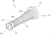
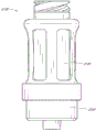
Fig. 2 A is valve or the near-end perspective view without an embodiment of male connector;
Fig. 2 B is the far-end perspective view of the adapter embodiment shown in Fig. 2 A;
Fig. 3 is the near-end decomposition view of the adapter embodiment shown in Fig. 2 A;
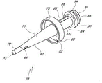
Fig. 4 is the distal portion diagrammatic view of the adapter embodiment shown in Fig. 2 A;
Fig. 4 A is the view sub-anatomy along its longitudinal center line of the adapter embodiment shown in Fig. 2 A;
Fig. 5 is the perspective view of the containment member embodiment of the adapter embodiment shown in Fig. 2 A;
Fig. 6 is another perspective view of the containment member embodiment shown in Fig. 5;
Fig. 7 is the near-end perspective view of the supporting member embodiment of the adapter embodiment shown in Fig. 2 A;
Fig. 8 is the far-end perspective view of the supporting member embodiment shown in Fig. 7;
Fig. 9 is the cutaway view of the supporting member embodiment shown in Fig. 7 along its longitudinal center line;
Figure 10 is the near-end perspective view of the actuator embodiment of the adapter embodiment shown in Fig. 2 A;
Figure 11 is the far-end perspective view of the actuator embodiment shown in Figure 10;
Figure 12 is the cutaway view of the actuator embodiment shown in Figure 10 along its longitudinal center line;
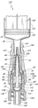
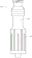
Figure 13 is the cutaway view of the adapter embodiment shown in Fig. 2 A, and it had shown before containment member for example, is contacted and opened by medical appliance (example of the syringe set forth), in first or the containment member of detent position;
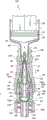
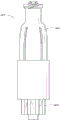
Figure 14 is the cutaway view of the adapter embodiment shown in Fig. 2 A, and it has shown after containment member is contacted and opened by syringe, in second or the containment member of open position;
Figure 15 is the schematic diagram of the adapter embodiment shown in Fig. 2 A, and this adapter is for injecting fluid the blood flow of patient's arm;
Figure 16 is the cutaway view of the adapter embodiment shown in Fig. 2 A, and it has shown containment member in an open position, and is advanced into the piston of syringe lower surface;
Figure 17 is the cutaway view of the adapter embodiment shown in Fig. 2 A, and it has shown containment member in an open position, and the syringe of the piston of syringe after the lower surface bounce-back of syringe;
Figure 17 A is the cutaway view of the adapter embodiment shown in Fig. 2 A, and it has been shown when the containment member of syringe after adapter removes, in primary importance;
Figure 18 is the near-end perspective view of another embodiment of supporting member, and this supporting member can use together with the adapter shown in Fig. 2 A or other adapter arbitrarily disclosed herein;
Figure 19 is the far-end perspective view of the supporting member embodiment shown in Figure 18;
Figure 20 is the cutaway view of the supporting member embodiment shown in Figure 18 along its longitudinal center line;
Figure 21 is the near-end perspective view of another embodiment of containment member, and sealing member can use together with the adapter shown in Fig. 2 A or other adapter arbitrarily disclosed herein;
Figure 22 is the far-end perspective view of the containment member embodiment shown in Figure 21;
Figure 23 is the near-end perspective view of another embodiment of containment member, and sealing member can use together with the adapter shown in Fig. 2 A or other adapter arbitrarily disclosed herein;
Figure 24 is the far-end perspective view of the containment member embodiment shown in Figure 23;
Figure 25 A is the near-end perspective view of another embodiment of containment member, and sealing member can use together with the adapter shown in Fig. 2 A or other adapter arbitrarily disclosed herein;
Figure 25 B is the far-end perspective view of the containment member embodiment shown in Figure 25;
Figure 26 A is the perspective view of another embodiment of supporting member, and this supporting member can use together with the adapter shown in Fig. 2 A or other adapter arbitrarily disclosed herein;
Figure 26 B is the cutaway view of the supporting member embodiment shown in Figure 26 A;
Figure 26 C is the cutaway view that comprises the adapter of the supporting member embodiment shown in Figure 26 A;
Figure 26 D is the cutaway view of another embodiment of supporting member, and this supporting member can use together with the adapter shown in Fig. 2 A or other adapter arbitrarily disclosed herein;
Figure 27 is valve or the near-end perspective view without another embodiment of male connector;
Figure 28 is the far-end perspective view of the adapter embodiment shown in Figure 27;
Figure 29 is the near-end decomposition view of the adapter embodiment shown in Figure 27;
Figure 30 is the distal portion diagrammatic view of the adapter embodiment shown in Figure 27;
Figure 31 is the cutaway view of the adapter embodiment shown in Figure 27, and it had shown before containment member is contacted and opened by syringe, in first or the containment member of detent position;
Figure 32 is the cutaway view of the adapter embodiment shown in Figure 27, and it has shown after containment member is contacted and opened by syringe, in first or the containment member of open position;
Figure 33 is the far-end decomposition diagram of another embodiment of adapter;
Figure 34 is the view sub-anatomy of the adapter embodiment shown in Figure 33 along its longitudinal center line;
Figure 35 be the adapter embodiment shown in Figure 33 containment member along its longitudinal center line cutaway view, wherein containment member is in second or open position;
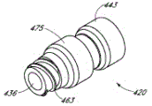
Figure 36 is valve or the near-end perspective view without another embodiment of male connector;
Figure 37 is the far-end perspective view of the adapter shown in Figure 36;
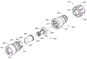
Figure 38 is the near-end decomposition diagram of the adapter shown in Figure 36;
Figure 39 is the far-end decomposition diagram of the adapter shown in Figure 36;
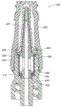
Figure 40 is the view sub-anatomy of the adapter shown in Figure 36 along its longitudinal center line;
Figure 41 is the adapter shown in Figure 36 and in not engaging the additional cutaway view without male connector of form;
Figure 42 is the adapter shown in Figure 36 and in engaging the cutaway view of additional adapter form, shown in Figure 41;
Figure 43 is the far-end cutaway view of the embodiment of dynamic volume adjustor;
Figure 44 is the cutaway view of the dynamic volume adjustor shown in Figure 43 along its longitudinal center line;
Figure 45 comprises the valve of the dynamic volume adjustor shown in Figure 43 or the cutaway view without male connector;
Figure 46 is the far-end perspective view of the embodiment of valve member;
Figure 47 is the cutaway view of the valve member shown in Figure 45 along its longitudinal center line;
Figure 48 comprises the valve of the dynamic volume adjustor shown in Figure 46 or the cutaway view without male connector;
Figure 49 comprises the valve of the valve member shown in the dynamic volume adjustor shown in Figure 43 and Figure 46 or the cutaway view without male connector simultaneously;
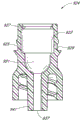
Figure 50 A is the cutaway view of the embodiment of base component;
Figure 50 B comprises the valve of the base component shown in Figure 50 A or the cutaway view without male connector;
Figure 51 is the far-end perspective view with the actuator embodiment of single seam;
Figure 52 is the far-end perspective view with the actuator embodiment of five seams;
Figure 53 is the far-end perspective view of another embodiment of actuator;
Figure 54 is the actuator shown in Figure 53 along its longitudinal center line, cutaway view in a first direction;
Figure 55 is the actuator shown in Figure 53 along its longitudinal center line, cutaway view in second direction;
Figure 56 is the far-end perspective view of another embodiment of valve member;
Figure 57 comprises the valve valve member shown in Figure 56, in arrangement for closed configuration or the cutaway view of medical connector;
Figure 58 is another cutaway view of the adapter shown in Figure 57, and wherein valve member is in opening form;
Figure 59 is the far-end perspective view of another embodiment of actuator;
Figure 60 is the cutaway view of the actuator shown in Figure 59 along its longitudinal center line;
Figure 61 comprises the valve actuator shown in Figure 59, in arrangement for closed configuration or the cutaway view without male connector;
Figure 62 is another cutaway view of the adapter shown in Figure 61, and wherein actuator is in opening form;
Figure 63 is the near-end perspective view of another embodiment of actuator;
Figure 64 comprises the valve actuator shown in Figure 63, in arrangement for closed configuration or the cutaway view without male connector;
Figure 65 is another cutaway view of the adapter shown in Figure 64, and wherein actuator is opened form in first;
Figure 66 is another cutaway view of the adapter shown in Figure 64, and wherein actuator is opened form in second;
Figure 67 is the far-end perspective view of another embodiment of actuator;
Figure 68 is the cutaway view of the actuator shown in Figure 67 along its longitudinal center line;
Figure 69 comprises the valve actuator shown in Figure 67, in arrangement for closed configuration or without male connector;
Figure 70 is the partial sectional view of the adapter shown in Figure 69, and wherein actuator is opened form in first;
Figure 71 is another width partial sectional view of the adapter shown in Figure 69, and wherein actuator is opened form in second;
Figure 72 is valve or the cutaway view without another embodiment of male connector supporting member;
Figure 73 is the near-end perspective view of another embodiment of supporting member;
Figure 74 comprises the valve of the supporting member shown in Figure 73 or the cutaway view without male connector;
Figure 75 is the cutaway view that comprises another embodiment of supporting member of bag-shaped member;
Figure 76 is the partial sectional view of the supporting member shown in Figure 75, and wherein bag-shaped member is in the approximate form of collapsing;
Figure 77 is another width partial sectional view of the supporting member shown in Figure 75, and wherein bag-shaped member is in expansion form;
Figure 78 is valve or the side view without another embodiment of male connector;
Figure 79 be the adapter shown in Figure 78 along its longitudinal center line cutaway view;
Figure 80 is valve or the side view without another embodiment of male connector;
Figure 81 is the cutaway view of the adapter shown in Figure 80 along its longitudinal center line;
Figure 82 is valve or the side view without another embodiment of male connector;
Figure 83 is the cutaway view of the adapter shown in Figure 82 along its longitudinal center line;
Figure 84 is valve or the side view without another embodiment of male connector;
Figure 85 is that adapter shown in Figure 84 is along the cutaway view of its longitudinal center line;
Figure 86 A is valve or the side view without another embodiment of male connector;
Figure 86 B is the cutaway view of the adapter shown in Figure 86 A along its longitudinal center line;
Figure 87 A is valve or the side view without another embodiment of male connector;
Figure 87 B is the cutaway view of the adapter shown in Figure 87 A along its longitudinal center line;
Figure 88 A is valve or the side view without another embodiment of male connector;
Figure 88 B is the cutaway view of the adapter shown in Figure 88 A along its longitudinal center line;
Figure 89 A is valve or the side view without another embodiment of male connector;
Figure 89 B is the cutaway view of the adapter shown in Figure 89 A along its longitudinal center line;
Figure 90 A is valve or the side view without another embodiment of male connector;
Figure 90 B is the cutaway view of the adapter shown in Figure 90 A along its longitudinal center line;
Figure 91 A is valve or the side view without another embodiment of male connector;
Figure 91 B is the cutaway view of the adapter shown in Figure 91 A along its longitudinal center line.
The specific embodiment
Be described in detail for specific embodiment of the present disclosure below.In description, description in the whole text and in accompanying drawing identical Reference numeral represent same parts.
In aspect some of described embodiment, the device of various one or more ends for closed adapter is described.These close mechanisms are used in close mechanism or valve and in the time of detent position, substantially prevent and/or substantially hinder the flow through end of adapter of fluid.In the time that close mechanism is in an open position, for example, in the time that adapter engages with needleless type syringe or other medical connector, allow flow through one or more ends of adapter of fluid.For example, should be understood in this term used, " closure " or " sealing " and various distortion, refer to obstacle or the obstruction of fluid flow.These terms should be interpreted as to be to need ad hoc structure or form to realize completeness fluid sealing in all cases.
In aspect some of the disclosed embodiments, the various devices for the fluid stream in control connection device are shown.These control valves for fluids or mechanism can assist the fluid motion of controlling inflow potential, that do not wish generation or flowing out adapter.For example, may wish to prevent, hinder or reduce the negative stream or the fluid that enter adapter.Negative stream used herein, the stream that falls back, reflux, enter stream and relational language is consistent with its usual implication in medical connector field.In some cases, these terms refer to the situation that is flowed into adapter by the caused fluid of following situation: due to the increase of the internal capacity in adapter inner fluid space or effectively increase or due to fluid from outside sucking-off or remove (for example, by removing a part of medical appliance being originally inserted in adapter) or the external force due to the fluid pressure in reverse direction roughly, for example, for example, because patient cough, patient's hypertension or fluid source unstable (, the minimizing of transfusion bag Fluid Volume or " drying up ") etc. causes.Minus flow is conventionally flowing in roughly relative or contrary direction and is producing with expection fluid.
Consistent at this term used " neutrality ", " neutral displacement ", " neutral current " and other relational language with its usual implication in medical connector field.In some cases, these terms relate to such medical connector or valve: these medical connectors or valve can not produce negative stream conventionally under most of clinical conditions that need to use specific adapter or valve, thereby or under most of clinical conditions that need to use specific adapter or valve, produce extremely low-level negative stream and make the probability that need to change adapter, valve or conduit causing to the hurtful risk of patient or by negative conductance become low in the extreme.In addition, the neutral union or valve generally do not produce has fluid stream clinical remarkable meaning, from the far-end of adapter or valve to the near-end of adapter or valve, and this fluid stream is being connected of far-end based on another medical appliance and adapter or valve or disconnection and generation automatically.In more disclosed embodiment, adapter or valve can be neutral, maybe can obtain neutral current.
Negative stream has many provenances, comprises the negative stream producing in the time that the near-end of adapter (claiming first end or the female end of adapter at this) removes when medical appliance, for example syringe.Along with removing of syringe, the fluid in adapter keeps space to increase.In the time that this fluid space communicates with patient's fluid line conduit, the increase of the fluid space in adapter may be returned fluid is sucked adapter from conduit from far-end, and the far-end of adapter claims the second end or male end at this.This may be disadvantageous, because this negative stream can be therefore by the opposite end of blood suction catheter from patient body.And this blood in fluid line may grumeleuse or stained fluid line, thereby probably need to change and again insert too early pipe line, adapter and other medical appliance.
Negative stream also can derive from the utensil that is connected to adapter near-end.An example of such negative stream is, the negative stream being caused by pump machine or hand gun.For example, in the time being connected to the medical appliance of adapter and being syringe, it generally includes the yielding movable chock plug of adapter piston, for being pressed by user or machine.When after the fluid expulsion in syringe, can be towards the end compression piston of syringe inner chamber.After the pressure unclamping on piston wall, compression piston head can rebound conventionally, or expansion slightly on the proximal direction away from adapter inner chamber end.Between the end in chamber and the distal surface of piston head, may form thus little vacuum.Because syringe and the conduit that is connected patient are still fluid communication, therefore, described vacuum may be by the fluid filled from adapter, and this can draw in fluid adapter from conduit.Refunding of this fluid can cause grumeleuse or stain pipe line.
In use negative stream can produce by alternate manner, for example, in the time that the transfusion bag exsiccation, patient's blood pressure or the patient body that are used for injecting fluid by conduit move etc.The momentum that negative stream also can be flowed by fluid produces.Syringe or machine can inject adapter by fluid.User or machine are conventionally by fluid-propelled adapter as much as possible, for example, by piston head being pressed into the end of syringe inner chamber.Even, before the earth pressure release on piston, in adapter, also may produce some negative streams.Fluid molecule is connected by intermolecular force, and has momentum.Along with the fluid of last amount leaves fluid source, fluid is pushed out adapter and conduit.Along with the end of the power of propelling fluid on distal direction, the fluid of end of conduit continues to flow out conduit, and still stays in conduit from the further fluid of end of conduit.Vacuum between the end of end of conduit and conduit inner fluid post can be filled by blood, and this will cause grumeleuse.
The impact in some or all negative stream sources can roughly be eliminated, reduces, minimizes or be controlled to some embodiments of the present invention.Although the running of embodiment more disclosed herein is for example, to discuss in conjunction with single negative stream source (, syringe bounce-back), but should be appreciated that available similar or same way eliminates, reduces, makes to minimize or control many negative streams source.
Fig. 1 shown can be contained in disclosed herein without various different parts and configuration in some embodiment of male connector.It is whole possible combination and/or the parts that explaination can be used that Fig. 1 should not be interpreted as.Some embodiment can comprise near-end, near-end closed system, enclose inside system and far-end, and these parts adjacently arrange, as are positioned at as shown in the first string square frame on the left of Fig. 1.Some embodiment can comprise near-end, near-end closed system, volume adjustor, enclose inside system and far-end, and these parts adjacently arrange, as are arranged in as shown in Fig. 1 the second string square frame.Some embodiment can comprise near-end, near-end closed system, enclose inside system, volume adjustor and far-end, and these parts adjacently arrange, as are arranged in as shown in Fig. 1 the 3rd string square frame.Some embodiment can comprise near-end, near-end closed system, volume adjustor and far-end, and these parts adjacently arrange, as are arranged in as shown in Fig. 1 the 4th string square frame.Some embodiment can comprise near-end, near-end closed system, combination type enclose inside system and volume adjustor and far-end, and these parts adjacently arrange, as are arranged in as shown in Fig. 1 the 5th string square frame.Any one in these parts all can be omitted in a particular embodiment, and setting connected with each other shown in also can comprise other parts between parts.
Can substitute or make an addition in the configuration shown in Fig. 1 with the parts of many other combinations and other type.For example, some embodiment can comprise near-end, combination type near-end closed system and volume adjustor and/or combination type near-end closed system and enclose inside system, and far-end.In certain embodiments, can there are the parts shown in many picture groups 1.For example, a pair of volume adjustor can be set in the both sides of enclose inside system.In certain embodiments, far-end can comprise closed system.Any parts, feature or the step explaining or describe at this all can be omitted in certain embodiments.Neither one parts, feature or step are essential or requisite.
Several embodiment of near-end closed system are explained, comprise that containment member 26 and supporting member 28(are for example shown in Fig. 3), containment member 26 ' (for example seeing Figure 21), containment member 26 ' ' (for example seeing Figure 23), containment member 326(be for example shown in Figure 34), cap 491(is for example shown in Figure 38), and containment member 2126,2226,2326,2426,2526,2626,2726,2826,2926 and 3026(are for example shown in Figure 79,81,83,85,86B, 87B, 88B, 89B, 90B and 91B).Also can use the near-end closed system of other type.The near-end closed system of each embodiment can be replaced (when needed) mutually with the near-end closed system in suitable other embodiment revising.In some embodiment, also can omit near-end closed system.
Explained several embodiment of volume adjustor, comprised that volume adjustor 30,330,630,1030,1130,1230,1430,1530,1730,1930,2130,2230,2330,2430,2530,2630,2730,2830,2930 and 3030(are for example shown in Figure 10-12,34,43-44,51-53,59-60,63,67-68,74,79,81,83,85,86B, 87B, 88B, 89B, 90B and 91B), balloon member 1830(is for example shown in Figure 72) and bag-shaped 2030(for example see Figure 75-77).Also can use the volume adjustor of other type, comprise other shown here and/or described volume adjustor.The volume adjustor of each embodiment can be replaced (when needed) mutually with the volume adjustor in suitable other embodiment revising.In some embodiment, also can omit volume adjustor.
Several embodiment of enclose inside system are explained, comprise valve member 108,308,408,730,1008,1108,1208,1330,1408,1508 and 1708(for example see Figure 10-12,34,40,46-47,51-53,57,59-60,63 and 67-68), and be showed in the similar valve member in Figure 79,81,83,85,86B, 87B, 88B, 89B, 90B and 91B.Also can use the enclose inside system of other type, comprise other shown here and/or described enclose inside system.The enclose inside system of each embodiment can be replaced (when needed) mutually with the enclose inside system in suitable other embodiment revising.In some embodiment, also can omit enclose inside system.
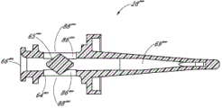
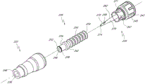
Fig. 2 A and Fig. 2 B are respectively valve or the perspective view without an embodiment of male connector 20.Fig. 3 and Fig. 4 are the decomposition view of the embodiment of the adapter 20 shown in Fig. 2 A.Fig. 4 A is the view sub-anatomy of the adapter 20 shown in Fig. 2 A.Referring to Fig. 2 A to Fig. 4 A, can be particularly including main component 22, base component 24, containment member 26, supporting member 28 and actuator 30 without male connector 20 some embodiment.
In the embodiment shown, main component 22 and base component 24 can fit together, to form close encapsulation member 26(roughly hereinafter referred to as the first valve member), the housing of supporting member 28 and actuator 30.Main component 22 and base component 24 useful binders, plasticity or sonic welded, bayonet mechanism, interference mechanism or clinching mechanism link together, or by using other any suitable feature or method to be connected.In certain embodiments, main component 22 and base component 24 can use as the sonic welded of general triangular links together, and other shape is also applicable to certainly.
Other any part of main component 22, base component 24, supporting member 28 and adapter 20 or feature all can be made up of any one in some suitable materials.For example, other any part of main component 22, base component 24, supporting member 28 and adapter 20 or feature can be made up of the material of relative stiffness, for example polycarbonate, glass-filled GE Valox 420, polypropylene or other polymeric material.Other any part or the feature of main component 22, base component 24, supporting member 28 and adapter 20 also can be made up of hydrophobic material, for example Bayer Makrolon or other any similar or suitable material.One or more parts of adapter 20 disclosed herein and other adapter can comprise the suitable antimicrobial agent of any appropriate format, for example, as the composition overlay film that becomes a sub matrix part, or other appropriate format.In certain embodiments, described antimicrobial agent in use or in time separates from one or more compositions.In certain embodiments, described antimicrobial can comprise silver ion.
As mentioned above, supporting member 28 can be by forming with the rigid material that forms main component 22 or base component 24 same types.In certain embodiments, for example, supporting member 28 can be by semi-rigid or even form than the more soft material of other parts material therefor of main component 22, base component 24 or adapter 20.In certain embodiments, any other embodiment of the supporting member of supporting member 28(and any other adapter disclosed herein) can with any other embodiment of the base component of base component 24(and any other adapter disclosed herein) integral type form, or may be separately formed, then engage with base component.
In certain embodiments, main component 22 can comprise one or more recess or grooves 41 that roughly extend along the longitudinal direction of adapter 20, to assist the movement of containment member 26.This groove 41 can be provided for making containment member 26 to collapse and enter region wherein, and can reduce the surf zone contacting with containment member 26 in the time that containment member 26 moves in housing.
Fig. 5 and Fig. 6 are the perspective view of containment member 26 embodiment in the adapter 20 shown in Fig. 2 A.Referring to Fig. 1 to 6, containment member 26 can be arranged so that the proximal part 34 of containment member 26 is held hermetically by the opening 36 of main component 22 near-ends 162.In certain embodiments, embodiment as shown, the proximal part 34 of containment member 26 can have this lip part 38 of lip part 38(formed thereon for annular outstanding), for contacting the opening 36 of main component 22, to realize sealing.The far-end 53 of containment member 26 can comprise opening 54.In certain embodiments, supporting member 28 can hold with this opening 54 in.In certain embodiments, far-end 53 further comprises outward extending flange 56, this flange 56 around or roughly extend around containment member 26.In certain embodiments, flange 56 can assist containment member 26 to be placed in the inner chamber of main component 22.
Term " near-end " refers to that at this adapter 20 is located on or near one end of main component 22 ends.Term " far-end " refers at this end that adapter is contrary, and adapter 20 is located on or near one end of base component 24 ends.In the illustrated embodiment, near-end is set to female end, and far-end is set to male end.Any end, setting or the aspect of adapter 20 can be set to adapt to medical connector or the utensil of any standard, and be set to follow ANSI(American National Standards Institute, Washington, D.C.) or other applicable standard.Term " medical appliance " refers to generally for any armarium medical field, that can be connected or engage with any embodiment of adapter disclosed herein at this.The example of contemplated medical appliance include but not limited to pipe, female Luer, conduit, syringe, intravenous injection device (periphery and maincenter line), can closed public Rule adapter (form with syringe integral type or as independently adapter), pump, backpack line and other can be used for being connected the parts of medical valve or adapter.
The proximal part 34 of containment member 26, containment member 26 and lip part 38 can integral type form, or may be separately formed, then are bonded together by binding agent or other suitable material or method.In certain embodiments, other any embodiment of containment member 26 disclosed herein or sealing member, containment member with and parts or feature all can be made by many different suitable materials, comprise silica-based can shape-changing material, rubber or other suitable material.Silica-based can shape-changing material and plastics and other rigid composite material form liquid-tight property sealing.
In certain embodiments, the outer surface that the inner surface of main part 50 can approximate match main part 50 so that the inner surface of main part 50 also can have structure or the profile that other place of the application is stated.In certain embodiments, the inner surface of main part 50 can roughly radially extend internally, and the appropriate section of main part 50 outer surfaces radially stretches out; The inner surface of main part 50 can roughly radially stretch out, and the appropriate section of main part 50 outer surfaces radially extends internally.Therefore, main part 50 can comprise a series of protuberances, and wherein the thickness of the wall of main part 50 replaces between thick section and thin section, and example as shown in Figure 4 A.In certain embodiments, the inner surface of main part 50 can roughly radially extend internally, and the appropriate section of main part 50 outer surfaces roughly radially extends internally; The inner surface of main part 50 can roughly radially stretch out, and the appropriate section of main part 50 outer surfaces radially stretches out.Therefore, main part 50 can comprise a series of bent section, and wherein the wall of main part 50 has more uniform thickness.In certain embodiments, the inner surface of main part 50 can have relatively level and smooth or flat surface configuration.
In addition, as shown in Figure 5, on the proximal part 34 of containment member 26, can form slit or opening 52.The slit 52 of containment member 26 can be partial to detent position, with the slit 52 that roughly stops or hinder fluid to flow through on containment member 26.In addition, in certain embodiments, as will be described in more detail, can retract and open slit 52 by making containment member 26 cross supporting member 28 on distal direction, thereby make at least a portion of the proximal part of supporting member 28 thrust and pass slit 52.In certain embodiments, slit 52 can be set to open, and without thrusting via supporting member 28.
Fig. 7 and Fig. 8 are the perspective view of supporting member 28 embodiment in adapter 20 embodiment shown in Fig. 2 A.Fig. 9 is the cutaway views of supporting member 28 embodiment shown in Fig. 7 along its longitudinal center line.Referring to Fig. 7 to Fig. 9, at some but in non-whole embodiment, supporting member 28 can comprise base part 60, on proximal direction from the outstanding microscler part 62 of base part 60, and on distal direction from the outstanding far-end 64 of base part 60.In certain embodiments, one or more parts of diagram supporting member 28 can omit, or are substituted by different parts.For example, supporting member is without comprising microscler part 62.In certain embodiments, supporting member can be roughly shorter, so as not extend into, by and/or near the near-end of containment member.In some embodiment of adapter 20, there is no supporting member at all.Containment member can be set to without thrust supporting member or just can open without supporting member at all, for example in the time that being positioned at nature open position, containment member (in the time of this nature open position, just can force its closure by the less housing of diameter), or in the time that containment member is connected to the proximal end region of housing etc.Also actuator can be fixed or is placed in housing, this actuator just can operate without supporting member.For example, in certain embodiments, actuator 30 can be connected to containment member and/or can separate and suspend with another structure, or actuator 30 not can be do not connect, free floating, without far-end 64 or inner support shown in Figure 13.
In certain embodiments, shown in one or more parts of supporting member 28 may be separately formed, then by binding agent, sonic welded, be clasped or alternate manner interconnects.For example, microscler part 62 and base part 60 may be separately formed, then are connected together by for example sonic welded.In certain embodiments, whole supporting member 28 can be used as the formation of single-piece unit integral type.In certain embodiments, can flow through one or more holes of adapter 20 intracavity of fluid, for example, be located on or near the hole of the far-end in chamber, and these holes are positioned at inside or the outside of containment member or other fluid barrier.Although show as solid memder, in certain embodiments, the parts of supporting member 28 also may be separately formed.For example, microscler part 62 and/or other any parts can be configured such that with in adapter, move.
In certain embodiments, far-end 64 can comprise and is roughly columniform outer surface 64a.The longitudinal length of far-end 64 can roughly be less than the longitudinal length of microscler part 62, as shown in the figure.The distance that roughly strides across the lateral cross section of far-end 64 can be less than the distance of the lateral cross section that roughly strides across actuator 30 (for example seeing Figure 12).In addition, in certain embodiments, opening 66 can axially pass at least a portion of supporting member 28.In the embodiment shown, opening 66 can fluidly be communicated with the fluid passage 69 that roughly axially extends through supporting member 28.The extensible major part through far-end 64, base part 60 and microscler part 62 of fluid passage, to make the one or more horizontal or radial opening 68 that is formed at microscler part 62 near-ends communicate with opening 66.
As shown in Fig. 7 to 9, microscler part 62 can have tapering outer surface 70 and proximal tip part 72.This proximal tip part 72 can have the roughly outer surface of tapering (or being roughly taper shape), maybe can be roughly cylindrical.Microscler part 62 can be arranged so that this proximal tip part comprises transverse cross-sectional area, and this transverse cross-sectional area is significantly less than the transverse cross-sectional area of the base part 60 of supporting member 28.In certain embodiments, proximal tip part 72 can be arranged so that the proximal part 34 of containment member 26 (for example can retract with respect to the proximal tip part 72 of supporting member 28, from compression position to expansion or initial position), and without carrying out significantly pulling or stopping of self-supporting construction element 28.In certain embodiments, proximal tip part 72 has tip 74 sharp-pointed or circle, to pierce through the slit 52 being formed on containment member 26.In certain embodiments, most advanced and sophisticated 74 form with the remainder integral type of tip portion 72 and microscler part 62.In certain embodiments, the near-end of microscler part 62 comprises the hole and the path 69 that are positioned at its proximal tip, and this path 69 can extend to most advanced and sophisticated opening from opening 66.
The distal portions 64 of supporting member 28 can have opening 86 laterally one or more or that radially become, pass far-end 64.In the illustrated embodiment, be formed with two openings 86 on far-end 64, and be set to the groove of essentially rectangular, its major axis roughly extends along the axle of adapter.But, in certain embodiments, on far-end 64, can form one, three, four or multiple opening, and these openings can be the holes of groove or other shape.In certain embodiments, one or more openings 86 can extend along at least most of of the longitudinal length of far-end 64, as shown in the figure.Can form this one or more openings 86, to communicate with the axially open 66 forming on supporting member 28.
Be roughly on the far-end 64 that annular chamber or chamber 88 can be positioned at supporting member 28.Annular chamber 88 can be given prominence between 90 and 92 two annulars, and two annulars outstanding 90 and 92 are positioned on far-end 64.As narrated detailed below, chamber 88 can be positioned at by flowing through the fluid of the opening 66 and 86 on supporting member 28 and fill.Annular outstanding 94 also can be positioned at the distal portions of supporting member 28, to make forming passage 96 between annular outstanding 90 and 94.
Figure 10 and 11 is respectively the perspective view of actuator 30 embodiment of adapter shown in Fig. 2 A.Figure 12 is the cutaway views of actuator 30 embodiment shown in Figure 10 along actuator 30 longitudinal center lines.As shown in Figure 10 to 12, actuator 30 can have main part 100 and proximal part 102.In certain embodiments, embodiment as shown, main body 100 can be near cylindrical, and proximal part 102 can have annular raised portion or lip 103 and pass its opening 104.In certain embodiments, as shown in the figure, adapter comprises multiple valve arrangements, and for example containment member 26 and actuator 30, to control the fluid of flowing through and/or being positioned at adapter 20.
Any other embodiment of actuator 30 disclosed herein or actuator, valve or valve member with and any parts or feature all can be made by multiple different materials, comprise silica-based can shape-changing material, rubber or other suitable material.Silica-based can shape-changing material be that those can form one of material of fluid-tight closure with plastics and other rigid composite material or metal material.In certain embodiments, actuator 30 can be springy, elastic and/or the property returned.In certain embodiments, actuator 30 can be made up of the material identical with containment member 26.As shown shown in embodiment, the variable volume of prescription dosage regulating device 30 or dynamic regulator part can have one or more sidewalls very thin, that have elastic force and/or compliance, described sidewall is even thinner than at least a portion or whole sidewall of containment member 26 in certain embodiments, so that the change in elevation sensitivity of actuator 30 to hydraulic pressure.
In addition, actuator 30 can comprise the valve member that is positioned at distal portions 108, and this valve member has one or more holes formed thereon or slit 110, is two slits 110 in illustrated embodiment.In certain embodiments, shown in embodiment, end 108 can comprise having valve member approximate arch, that be similar to dome-shaped or almost spherical shape as shown.Distal portions 108 can be arranged so that distal portions 108 is partial to detent position (for example, slit 110 is partial to arrangement for closed configuration).Therefore, in certain embodiments, when the fluid in actuator 30 and the amplitude that acts on pressure differential between the fluid of actuator 30 outer surfaces are during lower than predeterminated level, distal portions 108 can be set to roughly closed, (for example,, when acting on pressure on the 108 inner surface 108a of end with the difference that acts on the pressure on the 108 outer surface 108b of end during lower than predeterminated level).
As shown in the figure, along with the fluid pressure in valve member distally rises to specified level, the shape of the valve member on distal portions 108 can make valve member closed more closely.Outside this fluid pressure resistance levels time, valve member can curve inwardly or mobile (for example, at proximal direction), and to allow to fall back, stream passes through.Valve member can be set (for example, by the material of selecting suitable shape, position and using), with make this fluid resistance level be greater than conventionally because of syringe bounce-back, near-end female Luer remove and/or the outside negative stream causing (for example, patient's cough, sneeze, movement and hypertension or transfusion bag fluid reduce) pressure differential that produces, but be less than conventionally by removing fluids and the pressure differential that produces consciously of the near-end from adapter 20.In certain embodiments, as shown in the figure, along with the increase of pressure differential or towards the gathering of its opening pressure, valve member can roughly keep its original shape, communicate by valve member to avoid or to reduce negative stream power when the pressure differential lower than opening pressure.
In certain embodiments, fall back stream or negative stream can be caused by external effect (these external effects are sometimes from the upstream of adapter 20), the for example reduction of transfusion bag inner fluid liquid level, and/or the fluctuation of the fluid line being caused by patient or nursing staff or other move.In the time that the fluid in transfusion bag is down to low liquid level or is about to dry up (or the position of transfusion bag is too low for patient), the head pressure that transfusion bag had previously had has also reduced.In certain embodiments, this decline of head pressure can make fluid line be vulnerable to because of patient move around liquid column that cause, adapter upstream and downstream " rocking " or change the impact of motion, thereby produce periodically negative stream.In certain embodiments, inside or far-end valve member, the valve member that is for example positioned at actuator far-end 108 can be set to closure, the upstream head pressure of the fluid level reducing gradually in from transfusion bag falls to below threshold value, and in this threshold point, may start to rock or change fluid motion.
In certain embodiments, valve member can be bistable valve, this bistable valve is set to (for example open in a first direction under the hydrokinetic effect higher than specific threshold, in the direction from near-end to far-end), this fluid force effect in a first direction, and remain opening in the party's fluid stream upwards, for example, until (act in second direction higher than the fluid force of desired threshold, distal-to-proximal direction), this power causes valve to be opened, and keeps the fluid in second direction to open.Under the effect can be in a first direction, higher than the power of threshold value of this bistable valve, again switch and be back to first direction from the liquid stream of second direction.
In certain embodiments, the width of one or more slits 110 (being represented by " WS " in Figure 12) can be approximately equal to opening 104(and represented by " WO " in Figure 12) width.In certain embodiments, in embodiment, the width W S of one or more slits 110 can be less than the width of opening 104 as shown.In certain embodiments, as shown in the figure, width W S or the width that strides across the lateral cross section distance of variable volume chambers can roughly be less than the longitudinal length of variable volume chambers, or are roughly less than the longitudinal length of whole actuator 30.In certain embodiments, as shown in the figure, actuator 30 can roughly be greater than the thickness of actuator 30 at the wall of variable volume chambers or main part 100 at the thickness of wall distal portions 108, that be positioned at least a portion valve member region, with the block of the backflow that strengthens elasticity, the compliance of main body 100 and valve member is caused.In certain embodiments, as shown in the figure, valve member can roughly be less than the longitudinal length (at the embodiment of the two, these parts are connect or separate) of the variable volume chambers that is arranged in actuator 30 main parts 100 at the longitudinal length of distal portions 108.
In certain embodiments, actuator 30 can be set in the time that actuator 30 inside and outside pressure differentials reach the first amplitude, the distal portions 108 of actuator 30 is opened, for example flow through actuator 30(in a first direction to allow fluid, from near-end 102 to blind end or the direction of far-end 108, shown in the arrow A 1 in Figure 10).Similarly, actuator 30 can be set in the time that actuator 30 inside and outside pressure differentials reach the second amplitude, the distal portions 108 of actuator 30 is opened, for example in second direction, flow through actuator 30(to allow fluid, from blind end or far-end 108 direction of near-end 102, shown in the arrow A 2 in Figure 10).
The valve member that is positioned at inside or far-end closed system can have many different shapes and setting.For example, in certain embodiments, Figure 50 to 56, the 309th to 325 sections of valves of explaining 2200 and 2250 that valve member and related accessories and location structure can be the U.S. Patent application of 2010/0049157 A1 with publication No. are identical or similar, and the disclosed full content of this application (comprise and quote part) is all included the application in.
In certain embodiments, the first amplitude of pressure differential can be approximately equal to the second amplitude of pressure differential.In certain embodiments, in embodiment, the first amplitude of pressure differential can be less than the second amplitude of pressure differential as shown, to make actuator 30 fluid flow on second direction A2 than on first direction A1 have more barrier force.In other words, the end 108 of actuator 30 can be set to be partial to allow fluid on first direction A1 than on the second reverse A2, under lower pressure differential amplitude, to pass through end 108.Under this set, actuator 30 can suppress to come the backflow (for example, the liquid stream on second direction A2) in self tuning regulator 30 downstreams, opens the required threshold value of slit 110 until the amplitude of pressure differential exceedes.
For example, without limitation, in the embodiment of actuator 30 shown in Figure 10 to 12, the spherical form of actuator 30 distal portions 108 (is illustrated) in a first direction than (illustrated) to have lower hardness by arrow A 2 in second direction end 108 by arrow A 1.In this set, with the distal portions 108 that will make actuator in A1 direction deflection, so that opening 110 is opened compared with required power in A1 direction, make closed end or distal portions 108 deflection, larger to make opening 110 open required power in A2 direction in A2 direction of actuator.
In certain embodiments, fluid (liquid or the gas) pressure acting on actuator 30 inner surface 108a can, than about 0.5 atmospheric pressure of fluid (liquid or gas) pressure acting on actuator 30 outer surface 108b, be opened in A1 direction with the distal portions 108 that makes actuator 30.In certain embodiments, the fluid pressure acting on actuator 30 inner surface 108a can be pressed onto approximately 1.0 atmospheric pressure for likening about 0.1 atmosphere of the fluid pressure being used on actuator 30 outer surface 108b to, or approximately 0.2 atmosphere is pressed onto approximately 0.8 atmospheric pressure, or approximately 0.4 atmosphere is pressed onto approximately 0.6 atmospheric pressure, open in A1 direction with the blind end or the distal portions 108 that make actuator 30, thereby allow fluid to flow in A1 direction.
In certain embodiments, the fluid pressure acting on actuator 30 outer surface 108b can, than greatly approximate 1 atmospheric pressure of fluid pressure acting on actuator 30 inner surface 108a, be opened in A2 direction with the distal portions 108 that makes actuator 30.In certain embodiments, the fluid pressure acting on actuator 30 outer surface 108b can be pressed onto approximately 1.5 atmospheric pressure than about 0.5 atmosphere of fluid pressure acting on actuator 30 inner surface 108a, or approximately 0.7 atmosphere is pressed onto approximately 1.3 atmospheric pressure, or approximately 0.9 atmosphere is pressed onto approximately 1.1 atmospheric pressure, open in A2 direction with the distal portions 108 that makes actuator 30, thereby allow fluid to flow in A2 direction.
In certain embodiments, in A2 direction, open the required pressure differential amplitude of actuator 30 distal portions 108 and be about the twice that will open actuator 30 distal portions 108 required pressure in A1 direction.In certain embodiments, to in A2 direction, open the required pressure differential amplitude of actuator 30 distal portions 108 and roughly be greater than and will in A1 direction, open the required pressure of actuator 30 distal portions 108, for example, than will open the required pressure at least about 40% of actuator 30 distal portions 108 in A1 direction.In certain embodiments, comprise that some are in this illustrated embodiment, in A2 direction, open the required pressure differential Amplitude Ratio of actuator 30 distal portions 108 and will in A1 direction, open the required little about twice to three times of pressure of actuator 30 distal portions 108.In certain embodiments, in the time that standard syringe 15 is connected to the near-end of adapter and syringe handle and advances together along with the power for fluid transfer of common effect, actuator 30 will allow fluid to flow in A1 direction, and in the time that roughly larger retraction force acts on syringe handle, actuator 30 will allow liquid stream to flow in A2 direction.
In certain embodiments, at least a portion far-end 108 of actuator 30 can be general flat, rather than roughly spherical.In certain embodiments, in A1 direction, opening the required pressure differential amplitude of actuator 30 is substantially equal to or is approximately equal to and in A2 direction, open the required pressure differential amplitude of actuator 30.In certain embodiments, the fluid obstacle part of actuator 30, for example distal portions 108 can comprise a part or the recess that the thickness on proximal end face or the distal surface that is positioned at distal portions 108 increases, and this part can be depending on concrete orientation and in A1 or A2 direction, raises or reduce the required pressure differential amplitude of actuator 30 of opening.Therefore, in certain embodiments, even if distal portions is approximate flat and aspheric, actuator 30 still can produce in one direction than obstruction power larger to liquid stream in another direction, for example larger obstruction power in A2 direction than in A1 direction.
In certain embodiments, open to allow fluid at A2(near-end at slit 110) flow in direction before, the distal portions 108 of actuator 30 can curve inwardly on proximal direction.In some cases, thisly open in advance motion and can cause producing a little backflow and enter adapter 20 far-ends, therefore, alleviate or eliminate actuator 30 this to open in advance motion be favourable.In certain embodiments, the spherical distal ends part 108 of actuator can just reduce or minimize the movement of actuator 30 before the fluid stream in A2 direction is opened.In certain embodiments, open to allow before fluid flows through at actuator 30, the fluid that only have sub-fraction volume, is for example less than or equal to 0.1ml is shifted.
In addition, referring to Figure 12, actuator 30 can further comprise the inner annular outstanding 112 on the inner surface 100a that is formed at main part 100.In certain embodiments, inner annular outstanding 112 can be contained in passage 96, and this passage 96 is formed between the annular outstanding 90 and 94 of supporting member 28.In this set, inner annular outstanding 112 can be used for by fastening actuator 30 or be supported on the desirable axial location with respect to supporting member 28, to prevent or to stop actuator 30 to move axially with respect to supporting member 28.In certain embodiments, actuator 30 is placed in the chamber of adapter 20 remote areas, and roughly or fully around intraware, for example supporting member 28 far-end 64.
Referring to Figure 12, in certain embodiments, the width of annular outstanding 112 (being represented by " WP " in Figure 12) can be less than the width W O of (for example for half) opening 104.As shown in the figure, the inside of actuator 30 (for example can comprise the first transverse cross-sectional area, at proximal end region), the second transverse cross-sectional area (for example, at zone line) and the 3rd transverse cross-sectional area is (for example, at remote area), wherein, the second transverse cross-sectional area is less than the first transverse cross-sectional area and the 3rd transverse cross-sectional area.In addition, first or the internal capacity of proximal end region can roughly be greater than second or the internal capacity of remote area.In certain embodiments, embodiment as shown, can limit width W P by giving prominence to 112, and width W P can be 1/4th or the half of the width W O of opening 104.Other features about actuator 30 are described to 16 in connection with accompanying drawing 13.
Figure 13 is the cutaway view of adapter 20 embodiment shown in Fig. 2 A, it has for example shown the containment member 26(that is positioned on primary importance or detent position, before containment member 26 contacts and opens because of the insertion of the female Luer on female Luer, for example syringe 120).Figure 14 is the cutaway view of adapter 20 embodiment shown in Fig. 2 A, for example show the containment member 26(that is positioned on the second position or open position, after containment member 26 contacts and opens because of the insertion of the female Luer on female Luer, for example syringe 120).In the time navigating between closure and open position, containment member 26 is movably.In certain embodiments, as shown in the figure, containment member 26 can compress at open position, and in detent position expansion or be back to its initial position.In certain embodiments, the longitudinal length of containment member 26 on open position is less than its longitudinal length on detent position.Also can use the containment member of many other types, open in every way or closed connector in fluid passage.Containment member 26 can be placed in adapter 20, the proximal end face 46 of containment member 26 and the proximal openings of adapter 20 is roughly alignd or concordant, thereby can carry out effective sterilizing wiping across proximal end face 46.
Figure 13 to 16(and the disclosure other everywhere) shown in syringe 120 be the type of the medical appliance that can use together with adapter 20.Certainly, adapter 20 is set to use together with multiple medical appliance, and is not limited to illustrated syringe 120.Syringe 120 can be any injector for medical purpose medical field or conventional that is applicable to.As shown in the figure, syringe 120 can have cylindrical body portion 122, this main part 122 has opening 124, hollow sleeve 126 and piston 128, described hollow sleeve 126 is outstanding from main part 122, described piston 128 is suitable for being accommodated in the opening 124 of main part 122, and in the interior movement of this opening 124.Piston 128 can have and is fixed on sealing gasket 129 its end, that be made up of elastomeric material or rubber.Common this injector for medical purpose is operation like this: push piston 128 by the lower surface 130 towards main part 122, make fluid pass through hollow sleeve 126 and discharge, thereby fluid is discharged from syringe 120.In this mode, fluid conventionally until the rubber gasket 129 of piston just from syringe 120, discharge completely while contacting the lower surface 130 of syringe 120.
Figure 15 has shown that the embodiment of the adapter 20 shown in Fig. 2 A is used to fluid to inject the blood flow of patient's arm.Other any embodiment of adapter 20(or adapter disclosed herein) can be suitable for multiple medical applications, be not limited to the application shown in Figure 15.As shown in figure 15, adapter 20 can be connected with conduit 132, and the other end of conduit 132 and patient's blood flow are communicated with.In this set, in syringe 120 pluggable connectors 20, to open the containment member 26 of adapter 20.When containment member 26 is during in open position shown in Figure 14, can transmit by adapter 20 and conduit 132 from the fluid of syringe 120, enter patient's vascular system.
For by the fluid in syringe 120 all or roughly inject fully patient's vascular system, by nurse personnel or automaton by the piston of syringe 120 128 or other mechanism always by compressing into main component 122, until piston 128 or rubber gasket 129 touch the end and prop up the lower surface 130 of syringe 120, and this is compressed between the piston 128 and the lower surface of syringe of rigidity roughly elastic rubber gasket 129.At this moment,, after nursing staff acts on power on piston 128 and is removed, the sealing gasket 129 of being conventionally made up of rubber or other elastomeric material, be positioned at piston 128 ends can rebound.
For example, in conventional system (, do not have adapter 20 to carry out offset injector bounce-back bring in the system of effect), in the time that piston 128 and sealing gasket 129 are opened from the lower surface bounce-back of syringe 120, in syringe 120, can form vacuum or suction source.Sometimes, the rebound effect of piston 128 in syringe 120 can be enough large, with by fluid in conduit 132, even from patient's self vascular system towards syringe 120 sucking-offs.For example, syringe bounce-back can form vacuum, by the atmospheric pressure of the Pressure Drop to 1 in syringe and adapter.In addition, in some cases, syringe or other medical appliance are removed from adapter, can in adapter, form vacuum or suction source.Term " backflow " is used alternatingly at some occasions and " negative stream ", with other parts, that be not intended to produce or disadvantageous blood flow and/or other fluid stream described from patient's vascular system to pipeline 132 and/or be communicated with conduit 132 fluids.
Adapter 20 can comprise that backflow stops module, for preventing, roughly prevent, reduce or hindering backflows, the stream that falls back, negative flow, enter and flow or other pressure differential being caused by many dissimilar sources, the drying up etc. of the such as rebound effect of syringe 120, at least a portion medical appliance (the such as female Luer of syringe 120) removing from adapter, transfusion bag.In certain embodiments, can be by the backflow of adapter 20 being stopped to module arranges actuator and/or valve member, to prevent, roughly prevent, to reduce or to hinder backflow phenomenon, described actuator is for example interior chamber, volume adjustor, dynamic volume adjustor or the dynamic regulator of variable volume, for reducing volume by collapsing or moving, to offset because of syringe rebound vacuum effect or various other effect of producing, described valve member is used for preventing before exceeding specific threshold pressure difference that fluid at least in one direction from flowing.In certain embodiments, as shown in the figure, actuator can be set to expansion or mobile to increase volume, to carry out offset pressure poor.In certain embodiments, for example, actuator 30 can be realized the function of similar barrier film.Especially, actuator 30 can comprise elasticity or the flexible wall with inner surface, fluid passage fluid communication in itself and adapter 20, and this wall also can curve inwardly or shrink under suction or other fluid force effect, to reduce or to change the spatial volume in actuator 30, and finally make the interior contained all or part of gas of actuator 30, liquid or other fluid flow into or flow out syringe 120 or other medical appliance, to offset vacuum effect.As shown in the figure, actuator 30 can form by valve a part (for example, fluid can enter from the first end of actuator 30, then discharges from the second end of actuator 30) for fluid passage.The moving end-wall of actuator 30 can have various setting.For example, described wall can be elastic (as shown in the figure) or rigidity, and/or scalable or bending (as shown in the figure), or slidably, rotation etc.In certain embodiments, can dynamically change by the ideal of inserting the different roughly rigidity of internal capacity and/or generally tubular structure realizes volume in fluid path.For example, can this structure be set to roughly coaxially the mode of telescopic moving slide relative to one another, realize the change of fluid displacement.
In certain embodiments, reflux and stop that module also can comprise valve, for stopping that fluid flows through on proximal direction.This valve can be check-valves or check valve, to reduce or almost to stop that the fluid on proximal direction flows completely; Like this, adapter 20 is all one-directional connector under the usual most of fluid pressure of medical valve.In certain embodiments, this valve can be set to allow fluid to flow through on proximal direction under the effect of enough large power, and adapter 20 just becomes input/output port like this.In certain embodiments, for example, the distal portions of actuator 30 and the one or more slits 110 that form on it can be set to stop the fluid stream on proximal direction, and this point has more detailed narration at other place of this description.
In certain embodiments, can be set to by valve: make to open valve, be greater than and variable volume chambers will be reduced to the required power of the second volume from the first volume to allow fluid to flow through required power on proximal direction.For example, for example, if not inadvertently produced pressure differential (, due to the rebound effect of syringe), variable volume chambers is collapsible poor with offset pressure, and valve can remain closed simultaneously.Therefore, in certain embodiments, rebounded or the caused pressure differential of other effect does not shift or be passed to the fluid of valve distal side or adapter 20 distal sides by syringe, and, also prevent the backflow of fluid.
In certain embodiments, the volume of variable volume chambers is further contracted to the following required power of the second volume be greater than to open valve, to allow fluid to flow through required power on proximal direction.Therefore, for example, if pressure differential is (, doctor shrinks syringe piston 128 with by fluid inhalation syringe 120) of having a mind to manufacture, variable volume chambers may contract to the second volume, and valve can be opened subsequently, to allow fluid to flow through on proximal direction.Therefore, in certain embodiments, if applied enough large power, reflux and stop that module is can be uncared-for.
In the illustrated embodiment, reflux and stop that module can comprise the various parts of adapter 20, such as but not limited to: the distal portions 64 of actuator 30, supporting member 28, the inner surface of base component 24 and be formed at the one or more openings 140 on base component.Can also there be many other distortion.For example, in certain embodiments, actuator 30 itself or independently fluid obstacle part 108 itself all can be used as refluxing and stop module.
Referring to Figure 13, actuator 30 can be placed in the top of the distal portions 64 of supporting member 28, to seal the annular chamber 88 forming between two annulars outstanding 90 and 92.In this set, the border that annular is outstanding 90 and 92, the outer surface 64a of distal portions 64 of supporting member 28 and the inner surface 100a of the volume adjustor of actuator 30 or main part 100 form annular chamber 88 hermetically.As will be described in detail, in the time that a part of gas in chamber 88 or fluid are inhaled in syringe 120, volume adjustor or the main part 100 of actuator 30 can curve inwardly, contraction, deformation or movement, using the response as syringe 120 inner carriers 128 are rebounded, or as the response to many other effects that can cause the pressure-reduction level of not wishing generation.Actuator or volume adjustor can have multiple placement and/or locate mode in adapter.For example, in certain embodiments, actuator or volume adjustor can be placed in the inside of the microscler part 62 of supporting member 28, or become one with this microscler part 62.In certain embodiments, at least part of side of microscler part 62 can have elasticity or removable to change the volume in adapter.In this way, with respect to some embodiment shown here, the entire length of adapter can reduce.
Can form the opening 86 of one or more distal portions 64 through supporting member 28, to allow fluid to flow through between the chamber 88 of supporting member 28 and opening 66.In the illustrated embodiment, be formed with two openings 86 through the distal portions 64 of supporting member 28.On the distal portions 64 of supporting member 28, can form arbitrarily suitably or the opening of ideal quantity, to allow fluid to flow through between the chamber 88 of supporting member 28 and opening 66.In the illustrated embodiment, opening 86 is roughly flute profile, but in other embodiments, opening 86 can have suitable shape of cross section and/or size arbitrarily.For example, in certain embodiments, opening can have the cross section of circular.
In addition, referring to Fig. 3, Fig. 4 and Figure 13, adapter 20 can be set, for example, actuator 30 is placed in to the second chamber of adapter 20, in the chamber 138 of base component 24.In certain embodiments, the actuator 30 that is arranged in initial position can be contained in the chamber 138 of base component 24 firmly, to make almost there is no air chamber between the outer surface 100b of main part 100 of actuator 30 and the inner surface 138a in chamber 138.
As shown in Fig. 3 and Figure 13, can form one or more openings 140 through base component 24, to form air flue between the outer surface 100b of the main part 100 at actuator 30 and surrounding.Adapter 20 can be arranged so that the air flow of the one or more openings 140 of the not obvious restricted passage of main component 22.Although only illustrate an opening 140, but, the opening 140 of any right quantity on base component 24, can be formed.As will be described in detail, one or more openings 140 can allow air roughly freely to flow into the space between the outer surface 100b of actuator 30 and the inner surface 138b in chamber 138.In certain embodiments, air can for example, move at least a portion interface (, annular outstanding 182 and the interface section of circular passage below 180) between main component 22 and base component 24, to arrive hole 140.In certain embodiments, main component 22 can comprise the hole (not shown) that allows air to reach the hole 140 on base component 24.In certain embodiments, the hole on base component 140 can be opened and do not covered by main component 22 but directly lead to the outside position of adapter 20.In certain embodiments, air filters via at least a portion main component 22 and arrives hole 140.In certain embodiments, base component 24 can not have hole 140, but can allow air to filter via at least a portion main component 22 and arrive the space between the outer surface 100b of actuator 30 and the inner surface 138b in chamber 138.
The salable adapter 20 of actuator 30 and/or base component 24, so that the air of the opening 140 of flowing through cannot be mobile around the outer surface 100b of actuator 30, and cannot enter the chamber 138 forming on base component 24.For example, outstanding 90 can form airtight sealing together with the inwall 138a in the elastic wall of actuator 30 and chamber 138, so that the air that enters adapter 20 by hole 140 is remained between inner wall surface 138a and two outer surfaces 100 of giving prominence in the middle of 90 and 92 effectively.As will be described in detail, opening 140 can allow air to flow towards the outer surface 100b of the main part 100 of actuator 30, therefore actuator 30 can be substantially freely to internal strain, using the response of other effect as to syringe rebound effect or the stream that causes falling back described herein.
The further feature of main component 22 and base component 24 is described in conjunction with Fig. 3, Fig. 4 and Figure 13.In assembling morphology, containment member 26 can be supported by supporting member 28, microscler part 62 is contained in the opening 54 forming on containment member 26.In addition, actuator 30 can be supported by supporting member 28, so that the distal portions 64 of supporting member 28 is contained in the opening 104 forming on actuator 30.And then together with containment member 26, supporting member 28 can being turned with 30 groups, actuator, and be fixed on main component 22 and base component 24 inside.Main component 22 and base component 24 can be bonded together to form stiff case, and this stiff case is encapsulated in containment member 26, supporting member 28 and actuator 30 in inner chamber 61.
As shown in Figure 3 and Figure 4, base component 24 can comprise proximal part 170, and it has distribute around the outer surface of the proximal part 170 of base component 24 one or more and gives prominence to 172.In addition, main component 22 can comprise distal portions 174, and this distal portions 174 has the opening 176 extending through whole main component 22, and is formed at the one or more grooves 178 on distal portions 174.These one or more grooves 178 can be used for holding one or more outstanding 172 on the proximal part 170 of base component 24.Described outstanding 172 and groove 178 can be used for roughly stoping the rotation of main component 22 with respect to base component 24, thereby between main component 22 and base component 24, provide more firmly and be connected.
In addition, main component 22 can comprise the circular passage 180 that is formed at far-end 174 inside, and this circular passage 180 is for holding the annular outstanding 182 on the proximal part 170 of base component 24.Circular passage 180 and annular outstanding 182 can provide bayonet fittings type to be connected between main component 22 and base component 24.According to this set, after main component 22 is connected with base component 24 (as shown in figure 13), the basic main component 22 that stops of circular passage 180 and annular outstanding 182 disconnects from base component 24.Also can use many structure and methods that other connects about parts.
The operation of an embodiment of adapter 20 is below discussed.Figure 13 has for example illustrated, when containment member 26 during in detent position (, before syringe or other medical appliance are connected with adapter 20), the position of the parts of composition adapter 20.According to this set, containment member 26 can be partial to detent position, as shown in figure 13.In addition, the slit 110 on actuator 30 can be partial to detent position, as shown in figure 13.
Figure 14 has shown rear, the in an open position containment member 26 of syringe 120 being connected with adapter 20 inserting.As shown in figure 14, in Figure 14 shown in arrow A 4 in direction, can overcome the enough large power of containment member 25 biasing forces towards female Luer or the sleeve pipe 126 of containment member 26 pushing syringes 120 or other medical appliance, with compression seal member 26, or make it in the interior movement of main component 22.When containment member 26 being compressed in main component 22 to enough distances, with the end surface 46 that makes containment member 26, during through the opening 68 of supporting member 28, opening 66 and/or path 69 are connected with the internal flow of syringe 120.The power that sleeve pipe 126 applies the end surface 46 of containment member 26 can be enough large, so that roughly form liquid-tight property sealing between sleeve pipe 126 and the end surface 46 of containment member 26, like this, in the time that syringe 120 is connected by this way with adapter 20, the fluid in syringe 120 is all or almost all in inlet opening 68.
Therefore, as shown in figure 14, in the time that containment member 26 is in an open position, can press the piston 128 of syringe 120 to force the fluid into adapter 20.As shown in the flow arrows of Figure 14, in certain embodiments, after forcing fluid to be discharged from syringe 120, fluid can flow in the one or more openings 68 that are formed on supporting member 28, and the opening 66 of flowing through on path 69 and supporting member 28.In certain embodiments, the segment fluid flow opening 86 on supporting member 28 of can flowing through, enters the chamber 88 between supporting member 28 and actuator 30.In addition, if it is enough large to act on pressure on the piston 128 in syringe 120, exceed the needed threshold pressure difference of one or more slits 110 that will open on actuator 30, fluid, also by the opening 144 of flowing through on base component 24, enters in another medical appliance being connected with base component 24.As shown in the figure, the capacity in the actuator 30 when the stage shown in Figure 14 can with the stage shown in Figure 13 in roughly the same.As described herein, when syringe 120 or other medical appliance are when adapter 20 removes, adapter 20 can make to be back to detent position under containment member 26 effect of biasing force therein.
Figure 16 is the cutaway view of adapter 20 embodiment shown in Fig. 2 A, and it has been shown containment member in an open position 26 and has been pressed in the piston 128 in syringe 120 lower surface 130.As shown in figure 16, the doctor or the nursing staff that patient are given to the fluid in syringe 120 press piston 128 conventionally, make in its lower surface 130 that is resisted against piston, fluid is roughly all clamp-oned from syringe to adapter, the elastic sealing gasket 129 of pistons end is compressed in roughly between the piston 128 of rigidity and the lower surface 130 of the roughly rigidity of piston.What as shown in the figure, the capacity in the actuator 30 in stage shown in Figure 16 can be with the stage shown in Figure 13 and Figure 14 is roughly the same.
In the time of this position, when piston 128 compresses completely with respect to syringe 120, no longer include when more multithread body is extruded from syringe 120 mobile stop of fluid in syringe 120 and adapter 20.In the time no longer including fluid and flow through adapter 20, pressure differential between the fluid of the fluid in adapter 20 and adapter 20 outsides (for example, with the conduit of the far-end fluid communication of adapter in) is down to and will be made one or more slits 110 of actuator 30 open or remain on below the required threshold value of open mode; Will open the required threshold value of one or more slits 110 until contrary pressure differential exceedes, one or more slit 110 closures, no longer include more multithread body and pass through actuator 30.
Figure 17 is the cutaway view of the adapter embodiment shown in Fig. 2 A, and it has shown containment member in an open position 26 and syringe 120, and wherein the piston 128 of syringe 120 has rebounded and left the lower surface 130 of syringe 120.When the rubber gasket 129 of piston 128 ends pressed the lower surface 130 of syringe 120, to discharge almost all fluids from syringe 120; and after nursing staff unclamps piston 128, the elastic sealing gasket 129 that is positioned at piston 128 ends can make lower surface 130(that piston 128 bounce-backs leave syringe as shown in the figure conventionally) or upwards expand from the lower surface 130 of syringe.When this situation occurs, between sealing gasket 129 and the lower surface 130 of syringe 120, form space, thereby formed vacuum in syringe 120.
Referring to Figure 17, wherein adapter 20 can be used for compensating syringe rebound effect, to make the fluid-phase in adapter 20 can be less than the required threshold pressure difference of one or more slits 110 that will open on actuator 30 for the pressure differential of the fluid of adapter 20 outsides.
For example,, for example, when piston 128 is removed from the lower surface 130 of syringe 120 or after the expansion of direction shown in arrow A 5 (, when after piston 128 bounce-backs), adapter 20 can compensate the vacuum of syringe 120 interior formation.As shown in figure 17, actuator 30 can be arranged so that the volume adjustor of actuator 30 or main part 100 can respond the vacuum of syringe 120 interior formation, to the interior deflection in one or more chambers 88, to reduce the volume of chamber 88, thereby reduce the spatial volume in adapter 20.As shown in the figure, the capacity in the actuator 30 in stage shown in Figure 17 can be less than the capacity (amount for example, being less than is approximately the amount that reenters the fluid in syringe 120 due to the bounce-back of piston 128) in the actuator 30 in stage shown in Figure 13,14 and 16.
In certain embodiments, as shown in the figure, can movement governor, for example dynamic regulator, variable volume chambers or volume adjustor, reduce, roughly eliminate or roughly offset vacuum or pressure differential by making volume that corresponding or contrary change occur, described change has roughly equal amplitude or size with the pressure differential or the vacuum that produce negative stream or the stream that falls back, and/or described change is produced simultaneously with the pressure differential or the vacuum that produce negative stream or the stream that falls back.In certain embodiments, as shown in the figure, actuator 30 (for example can provide multiple different volume adjustors, lasting variable volume adjustor in cylindrical relevant range), may cause the multiple different effect of different vacuum capacities or pressure differential so that actuator can be responded, and these different vacuum capacities or pressure differential may cause negative stream or the stream that falls back.The volume adjustment of actuator 30 can be enabled or is configured to and automatically carry out, and be independent of the motion of other assembly of valve.For example, as shown in the figure, actuator 30 in the volume-variation between the stage shown in Figure 16 and Figure 17 without necessarily depending on or needing adapter 20 to move between closure and open position; On the contrary, the position of near-end closed system (for example, the sealing gasket 26 relevant to supporting member 28) can with these stages in roughly the same.As shown in the figure, in certain embodiments, open and/or detent position on, containment member 26 is can be with actuator 30 spaced and disconnect.
Along with actuator 30 changes its volumes, be arranged in chamber 88, change other medical appliance that the fluid (gas or liquid) of the displacement causing can flow into syringe 120 or be connected with adapter 20 because of chamber 88 volumes.In certain embodiments, the closed end portion 108 of actuator 30 can remain closed, and isochronous governor 30 regulates the fluid displacement in adapter 20.In certain embodiments, the main part 100 of actuator 30 can be independent of the motion of containment member 26 and move.As shown in the figure, in Figure 16 and 17, the main part 100 of actuator 30 can toe-in, and containment member 26 keeps roughly motionless collapsing in form.In certain embodiments, containment member 26 and actuator 30 can be combined into integrated form or single component, and/or containment member 26 can be similar to some or all features that are set to comprise actuator 30.
In certain embodiments, as shown in the figure, actuator 30 can be first with fluid through adapter 20 flow in the substantially vertical direction of axle expansion and retraction or claim mobile, and with the direction that flows to axle almost parallel of the fluid through adapter 20 on there is not significantly expansion or shrink (or expansion occurs or shrink).In certain embodiments, as shown in the figure, the variable volume part of actuator 30 or the diameter of main part 100 and/or cross-sectional area are roughly constant on initial position between near-end and far-end.
Therefore, adapter 20, particularly actuator 30 can be set to: in the time that syringe 120 rebounds, by reduce the volume in adapter 20 before containment member 26 is by closure, below the required threshold pressure difference of one or more slits 110 of pressure differential between fluid and the fluid of adapter 20 outsides in adapter 20 dynamically being remained on will open on actuator 30, thereby reduce the pull of vacuum in syringe or the stream that falls back.In addition, in certain embodiments, the end 108 of actuator 30 can not cause a little inwardly deflection under the prerequisite that one or more slits 110 are opened, to bear the vacuum being produced by syringe bounce-back.
In certain embodiments, adapter 20 and actuator 30 can not open actuator 30 and compensation in syringe 120 at least about 1 atmospheric vacuum.In certain embodiments, adapter 20 and actuator 30 can not opened actuator 30 and approximate 0.5 atmosphere of compensation in syringe 120 is pressed onto the vacuum between approximate 3 atmospheric pressure, or approximate 1 atmosphere is pressed onto the vacuum between approximate 2 atmospheric pressure.
When dispensing from syringe 120 or other medical appliance after the fluid of desired quantity, syringe 120 or other medical appliance can remove from adapter 20.When syringe 120 or other medical appliance are after adapter 20 removes, adapter 20 can make to be back to initial position under the partial pressure of containment member 26 in containment member 26.This reversibility of containment member 26 is particularly suitable for as the connection valve for two fluids between fluid line are communicated with adapter 20.Close concurrent disinfection because adapter 20 is salable, therefore, various syringes or medical appliance all can be connected for more than 20 time with adapter easily, and being connected without disconnect connector 20 and patient's vascular system.
Remove the female Luer of medical appliance, for example syringe 120, also may cause and reflux or negative stream inflow adapter 20.As shown in Figure 17 A, actuator 30 also can be set to hinder or to stop this negative stream.As shown in the figure, the large I of actuator 30 is set to after the syringe rebound effect shown in Figure 17, to hold extra curving inwardly or other motion.Therefore,, along with syringe 120 removes so that pressure differential keeps being less than while opening slit 110 and the required opening pressure of actuator 30 from adapter 20, the sidewall 100 of actuator 30 continues inwardly to collapse.As shown in the figure, the capacity in the actuator 30 in stage shown in Figure 17 can be less than the capacity in stage actuator 30 shown in Figure 13,14,16 and 17.Because actuator 30 remains closed, therefore, substantially do not have fluid to be inhaled into the far-end of adapter 20, in the conduit or other medical appliance that does not yet substantially have fluid to be inhaled into be connected with the far-end of adapter, therefore, substantially do not form negative stream.In certain embodiments, the variable volume in actuator 30 can produce at least about 0.01ml and/or be less than or equal to the variation of 0.1ml; Certainly, in many examples, depend on the concrete setting (for example, the amount in dead band) in adapter, the variable quantity of volume can surpass and goes beyond the scope.In certain embodiments, the variable volume of variable volume chambers is at least about 0.02cc and/or is less than or equal to about 0.06cc.In certain embodiments, the variable volume of variable volume chambers is about 0.04cc.
In certain embodiments, as shown in Figure 17 and 17A, even be moved at actuator 30, with compensate or the change of response pressure or fluid displacement after, still can more remaining fluids in actuator 30, comprise the fluid in the fluid cavity 88 between the outer surface of distal portions 64 of supporting member 28 and the inner surface of the volume adjustor of the main part of actuator 100.
In certain embodiments, as shown in Figure 17 A, the volume adjustment of actuator 30 can be independent of the motion of other assembly of valve (for example near-end closed system).For example, the volume of actuator 30 in the change between the stage shown in Figure 17 A and 18B without depending on or need adapter 20 to move between detent position and open position; On the contrary, the volume of actuator 30 can change because of the pressure differential that actuator 30 auto backs should transmit by fluid, but without certain because actuator and other assembly machinery in adapter 20 or be directly connected and change.In certain embodiments, actuator 30 and other assembly, comprise between near-end closed system it can being directly or mechanical connection.
(not shown) in certain embodiments, actuator 30 can be set to comprise rigidity chamber but not other described soft elastic body part 100 everywhere of this description.For example, actuator 30 can be set to have elastic ends, and this elastic ends forms one or more slits or opening endways, similar actuator 30, but have main part, this main part can because responding, the bounce-back of syringe or other stream that falls back are short lead that event curves inwardly or deflection.On the contrary, in certain embodiments, actuator (not shown) can slide axially in the chamber 138 on base component 24, but because spring member is partial to, away from supporting member.In these and other embodiment, supporting member can not have distal portions 64.Under this set, in the time forming vacuum in syringe, actuator can be set to slide towards syringe against biasing force, to reduce the volume in adapter, prevents that the one or more slits on actuator from opening.In certain embodiments, the variable volume of actuator 30 or dynamically volume adjustor can comprise soft bag or other flexible container for fluid, and this container does not have elasticity, not flexible substantially.This container can be made up of the polyethylene of dead-soft or other material, and can be set to by filling up but do not cause the mode that chamber wall is flexible and optionally allow fluid to enter.
(not shown) in certain embodiments, actuator can be placed in abutting connection with the inner surface of the opening 66 on the distal portions 64 of supporting member 28, with alinement, or be roughly positioned at the parts of opening 66 inner surfacies, and extend in the path 69 in the distal portions 64 of supporting member 28, or with have in the inner surface of another inside opening being communicated with opening 66 fluids.For example, in certain embodiments, actuator can cover a part for the inner surface of the cylindrical member of hollow, wherein communicates with opening 66 through the opening of this cylindrical member.In certain embodiments, at least a portion of actuator (for example mid portion) can be unrestricted, to curve inwardly or mobile, as the response of the disconnection of the vacuum in syringe, syringe or other medical appliance and adapter etc.The size or the diameter that are formed at the opening 66 of supporting member 28 distal portions 64 can increase, to hold the actuator in abutting connection with inner surface.As mentioned above, (not shown) in certain embodiments, actuator can comprise cylindrical side wall, and this cylindrical side wall is set to curve inwardly to reduce the internal pressure in internal capacity and adapter, thereby compensation is rebounded by syringe or the disconnection of medical appliance and the vacuum that forms.Other embodiment as described herein is the same, and adapter can have QI KOU, and the fluid of this QI KOU and opening 66 and the adapter of flowing through seals, but this QI KOU allows actuator freely to slide axially, or curves inwardly or collapse.Introducing after fluid, when by the female Luer end 126 of medical appliance, for example syringe 120 for example, in the time that closed state (, the stage shown in Figure 17 A) reinserts the near-end of adapter 20, the fluid displacement in adapter 20 can change again.In this case, the fluid displacement in adapter 20 can increase, so that sidewall expands outwardly or variable volume mobile and in increase actuator 30.Because therefore actuator 30 can absorb volume difference, therefore, valve member 138 can keep sealing in the time reinserting, and can substantially or completely eliminate after female Luer end 126 inserts again towards patient's fluid stream.In some cases, may be not wish to produce because again inserting the drag flow that medical appliance causes, and be avoidable, especially for thering is relatively little blood volume, this class of for example neonate patient.When again inserting after medical appliance, adapter 20 develops into one or more states, for example state shown in similar Figure 16 and 17, and these one or more states have the variable inner volume that is different from volume shown in Figure 17 A.
In certain embodiments, if Figure 13 is to as shown in 17A, the valve member being positioned on actuator 30 distal portions 108 can roughly stop the inside of many forms or entering of the outside negative stream producing or fluid.The main body 100 of actuator 30 dynamic type volume adjusted can make the valve member on distal portions 108 even in the time that fluid displacement is retracted or change, still remain closed, and can allow to use the valve member in distal portion 108, this valve member has the lower fluid that makes and flows through the threshold value of proximal direction.In certain embodiments, as shown in the figure, open valve member so that fluid from near-end to far-end, flow through on oppositely required pressure differential roughly lower than opening valve member so that fluid is flowing through required pressure differential from distal-to-proximal direction.In addition, the valve member on distal portions 108 can roughly prevent the negative stream being caused by the external source on the distal side of adapter 20 or the stream that falls back.
Figure 18 and 19 is the perspective view of another embodiment supporting member 28 ', and this supporting member 28 ' can use together with the adapter 20 shown in Fig. 2 A or any other adapter disclosed herein.Figure 20 is the cutaway view of the supporting member 28 ' embodiment shown in Figure 18 along the longitudinal center line of supporting member 28 '.In certain embodiments, supporting member 28 ' can have any feature or other details and the setting of supporting member 28.In addition, supporting member 28 ' can operate together with main component 22, base component 24, containment member 26 or actuator 30.Therefore, in certain embodiments, supporting member 28 ' can be replaced and use with supporting member 28.Many features of the supporting member 28 ' shown in Figure 18 to 20 can be identical with the individual features of supporting member 28 or similar.
As shown in Figure 18 to 20, it is laterally one or more or radially through the opening 86 ' of distal portions 64 ' that the distal portions 64 ' of supporting member 28 ' can have.In the illustrated embodiment, on distal portions 64 ', be formed with two openings 86 '.But, in certain embodiments, on distal portions 64 ', can only form an opening, maybe can form three, four or multiple opening.Opening 86 ' can communicate with axially open 66 ' and the fluid passage 69 ' being formed on supporting member 28 '.Be similar to supporting member 28, opening 66 ' can communicate with the upper one or more openings 68 ' that form of the proximal end part of supporting member 28 62 '.
In addition, supporting member 28 ' can have the recess 87 ' on one or more distal portions 64 ' that are formed at supporting member 28 ', these one or more recesses 87 ' be formed at the one or more openings 86 ' fluid communication on distal portions 64 '.Described one or more recess 87 ' with level and smooth profile can comprise one or more circular, parabola shaped chambeies 88 ' that are roughly, and the mode that can be similar to the chamber 88 of supporting member 28 in described chamber 88 ' is filled the opening 66 ' of the supporting member 28 ' of flowing through and the fluid of 68 ' opening.Similar with supporting member 28, the distal portions 64 ' of supporting member 28 ' can be set to be contained in the opening 104 on actuator 30, thereby to be similar to the mode support adapter 30 of adapter 20.
Supporting member 28 ' can have identical similar function mode with supporting member 28.Especially, when make to produce vacuum in syringe due to syringe bounce-back or other power, the main part 100 of actuator 30 can form chamber 88 ' because of the vacuum toe-in of syringe 120 interior formation.This can reduce the volume of chamber 88 ', thereby reduces the volume in adapter 20.Meanwhile, the fluid (gas or liquid) changing in chambers 88 ' that occur to be shifted, one or more because of the volume of one or more chambers 88 ' can flow in syringe 120, thereby alleviates the vacuum effect in above-mentioned syringe.
Figure 21 and 22 is the perspective view of containment member 26 ' another embodiment, and sealing member 26 ' can use together with the adapter 20 shown in Fig. 2 A or any other adapter disclosed herein.In certain embodiments, containment member 26 ' can have any feature or other details of containment member 26 or any other containment member described herein.Containment member 26 ' can operate together with main component 22, base component 24, supporting member 28 or actuator 30.Therefore, in certain embodiments, containment member 26 ' can be used alternatingly with containment member 26.In certain embodiments, the interior wall construction of main component 22 (including but not limited to interior abutment surface 164) can change to be applicable to the different shape of containment member 26 ' a little.For example, between the interior abutment surface 264 of the main component shown in Figure 27 to 32 and horizontal plane, can there is more shallow angle (for example, being less than about 45o).
Containment member 26 ' can comprise the annular collar part 42 ' with proximal end face 44 '.In certain embodiments, as will be described in detail, collar portion 42 ' can interact with the inner surface of main component 22 (this inner surface can have that annular is outstanding, the feature of one or more lugs or other protrusion), the axially-movable with the proximal part 34 ' that limits containment member 26 ' on proximal direction.In certain embodiments, main component 22 and containment member 26 ' can be set to: when containment member 26 ' is during in detent position, the end surface 46 ' (this end surface 46 ' can be plane) of containment member 26 ' is in abutting connection with the end surface 48 of main component 22, or with end surface 48 coplines of main component 22.Fig. 2 A has shown first or the detent position of containment member 26 ' with respect to main component 22.Proximal end face is roughly alignd can be easy to clean and other assembly of sterilization containment member and adapter 20.Containment member 26 ' and main component 22 can be set to: when containment member 26 ' is during in detent position, end surface 46 ' can roughly align continuously with the end surface of main component 22 48.
The same with containment member 26, containment member 26 ' can have elastic body part 50 ', the shape of this elastic body part 50 ' as previously mentioned, can make containment member 26 ' along with axial force applying and removing and flexibly compress and expand at containment member 26 ' proximal part 34 '.In certain embodiments, main part 50 ' can comprise that a series of integral types form or form separately the "O" ring structure of rejoining together.These "O" rings can have different diameters or shape of cross section and/or size.
In certain embodiments, the outer surface that the inner surface of main part 50 ' can approximate match main part 50 '.In certain embodiments, the inner surface of main part 50 ' can have relatively level and smooth or flat surface profile.Main part 50 ' can have along roughly continuous shape of cross section or size of its length, or the shape of cross section of main part 50 ' or size can be along its at least a portion length and be different.The outer surface of the microscler part 62 that in certain embodiments, the interior shape of main part 50 ' can approximate match supporting member 28.Containment member 26 ' can move to the second position from primary importance according to the mode similar to containment member 26.On detent position, containment member 26 ' can remain under the compression of some extra level, and for example, wherein the proximal end face 44 ' of collar portion 42 ' engages with one or more inner surfacies of main component 22.
The proximal part 34 ' of containment member 26 ' is sealably contained in the opening 36 on main component 22.In certain embodiments, as shown in embodiment, the proximal part 34 ' of containment member 26 ' can have lip part 38 ' (it is outstanding that this lip part 38 ' can be annular), for contacting the inner surface of opening 36 of main component 22, to realize sealing.
The proximal part 34 ' of containment member 26 ', containment member 26 ' and lip part 38 ' can form for integral type, also can form separately, then be bonded together by binding agent or other any suitable material or method.In certain embodiments, any other embodiment of containment member 26 ' or sealing member disclosed herein or containment member can be made up of various suitable material, comprise silica-based can shape-changing material, rubber or other suitable material.Silica-basedly can shape-changing material can form liquid-tight property sealing with plastics or other rigid polymer material.
Be similar to containment member 26, the main part 50 ' of containment member 26 ' can be partial to expansion or initial position.When responsive to axial force is during in containment member 26 ', main part 50 ' can be compressed, thereby axially shrink, to shorten the entire length of containment member 26 '.When axial force is after containment member 26 ' removes, main part 50 ' can be expanded due to biasing, so that containment member 26 ' is back to its initial or relaxation state.
In addition, as shown in figure 21, on the proximal part 34 ' of containment member 26 ', can there is slit or opening 52 '.The slit 52 ' of containment member 26 ' can be partial to detent position, roughly to prevent or to hinder slit 52 ' or the opening 54 ' that liquid is flowed through on containment member 26 '.In addition, as will be described in detail, in certain embodiments, can retract and open slit 52 ' by making containment member 26 ' cross supporting member 28 on distal direction, thereby at least a portion proximal part of supporting member 28 is penetrated and pass through slit 52 '.
Figure 23 and Figure 24 are another embodiment containment member 26 ' ' perspective view, sealing member 26 ' ' can use together with the adapter 20 shown in Fig. 2 A or any other adapter disclosed herein.In certain embodiments, containment member 26 ' ' can there is any feature, details or the configuration of containment member 26 or containment member 26 '.Containment member 26 ' ' can use together with main component 22, base component 24, supporting member 28 or actuator 30.In addition, containment member 26 ' ' can be with main component 22, base component 24, not have microscler part 62(not shown) use together with supporting member 28 embodiment and actuator 30.' just can open and close without the microscler part 62 of supporting member 28, therefore, in some embodiment of adapter 20 (not shown), containment member 26 ' ' do not have microscler part 62 and can operate yet especially, due to containment member 26 '.
Therefore, in certain embodiments, containment member 26 ' ' can substitute and use with containment member 26 or containment member 26 '.In certain embodiments, the interior wall construction of main component 22 includes but not limited to interior abutment surface 164, and this interior wall construction is without changing a little to adapt to containment member 26 ' ' different shape.Containment member 26 ' shown in Figure 23 ' many features can be identical with the individual features of containment member 26 or similar.
As shown in figure 23, containment member 26 ' ' proximal part 34 ' ' is sealably contained in the opening 36 on main component 22.Containment member 26 ' ' proximal part 34 ' ' and/or end surface 46 ' ' can be for roughly avette or oval.In certain embodiments, containment member 26 ' ' end surface 46 ' ' can have the first length or size (being represented by the length D1 in Figure 23) and the second length or size (being represented by the length D2 in Figure 23), and wherein the second length D2 is less than the first length D1.In certain embodiments, length D1 can be than length D2 greatly at least about 1/4th or at least about 1/3rd.The end surface 46 ' of proximal part 34 ' in certain embodiments, ' shape of cross section can with containment member 26 ' ' ' shape similar.
In addition, on as shown in figure 23, containment member 26 ' ' proximal part 34 ' ', can form slit or opening 52 ' '.Opening 54 ' on the opening 52 ' of ' in the time of relaxation state, containment member 26 ' ' when containment member 26 ' ' be partial to open position (as shown in the figure), to allow the liquid opening 52 ' of flowing through ' and containment member 26 ' '.' proximal part 34 ' ' acts on reverse power when to containment member 26 '---during such as but not limited to the power F1 shown in Figure 23 and F2, and opening 52 ' ' by seal closure, roughly to hinder or to prevent that any fluid from therefrom flowing through.
Therefore, opening 36 on main component 22 can have the cross section of circular, when so that at containment member 26 ', ' proximal part 34 ' ' inserts the opening 26 on main component 22, roughly the circular open 36 of rigidity is to containment member 26 ' ' proximal part 34 ' ' applies active force, this power energy closing any opening 52 ' ', roughly to hinder the fluid opening 52 ' of flowing through '.Along with containment member 26 ', ' proximal part 34 ' ' is compressed and from opening 36 retract (for example, by inserting syringe or other medical appliance), containment member 26 ' ' proximal part 34 ' ' will no longer be subject to the restriction of opening 36 of main component 22, therefore, proximal part 34 ' ' biasing will make opening 52 ' ' is opened, and allows fluid to flow through wherein.
Therefore,, in this set, adapter just can operate by ideal style without the microscler part 62 that uses supporting member 28.But, in certain embodiments, containment member 26 ' ' can use together with thering is the supporting member 28 of microscler part 62, wherein also can be by make containment member 26 ' on distal direction ' cross supporting member 28 retract open slit or opening 52 ' ', penetrate slit 52 ' with at least a portion proximal part that makes supporting member 28 '.In certain embodiments, the same with other embodiment of containment member, the proximal part 34 ' of containment member 26 ' can have lip part 38 ' ' (this lip part 38 ' ' can be outstanding for annular), for contacting the inner surface of opening 36 of main component 22, to realize sealing.
The proximal part 34 ' of containment member 26 ' ', containment member 26 ' ' ' and lip part 38 ' ' can form for integral type, also can form separately, then be bonded together by binding agent or other any suitable material or method.In certain embodiments, containment member 26 ' ' or any other embodiment of sealing member disclosed herein or containment member all can be made by various suitable material, comprise silica-based can shape-changing material, rubber or other suitable material.Silica-basedly can shape-changing material can form liquid-tight property sealing with plastics or other rigid polymer material.
Containment member 26 ' ' can there is elastic body part 50 ' ', this elastic body part 50 ' ' there are multiple accordion structure, the make containment member 26 ' proximal part 34 ' of ' elastic compression, and acting on containment member 26 ' ' ' on the effect of axial force under expand.The cross section of main part 50 ' ' can have in its whole length a roughly consistent shape of cross section (as shown in the figure), or, main part 50 ' ' can be along a part for its length and different (not shown) is similar to containment member 26 '.In certain embodiments, main part 50 ' ' interior shape can approximate match supporting member 28 the outer surface (in the time thering is this microscler part 62) of microscler part 62.
' main part 50 ' ' can be partial to open or initial position to be similar to containment member 26, containment member 26 '.' upper time, can by main part 50 ' ' compression and then axial retraction when responsive to axial force is at containment member 26 ', to shorten containment member 26 ' ' whole length.When axial force is from containment member 26 ', ' remove after, main part 50 ' ' can make containment member 26 ' due to the effect of biasing force ' be back to relaxation state.
Figure 25 A and 25B are another embodiment containment member 26 ' ' ' perspective view, sealing member 26 ' ' ' can use together with the adapter shown in Fig. 2 A or any other embodiment disclosed herein.In certain embodiments, containment member 26 ' ' ' can there is any feature or other details of containment member 26 or any other containment member described herein.Containment member 26 ' ' ' ' can operate together with main component 22, base component 24, supporting member 28 or actuator 30.Therefore, in certain embodiments, containment member 26 ' ' ' can be used alternatingly with containment member 26.Figure 25 A and the containment member 26 ' shown in 25B ' ' many features all can be identical with the individual features of containment member 26 or similar.
Containment member 26 ' ' ' proximal part 34 ' ' ' be sealably contained in the opening 36 on main component 22.This proximal part 34 ' ' ' can be substantial cylindrical, and there is roughly level and smooth sidewall.In certain embodiments, as shown in embodiment, the proximal part 34 ' of containment member 26 ' ' can there is lip part 38 ' ' ' (this lip part 38 ' ' ' to can be annular outstanding), for contacting the inner surface of opening 36 of main component 22, to realize sealing.
Containment member 26 ' ' ', containment member 26 ' ' ' proximal part 34 ' ' ' and lip part 38 ' ' ' can form for integral type, also can form separately, then be bonded together by binding agent or other any suitable material or method.In certain embodiments, containment member 26 ' ' ' or any other embodiment of sealing member disclosed herein or containment member all can be made by various suitable material, comprise silica-based can shape-changing material, rubber or other suitable material.Silica-basedly can form liquid-tight property closure with plastics or other rigid polymer material by shape-changing material.
Containment member 26 ' ' ' can there is elastic body part 50 ' ' ', this elastic body part 50 ' ' ' there is the profile as described in other sealing member embodiment, so that containment member 26 ' ' ' elastic compression, and acting on containment member 26 ' ' ' proximal part 34 on the effect of axial force under expand.In certain embodiments, main part 50 ' ' ' inner surface can approximate match main part 50 ' ' ' outer surface.In certain embodiments, main part 50 ' ' ' inner surface can there is relatively level and smooth or flat surface profile.In certain embodiments, main part 50 ' ' shape of cross section of ' can have along roughly consistent shape of cross section of its whole length, or, main part 50 ' ' or large I be along its at least a portion length and different.In certain embodiments, main part 50 ' ' ' interior shape can approximate match supporting member 28 the outer surface of microscler part 62.
Be similar to containment member 26, containment member 26 ' ' ' main part 50 ' ' ' can be partial to open or initial position.' ' upper time, can by main part 50 ' ' ' compression and then axial retraction when responsive to axial force is at containment member 26 ', to shorten containment member 26 ' ' ' whole length.When axial force is from containment member 26 ' ' ' remove after, main part 50 ' ' ' can make containment member 26 ' due to the effect of biasing force ' ' be back to relaxation state.
In addition, as shown in Figure 25 A, at containment member 26 ' ' ' proximal part 34 ' ' ' on can there is slit or opening 52 ' ' '.Containment member 26 ' ' ' slit 52 ' ' ' can be partial to detent position, roughly to prevent or to hinder the liquid containment member 26 ' of flowing through ' ' on slit 52 ' ' ' or opening 54 ' ' '.In addition, as will be described in detail, in certain embodiments, can be by make containment member 26 ' on distal direction ' ' cross supporting member 28 retract open slit 52 ' ' ', at least a portion proximal part of supporting member 28 is penetrated and pass through slit 52 ' ' '.
The perspective view that Figure 26 A is another embodiment, supporting member 28 ' ' ' ', this supporting member 28 ' ' ' ' can use together with the adapter 20 shown in Fig. 2 A or any other adapter disclosed herein.Figure 26 B is the supporting member 28 ' shown in Figure 26 A ' ' ' along the cutaway view of its longitudinal center line.The cutaway view of the adapter 20 that Figure 26 C comprises supporting member 28 ' ' ' '.In certain embodiments, supporting member 28 ' ' ' ' can have any feature, details or the setting of supporting member 28.In addition, supporting member 28 ' ' ' ' can with main component 22, base component 24, containment member 26, actuator 30 with and assembly described herein together with operate.Therefore, in certain embodiments, supporting member 28 ' ' ' ' can be used alternatingly with supporting member 28.Many features of Figure 26 A and the supporting member 28 ' shown in Figure 26 B ' ' ' all can be identical with the individual features of supporting member 28 or similar.
If Figure 26 A is to as shown in 26C, supporting member 28 ' ' ' ' can comprise fluid diverter 65 ' ' ', for by least a portion fluid from fluid passage 69 ' ' ' isolate, through supporting member 28 ' ' ' ' distal portions 64 ' ' ' ' opening 86 ' ' ' ' enter supporting member 28 ' ' ' ' and the main part 100 of actuator 30 between one or more chambers 88 ' ' ' ' in.
In certain embodiments, fluid diverter can be ball 65 ' ' ' '.This ball 65 ' ' ' ' can be made by the material, for example nylon that are roughly rigidity, or can be made by semi-rigid material or flexible material.In certain embodiments, ball 65 ' ' ' ' can be contained in fluid passage 69 ' ' ' ' in, another part that the part that its position makes opening 86 ' ' ' ' is near this ball 65 ' ' ' ', and opening 86 ' ' ' ' is away from this ball 65 ' ' ' ', as shown in Figure 26 B.In certain embodiments, ball 65 ' ' ' ' can separate formation (as shown in Figure 26 A) with the remainder of supporting member 28 ' ' ' ', and can pass through for example opening 66 ' ' ' ' insert in fluid passage.In certain embodiments, the material of the distal portions 64 ' that the material of ball 65 ' ' ' ' can be than supporting member 28 ' ' ' ' ' ' ' has more rigidity, the wall energy of inserting after ball 65 ' ' ' ' opening 66 ' making wall and the fluid passage 69 ' of ' ' ' ' ' ' is temporary transient outwards a small amount of bending.In certain embodiments, the rigidity of the material of the distal portions 64 ' that the rigidity of the material of ball 65 ' ' ' ' can be lower than supporting member 28 ' ' ' ' ' ' ', can be compressed after during to make ball 65 ', ' ' ' is by opening 66 ' ' ' ' inserts fluid passage 69 ' ' ' ', produce deformation.The wall of in certain embodiments, in the time inserting, wall and the fluid passage 69 ' of opening 66 ' ' ' ' ' ' ' is expansible, and ball is temporarily compressed and deformation.In certain embodiments, ball 65 ' ' ' ' can for example, be made up of the material (polycarbonate) identical with the remainder of supporting member 28 ' ' ' '.
The frictional force that the diameter that the diameter of in certain embodiments, ball 65 ' ' ' ' can be greater than fluid passage 69 ' ' ' ', therefore in operation because of fluid passage 69 ' ' ' ' extrusion ball 65 ' ' ' ' produces is by ball 65 ' ' ' ' is fastened on original position.The frictional force that the wall of depend on selected materials, ball 65 ' ' ' ' and/or fluid passage 69 ' ' ' ' can be compressed or be produced bendingly, produces ball 65 ' continuing ' ' ' is held in place.In certain embodiments, the groove 67 ' that fluid passage 69 ' ' ' ' can comprise for holding ball 65 ' ' ' ' ' ' '.The diameter at least a portion surface that the shape of groove 67 ' ' ' ' can be similar to ball 65 ' ' ' ', and its diameter can equal or be slightly less than ball 65 ' ' ' '.Some place during once ball 65 ' ' ' ' is inserted into the groove 67 ' that its institute " snaps in " ' ' ', ball 65 ' ' ' ' can roughly remain on this some place.Fluid diverter 65 ' ' ' ' can there is shape level and smooth, circular, bending and/or that change gradually, roughly to avoid or to reduce fluid and flow unexpected Angulation changes, and the torrent thereupon causing and/or the destruction to transported fluid (especially hemocyte).
From Figure 26 C, in operation, the fluid passage 69 ' that the one or more openings 68 ' on fluid can pass through microscler part 62 ' ' ' ' ' ' ' flow into supporting member 28 ' from the syringe that is connected with the near-end 162 of adapter 20 main parts 22 or other medical appliance ' ' ' ' ' ' in.Fluid can pass through fluid passage 69 ' ' ' ' flow at far-end, until its arrival fluid diverter (for example ball 65 ' ' ' ').Fluid diverter can make fluid through opening 86 ' ' ' ' effluent fluid path 69 ' ' ' ', flow into one or more chambers 88 ' ' ' ' in.Fluid can be at the far-end of fluid diverter through opening 86 ' ' ' ' incoming fluid path 69 ' again ' ' ' in.Fluid can be then via opening 66 ' ' ' ' flows out supporting member 28 ' ' ' ', and the slit 110 of the actuator 30 of flowing through, and flows out the far-end of base component 24.Therefore, fluid diverter can make the fluid path that is roughly linearity or laminar flow between near-end and far-end interrupt, produce in ' ' ' again at supporting member 28 ', and can increase by one or more chambers 88 ' the lateral fluid stream of ' ' ', thereby prevent or reduce one or more chambers 88 ' fluid retention in ' ' '.In certain embodiments, through one or more chambers 88 ' increase of ' ' ' fluid stream can prevent or reduce adapter 20 endogenous cause of ill fluid retention and the grumeleuse, bacteria breed or other ill effect that produce.Should be understood that, although in conjunction be to describe adapter 20 and supporting member 28 ' from the proximal flow of adapter 20 to the fluid of the far-end operation of ' ' ', but, for example, if the near-end that fluid is inhaled into adapter 20 from the far-end of adapter 20 (, when interior to syringe 120 from sucking-off blood in patient body), fluid diverter also can divide fluid and flow to one or more chambers 88 ' ' ' ' in, to increase fluid stream wherein.Fluid diverter also can be independent of supporting member and use, and for example, in the time not there is not supporting member, embodiment still can comprise the diverter that is connected to housing or another structure, or the diverter that can move in housing or another structure.
Should be understood that, although Figure 26 A has roughly spherical form to the fluid diverter of 65 ' shown in 26C ' ' ' form, but, also can be to fluid passage 69 ' insert the fluid diverter of many other shapes in ' ' ', fluid is introduced to one or more chambers 88 ' in ' ' ', these are for example roughly plate shaped, pyramid, rhombus or tear-drop shaped etc.Can also there are many form of distortion.
Figure 26 D is the supporting member 28 ' as another embodiment ' ' ' ' cutaway view.In certain embodiments, supporting member 28 ' ' ' ' ' can there is any feature, details or the configuration of supporting member 28.In addition, supporting member 28 ' ' ' ' ' can operate together with main component 22, base component 24, containment member 26, actuator 30, and without or only need a little these assemblies to be revised.Therefore, in certain embodiments, supporting member 28 ' ' ' ' ' can be used alternatingly with supporting member 28, and without or only need a little other assembly that comprises adapter 20 to be revised.Supporting member 28 ' shown in Figure 26 D ' ' ' ' many features all can be identical with the individual features of supporting member 28 or similar.
In certain embodiments, the fluid diverter 65 ' that supporting member 28 ' ' ' ' ' can comprise and supporting member 28 ' ' ' ' ' integral type forms ' ' '.The distal portions 64 ' of fluid diverter 65 ' in certain embodiments, ' ' ' ' can be used as supporting member 28 ' ' ' ' ' ' ' ' ' a part and injection molded.Fluid diverter 65 ' ' ' ' ' can be arranged in fluid passage 69 ' ' ' ' ', to make opening 86 ' ' ' ' ' a part near fluid diverter 65 ' ' ' ', and opening 86 ' ', the another part of ' ' ' is away from fluid diverter 65 ' ' ' ' '.Therefore, fluid diverter 65 ' ' ' ' ' can with ball ' ' ' ' similarly mode operates, fluid is derived to fluid passage 69 ' ' ' ' ', import one or more chambers 88 ' ' ' ' ' in, then by opening 86 ' ' ' ' ' from one or more chambers 88 ' ' ' ' ' importing fluid passage 69 ' ' ' ' '.In certain embodiments, as shown in the figure, the near-end of fluid diverter and/or far-end are (at this near-end and/or far-end fluid diverter contacting with fluid stream at first, specifically depend on flow direction) can be narrower than intermediate portion, so that walking unhurriedly more, at least a portion fluid stream fades to horizontal direction from substantially vertical direction.By fluid diverter 65 ' ' ' ' ' caused by one or more chambers 88 ' ', the increase of the liquid stream of ' ' ' can prevent one or more chambers 88 ' ' ' ' ' in produce fluid stagnation.In certain embodiments, fluid diverter 65 ' ' ' ' ' can be almost diamond, there is fillet with shunting liquid stream, and can not make liquid stream turn sharp.
Figure 27 and 28 is valve or the perspective view without male connector 220 another embodiment.Figure 29 and 30 is the exploded view of adapter 220 embodiment shown in Figure 27.In certain embodiments, adapter 220 can have feature, details or the configuration of any other adapter described herein, includes but not limited to adapter 20.
Compare conventionally the fluid ball capacity of target patient crowd administration is compared, in the adapter 220 in some embodiment, can there is very little dead volume.Therefore the Fluid Volume that, enters adapter 220 can be substantially equal to the Fluid Volume of discharging adapter 220.In addition, whole equivalent flow body bulks of adapter 220 can be very little, to make the system of flowing through, can approach very much or equal zero with the fluid displacement that substitutes the valve for example, being connected with medical appliance (syringe) fluid.Even in the embodiment that comprises internal valve mechanism, for example embodiment shown in Fig. 1 to 6, valve system can be realized underground stream compensating effect, reduces dead band simultaneously.
As will be described below, main component 222 and the base component 224 formation stiff case that can be bonded together, with potting member 226 roughly.Can use any suitable method or feature that main component 222 and base component 224 are bonded together, include but not limited to other described feature for engage body member 222 and base component 224 everywhere of the present invention.
With reference to Figure 27 to 30, in certain embodiments, adapter 220 can comprise main component 222, base component 224 and containment member 226.In certain embodiments, main component 222 and containment member 226 can be with the embodiment of main component 22 and containment member 26 or described any other main component or containment member is same or similar again.As shown in the figure, the proximal part 234 of containment member 226 is sealably contained in the opening 236 forming on main component 222.In certain embodiments, as shown in embodiment, the proximal part 234 of containment member 226 can have this lip part 238 of lip part 238(, and to can be annular outstanding), for contacting the inner surface of opening 236 of main component 222, to form sealing.
In addition, as shown in figure 29, on the proximal part 234 of containment member 226, can there is slit or opening 252.The slit 252 of containment member 226 can be partial to detent position, with the slit 252 or the opening 254 that roughly stop or hinder fluid to flow through on containment member 226.In opening 254, can accommodate microscler part 262.In addition, as will be described in detail, can on distal direction, retract and open slit 252 by making containment member 226 cross microscler part 262, at least a portion proximal part of microscler part 262 is penetrated and pass through slit 252.
Referring to Figure 29, microscler part 262 can be outstanding from base component 224.In certain embodiments, microscler part 262 can have feature or the configuration of any other microscler part described herein, includes but not limited to microscler part 62.As shown in the figure, microscler part 262 can have one or more openings 268.In addition, microscler part 262 can have gradually thin (or columniform) outer surface 270 and proximal end part 272.This proximal end part 272 can have gradually thin outer surface, and this outer surface also can be columniform.
Figure 31 is the cutaway view of 220 embodiment of adapter shown in Figure 27, has shown before syringe 120 contacts and open containment member 226, in first or the containment member 226 of detent position.Figure 32 is the cutaway view of 220 embodiment of adapter shown in Figure 27, has shown after syringe 120 contacts and open containment member 226, in second or the containment member 226 of open position.
Figure 31 and 32(and the disclosure other everywhere) shown in syringe 120 be an example of the class medical appliance that can use together with adapter 220.Certainly, adapter 220 can use together with multiple medical appliance, is not limited to syringe 120.Syringe 120 can be any suitable or common syringe that medical field uses.
Referring to Figure 31, main component 222 can have annular ridge or give prominence to 260, and it forms around the outer surface 222a of main component 222, in abutting connection with the proximal part 263 of main component 222.Proximal part 263 can be level and smooth substantial cylindrical, maybe can have external screw-thread or characteristic threads 163, so that adapter 220 can be threaded with suitable medical appliance.The inner surface 222b of main component 222 can be roughly level and smooth (as shown in Figure 31 and 32).In certain embodiments, the inner surface 222b of main component 222 can comprise roughly spine or passage axial distribution and that be roughly linear setting, or other this feature, in the time that containment member 226 is opened, along with containment member 226 is compressed and expand outwardly and holding portion containment member 226 against this spine or passage.
In addition, main component 222 can comprise interior abutment surface 264, its can with containment member 226 on corresponding annular collar part 242 interact.The annular collar part 242 that lays respectively at the interior abutment surface 264 on main component 222 and be positioned on containment member 226 can be used for limiting containment member 226 movement on proximal direction with respect to main component 222 (for example, the direction shown in the arrow A 6 of Figure 32).In certain embodiments, the annular collar part 242 that lays respectively at the interior abutment surface 264 on main component 222 and be positioned on containment member 226 can be used for making containment member 226 to stop at roughly certain position, the end surface 246 of this position containment member 226 can with the end surface of main component 222 248 in abutting connection with or copline roughly, prevent the outstanding specified point that exceedes of end surface 246 of containment member 226 with this, end surface 248 places of for example main component 222 or approach the region at this place.
Be similar to base component 24, as shown in Figure 29 and 30, base component 224 can comprise proximal part 267, and it has distribute around the outer surface of the proximal part 267 of base component 224 one or more and gives prominence to 271.In addition, main component 222 can comprise distal portions 275, and this distal portions 275 is formed with the opening 277 that extends through whole main component 222, and is formed at one or more passages or groove 279 on the distal portions 275 of main component 222.These one or more grooves 279 can be used for holding one or more outstanding 271 on the proximal part 267 of base component 224.Described outstanding 271 and groove 275 can be used for roughly stoping the rotation of main component 222 with respect to base component 224, thereby between main component 222 and base component 224, provide more firmly and be connected.
As shown in Figure 31 and 32, the main part 250 of containment member 226 extensible enter in base component 224.Make flexible sealing component bounce-back to first or the power of detent position depend on multiple factors, comprise elasticity, the shape of containment member wall and the length of containment member of material.In certain embodiments, compared with other containment member disclosed herein, the length of the main part 250 of containment member 226 increases, can reduce removing after syringe or other medical appliance, making containment member 226 be back to the power of primary importance, thereby make containment member 226 more easily disconnect or be connected with syringe or other medical appliance.In certain embodiments, the length of the main part 250 in relaxation state is that the proximal part 234(of containment member 226 comprises that any annular is outstanding) approximately 1 times to 4 times of length.In certain embodiments, the length of main part 250 is approximately 1.5 times to 3 times of proximal part 234 length of containment member 226.In certain embodiments, main part 250 is approximately at least 2.5 times of proximal part 234 length of containment member 226.
To the operation of adapter 220 be described below.Figure 31 has for example illustrated, when containment member 226 during in detent position (, in the time that syringe or other medical appliance are connected with adapter 220), has comprised the position of the assembly of adapter 220.In this configuration, containment member 226 can be partial to detent position, as shown in figure 31.
Figure 32 has shown rear, the in an open position containment member 226 of syringe 120 being connected with adapter 220 inserting.Shown in figure 32, in Figure 32 shown in arrow A 7 in direction, to overcome the enough large power of containment member 25 biasing forces facing to the sleeve pipe 126 of containment member 226 pushing syringes 120, with at the interior compression containment member 226 of main component 222.When containment member 226 being compressed in main component 222 to enough distances, with the end surface 246 that makes containment member 226, during through opening 268 on supporting member 228, path 269 is connected with the internal flow of syringe 120.In the time that syringe 120 is connected by this way with adapter 20, sleeve pipe 126 can apply enough large power to the end surface 246 of containment member 226, so that fluid-tight roughly between sleeve pipe 126 and the end surface 246 of containment member 226, like this, fluid in syringe 120 and/or exhaustjet device 120 flows in path 269 all or almost all.
Therefore,, in the time that containment member 226 is in an open position, shown in figure 32, the piston 128 of compressible syringe 120, connects in 220 to force the fluid into.The arrow of Figure 32 has been illustrated in the time that fluid is forced to flow out syringe 120, fluid can flow into the one or more openings 268 on supporting member 228, and flows into any medical appliance that other is connected with base component 224 through the path 269 on supporting member 228 with the opening 237 on base component 224.In the time removing syringe 120 or other medical appliance from adapter 220, adapter 220 can make to be back to detent position under the effect of the biasing force of containment member 226 in containment member 226.
In the illustrated embodiment, adapter 220 does not comprise backflow prevention module, but adapter 220 can comprise refluxing and stops and module stop that with the backflow of adapter 20 module is identical or similar.For example, adapter 220 can comprise variable volume chambers and valve, for stopping the backflow of liquid stream.In certain embodiments, reflux and stop that module can comprise the actuator that is similar to actuator 30.
Figure 33 is valve or the distal portion diagrammatic view without male connector 320.Figure 34 is the view sub-anatomy of the adapter 320 shown in Figure 33 along its longitudinal center line.In certain embodiments, adapter 320 can have any feature or details or the form of any other adapter described herein, to include but not limited to adapter 20.
Referring to Figure 33 and 34, in certain embodiments, adapter 320 can comprise main component 322, base component 324, containment member 326, supporting member 328 and actuator 330, and these members can be same or similar with main component 22, base component 24, containment member 26, supporting member 28 and actuator 30 or any other such member described herein.Main component 322 and base component 324 can be joined together to form stiff case, and this stiff case is enclosed its inside by containment member 326, supporting member 328 and actuator 330 conventionally.Main component 322 and base component 324 can be by binding agents, be clasped, sonic welded is connected, or are connected by the method for other suitable feature, include but not limited to method described herein and feature.
In an illustrated embodiment, containment member 326 can be configured such that its proximal end region 334 is contained in the opening 336 forming on main component 322.The cooperation of proximal end region 334 and opening 336 can form roughly fluid-tight sealing.In certain embodiments, the proximal part 334 of containment member 326 can have this lip part 338 of lip part 338(and can be annular outstanding), this lip part 338 is set to the inner surface of the opening 336 that contacts main component 322, thereby removable sealing is provided.
Containment member 326 also can have annular collar part 342, and this annular collar part 342 can be similar with the collar portion of containment member 26 ' 42 '.In certain embodiments, 342Ke Cong distally, described collar portion and proximal part 334 are spaced apart, and its diameter can be greater than any other parts of proximal part 334 or be greater than any other parts of containment member 326.Collar portion 342 can be configured such that it contact with the inner surface of main component 322 (this inner surface can be that annular is outstanding, one or more protuberances or other prominent features), thus the axially-movable of the proximal part 334 that limits containment member 326 on proximal direction.In certain embodiments, adjacent or adjacent domain at other, the vertical thickness of collar portion 342 can at least equal or substantially be greater than the wall thickness of containment member 326, as shown in the figure, thereby reduces bending or the distortion of collar portion 342.In certain embodiments, main component 322 and containment member 326 can be set to when containment member 326 is during in detent position, and this surface of end surface 346(of containment member 326 can be plane) the contiguous or intimate coplines with the end surface 348 of main component 322.Then containment member 326 and main component 322 can be set to when containment member 326 is during in detent position, and end surface 346 aligns with the end surface 348 of main component 322 all the time.
Figure 35 has shown for example, containment member 326 in opening (, compression) position.Opening and/or closure state, containment member 326 can have foldable area, the thickness of this foldable area wall be less than near rigid region wall thickness 1/3rd or 1/4th.In the time of compression seal member 326, foldable portion 349 can be set to the microscler part 362 away from supporting member 328 radially bending outwardly.When containment member 326 is in collapsing or when open mode and/or in the time that containment member 326 advances to open mode from closure state, foldable portion 349 can be opened with microscler part 362 horizontal intervals, and/or be conventionally configured such that they can sliding-contact to microscler part 362.In certain embodiments, in the time that containment member 326 slides axially along it, at least one, some or all rigid region, section or O shape ring 351 be configured such that it contacts with microscler part 362.In certain embodiments, when containment member 326 is in opening or when compressive state, and/or in the time that containment member 326 advances to open mode from closure state, roughly fewer than half the surf zone of the inner surface of containment member 326 contacts with microscler part 362.In certain embodiments, in the time of compression seal member 326, the inner surface of collar portion 342 (for example, the inside of containment member) can be set to radially outward bending.In certain embodiments, the proximal part 334 of containment member 326 also can comprise one or more O shape rings 351 and/or one or more foldable portion 349.In certain embodiments, O shape ring 351 can be radially inwardly outstanding, thereby when containment member 326 is during in closure state, the inner surface of foldable portion 349 and/or collar portion 342 can not contact with microscler part 362.As shown in figure 34, shown the closure state of containment member 326.
At open position, as described in Figure 35, containment member 326 for example can comprise at least one part 349(extending radially outwardly at its near-end, in collar portion 342, if existed, and between proximal end face 346), the transverse cross-sectional area (for example, being defined by outer perimeter) of the part 349 that this extends radially outwardly is greater than the surf zone of proximal part 346.Containment member 326 for example can at least comprise the first part 353(extending radially outwardly at its far-end, in collar portion 342, if exist, and between distal portions), the transverse cross-sectional area of the part 353 that this extends radially outwardly is greater than the surf zone axle collar 342 and/or proximal part 346.Containment member 326 can at least comprise the second part extending radially outwardly 355 at its far-end, the transverse cross-sectional area of this second part extending radially outwardly 355 is greater than the vicinity of foldable wall or near the transverse cross-sectional area of part of containment member 326, is less than the transverse cross-sectional area of the first part extending radially outwardly 353 that is positioned at far-end.In certain embodiments, containment member 326 can, under relatively very little frictional resistance, freely slide axially on microscler supporting member, and this is because most of inner surface of containment member 326 does not contact with microscler part 362.Therefore, containment member 326 can be set to reduce this probability, when containment member 326 is when (as, compression), state was removed from opening, becomes not actively or very slow.
Can containment member 326 be set by various other methods.For example, in an illustrated embodiment, containment member 326 comprises multiple (as 4) rigid regions or section, as O shape ring, comprise multiple (as 3) foldable portion 349, but also can use rigid region, rigid section or O shape ring 351 and/or the foldable portion 349 of other number.Equally, in certain embodiments, foldable portion 349 can be set to radially inwardly collapse, thereby a part for foldable portion 349 is contacted with microscler part 362, and the other parts of the inner surface of containment member 326 keep not contacting with microscler part 362.
Slit or opening 352 can be formed on the proximal part 334 of containment member 326.Containment member 326 can be configured such that slit 352 is partial to detent position, thereby substantially prevents or suppression fluid flows through by the slit 352 or the opening 354 that form on containment member 326.Opening 354 can be set to be contained in microscler part 362.Slit 352 can be retracted and open by being made containment member 326 cross microscler part 362 on distal direction, thereby makes at least a portion of the proximal part of microscler part 362 thrust and pass slit 352.
Supporting member 328 can be same or similar with supporting member 28, can comprise, for example at proximal direction from the outstanding microscler part 362 of base part 360, and at distal direction from the outstanding distal portions 364 of base part 360.Distal portions 364 can comprise opening 366, and this opening 366 can be communicated with fluid passage 369 fluids of at least a portion that axially extends through distal portions 364, base part 360 and microscler part 362.Microscler part 362 can comprise one or more openings 368 and opening 366, and opening 368 is communicated with fluid passage 369 fluids.Distal portions 364 can comprise and one or more openings 386 that are communicated with fluid passage 369 fluids.Supporting member 328 can have any further feature, size or other form details of other any supporting member disclosed herein.
Main component 322 can have annular ridge or outstanding 359, and this spine or outstanding 359 is around forming with the outer surface of the adjacent main component 322 of main component 322 proximal parts 363.Proximal part 363 can be level and smooth and be roughly cylindrically, or can have external screw thread or characteristic threads, so that the medical appliance that adapter 320 can be suitable with other is threaded.In addition, main component 322 can comprise interior abutment surface 365, and this abutment surface 365 can interact with the annular collar part 342 being formed on containment member 326.The abutment surface 36 and the annular collar part 34 that are formed at respectively on main component 322 and containment member 326 can be used for limiting containment member 326 motion on proximal direction with respect to main component 322.In certain embodiments, be formed at respectively abutment surface 364 on main component 322 and containment member 326 and annular collar part 342 for making containment member 326 stop at roughly certain position, on this position the end surface 346 of containment member 326 can be roughly with the end surface 348 of main component 322 contiguous or copline roughly, thereby the outstanding specified point that exceedes of the end surface 346 that prevents containment member 326, for example in or the region of the end surface 348 of contiguous main component 322, or the end surface 346 that prevents containment member 326 (for example exceedes scheduled volume than the end surface of main component 322 348 is outstanding, at least about 1mm).
Figure 36 and 37 is valve or the perspective view without the embodiment of male connector 420.Figure 38 and 39 is the decomposition diagram of adapter 420.Figure 40 is the view sub-anatomy of adapter 420.In certain embodiments, adapter 420 can have any feature or other details or the form of other any adapter disclosed herein, to include but not limited to adapter 20.Adapter 420 is particularly suitable for as the intermediate connector in the fluid flow path between patient's fluid line or conduit two parts, but also can be used for other purposes shown here.
Arrive Figure 40 referring to Figure 36, in the illustrated embodiment, adapter 420 can comprise main component 422, base component 424, supporting member 428 and actuator 430, and these members can be identical or similar with the main component of adapter 20 22, base component 24, supporting member 28 and actuator 30.In certain embodiments, adapter 420 can comprise that backflow stops module, and has omitted some further features of adapter 20.Significantly, illustrated embodiment can not comprise containment member.As will be described in detail, in certain embodiments, adapter 420 can be connected to and not comprise the adapter (embodiment as shown in adapter 220) that refluxes and stop, thereby makes adapter increase the function that refluxes and stop.In certain embodiments, adapter 420 can directly use together with medical appliance (as syringe 120).
Supporting member 428 can be same or similar with any supporting member disclosed herein, and this supporting member 428 can comprise, for example base part 460 and at distal direction from the outstanding distal portions 464 of base part 460.Distal portions 464 can comprise opening 466, and this opening 466 can be communicated with fluid passage 469 fluids that axially extend through distal portions 364 and base part 460.Base part 460 can comprise opening 468, and this opening 468 is communicated with fluid passage 469 and opening 466 fluids.Distal portions 464 can comprise one or more openings 486, and this opening 486 is communicated with fluid passage 469 fluids.In certain embodiments, as shown in the figure, supporting member 428 can not comprise microscler part.
In certain embodiments, adapter 420 also can comprise cap 491.This cap can comprise closed public affairs outstanding 493 and the cover 495 around closed public affairs outstanding 493.Cover 495 can have the female thread being formed on its inner surface, this female thread be set to the proximal part 463 of main component 422 on external screw thread by screw thread close match.Cap 491 can comprise the grip features 497 on the outer surface that is formed at cover 495, to assist to fix or remove cap 491.Also can make various deformation.For example, in certain embodiments, cap 491 can not comprise closed public affairs outstanding 493.
Figure 41 is the cutaway view that adapter 420 and the adapter 520 without the prevention function that refluxes do not engage form.Figure 42 is adapter 420 and the cutaway view of adapter 520 in joint form.Referring now to Figure 41 and 42,, cap 491 can be set in the time that it is fixed on the near-end 463 of main component 422, sealed open 436, as shown in figure 41.In certain embodiments, some part (for example closed public affairs outstanding 493 of this cap, around the annular surface 499 of the pedestal of closed public affairs outstanding 493) can comprise sealing gasket, sealing pad (for example, O shape ring) is set to end surface 448 or the other parts of sealed body member 422.In certain embodiments, closed public affairs outstanding 493 may extend to opening 436, and can be set to the inner surface of sealed body member 422.
In certain embodiments, adapter 520 does not have the prevention of backflow function, like this, if adapter 520 is not connected with adapter 420, disconnect or other occurs at syringe bounce-back, medical appliance and reflux shortly while leading event, adapter 520 may experience fluid reflux to a certain degree.Adapter 420 can comprise that backflow stops that module, this backflow stop that module can be made up of the various parts of adapter 420, for example actuator 430, supporting member 428 etc.In some cases, adapter 420 can be connected to adapter 520(as shown in figure 42), thus be that adapter 520 increases the prevention function that refluxes.Therefore, in the time that adapter 520 is connected on adapter 420, refluxes and stop that module can play substantially in this other local described function, reflux and shortly lead event if there is syringe bounce-back or other, prevent that fluid from refluxing out from adapter 520.Be understandable that, adapter 520 can be any other various connector types.Therefore the various connector types that, adapter 420 can be used for for various different characteristics can be provided increase the prevention function that refluxes.
In some cases, in the whole period that uses adapter 520, adapter 420 can keep being connected on adapter 520, like this, once the two connects above, adapter 420 and 520 can be considered as to single connector.In certain embodiments, adapter 420 can or be sold to before packing before user, is connected to adapter 520.In certain embodiments, adapter 420 can or be sold to before packing and for good and all be connected to adapter 520(before user and for example use plasticity welding or similar fashion).In certain embodiments, adapter 420 can not have cap 491.For example, if sell the adapter 420 of pre-connection to adapter 520, there is no cap 491.Equally, do not have the adapter 420 of cap 491 can be contained in sterilization wrap, being designed to before adapter 420 is connected to adapter 520 is what directly open.
In some cases, medical appliance, can be connected directly to the proximal part 463 of adapter 420 as syringe, and not have adapter 520 to be positioned between the two.For example, but in certain embodiments, adapter 420 does not comprise flexible sealing component (, containment member 526), with sealed open 436 again after removing medical appliance at every turn.Like this, use the adapter 420 that does not connect adapter 520 can there is advantage, for example, by medical appliance only once or relatively less number of times be connected to the situation on adapter 420 time.In certain embodiments, removing after medical appliance, cap 491 can be used for sealing proximal part 463.In certain embodiments, can use cap new, sterilization.
Figure 43 is the perspective view of actuator 630.Figure 44 is the cutaway view of the actuator 630 shown in Figure 43 along its axial centre.Actuator 630 can comprise main part 600, and this main part 600 can be, for example roughly cylindrical.The proximal part 602 of actuator 630 can comprise the lip 603 that annular raises and run through opening 604 wherein.Distal portions 608 can comprise inner annular outstanding 612 and the opening through it.In certain embodiments, as shown in the figure, actuator 630 does not comprise closing section (distal portions 108 of for example actuator 30 and slit 110).Therefore, in certain embodiments, the fluid passage that runs through actuator 630 is opened always.
Figure 45 is valve or the cutaway view without male connector 620, is configured such that the actuator 630 of using as shown in figure 43.In certain embodiments, adapter 620 can have any other any feature or other details or form of adapter disclosed herein.In certain embodiments, adapter 620 can comprise main component 622, base component 624, containment member 626, supporting member 628 and actuator 630, and these members can be same or similar with the main component 22 of for example adapter 20, base component 24, containment member 26, supporting member 28 and actuator 30.
Figure 46 is the perspective view of the embodiment of valve member 730.Figure 47 is the cutaway view of the valve member 730 shown in Figure 46.Valve member 730 can comprise proximal part 702, and this proximal part 702 comprises inner annular outstanding 712 and runs through its opening 704.Valve member 730 also can comprise distal portions 708, and this distal portions 708 can be dome-shaped or hemispherical roughly, and can comprise one or more slits 710.Similar to actuator 30, valve member 730 can be set to remain closed and stop fluid to flow through, until reach pressure threshold, the slit 710 on this pressure threshold valve member 730 can be opened, to allow fluid to flow through.In certain embodiments, valve member 730 can be set at first direction (for example, in A2 direction) than needing larger power to open valve member 730 in second direction (for example, in A1 direction).
Figure 48 is valve or the cutaway view without male connector 720, is configured such that with the valve member 730 shown in Figure 46.In certain embodiments, adapter 720 can have any other any feature or other details or form of adapter disclosed herein.In certain embodiments, adapter 720 can comprise main component 722, base component 724, containment member 726, supporting member 728 and valve member 730, and these members can be same or similar with the main component of adapter 20 22, base component 24, containment member 26, supporting member 28 and actuator 30.
Shown in some embodiment in, adapter 720 can not comprise variable volume chambers (for example annular chamber 88).In these embodiments, because do not have variable volume chambers to alleviate due to syringe bounce-back or other short pressure that event causes of leading that refluxes, valve member 730 can be set to stricter prevention and reflux.For example, in certain embodiments, the fluid pressure acting on the outer surface 708b of valve member 730 can be between approximately 1.0 atmospheric pressure and 2.0 atmospheric pressure, be greater than the fluid pressure on the inner surface 708a that acts on valve member 730, for allowing to open valve member 730 in the mobile A2 direction of fluid.Valve member 730 can be changed in a different manner, to increase the threshold pressure of opening valve member, needing for the fluid flows in A2 direction.For example, can change curvature, thickness or the material of dome-shaped distal portions 708, to regulate backflow threshold pressure.Equally, also can change number or the direction of slit 710, to adjust backflow threshold pressure.
Figure 49 has shown valve or the cutaway view without male connector 820, is configured such that with the actuator 630 shown in Figure 43 and the valve member 730 shown in Figure 46.In certain embodiments, adapter 820 can have any feature or other details or the form of other any adapter disclosed herein.In certain embodiments, adapter 820 can comprise main component 822, base component 824, containment member 826, supporting member 828, actuator 630 and valve member 730, and these members can be same or similar with the main component 22 of for example adapter 20, base component 24, containment member 26, supporting member 28 and actuator 30.
In certain embodiments, supporting member 828 can be included in the first passage 896a forming between annular outstanding 890 and 894a, and the second channel 896b forming between the outstanding 894a of annular and 894b.When assembling, actuator 630 and valve member 730 can be placed on the distal portions 864 of supporting member 828.The inner annular outstanding 612 of actuator 630 can be contained in passage 896a, and the inner annular of valve member 730 is outstanding can be contained in passage 896b, thereby prevents that actuator 630 and valve member 730 are with respect to supporting member 828 axially-movables.In certain embodiments, except the variable volume chambers and the backflow that are provided by actuator 630 and valve member 730 respectively stop valve, adapter 820 is similar with adapter 20 roles.
Figure 50 A is the cutaway view of base component 924.Base component 924 is similar to base component 24 in some aspects.Base component 924 can comprise that the public end of tool is outstanding 941, and this public affairs end outstanding 941 comprises the opening 937 that runs through it, be communicated with chamber 921 fluids of formation on base component 924.Chamber 921 can have the annular recess 923 between ring-shaped step 925 and annular outstanding 927.The hole 929 of running through the wall extension of base component 924 can provide the entrance that enters annular recess 923, thereby air can flow into or flow out annular recess 923 from the outside of base component 924 by hole 929.
Figure 50 B has shown and has used the valve of the base component 924 shown in Figure 50 A or the cutaway view without the embodiment of male connector 920.In certain embodiments, adapter 920 can have any feature or other details or the form of other any adapter disclosed herein.In certain embodiments, adapter 920 can comprise main component 922, base component 924, containment member 926, supporting member 928 and actuator 930, and these members can be same or similar with the main component 22 of for example adapter 20, base component 24, containment member 26, supporting member 28 and actuator 30.
In some embodiment of adapter 920, variable volume chambers can be set to for example, in the time that medical appliance (syringe) injects adapter 920, become expansion when fluid.Variable volume chambers can be configured such that it returns to its volume natural, that do not expand, or is contracted to the volume that is less than its natural volume, urge to lead event with offset injector bounce-back or other backflow, and anti-backflow.
In certain embodiments, when exerting pressure to the inner surface of main component 900, for example, in the time for example, injecting fluid from medical appliance (syringe) to adapter 920, the main part 900 of actuator 930 can be set to the outwardly-bent annular recess 923 that enters, thereby increases the volume of annular chamber 988.In certain embodiments, the required power of volume of expansion annular chamber 988 is less than the slit 910 of opening on actuator 930, to allow the mobile required power of fluid on distal direction.Like this, in the time that fluid for example, is injected into adapter 920 from medical appliance (syringe), annular chamber 988 is expanded, be greater than and open actuator 930 when making fluid flow required power on distal direction until further expand the required power of annular chamber 988, actuator 930 is opened at this moment, and fluid is pushed into the far-end of adapter 920.When syringe bounce-back occurs, or other refluxes shortly while leading event, and the main part 900 of actuator 930 can be returned to its not expanded position, reduces the volume of annular chamber 988, offsets vacuum, and the generation of anti-backflow.In some cases, can curve inwardly and enter annular chamber 988 by the main part of actuator 930 900, make the volume of annular chamber 988 be decreased to the volume that exceedes its nature, do not expand, thereby provide extra vacuum to offset.In certain embodiments, the main part 900 of actuator 930 is extensible in the time of expansion, thereby makes this main part 900 contain a certain amount of potential energy at its expansion state.In certain embodiments, these potential energy are not enough to have side effects, for example, rise the piston of syringe, or open the slit of actuator 930.
In certain embodiments, adapter 920 can be set to when main part 900 is during in expansion state not, and the main part 900 of valve body 930 is placed in the distal portions 964 near supporting member 928 substantially.In this embodiment, when main part 900 is during in expansion state not, there is not annular chamber 988.In the time that fluid injects adapter 920, main part 900 can expand outwardly and enter annular recess 923.For anti-backflow, main part 900 can be returned to its not expansion state, but can not curve inwardly further to reduce the volume of adapter 920.In certain embodiments, thick shown in the comparable Figure 50 B of the distal portions 964 of supporting member 928, thus between annular outstanding 990 and 992, can not form annular chamber 988, and the main part 900 of actuator 930 can be near the distal portions of supporting member 928 996.
In certain embodiments, base component 924 can not comprise hole 929, and annular recess 923 can be filled compressible fluid, for example air or other gas.Like this, in the time that main part 900 is bending, compressible fluid can be expanded or compression as required, thereby makes the volume of annular recess 923 increase or reduce.
Figure 51 is the perspective view of the embodiment of actuator 1030.Actuator 1030 in some aspects can be similar to actuator 30 or other any actuator disclosed herein or valve member.In certain embodiments, actuator 1030 comprises main part 1000, proximal part 1002 and distal portions 1008.Proximal part 1002 can comprise the lip 1003 that annular raises and run through opening 1004 wherein.Distal portions 1008 can be dome-shaped or hemispherical roughly, and can comprise that running through wherein single stitches 1010.Single seam 1010 can form various different sizes.In certain embodiments, the width of single seam 1010 can be equal to or less than the width of opening 1004.Slit 1010 can symmetrically or be formed asymmetrically on the distal portions 1008 of actuator 1030.
Figure 52 is the perspective view of the embodiment of actuator 1130.Actuator 1130 in some aspects can be similar to actuator 30 or other any actuator disclosed herein or valve member.In certain embodiments, actuator 1130 comprises main part 1100, proximal part 1102 and distal portions 1108.Proximal part 1102 can comprise the lip 1103 that annular raises and run through opening 1104 wherein.In certain embodiments, distal portions 1108 can be dome-shaped or hemispherical roughly, and for example can comprise multiple slit 1110(, 5, as shown in the figure).Each slit 1110 can meet in the central spot of the distal portions of actuator 1,130 1108, and extends radially outwardly along distal portions 1108.In certain embodiments, can use the slit of different numbers, such as, but not limited to 3 slits, 6 slits, 7 slits etc.The number of slit can be selected according to the required opening pressure of actuator 1130.Conventionally, plurality object slit, by producing less opening pressure, is so more easily opened actuator 1130, and fluid is flow through.
Figure 53 is the perspective view of the embodiment of actuator 1230.Figure 54 is actuator 1230 along its longitudinal center line, cutaway view in the first plane.Figure 55 be actuator 1230 along its longitudinal center line, with the second plane of the first planar quadrature on cutaway view.Actuator 1230 in some aspects can be similar to actuator 30 or other any actuator disclosed herein or valve member.In certain embodiments, actuator 1230 comprises main part 1200, proximal part 1202 and distal portions 1208.Proximal part 1202 can comprise the lip 1203 that annular raises and run through opening 1204 wherein.In certain embodiments, distal portions 1208 can be dome-shaped or hemispherical roughly, and can wrap slit 1210.In certain embodiments, form crossbeam 1209(as shown in Figure 53 dotted line in every side of slit 1209), slit 1209 is through this crossbeam.Crossbeam 1209 can play the wall thickness of the actuator at least a portion of the width that is increased in slit 1210, opens the required opening pressure of actuator 1230 thereby increase.
In certain embodiments, crossbeam 1209 can concentrate on the longitudinal center line of actuator 1230.Referring to Figure 54, in certain embodiments, the width (representing with " WS " in Figure 54) that the comparable slit 1210 of the width of crossbeam 1209 (representing with " WB " in Figure 54) defines is less.In certain embodiments, the width W B of crossbeam can extend in the whole length of the width W S of slit 1210, or exceedes the width W S of slit 1210.In certain embodiments, can use multiple crossbeams, to obtain the required opening pressure for actuator 1230.
Figure 56 is the perspective view of one way valve members 1330.In certain embodiments, valve member 1330 can be disc roughly, and is included in the passage 1301 that one side forms.Passage 1301 can pass through the center of valve member 1330.Valve member 1330 can by can deformation, elastomeric material, as silica-based can shape-changing material, the formation such as rubber.Valve member 1330 can be made up of the material that can form liquid-tight property sealing to plasticity or other rigid material.
Figure 57 is valve or the cutaway view without male connector 1320, is configured such that with the valve member 1330 shown in Figure 56.In certain embodiments, adapter 1320 can have any other any feature or other details or form of adapter disclosed herein.In certain embodiments, adapter 1320 can comprise main component 1322, base component 1324, containment member 1326, supporting member 1328, actuator 630 and valve member 1330, and these members can be same or similar with the main component 22 of for example adapter 20, base component 24, containment member 26, supporting member 28 and actuator 30.
Figure 58 has shown the cutaway view of the adapter 1320 shown in Figure 57, and wherein valve member 1330 is in opening form, and fluid injects by adapter 1320.Fluid can be injected into adapter 1320 from syringe 120 or other medical appliance.Fluid can enter valve member 1330 by the fluid passage 1369 in supporting member 1328.In the time that the pressure in fluid passage 1369 is sufficiently more than the pressure in chamber 1321, valve member 1330, by the direction bending to away from supporting member 1328, is broken sealing, makes fluid inflow chamber 1321 and flows out adapter 1320 by public end outstanding 1341.In the time of pressure drop (for example, in the time not reinjecting fluid), valve member 1330 flexibly returns to its detent position (as shown in Figure 57), and supporting member 1328 is formed to sealing.
If occurred, syringe rebounds or other backflow is short leads event, and pressure differential can make valve member 1330 press to more closely supporting member 1328, thus anti-backflow.In certain embodiments, adapter 1320 can comprise that actuator 630(is as discussed Figure 43-45).Actuator 630 can be set to curve inwardly, and to reduce the volume of annular chamber 1388, thereby alleviates due to syringe bounce-back or other short pressure differential that event causes of leading that refluxes.In certain embodiments, valve member 1330 can be check-valves or check valve, and it can prevent that the fluid on proximal direction from flowing substantially.Therefore, in certain embodiments, do not need the actuator 630 that is used to provide variable volume chambers to carry out anti-backflow.But, in certain embodiments, in for example, embodiment shown in Figure 57 and 58, can comprise actuator 630, thereby can reducing volume, variable volume chambers alleviates due to syringe bounce-back or other short pressure that event causes of leading that refluxes.
Also can carry out anti-backflow with the check-valves of various other types.For example, Figure 59 is the perspective view of actuator 1430, and it comprises general flat, tapering closed valve, for example duckbill check valve 1405.Figure 60 is the cutaway view of the actuator shown in Figure 59.Actuator 1430 can be similar to actuator 30 or any other actuator disclosed herein or valve member.In certain embodiments, actuator 1430 can comprise main part 1400, proximal part 1402 and distal portions 1408.Proximal part 1402 can comprise the lip 1403 that annular raises and run through opening 1404 wherein.Distal portions 1408 can comprise duckbill check valve 1405, this duckbill check valve 1405 is formed by two elastic general flat, tapering surface or mouth 1407a, 1407b, two surperficial 1407a and 1407b meet and form elongated slits 1410, and this elongated slits 1410 is extended in substantial transverse direction, on whole or approximate whole far-end.Actuator 1430 also can comprise inner annular outstanding 1412.Also can make a lot of distortion.For example, in certain embodiments, check-valves 1405 and the main part 1400 of actuator can independently form.
Figure 61 is valve or the cutaway view without male connector 1420, and this adapter 1420 comprises the actuator 1430 in arrangement for closed configuration.Figure 62 is the cutaway view of adapter 1420, and wherein actuator 1430 is in opening form, and fluid injects by adapter 1420.In certain embodiments, adapter 1420 can have any feature or other details or the form of any other adapter disclosed herein.In certain embodiments, adapter 1420 can comprise main component 1422, base component 1424, containment member 1426, supporting member 1428, actuator 1430, and these members can be same or similar with the main component 22 of for example adapter 20, base component 24, containment member 26, supporting member 28 and actuator 30.Similar with actuator 30, actuator 1430 can be placed on the distal portions 1464 of supporting member 1428.
In the time that fluid for example, injects adapter 1420 from medical appliance (syringe 120), fluid can flow into duckbill check valve 1405 by fluid passage 1469. Mouth 1407a and 1407b on the pressure official post duckbill check valve 1405 causing due to the inflow of fluid divide out, thereby open slit 1410, make fluid flow through duckbill check valve 1405, and flow out adapters 1420 by public end outstanding 1441.
If there is syringe bounce-back or other short event of leading that refluxes, the pressure differential of gained can make mouth 1407a, the 1407b extruding mutually more closely of duckbill check valve 1405, prevents the backflow of fluid.In certain embodiments, the main part 1400 of actuator 1430 can curve inwardly, and to reduce the volume of adapter, thereby slows down some due to syringe bounce-back or other short pressure that event causes of leading that falls back.In certain embodiments, duckbill check valve 1405 can be set to substantially prevent flowing of fluid at distal direction.Therefore, in certain embodiments, adapter 1420 can comprise duckbill check valve 1405, but has omitted the main part 1400 that variable volume chambers can be provided.
In certain embodiments, backflow prevention valve is not check-valves or the check valve of substantially anti-backflow.But until while reaching certain threshold pressure differential, refluxing stops the valve just can anti-backflow, reflux and stop valve to be opened in this threshold value, reflux allowing.In certain embodiments, reflux and stop valve can be configured such that this threshold pressure differential is enough high, to prevent unintentional backflow, for example, rebounded by syringe or the taking-up of medical appliance causes; But make again this threshold pressure differential enough low, to allow deliberate backflow, for example, when the backflow causing during by fluid (as blood) inhalation syringe by adapter.In certain embodiments, actuator 30 can provide bidirectional-reflux to stop valve, as described in detail in this other place.Also can use other bidirectional-reflux to stop valve.
Figure 63 is the perspective view of actuator 1530 embodiment, and it can have controls fluid and flow and/or use the ease off the pressure function of poor impact of moving end-wall part.In certain embodiments, this moving end-wall part can be general flat as shown in the figure, approximate horizontal.In certain embodiments, actuator 1530 can have the function that bidirectional-reflux stops valve, below will describe in detail.Actuator 1530 can comprise elastic body part 1500, near-end moving end-wall or plug portion 1508 and distal connector part 1502.Distal connector part 1502 can comprise the hole 1504 of running through wherein.Proximal end wall or plug portion 1508 can be discs roughly, and can comprise circumferential extension, that annular the is tapering or circular edge 1510 around plug portion 1508.In certain embodiments, wall or plug portion 1508 can be made up of elastomeric material, as shown in the figure, in certain embodiments, wall or plug portion 1508 can be rigidity or rigidity roughly.Elastic body part 1500 can be connected to connector part 1502 by plug portion 1508.In certain embodiments, elastic body part 1500 can comprise the groove of one or more substantial transverse, approximate horizontal, for example, be made up of a series of stacking O shapes rings, to assist compression.In certain embodiments, elastic body part 1500 can comprise spring or other member, makes elastic body part 1500 after being stretched or compressed, return to its original state.Actuator 1530 can be made up of various suitable material, these materials comprise silica-based can shape-changing material, rubber or other suitable material.In certain embodiments, actuator 1530 or its other parts, can be made up of the material that can form liquid-tight property sealing to plasticity or other rigid material.
Figure 64 is valve or the cutaway view without male connector 1520, and it comprises the adapter 1530 in slack position.In certain embodiments, adapter 1520 can have any feature or other details or the form of any other adapter disclosed herein.In certain embodiments, adapter 1520 can comprise main component 1522, base component 1524, containment member 1526, supporting member 1528, actuator 630 and actuator 1530, and these members can be same or similar with the main component 22 of for example adapter 20, base component 24, containment member 26, supporting member 28 and actuator 30.
In certain embodiments, base component 1524 comprises the chamber 1521 being positioned at wherein, and the brace summer 1519 extending in chamber 1521 or through chamber 1521.Connector part 1502 can be set to actuator 1530 to be fixed on brace summer 1519, and wherein brace summer 1519 extends through the opening 1504 in connector part 1502.For example, in certain embodiments, base component 1524 can form by two that separate along its longitudinal center line.Actuator 1530 can be connected in a slice of base component 1524, then two base components can be again by being clasped, the mode such as plasticity welding, sonic welded interconnects, to form the base component 1524 that is fixed with actuator 1530.Also can actuator 1530 be fixed to adapter by other variety of way.For example, in certain embodiments, a part for actuator 1530 for example can be placed in, between other two parts of adapter 1520 (, base component 1524 and supporting member 1528), thereby the frictional fit or the pressure fitted that make actuator 1530 be fixed on correct position are provided.
Figure 65 is the cutaway view of adapter 1520, and wherein actuator 1530 is positioned at open position, and fluid is injected at distal direction through adapter 1520.In the time that fluid for example, injects adapter 1520 from medical appliance (, syringe 120), fluid can enter by the fluid passage 1569 forming in supporting member 1528 top in chamber 1521, until fluid contact is to the upper surface of the plug portion 1508 of actuator 1530.Pressure differential can make elastic body part 1500 compress, and reduces plug portion 1508 until it departs from annular ridge 1523, thereby breaks ring packing, and fluid ring is flowed around actuator 1530, and flows out the public end outstanding 1541 of adapter 1520.For example, in the time of pressure drop (, when no longer injecting fluid to adapter 1520), the elastic body part 1500 of actuator 1530 can be back to its relaxation state (shown in Figure 64), again engages the ring packing between plug portion 1508 and annular ridge 1523.
Figure 66 is the cutaway view of adapter 1520, and wherein actuator 630 is positioned at open position, and fluid is inhaled at proximal direction through adapter 1520.If occurred, syringe rebounds or other backflow is short leads event, and the pressure differential of gained can make actuator 630 collapse (as shown in Figure 66), thereby reduces the volume of variable volume chambers, and alleviates due to the short pressure that event causes of leading that refluxes.In certain embodiments, actuator 1530 can be empty or have enough elasticity, thereby changes to respond pressure by changing its volume, not only valve function can be provided but also counteracted by pressure function can be provided.In certain embodiments, the folding required power of actuator 630 is less than the required power of elastic body member 1500 of stretching actuator 1530.Like this, in the time that actuator 630 is folding, the plug portion 1508 of actuator 1530 can substantially retain and be substantially indeformable, thereby the fluid that is positioned at the far-end of plug portion 1508 can not be subject to substantially due to the short impact of leading the vacuum that event causes that refluxes, thereby conventionally fully prevents fluid reflux.
In certain embodiments, after actuator 630 has been collapsed, (for example have a mind to take out the piston of syringe 120), can apply extra pressure.Extra pressure can make the elastic body part 1500 of actuator 1530 expand, thereby plug portion 1508 is axially slided to above annular ridge 1523.If apply enough pressure, plug portion 1508 can depart from from annular ridge 1523, and allows fluid to flow through adapter 1520, as shown in Figure 66 at proximal direction.In certain embodiments, actuator 1530 can be configured such that tensile elasticity main part 1500 make its enough can open actuator 1530, for fluid on proximal direction flow required power, be greater than elasticity of compression main part 1500 make its enough can open actuator 1530, for fluid on distal direction flow required power.In certain embodiments, when elastic body part 1500 is in relaxation state, the residing position of plug portion 1508 more approaches lower tapering surperficial 1525 than upper tapering surperficial 1527.
In certain embodiments, in for example, embodiment shown in the thickness of annular ridge 1523 (, at vertical direction) can be greater than substantially, thereby before opening and making the mobile valve of fluid, make plug portion or wall 1508 movable larger distance in all directions.For example, in certain embodiments, the thickness of annular ridge 1523 or other syndeton can be at least approximately 2 to 3 times of thickness of the plug portion of moving along it or wall 1508.Annular ridge 1523 or other syndeton can comprise outthrust, catch or other obstruction structure (not shown), the motion on far-end and/or near-end with limiting wall or plug portion.In certain embodiments, this set can form check valve.
Figure 67 is the perspective view of actuator 1730.Figure 68 is the cutaway view of the actuator 1730 shown in Figure 67 along its longitudinal center line.Referring to Figure 67 and 68, actuator 1730 can comprise main part 1700, proximal part 1702 and distal portions 1708.Proximal part can comprise the lip 1703 that annular raises and run through opening 1704 wherein.Distal portions 1708 can comprise recessed middle body 1705 and tapering annular wall 1706.Can form one or more holes 1710 through this tapering annular wall 1706.Actuator 1730 also can comprise inner annular outstanding 1712.Actuator 1730 can be made up of a lot of different suitable materials, these materials comprise silica-based can shape-changing material, rubber or other suitable material.In certain embodiments, actuator 1730 or its other parts, can be made up of the material that can form liquid-tight property sealing to plasticity or other rigid material.
Figure 69 is valve or the cutaway view without male connector 1720, and it comprises the valve 1730 shown in Figure 67 and 68.Figure 69 has shown the actuator 1730 in initial or lax (closure) state.In certain embodiments, adapter 1720 can have any feature or other details or the form of any other adapter disclosed herein.In certain embodiments, adapter 1720 can comprise main component 1722, base component 1724, containment member 1726, supporting member 1728 and actuator 1730, and these members can be same or similar with the main component 22 of for example adapter 20, base component 24, containment member 26, supporting member 28 and actuator 30.
Figure 70 is the partial sectional view of adapter 1720, and wherein actuator 1730 is in an open position, and fluid is injected on distal direction through adapter 1720.In the time that fluid for example, injects adapter 1720 from medical appliance (syringe), fluid can be passed in the fluid passage 1769 of supporting member 1728 interior formation, until fluid contact is to the surface of the recessed middle body 1705 of actuator 1730.Pressure differential can make the distal portions 1708 of actuator 1730 to the far-end bending away from supporting member 1728, until the tapering annular wall 1706 of actuator 1730 departs from the tapering wall 1765 in the inside of supporting member 1728, thereby break ring packing, make fluid flow through the hole 1710 on actuator 1730, and flow out the public end outstanding 1741 of adapter 1720.In the time of pressure drop (for example, in the time no longer injecting fluid to adapter 1720), the elasticity distal portions 1708 of actuator 1730 can be back to its initial or relaxation state (as shown in Figure 69), thereby tapering annular wall 1706 is re-engaged and seals tapering surface, the inside of supporting member 1,728 1765.
Figure 71 is the partial sectional view of adapter 1720, and wherein actuator 1730 is in an open position, and fluid is inhaled at proximal direction through adapter 1720.Urge to lead event if occur to reflux, the pressure differential of gained can make the main part 1700 of actuator 1730 collapse (as shown in Figure 71), thereby reduces the volume of annular chamber 1788, and slows down due to syringe bounce-back or other short pressure that event causes of leading that refluxes.In certain embodiments, the required power of main part 1700 of folding actuator 1730 is less than the tapering required power of wall 1706 of annular of stretching actuator 1730.Like this, when the main part 1700 of actuator 1730 collapse or volume change time, the recessed middle body 1705 of actuator 1730 can remain unaffected substantially, thereby the fluid that is positioned at the far-end of actuator 1730 is not subject to substantially due to syringe bounce-back or other short impact of leading the vacuum that event causes that falls back, thereby prevents fluid reflux.
In certain embodiments, after the main part 1700 of actuator 1730 has been collapsed, (for example intentionally take out the piston of syringe), can apply extra pressure.Extra pressure differential can make recessed middle body 1705 be pulled into the fluid passage 1769 of supporting member 1728 from near-end, thereby stretches tapering annular wall 1706.If apply enough pressure, the hole 1710 forming in tapering annular wall 1706 can expose, and flow in the hole 1710 that fluid is passed on actuator 1730 on proximal direction, as shown in Figure 71.In certain embodiments, actuator 1730 can be set to stretch tapering annular wall 1706 make its enough can exposed hole 1710, for the required power that flows of fluid on proximal direction, be greater than make tapering annular wall 1706 depart from the tapering wall 1765 in the inside of supporting member 1728, for the required power that flows of fluid on distal direction.
Figure 72 is valve or the cutaway view without male connector 1820.In certain embodiments, adapter 1820 can have any feature or other details or the form of any other adapter disclosed herein.In certain embodiments, adapter 1820 can comprise main component 1822, base component 1824, containment member 1826, supporting member 1828, valve member 730 and balloon member 1830, and these members can be same or similar with the main component of adapter 20 22, base component 24, containment member 26, supporting member 28 and actuator 30.
In certain embodiments, the distal portions 1864 of supporting member 1828 can comprise inner chamber 1865, the fluid passage 1869 being communicated with distal openings 1866 fluids and the one or more holes 1868 that form in microscler part 1862.In certain embodiments, supporting member 1828 can not comprise laterally or radially run through one or more holes of distal portions.In certain embodiments, in the inner chamber 1865 of supporting member 1865, can comprise variable volume chambers, rather than in the outside circular passage forming of supporting member.In certain embodiments, variable volume chambers 1830, for example balloon member 1830, can be included in the inner chamber 1865 of supporting member 1828.Balloon member 1830 can be fixed to supporting member 1828 by a lot of modes, for example, by one or more tethers 1801, binding agent etc.Variable volume chambers 1830 can have a lot of shapes, and can be placed in a lot of diverse locations.In certain embodiments, variable volume chambers 1830 is placed in one or more inner surfacies (for example,, on its angle) of contact or contiguous inner chamber 1865.Balloon member 1830 can be filled the fluid of compressible/expansible, for example air or other gas.When being contained in the volume of the fluid in inner chamber 1865 while reducing, balloon member 1830 is expansible, thereby slows down due to the short pressure differential that event causes of leading that refluxes.
In certain embodiments, valve member 730 can be placed on the distal portions 1864 of supporting member 1828 with the similar mode of the mode shown in Figure 48.In certain embodiments, in the time that balloon member 1830 is expanded, further expand the required power of balloon member 1830 and increase.Therefore, for example, if apply enough pressure (, when intentionally by fluid inhalation syringe), at a time further expand the required power of balloon member 1830 be greater than open valve member 730 for fluid on proximal direction flow required power.In the time arriving this threshold pressure, the one or more slits 710 on valve member 730 will be opened, to allow fluid to flow through valve member 730 on proximal direction.In certain embodiments, balloon member 1830 can be set to its expansion volume under threshold pressure and be not enough to hinder the flowing of fluid (for example, sealing enters the opening in chamber 1865 or fills the part in chamber 1865).In certain embodiments, even if one or more tethers 1801 can be set to balloon member 1830 to remain on balloon member 1830 when the expansion state, can not hinder the mobile position of fluid yet.In certain embodiments, one or more supporting construction, for example beam or wall (not shown) can prevent from hindering flowing of fluid during in expansion state when balloon member 1830.
Figure 73 is the perspective view of supporting member 1928.Figure 74 comprises the valve of supporting member 1928 or the cutaway view without male connector 1920.In certain embodiments, adapter 1920 can have any other any feature or other details or form of adapter disclosed herein.In certain embodiments, adapter 1920 can comprise main component 1922, base component 1924, containment member 1926, supporting member 1928 and actuator 1930, and these members can be same or similar with the main component 22 of for example adapter 20, base component 24, containment member 26, supporting member 28 and actuator 30.
In certain embodiments, the distal portions 1964 of supporting member 1928 can comprise inner chamber 1965, the fluid passage 1969 being communicated with distal openings 1966 fluids and the one or more holes 1968 that form in microscler part 1962.Supporting member 1928 can comprise laterally or radially run through one or more openings 1986 of distal portions 1964.
In certain embodiments, actuator 1930 can be placed on the distal portions 1964 of supporting member 1928 with the similar mode of mode described in adapter 20.In certain embodiments, the opening 1968 that at least a portion of main part 1900 can be set to by forming on the distal portions 1964 of supporting member 1928 stretches or expands, or moves into inner chamber 1965.If there is to reflux the short event of leading, the air of adapter 1920 outsides can pass through hole 1929, make main part 1900 expansions of actuator 1930 enter inner chamber 1965, thereby reduce the fluid displacement in inner chamber 1965, and alleviate taking-up or other short pressure differential that event causes of leading that refluxes due to syringe bounce-back, medical appliance.In certain embodiments, make main part 1900 expansions enter the required power of inner chamber 1965 and be less than one or more slits 1910 of opening on actuator, the power needing for the fluid flows on proximal direction.In certain embodiments, if apply extra pressure, for example when deliberately by fluid from adapter 1920 inhalation syringes time, the slit 1910 on actuator 1930 can be opened, so that fluid flows on proximal direction.
In certain embodiments, supporting member 1928 can comprise the further features in outstanding 1927 grooves (not shown) that maybe can be contained on base component 1924, thereby the opening 1986 on the distal portions 1964 of supporting member 1928 is alignd with the hole 1929 on base component 1924.In certain embodiments, base component 1924 can comprise the annular air channel (not shown) being connected with hole 1929, this annular air channel allows air to arrive the region of the main part 1900 of actuator 1930, even in the time that opening 1986 and hole 1929 are unjustified, main part 1900 is still expanded by opening 1986.In certain embodiments, supporting member 1928 can comprise multiple openings 1986, thereby the main part 1900 of actuator 1930 can enter inner chamber 1965 from multiple directions expansion.Annular air channel can allow air to arrive each expanded position from single pore 1929, or can on base component 1924, form multiple pores 1929.
Figure 75 is the cutaway view of supporting member 2028.Figure 76 is the partial sectional view of a part for supporting member 2028.Referring to Figure 75 and 76, in certain embodiments, the distal portions 2064 of supporting member 2028 can comprise the inner chamber 2065 that is communicated with distal openings 2066 fluids, fluid passage 2069, the one or more holes 2068 that form in microscler part 2062.Supporting member 2028 can comprise laterally or radially run through the opening 2086 of distal portions 2064.In certain embodiments, inflatable member, for example bag-shaped member 2030 can be placed in opening 2086 places.Bag-shaped member 2030 can comprise the join domain 2002 of circular, this join domain 2002 forms aeroseal with the wall of opening 2086 in the position of its formation, thereby air can not pass join domain 2002, except non-air enters the internal capacity 2006 of bag-shaped member 2030.Join domain 2002 can be fixed on the wall of the outer surface of supporting member 2028 and/or the opening of inner surface 2086.Bag-shaped member 2030 can be before fluid pressure differential changes its shape or volume, folded at its initial position, compress, flatten or become less.
Figure 76 is the partial sectional view of supporting member 2028, has shown that bag-shaped member is in less volume conditions.If there is to reflux the short event of leading, bag-shaped member 2030 is inflatable, expansion or mobile to increase its dischargeable capacity in inner chamber 2065, and internal capacity 2006 is filled the air entering from outside simultaneously.Along with the increase of internal capacity 2006 volumes of bag-shaped member 2030, in the inner chamber 2065 of supporting member 2028, the residual volume of fluid can reduce, thereby alleviates the pressure differential causing due to backflow event.In certain embodiments, the prevention valve (for example, valve member 730) that refluxes can be connected to the far-end of supporting member 2028, to coordinate with the variable volume chambers forming on bag-shaped member 2030, with the anti-backflow of similar mode in this discussion.
In certain embodiments, bag-shaped member 2030 can for example, be made up of flexible material (polyethylene), make its when inflation do not have a large amount of (or, in some cases, not at all) expansion or stretching, or bag-shaped member 2030 can for example, be made up of elastomeric material (rubber or silicones), makes bag-shaped member 2030 enlargement and contractions.In certain embodiments, bag-shaped member 2030 can be made up of the material of relatively not expanding, but it has enough pliabilities to allow bag-shaped member 2030 folding.In certain embodiments, bag-shaped member 2030 can be fixed to inner surface or the outer surface of supporting member 2028, rather than in the inside of opening 2086 own.
In certain embodiments, supporting member 2028 can comprise for example, further feature in the outstanding groove that maybe can be contained in another member (base component), so that opening 2086 aligns with pore.In certain embodiments, the mode that annular air channel can be similar to the mode described in adapter 1920, provides the fluid between opening 2086 and pore to be communicated with.
Very eurypalynous without male connector can comprise reflux stop module, for example disclosed herein any.For example, Figure 78 is valve or the side view without male connector 2120, this valve or can have and the 2452040xx Swabable valve of the Halkey-Roberts company of Florida, Sankt Peterburg similar some features or feature to a certain extent without male connector 2120.Figure 79 is the cutaway view of the adapter 2120 shown in Figure 78.United States Patent (USP) 6,651,956 have described some features and the feature of adapter 2120, and its whole disclosures are included the application by reference in.In certain embodiments, adapter 2120 can comprise main component 2122, base component 2124, containment member 2126, supporting member 2128 and actuator 2130.In certain embodiments, supporting member 2128 can not comprise microscler part.Actuator 2130 and supporting member 2128, and other parts of adapter 2120 can provide backflow to stop that module, this backflow stop that module comprises variable volume chambers and/or refluxes prevention valve.Backflow in embodiment shown in adapter 2120 stops that the mode that module can be similar to disclosed mode in adapter 20 operates, in case backflow.In certain embodiments, adapter 2120 can comprise that any other backflow stops module, for example, stop like module class and reflux and stop module with other backflow disclosed herein.
Figure 80 is valve or the side view without male connector 2220, this valve or can have and the SafeSite adapter of B. Braun Medical company similar some features or feature to a certain extent without male connector 2220.Figure 81 is the cutaway view of adapter 2220.United States Patent (USP) 4,683,916 have described some features and the feature of adapter 2220, and its whole disclosures are included the application by reference in.In certain embodiments, adapter 2220 can comprise main component 2222, base component 2224, disc valve 2225, in the time that medical appliance is connected to adapter 2220 for opening brake 2226, supporting member 2228 and the actuator 2230 of disc valve.In certain embodiments, supporting member 2228 can not comprise microscler part.Other parts of actuator 2230 and supporting member 2228 and adapter 2220, can provide refluxes stops that module, this backflow stop that module comprises variable volume chambers and/or refluxes prevention valve.The backflow of embodiment shown in adapter 2220 stops that the mode that module can be similar to the mode described in adapter 20 stops backflow.In certain embodiments, adapter 2220 can comprise that any other backflow stops module, for example, stop that to other backflow disclosed herein the similar backflow of module stops module.
Although adapter disc valve 2225 can be set in the time that medical appliance shifts out from adapter 2220, the fluid of hermetically sealed connector on proximal direction flows, and before disc valve 2225 closures, in the time that medical appliance is extracted, still can produce a small amount of backflow.Equally, in the time that adapter 2220 is connected to medical appliance, disc valve 2225 and opens, can there are some sources of refluxing, for example syringe bounce-back.The backflow of adapter 2220 stops that module can be set to eliminate or reduce the impact that the event of leading is urged in these backflows.
Figure 82 is valve or the side view without male connector 2320, this valve or can have and the MaxPlus adapter of the Medegen company in California, Ontario similar some features or feature to a certain extent without male connector 2320.Figure 83 is the cutaway view of adapter 2320.United States Patent (USP) 5,782,816 and the publication number U.S. Patent application that is 2005/0059952 some features and the feature of adapter 2320 have been described, its whole disclosures are included the application by reference in.In certain embodiments, adapter 2320 can comprise main component 2322, base component 2324, resilient plug sealing member 2326, supporting member 2328 and actuator 2330.Actuator 2330 and supporting member 2328, and other parts of adapter 2320 can provide backflow to stop that module, this backflow stop that module comprises variable volume chambers and refluxes prevention valve.Backflow in embodiment shown in adapter 2320 stops that module can stop backflow with the similar mode of mode described in adapter 20.In certain embodiments, adapter 2320 can comprise that any other backflow stops module, for example, stop that to other backflow disclosed herein the similar backflow of module stops module.
In certain embodiments, when medical appliance is when adapter 2320 disconnects, adapter 2320 is created in the positive flow of the fluid on distal direction.For example, in the time that medical appliance is connected to adapter 2320, resilient plug sealing member 2326 can collapse to increase the fluid displacement of adapter 2320 inside.Then, in the time removing medical appliance subsequently, resilient plug sealing member 2326 is expansible, reduces the volume of the fluid in adapter 2320, and slows down the pressure producing owing to removing medical appliance.But, when adapter 2320 is connected to medical appliance, when resilient plug member 2326 remains on compressive state, can there are some sources of refluxing, for example syringe bounce-back.The backflow of adapter 2320 stops that module can be set to elimination or reduce the short impact of leading event of these backflows that do not solved by resilient plug sealing member 2326.In certain embodiments, the variable volume chambers being formed by actuator 2330 at least partly can not rely on the motion of resilient plug sealing member 2326 and changes volume.In certain embodiments, in the time that medical appliance is connected to adapter, in the time that fluid flows into the volume increasing around resilient plug sealing member 2326, the variable volume chambers being formed by actuator 2330 at least partly can reduce volume, prevent or stop the backflow of fluid, otherwise these fluid reflux will be inhaled into the far-end (for example,, from conduit) of adapter 2320.When fluid by adapter 2320 in the time that far-end injects, the variable volume chambers enlarging volume being formed by actuator 2330 at least partly, stops that module can prepare to process ensuing backflow and urge to lead event thereby make to reflux.
Figure 84 is valve or the side view without male connector 2420, this valve or can have and the CLEARLINK adapter of the Baxter international corporation of Illinois, Deere Fil moral similar some features or feature to a certain extent without male connector 2420.Figure 85 is the cutaway view of adapter 2420.United States Patent (USP) 6,585,229 have described some features and the feature of adapter 2420, and its whole disclosures are included the application in way of reference.In certain embodiments, adapter 2420 can comprise main component 2422, base component 2424, containment member 2426, be contained in plug member 2425, supporting member 2428 and the actuator 2430 in containment member 2426 slidably.Actuator 2430 and supporting member 2428, and other parts of adapter 2420 can provide backflow to stop that module, this backflow stop that module comprises variable volume chambers and/or refluxes prevention valve.Backflow in embodiment shown in adapter 2420 stops that module can stop backflow with the similar mode of mode described in adapter 20.In certain embodiments, adapter 2420 can comprise that any other backflow stops module, for example, stop that to other backflow disclosed herein the similar backflow of module stops module.
Figure 86 A is valve or the side view without male connector 2520, this valve or can have and Ohio without male connector 2520, the SmartSite adapter of the Cardinal Health company of Dublin similar some features or feature to a certain extent.Figure 86 B is the cutaway view of adapter 2520.United States Patent (USP) 5,676,346 have described some features and the feature of adapter 2520, and its whole disclosures are included the application by reference in.In certain embodiments, adapter 2520 can comprise main component 2522, base component 2524, containment member 2526, supporting member 2528 and actuator 2530.In certain embodiments, supporting member 2528 can not comprise microscler part, but is included in the outstanding 2562 of proximal extension, this outstanding 2562 near-end that can greatly shorten and can not extend through containment member 2526.Actuator 2530 and supporting member 2528, and other parts of adapter 2520 can provide backflow to stop that module, this backflow stop that module comprises variable volume chambers and/or refluxes prevention valve.Backflow in embodiment shown in adapter 2520 stops that module can stop backflow with the similar mode of mode described in adapter 20.In certain embodiments, adapter 2520 can comprise that any other backflow stops module, for example, stop that to other backflow disclosed herein the similar backflow of module stops module.
Figure 87 A is valve or the side view without male connector 2620, this valve or can have and the UltraSite adapter of B. Braun Medical company similar some features or feature to a certain extent without male connector 2620.Figure 87 B is the cutaway view of adapter 2620.United States Patent (USP) 5,439,451 have described some features and the feature of adapter 2620, and its whole disclosures are included the application by reference in.In certain embodiments, adapter 2620 can comprise main component 2622, base component 2624, plug member 2625, flexible sealing component 2626, supporting member 2628 and actuator 2630.Actuator 2630 and supporting member 2628, and other parts of adapter 2620 can provide backflow to stop that module, this backflow stop that module comprises variable volume chambers and refluxes prevention valve.In embodiment shown in adapter 2620, reflux and stop that module can stop backflow with the similar mode of mode described in adapter 20.In certain embodiments, adapter 2620 can comprise that any other backflow stops module, for example, stop that to other backflow disclosed herein the similar backflow of module stops module.
Figure 88 A is valve or the side view without male connector 2720, this valve or can have and New Jersey without male connector 2720, the Becton of Franklin lachs, the Q-Syte adapter of Dickinson and Company similar some features or feature to a certain extent.Figure 88 B is the cutaway view of adapter 2720.United States Patent (USP) 6,908,459 have described some features and the feature of adapter 2720, and its whole disclosures are included the application by reference in.In certain embodiments, adapter 2720 can comprise main component 2722, base component 2724, containment member 2726, supporting member 2728 and actuator 2730.Actuator 2730 and supporting member 2728, and other parts of adapter 2720 can provide backflow to stop that module, this backflow stop that module comprises variable volume chambers and/or refluxes prevention valve.Backflow in embodiment shown in adapter 2720 stops that module can stop backflow with the similar mode of mode described in adapter 20.In certain embodiments, adapter 2720 can comprise that any other backflow stops module, for example, stop that to other backflow disclosed herein the similar backflow of module stops module.
Figure 89 A is valve or the side view without male connector 2820, this valve or can have and New Jersey without male connector 2820, the Becton of Franklin lachs, the Posiflow adapter of Dickinson and Company similar some features or feature to a certain extent.Figure 89 B is the cutaway view of adapter 2820.United States Patent (USP) 6,152,900 have described some features and the feature of adapter 2820, and its whole disclosures are included the application by reference in.In certain embodiments, adapter 2820 can comprise main component 2822, base component 2824, containment member 2826, elastic component 2825, supporting member 2828 and actuator 2830.Actuator 2830 and supporting member 2828, and other parts of adapter 2820 can provide backflow to stop that module, this backflow stop that module comprises variable volume chambers and/or refluxes prevention valve.Backflow in embodiment shown in adapter 2820 stops that module can stop backflow with the similar mode of mode described in adapter 20.In certain embodiments, adapter 2820 can comprise that any other backflow stops module, for example, stop that to other backflow disclosed herein the similar backflow of module stops module.
In certain embodiments, adapter 2820 can be set to, when medical appliance is when adapter 2820 disconnects, be created in the positive flow of the fluid on distal direction, to slow down the pressure producing owing to removing medical appliance.But, in the time that adapter 2820 is connected on medical appliance, can there are some sources of refluxing, for example syringe bounce-back.The backflow of adapter 2820 stops that module can be set to elimination or reduce the short impact of leading event of these backflows that are not solved.In certain embodiments, the variable volume chambers being formed by actuator 2830 at least partly can not rely on due to the connection of medical appliance or removes the containment member 2826 that causes and the motion of elastic component 2825 changes volume.In certain embodiments, in the time that medical appliance is connected to adapter 2820, in the time that fluid flows into the volume of containment member 2826 interior increases, the variable volume chambers being formed by actuator 2830 at least partly can reduce volume, prevent the backflow of fluid, otherwise these fluid reflux will be inhaled into the far-end (for example,, from conduit) of adapter 2820.When fluid by adapter 2820 in the time that far-end injects, the variable volume chambers enlarging volume being formed by actuator 2830 at least partly, stops that module can prepare to process ensuing backflow and urge to lead event thereby make to reflux.
Figure 90 A is valve or the side view without male connector 2920, this valve or can have and California without male connector 2920, the CLC2000 adapter of the ICU Medical company of San Clemente similar some features or feature to a certain extent.Figure 90 B is the cutaway view of adapter 2920.United States Patent (USP) 6,245,048 has described some features and the feature of adapter 2920, and its whole disclosures are included the application by reference in.In certain embodiments, adapter 2920 can comprise main component 2922, base component 2924, be placed in piston 2926, supporting member 2928 and the actuator 2930 on main component 2922 slidably.Actuator 2930 and supporting member 2928, and other parts of adapter 2920 can provide backflow to stop that module, this backflow stop that module comprises variable volume chambers and/or refluxes prevention valve.Backflow in embodiment shown in adapter 2920 stops that module can stop backflow with the similar mode of mode described in adapter 20.In certain embodiments, adapter 2920 can comprise that any other backflow stops module, for example, stop that to other backflow disclosed herein the similar backflow of module stops module.
In certain embodiments, adapter 2920 can be set to, when medical appliance is when adapter 2920 disconnects, be created in the positive flow of the fluid on distal direction.For example, piston 1926 can be set to, in the time connecting medical appliance, slide along the main part 1922 of adapter 2920, thereby increases the volume around the fluid of plug 1926.Then,, in the time pulling down medical appliance, piston 2926 can be sliding upper along main part 1922, reduces the volume around the fluid of piston 2926, and slow down the pressure causing owing to removing medical appliance.But, in the time that adapter 2920 is connected to medical appliance, can there are some sources of refluxing, for example syringe bounce-back.The backflow of adapter 2920 stops that module can be set to elimination or reduce the short impact of leading event of these backflows that do not solved by piston 2926.In certain embodiments, the variable volume chambers being formed by actuator 2930 at least partly can not rely on because the motion that connects or remove the piston 2926 that medical appliance causes changes volume.In certain embodiments, in the time that medical appliance is connected to adapter 2920, in the time that fluid flows into the volume increasing around piston 2926, the variable volume chambers being formed by actuator 2930 at least partly can reduce volume, prevent the backflow of fluid, otherwise these fluid reflux will be inhaled into the far-end (for example,, from conduit) of adapter 2920.When fluid by adapter 2920 in the time that far-end injects, the variable volume chambers enlarging volume being formed by actuator 2930 at least partly, stops that module can prepare to process ensuing backflow and urge to lead event thereby make to reflux.
Figure 91 A is valve or the side view without male connector 3020, this valve or can have and Tennessee State without male connector 3020, the InVision-Plus adapter of the RyMed Technologies company of Franklin similar some features or feature to a certain extent.Figure 91 B is the cutaway view of adapter 3020.United States Patent (USP) 6,994,315 have described some features and the feature of adapter 3020, and its whole disclosures are included the application by reference in.In certain embodiments, adapter 3020 can comprise main component 3022, base component 3024, containment member 3026, guiding elements 3025, diaphragm element 3027, supporting member 3028 and actuator 3030.Actuator 3030 and supporting member 3028, and other parts of adapter 3020 can provide backflow to stop that module, this backflow stop that module comprises variable volume chambers and/or refluxes prevention valve.In embodiment shown in adapter 3020, reflux and stop that module can stop backflow with the similar mode of mode described in adapter 20.In certain embodiments, adapter 3020 can comprise that any other backflow stops module, for example, stop that to other backflow disclosed herein the similar backflow of module stops module.
In certain embodiments, containment member 3026 can comprise a series of O shape ring, arcuate segment or other structure, so that valve member 3026 returns elastically its not compression position after compression.In certain embodiments, O shape ring, arcuate segment or other structure can join end to end, and roughly form helical pattern with the main body along containment member 3026, as shown in Figure 91 B.
Although the embodiment shown in Figure 78-91B has shown that having refluxes stop module, supporting member or the actuator similar with actuator 30 to supporting member 28 to a certain extent, but be understandable that, other any backflow stops module, comprises that backflow disclosed herein stops that module can include in the adapter shown in Figure 81 A-91B.
Though provide some object lessons at this, it should be understood that reflux stop module can and the adapter of many other types in, and be not only the concrete disclosed adapter in this place.For example, reflux and stop that module can be incorporated to threeway (y-site) adapter, maybe can be incorporated to the adapter that the entrance that enters transfusion bag and other containers for medical use is provided, or be incorporated in pipe line.
Shown in accompanying drawing and/or describe out and not in the text any feature of the embodiment of detailed description, all belong to a part of this disclosure as distance, scale of components etc.In addition, although disclose the present invention according to various embodiment, feature, aspect and example, but those skilled in the art are to be understood that, scope of the present invention has exceeded concrete disclosed embodiment, extend to alternate embodiment and/or use of the present invention, with and apparent fixed case and be equal to example.Therefore, it should be understood that each feature of the embodiment disclosed herein and aspect can combine mutually or mutually replace, to obtain the different mode of disclosed invention.Therefore, scope of the present invention disclosed herein should not be subject to the restriction of specific embodiment.
Although disclose the present invention according to some preferred embodiment and example, but, it will be appreciated by those skilled in the art that scope of the present invention has exceeded concrete disclosed embodiment, extend to alternate embodiment and/or use of the present invention, with and apparent fixed case and be equal to example.In addition,, although detail display described many modifications of the present invention, other modification is within the scope of the present invention apparent for those skilled in the art.Also consider and can carry out various combinations and time combination to the specific features of embodiment and aspect, these combinations and time combination also fall within the scope of the present invention.Therefore, it should be understood that each feature of the embodiment disclosed herein and aspect can combine mutually or mutually replace, to obtain the different mode of disclosed invention.Therefore, scope of the present invention disclosed herein should not be subject to the restriction of specific embodiment.
Claims (21)
1. the medical connector using in fluid passage, this medical connector comprises:
Housing, this housing has near-end with proximal openings and the far-end of band distal end opening;
The first valve member, this first valve member is roughly positioned at described housing, for optionally sealing described proximal openings; And second valve member, this second valve member is positioned at described housing, for optionally sealing described housing in enclosure interior on distal direction, making it and described the first valve member isolation; Wherein,
State is opened and stayed open to described second valve member, so that described in the pressure ratio of the proximal end region in proper described adapter when the large first threshold pressure of pressure of the remote area in adapter, allow liquid stream to flow through in a first direction, described first direction is the direction from described proximal part to described distal portions;
State is opened and stayed open to described second valve member, so that described in the pressure ratio of the remote area in proper described adapter when the large Second Threshold pressure of pressure of the proximal end region in adapter, allow liquid stream to flow through in second direction, described second direction is the direction from described distal portions to described proximal part, and described Second Threshold pressure is greater than described first threshold pressure; And
Dynamic regulator, it comprises the sidewall of being made up of flexible material, and in the time that described far-end produces pressure variation, this sidewall is for bending, contraction or mobile, so that internal capacity is decreased to the second internal capacity from the first internal capacity, thus reduce described adapter remote area pressure change.
2. medical connector according to claim 1, it is characterized in that: described adapter further comprises fluid diverter, this fluid diverter is changed into more horizontal direction for the direction of the fluid of described adapter that at least a portion is flowed through from longitudinal direction roughly.
3. medical connector according to claim 1, is characterized in that: described Second Threshold pressure is roughly greater than described first threshold pressure.
4. medical connector according to claim 1, is characterized in that: described dynamic regulator and described second valve member form single structure.
5. medical connector according to claim 1, is characterized in that: described adapter has substantially prevented negative stream in the time that the near-end of adapter disconnects at medical appliance.
6. medical connector according to claim 1, is characterized in that: described adapter is neutral current adapter.
7. medical connector according to claim 1, is characterized in that: described dynamic regulator and described the first valve member and described second valve member are spaced.
8. for the manufacture of a method for medical connector, comprising:
The housing with inner chamber is provided;
The the first enclose inside system that is positioned at described intracavity is provided;
The the second enclose inside system that is positioned at described intracavity is provided; And
Volume adjustor is provided, it is between described the first enclose inside system and described the second enclose inside system, described volume adjustor can be independent of the motion of described the first enclose inside system and reduce the fluid displacement in described adapter, with at medical appliance when adapter disconnects, stop negative flowing to into adapter.
9. method according to claim 8, is characterized in that: described method further comprises provides the step that is positioned at intrasystem the first supporting member of described the first enclose inside.
10. method according to claim 9, is characterized in that: described method further comprises provides the step that is positioned at intrasystem the second supporting member of described the second enclose inside.
11. methods according to claim 10, is characterized in that: described the first supporting member and described the second supporting member form single structure.
12. methods according to claim 8, is characterized in that: described in provide the step of housing to comprise the step that two interconnective housing parts are provided.
13. methods according to claim 8, is characterized in that: described the second enclose inside system and described volume adjustor are integrated into same assembly.
14. 1 kinds use the method for medical connector, comprising:
Medical connector is provided;
Described medical connector is connected to the fluid line that is positioned at far-end;
Described medical connector is connected to medical appliance at the near-end of medical appliance;
Containment member in described medical connector is moved to the second position from primary importance, to open the fluid passage in described medical connector;
Fluid is introduced to described medical connector;
By medical appliance is disconnected from medical connector, the volume in described medical connector is changed; And
Formation is positioned at the variable volume chambers of described adapter, this variable volume chambers and described containment member are spaced and disconnect, to move to the second position with second fluid volume from the primary importance with first fluid volume, described second fluid volume is less than described first fluid volume, with along with medical appliance disconnects from medical connector, stop negative flowing to into described adapter.
15. methods according to claim 14, is characterized in that: described method comprises the step that the valve member that is positioned at described adapter remote area is provided.
16. methods according to claim 15, is characterized in that: described method further comprises that the described valve member of use is roughly to prevent the fluid step entering in one direction.
17. methods according to claim 14, is characterized in that: described method is further included in medical appliance is disconnected to step rear, that obtain neutral current from described medical connector.
18. methods according to claim 14, is characterized in that: described method further comprises described containment member is moved to described primary importance, stops that the stream that falls back flows into the step of described adapter from the far-end of described adapter simultaneously from the described second position.
19. methods according to claim 14, it is characterized in that: described method further comprises the step that makes described variable volume chambers move to the 3rd position with the 3rd fluid displacement from having the second position of second fluid volume, wherein said the 3rd fluid displacement is greater than described second fluid volume.
20. methods according to claim 19, is characterized in that: described first fluid volume and described the 3rd fluid displacement are roughly equal.
21. methods according to claim 19, is characterized in that: described variable volume chambers comprises the sidewall that flexible material forms, and this sidewall is configured to distortion or bending.
Priority Applications (1)
| Application Number | Priority Date | Filing Date | Title |
|---|---|---|---|
| CN201410170382.2A CN103961793B (en) | 2009-03-25 | 2010-03-25 | Medical connector and using method thereof |
Applications Claiming Priority (7)
| Application Number | Priority Date | Filing Date | Title |
|---|---|---|---|
| US16336709P | 2009-03-25 | 2009-03-25 | |
| US61/163,367 | 2009-03-25 | ||
| US25123209P | 2009-10-13 | 2009-10-13 | |
| US61/251,232 | 2009-10-13 | ||
| US12/730,074 US8454579B2 (en) | 2009-03-25 | 2010-03-23 | Medical connector with automatic valves and volume regulator |
| US12/730,074 | 2010-03-23 | ||
| PCT/US2010/028743 WO2010111546A2 (en) | 2009-03-25 | 2010-03-25 | Medical connectors and methods of use |
Related Child Applications (1)
| Application Number | Title | Priority Date | Filing Date |
|---|---|---|---|
| CN201410170382.2A Division CN103961793B (en) | 2009-03-25 | 2010-03-25 | Medical connector and using method thereof |
Publications (2)
| Publication Number | Publication Date |
|---|---|
| CN102448537A CN102448537A (en) | 2012-05-09 |
| CN102448537B true CN102448537B (en) | 2014-05-28 |
Family
ID=42732823
Family Applications (2)
| Application Number | Title | Priority Date | Filing Date |
|---|---|---|---|
| CN201410170382.2A Active CN103961793B (en) | 2009-03-25 | 2010-03-25 | Medical connector and using method thereof |
| CN201080022836.1A Active CN102448537B (en) | 2009-03-25 | 2010-03-25 | Medical connectors and methods of use |
Family Applications Before (1)
| Application Number | Title | Priority Date | Filing Date |
|---|---|---|---|
| CN201410170382.2A Active CN103961793B (en) | 2009-03-25 | 2010-03-25 | Medical connector and using method thereof |
Country Status (13)
| Country | Link |
|---|---|
| US (9) | US8454579B2 (en) |
| EP (2) | EP3556426A1 (en) |
| JP (2) | JP5795570B2 (en) |
| CN (2) | CN103961793B (en) |
| AR (1) | AR075947A1 (en) |
| AU (2) | AU2010229807B2 (en) |
| BR (1) | BRPI1009847B8 (en) |
| CA (1) | CA2756739C (en) |
| ES (1) | ES2729975T3 (en) |
| HK (1) | HK1200745A1 (en) |
| MX (1) | MX2011009962A (en) |
| TW (1) | TWI564045B (en) |
| WO (1) | WO2010111546A2 (en) |
Families Citing this family (152)
| Publication number | Priority date | Publication date | Assignee | Title |
|---|---|---|---|---|
| US6695817B1 (en) | 2000-07-11 | 2004-02-24 | Icu Medical, Inc. | Medical valve with positive flow characteristics |
| US7435236B2 (en) | 2003-06-27 | 2008-10-14 | Navilyst Medical, Inc. | Pressure actuated valve with improved biasing member |
| HK1077154A2 (en) | 2003-12-30 | 2006-02-03 | Vasogen Ireland Ltd | Valve assembly |
| ATE542564T1 (en) | 2004-11-05 | 2012-02-15 | Icu Medical Inc | MEDICAL CONNECTOR WITH HIGH FLOW CHARACTERISTICS |
| US7803139B2 (en) | 2005-07-06 | 2010-09-28 | Icu Medical, Inc. | Medical connector with closeable male luer |
| US7998134B2 (en) | 2007-05-16 | 2011-08-16 | Icu Medical, Inc. | Medical connector |
| US7547300B2 (en) | 2006-04-12 | 2009-06-16 | Icu Medical, Inc. | Vial adaptor for regulating pressure |
| US11229746B2 (en) | 2006-06-22 | 2022-01-25 | Excelsior Medical Corporation | Antiseptic cap |
| DK2086623T3 (en) | 2006-10-25 | 2011-08-15 | Icu Medical Inc | Medical connector |
| US8257321B2 (en) | 2008-05-21 | 2012-09-04 | Navilyst Medical, Inc. | Pressure activated valve for high flow rate and pressure venous access applications |
| US9078992B2 (en) | 2008-10-27 | 2015-07-14 | Pursuit Vascular, Inc. | Medical device for applying antimicrobial to proximal end of catheter |
| US9168366B2 (en) | 2008-12-19 | 2015-10-27 | Icu Medical, Inc. | Medical connector with closeable luer connector |
| US8679090B2 (en) | 2008-12-19 | 2014-03-25 | Icu Medical, Inc. | Medical connector with closeable luer connector |
| US8454579B2 (en) | 2009-03-25 | 2013-06-04 | Icu Medical, Inc. | Medical connector with automatic valves and volume regulator |
| US8007468B2 (en) | 2009-07-13 | 2011-08-30 | Navilyst Medical, Inc. | Method to secure an elastic component in a valve |
| WO2011014525A2 (en) | 2009-07-29 | 2011-02-03 | Icu Medical, Inc. | Fluid transfer devices and methods of use |
| US9109423B2 (en) | 2009-08-18 | 2015-08-18 | Halliburton Energy Services, Inc. | Apparatus for autonomous downhole fluid selection with pathway dependent resistance system |
| USD644731S1 (en) * | 2010-03-23 | 2011-09-06 | Icu Medical, Inc. | Medical connector |
| EP2555825B1 (en) | 2010-04-05 | 2022-06-22 | Daniel Py | Aseptic fluid connector with deflecting members and method comprising the use of such a connector |
| US8708050B2 (en) | 2010-04-29 | 2014-04-29 | Halliburton Energy Services, Inc. | Method and apparatus for controlling fluid flow using movable flow diverter assembly |
| BR112012028401B1 (en) | 2010-05-06 | 2020-10-06 | Icu Medical, Inc | CLOSABLE LUER CONNECTOR |
| US8758306B2 (en) | 2010-05-17 | 2014-06-24 | Icu Medical, Inc. | Medical connectors and methods of use |
| US9017295B2 (en) | 2010-09-02 | 2015-04-28 | Skill Partner Limited | Syringe adapter with a ball-typed valve |
| GB2486644B (en) * | 2010-12-20 | 2013-02-13 | Hsiu-Feng Pan | Syringe adapter with a valve and an exhaust channel |
| EP2469146B1 (en) * | 2010-12-21 | 2017-08-30 | CareFusion Corporation | Connector part and fluid connection structure |
| CA2828689C (en) | 2011-04-08 | 2016-12-06 | Halliburton Energy Services, Inc. | Method and apparatus for controlling fluid flow in an autonomous valve using a sticky switch |
| CA2841832C (en) | 2011-07-12 | 2019-06-04 | Pursuit Vascular, Inc. | Device for delivery of antimicrobial agent into a trans-dermal catheter |
| AU2012296495B2 (en) | 2011-08-18 | 2016-03-10 | Icu Medical, Inc. | Pressure-regulating vial adaptors |
| CA2844684C (en) * | 2011-09-09 | 2019-10-29 | Icu Medical, Inc. | Medical connectors with fluid-resistant mating interfaces |
| US9291032B2 (en) | 2011-10-31 | 2016-03-22 | Halliburton Energy Services, Inc. | Autonomous fluid control device having a reciprocating valve for downhole fluid selection |
| WO2013066295A1 (en) | 2011-10-31 | 2013-05-10 | Halliburton Energy Services, Inc | Autonomus fluid control device having a movable valve plate for downhole fluid selection |
| AU2011381604B2 (en) * | 2011-11-22 | 2014-05-22 | Halliburton Energy Services, Inc. | An exit assembly having a fluid diverter that displaces the pathway of a fluid into two or more pathways |
| AU2012324021A1 (en) | 2011-12-22 | 2013-07-11 | Icu Medical, Inc. | Fluid transfer devices and methods of use |
| US9114244B2 (en) | 2012-01-27 | 2015-08-25 | Carefusion 303, Inc. | Needleless valve system fluid control |
| JP5907379B2 (en) * | 2012-02-15 | 2016-04-26 | 株式会社ジェイ・エム・エス | Medical male cover |
| AU2013204180B2 (en) * | 2012-03-22 | 2016-07-21 | Icu Medical, Inc. | Pressure-regulating vial adaptors |
| DE102012205490A1 (en) * | 2012-04-03 | 2013-10-10 | Parker Hannifin Manufacturing Germany GmbH & Co. KG | connecting element |
| US9951899B2 (en) | 2012-04-17 | 2018-04-24 | Dr. Py Institute, Llc | Self closing connector |
| WO2013166143A1 (en) | 2012-05-01 | 2013-11-07 | Py Daniel C | Device for connecting or filling and method |
| US10351271B2 (en) | 2012-05-01 | 2019-07-16 | Dr. Py Institute Llc | Device for connecting or filling and method |
| EP2846713A1 (en) | 2012-05-09 | 2015-03-18 | EON Surgical Ltd. | Laparoscopic port |
| US8973596B2 (en) | 2012-07-12 | 2015-03-10 | Confluent Surgical, Inc. | Applicator assembly with integral check-valve |
| US9895524B2 (en) | 2012-07-13 | 2018-02-20 | Angiodynamics, Inc. | Fluid bypass device for valved catheters |
| US9404349B2 (en) | 2012-10-22 | 2016-08-02 | Halliburton Energy Services, Inc. | Autonomous fluid control system having a fluid diode |
| US9127526B2 (en) | 2012-12-03 | 2015-09-08 | Halliburton Energy Services, Inc. | Fast pressure protection system and method |
| US9695654B2 (en) | 2012-12-03 | 2017-07-04 | Halliburton Energy Services, Inc. | Wellhead flowback control system and method |
| US9089475B2 (en) | 2013-01-23 | 2015-07-28 | Icu Medical, Inc. | Pressure-regulating vial adaptors |
| US8814849B1 (en) * | 2013-02-14 | 2014-08-26 | Nexus Medical, Llc | Infusion check valve for medical devices |
| US10006573B2 (en) | 2013-02-20 | 2018-06-26 | Fisher & Paykel Healthcare Limited | Connector for multiple sized connections |
| US9144672B2 (en) | 2013-03-13 | 2015-09-29 | Carefusion 303, Inc. | Needleless connector with compressible valve |
| US9089682B2 (en) | 2013-03-14 | 2015-07-28 | Carefusion 303, Inc. | Needleless connector with support member |
| US8708976B1 (en) * | 2013-03-14 | 2014-04-29 | Carefusion 303, Inc. | Needleless connector with a tortuous fluid flow path |
| US10022301B2 (en) | 2013-03-15 | 2018-07-17 | Becton Dickinson and Company Ltd. | Connection system for medical device components |
| KR102263974B1 (en) * | 2013-03-15 | 2021-06-10 | 아이씨유 메디칼 인코퍼레이티드 | Medical connector |
| US9414990B2 (en) | 2013-03-15 | 2016-08-16 | Becton Dickinson and Company Ltd. | Seal system for cannula |
| US9381320B2 (en) * | 2013-03-18 | 2016-07-05 | Becton, Dickinson And Company | Multiple-use intravenous catheter assembly septum and septum actuator |
| DE202013101695U1 (en) * | 2013-04-19 | 2013-05-07 | B. Braun Avitum Ag | Recirculation device of an extracorporeal blood treatment device |
| WO2014179326A1 (en) * | 2013-05-01 | 2014-11-06 | Bayer Medical Care Inc. | Fluid path set bolus control device |
| CN105722493B (en) | 2013-07-19 | 2019-10-11 | 伊库医学有限公司 | Pressure adjusts fluid delivery system and method |
| US10286203B2 (en) * | 2013-08-21 | 2019-05-14 | Cedic S.R. L. | Needlefree valve device |
| EP3049189B1 (en) * | 2013-09-25 | 2019-10-30 | United Technologies Corporation | Simplified cold spray nozzle and gun |
| ITMO20130264A1 (en) * | 2013-09-25 | 2015-03-26 | Giuseppe Maffei | CONNECTOR WITHOUT NEEDLE |
| DE102013220073A1 (en) * | 2013-10-02 | 2015-04-16 | Parker Hannifin Manufacturing Germany GmbH & Co. KG | connecting element |
| EP2862587A1 (en) | 2013-10-15 | 2015-04-22 | Becton Dickinson France | Tip cap assembly for closing an injection system |
| ES2780857T3 (en) | 2013-11-06 | 2020-08-27 | Becton Dickinson & Co Ltd | Connection device for a medical device |
| CA2929473C (en) | 2013-11-06 | 2019-06-04 | Becton Dickinson and Company Limited | Medical connector having locking engagement |
| ES2956015T3 (en) | 2013-11-06 | 2023-12-11 | Becton Dickinson & Co Ltd | System for closed fluid transfer with a locking member |
| US9642775B2 (en) | 2013-11-06 | 2017-05-09 | Becton Dickinson and Company Limited | System for closed transfer of fluids having connector |
| BR112016011279B1 (en) * | 2013-11-18 | 2022-09-06 | Halkey-Roberts Corporation | MEDICAL CONNECTOR ASSEMBLY |
| EP3071168A4 (en) * | 2013-11-22 | 2017-08-02 | ICU Medical, Inc. | Fluid transfer devices and methods of use |
| US9161680B2 (en) | 2013-11-26 | 2015-10-20 | Bracco Diagnostics Inc. | Disposable air/water valve for an endoscopic device |
| WO2015080694A1 (en) * | 2013-11-26 | 2015-06-04 | Bracco Diagnostics Inc. | Disposable air/water valve for an endoscopic device |
| US10315025B2 (en) * | 2013-12-10 | 2019-06-11 | Applied Medical Technology, Inc. | Auto-shutoff coupling |
| ES2941891T3 (en) * | 2013-12-11 | 2023-05-26 | Icu Medical Inc | Retention valve |
| US9283369B2 (en) | 2014-02-20 | 2016-03-15 | Becton, Dickinson And Company | IV access port cap for providing antimicrobial protection |
| US9737700B2 (en) * | 2014-02-21 | 2017-08-22 | B. Braun Medical Inc. | Flexible multi-use container, system and method of manufacture |
| US9498605B2 (en) * | 2014-03-31 | 2016-11-22 | DePuy Synthes Products, Inc. | External volume-limiting CSF drainage system |
| JP6700194B2 (en) | 2014-04-16 | 2020-05-27 | ベクトン ディキンソン アンド カンパニー リミテッド | Fluid transfer device |
| EP3134054B1 (en) | 2014-04-21 | 2021-03-17 | Becton Dickinson and Company Limited | Vial stabilizer base with connectable vial adapter |
| US9833605B2 (en) | 2014-04-21 | 2017-12-05 | Becton Dickinson and Company Limited | Fluid transfer device and packaging therefor |
| IL273763B2 (en) | 2014-04-21 | 2023-10-01 | Becton Dickinson & Co Ltd | Fluid transfer device and packaging therefor |
| CA2946554C (en) | 2014-04-21 | 2019-02-19 | Becton Dickinson and Company Limited | Syringe adapter with disconnection feedback mechanism |
| EP3381431B1 (en) | 2014-04-21 | 2023-03-29 | Becton Dickinson and Company Limited | Syringe adapter with compound motion disengagement |
| ES2950990T3 (en) | 2014-04-21 | 2023-10-17 | Becton Dickinson & Co Ltd | Closed fluid transfer system |
| CN110368302B (en) | 2014-04-21 | 2023-03-10 | 贝克顿迪金森有限公司 | Diaphragm device for use with closed system transfer device |
| EP3398583A1 (en) | 2014-04-21 | 2018-11-07 | Becton Dickinson and Company Limited | System with adapter for closed transfer of fluids |
| CN105079915B (en) * | 2014-05-13 | 2020-08-04 | 弘人工业股份有限公司 | Infusion auxiliary pushing device |
| WO2015195844A1 (en) | 2014-06-20 | 2015-12-23 | Icu Medical, Inc. | Pressure-regulating vial adaptors |
| DE102014213947A1 (en) * | 2014-07-17 | 2016-01-21 | B. Braun Melsungen Ag | Closure device for a fluid system for medical purposes |
| US11602607B2 (en) * | 2014-09-24 | 2023-03-14 | Fisher & Paykel Healthcare Limited | Swivel connector |
| TWI637760B (en) * | 2014-10-24 | 2018-10-11 | 潘秀鳳 | Improved needleless connector |
| US10105529B2 (en) | 2014-11-12 | 2018-10-23 | Rymed Technologies, Llc | Needleless, intermittent, neutral displacement IV injection port |
| USD793551S1 (en) | 2014-12-03 | 2017-08-01 | Icu Medical, Inc. | Fluid manifold |
| USD786427S1 (en) | 2014-12-03 | 2017-05-09 | Icu Medical, Inc. | Fluid manifold |
| CA2982456A1 (en) | 2015-05-08 | 2016-11-17 | Icu Medical, Inc. | Medical connectors configured to receive emitters of therapeutic agents |
| US10413662B2 (en) | 2015-05-14 | 2019-09-17 | Carefusion 303, Inc. | Priming apparatus and method |
| WO2016193693A2 (en) * | 2015-05-29 | 2016-12-08 | Medical Device Creations Limited | Medical connector |
| US10655768B2 (en) * | 2015-08-13 | 2020-05-19 | Site Saver, Inc. | Breakaway connector |
| ES2746004T3 (en) | 2015-08-18 | 2020-03-04 | Braun Melsungen Ag | Valve catheter devices and related methods |
| CA3002966A1 (en) * | 2015-09-15 | 2017-03-23 | Dr. Py Institute Llc | Septum that decontaminates by interaction with penetrating element |
| WO2017127589A1 (en) | 2016-01-19 | 2017-07-27 | Py Daniel C | Single use connectors |
| WO2017132588A1 (en) | 2016-01-29 | 2017-08-03 | Icu Medical, Inc. | Pressure-regulating vial adaptors |
| US11350838B2 (en) | 2016-03-11 | 2022-06-07 | Laborie Medical Technologies Corp. | Pressure catheter device |
| CA3016703A1 (en) * | 2016-03-11 | 2017-09-14 | Laborie Medical Technologies Corp. | Pressure catheter and connector device |
| US10729617B2 (en) | 2016-03-29 | 2020-08-04 | Phipps Innovations, Llc | System, apparatus, and method for extending the useful life of medicine |
| WO2017199248A1 (en) * | 2016-05-16 | 2017-11-23 | Airway Medix S.A. | Catheter dynamic tip occlusion |
| JP6865220B2 (en) * | 2016-06-24 | 2021-04-28 | テルモ株式会社 | connector |
| CN105963824A (en) * | 2016-06-28 | 2016-09-28 | 李卫林 | Rotary type needle-free connector keeping positive pressure constantly |
| USD851745S1 (en) | 2016-07-19 | 2019-06-18 | Icu Medical, Inc. | Medical fluid transfer system |
| WO2018022640A1 (en) | 2016-07-25 | 2018-02-01 | Icu Medical, Inc. | Systems, methods, and components for trapping air bubbles in medical fluid transfer modules and systems |
| KR101868055B1 (en) * | 2016-08-05 | 2018-06-15 | (주)지메디 | Medical feeltering member for inning drug |
| TWI576132B (en) * | 2016-08-08 | 2017-04-01 | Safe infusion connection | |
| TWI576133B (en) * | 2016-08-08 | 2017-04-01 | Safe infusion connection | |
| US10610678B2 (en) | 2016-08-11 | 2020-04-07 | Angiodynamics, Inc. | Bi-directional, pressure-actuated medical valve with improved fluid flow control and method of using such |
| CA3037577A1 (en) | 2016-09-30 | 2018-04-05 | Icu Medical, Inc. | Pressure-regulating vial access devices and methods |
| ES2929769T3 (en) | 2016-10-14 | 2022-12-01 | Icu Medical Inc | Disinfectant caps for medical connectors |
| EP3538191A1 (en) * | 2016-11-09 | 2019-09-18 | Boston Scientific Limited | Hemostasis valve design for introducer sheath |
| US10675820B2 (en) * | 2017-01-10 | 2020-06-09 | Tbl Performance Plastics, Llc | Connector and tubing assembly and method of molding connector and tubing assembly |
| WO2018204206A2 (en) | 2017-05-01 | 2018-11-08 | Icu Medical, Inc. | Medical fluid connectors and methods for providing additives in medical fluid lines |
| US9925365B1 (en) | 2017-06-21 | 2018-03-27 | Rymed Technologies, Llc | Needleless IV injection port |
| DE102017210795A1 (en) * | 2017-06-27 | 2018-12-27 | B. Braun Melsungen Ag | Medical fluid connection device |
| US11147957B2 (en) * | 2017-07-19 | 2021-10-19 | Becton, Dickinson And Company | Systems and methods to improve instrument guidance within an intravenous catheter assembly |
| EP3740273A4 (en) | 2018-01-19 | 2021-10-20 | Site Saver, Inc. | Breakaway medical tubing connector |
| WO2019177725A1 (en) | 2018-03-13 | 2019-09-19 | Nevakar Inc. | Prefilled syringe, compositions and methods |
| TWI645871B (en) | 2018-03-19 | 2019-01-01 | 蔡溪進 | Infusion closed connector for preventing leakage of medical fluid or body fluid |
| CN110384858B (en) * | 2018-04-18 | 2021-05-18 | 蔡溪进 | Transfusion closed joint for preventing leakage of liquid medicine or body fluid |
| CN112165965B (en) | 2018-04-19 | 2022-10-14 | 贝克顿迪金森有限公司 | Syringe adapter with aspiration assembly |
| US10531834B1 (en) | 2018-07-26 | 2020-01-14 | Laborie Medical Technologies Corp. | Pressure catheter connector |
| US10893834B2 (en) * | 2018-07-26 | 2021-01-19 | Laborie Medical Technologies Corp. | Charger for pressure sensing catheter |
| USD880690S1 (en) | 2018-07-26 | 2020-04-07 | Laborie Medical Technologies Corp. | Pressure catheter connector |
| US11285261B2 (en) * | 2018-10-11 | 2022-03-29 | Carefusion 303, Inc. | Syringe adapter |
| TWI689325B (en) * | 2018-10-25 | 2020-04-01 | 陳戴毅 | Needle-free connector |
| US11534595B2 (en) | 2018-11-07 | 2022-12-27 | Icu Medical, Inc. | Device for delivering an antimicrobial composition into an infusion device |
| US11517732B2 (en) | 2018-11-07 | 2022-12-06 | Icu Medical, Inc. | Syringe with antimicrobial properties |
| US11541221B2 (en) | 2018-11-07 | 2023-01-03 | Icu Medical, Inc. | Tubing set with antimicrobial properties |
| US11541220B2 (en) | 2018-11-07 | 2023-01-03 | Icu Medical, Inc. | Needleless connector with antimicrobial properties |
| US11400195B2 (en) | 2018-11-07 | 2022-08-02 | Icu Medical, Inc. | Peritoneal dialysis transfer set with antimicrobial properties |
| US11433215B2 (en) | 2018-11-21 | 2022-09-06 | Icu Medical, Inc. | Antimicrobial device comprising a cap with ring and insert |
| US11850377B2 (en) | 2018-12-17 | 2023-12-26 | B. Braun Melsungen Ag | Catheter assemblies and related methods |
| US11219383B2 (en) | 2019-01-28 | 2022-01-11 | Laborie Medical Technologies Corp. | Radiofrequency detection and identification of pressure sensing catheters |
| KR102156610B1 (en) * | 2019-03-04 | 2020-09-16 | 주식회사 인성메디칼 | Safety cap for injecting drug |
| KR102013945B1 (en) * | 2019-06-10 | 2019-08-23 | 고정서 | Tube connector for medical treatment |
| JP2022540595A (en) * | 2019-07-09 | 2022-09-16 | ベクトン・ディキンソン・アンド・カンパニー | spinal stem connector |
| US20210370020A1 (en) * | 2019-09-10 | 2021-12-02 | Neeraj Gupta | An intravenous catheter device |
| CN110694137B (en) * | 2019-11-04 | 2021-10-01 | 上海康德莱企业发展集团股份有限公司 | Seamless filling needle-free dosing connector |
| US11872651B2 (en) * | 2019-11-12 | 2024-01-16 | Osaka University | Dissimilar material solid phase bonding method, dissimilar material solid phase bonded structure, and dissimilar material solid phase bonding device |
| US11590057B2 (en) | 2020-04-03 | 2023-02-28 | Icu Medical, Inc. | Systems, methods, and components for transferring medical fluids |
| JP2024500319A (en) | 2020-12-07 | 2024-01-09 | アイシーユー・メディカル・インコーポレーテッド | Peritoneal dialysis cap, system, and method |
| US11690993B1 (en) * | 2022-01-12 | 2023-07-04 | Nexus Medical, Llc | Coupling apparatus for infusion device |
| WO2023140936A1 (en) * | 2022-01-24 | 2023-07-27 | Becton, Dickinson And Company | Systems and methods for preventing backflow in a catheter system |
| CN114148614B (en) * | 2022-02-10 | 2022-04-29 | 莱州市文昌路畜牧兽医站 | Poultry animal doctor holds instrument with liquid medicine |
| KR102590582B1 (en) * | 2022-11-29 | 2023-10-17 | 김성기 | Medical fluid supply device with backflow prevention funtion |
Citations (1)
| Publication number | Priority date | Publication date | Assignee | Title |
|---|---|---|---|---|
| CN1139010A (en) * | 1995-06-23 | 1997-01-01 | 贝克顿迪金森公司 | Valved PRN adapter for medical access devices |
Family Cites Families (675)
| Publication number | Priority date | Publication date | Assignee | Title |
|---|---|---|---|---|
| US274447A (en) | 1883-03-20 | William-kentish | ||
| US1578517A (en) | 1924-12-23 | 1926-03-30 | George N Hein | Valve piston and barrel construction for hypodermic syringes |
| US1923501A (en) | 1933-01-12 | 1933-08-22 | Agnes S Perry | Air valve and the like |
| US2210098A (en) | 1936-04-11 | 1940-08-06 | Abbott Lab | Apparatus for venoclysis |
| US2289677A (en) | 1940-09-24 | 1942-07-14 | Harold N Perelson | Rubber stopper |
| US2347988A (en) | 1943-10-20 | 1944-05-02 | Ormonde J Burke | Valve construction |
| US2577780A (en) | 1950-05-09 | 1951-12-11 | Compule Corp | Crowned cupped resilient plug for cylindrical passages |
| DE856319C (en) | 1949-04-12 | 1952-11-20 | Mix & Genest Ag | Circuit arrangement for telephone extension systems |
| DE855319C (en) | 1951-06-05 | 1952-11-13 | Hermann Steiner | Jig for catheter |
| US2688979A (en) | 1951-08-31 | 1954-09-14 | John F Kendrick | Abrasion resistant check valve |
| US2756282A (en) | 1953-01-12 | 1956-07-24 | Sierra Electronic Corp | Directional amplifier system and apparatus |
| US2756740A (en) | 1954-04-30 | 1956-07-31 | William V Deane | Drinking device for hospital patients |
| US2847995A (en) | 1954-08-23 | 1958-08-19 | Becton Dickinson Co | Transfusion needle sheath |
| US2809665A (en) | 1955-02-01 | 1957-10-15 | Matthew R Crowe | Water hammer cushioning device |
| IT588491A (en) | 1956-06-15 | 1900-01-01 | ||
| US2999499A (en) | 1958-07-11 | 1961-09-12 | Cutter Lab | Flexible check valve |
| DE1432098A1 (en) | 1961-05-17 | 1969-10-09 | Bross Dipl Ing Helmut | Automatic closure with a safety device for containers with a deformable wall |
| US3135261A (en) | 1961-09-21 | 1964-06-02 | Theodore H Chamberlin | Blood sampler |
| NL134525C (en) | 1962-01-09 | |||
| US3134380A (en) | 1962-02-08 | 1964-05-26 | Thomas A Armao | Shielded hypodermic needle |
| US3191655A (en) | 1963-03-21 | 1965-06-29 | Us Rubber Co | Molded article, especially a tubeless tire valve stem assembly |
| US3352531A (en) | 1964-04-02 | 1967-11-14 | Scovill Manufacturing Co | Check valve |
| US3334860A (en) | 1964-07-13 | 1967-08-08 | Jr Cecil G Bolton | Fluid coupling |
| US3354881A (en) | 1964-11-03 | 1967-11-28 | Universal Oil Prod Co | Hypodermic needle protector |
| US3385301A (en) | 1965-10-11 | 1968-05-28 | American Hospital Supply Corp | Balloon catheter having a deformable one-way inflation valve |
| US3502097A (en) | 1966-06-08 | 1970-03-24 | Us Catheter & Instr Corp | Catheter-infuser connector |
| GB1192986A (en) | 1967-08-31 | 1970-05-28 | Eschmann Bros & Walsh Ltd | Intravenous Valve Assembly |
| US3534771A (en) | 1967-10-30 | 1970-10-20 | Eaton Yale & Towne | Valve assembly |
| US3630199A (en) | 1970-05-26 | 1971-12-28 | Louis P Gangarosa | Unitized injection system |
| US3648684A (en) | 1970-08-04 | 1972-03-14 | Cleora W Barnwell | Device for the direct transfer of blood from a human to culture bottles |
| US3659602A (en) | 1970-12-30 | 1972-05-02 | Nosco Plastics | Two component syringe |
| US3788519A (en) | 1971-03-01 | 1974-01-29 | Eastman Kodak Co | Apparatus for piercing a container |
| US3717174A (en) | 1971-08-03 | 1973-02-20 | R Dewall | Perfusion safety valve |
| US3726282A (en) | 1971-09-30 | 1973-04-10 | Kendall & Co | Inflation valve for catheter retention balloon |
| US3831629A (en) | 1972-01-24 | 1974-08-27 | Halkey Roberts Corp | Check valve |
| US3896853A (en) | 1972-07-10 | 1975-07-29 | Pro Medical Eng Ab | Coupling means for use with blood sampling apparatus |
| US3830241A (en) | 1972-08-07 | 1974-08-20 | Kendall & Co | Vented adapter |
| US3852385A (en) | 1972-12-06 | 1974-12-03 | Med Pak Corp | Gas humidification apparatus |
| US3861388A (en) | 1973-07-30 | 1975-01-21 | Robert Lee Vaughn | Apparatus for administering supplemental medication with parenteral solutions |
| US3986508A (en) | 1973-08-22 | 1976-10-19 | Abcor, Inc. | Sterilizable, medical connector for blood processing |
| US4022205A (en) | 1973-11-05 | 1977-05-10 | Tenczar Francis J | Fluid connectors |
| US3976073A (en) | 1974-05-01 | 1976-08-24 | Baxter Laboratories, Inc. | Vial and syringe connector assembly |
| FR2269970A1 (en) | 1974-05-07 | 1975-12-05 | Crinospital Spa | |
| US3889675A (en) | 1974-06-25 | 1975-06-17 | Stewart Research | Suction-irrigator |
| US3976063A (en) | 1974-09-16 | 1976-08-24 | The Bendix Corporation | Escape breathing apparatus |
| US3974832A (en) | 1975-01-07 | 1976-08-17 | Vca Corporation | Interchangeable hypodermic needle assemblage |
| US4005710A (en) | 1975-02-12 | 1977-02-01 | Abbott Laboratories | Parenteral apparatus with one-way valve |
| US3977403A (en) | 1975-02-24 | 1976-08-31 | The Kendall Company | Catheter adapter |
| US3965910A (en) | 1975-04-28 | 1976-06-29 | Walpak Company | Urinary irrigation valve |
| US3993063A (en) | 1975-06-16 | 1976-11-23 | Union Carbide Corporation | Protective shielding assembly for use in loading a hypodermic syringe with radioactive material |
| US4076285A (en) | 1975-08-01 | 1978-02-28 | Erika, Inc. | Laminar flow connector for conduits |
| US4186775A (en) | 1975-10-07 | 1980-02-05 | Tozen Sangyo Co., Ltd. | Water hammer shock absorber |
| US4019512A (en) | 1975-12-04 | 1977-04-26 | Tenczar Francis J | Adhesively activated sterile connector |
| US4040420A (en) | 1976-04-22 | 1977-08-09 | General Dynamics | Packaging and dispensing kit |
| LU77252A1 (en) | 1976-05-06 | 1977-08-22 | ||
| FR2354104A1 (en) | 1976-06-09 | 1978-01-06 | Charvin Guy | INTRAVENOUS CANNULA DEVICE |
| US4079738A (en) | 1976-09-20 | 1978-03-21 | Sorenson Research Co., Inc. | Needle restraining apparatus |
| US4080965A (en) | 1976-09-30 | 1978-03-28 | Baxter Travenol Laboratories, Inc. | In-line cannula valve assembly |
| US4128098A (en) | 1976-12-06 | 1978-12-05 | American Hospital Supply Corporation | Valved spike transfer device |
| US4121585A (en) | 1977-01-24 | 1978-10-24 | Becker Jr Karl E | Anti backflow injection device |
| SE415728B (en) | 1977-03-07 | 1980-10-27 | Gambro Ab | COUPLING |
| AU3775578A (en) | 1977-07-08 | 1980-01-10 | Johnson & Johnson | Vented filter assembly |
| GB2001146B (en) | 1977-07-14 | 1982-05-19 | Smiths Industries Ltd | Valve assemblies |
| US4143853A (en) | 1977-07-14 | 1979-03-13 | Metatech Corporation | Valve for use with a catheter or the like |
| US4161949A (en) | 1977-10-27 | 1979-07-24 | Pennwalt Corporation | Aseptic connector |
| US4191183A (en) | 1977-10-31 | 1980-03-04 | Barry Mendelson | Mixing chamber for use in plural medical liquid intravenous administration set |
| US4198983A (en) | 1978-04-28 | 1980-04-22 | Baxter Travenol Laboratories, Inc. | Catheter made of a thermoplastic material having improved softness and low friction |
| US4133441A (en) | 1978-03-23 | 1979-01-09 | Baxter Travenol Laboratories, Inc. | Injection site |
| DE2817102C2 (en) | 1978-04-19 | 1985-01-24 | Dr. Eduard Fresenius, Chemisch-pharmazeutische Industrie KG, 6380 Bad Homburg | Connector for plastic cannulas or venous catheters |
| US4187846A (en) | 1978-06-22 | 1980-02-12 | Union Carbide Corporation | Sterile connectors |
| USD259278S (en) | 1978-09-08 | 1981-05-19 | Shiley Inc. | Tubing connector for blood and other medical applications |
| US4219912A (en) | 1978-10-10 | 1980-09-02 | Baxter Travenol Laboratories, Inc. | Injection site having thermoplastically sealed injection port |
| SE414272B (en) | 1978-10-17 | 1980-07-21 | Viggo Ab | CANNEL OR CATETER DEVICE |
| US4508367A (en) | 1979-01-09 | 1985-04-02 | Oreopoulos Dimitrios G | Connector |
| CA1105959A (en) | 1979-01-15 | 1981-07-28 | Dimitrios G. Oreopoulos | Connector |
| US4306705A (en) | 1979-01-22 | 1981-12-22 | Svensson Jan A | Slide valve and coupler assembly |
| US4346703A (en) | 1979-01-23 | 1982-08-31 | Baxter Travenol Laboratories, Inc. | Solution container for continuous ambulatory peritoneal dialysis |
| US4362156A (en) | 1979-04-18 | 1982-12-07 | Riverain Corporation | Intravenous infusion assembly |
| US4334551A (en) | 1979-04-30 | 1982-06-15 | Becton Dickinson & Company | Connector |
| US4257416A (en) | 1979-05-03 | 1981-03-24 | David Prager | Multi-channel venipuncture infusion set |
| US4342315A (en) | 1979-05-10 | 1982-08-03 | Mallinckrodt, Inc. | Suction catheters with improved suction control valve |
| USRE31315E (en) | 1979-07-02 | 1983-07-19 | Imed Corporation | Apparatus for converting a pump to a controller |
| US4296949A (en) | 1979-08-06 | 1981-10-27 | Abbott Laboratories | Rotatable connecting device for I.V. administration set |
| US4294249A (en) | 1979-10-18 | 1981-10-13 | Cutter Laboratories, Inc. | Swage-molded injection site |
| US4294250A (en) | 1979-12-07 | 1981-10-13 | Baxter Travenol Laboratories, Inc. | Luer lock connection device |
| DE2949865C2 (en) | 1979-12-12 | 1985-04-18 | B. Braun Melsungen Ag, 3508 Melsungen | Hose connection for medical devices |
| CH636526A5 (en) | 1980-01-21 | 1983-06-15 | Vifor Sa | Endpiece for apparatus intended to introduce a liquid into the human body |
| DE3014527A1 (en) | 1980-04-16 | 1981-10-22 | Tetra Werke Dr.Rer.Nat. Ulrich Baensch Gmbh, 4520 Melle | CONNECTOR FOR AQUARIUM PRESSURE MEDIUM PIPES |
| US4328802A (en) | 1980-05-14 | 1982-05-11 | Survival Technology, Inc. | Wet dry syringe package |
| US4810241A (en) | 1980-06-09 | 1989-03-07 | Rogers Phillip P | Ambulatory dialysis system and connector |
| US4324239A (en) | 1980-06-20 | 1982-04-13 | Whitman Medical Corp. | Safety valve for preventing air embolism and hemorrhage |
| US4434810A (en) | 1980-07-14 | 1984-03-06 | Vernay Laboratories, Inc. | Bi-directional pressure relief valve |
| US4421296A (en) | 1980-07-17 | 1983-12-20 | Medical Valve Corporation | Disposable plastic reciprocating valve |
| US4439188A (en) | 1980-09-15 | 1984-03-27 | Baxter Travenol Laboratories, Inc. | Tube connector |
| US4329987A (en) | 1980-11-21 | 1982-05-18 | Thomas Derrill Rogers | Subclavian intravenous clamp |
| US4338933A (en) | 1980-12-22 | 1982-07-13 | Abbott Laboratories | Combination quick disconnect coupling and liquid cutoff valve |
| US4417890A (en) | 1981-08-17 | 1983-11-29 | Baxter Travenol Laboratories, Inc. | Antibacterial closure |
| US4405312A (en) | 1981-08-31 | 1983-09-20 | Abbott Laboratories | Connecting device for medical liquid containers |
| US4392851A (en) | 1981-11-23 | 1983-07-12 | Abbott Laboratories | In-line transfer unit |
| US4429856A (en) | 1981-12-18 | 1984-02-07 | Mallinckrodt, Inc. | Inflation valve |
| US4439193A (en) | 1982-02-19 | 1984-03-27 | Abbott Laboratories | Apparatus for connecting medical liquid containers |
| US4458733A (en) | 1982-04-06 | 1984-07-10 | Baxter Travenol Laboratories, Inc. | Mixing apparatus |
| US4457749A (en) | 1982-04-19 | 1984-07-03 | Baxter Travenol Laboratories, Inc. | Shield for connectors |
| US4432759A (en) | 1982-04-26 | 1984-02-21 | Abbott Laboratories | Connecting device for medical liquid containers |
| US4432765A (en) | 1982-07-14 | 1984-02-21 | Oscarsson Rolf A | Attachment device for medical fluids bag |
| US4511359A (en) | 1982-09-29 | 1985-04-16 | Manresa, Inc. | Sterile connection device |
| US4449693A (en) | 1982-09-30 | 1984-05-22 | Gereg Gordon A | Catheter check valve |
| US4623068A (en) | 1982-12-06 | 1986-11-18 | Gerber Products Company | Nipple assembly |
| US4512766A (en) | 1982-12-08 | 1985-04-23 | Whitman Medical Corporation | Catheter valve |
| US4752292A (en) | 1983-01-24 | 1988-06-21 | Icu Medical, Inc. | Medical connector |
| US5344414A (en) | 1983-01-24 | 1994-09-06 | Icu Medical Inc. | Medical connector |
| US5199947A (en) | 1983-01-24 | 1993-04-06 | Icu Medical, Inc. | Method of locking an influent line to a piggyback connector |
| NL8300386A (en) | 1983-02-02 | 1984-09-03 | Steritech Bv | STERILE DEVICE CONNECTING TWO ROOMS. |
| US4778447A (en) | 1983-05-20 | 1988-10-18 | Travenol European Research & Development Center | Connectors |
| DE3483475D1 (en) | 1983-05-20 | 1990-11-29 | Bengt Gustavsson | ARRANGEMENT FOR TRANSFERRING A SUBSTANCE. |
| US4535818A (en) | 1983-09-26 | 1985-08-20 | Vernay Laboratories, Inc. | Valve assembly |
| US4607868A (en) | 1983-11-30 | 1986-08-26 | Baxter Travenol Laboratories, Inc. | Universal connector |
| US4619640A (en) | 1984-08-17 | 1986-10-28 | Potolsky Abraham I | Blood transfusion connector assembly |
| DE8425197U1 (en) | 1984-08-25 | 1985-09-19 | Magasi, Josef, 6902 Sandhausen | Self-sterile coupling for fluids to be supplied to the human or animal organism, in particular for hyperosmolar peritoneal dialysis fluids |
| US4759756A (en) | 1984-09-14 | 1988-07-26 | Baxter Travenol Laboratories, Inc. | Reconstitution device |
| US4592356A (en) | 1984-09-28 | 1986-06-03 | Pedro Gutierrez | Localizing device |
| JPS62501270A (en) | 1984-12-03 | 1987-05-21 | バクスタ−、インターナショナル、インコ−ポレイテッド | Drug release device to prevent local and systemic toxicity |
| AU96461S (en) | 1985-01-08 | 1987-05-07 | Astra Meditec Ab | Connecting valve |
| US4758224A (en) | 1985-03-25 | 1988-07-19 | Siposs George G | Suction control valve for left ventricle venting |
| US4710168A (en) | 1985-04-19 | 1987-12-01 | Egon Schwab | Non-return valve for medical purposes in particular for balloon catheters |
| JPS61278467A (en) | 1985-06-03 | 1986-12-09 | Jidosha Kiki Co Ltd | Valve sleeve and manufacture thereof |
| CH665954A5 (en) | 1985-07-08 | 1988-06-30 | Battelle Memorial Institute | SUBSTRATE WITH A SURFACE OF ANTITHROMBOGENIC ACTIVITY. |
| KR900006272B1 (en) | 1985-07-24 | 1990-08-27 | 마쯔시다덴기산교 가부시기가이샤 | Thermal dye transfer printing systems thermal printing sheets and dye receiving sheet |
| US4645494A (en) | 1985-10-22 | 1987-02-24 | Renal Systems, Inc. | Peritoneal device system |
| US4676228A (en) | 1985-10-25 | 1987-06-30 | Krasner Jerome L | Medical apparatus having inflatable cuffs and a middle expandable section |
| US4617012A (en) | 1985-10-29 | 1986-10-14 | Manresa, Inc. | Sterile connector with movable connection member |
| SE451089B (en) | 1985-12-20 | 1987-08-31 | Steridose Systems Ab | CONTAMINATION-FREE CLUTCH |
| US4621654A (en) | 1986-02-03 | 1986-11-11 | Holter John W | Attitude and pressure responsive valve |
| US4673400A (en) | 1986-02-10 | 1987-06-16 | Martin Ivan W | Aseptic connector assembly for conduits for sterile fluids |
| US4666429A (en) | 1986-02-26 | 1987-05-19 | Intelligent Medicine, Inc. | Infusion device having improved valving apparatus |
| US5353837A (en) | 1986-03-04 | 1994-10-11 | Deka Products Limited Partnership | Quick-disconnect valve |
| US4934657A (en) | 1986-03-10 | 1990-06-19 | Dodson Garry W | Graphite spiral packing for stuffing box and method for manufacturing the same |
| US4778453A (en) | 1986-04-07 | 1988-10-18 | Icu Medical, Inc. | Medical device |
| ATE66622T1 (en) | 1986-04-11 | 1991-09-15 | Braun Melsungen Ag | INJECTION SHUT-OFF VALVE. |
| USD300177S (en) | 1986-05-08 | 1989-03-07 | Baxter Travenol Laboratories, Inc. | Spike connector with reverse taper |
| US4878897A (en) | 1986-05-15 | 1989-11-07 | Ideation Enterprises, Inc. | Injection site device having a safety shield |
| USD303013S (en) | 1986-06-19 | 1989-08-22 | Pacesetter Infusion, Ltd. | Female luer connector |
| CH671159A5 (en) | 1986-06-20 | 1989-08-15 | Contempo Products | |
| CH670955A5 (en) | 1986-09-08 | 1989-07-31 | Contempo Products | Two=part coupling for medical liq. exchange - has sleeves with chambers, each contg. tube, and elastic component in second chamber |
| US4775369A (en) | 1986-09-09 | 1988-10-04 | Boris Schwartz | Automatically actionable sharpened needle-tip protection |
| US4683916A (en) | 1986-09-25 | 1987-08-04 | Burron Medical Inc. | Normally closed automatic reflux valve |
| CH672363A5 (en) | 1986-09-29 | 1989-11-15 | Contempo Products | |
| US4995863A (en) | 1986-10-06 | 1991-02-26 | Catheter Technology Corporation | Catheter with slit valve |
| SE456080B (en) | 1987-01-15 | 1988-09-05 | Rexinell Ab | DEVICE FOR CLOSING CONTAINERS |
| US5251873B1 (en) | 1992-06-04 | 1995-05-02 | Vernay Laboratories | Medical coupling site. |
| US5295658A (en) | 1987-04-27 | 1994-03-22 | Vernay Laboratories, Inc. | Medical coupling site including slit reinforcing members |
| US4725267A (en) | 1987-05-06 | 1988-02-16 | Vaillancourt Vincent L | Post-injection needle sheath |
| DE3721299A1 (en) | 1987-06-27 | 1989-01-12 | Braun Melsungen Ag | CATHETER DEVICE |
| US4834716A (en) | 1987-07-17 | 1989-05-30 | Ims, Limited | Protected cannula |
| US4730635A (en) | 1987-08-19 | 1988-03-15 | Hall Surgical | Valve and method |
| US4813938A (en) | 1987-09-17 | 1989-03-21 | Raulerson J Daniel | Catheter introduction syringe |
| US4895565A (en) | 1987-09-21 | 1990-01-23 | Cordis Corporation | Medical instrument valve |
| EP0309426A3 (en) | 1987-09-25 | 1991-04-03 | INDUSTRIE BORLA S.p.A. | A gas-tight closure device for the connecting ends of tubes for biomedical fluid-transporting apparatus, particularly haemodialysis lines, which are sterilised by means of sterilising gas |
| DE3732515A1 (en) | 1987-09-26 | 1989-04-06 | Joka Kathetertechnik Gmbh | DEVICE FOR INJECTING AND / OR REMOVING LIQUIDS |
| DE3740269A1 (en) | 1987-11-27 | 1989-06-01 | Ritter Plastic Gmbh | Blood-taking device |
| USD314050S (en) | 1987-11-27 | 1991-01-22 | Terumo Kabushiki Kaisha | Medical connector |
| US4834664A (en) | 1987-12-11 | 1989-05-30 | Lin Mei Mei | Safety end-connector used for extension cord |
| US4963133A (en) | 1987-12-31 | 1990-10-16 | Pharmacia Deltec, Inc. | Catheter attachment system |
| US4880414A (en) | 1987-12-31 | 1989-11-14 | Pharmacia Nu Tech | Catheter attachment system |
| US5100394A (en) | 1988-01-25 | 1992-03-31 | Baxter International Inc. | Pre-slit injection site |
| US5411499A (en) | 1988-01-25 | 1995-05-02 | Baxter International Inc. | Needleless vial access device |
| US5135489A (en) | 1988-01-25 | 1992-08-04 | Baxter International Inc. | Pre-slit injection site and tapered cannula |
| CA1335167C (en) | 1988-01-25 | 1995-04-11 | Steven C. Jepson | Pre-slit injection site and associated cannula |
| US5211638A (en) | 1988-01-25 | 1993-05-18 | Baxter International Inc. | Pre-slit injection site |
| WO1989006553A2 (en) | 1988-01-25 | 1989-07-27 | Baxter International Inc. | Pre-slit injection site and tapered cannula |
| US5030210A (en) | 1988-02-08 | 1991-07-09 | Becton, Dickinson And Company | Catheter valve assembly |
| US4883456A (en) | 1988-02-22 | 1989-11-28 | Holter John W | Attitude and pressure responsive valve |
| US4832214A (en) | 1988-03-18 | 1989-05-23 | Schrader Jerome W | Glowing baby bottle nipple collar |
| DE3809127C1 (en) | 1988-03-18 | 1989-04-13 | B. Braun Melsungen Ag, 3508 Melsungen, De | |
| US5064416A (en) | 1988-05-26 | 1991-11-12 | Newgard Kent W | Self-occluding intravascular cannula assembly |
| US4874377A (en) | 1988-05-26 | 1989-10-17 | Davis Newgard Revocable Family Living Trust | Self-occluding intravascular cannula assembly |
| US5018532A (en) | 1988-06-27 | 1991-05-28 | Etheredge Iii Robert W | Novel phosphorescent condoms |
| US5041087A (en) | 1988-08-11 | 1991-08-20 | Loo George D H | Needle-less parenteral fluid injector |
| US4946445A (en) | 1988-09-06 | 1990-08-07 | Lynn Lawrence A | Intravenous line coupling device |
| CA2001732A1 (en) | 1988-10-31 | 1990-04-30 | Lawrence A. Lynn | Intravenous line coupling device |
| US4928212A (en) | 1988-11-03 | 1990-05-22 | Butch Benavides | Phosphorescent vehicle part identification system |
| JPH02131221A (en) | 1988-11-11 | 1990-05-21 | Pioneer Electron Corp | Photoconduction type liquid crystal light valve |
| JP2505871B2 (en) | 1988-11-14 | 1996-06-12 | 株式会社ニッショー | Communication tool when used |
| US4943896A (en) | 1988-11-21 | 1990-07-24 | Tony Johnson | Production of improved infant care articles |
| US4969883A (en) | 1989-01-03 | 1990-11-13 | Gilbert Michael D | Medicament vial end cap membrane piercing device |
| US4915687A (en) | 1989-02-17 | 1990-04-10 | Sivert George A | Needleless injection port arrangement |
| USD321251S (en) | 1989-03-07 | 1991-10-29 | Baxter International Inc. | Cannula receiver |
| USD321250S (en) | 1989-03-07 | 1991-10-29 | Baxter International Inc. | Cannula |
| MX173202B (en) | 1989-03-17 | 1994-02-08 | Baxter Int | PLACE TO PLACE INJECTIONS WITH PRE-CUT AND SHARP CANNULA |
| US4919167A (en) | 1989-03-17 | 1990-04-24 | Manska Wayne E | Check valve |
| US4964855A (en) | 1989-03-31 | 1990-10-23 | Joseph J. Todd | Connector with recessed needle for Y-tube, and assembly |
| US4991745A (en) | 1989-04-25 | 1991-02-12 | Liquid Molding Systems, Inc. | Dispensing valve with trampoline-like construction |
| IT1229245B (en) | 1989-05-09 | 1991-07-26 | Mazzucchelli King Plasti | ANTI-THEFT DEVICE FOR ITEMS EQUIPPED WITH AT LEAST ONE BAR ELEMENT, IN PARTICULAR GLASSES |
| EP0399119A1 (en) | 1989-05-25 | 1990-11-28 | Imed Corporation | An intravenous fluid infusing device |
| US4966199A (en) | 1989-06-08 | 1990-10-30 | Filtertek, Inc. | Diaphragm-type center flow check valve |
| KR940003440Y1 (en) | 1989-06-21 | 1994-05-25 | 대우전자 주식회사 | Control device for audio head |
| US4998927A (en) | 1989-08-18 | 1991-03-12 | Vaillancourt Vincent L | Connector |
| US4998713A (en) | 1990-01-10 | 1991-03-12 | Vaillancourt Vincent L | Needle connector |
| DE4000764A1 (en) | 1990-01-12 | 1991-07-18 | Braun Melsungen Ag | APPROACH |
| US5049128A (en) | 1990-02-06 | 1991-09-17 | Duquette Irene A | Valved infusion port |
| US5125915A (en) | 1990-03-02 | 1992-06-30 | Cardiopulmonics, Inc. | Locking y-connector for selective attachment to exterior of medical tubing |
| DE9002924U1 (en) | 1990-03-15 | 1990-05-17 | Pharma-Gummi Wimmer West Gmbh, 5180 Eschweiler, De | |
| US5071411A (en) | 1990-03-26 | 1991-12-10 | Cordis Corporation | Pressure-actuated valve for sealing flow conduit |
| US5006114A (en) | 1990-04-20 | 1991-04-09 | Rogers Bobby E | Medical valve assembly |
| US5098385A (en) | 1990-04-26 | 1992-03-24 | Baxter International Inc. | Two-way valve for infusion devices |
| US5190067A (en) | 1990-05-29 | 1993-03-02 | Nypro, Inc. | Directional flow control |
| US5201722A (en) | 1990-09-04 | 1993-04-13 | Moorehead Robert H | Two-way outdwelling slit valving of medical liquid flow through a cannula and methods |
| US5203775A (en) | 1990-09-18 | 1993-04-20 | Medex, Inc. | Needleless connector sample site |
| US5065783A (en) | 1990-09-20 | 1991-11-19 | George Braddock Ogle, II | Valve with self-sealing internal cannula |
| US5156600A (en) | 1990-10-10 | 1992-10-20 | Strato Medical Corporation | Bidirectional check valve catheter |
| US5114408A (en) | 1990-10-18 | 1992-05-19 | Daig Corporation | Universal hemostasis valve having improved sealing characteristics |
| US5154703A (en) | 1990-10-30 | 1992-10-13 | Care Medical Devices, Inc. | Bloodless catheter |
| US5098406A (en) | 1990-11-01 | 1992-03-24 | Interface Biomedical Laboratories Corp. | Anti-reflux, low friction, skirted hemostasis valve and introducer |
| US5201717A (en) | 1990-12-05 | 1993-04-13 | Philip Wyatt | Safety enclosure |
| US5122123A (en) | 1991-01-30 | 1992-06-16 | Vaillancourt Vincent L | Closed system connector assembly |
| US5098405A (en) | 1991-01-31 | 1992-03-24 | Becton, Dickinson And Company | Apparatus and method for a side port cathether adapter with a one piece integral combination valve |
| GB9103122D0 (en) | 1991-02-14 | 1991-04-03 | Wallace Ltd H G | Resealable sampling port |
| US5046456A (en) | 1991-03-18 | 1991-09-10 | Protect A Pet, Inc. | Illuminated collar |
| US5256155A (en) | 1991-04-01 | 1993-10-26 | Sherwood Medical Company | Drop detection method and apparatus |
| DE9105229U1 (en) | 1991-04-27 | 1991-06-13 | B. Braun Melsungen Ag, 3508 Melsungen, De | |
| US5163922A (en) | 1991-04-29 | 1992-11-17 | Charles E. McElveen, Jr. | Dual-valved connector for intravenous systems |
| US5167238A (en) | 1991-05-02 | 1992-12-01 | Cobe Laboratories, Inc. | Fluid sampling device |
| US5147333A (en) | 1991-05-13 | 1992-09-15 | Burron Medical Inc. | Needleless injection port with automatic backcheck valve |
| US5180761A (en) | 1991-05-24 | 1993-01-19 | National Science Council | Polymer based self-lubrication composite |
| WO1993001848A1 (en) | 1991-07-23 | 1993-02-04 | Preiss, Otto, T. | A closure for a medicament well |
| US5221271A (en) | 1991-08-15 | 1993-06-22 | Medex, Inc. | Sample site with flow directors |
| US5242432A (en) | 1991-09-26 | 1993-09-07 | Ivac | Needleless adapter |
| US5167636A (en) | 1991-10-24 | 1992-12-01 | Mectra Labs, Inc. | Cannula sealing mechanism |
| US5255676A (en) | 1991-11-08 | 1993-10-26 | Russo Ronald D | Safety sealed tracheal suction system |
| US5242425A (en) | 1991-11-14 | 1993-09-07 | Gish Biomedical, Inc. | Antiseptic catheter coupling septum |
| FR2684007B1 (en) | 1991-11-25 | 1997-04-18 | Vygon | MONOBLOCK CONNECTOR WITH INTERNAL INJECTION NEEDLE FOR CONNECTING A LIQUID CIRCUIT, ESPECIALLY FOR MEDICAL APPLICATIONS. |
| US5336192A (en) | 1991-11-27 | 1994-08-09 | Palestrant Aubrey M | Self-sealing valve device for angiographic catheters |
| US5428031A (en) | 1991-12-03 | 1995-06-27 | Merck & Co., Inc. | Methods of treating cardiac arrhythmia |
| US5839614A (en) | 1991-12-06 | 1998-11-24 | Aptar Group, Inc. | Dispensing package |
| US5360413A (en) | 1991-12-06 | 1994-11-01 | Filtertek, Inc. | Needleless access device |
| IT1250529B (en) | 1991-12-13 | 1995-04-08 | Hospal Dasco Spa | SAMPLE AND INFUSION FITTING FOR AN EXTRACORPOREAL BLOOD CIRCULATION LINE. |
| US5694686A (en) | 1991-12-18 | 1997-12-09 | Icu Medical, Inc. | Method for assembling a medical valve |
| DE69233329T2 (en) | 1991-12-18 | 2004-08-05 | Icu Medical, Inc., Irvine | Method for fluid transfer |
| US5695466A (en) | 1993-07-23 | 1997-12-09 | Icu Medical, Inc. | Medical connection indicator and method of use |
| US5224515A (en) | 1992-01-30 | 1993-07-06 | Porex Technologies Corp. | Tube closure |
| US5215538A (en) | 1992-02-05 | 1993-06-01 | Abbott Laboratories | Connector-activated in-line valve |
| US5624414A (en) | 1992-02-18 | 1997-04-29 | St. Francis Research Institute | Needleless straight infusion port |
| US5242423A (en) | 1992-03-09 | 1993-09-07 | American Home Products Corporation | Needleless syringe |
| US5273533A (en) | 1992-03-11 | 1993-12-28 | Care Medical Products, Inc. | Medical valve |
| SE503140C2 (en) | 1992-05-07 | 1996-04-01 | Dart Engineering Ag | Device at media transmitting unit |
| US5556388A (en) | 1992-06-04 | 1996-09-17 | Advanced Medical Concepts Incorporated | Safety retention and recapping devices for hypodermic needles/intravenous injection/ports |
| US5533708A (en) | 1992-06-04 | 1996-07-09 | Vernay Laboratories, Inc. | Medical coupling site valve body |
| US5501426A (en) | 1992-06-04 | 1996-03-26 | Vernay Laboratories, Inc. | Medical coupling site valve body |
| US5242393A (en) | 1992-06-18 | 1993-09-07 | Becton, Dickinson And Company | Valved blunt cannula injection site |
| US5389086A (en) | 1992-07-06 | 1995-02-14 | Sterling Winthrop Inc. | Safety cannula |
| US5284475A (en) | 1992-07-21 | 1994-02-08 | Mackal Glenn H | Luer valve adapter with expandable end |
| US5253842A (en) | 1992-07-30 | 1993-10-19 | Lab Products, Inc. | Quick disconnect water valve assembly |
| US5254086A (en) | 1992-07-31 | 1993-10-19 | Ballard Medical Products | Medical lavage apparatus and methods |
| US5249598A (en) | 1992-08-03 | 1993-10-05 | Vernay Laboratories, Inc. | Bi-directional vent and overpressure relief valve |
| GB2270725B (en) | 1992-09-07 | 1995-08-02 | Bespak Plc | Connecting apparatus for medical conduits |
| US5267966A (en) | 1992-09-28 | 1993-12-07 | Cook Incorporated | Hemostasis cannula and method of making a valve for same |
| US5356396A (en) | 1992-09-29 | 1994-10-18 | Medical Associates Network Inc. | Infusion apparatus |
| US5603706A (en) | 1992-09-29 | 1997-02-18 | Wyatt; Philip | Infusion apparatus |
| US5324270A (en) | 1992-10-29 | 1994-06-28 | General Surgical Innovations, Inc. | Cannula with improved valve and skin seal |
| US5290254A (en) | 1992-11-16 | 1994-03-01 | Vaillancourt Vincent L | Shielded cannula assembly |
| WO1994015665A1 (en) | 1993-01-13 | 1994-07-21 | Medex, Inc. | Needleless sample set |
| FI93253C (en) | 1993-02-05 | 1995-03-10 | Abloy Security Ltd Oy | Padlock |
| US5411483A (en) | 1993-02-10 | 1995-05-02 | Origin Medsystems, Inc. | Gas-tight seal accommodating surgical instruments with a wide range of diameters |
| DE4304949C2 (en) | 1993-02-18 | 1996-07-18 | Filtertek Sa | Check valve for medical applications in fluid technology |
| US5269771A (en) | 1993-02-24 | 1993-12-14 | Thomas Medical Products, Inc. | Needleless introducer with hemostatic valve |
| US5280876A (en) | 1993-03-25 | 1994-01-25 | Roger Atkins | Limited restriction quick disconnect valve |
| US5312377A (en) | 1993-03-29 | 1994-05-17 | Dalton Michael J | Tapered luer connector |
| WO1994022523A1 (en) | 1993-04-05 | 1994-10-13 | Vernay Laboratories, Inc. | Medical coupling site including slit reinforcing members |
| CA2119286A1 (en) | 1993-04-15 | 1994-10-16 | Hubert S. Smith, Iii | Internally lubricated elastomers for use in biomedical applications |
| US5395348A (en) | 1993-05-04 | 1995-03-07 | Symbiosis Corporation | Medical intravenous administration line connectors |
| US5292308A (en) | 1993-05-04 | 1994-03-08 | Ryan Dana W | Three piece intravenous line connector |
| US5348542A (en) | 1993-05-05 | 1994-09-20 | Joseph P. Padula | Holder for percutaneously introduced tubes |
| US5293902A (en) | 1993-06-07 | 1994-03-15 | Tif Instruments, Inc. | Quick-disconnect fluid coupling |
| US5501526A (en) | 1993-06-15 | 1996-03-26 | Nsk Ltd. | Sliding bearing |
| US5480393A (en) | 1993-07-02 | 1996-01-02 | Bommarito; Alexander A. | Needle free access adapter |
| US5409471A (en) | 1993-07-06 | 1995-04-25 | Vernay Laboratories, Inc. | Method of lubricating a medical coupling site |
| FR2707505B1 (en) | 1993-07-13 | 1995-09-01 | Celsa Lg | Axial dual-way valve catheter. |
| US5398530A (en) | 1993-07-15 | 1995-03-21 | Derman; Jay S. | Electrical cord locking device |
| US5342326A (en) | 1993-09-22 | 1994-08-30 | B. Braun Medical, Inc. | Capless medical valve |
| US5699821A (en) | 1993-10-13 | 1997-12-23 | Paradis; Joseph R. | Control of fluid flow |
| US5509433A (en) | 1993-10-13 | 1996-04-23 | Paradis; Joseph R. | Control of fluid flow |
| US5806831A (en) | 1993-10-13 | 1998-09-15 | Paradis; Joseph R. | Control of fluid flow with internal cannula |
| US5529278A (en) | 1993-11-19 | 1996-06-25 | Novoste Corporation | Fluid access and flow control valve |
| US5806551A (en) | 1993-11-19 | 1998-09-15 | Novoste Corporation | Automatic fluid control valve |
| US5785693A (en) | 1993-11-26 | 1998-07-28 | Haining; Michael L. | Medical connector |
| US5401245A (en) | 1993-11-26 | 1995-03-28 | Haining; Michael L. | Medical connector with valve |
| AU1331595A (en) | 1993-11-30 | 1995-06-19 | Medex, Inc. | Anti-reflux valve with environmental barrier |
| AU1332795A (en) | 1993-11-30 | 1995-06-19 | Medex, Inc. | Plastic needleless valve housing for standard male luer locks |
| US5549577A (en) | 1993-12-29 | 1996-08-27 | Ivac Corporation | Needleless connector |
| US5439452A (en) | 1994-01-31 | 1995-08-08 | Children's Medical Ventures, Inc. | Limit stop valve infusion device |
| US5549651A (en) | 1994-05-25 | 1996-08-27 | Lynn; Lawrence A. | Luer-receiving medical valve and fluid transfer method |
| US5522804A (en) | 1994-02-15 | 1996-06-04 | Lynn; Lawrence A. | Aspiration, mixing, and injection syringe |
| US5456676A (en) | 1994-02-18 | 1995-10-10 | Merit Medical Systems, Inc. | Rotatable bubble-free connector |
| US5487731A (en) | 1994-02-22 | 1996-01-30 | Wolfe Tory Medical, Inc. | Esophageal intubation detector with indicator |
| US5402826A (en) | 1994-03-07 | 1995-04-04 | Nordson Corporation | Coupling device |
| US5620434A (en) | 1994-03-14 | 1997-04-15 | Brony; Seth K. | Medicine vial link for needleless syringes |
| US5439451A (en) | 1994-03-22 | 1995-08-08 | B. Braun Medical, Inc. | Capless medical backcheck valve |
| US7033339B1 (en) | 1998-05-29 | 2006-04-25 | Becton Dickinson And Company (Part Interest) | Self sealing luer receiving stopcock |
| US5540661A (en) | 1994-05-03 | 1996-07-30 | Medex, Inc. | Needleless valve having a covalently bonded lubricious coating |
| US5609584A (en) | 1994-05-18 | 1997-03-11 | Gettig Technologies, Inc. | Adaptor system for use with a syringe |
| US5474544A (en) | 1994-05-25 | 1995-12-12 | Lynn; Lawrence A. | Luer-receiving medical valve |
| CA2149725A1 (en) | 1994-05-27 | 1995-11-28 | Adib G. Daoud | Needleless injection site with bypass valve arrangement |
| US5453095A (en) | 1994-06-07 | 1995-09-26 | Cordis Corporation | One piece self-aligning, self-lubricating catheter valve |
| US5820601A (en) | 1994-06-20 | 1998-10-13 | Critical Device Corporation | Needleless injection site |
| US6177037B1 (en) | 1994-06-20 | 2001-01-23 | Becton, Dickinson And Company | Method of forming a slit in a reseal element for a needleless injection site |
| US6210624B1 (en) | 1994-06-20 | 2001-04-03 | Critical Device Corporation | Method of forming a reseal element for a needleless injection site |
| US5470319A (en) | 1994-06-20 | 1995-11-28 | Critical Device Corporation | Needleless injection site |
| US5616130A (en) | 1994-06-20 | 1997-04-01 | Nima Enterprises, Inc. | Needleless injection site |
| US6183448B1 (en) | 1994-06-20 | 2001-02-06 | Bruno Franz P. Mayer | Needleless injection site |
| US5836923A (en) * | 1994-06-20 | 1998-11-17 | Critical Device Corp. | Needleless injection site with fixed flow rate |
| US5569235A (en) | 1994-06-21 | 1996-10-29 | Modern Medical Devices | Valve and valved container for use with a syringe fitting |
| RU2154462C2 (en) | 1994-06-24 | 2000-08-20 | Айку Медикал, Инк. | Device and method for transfer of liquid |
| US5552118A (en) | 1994-07-22 | 1996-09-03 | Critical Device Corporation | Needleless vacuum container port system |
| US5535771A (en) | 1994-08-10 | 1996-07-16 | Becton, Dickinson And Company | Valved PRN adapter for infusion devices |
| US5533996A (en) | 1994-08-24 | 1996-07-09 | Baxter International, Inc. | Transfer set connector with permanent, integral cam opening closure and a method of using the same |
| US5554136A (en) | 1994-09-07 | 1996-09-10 | Luther Medical Products, Inc. | Dual lumen infusion/aspiration catheter |
| US5535785A (en) | 1994-09-08 | 1996-07-16 | Nypro, Inc. | Luer-activated check valve |
| US5509912A (en) | 1994-10-24 | 1996-04-23 | Vlv Associates | Connector |
| US5514116A (en) | 1994-10-24 | 1996-05-07 | Vlv Associates | Connector |
| US5549566A (en) | 1994-10-27 | 1996-08-27 | Abbott Laboratories | Valved intravenous fluid line infusion device |
| US5660205A (en) | 1994-12-15 | 1997-08-26 | Epstein; Alan B. | One-way valve |
| US5599302A (en) | 1995-01-09 | 1997-02-04 | Medi-Ject Corporation | Medical injection system and method, gas spring thereof and launching device using gas spring |
| US5624395A (en) | 1995-02-23 | 1997-04-29 | Cv Dynamics, Inc. | Urinary catheter having palpitatable valve and balloon and method for making same |
| US5690865A (en) | 1995-03-31 | 1997-11-25 | Johnson & Johnson Vision Products, Inc. | Mold material with additives |
| US5839715A (en) | 1995-05-16 | 1998-11-24 | Alaris Medical Systems, Inc. | Medical adapter having needleless valve and sharpened cannula |
| NZ286445A (en) | 1995-05-16 | 1997-12-19 | Ivac Corp | Needleless luer connector: deformable piston occludes bore |
| US5620424A (en) | 1995-06-26 | 1997-04-15 | Abramson; Daniel J. | Device for preventing catheter related infection |
| US5662615A (en) | 1995-09-01 | 1997-09-02 | Blake, Iii; Joseph W. | Valve and valve cartridge for trocar |
| US5782816A (en) | 1995-09-07 | 1998-07-21 | David R. Kipp | Bi-directional valve and method of using same |
| US5573516A (en) | 1995-09-18 | 1996-11-12 | Medical Connexions, Inc. | Needleless connector |
| US5577706A (en) | 1995-10-25 | 1996-11-26 | King; Robert J. | Water faucet with automatic shut-off mechanism for water conservation |
| US5700248A (en) | 1995-12-15 | 1997-12-23 | Icu Medical, Inc. | Medical valve with tire seal |
| US5738663A (en) | 1995-12-15 | 1998-04-14 | Icu Medical, Inc. | Medical valve with fluid escape space |
| FR2742665B1 (en) | 1995-12-21 | 1998-02-27 | Braun Celsa Sa | BI-DIRECTIONAL AXIAL SLOT VALVE CATHETER |
| US5788215A (en) | 1995-12-29 | 1998-08-04 | Rymed Technologies | Medical intravenous administration line connectors having a luer or pressure activated valve |
| US5954313A (en) | 1995-12-29 | 1999-09-21 | Rymed Technologies, Inc. | Medical intravenous administration line connectors having a luer activated valve |
| US5833213A (en) | 1995-12-29 | 1998-11-10 | Rymed Technologies, Inc. | Multiple dose drug vial adapter for use with a vial having a pierceable septum and a needleless syringe |
| IT1285266B1 (en) | 1996-02-26 | 1998-06-03 | Borla Ind | CONNECTOR WITH PROTECTION VALVE FOR INFUSION / TRANSFUSION AND SIMILAR MEDICAL LINES. |
| US5817069A (en) | 1996-02-28 | 1998-10-06 | Vadus, Inc. | Valve assembly |
| US5776113A (en) | 1996-03-29 | 1998-07-07 | Becton Dickinson And Company | Valved PRN adapter for medical access devices |
| US5810789A (en) | 1996-04-05 | 1998-09-22 | C. R. Bard, Inc. | Catheters with novel lumen shapes |
| US5775671A (en) | 1996-06-13 | 1998-07-07 | Nypro Inc. | Luer-activated valve |
| US6079432A (en) | 1996-07-02 | 2000-06-27 | Paradis; Joseph R. | Control of fluid flow by oval shaped valve member containing a cam interface |
| US5674206A (en) | 1996-07-19 | 1997-10-07 | Benlan Inc. | Intravenous injection site having wipeable septum and valve structure |
| US6189859B1 (en) | 1996-08-01 | 2001-02-20 | Faulding Inc. | Indwelling catheter valve |
| US20020024036A1 (en) * | 1996-08-01 | 2002-02-28 | Rohrbough John D. | Indwelling catheter valve |
| US5730418A (en) | 1996-09-30 | 1998-03-24 | The Kipp Group | Minimum fluid displacement medical connector |
| WO1998022178A1 (en) | 1996-11-18 | 1998-05-28 | Nypro, Inc. | Swabbable luer-coned valve |
| US6883778B1 (en) | 1996-11-18 | 2005-04-26 | Nypro Inc. | Apparatus for reducing fluid drawback through a medical valve |
| US5728751A (en) | 1996-11-25 | 1998-03-17 | Meadox Medicals, Inc. | Bonding bio-active materials to substrate surfaces |
| US5807348A (en) | 1996-11-27 | 1998-09-15 | Elcam Plastics | Needleless valve |
| FR2756509B1 (en) | 1996-12-04 | 1999-01-08 | Oreal | BLOW MOLDING OF A THERMOPLASTIC CONTAINER |
| CN1768871A (en) | 1996-12-16 | 2006-05-10 | Icu医学有限公司 | Positive flow valve |
| US6245048B1 (en) | 1996-12-16 | 2001-06-12 | Icu Medical, Inc. | Medical valve with positive flow characteristics |
| US6168137B1 (en) | 1996-12-30 | 2001-01-02 | Joseph R. Paradis | Swabbable check valve |
| US5967490A (en) | 1997-01-08 | 1999-10-19 | Vadus, Inc. | Catheter hubs having a valve |
| US5882348A (en) | 1997-02-03 | 1999-03-16 | Sorenson Critical Care, Inc. | Valved manifold |
| US5807349A (en) | 1997-03-10 | 1998-09-15 | United States Surgical Corporation | Catheter having valve mechanism |
| DE29706688U1 (en) | 1997-04-14 | 1997-07-17 | Buerkert Werke Gmbh & Co | Linear valve |
| US6063062A (en) | 1997-04-18 | 2000-05-16 | Paradis; Joseph R. | Universal luer activatable and swabbable antireflux valve |
| US5911710A (en) | 1997-05-02 | 1999-06-15 | Schneider/Namic | Medical insertion device with hemostatic valve |
| US6050978A (en) | 1997-05-09 | 2000-04-18 | Becton Dickinson And Company | Needleless valve connector |
| WO1998052631A1 (en) | 1997-05-20 | 1998-11-26 | Baxter International, Inc. | Needleless connector |
| US5957898A (en) | 1997-05-20 | 1999-09-28 | Baxter International Inc. | Needleless connector |
| US5843046A (en) | 1997-05-29 | 1998-12-01 | Paul J. Motisi | Catheter apparatus |
| US6221467B1 (en) | 1997-06-03 | 2001-04-24 | Scimed Life Systems, Inc. | Coating gradient for lubricious coatings on balloon catheters |
| US6402207B1 (en) | 1997-06-09 | 2002-06-11 | Qd Enterprises, Llc | Safety indexed medical connectors |
| US5843044A (en) | 1997-06-16 | 1998-12-01 | Catheter Innovations | Outdwelling slit valve and variable control for controlling opening and closing the slit |
| US6029946A (en) | 1997-09-15 | 2000-02-29 | Tiva Medical Inc. | Needleless valve |
| US6036171A (en) | 1997-09-17 | 2000-03-14 | Halkey-Roberts Corporation | Swabbable valve assembly |
| US6089541A (en) | 1998-09-10 | 2000-07-18 | Halkey-Roberts Corporation | Valve having a valve body and a deformable stem therein |
| US6070854A (en) | 1997-11-12 | 2000-06-06 | Westinghouse Air Brake Company | Dual valve fitting for enabling quick measurement of pressure |
| US5947954A (en) | 1997-11-19 | 1999-09-07 | Creative Plastic Technology, Llc | Needle-less luer actuated medical connector |
| US6162206A (en) | 1997-12-23 | 2000-12-19 | Baxter International Inc. | Resealable access site |
| US6221425B1 (en) | 1998-01-30 | 2001-04-24 | Advanced Cardiovascular Systems, Inc. | Lubricious hydrophilic coating for an intracorporeal medical device |
| DE29807803U1 (en) | 1998-04-30 | 1998-07-30 | Wu Jean Ton | Hose coupling |
| US6117114A (en) | 1998-05-07 | 2000-09-12 | Paradis; Joseph R. | Swabbable needleless valve adaptations |
| CN100471535C (en) | 1998-05-29 | 2009-03-25 | 劳伦斯A·林恩 | Luer receiver and method for fluid transfer |
| US6727294B2 (en) | 1998-07-28 | 2004-04-27 | Mitsubishi Engineering-Plastics Corporation | Thermoplastic resin composition containing a naphthalene dicarboxylic acid moiety and an aliphatic diol moiety |
| US7074216B2 (en) | 1998-09-15 | 2006-07-11 | Baxter International Inc. | Sliding reconstitution device for a diluent container |
| US6113068A (en) | 1998-10-05 | 2000-09-05 | Rymed Technologies | Swabbable needleless injection port system having low reflux |
| EP1002553B1 (en) | 1998-11-18 | 2003-10-01 | Arthesys | Valved connector with closure operated by axial movement of the valve |
| US6585229B2 (en) | 1999-01-27 | 2003-07-01 | Nypro Inc. | Medical nozzle securing apparatus |
| US6299132B1 (en) | 1999-03-31 | 2001-10-09 | Halkey-Roberts Corporation | Reflux valve |
| US6228069B1 (en) | 1999-04-05 | 2001-05-08 | Filtertek Inc. | Needleless access device |
| US6673053B2 (en) | 1999-05-07 | 2004-01-06 | Scimed Life Systems, Inc. | Hydrophilic lubricity coating for medical devices comprising an antiblock agent |
| US6162251A (en) | 1999-05-25 | 2000-12-19 | Novamed Medical Products Manufacturing, Inc. | Saline implant having single valve with primary and secondary closures |
| US6706022B1 (en) | 1999-07-27 | 2004-03-16 | Alaris Medical Systems, Inc. | Needleless medical connector with expandable valve mechanism |
| WO2001012249A1 (en) | 1999-08-12 | 2001-02-22 | Lynn Lawrence A | Luer receiving vascular access system |
| JP3935292B2 (en) | 1999-09-16 | 2007-06-20 | テルモ株式会社 | connector |
| US6482188B1 (en) | 1999-10-01 | 2002-11-19 | Mission Medical Devices, Inc. | Nonvented needle-free injection valve |
| US6254579B1 (en) | 1999-11-08 | 2001-07-03 | Allergan Sales, Inc. | Multiple precision dose, preservative-free medication delivery system |
| FR2802432B1 (en) | 1999-12-16 | 2002-03-08 | Vygon | AUTOMATIC SHUTTER CONNECTOR FOR CONNECTING A LIQUID INJECTION HEAD TO AN INJECTION OUTPUT |
| WO2001049363A1 (en) | 1999-12-30 | 2001-07-12 | Cook Vascular Incorporated | Splittable medical valve |
| US6832994B2 (en) | 2000-01-24 | 2004-12-21 | Bracco Diagnostics Inc. | Table top drug dispensing vial access adapter |
| US7799009B2 (en) | 2000-01-24 | 2010-09-21 | Bracco Diagnostics Inc. | Tabletop drug dispensing vial access adapter |
| US6689109B2 (en) | 2000-05-02 | 2004-02-10 | Lawrence A. Lynn | Positive flow generator for indwelling medical fluid systems |
| US6364869B1 (en) | 2000-06-07 | 2002-04-02 | Creative Plastics Technology, Llc | Medical connector with swabbable stopper |
| US6695817B1 (en) | 2000-07-11 | 2004-02-24 | Icu Medical, Inc. | Medical valve with positive flow characteristics |
| US6755391B2 (en) | 2000-10-23 | 2004-06-29 | Nypro Inc. | Anti-drawback medical valve |
| US6444324B1 (en) | 2000-12-01 | 2002-09-03 | Scimed Life Systems, Inc. | Lubricated catheter balloon |
| US6595964B2 (en) | 2000-12-22 | 2003-07-22 | Baxter International Inc. | Luer activated thread coupler |
| GB2370332B (en) | 2000-12-22 | 2005-02-02 | James Jeory | Improvements in or relating to a combined connector and valve |
| WO2002078748A2 (en) | 2001-01-24 | 2002-10-10 | Becton Dickinson And Company | Lubricious coating for medical device |
| US20020120333A1 (en) | 2001-01-31 | 2002-08-29 | Keogh James R. | Method for coating medical device surfaces |
| US6530504B2 (en) | 2001-03-02 | 2003-03-11 | Seaquist Closures Foreign, Inc. | Multiple orifice valve |
| US20020156430A1 (en) | 2001-04-19 | 2002-10-24 | Haarala Brett T. | Catheter slit valves |
| US6964406B2 (en) * | 2001-08-10 | 2005-11-15 | Alaris Medical Systems, Inc. | Valved male luer |
| US7044441B2 (en) | 2001-08-10 | 2006-05-16 | Cardinal Health 303, Inc. | Valved male luer connector having sequential valve timing |
| US6745998B2 (en) | 2001-08-10 | 2004-06-08 | Alaris Medical Systems, Inc. | Valved male luer |
| US7396348B2 (en) | 2001-08-22 | 2008-07-08 | Nypro Inc. | Medical valve with expandable member |
| CN1230225C (en) | 2001-08-23 | 2005-12-07 | 医疗器械创新有限公司 | Valve for use with syringe and which prevents backflow |
| USD476731S1 (en) | 2001-08-27 | 2003-07-01 | Kimberly-Clark Worldwide, Inc. | Bendable connector |
| USD473941S1 (en) | 2001-08-27 | 2003-04-29 | Kimberly-Clark Worldwide, Inc. | Flexible connecting device |
| US7004934B2 (en) | 2001-09-06 | 2006-02-28 | Vaillancourt Vincent L | Closed system connector assembly |
| US7037302B2 (en) | 2001-09-07 | 2006-05-02 | Patricia B. Vaillancourt, legal representative | Positive flow needleless connector |
| US6543745B1 (en) | 2001-10-09 | 2003-04-08 | Halkey-Roberts Corporation | Male luer valve |
| WO2003030987A1 (en) | 2001-10-09 | 2003-04-17 | Nypro, Inc. | Medical valve and method of assembling the same |
| US7753892B2 (en) | 2001-11-13 | 2010-07-13 | Nypro Inc. | Anti-drawback medical valve |
| US7837658B2 (en) | 2001-11-13 | 2010-11-23 | Nypro Inc. | Anti-drawback medical valve |
| US6869426B2 (en) | 2001-11-13 | 2005-03-22 | Nypro Inc. | Anti-drawback medical valve |
| US6802490B2 (en) | 2001-11-29 | 2004-10-12 | Alaris Medical Systems, Inc. | Needle free medical connector with expanded valve mechanism and method of fluid flow control |
| USD468016S1 (en) | 2001-11-30 | 2002-12-31 | Alaris Medical Systems, Inc. | Medical fluid connector |
| US6908459B2 (en) | 2001-12-07 | 2005-06-21 | Becton, Dickinson And Company | Needleless luer access connector |
| US6651956B2 (en) | 2002-01-31 | 2003-11-25 | Halkey-Roberts Corporation | Slit-type swabable valve |
| US6875205B2 (en) | 2002-02-08 | 2005-04-05 | Alaris Medical Systems, Inc. | Vial adapter having a needle-free valve for use with vial closures of different sizes |
| US7198611B2 (en) | 2002-02-11 | 2007-04-03 | Baxter International Inc. | Dialysis connector and cap having an integral disinfectant |
| US7744581B2 (en) | 2002-04-08 | 2010-06-29 | Carmel Pharma Ab | Device and method for mixing medical fluids |
| ITMI20020819A1 (en) | 2002-04-18 | 2003-10-20 | Gambro Lundia Ab | CONNECTION ELEMENT AND CONNECTION DEVICE FOR MEDICAL USE PIPES |
| US7244249B2 (en) | 2002-05-08 | 2007-07-17 | Cardinal Health 303, Inc. | Needle-free medical connector with expandable valve mechanism and method of fluid flow control |
| DE20210394U1 (en) | 2002-07-04 | 2002-09-12 | Braun Melsungen Ag | catheter introducer |
| US6783709B2 (en) | 2002-07-10 | 2004-08-31 | The Regents Of The University Of California | Self-healing organosiloxane materials containing reversible and energy-dispersive crosslinking domains |
| US7025744B2 (en) | 2002-10-04 | 2006-04-11 | Dsu Medical Corporation | Injection site for male luer or other tubular connector |
| US7357792B2 (en) | 2002-10-29 | 2008-04-15 | Nypro Inc. | Positive push medical valve with internal seal |
| IL152950A0 (en) | 2002-11-19 | 2003-06-24 | Biometrix Ltd | A fluid administrating manifold |
| US7601141B2 (en) | 2002-11-26 | 2009-10-13 | Nexus Medical, Llc | Pressure actuated flow control valve |
| US7264859B2 (en) | 2002-12-19 | 2007-09-04 | Kimberly-Clark Worldwide, Inc. | Lubricious coating for medical devices |
| US7125396B2 (en) | 2002-12-30 | 2006-10-24 | Cardinal Health 303, Inc. | Safety catheter system and method |
| US7140592B2 (en) | 2002-12-31 | 2006-11-28 | Cardinal Health 303, Inc. | Self-sealing male Luer connector with biased valve plug |
| US7118560B2 (en) | 2003-02-28 | 2006-10-10 | Creative Plastic Technology, Llc | Needleless Luer activated medical connector |
| US7470262B2 (en) | 2003-03-17 | 2008-12-30 | Nipro Corporation | Medical valve |
| US6871838B2 (en) | 2003-04-03 | 2005-03-29 | B. Braun Medical Inc. | Injection port valve |
| JP3864925B2 (en) | 2003-04-08 | 2007-01-10 | ニプロ株式会社 | Indwelling catheter set |
| US6848139B2 (en) | 2003-05-01 | 2005-02-01 | Rodolphe Simon | Combination hand tool and electrical testing device |
| US7225359B2 (en) | 2003-05-05 | 2007-05-29 | Agilent Technologies, Inc. | Method and apparatus for mapping signals of a device under test to logic analyzer measurement channels |
| US7988128B2 (en) | 2003-06-04 | 2011-08-02 | Medical Components, Inc. | Sealing luer |
| EP1639286B1 (en) | 2003-06-17 | 2014-12-03 | Filtertek Inc. | Fluid handling device |
| EP1633413A2 (en) | 2003-06-18 | 2006-03-15 | Pressure Products Medical Supplies, Inc. | A method and apparatus with a splittable hemostatic valve with a variable aperture |
| US7914502B2 (en) | 2003-07-31 | 2011-03-29 | Nypro Inc. | Anti-drawback medical valve |
| USD510614S1 (en) | 2003-08-19 | 2005-10-11 | Rehau Ag & Co. | Component of a device for transport of liquid |
| US7252652B2 (en) | 2003-08-29 | 2007-08-07 | Boston Scientific Scimed, Inc. | Valved catheters including high flow rate catheters |
| US20050059952A1 (en) | 2003-09-17 | 2005-03-17 | Giuliano Amy S. | I.V. solution bag with a needleless port |
| DE10348016B4 (en) | 2003-10-15 | 2007-05-03 | Fresenius Kabi Deutschland Gmbh | Connector for medical fluid containing packaging and packaging for medical fluids |
| ES2461190T3 (en) | 2003-10-30 | 2014-05-19 | Teva Medical Ltd. | Safety drug handling device |
| ES2341735T3 (en) | 2003-12-22 | 2010-06-25 | Nexus Medical, Llc. | PRESSURE ACTUATED TWO-WAY VALVE FOR INFUSION CATHETERS. |
| HK1077154A2 (en) | 2003-12-30 | 2006-02-03 | Vasogen Ireland Ltd | Valve assembly |
| US6994315B2 (en) | 2004-01-13 | 2006-02-07 | Rymed Technologies, Inc. | Swabbable needle-free injection port valve system with neutral fluid displacement |
| US7530546B2 (en) | 2004-01-13 | 2009-05-12 | Rymed Technologies, Inc. | Swabbable needle-free injection port valve system with zero fluid displacement |
| US8034035B2 (en) | 2004-01-29 | 2011-10-11 | Navilyst Medical, Inc. | Pressure activated safety valve with high flow slit |
| US7722577B2 (en) | 2005-02-18 | 2010-05-25 | Becton, Dickinson And Company | Bubble free—self primed IV set |
| US8066648B1 (en) | 2004-02-25 | 2011-11-29 | Suros Surgical Systems, Inc. | Fluid connector and biopsy system including same |
| US20050234405A1 (en) | 2004-04-16 | 2005-10-20 | Dikeman W C | Site securement device for securing intravascular tubing |
| CA2566203A1 (en) | 2004-05-11 | 2005-11-17 | Occupational & Medical Innovations Ltd | A one way valve that uses fluid pressure to open and close the valve |
| US8177760B2 (en) | 2004-05-12 | 2012-05-15 | C. R. Bard, Inc. | Valved connector |
| WO2005115521A1 (en) | 2004-05-14 | 2005-12-08 | Medtronic, Inc. | Medical tubing connector assembly incorporating strain relief sleeve |
| US7673653B2 (en) | 2004-06-17 | 2010-03-09 | Filtertek Inc. | Check valve |
| ITTO20040524A1 (en) | 2004-07-27 | 2004-10-27 | Borla Ind | VALVE CONNECTOR FOR MEDICAL INFUSION LINES |
| US7600530B2 (en) | 2004-08-09 | 2009-10-13 | Medegen, Inc. | Connector with check valve and method of use |
| JP5015778B2 (en) | 2004-09-03 | 2012-08-29 | エルカム メディカル アグリカルチュラル コーポレイティブ アソシエイション リミティド | Stopcock |
| US7771383B2 (en) | 2004-10-22 | 2010-08-10 | Medegen, Inc. | Fluid control device with valve and methods of use |
| ATE542564T1 (en) | 2004-11-05 | 2012-02-15 | Icu Medical Inc | MEDICAL CONNECTOR WITH HIGH FLOW CHARACTERISTICS |
| ITTO20040830A1 (en) | 2004-11-24 | 2005-02-24 | Borla Ind | FLOW COMPONENT FOR MEDICAL LINES OF INFUSION / TRANSFUSION |
| US7645274B2 (en) * | 2004-12-10 | 2010-01-12 | Cardinal Health 303, Inc. | Self-sealing male luer connector with multiple seats |
| CA2592432A1 (en) | 2004-12-23 | 2006-07-06 | Hospira, Inc. | Port closure system for intravenous fluid container |
| US7651481B2 (en) | 2004-12-30 | 2010-01-26 | CareFusion 303 Inc. | Self-sealing male connector device with collapsible body |
| US7396051B2 (en) | 2005-01-14 | 2008-07-08 | Baxa Corporation | Swabable fluid connectors and fluid connector pairs |
| US7422369B2 (en) | 2005-01-20 | 2008-09-09 | The Glad Products Company | Storage bag with fluid separator |
| US7510545B2 (en) | 2005-02-09 | 2009-03-31 | B. Braun Medical Inc. | Needleless access port valves |
| AU2006214407B2 (en) | 2005-02-14 | 2012-01-19 | Industrie Borla S.P.A. | Valved fluid connector |
| ATE483442T1 (en) | 2005-02-14 | 2010-10-15 | Medimop Medical Projects Ltd | MEDICAL DEVICE FOR THE RECONSTITUTION OF A LIQUID MEDICINAL PRODUCT IN SITU IN MEDICAL VESSELS |
| US7114701B2 (en) | 2005-03-02 | 2006-10-03 | B. Braun Medical, Inc. | Needleless access port valves |
| US7615035B2 (en) | 2005-03-24 | 2009-11-10 | B. Braun Medical Inc. | Needleless access port valves |
| US7314061B2 (en) | 2005-03-25 | 2008-01-01 | B. Braun Medical Inc. | Needleless access port valves |
| ITTO20050276A1 (en) | 2005-04-26 | 2006-10-27 | Borla Ind | DEVICE FOR THE ADMINISTRATION OF MEDICAL LIQUIDS AND PROCEDURE FOR ITS MANUFACTURING |
| US8092432B2 (en) | 2005-05-03 | 2012-01-10 | Nordgren Corporation | Outdwelling slit valves and assemblies for medical liquid flow through a cannula and related methods |
| WO2006124756A2 (en) | 2005-05-13 | 2006-11-23 | Bob Rogers | Medical substance transfer system |
| ITTO20050394A1 (en) | 2005-06-09 | 2006-12-10 | Borla Ind | FLOW REGULATOR FOR LIQUIDS AND PROCEDURE FOR ITS MANUFACTURING |
| US7998134B2 (en) | 2007-05-16 | 2011-08-16 | Icu Medical, Inc. | Medical connector |
| CA2551995C (en) | 2005-07-13 | 2013-12-03 | Baxter International Inc. | Improved lubricious or/and wettable or/and anti-thrombin elastomeric gland materials in luer activated devices |
| ITTO20050516A1 (en) | 2005-07-25 | 2007-01-26 | Borla Ind | MEDICAL CONNECTOR |
| ITTO20050515A1 (en) | 2005-07-25 | 2007-01-26 | Borla Ind | MEDICAL VALVE CONNECTOR |
| US8403886B2 (en) | 2005-08-08 | 2013-03-26 | Smiths Medical Asd, Inc. | Needle guard clip with lip |
| WO2007033103A1 (en) | 2005-09-14 | 2007-03-22 | Acist Medical Systems, Inc. | Medical fluid injection system |
| US8177772B2 (en) | 2005-09-26 | 2012-05-15 | C. R. Bard, Inc. | Catheter connection systems |
| US7691090B2 (en) | 2005-10-11 | 2010-04-06 | Tyco Healthcare Group Lp | IV catheter with in-line valve and methods related thereto |
| WO2008036101A2 (en) | 2005-11-07 | 2008-03-27 | Industrie Borla S.P.A. | Vented safe handling vial adapter |
| US8377010B2 (en) | 2005-11-17 | 2013-02-19 | Becton, Dickinson And Company | Medical access device |
| US7717882B2 (en) | 2005-11-17 | 2010-05-18 | Becton, Dickinson And Company | Medical access device |
| CA2567868C (en) | 2005-12-02 | 2010-02-16 | Shigeaki Funamura | Connector |
| FR2894150B1 (en) | 2005-12-05 | 2008-01-04 | Ace Dev Solution Soc A Respons | CONNECTOR FOR MEDICAL USE |
| US7879013B2 (en) | 2005-12-21 | 2011-02-01 | Venetec International, Inc. | Intravenous catheter anchoring device |
| USD569506S1 (en) | 2005-12-21 | 2008-05-20 | Nexus Medical, Llc | Intravenous site securement device for catheters |
| US8052648B2 (en) | 2005-12-21 | 2011-11-08 | Venetec International, Inc. | Intravenous catheter anchoring device |
| EP1965855B1 (en) | 2005-12-28 | 2014-06-18 | Covidien AG | Male leur connector |
| EP1973594A1 (en) | 2005-12-29 | 2008-10-01 | NMT Medical, Inc. | Syringe activated-valve for flushing a catheter and methods thereof |
| DE202006001474U1 (en) | 2006-01-30 | 2006-04-13 | Filtertek B.V., Newcastle West | One-way valve, in particular low-pressure check valve, for use in medical technology |
| USD547862S1 (en) | 2006-02-06 | 2007-07-31 | Nexus Medical, Llc | Adhesive patient-contact strip for intravenous catheter anchoring devices |
| US7591449B2 (en) | 2006-02-14 | 2009-09-22 | B. Braun Medical Inc. | Needleless access port valves |
| US9695953B2 (en) | 2006-02-14 | 2017-07-04 | B. Braun Medical Inc. | Needleless access port valves |
| US20070224865A1 (en) | 2006-02-17 | 2007-09-27 | Fangrow Thomas F | Soft-grip medical connector |
| US9895526B2 (en) | 2006-03-08 | 2018-02-20 | Ivaxis, Llc | Anti-contamination cover for fluid connections |
| US8361408B2 (en) | 2006-03-16 | 2013-01-29 | Lawrence Allan Lynn | Luer protection pouch and luer valve/male luer protection method |
| ITTO20060206A1 (en) | 2006-03-17 | 2007-09-18 | Borla Ind | VALVE VALVE FOR MEDICAL LINES |
| US8211089B2 (en) | 2006-03-24 | 2012-07-03 | Nexus Medical, Llc | Intravenous injection site with split septum and pressure activated flow control valve |
| US20070225425A1 (en) | 2006-03-24 | 2007-09-27 | Nash Paul L | Low tack elastomer composition, part and methods |
| US7584767B2 (en) | 2006-03-31 | 2009-09-08 | Tyco Healthcare Group Lp | Connector |
| JP5161457B2 (en) | 2006-04-03 | 2013-03-13 | 日本コヴィディエン株式会社 | Male luer connector |
| US7815168B2 (en) | 2006-04-11 | 2010-10-19 | Nypro Inc. | Medical valve with rotating member and method |
| US7547300B2 (en) | 2006-04-12 | 2009-06-16 | Icu Medical, Inc. | Vial adaptor for regulating pressure |
| US20070254000A1 (en) | 2006-04-28 | 2007-11-01 | Xiaoping Guo | Biocompatible self-lubricating polymer compositions and their use in medical and surgical devices |
| US7867204B2 (en) | 2006-05-04 | 2011-01-11 | B. Braun Medical Inc. | Needleless access port valves |
| US8137303B2 (en) | 2006-05-08 | 2012-03-20 | Becton, Dickinson And Company | Vascular access device cleaning status indication |
| US20070270756A1 (en) | 2006-05-22 | 2007-11-22 | Peter Peppel | Needleless access port valves |
| US7703486B2 (en) | 2006-06-06 | 2010-04-27 | Cardinal Health 414, Inc. | Method and apparatus for the handling of a radiopharmaceutical fluid |
| US7806873B2 (en) | 2006-07-13 | 2010-10-05 | Venetec International, Inc. | Intravenous securement device with adhesively interconnected anchoring component and permeable adhesive strip |
| US20080107564A1 (en) | 2006-07-20 | 2008-05-08 | Shmuel Sternberg | Medical fluid access site with antiseptic indicator |
| US8197452B2 (en) | 2006-07-28 | 2012-06-12 | Becton, Dickinson And Company | Vascular access device non-adhering surfaces |
| US10881847B2 (en) | 2006-08-09 | 2021-01-05 | Lawrence Allan Lynn | Neutral pressure split septum luer access device |
| WO2008022040A1 (en) | 2006-08-11 | 2008-02-21 | Nypro Inc. | Medical valve with expandable member |
| US7833201B2 (en) | 2006-09-29 | 2010-11-16 | Tyco Healthcare Group Lp | Flashback chamber visual enhancement |
| US7857805B2 (en) | 2006-10-02 | 2010-12-28 | B. Braun Medical Inc. | Ratcheting luer lock connector |
| US20080086097A1 (en) | 2006-10-05 | 2008-04-10 | Becton, Dickinson And Company | Vascular access device fluid flow direction |
| US8062267B2 (en) | 2006-10-05 | 2011-11-22 | Becton, Dickinson And Company | Vascular access device including a tear-resistant septum |
| US8062266B2 (en) | 2006-10-11 | 2011-11-22 | Becton, Dickinson And Company | Vascular access device including a tear-resistant septum |
| US8167863B2 (en) | 2006-10-16 | 2012-05-01 | Carefusion 303, Inc. | Vented vial adapter with filter for aerosol retention |
| US8221363B2 (en) | 2006-10-18 | 2012-07-17 | Baxter Healthcare S.A. | Luer activated device with valve element under tension |
| US7981090B2 (en) | 2006-10-18 | 2011-07-19 | Baxter International Inc. | Luer activated device |
| US20080097407A1 (en) | 2006-10-18 | 2008-04-24 | Michael Plishka | Luer activated device with compressible valve element |
| US7753338B2 (en) | 2006-10-23 | 2010-07-13 | Baxter International Inc. | Luer activated device with minimal fluid displacement |
| DK2086623T3 (en) | 2006-10-25 | 2011-08-15 | Icu Medical Inc | Medical connector |
| US8337483B2 (en) | 2006-11-02 | 2012-12-25 | Becton, Dickinson And Company | Vascular access device chamber replacement |
| US8366676B2 (en) | 2006-11-02 | 2013-02-05 | Becton, Dickinson And Company | Vascular access device gas displacement |
| US8066669B2 (en) | 2006-11-06 | 2011-11-29 | Becton, Dickinson And Company | Vascular access device housing venting |
| US8066670B2 (en) | 2006-11-06 | 2011-11-29 | Becton, Dickinson And Company | Vascular access device septum venting |
| DE102006053219B4 (en) | 2006-11-11 | 2017-01-05 | Fresenius Kabi Deutschland Gmbh | Drip chamber for an infusion device and infusion device with a drip chamber and arrangement consisting of an infusion container and an infusion device |
| WO2008064173A2 (en) | 2006-11-17 | 2008-05-29 | B. Braun Medical Inc. | Antimicrobial silicone rubber injection port valves |
| EP2087920A4 (en) | 2006-11-24 | 2012-09-12 | Terumo Corp | Connector and infusion tube set |
| US7758082B2 (en) | 2006-12-05 | 2010-07-20 | Nxstage Medical, Inc. | Fluid line connector safety device |
| US7900659B2 (en) | 2006-12-19 | 2011-03-08 | Carefusion 303, Inc. | Pressure equalizing device for vial access |
| FR2910817B1 (en) | 2007-01-03 | 2009-02-13 | Vygon Sa | CONNECTOR FOR ESTABLISHING A FLUID COMMUNICATION UNDER THE CONTROL OF A VALVE, IN PARTICULAR FOR USE IN THE MEDICAL FIELD |
| ITTO20070023A1 (en) | 2007-01-17 | 2008-07-18 | Borla Ind | UNIDIRECTIONAL VALVE FOR MEDICAL INFUSION AND SIMILAR LINES |
| DE102007005407A1 (en) | 2007-02-03 | 2008-08-07 | Fresenius Kabi Deutschland Gmbh | Cap for a container for holding medical fluids and container for receiving medical fluids |
| US7883499B2 (en) | 2007-03-09 | 2011-02-08 | Icu Medical, Inc. | Vial adaptors and vials for regulating pressure |
| CA2866458C (en) | 2007-04-23 | 2016-08-30 | Marino Kriheli | Method and apparatus for contamination-free transfer of a hazardous drug |
| US8372043B2 (en) | 2007-05-01 | 2013-02-12 | Geisinger Clinic | Devices and methods for fluid administration |
| US8006953B2 (en) | 2007-05-17 | 2011-08-30 | Lavon Bennett | Luer hub connector |
| JP5290630B2 (en) | 2007-06-05 | 2013-09-18 | ニプロ株式会社 | Medical connector and manufacturing method thereof |
| FR2917628B1 (en) | 2007-06-19 | 2009-09-18 | Commissariat Energie Atomique | FLUIDIC CONNECTION DEVICE, SYSTEM AND METHOD FOR CONTINUOUSLY SAMPLING FLUID MICROECHANTILLES USING THE DEVICE. |
| US8070189B2 (en) | 2007-06-20 | 2011-12-06 | Carefusion 303, Inc. | Safety luer connection |
| CA2635168A1 (en) | 2007-06-27 | 2008-12-27 | Tyco Healthcare Group Lp | Positive displacement fluid lock port |
| ITTO20070473A1 (en) | 2007-06-29 | 2008-12-30 | Borla Ind | FLOW COMPONENT FOR MEDICAL LINES OF INFLUSION / TRANSFUSION |
| CA2704933A1 (en) | 2007-08-21 | 2009-02-26 | Yukon Medical, Llc | Vial access and injection system |
| JP4999604B2 (en) | 2007-08-23 | 2012-08-15 | 日本コヴィディエン株式会社 | Connector connection structure |
| US7841581B2 (en) | 2007-09-05 | 2010-11-30 | Thorne Consulting & Intellectual Property, LLC | Needle-free medical connector |
| CA2739661C (en) | 2007-10-19 | 2016-08-02 | Infusion Innovations, Inc. | Devices and assemblies for controlling fluid flow |
| US8298195B2 (en) | 2007-10-23 | 2012-10-30 | B. Braun Medical Inc. | Needleless access port valve |
| ITTO20070141U1 (en) | 2007-11-14 | 2009-05-15 | Borla Ind | SYRINGE |
| WO2009067531A1 (en) | 2007-11-19 | 2009-05-28 | Gilero, Llc | Needle safety mechanism |
| USD585550S1 (en) | 2007-11-30 | 2009-01-27 | Terumo Kabushiki Kaisha | Puncture needle chip |
| CA2646265A1 (en) | 2007-12-20 | 2009-06-20 | Tyco Healthcare Group Lp | Cap assembly for use with a prefilled lock solution syringe |
| DE202008001077U1 (en) | 2008-01-24 | 2008-05-15 | Filtertek B.V., Newcastle West | Check valve, in particular for medical applications |
| ITTO20080059A1 (en) | 2008-01-29 | 2009-07-30 | Industrie Borla Spa | VALVE VALVE FOR MEDICAL LINES |
| US20090209922A1 (en) | 2008-02-15 | 2009-08-20 | Nypro Inc. | Self-Lubricating Elastomeric Components for Use in Medical Devices |
| CA2717754C (en) | 2008-03-04 | 2017-06-06 | Infusion Innovations, Inc. | Devices, assemblies, and methods for controlling fluid flow |
| US8251346B2 (en) | 2008-03-04 | 2012-08-28 | Infusion Innovations, Inc. | Devices, assemblies, and methods for controlling fluid flow |
| FR2928539B1 (en) | 2008-03-12 | 2012-02-24 | Vygon | INTERFACING DEVICE FOR PERFORATING BOTTLES FOR THE PREPARATION OF PERFUME FLUIDS |
| JP5685522B2 (en) | 2008-04-01 | 2015-03-18 | ユーコン・メディカル,リミテッド・ライアビリティ・カンパニー | Duplex container fluid transfer device |
| US9039047B2 (en) | 2008-05-02 | 2015-05-26 | Terumo Kabushiki Kaisha | Connector assembly |
| WO2009133755A1 (en) | 2008-05-02 | 2009-11-05 | テルモ株式会社 | Connector assembly |
| ITTO20080381A1 (en) | 2008-05-21 | 2009-11-22 | Industrie Borla Spa | VALVE VALVE FOR MEDICAL LINES |
| US8257321B2 (en) | 2008-05-21 | 2012-09-04 | Navilyst Medical, Inc. | Pressure activated valve for high flow rate and pressure venous access applications |
| FR2931681B1 (en) | 2008-05-30 | 2011-11-25 | Becton Dickinson France | SYRINGE WITH UNIVERSAL TIP |
| US8142403B2 (en) | 2008-06-30 | 2012-03-27 | Tyco Healthcare Group Lp | Syringe assembly with plunger having a secondary dispensing reservoir |
| US7905873B2 (en) | 2008-07-03 | 2011-03-15 | Baxter International Inc. | Port assembly for use with needleless connector |
| US8172823B2 (en) | 2008-07-03 | 2012-05-08 | Baxter International Inc. | Port assembly for use with needleless connector |
| US20100030164A1 (en) | 2008-08-04 | 2010-02-04 | Np Medical Inc. | Medical Valve with Raised Seal |
| US20100036330A1 (en) | 2008-08-11 | 2010-02-11 | Baxter International Inc. | Needleless connector with displacement correction |
| US8070725B2 (en) | 2008-08-15 | 2011-12-06 | Becton, Dickinson And Company | Luer integrated air venting system |
| US7954515B2 (en) | 2008-08-15 | 2011-06-07 | Colder Products Company | Combination cap and plug assembly |
| US8062280B2 (en) | 2008-08-19 | 2011-11-22 | Baxter Healthcare S.A. | Port assembly for use with needleless connector |
| WO2010022095A1 (en) | 2008-08-20 | 2010-02-25 | Icu Medical, Inc. | Anti-reflux vial adaptors |
| US8888758B2 (en) | 2008-09-05 | 2014-11-18 | Carefusion 303, Inc. | Closed male luer device for minimizing leakage during connection and disconnection |
| US8074964B2 (en) | 2008-09-05 | 2011-12-13 | Carefusion 303, Inc. | Luer activated medical connector having a low priming volume |
| US8511638B2 (en) | 2008-09-05 | 2013-08-20 | Carefusion 303, Inc. | Neonatal Luer-activated medical connector |
| DE102008048988A1 (en) | 2008-09-25 | 2010-04-08 | Fresenius Kabi Deutschland Gmbh | Device for connecting a syringe to a container or a hose line |
| WO2010054463A1 (en) | 2008-11-12 | 2010-05-20 | British Columbia Cancer Agency Branch | Vial handling and injection safety systems and connectors |
| EP2351550A1 (en) | 2008-11-25 | 2011-08-03 | JMS Co., Ltd. | Connector |
| US8679090B2 (en) | 2008-12-19 | 2014-03-25 | Icu Medical, Inc. | Medical connector with closeable luer connector |
| IT1392847B1 (en) | 2009-01-14 | 2012-03-23 | Borla Ind | VALVE VALVE FOR MEDICAL LINES |
| US8162914B2 (en) | 2009-02-10 | 2012-04-24 | Kraushaar Timothy Y | Cap adapters for medicament vial and associated methods |
| TW201032852A (en) | 2009-03-11 | 2010-09-16 | Shu-Fang Huang | Needle-free injection structure |
| US8864725B2 (en) | 2009-03-17 | 2014-10-21 | Baxter Corporation Englewood | Hazardous drug handling system, apparatus and method |
| JP6017955B2 (en) | 2009-03-22 | 2016-11-09 | エルカム メディカル アグリカルチュラル コーオペラティブ アソシエーション リミテッド | Closed male luer connector |
| US8454579B2 (en) | 2009-03-25 | 2013-06-04 | Icu Medical, Inc. | Medical connector with automatic valves and volume regulator |
| DE102009001858A1 (en) | 2009-03-25 | 2010-09-30 | Primojex Gmbh | Attachment for a standard syringe device and injection device for needleless injection |
| US20100249725A1 (en) | 2009-03-30 | 2010-09-30 | Np Medical Inc. | Medical Valve with Multiple Variable Volume Regions |
| US8182452B2 (en) | 2009-04-06 | 2012-05-22 | Carefusion 303, Inc. | Closed male luer device for use with needleless access devices |
| WO2010122872A1 (en) | 2009-04-21 | 2010-10-28 | テルモ株式会社 | Medical container and syringe |
| DE102009024575A1 (en) | 2009-04-23 | 2010-12-23 | Fresenius Medical Care Deutschland Gmbh | Connection mechanism for use in e.g. peritoneal dialysis device for extracorporeal blood treatment in medical and laboratory technology, has pre-centering device provided for alignment of tubular pieces, which are connected with each other |
| EP2251061B1 (en) | 2009-05-11 | 2018-04-18 | Kpr U.S., Llc | Discriminating fluid connection system |
| US8394080B2 (en) | 2009-05-14 | 2013-03-12 | Baxter International Inc. | Needleless connector with slider |
| US7967797B2 (en) | 2009-05-19 | 2011-06-28 | Nexus Medical, Llc | Intravascular valve component with improved valve positioning |
| TR201808279T4 (en) | 2009-06-03 | 2018-07-23 | Becton Dickinson France | Improved luer lock adapter. |
| CN102481445B (en) | 2009-06-22 | 2014-11-26 | Np医药公司 | Medical valve with improved back-pressure sealing |
| US9017291B2 (en) | 2009-06-24 | 2015-04-28 | Becton Dickinson France | Luer connector |
| US9314604B2 (en) | 2009-07-16 | 2016-04-19 | B. Braun Melsungen Ag | Apparatus for selectively establishing a needleless injection port on IV tubing, and associated methods |
| US8277424B2 (en) | 2009-07-17 | 2012-10-02 | Pan Hsiu-Feng | Needle-less syringe adapter |
| US8715247B2 (en) | 2009-07-30 | 2014-05-06 | Carefusion 303, Inc. | Collapsible valve |
| US9149624B2 (en) | 2009-09-02 | 2015-10-06 | Carefusion 303, Inc. | Disinfecting male luer connector caps |
| US8910919B2 (en) | 2009-09-04 | 2014-12-16 | B. Braun Melsungen Ag | Selectively sealable male needleless connectors and associated methods |
| US8636720B2 (en) | 2009-11-16 | 2014-01-28 | Carefusion 303, Inc. | Needleless access connectors and valve elements therefor |
| CA2777721C (en) | 2009-11-25 | 2018-01-16 | Baxter International Inc. | Drip chamber with flow control |
| IT1396791B1 (en) | 2009-11-26 | 2012-12-14 | Borla Ind | VALVE MALE LUER CONNECTOR |
| CN103585015B (en) | 2009-12-04 | 2016-03-23 | 泰尔茂株式会社 | Vial adapter |
| USD636079S1 (en) | 2009-12-22 | 2011-04-12 | Karl Storz Gmbh & Co. Kg | Irrigation adapter for shaver blades |
| FR2956326A1 (en) | 2010-02-17 | 2011-08-19 | Vygon | CONNECTOR ASSEMBLY FOR A LIQUID CIRCUIT |
| US9205248B2 (en) | 2010-02-24 | 2015-12-08 | Becton, Dickinson And Company | Safety Drug delivery connectors |
| JP5416848B2 (en) | 2010-02-24 | 2014-02-12 | メディモップ・メディカル・プロジェクツ・リミテッド | Fluid transfer assembly having a vent structure |
| USD644731S1 (en) | 2010-03-23 | 2011-09-06 | Icu Medical, Inc. | Medical connector |
| US8298196B1 (en) | 2010-03-24 | 2012-10-30 | Mansour George M | Needleless access connector and method of use |
| EP2555825B1 (en) | 2010-04-05 | 2022-06-22 | Daniel Py | Aseptic fluid connector with deflecting members and method comprising the use of such a connector |
| US8366658B2 (en) | 2010-05-06 | 2013-02-05 | Becton, Dickinson And Company | Systems and methods for providing a closed venting hazardous drug IV set |
| US20110276010A1 (en) | 2010-05-06 | 2011-11-10 | Becton, Dickinson And Company | Systems and methods for providing a closed venting hazardous drug iv set |
| US20110276031A1 (en) | 2010-05-06 | 2011-11-10 | Becton, Dickinson And Company | Systems and methods for providing a closed venting hazardous drug iv set |
| US8758306B2 (en) | 2010-05-17 | 2014-06-24 | Icu Medical, Inc. | Medical connectors and methods of use |
| US8162013B2 (en) | 2010-05-21 | 2012-04-24 | Tobias Rosenquist | Connectors for fluid containers |
| MX348044B (en) | 2010-05-27 | 2017-05-25 | J&J Solutions Inc | Closed fluid transfer system. |
| US20130079730A1 (en) | 2010-06-08 | 2013-03-28 | Theodore J. Mosler | Connector assembly |
| JP5562130B2 (en) | 2010-06-14 | 2014-07-30 | 日本コヴィディエン株式会社 | Male connector and infusion line connecting device having the same |
| US9138572B2 (en) | 2010-06-24 | 2015-09-22 | Np Medical Inc. | Medical valve with fluid volume alteration |
| EP2407103B1 (en) | 2010-07-14 | 2013-11-27 | General Electric Company | Fluid connection for reducing a fluid volume in the connection |
| US8721627B2 (en) | 2010-07-22 | 2014-05-13 | Carefusion 303, Inc. | Needleless valve infection prevention and pre-opening device |
| US9814870B2 (en) | 2010-08-17 | 2017-11-14 | Becton, Dickinson And Company | Non-luer connectors |
| US8746278B2 (en) | 2010-08-20 | 2014-06-10 | Daniel Py | Connector and related method |
| US9017295B2 (en) | 2010-09-02 | 2015-04-28 | Skill Partner Limited | Syringe adapter with a ball-typed valve |
| US20120153201A1 (en) | 2010-12-21 | 2012-06-21 | Amsino International, Inc. | Luer access valve |
| USD670356S1 (en) | 2011-02-22 | 2012-11-06 | Illinois Tool Works Inc | Nozzle for a powder-conveying injector |
| US20120220955A1 (en) | 2011-02-25 | 2012-08-30 | Np Medical Inc. | Apparatus and Method for Preventing Aperture Re-Knitting |
| US9433768B2 (en) | 2011-03-25 | 2016-09-06 | Becton, Dickinson And Company | Drug delivery connectors |
| US9526828B2 (en) | 2011-04-07 | 2016-12-27 | Cook Medical Technologies Llc | Flow-controlling catheter hub |
| JP6140916B2 (en) | 2011-06-08 | 2017-06-07 | 株式会社ジェイ・エム・エス | Medical male parts |
| US9067049B2 (en) | 2011-07-25 | 2015-06-30 | Carefusion 303, Inc. | Providing positive displacement upon disconnection using a connector with a dual diaphragm valve |
| FR2978353B1 (en) | 2011-07-29 | 2013-08-02 | Vygon | ANTI-DROP DIRECT FLOW CONNECTORS WITH SECURE LATCHING |
| EP2554214A1 (en) | 2011-08-04 | 2013-02-06 | B. Braun Melsungen AG | Needle free connector with a collapsible resilient membrane fitting and corresponding method |
| US20130053815A1 (en) | 2011-08-23 | 2013-02-28 | Allergan, Inc. | High recovery vial adaptor |
| US9375561B2 (en) | 2011-09-02 | 2016-06-28 | Carefusion 303, Inc. | Self-flushing valve |
| US20130138075A1 (en) | 2011-11-30 | 2013-05-30 | Emed Technologies Corp. (Nv) | Variable flow control device, system and method |
| CN104023786B (en) | 2011-12-27 | 2017-03-22 | 尼普洛株式会社 | Needleless connector |
| US9114244B2 (en) | 2012-01-27 | 2015-08-25 | Carefusion 303, Inc. | Needleless valve system fluid control |
| WO2013121769A1 (en) | 2012-02-13 | 2013-08-22 | 二プロ株式会社 | Needle-less connector |
| JP5907379B2 (en) | 2012-02-15 | 2016-04-26 | 株式会社ジェイ・エム・エス | Medical male cover |
| FR2988006B1 (en) | 2012-03-16 | 2014-05-09 | Technoflex | SECURE LIQUID TRANSFER ASSEMBLY FOR MEDICAL USE |
| BR102012015897A2 (en) | 2012-06-27 | 2015-04-14 | Hsiu Feng Pan | Needle-free drug injection connector without non-positive and non-negative pressure |
| CN104640597B (en) | 2012-09-28 | 2017-10-31 | 泰尔茂株式会社 | Connector |
| US8814849B1 (en) | 2013-02-14 | 2014-08-26 | Nexus Medical, Llc | Infusion check valve for medical devices |
| US10071852B2 (en) | 2013-04-22 | 2018-09-11 | Paul Alan Stewart | Beverage brewing product |
| TWM480392U (en) | 2013-10-16 | 2014-06-21 | Yi Jin Promold Entpr Ltd | Anti-backflow medical connector |
| JP6710677B2 (en) | 2015-03-30 | 2020-06-17 | テルモ株式会社 | Medical connector |
| CA3068001A1 (en) | 2017-06-21 | 2018-12-27 | Fresenius Kabi Deutschland Gmbh | Needleless iv injection port |
| USD861161S1 (en) | 2017-06-22 | 2019-09-24 | Kpr U.S., Llc | Connector |
| USD882384S1 (en) | 2018-09-25 | 2020-04-28 | Mcs Industries, Inc. | Mechanical coupler |
| USD912202S1 (en) | 2019-06-24 | 2021-03-02 | Tatsuno Corporation | Filling nozzle |
| USD921855S1 (en) | 2019-10-23 | 2021-06-08 | J.Juan S.A.U. | Connector for fluids |
| USD975273S1 (en) | 2021-03-03 | 2023-01-10 | Manamed Inc | Syringe pump |
| KR102370973B1 (en) | 2021-08-02 | 2022-03-07 | 윤석주 | Integrated needleless connector for meical |
-
2010
- 2010-03-23 US US12/730,074 patent/US8454579B2/en active Active
- 2010-03-25 AU AU2010229807A patent/AU2010229807B2/en active Active
- 2010-03-25 EP EP19150262.4A patent/EP3556426A1/en active Pending
- 2010-03-25 AR ARP100100960 patent/AR075947A1/en active IP Right Grant
- 2010-03-25 BR BRPI1009847A patent/BRPI1009847B8/en active IP Right Grant
- 2010-03-25 CN CN201410170382.2A patent/CN103961793B/en active Active
- 2010-03-25 CN CN201080022836.1A patent/CN102448537B/en active Active
- 2010-03-25 MX MX2011009962A patent/MX2011009962A/en active IP Right Grant
- 2010-03-25 ES ES10714720T patent/ES2729975T3/en active Active
- 2010-03-25 WO PCT/US2010/028743 patent/WO2010111546A2/en active Application Filing
- 2010-03-25 TW TW099108942A patent/TWI564045B/en active
- 2010-03-25 EP EP10714720.9A patent/EP2411085B1/en active Active
- 2010-03-25 CA CA2756739A patent/CA2756739C/en active Active
- 2010-03-25 JP JP2012502268A patent/JP5795570B2/en active Active
-
2013
- 2013-04-04 US US13/857,019 patent/US9278206B2/en active Active
- 2013-12-20 US US14/137,732 patent/US9440060B2/en active Active
-
2015
- 2015-02-02 HK HK15101115.1A patent/HK1200745A1/en unknown
- 2015-05-13 JP JP2015098277A patent/JP6066505B2/en active Active
- 2015-12-21 US US14/977,550 patent/US10086188B2/en active Active
-
2016
- 2016-06-08 AU AU2016203795A patent/AU2016203795B2/en active Active
-
2017
- 2017-11-30 US US15/828,317 patent/US10391293B2/en active Active
-
2018
- 2018-09-07 US US16/125,567 patent/US10799692B2/en active Active
-
2019
- 2019-05-14 US US16/412,326 patent/US11376411B2/en active Active
-
2020
- 2020-12-14 US US17/121,226 patent/US11931539B2/en active Active
-
2023
- 2023-03-17 US US18/123,181 patent/US11896795B2/en active Active
Patent Citations (1)
| Publication number | Priority date | Publication date | Assignee | Title |
|---|---|---|---|---|
| CN1139010A (en) * | 1995-06-23 | 1997-01-01 | 贝克顿迪金森公司 | Valved PRN adapter for medical access devices |
Also Published As
Similar Documents
| Publication | Publication Date | Title |
|---|---|---|
| CN102448537B (en) | Medical connectors and methods of use | |
| AU2002350208B2 (en) | Needle free medical connector with expanded valve mechanism and method of fluid flow control | |
| AU2009327368B2 (en) | A Selectively Closable Medical Male Luer Connector | |
| NZ536325A (en) | Needle-free medical connector with expandable valve mechanism and method of fluid flow control | |
| AU2013203949A1 (en) | Medical connectors and methods of use |
Legal Events
| Date | Code | Title | Description |
|---|---|---|---|
| C06 | Publication | ||
| PB01 | Publication | ||
| C10 | Entry into substantive examination | ||
| SE01 | Entry into force of request for substantive examination | ||
| C14 | Grant of patent or utility model | ||
| GR01 | Patent grant |