JP5015778B2 - Stopcock - Google Patents
Stopcock Download PDFInfo
- Publication number
- JP5015778B2 JP5015778B2 JP2007529136A JP2007529136A JP5015778B2 JP 5015778 B2 JP5015778 B2 JP 5015778B2 JP 2007529136 A JP2007529136 A JP 2007529136A JP 2007529136 A JP2007529136 A JP 2007529136A JP 5015778 B2 JP5015778 B2 JP 5015778B2
- Authority
- JP
- Japan
- Prior art keywords
- stopcock
- port
- fluid
- fluid flow
- ports
- Prior art date
- Legal status (The legal status is an assumption and is not a legal conclusion. Google has not performed a legal analysis and makes no representation as to the accuracy of the status listed.)
- Expired - Fee Related
Links
Images


Classifications
-
- A—HUMAN NECESSITIES
- A61—MEDICAL OR VETERINARY SCIENCE; HYGIENE
- A61M—DEVICES FOR INTRODUCING MEDIA INTO, OR ONTO, THE BODY; DEVICES FOR TRANSDUCING BODY MEDIA OR FOR TAKING MEDIA FROM THE BODY; DEVICES FOR PRODUCING OR ENDING SLEEP OR STUPOR
- A61M39/00—Tubes, tube connectors, tube couplings, valves, access sites or the like, specially adapted for medical use
- A61M39/22—Valves or arrangement of valves
- A61M39/223—Multiway valves
-
- F—MECHANICAL ENGINEERING; LIGHTING; HEATING; WEAPONS; BLASTING
- F16—ENGINEERING ELEMENTS AND UNITS; GENERAL MEASURES FOR PRODUCING AND MAINTAINING EFFECTIVE FUNCTIONING OF MACHINES OR INSTALLATIONS; THERMAL INSULATION IN GENERAL
- F16K—VALVES; TAPS; COCKS; ACTUATING-FLOATS; DEVICES FOR VENTING OR AERATING
- F16K11/00—Multiple-way valves, e.g. mixing valves; Pipe fittings incorporating such valves
- F16K11/02—Multiple-way valves, e.g. mixing valves; Pipe fittings incorporating such valves with all movable sealing faces moving as one unit
- F16K11/08—Multiple-way valves, e.g. mixing valves; Pipe fittings incorporating such valves with all movable sealing faces moving as one unit comprising only taps or cocks
- F16K11/083—Multiple-way valves, e.g. mixing valves; Pipe fittings incorporating such valves with all movable sealing faces moving as one unit comprising only taps or cocks with tapered plug
- F16K11/0833—Multiple-way valves, e.g. mixing valves; Pipe fittings incorporating such valves with all movable sealing faces moving as one unit comprising only taps or cocks with tapered plug having all the connecting conduits situated in a single plane perpendicular to the axis of the plug
-
- F—MECHANICAL ENGINEERING; LIGHTING; HEATING; WEAPONS; BLASTING
- F16—ENGINEERING ELEMENTS AND UNITS; GENERAL MEASURES FOR PRODUCING AND MAINTAINING EFFECTIVE FUNCTIONING OF MACHINES OR INSTALLATIONS; THERMAL INSULATION IN GENERAL
- F16K—VALVES; TAPS; COCKS; ACTUATING-FLOATS; DEVICES FOR VENTING OR AERATING
- F16K11/00—Multiple-way valves, e.g. mixing valves; Pipe fittings incorporating such valves
- F16K11/02—Multiple-way valves, e.g. mixing valves; Pipe fittings incorporating such valves with all movable sealing faces moving as one unit
- F16K11/08—Multiple-way valves, e.g. mixing valves; Pipe fittings incorporating such valves with all movable sealing faces moving as one unit comprising only taps or cocks
- F16K11/085—Multiple-way valves, e.g. mixing valves; Pipe fittings incorporating such valves with all movable sealing faces moving as one unit comprising only taps or cocks with cylindrical plug
- F16K11/0853—Multiple-way valves, e.g. mixing valves; Pipe fittings incorporating such valves with all movable sealing faces moving as one unit comprising only taps or cocks with cylindrical plug having all the connecting conduits situated in a single plane perpendicular to the axis of the plug
-
- F—MECHANICAL ENGINEERING; LIGHTING; HEATING; WEAPONS; BLASTING
- F16—ENGINEERING ELEMENTS AND UNITS; GENERAL MEASURES FOR PRODUCING AND MAINTAINING EFFECTIVE FUNCTIONING OF MACHINES OR INSTALLATIONS; THERMAL INSULATION IN GENERAL
- F16K—VALVES; TAPS; COCKS; ACTUATING-FLOATS; DEVICES FOR VENTING OR AERATING
- F16K27/00—Construction of housing; Use of materials therefor
- F16K27/06—Construction of housing; Use of materials therefor of taps or cocks
- F16K27/062—Construction of housing; Use of materials therefor of taps or cocks with conical plugs
-
- F—MECHANICAL ENGINEERING; LIGHTING; HEATING; WEAPONS; BLASTING
- F16—ENGINEERING ELEMENTS AND UNITS; GENERAL MEASURES FOR PRODUCING AND MAINTAINING EFFECTIVE FUNCTIONING OF MACHINES OR INSTALLATIONS; THERMAL INSULATION IN GENERAL
- F16K—VALVES; TAPS; COCKS; ACTUATING-FLOATS; DEVICES FOR VENTING OR AERATING
- F16K27/00—Construction of housing; Use of materials therefor
- F16K27/06—Construction of housing; Use of materials therefor of taps or cocks
- F16K27/065—Construction of housing; Use of materials therefor of taps or cocks with cylindrical plugs
-
- F—MECHANICAL ENGINEERING; LIGHTING; HEATING; WEAPONS; BLASTING
- F16—ENGINEERING ELEMENTS AND UNITS; GENERAL MEASURES FOR PRODUCING AND MAINTAINING EFFECTIVE FUNCTIONING OF MACHINES OR INSTALLATIONS; THERMAL INSULATION IN GENERAL
- F16K—VALVES; TAPS; COCKS; ACTUATING-FLOATS; DEVICES FOR VENTING OR AERATING
- F16K31/00—Actuating devices; Operating means; Releasing devices
- F16K31/44—Mechanical actuating means
- F16K31/60—Handles
- F16K31/602—Pivoting levers, e.g. single-sided
-
- F—MECHANICAL ENGINEERING; LIGHTING; HEATING; WEAPONS; BLASTING
- F16—ENGINEERING ELEMENTS AND UNITS; GENERAL MEASURES FOR PRODUCING AND MAINTAINING EFFECTIVE FUNCTIONING OF MACHINES OR INSTALLATIONS; THERMAL INSULATION IN GENERAL
- F16K—VALVES; TAPS; COCKS; ACTUATING-FLOATS; DEVICES FOR VENTING OR AERATING
- F16K5/00—Plug valves; Taps or cocks comprising only cut-off apparatus having at least one of the sealing faces shaped as a more or less complete surface of a solid of revolution, the opening and closing movement being predominantly rotary
- F16K5/04—Plug valves; Taps or cocks comprising only cut-off apparatus having at least one of the sealing faces shaped as a more or less complete surface of a solid of revolution, the opening and closing movement being predominantly rotary with plugs having cylindrical surfaces; Packings therefor
- F16K5/0407—Plug valves; Taps or cocks comprising only cut-off apparatus having at least one of the sealing faces shaped as a more or less complete surface of a solid of revolution, the opening and closing movement being predominantly rotary with plugs having cylindrical surfaces; Packings therefor with particular plug arrangements, e.g. particular shape or built-in means
-
- A—HUMAN NECESSITIES
- A61—MEDICAL OR VETERINARY SCIENCE; HYGIENE
- A61M—DEVICES FOR INTRODUCING MEDIA INTO, OR ONTO, THE BODY; DEVICES FOR TRANSDUCING BODY MEDIA OR FOR TAKING MEDIA FROM THE BODY; DEVICES FOR PRODUCING OR ENDING SLEEP OR STUPOR
- A61M39/00—Tubes, tube connectors, tube couplings, valves, access sites or the like, specially adapted for medical use
- A61M39/22—Valves or arrangement of valves
- A61M2039/229—Stopcocks
-
- A—HUMAN NECESSITIES
- A61—MEDICAL OR VETERINARY SCIENCE; HYGIENE
- A61M—DEVICES FOR INTRODUCING MEDIA INTO, OR ONTO, THE BODY; DEVICES FOR TRANSDUCING BODY MEDIA OR FOR TAKING MEDIA FROM THE BODY; DEVICES FOR PRODUCING OR ENDING SLEEP OR STUPOR
- A61M39/00—Tubes, tube connectors, tube couplings, valves, access sites or the like, specially adapted for medical use
- A61M39/02—Access sites
- A61M39/04—Access sites having pierceable self-sealing members
- A61M39/045—Access sites having pierceable self-sealing members pre-slit to be pierced by blunt instrument
-
- Y—GENERAL TAGGING OF NEW TECHNOLOGICAL DEVELOPMENTS; GENERAL TAGGING OF CROSS-SECTIONAL TECHNOLOGIES SPANNING OVER SEVERAL SECTIONS OF THE IPC; TECHNICAL SUBJECTS COVERED BY FORMER USPC CROSS-REFERENCE ART COLLECTIONS [XRACs] AND DIGESTS
- Y10—TECHNICAL SUBJECTS COVERED BY FORMER USPC
- Y10T—TECHNICAL SUBJECTS COVERED BY FORMER US CLASSIFICATION
- Y10T137/00—Fluid handling
- Y10T137/4238—With cleaner, lubrication added to fluid or liquid sealing at valve interface
- Y10T137/4245—Cleaning or steam sterilizing
- Y10T137/4252—Reverse fluid flow
-
- Y—GENERAL TAGGING OF NEW TECHNOLOGICAL DEVELOPMENTS; GENERAL TAGGING OF CROSS-SECTIONAL TECHNOLOGIES SPANNING OVER SEVERAL SECTIONS OF THE IPC; TECHNICAL SUBJECTS COVERED BY FORMER USPC CROSS-REFERENCE ART COLLECTIONS [XRACs] AND DIGESTS
- Y10—TECHNICAL SUBJECTS COVERED BY FORMER USPC
- Y10T—TECHNICAL SUBJECTS COVERED BY FORMER US CLASSIFICATION
- Y10T137/00—Fluid handling
- Y10T137/8593—Systems
- Y10T137/86493—Multi-way valve unit
- Y10T137/86863—Rotary valve unit
- Y10T137/86871—Plug
-
- Y—GENERAL TAGGING OF NEW TECHNOLOGICAL DEVELOPMENTS; GENERAL TAGGING OF CROSS-SECTIONAL TECHNOLOGIES SPANNING OVER SEVERAL SECTIONS OF THE IPC; TECHNICAL SUBJECTS COVERED BY FORMER USPC CROSS-REFERENCE ART COLLECTIONS [XRACs] AND DIGESTS
- Y10—TECHNICAL SUBJECTS COVERED BY FORMER USPC
- Y10T—TECHNICAL SUBJECTS COVERED BY FORMER US CLASSIFICATION
- Y10T137/00—Fluid handling
- Y10T137/8593—Systems
- Y10T137/87571—Multiple inlet with single outlet
- Y10T137/87676—With flow control
Landscapes
- Engineering & Computer Science (AREA)
- General Engineering & Computer Science (AREA)
- Mechanical Engineering (AREA)
- Health & Medical Sciences (AREA)
- Heart & Thoracic Surgery (AREA)
- Hematology (AREA)
- Anesthesiology (AREA)
- Biomedical Technology (AREA)
- Pulmonology (AREA)
- Life Sciences & Earth Sciences (AREA)
- Animal Behavior & Ethology (AREA)
- General Health & Medical Sciences (AREA)
- Public Health (AREA)
- Veterinary Medicine (AREA)
- Infusion, Injection, And Reservoir Apparatuses (AREA)
- Multiple-Way Valves (AREA)
- External Artificial Organs (AREA)
Abstract
Description
本発明は、一般に活栓、より詳しくは清掃可能な活栓に関する。 The present invention relates generally to a stopcock, and more particularly to a stopcock that can be cleaned.
次の文献、すなわち、特許文献1、特許文献2と特許文献3、及び特許文献4は、現在の技術状態を表すと信じられる。 The following documents, namely, Patent Document 1, Patent Document 2, and Patent Document 3, and Patent Document 4, are believed to represent the current technical state.
本発明は、改良された清掃可能な活栓を提供することを追求する。 The present invention seeks to provide an improved cleanable stopcock.
したがって、本発明の好適な実施形態に従って、中心孔及び少なくとも第1、第2及び第3のポートを画定するハウジング要素と、ハウジング要素に対し選択可能に位置決め可能な取っ手要素と、少なくとも第1、第2及び第3のポートの内の少なくとも2つの間で連通する少なくとも1つの流体通路であって、前記少なくとも1つの流体通路が、ハウジング要素及び取っ手要素の内の少なくとも1つによって選択可能に画定され、内部容積がフラッシュされるポートを介しては全く流れない流体流によって、第1、第2及び第3のポートの内の少なくとも1つの内部容積のフラッシングを可能にするために形成される少なくとも1つの流体通路と、少なくとも1つの流体通路に関連する流体流ガイドであって、半径方向に中心孔の内面壁まで延在し且つ少なくとも1つの流体通路を部分的に分岐させる、流体流ガイドと、を含む活栓が提供される。少なくとも1つの流体通路は、流体流によって、第1、第2及び第3のポートの内の少なくとも1つの内部容積のフラッシングが可能であるように形成されており、流体流は、内部容積がフラッシュされるポートを介しては流出しない。 Thus, in accordance with a preferred embodiment of the present invention, a housing element that defines a central bore and at least first, second and third ports, a handle element selectably positionable relative to the housing element, and at least a first At least one fluid passage communicating between at least two of the second and third ports, wherein the at least one fluid passage is selectively defined by at least one of the housing element and the handle element. And at least formed to allow flushing of at least one of the first, second and third ports by a fluid flow which does not flow at all through the port where the inner volume is flushed and one fluid passageway, a fluid flow guide associated with at least one fluid passageway, the inner surface wall of the radial center hole or Extending Mashimashi and diverts at least one fluid passageway partially, stopcock including a fluid flow guide, is provided. The at least one fluid passage is formed such that at least one internal volume of the first, second and third ports can be flushed by the fluid flow, and the fluid flow is flushed by the internal volume. Will not flow out through the port.
好ましくは、取っ手要素及びハウジング要素は、多数の相互位置に配列可能であり、この場合、ハウジング要素及び取っ手要素が多数の相互位置の内の少なくとも1つにあるとき、少なくとも1つの流体通路は、第1、第2及び第3のポートの内の少なくとも1つの内部容積のフラッシングを可能にするために形成される。 Preferably, the handle element and the housing element can be arranged in a number of mutual positions, wherein when the housing element and the handle element are in at least one of the number of mutual positions, the at least one fluid passageway is Formed to allow flushing of the internal volume of at least one of the first, second and third ports.
好ましくは、活栓はまた、第1、第2及び第3のポートの内の少なくとも1つと関連する少なくとも1つの弁を含む。さらに、弁はエラストマ要素を含み、少なくとも1つの流体通路が、ハウジング要素及び取っ手要素が多数の相互位置の内の他の位置にあるとき、エラストマ要素に流体流を供給するように形成されており、エラストマ要素は流体流を密封するように機能できる。 Preferably, the stopcock also includes at least one valve associated with at least one of the first, second and third ports. Furthermore, the valve comprises an elastomeric element, at least one fluid passage, when the housing elements and the handle element is in the other positions of a number of mutual positions, are formed so as to provide fluid flow to the elastomer element The elastomeric element can function to seal the fluid flow .
さらに、少なくとも1つの流体通路が、取っ手要素のシャフト部分によって画定される。 Furthermore, at least one fluid passage is defined by the shaft portion of the handle element.
好ましくは、少なくとも1つの流体通路は、取っ手要素の周縁面に形成される少なくとも1つの凹部によって画定される。 Preferably, the at least one fluid passage is defined by at least one recess formed in the peripheral surface of the handle element .
少なくとも1つのポートの内の少なくとも1つを分岐させる、別の流体流ガイドを更に具備する。 Even without least diverts at least one of the one port, further comprising another fluid flow guide.
好ましくは、ハウジング要素は、ハウジング要素の中心孔内に配置された側面凹部を包含する。 Preferably, the housing element includes a side recess disposed in the central hole of the housing element.
本発明の別の好適な実施形態に従って、動脈監視セットにおいて、動脈線の第1端部で圧力下の液体源に、動脈線の第2端部で患者の動脈に接続されるようになっている動脈線と、動脈線内の液体圧力を感知するための動脈線に沿って配置される圧力変換器と、前記動脈線に沿って配置される活栓とを包含し、前記活栓が、中心孔及び少なくとも第1、第2及び第3のポートを画定するハウジング要素と、ハウジング要素に対し選択可能に位置決め可能な取っ手要素と、少なくとも第1、第2及び第3のポートの内の少なくとも2つの間で連通する少なくとも1つの流体通路と、少なくとも1つの流体通路に関連する流体流ガイドであって、半径方向に中心孔の内面壁まで延在し且つ少なくとも1つの流体通路を部分的に分岐させる、流体流ガイドと、を包含し、前記少なくとも1つの流体通路は、ハウジング要素及び取っ手要素の内の少なくとも1つによって選択可能に画定され、動脈線を介して前記患者に流れる流体流によって、第1、第2及び第3のポートの内の少なくとも1つの内部容積のフラッシングを可能にするために形成される、動脈監視セットがまた提供される。 In accordance with another preferred embodiment of the present invention, the arterial monitoring set is adapted to be connected to a fluid source under pressure at the first end of the arterial line and to the patient's artery at the second end of the arterial line. An arterial line, a pressure transducer disposed along the arterial line for sensing fluid pressure in the arterial line, and a stopcock disposed along the arterial line, wherein the stopcock includes a central hole And a housing element defining at least a first, second and third port, a handle element selectably positionable with respect to the housing element, and at least two of at least the first, second and third ports At least one fluid passage in communication therewith and a fluid flow guide associated with the at least one fluid passage, extending radially to the inner wall of the central bore and partially branching the at least one fluid passage Fluid flow It encompasses id and the said at least one fluid passageway is selectably defined by at least one of the housing element and the handle element, the fluid flow flowing through the patient via the arterial line, first, second An arterial monitoring set is also provided that is configured to allow flushing of the internal volume of at least one of the second and third ports.
好ましくは、取っ手要素及びハウジング要素は、多数の相互位置に配列可能であり、ハウジング要素及び取っ手要素が、多数の相互位置の内の少なくとも1つにあるときに、少なくとも1つの流体通路は、第1、第2及び第3のポートの内の少なくとも1つの内部容積のフラッシングを可能にするために形成される。 Preferably, the handle element and the housing element can be arranged in a number of mutual positions, and when the housing element and the handle element are in at least one of the multiple positions, the at least one fluid passageway is Formed to allow flushing of the internal volume of at least one of the first, second and third ports.
好ましくは、活栓は、第1、第2及び第3のポートの内の少なくとも1つと関連する少なくとも1つの弁を包含する。さらに、弁がエラストマ要素を包含し、少なくとも1つの流体通路が、ハウジング要素及び取っ手要素が、多数の相互位置の内の別の位置にあるときに、エラストマ要素に流体流を供給するように形成されており、エラストマ要素は流体流を密封するように機能できる。 Preferably, the stopcock includes at least one valve associated with at least one of the first, second and third ports. Furthermore, the valve includes an elastomeric element, at least one fluid passage is formed as the housing element and the handle element, when in another position of the multiple mutual position, supplying fluid to the elastomer element The elastomer element can function to seal the fluid flow .
好ましくは、少なくとも1つの流体通路は、取っ手要素のシャフト部分によって画定される。 Preferably, the at least one fluid passage is defined by the shaft portion of the handle element.
好ましくは、少なくとも1つの流体通路は、取っ手要素の周縁面に形成される少なくとも1つの凹部によって画定される。 Preferably, the at least one fluid passage is defined by at least one recess formed in the peripheral surface of the handle element .
好ましくは、少なくとも1つのポートの内の少なくとも1つを分岐させる、別の流体流ガイドを更に具備する。代替として又は追加として、ハウジング要素は、ハウジング要素の中心孔内に配置された側面凹部を包含する。 Preferably, it further comprises another fluid flow guide that branches at least one of the at least one port. Alternatively or additionally, the housing element includes a side recess disposed in the central hole of the housing element.
本発明は、図面に関連して行われる次の詳細な説明からより完全に理解かつ認識されるであろう。 The present invention will be understood and appreciated more fully from the following detailed description taken in conjunction with the drawings in which:
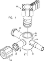
本発明の好適な実施形態に従って構成されかつ動作する活栓の組立分解図である図1を参照する。図1に見られるように、活栓は、参照番号14、16及び18によってそれぞれ示される主管状部12と3つの側面ポートとを含むハウジング要素10を具備する。取っ手要素20は、ハウジング要素10の主管状部12内に位置付けられて配列される。一般的なネジ付きプラグ23は、側面ポート16に接続されるようになっている。
Reference is made to FIG. 1, which is an exploded view of a stopcock constructed and operative in accordance with a preferred embodiment of the present invention. As seen in FIG. 1, the stopcock includes a
ハウジング要素10の絵画図である図2と図3、及びハウジング要素10の断面図である図4Aと図4Bをさらに参照する。図1〜図4Bに見られるように、ハウジング要素10の管状部12は、概ね円筒状であり、軸線22を中心に配列され、軸線から異なる方向に延在し、一般的に軸線22を中心に90度で分離される側面ポート14、16及び18を有する。ポート14は、好ましくはルエル標準ISO594−1に適合する雄ポートであることが好ましく、一方、ポート16と18は、好ましくはルエル標準ISO594−1に適合する雌ポートであることが好ましい。ポート14、16及び18と関連して、従来のプラグ、ナット及びカバーを使用してもよい。特に、図1〜図3に見られるように、ポート16と密閉係合するように配列されるネジ付きプラグ23が示されている。管状部分12は、周方向アンダカット26で形成される僅かに円錐形の形態を有する中心孔24を包含する。ポート16は内部容積25を画定する。
Further reference is made to FIGS. 2 and 3 which are pictorial views of the
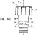
取っ手要素20を示す図5A〜図8Bを参照する。図5A〜図8Bに見られるように、取っ手要素は、頂部32と一体形成されるシャフト部分30を含み、指状の係合可能な突出部34が頂部32から延伸している。取っ手要素の頂部のその他のどのような適切で一般的な形態を代替として使用してもよいことが認識される。
Reference is made to FIGS. 5A-8B showing the
シャフト部分30は、シャフト軸線42を中心に概ね対称であり、3〜4度の(特に図6Aに見られるような)角度αを一般的に有する僅かに円錐形の外面44を有し、それは、シャフト部分との回転可能な密閉係合のための中心孔24の僅かに円錐形の外形に対応する。特に、図8Aと図8Bに見られるように、シャフト部分30は、一般的に相互に密閉される頂部及び底部の円筒状凹部46と48とで形成され、これらの凹部は仕切り50によって密閉して分離される。
The
概ね凹部46と48との間に配置され凹部46と48とから密閉される、部分的に周縁に延在する凹部52は、ハウジング要素10に対する取っ手要素20の回転方向に依存する、側面ポート14、16と18の内の選択可能な側面ポートの間で、選択可能に流体流の通路を画定する。好ましくは半径方向に延在し、部分的に凹部52を分岐させる流体流ガイド54は、取っ手要素20が適切に位置決めされたときに、ポート16の内部容積25のフラッシングのために、凹部52によって画定される通路を介して、ポート14と18の間の液体の流れを内部容積25に向ける。流体流ガイド54の半径方向に外向きの縁部56は、凹状の外形を備えて形成される。
A
5つの動作方向における、図1の活栓の単純化した絵画図である図9A、図9B、図9C、図9D及び図9Eと、図9A、図9B、図9C、図9D及び図9Eのそれぞれの活栓の断面図である図10A、図10B、図10C、図10D及び図10Eとを参照する。 9A, 9B, 9C, 9D, and 9E, and FIGS. 9A, 9B, 9C, 9D, and 9E, respectively, are simplified pictorial views of the stopcock of FIG. 1 in five directions of operation. 10A, FIG. 10B, FIG. 10C, FIG. 10D, and FIG.
図9Aと図10Aは、ポート16がネジ付きプラグ23によって密閉されるときの、図1の活栓の第1動作位置を示している。使用者は一般的に、IVセットのような加圧流体源をポート18に接続し、液体は、矢印60で示されるように、ポート18と部分的に周縁に延在する凹部52とを介し、流体流ガイド54の凹状縁部56を通過し、ポート14を経由して患者に流れる。
9A and 10A show the first operating position of the stopcock of FIG. 1 when the
図9Bと図10Bは、患者から血液又は他の流体を抜き取るために、一般的に使用される図1の活栓の第2動作位置を示している。使用者は一般的に、注射器(示されていない)をポート16に接続し、矢印62で示されるように、患者からポート14と部分的に周縁に延在する凹部52とを介し、ポート16を通して注射器に血液を抜き取る。ポート18が閉鎖しているときに、矢印62で示された方向と反対の流れ方向で医薬品を患者に供給するために、この動作位置をまた使用してもよいことが認識される。
9B and 10B show a second operating position of the stopcock of FIG. 1 that is commonly used to draw blood or other fluid from a patient. The user typically connects a syringe (not shown) to
図9Cと図10Cは、ポート16が二次管路(示されていない)に開口しているか又は接続されているときに、医薬品を患者に供給するために一般的に使用される、図1の活栓の第3動作位置を示している。二次管路が医薬品の供給源でもよい。医薬品は、矢印63で示されるように、ポート16と部分的に周縁に延在する凹部52とを介して、ポート16を通って患者に流れる。同時に、液体は、矢印64で示されるように、ポート18と部分的に周縁に延在する凹部52とを経由し、流体流ガイド54を回って、ポート16の内部容積25の中に僅かに入り、ポート14を経由して患者に流れる。
9C and 10C are commonly used to deliver medication to a patient when the
図9Dと図10Dは、ポート16がネジ付きプラグ23によって密閉されるときに、ポート18からポート14へ液体を患者に供給するために一般的に使用される、図1の活栓の第4動作位置を示している。液体は、矢印66で示されるように、ポート18と部分的に周縁に延在する凹部52とを経由し、流体流ガイド54を回って、ポート16の内部容積25の中に入り、内部容積から残留液体をフラッシングし、ポート14を経由して患者に流れる。
9D and 10D show a fourth operation of the stopcock of FIG. 1 that is typically used to supply fluid from
本発明の特徴は、流体流ガイド54の提供により、ポート16の内部容積25に留まる残余の液体の存在の問題が概ね克服されることである。このことは、様々な治療状態で重要である。例えば血液がポート16を介して患者から抜き取られるときに、ポート16の内部容積25に留まる残余の血液がある。この血液は、ある時間の間内部容積25に残った場合に、凝固し、従って患者に供給されると危険となる可能性がある。さらに、凝固した血液は、ポート16を介して延在する液体通路を塞ぐことがあるだろう。残留する血液の結果として、様々な感染がおそらく生じることがあるだろう。
A feature of the present invention is that provision of a fluid flow guide 54 generally overcomes the problem of the presence of residual liquid remaining in the
この特徴はまた、医薬品がポート16を介して患者に供給される場合に有用である。医薬品の一部がポート16の内部容積25に留まると、患者が受け取る医薬品の投与量は、容易に確かめることができない量だけ、意図する投与量よりも少なくなる。さらに、この残余の医薬品は、活栓の引き続く使用の間、患者に不注意で供給されるかもしれず、このことは、患者に害を及ぼすこととなるであろう。
This feature is also useful when medication is delivered to the patient via
本発明は、内部容積25から血液又は医薬品のような液体を自動的にフラッシングし、一般的に、余分な注射器の使用を必要とすること、ネジ付きプラグ23の操作、及び汚染の機会を増大するであろう医療セットを雰囲気中に開放することなしに、液体を患者に戻すことを可能にする。
The present invention automatically flushes fluids such as blood or pharmaceuticals from the
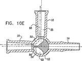
図9Eと図10Eは、ポート16が雰囲気中に開放される時に、活栓の上流のIVセットをフラッシングするために使用可能な図1の活栓の第5動作位置を示している。液体は、矢印68で示されるように、ポート18を経由し、流体流ガイド54を回って、部分的に周縁に延在する凹部52を介し、ポート16を経由して雰囲気中に流れる。代替として、例えば圧力バッグ内の液体を混合することが望ましい場合に、側面ポート16を経由し、ポート18を介して矢印68と反対の方向に液体を押圧するために、この動作位置を使用してもよい。
FIGS. 9E and 10E show a fifth operating position of the stopcock of FIG. 1 that can be used to flush the IV set upstream of the stopcock when the
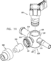
本発明の好適な実施形態に従って構成されかつ動作する活栓の組立分解図である図11を参照する。図11に見られるように、活栓は、主管状部112と、参照番号114、116及び118によってそれぞれ示される3つの側面ポートとを包含するハウジング要素110を備える。取っ手要素120は、ハウジング要素110の主管状部分112内に設置されるように配列される。
Reference is made to FIG. 11, which is an exploded view of a stopcock constructed and operative in accordance with a preferred embodiment of the present invention. As seen in FIG. 11, the stopcock includes a
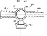
ハウジング要素110の絵画図である図12と図13、及びハウジング要素110の断面図である図14Aと図14Bをさらに参照する。図11〜図14Bに見られるように、ハウジング要素110の管状部分112は、概ね円筒状であり、軸線122を中心に配列され、軸線122を中心に一般的に90度の角度で分離される、互いに異なる方向に延在する側面ポート114、116及び118を有する。ポート114は、好ましくはルエル標準ISO594−1に適合する雄ポートであることが好ましく、一方、ポート116は、雄ルエルを受容するように形成されるノーマルクローズの清掃可能な弁を組み込み、ポート118は、好ましくはルエル標準ISO594−1に適合する雌ポートであることが好ましい。ポート114と118とに関連して、従来のプラグ、ナット及びカバーを使用してもよい。
Further reference is made to FIGS. 12 and 13, which are pictorial views of
ハウジング要素110のポート116は、ハウジング要素110に溶接されるか、さもなければ固定されるキャップ124によって所定の場所に保持されるエラストマ要素123を使用する弁を包含する。エラストマ要素123及びキャップ124は、サンペテルブルグ、フロリダ、米国のハルキー・ロバーツ株式会社(Halkey-Roberts Corporation)から商業的に入手可能であり、特許文献5、特許文献6及び特許文献7の1つ以上に記載されており、それらの開示は参照によって本出願に組み込まれている。代替として、ベクトン・ディキンソン、カーディナル、メデゲン及びフィルタテク(Becton-Dickinson, Cardinal,Medegen and Filtertek)のような他のソースから商業的に入手可能な弁及び弁要素を使用してもよい。
The
管状部分112は、周方向アンダカット126で形成される僅かに円錐形の外形を有する中心孔125を包含する。ポート116は内部容積127を画定する。
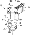
取っ手要素120を示す図15A〜図18Bを参照する。図15A〜図18Bに見られるように、取っ手要素は、頂部132と一体形成されるシャフト部分130を包含し、指状の係合可能な突出部134が頂部132から延伸する。取っ手要素の頂部のその他のいかなる適切な一般的な外形が代替として使用されてもよいことが認識される。
Reference is made to FIGS. 15A-18B
シャフト部分130は、シャフト軸線142を中心に概ね対称であり、3〜4度の(特に図16Aに見られるような)角度αを一般的に有する僅かに円錐形の外面144を有し、それは、シャフト部分との回転可能な密閉係合のための中心孔125の僅かに円錐形の外形に対応する。特に、図18Aと図18Bに見られるように、シャフト部分130は、一般的に、相互に密閉される頂部及び底部の円筒状凹部146と148で形成され、これらの凹部は仕切り150によって密閉して分離される。
The
概ね凹部146と148との間に配置され凹部146と148から密閉される、部分的に周縁に延在する凹部152は、ハウジング要素110に対する取っ手要素120の回転方向に依存する、側面ポート114、116と118の内の選択可能な側面ポートの間で、選択可能に流体流通路を画定する。好ましくは半径方向に延在し、部分的に凹部152を分岐させる流体流ガイド154は、取っ手要素120が適切に位置決めされたときに、ポート116の内部容積127のフラッシングのために、凹部152によって画定される通路を介してポート114と118の間の液体の流れを内部容積127に向ける。流体流ガイド154の半径方向に外向きの縁部156は、凹状の外形を備えて形成される。
A laterally extending
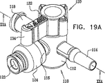
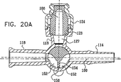
4つの動作方向における図11の活栓の単純化した絵画図である図19A、図19B、図19C及び図19Dと、図19A、図19B、図19C及び図19Dのそれぞれの活栓の断面図である図20A、図20B、図20C及び図20Dとを参照する。 19A, 19B, 19C and 19D, which are simplified pictorial views of the stopcock of FIG. 11 in four directions of operation, and cross-sectional views of the stopcocks of FIGS. 19A, 19B, 19C and 19D, respectively. Reference is made to FIGS. 20A, 20B, 20C, and 20D.
図19Aと図20Aは、図11の活栓の第1動作位置を示している。使用者は一般的に、IVセットのような加圧流体源をポート118に接続し、液体は、矢印160で示されるように、ポート118と部分的に周縁に延在する凹部152とを介し、流体流ガイド154の凹状縁部156を通過し、ポート114を経由して患者に流れる。
19A and 20A show the first operating position of the stopcock of FIG. The user typically connects a pressurized fluid source, such as an IV set, to the
図19Bと図20Bは、患者から血液又は他の流体を抜き取るために、一般的に使用される図11の活栓の第2動作位置を示している。使用者は一般的に、注射器をポート116に接続し、矢印162で示されるように、患者からポート114と部分的に周縁に延在する凹部152とを介し、ポート116を通して注射器に血液を抜き取る。ポート118が閉鎖しているときに、矢印162で示された方向と反対の流れ方向で医薬品を患者に供給するために、この動作位置をまた使用してもよいことが認識される。
19B and 20B show a second operational position of the stopcock of FIG. 11 that is commonly used to draw blood or other fluid from a patient. The user typically connects the syringe to
図19Cと図20Cは、ポート118からポート114へ液体を患者に供給するために一般的に使用される、図1の活栓の第3動作位置を示している。液体は、矢印164で示されるように、ポート118と部分的に周縁に延在する凹部152とを経由し、流体流ガイド154を回って、ポート116の内部容積127ならびにエラストマ要素123の内部容積166の中に入り、それらの内部容積から残留液をフラッシングし、ポート114を経由して患者に流れる。
19C and 20C show a third operating position of the stopcock of FIG. 1 that is commonly used to supply liquid from
本発明の特徴は、流体流ガイド154の提供により、ポート116の内部容積127ならびにエラストマ要素123の内部容積166に留まる残余の液体の存在の問題が、概ね克服されることである。このことは、様々な治療状態で重要である。例えば血液がポート116を介して患者から抜き取られるときに、ポート116の内部容積127とエラストマ要素123の内部容積166とに留まる残余の血液がある。この血液は、ある時間の間内部容積127と166とに残った場合に、凝固し、従って、患者に供給されると危険となる可能性がある。さらに、凝固した血液は、ポート116を介して延在する液体通路を塞ぐことがあるだろう。残留する血液の結果として、様々な感染がおそらく生じることがあるだろう。
A feature of the present invention is that provision of
この特徴はまた、医薬品がポート116を介して患者に供給される場合に有用である。医薬品の一部がエラストマ要素123のポート116と166の内部容積127に留まると、患者が受け取る医薬品の投与量は、容易に確かめることができない量だけ、意図する投与量よりも少なくなる。さらに、この残余の医薬品は、活栓の引き続く使用の間、患者に不注意で供給されるかもしれず、このことは、患者に害を及ぼすこととなるであろう。
This feature is also useful when medication is delivered to the patient via
本発明は、内部容積127と166から血液又は医薬品のような液体を自動的にフラッシングし、一般的に、余分な注射器の使用を必要とすること、及び医療セットを雰囲気中に開放してこれにより汚染の機会を増大することなしに、液体を患者に戻すことを可能にする。
The present invention automatically flushes liquids such as blood or pharmaceuticals from the
図19Dと図20Dは、ポート116が、弁のエラストマ要素123に注射器先端(示されていない)のような雄ルエルコネクタを挿入することによって雰囲気中に開放されるときに、活栓の上流のIVセットをフラッシングするために使用可能な、図11の活栓の第4動作位置を示す。雄ルエルコネクタの挿入により、矢印165で示されるように、ポート118からの液体は、流体流ガイド154を回り、部分的に周縁に延在する凹部152を介し、ポート116のエラストマ要素123を経由して雄ルエルネクタに流れるようにされる。代替として、例えば圧力バッグ内の液体を混合することが望ましい場合に、側面ポート116を経由し、ポート118を介して矢印165と反対の方向に液体を押圧するために、この動作位置を使用してもよい。
19D and 20D show that when the
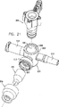
本発明の好適な実施形態に従って構成されかつ動作する活栓の組立分解図である図21を参照する。図21に見られるように、活栓は、主管状部212と、参照番号214、216及び218によってそれぞれ示される3つの側面ポートとを包含するハウジング要素210を備える。取っ手要素220は、ハウジング要素210の主管状部212内に設置されるように配列される。
Reference is made to FIG. 21, which is an exploded view of a stopcock constructed and operative in accordance with a preferred embodiment of the present invention. As seen in FIG. 21, the stopcock includes a
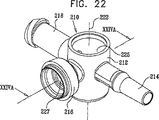
ハウジング要素210の絵画図である図22と図23、及びハウジング要素210の断面図である図24Aと図24Bをさらに参照する。図21〜図24Bに見られるように、ハウジング要素210の管状部212は、概ね円筒状であり、軸線222を中心に配列され、軸線222を中心に一般的に90度の角度で分離される、互いに異なる方向に延在する側面ポート214、216及び218を有する。ポート214は、好ましくはルエル標準ISO594−1に適合する雄ポートであることが好ましく、一方、ポート216は、雄ルエルを受容するように形成されるノーマルクローズの清掃可能な弁を組み込み、ポート218は、好ましくはルエル標準ISO594−1に適合する雌ポートであることが好ましい。ポート214と218とに関連して、従来のプラグ、ナット及びカバーを使用してもよい。
Further reference is made to FIGS. 22 and 23, which are pictorial views of the
ハウジング要素210のポート216は、ハウジング要素110に溶接されるか、さもなければ固定されるキャップ224によって所定の場所に保持されるエラストマ要素223を使用する弁を包含する。エラストマ要素123及びキャップ124は、サンペテルブルグ、フロリダ、米国のハルキー・ロバーツ株式会社(Halkey-Roberts Corporation)から商業的に入手可能であり、特許文献5、特許文献6及び特許文献7の1つ以上に記載されており、それらの開示は参照によって本出願に組み込まれている。代替として、ベクトン・ディキンソン、カーディナル、メデゲン及びフィルタテク(Becton-Dickinson, Cardinal,Medegen and Filtertek)のような他のソースから商業的に入手可能な弁及び弁要素を使用してもよい。
The
管状部分212は、周方向アンダカット226で形成される僅かに円錐形の外形を有する中心孔225を包含する。ポート216は内部容積227を画定する。
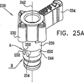
取っ手要素220を示す図25A〜図28Bを参照する。図25A〜図28Bに見られるように、取っ手要素は、頂部232と一体形成されるシャフト部分230を包含し、指状の係合可能な突出部234が頂部232から延伸する。取っ手要素の頂部のその他のいかなる適切な一般的な外形が代替として使用されてもよいことが認識される。
Reference is made to FIGS. 25A-28B
シャフト部分230は、シャフト軸線242を中心に概ね対称であり、3〜4度の(特に図26Aに見られるような)角度αを一般的に有する僅かに円錐形の外面244を有し、それは、シャフト部分との回転可能な密閉係合のための中心孔225の僅かに円錐形の外形に対応する。特に、図28Aと図28Bに見られるように、シャフト部分230は、一般的に、相互に密閉される頂部及び底部の円筒状凹部246と248で形成され、これらの凹部は仕切り250によって密閉して分離される。
The
概ね凹部246と248との間に配置され凹部246と248から密閉される、部分的に周縁に延在する凹部252は、ハウジング要素210に対する取っ手要素220の回転方向に依存する、側面ポート214、216及び218の内の選択可能な側面ポートの間で、選択可能に流体流通路を画定する。好ましくは半径方向に延在し、部分的に凹部252を分岐させる流体流ガイド254は、取っ手要素220が適切に位置決めされたときに、ポート216の内部容積227のフラッシングのために、凹部252によって画定される通路を介してポート214と218の間の液体の流れを内部容積227に向ける。流体流ガイド254の半径方向に外向きの縁部256は、流体流ガイド254がポートの反対側に配置されない場合に、流体流ガイドを通過する液体流を妨げるために適切な先細り外形に形成される。
A laterally extending
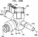
4つの動作方向における図21の活栓の単純化した絵画図である図29A、図29B、図29C及び図29Dと、図29A、図29B、図29C及び図29Dのそれぞれの活栓の断面図である図30A、図30B、図30C及び図30Dとを参照する。 FIGS. 29A, 29B, 29C, and 29D are cross-sectional views of the stopcocks of FIGS. 29A, 29B, 29C, and 29D, and FIGS. 29A, 29B, 29C, and 29D, respectively. Reference is made to FIGS. 30A, 30B, 30C, and 30D.
図29Aと図30Aは、図21の活栓の第1動作位置を示している。見られるように、ポートのいずれの間にも流体連通はない。液体は、ポート218からポート214に流れないが、この理由は、流体流ガイド254の縁部256が、ハウジング要素210の孔225の内部対面壁257と密閉係合し、液体がこの流体流ガイドによって遮断されるからである。すべての3つのポートを閉鎖するために、この方向を利用してもよい。
29A and 30A show the first operating position of the stopcock of FIG. As can be seen, there is no fluid communication between any of the ports. Liquid does not flow from
活栓を介する全ての液体の流れを妨げることが望ましい場合に、図29Aと図30Aに示した動作方向を有利に使用してもよい。現在使用されている手順は、取っ手をポートの1つから45度の角度で慎重に配置することを必要とする。このような手順は、信頼性に欠け、また手術の中心にいる医者又は看護婦であるかもしれない操作者の、慎重な注意を必要とする。 If it is desired to block all liquid flow through the stopcock, the direction of motion shown in FIGS. 29A and 30A may be advantageously used. Currently used procedures require the handle to be carefully placed at a 45 degree angle from one of the ports. Such a procedure is unreliable and requires the careful attention of an operator who may be a doctor or nurse at the heart of the operation.
図29Bと図30Bは、患者から血液又は他の流体を抜き取るために、一般的に使用される図21の活栓の第2動作位置を示している。使用者は一般的に、注射器をポート216に接続し、矢印262で示されるように、患者からポート214と部分的に周縁に延在する凹部252とを介して、ポート216を通って注射器に血液を抜き取る。ポート218が閉鎖しているときに、矢印262で示された方向と反対の流れ方向で医薬品を患者に供給するために、この動作位置をまた使用してもよいことが認識される。
FIGS. 29B and 30B show a second operating position of the stopcock of FIG. 21 that is commonly used to draw blood or other fluid from a patient. The user typically connects the syringe to
図29Cと図30Cは、ポート218からポート214へ液体を患者に供給するために一般的に使用される、図1の活栓の第3動作位置を示している。液体は、矢印264で示されるように、ポート218と部分的に周縁に延在する凹部252とを経由し、流体流ガイド254を回って、ポート216の内部容積227ならびにエラストマ要素223の内部容積266の中に入り、それらの内部容積から残留液をフラッシングし、ポート214を経由して患者に流れる。
FIGS. 29C and 30C show a third operating position of the stopcock of FIG. 1 that is commonly used to supply liquid from
本発明の特徴は、流体流ガイド254の提供により、ポート216の内部容積227ならびにエラストマ要素223の内部容積266に留まる残余の液体の存在の問題が、概ね克服されることである。このことは、様々な治療状態で重要である。例えば血液がポート216を介して患者から抜き取られるときに、ポート216の内部容積227とエラストマ要素223の内部容積266とに留まる残余の血液がある。この血液は、ある時間の間内部容積227と266に残った場合に、凝固し、従って、患者に供給されると危険となる可能性がある。さらに、凝固した血液は、ポート216を介して延在する液体通路を塞ぐことがあるだろう。残留する血液の結果として、様々な感染がおそらく生じることがあるだろう。
A feature of the present invention is that provision of the
この特徴はまた、医薬品がポート216を介して患者に供給される場合に有用である。医薬品の一部がエラストマ要素223のポート216と266の内部容積227に留まると、患者が受け取る医薬品の投与量は、容易に確かめることができない量だけ、意図する投与量よりも少なくなる。さらに、この残余の医薬品は、活栓の引き続き使用の間、患者に不注意で供給されるかもしれず、このことは、患者に害を及ぼすこととなるであろう。
This feature is also useful when medication is delivered to the patient via
本発明は、内部容積227と266から血液又は医薬品のような液体を自動的にフラッシングし、一般的に、余分な注射器の使用を必要とすること、及び医療セットを雰囲気中に開放してこれにより汚染の機会を増大することなしに、液体を患者に戻すことを可能にする。
The present invention automatically flushes liquids such as blood or pharmaceuticals from the
図29Dと図30Dは、ポート216が、弁のエラストマ要素223に注射器先端(示されていない)のような雄ルエルコネクタの挿入することによって雰囲気中に開放されるときに、活栓の上流のIVセットをフラッシングするために使用可能な、図21の活栓の第4動作位置を示す。雄ルエルコネクタの挿入により、矢印265で示されるように、ポート218からの液体は、流体流ガイド254を回って、部分的に周縁に延在する凹部252を介し、ポート216のエラストマ要素223を経由して雄ルエルネクタに流れるようにされる。代替として、圧力バッグ内の液体を混合するような用途のために、側面ポート216を経由し、ポート18を介して矢印265と反対の方向に液体を押圧するために、この動作位置を使用してもよい。
29D and 30D show that when the
本発明の好適な実施形態に従って構成されかつ動作する活栓の組立分解図である図31を参照する。図31に見られるように、活栓は、主管状部312と、参照番号314、316及び318によってそれぞれ示される3つの側面ポートとを包含するハウジング要素310を備える。取っ手要素320は、ハウジング要素310の主管状部312内に設置されるように配列される。
Reference is made to FIG. 31, which is an exploded view of a stopcock constructed and operative in accordance with a preferred embodiment of the present invention. As seen in FIG. 31, the stopcock includes a
ハウジング要素310の絵画図である図32と図33、及びハウジング要素310の断面図である図34Aと図34Bをさらに参照する。図31〜図34Bに見られるように、ハウジング要素310の管状部312は、概ね円筒状であり、軸線322を中心に配列され、軸線322を中心に一般的に90度の角度で分離される、互いに異なる方向に延在する側面ポート314、316及び318を有する。ポート314は、好ましくはルエル標準ISO594−1に適合する雄ポートであることが好ましく、一方、ポート316は、雄ルエルを受容するように形成されるノーマルクローズの清掃可能な弁を組み込み、ポート318は、好ましくはルエル標準ISO594−1に適合する雌ポートであることが好ましい。ポート314と318とに関連して、従来のプラグ、ナット及びカバーを使用してもよい。
Further reference is made to FIGS. 32 and 33, which are pictorial views of the
ハウジング要素310のポート316は、ハウジング要素310に溶接されるか、さもなければ固定されるキャップ324によって所定の場所に保持されるエラストマ要素323を使用する弁を包含する。エラストマ要素323及びキャップ324は、サンペテルブルグ、フロリダ、米国のハルキー・ロバーツ株式会社(Halkey-Roberts Corporation)から商業的に入手可能であり、特許文献5、特許文献6及び特許文献7の1つ以上に記載されており、それらの開示は参照によって本出願に組み込まれている。代替として、ベクトン・ディキンソン、カーディナル、メデゲン及びフィルタテク(Becton-Dickinson, Cardinal,Medegen and Filtertek)のような他のソースから商業的に入手可能な弁及び弁要素を使用してもよい。
The
管状部分312は、周方向アンダカット326で形成される僅かに円錐形の外形を有する中心孔325を包含する。本実施形態において、側面凹部327は、ポート316の反対側の孔325の壁部に形成される。ポート316は内部容積328を画定する。
取っ手要素320を示す図35A〜図38Bを参照する。図35A〜図38Bに見られるように、取っ手要素は、頂部332と一体形成されるシャフト部分330を包含し、指状の係合可能な突出部334が頂部332から延伸する。取っ手要素の頂部のその他のいかなる適切な一般的な外形が代替として使用されてもよいことが認識される。
Reference is made to FIGS. 35A-38B
シャフト部分330は、シャフト軸線342を中心に概ね対称であり、3〜4度の(特に図36Aに見られるような)角度αを一般的に有する僅かに円錐形の外面344を有し、それは、シャフト部分との回転可能な密閉係合のための中心孔325の僅かに円錐形の外形に対応する。特に、図38Aと図38Bに見られるように、シャフト部分330は、一般的に、相互に密閉される頂部及び底部の円筒状凹部346と348で形成され、これらの凹部は仕切り350によって密閉して分離される。
The
部分的に周縁に延在する凹部352は、概ね凹部346と348との間に配置され凹部346と348から密閉される。好ましくは半径方向に延在し、部分的に凹部352を分岐させる流体流ガイド354は、取っ手要素320が適切に位置決めされたときに、ポート316の内部容積328のフラッシングのために、凹部352によって画定される通路を介してポート314と318の間の液体の流れを内部容積328に向ける。流体流ガイド354の厚さは、側面凹部327の周方向長さよりもほぼ短い。流体流ガイド354の半径方向に外向きの縁部356は、流体流ガイド354がポートの反対側に配置されない場合に、流体流ガイドを通過する液体流を妨げるために適切な先細り外形に形成される。
A
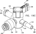
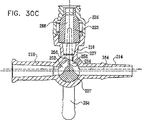
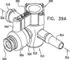
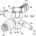
4つの動作方向における図31の活栓の単純化した絵画図である図39A、図39B、図39C及び図39Dと、図39A、図39B、図39C及び図39Dのそれぞれの活栓の断面図である図40A、図40B、図40C及び図40Dとを参照する。 FIGS. 39A, 39B, 39C, and 39D are cross-sectional views of the stopcocks of FIGS. 39A, 39B, 39C, and 39D, and FIG. 39A, FIG. 39B, FIG. 39C, and FIG. Reference is made to FIGS. 40A, 40B, 40C and 40D.
図39Aと図40Aは、図31の活栓の第1動作位置を示している。使用者は一般的に、IVセットのような加圧流体源をポート318に接続し、液体は、矢印60で示されるように、ポート318から、流体流ガイド354を回って、側面凹部327を介してポート314に流れる。
39A and 40A show the first operating position of the stopcock of FIG. A user typically connects a pressurized fluid source, such as an IV set, to port 318, and the liquid, from the
図39Bと図40Bは、患者から血液又は他の流体を抜き取るために、一般的に使用される図31の活栓の第2動作位置を示している。使用者は一般的に、注射器をポート316に接続し、矢印362で示されるように、患者からポート314と部分的に周縁に延在する凹部352とを介し、ポート316を通して注射器に血液を抜き取る。ポート318が閉鎖しているときに、矢印362で示された方向と反対の流れ方向で医薬品を患者に供給するために、この動作位置をまた使用してもよいことが認識される。
39B and 40B show a second operating position of the stopcock of FIG. 31 that is commonly used to draw blood or other fluid from a patient. The user typically connects the syringe to
図39Cと図40Cは、ポート318からポート314へ液体を患者に供給するために一般的に使用される、図31の活栓の第3動作位置を示している。液体は、矢印364で示されるように、ポート318と部分的に周縁に延在する凹部352とを経由し、流体流ガイド354を回って、ポート316の内部容積328ならびにエラストマ要素323の内部容積366の中に入り、それらの内部容積から残留液をフラッシングし、ポート314を経由して患者に流れる。
FIGS. 39C and 40C show a third operational position of the stopcock of FIG. 31 that is typically used to supply liquid from
本発明の特徴は、流体流ガイド354の提供により、ポート316の内部容積328ならびにエラストマ要素323の内部容積366に留まる残余の液体の存在の問題が、概ね克服されることである。このことは、様々な治療状態で重要である。例えば血液がポート316を介して患者から抜き取られるときに、ポート316の内部容積328及びエラストマ要素323の内部容積366に留まる残余の血液がある。この血液は、ある時間の間内部容積328と366に残った場合に、凝固し、従って、患者に供給されると危険となる可能性がある。さらに、凝固した血液は、ポート316を介して延在する液体通路を塞ぐことがあるだろう。残留する血液の結果として、様々な感染がおそらく生じることがあるだろう。
A feature of the present invention is that provision of the
この特徴はまた、医薬品がポート316を介して患者に供給される場合に有用である。医薬品の一部がポート316の内部容積328とエラストマ要素323の内部容積366とに留まると、患者が受け取る医薬品の投与量は、容易に確かめることができない量だけ、意図する投与量よりも少なくなる。さらに、この残余の医薬品は、活栓の引き続く使用の間、患者に不注意で供給されるかもしれず、このことは、患者に害を及ぼすこととなるであろう。
This feature is also useful when medication is delivered to the patient via
本発明は、内部容積328と366から血液又は医薬品のような液体を自動的にフラッシングし、一般的に、余分な注射器の使用を必要とすること、及び医療セットを雰囲気中に開放してこれにより汚染の機会を増大することなしに、液体を患者に戻すことを可能にする。
The present invention automatically flushes liquids such as blood or pharmaceuticals from the
図39Dと図40Dは、ポート316が、弁のエラストマ要素323に注射器先端(示されていない)のような雄ルエルコネクタを挿入することによって雰囲気中に開放されるときに、活栓の上流のIVセットをフラッシングするために使用可能な、図31の活栓の第4動作位置を示す。雄ルエルコネクタの挿入により、矢印365で示されるように、ポート318からの液体は、流体流ガイド354を回り、部分的に周縁に延在する凹部352を介し、ポート316のエラストマ要素323を経由して雄ルエルネクタに流れるようにされる。代替として、圧力バッグ内の液体を混合するような用途のために、側面ポート316を経由し、ポート318を介して矢印365と反対の方向に液体を押圧するために、この動作位置を使用可能してもよい。
39D and 40D show that when the
本発明の好適な実施形態に従って構成されかつ動作する活栓の組立分解図である図41を参照する。図41に見られるように、活栓は、主管状部412と、参照番号414、416及び418によってそれぞれ示される3つの側面ポートとを包含するハウジング要素410を備える。取っ手要素420は、ハウジング要素410の主管状部412内に設置されるように配列される。
Reference is made to FIG. 41, which is an exploded view of a stopcock constructed and operative in accordance with a preferred embodiment of the present invention. As seen in FIG. 41, the stopcock includes a
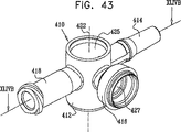
ハウジング要素410の絵画図である図42と図43、及びハウジング要素410の断面図である図44Aと図44Bをさらに参照する。図41〜図44Bに見られるように、ハウジング要素410の管状部412は、概ね円筒状であり、軸線422を中心に配列され、軸線422を中心に一般的に90度の角度で分離される、互いに異なる方向に延在する側面ポート414、416と418を有する。ポート414は、好ましくはルエル標準ISO594−1に適合する雄ポートであることが好ましく、一方、ポート416は、雄ルエルを受容するように形成されるノーマルクローズの清掃可能な弁を組み込み、ポート418は、好ましくはルエル標準ISO594−1に適合する雌ポートであることが好ましい。ポート414と418とに関連して、従来のプラグ、ナット及びカバーを使用してもよい。
Further reference is made to FIGS. 42 and 43, which are pictorial views of the
ハウジング要素410のポート416は、ハウジング要素410に溶接されるか、さもなければ固定されるキャップ424によって所定の場所に保持されたエラストマ要素423を使用する弁を包含する。エラストマ要素423及びキャップ424は、サンペテルブルグ、フロリダ、米国のハルキー・ロバーツ株式会社(Halkey-Roberts Corporation)から商業的に入手可能であり、特許文献5、特許文献6及び特許文献7の1つ以上に記載されており、それらの開示は参照によって本出願に組み込まれている。代替として、ベクトン・ディキンソン、カーディナル、メデゲン及びフィルタテク(Becton-Dickinson, Cardinal,Medegen and Filtertek)のような他のソースから商業的に入手可能な弁及び弁要素を使用してもよい。
The
管状部分412は、周方向アンダカット426で形成される僅かに円錐形の外形を有する中心孔425を包含する。ポート416は内部容積427を画定する。
取っ手要素420を示す図45A〜図48Bを参照する。図45A〜図48Bに見られるように、取っ手要素は、頂部432と一体形成されるシャフト部分430を包含し、指状の係合可能な突出部434が頂部432から延伸する。取っ手要素の頂部のその他のいかなる適切な一般的な外形が代替として使用されてもよいことが認識される。
Reference is made to FIGS. 45A-48B
シャフト部分430は、シャフト軸線442を中心に概ね対称であり、3〜4度の(特に図46Aに見られるような)角度αを一般的に有する僅かに円錐形の外面444を有し、それは、シャフト部分との回転可能な密閉係合のための中心孔425の僅かに円錐形の外形に対応する。特に、図48Aと図48Bに見られるように、シャフト部分430は、一般的に、相互に密閉される頂部及び底部の円筒状凹部446と448で形成され、これらの凹部は仕切り450によって密閉して分離される。
The
側部から側部に延在する孔452が、概ね凹部446と448との間に配置され凹部446と448から密閉されていて、側面孔453が孔452に対し直角に延びて孔452と連通する。孔452及び側面孔453は、孔452の両端部の間の流体連通が側面孔453を経由して行われるように、流体流ガイド454によって分岐させられる。孔452と453と流体流ガイド454とは、ハウジング要素410に対する取っ手要素420の回転方向に依存する、側面ポート414、416及び418の選択可能な側面ポートの間で流体流通路を画定する。流体流ガイド454は、取っ手要素420が適切に位置決めされたときに、内部容積427のフラッシングのために、孔452と453を介してポート416の内部容積427内に、ポート414と418の間の液体の流れを向ける。流体流ガイド454の半径方向に外向きの縁部456は、流体流ガイド454が、図45Aに示されるようなポートの反対側に配置されない場合に、流体流ガイドを通過する液体流を妨げるために適切な先細り外形で形成されるが、代替として、外向きの縁部は、その他の多くの形状を有してもよい。
A
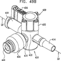
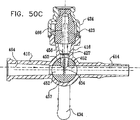
4つの動作方向における図41の活栓の単純化した絵画図である図49A、図49B、図49C及び図49Dと、図49A、図49B、図49C及び図49Dのそれぞれの活栓の断面図である図50A、図50B、図50C及び図50Dとを参照する。 FIGS. 49A, 49B, 49C, and 49D are cross-sectional views of the stopcocks of FIGS. 49A, 49B, 49C, and 49D, and FIGS. 49A, 49B, 49C, and 49D, respectively. Reference is made to FIGS. 50A, 50B, 50C, and 50D.
図49Aと図50Aは、図41の活栓の第1動作位置を示している。見られるように、ポートのいずれの間にも流体連通はない。液体は、ポート418からポート414に流れないが、この理由は、流体流ガイド454の縁部456が、ハウジング要素410の孔425の内部対面壁457と密閉係合するからである。すべての3つのポートを閉鎖するために、この方向を利用してもよい。
49A and 50A show the first operating position of the stopcock of FIG. As can be seen, there is no fluid communication between any of the ports. Liquid does not flow from
活栓を介する全ての液体の流れを妨げることが望ましい場合に、図49Aと図50Aに示した動作方向を有利に使用してもよい。現在使用されている手順は、取っ手をポートの1つから45度の角度で慎重に配置することを必要とする。このような手順は信頼性に欠け、また手術の中心にいる医者又は看護婦であるかもしれない操作者の、慎重な注意を必要とする。 If it is desired to block all liquid flow through the stopcock, the direction of motion shown in FIGS. 49A and 50A may be advantageously used. Currently used procedures require the handle to be carefully placed at a 45 degree angle from one of the ports. Such a procedure is unreliable and requires careful attention from an operator who may be a doctor or nurse at the heart of the operation.
図49Bと図50Bは、患者から血液又は他の流体を抜き取るために、一般的に使用される図41の活栓の第2動作位置を示している。使用者は一般的に、注射器をポート416に接続し、矢印462で示されるように、患者からポート414及び孔453と452を介し、ポート416を通して注射器に血液を抜き取る。ポート418が閉鎖しているときに、矢印462で示された方向と反対の流れ方向で医薬品を患者に供給するために、この動作位置をまた使用してもよいことが認識される。
49B and 50B show a second operating position of the stopcock of FIG. 41 that is commonly used to draw blood or other fluid from a patient. The user typically connects a syringe to
図49Cと図50Cは、ポート418からポート414へ液体を患者に供給するために一般的に使用される、図41の活栓の第3動作位置を示している。液体は、矢印464で示されるように、ポート418と孔453と452とを経由して、流体流ガイド454を回って、ポート416の内部容積427ならびにエラストマ要素423の内部容積466の中に入り、それらの内部容積から残留液をフラッシングし、ポート414を経由して患者に流れる。
49C and 50C show a third operating position of the stopcock of FIG. 41, which is commonly used to supply liquid from
本発明の特徴は、流体流ガイド454の提供により、ポート416の内部容積427ならびにエラストマ要素423の内部容積466に留まる残余の液体の存在の問題が、概ね克服されることである。このことは、様々な治療状態で重要である。例えば血液がポート416を通して患者から抜き取られるときに、ポート416の内部容積427及びエラストマ要素423の内部容積466に留まる残余の血液がある。この血液は、ある時間の間内部容積427と466とに残された場合に、凝固し、従って、患者に供給されると危険となる可能性がある。さらに、凝固した血液は、ポート416を介して延在する液体通路を塞ぐことがあるだろう。残留する血液の結果として、様々な感染がおそらく生じることがあるだろう。
A feature of the present invention is that provision of
この特徴はまた、医薬品がポート416を通して患者に供給される場合に有用である。医薬品の一部がポート416の内部容積427とエラストマ要素423の内部容積466とに留まると、患者が受け取る医薬品の投与量は、容易に確かめることができない量だけ、意図する投与量よりも少なくなる。さらに、この残余の医薬品は、活栓の引き続き使用の間、患者に不注意で供給されるかもしれず、このことは、患者に害を及ぼすこととなるであろう。
This feature is also useful when medication is delivered to the patient through
本発明は、内部容積427と466から血液又は医薬品のような液体を自動的にフラッシングし、一般的に、余分な注射器の使用を必要とすること、及び医療セットを雰囲気中に開放してこれにより汚染の機会を増大することなしに、液体を患者に戻すことを可能にする。
The present invention automatically flushes liquids such as blood or pharmaceuticals from the
図49Dと図50Dは、ポート416が、弁のエラストマ要素423に注射器先端(示されていない)のような雄ルエルコネクタの挿入することによって雰囲気中に開放されるときに、活栓の上流のIVセットをフラッシングするために使用可能な、図41の活栓の第4動作位置を示す。雄ルエルコネクタの挿入により、矢印465で示されるように、ポート418からの液体は、流体流ガイド454を回って、孔453と452を介し、ポート416のエラストマ要素423を経由して雄ルエルネクタに流れるようにされる。代替として、圧力バッグ内の液体の混合のような用途のために、側面ポート416を経由し、ポート418を介して矢印465と反対の方向に液体を押圧するために、この動作位置を使用してもよい。
49D and 50D show that when the
本発明の好適な実施形態に従って構成されかつ動作する活栓の組立分解図である図51を参照する。図51に見られるように、活栓は、主管状部512と、参照番号514、516と518によってそれぞれ示される3つの側面ポートとを包含するハウジング要素510を備える。取っ手要素520は、ハウジング要素510の主管状部512内に設置されるように配列される。
Reference is made to FIG. 51, which is an exploded view of a stopcock constructed and operative in accordance with a preferred embodiment of the present invention. As seen in FIG. 51, the stopcock comprises a
ハウジング要素510の絵画図である図52と図53、及びハウジング要素510の断面図である図54Aと図54Bをさらに参照する。図51〜図54Bに見られるように、ハウジング要素510の管状部512は、概ね円筒状であり、軸線522を中心に配列され、軸線522を中心に一般的に90度の角度で分離される、互いに異なる方向に延在する側面ポート514、516と518を有する。ポート514は、好ましくはルエル標準ISO594−1に適合する雄ポートであることが好ましく、一方、ポート516は、雄ルエルを受容するように形成されるノーマルクローズの清掃可能な弁を組み込み、ポート518は、好ましくはルエル標準ISO594−1に適合する雌ポートであることが好ましい。ポート514と518と関連して、従来のプラグ、ナット及びカバーを使用してもよい。
Further reference is made to FIGS. 52 and 53, which are pictorial views of
ハウジング要素510のポート516は、ハウジング要素510に溶接されるか、さもなければ固定されるキャップ524によって所定の場所に保持されたエラストマ要素523を使用する弁を包含する。エラストマ要素523及びキャップ524は、サンペテルブルグ、フロリダ、米国のハルキー・ロバーツ株式会社(Halkey-Roberts Corporation)から商業的に入手可能であり、特許文献5、特許文献6及び特許文献7の1つ以上に記載されており、それらの開示は参照によって本出願に組み込まれている。代替として、ベクトン・ディキンソン、カーディナル、メデゲン及びフィルタテク(Becton-Dickinson, Cardinal,Medegen and Filtertek)のような他のソースから商業的に入手可能な弁及び弁要素を使用してもよい。
The
管状部分512は、周方向アンダカット526で形成される僅かに円錐形の構造を有する中心孔525を包含する。孔525とエラストマ要素523との間で、ポート516は流体流ガイド527によって分岐される。ポート516は内部容積528を画定する。
取っ手要素520を示す図55A〜図58Bを参照する。図55A〜図58Bに見られるように、取っ手要素は、頂部532と一体形成されるシャフト部分530を包含し、指状の係合可能な突出部534が頂部532から延伸する。取っ手要素の頂部のその他のいかなる適切な一般的な外形が代替として使用されてもよいことが認識される。
Reference is made to FIGS. 55A-58B
シャフト部分530は、シャフト軸線542を中心に概ね対称であり、3〜4度の(特に図56Aに見られるような)角度αを一般的に有する僅かに円錐形の外面544を有し、それは、シャフト部分との回転可能な密閉係合のための中心孔525の僅かに円錐形の外形に対応する。特に、図58A〜図58Bに見られるように、シャフト部分530は、一般的に、相互に密閉される頂部及び底部の円筒状凹部546と548で形成され、これらの凹部は仕切り550によって密閉して分離される。
The
概ね凹部546と548との間に配置され凹部546と548から密閉される、部分的に周縁に延びる凹部552は、ハウジング要素510に対する取っ手要素520の回転方向に依存する、側面ポート514、516と518の内の選択可能な側面ポートの間で、選択可能に流体流通路を画定する。好ましくは半径方向に延在し、部分的に凹部552を分岐させる流体流ガイド554は、取っ手要素520が適切に位置決めされたときに、ポート516の内部容積528のフラッシングのために、凹部552によって画定される通路を介して、ポート514と518の間の液体の流れを内部容積528に向ける。流体流ガイド554の半径方向に外向きの縁部556は、流体流ガイド554が図55Aに示すようなポートの反対側に配置されない場合に、流体流ガイドを通過する液体流を妨げるために適切な先細り外形で形成されるが、代替として、外向きの縁部が、その他の多くの形状を有してもよい。
A partially peripherally extending
4つの動作方向における、図51の活栓の単純化した絵画図である図59A、図59B、図59C及び図59Dと、図59A、図59B、図59C及び図59Dのそれぞれの活栓の断面図である図60A、図60B、図60C及び図60Dとを参照する。 FIG. 59A, FIG. 59B, FIG. 59C and FIG. 59D, which are simplified pictorial views of the stopcock of FIG. 51, and sectional views of the stopcocks of FIG. 59A, FIG. 59B, FIG. 59C and FIG. Reference is made to FIGS. 60A, 60B, 60C and 60D.
図59Aと図60Aは、図51の活栓の第1動作位置を示している。見られるように、ポートのいずれの間にも流体連通はない。液体は、ポート518からポート514に流れないが、この理由は、流体流ガイド554の縁部556が、ハウジング要素510の孔525の内部対面壁557と密閉係合し、液体がこの流体流ガイドによって遮断されるからである。すべての3つのポートを閉鎖するために、この方向を利用してもよい。
59A and 60A show a first operating position of the stopcock of FIG. As can be seen, there is no fluid communication between any of the ports. Liquid does not flow from
活栓を介する全ての液体の流れを妨げることが望ましい場合に、図59Aと図60Aに示した動作方向を有利に使用してもよい。現在使用されている手順は、取っ手をポートの1つから45度の角度で慎重に配置することを必要とする。このような手順は、信頼性に欠け、また手術の中心にいる医者又は看護婦であるかもしれない操作者の、慎重な注意を必要とする。 If it is desirable to block all liquid flow through the stopcock, the direction of motion shown in FIGS. 59A and 60A may be advantageously used. Currently used procedures require the handle to be carefully placed at a 45 degree angle from one of the ports. Such a procedure is unreliable and requires the careful attention of an operator who may be a doctor or nurse at the heart of the operation.
図59Bと図60Bは、患者から血液又は他の流体を抜き取るために、一般的に使用される図51の活栓の第2動作位置を示している。使用者は一般的に、注射器をポート516に接続し、矢印562で示されるように、患者からポート514と部分的に周縁に延在する凹部552とを介し、ポート516を通して注射器に血液を抜き取る。ポート518が閉鎖しているときに、矢印562で示された方向と反対の流れ方向で医薬品を患者に供給するために、この動作位置をまた使用してもよいことが認識される。
FIGS. 59B and 60B show a second operational position of the stopcock of FIG. 51 that is commonly used to draw blood or other fluid from the patient. A user typically connects a syringe to
図59Cと図60Cは、ポート518からポート514へ液体を患者に供給するために一般的に使用される、図51の活栓の第3動作位置を示している。液体は、矢印564で示されるように、ポート518と部分的に周縁に延在する凹部552とを経由し、流体流ガイド554と527に沿って、またポート516の内部容積528ならびにエラストマ要素523の内部容積566の中に入り、それらの内部容積から残留液をフラッシングし、ポート514を経由して患者に流れる。
FIGS. 59C and 60C show a third operating position of the stopcock of FIG. 51 that is typically used to supply liquid from
本発明の特徴は、流体流ガイド554と527の提供により、ポート516の内部容積528ならびにエラストマ要素523の内部容積566に留まる残余の液体の存在の問題が、概ね克服されることである。このことは、様々な治療状態で重要である。例えば血液がポート516を通して患者から抜き取られるときに、ポート516の内部容積528及びエラストマ要素523の内部容積566に留まる残余の血液がある。この血液は、ある時間の間内部容積528と566に残った場合に、凝固し、従って、患者に供給されると危険となる可能性がある。さらに、凝固した血液は、ポート516を介して延在する液体通路を塞ぐことがあるだろう。残留する血液の結果として、様々な感染がおそらく生じることがあるだろう。
A feature of the present invention is that provision of fluid flow guides 554 and 527 generally overcomes the problem of the presence of residual liquid remaining in
この特徴はまた、医薬品がポート516を介して患者に供給される場合に有用である。医薬品の一部がエラストマ要素523のポート516と566の内部容積528に留まると、患者が受け取る医薬品の投与量は、容易に確かめることができない量だけ、意図する投与量よりも少なくなる。さらに、この残余の医薬品は、活栓の引き続く使用の間、患者に不注意で供給されるかもしれず、このことは、患者に害を及ぼすこととなるであろう。
This feature is also useful when medication is delivered to the patient via
本発明は、内部容積528と566から血液又は医薬品のような液体を自動的にフラッシングし、一般的に、余分な注射器の使用を必要とすること、及び医療セットを雰囲気中に開放してこれにより汚染の機会を増大することなしに、液体を患者に戻すことを可能にする。
The present invention automatically flushes liquids such as blood or pharmaceuticals from the
図59Dと図60Dは、ポート516が、弁のエラストマ要素523に注射器先端(示されていない)のような雄ルエルコネクタの挿入することによって雰囲気中に開放されるときに、活栓の上流のIVセットをフラッシングするために使用可能な、図51の活栓の第4動作位置を示す。雄ルエルコネクタの挿入により、矢印565で示されるように、ポート518からの液体は、流体流ガイド554を回って、部分的に周縁に延在する凹部552を介して、ポート516のエラストマ要素523を経由して雄ルエルネクタに流れるようにされる。代替として、圧力バッグ内の液体の混合のような用途のために、側面ポート516を経由し、ポート518を介して矢印565と反対の方向に液体を押圧するために、この動作位置を使用してもよい。
59D and 60D show that when the
様々な動作方向における本発明の好適な実施形態に従って構成されかつ動作する動脈監視セットの単純化した絵画図である図61A、図61B及び図61Cを参照する。動脈監視セットは、流体で満たされたバッグ612と患者の動脈に導く管部分614とを含む。図面61A〜図61Cに概略的に示されている動脈圧力センサ616は、管部分614に沿って直列に結合され、目で見える出力を従来の監視装置618に供給する。動脈圧力センサ616の下流に、図11〜図60Dのいずれかの図を参照して上述した種類の活栓620が設けられ、活栓は、エラストマの要素623を有する清掃可能な弁622を含む。
Reference is made to FIGS. 61A, 61B and 61C, which are simplified pictorial views of an arterial monitoring set constructed and operative in accordance with a preferred embodiment of the present invention in various directions of motion. The arterial monitoring set includes a fluid-filled
図61Aは、図19Aと図20A、図29Aと図30A、図39Aと図40A、図49Aと図50A及び図59Aと図60Aに示すような動作方向における活栓を示す。図19A、図20A、図39A及び図40Aに示すように、液体は、活栓620を含む動脈セットを介して、バッグ612から患者の動脈に通過する。代替として、図29A、図30A、図49A、図50A、図59A及び図60Aに例示した活栓に示すように、医療処置が動脈セット内の液体流の停止を必要とする場合に、この動作方向を利用してもよい。
FIG. 61A shows stopcocks in the operating directions as shown in FIGS. 19A and 20A, FIGS. 29A and 30A, FIGS. 39A and 40A, FIGS. 49A and 50A, and FIGS. 59A and 60A. As shown in FIGS. 19A, 20A, 39A, and 40A, fluid passes from the
図61Bは、図19Bと図20B、図29Bと図30B、図39Bと図40B、図49Bと図50B及び図59Bと図60Bに示すような動作方向における活栓を示しており、この活栓は、清掃可能な弁622に結合された注射器624を使用することによって、患者から血液又は他の流体を抜き取るために一般的に使用される。この動作位置は、注射器624を経由して医薬品を患者に供給するためにまた使用してもよいことが認識される。
FIG. 61B shows stopcocks in the operating directions as shown in FIGS. 19B and 20B, FIGS. 29B and 30B, FIGS. 39B and 40B, FIGS. 49B and 50B, and FIGS. 59B and 60B. It is commonly used to draw blood or other fluid from a patient by using a
図61Cは、例えば図19Cと図20C、図29Cと図30C、図39Cと図40C、図49Cと図50C及び図59Cと図60Cに示すような動作方向における活栓を示しており、この活栓は、動脈セットから患者に液体を供給するために一般的に使用される。液体は、活栓を介して流れ、内部容積から患者への残留液をフラッシュしながら、清掃可能な弁及びそれが配置されるポートの内部容積をフラッシングする。 FIG. 61C shows stopcocks in the operating directions as shown in FIGS. 19C and 20C, FIGS. 29C and 30C, FIGS. 39C and 40C, FIGS. 49C and 50C, and FIGS. 59C and 60C. Commonly used to supply fluid from an arterial set to a patient. The liquid flows through the stopcock and flushes the internal volume of the cleanable valve and the port in which it is placed while flushing residual liquid from the internal volume to the patient.
操作者は、活栓により動脈線を雰囲気にさらすことなく容易に血液を抜き取ることができるので、監視セットの図11〜図60Dのいずれかに示された活栓を使用することにより、汚染の危険と余分のカバー又はプラグの必要性との両方が低減される。 Since the operator can easily extract blood without exposing the arterial line to the atmosphere with the stopcock, the use of the stopcock shown in any of FIGS. Both the need for an extra cover or plug is reduced.
動脈線の日常の使用のために、活栓は、図19A、図20A、図39A、図40A及び図61Aに示されるような位置で使用され、この位置で、流体は、弁622のエラストマ要素623と接触することなく動脈線から患者に流れる。
For routine use of the arterial line, the stopcock is used in the position as shown in FIGS. 19A, 20A, 39A, 40A and 61A, where the fluid is the elastomeric element 623 of the
患者から血液を抜き取るために、操作者は、図19B、図20B、図29B、図30B、図39B、図40B、図49B、図50B、図59B、図60B及び図61Bに示された動作方向に活栓の取っ手を置き、注射器を弁に導入し、これによって弁を開き、血液を抜き取る。 In order to draw blood from the patient, the operator can move the direction of motion shown in FIGS. 19B, 20B, 29B, 30B, 39B, 40B, 49B, 50B, 59B, 60B and 61B. Place a stopcock handle and introduce a syringe into the valve, thereby opening the valve and drawing blood.
血液が抜き取られた後で、残余の血液は、弁と活栓の側面ポートとの内部容積に留まる。この残余の血液は、活栓から除去されないと、図9C、図19C、図20C、図29C、図30C、図39C、図40C、図49C、図50C、図59C及び図60Cを参照して上に説明したように、患者に損害を与えるかもしれない。 After the blood has been withdrawn, the remaining blood remains in the internal volume of the valve and the stopcock side port. If this residual blood is not removed from the stopcock, refer to FIGS. 9C, 19C, 20C, 29C, 30C, 39C, 40C, 49C, 50C, 59C and 60C. As explained, it may harm the patient.
内部容積から残余の血液を取り除くために、操作者は、図19C、図20C、図29C、図30C、図39C、図40C、図49C、図50C、図59C、図60C及び図61Cに示した動作方向に活栓の取っ手を配置する。この方向において、動脈線の液体の流れは、活栓の弁及び側面ポートの両方の内部容積をフラッシュして、内部容積から残余の血を取り除く。 To remove residual blood from the internal volume, the operator has shown in FIGS. 19C, 20C, 29C, 30C, 39C, 40C, 49C, 50C, 59C, 60C and 61C. Position the stopcock handle in the direction of movement. In this direction, the arterial fluid flow flushes the internal volume of both the stopcock valve and the side port to remove residual blood from the internal volume.
患者の動脈血の圧力の監視に活栓を使用するために、液体の流れは、弁のエラストマ構成要素と接触してはならない。その結果、操作者が弁と活栓の側面ポートとの内部容積から残余の血を除去したときに、操作者は、活栓の取っ手を図61Aに見られる動作方向に再び配置するだろう。 In order to use a stopcock to monitor a patient's arterial blood pressure, fluid flow should not contact the elastomer component of the valve. As a result, when the operator removes residual blood from the internal volume of the valve and the side port of the stopcock, the operator will reposition the stopcock handle in the direction of motion seen in FIG. 61A.
上に図示しかつ説明した活栓構造は、上に特に述べられた用途に加え、多くの有利な用途を有することが可能であることが認識される。 It will be appreciated that the stopcock structure shown and described above can have many advantageous applications in addition to those specifically mentioned above.
本発明は、特に上に図示し述べられたものに限定されないことが、当業者によって認識されるであろう。むしろ、本発明の範囲は、上に説明した様々な特徴の組み合わせ及び下位の組み合わせの両方を含み、同様に前述の明細書を読んだ当業者に想起されるであろう及び従来技術にない本発明の修正と変更を含んでいる。 It will be appreciated by persons skilled in the art that the present invention is not limited to what has been particularly shown and described hereinabove. Rather, the scope of the present invention includes both the various combinations of features and sub-combinations described above, as well as books that would occur to those skilled in the art who have read the foregoing specification and are not in the prior art. Includes modifications and changes of the invention.
Claims (16)
中心孔及び少なくとも第1、第2及び第3のポートを画定するハウジング要素と、
前記ハウジング要素に対し選択可能に位置決め可能な取っ手要素と、
前記少なくとも第1、第2及び第3のポートの内の少なくとも2つの間で連通する少なくとも1つの流体通路であって、前記ハウジング要素及び前記取っ手要素の内の少なくとも1つによって選択可能に画定される少なくとも1つの流体通路と、前記少なくとも1つの流体通路に関連する流体流ガイドであって、半径方向に前記中心孔の内面壁まで延在し且つ前記少なくとも1つの流体通路を部分的に分岐させる、流体流ガイドと;を具備する、活栓において、
前記少なくとも1つの流体通路は、流体流によって、前記第1、第2及び第3のポートの内の少なくとも1つの内部容積のフラッシングが可能であるように形成されており、流体流は、内部容積がフラッシュされる前記ポートを介して流出しない、活栓。A stopcock,
A housing element defining a central bore and at least first, second and third ports;
A handle element selectably positionable relative to the housing element;
At least one fluid passage communicating between at least two of the at least first, second, and third ports, and is selectively defined by at least one of the housing element and the handle element. At least one fluid passage and a fluid flow guide associated with the at least one fluid passage, extending radially to the inner wall of the central bore and partially branching the at least one fluid passage. A stopcock comprising : a fluid flow guide;
Wherein said at least one fluid passageway, the fluid flow, the first, is formed so as to be flush at least one internal volume of the second and third ports, the fluid flow, the internal volume Stopcock, does not flow out through the port to be flushed.
動脈線の第1端部で圧力下の液体源に、動脈線の第2端部で患者の動脈に接続されるようになっている動脈線と、
前記動脈線内の液体圧力を感知するための前記動脈線に沿って配置される圧力変換器と、
前記動脈線に沿って配置される活栓と、を具備し、
前記活栓が、
中心孔及び少なくとも第1、第2及び第3のポートを画定するハウジング要素と、
前記ハウジング要素に対し選択可能に位置決め可能な取っ手要素と、
前記少なくとも第1、第2及び第3のポートの内の少なくとも2つの間で連通する少なくとも1つの流体通路であって、前記ハウジング要素及び前記取っ手要素の内の少なくとも1つによって選択可能に画定される少なくとも1つの流体通路と、前記少なくとも1つの流体通路に関連する流体流ガイドであって、半径方向に前記中心孔の内面壁まで延在し且つ前記少なくとも1つの流体通路を部分的に分岐させる、流体流ガイドと;を具備し、
前記動脈線を介して前記患者に流れる流体流によって、前記第1、第2及び第3のポートの内の少なくとも1つの内部容積のフラッシングを可能にするために、前記少なくとも1つの流体通路が形成される、動脈監視セット。An arterial monitoring set,
An arterial line adapted to be connected to a liquid source under pressure at a first end of the arterial line and to a patient's artery at the second end of the arterial line;
A pressure transducer disposed along the arterial line for sensing fluid pressure in the arterial line;
A stopcock disposed along the arterial line,
The stopcock is
A housing element defining a central bore and at least first, second and third ports;
A handle element selectably positionable relative to the housing element;
At least one fluid passage communicating between at least two of the at least first, second, and third ports, and is selectively defined by at least one of the housing element and the handle element. At least one fluid passage and a fluid flow guide associated with the at least one fluid passage, extending radially to the inner wall of the central bore and partially branching the at least one fluid passage. A fluid flow guide; and
The at least one fluid passage is formed to allow flushing of at least one internal volume of the first, second and third ports by fluid flow flowing to the patient via the arterial line. An arterial monitoring set.
Applications Claiming Priority (5)
| Application Number | Priority Date | Filing Date | Title |
|---|---|---|---|
| US60711304P | 2004-09-03 | 2004-09-03 | |
| US60/607,113 | 2004-09-03 | ||
| US64190905P | 2005-01-05 | 2005-01-05 | |
| US60/641,909 | 2005-01-05 | ||
| PCT/IL2005/000925 WO2006025054A2 (en) | 2004-09-03 | 2005-08-29 | Closed stopcock |
Related Child Applications (1)
| Application Number | Title | Priority Date | Filing Date |
|---|---|---|---|
| JP2011202066A Division JP5502825B2 (en) | 2004-09-03 | 2011-09-15 | Stopcock |
Publications (2)
| Publication Number | Publication Date |
|---|---|
| JP2008511371A JP2008511371A (en) | 2008-04-17 |
| JP5015778B2 true JP5015778B2 (en) | 2012-08-29 |
Family
ID=36000434
Family Applications (2)
| Application Number | Title | Priority Date | Filing Date |
|---|---|---|---|
| JP2007529136A Expired - Fee Related JP5015778B2 (en) | 2004-09-03 | 2005-08-29 | Stopcock |
| JP2011202066A Expired - Fee Related JP5502825B2 (en) | 2004-09-03 | 2011-09-15 | Stopcock |
Family Applications After (1)
| Application Number | Title | Priority Date | Filing Date |
|---|---|---|---|
| JP2011202066A Expired - Fee Related JP5502825B2 (en) | 2004-09-03 | 2011-09-15 | Stopcock |
Country Status (6)
| Country | Link |
|---|---|
| US (5) | US7984730B2 (en) |
| EP (3) | EP1789709B1 (en) |
| JP (2) | JP5015778B2 (en) |
| CA (2) | CA2578989C (en) |
| ES (1) | ES2569208T3 (en) |
| WO (1) | WO2006025054A2 (en) |
Families Citing this family (164)
| Publication number | Priority date | Publication date | Assignee | Title |
|---|---|---|---|---|
| IL114960A0 (en) | 1995-03-20 | 1995-12-08 | Medimop Medical Projects Ltd | Flow control device |
| US6695817B1 (en) | 2000-07-11 | 2004-02-24 | Icu Medical, Inc. | Medical valve with positive flow characteristics |
| CN1332722C (en) | 2001-11-14 | 2007-08-22 | 株式会社Jms | Three-way stopcock, and liquid transfusion circuit or blood transfusion circuit using the three-way stopcock |
| IL161660A0 (en) | 2004-04-29 | 2004-09-27 | Medimop Medical Projects Ltd | Liquid drug delivery device |
| ES2569208T3 (en) | 2004-09-03 | 2016-05-09 | Elcam Medical Agricultural Cooperative Association Ltd. | Stopcock |
| US20060161115A1 (en) | 2004-11-05 | 2006-07-20 | Fangrow Thomas F | Soft-grip medical connector |
| JP2009504230A (en) | 2005-08-11 | 2009-02-05 | メディモップ・メディカル・プロジェクツ・リミテッド | Liquid drug transfer device that snap-fits accurately and securely into pharmaceutical vials |
| US8430851B2 (en) | 2005-10-14 | 2013-04-30 | Applied Medical Resources Corporation | Surgical access port |
| JP4820703B2 (en) * | 2006-04-28 | 2011-11-24 | 日本シャーウッド株式会社 | Liquid infusion tool |
| JP4871055B2 (en) * | 2006-07-27 | 2012-02-08 | 日本コヴィディエン株式会社 | connector |
| JP4820708B2 (en) * | 2006-07-27 | 2011-11-24 | 日本シャーウッド株式会社 | Liquid infusion tool |
| JP4871078B2 (en) * | 2006-09-01 | 2012-02-08 | 日本コヴィディエン株式会社 | Liquid infusion tool |
| US20100106012A1 (en) * | 2006-09-29 | 2010-04-29 | Ge Medical Systems Benelux S.A. | Pressure-resistant 3-way stopcock |
| US20080086097A1 (en) * | 2006-10-05 | 2008-04-10 | Becton, Dickinson And Company | Vascular access device fluid flow direction |
| US8105314B2 (en) | 2006-10-25 | 2012-01-31 | Icu Medical, Inc. | Medical connector |
| DE102007003690B4 (en) | 2007-01-25 | 2009-05-14 | Iprm Intellectual Property Rights Management Ag | Multi-function valve |
| JP2008200312A (en) * | 2007-02-21 | 2008-09-04 | Nippon Sherwood Medical Industries Ltd | Utensil for mixed injection of liquid |
| IL182605A0 (en) | 2007-04-17 | 2007-07-24 | Medimop Medical Projects Ltd | Fluid control device with manually depressed actuator |
| JP2010538744A (en) | 2007-09-18 | 2010-12-16 | メディモップ・メディカル・プロジェクツ・リミテッド | Drug mixing injection device |
| IL186290A0 (en) | 2007-09-25 | 2008-01-20 | Medimop Medical Projects Ltd | Liquid drug delivery devices for use with syringe having widened distal tip |
| FR2931684A1 (en) * | 2008-05-28 | 2009-12-04 | Doran Internat | INFUSION LINE FOR THE ADMINISTRATION OF MEDICAL TREATMENT LIQUIDS, SUCH AS CHEMOTHERAPY PRODUCTS, TO A PATIENT, AND METHOD OF USING SUCH A LINE OF INFUSION |
| JP5124358B2 (en) * | 2008-06-18 | 2013-01-23 | 株式会社不二工機 | Flow control valve |
| JP5154326B2 (en) * | 2008-07-28 | 2013-02-27 | 日本コヴィディエン株式会社 | Medical stopcock with cap |
| EP2351549B1 (en) * | 2008-11-25 | 2016-03-30 | JMS Co., Ltd. | Connector |
| US8506548B2 (en) * | 2008-11-25 | 2013-08-13 | Jms Co., Ltd. | Connector |
| US9168366B2 (en) | 2008-12-19 | 2015-10-27 | Icu Medical, Inc. | Medical connector with closeable luer connector |
| CN102292116B (en) * | 2009-02-02 | 2014-04-23 | 泰尔茂株式会社 | Clamp and blood collecting device |
| US8454579B2 (en) | 2009-03-25 | 2013-06-04 | Icu Medical, Inc. | Medical connector with automatic valves and volume regulator |
| USD641080S1 (en) | 2009-03-31 | 2011-07-05 | Medimop Medical Projects Ltd. | Medical device having syringe port with locking mechanism |
| KR101122531B1 (en) * | 2009-04-13 | 2012-03-15 | (주)이화프레지니우스카비 | Device of charging medical liguid and controlling flow thereof and medical liquid injection apparatus comprising the same |
| CA2768985C (en) | 2009-07-29 | 2020-03-10 | Icu Medical, Inc. | Fluid transfer devices and methods of use |
| US8323249B2 (en) | 2009-08-14 | 2012-12-04 | The Regents Of The University Of Michigan | Integrated vascular delivery system |
| IL201323A0 (en) | 2009-10-01 | 2010-05-31 | Medimop Medical Projects Ltd | Fluid transfer device for assembling a vial with pre-attached female connector |
| IL202070A0 (en) | 2009-11-12 | 2010-06-16 | Medimop Medical Projects Ltd | Inline liquid drug medical device |
| IL202069A0 (en) | 2009-11-12 | 2010-06-16 | Medimop Medical Projects Ltd | Fluid transfer device with sealing arrangement |
| FR2952691B1 (en) * | 2009-11-16 | 2012-02-24 | Laurence Technologies Sa | ROTARY SHUTTER VALVE AND WATER TREATMENT PLANT COMPRISING SUCH VALVE |
| GB2475534B (en) * | 2009-11-21 | 2014-11-12 | Cummins Turbo Tech Ltd | Sequential two-stage turbocharger system |
| US10054037B2 (en) | 2009-11-21 | 2018-08-21 | Cummins Turbo Technologies Limited | Multi-stage turbocharger system with bypass flowpaths and flow control valve |
| CA2786339C (en) * | 2010-01-29 | 2017-07-11 | Mbh-International A/S | A drainage valve and a collection bag assembly comprising said valve |
| CN102781396B (en) | 2010-02-24 | 2015-01-07 | 麦迪麦珀医疗工程有限公司 | Liquid drug transfer device with vented vial adapter |
| JP5416848B2 (en) | 2010-02-24 | 2014-02-12 | メディモップ・メディカル・プロジェクツ・リミテッド | Fluid transfer assembly having a vent structure |
| USD644731S1 (en) | 2010-03-23 | 2011-09-06 | Icu Medical, Inc. | Medical connector |
| WO2011119021A1 (en) | 2010-03-23 | 2011-09-29 | N.V. Nutricia | Three-way stop cock for enteral tube feeding applications |
| US8758306B2 (en) | 2010-05-17 | 2014-06-24 | Icu Medical, Inc. | Medical connectors and methods of use |
| WO2011146772A1 (en) | 2010-05-19 | 2011-11-24 | Tangent Medical Technologies Llc | Safety needle system operable with a medical device |
| US8771230B2 (en) | 2010-05-19 | 2014-07-08 | Tangent Medical Technologies, Llc | Integrated vascular delivery system |
| USD669980S1 (en) | 2010-10-15 | 2012-10-30 | Medimop Medical Projects Ltd. | Vented vial adapter |
| IL209290A0 (en) | 2010-11-14 | 2011-01-31 | Medimop Medical Projects Ltd | Inline liquid drug medical device having rotary flow control member |
| US8882732B2 (en) * | 2010-11-22 | 2014-11-11 | Hollister Incorporated | Valve for ostomy pouch |
| EP2481445B1 (en) * | 2011-01-26 | 2016-11-30 | Johann-Christoph Prof. Dr. med. Geller | Valve on a catheter or sheath-like medical device |
| US9943679B2 (en) | 2011-01-28 | 2018-04-17 | Johan-Christoph Geller | Stopcock on a catheter-like or a sheath-like medical installation |
| JP5971730B2 (en) * | 2011-03-25 | 2016-08-17 | テルモ株式会社 | Medical stopcock |
| IL212420A0 (en) | 2011-04-17 | 2011-06-30 | Medimop Medical Projects Ltd | Liquid drug transfer assembly |
| DE102011108787A1 (en) * | 2011-07-29 | 2013-01-31 | Fresenius Medical Care Deutschland Gmbh | Medical port, blood tube for use in extracorporeal blood treatment and medical treatment device |
| US9375561B2 (en) * | 2011-09-02 | 2016-06-28 | Carefusion 303, Inc. | Self-flushing valve |
| ES2664517T3 (en) | 2011-09-09 | 2018-04-19 | Icu Medical, Inc. | Medical connectors with fluid resistant coupling interfaces |
| JP2014527881A (en) | 2011-09-21 | 2014-10-23 | ベイヤー メディカル ケア インク. | Continuous multi-fluid pump device, drive and actuation system and method |
| SE535882C2 (en) | 2011-10-10 | 2013-01-29 | Micael Toernblom | Valve for administering a variety of drug fluids |
| IL215699A0 (en) | 2011-10-11 | 2011-12-29 | Medimop Medical Projects Ltd | Liquid drug reconstitution assemblage for use with iv bag and drug vial |
| EP4218857A3 (en) | 2011-12-22 | 2023-10-25 | ICU Medical, Inc. | Fluid transfer devices and methods of use |
| USD674088S1 (en) | 2012-02-13 | 2013-01-08 | Medimop Medical Projects Ltd. | Vial adapter |
| USD720451S1 (en) | 2012-02-13 | 2014-12-30 | Medimop Medical Projects Ltd. | Liquid drug transfer assembly |
| USD737436S1 (en) | 2012-02-13 | 2015-08-25 | Medimop Medical Projects Ltd. | Liquid drug reconstitution assembly |
| WO2013146752A1 (en) * | 2012-03-26 | 2013-10-03 | テルモ株式会社 | Medical stopcock |
| EP2832398B1 (en) * | 2012-03-26 | 2017-09-06 | Terumo Kabushiki Kaisha | Medical stopcock |
| IL219065A0 (en) | 2012-04-05 | 2012-07-31 | Medimop Medical Projects Ltd | Fluid transfer device with manual operated cartridge release arrangement |
| IL221634A0 (en) | 2012-08-26 | 2012-12-31 | Medimop Medical Projects Ltd | Universal drug vial adapter |
| IL221635A0 (en) | 2012-08-26 | 2012-12-31 | Medimop Medical Projects Ltd | Drug vial mixing and transfer device for use with iv bag and drug vial |
| IN2015DN02677A (en) | 2012-09-13 | 2015-09-04 | Medimop Medical Projects Ltd | |
| WO2014049826A1 (en) * | 2012-09-28 | 2014-04-03 | テルモ株式会社 | Medical stopcock |
| US9212751B2 (en) | 2012-09-28 | 2015-12-15 | Robertshaw Controls Company | Valve system and method |
| JP6382210B2 (en) | 2012-11-12 | 2018-08-29 | アイシーユー・メディカル・インコーポレーテッド | Medical connector |
| USD734868S1 (en) | 2012-11-27 | 2015-07-21 | Medimop Medical Projects Ltd. | Drug vial adapter with downwardly depending stopper |
| KR102263974B1 (en) * | 2013-03-15 | 2021-06-10 | 아이씨유 메디칼 인코퍼레이티드 | Medical connector |
| IL225734A0 (en) | 2013-04-14 | 2013-09-30 | Medimop Medical Projects Ltd | Ready-to-use drug vial assemblages including drug vial and drug vial closure having fluid transfer member, and drug vial closure therefor |
| CN105228676B (en) | 2013-05-10 | 2018-01-05 | 麦迪麦珀医疗工程有限公司 | Include the medical treatment device of the vial adapter with inline dry kit |
| EP3028736B1 (en) | 2013-07-31 | 2022-11-23 | Terumo Kabushiki Kaisha | Connector and transfusion set |
| USD767124S1 (en) | 2013-08-07 | 2016-09-20 | Medimop Medical Projects Ltd. | Liquid transfer device with integral vial adapter |
| USD765837S1 (en) | 2013-08-07 | 2016-09-06 | Medimop Medical Projects Ltd. | Liquid transfer device with integral vial adapter |
| GB2533714B (en) | 2013-08-07 | 2020-04-08 | Medimop Medical Projects Ltd | Liquid transfer devices for use with infusion liquid containers |
| US9079005B2 (en) | 2013-10-18 | 2015-07-14 | Np Medical Inc. | Sampling port |
| AU2014349176A1 (en) * | 2013-11-14 | 2016-06-16 | David R. Duncan | Valve with positive and negative status indicator |
| WO2015077184A1 (en) | 2013-11-25 | 2015-05-28 | Icu Medical, Inc. | Methods and system for filling iv bags with therapeutic fluid |
| CN103611216B (en) * | 2013-12-10 | 2016-03-16 | 常熟市精亮微医疗器械科技有限公司 | Folder control formula tapping valve |
| EP3079739B1 (en) | 2013-12-11 | 2023-02-22 | ICU Medical, Inc. | Check valve |
| US10376684B2 (en) | 2013-12-27 | 2019-08-13 | Np Medical Inc. | Multi-functional medical sampling port and method of using same |
| WO2015112803A1 (en) | 2014-01-25 | 2015-07-30 | Board Of Supervisors Of Louisiana State University And Agricultural And Mechanical College, Acting Through The Louisiana State University Health Sciences Center | Medical stopcock valve |
| JP6461174B2 (en) | 2014-02-04 | 2019-01-30 | アイシーユー・メディカル・インコーポレーテッド | Self-priming system and self-priming method |
| US10792398B2 (en) | 2014-02-20 | 2020-10-06 | Becton, Dickinson And Company | Antimicrobial inserts for medical devices |
| US10792399B2 (en) | 2014-02-20 | 2020-10-06 | Becton, Dickinson And Company | Antimicrobial inserts for medical devices |
| CN103877640B (en) * | 2014-03-24 | 2015-12-30 | 上海理工大学 | Infusion set |
| US20150273121A1 (en) * | 2014-03-26 | 2015-10-01 | William Olivero | Suction cleaning device |
| JP6277051B2 (en) * | 2014-04-22 | 2018-02-07 | 東京応化工業株式会社 | Plug valve, liquid supply method, liquid supply apparatus, and coating apparatus |
| US10149971B2 (en) * | 2014-04-23 | 2018-12-11 | Becton, Dickinson And Company | Antimicrobial stopcock medical connector |
| US11007361B2 (en) * | 2014-06-05 | 2021-05-18 | Puracath Medical, Inc. | Transfer catheter for ultraviolet disinfection |
| US9822885B2 (en) | 2014-08-29 | 2017-11-21 | Automatic Switch Company | Flow rib in valves |
| ES2748191T3 (en) * | 2014-09-10 | 2020-03-13 | Cyto365 Ab | Drug Fluid Administration Valve |
| DK3191168T3 (en) * | 2014-09-10 | 2019-04-08 | Cyto365 Ab | Valve for administering a plurality of drug fluids |
| USD757933S1 (en) | 2014-09-11 | 2016-05-31 | Medimop Medical Projects Ltd. | Dual vial adapter assemblage |
| CN104324445B (en) * | 2014-10-30 | 2017-02-01 | 四川省广元市康康医疗器械有限公司 | Medium-pressure medical three-way valve and medium-pressure sealing process of medium-pressure medical three-way valve |
| USD793551S1 (en) | 2014-12-03 | 2017-08-01 | Icu Medical, Inc. | Fluid manifold |
| USD786427S1 (en) | 2014-12-03 | 2017-05-09 | Icu Medical, Inc. | Fluid manifold |
| EP3037699B1 (en) * | 2014-12-22 | 2018-07-25 | Grundfos Holding A/S | Mixer valve |
| JP6358724B2 (en) | 2015-01-05 | 2018-07-18 | ウエスト・ファーマ.サービシーズ・イスラエル,リミテッド | Dual vial adapter assembly with easy removable pill adapter to ensure accurate use |
| CA2973257C (en) | 2015-01-09 | 2023-09-19 | Bayer Healthcare Llc | Multiple fluid delivery system with multi-use disposable set and features thereof |
| CN104740749A (en) * | 2015-01-27 | 2015-07-01 | 徐志华 | Medical multifunctional attraction regulating converter |
| US10004890B2 (en) | 2015-01-27 | 2018-06-26 | Becton, Dickinson And Company | Antimicrobial inserts for stopcock medical connectors |
| DE102015203863A1 (en) | 2015-03-04 | 2016-09-08 | B. Braun Melsungen Ag | Medical fluid control device and particle filter for this |
| DE102015205517A1 (en) | 2015-03-26 | 2016-09-29 | B. Braun Melsungen Ag | Medical fluid control device for a medical fluid line system |
| US10953215B2 (en) * | 2015-04-08 | 2021-03-23 | Dale Medical Products, Inc. | Non-luer compatible administration port |
| EP3319576B1 (en) | 2015-07-16 | 2019-10-02 | West Pharma. Services IL, Ltd | Liquid drug transfer devices for secure telescopic snap fit on injection vials |
| USD801522S1 (en) | 2015-11-09 | 2017-10-31 | Medimop Medical Projects Ltd. | Fluid transfer assembly |
| EP3380058B1 (en) | 2015-11-25 | 2020-01-08 | West Pharma Services IL, Ltd. | Dual vial adapter assemblage including drug vial adapter with self-sealing access valve |
| AU2016365335B2 (en) | 2015-12-04 | 2021-10-21 | Icu Medical, Inc. | Systems methods and components for transferring medical fluids |
| JP6864838B2 (en) * | 2016-03-02 | 2021-04-28 | ニプロ株式会社 | Medical stopcock |
| US10357604B2 (en) | 2016-03-08 | 2019-07-23 | Cyto365 Ab | Valve and a method for administering a plurality of drug fluids |
| CN107374648A (en) * | 2016-05-17 | 2017-11-24 | 爱康医学农业合作协会有限公司 | Flushable Fluid Handling Component |
| IL245800A0 (en) | 2016-05-24 | 2016-08-31 | West Pharma Services Il Ltd | Dual vial adapter assemblages including identical twin vial adapters |
| IL245803A0 (en) | 2016-05-24 | 2016-08-31 | West Pharma Services Il Ltd | Dual vial adapter assemblages including vented drug vial adapter and vented liquid vial adapter |
| IL246073A0 (en) | 2016-06-06 | 2016-08-31 | West Pharma Services Il Ltd | Fluid transfer devices for use with drug pump cartridge having slidable driving plunger |
| USD851745S1 (en) | 2016-07-19 | 2019-06-18 | Icu Medical, Inc. | Medical fluid transfer system |
| WO2018022640A1 (en) | 2016-07-25 | 2018-02-01 | Icu Medical, Inc. | Systems, methods, and components for trapping air bubbles in medical fluid transfer modules and systems |
| US10238326B2 (en) | 2016-08-04 | 2019-03-26 | Elcam Medical Agricultural Cooperative Association Ltd. | Flushable fluid handling assembly |
| IL247376A0 (en) | 2016-08-21 | 2016-12-29 | Medimop Medical Projects Ltd | Syringe assembly |
| USD832430S1 (en) | 2016-11-15 | 2018-10-30 | West Pharma. Services IL, Ltd. | Dual vial adapter assemblage |
| IL249408A0 (en) | 2016-12-06 | 2017-03-30 | Medimop Medical Projects Ltd | Liquid transfer device for use with infusion liquid container and pincers-like hand tool for use therewith for releasing intact drug vial therefrom |
| US10368789B2 (en) | 2016-12-23 | 2019-08-06 | Np Medical Inc. | Medical port with constraining biasing element |
| US10835730B2 (en) | 2016-12-23 | 2020-11-17 | Np Medical Inc. | Sampling port for hemodynamic monitoring systems |
| IL251458A0 (en) | 2017-03-29 | 2017-06-29 | Medimop Medical Projects Ltd | User actuated liquid drug transfer devices for use in ready-to-use (rtu) liquid drug transfer assemblages |
| US20180296820A1 (en) * | 2017-04-13 | 2018-10-18 | Smiths Medical Asd, Inc. | Stopcock |
| US10919750B2 (en) * | 2017-06-06 | 2021-02-16 | Pacific Packaging Machinery, Llc | Rotary filling machine |
| KR102630666B1 (en) * | 2017-06-22 | 2024-01-29 | 엘캠 메디컬 애그리컬처럴 코오퍼레이티브 어소시에이션 리미티드 | Closed stopcock |
| IL254802A0 (en) | 2017-09-29 | 2017-12-31 | Medimop Medical Projects Ltd | Dual vial adapter assemblages with twin vented female vial adapters |
| USD900974S1 (en) * | 2017-10-06 | 2020-11-03 | Pegler Yorkshire Group Limited | Handle grip for valves |
| USD872834S1 (en) * | 2017-10-13 | 2020-01-14 | Gas Stop Europe Bv | Gas safety valve |
| US10595761B2 (en) * | 2017-11-01 | 2020-03-24 | Edwards Lifesciences Corporation | Adapter for use with a multi-port control valve used in blood sampling, blood pressure measurement systems |
| US20190125232A1 (en) * | 2017-11-01 | 2019-05-02 | Edwards Lifesciences Corporation | Multi-port control valve for use in blood sampling, blood pressure measurement systems |
| USD894378S1 (en) * | 2017-11-03 | 2020-08-25 | Medline Industries, Inc. | Enteral feeding valve |
| DE102017129033A1 (en) * | 2017-12-06 | 2019-06-06 | Hans-Jürgen Hopf | Plug valve for medical technology |
| CN107956901A (en) * | 2017-12-28 | 2018-04-24 | 樊东升 | A kind of electric four passes plug valve |
| USD908872S1 (en) * | 2018-04-04 | 2021-01-26 | Becton Dickinson and Company Limited | Medical vial access device |
| DE102018207635A1 (en) * | 2018-05-16 | 2019-11-21 | B. Braun Melsungen Ag | Medical fluid control device for a medical fluid line system |
| JP1630477S (en) | 2018-07-06 | 2019-05-07 | ||
| US11446458B2 (en) | 2018-09-05 | 2022-09-20 | Lit Device Llc | Apparatus and method for a lung isolation tube assembly |
| CN109163120B (en) * | 2018-09-18 | 2020-02-18 | 北京金波绿泰科技有限公司 | Swing type half-body valve core plug valve |
| US20200086017A1 (en) | 2018-09-19 | 2020-03-19 | Deroyal Industries, Inc. | Tubing connection system for negative pressure wound therapy |
| USD923812S1 (en) | 2019-01-16 | 2021-06-29 | West Pharma. Services IL, Ltd. | Medication mixing apparatus |
| JP1648075S (en) | 2019-01-17 | 2019-12-16 | ||
| WO2020157719A1 (en) | 2019-01-31 | 2020-08-06 | West Pharma. Services Il, Ltd | Liquid transfer device |
| USD978344S1 (en) * | 2019-04-08 | 2023-02-14 | Karl Storz Se & Co. Kg | Three-way stopcock |
| CN109893108B (en) * | 2019-04-17 | 2023-07-14 | 山东大学齐鲁医院 | Invasive blood pressure measuring device with bypass water bag |
| WO2020222220A1 (en) | 2019-04-30 | 2020-11-05 | West Pharma. Services IL, Ltd. | Liquid transfer device with dual lumen iv spike |
| CN110529628B (en) * | 2019-07-23 | 2024-04-02 | 上海蔚来汽车有限公司 | Multi-way valve, thermal management system and electric automobile |
| DE102019128897A1 (en) * | 2019-10-25 | 2021-04-29 | Woco Industrietechnik Gmbh | Multi-way valve, fluid circuit and cooling fluid circuit |
| US11066291B1 (en) * | 2019-12-05 | 2021-07-20 | River Rock Inc. | Flush and winterizing system |
| CN115003365A (en) * | 2020-01-27 | 2022-09-02 | 贝克顿·迪金森公司 | Intelligent valve of plug valve actuated by injector |
| JP2021127782A (en) * | 2020-02-12 | 2021-09-02 | 株式会社アイシン | Valve device and assembly method of the same |
| IT202000006508A1 (en) | 2020-03-27 | 2021-09-27 | Gvs Spa | PERFECTED THREE-WAY MEDICAL CONNECTOR WITH WASH BULK |
| US11717643B2 (en) * | 2020-04-15 | 2023-08-08 | Stephen J. Hunt | Device for midstream sample collection from a catheterized subject and method and systems for use thereof |
| USD956958S1 (en) | 2020-07-13 | 2022-07-05 | West Pharma. Services IL, Ltd. | Liquid transfer device |
| DE102021105353A1 (en) * | 2021-03-05 | 2022-09-08 | Olympus Winter & Ibe Gmbh | Stopcock, stopcock housing and method of manufacturing a stopcock housing |
| CN215950469U (en) * | 2021-06-15 | 2022-03-04 | 广东德昌电机有限公司 | Multi-port valve and thermal management system with same |
| CN113864490B (en) * | 2021-09-27 | 2024-03-19 | 浙江吉利控股集团有限公司 | Multi-way valve |
| CN116159205A (en) * | 2023-03-22 | 2023-05-26 | 北京市肿瘤防治研究所 | Infusion pump capable of automatically switching infusion apparatus |
Family Cites Families (38)
| Publication number | Priority date | Publication date | Assignee | Title |
|---|---|---|---|---|
| US37357A (en) | 1863-01-06 | Improvement in churn-dashers | ||
| US2868176A (en) * | 1954-07-14 | 1959-01-13 | Robert H Bennett | Rotary plug valve |
| JPS4915938Y1 (en) * | 1969-07-15 | 1974-04-22 | ||
| US3721265A (en) * | 1971-04-29 | 1973-03-20 | Fmc Corp | Three-way valve |
| JPS5415073B2 (en) | 1972-09-14 | 1979-06-12 | ||
| US3780736A (en) * | 1972-10-20 | 1973-12-25 | A Chen | Surgical valve assembly for urinary bladder irrigation and drainage |
| US3834372A (en) * | 1973-01-12 | 1974-09-10 | S Turney | Disposable manifold with atmospheric vent |
| US4146055A (en) * | 1977-03-21 | 1979-03-27 | Ryder International Corporation | Valve structure |
| US4397335A (en) * | 1981-05-26 | 1983-08-09 | Doblar Dennis D | Rotary valve especially useful in a medical system including a flow-directed venous catheter |
| JPS599376A (en) * | 1982-07-08 | 1984-01-18 | Yoshiyuki Yugai | Butterfly valve |
| US4608996A (en) * | 1984-08-10 | 1986-09-02 | Cordis Corporation | External blood parameter diagnostic system |
| US4654027A (en) * | 1985-10-30 | 1987-03-31 | Dragan William B | Vascular dilating device |
| US5002066A (en) * | 1988-12-22 | 1991-03-26 | Medex, Inc. | Blood sampling apparatus |
| NO166460C (en) * | 1989-05-23 | 1991-07-31 | Amund Lie | Three-way butterfly valves. |
| US4967797A (en) * | 1989-08-16 | 1990-11-06 | Manska Wayne E | Tap valve |
| US5135026A (en) * | 1989-08-16 | 1992-08-04 | Manska Wayne E | Medical valve having fluid flow indicia |
| IT1244370B (en) * | 1991-01-11 | 1994-07-08 | Roerig Farmaceutici Italiana S | DEVICE FOR THE SELECTIVE COLLECTION OF BLOOD SAMPLES FROM TWO SECTIONS OF A LINE AND BY INJECTION OF DRUGS INTO THE BLOOD ITSELF |
| US5466228A (en) * | 1991-01-25 | 1995-11-14 | California State University, Fresno Foundation | Fluid control apparatus |
| US5340634A (en) | 1993-01-08 | 1994-08-23 | Adams Mfg. Corp. | Elastic articles having parallel gripping surfaces |
| US5549651A (en) | 1994-05-25 | 1996-08-27 | Lynn; Lawrence A. | Luer-receiving medical valve and fluid transfer method |
| IL110508A (en) | 1994-07-29 | 1998-08-16 | United States Surgical Corp | Stopcock |
| IL114960A0 (en) | 1995-03-20 | 1995-12-08 | Medimop Medical Projects Ltd | Flow control device |
| US6036171A (en) | 1997-09-17 | 2000-03-14 | Halkey-Roberts Corporation | Swabbable valve assembly |
| US6089541A (en) | 1998-09-10 | 2000-07-18 | Halkey-Roberts Corporation | Valve having a valve body and a deformable stem therein |
| WO2001039826A1 (en) * | 1998-06-03 | 2001-06-07 | Nippon Sherwood Medical Industries Ltd. | Medical cock |
| JPH11342209A (en) * | 1998-06-03 | 1999-12-14 | Nippon Sherwood Medical Industries Ltd | Medical stop cock |
| JP2002153562A (en) | 2000-11-22 | 2002-05-28 | Jms Co Ltd | Three-way stopcock |
| CN1332722C (en) * | 2001-11-14 | 2007-08-22 | 株式会社Jms | Three-way stopcock, and liquid transfusion circuit or blood transfusion circuit using the three-way stopcock |
| JP2003159336A (en) | 2001-11-29 | 2003-06-03 | Jms Co Ltd | Stopcock for medical treatment |
| US6651956B2 (en) * | 2002-01-31 | 2003-11-25 | Halkey-Roberts Corporation | Slit-type swabable valve |
| JP2004190693A (en) | 2002-12-06 | 2004-07-08 | Aisan Ind Co Ltd | Flow passage switching valve |
| US20040210162A1 (en) | 2003-04-21 | 2004-10-21 | Wyatt Philip W. | Unitary blood sampling apparatus and method of using same |
| US6780736B1 (en) | 2003-06-20 | 2004-08-24 | International Business Machines Corporation | Method for image reversal of implant resist using a single photolithography exposure and structures formed thereby |
| ES2569208T3 (en) | 2004-09-03 | 2016-05-09 | Elcam Medical Agricultural Cooperative Association Ltd. | Stopcock |
| CA2623420C (en) | 2005-09-13 | 2014-06-10 | Edwards Lifesciences Corporation | Closed blood sampling system with isolated pressure monitoring |
| JP4871019B2 (en) * | 2006-05-15 | 2012-02-08 | 日本コヴィディエン株式会社 | Liquid infusion tool |
| US7963951B2 (en) * | 2007-02-09 | 2011-06-21 | Tyco Healthcare Group Lp | Medical valve device |
| JP5092147B2 (en) | 2007-09-26 | 2012-12-05 | 株式会社トップ | Three-way stopcock |
-
2005
- 2005-08-29 ES ES05775471.5T patent/ES2569208T3/en active Active
- 2005-08-29 JP JP2007529136A patent/JP5015778B2/en not_active Expired - Fee Related
- 2005-08-29 EP EP05775471.5A patent/EP1789709B1/en active Active
- 2005-08-29 CA CA 2578989 patent/CA2578989C/en not_active Expired - Fee Related
- 2005-08-29 EP EP16156443.0A patent/EP3045787A1/en not_active Withdrawn
- 2005-08-29 CA CA2836337A patent/CA2836337C/en not_active Expired - Fee Related
- 2005-08-29 US US11/574,618 patent/US7984730B2/en active Active
- 2005-08-29 WO PCT/IL2005/000925 patent/WO2006025054A2/en active Application Filing
- 2005-08-29 EP EP14177670.8A patent/EP2808586B1/en active Active
-
2011
- 2011-06-24 US US13/167,871 patent/US8534321B2/en active Active
- 2011-09-15 JP JP2011202066A patent/JP5502825B2/en not_active Expired - Fee Related
-
2013
- 2013-07-08 US US13/937,053 patent/US9016316B2/en active Active
-
2015
- 2015-03-23 US US14/665,850 patent/US10279161B2/en active Active
-
2019
- 2019-03-19 US US16/358,133 patent/US10982781B2/en active Active
Also Published As
| Publication number | Publication date |
|---|---|
| US7984730B2 (en) | 2011-07-26 |
| US20140014207A1 (en) | 2014-01-16 |
| EP2808586B1 (en) | 2019-05-22 |
| US9016316B2 (en) | 2015-04-28 |
| WO2006025054A2 (en) | 2006-03-09 |
| CA2578989C (en) | 2014-02-25 |
| US20070287953A1 (en) | 2007-12-13 |
| EP1789709B1 (en) | 2016-03-23 |
| EP1789709A4 (en) | 2011-01-19 |
| US10982781B2 (en) | 2021-04-20 |
| US20190209827A1 (en) | 2019-07-11 |
| EP3045787A1 (en) | 2016-07-20 |
| WO2006025054A3 (en) | 2006-09-21 |
| ES2569208T3 (en) | 2016-05-09 |
| JP2008511371A (en) | 2008-04-17 |
| JP5502825B2 (en) | 2014-05-28 |
| US20150196749A1 (en) | 2015-07-16 |
| US20110308651A1 (en) | 2011-12-22 |
| JP2012052664A (en) | 2012-03-15 |
| CA2836337A1 (en) | 2006-03-09 |
| CA2836337C (en) | 2015-12-01 |
| US8534321B2 (en) | 2013-09-17 |
| EP2808586A1 (en) | 2014-12-03 |
| US10279161B2 (en) | 2019-05-07 |
| EP1789709A2 (en) | 2007-05-30 |
| CA2578989A1 (en) | 2006-03-09 |
Similar Documents
| Publication | Publication Date | Title |
|---|---|---|
| JP5015778B2 (en) | Stopcock | |
| US9061129B2 (en) | Medical port, blood hose for use in an extracorporeal blood treatment as well as medical treatment appratus | |
| AU2019216593A1 (en) | Valve with positive and negative status indicator | |
| EP3191167B1 (en) | Valve for administration of drug fluids | |
| US11306832B2 (en) | Closed stopcock | |
| JP2007517631A (en) | Flushable neutral fluid displacement needleless injection port valve system | |
| DK3191168T3 (en) | Valve for administering a plurality of drug fluids | |
| US20220257919A1 (en) | Valving system with improved flushability and methods of using same | |
| US10137293B2 (en) | Medical stopcock valve |
Legal Events
| Date | Code | Title | Description |
|---|---|---|---|
| A621 | Written request for application examination |
Free format text: JAPANESE INTERMEDIATE CODE: A621 Effective date: 20080423 |
|
| A131 | Notification of reasons for refusal |
Free format text: JAPANESE INTERMEDIATE CODE: A131 Effective date: 20100803 |
|
| A601 | Written request for extension of time |
Free format text: JAPANESE INTERMEDIATE CODE: A601 Effective date: 20101102 |
|
| A602 | Written permission of extension of time |
Free format text: JAPANESE INTERMEDIATE CODE: A602 Effective date: 20101110 |
|
| A521 | Written amendment |
Free format text: JAPANESE INTERMEDIATE CODE: A523 Effective date: 20101126 |
|
| A02 | Decision of refusal |
Free format text: JAPANESE INTERMEDIATE CODE: A02 Effective date: 20110517 |
|
| A01 | Written decision to grant a patent or to grant a registration (utility model) |
Free format text: JAPANESE INTERMEDIATE CODE: A01 |
|
| A61 | First payment of annual fees (during grant procedure) |
Free format text: JAPANESE INTERMEDIATE CODE: A61 Effective date: 20120607 |
|
| FPAY | Renewal fee payment (event date is renewal date of database) |
Free format text: PAYMENT UNTIL: 20150615 Year of fee payment: 3 |
|
| R150 | Certificate of patent or registration of utility model |
Ref document number: 5015778 Country of ref document: JP Free format text: JAPANESE INTERMEDIATE CODE: R150 Free format text: JAPANESE INTERMEDIATE CODE: R150 |
|
| R250 | Receipt of annual fees |
Free format text: JAPANESE INTERMEDIATE CODE: R250 |
|
| R250 | Receipt of annual fees |
Free format text: JAPANESE INTERMEDIATE CODE: R250 |
|
| R250 | Receipt of annual fees |
Free format text: JAPANESE INTERMEDIATE CODE: R250 |
|
| R250 | Receipt of annual fees |
Free format text: JAPANESE INTERMEDIATE CODE: R250 |
|
| R250 | Receipt of annual fees |
Free format text: JAPANESE INTERMEDIATE CODE: R250 |
|
| LAPS | Cancellation because of no payment of annual fees |