CN102334943A - Robot cleaner and cleaning system having same - Google Patents
Robot cleaner and cleaning system having same Download PDFInfo
- Publication number
- CN102334943A CN102334943A CN2011102101126A CN201110210112A CN102334943A CN 102334943 A CN102334943 A CN 102334943A CN 2011102101126 A CN2011102101126 A CN 2011102101126A CN 201110210112 A CN201110210112 A CN 201110210112A CN 102334943 A CN102334943 A CN 102334943A
- Authority
- CN
- China
- Prior art keywords
- dust
- robot cleaner
- opening
- floss hole
- dust bin
- Prior art date
- Legal status (The legal status is an assumption and is not a legal conclusion. Google has not performed a legal analysis and makes no representation as to the accuracy of the status listed.)
- Granted
Links
Images


Classifications
-
- A—HUMAN NECESSITIES
- A47—FURNITURE; DOMESTIC ARTICLES OR APPLIANCES; COFFEE MILLS; SPICE MILLS; SUCTION CLEANERS IN GENERAL
- A47L—DOMESTIC WASHING OR CLEANING; SUCTION CLEANERS IN GENERAL
- A47L9/00—Details or accessories of suction cleaners, e.g. mechanical means for controlling the suction or for effecting pulsating action; Storing devices specially adapted to suction cleaners or parts thereof; Carrying-vehicles specially adapted for suction cleaners
- A47L9/28—Installation of the electric equipment, e.g. adaptation or attachment to the suction cleaner; Controlling suction cleaners by electric means
- A47L9/2805—Parameters or conditions being sensed
- A47L9/281—Parameters or conditions being sensed the amount or condition of incoming dirt or dust
- A47L9/2815—Parameters or conditions being sensed the amount or condition of incoming dirt or dust using optical detectors
-
- A—HUMAN NECESSITIES
- A47—FURNITURE; DOMESTIC ARTICLES OR APPLIANCES; COFFEE MILLS; SPICE MILLS; SUCTION CLEANERS IN GENERAL
- A47L—DOMESTIC WASHING OR CLEANING; SUCTION CLEANERS IN GENERAL
- A47L9/00—Details or accessories of suction cleaners, e.g. mechanical means for controlling the suction or for effecting pulsating action; Storing devices specially adapted to suction cleaners or parts thereof; Carrying-vehicles specially adapted for suction cleaners
- A47L9/02—Nozzles
- A47L9/04—Nozzles with driven brushes or agitators
- A47L9/0461—Dust-loosening tools, e.g. agitators, brushes
- A47L9/0466—Rotating tools
- A47L9/0477—Rolls
-
- A—HUMAN NECESSITIES
- A47—FURNITURE; DOMESTIC ARTICLES OR APPLIANCES; COFFEE MILLS; SPICE MILLS; SUCTION CLEANERS IN GENERAL
- A47L—DOMESTIC WASHING OR CLEANING; SUCTION CLEANERS IN GENERAL
- A47L9/00—Details or accessories of suction cleaners, e.g. mechanical means for controlling the suction or for effecting pulsating action; Storing devices specially adapted to suction cleaners or parts thereof; Carrying-vehicles specially adapted for suction cleaners
- A47L9/28—Installation of the electric equipment, e.g. adaptation or attachment to the suction cleaner; Controlling suction cleaners by electric means
- A47L9/2805—Parameters or conditions being sensed
-
- A—HUMAN NECESSITIES
- A47—FURNITURE; DOMESTIC ARTICLES OR APPLIANCES; COFFEE MILLS; SPICE MILLS; SUCTION CLEANERS IN GENERAL
- A47L—DOMESTIC WASHING OR CLEANING; SUCTION CLEANERS IN GENERAL
- A47L5/00—Structural features of suction cleaners
- A47L5/12—Structural features of suction cleaners with power-driven air-pumps or air-compressors, e.g. driven by motor vehicle engine vacuum
- A47L5/22—Structural features of suction cleaners with power-driven air-pumps or air-compressors, e.g. driven by motor vehicle engine vacuum with rotary fans
-
- A—HUMAN NECESSITIES
- A47—FURNITURE; DOMESTIC ARTICLES OR APPLIANCES; COFFEE MILLS; SPICE MILLS; SUCTION CLEANERS IN GENERAL
- A47L—DOMESTIC WASHING OR CLEANING; SUCTION CLEANERS IN GENERAL
- A47L9/00—Details or accessories of suction cleaners, e.g. mechanical means for controlling the suction or for effecting pulsating action; Storing devices specially adapted to suction cleaners or parts thereof; Carrying-vehicles specially adapted for suction cleaners
- A47L9/02—Nozzles
- A47L9/04—Nozzles with driven brushes or agitators
-
- A—HUMAN NECESSITIES
- A47—FURNITURE; DOMESTIC ARTICLES OR APPLIANCES; COFFEE MILLS; SPICE MILLS; SUCTION CLEANERS IN GENERAL
- A47L—DOMESTIC WASHING OR CLEANING; SUCTION CLEANERS IN GENERAL
- A47L9/00—Details or accessories of suction cleaners, e.g. mechanical means for controlling the suction or for effecting pulsating action; Storing devices specially adapted to suction cleaners or parts thereof; Carrying-vehicles specially adapted for suction cleaners
- A47L9/10—Filters; Dust separators; Dust removal; Automatic exchange of filters
- A47L9/106—Dust removal
-
- A—HUMAN NECESSITIES
- A47—FURNITURE; DOMESTIC ARTICLES OR APPLIANCES; COFFEE MILLS; SPICE MILLS; SUCTION CLEANERS IN GENERAL
- A47L—DOMESTIC WASHING OR CLEANING; SUCTION CLEANERS IN GENERAL
- A47L9/00—Details or accessories of suction cleaners, e.g. mechanical means for controlling the suction or for effecting pulsating action; Storing devices specially adapted to suction cleaners or parts thereof; Carrying-vehicles specially adapted for suction cleaners
- A47L9/28—Installation of the electric equipment, e.g. adaptation or attachment to the suction cleaner; Controlling suction cleaners by electric means
- A47L9/30—Arrangement of illuminating devices
-
- B—PERFORMING OPERATIONS; TRANSPORTING
- B25—HAND TOOLS; PORTABLE POWER-DRIVEN TOOLS; MANIPULATORS
- B25J—MANIPULATORS; CHAMBERS PROVIDED WITH MANIPULATION DEVICES
- B25J9/00—Programme-controlled manipulators
- B25J9/16—Programme controls
-
- A—HUMAN NECESSITIES
- A47—FURNITURE; DOMESTIC ARTICLES OR APPLIANCES; COFFEE MILLS; SPICE MILLS; SUCTION CLEANERS IN GENERAL
- A47L—DOMESTIC WASHING OR CLEANING; SUCTION CLEANERS IN GENERAL
- A47L2201/00—Robotic cleaning machines, i.e. with automatic control of the travelling movement or the cleaning operation
- A47L2201/02—Docking stations; Docking operations
- A47L2201/024—Emptying dust or waste liquid containers
-
- A—HUMAN NECESSITIES
- A47—FURNITURE; DOMESTIC ARTICLES OR APPLIANCES; COFFEE MILLS; SPICE MILLS; SUCTION CLEANERS IN GENERAL
- A47L—DOMESTIC WASHING OR CLEANING; SUCTION CLEANERS IN GENERAL
- A47L2201/00—Robotic cleaning machines, i.e. with automatic control of the travelling movement or the cleaning operation
- A47L2201/02—Docking stations; Docking operations
- A47L2201/028—Refurbishing floor engaging tools, e.g. cleaning of beating brushes
-
- A—HUMAN NECESSITIES
- A47—FURNITURE; DOMESTIC ARTICLES OR APPLIANCES; COFFEE MILLS; SPICE MILLS; SUCTION CLEANERS IN GENERAL
- A47L—DOMESTIC WASHING OR CLEANING; SUCTION CLEANERS IN GENERAL
- A47L2201/00—Robotic cleaning machines, i.e. with automatic control of the travelling movement or the cleaning operation
- A47L2201/04—Automatic control of the travelling movement; Automatic obstacle detection
-
- A—HUMAN NECESSITIES
- A47—FURNITURE; DOMESTIC ARTICLES OR APPLIANCES; COFFEE MILLS; SPICE MILLS; SUCTION CLEANERS IN GENERAL
- A47L—DOMESTIC WASHING OR CLEANING; SUCTION CLEANERS IN GENERAL
- A47L2201/00—Robotic cleaning machines, i.e. with automatic control of the travelling movement or the cleaning operation
- A47L2201/06—Control of the cleaning action for autonomous devices; Automatic detection of the surface condition before, during or after cleaning
Landscapes
- Engineering & Computer Science (AREA)
- Mechanical Engineering (AREA)
- Robotics (AREA)
- Electric Vacuum Cleaner (AREA)
- Filters For Electric Vacuum Cleaners (AREA)
- Cleaning In General (AREA)
Abstract
The invention discloses a robot cleaner and a cleaning system having the same. In the cleaning system, dust stored in a dust box is suspended in air introduced into the dust box through a first opening formed through a robot cleaner, and is then discharged to a second opening formed through a maintenance station through the first opening of the robot cleaner.
Description
Technical field
Embodiment of the present disclosure relates to the system that a kind of use self-control robot (autonomous robot) is carried out clean operation.
Background technology
Self-control robot be under the situation that does not need the user to operate when advancing in the specific region device of carry out desired task.This robot is independent operation basically.Independent operation can be implemented according to variety of way.Specifically, robot cleaner is at the device of when advancing in the zone that will be cleaned, removing dust under the situation that does not need the user to operate from the floor.Say that at length this robot cleaner can be carried out vacuum cleaning operation and wiping operation in the house.Here, dust can refer to (dirt) dust, dust, powder, spot and other dust granules.
Summary of the invention
Therefore, one side of the present disclosure provides a kind of cleaning systems that can prevent the clean-up performance variation of robot cleaner.
Will be in ensuing description part set forth the disclosure other aspect, some will be clearly through describing, and perhaps can pass through enforcement of the present disclosure and learn.
According to one side of the present disclosure, a kind of robot cleaner comprises: main body has opening; Dust bin is arranged in the main body, is used to store dust; Brush unit is arranged on the opening part of main body, is used for the dust on the floor is swept into dust bin, wherein, is swept into the opening that the dust in the dust bin is suspended in through main body and is introduced in the air in the dust bin, and the opening through main body is discharged then.
Air can be through main body the lateral region of opening be introduced in the dust bin, the middle section of the opening through main body is by outwards discharging then.
Robot cleaner also can comprise the brush unit that is arranged in the main body, makes that brush unit is rotatable.Brush unit can be controlled, and makes dust by discharging more effectively.
Brush unit can comprise roller, and in the process of dust emissions, the direction of rotation of the said roller of brush unit changes at least once.
In the dust emissions process, in the initial time section of the light dust of discharging, the said roller of brush unit can rotate lentamente, but fast rotational then.
Said robot cleaner also can comprise all-in-service station, and said all-in-service station is used to produce the air-flow that air is sucked air towards the air-flow of main body discharging with from main body.The said opening of main body can with the open communication that is arranged on the all-in-service station place.
According to another aspect of the present disclosure, all-in-service station blows the opening that brush unit be installed of air through robot cleaner in the dust bin that is included in the robot cleaner and sucks and is suspended in the dust in air of being blown in the dust bin when being stored in the dust bin.
Can be blown the dust bin once more through the said opening of robot cleaner from the dust bin inhaled air of robot cleaner.
Said all-in-service station also can comprise opening, the said open communication of said opening and robot cleaner.The dust that is stored in the dust bin of robot cleaner can be discharged into the said opening of robot cleaner, thereby is introduced in the said opening of all-in-service station.
Said all-in-service station also can comprise: the pump unit; Intake line is arranged on the suction side of pump unit; Discharge tube is arranged on the waste side of pump unit.Intake line can have the suction inlet of the said opening part that is arranged in all-in-service station, and discharge tube can have the floss hole of the said opening part that is arranged in all-in-service station.
Said all-in-service station also can comprise: the pump unit; Intake line is arranged on the suction side of pump unit; Discharge tube is arranged on the waste side of pump unit.Intake line can have the suction inlet of the said opening part that is arranged in all-in-service station.Discharge tube can have floss hole.Suction inlet and floss hole can form the said opening of all-in-service station.
The suction inlet of said intake line can be along the big zone that vertically is formed on said opening of the opening of all-in-service station, and the floss hole of said discharge tube can be formed on along the end regions of the said opening of vertically watching of said opening.
The cross-sectional area of the suction inlet of said intake line can be greater than the cross-sectional area of the floss hole of said discharge tube.
Said all-in-service station also can comprise the dust bin that is arranged between intake line and the pump unit.Can after the dust bin of opening, intake line and the all-in-service station of the dust bin of the opening through discharge tube, robot cleaner, robot cleaner successively, robot cleaner, be recycled to the pump unit from pump unit air discharged.
Said discharge tube can comprise first discharge tube; Said first discharge tube has first floss hole and second floss hole; In the bigger dust bin in the dust bin that said first floss hole makes air blown to be included in robot cleaner, in the less dust bin in the dust bin that said second floss hole makes air blown to be included in robot cleaner.
First floss hole of first discharge tube and second floss hole can be arranged in the relative two ends of said opening in a regions of said opening along width.
Said discharge tube can comprise second discharge tube; Said second discharge tube has the 3rd floss hole and the 4th floss hole; In the bigger dust bin in the dust bin that said the 3rd floss hole makes air blown to be included in robot cleaner, in the less dust bin in the dust bin that said the 4th floss hole makes air blown to be included in robot cleaner.
The 3rd floss hole of second discharge tube and the 4th floss hole can be arranged in the relative two ends of said opening in the opposite side zone of said opening along width.
Said all-in-service station can comprise that also suction/discharging is two-tube, the two-tube guiding air of said suction/discharging, and the sensor that said air is blown to be arranged in the robot cleaner, and suck said air from said sensor once more.
Said all-in-service station also can comprise: the pump unit; Intake line is arranged on the suction side of pump unit; Discharge tube is arranged on the waste side of pump unit.Said intake line can be communicated with the two-tube suction line of suction/discharging, and said discharge tube can be communicated with the two-tube delivery pipe of suction/discharging.
Said all-in-service station also can comprise: the pump unit, and intake line is arranged on the suction side of pump unit; Port assembly is divided into said intake line the two parts that have first suction inlet and second suction inlet respectively.
Port assembly can comprise that the suction inlet that is used to form said first suction inlet and said second suction inlet forms member.
Said second suction inlet can be around at least a portion of said first suction inlet.
First suction inlet can be arranged on corresponding with the opening of robot cleaner basically position.At least a portion of second suction inlet is arranged in outside the opening of robot cleaner.
Can be provided with lid at the second suction inlet place with a plurality of through holes.
Said all-in-service station also can comprise: the pump unit; First discharge tube and second discharge tube are arranged on the waste side of pump unit; Port assembly is divided into the two parts that have first floss hole and second floss hole respectively with said first discharge tube, and said second discharge tube is divided into the two parts that have the 3rd floss hole and the 4th floss hole respectively.
The 4th floss hole that the 3rd floss hole that port assembly can comprise that first floss hole that is used to form first floss hole forms member, second floss hole that is used to form second floss hole forms member, be used to form the 3rd floss hole forms member and is used to form the 4th floss hole forms member.
Said second suction inlet can be around at least a portion of said first floss hole, second floss hole, the 3rd floss hole and the 4th floss hole.
Port assembly also can comprise a plurality of brush cleaning elements of the brush unit that is used for the clean robot dust catcher.
Each brush cleaning element in said a plurality of brush cleaning element can comprise guide that extends obliquely with respect to the direction of rotation of brush unit and at least one hook of giving prominence to from the side surface of said guide.
Port assembly is releasably attached to the opening of all-in-service station.
Port assembly also can comprise first separator and second separator that is arranged on the relative both sides of first separator of the bottom that is arranged on port assembly.
The opening of all-in-service station can be greater than the opening of robot cleaner.
Said all-in-service station also can comprise: the pump unit; Intake line is arranged on the suction side of pump unit.Intake line can have suction inlet, and suction inlet is greater than the opening of robot cleaner.
According to another aspect of the present disclosure, a kind of cleaning systems comprise: robot cleaner, comprise first opening and with first dust bin of first open communication; All-in-service station; Comprise second opening and with second dust bin of second open communication; Wherein, be discharged into second opening of all-in-service station after being stored in the air of dust in being suspended in first dust bin that is introduced in robot cleaner in first dust bin of robot cleaner through first opening of robot cleaner.
Be introduced in first opening that air in first dust bin of robot cleaner can pass robot cleaner.
Said cleaning systems also can comprise dust removing units, and said dust removing units blows first opening of robot cleaner once more from first dust bin suction air of robot cleaner and with said air through first opening of robot cleaner.
Dust removing units can suck air, and feasible air first opening from robot cleaner after cycling through first dust bin of robot cleaner that is blown first opening of robot cleaner comes out.
Dust removing units can blow along the air of the lateral region of first opening of the robot cleaner of vertically watching of first opening and suck along the air in the big zone of first opening of vertically watching of first opening.
Dust removing units can comprise: the pump unit; First discharge tube is arranged on the waste side of pump unit.First discharge tube can have first floss hole and second floss hole; In the bigger dust bin that said first floss hole makes air blown to be included in first dust bin, in the less dust bin that said second floss hole makes air blown to comprise in first dust bin.
Dust removing units also can comprise second discharge tube of the waste side that is arranged on the pump unit.Said second discharge tube can have the 3rd floss hole and the 4th floss hole; In the bigger dust bin that said the 3rd floss hole makes air blown to be included in first dust bin, in the less dust bin that said the 4th floss hole makes air blown to be included in first dust bin.
Dust removing units can comprise: the pump unit; Intake line is arranged on the suction side of pump unit.Intake line can have suction inlet, and this suction inlet is greater than the opening of robot cleaner.
Dust removing units can comprise: the pump unit; Intake line is arranged on the suction side of pump unit; First discharge tube and second discharge tube are arranged on the waste side of pump unit; Port assembly; Be used for intake line is divided into the two parts that have first suction inlet and second suction inlet respectively; Be used for first discharge tube is divided into the two parts that have first floss hole and second floss hole respectively, and said second discharge tube is divided into the two parts that have the 3rd floss hole and the 4th floss hole respectively.
The 4th floss hole that the 3rd floss hole that second floss hole that port assembly can comprise that the suction inlet that is used to form first suction inlet and second suction inlet forms member, first floss hole that is used to form first floss hole forms member, be used to form second floss hole forms member, be used to form the 3rd floss hole forms member and is used to form the 4th floss hole forms member.
Said second suction inlet can be around said first suction inlet, said first floss hole, second floss hole, the 3rd floss hole and the 4th floss hole.
Dust removing units can comprise: the pump unit; Intake line is arranged on the suction side of pump unit; Discharge tube is arranged on the waste side of pump unit.Said intake line can have suction inlet; Said suction inlet is arranged in along the big zone of said longitudinally first opening of first opening of robot cleaner; Said discharge tube can have floss hole, and said floss hole is arranged in along the lateral region of said first opening of vertically watching of said first opening.
The cross-sectional area of the suction inlet of said intake line can be greater than the cross-sectional area of the floss hole of said discharge tube.
The ratio of the cross-sectional area between the suction inlet of intake line and the floss hole of discharge tube can be 7.5: 1.
The suction inlet of intake line and the floss hole of discharge tube can form second opening of all-in-service station.
All-in-service station also can comprise the lid of second opening that is used to open or close all-in-service station.
All-in-service station also can comprise the bridge spare that extends along the middle part of second opening of all-in-service station.
Robot cleaner also can comprise the brush unit of first opening part that is arranged on robot cleaner.Brush unit can be controlled, and makes the dust in first dust bin be stored in robot cleaner be discharged into second opening of all-in-service station more effectively.
Brush unit can comprise roller, and in the process of dust emissions, the direction of rotation of the said roller of brush unit changes at least once.
In the initial time section of the light dust of discharging, said roller can rotate lentamente, but fast rotational then.
All-in-service station also can comprise the brush cleaning element that is used for cleaning brush unit.
The brush cleaning element can be adjacent to second opening of all-in-service station arrange.
Said brush cleaning element can comprise guide that extends obliquely with respect to the direction of rotation of brush unit and at least one hook of giving prominence to from the side surface of said guide.
Robot cleaner also can comprise and is used for the dust sensing unit of amount that sensing is stored in the dust of first dust bin.Dust sensing unit can comprise photoemission pickoff and optical receiving sensor and reflecting member; Photoemission pickoff and optical receiving sensor are installed in other zones except that first dust bin; Reflecting member is installed in first dust bin, and reflecting member is used for the signal reflex of sending from photoemission pickoff to optical receiving sensor.
Robot cleaner also can comprise and is used for the dust sensing unit of amount that sensing is stored in the dust of first dust bin.When by the amount of dust of dust sensing unit sensing corresponding to scheduled volume or more during volume, robot cleaner is moveable to all-in-service station.
According to another aspect of the present disclosure, a kind of clean method may further comprise the steps: robot cleaner is docked with all-in-service station; Whether definite butt joint is accomplished; When accomplishing butt joint, the dust emissions that will be stored in the robot cleaner through opening arrives all-in-service station, and the brush unit that is included in the robot cleaner is installed in said opening part; In the dust emissions process, the brush unit of manipulation robot's dust catcher.
The direction of rotation of brush unit can change once at least.
In the initial time section of the light dust of discharging, said roller can rotate lentamente, but fast rotational then.
Whether said method also can may further comprise the steps: confirm in the dust bin of robot cleaner by the dust complete filling.
According to another aspect of the present disclosure, a kind of robot cleaner comprises: main body; Dust bin is arranged in the main body, is used for the dedusting dust; Dust sensing unit is used for measuring the amount of the dust that is stored in dust bin, and wherein, dust sensing unit comprises: photoemission pickoff, be installed in other zones except that dust bin, and be used to send signal to the inside of dust bin; Optical receiving sensor is installed in other zones except that dust bin, is used for the signal that sensing comes out from the inside of dust bin.
Dust sensing unit also can comprise reflecting member, and this reflecting member is installed in the dust bin, is used for the signal reflex of sending from photoemission pickoff to optical receiving sensor.
Dust bin can comprise at least one inlet, and dust is introduced in the dust bin through said at least one inlet.Photoemission pickoff and optical receiving sensor can be arranged on the part corresponding with inlet dust bin main body, and the signal that photoemission pickoff and optical receiving sensor are carried out respectively through the inlet of dust bin sends and the signal reception.
Robot cleaner also can comprise the display that is arranged in the main body, and said display is used to show various information.Said display can show the dust sensing information from dust sensing unit.
There is not the splicing ear that is connected to dust bin.
According to another aspect of the present disclosure, robot cleaner can comprise: main body; Dust bin is arranged in the main body, is used to store dust; Dust sensing unit is used for measuring the amount of the dust that is stored in dust bin.Dust sensing unit can comprise other regional photoemission pickoffs that are installed in except dust bin.The signal that sends from photoemission pickoff can arrive optical receiving sensor after through dust bin.
Dust bin can be processed by transparent material, passes through dust bin to allow signal.
Photoemission pickoff and optical receiving sensor can be installed into and face with each other.
Dust bin can comprise: send signal and pass part, arrange the position that is that photoemission pickoff is corresponding, be used to allow signal to get into dust bin; Receive signal and pass part, arrange the layout that is that optical receiving sensor is corresponding, be used to allow signal to come out from dust bin.
The transmission signal passes part and passes partly and can be processed by transparent material with the reception signal.
There is not the splicing ear that is connected to dust bin.
Description of drawings
Through the description of embodiment being carried out below in conjunction with accompanying drawing, these and/or other aspect of the present disclosure will become clear and be more readily understood, wherein:
Fig. 1 is the view that illustrates according to the cleaning systems of exemplary embodiment of the present disclosure;
Fig. 2 is the cutaway view that illustrates according to the structure of the robot cleaner of exemplary embodiment of the present disclosure;
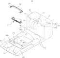
Fig. 3 is the perspective view that illustrates according to the bottom of the robot cleaner of the embodiment shown in the disclosure;
Fig. 4 A is the vertical view that illustrates according to the dust sensing unit of exemplary embodiment of the present disclosure;
Fig. 4 B is the vertical view that illustrates according to the dust sensing unit of another exemplary embodiment of the present disclosure;
Fig. 4 C is the vertical view that illustrates according to the dust sensing unit of another exemplary embodiment of the present disclosure;
Fig. 5 A is the top perspective that the structure of the all-in-service station (maintenance station) according to exemplary embodiment of the present disclosure is shown;
Fig. 5 B is the top perspective that illustrates according to the structure of the all-in-service station of another exemplary embodiment of the present disclosure;
Fig. 5 C is the top perspective that illustrates according to the structure of the all-in-service station of another exemplary embodiment of the present disclosure;
Fig. 5 D is the top perspective that illustrates according to the structure of the all-in-service station of another exemplary embodiment of the present disclosure;
Fig. 5 E is the cutaway view that illustrates according to the structure of the all-in-service station of another exemplary embodiment of the present disclosure;
Fig. 6 illustrates the plane that is included in according to the pipeline in the all-in-service station of the embodiment of Fig. 5 A;
Fig. 7 is the plane that illustrates according to the all-in-service station of the embodiment of Fig. 5 A;
Fig. 8 is the cutaway view that the mated condition of robot cleaner and all-in-service station is shown;
Fig. 9 A is the view that illustrates according to the structure of the brush cleaning element of exemplary embodiment of the present disclosure;
Fig. 9 B is the view that illustrates according to the structure of the brush cleaning element of another exemplary embodiment of the present disclosure;
Fig. 9 C is the view that illustrates according to the structure of the brush cleaning element of another exemplary embodiment of the present disclosure;
Figure 10 is the view of schematically illustrated cleaning systems according to another exemplary embodiment of the present disclosure;
Figure 11 illustrates the two-tube perspective view of suction/discharging;
Figure 12 is the view that is illustrated in according to air-flow in the cleaning systems of the embodiment shown in Figure 10;
Figure 13 is the view of schematically illustrated cleaning systems according to another embodiment of the present disclosure;
Figure 14 is the view of schematically illustrated cleaning systems according to another embodiment of the present disclosure;
Figure 15 is the top perspective that illustrates according to the structure of the all-in-service station of another exemplary embodiment of the present disclosure;
Figure 16 is the decomposition diagram that illustrates according to the structure of the all-in-service station of disclosure illustrated embodiment;
Figure 17 illustrates the vertical view that is included in according to the pipeline in the all-in-service station of disclosure illustrated embodiment;
Figure 18 is the cutaway view that is illustrated in during the docking operation (docking operation) through the air-flow of second opening discharging;
Figure 19 is the cutaway view that is illustrated in the air-flow that sucks through second opening during the docking operation;
Figure 20 is the top perspective that illustrates according to the port assembly of another exemplary embodiment of the present disclosure;
Figure 21 is the bottom perspective view that illustrates according to the port assembly of disclosure illustrated embodiment.
The specific embodiment
Below, will describe robot cleaner, all-in-service station and cleaning systems with reference to accompanying drawing according to embodiment of the present disclosure.
Fig. 1 is the view that illustrates according to the cleaning systems of exemplary embodiment of the present disclosure.
As shown in fig. 1, cleaning systems 10 can comprise robot cleaner 20 and all-in-service station 60.Robot cleaner 20 is a kind of independent devices of carrying out various clean up tasks.All-in-service station 60 is a kind of devices that are used for R and M.All-in-service station 60 can be given the battery charge of robot cleaner 20 and empty the dust bin of robot cleaner 20.
Fig. 2 is the cutaway view that illustrates according to the structure of the robot cleaner of exemplary embodiment of the present disclosure.Fig. 3 is the perspective view that illustrates according to the bottom of the robot cleaner of the embodiment shown in the disclosure.
To shown in Figure 3, robot cleaner 20 comprises main body 21, driver element 30, cleaning unit 40, various sensor 50 and controller (not shown) like Fig. 1.
Be used to carry out the various element of clean up task, that is, driver element 30, cleaning unit 40, various sensor 50, controller (not shown) and display 23 can be installed on the main body 21.
Can control left driving wheel 31a and right driving wheel 31b,, perhaps change the direct of travel of robot cleaner 20 so that robot cleaner 20 moves forwards or backwards.For example, can be through controlling left driving wheel 31a uniformly and right driving wheel 31b moves forwards or backwards robot cleaner 20.In addition.Can be through control the direct of travel that left driving wheel 31a and right driving wheel 31b change robot cleaner 20 differently.
Simultaneously, each in left driving wheel 31a and right driving wheel 31b and the castor 32 all can be configured to be releasably attached to the single component of main body 21.
But zone and part on every side thereof under cleaning unit 40 cleaning bodies 21.Cleaning unit 40 can comprise brush unit 41, side brush 42 and first dust bin 43.
In order to show unified clean-up performance, can control brush unit 41 so that it is with at the uniform velocity rotation.Compare with the situation of the floor surface of brush unit 41 clean, smooth, when the coarse floor surface of brush unit 41 cleanings, can reduce the rotary speed of brush unit 41.In this case, can supply recruitment electric current so that the speed of brush unit 41 remain unchanged.
Simultaneously, each in brush unit 41, side brush 42 and first dust bin 43 all can be configured to be releasably attached to the single component of main body 21.
Fig. 4 A is the plane that illustrates according to the dust sensing unit of exemplary embodiment of the present disclosure.Fig. 4 B is the plane that illustrates according to the dust sensing unit of another exemplary embodiment of the present disclosure.Fig. 4 C is the plane that illustrates according to the dust sensing unit of another exemplary embodiment of the present disclosure.
Shown in Fig. 4 A, dust sensing unit can be installed in first dust bin 43, with the amount of the dust in sensing first dust bin 43.
In this case, dust sensing unit 44 can comprise photoemission pickoff 44a and optical receiving sensor 44b.The signal that photoemission pickoff 44a in first dust bin 43 sends can directly be received by optical receiving sensor 44b.
Among photoemission pickoff 44a and the optical receiving sensor 44b each all can comprise photodiode or phototransistor.In this case, can confirm that whether first dust bin 43 is by the dust complete filling based on the amount of the energy that senses by photodiode or phototransistor.That is, along with dust gathers in first dust bin 43, the amount of the energy that is sensed by photodiode or phototransistor can reduce greatly.Through the amount of the energy that senses is compared with the predetermined reference value, when the amount of the energy that senses during less than reference value, controller can confirm that first dust bin 43 is by the dust complete filling.Owing to disturb the influence of the photoemission pickoff 44a that constitutes by photodiode or phototransistor and optical receiving sensor 44b quite big; Therefore under the situation that signal that sends from photoemission pickoff 44a with guiding such as the structure of slit or photoconduction or the signal that is received by optical receiving sensor 44b are installed, the amount of sensing dust more exactly.
Among photoemission pickoff 44a and the optical receiving sensor 44b each also can be made up of the remote controllers receiver module.In this case, can whether be received to confirm that by optical receiving sensor 44b whether first dust bin 43 is by the dust complete filling based on signal.That is, when dust was gathered, optical receiving sensor 44b can not receive the signal that sends from photoemission pickoff 44a.In this case, controller can confirm the dust in first dust bin 43 amount corresponding to scheduled volume or bigger amount.As the structure that the photoemission pickoff 44a and the optical receiving sensor 44b of remote controllers receiver module can not need slit or photoconduction, this is to show high strength and high sensitivity simultaneously because photoemission pickoff 44a and optical receiving sensor 44b have filtered low frequency wave.
For the signal that sends from photoemission pickoff 44a and received by optical receiving sensor 44b, can use visible light, infrared light, sound wave, ultrasonic wave etc.
Simultaneously, shown in Fig. 4 B, dust sensing unit 44 can comprise photoemission pickoff 44a, optical receiving sensor 44b and reflecting member 44c.
In this case, photoemission pickoff 44a and optical receiving sensor 44b are not installed in first dust bin 43, but are installed in the zone except first dust bin 43.That is, photoemission pickoff 44a and optical receiving sensor 44b can be installed in the part place in the face of first dust bin 43 of main body 21.At length say the inlet 43 ' installation of photoemission pickoff 44a and optical receiving sensor 44b close first dust bin 43.Therefore, in this case, photoemission pickoff 44a can through enter the mouth 43 ' send signal in first dust bin 43.Optical receiving sensor 44b can receive the signal of inlet 43 through first dust bin 43 ' occur from first dust bin 43.
Reflecting member 44c can be installed in first dust bin 43.Reflecting member 44c can reflect from the signal of photoemission pickoff 44a emission towards optical receiving sensor 44b.
In this case; When first dust bin 43 during by the dust complete filling; Reflecting member 44c is blocked by dust, makes can not to be received by optical receiving sensor 44b from the signal of photoemission pickoff 44a emission, and the amount of the energy that is perhaps received by optical receiving sensor 44b reduces greatly.Therefore, in this case, controller can confirm that first dust bin 43 is filled with dust or more dusts of scheduled volume.
Simultaneously; Under the situation that photoemission pickoff 44a and optical receiving sensor 44b are made up of the remote controllers module; Can use the structure of slit or photoconduction; This is to show high strength and high sensitivity simultaneously because photoemission pickoff 44a and optical receiving sensor 44b have filtered low frequency wave, as stated.That is, even do not have the structure such as reflecting member 44c in first dust bin 43, the photoemission pickoff 44a and the optical receiving sensor 44b that are made up of the remote controllers module can confirm that still whether first dust bin 43 is by the dust complete filling.
As stated, because photoemission pickoff 44a and optical receiving sensor 44b are not installed in first dust bin 43, therefore electric connection terminal can be installed in first dust bin 43.Therefore, user's available water cleans first dust bin 43.
In this case, photoemission pickoff 44a and optical receiving sensor 44b need not be installed in first dust bin 43, but can be installed in the zone except first dust bin 43.That is, photoemission pickoff 44a and optical receiving sensor 44b can be installed on the main body 21, to face with each other.Say that at length photoemission pickoff 44a can be installed in the part place of a side of facing first dust bin 43 of main body 21, and optical receiving sensor 44b can be installed in another part place of the opposite side of facing first dust bin 43 of main body 21.In this case, first dust bin 43 is disposed between photoemission pickoff 44a and the optical receiving sensor 44b, makes the signal that sends from photoemission pickoff 44a to be received by optical receiving sensor 44b through first dust bin 43.First dust bin 43 can be formed transparent fully, passes to allow signal.First dust bin 43 can comprise: transparent transmission signal passes part 43a ", be positioned at the position corresponding with photoemission pickoff 44a, pass to allow signal; Transparent reception signal passes part 43b ", be positioned at the position corresponding with optical receiving sensor 44b, pass to allow signal.
The signal that sends from photoemission pickoff 44a can directly be received by optical receiving sensor 44b.When first dust bin 43 during by the dust complete filling, optical receiving sensor 44b sensing is less than any signal, and the amount of the energy that is perhaps sensed by optical receiving sensor 44b can reduce greatly.In this case, controller can confirm that first dust bin 43 is by the dust complete filling.
Owing in first dust bin 43, electric connection structure is not installed, so available water cleans first dust bin 43.
When dust sensing unit 44 senses scheduled volume or more during the dust of volume, robot cleaner 20 can show the information about sensing result on display 23.The user can directly clean first dust bin 43.Simultaneously, robot cleaner 20 can automatically dock with all-in-service station 60, is collected in the dust in first dust bin 43 with discharging automatically.
The various sensors 50 of being installed to main body 21 can be used for the sensing barrier.Feeler, proximity transducer (proximity sensor) etc. can be used as these sensors 50.For example, the front portion that is arranged in main body 21 can be used for the barrier in the place ahead of sensing such as wall with the buffer 51 of the direction F forward that points to main body 21.Infrared sensor also capable of using (or ultrasonic sensor) comes the barrier in sensing the place ahead.
Be arranged in infrared sensor 52 (or ultrasonic sensor) on the bottom of main body 21 and can be used for the situation on sensing floor, for example, the situation of step.A plurality of infrared sensors 52 can be installed on the bottom of main body 21 along the arc periphery of main body 21.
Various sensors except the sensor also can be installed on the main body 21, send controller to the various situations with robot cleaner 20.
Controller receives the signal from various sensors 50, and controls driver element 30 and cleaning unit 40 based on the signal that receives, thereby controls robot cleaner 20 more effectively.
Fig. 5 A is the top perspective that illustrates according to the structure of the all-in-service station of exemplary embodiment of the present disclosure.Fig. 5 B is the top perspective that illustrates according to the structure of the all-in-service station of another exemplary embodiment of the present disclosure.Fig. 5 C is the top perspective that illustrates according to the structure of the all-in-service station of another exemplary embodiment of the present disclosure.Fig. 5 D is the top perspective that illustrates according to the structure of the all-in-service station of another exemplary embodiment of the present disclosure.Fig. 5 E is the cutaway view that illustrates according to the structure of the all-in-service station of another exemplary embodiment of the present disclosure.Fig. 6 illustrates the plane that is included in according to the pipeline in the all-in-service station of the embodiment of Fig. 5 A.Fig. 7 is the plane that illustrates according to the all-in-service station of the embodiment of Fig. 5 A.
To shown in Figure 7, robot cleaner 20 can dock with all-in-service station 60 under various situations like Fig. 1.For example; Can there be various situations; Such as, first dust bin 43 of need giving the situation of the battery (not shown) charging of robot cleaner 20, situation that robot cleaner 20 has been carried out the clean up task of the scheduled time, situation that robot cleaner 20 has been accomplished clean up task and robot cleaner 20 is by the situation of dust complete filling.
All-in-service station 60 can comprise shell 61, butt joint guidance unit 70, charhing unit 80, dust removing units 90 and controller (not shown).
The second opening 62a can pass platform 62 and form.The second opening 62a of platform 62 can be disposed in the position that the second opening 62a can be communicated with the first opening 21a of robot cleaner 20.According to this layout, the dust that the first opening 21a through robot cleaner 20 discharges can be introduced among the second opening 62a of platform 62.The dust that is introduced among the second opening 62a of platform 62 can be collected in second dust bin 94 that is included in the all-in-service station 60.
In this case, dust sensing unit 44 can comprise photoemission pickoff 44a and optical receiving sensor 44b.When optical receiving sensor 44b did not receive from signal that photoemission pickoff 44a sends, controller can confirm that the amount of the dust in second dust bin 94 is corresponding to scheduled volume or bigger amount.
Described in Fig. 5 A, the second opening 62a of platform 62 can have open design.That is, the second opening 62a of platform 62 can open wide all the time, and is not covered by independent lid.
Simultaneously, shown in Fig. 5 B, lid 64 can be installed in the second opening 62a place of platform 62, to move slidably along the second opening 62a.When robot cleaner 20 docks fully, but uncap 64, to allow the second opening 62a discharging dust of robot cleaner 20 through platform 62.On the other hand, when the mated condition of robot cleaner 20 is removed, but close cap 64, with the second opening 62a of closed platform 62.
On the other hand, shown in Fig. 5 C, lid 65 can be installed in the second opening 62a place of platform 62, to move slidably along the second opening 62a.Certainly, different with the situation of Fig. 5 B, in the situation of Fig. 5 C, lid 65 can only be installed in the middle body of the second opening 62a of platform 62.This structure is suitable for allowing the second opening 62a of the castor 32 of robot cleaner 20 through platform 62.Can realize the opening of lid 65 according to the mode identical with aforesaid way.
On the other hand, shown in Fig. 5 D, bridge spare 66 can be installed in the second opening 62a place of platform 62.Bridge spare 66 can only be installed in the middle body of the second opening 62a of platform 62, to realize allowing the bridge function of the castor 32 of robot cleaner 20 through the second opening 62a of platform 62.
Shown in Fig. 5 E, the second opening 62a that bridge spare 67a can be installed in platform 62 sentences upwards and moves downward.That is, when robot cleaner 20 got into platform 62, bridge spare 67a moved upward, and moved on bridge spare 67a with the castor 32 that allows robot cleaner 20.When the butt joint of robot cleaner 20 was accomplished, bridge spare 67a moved downward, and guaranteed that with the second opening 62a that allows platform 62 aperture area increases.
Butt joint guidance unit 70 can be installed in the top of shell 61.Butt joint guidance unit 70 can comprise a plurality of sensors 71.Sensor 71 can limit butt joint guidance field and butt joint zone, docks with all-in-service station 60 with guided robot dust catcher 20 exactly.
Except that second dust bin 94, dust removing units 90 also can comprise pump unit 91, intake line 92 and discharge tube 93.Dust removing units 90 is used for making from the air-flow of discharge tube 93 dischargings forces suction to get back to intake line 92.Utilize this circulating current, the dust that dust removing units 90 is removed in first dust bin 43 that is stored in robot cleaner 20.
The floss hole 93a of the comparable discharge tube 93 of cross-sectional area of the suction inlet 92a of intake line 92 and the cross-sectional area sum of 93b are big.Below, will abbreviate the cross-sectional area sum of the floss hole 93a of discharge tube 93 and 93b as " cross-sectional area of floss hole 93a and 93b ".The suction inlet 92a of intake line 92 can be 7.5: 1 with the ratio of the cross-sectional area of the floss hole 93a of discharge tube 93 and 93b.Certainly, the suction inlet 92a of intake line 92 can for example, can be 7: 1,6.5: 1 or 6: 1 less than above-mentioned ratio with the ratio of the cross-sectional area of the floss hole 93a of discharge tube 93 and 93b.Even when the ratio of cross-sectional area reduces (as stated) slightly, it still falls in the technical scope of the present disclosure.
Therefore; The air velocity at the suction inlet 92a place of the comparable intake line 92 of air velocity at the floss hole 93a of discharge tube 93 and 93b place is high; This is because under the suction flow velocity and the essentially identical condition of discharge speed of pump unit 91, between floss hole 93a and 93b and suction inlet 92a, has the cross section product moment.Because this current difference, so can prevent to be inhaled into the suction inlet 92a from the air that floss hole 93a and 93b come out.That is, the air that comes out from floss hole 93a and 93b can be injected into first dust bin 43, and the suction through suction inlet 92a place directly is not drawn among the suction inlet 92a, and this is because the air velocity of air discharged is very high.Therefore, the air that is injected in first dust bin 43 can circulate to come out from first dust bin 43 afterwards in first dust bin 43, can get into suction inlet 92a then.
Fig. 8 is the cutaway view that the mated condition of robot cleaner and all-in-service station is shown.
To shown in Figure 8, when robot cleaner 20 docked with all-in-service station 60, the first opening 21a of robot cleaner 20 can be communicated with the second opening 62a of all-in-service station 60 like Fig. 1.
When achieving a butt joint, the first opening 21a of the suction inlet 92a close robot cleaner 20 of intake line 92 arranges that the while is along the longitudinal extension of the first opening 21a.In addition; The first opening 21a of the floss hole 93a of discharge tube 93 and 93b close robot cleaner 20 is along the two ends that vertically are arranged in the first opening 21a of the first opening 21a of robot cleaner 20; That is the relative two side areas of the first opening 21a.
According to above-mentioned structure, the air through dust removing units 90 circulations (returning) during docking operation can form the closed-loop path.That is, 91 air discharged are come out from the floss hole 93a and the 93b of discharge tube 93 apace from the pump unit, after the relative two side areas of passing the first opening 21a, get into first dust bin 43 of robot cleaner 20 then.The middle section of air through the first opening 21a that is introduced in first dust bin 43 of robot cleaner 20 is discharged, and is introduced in the suction inlet 92a through intake line 92 in second dust bin 94 of all-in-service station 60.Afterwards, air is drawn in the pump unit 91 once more.
Fig. 9 A is the view that illustrates according to the structure of the brush cleaning element of exemplary embodiment of the present disclosure.Fig. 9 B is the view that illustrates according to the structure of the brush cleaning element of another exemplary embodiment of the present disclosure.Fig. 9 C is the view that illustrates according to the structure of the brush cleaning element of another exemplary embodiment of the present disclosure.
Shown in Fig. 9 A, all-in-service station 60 can comprise brush cleaning element 95a, with the brush unit 41 of clean robot dust catcher 20.The brush cleaning element 95a of all-in-service station 60 is different with the brush cleaning element 41c of robot cleaner 20.
The brush cleaning element 95a close second opening 62a of all-in-service station 60 arranges.The brush cleaning element 95a of all-in-service station 60 can be outstanding towards the second opening 62a from the bottom of shell 61.Brush cleaning element 95a can comprise along a plurality of brush cleaning elements of vertical layout of the second opening 62a.
Under mated condition, the brush cleaning element 95a of all-in-service station 60 can contact with the brush unit 41 of robot cleaner 20.The brush cleaning element 95a of all-in-service station 60 can remove impurity (for example, twining the hair of the brush unit 41 of robot cleaner 20).Particularly, can be incorporated in second dust bin 94 through the impurity that the suction of pump unit 91 will be removed by the brush cleaning element 95a of all-in-service station 60, this is because the brush cleaning element 95a of all-in-service station 60 can be arranged in intake line 92 places.
According to another embodiment of the present disclosure, shown in Fig. 9 B, the brush cleaning element 95b of all-in-service station 60 can be arranged to moving along the second opening 62a longitudinally-slidablely.The brush cleaning element 95b of all-in-service station 60 can remove the impurity of the brush unit 41 that is twining robot cleaner 20 when sliding.
According to another embodiment of the present disclosure, shown in Fig. 9 C, the brush cleaning element 95c of all-in-service station 60 can be installed to be and can move up and down.When accomplishing the butt joint of robot cleaner, brush cleaning element 95c can move upward, so that brush cleaning element 95c contacts with the brush unit 41 of robot cleaner 20.On the other hand, when removing the butt joint of robot cleaner, brush cleaning element 95c can move downward.Simultaneously, can carry out moving up and down of brush cleaning element 95c with the butt joint of robot cleaner 20 relatedly.
The brush unit 41 of robot cleaner 20 can the more effectively dedusting with dust removing units 90 cooperations.When dust removing units 90 made air circulation, the brush unit 41 of robot cleaner 20 can rotate along the clockwise direction among Fig. 8.In this case, the brush unit 41 of robot cleaner 20 can be assisted air is incorporated in first dust bin 43 of robot cleaner 20.In addition, brush unit 41 can be assisted and will be incorporated into the suction inlet 92a of intake line 92 from the air that first dust bin 43 of robot cleaner 20 is come out.
The brush unit 41 of robot cleaner can be with various speed rotations, with more effectively dedusting.For example, when dust removing units 90 makes air circulation, the brush unit 41 of robot cleaner 20 in early days the stage can slowly rotate, but fast rotational then.Here, " commitment " meaning is cycle regular hour.This cycle can be configured to time enough, is discharged to allow light dust (for example, hair).Since the brush unit 41 of robot cleaner 20 in early days the stage slowly rotate, so can make impurity (for example, light relatively hair) easily move to the suction inlet 92a of intake line 92 through the suction of dust removing units 90.Because the brush unit 41 of robot cleaner 20 is fast rotational subsequently, so can make the dust of phase counterweight easily move to the suction inlet 92a of intake line 92 by means of the revolving force of brush unit 41.
The brush unit 41 of robot cleaner 20 can be removed the impurity that is twining brush unit 41 when the direction of rotation that changes brush unit 41 at least once.Be stored in dust in first dust bin 43 of robot cleaner 20 and can twining the brush unit 41 of robot cleaner 20, this is because dust first opening 21a through robot cleaner 20 after through the brush unit 41 of robot cleaner 20 is discharged.The direction of rotation of brush unit 41 that at this moment, can be through changing robot cleaner 20 discharges the impurity of the brush unit 41 that is twining robot cleaner 20.The impurity that discharges moves to the suction inlet 92a of intake line 92, is stored in then in second dust bin 94 of all-in-service station 60.Next, the brush unit 41 of robot cleaner 20 can change direction of rotation once more, to rotate along its original orientation.The brush unit 41 of robot cleaner 20 can repeatedly repeat to change direction of rotation.
Hereinafter, with the operation of describing according to the cleaning systems of exemplary embodiment of the present disclosure.
Shown in Fig. 1 to Fig. 9 C, but robot cleaner 20 sensings are from the signal of butt joint guidance unit 70, accurately to dock with all-in-service station 60 according to sensed signal.When main body 21 starts (initiate) butt joint when the front portion of main body 21 begins to get into platform 62.In the position that the first opening 21a of robot cleaner 20 is communicated with the second opening 62a of all-in-service station 60, accomplish butt joint.
When accomplishing butt joint, dust removing units 90 can arrive all-in-service station 60 with the dust emissions that is stored in the robot cleaner 20.Say that at length pump unit 91 can be with floss hole 93a and the 93b discharged air of high flow rate through discharge tube 93.The air that comes out from floss hole 93a and 93b can be introduced in first dust bin 43 after the first opening 21a through robot cleaner 20.The air that is introduced in first dust bin 43 of robot cleaner 20 can circulate through the whole space of first dust bin 43 fully, and in first dust bin 43, does not form the dead band.Specifically; The air that comes out from floss hole 93a and 93b can stir dust fully since the sidepiece of first dust bin 43; This is that floss hole 93a and 93b are disposed in the relative lateral region of the first opening 21a of robot cleaner 20 because of the longitudinal 2 observation along the first opening 21a.Next, the dust that is stored in first dust bin 43 can be suspended in the air that is introduced in first dust bin 43, can be discharged through the first opening 21a with the air in being introduced in first dust bin 43 then.The suction inlet 92a of intake line 92 applies suction to the first opening 21a of robot cleaner 20, thereby causes being inhaled into from the dust that first dust bin 43 of robot cleaner 20 is come out.The dust that is introduced among the suction inlet 92a of intake line 92 can be stored in second dust bin 94 of all-in-service station 60.Air is inhaled in the pump unit 91 through filter 94a once more.
Therefore, can after second dust bin 94 of the first opening 21a of first dust bin 43 of the first opening 21a of order through discharge tube 93, robot cleaner 20, robot cleaner 20, robot cleaner 20, intake line 92, all-in-service station 60, be introduced in once more the pump unit 91 from pump unit 91 air discharged.Because air circulates (returning) as described above, so can farthest prevent outside discharged air.Therefore, can reduce the performance demands of filter 94a.In addition, the suction/discharging of air is realized in single pump capable of using unit as pump unit 91.
The dust that comes out from first dust bin 43 of robot cleaner 20 is moveable to the big middle section of the second opening 62a of big middle section and all-in-service station 60 of the first opening 21a of robot cleaner 20; This is because of the longitudinal 2 observation along the first opening 21a and the second opening 62a; The relative lateral region of second opening 62a that the air that comes out from the floss hole 93a and the 93b of discharge tube 93 can be through all-in-service station 60 and the first opening 21a of robot cleaner 20 is discharged; Along the longitudinal 2 observation of the first opening 21a and the second opening 62a, the big zone of the first opening 21a of the second opening 62a and robot cleaner 20 that can be through all-in-service station 60 at the suction inlet 92a of intake line 92 inhaled air is inhaled into.The layout of suction inlet 92a and floss hole 93a and 93b can prevent to move through said relative lateral region from the dust that first dust bin 43 of robot cleaner 20 is come out, thereby can prevent outwards to discharge dust.Suction inlet 92a and floss hole 93a and 93b can provide specific sealing effectiveness with respect to the position of the second opening 62a of the first opening 21a of robot cleaner 20 and all-in-service station 60 between robot cleaner 20 and all-in-service station 60.
Simultaneously, can control brush unit 41 in early days the stage slowly rotate, fast rotational when dust removing units 90 makes air circulation then is with assisted dust-collecting unit 90.At length say, brush unit 41 in early days the stage slowly rotation the time assisted dust-collecting unit 90 suck light dust (for example, hair) fast.Next, brush unit 41 sucks the dust of phase counterweight in atwirl while assisted dust-collecting unit 90.
In addition, can be when dust removing units 90 makes air circulation pilot brush unit 41 change brush units 41 direction of rotation at least once, with assisted dust-collecting unit 90.Say that at length impurity (for example, hair) can twine brush unit 41.When the direction of rotation of brush unit 41 changes, can discharge the impurity (for example, hair) of winding.In this case, dust removing units 90 can suck the impurity (for example, hair) that breaks away from brush unit 41.
Simultaneously, the brush cleaning element 95 of all-in-service station 60 can be removed the impurity (for example, hair) of the brush unit 41 that is twining robot cleaner 20.The impurity that is twining the brush unit 41 of robot cleaner 20 contacts with the brush cleaning element 95 of all-in-service station 60 during the rotation of brush unit 41, thereby can remove impurity from brush unit 41 through the brush cleaning element 95 of all-in-service station 60.Suction through dust removing units 90 can be collected in the impurity of removing in second dust bin 94.
Figure 10 is the view of schematically illustrated cleaning systems according to another exemplary embodiment of the present disclosure.Figure 11 illustrates the two-tube perspective view of suction/discharging.Figure 12 illustrates the view that air flows in according to the cleaning systems of the embodiment shown in Figure 10.
To shown in Figure 12, cleaning systems 100 can be with being stored in dust emissions in first dust bin 143 (being included in the robot cleaner 120) to second dust bin 194 (being included in the all-in-service station 160) like Figure 10.To only combine the situation different to provide description below with the situation of previous embodiment.
All-in-service station 160 can comprise that suction/discharging is two-tube 200, sucks air-flow and exhaust jet stream and is applied to suction/discharging two-tube 200.Here, " suction air-flow " is the air-flow that comes out from first dust bin 143 of robot cleaner 120, and " exhaust jet stream " is the air-flow that is introduced in first dust bin 143 of robot cleaner 120.When carrying out butt joint, first dust bin 143 of robot cleaner 120 can combine with the suction/discharging two-tube 200 of all-in-service station 160 through communication member 145.
Suction/discharging two-tube 200 can have the coaxial-type double pipe structure.For example, suction/discharging two-tube 200 can comprise: delivery pipe 293 is arranged in the middle body of suction/discharging two-tube 200; Suction line 292 is around the outer surface of delivery pipe 293.
On the other hand, according to another embodiment, suction/discharging is two-tube to have parallel double pipe structure.For example, two-tube suction line and the delivery pipe of perhaps laterally arranging abreast along vertically that comprise of suction/discharging.
All-in-service station 160 can comprise dust removing units 190.Dust removing units 190 can comprise: pump unit 191; Intake line 192 is installed in the suction side of pump unit 191, and is connected to the suction line 292 of suction/discharging two-tube 200; Discharge tube 193 is installed in the waste side of pump unit 191, and is connected to the delivery pipe 293 of suction/discharging two-tube 200; Second dust bin 194.
When robot cleaner 20 docks with all-in-service station 160, can after the delivery pipe 293 that gets into suction/discharging two-tube 200 through discharge tube 193, be introduced in first dust bin 143 of robot cleaner 120 from pump unit 191 air discharged.Afterwards, the air that is introduced in first dust bin 143 can be through intake line 192 after the dust in being stored in first dust bin 143 is in the suction line 292 that is inhaled into suction/discharging two-tube 200.Dust through intake line 192 can be stored in second dust bin 194, can be inhaled into once more in the pump unit 191 then.
Therefore, can after second dust bin 194 of suction line 292, intake line 192 and the all-in-service station 160 of first dust bin 143 of the sequentially delivery pipe 293 through discharge tube 193 (see figure 10)s, suction/discharging two-tube 200, robot cleaner 120, suction/discharging two-tube 200, be introduced in once more the pump unit 191 from pump unit 191 air discharged.
Figure 13 is the view of schematically illustrated cleaning systems according to another embodiment of the present disclosure.
Shown in figure 13, cleaning systems 300 can be with being stored in dust emissions in first dust bin 343 (being included in the robot cleaner 320) to second dust bin 394 (being included in the all-in-service station 360).To only combine the situation different to provide description below with the situation of previous embodiment.
First dust bin 343 of robot cleaner 320 can comprise: inlet 343 ' and, be communicated with the first opening 321a (being included in the robot cleaner 320); Communication member 345 directly is communicated with all-in-service station 360.
All-in-service station 360 can comprise dust removing units 390.Dust removing units 390 can comprise: pump unit 391; Intake line 392 is installed in the suction side of pump unit 391; Discharge tube 393 is installed in the waste side of pump unit 391.
When robot cleaner 320 docks with all-in-service station 360; The first opening 321a of robot cleaner 320 can be connected to the intake line 392 of all-in-service station 360, and the communication member 345 of first dust bin 343 in the robot cleaner 320 can be connected to the discharge tube 393 of all-in-service station 360.
Can be introduced in first dust bin 343 of robot cleaner 320 through discharge tube 393 from pump unit 391 air discharged.Be introduced in first dust bin 343 of robot cleaner 320 air can with the dust in being stored in first dust bin 343 the inlet 343 through first dust bin 343 ' and the first opening 321a of robot cleaner 320 after move to intake line 392.The dust that moves to intake line 392 is stored in second dust bin 394 of all-in-service station 360, and air can be drawn in the pump unit 391 once more.
Therefore, from pump unit 391 air discharged can first dust bin 343 of the communication member 345 of order through discharge tube 393, first dust bin 343, robot cleaner 320, the inlet 343 of first dust bin 343 ', be incorporated into once more the pump unit 391 after second dust bin 394 of intake line 392 and all-in-service station 360.
Figure 14 is the view of schematically illustrated cleaning systems according to another embodiment of the present disclosure.
Shown in figure 14, cleaning systems 400 can be with being stored in dust emissions in first dust bin 443 (being included in the robot cleaner 420) to second dust bin 494 (being included in the all-in-service station 460).To only combine the situation different to provide description below with the situation of previous embodiment.
When robot cleaner 420 docks with all-in-service station 460; The first opening 421a of robot cleaner 420 can be connected to the discharge tube 493 of all-in-service station 460, is included in the intake line 492 that communication member 445 in first dust bin 443 of robot cleaner 420 can be connected to all-in-service station 460.
Can be from pump unit 491 air discharged through the first opening 421a of discharge tube 493, robot cleaner 420 and the inlet 443 of first dust bin 443 ' be introduced in first dust bin 443 of robot cleaner 420.The air that is introduced in first dust bin 443 of robot cleaner 420 can move to intake line 492 with the dust in being stored in first dust bin 443 after the communication member 445 through first dust bin 443.The dust that moves to intake line 492 is stored in second dust bin 494 of all-in-service station 460, and air can be drawn in the pump unit 491 once more.
Therefore, from pump unit 491 air discharged can the inlet 443 through discharge tube 493, first dust bin 443 sequentially ', be incorporated into once more the pump unit 491 after second dust bin 494 of communication member 445, intake line 492 and the all-in-service station 460 of first dust bin 443 of robot cleaner 420, first dust bin 443.
Figure 15 is the top perspective that illustrates according to the structure of the all-in-service station of another exemplary embodiment of the present disclosure.Figure 16 is the decomposition diagram that illustrates according to the structure of the all-in-service station of disclosure illustrated embodiment.Figure 17 illustrates the vertical view that is included in according to the pipeline in the all-in-service station of disclosure illustrated embodiment.Figure 18 is the cutaway view that is illustrated in during the docking operation through the air-flow of second opening discharging.Figure 19 is the cutaway view that is illustrated in the air-flow that sucks through second opening during the docking operation.Figure 20 is the top perspective that illustrates according to the port assembly of another exemplary embodiment of the present disclosure.Figure 21 is the bottom perspective view that illustrates according to the port assembly of disclosure illustrated embodiment.
With reference to Figure 15 to Figure 21, show cleaning systems 510.Cleaning systems 510 have and above-mentioned cleaning systems 10 essentially identical structures.Therefore, will mainly combine cleaning systems 510 and cleaning systems 10 different portions to provide description below, if possible, with the description that does not provide the identical part of cleaning systems 510 and cleaning systems 10.
All-in-service station 560 can comprise housing 561, butt joint guidance unit 570, charhing unit 580, dust removing units 590 and controller (not shown).
Can platform 562 be set at housing 561 places.The second opening 562a can be formed on platform 562 places.The second opening 562a of platform 562 is disposed in the position that the second opening 562a can be communicated with the first opening 521a of robot cleaner 520.The dust of the first opening 521a discharging through robot cleaner 520 can be introduced among the second opening 562a of platform 562, is stored in then in second dust bin 594 of all-in-service station 560.In this case, the second opening 562a of platform 562 can be greater than the first opening 521a of robot cleaner 520.
Except second dust bin 594, dust removing units 590 also can comprise pump unit 591, intake line 592, the first discharge tube 593a, the second discharge tube 593b, port assembly 600 and suction/discharging two-tube 200.Dust removing units 590 is used for forcing from the first discharge tube 593a and the second discharge tube 593b air discharged is got back to intake line 592 by suction.Utilize the air-flow of circulation like this, the dust that dust removing units 590 is removed in first dust bin 543 that is stored in robot cleaner 520.
Suction inlet forms member 610 intake line 592 is divided into two parts, and these two parts form the first suction inlet 592a and the second suction inlet 592b respectively.The first separator 610a and 610b are formed on the lower surface that suction inlet forms member 610.The bottom that the first separator 610a and 610b are used for suction inlet is formed member 610 and housing 561 separates.
The air or the dust that are introduced among the first suction inlet 592a are mobile towards intake line 592 along the upper surface of suction inlet formation member 610.The air or the dust that are introduced among the second suction inlet 592b are mobile towards intake line 592 along the lower surface of suction inlet formation member 610.Next, dust is stored in second dust bin 594 of all-in-service station 560.
First floss hole forms member 621 and second floss hole formation member 622 is divided into two parts with the first discharge tube 593a, and these two parts form the first floss hole 593a ' and the second floss hole 593a respectively ".On the other hand, the 3rd floss hole forms member 623 and the 4th floss hole formation member 624 is divided into two parts with the second discharge tube 593b, and these two parts form the 3rd floss hole 593b ' and the 4th floss hole 593b respectively ".
Be transported to the big dust bin 543a of robot cleaner 520 through the first floss hole 593a ' with the 3rd floss hole 593b ' air discharged, and be transported to the little dust bin 543b of robot cleaner 520 through the second floss hole 593a " with the 4th floss hole 593b " air discharged.The first floss hole 593a ' and the 3rd floss hole 593b ' directly face big dust bin 543a.Therefore, be transported to big dust bin 543a with high flow rate in through brush unit 541 through the first floss hole 593a ' and the 3rd floss hole 593b ' air discharged.
Yet the second floss hole 593a " with the 4th floss hole 593b " is not directly in the face of little dust bin 543b.For this reason, guided by rotary broom 540a through the second floss hole 593a " with the 4th floss hole 593b " air discharged, to be transported to little dust bin 543b.When the counter clockwise direction of brush unit 541 in Figure 18 rotated, little dust bin 543b can be transported to more reposefully through the second floss hole 593a " with the 4th floss hole 593b " air discharged.
The first floss hole 593a ' and the 3rd floss hole 593b ' are arranged in relative vertical (perhaps horizontal) end of the second opening 562a, that is, and and the relative lateral region of the second opening 562a.In addition, the second floss hole 593a " with the 4th floss hole 593b " is arranged in relative vertical (perhaps horizontal) end of the second opening 562a, that is, and and the relative lateral region of the second opening 562a.On the other hand, the first floss hole 593a ' and the second floss hole 593a " are arranged in the relative end of the second opening 562a along width (forward or backward) direction in the lateral region of the second opening 562a.In addition, the 3rd floss hole 593b ' and the 4th floss hole 593b " are arranged in the relative end of the second opening 562a along width (forward or backward) direction in another lateral region of the second opening 562a.Therefore, the first floss hole 593a ' is to the 4th floss hole 593b " is disposed in each corner regions of the second opening 562a.
Simultaneously, the second separator 622a and 624a are respectively formed at second floss hole and form the sidewall of member 622 and the side-walls that the 4th floss hole forms member 624.The second separator 622a and 624a are used to prevent that port assembly 600 from putting towards the lateral deviation of the second opening 562a.
Therefore, the second suction inlet 592b can form the structure that has around the first suction inlet 592a, the first floss hole 593a ', the second floss hole 593a ", the 3rd floss hole 593b ' and the 4th floss hole 593b ".By the zone of the first suction inlet 592a, the first floss hole 593a ', the second floss hole 593a ", the 3rd floss hole 593b ' and the 4th floss hole 593b " region occupied corresponding to the first opening 521a of robot cleaner 520.The second suction inlet 592b can suck the outside dust of the first opening 521a that is dispersed in robot cleaner 520, and this is because the second suction inlet 592b is arranged in the outside of the first opening 521a of robot cleaner 520.
The lid 640 that is formed with a plurality of through hole 640a can be installed to the second suction inlet 592a.In this case, the outside dust of the first opening 521a that is dispersed in robot cleaner 520 can be inhaled among the second suction inlet 592b through through hole 640a.Usually, lid 640 prevents to have large-sized impurity and gets into the second suction inlet 592a, thereby prevents the suction passage obstruction that becomes.
Simultaneously, in another embodiment, a plurality of guides 631 can form vertical layout of member 610 along suction inlet, and a plurality of hooks 632 can be outstanding from the side surface of said a plurality of guides 631 respectively.The said a plurality of guides 631 that form vertical layout of member 610 along suction inlet can be arranged on lateral symmetry ground.
A plurality of suctions/discharging two-tube 200 can be arranged on platform 562 places.Said a plurality of suction/discharging two-tube 200 is arranged in the position (infrared sensor 552 is installed in the bottom of robot cleaner 520) corresponding to a plurality of infrared sensors 552.The concrete shape of each suction/discharging two-tube 200 can be with reference to the description that is provided by Figure 11.
Each suction/discharging two-tube 200 produces and sucks air-flow and exhaust jet stream.Here; Sucking air-flow is to be introduced in the air-flow in the housing 561 through the suction line 292 that is communicated with intake line 592, and exhaust jet stream is the air-flow that outwards discharges from housing 561 through the delivery pipe 293 that is communicated with the first discharge tube 593a or the second discharge tube 593b.
The infrared sensor 552 of robot cleaner 520 can be flow through the air cleaner of corresponding suction/discharging two-tube 200 respectively.Promptly; Air is blown each infrared sensor 552 of robot cleaner 520 through the delivery pipe 293 of corresponding suction/discharging two-tube 200; To remove dust from infrared sensor 552, the suction line 292 through corresponding suction/discharging two-tube 200 sucks removed dust then.The dust that is introduced in the suction line 292 is collected in second dust bin 594 of all-in-service station 560.
Therefore, the dust that is attached to each infrared sensor 552 is removed, thereby can keep the sensing performance expected.Owing to inhaled back from the dust that infrared sensor 552 is removed, rather than scatter, can make the maintenance on every side of all-in-service station 560 clean.
Be clear that from above description, can prevent that according to the cleaning systems in each illustrated embodiment the clean-up performance of robot cleaner from slackening.
Cleaning systems also can be realized the minimizing of energy and the reduction of material cost through air is circulated between robot cleaner and all-in-service station.
Cleaning systems also can easily be realized automatic dust emissions through the opening discharging dust of robot cleaner.
Cleaning systems can hinder dust and scatter during automatic dust emissions, thereby make keeping totally of all-in-service station on every side.
The cleaning systems also discharged air of circulation capable of using clean sensor, thus prevent dust be scattered in cleaning systems around.
In addition, cleaning systems can be removed effectively during automatic dust emissions and be wrapped in the impurity on the brush unit.
Though illustrated and described embodiment more of the present disclosure, it should be recognized by those skilled in the art that under the situation that does not break away from the principle of the present invention that limits its scope claim and equivalent thereof and spirit, can change these embodiments.
Claims (27)
1. robot cleaner comprises:
Main body has opening;
Dust bin is arranged in the main body, is used to store dust;
Brush unit is used for the dust on the floor is swept into dust bin,
Wherein, make and be stored in the dust motion in the dust bin, in the dust emissions operating process, apply suction through dust and make the opening of dust process main body of motion discharge from dust bin to motion through air-flow being incorporated in the dust bin.
2. robot cleaner as claimed in claim 1, wherein, brush unit is arranged on the opening part of main body, and the lateral region that air communication is crossed the opening of main body is introduced in the dust bin, and the middle section that passes through the opening of main body is then outwards discharged.
3. robot cleaner as claimed in claim 1, wherein, in the dust emissions operating process, brush unit is controlled to make dust by discharging more effectively.
4. robot cleaner as claimed in claim 3, wherein, brush unit comprises roller, in the dust emissions operating process, the direction of rotation of the said roller of brush unit changes at least once.
5. robot cleaner as claimed in claim 3, wherein, in the dust emissions operating process, in the initial time section of the light dust of discharging, the said roller of brush unit rotates lentamente, then fast rotational.
6. robot cleaner as claimed in claim 2 also comprises:
All-in-service station; The lateral region that is used for producing the opening of the main body through robot cleaner is introduced in the exhaust jet stream of the dust bin of robot cleaner; And the middle section that is used to produce the main body through robot cleaner is applied to the suction of the dust bin of robot cleaner
Wherein, the said opening of the main body of robot cleaner and the open communication that is provided with at the all-in-service station place.
7. cleaning systems comprise:
Robot cleaner, comprise first opening and with first dust bin of first open communication;
All-in-service station, comprise second opening and with second dust bin of second open communication,
Wherein, after the dust motion that makes in first dust bin that air-flow is incorporated into robot cleaner in first dust bin be stored in robot cleaner, said dust is discharged into second opening of all-in-service station through first opening of robot cleaner.
8. cleaning systems as claimed in claim 7 wherein, are introduced in first opening that air in first dust bin of robot cleaner passes robot cleaner.
9. cleaning systems as claimed in claim 8 also comprise:
Dust removing units, first opening through robot cleaner sucks air and once more said air is blown first opening of robot cleaner from first dust bin of robot cleaner.
10. cleaning systems as claimed in claim 9, wherein, dust removing units sucks air, and feasible air first opening from robot cleaner after cycling through first dust bin of robot cleaner that is blown first opening of robot cleaner comes out.
11. cleaning systems as claimed in claim 10; Wherein, dust removing units blows along the air of the lateral region of first opening of the robot cleaner of vertically watching of first opening and suck along the air in the big zone of first opening of vertically watching of first opening.
12. cleaning systems as claimed in claim 9, wherein, dust removing units comprises:
The pump unit;
First discharge tube is arranged on the waste side of pump unit,
Wherein, First discharge tube has first floss hole and second floss hole; In the bigger dust bin that said first floss hole makes air blown to be included in first dust bin, in the less dust bin that said second floss hole makes air blown to comprise in first dust bin.
13. cleaning systems as claimed in claim 12, wherein, dust removing units also comprises:
Second discharge tube is arranged on the waste side of pump unit,
Wherein, Said second discharge tube has the 3rd floss hole and the 4th floss hole; In the bigger dust bin that said the 3rd floss hole makes air blown to be included in first dust bin, in the less dust bin that said the 4th floss hole makes air blown to be included in first dust bin.
14. cleaning systems as claimed in claim 10, wherein, dust removing units comprises:
The pump unit;
Intake line is arranged on the suction side of pump unit,
Wherein, intake line has suction inlet, and this suction inlet is greater than the opening of robot cleaner.
15. cleaning systems as claimed in claim 9, wherein, dust removing units comprises:
The pump unit;
Intake line is arranged on the suction side of pump unit;
First discharge tube and second discharge tube are arranged on the waste side of pump unit;
Port assembly; Be used for intake line is divided into the two parts that have first suction inlet and second suction inlet respectively; Be used for first discharge tube is divided into the two parts that have first floss hole and second floss hole respectively, and said second discharge tube is divided into the two parts that have the 3rd floss hole and the 4th floss hole respectively.
16. cleaning systems as claimed in claim 15; Wherein, the 4th floss hole that the 3rd floss hole that port assembly comprises that the suction inlet that is used to form first suction inlet and second suction inlet forms member, first floss hole that is used to form first floss hole forms member, second floss hole that is used to form second floss hole forms member, be used to form the 3rd floss hole forms member and is used to form the 4th floss hole forms member.
17. cleaning systems as claimed in claim 16, wherein, said second suction inlet is around said first suction inlet, said first floss hole, second floss hole, the 3rd floss hole and the 4th floss hole.
18. cleaning systems as claimed in claim 9, wherein, dust removing units comprises:
The pump unit;
Intake line is arranged on the suction side of pump unit;
Discharge tube is arranged on the waste side of pump unit,
Wherein, Said intake line has suction inlet; Said suction inlet is arranged in along the big zone of said longitudinally first opening of first opening of robot cleaner; Said discharge tube has floss hole, and said floss hole is arranged in along the lateral region of said first opening of vertically watching of said first opening.
19. cleaning systems as claimed in claim 18, wherein, the cross-sectional area of the suction inlet of said intake line is greater than the cross-sectional area of the floss hole of said discharge tube.
20. cleaning systems as claimed in claim 19, wherein, the ratio of the cross-sectional area between the suction inlet of intake line and the floss hole of discharge tube is 7.5: 1.
21. cleaning systems as claimed in claim 18, wherein, the suction inlet of intake line and the floss hole of discharge tube form second opening of all-in-service station.
22. cleaning systems as claimed in claim 7, wherein,
Robot cleaner also comprises the brush unit of first opening part that is arranged on robot cleaner;
Brush unit is controlled, so that be stored in second opening that dust in first dust bin of robot cleaner is discharged into all-in-service station more effectively.
23. cleaning systems as claimed in claim 22, wherein, all-in-service station also comprises the brush cleaning element that is used for cleaning brush unit.
24. cleaning systems as claimed in claim 23, wherein, second opening of brush cleaning element and all-in-service station is adjacent to arrange.
25. cleaning systems as claimed in claim 23, wherein, said brush cleaning element comprises guide that extends obliquely with respect to the direction of rotation of brush unit and at least one hook of giving prominence to from the side surface of said guide.
26. cleaning systems as claimed in claim 7, wherein,
Robot cleaner also comprises the dust sensing unit that is used for detecting the dust that is stored in first dust bin;
Dust sensing unit comprises photoemission pickoff and optical receiving sensor, and photoemission pickoff and optical receiving sensor are installed in other zones except that first dust bin.
27. cleaning systems as claimed in claim 7, wherein,
Robot cleaner also comprises the dust sensing unit that is used for detecting the dust that is stored in first dust bin,
When by the dust of dust sensing unit sensing corresponding to scheduled volume or more during volume, robot cleaner moves to all-in-service station.
Applications Claiming Priority (4)
| Application Number | Priority Date | Filing Date | Title |
|---|---|---|---|
| KR20100068670 | 2010-07-15 | ||
| KR10-2010-0068670 | 2010-07-15 | ||
| KR20100108235A KR101483541B1 (en) | 2010-07-15 | 2010-11-02 | Autonomous cleaning device, maintenance station and cleaning system having them |
| KR10-2010-0108235 | 2010-11-02 |
Publications (2)
| Publication Number | Publication Date |
|---|---|
| CN102334943A true CN102334943A (en) | 2012-02-01 |
| CN102334943B CN102334943B (en) | 2017-03-01 |
Family
ID=45613125
Family Applications (4)
| Application Number | Title | Priority Date | Filing Date |
|---|---|---|---|
| CN201110210112.6A Active CN102334943B (en) | 2010-07-15 | 2011-07-15 | Robot cleaner and the cleaning systems with this robot cleaner |
| CN201110210157.3A Active CN102334945B (en) | 2010-07-15 | 2011-07-15 | All-in-service station |
| CN201610647435.4A Pending CN106264335A (en) | 2010-07-15 | 2011-07-15 | Robot cleaner |
| CN201110210121.5A Active CN102342805B (en) | 2010-07-15 | 2011-07-15 | Robot cleaner |
Family Applications After (3)
| Application Number | Title | Priority Date | Filing Date |
|---|---|---|---|
| CN201110210157.3A Active CN102334945B (en) | 2010-07-15 | 2011-07-15 | All-in-service station |
| CN201610647435.4A Pending CN106264335A (en) | 2010-07-15 | 2011-07-15 | Robot cleaner |
| CN201110210121.5A Active CN102342805B (en) | 2010-07-15 | 2011-07-15 | Robot cleaner |
Country Status (6)
| Country | Link |
|---|---|
| US (5) | US8756751B2 (en) |
| EP (6) | EP2407074B1 (en) |
| KR (4) | KR101483541B1 (en) |
| CN (4) | CN102334943B (en) |
| AT (1) | AT12830U3 (en) |
| DE (1) | DE202011110010U1 (en) |
Cited By (41)
| Publication number | Priority date | Publication date | Assignee | Title |
|---|---|---|---|---|
| CN104080384A (en) * | 2012-02-02 | 2014-10-01 | 伊莱克斯公司 | Cleaning arrangement for a nozzle of a vacuum cleaner |
| CN104414585A (en) * | 2013-08-30 | 2015-03-18 | 威赛有限公司 | Self-propelled vacuum cleaner |
| CN105392406A (en) * | 2013-05-02 | 2016-03-09 | 伊莱克斯公司 | Cleaning nozzle for a vacuum cleaner |
| US9295362B2 (en) | 2008-03-17 | 2016-03-29 | Aktiebolaget Electrolux | Vacuum cleaner agitator cleaner with power control |
| US9295364B2 (en) | 2008-03-17 | 2016-03-29 | Aktiebolaget Electrolux | Brushroll cleaning feature with spaced brushes and friction surfaces to prevent contact |
| US9314140B2 (en) | 2011-10-26 | 2016-04-19 | Aktiebolaget Electrolux | Cleaning nozzle for a vacuum cleaner |
| CN105496308A (en) * | 2016-01-20 | 2016-04-20 | 江苏美的清洁电器股份有限公司 | Nap cutting device for dust collector, charging seat for dust collector and dust collector |
| CN105640440A (en) * | 2014-11-10 | 2016-06-08 | 江苏美的清洁电器股份有限公司 | Sweeping robot |
| US9615708B2 (en) | 2013-03-15 | 2017-04-11 | Aktiebolaget Electrolux | Vacuum cleaner agitator cleaner with agitator lifting mechanism |
| CN106659346A (en) * | 2014-07-04 | 2017-05-10 | 东芝生活电器株式会社 | Electric vacuum cleaner |
| WO2017124626A1 (en) * | 2016-01-20 | 2017-07-27 | 江苏美的清洁电器股份有限公司 | Charging seat for dust collector |
| CN107205602A (en) * | 2014-12-10 | 2017-09-26 | 美国iRobot公司 | Chip evacuation for clean robot |
| US9820626B2 (en) | 2008-03-17 | 2017-11-21 | Aktiebolaget Electrolux | Actuator mechanism for a brushroll cleaner |
| CN107744370A (en) * | 2016-07-13 | 2018-03-02 | 艾罗伯特公司 | Autonomous robot automatic docked and EMS and method |
| CN107811578A (en) * | 2014-12-24 | 2018-03-20 | 美国iRobot公司 | Emptying station |
| CN107997686A (en) * | 2017-11-30 | 2018-05-08 | 深圳市沃特沃德股份有限公司 | Garbage recovery device and system of sweeping the floor |
| CN108378776A (en) * | 2018-05-10 | 2018-08-10 | 深圳市宇辰智能科技有限公司 | It is a kind of with can self-cleaning dustbin |
| US10045672B2 (en) | 2012-12-21 | 2018-08-14 | Aktiebolaget Electrolux | Cleaning arrangement for a rotatable member of a vacuum cleaner, cleaner nozzle, vacuum cleaner and cleaning unit |
| CN108403022A (en) * | 2018-05-10 | 2018-08-17 | 深圳市宇辰智能科技有限公司 | A kind of intelligence mop cleaning work station |
| US10117553B2 (en) | 2008-03-17 | 2018-11-06 | Aktiebolaget Electrolux | Cleaning nozzle for a vacuum cleaner |
| CN109419460A (en) * | 2017-08-31 | 2019-03-05 | 艾罗伯特公司 | Wet type robot Docking station |
| CN109431376A (en) * | 2015-06-25 | 2019-03-08 | 艾罗伯特公司 | Emptying station |
| CN109528100A (en) * | 2018-12-21 | 2019-03-29 | 宁波富佳实业股份有限公司 | It is a kind of for cleaning the toilet seat of wiper in floor-mopping robot automatically |
| CN109528111A (en) * | 2018-12-28 | 2019-03-29 | 云鲸智能科技(东莞)有限公司 | Base station |
| WO2019104668A1 (en) * | 2017-11-30 | 2019-06-06 | 深圳市沃特沃德股份有限公司 | Garbage collection device and sweeping system |
| CN110430796A (en) * | 2016-07-14 | 2019-11-08 | Lg电子株式会社 | Robot cleaner and maintenance device for robot cleaner |
| CN110466918A (en) * | 2019-08-21 | 2019-11-19 | 深圳市无限动力发展有限公司 | Garbage reclamation station and cleaning systems |
| CN110652254A (en) * | 2018-06-28 | 2020-01-07 | 广达电脑股份有限公司 | Robot system |
| CN110840334A (en) * | 2019-11-05 | 2020-02-28 | 深圳市银星智能科技股份有限公司 | Machine cleaning system and maintenance method thereof |
| CN110946517A (en) * | 2018-09-27 | 2020-04-03 | 欧姆龙株式会社 | Autonomous travel type cleaning device |
| CN110974090A (en) * | 2019-12-24 | 2020-04-10 | 深圳市银星智能科技股份有限公司 | Emptying station and cleaning robot system with same |
| CN111246786A (en) * | 2018-07-20 | 2020-06-05 | 尚科宁家运营有限公司 | Robot cleaner debris removal docking station |
| WO2020200328A1 (en) * | 2019-03-29 | 2020-10-08 | 北京石头世纪科技股份有限公司 | Smart cleaning system, autonomous robot, and dock station |
| WO2020233450A1 (en) * | 2019-05-22 | 2020-11-26 | 科沃斯机器人股份有限公司 | Robot, robot system, dust bin, and control method |
| CN112788973A (en) * | 2018-08-30 | 2021-05-11 | 美国iRobot公司 | Control of evacuation stations |
| CN112974338A (en) * | 2021-02-01 | 2021-06-18 | 深圳市无限动力发展有限公司 | External cleaning device of sweeper |
| CN113261881A (en) * | 2021-05-31 | 2021-08-17 | 深圳市云视机器人有限公司 | Cleaning system and automatic battery replacement method |
| CN113827132A (en) * | 2020-06-23 | 2021-12-24 | 添可智能科技有限公司 | Recovery device and recovery method |
| WO2022048510A1 (en) * | 2020-09-07 | 2022-03-10 | 追觅创新科技(苏州)有限公司 | Intelligent cleaning system |
| CN114343500A (en) * | 2021-12-31 | 2022-04-15 | 深圳市杉川机器人有限公司 | Working base station |
| CN115778235A (en) * | 2019-09-05 | 2023-03-14 | 三星电子株式会社 | Cleaning apparatus with vacuum cleaner and docking station and method of controlling the same |
Families Citing this family (156)
| Publication number | Priority date | Publication date | Assignee | Title |
|---|---|---|---|---|
| US9192272B2 (en) * | 2011-08-01 | 2015-11-24 | Life Labo Corp. | Robot cleaner and dust discharge station |
| KR101878142B1 (en) * | 2012-03-21 | 2018-08-17 | 엘지전자 주식회사 | Cleaner for Bedclothes |
| WO2014033055A1 (en) | 2012-08-27 | 2014-03-06 | Aktiebolaget Electrolux | Robot positioning system |
| KR101428877B1 (en) * | 2012-12-05 | 2014-08-14 | 엘지전자 주식회사 | A robot cleaner |
| CN103844996B (en) * | 2012-12-05 | 2017-02-15 | 科沃斯机器人股份有限公司 | Cleaning system and dust suction device |
| CN103006153A (en) * | 2012-12-14 | 2013-04-03 | 向桂南 | Intelligent floor wiping machine |
| US9903130B2 (en) * | 2012-12-22 | 2018-02-27 | Maytronics Ltd. | Autonomous pool cleaning robot with an external docking station |
| US10703589B2 (en) * | 2012-12-22 | 2020-07-07 | Maytronics Ltd. | Dry docking station |
| JP6047406B2 (en) * | 2013-01-09 | 2016-12-21 | シャープ株式会社 | Self-propelled cleaner and self-propelled cleaner |
| CN110448222A (en) | 2013-04-15 | 2019-11-15 | 伊莱克斯公司 | Robotic vacuum cleaner |
| KR20150141979A (en) | 2013-04-15 | 2015-12-21 | 악티에볼라겟 엘렉트로룩스 | Robotic vacuum cleaner with protruding sidebrush |
| KR101437778B1 (en) * | 2013-05-06 | 2014-09-11 | (주)마미로봇 | Guide signal transmitter of docking station |
| KR20160096099A (en) | 2013-12-06 | 2016-08-12 | 알프레드 캐르혀 게엠베하 운트 컴파니. 카게 | Self-propelled and self-steering floor cleaning device and cleaning system |
| KR102099495B1 (en) | 2013-12-19 | 2020-04-09 | 에이비 엘렉트로룩스 | Sensing climb of obstacle of a robotic cleaning device |
| EP3084540B1 (en) | 2013-12-19 | 2021-04-14 | Aktiebolaget Electrolux | Robotic cleaning device and operating method |
| JP6638987B2 (en) | 2013-12-19 | 2020-02-05 | アクチエボラゲット エレクトロルックス | Adaptive speed control of rotating side brush |
| US9811089B2 (en) | 2013-12-19 | 2017-11-07 | Aktiebolaget Electrolux | Robotic cleaning device with perimeter recording function |
| WO2015090399A1 (en) | 2013-12-19 | 2015-06-25 | Aktiebolaget Electrolux | Robotic cleaning device and method for landmark recognition |
| US10045675B2 (en) | 2013-12-19 | 2018-08-14 | Aktiebolaget Electrolux | Robotic vacuum cleaner with side brush moving in spiral pattern |
| US9946263B2 (en) | 2013-12-19 | 2018-04-17 | Aktiebolaget Electrolux | Prioritizing cleaning areas |
| CN105848545B (en) | 2013-12-20 | 2019-02-19 | 伊莱克斯公司 | Dust receptacle |
| CN104739324A (en) * | 2013-12-26 | 2015-07-01 | 戴洪平 | Automatic mopping machine |
| DE102014100358B4 (en) | 2014-01-14 | 2023-01-05 | Miele & Cie. Kg | Self-propelled cleaning device |
| DE102014108217A1 (en) | 2014-06-12 | 2015-12-17 | Miele & Cie. Kg | cleaning system |
| CN106535729A (en) * | 2014-06-30 | 2017-03-22 | 松下知识产权经营株式会社 | Autonomous travel-type cleaner |
| ES2681802T3 (en) | 2014-07-10 | 2018-09-17 | Aktiebolaget Electrolux | Method to detect a measurement error in a robotic cleaning device |
| DE102014110025A1 (en) | 2014-07-17 | 2016-01-21 | Miele & Cie. Kg | Vacuum robot with rotating roller brush and cleaning process for a roller brush of a vacuum robot |
| JP6522905B2 (en) | 2014-08-20 | 2019-05-29 | 東芝ライフスタイル株式会社 | Electric vacuum cleaner |
| CN106659345B (en) | 2014-09-08 | 2019-09-03 | 伊莱克斯公司 | Robotic vacuum cleaner |
| CN106659344B (en) | 2014-09-08 | 2019-10-25 | 伊莱克斯公司 | Robotic vacuum cleaner |
| US10877484B2 (en) | 2014-12-10 | 2020-12-29 | Aktiebolaget Electrolux | Using laser sensor for floor type detection |
| CN107072454A (en) | 2014-12-12 | 2017-08-18 | 伊莱克斯公司 | Side brush and robot cleaner |
| CN106998984B (en) | 2014-12-16 | 2021-07-27 | 伊莱克斯公司 | Cleaning method for a robotic cleaning device |
| WO2016095965A2 (en) | 2014-12-16 | 2016-06-23 | Aktiebolaget Electrolux | Experience-based roadmap for a robotic cleaning device |
| DE102014119191A1 (en) * | 2014-12-19 | 2016-06-23 | Vorwerk & Co. Interholding Gmbh | Base station for a vacuum cleaner |
| DE102014119192A1 (en) * | 2014-12-19 | 2016-06-23 | Vorwerk & Co. Interholding Gmbh | Base station for a vacuum cleaner |
| JP6552856B2 (en) * | 2015-03-26 | 2019-07-31 | 東芝ライフスタイル株式会社 | Cleaning device |
| JP6489893B2 (en) * | 2015-03-27 | 2019-03-27 | 東芝ライフスタイル株式会社 | Electric vacuum cleaner |
| WO2016165772A1 (en) | 2015-04-17 | 2016-10-20 | Aktiebolaget Electrolux | Robotic cleaning device and a method of controlling the robotic cleaning device |
| DE102015108462A1 (en) * | 2015-05-28 | 2016-12-01 | Vorwerk & Co. Interholding Gmbh | Vacuum cleaner and base station for a vacuum cleaner |
| DE102015108534A1 (en) * | 2015-05-29 | 2016-12-01 | Vorwerk & Co. Interholding Gmbh | Cleaning device with a cleaning roller |
| JP6496612B2 (en) * | 2015-06-05 | 2019-04-03 | 株式会社マキタ | Self-propelled dust collection robot |
| DE102015109775B3 (en) | 2015-06-18 | 2016-09-22 | RobArt GmbH | Optical triangulation sensor for distance measurement |
| JP6736831B2 (en) | 2015-09-03 | 2020-08-05 | アクチエボラゲット エレクトロルックス | Robot cleaning device system, method for controlling cleaning device, computer program and computer program product |
| DE102015114883A1 (en) | 2015-09-04 | 2017-03-09 | RobArt GmbH | Identification and localization of a base station of an autonomous mobile robot |
| CN108024679A (en) * | 2015-09-14 | 2018-05-11 | 东芝生活电器株式会社 | Electric dust cleaner |
| US10702108B2 (en) | 2015-09-28 | 2020-07-07 | Sharkninja Operating Llc | Surface cleaning head for vacuum cleaner |
| TWM520874U (en) * | 2015-10-13 | 2016-05-01 | Lumiplus Technology Suzhou Co Ltd | Dust collection device |
| WO2017070492A1 (en) | 2015-10-21 | 2017-04-27 | Sharkninja Operating Llc | Surface cleaning head with dual rotating agitators |
| US11647881B2 (en) | 2015-10-21 | 2023-05-16 | Sharkninja Operating Llc | Cleaning apparatus with combing unit for removing debris from cleaning roller |
| DE102015119501A1 (en) | 2015-11-11 | 2017-05-11 | RobArt GmbH | Subdivision of maps for robot navigation |
| DE102015119865B4 (en) | 2015-11-17 | 2023-12-21 | RobArt GmbH | Robot-assisted processing of a surface using a robot |
| DE102015121666B3 (en) | 2015-12-11 | 2017-05-24 | RobArt GmbH | Remote control of a mobile, autonomous robot |
| NL2015967B1 (en) * | 2015-12-16 | 2017-06-30 | Viku B V | Combination of an autonomous cleaning device and a waste bin. |
| EP3406174B1 (en) * | 2016-01-20 | 2021-01-20 | Jiangsu Midea Cleaning Appliances Co., Ltd. | Charging seat for dust collector |
| DE102016102644A1 (en) | 2016-02-15 | 2017-08-17 | RobArt GmbH | Method for controlling an autonomous mobile robot |
| EP3430424B1 (en) | 2016-03-15 | 2021-07-21 | Aktiebolaget Electrolux | Robotic cleaning device and a method at the robotic cleaning device of performing cliff detection |
| DE102016105171A1 (en) * | 2016-03-21 | 2017-09-21 | Miele & Cie. Kg | Method for driving a self-propelled floor cleaning device |
| CN109068908B (en) | 2016-05-11 | 2021-05-11 | 伊莱克斯公司 | Robot cleaning device |
| FR3055789B1 (en) * | 2016-09-13 | 2018-09-07 | Seb S.A. | DEVICE FOR CLEANING A ROTATING BRUSH OF SUCTION ROBOT AND METHOD THEREOF |
| EP3542695B1 (en) * | 2016-12-16 | 2024-05-01 | Yunjing Intelligence Innovation (Shenzhen) Co., Ltd. | Base station and cleaning robot system |
| DE102016124684A1 (en) * | 2016-12-16 | 2018-06-21 | Vorwerk & Co. Interholding Gmbh | Service device for a household appliance |
| CA3086063A1 (en) * | 2016-12-21 | 2018-06-28 | Service-Konzepte MM AG | Autonomous domestic appliance and seating or lying furniture therefor as well as domestic appliance |
| US11794141B2 (en) * | 2021-01-25 | 2023-10-24 | Omachron Intellectual Property Inc. | Multiuse home station |
| KR101897730B1 (en) * | 2016-12-30 | 2018-09-12 | 엘지전자 주식회사 | Charging stating for robot cleaner |
| JP6852456B2 (en) * | 2017-02-23 | 2021-03-31 | 三菱電機株式会社 | Vacuum cleaner stand and vacuum cleaner system |
| US11709489B2 (en) | 2017-03-02 | 2023-07-25 | RobArt GmbH | Method for controlling an autonomous, mobile robot |
| US11305663B2 (en) * | 2017-03-27 | 2022-04-19 | General Electric Company | Energy efficient hands-free electric vehicle charger for autonomous vehicles in uncontrolled environments |
| KR102428709B1 (en) * | 2017-04-20 | 2022-08-03 | 샤크닌자 오퍼레이팅 엘엘씨 | Vacuum cleaner with coaming unit to remove garbage from cleaning rollers |
| US11202542B2 (en) | 2017-05-25 | 2021-12-21 | Sharkninja Operating Llc | Robotic cleaner with dual cleaning rollers |
| KR20220025250A (en) | 2017-06-02 | 2022-03-03 | 에이비 엘렉트로룩스 | Method of detecting a difference in level of a surface in front of a robotic cleaning device |
| JP6910864B2 (en) * | 2017-06-22 | 2021-07-28 | 東芝ライフスタイル株式会社 | Electric cleaning device |
| JP6933924B2 (en) * | 2017-06-23 | 2021-09-08 | 東芝ライフスタイル株式会社 | Electric cleaning device |
| US10918252B2 (en) * | 2017-07-27 | 2021-02-16 | Neato Robotics, Inc. | Dirt detection layer and laser backscatter dirt detection |
| DE102017119590A1 (en) * | 2017-08-25 | 2019-02-28 | Vorwerk & Co. Interholding Gmbh | Soil cultivation device with an electric motor driven soil cultivation element |
| US10921250B2 (en) * | 2017-09-05 | 2021-02-16 | Baker Engineering & Risk Consultants, Inc. | Dust accumulation monitor |
| USD867987S1 (en) * | 2017-09-15 | 2019-11-26 | Beijing Rockrobo Technology Co., Ltd. | Base station |
| CN208973678U (en) * | 2017-09-19 | 2019-06-14 | 北京石头世纪科技股份有限公司 | Dampproofing pad and clean system of intelligence |
| CN111093447B (en) | 2017-09-26 | 2022-09-02 | 伊莱克斯公司 | Movement control of a robotic cleaning device |
| WO2019082779A1 (en) * | 2017-10-23 | 2019-05-02 | Groove X株式会社 | Robot charging station |
| US10737395B2 (en) * | 2017-12-29 | 2020-08-11 | Irobot Corporation | Mobile robot docking systems and methods |
| US11144066B1 (en) * | 2018-01-31 | 2021-10-12 | AI Incorporated | Autonomous refuse bag replacement system |
| US20190314863A1 (en) * | 2018-04-16 | 2019-10-17 | Dirk Matthew VandenBergh | Beater bar cleaner |
| US10595696B2 (en) | 2018-05-01 | 2020-03-24 | Sharkninja Operating Llc | Docking station for robotic cleaner |
| USD893561S1 (en) | 2018-05-04 | 2020-08-18 | Irobot Corporation | Debris container |
| US10842334B2 (en) | 2018-05-04 | 2020-11-24 | Irobot Corporation | Filtering devices for evacuation stations |
| USD930053S1 (en) | 2018-05-04 | 2021-09-07 | Irobot Corporation | Debris container |
| USD908993S1 (en) | 2018-05-04 | 2021-01-26 | Irobot Corporation | Evacuation station |
| USD890231S1 (en) | 2018-05-04 | 2020-07-14 | Irobot Corporation | Debris container |
| USD924522S1 (en) | 2018-05-04 | 2021-07-06 | Irobot Corporation | Evacuation station |
| USD893562S1 (en) | 2018-05-04 | 2020-08-18 | Irobot Corporation | Debris container |
| USD908992S1 (en) | 2018-05-04 | 2021-01-26 | Irobot Corporation | Evacuation station |
| CN108553047A (en) * | 2018-05-10 | 2018-09-21 | 深圳市宇辰智能科技有限公司 | A kind of dustbin of off-loadable rubbish |
| KR102071959B1 (en) * | 2018-05-16 | 2020-04-01 | 엘지전자 주식회사 | A Recharger Deck for a Robot Vacuum Cleaner |
| KR102515485B1 (en) * | 2018-06-14 | 2023-03-29 | 삼성전자주식회사 | Charging station of robot cleaner |
| US11583158B2 (en) | 2018-08-01 | 2023-02-21 | Sharkninja Operating Llc | Robotic vacuum cleaner |
| CN112804925A (en) * | 2018-10-02 | 2021-05-14 | 尚科宁家运营有限公司 | Surface cleaning apparatus lighting system |
| EP3866659B1 (en) | 2018-10-19 | 2023-12-27 | SharkNinja Operating LLC | Agitator for a surface treatment apparatus and a surface treatment apparatus having the same |
| CN113365535B (en) * | 2018-12-03 | 2023-01-06 | 尚科宁家运营有限公司 | Optical marker for communicating information to autonomous device |
| CN111317405B (en) | 2018-12-13 | 2023-07-07 | 美智纵横科技有限责任公司 | Charging station |
| KR102620360B1 (en) * | 2018-12-14 | 2024-01-04 | 삼성전자주식회사 | Robot cleaner, station and cleaning system |
| CN109480714B (en) * | 2018-12-25 | 2023-10-03 | 北京享捷科技有限公司 | Dust collection and charging device and dust collection and charging method for sweeping robot |
| CN109394076A (en) * | 2018-12-28 | 2019-03-01 | 云鲸智能科技(东莞)有限公司 | Base station |
| KR102656583B1 (en) | 2019-01-21 | 2024-04-12 | 삼성전자주식회사 | Robot cleaner |
| UA41384S (en) * | 2019-03-18 | 2020-04-27 | Бейцзін Сяомі Мо | CHARGER FOR CLEANING DEVICE |
| CN109846418A (en) * | 2019-03-30 | 2019-06-07 | 深圳市银星智能科技股份有限公司 | Cleaning systems |
| EP4233666A3 (en) * | 2019-04-18 | 2023-09-20 | Vorwerk & Co. Interholding GmbH | Method for operating a cleaning system, base station and filter device |
| CN110238101A (en) * | 2019-05-27 | 2019-09-17 | 中国石油天然气股份有限公司 | Storage tank detects robot cleaning device |
| KR20210000397A (en) | 2019-06-25 | 2021-01-05 | 삼성전자주식회사 | Robot cleaner, station and cleaning system |
| KR20210015596A (en) * | 2019-07-31 | 2021-02-10 | 엘지전자 주식회사 | Charging apparatus for the moving robot |
| AU2020322423B2 (en) * | 2019-07-31 | 2023-09-28 | Lg Electronics Inc. | Charging stand for moving robot |
| US20210030235A1 (en) * | 2019-07-31 | 2021-02-04 | Lg Electronics Inc. | Moving robot and method of calculating moving distance of the same |
| EP3771392B1 (en) | 2019-07-31 | 2023-11-22 | LG Electronics Inc. | Charging apparatus for mobile robot |
| USD951859S1 (en) * | 2019-08-15 | 2022-05-17 | Beijing Xiaomi Mobile Software Co., Ltd. | Charging base for robot vacuum cleaner |
| DE102019213088B3 (en) * | 2019-08-30 | 2021-02-18 | BSH Hausgeräte GmbH | Cleaning device, base station and operating method of such a cleaning device |
| CN110859550A (en) * | 2019-11-07 | 2020-03-06 | 珠海格力电器股份有限公司 | Dust collection method, device, dust collection system and readable storage medium |
| DE102019131662A1 (en) * | 2019-11-22 | 2021-05-27 | Vorwerk & Co. Interholding Gmbh | Base station for a soil cultivation device, drive wheel for a soil cultivation device and a system comprising a base station and a soil cultivation device |
| KR20210069466A (en) | 2019-12-03 | 2021-06-11 | 삼성전자주식회사 | Pollution source determination robot cleaner and operating method thereof |
| US11382473B2 (en) | 2019-12-11 | 2022-07-12 | Irobot Corporation | Predictive maintenance of mobile cleaning robot |
| CN113116227B (en) * | 2019-12-31 | 2023-12-05 | 佛山市云米电器科技有限公司 | Cleaning robot maintenance method, cleaning robot, cleaning system, and storage medium |
| CN113303735A (en) * | 2020-02-27 | 2021-08-27 | 佛山市云米电器科技有限公司 | Maintenance station and sweeping robot |
| CN113303708A (en) * | 2020-02-27 | 2021-08-27 | 佛山市云米电器科技有限公司 | Control method for maintenance device, and storage medium |
| KR20210110427A (en) | 2020-02-28 | 2021-09-08 | 한국공조엔지니어링 주식회사 | Docking Station with Air Cleaner and Robot Cleaning System with it |
| KR20210128786A (en) | 2020-04-17 | 2021-10-27 | 엘지전자 주식회사 | Docking station and dust removal syatem inclduing the same |
| US11617488B2 (en) * | 2020-04-22 | 2023-04-04 | Omachron Intellectual Property Inc. | Robotic vacuum cleaner and docking station for a robotic vacuum cleaner |
| CN111266954B (en) * | 2020-05-08 | 2020-09-22 | 苏州高之仙自动化科技有限公司 | Workstation and dust pelletizing system that has it |
| CN111671362B (en) * | 2020-06-18 | 2021-11-30 | 深圳市银星智能科技股份有限公司 | Cleaning robot and cleaning robot system |
| CN114052555A (en) * | 2020-07-31 | 2022-02-18 | 博西华电器(江苏)有限公司 | Charging device of dust collector, control method of charging device and dust collection equipment |
| EP4195990A4 (en) * | 2020-08-14 | 2024-05-15 | Irobot Corp | Evacuation dock with fluid management |
| CN216569815U (en) * | 2020-09-02 | 2022-05-24 | 尚科宁家运营有限公司 | Docking station for robot cleaner, robot cleaner and system |
| CN112022007B (en) * | 2020-09-07 | 2022-10-21 | 追觅创新科技(苏州)有限公司 | Cleaning control method and device for dust box of sweeping robot and storage medium |
| CN114424905A (en) * | 2020-10-29 | 2022-05-03 | 深圳市普森斯科技有限公司 | Multifunctional service station, floor sweeping robot system and control method thereof |
| CN112617684B (en) * | 2020-12-16 | 2022-11-11 | 江苏美的清洁电器股份有限公司 | Base and cleaning equipment |
| CN113017489B (en) * | 2021-02-07 | 2022-02-15 | 黄晔 | Robot of sweeping floor fills electric pile, robot and house cleaning system of sweeping floor |
| CN112998602B (en) * | 2021-02-22 | 2022-11-18 | 上海高仙自动化科技发展有限公司 | Rolling brush hair removing device and workstation for cleaning robot |
| GB2604340B (en) * | 2021-02-26 | 2023-10-11 | Dyson Technology Ltd | Floor Cleaner Dock |
| CN112914448A (en) * | 2021-03-15 | 2021-06-08 | 深圳市杰深科技有限公司 | Cleaning machine for cleaning storage seat and self-cleaning |
| WO2022211324A1 (en) * | 2021-03-30 | 2022-10-06 | 삼성전자주식회사 | Cleaning apparatus including vacuum cleaner and dust collection station |
| CN112956965A (en) * | 2021-03-31 | 2021-06-15 | 深圳市银星智能科技股份有限公司 | Maintenance base station and cleaning robot system |
| US20220326185A1 (en) * | 2021-04-09 | 2022-10-13 | Invensense, Inc. | Surface type detection |
| CN113180548B (en) * | 2021-04-29 | 2022-08-16 | 深圳市云视机器人有限公司 | Cleaning system |
| BE1029361B1 (en) * | 2021-05-03 | 2022-12-05 | Miele & Cie | Trolley and method for loading and unloading cleaning robots in and out of a trolley |
| USD1021784S1 (en) * | 2021-05-05 | 2024-04-09 | Vorwerk & Co. Interholding Gmbh | Charging unit |
| CN113208514B (en) * | 2021-05-31 | 2024-02-02 | 深圳市云视机器人有限公司 | Cleaning system |
| CN116869412A (en) * | 2021-08-05 | 2023-10-13 | 科沃斯机器人股份有限公司 | Self-cleaning system, self-moving device, workstation and working method thereof |
| CN113576320A (en) * | 2021-08-10 | 2021-11-02 | 苏州日新电器科技有限公司 | Dust catcher charging base and dust catcher subassembly |
| KR102370649B1 (en) | 2021-08-30 | 2022-03-07 | 이에스산업 주식회사 | Robotic cleaning system |
| KR20230040552A (en) * | 2021-09-16 | 2023-03-23 | 엘지전자 주식회사 | A vacuum cleaner, a vacuum cleaner system, and a control method of the vacuum cleaner system |
| EP4216783B1 (en) * | 2021-09-17 | 2024-01-31 | Yunjing Intelligence Innovation (Shenzhen) Co., Ltd. | Cleaning robot |
| USD1016009S1 (en) | 2021-11-10 | 2024-02-27 | Husqvarna | Charging station |
| DE102021006683A1 (en) | 2021-12-01 | 2023-06-01 | Miele & Cie. Kg | Cleaning system with vacuum robot and cleaning station |
| DE102021131524A1 (en) | 2021-12-01 | 2023-06-01 | Miele & Cie. Kg | Cleaning system with vacuum robot and cleaning station |
| CN114305263B (en) * | 2021-12-30 | 2022-12-16 | 深圳银星智能集团股份有限公司 | Cleaning base station and cleaning machine system |
| CN114617485A (en) * | 2022-01-11 | 2022-06-14 | 北京石头世纪科技股份有限公司 | Automatic cleaning equipment and system |
| KR20240019600A (en) * | 2022-08-04 | 2024-02-14 | 삼성전자주식회사 | Docking station, robot cleaner and cleaning system having the same |
| USD1017543S1 (en) * | 2022-11-24 | 2024-03-12 | WeHome Technology Company Limited | Charging station for robot |
Citations (6)
| Publication number | Priority date | Publication date | Assignee | Title |
|---|---|---|---|---|
| US4977640A (en) * | 1988-07-22 | 1990-12-18 | Matsushita Electric Industrial Co., Ltd. | Floor nozzle for vacuum cleaner |
| US6446302B1 (en) * | 1999-06-14 | 2002-09-10 | Bissell Homecare, Inc. | Extraction cleaning machine with cleaning control |
| CN1669514A (en) * | 2004-03-18 | 2005-09-21 | 泰怡凯电器(苏州)有限公司 | Automatic suction cleaner |
| CN1833594A (en) * | 2006-04-10 | 2006-09-20 | 东莞市博思电子数码科技有限公司 | Automatic duster |
| CN1889881A (en) * | 2003-12-10 | 2007-01-03 | 沃维克股份有限公司 | Automotive or drivable sweeping device and combined sweeping device/ base station device |
| WO2007137234A2 (en) * | 2006-05-19 | 2007-11-29 | Irobot Corporation | Removing debris from cleaning robots |
Family Cites Families (58)
| Publication number | Priority date | Publication date | Assignee | Title |
|---|---|---|---|---|
| DE3431164A1 (en) * | 1984-02-08 | 1985-08-14 | Gerhard 7262 Althengstett Kurz | VACUUM CLEANER |
| KR910006887B1 (en) * | 1988-06-15 | 1991-09-10 | 마쯔시다덴기산교 가부시기가이샤 | Dust detector for vacuum cleaner |
| US5182833A (en) * | 1989-05-11 | 1993-02-02 | Matsushita Electric Industrial Co., Ltd. | Vacuum cleaner |
| DE4014442A1 (en) * | 1990-05-05 | 1991-11-07 | Duepro Ag | DEVICE FOR DISPLAYING THE DEGREE OF POLLUTION OF AIR FILTERS IN SUCTION CLEANING DEVICES, ROOM FILTERS OR THE LIKE. |
| KR930003937Y1 (en) * | 1991-08-14 | 1993-06-25 | 주식회사 금성사 | Apparatus for detecting suction dirt for vacuum cleaner |
| US5613269A (en) * | 1992-10-26 | 1997-03-25 | Miwa Science Laboratory Inc. | Recirculating type cleaner |
| US6076226A (en) * | 1997-01-27 | 2000-06-20 | Robert J. Schaap | Controlled self operated vacuum cleaning system |
| US5819367A (en) * | 1997-02-25 | 1998-10-13 | Yashima Electric Co., Ltd. | Vacuum cleaner with optical sensor |
| KR19990048500A (en) | 1997-12-10 | 1999-07-05 | 전주범 | Dust display device and method of vacuum cleaner |
| GB9917922D0 (en) * | 1999-07-31 | 1999-09-29 | Notetry Ltd | Vacuum cleaner |
| JP3729726B2 (en) * | 2000-11-13 | 2005-12-21 | シャープ株式会社 | Vacuum cleaner |
| US20050217065A1 (en) * | 2001-05-03 | 2005-10-06 | Allen Donavan J | Air recirculating surface cleaning device |
| DE10242257C5 (en) * | 2001-09-14 | 2017-05-11 | Vorwerk & Co. Interholding Gmbh | Automatically movable floor dust collecting device, and combination of such a collecting device and a base station |
| IL145680A0 (en) * | 2001-09-26 | 2002-06-30 | Friendly Robotics Ltd | Robotic vacuum cleaner |
| JP2003144363A (en) | 2001-11-09 | 2003-05-20 | Toshiba Tec Corp | Vacuum cleaner |
| KR100442388B1 (en) * | 2001-11-28 | 2004-07-30 | 엘지전자 주식회사 | Automatic dust collecting device of vacuum cleaner |
| JP3986310B2 (en) * | 2001-12-19 | 2007-10-03 | シャープ株式会社 | Parent-child type vacuum cleaner |
| JP3641618B2 (en) * | 2002-05-02 | 2005-04-27 | 山崎産業株式会社 | Cleaning tool |
| KR100483548B1 (en) * | 2002-07-26 | 2005-04-15 | 삼성광주전자 주식회사 | Robot cleaner and system and method of controlling thereof |
| DE10231388A1 (en) * | 2002-07-08 | 2004-02-05 | Alfred Kärcher Gmbh & Co. Kg | Tillage system |
| US20050150519A1 (en) * | 2002-07-08 | 2005-07-14 | Alfred Kaercher Gmbh & Co. Kg | Method for operating a floor cleaning system, and floor cleaning system for use of the method |
| US6779220B1 (en) * | 2002-11-25 | 2004-08-24 | Caroline Raffa | Cylindrical hair brush cleaner |
| KR100533829B1 (en) * | 2003-07-29 | 2005-12-07 | 삼성광주전자 주식회사 | an air-cleaning robot and system thereof |
| JP2005211493A (en) * | 2004-01-30 | 2005-08-11 | Funai Electric Co Ltd | Self-propelled cleaner |
| JP2005211365A (en) * | 2004-01-30 | 2005-08-11 | Funai Electric Co Ltd | Autonomous traveling robot cleaner |
| US20050183230A1 (en) | 2004-01-30 | 2005-08-25 | Funai Electric Co., Ltd. | Self-propelling cleaner |
| DE102004041021B3 (en) | 2004-08-17 | 2005-08-25 | Alfred Kärcher Gmbh & Co. Kg | Floor cleaning system with self-propelled, automatically-controlled roller brush sweeper and central dirt collection station, reverses roller brush rotation during dirt transfer and battery charging |
| KR100595571B1 (en) * | 2004-09-13 | 2006-07-03 | 엘지전자 주식회사 | Robot cleaner |
| KR100565254B1 (en) | 2004-09-13 | 2006-03-30 | 엘지전자 주식회사 | Sensor window cleaning apparatus of robot cleaner |
| US8670866B2 (en) * | 2005-02-18 | 2014-03-11 | Irobot Corporation | Autonomous surface cleaning robot for wet and dry cleaning |
| CN2843326Y (en) * | 2005-06-22 | 2006-12-06 | 王冬雷 | Robot dust collector |
| KR100738890B1 (en) * | 2005-07-22 | 2007-07-12 | 엘지전자 주식회사 | Home networking system for using a moving robot |
| KR101223478B1 (en) * | 2005-08-10 | 2013-01-17 | 엘지전자 주식회사 | Apparatus sensing the engagement of a dust tank for a robot-cleaner |
| JP2007097984A (en) | 2005-10-07 | 2007-04-19 | Funai Electric Co Ltd | Self-propelled vacuum cleaner |
| JP4779568B2 (en) | 2005-10-25 | 2011-09-28 | パナソニック株式会社 | Notification device and vacuum cleaner provided with the same |
| KR20070074146A (en) * | 2006-01-06 | 2007-07-12 | 삼성전자주식회사 | Cleaner system |
| KR20070074147A (en) * | 2006-01-06 | 2007-07-12 | 삼성전자주식회사 | Cleaner system |
| KR20070074145A (en) * | 2006-01-06 | 2007-07-12 | 삼성전자주식회사 | Cleaner |
| KR100761667B1 (en) | 2006-03-06 | 2007-10-01 | 주식회사 대우일렉트로닉스 | Robot cleaner |
| JP4342526B2 (en) * | 2006-03-14 | 2009-10-14 | 株式会社東芝 | Electric vacuum cleaner |
| EP1836941B1 (en) | 2006-03-14 | 2014-02-12 | Toshiba TEC Kabushiki Kaisha | Electric vacuum cleaner |
| US7861366B2 (en) * | 2006-04-04 | 2011-01-04 | Samsung Electronics Co., Ltd. | Robot cleaner system having robot cleaner and docking station |
| KR20070101002A (en) * | 2006-04-10 | 2007-10-16 | 이바도 | Cleaning robot system of satellite type |
| US7441305B2 (en) * | 2006-08-04 | 2008-10-28 | Cascio Gregory R | Floor cleaner |
| KR20090018287A (en) | 2007-08-17 | 2009-02-20 | 주식회사 한울로보틱스 | Exhaust air feed back robot cleaner |
| KR101204440B1 (en) * | 2007-02-26 | 2012-11-26 | 삼성전자주식회사 | Robot cleaner system having robot cleaner and docking station |
| KR20080087596A (en) * | 2007-03-27 | 2008-10-01 | 삼성전자주식회사 | Robot cleaner |
| JP5006091B2 (en) * | 2007-03-30 | 2012-08-22 | 株式会社東芝 | Electric vacuum cleaner |
| KR20080092063A (en) * | 2007-04-11 | 2008-10-15 | 삼성광주전자 주식회사 | Dust sensing unit for use in a vacuum cleaner |
| US7627927B2 (en) * | 2007-06-08 | 2009-12-08 | Tacony Corporation | Vacuum cleaner with sensing system |
| KR100849554B1 (en) | 2007-07-12 | 2008-07-31 | 엘지전자 주식회사 | (dust-emptying system for robot vacuum cleaner |
| US8489234B2 (en) * | 2007-07-18 | 2013-07-16 | Lg Electronics Inc. | Mobile robot and controlling method thereof |
| DE102007036170B4 (en) * | 2007-08-02 | 2012-01-26 | BSH Bosch und Siemens Hausgeräte GmbH | Method and device for determining the amount of dust particles, in particular in a dust-collecting robot, and dust-collecting device with such a device |
| KR101330734B1 (en) * | 2007-08-24 | 2013-11-20 | 삼성전자주식회사 | Robot cleaner system having robot cleaner and docking station |
| US20100125968A1 (en) * | 2008-11-26 | 2010-05-27 | Howard Ho | Automated apparatus and equipped trashcan |
| KR101103910B1 (en) | 2009-07-24 | 2012-01-12 | 주식회사 모뉴엘 | Structure of dust perceiving sensor for robot cleaner |
| CN201641878U (en) | 2009-12-31 | 2010-11-24 | 燕成祥 | Automatic cleaner with dust collecting and sensing device |
| EP2494900B1 (en) * | 2011-03-04 | 2014-04-09 | Samsung Electronics Co., Ltd. | Debris detecting unit and robot cleaning device having the same |
-
2010
- 2010-11-02 KR KR20100108235A patent/KR101483541B1/en active IP Right Grant
-
2011
- 2011-07-13 EP EP11173746.6A patent/EP2407074B1/en active Active
- 2011-07-13 US US13/067,986 patent/US8756751B2/en active Active
- 2011-07-13 EP EP11173747.4A patent/EP2407075B1/en active Active
- 2011-07-14 EP EP12005268.3A patent/EP2517610B1/en active Active
- 2011-07-14 EP EP11173894.4A patent/EP2407077B1/en active Active
- 2011-07-14 DE DE202011110010U patent/DE202011110010U1/en not_active Expired - Lifetime
- 2011-07-14 EP EP21177436.9A patent/EP3901944A1/en active Pending
- 2011-07-14 EP EP11173893.6A patent/EP2407076B1/en active Active
- 2011-07-15 US US13/183,723 patent/US9186030B2/en active Active
- 2011-07-15 CN CN201110210112.6A patent/CN102334943B/en active Active
- 2011-07-15 CN CN201110210157.3A patent/CN102334945B/en active Active
- 2011-07-15 CN CN201610647435.4A patent/CN106264335A/en active Pending
- 2011-07-15 US US13/183,529 patent/US9027199B2/en active Active
- 2011-07-15 CN CN201110210121.5A patent/CN102342805B/en active Active
-
2012
- 2012-07-06 AT ATGM282/2012U patent/AT12830U3/en not_active IP Right Cessation
-
2014
- 2014-08-27 KR KR1020140112193A patent/KR101648880B1/en active IP Right Grant
-
2015
- 2015-10-16 US US14/885,357 patent/US10028631B2/en active Active
-
2016
- 2016-07-26 KR KR1020160094501A patent/KR101680884B1/en active IP Right Grant
- 2016-11-23 KR KR1020160156757A patent/KR20160137494A/en active Application Filing
-
2018
- 2018-06-26 US US16/018,836 patent/US20180296051A1/en not_active Abandoned
Patent Citations (7)
| Publication number | Priority date | Publication date | Assignee | Title |
|---|---|---|---|---|
| US4977640A (en) * | 1988-07-22 | 1990-12-18 | Matsushita Electric Industrial Co., Ltd. | Floor nozzle for vacuum cleaner |
| US6446302B1 (en) * | 1999-06-14 | 2002-09-10 | Bissell Homecare, Inc. | Extraction cleaning machine with cleaning control |
| CN1889881A (en) * | 2003-12-10 | 2007-01-03 | 沃维克股份有限公司 | Automotive or drivable sweeping device and combined sweeping device/ base station device |
| CN1669514A (en) * | 2004-03-18 | 2005-09-21 | 泰怡凯电器(苏州)有限公司 | Automatic suction cleaner |
| CN1833594A (en) * | 2006-04-10 | 2006-09-20 | 东莞市博思电子数码科技有限公司 | Automatic duster |
| WO2007137234A2 (en) * | 2006-05-19 | 2007-11-29 | Irobot Corporation | Removing debris from cleaning robots |
| US20090044370A1 (en) * | 2006-05-19 | 2009-02-19 | Irobot Corporation | Removing debris from cleaning robots |
Cited By (71)
| Publication number | Priority date | Publication date | Assignee | Title |
|---|---|---|---|---|
| US9375122B2 (en) | 2008-03-17 | 2016-06-28 | Aktiebolaget Electrolux | Automated brushroll cleaning |
| US9295362B2 (en) | 2008-03-17 | 2016-03-29 | Aktiebolaget Electrolux | Vacuum cleaner agitator cleaner with power control |
| US9820624B2 (en) | 2008-03-17 | 2017-11-21 | Aktiebolaget Electrolux | Vacuum cleaner brushroll cleaner configuration |
| US10117553B2 (en) | 2008-03-17 | 2018-11-06 | Aktiebolaget Electrolux | Cleaning nozzle for a vacuum cleaner |
| US9295364B2 (en) | 2008-03-17 | 2016-03-29 | Aktiebolaget Electrolux | Brushroll cleaning feature with spaced brushes and friction surfaces to prevent contact |
| US9820626B2 (en) | 2008-03-17 | 2017-11-21 | Aktiebolaget Electrolux | Actuator mechanism for a brushroll cleaner |
| US10376114B2 (en) | 2011-10-26 | 2019-08-13 | Aktiebolaget Electrolux | Cleaning nozzle for a vacuum cleaner |
| US9839335B2 (en) | 2011-10-26 | 2017-12-12 | Aktiebolaget Electrolux | Cleaning nozzle for a vacuum cleaner |
| US9833115B2 (en) | 2011-10-26 | 2017-12-05 | Aktiebolaget Electrolux | Cleaning nozzle for a vacuum cleaner |
| US9314140B2 (en) | 2011-10-26 | 2016-04-19 | Aktiebolaget Electrolux | Cleaning nozzle for a vacuum cleaner |
| CN104080384A (en) * | 2012-02-02 | 2014-10-01 | 伊莱克斯公司 | Cleaning arrangement for a nozzle of a vacuum cleaner |
| US9993847B2 (en) | 2012-02-02 | 2018-06-12 | Aktiebolaget Electrolux | Cleaning arrangement for a nozzle of a vacuum cleaner |
| US10045672B2 (en) | 2012-12-21 | 2018-08-14 | Aktiebolaget Electrolux | Cleaning arrangement for a rotatable member of a vacuum cleaner, cleaner nozzle, vacuum cleaner and cleaning unit |
| US9615708B2 (en) | 2013-03-15 | 2017-04-11 | Aktiebolaget Electrolux | Vacuum cleaner agitator cleaner with agitator lifting mechanism |
| CN105392406A (en) * | 2013-05-02 | 2016-03-09 | 伊莱克斯公司 | Cleaning nozzle for a vacuum cleaner |
| US9775477B2 (en) | 2013-05-02 | 2017-10-03 | Aktiebolaget Electrolux | Cleaning nozzle for a vacuum cleaner |
| CN104414585A (en) * | 2013-08-30 | 2015-03-18 | 威赛有限公司 | Self-propelled vacuum cleaner |
| CN104414585B (en) * | 2013-08-30 | 2018-05-25 | 威赛有限公司 | Self-propelled cleaner |
| CN106659346B (en) * | 2014-07-04 | 2019-08-16 | 东芝生活电器株式会社 | Electric dust collector |
| CN106659346A (en) * | 2014-07-04 | 2017-05-10 | 东芝生活电器株式会社 | Electric vacuum cleaner |
| CN105640440A (en) * | 2014-11-10 | 2016-06-08 | 江苏美的清洁电器股份有限公司 | Sweeping robot |
| CN111227717A (en) * | 2014-12-10 | 2020-06-05 | 美国iRobot公司 | Debris evacuation for a cleaning robot |
| CN107205602A (en) * | 2014-12-10 | 2017-09-26 | 美国iRobot公司 | Chip evacuation for clean robot |
| CN111870182A (en) * | 2014-12-10 | 2020-11-03 | 美国iRobot公司 | Debris evacuation for a cleaning robot |
| US11969139B2 (en) | 2014-12-24 | 2024-04-30 | Irobot Corporation | Evacuation station |
| CN107811578A (en) * | 2014-12-24 | 2018-03-20 | 美国iRobot公司 | Emptying station |
| CN109528088B (en) * | 2015-06-25 | 2021-09-14 | 艾罗伯特公司 | Emptying station |
| US11445880B2 (en) | 2015-06-25 | 2022-09-20 | Irobot Corporation | Evacuation station |
| CN109528088A (en) * | 2015-06-25 | 2019-03-29 | 艾罗伯特公司 | Emptying station |
| CN109431376A (en) * | 2015-06-25 | 2019-03-08 | 艾罗伯特公司 | Emptying station |
| US10463218B2 (en) | 2016-01-20 | 2019-11-05 | Jiangsu Midea Cleaning Appliances Co., Ltd. | Charging stand for vacuum cleaner |
| US10136786B2 (en) | 2016-01-20 | 2018-11-27 | Jiangsu Midea Cleaning Appliances Co., Ltd. | Charging stand for vacuum cleaner |
| CN105496308A (en) * | 2016-01-20 | 2016-04-20 | 江苏美的清洁电器股份有限公司 | Nap cutting device for dust collector, charging seat for dust collector and dust collector |
| EP3406176A4 (en) * | 2016-01-20 | 2019-08-28 | Jiangsu Midea Cleaning Appliances Co., Ltd. | Charging seat for dust collector |
| WO2017124626A1 (en) * | 2016-01-20 | 2017-07-27 | 江苏美的清洁电器股份有限公司 | Charging seat for dust collector |
| CN107744370A (en) * | 2016-07-13 | 2018-03-02 | 艾罗伯特公司 | Autonomous robot automatic docked and EMS and method |
| CN110430796A (en) * | 2016-07-14 | 2019-11-08 | Lg电子株式会社 | Robot cleaner and maintenance device for robot cleaner |
| CN110430796B (en) * | 2016-07-14 | 2022-04-19 | Lg电子株式会社 | Robot cleaner and maintenance device for robot cleaner |
| US11291343B2 (en) | 2016-07-14 | 2022-04-05 | Lg Electronics Inc. | Robot cleaner and maintenance device for the same |
| CN109419460A (en) * | 2017-08-31 | 2019-03-05 | 艾罗伯特公司 | Wet type robot Docking station |
| WO2019104668A1 (en) * | 2017-11-30 | 2019-06-06 | 深圳市沃特沃德股份有限公司 | Garbage collection device and sweeping system |
| CN107997686A (en) * | 2017-11-30 | 2018-05-08 | 深圳市沃特沃德股份有限公司 | Garbage recovery device and system of sweeping the floor |
| CN108403022A (en) * | 2018-05-10 | 2018-08-17 | 深圳市宇辰智能科技有限公司 | A kind of intelligence mop cleaning work station |
| CN108378776A (en) * | 2018-05-10 | 2018-08-10 | 深圳市宇辰智能科技有限公司 | It is a kind of with can self-cleaning dustbin |
| CN110652254B (en) * | 2018-06-28 | 2021-08-17 | 广达电脑股份有限公司 | Robot system |
| CN110652254A (en) * | 2018-06-28 | 2020-01-07 | 广达电脑股份有限公司 | Robot system |
| CN111246786A (en) * | 2018-07-20 | 2020-06-05 | 尚科宁家运营有限公司 | Robot cleaner debris removal docking station |
| US11375866B2 (en) | 2018-08-30 | 2022-07-05 | Irobot Corporation | Control of evacuation stations |
| CN112788973A (en) * | 2018-08-30 | 2021-05-11 | 美国iRobot公司 | Control of evacuation stations |
| CN114983295A (en) * | 2018-08-30 | 2022-09-02 | 美国iRobot公司 | Control of evacuation stations |
| US11771288B2 (en) | 2018-08-30 | 2023-10-03 | Irobot Corporation | Control of evacuation stations |
| CN110946517A (en) * | 2018-09-27 | 2020-04-03 | 欧姆龙株式会社 | Autonomous travel type cleaning device |
| CN109528100A (en) * | 2018-12-21 | 2019-03-29 | 宁波富佳实业股份有限公司 | It is a kind of for cleaning the toilet seat of wiper in floor-mopping robot automatically |
| CN109528111A (en) * | 2018-12-28 | 2019-03-29 | 云鲸智能科技(东莞)有限公司 | Base station |
| WO2020200328A1 (en) * | 2019-03-29 | 2020-10-08 | 北京石头世纪科技股份有限公司 | Smart cleaning system, autonomous robot, and dock station |
| WO2020233450A1 (en) * | 2019-05-22 | 2020-11-26 | 科沃斯机器人股份有限公司 | Robot, robot system, dust bin, and control method |
| CN110466918A (en) * | 2019-08-21 | 2019-11-19 | 深圳市无限动力发展有限公司 | Garbage reclamation station and cleaning systems |
| CN110466918B (en) * | 2019-08-21 | 2022-08-05 | 深圳市无限动力发展有限公司 | Garbage recycling station and cleaning system |
| CN115778235A (en) * | 2019-09-05 | 2023-03-14 | 三星电子株式会社 | Cleaning apparatus with vacuum cleaner and docking station and method of controlling the same |
| CN115844252A (en) * | 2019-09-05 | 2023-03-28 | 三星电子株式会社 | Cleaning apparatus with vacuum cleaner and docking station and method of controlling the same |
| CN110840334A (en) * | 2019-11-05 | 2020-02-28 | 深圳市银星智能科技股份有限公司 | Machine cleaning system and maintenance method thereof |
| CN110840334B (en) * | 2019-11-05 | 2021-05-28 | 深圳市银星智能科技股份有限公司 | Machine cleaning system and maintenance method thereof |
| CN110974090A (en) * | 2019-12-24 | 2020-04-10 | 深圳市银星智能科技股份有限公司 | Emptying station and cleaning robot system with same |
| CN110974090B (en) * | 2019-12-24 | 2021-11-16 | 深圳市银星智能科技股份有限公司 | Emptying station and cleaning robot system with same |
| CN113827132B (en) * | 2020-06-23 | 2023-08-01 | 添可智能科技有限公司 | Recovery device and recovery method |
| CN113827132A (en) * | 2020-06-23 | 2021-12-24 | 添可智能科技有限公司 | Recovery device and recovery method |
| WO2022048510A1 (en) * | 2020-09-07 | 2022-03-10 | 追觅创新科技(苏州)有限公司 | Intelligent cleaning system |
| CN112974338B (en) * | 2021-02-01 | 2022-06-17 | 深圳市无限动力发展有限公司 | External cleaning device of sweeper |
| CN112974338A (en) * | 2021-02-01 | 2021-06-18 | 深圳市无限动力发展有限公司 | External cleaning device of sweeper |
| CN113261881A (en) * | 2021-05-31 | 2021-08-17 | 深圳市云视机器人有限公司 | Cleaning system and automatic battery replacement method |
| CN114343500A (en) * | 2021-12-31 | 2022-04-15 | 深圳市杉川机器人有限公司 | Working base station |
Also Published As
Similar Documents
| Publication | Publication Date | Title |
|---|---|---|
| CN102334943A (en) | Robot cleaner and cleaning system having same | |
| WO2017177685A1 (en) | Wind path structure for automatic cleaning device, and automatic cleaning device | |
| CN102440718B (en) | Robot cleaner | |
| CN102652654B (en) | There is the robotic cleaning device of rubbish detecting unit | |
| CN102525335B (en) | Robot cleaner | |
| KR101573742B1 (en) | Autonomous cleaning device | |
| US20130305481A1 (en) | Maintenance system and cleaning system having the same | |
| CN105982620B (en) | Air duct structure and air path structure of automatic cleaning equipment and automatic cleaning equipment | |
| KR20120100682A (en) | Debris detecting unit and robot cleaning device having the same | |
| KR20130127903A (en) | Maintenance system and cleaning system having the same | |
| KR102180682B1 (en) | Robot Cleaner | |
| KR101413259B1 (en) | Autonomous cleaning device | |
| CN218500627U (en) | Cleaning device and system | |
| SK50562012U1 (en) | Robot for cleaning and maintenance and self-cleaning method |
Legal Events
| Date | Code | Title | Description |
|---|---|---|---|
| C06 | Publication | ||
| PB01 | Publication | ||
| C10 | Entry into substantive examination | ||
| SE01 | Entry into force of request for substantive examination | ||
| GR01 | Patent grant | ||
| GR01 | Patent grant |