CN100474429C - Recording/reproducing apparatus, recording/reproducing method, and recording power adjustment apparatus - Google Patents
Recording/reproducing apparatus, recording/reproducing method, and recording power adjustment apparatus Download PDFInfo
- Publication number
- CN100474429C CN100474429C CNB2004100874488A CN200410087448A CN100474429C CN 100474429 C CN100474429 C CN 100474429C CN B2004100874488 A CNB2004100874488 A CN B2004100874488A CN 200410087448 A CN200410087448 A CN 200410087448A CN 100474429 C CN100474429 C CN 100474429C
- Authority
- CN
- China
- Prior art keywords
- recording
- power
- signal
- medium
- reliability
- Prior art date
- Legal status (The legal status is an assumption and is not a legal conclusion. Google has not performed a legal analysis and makes no representation as to the accuracy of the status listed.)
- Active
Links
Images


Classifications
-
- G—PHYSICS
- G11—INFORMATION STORAGE
- G11B—INFORMATION STORAGE BASED ON RELATIVE MOVEMENT BETWEEN RECORD CARRIER AND TRANSDUCER
- G11B7/00—Recording or reproducing by optical means, e.g. recording using a thermal beam of optical radiation by modifying optical properties or the physical structure, reproducing using an optical beam at lower power by sensing optical properties; Record carriers therefor
- G11B7/004—Recording, reproducing or erasing methods; Read, write or erase circuits therefor
-
- G—PHYSICS
- G11—INFORMATION STORAGE
- G11B—INFORMATION STORAGE BASED ON RELATIVE MOVEMENT BETWEEN RECORD CARRIER AND TRANSDUCER
- G11B7/00—Recording or reproducing by optical means, e.g. recording using a thermal beam of optical radiation by modifying optical properties or the physical structure, reproducing using an optical beam at lower power by sensing optical properties; Record carriers therefor
- G11B7/12—Heads, e.g. forming of the optical beam spot or modulation of the optical beam
- G11B7/125—Optical beam sources therefor, e.g. laser control circuitry specially adapted for optical storage devices; Modulators, e.g. means for controlling the size or intensity of optical spots or optical traces
- G11B7/126—Circuits, methods or arrangements for laser control or stabilisation
- G11B7/1267—Power calibration
-
- G—PHYSICS
- G11—INFORMATION STORAGE
- G11B—INFORMATION STORAGE BASED ON RELATIVE MOVEMENT BETWEEN RECORD CARRIER AND TRANSDUCER
- G11B7/00—Recording or reproducing by optical means, e.g. recording using a thermal beam of optical radiation by modifying optical properties or the physical structure, reproducing using an optical beam at lower power by sensing optical properties; Record carriers therefor
- G11B7/004—Recording, reproducing or erasing methods; Read, write or erase circuits therefor
- G11B7/005—Reproducing
- G11B7/0053—Reproducing non-user data, e.g. wobbled address, prepits, BCA
-
- G—PHYSICS
- G11—INFORMATION STORAGE
- G11B—INFORMATION STORAGE BASED ON RELATIVE MOVEMENT BETWEEN RECORD CARRIER AND TRANSDUCER
- G11B7/00—Recording or reproducing by optical means, e.g. recording using a thermal beam of optical radiation by modifying optical properties or the physical structure, reproducing using an optical beam at lower power by sensing optical properties; Record carriers therefor
- G11B7/004—Recording, reproducing or erasing methods; Read, write or erase circuits therefor
- G11B7/006—Overwriting
- G11B7/0062—Overwriting strategies, e.g. recording pulse sequences with erasing level used for phase-change media
-
- G—PHYSICS
- G11—INFORMATION STORAGE
- G11B—INFORMATION STORAGE BASED ON RELATIVE MOVEMENT BETWEEN RECORD CARRIER AND TRANSDUCER
- G11B7/00—Recording or reproducing by optical means, e.g. recording using a thermal beam of optical radiation by modifying optical properties or the physical structure, reproducing using an optical beam at lower power by sensing optical properties; Record carriers therefor
- G11B7/007—Arrangement of the information on the record carrier, e.g. form of tracks, actual track shape, e.g. wobbled, or cross-section, e.g. v-shaped; Sequential information structures, e.g. sectoring or header formats within a track
- G11B7/00736—Auxiliary data, e.g. lead-in, lead-out, Power Calibration Area [PCA], Burst Cutting Area [BCA], control information
Landscapes
- Physics & Mathematics (AREA)
- Optics & Photonics (AREA)
- Optical Recording Or Reproduction (AREA)
- Optical Head (AREA)
Abstract
A recording/reproduction apparatus, comprising a first recording section for recording test information onto a medium using at least one recording power, a reproduction section for reproducing at least one test signal indicating the test information from the medium, and a second recording section for recording information onto the medium using one of the at least one recording power. The reproduction section comprises a decoding section for performing maximum likelihood decoding of the at least one test signal and generating at least one binary signal indicating a result of the maximum likelihood decoding, a calculation section for calculating a reliability of the result of the maximum likelihood decoding based on the at least one test signal and the at least one binary signal, and an adjustment section for adjusting a recording power for recording the information onto the medium to the one recording power based on the reliability.
Description
Technical field
The present invention relates to adjust data recording/reproducing device, recording/reproducing method, program and the recording power adjustment apparatus of recording power (for example, inscribing power, erase power or end power).More specifically, the present invention relates to adjust according to local acknowledgement's maximum comparability (PRML) technology (a kind of reproducing technology) data recording/reproducing device, recording/reproducing method, program and the recording power adjustment apparatus of recording power.
Background technology
The application's non-provisional application requires the right of priority of on November 6th, 2003 at the patented claim No.2003-376855 of Japan's submission according to 35U.S.C § 119 (a), and its full content is incorporated herein by reference.
Phase change disc (CD-RW, DVD-RAM, DVD-RW, Blu-ray disc etc.) conduct writing optical disk again is known.For phase change disc, use multi-pulse laser to carry out regenerative recording.Laser has, and for example inscribes power P w, erase power Pe and end power P b.
Figure 24 shows has the multiple-pulse of inscribing power P w, erase power Pe and end power P b.
Inscribing power P w is used for the state of recording film is changed into noncrystalline state so that form mark from crystal state.Erase power Pe is used for the state of recording film is changed into crystal state so that wipe (rewriting) old mark from noncrystalline state.End power P b is used for preventing because the thermal diffusion that laser emission causes during using the multiple-pulse record corresponding to power section of the multipulse end.
Traditionally, at recording/reproducing method that is used for digital-information recording on recording medium and data recording/reproducing device, when changing inscription power P w, erase power Pe and end power P b in every way, on recording medium, write down test signal, and the test signal that is write down is reproduced also.Whether detect the prearranged signal assessment index normal with the recording status of determining described signal.In order to obtain to allow the recording status of prearranged signals assessment index for optimum or required state, the power of control and definite laser.The example of prearranged signals assessment index comprises (for example, Jap.P. No.3259642 (particularly Fig. 1)) such as shake, degree of asymmetry, error rate (bit error rate (BER) (BER)), degree of modulation.
Perhaps, proposed a kind of method, this method is come the reference signal assessment index according to PRML predicted value error, thus the power of control and definite laser.For example, local acknowledgement's maximum comparability (PRML) is a kind of signal processing technology, is expected improving the reproduction performance when recording medium reproduces original digital information.PRML is the combination that is known as the wave shape equalization of PR and is known as the maximum comparability decoding of ML.
Traditionally, according to the shake in the binary pulse with reproduce the characteristic of clock evaluate recorded/reproduction transmission path.Yet,, be difficult to evaluate and optimize the characteristic of reproducing transmission path according to the PRML technology.This is because shake is uncorrelated with the performance (BER) of PRML technology.
For example, and the open No.2003-141823 of Jap.P. (particularly, the 79th page, expression formula (14); The 173rd page and Figure 14) a kind of technology is disclosed, wherein relevant with the BER of PRML technology expectation value error replaces shake as index.This index is used for indicating because the error occurrence probability that the pressure (stress) as focusing deviation, inclination etc. of playback system produces.This index also is used in optimum focusing inquiry etc.In other words, whether normally this index is used to optimize definite playback mode parameter.
Yet, asymmetricly determine in the method and apparatus of optimum recording power using as index, may can not obtain optimal power because the detection of right title is accurate inadequately.Adopting the PRML technology to use shake to determine in the method and apparatus of optimum recording power, because the recording power minimum jitter needn't equal the minimum BER of recording power, so may not correctly obtain optimum power as index.Adopting the PRML technology to use BER to determine as index in the method and apparatus of optimum recording power, since accurate inadequately to the detection of this index, optimal power may not be obtained.To described index accurate inadequately detect be since for the measurement of BER need a large amount of posting fields, the degeneration of the BER that causes by the stain on the CD, dust etc., rather than since recording status, the BER that causes by the high level error calibration capability of PRML technology with respect to the variation (sensitivity) of recording power etc.
As mentioned above, when use in the system that is adopting the PRML technology with optimize shake, when asymmetric or BER mode is set the classic method (for example, Jap.P. No.3259642) of the parameter that is used for recording power, the error odds not necessarily is minimized.In addition, since accurate inadequately to the detection of the index that is used for determining recording power, not necessarily can very accurately determine recording power.Therefore, performance is owing to cross-power (rewriteeing on the zone of having write down at CD under the different conditions) is degenerated, and described cross-power is owing to the error in the setting recording power produces.Therefore, may be difficult to obtain optical disc apparatus and optical disc media stable compatibility to identical standard.
Summary of the invention
According to an aspect of the present invention, provide a kind of data recording/reproducing device, it comprises: first recording section, use a kind of recording power that at least one detecting information is recorded on the medium at least; Reproducing part is used for reproducing at least one test signal from described medium, represents described at least one detecting information; Second recording section uses one of described at least a recording power to record the information on the described medium.Described reproducing part comprises: decoded portion, and be used for described at least one test signal is carried out the maximum comparability decoding, and produce at least one binary signal, represent described maximum comparability decoded results; Calculating section calculates the reliability of described maximum comparability decoded result according to described at least one test signal and described at least one binary signal; And adjustment member, will be used on described medium, writing down described recording of information power according to described reliability and adjust to a recording power.
In one embodiment of the invention, described calculating section calculates described reliability according to a test signal in described at least one test signal and a binary signal in described at least one binary signal, described at least one test signal is corresponding to the limit of the record mark that forms on described medium, and described at least one binary signal is corresponding to the described limit of described record mark.
In one embodiment of the invention, described calculating section calculates described reliability according to corresponding to a plurality of test signals on the limit of a plurality of record marks that form and corresponding to a plurality of binary signals on the limit of described a plurality of record marks on described medium.
In one embodiment of the invention, first recording section uses a plurality of recording powers that a detecting information is recorded on the described medium.
In one embodiment of the invention, first recording section uses a plurality of recording powers that many detecting informations are recorded on the described medium.
In one embodiment of the invention, first recording section uses single recording power that a detecting information is recorded on the described medium.
In one embodiment of the invention, first recording section uses single recording power that many detecting informations are recorded on the described medium.
In one embodiment of the invention, reproducing part is reproduced first signal of the information at least one expression medium.Decoded portion is carried out the maximum comparability decoding and is produced first binary signal that at least one represents described maximum comparability decoded result described at least one first signal.Calculating section calculates the reliability of described maximum comparability decoded result according to described at least one first signal and described at least one first binary signal.Adjustment member is used for the recording power of recorded information on medium according to described reliability adjustment.
In one embodiment of the invention, recording power to be adjusted comprises at least one that inscribe in power, erase power and the end power.
In one embodiment of the invention, described at least one test signal comprises record having short data modulus of periodicity formula and having long data modulus of periodicity formula in the modulating rule, and the occurrence probability of record mark equals the occurrence probability of dead zone.
In one embodiment of the invention, calculating section calculates the degree of modulation characteristic according to the amplitude of described at least one test signal.Adjustment member is according in described reliability and the described degree of modulation characteristic at least one, will be used for that the recording power of recorded information is adjusted into a recording power on medium.
In one embodiment of the invention, adjustment member is adjusted in erase power and the end power at least one according to described reliability.Adjustment member is inscribed power according to the adjustment of degree of modulation characteristic.
In one embodiment of the invention, the test signal that is used to calculate described reliability comprises having short data modulus of periodicity formula and have long data modulus of periodicity formula, and the occurrence probability of record mark equals the occurrence probability of dead zone.The test signal that is used to calculate described degree of modulation characteristic comprises having long data modulus of periodicity formula.
In one embodiment of the invention, decoded portion comprises: the A/D conversion portion, and the synchronous test clock of use and described at least one test signal is taken a sample to described at least one test signal; Digital filter is used for and will be predetermined PR equalization characteristic from the wave shaping of the data of described A/D conversion portion output; And the maximum comparability decoded portion that is used to produce the binary signal of at least one possibility maximum, described at least one binary signal is from the output data of described digital filter.Calculating section comprises: differential tolerance test section, be used for state-transition sequence and the output result of digital filter and the result of calculation of the Euclid distance between the desired value that the maximum comparability decoding is used, detect the reliability value of maximum comparability decoded portion decoded result according to the estimation of maximum comparability decoded portion; And determining section, determine according to the output of differential tolerance test section whether the state that is recorded is normal.Adjustment member comprises the laser power control section, is used to control laser power has booking situation power with output laser.
In one embodiment of the invention, calculating section also comprises the degree of modulation test section that is used for the amplitude detection degree of modulation characteristic of at least one test signal shown in the basis.Determining section weigh according to described differential in the output of the output of test section and degree of modulation test section at least one determine whether the state that is recorded normal.
In one embodiment of the invention, decoded portion use have be 2 least polar back span record code and by equalizing system PR (C0, C1, C1, C0) Ding Yi state-transition rule is carried out maximum comparability and is decoded.
According to a further aspect in the invention, provide a kind of data recording/reproducing device, it comprises: first recording section, use at least one recording power to write down at least one detecting information on medium; Reproducing part is used for reproducing at least one test signal of representing described at least one detecting information from described medium; And second recording section, use one of described at least one recording power recorded information on described medium.Reproducing part comprises: decoded portion, and described at least one test signal is carried out the maximum comparability decoding and produced at least one binary signal, represent described maximum comparability decoded results; Calculating section, according to corresponding to test signal in described at least one test signal on the limit of the record mark that on described medium, forms and corresponding to a binary signal at least one binary signal on the described limit of described record mark, calculate the reliability of described maximum comparability decoded result; And adjustment member, will be used on described medium, writing down described recording of information power according to described reliability and adjust to a described recording power.
According to a further aspect in the invention, a kind of recording/reproducing method is provided, it comprises: use at least one recording power that at least one detecting information is recorded on the medium, reproduce at least one test signal from described medium, represent described at least one detecting information, and use one of described at least one recording power recorded information on described medium.Described reproduction step comprises carries out the maximum comparability decoding and produces at least one binary signal described at least one test signal, expression maximum comparability decoded results, calculate the reliability of maximum comparability decoded result according to described at least one test signal and described at least one binary signal, and adjust to a recording power according to the power that described reliability will be used for recorded information on described medium.
According to a further aspect in the invention, a kind of recording/reproducing method is provided, it comprises: use at least one recording power that at least one detecting information is recorded on the medium, reproduce at least one test signal from described medium, represent described at least one detecting information, and use one of described at least one recording power recorded information on described medium.Described reproduction step comprises carries out the maximum comparability decoding and produces at least one binary signal described at least one test signal, expression maximum comparability decoded results, according to calculating the reliability of maximum comparability decoded result, and adjust to a described recording power according to the power that described reliability will be used for recorded information on described medium corresponding to test signal in described at least one test signal on the limit of the record mark that on described medium, forms with corresponding to a binary signal in described at least one binary signal on the limit of described record mark.
According to a further aspect in the invention, provide a kind of program, be used to make computing machine executive logging power adjustment process.Described recording power adjustment process comprises: use at least one recording power that at least one detecting information is recorded on the medium, reproduce at least one test signal from described medium, represent described at least one detecting information, and use one of described at least one recording power recorded information on described medium.Described reproduction step comprises carries out the maximum comparability decoding and produces at least one binary signal described at least one test signal, expression maximum comparability decoded results, calculate the reliability of maximum comparability decoded result according to described at least one test signal and described at least one binary signal, and adjust to a described recording power according to the recording power that described reliability will be used for recorded information on described medium.
According to a further aspect in the invention, provide a kind of program, be used to make computing machine executive logging power adjustment process.Described recording power adjustment process comprises: use at least one recording power that at least one detecting information is recorded on the medium, reproduce at least one test signal from described medium, represent described at least one detecting information, and use one of described at least one recording power recorded information on described medium.Described reproduction step comprises carries out the maximum comparability decoding and produces at least one binary signal described at least one test signal, expression maximum comparability decoded results, according to calculating the reliability of maximum comparability decoded result, and adjust to a recording power according to the power that described reliability will be used for recorded information on described medium corresponding to test signal in described at least one test signal on the limit of the record mark that on described medium, forms with corresponding to a binary signal in described at least one binary signal on the limit of described record mark.
According to a further aspect in the invention, a kind of recording power adjustment apparatus is provided, it comprises: decoded portion, to carrying out the maximum comparability decoding from least one test signal of medium and producing a minimum binary signal, represent described maximum comparability decoded results; Calculating section calculates the reliability of described maximum comparability decoded result based on described at least one test signal and described at least one binary signal; And adjustment member, the power that is used for will being used for according to described reliability recorded information on described medium is adjusted to a described recording power.
According to a further aspect in the invention, a kind of recording power adjustment apparatus is provided, it comprises: decoded portion, to carrying out the maximum comparability decoding from least one test signal of medium and producing at least one binary signal, represent described maximum comparability decoded results; Calculating section is according to corresponding to test signal in described at least one test signal on the limit of the record mark that forms on described medium with calculate the reliability of maximum comparability decoded result corresponding to a binary signal in described at least one binary signal on the limit of described record mark; And adjustment member, the power that will be used for recorded information on described medium according to described reliability is adjusted to a described recording power.
According to data recording/reproducing device of the present invention, recording/reproducing method, program and recording power adjustment apparatus, pass through to use the reproducing signal assessment index to optimize recording power during writing down, described reproducing signal assessment index is relevant with decoding performance in the disposal system of using maximum comparability decoding (PRML) processing reproducing signal.Therefore can optimize recording status and can make error minimize at reproduction period.Than in tradition, using, can detect accurately in the present invention because the variation of the reproduction waveform that the variation of recording power causes such as reproducing signal index controlling recording power such as shake, asymmetric, BER.Therefore, can carry out the control of recording power accurately.Thereby, the performance degradation that causes owing to cross-power can be minimized, thereby obtain optical disc apparatus and stable compatibility with optical disc media of identical standard.
A kind of data recording/reproducing device according to first aspect present invention comprises: first recording section, and it uses at least one recording power to write down at least one detecting information on medium; Reproducing part is used for reproducing at least one test signal of representing described at least one detecting information from described medium; And second recording section, it uses the power recorded information on described medium in described at least one recording power, wherein said reproducing part comprises: decoded portion is used for described at least one test signal is carried out the maximum comparability decoding and produced the binary signal that at least one represents the maximum comparability decoded result; Calculating section, comprise differential tolerance test section, wherein this differential tolerance test section is used for calculating according at least one state-transition sequence the reliability of maximum comparability decoded result, and this at least one state-transition sequence is to be discerned by the result of calculation of the Euclid distance between at least one desired value of using at least one binary signal and at least one test signal and the maximum comparability decoding; And adjustment member, the recording power that is used for will being used for according to described reliability recorded information on described medium is adjusted to a described recording power.
A kind of recording/reproducing method according to second aspect present invention comprises: use at least one recording power to write down at least one detecting information on recording medium; Reproduce at least one test signal of described at least one detecting information of expression from described medium; And the recording power recorded information on described medium at least one recording power shown in using, wherein said reproduction step comprises: described at least one test signal is carried out the maximum comparability decoding and produced the binary signal that at least one represents the maximum comparability decoded result; According to the reliability of at least one state-transition sequence calculating maximum comparability decoded result, this at least one state-transition sequence is to be discerned by the result of calculation of the Euclid distance between at least one desired value of using at least one binary signal and at least one test signal and the maximum comparability decoding; And adjust to a described recording power according to the recording power that described reliability will be used for recorded information on described medium.
A kind of recording/reproducing method according to third aspect present invention comprises: use at least one recording power to write down at least one detecting information on medium; Reproduce at least one test signal of described at least one detecting information of expression from described medium; And use recording power recorded information on described medium in described at least one recording power, wherein said reproduction step comprises: described at least one test signal is carried out the maximum comparability decoding and produced the binary signal of at least one expression maximum comparability decoded result; Calculate the reliability of maximum comparability decoded result according at least one state-transition sequence, this at least one state-transition sequence is by discerning corresponding to the binary signal in described at least one binary signal on the limit of record mark with corresponding to the result of calculation of the Euclid distance between at least one desired value of use in a test signal of at least one test signal on the limit of the record mark that forms on medium and the maximum comparability decoding; And adjust to a recording power according to the recording power that described reliability will be used for recorded information on described medium.
A kind of recording power adjustment apparatus according to fourth aspect present invention comprises: decoded portion is used for carrying out the maximum comparability decoding from least one test signal of medium and producing the binary signal that at least one represents the maximum comparability decoded result; Calculating section, comprise differential tolerance part, wherein this differential tolerance part is used for calculating according at least one state-transition sequence the reliability of maximum comparability decoded result, and this at least one state-transition sequence is to be discerned by the result of calculation of the Euclid distance between at least one desired value of using at least one binary signal and at least one test signal and the maximum comparability decoding; And adjustment member, the recording power that is used for will being used for according to described reliability recorded information on described medium is adjusted to a recording power.
A kind of recording power adjustment apparatus according to fifth aspect present invention comprises: decoded portion is used for carrying out the maximum comparability decoding from least one test signal of medium and producing the binary signal that at least one represents the maximum comparability decoded result; Calculating section, comprise differential tolerance part, wherein this differential tolerance part is used for calculating according at least one state-transition sequence the reliability of maximum comparability decoded result, and this at least one state-transition sequence is by discerning corresponding to the binary signal in described at least one binary signal on the limit of record mark with corresponding to the result of calculation of the Euclid distance between at least one desired value of use in a test signal of at least one test signal on the limit of the record mark that forms on medium and the maximum comparability decoding; And adjustment member, the recording power that is used for will being used for according to described reliability recorded information on described medium is adjusted to a recording power.
Therefore, the present invention described herein has advantageously provided data recording/reproducing device, recording/reproducing method, program and recording power adjustment apparatus, and it has higher detection sensitivity and do not need a large amount of tests to write the zone the degeneration that departs from the reproduction waveform that causes owing to record condition; And data recording/reproducing device, recording/reproducing method, program and recording power adjustment apparatus be provided, it can suppress because the degeneration of the performance that cross-power causes and the stable compatibility that has optical disc apparatus and have the optical disc media of identical standard.
By detailed description with reference to the accompanying drawings being read and understanding, these and other advantage of the present invention will become obvious for those skilled in the art.
Description of drawings
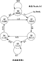
It is the record code of 2 least polar back span and the state transition diagram of the state-transition rule that equalizing system PR (1,2,2,1) limits according to having that Fig. 1 shows expression.
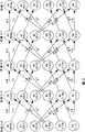
Fig. 2 shows by state transition diagram A is extended the trellis diagram that obtains along time shaft.
Fig. 3 A and 3B show the distribution of Pa-Pb.
The block diagram of Fig. 4 shows data recording/reproducing device according to an embodiment of the invention.
The block diagram of Fig. 5 shows the step of knowing according to the recording power of embodiments of the invention 1.
Fig. 6 shows index M and inscribes the curve and best the determining of power P wo of inscribing of power with respect to each.
Fig. 7 shows test pattern and the waveform when a pattern is reproduced.
Fig. 8 shows index M with respect to the curve of each erase power and determining of optimum erase power Peo.
Fig. 9 shows index M with respect to the curve of each end power and determining of best end power P bo.
Figure 10 shows the data recording/reproducing device according to embodiments of the invention 2.
The diagrammatic sketch of Figure 11 shows the relation of having explained between Itop, Ibtm and the Ith.
Figure 12 shows the relation between degree of modulation MOD and the inscription power P w.
Figure 13 shows the data recording/reproducing device according to embodiments of the invention 3.
Figure 14 shows pattern detection circuit and edge moving detecting circuit.
Figure 15 shows the time sequential routine figure of edge moving detecting circuit.
Figure 16 shows an example of the logging mode that is used to know.
Edge moving detecting circuit shown in Figure 17 is the modification of the edge moving detecting circuit of Figure 14.
Figure 18 A~18H shows the sampling value (pattern-1 is to pattern-8) of 8 patterns.
Figure 19 A and 19B show when path A is correct path the contact between the moving of record mark of the pattern-1 of reproducing waveform and Figure 18 A.
Figure 20 A and 20B show when path B is correct path the contact between the moving of the record mark of reproducing waveform and pattern-1.
The form of Figure 21 shows the tabulation of the recording parameters that needs optimization.
The form of Figure 22 shows (a plurality of) pattern of 8 AD HOC that are used for detecting the recording parameters that needs optimize.
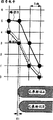
The relation of the edge movement value (solid triangle) that Figure 23 shows 5Ts5Tm, 5Tm5Ts and the variation of power is according to the absolute value (closed square) of the 5T mark lengths of the edge movement value measurement of the edge movement value (filled circles) of 5Ts5Tm and 5Tm5Ts.
Figure 24 shows has the multiple-pulse of inscribing power P w, erase power Pe and end power P b.
Embodiment
Below, the mode with illustrative example is in conjunction with the accompanying drawings described the present invention.
1, index M
At first, the reproducing signal assessment index of mentioning in the present invention (index M) is described.For example, reproducing signal assessment index M will be described, wherein recoding/reproduction operating period use have be 2 least polar back span record code (for example, the limited code of (1,7) run length) is used to the PR (1,2 of the frequency characteristic of signal, 2,1) balanced reshaping signal waveform.
After test record, comprise the record code b of current time k from a series of digital signals (binary signal " 1 " or " 0 ") of track record reproduction
k, the record code b of moment k-1 (preceding 1 unit interval of current time)
K-1, the record code b of moment k-2 (preceding 2 unit interval of current time)
K-2, the record code b of moment k-3 (preceding 3 unit interval of current time)
K-3The idea output Level that PR (1,2,2,1) is balanced
vBe expressed as:
(expression formula 1)
Level
v=b
k-3+2b
k-2+2b
k-1+b
k
Wherein k is the integer of express time, and v is 0~6 integer.
Following table 1 shows state transition table, wherein the state S (b of moment k
K-2, b
K-1, b
k) expression.
Table 1: according to having is the record code of 2 least polar back span and the state-transition of PR (1,2,2,1)
| State S (the b of moment k-1 k-3,b k-2,b k-1) | State S (the b of moment k k-2,b k-1,b k) | B k/Level v |
| S(0,0,0) | S(0,0,0) | 0/0 |
| S(0,0,0) | S(0,0,1) | 1/1 |
| S(0,0,1) | S(0,1,1) | 1/3 |
| S(0,1,1) | S(1,1,0) | 0/4 |
| S(0,1,1) | S(1,1,1) | 1/5 |
| S(1,0,0) | S(0,0,0) | 0/1 |
| S(1,0,0) | S(0,0,1) | 1/2 |
| S(1,1,0) | S(1,0,0) | 0/3 |
| S(1,1,1) | S(1,1,0) | 0/5 |
| S(1,1,1) | S(1,1,1) | 1/6 |
Fig. 1 shows state-transition block diagram A, wherein for simplicity, and the state S (0,0,0) of moment k
kUse S0
kExpression, S (0,0,1)
kUse S1
kExpression, S (0,1,1) k S2
kExpression, S (1,1,1)
kUse S3
kExpression, S (1,1,0)
kUse S4
kExpression, S (1,0,0)
kUse S5
kExpression.
State-transition block diagram A shown in Fig. 1 represents a kind of state-transition rule, and this rule is the record code of 2 least polar back span and the state-transition definition of equalizing system PR (1,2,2,1) according to having.
Fig. 2 shows by state-transition block diagram A is extended the trellis diagram that obtains along time shaft.
Below, describe according to state-transition with reference to Fig. 1 and Fig. 2 with the state-transition definition that is the record code of 2 least polar back span and PR (1,2,2,1).
Referring to the state S0k of moment k and the state S0 of moment k-4
K-4Fig. 2 shows at state S0
kWith state S0
K-4Between two possible state-transition sequences are arranged.A possible state-transition sequence is known as path A.The transformation sequence of path A is S2
K-4, S4
K-3, S5
K-2, S0
K-1, S0
kAnother changes sequence and is known as B.The transformation sequence of path B is S2
K-4, S3
K-3, S4
K-2, S5
K-1, S0
kMaximum comparability decoded result from moment k-6 to moment k (C
K-6, C
K-5, C
K-4, C
K-3, C
K-2, C
K-1, C
k) expression.In this case, as decoded result (C
K-6, C
K-5, C
K-4, C
K-3, C
K-2, C
K-1, C
k) when being (0,1,1, x, 0,0,0), wherein x is 0 or 1, then the state-transition sequence of estimated path A or path B is most possible.Path A and path B are S at the state of moment k-4
2k-4Possibility be identical.Therefore, by calculating reproducing signal y
K-3To reproducing signal y
kWith the value of the quadratic sum of the difference expectation value corresponding on path A and the path B respectively from moment k-3 to moment k, determine path A still be the transformation sequence of path B be possible.
Reproducing signal y
K-3To reproducing signal y
kRepresent with Pa with the value of quadratic sum from moment k-3 to the difference of moment k expectation value corresponding on the path A.Pa is expressed as:
(expression formula 2)
Pa=(y
k-3-4)
2+(y
k-2-3)
2+(y
k-1-1)
2+(y
k-o)
2
Reproducing signal y
K-3To reproducing signal y
kRepresent with Pb with the value of quadratic sum from moment k-3 to the difference of moment k expectation value corresponding on the B of path.Pb is expressed as:
(expression formula 3)
Pb=(y
k-3-5)
2+(y
k-2-5)
2+(y
k-1-3)
2+(y
k-1)
2
Below, will explain the meaning of Pa and Pb poor (being Pa-Pb), wherein Pa and Pb represent the reliability of maximum comparability decoded results.If Pa<<Pb, the maximum comparability decoded portion is selected path A with high reliability, and if Pa〉Pb, path B then selected.If Pa=Pb then selects path A or B.In this case, the correct chance of decoded result is 50 pairs 50.Therefore, according to the quantity of predetermined instant or predetermined instant and the distribution of decoded result acquisition Pa-Pb.
Fig. 3 A and 3B show the distribution of Pa-Pb.
Fig. 3 A shows the distribution of the Pa-Pb when increasing noise on reproducing signal.This is distributed with two peaks.The maximum incidence when Pa=0 is represented at one of them peak, and another expression another maximum incidence when Pb=0.Usefulness-Pstd represents the value of Pa-Pb when Pa=0, and represents the value of Pa-Pb when Pb=0 with Pstd.Calculated the value of Pa-Pb and obtained | Pa-Pb|-Pstd.
Fig. 3 B shows | the distribution of Pa-Pb|-Pstd.The standard deviation and the average Pave of the distribution of Fig. 3 B have been calculated.The distribution of supposing Fig. 3 is normal distribution.For example, hypothesis is when as the decoded result reliability simultaneously | and Pa-Pb| is equal to or less than-during Pstd, the generation error.Based on P (σ, error probability Pave) is represented with following formula:
(expression formula 4)
P(σ,Pave)=erfc((Pstd+Pave)/σ).
Can be according to the error rate of the binary signal of the mean P ave of the distribution of Pa-Pb and standard deviation prediction expression maximum comparability decoded result.In other words, can use mean P ave and standard deviation index as the reproducing signal quality.
In above-mentioned example, suppose | the distribution of Pa-Pb| is normal distribution.In this distribution is not under the situation of normal distribution, to wherein | and the value of Pa-Pb|-Pstd is less than or equal to the moment counting of predetermined reference value.The numeral of the counting that is obtained can be used as the index of the quality of reproducing signal.
Having in use is the record code and the equalizing system PR (1 of 2 Minimum Polarization back span, 2,2,1) under the situation of definition status transition rule, two kinds of possible state-transition paths are arranged: 8 patterns in the state-transition pattern count below from moment k-4 to moment k, 8 patterns from moment k-5 to moment k, and 8 patterns from moment k-6 to moment k.In sensing range widely, the Pa-Pb pattern is arranged, wherein Pa-Pb is a reliability level.
In a plurality of patterns, some insensitive patterns of variation to recording parameters (for example, inscribing power, erase power etc.) are arranged.For example, such pattern is included in the path in the variation of dead zone of long mark or mark part.By only selecting the pattern that is quick on the draw to recording parameters outside the above-mentioned pattern, detection reproduction waveform in high precision ground is possible with respect to the variation of the variation of recording parameters (recording power).In table 2, illustrated the super-sensitive pattern of recording parameters.
Table 2: the pattern that wherein has two state-transition paths the shortest

Particularly, the model group that in the waveform from the mark to the dead zone or from the dead zone to the mark changes, comprises table 2.For example, for the power (inscription power), cooling pulse power (end power) of record forward position pulse or the sensitive part of ratio of the inscribing power/erase power index of preferred dependability Pa-Pb that be combined as the reproducing signal quality.In this case, all patterns of unnecessary detection.By only detecting (a plurality of) pattern with high error rate, this measurement result can be used as the index relevant with the error probability.Pattern with high level error probability is the less pattern of the value of reliability Pa-Pb.8 this patterns are arranged, wherein Pa-Pa=± 10.Summarized this 8 patterns and Pa-Pb in the superincumbent table 2.
In addition, calculated | Pa-Pb|-Pstd.From described Distribution calculation standard deviation
10With average Pave
10As the description of reference Fig. 3 B, if this distribution is assumed to be normal distribution, the probability P of error takes place then
10Be expressed as:
(expression formula 5)
P
10(σ
10,Pave
10)=erfc((10+Pave
10)/σ
10).
In 8 above-mentioned patterns, 1-bit shift error takes place.In other pattern, 2-or multibit shift error more take place.The analysis result of Post-PRML process errors shows that the major part in these errors is a 1-bit shift error.Therefore, can estimate the error probability of reproducing signal by expression formula 6.Like this, standard deviation
10With mean value Pave
10Can be used as the index of reproducing signal quality.For example, suppose that above-mentioned index is PRML error extension M, then can define following formula:
(expression formula 6)
M=σ10/(2·d
min 2)[%]
D wherein
Min 2Be the Euclid minimum value and value square, be that it equaled 10 when the ML system combined for the modulation code of 2 least polar back span and PR (1,2,2,1) when having.In other words, d
Min 2=10=Pstd.Attention in expression formula 5 with mean P ave
10Be assumed to be 0, and when the index of calculation expression 6, it does not counted.According to the relation between expression formula 5 and 6, the error rate after PRML handles can use index M to estimate.
Therefore, by detecting a kind of state, the record of this state uses near the tolerance expectation value error of the state-transition pattern (pattern with minimum Euclid distance) the limit in a plurality of state-transition patterns that are included in the PRML algorithm, that reproduce waveform, detection index M accurately, and no matter the power (inscription power) of record forward position pulse, cooling pulse power (end power) or the variation of inscribing the ratio of power/erase power.
2, embodiment 1
The data recording/reproducing device of 2-1, embodiment 1
Fig. 4 shows the data recording/reproducing device 100 according to an example of the present invention.Data recording/reproducing device 100 comprises reproducing part 101, recording control apparatus 102 and recording section 103.On data recording/reproducing device 100, can place recording medium 1.Recording medium 1 is a CD for example, is used for the record and the reproduction of optical information.
Reproducing part 101 comprises bare headed part 2, prime amplifier 3, AGC4, waveform equalizer 5, A/D converter 6 and PLL circuit 7.Reproducing part 101 is from the analogue signal generating digital signal, and described simulating signal representative is from the information of recording medium 1 reproduction.
Shaping unit 8 is digital filters for example, receive the digital signal that produces by reproducing part 101 and to the wave shaping of this digital signal so that this digital signal has predetermined equalization characteristic.
Maximum comparability decoded portion 9 is Veterbi decoding circuits for example, and its waveform is carried out the maximum comparability decoding and produces the binary signal of representing this maximum comparability decoded result by the digital signal of shaping unit 8 shapings.
Recording medium controller 11 is used for the recording power of recorded information on recording medium 1 according to the reliability adjustment that is calculated by reliability calculation section 10.For example, the recording power that adjust comprises at least one that inscribe in power, erase power and the end power.Recording medium controller 11 is adjusted the shape of tracer signal in the mode that allows the maximum comparability decoded result to have the higher reliability level.Recording medium controller 11 is optical disc controllers for example.
In this example, reproducing part 101 and recording section 103 shared bare headed 2, bare headed 2 are simultaneously as record-header and reproduction head.Record-header also can separately be provided and reproduce head.
Below, the operation of data recording/reproducing device 100 is described with reference to Fig. 4.
Be input to shaping unit 8 by A/D converter 6 digital reproduction signal that produces of sampling.Shaping unit 8 is adjusted the frequency characteristic (that is, adjusting the waveform of this digital reproduction) of these digital reproduction signals, make at record and when reproducing the frequency characteristic of this digital reproduction signal be that the characteristic supposed by maximum comparability decoded portion 9 is (in this example, PR (1,2,2,1) equalization characteristic).
Maximum comparability decoded portion 9 is carried out the maximum comparability decoding to its waveform by the digital reproduction signal of shaping unit 8 shapings, therefore produces at least one binary signal.Described at least one binary signal is represented the maximum comparability decoded results.
Recording medium controller 11 controlling recording power-aware steps.In this step, setting recording power is used for test record, and controlling recording operation, control are reproduced operation, are each recording power gauge index M, and determine a recording power so that optimize index M.To introduce recording power in detail below and know step.
Recording power control section 13 is based on producing the record test mode generation laser waveform that part 12 is exported from the recording power parameter of recording medium controller 11 outputs with from tracer signal.Drive circuit for laser 14 drives shaven head 2 to launch laser according to this zlasing mode.
By service recorder/transcriber 100, it is possible setting up and making inscription power, erase power and the end power of the optimum of error minimize at reproduction period.
The recording/reproducing method of 2-2, embodiment 1
Fig. 5 shows according to the recording power of embodiments of the invention 1 knows step.Data recording/reproducing device 100 these recording powers of execution know that step is to adjust recording power.This recording power knows that step comprises step 1~3.
Below, describe this recording power length by length with reference to Fig. 5 and know step.
When recording power is known beginning, in step 1, calculate the optimum power P wo that inscribes.Step 1 comprises step 1-1,1-2 and 1-3.
Step 1-1: control shaven head 2 makes it move on to predetermined on the recording medium 1 to know the zone.Fixing erase power/inscription power ratio (Pe/Pw) and end power.Change inscription power when inscribing test signal continuously.In this case, erase power/inscription power ratio and end power can be fixed to the previous recommendation that writes down as initial value on recording medium 1, and this recommendation is according to definition such as standards.Inscribing power can change around the previous recommendation that writes down on recording medium 1.
Perhaps, the recommendation that is used for each recording medium of data recording/reproducing device 100 storages can be used as initial value.For example, suppose that the previous recommendation that writes down is Pw=9.0[mW on recording medium 1], Pe/Pw=0.40 and Pb=0.3[mW].In this case, Pe/Pw and Pb are fixed as 0.40 and 0.3 respectively.When Pw from 8.0 stepping 0.2[mW] change to 10.0[mW] time, be that each inscribes the identical test record signal of power duplicate record.
After test record, forward step 1-2 to.
Step 1-2: the test record signal of bare headed 2 reproducing recorded.Reliability calculation section 10 is inscribed state that power calculation write down definiteness numerical value really for each.(1. index M) the invention is characterized in that the tolerance expectation value error (hereinafter being called index M) of PRML technology is used as the state that is write down and determines exponential quantity as mentioned above, and described tolerance expectation value error is from corresponding to extracting near the state-transition the limit of reproducing waveform.Index M is characterised in that index M is associated with error rate in the route of transition that adopts PRML technical finesse reproducing signal, and is that the detection of index M can be to having a high sensitivity because the waveform that variable power etc. cause is asymmetric.
Calculate each state that is write down of inscribing power really after the definiteness numerical value in reliability calculation section 10, forward step 1-3 to.
Step 1-3: reliability calculation section 10 will allow the inscription power of optimality index M to be defined as the optimum power of inscribing.For example, reliability calculation section 10 selects minimum value as optimality index M, and will be defined as the optimum power P wo that inscribes corresponding to the inscription power of selected index M.
For example, Fig. 6 shows the curve and optimum the determining of power of inscribing of each index M of inscribing power.
Fig. 7 shows test pattern and the waveform when pattern is reproduced.Open circles on the reproduction waveform represents to have the sampling spot of A/D converter 6 acquisitions.Feature of the present invention also is the test record signal.Traditionally, the test pattern that uses single pattern to know as recording power with predetermined period.For example, such one single pattern is the repeat pattern of 6T (T is a channel cycle).This single pattern stops the width of recording impulse of each record mark length or the influence of phase shift.Yet detection is lower slightly corresponding to the degree of accuracy of the variation of the waveform of recording power variation.In the present invention, in the record modulating rule, minimum mark length and maximum mark length are combinations, and use wherein recording section (mark) and non-recording section (dead zone) phase shift with the test pattern of probability generation.For example, when the limited code of (1,7) run length when noting down modulation code, minimum mark length is that 2T and maximum mark length are 8T, uses the repeat pattern of 8Tm2Ts8Tm8Ts2Tm8Ts.The channel cycle length of Tm expressive notation, Ts represents the channel cycle length of dead zone.
Therefore, in step 1, allow the inscription power of optimality index M to be confirmed as the optimum power P wo that inscribes.
After this, in step 2, obtain optimal erase power.Step 2 comprises step 2-1,2-2 and 2-3.
In step 2-1: recording medium controller 11 will be inscribed power setting and inscribe power P wo for the optimum of determining in step 1.In addition, recording medium controller 11 is end power fixedly, and inscribe test record signal (test record) when continuously changing erase power.
For example, Pw and Pb are fixed to 9.4[mW respectively] (Pwo) and 0.3[mW].And Pe is with 0.1[mW] be that unit is from 3.4[mW] change to 4.1[mW], wherein the center is Pe=Pw*0.4=3.76[mW], each is inscribed the identical test record signal of power duplicate record.Can carry out described record by the track that rewriting has at the state of preceding record.Perhaps, can use and the identical track of track that in step 1, uses.
After inscribing test record signal (test record) end, described step forwards step 2-2 to.
Step 2-2: shaven head 2 reproduces record test record signal.Institute's recording status that reliability calculation section 10 is calculated each erase power is determined exponential quantity (index M).
Index M is as determine index as recording status in step 1.Repeating of 8Tm2Ts8Tm8Ts2Tm8Ts pattern as the test record signal.
After the recording status that reliability calculation section 10 has been calculated each erase power was determined exponential quantity, described step forwarded step 2-3 to.
Step 2-3: reliability calculation section 10 determines to allow the erase power of optimality index M as optimal erase power Peo.Reliability calculation section 10 is for example selected minimum value optimality index M the most, and corresponding to the erase power of selecteed index M as optimal erase power Peo.
For example, Fig. 8 shows the curve of the index M of each erase power, and optimal erase power Peo's is definite.
After this, in step 3, calculate optimum end power P bo.Step 3 comprises step 3-1,3-2 and 3-3.
Step 3-1: recording medium controller 11 will be inscribed power setting and inscribe power P wo for the optimum of determining in step 1.Recording medium controller 11 is set at erase power the optimal erase power Pwo that determines in step 2.In addition, recording medium controller 11 is inscribed test record signal (test record) when continuously changing end power.
For example, Pw and Pe are fixed as Pwo=9.4[mW respectively] and Peo=3.9[mW].When Pb with 0.05[mW] be that unit changes to 0.4[mW from 0.2] time, be that each inscribes the identical test record signal of power duplicate record.Can having formerly by rewriting, the track of recording status carries out described record.Perhaps, can use with track identical in step 1 and 2 and carry out record.
After inscribing test record signal (test record) end, described step forwards step 3-2 to.
Step 3-2: the test record signal of bare headed 2 reproducing recorded.The recording status that reliability calculation section 10 is calculated each end power is determined exponential quantity (index M).Index M is as determining index at the same recording status that is used as with 2 of step 1.Repeating of 8Tm2Ts8Tm8Ts2Tm8Ts pattern as the test record signal.
After the recording status that reliability calculation section 10 has been calculated each end power was determined exponential quantity, described step forwarded step 3-3 to.
Step 3-3: reliability calculation section 10 will be defined as optimum end power P bo from the end power that optimality index M obtains.Reliability calculation section 10 selects minimum value also will be defined as optimum end power P bo with power of the corresponding end of selected index M as optimality index M.
For example, the curve of the index M of each end power shown in Fig. 9, and determine optimum end power P bo.
As mentioned above, by execution in step 1-3, be used to set up the optimum step of knowing of inscribing power, erase power and end power and finish, and can carry out record with least error at reproduction period.Notice that when the variation at power at the bottom of the reproduction period readability is not had when influence substantially, knowing in step 3 can be omitted, end power can be set to suitable fixed value.
As mentioned above, in embodiments of the invention 1, by detecting the only state of the tolerance expectation value error log of a state-transition pattern (Euclid is apart from the pattern of minimum) that uses, can detect the power (inscription power) corresponding to record forward position pulse, the power (end power) of cooling pulse or the wave recording variation of inscribing power/erase power ratio in high precision ground, wherein said state-transition pattern is included in a plurality of state-transition patterns of PRML algorithm, relates near the limit of reproducing waveform.Consider the width of the recording impulse that it resists each record mark length and the influence of phase shift, the repetition of using the 8Tm2Ts8Tm8Ts2Tm8Ts pattern is as test pattern, makes the variation that can detect the waveform that changes corresponding to recording power in high sensitivity.As a result of, can further improve detection sensitivity.
3, embodiment 2
The data recording/reproducing device of 3-1, embodiment 2
Figure 10 shows the data recording/reproducing device 200 according to embodiments of the invention 2.Data recording/reproducing device 200 comprises recording control apparatus 202, and replacement is with reference to the recording control apparatus 102 of the data recording/reproducing device 100 of the embodiments of the invention 1 of Fig. 4 description.Therefore, in Figure 10, use identical Reference numeral to represent and the identical part of the data recording/reproducing device 100 of Fig. 4, will no longer lay down a definition these parts.
Recording control apparatus 202 comprises shaping unit 8, maximum comparability decoded portion 9, reliability calculation section 10, recording medium controller 11 and degree of modulation testing circuit 15.Recording control apparatus 202 is made for for example semi-conductor chip.
Degree of modulation testing circuit 15 calculates the degree of modulation characteristic according to the amplitude from bare headed 2 reproducing signals that read, and to recording medium controller 11 these degree of modulation characteristics of output.
Recording medium controller 11 is adjusted at the recording power of recorded information on the recording medium 1 according in reliability and the degree of modulation characteristic at least one.
As mentioned above, data recording/reproducing device 200 is set up optimum power, erase power and the end power inscribed at reproduction period.
The recording/reproducing method of 3-2, embodiment 2
Below, know step with reference to Fig. 5 description according to the recording power of embodiments of the invention 2.Data recording/reproducing device 200 executive logging power-aware programs are to adjust recording power.
In embodiments of the invention 2, with no longer explain with embodiment 1 in identical step.As in embodiment 1, the recording power of embodiment 2 knows that step comprises step 1~3.(step 1) uses degree of modulation to determine exponential quantity as recording status, and this is different with embodiment 1 in the step of calculating optimum inscription power P wo.To describe below according to degree of modulation and calculate the optimum details of inscribing the step of power P wo.
In step 1, obtain the control of each setting that is used for the recording power parameter of test record, recording operation, the control of reproducing operation and the degree of modulation of recording power.Reliability calculation section 10 is determined the optimum power P wo that inscribes according to the degree of modulation of being calculated.
Similarly, in step 2 and 3, obtain the setting of the recording power parameter of each test record, the control of recording operation, the control of reproducing operation and the index M of recording power.Reliability calculation section 10 is determined optimal erase power Peo and optimum end power P bo according to index M.
Below, determine the optimum step of inscribing power P wo with describing according to degree of modulation.
Degree of modulation is the index of the amplitude size of expression reproducing signal.Degree of modulation MOD is according to expression formula 7 definition.
(expression formula 7)
MOD=(Itop-Ibtm)/(Itop-Ith)
The diagrammatic sketch of Figure 11 has been explained the relation between Itop, Ibtm and the Ith.
Below, with reference to Figure 11 Itop, Ibtm and Ith in the expression formula 7 are described.
Itop represents the highest order of reflection of reproducing signal.Ibtm represents the minimum order of reflection of reproducing signal.Ith represents to wipe the rank of laser.In this embodiment, degree of modulation is used to obtain the 8T repeating signal.The present invention is not limited to this.
Figure 12 shows the relation between degree of modulation MOD and the inscription power P w.
The variation of degree of modulation MOD depends on inscribes power x.When inscription power P w was low, the amplitude of reproducing signal was low, thereby degree of modulation MOD is little.Increase along with inscribing power P w, the amplitude of reproducing signal increases, thereby degree of modulation MOD increases.When inscription power P w was increased to predetermined extent, degree of modulation MOD was saturated.
Obtained to inscribe in the degree of modulation curve tangent line of power lower that part of (from several samplings in unsaturation zone).Obtain the point of crossing Pth (seeing Figure 12) between this tangent line and the x axle.Being used for of every CD obtains the optimum coefficient ρ that inscribes power P wo from Pth and is recorded on the CD in advance or is stored in data recording/reproducing device.Coefficient ρ is used for calculating the optimum power P wo that inscribes according to following formula.
(expression formula 8)
Pwo=ρ×Pth
Therefore, in step 1, determine the optimum power P wo that inscribes according to the degree of modulation characteristic.
In step 2 and 3, identical among the step of determining optimal erase power Peo and end power P bo and the embodiment 1 will no longer lay down a definition.Substantially do not have when influencing when the variation of end power for readability at reproduction period, can omit step 3, and end power can be fixed as appropriate value.
In embodiment 2, when using degree of modulation to determine Pwo with reference to expression formula 8.The invention is not restricted to this.For example, a power makes that this power can be considered to Pwo when detecting the predetermined modulation degree.Perhaps, a power makes when degree of modulation is saturated that this power is considered to Pwo.
In embodiment 2, test signal comprises the repetition of 8Tm8Ts pattern.The invention is not restricted to this.Test signal only need comprise the pattern that the upper and lower amplitude of reproducing signal wherein can be measured.
4, embodiment 3
The data recording/reproducing device of 4-1, embodiment 3
Figure 13 shows the data recording/reproducing device 300 according to embodiments of the invention 3.Record reproducing device 300 comprises recording control apparatus 302, and replacement is with reference to the recording control apparatus 102 of the data recording/reproducing device 100 of the embodiments of the invention 1 of Fig. 4 description; Recording section 303 replaces being included in the recording section 103 in the data recording/reproducing device 100.Therefore, the part identical with part in the data recording/reproducing device device 100 of Fig. 4 uses identical Reference numeral to represent and no longer explain in Figure 13.
Record controls part 302 comprises shaping unit 8, maximum comparability decoded portion 9, reliability calculation section 10 and control section 304 (pattern detection circuit 17, edge moving detecting circuit 18 and recording medium controller 11).Recording control apparatus 302 is made for example semi-conductor chip.
Adjusting gear 304 is used for the shape of the predetermined portions of the tracer signal of recorded information on recording medium 1 according to the reliability adjustment that is calculated by reliability calculation section 10.Adjustment member 304 is adjusted, for example the position on the limit of tracer signal.Adjust by 104 pairs of tracer signal positions of adjusting gear, make the reliability of maximum comparability decoded result be improved.Recording medium controller 11 is optical disc controllers for example.
Describe the operation of data recording/reproducing device 300 below in detail.With no longer explain with data recording/reproducing device 100 in the operation of identical part.
According to binary signal, pattern detection circuit 17 produces pulse signal, be used for above-mentioned 8 patterns (pattern 1 is to pattern 8) are distributed to each logging mode, and to edge moving detecting circuit 18 output pulse signals.
The edge moving detecting circuit 18 reliability Pab that adds up to pattern one by one, and obtain move (that is, the edge moves) of record compensating parameter from optimal value.
Recording medium controller 11 changes the recording parameters (waveform of recording medium) that is confirmed as the needs change according to the edge amount of movement of each pattern.
Based on the recording parameters from recording medium controller 11, record compensating circuit 15 is according to described record compensating for tilt mode producing laser waveform pattern.According to the laser waveform pattern that is produced, the Laser emission operation of the bare headed part 2 of drive circuit for laser 16 controls.
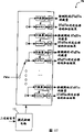
Figure 14 shows pattern detection circuit 17 and edge moving detecting circuit 18.
Below, will describe the operation of edge moving detecting circuit 18 according to Figure 14 in detail.
Edge moving detecting circuit 18 receives the mode detection result who is obtained by pattern detection circuit 17, and the reliability Pab that is calculated by reliability calculation section 10.Consider the delay that is caused by pattern detection circuit 17, the reliability Pab data of input edge moving detecting circuit 18 produce by trigger (FF) and postpone.Reliability Pab data corresponding to mode detection output and detection output point are input to totalizer, and the mode detection result is input to selector switch.The accumulated result that selector switch select to obtain according to detecting pattern until that, and selection result is input to totalizer, totalizer is added up the reliability Pab data of accumulated result and new input, and the output addition results.When the concrete register corresponding to detecting pattern receives enable signal, store this addition results.
The sequential chart of Figure 15 shows the operation of edge moving detecting circuit 18.For example, under information is recorded in it situation on the recording medium that information is address administration one by one, suppose to use addition pocket door signal (Figure 15 (b)) and register enable signal (Figure 15 (c)).The part of Figure 15 (a) shows address location.
Test record in the user area one by one the address carry out so that obtain under the situation of edge amount of movement, need control addition definition at interval.When addition pocket door signal was input to edge moving detecting circuit 18, addition pocket door signal was imported into trigger FF29 (Figure 14) through the two-stage trigger and by FF0.Trigger the low tone of addition pocket door signal every in be reset, and addition results be stored in high at interval in.Produce register enable signal from addition pocket door signal.Register enable signal is used for addition results is stored into the register REG29 to REG0 of addition pocket door signal end.
The data storage of representing the edge amount of movement of address one by one is in register REG29 to REG0.Because such circuit arrangement, edge moving detecting circuit 18 can use a totalizer to obtain to optimize necessary all edge amount of movements for recording parameters.
In the typical circuit that reference Figure 14 describes, be used for each logging mode of test record (for example random pattern), the generation frequency of logging mode changes according to the combination of the predetermined length of optimizing needed mark of recording parameters and dead zone.Detected 30 edge amount of movements (R23T, R33T ..., R45L, R55L) depend on the incidence of logging mode.PLL circuit 7 shown in Figure 1 uses DC component (being included in the low frequency component in the reproducing signal) to detect the threshold value of cutter (not shown) automatically, and makes reproducing signal and reproduce clock signal synchronous.Therefore, preferred, the amount that is included in the DC component in the test record pattern is as far as possible little, makes FEEDBACK CONTROL not influence the generation of the clock that is undertaken by PLL circuit 7.Consider and optimize the required time and optimize degree of accuracy that the minimum possibility of preferred use posting field obtains to have the testing result of pinpoint accuracy.Therefore, need following logging mode: a kind of logging mode, has the combination of optimizing the needed mark lengths of recording parameters/dead zone length under the same frequency, wherein code does not comprise DC component (DSV), and it is wherein, higher for the generation frequency of mark lengths/dead zone length combination of optimizing the required per unit area of recording parameters.
Figure 16 shows an example of the logging mode that is used to know.2M represents the 2T mark, and 2S represents the 2T dead zone.In this example, each in 30 patterns of the combination of 2T~5T mark and 2T~5T dead zone produces once in the logging mode of 108-position.Comprise that the quantity of code " 0 " of 108-position logging mode and the quantity of code " 1 " all are 54, and DSV is 0 in logging mode.By this logging mode being applied to the edge moving detecting circuit 18 of Figure 13, the number of times that each pattern is recorded is identical.Therefore, obtained amount of movement testing result more accurately.In this example, suppose to use identical recording parameters record 5T or longer mark or 5T or vast sky district more.
Edge moving detecting circuit 18a shown in Figure 17 is the modification of edge moving detecting circuit 18.
As mentioned above, the edge moving detecting circuit 18 that is included in the adjustment member 304 calculates each logging mode (promptly, each mark/dead zone length in conjunction with) the aggregate-value of maximum comparability decoded result reliability or one of mean value, and adjust the shape of tracer signal according to the aggregate-value that is obtained or mean value.
In the above example, be that the state-transition rule of record code definition of equalizing system of 2 least polar back span and PR (1,2,2,1) is used to carry out the maximum comparability decoding by maximum comparability decoded portion 9 by having.The invention is not restricted to this.The present invention for example can be applicable to, and is 3 least polar back span and PR (C0, C1 by having, C1, the state-transition rule of the record code of equalizing system C0) definition is 2 or 3 least polar back span and PR (C0, C1 by having, the state-transition rule of the record code definition of equalizing system C0), and to have be 2 or 3 least polar back span and PR (C0, C1, C2, C1, the state-transition rule of the record code definition of equalizing system C0).C0, C1, C2 are respectively positive counts.
The recording/reproducing method of 4-2, embodiment 3
In this example of the present invention, for each logging mode (be each mark lengths and each combination that is right after the dead zone length before this mark, and be mark lengths and each combination that is right after the dead zone length after this mark) detects 8 above-mentioned patterns.Be identified for optimizing the recording parameters of position on the limit of tracer signal, pay special attention to the whole limit of shape, especially mark initial line and mark of tracer signal.
Only pay close attention to the reliability of all maximum comparability decoded results with all patterns
1Pa-Pb
1In minimum
1Pa-Pb
1The pattern of value means the limit of only paying close attention to record mark.As mentioned above, the pattern with less Pa-Pb value has the high level error probability.This means that the position on limit of optimizing record mark by part to improve the reliability of maximum comparability decoded result, optimized whole recording parameters.The method of the position on the limit of optimizing record mark will be described below.
Figure 18 A~18H has used the sampling value of 8 patterns (pattern-1 is to pattern-8).Transverse axis is represented the time.A scale is represented a channel clock (Tclk).Vertical axis represent signal level (0~6).Dotted line delegated path A, solid line delegated path B.Each sampling value is corresponding to the expectation value Level of the maximum comparability decoding of reference table 1
v0~6.
Recording section (non-crystalline areas) is described to have the signal level of the threshold value that is lower than comparer, owing to be lower than the light quantity that is reflected by other parts by the light quantity of recording section reflection.(non--non-crystalline areas) is described to have the signal level that is higher than comparator threshold in the zone that is not recorded.8 patterns correspond respectively to recording section (mark) and are not recorded the partly reproduction waveform on the border between (dead zone) (the whole limit of mark initial line or mark).Pattern-1 (Figure 18 A), pattern-2 (Figure 18 B), pattern-3 (Figure 18 C) and pattern-4 (Figure 18 D) correspond respectively to the mark initial line, and pattern-5 (Figure 18 E), pattern-6 (Figure 18 F), pattern-7 (Figure 18 G) and pattern-8 (Figure 18 H) correspond respectively to the whole limit of mark.
With using pattern-1 method that moves of certification mark initial line is described as example.
Figure 19 A and 19B show the contact between the moving of the record mark of reproducing waveform and pattern-1.In Figure 19 A and 19B, hollow triangle is represented input signal.The path A of being represented by dotted line is correct state-transition path.Input signal produces based on record mark B1.Record mark A1 has the ideal position of this mark initial line.
In Figure 19 A, the position of the mark initial line of record mark B1 is after ideal position.Input signal (y
K-3, y
K-2, y
K-1, y
k) sampling value be (4.2,3.2,1.2,0.2).From expression formula 2 and 3, the distance P a between path A and the input signal, the distance P b between path B and the input signal through type 9 and 10 respectively obtain.
(expression formula 9)
Pa=(4.2-4)
2+(3.2-3)
2+(1.2-1)
2+(0.2-0)
2=0.16
(expression formula 10)
Pb=(4.2-5)
2+(3.2-5)
2+(1.2-3)
2+(0.2-1)
2=7.76
By obtaining
1Pa-Pb
1Can obtain the amount and the direction that move of mark initial line,
1Pa-Pb
1Can obtain by expression formula 9.
(expression formula 11)
E1=|Pa-Pb|-Pstd=|0.16-7.76|-10=-2.4
The absolute value of the E1 that obtains by expression formula 11 is an amount of movement, and the symbol of E1 is a moving direction.Under the situation of the record mark B1 of Figure 19 A, E1=-2.4.The position that this means the mark initial line of record mark B1 has moved 2.4 backward from the reference position.
In Figure 19 B, the position of the mark initial line of record mark B1 has advanced to ideal position.Input signal (y
K-3, y
K-2, y
K-1, y
k) sampling value be (3.8,2.8,0.8 ,-0.2).By E2=
1Pa-Pb
1-Pstd draws E2.E2 is 2.4.The position that this means the mark initial line of record mark B1 has moved forward 2.4 from the reference position.
Figure 20 A and 20B show the relation between the moving of the record mark of reproducing waveform and pattern-1.In Figure 20 A and 20B, the path B that represents with solid line is correct state-transition path.
In Figure 20 A, the position of the mark initial line of record mark B1 is after ideal position.Input signal (y
K-3, y
K-2, y
K-1, y
k) sampling value be (5.2,5.2,3.2,1.2).By E3=
1Pa-Pb
1-Pstd draws E3.E3 is 2.4.The position that this means the mark initial line of record mark B1 has moved 2.4 backward from the reference position.
In Figure 20 B, the position of the mark initial line of record mark B1 has advanced to ideal position.Input signal (y
K-3, y
K-2, y
K-1, y
k) sampling value be (4.8,4.8,2.8,0.8).By E4=
1Pa-Pb
1-Pstd draws E4.E4 is-2.4.The position that this means the mark initial line of record mark B1 has moved forward 2.4 from the reference position.
Wherein path A be the situation of Figure 19 A of correct status route of transition and 19B and wherein path B be Figure 20 A of correct status route of transition and the situation of 20B, the symbol of the code of expression moving direction is opposite.The symbol of code depends on the expectation value sequence of correct status route of transition and the relation between the input signal sequence, and the expectation value sequence of other path candidate and the relation between the input signal sequence.When among the expectation value of incorrect path candidate and the error image pattern 19B between the input signal and Figure 20 A when so big, the symbol of the value that obtains by expression formula 11 is for just.That is, expectation value and the difference between the input signal along with incorrect path candidate becomes big, the error probability reduction of maximum comparability decoding.In this case, the symbol of the value that obtains by expression formula 11 is for just.Consider this point, the moving direction of the position of mark initial line that can the detection record mark.
When path A was the correct status route of transition in pattern-1, pattern-1 was used to detect the initial line of record mark of the combination of 2T dead zone and 4T or longer mark.When path B in pattern-1 was correct state-transition path, pattern-1 was used to detect the initial line of record mark of the combination of 3T dead zone and 3T or longer mark.
Use said method, (that is the position amount of movement that is arranged so that initial line and whole limit of) aggregate-value or mean value, the combination of each mark lengths/dead zone length, and recording parameters is near 0 to obtain each logging mode.Therefore, realized record controls for maximum comparability coding/decoding method the best.
Determine to be formed on that the initial line of the mark on the dish and whole limit be positioned at before the reference position after still being is important.For the purpose of determining, must detect which pattern has the limit of having departed from.Be each mode detection amount of movement.
Described as reference Figure 19 A, 19B, 20A and 20B, the symbol of representing the code of moving direction is opposite.Therefore, when mark than with reference in short-term, this mark has minus sign.When this minus sign mark was longer than the reference position, this mark had plus sige.According to this rule,, make that therefore the initial line of the mark lengths that detection is concerned about and the length on whole limit are possible for analyzing above-mentioned error amount in the initial line and the whole limit of each mark lengths.In addition, can be according to the absolute value forecasting correcting value of the value that is detected.
To the optimization of recording parameters be described.The least polar back span of record symbol is represented (in this example, m=2) with m.The length of the dead zone before the position of the initial line of the record mark that forms on the recording medium can be dependent on this record mark and then and the length of this record mark itself.For example, when the length of the dead zone before this record mark and then was the T of mT~(m+b), the position of the mark initial line of this record mark depended on the length of the dead zone before this record mark and then.When the length of the dead zone before this record mark and then during greater than (m+b) T, the position of the mark initial line of this record mark does not rely on the length of the dead zone before this record mark and then.When the length of this record mark self was the T of mT~(m+a), the position of the mark initial line of this record mark depended on the length of this record mark self.When the length of this record mark self during greater than (m+a) T, the position of the mark initial line of this record mark does not rely on the length of this record mark self.
The position on the whole limit of the record mark that forms on recording medium may depend on the length of the dead zone after this record mark and then and the length of this record mark itself.For example, when the length of this record mark self was the T of mT~(m+a), the position on the whole limit of the mark of this record mark depended on the length of this record mark self.When the length of this record mark self during greater than (m+a) T, the position on the whole limit of the mark of this record mark does not rely on the length of this record mark self.When the length of the dead zone after this record mark and then was the T of mT~(m+b), the position on the whole limit of the mark of this record mark depended on the length of the dead zone after this record mark and then.When the length of the dead zone after this record mark and then during greater than (m+b) T, the position on the whole limit of the mark of this record mark does not rely on the length of the dead zone after this record mark and then." a " and " b " is equal to or greater than 0 integer in the superincumbent description, and the least polar back span of record symbol is greater than m+a and m+b.
Consider the position of mark initial line of record mark and the position on whole limit, need with length be the optimization of the parameter Tsfp on the adjacent enterprising row labels initial line of record mark in (m+b) T or shorter dead zone.Need in length the optimization of the parameter Telp on the whole limit of the enterprising row labels of (m+a) T or shorter record mark.
Figure 21 shows the tabulation of the recording parameters that needs optimization.Wherein, for simplicity, m=3 and a=b=3 need be shown in Figure 8 for 32 logging mode optimum parameters.2Ts2Tm for example means the pattern that wherein and then had the 2T dead zone before the 2T mark in Fig. 8.
Figure 22 shows (a plurality of) pattern of 8 special patterns that are used for detecting the recording parameters that needs optimize.In other words, show (a plurality of) pattern in above-mentioned 8 patterns (pattern-1 is to pattern-8) that are used to detect each logging mode (that is edge mode).
For example, use the amount of movement of P3A detection corresponding to the signal of 2Ts3Tm logging mode.P3A is a pattern-3, and wherein path A is correct state-transition path.
Use P1B or P4A to detect the amount of movement of the signal of 3Ts3Tm logging mode (Figure 21).P1B is a pattern-1, and wherein path B is correct state-transition path.P4A is a pattern-4, and wherein path A is correct state-transition path.
Be appreciated that from above the method that is used to control for the recording parameters of maximum comparability coding/decoding method optimum is the improvement recording parameters, make amount of movement corresponding to the signal of each logging mode among Figure 22 near 0.
Amount of movement corresponding to the signal of 2Ts2Tm logging mode (and then 2T mark before occur 2T dead zone) and 2Tm2Ts (and then the 2T dead zone appears afterwards in the 2T mark) can not be by any one detection in above-mentioned 8 patterns.Therefore, need to optimize described amount of movement by other method (seeing Figure 22).Yet 2Ts2Tm logging mode and 2Tm2Ts logging mode have the value of bigger reliability Pa-Pb, therefore are not included in 8 above-mentioned patterns.In other words, place, the whole limit of the mark initial line of the record mark of each of 2Ts2Tm logging mode and 2Tm2Ts logging mode or mark, the error probability is low; There is no need the strict recording parameters of optimizing these logging modes.Therefore, can use suitable initial value to replace this amount of movement is optimized for each information recording medium as recording parameters.Perhaps, 2Ts2Tm logging mode and 2Tm2Ts logging mode can optimisedly make the aggregate-value of phase error of reproducing signal minimize.
In the description in front, explained that recording impulse (strategy of writing) adjusts and do not explain the power adjustment.The invention is characterized in detected value (edge movement value) the adjustment power that use is adjusted by being used for recording impulse traditionally.By using above-mentioned edge movement value, can the survey record medium on the length of record mark.Therefore, adjusting recording power makes mark lengths become predetermined length.Recording power parameter to be adjusted can be any that inscribe in power, erase power and the end power.
For example, will the method for inscribing power parameter of adjusting be described.In the erase power and the ratio between the end power that keep being scheduled to, carry out test record by changing inscription power.Logging mode is assumed to be single 5T pattern, detects the edge movement value (seeing Figure 21) of 5Ts5Tm5Tm5Ts.
Figure 23 shows the edge movement value (solid triangle) of 5Ts5Tm, 5Tm5Ts and the relation between the variable power, the absolute value (closed square) of the 5T mark that records according to the edge movement value of the edge movement value (filled circles) of 5Ts5Tm and 5Tm5Ts.
By the edge movement value of 5Ts5Tm and the edge movement value addition of 5Tm5Ts are obtained the 5T mark lengths.Adjusting recording power makes this additive value approximately become 0.
Notice that the desired value of above-mentioned additive value and mark lengths can be according to the characteristic variations of CD.In addition, logging mode can be single-mode, AD HOC or random pattern.
When the logging mode that uses except that single labelled, for each record mark length detection mark width and carry out the power adjustment, make the target label length of every dish on average or during all mark lengths sums of all mark lengths.
Characteristic variations, required time and the scheduled operation that can be respectively environmental change (temperature, humidity), dish plane carry out the recording power adjustment.In this case, recording operation is hung up, and the posting field before the and then described hang-up is reproduced, and detects the mark width of each record mark length.When described mark lengths is defined as in short-term, can increase recording power according to mark width.When described mark lengths is defined as length, can reduce recording power according to mark width.Can make this decision according to all mark lengths.When only basis has the width of highly sensitive relatively short mark, can determine that power increases still reduction.
With reference to Figure 21 and 22 mark lengths up to 5T has been described.For 5T or above mark lengths, can measure the edge movement value for each mark lengths.
Embodiments of the invention 1~3 have been described with reference to Fig. 1~23 in the front.
Data recording/reproducing device 100,200 of the present invention and 300 element can be implemented as hardware or software.For example, can be implemented as by at least one the performed operation in shaping unit 8, maximum comparability decoded portion 9, reliability calculation section 10 and the recording medium controller 11 can be by the program of computing machine execution.
In embodiments of the invention 1~3, recording section 103 and recording section 303 use a plurality of recording powers to write down a detecting information on recording medium 1.Perhaps, recording section 103 and recording section 303 can use a plurality of recording powers to write down many detecting informations on recording medium 1.In addition, recording section 103 and recording section 303 can use single recording power to write down a detecting information on recording medium 1.In addition, recording section 103 and recording section 303 can use single recording power to write down many detecting informations on recording medium 1.
In embodiment 1~3, index M is by comprising variable | expression formula 6 definition of Pa-Pb|-Pstd.The invention is not restricted to this.For example, can use by pre-determined number integration Pa-Pb or | the value that Pa-Pb|-Pstd obtains is as index M.
In embodiment 1~3, use the recording impulse of describing with reference to Fig. 2.The invention is not restricted to this.For example, the present invention do not need to can be applicable to the recording power control of the recording medium of cooling pulse (end power level).In this case, only power and erase power are inscribed in control.
In addition, in embodiment 1~3, test signal be not limited to above-described those.Test pattern can be the combination of long relatively mark/dead zone and relative short mark/dead zone, and wherein said mark has identical occurrence probability with described dead zone.For example, such test pattern: comprise the repeat pattern of 8Tm3Ts8Tm8Ts3Tm8Ts and the repeat pattern of 7Tm2Ts7Tm7Ts2Tm7Ts.
In addition, in embodiment 1~3, record modulating rule and PRML technology be not limited to above-described those.Can be in conjunction with the PRML technology of various record modulating modes and various characterizations.For example, can be in conjunction with the limited code of (1,7) run length and PR (1,2,1) ML or PR (1,2,2,2,1) ML.The 8-6 modulation code that is used for CD and DVD can be combined with above-mentioned PRML technology.
In addition, in embodiment 1~3, the power bracket that is used to search Pwo, Peo and Pbo be not limited to above-described those.For example, each power seek scope can be around recommended value ± x% (for example, x=10).If in this scope, do not detect optimum point, as shown in figure 18, will provide the upper limit or lower limit.
In addition, in embodiment 1~3, when searching Pwo, fixedly changing parameter in the Pe/Pw ratio.The invention is not restricted to this.For example, can obtain Pwo by when Pe and Pb are fixed as appropriate value, changing Pw.
Optical data recording/reproducing device according to the present invention is optimized recording power by using the reproducing signal assessment index during writing down, described reproducing signal assessment index is with to be used to handle decoding performance reproducing signal, employing maximum comparability process of decoding system relevant.Therefore, can optimize recording status and make error minimize at reproduction period.Than in tradition, being used for recording power control, in the present invention, can detect accurately because the variation of the reproduction waveform that the variation of recording power causes such as the reproducing signal qualitative index of shake, asymmetric, BER etc.Therefore, can carry out recording power control accurately.Owing to can determine to pinpoint accuracy recording power,, consequently produce optical disc apparatus and stable compatibility with optical disc media of identical standard because the performance degradation that cross-power causes can minimize.
Traditionally, use such as the reproducing signal qualitative index of shake, asymmetric, BER etc. and can not pinpoint accuracy ground obtain suitable parameter to determine accurately and to set optimum recording parameters.
In the present invention, by detecting the only state of the tolerance expectation value error log of a state-transition pattern that uses, the end power of detection record forward position pulse accurately (inscription power), cooling pulse and the variation of inscribing power/erase power ratio, during wherein said only state is included near the edge of the reproduction waveform in a plurality of state-transition patterns in the PRML algorithm, and according to the result during writing down controlling recording power to optimize recording status.In order to carry out the control of recording power accurately, the test signal of using in test record has AD HOC, and described AD HOC can detect to high precision the variation of the reproduction waveform that changes corresponding to recording power.
Though described preferred embodiment herein, and do not meant that these embodiment constitute the restriction to scope of the present invention, scope of the present invention is set forth by claims.For those skilled in the art, after having read this instructions, various modification and the equivalents that do not break away from the scope of the invention and essence are significantly and are easy to make.All patents of herein quoting as a reference, the patented claim of publication and announcement are as quoting in full at this.
Claims (20)
1, a kind of data recording/reproducing device comprises:
First recording section, it uses at least one recording power to write down at least one detecting information on medium;
Reproducing part is used for reproducing at least one test signal of representing described at least one detecting information from described medium; And
Second recording section, it uses the power recorded information on described medium in described at least one recording power,
Wherein said reproducing part comprises:
Decoded portion is used for described at least one test signal is carried out the maximum comparability decoding and produced the binary signal that at least one represents the maximum comparability decoded result;
Calculating section, comprise differential tolerance test section, wherein this differential tolerance test section is according to the reliability of at least one state-transition sequence calculating maximum comparability decoded result, and this at least one state-transition sequence is to be discerned by the result of calculation of the Euclid distance between at least one desired value of using at least one binary signal and at least one test signal and the maximum comparability decoding; And
Adjustment member, the recording power that is used for will being used for according to described reliability recorded information on described medium is adjusted to a described recording power.
2, according to the data recording/reproducing device of claim 1, wherein calculating section is based on corresponding to a test signal in described at least one test signal on the limit of a record mark that forms on described medium the calculating of described reliability, and corresponding to a binary signal in described at least one binary signal on the limit of described record mark.
3, according to the data recording/reproducing device of claim 1, wherein calculating section is based on a plurality of test signals corresponding to the limit of a plurality of record marks that form to the calculating of described reliability on described medium, and corresponding to a plurality of binary signals on the limit of described a plurality of record marks.
4, according to the data recording/reproducing device of claim 1, wherein first recording section uses a plurality of recording powers to write down a detecting information on described medium.
5, according to the data recording/reproducing device of claim 1, wherein first recording section uses a plurality of recording powers to write down many detecting informations on described medium.
6, according to the data recording/reproducing device of claim 1, wherein first recording section uses a recording power to write down a detecting information on described medium.
7, according to the data recording/reproducing device of claim 1, wherein first recording section uses a recording power to write down many detecting informations on described medium.
8, according to the data recording/reproducing device of claim 1, wherein:
Reproducing part is reproduced at least one first signal of the described information of expression from described medium;
Decoded portion is carried out the maximum comparability decoding and is produced at least one first binary signal described at least one first signal, expression maximum comparability decoded result;
Calculating section calculates the reliability of maximum comparability decoded result according at least one first signal and at least one first binary signal; And
Adjustment member is used for the recording power of recorded information on described medium according to described reliability adjustment.
9, according to the data recording/reproducing device of claim 1, recording power wherein to be adjusted comprises at least one that inscribe in power, erase power and the end power.
10, according to the data recording/reproducing device of claim 1, wherein said at least one test signal comprises record having short data modulus of periodicity formula and having long data modulus of periodicity formula in the modulating rule, and the occurrence probability of record mark equals to write down the occurrence probability of dead zone.
11, according to the data recording/reproducing device of claim 1, wherein:
Calculating section calculates the degree of modulation characteristic according to the amplitude of described at least one test signal; And
Adjustment member is adjusted to a described recording power according to the recording power that in described reliability and the described degree of modulation characteristic at least one will be used for recorded information on described medium.
12, according to the data recording/reproducing device of claim 11, wherein:
Adjustment member is adjusted in erase power and the end power at least one according to described reliability; And
Adjustment member is inscribed power according to the adjustment of degree of modulation characteristic.
13, according to the data recording/reproducing device of claim 11, wherein:
The test signal that is used to calculate described reliability comprises having short data modulus of periodicity formula and have long data modulus of periodicity formula, and the occurrence probability of record mark equals to write down the occurrence probability of dead zone; And
The test signal that is used to calculate described degree of modulation characteristic comprises having long data modulus of periodicity formula.
14, according to the data recording/reproducing device of claim 1, wherein:
Decoded portion comprises:
The A/D conversion portion, the test clock that it uses and described at least one test signal is synchronous is to described at least one test signal sampling;
Digital filter is used for and will be predetermined PR equalization characteristic from the wave shaping of the data of A/D conversion portion output; And
The maximum comparability decoded portion is used for producing from the output data of digital filter the binary signal of at least one possibility maximum.
Calculating section further comprises:
Determining section is used for determining that according to the output of differential tolerance test section normally whether recording status; And
Modulating part comprises:
The laser power control section is used to control laser power has booking situation power with output laser.
15, according to the data recording/reproducing device of claim 14, wherein:
Calculating section also comprises the degree of modulation test section, is used for the amplitude detection degree of modulation characteristic according to described at least one test signal; And
Determining section determines that according in the output of the output of differential tolerance test section and degree of modulation test section at least one normally whether recording status.
16, according to the data recording/reproducing device of claim 1, wherein decoded portion use have be 2 least polar back span record rule and by equalizing system PR (C0, C1, C1, C0) state-transition of definition rule is carried out the maximum comparability decoding.
17, a kind of recording/reproducing method comprises:
Use at least one recording power on recording medium, to write down at least one detecting information;
Reproduce at least one test signal of described at least one detecting information of expression from described medium; And
Recording power recorded information on described medium shown in the use at least one recording power,
Wherein said reproduction step comprises:
Described at least one test signal is carried out the maximum comparability decoding and produced the binary signal that at least one represents the maximum comparability decoded result;
According to the reliability of at least one state-transition sequence calculating maximum comparability decoded result, this at least one state-transition sequence is to be discerned by the result of calculation of the Euclid distance between at least one desired value of using at least one binary signal and at least one test signal and the maximum comparability decoding; And
The recording power that will be used for recorded information on described medium according to described reliability is adjusted to a described recording power.
18, a kind of recording/reproducing method comprises:
Use at least one recording power on medium, to write down at least one detecting information;
Reproduce at least one test signal of described at least one detecting information of expression from described medium; And
Use the recording power recorded information on described medium in described at least one recording power,
Wherein said reproduction step comprises:
Described at least one test signal is carried out the maximum comparability decoding and produced the binary signal that at least one represents the maximum comparability decoded result;
Calculate the reliability of maximum comparability decoded result according at least one state-transition sequence, this at least one state-transition sequence is by discerning corresponding to the binary signal in described at least one binary signal on the limit of record mark with corresponding to the result of calculation of the Euclid distance between at least one desired value of use in the test signal at least one test signal on the limit of the record mark that forms on medium and the maximum comparability decoding; And
The recording power that will be used for recorded information on described medium according to described reliability is adjusted to a recording power.
19, a kind of recording power adjustment apparatus comprises:
Decoded portion is used for carrying out the maximum comparability decoding from least one test signal of medium and producing the binary signal that at least one represents the maximum comparability decoded result;
Calculating section, comprise differential tolerance part, wherein this differential tolerance part is according to the reliability of at least one state-transition sequence calculating maximum comparability decoded result, and this at least one state-transition sequence is to be discerned by the result of calculation of the Euclid distance between at least one desired value of using at least one binary signal and at least one test signal and the maximum comparability decoding; And
Adjustment member, the recording power that is used for will being used for according to described reliability recorded information on described medium is adjusted to a recording power.
20, a kind of recording power adjustment apparatus comprises:
Decoded portion is used for carrying out the maximum comparability decoding from least one test signal of medium and producing the binary signal that at least one represents the maximum comparability decoded result;
Calculating section, comprise differential tolerance part, wherein this differential tolerance part is calculated the reliability of maximum comparability decoded result according at least one state-transition sequence, and this at least one state-transition sequence is by discerning corresponding to the binary signal in described at least one binary signal on the limit of record mark with corresponding to the result of calculation of the Euclid distance between at least one desired value of use in the test signal at least one test signal on the limit of the record mark that forms on medium and the maximum comparability decoding; And
Adjustment member, the recording power that is used for will being used for according to described reliability recorded information on described medium is adjusted to a recording power.
Applications Claiming Priority (3)
| Application Number | Priority Date | Filing Date | Title |
|---|---|---|---|
| JP2003376855 | 2003-11-06 | ||
| JP376855/03 | 2003-11-06 | ||
| JP376855/2003 | 2003-11-06 |
Publications (2)
| Publication Number | Publication Date |
|---|---|
| CN1614707A CN1614707A (en) | 2005-05-11 |
| CN100474429C true CN100474429C (en) | 2009-04-01 |
Family
ID=34431306
Family Applications (1)
| Application Number | Title | Priority Date | Filing Date |
|---|---|---|---|
| CNB2004100874488A Active CN100474429C (en) | 2003-11-06 | 2004-11-05 | Recording/reproducing apparatus, recording/reproducing method, and recording power adjustment apparatus |
Country Status (5)
| Country | Link |
|---|---|
| US (2) | US7646686B2 (en) |
| EP (1) | EP1530202B1 (en) |
| KR (1) | KR20050043712A (en) |
| CN (1) | CN100474429C (en) |
| DE (1) | DE602004023579D1 (en) |
Families Citing this family (17)
| Publication number | Priority date | Publication date | Assignee | Title |
|---|---|---|---|---|
| JP4456928B2 (en) | 2004-05-14 | 2010-04-28 | 株式会社日立製作所 | Optical disk device |
| US20080205231A1 (en) * | 2004-07-22 | 2008-08-28 | Harumitsu Miyashita | Optical Disc Recording Pulse Control Method, and Control Device and Optical Disc Device Employed Therein |
| KR101150986B1 (en) * | 2005-07-04 | 2012-06-08 | 삼성전자주식회사 | Optical disc driving apparatus for opc and controlling method the same |
| US8000197B2 (en) * | 2005-07-15 | 2011-08-16 | Panasonic Corporation | Recording/reproducing device, recording condition adjusting device and recording/reproducing method |
| JP2007149180A (en) * | 2005-11-25 | 2007-06-14 | Hitachi Ltd | Optical disk device |
| WO2009001522A1 (en) * | 2007-06-28 | 2008-12-31 | Panasonic Corporation | Information recording/reproducing apparatus |
| JP4420072B2 (en) * | 2007-07-06 | 2010-02-24 | ソニー株式会社 | Information recording apparatus, information processing method, and computer program |
| JP5081737B2 (en) * | 2008-06-18 | 2012-11-28 | 株式会社日立製作所 | Optical information recording method, optical information reproducing method, and optical disc apparatus |
| US20100085851A1 (en) * | 2008-10-02 | 2010-04-08 | Panasonic Corporation | Method and apparatus for evaluating information recording medium |
| US8179760B2 (en) * | 2008-10-02 | 2012-05-15 | Panasonic Corporation | Reproduction signal evaluation method, information recording medium, reproduction apparatus and recording apparatus |
| MX2010005892A (en) * | 2008-10-02 | 2010-08-12 | Panasonic Corp | Reproduced signal evaluating method, information recording medium, reproducing device, and recording device. |
| JP4786722B2 (en) * | 2009-01-22 | 2011-10-05 | ソニーオプティアーク株式会社 | Recording apparatus and recording laser power setting method |
| JP4580450B1 (en) * | 2009-07-03 | 2010-11-10 | 株式会社日立製作所 | Recording power adjustment method, information recording method and evaluation method |
| JP4586106B1 (en) * | 2009-12-16 | 2010-11-24 | 日立コンシューマエレクトロニクス株式会社 | Evaluation methods |
| JP5507482B2 (en) * | 2011-02-23 | 2014-05-28 | 日立コンシューマエレクトロニクス株式会社 | Reproduction signal evaluation method, information recording / reproducing method, and information recording / reproducing apparatus |
| CN102855889B (en) * | 2011-06-27 | 2015-03-18 | 晶致半导体股份有限公司 | Laser diode control circuit, and laser diode control device provided with the circuit |
| US8929186B1 (en) * | 2013-02-11 | 2015-01-06 | Western Digital Technologies, Inc. | Disk drive calibrating laser power for heat assisted magnetic recording based on quality metric and track width |
Family Cites Families (9)
| Publication number | Priority date | Publication date | Assignee | Title |
|---|---|---|---|---|
| JPH06195716A (en) | 1992-12-28 | 1994-07-15 | Mitsubishi Electric Corp | Optical disk apparatus and setting method for its recording power |
| JP3259642B2 (en) | 1996-08-14 | 2002-02-25 | ヤマハ株式会社 | Optical disk recording method |
| US6807134B2 (en) | 1999-12-28 | 2004-10-19 | Matsushita Electric Industrial Co., Ltd. | Asymmetry detection apparatus, jitter detection apparatus, and recording/reproduction apparatus |
| US6839310B2 (en) * | 2001-02-14 | 2005-01-04 | Matsushita Electric Industrial Co., Ltd. | Optical disk drive having optical power control |
| JPWO2002084653A1 (en) * | 2001-04-09 | 2004-08-05 | 松下電器産業株式会社 | Recording / playback device |
| JP4351813B2 (en) * | 2001-04-20 | 2009-10-28 | 株式会社東芝 | Optical disk device |
| EP1262971B1 (en) * | 2001-05-28 | 2009-07-29 | Sharp Kabushiki Kaisha | BER evaluation in an optical disk decoder by counting a number of signals after PRML having a likelihood below a threshold. |
| JP3926688B2 (en) | 2001-07-19 | 2007-06-06 | 松下電器産業株式会社 | Reproduction signal quality evaluation method and information reproduction apparatus |
| EP1679709A1 (en) | 2003-10-31 | 2006-07-12 | Matsushita Electric Industrial Co., Ltd. | Recording method, recording apparatus, program and recording control apparatus |
-
2004
- 2004-11-05 CN CNB2004100874488A patent/CN100474429C/en active Active
- 2004-11-05 KR KR1020040089893A patent/KR20050043712A/en active IP Right Grant
- 2004-11-05 US US10/981,869 patent/US7646686B2/en active Active
- 2004-11-08 EP EP04026435A patent/EP1530202B1/en active Active
- 2004-11-08 DE DE602004023579T patent/DE602004023579D1/en active Active
-
2009
- 2009-11-06 US US12/613,833 patent/US7907487B2/en active Active
Also Published As
| Publication number | Publication date |
|---|---|
| DE602004023579D1 (en) | 2009-11-26 |
| CN1614707A (en) | 2005-05-11 |
| US7646686B2 (en) | 2010-01-12 |
| KR20050043712A (en) | 2005-05-11 |
| EP1530202A2 (en) | 2005-05-11 |
| US7907487B2 (en) | 2011-03-15 |
| EP1530202B1 (en) | 2009-10-14 |
| US20050128911A1 (en) | 2005-06-16 |
| US20100054097A1 (en) | 2010-03-04 |
| EP1530202A3 (en) | 2007-09-19 |
Similar Documents
| Publication | Publication Date | Title |
|---|---|---|
| US7907487B2 (en) | Recording/reproduction apparatus, recording/reproduction method, program, and recording power adjustment apparatus | |
| US6233211B1 (en) | Data recording medium, recording/reproducing apparatus, manufacturing apparatus, and method for providing optimum position of mark start and end parts | |
| KR101049695B1 (en) | Recording control apparatus, recording and reproduction apparatus, and recording control method | |
| US6975571B1 (en) | Method for optically recording information and device for optically recording information by the same | |
| CN101223601B (en) | Recording/reproducing device, recording condition adjusting device and recording/reproducing method | |
| TWI413115B (en) | A data recording evaluation method, a disc recording / reproducing apparatus, and a data recording evaluation program product | |
| US8743671B2 (en) | Method for adjusting recording condition, optical disc device, and information recording method | |
| JP2006302332A (en) | Recording and reproducing device | |
| JP4229331B2 (en) | Optical information recording apparatus and method, and signal processing circuit | |
| JP4350024B2 (en) | Recording power control method, recording method, recording power control device, recording device, and power control program | |
| JP4420072B2 (en) | Information recording apparatus, information processing method, and computer program | |
| JP4384995B2 (en) | Optical information recording apparatus and method, and signal processing circuit | |
| JP4253257B2 (en) | Recording power determination method and information recording apparatus | |
| CN101647063A (en) | Apparatus and method for determining write strategy, and apparatus and method for recording data |
Legal Events
| Date | Code | Title | Description |
|---|---|---|---|
| C06 | Publication | ||
| PB01 | Publication | ||
| C10 | Entry into substantive examination | ||
| SE01 | Entry into force of request for substantive examination | ||
| C14 | Grant of patent or utility model | ||
| GR01 | Patent grant |