CN100411917C - Power seat operation switch - Google Patents
Power seat operation switch Download PDFInfo
- Publication number
- CN100411917C CN100411917C CNB2006100736364A CN200610073636A CN100411917C CN 100411917 C CN100411917 C CN 100411917C CN B2006100736364 A CNB2006100736364 A CN B2006100736364A CN 200610073636 A CN200610073636 A CN 200610073636A CN 100411917 C CN100411917 C CN 100411917C
- Authority
- CN
- China
- Prior art keywords
- switch
- seat
- handle part
- forwards
- sliding
- Prior art date
- Legal status (The legal status is an assumption and is not a legal conclusion. Google has not performed a legal analysis and makes no representation as to the accuracy of the status listed.)
- Active
Links
- 230000007423 decrease Effects 0.000 claims description 8
- 238000010276 construction Methods 0.000 description 11
- 230000000630 rising effect Effects 0.000 description 5
- 238000005516 engineering process Methods 0.000 description 1
- 230000035935 pregnancy Effects 0.000 description 1
Images


Classifications
-
- B—PERFORMING OPERATIONS; TRANSPORTING
- B60—VEHICLES IN GENERAL
- B60N—SEATS SPECIALLY ADAPTED FOR VEHICLES; VEHICLE PASSENGER ACCOMMODATION NOT OTHERWISE PROVIDED FOR
- B60N2/00—Seats specially adapted for vehicles; Arrangement or mounting of seats in vehicles
- B60N2/02—Seats specially adapted for vehicles; Arrangement or mounting of seats in vehicles the seat or part thereof being movable, e.g. adjustable
- B60N2/0224—Non-manual adjustments, e.g. with electrical operation
- B60N2/0226—User interfaces specially adapted for seat adjustment
- B60N2/0228—Hand-activated mechanical switches
Landscapes
- Engineering & Computer Science (AREA)
- Human Computer Interaction (AREA)
- Aviation & Aerospace Engineering (AREA)
- Transportation (AREA)
- Mechanical Engineering (AREA)
- Seats For Vehicles (AREA)
- Switches With Compound Operations (AREA)
- Special Chairs (AREA)
- Switch Cases, Indication, And Locking (AREA)
Abstract
An operation switch for a power seat in vehicle, which allows an occupant to adjust the seat forward/backward, tilt the rear/front part of the seat up/down and recline a backrest of the seat by naturally operating a grip portion only in the conformity with actual movements of the seat and which comprises a main body attached to a side of the seat and a grip portion movable in longitudinal and vertical directions relative to the main body and turnable forward/backward about a center axis of the body, wherein the main body incorporates a switch for sliding the power seat forward or backward while moving the grip portion in the longitudinal direction, a switch for tilting the rear part of the seat up or down while moving the grip portion in the vertical direction, a switch for reclining a backrest of the seat while turning the grip portion forward or backward and a switch for tilting the front part of the seat up or down while operating upward or downward a knob attached to a front of the grip portion.
Description
Technical field
The front and back that the present invention relates to be used to carry out seat are slided, are toppled over and the operating switch of the power seat of the height adjustment of seat front and rear portions.
Background technology
In the prior art, operating switch as this power seat, developed such mechanism: slide, topple over and the assembleability of each switch of the height adjustment of seat front and rear portions in order to improve the front and back that are used to carry out seat, with dumping switch with slide in the front and back of carrying out seat and the seat switch of front and rear portions height adjustment is assembled on the housing, carry out each independently switching manipulation (with reference to patent documentation 1) respectively.But, owing to be respectively provided with dumping switch and seat switch, so, must be on one side by groping to select each switch target switch to be operated on one side, operability is poor, and maloperation takes place easily.
[patent documentation 1] Japanese kokai publication hei 9-240340 communique
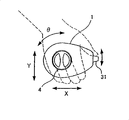
Moreover, in the prior art, in order to realize the raising of operability, as shown in Figure 7, developed such mechanism: thus make it on the directions X of front and back, to move the front and back slip of carrying out seat by holding the handle part 71 that is arranged on the circle on the seat sidepiece, thereby, this handle part 71 carries out toppling over of back of seat on the θ direction of front and back by being turned round, in addition, be incorporated with front portion by controlling face at it by pressing, thereby the button switch 72 of the seesaw type (シ one ソ one type) of the height adjustment of seat front portion is carried out in the lower part, and the rear portion by controlling face at it is by pressing, thereby the button switch 73 of seesaw type of the height adjustment of seat rear is carried out in the lower part, can carry out the switching manipulation of keeping strokes (with reference to patent documentation 2) with seat.
The real fair 6-29111 communique of [patent documentation 2] Japan
Summary of the invention
The problem that needs to solve is, in as lower device, the switching manipulation of this device in order to carry out keeping strokes with seat, thereby make it move forward and backward the slip of carrying out seat by holding the handle part that is arranged at the seat sidepiece, thus by make this handle part forward rear revolution carry out the toppling over of backrest of seat; When the button switch of each seesaw type of the height adjustment that is used to carry out seat front portion, rear portion is packed at front portion, the rear portion of controlling face at it into, can't operate holding under the state of handle part button switch this each seesaw type.
The operating switch of power seat of the present invention, it is characterized in that, can be with respect to the Switch main body that is arranged on the seat sidepiece in the front and back of seat, up and down all directions move and can be forwards, the rear is equipped with the handle part of switch pivotally, being incorporated with in Switch main body slides tilts with sliding with switch and toppling over sliding and use switch with switch, rear portion, simultaneously, be incorporated with the anterior switch that tilts to use in the front portion of this handle part; Described slip switch makes described handle part during front and rear direction moves, make seat forwards, the rear slides; Described rear portion tilts and use switch with sliding, during making described handle part direction move up and down, make on the rear portion of seat rise, decline; Described topple over use switch with sliding, make described handle part forwards, during the rear turns round, the backrest that makes seat is forwards, the rear topples over; Switch is used in described anterior inclination,, is risen in the front portion of seat, descends during the operating switch handle at upper and lower; Holding under the state of handle part, can carry out the operation of each switch.
According to the present invention, can hold under the state of handle part, with the seat of reality keep strokes and slide in the front and back that operability is sensuously carried out seat well, the toppling over and the height adjustment of seat front and rear portions of backrest.
Description of drawings
Fig. 1 is the figure of the operating state of expression dynamical type barbed chair of the present invention.
Fig. 2 is the front elevation of the handle part of the operating switch of expression power seat of the present invention.
Fig. 3 holds the front elevation of the state that the handle part of the operating switch of power seat of the present invention operates with palm for expression.
The lateral plan of the construction of switch that construction of switch that Fig. 4 uses for the rear portion tilting action of Switch main body side of the operating switch of expression power seat of the present invention and sliding action are used is the front elevation of the motion of toppling over sensor of representing this basic comprising example.
Fig. 5 is the birds-eye view of the contact portions of expression construction of switch shown in Figure 4.
Fig. 6 is the figure of expression with the driving circuit of cooresponding each drive motor of each switch motion of the operating switch of power seat of the present invention.
Fig. 7 is the front elevation of the handle part of the operating switch of the existing power seat of expression.
The specific embodiment
[embodiment 1]
Fig. 1 shows the operating state of dynamical type barbed chair of the present invention, by precedingly falling of carrying out backrest, after fall the rear portion tilting action B that topples over action A, the rising of carrying out seat rear, decline, carry out the anterior tilting action D of the sliding action C that moves forward and backward of seat, the rising of carrying out the seat front portion, decline and carry out the release forwards of the waist support (ラ Application バ one サ Port one ト) of backrest, the rearward waist support action E that draws in constitutes.Driver train as each one of this dynamical type barbed chair moves directly is suitable for existing known mechanism, does not here illustrate especially.
In the present invention, as the operating switch of such dynamical type barbed chair, the handle part of switch is installed as follows: with respect to the Switch main body that is arranged on the seat sidepiece, can be in the front and back of seat, each side moves up up and down, simultaneously, can be forwards, the rear revolution.
Fig. 2 shows handle part 1, by watch the handle that is shaped as the substantially elliptical shape to constitute from the front, as shown in Figure 3, can hold integral body with palm, makes it at the front and back directions X and move θ direction revolution forwards, backwards up and down on the Y direction.
Fig. 4 shows the construction of switch that the rear portion tilting action B of the rising that is used to carry out seat rear, the decline of Switch main body 2 sides uses and is used to carry out the construction of switch that the sliding action C that moves forward and backward of seat uses.Fig. 5 shows the contact portions of this each construction of switch.
Here, corresponding to make be installed on bar 21 handle part (not shown) forwards, the action of bar 21 when move at the rear, each switch portion 23 that is provided with a pair of seesaw type by 22 pairs of adapters is switched, and carries out just commentaries on classics, the counter-rotating of CD-ROM drive motor of the slip usefulness of seat.
In addition, corresponding to make handle part upward, below the action of bar 21 when mobile, each switch portion 25 that is provided with a pair of seesaw type by 24 pairs of adapters is switched, and carries out just commentaries on classics, the counter-rotating of the CD-ROM drive motor of seat rear inclination usefulness.
In addition, equally in this Switch main body 2, though illustrate especially, but the construction of switch same as the prior art of having packed in the present embodiment, this construction of switch is corresponding to the action that is installed in the bar on the handle part in addition forwards, when handle part is turned round at the rear, by adapter each switch portion that is provided with a pair of seesaw type is switched, carried out just commentaries on classics, the counter-rotating of the CD-ROM drive motor of toppling over usefulness of seat.
And, as shown in Figure 2, be incorporated with in the front portion of handle part 1 and anteriorly tilt with switch 3, this front portion tilt with switch 3 carry out switch handle (ノ Block) is 31 cocked upward, depress downwards operating period the chien shih seat the front portion rise, decline.
As toppling over the construction of switch used of action A, construction of switch that seat rear tilting action B uses, construction of switch that sliding action C uses and anteriorly tilting, when not carrying out each switching manipulation, automatically restore to center position with switch 3.
In addition, be incorporated with the pair of buttons switch 4 of seesaw type at the middle body of handle part 1, it is forwards released the waist support of seat during the button 41 of pushing the place ahead with respect to the fore-and-aft direction of seat, during the button 42 of pushing the rear waist support of seat is rearward drawn in.
Fig. 6 shows driving circuit D1, driving circuit D2; Described driving circuit D1 corresponding to the switching state of each switch portion 23 that is arranged on a pair of seesaw type on the Switch main body 2 when the sliding action C of handle part, carries out just commentaries on classics, the counter-rotating of CD-ROM drive motor M1 of the slip usefulness of seat; Described driving circuit D2, corresponding to the switching state of each switch portion 25 that is arranged on a pair of seesaw type on the Switch main body 2 when the tilting action B of the rear portion of handle part, carry out just commentaries on classics, the counter-rotating of CD-ROM drive motor M2 of inclination rising, the inclination decline usefulness of seat rear.And, show driving circuit D3, driving circuit D4, driving circuit D5; Described driving circuit D3, the switching state corresponding to each switch portion 26 that is arranged on a pair of seesaw type on the Switch main body 2 when toppling over of handle part moves A carries out just commentaries on classics, the counter-rotating of the CD-ROM drive motor M3 that topples over usefulness of seat; Described driving circuit D4 corresponding at the switching manipulation state that tilts by the front portion when carrying out anterior tilting action D with switch 3, carries out just commentaries on classics, the counter-rotating of CD-ROM drive motor M4 of inclination rising, the inclination decline usefulness of seat front portion; Switching manipulation state when described driving circuit D5, the corresponding pair of buttons switch of using by the waist support 4 carry out waist support action E carries out just commentaries on classics, counter-rotating that the waist support is released, drawn in the CD-ROM drive motor M5 of usefulness.
In addition, in the operating switch of power seat of the present invention, not necessarily leave no choice but the pair of buttons switch 4 that the waist support is used is set at the middle body of handle part 1.
Industrial applicibility
The present invention is made for can be at the console switch of having held power seat Under the state of handle part, with keeping strokes and in operability sensuously well of the seat of reality Slide in the front and back of carrying out seat, the toppling over and the inclination of seat front and rear portions a series of of backrest Adjust pregnancy when the console switch as power seat uses.
Symbol description
1 handle part
2 Switch main bodies
3 anterior inclination switches
The pair of buttons switch 4 that 4 waist supports are used
The A car body is toppled over action
B rear portion tilting action
The C sliding action
The anterior tilting action of D
E waist support action E
Claims (2)
1. the operating switch of a power seat, it is characterized in that, can be with respect to the Switch main body that is arranged on the seat sidepiece in the front and back of seat, up and down all directions move and can be forwards, the rear is equipped with the handle part of switch pivotally, being incorporated with in Switch main body slides tilts with sliding with switch and toppling over sliding and use switch with switch, rear portion, simultaneously, be incorporated with the anterior switch that tilts to use in the front portion of this handle part; Described slip switch makes described handle part during front and rear direction moves, make seat forwards, the rear slides; Described rear portion tilts and use switch with sliding, during making described handle part direction move up and down, make on the rear portion of seat rise, decline; Described topple over use switch with sliding, make described handle part forwards, during the rear turns round, the backrest that makes seat is forwards, the rear topples over; Switch is used in described anterior inclination,, is risen in the front portion of seat, descends during the operating switch handle at upper and lower; Holding under the state of handle part, can carry out the operation of each switch.
2. the operating switch of power seat as claimed in claim 1, it is characterized in that, middle body at handle part, fore-and-aft direction with respect to seat is incorporated with the pair of buttons switch, during pushing the button switch in the place ahead, forwards release the waist support of seat, during pushing the button switch at rear, rearward draw in the waist support of seat.
Applications Claiming Priority (2)
| Application Number | Priority Date | Filing Date | Title |
|---|---|---|---|
| JP2005160368 | 2005-04-28 | ||
| JP2005160368A JP4560817B2 (en) | 2005-04-28 | 2005-04-28 | Operation switch for vehicle power seat |
Publications (2)
| Publication Number | Publication Date |
|---|---|
| CN1853985A CN1853985A (en) | 2006-11-01 |
| CN100411917C true CN100411917C (en) | 2008-08-20 |
Family
ID=36659928
Family Applications (1)
| Application Number | Title | Priority Date | Filing Date |
|---|---|---|---|
| CNB2006100736364A Active CN100411917C (en) | 2005-04-28 | 2006-04-13 | Power seat operation switch |
Country Status (5)
| Country | Link |
|---|---|
| US (1) | US20060243566A1 (en) |
| EP (1) | EP1717094B1 (en) |
| JP (1) | JP4560817B2 (en) |
| CN (1) | CN100411917C (en) |
| DE (1) | DE602006002540D1 (en) |
Cited By (1)
| Publication number | Priority date | Publication date | Assignee | Title |
|---|---|---|---|---|
| CN103692935A (en) * | 2013-11-26 | 2014-04-02 | 上海延锋江森座椅有限公司 | Automobile seat regulating handle |
Families Citing this family (13)
| Publication number | Priority date | Publication date | Assignee | Title |
|---|---|---|---|---|
| US20070267243A1 (en) * | 2006-05-19 | 2007-11-22 | Textron Inc. | Multi-purpose key switch for lightweight utility vehicle |
| JP4917416B2 (en) * | 2006-11-29 | 2012-04-18 | トヨタ紡織株式会社 | Electric operating device for vehicle seat |
| JP5386189B2 (en) | 2009-02-05 | 2014-01-15 | デルタ工業株式会社 | Power seat adjustment device |
| US8471158B2 (en) * | 2009-12-17 | 2013-06-25 | Omron Dualtec Automotive Electronics Inc. | Power seat switch assembly |
| JP5605907B2 (en) * | 2011-01-11 | 2014-10-15 | アルプス電気株式会社 | Switch device |
| US9446690B2 (en) | 2012-08-31 | 2016-09-20 | Nhk Spring Co., Ltd. | Power seat operation device and power seat |
| US11124092B2 (en) | 2013-06-26 | 2021-09-21 | Ricon Corp. | Transfer seat and method |
| DK3013300T3 (en) * | 2013-06-26 | 2021-04-06 | Ricon Corp | POWER TRANSFER UNIT |
| USD762180S1 (en) * | 2013-12-20 | 2016-07-26 | Ford Motor Company | Vehicle switch |
| CN104085319A (en) * | 2014-06-20 | 2014-10-08 | 苏州中航中振汽车饰件有限公司 | Automobile seat provided with fixed armrests |
| CN104085322A (en) * | 2014-06-20 | 2014-10-08 | 苏州中航中振汽车饰件有限公司 | Automobile seat provided with table board |
| CN108136938A (en) * | 2015-10-14 | 2018-06-08 | 大陆汽车有限责任公司 | Use the seat adjustment control apparatus of wearable device |
| DE102018117000B4 (en) * | 2018-07-13 | 2020-04-02 | Grammer Ag | Vehicle seat with control device |
Citations (5)
| Publication number | Priority date | Publication date | Assignee | Title |
|---|---|---|---|---|
| EP0530509A2 (en) * | 1991-07-31 | 1993-03-10 | Omron Corporation | Switch device |
| US6040533A (en) * | 1997-07-11 | 2000-03-21 | Bayerische Motoren Werke Aktiengesellschaft | Switch arrangement for a vehicle seat |
| CN2433118Y (en) * | 2000-05-30 | 2001-06-06 | 朱丰 | Seat of electric vehicle |
| DE10002493C1 (en) * | 2000-01-21 | 2001-06-13 | Faure Bertrand Sitztech Gmbh | Automobile passenger seat adjustment switch has single switch operating element rotated in opposite directions and provided with horizontal and vertical sliding and tipping movements |
| EP1340647A2 (en) * | 2002-02-27 | 2003-09-03 | BITRON S.p.A. | Manual control for the regulation of the position of a seat |
Family Cites Families (10)
| Publication number | Priority date | Publication date | Assignee | Title |
|---|---|---|---|---|
| US4678872A (en) * | 1986-09-10 | 1987-07-07 | United Techologies Automotive, Inc. | Button set and switch |
| JPH0340124U (en) * | 1988-12-01 | 1991-04-17 | ||
| DE3933561C1 (en) * | 1989-10-07 | 1991-01-31 | Mercedes-Benz Aktiengesellschaft, 7000 Stuttgart, De | |
| JPH0410940U (en) * | 1990-05-14 | 1992-01-29 | ||
| JPH0629111A (en) | 1992-07-10 | 1994-02-04 | Murata Mfg Co Ltd | Method of adjusting resistance value of resistor |
| JPH0922642A (en) * | 1995-07-07 | 1997-01-21 | Yazaki Corp | Multidirectional changeover switch |
| JPH09240340A (en) | 1996-03-01 | 1997-09-16 | Niles Parts Co Ltd | Power seat switch |
| US5866862A (en) * | 1997-04-07 | 1999-02-02 | Ut Automotive Dearborn, Inc. | Vehicle positioning control |
| ES2160540B1 (en) * | 2000-02-11 | 2003-04-01 | Lear Automotive Eeds Spain | MEMBRANE SLIDING SWITCH. |
| FR2847712B1 (en) * | 2002-11-22 | 2008-08-22 | Dav | METHOD FOR CONTROLLING AT LEAST TWO FUNCTIONS OF AN ORGAN AND / OR AT LEAST TWO DISTINCT PARTS OF AN ORGAN AND CONTROL DEVICE |
-
2005
- 2005-04-28 JP JP2005160368A patent/JP4560817B2/en active Active
-
2006
- 2006-03-22 EP EP06005905A patent/EP1717094B1/en active Active
- 2006-03-22 DE DE602006002540T patent/DE602006002540D1/de active Active
- 2006-04-13 CN CNB2006100736364A patent/CN100411917C/en active Active
- 2006-04-21 US US11/409,413 patent/US20060243566A1/en not_active Abandoned
Patent Citations (5)
| Publication number | Priority date | Publication date | Assignee | Title |
|---|---|---|---|---|
| EP0530509A2 (en) * | 1991-07-31 | 1993-03-10 | Omron Corporation | Switch device |
| US6040533A (en) * | 1997-07-11 | 2000-03-21 | Bayerische Motoren Werke Aktiengesellschaft | Switch arrangement for a vehicle seat |
| DE10002493C1 (en) * | 2000-01-21 | 2001-06-13 | Faure Bertrand Sitztech Gmbh | Automobile passenger seat adjustment switch has single switch operating element rotated in opposite directions and provided with horizontal and vertical sliding and tipping movements |
| CN2433118Y (en) * | 2000-05-30 | 2001-06-06 | 朱丰 | Seat of electric vehicle |
| EP1340647A2 (en) * | 2002-02-27 | 2003-09-03 | BITRON S.p.A. | Manual control for the regulation of the position of a seat |
Cited By (2)
| Publication number | Priority date | Publication date | Assignee | Title |
|---|---|---|---|---|
| CN103692935A (en) * | 2013-11-26 | 2014-04-02 | 上海延锋江森座椅有限公司 | Automobile seat regulating handle |
| CN103692935B (en) * | 2013-11-26 | 2016-04-06 | 上海延锋江森座椅有限公司 | A kind of automotive seat regulating handle |
Also Published As
| Publication number | Publication date |
|---|---|
| EP1717094B1 (en) | 2008-09-03 |
| US20060243566A1 (en) | 2006-11-02 |
| DE602006002540D1 (en) | 2008-10-16 |
| EP1717094A3 (en) | 2007-06-13 |
| EP1717094A2 (en) | 2006-11-02 |
| JP4560817B2 (en) | 2010-10-13 |
| JP2006310243A (en) | 2006-11-09 |
| CN1853985A (en) | 2006-11-01 |
Similar Documents
| Publication | Publication Date | Title |
|---|---|---|
| CN100411917C (en) | Power seat operation switch | |
| JPH0755636B2 (en) | Control device for controlling an operating motor for adjusting a car seat | |
| CN101797899A (en) | The setting device of power seat | |
| JPS6363413B2 (en) | ||
| JP2002144937A (en) | Automobile power seat switch device | |
| JP2008056161A (en) | Open vehicle rear view system | |
| TW475905B (en) | Rearward arranged configuration for swinging auto-walker | |
| CN110712577B (en) | Vehicle seat with operating device | |
| JP6769316B2 (en) | Vehicle console | |
| US20080012413A1 (en) | Seat Adjustment Mechanism Comprising a Rotative Actuating Element | |
| CN115429559A (en) | Wheelchair and method for walking wheelchair | |
| JP2006088718A (en) | Adjusting device of seat | |
| KR100976916B1 (en) | Armrest device for construction heavy equipment | |
| JP4923788B2 (en) | Chair device with convertible sitting position | |
| JP2000118275A (en) | Vehicular seat | |
| CN215971722U (en) | Steering control mechanism and robot | |
| EP1304256A3 (en) | A tiltable rear seat for a motor vehicle | |
| JPH0340124U (en) | ||
| JPH0672198A (en) | Seat device | |
| JP2021088243A (en) | Seat adjustment device for vehicle | |
| KR101593813B1 (en) | Apparatus for controlling seat of vehicle | |
| JP2012136146A (en) | Power seat operation device | |
| JPH0672213A (en) | Seat device | |
| JP2001149178A (en) | Lumbar support apparatus | |
| JP2021088244A (en) | Seat adjustment device for vehicle |
Legal Events
| Date | Code | Title | Description |
|---|---|---|---|
| C06 | Publication | ||
| PB01 | Publication | ||
| C10 | Entry into substantive examination | ||
| SE01 | Entry into force of request for substantive examination | ||
| C14 | Grant of patent or utility model | ||
| GR01 | Patent grant |