CN100346943C - Device for handling flat panels in a vacuum - Google Patents
Device for handling flat panels in a vacuum Download PDFInfo
- Publication number
- CN100346943C CN100346943C CNB038066831A CN03806683A CN100346943C CN 100346943 C CN100346943 C CN 100346943C CN B038066831 A CNB038066831 A CN B038066831A CN 03806683 A CN03806683 A CN 03806683A CN 100346943 C CN100346943 C CN 100346943C
- Authority
- CN
- China
- Prior art keywords
- vacuum chamber
- assembly
- linear movement
- sub
- end effector
- Prior art date
- Legal status (The legal status is an assumption and is not a legal conclusion. Google has not performed a legal analysis and makes no representation as to the accuracy of the status listed.)
- Expired - Lifetime
Links
Images


Classifications
-
- H—ELECTRICITY
- H01—ELECTRIC ELEMENTS
- H01L—SEMICONDUCTOR DEVICES NOT COVERED BY CLASS H10
- H01L21/00—Processes or apparatus adapted for the manufacture or treatment of semiconductor or solid state devices or of parts thereof
- H01L21/67—Apparatus specially adapted for handling semiconductor or electric solid state devices during manufacture or treatment thereof; Apparatus specially adapted for handling wafers during manufacture or treatment of semiconductor or electric solid state devices or components ; Apparatus not specifically provided for elsewhere
- H01L21/68—Apparatus specially adapted for handling semiconductor or electric solid state devices during manufacture or treatment thereof; Apparatus specially adapted for handling wafers during manufacture or treatment of semiconductor or electric solid state devices or components ; Apparatus not specifically provided for elsewhere for positioning, orientation or alignment
-
- B—PERFORMING OPERATIONS; TRANSPORTING
- B25—HAND TOOLS; PORTABLE POWER-DRIVEN TOOLS; MANIPULATORS
- B25J—MANIPULATORS; CHAMBERS PROVIDED WITH MANIPULATION DEVICES
- B25J18/00—Arms
- B25J18/02—Arms extensible
- B25J18/04—Arms extensible rotatable
-
- B—PERFORMING OPERATIONS; TRANSPORTING
- B25—HAND TOOLS; PORTABLE POWER-DRIVEN TOOLS; MANIPULATORS
- B25J—MANIPULATORS; CHAMBERS PROVIDED WITH MANIPULATION DEVICES
- B25J9/00—Programme-controlled manipulators
- B25J9/02—Programme-controlled manipulators characterised by movement of the arms, e.g. cartesian coordinate type
- B25J9/04—Programme-controlled manipulators characterised by movement of the arms, e.g. cartesian coordinate type by rotating at least one arm, excluding the head movement itself, e.g. cylindrical coordinate type or polar coordinate type
- B25J9/041—Cylindrical coordinate type
-
- H—ELECTRICITY
- H01—ELECTRIC ELEMENTS
- H01L—SEMICONDUCTOR DEVICES NOT COVERED BY CLASS H10
- H01L21/00—Processes or apparatus adapted for the manufacture or treatment of semiconductor or solid state devices or of parts thereof
- H01L21/67—Apparatus specially adapted for handling semiconductor or electric solid state devices during manufacture or treatment thereof; Apparatus specially adapted for handling wafers during manufacture or treatment of semiconductor or electric solid state devices or components ; Apparatus not specifically provided for elsewhere
- H01L21/677—Apparatus specially adapted for handling semiconductor or electric solid state devices during manufacture or treatment thereof; Apparatus specially adapted for handling wafers during manufacture or treatment of semiconductor or electric solid state devices or components ; Apparatus not specifically provided for elsewhere for conveying, e.g. between different workstations
- H01L21/67739—Apparatus specially adapted for handling semiconductor or electric solid state devices during manufacture or treatment thereof; Apparatus specially adapted for handling wafers during manufacture or treatment of semiconductor or electric solid state devices or components ; Apparatus not specifically provided for elsewhere for conveying, e.g. between different workstations into and out of processing chamber
- H01L21/67742—Mechanical parts of transfer devices
-
- Y—GENERAL TAGGING OF NEW TECHNOLOGICAL DEVELOPMENTS; GENERAL TAGGING OF CROSS-SECTIONAL TECHNOLOGIES SPANNING OVER SEVERAL SECTIONS OF THE IPC; TECHNICAL SUBJECTS COVERED BY FORMER USPC CROSS-REFERENCE ART COLLECTIONS [XRACs] AND DIGESTS
- Y10—TECHNICAL SUBJECTS COVERED BY FORMER USPC
- Y10S—TECHNICAL SUBJECTS COVERED BY FORMER USPC CROSS-REFERENCE ART COLLECTIONS [XRACs] AND DIGESTS
- Y10S414/00—Material or article handling
- Y10S414/135—Associated with semiconductor wafer handling
- Y10S414/141—Associated with semiconductor wafer handling includes means for gripping wafer
Landscapes
- Engineering & Computer Science (AREA)
- Robotics (AREA)
- Mechanical Engineering (AREA)
- Physics & Mathematics (AREA)
- Condensed Matter Physics & Semiconductors (AREA)
- General Physics & Mathematics (AREA)
- Manufacturing & Machinery (AREA)
- Computer Hardware Design (AREA)
- Microelectronics & Electronic Packaging (AREA)
- Power Engineering (AREA)
- Manipulator (AREA)
- Container, Conveyance, Adherence, Positioning, Of Wafer (AREA)
Abstract
A linear motion assembly is provided as part of a robot for processing substrates in a vacuum. An effector assembly is mounted for linear movement on linear bearings. The end effectors are driven by cables which in turn are driven by a drive which is positioned in an adjacent pressure vessel maintained at atmospheric pressure.
Description
Technical field
The present invention relates to a kind of automaton, be used for this straight plate of carrying during vacuum environment is handled the straight plate of for example LCD.Especially, automaton of the present invention system uses linear movement to operate in a vacuum.
Background technology
Exist many dissimilar automatons to be used for processing at semiconductor He other parts of the environment that is evacuated.These automatons have a plurality of axis of movements usually, and these motions must take place in a confined area, promptly in a vacuum chamber.Wish to constitute in a such mode moving link of automaton thus, the operating area (track (foot print)) of its restriction automaton.Usually by rotation and translation bindiny mechanism realization are provided, this bindiny mechanism moves through a path with work support (end effector) to this point, in the path workpiece picked, handle and return conveying.
Semi-conductive processing generally includes a plurality of treatment steps, and for example, film passes through deposition, thin film photolithography, heating, cooling and the cleaning of chemical vapour sedimentation method (CVD) on substrate.
Handling operation carries out in a special process chamber under vacuum environment usually.Because every kind of treatment process is needed efficiently, the batch process of semiconductor chip is normally used for substrate and handles.This be because, for each treatment step, process chamber must be ventilated, the substrate of packing into is with process chamber sealing and be evacuated.After handling, these steps are by reverse.
In order to improve treatment effeciency, a series of process chamber is provided with around a substrate conveying chamber, and this substrate conveying chamber is constituted as and remains under the vacuum condition.One or more loading lockings (loadlock) chamber is connected to conveying chamber by slit valve (slit valve).
Load locking and box adaptation that will processed substrate.Box sends to the loading locking by the front end transmission conveyer of system.Be constituted as the loading that adapts to this box and be latched in U.S. Patent No. 5,664, shown in 925, this United States Patent (USP) is had by the applicant.The content that discloses in the patent of ' 925 at this by hereby incorporated by reference.
So reduce circulation timei, significantly increased output simultaneously.Processing and conveying chamber remain under the vacuum condition continuously, only have the locking of loading to be recycled simultaneously.Loading locking is received in the conveying chamber sealing and is pumped into ambiance treatment substrate afterwards.Front end inlet is sealed then, loads locking and is become vacuum with process chamber by pump with conveying.
An automatic delivering mechanism is installed in the conveying chamber and running is from loading the locking mobile substrate and they being sent to selected process chamber.After handling, substrate picks up and is transported to next process chamber by automaton, perhaps is transported to the loading locking that is used for from the conveying chamber taking-up.In some cases, for the purpose of arranging the time, these systems can use buffered station, and they are suitable for before packing into or the storage substrate At All Other Times during substrate is carried by system.Should
Such system is in U.S. Patent No. 5,882, describes in 413, and the example of automatic delivering mechanism is at United States Patent (USP) NO.5, and shown in 647,724, each all licenses to the applicant.The content that these patents disclose is in this hereby incorporated by reference.
Because these systems are used for increasing semiconductor device, LCD etc. for example produces in a compact as far as possible space and makes substrate pass its challenge of handling the required motion of route to become important.As shown in the connected system of above-mentioned patent, a series of being rotatably connected, for example SCARA or combination machines arm connect, and drive so that the end effector of translation automaton passes the guide rail of expectation by rotating driver.In some cases, because its less track may expect to use linear movement to obtain the sensing of expectation.This selects when handling big substrate or even expectation more.The example of the system of use linear movement is in U.S. Patent No. 4,715, shown in 921.Especially, ' embodiment of accompanying drawing 4 and 11 (a) has been described linear movement type mechanism in 921.Yet it is dirty that linear movement is considered to usually, and wherein a large amount of fumes may be produced by linear bearing, cable and pulley drive mechanism.
The objective of the invention is to construct a kind of automaton of big substrate usually that is used for handling in a vacuum, wherein end effector uses linear movement in its guide rail.Another object of the present invention provides a kind of automaton with end effector, and this end effector is installed on the linear bearing and by cable and drives.Another object of the present invention is a kind of automaton of structure system, and it has the end effector by the cable driving that is installed on the linear bearing, and wherein the systemic contamination thing from linear bearing and cable driving is minimized.
Summary of the invention
The present invention is intended to a kind of automaton system that is used for carrying the substrate of handling at vacuum chamber.It illustrates that with a batch processing system with a plurality for the treatment of stations a plurality for the treatment of stations are connected to each other by central conveying chamber.The substrate station of packing into from an outside is passed one or more loading lockings and is sent or pick up, the operation of one or more loading lockings by suitable slit valve from vacuum cycle to atmospheric pressure.Conveying mechanism of the present invention also can be designed as provides an independent process chamber.
System of the present invention utilizes an automaton main body, and it extends in the conveying chamber and holds a revolution driver and other assembly, for example the lead and the conduit of isolating from vacuum environment.Axially extended axle extends upward by drive mechanism and from the automaton main body.This is axially driven with rotation simultaneously so that provide vertical and the rotation location.Accommodating in the automaton main body remains on atmospheric pressure usually.In addition, rotating main body forms a bearing and is used on axle the linear movement sub-assembly that rotatablely moves about automaton main body vertical axis with support.
The linear movement sub-assembly comprises a U-shape assembly housing, and it forms a seal closure that is used for linear motion drive system.U-shape assembly housing is installed in the axis of the automaton main body that is used for rotatablely moving with it.The linear movement sub-assembly comprises upside and the downside end effector that is supported on the extension wrist part in addition.Wrist partly is mounted for the linear movement on linear bearing, and linear bearing is oriented the axis transverse to automaton.Because end effector is installed on the U-shape housing, they can pile up mutually easily, and it has significantly reduced the track of two actuator systems.
U-shape assembly holds drive motors, Control Component, lead and the conduit that is used for linear movement sub-assembly Linear Driving.Two pin components linear bearing laterally in support, one on another.The Linear Driving motor that is housed in each pin components is mechanically connected to pulley and funicular system by a dynamic sealing, and this system is connected to drive the end effector on linear bearing.For with minimum contamination, make up a labyrinth in the bottom of linear bearing.The running of these seals to be preventing the particulate from cable and driven pulley system, and prevents that linear bearing from entering vacuum chamber and polluting substrate.
By suitable control by the executable algorithm of microprocessor in the bridging part that is arranged on U-shape housing, end effector can activate mutually with substrate load to process chamber or from the process chamber unloading substrate.
So, make up an automaton system, it provides the linear movement sub-assembly about the rotatablely moving of automaton main body axis, linear movement sub-assembly moving both vertically on the automaton main body axis, and the linear movement of end effector on linear bearing.
Technical scheme of the present invention is as follows:
According to the present invention, a kind of linear movement sub-assembly that is used for carrying at vacuum chamber substrate is provided, described linear movement sub-assembly comprises: be installed in the linear bearing in the described vacuum chamber; At least one end effector that engagement and supporting substrate are used to carry, its installation is used for the linear movement on described linear bearing; Be installed on the linear movement sub-assembly and encapsulate the housing of a balancing gate pit, described balancing gate pit and described vacuum chamber are isolated; And be installed in the described housing and be operably connected with described at least one end effector so that the drive system of described end effector motion, wherein said drive system is connected to described end effector by a dynamic sealing, so that keep the isolation of described balancing gate pit and described vacuum chamber.
Preferably, described linear bearing comprises in addition: at least one is fixed on the bearing guide on the described linear movement sub-assembly; At least one appends to described at least one end effector and the bearing block that is used for linear movement on described bearing guide is installed; And the labyrinth of collecting the fume that produces by described linear bearing.
Preferably, described balancing gate pit remains on atmospheric pressure.
Preferably, described drive system further comprises: be installed in the capstan winch that is used on the axle that rotates on the described sub-assembly; Be wound in a spiral on the described capstan winch and be connected to the cable of described at least one end effector at each end, therefore when capstan winch rotates, one end of cable is reeled and other end unwinding produces the motion of described at least one end effector on described linear bearing around described capstan winch; And wherein said drive system is operably connected to described axle to produce the rotation of described capstan winch, wherein said axle is centered on by a dynamic sealing, when it extends through described housing with box lunch with the balancing gate pit and the described vacuum chamber seal isolation of described housing.
Preferably, described cable is connected to described at least one end effector by spring, and other wherein said cable is against the pre-tensioning of described spring quilt.
Preferably, described drive system further comprises controller and the encoder that is installed in the described balancing gate pit.
According to the present invention, a kind of automaton sub-assembly that is used for carrying at vacuum chamber substrate also is provided, described automaton sub-assembly comprises: the automaton main body, it has a central shaft and is fixed in the described vacuum chamber, first balancing gate pit that isolates with described vacuum chamber of described automaton main body encapsulation; First drive system, be used to provide around described axis rotatablely move and along the translational motion of described axis, described drive system is installed in described first balancing gate pit; And linear movement sub-assembly, it is installed on the described automaton main body that is arranged in described vacuum chamber, and be operably connected to described first drive system and be used for therewith moving, described linear movement sub-assembly further comprises: be installed in the linear bearing in the described vacuum chamber; The end effector that at least one is used to mesh and support the substrate that is used to transmit is installed on the described linear bearing and is used for linear movement; Be installed on the linear movement sub-assembly and encapsulate the housing of one second balancing gate pit, described second balancing gate pit and described vacuum chamber are isolated; And second drive system, it is installed in the described housing and with described at least one end effector and is operably connected to produce the motion of described end effector, wherein said second drive system is connected to described end effector by a dynamic sealing, so that keep described second balancing gate pit and described vacuum chamber to isolate.
Preferably, described linear bearing further comprises: at least one is fixed on the bearing guide on the described linear movement sub-assembly; At least one appends on described at least one end effector and is installed in the bearing block that is used for linear movement on the described bearing guide; And the labyrinth of collecting the fume that produces by described linear bearing.
Preferably, described balancing gate pit remains on atmospheric pressure.
Preferably, described drive system further comprises: be installed in one and go up so that the capstan winch that rotates on described sub-assembly; Be wound in a spiral on the described capstan winch and be connected to the cable of described at least one end effector at each end, therefore when capstan winch rotates, one end of cable is reeled and other end unwinding produces the motion of described at least one end effector on described linear bearing around described capstan winch; And wherein said drive system is operably connected to described axle to produce the rotation of described capstan winch, wherein said axle by a dynamic sealing around, when it extends through described housing with box lunch with the balancing gate pit and the described vacuum chamber seal isolation of described housing.
Preferably, described cable is connected to described at least one end effector by spring, and other wherein said cable is against the pre-tensioning of described spring quilt.
Preferably, described drive system further comprises controller and the encoder that is installed in the described balancing gate pit.
According to the present invention, a kind of linear movement sub-assembly that is used for carrying at vacuum chamber substrate also is provided, described linear movement sub-assembly comprises: the U-shape housing with pair of leg parts and a bridging part, described housing is installed in the described vacuum chamber, balancing gate pit of described housing encapsulation, described balancing gate pit and described vacuum chamber are isolated; Be installed in first linear bearing on of described pin components, and separate second linear bearing on another that is installed in described pin components; Be used to mesh and supporting substrate so that first and second end effectors of carrying separate the linear movement that is used on described linear bearing are installed; Separate and to be installed in the described housing and to be operably connected with described first and second end effectors respectively with first and second drive systems of the motion that produces described end effector, wherein said drive system is connected to described each end effector by dynamic sealing, so that keep described balancing gate pit and described vacuum chamber is isolated.
Preferably, described sub-assembly further comprises: one has central shaft and is fixed on automaton main body in the described vacuum chamber, second balancing gate pit of one of described automaton main body encapsulation and described vacuum chamber isolation; One is used to provide around described axis rotation with along the 3rd drive system of described axis translational motion, and described the 3rd drive system is installed in the described balancing gate pit; And wherein said linear movement sub-assembly is installed on the described automaton main body, is operably connected to described second drive system with therewith motion.
Preferably, described U-shape housing by directed like this so that leg on another, so that of described end effector has a plane of movement on another described end effector.
Description of drawings
The present invention is being described in more detail below with reference to accompanying drawing, wherein:
Fig. 1 is the schematic diagram of batch processing system, and the present invention can use in this batch processing system;
Fig. 2 is the perspective schematic view of automaton of the present invention system;
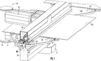
Fig. 3 is the perspective schematic view of the automaton system of Fig. 2, has shown according to linear movement sub-assembly of the present invention;
Fig. 4 is the close-up view of the thin A of portion of Fig. 3;
Fig. 5 is the perspective schematic view of cable drive system of the present invention;
Fig. 6 is the close-up view of the thin B of portion of Fig. 5;
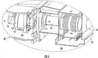
Fig. 7 is the plane perspective schematic view of linear bearing driven unit; And
Fig. 8 is the close-up view of the thin C of portion of Fig. 7.
The specific embodiment
With reference to figure 2, shown the perspective view of a substrate transmission system, automaton (robot) system 100, comprised feature of the present invention.Though the embodiment shown in the present invention incites somebody to action is with reference to the accompanying drawings described, and should be appreciated that the present invention can comprise many versions of embodiment.In addition, arbitrarily suitable size, shape or the type of element or material can be used.
Be used in the automaton system 100 of the substrate of vacuum chamber transport process shown in Figure 2.It has described the use that combines with batch processing system 21.System 21 is made up by a plurality for the treatment of stations 24, and a plurality for the treatment of stations 24 are connected to each other by suitable guiding valve 23 by a central conveying chamber 26.The substrate (not shown) is from 29 supplies of outside loading depot or pick up and pass one or more loading lockings 22, and its operation by suitable guiding valve 23 is from the vacuum cycle to the atmospheric pressure.Automaton of the present invention system 100 also can be designed as an independent process chamber provides workpiece.
For the purpose of simplifying, only there are the installation of upside end effector 10 and associated component to be described.Should be appreciated that the downside end effector has structure and the operation similar with the description of end effector 10.
In Fig. 4 to 6, the drive system 300 that is used for linear movement sub-assembly 200 is illustrated, and comprises move forward and backward cable 59 and 60, they by spiral wound on capstan winch 61.Capstan winch 61 can be slotted with the screw winding of maintenance cable, and drives around axial axis 62 rotations.Cable 59,60 extends around pulley 63 and 64 to be connected to contiguous block 65 from capstan winch 61, and contiguous block 65 is fixed to the carriage 14 and 15 of wrist 12 and 13 respectively.Cable 59 and 60 all is connected to capstan winch 61, and therefore a cable is picked in the trailed while of another cable.Cable 59 and 60 against the group of Beile Wei Er (belleville) packing ring cover 66 they with the junction of piece 65 by tensioning in advance.Helical spring also can be used as this purpose.Suitable build-up member can be used so that cable 59,60 is connected to piece 65, and can comprise the tension regulator of adjustment screw 73 for example and 74.
As shown in Fig. 7 and 8, capstan winch 61 is driven by the motor 67 and the controller 68 that are included in the U-shape housing 4.Motor 67 is by being with 69 driving shafts 62.Controller 68 activates rotatablely moving of motor 67 by encoder 72.
Since capstan winch and sets of cables component in the vacuum environment of conveying chamber 26 and driving element in the pressure vessel of housing 4, for axle 62 provides a dynamic sealing 35, when it passes the wall 71 of housing 4.Dynamic sealing 35 is isolated housing 4 and conveying chamber 25.This normal running to driven unit is essential.
For fear of pollution by the manufacturing dregs of fat residual on cable 59 and 60.Cable materials stands cleaning and electropolishing so that remove this residue.When using under vacuum environment, the dregs of fat are easy to emit gaseous contaminant.In order to lubricate the linear bearing and the cable of operation in vacuum chamber 26, nothing-venting lubricant is used.
At big template, can be effective especially the processing of from 106 to 140 inches long LCD displays as the native system of theme for example.This system also can be advantageously used in littler substrate.This system is provided at the automaton conveying mechanism that uses linear movement in the vacuum environment, avoids the pollution of vacuum chamber simultaneously.Linear movement provides compact movement locus for automaton.
The description that should be appreciated that the front only is illustrative description of the present invention.Various substitutions and modifications can not made in the technical staff by ability with not deviating from the present invention.Therefore, the present invention means and comprises replacement, the modifications and variations that all these fall into the claim scope of enclosing.
Claims (15)
1. linear movement sub-assembly that is used for carrying substrate at vacuum chamber, described linear movement sub-assembly comprises:
Be installed in the linear bearing in the described vacuum chamber;
At least one end effector that engagement and supporting substrate are used to carry, its installation is used for the linear movement on described linear bearing;
Be installed on the linear movement sub-assembly and encapsulate the housing of a balancing gate pit, described balancing gate pit and described vacuum chamber are isolated; And
Be installed in the described housing and be operably connected with described at least one end effector so that the drive system of described end effector motion, wherein said drive system is connected to described end effector by a dynamic sealing, so that keep the isolation of described balancing gate pit and described vacuum chamber.
2. the linear movement sub-assembly that is used for carrying substrate described in claim 1 at vacuum chamber, wherein said linear bearing comprises in addition:
At least one is fixed on the bearing guide on the described linear movement sub-assembly;
At least one appends to described at least one end effector and the bearing block that is used for linear movement on described bearing guide is installed; And
Collection is by the labyrinth of the fume of described linear bearing generation.
3. the linear movement sub-assembly that is used for carrying at vacuum chamber substrate described in claim 1, wherein said balancing gate pit remains on atmospheric pressure.
4. the linear movement sub-assembly that is used for carrying substrate described in claim 1 at vacuum chamber, wherein said drive system further comprises:
Be installed in the capstan winch that is used on the axle that rotates on the described sub-assembly;
Be wound in a spiral on the described capstan winch and be connected to the cable of described at least one end effector at each end, therefore when capstan winch rotates, one end of cable is reeled and other end unwinding produces the motion of described at least one end effector on described linear bearing around described capstan winch; And
Wherein said drive system is operably connected to described axle to produce the rotation of described capstan winch, wherein said axle is centered on by a dynamic sealing, when it extends through described housing with box lunch with the balancing gate pit and the described vacuum chamber seal isolation of described housing.
5. the linear movement sub-assembly that is used for carrying substrate described in claim 4 at vacuum chamber, wherein said cable is connected to described at least one end effector by spring, and other wherein said cable against described spring by pre-tensioning.
6. the linear movement sub-assembly that is used for carrying at vacuum chamber substrate described in claim 1, wherein said drive system further comprises controller and the encoder that is installed in the described balancing gate pit.
7. automaton sub-assembly that is used for carrying substrate at vacuum chamber, described automaton sub-assembly comprises:
The automaton main body, it has a central shaft and is fixed in the described vacuum chamber, first balancing gate pit that isolates with described vacuum chamber of described automaton main body encapsulation;
First drive system, be used to provide around described axis rotatablely move and along the translational motion of described axis, described drive system is installed in described first balancing gate pit; And
The linear movement sub-assembly, it is installed on the described automaton main body that is arranged in described vacuum chamber, and is operably connected to described first drive system and is used for therewith moving, and described linear movement sub-assembly further comprises:
Be installed in the linear bearing in the described vacuum chamber;
The end effector that at least one is used to mesh and support the substrate that is used to transmit is installed on the described linear bearing and is used for linear movement;
Be installed on the linear movement sub-assembly and encapsulate the housing of one second balancing gate pit, described second balancing gate pit and described vacuum chamber are isolated; And
Second drive system, it is installed in the described housing and with described at least one end effector and is operably connected to produce the motion of described end effector, wherein said second drive system is connected to described end effector by a dynamic sealing, so that keep described second balancing gate pit and described vacuum chamber to isolate.
8. the automaton sub-assembly that is used for carrying substrate described in claim 7 at vacuum chamber, wherein said linear bearing further comprises:
At least one is fixed on the bearing guide on the described linear movement sub-assembly;
At least one appends on described at least one end effector and is installed in the bearing block that is used for linear movement on the described bearing guide; And
Collection is by the labyrinth of the fume of described linear bearing generation.
9. the automaton sub-assembly that is used for carrying at vacuum chamber substrate described in claim 7, wherein said balancing gate pit remains on atmospheric pressure.
10. the automaton sub-assembly that is used for carrying substrate described in claim 7 at vacuum chamber, wherein said drive system further comprises:
Being installed in one goes up so that the capstan winch that rotates on described sub-assembly;
Be wound in a spiral on the described capstan winch and be connected to the cable of described at least one end effector at each end, therefore when capstan winch rotates, one end of cable is reeled and other end unwinding produces the motion of described at least one end effector on described linear bearing around described capstan winch; And
Wherein said drive system is operably connected to described axle to produce the rotation of described capstan winch, wherein said axle by a dynamic sealing around, when it extends through described housing with box lunch with the balancing gate pit and the described vacuum chamber seal isolation of described housing.
11. the automaton sub-assembly that is used for carrying substrate described in claim 10 at vacuum chamber, wherein said cable is connected to described at least one end effector by spring, and other wherein said cable is against the pre-tensioning of described spring quilt.
12. the automaton sub-assembly that is used for carrying at vacuum chamber substrate described in claim 7, wherein said drive system further comprises controller and the encoder that is installed in the described balancing gate pit.
13. a linear movement sub-assembly that is used for carrying at vacuum chamber substrate, described linear movement sub-assembly comprises:
Have the U-shape housing of pair of leg parts and a bridging part, described housing is installed in the described vacuum chamber, balancing gate pit of described housing encapsulation, and described balancing gate pit and described vacuum chamber are isolated;
Be installed in first linear bearing on of described pin components, and separate second linear bearing on another that is installed in described pin components;
Be used to mesh and supporting substrate so that first and second end effectors of carrying separate the linear movement that is used on described linear bearing are installed;
Separate and to be installed in the described housing and to be operably connected with described first and second end effectors respectively with first and second drive systems of the motion that produces described end effector, wherein said drive system is connected to described each end effector by dynamic sealing, so that keep described balancing gate pit and described vacuum chamber is isolated.
14. the linear movement sub-assembly that is used for carrying at vacuum chamber substrate described in claim 13, wherein said sub-assembly further comprises:
One has central shaft and is fixed on automaton main body in the described vacuum chamber, second balancing gate pit of one of described automaton main body encapsulation and described vacuum chamber isolation;
One is used to provide around described axis rotation with along the 3rd drive system of described axis translational motion, and described the 3rd drive system is installed in the described balancing gate pit; And
Wherein said linear movement sub-assembly is installed on the described automaton main body, is operably connected to described second drive system with therewith motion.
15. the linear movement sub-assembly that is used for carrying substrate described in claim 13 at vacuum chamber, wherein said U-shape housing by directed like this so that leg on another, so that of described end effector has a plane of movement on another described end effector.
Applications Claiming Priority (2)
| Application Number | Priority Date | Filing Date | Title |
|---|---|---|---|
| US10/104,846 | 2002-03-22 | ||
| US10/104,846 US6779962B2 (en) | 2002-03-22 | 2002-03-22 | Device for handling flat panels in a vacuum |
Publications (2)
| Publication Number | Publication Date |
|---|---|
| CN1643177A CN1643177A (en) | 2005-07-20 |
| CN100346943C true CN100346943C (en) | 2007-11-07 |
Family
ID=28040712
Family Applications (1)
| Application Number | Title | Priority Date | Filing Date |
|---|---|---|---|
| CNB038066831A Expired - Lifetime CN100346943C (en) | 2002-03-22 | 2003-02-21 | Device for handling flat panels in a vacuum |
Country Status (8)
| Country | Link |
|---|---|
| US (1) | US6779962B2 (en) |
| EP (1) | EP1513962A4 (en) |
| JP (1) | JP2005521268A (en) |
| KR (1) | KR100738592B1 (en) |
| CN (1) | CN100346943C (en) |
| AU (1) | AU2003219828A1 (en) |
| TW (1) | TWI251288B (en) |
| WO (1) | WO2003084043A2 (en) |
Families Citing this family (20)
| Publication number | Priority date | Publication date | Assignee | Title |
|---|---|---|---|---|
| US7458763B2 (en) | 2003-11-10 | 2008-12-02 | Blueshift Technologies, Inc. | Mid-entry load lock for semiconductor handling system |
| US10086511B2 (en) | 2003-11-10 | 2018-10-02 | Brooks Automation, Inc. | Semiconductor manufacturing systems |
| US20050113976A1 (en) * | 2003-11-10 | 2005-05-26 | Blueshift Technologies, Inc. | Software controller for handling system |
| US20070269297A1 (en) | 2003-11-10 | 2007-11-22 | Meulen Peter V D | Semiconductor wafer handling and transport |
| US9099506B2 (en) * | 2005-03-30 | 2015-08-04 | Brooks Automation, Inc. | Transfer chamber between workstations |
| US20060251499A1 (en) * | 2005-05-09 | 2006-11-09 | Lunday Andrew P | Linear substrate delivery system with intermediate carousel |
| US20070048451A1 (en) * | 2005-08-26 | 2007-03-01 | Applied Materials, Inc. | Substrate movement and process chamber scheduling |
| US7432184B2 (en) * | 2005-08-26 | 2008-10-07 | Applied Materials, Inc. | Integrated PVD system using designated PVD chambers |
| NL1036794A1 (en) * | 2008-04-25 | 2009-10-27 | Asml Netherlands Bv | Robot for in-vacuum use. |
| KR20090130559A (en) * | 2008-06-16 | 2009-12-24 | 삼성모바일디스플레이주식회사 | Transfer apparatus and organic deposition device with the same |
| KR101917335B1 (en) * | 2010-10-08 | 2018-11-09 | 브룩스 오토메이션 인코퍼레이티드 | Coaxial drive vacuum robot |
| RU2481057C1 (en) * | 2011-12-20 | 2013-05-10 | Юрий Иванович Русанов | Device of horizontal reciprocating turn of diagnostic apparatuses after lifting multifunctional diagnostic-surgical robotic system for operation table with possibility of information and computer control named after yirusanov |
| US10363665B2 (en) * | 2012-07-10 | 2019-07-30 | Persimmon Technologies Corporation | Linear robot arm with multiple end effectors |
| US9293317B2 (en) * | 2012-09-12 | 2016-03-22 | Lam Research Corporation | Method and system related to semiconductor processing equipment |
| US10134621B2 (en) | 2013-12-17 | 2018-11-20 | Brooks Automation, Inc. | Substrate transport apparatus |
| CN111121374B (en) * | 2015-03-30 | 2022-03-01 | 布鲁克斯自动化公司 | Automatic cryogenic storage system |
| GB201900478D0 (en) | 2019-01-14 | 2019-02-27 | Rolls Royce Plc | Turbomachine |
| JP6677366B1 (en) * | 2019-03-12 | 2020-04-08 | 日本精工株式会社 | Work changer, work transfer device, processing device, method for manufacturing ring bearing, method for manufacturing machine, method for manufacturing vehicle |
| CN113043253B (en) * | 2021-02-08 | 2022-05-17 | 珞石(北京)科技有限公司 | Single-drive linear motion robot |
| CN114014018B (en) * | 2021-11-16 | 2023-05-26 | 仪晟科学仪器(嘉兴)有限公司 | Ultrahigh vacuum sample transfer device |
Citations (4)
| Publication number | Priority date | Publication date | Assignee | Title |
|---|---|---|---|---|
| US4820109A (en) * | 1986-04-11 | 1989-04-11 | Ampex Corporation | Bidirectional transfer mechanism |
| US5354380A (en) * | 1993-02-02 | 1994-10-11 | Leybold Aktiengesellschaft | Apparatus for the insertion and removal of a mask through the airlock of a vacuum coating apparatus |
| US6177129B1 (en) * | 1997-07-08 | 2001-01-23 | Balzers Aktiengesellschaft | Process for handling workpieces and apparatus therefor |
| US6318951B1 (en) * | 1999-07-09 | 2001-11-20 | Semitool, Inc. | Robots for microelectronic workpiece handling |
Family Cites Families (8)
| Publication number | Priority date | Publication date | Assignee | Title |
|---|---|---|---|---|
| US4787813A (en) * | 1987-08-26 | 1988-11-29 | Watkins-Johnson Company | Industrial robot for use in clean room environment |
| US5102373A (en) * | 1989-12-01 | 1992-04-07 | Martinsound Technologies, Inc. | Automated fader system |
| US5135349A (en) * | 1990-05-17 | 1992-08-04 | Cybeq Systems, Inc. | Robotic handling system |
| JPH07115120A (en) * | 1993-10-18 | 1995-05-02 | Hitachi Ltd | Substrate conveying device and method thereof |
| US5794487A (en) * | 1995-07-10 | 1998-08-18 | Smart Machines | Drive system for a robotic arm |
| JPH09267289A (en) * | 1996-03-29 | 1997-10-14 | Mitsubishi Electric Corp | Industrial robot |
| US6585478B1 (en) * | 2000-11-07 | 2003-07-01 | Asm America, Inc. | Semiconductor handling robot with improved paddle-type end effector |
| KR20190000980A (en) * | 2017-06-26 | 2019-01-04 | 이동원 | A personal Healthcare System |
-
2002
- 2002-03-22 US US10/104,846 patent/US6779962B2/en not_active Expired - Lifetime
-
2003
- 2003-02-21 CN CNB038066831A patent/CN100346943C/en not_active Expired - Lifetime
- 2003-02-21 JP JP2003581335A patent/JP2005521268A/en active Pending
- 2003-02-21 AU AU2003219828A patent/AU2003219828A1/en not_active Abandoned
- 2003-02-21 EP EP03716105A patent/EP1513962A4/en not_active Withdrawn
- 2003-02-21 KR KR1020047009278A patent/KR100738592B1/en active IP Right Grant
- 2003-02-21 WO PCT/US2003/005191 patent/WO2003084043A2/en active Application Filing
- 2003-03-20 TW TW092106114A patent/TWI251288B/en not_active IP Right Cessation
Patent Citations (4)
| Publication number | Priority date | Publication date | Assignee | Title |
|---|---|---|---|---|
| US4820109A (en) * | 1986-04-11 | 1989-04-11 | Ampex Corporation | Bidirectional transfer mechanism |
| US5354380A (en) * | 1993-02-02 | 1994-10-11 | Leybold Aktiengesellschaft | Apparatus for the insertion and removal of a mask through the airlock of a vacuum coating apparatus |
| US6177129B1 (en) * | 1997-07-08 | 2001-01-23 | Balzers Aktiengesellschaft | Process for handling workpieces and apparatus therefor |
| US6318951B1 (en) * | 1999-07-09 | 2001-11-20 | Semitool, Inc. | Robots for microelectronic workpiece handling |
Also Published As
| Publication number | Publication date |
|---|---|
| WO2003084043A2 (en) | 2003-10-09 |
| TW200305968A (en) | 2003-11-01 |
| KR100738592B1 (en) | 2007-07-11 |
| CN1643177A (en) | 2005-07-20 |
| EP1513962A4 (en) | 2008-05-14 |
| US6779962B2 (en) | 2004-08-24 |
| KR20040099259A (en) | 2004-11-26 |
| AU2003219828A1 (en) | 2003-10-13 |
| WO2003084043A3 (en) | 2004-12-29 |
| EP1513962A2 (en) | 2005-03-16 |
| JP2005521268A (en) | 2005-07-14 |
| US20030180126A1 (en) | 2003-09-25 |
| TWI251288B (en) | 2006-03-11 |
| AU2003219828A8 (en) | 2003-10-13 |
Similar Documents
| Publication | Publication Date | Title |
|---|---|---|
| CN100346943C (en) | Device for handling flat panels in a vacuum | |
| CN1126610C (en) | Automated semiconductor processing system | |
| US7578649B2 (en) | Dual arm substrate transport apparatus | |
| KR101622421B1 (en) | Horizontal articulated robot and substrate transfer system provided with the same | |
| KR101160242B1 (en) | Rotation introducing mechanism, substrate transfer device, and vacuum treating apparatus | |
| KR20050040222A (en) | System for carrying flat panel display and the carrying method using the same | |
| CN1574271A (en) | Substrate conveying device and conveying method, and vacuum disposal device | |
| CN1284041A (en) | Semiconductor wafer input/output handling system | |
| KR20140033521A (en) | Substrate transfer robot and system | |
| US11545380B2 (en) | Transport apparatus with linear bearing | |
| JP2005521268A5 (en) | ||
| CN210073799U (en) | Wafer taking device | |
| JP2013049128A (en) | Robot arm structure and robot | |
| KR102557355B1 (en) | substrate transport device | |
| CN101459100B (en) | Automatic conveying device for compact wafer | |
| US7984543B2 (en) | Methods for moving a substrate carrier | |
| TW201233511A (en) | Coaxial harmonic drive vacuum robot | |
| CN110666784B (en) | Industrial robot | |
| JPS61288990A (en) | Industrial robot | |
| JPS61121889A (en) | Industrial robot | |
| CN201374322Y (en) | Translating and overturning type wafer automatic conveying device | |
| KR102509722B1 (en) | Hand of industrial robot and industrial robot | |
| CN201345357Y (en) | Rotary type wafer automatic transmission device | |
| CN114378851A (en) | Hand of industrial robot and industrial robot | |
| CN115924540A (en) | Industrial robot and manufacturing system |
Legal Events
| Date | Code | Title | Description |
|---|---|---|---|
| C06 | Publication | ||
| PB01 | Publication | ||
| C10 | Entry into substantive examination | ||
| SE01 | Entry into force of request for substantive examination | ||
| C14 | Grant of patent or utility model | ||
| GR01 | Patent grant | ||
| CX01 | Expiry of patent term |
Granted publication date: 20071107 |
|
| CX01 | Expiry of patent term |