BR112014025803B1 - Elongated Squeeze Roller, Elongated Squeeze PRESS USING THE Elongated Squeeze ROLLER, PAPER MAKING MACHINE AND METHOD OF OPERATING AN Elongated Squeeze PRESS - Google Patents
Elongated Squeeze Roller, Elongated Squeeze PRESS USING THE Elongated Squeeze ROLLER, PAPER MAKING MACHINE AND METHOD OF OPERATING AN Elongated Squeeze PRESS Download PDFInfo
- Publication number
- BR112014025803B1 BR112014025803B1 BR112014025803-1A BR112014025803A BR112014025803B1 BR 112014025803 B1 BR112014025803 B1 BR 112014025803B1 BR 112014025803 A BR112014025803 A BR 112014025803A BR 112014025803 B1 BR112014025803 B1 BR 112014025803B1
- Authority
- BR
- Brazil
- Prior art keywords
- elongated
- press
- press body
- roller
- internal pressure
- Prior art date
Links
Images


Classifications
-
- D—TEXTILES; PAPER
- D21—PAPER-MAKING; PRODUCTION OF CELLULOSE
- D21G—CALENDERS; ACCESSORIES FOR PAPER-MAKING MACHINES
- D21G1/00—Calenders; Smoothing apparatus
- D21G1/006—Calenders; Smoothing apparatus with extended nips
-
- D—TEXTILES; PAPER
- D21—PAPER-MAKING; PRODUCTION OF CELLULOSE
- D21F—PAPER-MAKING MACHINES; METHODS OF PRODUCING PAPER THEREON
- D21F3/00—Press section of machines for making continuous webs of paper
- D21F3/02—Wet presses
- D21F3/0209—Wet presses with extended press nip
- D21F3/0218—Shoe presses
-
- D—TEXTILES; PAPER
- D21—PAPER-MAKING; PRODUCTION OF CELLULOSE
- D21F—PAPER-MAKING MACHINES; METHODS OF PRODUCING PAPER THEREON
- D21F11/00—Processes for making continuous lengths of paper, or of cardboard, or of wet web for fibre board production, on paper-making machines
- D21F11/14—Making cellulose wadding, filter or blotting paper
-
- D—TEXTILES; PAPER
- D21—PAPER-MAKING; PRODUCTION OF CELLULOSE
- D21F—PAPER-MAKING MACHINES; METHODS OF PRODUCING PAPER THEREON
- D21F3/00—Press section of machines for making continuous webs of paper
- D21F3/02—Wet presses
- D21F3/0281—Wet presses in combination with a dryer roll
Landscapes
- Paper (AREA)
- Machines For Manufacturing Corrugated Board In Mechanical Paper-Making Processes (AREA)
Abstract
rolo de aperto alongado, prensa de aperto alongada utilizando o rolo de aperto alongado, máquina de fabricação de papel e método de operar uma prensa de aperto alongada. a presente invenção está correlacionada a um rolo de aperto alongado (5), capaz de formar um elemento de aperto de prensa (n) com um contra-rolo (7), cujo elemento de aperto de prensa (n) apresenta uma extensão numa direção da máquina quando o rolo de aperto alongado (5) coopera com o contra-rolo (7). o rolo de aperto alongado (5) compreende uma camisa flexível, um corpo de prensa elástico (13) disposto no interior da camisa flexível. o lado superior (14) do corpo de prensa (13) é chanfrado de modo a que na direção da máquina, uma superfície útil (15) do lado superior apresenta uma extremidade a jusante (16), que, na direção da máquina, é seguida por uma superfície lateral de saída (17), que diverge da superfície interior (11) da camisa flexível (10). o corpo de prensa (13) apresenta ainda pelo menos uma primeira e uma segunda câmara de pressão interna (18, 19). as câmaras de pressão (18, 19) podem ser pressurizadas de modo a que o corpo de prensa (13) se expanda. a primeira câmara de pressão interna (18) apresenta uma extensão na direção da máquina que não se alonga além da superfície útil (15), e a segunda câmara de pressão interna (19) é localizada a jusante da primeira câmara de pressão interna (18) e apresenta uma extensão na direção da máquina além da extremidade a jusante (16) da superfície útil (15). a superfície útil (15) e a superfície lateral de saída (17) são feitas de um material que apresenta uma maior dureza shore a, do que o material do resto do corpo de prensa (13). a invenção também se refere a uma prensa de aperto alongada e a uma máquina de fabricação de papel em que o rolo de aperto alongado é utilizado. a invenção se refere ainda a um método de operação da prensa de aperto alongada.elongated nip roller, elongated nip press using the elongate nip roller, paper making machine and method of operating an elongated nip press. the present invention relates to an elongated clamping roller (5), capable of forming a press clamping element (n) with a counter-roller (7), whose press clamping element (n) has an extension in one direction of the machine when the elongated pinch roller (5) cooperates with the counter roller (7). the elongated pinch roller (5) comprises a flexible sleeve, an elastic press body (13) disposed inside the flexible sleeve. the upper side (14) of the press body (13) is chamfered so that in the machine direction, a working surface (15) of the upper side has a downstream end (16), which, in the machine direction, is followed by an outlet side surface (17), which diverges from the inner surface (11) of the flexible jacket (10). the press body (13) also has at least a first and a second internal pressure chamber (18, 19). the pressure chambers (18, 19) can be pressurized so that the press body (13) expands. the first internal pressure chamber (18) has an extension in the machine direction that does not extend beyond the working surface (15), and the second internal pressure chamber (19) is located downstream of the first internal pressure chamber (18). ) and has an extension in the machine direction beyond the downstream end (16) of the working surface (15). the working surface (15) and the outlet side surface (17) are made of a material that has a higher shore a hardness than the material of the rest of the press body (13). the invention also relates to an elongated nip press and a papermaking machine in which the elongate nip roller is used. the invention further relates to a method of operating the elongated clamping press.
Description
[001] A presente invenção está correlacionada a um rolo de aperto alongado, a uma prensa de aperto alongado compreendendo o inventivo rolo de aperto alongado e a uma máquina de fabricação de papel compreendendo a dita prensa de aperto alongada. A invenção se refere ainda a um método de operação do inventivo rolo alongado, em que um tecido de papel úmido é passado através do rolo alongado.[001] The present invention relates to an elongated nip roller, an elongated nip press comprising the inventive elongated nip roller and a papermaking machine comprising said elongated nip press. The invention further relates to a method of operating the inventive elongated roll, wherein a damp paper tissue is passed through the elongated roll.
[002] A invenção está correlacionada ao segmento da técnica que inclui as prensas de aperto alongadas usadas nas máquinas de fabricação de papel. Em uma máquina de fabricação de papel, uma prensa de aperto alongada é normalmente usada para comprimir a água para fora de um tecido fibroso úmido recém formado, mas, um meio de aperto alongado pode também ser usado para outros fins em uma máquina de fabricação de papel, por exemplo, para calandragem. Embora as prensas de aperto alongadas tenham sido primeiramente introduzidas para classificações de maior peso, como, por exemplo, o papelão, ultimamente, as mesmas tem sido usadas também para classificações de menor peso, como, por exemplo, papel de impressão. Nos últimos anos, essas prensas têm sido usadas em máquinas para fabricação de papel de tipo tecido fino. Nessas máquinas, a prensa de aperto alongada é normalmente formada por um rolo de aperto alongado e um cilindro de secagem Yankee, que atua como um contra-rolo em relação ao rolo de aperto alongado. Uma prensa de aperto alongada, tipicamente, é formada por um rolo de aperto alongado que compreende uma sapara rígida com uma superfície côncava. A sapata rígida de tal rolo de aperto alongado pode ser feita de um material, tal como, por exemplo, aço ou alumínio. A Patente US No. 7.527.708 divulga como um elemento de aperto alongado pode ser formado por meio de um dispositivo que não utiliza uma sapata de aço, em vez disso, um corpo de suporte que é elasticamente deformável. O corpo de suporte divulgado nesse documento apresenta câmaras de pressão internas que podem ser conectadas a uma fonte de um meio de pressão.[002] The invention is related to the segment of the art that includes the elongated pinch presses used in papermaking machines. In a papermaking machine, an elongated nip press is typically used to compress water out of a newly formed wet fibrous fabric, but an elongated nip can also be used for other purposes in a papermaking machine. paper, for example, for calendering. Although elongated nip presses were first introduced for heavier grades such as cardboard, lately they have also been used for lighter weight grades such as printing paper. In recent years, these presses have been used in machines for making fine tissue-type paper. In these machines, the elongated nip press is typically formed by an elongated nip roller and a Yankee drying cylinder, which acts as a counter roller to the elongated nip roller. An elongated nip press typically is formed by an elongated nip roller comprising a rigid slug with a concave surface. The rigid shoe of such an elongated nip roller may be made of a material such as, for example, steel or aluminum. US Patent No. 7,527,708 discloses how an elongated gripping member can be formed by means of a device that does not use a steel shoe, rather a support body that is elastically deformable. The support body disclosed in this document has internal pressure chambers that can be connected to a source of pressure means.
[003] Ge ralmente, é desejável que a pressão no meio de aperto de uma prensa de aperto alongada se eleve a partir do começo do aperto para alcançar um pico no final do aperto. Esse perfil de pressão é vantajoso, uma vez que reduz o reumedecimento do tecido de papel quando o tecido deixa o aperto do rolo. Na Patente US No. 7.527.708 é sugerido que diferentes câmaras de pressão sejam estabelecidas sob diferentes pressões, de modo que seja obtida uma curva de pressão descrevendo um curso escalonado.[003] Generally, it is desirable that the pressure in the tightening medium of an elongated tightening press rises from the beginning of the tightening to reach a peak at the end of the tightening. This pressure profile is advantageous as it reduces the rewetting of the paper fabric when the fabric leaves the roll grip. In US Patent No. 7,527,708 it is suggested that different pressure chambers be set at different pressures so that a pressure curve describing a stepped stroke is obtained.
[004] Constitui um objetivo da presente invenção, proporcionar uma prensa de aperto alongada, que seja projetada de modo a que seja obtido um adequado perfil de pressão.[004] It is an objective of the present invention to provide an elongated clamping press, which is designed so that a suitable pressure profile is obtained.
[005] Outro objetivo da invenção é proporcionar uma prensa de aperto alongada, na qual a lubrificação funcione de maneira confiável.[005] Another objective of the invention is to provide an elongated clamping press, in which lubrication works reliably.
[006] A invenção se refere a um rolo de aperto prolongado capaz de formar um aperto de prensa com um contra- rolo, cujo aperto de prensa apresenta uma extensão na direção da máquina quando o rolo de aperto prolongado coopera com o contra-rolo. O inventivo rolo de aperto prolongado compreende uma camisa flexível com uma superfície interior e uma superfície exterior, e um corpo de prensa disposto no interior da camisa flexível. O corpo de prensa é elasticamente deformável e apresenta um lado superior que se opõe à superfície interior da camisa flexível. O lado superior do corpo de prensa é chanfrado, de modo a que na direção da máquina, uma superfície útil do lado superior apresenta uma extremidade a jusante que, na direção da máquina, é seguida de uma superfície lateral de saída que diverge da superfície interior da camisa flexível. O corpo de prensa apresenta ainda pelo menos uma primeira e uma segunda câmara de pressão interna, cujas câmaras de pressão internas podem ser pressurizadas, de modo a que o corpo de prensa se expanda. A primeira câmara de pressão interna apresenta uma extensão na direção da máquina que não se alonga além da superfície útil e a segunda câmara de pressão interna é localizada a jusante da primeira câmara de pressão interna, apresentando uma extensão na direção da máquina além da extremidade a jusante da superfície útil. O rolo de aperto alongado compreende também um meio de suporte para o corpo de prensa, cujo meio de suporte proporciona apoio para os lados do corpo de prensa, mas, também permite ao corpo de prensa se expandir numa direção da superfície interior da camisa flexível. A segunda câmara de pressão interna apresenta uma tal extensão na direção da máquina, que mais de 30% da extensão (o comprimento da segunda câmara de pressão interna na direção da máquina) se estende além da extremidade a jusante da superfície útil e em que a superfície útil e a superfície lateral de saída são feitas de um material que apresenta uma dureza Shore A superior a do material no restante do corpo de prensa.[006] The invention relates to an extended nip roller capable of forming a press nip with a counterroller, which press nip presents an extension in the machine direction when the extended nip roller cooperates with the anvil roll. The inventive extended nip roller comprises a flexible jacket with an inner surface and an outer surface, and a press body disposed within the flexible jacket. The press body is elastically deformable and has an upper side that opposes the inner surface of the flexible jacket. The upper side of the press body is chamfered so that in the machine direction, a usable surface of the upper side has a downstream end which, in the machine direction, is followed by an output side surface that diverges from the inner surface. of flexible jacket. The press body also has at least a first and a second internal pressure chamber, which internal pressure chambers can be pressurized so that the press body expands. The first internal pressure chamber has an extension in the machine direction that does not extend beyond the usable surface and the second internal pressure chamber is located downstream of the first internal pressure chamber, having an extension in the machine direction beyond the end to downstream of the usable surface. The elongated nip roller also comprises support means for the press body, which support means provides support for the sides of the press body, but also allows the press body to expand in a direction towards the inner surface of the flexible jacket. The second inner pressure chamber has such an extension in the machine direction that more than 30% of the extension (the length of the second inner pressure chamber in the machine direction) extends beyond the downstream end of the working surface and where the usable surface and the exit side surface are made of a material that has a greater Shore A hardness than the material in the rest of the press body.
[007] O corpo de prensa pode ser projetado de modo a que em um estado descarregado do rolo de aperto alongado, a superfície lateral de saída a jusante da superfície útil forme um ângulo de 30° - 65° com uma tangente em relação à superfície útil, preferivelmente, um ângulo na faixa de 35° - 60°.[007] The press body can be designed so that in an unloaded state from the elongated nip roller, the output side surface downstream of the working surface forms an angle of 30° - 65° with a tangent to the surface preferably an angle in the range of 35° - 60° is useful.
[008] A superfície útil do lado superior pode ser uma superfície plana no estado descarregado do rolo de aperto alongado quando o rolo de aperto alongado não forma um m meio de aperto com um contra-rolo. Além disso, no estado descarregado do rolo de aperto alongado, a superfície de saída lateral a jusante da superfície útil pode formar um ângulo de 40° - 50° com a superfície útil. Em vez de ser plana no estado descarregado do rolo, a superfície útil pode ser, por exemplo, uma superfície convexa ou côncava.[008] The useful surface of the upper side may be a flat surface in the unloaded state of the elongated nip roller when the elongated nip roller does not form a nip means with a counter roller. Furthermore, in the unloaded state of the elongated nip roller, the lateral exit surface downstream of the useful surface can form an angle of 40° - 50° with the useful surface. Instead of being flat in the unloaded state of the roll, the usable surface can be, for example, a convex or concave surface.
[009] Nas modalidades da invenção, uma parte do corpo de prensa pode compreender uma soleira que forma a superfície útil e a superfície lateral de saída. Nessas modalidades, a soleira, preferivelmente, pode apresentar uma espessura na faixa de 1 mm - 30 mm, preferivelmente, de 5 mm - 25 mm, ainda mais preferivelmente, de 10 mm - 25 mm.[009] In the embodiments of the invention, a part of the press body may comprise a threshold that forms the usable surface and the exit side surface. In such embodiments, the threshold preferably may have a thickness in the range of 1mm - 30mm, preferably 5mm - 25mm, even more preferably 10mm - 25mm.
[010] A soleira pode apresentar uma dureza Shore A superior a 90 Shore A, enquanto a parte do corpo de prensa que envolve as câmaras de pressão internas apresenta uma dureza inferior ou igual a 90 Shore A (isto é, no máximo de 90 Shore A). Preferivelmente, a soleira apresenta uma dureza de 93 Shore A - 100 Shore A, enquanto a parte do corpo de prensa que envolve as câmaras de pressão internas apresenta uma dureza de 70 Shore A - 90 Shore A.[010] The threshold may have a Shore A hardness greater than 90 Shore A, while the part of the press body that surrounds the internal pressure chambers has a hardness less than or equal to 90 Shore A (ie, a maximum of 90 Shore THE). Preferably, the sill has a hardness of 93 Shore A - 100 Shore A, while the part of the press body surrounding the internal pressure chambers has a hardness of 70 Shore A - 90 Shore A.
[011] A superfície lateral de saída, preferivelmente, é separada da superfície útil por meio de uma borda arredondada que apresenta um primeiro raio numa área adjacente à superfície útil e um segundo raio numa área adjacente à superfície lateral de saída, e em que o segundo raio é menor que o primeiro raio. Nas modalidades da invenção, o primeiro raio se dispõe na faixa de 20 mm - 40 mm, e o segundo raio na faixa de 6 mm - 15 mm.[011] The output side surface preferably is separated from the useful surface by means of a rounded edge that has a first radius in an area adjacent to the useful surface and a second radius in an area adjacent to the output side surface, and wherein the second radius is smaller than the first radius. In the embodiments of the invention, the first radius is arranged in the range of 20 mm - 40 mm, and the second radius in the range of 6 mm - 15 mm.
[012] A borda arredondada que separa a superfície útil da superfície lateral de saída apresenta uma extensão na direção da máquina que se dispõe na faixa de 6 mm - 16 mm.[012] The rounded edge that separates the usable surface from the output side surface has an extension in the machine direction that is arranged in the range of 6 mm - 16 mm.
[013] Nas modalidades da invenção, o corpo de prensa compreende também uma terceira câmara de pressão interna, que, na direção da máquina, é localizado a montante da primeira câmara de pressão interna.[013] In the embodiments of the invention, the press body also comprises a third internal pressure chamber, which, in the machine direction, is located upstream of the first internal pressure chamber.
[014] Preferivelmente, as câmaras de pressão internas apresentam um formato retangular e uma maior extensão na direção radial do rolo de aperto alongado do que na direção da máquina.[014] Preferably, the internal pressure chambers have a rectangular shape and a greater extension in the radial direction of the elongated nip roller than in the machine direction.
[015] Nas modalidades da invenção, o corpo de prensa compreende uma aba localizada a montante da superfície útil e cuja Ava se salienta na direção a montante. A aba apresenta uma superfície de entrada que se opõe a superfície interior da camisa flexível e forma um ângulo de 2° - 50° com uma tangente à superfície útil.[015] In the embodiments of the invention, the press body comprises a flap located upstream of the useful surface and whose Ava protrudes in the upstream direction. The flap features an inlet surface which opposes the inner surface of the flexible jacket and forms an angle of 2° - 50° with a tangent to the usable surface.
[016] Um canal de lubrificação pode vantajosamente ser disposto para alimentar um lubrificante à superfície útil. Entretanto, deverá ser entendido que tal canal de lubrificação é opcional.[016] A lubrication channel can advantageously be arranged to feed a lubricant to the useful surface. However, it should be understood that such a lubrication channel is optional.
[017] Preferivelmente, o corpo de prensa pode ser coberto por uma camada intercambiável de proteção a desgaste. Entretanto, deverá ser entendido que modalidades sem essa camada de proteção ao desgaste são também concebíveis.[017] Preferably, the press body can be covered by an interchangeable wear protection layer. However, it should be understood that modalities without this wear protection layer are also conceivable.
[018] A invenção também se refere a uma prensa de aperto alongada compreendendo um rolo de aperto alongado conforme descrito acima e, adicionalmente, compreendendo um contra-rolo cooperando com o rolo de aperto alongado. Preferivelmente, o contra-rolo pode ser um rolo que é disposto para ser aquecido, por exemplo, um cilindro de secagem Yankee.[018] The invention also relates to an elongated nip press comprising an elongated nip roller as described above and additionally comprising a counter roller cooperating with the elongated nip roller. Preferably, the counter roller may be a roller which is arranged to be heated, for example a Yankee drying roller.
[019] A invenção também está correlacionada com uma máquina de fabricação de papel compreendendo um rolo de aperto alongado conforme descrito acima, um contra-rolo cooperando com o rolo de aperto alongado para formar uma prensa de aperto alongada e uma seção de modelagem disposta a montante da prensa de aperto alongada.[019] The invention is also correlated with a papermaking machine comprising an elongated nip roller as described above, a counter roller cooperating with the elongated nip roller to form an elongated nip press and a shaping section disposed to upstream of the elongated clamping press.
[020] A invenção também se refere a um método de operação de uma prensa de aperto alongada, conforme descrito acima, em que um tecido de papel úmido é passado através do meio de aperto alongado e submetido à pressão ao passar através do meio de aperto. O meio de aperto é operado de modo a que a pressão se eleve quando o tecido passa através do mesmo e alcança um pico quando o tecido passa sobre a extremidade a jusante da superfície útil do corpo de prensa.[020] The invention also relates to a method of operating an elongated nip press, as described above, in which a wet paper tissue is passed through the elongated nip and subjected to pressure as it passes through the nip. . The clamping means is operated so that the pressure rises as the fabric passes through it and reaches a peak when the fabric passes over the downstream end of the usable surface of the press body.
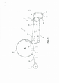
[021] A figura 1 é uma representação esquemática de uma máquina de fabricação de papel, na qual os inventivos rolo de aperto alongado e prensa de aperto alongada podem ser usados.[021] Figure 1 is a schematic representation of a papermaking machine, in which the inventive elongated nip roller and elongated nip press can be used.
[022] A figura 2 é uma vista esquemática em seção transversal de uma prensa de aperto alongada, de acordo com a invenção.[022] Figure 2 is a schematic cross-sectional view of an elongated press press, according to the invention.
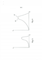
[023] A figura 3 mostra um desejado perfil de pressão em um meio de aperto alongado.[023] Figure 3 shows a desired pressure profile in an elongated clamping means.
[024] A figura 4 mostra um possível perfil real de pressão em um meio de aperto alongado.[024] Figure 4 shows a possible real pressure profile in an elongated clamping means.
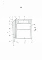
[025] A figura 5 é uma vista em seção transversal de um suporte para um corpo de prensa, usado em um rolo de aperto alongado, de acordo com a invenção.[025] Figure 5 is a cross-sectional view of a support for a press body, used in an elongated pinch roller, according to the invention.
[026] A figura 6 é uma vista em seção transversal de um corpo de prensa de acordo com a invenção, colocado em um suporte.[026] Figure 6 is a cross-sectional view of a press body according to the invention, placed on a support.
[027] A figura 7 é uma vista em seção transversal, mostrando em maiores detalhes uma modalidade de um corpo de prensa para um rolo de aperto alongado, de acordo com a presente invenção.[027] Figure 7 is a cross-sectional view, showing in greater detail an embodiment of a press body for an elongated pinch roller, according to the present invention.
[028] A figura 8 é uma vista em seção transversal, ilustrando uma parte de um corpo de prensa, de acordo com uma modalidade da invenção.[028] Figure 8 is a cross-sectional view, illustrating a part of a press body, according to an embodiment of the invention.
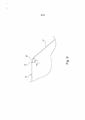
[029] A figura 9 é uma vista em seção transversal, similar à figura 8, mas, ilustrando em maiores detalhes uma parte do corpo de prensa de acordo com a invenção.[029] Figure 9 is a cross-sectional view, similar to Figure 8, but illustrating in greater detail a part of the press body according to the invention.
[030] A figura 10 é uma vista em seção transversal, similar à figura 9, mas, incluindo uma parte da camisa flexível.[030] Figure 10 is a cross-sectional view, similar to Figure 9, but including a portion of the flexible jacket.
[031] A figura 11 é uma vista em seção transversal, ilustrando como uma camada intercambiável de proteção ao desgaste pode ser colocada sobre o corpo de prensa.[031] Figure 11 is a cross-sectional view, illustrating how an interchangeable wear protection layer can be placed on the press body.
[032] Com referência à figura 1, é mostrada uma máquina de fabricação de papel (1), adequada para fabricação de papel tecido, tal como, papel de toalete, toalha de papel para cozinha, ou tipos similares. Em muitas aplicações práticas, o papel tecido produzido em tal máquina pode apresentar um peso de resma na faixa de 15 g/m2 - 25 g/m2 , mas, um papel tecido tendo um peso de resma fora dessa faixa pode ser também produzido. A máquina de fabricação de papel mostrada na figura 1 inclui uma seção de modelagem (4), na qual uma caixa superior (31) é disposta para injetar matéria-prima em um espaço entre um tecido modelador (32) e um feltro (33). O tecido modelador (32), tipicamente, pode ser uma telporosa. O feltro (33) é disposto para passar sobre um rolo modelador (35) e o feltro (33) e o tecido modelador (32) são orientados em seus circuitos pelos rolos guias (34). A partir da seção de modelagem (4), um tecido fibroso úmido recém formado (W) é transportado pelo feltro (33) para um elemento de aperto de prensa (N), formado entre um rolo de aperto alongado (5) e um contra-rolo (7). O contra-rolo (7) pode ser um cilindro de secagem Yankee, mas, são concebidas modalidades em que o tecido (W) é primeiramente prensado em um meio de aperto de prensa, antes do cilindro de secagem Yankee, e subsequentemente passado para o cilindro de secagem Yankee. No meio de aperto de prensa (N) entre o rolo de aperto alongado e o contra-rolo (7), a água é pressionada para fora do tecido (W) e absorvida pelo feltro (33) que é receptor de água. O tecido (W) então passa sobre um cilindro de secagem Yankee, que na modalidade da figura 1 é idênticoao contra-rolo (7) para o rolo de aperto alongado (5). Nafigura 1 deverá ser entendido que o contra-rolo (7) (isto é,o cilindro de secagem Yankee) gira na direção da seta “A”.No cilindro de secagem Yankee, o tecido é seco por calor, namedida em que a água que permanece no tecido após sofrer oaperto (N) é evaporada pelo calor. O contra-rolo (7) pode ser aquecido através de meios de aquecimento, que são simbolicamente indicados pela referência numérica (8) na figura 1. Na prática, o meio de aquecimento pode se constituir de um suprimento de vapor quente, que é introduzido no interior do cilindro de secagem Yankee. No interior do cilindro Yankee, o vapor quente pode apresentar uma temperatura significativamente superior a 100°C e a superfície interna da parede do cilindro Yankee pode alcançar temperaturas da ordem de cerca de 180°C. A temperatura na superfície exterior do cilindro Yankee é significativamente mais baixa quando a superfície do cilindro Yankee é coberta pelo tecido (W), uma vez que uma grande quantidade de calor é consumida quando a água no tecido úmido (W) é evaporada. Numa máquina de fabricação de papel para papel tipo tecido, a temperatura da superfície exterior do cilindro Yankee abaixo do tecido úmido (W) pode, normalmente, se dispor na faixa de 95°C - 100°C, mas, temperaturas mais altas e mais baixas podem ser usadas, dependendo das condições e exigências de operação de cada aplicação específica. Em alguns casos, temperaturas de superfície de até 140°C podem ser consideradas. Em princípio, o meio de aquecimento (8) pode ser algo diferente de vapor quente. Por exemplo, o meio de aquecimento pode ser um aquecedor indutivo localizado no interior ou no exterior do contra-rolo (7). O teor de sólido secos no tecido, quando é alcançado o aperto de prensa, pode variar consideravelmente, mas, em muitos casos realísticos, o teor de sólidos secos pode ser da ordem de 18% - 22%, quando o tecido (W) chega ao meio de aperto (N). Após o aperto (N), o tecido (W) pode apresentar um teor de sólido seco de 40% - 55%, dependendo desses fatores, como, por exemplo, da carga linear no meio de aperto, da temperatura do contra-rolo e do teor de sólido seco do tecido (W) antes do tecido (W) chegar ao meio de aperto (N). O tecido (W) é tipicamente raspado do cilindro de secagem Yankee por meio de uma lâmina de raspagem (9). O tecido seco pronto (W) é então passado para um meio de embobinamento (3). Deve ser entendido que o explicado acima com referência à figura 1 pode ser aplicável a todas as modalidades da presente invenção.[032] Referring to figure 1, there is shown a paper making machine (1), suitable for making tissue paper such as toilet paper, kitchen paper towel, or similar types. In many practical applications, tissue paper produced on such a machine can have a ream weight in the range of 15 g/m2 - 25 g/m2, but tissue paper having a ream weight outside this range can also be produced. The papermaking machine shown in Figure 1 includes a shaping section (4), in which an upper box (31) is arranged to inject raw material into a space between a shaping fabric (32) and a felt (33) . The shaping
[033] Com referência à figura 2, pode ser observadoque o aperto de prensa (N) é formado entre um rolo de aperto alongado (5) e o contra-rolo (7). Deverá ser entendido que o rolo de aperto alongado (5) pode ser movido distante do contra-rolo (7), de modo que o meio de aperto (N) seja aberto. O aperto de prensa (N) apresenta uma extensão na direção da máquina, quando o rolo de aperto alongado (5) coopera com o contra-rolo (7).[033] With reference to figure 2, it can be seen that the press clamping (N) is formed between an elongated clamping roller (5) and the counter-roller (7). It should be understood that the elongated pinch roller (5) can be moved away from the counter roller (7) so that the pinch means (N) is open. The press nip (N) has an extension in the machine direction when the elongated nip roller (5) cooperates with the counter roller (7).
[034] O rolo de aperto alongado (5) compreende umacamisa flexível (10) com uma superfície interior (11) e uma superfície exterior (12). A camisa flexível (10) é tipicamente feita de poliuretana ou compreende poliuretana. A camisa flexível (10) se apresenta na forma de um tubo que se estende na direção da máquina. Nas suas extremidades axiais, a mesma é normalmente conectada às paredes terminais que podem girar em torno de um eixo. Essas disposições são bem conhecidas na técnica de maquinaria de papel e exemplos de fixações para as extremidades axiais da camisa flexível são divulgados, por exemplo, na Patente US No. 5.904.813 e Patente Europeia No. 1.273.701. A camisa flexível (10) pode, assim, definir um espaço incluso. Vantajosamente, o rolo de aperto alongado (5) pode ser conectado a uma fonte de ar pressurizado, de modo que o espaço incluso dentro da camisa flexível (10) pode ser preenchido com ar pressurizado. Essa disposição ajuda a manter o formato da camisa flexível.[034] The elongated pinch roller (5) comprises a flexible jacket (10) with an inner surface (11) and an outer surface (12). The flexible jacket (10) is typically made of polyurethane or comprises polyurethane. The flexible jacket (10) is in the form of a tube that extends towards the machine. At its axial ends, it is normally connected to end walls that can rotate around an axis. Such arrangements are well known in the paper machine art and examples of attachments for the axial ends of the flexible jacket are disclosed, for example, in US Patent No. 5,904,813 and European Patent No. 1,273,701. The flexible jacket (10) can thus define an enclosed space. Advantageously, the elongated pinch roller (5) can be connected to a source of pressurized air, so that the space enclosed within the flexible jacket (10) can be filled with pressurized air. This arrangement helps keep the shirt shape flexible.
[035] Um corpo de prensa (13) é disposto no interior da camisa flexível (10). O corpo de prensa (13) é elasticamente deformável e apresenta um lado superior (14) que se opõe à superfície interior (11) da camisa flexível (10) (ver, também, a figura 6 e a figura 10). O corpo de prensa (13) é colocado em um suporte (21) de corpo de prensa (13). O suporte (21) proporciona suporte ou apoio para os lados do corpo de prensa (13), mas permite que o corpo de prensa (13) se expanda na direção da superfície interior (11da camisa flexível (10). Com referência à figura 5, o suporte (21) apresenta uma fenda (36) na qual o corpo de prensa pode ser colocado. A fenda (36) apresenta uma parede de base (37), uma parede a montante (38) e uma parede a jusante (39). Na figura 6, pode ser observado como o corpo de prensa (13) foi colocado na fenda (36) do suporte (21). O corpo de prensa (13) pode ser conectado a uma fonte de fluido pressurizado da mesma maneira que a divulgada na Patente US No. 7.527.708. Conforme descrito nessa dita Patente, o corpo de prensa (13) pode ser vedado (por exemplo, nas suas extremidades axiais) e conectado a uma fonte de um meio de pressão. O meio de pressão pode ser, por exemplo, óleo hidráulico. O corpo de prensa (13) apresenta, pelo menos, uma primeira e uma segunda câmara de pressão interna (18, 19), conforme pode ser visto nas figuras 6, 7, 8 e 11. Nas modalidades da presente invenção, o corpo de prensa (13) pode, opcionalmente, apresentar uma terceira câmara de pressão interna (20), conforme pode ser visto, por exemplo, na figura 7. Opcionalmente, o corpo de prensa (13) pode apresentar mais de três câmaras de pressão internas e modalidades com quatro, cinco, seis ou até mesmo mais câmaras de pressão internas são concebíveis. Quando o corpo de prensa (13) é conectado a uma fonte de um meio de pressão, o meio de pressão pode ser usado para enchimento das câmaras internas (18, 19, 20). Quando as câmaras de pressão internas (18, 19, 20) são vedadas (por exemplo, nas extremidades axiais do corpo de prensa (13)), as câmaras internas (18, 19, 20) se tornarão pressurizadas quando forem cheias com fluido pressurizado.[035] A press body (13) is disposed inside the flexible jacket (10). The press body (13) is elastically deformable and has an upper side (14) that opposes the inner surface (11) of the flexible jacket (10) (see also figure 6 and figure 10). The press body (13) is placed on a support (21) of the press body (13). The bracket (21) provides support or support for the sides of the press body (13), but allows the press body (13) to expand towards the inner surface (11 of the flexible jacket (10). Referring to Figure 5 , the support (21) has a slot (36) in which the press body can be placed. The slot (36) has a base wall (37), an upstream wall (38) and a downstream wall (39 In figure 6, it can be seen how the press body (13) was placed in the slot (36) of the support (21). The press body (13) can be connected to a source of pressurized fluid in the same way as that disclosed in US Patent No. 7,527,708. As described in that said patent, the press body (13) can be sealed (eg at its axial ends) and connected to a source of a pressure means. pressure can be, for example, hydraulic oil. The press body (13) has at least a first and a second internal pressure chamber (18, 19), as per to be seen in figures 6, 7, 8 and 11. In the embodiments of the present invention, the press body (13) can optionally have a third internal pressure chamber (20), as can be seen, for example, in the Figure 7. Optionally, the press body (13) can have more than three internal pressure chambers and modes with four, five, six or even more internal pressure chambers are conceivable. When the press body (13) is connected to a source of a pressure medium, the pressure medium can be used for filling the inner chambers (18, 19, 20). When the inner pressure chambers (18, 19, 20) are sealed (eg at the axial ends of the press body (13)), the inner chambers (18, 19, 20) will become pressurized when filled with pressurized fluid .
[036] Deverá ser entendido que o suporte (21) se encontra numa posição fixa, não se movendo durante a operação da prensa de aperto alongada. Esta pode ser suportada por uma viga de suporte (não mostrado) que pode apresentar paredes terminais giratórias, nas quais as extremidades axiais da camisa flexível (10) são fixadas, conforme é conhecido no segmento da técnica e conforme explicado acima. Quando as câmaras de pressão internas (18, 19, 20) são pressurizadas, o corpo de prensa (13) irá se expandir. A parede da base (37) e as paredes a montante e a jusante (38, 39) do suporte (21) impedem ou limitam a expansão na direção daquelas paredes giratórias, e o suporte (21), do mesmo modo, apresenta paredes nas suas extremidades axiais (não mostrado) que impedem ou limitam a expansão na direção axial. Entretanto, o lado superior (14) do corpo de prensa (13) não é limitado por nenhuma parede do suporte (21). No seu lado superior (14), portanto, o corpo de prensa (13) é livre para expansão numa direção da superfície interna (11) da camisa flexível (10), quando as câmaras de pressão internas são pressurizadas. Quando as câmaras de pressão internas (18, 19, 20) são pressurizadas, o corpo de prensa (13) irá então se expandir. Deverá ser entendido que quando o rolo de aperto alongado (5) for usado, tipicamente, será de modo a que o meio de aperto de prensa (N) seja fechado, quando o corpo de prensa (13) é obrigado a se expandir devido à pressão nas câmaras de pressão internas (18, 19, 20).[036] It should be understood that the support (21) is in a fixed position, not moving during the operation of the elongated clamping press. This can be supported by a support beam (not shown) which can have swiveling end walls to which the axial ends of the flexible jacket (10) are fixed, as is known in the art and as explained above. When the internal pressure chambers (18, 19, 20) are pressurized, the press body (13) will expand. The base wall (37) and the upstream and downstream walls (38, 39) of the support (21) prevent or limit expansion towards those revolving walls, and the support (21) likewise has walls in the its axial ends (not shown) that prevent or limit expansion in the axial direction. However, the upper side (14) of the press body (13) is not limited by any wall of the support (21). On its upper side (14), therefore, the press body (13) is free for expansion in a direction towards the inner surface (11) of the flexible jacket (10) when the inner pressure chambers are pressurized. When the internal pressure chambers (18, 19, 20) are pressurized, the press body (13) will then expand. It should be understood that when the elongated nip roller (5) is used, it will typically be such that the press nip means (N) is closed, when the press body (13) is forced to expand due to the pressure in the internal pressure chambers (18, 19, 20).
[037] Em uma prensa de aperto alongada, o perfil de pressão deverá ser assimétrico, de modo a que a pressão de pico seja alcançada um pouco antes do final do aperto de prensa, após o que a pressão é rapidamente reduzida. Esse perfil de pressão reduz o reumedecimento do tecido de papel. É também desejável que o gradiente de pressão no início do aperto seja relativamente pequeno, de modo a que a pressão, no estágio inicial, seja aumentada aos poucos. Em seguida, a pressão deverá aumentar progressivamente, até alcançar um valor de pico no final do aperto.[037] In an elongated clamping press, the pressure profile should be asymmetrical, so that the peak pressure is reached just before the end of the press clamping, after which the pressure is rapidly reduced. This pressure profile reduces rewetting of the paper fabric. It is also desirable that the pressure gradient at the beginning of tightening is relatively small, so that the pressure in the initial stage is gradually increased. Then the pressure should increase progressively, until reaching a peak value at the end of tightening.
[038] Com referência à figura 3, é ilustrado um desejável perfil de pressão. Na figura 3, o eixo horizontal (NL) representa a extensão do aperto, enquanto o eixo vertical (P) representa a pressão. Conforme pode ser observado na figura 3, a pressão de aperto aumenta progressivamente com um pequeno gradiente de pressão no início do aperto, e uma elevação gradual da pressão dirigidapara o final do aperto. Quando a pressão se eleva suavementeno início do aperto, o risco do tecido se romper se torna menor.[038] With reference to figure 3, a desirable pressure profile is illustrated. In Figure 3, the horizontal axis (NL) represents the extent of the grip, while the vertical axis (P) represents the pressure. As can be seen in Figure 3, the tightening pressure progressively increases with a small pressure gradient at the beginning of the tightening, and a gradual increase in pressure towards the end of the tightening. When the pressure rises gently at the beginning of the tightening, the risk of tissue tearing becomes less.
[039] De acordo com um aspecto da invenção, o corpo de prensa (13) é projetado de modo a que auxilie na produção de um perfil de pressão, quando a pressão de pico surgir nofinal do aperto. Para alcançar esse objetivo, o corpo de prensa é projetado da seguinte maneira. Com referência àsfiguras 6, 7, 8, 9, e 10, o lado superior (14) do corpo dprensa (13) é chanfrado, de modo que, na direção da máquina, uma superfície útil (15) do lado superior tenha uma extremidade a jusante (16), que, na direção da máquina, é seguida de uma superfície lateral de saída (17), que diverge fora da superfície interior (11) da camisa flexível (10). A superfície útil (15) é aquela parte do lado superior (14) que é idealizada de atuar contra o contra-rolo (7), para formar o meio de aperto em questão (N).[039] According to an aspect of the invention, the press body (13) is designed so that it assists in the production of a pressure profile when the peak pressure arises at the end of the tightening. To achieve this goal, the press body is designed as follows. With reference to figures 6, 7, 8, 9, and 10, the upper side (14) of the press body (13) is chamfered so that, in the machine direction, a working surface (15) of the upper side has an end. downstream (16), which, in the machine direction, is followed by an outlet side surface (17), which diverges outside the inner surface (11) of the flexible jacket (10). The useful surface (15) is that part of the upper side (14) which is designed to act against the counter roller (7), to form the tightening means in question (N).
[040] Conforme pode ser visto de uma maneira melhor na figura 7, a primeira câmara de pressão interna (18) apresenta uma extensão na direção da máquina que não se estende além da superfície útil (15). Isso significa que a força gerada na primeira câmara de pressão interna é distribuída sobre uma parte da superfície útil, que não é mais curta na direção da máquina do que a dita primeira câmara de pressão interna. Portanto, a pressão será distribuída de um modo relativamente uniforme sobre toda aquela parte da superfície útil (15). Entretanto, a distribuição de pressão não será inteiramente uniforme, uma vez que a distribuição de pressão é também influenciada poroutros fatores, como, por exemplo, a pressão a montante e ajusante da primeira câmara de pressão interna (18). Com referência à figura 8, a segunda a segunda câmara de pressão interna (19) é localizada a jusante da primeira câmara de pressão interna (18). Conforme pode ser visto na figura 8, a segunda câmara de pressão interna (19) apresenta uma extensão (L1) na direção da máquina. Como também pode ser observado na figura 8, a segunda câmara de pressão interna (19) se estende na direção da máquina além do limite da extremidade a jusante (16) da superfície útil (15), enquanto uma parte da segunda câmara de pressão interna (19) se estende abaixo de uma parte da superfície útil (15) que está localizada a montante da extremidade a jusante (16) da superfície útil (15). A parte da superfície útil (15) que está localizada acima da segunda câmara de pressão interna (19) apresenta uma extensão (L2) na direção da máquina que é menor que a extensão (L1) da segunda câmara de pressão interna (19). Portanto, a força gerada pela pressão na segunda câmara de pressão interna (19) será distribuída sobre uma superfície que é menor que a área efetiva da segunda câmara de pressão interna (19). Consequentemente, a pressão sobre aquela parte da superfície útil (15) sobre a qual a segunda câmara de pressão interna atua será maior que a pressão na segunda câmara de pressão interna (19), ou seja, a pressão é “acelerada”. Desse modo, um pico de pressão é obtido na área imediatamente anterior à extremidade do meio de aperto de prensa (N). Esse pico de pressão pode ser obtido mesmo que a pressão na segunda câmara de pressão interna seja a mesma ou mesmo um pouco inferior que a pressão na primeira câmara de pressão interna (18). Os presentes inventores descobriram que a segunda câmara de pressão interna (19) deve apresentar uma tal extensão (L1) na direção da máquina, que mais de 30% da extensão (o comprimento (L1) da direção da máquina da segunda câmara de pressão interna (19)) se estende além da extremidade a jusante (16) da superfície útil (15), isto é, L2 < 0,70 L1. Preferivelmente, a segunda câmara de pressão interna (19) apresenta tal extensão na direção da máquina que mais de 40% da extensão (o comprimento da direção da máquina da segunda câmara de pressão interna) se estende além da extremidade a jusante (16) da superfície útil (15). Preferivelmente, não mais que 90% da extensão deverá se estender além da extremidade a jusante (16). Ainda mais preferido, não mais que 70% da extensão (L1) deverá se estender além da extremidade a jusante (16). Em muitas modalidades realísticas, 40% - 60% da extensão (L1) se estende além da extremidade a jusante (16) da superfície útil (15). Por exemplo, 45% - 50% da extensão (L1) da segunda câmara de pressão interna (19) pode se estender além da extremidade a jusante (16) da superfície útil (15).[040] As can be seen in a better way in Figure 7, the first internal pressure chamber (18) has an extension in the machine direction that does not extend beyond the useful surface (15). This means that the force generated in the first internal pressure chamber is distributed over a part of the working surface, which is no shorter in the machine direction than said first internal pressure chamber. Therefore, the pressure will be distributed relatively evenly over all that part of the usable surface (15). However, the pressure distribution will not be entirely uniform, since the pressure distribution is also influenced by other factors, such as, for example, the pressure upstream and downstream of the first internal pressure chamber (18). Referring to Figure 8, the second and second internal pressure chamber (19) is located downstream of the first internal pressure chamber (18). As can be seen in figure 8, the second internal pressure chamber (19) has an extension (L1) towards the machine. As can also be seen in Figure 8, the second inner pressure chamber (19) extends in the machine direction beyond the boundary of the downstream end (16) of the working surface (15), while a part of the second inner pressure chamber (19) extends below a portion of the useful surface (15) which is located upstream of the downstream end (16) of the useful surface (15). The portion of the usable surface (15) which is located above the second internal pressure chamber (19) has an extension (L2) in the machine direction that is less than the extension (L1) of the second internal pressure chamber (19). Therefore, the force generated by the pressure in the second inner pressure chamber (19) will be distributed over a surface that is smaller than the effective area of the second inner pressure chamber (19). Consequently, the pressure on that part of the usable surface (15) on which the second internal pressure chamber acts will be greater than the pressure on the second internal pressure chamber (19), that is, the pressure is “accelerated”. Thereby, a pressure peak is obtained in the area immediately preceding the end of the press clamping means (N). This peak pressure can be obtained even if the pressure in the second internal pressure chamber is the same or even slightly lower than the pressure in the first internal pressure chamber (18). The present inventors have found that the second inner pressure chamber (19) must have such an extension (L1) in the machine direction that more than 30% of the extension (the length (L1) of the machine direction of the second inner pressure chamber (19)) extends beyond the downstream end (16) of the usable surface (15), ie, L2 < 0.70 L1. Preferably, the second inner pressure chamber (19) has such an extension in the machine direction that more than 40% of the extension (the machine direction length of the second inner pressure chamber) extends beyond the downstream end (16) of the usable surface (15). Preferably, no more than 90% of the span should extend beyond the downstream end (16). Even more preferred, no more than 70% of the extension (L1) should extend beyond the downstream end (16). In many realistic modalities, 40% - 60% of the extension (L1) extends beyond the downstream end (16) of the usable surface (15). For example, 45% - 50% of the extent (L1) of the second inner pressure chamber (19) may extend beyond the downstream end (16) of the usable surface (15).
[041] Os inventores descobriram ser vantajoso quando o corpo de prensa (13) é feito de um material elástico. Uma das vantagens é que a elasticidade do corpo de prensa possibilita expandir o dito corpo de prensa por meio de fluido pressurizado. Outra vantagem é que o corpo de prensa pode se adaptar de modo bastante preciso ao perfil do contra- rolo, de modo que possa ser obtida uma distribuição regular de pressão. Entretanto, os inventores descobriram que a elasticidade do corpo de prensa (13) pode resultar em problema, que se correlaciona precisamente à distribuição de pressão. Com referência à figura 4, os inventores descobriram que no final do aperto de prensa e após o alcance do idealizado ponto de pico (IPP), a pressão pode se elevar novamente, de modo a resultar em um segundo pico (SPP) (ver a figura 4). Esse segundo pico ou “pico de retorno” é perigoso, pelo fato de contrabalançar a lubrificação na área dos picos. Se o não pretendido segundo pico for demasiadamente alto, isso pode também causar danos ao tecido. Os inventores descobriram que a razão para a ocorrência do segundo pico é que quando o material elástico no corpo de prensa (13) é demasiadamente mole, uma parte do corpo de prensa a jusante da superfície útil em questão pode se deformar numa tal proporção, que esta parte realmente encontra a camisa flexível (10) e pressiona a superfície externa (12) da camisa flexível (10) contra o contra-rolo, desse modo, proporcionando um segundo pico.[041] The inventors have found it to be advantageous when the press body (13) is made of an elastic material. One of the advantages is that the elasticity of the press body makes it possible to expand said press body by means of pressurized fluid. Another advantage is that the press body can adapt very precisely to the profile of the anvil roller, so that an even pressure distribution can be obtained. However, the inventors have found that the elasticity of the press body (13) can result in a problem, which precisely correlates to the pressure distribution. Referring to Figure 4, the inventors have found that at the end of press tightening and after reaching the idealized peak point (IPP), the pressure can rise again to result in a second peak (SPP) (see figure 4). This second peak or “return peak” is dangerous in that it counterbalances the lubrication in the peak area. If the unintended second peak is too high, it can also cause tissue damage. The inventors have found that the reason for the occurrence of the second peak is that when the elastic material in the press body (13) is too soft, a part of the press body downstream of the useful surface in question can deform to such an extent that this part actually meets the flexible jacket (10) and presses the outer surface (12) of the flexible jacket (10) against the anvil roll, thereby providing a second peak.
[042] Os inventores descobriram que o segundo pico pode ser impedido ou reduzido, se a superfície útil (15) e a superfície lateral de saída (17) forem feitas de um material que apresenta uma dureza Shore A maior que do material do restante do corpo de prensa (13).[042] The inventors have found that the second peak can be prevented or reduced if the usable surface (15) and the exit side surface (17) are made of a material that has a greater Shore A hardness than the material of the rest of the press body (13).
[043] Com referência à figura 7, pelo menos uma parte do lado superior (14) pode ser feita de um material mais duro que o restante do corpo de prensa (13). Na modalidade da figura 7, a parte do corpo de prensa (13) que forma a superfície útil (15) e a superfície lateral de saída (17) é uma soleira (22). A soleira (22) pode ser feita de um material mais duro, enquanto o restante do corpo de prensa é uma parte mais mole (23). A soleira (22) apresenta uma maior dureza Shore A do que a parte (23), na qual as câmaras de pressão internas (18, 19, 20) são formadas. A soleira (22), adequadamente, pode apresentar uma espessura na faixa de 1 mm - 30 mm, preferivelmente, de 5 mm - 25 mm, ainda mais preferivelmente, de 10 mm - 25 mm. A soleira não pode ser mais fina do que 1 mm, uma vez que poderá se tornar bastante flexível, o que irá aumentar o risco do surgimento de um segundo pico. Caso seja demasiadamente espessa, a capacidade da soleira (22) em adaptar seu formato ao do contra-rolo poderá ser reduzida, o que seria indesejável.[043] Referring to figure 7, at least a part of the upper side (14) can be made of a material harder than the rest of the press body (13). In the embodiment of figure 7, the part of the press body (13) which forms the useful surface (15) and the exit side surface (17) is a threshold (22). The threshold (22) can be made of a harder material, while the rest of the press body is a softer part (23). The threshold (22) has a greater Shore A hardness than the part (23), in which the internal pressure chambers (18, 19, 20) are formed. The
[044] Preferivelmente, a soleira (22) apresenta uma dureza superior a 90 Shore A, enquanto a parte mais mole (23) do corpo de prensa (13) que envolve as câmaras de pressão internas (18, 19, 20) apresenta uma dureza inferior ou igual a 90 Shore A, preferivelmente, soleira apresenta uma dureza de 93 Shore A - 100 Shore A, enquanto a parte mais mole (23) do corpo de prensa que envolve as câmaras de pressão internas (18, 19, 20) apresenta uma dureza de 70 Shore A - 90 Shore A. Numa modalidade realística considerada pelos inventores, a soleira (22) pode apresentar uma dureza Shore A de 95, enquanto a parte mais mole (23) do corpo de prensa que envolve as câmaras de pressão internas (18, 19, 20) pode apresentar uma dureza Shore A de 90. Isso significa que a parte mais mole (23) do corpo de prensa (13) que envolve as câmaras de pressão internas (18, 19, 20) é suficiente mole para se deformar e se expandir em resposta ao aumento de pressão nas câmaras de pressão internas (18, 19, 20). Ao mesmo tempo, a soleira (22) apresenta uma tal dureza que não irá facilmente se deformar, o que causaria o surgimento de um segundo pico.[044] Preferably, the threshold (22) has a hardness greater than 90 Shore A, while the softer part (23) of the press body (13) that surrounds the internal pressure chambers (18, 19, 20) has a hardness less than or equal to 90 Shore A, preferably, the threshold has a hardness of 93 Shore A - 100 Shore A, while the softest part (23) of the press body that surrounds the internal pressure chambers (18, 19, 20) it has a hardness of 70 Shore A - 90 Shore A. In a realistic modality considered by the inventors, the threshold (22) can have a Shore A hardness of 95, while the softest part (23) of the press body that surrounds the chambers internal pressure (18, 19, 20) can have a Shore A hardness of 90. This means that the softest part (23) of the press body (13) that surrounds the internal pressure chambers (18, 19, 20) is soft enough to deform and expand in response to increased pressure in the internal pressure chambers (18, 19, 20). At the same time, the threshold (22) has such a hardness that it will not easily deform, which would cause a second peak to appear.
[045] Em um estado descarregado do rolo de aperto alongado (5), a superfície lateral de saída (17) a jusante da superfície útil (15), preferivelmente, forma um ângulo β de 30° - 65° com uma tangente à superfície útil (15), preferivelmente, um ângulo β na faixa de 35° - 60° (ver a figura 7). Em diversas modalidades realísticas, a superfície útil (15) do lado superior (14) é uma superfície plana no estado descarregado do rolo de aperto alongado (5), quando o rolo de aperto alongado (5) não forma um aperto com um contra- rolo (7). Nessas modalidades, a superfície lateral de saída (17), a jusante da superfície útil (15), pode no estado descarregado do rolo de aperto alongado (5) formar um ângulo β de 40° - 50° com a superfície útil (15). Quando a superfície lateral de saída (17) forma um ângulo β de 30° - 65° com a superfície útil (ou com uma tangente à superfície útil se a superfície útil não for uma superfície plana no estado descarregado do rolo de aperto alongado), a superfície lateral de saída (17) diverge numa tal proporção do aperto e da camisa flexível (10), que o risco de um segundo pico é reduzido. Ao mesmo tempo, existe material a jusante da superfície útil (15) que pode contribuir para suportar o corpo de prensa (13) no meio de aperto (N).[045] In an unloaded state of the elongated pinch roller (5), the exit side surface (17) downstream of the useful surface (15) preferably forms an angle β of 30° - 65° with a tangent to the surface useful (15), preferably an angle β in the range of 35° - 60° (see figure 7). In various realistic embodiments, the useful surface (15) of the upper side (14) is a flat surface in the unloaded state of the elongated nip roller (5), when the elongated nip roller (5) does not form a nip with a counter. roller (7). In these embodiments, the output side surface (17), downstream of the useful surface (15), can in the unloaded state of the elongated nip roller (5) form an angle β of 40° - 50° with the useful surface (15) . When the output side surface (17) forms an angle β of 30° - 65° with the work surface (or with a tangent to the work surface if the work surface is not a flat surface in the unloaded state of the elongated nip roller), the exit side surface (17) diverges to such a degree from the grip and the flexible jacket (10) that the risk of a second spike is reduced. At the same time, there is material downstream of the useful surface (15) which can contribute to supporting the press body (13) in the clamping means (N).
[046] Para reduzir mais ainda o risco de ocorrência de um segundo pico, os inventores descobriram que a área na qual a superfície útil (15) se sobrepõe à superfície lateral de saída (17) deve, preferivelmente, ser modelada de modo a que neutralize qualquer tendência do corpo de prensa (13) se deformar, desse modo, evitando a ocorrência de um segundo pico.[046] To further reduce the risk of a second peak occurring, the inventors have found that the area in which the useful surface (15) overlaps the exit side surface (17) should preferably be shaped so that counteract any tendency of the press body (13) to deform, thereby preventing the occurrence of a second peak.
[047] Com referência às figuras 9 e 10, a superfície lateral de saída (17) é separada da superfície útil (15) por meio de uma borda arredondada (24), que apresenta um primeiro raio (R1) em uma área adjacente à superfície útil (15), e um segundo raio (R2) em uma área adjacente à superfície lateral de saída (17). De acordo com uma vantajosa modalidade da invenção, o segundo raio (R2) é menor que o primeiro raio (R1). Desse modo, a borda arredondada (24), primeiramente, gira suavemente para fora do meio de aperto e, em seguida, de modo mais abrupto. Esse formato da borda arredondada (24) reduz ainda mais o risco de ocorrência de um segundo pico (“pico de retorno”). Em muitas modalidades realísticas da invenção, o primeiro raio (R1) pode se dispor na faixa de 20 mm - 40 mm, enquanto que o segundo raio (R2) pode se dispor na faixa de 6 mm - 15 mm. A borda arredondada (24) é então dividida em uma primeira zona com um raio maior (R1) e uma segunda zona com um raio menor (R2). Na direção da máquina, a borda arredondada pode apresentar uma extensão total na faixa de 6 mm - 16 mm.[047] With reference to figures 9 and 10, the output side surface (17) is separated from the useful surface (15) by means of a rounded edge (24), which has a first radius (R1) in an area adjacent to the usable surface (15), and a second radius (R2) in an area adjacent to the output side surface (17). According to an advantageous embodiment of the invention, the second radius (R2) is smaller than the first radius (R1). In this way, the rounded edge (24) first rotates smoothly out of the clamping means and then more abruptly. This rounded edge shape (24) further reduces the risk of a second peak (“return peak”) occurring. In many realistic embodiments of the invention, the first radius (R1) can be arranged in the range 20mm - 40mm, while the second radius (R2) can be arranged in the range 6mm - 15mm. The rounded edge (24) is then divided into a first zone with a larger radius (R1) and a second zone with a smaller radius (R2). In machine direction, the rounded edge can have a full extension in the range of 6mm - 16mm.
[048] Com referência à figura 7, as modalidades são concebíveis em que o corpo de prensa (13) compreende também uma terceira câmara de pressão interna (20), a qual, na direção da máquina, é localizada a montante da primeira câmara de pressão interna (18). Modalidades são também concebíveis em que existem mais de três câmaras de pressão internas. O uso de diversas câmaras de pressão internas (18, 19, 20) facilita produzir um perfil de elevação de pressão, uma vez que diferentes pressões podem ser usadas em diferentes câmaras de pressão internas (18, 19, 20).[048] With reference to figure 7, the modalities are conceivable in which the press body (13) also comprises a third internal pressure chamber (20), which, in the machine direction, is located upstream of the first pressure chamber. internal pressure (18). Modalities are also conceivable where there are more than three internal pressure chambers. The use of multiple internal pressure chambers (18, 19, 20) makes it easier to produce a pressure rise profile, as different pressures can be used in different internal pressure chambers (18, 19, 20).
[049] As câmaras de pressão internas (18, 19, 20), preferivelmente, apresentam um formato retangular e uma maior extensão na direção radial do rolo de aperto alongado (5), do que na direção da máquina.[049] The internal pressure chambers (18, 19, 20), preferably, have a rectangular shape and a greater extension in the radial direction of the elongated pinch roller (5), than in the machine direction.
[050] Outro aspecto da invenção será agora explicado com referência às figuras 6 e 7. Nas modalidades da invenção, o corpo de prensa (13), opcionalmente, compreende uma aba (27) localizada a montante da superfície útil (15). A aba (27) se salienta numa direção a montante e apresenta uma superfície de entrada (28) que se opõe à superfície interior (11) da camisa flexível (10) (deverá ser entendido que embora a camisa flexível (10) não seja mostrada nas figuras 6 e 7, ela, de fato, inclui o corpo de prensa (13) e se dispõe para se deslocar sobre o corpo de prensa (13) durante a operação). A superfície de entrada (28) forma um ângulo α de 2° - 50° com uma tangente à superfície útil (15). Preferivelmente, forma um ângulo α de cerca de 5° - 15° com uma tangente à superfície útil (15) ou com a própria superfície útil quando a superfície útil (15) for plana no estado descarregado do rolo de aperto alongado. Numa modalidade considerada pelos inventores, a superfície de entrada (28) forma um ângulo α de 10° com a superfície útil, que pode então ser plana no estado descarregado do rolo de aperto alongado. Mediante uso de uma aba que se salienta para trás a partir da superfície útil e além da área do lado superior (14) que pode ser atuada por quaisquer das câmaras de pressão internas (18, 19, 20), a pressão no meio de aperto (N) pode sofrer uma suave partida, especialmente, quando a superfície de entrada (28) formar um ângulo com a superfície útil (15). Desse modo, a aba (27) contribui para proporcionar uma fácil partida para a curva de pressão.[050] Another aspect of the invention will now be explained with reference to figures 6 and 7. In the embodiments of the invention, the press body (13) optionally comprises a tab (27) located upstream of the useful surface (15). The flap (27) protrudes in an upstream direction and has an inlet surface (28) that opposes the inner surface (11) of the flexible jacket (10) (it will be understood that although the flexible jacket (10) is not shown in figures 6 and 7 it in fact includes the press body (13) and is arranged to move over the press body (13) during operation). The inlet surface (28) forms an angle α of 2° - 50° with a tangent to the usable surface (15). Preferably, it forms an angle α of about 5° - 15° with a tangent to the useful surface (15) or to the useful surface itself when the useful surface (15) is flat in the unloaded state of the elongated nip roller. In an embodiment considered by the inventors, the entrance surface (28) forms an angle α of 10° with the useful surface, which can then be flat in the unloaded state of the elongated nip roller. By using a flap that protrudes backwards from the working surface and beyond the area of the upper side (14) which can be actuated by any of the internal pressure chambers (18, 19, 20), the pressure in the clamping means (N) may start softly, especially when the input surface (28) forms an angle with the usable surface (15). In this way, the tab (27) contributes to providing an easy start for the pressure curve.
[051] Preferivelmente, um canal de lubrificação (29) é disposto para alimentar um lubrificante à superfície útil (15). Na modalidade mostrada na figura 7, o canal de lubrificação (29) é localizado na soleira (22), mas, o canal de lubrificação (29) pode ser também localizado a montante do ponto em que a soleira começa. Deverá ser entendido que o rolo de aperto alongado pode compreender também meios adicionais para suprir um lubrificante. Assim, por exemplo, um lubrificante, tal como, um óleo, pode ser alimentado à superfície interior (11) da camisa flexível (10) em uma localização fora do meio de aperto, por exemplo, imediatamente antes de a camisa flexível (10) alcançar o meio de aperto (N). Deverá ser ainda entendido que o rolo de aperto alongado (5) pode ser provido de meios para descarga por vácuo do dito lubrificante que já tenha sido usado.[051] Preferably, a lubrication channel (29) is arranged to feed a lubricant to the useful surface (15). In the embodiment shown in Figure 7, the lubrication channel (29) is located in the threshold (22), but the lubrication channel (29) can also be located upstream from the point where the threshold begins. It should be understood that the elongated nip roller may also comprise additional means for supplying a lubricant. Thus, for example, a lubricant, such as an oil, can be fed to the inner surface (11) of the flexible jacket (10) at a location outside the clamping means, for example, immediately before the flexible jacket (10) reach the tightening medium (N). It should further be understood that the elongated nip roller (5) may be provided with means for vacuum discharge of said lubricant which has already been used.
[052] Embora não mostrado nas figuras, deverá ser entendido que o rolo de aperto alongado da presente invenção pode ser também provido de um sistema de vácuo para a remoção do dito fluido lubrificante que já tenha sido usado, de modo que o fluido lubrificante exaurido possa ser continuamente substituído por um fluido lubrificante novo (por exemplo, um óleo lubrificante).[052] Although not shown in the figures, it should be understood that the elongated nip roller of the present invention may also be provided with a vacuum system for removing said lubricating fluid that has already been used, so that the lubricating fluid is exhausted. can be continuously replaced with a new lubricating fluid (eg a lubricating oil).
[053] Com referência à figura 11, outra característica da invenção será explicada. Opcionalmente, o corpo de prensa (13) pode ser coberto por uma camada de proteção ao desgaste intercambiável (30), que pode ser presa ao suporte disposto a montante e a jusante do corpo de prensa (13). A camada de proteção ao desgaste (30) pode ser presa de modo destacável ao suporte (21) por meio de elementos (40), tais como, parafusos ou cavilhas, ou outros adequados meios de fixação. A camada de proteção ao desgaste (30) pode ser, por exemplo, uma lâmina Thordon®.[053] With reference to figure 11, another feature of the invention will be explained. Optionally, the press body (13) can be covered by an interchangeable wear protection layer (30), which can be secured to the support arranged upstream and downstream of the press body (13). The wear protection layer (30) may be detachably secured to the support (21) by means of elements (40) such as screws or bolts, or other suitable fastening means. The wear protection layer (30) can be, for example, a Thordon® blade.
[054] Quando em operação, um tecido (W) é formado na seção de modelagem e passado para uma prensa de aperto alongada formada entre o rolo de aperto alongado (5) e o contra-rolo (7), e submetido à pressão quando o tecido (W) passa através do meio de aperto (N). A pressão irá se elevar quando o tecido (W) passar através do meio de aperto (N) e alcançar um pico quando o tecido passar sobre a extremidade a jusante da superfície útil (15) do corpo de prensa (13).[054] When in operation, a fabric (W) is formed in the shaping section and passed to an elongated pinch press formed between the elongated pinch roller (5) and the counter roller (7), and subjected to pressure when the fabric (W) passes through the clamping means (N). The pressure will rise when the fabric (W) passes through the clamping means (N) and reach a peak when the fabric passes over the downstream end of the usable surface (15) of the press body (13).
[055] Quando o corpo de prensa (13) apresenta duas câmaras de pressão internas (18, 19), a pressão hidráulica na primeira câmara de pressão interna (18) pode ser de cerca de 0,16 MPa durante a operação da prensa de aperto alongada, enquanto a pressão na segunda câmara de pressão interna (19) pode ser de cerca de 3,2 MPa. A pressão de pico pode ser então da ordem de cerca de 6,5 MPa. Em outra modalidade, a pressão na primeira câmara (18) pode ser de cerca de 0,9 MPa, enquanto a pressão na segunda câmara de pressão interna (19) pode ser de cerca de 2,6 MPa, e a pressão de pico de cerca de 6 MPa. Dependendo do formato do corpo de prensa (13) e da pressão na segunda câmara de pressão interna (19), a pressão de pico poderá ser significativamente mais alta que 6,5 MPa. Devido ao modelo do corpo de prensa, a pressão de pico é então claramente superior à pressão real na segunda câmara de pressão interna (19). De um modo geral, um adequado nível de pressão na primeira câmara de pressão interna (18) durante a operação pode, em muitas modalidades, se dispor na faixa de 0,1 MPa - 0,6 MPa, enquanto a pressão na segunda câmara de pressão interna (19), em muitas modalidades práticas, pode se dispor na faixa de 1,5 MPa - 5 MPa.[055] When the press body (13) has two internal pressure chambers (18, 19), the hydraulic pressure in the first internal pressure chamber (18) can be about 0.16 MPa during the operation of the press. elongated grip, while the pressure in the second inner pressure chamber (19) may be about 3.2 MPa. The peak pressure can then be on the order of about 6.5 MPa. In another embodiment, the pressure in the first chamber (18) can be about 0.9 MPa, while the pressure in the second internal pressure chamber (19) can be about 2.6 MPa, and the peak pressure of about 6 MPa. Depending on the shape of the press body (13) and the pressure in the second internal pressure chamber (19), the peak pressure may be significantly higher than 6.5 MPa. Due to the design of the press body, the peak pressure is then clearly higher than the actual pressure in the second internal pressure chamber (19). Generally speaking, an adequate pressure level in the first internal pressure chamber (18) during operation can, in many modes, be in the range of 0.1 MPa - 0.6 MPa, while the pressure in the second internal pressure chamber (18) internal pressure (19), in many practical modalities, can be available in the range of 1.5 MPa - 5 MPa.
[056] Deverá ser entendido que a pressão de pico real (a mais alta pressão que atua sobre o tecido (W) no meio de aperto (N)) obtida poderá variar, dependendo, por exemplo, da pressão nas câmaras de pressão internas e do formato do corpo de prensa. Em diversas modalidades, a pressão de pico real obtida no meio de aperto (N) pode se situar na faixa de, por exemplo, 1,6 MPa - 6,5 MPa. Entretanto, pressões de pico mais baixas e mais altas são concebíveis.[056] It should be understood that the actual peak pressure (the highest pressure acting on the tissue (W) in the clamping means (N)) obtained may vary depending, for example, on the pressure in the internal pressure chambers and of the shape of the press body. In various modes, the actual peak pressure obtained in the clamping medium (N) can be in the range, for example, 1.6 MPa - 6.5 MPa. However, lower and higher peak pressures are conceivable.
[057] Em diversas modalidades realísticas da invenção, o comprimento do meio de aperto pode se dispor na faixa de, por exemplo, 80 mm - 150 mm, embora outras dimensões sejam também concebíveis. O comprimento do meio de aperto depende do comprimento da superfície útil (15) do corpo de prensa (13). Numa modalidade realística contemplada, o comprimento do meio de aperto pode ser de 130 mm.[057] In various realistic embodiments of the invention, the length of the clamping means can be arranged in the range, for example, 80 mm - 150 mm, although other dimensions are also conceivable. The length of the clamping means depends on the length of the working surface (15) of the press body (13). In a contemplated realistic embodiment, the length of the clamping means may be 130 mm.
[058] As dimensões do rolo de aperto alongado (5), logicamente, podem variar. Entretanto, em diversas modalidades realísticas da invenção, o rolo pode apresentar um diâmetro na faixa de 800 mm - 1500 mm, como, por exemplo, um diâmetro de 1100 mm.[058] The dimensions of the elongated pinch roller (5) can of course vary. However, in various realistic embodiments of the invention, the roller may have a diameter in the range of 800 mm - 1500 mm, such as a diameter of 1100 mm.
[059] Na prática, a máquina na qual o rolo de aperto alongado da invenção é usado pode ser operada a uma velocidade na faixa de, por exemplo, 800 m/minuto - 1800 m/minuto. Velocidades superiores a 1800 m/minuto podem também ser contempladas. De um modo geral, velocidades mais altas são normalmente desejáveis, uma vez que as velocidades mais altas, normalmente, significam uma maior produtividade. Entretanto, uma velocidade de máquina mais alta pode proporcionar determinadas dificuldades. Assim, por exemplo, uma velocidade de máquina mais alta significa um tempo de residência mais curto no meio de aperto (N). Um tempo de residência mais curto no meio de aperto (N) pode resultar em que uma menor quantidade de água seja pressionada para fora do tecido. Foi observado que numa aplicação em que o contra- rolo (7) foi um cilindro Yankee aquecido e em que a carga linear foi de 150 kN/m, o nível de secura após o meio de aperto (N) diminuiu de 1%, quando a velocidade da máquina foi aumentada de 1500 m/minuto para 1800 m/minuto.[059] In practice, the machine in which the elongated nip roller of the invention is used can be operated at a speed in the range, for example, 800 m/minute - 1800 m/minute. Speeds greater than 1800 m/minute can also be contemplated. In general, higher speeds are usually desirable, as higher speeds usually mean greater productivity. However, a higher machine speed can present certain difficulties. So, for example, a higher machine speed means a shorter residence time in the tightening medium (N). A shorter residence time in the clamping medium (N) can result in less water being pressed out of the fabric. It was observed that in an application where the anvil roll (7) was a heated Yankee cylinder and where the linear load was 150 kN/m, the dryness level after the tightening means (N) decreased by 1% when the machine speed was increased from 1500 m/min to 1800 m/min.
[060] Pode ser ainda mencionado que quando o pressionamento do papel tecido ocorre a uma baixa temperatura, por exemplo, quando o contra-rolo (7) se encontra à temperatura ambiente (cerca de 10°C - 30°C), experimentos indicaram que a desidratação é menos influenciada pela velocidade da máquina. Entretanto, quando a temperatura no meio de aperto é alta (quando o contra-rolo é um cilindro Yankee aquecido), o tempo de residência no meio de aperto faz uma significativa diferença com relação ao efeito de desidratação em um tecido fino. A desidratação é também mais eficaz quando o meio de aperto (N) é formado contra um contra-rolo quente, tal como, um cilindro Yankee aquecido.[060] It can also be mentioned that when the pressing of tissue paper occurs at a low temperature, for example, when the counter roller (7) is at room temperature (about 10°C - 30°C), experiments indicated that dehydration is less influenced by machine speed. However, when the temperature in the clamping medium is high (when the anvil roll is a heated Yankee cylinder), the residence time in the clamping medium makes a significant difference with respect to the dehydrating effect on a thin tissue. Dehydration is also more effective when the clamping means (N) is formed against a hot counter roller such as a heated Yankee cylinder.
[061] A princípio, o rolo de aperto alongado (5) pode ser pressurizado já quando é dada a partida na máquina de fabricação de papel e o meio de aperto (N) já pode ser fechado. Entretanto, o rolo de aperto alongado (5), normalmente, não é pressurizado quando da partida da máquina de fabricação de papel ou, pelo menos, não totalmente pressurizado. Em vez disso, O meio de aperto (N) pode realmente ser aberto quando for dada a partida na máquina de fabricação de papel. Quando a máquina tiver atingido uma determinada velocidade, por exemplo, uma velocidade na faixa de 550 m/minuto - 650 m/minuto, o meio de aperto (N) pode ser fechado e as câmaras de pressão internas podem ser pressurizadas. Preferivelmente, todo o rolo de aperto alongado (5) pode ser móvel na direção do contra-rolo (7) e fora do mesmo (dito contra-rolo podendo ser um cilindro Yankee). A sequência de partida pode ser então que o rolo de aperto alongado (5) seja movido próximo do contra-rolo (7), quando a máquina tiver atingido uma determinada velocidade (por exemplo, 600 m/minuto). Quando o rolo de aperto alongado (5) tiver alcançado uma posição próxima ao contra-rolo (7), as câmaras de pressão internas podem ser pressurizadas, de modo que o corpo de prensa (13) seja obrigado a se expandir radialmente para fora. Quando o corpo de prensa (13) se expande, a camisa flexível (10) é pressionada na direção do contra-rolo (7) e o meio de aperto (N) é fechado. Quando tiver sido estabelecido que o meio de aperto (N) deve ser fechado, a carga pode ser aumentada mediante aumento de pressão nas câmaras de pressão internas. Alternativamente, as câmaras de pressão internas podem ser ligeiramente pressurizadas, enquanto o rolo de aperto alongado (5) é movido na direção do contra-rolo (7), até que o meio de aperto (N) seja fechado. Portanto, ao se estabelecer que o meio de aperto (N) deve ser fechado, a carga poderá ser aumentada mediante aumento de pressão nas câmaras de pressão internas.[061] In principle, the elongated pinch roller (5) can be pressurized already when the paper machine is started and the pinch means (N) can already be closed. However, the elongated nip roller (5) is normally not pressurized when starting the paper machine or at least not fully pressurized. Instead, the clamping means (N) can actually be opened when the paper machine is started up. When the machine has reached a certain speed, for example a speed in the range of 550 m/minute - 650 m/minute, the clamping means (N) can be closed and the internal pressure chambers can be pressurized. Preferably, the entire elongated nip roller (5) can be movable towards and away from the counter roller (7) (said counter roller may be a Yankee cylinder). The starting sequence can then be for the elongated pinch roller (5) to be moved close to the counter roller (7) when the machine has reached a certain speed (eg 600 m/minute). When the elongated pinch roller (5) has reached a position close to the counter roller (7), the inner pressure chambers can be pressurized so that the press body (13) is forced to expand radially outward. When the press body (13) expands, the flexible jacket (10) is pressed towards the counter roller (7) and the clamping means (N) is closed. When it has been established that the clamping means (N) is to be closed, the load can be increased by increasing pressure in the internal pressure chambers. Alternatively, the internal pressure chambers can be slightly pressurized, while the elongated pinch roller (5) is moved towards the counter roller (7), until the pinch means (N) is closed. Therefore, by establishing that the clamping means (N) must be closed, the load can be increased by increasing the pressure in the internal pressure chambers.
[062] Caso seja desejado produzir um produto de alta quantidade de massa, o perfil de pressão poderá ser alterado, de modo que a pressão na última câmara de pressão interna será diminuída (a última câmara de pressão interna é a segunda câmara de pressão interna (19), uma vez que esta é a última câmara de pressão interna na direção da máquina). Esse perfil de pressão pode aumentar a quantidade de massa, mas, a desidratação se torna menos eficaz. Se, em vez disso, o consumo de energia for mantido baixo, uma efetiva desidratação no meio de aperto (N) será desejável. Se uma efetiva desidratação for desejável, a pressão na última câmara de pressão interna (isto é, a segunda câmara de pressão interna (19)) deverá ser mais alta. Geralmente, é de conhecimento geral que a massa diminui com o aumento de carga no meio de aperto.[062] If it is desired to produce a high mass product, the pressure profile can be changed so that the pressure in the last internal pressure chamber will be decreased (the last internal pressure chamber is the second internal pressure chamber (19), since this is the last internal pressure chamber in the machine direction). This pressure profile can increase the amount of mass, but dehydration becomes less effective. If instead the energy consumption is kept low, an effective dehydration in the clamping medium (N) is desirable. If effective dehydration is desirable, the pressure in the last internal pressure chamber (ie, the second internal pressure chamber (19)) should be higher. It is generally known that the mass decreases with increasing load in the clamping medium.
[063] Deverá ser entendido que no contexto da presente divulgação, a direção da máquina é a direção na qual o tecido se move, a partir da seção de modelagem para a seção de embobinamento.[063] It should be understood that in the context of the present disclosure, the machine direction is the direction in which the fabric moves, from the shaping section to the winding section.
[064] Conquanto que a presente invenção tenha sido descrita acima com relação a um rolo de aperto alongado, a uma prensa de aperto alongada, a uma máquina de fabricação de papel e a um método de operação da prensa de aperto alongado, deverá ser entendido que essas categorias refletem somente diferentes aspectos de uma única invenção. O rolo de aperto alongado da invenção, assim, pode ser usado na inventiva prensa de aperto alongada, e a inventiva prensa de aperto alongada é usada na inventiva máquina de fabricação de papel e no inventivo método.[064] While the present invention has been described above with respect to an elongated nip roller, an elongated nip press, a paper making machine and a method of operation of the elongated nip press, it should be understood that these categories only reflect different aspects of a single invention. The inventive elongated nip roller, thus, can be used in the inventive elongated nip press, and the inventive elongated nip press is used in the inventive papermaking machine and the inventive method.
Claims (15)
Applications Claiming Priority (5)
| Application Number | Priority Date | Filing Date | Title |
|---|---|---|---|
| SE1250393A SE536539C2 (en) | 2012-04-19 | 2012-04-19 | Roll with extended nip, press with extended nip as the utilizing roll with extended nip, paper machine, and operating procedure for a press with extended nip |
| SE1250393-4 | 2012-04-19 | ||
| SE1251000-4 | 2012-09-06 | ||
| SE1251000 | 2012-09-06 | ||
| PCT/SE2013/050227 WO2013158010A1 (en) | 2012-04-19 | 2013-03-12 | An extended nip roll, an extended nip press making use of the extended nip roll, a papermaking machine and a method of operating an extended nip press |
Publications (2)
| Publication Number | Publication Date |
|---|---|
| BR112014025803A2 BR112014025803A2 (en) | 2017-06-20 |
| BR112014025803B1 true BR112014025803B1 (en) | 2021-09-08 |
Family
ID=49383816
Family Applications (1)
| Application Number | Title | Priority Date | Filing Date |
|---|---|---|---|
| BR112014025803-1A BR112014025803B1 (en) | 2012-04-19 | 2013-03-12 | Elongated Squeeze Roller, Elongated Squeeze PRESS USING THE Elongated Squeeze ROLLER, PAPER MAKING MACHINE AND METHOD OF OPERATING AN Elongated Squeeze PRESS |
Country Status (7)
| Country | Link |
|---|---|
| US (1) | US9181655B2 (en) |
| EP (1) | EP2839074B1 (en) |
| JP (1) | JP6157589B2 (en) |
| CN (1) | CN104379835B (en) |
| BR (1) | BR112014025803B1 (en) |
| PL (1) | PL2839074T3 (en) |
| WO (1) | WO2013158010A1 (en) |
Families Citing this family (5)
| Publication number | Priority date | Publication date | Assignee | Title |
|---|---|---|---|---|
| PL2602387T3 (en) | 2011-12-07 | 2017-01-31 | Valmet Aktiebolag | A paper making machine, an extended nip roll and a method of producing tissue paper |
| SE1651555A1 (en) * | 2016-11-28 | 2018-02-13 | Valmet Oy | A forming section for forming a fibrous web, a papermaking machine comprising a forming section and a method of forming a fibrous web |
| SE1651680A1 (en) * | 2016-12-19 | 2018-04-24 | Valmet Oy | A method for making tissue paper |
| SE542214C2 (en) * | 2018-10-12 | 2020-03-10 | Valmet Oy | A tissue paper making machine and a method of operating a tissue paper making machine |
| SE545633C2 (en) | 2020-12-07 | 2023-11-21 | Valmet Oy | A method for manufacturing a support body arrangement, and a support body arrangement |
Family Cites Families (48)
| Publication number | Priority date | Publication date | Assignee | Title |
|---|---|---|---|---|
| US3981084A (en) | 1972-06-19 | 1976-09-21 | Fort Howard Paper Company | Closed draw transfer system with gaseous pressure direction of web |
| FI74060C (en) | 1975-09-17 | 1987-12-10 | Valmet Oy | tissue Paper Machine |
| FI770610A (en) | 1977-02-24 | 1978-08-25 | Valmet Oy | TISSUEPAPPERSMASKIN |
| US4309246A (en) | 1977-06-20 | 1982-01-05 | Crown Zellerbach Corporation | Papermaking apparatus and method |
| US4225382A (en) | 1979-05-24 | 1980-09-30 | The Procter & Gamble Company | Method of making ply-separable paper |
| DE3030233C2 (en) * | 1980-08-09 | 1988-10-20 | J.M. Voith Gmbh, 7920 Heidenheim | Wet press for dewatering fiber webs |
| US4507173A (en) | 1980-08-29 | 1985-03-26 | James River-Norwalk, Inc. | Pattern bonding and creping of fibrous products |
| AT380907B (en) * | 1981-01-27 | 1986-07-25 | Escher Wyss Gmbh | WET PRESS WITH EXTENDED PRESS SPLIT FOR PAPER MACHINES |
| FI71369C (en) * | 1983-03-23 | 1986-12-19 | Valmet Oy | LAONGNYPPRESS FOER PAPER MASK |
| DE3501635A1 (en) | 1985-01-19 | 1986-07-24 | J.M. Voith Gmbh, 7920 Heidenheim | PRESS ROLLER |
| US5098523A (en) | 1990-01-16 | 1992-03-24 | Valmet Paper Machinery, Inc. | Press roll with wedge clamp for the press jacket edges |
| US5126015A (en) | 1990-12-12 | 1992-06-30 | James River Corporation Of Virginia | Method for simultaneously drying and imprinting moist fibrous webs |
| DE4224730C1 (en) | 1992-07-27 | 1993-09-02 | J.M. Voith Gmbh, 89522 Heidenheim, De | Tissue paper mfg. machine preventing moisture return - comprises shoe press for press unit(s) for drying tissue web, for min. press units |
| EP0652992B2 (en) | 1993-05-29 | 2000-11-02 | J.M. Voith GmbH | Press of paper machine for thin papers |
| SE504708C2 (en) | 1995-09-13 | 1997-04-07 | Valmet Karlstad Ab | Method and apparatus for transferring a fast-running ready-dried fiber web, in particular a tissue web, from a device and along a predetermined path to a subsequent device |
| US5853545A (en) | 1996-03-08 | 1998-12-29 | Valmet-Karlstad Ab | Arrangement for feeding stock to a headbox in a papermaking machine |
| US5741402A (en) | 1996-09-03 | 1998-04-21 | The Procter & Gamble Company | Vacuum apparatus having plurality of vacuum sections for controlling the rate of application of vacuum pressure in a through air drying papermaking process |
| US5904813A (en) | 1996-10-18 | 1999-05-18 | Valmet-Karlstad Ab | Press roll with jacket edge clamping ring |
| US5875990A (en) | 1996-12-16 | 1999-03-02 | Valmet-Karlstad Ab | Reel-up |
| US5951824A (en) * | 1997-06-19 | 1999-09-14 | Beloit Technologies, Inc. | Compliant hydrodynamic/hydrostatic shoe for papermaking press |
| US5901918A (en) | 1997-07-03 | 1999-05-11 | Valmet-Karlstad Ab | Apparatus and method for winding paper |
| US6036909A (en) | 1997-11-25 | 2000-03-14 | Kimberly-Clark Worldwide, Inc. | Method for embossing web material using an extended nip |
| SE511485C2 (en) | 1998-02-04 | 1999-10-04 | Valmet Karlstad Ab | Paper machine and process for making a paper press web |
| US6165324A (en) | 1998-03-02 | 2000-12-26 | Valmet Karlstad Ab | Multi-layer headbox and separator vane therefor |
| FI111860B (en) | 1998-03-04 | 2003-09-30 | Metso Paper Inc | Roll with a long press nip and a press section in a paper machine applying it |
| US6547924B2 (en) | 1998-03-20 | 2003-04-15 | Metso Paper Karlstad Ab | Paper machine for and method of manufacturing textured soft paper |
| SE9804347D0 (en) | 1998-12-16 | 1998-12-16 | Valmet Corp | Method and apparatus for calendering paper |
| US6176898B1 (en) | 1999-04-09 | 2001-01-23 | Valmet, Inc. | Method and system for collecting and handling dust in a papermachine environment |
| FI113788B (en) * | 1999-04-14 | 2004-06-15 | Metso Paper Pori Oy | Press |
| US6790315B2 (en) | 1999-06-17 | 2004-09-14 | Metso Paper Karlstad Ab | Drying section and method for drying a paper web |
| US6395136B1 (en) | 1999-06-17 | 2002-05-28 | Valmet-Karlstad Aktiebolag | Press for imprinting and drying a fibrous web |
| SE514421C2 (en) | 1999-06-17 | 2001-02-19 | Valmet Karlstad Ab | Press, and press section and machine for producing webs which comprise said press |
| DE19962708A1 (en) | 1999-12-23 | 2001-06-28 | Voith Paper Patent Gmbh | Press arrangement |
| US20020052160A1 (en) | 2000-10-31 | 2002-05-02 | Walter Hill | Fluid-pervious fabric and a method of producing it |
| SE518068C2 (en) | 2000-12-19 | 2002-08-20 | Metso Paper Karlstad Ab | Apparatus for making an extensible paper with a three-dimensional pattern |
| DE10129613A1 (en) | 2001-06-20 | 2003-01-02 | Voith Paper Patent Gmbh | Method and device for producing a fibrous web provided with a three-dimensional surface structure |
| FI20020683A0 (en) | 2001-07-05 | 2002-04-10 | Vaahto Oy | Press roller |
| SE0103469D0 (en) | 2001-10-17 | 2001-10-17 | Sca Hygiene Prod Ab | Method and device for web for embossing and printing a web of flexible material, such as paper and nonwoven, and a web material produced by the method |
| DE10229155A1 (en) | 2002-06-28 | 2004-01-15 | Voith Paper Patent Gmbh | Adjustment to the longitudinal/lateral pressure profile for a moving web, through a press gap, changes the contour of the press shoe body through an inner chamber which is pressurized and/or heated/cooled |
| SE526787C2 (en) * | 2003-10-21 | 2005-11-01 | Metso Paper Karlstad Ab | Support for use in e.g. press for dewatering fiber web manufactured in paper manufacturing machine, is movable towards counter-pressure surface, is elastically deformable, and has contact surface adaptable to counter-pressure surface |
| US7527708B2 (en) * | 2003-10-21 | 2009-05-05 | Metso Paper Karlstad Ab | Support body, holding device therefor, apparatus with said body for treatment of a web, and methods of forming an extended nip in the apparatus and controlling load in the nip |
| SE527236C2 (en) | 2004-05-26 | 2006-01-24 | Metso Paper Karlstad Ab | Press, method at a press and press elements for a press |
| US8075738B2 (en) | 2006-10-27 | 2011-12-13 | Metso Paper Karlstad Ab | Apparatus with an impermeable transfer belt in a papermaking machine, and associated methods |
| DE102008000199A1 (en) | 2008-01-31 | 2009-08-06 | Voith Patent Gmbh | pressing unit |
| US8002950B2 (en) | 2008-06-11 | 2011-08-23 | Voith Patent Gmbh | Structured fabric for papermaking and method |
| DE102008042087A1 (en) | 2008-09-15 | 2010-03-18 | Voith Patent Gmbh | Pressing unit for a paper, board or tissue machine |
| SE536201C2 (en) | 2011-07-28 | 2013-06-25 | Metso Paper Sweden Ab | A machine for making Tissue paper and a method of running such a machine |
| PL2602387T3 (en) | 2011-12-07 | 2017-01-31 | Valmet Aktiebolag | A paper making machine, an extended nip roll and a method of producing tissue paper |
-
2013
- 2013-03-12 JP JP2015506939A patent/JP6157589B2/en active Active
- 2013-03-12 US US14/391,152 patent/US9181655B2/en active Active
- 2013-03-12 CN CN201380020483.5A patent/CN104379835B/en active Active
- 2013-03-12 EP EP13777478.2A patent/EP2839074B1/en active Active
- 2013-03-12 BR BR112014025803-1A patent/BR112014025803B1/en active IP Right Grant
- 2013-03-12 PL PL13777478.2T patent/PL2839074T3/en unknown
- 2013-03-12 WO PCT/SE2013/050227 patent/WO2013158010A1/en active Application Filing
Also Published As
| Publication number | Publication date |
|---|---|
| WO2013158010A1 (en) | 2013-10-24 |
| EP2839074A1 (en) | 2015-02-25 |
| CN104379835B (en) | 2016-05-18 |
| PL2839074T3 (en) | 2016-09-30 |
| EP2839074B1 (en) | 2016-03-09 |
| EP2839074A4 (en) | 2015-04-01 |
| US9181655B2 (en) | 2015-11-10 |
| JP2015519484A (en) | 2015-07-09 |
| BR112014025803A2 (en) | 2017-06-20 |
| JP6157589B2 (en) | 2017-07-05 |
| CN104379835A (en) | 2015-02-25 |
| US20150060000A1 (en) | 2015-03-05 |
Similar Documents
| Publication | Publication Date | Title |
|---|---|---|
| BR112014025803B1 (en) | Elongated Squeeze Roller, Elongated Squeeze PRESS USING THE Elongated Squeeze ROLLER, PAPER MAKING MACHINE AND METHOD OF OPERATING AN Elongated Squeeze PRESS | |
| US4351700A (en) | Steam distribution apparatus for the nip of two rolls | |
| EP2910679B1 (en) | An extended nip roll for a papermaking machine and a method of producing tissue paper | |
| US8486229B2 (en) | Device for drying and treating a tissue paper web | |
| SE536202C2 (en) | Process and machine for manufacturing a textured fibrous web of paper | |
| EP3545129B1 (en) | A forming section for forming a fibrous web, a papermaking machine comprising a forming section and a method of forming a fibrous web | |
| EP3864218B1 (en) | A tissue paper making machine and a method of operating a tissue paper making machine | |
| US20210156089A1 (en) | Method and apparatus for producing a fibre web | |
| EP2737125B1 (en) | A paper making machine for making tissue paper and a method of operating a paper making machine | |
| BR112018016155B1 (en) | METHODS FOR MANUFACTURING A FIBROUS SHEET | |
| US20140053998A1 (en) | Apparatus for producing a material web | |
| US6332955B1 (en) | Press arrangement and method for treating a fibrous web | |
| CA3091525C (en) | Method and device for treating a pulp web in an extended-nip press unit | |
| EP3749804B1 (en) | Method and a machine for producing a tissue web | |
| EP2722437B1 (en) | Web pressing and dewatering method and pressing apparatus for a paper- or board-making machine | |
| EP2331750B1 (en) | Forming section with metal belt | |
| SE1250393A1 (en) | Roll with extended nip, press with extended nip as the utilizing roll with extended nip, paper machine, and operating procedure for a press with extended nip | |
| FI105050B (en) | Pulse drying method and apparatus | |
| FI111472B (en) | Procedure for controlling the moisture profile in a paper web | |
| CN103711021B (en) | The equipment of transferring heat, surface processing device and drying section in fiber web machine |
Legal Events
| Date | Code | Title | Description |
|---|---|---|---|
| B06F | Objections, documents and/or translations needed after an examination request according [chapter 6.6 patent gazette] | ||
| B06U | Preliminary requirement: requests with searches performed by other patent offices: procedure suspended [chapter 6.21 patent gazette] | ||
| B06A | Patent application procedure suspended [chapter 6.1 patent gazette] | ||
| B09A | Decision: intention to grant [chapter 9.1 patent gazette] | ||
| B16A | Patent or certificate of addition of invention granted [chapter 16.1 patent gazette] |
Free format text: PRAZO DE VALIDADE: 20 (VINTE) ANOS CONTADOS A PARTIR DE 12/03/2013, OBSERVADAS AS CONDICOES LEGAIS. |