BR112014012482B1 - HAIR CUTTING SYSTEM WITH HAIR CUTTING DEVICE, AND HAIR CUTTING DEVICE FOR A HAIR CUTTING SYSTEM - Google Patents
HAIR CUTTING SYSTEM WITH HAIR CUTTING DEVICE, AND HAIR CUTTING DEVICE FOR A HAIR CUTTING SYSTEM Download PDFInfo
- Publication number
- BR112014012482B1 BR112014012482B1 BR112014012482-5A BR112014012482A BR112014012482B1 BR 112014012482 B1 BR112014012482 B1 BR 112014012482B1 BR 112014012482 A BR112014012482 A BR 112014012482A BR 112014012482 B1 BR112014012482 B1 BR 112014012482B1
- Authority
- BR
- Brazil
- Prior art keywords
- comb
- adjustment
- blade
- movable blade
- movement
- Prior art date
Links
- 230000033001 locomotion Effects 0.000 claims abstract description 81
- 208000019300 CLIPPERS Diseases 0.000 claims abstract description 18
- 208000021930 chronic lymphocytic inflammation with pontine perivascular enhancement responsive to steroids Diseases 0.000 claims abstract description 18
- 230000003534 oscillatory effect Effects 0.000 claims abstract description 4
- 230000003213 activating effect Effects 0.000 claims description 4
- 230000004913 activation Effects 0.000 claims description 4
- 230000000903 blocking effect Effects 0.000 claims description 4
- 230000004308 accommodation Effects 0.000 abstract description 2
- 238000013461 design Methods 0.000 description 11
- 230000008901 benefit Effects 0.000 description 6
- 230000008878 coupling Effects 0.000 description 5
- 238000010168 coupling process Methods 0.000 description 5
- 238000005859 coupling reaction Methods 0.000 description 5
- 230000001419 dependent effect Effects 0.000 description 3
- 230000005540 biological transmission Effects 0.000 description 2
- 238000011161 development Methods 0.000 description 2
- 230000018109 developmental process Effects 0.000 description 2
- 238000000034 method Methods 0.000 description 2
- 230000036346 tooth eruption Effects 0.000 description 2
- 238000013519 translation Methods 0.000 description 2
- 230000008859 change Effects 0.000 description 1
- 238000004140 cleaning Methods 0.000 description 1
- 230000003247 decreasing effect Effects 0.000 description 1
- 230000009977 dual effect Effects 0.000 description 1
- 230000000694 effects Effects 0.000 description 1
- 230000005611 electricity Effects 0.000 description 1
- 230000001815 facial effect Effects 0.000 description 1
- 230000003993 interaction Effects 0.000 description 1
- 230000007246 mechanism Effects 0.000 description 1
- 230000004048 modification Effects 0.000 description 1
- 238000012986 modification Methods 0.000 description 1
- 239000003380 propellant Substances 0.000 description 1
- 125000006850 spacer group Chemical group 0.000 description 1
- 230000007704 transition Effects 0.000 description 1
Images


Classifications
-
- B—PERFORMING OPERATIONS; TRANSPORTING
- B26—HAND CUTTING TOOLS; CUTTING; SEVERING
- B26B—HAND-HELD CUTTING TOOLS NOT OTHERWISE PROVIDED FOR
- B26B19/00—Clippers or shavers operating with a plurality of cutting edges, e.g. hair clippers, dry shavers
- B26B19/20—Clippers or shavers operating with a plurality of cutting edges, e.g. hair clippers, dry shavers with provision for shearing hair of preselected or variable length
-
- B—PERFORMING OPERATIONS; TRANSPORTING
- B26—HAND CUTTING TOOLS; CUTTING; SEVERING
- B26B—HAND-HELD CUTTING TOOLS NOT OTHERWISE PROVIDED FOR
- B26B19/00—Clippers or shavers operating with a plurality of cutting edges, e.g. hair clippers, dry shavers
- B26B19/12—Clippers or shavers operating with a plurality of cutting edges, e.g. hair clippers, dry shavers of the oscillating- cutter type; Cutting heads therefor; Cutters therefor
-
- B—PERFORMING OPERATIONS; TRANSPORTING
- B26—HAND CUTTING TOOLS; CUTTING; SEVERING
- B26B—HAND-HELD CUTTING TOOLS NOT OTHERWISE PROVIDED FOR
- B26B19/00—Clippers or shavers operating with a plurality of cutting edges, e.g. hair clippers, dry shavers
- B26B19/20—Clippers or shavers operating with a plurality of cutting edges, e.g. hair clippers, dry shavers with provision for shearing hair of preselected or variable length
- B26B19/205—Clippers or shavers operating with a plurality of cutting edges, e.g. hair clippers, dry shavers with provision for shearing hair of preselected or variable length by adjustment of the cutting members
Landscapes
- Life Sciences & Earth Sciences (AREA)
- Forests & Forestry (AREA)
- Engineering & Computer Science (AREA)
- Mechanical Engineering (AREA)
- Dry Shavers And Clippers (AREA)
- Scissors And Nippers (AREA)
Abstract
sistema de corte de cabelo com dispositivo de corte de cabelo, e dispositivo de corte de cabelo para um sistema de corte de cabelo a presente invenção se refere a um sistema de corte de cabelo, com um dispositivo de corte de cabelo (10) que compreende: - alojamento (16); - conjunto de corte (18) que é disposto em uma extremidade (14) do dito alojamento (16) e compreende uma lâmina estacionária (24) com uma margem frontal (34) e uma lâmina móvel (26) com uma margem dentada (36) disposta de modo paralelo à dita margem frontal (34) da lâmina estacionária (24), em que a lâmina móvel (26) é montada, de modo deslocável, sobre uma superfície (28) da lâmina estacionária (24) e inclinada, de modo resiliente, contra a dita superfície (28) da lâmina estacionária (24); - arranjo de condução (30) para conduzir a dita lâmina móvel (26) em um movimento oscilatório em uma direção transversa (32) substancialmente paralela à margem frontal (34) da lâmina estacionária (24); - unidade de ajuste (42) para ajuste da posição da lâmina móvel (26) em relação à lâmina estacionária (24) em uma primeira direção de ajuste (50) substancialmente perpendicular à dita direção transversa (32); e com - acessório de pente (12) com uma pluralidade de dentes de pente que podem ser fixados, de modo liberável, ao dispositivo de corte de cabelo (10) em um lado da lâmina estacionária (24) não voltado à dita superfície (28) da dita lâmina estacionária (24) para criar um espaço definido entre os dentes do pente, que são adaptados para cercar, pelo menos parcialmente, o conjunto de corte (18), e a lâmina móvel (26); em que a unidade de ajuste (42) é adaptada para ajuste da posição do acessório de pente (12) em relação ao dito conjunto de corte (18) em uma segunda direção de ajuste (52) substancialmente perpendicular à dita superfície (28) da lâmina estacionária (24) caso o acessório de pente (12) esteja fixado ao dispositivo de corte de cabelo (10).hair cutting system with hair cutting device, and hair cutting device for a hair cutting system the present invention relates to a hair cutting system, with a hair cutting device (10) comprising : - accommodation (16); - cutting set (18) which is arranged at one end (14) of said housing (16) and comprises a stationary blade (24) with a front edge (34) and a movable blade (26) with a toothed edge (36 ) disposed parallel to said front edge (34) of the stationary blade (24), in which the movable blade (26) is mounted, in a displaceable manner, on a surface (28) of the stationary blade (24) and inclined, resiliently, against said surface (28) of the stationary blade (24); - conduction arrangement (30) for driving said movable blade (26) in an oscillatory movement in a transverse direction (32) substantially parallel to the front edge (34) of the stationary blade (24); - adjustment unit (42) for adjusting the position of the movable blade (26) in relation to the stationary blade (24) in a first adjustment direction (50) substantially perpendicular to said transverse direction (32); and with - comb accessory (12) with a plurality of comb teeth that can be releasably attached to the hair cutting device (10) on one side of the stationary blade (24) not facing said surface (28 ) of said stationary blade (24) to create a defined space between the teeth of the comb, which are adapted to surround, at least partially, the cutting set (18), and the movable blade (26); wherein the adjustment unit (42) is adapted to adjust the position of the comb attachment (12) in relation to said cutting set (18) in a second adjustment direction (52) substantially perpendicular to said surface (28) of the stationary blade (24) if the comb accessory (12) is attached to the hair clipper (10).
Description
[0001] A presente invenção se refere a um sistema de corte de cabelo, particularmente, a um sistema de corte de cabelo que é adaptado para ajustar, de modo variável, o comprimento do corte de cabelo. A invenção ainda se refere a um dispositivo de corte de cabelo para utilização em tal sistema de corte de cabelo.[0001] The present invention relates to a haircut system, in particular, a haircut system that is adapted to vary, variablely, the length of the haircut. The invention further relates to a hair cutting device for use in such a hair cutting system.
[0002] Aparelhos de corte de cabelo elétricos são geralmente conhecidos, incluindo aparadores, cortadores e barbeadores, alimentados ou não por eletricidade ou baterias. Tais dispositivos são geralmente utilizados para aparar pelos do corpo, particularmente pelos faciais e cabelo, para permitir uma aparência elegante.[0002] Electric hair clippers are generally known, including trimmers, cutters and shavers, whether or not powered by electricity or batteries. Such devices are generally used to trim body hair, particularly facials and hair, to allow for an elegant appearance.
[0003] Comumente, dispositivos convencionais para corte de cabelo compreendem uma estrutura principal formando um alojamento alongado com uma extremidade frontal ou cortante e uma extremidade manuseável oposta. Um conjunto de lâminas cortantes é disposto na extremidade cortante. 0 conjunto de lâminas cortantes geralmente inclui um elemento de lâmina estacionário e um elemento de lâmina móvel que se move de modo recíproco contra o elemento de lâmina estacionário. 0 conjunto de lâminas cortantes em si se estende a partir da extremidade cortante e é geralmente fixado em uma posição única relativa à estrutura principal do cortador de cabelo, de modo que a orientação do conjunto de lâminas cortantes seja determinada pela orientação da estrutura principal do dispositivo pelo usuário.[0003] Commonly, conventional hair cutting devices comprise a main structure forming an elongated housing with a front or cutting end and an opposite manageable end. A set of cutting blades is arranged on the cutting edge. The set of cutting blades generally includes a stationary blade element and a movable blade element that moves reciprocally against the stationary blade element. The cutting blade set itself extends from the cutting edge and is generally fixed in a unique position relative to the main structure of the hair clipper, so that the orientation of the cutting blade set is determined by the orientation of the main structure of the device. by the user.
[0004] Como há uma grande demanda dos usuários para sistemas de corte de cabelo que ofereçam a possibilidade de comprimentos de corte de cabelo diferentes, muitos sistemas de corte de cabelo conhecidos utilizam acessórios de pente separados com tamanhos diferentes. Esses acessórios de pente são geralmente montados na extremidade cortante de um dispositivo de corte de cabelo convencional para posicionar a lâmina cortante em relação à pele. Em outras palavras, tal acessório de pente é utilizado como um guia que se move sobre a pele e guia o cabelo em direção ao elemento cortante. Tipicamente, esses acessórios de pente são montados sobre o conjunto de lâminas cortantes e afastam as lâminas cortantes da superfície da pele da qual o cabelo se estende.[0004] As there is a high demand from users for haircut systems that offer the possibility of different haircut lengths, many known haircut systems use separate comb accessories with different sizes. These comb accessories are usually mounted on the cutting edge of a conventional hair clipper to position the cutting blade in relation to the skin. In other words, such a comb attachment is used as a guide that moves over the skin and guides the hair towards the cutting element. Typically, these comb accessories are mounted on the set of cutting blades and move the cutting blades away from the skin surface from which the hair extends.
[0005] Para ajustar entre comprimentos de corte diferentes, os acessórios de pente podem ser montados sobre o cortador de cabelo de modo móvel. Assim, os usuários podem alternar o acessório de pente entre posições diferentes, resultando em comprimentos de corte de cabelo diferentes. Geralmente, esses acessórios de pente móveis podem ser ajustados entre comprimentos de corte de cabelo de 3 mm, 5 mm, 7 mm, 9 mm e geralmente até 10 mm. Entretanto, esses sistemas apresentam a desvantagem de permitirem somente comprimentos de corte de cabelo de 2,5 mm ou 3 mm e superiores, uma vez que tais comprimentos são, geralmente, os menores comprimentos que podem ser alcançados com o acessório de pente em sua posição mais curta. Obviamente, o usuário também pode utilizar o dispositivo de corte de cabelo sem o acessório de pente, geralmente resultando em um comprimento de corte de cabelo de 0,3 mm. Entretanto, comprimentos de corte de cabelo entre essas variações, isto é, entre 0,3 mm e 2,5 mm ou 3 mm, não podem ser alcançados com tais sistemas.[0005] To adjust between different cutting lengths, the comb accessories can be mounted on the hair clipper in a mobile way. Thus, users can switch the comb attachment between different positions, resulting in different haircut lengths. Generally, these mobile comb accessories can be adjusted between 3 mm, 5 mm, 7 mm, 9 mm haircut lengths and generally up to 10 mm. However, these systems have the disadvantage that they only allow haircut lengths of 2.5 mm or 3 mm and higher, since such lengths are generally the shortest lengths that can be achieved with the comb attachment in position. shorter. Of course, the user can also use the hair clipper without the comb attachment, usually resulting in a 0.3 mm cut length. However, haircut lengths between these variations, that is, between 0.3 mm and 2.5 mm or 3 mm, cannot be achieved with such systems.
[0006] Cortadores de cabelo adicionais são conhecidos na técnica anterior, que permitem ajuste para variações de comprimento de corte menores, isto é, entre 0,3 mm e 2,5 mm. Tais sistemas geralmente permitem um ajuste da posição da lâmina cortante móvel em relação à lâmina cortante estacionária para aumentar a distância entre essas lâminas. Tal dispositivo é conhecido, por exemplo, a partir da patente US 5.367.772 A.[0006] Additional hair cutters are known in the prior art, which allow adjustment for minor cut length variations, that is, between 0.3 mm and 2.5 mm. Such systems generally allow an adjustment of the position of the mobile cutting blade in relation to the stationary cutting blade to increase the distance between these blades. Such a device is known, for example, from US patent 5,367,772 A.
[0007] O cabeçote de corte desse dispositivo inclui uma lâmina estacionária dentada e uma lâmina móvel dentada que se alternam na lâmina estacionária em uma engrenagem de tosa de cabelo entre as margens dentadas individuais. A lâmina móvel é relativa, de modo deslizante, à lâmina estacionária em uma direção lateral perpendicular ao movimento recíproco da lâmina móvel para variação do comprimento de corte de cabelo. Uma alça ajustadora é encaixada, de modo deslizante, em uma superfície circular externa do alojamento e vinculada à lâmina móvel por meio de um membro de ligação, de modo que a lâmina móvel seja alternada na direção lateral para aumentar ou reduzir o comprimento de corte, girando a alça ajustadora sobre um eixo longitudinal do alojamento. Um dispositivo de corte de cabelo semelhante desse tipo é conhecido a partir da patente US 6.260.276 BI.[0007] The cutting head of this device includes a toothed stationary blade and a toothed movable blade that alternate on the stationary blade in a haircut between the individual toothed margins. The movable blade is slidingly relative to the stationary blade in a lateral direction perpendicular to the reciprocal movement of the movable blade for varying the length of the haircut. An adjusting handle is slidably attached to an outer circular surface of the housing and linked to the movable blade by means of a connecting member, so that the movable blade is alternated in the lateral direction to increase or reduce the cutting length, rotating the adjusting handle on a longitudinal axis of the housing. A similar haircut device of this type is known from US patent 6,260,276 BI.
[0008] Os cortadores de cabelo descritos nos dois documentos da técnica anterior acima permitem somente um ajuste de comprimento de corte entre 0,3 mm e 2 mm, até, no máximo, 3 mm. Portanto, tais dispositivos permitem somente um ajuste dentro de uma variação muito pequena de ajuste de comprimento, não podendo ser utilizados para comprimentos de corte maiores. Isso, obviamente, resulta em flexibilidade pequena para o usuário.[0008] The hair cutters described in the two prior art documents above allow only a cut length adjustment between 0.3 mm and 2 mm, up to a maximum of 3 mm. Therefore, such devices allow only an adjustment within a very small variation of length adjustment, and cannot be used for longer cutting lengths. This, of course, results in little flexibility for the user.
[0009] Assim, é um objetivo da presente invenção prover um sistema de corte de cabelo que reduza ou supere substancialmente os problemas acima mencionados e permita um ajuste fácil e variável do comprimento de corte de cabelo sobre uma variação de comprimento de corte abrangente sem a necessidade de uma pluralidade de peças adicionais. Um objetivo adicional é simplificar o manuseio do sistema e aumentar o desempenho de corte.[0009] Thus, it is an objective of the present invention to provide a haircut system that substantially reduces or overcomes the aforementioned problems and allows for an easy and variable adjustment of the haircut length over a comprehensive cut length variation without the need for a plurality of additional parts. An additional objective is to simplify the handling of the system and increase cutting performance.
[0010] Tal problema é resolvido com um sistema de corte de cabelo do tipo mencionado inicialmente, o qual compreende um dispositivo de corte de cabelo, que compreende:[0010] Such a problem is solved with a haircut system of the type mentioned initially, which comprises a haircut device, which comprises:
[0011] - alojamento;[0011] - accommodation;
[0012] - conjunto de corte que é disposto em uma extremidade do dito alojamento e compreende uma lâmina estacionária com uma margem frontal e uma lâmina móvel com uma margem dentada disposta paralelamente à dita margem frontal da lâmina estacionária, em que a lâmina móvel é montada, de modo deslocável, sobre uma superfície superior da lâmina estacionária e inclinada, de modo resiliente, contra a dita superfície da lâmina estacionária;[0012] - cutting set that is arranged at one end of said housing and comprises a stationary blade with a front edge and a movable blade with a toothed edge arranged parallel to said front edge of the stationary blade, on which the movable blade is mounted in a displaceable manner on an upper surface of the stationary blade and inclined resiliently against said surface of the stationary blade;
[0013] - arranjo de condução para conduzir a dita lâmina móvel em um movimento oscilatório em uma direção transversa substancialmente paralela à margem frontal da lâmina estacionária;[0013] - conduction arrangement for driving said movable blade in an oscillatory movement in a transverse direction substantially parallel to the front edge of the stationary blade;
[0014] - unidade de ajuste para ajustar a posição da lâmina móvel em relação à lâmina estacionária em uma primeira direção de ajuste substancialmente perpendicular à dita direção transversa; e em que o dito sistema de corte de cabelo inclui adicionalmente[0014] - adjustment unit to adjust the position of the movable blade in relation to the stationary blade in a first adjustment direction substantially perpendicular to said transverse direction; and wherein said haircut system additionally includes
[0015] - acessório de pente com uma pluralidade de dentes de pente que podem ser fixados, de modo liberável, ao dispositivo de corte de cabelo em um lado da lâmina estacionária não voltado para a dita superfície da dita lâmina estacionária para criar um espaço definido entre os dentes do pente, que são adaptados para cercar, pelo menos parcialmente, o conjunto de corte, e a lâmina móvel;[0015] - comb accessory with a plurality of comb teeth that can be releasably attached to the hair cutting device on one side of the stationary blade not facing said surface of said stationary blade to create a defined space between the teeth of the comb, which are adapted to surround, at least partially, the cutting set and the movable blade;
[0016] em que a unidade de ajuste é adaptada pra ajustar a posição do acessório de pente em relação ao dito conjunto de corte em uma segunda direção de ajuste substancialmente perpendicular à dita superfície da lâmina estacionária se o acessório de pente estiver fixado ao dispositivo de corte de cabelo.[0016] wherein the adjustment unit is adapted to adjust the position of the comb attachment in relation to said cutting assembly in a second adjustment direction substantially perpendicular to said surface of the stationary blade if the comb attachment is attached to the attachment device haircut.
[0017] Realizações preferidas da invenção são definidas nas reivindicações dependentes. Deve ser compreendido que o dispositivo de corte de cabelo reivindicado apresenta realizações preferidas semelhantes e/ou idênticas em relação ao sistema de corte de cabelo reivindicado e como definido nas reivindicações dependentes.[0017] Preferred embodiments of the invention are defined in the dependent claims. It should be understood that the claimed haircut device has similar and / or identical preferred embodiments with respect to the claimed haircut system and as defined in the dependent claims.
[0018] Portanto, o sistema de corte de cabelo apresentado provê uma solução inteligente para ajustar a lâmina móvel e o acessório de pente utilizando a mesma unidade de ajuste. Assim, os usuários podem utilizar o dispositivo de corte de cabelo sem o acessório de pente e ajustar o comprimento de corte de cabelo desejado pelo ajuste da posição da lâmina móvel, em relação à lâmina estacionária, movendo-a para frente e para trás sobre a lâmina estacionária na primeira direção de ajuste ou, se for desejado comprimentos de corte de cabelo maiores, os usuários podem adaptar o comprimento de corte de cabelo pelo ajuste da posição do acessório de pente em relação ao conjunto de corte na segunda direção de ajuste. Ambos os ajustes podem ser feitos com a mesma unidade de ajuste.[0018] Therefore, the presented haircut system provides an intelligent solution for adjusting the movable blade and comb attachment using the same adjustment unit. Thus, users can use the haircut device without the comb attachment and adjust the desired haircut length by adjusting the position of the movable blade in relation to the stationary blade, moving it back and forth over the stationary blade in the first setting direction or, if longer haircut lengths are desired, users can adapt the haircut length by adjusting the position of the comb attachment in relation to the cutting set in the second setting direction. Both adjustments can be made with the same adjustment unit.
[0019] O ajuste da lâmina móvel na primeira direção de ajuste é geralmente utilizado para ajuste entre comprimentos de corte de cabelo menores, por exemplo, entre 0,3 mm e 2 mm. 0 ajuste do acessório de pente, por sua vez, é geralmente utilizado para ajuste entre comprimentos de corte de cabelo maiores, por exemplo, entre 2,5 mm e 10 mm. A utilização de somente uma unidade de ajuste para ambos os modos de ajuste de comprimento de corte de cabelo aumenta significativamente a comodidade do usuário e simplifica a utilização do sistema de corte de cabelo.[0019] Adjusting the movable blade in the first adjustment direction is generally used to adjust between shorter haircut lengths, for example, between 0.3 mm and 2 mm. The adjustment of the comb accessory, in turn, is generally used to adjust between longer haircut lengths, for example, between 2.5 mm and 10 mm. The use of only one adjustment unit for both haircut length adjustment modes significantly increases user comfort and simplifies the use of the haircut system.
[0020] Em contraste à técnica anterior acima mencionada, a variação de comprimento de corte de cabelo possível é significativamente aumentada, uma vez que os comprimentos de corte são atingíveis entre 0,3 mm e 10 mm sem peças adicionais complicadas ou equipamento extra. 0 acessório de pente ajustável também substitui a utilização de um conjunto completo de acessório de pente incluindo uma pluralidade de acessórios de pente que corresponde a comprimentos de corte de cabelo diferentes desejados.[0020] In contrast to the aforementioned prior art, the possible haircut length variation is significantly increased, since the cut lengths are attainable between 0.3 mm and 10 mm without additional complicated parts or extra equipment. The adjustable comb accessory also replaces the use of a complete comb accessory set including a plurality of comb accessories that correspond to different desired haircut lengths.
[0021] Deve ser observado que o texto acima mencionado da reivindicação 1 inclui o fato de que, se o acessório de pente for utilizado, a unidade de ajuste será adaptada para posicionar a lâmina móvel e o pente, bem como o fato de que a unidade de ajuste é adaptada para posicionar somente o acessório de pente (se o acessório de pente estiver fixado ao cortador de cabelo) . Isso significa que, caso o pente esteja fixado, a unidade de ajuste poderá ser utilizada para ajustar somente o acessório de pente, bem como para ajustar a posição de ambos os subsistemas (a lâmina móvel e o acessório de pente).[0021] It should be noted that the aforementioned text of claim 1 includes the fact that, if the comb attachment is used, the adjustment unit will be adapted to position the movable blade and the comb, as well as the fact that the adjustment unit is adapted to position the comb attachment only (if the comb attachment is attached to the hair clipper). This means that, if the comb is attached, the adjustment unit can be used to adjust only the comb attachment, as well as to adjust the position of both subsystems (the movable blade and the comb attachment).
[0022] A dita unidade de ajuste pode ser concebida de diferentes maneiras. Um exemplo é a utilização de uma alavanca ajustável que é montada de maneira móvel com o alojamento e utilizada para ajustar a posição da lâmina móvel e/ou o do acessório de pente. Outra possibilidade é mover manualmente a lâmina móvel e/ou o acessório de pente com um propulsor ou deslizador. Além disso, é concebível utilizar um ajuste acionado por motor. Uma das técnicas de ajuste preferidas de acordo com a presente invenção é a utilização de uma roda de ajuste girável que permite o ajuste da posição da lâmina móvel e/ou do acessório de pente por um movimento de giro da dita roda.[0022] Said adjustment unit can be designed in different ways. An example is the use of an adjustable lever that is movably mounted with the housing and used to adjust the position of the movable blade and / or that of the comb attachment. Another possibility is to manually move the movable blade and / or the comb attachment with a propellant or slide. In addition, it is conceivable to use a motor driven adjustment. One of the preferred adjustment techniques according to the present invention is the use of a rotatable adjustment wheel that allows the position of the movable blade and / or the comb attachment to be adjusted by a rotating movement of said wheel.
[0023] A distância ajustável entre a margem dentada da lâmina móvel e a margem frontal da lâmina estacionária, medida na primeira direção de ajuste, também é denotada como a distância de ponta a ponta. Essa distância de ponta a ponta define o comprimento de corte de cabelo resultante quando o dispositivo de corte de cabelo é utilizado separadamente sem o acessório de pente. Se um pente estiver fixado, o comprimento de corte de cabelo resultante será definido pela distância medida na segunda direção de ajuste entre o conjunto de lâminas cortantes e os dentes do pente. Deve ser observado que o termo "comprimento de corte de cabelo" não define o comprimento do cabelo cortado, mas define o comprimento de cabelo que permanece sobre a pele.[0023] The adjustable distance between the toothed edge of the movable blade and the front edge of the stationary blade, measured in the first adjustment direction, is also denoted as the end-to-end distance. This end-to-end distance defines the resulting haircut length when the haircut is used separately without the comb attachment. If a comb is attached, the resulting haircut length will be defined by the distance measured in the second adjustment direction between the set of cutting blades and the teeth of the comb. It should be noted that the term "haircut length" does not define the length of the cut hair, but rather defines the length of hair that remains on the skin.
[0024] Entretanto, a utilização do pente fixável geralmente complica a operação do dispositivo e pode levar a um desempenho de corte inferior em comparação a uma utilização sem pente. Isso ocorre em razão do fato de que o cabelo terá mais dificuldade de entrar profundamente, através dos dentes do pente, no sistema em razão de obstáculos, como os dentes do pente e a maior distância a ser percorrida até o conjunto de corte. Especialmente em casos nos quais o acessório de pente é posicionado de modo afastado do conjunto de corte (para atingir comprimentos de corte de cabelo maiores), a distância a ser percorrida pelo cabelo até o conjunto de corte pode se tornar tão grande que o desempenho do corte será gravemente afetado.[0024] However, the use of the fixable comb generally complicates the operation of the device and can lead to lower cutting performance compared to use without a comb. This is due to the fact that the hair will have more difficulty to enter deeply, through the teeth of the comb, in the system due to obstacles, such as the teeth of the comb and the greater distance to be covered until the cutting set. Especially in cases where the comb attachment is positioned away from the cutting set (to achieve longer haircut lengths), the distance to be traveled by the hair to the cutting set can become so great that the performance of the comb cut will be severely affected.
[0025] De acordo com uma realização da presente invenção, o acessório de pente, portanto, compreende adicionalmente um elemento de bloqueio que é adaptado para bloquear o ajuste da posição da lâmina móvel com a unidade de ajuste e empurrar a lâmina móvel para uma posição predefinida ao longo da primeira direção de ajuste, caso o acessório de pente esteja fixado ao dispositivo de corte de cabelo.[0025] According to an embodiment of the present invention, the comb accessory therefore further comprises a locking element which is adapted to lock the adjustment of the position of the movable blade with the adjustment unit and push the movable blade into position predefined along the first adjustment direction if the comb attachment is attached to the hair clipper.
[0026] A posição predefinida acima mencionada da lâmina móvel é preferivelmente uma posição na qual a margem dentada da lâmina móvel está, observada na primeira direção de ajuste, em sua posição mais dianteira em relação à margem frontal da lâmina estacionária. Em outras palavras, essa posição preferida leva a menor distância ponta a ponta possível, que, na prática, é preferida como sendo menor que 0,6 mm e ainda mais preferida como sendo próxima ou igual a 0,3 mm. A distância ponta a ponta menor que 0,3 mm também é concebível e tecnicamente possível. Entretanto, uma distância ponta a ponta muito pequena também aumenta o risco de corte dos usuários. Uma distância de 0,3 mm mostrou-se ser um bom equilíbrio.[0026] The aforementioned predefined position of the movable blade is preferably a position in which the toothed edge of the movable blade is, seen in the first adjustment direction, in its most forward position in relation to the front edge of the stationary blade. In other words, this preferred position takes the shortest possible end-to-end distance, which in practice is preferred to be less than 0.6 mm and even more preferred to be close to or equal to 0.3 mm. The end-to-end distance of less than 0.3 mm is also conceivable and technically possible. However, a very small end-to-end distance also increases the risk of cutting users. A distance of 0.3 mm proved to be a good balance.
[0027] Portanto, a solução permite o movimento da lâmina móvel automaticamente para sua posição mais dianteira quando um pente é fixado ao dispositivo de corte de cabelo. Assim, a desvantagem acima mencionada é superada, e o melhor desempenho em relação ao alcance de cabelo também é fornecido com a utilização do acessório de pente adicional. Obviamente, a lâmina móvel também poderá ser manualmente movida para sua posição mais dianteira se um pente estiver fixado ao dispositivo de corte de cabelo. Entretanto, a solução de acordo com essa realização move a lâmina móvel automaticamente para essa posição preferida, de modo que o usuário não precise se preocupar com isso.[0027] Therefore, the solution allows the movable blade to move automatically to its most forward position when a comb is attached to the hair cutter. Thus, the aforementioned disadvantage is overcome, and the best performance in relation to hair reach is also provided with the use of the additional comb accessory. Of course, the movable blade can also be manually moved to its most forward position if a comb is attached to the hair clipper. However, the solution according to this realization moves the movable blade automatically to this preferred position, so that the user does not have to worry about it.
[0028] Em outras palavras, a armação de ajuste de ponta a ponta, isto é, a conexão da unidade de ajuste à lâmina móvel, é desconectada ou anulada, de modo que a unidade de ajuste seja adaptada para ajustar somente a posição do acessório de pente na segunda direção de ajuste se um pente estiver fixado. Ao mesmo tempo, o elemento de bloqueio do acessório de pente empurra a lâmina móvel para sua posição mais dianteira preferida.[0028] In other words, the end-to-end adjustment frame, that is, the connection of the adjustment unit to the movable blade, is disconnected or canceled, so that the adjustment unit is adapted to adjust only the position of the accessory comb in the second adjustment direction if a comb is attached. At the same time, the comb attachment locking element pushes the movable blade to its preferred frontmost position.
[0029] De acordo com uma realização adicional, a unidade de ajuste compreende uma conexão removível com a lâmina móvel para ajustar a posição da lâmina móvel na primeira direção de ajuste, cuja conexão é mecanicamente liberada pelo elemento de bloqueio do acessório de pente, bloqueando o ajuste da posição da lâmina móvel com a unidade de ajuste, caso o acessório de pente esteja fixado ao dispositivo de corte.[0029] According to an additional embodiment, the adjustment unit comprises a removable connection with the movable blade to adjust the position of the movable blade in the first adjustment direction, the connection of which is mechanically released by the comb element of the comb attachment, blocking adjusting the position of the movable blade with the adjustment unit if the comb attachment is attached to the cutting device.
[0030] O termo "bloqueio" nesse sentido significa a liberação da conexão entre a unidade de ajuste e a lâmina móvel. 0 elemento de bloqueio pode, por exemplo, ser concebido por uma parte de alojamento do acessório de pente que se projeta para dentro do alojamento quando o pente está fixado e alterna mecanicamente um elemento de condução ao qual a lâmina móvel é conectada na primeira direção de ajuste. 0 elemento de condução pode ser disposto em uma posição na qual o elemento de bloqueio do acessório de pente é inserido no alojamento, de modo que, durante a fixação do pente, o elemento de bloqueio contata automaticamente o elemento de condução e o empurra para a posição mais avançada preferida. Como o elemento de bloqueio, ao mesmo tempo, também libera a conexão da unidade de ajuste com a lâmina móvel, a unidade de ajuste é adaptada somente para posicionamento do acessório de pente na segunda direção de ajuste, enquanto um ajuste da lâmina móvel não será mais possível se o pente estiver fixado.[0030] The term "lock" in this sense means releasing the connection between the adjustment unit and the movable blade. The locking element can, for example, be designed by a housing part of the comb attachment that protrudes into the housing when the comb is attached and mechanically alternates a driving element to which the movable blade is connected in the first direction of adjustment. The driving element can be arranged in a position in which the locking element of the comb attachment is inserted into the housing, so that, when attaching the comb, the locking element automatically contacts the driving element and pushes it towards the preferred most advanced position. As the locking element, at the same time, also releases the connection of the adjustment unit to the movable blade, the adjustment unit is adapted only for positioning the comb attachment in the second adjustment direction, while an adjustment of the movable blade will not be as possible if the comb is attached.
[0031] Deve ser observado que o elemento de bloqueio também pode ser uma parede plana simples configurada para contatar a lâmina móvel ou um elemento de condução conectado à lâmina móvel. 0 elemento de bloqueio em si também pode ser parte da lâmina móvel ou do dito elemento de condução que é configurado para contatar o acessório de pente ou parte deste assim que o acessório de pente é fixado ao alojamento. Para o princípio técnico, não importa se o elemento de bloqueio, por exemplo, uma parte do alojamento que ressalta, faz parte do acessório de pente, da lâmina móvel ou do elemento de condução, contanto que a fixação de um acessório de pente ao dispositivo de corte resulte em uma desconexão do ajuste da lâmina móvel com a unidade de ajuste e em movimento da lâmina móvel em direção à sua posição mais dianteira preferida.[0031] It should be noted that the locking element can also be a simple flat wall configured to contact the moving blade or a driving element connected to the moving blade. The locking element itself can also be part of the movable blade or said driving element that is configured to contact the comb attachment or part of it as soon as the comb attachment is attached to the housing. For the technical principle, it does not matter whether the locking element, for example, a part of the protruding housing, is part of the comb attachment, the movable blade or the driving element, as long as the attachment of a comb attachment to the device cutting edge results in a disconnection of the moving blade adjustment with the adjustment unit and moving the moving blade towards its preferred frontmost position.
[0032] De acordo com uma realização preferida adicional, a unidade de ajuste compreende uma alça ajustadora disposta sobre ou dentro do alojamento do dispositivo de corte, cuja alça ajustadora está ao redor, de modo girável, de seu eixo central, em que um movimento rotacional da alça ajustadora causa um movimento de um deslizador ao qual está conectada, em que o deslizador é vinculado à lâmina móvel de modo a ativar um movimento da lâmina móvel na primeira direção de ajuste, e em que o deslizador é conectado ao acessório de pente ativando um movimento do acessório de pente na segunda direção de ajuste caso o acessório de pente esteja fixado ao dispositivo de corte.[0032] According to an additional preferred embodiment, the adjustment unit comprises an adjusting handle arranged on or within the housing of the cutting device, the adjusting handle of which is rotatable around its central axis, in which a movement rotation of the adjusting handle causes a movement of a slide to which it is attached, in which the slide is linked to the movable blade in order to activate a movement of the movable blade in the first adjustment direction, and in which the slide is connected to the comb attachment activating a movement of the comb attachment in the second adjustment direction if the comb attachment is attached to the cutting device.
[0033] A alça ajustadora girável também é denotada como roda de zoom. Mecanismos de ajuste de roda de zoom são conhecidos, por exemplo, a partir da patente EP 0 325 326 BI. A dita roda de zoom aciona diretamente um deslizador que move tanto o pente como a lâmina móvel. A dita roda de zoom é preferivelmente formada como uma roda simétrica que pode ser disposta sobre ou dentro do alojamento do dispositivo de corte de cabelo, em que é preferido que o eixo central da roda de zoom seja substancialmente paralelo ao eixo longitudinal do alojamento. A roda de zoom, portanto, permite facilmente que o usuário ajuste o comprimento de corte de cabelo desejado girando-a ao redor de seu eixo central. A rotação da roda de zoom pode, por exemplo, causar um movimento do deslizador acima mencionado em uma direção do deslizador. A direção do deslizador pode, por exemplo, ser substancialmente paralela ao eixo longitudinal do alojamento. Entretanto, o deslizador também pode ser dobrado ou inclinado em relação ao eixo longitudinal do alojamento.[0033] The rotating adjusting handle is also denoted as the zoom wheel. Zoom wheel adjustment mechanisms are known, for example, from EP 0 325 326 BI. Said zoom wheel directly drives a slide that moves both the comb and the movable blade. Said zoom wheel is preferably formed as a symmetrical wheel that can be arranged on or within the housing of the hair clipper, where it is preferred that the central axis of the zoom wheel is substantially parallel to the longitudinal axis of the housing. The zoom wheel, therefore, allows the user to easily adjust the desired haircut length by rotating it around its central axis. Rotating the zoom wheel can, for example, cause the aforementioned slider to move in one direction of the slider. The direction of the slider can, for example, be substantially parallel to the longitudinal axis of the housing. However, the slide can also be bent or tilted in relation to the longitudinal axis of the housing.
[0034] Em uma aplicação prática, a roda de zoom pode, por exemplo, ser disposta na parte do meio do alojamento ou na parte traseira do alojamento. Dependendo do projeto técnico, a roda de zoom pode ser adaptada para ajustar simultaneamente a posição do pente e a lâmina móvel. Como somente um deslizador é utilizado de acordo com essa realização, o movimento do pente, neste caso, é diretamente vinculado ao movimento da lâmina móvel.[0034] In a practical application, the zoom wheel can, for example, be arranged in the middle of the housing or at the rear of the housing. Depending on the technical design, the zoom wheel can be adapted to simultaneously adjust the position of the comb and the movable blade. As only one slider is used according to this realization, the movement of the comb, in this case, is directly linked to the movement of the movable blade.
[0035] Como tal projeto técnico pode levar às desvantagens acima mencionadas, a armação de roda de zoom única também pode ser combinada ao recurso de bloqueio acima mencionado. Se o acessório de pente ou o elemento de condução que é conectado à lâmina móvel compreender o elemento de bloqueio acima mencionado, a conexão entre o deslizador e a lâmina móvel será liberada assim que o pente for fixado, significando que a roda de zoom, nesse caso, é adaptada para ajustar somente a posição do acessório de pente. Isso leva a uma situação preferida, em que somente a roda de zoom é capaz de ajustar ambas as configurações, a configuração de ponta a ponta se não houver um pente fixado e a configuração de pente se houver um pente fixado.[0035] As such a technical design can lead to the aforementioned disadvantages, the single zoom wheel frame can also be combined with the aforementioned locking feature. If the comb attachment or driving element that is connected to the movable blade comprises the locking element mentioned above, the connection between the slider and the movable blade will be released as soon as the comb is attached, meaning that the zoom wheel at that time case, it is adapted to adjust only the position of the comb attachment. This leads to a preferred situation, in which only the zoom wheel is able to adjust both settings, the end-to-end setting if there is no attached comb and the comb setting if there is a attached comb.
[0036] Entretanto, essa configuração pode, por alguns motivos secundários, ser indesejada. Dependendo do projeto técnico do deslizador e da conexão à lâmina móvel e/ou ao pente, pode ser que um giro da roda de zoom em uma direção específica resulte, ao mesmo tempo, em um aumento da distância de ponta a ponta e em um movimento do pente para longe do conjunto de corte. Em outras palavras, a distância a ser percorrida pelo cabelo até o conjunto de corte se torna muito grande, uma vez que as distâncias de ambos os subsistemas são aumentadas ao mesmo tempo. Se o projeto técnico for alterado de modo que o giro da roda de zoom em uma direção específica resulte em uma diminuição da distância de ponta a ponta e, simultaneamente, em um aumento da distância entre o pente e o conjunto de corte, esse problema será compensado, mas não resolvido. Nesse caso, o movimento da roda de zoom significaria coisas diferentes para ambos os subsistemas, isto é, o giro para a direita significaria cabelo mais comprido em relação ao ajuste de ponta a ponta, mas cabelo mais curto em relação ao ajuste de pente. Pode ser difícil para um consumidor compreender isso, podendo resultar em confusão.[0036] However, this configuration may, for some secondary reasons, be unwanted. Depending on the technical design of the slider and the connection to the movable blade and / or the comb, it may be that turning the zoom wheel in a specific direction results in both an increase in distance from end to end and a movement the comb away from the cutting set. In other words, the distance to be traveled by the hair to the cutting set becomes very large, since the distances of both subsystems are increased at the same time. If the technical design is altered so that the rotation of the zoom wheel in a specific direction results in a decrease in the distance from end to end and, simultaneously, an increase in the distance between the comb and the cutting set, this problem will be compensated, but not resolved. In this case, the movement of the zoom wheel would mean different things for both subsystems, that is, turning to the right would mean longer hair in relation to end to end adjustment, but shorter hair in relation to comb adjustment. It can be difficult for a consumer to understand this, and can result in confusion.
[0037] De acordo com uma realização adicional, a unidade de ajuste pode, portanto, compreender dois elementos de ajuste independentes, um primeiro elemento de ajuste para ajustar a posição da lâmina móvel na dita primeira direção de ajuste e um segundo elemento de ajuste para ajustar a posição do dito acessório de pente na dita segunda direção de ajuste, caso o elemento de pente esteja fixado ao dispositivo de corte de cabelo. Isso permite o ajuste, de modo independente, da distância de ponta a ponta e da posição do acessório de pente.[0037] According to an additional embodiment, the adjustment unit can therefore comprise two independent adjustment elements, a first adjustment element for adjusting the position of the movable blade in said first adjustment direction and a second adjustment element for adjusting the position of said comb attachment in said second adjustment direction, if the comb element is attached to the hair cutter. This allows you to independently adjust the end-to-end distance and the position of the comb attachment.
[0038] Tal ajuste com dois elementos de ajuste independentes pode, por exemplo, ser implementado por uma unidade de ajuste que compreende duas alças ajustadoras independentes dispostas sobre ou dentro do alojamento do dispositivo de corte, cujas alças ajustadoras são giráveis ao redor de seu eixo central comum, em que um movimento rotacional da primeira alça ajustadora causa um movimento de um primeiro deslizador ao qual está conectada, em que o primeiro deslizador é vinculado à lâmina móvel de modo a ativar um movimento de translação da lâmina móvel na primeira direção de ajuste e em que um movimento rotacional da segunda alça ajustadora causa um movimento de um segundo deslizador ao qual está conectada, em que o segundo deslizador é conectado ao acessório de pente, ativando um movimento do acessório de pente na segunda direção de ajuste caso o acessório de pente esteja fixado ao dispositivo de corte.[0038] Such adjustment with two independent adjustment elements can, for example, be implemented by an adjustment unit comprising two independent adjusting handles arranged on or inside the housing of the cutting device, whose adjusting handles are rotatable around its axis common center, in which a rotational movement of the first adjusting handle causes a movement of a first slide to which it is connected, in which the first slide is linked to the movable blade in order to activate a translation movement of the movable blade in the first adjustment direction and in which a rotational movement of the second adjusting handle causes a movement of a second slide to which it is connected, in which the second slide is connected to the comb attachment, activating a movement of the comb attachment in the second adjustment direction if the attachment comb is attached to the cutting device.
[0039] O projeto técnico das alças ajustadoras/rodas de zoom pode, nesse caso, ser adaptado de modo que o giro de cada roda de zoom na mesma direção resulte na mesma situação para ambos os subsistemas de ajuste, isto é, aumentar a distância de ponta a ponta e aumentar a distância entre o pente e o conjunto de corte ao girar cada roda de zoom para a direita, e vice-versa para um giro para a esquerda. Isso simplifica o manuseio pelo usuário e não resulta mais nas confusões acima mencionadas. Entretanto, de modo semelhante ao que foi mencionado acima, outras técnicas de ajuste também são geralmente possíveis que permitem um ajuste independente da configuração de ponta a ponta e da configuração de pente.[0039] The technical design of the adjusting handles / zoom wheels can, in this case, be adapted so that turning each zoom wheel in the same direction results in the same situation for both adjustment subsystems, that is, increasing the distance from end to end and increase the distance between the comb and the cutting set by turning each zoom wheel to the right, and vice versa for turning to the left. This simplifies handling by the user and no longer results in the aforementioned confusions. However, similarly to what was mentioned above, other adjustment techniques are also generally possible that allow an independent adjustment of the end-to-end configuration and the comb configuration.
[0040] Porém, deve ser observado que o mesmo efeito técnico também pode ser atingido com somente uma roda de zoom. De acordo com uma realização, em que os ditos dois elementos de ajuste independentes são conectados a uma alça ajustadora única, em que a ativação da alça ajustadora causa um movimento do primeiro elemento de ajuste que é vinculado à lâmina móvel de modo a ativar um movimento da lâmina móvel na primeira direção de ajuste, e em que a ativação da alça ajustadora causa um movimento do segundo elemento de ajuste que é vinculado ao acessório de pente de modo a ativar um movimento do acessório de pente na segunda direção de ajuste, caso o acessório de pente esteja fixado ao dispositivo de corte de cabelo.[0040] However, it should be noted that the same technical effect can also be achieved with just a zoom wheel. According to one embodiment, in which said two independent adjustment elements are connected to a single adjusting handle, wherein the activation of the adjusting handle causes a movement of the first adjustment element which is linked to the movable blade in order to activate a movement of the movable blade in the first adjustment direction, and in which the activation of the adjusting handle causes a movement of the second adjustment element that is linked to the comb attachment in order to activate a movement of the comb attachment in the second adjustment direction, if the comb attachment is attached to the hair clipper.
[0041] Nesse caso, a alça de ajuste/roda de zoom única é conectada à lâmina de corte móvel por meio de um primeiro elemento de ajuste e ao acessório de pente por meio de um segundo elemento de ajuste (no caso de um pente fixado). 0 princípio técnico permanece o mesmo. Por exemplo, ao prover duas orientações na parte interna da roda de zoom que são dispostas de maneira oposta uma à outra, de modo que o giro da roda de zoom na direção de rotação em ambos os casos (pente fixado ou não) leve a um comprimento de corte maior, independentemente de o pente estar fixado ou não. A utilização de somente uma roda de zoom ainda apresenta a vantagem de facilitar o ajuste para o usuário.[0041] In this case, the single adjustment handle / zoom wheel is connected to the movable cutting blade by means of a first adjustment element and to the comb accessory by means of a second adjustment element (in the case of a fixed comb ). The technical principle remains the same. For example, by providing two orientations on the inside of the zoom wheel that are arranged opposite each other, so that the rotation of the zoom wheel in the direction of rotation in both cases (comb attached or not) leads to a longer cut length, regardless of whether the comb is attached or not. The use of only one zoom wheel still has the advantage of facilitating the adjustment for the user.
[0042] Independentemente de somente uma roda de zoom única ou dupla ser utilizada para o ajuste de comprimento, prefere-se, de acordo com a presente invenção, que a(s) alça(s) ajustadora(s) (roda(s) de zoom) seja/sejam adaptada(s) para serem giráveis de maneira gradual para permitir um ajuste gradual da posição da lâmina móvel e/ou do acessório de pente, preferivelmente permitindo etapas de ajuste de 0,3 mm. Etapas de ajuste de 0,3 mm, nesse caso, significam que o comprimento de corte de cabelo pode ser ajustado em etapas de 0,3 mm. Obviamente, outros tamanhos de etapa de ajuste são possíveis.[0042] Regardless of whether only a single or double zoom wheel is used for the length adjustment, it is preferred, according to the present invention, that the adjusting handle (s) (wheel (s) zoom) is / are adapted to be rotated gradually to allow gradual adjustment of the position of the movable blade and / or comb attachment, preferably allowing 0.3mm adjustment steps. Adjustment steps of 0.3 mm, in this case, mean that the length of the haircut can be adjusted in steps of 0.3 mm. Obviously, other sizes of adjustment step are possible.
[0043] De acordo com uma realização adicional da presente invenção, a dita unidade de ajuste compreende um elemento de condução disposto na lâmina estacionária que é conectada, de modo liberável, ao deslizador e vinculada à lâmina móvel, em que um movimento do deslizador causa um movimento do elemento de condução, causando novamente um movimento da lâmina na dita primeira direção de ajuste.[0043] According to a further embodiment of the present invention, said adjustment unit comprises a guide element arranged on the stationary blade which is releasably connected to the slide and linked to the movable blade, in which a movement of the slide causes a movement of the driving element, again causing the blade to move in said first adjustment direction.
[0044] O dito elemento de condução é utilizado para converter o movimento do deslizador, que se move em uma direção de deslizador, que é preferivelmente disposto substancialmente ou quase paralelamente ao eixo longitudinal do alojamento, em um movimento translacional da lâmina móvel na primeira direção de ajuste. Essa transmissão de movimento pode ser implementada de diferentes maneiras. De acordo com uma realização, a transmissão de movimento pode ser implementada por um movimento de inclinação do elemento de condução. 0 elemento de condução pode ser fixado na lâmina estacionária e ser inclinável sobre seu eixo principal que é substancialmente paralelo à margem dentada, em que um movimento do deslizador faz com que o elemento de condução incline sobre seu eixo principal, causando, assim, um movimento translacional da lâmina móvel na dita primeira direção de ajuste.[0044] Said driving element is used to convert the movement of the slide, which moves in a direction of the slide, which is preferably arranged substantially or almost parallel to the longitudinal axis of the housing, in a translational movement of the movable blade in the first direction adjustment. This transmission of movement can be implemented in different ways. According to one embodiment, the movement transmission can be implemented by tilting the driving element. The driving element can be fixed on the stationary blade and can be tilted on its main axis which is substantially parallel to the toothed edge, where a movement of the slider causes the driving element to tilt on its main axis, thus causing a movement translational movement of the movable blade in said first adjustment direction.
[0045] Outra maneira de implementar a transição de movimento acima mencionada é orientar o elemento de condução para uma respectiva orientação na lâmina estacionária para ser móvel na primeira direção de ajuste, em que o elemento de condução compreende uma superfície inclinada que é inclinada, de modo resiliente, contra uma superfície inclinada correspondente do deslizador, de modo que um movimento do deslizador ocorra em razão da mudança das superfícies inclinadas para um movimento translacional do elemento de condução na primeira direção de ajuste. 0 dito movimento translacional do elemento de condução causa novamente um movimento translacional da lâmina móvel à qual está fixado. Em contraste à definição de inclinação acima mencionada do elemento de condução, esse sistema de condução deslizante é mais fácil de ser implementado e é mecanicamente mais confiável. De modo semelhante ao explicado acima, a definição de condução deslizante também pode ser combinada ao sistema de roda de zoom dupla para permitir dois deslizadores individuais para um ajuste separado do pente e do sistema de ponta a ponta.[0045] Another way to implement the aforementioned movement transition is to orient the driving element to a respective orientation on the stationary blade to be movable in the first adjustment direction, wherein the driving element comprises an inclined surface that is inclined, resiliently, against a corresponding inclined surface of the slider, so that a movement of the slider occurs due to the change of the inclined surfaces for a translational movement of the driving element in the first adjustment direction. Said translational movement of the driving element again causes a translational movement of the movable blade to which it is attached. In contrast to the aforementioned definition of inclination of the driving element, this sliding driving system is easier to implement and is mechanically more reliable. Similar to that explained above, the definition of sliding driving can also be combined with the dual zoom wheel system to allow two individual sliders for separate adjustment of the comb and end-to-end system.
[0046] De acordo com uma realização adicional da presente invenção, a orientação na qual o elemento de condução é orientado na lâmina estacionária compreende um elemento de parada de extremidade que bloqueia o movimento translacional, de modo que a distância entre a margem dentada e a margem frontal, observada na primeira direção de ajuste, não possa se tornar menor que uma distância predefinida, preferivelmente não menor que 0,3 mm. Esse elemento de parada de extremidade pode, por exemplo, ser concebido como uma parede vertical simples que é disposta na extremidade frontal da orientação. Ele garante que a distância de ponta a ponta não se torne menor que a menor distância preferida. Especialmente no caso de um acessório de pente ser utilizado para empurrar o elemento de condução junto à lâmina móvel em sua posição mais dianteira da maneira acima mencionada, o dito elemento de parada de extremidade garante um posicionamento correto e exato da lâmina móvel.[0046] According to a further embodiment of the present invention, the orientation in which the driving element is oriented on the stationary blade comprises an end stop element that blocks the translational movement, so that the distance between the toothed edge and the frontal margin, observed in the first adjustment direction, cannot become smaller than a predefined distance, preferably not less than 0.3 mm. Such an end stop element can, for example, be designed as a simple vertical wall which is arranged at the front end of the orientation. It ensures that the end-to-end distance does not become less than the shortest preferred distance. Especially in the event that a comb attachment is used to push the guide element close to the movable blade in its most forward position in the manner mentioned above, said end stop element ensures correct and exact positioning of the movable blade.
[0047] De acordo com uma realização adicional, o elemento de condução é conectado à lâmina móvel por meio de um elemento de mola que pressiona a lâmina móvel contra a dita superfície superior da lâmina estacionária, e em que o elemento de mola é adaptado para pressionar o elemento de condução na direção do deslizador para manter a dita conexão liberável.[0047] According to an additional embodiment, the driving element is connected to the movable blade by means of a spring element that presses the movable blade against said upper surface of the stationary blade, and in which the spring element is adapted to press the guide element in the direction of the slider to keep said connection release.
[0048] O elemento de mola mencionado apresenta a principal função de fornecer uma então chamada pressão dentada com a qual a margem dentada da lâmina móvel é pressionada contra a lâmina estacionária. Deve ser observado que a margem frontal da lâmina estacionária é preferivelmente dentada, apresentando uma pluralidade de dentes cortantes. A dita pressão dentada garante um desempenho de corte satisfatório e um posicionamento exato da lâmina móvel em relação à lâmina estacionária.[0048] The mentioned spring element has the main function of providing a so-called toothed pressure with which the toothed edge of the movable blade is pressed against the stationary blade. It should be noted that the front edge of the stationary blade is preferably serrated, with a plurality of cutting teeth. Said toothed pressure guarantees satisfactory cutting performance and an exact positioning of the movable blade in relation to the stationary blade.
[0049] A segunda função do dito elemento de mola é pressionar o elemento de condução na direção do deslizador. A força de mola, nesse caso, garante que a definição de ponta a ponta retorne à definição de roda de zoom correspondente quando o pente é removido. Em outras palavras, a lâmina móvel retorna automaticamente para a posição ajustada da alça ajustadora assim que o acessório de pente é liberado do dispositivo de corte. Após remover o acessório de pente, um usuário poderá utilizar diretamente o dispositivo de corte sem o pente, em que a definição de ponta a ponta segue diretamente o ajuste da unidade de ajuste sem necessidade de etapas adicionais.[0049] The second function of said spring element is to press the guide element in the direction of the slide. The spring force in this case ensures that the end-to-end setting returns to the corresponding zoom wheel setting when the comb is removed. In other words, the movable blade automatically returns to the adjusted position of the adjusting handle as soon as the comb attachment is released from the cutting device. After removing the comb attachment, a user can directly use the cutting device without the comb, where the end-to-end definition directly follows the adjustment of the adjustment unit without the need for additional steps.
[0050] Esses e outros aspectos da invenção serão evidentes a partir das realizações descritas a partir daqui e serão esclarecidos com referência a essas realizações. Nos seguintes desenhos.[0050] These and other aspects of the invention will be evident from the achievements described hereinafter and will be clarified with reference to those achievements. In the following drawings.
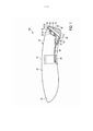
[0051] A Figura 1 ilustra o projeto geral de sistemas de corte de cabelo de acordo com a presente invenção em sua totalidade em uma vista em seções;[0051] Figure 1 illustrates the general design of haircut systems according to the present invention in its entirety in a sectional view;
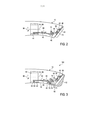
[0052] A Figura 2 ilustra uma primeira realização do sistema de corte de cabelo de acordo com a presente invenção sem acessório de pente;[0052] Figure 2 illustrates a first embodiment of the haircut system according to the present invention without comb attachment;
[0053] A Figura 3 ilustra a primeira realização mostrada na Figura 2 com acessório de pente;[0053] Figure 3 illustrates the first embodiment shown in Figure 2 with comb attachment;
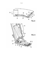
[0054] A Figura 4 ilustra uma segunda realização do sistema de corte de cabelo de acordo com a presente invenção com acessório de pente em uma primeira posição;[0054] Figure 4 illustrates a second embodiment of the haircut system according to the present invention with comb attachment in a first position;
[0055] A Figura 5 ilustra a segunda realização mostrada na Figura 4 com acessório de pente em uma segunda posição;[0055] Figure 5 illustrates the second embodiment shown in Figure 4 with comb attachment in a second position;
[0056] A Figura 6 ilustra uma terceira realização do sistema de corte de cabelo de acordo com a presente invenção sem acessório de pente;[0056] Figure 6 illustrates a third embodiment of the haircut system according to the present invention without comb attachment;
[0057] A Figura 7 ilustra a terceira realização mostrada na Figura 6 com acessório de pente;[0057] Figure 7 illustrates the third embodiment shown in Figure 6 with comb attachment;
[0058] A Figura 8 ilustra uma quarta realização do sistema de corte de cabelo de acordo com a presente invenção sem acessório de pente;[0058] Figure 8 illustrates a fourth embodiment of the haircut system according to the present invention without comb attachment;
[0059] A Figura 9 mostra uma vista em perspectiva ilustrando as peças do sistema de corte de cabelo de acordo com a quarta realização mostrada na Figura 8;[0059] Figure 9 shows a perspective view illustrating the parts of the haircut system according to the fourth embodiment shown in Figure 8;
[0060] A Figura 10 ilustra esquematicamente o princípio de ajuste da lâmina móvel do sistema de corte de cabelo de acordo com a primeira e a terceira realização;[0060] Figure 10 schematically illustrates the principle of adjustment of the movable blade of the haircut system according to the first and the third realization;
[0061] A Figura 11 ilustra esquematicamente o princípio de ajuste da lâmina móvel do sistema de corte de cabelo de acordo com a segunda realização;[0061] Figure 11 schematically illustrates the principle of adjustment of the movable blade of the haircut system according to the second embodiment;
[0062] A Figura 12 ilustra esquematicamente o princípio de ajuste da lâmina móvel do sistema de corte de cabelo de acordo com a quarta realização;[0062] Figure 12 schematically illustrates the principle of adjustment of the movable blade of the haircut system according to the fourth embodiment;
[0063] A Figura 13 mostra uma vista aumentada da Figura 12; e[0063] Figure 13 shows an enlarged view of Figure 12; and
[0064] As Figuras 14 A-D ilustram o ajuste da lâmina móvel e o acessório de pente em posições diferentes.[0064] Figures 14 A-D illustrate the adjustment of the movable blade and the comb attachment in different positions.
[0065] A Figura 1 ilustra esquematicamente o princípio de um sistema de corte de cabelo de acordo com a presente invenção, o qual é, em sua totalidade, denotado pelo número de referência 100. 0 sistema de corte de cabelo 100 compreende um dispositivo de corte de cabelo 10 e um acessório de pente 12 que pode ser fixado a uma extremidade frontal ou traseira 14 do dispositivo de corte 10. 0 dispositivo de corte 10 compreende um alojamento 16 que conecta todas as partes e também serve como uma estrutura para um conjunto de corte 18. 0 alojamento 16 apresenta um corpo alongado, em que o conjunto de corte 18 é fixado à extremidade frontal 14, compreendendo uma alça 20 em sua extremidade traseira 22.[0065] Figure 1 schematically illustrates the principle of a haircut system according to the present invention, which is, in its entirety, denoted by
[0066] A superfície externa do alojamento alongado 16 é reduzida gradualmente na direção externa a partir da extremidade traseira 22 para a extremidade frontal 14 e apresenta um desenvolvimento levemente inclinado para prover uma posição de fixação mais ergonômica e aprimorar a aparência estética do dispositivo de corte 10. Deve ser observado que outras disposições e projetos do alojamento também são considerados sem sair do escopo da invenção.[0066] The external surface of the
[0067] Um botão de operação (para fins de simplicidade não mostrados) é provido no alojamento 16 para operar o dispositivo 10, como será explicado posteriormente.[0067] An operation button (for simplicity purposes not shown) is provided in
[0068] O conjunto de lâmina cortante 18 é montado de modo removível na extremidade frontal 14 do alojamento 16. 0 dito conjunto de corte 18 pode, portanto, ser facilmente removido, o que aumenta a capacidade de limpeza do conjunto de corte 18 e aprimora a utilização pelo usuário. 0 conjunto de corte 18 inclui uma lâmina estacionária 24 e uma lâmina móvel 26. A lâmina móvel 26 é montada de modo liberável em uma superfície superior 28 da lâmina estacionária 24 cuja superfície superior 28 está voltada substancialmente na direção do lado interno do alojamento 16. Um arranjo de condução 30, incluindo um motor (mostrado na Figura 9) é adaptado para conduzir a lâmina móvel 18 em um movimento oscilatório em uma direção transversa 32 paralela à margem frontal 34 da lâmina estacionária 24. Uma ponte de condução 40 é utilizada como elemento de acoplamento que acopla o motor à lâmina móvel 26 e converte o movimento do motor em um movimento translacional/reciproco na direção transversa 32.[0068] The
[0069] A lâmina móvel 26 compreende uma margem dentada 36 com um conjunto de dentes que é disposto substancialmente paralelo à margem frontal 34 da lâmina estacionária 24. Durante a operação, o corte de cabelo é realizado em razão da interação da lâmina estacionária 24 e da lâmina móvel 26 que se alterna na direção transversa 32, conforme conhecido a partir de outros dispositivos de corte de cabelo convencionais.[0069] The
[0070] A lâmina estacionária 24 é geralmente projetada para ser mais espessa que a lâmina móvel 26. A dita lâmina estacionária 24 também é denotada como proteção 24. Sua margem frontal 34 pode ser projetada como uma margem contínua cortante ou, de modo semelhante à lâmina móvel 26, como uma margem dentada com um conjunto de dentes cortantes. Para receber um desempenho de corte satisfatório, a lâmina móvel 26 é pressionada ativamente na superfície superior 28 da lâmina estacionária 24 para receber uma então chamada pressão dentada. Uma mola 38 é geralmente utilizada para fornecer a dita pressão dentada inclinando, de modo resiliente, a lâmina móvel 26 contra a superfície superior 28 da lâmina estacionária 24.[0070] The
[0071] O acessório de pente 12 já mencionado é fixável, de modo liberável, à extremidade frontal 14 do alojamento 16. Ele pode ser fixado ao dispositivo de corte de cabelo 10 por meio de uma superfície entre duas faces do pente que é geralmente concebida por uma fixação simples (não visível). 0 acessório de pente 12 compreende uma pluralidade de dentes de pente 12' (mostrada exemplarmente nas Figuras 14 C, D) que são adaptados para cercar, pelo menos parcialmente, o conjunto de corte 18. Os dentes de pente 12' servem como espaçadores que definem um espaço entre si e a margem cortante 36 da lâmina móvel 26.[0071] The
[0072] O elemento de pente 12, em outras palavras, espaça os elementos de corte 24, 26 da superfície da pele do cabelo a partir da qual o cabelo se estende, para aumentar o comprimento do corte de cabelo. Nesse ponto, deve ser esclarecido que o termo "comprimento de corte de cabelo" denota o comprimento dos cabelos que permanecem na pele, e não o comprimento das partes do cabelo que são cortadas. Ainda, deve ser observado que o acessório de pente 12 pode apresentar qualquer desenho, contanto que seja mecanicamente fixável ao dispositivo de corte de cabelo 10. 0 termo "sistema de corte de cabelo 100" inclui o dispositivo de corte de cabelo 10 e o acessório de pente 12 (fixado ao cortador de cabelo 10 ou não), enquanto o dispositivo de corte de cabelo 10 denota o próprio cortador de cabelo sem o acessório de pente 12 .[0072] The
[0073] O dispositivo de corte de cabelo 10 também pode ser utilizado sem o acessório de pente 12, de modo que o conjunto de lâmina cortante 18 fique exposto. Esse modo de trabalho permite especialmente corte de cabelo preciso e leva a comprimentos de corte de cabelo mais curtos, que podem ser particularmente utilizados para contornos externos do cabelo ou da barba.[0073] The
[0074] Um dos principais elementos da presente invenção se refere ao sistema de ajuste especial para ajustar a posição da lâmina móvel 26 e/ou a posição do acessório de pente 12. Esse sistema de ajuste especial é concebido por uma unidade de ajuste que é, em sua totalidade, denotada pelo número de referência 42. A unidade de ajuste 42 compreende uma alça ajustadora 44, um elemento de ajuste 46, também denotado como deslizador, um elemento de condução 48 e a mola 38 .[0074] One of the main elements of the present invention relates to the special adjustment system for adjusting the position of the
[0075] A unidade de ajuste é, por um lado, adaptado para ajustar a posição da lâmina móvel 26 em relação à lâmina estacionária 24 em uma primeira direção de ajuste 50 (consulte as Figuras 10 a 12) , a primeira direção de ajuste 50 sendo substancialmente perpendicular à dita direção transversa 32. Por outro lado, a unidade de ajuste 42 é adaptada para ajustar a posição do acessório de pente 12 em relação ao conjunto de corte 18 em uma segunda direção de ajuste 52, caso o acessório de pente 12 esteja fixado ao dispositivo de corte de cabelo 10 (consulte as Figuras 1, 3 e 5) . A dita segunda direção de ajuste 52 é disposta substancialmente de modo perpendicular à superfície superior 28 da lâmina estacionária 24, de modo que o acessório de pente possa ser movido para longe do conjunto de corte 18 em uma direção substancialmente perpendicular a ele, aumentando o comprimento do corte de cabelo.[0075] The adjustment unit is, on the one hand, adapted to adjust the position of the
[0076] Em outras palavras, a unidade de ajuste 42 pode ser utilizada para adaptar a posição da lâmina de corte móvel 26, bem como para posicionar o acessório de pente 12 em direções correspondentes de ajuste diferente 50, 52. Preferivelmente, a dita primeira direção de ajuste 50 é perpendicular à dita direção transversa 32, e a dita segunda direção de ajuste 52 é perpendicular à dita superfície superior 28 da lâmina estacionária 24. 0 princípio de trabalho da dita unidade de ajuste 42 será explicado com detalhes a seguir.[0076] In other words, the
[0077] De acordo com a primeira realização ilustrada nas Figuras 2 e 3, a unidade de ajuste 42 compreende uma alça ajustadora 44 que é girável ao redor de seu eixo central 54 em uma direção de rotação 56. 0 dito eixo central 54 é preferivelmente alinhado substancialmente de modo paralelo a um eixo longitudinal 58 do alojamento 16. Deve ser observado que, caso o alojamento 16 seja dobrado da maneira mostrada, o eixo longitudinal 58 denotará o eixo médio do alojamento 16 na posição na qual a alça ajustadora é 44 disposta. A alça ajustadora 44 pode, obviamente, ser disposta em posições variáveis dentro ou sobre o alojamento 16. Poderia, por exemplo, também ser disposta na extremidade mais traseira 22 do alojamento 16. Em razão de seu projeto como uma roda rotacionalmente simétrica, a alça ajustadora 44 é, na prática, também denotada como roda de zoom 44.[0077] According to the first embodiment illustrated in Figures 2 and 3, the
[0078] Como pode ser observado nas Figuras 2 e 3, o deslizador 46 é mecanicamente acoplado à roda de zoom 44. Essa conexão pode, por exemplo, ser concebida por um elemento de acoplamento 60 que se projeta a partir do braço alongado 62 do deslizador 46, cujo elemento de acoplamento 60 é mecanicamente orientado em uma orientação correspondente dentro da superfície interna da roda de zoom 44. A dita orientação 64 pode, em uma vista superior, ser inclinada em relação ao eixo central 54, isto é, desenvolvendo-se, de modo espiral ou helical, dentro da superfície interna 66 da roda de zoom oca 44.[0078] As can be seen in Figures 2 and 3, the
[0079] Desse modo, um movimento rotacional sobre o eixo central 54 da alça ajustadora/roda de zoom 44 causa um movimento do deslizador 46 em uma direção do deslizador 68, isto é, ao longo da direção longitudinal do braço alongado 62 do deslizador 46. Em outras palavras, a roda de zoom 44 converte um movimento rotacional (na direção de rotação 56) em um movimento de translação eficaz do deslizador 46 (na direção do deslizador 68) . Deve ser observado que o termo "efetivamente" é utilizado para denotar que o deslizador 46 é efetivamente movido de modo translacional na direção do deslizador 68, em que é, ao mesmo tempo, girado junto à roda de zoom 44 na direção de rotação 56.[0079] Thus, a rotational movement about the central axis 54 of the adjusting handle /
[0080] O movimento descrito do deslizador 46, por sua vez, causará um movimento da lâmina móvel 26 na primeira direção de ajuste 50 se o acessório de pente 12 não estiver fixado ao dispositivo de corte 10 como mostrado na Figura 2. A translação do movimento do deslizador na direção do deslizador 68 para o movimento da lâmina móvel 26 ao longo da primeira direção de ajuste 50 é concebida pelo elemento de condução 48 que é, em um lado, conectado ao deslizador 46 e, em outro lado, conectado à lâmina móvel 2 6 por meio da mola 38 já descrita.[0080] The described movement of the
[0081] De acordo com a primeira realização mostrada (mostrada nas Figuras 2 e 3), o elemento de condução 4 8 é fixado, de modo inclinável, na lâmina estacionária/proteção 28 com uma fixação 70. A mola 38, por um lado, pressiona a lâmina móvel 26 contra a superfície superior 28 da proteção 24 e, por outro lado, pressiona o elemento de condução inclinável 48 sobre uma superfície inclinada 72 do deslizador 46. Deve ser observado que a mola 38 não precisa ser necessariamente conectada diretamente à lâmina móvel, mas também pode ser conectada à ponte de condução 40. A última conexão indireta é preferida na prática.[0081] According to the first embodiment shown (shown in Figures 2 and 3), the
[0082] Como mostrado esquematicamente na Figura 10, o movimento do deslizador 46, em razão da superfície inclinada 72, faz com que o elemento de condução 48 se incline sobre seu ponto de fixação 70, posicionado junto à sua inclinação ou ao eixo principal. A inclinação do elemento de condução 48 força novamente a lâmina móvel 26 na primeira direção de ajuste 50 na direção da margem frontal 34 da proteção 24, diminuindo assim o comprimento de corte de cabelo resultante. 0 ajuste proposto, portanto, permite que um usuário ajuste facilmente a posição da lâmina móvel 26 na primeira direção de ajuste 50.[0082] As shown schematically in Figure 10, the movement of the
[0083] A distância ali ajustada entre a margem dentada 36 da lâmina de corte móvel 26 e a margem frontal 34 da lâmina de corte estacionária 24 também é denotada como ajuste de ponta a ponta ou distância de ponta a ponta, respectivamente. Esse termo técnico abrevia a distância da parte de ponta da lâmina móvel 2 6 para a parte de ponta da lâmina estacionária ou proteção 24.[0083] The distance set there between the
[0084] Um uma aplicação prática da presente invenção, a dita distância de ponta a ponta é preferivelmente ajustável entre 0,3 mm e 2 mm, com um tamanho de etapas de 0,3 mm. Obviamente, outros tamanhos de etapas são tecnicamente possíveis, bem como ajuste contínuo sem etapas. Para facilitar a utilização pelo usuário, uma escala de distância correspondente (não mostrada) pode ser visivelmente marcada no corpo externo do alojamento 16, próximo à roda de zoom 44.[0084] As a practical application of the present invention, said end-to-end distance is preferably adjustable between 0.3 mm and 2 mm, with a step size of 0.3 mm. Obviously, other step sizes are technically possible, as well as continuous adjustment without steps. To facilitate use by the user, a corresponding distance scale (not shown) can be visibly marked on the outer body of the
[0085] Como já explicado acima, a mesma unidade de ajuste 42 também poderá ser utilizada para ajustar a posição do acessório de pente 12 se o acessório de pente estiver fixado ao dispositivo de corte de cabelo 10 como mostrado na Figura 3. 0 acessório de pente 12 pode se conectar ao deslizador 46 ao ser fixado à extremidade frontal 14 do cortador de cabelo 10. Tal conexão é, por exemplo, concebida por um elemento de acoplamento adicional 74 que se fixa em uma ranhura correspondente 76 dentro do acessório de pente 12 ao fixar o acessório de pente 12 ao dispositivo de corte de cabelo 10. Desse modo, o movimento rotacional descrito acima da roda de zoom 44 causa um movimento do deslizador 46 na direção do deslizador 68 acima mencionado que, por sua vez, causa um movimento do acessório de pente 12 na segunda direção de ajuste 52. Assim, o usuário pode facilmente ajustar o comprimento de corte de cabelo utilizando a mesma roda de zoom 44 anterior. Uma rotação na direção de rotação 56 força, então o acessório de pente a se mover para longe do conjunto de lâmina 18, aumentando o comprimento de corte de cabelo.[0085] As already explained above, the
[0086] Ao estudar a Figura 3 em detalhes, pode ser observado que o acessório de pente 12 compreende adicionalmente um então chamado elemento de bloqueio 78 que se projeta na direção do lado interno do alojamento 16 e desacopla o elemento de condução 48 do deslizador 46, isto é, liberando a conexão entre a superfície inclinada 72 do deslizador 46 e o elemento de condução 48. 0 elemento de bloqueio 78 pode ser concebido de várias maneiras. A maneira mais fácil é projetar o elemento de bloqueio como uma peça do alojamento que se projeta do acessório de pente 12 que é adaptado para empurrar o elemento de condução 48 para longe do deslizador 46 para então, bloquear o ajuste da lâmina móvel. Entretanto, disposições mais complicadas também são geralmente concebíveis. Além disso, deve ser observado que o elemento de bloqueio 78 não precisa necessariamente ser disposto no acessório de pente 12. Como mostrado esquematicamente na Figura 12, um elemento de bloqueio 78' pode, da mesma maneira, também fazer parte do elemento de condução 48.[0086] When studying Figure 3 in detail, it can be seen that the
[0087] O dito elemento de bloqueio 78, de acordo com a primeira realização descrita (Figuras 2 e 3) , não somente desacopla a conexão entre o deslizador 46 e o elemento de condução 48, mas também empurra a lâmina móvel 26 para uma posição predefinida em relação à proteção/lâmina estacionária 24. 0 movimento ali permitido da lâmina móvel 26 resulta nas seguintes vantagens.[0087] Said locking
[0100] A fixação do acessório de pente 12 automaticamente aumenta a dificuldade de cortar o cabelo. Em outras palavras, o cabelo terá dificuldade de entrar mais no sistema alcançando o conjunto de corte 18 em razão de obstáculos, como os dentes do pente e a distância a ser percorrida até o conjunto de corte 18. A dita dificuldade aumenta ao aumentar o comprimento de corte de cabelo desejado, isto é, aumentar a distância entre os dentes do pente e o conjunto de corte 18. Se a dita distância a ser percorrida até o conjunto de corte 18 for muito grande, o corte não ocorrerá, ou no melhor caso, um desempenho de corte insatisfatório será alcançado.[0100] Fixing the
[0101] Entretanto, isso é superado ao liberar, de maneira mecânica e automática, a conexão entre a unidade de ajuste 42 e a lâmina de corte móvel 26 e empurrar a lâmina de corte móvel 26 para a posição predefinida preferida, como mencionada acima. A dita posição predefinida da lâmina de corte móvel 2 6 é uma posição na qual a margem dentada 3 6 da lâmina de corte móvel 26 está, observada na primeira direção de ajuste 50, em sua posição mais dianteira em relação à margem frontal 34 da proteção 24. Em outras palavras, a posição predefinida preferida é uma posição na qual a distância de ponta a ponta é a menor possível. De acordo com a presente invenção, prefere-se, nesse caso, uma distância de ponta a ponta menor que 0,6 mm, mais preferivelmente de 0,3 mm ou ainda menor.[0101] However, this is overcome by mechanically and automatically releasing the connection between the
[0102] Como a mola acima mencionada 38 pressiona, de maneira resiliente, o elemento de condução 48 contra a superfície inclinada 72 do deslizador 46, a mola 38 forçará o elemento de condução 48 a retornar contra a superfície inclinada 72 quando o acessório de pente 12 for liberado do dispositivo de corte 10 e o elemento de bloqueio 7 8 não mais empurrar o elemento de condução 4 8 para sua posição mais dianteira. Isso garante que a lâmina de corte móvel 2 6 sempre retorne para a posição que é definida pela roda de zoom 44 quando o acessório de pente 12 é liberado.[0102] As the
[0103] Em resumo, a disposição acima descrita permite o melhor desempenho de corte de cabelo ao utilizar o acessório de pente 12 de modo independente de sua posição, uma vez que a menor distância de ponta a ponta possível é sempre mantida. Um usuário pode utilizar o dispositivo de corte 10 em conexão com o acessório de pente 12 para ajustar, de modo variável, os comprimentos de corte de cabelo entre, por exemplo, 2,5 mm e 10 mm sem perder o desempenho de corte. De modo semelhante, como o ajuste da posição da lâmina de corte móvel 26, o ajuste do acessório de pente 12 também pode ser um ajuste gradual ou não gradual. Na prática, tamanhos de etapas de 0,3 ou 0,5 mm parecem ser razoáveis. Também de modo semelhante ao explicado acima, uma segunda escala de comprimento pode ser marcada no alojamento 16 para fornecer ao usuário informações sobre o comprimento de corte de cabelo ajustado no momento com o pente 12.[0103] In summary, the arrangement described above allows for the best haircut performance when using
[0104] Ao comparar as Figuras 2 e 3, pode ser observado que a rotação da roda de zoom 44 na direção de rotação 56, de acordo com essa realização, leva a situações de ajuste diferentes. Enquanto o giro da roda de zoom 44 na direção de rotação 56 leva a uma distância de ponta a ponta menor, isto é, a um corte de cabelo mais curto (se o pente 12 não estiver fixado), uma rotação na mesma direção 56 leva a uma distância maior entre os dentes do pente e o conjunto de lâmina de corte 18, isto é, a um corte de cabelo mais longo (se o pente 12 estiver fixado). Isso pode confundir o usuário, uma vez que a roda de zoom 44 deve ser movida em uma direção para diminuir o comprimento de corte de cabelo quando o pente 12 não estiver fixado, enquanto, por outro lado, o usuário deve mover a roda de zoom 44 na outra direção oposta para diminuir o comprimento de corte de cabelo se um pente 12 estiver fixado.[0104] When comparing Figures 2 and 3, it can be seen that the rotation of the
[0105] Esse não é o caso na segunda realização ilustrada nas Figuras 4 e 5. Enquanto todas as outras peças do dispositivo de corte 10 basicamente permanecem as mesmas da primeira realização, o deslizador 46 e sua disposição em relação ao elemento de condução 48 são levemente modificados. A superfície inclinada 72', de acordo com a segunda realização, é inversamente inclinada e disposta no outro lado do elemento de condução 48. A mola 38, nesse caso, empurra o elemento de condução 48 contra a superfície inclinada 72' a partir da direção oposta em comparação à primeira realização (em comparação às Figuras 2 e 3). Em outras palavras, a força de mola da mola 3 8 agora puxa o elemento de condução 4 8 contra a superfície inclinada 72', enquanto empurra o elemento de condução 48 contra a superfície inclinada 72 na primeira realização.[0105] This is not the case in the second embodiment illustrated in Figures 4 and 5. While all the other parts of the cutting
[0106] Essa modificação leva à situação na qual um giro da roda de zoom 44 na direção de rotação 56 aumenta a distância de ponta a ponta e, ao mesmo tempo, também aumenta a distância entre o acessório de pente 12 e o conjunto de lâmina 18, ambas as situações levando a um aumento do comprimento do corte de cabelo. A confusão do usuário, como mencionada acima, não mais ocorre.[0106] This modification leads to the situation in which a rotation of the
[0107] Entretanto, essa solução não permite que o acessório de pente 12 ou o elemento de condução 46 compreenda um elemento de bloqueio 78 como apresentado em relação à primeira realização. A fixação do pente 12 ao dispositivo de corte 10, portanto, não libera a conexão entre a unidade de ajuste 42 e a lâmina de corte móvel 24 e empurra a lâmina de corte móvel 24 para sua posição preferida (menor distância de ponta a ponta) . 0 princípio de ajuste do então chamado sistema de retrocesso da segunda realização é esquematicamente ilustrado em detalhes na Figura. 11.[0107] However, this solution does not allow the
[0108] Os princípios técnicos acima mencionados e suas vantagens associadas são combinados e realizados na terceira realização mostrada nas Figuras 6 e 7. Ali, a unidade de ajuste 42 compreende dois elementos de ajuste independentes 46', 46'', que serão referenciados, no que segue, como deslizador de lâmina 46' e deslizador de pente 46''. 0 primeiro elemento de ajuste 46', o deslizador de lâmina, é adaptado para ajustar a posição da lâmina móvel 26 na primeira direção de ajuste 50 da mesma forma explicada com referência à primeira realização (Figuras 2, 3) . 0 segundo elemento de ajuste 46'', o deslizador de pente, é adaptado para ajustar a posição do acessório de pente 12 por meio do elemento de acoplamento 74 e a ranhura correspondente 76 dentro do acessório de pente 12.[0108] The aforementioned technical principles and their associated advantages are combined and carried out in the third embodiment shown in Figures 6 and 7. There, the
[0109] A alça ajustadora 44 também é modificada e compreende duas alças ajustadoras independentes 44', 44'', que são, no que segue, também denotadas como rodas de zoom 44', 44''. A roda de zoom da lâmina 44' é conectada à lâmina de corte móvel 26 por meio do deslizador de lâmina 46', e a roda de zoom do pente 44'' é conectada ao acessório de pente 12 por meio do deslizador de pente 46''. As orientações 64', 64'' dentro da superfície interna 66 das rodas de zoom 44', 44'' novamente apresentam um desenvolvimento espiral ou helical ao longo da superfície interna 66. Entretanto, as orientações 64', 64'' são inclinadas em direções opostas, isto é, as orientações 64', 64'' são dispostas de modo oposto uma em relação à outra.[0109] The adjusting handle 44 is also modified and comprises two independent adjusting handles 44 ', 44' ', which are, in the following, also denoted as zoom wheels 44', 44 ''. The blade zoom wheel 44 'is connected to the
[0110] As duas disposições da roda de zoom independentes descritas permitem que o usuário gire cada roda de zoom 44', 44'' na mesma direção, em que o giro das rodas de zoom 44', 44'' na direção de rotação 56 em ambos os casos leva a um comprimento de corte maior, independentemente de o pente 12 estar fixado ou não. Uma rotação na direção de rotação 56 aumentará a distância de ponta a ponta ao utilizar a roda de zoom 44' e não houver pente 12 fixado e aumentará a distância entre os dentes do pente e o conjunto de lâmina de corte 18 se o pente estiver fixado ao dispositivo de corte de cabelo. Prover o acessório de pente 12 com o elemento de bloqueio 78 também permite desacoplar a lâmina de corte móvel 26 da unidade de ajuste 42, bloqueando assim, o ajuste da lâmina de corte se o pente 12 estiver fixado.[0110] The two independent zoom wheel arrangements described allow the user to rotate each zoom wheel 44 ', 44' 'in the same direction, with the rotation of the zoom wheels 44', 44 '' in the direction of
[0111] Deve ser observado que a roda de zoom 44 é mostrada nas Figuras 6 e 7 como duas rodas de zoom individuais, mas ela também pode ser uma roda de zoom única 44, que é conectada à lâmina de corte móvel 26 por meio de um deslizador de lâmina 46' e ao acessório de pente 12 por meio de um deslizador de pente 46'' (se um pente estiver fixado). 0 princípio técnico permanece o mesmo, isto é, prover duas orientações 64', 64'' que são dispostas de maneira oposta uma à outra, de modo que o giro da roda de zoom 44 na direção de rotação 56 em ambos os casos (pente fixado ou não) leve a um comprimento de corte maior, independentemente se o pente 12 estiver fixado ou não. A utilização de somente uma roda de zoom ainda apresenta a vantagem de facilitar o ajuste para o usuário.[0111] It should be noted that the
[0112] Uma quarta realização da presente invenção é mostrada nas Figuras 8 e 9. Embora a maioria das outras peças permaneça a mesma, o elemento de condução 48' é, de acordo com a realização de força, levemente modificado. Em contraste às três primeiras realizações mencionadas anteriormente, o elemento de condução 48' não é mais montado, de modo inclinável, sobre a proteção 24. Em vez disso, o elemento de condução 48' é posicionado, de modo deslizante, ao longo da primeira direção de ajuste 50. 0 elemento de condução 48' é preferivelmente guiado em uma orientação 80 sobre a lâmina de corte estacionária/proteção 24, que pode ser observado em detalhes no desenho mostrado na Figura 12. Para converter o movimento do deslizador 46 em um movimento translacional do elemento de condução 48', o elemento de condução 48' compreende, em sua extremidade traseira, uma superfície inclinada 82 que é inclinada, de modo resiliente, contra a superfície inclinada 72 já descrita do deslizador 46. Em vez de inclinar o elemento de condução 48, o elemento de condução é, desse modo, deslizável dentro da orientação 80, e um movimento na direção de ajuste 50 é ativado por meio de duas superfícies inclinadas 72, 82.[0112] A fourth embodiment of the present invention is shown in Figures 8 and 9. Although most of the other parts remain the same, the driving element 48 'is, according to the realization of force, slightly modified. In contrast to the first three embodiments mentioned above, the guiding element 48 'is no longer tiltable on the
[0113] Através dessa conexão, o elemento de condução 48' e o deslizador 4 6 são conectados, de modo liberável, um ao outro novamente. Como pode ser observado na Figura 9, uma mola adicional 39 deve ser provida para inclinar o elemento de condução 48' contra a superfície inclinada 72 do deslizador 46. A mola adicional 39 é disposta de modo paralelo à primeira direção de ajuste 50, de modo que sua força de mola também seja eficaz na dita direção 50.[0113] Through this connection, the driving element 48 'and the
[0114] O motivo da necessidade de uma mola adicional 39 é que a força de mola da primeira mola 38 é, de acordo com essa realização, eficaz somente de modo perpendicular à superfície superior 28 da proteção 24 (perpendicular à primeira direção de ajuste 50) para pressionar a lâmina de corte móvel 26 contra a proteção e prover a pressão dentada acima mencionada.[0114] The reason for the need for an
[0115] De modo semelhante à primeira e terceira realizações, o ajuste da lâmina de corte móvel 26 poderá ser desacoplado se um pente 12 estiver fixado ao dispositivo de corte de cabelo 10. 0 elemento de bloqueio 78 que desacopla a conexão entre o deslizador 46 e o elemento de condução 48' pode ser disposto em uma peça do alojamento que se projeta do acessório de pente (como explicado de acordo com a primeira e terceira realizações) ou disposto na extremidade traseira do elemento de condução 48' (como mostrado esquematicamente na Figura 12). Ali, o elemento de bloqueio semelhante é denotado com o numeral de referência 78'.[0115] Similar to the first and third embodiments, the adjustment of the
[0116] Como pode ser observado adicionalmente na Figura 12, dois deslizadores independentes 46', 46''são utilizados para adaptar a posição do elemento de condução 48' e do acessório de pente 12. 0 princípio técnico e as vantagens associadas são os mesmos que os explicados anteriormente com referência à terceira realização. Porém, deve ser compreendido que um deslizador integral 46 também pode ser utilizado nessa realização, o qual é adaptado para posicionar a lâmina de corte móvel 26, bem como o acessório de pente 12 (como explicado acima com referência à primeira realização).[0116] As can be seen additionally in Figure 12, two independent slides 46 ', 46' are used to adapt the position of the driving element 48 'and the
[0117] A Figura 13 também corresponde à quarta realização e mostra uma vista aumentada da extremidade frontal do conjunto de corte 18 mostrado na Figura. 12 Ali, pode ser observado que a orientação 80 também compreende um elemento de parada de extremidade 82 que é projetado como uma parede vertical simples e adaptado para bloquear o movimento translacional do elemento de condução 48' em uma posição predefinida. Preferivelmente, a dita posição predefinida define a posição mais dianteira da lâmina de corte móvel, de modo que o elemento de parada de extremidade 82 evite que a distância di entre a margem dentada 36 da lâmina de corte móvel 26 e a margem frontal 34 da proteção 24 se torne muito pequena, por exemplo, menor que 0,3 mm.[0117] Figure 13 also corresponds to the fourth embodiment and shows an enlarged view of the front end of the cutting set 18 shown in the Figure. 12 There, it can be seen that the
[0118] A Figura 14 resume o princípio técnico da presente invenção e mostra o dispositivo de corte de cabelo 10 nas posições de trabalho diferentes explicadas acima com e sem acessório de pente 12. Na Figura 14A, a lâmina de corte móvel 26 está em sua posição mais recuada, que corresponde à definição de ponta a ponta mais longa, e dependendo do projeto específico, resulta em um comprimento de corte de cabelo entre 2 a 4 mm. Na Figura 14B, a lâmina de corte móvel 26 está em sua posição mais dianteira, que corresponde à definição de ponta a ponta mais curta, levando a um comprimento de corte de cabelo de cerca de 0,3 mm. Nas Figuras 14C e D, o acessório de pente 12 está fixado ao dispositivo de corte de cabelo 10 e o ajuste da lâmina móvel é anulado ou desacoplado, em que a definição de ponta a ponta é disposta para ser a menor, isto é, a lâmina de corte móvel é automaticamente movida para sua posição mais dianteira. Enquanto a Figura 14C mostra a definição de pente mais longa (distância mais longa entre o pente 12 e o conjunto de corte 18) resultando em um comprimento de corte de cabelo de cerca de 10 mm, a Figura 14D mostra a definição de pente mais curta (distância mais curta entre o pente 12 e o conjunto de corte 18) resultando em um comprimento de corte de cabelo de cerca de 2 a 5 mm (dependendo do projeto específico).[0118] Figure 14 summarizes the technical principle of the present invention and shows the
[0119] Em resumo, a presente invenção provê uma solução inteligente para ajuste da distância de ponta a ponta e fixação do pente de um dispositivo de corte simultaneamente. Por um lado, o sistema de ponta a ponta pode ser utilizado para criar comprimentos de corte de cabelo diferentes, adaptando a posição de uma lâmina de corte móvel em relação a uma lâmina de proteção estacionária. Além disso, a solução apresentada também permite ajuste da posição de um acessório de pente com a mesma unidade de ajuste. Em razão do projeto técnico específico da solução apresentada, a lâmina de corte móvel pode ser automaticamente movida para sua posição mais dianteira assim que um acessório de pente for fixado ao dispositivo de corte. Isso garante o melhor desempenho de corte em relação ao alcance de cabelo também em situações nas quais um pente estiver fixado ao cortador de cabelo. Nesses casos, o sistema apresentado também permite desacoplamento e bloqueio automático da unidade de ajuste da lâmina de corte móvel.[0119] In summary, the present invention provides an intelligent solution for adjusting the distance from end to end and fixing the comb of a cutting device simultaneously. On the one hand, the end-to-end system can be used to create different haircut lengths, adapting the position of a movable cutting blade in relation to a stationary protection blade. In addition, the solution presented also allows adjustment of the position of a comb attachment with the same adjustment unit. Due to the specific technical design of the presented solution, the mobile cutting blade can be automatically moved to its most forward position as soon as a comb attachment is attached to the cutting device. This guarantees the best cutting performance in relation to hair reach even in situations where a comb is attached to the hair clipper. In such cases, the presented system also allows automatic decoupling and locking of the mobile cutting blade adjustment unit.
[0120] Embora a invenção tenha sido ilustrada e descrita em detalhes nos desenhos e na descrição anterior, tal ilustração e descrição devem ser consideradas como ilustrativas ou exemplares e não restritivas; a invenção não se limita às realizações descritas. Outras variações das realizações descritas podem ser compreendidas e realizadas pelos técnicos no assunto ao realizar a invenção reivindicada a partir de um estudo dos desenhos, da invenção e das reivindicações anexadas.[0120] Although the invention has been illustrated and described in detail in the drawings and in the previous description, such illustration and description must be considered as illustrative or exemplary and not restrictive; the invention is not limited to the described embodiments. Other variations of the described embodiments can be understood and realized by those skilled in the art when carrying out the claimed invention from a study of the drawings, the invention and the attached claims.
[0121] Nas reivindicações, a palavra "compreender" não exclui outros elementos e outras etapas, e o artigo indefinido "um" ou "uma" não exclui uma pluralidade. Um elemento único ou outra unidade pode preencher as funções de diversos itens mencionados nas reivindicações. 0 mero fato de determinadas medidas serem mencionadas em reivindicações dependentes mutuamente diferentes não indica que uma combinação dessas medidas não possa ser utilizada para obtenção de vantagem.[0121] In the claims, the word "understand" does not exclude other elements and other stages, and the indefinite article "one" or "one" does not exclude a plurality. A single element or another unit can fulfill the functions of several items mentioned in the claims. The mere fact that certain measures are mentioned in mutually different dependent claims does not indicate that a combination of these measures cannot be used to obtain an advantage.
[0122] Quaisquer sinais de referência nas reivindicações não devem ser interpretados como limitantes do escopo.[0122] Any reference signs in the claims should not be construed as limiting the scope.
Claims (14)
Applications Claiming Priority (3)
| Application Number | Priority Date | Filing Date | Title |
|---|---|---|---|
| US201161564118P | 2011-11-28 | 2011-11-28 | |
| US61/564,118 | 2011-11-28 | ||
| PCT/IB2012/056724 WO2013080114A1 (en) | 2011-11-28 | 2012-11-26 | Variable cutting length hair clipping system |
Publications (2)
| Publication Number | Publication Date |
|---|---|
| BR112014012482A2 BR112014012482A2 (en) | 2017-06-06 |
| BR112014012482B1 true BR112014012482B1 (en) | 2020-09-15 |
Family
ID=47471882
Family Applications (1)
| Application Number | Title | Priority Date | Filing Date |
|---|---|---|---|
| BR112014012482-5A BR112014012482B1 (en) | 2011-11-28 | 2012-11-26 | HAIR CUTTING SYSTEM WITH HAIR CUTTING DEVICE, AND HAIR CUTTING DEVICE FOR A HAIR CUTTING SYSTEM |
Country Status (8)
| Country | Link |
|---|---|
| US (1) | US9815215B2 (en) |
| EP (2) | EP3059052B1 (en) |
| JP (1) | JP6157495B2 (en) |
| CN (1) | CN103958134B (en) |
| BR (1) | BR112014012482B1 (en) |
| IN (1) | IN2014CN03835A (en) |
| RU (1) | RU2623961C2 (en) |
| WO (1) | WO2013080114A1 (en) |
Families Citing this family (21)
| Publication number | Priority date | Publication date | Assignee | Title |
|---|---|---|---|---|
| US8341846B1 (en) * | 2008-11-24 | 2013-01-01 | Lonnie Holmes | Hair clippers with electrically adjustable blades |
| EP2322328A1 (en) * | 2009-11-17 | 2011-05-18 | Koninklijke Philips Electronics N.V. | Hair cutting device with comb unit recognition |
| EP2359991A1 (en) * | 2010-02-12 | 2011-08-24 | Babyliss Faco S.A. | Beard trimmer with automatic positioning of the cutting unit |
| US8844142B2 (en) | 2011-03-18 | 2014-09-30 | Spectrum Brands, Inc. | Adjustable comb assembly for hair cutting appliance |
| EP3215322B1 (en) * | 2014-11-06 | 2018-06-27 | Koninklijke Philips N.V. | Hair clipping device |
| WO2017108937A1 (en) * | 2015-12-22 | 2017-06-29 | Koninklijke Philips N.V. | Haircut recording device, method and system |
| RU2737101C2 (en) | 2016-01-12 | 2020-11-24 | Конинклейке Филипс Н.В. | Length adjustment mechanism for hair clipper |
| RU169824U1 (en) * | 2016-06-16 | 2017-04-03 | Евгений Владимирович Шмидт | HAIR CLIP CUTTER |
| CN106758120B (en) * | 2017-03-02 | 2023-03-14 | 杭州凯秀纺织有限公司 | Fabric dividing device for scarf weaving |
| EP3381629A1 (en) * | 2017-03-28 | 2018-10-03 | Koninklijke Philips N.V. | Comb arrangement, cutting head, and hair cutting appliance |
| RU181229U1 (en) * | 2017-08-11 | 2018-07-06 | Евгений Владимирович Шмидт | MANUAL HAIR CLIPPER |
| EP3461603A1 (en) * | 2017-09-29 | 2019-04-03 | Koninklijke Philips N.V. | A hair cutting device |
| CN107650164A (en) * | 2017-10-12 | 2018-02-02 | 浙江安达电器有限公司 | A kind of electric hair trimmer of adjustable-length |
| CN107718059B (en) * | 2017-10-31 | 2019-11-15 | 北京小米移动软件有限公司 | Control method and device that hair is repaired facility, hair are repaired facility |
| EP3552778A1 (en) | 2018-04-11 | 2019-10-16 | Koninklijke Philips N.V. | A hair cutting device |
| US11148307B2 (en) | 2018-12-20 | 2021-10-19 | Andis Company | Blade pad assembly for hair cutting apparatus |
| WO2020150321A1 (en) | 2019-01-15 | 2020-07-23 | Carefusion 2200, Inc. | Surgical clipper blade assemblies with hydrophobic layers and methods of use |
| MX2021008509A (en) | 2019-01-15 | 2021-08-19 | Carefusion 2200 Inc | Powered hair clippers with blade assemblies including patterned rib arrays. |
| JP7434333B2 (en) | 2019-01-15 | 2024-02-20 | ケアフュージョン 2200,インコーポレーテッド | Electric hair clipper with blade assembly including blade suspension assembly |
| WO2021167652A1 (en) | 2020-02-18 | 2021-08-26 | Spectrum Brands, Inc. | Hair dryer assembly having hair receiving channel |
| USD981043S1 (en) | 2022-12-12 | 2023-03-14 | E. Mishan & Sons, Inc. | Shaver |
Family Cites Families (42)
| Publication number | Priority date | Publication date | Assignee | Title |
|---|---|---|---|---|
| US1516635A (en) * | 1923-10-19 | 1924-11-25 | Friedman Sam | Hair-gauge clipper |
| DE628752C (en) * | 1933-09-14 | 1936-04-15 | Wilhelm Oehler | Hair clipper |
| US2726447A (en) * | 1952-05-12 | 1955-12-13 | Ernest D Maloy | Hair clippers |
| US2731720A (en) * | 1954-06-25 | 1956-01-24 | Glen L Henard | Comb blade structure and arrangement for adjustable hair clipper |
| US3430342A (en) * | 1967-03-29 | 1969-03-04 | Wahl Clipper Corp | Adjustable clipper head |
| US4274199A (en) * | 1979-01-02 | 1981-06-23 | Sunbeam Corporation | Electric shaver |
| JPS6037753B2 (en) * | 1981-12-15 | 1985-08-28 | 松下電工株式会社 | hair cutter |
| JPS60108074A (en) * | 1983-11-17 | 1985-06-13 | 松下電工株式会社 | Attachment of hair cutter |
| US4622745A (en) * | 1984-09-28 | 1986-11-18 | Wahl Clipper Corporation | Hair trimming apparatus |
| JPH038196Y2 (en) * | 1985-07-24 | 1991-02-28 | ||
| JPS62114586A (en) * | 1985-11-14 | 1987-05-26 | 松下電工株式会社 | Hair cutter |
| JPS62114588A (en) * | 1985-11-14 | 1987-05-26 | 松下電工株式会社 | Hairclippers |
| US4940460A (en) * | 1987-06-19 | 1990-07-10 | Bioject, Inc. | Patient-fillable and non-invasive hypodermic injection device assembly |
| US4845852A (en) * | 1987-10-23 | 1989-07-11 | Andis Company | Hair trimmer with adjustable comb |
| NL8800132A (en) | 1988-01-21 | 1989-08-16 | Philips Nv | HAIR CUTTING DEVICE. |
| JP3080975B2 (en) | 1990-06-15 | 2000-08-28 | 松下電工株式会社 | Electric clippers |
| US5084974A (en) * | 1991-01-22 | 1992-02-04 | Andis Company | Clipper with lever actuated adjustable comb |
| US5367772A (en) * | 1992-05-26 | 1994-11-29 | Matsushita Electric Works, Ltd. | Hair clipper |
| JP3412834B2 (en) | 1992-05-26 | 2003-06-03 | 松下電工株式会社 | Electric clipper cutting height adjustment device |
| JPH06223617A (en) | 1993-01-27 | 1994-08-12 | Sumitomo Metal Mining Co Ltd | Conductive paste composition |
| DE19708145C2 (en) | 1997-02-28 | 2001-09-06 | Moser Elektrogeraete Gmbh | Hair clipper with cutting length adjustment device |
| ATE209557T1 (en) * | 1998-08-21 | 2001-12-15 | Koninkl Philips Electronics Nv | HAIR CUTTING SYSTEM COMPRISING A HAIR CUTTING DEVICE HAVING A COMB WHICH ANGLE POSITION IS CONTINUOUSLY ADJUSTABLE WITH RESPECT TO THE HAIR CUTTING POSITION |
| EP1156909A1 (en) * | 1999-12-22 | 2001-11-28 | Koninklijke Philips Electronics N.V. | Hair-cutting system including a hair-cutting apparatus and a comb device |
| US6578269B2 (en) * | 2000-12-19 | 2003-06-17 | Remington Corporation, L.L.C. | Movable comb advancing system for hair trimmers |
| US6604287B2 (en) * | 2001-09-19 | 2003-08-12 | Wahl Clipper Corporation | Hair clipper with tethered trimmer attachment and on-board attachment storage |
| US7188422B2 (en) * | 2001-09-19 | 2007-03-13 | Wahl Clipper Corporation | Attachment for hair clippers |
| KR101068659B1 (en) * | 2002-09-06 | 2011-09-28 | 코닌클리케 필립스 일렉트로닉스 엔.브이. | Personal care apparatus with an automatically pivotable head part |
| JP4466077B2 (en) * | 2003-12-26 | 2010-05-26 | パナソニック電工株式会社 | Hair cutter |
| IL160955A0 (en) | 2004-03-18 | 2004-08-31 | Epilady 2000 Llc | Comb adjusting mechanism for hair clipper |
| JP2008502407A (en) * | 2004-06-15 | 2008-01-31 | コーニンクレッカ フィリップス エレクトロニクス エヌ ヴィ | Pruning device and method for operating such a device |
| EP1904277B1 (en) * | 2005-06-17 | 2014-07-16 | Koninklijke Philips N.V. | Hair cutting device with hair length indicator means |
| US7234242B2 (en) * | 2005-11-14 | 2007-06-26 | Woody Yao | Adjustable apparatus for hair clipper |
| JP2009536544A (en) * | 2006-05-11 | 2009-10-15 | コーニンクレッカ フィリップス エレクトロニクス エヌ ヴィ | Comb device and hair cutting system |
| FR2903929B1 (en) * | 2006-07-19 | 2009-07-10 | Seb Sa | HAIR CLIPPER WITH ASSISTED ADJUSTMENT OF CUTTING HEIGHT |
| KR100900123B1 (en) * | 2006-08-31 | 2009-06-01 | 파나소닉 전공 주식회사 | Hair clipper |
| DE202007001336U1 (en) | 2007-01-30 | 2007-06-21 | Jeng Shyuan Precision Co., Ltd., Wurih | Electrical hair clipper, has sliding pusher with body, and drive connecting region moving along axial guide slot of combination housing such that sliding pusher is moved, where pressure head of pusher is pressed against shearing kit |
| JP4678035B2 (en) * | 2008-03-25 | 2011-04-27 | パナソニック電工株式会社 | Hair cutter |
| US8341846B1 (en) * | 2008-11-24 | 2013-01-01 | Lonnie Holmes | Hair clippers with electrically adjustable blades |
| EP2322328A1 (en) * | 2009-11-17 | 2011-05-18 | Koninklijke Philips Electronics N.V. | Hair cutting device with comb unit recognition |
| US8844142B2 (en) * | 2011-03-18 | 2014-09-30 | Spectrum Brands, Inc. | Adjustable comb assembly for hair cutting appliance |
| JP5923750B2 (en) * | 2012-04-06 | 2016-05-25 | パナソニックIpマネジメント株式会社 | Clippers |
| JP6223617B1 (en) | 2017-05-26 | 2017-11-01 | 株式会社テクテック | Virtual map display system, program and method |
-
2012
- 2012-11-26 IN IN3835CHN2014 patent/IN2014CN03835A/en unknown
- 2012-11-26 EP EP16159737.2A patent/EP3059052B1/en active Active
- 2012-11-26 EP EP12809347.3A patent/EP2747961B1/en active Active
- 2012-11-26 WO PCT/IB2012/056724 patent/WO2013080114A1/en active Application Filing
- 2012-11-26 US US14/360,845 patent/US9815215B2/en active Active
- 2012-11-26 RU RU2014126357A patent/RU2623961C2/en active
- 2012-11-26 JP JP2014542986A patent/JP6157495B2/en active Active
- 2012-11-26 BR BR112014012482-5A patent/BR112014012482B1/en not_active IP Right Cessation
- 2012-11-26 CN CN201280058341.3A patent/CN103958134B/en active Active
Also Published As
| Publication number | Publication date |
|---|---|
| RU2014126357A (en) | 2016-01-27 |
| US20140331503A1 (en) | 2014-11-13 |
| CN103958134B (en) | 2016-02-10 |
| EP2747961A1 (en) | 2014-07-02 |
| IN2014CN03835A (en) | 2015-07-03 |
| EP3059052B1 (en) | 2019-07-31 |
| JP2014533573A (en) | 2014-12-15 |
| WO2013080114A1 (en) | 2013-06-06 |
| CN103958134A (en) | 2014-07-30 |
| BR112014012482A2 (en) | 2017-06-06 |
| EP2747961B1 (en) | 2016-10-26 |
| JP6157495B2 (en) | 2017-07-05 |
| US9815215B2 (en) | 2017-11-14 |
| EP3059052A1 (en) | 2016-08-24 |
| RU2623961C2 (en) | 2017-06-29 |
Similar Documents
| Publication | Publication Date | Title |
|---|---|---|
| BR112014012482B1 (en) | HAIR CUTTING SYSTEM WITH HAIR CUTTING DEVICE, AND HAIR CUTTING DEVICE FOR A HAIR CUTTING SYSTEM | |
| BR112017009181B1 (en) | device for trimming hair and hair | |
| ES2701524T3 (en) | Hair cutting device | |
| BR112014022870B1 (en) | trimming device | |
| ES2904600T3 (en) | Length adjustment mechanism for a hair cutting apparatus | |
| JP5612118B2 (en) | Device for trimming hair | |
| BR112016028997B1 (en) | CUTTING HEAD AND HAIR CUTTING APPLIANCE | |
| CN108858297B (en) | Spacing comb and hair cutting device | |
| BR112017000133B1 (en) | hair and beard trimming device | |
| BR112016023795B1 (en) | HAIR CUTTING APPLIANCE AND ATTACHABLE REMOVABLE COMB | |
| ES2788858T3 (en) | A hair cutting device | |
| EP1758715B1 (en) | Clipping device and comb unit | |
| ES2663823T3 (en) | Precision Beard Trimmer | |
| ES2878123T3 (en) | Disposable safety surgical scalpel with protector | |
| ES2755910T3 (en) | Electric hair clipper | |
| BR112016030269B1 (en) | actuator mechanism to control the cutting length of a hair trimmer, cutting guide for a hair trimmer, and electric hair trimmer | |
| ES2364603T3 (en) | ELECTRICAL AND SHAVING DEVICE. | |
| WO2021198122A1 (en) | A cutting unit | |
| ES2928950T3 (en) | Styling accessory and hair cutting device | |
| KR200482245Y1 (en) | Hair Clipper with Cut Comb for Easy Hair Cutting | |
| ES2901517T3 (en) | hair cutting device | |
| ES2251637T3 (en) | COMB, ESPECIALLY INSERTION COMB, FOR A HAIR CUTTER. | |
| TWM587104U (en) | Electric pet fur clippers | |
| ES1224185U (en) | Useful to facilitate hair cutting (Machine-translation by Google Translate, not legally binding) |
Legal Events
| Date | Code | Title | Description |
|---|---|---|---|
| B06F | Objections, documents and/or translations needed after an examination request according [chapter 6.6 patent gazette] | ||
| B06U | Preliminary requirement: requests with searches performed by other patent offices: procedure suspended [chapter 6.21 patent gazette] | ||
| B09A | Decision: intention to grant [chapter 9.1 patent gazette] | ||
| B16A | Patent or certificate of addition of invention granted [chapter 16.1 patent gazette] |
Free format text: PRAZO DE VALIDADE: 20 (VINTE) ANOS CONTADOS A PARTIR DE 26/11/2012, OBSERVADAS AS CONDICOES LEGAIS. |
|
| B21F | Lapse acc. art. 78, item iv - on non-payment of the annual fees in time |
Free format text: REFERENTE A 11A ANUIDADE. |
|
| B24J | Lapse because of non-payment of annual fees (definitively: art 78 iv lpi, resolution 113/2013 art. 12) |
Free format text: EM VIRTUDE DA EXTINCAO PUBLICADA NA RPI 2750 DE 19-09-2023 E CONSIDERANDO AUSENCIA DE MANIFESTACAO DENTRO DOS PRAZOS LEGAIS, INFORMO QUE CABE SER MANTIDA A EXTINCAO DA PATENTE E SEUS CERTIFICADOS, CONFORME O DISPOSTO NO ARTIGO 12, DA RESOLUCAO 113/2013. |