WO2025146752A1 - メッシュ復号装置、メッシュ復号方法及びプログラム - Google Patents
メッシュ復号装置、メッシュ復号方法及びプログラム Download PDFInfo
- Publication number
- WO2025146752A1 WO2025146752A1 PCT/JP2024/041298 JP2024041298W WO2025146752A1 WO 2025146752 A1 WO2025146752 A1 WO 2025146752A1 JP 2024041298 W JP2024041298 W JP 2024041298W WO 2025146752 A1 WO2025146752 A1 WO 2025146752A1
- Authority
- WO
- WIPO (PCT)
- Prior art keywords
- vertex
- frame
- mesh
- vertices
- decoded
- Prior art date
- Legal status (The legal status is an assumption and is not a legal conclusion. Google has not performed a legal analysis and makes no representation as to the accuracy of the status listed.)
- Pending
Links
Images






Classifications
-
- G—PHYSICS
- G06—COMPUTING OR CALCULATING; COUNTING
- G06T—IMAGE DATA PROCESSING OR GENERATION, IN GENERAL
- G06T17/00—Three-dimensional [3D] modelling for computer graphics
- G06T17/20—Finite element generation, e.g. wire-frame surface description, tesselation
-
- G—PHYSICS
- G06—COMPUTING OR CALCULATING; COUNTING
- G06T—IMAGE DATA PROCESSING OR GENERATION, IN GENERAL
- G06T9/00—Image coding
Definitions
- the present invention relates to a mesh decoding device, a mesh decoding method, and a program.
- Non-patent Document 1 or Non-patent Document 4 discloses a technique for encoding a mesh using Non-patent Document 2 or 3 according to the framework of Non-patent Document 5.
- the present invention has been made in consideration of the above-mentioned problems, and aims to provide a mesh decoding device, a mesh decoding method, and a program that can guarantee that the above-mentioned base mesh has at least one face.
- the first feature of the present invention is a mesh decoding device comprising an intra-decoding unit that decodes vertex coordinates and connection information in an intra-frame from a bit stream of the intra-frame, and an inter-decoding unit that decodes the coordinates of a vertex to be decoded by adding a motion vector decoded from a bit stream of an inter-frame and the coordinates of a vertex corresponding to the vertex to be decoded in a reference frame, and the basic mesh in the intra-frame and the inter-frame has at least one face.
- the second feature of the present invention is a mesh decoding method comprising step A of decoding vertex coordinates and connection information in an intraframe from a bitstream of the intraframe, and step B of decoding coordinates of a vertex to be decoded by adding a motion vector decoded from a bitstream of an interframe and coordinates of a vertex corresponding to the vertex to be decoded in a reference frame, and the gist of the method is that in steps A and B, a basic mesh in the intraframe and the interframe has at least one face.
- the third feature of the present invention is a program that causes a computer to function as a mesh decoding device, the mesh decoding device comprising an intra-decoding unit that decodes vertex coordinates and connection information in an intra-frame from a bit stream of the intra-frame, and an inter-decoding unit that decodes the coordinates of a vertex to be decoded by adding a motion vector decoded from a bit stream of an inter-frame and the coordinates of a vertex corresponding to the vertex to be decoded in a reference frame, and the basic mesh in the intra-frame and the inter-frame has at least one face.
- the present invention provides a mesh decoding device, a mesh decoding method, and a program that can ensure that a base mesh has at least one face.
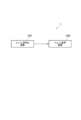
- FIG. 1 is a diagram showing an example of a configuration of a mesh processing system 1 according to an embodiment.
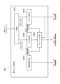
- FIG. 2 is a diagram showing an example of functional blocks of a mesh decoding device 200 according to an embodiment.
- FIG. 3A is a diagram showing an example of a base mesh and a subdivision mesh.
- FIG. 3B is a diagram showing an example of a base mesh and a subdivision mesh.
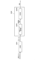
- FIG. 4 is a diagram showing an example of functional blocks of the basic mesh decoding unit 202 of the mesh decoding device 200 according to an embodiment.
- FIG. 5 is a diagram showing an example of functional blocks of the intra-decoding unit 202B of the basic mesh decoding unit 202 of the mesh decoding device 200 according to an embodiment.
- FIG. 6 is a diagram showing an example of the correspondence between the vertices of the basic mesh of a P frame and the vertices of the basic mesh of an I frame.
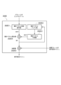
- FIG. 7 is a diagram showing an example of functional blocks of the inter decoding unit 202E of the basic mesh decoding unit 202 of the mesh decoding device 200 according to an embodiment.
- FIG. 8 is a diagram for explaining an example of a method for calculating the MVP of a vertex to be decoded by the motion vector prediction unit 202E3 of the inter decoding unit 202E of the basic mesh decoding unit 202 of the mesh decoding device 200 according to one embodiment.
- FIG. 10A is a diagram showing an example of a decoding order for a mesh.
- FIG. 10B is an example of a list of vertices around the vertex to be decoded.
- FIG. 11 is a diagram showing an example of statistical data indicating the relationship between the number of decoded motion vectors and the number of vertices around the vertex to be decoded.
- Figure 12 is a diagram illustrating an example of the worst case.
- FIG. 13 is a diagram illustrating a second modification of the inter decoding unit 202E of the basic mesh decoding unit 202 of the mesh decoding device 200 according to an embodiment.
- FIG. 14 is a diagram illustrating a second modification of the inter decoding unit 202E of the basic mesh decoding unit 202 of the mesh decoding device 200 according to an embodiment.
- FIG. 15 is a diagram illustrating a third modification of the inter decoding unit 202E of the basic mesh decoding unit 202 of the mesh decoding device 200 according to an embodiment.
- FIG. 16 is a diagram showing a modification of the functional blocks of the modification 1 of the basic mesh decoding unit 202 of the mesh decoding device 200 according to an embodiment.
- FIG. 17 is a diagram for explaining a first modification of the basic mesh decoding unit 202 of the mesh decoding device 200 according to an embodiment.
- FIG. 18 is a diagram illustrating the mesh buffer unit 202C of the basic mesh decoding unit 202 of the mesh decoding device 200 according to an embodiment.
- FIG. 19 is a diagram illustrating the mesh buffer unit 202C of the basic mesh decoding unit 202 of the mesh decoding device 200 according to an embodiment.
- FIG. 20 is a diagram for explaining a modification of the basic mesh decoding unit 202 of the mesh decoding device 200 according to the second modification.
- FIG. 21 is a diagram for explaining a modification of the basic mesh decoding unit 202 of the mesh decoding device 200 according to the second modification.
- FIG. 22 is a diagram showing an example of a NAL header.
- FIG. 23 is a diagram showing an example of a case in which the number of sub-meshes varies between frames.
- FIG. 24 is a diagram showing an example of a case where corresponding sub
- FIG. 1 is a diagram showing an example of the configuration of a mesh processing system 1 according to this embodiment.
- the mesh processing system 1 includes a mesh encoding device 100 and a mesh decoding device 200.
- FIG. 2 is a diagram showing an example of functional blocks of a mesh decoding device 200 according to this embodiment.
- the mesh decoding device 200 includes a demultiplexing unit 201, a basic mesh decoding unit 202, a subdivision unit 203, a mesh decoding unit 204, a patch integration unit 205, a displacement amount decoding unit 206, a video decoding unit 207, and an atlas data decoding unit 208.
- the basic mesh decoding unit 202, the subdivision unit 203, the mesh decoding unit 204, and the displacement amount decoding unit 206 are configured to perform processing in units of patches into which the mesh is divided, and the results of these processes may then be integrated by the patch integration unit 205.
- the mesh is divided into patch 1, which is made up of base faces 1 and 2, and patch 2, which is made up of base faces 3 and 4.
- the demultiplexing unit 201 is configured to separate the multiplexed bit stream into a base mesh bit stream, a displacement amount bit stream, a texture bit stream, and an atlas bit stream.
- the atlas data decoding unit 208 is configured to decode the atlas bitstream and output control information.
- control signals may be used as metadata by the basic mesh decoding unit 202, the subdivision unit 203, the mesh decoding unit 204, the displacement amount decoding unit 206, and the video decoding unit 207.
- the base mesh decoding unit 202 is configured to decode the base mesh bitstream and generate and output base meshes.
- the base mesh is composed of multiple vertices in three-dimensional space and edges connecting these multiple vertices.
- the basic mesh is constructed by combining basic faces represented by three vertices.
- the base mesh decoding unit 202 may be configured to decode the base mesh bitstream using, for example, Draco shown in Non-Patent Document 2 or the technology described in Non-Patent Document 3.
- the base mesh decoding unit 202 may also be configured to generate "subdivision_method_id" (described below) as control information that controls the type of subdivision method.
- the basic mesh decoding unit 202 includes a separation unit 202A, an intra decoding unit 202B, a mesh buffer unit 202C, a connection information decoding unit 202D, and an inter decoding unit 202E.
- the separation unit 202A is configured to classify the basic mesh bitstream into an I frame bitstream and a P frame bitstream.
- the intra decoding unit 202B is configured to decode the coordinates and connection information of the vertices of the I frame from the bit stream of the I frame, for example, using the technique Draco shown in Non-Patent Document 2 or the technique described in Non-Patent Document 3.
- FIG. 5 shows an example of the functional blocks of the intra decoder 202B.
- the intra decoding unit 202B has an arbitrary intra decoding unit 202B1 and an alignment unit 202B2.
- the arbitrary intra-decoding unit 202B1 is configured to decode the coordinates and connection information of the unordered vertices of the I-frame from the bit stream of the I-frame using any method including the Draco technique shown in Non-Patent Document 2 or the technique described in Non-Patent Document 3.
- the sorting unit 202B2 is configured to output vertices by sorting the unordered vertices into a predetermined order.
- the predetermined order may be, for example, the Morton code order or the raster scan order.
- the alignment unit 202B2 may also group together overlapping vertices, which are multiple vertices with the same coordinates in the decoded base mesh, into a single vertex and then rearrange them in a predetermined order.
- the mesh buffer unit 202C is configured to accumulate the coordinates and connection information of the vertices of the I frame decoded by the intra-decoding unit 202B.
- a specific buffer may be provided to store pairs of vertex indexes A(k) and B(k) of overlapping vertices in a predetermined order.
- connection information decoding unit 202D is configured to convert the connection information of the I frame or reference frame extracted from the mesh buffer unit 202C into connection information of the P frame.
- the inter-decoding unit 202E is configured to decode the coordinates of the vertices of the P frame by adding the coordinates of the vertices of the reference frame retrieved from the mesh buffer unit 202C and the motion vectors decoded from the bit stream of the P frame.
- the inter-decoding unit 202E can adjust the index of the vertex of the P frame using the pair of vertex indexes A(k) and B(k) that exist as overlapping vertices stored in the specific buffer.
- Such a decoding method may be arithmetic coding. As a result, it is expected that there will be no limit to the maximum value of the index to be decoded using arithmetic coding.
- ue(v) an arithmetic coding
- ue(v) represents left-most bit-first, zeroth-order exponential-Golomb coding of an unsigned integer.
- the variable codeNum is then assigned as follows:
- codeNum 2 leadingZeroBits -1+read_bits(leadingZeroBits) where the value returned by read_bits (leadingZeroBits) is interpreted as a binary representation of an unsigned integer written most significant bit first, and the value of ue(v) is equal to the value of codeNum.
- Table 1 shows the structure of an Exp-Golomb code by separating the bit string into "prefix” bits and "suffix" bits.
- the "prefix" bits are the bits that are parsed as specified in the calculation of leadingZeroBits, and appear as 0 or 1 in the bit string column of Table 1.
- the "suffix" bits are the bits that are parsed in the calculation of codeNum and are denoted as x i in Table 1, where i ranges from 0 to leadingZeroBits-1. Each x i is equal to either 0 or 1.
- Table 2 shows how to explicitly assign bit strings to values of codeNum, where the value of ue(v) is equal to the value of codeNum.
- the motion vector decoded by the inter decoding unit 202E is a difference vector between the coordinates of the vertices of the base mesh of the P frame and the coordinates of the vertices of the base mesh of the I frame.
- the inter-decoding unit 202E may decode the number of vertices of the current frame or current submesh from the bitstream.
- the inter-decoding unit 202E decodes the number of vertices of the current frame or current submesh from the above-mentioned bitstream
- the requirement for the conformance of such a bitstream is that the number of vertices of the decoded current frame or current submesh must be equal to the number of vertices of the reference frame or reference submesh.
- the inter-decoding unit 202E is configured to preferentially use the number of vertices of the current frame or current submesh decoded from the bitstream.
- the inter-decoding unit 202E may use the number of vertices of the reference frame or reference submesh as the number of vertices of the current frame or current submesh.
- the inter-decoding unit 202E may add dummy vertices and connection information of the dummy vertices to the reference frame or reference submesh.
- the inter-decoding unit 202E may set the coordinates of such dummy vertices to fixed values (e.g., (0,0,0)) or may copy them from a specified vertex (e.g., the last vertex of the reference frame).
- the inter-decoding unit 202E may copy the necessary amount of vertex connection information from the beginning in the reference frame or reference submesh as the connection information for the dummy vertices.
- This configuration is expected to have the effect of ensuring the decoding operation of the current frame or current submesh.
- a base mesh has at least one face, and such face has at least three or more vertices
- the control signal indicating the number of vertices for each frame or submesh is limited to include at least three or more vertices.
- control signals pdu_vertex_count_minus_1[titleID][patchIdx] defined in section 8.3.7.3 of Non-Patent Document 4 the control signals sismu_inter_vertex_count[subMeshID] defined in section H.8.1.3.8, and mesh_vertex_count defined in section I.8.3.7 are modified as shown in Table 3 and restricted to include three or more vertices.
- control signal pdu_vertex_count_minus_1[titleID][patchIdx] is a control signal that specifies the number of vertices in a patch having a patchID equal to the patchID specified by [patchIdx] in an atlas tile having a tileID equal to the tileID specified by [titleID].
- the control signal sismu_inter_vertex_count[subMeshID] is a control signal that specifies the number of vertices in the submesh that has a SubmeshID equal to the SubmeshID specified by [subMeshID].
- the control signal mesh_vertex_count is a control signal that specifies the number of vertices in the decoded mesh.
- This configuration is expected to have the effect of preventing situations where the vertices are operated with meaningless data such as 1 or 2.
- FIG. 7 is a diagram showing an example of functional blocks of the inter decoding unit 202E.
- the inter-decoding unit 202E has a motion vector residual decoding unit 202E1, a motion vector buffer unit 202E2, a motion vector prediction unit 202E3, a motion vector calculation unit 202E4, and an adder 202E5.
- the motion vector residual decoding unit 202E1 is configured to generate a motion vector residual (MVR) from the P frame bitstream.
- MVR motion vector residual
- MVR is the motion vector residual indicating the difference between MV (Motion Vector) and MVP (Motion Vector Prediction).
- MV is the difference vector (motion vector) between the coordinates of the corresponding vertex in the I frame and the coordinates of the vertex in the P frame.
- MVP is the predicted value of the MV of the target vertex using MV (motion vector prediction value).
- the motion vector buffer unit 202E2 is configured to sequentially store the MVs output by the motion vector calculation unit 202E4.
- the motion vector prediction unit 202E3 is configured to obtain the decoded MVs from the motion vector buffer unit 202E2 for the vertices connected to the vertex to be decoded, and output the MVP of the vertex to be decoded using all or part of the obtained decoded MVs, as shown in FIG. 8.
- the motion vector calculation unit 202E4 is configured to add the MVR generated by the motion vector residual decoding unit 202E1 and the MVP output from the motion vector prediction unit 202E3, and output the MV of the vertex to be decoded.
- the adder 202E5 is configured to add the coordinates of the vertex corresponding to the vertex to be decoded, which is obtained from the decoded base mesh of the corresponding reference frame (I frame or P frame), to the motion vector MV output from the motion vector calculation unit 202E3, and output the coordinates of the vertex to be decoded.
- MVP is used to encode only MVR instead of MV, which is expected to improve encoding efficiency.
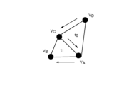
- the decoding order for a mesh such as that shown in FIG. 10A is vertices vD ⁇ vC ⁇ vA ⁇ vB , as indicated by the arrows.
- FIG. 10B shows a list of vertices around the vertex to be decoded, which is used to calculate the MVP of each of the vertices v A to v D when the maximum number of decoded adjacent vertices is set to three.
- the range that can be set for the maximum number of adjacent vertices is set to a large value, such as the worst case of 256 or 8 bits, it may not be possible to achieve the effect of reducing not only the amount of memory required but also the amount of calculations.
- Figure 12 shows an example of the worst case, where the number of decoded adjacent vertices exceeds 256 when n ⁇ 256.
- the number of decoded adjacent vertices at vertex n+1 is n.
- the mesh decoding device 200 would require not only a huge amount of memory but also a huge amount of calculation, as shown in FIG. 10B. Therefore, the upper limit (maximum value) of the range that can be set as the above-mentioned maximum number of adjacent vertices may be set to 8.
- the range that can be set as the maximum number of adjacent vertices in the above-mentioned control signal may be a clear value, or may be calculated from other control signals or data.
- Level 1 may specify the range that can be set as the maximum number of adjacent vertices in the control signal.
- the upper limit of the range that can be set as the maximum number of adjacent vertices in the control signal can be calculated from the number of vertices in the base mesh using the following formula (3).
- the motion vector prediction unit 202E3 also refers to the adjacent vertex list and calculates a predicted value of the motion vector of the vertex to be decoded by averaging all or part of the motion vectors of the decoded vertices adjacent to the vertex to be decoded.
- the adjacent vertex list is a list of vertices adjacent to each vertex.
- the motion vector prediction unit 202E3 can reuse the adjacent vertex list in the reference frame as the adjacent vertex list in the current frame.
- adjacent vertex list contains decoded vertices that have been picked up up to the maximum number of uses (the maximum number of adjacent vertices that has been set).
- the motion vector prediction unit 202E3 can reuse the adjacent vertex list in the reference frame if the following conditions (reuse conditions) are met: each vertex in the reference frame has a one-to-one correspondence with each vertex in the current frame, the decoding order of each vertex in the reference frame is the same as the decoding order of each vertex in the current frame, and an adjacent vertex list containing decoded vertices picked up up to the maximum number of uses in the reference frame has already been saved.
- the motion vector prediction unit 292E3 stores the decoded reference frame in a reference frame buffer and also stores the adjacent vertex list in the reference frame in a specific buffer.
- the motion vector prediction unit 292E3 reuses the adjacent vertex list in the reference frame stored in the specific buffer as the adjacent vertex list in the current frame.
- a particular buffer may store an adjacent vertex list that includes decoded vertices picked up to the maximum number of uses in one or more frames.
- a specific buffer is required to store the adjacent vertex list in one or more frames.
- further conditions may be added to the above reuse conditions in order to minimize the size of the specific buffer.
- the motion vector prediction unit 202E3 can reuse the adjacent vertex list in the reference frame as the adjacent vertex list in the current frame when, in addition to the above-mentioned reuse conditions, the condition that the reference frame is the frame immediately preceding the current frame in decoding order is further satisfied.
- the motion vector calculation unit 202E4 of the inter decoding unit 202E has mode 1 and mode 0.
- the motion vector calculation unit 202E4 adds the MVR generated by the motion vector residual decoding unit 202E1 and the MVP output from the motion vector prediction unit 202E3, and outputs the MV of the vertex to be decoded (see A in Figure 13).
- the operation of the motion vector calculation unit 202E4 in mode 0 corresponds to setting the MVP output from the motion vector prediction unit 202E3 to zero.
- the motion vector calculation unit 202E4 may set the MV modes of N (N ⁇ 1) consecutive vertices in decoding order to the same mode.
- derived_my_present_flag indicates Yes (for example, derived_my_present_flag is 1)
- the mv_signaled_flag acquisition unit 202E7 performs different processing on each vertex of the P frame.
- the mv_signaled_flag acquisition unit 202E7 may use mv_signaled_flag to determine the processing method for each vertex.
- the mv_signaled_flag acquisition unit 202E7 decodes mv_signaled_flag for each vertex from the bitstream of the P frame.
- the mv_signaled_flag acquisition unit 202E7 sets the prediction mode (MV mode) of the vertex to 2.
- the mv_signaled_flag acquisition unit 202E7 sets the prediction mode of that vertex to a value other than 2.
- the mv_signaled_flag acquisition unit 202E7 does not decode the mv_signaled_flag of all vertices of the P frame from the bitstream, but sets the value to 1, and sets the MV mode of the vertex to a value other than 2.
- the overlapping vertex search unit 202E6 is configured to search for the indexes of vertices (hereafter referred to as overlapping vertices) with matching coordinates from the geometric information of the base mesh of the decoded reference frame, and store them in a buffer (not shown).
- the duplicated vertex search unit 202E6 determines whether or not a duplicated vertex exists for each vertex (index: vindex0) of the base mesh of the reference frame, from the first vertex (index: 0) of the base mesh of the decoded reference frame to the immediately preceding vertex (index: vindex0-1), and if it determines that such a duplicated vertex exists, it outputs the index of the duplicated vertex using at least one of the following three methods.
- the overlapping vertex search unit 202E6 searches for overlapping vertices whose coordinates match using a binary search.
- the overlapping vertex search unit 202E6 may use a find function of the associative array class map.
- the duplicated vertex search unit 202E6 searches for duplicated vertices whose coordinates match using a hash table.
- the duplicated vertex search unit 202E6 may use a find function of a hash associative array class unordered_map.
- the motion vector acquisition unit 202E8 is configured to acquire, from the motion vector buffer unit 202E2, the motion vector of the vertex having the duplicate vertex index (vindex1) related to the index of the vertex (vindex0) output from the duplicate vertex search unit 202E6, and set the motion vector of the vertex as the motion vector of the vertex.
- MVmode is other than 2 (if derived_my_present_flag indicates No, or if derived_my_present_flag indicates Yes and the mv_signaled_flag of the vertex indicates Yes), processing similar to that of the inter decoding unit 202E shown in FIG. 7 or a modified example thereof is performed instead of the motion vector acquisition unit 202E8.
- This configuration is expected to reduce the amount of code and the motion vector decoding calculations for vertices that have overlapping vertices.
- the overlapping vertex search unit 202E6 searches for overlapping vertices only among vertices for which mv_signaled_flag is No, rather than searching for overlapping vertices among all vertices of the base mesh of the reference frame.
- the input to the overlapping vertex search unit 202E6 includes the index (in decoding order) and position coordinates of each vertex of the base mesh of the decoded reference frame, as well as mv_signaled_flag.
- the mv_signaled_flag acquisition unit 202E7 decodes the mv_signaled_flag in two stages.
- the mv_signaled_flag acquisition unit 202E7 groups N vertices together, decodes the mv_group_signaled_flag (third flag) from the P frame bitstream for each group, sets the mv_signaled_flag of all vertices in the group where mv_group_signaled_flag is 1 to 1, and decodes the mv_group_signaled_flag from the P frame bitstream for each vertex in the group where mv_group_signaled_flag is 0.
- mv_group_signaled_flag is decoded in two stages, which is expected to reduce the motion vector decoding calculations and the amount of code.
- the inter decoding unit 202E decodes a control signal indicating the number of vertices that have overlapping vertices before mv_signaled_flag from the bitstream.
- This control signal makes it possible to decode mv_signaled_flag without performing processing by the overlapping vertex search unit 202E6.
- the number of vertices with overlapping vertices output by overlapping vertex search unit 202E6 must match the number of vertices indicated by the control signal.
- the duplicated vertex search unit 202E6 also stores all duplicated vertex indexes in a separate list.
- the duplicated vertex search unit 202E6 may store all duplicated vertex indexes in duplicated_vertex_list, as shown below (a modified example of method 1).
- the mv_signaled_flag acquisition unit 202E7 may set the mv_signaled_flag of vertices that do not have overlapping vertices to 0.
- the mv_signaled_flag acquisition unit 202E7 decodes the index of the vertex with the same motion vector as the vertex in question from the interframe bitstream and acquires the motion vector of the vertex in question.
- the motion vector acquisition unit 202E8 is configured to acquire, from the motion vector buffer unit 202E2, the motion vector of a vertex having an index (vindex1) of a duplicate vertex related to the index (vindex0) of the vertex output by the duplicate vertex search unit 202E6, and set the motion vector of the vertex as the motion vector of the vertex; however, in this modified example, when a duplicate vertex of the vertex does not exist, the motion vector acquisition unit 202E8 is configured to decode, from the bitstream, the index (vindex1) of a vertex having the same motion vector as the vertex, acquire the motion vector of the vertex having the index (vindex1), and set the motion vector of the vertex as the motion vector of the vertex.
- the overlapping vertex search unit 202E6 reuses the results obtained in the reference frame in the frame to be decoded.
- the basic mesh decoding unit 202 includes a separation unit 202A, an intra decoding unit 202B, a mesh buffer unit 202C, an inter decoding unit 202E, and a skip decoding unit 202F.
- the skip decoding unit 202F is configured to decode the base mesh of the frame to be decoded by directly using the decoded base mesh of the specified reference frame.
- the frame may be either a mesh or a submesh.
- P_SUBMESH in smh_type may correspond to a P frame
- I_SUBMESH in smh_type may correspond to an I frame
- SKIP_SUBMESH in smh_type may correspond to an S frame.
- the skip decoding unit 202F is configured to extract a decoded base mesh (a decoded base mesh for reference) of a specified reference frame from the mesh buffer unit 202C, and use the coordinates of the vertices and the indexes of the vertices of the extracted decoded base mesh for reference to decode the coordinates of the vertices and the indexes of the vertices of the base mesh of the frame to be decoded.
- a decoded base mesh a decoded base mesh for reference
- the skip decoding unit 202F is configured to extract a decoded base mesh (a decoded base mesh for reference) of a specified reference frame from the mesh buffer unit 202C, and use the coordinates of the vertices and the indexes of the vertices of the extracted decoded base mesh for reference to decode the coordinates of the vertices and the indexes of the vertices of the base mesh of the frame to be decoded.
- the mesh buffer unit 202C has at least one reference frame and is configured to store at least one decoded base mesh for each reference frame.
- the skip decoding unit 202F may identify the specified reference decoding base mesh using a control signal decoded from the bitstream or a predetermined rule.
- such a predetermined rule may be to extract the first reference frame in the reference frame list from the mesh buffer unit 202C, or to extract the reference frame whose frame index is closest to the frame to be decoded.
- a frame in which the coordinates of the vertices of a base mesh are decoded using the coordinates of the vertices of the decoded base mesh for reference and the index of the vertices is called an "S frame.”
- the mesh buffer unit 202C is configured to store one or more reference decoded base meshes in a predetermined order.
- such a basic mesh has metadata such as a frame number and a submesh number, as well as at least the coordinates of each vertex and an index of the vertex, and is stored in the mesh buffer unit 202C in a predetermined order determined by the reference frame list.
- the reference frame list (ref_list0) is a list of information that identifies all reference decoding base meshes stored in the mesh buffer unit 202C.
- the reference frame list may be determined by control signals decoded from the bitstream, as shown in FIG. 18, or may be calculated naturally from the frame decoding order.
- control signal decoded from the bitstream may be indicated by a relative distance from the frame to be decoded, or may be an absolute frame index.
- control signal may use a short-term or long-term reference frame.
- the absolute value (abs_delta_mfoc_st) of the difference in the display order (Display Order) of the current frame (cur) and the reference frame (ref) and its sign (sign_flag) may be decoded from the bitstream, and the display order (Display Order) of the reference frame may be specified by the following formula.
- the frames may be arranged in sequence starting from the last decoded frame by a certain number of frames. That is, the reference frame list may be ⁇ 0, -1, -2, ..., -(N-1) ⁇ .
- the reference frame list does not change for each frame unless there are special circumstances (for example, when a re-ordering command is received).
- the mesh buffer unit 202C may be updated as follows:
- the mesh buffer unit 202C deletes one or more existing reference frames in a predetermined order determined by the reference frame list, and inserts one or more base meshes including the base mesh of the decoded frame, or creates and inserts one base mesh from multiple base meshes, thereby adjusting the order of the reference frames.
- Such a deletion operation may be performed only when the mesh buffer unit 202C is full.
- the number of basic meshes that can be stored in the mesh buffer unit 202C is determined in advance. In this embodiment, it is defined that the mesh buffer unit 202C is full when the number of basic meshes is reached.
- a weighted average of the coordinates of vertices corresponding to the basic meshes of the decoded frame and the existing basic meshes stored in the mesh buffer unit 202C may be obtained to create one basic mesh.
- the weights used in such a weighted average may be predetermined, calculated using a frame index, or decoded from the control signal.
- the mesh buffer unit 202C may or may not perform such an update when it is an S frame.
- the mesh buffer unit 202C When the mesh buffer unit 202C receives a control signal indicating a re-ordering instruction from the control signal decoded from the bit stream, it updates the reference frame list as shown in FIG. 19 and adjusts the order of the reference frames according to the predetermined order determined by the updated reference frame list (ref_list0).
- the inter decoding unit 202E is configured to decode the coordinates of the vertices of the P frame by adding the coordinates of the vertices of the reference frame retrieved from the mesh buffer unit 202C to the motion vectors decoded from the bit stream of the P frame.
- the inter-decoding unit 202E can adjust the indexes of the vertices of the P frame using a pair of vertex indexes A(k) and B(k) that exist as overlapping vertices stored in the specific buffer. All or part of the indexes are decoded from the bitstream.
- the decoding method may be arithmetic coding. With this configuration, it is expected that there will be no limit to the maximum value of the index to be decoded using arithmetic coding. For example, arithmetic coding called ue(v) may be used.
- the following describes the skip decoding unit 202F, but it may also be applied to the inter decoding unit 202E.
- the decoding order and the display order are different in order to allow reference to subsequent frames.
- the display order is the same as the input order when encoding, and the same as the output order when decoding.
- the decoding order is the same as the output order when encoding, and the same as the input order when decoding.
- such a reference frame may be calculated by taking a weighted average of the subsequent frame and one or more other frames.
- MR_SUBMESH MR frame or B frame
- smh_type new frame type
- such other frame may be a decoded frame immediately before the target frame, as shown in FIG. 21.
- weights may be calculated using the frame interval between the target frame and the subsequent frame and the frame interval between the target frame and other frames, or may be determined in advance.
- the basic mesh decoding unit 202 decodes the control signal (smh_mesh_frm_order_cnt_lsb) from the bit stream and decodes the order of the output.
- all sub-meshes are set to the same control signal (smh_mesh_frm_order_cnt_lsb) or the control signal (smh_mesh_frm_order_cnt_lsb) is applied to all sub-meshes.
- the value indicated by this control signal may be the difference from the display order of the frame to be decoded, or may be the order within a predetermined group of frames MaxMeshFrmOrderCntLsb.
- the basic mesh decoding unit 202 may rearrange the decoded basic meshes in the display order (Display Order).
- two mesh buffers 202C may be provided, and when only one mesh buffer unit 202 is provided, there is at least one reference frame, including a reference frame whose display order is later than the frame to be decoded.
- the skip decoding unit 202F specifies a reference frame by receiving a control signal decoded from the bitstream, a predetermined rule, or a re-ordering instruction.
- the skip decoding unit 202F specifies a reference frame in the reference frame list using this control signal.
- the skip decoding unit 202F specifies the first reference frame in the reference frame list.
- the skip decoding unit 202F updates the reference frame order in the reference frame list and the mesh buffer unit 202C, and specifies the first reference frame in the reference frame list.
- the base mesh decoding unit 202 may decode the base mesh of the S frame by integrating multiple reference frames according to a control signal.
- NAL Network Abstraction Layer
- LayerID/R6 defined as the 6 bits immediately preceding the TID in the NAL header, specifies the identifier of the layer to which the NAL unit belongs.
- the value 63 of LayerID/R6 can be used to indicate an extension layer identifier in future extensions.
- Non-Patent Document 5 can be used, and for the displacement and texture, the video coding methods HEVC and VVC can be used, so the following will explain the basic mesh.
- Temporal_ID of a coded basic mesh frame or access unit is the value of Temporal_ID of the BMCL NAL unit of the coded basic mesh frame or access unit.
- the value of Temporal_ID of a sublayer representation is the maximum value of Temporal_ID of all BMCL NAL units in the sublayer representation.
- Temporal_ID for non-BMCL NAL units are restricted as follows: - If NALType is equal to NAL_BMSPS, then Temporal_ID must be 0 and the Temporal_ID of the access unit containing the NAL unit must be 0. Otherwise, if NALType is equal to NAL_EOS or NAL_EOB, Temporal_ID must be 0. Otherwise, if NALType is equal to NAL_AUD or NALLFDD, then Temporal_ID must be equal to the Temporal_ID of the access unit that contains the NALL unit. Otherwise, the Temporal_ID must be greater than or equal to the Temporal_ID of the access unit that contains the NAL unit.
- Temporal_ID is equal to the minimum of the Temporal_ID values of all access units to which the non-BMCL NAL unit applies.
- Temporal_ID can be greater than or equal to the Temporal_ID of the included access unit because all basic mesh frame parameter sets (BMFPS) are included at the beginning of the bitstream where the Temporal_ID of the first encoded basic mesh frame is 0.
- the skip decoding unit 202F refers to the specified tIDTarget and discards NAL units whose Temporal_ID is higher than tIDTarget without decoding them.
- tIDTarget may be specified by a predetermined value, or may be specified based on the network conditions or the terminal capabilities of the mesh decoding device 200.
- a lower tIDTarget is specified in the wireless case than in the wired case. Also, when the network conditions are poor, a lower tIDTarget is specified. Also, when decoding is performed by a mesh decoding device 200 with low specifications, a lower tIDTarget is specified.
- bitstream conformance is that there must be at least one NAL unit in the bitstream whose Temporal_ID is not higher than tIDTarget.
- the number of sub-meshes may differ for each frame (intraframe, interframe, and skip frame).
- the intra decoding unit 202B, the inter decoding unit 202E, and the skip decoding unit 202F assign unique submesh IDs to each submesh in each frame.
- the intra decoding unit 202B, the inter decoding unit 202E, and the skip decoding unit 202F may assign different SubmeshIDs to corresponding submeshes between frames.
- the inter decoding unit 202E or the skip decoding unit 202F can only refer to submeshes that have the same SubmeshID in the reference frame.
- the inter decoding unit 202E or the skip decoding unit 202F can only refer to submeshes that have the same number of vertices in the reference frame.
- the intra-decoding unit 202B and the inter-decoding unit 202E can refer to a submesh specified in the reference frame.
- the inter decoding unit 202E or the skip decoding unit 202F may decode a control signal that specifies the SubmeshID of a referenceable submesh from the bit stream of the current submesh.
- the inter decoding unit 202E or the skip decoding unit 202F may treat such submesh as a referenceable submesh.
- the inter decoding unit 202E or the skip decoding unit 202F sets the Submesh ID of the referenceable submesh to the same Submesh ID as the submesh in the current frame.
- inter decoding unit 202E or the skip decoding unit 202F may decode a control signal from the bitstream that indicates whether the above-mentioned control signal is present.
- inter decoding unit 202E or the skip decoding unit 202F may decode a control signal that selects the method for determining the above-mentioned referenceable submeshes.
- the subdivision unit 203 and the displacement amount decoding unit 206 may follow Non-Patent Document 4.
- the amount of calculation can be reduced by reusing the reference frame itself, without searching for adjacent vertices that have already been decoded.
- the base mesh of the current frame can be decoded even if the number of vertices of the base mesh of the current frame differs from the number of vertices of the reference frame or reference submesh.
- this embodiment can ensure that the base mesh has at least one face.
- the Temporal_scalability function can be realized.
- the encoding efficiency of the mesh can be improved.
- the above-mentioned mesh encoding device 100 and mesh decoding device 200 may be realized as a program that causes a computer to execute each function (each process).
Landscapes
- Engineering & Computer Science (AREA)
- Physics & Mathematics (AREA)
- General Physics & Mathematics (AREA)
- Theoretical Computer Science (AREA)
- Multimedia (AREA)
- Computer Graphics (AREA)
- Geometry (AREA)
- Software Systems (AREA)
- Compression Or Coding Systems Of Tv Signals (AREA)
- Image Generation (AREA)
Abstract
本発明に係るメッシュ復号装置200は、イントラフレームのビットストリームからイントラフレームにおける頂点の座標及び接続情報を復号するイントラ復号部202Bと、インターフレームのビットストリームから復号した動きベクトルと参照フレームにおいて復号対象の頂点に対応する頂点の座標とを加算することで復号対象の頂点の座標を復号するインター復号部202Eとを備え、イントラフレーム及びインターフレームにおける基本メッシュは少なくとも1つの面を有する。
Description
本発明は、メッシュ復号装置、メッシュ復号方法及びプログラムに関する。
非特許文献1又は非特許文献4には、非特許文献5のフレームワークに従って、非特許文献2又は3を用いてメッシュを符号化する技術が開示されている。
Khaled Mammou, Jungsun Kim, Alexis M Tourapis, Dimitri Podborski, and Krasimir Kolarov, "[V-CG] Apple’s Dynamic Mesh Coding CfP Response," April 2022, ISO/IEC JTC 1/SC 29/WG 7 m59281.
Google Draco、2022年5月26日アクセス[Online]、https://google.github.io/draco
Jean-Eudes Marvie, Olivier Mocquard, "[V-DMC][EE4.4-related] An efficient EdgeBreaker implementation," April 2023, ISO/IEC JTC 1/SC 29/WG 7 m63344.
"WD 5.0 of V-DMC," Oct. 2023, ISO/IEC JTC 1/SC 29/WG 7 N00744.
"Information technology - Coded Representation of Immersive Media - Part 5: Visual Volumetric Video-based Coding (V3C) and Video-based Point Cloud Compression (V-PCC)," ISO/IEC JTC 1/SC 29/WG 7, ISO/IEC 23090-5:2021(2E).
しかしながら、従来技術では、基本メッシュが少なくとも1つの面を有することを保証できないという問題点があった。 そこで、本発明は、上述の課題に鑑みてなされたものであり、上述の基本メッシュが少なくとも1つの面を有することを保証することができるメッシュ復号装置、メッシュ復号方法及びプログラムを提供することを目的とする。
本発明の第1の特徴は、メッシュ復号装置であって、イントラフレームのビットストリームから、前記イントラフレームにおける頂点の座標及び接続情報を復号するイントラ復号部と、インターフレームのビットストリームから復号した動きベクトルと、参照フレームにおいて復号対象の頂点に対応する頂点の座標とを加算することで、前記復号対象の頂点の座標を復号するインター復号部とを備え、前記イントラフレーム及び前記インターフレームにおける基本メッシュは、少なくとも1つの面を有することを要旨とする。
本発明の第2の特徴は、メッシュ復号方法であって、イントラフレームのビットストリームから、前記イントラフレームにおける頂点の座標及び接続情報を復号する工程Aと、インターフレームのビットストリームから復号した動きベクトルと、参照フレームにおいて復号対象の頂点に対応する頂点の座標とを加算することで、前記復号対象の頂点の座標を復号する工程Bとを有し、前記工程A及び前記工程Bにおいて、前記イントラフレーム及び前記インターフレームにおける基本メッシュは、少なくとも1つの面を有することを要旨とする。
本発明の第3の特徴は、コンピュータを、メッシュ復号装置として機能させるプログラムであって、前記メッシュ復号装置は、イントラフレームのビットストリームから、前記イントラフレームにおける頂点の座標及び接続情報を復号するイントラ復号部と、インターフレームのビットストリームから復号した動きベクトルと、参照フレームにおいて復号対象の頂点に対応する頂点の座標とを加算することで、前記復号対象の頂点の座標を復号するインター復号部とを備え、前記イントラフレーム及び前記インターフレームにおける基本メッシュは、少なくとも1つの面を有することを要旨とする。
本発明によれば、基本メッシュが少なくとも1つの面を有することを保証することができるメッシュ復号装置、メッシュ復号方法及びプログラムを提供することができる。
以下、本発明の実施の形態について、図面を参照しながら説明する。なお、以下の実施形態における構成要素は、適宜、既存の構成要素等との置き換えが可能であり、また、他の既存の構成要素との組み合わせを含む様々なバリエーションが可能である。したがって、以下の実施形態の記載をもって、特許請求の範囲に記載された発明の内容を限定するものではない。
<第1実施形態>
以下、図1~図24を参照して、本実施形態に係るメッシュ処理システムについて説明する。
以下、図1~図24を参照して、本実施形態に係るメッシュ処理システムについて説明する。
図1は、本実施形態に係るメッシュ処理システム1の構成の一例を示す図である。図1に示すように、メッシュ処理システム1は、メッシュ符号化装置100及びメッシュ復号装置200を備えている。
図2は、本実施形態に係るメッシュ復号装置200の機能ブロックの一例を示す図である。
図2に示すように、メッシュ復号装置200は、多重分離部201と、基本メッシュ復号部202と、細分割部203と、メッシュ復号部204と、パッチ統合部205と、変位量復号部206と、映像復号部207と、アトラスデータ復号部208とを有する。
ここで、基本メッシュ復号部202、細分割部203、メッシュ復号部204及び変位量復号部206は、メッシュを分割したパッチ単位で処理を行うように構成されており、その後、これらの処理結果についてパッチ統合部205で統合されるように構成されていてもよい。
図3Aの例では、メッシュが、基本面1及び2で構成されるパッチ1と、基本面3及び4で構成されるパッチ2とに分割されている。
多重分離部201は、多重化されたビットストリームを、基本メッシュビットストリームと変位量ビットストリームとテクスチャビットストリームとアトラス(atlas)ビットストリームとに分離するように構成されている。
アトラスデータ復号部208は、アトラスビットストリームを復号して制御情報を出力するように構成されている。かかる制御信号は、メタデータとして基本メッシュ復号部202、細分割部203、メッシュ復号部204、変位量復号部206及び映像復号部207で利用されてもよい。
<基本メッシュ復号部202>
基本メッシュ復号部202は、基本メッシュビットストリームを復号し、基本メッシュを生成して出力するように構成されている。
基本メッシュ復号部202は、基本メッシュビットストリームを復号し、基本メッシュを生成して出力するように構成されている。
ここで、基本メッシュは、3次元空間における複数の頂点と、かかる複数の頂点を接続する辺とで構成される。
なお、図3Aに示すように、基本メッシュは、3つの頂点で表現される基本面を組み合わせて構成される。
基本メッシュ復号部202は、例えば、非特許文献2に示すDraco又は非特許文献3に記載されている技術を用いて、基本メッシュビットストリームを復号するように構成されていてもよい。
また、基本メッシュ復号部202は、細分割手法の種別を制御する制御情報として、後述の「subdivision_method_id」を生成するように構成されていてもよい。
図4に示すように、基本メッシュ復号部202は、分離部202Aと、イントラ復号部202Bと、メッシュバッファ部202Cと、接続情報復号部202Dと、インター復号部202Eとを備える。
分離部202Aは、基本メッシュビットストリームを、IフレームのビットストリームとPフレームのビットストリームとに分類するように構成されている。
(イントラ復号部202B)
イントラ復号部202Bは、例えば、非特許文献2に示すDraco又は非特許文献3に記載されている技術を用いて、Iフレームのビットストリームから、Iフレームの頂点の座標及び接続情報を復号するように構成されている。
イントラ復号部202Bは、例えば、非特許文献2に示すDraco又は非特許文献3に記載されている技術を用いて、Iフレームのビットストリームから、Iフレームの頂点の座標及び接続情報を復号するように構成されている。
図5は、イントラ復号部202Bの機能ブロックの一例を示す図である。
図5に示すように、イントラ復号部202Bは、任意イントラ復号部202B1と、整列部202B2とを有する。
任意イントラ復号部202B1は、非特許文献2に示すDraco又は非特許文献3に記載されている技術を含む任意の方式を用いて、Iフレームのビットストリームから、Iフレームの順序無し頂点の座標及び接続情報を復号するように構成されている。
整列部202B2は、順序無し頂点を所定の順序に並び替えることによって頂点を出力するように構成されている。
所定の順序として、例えば、モートンコード順を用いてもよく、ラスタスキャン順を用いてもよい。
また、整列部202B2は、復号された基本メッシュにおいて座標が一致する複数の頂点である重複頂点をまとめて、単一頂点としてから、所定の順序に並び替えてもよい。
メッシュバッファ部202Cは、イントラ復号部202Bによって復号されたIフレームの頂点の座標及び接続情報を蓄積するように構成されている。ここで、重複頂点として存在する頂点のインデックスA(k)及びB(k)のペアを所定順で保存する特定バッファが設けられていてもよい。
接続情報復号部202Dは、メッシュバッファ部202Cから取り出したIフレーム又は参照フレームの接続情報をPフレームの接続情報にするように構成されている。
インター復号部202Eは、メッシュバッファ部202Cから取り出した参照フレームの頂点の座標とPフレームのビットストリームから復号した動きベクトルとを加算することによって、Pフレームの頂点の座標を復号するように構成されている。
更に、インター復号部202Eは、かかる特定バッファに保存されている重複頂点として存在する頂点のインデックスA(k)及びB(k)のペアにより、Pフレームの頂点のインデックスを調整することが可能である。
ここで、上述のインデックスの全部又は一部は、ビットストリームから復号される。かかる復号方法は、算術符号化でもよい。この結果、算術符号化を用いて復号対象のインデックスの最大値に制限が無くなるという効果が期待できる。
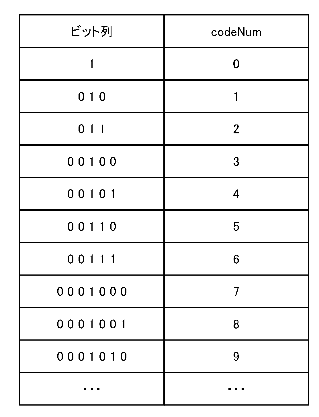
例えば、ue(v)という算術符号化を使ってもよい。ue(v)は、左端ビットファーストで符号なし整数0次の指数ゴロム符号化(Exp-Golomb)を示す。
具体的には、ue(v)の構文要素の解析プロセスは、ビットストリーム内の現在の位置から始まり、最初の非ゼロビットを含むビットを読み取って、0に等しい先行ビット数を数えることから始まる。このプロセスは、次のように指定される。
leadingZeroBits=-1
for(b=0;!b;leadingZeroBits++
b=read_bits(l)
次に、変数codeNumが、次のように割り当てられる。
leadingZeroBits=-1
for(b=0;!b;leadingZeroBits++
b=read_bits(l)
次に、変数codeNumが、次のように割り当てられる。
codeNum=2leadingZeroBits-1+read_bits(leadingZeroBits)
ただし、read_bits(leadingZeroBits)の返す値は、最上位ビットが先に書かれた符号なし整数の2進表現として解釈される。また、ue(v)の値は、codeNumの値に等しい。
ただし、read_bits(leadingZeroBits)の返す値は、最上位ビットが先に書かれた符号なし整数の2進表現として解釈される。また、ue(v)の値は、codeNumの値に等しい。
表1は、ビット列を「接頭辞」ビットと「接尾辞」ビットとに分離して、Exp-Golombコードの構造を示している。

ここで、「接頭辞」ビットは、leadingZeroBitsの計算で指定されたように解析されるビットであり、表1のビット列の列に0又は1として表示される。
「接尾辞」ビットは、codeNumの計算で解析されるビットであり、表1においてxiとして表示される。iは、0からleadingZeroBits-1までの範囲にある。各xiは、0又は1のいずれかに等しい。
表2は、ビット列をcodeNumの値に明示的に割り当てる方法を示す。ここで、ue(v)の値は、codeNumの値に等しい。
本実施形態では、図6に示すように、Pフレームの基本メッシュの頂点と参照フレーム(Iフレーム又はPフレーム)の基本メッシュの頂点との間で対応関係が存在する。ここで、インター復号部202Eによって復号される動きベクトルは、Pフレームの基本メッシュの頂点の座標とIフレームの基本メッシュの頂点の座標との差分ベクトルである。
なお、インター復号部202Eは、ビットストリームから、現フレーム又は現サブメッシュの頂点数を復号してもよい。
ここで、インター復号部202Eが、上述のビットストリームから現フレーム又は現サブメッシュの頂点数を復号する場合、かかるビットストリームの適合性の要件は、復号した現フレーム又は現サブメッシュの頂点数が参照フレーム又は参照サブメッシュの頂点数と等しくなければならないということである。
なお、インター復号部202Eは、上述のビットストリームから現フレーム又は現サブメッシュの頂点数を復号する場合、復号した現フレーム又は現サブメッシュの頂点数と参照フレーム又は参照サブメッシュの頂点数とが異なる場合、ビットストリームから復号した現フレーム又は現サブメッシュの頂点数を優先して利用するように構成されている。
また、インター復号部202Eは、参照フレーム又は参照サブメッシュの頂点数を、そのまま現フレーム又は現サブメッシュの頂点数として利用してもよい。
かかる場合、インター復号部202Eは、現フレーム又は現サブメッシュの頂点数が参照フレーム又は参照サブメッシュの頂点数よりも多い場合、参照フレーム又は参照サブメッシュに対して、ダミー頂点及びダミー頂点の接続情報を追加してもよい。
ここで、インター復号部202Eは、かかるダミー頂点の座標を固定値(例えば、(0,0,0))としてもよいし、所定頂点(例えば、参照フレームの最後の頂点)からコピーしてもよい。
また、インター復号部202Eは、ダミー頂点の接続情報として、参照フレーム又は参照サブメッシュにおける頂点の接続情報の最初から必要な分をコピーしてもよい。
かかる構成によれば、現フレーム又は現サブメッシュの復号動作を保障するという効果が期待できる。
なお、 基本メッシュが少なくとも1つの面を持ち、かかる面が少なくとも3つ以上の頂点を持つため、フレーム毎又はサブメッシュ毎で頂点数を示す制御信号は、少なくとも3つ以上の頂点を含むように制限される。
例えば、非特許文献4の8.3.7.3節で定義されている制御信号pdu_vertex_count_minus_1[titleID][patchIdx]、H.8.1.3.8節で定義されている制御信号sismu_inter_vertex_count[subMeshID]及びI.8.3.7節で定義されている制御信号mesh_vertex_countが、表3に示すように変更され、3つ以上の頂点を含むように制限される。
ここで、制御信号pdu_vertex_count_minus_1[titleID][patchIdx]は、[titleID]で指定されるtileID(タイルID)と等しいtileIDを有するアトラスタイル内で[patchIdx]で指定されるpatchID(パッチID)と等しいpatchIDを有するパッチ内の頂点数を指定する制御信号である。
制御信号sismu_inter_vertex_count[subMeshID]は、[subMeshID]で指定されるSubmeshIDと等しいSubmeshIDを有するサブメッシュ内の頂点数を指定する制御信号である。
制御信号mesh_vertex_countは、復号されたメッシュ内の頂点数を指定する制御信号である。
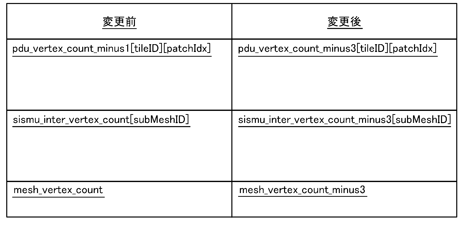
かかる構成によれば、頂点が1や2といった意味がないデータで動作してしまうという事態を防ぐことができるという効果が期待できる。
(インター復号部202E)
図7は、インター復号部202Eの機能ブロックの一例を示す図である。
図7は、インター復号部202Eの機能ブロックの一例を示す図である。
図7に示すように、インター復号部202Eは、動きベクトル残差復号部202E1と、動きベクトルバッファ部202E2と、動きベクトル予測部202E3と、動きベクトル算出部202E4と、加算器202E5とを有する。
動きベクトル残差復号部202E1は、PフレームのビットストリームからMVR(Motion Vector Residual)を生成するように構成されている。
ここで、MVRは、MV(Motion Vector)とMVP(Motion Vector Prediction)との差分を示す動きベクトル残差である。MVは、対応するIフレームの頂点の座標とPフレームの頂点の座標との間の差分ベクトル(動きベクトル)である。MVPは、MVを用いて対象の頂点のMVの予測した値(動きベクトルの予測値)である。
動きベクトルバッファ部202E2は、動きベクトル算出部202E4によって出力されたMVを順次に保存するように構成されている。
動きベクトル予測部202E3は、復号対象の頂点と接続している頂点について、動きベクトルバッファ部202E2から復号済みのMVを取得し、図8に示すように、取得された復号済みのMVの全部又は一部を用いて、復号対象の頂点のMVPを出力するように構成されている。
動きベクトル算出部202E4は、動きベクトル残差復号部202E1で生成されたMVRと動きベクトル予測部202E3から出力されたMVPとを加算し、復号対象の頂点のMVを出力するように構成されている。
加算器202E5は、対応関係を持つ参照フレーム(Iフレーム又はPフレーム)の復号済みの基本メッシュから得られた復号対象の頂点に対応する頂点の座標と、動きベクトル算出部202E3から出力された動きベクトルMVとを加算し、復号対象の頂点の座標を出力するように構成されている。
以下、インター復号部202Eの各部の詳細について説明する。
図9に、動きベクトル予測部202E3の動作の一例を示すフローチャートを示す。以下、動きベクトル予測部202E3の動作を「平均予測法」と呼ぶ。
図9に示すように、ステップS1001において、動きベクトル予測部202E3は、MVP及びNに0を設定する。
ステップS1002において、動きベクトル予測部202E3は、動きベクトルバッファ部202E2から、復号対象の頂点の周りの頂点のMVの集合を取得し、後続の処理が終わっていない頂点を特定し、Noに遷移し、全ての頂点について後続の処理が終わっている場合は、Yesに遷移する。
ステップS1003において、動きベクトル予測部202E3は、処理対象の頂点のMVが、復号済みでなければ、Noに遷移し、処理対象の頂点のMVが、復号済みであれば、Yesに遷移する。
ステップS1004において、動きベクトル予測部202E3は、MVPにMVを加算し、Nに1を加算する。
ステップS1005において、動きベクトル予測部202E3は、Nが0より大きければ、MVPをNで除した結果を出力し、Nが0であれば、0を出力し、処理を終了する。
すなわち、動きベクトル予測部202E3は、復号対象の頂点の周りにある頂点の復号済みの動きベクトルを平均することによって、復号対象のMVPを出力するように構成されている。
なお、動きベクトル予測部202E3は、かかる復号済みの動きベクトルの集合が空集合の場合、MVPを0とするように構成されていてもよい。
動きベクトル算出部202E4は、式(1)によって、動きベクトル予測部202E3によって出力されたMVP及び動きベクトル残差復号部202E1によって生成されたMVRから、復号対象の頂点のMVを算出するように構成されていてもよい。
MV(k)=MVP(k)+MVR(k) … (1)
ここで、kは、頂点のインデックスである。MV、MVR及びMVPは、x成分、y成分及びz成分を有するベクターである。
ここで、kは、頂点のインデックスである。MV、MVR及びMVPは、x成分、y成分及びz成分を有するベクターである。
かかる構成によれば、MVPを用いて、MVの代わりにMVRのみを符号化するため、符号化効率を高める効果が期待できる。
加算器202E5は、動きベクトル算出部202E4によって算出された頂点のMVと、かかる頂点に対応する参照フレームの頂点の座標とを加算することによって、かかる頂点の座標を算出し、接続情報(Connectivity)を参照フレームのままにするように構成されている。
具体的には、加算器202E5は、式(2)を用いて、k番目の頂点の座標v’i(k)を算出するように構成されていてもよい。
v’i(k)=v’j(k)+MV(k) … (2)
ここで、v’i(k)は、復号対象のフレームで復号するk番目の頂点の座標であり、v’j(k)は、参照フレームの復号したk番目の頂点の座標であり、MV(k)は、復号対象のフレームのk番目のMVであり、k=1,2…,Kである。
ここで、v’i(k)は、復号対象のフレームで復号するk番目の頂点の座標であり、v’j(k)は、参照フレームの復号したk番目の頂点の座標であり、MV(k)は、復号対象のフレームのk番目のMVであり、k=1,2…,Kである。
また、復号対象のフレームの接続情報は、参照フレームの接続情報と同一にされる。
なお、動きベクトル予測部202E3は、復号済みのMVを用いてMVPを算出するため、復号の順番がMVPに影響を及ぼす。
かかる復号の順番は、参照フレームの基本メッシュの頂点の復号の順番にする。一般的に、一定の繰り返しパターンを用いて、起点となるエッジから基本面を1つずつ増やす復号手法であれば、復号した基本メッシュの頂点の順番が復号の過程で決められる。
例えば、動きベクトル予測部202E3は、参照フレームの基本メッシュにおいて、Edgebreakerを用いて、頂点の復号の順番を決めてもよい。
かかる構成によれば、頂点の座標の代わりに参照フレームからのMVを符号化するため、符号化効率を高める効果が期待できる。
(インター復号部202Eの変更例1)
以下、インター復号部202Eの変更例1について説明する。
以下、インター復号部202Eの変更例1について説明する。
インター復号部202Eの動きベクトル予測部202E3は、復号対象の頂点の周りにある頂点の復号済みの動きベクトルを平均するという「平均予測法」において、事前に決めた最大の利用数を超えないように、復号対象の頂点の周りにある頂点の復号済みの動きベクトルを全部又は一部のみ利用してMVPを算出する。
なお、事前に決めた最大の利用数は、制御信号としてビットストリームから復号される。
また、動きベクトル予測部202E3は、復号対象の頂点の周りにある頂点の復号済みの動きベクトル数が最大の利用数を超える場合、一定のルールで最大の利用数までピックアップする。
例えば、動きベクトル予測部202E3は、かかるルールとして、復号順で最初又は最後の頂点を選ぶことにする。
図10Aに示すようなメッシュに対する復号順は、矢印によって示されるように、頂点vD→vC→vA→vBである。
図10Bは、復号済みの隣接頂点数の最大値を3にする時に、各頂点vA~vDのMVPを算出する際に利用する復号対象の頂点の周りにある頂点のリストである。
かかる構成によれば、最大隣接頂点数を決めることによって、符号化効率を維持又は微減しながら計算量及びメモリー量を削減する効果が期待できる。
ただし、上述の効果を発揮するため、メッシュ符号化装置100で適切な最大隣接頂点数を設定し、関連の制御信号としてビットストリームに書き込む必要がある。
よって、上述の最大隣接頂点数として設定可能な範囲は、メッシュ復号装置200で用意するメモリー量を決めるため、最大隣接頂点数に関して合理的な制約として最大隣接頂点数は、予め定めた最大値以下となるように符号化/復号される。
このように、最大隣接頂点数に関して合理的な制約を規定することでメッシュ復号装置200の設計を容易にする効果が期待できる。
一般的に、Closed 2-manifold triangle meshにおける隣接頂点数の平均は、約6であるが、統計的には、最大隣接頂点数は、7~8である場合が多い。なお、図11に示すように、復号対象の頂点の周りにある頂点の数(横軸)に応じて、復号済みの動きベクトル数(縦軸)が動的に変化する。
よって、上述の最大隣接頂点数として設定可能な範囲を絞ることが望ましい。
例えば、図11に示すように、統計上、復号済みの動きベクトル数が最も多い復号対象の頂点の周りにある頂点の数である「3」を、上述の制御信号において最大隣接頂点数として設定可能な範囲内に含めるようにしたり、統計的な隣接頂点数の平均の一定比率(例えば、50%や120%)或いはNビット(例えば、3ビット)までカバーできる自然数より大きくない値を、上述の制御信号において最大隣接頂点数として設定可能な範囲の上限(最大値)にしたりすることで、計算量及びメモリー量を削減する効果が発揮できる。
一方、最大隣接頂点数として設定可能な範囲を、大きい値、例えば、Worst caseの256或いは8ビットにすると、メモリー量だけではなく、計算量も削減する効果が発揮できない可能性がある。
図12は、Worst caseの一例であり、n≧256のときに、復号済みの隣接頂点数が256を超える。図12において、頂点n+1における復号済みの隣接頂点数はnである。
仮に、最大隣接頂点数の上限を256に設定した場合、メッシュ復号装置200では、図10Bに示すように、膨大なメモリーだけではなく、膨大な計算量が必要となる。よって、上述の最大隣接頂点数として設定可能な範囲の上限(最大値)は、8であることにしてもよい。
さらに、上述の制御信号において最大隣接頂点数として設定可能な範囲は、明確な値にしてもよいし、他の制御信号やデータから算出されてもよい。
例えば、Level1により、制御信号において最大隣接頂点数として設定可能な範囲が規定されてもよい。
或いは、以下の式(3)で、基本メッシュの頂点数から、制御信号において最大隣接頂点数として設定可能な範囲の上限が算出されてもよい。
制御信号において最大隣接頂点数として設定可能な範囲の上限=log2(基本メッシュの頂点数) … 式(3)
かかる構成によれば、適正に最大隣接頂点数の設定可能な範囲を決めることができ、Worst caseでも、確実に計算量及びメモリー量の両方を削減する効果が期待できる。
かかる構成によれば、適正に最大隣接頂点数の設定可能な範囲を決めることができ、Worst caseでも、確実に計算量及びメモリー量の両方を削減する効果が期待できる。
なお、インター復号部202Eは、インターフレームのビットストリームから復号したMVと、参照フレームにおいて復号対象の頂点に対応する頂点の座標とを加算することで、復号対象の頂点の座標を復号する。
また、動きベクトル予測部202E3は、隣接頂点リストを参照して、前記復号対象の頂点に隣接する復号済みの頂点の動きベクトルの全部又は一部を平均することによって、前記復号対象の頂点の動きベクトルの予測値を算出する。ここで、隣接頂点リストは、各頂点に隣接する頂点のリストである。
動きベクトル予測部202E3は、現フレームにおける隣接頂点リストとして、参照フレームにおける隣接頂点リストを再利用することができる。ここで、かかる隣接頂点リストには、最大利用数(設定された最大隣接頂点数)までピックアップされた復号済みの頂点が含まれているものとする。
ここで、動きベクトル予測部202E3は、参照フレームにおける各頂点と現フレームにおける各頂点とが1対1の対応関係を有しており、参照フレームにおける各頂点の復号順及び現フレームにおける各頂点の復号順が同じであり、且つ、参照フレームにおいて最大利用数までピックアップされた復号済みの頂点を含む隣接頂点リストが既に保存されているという条件(再利用条件)が満たされる場合、参照フレームにおける隣接頂点リストを再利用することができる。
例えば、参照フレームが復号された際に、参照フレームがPフレーム又はSフレームである場合、最大利用数までピックアップされた復号済みの頂点を含む隣接頂点リストが存在する。
そのため、動きベクトル予測部292E3は、参照フレームが復号された際に、参照フレームがPフレーム又はSフレームである場合、復号された参照フレームを参照フレームバッファに保存すると共に、参照フレームにおける隣接頂点リストを特定バッファに保存する。
そして、動きベクトル予測部292E3は、現フレームが復号される際に、参照フレームのタイプがPフレーム又はSフレームであれば、特定バッファに保存されている参照フレームにおける隣接頂点リストを、現フレームにおける隣接頂点リストとして再利用する。
ただし、特定バッファには、1又は複数のフレームにおける最大利用数までピックアップされた復号済みの頂点を含む隣接頂点リストが保存されている可能性がある。
そこで、動きベクトル予測部202E3は、特定バッファに複数のフレームにおける隣接頂点リストが保存されている場合、参照フレームに対応するフレーム(参照フレームと同じフレームインデックスを含むフレーム)における隣接頂点リストを、現フレームにおける隣接頂点リストとして再利用する。
動きベクトル予測部202E3は、参照フレームバッファに対する操作を、特定バッファに対しても適用する。ここで、参照フレームバッファに対する操作は、例えば、非特許文献4又は非特許文献5の章9.2.4.4に記載されているmarking processである。
かかる構成によれば、現フレームにおいて最大利用数までピックアップされた復号済みの頂点を含む隣接頂点リストを作成するための計算量を削減するという効果が期待できる。
ただし、かかる場合、1又は複数のフレームにおける隣接頂点リストを保存するための特定バッファが必要である。ここで、特定バッファのサイズを最小化するために、上述の再利用条件に更なる条件が追加されてもよい。
例えば、動きベクトル予測部202E3は、上述の再利用条件に加えて、更に参照フレームが復号順で現フレームの直前フレームであるという条件が満たされる場合に、参照フレームにおける隣接頂点リストを、現フレームにおける隣接頂点リストとして再利用することができる。
かかる場合、動きベクトル予測部202E3は、復号順で現フレームの直前フレームにおける隣接頂点リストのみを特定バッファに保存してもよい。また、動きベクトル予測部202E3は、参照フレームバッファに対する操作について特定バッファに適用させない。かかる構成によれば、特定バッファのサイズを削減するという効果が期待できる。
(インター復号部202Eの変更例2)
以下、図13を参照して、インター復号部202Eの変更例2について説明する。
以下、図13を参照して、インター復号部202Eの変更例2について説明する。
インター復号部202Eの動きベクトル算出部202E4は、モード1及びモード0を有する。
モード1では、動きベクトル算出部202E4は、動きベクトル残差復号部202E1で生成されたMVRと動きベクトル予測部202E3から出力されたMVPとを加算し、復号対象の頂点のMVを出力する(図13のA参照)。
一方、モード0では、動きベクトル算出部202E4は、動きベクトル残差復号部202E1で生成されたMVRを復号対象の頂点のMVとして出力する(図13のB参照)。
なお、モード0における動きベクトル算出部202E4の動作は、動きベクトル予測部202E3から出力されたMVPをゼロにするという動作に相当する。
さらに、動きベクトル算出部202E4は、復号順で連続のN(N≧1)個の頂点のMVのモードを同一にしてもよい。
動きベクトル算出部202E4は、上述のN個の頂点を1つのグループにする。かかるグループのサイズ(グループサイズ)Nは、1以上である。動きベクトル算出部202E4は、ビットストリームから、かかるグループサイズを算出できる制御信号(図13に示すgroup size)を復号する。
ただし、最後のグループに残った頂点の数がグループサイズより小さい場合、動きベクトル算出部202E4は、残った頂点の全部をグループに入れることにする。
このように、連続するN個の頂点を同じモードにすると、モードの符号量を削減できるため、符号化効率を向上させる効果が期待できる。
ここで、同じモードを持つ連続する頂点の数が多いほど、モードの符号量の削減効果が大きい。したがって、メッシュ符号化装置100で適切なgroup sizeを設定し、メッシュ復号装置200で制御信号としてビットストリームから復号する必要がある。
よって、かかる制御信号において設定可能な範囲は、実際に同じモードを持つ連続する頂点の数より小さくないことが望ましい。
例えば、全頂点がほとんど同じモードを選択した場合は、group sizeを全頂点数にしてもよい。
表4は、モード0を選択した頂点の数が8割以上である場合や、モード1を選択した頂点の数が9割以上である場合の例を示す。
よって、上述の制御信号において設定可能な範囲が1から予め定めた最大値までカバーできるようにする。かかる最大値は、基本メッシュの全頂点数以上にする。
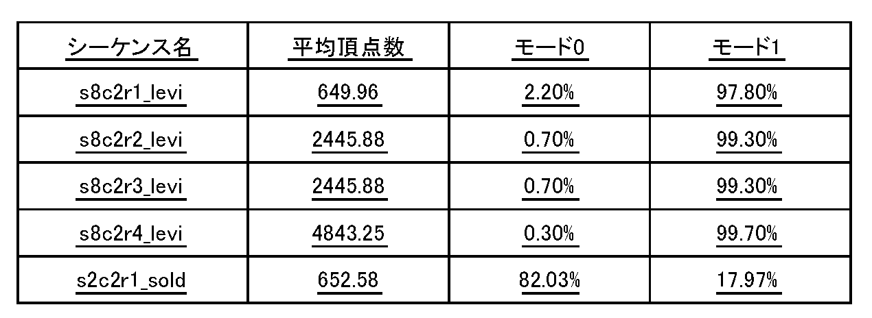
なお、上述の制御信号(group size)を自然数にすると、全頂点数以上に設定する場合、絶対値が大きいので、符号量が大きくなる。
したがって、上述の制御信号を対数にすることも可能である。具体的に、制御信号をlog2_group_sizeとして、以下の式(4)で、グループサイズが算出されてもよい。
group size=2log2_group_size … 式(4)
ここで、フレームの中にグループが1つのみであれば、そのグループを最後のグループにする。つまり、group sizeが頂点の数より大きいと、全頂点をグループに入れることにする。
ここで、フレームの中にグループが1つのみであれば、そのグループを最後のグループにする。つまり、group sizeが頂点の数より大きいと、全頂点をグループに入れることにする。
さらに、上述の制御信号において設定可能な範囲は、明確な値にしてもよいし、他の制御信号やデータから算出されてもよい。
例えば、Level1により、かかる制御信号において設定可能な範囲は、規定されてもよい。
或いは、かかる制御信号において設定可能な範囲は、基本メッシュの頂点数から算出されてもよい。
例えば、かかる制御信号において設定可能な範囲について、基本メッシュの頂点数をカバーできる2の冪乗である最小の自然数にしてもよい。
さらに、上述の制御信号において設定可能な範囲について、小さい範囲にした上で、図14に示すように、別の制御信号の所定フラグ(Mode flag)を導入してもよい。かかる場合、図14に示すように、動きベクトル算出部202E4は、かかる所定フラグがTRUE(Mode flag=1)であれば、全ての頂点を1つのグループにし(すなわち、全ての頂点の数をグループサイズとし)、FALSEであれば、上述の制御信号から算出したグループサイズのままにする。
なお、上述の制御信号は、シーケンス毎で設定されてもよいし、フレーム毎で設定されてもよい。上述の制御信号が、シーケンス毎で設定されると、全フレームのグループサイズが同じである。
かかる構成によれば、適正にグループサイズの設定可能な範囲を決めることで、あらゆる状況を対応でき、確実にモードの符号量を削減し、符号化効率を向上させる効果が期待できる。
(インター復号部202Eの変更例3)
上述のインター復号部202Eの更なる変更例では、上述のインター復号部202Eを実施する前に、以下の機能ブロックを追加するように構成されている。
上述のインター復号部202Eの更なる変更例では、上述のインター復号部202Eを実施する前に、以下の機能ブロックを追加するように構成されている。
具体的には、図15に示すように、インター復号部202Eは、図8に示す構成に加えて、重複頂点探索部202E6と、mv_signalled_flag取得部(フラグ取得部)202E7と、動きベクトル取得部202E8とを備える。
ここで、derived_my_present_flag(第1フラグ)が、Pフレームのビットストリームの最初に含まれており、少なくとも0又は1という2値を持つ。
また、mv_signalled_flag(第2フラグ)は、derived_my_present_flagがNoを示す場合に、Pフレームのビットストリーム含まれ、頂点毎に0又は1という2値を持つ。
mv_signalled_flag取得部202E7は、derived_my_present_flagがNoを示す場合(例えば、derived_my_present_flagが0である場合)、Pフレームのビットストリームから全頂点の動きベクトルを復号し、Pフレームのビットストリームから全頂点のmy_signalled_flagを復号せずに、my_signalled_flagの値を1にする。
mv_signalled_flag取得部202E7は、derived_my_present_flagがYesを示す場合(例えば、derived_my_present_flagが1である場合)、Pフレームの各頂点で異なる処理を行う。mv_signalled_flag取得部202E7は、mv_signalled_flagを用いて、各頂点の処理方法について決めてもよい。
また、mv_signalled_flag取得部202E7は、derived_my_present_flagがYesを示す場合で、且つ、ある頂点のmv_signalled_flagがYesを示す場合、かかる頂点の動きベクトルについて動きベクトル取得部202E8における処理を実施せず、図7に示すインター復号部202E又はその変更例と同様の処理を行う。
また、mv_signalled_flag取得部202E7は、derived_my_present_flagがYesを示す場合で、かつ、ある頂点のmv_signalled_flagがNoを示す場合、かかる頂点の動きベクトルについて動きベクトル取得部202E8における処理を実施し、当該頂点の動きベクトルを取得する。
例えば、mv_signalled_flag取得部202E7は、derived_my_present_flagがYesを示す場合、Pフレームのビットストリームから頂点毎にmv_signalled_flagを復号する。
mv_signalled_flag取得部202E7は、derived_my_present_flagがYesを示す場合で、且つ、ある頂点のmv_signalled_flagがYesを示す場合、かかる頂点の予測モード(MVモード)を2とする。
一方、mv_signalled_flag取得部202E7は、derived_my_present_flagがYesを示す場合で、且つ、ある頂点のmv_signalled_flagがNoを示す場合、かかる頂点の予測モードを2以外とする。
また、mv_signalled_flag取得部202E7は、derived_my_present_flagがNoを示す場合、Pフレームの全頂点のmv_signalled_flagをビットストリームから復号せず、その値を1にし、当該頂点のMVモードが2以外にする。
重複頂点探索部202E6は、復号した参照フレームの基本メッシュの幾何情報から、座標が一致する頂点(以下、重複頂点と呼ぶ)のインデックスを探索してバッファ(図示せず)に保存するように構成されている。
具体的には、重複頂点探索部202E6の入力は、復号した参照フレームの基本メッシュの各頂点のインデックス(復号順)及び位置座標である。
また、重複頂点探索部202E6の出力は、各頂点のインデックス(vindex0)に係る重複頂点が存在する場合、かかるインデックス(vindex1)を保存し、かかる重複頂点が存在しないと、当該頂点のインデックス(vindex0)自身或いは各頂点のインデックスで使われない特定な値(例えば、―1)を保存するリストである。ここで、かかるリストは、index0の順で、バッファrepVertに保存される。
また、vindex1の頂点が、vindex0の前に復号されるため、vindex0>vindex1の関係となる。
重複頂点探索部202E6は、参照フレームの基本メッシュの各頂点(インデックス:vindex0)に対して、復号した参照フレームの基本メッシュの最初頂点(インデックス:0)から直前の頂点(インデックス:vindex0―1)に係る重複頂点が存在するか否かについて判断し、かかる重複頂点が存在すると判断した場合、少なくとも以下の3種類の方法のいずれかで、かかる重複頂点のインデックスを出力する。
(方法1)
重複頂点探索部202E6は、以下のように、順次に座標が一致する重複頂点を探す。重複頂点が存在する時は、vrefががvindex1であり、重複頂点が存在しない時は、vRefが-1である。
重複頂点探索部202E6は、以下のように、順次に座標が一致する重複頂点を探す。重複頂点が存在する時は、vrefががvindex1であり、重複頂点が存在しない時は、vRefが-1である。
vRef =firstVertexIndexDuplicated(vindex0)
where
firstVertexIndexDuplicated(v){
for( i = 0; i<v; i++){
if(referenceSubmeshVertexPositions[ i ] ==
referenceSubmeshVertexPositions[ v ]) {
return i
}
}
return -1
}
where
firstVertexIndexDuplicated(v){
for( i = 0; i<v; i++){
if(referenceSubmeshVertexPositions[ i ] ==
referenceSubmeshVertexPositions[ v ]) {
return i
}
}
return -1
}
(方法2)
重複頂点探索部202E6は、二分探索を用いた座標が一致する重複頂点を探す。例えば、重複頂点探索部202E6は、連想配列クラスmapのfind関数を利用してもよい。
重複頂点探索部202E6は、二分探索を用いた座標が一致する重複頂点を探す。例えば、重複頂点探索部202E6は、連想配列クラスmapのfind関数を利用してもよい。
(方法3)
重複頂点探索部202E6は、ハッシュテーブルを用いた座標が一致する重複頂点を探す。例えば、重複頂点探索部202E6は、ハッシュ連想配列クラスunordered_mapのfind関数を利用してもよい。
重複頂点探索部202E6は、ハッシュテーブルを用いた座標が一致する重複頂点を探す。例えば、重複頂点探索部202E6は、ハッシュ連想配列クラスunordered_mapのfind関数を利用してもよい。
なお、参照フレームの基本メッシュで重複頂点を見つける方法として、重複頂点が存在する頂点について、特別なシグナルから位置座標ではなく重複頂点のインデックスを復号する方法が用いられてもよい。
動きベクトル取得部202E8は、MVmodeが2である場合(derived_my_present_flagがYesを示し、当該頂点のmv_signalled_flagがNoを示す場合)、当該頂点の重複頂点が存在するため、動きベクトルバッファ部202E2から、重複頂点探索部202E6から出力された当該頂点のインデックス(vindex0)に係る重複頂点のインデックス(vindex1)を持つ頂点の動きベクトルを取得し、かかる頂点の動きベクトルを、当該頂点の動きベクトルとするように構成されている。
つまり、重複頂点のインデックス(vindex1)202E6の出力であり、ビットストリームから復号されない。
ここで、MVmodeが2以外である場合に(derived_my_present_flagがNoを示す場合、又は、derived_my_present_flagYesを示し、当該頂点のmv_signalled_flagがYesを示す場合)、動きベクトル取得部202E8の代わりに、図7に示すインター復号部202E又はその変更例と同様の処理が行われる。
かかる構成によれば、重複頂点が存在する頂点に対して動きベクトルの復号計算及び符号量の削減効果が期待できる。
上述のインター復号部202Eの更なる変更例では、重複頂点探索部202E6は、参照フレームの基本メッシュの全ての頂点の中から重複頂点を探すのではなく、mv_signalled_flagがNoである頂点の中からのみ重複頂点を探す。
ただし、重複頂点探索部202E6の入力は、復号した参照フレームの基本メッシュの各頂点のインデックス(復号順)及び位置座標に加えて、mv_signalled_flagも含む。
本変更例によれば、全頂点ではなく重複頂点を持つ頂点のみで重複頂点を探すため、動きベクトルの復号計算の削減効果が期待できる。
上述のインター復号部202Eの更なる変更例では、mv_signalled_flag取得部202E7は、2段階で、mv_signalled_flagを復号する。
mv_signalled_flag取得部202E7は、N個の頂点を1つのグループにした上で、グループ毎で、Pフレームのビットストリームからmv_group_signalled_flag(第3フラグ)を復号し、mv_group_signalled_flagが1であるグループの全頂点のmv_signalled_flagを1とし、mv_group_signalled_flagが0であるグループの頂点毎で、Pフレームのビットストリームからmv_group_signalled_flagを復号する。
本変更例によれば、2段階で、mv_group_signalled_flagを復号するため、動きベクトルの復号計算及び符号量の削減効果が期待できる。
上述のインター復号部202Eの更なる変更例では、mv_signalled_flag取得部202E7は、頂点毎ではなく、重複頂点を持つ頂点では、Pフレームのビットストリームからmv_signalled_flagを復号し、重複頂点を持ってない頂点では、Pフレームのビットストリームからmv_signalled_flagを復号せず、mv_signalled_flagを1とする。
なお、インター復号部202Eは、mv_signalled_flagより前に重複頂点を持つ頂点数を示す制御信号をビットストリームから復号する。
かかる制御信号により、重複頂点探索部202E6の処理を実施しなくても、mv_signalled_flagの復号が可能にする。
また、ビットストリームの適合性の要件として、重複頂点探索部202E6で出力する重複頂点を持つ頂点数と制御信号によって示される頂点数とが一致することにする。
また、重複頂点探索部202E6は、全ての重複頂点インデックスを別のリストに保存する。例えば、重複頂点探索部202E6は、以下の(方法1の変更例)に示すように、duplicated_vertex_listに、全ての重複頂点インデックスを保存してもよい。
(方法1の変更例)
重複頂点探索部202E6は、以下に示すように、順次に座標が一致する重複頂点を探す。重複頂点が存在する時は、vRefがvindex1であり、重複頂点が存在しない時は、vRefが-1である。
重複頂点探索部202E6は、以下に示すように、順次に座標が一致する重複頂点を探す。重複頂点が存在する時は、vRefがvindex1であり、重複頂点が存在しない時は、vRefが-1である。
vRef =firstVertexIndexDuplicated(vindex0,duplicated_vertex_list)
where
firstVertexIndexDuplicated(v,duplicated_vertex_list){
for( i = 0; i<v; i++){
if(referenceSubmeshVertexPositions[ i ] ==
referenceSubmeshVertexPositions[ v ]) {
duplicated_vertex_list.push_back(v)
return i
}
}
return -1
}
本変更例によれば、全頂点ではなく重複頂点を持つ頂点のみでmv_signalled_flagを設けるため、動きベクトルの復号計算及び符号量の削減効果が期待できる。
where
firstVertexIndexDuplicated(v,duplicated_vertex_list){
for( i = 0; i<v; i++){
if(referenceSubmeshVertexPositions[ i ] ==
referenceSubmeshVertexPositions[ v ]) {
duplicated_vertex_list.push_back(v)
return i
}
}
return -1
}
本変更例によれば、全頂点ではなく重複頂点を持つ頂点のみでmv_signalled_flagを設けるため、動きベクトルの復号計算及び符号量の削減効果が期待できる。
上述のインター復号部202Eの更なる変更例では、mv_signalled_flag取得部202E7は、重複頂点を持ってない頂点のmv_signalled_flagを0にしてもよい。
ここで、mv_signalled_flag取得部202E7は、重複頂点を持たない頂点のmv_signalled_flagが0である場合、参照フレームの基本メッシュにおいて、重複頂点は存在しないが、同じ動きベクトルを持つ頂点が存在するので、インターフレームのビットストリームから当該頂点と同じ動きベクトルを持つ頂点のインデックスを復号し、当該頂点の動きベクトルを取得する。
具体的には、動きベクトル取得部202E8は、MVmodeが2である場合に(derived_my_present_flagがYesを示し、当該頂点のmv_signalled_flagがNoを示す場合)、かかる頂点の重複頂点が存在する時に、動きベクトルバッファ部202E2から、重複頂点探索部202E6によって出力された当該頂点のインデックス(vindex0)に係る重複頂点のインデックス(vindex1)を持つ頂点の動きベクトルを取得し、かかる頂点の動きベクトルを、当該頂点の動きベクトルにするように構成されているが、本変更例では、当該頂点の重複頂点が存在しない時に、ビットストリームから当該頂点と同じ動きベクトルを持つ頂点のインデックス(vindex1)を復号し、かかるインデックス(vindex1)を持つ頂点の動きベクトルを取得し、かかる頂点の動きベクトルを、当該頂点の動きベクトルにするように構成されている。
本変更例によれば、重複頂点を持たない頂点でも、mv_signalled_flagがNoを示す場合、動きベクトルを別の頂点から取得するため、動きベクトルの復号計算及び符号量の削減効果が期待できる。
なお、上述の変更例について同時に利用できる場合とできない場合もある。同時に利用できない場合は、どの変更例を利用するかについて示す制御信号を設けて、ビットストリームから、かかる制御信号を復号し、どの変更例を利用するかについて判断する。ただし、かかる制御信号は、既存の制御信号を拡張してもよい。
上述のインター復号部202Eの更なる変更例では、重複頂点探索部202E6は、参照フレームがインターフレームであれば、復号対象のフレームで、参照フレームにおいて取得した結果を再利用する。
ただし、参照フレームがイントラフレームであれば、重複頂点探索部202E6は、重複頂点に関する情報を持っているとして、かかる情報を再利用してもよい。
具体的に、第1に、重複頂点探索部202E6は、ビットストリームから、参照フレームにおいて取得した結果(重複頂点を持つ頂点数を含む重複頂点に関する情報)を、復号対象フレームで再利用するかどうかを示す制御信号を復号する。ただし、重複頂点探索部202E6は、かかる制御信号について、既存の制御信号をそのまま又は拡張して利用してもよい。
第2に、重複頂点探索部202E6は、かかる制御信号がYesである場合、参照フレームがインターフレームであれば、参照フレームにおいて取得した結果を、復号対象フレームで再利用する。ただし、重複頂点探索部202E6は、参照フレームがイントラフレームであれば、重複頂点に関する情報を持っているとして、かかる情報を再利用してもよい。
具体的に、参照フレームに係る重複頂点探索部202E6の出力(上述の結果)は、各頂点のインデックス(vindex0)に係る重複頂点が存在する場合、かかる重複頂点のインデックス(vindex1)を保存し、かかる重複頂点が存在しない場合、当該頂点のインデックス(vindex0)自身或いはインデックスが使えない特定な値(例えば、―1)を保存するリストである。
ここで、かかるリストは、vindex0の順で、バッファrepVertに保存される。
以下の例では、重複頂点が存在しない場合、当該頂点のインデックス(vindex0)自身が保存される。また、フレームのインデックスtRefを明示するため、バッファrepVerttRefで表示する。
repVerttRef(vindex0)=vRef
vRef=vindex1 if vindex0及びvindex1が重複頂点である
vRef=vindex0 if vindex0及びvindex1が重複頂点ではない
復号対象フレームtにおいて、repVerttRefが再利用される場合、重複頂点探索部202E6は、復号対象フレームの参照フレームの基本メッシュの各頂点(インデックス:vindex0)に対して、重複頂点の探索が不要であり、repVerttRefをそのままで利用するだけでよい。
vRef=vindex1 if vindex0及びvindex1が重複頂点である
vRef=vindex0 if vindex0及びvindex1が重複頂点ではない
復号対象フレームtにおいて、repVerttRefが再利用される場合、重複頂点探索部202E6は、復号対象フレームの参照フレームの基本メッシュの各頂点(インデックス:vindex0)に対して、重複頂点の探索が不要であり、repVerttRefをそのままで利用するだけでよい。
repVertt(vindex0)=vindex0 if repVerttRef(vindex0)=vindex0
repVertt(vindex0)=repVerttRef(vindex0) if repVerttRef(vindex0)!=vindex0
本変更例によれば、重複頂点を探さないため、動きベクトルの復号計算の削減効果が期待できる。
repVertt(vindex0)=repVerttRef(vindex0) if repVerttRef(vindex0)!=vindex0
本変更例によれば、重複頂点を探さないため、動きベクトルの復号計算の削減効果が期待できる。
上述のインター復号部202Eの更なる変更例では、mv_signalled_flag取得部(フラグ取得部)202E7は、参照フレームがインターフレームであれば、参照フレームにおいて取得したmv_signalled_flagを復号対象のフレームで再利用する。
ただし、参照フレームがイントラフレームであれば、mv_signalled_flag取得部202E7は、mv_signalled_flagを持っているとして、かかるmv_signalled_flagを再利用してもよい。
具体的には、derived_my_present_flagがYesを示す場合、mv_signalled_flag取得部202E7は、Pフレームのビットストリームから頂点毎に、mv_signalled_flagを復号せず、参照フレームのmv_signalled_flagとの差分を復号する。
また、全てのmv_signalled_flagで差分がない時に、制御信号が設けられてもよい。その場合は、mv_signalled_flag取得部202E7は、かかる制御信号を復号し、かかる制御信号が特定な値(例えば、TRUE)であれば、参照フレームのmv_signalled_flagをそのままで対象フレームのmv_signalled_flagとし、かかる制御信号が特定な値(例えば、FALSE)であれば、参照フレームのmv_signalled_flagとの差分を更に復号し、対象フレームのmv_signalled_flagを算出する。
本変更例によれば、mv_signalled_flagの符号量削減効果が期待できる。
なお、上述の変更例について同時に利用できる場合とできない場合もある。同時に利用できない場合は、どの変更例を利用するかについて示す制御信号を設けて、ビットストリームから、かかる制御信号を復号し、どの変更例を利用するかについて判断する。
(基本メッシュ復号部202の変更例1)
以下、図16及び図17を参照して、基本メッシュ復号部202の変更例1について説明する 。
以下、図16及び図17を参照して、基本メッシュ復号部202の変更例1について説明する 。
図16に示すように、本変更例1に係る基本メッシュ復号部202は、分離部202Aと、イントラ復号部202Bと、メッシュバッファ部202Cと、インター復号部202Eと、スキップ復号部202Fとを備える。
スキップ復号部202Fは、指定された参照フレームの復号基本メッシュをそのまま用いて、復号対象フレームの基本メッシュを復号するように構成されている。
なお、本実施形態において、フレームは、メッシュ(Mesh)又はサブメッシュ(Submesh)のいずれであってもよい。
例えば、図17に示すように、smh_typeにおける「P_SUBMESH」は、Pフレームに対応し、smh_typeにおける「I_SUBMESH」は、Iフレームに対応し、smh_typeにおける「SKIP_SUBMESH」は、Sフレームに対応してもよい。
(スキップ復号部202F)
スキップ復号部202Fは、メッシュバッファ部202Cから指定された参照フレームの復号基本メッシュ(参照用の復号基本メッシュ)を取り出し、取り出した参照用の復号基本メッシュの頂点の座標及び当該頂点のインデックスをそのまま用いて、復号対象フレームの基本メッシュの頂点の座標及び当該頂点のインデックスを復号するように構成されている。
スキップ復号部202Fは、メッシュバッファ部202Cから指定された参照フレームの復号基本メッシュ(参照用の復号基本メッシュ)を取り出し、取り出した参照用の復号基本メッシュの頂点の座標及び当該頂点のインデックスをそのまま用いて、復号対象フレームの基本メッシュの頂点の座標及び当該頂点のインデックスを復号するように構成されている。
ここで、メッシュバッファ部202Cは、少なくとも1枚の参照フレームを持ち、参照フレーム毎で少なくとも1枚の復号された基本メッシュを保存するように構成されている。
スキップ復号部202Fは、ビットストリームから復号した制御信号又は所定ルールを用いて、指定された参照用の復号基本メッシュについて特定してもよい。
例えば、かかる所定ルールは、メッシュバッファ部202Cから参照フレームリストの1番目の参照フレームを取り出すこと、或いは、復号対象フレームにフレームインデックスが最も近い参照フレームを取り出すこと等であってもよい。
本実施形態では、参照用の復号基本メッシュの頂点の座標及び当該頂点のインデックスをそのまま用いて基本メッシュの頂点の座標を復号するフレームを「Sフレーム」と呼ぶ。
かかる構成によれば、スキップ復号部202Fにおいて動きベクトルを不要とすることができるため、符号量の大幅な削減効果及び計算量の大幅な削減効果が期待できる。
(メッシュバッファ部202C)
メッシュバッファ部202Cは、1枚又は複数枚の参照用の復号基本メッシュを、所定順番で保存するように構成されている。
メッシュバッファ部202Cは、1枚又は複数枚の参照用の復号基本メッシュを、所定順番で保存するように構成されている。
なお、かかる基本メッシュは、フレーム番号やサブメッシュ番号等のメタデータや少なくとも各頂点の座標及び当該頂点のインデックスを有しており、参照フレームリストで決められた所定順番でメッシュバッファ部202Cに保存される。
ここで、図18に示すように、かかる参照フレームリスト(ref_list0)は、メッシュバッファ部202Cに保存されている全ての参照用の復号基本メッシュを特定する情報のリストである。
参照フレームリストは、図18に示すように、ビットストリームから復号された制御信号によって決められてもよいし、自然にフレームの復号順から算出されてもよい。
なお、ビットストリームから復号された制御信号は、復号対象フレームとの相対的な距離で示されていてもいし、絶対値であるのフレームインデックスであってもよい。
さらに、制御信号により、短期的な参照フレーム又は長期的な参照フレームが使われてもよい。
例えば、短期的な参照フレームを使うと、当フレーム(cur)及び参照フレーム(ref)の表示順(Display Order)の差の絶対値(abs_delta_mfoc_st)及びその符号(sign_flag)をビットストリームから復号し、参照フレームの表示順(Display Order)を下式で指定してもよい。
If(sign_flag){
Display Order(ref)=Display Order(cur)+abs_delta_mfoc_st
}else{
Display Order(ref)=Display Order(cur)-abs_delta_mfoc_st
}
また、自然にフレームの復号順から算出する方法が用いられる場合、例えば、参照フレームリストにおいて、制御信号が存在していない時に、直前に復号済みのフレームから一定のフレーム数で順次に並べられてもよい。つまり、参照フレームリストは、{0, -1, -2,…, -(N―1)}とされてもよい。
If(sign_flag){
Display Order(ref)=Display Order(cur)+abs_delta_mfoc_st
}else{
Display Order(ref)=Display Order(cur)-abs_delta_mfoc_st
}
また、自然にフレームの復号順から算出する方法が用いられる場合、例えば、参照フレームリストにおいて、制御信号が存在していない時に、直前に復号済みのフレームから一定のフレーム数で順次に並べられてもよい。つまり、参照フレームリストは、{0, -1, -2,…, -(N―1)}とされてもよい。
基本的に、参照フレームリストは、特別な事情(例えば、Re-ordering指示を受ける時)以外に各フレームで変化しない。
メッシュバッファ部202Cは、以下のように更新されてもよい。
メッシュバッファ部202Cは、基本メッシュが復号された時に、Iフレーム及びPフレームの場合、参照フレームリストで決められた所定順番により1枚又は複数枚の既存の参照フレームを削除し、復号済みのフレームの基本メッシュを含めて1枚又は複数枚の基本メッシュを入れて、又は、複数枚の基本メッシュから1枚の基本メッシュを作成して入れて、参照フレームの順番を調整する。
かかる削除作業は、メッシュバッファ部202Cが満了する時のみに実施されてもよい。なお、メッシュバッファ部202Cで保存できる基本メッシュの数は、事前に決められている。ここで、本実施形態では、かかる基本メッシュの数に到達すると、メッシュバッファ部202Cが満了すると定義するものとする
上述の作成作業では、復号済みのフレームの基本メッシュ及びメッシュバッファ部202Cに保存されている既存の基本メッシュに対応する頂点の座標について重み付け平均して1枚の基本メッシュにしてもよい。
上述の作成作業では、復号済みのフレームの基本メッシュ及びメッシュバッファ部202Cに保存されている既存の基本メッシュに対応する頂点の座標について重み付け平均して1枚の基本メッシュにしてもよい。
かかる重み付け平均で用いられる重みは、事前に決められていてもよいし、フレームインデックスを用いて算出されてもよいし、制御信号から復号されてもよい。
ただし、メッシュバッファ部202Cは、Sフレームである時には、かかる更新を実施してもよいし、かかる更新を実施しなくてもよい。
なお、メッシュバッファ部202Cは、ビットストリームから復号された制御信号によりRe-orderingの指示を示す制御信号を受けた時に、図19に示すように、参照フレームリストを更新し、更新した参照フレームリスト(ref_list0)で決められた所定順番により参照フレームの順番を調整する。
(インター復号部202E)
インター復号部202Eは、メッシュバッファ部202Cから取り出した参照フレームの頂点の座標とPフレームのビットストリームから復号した動きベクトルとを加算することによって、Pフレームの頂点の座標を復号するように構成されている。
インター復号部202Eは、メッシュバッファ部202Cから取り出した参照フレームの頂点の座標とPフレームのビットストリームから復号した動きベクトルとを加算することによって、Pフレームの頂点の座標を復号するように構成されている。
さらに、インター復号部202Eは、かかる特定バッファに保存されている重複頂点として存在する頂点のインデックスA(k)及びB(k)のペアにより、Pフレームの頂点のインデックスを調整することが可能である。かかるインデックスの全部又は一部は、ビットストリームから復号される。かかる復号方法は、算術符号化でもよい。かかる構成によれば、算術符号化を用いて復号対象のインデックスの最大値に制限が無くなるという効果が期待できる。例えば、ue(v)という算術符号化を使ってもよい。
(基本メッシュ復号部202の変更例2)
以下、図20を参照して、基本メッシュ復号部202の変更例2について説明する。
以下、図20を参照して、基本メッシュ復号部202の変更例2について説明する。
以下、スキップ復号部202Fについて説明するが、インター復号部202Eへ適用してもよい。
図20に示すように、スキップ復号部202Fでは、後続フレームを参照することが可能にするため、復号順(Decode Order)と表示順(Display Order)とが異なる。
ここで、表示順は、符号化する際の入力の順番と同じであり、復号する際の出力の順番と同じである。
一方、復号順は、符号化する際の出力の順番と同じであり、復号する際の入力の順番と同じである。
なお、かかる参照フレームは、後続フレームと1枚又は複数枚の他フレームとを重み付け平均して算出されてもよい。
ただし、後続フレームを含めて複数枚のフレームを参照する場合、図14における新しいフレームタイプ(smh_type)として、MR_SUBMESH(MRフレームやBフレーム)を定義し、MR_SUBMESHは、ビットストリームから復号される。
また、かかる他フレームは、図21に示すように、対象フレームの直前の復号済のフレームであってもよい。
かかる重みは、対象フレームと後続フレームと間のフレーム間隔及び対象フレームと他フレームとの間のフレーム間隔を用いて算出されてもよいし、事前に決められてもよい。
基本メッシュ復号部202は、ビットストリームから制御信号(smh_mesh_frm_order_cnt_lsb)を復号し、かかる出力の順番を復号する。
なお、上述の非特許文献4で定義したサブメッシュが存在するときに、全てのサブメッシュを同じ制御信号(smh_mesh_frm_order_cnt_lsb)にすること又は制御信号(smh_mesh_frm_order_cnt_lsb)を全てのサブメッシュに適用させることにする。
かかる制御信号(smh_mesh_frm_order_cnt_lsb)によって示される値は、復号対象フレームの表示順との差分であってもよいし、事前に決めたフレーム集団MaxMeshFrmOrderCntLsbの中の順番であってもよい。
なお、復号順(Decode Order)と表示順(Display Order)とが異なる時に、復号済みの基本メッシュが復号順(Decode Order)で並んでいると、基本メッシュ復号部202は、復号済みの基本メッシュを表示順(Display Order)に並び替えてもよい。
なお、後続フレームを参照できるSフレームにおいて、2つのメッシュバッファ202Cが設けられていてもよいし、1つのメッシュバッファ部202のみが設けられている際には、表示順が復号対象フレームよりも後になる参照フレームを含めて少なくとも1枚の参照フレームが存在する。
スキップ復号部202Fは、ビットストリームから復号した制御信号又は所定ルール又はRe-ordering指示を受けることにより、参照フレームを指定する。
具体的には、スキップ復号部202Fは、かかる制御信号により参照フレームリストの中に参照フレームを指定する。
或いは、スキップ復号部202Fは、参照フレームリストの1番目の参照フレームを指定する。
或いは、スキップ復号部202Fは、Re-ordering指示を受けで、参照フレームリスト及びメッシュバッファ部202Cの参照フレーム順番を更新し、かかる参照フレームリストの1番目の参照フレームを指定する。
なお、本実施形態では、Sフレームを復号しなくても他のフレームの復号に影響を及ぼさない。よって、Sフレームを一部又は全部を復号しない場合、Temporal scalabilityを実現できる。
さらに、基本メッシュ復号部202は、制御信号により、複数の参照フレームを統合してSフレームの基本メッシュを復号してもよい。
例えば、基本メッシュ復号部202は、前後2枚の参照フレームの基本メッシュにおいて、対応する頂点の座標を平均して、平均座標及び頂点のインデックスをそのまま用いて、復号対象フレームの基本メッシュの頂点の座標及び当該頂点のインデックスを復号するように構成されていてもよい。
かかる構成によれば、スキップ復号部202F又はインター復号部202Eにおいて動きベクトルを不要としながらも高品質な基本メッシュにすることができるため、復号メッシュの質を向上させる効果が期待できる。さらに、Temporal scalabilityを実現できる効果が期待できる。
ただし、Temporal scalabilityを実現するため、各フレームにおいて基本メッシュと変位量とテクスチャとをそれぞれ復号するかどうかを示す制御信号をそれぞれ定義し、ビットストリームからそれぞれ復号する。
また、同じフレーム内において、アトラス及び基本メッシュのTemporal_IDを一致させてもよい。また、同じフレーム内において、アトラス及びテクスチャのTemporal_IDを一致させてもよい。また、同じフレーム内において、アトラス及び変位量のTemporal_IDを一致させてもよい。
かかる構成によれば、フレームが復号できないことや無駄なデータを回避することができるという効果が期待できる。
なお、同じTemporal_IDを持つ隣接するフレームの間隔が一定であることが望ましい。
同じTemporal_IDを持つ隣接するフレームは、POCが最も近い。
上述のようにフレームの間隔を一定にすることで、復号したフレームを表示する際に一定のフレームレートを保つ効果が期待できる。
さらに、同じ表示順を持つアトラス及び基本メッシュの復号順を一致させてもよい。また、同じ表示順を持つアトラス及び変位量の復号順を一致させてもよい。また、同じ表示順を持つアトラス及びテクスチャの復号順を一致させてもよい。
または、同じ表示順を持つアトラス及び基本メッシュのランダムアクセスポイントを一致させてもよい。また、同じ表示順を持つアトラス及び変位量のランダムアクセスポイントを一致させてもよい。また、同じ表示順を持つアトラス及びテクスチャのランダムアクセスポイントを一致させてもよい。なお、ランダムアクセスポイントは、非特許文献4又は非特許文献5で定義されている。
かかる構成によれば、基本メッシュ、変位量及びテクスチャをそれぞれ復号する際に、互いの復号を待つことなく、メッシュを再現できるという効果が期待できる。
さらに、復号対象フレームの制御信号Temporal_IDよりも高いTemporal_IDを持つフレームは、かかる復号対象フレームの参照フレームにしない。
これによって、参照フレームが捨てられる可能性が無くなるという効果が期待できる。
以下に、上述のTemporal_IDを用いてTemporal scalabilityを実現する一例について述べる。
アトラス、基本メッシュ、変位量及びテクスチャのビットストリームは、ネットワーク抽象レイヤ(NAL)ユニットによりカプセル化される。NALユニットは、図22のようなNALヘッダを持ってもよい。
NALヘッダ内の最後の3ビットとして定義したTIDは、Temporal_IDプラス1である。TIDの範囲は、1から7までとし、ゼロを禁止する。
NALヘッダ内のTIDの直前の6ビットとして定義されたLayerID/R6は、NALユニットが属するレイヤの識別子を指定する。
LayerID/R6の値は、0~62の範囲内でなければならない。値63は、将来的にISO/IECによって指定される可能性がある。
ビットストリームのデコードユニットのデータ量を決定する以外の目的で、メッシュ復号装置200は、NALユニット内の値63に続く全てのデータを無視し、指定されたプロファイルに準拠するメッシュ復号装置200は、LayerID-R6の値が0でない全てのNALユニットを無視する(つまり、ビットストリームから取り除き、破棄する)。
LayerID/R6の値63は、将来の拡張で拡張レイヤ識別子を示すために使用することができる。
なお、非特許文献4で定義されたサブメッシュが存在するときは、全てのサブメッシュを同じTIDにすること又はTIDを全てのサブメッシュに適用させることにする。
アトラスについては、非特許文献5を利用でき、変位量及びテクスチャについては、映像符号化方式のHEVCやVVCを利用できるため、以下は、基本メッシュについて説明する。
符号化された基本メッシュフレームの全ての BMCL NALユニットのLayerID/R6の値は、同じでなければならない。符号化された基本メッシュフレームのLayerID/R6の値は、符号化された基本メッシュフレームのBMCL NALユニットのLayerID/R6の値である。
NALTypeが、NAL_EOBと等しい場合、LayerID/R6の値は、0と等しくなければならない。
NALTypeが、非特許文献4で定義されたNAL_BLA_W_LPからNAL_RSV_BMCL_29までの範囲にある場合、つまり、IRAPコード化された基本メッシュフレームに属する場合、Temporal_IDは、0でなければならない。
NALTypeが、NAL_TSA_R又はNAL_TSA_Nに等しい場合、Temporal_IDは、0に等しくてはならない。
NALTypeが0に等しく、NALTypeがNAL_STSA_R又はNAL_STSA_Nに等しい場合、Temporal_IDは、0に等しくてはならない。
Temporal_IDの値は、アクセスユニット内の全てのBMCL NALユニットについて同じでなければならない。
コード化された基本メッシュフレーム又はアクセスユニットのTemporal_IDの値は、コード化された基本メッシュフレーム又はアクセスユニットのBMCL NALユニットのTemporal_IDの値である。
サブレイヤ表現のTemporal_IDの値は、サブレイヤ表現内の全てのBMCL NALユニットのTemporal_IDの最大値である。
非BMCL NALユニットのTemporal_IDの値は、以下のように制限される。
- NALTypeがNAL_BMSPSに等しい場合、Temporal_IDは0でなければならず、NALユニットを含むアクセスユニットのTemporal_IDは、0でなければならない。
- それ以外の場合で、NALTypeがNAL_EOS又はNAL_EOBに等しい場合、Temporal_IDは、0でなければならない。
- それ以外の場合で、NALTypeがNAL_AUD又はNALLFDDに等しい場合、Temporal_IDは、NALLユニットを含むアクセスユニットのTemporal_IDに等しくなければならない。
- それ以外の場合、Temporal_IDは、NALユニットを含むアクセスユニットのTemporal_ID以上でなければならない。
- NALTypeがNAL_BMSPSに等しい場合、Temporal_IDは0でなければならず、NALユニットを含むアクセスユニットのTemporal_IDは、0でなければならない。
- それ以外の場合で、NALTypeがNAL_EOS又はNAL_EOBに等しい場合、Temporal_IDは、0でなければならない。
- それ以外の場合で、NALTypeがNAL_AUD又はNALLFDDに等しい場合、Temporal_IDは、NALLユニットを含むアクセスユニットのTemporal_IDに等しくなければならない。
- それ以外の場合、Temporal_IDは、NALユニットを含むアクセスユニットのTemporal_ID以上でなければならない。
なお、NALユニットがBMCLでない場合、Temporal_IDの値は、非BMCL NALユニットが適用される全てのアクセスユニットのTemporal_ID値の最小値に等しくなる。
NALTypeがNAL_BMFPSに等しい場合、Temporal_IDは、最初の符号化基本メッシュフレームのTemporal_IDが0であるビットストリームの先頭に全ての基本メッシュフレームパラメータセット(BMFPS)が含まれるため、含まれるアクセスユニットのTemporal_ID以上であることができる。
なお、スキップ復号部202Fは、指定されたtIDTargetを参照して、Temporal_IDがtIDTargetより高いNALユニットを復号せずに捨てることにする。
ここで、tIDTargetは、事前に決めた値により指定されてもよいし、ネットワーク状況やメッシュ復号装置200の端末能力により指定されてもよい。
例えば、有線のケースよりも無線のケースの方が低いtIDTargetが指定される。また、ネットワーク状況が悪い場合に、低いtIDTargetが指定される。また、低スペックのメッシュ復号装置200で復号される場合、低いtIDTargetが指定される。
ただし、ビットストリームの適合性の要件としては、Temporal_IDがtIDTargetより高くないNALユニットが少なくとも1つはビットストリームに存在しなければならないということとする。
なお、図23に示すように、各フレーム(イントラフレーム、インターフレーム及びスキップフレーム)でサブメッシュの数が異なってもよい。
かかる場合、イントラ復号部202B、インター復号部202E及びスキップ復号部202Fは、各フレームにおけるサブメッシュの各々に対して、重複しないサブメッシュIDを付与する。
また、図24に示すように、イントラ復号部202B、インター復号部202E及びスキップ復号部202Fは、フレーム間で対応するサブメッシュに対して異なるSubmeshID(サブメッシュID)を付与してもよい。
ただし、インター復号部202E又はスキップ復号部202Fは、参照フレームの中で同じSubmeshIDを持つサブメッシュのみを参照することができるものとする。
或いは、インター復号部202E又はスキップ復号部202Fは、参照フレームの中で同じ頂点数を持つサブメッシュのみを参照することができるものとする。
或いは、イントラ復号部202B及びインター復号部202Eは、参照フレームの中で指定されたサブメッシュを参照することができるものとする。
かかる場合、インター復号部202E又はスキップ復号部202Fは、参照フレーム内にサブメッシュが複数ある場合、現サブメッシュのビットストリームから、参照可能なサブメッシュのSubmeshIDを指定する制御信号を復号してもよい。
一方、インター復号部202E又はスキップ復号部202Fは、参照フレーム内にサブメッシュが1つのみある場合、かかるサブメッシュを参照可能なサブメッシュとしてもよい。
ただし、上述の制御信号が存在しない場合、インター復号部202E又はスキップ復号部202Fは、参照可能なサブメッシュのSubmeshIDを、現フレーム内のサブメッシュと同じSubmeshIDとする。
また、インター復号部202E又はスキップ復号部202Fは、ビットストリームから、上述の制御信号が存在するかどうかを示す制御信号を復号してもよい。
なお、インター復号部202E又はスキップ復号部202Fは、上述の参照可能なサブメッシュを決める方法を選択する制御信号を復号してもよい。
細分割部203及び変位量復号部206は、非特許文献4に従ってもよい。
本発明によれば、復号済みの隣接頂点を探索せず、参照フレームそのものを再利用することにより計算量を削減することができる。
また、本実施形態によれば、インター予測符号化において、現フレームの基本メッシュの頂点数が参照フレーム又は参照サブメッシュの頂点数と異なる場合であっても現フレームの基本メッシュを復号することができる。
また、本実施形態によれば、インター予測符号化において、現フレームの基本メッシュの頂点数が参照フレーム又は参照サブメッシュの頂点数と異なるという事態を回避することができる。
また、本実施形態によれば、インター予測符号化において、現フレームの参照フレームの中にどのサブメッシュを参照するかという制御信号を導入することで、どのサブメッシュを参照するかについて特定することができる。
また、本実施形態によれば、インター予測符号化において、現フレームの参照フレームの中にどのサブメッシュを参照するかという情報が無くても、どのサブメッシュを参照するかについて特定することができる。
また、本実施形態によれば、基本メッシュが少なくとも1つの面を有することを保証することができる。
また、本実施形態によれば、Temporal_scalability機能を実現することができる。
さらに、本実施形態によれば、メッシュの符号化効率を向上させることができる。
上述のメッシュ符号化装置100及びメッシュ復号装置200は、コンピュータに各機能(各工程)を実行させるプログラムであって実現されていてもよい。
なお、本実施形態によれば、例えば、動画像通信において総合的なサービス品質の向上を実現できることから、国連が主導する持続可能な開発目標(SDGs)の目標9「レジリエントなインフラを整備し、持続可能な産業化を推進するとともに、イノベーションの拡大を図る」に貢献することが可能となる。
1…メッシュ処理システム
100…メッシュ符号化装置
200…メッシュ復号装置
201…多重分離部
202…基本メッシュ復号部
202A…分離部
202B…イントラ復号部
202B1…任意イントラ復号部
202B2…整列部
202C…メッシュバッファ部
202D…接続情報復号部
202E…インター復号部
202E1…動きベクトル残差復号部
202E2…動きベクトルバッファ部
202E3…動きベクトル予測部
202E4…動きベクトル算出部
202E5…加算器
202E6…重複頂点探索部
202E7…mv_signalled_flag取得部
202E8…動きベクトル取得部
202F…スキップ復号部
203…細分割部
204…メッシュ復号部
205…パッチ統合部
206…変位量復号部
207…映像復号部
208…アトラスデータ復号部
100…メッシュ符号化装置
200…メッシュ復号装置
201…多重分離部
202…基本メッシュ復号部
202A…分離部
202B…イントラ復号部
202B1…任意イントラ復号部
202B2…整列部
202C…メッシュバッファ部
202D…接続情報復号部
202E…インター復号部
202E1…動きベクトル残差復号部
202E2…動きベクトルバッファ部
202E3…動きベクトル予測部
202E4…動きベクトル算出部
202E5…加算器
202E6…重複頂点探索部
202E7…mv_signalled_flag取得部
202E8…動きベクトル取得部
202F…スキップ復号部
203…細分割部
204…メッシュ復号部
205…パッチ統合部
206…変位量復号部
207…映像復号部
208…アトラスデータ復号部
Claims (7)
- メッシュ復号装置であって、
イントラフレームのビットストリームから、前記イントラフレームにおける頂点の座標及び接続情報を復号するイントラ復号部と、
インターフレームのビットストリームから復号した動きベクトルと、参照フレームにおいて復号対象の頂点に対応する頂点の座標とを加算することで、前記復号対象の頂点の座標を復号するインター復号部とを備え、
前記イントラフレーム及び前記インターフレームにおける基本メッシュは、少なくとも1つの面を有することを特徴とするメッシュ復号装置。 - フレーム毎でまたはサブメッシュ毎で頂点数を示す制御信号は、少なくとも3つ以上の頂点を含むように制限されることを特徴とする請求項1に記載のメッシュ復号装置。
- 前記制御信号は、アトラスタイル内のパッチ内の頂点数を指定する制御信号であることを特徴とする請求項2に記載のメッシュ復号装置。
- 前記制御信号は、サブメッシュ内の頂点数を指定する制御信号であることを特徴とする請求項2に記載のメッシュ復号装置。
- 前記制御信号は、復号されたメッシュ内の頂点数を指定する制御信号であることを特徴とする請求項2に記載のメッシュ復号装置。
- メッシュ復号方法であって、
イントラフレームのビットストリームから、前記イントラフレームにおける頂点の座標及び接続情報を復号する工程Aと、
インターフレームのビットストリームから復号した動きベクトルと、参照フレームにおいて復号対象の頂点に対応する頂点の座標とを加算することで、前記復号対象の頂点の座標を復号する工程Bとを有し、
前記工程A及び前記工程Bにおいて、前記イントラフレーム及び前記インターフレームにおける基本メッシュは、少なくとも1つの面を有することを特徴とするメッシュ復号方法。 - コンピュータを、メッシュ復号装置として機能させるプログラムであって、
前記メッシュ復号装置は、
イントラフレームのビットストリームから、前記イントラフレームにおける頂点の座標及び接続情報を復号するイントラ復号部と、
インターフレームのビットストリームから復号した動きベクトルと、参照フレームにおいて復号対象の頂点に対応する頂点の座標とを加算することで、前記復号対象の頂点の座標を復号するインター復号部とを備え、
前記イントラフレーム及び前記インターフレームにおける基本メッシュは、少なくとも1つの面を有することを特徴とするプログラム。
Applications Claiming Priority (2)
| Application Number | Priority Date | Filing Date | Title |
|---|---|---|---|
| JP2024-000910 | 2024-01-06 | ||
| JP2024000910A JP2025107109A (ja) | 2024-01-06 | 2024-01-06 | メッシュ復号装置、メッシュ復号方法及びプログラム |
Publications (1)
| Publication Number | Publication Date |
|---|---|
| WO2025146752A1 true WO2025146752A1 (ja) | 2025-07-10 |
Family
ID=96300344
Family Applications (1)
| Application Number | Title | Priority Date | Filing Date |
|---|---|---|---|
| PCT/JP2024/041298 Pending WO2025146752A1 (ja) | 2024-01-06 | 2024-11-21 | メッシュ復号装置、メッシュ復号方法及びプログラム |
Country Status (2)
| Country | Link |
|---|---|
| JP (1) | JP2025107109A (ja) |
| WO (1) | WO2025146752A1 (ja) |
Citations (4)
| Publication number | Priority date | Publication date | Assignee | Title |
|---|---|---|---|---|
| JP2020119292A (ja) * | 2019-01-24 | 2020-08-06 | キヤノン株式会社 | 情報処理装置、情報処理方法、データ構造、及びプログラム |
| JP2023514853A (ja) * | 2020-03-18 | 2023-04-11 | ソニーグループ株式会社 | 投影ベースのメッシュ圧縮 |
| WO2023181875A1 (ja) * | 2022-03-24 | 2023-09-28 | ソニーグループ株式会社 | 情報処理装置および方法 |
| WO2023229762A1 (en) * | 2022-05-27 | 2023-11-30 | Tencent America LLC | Dynamic mesh compression using inter and intra prediction |
-
2024
- 2024-01-06 JP JP2024000910A patent/JP2025107109A/ja active Pending
- 2024-11-21 WO PCT/JP2024/041298 patent/WO2025146752A1/ja active Pending
Patent Citations (4)
| Publication number | Priority date | Publication date | Assignee | Title |
|---|---|---|---|---|
| JP2020119292A (ja) * | 2019-01-24 | 2020-08-06 | キヤノン株式会社 | 情報処理装置、情報処理方法、データ構造、及びプログラム |
| JP2023514853A (ja) * | 2020-03-18 | 2023-04-11 | ソニーグループ株式会社 | 投影ベースのメッシュ圧縮 |
| WO2023181875A1 (ja) * | 2022-03-24 | 2023-09-28 | ソニーグループ株式会社 | 情報処理装置および方法 |
| WO2023229762A1 (en) * | 2022-05-27 | 2023-11-30 | Tencent America LLC | Dynamic mesh compression using inter and intra prediction |
Also Published As
| Publication number | Publication date |
|---|---|
| JP2025107109A (ja) | 2025-07-17 |
Similar Documents
| Publication | Publication Date | Title |
|---|---|---|
| CN120378608A (zh) | 解码和编码设备及发送用于图像的数据的设备 | |
| US20260095593A1 (en) | Mesh decoding device, mesh encoding device, mesh decoding method, and program | |
| WO2025146752A1 (ja) | メッシュ復号装置、メッシュ復号方法及びプログラム | |
| WO2025146754A1 (ja) | メッシュ復号装置、メッシュ復号方法及びプログラム | |
| WO2025146750A1 (ja) | メッシュ復号装置、メッシュ復号方法及びプログラム | |
| WO2025146753A1 (ja) | メッシュ復号装置、メッシュ復号方法及びプログラム | |
| WO2025146749A1 (ja) | メッシュ復号装置、メッシュ復号方法及びプログラム | |
| WO2025146751A1 (ja) | メッシュ復号装置、メッシュ復号方法及びプログラム | |
| WO2025215918A1 (ja) | メッシュ復号装置、メッシュ復号方法及びプログラム | |
| WO2025215921A1 (ja) | メッシュ復号装置、メッシュ復号方法及びプログラム | |
| WO2025215917A1 (ja) | メッシュ復号装置、メッシュ復号方法及びプログラム | |
| WO2025215922A1 (ja) | メッシュ復号装置、メッシュ復号方法及びプログラム | |
| WO2026009477A1 (ja) | メッシュ復号装置、メッシュ復号方法及びプログラム | |
| WO2026088614A1 (ja) | メッシュ復号装置、メッシュ復号方法及びプログラム | |
| WO2026009476A1 (ja) | メッシュ復号装置、メッシュ復号方法及びプログラム | |
| WO2025074664A1 (ja) | メッシュ復号装置、メッシュ復号方法及びプログラム | |
| JP2025064209A (ja) | メッシュ復号装置、メッシュ復号方法及びプログラム | |
| WO2026088613A1 (ja) | メッシュ復号装置、メッシュ復号方法及びプログラム | |
| WO2025074663A1 (ja) | メッシュ復号装置、メッシュ復号方法及びプログラム | |
| WO2026088615A1 (ja) | メッシュ復号装置、メッシュ復号方法及びプログラム | |
| WO2025009222A1 (ja) | メッシュ復号装置、メッシュ復号方法及びプログラム | |
| JP2025136391A (ja) | 3dデータ復号装置および3dデータ符号化装置 | |
| JP2025101018A (ja) | 3dデータ復号装置および3dデータ符号化装置 | |
| CN121058240A (zh) | 图像编码/解码方法和装置以及用于存储比特流的记录介质 | |
| JP2025064311A (ja) | 3dデータ復号装置および3dデータ符号化装置 |
Legal Events
| Date | Code | Title | Description |
|---|---|---|---|
| 121 | Ep: the epo has been informed by wipo that ep was designated in this application |
Ref document number: 24915675 Country of ref document: EP Kind code of ref document: A1 |