WO2025142425A1 - 無段変速機システム、無段変速機、無段変速機システムの制御方法 - Google Patents
無段変速機システム、無段変速機、無段変速機システムの制御方法 Download PDFInfo
- Publication number
- WO2025142425A1 WO2025142425A1 PCT/JP2024/043372 JP2024043372W WO2025142425A1 WO 2025142425 A1 WO2025142425 A1 WO 2025142425A1 JP 2024043372 W JP2024043372 W JP 2024043372W WO 2025142425 A1 WO2025142425 A1 WO 2025142425A1
- Authority
- WO
- WIPO (PCT)
- Prior art keywords
- command signal
- continuously variable
- variable transmission
- gear ratio
- rotation
- Prior art date
- Legal status (The legal status is an assumption and is not a legal conclusion. Google has not performed a legal analysis and makes no representation as to the accuracy of the status listed.)
- Pending
Links
Images



Classifications
-
- F—MECHANICAL ENGINEERING; LIGHTING; HEATING; WEAPONS; BLASTING
- F16—ENGINEERING ELEMENTS AND UNITS; GENERAL MEASURES FOR PRODUCING AND MAINTAINING EFFECTIVE FUNCTIONING OF MACHINES OR INSTALLATIONS; THERMAL INSULATION IN GENERAL
- F16H—GEARING
- F16H59/00—Control inputs to control units of change-speed- or reversing-gearings for conveying rotary motion
- F16H59/14—Inputs being a function of torque or torque demand
-
- F—MECHANICAL ENGINEERING; LIGHTING; HEATING; WEAPONS; BLASTING
- F16—ENGINEERING ELEMENTS AND UNITS; GENERAL MEASURES FOR PRODUCING AND MAINTAINING EFFECTIVE FUNCTIONING OF MACHINES OR INSTALLATIONS; THERMAL INSULATION IN GENERAL
- F16H—GEARING
- F16H59/00—Control inputs to control units of change-speed- or reversing-gearings for conveying rotary motion
- F16H59/36—Inputs being a function of speed
- F16H59/38—Inputs being a function of speed of gearing elements
- F16H59/40—Output shaft speed
-
- F—MECHANICAL ENGINEERING; LIGHTING; HEATING; WEAPONS; BLASTING
- F16—ENGINEERING ELEMENTS AND UNITS; GENERAL MEASURES FOR PRODUCING AND MAINTAINING EFFECTIVE FUNCTIONING OF MACHINES OR INSTALLATIONS; THERMAL INSULATION IN GENERAL
- F16H—GEARING
- F16H59/00—Control inputs to control units of change-speed- or reversing-gearings for conveying rotary motion
- F16H59/36—Inputs being a function of speed
- F16H59/38—Inputs being a function of speed of gearing elements
- F16H59/42—Input shaft speed
-
- F—MECHANICAL ENGINEERING; LIGHTING; HEATING; WEAPONS; BLASTING
- F16—ENGINEERING ELEMENTS AND UNITS; GENERAL MEASURES FOR PRODUCING AND MAINTAINING EFFECTIVE FUNCTIONING OF MACHINES OR INSTALLATIONS; THERMAL INSULATION IN GENERAL
- F16H—GEARING
- F16H61/00—Control functions within control units of change-speed- or reversing-gearings for conveying rotary motion ; Control of exclusively fluid gearing, friction gearing, gearings with endless flexible members or other particular types of gearing
- F16H61/02—Control functions within control units of change-speed- or reversing-gearings for conveying rotary motion ; Control of exclusively fluid gearing, friction gearing, gearings with endless flexible members or other particular types of gearing characterised by the signals used
-
- F—MECHANICAL ENGINEERING; LIGHTING; HEATING; WEAPONS; BLASTING
- F16—ENGINEERING ELEMENTS AND UNITS; GENERAL MEASURES FOR PRODUCING AND MAINTAINING EFFECTIVE FUNCTIONING OF MACHINES OR INSTALLATIONS; THERMAL INSULATION IN GENERAL
- F16H—GEARING
- F16H61/00—Control functions within control units of change-speed- or reversing-gearings for conveying rotary motion ; Control of exclusively fluid gearing, friction gearing, gearings with endless flexible members or other particular types of gearing
- F16H61/66—Control functions within control units of change-speed- or reversing-gearings for conveying rotary motion ; Control of exclusively fluid gearing, friction gearing, gearings with endless flexible members or other particular types of gearing specially adapted for continuously variable gearings
-
- F—MECHANICAL ENGINEERING; LIGHTING; HEATING; WEAPONS; BLASTING
- F16—ENGINEERING ELEMENTS AND UNITS; GENERAL MEASURES FOR PRODUCING AND MAINTAINING EFFECTIVE FUNCTIONING OF MACHINES OR INSTALLATIONS; THERMAL INSULATION IN GENERAL
- F16H—GEARING
- F16H61/00—Control functions within control units of change-speed- or reversing-gearings for conveying rotary motion ; Control of exclusively fluid gearing, friction gearing, gearings with endless flexible members or other particular types of gearing
- F16H61/66—Control functions within control units of change-speed- or reversing-gearings for conveying rotary motion ; Control of exclusively fluid gearing, friction gearing, gearings with endless flexible members or other particular types of gearing specially adapted for continuously variable gearings
- F16H61/664—Friction gearings
Definitions
- This disclosure relates to a continuously variable transmission system, a continuously variable transmission, and a method for controlling a continuously variable transmission system.
- a continuously variable transmission capable of an infinitely large gear ratio is known, known as an IVT (Infinitely Variable Transmission).
- IVT Intelligent Variable Transmission
- the planetary rolling elements are arranged around the rotation axis of the input raceway and contact the input raceway, and the output raceway contacts the planetary rolling elements and is connected to the output shaft.
- This device also has multiple support raceways that contact the planetary rolling elements, and changes the speed of the rotation input to the input raceway and outputs it from the output shaft.
- the inventor has come to the following realization regarding continuously variable transmissions.
- the continuously variable transmission described in Patent Document 1 is equipped with a traction mechanism that transmits rotation between contacting members, and therefore generates relative slip in angular velocity, in which the output shaft angular velocity is smaller than the result of multiplying the input shaft angular velocity by the gear ratio.
- This relative slip in angular velocity has been a bottleneck in controlling the output of the continuously variable transmission with high precision.
- This disclosure was made in consideration of these issues, and one of its objectives is to provide a continuously variable transmission system that is capable of controlling the output of the continuously variable transmission with high precision.
- a continuously variable transmission system includes a continuously variable transmission having rolling elements and raceways in contact with the rolling elements, which changes the speed of the rotation of the input shaft and outputs it to the output shaft, a drive source which inputs rotation to the input shaft, an input shaft control unit which controls the rotation of the input shaft through the drive source, a gear ratio change device which changes the gear ratio of the continuously variable transmission, a gear ratio control unit which controls the gear ratio through the gear ratio change device, an output shaft information detection unit which detects rotation information of the output shaft, and a command signal supply unit which supplies a gear ratio command signal to the gear ratio control unit and a rotation command signal to the input shaft control unit based on an output command signal related to the output shaft and the detection result of the output shaft information detection unit.
- This continuously variable transmission has rolling elements and raceways that contact the rolling elements, and changes the speed of the rotation of an input shaft and outputs it to an output shaft.
- the gear ratio of this continuously variable transmission and the rotation of the input shaft are controlled based on an output command signal related to the rotation of the output shaft and rotation information of the output shaft.
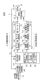
- FIG. 1 is a block diagram showing a continuously variable transmission system according to a first embodiment
- FIG. 2 is a vertical cross-sectional view showing the configuration of the continuously variable transmission of FIG. 1
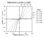
- 3 is a diagram showing an example of a relationship between relative slip of the angular velocity of the continuously variable transmission of FIG. 2 and output shaft torque.
- 3 is a diagram illustrating an example of a relationship between a speed ratio of the continuously variable transmission of FIG. 2 and an angular velocity of an input shaft.
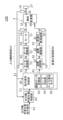
- FIG. FIG. 11 is a block diagram showing a continuously variable transmission system according to a second embodiment.
- FIG. 11 is a block diagram showing a continuously variable transmission system according to a third embodiment.
- the driving source is not limited as long as it can input rotation to the input shaft 22, and in this example, is exemplified by a motor 11.
- the motor 11 inputs rotation to the input shaft 22 of the continuously variable transmission 2.
- the continuously variable transmission 2 changes the speed of the rotation input to the input shaft 22 and outputs it to the output shaft 25.
- the continuously variable transmission 2 has a speed change mechanism 24 including a traction mechanism having a rolling element 41 and a raceway ring that contacts the rolling element 41.
- the rolling element 41 in this embodiment is a planetary rolling element that revolves while rotating on its own axis.
- the continuously variable transmission 2 drives a driven device 27 by the rotation of the output shaft 25.
- the input shaft information detection unit 14 detects rotation information related to the rotation of the input shaft 22, and outputs the detection result as input side information F2.
- the rotation of the input shaft 22 is also the output rotation of the motor 11.
- the output shaft information detection unit 16 detects rotation information related to the rotation of the output shaft 25, and outputs the detection result as detection result F1.
- the rotation of the output shaft 25 is also the input rotation of the driven device 27. Examples of rotation information include the angular velocity and angular position of the input shaft 22 and the output shaft 25.
- the detection result F1 in this example is the angular velocity of the output shaft 25.
- the gear ratio input detection unit 35 detects the physical quantity output by the gear ratio change device 31 to the gear ratio input unit 26, and outputs the detection result as gear ratio information F3.
- the input shaft information detection unit 14, the output shaft information detection unit 16, and the gear ratio input detection unit 35 are rotary encoders capable of detecting the angular position and angular velocity of the rotating shaft. These detection units may be composed of different types of sensors or the same type of sensor.
- the command signal supply unit 50 generates a rotation command signal S1 and a gear ratio command signal P1 based on a torque command signal C1 related to the torque of the output shaft 25 provided from a higher-level means and the detection result F1 of the output shaft information detection unit 16.
- the command signal supply unit 50 supplies the generated rotation command signal S1 to the input shaft control unit 10, and supplies the generated gear ratio command signal P1 to the gear ratio control unit 30.
- the higher-level means is not limited as long as it is an element capable of generating the torque command signal C1, and may be, for example, a higher-level control element.
- the higher-level means may be provided within the system of the continuously variable transmission system 100.
- the torque command signal C1 related to the torque of the output shaft 25 may be a target value for the torque of the output shaft 25, and the detection result F1 may be a feedback value.
- the input shaft control unit 10 is an angular velocity control unit that controls the angular velocity of the input shaft 22, and provides motor drive power S3 to the motor 11 based on the rotation command signal S1.
- the motor 11 rotates based on the motor drive power S3, and inputs the rotation to the input shaft 22.
- the input shaft control unit 10 controls the angular velocity of the input shaft 22 through the motor 11.
- the input shaft control unit 10 of the embodiment has a motor control unit 13 and a motor drive unit 12.
- the motor control unit 13 compares the angular velocity of the input shaft 22 calculated from the input side information F2 with the rotation command signal S1, and provides the motor control signal S2 generated based on the result to the motor drive unit 12.
- the motor control unit 13 may be a PI controller.
- the motor drive unit 12 supplies motor drive power S3 to the motor 11 based on the motor control signal S2.
- the motor drive unit 12 may be a three-phase inverter.
- the gear ratio control unit 30 provides the device drive power P3 to the gear ratio change device 31 based on the gear ratio command signal P1.
- the gear ratio change device 31 changes the axial position of the gear ratio input unit 26 based on the device drive power P3, thereby changing the gear ratio of the continuously variable transmission 2.
- the gear ratio control unit 30 controls the gear ratio of the continuously variable transmission 2 through the gear ratio change device 31.
- the gear ratio control unit 30 of the embodiment has a device control unit 33 and a device drive unit 32.
- the device control unit 33 compares the axial position of the gear ratio input unit 26 calculated from the gear ratio information F3 with the gear ratio command signal P1, and provides a device control signal P2 generated based on the result to the device drive unit 32.
- the device drive unit 32 supplies device drive power P3 to the gear ratio change device 31 based on the device control signal P2.
- the device drive unit 32 may be a three-phase inverter.
- the gear ratio change device 31 is not particularly limited in terms of its specific type, as long as it can change the gear ratio of the continuously variable transmission 2.
- a linear actuator or a rotary actuator can be used as the gear ratio change device 31.
- the gear ratio change device 31 of the embodiment is a device that combines a rotary actuator with a motion conversion mechanism that converts rotational motion into linear motion, and inputs power along the axial direction of the continuously variable transmission 2 to the gear ratio input unit 26 of the continuously variable transmission 2.
- the gear ratio change device 31 can use a device based on a known principle, such as a servo motor, a stepping motor, or an ultrasonic motor, as the rotary actuator.
- the gear ratio change device 31 can use a mechanism based on a known principle, such as a ball screw, a rack and pinion, or a cam, as the motion conversion mechanism.
- the rotary actuator and the motion conversion mechanism may be connected via a known transmission mechanism, such as a gear, a chain, or a belt.
- the motor 11 in this embodiment is an electric motor that uses electrical energy to rotate a motor shaft (not shown).
- the motor 11 rotates the motor shaft using torque generated by the cooperation of a stator (not shown) and a rotor (not shown), and outputs the rotation from the motor shaft to the continuously variable transmission 2.
- a stator not shown
- a rotor not shown
- the motor 11 may be, for example, a DC motor or an AC motor other than a servo motor.
- the continuously variable transmission 2 includes an input shaft 22, a transmission mechanism 24, and a gear ratio change mechanism 23.
- the rotation to be changed is input from the motor 11 to the input shaft 22.
- the transmission mechanism 24 changes the speed of the rotation input to the input shaft 22 and transmits it to the output shaft 25.
- the continuously variable transmission 2 outputs the rotation changed in the transmission mechanism 24 from the output shaft 25 to the driven device 27.
- the gear ratio change mechanism 23 changes the gear ratio of the transmission mechanism 24.
- the rotation of the motor 11 refers to the rotation of the object rotating in the motor 11, and in this example refers to the rotation of the output shaft of the motor 11.
- the rotation of the driven device 27 refers to the rotation of the object rotating in the driven device 27.
- the continuously variable transmission 2 can change the actual gear ratio, which is the actual gear ratio, steplessly or continuously by using the gear ratio changing device 31 and the gear ratio changing mechanism 23.
- the gear ratio here means the ratio of the output angular velocity, which is the angular velocity of the output shaft 25, to the input angular velocity, which is the angular velocity of the input shaft 22. This ratio is obtained by dividing the output angular velocity by the input angular velocity.
- the continuously variable transmission 2 of this embodiment is an infinitely variable gear ratio transmission, and is configured so that the variable range of the actual gear ratio includes zero.
- An infinitely variable gear ratio transmission is sometimes called an "Infinitely Variable Transmission," and the abbreviation "IVT" is sometimes used.
- the actual gear ratio being zero means that the actual gear ratio is 1/ ⁇ .
- an example of such a continuously variable transmission 2 will be described, but the specific example is not particularly limited.
- the input shaft 22 includes an input member 221 to which rotation is input from the motor 11, a shaft 222 connected to the input member 221, and a sleeve 223 fixed to the shaft 222.
- the specific structure of the input shaft 22 as long as it can transmit rotation from the motor 11 to the speed change mechanism 24.
- the input shaft 22 is made up of multiple members, but it may also be made up of a single member, and the number of members is not particularly limited.
- the speed change mechanism 24 includes an input raceway 40 rotatably mounted on the input shaft 22, a first support raceway 42 rotatably supported on the input shaft 22, a second support raceway 46 axially movable within a casing 44 of the continuously variable transmission 2, an output raceway 48 rotatably mounted on the output shaft 25, and a plurality of rolling bodies 41.
- the raceways 40, 42, 46, and 48 are collectively referred to simply as raceways.
- the rolling bodies 41 roll on the raceways 40, 42, 46, and 48.
- the rolling bodies 41 are pressed against the output raceway 48 by a pressing force applied from the second support raceway 46 by a pressing force applying mechanism (not shown).
- the rolling elements 41 rotate about the rotation axis LB while revolving around the rotation axis LA, which is the revolution axis of the input shaft 22.
- the output raceway 48 rotates about the rotation axis LA in response.
- the output raceway 48 rotates at an output angular velocity obtained by multiplying the input angular velocity of the input shaft 22 by the gear ratio.
- This gear ratio is determined according to the inclination angle of the rotation axis LB relative to the rotation axis LA, and is changed by the gear ratio change mechanism 23.
- the output shaft 25 includes an output raceway 48 and an output member 251 that is connected to the output raceway 48 so as to rotate integrally with the output raceway 48 and outputs rotation to the driven device 27.
- the output shaft 25 is made up of multiple members, but it may also be made up of a single member, and the number of members is not particularly limited.
- the gear ratio change mechanism 23 of this embodiment can change the gear ratio by changing the attitude of the input raceway 40.
- the gear ratio change mechanism 23 includes a shaft-shaped gear ratio input section 26 that can move axially by the power output from the gear ratio change device 31, and a ring member 232 that can move axially together with the gear ratio input section 26.
- the ring member 232 rotatably supports the input shaft 22 via a bearing 233, and can move axially together with the input shaft 22 by a retaining ring or the like.
- Specific examples of the gear ratio change mechanism 23 are not particularly limited, and various mechanisms similar to those used in the continuously variable transmission 2 may be used.
- the input shaft 22 including the input race 40 and the first support race 42 moves axially together with the ring member 232.
- the input race 40 and the first support race 42 move axially relative to the second support race 46 and the output race 48, changing the inclination angle of the rotation axis LB of the rolling elements 41 relative to the rotation axis LA, and changing the gear ratio according to the inclination angle.
- This gear ratio becomes zero when the rotation axis LB is parallel to the rotation axis LA, and increases continuously as the inclination angle of the rotation axis LB relative to the rotation axis LA increases.
- the actual gear ratio can be changed steplessly or continuously, and is configured to include zero in its variable range.
- FIG. 3 is a diagram showing an example of the relationship between the slip R1 and torque T1 of the continuously variable transmission 2.
- the horizontal axis shows slip R1
- the vertical axis shows torque T1.
- the diagram shows a case where the angular velocity of the output shaft 25 is 2 (rad/s).
- the zero and positive regions of torque T1 indicate a power running state, and the negative region indicates a regenerative state.
- q1, q2, q3, q4, q5, q6, and q7 indicate the relationship between the slip R1 and torque T1 corresponding to the gear ratio.
- a slip R1 corresponding to the torque T1 occurs between the input shaft 22 and the output shaft 25.
- the slip R1 can be defined by Equation 1.
- Slip R1 [1 - output shaft angular velocity / (gear ratio x input shaft angular velocity)] ... (Equation 1)
- the slip R1 is shown as a percentage.
- the torque T1 is approximately zero, and the torque T1 increases approximately nonlinearly as the slip R1 increases. Note that these relationships can be interpreted as a relationship in which the slip R1 increases as the torque T1 increases, or as a relationship in which the torque T1 increases as the slip R1 increases.
- the relationship between slip R1 and torque T1 changes significantly depending on the gear ratio.
- the relationship between slip R1 and torque T1 is nonlinear and changes depending on the gear ratio, so if the output of the continuously variable transmission 2 is controlled based on a target without taking into account the relationship between slip R1 and torque T1, it is difficult to improve control accuracy.
- the output of the continuously variable transmission 2 is the torque of the output shaft 25, the angular velocity of the output shaft 25, and the angular position of the output shaft 25.
- the command signal supply unit 50 generates a rotation command signal S1 and a gear ratio command signal P1 using relationship data D1 between the torque T1 and slip R1 of the continuously variable transmission 2.
- the continuously variable transmission system 100 includes a relationship data storage unit 52 that stores the relationship data D1.
- the relationship data storage unit 52 is provided within the command signal supply unit 50, but may be provided outside the command signal supply unit 50.
- the relationship data D1 can be obtained in advance by actually measuring or simulating the relationship between the torque T1 and slip R1 for the continuously variable transmission 2.
- the gear ratio command signal P1 and the rotation command signal S1 can also be generated simultaneously.
- the command signal supply unit 50 of this embodiment generates either the gear ratio command signal P1 or the rotation command signal S1 using the relationship data D1, and generates the other command signal from the one generated command signal.
- the generation algorithm is simplified and can be configured with a small-scale device.
- the gear ratio command signal P1 is generated using the relationship data D1, and the rotation command signal S1 is generated from the generated gear ratio command signal P1.
- the continuously variable transmission system 100 has a powering state in which the continuously variable transmission 2 provides positive kinetic energy to the driven device 27, and a regenerative state in which the continuously variable transmission 2 provides negative kinetic energy to the driven device 27.
- the powering state includes a state in which neither positive nor negative kinetic energy is provided.
- the command signal supply unit 50 switches the generation algorithm between a powering mode corresponding to the powering state and a regenerative mode corresponding to the regenerative state.
- the command signal supply unit 50 has a powering mode and a regenerative mode as generation modes for generating the gear ratio command signal P1 and the rotation command signal S1, and generates the gear ratio command signal P1 and the rotation command signal S1 in either the powering mode or the regenerative mode based on the mode discrimination result of the mode discrimination unit 54.
- the control accuracy can be improved by using a generation algorithm suitable for each mode.
- the generation algorithm may be, for example, a transfer function.
- the polarity of the slip R1 value changes between the powering state and the regenerative state.
- the slip R1 value has a positive polarity in the powering state and a negative polarity in the regenerative state, so the mode can be determined according to the polarity of the slip R1 value calculated from the angular velocity of the input shaft 22, the angular velocity of the output shaft 25, and the gear ratio by the gear ratio input unit 26.
- the mode discrimination unit 54 discriminates between the powering mode and the regenerative mode based on the detection result F1, which is the detection result of the output shaft information detection unit 16, and the input side information F2, which is the detection result of the input shaft information detection unit 14.
- the mode discrimination unit 54 determines whether or not the regenerative state is in effect based on the relationship between the angular velocity of the input shaft 22 and the angular velocity of the output shaft 25, and discriminates the regenerative mode if the regenerative state is in effect, and discriminates the powering mode if the regenerative state is not in effect.
- the command signal supply unit 50 generates the gear ratio command signal P1 by calculation using a torque generation model 55 of the motor 11 and the continuously variable transmission 2.
- the torque generation model 55 is a model that takes three parameters, the gear ratio, the angular velocity of the input shaft 22, and the angular velocity of the output shaft 25, as input, and outputs the torque of the output shaft 25, and incorporates relationship data D1.
- the torque generation model 55 can be obtained in advance by measuring or simulating the relationship between the torque T1, the gear ratio, the angular velocity of the input shaft 22, and the angular velocity of the output shaft 25 for the motor 11 and the continuously variable transmission 2.
- the command signal supply unit 50 has two torque generation models 55, one for the powering mode and one for the regenerative mode, and switches between them based on the mode discrimination result.
- the angular velocity of the input shaft 22 can be calculated from the input side information F2, and the angular velocity of the output shaft 25 can be calculated from the detection result F1.
- the rotation command signal S1 can be generated by substituting the generated gear ratio command signal P1 and the angular velocity of the input shaft 22 into a calculation model.
- This calculation model can be obtained in advance by actually measuring or simulating the relationship between the gear ratio command signal P1 and the angular velocity of the input shaft 22.
- FIG. 4 is a diagram showing an example of the relationship between the gear ratio and the angular velocity of the input shaft 22.
- the horizontal axis shows the gear ratio
- the vertical axis shows the angular velocity.
- the relationship between the gear ratio and the angular velocity of the input shaft 22 can have a variety of characteristics, such as a linear characteristic shown in g1, a convex curve characteristic shown in g2, and a concave curve characteristic shown in g3.
- the relationship between the gear ratio and the angular velocity of the input shaft 22 can be specified in advance and incorporated into a calculation model that generates the rotation command signal S1.
- the relationship between the gear ratio and the angular velocity of the input shaft 22 can be regarded as correction information that corrects the transfer function of the command signal supply unit 50.
- a method using a learning model can be adopted.
- This learning model can be generated in advance by machine learning based on a data set of the torque of the output shaft 25, the gear ratio, the angular velocity of the input shaft 22, and the actual measured values of the angular velocity of the output shaft 25 collected for the motor 11 and the continuously variable transmission 2.
- the learning model can be generated using known machine learning methods such as a support vector machine, a neural network including deep learning, or a random forest, and is stored in a memory unit (not shown) in the command signal supply unit 50.
- the continuously variable transmission system 100 of this embodiment configured as described above controls the motor 11 and the gear ratio change device 31 so that the torque of the output shaft 25 of the continuously variable transmission 2 approaches the target value, using the torque command signal C1 as a target value, and drives the driven device 27 by the rotation of the output shaft 25.
- the continuously variable transmission system 100 includes a continuously variable transmission 2 having rolling elements 41 and raceways in contact with the rolling elements 41, which changes the speed of the rotation of the input shaft 22 and outputs it to the output shaft 25, a motor 11 which inputs the rotation to the input shaft 22, an input shaft control unit 10 which controls the angular velocity of the input shaft 22 through the motor 11, a gear ratio change device 31 which changes the gear ratio of the continuously variable transmission 2, a gear ratio control unit 30 which controls the gear ratio through the gear ratio change device 31, an output shaft information detection unit 16 which detects the rotation information of the output shaft 25, and a command signal supply unit 50 which supplies a gear ratio command signal P1 to the gear ratio control unit 30 and a rotation command signal S1 to the input shaft control unit 10 based on a torque command signal C1 related to the torque of the output shaft 25 and a detection result F1 which is the detection result of the output shaft information detection unit 16.
- the torque of the output shaft 25 of the continuously variable transmission 2 can be controlled based on the torque command signal C1 related to the torque of the output shaft 25, making it possible to control the torque of the output shaft 25 of the continuously variable transmission 2 with high precision.
- FIG. 5 is a block diagram of the continuously variable transmission system 100 of this embodiment.
- the continuously variable transmission system 100 of this embodiment differs from the first embodiment in that it includes an angular velocity control unit 60 that provides a torque command signal C1 to a command signal supply unit 50 based on the angular velocity of the output shaft 25 detected by the output shaft information detection unit 16 and an angular velocity command signal J1 related to the angular velocity of the output shaft 25, but the other configurations are similar. Therefore, the differences will be mainly described.
- the angular velocity command signal J1 is provided from a higher-level means.
- This higher-level means is not limited as long as it is an element capable of generating the angular velocity command signal J1, and may be, for example, a higher-level control element.
- the higher-level means may be provided within the system of the continuously variable transmission system 100.
- the angular velocity command signal J1 may be a target value for the angular velocity of the output shaft 25, and the detection result F1 may be a feedback value.
- the continuously variable transmission system 100 of this embodiment uses the angular velocity command signal J1 as a target value, controls the motor 11 and the gear ratio change device 31 so that the angular velocity of the output shaft 25 of the continuously variable transmission 2 approaches the target value, and drives the driven device 27 by the rotation of the output shaft 25. This makes it possible to control the angular velocity of the output shaft 25 of the continuously variable transmission 2 with high precision.
- the continuously variable transmission system 100 of this embodiment exerts the same functions and effects as those of the first embodiment to the extent that there is no contradiction.
- the above is a description of the second embodiment.
- the continuously variable transmission system 100 of this embodiment controls the output rotation of the continuously variable transmission 2, which drives the driven device 27, based on an angle position command signal K1 provided from outside the system.
- the continuously variable transmission system 100 of this embodiment controls the output rotation of the continuously variable transmission 2, which drives the driven device 27, based on an angular position command signal K1 provided from outside the system.
- the angular position control unit 62 calculates the output shaft 25 from the detection result F1 of the output shaft 25 detected by the output shaft information detection unit 16, compares the calculation result with the angular position command signal K1, and generates and outputs a torque command signal C1 for the output shaft 25 based on the comparison result.
- the angular position command signal K1 is provided from a higher-level means.
- This higher-level means is not limited as long as it is an element capable of generating the angular position command signal K1, and may be, for example, a higher-level control element.
- the higher-level means may be provided within the continuously variable transmission system 100 or may be provided outside the system.
- the angular position command signal K1 may be a target value for the angular position of the output shaft 25, and the detection result F1 may be a feedback value.
- the continuously variable transmission system 100 of this embodiment uses the angular position command signal K1 as a target value, controls the motor 11 and the gear ratio change device 31 so that the angular position of the output shaft 25 of the continuously variable transmission 2 approaches the target value, and drives the driven device 27 by the rotation of the output shaft 25. This makes it possible to control the angular position of the output shaft 25 of the continuously variable transmission 2 with high precision.
- the continuously variable transmission system 100 of this embodiment exerts the same functions and effects as those of the first embodiment to the extent that there is no contradiction.
- the above is a description of the third embodiment.
- the angular velocity of the input shaft 22 is directly controlled, but the angular velocity of the input shaft 22 may be indirectly controlled by controlling the input shaft torque or input shaft angle.
- the mode was determined according to the value of slip R1 calculated from the angular velocity of the input shaft 22, the angular velocity of the output shaft 25, and the gear ratio by the gear ratio input unit 26, but the present disclosure is not limited to this.
- the powering mode and the regenerative mode may be determined according to the product of the angular velocity of the output shaft and the torque command signal C1. If the product of the angular velocity of the output shaft and the torque command signal C1 is zero or positive polarity, it is determined to be the powering mode, and if it is negative polarity, it is determined to be the regenerative mode.
- the powering mode and the regenerative mode may also be determined by a calculation model that includes the angular velocity of the input shaft, the angular velocity of the output shaft, and the torque command signal C1 as parameters.
- This calculation model can be obtained in advance by measuring or simulating the characteristics of the continuously variable transmission.
- the motor shaft and the input shaft of the continuously variable transmission are directly connected, but the present disclosure is not limited to this.
- the motor shaft and the input shaft of the continuously variable transmission may be connected via various well-known transmission mechanisms such as gears, chains, and belts.
- the gear ratio input detection unit 35 is a rotary encoder, but the present disclosure is not limited to this.
- the gear ratio input detection unit 35 may be a linear encoder.
- each control unit of the continuously variable transmission system 100 performs feedback control
- the present disclosure is not limited to this.
- any of the control units of the continuously variable transmission system 100 may perform feedforward control.
- the continuously variable transmission system 100 may be equipped with a state estimation unit that uses an observer.
- mode discrimination unit 54 is provided within the command signal supply unit 50, but the mode discrimination unit may also be provided outside the command signal supply unit.
- This disclosure relates to a continuously variable transmission system, a continuously variable transmission, and a method for controlling a continuously variable transmission system.
Landscapes
- Engineering & Computer Science (AREA)
- General Engineering & Computer Science (AREA)
- Mechanical Engineering (AREA)
- Control Of Transmission Device (AREA)
Abstract
無段変速機システム100は、転動体および転動体と接触する軌道輪を有し、入力軸22の回転を変速して出力軸25に出力する無段変速機2と、入力軸22に回転を入力する駆動源と、駆動源を通じて入力軸22の回転を制御する入力軸制御部10と、無段変速機2の変速比を変更する変速比変更装置31と、変速比変更装置31を通じて変速比を制御する変速比制御部30と、出力軸25の回転情報を検出する出力軸情報検出部16と、出力軸25に関する出力指令信号と、出力軸情報検出部16の検出結果F1とに基づいて、変速比制御部30への変速比指令信号P1および入力軸制御部10への回転指令信号S1を供給する指令信号供給部50と、を備える。
Description
本開示は、無段変速機システム、無段変速機、および無段変速機システムの制御方法に関する。
IVT(Infinitely Variable Transmission)と呼ばれ、無限大の変速比が可能な無段変速機が知られている。本出願人は、特許文献1において、入力軌道輪と、遊星転動体と、出力軌道輪とを備える摩擦伝動装置の技術を開示した。この装置では、遊星転動体は、入力軌道輪の回転軸周りに配置され入力軌道輪に接触し、出力軌道輪は、遊星転動体と接触し出力軸と連結される。また、この装置は、遊星転動体に接触する複数の支持軌道輪を有しており、入力軌道輪に入力された回転を変速して出力軸から出力する。
本発明者は、無段変速機について以下の認識を得た。特許文献1に記載の無段変速機は、接触する部材間で回転伝達するトラクション機構を備えているため、入力軸角速度に変速比を乗算した結果に対して出力軸角速度が小さいという角速度の相対滑りが生じる。この角速度の相対滑りは、無段変速機の出力を高精度に制御する際のネックとなっていた。
本開示は、このような課題に鑑みてなされたもので、無段変速機の出力を高精度に制御することが可能な無段変速機システムを提供することを目的の一つとする。
上記課題を解決するために、本開示のある態様の無段変速機システムは、転動体および転動体と接触する軌道輪を有し、入力軸の回転を変速して出力軸に出力する無段変速機と、入力軸に回転を入力する駆動源と、駆動源を通じて入力軸の回転を制御する入力軸制御部と、無段変速機の変速比を変更する変速比変更装置と、変速比変更装置を通じて変速比を制御する変速比制御部と、出力軸の回転情報を検出する出力軸情報検出部と、出力軸に関する出力指令信号と、出力軸情報検出部の検出結果とに基づいて、変速比制御部への変速比指令信号および入力軸制御部への回転指令信号を供給する指令信号供給部と、を備える。
本開示の別の態様は、無段変速機である。この無段変速機は、転動体および転動体と接触する軌道輪を有し、入力軸の回転を変速して出力軸に出力する無段変速機であって、出力軸の回転に関する出力指令信号と、出力軸の回転情報とに基づいて、本無段変速機の変速比および入力軸の回転が制御される。
本開示のさらに別の態様は、無段変速機システムの制御方法である。この方法は、転動体および転動体と接触する軌道輪を有し、入力軸の回転を変速して出力軸に出力する無段変速機と、無段変速機の変速比を変更する変速比変更装置と、を備える無段変速機システムの制御方法について、出力軸の回転情報を検出することと、出力軸の回転に関する出力指令信号と、回転情報とに基づいて無段変速機の変速比および入力軸の回転を制御することと、を含む。
なお、以上の構成要素の任意の組み合わせや、本開示の構成要素や表現を方法、システムなどの間で相互に置換したものもまた、本開示の態様として有効である。
本開示によれば、無段変速機の出力を高精度に制御することが可能な無段変速機システムを提供できる。
以下、本開示を好適な実施形態をもとに各図面を参照しながら説明する。実施形態および変形例では、同一または同等の構成要素、部材には、同一の符号を付するものとし、適宜重複した説明は省略する。また、各図面における部材の寸法は、理解を容易にするために適宜拡大、縮小して示される。また、各図面において実施形態を説明する上で重要ではない部材の一部は省略して表示する。
また、第1、第2などの序数を含む用語は多様な構成要素を説明するために用いられるが、この用語は一つの構成要素を他の構成要素から区別する目的でのみ用いられ、この用語によって構成要素が限定されるものではない。
[第1実施形態]
図1-4を参照して、本開示の第1実施形態に係る無段変速機システム100を説明する。図1は、無段変速機システム100のブロック図である。図2は、無段変速機2の構成を示す縦断面図である。
図1-4を参照して、本開示の第1実施形態に係る無段変速機システム100を説明する。図1は、無段変速機システム100のブロック図である。図2は、無段変速機2の構成を示す縦断面図である。
無段変速機システム100は、システム外から提供されるトルク指令信号C1に基づいて被駆動装置27を駆動する無段変速機2の出力回転を制御する。なお、トルク指令信号C1と、後述する角速度指令信号J1および角度位置指令信号K1を総括して出力指令信号ということがある。説明の便宜上、図2において、無段変速機2の軸方向を単に「軸方向」といい軸方向右側を入力側といい、その反対側を反入力側という。
図1に示すように、無段変速機システム100は、無段変速機2と、モータ11と、入力軸制御部10と、変速比変更装置31と、変速比制御部30と、指令信号供給部50と、入力軸情報検出部14と、出力軸情報検出部16と、変速比入力検出部35とを主に備える。本実施形態の無段変速機システム100は、無段変速機2の出力トルクが与えられた目標値に近づくように制御する。
図1、図5、図6に示す各機能ブロックは、ハードウェア的には、コンピュータのプロセッサ、CPU、メモリをはじめとする素子や電子回路、機械装置で実現でき、ソフトウェア的にはコンピュータプログラム等によって実現されるが、ここでは、それらの連携によって実現される機能ブロックを描いている。したがって、これらの機能ブロックはハードウェア、ソフトウェアの組合せによっていろいろなかたちで実現できることは、当業者には理解されるところである。本実施形態の入力軸制御部10、変速比制御部30、指令信号供給部50および後述する角速度制御部60、角度位置制御部62は、主にCPUと、そのプログラムによって実現されている。
駆動源は、入力軸22に回転を入力可能なものであれば制限はなく、この例ではモータ11に例示される。モータ11は、無段変速機2の入力軸22に回転を入力する。無段変速機2は、入力軸22に入力された回転を変速して出力軸25に出力する。無段変速機2は、転動体41および転動体41と接触する軌道輪を有するトラクション機構を含む変速機構24を有する。本実施形態の転動体41は、自転しながら公転する遊星転動体である。例えば、無段変速機2は、出力軸25の回転により被駆動装置27を駆動する。
無段変速機2は、変速機構24の変速比を変更するための動力を受け付ける変速比入力部26を有する。この動力によって、変速比入力部26の軸方向位置が変化し、これにより変速比が変化する。変速比変更装置31は、変速比入力部26に動力を出力して無段変速機2の変速比を変更する。変速比制御部30は、変速比変更装置31を通じて変速比を制御する。なお、本明細書でいう変速機構24の変速比は、変速機構24の構成部材の機械寸法から定義される理想変速比をいう。現実の変速比は、後述する角速度の相対滑りの影響を受けるため、理想変速比から若干のずれを生じる。
入力軸情報検出部14は、入力軸22の回転に関する回転情報を検出し、その検出結果を入力側情報F2として出力する。入力軸22の回転は、モータ11の出力回転でもある。出力軸情報検出部16は、出力軸25の回転に関する回転情報を検出し、その検出結果を検出結果F1として出力する。出力軸25の回転は、被駆動装置27の入力回転でもある。回転情報としては、例えば、入力軸22および出力軸25の角速度、角度位置等が挙げられる。この例の検出結果F1は出力軸25の角速度である。変速比入力検出部35は、変速比変更装置31が変速比入力部26に出力する物理量を検出し、その検出結果を変速比情報F3として出力する。
本実施形態の入力軸情報検出部14、出力軸情報検出部16、および変速比入力検出部35は、回転軸の角度位置および角速度を検出可能なロータリーエンコーダである。これらの検出部は、互いに別種類のセンサで構成されてもよいし、同じ種類のセンサで構成されてもよい。
指令信号供給部50は、上位の手段から与えられる出力軸25のトルクに関するトルク指令信号C1と、出力軸情報検出部16の検出結果F1とに基づいて、回転指令信号S1および変速比指令信号P1を生成する。指令信号供給部50は、生成された回転指令信号S1を入力軸制御部10に供給し、生成された変速比指令信号P1を変速比制御部30に供給する。上位手段は、トルク指令信号C1を生成可能な要素であれば、限定はなく、例えば、上位の制御要素であってもよい。上位手段は、無段変速機システム100のシステム内に設けられてもよい。出力軸25のトルクに関するトルク指令信号C1は、出力軸25のトルクの目標値であり、検出結果F1は帰還値であってもよい。
入力軸制御部10は、入力軸22の角速度を制御する角速度制御部であり、回転指令信号S1に基づいてモータ駆動電力S3をモータ11に提供する。モータ11は、モータ駆動電力S3に基づいて回転し、その回転を入力軸22に入力する。つまり、入力軸制御部10は、モータ11を通じて入力軸22の角速度を制御する。
実施形態の入力軸制御部10は、モータ制御部13と、モータ駆動部12とを有する。モータ制御部13は、入力側情報F2から計算して得た入力軸22の角速度を回転指令信号S1と比較し、その結果に基づいて生成したモータ制御信号S2をモータ駆動部12に与える。一例として、モータ制御部13はPI制御器であってもよい。モータ駆動部12は、モータ制御信号S2に基づいてモータ11にモータ駆動電力S3を供給する。一例として、モータ駆動部12は、3相インバータであってもよい。
変速比制御部30は、変速比指令信号P1に基づいて装置駆動電力P3を変速比変更装置31に提供する。変速比変更装置31は、装置駆動電力P3に基づいて変速比入力部26の軸方向位置を変化させ、これにより無段変速機2の変速比を変更する。つまり、変速比制御部30は、変速比変更装置31を通じて無段変速機2の変速比を制御する。
実施形態の変速比制御部30は、装置制御部33と、装置駆動部32とを有する。装置制御部33は、変速比情報F3から計算して得た変速比入力部26の軸方向位置を変速比指令信号P1と比較し、その結果に基づいて生成した装置制御信号P2を装置駆動部32に与える。装置駆動部32は、装置制御信号P2に基づいて変速比変更装置31に装置駆動電力P3を供給する。一例として、装置駆動部32は、3相インバータであってもよい。
変速比変更装置31は、無段変速機2の変速比を変更できれば、その具体的な種類は特に限定されない。変速比変更装置31としては、例えば、リニアアクチュエータやロータリーアクチュエータを採用できる。実施形態の変速比変更装置31は、ロータリーアクチュエータに回転運動を直線運動に変換する運動変換機構を組み合わせた装置であり、無段変速機2の軸方向に沿った動力を無段変速機2の変速比入力部26に入力する。変速比変更装置31は、ロータリーアクチュエータとしてサーボモータ、ステッピングモータ、超音波モータ等の公知の原理に基づく装置を使用できる。変速比変更装置31は、運動変換機構としてボールねじ、ラック&ピニオン、カム等の公知の原理に基づく機構を使用できる。ロータリーアクチュエータと運動変換機構とは、ギヤ、チェーン、ベルト等の公知の伝達機構を介して接続されてもよい。
本実施形態のモータ11は、電気エネルギーを用いてモータ軸(不図示)を回転させる電動モータである。モータ11は、ステータ(不図示)およびロータ(不図示)が協働して発生させたトルクによりモータ軸を回転させたうえで、その回転をモータ軸から無段変速機2に出力する。モータ11の種類に限定はなく、この例ではサーボモータである。モータ11は、例えば、サーボモータ以外のDCモータやACモータであってもよい。
無段変速機2の概略動作を説明する。無段変速機2は、入力軸22と、変速機構24と、変速比変更機構23とを備える。入力軸22には、モータ11から変速対象の回転が入力される。変速機構24は、入力軸22に入力された回転を変速したうえで出力軸25に伝達する。無段変速機2は、変速機構24で変速された回転を出力軸25から被駆動装置27に出力する。変速比変更機構23は、変速機構24の変速比を変更する。
以下、モータ11の回転は、モータ11において回転している物体の回転をいい、この例ではモータ11の出力軸の回転をいう。また、被駆動装置27の回転は、被駆動装置27において回転している物体の回転をいう。
本実施形態の無段変速機2の具体的な構成を説明する。無段変速機2は、変速比変更装置31によって、変速比変更機構23を用いて実際の変速比である実変速比を無段階または連続的に変更可能である。ここでの変速比は、入力軸22の角速度である入力角速度に対する出力軸25の角速度である出力角速度の比を意味する。この比は、出力角速度を入力角速度で除算することにより得られる。実施形態の無段変速機2は、変速比無限大無段変速機であり、実変速比の可変範囲にゼロを含むように構成される。変速比無限大無段変速機は、「Infinitely Variable Transmission」と称されることがあり、略語として「IVT」が使用されることがある。実変速比がゼロとは実変速比が1/∞である場合である。ここでは、このような無段変速機2の一例を説明するが、その具体例は特に限定されない。
入力軸22は、モータ11から回転が入力される入力部材221と、入力部材221に連結されるシャフト222と、シャフト222に固定されるスリーブ223と、を備える。入力軸22は、モータ11から変速機構24に回転を伝達できれば、その具体的な構造は特に限定されない。ここでの入力軸22は、複数部材により構成される例を示すが、単数部材により構成されてもよいし、その部材数も特に限定されない。
変速機構24は、入力軸22に一体回転可能に設けられる入力軌道輪40と、入力軸22に回転可能に支持される第1支持軌道輪42と、無段変速機2のケーシング44内に軸方向に移動可能に設けられる第2支持軌道輪46と、出力軸25に一体回転可能に設けられる出力軌道輪48と、複数の転動体41とを備える。軌道輪40、42、46、48を総称するときは単に軌道輪という。複数の転動体41は、各軌道輪40、42、46、48を転動する。複数の転動体41は、押付力付与機構(不図示)により第2支持軌道輪46から付与される押付力により出力軌道輪48に押し付けられる。
入力軌道輪40が回転すると、転動体41が自転軸LB周りに自転しながら入力軸22の公転軸である回転軸線LA周りに公転する。転動体41が公転すると、それに追従して出力軌道輪48が回転軸線LA周りに回転する。このとき、理想的には、出力軌道輪48は、入力軸22の入力角速度に変速比を乗じた出力角速度で回転する。この変速比は、回転軸線LAに対する自転軸LBの傾斜角度に応じて定まり、変速比変更機構23により変更される。
出力軸25は、出力軌道輪48と、出力軌道輪48と一体回転するように連結され被駆動装置27に回転を出力する出力部材251と、を備える。出力軸25は、変速機構24から被駆動装置27に回転を伝達できれば、その具体的な構造は特に限定されない。ここでの出力軸25は、複数部材により構成される例を示すが、単数部材により構成されてもよいし、その部材数も特に限定されない。
本実施形態の変速比変更機構23は、入力軌道輪40の姿勢を変更することで変速比を変更可能である。変速比変更機構23は、変速比変更装置31から出力される動力により軸方向移動可能なシャフト状の変速比入力部26と、変速比入力部26と一体的に軸方向移動可能なリング部材232と、を備える。リング部材232は、軸受233を介して入力軸22を回転自在に支持しており、止め輪等により入力軸22と一体的に軸方向移動可能である。変速比変更機構23の具体例は特に限定されず、無段変速機2に採用される同様の各種機構を採用してもよい。
変速比変更装置31から軸方向の動力が変速比入力部26に入力されると、リング部材232とともに入力軌道輪40及び第1支持軌道輪42を含む入力軸22が一体的に軸方向に移動する。第2支持軌道輪46及び出力軌道輪48に対して入力軌道輪40及び第1支持軌道輪42が軸方向に移動することで、転動体41の自転軸LBの回転軸線LAに対する傾斜角度が変更され、その傾斜角度に応じた変速比に変更される。この変速比は、自転軸LBが回転軸線LAと平行となるときにゼロとなり、回転軸線LAに対する自転軸LBの傾斜角度が大きくなるほど連続的に大きくなる。つまり、実変速比を無段階または連続的に変更可能であり、その可変範囲にゼロを含むように構成される。
本出願人は、特開2021-181812号公報、特開2022-135086号公報等によって、変速比無限大無段変速機の一例を開示しており、これらによって無段変速機の技術は当業者に理解されるところである。
次に図3を参照して、無段変速機2の出力軸トルクT1と、入力軸22および出力軸25の角速度の相対滑りR1との関係を説明する。以下、出力軸トルクT1を「トルクT1」と、角速度の相対滑りR1を「滑りR1」ということがある。図3は、無段変速機2の滑りR1とトルクT1との関係の一例を示す図である。この図では、横軸に滑りR1を示し、縦軸にトルクT1を示す。出力軸25の角速度が2(rad/s)である場合を示す。この図において、トルクT1がゼロおよびプラスの領域は力行状態を示し、マイナスの領域は回生状態を示す。q1、q2、q3、q4、q5、q6、q7は、変速比に対応する滑りR1とトルクT1の関係を示している。
無段変速機2は、互いに接触する転動体41および軌道輪を有するトラクション機構であるため、入力軸22と出力軸25との間でトルクT1に応じた滑りR1が生じる。滑りR1は、式1により定義できる。
滑りR1=[1-出力軸角速度/(変速比×入力軸角速度)]・・・(式1)
図3では、滑りR1を百分率で示している。図3に示すように、滑りR1がゼロの場合にトルクT1が略ゼロで、滑りR1の増加に応じてトルクT1が略非線形に増加する。なお、これらの関係は、トルクT1が増加することにより滑りR1が増加する関係と捉えることもできるし、滑りR1が増加することによりトルクT1が増加する関係と捉えることもできる。
滑りR1=[1-出力軸角速度/(変速比×入力軸角速度)]・・・(式1)
図3では、滑りR1を百分率で示している。図3に示すように、滑りR1がゼロの場合にトルクT1が略ゼロで、滑りR1の増加に応じてトルクT1が略非線形に増加する。なお、これらの関係は、トルクT1が増加することにより滑りR1が増加する関係と捉えることもできるし、滑りR1が増加することによりトルクT1が増加する関係と捉えることもできる。
また、図3に示すように、滑りR1とトルクT1の関係は変速比によって大幅に変化する。このように、滑りR1とトルクT1の関係は非線形であり、変速比によって変化するため、滑りR1とトルクT1の関係を考慮せずに、目標に基づいて無段変速機2の出力を制御すると、制御精度を向上させることが困難である。なお、無段変速機2の出力は、出力軸25のトルク、出力軸25の角速度、出力軸25の角度位置である。
上記を踏まえ、本実施形態では、一例として、指令信号供給部50は、無段変速機2のトルクT1と滑りR1との関係データD1を用いて回転指令信号S1および変速比指令信号P1を生成する。このために、無段変速機システム100は、関係データD1を記憶する関係データ記憶部52を備える。本実施形態では、関係データ記憶部52は、指令信号供給部50内に設けられているが、指令信号供給部50外に設けられてもよい。関係データD1は、無段変速機2についてトルクT1と滑りR1との関係を実測またはシミュレーションすることにより、予め取得できる。
変速比指令信号P1と回転指令信号S1とは、同時に生成することもできる。一例として、本実施形態の指令信号供給部50は、関係データD1を用いて変速比指令信号P1および回転指令信号S1のいずれか一方の指令信号を生成し、生成された一方の指令信号から他方の指令信号を生成する。この場合、生成アルゴリズムが簡素化され、小規模なデバイスで構成できる。本実施形態では、関係データD1を用いて変速比指令信号P1を生成し、回転指令信号S1は、生成された変速比指令信号P1から生成する。
無段変速機システム100は、無段変速機2が被駆動装置27に正の運動エネルギを与える力行状態と、無段変速機2が被駆動装置27に負の運動エネルギを与える回生状態とがある。なお、正負いずれの運動エネルギも与えない状態は力行状態に含まれる。本実施形態では、指令信号供給部50は、力行状態に対応する力行モードと、回生状態に対応する回生モードとで生成アルゴリズムを切り替えている。
具体的には、指令信号供給部50は、変速比指令信号P1および回転指令信号S1を生成する生成モードとして、力行モードと回生モードとを有し、モード判別部54のモード判別結果に基づいて、力行モードと回生モードのいずれかによって変速比指令信号P1および回転指令信号S1を生成する。この場合、それぞれのモードに適した生成アルゴリズムを用いることにより制御精度を向上できる。生成アルゴリズムは、例えば、伝達関数であってもよい。
力行状態と回生状態とで、滑りR1の値の極性が変化する。例えば、力行状態では滑りR1の値が正の極性となり、回生状態では負の極性となるので、入力軸22の角速度と出力軸25の角速度と変速比入力部26による変速比から計算される滑りR1の値の極性に応じてモード判別できる。
実施形態では、モード判別部54は、出力軸情報検出部16の検出結果である検出結果F1および入力軸情報検出部14の検出結果である入力側情報F2に基づいて力行モードと回生モードの判別を行う。特に、モード判別部54は、入力軸22の角速度と出力軸25の角速度との関係から回生状態であるか否かを判断し、回生状態であれば回生モードと判別し、回生状態でなければ力行モードと判別する。
指令信号供給部50における変速比指令信号P1の生成方法を説明する。指令信号供給部50では、モータ11および無段変速機2のトルク発生モデル55を用いた計算によって変速比指令信号P1を生成する。トルク発生モデル55は、変速比、入力軸22の角速度、および出力軸25の角速度の3個のパラメータを入力として、出力軸25のトルクを出力とするモデルであり、関係データD1が組み込まれている。トルク発生モデル55は、モータ11および無段変速機2についてトルクT1、変速比、入力軸22の角速度、および出力軸25の角速度の関係を実測またはシミュレーションすることにより、予め取得できる。指令信号供給部50は、力行モード用と、回生モード用の2つのトルク発生モデル55を有し、これらをモード判別結果に基づいて切り替えて使用する。
入力軸22の角速度は、入力側情報F2から算出でき、出力軸25の角速度は、検出結果F1から算出できる。
指令信号供給部50における回転指令信号S1の生成方法を説明する。回転指令信号S1は、生成された変速比指令信号P1と入力軸22の角速度を計算モデルに代入することによって生成できる。この計算モデルは、変速比指令信号P1と入力軸22の角速度の関係を実測またはシミュレーションすることにより、予め取得できる。
検討によると、変速比と入力軸22の角速度の関係は、互いに異なる複数の特性を有する。図4は、変速比と入力軸22の角速度との関係の一例を模式的に示す図である。この図では、横軸に変速比を示し、縦軸に角速度を示している。図4に示すように、変速比と入力軸22の角速度の関係は、g1に示す直線的な特性と、g2に示す凸曲線的な特性と、g3に示す凹曲線的な特性など多様な特性が考えられる。このため、変速比と入力軸22の角速度の関係を予め特定し、回転指令信号S1を生成する計算モデルに組み込むことができる。なお、変速比と入力軸22の角速度の関係は、指令信号供給部50の伝達関数を補正する補正情報と捉えることができる。
変速比指令信号P1および回転指令信号S1を生成するための別の方法として、学習モデルを用いる方法を採用できる。この学習モデルは、モータ11および無段変速機2について収集された出力軸25のトルク、変速比、入力軸22の角速度、および出力軸25の角速度の実測値をデータセットとして、このデータセットをもとに機械学習により、予め生成できる。学習モデルは、例えば、サポートベクターマシン、ディープラーニングを含むニューラルネットワーク、ランダムフォレスト等、公知の機械学習手法を用いて生成可能であり、指令信号供給部50内の記憶部(不図示)に格納される。学習モデルを用いることで、高精度な制御を実現可能な制御システムを柔軟に構成できる。
以上のように構成された本実施形態の無段変速機システム100は、トルク指令信号C1を目標値として、無段変速機2の出力軸25のトルクが目標値に近づくように、モータ11および変速比変更装置31を制御し、出力軸25の回転により被駆動装置27を駆動する。
以上のように構成された無段変速機システム100の特徴を説明する。無段変速機システム100は、転動体41および転動体41と接触する軌道輪を有し、入力軸22の回転を変速して出力軸25に出力する無段変速機2と、入力軸22に回転を入力するモータ11と、モータ11を通じて入力軸22の角速度を制御する入力軸制御部10と、無段変速機2の変速比を変更する変速比変更装置31と、変速比変更装置31を通じて変速比を制御する変速比制御部30と、出力軸25の回転情報を検出する出力軸情報検出部16と、出力軸25のトルクに関するトルク指令信号C1と、出力軸情報検出部16の検出結果である検出結果F1に基づいて、変速比制御部30への変速比指令信号P1および入力軸制御部10への回転指令信号S1を供給する指令信号供給部50と、を備える。
この構成によれば、出力軸25のトルクに関するトルク指令信号C1に基づいて、無段変速機2の出力軸25のトルクを制御できるため、無段変速機2の出力軸25のトルクを高精度に制御することが可能になる。
以上が、第1実施形態の説明である。
[第2実施形態]
図5を参照して、本開示の第2実施形態に係る無段変速機システム100を説明する。図5は、本実施形態の無段変速機システム100のブロック図である。本実施形態の無段変速機システム100は、第1実施形態に対して、出力軸情報検出部16で検出された出力軸25の角速度および出力軸25の角速度に関する角速度指令信号J1に基づいて、トルク指令信号C1を指令信号供給部50に与える角速度制御部60を備える点で相違し、他の構成は同様である。よって、相違点を重点的に説明する。
図5を参照して、本開示の第2実施形態に係る無段変速機システム100を説明する。図5は、本実施形態の無段変速機システム100のブロック図である。本実施形態の無段変速機システム100は、第1実施形態に対して、出力軸情報検出部16で検出された出力軸25の角速度および出力軸25の角速度に関する角速度指令信号J1に基づいて、トルク指令信号C1を指令信号供給部50に与える角速度制御部60を備える点で相違し、他の構成は同様である。よって、相違点を重点的に説明する。
本実施形態の無段変速機システム100は、システム外から提供される角速度指令信号J1に基づいて被駆動装置27を駆動する無段変速機2の出力回転を制御する。角速度制御部60は、出力軸情報検出部16で検出された出力軸25の検出結果F1から出力軸25の角速度を計算し、その計算結果を角速度指令信号J1と比較し、その比較結果に基づいて出力軸25のトルク指令信号C1を生成して出力する。
例えば、角速度指令信号J1は、上位の手段から与えられる。この上位手段は、角速度指令信号J1を生成可能な要素であれば限定はなく、例えば、上位の制御要素であってもよい。上位手段は、無段変速機システム100のシステム内に設けられてもよい。角速度指令信号J1は、出力軸25の角速度の目標値であり、検出結果F1は帰還値であってもよい。
以上のように構成された本実施形態の無段変速機システム100は、角速度指令信号J1を目標値として、無段変速機2の出力軸25の角速度が目標値に近づくように、モータ11および変速比変更装置31を制御し、出力軸25の回転により被駆動装置27を駆動する。このため、無段変速機2の出力軸25の角速度を高精度に制御することが可能になる。
本実施形態の無段変速機システム100は、矛盾しない範囲で、第1実施形態と同様の作用と効果を奏する。
以上が、第2実施形態の説明である。
以上が、第2実施形態の説明である。
[第3実施形態]
図6を参照して、本開示の第3実施形態に係る無段変速機システム100を説明する。図6は、本実施形態の無段変速機システム100のブロック図である。本実施形態の無段変速機システム100は、第1実施形態に対して、出力軸情報検出部16で検出された出力軸25の角度および出力軸25の角度位置に関する角度位置指令信号K1に基づいて、トルク指令信号C1を指令信号供給部50に与える角度位置制御部62を備える点で相違し他の構成は同様である。よって、相違点を重点的に説明する。
図6を参照して、本開示の第3実施形態に係る無段変速機システム100を説明する。図6は、本実施形態の無段変速機システム100のブロック図である。本実施形態の無段変速機システム100は、第1実施形態に対して、出力軸情報検出部16で検出された出力軸25の角度および出力軸25の角度位置に関する角度位置指令信号K1に基づいて、トルク指令信号C1を指令信号供給部50に与える角度位置制御部62を備える点で相違し他の構成は同様である。よって、相違点を重点的に説明する。
本実施形態の無段変速機システム100は、システム外から提供される角度位置指令信号K1に基づいて被駆動装置27を駆動する無段変速機2の出力回転を制御する。
本実施形態の無段変速機システム100は、システム外から提供される角度位置指令信号K1に基づいて被駆動装置27を駆動する無段変速機2の出力回転を制御する。角度位置制御部62は、出力軸情報検出部16で検出された出力軸25の検出結果F1から出力軸25を計算し、その計算結果を角度位置指令信号K1と比較し、その比較結果に基づいて出力軸25のトルク指令信号C1を生成して出力する。
例えば、角度位置指令信号K1は、上位の手段から与えられる。この上位手段は、角度位置指令信号K1を生成可能な要素であれば、限定はなく、例えば、上位の制御要素であってもよい。上位手段は、無段変速機システム100のシステム内に設けられてもよいし、システム外に設けられてもよい。角度位置指令信号K1は、出力軸25の角度位置の目標値であり、検出結果F1は帰還値であってもよい。
以上のように構成された本実施形態の無段変速機システム100は、角度位置指令信号K1を目標値として、無段変速機2の出力軸25の角度位置が目標値に近づくように、モータ11および変速比変更装置31を制御し、出力軸25の回転により被駆動装置27を駆動する。このため、無段変速機2の出力軸25の角度位置を高精度に制御することが可能になる。
本実施形態の無段変速機システム100は、矛盾しない範囲で、第1実施形態と同様の作用と効果を奏する。
以上が、第3実施形態の説明である。
以上が、第3実施形態の説明である。
以上、実施形態をもとに説明した。これらの実施形態は例示であり、いろいろな変形および変更が可能なこと、またそうした変形例および変更も本開示の特許請求の範囲にあることは当業者に理解されるところである。従って、本明細書での記述および図面は限定的ではなく例証的に扱われるべきものである。
(変形例)
以下、変形例を説明する。変形例の図面および説明では、実施形態と同一または同等の構成要素、部材には、同一の符号を付する。実施形態と重複する説明を適宜省略し、実施形態と相違する構成について重点的に説明する。
以下、変形例を説明する。変形例の図面および説明では、実施形態と同一または同等の構成要素、部材には、同一の符号を付する。実施形態と重複する説明を適宜省略し、実施形態と相違する構成について重点的に説明する。
上述の説明では、入力軸22の角速度を直接的に制御する例を示したが、入力軸トルクや入力軸角度を制御することによって、入力軸22の角速度を間接的に制御するようにしてもよい。
上述の説明では、入力軸22の角速度と出力軸25の角速度と変速比入力部26による変速比から計算される滑りR1の値に応じてモード判別する例を示したが本開示はこれに限定されない。例えば、出力軸の角速度と、トルク指令信号C1との積の値によって力行モードと回生モードの判別をしてもよい。出力軸の角速度と、トルク指令信号C1との積の値が、ゼロまたは正の極性であれば力行モード、負の極性であれば回生モードとしてもよい。
また、入力軸の角速度と、出力軸の角速度と、トルク指令信号C1をパラメータに含む計算モデルによって力行モードと回生モードの判別をしてもよい。この計算モデルは、無段変速機の特性を実測またはシミュレーションすることで予め取得できる。
上述の説明では、モータ軸と無段変速機の入力軸とは、直接接続される例を示したが本開示はこれに限定されない。例えば、モータ軸と無段変速機の入力軸とは、ギヤ、チェーン、ベルトといった公知の様々な伝達機構を介して接続されてもよい。
上述の説明では、変速比入力検出部35がロータリーエンコーダである例を示したが本開示はこれに限定されない。例えば、変速比入力検出部35はリニアエンコーダであってもよい。
上述の説明では、無段変速機システム100の各制御部がフィードバック制御する例を示したが本開示はこれに限定されない。例えば、無段変速機システム100の制御部のいずれかはフィードフォワード制御するものであってもよい。また、無段変速機システム100はオブザーバによる状態推定部を備えてもよい。
上述の説明では、モード判別部54が指令信号供給部50内に設けられる例を示したが、モード判別部は、指令信号供給部外に設けられてもよい。
これらの各変形例は、実施形態と同様の作用と効果を奏する。
上述した各実施形態と変形例の任意の組み合わせもまた本開示の実施形態として有用である。組み合わせによって生じる新たな実施形態は、組み合わされる実施形態および変形例それぞれの効果をあわせもつ。
本開示は、無段変速機システム、無段変速機、および無段変速機システムの制御方法に関する。
2 無段変速機、 10 入力軸制御部、 11 モータ、 12 モータ駆動部、 13 モータ制御部、 14 入力軸情報検出部、 16 出力軸情報検出部、 22 入力軸、 23 変速比変更機構、 25 出力軸、 26 変速比入力部、 30 変速比制御部、 31 変速比変更装置、 40 入力軌道輪、 41 転動体、 42 第1支持軌道輪、 46 第2支持軌道輪、 48 出力軌道輪、 50 指令信号供給部、 52 関係データ記憶部、 54 モード判別部、 55 トルク発生モデル、 60 角速度制御部、 62 角度位置制御部、 100 無段変速機システム。
Claims (11)
- 転動体および前記転動体と接触する軌道輪を有し、入力軸の回転を変速して出力軸に出力する無段変速機と、前記入力軸に回転を入力する駆動源と、
前記駆動源を通じて前記入力軸の回転を制御する入力軸制御部と、
前記無段変速機の変速比を変更する変速比変更装置と、
前記変速比変更装置を通じて変速比を制御する変速比制御部と、
前記出力軸の回転情報を検出する出力軸情報検出部と、
前記出力軸に関する出力指令信号と、前記出力軸情報検出部の検出結果とに基づいて、前記変速比制御部への変速比指令信号および前記入力軸制御部への回転指令信号を供給する指令信号供給部と、
を備える無段変速機システム。 - 前記入力軸制御部は、前記入力軸の角速度を制御する角速度制御部であることを特徴とする請求項1に記載の無段変速機システム
- 前記指令信号供給部は、前記無段変速機の出力軸トルクと前記入力軸および前記出力軸の角速度の相対滑りとの関係データを用いて前記入力軸制御部への前記回転指令信号および前記変速比指令信号を生成する、請求項1または2に記載の無段変速機システム。
- 前記指令信号供給部は、前記関係データを用いて前記変速比指令信号および前記回転指令信号のいずれか一方の指令信号を生成し、生成された一方の指令信号から他方の指令信号を生成する、請求項3に記載の無段変速機システム。
- 前記指令信号供給部は、前記変速比指令信号および前記回転指令信号を生成する生成モードとして、力行モードと回生モードとを有し、モード判別結果に基づいて、力行モードと回生モードのいずれかによって前記変速比指令信号および前記回転指令信号を生成する、請求項1から4のいずれかに記載の無段変速機システム。
- 前記入力軸の回転を検出する入力軸情報検出部を有し、
前記指令信号供給部は、前記出力軸情報検出部の検出結果および前記入力軸情報検出部の検出結果に基づいて力行モードと回生モードの判別を行うモード判別部を有する、請求項5に記載の無段変速機システム。 - 前記出力軸の角速度に関する角速度指令信号と、前記出力軸情報検出部で検出された前記出力軸の角速度とに基づいて、前記出力指令信号を前記指令信号供給部に与える角速度制御部を備える、請求項1から6のいずれかに記載の無段変速機システム。
- 前記出力軸の角度位置に関する角度位置指令信号と、前記出力軸情報検出部で検出された前記出力軸の角度位置とに基づいて、前記出力指令信号を前記指令信号供給部に与える角度位置制御部を備える、請求項1から6のいずれかに記載の無段変速機システム。
- 前記出力軸に関する出力指令信号は、出力軸のトルクに関するトルク指令信号である、請求項1から8のいずれかに記載の無段変速機システム。
- 転動体および前記転動体と接触する軌道輪を有し、入力軸の回転を変速して出力軸に出力する無段変速機であって、
前記出力軸の回転に関する出力指令信号と、前記出力軸の回転情報とに基づいて、本無段変速機の変速比および前記入力軸の回転が制御される無段変速機。 - 転動体および前記転動体と接触する軌道輪を有し、入力軸の回転を変速して出力軸に出力する無段変速機と、前記無段変速機の変速比を変更する変速比変更装置と、を備える無段変速機システムの制御方法について、
前記出力軸の回転情報を検出することと、
前記出力軸の回転に関する出力指令信号と、前記回転情報とに基づいて、前記無段変速機の変速比および前記入力軸の回転を制御することと、
を含む、無段変速機システムの制御方法。
Applications Claiming Priority (2)
| Application Number | Priority Date | Filing Date | Title |
|---|---|---|---|
| JP2023-218634 | 2023-12-25 | ||
| JP2023218634A JP2025101646A (ja) | 2023-12-25 | 2023-12-25 | 無段変速機システム、無段変速機、無段変速機システムの制御方法 |
Publications (1)
| Publication Number | Publication Date |
|---|---|
| WO2025142425A1 true WO2025142425A1 (ja) | 2025-07-03 |
Family
ID=96217725
Family Applications (1)
| Application Number | Title | Priority Date | Filing Date |
|---|---|---|---|
| PCT/JP2024/043372 Pending WO2025142425A1 (ja) | 2023-12-25 | 2024-12-09 | 無段変速機システム、無段変速機、無段変速機システムの制御方法 |
Country Status (2)
| Country | Link |
|---|---|
| JP (1) | JP2025101646A (ja) |
| WO (1) | WO2025142425A1 (ja) |
Citations (4)
| Publication number | Priority date | Publication date | Assignee | Title |
|---|---|---|---|---|
| JP2001071793A (ja) * | 1999-09-09 | 2001-03-21 | Nissan Motor Co Ltd | 車両の駆動力制御装置 |
| JP2009228866A (ja) * | 2008-03-25 | 2009-10-08 | Jtekt Corp | 車両の駆動制御装置 |
| JP2009298202A (ja) * | 2008-06-10 | 2009-12-24 | Toyota Motor Corp | 車両用駆動装置の制御装置 |
| JP2011240841A (ja) * | 2010-05-19 | 2011-12-01 | Jtekt Corp | 車速制御装置 |
-
2023
- 2023-12-25 JP JP2023218634A patent/JP2025101646A/ja active Pending
-
2024
- 2024-12-09 WO PCT/JP2024/043372 patent/WO2025142425A1/ja active Pending
Patent Citations (4)
| Publication number | Priority date | Publication date | Assignee | Title |
|---|---|---|---|---|
| JP2001071793A (ja) * | 1999-09-09 | 2001-03-21 | Nissan Motor Co Ltd | 車両の駆動力制御装置 |
| JP2009228866A (ja) * | 2008-03-25 | 2009-10-08 | Jtekt Corp | 車両の駆動制御装置 |
| JP2009298202A (ja) * | 2008-06-10 | 2009-12-24 | Toyota Motor Corp | 車両用駆動装置の制御装置 |
| JP2011240841A (ja) * | 2010-05-19 | 2011-12-01 | Jtekt Corp | 車速制御装置 |
Also Published As
| Publication number | Publication date |
|---|---|
| JP2025101646A (ja) | 2025-07-07 |
Similar Documents
| Publication | Publication Date | Title |
|---|---|---|
| US8251863B2 (en) | Continuously variable transmission with multiple outputs | |
| Lee et al. | Development of a lightweight and high-efficiency compact cycloidal reducer for legged robots | |
| US9273758B2 (en) | Power transmission device | |
| EP0168152A1 (en) | Transmission apparatus | |
| CN109227596B (zh) | 一种变刚度柔性关节装置 | |
| JP5326866B2 (ja) | 駆動力配分装置のトランクション伝動容量制御装置 | |
| JPS6293565A (ja) | 減速装置 | |
| Li et al. | A novel variable stiffness actuator based on a rocker-linked epicyclic gear train | |
| CN102483140B (zh) | 无级变速传动装置 | |
| KR101434483B1 (ko) | 복수의 모터 결합을 위한 기어 장치 | |
| WO2025142425A1 (ja) | 無段変速機システム、無段変速機、無段変速機システムの制御方法 | |
| Hsieh | An experimental study on cam-controlled planetary gear trains | |
| US6247716B1 (en) | Phase difference detecting apparatus and wheelchair using the same | |
| CA1210612A (en) | Differential rotary-to-rotary cam system to achieve long dwell periods with continuous rotary input | |
| JP2007245819A (ja) | ステアバイワイヤシステムの入力装置 | |
| JP2001263444A (ja) | フリクションフリー・ドライブシステム | |
| CN101363518A (zh) | 一种过零变速装置及其方法 | |
| KR20170118227A (ko) | 무단 변속 동력 베어링 | |
| WO2025142426A1 (ja) | 制御装置及び駆動アクチュエータ | |
| JP5016639B2 (ja) | 駆動装置 | |
| JP2013110874A (ja) | 回転駆動装置及びロボット装置 | |
| WO2025142428A1 (ja) | 制御装置、アクチュエータユニット及びロボット | |
| JP2026071985A (ja) | 変速機ユニット、アクチュエータ及びロボット | |
| US20110263364A1 (en) | Infinitely Variable Transmission | |
| WO2025142809A1 (ja) | 親機械 |
Legal Events
| Date | Code | Title | Description |
|---|---|---|---|
| 121 | Ep: the epo has been informed by wipo that ep was designated in this application |
Ref document number: 24912314 Country of ref document: EP Kind code of ref document: A1 |