WO2025142007A1 - 作業車両 - Google Patents
作業車両 Download PDFInfo
- Publication number
- WO2025142007A1 WO2025142007A1 PCT/JP2024/035197 JP2024035197W WO2025142007A1 WO 2025142007 A1 WO2025142007 A1 WO 2025142007A1 JP 2024035197 W JP2024035197 W JP 2024035197W WO 2025142007 A1 WO2025142007 A1 WO 2025142007A1
- Authority
- WO
- WIPO (PCT)
- Prior art keywords
- filling port
- filling
- tank
- work vehicle
- hydrogen gas
- Prior art date
- Legal status (The legal status is an assumption and is not a legal conclusion. Google has not performed a legal analysis and makes no representation as to the accuracy of the status listed.)
- Pending
Links
Images




Classifications
-
- B—PERFORMING OPERATIONS; TRANSPORTING
- B60—VEHICLES IN GENERAL
- B60K—ARRANGEMENT OR MOUNTING OF PROPULSION UNITS OR OF TRANSMISSIONS IN VEHICLES; ARRANGEMENT OR MOUNTING OF PLURAL DIVERSE PRIME-MOVERS IN VEHICLES; AUXILIARY DRIVES FOR VEHICLES; INSTRUMENTATION OR DASHBOARDS FOR VEHICLES; ARRANGEMENTS IN CONNECTION WITH COOLING, AIR INTAKE, GAS EXHAUST OR FUEL SUPPLY OF PROPULSION UNITS IN VEHICLES
- B60K15/00—Arrangement in connection with fuel supply of combustion engines or other fuel consuming energy converters, e.g. fuel cells; Mounting or construction of fuel tanks
- B60K15/03—Fuel tanks
- B60K15/04—Tank inlets
-
- B—PERFORMING OPERATIONS; TRANSPORTING
- B60—VEHICLES IN GENERAL
- B60K—ARRANGEMENT OR MOUNTING OF PROPULSION UNITS OR OF TRANSMISSIONS IN VEHICLES; ARRANGEMENT OR MOUNTING OF PLURAL DIVERSE PRIME-MOVERS IN VEHICLES; AUXILIARY DRIVES FOR VEHICLES; INSTRUMENTATION OR DASHBOARDS FOR VEHICLES; ARRANGEMENTS IN CONNECTION WITH COOLING, AIR INTAKE, GAS EXHAUST OR FUEL SUPPLY OF PROPULSION UNITS IN VEHICLES
- B60K8/00—Arrangement or mounting of propulsion units not provided for in one of main groups B60K1/00 - B60K7/00
-
- B—PERFORMING OPERATIONS; TRANSPORTING
- B62—LAND VEHICLES FOR TRAVELLING OTHERWISE THAN ON RAILS
- B62D—MOTOR VEHICLES; TRAILERS
- B62D49/00—Tractors
-
- H—ELECTRICITY
- H01—ELECTRIC ELEMENTS
- H01M—PROCESSES OR MEANS, e.g. BATTERIES, FOR THE DIRECT CONVERSION OF CHEMICAL ENERGY INTO ELECTRICAL ENERGY
- H01M8/00—Fuel cells; Manufacture thereof
- H01M8/04—Auxiliary arrangements, e.g. for control of pressure or for circulation of fluids
Definitions
- This configuration reduces the amount of movement of the work vehicle, such as back and forth, when bringing the filling port closer to the filling nozzle of the fuel supply machine. It also makes it easy to fill both filling ports with fuel at the same time.
- the direction in which the work vehicle 1 moves forward is defined as “front”
- the direction in which the work vehicle 1 moves backward is defined as “rear”
- the left side of the work vehicle 1 facing forward is defined as “left”
- the right side of the work vehicle 1 facing forward is defined as “right.”
- FIG. 2 to FIG. 7 the front, rear, left, right, up, and down directions are indicated by arrows X1, X2, Y1, Y2, Z1, and Z2, respectively.
- the work vehicle 1 is a vehicle used for agricultural work, specifically a tractor.
- the work vehicle 1 is not limited to a tractor, and may be a moving body such as an agricultural machine, a construction machine, or a utility vehicle.
- the work vehicle 1 includes a vehicle body 11, a running gear 12 that supports the vehicle body 11, a driver's seat 15, and a cabin 16.
- the vehicle body 11 includes a chassis 41, a bonnet 34, a cover 111, the cabin 16, and a fender 47 for the rear wheel 12B.
- the bonnet 34 and the cover 111 are mounted on the chassis 41 of the vehicle body 11 from the front to the rear, and the cabin 16 is disposed behind the cover 111.
- the bonnet 34, the cover 111, and the cabin 16 all function as covers that cover the equipment mounted on the vehicle body 11 (such as the fuel cell 24, radiators 48, 49, and seat 15A, which will be described later).
- the work vehicle 1 further has a tank unit 21 having multiple tanks 13 (see Figure 4) that store fuel, and a drive unit 14 that is powered by the stored fuel.
- the tank unit 21 has a rectangular parallelepiped case 21A whose vertical length (height) is smaller than its length in the front-rear and left-right directions, and the multiple tanks 13 are housed side by side within this case 21A.
- the tank unit 21 includes various valves 74-78 (see Figure 9).
- the tank unit 21 is positioned above the driver's seat 15 and cabin 16 by a mounting frame 17.
- the fuel is liquid or gas, and may be hydrogen, methane, carbon monoxide (CO), or the like.
- the tank 13 stores hydrogen gas. Therefore, the work vehicle 1 is a fuel cell vehicle (FCV), and runs on electricity generated by a chemical reaction between hydrogen and oxygen from the fuel cell 24, as its energy source.
- the fuel cell 24 generates electricity from hydrogen.
- the fuel cell 24 may also generate electricity from methane or carbon monoxide (CO).
- the drive device 14 includes a fuel cell 24, a battery unit 30, and an electric motor 31 (see FIG. 3; hereafter also referred to as "motor 31").
- the battery unit 30 incorporates at least one battery pack 30A (see FIG. 9) that stores the output power of the fuel cell 24.
- the work vehicle 1 has a pipe 22 and a filling section 25.
- the pipe 22 passes hydrogen gas.
- the pipe 22 may be a pipe that passes methane or carbon monoxide (CO).
- the filling section 25 has a filling port (receptacle; hereinafter, simply referred to as a "filling port") 26 to which a filling nozzle 401 is connected.
- the filling port 26 is filled with hydrogen gas from the filling nozzle 401.
- the filling port 26 may be filled with methane or carbon monoxide (CO) from the filling nozzle 401.
- the filling section 25 is filled with hydrogen gas from a hydrogen gas supply machine (fuel supply machine) 400 (see FIG.
- the hydrogen gas is supplied to the tank 13 through the pipe 22 (22A).
- the hydrogen gas in the tank 13 is supplied to the fuel cell 24 through the pipe 22 (22B).
- the specific configuration of the filling section 25 and piping 22 will be described later.
- the running gear 12 is composed of front wheels 12A and rear wheels 12B. Both of these are arranged symmetrically on the left and right sides of the vehicle body 11. One or both of the front wheels 12A and rear wheels 12B rotate by the power of a motor 31. One or both of the wheels 12A, 12B (drive wheels) that rotate by the power of the motor 31 may be crawlers (crawlers). The upper and front of the rear wheels 12B are covered by fenders 47.
- a first radiator 48, a fuel cell 24, and a second radiator 49 are mounted in that order from the front to the rear on the portion of the chassis 41 corresponding to the front wheels 12A.
- the first radiator 48 and the fuel cell 24 are covered by a bonnet (cover) 34, and the second radiator 49 is covered by a cover 111.
- the top surface 111a of the cover 111 is higher than the top end of the bonnet 34, but lower than the top end of the steering wheel 15B of the driver's seat 15.
- the rear end of the bonnet 34 is located lower than the cover 111, and the top surface 34a of the bonnet 34 is tapered from the rear end to the front end. This makes it difficult for the forward visibility of the operator sitting in the driver's seat 15 to be obstructed.
- FIG. 7 is a perspective view showing an example of the internal structure of a work vehicle.
- the chassis 41 that constitutes the vehicle body 11 is made of a steel frame that is long in the front-rear direction, and has a front frame 32 and a transmission case 33 .
- the transmission case 33 is connected to the rear of the front frame 32 , and the transmission case 33 and the front frame 32 form the framework of the vehicle body 11 .
- a mounting frame 17 for positioning the tank unit 21 above the cabin 16 is connected to the chassis 41.
- the mounting frame 17 includes a roughly rectangular ceiling frame 17A that is longer in the front-to-rear direction than in the left-to-right direction, a number of pillars 17B that support the ceiling frame 17A from below, and a pair of left and right reinforcing frames 17C that are connected to the front end of the ceiling frame 17A.
- the mounting frame 17 also includes a base frame 17D to which the lower ends of the left and right rear pillars 17B are connected, and a pair of left and right lower frames 17E that extend downward from the base frame.
- the base frame 17D is positioned roughly horizontally and extends in the left-to-right direction.
- the reinforcing frame 17C is a reinforcing diagonal member that slopes downward from the front end of the ceiling frame 17A to the front frame 32. Therefore, the rigidity of the mounting frame 17 in the fore-and-aft direction is strengthened compared to when the ceiling frame 17A and the tank unit 21 are supported only by the pillars 17B.
- a support frame 37 for supporting the battery unit 30 on the vehicle body 11 is connected to the chassis 41 of the work vehicle 1 .
- the motor 31 is mounted on the front frame 32 of the chassis 41, and the support frame 37 is attached to a portion of the front frame 32 corresponding to the motor 31.
- the support frame 37 is made of, for example, a metal frame member, and is attached in a cantilever state so as to protrude from the front frame 32 to the right.
- a transmission case 33 located behind the motor 31 has a power transmission mechanism therein.
- the power transmission mechanism includes a transmission, a clutch, and a differential gear, and transmits the rotation of the output shaft of the motor 31 to the traveling device 12 while slowing down or speeding up the rotation.
- the power transmission mechanism inside the transmission case 33 includes a branching mechanism that outputs a portion of the power of the motor 31 to a PTO shaft 334 (see FIG. 9 ).
- the PTO shaft 334 is an output shaft that protrudes rearward from the transmission case 33.
- a coupling device 44 (see FIG. 6), for example a three-point link mechanism, is attached to the transmission case 33 to couple a work implement 335 (see FIG. 9, also called an "implement") for performing the desired agricultural work to the rear of the vehicle body 11.
- the work implement 335 is, for example, a tiller or a baler.
- the rotational motion of the PTO shaft 334 is transmitted to the input shaft of the working device 335 connected to the coupling device 44, for example, while the traveling device 12 is being driven. Therefore, the work vehicle 1 can drive the working device 335 with the power of the motor 31 while traveling in a field or the like.
- FIG. 8 is a perspective view showing the periphery of the filling port of the work vehicle.
- the work vehicle 1 of this embodiment is equipped with two filling units 25.
- the two filling units 25 are arranged on the rear surface of the work vehicle 1 (vehicle body 11).
- Each filling unit 25 has a filling port 26 and a housing 28 that houses the filling port 26.
- the filling port 26 faces rearward, and a filling nozzle 401 of a hydrogen gas supply device 400 is inserted from the rear.
- the housing 28 has a case 28a and a lid 28b.
- the case 28a has walls on the top, bottom, left, right, and front, and opens to the rear.
- the lid 28b is of an openable/closable type, and can close the opening of the case 28a.
- the piping 22A is connected to the filling unit 25 (filling port 26) from the front of the housing 28.
- the filling port 26 is protected by the housing 28.
- the pipe 22A is connected to the filling section 25 from the space formed between the housing 28 and the rear of the vehicle body 11.
- the connection section 29 between the pipe 22A and the housing 28 is not exposed to the large space behind the vehicle, and the connection section 29 is protected.
- the two filling sections 25 are located behind the cabin 16, between the rear wheels 12B on both the left and right sides.
- the two filling sections 25 are protected from the left and right by the rear wheels 12B, and are protected from the front by the cabin 16.
- FIG. 9 is a block diagram showing an example of the functional configuration of a work vehicle.
- the functional systems of the work vehicle 1 include a fuel system FS, a power system PS, and a temperature control system TS.
- the components of the fuel system FS include at least one tank (hydrogen tank) 13, valves 74-78, and sensors 81, 82.
- the components of the temperature control system TS include multiple radiators 48, 49, and an air conditioner 50.
- the components of the power system PS include a fuel cell 24, a boost circuit 61, an inverter 62, a motor 31, a transmission case 33, DC/DC converters 64, 65, and a battery unit 30.
- the work vehicle 1 of this embodiment is equipped with multiple tanks 13, for example, three tanks 13. Each tank 13 is connected to piping 22A, 22B.
- Piping 22A is a gas pipe connecting a filling port 26 to each tank 13. Hydrogen gas is introduced into the filling port 26 from a hydrogen gas supply device 400 such as a gas station. Piping 22A guides the hydrogen gas introduced into the filling port 26 to each tank 13.
- the pipe 22A has multiple downstream branch sections 22A1, a junction section 22A2, and multiple upstream branch sections 22A3.
- the upstream branch sections 22A3 are provided in the same number as the filling ports 26 (two in the illustrated example). One end (upstream end) of each upstream branch section 22A3 is connected to each filling port 26. One end (upstream end) of the junction section 22A2 is connected to the other ends (downstream ends) of the two upstream branch sections 22A3.
- the other end (downstream end) of the junction 22A2 is connected to one end (upstream end) of multiple downstream branch sections 22A1.
- the downstream branch sections 22A1 are provided in the same number as the tanks 13 (three in the illustrated example).
- the other end (downstream end) of each downstream branch section 22A1 is connected to each tank 13. Therefore, the hydrogen gas introduced from the filling port 26 flows through each upstream branch section 22A3, is joined at the junction 22A2, and then is branched at each downstream branch section 22A1 before being filled into each tank 13.
- a check valve 74 is provided in the upstream branch section 22A3.
- the check valve 74 allows hydrogen gas to flow from the filling port 26 toward the junction section 22A2, and blocks the flow of hydrogen gas in the opposite direction. This prevents hydrogen gas introduced from one filling port 26 from flowing into the other filling port 26.
- the downstream branch section 22A1 is also provided with a check valve 75.
- the check valve 75 allows hydrogen gas to flow from the junction section 22A2 toward the tank 13, and blocks the flow of hydrogen gas in the opposite direction. This makes it possible to prevent hydrogen gas in the tank 13 from flowing back into the downstream branch section 22A1.
- the work vehicle 1 of this embodiment can fill all of the tanks 13 with hydrogen gas regardless of which of the two filling ports 26 hydrogen gas is supplied from. Also, even if hydrogen gas is supplied from both filling ports 26 at the same time, hydrogen gas can be filled into all of the tanks 13.
- Pipe 22B is a gas pipe connecting fuel cell 24 and tank 13. Pipe 22B guides hydrogen gas stored in each tank 13 to fuel cell 24.
- Pipe 22B has a branch section 22B1 and a junction section 22B2.
- the number of branch sections 22B1 is the same as the number of tanks 13 (three in the illustrated example).
- One end (upstream end) of branch section 22B1 is connected to tank 13, and the other end (downstream end) is connected to junction section 22B2. Therefore, hydrogen gas released from each tank 13 flows through branch section 22B1, is joined at junction section 22B2, and then guided to fuel cell 24.
- An on-off valve 76 is provided at each branch 22B1 of the pipe 22B. Each on-off valve 76 switches between releasing hydrogen gas in each tank 13 and stopping (shutting off) the release.
- a pressure reducing valve 77 and a main on-off valve 78 are provided at the junction 22B2 of the pipe 22B.
- the pressure reducing valve 77 reduces the pressure of the hydrogen gas released from the tank 13.
- the pressure of the hydrogen gas in the tank 13 is, for example, 35 megapascals or more, while the pressure of the hydrogen gas after being reduced by the pressure reducing valve 77 is, for example, about 2 atmospheres.
- the main on-off valve 78 switches between supplying the hydrogen gas reduced by the pressure reducing valve 77 to the fuel cell 24 and stopping (shutting off) the supply.
- the on-off valves 76 and 78 are composed of electromagnetic valves operated by a solenoid or electric valves operated by a motor.
- a pressure sensor 81 is provided between the multiple on-off valves 76 and the pressure reducing valve 77.
- the pressure sensor 81 is provided at the junction 22B2 of the pipe 22B.
- the pressure sensor 81 detects the pressure of the hydrogen gas released from the multiple tanks 13.
- the pressure detected by the pressure sensor 81 corresponds to the pressure of the hydrogen gas in the tank 13 that is releasing the hydrogen gas through the on-off valve 76.
- a temperature sensor 82 is provided in each tank 13. The temperature sensor 82 detects the temperature of the hydrogen gas in the tank 13.
- the hydrogen gas released from the tank 13 and flowing through the pipe 22B is supplied to the fuel cell 24.
- the fuel cell 24 is, for example, a battery module configured by arranging multiple unit cells, each having a positive electrode and a negative electrode, in a stacked state.
- the fuel cell 24 aggregates the electric power generated by each unit cell to generate the electric power required to drive the electric motor 31.
- the fuel cell 24 is connected to the second radiator 49 through the cooling flow path H2.
- the electrodes of the fuel cell 24 are adjusted to a predetermined temperature by the coolant circulated from the second radiator 49. This allows the fuel cell 24 to maintain high power generation efficiency.
- the fuel cell 24 is electrically connected to the input side of the boost circuit 61, and the output side of the boost circuit 61 is electrically connected to the DC side of the inverter 62.
- the boost circuit 61 boosts the voltage input from the fuel cell 24 and outputs it to the inverter 62 and the battery unit 30.
- the inverter 62 is electrically connected to the motor 31.
- the inverter 62 converts the direct current input from the boost circuit 61 into three-phase alternating current and outputs it to the motor 31. Therefore, the power generated by the fuel cell 24 is boosted and converted into alternating current before being transmitted to the motor 31.
- the motor 31 has a rotor and a stator with multiple coils, and drives the output shaft with a predetermined torque and rotational speed.
- only one motor 31 is mounted on the work vehicle 1, and the output shaft of the motor 31 is connected to the transmission case 33.
- a plurality of motors 31 may be mounted.
- the power of each motor 31 can be output to the front wheels 12A and the rear wheels 12B, respectively.
- the power transmission mechanism of the transmission case 33 outputs all or part of the power of the motor 31 to the traveling device 12. When the working device 335 is operated, the power transmission mechanism also outputs the power of the motor 31 to the PTO shaft 334.
- the battery unit 30 is an electricity storage device that absorbs load fluctuations of the fuel cell 24. Specifically, the battery unit 30 temporarily stores power supplied from the boost circuit 61, and discharges the power when the load is high to supply the inverter 62 with drive power for the motor 31.
- the battery unit 30 includes a battery pack 30A and a monitoring unit 30B.
- the battery pack 30A includes at least one cell.
- the cell is a charge-discharge type cell such as a lithium ion battery cell.
- the output voltage of the battery unit 30 is, for example, 24V.
- the monitoring unit 30B includes a processor that controls switching between the operation (charging or discharging) of the battery pack 30A and measures the state of charge (e.g., SOC).
- a processor that controls switching between the operation (charging or discharging) of the battery pack 30A and measures the state of charge (e.g., SOC).
- the work vehicle 1 has a number of electrical components that operate at a lower voltage than the motor 31. These electrical components are supplied with DC power that has been stepped down by a step-down circuit.
- the electrical components include, for example, an auxiliary battery 63, radiators 48, 49, and an air conditioner 50.
- the step-down circuit is, for example, a plurality of DC/DC converters 64, 65 (hereinafter also referred to as a “first converter 64” and a “second converter 65”) having different output voltages.
- the first converter 64 steps down the DC voltage input from the boost circuit 61 to a first voltage (for example, 12 volts) and supplies it to the auxiliary battery 63, the air conditioner 50, and the like.
- the second converter 65 steps down the DC voltage input from the boost circuit 61 to a second voltage (e.g., 24 volts) and supplies it to the radiators 48, 49.
- the inverter 62 and both converters 64, 65 are disposed in a portion of the chassis 41 corresponding to the driver's seat 15.
- the second voltage of the second converter 65 may be supplied to the battery unit 30.
- the first radiator 48 is disposed in front of the fuel cell 24, and the second radiator 49 is disposed behind the fuel cell 24 (see FIG. 2).
- These radiators 48, 49 constitute a cooling system that cools electrical components such as the fuel cell 24, the boost circuit 61, the inverter 62, the motor 31, and the first and second converters 64, 65 with a coolant (refrigerant).
- a cooling flow path H1 through which the coolant is circulated by a pump 66, is connected to the first radiator 48, and the coolant is cooled by heat exchange with the outside air.
- the first radiator 48 has a first fan 35 for promoting heat exchange with the outside air.
- the objects to be cooled by the cooling passage H1 of the first radiator 48 are, for example, electrical components (heat generating components) such as the boost circuit 61, the inverter 62, the motor 31, and the first and second converters 64, 65.
- a cooling flow path H2 through which the coolant is circulated by a pump 67 is connected to the second radiator 49, and the coolant is cooled by heat exchange with the outside air.
- the second radiator 49 has a second fan 36 for promoting heat exchange with the outside air.
- the object to be cooled by the cooling passage H2 of the second radiator 49 is, for example, an electrical component such as the fuel cell 24.
- the auxiliary battery 63 is a power storage device that supplies power to a display, communication devices, and the like mounted on the driver's seat 15.
- the auxiliary battery 63 is, for example, a charge-discharge type lead acid battery.
- the output voltage of the auxiliary battery (second battery) 63 is, for example, 12 V, which is lower than the output voltage (for example, 24 V) of the battery unit (first battery) 30.
- the auxiliary battery 63 can also be used as an auxiliary power source that supplies power to a control device 70, which will be described later, when the fuel cell 24 is stopped.
- the work vehicle 1 further includes a control device 70.
- the control device 70 may be configured, for example, with an ECU (Electronic Control Unit) that communicates with various electrical components using a communication protocol such as CAN (Controller Area Network).
- the control device 70 includes an ECU that controls the overall operation of the system, from filling the tank 13 with hydrogen gas and generating electricity using the fuel cell 24 to outputting power, and an ECU involved in individual control of the tank unit 21 including the tank 13, valves 74-78, and sensors 81, 82.
- the control device 70 controls the opening and closing of the valves 76-78 included in the tank unit 21, acquires detection values from the pressure sensor 81 and temperature sensor 82, and processes the acquired detection values.
- the two filling ports 26 were arranged at the rear (rear surface) of the work vehicle 1.
- the two filling ports 26 can be arranged on the side, top, and/or front surface of the work vehicle 1.
- the two filling ports 26 can be arranged in positions close to each other, or can be arranged in positions distant from each other.
- the two filling ports 26 are not limited to being arranged on a common surface of the work vehicle 1, and can also be arranged on different surfaces.
- the two filling ports 26 can be arranged on both left and right side surfaces of the bonnet 34, indicated by the symbol Q1.
- the filling port 26 may be arranged on the inside of the bonnet 34.
- a part of the side surface of the bonnet 34 can be used as the lid 28b of the housing 28, the case 28a of the housing 28 can be arranged inside the lid 28b, and the filling port 26 can be arranged inside the housing 28.
- the filling port 26 is arranged so as to face outward in the left and right direction.
- the filling port 26 and the housing 28 can also be arranged on the outside of the bonnet 34.
- the two filling ports 26 may be located on both left and right side surfaces of the cover 111, indicated by reference symbol Q2.
- the filling ports 26 can be provided on both left and right side surfaces of the fender 47, indicated by reference symbols Q3 and Q4.
- Reference symbol Q3 shows an example in which the filling port 26 is located closer to the front of the fender 47
- reference symbol Q4 shows an example in which the filling port 26 is located closer to the rear of the fender 47.
- the filling port 26 can be located on the inside or outside of the cover 111 or fender 47.
- the two filling ports 26 may be located on both the left and right side surfaces of the cabin 16, indicated by symbols Q5 and Q6.
- Symbol Q5 indicates an example in which the filling port 26 is located closer to the front of the cabin 16
- symbol Q6 indicates an example in which the filling port 26 is located closer to the rear of the cabin 16. In either case, the filling port 26 can be located on the inside or outside of the cabin 16.
- the two filling ports 26 are distributed to the left and right sides of the work vehicle 1 (vehicle body 11), it is possible to reduce the amount of movement, such as changing direction, of the work vehicle 1 when, for example, bringing the filling port 26 closer to a hydrogen gas supply device 400 at a gas station or the like. This reduces the effort required for the filling operation, making it easier to perform the filling operation.
- the two filling ports 26 can be arranged by selecting any two of Q1 to Q6.
- one of the two filling ports 26 can be arranged on the bonnet (Q1), and the other can be arranged on the fender 47 (Q3, Q4).
- both of the two filling ports 26 can be arranged on the left side or right side of the work vehicle 1 (body 11). In this case, the two filling ports 26 can be arranged at positions spaced apart from each other in the front-rear direction and/or in positions spaced apart from each other in the up-down direction.
- one of the two filling ports 26 can be arranged on the left side of the bonnet 34 (Q1), and the other can be arranged on the left side of the fender 47 (Q3, Q4).
- the two filling ports 26 can be arranged on a common surface of the work vehicle 1, it is possible to easily perform the task of filling hydrogen gas from both of the two filling ports 26 at the same time.
- the two filling ports 26 are arranged at positions spaced apart in the front-rear direction, the movement of the work vehicle 1 in the front-rear direction can be reduced when the filling port 26 is brought closer to a hydrogen gas supply device 400 such as a gas station. This reduces the effort required for the filling process and makes it easier to do.
- one or both of the two filling ports 26 can be arranged on the front of the work vehicle 1 (vehicle body 11).
- the filling port 26 can be arranged on the front of the bonnet 34, indicated by the symbol Q7.
- the filling port 26 can be arranged on the inside or outside of the bonnet 34.
- the two filling ports 26 can be arranged at positions spaced apart from each other in the vertical direction and/or in the horizontal direction.
- the other filling port 26 can be arranged at another position on the work vehicle 1 (for example, the rear (see FIG. 8), the left and right side surfaces Q1 to Q6 (see FIG. 4 and FIG. 5), or the top surface Q8 to Q10 (see FIG. 6)).
- one or both of the two filling ports 26 can be arranged on the top surface of the work vehicle 1 (vehicle body 11). Specifically, the filling ports 26 can be arranged on the top surface of the bonnet 34 indicated by reference symbol Q8, the top surface of the cover 111 indicated by reference symbol Q9, the top surface of the fender 47 indicated by reference symbol Q10, etc. When the two filling ports 26 are arranged on the top surface of the work vehicle 1, the two filling ports 26 can be arranged at positions spaced apart from each other in the front-rear direction and/or the left-right direction.
- the other filling port 26 can be arranged at another position on the work vehicle 1 (for example, the front surface Q7 (see FIG. 2), the rear surface (see FIG. 8), the left and right side surfaces Q1 to Q6 (see FIG. 4 and FIG. 5)).
- one or both of the two filling ports 26 can be located on the rear surface of the fender 47, indicated by the reference symbol Q10, or on the rear surface of the cabin 16, indicated by the reference symbol Q11.
- the other filling port 26 can be located in another position on the work vehicle 1 (for example, on the front surface (see Figure 2), on the left and right side surfaces Q1 to Q6 (see Figures 4 and 5), or on the top surface Q8 to Q10 (see Figure 6)).
- the filling ports 26 can be arranged on the chassis 41 of the body 11 of the work vehicle 1.
- one or both filling ports 26 can be arranged on the left and right side of the front frame 32, or on the left and right side of the transmission case 33.
- one or both filling ports 26 can be arranged on the underside of the chassis 41.
- [Modification of piping] 11A to 11C are schematic diagrams showing modified examples of the connection between the tank and the filling port, i.e., modified examples of the pipe 22A that connects the tank 13 and multiple filling ports 26.
- the modified example shown in FIG. 11A has two tanks 13 and two filling ports 26.
- One tank 13 and one filling port 26 are directly connected by a pipe 22A4, and the other tank 13 and the other filling port 26 are directly connected by another pipe 22A4.
- Each pipe 22A4 is provided with a check valve 74. Therefore, hydrogen gas supplied from one filling port 26 fills only one tank 13, and hydrogen gas supplied from the other filling port 26 fills only the other tank 13.
- hydrogen gas can be supplied from both filling ports 26 simultaneously to fill the tank 13 with hydrogen gas in a short time.
- the two filling ports 26 and the two tanks 13 are individually connected by the pipes 22A4. Furthermore, the two pipes 22A4 are connected by a connecting pipe 22A5. An on-off valve 79 is provided on the connecting pipe 22A5. The on-off valve 79 switches between a mode in which hydrogen gas is permitted to flow through the connecting pipe 22A5 and a mode in which hydrogen gas is blocked by opening and closing the on-off valve 79.
- the on-off valve 79 switches between a mode in which hydrogen gas is permitted to flow through the connecting pipe 22A5 and a mode in which hydrogen gas is blocked by opening and closing the on-off valve 79.
- the on-off valve 79 by closing the on-off valve 79, hydrogen gas supplied from one filling port 26 is filled only in one tank 13, and hydrogen gas supplied from the other filling port 26 is filled only in the other tank 13.
- the two pipes 22A4 are connected to each other, and hydrogen gas supplied from each filling port 26 is filled in both tanks 13. Therefore, hydrogen gas can be filled in two ways by opening and closing the on
- FIG. 11C like the embodiment shown in FIG. 9, two (the upper two) tanks 13 and two (the upper two) filling ports 26 are connected by piping 22A having a downstream branch section 22A1, a junction section 22A2, and an upstream branch section 22A3. Furthermore, one (the one at the bottom) tank and one (the one at the bottom) filling port 26 are connected by piping 22A4. The junction section 22A2 and the piping 22A4 are connected by a connecting pipe 22A5 provided with an opening/closing valve 79, like the modified example shown in FIG. 11B.
- the work vehicle 1 is mainly described as having two filling ports 26, but it may also have three or more filling ports 26.
- the two filling ports (first filling port and second filling port) 26 are arranged at the positions shown in Figures 2 to 6 and 8, and the other filling ports 26 can be arranged at any position.
- the number of tanks 13 is not limited.
Landscapes
- Engineering & Computer Science (AREA)
- Chemical & Material Sciences (AREA)
- Combustion & Propulsion (AREA)
- Transportation (AREA)
- Mechanical Engineering (AREA)
- Sustainable Development (AREA)
- Life Sciences & Earth Sciences (AREA)
- Sustainable Energy (AREA)
- Manufacturing & Machinery (AREA)
- Chemical Kinetics & Catalysis (AREA)
- Electrochemistry (AREA)
- General Chemical & Material Sciences (AREA)
- Cooling, Air Intake And Gas Exhaust, And Fuel Tank Arrangements In Propulsion Units (AREA)
- Arrangement Or Mounting Of Propulsion Units For Vehicles (AREA)
- Fuel Cell (AREA)
Abstract
作業車両は、車体と、車体に搭載される燃料電池と、燃料電池に供給される燃料を収容するタンクと、タンクに燃料を充填するための第1充填口及び第2充填口と、を備える。
Description
本開示は、燃料電池で駆動する作業車両に関する。本出願は、2023年12月26日出願の日本出願第2023-219057号に基づく優先権を主張し、前記日本出願に記載された全ての記載内容を援用するものである。
トラクタ等の作業車両においては、地球環境保護の観点から化石燃料を用いた内燃機関に代えて、水素ガスにより発電する燃料電池を用い、発電した電力で駆動する電動モータにより走行装置及び作業装置を動作させるものが提案されている(特許文献1参照)。この作業車両には、水素ガスを貯留するタンクが備わっている。
また、特許文献2には、燃料電池及びタンクを搭載した車両と、ガスステーションとを備えたガス充填システムが開示されている。ガスステーションは、水素ガス供給源に接続される充填ノズルを備え、車両は、充填ノズルが接続される充填口(レセプタクル)を備え、充填口が、タンクに配管を介して接続されている。車両のタンクには、水素ガス供給源から充填ノズル、充填口、及び配管を介して水素ガスが充填される。
また、特許文献2には、燃料電池及びタンクを搭載した車両と、ガスステーションとを備えたガス充填システムが開示されている。ガスステーションは、水素ガス供給源に接続される充填ノズルを備え、車両は、充填ノズルが接続される充填口(レセプタクル)を備え、充填口が、タンクに配管を介して接続されている。車両のタンクには、水素ガス供給源から充填ノズル、充填口、及び配管を介して水素ガスが充填される。
本開示の作業車両は、車体と、
前記車体に搭載される燃料電池と、
前記燃料電池に供給される燃料を収容するタンクと、
前記タンクに燃料を充填するための第1充填口及び第2充填口と、を備える。
前記車体に搭載される燃料電池と、
前記燃料電池に供給される燃料を収容するタンクと、
前記タンクに燃料を充填するための第1充填口及び第2充填口と、を備える。
<本開示が解決しようとする課題>
トラクタ等の作業車両には、例えば全高が3mにも及ぶ非常に大型のものが存在する。そのため、充填口からタンクに水素ガスを充填するにあたり、ガスステーションの充填ノズルに充填口を近づけるために作業車両を取り廻すことが困難になったり水素ガスの充填作業が煩雑になったりする可能性がある。
トラクタ等の作業車両には、例えば全高が3mにも及ぶ非常に大型のものが存在する。そのため、充填口からタンクに水素ガスを充填するにあたり、ガスステーションの充填ノズルに充填口を近づけるために作業車両を取り廻すことが困難になったり水素ガスの充填作業が煩雑になったりする可能性がある。
本開示は、燃料の充填作業を容易に行い得る作業車両を提供することを目的とする。
<本開示の効果>
本開示によれば、燃料の充填作業を容易に行い得る作業車両を提供することができる。
本開示によれば、燃料の充填作業を容易に行い得る作業車両を提供することができる。
<本開示の実施形態の概要>
以下、本開示の実施形態の概要を列記して説明する。
(1) 本実施形態に係る作業車両は、車体と、
前記車体に搭載される燃料電池と、
前記燃料電池に供給される燃料を収容するタンクと、
前記タンクに燃料を充填するための第1充填口及び第2充填口と、を備える。
以下、本開示の実施形態の概要を列記して説明する。
(1) 本実施形態に係る作業車両は、車体と、
前記車体に搭載される燃料電池と、
前記燃料電池に供給される燃料を収容するタンクと、
前記タンクに燃料を充填するための第1充填口及び第2充填口と、を備える。
上記構成によれば、作業車両が第1、第2充填口を備えているので、ガスステーション等の燃料供給機の設置状況や作業車両の構造等に応じて、いずれかの充填口を選択的に燃料供給機の充填ノズルに近づけて使用したり、双方の充填口を使用したりすることができ、状況に応じた燃料の充填作業を行うことが可能となる。したがって、燃料の充填作業の利便性が向上し、充填作業を容易に行うことができる。なお、本開示は、作業車両が第1充填口及び第2充填口以外の他の充填口を備えることを妨げるものではない。したがって、作業車両は、3つ以上の充填口を備えていてもよい。
(2) 上記(1)に記載の作業車両は、前記第1充填口が、左右方向における前記車体の一側面に配置され、
前記第2充填口が、左右方向における前記車体の他側面に配置される。
この構成によれば、充填口を燃料供給機の充填ノズルに近づける際に、方向転換等の作業車両の移動を少なくすることができる。
前記第2充填口が、左右方向における前記車体の他側面に配置される。
この構成によれば、充填口を燃料供給機の充填ノズルに近づける際に、方向転換等の作業車両の移動を少なくすることができる。
(3) 上記(1)に記載の作業車両は、前記第1充填口が、前後方向における前記車体の一側面に配置され、
前記第2充填口が、前後方向における前記車体の他側面に配置される。
この構成によれば、充填口を燃料供給機の充填ノズルに近づける際に、方向転換等の作業車両の移動を少なくすることができる。
前記第2充填口が、前後方向における前記車体の他側面に配置される。
この構成によれば、充填口を燃料供給機の充填ノズルに近づける際に、方向転換等の作業車両の移動を少なくすることができる。
(4) 上記(1)に記載の作業車両は、前記第1充填口が、左右方向における前記車体の一側面に配置され、
前記第2充填口が、前後方向における車体の一側面に配置される。
この構成によれば、充填口を燃料供給機の充填ノズルに近づける際に、方向転換等の作業車両の移動を少なくすることができる。
前記第2充填口が、前後方向における車体の一側面に配置される。
この構成によれば、充填口を燃料供給機の充填ノズルに近づける際に、方向転換等の作業車両の移動を少なくすることができる。
(5) 上記(1)に記載の作業車両は、前記第1充填口及び前記第2充填口が、前記車体の共通する面に配置される。
この構成によれば、充填口を燃料供給機の充填ノズルに近づける際に、前後移動等の作業車両の移動を少なくすることができる。また、双方の充填口に対して同時に燃料を充填する作業を容易に行うことができる。
(6) 上記(1)~(5)のいずれか1つに記載の作業車両において、前記車体が、搭載された機器を覆うカバーを含み、
前記カバーの内側又は外側に前記第1充填口及び前記第2充填口の少なくとも一方が配置される。
前記カバーの内側又は外側に前記第1充填口及び前記第2充填口の少なくとも一方が配置される。
(7) 上記(1)~(6)のいずれか1つに記載の作業車両において、前記タンクが、第1タンクと第2タンクとを含み、
前記第1充填口及び前記第2充填口の双方を、前記第1タンク及び前記第2タンクに接続する配管を備える。
前記第1充填口及び前記第2充填口の双方を、前記第1タンク及び前記第2タンクに接続する配管を備える。
この構成によれば、第1、第2充填口のどちらからでも、第1、第2タンクに燃料を充填することができる。なお、本開示は、作業車両が第1タンク及び第2タンク以外の他のタンクを備えることを妨げるものではない。したがって、作業車両は、3つ以上のタンクを備えていてもよい。
(8) 上記(7)に記載の作業車両において、前記配管が、一端が前記第1充填口に接続される第1分岐部と、一端が前記第2充填口に接続される第2分岐部と、前記第1分岐部及び前記第2分岐部の他端を合流させる合流部とを備え、前記第1分岐部及び前記第2分岐部には、前記合流部へ向かう方向の燃料の流れを許容し逆方向の燃料の流れを遮断する逆止弁が設けられる。
この構成によれば、一方の充填口から供給された燃料が他方の充填口へ流れることを抑制することができる。
(9) 上述の(1)~(6)のいずれか1つに記載の作業車両において、前記タンクが、第1タンクと第2タンクとを含み、
前記第1充填口を前記第1タンクに接続する第1配管と、前記第2充填口を前記第2タンクに接続する第2配管と、を備える。
前記第1充填口を前記第1タンクに接続する第1配管と、前記第2充填口を前記第2タンクに接続する第2配管と、を備える。
この構成によれば、第1、第2充填口から第1、第2タンクにそれぞれ個別に燃料を充填することができる。また、両方の充填口から同時に燃料を充填することで短時間に燃料を充填することができる。
<本開示の実施形態の詳細>
以下、図面を参照して、本開示の実施形態の詳細を説明する。
[作業車両の全体構造]
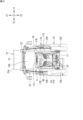
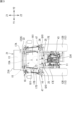
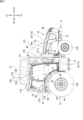
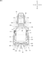
図1は、作業車両の斜視図である。図2は、作業車両の正面図である。図3は、作業車両の背面図である。図4は、作業車両の右側面図である。図5は、作業車両の左側面図である。図6は、作業車両の平面図である。なお、本明細書では、作業車両1が前進する方向を前、作業車両1が後退する方向を後ろ、作業車両1が前方を向いて左側を左、作業車両1が前方を向いて右側を右と定義する。図2~図7においては、前、後ろ、左、右、上、下の方向を、それぞれ矢印X1、X2、Y1、Y2、Z1、Z2で示している。
以下、図面を参照して、本開示の実施形態の詳細を説明する。
[作業車両の全体構造]
図1は、作業車両の斜視図である。図2は、作業車両の正面図である。図3は、作業車両の背面図である。図4は、作業車両の右側面図である。図5は、作業車両の左側面図である。図6は、作業車両の平面図である。なお、本明細書では、作業車両1が前進する方向を前、作業車両1が後退する方向を後ろ、作業車両1が前方を向いて左側を左、作業車両1が前方を向いて右側を右と定義する。図2~図7においては、前、後ろ、左、右、上、下の方向を、それぞれ矢印X1、X2、Y1、Y2、Z1、Z2で示している。
図1~図6に示すように、作業車両1は、農作業に用いられる車両、具体的にはトラクタである。もっとも、作業車両1は、トラクタに限定されるものではなく、農業機械、建設機械、及びユーティリティビークルなどの移動体であってもよい。
作業車両1は、車体11、車体11を支持する走行装置12、運転席15、及びキャビン16などを備える。車体11は、シャーシ41、ボンネット34、カバー111、キャビン16、及び後輪12B用のフェンダー47などを含む。車体11のシャーシ41には、前部から後部に向かって順に、ボンネット34とカバー111が搭載され、カバー111の後方にキャビン16が配置される。ボンネット34、カバー111、キャビン16は、いずれも車体11に搭載された機器(後述する燃料電池24、ラジエータ48,49、座席15A等)を覆うカバーとして機能する。
作業車両1は、さらに、燃料を貯蔵する複数のタンク13(図4参照)を有するタンクユニット21と、貯蔵された燃料により駆動する駆動装置14を有する。タンクユニット21は、上下方向の長さ(高さ)が前後左右方向の長さよりも小さい直方体形状のケース21Aを備え、複数のタンク13は、このケース21A内に並べて収容されている。タンクユニット21は、各種の弁74~78(図9参照)を含む。タンクユニット21は、搭載フレーム17により運転席15及びキャビン16の上方に配置される。
燃料は、液体又は気体であり、水素、メタン、一酸化炭素(CO)等である。この実施形態では、タンク13は水素ガスを貯蔵する。したがって、作業車両1は、燃料電池車両(FCV:Fuel Cell Vehicle)であり、燃料電池24が水素と酸素の化学反応により発生させる電力をエネルギー源として走行する。燃料電池24は、水素によって電力を発生させる。燃料電池24は、メタン又は一酸化炭素(CO)によって電力を発生させるものであってもよい。
駆動装置14は、燃料電池24、バッテリユニット30、及び電動モータ31(図3参照:以下、「モータ31」ともいう。)を含む。バッテリユニット30は、燃料電池24の出力電力を蓄積する少なくとも1つのバッテリパック30A(図9参照)を内蔵する。
作業車両1は、図3に示すように、配管22及び充填部25を有する。この実施形態では、配管22は、水素ガスを通過させる。なお、配管22は、メタン又は一酸化炭素(CO)を通過させる管であってもよい。充填部25は、充填ノズル401を接続する充填口(レセプタクル;以下、単に「充填口」ともいう)26を有する。充填口26には、充填ノズル401から水素ガスが充填される。なお、充填口26には、充填ノズル401からメタン又は一酸化炭素(CO)を充填してもよい。この実施形態では、充填部25は、作業車両1と別であるガスステーション等の水素ガス供給機(燃料供給機)400(図9参照)から水素ガスが充填口(ガス充填口)26に充填される。水素ガスは、配管22(22A)を通じて、タンク13に供給される。タンク13の水素ガスは、配管22(22B)を通じて、燃料電池24に供給される。充填部25及び配管22の具体的構成については、後に説明する。
キャビン16は、前柱、後ろ柱及びルーフを有する区画された運転室であり、運転席15を囲っている。運転席15は、座席15A及び操縦装置15Bを含む。操縦装置15Bは、ステアリングハンドルやレバー、計器等を含む。キャビン16の前柱は、運転席15の前側の左右に配置され、後ろ柱は、運転席15の後側の左右に配置される。キャビン16は、左右の前柱の間に前面パネル165(図2参照)を備え、左右の後ろ柱の間に背面パネル161(図3参照)を備え、前柱と後ろ柱との間に側面パネル166を備える。側面パネル166は、開閉可能なドアを含む。前面パネル165、背面パネル161、側面パネル166は、ガラス又は合成樹脂材等の透明な材料により形成され、キャビン16の内側から外側及び外側から内側を視認可能である。作業車両1は、キャビン16の代わりに、キャノピやロプスを有していてもよい。
走行装置12は、前輪12Aと後輪12Bにより構成される。これらはいずれも車体11に対して左右対称に配置される。前輪12Aと後輪12Bのうちの一方又は双方はモータ31の動力によって回転する。モータ31の動力により回転する車輪12A,12Bのうちの一方又は双方(駆動輪)は、クローラ(無限軌道)であってもよい。後輪12Bの上方及び前方は、フェンダー47で覆われている。
図4及び図5に示すように、シャーシ41の前輪12A対応部分には、前側から後ろ側に向かって順に、第1ラジエータ48、燃料電池24、及び第2ラジエータ49が搭載される。第1ラジエータ48と燃料電池24は、ボンネット(カバー)34により覆われ、第2ラジエータ49はカバー111により覆われる。
図4に示すように、カバー111の上面111aは、ボンネット34の最上端よりも高いが、運転席15のステアリングハンドル15Bの最上端よりも低い。また、ボンネット34の後端部はカバー111よりも低い位置にあり、ボンネット34の上面34aは、当該後端部から前端部に向かって次第に低くなる先細り状に形成される。このため、運転席15に座る作業者からの前方の視界が妨げられ難い構造となっている。
[作業車両の内部構造]
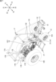
図7は、作業車両の内部構造の一例を示す斜視図である。
図7に示すように、車体11を構成するシャーシ41は、前後方向に長い形状の鋼製フレームよりなり、前フレーム32とミッションケース33とを有する。
ミッションケース33は、前フレーム32の後部に連結されており、ミッションケース33と前フレーム32とから車体11の骨格が形成される。
図7は、作業車両の内部構造の一例を示す斜視図である。
図7に示すように、車体11を構成するシャーシ41は、前後方向に長い形状の鋼製フレームよりなり、前フレーム32とミッションケース33とを有する。
ミッションケース33は、前フレーム32の後部に連結されており、ミッションケース33と前フレーム32とから車体11の骨格が形成される。
シャーシ41には、タンクユニット21をキャビン16の上方に配置するための搭載フレーム17が連結される。搭載フレーム17は、前後方向が左右方向よりも長いほぼ長方形状の天井フレーム17Aと、天井フレーム17Aを下方から支持する複数本のピラー17Bと、天井フレーム17Aの前端部に連結される左右一対の補強フレーム17Cとを含む。また、搭載フレーム17は、後ろ側の左右ピラー17Bの下端が連結されるベースフレーム17Dと、ベースフレームから下方に延びる左右一対の下部フレーム17Eとを含む。ベースフレーム17Dは、略水平に配置され左右方向に延びている。
天井フレーム17Aには、タンクユニット21が載置され、連結される。図2に示すように、天井フレーム17Aは、キャビン16のルーフよりも高い位置にある。したがって、タンクユニット21は、キャビン16のルーフよりも上方に配置される。
図7に示すように、補強フレーム17Cは、天井フレーム17Aの前端部から前フレーム32に渡って下方に傾斜する補強用斜材である。したがって、天井フレーム17Aとタンクユニット21をピラー17Bのみで支持する場合に比べて搭載フレーム17の前後方向の剛性が強化される。
作業車両1のシャーシ41には、バッテリユニット30を車体11に支持させるための支持フレーム37が連結される。
具体的には、シャーシ41の前フレーム32にモータ31が搭載され、前フレーム32におけるモータ31対応部分に支持フレーム37が取り付けられる。支持フレーム37は、例えば金属製のフレーム部材よりなり、前フレーム32から右側に突出するように片持ち状態で取り付けられる。
具体的には、シャーシ41の前フレーム32にモータ31が搭載され、前フレーム32におけるモータ31対応部分に支持フレーム37が取り付けられる。支持フレーム37は、例えば金属製のフレーム部材よりなり、前フレーム32から右側に突出するように片持ち状態で取り付けられる。
モータ31の後方に位置するミッションケース33は、内部に動力伝達機構を有する。動力伝達機構は、トランスミッション、クラッチ、及びデファレンシャルギアを含み、モータ31の出力軸の回転を減速又は増速して走行装置12に伝達する。
ミッションケース33の内部の動力伝達機構は、モータ31の動力の一部を、PTO軸334(図9参照)に出力する分岐機構を含む。PTO軸334は、ミッションケース33から後方に突出する出力軸である。
ミッションケース33の内部の動力伝達機構は、モータ31の動力の一部を、PTO軸334(図9参照)に出力する分岐機構を含む。PTO軸334は、ミッションケース33から後方に突出する出力軸である。
ミッションケース33には、所望の農作業を行うための作業装置335(図9参照。「インプルメント」ともいう。)を車体11の後ろに連結するための、例えば3点リンク機構により構成される連結装置44(図6参照)が取り付けられる。作業装置335は、例えば耕運機及びベーラーなどである。
PTO軸334の回転運動は、例えば走行装置12の駆動中において、連結装置44に連結された作業装置335の入力軸に伝達される。したがって、作業車両1は、圃場などを走行しつつ、作業装置335をモータ31の動力によって駆動することができる。
図8は、作業車両の充填口の周辺を示す斜視図である。
本実施形態の作業車両1は、2つの充填部25を備えている。2つの充填部25は、作業車両1(車体11)の後面に配置されている。各充填部25は、充填口26と、充填口26を収容する筐体28とを有する。充填口26は後方に向き、水素ガス供給機400の充填ノズル401が後方から差し込まれる。筐体28は、ケース28aと、蓋28bとを有する。ケース28aは、上下、左右、及び前に壁を有し、後ろに開口する。蓋28bは、開閉式であり、ケース28aの開口を閉じることができる。配管22Aは、筐体28の前から充填部25(充填口26)と連結されている。
本実施形態の作業車両1は、2つの充填部25を備えている。2つの充填部25は、作業車両1(車体11)の後面に配置されている。各充填部25は、充填口26と、充填口26を収容する筐体28とを有する。充填口26は後方に向き、水素ガス供給機400の充填ノズル401が後方から差し込まれる。筐体28は、ケース28aと、蓋28bとを有する。ケース28aは、上下、左右、及び前に壁を有し、後ろに開口する。蓋28bは、開閉式であり、ケース28aの開口を閉じることができる。配管22Aは、筐体28の前から充填部25(充填口26)と連結されている。
この構成により、充填口26は、筐体28により保護される。配管22Aは、筐体28と、車体11の後部との間に形成される空間から、充填部25に連結される。配管22Aと筐体28との接続部29が、車両後方の広い空間に露出せず、その接続部29は保護される。
2つの充填部25は、キャビン16の後ろであって、左右方向両側の後輪12Bの間に位置する。2つの充填部25は、後輪12Bによって左右方向から保護され、キャビン16によって前方から保護される。
2つの充填部25は、搭載フレーム17のベースフレーム17Dの下に配置される。2つの充填部25は、いずれもベースフレーム17Dにブラケット27を介して支持されている。充填部25は、ベースフレーム17Dよって上から保護される。2つの充填部25は、左右の下部フレーム17Eの間に配置されている。
一方の充填部25と他方の充填部25とは、左右に並べて配置されている。一方の充填部25は、作業車両の左右方向の中心よりも左側に配置され、他方の充填部25は、作業車両の左右方向の中心よりも右側に配置されている。したがって、水素ガス供給機400の充填ノズル401が作業車両1の左側にある場合は、左側の充填部25を用いて水素ガスを充填しやすくなり、水素ガス供給機400の充填ノズル401が作業車両1の右側にある場合は、右側の充填部25を用いて水素ガスを充填しやすくなる。
2つの充填部25は、同じ高さに配置されている。ただし、2つの充填部25は、異なる高さに配置されていてもよい。2つの充填部25は、上下方向に並べて配置されていてもよい。2つの充填部25の高さが異なることによって、作業者の身長や姿勢等に応じて作業しやすい充填部25を選択し、水素ガスを充填することができる。
[作業車両の機能的構成]
図9は、作業車両の機能的構成の一例を示すブロック図である。
図9に示すように、作業車両1の機能的な系統には、燃料系統FS、動力系統PS、及び温調系統TSが含まれる。
図9は、作業車両の機能的構成の一例を示すブロック図である。
図9に示すように、作業車両1の機能的な系統には、燃料系統FS、動力系統PS、及び温調系統TSが含まれる。
燃料系統FSの構成要素には、少なくとも1つのタンク(水素タンク)13、弁74~78、及びセンサ81,82などが含まれる。温調系統TSの構成要素には、複数のラジエータ48,49、及び空調装置50などが含まれる。動力系統PSの構成要素には、燃料電池24、昇圧回路61、インバータ62、モータ31、ミッションケース33、DC/DCコンバータ64,65、及びバッテリユニット30などが含まれる。
本実施形態の作業車両1は、複数のタンク13、例えば3つのタンク13を備える。各タンク13は、配管22A,22Bに接続される。配管22Aは、充填口26と各タンク13とを繋ぐガス管である。充填口26は、ガスステーション等の水素ガス供給機400から水素ガスが導入される。配管22Aは、充填口26に導入される水素ガスを各タンク13へ導く。
配管22Aは、複数の下流側分岐部22A1と、合流部22A2と、複数の上流側分岐部22A3とを有する。上流側分岐部22A3は、充填口26と同数(図示例では2つ)設けられている。各上流側分岐部22A3の一端(上流端)には、各充填口26が接続されている。2つの上流側分岐部22A3の他端(下流端)には、合流部22A2の一端(上流端)が接続されている。
合流部22A2の他端(下流端)は、複数の下流側分岐部22A1の一端(上流端)に接続されている。下流側分岐部22A1は、タンク13と同数(図示例では3つ)設けられている。各下流側分岐部22A1の他端(下流端)は、各タンク13に接続されている。したがって、充填口26から導入された水素ガスは、各上流側分岐部22A3を流れた後、合流部22A2で合流され、その後、各下流側分岐部22A1で分岐された後に、各タンク13に充填される。
上流側分岐部22A3には、逆止弁74が設けられている。逆止弁74は、充填口26から合流部22A2へ向かう水素ガスの流れを許容し、その逆方向の水素ガスの流れを遮断する。そのため、一方の充填口26から導入された水素ガスが他方の充填口26へ流入することが抑制される。
下流側分岐部22A1にも、逆止弁75が設けられている。逆止弁75は、合流部22A2からタンク13へ向かう水素ガスの流れを許容し、その逆方向の水素ガスの流れを遮断する。そのため、タンク13内の水素ガスが下流側分岐部22A1に逆流することを抑制することができる。
以上より、本実施形態の作業車両1は、2つの充填口26のどちらから水素ガスを供給しても全てのタンク13に水素ガスを充填することができる。また、両方の充填口26から同時に水素ガスを供給した場合も、全てのタンク13に水素ガスを充填することができる。
配管22Bは、燃料電池24とタンク13とを繋ぐガス管である。配管22Bは、各タンク13に貯蔵された水素ガスを燃料電池24へ導く。配管22Bは、分岐部22B1と合流部22B2とを有する。分岐部22B1は、タンク13と同数(図示例では3つ)設けられる。分岐部22B1の一端(上流端)は、タンク13に接続され、他端(下流端)は合流部22B2に接続される。したがって、各タンク13から放出された水素ガスは、分岐部22B1を流れた後、合流部22B2で合流され、その後、燃料電池24へと導かれる。
配管22Bの各分岐部22B1には、開閉弁76が設けられる。各開閉弁76は、各タンク13内の水素ガスの放出と、放出の停止(遮断)とを切り替える。配管22Bの合流部22B2には、減圧弁77と、主開閉弁78とが設けられる。減圧弁77は、タンク13から放出された水素ガスの圧力を低下させる。タンク13内の水素ガスの圧力は、例えば35メガパスカル以上であるのに対して、減圧弁77で減圧された後の水素ガスの圧力は、例えば2気圧程度である。主開閉弁78は、減圧弁77で減圧された水素ガスの燃料電池24への供給と、供給の停止(遮断)とを切り替える。開閉弁76,78は、ソレノイドにより作動する電磁弁やモータにより作動する電動弁等により構成される。
複数の開閉弁76と減圧弁77との間には、圧力センサ81が設けられている。圧力センサ81は、配管22Bの合流部22B2に設けられている。圧力センサ81は、複数のタンク13から放出された水素ガスの圧力を検出する。圧力センサ81によって検出される圧力は、開閉弁76を介して水素ガスを放出しているタンク13内の水素ガスの圧力に相当する。また、各タンク13には、温度センサ82が設けられている。温度センサ82は、タンク13内の水素ガスの温度を検出する。
タンク13から放出され配管22Bを流れる水素ガスは、燃料電池24に供給される。燃料電池24は、例えば、正極と負極を有する単セルを積層状態で複数並設して構成された電池モジュールである。燃料電池24は、各単セルで発電された電力を集約して電動モータ31の駆動に必要な電力を発生させる。
燃料電池24は、冷却流路H2を通じて第2ラジエータ49に接続される。燃料電池24の電極は、第2ラジエータ49から循環的に供給される冷却液により所定温度に調整される。これにより、燃料電池24は、高い発電効率を維持できる。
燃料電池24は、昇圧回路61の入力側に電気的に接続され、昇圧回路61の出力側はインバータ62の直流側に電気的に接続される。昇圧回路61は、燃料電池24から入力される電圧を上昇させてインバータ62とバッテリユニット30に出力する。
インバータ62は、モータ31と電気的に接続される。インバータ62は、昇圧回路61から入力される直流を三相交流に変換してモータ31に出力する。したがって、燃料電池24が発生させた電力は、昇圧かつ交流に変換されてモータ31に伝送される。
モータ31は、ロータと複数のコイルを有するステータとを有し、所定のトルク及び回転速度で出力軸を駆動する。作業車両1には、例えばモータ31が1つだけ搭載され、当該モータ31の出力軸はミッションケース33に結合される。モータ31は、複数搭載されてもよい。例えば、前輪12A用と後輪12B用の2種類のモータ31を設ける場合には、各モータ31の動力を前輪12A及び後輪12Bにそれぞれ出力すればよい。
ミッションケース33の動力伝達機構は、モータ31の動力の全部又は一部を走行装置12に出力する。また、動力伝達機構は、作業装置335を稼働させる場合は、モータ31の動力をPTO軸334にも出力する。
バッテリユニット30は、燃料電池24の負荷変動を吸収する蓄電装置である。具体的は、バッテリユニット30は、昇圧回路61から供給される電力を一時的に充電し、高負荷時に放電してモータ31への駆動電力をインバータ62に供給する。
バッテリユニット30は、バッテリパック30Aと監視ユニット30Bを備える。バッテリパック30Aは、少なくとも1つのセルを含む。セルは、例えばリチウムイオン電池セルなどの充放電型である。バッテリユニット30の出力電圧は、例えば24Vである。
バッテリユニット30は、バッテリパック30Aと監視ユニット30Bを備える。バッテリパック30Aは、少なくとも1つのセルを含む。セルは、例えばリチウムイオン電池セルなどの充放電型である。バッテリユニット30の出力電圧は、例えば24Vである。
監視ユニット30Bは、バッテリパック30Aの動作(充電又は放電)の切り替え制御と、充電状態(例えばSOC)の計測とを行うプロセッサを含む。
作業車両1は、モータ31よりも低い電圧で作動する複数の電装品を有する。これらの電装品に対しては、降圧回路で降圧された直流電力が供給される。
複数の電装品は、例えば、補助バッテリ63、ラジエータ48,49、及び空調装置50を含む。降圧回路は、例えば出力電圧が異なる複数のDC/DCコンバータ64,65(以下、「第1コンバータ64」及び「第2コンバータ65」ともいう。)である。
複数の電装品は、例えば、補助バッテリ63、ラジエータ48,49、及び空調装置50を含む。降圧回路は、例えば出力電圧が異なる複数のDC/DCコンバータ64,65(以下、「第1コンバータ64」及び「第2コンバータ65」ともいう。)である。
第1コンバータ64は、昇圧回路61から入力される直流電圧を第1電圧(例えば12ボルト)に降圧し、補助バッテリ63、及び空調装置50などに供給する。
第2コンバータ65は、昇圧回路61から入力される直流電圧を第2電圧(例えば24ボルト)に降圧し、ラジエータ48,49に供給する。インバータ62と両コンバータ64,65は、シャーシ41における運転席15に対応する部分に配設される。なお、第2コンバータ65の第2電圧をバッテリユニット30に供給してもよい。
第2コンバータ65は、昇圧回路61から入力される直流電圧を第2電圧(例えば24ボルト)に降圧し、ラジエータ48,49に供給する。インバータ62と両コンバータ64,65は、シャーシ41における運転席15に対応する部分に配設される。なお、第2コンバータ65の第2電圧をバッテリユニット30に供給してもよい。
前述の通り、第1ラジエータ48は燃料電池24の前方に配置され、第2ラジエータ49は燃料電池24の後方に配置される(図2参照)。
これらのラジエータ48,49は、燃料電池24、昇圧回路61、インバータ62、モータ31、第1及び第2コンバータ64,65などの電装品を冷却液(冷媒)により冷却きせる冷却システムを構成している。
これらのラジエータ48,49は、燃料電池24、昇圧回路61、インバータ62、モータ31、第1及び第2コンバータ64,65などの電装品を冷却液(冷媒)により冷却きせる冷却システムを構成している。
第1ラジエータ48には、冷却液がポンプ66で循環される冷却流路H1が接続され、冷却液は外部空気との熱交換により冷却される。第1ラジエータ48は、外部空気との熱交換を促進させるための第1ファン35を有する。
第1ラジエータ48の冷却流路H1の冷却対象は、例えば、昇圧回路61、インバータ62、モータ31、及び第1及び第2コンバータ64,65などの電装品(発熱部品)である。
第1ラジエータ48の冷却流路H1の冷却対象は、例えば、昇圧回路61、インバータ62、モータ31、及び第1及び第2コンバータ64,65などの電装品(発熱部品)である。
第2ラジエータ49には、冷却液がポンプ67で循環される冷却流路H2が接続され、冷却液は外部空気との熱交換により冷却する。第2ラジエータ49は、外部空気との熱交換を促進させるための第2ファン36を有する。
第2ラジエータ49の冷却流路H2による冷却対象は、例えば、燃料電池24などの電装品である。
第2ラジエータ49の冷却流路H2による冷却対象は、例えば、燃料電池24などの電装品である。
補助バッテリ63は、運転席15に搭載されるディスプレイ及び通信機器などに電力を供給する蓄電装置である。補助バッテリ63は、例えば充放電型の鉛蓄電池である。補助バッテリ(第2バッテリ)63の出力電圧は、例えば12Vであり、バッテリユニット(第1バッテリ)30の出力電圧(例えば24V)よりも低い。
補助バッテリ63は、燃料電池24が停止中である場合に、後述する制御装置70に電力供給する補助電源としても使用され得る。
補助バッテリ63は、燃料電池24が停止中である場合に、後述する制御装置70に電力供給する補助電源としても使用され得る。
図9に示すように、作業車両1は、さらに制御装置70を含む。制御装置70は、例えば、CAN(Controller Area Network)などの通信プロトコルにより各種の電装品と通信するECU(Electronic Control Unit)により構成され得る。例えば、制御装置70は、タンク13への水素ガスの充填や燃料電池24による発電から動力の出力に到るまでのシステム全体の動作を統括して制御するECUや、タンク13、弁74~78、及びセンサ81,82を含むタンクユニット21等の個別の制御に関わるECUを含む。したがって、制御装置70は、タンクユニット21に含まれる弁76~78の開閉制御、圧力センサ81や温度センサ82の検出値の取得や取得した検出値の処理等を行う。
[充填口の配置例]
上述した実施形態(図3、図8参照)では、作業車両1の後部(後面)に2つの充填口26(充填部25)が配置されていた。しかしながら、これに限定されるものではない。例えば、2つの充填口26は、作業車両1の側面、上面、及び/又は前面に配置することができる。2つの充填口26は、互いに接近した位置に配置することもできるし、互いに離れた位置に配置することができる。2つの充填口26は、作業車両1の共通する面に限らず、互いに異なる面に配置することもできる。
上述した実施形態(図3、図8参照)では、作業車両1の後部(後面)に2つの充填口26(充填部25)が配置されていた。しかしながら、これに限定されるものではない。例えば、2つの充填口26は、作業車両1の側面、上面、及び/又は前面に配置することができる。2つの充填口26は、互いに接近した位置に配置することもできるし、互いに離れた位置に配置することができる。2つの充填口26は、作業車両1の共通する面に限らず、互いに異なる面に配置することもできる。
以下、図2~図6を参照して充填口26の配置例を説明する。図2~図6においては、充填口26の配置例が符号Qで示されている。
図4及び図5に示すように、2つの充填口26は、符号Q1で示すボンネット34の左右方向の両側面に配置することができる。この場合、図10に例示されるように、充填口26を、ボンネット34の内側に配置してもよい。具体的に、ボンネット34の側面の一部を筐体28の蓋28bとし、その蓋28bの内側に、筐体28のケース28aを配置し、筐体28の内部に充填口26を配置することができる。充填口26は、左右方向の外側に向くように配置される。充填口26及び筐体28は、ボンネット34の外側に配置することも可能である。
図4及び図5に示すように、2つの充填口26は、符号Q2で示すカバー111の左右方向の両側面に配置してもよい。あるいは、充填口26は、符号Q3、Q4で示すフェンダー47の左右方向の両側面に設けることができる。符号Q3は、フェンダー47の前部寄りに充填口26を配置する例を示し、符号Q4は、フェンダー47の後部寄りに充填口26を配置する例を示す。いずれの場合(Q2~Q4)も充填口26は、カバー111又はフェンダー47の内側又は外側に配置することができる。
図4及び図5に示すように2つの充填口26は、符号Q5、Q6で示すキャビン16の左右両側面に配置してもよい。符号Q5は、キャビン16の前部寄りに充填口26を配置する例を示し、符号Q6は、キャビン16の後部寄りに充填口26を配置する例を示す。いずれの場合も、キャビン16の内側又は外側に充填口26を配置することができる。
以上のように、2つの充填口26を作業車両1(車体11)の左右両側に振り分けて配置することによって、例えば、ガスステーション等の水素ガス供給機400に充填口26を近づける際に、作業車両1の方向転換等の移動を少なくすることができる。そのため、充填作業にかかる手間を少なくし、充填作業を容易に行うことができる。
図4及び図5において、2つの充填口26は、Q1~Q6のいずれか2つを選択して配置することができる。例えば、2つの充填口26のうち一方をボンネット(Q1)に配置し、他方をフェンダー47(Q3,Q4)に配置することができる。また、2つの充填口26の両方を作業車両1(車体11)の左側面又は右側面に配置することもできる。この場合、2つの充填口26を互いに前後方向に離れた位置、及び/又は、上下方向に離れた位置に配置することができる。例えば、2つの充填口26のうち一方をボンネット34(Q1)の左側面に配置し、他方をフェンダー47(Q3、Q4)の左側面に配置することができる。2つの充填口26を作業車両1の共通する面に配置することによって、2つの充填口26の両方から同時に水素ガスを充填する作業を容易に行うことができる。また、2つの充填口26を前後方向に離れた位置に配置した場合、ガスステーション等の水素ガス供給機400に充填口26を近づける際に、作業車両1の前後方向の移動を少なくすることができる。そのため、充填作業にかかる手間を少なくし、充填作業を容易に行うことができる。
図2に示すように、2つの充填口26のうち一方又は両方を作業車両1(車体11)の前面に配置することができる。例えば、符号Q7で示すボンネット34の前面に充填口26を配置することができる。この場合も、ボンネット34の内側又は外側に充填口26を配置することができる。2つの充填口26を作業車両1の前面に配置する場合、2つの充填口26を互いに上下方向に離れた位置、及び/又は、左右方向に離れた位置に配置することができる。一方の充填口26を作業車両1の前面に配置した場合、他方の充填口26を作業車両1の他の位置(例えば、後面(図8参照)、左右側面Q1~Q6(図4及び図5参照)、上面Q8~Q10(図6参照))に配置することができる。
図6に示すように、2つの充填口26のうち一方又は両方を作業車両1(車体11)の上面に配置することができる。具体的に、符号Q8で示すボンネット34の上面、符号Q9で示すカバー111の上面、符号Q10で示すフェンダー47の上面等に充填口26を配置することができる。2つの充填口26を作業車両1の上面に配置する場合、2つの充填口26を互いに前後方向に離れた位置、及び/又は、左右方向に離れた位置に配置することができる。一方の充填口26を作業車両1の上面(Q9、Q10)に配置した場合、他方の充填口26を作業車両1の他の位置(例えば、前面Q7(図2参照)、後面(図8参照)、左右側面Q1~Q6(図4及び図5参照))に配置することができる。
図3に示すように、2つの充填口26のうち一方又は両方を、符号Q10で示すフェンダー47の後面、符号Q11で示すキャビン16の後面に配置することができる。一方の充填口26を作業車両1の後面(Q10、Q11、図3参照)に配置した場合、他方の充填口26を作業車両1の他の位置(例えば、前面(図2参照)、左右側面Q1~Q6(図4及び図5参照)、上面Q8~Q10(図6参照))に配置することができる。
以上のほか、充填口26は、作業車両1の車体11におけるシャーシ41に配置することができる。例えば、一方又は両方の充填口26を、前フレーム32の左右方向の側面、ミッションケース33の左右方向の側面に配置することができる。あるいは、一方又は両方の充填口26を、シャーシ41の下面に配置することもできる。
[配管の変形例]
図11A~図11Cは、タンクと充填口との接続形態の変形例を示す概略図である。言い換えると、図11A~図11Cは、タンク13と複数の充填口26を接続する配管22Aの変形例を示している。
図11A~図11Cは、タンクと充填口との接続形態の変形例を示す概略図である。言い換えると、図11A~図11Cは、タンク13と複数の充填口26を接続する配管22Aの変形例を示している。
図11Aに示す変形例は、2つのタンク13と、2つの充填口26とを有する。一方のタンク13と一方の充填口26とは配管22A4によって直接的に接続され、他方のタンク13と他方の充填口26とは他の配管22A4によって直接的に接続されている。各配管22A4には、逆止弁74が設けられている。したがって、一方の充填口26から供給される水素ガスは一方のタンク13のみに充填され、他方の充填口26から供給される水素ガスは他方のタンク13のみに充填される。この変形例では、例えば、両方の充填口26から同時に水素ガスを供給することによって短時間でタンク13に水素ガスを充填することができる。
図11Bに示す変形例は、図11Aに示す変形例と同様に、2つの充填口26と2つのタンク13とがそれぞれ配管22A4によって個別に接続されている。さらに2つの配管22A4が、連結管22A5によって接続されている。連結管22A5には開閉弁79が設けられている。開閉弁79は、開閉することによって連結管22A5における水素ガスの流れを許容する形態と、遮断する形態とを切り替える。この変形例では、開閉弁79を閉じることによって、図11Aに示す変形例と同様に、一方の充填口26から供給される水素ガスは一方のタンク13のみに充填され、他方の充填口26から供給される水素ガスは他方のタンク13のみに充填される。また、開閉弁79を開くことによって、2つの配管22A4が互いに連通し、各充填口26から供給された水素ガスは、両方のタンク13に充填されることになる。したがって、開閉弁79を開閉することによって2つの態様で水素ガスを充填することができる。
図11Cに示す変形例は、図9に示す実施形態と同様に、2つ(上側2つ)のタンク13と2つ(上側2つ)の充填口26とが下流側分岐部22A1、合流部22A2、及び上流側分岐部22A3を有する配管22Aによって接続されている。さらに、1つ(最下部の1つ)のタンクと1つ(最下部の1つ)の充填口26とが配管22A4によって接続されている。合流部22A2と配管22A4とは、図11Bに示す変形例と同様に、開閉弁79が設けられた連結管22A5によって接続されている。この変形例では、開閉弁79を閉じることによって、上側2つの充填口26から充填された水素ガスは、上側2つのタンク13に充填され、最下部の1つの充填口26から供給された水素ガスは、最下部の1つのタンク13のみに充填される。また、開閉弁79を開くことによって、各充填口26から供給された水素ガスが3つのタンク13に充填される。したがって、開閉弁79を開閉することによって2つの態様で水素ガスを充填することができる。
[その他の変形例]
今回開示した実施形態はすべての点で例示であって制限的なものではない。本開示の権利範囲は、上述の実施形態に限定されるものではなく、請求の範囲に記載された構成と均等の範囲内でのすべての変更が含まれる。
今回開示した実施形態はすべての点で例示であって制限的なものではない。本開示の権利範囲は、上述の実施形態に限定されるものではなく、請求の範囲に記載された構成と均等の範囲内でのすべての変更が含まれる。
上記実施形態では、主に作業車両1が2つの充填口26を備える場合について説明したが、3つ以上の充填口26を備えていてもよい。この場合、2つの充填口(第1充填口及び第2充填口)26を図2~図6、図8に示した位置に配置し、他の充填口26を任意の位置に配置することができる。また、タンク13の数についても限定されるものではない。
1 :作業車両
11 :車体
13 :タンク
22A :配管
22A2 :合流部
22A3 :上流側分岐部
24 :燃料電池
74 :逆止弁
111 :カバー
11 :車体
13 :タンク
22A :配管
22A2 :合流部
22A3 :上流側分岐部
24 :燃料電池
74 :逆止弁
111 :カバー
Claims (9)
- 車体と、
前記車体に搭載される燃料電池と、
前記燃料電池に供給される燃料を収容するタンクと、
前記タンクに燃料を充填するための第1充填口及び第2充填口と、を備える、作業車両。 - 前記第1充填口が、左右方向における前記車体の一側面に配置され、
前記第2充填口が、左右方向における前記車体の他側面に配置される、請求項1に記載の作業車両。 - 前記第1充填口が、前後方向における前記車体の一側面に配置され、
前記第2充填口が、前後方向における前記車体の他側面に配置される、請求項1に記載の作業車両。 - 前記第1充填口が、左右方向における前記車体の一側面に配置され、
前記第2充填口が、前後方向における前記車体の一側面に配置される、請求項1に記載の作業車両。 - 前記第1充填口及び前記第2充填口が、前記車体の共通する面に配置される、請求項1に記載の作業車両。
- 前記車体が、搭載された機器を覆うカバーを含み、
前記カバーの内側又は外側に前記第1充填口及び前記第2充填口の少なくとも一方が配置される、請求項1~5のいずれか1項に記載の作業車両。 - 前記タンクが、第1タンクと第2タンクとを含み、
前記第1充填口及び前記第2充填口の双方を、前記第1タンク及び前記第2タンクに接続する配管を備える、請求項1~6のいずれか1項に記載の作業車両。 - 前記配管が、一端が前記第1充填口に接続される第1分岐部と、一端が前記第2充填口に接続される第2分岐部と、前記第1分岐部及び前記第2分岐部の他端を合流させる合流部とを備え、前記第1分岐部及び前記第2分岐部には、前記合流部へ向かう方向の燃料の流れを許容し逆方向の燃料の流れを遮断する逆止弁が設けられる、請求項7に記載の作業車両。
- 前記タンクが、第1タンクと第2タンクとを含み、
前記第1充填口を前記第1タンクに接続する第1配管と、前記第2充填口を前記第2タンクに接続する第2配管と、を備える、請求項1~6のいずれか1項に記載の作業車両。
Applications Claiming Priority (2)
| Application Number | Priority Date | Filing Date | Title |
|---|---|---|---|
| JP2023-219057 | 2023-12-26 | ||
| JP2023219057A JP2025101945A (ja) | 2023-12-26 | 2023-12-26 | 作業車両 |
Publications (1)
| Publication Number | Publication Date |
|---|---|
| WO2025142007A1 true WO2025142007A1 (ja) | 2025-07-03 |
Family
ID=96217308
Family Applications (1)
| Application Number | Title | Priority Date | Filing Date |
|---|---|---|---|
| PCT/JP2024/035197 Pending WO2025142007A1 (ja) | 2023-12-26 | 2024-10-02 | 作業車両 |
Country Status (2)
| Country | Link |
|---|---|
| JP (1) | JP2025101945A (ja) |
| WO (1) | WO2025142007A1 (ja) |
Families Citing this family (1)
| Publication number | Priority date | Publication date | Assignee | Title |
|---|---|---|---|---|
| JP7322284B2 (ja) | 2020-04-15 | 2023-08-07 | 株式会社日立ハイテク | 搬送装置および解析システム |
Citations (6)
| Publication number | Priority date | Publication date | Assignee | Title |
|---|---|---|---|---|
| WO2006054642A1 (ja) * | 2004-11-18 | 2006-05-26 | Kabushiki Kaisha Toyota Jidoshokki | 水素燃料自動車における水素タンク冷却装置、水素タンク冷却方法、及び水素燃料自動車 |
| JP2017128202A (ja) * | 2016-01-20 | 2017-07-27 | 新明和工業株式会社 | 作業車両 |
| CN108134112A (zh) * | 2017-12-25 | 2018-06-08 | 东风农业装备(襄阳)有限公司 | 燃料电池系统及其应用 |
| US20220185106A1 (en) * | 2020-12-16 | 2022-06-16 | Cnh Industrial America Llc | Track assembly with electric motor |
| JP2023013186A (ja) * | 2021-07-15 | 2023-01-26 | 株式会社クボタ | 作業機 |
| JP2023156109A (ja) * | 2022-04-12 | 2023-10-24 | トヨタ自動車株式会社 | 車両の制御装置 |
-
2023
- 2023-12-26 JP JP2023219057A patent/JP2025101945A/ja active Pending
-
2024
- 2024-10-02 WO PCT/JP2024/035197 patent/WO2025142007A1/ja active Pending
Patent Citations (6)
| Publication number | Priority date | Publication date | Assignee | Title |
|---|---|---|---|---|
| WO2006054642A1 (ja) * | 2004-11-18 | 2006-05-26 | Kabushiki Kaisha Toyota Jidoshokki | 水素燃料自動車における水素タンク冷却装置、水素タンク冷却方法、及び水素燃料自動車 |
| JP2017128202A (ja) * | 2016-01-20 | 2017-07-27 | 新明和工業株式会社 | 作業車両 |
| CN108134112A (zh) * | 2017-12-25 | 2018-06-08 | 东风农业装备(襄阳)有限公司 | 燃料电池系统及其应用 |
| US20220185106A1 (en) * | 2020-12-16 | 2022-06-16 | Cnh Industrial America Llc | Track assembly with electric motor |
| JP2023013186A (ja) * | 2021-07-15 | 2023-01-26 | 株式会社クボタ | 作業機 |
| JP2023156109A (ja) * | 2022-04-12 | 2023-10-24 | トヨタ自動車株式会社 | 車両の制御装置 |
Also Published As
| Publication number | Publication date |
|---|---|
| JP2025101945A (ja) | 2025-07-08 |
Similar Documents
| Publication | Publication Date | Title |
|---|---|---|
| CN101573246B (zh) | 混合动力车辆以及车辆 | |
| US11273717B2 (en) | Open cabin vehicle | |
| JP7769113B2 (ja) | 作業車両 | |
| WO2025142007A1 (ja) | 作業車両 | |
| WO2024004915A1 (ja) | 農業用作業車両 | |
| WO2024004914A1 (ja) | 農業トラクタ | |
| WO2024004906A1 (ja) | 作業車両 | |
| WO2024004908A1 (ja) | 作業車両 | |
| JP2025102043A (ja) | 作業車両 | |
| JP2020059299A (ja) | 燃料電池貨物車 | |
| WO2025142043A1 (ja) | 作業車両 | |
| WO2025142022A1 (ja) | 作業車両 | |
| EP4737168A1 (en) | Work vehicle | |
| JP2025102049A (ja) | 作業車両、及びタンクユニット | |
| JP2024095104A (ja) | 作業車両 | |
| JP7797372B2 (ja) | 作業車両 | |
| JP2025009259A (ja) | 作業車両 | |
| JP7801447B2 (ja) | 作業車両 | |
| US20260084519A1 (en) | Work vehicle | |
| EP4737151A1 (en) | Work vehicle | |
| US20260084520A1 (en) | Work vehicle | |
| US20260070410A1 (en) | Work vehicle | |
| JP2025102002A (ja) | 作業機械 | |
| JP2025102031A (ja) | 作業車両 | |
| WO2025004676A1 (ja) | 作業車両 |
Legal Events
| Date | Code | Title | Description |
|---|---|---|---|
| 121 | Ep: the epo has been informed by wipo that ep was designated in this application |
Ref document number: 24911901 Country of ref document: EP Kind code of ref document: A1 |