WO2025142004A1 - 仮想空間制御システム、仮想空間制御方法およびプログラム - Google Patents
仮想空間制御システム、仮想空間制御方法およびプログラム Download PDFInfo
- Publication number
- WO2025142004A1 WO2025142004A1 PCT/JP2024/035077 JP2024035077W WO2025142004A1 WO 2025142004 A1 WO2025142004 A1 WO 2025142004A1 JP 2024035077 W JP2024035077 W JP 2024035077W WO 2025142004 A1 WO2025142004 A1 WO 2025142004A1
- Authority
- WO
- WIPO (PCT)
- Prior art keywords
- avatar
- user
- information
- virtual space
- terminal device
- Prior art date
- Legal status (The legal status is an assumption and is not a legal conclusion. Google has not performed a legal analysis and makes no representation as to the accuracy of the status listed.)
- Pending
Links
Images




Classifications
-
- G—PHYSICS
- G06—COMPUTING OR CALCULATING; COUNTING
- G06F—ELECTRIC DIGITAL DATA PROCESSING
- G06F3/00—Input arrangements for transferring data to be processed into a form capable of being handled by the computer; Output arrangements for transferring data from processing unit to output unit, e.g. interface arrangements
- G06F3/01—Input arrangements or combined input and output arrangements for interaction between user and computer
- G06F3/048—Interaction techniques based on graphical user interfaces [GUI]
- G06F3/0481—Interaction techniques based on graphical user interfaces [GUI] based on specific properties of the displayed interaction object or a metaphor-based environment, e.g. interaction with desktop elements like windows or icons, or assisted by a cursor's changing behaviour or appearance
-
- G—PHYSICS
- G06—COMPUTING OR CALCULATING; COUNTING
- G06T—IMAGE DATA PROCESSING OR GENERATION, IN GENERAL
- G06T19/00—Manipulating three-dimensional [3D] models or images for computer graphics
Definitions
- the present invention relates to a virtual space control system, a virtual space control method, and a program.
- a virtual space such as a virtual office
- an information sharing function that allows them to hear each other's voices and other sounds.
- avatar users display the virtual space on the display screen of their information terminal devices, depending on the nature of their work, the screen of the window displaying the virtual space may be minimized or displayed behind the screen of another window. In such a situation, they may not notice that another user's avatar is approaching.
- the present disclosure aims to properly notify a user when another user's avatar approaches in a virtual space.
- the virtual space control system of the present disclosure is a virtual space control system that causes an information terminal device to display a virtual space and causes an avatar corresponding to a user to be displayed in the displayed virtual space, and when an information processing device provided in the virtual space control system detects that a second avatar corresponding to a second user has entered, or is in a close proximity state where it is likely to enter, the information sharing range of a first avatar corresponding to a first user in the virtual space, the information processing device displays the second avatar on the display screen of a first information terminal device in which the first user is logged in to the virtual space, in a position that is exposed and not hidden by information displayed on the display screen.
- the virtual space control method is a virtual space control method executed by a virtual space control system that causes an information terminal device to display a virtual space and that causes an avatar corresponding to a user to be displayed in the displayed virtual space, and when it is detected that a second avatar corresponding to a second user is within the information sharing range of a first avatar corresponding to a first user in the virtual space, or is in a close proximity state in which the second avatar is likely to enter, the second avatar is displayed on the display screen of a first information terminal device in which the first user is logged in to the virtual space, in a position that is exposed and not hidden by information displayed on the display screen.
- a program when detecting a state in which a second avatar corresponding to a second user has entered an information sharing range of a first avatar corresponding to a first user in a virtual space, or is in an approaching state in which the second avatar is likely to enter the information sharing range of the first avatar corresponding to a first user, displays the second avatar on a display screen of a first information terminal device in which the first user has logged in to the virtual space, in a position that is exposed and not hidden by information displayed on the display screen; This is done by the computer that controls the space sharing system.
- a user can be appropriately notified in a virtual space that another user's avatar is approaching.
- FIG. 1 is a schematic diagram showing an example of the configuration of a virtual space control system according to a first embodiment.
- FIG. 2 is a block diagram showing an example of the configuration of an information terminal device according to the first embodiment.
- FIG. 3 is a block diagram illustrating an example of the configuration of a server device according to the first embodiment.
- FIG. 4 is a block diagram illustrating an example of the configuration of the information processing device according to the first embodiment.
- FIG. 5 is a diagram showing an example of a display screen of the information terminal device according to the first embodiment.
- FIG. 6 is a diagram showing an example of a virtual office window displayed on the display screen of FIG.
- FIG. 7 is a diagram showing another example of the display screen of the information terminal device according to the first embodiment.
- FIG. 1 is a schematic diagram showing an example of the configuration of a virtual space control system according to a first embodiment.
- FIG. 2 is a block diagram showing an example of the configuration of an information terminal device according to the first embodiment.
- FIG. 3
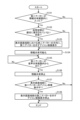
- FIG. 8 is a flowchart showing an example of a virtual space control method according to the first embodiment.
- FIG. 9 is a flowchart showing another example of the virtual space control method according to the first embodiment.
- FIG. 10 is a diagram showing an example of a display screen of an information terminal device according to the second embodiment.
- FIG. 11 is a diagram showing another example of the display screen of the information terminal device according to the second embodiment.
- FIG. 12 is a flowchart showing an example of a virtual space control method according to the second embodiment.
- FIG. 13 is a flowchart showing another example of the virtual space control method according to the second embodiment.
- FIG. 1 is a schematic diagram showing an example of the configuration of a virtual space control system according to a first embodiment.
- the virtual space control system 1 controls a virtual office configured in a virtual space.
- a virtual office is used as an example for explanation, but the present invention is not limited to virtual offices and can also be applied to various services that use avatars for communication in a virtual space.
- a user uses an information terminal device to come to work (log in) to the virtual office with their own account and perform their work.
- an avatar associated with the user is set.
- the user When a user logs in to the virtual office using their own information terminal device 10 (described later), the user operates and displays the avatar to move to any seat in the virtual office or to a predetermined seat and sit down.
- the user can operate the avatar to move around the virtual office.
- the virtual office for example, when avatars are close to each other in the virtual office or when avatars are located in the same space such as a conference room in the virtual office, they can share information in such a way that they can hear each other's voices and other sounds.
- the virtual space control system 1 includes an information terminal device 10 that each user uses for business purposes, and a server device 30.
- the (Information terminal device) 2 is a block diagram showing an example of the configuration of an information terminal device according to the first embodiment.
- the information terminal device 10 is a terminal device used by a user who performs work in a virtual office.
- the information terminal device 10 is a terminal device on which the user executes a virtual office application.
- the information terminal device 10 is a terminal device on which the user logs in to the virtual office with his or her own account when logging in to the virtual office.
- the information terminal device 10 is, for example, a general-purpose personal computer, a smartphone, or an information terminal device such as a tablet terminal.
- the information terminal device 10 is connected to the server device 30 via a network so that data can be communicated therewith.
- the information terminal device 10 acquires account user information for the information terminal device 10 based on the account information of the person logged in to the information terminal device 10.
- the information terminal device 10 includes a camera 11, a microphone 12, an operation unit 13, a display unit 17, an audio output unit 18, a communication unit 19, and a terminal control device 20.
- Camera 11 captures an image in the direction facing information terminal device 10.
- Camera 11 is positioned to capture an image in the direction facing display unit 17 of information terminal device 10. In other words, camera 11 captures an image in the direction in which a person using information terminal device 10 is present.
- Camera 11 is positioned, for example, near display unit 17.
- Camera 11 outputs the captured image to image acquisition unit 21 of terminal control device 20.
- the microphone 12 picks up sound around the information terminal device 10.
- the microphone 12 may pick up sound from the direction facing the display unit 17 of the information terminal device 10, and may be provided in a headset connected to the information terminal device 10. In other words, the microphone 12 picks up the sound spoken by the person using the information terminal device 10 and the surrounding sounds.
- the microphone 12 outputs audio information related to the picked up sound to the audio acquisition unit 22 of the terminal control device 20.
- the operation unit 13 is an input device capable of inputting various operations to the information terminal device 10.
- the operation unit 13 outputs an operation signal corresponding to the received input operation to the terminal control device 20.
- the operation unit 13 includes, for example, a keyboard, a mouse, a touch panel arranged over the display unit 17, buttons, switches, etc.
- the operation unit 13 can accept, for example, key input operations, click operations, or touch operations.
- the operation unit 13 can accept operations such as moving an avatar corresponding to the user in the virtual office in any direction on the display screen of the display unit 17. For example, the operation unit 13 accepts operations such as overlapping or placing the user's avatar in the virtual office next to another avatar on the display screen of the display unit 17.
- users can start a video call or voice call in the virtual office application. Whether to make a video call or a voice call may be preset, or may be set by the user's operation.
- the display unit 17 displays various images including text and images.
- the display unit 17 is, for example, a display including a liquid crystal display, an organic EL (Electro Luminescence), etc.
- the display unit 17 displays an image of a virtual office.
- the display unit 17 outputs an image of the user of the other avatar making the video call, in other words, an image captured by the camera 11 of the information terminal device 10 used by the user of the other avatar.
- the display of the display unit 17 is controlled by the display control unit 27.
- the storage unit 26 stores, for example, information such as the contents of calculations performed by the terminal control device 20 and programs.
- the storage unit 26 is composed of, for example, a RAM, a main storage device such as a ROM, an SSD, a HDD (Hard Disk Drive), and other storage devices.
- the communication unit 31 is a communication unit for performing wired or wireless communication.
- the communication unit 31 performs communication using a communication method that uses, for example, Wi-Fi or a mobile phone line, and is connected to an intranet or the Internet.
- the communication unit 31 has its communication controlled by the communication control unit 41.
- the communication unit 31 communicates data such as video, audio, and application operation status information between multiple information terminal devices 10.
- the detection unit 51 may detect, as the approach state, that a second avatar corresponding to a second user who belongs to an organization different from the first user has entered, or is likely to enter, the information sharing range of the first avatar.
- a job title different from that of the first user is, for example, a higher-ranking job title than the first user who is a general employee.
- a job title different from that of the first user is, for example, a higher-ranking job title than the other avatars that exist in the same virtual office as the first user.
- a job title different from that of the first user is, for example, a lower-ranking job title than the first user, such as an executive or department head.
- a job title different from that of the first user is, for example, a lower-ranking job title than the avatars that exist in the same virtual office as the first user.
- the detection unit 51 detects a second avatar that has left the information sharing range of a first avatar in the virtual office. When it detects that the second avatar has left the information sharing range of the first avatar, the information processing device 50 is in a state where the second user cannot hear the speech of the first user.
- the detection unit 51 When the information processing device 50 is implemented in an information terminal device 10, the detection unit 51 only needs to detect a second user for a first user who is logged in to the information terminal device 10. When the information processing device 50 is implemented in a server device 30, the detection unit 51 only needs to detect a second user for each of all users.
- the display control unit 54 causes the display units 17 of the multiple information terminal devices 10 to display images showing various information, such as a virtual office screen.
- the display control unit 54 displays an icon image representing the second avatar on the display screen of the first information terminal device 10 where the first user is logged in to the virtual office, in a position that is exposed and not hidden by information such as windows displayed on the display screen.
- the positions that are exposed and not hidden by information such as windows displayed on the display screen are, for example, the top, bottom, left and right outer edges of the display screen of the display unit 17.
- the positions that are exposed and not hidden by information such as windows displayed on the display screen are, for example, areas on the display screen where information such as windows is not displayed and the background image is visible.
- the display control unit 54 causes images of faces and the like to be displayed on the information terminal device 10 used by the first user corresponding to the first avatar and the information terminal device 10 used by the second user corresponding to the second avatar logged in to the virtual office (hereinafter referred to as the "second information terminal device 10"). More specifically, the display control unit 54 causes the display unit 17 of the first information terminal device 10 to output an image of the second user captured by the camera 11 of the second information terminal device 10, and causes the display unit 17 of the second information terminal device 10 to output an image of the first user captured by the camera 11 of the first information terminal device 10.
- the display control unit 54 stops sharing of video between the first user and the second user.
- the audio output control unit 55 When the second avatar enters the information sharing range of the first avatar, the audio output control unit 55 enables the second user to share the voice of the first user. Furthermore, when the second avatar is in the information sharing range of the first avatar and the first avatar is in the information sharing range of the second avatar, the second user can share the voice of the first user, and the first user can share the voice of the second user. In other words, the first user and the second user can share voice, and can have a conversation by voice, etc. More specifically, when voice sharing is enabled, the audio output control unit 55 enables voices and other sounds to be heard by each other on the information terminal device 10 used by the first user corresponding to the first avatar and the second information terminal device 10 in which the second user corresponding to the second avatar is logged in to the virtual office.
- the audio output control unit 55 causes the audio output unit 18 of the first information terminal device 10 to output the audio of the second user picked up by the microphone 12 of the second information terminal device 10, and causes the audio output unit 18 of the second information terminal device 10 to output the audio of the first user picked up by the microphone 12 of the first information terminal device 10.
- the audio output control unit 55 stops audio sharing between the first user and the second user when the first avatar and the second avatar are no longer included in the information sharing range due to the movement of the avatar, etc.
- FIG. 6 is an enlarged view of window W1 in FIG. 5.
- window W1 displaying the virtual office displays an image of the virtual office.
- a number of virtual desks D are arranged in the virtual office, and a number of avatars A are present therein.
- FIG. 6 shows a state in which the second avatar A2 has moved in the direction of arrow R2 from an adjacent section not displayed on the first user's information terminal device 10, which is outside the display range of the virtual office displayed on the first user's information terminal device 10. In this case, there is a high possibility that the second avatar A2 will enter the information sharing range C1 of the first avatar A1.
- a display B2 indicating the presence of the second avatar A2 is displayed on the outer periphery of the display screen of the first user's information terminal device 10 at a position that is not hidden by a window and is exposed.
- the display B2 indicating the presence of the second avatar may be a display using an image or text indicating that the second avatar A2 is likely to enter when there is a high possibility that the second avatar A2 will enter the information sharing range C1 of the first avatar A1, as shown in FIG. 6.
- the second avatar A2 when the second avatar A2 is in the information sharing range C1 of the first avatar A1, there may be a display using an image or text indicating that the second avatar A2 has entered.
- FIG. 8 is a flowchart showing an example of a virtual space control method according to the first embodiment.
- the process shown in Figure 8 is executed while a virtual office is provided by the virtual space control system 1.
- the process of the flowcharts shown in Figures 8 and 9 may be executed for a first user who is logged in to the information terminal device 10.
- the process of the flowcharts shown in Figures 8 and 9 may be executed for all users.
- the information processing device 50 displays an icon image representing the second avatar at the edge of the display screen of the display unit 17 of the first information terminal 10, in the direction of the second avatar as seen from the first avatar (step S102). The information processing device 50 proceeds to step S103.
- the information processing device 50 detects whether the second avatar has left the information sharing range of the first avatar (step S104). More specifically, the information processing device 50 detects, by the detection unit 51, that the second avatar has left the information sharing range of the first avatar in the virtual office. If the information processing device 50 determines that the second avatar has left the information sharing range of the first avatar (Yes in step S104), it proceeds to step S105. If the information processing device 50 does not determine that the second avatar has left the information sharing range of the first avatar (No in step S104), it executes the process of step S104 again.
- FIG. 9 is a flowchart showing another example of the virtual space control method according to the first embodiment.
- the process shown in FIG. 9 is executed while the virtual office is provided by the virtual space control system 1.
- the processes in steps S112, S113, S114 to S116, and S118 in FIG. 9 are similar to those in steps S102, S101, S103 to S105, and S106 in FIG. 8.
- the second avatar when it is detected that the second avatar is approaching the information sharing range of the first avatar in the virtual office, the second avatar can be displayed on the display screen of the first information terminal device 10 at a position where it is exposed and not hidden by the window. According to this embodiment, even if the first user minimizes the window of the virtual office screen on the display screen of the information terminal device 10 or displays it behind another window, the first user can confirm the approach of the second avatar of the second user. According to this embodiment, the first user can notice that the second avatar has entered the information sharing range of the first avatar or is likely to enter it. According to this embodiment, it is possible to appropriately display that the avatar of another user is approaching in a virtual space such as a virtual office.
- the first user can notice that the second avatar has entered or is likely to enter the information sharing range of the first avatar, thereby reducing the occurrence of situations in which the second user suddenly speaks to the first avatar in close proximity or suddenly requests a voice call.
- the first user can notice that the second avatar has entered or is likely to enter the information sharing range of the first avatar, and can therefore prepare for communication with the second user, for example, by saving or minimizing materials corresponding to the window being worked on, or by presenting materials to be used in communication with the second user. Furthermore, according to this embodiment, the first user can respond to the second user with plenty of time to spare.
- this embodiment it is possible to detect a state in which a second avatar corresponding to a second user who belongs to a different organization from the first user has entered, or is likely to enter, the information sharing range of a first avatar. According to this embodiment, it is possible to notice the approach of a second user who belongs to a different organization from the first user and who is likely to need to keep information secret. In this embodiment, for example, when a first user is having a conversation about highly confidential content with a second user, by confirming that a second avatar is approaching, the first user can interrupt the conversation about highly confidential content or ask the second user to wait.
- this embodiment it is possible to detect the entry or high possibility of the entry of a second avatar corresponding to a second user who has a different job title from the first user.
- the first user is having a highly confidential conversation with the second user
- by detecting the approach of the second avatar it is possible to interrupt the highly confidential conversation or ask the second user to wait.
- Fig. 10 is a diagram showing an example of a display screen of an information terminal device according to the second embodiment.
- Fig. 11 is a diagram showing another example of a display screen of an information terminal device according to the second embodiment.
- Fig. 12 is a flowchart showing an example of a virtual space control method according to the second embodiment.
- Fig. 13 is a flowchart showing another example of a virtual space control method according to the second embodiment.
- components similar to those of the virtual space control system 1 of the first embodiment are given the same or corresponding reference numerals, and detailed description thereof will be omitted.
- the virtual space control system 1 differs from the first embodiment in the processing of the information processing device 50.
Landscapes
- Engineering & Computer Science (AREA)
- General Engineering & Computer Science (AREA)
- Theoretical Computer Science (AREA)
- Physics & Mathematics (AREA)
- General Physics & Mathematics (AREA)
- Human Computer Interaction (AREA)
- Computer Graphics (AREA)
- Computer Hardware Design (AREA)
- Software Systems (AREA)
- Information Transfer Between Computers (AREA)
- User Interface Of Digital Computer (AREA)
- Processing Or Creating Images (AREA)
Abstract
仮想空間制御システム1は、情報端末装置50に仮想空間を表示させ、表示させた仮想空間にユーザに対応するアバターを表示させる仮想空間制御システム1であって、仮想空間制御システム1が備える情報処理装置50は、仮想空間において、第一ユーザに対応する第一アバターの情報共有範囲に、第二ユーザに対応する第二アバターが入った状態、または、入る可能性が高い状態にある接近状態であることを検出した場合、第一ユーザが仮想空間にログインしている第一情報端末装置の表示画面において、前記表示画面に表示されている情報によって隠れずに露出する位置に、第二アバターを示す表示を行う。
Description
本発明は、仮想空間制御システム、仮想空間制御方法およびプログラムに関する。
各々のユーザがアバターを利用して、仮想オフィス内で業務等を行う、仮想空間に構成した仮想オフィス(バーチャルオフィス)に関する技術が知られている(例えば、特許文献1参照)。
仮想オフィスなどの仮想空間において、複数のアバターの仮想空間上の距離が近い場合、または、同一空間内に存在する場合などには、相互に声などの音声が聞こえる情報共有機能が知られている。アバターのユーザは、情報端末装置の表示画面上に仮想空間を表示させるため、業務内容によっては、仮想空間を表示するウィンドウなどの画面を最小化していたり、他のウィンドウなどの画面の背後に表示されていたりすることがある。このような状態においては、他のユーザのアバターが近づいてきたことに気付かないことがある。
本開示は、仮想空間において、他のユーザのアバターが近づいてきたことを、ユーザに適切に通知することを目的とする。
上述した課題を解決し、目的を達成するために、本開示に係る仮想空間制御システムは、情報端末装置に仮想空間を表示させ、表示させた前記仮想空間にユーザに対応するアバターを表示させる仮想空間制御システムであって、前記仮想空間制御システムが備える情報処理装置は、前記仮想空間において、第一ユーザに対応する第一アバターの情報共有範囲に、第二ユーザに対応する第二アバターが入った状態、または、入る可能性が高い状態にある接近状態であることを検出した場合、前記第一ユーザが前記仮想空間にログインしている第一情報端末装置の表示画面において、前記表示画面に表示されている情報によって隠れずに露出する位置に、前記第二アバターを示す表示を行う。
本開示に係る仮想空間制御方法は、情報端末装置に仮想空間を表示させ、表示させた前記仮想空間にユーザに対応するアバターを表示させる仮想空間制御システムが実行する仮想空間制御方法であって、前記仮想空間において、第一ユーザに対応する第一アバターの情報共有範囲に、第二ユーザに対応する第二アバターが入った状態、または、入る可能性が高い状態にある接近状態であることを検出した場合、前記第一ユーザが前記仮想空間にログインしている第一情報端末装置の表示画面において、前記表示画面に表示されている情報によって隠れずに露出する位置に、前記第二アバターを示す表示を行う。
本開示に係るプログラムは、仮想空間において、第一ユーザに対応する第一アバターの情報共有範囲に、第二ユーザに対応する第二アバターが入った状態、または、入る可能性が高い状態にある接近状態であることを検出した場合、前記第一ユーザが前記仮想空間にログインしている第一情報端末装置の表示画面において、前記表示画面に表示されている情報によって隠れずに露出する位置に、前記第二アバターを示す表示を行う、
ことを空間共有システムを制御するコンピュータに動作させる。
ことを空間共有システムを制御するコンピュータに動作させる。
本開示によれば、仮想空間において、他のユーザのアバターが近づいてきたことを、ユーザに適切に通知することができる。
以下に添付図面を参照して、本発明に係る仮想空間制御システム、仮想空間制御方法およびプログラムの実施形態を詳細に説明する。なお、以下の実施形態により本発明が限定されるものではない。
[第一実施形態]
(仮想空間制御システム)
図1は、第一実施形態に係る仮想空間制御システムの構成例を示す概略図である。仮想空間制御システム1は、仮想空間に構成した仮想オフィスを制御する。以下の実施形態においては仮想オフィスを例示して説明するが、仮想オフィスに限らず仮想空間においてアバターを用いたコミュニケーションを行う様々なサービス等にも適用可能である。
(仮想空間制御システム)
図1は、第一実施形態に係る仮想空間制御システムの構成例を示す概略図である。仮想空間制御システム1は、仮想空間に構成した仮想オフィスを制御する。以下の実施形態においては仮想オフィスを例示して説明するが、仮想オフィスに限らず仮想空間においてアバターを用いたコミュニケーションを行う様々なサービス等にも適用可能である。
仮想空間制御システム1が制御する仮想オフィスの概要を説明する。ユーザは、情報端末装置を用い、自身のアカウントで仮想オフィスに出社(ログイン)して業務を行う。仮想オフィスにおいては、ユーザに対応つけられたアバターが設定される。ユーザが、自身が使用する後述する情報端末装置10を用いて仮想オフィスにログインした場合、仮想オフィス内の任意の座席、または、予め定められた座席までアバターを移動させ、着座するようにユーザ操作および表示が行われる。ユーザは、アバターを操作して仮想オフィス内を移動させることができる。仮想オフィスでは、例えば、アバター同士の仮想オフィスにける距離が近い場合、または、アバター同士が仮想オフィス内の会議室のような同一空間に位置する場合、相互に声などの音声が聞こえるような情報共有を行うことができる。
仮想空間制御システム1は、各ユーザが業務に使用する情報端末装置10と、サーバ装置30とを備える。
(情報端末装置)
図2は、第一実施形態に係る情報端末装置の構成例を示すブロック図である。情報端末装置10は、仮想オフィスで業務を行うユーザが使用する端末装置である。情報端末装置10は、ユーザが仮想オフィスのアプリケーションを実行する端末装置である。情報端末装置10は、ユーザが仮想オフィスをログインする際に、仮想オフィスに自身のアカウントでログインする端末装置である。
図2は、第一実施形態に係る情報端末装置の構成例を示すブロック図である。情報端末装置10は、仮想オフィスで業務を行うユーザが使用する端末装置である。情報端末装置10は、ユーザが仮想オフィスのアプリケーションを実行する端末装置である。情報端末装置10は、ユーザが仮想オフィスをログインする際に、仮想オフィスに自身のアカウントでログインする端末装置である。
情報端末装置10は、例えば、汎用のパーソナルコンピュータ、スマートフォン、または、タブレット端末のような情報端末装置などである。情報端末装置10は、ネットワークを介して、サーバ装置30にデータ通信可能に接続されている。
情報端末装置10は、情報端末装置10にログインしている人物のアカウント情報などに基づき、情報端末装置10のアカウントユーザ情報を取得している。
情報端末装置10は、カメラ11と、マイクロフォン12と、操作部13と、表示部17と、音声出力部18と、通信部19と、端末制御装置20と、を備える。
カメラ11は、情報端末装置10に向かい合う方向を撮像する。カメラ11は、情報端末装置10の表示部17に対向する方向を撮像する位置に配置されている。つまり、カメラ11は、情報端末装置10を使用している人物が存在する方向を撮影する。カメラ11は、例えば、表示部17の周辺などに配置されている。カメラ11は、撮像した映像を端末制御装置20の映像取得部21に出力する。
マイクロフォン12は、情報端末装置10の周辺の音声を収音する。マイクロフォン12は、情報端末装置10の表示部17に対向する方向の音声を収音することとしてもよく、情報端末装置10に接続されたヘッドセットなどに備えられていてもよい。つまり、マイクロフォン12は、情報端末装置10を使用している人物が発話した音声および周囲の音声を収音する。マイクロフォン12は、収音した音声に関する音声情報を端末制御装置20の音声取得部22に出力する。
操作部13は、情報端末装置10に対する各種操作を入力可能な入力装置である。操作部13は、受け付けた入力操作に応じた操作信号を端末制御装置20に出力する。操作部13は、例えば、キーボード、マウス、表示部17に重ねて配置されたタッチパネル、ボタン、スイッチなどを含む。操作部13は、例えば、キー入力操作、クリック操作またはタッチ操作を受け付け可能である。
操作部13は、表示部17の表示画面上において、仮想オフィス内のユーザ自身に対応するアバターを任意の方向に移動させる操作などを受け付け可能である。操作部13は、例えば、表示部17の表示画面上において、仮想オフィス内の自身のアバターを他のアバターに重ねる、または、隣接させるなどの操作を受け付ける。
自身のアバターを他のアバターに重ねる、または、隣接させるなどの操作を行うことにより、仮想オフィスのアプリケーションにおいて、ユーザ同士のビデオ通話または音声通話が開始可能になる。ビデオ通話および音声通話のどちらを行うかは、あらかじめ設定されていてもよいし、ユーザの操作によって設定されてもよい。
表示部17は、文字および画像を含む各種の映像を表示する。表示部17は、例えば、液晶ディスプレイ、有機EL(Electro Luminescence)などを含むディスプレイである。表示部17は、仮想オフィスの映像が表示される。本実施形態では、表示部17は、ビデオ通話が可能になった場合、ビデオ通話を行う他のアバターのユーザの映像、言い換えると、他のアバターのユーザが使用する情報端末装置10のカメラ11が撮影した映像が出力される。表示部17は、表示制御部27によって表示が制御される。
音声出力部18は、仮想オフィスの音声を出力する音声出力装置である。本実施形態では、音声出力部18は、仮想オフィスを利用しているとき、自身のアバターの周囲の音声が出力される。また、音声出力部18は、音声通話またはビデオ通話が可能になった場合、音声通話またはビデオ通話を行う他のアバターのユーザの音声、言い換えると、アバターのユーザが使用する情報端末装置10のマイクロフォン12が収音した音声が出力される。音声出力部18は、音声出力制御部28によって音声の出力が制御される。
通信部19は、有線通信または無線通信などを行うための通信ユニットである。通信部19は、例えば、Wi-Fi(登録商標)や携帯電話回線などを用いた通信方法で通信を行い、イントラネットやインターネットに接続される。通信部19は、通信制御部29によって通信を制御される。通信部19は、サーバ装置30との間で、映像および音声などのデータの通信を行う。通信部19は、サーバ装置30との間で、情報端末装置10のアカウントユーザ情報およびアプリケーションの動作状態情報などのデータの通信を行う。
(端末制御装置)
端末制御装置20は、情報端末装置10の各部を制御する。端末制御装置20は、例えば、CPU(Central Processing Unit)やMPU(Micro Processing Unit)などの制御装置と、RAM(Random Access Memory)またはROM(Read Only Memory)などの記憶装置とを有する。端末制御装置20は、本開示に係る情報端末装置10の動作を制御するプログラムを実行する。端末制御装置20は、例えば、ASICやFPGAなどの集積回路により実現されてもよい。端末制御装置20は、記憶されているプログラムをメモリにロードして、プログラムに含まれる命令を実行する。端末制御装置20には上述したRAMなどの内部メモリが含まれ、内部メモリは端末制御装置20におけるデータの一時記憶などに用いられる。端末制御装置20は、ハードウェアと、ソフトウェアとの組み合わせで実現されてもよい。
端末制御装置20は、情報端末装置10の各部を制御する。端末制御装置20は、例えば、CPU(Central Processing Unit)やMPU(Micro Processing Unit)などの制御装置と、RAM(Random Access Memory)またはROM(Read Only Memory)などの記憶装置とを有する。端末制御装置20は、本開示に係る情報端末装置10の動作を制御するプログラムを実行する。端末制御装置20は、例えば、ASICやFPGAなどの集積回路により実現されてもよい。端末制御装置20は、記憶されているプログラムをメモリにロードして、プログラムに含まれる命令を実行する。端末制御装置20には上述したRAMなどの内部メモリが含まれ、内部メモリは端末制御装置20におけるデータの一時記憶などに用いられる。端末制御装置20は、ハードウェアと、ソフトウェアとの組み合わせで実現されてもよい。
端末制御装置20は、回路や実行されるプログラムによって実現される機能ブロックとして、映像取得部21と、音声取得部22と、操作受付部23と、アプリケーション制御部24と、記憶部26と、表示制御部27と、音声出力制御部28と、通信制御部29と、を有する。
映像取得部21は、カメラ11が撮像した映像を取得する。より詳しくは、映像取得部21は、カメラ11によって撮像された、情報端末装置10と向かい合う人物などを撮像した映像を取得する。カメラ11の撮像によって取得する映像データは、動画像である。
音声取得部22は、マイクロフォン12が検出した音声を取得する。音声取得部22は、情報端末装置10の周辺に存在する人物が発話した音声などの音声を取得する。
操作受付部23は、操作部13に対する操作に応じた操作信号を操作部13から取得する。操作受付部23は、取得した操作信号に応じた制御信号を、各部に出力する。
操作受付部23は、表示部17の表示画面に対する操作を受け付ける。操作受付部23は、例えば、表示部17の表示画面上において、仮想オフィス内の自身のアバターを移動させる操作を受け付ける。操作受付部23は、例えば、表示部17の表示画面上において、仮想オフィス内の自身のアバターを他のアバターに重ねる、または、隣接させるなどの操作を受け付ける。
アプリケーション制御部24は、情報端末装置10で実行される様々なアプリケーションの動作を制御する。アプリケーション制御部24で動作するアプリケーションは、後述するサーバ装置30のアプリケーション制御部42と協働して、様々なアプリケーションが制御されてもよい。
アプリケーション制御部24は、情報端末装置10で動作しているアプリケーションに関する表示を、後述する表示制御部27によって表示部17に表示させる。アプリケーションに関する表示とは、アプリケーションに関する表示を情報端末装置10のユーザに示すウィンドウやアイコンなどである。
アプリケーション制御部24は、情報端末装置10のユーザが仮想オフィスにログインしているとき、サーバ装置30のアプリケーション制御部42で実行されている仮想オフィスを、情報端末装置10において利用可能とする。また、アプリケーション制御部24は、サーバ装置30のアプリケーション制御部42の指示に基づき、表示部17の表示画面に表示されている情報によって隠れずに露出する位置に、他のアバターを示す表示を行う。
アプリケーション制御部24は、情報端末装置10において仮想オフィスアプリケーションが実行されている場合、情報端末装置10のユーザに対応したアバターの周囲に設定されている情報共有範囲に基づき、表示制御部27および音声出力制御部28を用いた情報共有を行う。また、アプリケーション制御部24は、情報端末装置10において仮想オフィスアプリケーションが実行されているときに、他のユーザに対応するアバターとのビデオ通話が開始された場合、表示制御部27および音声出力制御部28を用いたビデオ通話を行う。
アプリケーション制御部24は、情報端末装置10の表示部17における仮想オフィスを表示するウィンドウの表示状態を、通信制御部29によってサーバ装置30に送信させる。仮想オフィスを表示するウィンドウの表示状態とは、表示部17において、仮想オフィスを表示するウィンドウが適切に表示されているか否かの状態を示す情報である。
仮想オフィスを表示するウィンドウが適切に表示されている状態とは、仮想オフィスを表示するウィンドウが、他のウィンドウなどの情報の背後に隠れず、情報端末装置10のユーザが、自己のアバターの周囲に存在する他のアバターを確認できる状態で表示されている状態である。仮想オフィスを表示するウィンドウが、他のウィンドウなどの情報に一部分が隠れていても、情報端末装置10のユーザが、自己のアバターの周囲に存在する他のアバターを確認できる範囲が表示されている場合は、仮想オフィスを表示するウィンドウが適切に表示されている状態としてもよい。
仮想オフィスを表示するウィンドウが適切に表示されていない状態とは、仮想オフィスを表示するウィンドウが、他のウィンドウなどの情報の背後に隠され、情報端末装置10のユーザが、自己のアバターの周囲に存在する他のアバターを確認できない状態である。この場合、仮想オフィスを表示するウィンドウが他のウィンドウなどの情報に完全に隠されている状態に加え、他のウィンドウなどの情報に一部分が隠れていることで、情報端末装置10のユーザが、自己のアバターの周囲に存在する他のアバターを確認できない場合は、仮想オフィスを表示するウィンドウが適切に表示されてない状態とする。また、仮想オフィスを表示するウィンドウが、情報端末装置10のユーザによる操作などで、最小化されている場合も、仮想オフィスを表示するウィンドウが適切に表示されていない状態である。
アプリケーション制御部24は、仮想オフィスにおける各アバターの位置および情報共有範囲を把握し、いずれかのアバターの情報共有範囲に他のアバターが入った状態であるか、または、入る可能性が高い状態であるかを検出する。
記憶部26は、例えば、端末制御装置20の演算内容、およびプログラム等の情報を記憶する。記憶部26は、例えば、RAMと、ROMのような主記憶装置、SSD、HDD(Hard Disk Drive)等の記憶装置などで構成される。
記憶部26は、例えば、仮想オフィスのアプリケーションなど、情報端末装置10で用いるアプリケーションに関するプログラムや設定情報などを記憶する。
仮想オフィスにおけるアバターに設定される情報共有範囲および情報共有について説明する。仮想オフィスにおいては、各アバターの周囲に、情報共有範囲が設定されている。情報共有範囲は、他のアバターのユーザとの情報共有を行うことができる範囲であり、相互に情報共有範囲に含まれる複数のユーザ間で、情報共有が可能となる範囲である。情報共有範囲における情報共有の一例としては、相互に音声が共有される。言い換えると、情報共有範囲は、各アバターのユーザの声などの音声が、他のアバターのユーザに聞こえる範囲である。また、情報共有範囲は、各アバターのユーザに対して、他のアバターのユーザの声などの音声が聞こえる範囲である。情報共有範囲で共有可能な情報は、音声に限らず映像やテキストなど他の情報も含まれる。本実施形態においては、情報共有範囲は、音声を共有する例として説明する。
例えば、第一アバターの情報共有範囲に、第二アバターが入った場合、第二アバターの第二ユーザは、第一アバターの第一ユーザの音声を聞くことができる。また、第一アバターの情報共有範囲に、第二アバターが入り、第二アバターの情報共有範囲に第一アバターが入っている場合、双方向の音声共有が行われることで、相互に存在を感じ取れるとともに、特段の操作を行わずとも、会話などが可能となる。したがって、情報共有範囲は、音声共有範囲と言い換えることもできる。具体的には、第一アバターと第二アバターが相互に情報共有範囲に含まれている場合、第一アバターの第一ユーザが使用している情報端末装置10の音声取得部22が取得した音声が、第二ユーザが使用している情報端末装置10において聞こえる状態となり、第二アバターの第二ユーザが使用している情報端末装置10の音声取得部22が取得した音声が、第一ユーザが使用している情報端末装置10において聞こえる状態となる。
また、仮想オフィスに設定された会議室など、特定の範囲に存在する全てのアバター間の情報共有を可能とする空間を設定することも可能である。そのように設定された空間以外は、アバターごとに情報共有範囲が設定される。
各アバターにおける情報共有範囲は、仮想オフィスの利用開始時に初期値の大きさおよび形状が設定される。各アバターにおける情報共有範囲は、ユーザ操作によって大きさおよび形状が変更可能であってもよい。
表示制御部27は、表示部17における各種の映像の表示を制御する。表示制御部27は、表示部17における仮想オフィスの映像の表示を制御する。本実施形態では、情報共有される情報に映像やテキストが含まれる場合、映像やテキストを表示部17に出力させる。また、表示制御部27は、ビデオ通話が可能になった場合、仮想オフィスのアバターのユーザの映像などを表示部17に出力させる。
音声出力制御部28は、音声出力部18における音声の出力を制御する。音声出力制御部28は、情報共有が行われている場合、仮想オフィス内における情報共有範囲内に存在する他のアバターのユーザの発話音声などを、音声出力部18に出力させる。また、音声出力制御部28は、ビデオ通話が可能になった場合、ビデオ通話の相手となるユーザの発話音声などを、音声出力部18に出力させる。
通信制御部29は、通信部19を制御して、サーバ装置30との間における映像および音声などのデータの送受信、アプリケーションの動作状態情報などの送受信を制御する。より詳しくは、通信制御部29は、例えば、通信部19を制御して、サーバ装置30から仮想オフィスの映像および音声を受信する。通信制御部29は、例えば、通信部19を制御して、サーバ装置30へ、映像取得部21および音声取得部22によって取得された、情報端末装置10の表示部17に対向している人物の映像および音声を送信する。アプリケーションの動作状態情報とは、例えば、仮想オフィスアプリケーションにおいては、操作部13によるアバターの操作、ビデオ通話の開始および終了の操作などである。
(サーバ装置)
図3は、第一実施形態に係るサーバ装置の構成例を示すブロック図である。サーバ装置30は、各情報端末装置10のユーザが所属している企業のサーバ装置、または、仮想オフィスサービスを提供する事業体のサーバ装置であり、分散型を含む汎用のサーバ装置であってもよい。サーバ装置30は、仮想オフィスなどの仮想空間を構築して制御する。サーバ装置30は、通信部31と、サーバ制御装置40と、を備える。
図3は、第一実施形態に係るサーバ装置の構成例を示すブロック図である。サーバ装置30は、各情報端末装置10のユーザが所属している企業のサーバ装置、または、仮想オフィスサービスを提供する事業体のサーバ装置であり、分散型を含む汎用のサーバ装置であってもよい。サーバ装置30は、仮想オフィスなどの仮想空間を構築して制御する。サーバ装置30は、通信部31と、サーバ制御装置40と、を備える。
通信部31は、有線通信または無線通信などを行うための通信ユニットである。通信部31は、例えば、Wi-Fiや携帯電話回線などを用いた通信方法で通信を行い、イントラネットやインターネットに接続される。通信部31は、通信制御部41によって通信を制御される。通信部31は、複数の情報端末装置10との間で、映像および音声、アプリケーションの動作状態情報などのデータの通信を行う。
(サーバ制御装置)
サーバ制御装置40は、サーバ装置30の各部を制御する。サーバ制御装置40は、例えば、CPUやMPUなどの制御装置と、RAMまたはROMなどの記憶装置とを有する。サーバ制御装置40は、例えば、ASICやFPGAなどの集積回路により実現されてもよい。サーバ制御装置40は、ハードウェアと、ソフトウェアとの組み合わせで実現されてもよい。サーバ制御装置40は、本開示に係るサーバ装置30の動作を制御するプログラムを実行する。
サーバ制御装置40は、サーバ装置30の各部を制御する。サーバ制御装置40は、例えば、CPUやMPUなどの制御装置と、RAMまたはROMなどの記憶装置とを有する。サーバ制御装置40は、例えば、ASICやFPGAなどの集積回路により実現されてもよい。サーバ制御装置40は、ハードウェアと、ソフトウェアとの組み合わせで実現されてもよい。サーバ制御装置40は、本開示に係るサーバ装置30の動作を制御するプログラムを実行する。
サーバ制御装置40は、回路や実行されるプログラムによって実現される機能ブロックとして、通信制御部41と、アプリケーション制御部42と、記憶部49と、を備える。
通信制御部41は、通信部31を制御して、情報端末装置10との間における映像および音声を含むデータの送受信、アプリケーションの動作状態情報などの送受信を制御する。通信制御部41は、例えば、通信部31を制御して、情報端末装置10から情報端末装置10のカメラ11で撮像した映像およびマイクロフォン12で収音した音声を受信する。通信制御部41は、例えば、通信部31を制御して、情報端末装置10へ、仮想オフィスの映像および音声を送信する。アプリケーションの動作状態情報とは、例えば、仮想オフィスアプリケーションの構成情報などである。
アプリケーション制御部42は、サーバ装置30で動作する各種のアプリケーションの動作を制御する。アプリケーション制御部42は、例えば、仮想オフィスのアプリケーションの動作を制御する。アプリケーション制御部42は、例えば、オンラインコミュニケーションに使用するアプリケーションの動作を制御する。
アプリケーション制御部42は、サーバ装置30で動作しているアプリケーションの構成を、通信制御部41によって、アプリケーションを実行している情報端末装置10に送信する。具体的には、アプリケーション制御部43は、サーバ装置30で動作している仮想オフィスの構成を示す情報を、仮想オフィスにログインしている情報端末装置10に送信する。
記憶部49は、例えば、サーバ制御装置40の演算内容、およびプログラム等の情報を記憶する。記憶部49は、例えば、RAMと、ROMのような主記憶装置、SSD、HDD等の記憶装置などで構成される。
記憶部49は、仮想空間に構成する仮想オフィスを示す情報を記憶している。記憶部49は、仮想オフィスにログインするユーザごとに、アバターと、アバターに対応付けられた情報端末装置10、および、情報端末装置10のアカウントユーザを示す情報を記憶している。記憶部49は、ユーザごとに、所属部署を示す組織情報、または、職位を示す職位情報を記憶していてもよい。記憶部49は、仮想オフィスを構成する区画や仮想デスクなど仮想オフィスを構成する物体の配置などを示す情報を記憶している。
(情報処理装置)
図4を用いて、第一実施形態に係る情報処理装置の構成例について説明する。図4は、第一実施形態に係る情報処理装置の構成例を示すブロック図である。情報処理装置50は、サーバ装置30および仮想オフィスに用いられている複数の情報端末装置10のいずれか一方または双方の装置の協働で実現される概念的な装置である。情報端末装置10またはサーバ装置30のどちらかを情報処理装置50としてもよく、情報端末装置10およびサーバ装置30とを備える情報処理システム1を情報処理装置50としてもよい。情報処理装置50の各部は、端末制御装置20およびサーバ制御装置40のいずれか、または双方の装置の協働で実現される。
図4を用いて、第一実施形態に係る情報処理装置の構成例について説明する。図4は、第一実施形態に係る情報処理装置の構成例を示すブロック図である。情報処理装置50は、サーバ装置30および仮想オフィスに用いられている複数の情報端末装置10のいずれか一方または双方の装置の協働で実現される概念的な装置である。情報端末装置10またはサーバ装置30のどちらかを情報処理装置50としてもよく、情報端末装置10およびサーバ装置30とを備える情報処理システム1を情報処理装置50としてもよい。情報処理装置50の各部は、端末制御装置20およびサーバ制御装置40のいずれか、または双方の装置の協働で実現される。
情報処理装置50は、仮想オフィスにおいて、第一ユーザに対応する第一アバターに対して、第二ユーザに対応する第二アバターが接近状態であることを検出した場合、第一ユーザが仮想オフィスにログインしている第一情報端末装置(以下、「第一情報端末装置10」という。)の表示画面において、表示画面に表示されているウィンドウなどの情報によって隠れずに露出する位置に、第二アバターを示すアイコン画像の表示を行う。
接近状態とは、第一ユーザに対応する第一アバターの情報共有範囲に、第二ユーザに対応する第二アバターが入った状態、または、入る可能性が高い状態である。
第一アバターの情報共有範囲内に入った状態とは、第二アバターが第一アバターの情報共有範囲の外側から内側に移動してきた状態である。
第一アバターの情報共有範囲内に入る可能性が高い状態とは、第二アバターの移動方向が第一アバターの情報共有範囲に向かって移動しており、第一アバターの情報共有範囲から所定距離まで近づいた状態である。具体的には、第二アバターが第一アバターの情報共有範囲に向かって移動しており、且つ、第二アバターの位置が第一アバターを中心とした第一アバターの情報共有範囲の半径の1,2倍以内などの所定距離まで近づいた状態などである。
図4に示すように、情報処理装置50は、検出部51と、表示制御部54と、音声出力制御55と、を備える。
検出部51は、仮想オフィスにおいて、第一ユーザに対応する第一アバターに対して、第二ユーザに対応する第二アバターが接近状態であることを検出する。第二アバターが第一アバターに接近状態であることとは、第一アバターのユーザの発話などの音声が、第二ユーザに聞こえている、または聞こえる状態となる状態である。
本実施形態では、検出部51は、接近状態として、第一アバターの情報共有範囲に、第一ユーザとは異なる組織に所属している第二ユーザに対応する第二アバターが入った状態、または、入る可能性が高い状態にあることを検出してもよい。
本実施形態では、検出部51は、接近状態として、第一アバターの情報共有範囲に、第一ユーザとは異なる職位である第二ユーザに対応する第二アバターが入ったこと、または、入る可能性が高い状態にあることを検出してもよい。
第一ユーザとは異なる職位とは、例えば、一般職の第一ユーザに対して上位の職位である。第一ユーザとは異なる職位とは、例えば、第一ユーザと同一の仮想オフィス内に存在する他のアバター群に対して上位の職位である。第一ユーザとは異なる職位とは、例えば、幹部または部門長などの第一ユーザに対して下位の職位である。第一ユーザとは異なる職位とは、例えば。第一ユーザと同一の仮想オフィスに存在するアバター群に対して下位の職位である。
検出部51は、仮想オフィスにおいて、第一アバターの情報共有範囲内から出た第二アバターを検出する。第二アバターが第一アバターの情報共有範囲内から出たことを検出した場合、情報処理装置50では、第一ユーザの発話などの音声が、第二ユーザに聞こえない状態である。
情報処理装置50が情報端末装置10において実装される場合、検出部51は、その情報端末装置10にログインしている第一ユーザに対する第二ユーザを検出すればよい。情報処理装置50がサーバ装置30において実装される場合、検出部51は、すべてのユーザについて、第二ユーザをそれぞれ検出すればよい。
表示制御部54は、複数の情報端末装置10の表示部17に、仮想オフィス画面などの各種の情報を示す映像を表示させる。
表示制御部54は、検出部51によって第二アバターが第一アバターに接近状態であることが検出された場合、第一ユーザが仮想オフィスにログインしている第一情報端末装置10の表示画面において、表示画面に表示されているウィンドウなどの情報によって隠れずに露出する位置に、第二アバターを示すアイコン画像を表示させる。
表示画面に表示されているウィンドウなどの情報によって隠れずに露出する位置は、例えば、表示部17の表示画面における上下左右の外周部である。表示画面に表示されているウィンドウなどの情報によって隠れずに露出する位置は、例えば、表示画面においてウィンドウなどの情報が表示されておらず、背景画像が見えている領域である。
表示制御部54は、ビデオ通話が可能になった場合、第一アバターに対応する第一ユーザが使用する情報端末装置10と、第二アバターに対応する第二ユーザが仮想オフィスにログインしている情報端末装置10(以下、「第二情報端末装置10」という。)とにおいて、相互に顔などの映像が表示されるようにする。より詳しくは、表示制御部54は、第一情報端末装置10の表示部17に、第二情報端末装置10のカメラ11によって撮影された第二ユーザの映像を出力させ、第二情報端末装置10の表示部17に、第一情報端末装置10のカメラ11によって撮影された第一ユーザの映像を出力させる。
表示制御部54は、ビデオ通話が停止された場合、第一ユーザと第二ユーザとの映像共有を停止する。
音声出力制御部55は、第一アバターの情報共有範囲に第二アバターが入った場合、第一ユーザの音声を第二ユーザが共有可能とする。また、第一アバターの情報共有範囲に第二アバターが入った状態で、第二アバターの情報共有範囲に第一アバターが入っている場合、第一ユーザの音声を第二ユーザが共有可能とし、第二ユーザの音声を第一ユーザが共有可能とする。言い換えると、第一ユーザと第二ユーザとが、音声共有可能となり、音声による会話などが可能となる。より詳しくは、音声出力制御部55は、音声共有が可能になった場合、第一アバターに対応する第一ユーザが使用する情報端末装置10と、第二アバターに対応する第二ユーザが仮想オフィスにログインしている第二情報端末装置10とにおいて、相互に声などの音声が聞こえるようにする。より詳しくは、音声出力制御部55は、第一情報端末装置10の音声出力部18から、第二情報端末装置10のマイクロフォン12によって収音された第二ユーザの音声を出力させ、第二情報端末装置10の音声出力部18から、第一情報端末装置10のマイクロフォン12によって収音された第一ユーザの音声を出力させる。
音声出力制御部55は、アバターの移動などによって、第一アバターと第二アバターとが情報共有範囲に含まれなくなった場合、第一ユーザと第二ユーザとの音声共有を停止する。
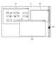
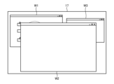
図5ないし図7を用いて、仮想オフィスにログイン中の第一ユーザが使用している第一情報端末装置10の表示部17における表示画面について説明する。図5は、第一実施形態に係る情報端末装置の表示部17における表示画面の一例を示す図である。図6は、図5の表示画面に表示された仮想オフィスのウィンドウの一例を示す図である。図7は、第一実施形態に係る情報端末装置の表示画面の他の例を示す図である。図5に示すように、第一情報端末装置10の表示部17には、例えば、仮想オフィスのアプリケーションによって仮想オフィス画面を表示するウィンドウW1と、その他のアプリケーションのウィンドウW2と、ウィンドウW3と、が表示される。図5に示す例では、ウィンドウW1は、ウィンドウW2の背面に表示されている。
図6は、図5のウィンドウW1を拡大した図である。図6に示すように、仮想オフィスを表示するウィンドウW1には、仮想オフィスの映像が表示されている。仮想オフィスには、複数の仮想デスクDが配置され、複数のアバターAが在室している。図6では、第一ユーザの情報端末装置10に表示されている仮想オフィスの表示範囲外である、第一ユーザの情報端末装置10に表示されていない隣接区画などから、第二アバターA2が矢印R2の方向に移動してきた状態を示す。この場合、第一アバターA1の情報共有範囲C1に第二アバターA2が入る可能性が高い状態である。
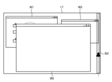
図7に示すように、第一ユーザの情報端末装置10における表示画面においてウィンドウによって隠れずに露出する位置として、表示画面の外周部に、第二アバターA2の存在を示す表示B2を行う。
第二アバターの存在を示す表示B2は、図6のように、第一アバターA1の情報共有範囲C1に第二アバターA2が入る可能性が高い状態である場合は、第二アバターA2が入る可能性が高いことを示す画像やテキストなどを用いた表示としてもよい。図示していないが、第一アバターA1の情報共有範囲C1に第二アバターA2が入った状態である場合は、第二アバターA2が入ったことを示す画像やテキストなどを用いた表示としてもよい。
(仮想空間制御方法)
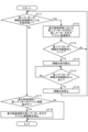
図8、図9を用いて、仮想空間制御方法について説明する。図8は、第一実施形態に係る仮想空間制御方法の一例を示すフローチャートである。図8に示す処理は、仮想空間制御システム1によって仮想オフィスが提供されている間、実行される。情報処理装置50が情報端末装置10において実装される場合、図8、図9示すフローチャートの処理は、その情報端末装置10にログインしている第一ユーザについて実行すればよい。情報処理装置50がサーバ装置30において実装される場合、図8、図9示すフローチャートの処理は、すべてのユーザについて実行すればよい。
図8、図9を用いて、仮想空間制御方法について説明する。図8は、第一実施形態に係る仮想空間制御方法の一例を示すフローチャートである。図8に示す処理は、仮想空間制御システム1によって仮想オフィスが提供されている間、実行される。情報処理装置50が情報端末装置10において実装される場合、図8、図9示すフローチャートの処理は、その情報端末装置10にログインしている第一ユーザについて実行すればよい。情報処理装置50がサーバ装置30において実装される場合、図8、図9示すフローチャートの処理は、すべてのユーザについて実行すればよい。
情報処理装置50は、第二アバターが第一アバターの情報共有範囲内に入ったか否かを判定する(ステップS101)。より詳しくは、情報処理装置50は、検出部51によって、仮想オフィスにおいて、第一アバターの情報共有範囲内に入った第二アバターを検出する。情報処理装置50は、第二アバターが第一アバターの情報共有範囲内に入ったと判定する場合(ステップS101でYes)、ステップS102へ進む。情報処理装置50は、第二アバターが第一アバターの情報共有範囲内に入ったと判定しない場合(ステップS101でNo)、本フローチャートの処理を終了する。
第二アバターが第一アバターの情報共有範囲内に入ったと判定する場合(ステップS101でYes)、情報処理装置50は、第一情報端末10の表示部17の表示画面端部における、第一アバターから見た第二アバターの方向に、第二アバターを示すアイコン画像を表示する(ステップS102)。情報処理装置50は、ステップS103へ進む。
情報処理装置50は、音声共有を可能化する(ステップS103)。より詳しくは、情報処理装置50は、音声出力制御部55によって、第一情報端末装置10と第二情報端末装置10とにおいて、相互に声などの音声が聞こえるようにする。情報処理装置50は、ステップS104へ進む。
情報処理装置50は、第二アバターが第一アバターの情報共有範囲内から出たか否かを検出する(ステップS104)。より詳しくは、情報処理装置50は、検出部51によって、仮想オフィスにおいて、第一アバターの情報共有範囲から第二アバターが出たことを検出する。情報処理装置50は、第二アバターが第一アバターの情報共有範囲内から出たと判定する場合(ステップS104でYes)、ステップS105へ進む。情報処理装置50は、第二アバターが第一アバターの情報共有範囲内から出たと判定しない場合(ステップS104でNo)、ステップS104の処理を再度実行する。
第二アバターが第一アバターの情報共有範囲内から出たと判定する場合(ステップS104でYes)、情報処理装置50は、音声共有を停止する(ステップS105)。より詳しくは、情報処理装置50は、音声出力制御部55によって、第一情報端末装置10と第二情報端末装置10とにおける音声共有を停止する。情報処理装置50は、ステップS106へ進む。
情報処理装置50は、第一情報端末10の表示部17の表示画面端部における第二アバターの方向に表示している第二アバターを示すアイコン画像の表示を停止する(ステップS106)。情報処理装置50は、本フローチャートの処理を終了する。
図9は、第一実施形態に係る仮想空間制御方法の他の例を示すフローチャートである。図9に示す処理は、仮想空間制御システム1によって仮想オフィスが提供されている間、実行される。図9のステップS112、ステップS113、ステップS114ないしステップS116、ステップS118の処理は、図8のステップS102、ステップS101、ステップS103ないしステップS105、ステップS106と同様の処理を行う。
情報処理装置50は、第二アバターが第一アバターの情報共有範囲内に入る可能性が高いか否かを判定する(ステップS111)。より詳しくは、情報処理装置50は、検出部51によって、仮想オフィスにおいて、第一アバターの情報共有範囲内に入る可能性が高い第二アバターを検出する。情報処理装置50は、第二アバターが第一アバターの情報共有範囲内に入る可能性が高いと判定する場合(ステップS111でYes)、ステップS112へ進む。情報処理装置50は、第二アバターが第一アバターの情報共有範囲内に入る可能性が高いと判定しない場合(ステップS111でNo)、ステップS117へ進む。
情報処理装置50は、第一情報端末10の表示部17の表示画面端部に、第二アバターのアイコン画像を表示中であるか否かを判定する(ステップS117)。情報処理装置50は、第一情報端末10の表示部17の表示画面端部に、第二アバターのアイコン画像を表示中であると判定する場合(ステップS117でYes)、ステップS118へ進む。ステップS117でYesとなる場合は、ステップS116からステップS111でのYesを得てステップS117の判定に進んだ場合である。ステップS117でNoとなる場合は、ステップS112からステップS116の処理を経ずに、ステップS111がNoとなった場合、または、ステップS118の処理後に再度、本処理が開始され、ステップS111がNoとなった場合である。情報処理装置50は、第一情報端末10の表示部17の表示画面端部に、第二アバターのアイコン画像を表示中であると判定しない場合(ステップS117でNo)、本フローチャートの処理を実行する。
(効果)
上述したように、本実施形態では、仮想オフィスにおいて、第一アバターの情報共有範囲に第二アバターが接近状態であることを検出した場合、第一情報端末装置10の表示画面において、ウィンドウによって隠れずに露出する位置に、第二アバターを示す表示を行うことができる。本実施形態によれば、第一ユーザが、情報端末装置10の表示画面において、仮想オフィス画面のウィンドウを最小化したり、他のウィンドウの背後に表示したりしていても、第二ユーザの第二アバターの接近を確認することができる。本実施形態によれば、第一ユーザは、第二アバターが、第一アバターの情報共有範囲内に入ったこと、または、入ってくる可能性が高いことに気付くことができる。本実施形態によれば、仮想オフィスなどの仮想空間において、他のユーザのアバターが近づいてきたことを適切に表示することができる。
上述したように、本実施形態では、仮想オフィスにおいて、第一アバターの情報共有範囲に第二アバターが接近状態であることを検出した場合、第一情報端末装置10の表示画面において、ウィンドウによって隠れずに露出する位置に、第二アバターを示す表示を行うことができる。本実施形態によれば、第一ユーザが、情報端末装置10の表示画面において、仮想オフィス画面のウィンドウを最小化したり、他のウィンドウの背後に表示したりしていても、第二ユーザの第二アバターの接近を確認することができる。本実施形態によれば、第一ユーザは、第二アバターが、第一アバターの情報共有範囲内に入ったこと、または、入ってくる可能性が高いことに気付くことができる。本実施形態によれば、仮想オフィスなどの仮想空間において、他のユーザのアバターが近づいてきたことを適切に表示することができる。
このようにして、本実施形態では、例えば、第一ユーザが、第二ユーザに対して秘匿性の高い内容の会話を行っているときに、第二アバターが接近していることを確認することにより、秘匿性の高い内容の会話を中断したり、第二ユーザに待ってもらったりすることができる。
本実施形態によれば、第一ユーザは、第二アバターが第一アバターの情報共有範囲内に入ったこと、または、入ってくる可能性が高いことに気付くことができるので、第二ユーザに突然近傍で話しかけられるような状態や、突然音声通話が要求されるような状態の発生を抑えることができる。
本実施形態によれば、第一ユーザは、第二アバターが第一アバターの情報共有範囲内に入ったこと、または、入ってくる可能性が高いことに気付くことができるので、第二ユーザとのコミュニケーションのための準備、例えば、作業中のウィンドウに対応する資料の保存や最小化、第二ユーザとのコミュニケーションに用いる資料の提示などを行うことができる。また、本実施形態によれば、第一ユーザが余裕をもって第二ユーザに対応することができる。
本実施形態によれば、第一アバターの情報共有範囲に、第一ユーザとは異なる組織に所属している第二ユーザに対応する第二アバターが入った状態、または、入る可能性が高い状態を検出できる。本実施形態によれば、第一ユーザと所属が異なり、情報を秘匿にする必要がある可能性が高い第二ユーザの接近に気付くことができる。本実施形態では、例えば、第一ユーザが、第二ユーザに対して秘匿性の高い内容の会話を行っているときに、第二アバターが接近していることを確認することにより、秘匿性の高い内容の会話を中断したり、第二ユーザに待ってもらったりすることができる。
本実施形態によれば、第一ユーザとは異なる職位である第二ユーザに対応する第二アバターが入ったこと、または、入る可能性が高い状態を検出できる。本実施形態では、例えば、第一ユーザが、第二ユーザに対して秘匿性の高い内容の会話を行っているときに、第二アバターが接近していることを確認することにより、秘匿性の高い内容の会話を中断したり、第二ユーザに待ってもらったりすることができる。
[第二実施形態]
図10ないし図13を用いて、第二実施形態に係る仮想空間制御システム1について説明する。図10は、第二実施形態に係る情報端末装置の表示画面の一例を示す図である。図11は、第二実施形態に係る情報端末装置の表示画面の他の例を示す図である。図12は、第二実施形態に係る仮想空間制御方法の一例を示すフローチャートである。図13は、第二実施形態に係る仮想空間制御方法の他の例を示すフローチャートである。以下の説明においては、第一実施形態の仮想空間制御システム1と同様の構成要素には、同一の符号または対応する符号を付し、その詳細な説明は省略する。仮想空間制御システム1は、情報処理装置50の処理が、第一実施形態と異なる。
図10ないし図13を用いて、第二実施形態に係る仮想空間制御システム1について説明する。図10は、第二実施形態に係る情報端末装置の表示画面の一例を示す図である。図11は、第二実施形態に係る情報端末装置の表示画面の他の例を示す図である。図12は、第二実施形態に係る仮想空間制御方法の一例を示すフローチャートである。図13は、第二実施形態に係る仮想空間制御方法の他の例を示すフローチャートである。以下の説明においては、第一実施形態の仮想空間制御システム1と同様の構成要素には、同一の符号または対応する符号を付し、その詳細な説明は省略する。仮想空間制御システム1は、情報処理装置50の処理が、第一実施形態と異なる。
情報処理装置50は、仮想オフィスにおいて第一アバターに対して第二アバターが接近状態であることを検出した場合、第一情報端末装置の表示画面において、仮想オフィスにおける第一アバターの位置を基準とした第二アバターの方向に、第二アバターを示すアイコン画像の表示を行う。
情報処理装置50は、第一情報端末装置10の表示画面に仮想オフィスを表示するウィンドウが隠れている状態において、第一情報端末装置10の表示画面の外周部に、第二アバターを示すアイコン画像の表示を行う。言い換えると、情報処理装置50は、第一情報端末装置10の表示画面に仮想オフィスを表示するウィンドウが適切に表示されていない状態において、第一情報端末装置10の表示画面の外周部に、第二アバターを示すアイコン画像の表示を行う。
仮想オフィスを表示するウィンドウが適切に表示されていない状態とは、上述したように、仮想オフィスを表示するウィンドウが他のウィンドウなどの情報に隠れている、または、最小化されている状態である。
外周部とは、例えば、表示画面の上端部、下端部、右端部、および、左端部である。
表示制御部54は、検出部51によって第二アバターが第一アバターに接近状態であることが検出された場合、第一ユーザが仮想オフィスにログインしている第一情報端末装置10の表示画面において、仮想オフィスにおける第一アバターの位置を基準とした第二アバターの方向に、第二アバターを示すアイコン画像を表示させる。
表示制御部54は、検出部51によって第二アバターが第一アバターに接近状態であることが検出された場合、第一ユーザが仮想オフィスにログインしている第一情報端末装置10の表示画面の外周部に、第二アバターを示すアイコン画像を表示させる。
図10ないし図11を用いて、仮想オフィスにログイン中の第一ユーザが使用している第一情報端末装置10の表示部17における表示画面について説明する。図10に示すように、第一情報端末装置10の表示部17において、仮想オフィス画面を表示するウィンドウW1は、ウィンドウW2の背面に隠されて表示されている。ウィンドウW1は、図6と同様である。
図11に示すように、第一アバターの位置を基準とした第二アバターの方向に、第二アバターA2の存在を示す表示B2が表示されている。具体的には、図11において、ウィンドウW2の背面に隠されて表示されているウィンドウW1においては、図6に示すように、第一アバターA1の位置に対して、情報共有範囲C1の右下方向に、第二アバターA2が入る可能性が高い状態である。このため、第一情報端末装置10の表示部17における表示画面の外周部における右下の位置に第二アバターを示すアイコンB2を表示させる。
(仮想空間制御方法)
図12、図13を用いて、仮想空間制御方法について説明する。図12のステップS121、ステップS123ないしステップS126、ステップS128の処理は、図8のステップS101、ステップS102ないしステップS105、ステップS106と同様の処理を行う。図12のステップS127の処理は、図9のステップS117と同様の処理を行う。
図12、図13を用いて、仮想空間制御方法について説明する。図12のステップS121、ステップS123ないしステップS126、ステップS128の処理は、図8のステップS101、ステップS102ないしステップS105、ステップS106と同様の処理を行う。図12のステップS127の処理は、図9のステップS117と同様の処理を行う。
情報処理装置50は、第一情報端末10の表示部17の表示画面に、仮想オフィスを表示するウィンドウが適切に表示されていない状態であるか否かを判定する(ステップS122)。情報処理装置50は、第一情報端末10の表示部17の表示画面に、仮想オフィスを表示するウィンドウが適切に表示されていない状態であると判定する場合(ステップS122でYes)、ステップS123へ進む。情報処理装置50は、第一情報端末10の表示部17の表示画面に、仮想オフィスを表示するウィンドウが適切に表示されていない状態であると判定しない場合(ステップS122でNo)、ステップS124へ進む。
図13のステップS131、ステップS133ないしステップS139の処理は、図9のステップS111、ステップS112ないしステップS118と同様の処理を行う。図13のステップS132の処理は、図12のステップS122と同様の処理を行う。
(効果)
上述したように、本実施形態では、第一アバターA1の位置を基準とした第二アバターA2の方向に第二アバターA2の存在を示す表示を行うことができる。本実施形態によれば、第二アバターA2が来る方向に合わせた位置に表示を行うので、第一ユーザは、仮想オフィスにおいて、第二アバターがどの方向から来たのかを確認できる。本実施形態によれば、第一ユーザが、第二アバターが来ることを想定していた場合、想定していた第二アバターの方向が予測されるため、想定していた第二アバターが来たことを直観的に把握できる。本実施形態によれば、第二アバターが来ることを想定していない場合であっても、第二アバターが来た方向が分かることにより、どのようなユーザの第二アバターが来たのか、ある程度の想定ができる場合がある。
上述したように、本実施形態では、第一アバターA1の位置を基準とした第二アバターA2の方向に第二アバターA2の存在を示す表示を行うことができる。本実施形態によれば、第二アバターA2が来る方向に合わせた位置に表示を行うので、第一ユーザは、仮想オフィスにおいて、第二アバターがどの方向から来たのかを確認できる。本実施形態によれば、第一ユーザが、第二アバターが来ることを想定していた場合、想定していた第二アバターの方向が予測されるため、想定していた第二アバターが来たことを直観的に把握できる。本実施形態によれば、第二アバターが来ることを想定していない場合であっても、第二アバターが来た方向が分かることにより、どのようなユーザの第二アバターが来たのか、ある程度の想定ができる場合がある。
本実施形態では、第一情報端末装置10の表示画面に仮想オフィスを表示するウィンドウが隠れている状態、つまり仮想オフィスを表示するウィンドウが適切に表示されていない状態において、第一情報端末装置10の表示画面の外周部などに、第二アバターを示す表示を行うことができる。本実施形態によれば、第一ユーザが表示画面で第一アバターの周囲に存在する他のアバターの存在を確認できない状態において、他のアバターが第一アバターの情報共有範囲内に入ったこと、または、入ってくる可能性が高いことに気付くことができる。
本開示の仮想空間制御システム、仮想空間制御方法およびプログラムは、例えば、仮想オフィスなどの仮想空間においてアバターを用いたコミュニケーションを行うコミュニケーションシステムに使用することができる。
1 仮想空間制御システム
10 情報端末装置
11 カメラ
12 マイクロフォン
13 操作部
17 表示部
18 音声出力部
19 通信部
20 端末制御装置
21 映像取得部
22 音声取得部
23 操作受付部
24 アプリケーション制御部
27 表示制御部
28 音声出力制御部
29 通信制御部
30 サーバ装置
31 通信部
40 サーバ制御装置
41 通信制御部
42 アプリケーション制御部
49 記憶部
50 情報処理装置
51 検出部
54 表示制御部
55 音声出力制御部
10 情報端末装置
11 カメラ
12 マイクロフォン
13 操作部
17 表示部
18 音声出力部
19 通信部
20 端末制御装置
21 映像取得部
22 音声取得部
23 操作受付部
24 アプリケーション制御部
27 表示制御部
28 音声出力制御部
29 通信制御部
30 サーバ装置
31 通信部
40 サーバ制御装置
41 通信制御部
42 アプリケーション制御部
49 記憶部
50 情報処理装置
51 検出部
54 表示制御部
55 音声出力制御部
Claims (7)
- 情報端末装置に仮想空間を表示させ、表示させた前記仮想空間にユーザに対応するアバターを表示させる仮想空間制御システムであって、
前記仮想空間制御システムが備える情報処理装置は、
前記仮想空間において、第一ユーザに対応する第一アバターの情報共有範囲に、第二ユーザに対応する第二アバターが入った状態、または、入る可能性が高い状態にある接近状態であることを検出した場合、前記第一ユーザが前記仮想空間にログインしている第一情報端末装置の表示画面において、前記表示画面に表示されている情報によって隠れずに露出する位置に、前記第二アバターを示す表示を行う、
仮想空間制御システム。 - 前記情報処理装置は、
前記仮想空間において、前記接近状態であることを検出した場合、前記仮想空間における前記第一アバターの位置を基準とした前記第二アバターの方向に、前記第二アバターを示す表示を行う、
請求項1に記載の仮想空間制御システム。 - 前記情報処理装置は、
前記第一情報端末装置の表示画面で前記仮想空間を表示するウィンドウが隠れている状態において、前記第一情報端末装置の表示画面の外周部に、前記第二アバターを示す表示を行う、
請求項1または2に記載の仮想空間制御システム。 - 前記情報処理装置は、
前記第一ユーザとは異なる組織に所属している第二ユーザに対応する前記第二アバターが前記接近状態であることを検出した場合、前記第一情報端末装置の表示画面に表示されている情報によって隠れずに露出する位置に、前記第二アバターを示す表示を行う、
請求項1または2に記載の仮想空間制御システム。 - 前記情報処理装置は、
前記第一ユーザとは異なる職位である第二ユーザに対応する前記第二アバターが前記接近状態であることを検出した場合、前記第一情報端末装置の表示画面に表示されている情報によって隠れずに露出する位置に、前記第二アバターを示す表示を行う、
請求項1または2に記載の仮想空間制御システム。 - 情報端末装置に仮想空間を表示させ、表示させた前記仮想空間にユーザに対応するアバターを表示させる仮想空間制御システムが実行する仮想空間制御方法であって、
前記仮想空間において、第一ユーザに対応する第一アバターの情報共有範囲に、第二ユーザに対応する第二アバターが入った状態、または、入る可能性が高い状態にある接近状態であることを検出した場合、前記第一ユーザが前記仮想空間にログインしている第一情報端末装置の表示画面において、前記表示画面に表示されている情報によって隠れずに露出する位置に、前記第二アバターを示す表示を行う、
仮想空間制御方法。 - 仮想空間において、第一ユーザに対応する第一アバターの情報共有範囲に、第二ユーザに対応する第二アバターが入った状態、または、入る可能性が高い状態にある接近状態であることを検出した場合、前記第一ユーザが前記仮想空間にログインしている第一情報端末装置の表示画面において、前記表示画面に表示されている情報によって隠れずに露出する位置に、前記第二アバターを示す表示を行う、
ことを空間共有システムを制御するコンピュータに動作させるプログラム。
Applications Claiming Priority (2)
| Application Number | Priority Date | Filing Date | Title |
|---|---|---|---|
| JP2023217786A JP2025101154A (ja) | 2023-12-25 | 2023-12-25 | 仮想空間制御システムおよび仮想空間制御方法 |
| JP2023-217786 | 2023-12-25 |
Publications (1)
| Publication Number | Publication Date |
|---|---|
| WO2025142004A1 true WO2025142004A1 (ja) | 2025-07-03 |
Family
ID=96217221
Family Applications (1)
| Application Number | Title | Priority Date | Filing Date |
|---|---|---|---|
| PCT/JP2024/035077 Pending WO2025142004A1 (ja) | 2023-12-25 | 2024-10-01 | 仮想空間制御システム、仮想空間制御方法およびプログラム |
Country Status (2)
| Country | Link |
|---|---|
| JP (1) | JP2025101154A (ja) |
| WO (1) | WO2025142004A1 (ja) |
Citations (2)
| Publication number | Priority date | Publication date | Assignee | Title |
|---|---|---|---|---|
| JP2022177677A (ja) * | 2021-05-18 | 2022-12-01 | 富士ソフト株式会社 | 仮想空間ビデオ通話システムおよび方法 |
| JP2023147694A (ja) * | 2022-03-30 | 2023-10-13 | 富士ソフト株式会社 | 仮想空間ビデオ通話システムおよび方法 |
-
2023
- 2023-12-25 JP JP2023217786A patent/JP2025101154A/ja active Pending
-
2024
- 2024-10-01 WO PCT/JP2024/035077 patent/WO2025142004A1/ja active Pending
Patent Citations (2)
| Publication number | Priority date | Publication date | Assignee | Title |
|---|---|---|---|---|
| JP2022177677A (ja) * | 2021-05-18 | 2022-12-01 | 富士ソフト株式会社 | 仮想空間ビデオ通話システムおよび方法 |
| JP2023147694A (ja) * | 2022-03-30 | 2023-10-13 | 富士ソフト株式会社 | 仮想空間ビデオ通話システムおよび方法 |
Also Published As
| Publication number | Publication date |
|---|---|
| JP2025101154A (ja) | 2025-07-07 |
Similar Documents
| Publication | Publication Date | Title |
|---|---|---|
| US11516431B2 (en) | Meeting privacy protection system | |
| US11461736B2 (en) | Presence status display system and presence status display method | |
| WO2012158576A2 (en) | Presenting or sharing state in presence | |
| JP2019197382A (ja) | 所在を通知するためにコンピュータで実行される方法、当該方法をコンピュータ実行させるプログラム、および、情報提供装置 | |
| WO2025142004A1 (ja) | 仮想空間制御システム、仮想空間制御方法およびプログラム | |
| JP2021082013A (ja) | 見守りシステム、見守り方法、見守り装置、見守りプログラム | |
| EP4068699A1 (en) | Devices and related methods for providing environments | |
| JP2026058198A (ja) | 仮想空間制御システムおよび仮想空間制御方法 | |
| JP2025101155A (ja) | 仮想空間制御システムおよび仮想空間制御方法 | |
| JP2025123718A (ja) | 仮想空間制御システムおよび仮想空間制御方法 | |
| WO2025177685A1 (ja) | 仮想空間制御システムおよび仮想空間制御方法 | |
| JP2025123716A (ja) | 仮想空間制御システムおよび仮想空間制御方法 | |
| WO2026069911A1 (ja) | 仮想空間制御システムおよび仮想空間制御方法 | |
| JP2025147896A (ja) | 仮想空間制御システムおよび仮想空間制御方法 | |
| JP2025166788A (ja) | 仮想空間制御システムおよび仮想空間制御方法 | |
| JP2026025241A (ja) | 仮想空間制御システムおよび仮想空間制御方法 | |
| JP2025141629A (ja) | 仮想空間制御システムおよび仮想空間制御方法 | |
| JP2025141622A (ja) | 仮想空間制御システムおよび仮想空間制御方法 | |
| JP2025123717A (ja) | 仮想空間制御システムおよび仮想空間制御方法 | |
| JP2025132072A (ja) | 仮想空間制御システムおよび仮想空間制御方法 | |
| JP2025132608A (ja) | 仮想空間制御システムおよび仮想空間制御方法 | |
| JP2025132385A (ja) | 仮想空間制御システムおよび仮想空間制御方法 | |
| CN114586053B (zh) | 在日历事件期间对通信设备的配置和控制 | |
| WO2025182184A1 (ja) | 仮想空間制御システムおよび仮想空間制御方法 | |
| JP2025135857A (ja) | 仮想空間制御システムおよび仮想空間制御方法 |
Legal Events
| Date | Code | Title | Description |
|---|---|---|---|
| 121 | Ep: the epo has been informed by wipo that ep was designated in this application |
Ref document number: 24911898 Country of ref document: EP Kind code of ref document: A1 |