WO2025136102A1 - An acoustic subsurface inspection device and method - Google Patents
An acoustic subsurface inspection device and method Download PDFInfo
- Publication number
- WO2025136102A1 WO2025136102A1 PCT/NL2024/050691 NL2024050691W WO2025136102A1 WO 2025136102 A1 WO2025136102 A1 WO 2025136102A1 NL 2024050691 W NL2024050691 W NL 2024050691W WO 2025136102 A1 WO2025136102 A1 WO 2025136102A1
- Authority
- WO
- WIPO (PCT)
- Prior art keywords
- acoustic
- sample
- afm
- subsurface
- tip
- Prior art date
- Legal status (The legal status is an assumption and is not a legal conclusion. Google has not performed a legal analysis and makes no representation as to the accuracy of the status listed.)
- Pending
Links
Classifications
-
- G—PHYSICS
- G01—MEASURING; TESTING
- G01Q—SCANNING-PROBE TECHNIQUES OR APPARATUS; APPLICATIONS OF SCANNING-PROBE TECHNIQUES, e.g. SCANNING PROBE MICROSCOPY [SPM]
- G01Q60/00—Particular types of SPM [Scanning Probe Microscopy] or microscopes; Essential components thereof
- G01Q60/24—AFM [Atomic Force Microscopy] or apparatus therefor, e.g. AFM probes
- G01Q60/32—AC mode
-
- G—PHYSICS
- G01—MEASURING; TESTING
- G01N—INVESTIGATING OR ANALYSING MATERIALS BY DETERMINING THEIR CHEMICAL OR PHYSICAL PROPERTIES
- G01N29/00—Investigating or analysing materials by the use of ultrasonic, sonic or infrasonic waves; Visualisation of the interior of objects by transmitting ultrasonic or sonic waves through the object
- G01N29/04—Analysing solids
- G01N29/06—Visualisation of the interior, e.g. acoustic microscopy
- G01N29/0654—Imaging
- G01N29/0681—Imaging by acoustic microscopy, e.g. scanning acoustic microscopy
-
- G—PHYSICS
- G01—MEASURING; TESTING
- G01Q—SCANNING-PROBE TECHNIQUES OR APPARATUS; APPLICATIONS OF SCANNING-PROBE TECHNIQUES, e.g. SCANNING PROBE MICROSCOPY [SPM]
- G01Q30/00—Auxiliary means serving to assist or improve the scanning probe techniques or apparatus, e.g. display or data processing devices
- G01Q30/04—Display or data processing devices
-
- G—PHYSICS
- G01—MEASURING; TESTING
- G01Q—SCANNING-PROBE TECHNIQUES OR APPARATUS; APPLICATIONS OF SCANNING-PROBE TECHNIQUES, e.g. SCANNING PROBE MICROSCOPY [SPM]
- G01Q70/00—General aspects of SPM probes, their manufacture or their related instrumentation, insofar as they are not specially adapted to a single SPM technique covered by group G01Q60/00
- G01Q70/06—Probe tip arrays
Definitions
- the present application pertains to an acoustic subsurface inspection device.
- the present application further pertains to an acoustic subsurface inspection method.
- Existing acoustic inspection methods operate according to first, low frequency based approach and a second, high frequency based approach.
- first approach the stiffness of the sample surface is measured at a relatively low acoustic frequency, e.g. in a range from about 1 MHz to a few hundred MHz.
- subsurface features can be identified at a sub nanometer resolution up to a depth of about 2 micron.
- second approach elasticity and wave scattering is measured at a relatively high acoustic frequency, e.g. exceeding 1 GHz.
- This approach renders it possible to inspect a sample at a level deeper than is possible with the first approach, but so far, the practically achievable resolution is inferior as compared to what is achievable with the first approach.
- the improved acoustic subsurface inspection device comprises a carrier for holding a sample to be inspected, a signal generator, at least one AFM-tip, a lateral positioning device, a distance control device, and a signal processor.
- the device is particularly relevant for application in the lithographic industry, wherein the sample to be inspected is a semiconductor device, e.g. a (semi-finished) integrated circuit, such as a NAND-memory.
- the sample is a micro-optic device comprising highly integrated optical circuitry.
- the sample is a MEMS-device.
- the sample comprises a combination of two or more selected from electronical, optical and mechanical elements.
- the signal generator is configured to provide a drive signal with which the at least one AFM-tip is driven so as to induce an acoustic wave into the sample at an input location on a surface of the sample.
- an electric drive-signal may be converted in an acoustic signal for the at least one AFM-tip by an actuator, such as an electro-static or piezo-electric actuator.
- the acoustic signal is generated by a laser that directs a modulated laser beam to the tip or to a cantilever or membrane carrying the tip.
- the signal generator is preferably configured to generate pulse signals. This simplifies signal processing operations to be performed on the sense signal.
- the signal processor generates the pulse signals with a pulse duration that is short in comparison to the time it takes the reflection to arrive at the single AFM-tip so that the sensed signal resulting from the reflection can be easily discriminated from the sensed signal resulting from the acoustic input signal.
- the signal processor generates pulses in a pulse train with a time interval between subsequent pulses that exceeds the response duration.
- the response duration is for example defined as the interval of time wherein a response amplitude has decreased to a value that is substantially less than its maximum value, e.g. less than 10 times or less than 100 times the maximum value.
- the signal processor may generate the drive signal as a continuous high frequent signal or generate pulse like signals as described for the case where a single AFM-tip is used.
- the lateral positioning device serves to control a lateral position of the at least one AFM-tip with respect to the surface of the sample.
- the lateral positioning device is configured to control the lateral position in two orthogonal directions of the sample surface, e.g. by positioning the sample and/or the at least one AFM-tip.
- the distance control device controls a distance of the at least one of the AFM-tips with respect to the surface of the sample.
- the distance control device controls the position of a device head carrying the at least one AFM-tip in a direction transverse to the sample surface.
- the distance control device controls the position of an AFM-tip arranged in the device head in a direction transverse to the sample surface.
- the signal processor is configured for generating output data about the subsurface feature in the sample.
- the output data comprises for example a location of the subsurface feature, a shape of the subsurface feature, a material property of the subsurface feature and the like.
- the acoustic subsurface inspection device is configured to perform a measurement session with at least two acoustic measurements with mutually different input locations and/or mutually different receiving locations.
- the signal processor is configured to combine information from the respective sense signals generated with the at least two acoustic measurements in the measurement session to compute information about the subsurface feature in the sample.
- the signal processor combines information from the respective sense signals generated with the at least two acoustic measurements in the measurement session it can obtain information about the subsurface feature in the sample that would otherwise not be available.
- an AFM-tip is used that is configured for inducing an acoustic wave and configured for receiving a reflection of the acoustic wave.
- the at least two acoustic measurements are performed in mutually different time intervals at mutually different lateral positions of the AFM-tip relative to the sample surface.
- the first one of the lateral positions is the input location and the receiving location in the first acoustic measurement.
- the second one of the lateral positions is the input location and the receiving location in the second acoustic measurement.
- the acoustic subsurface inspection device comprises a plurality of transmitting AFM-tips configured for inducing an acoustic wave into the sample, and at least one separate receiving AFM-tip for receiving a reflected acoustic wave.
- the signal processor is configured to generate output data based on a comparison of the generated sense signals resulting from reflections of the acoustic waves originating from each of the plurality of transmitting AFM-tips.
- the acoustic subsurface inspection device comprises a plurality of receiving AFM-tips configured for receiving a reflected acoustic wave as well as at least one transmitting AFM-tip and the signal processor is configured to generate output data based on a comparison of the generated sense signals provided by each of the plurality of receiving AFM-tips.
- an AFM-tip is statically configured as either a transmitting AFM-tip, a receiving AFM-tip or both at the same time.
- the acoustic subsurface inspection device comprises at least one AFM- tip that is dynamically configurable as either a transmitting AFM-tip, a receiving AFM-tip or both at the same time.
- the drive signal can be provided as a pulse train.
- a plurality of sense signals can be obtained for each pulse in the pulse train.
- the obtained plurality of sense signals can be subjected to a statistical analysis, for example to derive an estimation of measurement noise and/or to provide a denoised sense signal.
- the drive signal can be provided as a pulse train in order to perform a lock-in detection.
- the signal processor of the acoustic subsurface inspection device comprises a peak detection unit to determine a respective delay with which a peak value occurs in respective sense signals obtained in respective ones of the at least two acoustic measurements in the measurement session and a computation unit to compute a position of the subsurface feature from a difference between the respective delays.
- the difference between the respective delays is a monotonic function of the lateral position of the subsurface feature.
- the lateral position of the subsurface feature can be computed from the measured difference with the inverse function or estimated with an approximation thereof, e.g. using a look-up table or a polynomial approximation.
- the peak detection unit can be configured to detect a plurality of peaks in the signal and to correlate the difference in delay between mutually corresponding peaks. Peaks occurring in the sense signal of the first acoustic measurement can be paired with peaks occurring in the sense signal of the second acoustic measurement provided that the input location and the receiving location in the first measurement are sufficiently close to the input location and the receiving location in the second measurement.
- the respective sense signals ST(x) generated, e.g. with a head 30, with the at least two acoustic measurements in the measurement session are provided at an input of the neural network 50NN to be trained;
Landscapes
- Physics & Mathematics (AREA)
- General Health & Medical Sciences (AREA)
- Health & Medical Sciences (AREA)
- General Physics & Mathematics (AREA)
- Radiology & Medical Imaging (AREA)
- Nuclear Medicine, Radiotherapy & Molecular Imaging (AREA)
- Analytical Chemistry (AREA)
- Biochemistry (AREA)
- Chemical & Material Sciences (AREA)
- Life Sciences & Earth Sciences (AREA)
- Immunology (AREA)
- Pathology (AREA)
- Acoustics & Sound (AREA)
- Engineering & Computer Science (AREA)
- Power Engineering (AREA)
- Investigating Or Analyzing Materials By The Use Of Ultrasonic Waves (AREA)
Abstract
The present application discloses an acoustic subsurface inspection device (1) an a corresponding method. The disclosure comprises performing a measurement session including at least two acoustic measurements, each acoustic measurement comprising inputting an acoustic wave at an input location at a surface (114) of a sample (11) and generating a respective sense signal (S32a, S32b) that is indicative for a measured reflections of the acoustic wave at a measurement location. A measurement session comprises at least two acoustic measurements that are performed with a different input location and/or a different measurement location. Subsequently output data indicative for subsurface features in the sample is generated based on a computation using the respective sense signals generated with the at least two acoustic measurements in the measurement session.
Description
Title: An acoustic subsurface inspection device and method
BACKGROUND
The present application pertains to an acoustic subsurface inspection device.
The present application further pertains to an acoustic subsurface inspection method.
Acoustic inspection devices and methods are available for use in the lithographic industry to enable subsurface inspection of finished and/or intermediary products so as to properly control alignment and process parameters of the process and if necessary to remove invalid products. According to Moore’s law, critical dimensions of semiconductor devices become smaller and smaller in order to enable an ever increasing integration level. Also there is a tendency for manufacturing the devices with an increasing number of layers.
Existing acoustic inspection methods operate according to first, low frequency based approach and a second, high frequency based approach. In the first approach the stiffness of the sample surface is measured at a relatively low acoustic frequency, e.g. in a range from about 1 MHz to a few hundred MHz. Therewith subsurface features can be identified at a sub nanometer resolution up to a depth of about 2 micron. In the second approach, elasticity and wave scattering is measured at a relatively high acoustic frequency, e.g. exceeding 1 GHz. This approach renders it possible to inspect a sample at a level deeper than is possible with the first approach, but so far, the practically achievable resolution is inferior as compared to what is achievable with the first approach.
SUMMARY
It is an object of the present disclosure to provide an improved acoustic subsurface inspection device to address the above-mentioned shortcomings.
It is a further object of the present disclosure to provide an improved acoustic subsurface inspection method to address the above-mentioned shortcomings.
In accordance with the first mentioned object the improved acoustic subsurface inspection device comprises a carrier for holding a sample to be inspected, a signal generator, at least one AFM-tip, a lateral positioning device, a distance control device, and a signal processor.
As noted above, the device is particularly relevant for application in the lithographic industry, wherein the sample to be inspected is a semiconductor device, e.g. a (semi-finished) integrated circuit, such as a NAND-memory. In other examples the sample is a micro-optic device comprising highly integrated optical circuitry. In still further examples the sample is a MEMS-device. In again further examples, the sample comprises a combination of two or more selected from electronical, optical and mechanical elements.
The signal generator is configured to provide a drive signal with which the at least one AFM-tip is driven so as to induce an acoustic wave into the sample at an input location on a surface of the sample. Therewith an electric drive-signal may be converted in an acoustic signal for the at least one AFM-tip by an actuator, such as an electro-static or piezo-electric actuator. According to another approach the acoustic signal is generated by a laser that directs a modulated laser beam to the tip or to a cantilever or membrane carrying the tip.
The at least one AFM-tip or another at least one AFM-tip is (also) configured for receiving a reflection of the acoustic wave in the sample at a receiving location on the surface of the sample. To that end it is coupled to an acoustic sensor (e.g. a piezo electric element) configured to generate a sense signal indicative for the received reflected acoustic wave. In case a single AFM- tip is configured both to induce an acoustic wave and to receive a reflected acoustic wave the actuator, e.g. a piezo-electric element, to convert an electric signal into an acoustic signal may also serve as a sensor to convert an acoustic signal into an electric signal. In case there is only a single AFM-tip that is configured to induce an acoustic wave and to receive a reflected acoustic wave the actuator, the signal generator is preferably configured to generate pulse signals.
This simplifies signal processing operations to be performed on the sense signal. In some example the signal processor generates the pulse signals with a pulse duration that is short in comparison to the time it takes the reflection to arrive at the single AFM-tip so that the sensed signal resulting from the reflection can be easily discriminated from the sensed signal resulting from the acoustic input signal. In some of these examples, the signal processor generates pulses in a pulse train with a time interval between subsequent pulses that exceeds the response duration. The response duration is for example defined as the interval of time wherein a response amplitude has decreased to a value that is substantially less than its maximum value, e.g. less than 10 times or less than 100 times the maximum value.
In case separate AFM-tips are used to induce an acoustic wave and to receive a reflected acoustic wave, then it is easier to discriminate the sensed signal resulting due to the reflection from the sensed signal resulting from the acoustic input signal. The signal processor may generate the drive signal as a continuous high frequent signal or generate pulse like signals as described for the case where a single AFM-tip is used.
The lateral positioning device serves to control a lateral position of the at least one AFM-tip with respect to the surface of the sample. Typically the lateral positioning device is configured to control the lateral position in two orthogonal directions of the sample surface, e.g. by positioning the sample and/or the at least one AFM-tip.
The distance control device controls a distance of the at least one of the AFM-tips with respect to the surface of the sample. In an example the distance control device controls the position of a device head carrying the at least one AFM-tip in a direction transverse to the sample surface. Alternatively or additionally the distance control device controls the position of an AFM-tip arranged in the device head in a direction transverse to the sample surface.
The signal processor is configured for generating output data about the subsurface feature in the sample. The output data comprises for example a location of the subsurface feature, a shape of the subsurface feature, a material property of the subsurface feature and the like.
The acoustic subsurface inspection device is configured to perform a measurement session with at least two acoustic measurements with mutually different input locations and/or mutually different receiving locations. The signal processor is configured to combine information from the respective sense signals generated with the at least two acoustic measurements in the measurement session to compute information about the subsurface feature in the sample.
Due to the fact that the signal processor combines information from the respective sense signals generated with the at least two acoustic measurements in the measurement session it can obtain information about the subsurface feature in the sample that would otherwise not be available.
As noted above, in some examples an AFM-tip is used that is configured for inducing an acoustic wave and configured for receiving a reflection of the acoustic wave. In those examples the at least two acoustic measurements are performed in mutually different time intervals at mutually different lateral positions of the AFM-tip relative to the sample surface. The first one of the lateral positions is the input location and the receiving location in the first acoustic measurement. The second one of the lateral positions is the input location and the receiving location in the second acoustic measurement.
In another embodiment the acoustic subsurface inspection device comprises a plurality of transmitting AFM-tips configured for inducing an acoustic wave into the sample, and at least one separate receiving AFM-tip for receiving a reflected acoustic wave. In that embodiment the signal processor is configured to generate output data based on a comparison of the generated sense signals resulting from reflections of the acoustic waves originating from each of the plurality of transmitting AFM-tips.
In another embodiment the acoustic subsurface inspection device comprises a plurality of receiving AFM-tips configured for receiving a reflected acoustic wave as well as at least one transmitting AFM-tip and the signal processor is configured to generate output data based on a comparison of the generated sense signals provided by each of the plurality of receiving AFM-tips.
It is not necessary that an AFM-tip is statically configured as either a transmitting AFM-tip, a receiving AFM-tip or both at the same time. In some
examples the acoustic subsurface inspection device comprises at least one AFM- tip that is dynamically configurable as either a transmitting AFM-tip, a receiving AFM-tip or both at the same time.
As noted above, the drive signal can be provided as a pulse train. During a same acoustic measurement in an acoustic measurement session, i.e. while not changing the input location and the receiving location, a plurality of sense signals can be obtained for each pulse in the pulse train. The obtained plurality of sense signals can be subjected to a statistical analysis, for example to derive an estimation of measurement noise and/or to provide a denoised sense signal. Also the drive signal can be provided as a pulse train in order to perform a lock-in detection.
In some embodiments the signal processor of the acoustic subsurface inspection device comprises a peak detection unit to determine a respective delay with which a peak value occurs in respective sense signals obtained in respective ones of the at least two acoustic measurements in the measurement session and a computation unit to compute a position of the subsurface feature from a difference between the respective delays. The difference between the respective delays is a monotonic function of the lateral position of the subsurface feature. Therewith the lateral position of the subsurface feature can be computed from the measured difference with the inverse function or estimated with an approximation thereof, e.g. using a look-up table or a polynomial approximation.
In case there are more subsurface features present, the peak detection unit can be configured to detect a plurality of peaks in the signal and to correlate the difference in delay between mutually corresponding peaks. Peaks occurring in the sense signal of the first acoustic measurement can be paired with peaks occurring in the sense signal of the second acoustic measurement provided that the input location and the receiving location in the first measurement are sufficiently close to the input location and the receiving location in the second measurement.
It is further possible to perform a measurement session with more than two acoustic measurements at mutually different input locations and/or mutually
different receiving locations, for example to determine more than one coordinate of the subsurface feature.
In an alternative embodiment the signal processor of the acoustic subsurface inspection device comprises a prediction module that is configured to generate predicted detection signals based on a model of the sample and generating output data based on a comparison of the predicted detection signals and the actual detection signals. In this embodiment the comparison between the predicted detection signals and the actual detection signals indicates whether or not a property of the sample deviates from what it should be. If this is the case the sample can be subjected to a further measurement to identify the cause of the deviation.
In again another embodiment of the acoustic subsurface inspection device the signal processor comprises a trained neural network that receives the respective sense signals and that is configured to apply neural network operations to the received sense signals to estimate properties of the subsurface feature. The obtained sense signals comprise convolved information about the subsurface features present in the sample. A neural network can be trained for the purpose to reconstruct information about the subsurface features. Due to the fact that sense signals are dominated by local information, the neural network can be trained with a training sample having a large plurality of training regions with mutually different subsurface patterns. The properties of the training sample determined at design time therewith serve as a ground truth.
In further embodiments the signal processor of the acoustic subsurface inspection device comprises two or more of the signal analysis components as described above, so as to analyze the sense signals in various ways.
The present application further pertains to an improved acoustic subsurface inspection method holding a sample to be inspected
The method comprises performing a measurement session that includes at least two acoustic measurements. Each acoustic measurement comprises inputting an acoustic wave at an input location of the sample surface and generating a respective sense signal measuring reflections of the acoustic wave at a measurement location of the sample surface. The at least two acoustic
measurements are performed with a different input location and/or a different measurement location.
Then output data is generated that is indicative for subsurface features in the sample based on a computation using the respective sense signals generated with the at least two acoustic measurements in the measurement session.
An embodiment of the acoustic subsurface inspection method further comprises additional steps preceding the step of holding a sample to be inspected. The additional steps comprise:
Providing a neural network;
Providing at least one test sample;
Performing a plurality of acoustic measurements, each acoustic measurement in the plurality of acoustic measurements comprising:
Inputting an acoustic input signal at an input location and obtaining a sense signal indicative for an acoustic reflection signal at a sensing location, wherein the input locations and/or the sensing locations of the at least two acoustic measurements are at mutually different lateral positions with respect to the sample surface.
Therewith the neural network is trained for the purpose to reconstruct information about the subsurface features. Due to the fact that sense signals are dominated by local information, training can be performed with a training sample having a large plurality of training regions with mutually different subsurface patterns. The properties of the training sample determined at design time therewith serve as a ground truth.
In an embodiment of the acoustic subsurface inspection method, the computation comprises generating a difference signal indicative for a difference between the respective sense signals, This serves as an intermediate computational step that simplifies further computational steps for generating the output data.
In an embodiment, the acoustic subsurface inspection device comprises a prediction module that is configured to generate predicted detection signals based on a model of the sample and generating output data based on a comparison of the predicted detection signals and the actual detection signals. In
this case it is not necessary to reconstruct subsurface features from the detection signals. Instead, based on the comparison it can be determined whether or not a subsurface defect is present.
In an embodiment of the acoustic subsurface inspection device the at least one AFM-tip that is configured to detect a reflection is at a fixed distance with respect to the at least one AFM-tip configured for supplying an acoustic input signal. This embodiment is advantageous in the sense that it has a mechanically simple construction and the relative position can be very accurately be calibrated.
In another embodiment of the acoustic subsurface inspection device the at least one AFM-tip that is configured to detect a reflection is at a configurable distance with respect to the at least one AFM-tip configured for supplying an acoustic input signal. This renders it possible to perform additional measurements.
In some examples, the relative lateral positioning between the transmitting and receiving AFM-tips is not fixed but can be adjusted. This adjustability allows, for example, the receiving AFM-tip to be positioned at a plurality of selectable/adjustable lateral offsets relative to the transmitting AFM- tip. By selecting different lateral separations, the measurement conditions can be improved to suit the particular characteristics of the sample under inspection, its subsurface structures, and the desired measurement resolution and accuracy.
Optionally, the configurable distance is adjusted based on (e.g. expected) buried structures to be imaged and/or parameters derived from the same. Having a configurable distance allows for optimization depending on the nature of the buried structures to be imaged and/or parameters derived from the same.
By adjusting the transmitter-receiver spacing, the path lengths of the acoustic waves to and from subsurface features can be modified, which in turn influences the delay times and detected signal characteristics. Such flexibility is advantageous for fine-tuning the measurement to increase signal contrast, reduce measurement uncertainty, and achieve an improved signal-to-noise ratio. For example, by increasing the lateral distance between the transmitting AFM- tip and the receiving AFM-tip, certain interference patterns in the sensed signal may be mitigated, or certain subsurface features that were previously
indistinguishable may now yield distinguishable peaks in the reflected signal. Conversely, by decreasing the lateral distance, it may be possible to increase measurement sensitivity for specific localized subsurface structures. Thus, having a configurable distance provides a metrology advantage: the operator or automated control system can select or tune the AFM-tip positions to best suit the materials and configuration of the sample at hand.
Embodiments of the acoustic subsurface inspection device having more than one AFM-tip may comprise a respective actuator for individually positioning each AFM-tip in a direction towards a surface of the sample.
Advantageously, effectively controlled, individual coupling levels can be ensured. By providing individual actuators for each AFM-tip, it becomes possible to finely adjust the vertical positioning of the tips relative to the sample surface, thereby allowing precise control of the contact force and thus the acoustic coupling at each tip location. The acoustic coupling between the AFM-tip and the sample surface, which is influenced by the applied force, directly affects the signal-to-noise ratio (SNR) of the measured reflection signals.
In some examples, ensuring ideal parallel alignment of the head and the sample substrate may be challenging, and a small angular misalignment (tilt) may be present. As a consequence, a fixed vertical position of the head relative to the sample may lead to varying tip-to-substrate distances across multiple AFM- tips, since each tip may engage the substrate surface at a slightly different angle or vertical offset. These variations can cause differences in the contact forces applied by the individual AFM-tips to the substrate, resulting in uneven acoustic coupling conditions that may adversely affect measurement quality. Advantageously, by employing individual actuators for each AFM-tip, the vertical displacement and contact force of each tip can be individually controlled, even in the presence of tilt or other spatial variations in the substrate surface. For example, one AFM-tip acting as the acoustic source may be positioned at a certain contact force level to achieve improved acoustic wave transmission into the sample, while the AFM-tips designated as receivers can be adjusted independently to ensure a suitable force level for optimal detection and coupling efficiency. In some examples, such an individual control can be further combined
with the embodiments where one of the AFM-tips is configured for receiving the reflection is placed at a configurable lateral distance from the source AFM-tip. By doing so, the force applied by the sensing tips can be tuned to provide improved acoustic coupling (adequate couplings for each tip), thereby enhancing SNR for the reflected signals and improving the fidelity and reliability of the subsurface feature detection.
In an embodiment, a head of the acoustic subsurface inspection device has one or more AFM-tips removably mounted therein.
Still further the present disclosure provides a system that comprises in addition to the improved acoustic subsurface inspection device, a calibration sample and a calibration unit. Therein the calibration unit is configured to cause the acoustic subsurface inspection device to generate output data indicative for subsurface features in the calibration sample and to calibrate the acoustic subsurface inspection device based on a comparison of the output data with output data expected for the calibration sample.
BRIEF DESCRIPTION OF THE DRAWINGS
These and other aspects of the present disclosure are shown in more detail with reference to the drawings: Therein:
FIG. 1 schematically shows an embodiment of the improved acoustic subsurface inspection device;
FIG. 2 illustrates various measurement options;
FIG. 3A - 3D illustrate operations of an embodiment of an improved acoustic subsurface inspection device 1 in more detail;
FIG. 4A, 4B illustrate another embodiment of the improved acoustic subsurface inspection device;
FIG. 5A, 5B illustrate again another embodiment of the improved acoustic subsurface inspection device;
FIG. 6A - 6D illustrate an application to overlay detection;
FIG. 7 illustrates a method of training a neural network for uses in an embodiment the improved acoustic subsurface inspection device or in an embodiment of the corresponding method.
DETAILED DESCRIPTION OF EMBODIMENTS
FIG. 1 schematically shows an embodiment of an improved acoustic subsurface inspection device 1. In the embodiment of FIG. 1, the acoustic subsurface inspection device 1 comprises a carrier 10 for holding a sample 11 to be inspected, a signal generator 20, at least one AFM-tip 31 configured for inducing an acoustic wave W, at least one AFM-tip 32, 32a, 32b configured for receiving a reflection Rca, Rda of the acoustic wave, a lateral positioning device 16, a distance control device, and a signal processor 50.
The at least one AFM-tip 31 when driven by the signal generator 20 is configured for inducing an acoustic wave W into the sample at an input location pa; Pd, Pe on a surface 114 of the sample.
The at least one AFM-tip 32, 32a, 32b is configured for receiving a reflection Rca, Rda of the acoustic wave in the sample at a receiving location pb, pc; Pf on the surface (114) of the sample and it is coupled to an acoustic sensor configured to generate a sense signal S32a, S32b that is indicative for the received reflected acoustic wave.
The lateral positioning device 16 is configured for controlling a lateral position of at least one AFM-tip 31, 32 with respect to the surface of the sample 11.
The distance control device 51 is provided for controlling a distance of at least one of the AFM-tips with respect to the surface of the sample 11.
The signal processor 50 is configured for generating output data Sim about the subsurface feature 113c, 113d in the sample.
The acoustic subsurface inspection device is configured to perform a measurement session with at least two acoustic measurements with mutually different input locations and/or mutually different receiving locations.
The signal processor 50 is configured to combine information from the respective sense signals generated with the at least two acoustic measurements in the measurement session to compute information about the subsurface feature 113c, 113d in the sample.
FIG. 2 schematically shows a surface 114 of a sample 11 and illustrates operation of two embodiments of the acoustic subsurface inspection device. The upper part of FIG. 2 illustrates the operation of a first embodiment wherein an AFM-tip 31 driven by the signal generator 20 induces an acoustic wave W into the sample at an input location pa on the surface 114 of the sample 11. At least one AFM-tip receives a reflection Rab, Rac of the acoustic wave in the sample at the respective receiving locations pb, pc on the surface 114 of the sample. In one example a single AFM-tip is subsequently positioned at the receiving locations pb, pc. In another example respective AFM-tips are positioned at the receiving locations pb, pc on to simultaneously receive the reflections Rab, Rac of the acoustic wave.
The lower part of FIG. 2 shows operation of a second embodiment wherein a single AFM-tip positioned at a receiving locations pf receives reflections Rdf, Ref of acoustic waves in the sample induced at respective positions pd, pe on the surface 114 of the sample 11. In one example a single AFM-tip is subsequently positioned at the locations pd, pe for inducing an acoustic wave. In another example respective AFM-tips are positioned at the locations pd, pe to simultaneously induce an acoustic wave in the sample 11.
In each of these examples in these embodiments respective sense signals are obtained that are generated with at least two acoustic measurements in a measurement session. In the examples of the first embodiment respective sense signals are obtained for the reflections Rab, Rac. In the examples of the second embodiment respective sense signals are obtained for the reflections Rdf, Ref. Based on a comparison of the generated sense signals the signal processor generates output data.
FIG. 3A and 3B illustrates an operation of an embodiment of the improved acoustic subsurface inspection device in more detail. FIG. 3A shows an exemplary sample 11 having a lower layer 111, e.g. a substrate, a matrix 112 and a series of
features of which the two that are most close to the transmission tip 31 are denoted as 113c and 113d.
In this embodiment, the improved acoustic subsurface inspection device comprises a sense head 30 with an AFM-tip 31 configured to induce an acoustic wave W into the sample 11 at an input location on a surface 114 of the sample 11. The sense head 30 also has a pair of AFM-tips 32a, 32b that are symmetrically arranged with respect to AFM-tip 31 at a distance of 5nm to each other, and that are configured to receive reflections of the acoustic wave W at respective receiving locations. In one example the AFM-tips 31, 32a, 32b are statically configured to perform these functions. I.e. their function is hardwired. For example the AFM-tip 31 is exclusively connected to the signal generator 20 to receive the drive signal S31 and the AFM-tips 32a, 32b are exclusively connected to the signal processor 50 to provide their respective sense signals S32a, S32b. In that case, the AFM-tip 31 on the one hand and the AFM-tips 32 a, 32b on the other hand may have a dedicated construction to optimally perform their respective hardwired functions. In another example the AFM-tips 31, 32a, 32b are dynamically configured to perform these functions. For example each of these AFM-tips is mechanically coupled to a respective piezo-electric element. In this case the AFM-tip 31 is configured to induce an acoustic wave W into the sample 11 in that its piezo-electric element is dynamically configured to receive the drive signal S31 from the signal generator 20 and the piezo-electric elements of the AFM-tips 31, 32a, 32b are dynamically configured to provide their respective sense signals S32a, S32b to the signal generator 20.
For simplicity the acoustic waves emitted by the transmission tip 31 and reflected by the features 113c, 113d are schematically shown as arrows.
The drive signal S31 and the sense signals Ss2a, 832b typically are electric signals, but it may alternatively be the case that one or more of these signals are optical signals.
As shown in FIG. 3A, AFM-tip 32a, 32b receives reflections Rca and Rda from the two nearest subsurface features 113c, 113d in the sample 11 respectively and generates the sense signal S32a as shown in FIG. 3B In. In practice it can be presumed that reflections from other subsurface features,
farther away from these two subsurface features 113c, 113d can be ignored. Likewise AFM-tip 32b receives reflections Rcb and Rdb from the two nearest subsurface features 113c, 113d in the sample 11 respectively and generates the sense signal S32b shown in FIG. 3B.
FIG. 3B shows that the sense signals S32a and S32b each have a dominant peak near the origin of the graph that is due to the initial acoustic excitation due to a wave propagating on the sample surface 114. The sense signal S32a has a first and a second peak following the dominant peak after a time delay tca and tda respectively. These time delays tca and tda respectively are indicative for the path length from AFM-tip 31 via subsurface feature 113c to the AFM-tip 32a, and the path length from AFM-tip 31 via subsurface feature 113d to the AFM-tip 32a. Likewise, the sense signal S32b has a first and a second peak following the dominant peak after a time delay tcb and tdb respectively. These time delays tcb and tdb respectively are indicative for the path length from AFM-tip 31 via subsurface feature 113c to the AFM-tip 32b, and the path length from AFM-tip 31 via subsurface feature 113d to the AFM-tip 32b.
In this example the acoustic wave W is induced with a single pulse. As shown in FIG. 3B, the pulse has a duration that is short compared to the time it takes sound to travel the distance to the subsurface features to be detected. Therewith the response, i.e. in this case the peaks succeeding the initial peak can be easily discriminated from the initial peak. By way of example the speed of sound in the substrate is in the order of 2000 m/s. When measuring within a range of 1 micron, the travel time is about 0.5 ns and the pulse width is at most one tenth of the travel time, i.e. not greater than 0.05 ns. In practice the measurement pulse can be induced as part of a pulse train, provided that the time interval between subsequent pulses exceeds the time interval in which the reflections of the acoustic wave are measured. While providing the acoustic wave in response to the pulse train like drive signal S31, the AFM-tips 31, 32a, 32b may be maintained at a fixed position so that a plurality measurement sessions with the same conditions is performed enabling to perform statistic operations. For example to compute a more accurate location estimation of a subsurface feature or to compute a measure for an uncertainty in the location estimation.
In the following discussion, the coordinates (x, z) of the tips 32a, 31 and 32b as well as the coordinates of the features 113c, 113d are expressed relative to the coordinates of the transmission tip 31. Accordingly, the relative coordinates of the transmission tip are (0, 0). It is further presumed that the receiving tips 32a, 32b are at equal distances d from the transmission tip 31 at the same level z. Accordingly, the receiving tips have coordinates (-dx,0) and (dx,0) respectively. It is further presumed that the features have a z-coordinate dz, and relative positions -xc, +xd along the x-axis relative to the transmission tip 31. Accordingly, the coordinates of the features 113c and 113d are (-xc, dz) and (xd, dz) respectively. In the example shown, the first receiving tip 32a generates a sense signal 832a that is indicative for a superposition of acoustic waves reflected by the features in the sample 11, in particular the reflections Rca and Rda received from the closest features 113c and 113d respectively. Likewise the second receiving tip 32b generates a sense signal 832b that is indicative for a superposition of acoustic waves reflected by the features in the sample 11, in particular the reflections Rcb and Rdb received from the closest features 113c and 113d respectively. The reflections are received with different delays depending of the relative positions of the features to the tips.
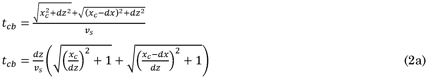
The delay with which the reflections are received are determined by the pathlengths and the speed of sound vs in the matrix 112. The relative temporal location tca of a peak, i.e. the time interval between emission of an acoustic pulse by the transmission tip 31 and the occurrence of the peak in the detected signal 832a caused by reflection of the feature 113c is approximated as:

Likewise for the peak in detected signal 832a caused by reflection Rda from feature 113d the relative temporal location tdais:


The temporal location tcbin detected signal 832b of the peak caused by reflection
Rcb from feature 113c is:
And the reflection Rdb from feature 113d causes a peak in detected signal 832b at temporal location tab:

The distance between the peaks in the detected signal 832a is:

The distance between the peaks in the detected signal 832b is:

In case of a single measurement it could be determined that there are two features in the neighborhood of the head 30, but the location could not be determined.
Due to the fact that the respective sense signals generated with at least two acoustic measurements in the measurement session it is possible to compute
information about the subsurface feature 113c, 113d in the sample 11 from the measured delay times tca, tcb as shown below.

FIG. 3C shows in arbitrary units the relationship between the position xc of the feature relative to the position of the transmitter tip and the observed difference Ac,ab in the delay. As becomes apparent therefrom, the observed difference is a monotonously increasing function of the distance, which renders it possible to determine the position of the feature.
FIG. 3D shows in more detail a signal processor 50 to perform the computations discussed above. The exemplary signal processor of FIG. 3D comprises a first delay time computation module 55a that computes the delay time tea as specified in equation la. A second delay time computation module 55b computes the delay time tcb as specified in equation 2a. The subtraction element 56 computes the difference Ac,ab between these delay times. Feature position computation module 57 computes the position xc of a feature in accordance with equation 3.
In another approach, illustrated in FIG. 4A, 4B, the device comprises an inspection head 30 with a single transmission tip 31 and a single receiving tip 32a and a measurement session comprises measuring at two or more different locations. For example a first measurement is performed at a reference location and a second measurement is performed a location different from the reference location by a shift in the direction of the x-axis. As a non-limitative example, it is presumed that the shift is dx.
As above, it is presumed for the first measurement that the position of the transmission tip is at the origin, and that the position of the receiving tip 32a is at a position -dx with respect to that of the transmitting tip 31. In that case the observed delay denoted as tdai is:

For the second measurement, with the location of the transmitting tip at dx, the observed delay denoted as tda2 is:

Accordingly, the difference in delay time Ac,i2 can be computed as

Therewith the location of the feature can be determined with the same computations as described in the example of FIG. 3A, 3B, 3C.
In a further embodiment, illustrated in FIG. 5A, 5B, the acoustic subsurface inspection device comprises an AFM-tip 31 that is dynamically configurable to function as an AFM-tip for inducing an acoustic wave and as an AFM-tip for receiving a reflection. In operation, the signal generator 20 drives the AFM-tip 31 with a drive signal S31_il that causes the AFM-tip 31 to induce an acoustic wave W1 into the sample at a first input location on the surface 114 of the sample 11 and the signal processor 50 processes the sense signal Ssi.oi that is generated by the AFM-tip in response to a received reflection of the induced acoustic wave. Without loss of generality it is presumed that the location has coordinates (xl = 0, zl = 0). The AFM-tip 31 is also configured for receiving a reflection Rci, Rdi of the acoustic wave in the sample at that location and to generate a sense signal Ssi.oi that is indicative for the received reflected acoustic wave and that is to be processed by the signal processor 50.
The reflection of the acoustic signal W1 at the feature 113c causes a peak in the sense signal Ssi.oi at a time-interval tci following the peak in the drive signal, wherein the time-interval is specified by:
 Similarly the time-location of the peak caused by the reflection of other features, e.g. feature 113d can be computed.
As shown in FIG. 5B, the head 30 is displaced in the positive direction of the x-axis over a distance dx and the measurement as described above is repeated, resulting in a second sense signal S3i_o2. Now a time-interval tc2 is measured which is determined by:

The difference Ac, 12 in the length of these time-intervals is:

This is again a monotonously related function of the location xc of the feature 113c rendering it possible to compute the location xc.
In summary, the acoustic subsurface inspection device is configured to perform an acoustic subsurface inspection method. While performing the method a sample 11 to be inspected is hold for example on an xy-table with which its lateral position can be dynamically controlled. The method comprises performing a measurement session including at least two acoustic measurements. In each acoustic measurement an acoustic wave is inputted at an input location and generating respective sense signals that are indicative for measured reflections of the acoustic wave at a measurement location. The at least two acoustic measurements in a measurement session are performed with a different input location and/or with a different measurement location. The method also comprises generating output data indicative for subsurface features in the sample based on a computation using the respective sense signals generated with the at least two acoustic measurements in the measurement session.
As discussed above, the at least two acoustic measurements in the measurement session can be performed in various ways. For example, as discussed with reference to FIG. 2 the measurement session can be performed with a single transmission tip and a plurality of receiving tips, or with a plurality of transmission tips and a single receiving tip. Also the measurement session can
be performed with a plurality of transmission tips and a plurality of receiving tips, or, as shown in FIG. 4A, 4B with a single transmission tip and a single receiving tip, or as shown in FIG. 5A, 5B with a single tip configured to induce an acoustic wave and to receive its reflections.
As discussed further, the function of a tip can be either hardwired or be configurable dynamically.
FIG. 6A - 6D illustrate an embodiment of the improved acoustic subsurface inspection method for the purpose of overlay detection. Therein FIG. 6A shows two detection signals from two subsurface subsurface features at a depth of 2.5 micron below the sample surface and mutually separated by 5 nm. In this graph, the vertical axis indicates the signal strength and the horizontal axis indicates the distance from the subsurface features to the detector as computed from the time delay with which the response to the induced acoustic wave is received. FIG. 6B shows an enlarged portion. FIG. 60 shows the difference signal computed from the difference between the two detection signals. FIG. 6D shows the difference signal obtained for various lateral offsets of the subsurface features. As becomes apparent from FIG. 6D the difference signal clearly indicates the offset between the subsurface features.
In an embodiment the signal processor 50 that is configured to compute information about the subsurface feature in the sample comprises a trained neural network 50NN. A trained neural network 50NN for this purpose can be obtained with the following procedure that is applied to a network to be trained;
At least one training sample 1 IT is provided that comprises a variety of mutually different subsurface structures that are laterally distributed in the sample. Using the least one training sample 11T the following sequence of training steps is repeatedly performed.
Respective sense data are obtained in a measurement session with the input locations and the measurement locations in a spatial range around a position x. The measurement session includes at least two acoustic measurements, each acoustic measurement comprises inputting an acoustic wave at an input location and generating a respective sense signals indicative for measured reflections of the acoustic wave at a measurement location, wherein
the at least two acoustic measurements are performed with a different input location and/or a different measurement location within the spatial range.
The respective sense signals ST(x) generated, e.g. with a head 30, with the at least two acoustic measurements in the measurement session are provided at an input of the neural network 50NN to be trained;
In response thereto, the neural network 50NN to be trained applies neural network operations to the respective sense signals and provides output data F(x). The output data F(x) for example indicates an estimated offset of subsurface features in the training sample 1 IT in the region x.
Also ground truth data GT(x) is obtained from a subsurface specification of the at least one training sample in the spatial range x.
A loss L(x) is computed, here with a loss computation module 70, based on a comparison of the output data F(x) and the ground truth data GT(x).
Neural network parameters of the neural network 50NN to be trained are subsequently updated by backpropagation of the computed loss L(x).
Subsequent to updating a new spatial range different from preceding spatial ranges is selected and the next sequence of training steps is performed.
It is noted that in a still further embodiment of the acoustic subsurface inspection device the signal processor comprises a prediction module that is configured to generate predicted detection signals based on a model of the sample and generating output data based on a comparison of the predicted detection signals and the actual detection signals. In this embodiment it is not necessary to reconstruct subsurface properties from the detection signals. Instead the obtained detection signals are compared with expected detection signals and a deviation is indicative for a defect of the sample.
In the claims the word “comprising” does not exclude other elements or steps, and the indefinite article “a” or “an” does not exclude a plurality. A single component or other unit may fulfill the functions of several items recited in the claims. The mere fact that certain measures are recited in mutually different
claims does not indicate that a combination of these measures cannot be used to advantage. Any reference signs in the claims should not be construed as limiting the scope.
Claims
1. An acoustic subsurface inspection device (1) comprising: a carrier (10) for holding a sample (11) to be inspected; a signal generator (20); at least one AFM-tip (31) configured to be driven by the signal generator configured for inducing an acoustic wave (W) into the sample at an input location (pa; Pd, Pe) on a surface (114) of the sample; at least one AFM-tip (32, 32a, 32b) that is configured for receiving a reflection (Rca, Rda) of the acoustic wave in the sample at a receiving location (pb, pc; pf) on the surface (114) of the sample and that is coupled to an acoustic sensor configured to generate a sense signal (S32a, 832b) indicative for the received reflected acoustic wave; a lateral positioning device (16) for controlling a lateral position of at least one AFM-tips (31, 32) with respect to the surface of the sample; a distance control device (51) for controlling a distance of at least one of the AFM-tips with respect to the surface of the sample; a signal processor (50) for generating output data (Sim) about the subsurface feature (113c, 113d) in the sample; wherein the acoustic subsurface inspection device is configured to perform a measurement session with at least two acoustic measurements with mutually different input locations and/or mutually different receiving locations; and wherein the signal processor (50) is configured to combine information from the respective sense signals generated with the at least two acoustic measurements in the measurement session to compute information about the subsurface feature (113c, 113d) in the sample.
2. The acoustic subsurface inspection device according to claim 1, comprising a plurality of transmitting AFM-tips configured for inducing an acoustic wave into the sample and at least one AFM-tip configured for receiving a reflected acoustic wave, wherein said signal processor is configured to generate output data based on a comparison of the generated sense signals resulting from
reflections of the acoustic waves originating from each of the plurality of transmitting AFM-tips.
3. The acoustic subsurface inspection device according to claim 1 or 2, comprising a plurality of receiving AFM-tips configured for receiving a reflected acoustic wave and at least one transmitting AFM-tip configured for inducing an acoustic wave into the sample, wherein said signal processor is configured to generate output data based on a comparison of the generated sense signals provided by each of the plurality of receiving AFM-tips.
4. The acoustic subsurface inspection device according to claim 1 or 2, configured to perform the at least two acoustic measurements at mutually different time intervals, wherein at least one of an input location and/or a receiving location is changed subsequent to performing a first one of the at least two acoustic measurements and before performing a second one of the at least two acoustic measurements.
5. The acoustic subsurface inspection device according to any of the preceding claims, wherein the signal processor comprises a peak detection unit (55a, 55b) to determine a respective delay (tca, tcb) with which a peak value occurs in respective sense signals (S32a, 832b) obtained in respective ones of the at least two acoustic measurements in the measurement session and a computation unit (57) to compute a position (xc) of the subsurface feature (113c, 113d) from a difference between the respective delays.
6. The acoustic subsurface inspection device according to any of the claims 1 - 4, the signal processor comprises a prediction module that is configured to generate predicted detection signals based on a model of the sample and generating output data based on a comparison of the predicted detection signals and the actual detection signals.
7. The acoustic subsurface inspection device according to any of the claims 1 - 4, wherein the signal processor (50) comprises a trained neural network (50NN) that receives the respective sense signals and that is configured to apply neural network operations to the received sense signals to estimates properties of the subsurface feature.
8. The acoustic subsurface inspection device according to claim 1, wherein the at least one AFM-tip that is configured to detect a reflection is at a configurable distance with respect to the at least one AFM-tip configured for supplying an acoustic input signal.
9. The acoustic subsurface inspection device according to claim 1, comprising a head carrying the at least one AFM-tip configured for supplying an acoustic input signal and at least two AFM-tips configured to detect a reflection, the head comprising a respective actuator for individually positioning the AFM-tips in a direction towards a surface of the sample.
10. The acoustic subsurface inspection device according to claim 1, comprising at least three AFM-tips that are dynamically configurable to function as an AFM- tip for supplying an acoustic input signal or an AFM-tip to detect a reflection.
11. The acoustic subsurface inspection device according to claim 1, having one or more of the AFM-tips removably mounted therein.
12. The acoustic subsurface inspection device according to claim 1, configured to be operated with at least two AFM-tips to detect a reflection at a fixed lateral position relative to the sample while positioning the at least one AFM-tip for supplying an acoustic input signal at mutually different lateral positions with respect to the sample, the signal processor being configured to generate the output data on the basis of the detection signals obtained for the mutually different positions.
13. A system comprising in addition to the acoustic subsurface inspection device according to any of the preceding claims, a calibration sample and a calibration unit, wherein the calibration unit is configured to cause the acoustic subsurface inspection device to generate output data indicative for subsurface features in the sample and to calibrate the acoustic subsurface inspection device based on a comparison of the output data with output data expected for the calibration sample.
14. An acoustic subsurface inspection method comprising: holding a sample (11) to be inspected, the sample having a sample surface; performing a measurement session including at least two acoustic measurements, each acoustic measurement comprising inputting an acoustic wave at an input location (pa; p , Pe) and generating a respective sense signal indicative for reflections of the acoustic wave measured at a measurement location (pb, pc; Pf), wherein the at least two acoustic measurements are performed with a different input location (pa; p , Pe) and/or a different measurement location; generating output data indicative for subsurface features in the sample based on a computation using the respective sense signals generated with the at least two acoustic measurements in the measurement session.
15. The acoustic subsurface inspection method according to claim 14, wherein the computation comprises generating a difference signal indicative for a difference between the respective sense signals, as an intermediate computational step for the computation of the output data.
16. The acoustic subsurface inspection method according to claim 14, wherein the computation comprises: providing the respective sense signals generated with the at least two acoustic measurements in the measurement session at an input of a trained neural network;
with the neural network applying neural network operations to the respective sense signals; obtaining the output data indicative for subsurface features in the sample at an output of the trained neural network.
17. The acoustic subsurface inspection method according to claim 16, comprising:
Providing a neural network to be trained;
Preparing at least one training sample which comprises a variety of mutually different subsurface structures that are laterally distributed in the sample;
Repeating the following training steps: applying the steps of claim 10 to obtain respective sense data in a measurement session with the input locations and the measurement locations in a spatial range; providing the respective sense signals generated with the at least two acoustic measurements in the measurement session at an input of a neural network to be trained; with the neural network applying neural network operations to the respective sense signals; obtaining output data at an output of the neural network to be trained; obtaining ground truth data obtained from a subsurface specification of the at least one training sample in said spatial range; computing a loss based on a comparison of the output data and the ground truth data; updating neural network parameters of the neural network to be trained by backpropagation of the computed loss; selecting a new spatial range different from preceding spatial ranges.
Applications Claiming Priority (2)
| Application Number | Priority Date | Filing Date | Title |
|---|---|---|---|
| NL2036631A NL2036631B1 (en) | 2023-12-21 | 2023-12-21 | An acoustic subsurface inspection device and method |
| NL2036631 | 2023-12-21 |
Publications (1)
| Publication Number | Publication Date |
|---|---|
| WO2025136102A1 true WO2025136102A1 (en) | 2025-06-26 |
Family
ID=91072814
Family Applications (1)
| Application Number | Title | Priority Date | Filing Date |
|---|---|---|---|
| PCT/NL2024/050691 Pending WO2025136102A1 (en) | 2023-12-21 | 2024-12-20 | An acoustic subsurface inspection device and method |
Country Status (3)
| Country | Link |
|---|---|
| NL (1) | NL2036631B1 (en) |
| TW (1) | TW202526320A (en) |
| WO (1) | WO2025136102A1 (en) |
Citations (4)
| Publication number | Priority date | Publication date | Assignee | Title |
|---|---|---|---|---|
| JP2012083130A (en) * | 2010-10-07 | 2012-04-26 | Fujitsu Ltd | Ultrasonic inspection method and ultrasonic inspection device |
| WO2021125944A1 (en) * | 2019-12-16 | 2021-06-24 | Nearfield Instruments B.V. | A method and system for performing characterization measurements on an elongated substrate |
| US20220091069A1 (en) * | 2019-02-04 | 2022-03-24 | Nederlandse Organisatie Voor Toegepast-Natuurwetenschappelijk Onderzoek Tno | Cantilever, ultrasound acoustic microscopy device comprising the cantilever, method of using the same and lithographic system including the same |
| WO2023126300A1 (en) * | 2021-12-28 | 2023-07-06 | Asml Netherlands B.V. | Element of an afm tool |
-
2023
- 2023-12-21 NL NL2036631A patent/NL2036631B1/en active
-
2024
- 2024-12-20 WO PCT/NL2024/050691 patent/WO2025136102A1/en active Pending
- 2024-12-20 TW TW113149984A patent/TW202526320A/en unknown
Patent Citations (4)
| Publication number | Priority date | Publication date | Assignee | Title |
|---|---|---|---|---|
| JP2012083130A (en) * | 2010-10-07 | 2012-04-26 | Fujitsu Ltd | Ultrasonic inspection method and ultrasonic inspection device |
| US20220091069A1 (en) * | 2019-02-04 | 2022-03-24 | Nederlandse Organisatie Voor Toegepast-Natuurwetenschappelijk Onderzoek Tno | Cantilever, ultrasound acoustic microscopy device comprising the cantilever, method of using the same and lithographic system including the same |
| WO2021125944A1 (en) * | 2019-12-16 | 2021-06-24 | Nearfield Instruments B.V. | A method and system for performing characterization measurements on an elongated substrate |
| WO2023126300A1 (en) * | 2021-12-28 | 2023-07-06 | Asml Netherlands B.V. | Element of an afm tool |
Also Published As
| Publication number | Publication date |
|---|---|
| NL2036631B1 (en) | 2025-07-07 |
| TW202526320A (en) | 2025-07-01 |
Similar Documents
| Publication | Publication Date | Title |
|---|---|---|
| JP5154422B2 (en) | Ultrasonic measurement method and apparatus | |
| KR101774514B1 (en) | Method and device for improving the saft analysis when measuring irregularities | |
| US11268935B2 (en) | Method of and atomic force microscopy system for performing subsurface imaging | |
| CN110376280A (en) | Apparatus for ultrasonic examination and ultrasonic inspection method | |
| CN108267102B (en) | Segment difference detection equipment and segment difference detection method | |
| JP2001194137A (en) | Non-contact measurement method and apparatus for material thickness | |
| US20090189278A1 (en) | Ultrasonic measuring method, electronic component manufacturing method, and semiconductor package | |
| CN115684024B (en) | Residual stress distribution detection method and system based on laser ultrasound | |
| WO2025136102A1 (en) | An acoustic subsurface inspection device and method | |
| US6801322B2 (en) | Method and apparatus for IN SITU measuring a required feature of a layer during a polishing process | |
| JP4412180B2 (en) | Laser ultrasonic inspection method and laser ultrasonic inspection device | |
| JP2009192497A (en) | Surface potential measuring method and surface electrometer | |
| JP7131438B2 (en) | Anomaly detection device, anomaly detection system, and anomaly detection method | |
| US12130258B2 (en) | Ultrasound sub-surface probe microscopy device and corresponding method | |
| KR20190070324A (en) | Method and device for compensating coupling non-uniformity in ultrasonic testing | |
| JP4112526B2 (en) | Ultrasonic flaw detection method and apparatus | |
| CN117804653B (en) | Residual stress detection device and method based on critical refraction longitudinal wave | |
| US20210239654A1 (en) | Sensor Apparatus for Lithographic Measurements | |
| JP7646228B2 (en) | Method for monitoring at least one of overlay and alignment between layers of a semiconductor substrate, scanning probe microscope system, and computer program | |
| US10916481B2 (en) | Thickness sensor for conductive features | |
| US20250321661A1 (en) | Ultrasonic touch sensor with water detection | |
| JP6973203B2 (en) | Anomaly detection device, anomaly detection system, and anomaly detection method | |
| JP3463729B2 (en) | Non-destructive inspection method of internal organization | |
| KR20160116925A (en) | Examining apparatus and examinig method thereof | |
| CN117331086A (en) | Laser ranging method and system based on boundary positioning |
Legal Events
| Date | Code | Title | Description |
|---|---|---|---|
| 121 | Ep: the epo has been informed by wipo that ep was designated in this application |
Ref document number: 24836841 Country of ref document: EP Kind code of ref document: A1 |