WO2025121097A1 - 直接還元炉の操業方法および還元鉄の製造方法 - Google Patents
直接還元炉の操業方法および還元鉄の製造方法 Download PDFInfo
- Publication number
- WO2025121097A1 WO2025121097A1 PCT/JP2024/040537 JP2024040537W WO2025121097A1 WO 2025121097 A1 WO2025121097 A1 WO 2025121097A1 JP 2024040537 W JP2024040537 W JP 2024040537W WO 2025121097 A1 WO2025121097 A1 WO 2025121097A1
- Authority
- WO
- WIPO (PCT)
- Prior art keywords
- direct reduction
- furnace
- reduction furnace
- reduced iron
- gas
- Prior art date
- Legal status (The legal status is an assumption and is not a legal conclusion. Google has not performed a legal analysis and makes no representation as to the accuracy of the status listed.)
- Pending
Links
Images

Classifications
-
- C—CHEMISTRY; METALLURGY
- C10—PETROLEUM, GAS OR COKE INDUSTRIES; TECHNICAL GASES CONTAINING CARBON MONOXIDE; FUELS; LUBRICANTS; PEAT
- C10B—DESTRUCTIVE DISTILLATION OF CARBONACEOUS MATERIALS FOR PRODUCTION OF GAS, COKE, TAR, OR SIMILAR MATERIALS
- C10B53/00—Destructive distillation, specially adapted for particular solid raw materials or solid raw materials in special form
- C10B53/02—Destructive distillation, specially adapted for particular solid raw materials or solid raw materials in special form of cellulose-containing material
-
- C—CHEMISTRY; METALLURGY
- C21—METALLURGY OF IRON
- C21B—MANUFACTURE OF IRON OR STEEL
- C21B11/00—Making pig-iron other than in blast furnaces
-
- C—CHEMISTRY; METALLURGY
- C21—METALLURGY OF IRON
- C21B—MANUFACTURE OF IRON OR STEEL
- C21B13/00—Making spongy iron or liquid steel, by direct processes
Definitions
- the present invention relates to a method for operating a direct reduction furnace and a method for producing reduced iron.
- the raw material of iron is mainly iron oxide such as iron ore, and a reduction process for reducing this iron ore is essential in steelworks.
- the most common reduction process that is widespread worldwide is the blast furnace.
- coke or pulverized coal reacts with oxygen in hot air (air heated to about 1200 ° C) at the tuyere. This reaction produces reducing gases CO and H 2 , which are used to reduce iron ore in the furnace.
- the reducing agent ratio (the amount of coke and pulverized coal used per ton of molten iron) has been reduced to about 500 kg/t, and the reducing agent ratio has already reached almost the lower limit. Therefore, a further significant reduction in the reducing agent ratio cannot be expected.
- the direct reduction ironmaking process (sometimes called the direct reduction method or direct ironmaking method) has been developed as a reduction process different from that of the blast furnace.
- the direct reduction ironmaking process is as follows. That is, iron ore (lump ore) or pellets (iron ore powder solidified into a spherical shape) are charged into a direct reduction furnace as iron oxide raw material (hereinafter simply referred to as iron oxide). Reducing gas is then blown into the direct reduction furnace to reduce the iron oxide and obtain reduced iron. The reduced iron obtained is then cooled in a region (cooling zone) below the position where the reducing gas is blown into the direct reduction furnace. The reduced iron is then discharged from the bottom of the direct reduction furnace. The reduced iron discharged from the direct reduction furnace is then melted in an electric furnace.
- iron oxide raw material hereinafter simply referred to as iron oxide
- Reducing gas is then blown into the direct reduction furnace to reduce the iron oxide and obtain reduced iron.
- the reduced iron obtained is then cooled in a region (cooling zone) below the position where the reducing gas is blown into the direct reduction furnace.
- the reduced iron is then discharged from the bottom of the direct reduction furnace.
- a shaft furnace is mainly used as the direct reduction furnace.
- natural gas is generally used as the gas source of the reducing gas, such as Midrex (registered trademark) or Hyl (registered trademark).
- the natural gas is reformed with the exhaust gas discharged from the top of the direct reduction furnace (hereinafter also referred to as top gas) to generate a reducing gas containing CO and H2 .
- the reducing gas is blown into the reduction furnace to reduce the iron oxide according to the following formula, thereby obtaining reduced iron.
- Patent Document 1 describes: "In a method of operating a direct reduction furnace using a shaft furnace system to produce reduced iron using reducing gas mainly composed of hydrogen, A method for operating a direct reduction furnace using preheated raw material, characterized in that a preheated raw material iron oxide is charged into the direct reduction furnace. has been disclosed.
- Patent Document 2 In a method of operating a direct reduction furnace using a shaft furnace system to produce reduced iron using reducing gas mainly composed of hydrogen, A method for operating a direct reduction furnace with top gas circulation, characterized in that a portion of the gas discharged from the top of the furnace is blown into the middle of the furnace. has been disclosed.
- Patent Document 3 A method for producing reduced iron by reducing iron oxide charged in a shaft furnace, A method for producing reduced iron, comprising blowing into the shaft furnace a heated mixed gas containing a reducing gas containing 90 volume % or more of hydrogen gas and nitrogen gas. has been disclosed.
- the reduced iron obtained in the direct reduction furnace needs to be discharged from the furnace and then melted in an electric furnace.
- the energy efficiency hereinafter also referred to as the energy efficiency during melting in an electric furnace
- the energy efficiency during melting in an electric furnace is lower than when reduced iron obtained by a general direct reduction ironmaking process is melted in an electric furnace.
- any numerical range expressed using "to” means a range that includes the numerical values before and after "to" as the lower and upper limits, respectively.
- Patent Documents 1 to 3 use a reducing gas containing hydrogen as a main component.
- the reducing gas contains almost no CO.
- the reducing gas contains CO. Therefore, in the direct reduction furnace, carburization of the reduced iron progresses during the process of reducing iron ore by the Boudoir reaction (2CO ⁇ C+ CO2 ).
- the gist of the present invention is as follows:
- a method for operating a direct reduction furnace comprising the steps of: a charging step of charging iron oxide and carbonaceous material into the direct reduction furnace from a top portion of the furnace; A blowing step of blowing a reducing gas having an H2 concentration of 80% by volume or more into the direct reduction furnace; a reduction step of reducing the iron oxide in the direct reduction furnace to obtain reduced iron; A method for operating a direct reduction furnace comprising the steps of:
- a method for producing reduced iron comprising the steps of: operating a reduction furnace according to any one of the methods described above in 1 to 7.
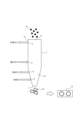
- FIG. 1 is a schematic diagram showing an example of a direct reduction furnace.
- FIG. 1 is a schematic diagram showing an example of a conventional process for producing reduced iron.
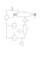
- FIG. 1 is a schematic diagram showing an example of a process for producing reduced iron according to an embodiment of the present invention.
- the following describes a method for operating a direct reduction furnace according to one embodiment of the present invention.
- a method for operating a direct reduction furnace includes the steps of: a charging step of charging iron oxide and carbonaceous material into the direct reduction furnace from a top portion of the furnace; A blowing step of blowing a reducing gas having an H2 concentration of 80% by volume or more into the direct reduction furnace; a reduction step of reducing the iron oxide in the direct reduction furnace to obtain reduced iron; has.
- FIG. 1 is a schematic diagram showing an example of the configuration of a shaft furnace, which is a direct reduction furnace.
- reference numeral 1 denotes a shaft furnace
- 1a denotes iron oxide
- 1b denotes reduced iron
- 1c denotes the furnace top
- 1d denotes a cooling zone
- 2 denotes a reduction gas inlet
- 3 denotes a furnace top gas outlet
- 4 denotes a cooling gas inlet
- 5 denotes a cooling gas suction port
- 6 denotes an iron oxide charging inlet
- 7 denotes a reduced iron outlet
- 13 denotes a briquette machine.
- iron oxide 1a is charged from the furnace top 1c, particularly from the iron oxide charging port 6, and the iron oxide 1a is gradually allowed to fall.
- High-temperature reducing gas is then blown in from the reducing gas blowing port 2 located in the center of the shaft furnace 1 to reduce the iron oxide 1a and obtain reduced iron 1b.
- the reduced iron 1b is then discharged from the reduced iron discharge port 7 located at the bottom of the shaft furnace 1. Meanwhile, top gas is discharged from the furnace gas discharge port 3.
- the temperature of the reducing gas blown in from the reducing gas blowing port 2 is, for example, 700°C to 1200°C.
- a cooling gas inlet 4 and a cooling gas suction port 5 are arranged in the cooling zone 1d located at the bottom of the shaft furnace 1. Cooling gas is blown into the cooling zone 1d from the cooling gas inlet 4. The cooling gas suction port 5 sucks the cooling gas so that it does not enter the furnace top 1c.
- N2 is used as the cooling gas.
- the generated carbon comes into contact with Fe3O4 , FeO , and Fe generated in the process of reducing the iron oxide, and carburization progresses.
- the volatile gas generated from the carbonaceous material contains CO, CH4 , and H2
- the Boudoir reaction CO ⁇ C+ CO2
- reactions such as CH4 ⁇ C+ 2H2 and CO+ H2 ⁇ C+ H2O occur, which further promotes carburization of the reduced iron.
- carbonaceous material may be additionally charged into the direct reduction furnace from a position other than the top of the furnace.
- the direct reduction furnace is charged with carbonaceous material together with iron oxide from the furnace top 1c, particularly from the iron oxide charging port 6 (hereinafter also referred to as the first method).
- the first method the following may be implemented: a method of charging carbonaceous material together with cooling gas from the cooling gas inlet 4 (hereinafter also referred to as the second method), a method of providing a tuyere in the middle of the furnace and carrying out gas-phase transport by gas (hereinafter also referred to as the third method), and a method of subjecting solid carbonaceous material to heat treatment in advance to generate volatile gas components containing C, and charging only the volatile gas into the direct reduction furnace 1 (hereinafter also referred to as the fourth method).
- carbonaceous material may also contain, for example, H (hydrogen) atoms and O (oxygen) atoms.
- H (hydrogen) atoms hydrogen
- O (oxygen) atoms a material in which the mass of C atoms, H atoms, and O atoms account for 30 to 100% of the total mass of the carbonaceous material, 0 to 30% of the mass, and 0 to 60% of the mass of O atoms is preferable.
- suitable carbonaceous materials from the viewpoint of effectively carburizing reduced iron include biomass and plastics.
- biomass is particularly advantageous because it is a carbon-neutral carbonaceous material and can reduce CO2 emissions to substantially zero.
- Plastics may be unused or used plastics.
- used plastics conceptually include waste plastics, plastics that are not scheduled to be disposed of, and factory scraps. When waste plastics are used, carbonaceous materials that would have been buried or incinerated can be effectively utilized, so that the environmental load can be reduced.
- biomass is a general term for a certain amount of accumulated animal and plant resources and waste materials originating from these (excluding fossil resources).
- any biomass that produces charcoal through pyrolysis such as agricultural, forestry, livestock, fisheries, and waste biomass, can be used.
- biomass with a high effective calorific value is preferred, such as woody biomass.
- woody biomass is forestry biomass.
- forestry biomass examples include: - Paper by-products such as pulp black liquor and chip dust, - Sawmill by-products such as bark and sawdust, branches, leaves, treetops, end pieces and other forest residues, - Special forest products such as thinned timber from cedar, cypress, and pine species, and waste logs for edible fungi, - Examples include firewood and charcoal forests such as shii, oak, and pine, and short-rotation forestry materials such as willow, poplar, eucalyptus, and pine.
- waste-based biomass e.g. - General waste such as pruned branches from city and town roadside trees and private garden trees, etc.
- - Pruned branches of national and prefectural roadside trees, company garden trees, and industrial waste such as construction and building waste can also be suitably used as wood-based biomass.
- some agricultural biomass e.g. ⁇ Waste and by-product sources include rice husks, wheat straw, rice straw, sugarcane waste, palm oil, etc.
- Energy crop sources such as rice bran, rapeseed, and soybeans can also be suitably used as woody biomass.
- Biomass is composed of C, O, and H atoms. However, biomass itself has a high moisture content and low density, making it weak. Therefore, if biomass is directly charged into a reduction furnace, it may become pulverized or hang up inside the furnace, causing the reduction reaction to stagnate. For this reason, it is preferable to use semi-carbonized biomass as the carbon material.
- semi-carbonized biomass is biomass that is not completely carbonized but is partially carbonized, and preferably has a density of 700 to 850 kg/m 3.
- Semi-carbonized biomass can also be said to be biomass that has been subjected to a heat treatment on biomass, for example, woody biomass, to reduce moisture and promote carbonization to increase density and strength.
- Semi-carbonized biomass has excellent storage and transportability. Semi-carbonized biomass is not completely carbonized, and therefore volatile gas components remain. Therefore, when semi-carbonized biomass is charged into a furnace and heated, it generates volatile gases such as CO, H 2 , CO 2 , CH 4 and O 2. Among these volatile gases, CO, CH 4 and H 2 promote the carburization of reduced iron. In particular, CO and H 2 have reducing properties, so they promote the reduction of iron oxide and prevent reaction stagnation due to endothermic heat during hydrogen reduction. Furthermore, the heat treatment temperature when semi-carbonized biomass is produced is mild, so the total energy consumption is also reduced. For these reasons, semi-carbonized biomass is preferably used as the carbon material. Hereinafter, biomass that has not been carbonized is also referred to as raw biomass.
- completely carbonized biomass is also referred to as carbonized biomass.
- carbonized biomass since the temperature of the upper part of the shaft furnace is about 300°C, when raw biomass is charged from the top of the furnace, carbonization proceeds to a certain extent in the furnace. However, as mentioned above, there is a concern that powdering or hanging may occur in the upper part of the furnace. Therefore, it is preferable to use semi-carbonized biomass.
- the method for producing semi-carbonized biomass is not particularly limited.
- the above-mentioned production method for example, when woody biomass (raw biomass) with a density of 200 kg/ m3 is used as the material, it is possible to produce carbonized biomass with a density of about 750 kg/m3.
- the amount of carbonaceous material (hereinafter also referred to as the charging amount of carbonaceous material) charged into the direct reduction furnace according to the amount of C contained in the reduced iron.
- the charging amount of carbonaceous material it is preferable to control the charging amount of carbonaceous material so that the amount of C contained in the reduced iron is 1.0 mass% or more and 5.0 mass% or less.
- HBI Hot Briquette Iron
- the amount of carbonaceous material charged is 1.0 mass% or more and 5.0 mass% or less. Furthermore, the amount of carbonaceous material charged is controlled so that the amount of C contained in the reduced iron is more preferably 2.0 mass% or more, even more preferably 3.0 mass% or more, and even more preferably 4.0 mass% or more.
- the amount of C contained in the reduced iron may be measured, for example, using reduced iron discharged from a direct reduction furnace according to the procedure described in Evaluation 1 of Example 1 below. Furthermore, the carbonaceous material to be used may be selected according to the amount of C contained in the reduced iron.
- the amount of carbon material charged into the direct reduction furnace using the ratio of the amount of C (mass of C atoms) contained in the carbonaceous material to the amount of Fe (mass of Fe atoms) contained in the iron oxide charged into the direct reduction furnace (hereinafter also referred to as the C/Fe charging ratio) so that the amount of C contained in the reduced iron is 1.0 mass% or more and 5.0 mass% or less.
- the C/Fe charging ratio is preferably in the range of 1.0 to 20.0%, more preferably 3.0 to 15.0%, the amount of C contained in the reduced iron can be 1.0 mass% or more and 5.0 mass% or less.
- the iron oxide charged into the direct reduction furnace is composed only of Fe2O3 and the mass of C atoms in the total mass of the carbonaceous material charged into the direct reduction furnace is 50%
- the C/Fe charging ratio is in the range of 1.0 to 20.0%.
- the mass of C atoms in the total mass of the carbonaceous material is, for example, 30 to 100%.
- the iron oxide used in the method for operating a direct reduction furnace is, for example, iron ore.
- specific examples include lump iron ore (lump ore) and iron oxide pellets (iron ore powder solidified into a spherical shape).
- the grade of the iron ore used as the iron oxide, i.e., the iron content is not particularly limited, but from the viewpoint of reduction in a shaft furnace, generally, 65 mass% or more is preferable.
- the price of high-grade ores such as those from South America is expected to rise.
- low-grade ores Fe content: 63 mass% or less
- those from Australia which is an inexpensive and abundant resource
- a reducing gas having a H 2 concentration of 80% by volume or more is blown into the direct reduction furnace.
- the H 2 concentration is preferably 90% by volume or more, more preferably 95% by volume or more.
- the upper limit of the H 2 concentration is not particularly limited, and may be 100% by volume.
- the type of the remaining gas other than hydrogen is not particularly limited.
- As the remaining gas for example, in addition to N 2 , H 2 O, CO and CO 2 , gas produced as a by-product in the ironmaking process (hereinafter also referred to as by-product gas) can also be used.
- the by-product gas for example, blast furnace gas (BFG) and coke oven gas (COG) can be mentioned.
- BFG blast furnace gas
- COG coke oven gas
- the furnace gas contains CO 2. In this case, it is preferable to supply the CO 2 contained in the furnace gas to CCU or CCS, as described later.
- the iron oxide is reduced to obtain reduced iron by using a reducing gas having a H2 concentration of 80% by volume or more according to the above formula (i).
- the iron oxide can also be reduced by a volatile gas generated from the carbonaceous material charged in the direct reduction furnace.
- Heat supply process In the method for operating a direct reduction furnace according to one embodiment of the present invention, it is preferable to further include a heat supply step of supplying heat to the direct reduction furnace.
- a reducing gas having an H 2 concentration of 80 volume % or more is used.
- the reduction reaction by CO is an exothermic reaction
- the reduction reaction by H 2 is an endothermic reaction. Therefore, when a gas having an H 2 concentration close to 100 volume % is used as the reducing gas, the temperature inside the direct reduction furnace may decrease. In this case, it is preferable to supply heat to the direct reduction furnace for endothermic compensation.
- the heat source is not particularly limited.
- the heat from biomass combustion is suitable as the heat source.
- the heat from biomass combustion it is possible to reduce not only the CO 2 emitted from the direct reduction furnace but also the CO 2 emitted from the entire manufacturing process to substantially zero.
- the biomass the semi-carbonized biomass described above and tar obtained in the process of pyrolysis of biomass are preferable.
- Carbonized biomass and tar have a large calorific value per unit volume and are considered promising as fuels to replace coal.
- the composition of the reducing gas used e.g., a gas having an H2 concentration of 100 volume %
- FIG. 2 is a diagram showing an example of the configuration of a conventional process for producing reduced iron.
- reference numeral 1 denotes a shaft furnace
- 1a denotes iron oxide
- 1b denotes reduced iron
- 8 denotes a dust remover
- 9 denotes a dehydrator
- 10 denotes a natural gas supply section
- 11 denotes an air supply section
- 12 denotes a heating reformer
- 14 denotes a reducing gas blower.
- iron oxide is charged from the top of the shaft furnace 1 and gradually lowered.
- High-temperature reducing gas is blown into the shaft furnace 1 from the middle to reduce the iron oxide 1a.
- reduced iron 1b is discharged from the bottom of the shaft furnace 1.
- furnace top gas containing mainly CO, CO 2 , H 2 , and H 2 O is discharged from the top of the shaft furnace 1.
- This furnace top gas is dusted by a dust remover 8, and a part of the top gas is adjusted in moisture by a dehydrator 9 as a raw material gas and sent to a thermal reformer 12.
- a gas containing a hydrocarbon for example, natural gas from a natural gas supply unit, is supplied to the thermal reformer 12 together with the moisture-adjusted top gas.
- the supplied gas is heated in the thermal reformer 12.
- a reforming reaction occurs to generate a high-temperature reducing gas containing mainly CO and H 2.
- this reducing gas is blown into the reducing furnace.
- the remaining part of the furnace gas is used as heating fuel in the combustion chamber of the thermal reformer 12 after being dehydrated.
- a reducing gas having a H 2 concentration of 80% by volume or more is used. Therefore, in the operation method of the direct reduction furnace according to one embodiment of the present invention, a heating reformer is not required. Instead, as shown in FIG. 3, hydrogen gas (having a H 2 concentration of 80% by volume or more, preferably 90% by volume or more, more preferably 95% by volume or more) supplied from the hydrogen supply unit 15 is heated by the gas heater 16.
- the heating temperature of the hydrogen gas is not particularly limited, but is preferably, for example, 900 to 1200°C.
- the heated hydrogen gas is blown into the shaft furnace 1 as a reducing gas by the reducing gas blowing device 14.
- the reducing gas is subjected to a reduction reaction in the furnace and then discharged from the shaft furnace 1 as a furnace top gas containing mainly H 2 and H 2 O. Then, the H 2 not used in the reduction reaction is recycled.
- the furnace gas is subjected to dust removal by a dust remover 8, dehydrated by a dehydrator 9, and then mixed with newly introduced H2 and blown into the shaft furnace 1 as a reducing gas.
- Fig. 3 shows an example in which CO2 is separated from the furnace gas by a CO2 separator 17, and then, as a CCU, the CO2 is supplied to a methanol synthesis unit 18.
- a non-carbon-neutral carbonaceous material such as waste plastic is used as the carbonaceous material, this can reduce CO2 emissions to substantially zero.
- the heat source of the gas heater 16 is not particularly limited.
- the heat source is preferably biomass combustion heat.
- the biomass combustion heat it is possible to reduce not only the CO 2 emitted from the direct reduction furnace but also the CO 2 emitted from the entire manufacturing process to substantially zero.
- the biomass the above-mentioned semi-carbonized biomass or tar obtained in the process of pyrolysis of biomass is preferable.
- a method using a shaft furnace has been described in particular.
- the type of direct reduction furnace is not limited to this, and methods using a fluidized bed, rotary kiln, rotary hearth furnace (RHF), etc. are also possible.
- a shaft furnace is preferable as a direct reduction furnace because of its high production efficiency, operating rate, and operational stability.
- the majority of direct reduction furnaces operating around the world are shaft furnace type Midrex (registered trademark) and Hyl (registered trademark).
- the method for producing reduced iron according to one embodiment of the present invention produces reduced iron by the above-mentioned method for operating a direct reduction furnace. Conditions other than those mentioned above are not particularly limited and may be performed according to conventional methods.
- Example 1 A test for producing reduced iron was carried out using a bench-scale shaft furnace in the process for producing reduced iron shown in Fig. 3.
- the test conditions were as follows. Note that conditions not specified were those according to conventional methods or the general description in the specification.
- Reduced iron production rate 15 kg/h Operation period: 7 days
- Amount of reducing gas injected 2200 Nm 3 /t-DRI (amount of gas per ton of reduced iron)
- Iron oxide Brazilian iron oxide pellets with a particle size of 10.0 to 15.0 mm.
- the carbonaceous material shown in Table 1 was charged together with the iron oxide through the iron oxide charging port at the top of the shaft furnace.
- Evaluation 1 evaluation of energy efficiency during melting in an electric furnace (hereinafter also referred to as Evaluation 1)] Evaluation 1 was performed based on the amount of C (amount of carburization) contained in the produced reduced iron. That is, the amount of C contained in the reduced iron discharged from the lower part of the shaft furnace was measured according to the infrared absorption method specified in JIS G 1211 (2016) "Iron and steel - Method for quantitative determination of carbon". The amount of C contained in this reduced iron was measured once a day, and the average value was taken as the amount of C contained in the reduced iron. The evaluation results are also shown in Table 1. Note that the meanings of A to E in the column for Evaluation 1 in Table 1 are as follows. Furthermore, cases A to C were evaluated as having excellent energy efficiency during melting in an electric furnace.
- A The amount of C contained in reduced iron is 4.0 mass% or more.
- B The amount of C contained in reduced iron is 3.0 mass% or more and less than 4.0 mass%.
- C The amount of C contained in reduced iron is 1.0 mass% or more and less than 3.0 mass%.
- D The amount of C contained in reduced iron is 0.5 mass% or more and less than 1.0 mass%.
- E The amount of C contained in reduced iron is less than 0.5 mass%.
- the amount of O (oxygen) (mass%) in the iron oxide before reduction is the total amount of O (mass%) contained in FeO and Fe2O3 contained in the iron oxide before reduction .
- the total amount of O (mass%) contained in Fe2O3 was calculated on the assumption that the amount of Fe obtained by subtracting the amount of Fe in FeO (mass%) from the T.Fe (mass%) of the iron oxide before reduction exists as Fe2O3 .
- the amount of O (mass%) in the reduced iron (obtained after reduction) is the total amount of O (mass%) contained in FeO and Fe3O4 contained in the reduced iron.
- the total amount of O (mass%) contained in Fe3O4 was calculated on the assumption that the amount of Fe obtained by subtracting the amount of Fe in FeO and M.Fe from the T.Fe (mass%) of the reduced iron exists as Fe3O4 .
- Example 2 Reduced iron was produced under the same conditions as in Example 1 except for the conditions shown in Table 2. The amount of C contained in the produced reduced iron was measured in the same manner as in Evaluation 1 of Example 1. The reaction efficiency in the direct reduction furnace was evaluated in the same manner as in Evaluation 2 of Example 1. The results are also shown in Table 2.
- Evaluation 1' Detailed evaluation of energy efficiency during melting in an electric furnace
- the produced reduced iron was used, and the energy efficiency during melting in an electric furnace was calculated according to the method specified in JIS G 0703 (1995) "Heat balance method for electric arc furnaces" using the following formula (1), to evaluate the energy efficiency during melting in an electric furnace.
- the meanings of A to E in the Evaluation 1' column in Table 2 are as follows. Also, cases A to C were evaluated as having excellent energy efficiency during melting in an electric furnace.
- Energy efficiency during melting in an electric furnace (heat of molten steel + heat of slag + heat of decomposition reaction - heat of molten iron) / (total heat input - heat of molten iron) x 100 (%) ...
- D Energy efficiency during melting in an electric furnace is 40% or more but less than 50%.
- E Energy efficiency during melting in an electric furnace is less than 40%.
- the apparent density of HBI was measured by the method described in "ISO15968: Direct reduced iron - Determination of apparent density and water absorption of hot briquette iron (HBI)". The apparent density of HBI was measured once a day. Specifically, 60 kg of reduced iron produced during the operation period was collected every day, and HBI was produced from the collected reduced iron. Five samples of the produced HBI were taken each time, and the apparent density of each HBI was measured. Then, the average value was calculated to evaluate the apparent density of the HBI.
- the meanings of A to D in the column of Evaluation 3 in Table 2 are as follows: A: The apparent density of the HBI is 5.5 g/cm 3 or more.
- the apparent density of the HBI is 5.0 g/cm 3 or more and less than 5.5 g/cm 3.
- C The apparent density of the HBI is 4.5 g/cm 3 or more and less than 5.0 g/cm 3.
- D The apparent density of the HBI is less than 4.5 g/cm 3 .
- the crushing strength of the HBI was measured using a general-purpose autograph at an application speed of 1 mm/min. The measurement of the crushing strength of the HBI was also carried out once a day. Specifically, 60 kg of reduced iron produced during the operation period was collected every day, and HBI was produced from the collected reduced iron. Five samples of the produced HBI were taken each time, and the crushing strength of each HBI was measured. The average value was then calculated to evaluate the crushing strength of the HBI.
- the meanings of A to D in the column for evaluation 4 in Table 2 are as follows: A: The crushing strength of the HBI is 8000 kgf or more.
- the crushing strength of the HBI is 6000 kgf or more and less than 8000 kgf.
- C The crushing strength of the HBI is 4000 kgf or more and less than 6000 kgf.
- D The crushing strength of the HBI is less than 4000 kgf.
Landscapes
- Chemical & Material Sciences (AREA)
- Engineering & Computer Science (AREA)
- Materials Engineering (AREA)
- Organic Chemistry (AREA)
- Manufacturing & Machinery (AREA)
- Metallurgy (AREA)
- Oil, Petroleum & Natural Gas (AREA)
- Manufacture Of Iron (AREA)
Priority Applications (1)
| Application Number | Priority Date | Filing Date | Title |
|---|---|---|---|
| JP2025509015A JPWO2025121097A1 (https=) | 2023-12-05 | 2024-11-14 |
Applications Claiming Priority (2)
| Application Number | Priority Date | Filing Date | Title |
|---|---|---|---|
| JP2023205467 | 2023-12-05 | ||
| JP2023-205467 | 2023-12-05 |
Publications (1)
| Publication Number | Publication Date |
|---|---|
| WO2025121097A1 true WO2025121097A1 (ja) | 2025-06-12 |
Family
ID=95979759
Family Applications (1)
| Application Number | Title | Priority Date | Filing Date |
|---|---|---|---|
| PCT/JP2024/040537 Pending WO2025121097A1 (ja) | 2023-12-05 | 2024-11-14 | 直接還元炉の操業方法および還元鉄の製造方法 |
Country Status (2)
| Country | Link |
|---|---|
| JP (1) | JPWO2025121097A1 (https=) |
| WO (1) | WO2025121097A1 (https=) |
Citations (3)
| Publication number | Priority date | Publication date | Assignee | Title |
|---|---|---|---|---|
| JP2018095895A (ja) * | 2016-12-08 | 2018-06-21 | 株式会社神戸製鋼所 | 高品位鉄源の製造方法 |
| WO2022178071A1 (en) * | 2021-02-18 | 2022-08-25 | Carbon Technology Holdings, LLC | Carbon-negative metallurgical products |
| JP7264313B1 (ja) * | 2021-06-15 | 2023-04-25 | Jfeスチール株式会社 | シャフト炉の操業方法及び還元鉄の製造方法 |
-
2024
- 2024-11-14 WO PCT/JP2024/040537 patent/WO2025121097A1/ja active Pending
- 2024-11-14 JP JP2025509015A patent/JPWO2025121097A1/ja active Pending
Patent Citations (3)
| Publication number | Priority date | Publication date | Assignee | Title |
|---|---|---|---|---|
| JP2018095895A (ja) * | 2016-12-08 | 2018-06-21 | 株式会社神戸製鋼所 | 高品位鉄源の製造方法 |
| WO2022178071A1 (en) * | 2021-02-18 | 2022-08-25 | Carbon Technology Holdings, LLC | Carbon-negative metallurgical products |
| JP7264313B1 (ja) * | 2021-06-15 | 2023-04-25 | Jfeスチール株式会社 | シャフト炉の操業方法及び還元鉄の製造方法 |
Also Published As
| Publication number | Publication date |
|---|---|
| JPWO2025121097A1 (https=) | 2025-06-12 |
Similar Documents
| Publication | Publication Date | Title |
|---|---|---|
| Safarian | To what extent could biochar replace coal and coke in steel industries? | |
| Mathieson et al. | Utilization of biomass as an alternative fuel in ironmaking | |
| CN115516116A (zh) | 用于生产渗碳海绵铁的方法 | |
| JP2009057438A (ja) | 半乾留バイオマス微粉炭材の製造方法および半乾留バイオマス微粉炭材の使用方法 | |
| JP5880941B2 (ja) | 還元鉄の製造方法 | |
| DiGiovanni et al. | Progress toward biocarbon utilization in electric arc furnace steelmaking: current status and future prospects | |
| Ren et al. | A state-of-the-art review on the utilization of biochar as renewable energy for the sustainable steel industry | |
| JP7809208B2 (ja) | 製銑方法及び関連プラント | |
| WO2025121097A1 (ja) | 直接還元炉の操業方法および還元鉄の製造方法 | |
| CN112662824A (zh) | 一种高效利用冶金废气的高炉富氢冶炼工艺 | |
| CN104024442A (zh) | 铁水制造设备及铁水制造方法 | |
| JP7795560B2 (ja) | 直接還元鉄を製造するための方法 | |
| JP7736229B1 (ja) | 直接還元炉の操業方法および還元鉄の製造方法 | |
| WO2025158890A1 (ja) | 直接還元炉の操業方法および還元鉄の製造方法 | |
| JP2024519059A5 (https=) | ||
| KR102960669B1 (ko) | 직접 환원 철을 제조하기 위한 방법 | |
| US20250059572A1 (en) | Method for employing corn plant residue in the production of direct reduced iron | |
| WO2025121099A1 (ja) | 還元炉の操業方法および還元鉄の製造方法 | |
| CN102482723A (zh) | 减少高炉的二氧化碳排放的方法和相关的装置 | |
| KR20260056303A (ko) | 용융환원로를 이용한 바이오매스 기반 철 생산 | |
| JP2026016960A (ja) | 高炉用炭材及び銑鉄の製造方法 | |
| Bizhanov et al. | Сoke Substitutes in Mini Blast Furnace | |
| WO2025224492A1 (en) | A method to produce direct reduced iron briquettes | |
| WO2025125869A1 (en) | A method to produce reduced iron | |
| TW202430654A (zh) | 源自燒結礦之熔鐵 |
Legal Events
| Date | Code | Title | Description |
|---|---|---|---|
| ENP | Entry into the national phase |
Ref document number: 2025509015 Country of ref document: JP Kind code of ref document: A |
|
| WWE | Wipo information: entry into national phase |
Ref document number: 2025509015 Country of ref document: JP |
|
| 121 | Ep: the epo has been informed by wipo that ep was designated in this application |
Ref document number: 24900392 Country of ref document: EP Kind code of ref document: A1 |