WO2025115705A1 - クレーン - Google Patents
クレーン Download PDFInfo
- Publication number
- WO2025115705A1 WO2025115705A1 PCT/JP2024/041021 JP2024041021W WO2025115705A1 WO 2025115705 A1 WO2025115705 A1 WO 2025115705A1 JP 2024041021 W JP2024041021 W JP 2024041021W WO 2025115705 A1 WO2025115705 A1 WO 2025115705A1
- Authority
- WO
- WIPO (PCT)
- Prior art keywords
- power
- hydraulic oil
- regenerative
- pump
- supply device
- Prior art date
- Legal status (The legal status is an assumption and is not a legal conclusion. Google has not performed a legal analysis and makes no representation as to the accuracy of the status listed.)
- Pending
Links
Images




Classifications
-
- B—PERFORMING OPERATIONS; TRANSPORTING
- B60—VEHICLES IN GENERAL
- B60L—PROPULSION OF ELECTRICALLY-PROPELLED VEHICLES; SUPPLYING ELECTRIC POWER FOR AUXILIARY EQUIPMENT OF ELECTRICALLY-PROPELLED VEHICLES; ELECTRODYNAMIC BRAKE SYSTEMS FOR VEHICLES IN GENERAL; MAGNETIC SUSPENSION OR LEVITATION FOR VEHICLES; MONITORING OPERATING VARIABLES OF ELECTRICALLY-PROPELLED VEHICLES; ELECTRIC SAFETY DEVICES FOR ELECTRICALLY-PROPELLED VEHICLES
- B60L1/00—Supplying electric power to auxiliary equipment of vehicles
-
- B—PERFORMING OPERATIONS; TRANSPORTING
- B60—VEHICLES IN GENERAL
- B60L—PROPULSION OF ELECTRICALLY-PROPELLED VEHICLES; SUPPLYING ELECTRIC POWER FOR AUXILIARY EQUIPMENT OF ELECTRICALLY-PROPELLED VEHICLES; ELECTRODYNAMIC BRAKE SYSTEMS FOR VEHICLES IN GENERAL; MAGNETIC SUSPENSION OR LEVITATION FOR VEHICLES; MONITORING OPERATING VARIABLES OF ELECTRICALLY-PROPELLED VEHICLES; ELECTRIC SAFETY DEVICES FOR ELECTRICALLY-PROPELLED VEHICLES
- B60L58/00—Methods or circuit arrangements for monitoring or controlling batteries or fuel cells, specially adapted for electric vehicles
- B60L58/10—Methods or circuit arrangements for monitoring or controlling batteries or fuel cells, specially adapted for electric vehicles for monitoring or controlling batteries
- B60L58/12—Methods or circuit arrangements for monitoring or controlling batteries or fuel cells, specially adapted for electric vehicles for monitoring or controlling batteries responding to state of charge [SoC]
-
- B—PERFORMING OPERATIONS; TRANSPORTING
- B60—VEHICLES IN GENERAL
- B60L—PROPULSION OF ELECTRICALLY-PROPELLED VEHICLES; SUPPLYING ELECTRIC POWER FOR AUXILIARY EQUIPMENT OF ELECTRICALLY-PROPELLED VEHICLES; ELECTRODYNAMIC BRAKE SYSTEMS FOR VEHICLES IN GENERAL; MAGNETIC SUSPENSION OR LEVITATION FOR VEHICLES; MONITORING OPERATING VARIABLES OF ELECTRICALLY-PROPELLED VEHICLES; ELECTRIC SAFETY DEVICES FOR ELECTRICALLY-PROPELLED VEHICLES
- B60L7/00—Electrodynamic brake systems for vehicles in general
- B60L7/10—Dynamic electric regenerative braking
- B60L7/12—Dynamic electric regenerative braking for vehicles propelled by DC motors
-
- B—PERFORMING OPERATIONS; TRANSPORTING
- B66—HOISTING; LIFTING; HAULING
- B66C—CRANES; LOAD-ENGAGING ELEMENTS OR DEVICES FOR CRANES, CAPSTANS, WINCHES, OR TACKLES
- B66C13/00—Other constructional features or details
- B66C13/52—Details of compartments for driving engines or motors or of operator's stands or cabins
-
- B—PERFORMING OPERATIONS; TRANSPORTING
- B66—HOISTING; LIFTING; HAULING
- B66C—CRANES; LOAD-ENGAGING ELEMENTS OR DEVICES FOR CRANES, CAPSTANS, WINCHES, OR TACKLES
- B66C23/00—Cranes comprising essentially a beam, boom, or triangular structure acting as a cantilever and mounted for translatory of swinging movements in vertical or horizontal planes or a combination of such movements, e.g. jib-cranes, derricks, tower cranes
- B66C23/18—Cranes comprising essentially a beam, boom, or triangular structure acting as a cantilever and mounted for translatory of swinging movements in vertical or horizontal planes or a combination of such movements, e.g. jib-cranes, derricks, tower cranes specially adapted for use in particular purposes
- B66C23/36—Cranes comprising essentially a beam, boom, or triangular structure acting as a cantilever and mounted for translatory of swinging movements in vertical or horizontal planes or a combination of such movements, e.g. jib-cranes, derricks, tower cranes specially adapted for use in particular purposes mounted on road or rail vehicles; Manually-movable jib-cranes for use in workshops; Floating cranes
Definitions
- the present invention relates to a crane.
- Patent Document 1 discloses a mobile crane that includes a lower running body with a traveling function, and an upper rotating body that is rotatably mounted on the upper part of the lower running body.
- the lower running body has an engine and runs on the power of the engine.
- the object of the present invention is to provide a crane that can run on electricity.
- One aspect of the crane according to the present invention is a traveling vehicle body having a traveling motor driven by a power supply unit; a hydraulic oil supply device that is driven by a power source and supplies hydraulic oil to a driven part; a regenerative braking device that performs regenerative braking control to generate a braking force by supplying regenerative power generated by a traveling motor to a power supply unit when a traveling vehicle body is decelerated,
- the regenerative brake device distributes regenerative power to the hydraulic oil supply device according to the chargeable power of the power supply unit, and changes the power consumed by the hydraulic oil supply device.
- the present invention provides a crane that can run on electricity.
- FIG. 1 is a schematic diagram of a mobile crane according to a first embodiment.
- FIG. 2 is a block diagram showing a schematic diagram of a system configuration of the mobile crane.
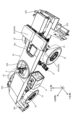
- FIG. 3 is a perspective view of the crane with some components omitted.
- FIG. 4 is a diagram for explaining the arrangement of the transmission member, the tank, and the hydraulic oil supply device.
- FIG. 5 is a flowchart of the regenerative power compensation control.
- FIG. 1 is a schematic diagram of a mobile crane 1 (a rough terrain crane in the illustrated case) according to this embodiment.
- the mobile crane is, for example, an all-terrain crane, a truck crane, or a loaded truck crane (also called a cargo crane).
- the crane according to the present invention may be various types of cranes.
- the mobile crane 1 has a lower running body 2 and an upper rotating body 3.
- the mobile crane 1 is an electric crane equipped with a high-power battery 60 (see Figure 2).
- the mobile crane 1 runs using only the power supplied from the high-power battery 60. In other words, the mobile crane 1 does not have an engine.
- the mobile crane 1 also performs operations other than traveling (e.g., crane work, air conditioning, and/or heating) based on the power supplied from the high-voltage battery 60.
- Crane work is, for example, turning operations and/or winch operations during cargo transport work.
- this type of mobile crane 1 When decelerating while traveling, this type of mobile crane 1 performs regenerative braking control, which supplies the regenerative power generated by the traveling motor 63 to the high-power battery 60 to generate a braking force.
- the mobile crane 1 distributes regenerative power to the hydraulic oil supply device 8 when the remaining battery charge of the high-power battery 60 is greater than a predetermined value. At this time, the mobile crane 1 changes the power consumed by the hydraulic oil supply device 8 according to the remaining battery charge.
- the specific configuration of the mobile crane 1 will be described below. After that, the regenerative braking control implemented by the mobile crane 1 will be described.
- Figure 1 is a schematic diagram of a mobile crane 1.
- the upper rotating body 3 is provided on the upper part of the lower running body 2, and rotates around a central axis of rotation ⁇ relative to the lower running body 2.
- the upper rotating body 3 has a rotating base 31, a telescopic boom 32, and a cab 33.
- the swivel base 31 is supported on the upper part of the lower running body 2 via bearings (not shown).
- the swivel base 31 rotates based on the power generated by a rotation actuator (not shown) provided on the upper rotating body 3.
- the rotation actuator is a hydraulic motor. This motor operates based on the supply and discharge of hydraulic oil.
- the hydraulic oil is supplied from the lower traveling body 2.
- the rotation actuator may also be an electric motor. In this case, the rotation electric motor is driven based on the power supplied from the high-power battery 60 described below.
- the telescopic boom 32 is supported by a rotating base 31 and has multiple booms that are combined so that they can be extended and retracted.
- the telescopic boom 32 can change its elevation angle based on the power generated by the elevation cylinder 34.
- the elevation cylinder 34 is a telescopic hydraulic cylinder that is provided on the upper rotating body 3.
- the elevation cylinder 34 operates based on the supply and discharge of hydraulic oil.
- the hydraulic oil is supplied by a hydraulic oil supply device 8 (see Figure 2) provided on the lower traveling body 2.
- the telescopic boom 32 extends and retracts based on the power generated by the telescopic cylinder 35.
- the telescopic cylinder 35 is a hydraulic cylinder that is provided inside the telescopic boom 32.
- the telescopic cylinder 35 operates based on the supply and discharge of hydraulic oil.
- the hydraulic oil is supplied by a hydraulic oil supply device 8 (see Figure 2) provided on the lower traveling body 2.
- the telescopic boom 32 also supports a wire rope 36.
- the wire rope 36 hangs down from the tip of the telescopic boom 32, and a hook 37 is attached to the tip. A portion of the wire rope 36 is wound around a winch 38.
- the motor for the winch may be an electric motor.
- the electric motor for the winch is driven by power supplied from the high-voltage battery 60 described below.
- the X direction corresponds to the front-to-rear direction of the lower running body 2.
- the positive side of the X direction corresponds to the front side of the lower running body 2.
- the negative side of the X direction corresponds to the rear side of the lower running body 2.
- the Y direction corresponds to the left-to-right direction of the lower running body 2.
- the positive side of the Y direction corresponds to the left side when the lower running body 2 is viewed from behind.
- the negative side of the Y direction corresponds to the right side when the lower running body 2 is viewed from behind.
- the Z direction corresponds to the up-down direction of the lower running body 2.
- the positive side of the Z direction corresponds to the upper side of the lower running body 2.
- the negative side of the Z direction corresponds to the lower side of the lower running body 2.
- the lower running body 2 is an example of a running vehicle body, and can run on electricity. Specifically, as shown in Figures 1 and 3, the lower running body 2 has a frame 20, a body 21, a front axle 22, a rear axle 23, front tires 24, rear tires 25, and outriggers 26.
- the frame 20 extends in the front-rear direction and is, for example, a box-shaped member with a rectangular cross-sectional shape, forming the skeleton of the lower running body 2.
- the frame 20 also has a transmission member arrangement space 200 formed by a through hole that passes through the frame 20 in the up-down direction.
- the transmission member arrangement space 200 is provided in the middle part of the frame 20 in the front-to-rear direction.
- the frame 20 also has a battery storage space 201 formed by a through hole that passes through the frame 20 in the vertical direction.
- the battery storage space 201 is provided in the frame 20 at a position ranging from above the rear axle 23 to the rear end.
- the battery storage space 201 is provided at the rear of the frame 20.
- the location of the battery storage space is not limited to the illustrated case.
- the battery storage space may be provided at a position in the frame 20 that extends from above the front axle 22 to the front end. In this case, too, the battery storage space may be formed by a through hole that passes through the frame 20 in the vertical direction.
- the frame 20 has a pair of front outrigger support parts 202 at its front end.
- the frame 20 has a pair of rear outrigger support parts 203 at its rear end.
- the body 21 (see Figure 1) is a member that forms the outer shape of the lower running body 2 and is supported by the frame 20.
- the front axle 22 is a shaft member that extends in the left-right direction and is supported on a portion of the frame 20 near the front end. Front tires 24 are rotatably supported on both left-right ends of the front axle 22.
- the rear axle 23 is a shaft member that extends in the left-right direction and is supported on a portion of the frame 20 near the rear end.
- Rear tires 25 are rotatably supported on both left-right ends of the rear axle 23.
- the mobile crane 1 is a so-called two-axle type mobile crane equipped with a front axle 22 and a rear axle 23.
- the mobile crane may also be a so-called multi-axle type mobile crane equipped with three or more axles.
- the outriggers 26 have a pair of front outriggers 26a and a pair of rear outriggers 26b.
- the pair of front outriggers 26a are each supported by a pair of front outrigger support parts 202 on the frame 20.
- the pair of rear outriggers 26b are each supported by a pair of rear outrigger support parts 203 on the frame 20.
- the mobile crane 1 also has a transmission member 4 provided between the lower running body 2 and the upper rotating body 3. Specifically, the transmission member 4 is arranged in a transmission member arrangement space 200 of the frame 20. Such a transmission member 4 is a member for transmitting power, fluid (hydraulic oil and/or compressed air), signals, etc. between the lower running body 2 and the upper rotating body 3, which rotate relative to one another.
- a transmission member 4 is a member for transmitting power, fluid (hydraulic oil and/or compressed air), signals, etc. between the lower running body 2 and the upper rotating body 3, which rotate relative to one another.
- the mobile crane 1 also has a low-voltage system 5, a high-voltage system 6, and a hydraulic system 7.
- the configurations of the low-voltage system 5, the high-voltage system 6, and the hydraulic system 7 are described below.
- the low-current system 5 includes a lower controller 50, a transmission member 4, an upper controller 51, and a low-current battery 53.
- the lower controller 50 sends, for example, video signals, sensor detection signals, and control signals to the upper controller 51 via the transmission member 4.
- the control signals are signals for controlling the operation of devices installed on the upper rotating body 3, which is the object of control.
- the lower controller 50 operates based on power supplied from the low-voltage battery 53.
- the upper controller 51 sends the signal received from the lower controller 50 to a control device that controls the operation of the devices provided on the upper rotating body 3.
- the control device is, for example, a solenoid valve that controls the operation of the upper hydraulic device 73 or a controller that controls the operation of the upper electric device 64.
- the low-voltage system 5 may also send, for example, information regarding the operation of a device provided on the upper rotating body 3 and/or a current below a specified voltage to be supplied to the device from the lower traveling body 2 to the upper rotating body 3.
- the high-power system 6 is a system for running the lower traveling body 2 and performing operations other than running (e.g., crane work, air conditioning, and/or heating) based on the power supplied from the high-power battery 60.
- the high-power system 6 has a high-power battery 60, a driving motor 63, a transmission member 4, an upper electric device 64, and a control unit 65.
- the high-power battery 60 is an example of a power supply unit, and as shown in FIG. 3, has multiple batteries 601a, 601b.
- the batteries 601a, 601b are arranged outside (specifically, above) the frame 20.
- the high-power battery 60 also has multiple batteries (not shown) arranged in the battery storage space 201 of the frame 20.
- the driving motor 63 has a front driving motor 631 and a rear driving motor 632.
- the front driving motor 631 and the rear driving motor 632 are provided below the frame 20 and between the front axle 22 and the rear axle 23.
- the front running motor 631 is connected to the front axle 22.
- the front running motor 631 drives the front axle 22 based on the power supplied from the high-power battery 60.
- the rear travel motor 632 is connected to the rear axle 23.
- the rear travel motor 632 drives the rear axle 23 based on the power supplied from the high-power battery 60.
- the above-mentioned travel motors 63 (specifically, the front travel motor 631 and the rear travel motor 632) are driven based on the power supplied from the high-power battery 60 under the control of the control unit 65.
- the lower travel body 2 (mobile crane 1) becomes capable of traveling based on the power of the travel motor 63.
- the power of the high-power battery 60 is sent to the upper rotating body 3 via the transmission member 4.
- the transmission member 4 constitutes an electric path for supplying power from the high-power battery 60 to the upper electric device 64 between the lower running body 2 and the upper rotating body 3, which rotate relative to one another.
- the upper electric device 64 is a device provided on the upper rotating body 3, and operates based on the power of the high-power battery 60.
- the upper electric device 64 is, for example, a heating compressor provided on the upper rotating body 3.
- the electric motor for turning is an electric motor
- the electric motor for turning is an example of an upper electric device
- the electric motor for winch is an example of an upper electric device.
- the transmission member 4 is connected to the electric motor for turning and the electric motor for winch via an upper junction box (not shown).
- Such an upper junction box has the function of allocating the power of the high-power battery 60 supplied via the transmission member 4 to the electric motor for turning and the electric motor for winch.
- the electric motor for rotation When power is supplied from the high-power battery 60, the electric motor for rotation operates based on that power. The electric motor for rotation then rotates the upper rotating body 3. When power is supplied from the high-power battery 60, the electric motor for winch operates based on that power. The electric motor for winch then rotates the winch (not shown). As a result, the wire rope 36 is wound up or unwound, and the hook 37 rises or falls.
- the hydraulic system 7 is a system for supplying hydraulic oil to the lower hydraulic device 72 provided on the lower traveling body 2 and the upper hydraulic device 73 provided on the upper rotating body 3.
- the lower hydraulic device 72 includes, for example, a hydraulic cylinder that constitutes a suspension and/or a hydraulic cylinder that constitutes an outrigger.
- the lower hydraulic device 72 may also include a hydraulic cylinder that constitutes a steering device.
- the upper hydraulic device 73 also includes a rotation actuator (not shown), a hoisting cylinder 34, a telescopic cylinder 35, and a winch actuator (not shown).
- the upper hydraulic device 73 may also include an actuator for moving the jib.
- the hydraulic system 7 includes a tank 71, a hydraulic oil supply device 8, and a transmission member 4.
- the hydraulic system 7 also includes a lower hydraulic device 72 and an upper hydraulic device 73.
- the elements that make up the hydraulic system 7 are connected by a circuit shown by a thick line in FIG. 2.
- the tank 71 and hydraulic oil supply device 8 are provided on the lower traveling body 2. Specifically, as shown in FIG. 3, the tank 71 and hydraulic oil supply device 8 are disposed in a predetermined area between the front axle 22 and the rear axle 23, and on the side of the frame 20 in the left-right direction (on the left side in this embodiment).
- the tank 71 and the hydraulic oil supply device 8 are arranged side by side in the front-to-rear direction in the specified area.
- the tank 71 is arranged forward of the hydraulic oil supply device 8.
- the tank 71 and the hydraulic oil supply device 8 are fixed to the side of the frame 20 (the left side in this embodiment).
- the hydraulic oil supply device 8 is provided to the side (rear in this embodiment) of the tank 71.
- the hydraulic oil supply device 8 has an electric motor 80, a reduction gear 81, and a pump 82.
- the electric motor 80 is an example of a pump motor.
- the reducer 81 is provided on one side of the electric motor 80 in the axial direction (the front side in this embodiment).
- the axial direction of the electric motor 80 is parallel to the front-to-rear direction. Note that the axial direction of the electric motor 80 may be inclined with respect to the front-to-rear direction in a horizontal plane.
- the reduction gear 81 reduces the speed of rotation of the electric motor 80 and transmits it to the pump 82.
- the electric motor 80 and the pump 82 (first pump 820 and second pump 821) are provided on opposite sides of the reduction gear 81 in the front-to-rear direction. Specifically, the pump 82 (first pump 820 and second pump 821) is provided in front of the reduction gear 81.
- the electric motor 80 is provided behind the reduction gear 81.
- the pump 82 is an example of a first pump section.
- the electric motor 80 is driven by power supplied from the high-power battery 60 via an inverter 83 (see FIG. 2).
- the inverter 83 is located between the tank 71 and the hydraulic oil supply device 8 in the front-rear direction.
- the reducer 81 reduces the rotation of the electric motor 80 at a predetermined reduction ratio and transmits it to the pump 82.
- the pump 82 is an example of a pump section, and operates based on the rotation transmitted from the electric motor 80.
- the pump 82 has a first pump 820 (see FIG. 4) and a second pump 821.
- the first pump 820 and the second pump 821 are arranged in parallel. In other words, the central axis of the first pump 820 and the central axis of the second pump 821 are parallel to each other.
- the central axes of the first pump 820 and the second pump 821 are parallel to the front-to-rear direction.
- the central axes of the first pump 820 and the second pump 821 are parallel to the central axis of the electric motor 80.
- the central axes of the first pump 820 and the second pump 821 may be inclined with respect to the front-to-rear direction in a horizontal plane. In this case as well, the central axes of the first pump 820 and the second pump 821 may be parallel to the central axis of the electric motor 80.
- the first pump 820 and the second pump 821 are each connected to the tank 71 via a discharge hose 88a.
- the discharge hose 88a extends from the tank 71 toward the pump 82.
- the hydraulic oil flowing out of the tank 71 passes through the discharge hose 88a and flows into the first pump 820 and the second pump 821.
- the first pump 820 is an example of a main pump, and is driven based on the rotation of the electric motor 80 to supply hydraulic oil to the first driven part.
- the first pump 820 is a variable displacement pump whose discharge volume can be changed.
- the first pump 820 has two operating modes: a first mode in which the discharge volume is a first discharge volume, and a second mode in which the discharge volume is a second discharge volume.
- the discharge volume of the first pump 820 in the first mode is smaller than the discharge volume of the first pump 820 in the second mode.
- the discharge capacity of the first pump 820 in the first mode is the minimum discharge capacity of the first pump 820.
- the discharge capacity of the first pump 820 in the second mode is the maximum discharge capacity of the first pump 820.
- the first driven part is the upper first hydraulic device 730 (see FIG. 2) included in the upper hydraulic device 73.
- the upper first hydraulic device 730 is a hydraulic device that is driven during crane operation, and includes a hoisting cylinder 34, an extension cylinder 35, and a winch actuator (not shown).
- the upper first hydraulic device 730 may also include an actuator for moving the jib.
- the first driven part also includes a hydraulic cylinder for the outrigger included in the lower hydraulic device 72.
- the first pump 820 When hydraulic oil is supplied to the upper first hydraulic device 730, the first pump 820 sends the hydraulic oil to the transmission member 4. In this embodiment, in the crane operation state, the first pump 820 is constantly driven to supply hydraulic oil to the upper first hydraulic device 730.
- the transmission member 4 forms a flow path for fluid (e.g., hydraulic oil and/or compressed air) supplied from the lower running body 2 to the upper rotating body 3 between the lower running body 2 and the upper rotating body 3, which rotate relative to each other.
- fluid e.g., hydraulic oil and/or compressed air
- the transmission member 4 constitutes part of a flow path that transmits hydraulic oil supplied from the hydraulic oil supply device 8 (first pump 820) to the upper hydraulic device 73 provided on the upper rotating body 3.
- the hydraulic oil used in the upper first hydraulic device 730 passes through the transmission member 4 and returns to the tank 71.
- the transmission member 4 also forms part of the flow path of the hydraulic oil that returns from the upper rotating body 3 to the lower running body 2.
- the first pump 820 and the transmission member 4 are connected via a discharge hose 88b (see Figure 4).
- the first pump 820 may be composed of multiple independent pumps corresponding to each hydraulic circuit.
- the second pump 821 is an example of a sub-pump, and is driven based on the rotation of the electric motor 80 to supply hydraulic oil to the second driven part.
- the second pump 821 is a pump smaller than the first pump 820.
- the discharge volume of the second pump 821 is smaller than the discharge volume of the first pump 820.
- the second driven part is the upper second hydraulic device 731 (see FIG. 2) included in the upper hydraulic device 73.
- the upper second hydraulic device 731 includes an actuator for turning (not shown) and an orbit roll (registered trademark) that constitutes a steering device.
- the orbit roll is attached to the handle of the crane, and is a hydraulic device that supplies pressurized oil to a hydraulic cylinder provided on the lower traveling body 2.
- the second pump 821 When hydraulic oil is supplied to the upper second hydraulic device 731, the second pump 821 sends the hydraulic oil to the transmission member 4.
- the transmission member 4 constitutes part of a flow path that transmits the hydraulic oil supplied from the hydraulic oil supply device 8 (second pump 821) to the upper second hydraulic device 731 provided on the upper rotating body 3.
- the hydraulic oil used by the upper second hydraulic device 731 passes through the transmission member 4 and returns to the tank 71.
- the transmission member 4 also constitutes a flow path for the hydraulic oil returning from the upper rotating body 3 to the lower running body 2.
- the second pump 821 and the transmission member 4 are connected via a discharge hose 88c (see FIG. 4).
- the discharge hose 88b and the discharge hose 88c are shown as a single discharge hose for convenience, but the discharge hose 88b and the discharge hose 88c are independent discharge hoses.
- the output of the first pump 820 may be set to a predetermined value or less.
- the output of the second pump 821 may be set to a predetermined value or less. This configuration can reduce power consumption, thereby saving energy.
- the mobile crane 1 When the mobile crane 1 decelerates while traveling, it performs regenerative brake control, which supplies regenerative power generated by the traveling motor 63 to the high-power battery 60 to generate braking force.
- the rotation of the front tires 24 and the rear tires 25 is transmitted to the traveling motor 63, generating regenerative power in the traveling motor 63 (specifically, the front traveling motor 631 and the rear traveling motor 632).
- a braking force equivalent to the regenerative power generated by the travel motors 63 (specifically, the front travel motor 631 and the rear travel motor 632) acts on the front tires 24 and the rear tires 25, slowing down the mobile crane 1.
- the regenerative power generated by the driving motor 63 is basically supplied to the high-power battery 60.
- This type of control in regenerative braking control is called normal regenerative braking control.
- the high-power system battery 60 may not be able to accept all of the regenerative power.
- the high-voltage battery 60 cannot accept regenerative power and cannot consume the regenerative power generated by the travel motor 63, it may not be possible to obtain braking force to decelerate the mobile crane 1.
- the mobile crane 1 distributes regenerative power to the hydraulic oil supply device 8 during regenerative braking control when the remaining battery charge of the high-power system battery 60 is greater than a predetermined value.
- This type of control during regenerative braking control is called regenerative power compensation control.
- the mobile crane 1 changes the power consumed by the hydraulic oil supply device 8 in regenerative power compensation control according to the remaining battery charge of the high-power system battery 60.
- FIG. 5 is a flowchart of the regenerative power compensation control.
- the regenerative brake control and the regenerative power compensation control are performed by the control unit 65. Therefore, the main control processing performed in the regenerative brake control and the regenerative power compensation control is the control unit 65.
- the control unit 65, the high-power battery 60, and the hydraulic oil supply device 8 constitute a regenerative braking device.
- the term “electric power” may be replaced with the term “current.”
- the control unit 65 calculates the required regenerative power P F.
- the required regenerative power P F is the sum of the power equivalent to the braking force to be applied to the front tires 24 (in other words, the front axle 22) and the power equivalent to the braking force to be applied to the rear tires 25 (in other words, the rear axle 23).
- the required regenerative power P F is also the regenerative power generated by the traction motor 63 in the regenerative brake control.
- the electric power equivalent to the braking force to be applied to the front tires 24 is the electric power that the front running motor 631 should generate based on the rotation transmitted from the front tires 24 to the front running motor 631 (hereinafter referred to as the front required regenerative power).
- the electric power equivalent to the braking force to be applied to the rear tires 25 is the electric power that the rear running motor 632 should generate based on the rotation transmitted from the rear tires 25 to the rear running motor 632 (hereinafter referred to as rear required regenerative power).
- the required regenerative power P F is the sum of the front side required regenerative power and the rear side required regenerative power.
- the front side required regenerative power and the rear side required regenerative power are calculated based on the vehicle speed of the mobile crane 1 and the required braking force corresponding to the vehicle speed.
- control unit 65 stores a first table (not shown) that associates vehicle speed with required braking force (hereinafter referred to as front required braking force).
- the vehicle speed in the first table corresponds to the rotation speed of the front driving motor 631.
- the control unit 65 also stores a second table (not shown) that associates the vehicle speed with the required braking force (hereinafter referred to as the rear required braking force).
- the vehicle speed in the second table corresponds to the rotation speed of the rear traveling motor 632.
- the control unit 65 obtains from the first table the front required braking force corresponding to the vehicle speed of the mobile crane 1 in the traveling state.
- the control unit 65 then calculates the front required regenerative power based on the vehicle speed and the front required braking force obtained from the first table. In this way, the front required regenerative power differs depending on the vehicle speed of the mobile crane 1 in the traveling state.
- the control unit 65 also obtains from the second table the rear required braking force corresponding to the vehicle speed of the mobile crane 1 in the traveling state.
- the control unit 65 then calculates the rear required regenerative power based on the vehicle speed and the rear required braking force obtained from the second table. In this way, the rear required regenerative power differs depending on the vehicle speed of the mobile crane 1 in the traveling state.
- step S102 in FIG. 5 the control unit 65 calculates the electric power P ePTO to be consumed in the hydraulic oil supplying device 8 (hereinafter referred to as first electric power consumption P ePTO ).
- the first power consumption P ePTO is calculated by the following formula (1): P F is the required regenerative power; P 60 is the chargeable power of the high power system battery 60.
- the chargeable power of the high power system battery 60 may be regarded as the power that the high power system battery 60 can accept at that time (i.e., the time when the process of step S102 is performed).
- P ⁇ is the power consumed at that time by the device that operates based on the power of the high power system battery 60.
- the chargeable power of the high power system battery 60 may be considered as the power that the high power system battery 60 can accept, which is determined according to the remaining battery charge of the high power system battery 60.
- the chargeable power of the high power system battery 60 may also be considered as the power that the high power system battery 60 can accept, which is determined according to the temperature of the high power system battery 60.
- step S103 of FIG. 5 the control unit 65 determines whether or not the first power consumption P ePTO calculated in step S102 is greater than zero.
- the first power consumption P ePTO When the first power consumption P ePTO is greater than zero, it means that the remaining charge of the high power system battery 60 is greater than a predetermined value, and all of the requested regenerative power cannot be charged to the high power system battery 60. On the other hand, when the first power consumption P ePTO is equal to or less than zero, it means that the remaining charge of the high power system battery 60 is equal to or less than a predetermined value, and all of the requested regenerative power can be charged to the high power system battery 60.
- the regenerative power generated by the driving motor 63 is distributed to the hydraulic oil supply device 8 according to the chargeable power of the high-power battery 60. Specifically, in this embodiment, when the remaining charge of the high-power battery 60 is greater than a predetermined value, the regenerative power compensation control distributes the regenerative power generated by the driving motor 63 to the hydraulic oil supply device 8.
- the control unit 65 ends the regenerative power compensation control. That is, the control unit 65 supplies the regenerative power generated by the traction motor 63 to the high-power system battery 60 by normal regenerative brake control.
- the control unit 65 determines whether the temperature of the hydraulic oil is equal to or lower than a predetermined threshold.
- the predetermined threshold is, for example, 85°C.
- the predetermined threshold may be set appropriately depending on the type of hydraulic oil or the usage environment.
- step S104 If the temperature of the hydraulic oil is equal to or lower than the predetermined threshold value ("YES" in step S104), the control unit 65 advances the control process to step S105.
- step S104 If the temperature of the hydraulic oil is greater than the predetermined threshold ("NO" in step S104), the control unit 65 ends the regenerative power compensation control. If the temperature of the hydraulic oil is greater than the predetermined threshold, the control unit 65 ends the regenerative brake control.
- the control unit 65 may notify the driver of this.
- control unit 65 may control the cooling device 86 described below to cool the hydraulic oil in the tank 71. During this time, the control unit 65 may repeat the operation of step S104.
- the control unit 65 sets the hydraulic oil temperature condition as one of the conditions for starting regenerative power compensation control.
- the condition for starting regenerative power compensation control is not limited to the hydraulic oil temperature condition.
- the condition for starting regenerative power compensation control may include various conditions depending on the state of the mobile crane 1.
- step S105 of FIG. 5 the control unit 65 performs a pump capacity change process.
- the pump capacity change process is a process for switching the discharge capacity of the first pump 820 from the first discharge capacity to the second discharge capacity.
- the first pump 820 has two operating modes: a first mode in which the discharge capacity is a first discharge capacity, and a second mode in which the discharge capacity is a second discharge capacity.
- the discharge capacity of the first pump 820 in the first mode is smaller than the discharge capacity of the first pump 820 in the second mode.
- the first pump 820 When the mobile crane 1 is traveling and normal regenerative brake control is being implemented, the first pump 820 operates in the first mode. Therefore, the power consumed by the first pump 820 (in other words, the hydraulic oil supply device 8) is relatively small. This configuration contributes to energy savings.
- step S105 the control unit 65 increases the discharge rate of the first pump 820 by switching the mode of the first pump 820 from the first mode to the second mode.
- the discharge rate of the first pump 820 increases, the power consumed by the hydraulic oil supply device 8 increases.
- step S106 of FIG. 5 the control unit 65 performs a return circuit switching process.
- the return circuit switching process is a process for switching the return circuit through which the hydraulic oil discharged from the first pump 820 passes when returning to the tank 71.
- the hydraulic oil discharged from the first pump 820 is not supplied to the upper first hydraulic device 730, but returns to the tank 71 through the return circuit 85 (see Figure 2).
- the first pump 820 is constantly operating when the mobile crane 1 is traveling.
- the return circuit 85 has a low-load return circuit 851 and a high-load return circuit 852.
- the return circuit 85 (the low-load return circuit 851 and the high-load return circuit 852) may be considered as an element of the hydraulic oil supply device 8.
- the load pressure in the low-load return circuit 851 is relatively small. In other words, when the hydraulic oil discharged from the first pump 820 is supplied to the low-load return circuit 851, the load torque acting on the first pump 820 (in other words, the electric motor 80) is small.
- the state in which the hydraulic oil discharged from the first pump 820 returns to the tank 71 through the low-load return circuit 851 is called the low-load return state (in other words, the unloaded state) of the first pump 820.
- the load torque acting on the first pump 820 in other words, the electric motor 80
- the power consumed by the hydraulic oil supply device 8 is small.
- the high-load return circuit 852 has a pressure regulating valve 852a.
- the pressure regulating valve 852a is, for example, a relief valve. In such a high-load return circuit 852, the load pressure within the circuit is higher than the load pressure of the low-load return circuit 851.
- the state in which the hydraulic oil discharged from the first pump 820 returns to the tank 71 through the high-load return circuit 852 is referred to as the high-load return state of the first pump 820.
- the load torque acting on the first pump 820 in other words, the electric motor 80
- the power consumed by the hydraulic oil supply device 8 is large.
- the first pump 820 when normal regenerative brake control is being implemented while the mobile crane 1 is traveling, the first pump 820 is in a low-load return state. As described above, the load pressure within the low-load return circuit 851 is relatively low. Therefore, the power consumed by the hydraulic oil supply device 8 is small. This configuration contributes to energy savings.
- step S106 the control unit 65 switches the return circuit through which the hydraulic oil discharged from the first pump 820 returns to the tank 71 from the low-load return circuit 851 to the high-load return circuit 852.
- the load pressure in the high-load return circuit 852 is higher than the load pressure in the low-load return circuit 851. Therefore, when the hydraulic oil discharged from the first pump 820 is supplied to the high-load return circuit 852, the load torque acting on the first pump 820 (in other words, the electric motor 80) is large. Therefore, the power consumed in the hydraulic oil supply device 8 is also large.
- control unit 65 increases the power consumed by the hydraulic oil supply device 8 in two stages by performing the pump capacity change process in step S105 and the return circuit switching process in step S106.
- the pump capacity change process and/or the return circuit switching process may be omitted.
- step S107 of FIG. 5 the control unit 65 performs a rotation speed change process.
- the rotation speed change process is a process for changing the rotation speed of the first pump 820 (in other words, the electric motor 80).
- the rotation speed change process is a process that changes the power consumed by the hydraulic oil supply device 8 by changing the rotation speed of the first pump 820 (in other words, the electric motor 80) according to the remaining battery charge.
- control unit 65 increases the rotation speed of the first pump 820 (in other words, the electric motor 80) as the remaining battery charge increases, thereby increasing the amount of power that can be consumed by the hydraulic oil supply device 8.
- control unit 65 sets the rotation speed of the first pump 820 to a rotation speed N ePTO (hereinafter referred to as the first rotation speed N ePTO ) corresponding to the first power consumption P ePTO calculated in step S104.
- the first rotation speed N ePTO is calculated by the following formula (2).
- P ePTO is the first power consumption calculated in step S104.
- E 80 is the motor efficiency of the electric motor 80.
- the motor efficiency of the electric motor 80 is a value that is preset according to the electric motor 80.
- T 80 is the motor shaft torque of the electric motor 80.
- the motor shaft torque of the electric motor 80 is a value that is preset according to the load torque acting on the first pump 820 and the reduction ratio of the reducer 81 (see FIG. 2 ).
- control unit 65 drives the first pump 820 at the first rotation speed N ePTO .
- the control unit 65 sets the first rotation speed N ePTO corresponding to the first power consumption P ePTO calculated in step S104 as the rotation speed of the first pump 820.
- the first power consumption P ePTO is a value corresponding to the remaining battery charge of the high power system battery 60.
- the first rotation speed N ePTO is set based on the first power consumption P ePTO .
- the first rotation speed N ePTO is set based on the remaining battery charge of the high power system battery 60.
- the regenerative power generated by the traveling motor 63 which corresponds to the first consumed power P ePTO , is distributed to the hydraulic oil supplying device 8. Then, the hydraulic oil supplying device 8 consumes power according to the remaining battery charge (i.e., the first consumed power P ePTO ).
- the regenerative power generated by the traveling motor 63 is equal to the required regenerative power P F calculated by the control unit 65 in step S101.
- the high-power system battery 60 may be able to accept a certain amount of regenerative power. In this case, the regenerative power generated by the traction motor 63 that the high-power system battery 60 can accept is distributed to the high-power system battery 60.
- the regenerative power generated by the traveling motor 63 that cannot be accepted by the high power system battery 60 is distributed to the hydraulic oil supply device 8 as described above.
- the power that cannot be accepted by the high power system battery 60 is the power P ePTO calculated by the control unit 65 in step S102.
- the regenerative power distributed to the hydraulic oil supply device 8 is consumed in the hydraulic oil supply device 8 as described above. Specifically, the regenerative power supplied to the hydraulic oil supply device 8 flows into the electric motor 80 through the inverter 83. The electric motor 80 then starts to drive.
- the first pump 820 When the electric motor 80 is driven, the first pump 820 is driven via the reduction gear 81, and hydraulic oil is discharged from the first pump 820.
- the hydraulic oil discharged from the first pump 820 when the mobile crane 1 is in a traveling state, the hydraulic oil discharged from the first pump 820 is not supplied to the upper first hydraulic device 730, but returns to the tank 71 through the high-load return circuit 852.
- the regenerative power supplied to the hydraulic oil supply device 8 is converted into the kinetic energy of the first pump 820.
- the kinetic energy of the first pump 820 is then converted into the kinetic energy of the hydraulic oil discharged from the first pump 820.
- the kinetic energy of the hydraulic oil is converted to thermal energy in the high-load return circuit 852.
- the regenerative power distributed to the hydraulic oil supply device 8 is consumed mainly by being converted to thermal energy in the high-load return circuit 852.
- step S105 in the pump capacity change process in step S105, the mode of the first pump 820 is changed so that the load torque acting on the first pump 820 is increased.
- step S106 the return circuit through which the hydraulic oil discharged from the first pump 820 returns to the tank 71 is set to the high-load return circuit 852 so that the load torque acting on the first pump 820 is increased.
- the rotation speed of the first pump 820 is set to the first rotation speed N ePTO corresponding to the first power consumption P ePTO calculated in step S104.
- the regenerative power supplied to the hydraulic oil supply device 8 can be consumed in the hydraulic oil supply device 8.
- the hydraulic oil supply device 8 may also have a cooling device 86 that cools the hydraulic oil. When the temperature of the hydraulic oil exceeds a predetermined temperature while the mobile crane 1 is traveling, the cooling device 86 cools the hydraulic oil in the tank 71.
- the location of the cooling device 86 is not particularly limited.
- the cooling device 86 may be disposed in a position where the hydraulic oil can be cooled.
- the mobile crane 1 of this embodiment can implement appropriate regenerative braking control according to the remaining battery charge of the high-power battery 60.
- the control unit 65 distributes the regenerative power generated by the driving motor 63 to the hydraulic oil supply device 8. Therefore, regenerative braking control can be performed even when the remaining battery charge of the high-power battery 60 is high.
- the control unit 65 also changes the power consumed by the hydraulic oil supply device depending on the remaining battery charge of the high-power battery 60. Therefore, the regenerative power generated by the travel motor 63 and supplied to the hydraulic oil supply device 8 can be reliably consumed by the hydraulic oil supply device 8. As a result, regenerative brake control can be stably performed regardless of the remaining battery charge of the high-power battery 60.
- the regenerative power generated by the travel motor 63 and supplied to the hydraulic oil supply device 8 is converted into thermal energy of the hydraulic oil in the hydraulic oil supply device 8 and consumed.
- the mobile crane 1 is equipped with many hydraulic devices that are used during crane operation. For this reason, the mobile crane 1 has a large amount of hydraulic oil. For this reason, the hydraulic oil can accept a lot of thermal energy. In other words, the hydraulic oil supply device 8 can accept a lot of regenerative power in regenerative power compensation control.
- Other actions and effects achieved by the mobile crane 1 according to this embodiment are as described above.
- the crane according to the present invention distributes the regenerative power generated by the traveling motor 63 to the hydraulic oil supply device 8 according to the chargeable power of the power source unit (specifically, the high-power battery 60) in regenerative brake control, and also performs regenerative power compensation control that changes the power consumed by the hydraulic oil supply device 8.
- the power source unit specifically, the high-power battery 60
- the chargeable power of the high-power system battery 60 is the power that the high-power system battery 60 can accept, which is determined according to the remaining battery charge of the high-power system battery 60.
- the crane according to the present invention may also perform regenerative power compensation control based on the temperature of the power source (specifically, the high-power battery 60). Specifically, in regenerative braking control, when the temperature of the high-power battery 60 satisfies a predetermined condition, the crane may distribute the regenerative power generated by the travel motor 63 to the hydraulic oil supply device 8 and change the power consumed by the hydraulic oil supply device 8.
- the chargeable power of the high-power system battery 60 is the power that the high-power system battery 60 can accept, which is determined according to the temperature of the high-power system battery 60.
- the case where the temperature of the high-power system battery 60 satisfies the specified condition is, for example, a case where the temperature of the high-power system battery 60 is equal to or lower than a first specified temperature. If the temperature of the high-power system battery 60 is lower than the first specified temperature, the chargeable power of the high-power system battery 60 decreases. In such a situation, when regenerative power compensation control is implemented, a portion of the regenerative power generated by the driving motor 63 can be consumed in the hydraulic oil supply device 8.
- the case where the temperature of the high-power system battery 60 satisfies the specified condition is, for example, a case where the temperature of the high-power system battery 60 is equal to or higher than a second specified temperature.
- the chargeable power of the high-power system battery 60 decreases.
- regenerative power compensation control is implemented, a portion of the regenerative power generated by the driving motor 63 can be consumed in the hydraulic oil supply device 8.
- the crane according to the present invention is not limited to a rough terrain crane, but may be any type of mobile crane, such as an all-terrain crane, a truck crane, or a loaded truck crane (also called a cargo crane).
Landscapes
- Engineering & Computer Science (AREA)
- Mechanical Engineering (AREA)
- Power Engineering (AREA)
- Transportation (AREA)
- Life Sciences & Earth Sciences (AREA)
- Sustainable Development (AREA)
- Sustainable Energy (AREA)
- Control And Safety Of Cranes (AREA)
- Jib Cranes (AREA)
- Electric Propulsion And Braking For Vehicles (AREA)
Abstract
クレーンは、電源部により駆動される走行用モータを有する走行車体と、電源部により駆動され、作動油を被駆動部に供給する作動油供給装置と、走行車体の減速時に、走行用モータが発電する回生電力を電源部に供給して制動力を生成する回生ブレーキ制御を行う回生ブレーキ装置と、を備え、回生ブレーキ装置は、回生ブレーキ制御において、電源部の充電可能電力に応じて、回生電力を作動油供給装置に分配し、且つ、作動油供給装置で消費される電力を変更する。
Description
本発明は、クレーンに関する。
特許文献1には、走行機能を有する下部走行体、及び、下部走行体の上部に旋回可能な状態で設けられた上部旋回体を備えた移動式のクレーンが開示されている。下部走行体は、エンジンを有しており、エンジンの動力に基づいて走行する。
近年、環境保護等の観点から、上述のようなクレーンの電動化が求められている。
本発明の目的は、電力により走行可能なクレーンを提供することである。
本発明に係るクレーンの一態様は、
電源部により駆動される走行用モータを有する走行車体と、
電源部により駆動され、作動油を被駆動部に供給する作動油供給装置と、
走行車体の減速時に、走行用モータが発電する回生電力を電源部に供給して制動力を生成する回生ブレーキ制御を行う回生ブレーキ装置と、を備え、
回生ブレーキ装置は、回生ブレーキ制御において、電源部の充電可能電力に応じて、回生電力を作動油供給装置に分配し、且つ、作動油供給装置で消費される電力を変更する。
電源部により駆動される走行用モータを有する走行車体と、
電源部により駆動され、作動油を被駆動部に供給する作動油供給装置と、
走行車体の減速時に、走行用モータが発電する回生電力を電源部に供給して制動力を生成する回生ブレーキ制御を行う回生ブレーキ装置と、を備え、
回生ブレーキ装置は、回生ブレーキ制御において、電源部の充電可能電力に応じて、回生電力を作動油供給装置に分配し、且つ、作動油供給装置で消費される電力を変更する。
本発明によれば、電力により走行可能なクレーンを提供できる。
以下、本発明に係るクレーンの実施形態の一例を図面に基づいて詳細に説明する。尚、後述の実施形態に係るクレーンは、本発明に係るクレーンの一例であり、本発明は後述の実施形態により限定されない。
[実施形態]
図1~図5を参照して、本実施形態に係る移動式クレーン1について説明する。図1は、本実施形態に係る移動式クレーン1(図示の場合、ラフテレーンクレーン)の模式図である。移動式クレーンは、例えば、オールテレーンクレーン、トラッククレーン、又は積載形トラッククレーン(カーゴクレーンとも称する。)である。但し、本発明に係るクレーンは、種々のクレーンであってよい。
図1~図5を参照して、本実施形態に係る移動式クレーン1について説明する。図1は、本実施形態に係る移動式クレーン1(図示の場合、ラフテレーンクレーン)の模式図である。移動式クレーンは、例えば、オールテレーンクレーン、トラッククレーン、又は積載形トラッククレーン(カーゴクレーンとも称する。)である。但し、本発明に係るクレーンは、種々のクレーンであってよい。
移動式クレーン1は、下部走行体2及び上部旋回体3を有する。移動式クレーン1は、強電系バッテリー60(図2参照)を備えた電動式クレーンである。移動式クレーン1は、強電系バッテリー60から供給される電力のみを動力として走行する。つまり、移動式クレーン1は、エンジンを備えていない。
又、移動式クレーン1は、強電系バッテリー60から供給される電力に基づいて、走行以外の動作(例えば、クレーン作業、冷房、及び/又は暖房)を実行する。クレーン作業は、例えば、荷物の搬送作業における旋回動作及び/又はウインチの動作である。
このような移動式クレーン1は、走行状態において減速する際、走行用モータ63が発電する回生電力を強電系バッテリー60に供給して制動力を生成する回生ブレーキ制御を行う。
そして、移動式クレーン1は、回生ブレーキ制御において、強電系バッテリー60のバッテリー残量が所定値よりも大きい場合に、回生電力を作動油供給装置8に分配する。この際、移動式クレーン1は、バッテリー残量に応じて、作動油供給装置8で消費される電力を変更する。以下、移動式クレーン1の具体的な構成について説明する。その後、移動式クレーン1において実施される、回生ブレーキ制御について説明する。
先ず、図1を参照して、上部旋回体3の構成について説明する。図1は、移動式クレーン1の模式図である。上部旋回体3は、下部走行体2の上部に設けられており、下部走行体2に対して旋回中心軸αを中心に旋回する。上部旋回体3は、旋回台31、伸縮式ブーム32、及びキャブ33を有する。
旋回台31は、軸受(不図示)を介して下部走行体2の上部に支持されている。旋回台31は、上部旋回体3に設けられた旋回用アクチュエータ(不図示)が発生する動力に基づいて旋回する。
本実施形態の場合、旋回用アクチュエータは、油圧式のモータである。このモータは、作動油の給排に基づいて作動する。作動油は、下部走行体2から供給される。尚、旋回用アクチュエータは、電動モータであってもよい。この場合、旋回用の電動モータは、後述の強電系バッテリー60から供給された電力に基づいて駆動する。
伸縮式ブーム32は、旋回台31に支持されており、伸縮可能に組み合わされた複数のブームを有する。伸縮式ブーム32は、起伏用シリンダ34が発生する動力に基づいて、起伏角度を変えることができる。
起伏用シリンダ34は、伸縮式の油圧シリンダであって、上部旋回体3に設けられている。起伏用シリンダ34は、作動油の給排に基づいて作動する。尚、作動油は、下部走行体2に設けられた作動油供給装置8(図2参照)により供給される。
又、伸縮式ブーム32は、伸縮用シリンダ35が発生する動力に基づいて伸縮する。伸縮用シリンダ35は、油圧シリンダであって、伸縮式ブーム32の内部に設けられている。伸縮用シリンダ35は、作動油の給排に基づいて作動する。尚、作動油は、下部走行体2に設けられた作動油供給装置8(図2参照)により供給される。
又、伸縮式ブーム32は、ワイヤロープ36を支持している。ワイヤロープ36は、伸縮式ブーム32の先端部から垂れ下がっており、先端部にフック37が設けられている。ワイヤロープ36の一部は、ウインチ38に巻かれている。
ウインチ38は、ウインチ用アクチュエータ(不図示)が発生する動力に基づいて駆動する。本実施形態の場合、ウインチ用アクチュエータは、旋回台31に設けられており、油圧式のモータである。このモータは、作動油の給排に基づいて作動する。作動油は、下部走行体2に設けられた作動油供給装置8(図2参照)により供給される。
ウインチ38が回転すると、ウインチ38の回転方向に応じて、ワイヤロープ36が巻き上げられる、又は、繰り出される。尚、ウインチ用のモータは、電動モータであってもよい。この場合、ウインチ用の電動モータは、後述の強電系バッテリー60から供給された電力に基づいて駆動する。
次に、図1~図4を参照して、下部走行体2について説明する。尚、下部走行体2の構造を説明するにあたり、各図に示す直交座標系(X、Y、Z)を使用する。X方向は、下部走行体2の前後方向に一致する。X方向+側は、下部走行体2の前側に一致する。X方向-側は、下部走行体2の後側に一致する。Y方向は、下部走行体2の左右方向に一致する。Y方向+側は、後方から下部走行体2を見た場合の左側に一致する。Y方向-側は、後方から下部走行体2を見た場合の右側に一致する。Z方向は、下部走行体2の上下方向に一致する。Z方向+側は、下部走行体2の上側に一致する。Z方向-側は、下部走行体2の下側に一致する。
下部走行体2は、走行車体の一例に該当し、電力により走行可能である。具体的には、下部走行体2は、図1及び図3に示すように、フレーム20、ボディ21、前側車軸22、後側車軸23、前側タイヤ24、後側タイヤ25、及びアウトリガ26を有する。
フレーム20は、前後方向に延在し、例えば断面形状が矩形の箱状部材であって、下部走行体2の骨格を構成している。
又、フレーム20は、フレーム20を上下方向に貫通した貫通孔により構成された伝達部材配置空間200を有する。伝達部材配置空間200は、フレーム20において、前後方向における中間部分に設けられている。
又、フレーム20は、フレーム20を上下方向に貫通した貫通孔により構成されたバッテリー収容空間201を有する。バッテリー収容空間201は、フレーム20において、後側車軸23の上方から後端部にわたる位置に設けられている。
つまり、バッテリー収容空間201は、フレーム20における後部に設けられている。バッテリー収容空間の位置は、図示の場合に限定されない。バッテリー収容空間は、フレーム20において、前側車軸22の上方から前端部にわたる位置に設けられてもよい。この場合も、バッテリー収容空間は、フレーム20を上下方向に貫通した貫通孔により構成されてよい。
フレーム20は、前端部に、一対の前側アウトリガ支持部202を有する。フレーム20は、後端部に、一対の後側アウトリガ支持部203を有する。
ボディ21(図1参照)は、下部走行体2の外形を構成する部材であって、フレーム20に支持されている。
前側車軸22は、左右方向に延在する軸部材であって、フレーム20の前端寄り部分に支持されている。前側車軸22の左右方向における両端部にはそれぞれ、前側タイヤ24が回転可能に支持されている。
後側車軸23は、左右方向に延在する軸部材であって、フレーム20の後端寄り部分に支持されている。後側車軸23の左右方向における両端部にはそれぞれ、後側タイヤ25が回転可能に支持されている。
尚、本実施形態の場合、移動式クレーン1は、前側車軸22及び後側車軸23を備えた所謂二軸タイプの移動式クレーンである。但し、移動式クレーンは、3本以上の車軸を備えた所謂多軸タイプの移動式クレーンであってもよい。
アウトリガ26は、一対の前側アウトリガ26a及び一対の後側アウトリガ26bを有する。一対の前側アウトリガ26aはそれぞれ、フレーム20における一対の前側アウトリガ支持部202に支持されている。又、一対の後側アウトリガ26bはそれぞれ、フレーム20における一対の後側アウトリガ支持部203に支持されている。
又、移動式クレーン1は、下部走行体2と上部旋回体3との間に設けられた伝達部材4を有する。具体的には、伝達部材4は、フレーム20の伝達部材配置空間200に配置されている。このような伝達部材4は、相対的に回転する下部走行体2と上部旋回体3との間で、電力、流体(作動油及び/又は圧縮空気)、並びに信号等を伝達するための部材である。
又、移動式クレーン1は、図2に示すように、弱電系システム5、強電系システム6、及び油圧系システム7を有する。以下、弱電系システム5、強電系システム6、及び油圧系システム7の構成について説明する。
先ず、弱電系システム5について説明する。弱電系システム5は、下部コントローラ50、伝達部材4、上部コントローラ51、及び弱電系バッテリー53を含む。
下部コントローラ50は、例えば、映像信号、センサの検出信号、及び制御信号を、伝達部材4を介して上部コントローラ51に送る。制御信号は、制御対象である上部旋回体3に設けられたデバイスの動作を制御するための信号である。下部コントローラ50は、弱電系バッテリー53から供給される電力に基づいて作動する。
上部コントローラ51は、下部コントローラ50から受け取った信号を、上部旋回体3に設けられたデバイスの動作を制御する制御デバイスに送る。制御デバイスは、例えば、上部油圧デバイス73の動作を制御する電磁弁や上部電動デバイス64の動作を制御するコントローラである。
尚、弱電系システム5は、信号以外に、例えば、上部旋回体3に設けられたデバイスの動作に関する情報、及び/又は、当該デバイスに供給する所定の電圧以下の電流を、下部走行体2から上部旋回体3に送ってもよい。
次に、強電系システム6について説明する。強電系システム6は、強電系バッテリー60から供給される電力に基づいて、下部走行体2の走行、及び、走行以外の動作(例えば、クレーン作業、冷房、及び/又は暖房)を実行するためのシステムである。
強電系システム6は、図2に示すように、強電系バッテリー60、走行用モータ63、伝達部材4、上部電動デバイス64、及び制御部65を有する。
強電系バッテリー60は、電源部の一例に該当し、図3に示すように、複数のバッテリー601a、601bを有する。バッテリー601a、601bは、フレーム20の外部(具体的には、上方)に配置されている。又、強電系バッテリー60は、フレーム20のバッテリー収容空間201に配置された複数のバッテリー(不図示)を有している。
走行用モータ63は、前側走行用モータ631及び後側走行用モータ632を有する。前側走行用モータ631及び後側走行用モータ632は、フレーム20の下方、且つ、前側車軸22と後側車軸23との間に設けられている。
前側走行用モータ631は、前側車軸22に接続されている。前側走行用モータ631は、強電系バッテリー60から供給される電力に基づいて、前側車軸22を駆動する。
後側走行用モータ632は、後側車軸23に接続されている。後側走行用モータ632は、強電系バッテリー60から供給される電力に基づいて、後側車軸23を駆動する。
以上のような走行用モータ63(具体的には、前側走行用モータ631及び後側走行用モータ632)は、制御部65の制御下で、強電系バッテリー60から供給される電力に基づいて駆動する。走行用モータ63が駆動すると、走行用モータ63の動力に基づいて、下部走行体2(移動式クレーン1)が走行可能な状態となる。尚、強電系バッテリー60の電力は、伝達部材4を介して、上部旋回体3に送られる。
伝達部材4は、相対的に回転する下部走行体2と上部旋回体3との間で、強電系バッテリー60から上部電動デバイス64に供給される電力の電路を構成している。上部電動デバイス64は、上部旋回体3に設けられ、強電系バッテリー60の電力に基づいて作動するデバイスである。上部電動デバイス64は、例えば、上部旋回体3に設けられた暖房用のコンプレッサである。
尚、旋回用アクチュエータが電動モータの場合、旋回用の電動モータは、上部電動デバイスの一例に該当する。又、ウインチ用アクチュエータが電動モータの場合、ウインチ用の電動モータは、上部電動デバイスの一例に該当する。この場合、伝達部材4と、旋回用の電動モータ及びウインチ用の電動モータとが、上部ジャンクションボックス(不図示)を介して接続される。このような上部ジャンクションボックスは、伝達部材4を介して供給された強電系バッテリー60の電力を、旋回用の電動モータ及びウインチ用の電動モータに割り振る機能を有する。
旋回用の電動モータは、強電系バッテリー60の電力が供給されると、当該電力に基づいて駆動する。そして、旋回用の電動モータは、上部旋回体3を旋回させる。又、ウインチ用の電動モータは、強電系バッテリー60の電力が供給されると、当該電力に基づいて駆動する。そして、ウインチ用の電動モータは、ウインチ(不図示)を回転させる。この結果、ワイヤロープ36が巻き上げられる又は繰り出されて、フック37が上昇又は降下する。
次に、油圧系システム7について説明する。油圧系システム7は、下部走行体2に設けられた下部油圧デバイス72及び上部旋回体3に設けられた上部油圧デバイス73に作動油を供給するためのシステムである。
下部油圧デバイス72は、例えば、サスペンションを構成する油圧シリンダ及び/又はアウトリガを構成する油圧シリンダを含む。又、下部油圧デバイス72は、ステアリング装置を構成する油圧シリンダを含んでもよい。
又、上部油圧デバイス73は、旋回用アクチュエータ(不図示)、起伏用シリンダ34、伸縮用シリンダ35、及びウインチ用アクチュエータ(不図示)を含む。上部油圧デバイス73は、ジブを動かすためのアクチュエータを含んでもよい。
油圧系システム7は、タンク71、作動油供給装置8、及び伝達部材4を含む。油圧系システム7には、下部油圧デバイス72及び上部油圧デバイス73も含まれる。油圧系システム7を構成するエレメントは、図2において太線で示される回路により接続されている。
タンク71及び作動油供給装置8は、下部走行体2に設けられている。具体的には、タンク71及び作動油供給装置8は、図3に示すように、前側車軸22と後側車軸23との間、且つ、左右方向においてフレーム20の側方(本実施形態の場合、左側)における所定領域に配置されている。
タンク71は、作動油タンクの一例に該当し、作動油を貯えるためのタンクであって、略直方体の箱状である。図4に示すように、タンク71は、伝達部材4の側方(本実施形態の場合、左側)に配置されている。
タンク71と作動油供給装置8とは、上記所定領域において、前後方向に並んで配置されている。タンク71は、作動油供給装置8よりも前方に配置されている。タンク71及び作動油供給装置8は、フレーム20の側面(本実施形態の場合、左側面)に固定されている。
作動油供給装置8は、タンク71の側方(本実施形態の場合、後方)に設けられている。作動油供給装置8は、電動モータ80、減速機81、及びポンプ82を有する。
電動モータ80は、ポンプ用モータの一例に該当する。減速機81は、電動モータ80の軸方向における一方側(本実施形態の場合、前側)に設けられている。本実施形態の場合、電動モータ80の軸方向は、前後方向に平行な方向である。尚、電動モータ80の軸方向は、水平面内において、前後方向に対して傾斜した方向であってもよい。
減速機81は、電動モータ80の回転を減速してポンプ82に伝達する。電動モータ80とポンプ82(第一ポンプ820及び第二ポンプ821)とは、減速機81を中心として、前後方向において反対側に設けられている。具体的には、ポンプ82(第一ポンプ820及び第二ポンプ821)は、減速機81よりも前側に設けられている。電動モータ80は、減速機81よりも後側に設けられている。ポンプ82は、第一ポンプ部の一例に該当する。電動モータ80は、強電系バッテリー60からインバータ83(図2参照)を介して供給される電力に基づいて駆動する。
インバータ83は、前後方向において、タンク71と作動油供給装置8との間に設けられている。
減速機81は、所定の減速比で電動モータ80の回転を減速して、ポンプ82に伝達する。
ポンプ82は、ポンプ部の一例に該当し、電動モータ80から伝達された回転に基づいて作動する。ポンプ82は、第一ポンプ820(図4参照)及び第二ポンプ821を有する。第一ポンプ820と第二ポンプ821とは、並列に配置されている。つまり、第一ポンプ820の中心軸と、第二ポンプ821の中心軸とは、平行である。
第一ポンプ820及び第二ポンプ821の中心軸は、前後方向に平行である。第一ポンプ820及び第二ポンプ821の中心軸は、電動モータ80の中心軸と平行である。尚、第一ポンプ820及び第二ポンプ821の中心軸は、水平面内において、前後方向に対して傾斜した方向であってもよい。この場合も、第一ポンプ820及び第二ポンプ821の中心軸は、電動モータ80の中心軸と平行であってよい。
第一ポンプ820及び第二ポンプ821はそれぞれ、吐出ホース88aを介してタンク71に接続されている。吐出ホース88aは、タンク71から、ポンプ82に向かって、延在している。
タンク71から流出した作動油は、吐出ホース88aを通って、第一ポンプ820及び第二ポンプ821のそれぞれに流入する。
第一ポンプ820は、メインポンプの一例に該当し、電動モータ80の回転に基づいて駆動して、作動油を第一被駆動部に供給する。
第一ポンプ820は、吐出量を変更できる可変容量形のポンプである。本実施形態の場合、第一ポンプ820は、運転モードとして、吐出容量が第一吐出容量である第一モードと、吐出容量が第二吐出容量である第二モードとを有する。第一モードにおける第一ポンプ820の吐出容量は、第二モードにおける第一ポンプ820の吐出容量よりも小さい。
第一モードにおける第一ポンプ820の吐出容量は、第一ポンプ820において最小の吐出容量である。第二モードにおける第一ポンプ820の吐出容量は、第一ポンプ820において最大の吐出容量である。
本実施形態の場合、第一被駆動部は、上部油圧デバイス73に含まれる上部第一油圧デバイス730(図2参照)である。
上部第一油圧デバイス730は、クレーン作業時に駆動する油圧デバイスであって、起伏用シリンダ34、伸縮用シリンダ35、及びウインチ用アクチュエータ(不図示)を含む。又、上部第一油圧デバイス730は、ジブを動かすためのアクチュエータを含んでもよい。又、第一被駆動部は、下部油圧デバイス72に含まれるアウトリガの油圧シリンダを含む。
作動油を上部第一油圧デバイス730に供給する際、第一ポンプ820は、作動油を、伝達部材4に送る。本実施形態の場合、クレーン作業状態において、第一ポンプ820は、常時駆動して、作動油を上部第一油圧デバイス730に供給する。
伝達部材4は、相対的に回転する下部走行体2と上部旋回体3との間で、下部走行体2から上部旋回体3に供給される流体(例えば、作動油及び/又は圧縮空気)の流路を構成している。
具体的には、伝達部材4は、作動油供給装置8(第一ポンプ820)から供給された作動油を、上部旋回体3に設けられた上部油圧デバイス73に伝達する流路の一部を構成している。
上部第一油圧デバイス730で使用された作動油は、伝達部材4を通り、タンク71に戻る。伝達部材4は、上部旋回体3から下部走行体2に戻る作動油の流路の一部も構成している。
第一ポンプ820と伝達部材4とは、吐出ホース88b(図4参照)を介して接続されている。
尚、ウインチ用アクチュエータ(不図示)、起伏用シリンダ34、及び伸縮用シリンダ35が、互いに独立した油圧回路に設けられている場合、第一ポンプ820は、各油圧回路に対応した独立した複数のポンプにより構成されてもよい。
又、第二ポンプ821は、サブポンプの一例に該当し、電動モータ80の回転に基づいて駆動して、作動油を第二被駆動部に供給する。本実施形態の場合、第二ポンプ821は、第一ポンプ820よりも小型のポンプである。換言すれば、第二ポンプ821の吐出量は、第一ポンプ820の吐出量よりも小さい。
本実施形態の場合、第二被駆動部は、上部油圧デバイス73に含まれる上部第二油圧デバイス731(図2参照)である。上部第二油圧デバイス731は、旋回用アクチュエータ(不図示)及びステアリング装置を構成するオービットロール(登録商標)を含む。尚、オービットロールは、クレーンのハンドル部に取り付けられており、下部走行体2に設けられた油圧シリンダに圧油を供給する油圧装置である。
作動油を上部第二油圧デバイス731に供給する際、第二ポンプ821は、作動油を、伝達部材4に送る。伝達部材4は、作動油供給装置8(第二ポンプ821)から供給された作動油を、上部旋回体3に設けられた上部第二油圧デバイス731に伝達する流路の一部を構成している。
上部第二油圧デバイス731で使用された作動油は、伝達部材4を通り、タンク71に戻る。伝達部材4は、上部旋回体3から下部走行体2に戻る作動油の流路も構成している。
第二ポンプ821と伝達部材4とは、吐出ホース88c(図4参照)を介して接続されている。図4において、吐出ホース88bと吐出ホース88cとは、便宜的に一本の吐出ホースとして示されているが、吐出ホース88bと吐出ホース88cとは互いに独立した吐出ホースである。
本実施形態の場合、第一ポンプ820と第二ポンプ821とは、共に作動する。但し、第一ポンプ820と第二ポンプ821とは、互いに独立して作動してもよい。つまり、第一被駆動部が作動油を必要とする状況で、第一ポンプ820は作動し、第一被駆動部が作動油を必要としない状況で、第一ポンプ820は停止してもよい。又、第二被駆動部が作動油を必要とする状況で、第二ポンプ821は作動し、第二被駆動部が作動油を必要としない状況で、第二ポンプ821は停止してもよい。
或いは、第一被駆動部が作動油を必要としない状況では、第一ポンプ820の出力を所定値以下としてもよい。又、第二被駆動部が作動油を必要としない状況では、第二ポンプ821の出力を所定値以下としてもよい。このような構成は、使用電力を抑えることができるため、省エネルギー化を図れる。
次に、移動式クレーン1において実施される、回生ブレーキ制御について説明する。移動式クレーン1は、走行状態において減速する際、走行用モータ63が発電する回生電力を強電系バッテリー60に供給して制動力を生成する回生ブレーキ制御を行う。
具体的には、移動式クレーン1の走行状態において、運転手がアクセルペダルを戻した際、前側タイヤ24及び後側タイヤ25の回転が走行用モータ63に伝わることで走行用モータ63(具体的には、前側走行用モータ631及び後側走行用モータ632)において回生電力が発生する。
そして、走行用モータ63(具体的には、前側走行用モータ631及び後側走行用モータ632)により発電された回生電力に相当する制動力が、前側タイヤ24及び後側タイヤ25に作用して、移動式クレーン1を減速させる。
本実施形態の場合、回生ブレーキ制御において、走行用モータ63により発電された回生電力は、基本的には、強電系バッテリー60に供給される。回生ブレーキ制御におけるこのような制御を、通常回生ブレーキ制御と称する。
ところで、回生ブレーキ制御において、強電系バッテリー60のバッテリー残量によっては、強電系バッテリー60が回生電力の総てを受け入れられない場合がある。
強電系バッテリー60が回生電力を受け入れられず、走行用モータ63により発電された回生電力を消費することができないと、移動式クレーン1を減速するために制動力を得ることができない場合がある。
そこで、本実施形態の場合、移動式クレーン1は、回生ブレーキ制御において、強電系バッテリー60のバッテリー残量が所定値よりも大きい場合に、回生電力を作動油供給装置8に分配する。回生ブレーキ制御おけるこのような制御を、回生電力補償制御と称する。
又、本実施形態の場合、移動式クレーン1は、回生電力補償制御において、強電系バッテリー60のバッテリー残量に応じて、作動油供給装置8で消費される電力を変更する。
以下、図5を参照して、回生ブレーキ制御において実施される回生電力補償制御について説明する。図5は、回生電力補償制御のフローチャートである。回生ブレーキ制御及び回生電力補償制御は、制御部65により実施される。よって、回生ブレーキ制御及び回生電力補償制御において実施される制御処理の主体は、制御部65である。
制御部65、強電系バッテリー60、及び作動油供給装置8は、回生ブレーキ装置を構成している。尚、以下の説明において、「電力」なる文言は、「電流」なる文言に置き換えられてもよい。
先ず、図5のステップS101において、制御部65は、要求回生電力PFを求める。要求回生電力PFは、前側タイヤ24(換言すれば、前側車軸22)に付与すべき制動力に相当する電力と、後側タイヤ25(換言すれば、後側車軸23)に付与すべき制動力に相当する電力との和である。要求回生電力PFは、回生ブレーキ制御において、走行用モータ63により発電される回生電力でもある。
前側タイヤ24に付与すべき制動力に相当する電力は、前側走行用モータ631が、前側タイヤ24から前側走行用モータ631に伝わる回転に基づいて発電すべき電力(以下、前側要求回生電力と称する。)である。
又、後側タイヤ25に付与すべき制動力に相当する電力は、後側走行用モータ632が、後側タイヤ25から後側走行用モータ632に伝わる回転に基づいて発電すべき電力(以下、後側要求回生電力と称する。)である。
よって、要求回生電力PFは、前側要求回生電力と後側要求回生電力との和である。前側要求回生電力及び後側要求回生電力は、移動式クレーン1の車速及び車速に対応した要求制動力に基づいて求められる。
本実施形態の場合、制御部65は、車速と要求制動力(以下、前側要求制動力と称する。)とを対応付けた第一テーブル(不図示)を記憶している。尚、第一テーブルにおける車速は、前側走行用モータ631の回転数に相当する。
又、制御部65は、車速と要求制動力(以下、後側要求制動力と称する。)とを対応付けた第二テーブル(不図示)を記憶している。尚、第二テーブルにおける車速は、後側走行用モータ632の回転数に相当する。
制御部65は、第一テーブルから、走行状態における移動式クレーン1の車速に対応する前側要求制動力を取得する。そして、制御部65は、車速、及び、第一テーブルから取得した前側要求制動力に基づいて、前側要求回生電力を算出する。このように、前側要求回生電力は、走行状態における移動式クレーン1の車速に応じて異なる。
又、制御部65は、第二テーブルから、走行状態における移動式クレーン1の車速に対応する後側要求制動力を取得する。そして、制御部65は、車速、及び、第二テーブルから取得した後側要求制動力に基づいて、後側要求回生電力を算出する。このように、後側要求回生電力は、走行状態における移動式クレーン1の車速に応じて異なる。
次に、図5のステップS102において、制御部65は、作動油供給装置8において消費すべき電力PePTO(以下、第一消費電力PePTOと称する。)を算出する。
第一消費電力PePTOは、下記式(1)により求められる。PFは、要求回生電力である。P60は、強電系バッテリー60の充電可能電力である。強電系バッテリー60の充電可能電力は、その時点(つまり、ステップS102の処理を実施する時点)における、強電系バッテリー60が受け入れ可能な電力と捉えてもよい。
Pαは、その時点における、強電系バッテリー60の電力に基づいて作動するデバイスにおいて消費される電力である。強電系バッテリー60の充電可能電力は、強電系バッテリー60のバッテリー残量に応じて決定される、強電系バッテリー60が受け入れ可能な電力と捉えてよい。尚、強電系バッテリー60の充電可能電力は、強電系バッテリー60の温度に応じて決定される、強電系バッテリー60が受け入れ可能な電力と捉えることもできる。

次に、図5のステップS103において、制御部65は、ステップS102において算出した第一消費電力PePTOが、ゼロより大きいか否かを判定する。
第一消費電力PePTOがゼロより大きい場合とは、強電系バッテリー60の残量が所定値よりも大きく、要求回生電力の総てを強電系バッテリー60に充電できない状態である。一方、第一消費電力PePTOがゼロ以下の場合とは、強電系バッテリー60の残量が所定値以下であり、要求回生電力の総てを強電系バッテリー60に充電できる状態である。
制御部65は、第一消費電力PePTOがゼロより大きい場合(ステップS103において“YES”)、制御処理をステップS104に進める。つまり、本実施形態の場合、強電系バッテリー60の残量が所定値よりも大きい場合に、制御処理をステップS104に進める。
上述のように、本実施形態の場合、強電系バッテリー60の充電可能電力に応じて、走行用モータ63により発電された回生電力を作動油供給装置8に分配する。具体的には、本実施形態の場合、強電系バッテリー60の残量が所定値よりも大きい場合に、回生電力補償制御により、走行用モータ63により発電された回生電力を作動油供給装置8に分配する。
一方、制御部65は、第一消費電力PePTOがゼロより小さい場合(ステップS103において“NO”)、回生電力補償制御を終了する。つまり、制御部65は、通常回生ブレーキ制御により、走行用モータ63により発電された回生電力を、強電系バッテリー60に供給する。
次に、図5のステップS104において、制御部65は、作動油の温度が、所定の閾値以下か否かを判定する。所定の閾値は、例えば、85℃である。尚、所定の閾値は、作動油の種類又は使用環境に応じて適宜設定されてよい。
作動油の温度が所定の閾値以下の場合(ステップS104において“YES”)、制御部65は、制御処理をステップS105に進める。
作動油の温度が所定の閾値より大きい場合(ステップS104において“NO”)、制御部65は、回生電力補償制御を終了する。作動油の温度が所定の閾値より大きい場合、制御部65は、回生ブレーキ制御を終了する。
このため、回生ブレーキ制御に基づく制動力は発生しない。この場合、運転手は、フットブレーキを操作することにより、移動式クレーン1に制動力を付与して、移動式クレーン1を減速する。尚、制御部65は、回生ブレーキ制御を終了する場合、その旨を運転手に報知してもよい。
又、制御部65は、作動油の温度が所定の閾値より大きい場合(ステップS104において“NO”)、後述の冷却装置86を制御して、タンク71内の作動油を冷却してもよい。この間、制御部65は、ステップS104の動作を繰り返してもよい。
以上のように、本実施形態の場合、制御部65は、作動油の温度条件を、回生電力補償制御を開始する条件の一つとしている。但し、回生電力補償制御を開始する条件は、作動油の温度条件に限定されない。回生電力補償制御を開始する条件は、移動式クレーン1の状態に応じた種々の条件を含んでもよい。
次に、図5のステップS105において、制御部65は、ポンプ容量変更処理を実施する。ポンプ容量変更処理は、第一ポンプ820の吐出容量を第一吐出容量から第二吐出容量に切り換える処理である。
上述のように、第一ポンプ820は、運転モードとして、吐出容量が第一吐出容量である第一モードと、吐出容量が第二吐出容量である第二モードとを有する。第一モードにおける第一ポンプ820の吐出容量は、第二モードにおける第一ポンプ820の吐出容量よりも小さい。
移動式クレーン1の走行状態において通常回生ブレーキ制御が実施されている状態では、第一ポンプ820は、第一モードで駆動する。このため、第一ポンプ820(換言すれば、作動油供給装置8)において消費される電力は、比較的小さい。このような構成は、省エネルギー化に寄与する。
一方、移動式クレーン1の走行状態において回生電力補償制御が実施される場合、作動油供給装置8により消費される電力は、大きい方が望ましい。そこで、制御部65は、ステップS105において、第一ポンプ820のモードを、第一モードから第二モードに切り換えることにより、第一ポンプ820の吐出量を大きくする。第一ポンプ820の吐出量が大きくなると、作動油供給装置8により消費される電力が大きくなる。
次に、図5のステップS106において、制御部65は、戻り回路切り換え処理を実施する。戻り回路切り換え処理は、第一ポンプ820から吐出される作動油が、タンク71に戻る際に通る戻り回路を切り換える処理である。
移動式クレーン1の走行状態において、第一ポンプ820から吐出される作動油は、上部第一油圧デバイス730に供給されず、戻り回路85(図2参照)を通ってタンク71に戻る。第一ポンプ820は、移動式クレーン1の走行状態において、常時駆動している。
戻り回路85は、低負荷戻り回路851、及び、高負荷戻り回路852を有する。戻り回路85(低負荷戻り回路851及び高負荷戻り回路852)を、作動油供給装置8のエレメントと捉えてもよい。
低負荷戻り回路851は、回路内の負荷圧力が比較的小さい。つまり、第一ポンプ820から吐出される作動油が低負荷戻り回路851に供給される状態において、第一ポンプ820(換言すれば、電動モータ80)に作用する負荷トルクは小さい。
第一ポンプ820から吐出される作動油が、低負荷戻り回路851を通ってタンク71に戻る状態を、第一ポンプ820の低負荷戻り状態(換言すれば、アンロード状態)と称する。低負荷戻り状態において、第一ポンプ820(換言すれば、電動モータ80)に作用する負荷トルクが小さいため、作動油供給装置8において消費される電力は小さい。
一方、高負荷戻り回路852は、圧力調整弁852aを有する。圧力調整弁852aは、例えば、リリーフ弁である。このような高負荷戻り回路852は、回路内の負荷圧力が、低負荷戻り回路851の負荷圧力よりも高い。
つまり、第一ポンプ820から吐出される作動油が高負荷戻り回路852に供給される状態において、第一ポンプ820(換言すれば、電動モータ80)に作用する負荷トルクは大きい。
第一ポンプ820から吐出される作動油が、高負荷戻り回路852を通ってタンク71に戻る状態を、第一ポンプ820の高負荷戻り状態と称する。高負荷戻り状態において、第一ポンプ820(換言すれば、電動モータ80)に作用する負荷トルクが大きいため、作動油供給装置8において消費される電力は大きい。
本実施形態の場合、移動式クレーン1の走行状態において通常回生ブレーキ制御が実施されている状態では、第一ポンプ820から吐出される作動油は、低負荷戻り回路851を通ってタンク71に戻る。
つまり、移動式クレーン1の走行状態において通常回生ブレーキ制御が実施されている状態では、第一ポンプ820は、低負荷戻り状態である。上述のように、低負荷戻り回路851は、回路内の負荷圧力が比較的小さい。よって、作動油供給装置8において消費される電力は小さい。このような構成は、省エネルギー化に寄与する。
一方、移動式クレーン1の走行状態において回生電力補償制御が実施される場合、作動油供給装置8により消費される電力は、大きい方が望ましい。そこで、制御部65は、ステップS106において、第一ポンプ820から吐出された作動油がタンク71に戻る際に通る戻り回路を、低負荷戻り回路851から高負荷戻り回路852に切り換える。
上述のように、高負荷戻り回路852は、回路内の負荷圧力が、低負荷戻り回路851の負荷圧力よりも高い。このため、第一ポンプ820から吐出される作動油が高負荷戻り回路852に供給される状態において、第一ポンプ820(換言すれば、電動モータ80)に作用する負荷トルクは大きい。よって、作動油供給装置8において消費される電力も大きい。
以上のように、本実施形態の場合、制御部65は、ステップS105におけるポンプ容量変更処理、及び、ステップS106における戻り回路切り換え処理を実施することにより、作動油供給装置8において消費される電力を、2段階で大きくする。
作動油供給装置8が消費すべき電力の大きさに応じて、ポンプ容量変更処理及び/又は戻り回路切り換え処理は省略されてもよい。
次に、図5のステップS107において、制御部65は、回転数変更処理を実施する。回転数変更処理は、第一ポンプ820(換言すれば、電動モータ80)の回転数を変更する処理である。
換言すれば、回転数変更処理は、バッテリー残量に応じて、第一ポンプ820(換言すれば、電動モータ80)の回転数を変更することにより、作動油供給装置8で消費される電力を変更する処理である。
制御部65は、回転数変更処理において、バッテリー残量が多いほど、第一ポンプ820(換言すれば、電動モータ80)の回転数を大きくして、作動油供給装置8で消費可能な電力を大きくする。
具体的には、制御部65は、第一ポンプ820の回転数を、ステップS104において算出した第一消費電力PePTOに対応する回転数NePTO(以下、第一回転数NePTOと称する。)に設定する。
第一回転数NePTOは、下記式(2)により求められる。PePTOは、ステップS104において算出された第一消費電力である。E80は、電動モータ80のモータ効率である。電動モータ80のモータ効率は、電動モータ80に応じて予め設定された値である。T80は、電動モータ80のモータ軸トルクである。電動モータ80のモータ軸トルクは、第一ポンプ820に作用する負荷トルク、及び、減速機81(図2参照)の減速比に応じて予め設定された値である。

そして、制御部65は、第一回転数NePTOで、第一ポンプ820を駆動する。
尚、上述のように、制御部65は、ステップS104において算出した第一消費電力PePTOに応じた第一回転数NePTOを、第一ポンプ820の回転数として設定する。つまり、第一消費電力PePTOは、強電系バッテリー60のバッテリー残量に応じた値である。上記式(2)に示すように、第一回転数NePTOは、第一消費電力PePTOに基づいて設定される。換言すれば、第一回転数NePTOは、強電系バッテリー60のバッテリー残量に基づいて設定される。
上述の回転数変更処理の結果、走行用モータ63により発電された回生電力のうちの第一消費電力PePTOに相当する回生電力が、作動油供給装置8に分配される。そして、作動油供給装置8において、バッテリー残量に応じた電力(つまり、第一消費電力PePTO)が消費される。尚、走行用モータ63により発電された回生電力は、ステップS101において、制御部65により算出された要求回生電力PFに等しい。
又、強電系バッテリー60のバッテリー残量が所定値よりも大きい場合であっても、強電系バッテリー60が、ある程度の回生電力を受け入れることができる場合がある。この場合、走行用モータ63により発電された回生電力のうち、強電系バッテリー60が受け入れることができる電力は、強電系バッテリー60に分配される。
一方、走行用モータ63により発電された回生電力のうち、強電系バッテリー60が受け入れることができない電力は、上述のように作動油供給装置8に分配される。強電系バッテリー60が受け入れることができない電力は、ステップS102において、制御部65により算出された電力PePTOである。
強電系バッテリー60のバッテリー残量が小さいほど、強電系バッテリー60が受け入れられる回生電力は大きい。よって、強電系バッテリー60のバッテリー残量が小さいほど、作動油供給装置8に分配される回生電力は小さい。
一方、強電系バッテリー60のバッテリー残量が大きいほど、強電系バッテリー60が受け入れられる回生電力は小さい。よって、強電系バッテリー60のバッテリー残量が大きいほど、作動油供給装置8に分配される回生電力は大きい。
作動油供給装置8に分配された回生電力は、上述のように作動油供給装置8において消費される。具体的には、作動油供給装置8に供給された回生電力は、インバータ83を通って、電動モータ80に流れ込む。そして、電動モータ80が、駆動する。
電動モータ80が駆動すると、減速機81を介して、第一ポンプ820が駆動して、第一ポンプ820から作動油が吐出される。本実施形態の場合、移動式クレーン1の走行状態において、第一ポンプ820から吐出される作動油は、上部第一油圧デバイス730に供給されず、高負荷戻り回路852を通ってタンク71に戻る。
この際、作動油供給装置8に供給された回生電力は、第一ポンプ820の運動エネルギーに変換される。そして、第一ポンプ820の運動エネルギーは、第一ポンプ820から吐出される作動油の運動エネルギーに変換される。
更に、作動油の運動エネルギーは、高負荷戻り回路852において熱エネルギーに変換される。つまり、作動油供給装置8に分配される回生電力は、主に、高負荷戻り回路852において熱エネルギーに変換されることにより消費される。
本実施形態の場合、ステップS105のポンプ容量変更処理において、第一ポンプ820に作用する負荷トルクが大きくなるように第一ポンプ820のモードが変更されている。
又、ステップS106の戻り回路切り換え処理において、第一ポンプ820に作用する負荷トルクが大きくなるように、第一ポンプ820から吐出される作動油がタンク71に戻る際に通る戻り回路が、高負荷戻り回路852に設定されている。
更に、ステップS107の回転数変更処理において、第一ポンプ820の回転数が、ステップS104において算出した第一消費電力PePTOに対応する第一回転数NePTOに設定されている。
このため、作動油供給装置8に供給された回生電力を、作動油供給装置8において消費することができる。
尚、作動油供給装置8は、作動油を冷却する冷却装置86を有してもよい。冷却装置86は、移動式クレーン1の走行状態において、作動油の温度が所定温度を超えた場合に、タンク71内の作動油を冷却する。尚、冷却装置86の位置は特に限定されない。冷却装置86は、作動油を冷却可能な位置に配置されてよい。
(本実施形態の作用・効果)
上述のような構成を備える本実施形態の移動式クレーン1によれば、電力により走行可能なクレーンを提供できる。
上述のような構成を備える本実施形態の移動式クレーン1によれば、電力により走行可能なクレーンを提供できる。
特に、本実施形態の移動式クレーン1によれば、強電系バッテリー60のバッテリー残量に応じた適切な回生ブレーキ制御を実施できる。
具体的には、制御部65は、回生ブレーキ制御において、強電系バッテリー60のバッテリー残量が所定値よりも大きい場合に、走行用モータ63により発電された回生電力を作動油供給装置8に分配する。このため、強電系バッテリー60のバッテリー残量が多い場合であっても、回生ブレーキ制御を実施することができる。
又、制御部65は、強電系バッテリー60のバッテリー残量に応じて、作動油供給装置で消費される電力を変更する。よって、走行用モータ63により発電された回生電力のうち作動油供給装置8に供給される回生電力を、作動油供給装置8において確実に消費できる。この結果、強電系バッテリー60のバッテリー残量に関わらず、安定的に回生ブレーキ制御を実施することができる。
又、走行用モータ63により発電された回生電力のうち作動油供給装置8に供給される回生電力は、作動油供給装置8の作動油の熱エネルギーに変換されて消費される。移動式クレーン1は、クレーン作業時に使用される多くの油圧デバイスを備えている。このため、移動式クレーン1は、大量の作動油を有する。このため、作動油は、多くの熱エネルギーを受け入れることができる。つまり、作動油供給装置8は、回生電力補償制御において、多くの回生電力を受け入れることができる。その他、本実施形態に係る移動式クレーン1が奏する作用・効果は、上述の通りである。
(付記)
上述の実施形態を含む本発明に係るクレーンは、回生ブレーキ制御において、電源部(具体的には、強電系バッテリー60)の充電可能電力に応じて、走行用モータ63により発電された回生電力を作動油供給装置8に分配し、且つ、作動油供給装置8で消費される電力を変更する回生電力補償制御を実施する。
上述の実施形態を含む本発明に係るクレーンは、回生ブレーキ制御において、電源部(具体的には、強電系バッテリー60)の充電可能電力に応じて、走行用モータ63により発電された回生電力を作動油供給装置8に分配し、且つ、作動油供給装置8で消費される電力を変更する回生電力補償制御を実施する。
上述の実施形態では、強電系バッテリー60のバッテリー残量に基づいて、回生電力補償制御が実施される例について説明した。このような実施形態の場合、強電系バッテリー60の充電可能電力は、強電系バッテリー60のバッテリー残量に応じて決定される、強電系バッテリー60が受け入れ可能な電力である。
但し、本発明に係るクレーンは、電源部(具体的には、強電系バッテリー60)の温度に基づいて、回生電力補償制御を実施してもよい。具体的には、クレーンは、回生ブレーキ制御において、強電系バッテリー60の温度が所定条件を満たす場合に、走行用モータ63により発電された回生電力を作動油供給装置8に分配し、且つ、作動油供給装置8で消費される電力を変更してもよい。
この場合、強電系バッテリー60の充電可能電力は、強電系バッテリー60の温度に応じて決定される、強電系バッテリー60が受け入れ可能な電力である。
強電系バッテリー60の温度が所定条件を満たす場合とは、例えば、強電系バッテリー60の温度が、第一所定温度以下の場合である。強電系バッテリー60の温度が、第一所定温度未満の場合、強電系バッテリー60の充電可能電力が低下する。このような状況において、回生電力補償制御が実施されると、走行用モータ63により発電された回生電力の一部を、作動油供給装置8において消費できる。
又、強電系バッテリー60の温度が所定条件を満たす場合とは、例えば、強電系バッテリー60の温度が、第二所定温度以上の場合である。強電系バッテリー60の温度が、第二所定温度以上の場合、強電系バッテリー60の充電可能電力が低下する。このような状況において、回生電力補償制御が実施されると、走行用モータ63により発電された回生電力の一部を、作動油供給装置8において消費できる。
2023年12月1日出願の特願2023-203954の日本出願に含まれる明細書、図面、及び要約書の開示内容は、総て本願に援用される。
本発明に係るクレーンは、ラフテレーンクレーンに限らず、例えば、オールテレーンクレーン、トラッククレーン、或いは積載形トラッククレーン(カーゴクレーンともいう。)等の各種の移動式クレーンであってよい。
1 移動式クレーン
2 下部走行体
20 フレーム
200 伝達部材配置空間
201 バッテリー収容空間
202 前側アウトリガ支持部
203 後側アウトリガ支持部
21 ボディ
22 前側車軸
23 後側車軸
24 前側タイヤ
25 後側タイヤ
26 アウトリガ
26a 前側アウトリガ
26b 後側アウトリガ
3 上部旋回体
31 旋回台
32 伸縮式ブーム
33 キャブ
34 起伏用シリンダ
35 伸縮用シリンダ
36 ワイヤロープ
37 フック
38 ウインチ
4 伝達部材
5 弱電系システム
50 下部コントローラ
51 上部コントローラ
53 弱電系バッテリー
6 強電系システム
60 強電系バッテリー
601a、601b バッテリー
63 走行用モータ
631 前側走行用モータ
632 後側走行用モータ
64 上部電動デバイス
65 制御部
7 油圧系システム
71 タンク
72 下部油圧デバイス
73 上部油圧デバイス
730 上部第一油圧デバイス
731 上部第二油圧デバイス
8 作動油供給装置
80 電動モータ
81 減速機
82、ポンプ
820 第一ポンプ
821 第二ポンプ
83 インバータ
85 戻り回路
851 低負荷戻り回路
852 高負荷戻り回路
852a 圧力調整弁
86 冷却装置
88a、88b、88c 吐出ホース
2 下部走行体
20 フレーム
200 伝達部材配置空間
201 バッテリー収容空間
202 前側アウトリガ支持部
203 後側アウトリガ支持部
21 ボディ
22 前側車軸
23 後側車軸
24 前側タイヤ
25 後側タイヤ
26 アウトリガ
26a 前側アウトリガ
26b 後側アウトリガ
3 上部旋回体
31 旋回台
32 伸縮式ブーム
33 キャブ
34 起伏用シリンダ
35 伸縮用シリンダ
36 ワイヤロープ
37 フック
38 ウインチ
4 伝達部材
5 弱電系システム
50 下部コントローラ
51 上部コントローラ
53 弱電系バッテリー
6 強電系システム
60 強電系バッテリー
601a、601b バッテリー
63 走行用モータ
631 前側走行用モータ
632 後側走行用モータ
64 上部電動デバイス
65 制御部
7 油圧系システム
71 タンク
72 下部油圧デバイス
73 上部油圧デバイス
730 上部第一油圧デバイス
731 上部第二油圧デバイス
8 作動油供給装置
80 電動モータ
81 減速機
82、ポンプ
820 第一ポンプ
821 第二ポンプ
83 インバータ
85 戻り回路
851 低負荷戻り回路
852 高負荷戻り回路
852a 圧力調整弁
86 冷却装置
88a、88b、88c 吐出ホース
Claims (9)
- 電源部により駆動される走行用モータを有する走行車体と、
前記電源部により駆動され、作動油を被駆動部に供給する作動油供給装置と、
前記走行車体の減速時に、前記走行用モータが発電する回生電力を前記電源部に供給して制動力を生成する回生ブレーキ制御を行う回生ブレーキ装置と、を備え、
前記回生ブレーキ装置は、前記回生ブレーキ制御において、前記電源部の充電可能電力に応じて、前記回生電力を前記作動油供給装置に分配し、且つ、前記作動油供給装置で消費される電力を変更する、
クレーン。 - 前記充電可能電力は、前記電源部のバッテリー残量に応じて決定される、前記電源部が受け入れ可能な電力であり、
前記回生ブレーキ装置は、前記回生ブレーキ制御において、前記電源部のバッテリー残量が所定値よりも大きい場合に、前記回生電力を前記作動油供給装置に分配し、且つ、前記バッテリー残量に応じて、前記作動油供給装置で消費される電力を変更する、
請求項1に記載のクレーン。 - 前記充電可能電力は、前記電源部の温度に応じて決定される、前記電源部が受け入れ可能な電力であり、
前記回生ブレーキ装置は、前記回生ブレーキ制御において、前記電源部の温度が所定条件を満たす場合に、前記回生電力を前記作動油供給装置に分配し、且つ、前記作動油供給装置で消費される電力を変更する、
請求項1に記載のクレーン。 - 前記作動油供給装置は、
前記電源部により駆動するポンプ用モータと、
前記ポンプ用モータにより駆動される第一ポンプ部と、を有し、
前記回生ブレーキ装置は、前記バッテリー残量に応じて、前記ポンプ用モータの回転数を変更することにより、前記作動油供給装置で消費される電力を変更する、
請求項2に記載のクレーン。 - 前記回生ブレーキ装置は、前記バッテリー残量が多いほど、前記ポンプ用モータの回転数を大きくして、前記作動油供給装置で消費可能な電力を大きくする、
請求項4に記載のクレーン。 - 前記回生ブレーキ装置は、前記回生電力を前記作動油供給装置に分配する際、前記第一ポンプ部の吐出容量を最小から最大に切り換える、
請求項4に記載のクレーン。 - 前記回生ブレーキ装置は、前記回生電力を前記作動油供給装置に分配する際、前記作動油が通る油圧回路を、前記第一ポンプ部に作用する負荷トルクが低い油圧回路から、前記負荷トルクが高い油圧回路に切り換える、
請求項4に記載のクレーン。 - 前記作動油供給装置は、
クレーン作業状態において、前記第一ポンプ部を常時駆動して、前記作動油を前記被駆動部に供給し、
走行状態において、前記第一ポンプ部を常時駆動して、作動油を前記被駆動部に供給せず、作動油タンクに戻す、
請求項4に記載のクレーン。 - 走行状態において、前記作動油の温度が所定温度を超えた場合に、前記作動油を冷却する冷却装置を、更に備える、
請求項1に記載のクレーン。
Applications Claiming Priority (2)
| Application Number | Priority Date | Filing Date | Title |
|---|---|---|---|
| JP2023-203954 | 2023-12-01 | ||
| JP2023203954A JP2025089028A (ja) | 2023-12-01 | 2023-12-01 | クレーン |
Publications (1)
| Publication Number | Publication Date |
|---|---|
| WO2025115705A1 true WO2025115705A1 (ja) | 2025-06-05 |
Family
ID=95897764
Family Applications (1)
| Application Number | Title | Priority Date | Filing Date |
|---|---|---|---|
| PCT/JP2024/041021 Pending WO2025115705A1 (ja) | 2023-12-01 | 2024-11-19 | クレーン |
Country Status (2)
| Country | Link |
|---|---|
| JP (1) | JP2025089028A (ja) |
| WO (1) | WO2025115705A1 (ja) |
Citations (4)
| Publication number | Priority date | Publication date | Assignee | Title |
|---|---|---|---|---|
| JP2008280178A (ja) * | 2007-04-10 | 2008-11-20 | Toyota Industries Corp | 産業車両の制御装置 |
| JP2012029464A (ja) * | 2010-07-23 | 2012-02-09 | Toyota Motor Corp | 車両の回生発電制御システム |
| JP2023069609A (ja) * | 2021-11-08 | 2023-05-18 | 株式会社小松製作所 | 電動ショベル |
| WO2023140371A1 (ja) * | 2022-01-24 | 2023-07-27 | 株式会社タダノ | クレーン |
-
2023
- 2023-12-01 JP JP2023203954A patent/JP2025089028A/ja active Pending
-
2024
- 2024-11-19 WO PCT/JP2024/041021 patent/WO2025115705A1/ja active Pending
Patent Citations (4)
| Publication number | Priority date | Publication date | Assignee | Title |
|---|---|---|---|---|
| JP2008280178A (ja) * | 2007-04-10 | 2008-11-20 | Toyota Industries Corp | 産業車両の制御装置 |
| JP2012029464A (ja) * | 2010-07-23 | 2012-02-09 | Toyota Motor Corp | 車両の回生発電制御システム |
| JP2023069609A (ja) * | 2021-11-08 | 2023-05-18 | 株式会社小松製作所 | 電動ショベル |
| WO2023140371A1 (ja) * | 2022-01-24 | 2023-07-27 | 株式会社タダノ | クレーン |
Also Published As
| Publication number | Publication date |
|---|---|
| JP2025089028A (ja) | 2025-06-12 |
Similar Documents
| Publication | Publication Date | Title |
|---|---|---|
| KR101882524B1 (ko) | 고무 타이어 상에서 주행할 수 있고 전기적 구동부를 구비하는 바닥에 바인딩된 대형 수송 차량의 에너지 최적화 동작 방법 | |
| CN104395162B (zh) | 作业车辆 | |
| CN110154733B (zh) | 一种混合动力工程车 | |
| US8914177B2 (en) | Hybrid wheel loader | |
| CN113463715B (zh) | 移动工作机 | |
| US11370306B2 (en) | Electrically driven underground vehicle, in particular a mobile loader | |
| WO2015186381A1 (ja) | ハイブリッド式作業車両 | |
| JP5485504B2 (ja) | ハイブリッド作業車両 | |
| JP6051364B2 (ja) | 作業車両 | |
| WO2025115705A1 (ja) | クレーン | |
| JP2014051252A (ja) | 作業車両 | |
| CN106740040B (zh) | 一种辅助电驱动液压平板车 | |
| CN217778346U (zh) | 用于起重机的动力系统及起重机 | |
| US8978801B2 (en) | Hoist system and method | |
| JP7468574B2 (ja) | クレーン | |
| JP5879296B2 (ja) | 電動式走行車両 | |
| JP6243808B2 (ja) | ハイブリッド式作業車両 | |
| US20250353706A1 (en) | Crane | |
| CN207328243U (zh) | 混凝土搅拌运输车 | |
| CN218619972U (zh) | 一种电动汽车起重机 | |
| CN120401584A (zh) | 一种基于摆动架的整车悬架系统、控制方法及装载机 | |
| JP2013177047A (ja) | ハイブリッド式作業車両 | |
| CN207510236U (zh) | 一种多轴驱动电动汽车自适应动力单元 | |
| JP2024013283A (ja) | 電気駆動式車両 | |
| JP2025101467A (ja) | クレーン |
Legal Events
| Date | Code | Title | Description |
|---|---|---|---|
| 121 | Ep: the epo has been informed by wipo that ep was designated in this application |
Ref document number: 24897391 Country of ref document: EP Kind code of ref document: A1 |