WO2025115646A1 - 基板載置台、高さ位置調整機構、および基板処理装置 - Google Patents
基板載置台、高さ位置調整機構、および基板処理装置 Download PDFInfo
- Publication number
- WO2025115646A1 WO2025115646A1 PCT/JP2024/040605 JP2024040605W WO2025115646A1 WO 2025115646 A1 WO2025115646 A1 WO 2025115646A1 JP 2024040605 W JP2024040605 W JP 2024040605W WO 2025115646 A1 WO2025115646 A1 WO 2025115646A1
- Authority
- WO
- WIPO (PCT)
- Prior art keywords
- substrate
- height
- pin
- height adjustment
- height position
- Prior art date
- Legal status (The legal status is an assumption and is not a legal conclusion. Google has not performed a legal analysis and makes no representation as to the accuracy of the status listed.)
- Pending
Links
Images



Classifications
-
- H—ELECTRICITY
- H10—SEMICONDUCTOR DEVICES; ELECTRIC SOLID-STATE DEVICES NOT OTHERWISE PROVIDED FOR
- H10P—GENERIC PROCESSES OR APPARATUS FOR THE MANUFACTURE OR TREATMENT OF DEVICES COVERED BY CLASS H10
- H10P72/00—Handling or holding of wafers, substrates or devices during manufacture or treatment thereof
- H10P72/70—Handling or holding of wafers, substrates or devices during manufacture or treatment thereof for supporting or gripping
Definitions
- This disclosure relates to a substrate mounting table, a height position adjustment mechanism, and a substrate processing apparatus.
- the substrate is processed while placed on a substrate placement table in a processing chamber.
- a widely known substrate placement table has a lifting mechanism that raises and lowers lift pins to raise and lower the substrate when the substrate is transferred (for example, Patent Documents 1 and 2).
- This disclosure provides a substrate placement table, a height position adjustment mechanism, and a substrate processing apparatus that allow the height of lift pins to be adjusted in a narrow space.
- a substrate mounting table is a substrate mounting table for mounting a substrate in a processing vessel in a substrate processing apparatus for processing a substrate in the processing vessel, and includes a mounting table main body and a lifting mechanism for raising and lowering the substrate relative to the mounting table main body, the lifting mechanism including a plurality of lifting pins that are inserted into a plurality of insertion holes provided in the mounting table main body and support and raise and lower the substrate at their tips, a height position adjustment mechanism to which the lifting pins are detachably attached and that adjusts the height positions of the lifting pins, a support member that supports the lifting pins via the height position adjustment mechanism, and a support member that supports the lifting pins via the support member.
- the height position adjustment mechanism includes a cylindrical base member that is attached to the support member with its axial direction vertical and has a screw formed on its inner circumference, a height adjustment member that has a first hole into which the lift pins are inserted, screws into the inner circumference of the base member, and moves up and down when rotated to adjust the height of the lift pins, and a fixing member that has a second hole into which the lift pins are inserted, screws into the inner circumference of the base member at a position above the height adjustment member, and rotates to hold and fix the height adjustment member.
- the present disclosure provides a substrate placement table, height position adjustment mechanism, and substrate processing apparatus that can adjust the height of lift pins in a narrow space.
- FIG. 1 is a plan view illustrating a substrate processing system including a first temperature adjustment device and a second temperature adjustment device, which is a substrate processing apparatus according to an embodiment of the present invention
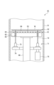
- FIG. 2 is a cross-sectional view showing an example of a first temperature adjustment device.
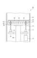
- FIG. 4 is a cross-sectional view showing an example of a second temperature adjustment device. 4 is a cross-sectional view showing a height position adjusting mechanism used in the substrate placing table.
- FIG. 1 is a partial cross-sectional perspective view showing a state in which lift pins of a height position adjustment mechanism used in a substrate mounting table are pulled out; 1 shows an example of a jig used when adjusting the height position of a lift pin, where (a) is a pin height position adjustment jig and (b) is a fixing jig.
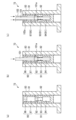
- 10A to 10C are cross-sectional process diagrams showing an example of a flow for adjusting the height positions of lift pins using a pin height position adjusting jig and a fixing jig.
- 11 is a cross-sectional view showing an example of a state in which a pin height position adjusting jig and a fixing jig are attached.
- FIG. FIG. 1 is a cross-sectional view showing a lift pin height adjustment mechanism that has been commonly used in the past.
- FIG. 1 is a plan view showing a substrate processing system including a first temperature adjustment device and a second temperature adjustment device, which is a substrate processing apparatus according to an embodiment of the present invention.
- the substrate processing system 1 has a processing section 2 that performs multiple processes on a substrate in a vacuum, a loading/unloading section 3 that loads and unloads the substrate into and from the processing section 2, and a control section 4.
- the substrate is not particularly limited, but may be, for example, a semiconductor wafer.
- the processing section 2 has multiple (eight in this example) processing modules PM1 to PM8 that perform film formation processing and the like on the substrates W, and a transport section 12 that has multiple transport modules TM1 to TM4 that sequentially transport the substrates W to the multiple processing modules PM1 to PM8.
- the processing modules PM1 to PM8 perform processes in a vacuum on a substrate, such as a film formation process for forming a film such as a magnetic film, and associated processes.
- a film formation process for forming a film such as a magnetic film
- associated processes include cleaning processes and pre-processing.
- the number of processing modules is not limited to eight, and may be set to the number required depending on the process.
- the transfer modules TM1 to TM4 each have a hexagonal container 30a, 30b, 30c, or 30d that is held in a vacuum, and a transfer mechanism 31a, 31b, 31c, or 31d that is provided within each container.
- each of the transport modules TM1 to TM4 is provided with a first temperature adjustment device 41 and a second temperature adjustment device 42 that adjust the temperature of the substrate as a substrate processing apparatus according to one embodiment.
- the first temperature adjustment device 41 is for heating the substrate
- the second temperature adjustment device 42 is for cooling the substrate.
- the first temperature adjustment device 41 has a function of heating the substrate W to a temperature required for transporting the substrate W to one of the processing modules
- the second temperature adjustment device 42 has a function of cooling the substrate W that has become hot in one of the processing modules.
- the first temperature adjustment device 41 and the second temperature adjustment device 42 have the same basic configuration, with only differences in the heating mechanism and cooling mechanism. These function as the substrate processing apparatus of this embodiment, and the detailed configuration will be described later.
- the containers 30a, 30b, 30c, and 30d are connected via a first temperature control device 41 and a second temperature control device 42.
- the transport section 12 is made up of multiple transport modules TM1 to TM4 arranged in a row in the Y direction in the figure, and the eight processing modules PM1 to PM8 are connected four on each side of the transport section 12 via openable and closable gate valves G.
- the gate valves G of the processing modules PM1 to PM8 are opened when the transport mechanism of the transport module accesses the processing module, and are closed when processing is being performed.
- the loading/unloading section 3 is connected to one end of the processing section 2.
- the loading/unloading section 3 has an atmospheric transfer chamber (EFEM) 21, three load ports 22 connected to the atmospheric transfer chamber 21, an aligner module 23, and two load lock modules LLM1 and LLM2, and a transfer device (not shown) provided in the atmospheric transfer chamber 21.
- EFEM atmospheric transfer chamber
- LLM1 and LLM2 load lock modules
- transfer device not shown
- the atmospheric transfer chamber 21 is shaped like a rectangular parallelepiped with its longitudinal direction in the X direction in the figure.
- the load ports 22 are provided on the long side wall of the atmospheric transfer chamber 21 opposite the processing section 2.
- Each load port 22 has a mounting table 25 and a transfer port 26.
- the aligner module 23 is connected to one of the short side walls of the atmospheric transfer chamber 21. Alignment of the substrate W is performed in the aligner module 23.
- the two load lock modules LLM1 and LLM2 are intended to enable the transfer of wafers W between the atmospheric transfer chamber 21, which is at atmospheric pressure, and the transfer section 12, which is at a vacuum atmosphere, and are capable of varying the pressure between atmospheric pressure and a vacuum equivalent to that of the transfer section 12.
- Each of the two load lock modules LLM1 and LLM2 has two transfer ports, one of which is connected to the long side wall of the atmospheric transfer chamber 21 on the processing section 2 side via a gate valve G2, and the other transfer port is connected to the container 30a of the transfer module TM1 in the processing section 2 via a gate valve G1.
- the load lock module LLM1 is used when transporting the substrate W from the loading/unloading section 3 to the processing section 2, and the load lock module LLM2 is used when transporting the substrate W from the processing section 2 to the loading/unloading section 3.
- the transfer device in the atmospheric transfer chamber 21 transfers substrates W to the FOUP 20 on the load port 22, the load lock modules LLM1 and LLM2, and the aligner module 23. For example, it removes an unprocessed wafer W from the FOUP 20 on the load port 22 and transfers the substrate W to the load lock module LLM1, and also receives a processed substrate W present in the load lock module LLM2 and transfers it to the FOUP 20 on the load port 22.
- processing modules PM1, PM3, PM5, PM7 are arranged on one side of the transfer section 12 in order from the load lock module LLM1 side
- processing modules PM2, PM4, PM6, PM8 are arranged on the other side of the transfer section 12 in order from the load lock module LLM2 side
- transfer modules TM1, TM2, TM3, TM4 are arranged on the load lock module LLM1 and LLM2 side in order.
- the transport mechanism 31a of the transport module TM1 can access the load lock modules LLM1 and LLM2, the processing modules PM1 and PM2, and the first and second temperature control devices 41 and 42 of the transport module TM1.
- the transport mechanism 31b of the transport module TM2 can access the processing modules PM1, PM2, PM3, and PM4, the first and second temperature control devices 41 and 42 of the transport module TM1, and the first and second temperature control devices 41 and 42 of the transport module TM2.
- the transport mechanism 31c of the transport module TM3 can access the processing modules PM3, PM4, PM5, and PM6, the first and second temperature control devices 41 and 42 of the transport module TM2, and the first and second temperature control devices 41 and 42 of the transport module TM3.
- the transport mechanism 31d of the transport module TM4 is accessible to the processing modules PM5, PM6, PM7, and PM8, the first and second temperature control devices 41 and 42 of the transport module TM3, and the first and second temperature control devices 41 and 42 of the transport module TM4.
- the control unit 4 controls each component of the substrate processing system 1, such as the transfer modules TM1 to TM4 (transfer mechanisms 31a to 31d), the transfer device in the atmospheric transfer chamber 21, the processing modules PM1 to PM8, the load lock modules LLM1 and LLM2, the gate valves G, G1, G2, and the first and second temperature adjustment devices 41 and 42.
- the control unit 4 is made up of a computer and includes a main control unit having a CPU, an input device, an output device, a display device, and a storage device.
- the storage device is provided with a storage medium in which a processing recipe is stored.
- the main control unit causes the substrate processing system 1 to perform a predetermined operation based on the processing recipe called up from the storage medium.
- the substrate W is removed from the FOUP 20 by the transfer device in the atmospheric transfer chamber 21, and the removed substrate W is transferred to the aligner module 23 for alignment and then transferred to the load lock module LLM1. Then, after the load lock module LLM1 is evacuated, the substrate W is removed by the transfer mechanism 31a of the transfer module TM1. Then, the substrate W is serially transferred in sequence to the processing modules PM1, PM3, PM5, PM7, PM8, PM6, PM4, and PM2 by the transfer mechanisms 31a to 31d of the transfer modules TM1 to TM4. In each processing module, a predetermined process, for example a film formation process, is performed on the substrate W.
- a predetermined process for example a film formation process
- the first temperature control device 41 of each transport module heats the substrate W to the temperature required for processing, and the second temperature control device 42 cools the substrate W that has become too hot, as necessary.
- the substrate W is transported by the transport mechanism 31a of the transport module TM1 to the load lock module LLM2, which is held at a vacuum. Then, after the load lock module LLM2 is brought to atmospheric pressure, the substrate W is returned to the FOUP 20 by the transport device in the atmospheric transport chamber 21.
- the substrate W can be transported serially in a U-shape to multiple processing modules to perform a series of processes, such as film formation.
- the first temperature adjustment device 41 has a processing vessel 51 defining a processing chamber, a substrate mounting table 52 on which a substrate W is mounted in the processing vessel 51, and a heater 53 as a processing mechanism for processing the substrate.
- the substrate mounting table 52 has a mounting table main body 61 and a lifting mechanism 71 that raises and lowers the substrate W relative to the mounting table main body 61 using lifting pins 72.
- the mounting table main body 61 has a base portion 62 and an electrostatic chuck 63 provided thereon.
- the electrostatic chuck 63 has a structure in which an adsorption electrode 64 is embedded in an insulator, and electrostatically adsorbs the substrate W by applying a DC voltage from a DC power supply (not shown) to the adsorption electrode 64.
- the mounting table main body 61 is also provided with a heater 53 as a processing mechanism.
- the heater 53 is embedded in the electrostatic chuck 63.
- the heater 53 may also be embedded in the base portion 62.
- the heater 53 is configured to perform a heating process on the substrate W.
- the mounting table main body 61 is provided with a pin insertion hole 65 through which a lift pin 72 of a lift mechanism 71 described later is inserted.
- the mounting table main body 61 is supported by a support shaft 66 extending from the bottom of the processing vessel 51.
- the support shaft 66 has a hollow structure, and a power supply line to the adsorption electrode 64 of the electrostatic chuck 63 and a power supply line to the heater 53 are inserted inside it.
- the lifting mechanism 71 has three lifting pins 72 (only two are shown) that support and raise and lower the substrate W at their tips, a height position adjustment mechanism 73 that adjusts the height position of the lifting pins 72, a support arm 74 that supports the lifting pins 72, and a drive unit 75 that drives the lifting pins to raise and lower via the support arm 74.
- the lifting pins 72 are detachably attached to the height position adjustment mechanism 73 and are inserted into the pin insertion holes 65 of the mounting table main body 61, with their tips being able to protrude and retract relative to the substrate mounting surface.
- the drive unit 75 raises and lowers the lifting pins 72 via the support arm 74 and the height position adjustment mechanism 73, so that the substrate W can be raised and lowered.
- the substrate W transported by the transport mechanism is received on the lifting pins 72, and the lifting pins 72 are lowered to lower the substrate W and place it on the mounting table main body 61.
- the height adjustment mechanism 73 will be explained in detail later.
- the first temperature control device 41 also has a loading/unloading port for loading and unloading the substrate W, a gate valve for opening and closing the loading/unloading port, an exhaust mechanism for individually exhausting the inside of the processing vessel 51 to control the pressure, and a mechanism for supplying gas to control the pressure (none of which are shown).
- the substrate W is carried into the processing vessel 51 by the corresponding one of the transport mechanisms 31a to 31d of the transport modules TM1 to TM4.
- the substrate W is then raised and lowered by the lifting mechanism 71 and placed on the mounting table main body 61, where it is electrostatically attracted by the electrostatic chuck 63.
- the processing vessel 51 is evacuated and gas is supplied to control the pressure, and the substrate W is heated by the heater 53, and the substrate W is adjusted to a predetermined temperature.
- the substrate W is carried out by the corresponding transport mechanism.
- the second temperature adjustment device 42 has a basic configuration similar to that of the first temperature adjustment device 41, but differs in that a substrate mounting table 52' having a mounting table main body 61' provided with a coolant flow path for cooling the substrate W is provided as a processing mechanism, instead of the substrate mounting table 52 having a mounting table main body 61 provided with a heater 53 as a processing mechanism in the first temperature adjustment device 41. Therefore, the same reference numerals are used for the same parts as those in the first temperature adjustment device 41 in FIG. 2, and description thereof will be omitted.
- the second temperature control device 42 has a processing vessel 51 similar to that of the first temperature control device 41, a substrate mounting table 52', and a coolant flow path 54 as a processing mechanism for processing the substrate.
- the substrate mounting table 52' has a mounting table main body 61' and a lifting mechanism 71 that raises and lowers the substrate W relative to the mounting table main body 61'.
- the lifting mechanism 71 is configured similarly to the lifting mechanism 71 of the first temperature adjustment device 41.
- the mounting table main body 61' has a base portion 62' and an electrostatic chuck 63' provided thereon.
- the electrostatic chuck 63' has a structure in which an adsorption electrode 64 is embedded in an insulator.
- the mounting table main body 61' is also provided with a refrigerant flow path 54 as a processing mechanism.
- the refrigerant flow path 54 is provided in the base portion 62'.
- the refrigerant flow path 54 may also be provided in the electrostatic chuck 63'.
- the substrate W is configured to be cooled by flowing a refrigerant from a refrigerant source (not shown) through piping (not shown) into the refrigerant flow path 54.
- the second temperature control device 42 does not need to have a gate valve, an exhaust mechanism that individually exhausts the inside of the processing vessel 51 to control the pressure, and a mechanism that supplies gas to control the pressure.
- the substrate W is loaded into the processing vessel 51 by the corresponding one of the transport mechanisms 31a-31d of the transport modules TM1-TM4.
- the substrate W is then raised and lowered by the lifting mechanism 71 to be placed on the mounting table main body 61' and electrostatically attracted by the electrostatic chuck 63'.
- a refrigerant is passed through the refrigerant flow path 54 to cool the substrate W and adjust the temperature of the substrate W to a predetermined temperature.
- the substrate W is removed by the corresponding transport mechanism.
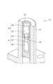
- FIG. 4 is a cross-sectional view showing the height position adjustment mechanism 73
- FIG. 5 is a partial cross-sectional perspective view showing the state in which the lift pins of the height position adjustment mechanism 73 are pulled out.
- the height position adjustment mechanism 73 adjusts the height position of the lift pins 72 in advance so that they are at an appropriate height position for smooth transfer of the substrate W from the transport mechanism to the mounting table main body.
- the lift pins 72 are detachably attached to the height position adjustment mechanism 73, and the height position of the lift pins 72 is adjusted with the lift pins pulled out using a pin height position adjustment jig as described below.
- the height position adjustment mechanism 73 has a base member 81, a height adjustment member 82, and a fixed member 83.
- the base member 81 is cylindrical and is attached to the support arm 74 with its axial direction vertical, and has a screw thread formed on its inner circumference.
- the height adjustment member 82 is a height adjustment set screw that adjusts the height position of the lift pin 72. It is cylindrical with a bottom and has a screw formed on its outer periphery, configured as a nut that screws into the inner periphery of the base member 81. When rotated, it moves up and down to adjust the height position of the lift pin 72. A hole 91 extending vertically is formed inside the height adjustment member 82, and when performing a processing operation, the lift pin 72 is inserted into the hole 91 and is supported by the height adjustment member 82.
- the lift pin 72 When adjusting the height position of the lift pin 72, for example, the lift pin 72 is pulled out of the height adjustment member 82, and a pin height position adjustment jig for adjusting the height position of the lift pin 72 is attached to the height adjustment member 82 from above.
- the height adjustment member 82 is rotated by the pin height position adjustment jig and is configured to be movable in the vertical direction, thereby adjusting the height of the pin height position adjustment jig, and thereby adjusting the height of the lift pin 72.
- the upper part of the hole 91 is an engagement hole 92 with which the pin height position adjustment jig engages, and is configured as a hexagonal hole as shown in FIG. 5, for example.
- the hole 91 further has a circular small diameter portion 93 that communicates with the lower part of the engagement hole 92, and a circular large diameter portion 94 that communicates with the lower part of the small diameter portion 93.
- the fixing member 83 is a set screw for fixing the height adjustment member 82, and is cylindrical in shape.
- a screw is formed on the outer periphery of the fixing member 83, and the fixing member 83 is configured as a nut that is screwed into a position above the height adjustment member 82 on the inner periphery of the base member 81.
- the fixing member 83 is rotated to press the height adjustment member 82 and fix it by a double nut effect.
- a hole 95 extending vertically is formed inside the fixing member 83, and the lift pin 72 is inserted into the hole 95 when performing a processing operation.
- the fixing member 83 When performing a height adjustment operation using the height adjustment member 82, the fixing member 83 is rotated by a fixing jig attached from above, for example, when the position of the height adjustment member 82 is determined.
- the upper part of the hole 95 is an engagement hole 96 with which the fixing jig engages, and is configured as a hexagonal hole as shown in FIG. 5, for example. This allows the fixing member 83 to be rotated by rotating the fixing jig with the engagement part of the fixing jig engaged with the engagement hole.
- the hole 95 further has a circular hole 97 that is circular and communicates with the lower part of the engagement hole 96.
- the circular hole 97 has a diameter that allows the part of the pin height position adjustment jig that corresponds to the engagement hole 92 to pass through.
- FIG. 6 shows an example of a jig used when adjusting the height position of the lift pin 72, where (a) is a pin height position adjustment jig 101 and (b) is a fixing jig 102.
- the pin height position adjustment jig 101 is long and shaped to mimic the lift pin 72, and is designed, for example, so that its height position when attached to the height position adjustment mechanism 73 is the same as that of the lift pin 72.
- the pin height position adjustment jig 101 is provided with a protrusion 101a that engages with the engagement hole 92 of the height adjustment member 82.
- the protrusion 101a may be hexagonal, for example, corresponding to the hexagonal hole of the engagement hole 92.
- a rotation jig (knob) for rotating the pin height position adjustment jig 101 can be attached to the upper part of the pin height position adjustment jig 101. Note that in the illustrated example, the pin height position adjustment jig 101 has a portion below the protrusion 101a, but this portion may not be present.
- the fixing jig 102 is a long cylinder with an insertion hole formed therein into which the pin height position adjustment jig 101 is inserted.
- the lower end of the fixing jig 102 is provided with an engagement portion 102a that engages with the engagement hole 96.
- the engagement portion 102a is, for example, hexagonal in shape to correspond to the hexagonal hole of the engagement hole 96.
- the upper end of the fixing jig 102 is provided with a head portion 102b to which a wrench for rotating the fixing jig 102 can be attached.
- the size of the engagement hole 96 may be the same as that of the engagement hole 92.
- FIG. 7 is a process cross-sectional view showing an example of a flow for adjusting the height position of the lift pin 72 using the pin height position adjustment jig 101 and the fixing jig 102 described above.
- the pin height position adjustment jig 101 is inserted from above into the height position adjustment mechanism 73 from which the lift pins 72 have been removed, and attached.
- the pin height position adjustment jig 101 is inserted into the height position adjustment mechanism 73 from above, and its protrusion 101a engages with the engagement hole 92 of the hole portion 91.
- the pin height position adjustment jig 101 is rotated to rotate the height adjustment member 82 and move it up and down, thereby adjusting the height position of the pin height position adjustment jig 101.
- the pin height position adjustment jig 101 is designed so that its height position is the same as the height position of the lift pins 72, the height position of the lift pins can be indirectly adjusted by adjusting the height position of the pin height position adjustment jig 101.
- the fixing jig 102 is attached to the height adjustment mechanism 73 with the pin height adjustment jig 101 still attached.
- the reason why the pin height adjustment jig 101 is left attached is to prevent the position of the height adjustment member 82 from shifting after the height adjustment is completed.
- the fixing jig 102 is lowered from above so that the pin height adjustment jig 101 is inserted into its internal hole and becomes coaxial, and the engagement portion 102a at its tip engages with the engagement hole 96.
- the fixing jig 102 is rotated to tighten the fixing member 83, and the height adjustment member 82 is fixed by the double nut effect.
- FIG. 8 is a cross-sectional view showing an example of the state in which the pin height position adjustment jig 101 and the fixing jig 102 are attached.
- the pin height position adjustment jig 101 and the fixing jig 102 can access the height position adjustment mechanism 73 from above the mounting table main body 61 (61') through the pin insertion hole 65.
- the pin height position adjustment jig 101 can adjust the height position of the height adjustment member 82 by moving the height adjustment member 82 up and down by rotating the rotating jig (knob) 103.
- the fixing jig 102 can rotate the fixing member 83 and fix the height adjustment member 82 by rotating the wrench 104 with the wrench 104 attached to the head portion 102b.
- the height position of the pin height position adjustment jig 101 is adjusted to indirectly adjust the height position of the lift pin 72, and then the pin height position adjustment jig 101 and the fixing jig 102 are removed, and the lift pin 72 is attached to the height position adjustment mechanism 73 to perform the actual processing.
- substrate mounting tables having a lifting mechanism that uses lifting pins to lift and lower the substrate when transferring the substrate have been widely used in substrate processing apparatuses.
- a base member 181 a height adjustment set screw 182 provided within the base member 181, and a fixing set screw 183 that fixes the height adjustment set screw 182 from the side as the height position adjustment mechanism 173.
- the first temperature adjustment device 41 and the second temperature adjustment device 42 are provided in the transfer module to efficiently perform heating and cooling processes before and after processing in the processing module, for example, film formation processing, and are structured to provide a substrate mounting table in the processing vessel so that temperature control can be performed with high precision. For this reason, the space below the mounting table main body 61 (61') is extremely narrow, making it extremely difficult to operate the fixing set screw from the side in that space.
- a substrate mounting table capable of temperature control in a transfer module for example, Patent Publication No. 5854741
- Patent Publication No. 5854741 there has been technology for providing a processing vessel for temperature control in a transfer module, and the problem of not being able to operate the fixing set screw in a narrow space has not been recognized.
- the height position adjustment mechanism 73 is structured so that a height adjustment member 82, which is a set screw for height adjustment, and a fixing member 83, which is a set screw for fixing, are screwed vertically into a screw formed on the inner circumference of a cylindrical base member 81.
- a height adjustment member 82 which is a set screw for height adjustment
- a fixing member 83 which is a set screw for fixing
- the height of the lift pin 72 can be easily adjusted, for example, by pulling out the lift pin 72, attaching a pin height position adjustment jig 101 to the height adjustment member 82 from above, and rotating the height adjustment member 82 with the pin height position adjustment jig 101 to adjust its height position.
- the height adjustment member 82 can also be easily fixed, for example, by attaching a fixing jig 102 to the fixing member 83 from above and rotating the fixing member 83.
- the fixing jig 102 can access the fixing member 83 of the height position adjustment mechanism 73 from above the mounting table body 61 (61') via the pin insertion hole 65, and the pin height position adjustment jig 101 can also be accessed via the pin insertion hole 65, so there is no need to remove the mounting table body 61 (61').
- the fixing member 83 can be operated with the fixing jig 102 without removing the pin height position adjustment jig 101. This allows the height adjustment member 82 to be fixed with the fixing member 83 without shifting, resulting in high precision, and also allows the height position adjustment of the lift pin 72 and the fixing of the height adjustment member 82 with the fixing member 83 to be performed efficiently.
- a processing system was described in which substrates are transported serially to a plurality of processing modules as processing modules to which a substrate processing apparatus is applied, but the present invention is not limited to this, and substrates may be transported randomly to a plurality of processing modules.
- a temperature control device installed in a transfer module has been used as an example of a substrate processing apparatus
- the present invention is not limited to being installed in a transfer module, nor is it limited to a temperature control device. Any substrate processing apparatus that uses lift pins to raise and lower a substrate and place the substrate on a mounting table body can be used.
Landscapes
- Container, Conveyance, Adherence, Positioning, Of Wafer (AREA)
Abstract
処理容器内で基板を載置する基板載置台は、載置台本体と、載置台本体に対して基板を昇降する昇降機構とを具備する。昇降機構は、載置台本体に設けられた複数の挿通孔に挿通され基板を支持して昇降する複数の昇降ピンを有し、昇降ピンの高さ位置を調整する高さ位置調整機構は、円筒状をなし、軸方向を鉛直にした状態で取り付けられ、内周部にネジが形成されたベース部材と、ベース部材の内周部に螺合し、回転されることにより上下動して昇降ピンの高さ調整を行う高さ調整部材と、ベース部材の内周部の高さ調整部材よりも上方位置に螺合し、回転されることにより高さ調整部材を押さえて固定する固定部材とを有する。
Description
本開示は、基板載置台、高さ位置調整機構、および基板処理装置に関する。
例えば、枚葉式の基板処理装置においては、処理容器内の基板載置台上に基板を載置した状態で基板の処理が行われる。基板載置台としては、基板の受け渡しの際に昇降ピンを昇降させて基板を昇降させる昇降機構を有するものが広く知られている(例えば、特許文献1、2)。
本開示は、狭隘なスペースにて昇降ピンの高さ調整が行える基板載置台、高さ位置調整機構、および基板処理装置を提供する。
本開示の一態様に係る基板載置台は、処理容器内で基板に対して処理を行う基板処理装置において、前記処理容器内で基板を載置する基板載置台であって、載置台本体と、前記載置台本体に対して基板を昇降する昇降機構と、を具備し、前記昇降機構は、前記載置台本体に設けられた複数の挿通孔にそれぞれ挿通され、その先端で前記基板を支持して昇降する複数の昇降ピンと、前記昇降ピンが着脱可能に装着され、前記昇降ピンの高さ位置を調整する高さ位置調整機構と、前記高さ位置調整機構を介して前記昇降ピンを支持する支持部材と、前記支持部材を介して前記昇降ピンを昇降させる駆動部と、を備え、前記高さ位置調整機構は、円筒状をなし、軸方向を鉛直にした状態で前記支持部材に取り付けられ、内周部にネジが形成されたベース部材と、前記昇降ピンが挿入される第1の孔部を有し、前記ベース部材の前記内周部に螺合し、回転されることにより上下動して前記昇降ピンの高さ調整を行う高さ調整部材と、前記昇降ピンが挿入される第2の孔部を有し、前記ベース部材の前記内周部の前記高さ調整部材よりも上方位置に螺合し、回転されることにより前記高さ調整部材を押さえて固定する固定部材と、を有する。
本開示によれば、狭隘なスペースにて昇降ピンの高さ調整が行える基板載置台、高さ位置調整機構、および基板処理装置が提供される。
以下、添付図面を参照して実施形態について具体的に説明する。
<基板処理システム>
図1は一実施形態に係る基板処理装置である第1の温調装置および第2の温調装置が搭載された基板処理システムを模式的に示す平面図である。
図1は一実施形態に係る基板処理装置である第1の温調装置および第2の温調装置が搭載された基板処理システムを模式的に示す平面図である。
基板処理システム1は、真空中で基板に対し複数の処理を行う処理部2と、処理部2に対し基板を搬出入する搬出入部3と、制御部4とを有する。基板は特に限定されないが、例えば半導体ウエハである。
処理部2は、基板Wに対して成膜処理等を行う複数(本例では8個)の処理モジュールPM1~PM8と、これら複数の処理モジュールPM1~PM8に対して基板Wを順次搬送する複数の搬送モジュールTM1~TM4を有する搬送部12とを有する。
処理モジュールPM1~PM8は、基板に対して真空中での処理、例えば磁性膜等の膜を成膜する成膜処理やそれに付随する処理を行うものである。成膜処理を行う場合は、複数の処理モジュールで順次成膜処理を行うことで、多層膜を形成することが可能である。付随する処理としては洗浄処理や前処理を挙げることができる。なお、処理モジュールの数は8個に限らず、処理に応じて必要な数に設定すればよい。
搬送モジュールTM1~TM4は、それぞれ真空に保持される平面形状が六角状の容器30a、30b、30c、30dと、各容器内に設けられた搬送機構31a、31b、31c、31dとを有する。
また、搬送モジュールTM1~TM4のそれぞれには、一実施形態に係る基板処理装置としての、基板を温調する第1の温調装置41および第2の温調装置42が設けられている。例えば、第1の温調装置41が基板を加熱するためのもので、第2の温調装置42が基板を冷却するためのものである。具体的には、第1の温調装置41は、例えば、いずれかの処理モジュールに基板Wを搬送する際に必要な温度に加熱する機能を有し、第2の温調装置42は、例えば、いずれかの処理モジュールで高温になった基板Wを冷却する機能を有する。第1の温調装置41および第2の温調装置42は、加熱機構および冷却機構の相違のみで、基本構成は同じである。これらは、本実施形態の基板処理装置として機能するものであり、詳細な構成は後述する。
なお、容器30a、30b、30c、30dは、第1の温調装置41および第2の温調装置42を介して連通している。
搬送部12は、複数の搬送モジュールTM1~TM4が図中Y方向に一列に配列されてなり、8つの処理モジュールPM1~PM8は、開閉可能なゲートバルブGを介して搬送部12の両側に4個ずつ接続されている。処理モジュールPM1~PM8のゲートバルブGは、処理モジュールに搬送モジュールの搬送機構がアクセスする際には開かれ、処理を行っている際には閉じられる。
搬出入部3は、処理部2の一端側に接続されている。搬出入部3は、大気搬送室(EFEM)21と、大気搬送室21に接続された、3つのロードポート22、アライナーモジュール23、ならびに2つのロードロックモジュールLLM1およびLLM2と、大気搬送室21内に設けられた搬送装置(図示せず)とを有する。なお、ロードポート22の数は3つに限らない。
大気搬送室21は、図中X方向を長手方向とする直方体状をなしている。ロードポート22は、大気搬送室21の処理部2とは反対側の長辺壁部に設けられている。各ロードポート22は載置台25と搬送口26とを有し、載置台25に複数の基板(半導体ウエハ)を収容する収容容器であるFOUP20が載置され、載置台25上のFOUP20は、搬送口26を介して大気搬送室21に密閉した状態で接続される。
アライナーモジュール23は、大気搬送室21の一方の短辺壁部に接続されている。アライナーモジュール23において、基板Wのアライメントが行われる。
2つのロードロックモジュールLLM1およびLLM2は、大気圧である大気搬送室21と真空雰囲気である搬送部12との間でウエハWの搬送を可能にするためのものであり、大気圧と搬送部12と同程度の真空との間で圧力可変となっている。2つのロードロックモジュールLLM1およびLLM2は、それぞれ2つの搬送口を有しており、一方の搬送口が大気搬送室21の処理部2側の長辺壁部にゲートバルブG2を介して接続され、他方の搬送口がゲートバルブG1を介して処理部2における搬送モジュールTM1の容器30aに接続されている。
ロードロックモジュールLLM1は基板Wを搬出入部3から処理部2に搬送する際に用いられ、ロードロックモジュールLLM2は基板Wを処理部2から搬出入部3に搬送する際に用いられる。
大気搬送室21内の搬送装置は、ロードポート22上のFOUP20、ロードロックモジュールLLM1およびLLM2、およびアライナーモジュール23に対する基板Wの搬送を行う。例えば、ロードポート22のFOUP20から未処理のウエハWを取り出し、ロードロックモジュールLLM1へ基板Wを搬送し、また、ロードロックモジュールLLM2に存在する処理後の基板Wを受け取り、ロードポート22のFOUP20へ搬送する。
上記処理部2においては、搬送部12の一方側に、ロードロックモジュールLLM1側から順に、処理モジュールPM1、PM3、PM5、PM7が配置され、搬送部12の他方側に、ロードロックモジュールLLM2側から順に、処理モジュールPM2、PM4、PM6、PM8が配置されている。また、搬送部12においては、ロードロックモジュールLLM1およびLLM2側から順に搬送モジュールTM1、TM2、TM3、TM4が配置されている。
搬送モジュールTM1の搬送機構31aは、ロードロックモジュールLLM1およびLLM2、処理モジュールPM1およびPM2、ならびに、搬送モジュールTM1の第1および第2の温調装置41および42にアクセス可能である。搬送モジュールTM2の搬送機構31bは、処理モジュールPM1、PM2、PM3、およびPM4、搬送モジュールTM1の第1および第2の温調装置41および42、ならびに搬送モジュールTM2の第1および第2の温調装置41および42にアクセス可能である。搬送モジュールTM3の搬送機構31cは、処理モジュールPM3、PM4、PM5、およびPM6、搬送モジュールTM2の第1および第2の温調装置41および42、ならびに搬送モジュールTM3の第1および第2の温調装置41および42にアクセス可能である。搬送モジュールTM4の搬送機構31dは、処理モジュールPM5、PM6、PM7、およびPM8、搬送モジュールTM3の第1および第2の温調装置41および42、ならびに搬送モジュールTM4の第1および第2の温調装置41および42にアクセス可能である。
制御部4は、基板処理システム1の各構成部、例えば、搬送モジュールTM1~TM4(搬送機構31a~31d)、および大気搬送室21内の搬送装置、処理モジュールPM1~PM8、ロードロックモジュールLLM1およびLLM2、ゲートバルブG、G1、G2、ならびに、第1および第2の温調装置41および42等を制御する。制御部4は、コンピュータからなっており、CPUを有する主制御部と、入力装置と、出力装置と、表示装置と、記憶装置とを備えている。記憶装置には、処理レシピが記憶された記憶媒体が設けられている。主制御部は、記憶媒体から呼び出された処理レシピに基づいて基板処理システム1に所定の動作を実行させる。
このように構成される基板処理システム1においては、まず、大気搬送室21内の搬送装置によりFOUP20から基板Wを取り出し、取り出された基板Wを、アライナーモジュール23に搬送しアライメントを行った後、ロードロックモジュールLLM1に搬送する。そして、ロードロックモジュールLLM1を真空排気した後、搬送モジュールTM1の搬送機構31aにより基板Wを取り出す。そして、搬送モジュールTM1~TM4の搬送機構31a~31dにより、基板Wを処理モジュールPM1、PM3、PM5、PM7、PM8、PM6、PM4、PM2に順次シリアルに搬送する。各処理モジュールでは、基板Wに対して所定の処理、例えば成膜処理を行う。
また、各処理モジュールの処理の前後に、必要に応じて、各搬送モジュールの第1の温調装置41で基板Wを処理に必要な温度に加熱したり、第2の温調装置42で高温になった基板Wを冷却したりする。
このようにして基板Wに対して処理モジュールPM2での処理が終了した後、搬送モジュールTM1の搬送機構31aにより基板Wを真空に保持されたロードロックモジュールLLM2に搬送する。そして、ロードロックモジュールLLM2を大気圧にした後、大気搬送室21の搬送装置により基板WをFOUP20へ戻す。
以上により、基板Wを複数の処理モジュールに対し順次シリアルにU字状に搬送して一連の処理、例えば成膜処理を行うことができる。
<第1の温調装置41>
次に、第1の温調装置41の一例について説明する。
図2は、第1の温調装置41の一例を示す断面図である。第1の温調装置41は、処理室を画成する処理容器51と、処理容器51内で基板Wを載置する基板載置台52と、基板を処理する処理機構としてのヒーター53とを有する。
次に、第1の温調装置41の一例について説明する。
図2は、第1の温調装置41の一例を示す断面図である。第1の温調装置41は、処理室を画成する処理容器51と、処理容器51内で基板Wを載置する基板載置台52と、基板を処理する処理機構としてのヒーター53とを有する。
基板載置台52は、載置台本体61と、載置台本体61に対して昇降ピン72により基板Wを昇降させる昇降機構71とを有する。
載置台本体61は、ベース部62と、その上に設けられた静電チャック63とを有する。静電チャック63は、絶縁体の中に吸着電極64が埋設された構造を有しており、吸着電極64に直流電源(図示せず)から直流電圧を印加することにより基板Wを静電吸着する。また、載置台本体61には処理機構としてのヒーター53が設けられている。本例では、ヒーター53は静電チャック63に埋設されている。ヒーター53はベース部62に埋設されていてもよい。ヒーター53により、基板Wに対して加熱処理を行えるように構成されている。載置台本体61には、後述する昇降機構71の昇降ピン72が挿通されるピン挿通孔65が設けられている。載置台本体61は、処理容器51の底部から延びる支持シャフト66により支持されている。支持シャフト66は中空構造を有しており、その内部には、静電チャック63の吸着電極64への給電線やヒーター53への給電線が挿入されている。
昇降機構71は、その先端で基板Wを支持して昇降させる3本(2本のみ図示)の昇降ピン72と、昇降ピン72の高さ位置の調整を行う高さ位置調整機構73と、昇降ピン72を支持する支持アーム74と、支持アーム74を介して昇降ピンを昇降駆動させる駆動部75とを有する。昇降ピン72は高さ位置調整機構73に着脱自在に装着されるとともに、載置台本体61のピン挿通孔65に挿通され、その先端が基板載置面に対して突没可能に設けられている。そして、駆動部75により支持アーム74および高さ位置調整機構73を介して昇降ピン72を昇降させることにより、基板Wが昇降可能になるように構成されている。具体的には、駆動部75により昇降ピン72を上昇させた状態で、搬送機構により搬送されてきた基板Wを昇降ピン72上に受け取り、昇降ピン72を下降させることにより基板Wを下降させて載置台本体61上へ載置する。高さ位置調整機構73については、後で詳細に説明する。
第1の温調装置41は、その他に、基板Wを搬入および搬出するための搬入出口、および搬入出口を開閉するゲートバルブ、処理容器51内を個別に排気して圧力を制御する排気機構、ならびに、圧力を制御するためのガスを供給する機構等を有している(いずれも図示せず)。
このように構成される第1の温調装置41においては、搬送モジュールTM1~TM4の搬送機構31a~31dのうち対応するものにより基板Wを処理容器51内に搬入する。そして、昇降機構71により基板Wを昇降させて載置台本体61に載置し、静電チャック63により静電吸着する。その状態で、処理容器51内を排気するとともにガスを供給して圧力を制御し、ヒーター53により基板Wの加熱処理を行い、基板Wを所定温度に温調する。処理終了後、対応する搬送機構により基板Wを搬出する。
<第2の温調装置42>
次に、第2の温調装置42の一例について説明する。
図3は、第2の温調装置42の一例を示す断面図である。第2の温調装置42は、基本構成は第1の温調装置41と同様であり、第1の温調装置41における処理機構としてのヒーター53が設けられた載置台本体61を有する基板載置台52の代わりに、処理機構として基板Wに対して冷却処理を行う冷媒流路を設けた載置台本体61´を有する基板載置台52´を設けた点が異なる。したがって、図2の第1の温調装置41と同じものには同じ符号を付して説明を省略する。
次に、第2の温調装置42の一例について説明する。
図3は、第2の温調装置42の一例を示す断面図である。第2の温調装置42は、基本構成は第1の温調装置41と同様であり、第1の温調装置41における処理機構としてのヒーター53が設けられた載置台本体61を有する基板載置台52の代わりに、処理機構として基板Wに対して冷却処理を行う冷媒流路を設けた載置台本体61´を有する基板載置台52´を設けた点が異なる。したがって、図2の第1の温調装置41と同じものには同じ符号を付して説明を省略する。
第2の温調装置42は、第1の温調装置41と同様の処理容器51と、基板載置台52´と、基板を処理する処理機構としての冷媒流路54と、を有している。
基板載置台52´は、載置台本体61´と、載置台本体61´に対して基板Wを昇降させる昇降機構71とを有する。昇降機構71は第1の温調装置41の昇降機構71と同様に構成される。
載置台本体61´は、ベース部62´と、その上に設けられた静電チャック63´とを有する。静電チャック63´は、絶縁体の中に吸着電極64が埋設された構造を有している。また、載置台本体61´には処理機構としての冷媒流路54が設けられている。本例では、冷媒流路54はベース部62´に設けられている。冷媒流路54は静電チャック63´に設けられていてもよい。冷媒流路54に冷媒源(図示せず)から配管(図示せず)を介して冷媒を流すことにより、基板Wに対して冷却処理を行えるように構成されている。
なお、第2の温調装置42は、ゲートバルブ、処理容器51内を個別に排気して圧力を制御する排気機構、および、圧力を制御するためのガスを供給する機構は有していなくてもよい。
このように構成される第2の温調装置42においては、搬送モジュールTM1~TM4の搬送機構31a~31dのうち対応するものにより基板Wを処理容器51内に搬入する。そして、昇降機構71により基板Wを昇降させて載置台本体61´に載置し、静電チャック63´により静電吸着する。その状態で、冷媒流路54に冷媒を通流して基板Wの冷却処理を行い、基板Wを所定温度に温調する。処理終了後、対応する搬送機構により基板Wを搬出する。
<高さ位置調整機構73>
次に、第1の温調装置41および第2の温調装置42に用いられる高さ位置調整機構73について詳細に説明する。
次に、第1の温調装置41および第2の温調装置42に用いられる高さ位置調整機構73について詳細に説明する。
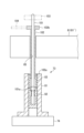
図4は高さ位置調整機構73を示す断面図、図5は高さ位置調整機構73の昇降ピンを引き抜いた状態を示す部分断面斜視図である。高さ位置調整機構73は、昇降ピン72が搬送機構から載置台本体への基板Wの円滑な受け渡しができる適切な高さ位置になるように、予めその高さ位置を調整するものである。高さ位置調整機構73は、昇降ピン72が着脱可能に装着され、昇降ピン72の高さ位置の調整は、昇降ピンは引き抜かれた状態で、後述するようにピン高さ位置調整治具により行われる。図4、図5に示すように、高さ位置調整機構73は、ベース部材81と、高さ調整部材82と、固定部材83とを有する。
ベース部材81は、円筒状をなし、軸方向を鉛直にした状態で支持アーム74に取り付けられ、内周部にネジが形成されている。
高さ調整部材82は、昇降ピン72の高さ位置の調整を行う高さ調整用セットスクリューであり、有底円筒状をなしており、外周部にネジが形成されてベース部材81の内周部に螺合するナットとして構成され、回転されることにより上下動して昇降ピン72の高さ位置の調整を行う。高さ調整部材82の内部には鉛直方向に延びる孔部91が形成されており、処理動作を行う際には、その孔部91に昇降ピン72が挿入され、高さ調整部材82により昇降ピン72が支持される。
昇降ピン72の高さ位置の調整を行う際には、例えば、高さ調整部材82から昇降ピン72が引き抜かれ、高さ調整部材82に上方から昇降ピン72の高さ位置の調整を行うためのピン高さ位置調整治具が装着される。そして、高さ調整部材82は、ピン高さ位置調整治具により回転されて上下方向に移動可能に構成され、これによりピン高さ位置調整治具の高さを調整し、それにより昇降ピン72の高さを調整する。孔部91の上部はピン高さ位置調整治具が係合する係合穴92となっており、例えば図5に示すように六角穴として構成される。孔部91は、さらに、係合穴92の下方に連通する円形の小径部93と、小径部93の下方に連通する円形の大径部94とを有している。昇降ピン72が挿入されている際には、昇降ピン72は小径部93により横方向位置が規定される。
固定部材83は、高さ調整部材82を固定する固定用セットスクリューであり、円筒状をなしており、外周部にネジが形成されてベース部材81の内周部の高さ調整部材82よりも上方位置に螺合するナットとして構成される。固定部材83は、回転されることにより高さ調整部材82を押さえてダブルナット効果により固定する。固定部材83の内部には鉛直方向に延びる孔部95が形成されており、処理動作を行う際には、その孔部95に昇降ピン72が挿入される。高さ調整部材82により高さ調整動作を行う際には、固定部材83は、高さ調整部材82の位置が決定された時点で、例えば、上方から固定治具が装着されて固定治具により回転される。孔部95の上部は固定治具が係合する係合穴96となっており、例えば図5に示すように六角穴として構成される。これにより、固定治具の係合部が係合穴に係合された状態で固定治具を回転させることにより固定部材83を回転させることができる。孔部95は、さらに、係合穴96の下方に連通する円形をなす円形孔部97を有している。円形孔部97は、ピン高さ位置調整治具の係合穴92に対応する部分が通過可能な径を有している。
<昇降ピンの高さ位置調整>
次に、高さ位置調整機構73による昇降ピン72の高さ位置調整動作の一例について詳細に説明する。
次に、高さ位置調整機構73による昇降ピン72の高さ位置調整動作の一例について詳細に説明する。
図6は昇降ピン72の高さ位置調整を行う際に用いる治具の一例を示すものであり、(a)はピン高さ位置調整治具101であり、(b)は固定治具102である。
ピン高さ位置調整治具101は、昇降ピン72を模擬した長尺状をなしており、例えば、高さ位置調整機構73に装着された際の高さ位置が、昇降ピン72の高さ位置と同じになるように設計される。ピン高さ位置調整治具101には、高さ調整部材82の係合穴92に係合する突出部101aが設けられている。突出部101aは、例えば、係合穴92の六角穴に対応する六角状をなしていてよい。ピン高さ位置調整治具101の上部には、ピン高さ位置調整治具101を回転するための回転治具(ツマミ)が装着可能となっている。なお、図示の例では、ピン高さ位置調整治具101は、突出部101aより下方の部分が存在しているが、その部分はなくてもよい。
固定治具102は長尺の円筒状をなしており、内部にピン高さ位置調整治具101が挿入される挿入孔が形成されている。固定治具102の下端には、係合穴96に係合する係合部102aが設けられている。係合部102aは、例えば、係合穴96の六角穴に対応する六角状をなしている。また固定治具102の上端には、固定治具102を回転させるレンチを取付けることが可能なヘッド部102bが設けられている。なお、係合穴96の大きさは、係合穴92と同じであってよい。
図7は、以上のようなピン高さ位置調整治具101と固定治具102を用いて昇降ピン72の高さ位置調整を行う際のフローの一例を示す工程断面図である。
まず、図7の(a)に示すように、高さ位置調整機構73から昇降ピンを抜き取る。
次に、図7の(b)に示すように、昇降ピン72が抜き取られた高さ位置調整機構73に対してピン高さ位置調整治具101を上方から挿入し装着する。このとき、ピン高さ位置調整治具101は、上方から高さ位置調整機構73に挿入され、その突出部101aが孔部91の係合穴92に係合される。この状態で、ピン高さ位置調整治具101を回転させることにより、高さ調整部材82を回転させ上下に移動させて、ピン高さ位置調整治具101の高さ位置調整を行う。上述のように、ピン高さ位置調整治具101を、その高さ位置が昇降ピン72の高さ位置と同じになるように設計すれば、ピン高さ位置調整治具101の高さ位置を調整することにより間接的に昇降ピンの高さ位置を調整することができる。
次に、図7(c)に示すように、ピン高さ位置調整治具101を装着した状態のまま、高さ位置調整機構73に固定治具102を装着する。ピン高さ位置調整治具101を装着した状態のままにするのは、高さ位置調整終了後、高さ調整部材82の位置がずれないようにするためである。このとき、固定治具102は、その内部の孔にピン高さ位置調整治具101が挿入されて同軸状になるように上方から下降され、その先端の係合部102aが係合穴96に係合される。この状態で、固定治具102を回転させて固定部材83を締め付け、ダブルナット効果により高さ調整部材82を固定する。
図8は、ピン高さ位置調整治具101および固定治具102を装着した状態の一例を示す断面図である。図8に示すように、ピン高さ位置調整治具101および固定治具102は、例えば載置台本体61(61´)の上方から、ピン挿通孔65を介して、高さ位置調整機構73にアクセスすることができる。そして、ピン高さ位置調整治具101は、回転治具(ツマミ)103を回転させることにより高さ調整部材82を上下方向に移動させて、高さ調整部材82の高さ位置を調整することができる。また、固定治具102は、ヘッド部102bにレンチ104を装着した状態でレンチ104により回転されることにより、固定部材83を回転させて高さ調整部材82を固定することができる。
以上のようにして、ピン高さ位置調整治具101の高さ位置を調整することにより、間接的に昇降ピン72の高さ位置を調整した後、ピン高さ位置調整治具101および固定治具102を取り外し、高さ位置調整機構73に昇降ピン72を装着して実際の処理を行う。
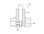
従来から、基板処理装置において、基板の受け渡しの際に昇降ピンにより基板を昇降させる昇降機構を有する基板載置台が広く用いられている。そして、従来は、図9に示すように、高さ位置調整機構173として、ベース部材181と、ベース部材181内に設けられた高さ調整用セットスクリュー182と、高さ調整用セットスクリュー182を横方向から固定する固定用セットスクリュー183とを用いるのが一般的であった。
しかし、第1の温調装置41および第2の温調装置42は、処理モジュールでの処理、例えば成膜処理の前後で、加熱処理や冷却処理を効率よく行うために、搬送モジュール内に設けられるものであり、しかも、高精度で温調を行えるように、処理容器内に基板載置台を設ける構造である。このため、載置台本体61(61´)の下方空間は極めて狭隘であり、その空間で固定用セットスクリューを横方向から操作することが極めて困難である。従来、搬送モジュール内に温調を行える基板載置台を設ける技術は存在しているが(例えば特許5854741号公報)、搬送モジュール内に温調を行うための処理容器を設ける技術は存在せず、狭隘な空間で固定用セットスクリューを操作できないという課題は認識されていなかった。
そこで、新たに生じた上述のような課題を解決すべく、高さ位置調整機構73を、円筒状のベース部材81の内周部に形成されたネジに、高さ調整用セットスクリューである高さ調整部材82と固定用セットスクリューである固定部材83を上下に螺合させる構造とした。これにより、上方からアクセスして固定部材83の操作が可能であり、載置台本体61(61´)の下方の空間が狭隘であっても、固定部材83の操作を容易に行うことができる。
そして、昇降ピン72の高さ調整は、例えば、昇降ピン72を引き抜いた状態で、上方からピン高さ位置調整治具101を高さ調整部材82に装着し、ピン高さ位置調整治具101により高さ調整部材82を回転させてその高さ位置を調整することにより簡易に行うことができる。また、高さ調整部材82の固定も、例えば、上方から固定治具102を固定部材83に装着して固定部材83を回転させることにより、容易に行うことができる。
また、従来は、固定用セットスクリューを横方向から操作するため、昇降ピンの高さ調整時に、操作の妨げとなる載置台本体等の部材を取り外すことが必要であり、煩雑であった。これに対し、本実施形態では、載置台本体61(61´)の上方からピン挿通孔65を介して固定治具102を高さ位置調整機構73の固定部材83にアクセスでき、ピン高さ位置調整治具101もピン挿通孔65を介してアクセスできるので、載置台本体61(61´)を取り外す必要はない。
さらに、ピン高さ位置調整治具101と固定治具102を同軸状にしたので、ピン高さ位置調整治具101で高さ調整部材82の調整を行った後、ピン高さ位置調整治具101を取り外すことなく固定治具102により固定部材83の操作を行うことができる。このため、高さ調整部材82のずれを生じさせずに固定部材83で固定することができ高精度であり、また、昇降ピン72の高さ位置調整と、固定部材83による高さ調整部材82の固定を効率よく行うことができる。
<他の適用>
以上、実施形態について説明したが、今回開示された実施形態は、全ての点で例示であって制限的なものではないと考えられるべきである。上記の実施形態は、添付の特許請求の範囲およびその主旨を逸脱することなく、様々な形態で省略、置換、変更されてもよい。
以上、実施形態について説明したが、今回開示された実施形態は、全ての点で例示であって制限的なものではないと考えられるべきである。上記の実施形態は、添付の特許請求の範囲およびその主旨を逸脱することなく、様々な形態で省略、置換、変更されてもよい。
例えば、上記実施形態では、基板処理装置が適用される処理モジュールとして複数の処理モジュールに対して基板を順次シリアルに搬送して処理する処理システムについて説明したが、これに限るものではなく、複数の処理モジュールにランダムに基板を搬送するものであってもよい。
また、基板処理装置として搬送モジュール内に設けられた温調装置を例にとって説明したが、搬送モジュール内に設けられるものに限定されず、また、温調装置にも限定されない。昇降ピンにより基板を昇降させて載置台本体に基板を載置する基板処理装置であれば適用可能である。
1;処理システム、2;処理部、3;搬出入部、4;制御部、12;搬送部、30a、30b、30c、30d;容器、31a、31b、31c、31d;搬送機構、41;第1の温調装置(基板処理装置)、42;第2の温調装置(基板処理装置)、51;処理容器、52、52´;基板載置台、53;ヒーター(処理機構)、54;冷媒流路(処理機構)、61、61´;載置台本体、65;ピン挿通孔、71;昇降機構、72;昇降ピン、73;高さ位置調整機構、74;支持アーム、75;駆動部、81;ベース部材、82;高さ調整部材、83;固定部材、91、95;孔部、92、96;係合穴、101;ピン高さ位置調整治具、101a;突出部、102;固定治具、102a;係合部、PM1~PM8;処理モジュール、TM1~TM4;搬送モジュール、W;基板
Claims (13)
- 処理容器内で基板に対して処理を行う基板処理装置において、前記処理容器内で基板を載置する基板載置台であって、
載置台本体と、
前記載置台本体に対して基板を昇降する昇降機構と、
を具備し、
前記昇降機構は、
前記載置台本体に設けられた複数の挿通孔にそれぞれ挿通され、その先端で前記基板を支持して昇降する複数の昇降ピンと、
前記昇降ピンが着脱可能に装着され、前記昇降ピンの高さ位置を調整する高さ位置調整機構と、
前記高さ位置調整機構を介して前記昇降ピンを支持する支持部材と、
前記支持部材を介して前記昇降ピンを昇降させる駆動部と、
を備え、
前記高さ位置調整機構は、
円筒状をなし、軸方向を鉛直にした状態で前記支持部材に取り付けられ、内周部にネジが形成されたベース部材と、
前記昇降ピンが挿入される第1の孔部を有し、前記ベース部材の前記内周部に螺合し、回転されることにより上下動して前記昇降ピンの高さ調整を行う高さ調整部材と、
前記昇降ピンが挿入される第2の孔部を有し、前記ベース部材の前記内周部の前記高さ調整部材よりも上方位置に螺合し、回転されることにより前記高さ調整部材を押さえて固定する固定部材と、
を有する、基板載置台。 - 前記昇降ピンの高さ調整は、前記昇降ピンを引き抜いた状態で、上方からピン高さ位置調整治具を前記高さ調整部材に装着し、前記ピン高さ位置調整治具により前記高さ調整部材を回転させて前記ピン高さ位置調整治具の高さ位置を調整することにより行い、
前記高さ調整部材の固定は、上方から固定治具を前記固定部材に装着して前記固定部材を回転させることにより行う、請求項1に記載の基板載置台。 - 前記高さ調整部材の前記第1の孔部は、前記ピン高さ位置調整治具が係合する係合穴を有し、前記固定部材の前記第2の孔部は、前記固定治具が係合する係合穴を有する、請求項2の基板載置台。
- 前記ピン高さ位置調整治具および前記固定治具は、前記載置台本体の上方から前記挿通孔を介して前記高さ位置調整機構にアクセスされる、請求項2に記載の基板載置台。
- 前記固定治具は内部に前記ピン高さ位置調整治具が挿入される挿入孔を有し、前記ピン高さ位置調整治具が前記高さ調整部材に装着された状態のまま、前記挿入孔に前記ピン高さ位置調整治具が挿入されて前記ピン高さ位置調整治具と同軸状になるような状態で、前記固定治具が前記固定部材に装着される、請求項2から請求項4のいずれか一項に記載の基板載置台。
- 処理容器内で基板に対して処理を行う基板処理装置の前記処理容器内で基板を載置する基板載置台において、基板を昇降して載置台本体に基板を載置するための複数の昇降ピンが着脱可能に装着され、前記昇降ピンの高さ位置を調整する高さ位置調整機構であって、
円筒状をなし、軸方向を鉛直にした状態で前記昇降ピンを支持する支持部材に取り付けられ、内周部にネジが形成されたベース部材と、
前記昇降ピンが挿入される第1の孔部を有し、前記ベース部材の前記内周部に螺合し、回転されることにより上下動して前記昇降ピンの高さ調整を行う高さ調整部材と、
前記昇降ピンが挿入される第2の孔部を有し、前記ベース部材の前記内周部の前記高さ調整部材よりも上方位置に螺合し、回転されることにより前記高さ調整部材を押さえて固定する固定部材と、
を有する、高さ位置調整機構。 - 前記昇降ピンの高さ調整は、前記昇降ピンを引き抜いた状態で、上方からピン高さ位置調整治具を前記高さ調整部材に装着し、前記ピン高さ位置調整治具により前記高さ調整部材を回転させて前記ピン高さ位置調整治具の高さ位置を調整することにより間接的に行い、
前記高さ調整部材の固定は、上方から固定治具を前記固定部材に装着して前記固定部材を回転させることにより行う、請求項6に記載の高さ位置調整機構。 - 基板に対して処理を行う基板処理装置であって、
処理容器と、
処理容器内で基板を載置する基板載置台と、
基板を処理する処理機構と、
を具備し、
前記基板載置台は、
載置台本体と、
前記載置台本体に対して基板を昇降する昇降機構と、
を備え、
前記昇降機構は、
前記載置台本体に設けられた複数の挿通孔にそれぞれ挿通され、その先端で前記基板を支持して昇降する昇降ピンと、
前記昇降ピンが着脱可能に装着され、前記昇降ピンの高さ位置を調整する高さ位置調整機構と、
前記高さ位置調整機構を介して前記昇降ピンを支持する支持部材と、
前記支持部材を介して前記昇降ピンを昇降させる駆動部と、
を有し、
前記高さ位置調整機構は、
円筒状をなし、軸方向を鉛直にした状態で前記支持部材に取り付けられ、内周部にネジが形成されたベース部材と、
前記昇降ピンが挿入される第1の孔部を有し、前記ベース部材の前記内周部に螺合し、回転されることにより上下動して前記昇降ピンの高さ調整を行う高さ調整部材と、
前記昇降ピンが挿入される第2の孔部を有し、前記ベース部材の前記内周部の前記高さ調整部材よりも上方位置に螺合し、回転されることにより前記高さ調整部材を押さえて固定する固定部材と、
を有する、基板処理装置。 - 前記昇降ピンの高さ調整は、前記昇降ピンを引き抜いた状態で、上方からピン高さ位置調整治具を前記高さ調整部材に装着し、前記ピン高さ位置調整治具により前記高さ調整部材を回転させて前記ピン高さ位置調整治具の高さ位置を調整することにより行い、
前記高さ調整部材の固定は、上方から固定治具を前記固定部材に装着して前記固定部材を回転させることにより行う、請求項8に記載の基板処理装置。 - 前記処理機構は、前記載置台本体に設けられた温調機構である、請求項8に記載の基板処理装置。
- 前記温調機構は、前記基板を加熱するヒーターを有する、請求項10に記載の基板処理装置。
- 前記温調機構は、前記基板を冷却する冷媒が通流される冷媒流路を有する、請求項10に記載の基板処理装置。
- 前記基板処理装置は、真空状態で基板に処理を行う複数の処理モジュールと、前記複数の処理モジュールが接続され、真空状態で前記基板を前記複数の処理モジュールに搬送する搬送モジュールを有する基板処理システムにおいて、前記搬送モジュールに設けられる、請求項10から請求項12のいずれか一項に記載の基板処理装置。
Priority Applications (2)
| Application Number | Priority Date | Filing Date | Title |
|---|---|---|---|
| KR1020267019373A KR20260115094A (ko) | 2023-11-29 | 2024-11-15 | 기판 탑재대, 높이 위치 조정 기구, 및 기판 처리 장치 |
| CN202480073530.0A CN122342318A (zh) | 2023-11-29 | 2024-11-15 | 基板载置台、高度位置调整机构以及基板处理装置 |
Applications Claiming Priority (2)
| Application Number | Priority Date | Filing Date | Title |
|---|---|---|---|
| JP2023-201797 | 2023-11-29 | ||
| JP2023201797A JP2025087263A (ja) | 2023-11-29 | 2023-11-29 | 基板載置台、高さ位置調整機構、および基板処理装置 |
Publications (1)
| Publication Number | Publication Date |
|---|---|
| WO2025115646A1 true WO2025115646A1 (ja) | 2025-06-05 |
Family
ID=95897783
Family Applications (1)
| Application Number | Title | Priority Date | Filing Date |
|---|---|---|---|
| PCT/JP2024/040605 Pending WO2025115646A1 (ja) | 2023-11-29 | 2024-11-15 | 基板載置台、高さ位置調整機構、および基板処理装置 |
Country Status (4)
| Country | Link |
|---|---|
| JP (1) | JP2025087263A (ja) |
| KR (1) | KR20260115094A (ja) |
| CN (1) | CN122342318A (ja) |
| WO (1) | WO2025115646A1 (ja) |
Citations (6)
| Publication number | Priority date | Publication date | Assignee | Title |
|---|---|---|---|---|
| JP2000260854A (ja) * | 1999-03-09 | 2000-09-22 | Hitachi Ltd | 半導体ウェハ押し上げ機構 |
| US20050092438A1 (en) * | 2003-11-04 | 2005-05-05 | Hur Gwang H. | Flat panel display manufacturing apparatus |
| US20140265098A1 (en) * | 2013-03-15 | 2014-09-18 | Infineon Technologies Ag | Lift Pin for Substrate Processing |
| JP2015228488A (ja) * | 2014-05-03 | 2015-12-17 | 株式会社半導体エネルギー研究所 | フィルム状部材の支持装置 |
| US20190080955A1 (en) * | 2017-09-12 | 2019-03-14 | Samsung Electronics Co., Ltd. | Lift Pin Assembly, Substrate Support Apparatus and Substrate Processing Apparatus Having the Same |
| JP2023000780A (ja) * | 2021-06-18 | 2023-01-04 | 東京エレクトロン株式会社 | プラズマ処理装置 |
-
2023
- 2023-11-29 JP JP2023201797A patent/JP2025087263A/ja active Pending
-
2024
- 2024-11-15 CN CN202480073530.0A patent/CN122342318A/zh active Pending
- 2024-11-15 WO PCT/JP2024/040605 patent/WO2025115646A1/ja active Pending
- 2024-11-15 KR KR1020267019373A patent/KR20260115094A/ko active Pending
Patent Citations (6)
| Publication number | Priority date | Publication date | Assignee | Title |
|---|---|---|---|---|
| JP2000260854A (ja) * | 1999-03-09 | 2000-09-22 | Hitachi Ltd | 半導体ウェハ押し上げ機構 |
| US20050092438A1 (en) * | 2003-11-04 | 2005-05-05 | Hur Gwang H. | Flat panel display manufacturing apparatus |
| US20140265098A1 (en) * | 2013-03-15 | 2014-09-18 | Infineon Technologies Ag | Lift Pin for Substrate Processing |
| JP2015228488A (ja) * | 2014-05-03 | 2015-12-17 | 株式会社半導体エネルギー研究所 | フィルム状部材の支持装置 |
| US20190080955A1 (en) * | 2017-09-12 | 2019-03-14 | Samsung Electronics Co., Ltd. | Lift Pin Assembly, Substrate Support Apparatus and Substrate Processing Apparatus Having the Same |
| JP2023000780A (ja) * | 2021-06-18 | 2023-01-04 | 東京エレクトロン株式会社 | プラズマ処理装置 |
Also Published As
| Publication number | Publication date |
|---|---|
| JP2025087263A (ja) | 2025-06-10 |
| KR20260115094A (ko) | 2026-07-23 |
| CN122342318A (zh) | 2026-07-03 |
Similar Documents
| Publication | Publication Date | Title |
|---|---|---|
| JP5650935B2 (ja) | 基板処理装置及び位置決め方法並びにフォーカスリング配置方法 | |
| US6331095B1 (en) | Transportation system and processing apparatus employing the transportation system | |
| KR101227809B1 (ko) | 기판 배치대의 강온 방법, 컴퓨터 판독 가능한 기억 매체, 및 기판 처리 시스템 | |
| TWI238438B (en) | Semiconductor wafer processing system with vertically-stacked process chambers and single-axis dual-wafer transfer | |
| CN101136349B (zh) | 衬底传送装置、衬底处理装置和传送衬底的方法 | |
| US9228685B2 (en) | Load lock device | |
| US20090087932A1 (en) | Substrate supporting apparatus, substrate supporting method, semiconductor manufacturing apparatus and storage medium | |
| JP2025041727A (ja) | 粒子ビーム検査装置 | |
| KR102642683B1 (ko) | 기판 처리 시스템 및 반송 방법 | |
| JP2007186757A (ja) | 真空処理装置及び真空処理方法 | |
| US20080223399A1 (en) | Substrate processing apparatus, substrate processing method and storage medium | |
| US20080223400A1 (en) | Substrate processing apparatus, substrate processing method and storage medium | |
| US11958087B2 (en) | Substrate processing method and substrate processing apparatus | |
| US20230282503A1 (en) | Substrate processing system and substrate transfer method | |
| TWI745744B (zh) | 基板處理裝置、半導體裝置之製造方法及記錄媒體 | |
| CN103681405A (zh) | 具有内晶圆载体缓冲区的半导体装置和方法 | |
| JP4642619B2 (ja) | 基板処理システム及び方法 | |
| US11725272B2 (en) | Method, system and apparatus for cooling a substrate | |
| JP2025087263A (ja) | 基板載置台、高さ位置調整機構、および基板処理装置 | |
| JP3560633B2 (ja) | 加熱処理装置 | |
| US20240203757A1 (en) | Control unit and semiconductor manufacturing equipment including the same | |
| KR102241600B1 (ko) | 로드락 챔버 및 이를 구비하는 기판 처리 시스템 | |
| US20240222156A1 (en) | Substrate treating apparatus and semiconductor manufacturing equipment including the same | |
| US20250273445A1 (en) | Substrate processing apparatus | |
| JP7844314B2 (ja) | 基板処理装置および基板処理方法 |
Legal Events
| Date | Code | Title | Description |
|---|---|---|---|
| 121 | Ep: the epo has been informed by wipo that ep was designated in this application |
Ref document number: 24897333 Country of ref document: EP Kind code of ref document: A1 |
|
| WWE | Wipo information: entry into national phase |
Ref document number: 1020267019373 Country of ref document: KR |
|
| NENP | Non-entry into the national phase |
Ref country code: DE |
|
| WWP | Wipo information: published in national office |
Ref document number: 1020267019373 Country of ref document: KR |