WO2025115259A1 - トイレシステム、トイレ装置用電波装置、及びトイレシステムの状態検知方法 - Google Patents
トイレシステム、トイレ装置用電波装置、及びトイレシステムの状態検知方法 Download PDFInfo
- Publication number
- WO2025115259A1 WO2025115259A1 PCT/JP2024/021081 JP2024021081W WO2025115259A1 WO 2025115259 A1 WO2025115259 A1 WO 2025115259A1 JP 2024021081 W JP2024021081 W JP 2024021081W WO 2025115259 A1 WO2025115259 A1 WO 2025115259A1
- Authority
- WO
- WIPO (PCT)
- Prior art keywords
- radio wave
- toilet
- wave sensor
- sensor
- water
- Prior art date
- Legal status (The legal status is an assumption and is not a legal conclusion. Google has not performed a legal analysis and makes no representation as to the accuracy of the status listed.)
- Pending
Links
Images










Classifications
-
- E—FIXED CONSTRUCTIONS
- E03—WATER SUPPLY; SEWERAGE
- E03D—WATER-CLOSETS OR URINALS WITH FLUSHING DEVICES; FLUSHING VALVES THEREFOR
- E03D9/00—Sanitary or other accessories for lavatories ; Devices for cleaning or disinfecting the toilet room or the toilet bowl; Devices for eliminating smells
Definitions
- the disclosed embodiments relate to a toilet system, a radio wave device for a toilet device, and a method for detecting the state of the toilet system.
- the drain pipe also simply called the "drain pipe”
- the drain pipe it is necessary to ensure that the camera does not come into contact with overflow water, and in order to place the camera inside the drain pipe, the drain pipe needs to be elongated horizontally, which places restrictions on the structure of the drain pipe. In this way, the above-mentioned conventional technology has many restrictions on properly detecting changes in conditions that occur in the toilet, and there is room for improvement.
- the toilet system is characterized by comprising a bowl portion for receiving waste material, a trap portion for forming a water seal on the bottom side of the bowl portion, a radio wave sensor for detecting a change in state of the water seal on the trap portion side caused by the waste material falling into the water seal, and an estimation means for estimating information about urine or feces related to the waste material based on the detection result of the radio wave sensor.
- the radio wave sensor is a millimeter wave sensor or a microwave sensor.
- the antenna portion of the radio wave sensor is provided on the outer wall of the drain pipe that has the trap portion.
- the toilet system further includes an optical sensor that detects changes in the state of the sealing water from the bowl side at multiple times, and the estimation means estimates the urine or feces information based on the detection results of the radio wave sensor and the optical sensor.
- information about excrement can be more appropriately estimated by estimating information about urine or feces using the detection results of an optical sensor that detects changes in the state of the sealing water from the bowl side at multiple times.
- a toilet system when there is a correlation between the detection results of the radio wave sensor and the optical sensor, information about the excrement can be more appropriately estimated by estimating information about urine or feces.
- the toilet system further includes an optical sensor that detects feces from the bowl side before it hits the sealed water, and the estimation means acquires information about the urine or feces based on the detection results of the radio wave sensor and the optical sensor.
- information about the excrement can be more appropriately estimated by acquiring information about the urine or feces using the detection results of an optical sensor that detects feces from the bowl side before it hits the sealed water.
- the estimation means obtains information about feces based on the detection results of the optical sensor, and obtains information about the urine or feces based on the detection results of the radio wave sensor.
- information about feces is obtained based on the detection results of an optical sensor, and information about urine or feces is obtained based on the detection results of a radio wave sensor, making it possible to more appropriately estimate information about excrement.
- the radio wave device for a toilet device is a radio wave device for a toilet device that is installed in a toilet device, and is characterized by having a radio wave sensor that detects a change in state that occurs in the water seal on the trap section side that forms a water seal on the bottom side of the bowl section when waste falls into the water seal in the bowl section of the toilet device.
- the radio wave device for a toilet apparatus uses a radio wave sensor that detects changes in the state of the seal water on the trap side due to excrement falling into the seal water, making it possible to appropriately detect changes in the state that occur in the toilet.
- the radio wave device for a toilet apparatus detects the behavior of overflowing water accompanying changes in the state of the seal water, such as the swaying of the seal water on the trap side, using a radio wave sensor such as a microwave sensor or millimeter wave sensor, and detects changes in the state of the seal water, such as the swaying of the seal water, due to objects (feces, urine) that fall into the seal water on the bowl side on the trap side, making it possible to easily obtain information on urine or feces without placing a sensor in the drain pipe.
- a radio wave sensor such as a microwave sensor or millimeter wave sensor
- the toilet system state detection method is characterized in that it includes a detection step of detecting a change in state of the water seal formed on the bottom side of the bowl section of the toilet system by a trap section provided downstream in the drainage direction from the bowl section, when excrement falls into the water seal on the bowl section side.
- a method for detecting the state of a toilet system uses a radio wave sensor that detects changes in the state of the seal water on the trap side due to excrement falling into the seal water, making it possible to appropriately detect changes in the state of the toilet.
- the method for detecting the state of the toilet system uses a radio wave sensor such as a microwave sensor or a millimeter wave sensor to detect overflow behavior accompanying changes in the state of the seal water, such as the swaying of the seal water on the trap side, and detects changes in the state of the seal water, such as the swaying of the seal water, due to objects (feces, urine) that fall into the seal water on the bowl side on the trap side, making it possible to easily obtain information on urine or feces without placing a sensor in the drain pipe.
- a radio wave sensor such as a microwave sensor or a millimeter wave sensor
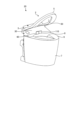
- FIG. 1 is a perspective view showing an example of a configuration of a toilet system according to an embodiment.
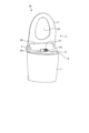
- FIG. 2 is a perspective view showing an example of the configuration of the toilet seat device according to the embodiment.
- FIG. 3 is a perspective view showing an example of the configuration of the toilet seat device according to the embodiment.
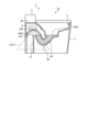
- FIG. 4 is a schematic diagram illustrating an example of the configuration of the toilet device according to the embodiment.
- FIG. 5 is a block diagram showing an example of the configuration of the toilet seat device and the radio wave sensor according to the embodiment.
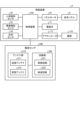
- FIG. 6 is a block diagram illustrating an example of the configuration of the control device according to the embodiment.
- FIG. 7 is a diagram showing an outline of the process of estimating information related to excrement.
- FIG. 1 is a perspective view showing an example of a configuration of a toilet system according to an embodiment.
- FIG. 2 is a perspective view showing an example of the configuration of the toilet seat device according to the embodiment.
- FIG. 3 is a perspective view showing an example of the configuration
- FIG. 16 is a diagram illustrating an example of a method for calculating a flow rate.
- FIG. 17 is a diagram showing an example of the relationship between the area and the total urine volume.
- FIG. 18 is a diagram showing an example of a process when defecation occurs during urination.
- FIG. 19 is a diagram showing an example of a process when defecation occurs during urination.
- FIG. 20 is a diagram showing an example of calculation using two outputs.
- FIG. 21 is a diagram illustrating an example of the configuration of a radio wave sensor.
- FIG. 22 is a diagram showing an example of a process using the relationship between two outputs.
- Fig. 1 is a perspective view showing an example of the configuration of a toilet system according to an embodiment.
- the toilet bowl 7 is a so-called toilet bowl (Western-style toilet bowl) and is made of materials such as ceramic or resin.
- the toilet bowl 7 is formed with a bowl portion 8.
- the bowl portion 8 is concave downwards and is the area that receives the user's excrement. In this way, the toilet bowl 7 functions as the toilet body having the bowl portion 8.
- the bottom side of the bowl portion 8 is connected to a drain pipe 81, which will be described later.
- the toilet bowl 7 is not limited to a floor-standing type as shown in the figure, and may be of any type, such as a wall-mounted type, as long as the toilet system 1 is applicable.
- the toilet bowl 7 is provided with a rim portion 9 around the entire edge of the opening facing the bowl portion 8.
- a flush water tank for storing flush water may be installed near the toilet bowl 7, or a so-called tankless type may be used in which no flush water tank is installed.
- the toilet seat device 2 is attached to the top of the toilet bowl 7, and comprises a main body 3, a toilet lid 4, a toilet seat 5, and a cleaning nozzle 6.
- the toilet seat device 2 is placed on top of the toilet bowl 7, which is formed with a bowl portion 8 that receives excrement.
- the toilet seat device 2 is placed on top of the toilet bowl 7 so that the cleaning nozzle 6 advances into the bowl portion 8 before spraying cleaning water.
- the toilet seat device 2 may be detachably attached to the toilet bowl 7, or may be attached so as to be integrated with the toilet bowl 7.
- the main body 3 also functions as a functional part in which components for executing various functions (e.g., the control device 100, etc.) are arranged within the main body cover 30.
- the toilet seat 5 is formed in a ring shape with an opening 50 in the center, and is positioned along the rim portion 9 so that it overlaps with the opening of the toilet bowl 7.
- a user sits on the toilet seat 5.
- the toilet seat 5 functions as a seating section that supports the buttocks of a seated user.
- the toilet lid 4 and toilet seat 5 are each pivotally supported at one end by the main body portion 3, and are attached so that they can rotate (be opened and closed) around the pivot portion of the main body portion 3.
- the toilet lid 4 is attached to the toilet seat device 2 as necessary, and the toilet seat device 2 does not have to have a toilet lid 4.
- the cleaning nozzle 6 is a nozzle for ejecting water for cleaning.
- the cleaning nozzle 6 is capable of spraying cleaning water.
- the cleaning nozzle 6 is capable of spraying cleaning water toward the user.
- the cleaning nozzle 6 is a nozzle for cleaning private parts.
- the cleaning nozzle 6 is configured to be movable forward and backward relative to the body cover 30, which is the housing of the main body 3, by being driven by a driving source such as an electric motor (such as the nozzle motor 61 in FIG. 5).
- the cleaning nozzle 6 is also connected to a water source such as a water pipe (not shown).
- an advanced position also called the "advanced position”
- the body cover 30 which is the housing of the main body 3, as shown in FIG. 1, it sprays water from the water source onto the user's body to clean the private parts.
- the cleaning nozzle 6 is shown in the advanced position.
- the cleaning nozzle 6 may also be used to clean the inside of the toilet bowl 7 (bowl portion 8, etc.).
- the cleaning nozzle 6 may be used to be switchable between a private parts cleaning mode for cleaning the private parts of the user, and a toilet bowl cleaning mode for spraying water inside the toilet bowl 7.
- the cleaning nozzle 6 may be used to be switchable between the private parts cleaning mode and the toilet bowl cleaning mode in response to control by the toilet seat device 2.
- the operating device 10 is provided in the toilet room R.
- the operating device 10 is provided in a position where it can be operated by a user.
- the operating device 10 is provided in a position where it can be operated when the user is seated on the toilet seat 5.
- the operating device 10 is provided on a wall surface W on the right side as seen from a user seated on the toilet seat 5.
- the operating device 10 may be provided in various ways, not limited to on a wall surface, as long as it is usable by a user seated on the toilet seat 5.
- the operating device 10 may be provided integrally with the toilet seat device 2.
- the operating device 10 is connected to the toilet seat device 2 via a specified network so as to be able to communicate with each other via a wired or wireless connection.
- the toilet seat device 2 and the operating device 10 may be connected in any manner as long as they are able to send and receive information, and may be connected to each other so as to be able to communicate with each other via a wired connection or a wireless connection.
- the operation device 10 accepts various operations from the user via a display surface (for example, the display screen 11) using, for example, a touch panel function.
- the operation device 10 may also include switches and buttons and accept various operations via the switches and buttons.
- the display screen 11 is a display screen of a tablet terminal or the like realized by, for example, a liquid crystal display or an organic EL (Electro-Luminescence) display, and is a display device for displaying various information.
- the operation device 10 accepts input from the user via the display screen 11 and also outputs to the user. At this time, the operation device 10 identifies which user who is registered in advance is the user.
- control unit 130 links the user information with information on excrement or information obtained from the information on excrement, which will be described later, and transmits the information to the user's terminal. At this time, information on the date and time when the information on excrement was obtained may also be transmitted to the user's terminal.
- the display screen 11 is a display device for displaying various information.
- the operating device 10 accepts a user's operation to stop control being performed by the toilet seat device 2.
- the operating device 10 accepts a user's operation to start the execution of private parts washing by the toilet seat device 2.
- the operating device 10 accepts an instruction from the user to the washing nozzle 6.
- the operating device 10 accepts a user's operation to cause the toilet seat device 2 to output a predetermined sound.
- the operating device 10 accepts a user's operation to perform a sterilization process to sterilize the washing nozzle 6 (see FIG. 1) of the toilet seat device 2 with disinfectant water.
- the operating device 10 accepts a user's operation to adjust the force of the water discharged during private parts washing by the toilet seat device 2.
- the operating device 10 accepts a user's operation to adjust the volume of the sound output by the toilet seat device 2.
- the operating device 10 accepts a user's operation to select the language when information regarding toilet use is displayed on the operating device 10 or output as audio.
- the operation device 10 may display an object that accepts the above-mentioned user's operation on the display screen 11, and execute various processes in response to the user touching the displayed object.
- the operation device 10 may have a switch, button, etc. that accepts the above-mentioned user's operation, and execute various processes in response to the user touching the switch, button, etc. Note that the above is an example, and the operation device 10 may accept a user's operation to execute various processes.
- the configuration of the toilet device 20 will be described below.
- the toilet device 20 has a toilet bowl 7 having a bowl portion 8, a radio wave sensor 200 (see FIG. 4), and a control device 100 (see FIG. 6) that functions as an estimation means.
- the toilet device 20 detects a state change that occurs in the sealed water due to the dropping of excrement into the sealed water by the radio wave sensor 200.
- the toilet device 20 also estimates information on urine or feces related to excrement based on the detection result of the radio wave sensor 200, which will be described later.
- the toilet system 1 may provide information to a terminal device such as a smartphone of the user based on the estimated information.
- the toilet system 1 may also provide information to an operating device 10 (or a display screen 11) of the toilet room R based on the estimated information.
- Fig. 1 is a diagram showing a case where a lid portion 110 of the toilet seat device 2 is in a closed state (also referred to as a "closed state").
- Fig. 3 is a diagram showing a state where the lid portion 110 of the toilet seat device 2 is removed.
- FIG. 2 also shows the cleaning nozzle 6 (see FIG. 1) in a position where it is stored inside the main body cover 30 (also called the "storage position").
- the cleaning nozzle 6 when the cleaning nozzle 6 is in the storage position, the nozzle lid 60 is closed and the cleaning nozzle 6 is hidden behind the nozzle lid 60.
- the nozzle lid 60 opens and the cleaning nozzle 6 protrudes from the opening for the cleaning nozzle 6 in the main body cover 30, and the cleaning nozzle 6 transitions to an advanced state.
- the optical sensor 34 is exposed from the opening 31 of the main body cover 30.
- the lid 110 is open (also called the "open state")
- the lid 110 is not positioned in front of the optical sensor 34.
- the optical sensor 34 is exposed.
- the optical sensor 34 is able to detect changes in the state of the sealed water in the toilet bowl 7.
- the toilet seat device 2 does not need to have a lid 110.
- the toilet seat device 2 does not need to have a lid 110 and an actuator 111, and the optical sensor 34 may be constantly exposed.
- Fig. 4 is a schematic diagram showing an example of the configuration of the toilet device according to the embodiment. Specifically, Fig. 4 is a schematic diagram of a side cross section showing only the main parts of the toilet device 20, such as the toilet bowl 7, in a cross section, in order to show the configuration of the drain pipe 81 and the arrangement of the radio wave sensor 200. Note that the cross-sectional shape of the toilet bowl 7 in Fig. 4 is only one example, and the toilet bowl 7 may have any cavity inside as long as the radio wave sensor 200 can be arranged at a desired position, and for example, only the location where the radio wave sensor 200 is arranged may be a cavity.
- a drain pipe 81 is connected to an opening provided at the bottom of the bowl portion 8 of the toilet 7.
- the drain pipe 81 is a drain pipe from the bowl portion 8, and the internal space of the drain pipe 81 functions as a drainage channel.
- the drain pipe 81 has a U (V) shape that extends diagonally downward from the end connected to the bottom of the bowl portion 8, then diagonally upward, and then extends downward. This forms a trap portion 82 in the drain pipe 81.
- the trap portion 82 forms a water seal WT including the bottom side of the bowl portion 8. Note that the configuration of the drain pipe 81 shown in FIG. 4 is only one example, and any configuration can be adopted for the drain pipe 81 as long as it is possible to form a trap that can perform the process described below.
- the hatched areas in the bowl portion 8 of the toilet 7 and the drain pipe 81 are shown filled with water seal WT (water).
- water seal WT water
- the water seal surface WS1 in Figure 4 indicates the upper surface formed by the water seal WT on the bottom side of the bowl portion 8
- the water seal surface WS2 in Figure 4 indicates the upper surface formed by the water seal WT on the trap portion 82 side.
- an apex 821 is formed at the end of the trap portion 82 opposite the end of the drain pipe 81 that is connected to the bottom of the bowl portion 8.
- the detection range DA11 of the radio wave sensor 200 is set to an area that includes the apex 821 of the trap portion 82.
- the radio wave sensor 200 is positioned so that the detection range DA11 includes the apex 821 of the trap portion 82.
- the range shown in FIG. 4 is merely one example of the detection range DA11 of the radio wave sensor 200, and the detection range DA11 of the radio wave sensor 200 is not limited to the range shown in FIG. 4 and may be any range as long as it includes the apex 821 of the trap portion 82.
- the radio wave sensor 200 is a microwave sensor.
- the radio wave sensor 200 will be described as a microwave sensor, but the radio wave sensor 200 is not limited to a microwave sensor.
- any sensor such as a millimeter wave sensor, can be used as the radio wave sensor 200 as long as it is capable of performing the desired detection.
- the radio wave sensor 200 may be arranged in various ways.
- the radio wave sensor 200 may be provided in the toilet seat device 2.
- the radio wave sensor 200 may be arranged on the bottom (lower side) of the toilet seat device 2.
- the antenna unit 210 of the radio wave sensor 200 is arranged on the bottom of the toilet seat device 2 on the toilet bowl 7 side.
- the radio wave sensor 200 may be arranged in the main body unit 3, which is a functional unit.
- the radio wave sensor 200 may be arranged, for example, in the main body cover 30. Below, a configuration in which the radio wave sensor 200 is arranged on the upper side of the trap unit 82 as shown in FIG. 4 will be described as an example.
- the radio wave sensor 200 detects changes in the state of the water seal on the trap section 82 side.
- the radio wave sensor 200 detects changes in the state of the water seal, including overflow from the apex 821 of the trap section 82.
- the radio wave sensor 200 detects changes in the state of the water seal on the trap section 82 side due to waste falling into the water seal on the bowl section 8 side.
- the radio wave sensor 200 detects changes in the state of the water seal based on overflow from the apex 821 of the trap section 82, but this will be described later.
- the radio wave sensor 200 may be separate from the toilet device 20 and may be detachable from the toilet device 20.
- the radio wave sensor 200 may be a radio wave device for the toilet device that is installed in the toilet device 20.
- the radio wave sensor 200 detects a change in state that occurs in the water seal on the trap section 82 side that forms the water seal on the bottom side of the bowl section 8 when waste falls into the water seal in the bowl section 8 of the toilet device 20.
- Fig. 5 is a block diagram showing an example of the configuration of the toilet seat device and the radio wave sensor according to the embodiment.
- the toilet seat device 2 includes a human body detection sensor 32, a seating detection sensor 33, an optical sensor 34, a control device 100, a nozzle motor 61, a cleaning nozzle 6, a solenoid valve 71, a lid unit 110, and an actuator 111.
- Fig. 5 omits illustration of some of the configuration of the toilet seat device 2 described in Fig. 1 (such as the main body unit 3, the toilet seat 5, and the toilet bowl 7).
- the configuration of the toilet seat device 2 shown in FIG. 5 is merely an example, and the toilet seat device 2 can have any configuration.
- the human body detection sensor 32, seating detection sensor 33, optical sensor 34, control device 100, etc. are arranged in any location.
- the optical sensor 34 is provided in the main body 3 of the toilet seat device 2.
- the toilet seat device 2 transmits and receives information to and from an information processing device such as the operating device 10 via a predetermined network (such as the Internet) in a wired or wireless manner using a communication device (such as the communication unit 101 of the control device 100 in FIG. 6).
- the human body detection sensor 32 has the function of detecting a human body.
- the human body detection sensor 32 is realized by a pyroelectric sensor using an infrared signal.
- the human body detection sensor 32 may be realized by a ⁇ (micro) wave sensor. Note that the above is just an example, and the human body detection sensor 32 is not limited to the above, and may detect the human body by various means.
- the human body detection sensor 32 detects a person (such as a user) who has entered the toilet room R (see FIG. 1).
- the human body detection sensor 32 outputs a detection signal to the control device 100.
- the seating detection sensor 33 has the function of detecting a person sitting on the toilet seat device 2.
- the seating detection sensor 33 detects when a user sits on the toilet seat 5.
- the seating detection sensor 33 is capable of detecting when the user sits on the toilet seat 5.
- the seating detection sensor 33 also functions as a leaving detection sensor that detects when the user leaves the toilet seat 5.
- the seating detection sensor 33 detects when the user is sitting on the toilet seat 5.
- the seating detection sensor 33 detects that a user has sat on the toilet seat 5 using a load sensor.
- the seating detection sensor 33 may be an infrared light emitting/receiving distance measuring sensor, and may detect a human body near the toilet seat 5 just before the person (user) sits on the toilet seat 5, or the user sitting on the toilet seat 5. Note that the above is just one example, and the seating detection sensor 33 is not limited to the above, and may detect a person sitting on the toilet seat device 2 by various means.
- the seating detection sensor 33 outputs a seating detection signal to the control device 100.
- the optical sensor 34 may detect feces before they hit the sealed water from the bowl portion 8 side.
- the optical sensor 34 detects feces falling inside the bowl portion 8 (falling feces).
- the optical sensor 34 includes the inside of the bowl portion 8 in its detection range.
- the optical sensor 34 when the optical sensor 34 detects the presence or absence of feces, the optical sensor 34 may be an imaging means such as a camera or a line sensor. In this case, for example, the optical sensor 34 may be a line sensor arranged facing the inside of the bowl portion 8, and may detect falling objects such as excrement falling inside the bowl portion 8. In addition, the optical sensor 34 may be a camera arranged facing the sealed water inside the bowl portion 8, and may detect falling objects such as excrement that land on the sealed water.
- the control device 100 controls various configurations and processes.
- the control device 100 is a computer (information processing device) that executes various information processing such as estimating (calculating) information related to excrement, such as urine flow rate (urine volume) or feces volume.
- the control device 100 functions as an estimation means that estimates information related to excrement, such as urine or feces, based on the detection results of the radio wave sensor 200.
- the control device 100 estimates the urine flow rate or stool volume based on the change in the state of the sealing water. For example, the control device 100 estimates the urine flow rate based on the information of the standing waves output from the radio wave sensor 200. For example, the control device 100 estimates information on the urine or stool volume based on the detection results of the radio wave sensor 200 and the optical sensor 34.
- the control device 100 estimates urine or feces information when there is a correlation between the detection results of the radio wave sensor 200 and the optical sensor 34. For example, the control device 100 acquires urine or feces information based on the detection results of the radio wave sensor 200 and the optical sensor 34. For example, the control device 100 acquires feces information based on the detection results of the optical sensor 34, and acquires information about urine or feces based on the detection results of the radio wave sensor 200.
- the control device 100 also controls various components of the toilet system 1.
- the control device 100 controls the nozzle motor 61, the solenoid valve 71, and the actuator 111.
- the control device 100 controls the nozzle motor 61, the solenoid valve 71, and the actuator 111 based on signals sent from the operating device 10.
- the control device 100 controls the nozzle motor 61 based on a control instruction signal for local cleaning sent from the operation device 10.
- the control device 100 controls the nozzle motor 61 to move the cleaning nozzle 6 forward and backward.
- the control device 100 controls the opening and closing of the solenoid valve 71.
- the control device 100 controls the actuator 111 to open and close the lid 110.
- the control device 100 transmits control information to the actuator 111 to put the lid 110 in an open state.
- the control device 100 transmits control information to the actuator 111 to put the lid 110 in a closed state.
- the control device 100 controls the lid 110 to be in a closed state while the optical sensor 34 is not detecting the lid, such as before the user uses the toilet 7.
- the control device 100 transmits control information to the nozzle motor 61, solenoid valve 71, and actuator 111 via wires.
- the control device 100 may also transmit control information to the nozzle motor 61, solenoid valve 71, and actuator 111 wirelessly.
- the control device 100 when configured as a separate device from the toilet seat device 2, it may transmit control information for the nozzle motor 61, solenoid valve 71, and actuator 111 to the toilet seat device 2 wirelessly.
- the control device of the toilet seat device 2 may control the nozzle motor 61, solenoid valve 71, and actuator 111 based on the control information received.
- the control device 100 controls the opening and closing of the lid 110.
- the control device 100 opens the lid 110 when the user starts using the toilet bowl 7 as detected by the human body detection sensor 32 or the seating detection sensor 33, and closes the lid 110 when the user finishes using the toilet bowl 7 as detected by the human body detection sensor 32 or the seating detection sensor 33.
- the control device 100 also opens the lid 110 when the seating detection sensor 33 detects that the user has sat on the toilet seat 5, and closes the lid 110 when the seating detection sensor 33 detects that the user has left the toilet seat 5.
- the control device 100 opens the lid 110 when the human body detection sensor 32 detects that the user has entered the toilet room R, and closes the lid 110 when the human body detection sensor 32 detects that the user has left the toilet room R.
- the control device 100 may control the opening and closing of the lid portion 110 based on various information.
- the control device 100 may open the lid portion 110 when the human body detection sensor 32 detects that a user is approaching the toilet bowl 7. For example, the control device 100 may open the lid portion 110 when it detects that the user is located within a predetermined range (e.g., 50 cm) from the toilet bowl 7.
- the control device 100 also closes the lid portion 110 when the human body detection sensor 32 detects that the user has moved away from the toilet bowl 7. For example, the control device 100 closes the lid portion 110 when it detects that the user is located outside the predetermined range (e.g., 50 cm) from the toilet bowl 7.
- the control device 100 closes the lid portion 110 in conjunction with an instruction from the user to the operating device 10 to operate the cleaning nozzle 6.
- the control device 100 closes the lid portion 110 in conjunction with the operation of the cleaning nozzle 6.
- the control device 100 controls the lid portion 110 based on the user's operation of the operating device 10, which controls the cleaning nozzle 6.
- the control device 100 detects the operation of the cleaning nozzle 6 (the nozzle advancing into the bowl portion 8) and controls the lid portion 110.
- the control device 100 controls the lid portion 110 to open upward when placed on the toilet bowl 7.
- the control device 100 controls the lid portion 110 to close when the cleaning nozzle 6 is in operation.
- the control device 100 controls the lid portion 110 to close when the cleaning nozzle 6 arranged on the toilet bowl 7 is in operation.
- the control device 100 may also control the optical sensor 34.
- the optical sensor 34 starts or stops detection according to the control of the control device 100.
- the control device 100 transmits control information to the optical sensor 34 for controlling the start or end of detection by the optical sensor 34.
- the control device 100 transmits control information to the optical sensor 34 for causing the optical sensor 34 to start detection.
- the control device 100 transmits control information to the optical sensor 34 for causing the optical sensor 34 to end detection.
- the control device 100 may also control the radio wave sensor 200.
- the radio wave sensor 200 starts or stops detection according to the control of the control device 100.
- the control device 100 transmits control information to the radio wave sensor 200 for controlling the start or end of detection by the radio wave sensor 200.
- the control device 100 transmits control information to the radio wave sensor 200 for causing the radio wave sensor 200 to start detection.
- the control device 100 transmits control information to the radio wave sensor 200 for causing the radio wave sensor 200 to end detection.
- the control device 100 also controls the toilet lid 4 and toilet seat 5 as shown in FIG. 1.
- the control device 100 controls the toilet lid 4 and toilet seat 5 based on a signal sent from the operation device 10.
- the control device 100 controls the toilet lid 4 based on a control instruction signal for opening and closing the toilet lid sent from the operation device 10.
- the control device 100 controls the toilet seat 5 based on a control instruction signal for opening and closing the seat sent from the operation device 10.
- the control device 100 transmits control information to the toilet lid 4 and toilet seat 5 via a wired connection.
- the control device 100 may also transmit control information to the toilet lid 4 and toilet seat 5 wirelessly.
- the control device 100 determines whether the human body detection sensor 32 detects the entry of a user into the toilet room R. The control device 100 determines whether the human body detection sensor 32 detects the entry of a user into the toilet room R. The control device 100 determines whether the seating detection sensor 33 detects the user sitting down. The control device 100 determines whether the seating detection sensor 33 detects the user sitting down on the toilet seat 5.
- the solenoid valve 71 functions as a valve that controls the flow of a fluid by electromagnetic means.
- the solenoid valve 71 switches between supplying and stopping tap water from a water supply pipe, for example.
- the solenoid valve 71 controls opening and closing in response to instructions from the control device 100.
- the nozzle motor 61 is a drive source (motor) that drives the cleaning nozzle 6 to move forward and backward.
- the nozzle motor 61 controls the cleaning nozzle 6 to move forward and backward relative to the body cover 30 of the main body 3.
- the nozzle motor 61 controls the cleaning nozzle 6 to move forward and backward in response to instructions from the control device 100.
- the lid portion 110 can be positioned in front of the optical sensor 34 and functions as a lid.
- the lid portion 110 is preferably formed of a non-transparent material in order to reduce the possibility of the optical sensor 34 being visible and to provide a configuration that takes into consideration the user's privacy.
- the lid portion 110 may be formed in a non-transparent state by coloring.
- the lid portion 110 may have a non-transparent material (paint) applied to its surface.
- the lid portion 110 is not limited to being non-transparent, and may be transparent.
- the lid portion 110 can transition between an open state and a closed state by an actuator 111, and is positioned in front of the optical sensor 34 or exposes the optical sensor 34.
- the actuator 111 is a drive source (motor) that switches the lid 110 to an open or closed state.
- the actuator 111 executes control to switch the lid 110 to an open or closed state in response to instructions from the control device 100.
- the actuator 111 switches the lid 110 to a closed state when the cleaning nozzle 6 is operating.
- the actuator 111 switches the lid 110 to a closed state when the cleaning nozzle 6 disposed on the toilet 7 is operating.
- the toilet seat device 2 includes the control device 100
- the control device 100, the human body detection sensor 32, the seating detection sensor 33, the optical sensor 34, and the like may be configured as devices separate from the toilet seat device 2.
- the control device 100 may be configured as a device separate from the toilet seat device 2.
- the control device 100 may be a server device and may be located at a position separate from the toilet seat device 2.
- the control device 100 communicates with each device, such as the toilet seat device 2, the human body detection sensor 32, the seating detection sensor 33, and the optical sensor 34, and receives information necessary for estimating information related to excrement, such as the urine flow rate (urine volume) or the amount of feces, from each device.
- the antenna unit 210 has the function of transmitting and receiving radio waves.
- the antenna unit 210 includes a transmitting antenna 211 that transmits (sends) predetermined radio waves, and a receiving antenna 212 that receives radio waves.
- the antenna section 210 is arranged near the trap section 82.
- the antenna section 210 is provided on the outer wall of the drain pipe 81 having the trap section 82.
- the antenna section 210 is provided along the outer wall of the drain pipe 81 having the trap section 82.
- the antenna section 210 is arranged vertically above the trap section 82.
- the antenna section 210 is arranged vertically above the sealing water on the trap section 82 side.
- the antenna unit 210 is disposed on the bottom (lower side) side of the toilet seat device 2.
- the above-mentioned arrangement of the antenna unit 210 is merely one example, and any arrangement of the antenna unit 210 can be adopted as long as the desired detection is possible.
- the antenna unit 210 may be disposed outside the drain pipe 81, such as on the outer wall of the drain pipe 81, or may be disposed inside the drain pipe 81, as long as the desired detection is possible.
- the circuit section 220 has the function of executing processes related to transmitting and receiving radio waves.
- the circuit section 220 includes a transmitting circuit 221 that functions as an electronic circuit that generates repeated electrical vibrations, and a detection circuit 222 that performs detection in response to reception by the receiving antenna 212.
- the configuration shown in FIG. 5 is merely an example, and the radio wave sensor 200 can adopt any configuration, and may have multiple detection circuits 222, for example, as shown in FIG. 21, etc., but this point will be described later.
- the circuit configuration of the radio wave sensor 200 that uses one output may be a configuration that has only one detection circuit 222 (for example, detection circuit #1) with the part corresponding to detection circuit #2 removed from the circuit schematic diagram shown in FIG. 21.
- the radio wave sensor 200 also has a function of transmitting information collected by detection to the control device 100.
- the radio wave sensor 200 may be connected to the control device 100 by a wire and be able to communicate information with the control device 100.
- the radio wave sensor 200 may also be connected to the control device 100 and be able to communicate information with the control device 100.
- the radio wave sensor 200 may have a communication device for communicating with the control device 100.
- Fig. 6 is a block diagram showing an example of the configuration of the control device according to the embodiment.
- the control device 100 has a communication unit 101, a storage unit 120, and a control unit 130.
- the control device 100 may also have an input unit (e.g., a keyboard, a mouse, etc.) that accepts various operations from an administrator of the control device 100, and a display unit (e.g., a liquid crystal display, etc.) that displays various information.
- an input unit e.g., a keyboard, a mouse, etc.
- a display unit e.g., a liquid crystal display, etc.
- the communication unit 101 is realized, for example, by a communication circuit or the like.
- the communication unit 101 is connected to a specified network by wire or wirelessly, and transmits and receives information to and from an external information processing device.
- the communication unit 101 is connected to a specified network by wire or wirelessly, and transmits and receives information to and from other devices such as the operation device 10.
- the control device 100 may also be connected to the radio wave sensor 200 by the communication unit 101 by wire or wirelessly, and transmit and receive information to and from the radio wave sensor 200.
- the communication unit 101 may be configured as a separate device (communication device) from the control device 100, and may be included in the toilet seat device 2.
- the storage unit 120 is realized, for example, by a semiconductor memory element such as a random access memory (RAM) or a flash memory, or a storage device such as a hard disk or an optical disk.
- the storage unit 120 is a computer-readable recording medium that non-temporarily records data used by various information processing programs, etc.
- the storage unit 120 stores various information required for processing.
- the storage unit 120 stores various information acquired from other devices such as various sensors.
- the storage unit 120 stores information related to a learning model (also simply referred to as a "model") used in processing.
- the storage unit 120 stores a model used in the estimation process of information related to excrement, such as urine flow rate (urine volume) or stool volume.
- the storage unit 120 stores various information (for example, information related to thresholds) used in various information processes.
- the control unit 130 is realized, for example, by a CPU (Central Processing Unit) or a GPU (Graphics Processing Unit) executing programs (for example, various information processing programs related to the present disclosure) stored inside the control device 100 using a RAM or the like as a working area.
- the control unit 130 is also a controller, and is realized, for example, by an integrated circuit such as an ASIC (Application Specific Integrated Circuit) or an FPGA (Field Programmable Gate Array).
- control unit 130 has an acquisition unit 131, a measurement unit 132, a determination unit 133, an estimation unit 134, and an output unit 135, and realizes or executes the functions and actions of the information processing described below.
- the internal configuration of the control unit 130 is not limited to the configuration shown in FIG. 6, and may be other configurations as long as they perform the information processing described below.
- the acquisition unit 131 acquires various information.
- the acquisition unit 131 acquires various information from the storage unit 120.
- the acquisition unit 131 receives information from other devices.
- the acquisition unit 131 receives information detected by various sensors (detection information, etc.) from the various sensors.
- the acquisition unit 131 receives information detected by each sensor (detection information, etc.) from each sensor, such as the human body detection sensor 32, the seating detection sensor 33, the optical sensor 34, and the radio wave sensor 200.
- the acquisition unit 131 acquires information to be used for processing from the storage unit 120.
- the measurement unit 132 performs various measurements.
- the measurement unit 132 performs various measurements using the information stored in the memory unit 120.
- the measurement unit 132 measures the sensor values detected by the radio wave sensor 200 using the information acquired by the radio wave sensor 200.
- the measurement unit 132 uses the information detected by the radio wave sensor 200 to measure information related to changes in the state of the seal water on the trap section 82 side.
- the measurement unit 132 uses the information detected by the radio wave sensor 200 to measure information related to changes in the state of the seal water based on overflow from the apex 821 of the trap section 82.
- the determination unit 133 performs a determination process.
- the determination unit 133 performs a determination process using various information stored in the storage unit 120.
- the determination unit 133 performs a determination process using various information acquired by the acquisition unit 131.
- the determination unit 133 determines the cause of the change in the state of the sealing water of the toilet bowl 7 based on the detection results by the optical sensor 34.
- the determination unit 133 classifies the change in the state of the sealing water of the toilet bowl 7 based on the detection results by the optical sensor 34.
- the determination unit 133 determines which object caused the change in the state of the sealing water of the toilet bowl 7 based on the detection results by the optical sensor 34.
- the determination unit 133 determines whether an object has fallen (landed) into the sealed water of the toilet bowl 7 based on the detection results of the optical sensor 34. The determination unit 133 determines whether an object has landed in the sealed water of the toilet bowl 7 based on the detection results of the optical sensor 34. The determination unit 133 determines whether the object has landed in the sealed water of the toilet bowl 7 based on the detection results of the optical sensor 34. The determination unit 133 determines whether the object is a user's excrement based on the detection results of the optical sensor 34.
- the determination unit 133 classifies a plurality of types of changes in the state of the seal water, including a first type of change in the state of the seal water, which is a change in the state of the seal water due to feces, a second type of change in the state of the seal water, which is a change in the state of the seal water due to urine, and a third type of change in the state of the seal water due to feces and urine.
- the determination unit 133 classifies the change in the state of the seal water detected by the optical sensor 34 as either a change in the state of the seal water due to feces, a change in the state of the seal water due to urine, or a change in the state of the seal water due to feces and urine.
- the determination unit 133 may determine whether the state of the seal water has changed using any method. For example, the determination unit 133 may determine whether the state of the seal water has changed by exceeding a signal level threshold or by AI (artificial intelligence). The determination unit 133 may determine whether the state of the seal water has changed by frequency analysis, image processing, machine learning, deep learning, etc.
- AI artificial intelligence
- the determination unit 133 determines the change in the state of the seal water using AI technology.
- the determination unit 133 may determine the change in the state of the seal water using a model (also referred to as a "seal water state change determination model") generated by machine learning.
- the seal water state change determination model is trained in advance using training data that indicates a classification judgment.
- This training data includes multiple combinations of information on the change in the state of the seal water (seal water change information), such as an image, and a label (correct answer information) indicating the type of the change in the state of the seal water corresponding to the seal water change information.
- the type here indicates the object that caused the change in the state of the seal water, such as feces, urine, or both feces and urine.
- the training data includes multiple combinations of seal water change information and a label (correct answer information) indicating an object (e.g. feces, urine, or both feces and urine, etc.) that landed (fell) on the seal water when the change in the state of the seal water corresponding to the seal water change information occurred in the seal water.
- the seal water state change judgment model is a model that receives seal water change information as input and outputs information indicating the type of seal water state change corresponding to the input seal water change information. For example, when seal water change information is input, the seal water state change judgment model is trained to output information of a label (type of seal water state change) corresponding to the input seal water change information.
- the seal water state change judgment model is trained using various methods related to so-called supervised learning as appropriate.
- the seal water state change judgment model is stored in the memory unit 120, and the judgment unit 133 may judge the change in the seal water state using the seal water state change judgment model stored in the memory unit 120.
- the control device 100 may perform a learning process and generate the seal water state change judgment model. Note that the above is merely an example, and the judgment unit 133 may judge the change in the seal water state using various information as appropriate.
- the determination unit 133 may also determine whether or not a defecation (faecal matter) has occurred based on information detected by the stool detection means.
- the determination unit 133 may determine whether or not the user has defecates using information detected by the stool detection means such as the optical sensor 34.
- the determination unit 133 determines whether or not a defecation has occurred based on an image captured by the stool detection means. Note that the above determination of whether or not a defecation has occurred is merely one example, and when determining whether or not a defecation has occurred, the determination unit 133 may determine whether or not a defecation has occurred by appropriately using various information.
- the estimation unit 134 performs estimation processing. For example, the estimation unit 134 performs estimation processing based on an arbitrary estimation method. For example, the estimation unit 134 performs estimation processing by calculating information through calculation processing based on an arbitrary calculation method. The estimation unit 134 performs estimation processing using various information stored in the storage unit 120. The estimation unit 134 performs estimation processing using various information acquired by the acquisition unit 131. The estimation unit 134 estimates (calculates) information related to excrement, such as urine flow rate (urine volume) or stool volume, based on the determination result by the determination unit 133.
- urine flow rate urine volume
- stool volume a determination result by the determination unit 133.
- the estimation unit 134 estimates information about urine or feces related to excrement based on the detection results of the radio wave sensor 200.
- the estimation unit 134 estimates the urine flow rate or feces volume based on changes in the state of the sealing water.
- the estimation unit 134 estimates the urine flow rate based on information about standing waves output from the radio wave sensor 200.
- the estimation unit 134 estimates information on urine or feces based on the detection results of the radio wave sensor 200 and the optical sensor 34. For example, the estimation unit 134 estimates information on urine or feces when there is a correlation between the detection results of the radio wave sensor 200 and the optical sensor 34.
- the estimation unit 134 estimates information on urine based on the detection result of the radio wave sensor 200.
- the estimation unit 134 estimates the amount of urine based on the detection result of the radio wave sensor 200.
- the estimation unit 134 acquires information on urine or feces based on the detection results of the radio wave sensor 200 and the optical sensor 34. For example, the estimation unit 134 acquires information on feces based on the detection results of the optical sensor 34, and acquires information on urine or feces based on the detection results of the radio wave sensor 200. The estimation unit 134 estimates the amount of feces based on the detection results of the optical sensor 34, and estimates the amount of urine based on the detection results of the radio wave sensor 200. For example, the estimation unit 134 estimates the amount of urine by subtracting the amount of feces estimated based on the detection results of the optical sensor 34 from the total amount of excrement estimated based on the detection results of the radio wave sensor 200.
- the output unit 135 executes an output process that outputs various information.
- the output unit 135 functions as a transmission unit that transmits various information.
- the output unit 135 executes the output process by transmitting information to an external information processing device.
- the output unit 135 transmits information to an external information processing device.
- the output unit 135 transmits various information to an administrator device such as a personal computer or smartphone used by an administrator.
- the output unit 135 may also execute the output process by transmitting information to the operation device 10 (or the display screen 11).
- the output unit 135 transmits information related to excrement, such as the urine flow rate (urine volume) or stool volume, estimated by the estimation unit 134.
- the output unit 135 transmits information indicating the urine volume estimated by the estimation unit 134.
- the output unit 135 outputs information indicating either "large,” “medium,” or “small,” which indicates the total urine volume (level) categorized by the estimation unit 134.
- the output unit 135 transmits information indicating the level of the total urine volume.
- Fig. 7 is a diagram showing an outline of the process of estimating information related to excrement. Note that in Fig. 7, in order to show the outline of detection by the radio wave sensor 200, some of the reference characters and the like shown in Fig. 4 (e.g., apex 821, detection range DA11, etc.) are omitted.
- the radio wave sensor 200 detects overflow OF1 from the apex 821 of the trap portion 82.
- the toilet system 1 obtains trap overflow information regarding overflow OF1 from the apex 821 of the trap portion 82 using the radio wave sensor 200.
- overflow OF1 from the apex 821 of the trap portion 82 shown in FIG. 7 occurs in response to inflow IF1 into the bowl portion 8 due to urination by the user, etc.
- the toilet system 1 detects overflow OF1 from the apex 821 of the trap portion 82 using the radio wave sensor 200, and estimates information related to excrement, such as urine volume, based on the detection by the radio wave sensor 200.
- the premise is that radio wave sensors such as microwave sensors and millimeter wave sensors can penetrate ceramics and resins, but are reflected by water. Therefore, the toilet system 1 detects the distance from the water surface by detecting the waves reflected from the water using the radio wave sensor 200.
- radio wave sensors such as microwave sensors and millimeter wave sensors can penetrate ceramics and resins, but are reflected by water. Therefore, the toilet system 1 detects the distance from the water surface by detecting the waves reflected from the water using the radio wave sensor 200.
- the sensor when the amount of water in the seal water increases due to urination, the water will overflow the top of the trap and flow to the drain side. As the water flows, the water level near the top of the trap will rise, and when detected from above, the distance to the water surface will shorten in proportion to the rise in water level. Therefore, by using the sensor to measure the change in water level from the initial value (how much the distance has shortened), it is possible to obtain information that can be used to estimate information about excrement. In this way, there is a correlation between the change in water level and the flow rate of urine. Therefore, the flow rate can be calculated from the output of the sensor using the relationship between the three pieces of information: sensor output, water level change, and flow rate.
- the radio wave sensor 200 when the amount of water in the seal water increases due to urination, the water will flow over the apex 821 of the trap section 82 and into the drain.
- the water level near the apex of the trap section 82 rises, and when detected from above the trap section 82, the distance between the radio wave sensor 200 and the water surface shortens in response to the rise in water level.
- the change in water level from the initial value is measured by detection by the radio wave sensor 200, and information used to estimate information related to excrement can be obtained.
- the flow rate is calculated (estimated) from the output of the radio wave sensor 200 using the relationship between the three pieces of information: the output of the radio wave sensor 200, the water level change, and the flow rate.
- FIG. 8 is a diagram showing an example of the relationship between flow rate and overflow height.
- FIG. 8 shows the results of an experiment in which the phenomenon of trap overflow behavior, which is behavior associated with a change in flow rate, was observed when water was allowed to flow in from 200 mm above the top surface of the bowl portion 8.
- FIG. 8 is a diagram showing a schematic diagram of the change in the seal water on the trap portion 82 side due to the inflow of water on the bowl portion 8 side. As shown in FIG. 8, the water level in the trap portion 82 changes in response to the inflow of water into the seal water from the bowl portion 8 side.
- the water level in the trap portion 82 rose by about 5 mm when the inflow rate was 40 mL/s compared to when the inflow rate was 10 mL/s. In this way, the rise in the water level in the trap due to the urine flow rate was confirmed. In addition, when the flow rate was changed, it was observed that the movement of water exceeding the apex portion 821 of the trap portion 82 changed.
- FIG. 9 is a diagram showing an example of the state change accompanying the flow rate change.
- FIG. 9 is a diagram showing an example of the relationship between the flow rate and the height of each position of the overflow.
- the experimental results shown in FIG. 9 show the results of measuring the water level change accompanying the flow rate change at four discharge flow rates (inflow rates), namely, 10 mL/s, 20 mL/s, 30 mL/s, and 40 mL/s.
- each column of the row corresponding to the head (dash-dotted line) in FIG. 9 indicates the amount of change in the water level at the head portion due to the corresponding discharge flow rate (inflow rate).
- each column of the row corresponding to the trap apex (dash-dotted line) in FIG. 9 indicates the amount of change in the water level at the trap apex portion due to the corresponding discharge flow rate (inflow rate). Note that 0 mL/s in FIG. 9 indicates the state when there is no inflow (initial state).
- a microwave sensor was placed on the outer wall above the trap apex (apex portion 821) to perform the measurement.
- the dashed line shown on the drain pipe 81 corresponding to each flow rate in Figure 9 indicates the height of the water head.
- the water head is the position of the tip of the water (overflow) that exceeds the apex 821 of the trap section 82.
- the dashed line shown on the drain pipe 81 corresponding to each flow rate in Figure 9 indicates the height of the trap apex.
- the trap apex is the position directly above the apex 821 of the trap section 82 of the water (overflow) that exceeds the apex 821 of the trap section 82.
- the results showed that the water head was higher in the overflow height than the trap apex for all four amounts.
- the results showed that both the water head and the trap apex became higher as the inflow rate increased.
- changes in the water level at the water head level, trap apex level, etc. were confirmed as the flow rate changed.
- Fig. 10 is a diagram showing an example of detection information from a microwave sensor.
- Information (detection information) obtained by detection with a radio wave sensor such as a microwave sensor includes information such as (1) to (5) in FIG. 10.
- detection with a radio wave sensor provides information on standing waves that can indicate the distance between the radio wave sensor and a target (such as the surface of water).
- the graph corresponding to (1) in FIG. 10 shows the relationship between the DC component corresponding to the output value of the sensor and the angle corresponding to the spatial wavelength, but as shown in FIG. 12 and subsequent figures, it may also be a graph showing the relationship between the sensor output (value) and distance.
- FIG. 11 is a diagram showing an example of the relationship of wavelengths. Specifically, FIG. 11 is a diagram showing an example of the relationship between a medium and a wavelength.
- the wavelength in air ⁇ (hereinafter also referred to as "spatial wavelength ⁇ 0") is calculated by dividing the speed of light by the transmission frequency.
- the transmission frequency is 24.15 gigahertz (24.15 x 10 ⁇ 9 Hz)
- the wavelength in air ⁇ is 0.0124 m (12.4 mm).
- the wavelength ⁇ d when passing through a material changes depending on the dielectric constant of the material.
- the wavelength ⁇ d when passing through resin e.g., dielectric constant 2 to 3.5, etc.
- ceramic e.g., dielectric constant 5 to 6, etc.
- the wavelength ⁇ d is calculated by dividing the spatial wavelength ⁇ 0 by the square root (value) of the dielectric constant of the material.
- the information (1) in Figure 10 makes it possible to estimate, for example, the distance between the radio wave sensor and an object that reflects radio waves from the radio wave sensor; this will be discussed later.
- detection by the radio wave sensor provides information on fluctuations (vibrations) such as frequency. Furthermore, as shown in (3) of FIG. 10, detection by the radio wave sensor provides information on changes in distance such as the approach or receding of the target, such as reflection intensity. Furthermore, as shown in (4) of FIG. 10, detection by the radio wave sensor provides information such as the distance traveled by the target. Furthermore, as shown in (5) of FIG. 10, detection by the radio wave sensor provides information such as the amount of reflection.
- the toilet system 1 may estimate the distance between the radio wave sensor and the target based on the relationship that the closer the distance and the larger the area, the larger the reflection amount value, and estimate information on excrement such as urine volume based on the estimated distance.
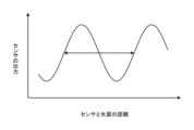
- FIG. 12 is a diagram showing an example of the characteristics of a radio wave sensor.
- the vertical axis corresponds to the output (value) of the radio wave sensor 200
- the horizontal axis corresponds to the distance between the radio wave sensor 200 and the water surface (for example, water (overflow) exceeding the apex portion 821 of the trap portion 82).
- the output of the sensor is related to the distance from the water surface.
- the output of the sensor is a sine curve, and one period of the sine curve coincides with the wavelength of the radio wave sensor. For example, in the case of a 24 GHz microwave, one wavelength (one period) is about 12.5 mm.
- FIG. 13 is a diagram showing an example of a method for detecting a change in water level.
- FIG. 13 shows a method for determining the change in water level due to urination from the output of one of the sensors.
- the initial value of the sensor e.g., the radio wave sensor 200
- the value before the water level changes due to urination e.g., the output value of the radio wave sensor 200
- the distance between the sensor and the water level is always shortened by urination.
- the toilet system 1 determines the change in water level due to urination by the following process. As shown below, in the process shown in FIG. 13, since it is desired to obtain information on the change rather than the absolute value of the water level, it is possible to obtain information on the initial value of the radio wave sensor 200 and the change in the value of the radio wave sensor 200 during urination.
- the candidates for the distance between the sensor (e.g., radio wave sensor 200) and the water surface are based on the positions of the sensor and trap section (e.g., trap section 82) in the configuration, and there are four candidate distances: 124.0 mm, 126.0 mm, 136.5 mm, and 138.5 mm.
- toilet system 1 estimates that the distance between radio wave sensor 200 and the water surface is one of 124.0 mm, 126.0 mm, 136.5 mm, and 138.5 mm.
- the distance candidates can be narrowed down to two, 124.0 mm or 136.5 mm, which is one wavelength away from 124.0 mm, as shown in FIG. 13.
- the toilet system 1 estimates that the distance between the radio wave sensor 200 and the water surface is either 124.0 mm or 136.5 mm.
- the toilet system 1 estimates that the distance between the radio wave sensor 200 and the water surface when the output of the radio wave sensor 200 has changed the most (for example, when the distance between the radio wave sensor 200 and the water surface is closest) is either 119.0 mm or 130.5 mm.
- the toilet system 1 estimates the change in water level due to urination to be 5.0 mm based on the output of the radio wave sensor 200.
- the first point about how the output of the radio wave sensor 200 can tell you about changes in water level due to urination is that when urination begins, the water level only rises due to urination, and does not fall. Therefore, if the sensor is placed above the trap, the distance between the radio wave sensor 200 and the water surface will always be short.
- the second point about how the output of the radio wave sensor 200 can tell you about changes in water level due to urination is that the flow rate of urine rises and falls continuously.
- the output value of the radio wave sensor 200 does not deviate significantly from the previous output value of the radio wave sensor 200. Therefore, by analyzing the signal of the radio wave sensor 200 in a time series based on the characteristics of the first and second points, the distance between the radio wave sensor 200 and the water surface can be narrowed down to a value for each wavelength.
- the second point about determining water level change due to urination from the output of the radio wave sensor 200 is that it is sufficient to know the water level change, not the absolute value of the water level. Also, even if there are multiple distances between the radio wave sensor 200 and the water surface per wavelength, the water level change will be the same regardless of the distance range. And since it is the water level change that is of interest, sufficient information can be obtained by measuring the distance with the radio wave sensor 200.
- the toilet system 1 can estimate the amount of flow into the bowl portion 8 (e.g., the amount of urine) from the water level change determined by the radio wave sensor 200, as shown in FIG. 14.
- FIG. 14 is a diagram showing an example of a process for calculating the flow rate from the water level change.
- the toilet system 1 estimates the amount of urine from the water level change determined by the radio wave sensor 200, based on the relationship between the flow rate and water level shown in FIG. 9, and the information obtained by detecting the water level change shown in FIG. 13.
- the vertical axis corresponds to the urine flow rate, i.e., the amount of urine
- the horizontal axis corresponds to the water level change determined by the radio wave sensor 200.
- the graph shown in FIG. 14 is derived from the relationship between the flow rate and the water level shown in FIG. 9.
- the toilet system 1 determines the urine flow rate from a conversion formula or conversion table between the water level change and the urine flow rate.
- information on the conversion formula or conversion table between the water level change and the urine flow rate may be stored in the memory unit 120, etc.
- the toilet system 1 estimates the water level change by the process shown in FIG. 13, and estimates the amount of urine using the estimated water level change and a conversion formula (function) corresponding to the graph shown in FIG. 14. For example, the toilet system 1 estimates the water level change by the process shown in FIG. 13, and estimates the amount of urine using the estimated water level change and a conversion table corresponding to the graph shown in FIG. 14. For example, if the toilet system 1 estimates the water level change to be 6 mm, it estimates the amount of urine to be, for example, 40 mL/s.
- the flow rate (amount of urine, etc.) estimated by the toilet system 1 may be a number, or may be in several stages (levels) such as large, medium, and small.
- the toilet system 1 may estimate the estimated amount as small when it is less than 15 mL/s, as medium when it is between 15 mL/s and 30 mL/s, and as large when it is 30 mL/s or more. Note that the above correspondence between the amount ranges and stages (levels) is merely an example, and any correspondence can be adopted.
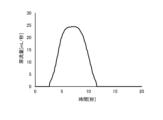
- FIG. 15 is a diagram showing an example of a method for calculating a flow rate.
- FIG. 15 is a diagram showing an example of a method for estimating a total urine volume.
- the vertical axis of FIG. 15 corresponds to the estimated urine flow rate (per unit time), and the horizontal axis corresponds to time.
- the toilet system 1 measures (estimates) the flow rate of urine in a time series based on the detection of the radio wave sensor 200.
- the toilet system 1 then integrates the time series flow rate to convert it into a volume (total volume).
- the toilet system 1 estimates the total urine volume by calculating the area of the region (diagram) formed by the waveform shown in FIG. 15 and the X-axis. In FIG. 15, the toilet system 1 estimates that the total volume of urine (total urine volume) is 144 mL.
- the toilet system 1 may also estimate the total urine volume in a similar manner when the urine volume is estimated in several stages (levels) of large, medium, and small. An example of this point will be described with reference to FIG. 16.
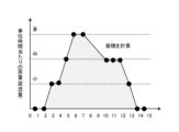
- FIG. 16 is a diagram showing an example of a method for calculating the flow rate. Specifically, FIG. 16 is a diagram showing an example of a method for estimating the total urine volume. The vertical axis of FIG. 16 corresponds to the level of the estimated urine flow rate (per unit time), and the horizontal axis corresponds to time.
- the toilet system 1 measures (estimates) the urine flow rate (level) over time based on the detection by the radio wave sensor 200. The toilet system 1 then calculates the area of the region enclosed by the line connecting those points and the horizontal axis, and calculates the total urine volume from the area. In FIG. 16, the toilet system 1 calculates the area of the hatched region, and converts the area into urine volume to calculate the total urine volume.
- the toilet system 1 may have a relationship between the change in the state of the sealing water and the urine flow rate in advance.
- the toilet system 1 may store, for example, in the memory unit 120, information indicating the correspondence between each level of urine volume and a numerical value indicating a specific volume (e.g., small is 10 mL/s, medium is 20 mL/s, large is 30 mL/s, etc.).
- the toilet system 1 may calculate the total urine volume to be, for example, 220 mL, by converting the level at each time into a numerical value indicating a specific volume and accumulating it based on the information indicating the correspondence between each level of urine volume and a numerical value indicating a specific volume.
- the toilet system 1 may store information indicating the correspondence between each level of urine volume and a numerical value corresponding to the area, for example in the memory unit 120.
- the toilet system 1 calculates the area by converting the level at each time into a numerical value corresponding to the area and accumulating it based on the information indicating the correspondence between each level of urine volume and a numerical value corresponding to the area (for example, 1 for small, 2 for medium, 3 for large, etc.).
- the toilet system 1 calculates the area to be 22.
- the toilet system 1 calculates the total urine volume from the calculated area. For example, the toilet system 1 calculates the total urine volume using the area and a conversion formula based on the relationship shown in FIG. 17.
- FIG. 17 is a diagram showing an example of the relationship between area and total urine volume.
- FIG. 17 shows an example of a calibration curve for calculating the total urine volume from the area.
- the toilet system 1 calculates the total urine volume to be 220 mL from the calculated area of "22".
- the toilet system 1 may provide (display) information using any of the acquired information.
- the toilet system 1 may display information in stages such as large, medium, and small, instead of displaying numerical values.
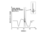
- Fig. 18 is a diagram showing an example of processing when there is defecation during urination.
- Fig. 18 shows an example of a method for detecting feces from the output of the radio wave sensor 200.
- the vertical axis of Fig. 18 corresponds to the output value of the radio wave sensor 200, and the horizontal axis corresponds to time.
- Fig. 18 shows a case where there is defecation during urination around 20 seconds in the graph.
- the toilet system 1 estimates (estimates) from the points before and after the discontinuous point, as shown by the dotted line in the enlarged view around 20 seconds on the graph. For example, the toilet system 1 estimates the output value of the radio wave sensor 200 excluding the influence of feces for the discontinuous time period based on the line connecting the start and end points of the discontinuous time period, as shown by the dotted line in the enlarged view around 20 seconds on the graph. The toilet system 1 may then use the estimated output value of the radio wave sensor 200 to estimate the amount of urine in that time period, and estimate the total amount of urine. In FIG. 18, the toilet system 1 calculates (estimates) that the total amount of urine (total urine volume) is 342 mL after converting it to a flow rate.
- FIG. 19 is a diagram showing an example of the process when defecation occurs during urination.
- FIG. 19 shows an example of a method for detecting feces after changing the output of the radio wave sensor 200 to a flow rate.
- the vertical axis of FIG. 19 corresponds to the urine flow rate, and the horizontal axis corresponds to time.
- FIG. 19 shows a case where defecation occurs during urination around 20 seconds on the graph.
- the toilet system 1 estimates (estimates) from the points before and after the discontinuous point, as shown by the dotted line in the enlarged view of the graph around 20 seconds. For example, the toilet system 1 estimates that the amount corresponding to the hatched area in the enlarged view of the graph around 20 seconds is the amount of stool. The toilet system 1 may calculate the amount of stool from the area of the hatched area in the enlarged view of the graph around 20 seconds, and estimate the total amount of urine (total urine amount) by subtracting this amount of stool from the total amount of excretion, which is the integration of the entire area. In FIG. 19, the toilet system 1 estimates the maximum urine flow rate to be 23.1 mL/sec, and calculates (estimates) the total amount of urine (total urine amount) to be 342 mL.
- the toilet system 1 deletes the value and uses the value before or after the discontinuity as is, or averages the values before and after, thereby deleting the signal due to the defecation.
- the toilet system 1 integrates everything, including the signal changes due to defecation, and furthermore, it can extract only the signal portion for the defecation to calculate the amount of stool, and then subtract the amount of stool from the total amount of excretion to obtain the urine volume.
- FIG. 20 is a diagram showing an example of calculation using two outputs. Note that, regarding FIG. 20, explanations of the same points as those in FIG. 12 and FIG. 13 will be omitted as appropriate.
- Figure 20 shows a method for determining the change in water level due to urination from two outputs of the sensor. Below, an example will be explained in which the initial values of the sensor are a first output of 100 and a second output of 50.
- the toilet system 1 may obtain two outputs with different phases by any configuration.
- the toilet system 1 may obtain two outputs with different phases by using two radio wave sensors 200.
- the toilet system 1 may have two radio wave sensors 200, one radio wave sensor 200 (first radio wave sensor) that outputs the first output in FIG. 20, and another radio wave sensor 200 (second radio wave sensor) that outputs the second output in FIG. 20.
- the toilet system 1 may obtain an output from each of the two radio wave sensors 200.
- the initial water level is determined by measuring the water level change at the beginning of urination over time, but with multiple sensors, the water level can be narrowed down from their output values. For example, if the water level drops momentarily due to sitting down, the initial water level may be misjudged with one sensor, but with multiple sensors, this possibility can be reduced.
- the toilet system 1 may use any information, such as differential information between signals from multiple sensors.
- the toilet system 1 may also obtain two outputs with different phases from a single radio wave sensor 200.
- the radio wave sensor 200 may have a configuration as shown in FIG. 21.
- FIG. 21 is a diagram showing an example of the configuration of a radio wave sensor.
- FIG. 21 is a diagram showing an example of the configuration of a radio wave sensor for obtaining two outputs.
- the radio wave sensor 200 may have two detection circuits 222.
- the radio wave sensor 200 has two detection circuits 222, detection circuit 222a shown as detection circuit #1 in FIG. 21 and detection circuit 222b shown as detection circuit #2 in FIG. 21.
- the radio wave sensor 200 has a configuration in which the line length on the detection circuit 222b side is longer than the line length of the detection circuit 222a so that the phase difference between the line length and the transmission circuit 221 is 60 degrees.
- the detection circuit 222b (detection circuit #2) is shifted by the line length (delayed by 60 degrees) relative to the detection circuit 222a (detection circuit #1).
- the toilet system 1 can estimate the distance with the combination (relationship) of two wavelengths.
- the toilet system 1 may estimate the distance using the relationship between two outputs, as shown in FIG. 22.
- FIG. 22 is a diagram showing an example of processing using the relationship between two outputs.
- the output (first output) by the detection circuit 222a is shown by a solid line
- the output (second output) by the detection circuit 222b is shown by a dashed line.
- the toilet system 1 may estimate the distance between the radio wave sensor 200 and the water surface based on the relationship between the first output and second output at A in FIG. 22, the first output and second output at B in FIG. 22, the first output and second output at C in FIG. 22, etc.
- a bowl portion for receiving excrement A trap portion that forms a water seal on the bottom side of the bowl portion; a radio wave sensor that detects a change in state of the water seal in the trap section caused by the dropping of the excrement into the water seal; an estimation means for estimating information on urine or feces related to the excrement based on a detection result of the radio wave sensor;
- a toilet system comprising: (2) The toilet system according to claim 1, wherein the detection range of the radio wave sensor is set to an area including the apex of the trap portion.
- a drainage path from the bowl portion passes between the radio wave sensor and the apex of the trap portion,
- a toilet seat device installed on an upper portion of a toilet body having the bowl portion; Further equipped with The toilet system according to any one of (1) to (7), wherein the radio wave sensor is provided in the toilet seat device.
- an optical sensor that detects a change in state of the sealing water from the bowl portion side at multiple timings; Further equipped with The toilet system according to any one of (1) to (12), wherein the estimation means estimates the urine or feces information based on the detection results of the radio wave sensor and the optical sensor.
- the estimation means estimates the urine or feces information when there is a correlation between the detection results of the radio wave sensor and the optical sensor.
- an optical sensor that detects feces from the bowl portion side before the feces hits the sealed water; Further equipped with The toilet system according to any one of (1) to (14), wherein the estimation means acquires information about the urine or feces based on detection results of the radio wave sensor and the optical sensor.
- the estimation means acquires information about feces based on the detection results of the optical sensor, and acquires information about the urine or feces based on the detection results of the radio wave sensor.
- a radio wave device for a toilet device that is installed in a toilet device, a radio wave sensor that detects a change in state that occurs in the water seal of a trap section that forms a water seal on the bottom side of the bowl section when excrement falls into the water seal of a bowl section of the toilet device;
- a radio wave device for a toilet device comprising: (18) a detection step of detecting a change in state of the water seal formed on the bottom side of the bowl section by a trap section provided downstream of the bowl section in the drainage direction from the bowl section of the toilet system, when excrement falls into the water seal on the bowl section side;
- a method for detecting the state of a toilet system comprising:
- Toilet system 1 Toilet system 2 Toilet seat device 3 Main body (functional part) 4 Toilet cover 5 Toilet seat 6 Cleaning nozzle 7 Toilet bowl (toilet body) 8 Bowl portion 9 Rim portion 20 Toilet device 34 Optical sensor 81 Drain pipe (drainage channel) 82 Trap section 100 Control device (estimation means) 200 Radio wave sensor (radio wave device for toilet device) 210 Antenna section 220 Circuit section R Toilet room
Landscapes
- Health & Medical Sciences (AREA)
- Public Health (AREA)
- Epidemiology (AREA)
- Life Sciences & Earth Sciences (AREA)
- Engineering & Computer Science (AREA)
- Hydrology & Water Resources (AREA)
- Water Supply & Treatment (AREA)
- Sanitary Device For Flush Toilet (AREA)
- Investigating Or Analysing Biological Materials (AREA)
- Geophysics And Detection Of Objects (AREA)
- Bidet-Like Cleaning Device And Other Flush Toilet Accessories (AREA)
Abstract
実施形態に係るトイレシステムは、排泄物を受けるボウル部と、前記ボウル部の底側に封水を形成するトラップ部と、前記排泄物の前記封水への落下により、前記トラップ部側の封水で発生する状態変化を検知する電波センサと、前記電波センサの検知結果に基づいて、前記排泄物に関する尿または便の情報を推定する推定手段と、を備える。
Description
開示の実施形態は、トイレシステム、トイレ装置用電波装置、及びトイレシステムの状態検知方法に関する。
従来、トイレを使用する使用者について様々な情報を取得する技術が提供されている。封水部から溢れ出る水(「溢水」ともいう)を撮像するために便器排水路内に配置された撮像部(カメラ)が撮像した画像情報に基づいて尿量を算出する技術が知られている(例えば、特許文献1参照)。
しかしながら、上述した従来技術には、改善の余地がある。例えば、上述した従来技術では、溢水を撮像するためにカメラを便器排水路、すなわち排水管(単に「排管」ともいう)内に配置する必要があり、センサの配置態様に制約がある。また、上述した従来技術では、カメラに溢水がかからないようにすること等も求められ、カメラを排管内に配置するために排管を水平方向に長くする必要があり排管の構造にも制約が生じる。このように、上述した従来技術には、トイレで発生する状態変化を適切に検知するための制約が多く、改善の余地がある。
開示の実施形態は、トイレで発生する状態変化を適切に検知することができるトイレシステム、トイレ装置用電波装置、及びトイレシステムの状態検知方法を提供することを目的とする。
実施形態の一態様に係るトイレシステムは、排泄物を受けるボウル部と、前記ボウル部の底側に封水を形成するトラップ部と、前記排泄物の前記封水への落下により、前記トラップ部側の封水で発生する状態変化を検知する電波センサと、前記電波センサの検知結果に基づいて、前記排泄物に関する尿または便の情報を推定する推定手段と、を備えたことを特徴とする。
実施形態の一態様に係るトイレシステムによれば、排泄物の封水への落下により、トラップ部側の封水で発生する状態変化を検知する電波センサを用いることで、トイレで発生する状態変化を適切に検知することができる。例えば、トイレシステムは、トラップ側の封水の揺れ等の封水の状態変化に付随する溢水の挙動を含めてマイクロ波センサまたはミリ波センサ等の電波センサで検知することにより、ボウル側で封水に落下した落下物(便、尿)により封水の揺れ等の封水の状態変化をトラップ部側で検知することにより、排管内にセンサを配置することなく、簡便に尿または便の情報を取得することができる。また、トイレシステムは、トラップ部側で生じる封水の状態変化を電波センサにより検知することで、排泄物に関する尿または便の情報を推定できる。
実施形態の一態様に係るトイレシステムにおいて、前記電波センサの検知範囲は、前記トラップ部の頂点部を含む領域に設定されることを特徴とする。
実施形態の一態様に係るトイレシステムによれば、電波センサの検知範囲をトラップ部の頂点部を含む領域に設定することで、トラップ部の上を通って溢れ出る水(溢水)を検知でき、トイレで発生する状態変化を適切に検知することができる。
実施形態の一態様に係るトイレシステムにおいて、前記電波センサは、前記トラップ部の頂点部からの溢水に基づいて前記封水の状態変化を検知することを特徴とする。
実施形態の一態様に係るトイレシステムによれば、トラップ部の頂点部からの溢水に基づいて封水の状態変化を検知することで、トラップ部の上を通って溢れ出る水(溢水)を検知でき、トイレで発生する状態変化を適切に検知することができる。
実施形態の一態様に係るトイレシステムにおいて、前記推定手段は、前記封水の状態変化に基づいて、尿流量または便量を推定することを特徴とする。
実施形態の一態様に係るトイレシステムによれば、封水の状態変化に基づいて、尿流量または便量を推定することで、トイレで発生する状態変化に基づいて、尿流量または便量等の排泄物に関する情報を適切に推定することができる。
実施形態の一態様に係るトイレシステムにおいて、前記推定手段は、前記電波センサから出力される定在波の情報に基づいて、尿流量を推定することを特徴とする。
実施形態の一態様に係るトイレシステムによれば、電波センサから出力される定在波の情報に基づいて、尿流量を推定することで、トイレで発生する状態変化に基づいて、排泄物に関する情報を適切に推定することができる。
実施形態の一態様に係るトイレシステムにおいて、前記電波センサは、ミリ波センサ又はマイクロ波センサであることを特徴とする。
実施形態の一態様に係るトイレシステムによれば、電波センサとして、ミリ波センサ又はマイクロ波センサを用いることで、トイレで発生する状態変化を適切に検知することができる。
実施形態の一態様に係るトイレシステムにおいて、前記電波センサと前記トラップ部の頂点部との間には、前記ボウル部からの排水路が通過し、前記電波センサは、前記トラップ部の頂点部からの溢水に基づいて前記封水の状態変化を検知することを特徴とする。
実施形態の一態様に係るトイレシステムによれば、電波センサとトラップ部の頂点部との間には、ボウル部からの排水路が通過し、電波センサが記トラップ部の頂点部からの溢水に基づいて封水の状態変化を検知するトラップ部の頂点部からの溢水に基づいて封水の状態変化を検知することで、電波センサとトラップ部との間を通って溢れ出る水(溢水)を検知でき、トイレで発生する状態変化を適切に検知することができる。
実施形態の一態様に係るトイレシステムは、前記ボウル部を有するトイレ本体の上部に設置される便座装置、をさらに備え、前記電波センサは、前記便座装置に設けられることを特徴とする。
実施形態の一態様に係るトイレシステムによれば、ボウル部を有するトイレ本体の上部に設置される便座装置に電波センサが設けられることで、便座装置に設置された電波センサにより、トイレで発生する状態変化を適切に検知することができる。
実施形態の一態様に係るトイレシステムにおいて、前記電波センサが有するアンテナ部は、前記便座装置の底部側に配置されることを特徴とする。
実施形態の一態様に係るトイレシステムによれば、電波センサのアンテナ部が便座装置の底部側に配置されることで、電波センサのうち電波を送受信するアンテナ部をトラップ部の頂点部の近くに配置することができ、トイレで発生する状態変化を適切に検知することができる。
実施形態の一態様に係るトイレシステムにおいて、前記電波センサが有するアンテナ部は、前記トラップ部を有する排管の外壁に設けられることを特徴とする。
実施形態の一態様に係るトイレシステムによれば、電波センサのアンテナ部がトラップ部を有する排管の外壁に設けられることで、電波センサのアンテナ部が排管内を流れる排水に接触することを抑制することができ、トイレで発生する状態変化を適切に検知することができる。
実施形態の一態様に係るトイレシステムにおいて、前記電波センサが有するアンテナ部は、前記トラップ部の鉛直方向上方に配置されることを特徴とする。
実施形態の一態様に係るトイレシステムによれば、電波センサのアンテナ部がトラップ部の鉛直方向上方に配置されることで、電波センサのうち電波を送受信するアンテナ部をトラップ部の頂点部の近くに配置することができ、トイレで発生する状態変化を適切に検知することができる。
実施形態の一態様に係るトイレシステムにおいて、前記電波センサが有するアンテナ部は、前記トラップ部側の封水の鉛直方向上方に配置されることを特徴とする。
実施形態の一態様に係るトイレシステムによれば、電波センサのアンテナ部がトラップ部側の封水の鉛直方向上方に配置されることで、電波センサのうち電波を送受信するアンテナ部をトラップ部の頂点部の近くに配置することができ、トイレで発生する状態変化を適切に検知することができる。
実施形態の一態様に係るトイレシステムは、前記ボウル部側から前記封水の状態変化を複数のタイミングで検知する光学センサ、をさらに備え、前記推定手段は、前記電波センサ及び前記光学センサの検知結果に基づいて前記尿または便の情報を推定することを特徴とする。
実施形態の一態様に係るトイレシステムによれば、ボウル部側から封水の状態変化を複数のタイミングで検知する光学センサの検知結果も用いて、尿または便の情報を推定することで、排泄物に関する情報をより適切に推定することができる。
実施形態の一態様に係るトイレシステムにおいて、前記推定手段は、前記電波センサ及び前記光学センサの検知結果に相関関係がある場合に、前記尿または便の情報を推定することを特徴とする。
実施形態の一態様に係るトイレシステムによれば、電波センサ及び光学センサの検知結果に相関関係がある場合に、尿または便の情報を推定することで、排泄物に関する情報をより適切に推定することができる。
実施形態の一態様に係るトイレシステムは、前記ボウル部側から前記封水に着水する前の便を検知する光学センサ、をさらに備え、前記推定手段は、前記電波センサ及び前記光学センサの検知結果に基づいて前記尿または便の情報を取得することを特徴とする。
実施形態の一態様に係るトイレシステムによれば、ボウル部側から封水に着水する前の便を検知する光学センサの検知結果も用いて、尿または便の情報を取得することで、排泄物に関する情報をより適切に推定することができる。
実施形態の一態様に係るトイレシステムにおいて、前記推定手段は、前記光学センサの検知結果に基づいて便の情報を取得するとともに、前記電波センサの検知結果に基づいて前記尿または便に関する情報を取得することを特徴とする。
実施形態の一態様に係るトイレシステムによれば、光学センサの検知結果に基づいて便の情報を取得するとともに、電波センサの検知結果に基づいて尿または便に関する情報を取得することで、排泄物に関する情報をより適切に推定することができる。
実施形態の一態様に係るトイレ装置用電波装置は、トイレ装置に設置されるトイレ装置用電波装置であって、前記トイレ装置が有するボウル部の封水に排泄物が落下することで、前記ボウル部の底側に封水を形成するトラップ部側の封水で発生する状態変化を検知する電波センサ、を備えたことを特徴とする。
実施形態の一態様に係るトイレ装置用電波装置によれば、排泄物の封水への落下により、トラップ部側の封水で発生する状態変化を検知する電波センサを用いることで、トイレで発生する状態変化を適切に検知することができる。例えば、トイレ装置用電波装置は、トラップ側の封水の揺れ等の封水の状態変化に付随する溢水の挙動を含めてマイクロ波センサまたはミリ波センサ等の電波センサで検知することにより、ボウル側で封水に落下した落下物(便、尿)により封水の揺れ等の封水の状態変化をトラップ部側で検知することにより、排管内にセンサを配置することなく、簡便に尿または便の情報を取得することができる。
実施形態の一態様に係るトイレシステムの状態検知方法は、トイレシステムが有するボウル部よりも排水方向下流側に設けられたトラップ部によって前記ボウル部の底側に形成された封水のうち、前記ボウル部側の封水に排泄物が落下することにより、前記トラップ部側の封水で発生する状態変化を検知する検知工程、を含むことを特徴とする。
実施形態の一態様に係るトイレシステムの状態検知方法によれば、排泄物の封水への落下により、トラップ部側の封水で発生する状態変化を検知する電波センサを用いることで、トイレで発生する状態変化を適切に検知することができる。例えば、トイレシステムの状態検知方法は、トラップ側の封水の揺れ等の封水の状態変化に付随する溢水の挙動を含めてマイクロ波センサまたはミリ波センサ等の電波センサで検知することにより、ボウル側で封水に落下した落下物(便、尿)により封水の揺れ等の封水の状態変化をトラップ部側で検知することにより、排管内にセンサを配置することなく、簡便に尿または便の情報を取得することができる。
実施形態の一態様によれば、トイレで発生する状態変化を適切に検知することができる。
以下、添付図面を参照して、本願の開示するトイレシステムの実施形態を詳細に説明する。なお、以下に示す実施形態によりこの発明が限定されるものではない。以下では、トイレシステム1が実行する尿量等の使用者の排泄物に関する情報の推定に関する処理やその処理を行うための構成について説明するが、最初に前提となるトイレシステムなどの各種構成を説明する。
<1.トイレシステムの構成>
まず、実施形態に係るトイレシステムの構成について図1を参照して説明する。図1は、実施形態に係るトイレシステムの構成の一例を示す斜視図である。
まず、実施形態に係るトイレシステムの構成について図1を参照して説明する。図1は、実施形態に係るトイレシステムの構成の一例を示す斜視図である。
図1に示すように、トイレシステム1は、トイレ装置20と、操作装置10とを備える。図1に示すように、トイレルームRには、床面Fに、便器7が設置され、便器7の上部に設置される便座装置2が設置される。なお、以下では、床面FからトイレルームRの空間内に臨む向きを上と記載する。
便器7は、いわゆる大便器(洋式大便器)であり、例えば、陶器または樹脂等の材料が用いられる。便器7には、ボウル部8が形成される。ボウル部8は、下方に凹んだ形状であり、使用者の排泄物を受ける部位である。このように、便器7は、ボウル部8を有するトイレ本体として機能する。なお、ボウル部8の底面側には排管81に連通するがこの点については後述する。
また、便器7は、図示のような床置き式に限らず、トイレシステム1を適用可能であれば、どのような形式でもよく、壁掛け式等のような形式であってもよい。便器7には、ボウル部8が臨む開口の端部の全周にわたってリム部9が設けられる。トイレルームRには、例えば、便器7付近に洗浄水を貯留する洗浄水タンクが設置されてもよいし、洗浄水タンクが設置されない、いわゆるタンクレス式でもよい。
例えば、トイレルームRに設けられた洗浄用の洗浄操作部(図示省略)が使用者により操作されると、便器7のボウル部8への洗浄水の供給による便器洗浄が実施される。洗浄操作部は操作レバーや、操作装置10に表示された便器洗浄オブジェクトに対するタッチ操作であってもよい。なお、洗浄操作部は、操作レバーなどのような使用者の手動によって便器洗浄を実施させるものに限らず、着座センサのような使用者を検知するセンサの人体検知によって便器洗浄を実施させるものでもよい。
便座装置2は、便器7の上部に取り付けられ、本体部3と、便蓋4と、便座5と、洗浄ノズル6とを備える。便座装置2は、排泄物を受けるボウル部8が形成された便器7の上部に載置される。便座装置2は、洗浄ノズル6が洗浄水を噴射する前にボウル部8に進出するように便器7の上部に載置される。なお、便座装置2は、便器7に対して着脱可能に取り付けられてもよいし、便器7と一体化するように取り付けられてもよい。また、本体部3は、例えば各種の機能を実行するための構成(例えば制御装置100等)が本体カバー30内に配置される機能部として機能する。
図1に示すように、便座5は、中央に開口50を有する環状に形成され、リム部9に沿って、便器7の開口に重なる位置に配置される。便座5は、使用者が着座する。便座5は、着座した使用者の臀部を支持する着座部として機能する。また、図1に示すように、便蓋4及び便座5は、それぞれの一端部が本体部3に軸支され、本体部3の軸支部分を中心として回動可能(開閉可能)に取り付けられる。なお、便蓋4は、便座装置2に必要に応じて取り付けられ、便座装置2は、便蓋4を有しなくてもよい。
洗浄ノズル6は、洗浄用の水を吐水するためのノズルである。洗浄ノズル6は、洗浄水を噴射可能である。洗浄ノズル6は、使用者に向けて洗浄水を噴射可能である。洗浄ノズル6は、局部洗浄用のノズルである。洗浄ノズル6は、電動モータなどの駆動源(図5中のノズルモータ61等)の駆動により、本体部3の筐体である本体カバー30に対して進退可能に構成される。また、洗浄ノズル6は、図示しない水道管などの水源に接続される。そして、洗浄ノズル6は、図1に示すように、本体部3の筐体である本体カバー30に対して進出した位置(「進出位置」ともいう)にあるときに、水源からの水を使用者の身体へ噴出させて局部を洗浄する。
図1では、洗浄ノズル6が進出位置にある状態を示す。なお、洗浄ノズル6は、便器7(ボウル部8等)内の洗浄用にも共用されてもよい。洗浄ノズル6は、使用者の局部を洗浄する局部洗浄モードと、便器7内に水を撒く便器洗浄モードとを切り替え可能に用いられてもよい。例えば、洗浄ノズル6は、便座装置2による制御に応じて、局部洗浄モードと便器洗浄モードとを切り替え可能に用いられてもよい。
操作装置10は、トイレルームR内に設けられる。操作装置10は、使用者が操作可能な位置に設けられる。操作装置10は、使用者が便座5に着座時において、操作可能な位置に設けられる。図1では、操作装置10は、便座5に着座した使用者から見て右側方の壁面Wに配置される。なお、操作装置10は、便座5に着座した使用者が利用可能であれば、壁面に限らず、種々の態様により配置されてもよい。例えば、操作装置10は、便座装置2と一体に設けられてもよい。
操作装置10は、便座装置2と所定のネットワークを介して、有線または無線により通信可能に接続される。例えば、便座装置2と操作装置10とは、情報の送受信が可能であれば、どのような接続であってもよく、有線により通信可能に接続されてもよいし、無線により通信可能に接続されてもよい。
操作装置10は、例えばタッチパネル機能により表示面(例えば表示画面11)を介して使用者からの各種操作を受け付ける。また、操作装置10は、スイッチやボタンを備え、スイッチやボタン等により各種操作を受け付けてもよい。表示画面11は、例えば液晶ディスプレイや有機EL(Electro-Luminescence)ディスプレイ等によって実現されるタブレット端末等の表示画面であり、各種情報を表示するための表示装置である。つまり、操作装置10は、表示画面11により使用者の入力を受け付け、使用者への出力も行う。この際、操作装置10は、使用者が予め登録されたどのユーザなのかを特定する。のちに、制御部130は、そのユーザ情報と後に説明する排泄物に関する情報もしくは排泄物に関する情報によって得られた情報とを紐づけて、使用者の端末に送信する。この際、排泄物に関する情報を取得した日時情報を合わせて使用者の端末に送信しても良い。表示画面11は、各種情報を表示する表示装置である。
操作装置10は、便座装置2により実行中の制御を止めるためのユーザの操作を受け付ける。操作装置10は、便座装置2による局部洗浄の実行を開始するためのユーザの操作を受け付ける。操作装置10は、使用者による洗浄ノズル6への指示を受け付ける。操作装置10は、便座装置2に所定の音を出力させるためのユーザの操作を受け付ける。操作装置10は、便座装置2の洗浄ノズル6(図1参照)を除菌水で殺菌する殺菌処理を行うためのユーザの操作を受け付ける。操作装置10は、便座装置2による局部洗浄時の吐水の勢いを調整するためのユーザの操作を受け付ける。操作装置10は、便座装置2が出力する音の音量を調整するためのユーザの操作を受け付ける。操作装置10は、トイレの利用に関する情報を操作装置10に表示したり音声出力したりする際の言語を選択するためのユーザの操作を受け付ける。
例えば、操作装置10は、上述したユーザの操作を受け付けるオブジェクトを表示画面11に表示し、表示したオブジェクトに対するユーザの接触に応じて、各種処理を実行してもよい。例えば、操作装置10は、上述したユーザの操作を受け付けるスイッチやボタン等を有し、スイッチやボタン等に対するユーザの接触に応じて、各種処理を実行してもよい。なお、上記は一例であり、操作装置10は、各種処理を実行するユーザによる操作を受け付けてもよい。
<2.トイレ装置の構成>
以下、トイレ装置20の構成について説明する。トイレ装置20は、ボウル部8を有する便器7と、電波センサ200(図4参照)と、推定手段として機能する制御装置100(図6参照)とを有する。トイレ装置20は、電波センサ200により排泄物の封水への落下により、封水で発生する状態変化を検知する。また、トイレ装置20は、電波センサ200の検知結果に基づいて、排泄物に関する尿または便の情報を推定するが、この点については後述する。トイレシステム1は、推定した情報を基に、使用者のスマートフォン等の端末装置に情報提供を行ってもよい。また、トイレシステム1は推定した情報を基に、トイレルームRの操作装置10(もしくは表示画面11)へ情報提供を行っても良い。
以下、トイレ装置20の構成について説明する。トイレ装置20は、ボウル部8を有する便器7と、電波センサ200(図4参照)と、推定手段として機能する制御装置100(図6参照)とを有する。トイレ装置20は、電波センサ200により排泄物の封水への落下により、封水で発生する状態変化を検知する。また、トイレ装置20は、電波センサ200の検知結果に基づいて、排泄物に関する尿または便の情報を推定するが、この点については後述する。トイレシステム1は、推定した情報を基に、使用者のスマートフォン等の端末装置に情報提供を行ってもよい。また、トイレシステム1は推定した情報を基に、トイレルームRの操作装置10(もしくは表示画面11)へ情報提供を行っても良い。
<2-1.便座装置の構成>
図1では、トイレ装置20は、便器7の上部に設置される便座装置2を有する。以下、便座装置2の構成について図2及び図3を参照して説明する。図2及び図3は、実施形態に係る便座装置の構成の一例を示す斜視図である。具体的には、図2は、便座装置2の蓋部110が閉じた状態(「閉鎖状態」ともいう)である場合を示す図である。また、図3は、便座装置2の蓋部110を除いた状態を示す図である。
図1では、トイレ装置20は、便器7の上部に設置される便座装置2を有する。以下、便座装置2の構成について図2及び図3を参照して説明する。図2及び図3は、実施形態に係る便座装置の構成の一例を示す斜視図である。具体的には、図2は、便座装置2の蓋部110が閉じた状態(「閉鎖状態」ともいう)である場合を示す図である。また、図3は、便座装置2の蓋部110を除いた状態を示す図である。
図2に示すように、蓋部110の閉鎖状態においては、光学センサ34は、蓋部110の裏に隠されている。蓋部110の閉鎖状態においては、光学センサ34の前方に蓋部110が位置する。このように、蓋部110は、閉鎖状態において光学センサ34の前方に位置する。
また、図2では、洗浄ノズル6(図1参照)が本体カバー30内に収納される位置(「収納位置」ともいう)にある状態を示す。図2に示すように、洗浄ノズル6が収納位置にある場合、ノズル用蓋60は閉じられており、洗浄ノズル6は、ノズル用蓋60の裏に隠されている。洗浄ノズル6による洗浄が行われる場合、ノズル用蓋60が開放するとともに、本体カバー30の洗浄ノズル6用の開口から洗浄ノズル6が突出し、洗浄ノズル6は、進出状態に移行する。
図3に示すように、蓋部110が除かれた場合、光学センサ34は、本体カバー30の開口31から露出する。例えば、蓋部110が開いた状態(「開放状態」ともいう)においては、図3に示すように、光学センサ34の前方に蓋部110が位置しない状態となる。これにより、蓋部110の開放状態においては、光学センサ34が露出する。蓋部110の開放状態において、光学センサ34は、便器7内の封水の状態変化を検知可能となる。なお、便座装置2は、蓋部110を有しなくてもよい。この場合、便座装置2は、蓋部110及びアクチュエータ111を有さず、光学センサ34は、常時露出した状態であってもよい。
<2-2.トイレ装置における排管の構成及び電波センサの配置>
次に、図4を用いて、トイレ装置における排管の構成及び電波センサの配置の一例について説明する。図4は、実施形態に係るトイレ装置の構成の一例を示す概要図である。具体的には、図4は、排管81の構成及び電波センサ200の配置を示すために、便器7を側面視し、トイレ装置20の構成のうち、便器7等の要部のみを断面で示す側断面の概要図である。なお、図4での便器7の断面形状は一例に過ぎず、便器7は、電波センサ200を所望の位置に配置可能であれば、便器7内部の空洞は任意の態様であってもよく、例えば、電波センサ200が配置される箇所のみが空洞であってもよい。
次に、図4を用いて、トイレ装置における排管の構成及び電波センサの配置の一例について説明する。図4は、実施形態に係るトイレ装置の構成の一例を示す概要図である。具体的には、図4は、排管81の構成及び電波センサ200の配置を示すために、便器7を側面視し、トイレ装置20の構成のうち、便器7等の要部のみを断面で示す側断面の概要図である。なお、図4での便器7の断面形状は一例に過ぎず、便器7は、電波センサ200を所望の位置に配置可能であれば、便器7内部の空洞は任意の態様であってもよく、例えば、電波センサ200が配置される箇所のみが空洞であってもよい。
便器7のボウル部8の底部に設けられた開口に排管81に連通する。排管81は、ボウル部8からの排水管であり、排管81の内部空間は、排水路として機能する。図4では、排管81は、ボウル部8の底部に接続される端部から斜め下方に伸びた後斜め上方に伸びるU(V)字形状を形成した後、下方に伸びる形状を有する。これにより、排管81には、トラップ部82が形成される。トラップ部82により、ボウル部8の底側を含め封水WTが形成される。なお、図4に示す排管81の構成は一例に過ぎず、後述する処理が実行可能なトラップが形成可能であれば、排管81は任意の構成が採用可能である。
図4では、便器7のボウル部8及び排管81中のハッチングが付された箇所に封水WT(水)が満たされていることを示す。また、図4では、図4中の封水面WS1が封水WTによりボウル部8の底側に形成される上表面を示し、図4中の封水面WS2が封水WTによりトラップ部82側に形成される上表面を示す。
図4では、排管81のうち、ボウル部8の底部に接続される端部とは反対側のトラップ部82の端部に頂点部821が形成される。電波センサ200の検知範囲DA11は、トラップ部82の頂点部821を含む領域に設定される。例えば、電波センサ200は、検知範囲DA11がトラップ部82の頂点部821を含むように配置される。なお、図4に示す範囲は、電波センサ200の検知範囲DA11の一例に過ぎず、電波センサ200の検知範囲DA11は、トラップ部82の頂点部821が含まれれば、図4に示す範囲に限らず、任意の範囲であってもよい。
例えば、電波センサ200は、マイクロ波センサである。以下では、電波センサ200は、マイクロ波センサである場合を一例として説明するが、電波センサ200は、マイクロ波センサに限られない。例えば、電波センサ200は、所望の検知が可能であれば、例えばミリ波センサ等の任意のセンサが採用可能である。
電波センサ200は、検知範囲DA11がトラップ部82の頂点部821を含むように配置されれば、任意の配置態様が採用可能である。例えば、電波センサ200は、トラップ部82の鉛直方向上方に配置される。例えば、電波センサ200は、トラップ部82側の封水(例えば封水面WS2)の鉛直方向上方に配置される。例えば、電波センサ200は、トラップ部82を有する排管81の外壁に沿って設けられる。図4では、電波センサ200は、排管81外に設けられ、トラップ部82の上側に配置される。この場合、電波センサ200とトラップ部82の頂点部821との間には、ボウル部8からの排水路が通過する。これにより、電波センサ200が有するアンテナ部210(図5参照)とトラップ部82の頂点部821との間には、便器7に設けられたボウル部8からの排水路が通過する。
なお、上述した配置態様は一例に過ぎず、電波センサ200は、様々な配置態様であってもよい。例えば、電波センサ200は、便座装置2に設けられてもよい。電波センサ200は、便座装置2に設けられる場合、電波センサ200は、便座装置2の底部(下側)側に配置されてもよい。この場合、電波センサ200が有するアンテナ部210は、便座装置2のうち便器7側の底部に配置される。例えば、電波センサ200は、機能部である本体部3中に配置されてもよい。電波センサ200は、例えば本体カバー30内に配置されてもよい。以下では、図4に示すように電波センサ200がトラップ部82の上側に配置される構成を一例として説明する。
上述した配置により、電波センサ200は、トラップ部82側の封水で発生する状態変化を検知する。電波センサ200は、トラップ部82の頂点部821からの溢水を含めて封水の状態変化を検知する。例えば、電波センサ200は、排泄物のボウル部8側の封水への落下により、トラップ部82側の封水で発生する状態変化を検知する。例えば、電波センサ200は、トラップ部82の頂点部821からの溢水に基づいて封水の状態変化を検知するが、この点については後述する。
なお、電波センサ200は、トイレ装置20とは別体であり、トイレ装置20に対して着脱可能であってもよい。この場合、例えば、電波センサ200は、トイレ装置20に設置されるトイレ装置用電波装置であってもよい。電波センサ200は、トイレ装置20が有するボウル部8の封水に排泄物が落下することで、ボウル部8の底側に封水を形成するトラップ部82側の封水で発生する状態変化を検知する。
<3.便座装置及び電波センサの構成>
次に、便座装置2及び電波センサ200の構成について図5を参照して説明する。図5は、実施形態に係る便座装置及び電波センサの構成の一例を示すブロック図である。
次に、便座装置2及び電波センサ200の構成について図5を参照して説明する。図5は、実施形態に係る便座装置及び電波センサの構成の一例を示すブロック図である。
<3-1.便座装置の機能構成>
まず、便座装置2の機能構成について説明する。図5に示すように、便座装置2は、人体検知センサ32と、着座検知センサ33と、光学センサ34と、制御装置100と、ノズルモータ61と、洗浄ノズル6と、電磁弁71と、蓋部110と、アクチュエータ111とを備える。なお、図5では、図1で説明した便座装置2の構成の一部(本体部3や便座5や便器7等)についての図示を省略する。
まず、便座装置2の機能構成について説明する。図5に示すように、便座装置2は、人体検知センサ32と、着座検知センサ33と、光学センサ34と、制御装置100と、ノズルモータ61と、洗浄ノズル6と、電磁弁71と、蓋部110と、アクチュエータ111とを備える。なお、図5では、図1で説明した便座装置2の構成の一部(本体部3や便座5や便器7等)についての図示を省略する。
また、図5に示す便座装置2の構成は一例に過ぎず、便座装置2は、任意の構成が採用可能である。人体検知センサ32や着座検知センサ33や光学センサ34や制御装置100等は、任意の箇所に配置される。例えば、光学センサ34は、便座装置2の本体部3に設けられる。便座装置2は、通信装置(例えば、図6中の制御装置100の通信部101等)により、所定のネットワーク(インターネット等)を介して、有線または無線で操作装置10等の情報処理装置との間で情報の送受信を行う。
人体検知センサ32は、人体を検知する機能を有する。例えば、人体検知センサ32は、赤外線信号を用いた焦電センサ等により実現される。例えば、人体検知センサ32は、μ(マイクロ)波センサ等により実現されてもよい。なお、上記は一例であり、人体検知センサ32は、上記に限らず、種々の手段により人体を検知してもよい。例えば、人体検知センサ32は、トイレルームR(図1参照)内に入室した人(使用者など)を検知する。人体検知センサ32は、検知信号を制御装置100へ出力する。
着座検知センサ33は、便座装置2への人の着座を検知する機能を有する。着座検知センサ33は、使用者が便座5に着座したことを検知する。着座検知センサ33は、便座5に対する使用者による着座を検知可能である。着座検知センサ33は、使用者による便座5からの離座を検知する離座検知センサとしても機能する。着座検知センサ33は、便座5に対する使用者の着座状態を検知する。
例えば、着座検知センサ33は、荷重センサにより使用者が便座5に着座したことを検知する。例えば、着座検知センサ33は、赤外線投受光式の測距センサであり、人(使用者)が便座5に着座する直前において便座5の付近に存在する人体や、便座5に着座した使用者を検知してもよい。なお、上記は一例であり、着座検知センサ33は、上記に限らず、種々の手段により便座装置2への人の着座を検知してもよい。着座検知センサ33は、着座検知信号を制御装置100へ出力する。
光学センサ34は、トイレ装置20に関する状態変化を検知するセンサである。光学センサ34は、便器7内の封水の状態変化を検知する。例えば、光学センサ34は、ボウル部8側の状態変化を検知する。光学センサ34は、ボウル部8側から封水の状態変化を複数のタイミングで検知する。例えば、光学センサ34は、ボウル部8側の封水(例えば封水面WS1等)を検知範囲に含む。なお、上述した検知態様は一例に過ぎず、光学センサ34は、所望の検知が可能であれば、任意の検知を行ってもよい。
例えば、光学センサ34は、ボウル部8側から封水に着水する前の便を検知してもよい。光学センサ34は、ボウル部8内を落下する便(落下便)を検知する。この場合、光学センサ34は、ボウル部8内を検知範囲に含む。
光学センサ34は、所望の状態変化を検知可能であれば、任意の構成が採用可能である。例えば、光学センサ34は、どのようなセンサが用いられるかに応じて、そのセンサの検知態様に応じた位置に配置される。光学センサ34は、非接触式のセンサであってもよい。例えば、図4では、光学センサ34が非接触式のセンサである場合を示す。この場合、光学センサ34は、カメラ、ラインセンサ、超音波センサ、赤外センサ等であってもよい。また、光学センサ34は、接触式のセンサであってもよい。この場合、光学センサ34は、フロートセンサ、圧力センサ等であってもよい。なお、上記は一例に過ぎず、光学センサ34は、所望の状態変化を検知可能であれば、どのようなセンサが用いられてもよい。
また、光学センサ34が排便の有無を検知する場合、光学センサ34には、カメラ、ラインセンサ等の撮像手段が用いられてもよい。この場合、例えば、光学センサ34は、ボウル部8内に向けて配置されたラインセンサであり、ボウル部8内を落下する排泄物等の落下物を検知してもよい。また、光学センサ34は、ボウル部8内の封水に向けて配置されたカメラであり、封水に着水した排泄物等の落下物を検知してもよい。
制御装置100は、各種構成や処理を制御する。制御装置100は、尿流量(尿量)または便量等の排泄物に関する情報の推定(算出)などの各種の情報処理を実行するコンピュータ(情報処理装置)である。制御装置100は、電波センサ200の検知結果に基づいて、排泄物に関する尿または便の情報を推定する推定手段として機能する。
制御装置100は、封水の状態変化に基づいて、尿流量または便量を推定する。例えば、制御装置100は、電波センサ200から出力される定在波の情報に基づいて、尿流量を推定する。例えば、制御装置100は、電波センサ200及び光学センサ34の検知結果に基づいて尿または便の情報を推定する。
例えば、制御装置100は、電波センサ200及び光学センサ34の検知結果に相関関係がある場合に、尿または便の情報を推定する。例えば、制御装置100は、電波センサ200及び光学センサ34の検知結果に基づいて尿または便の情報を取得する。例えば、制御装置100は、光学センサ34の検知結果に基づいて便の情報を取得するとともに、電波センサ200の検知結果に基づいて尿または便に関する情報を取得する。
また、制御装置100は、トイレシステム1の各種構成を制御する。制御装置100は、ノズルモータ61や電磁弁71やアクチュエータ111を制御する。制御装置100は、操作装置10から送信された信号に基づいて、ノズルモータ61や電磁弁71やアクチュエータ111を制御する。
制御装置100は、操作装置10から送信された局部洗浄に関する制御指示の信号に基づいて、ノズルモータ61を制御する。制御装置100は、洗浄ノズル6を進退させるためにノズルモータ61を制御する。制御装置100は、電磁弁71の開閉を制御する。
制御装置100は、蓋部110を開閉させるためにアクチュエータ111を制御する。制御装置100は、蓋部110を開放状態にするための制御情報をアクチュエータ111に送信する。制御装置100は、蓋部110を閉鎖状態にするための制御情報をアクチュエータ111に送信する。制御装置100は、使用者による便器7の使用前等、光学センサ34による検知が行われていない間等では、蓋部110を閉鎖状態に制御する。
制御装置100は、有線により、ノズルモータ61や電磁弁71やアクチュエータ111に制御情報を送信する。なお、制御装置100は、無線により、ノズルモータ61や電磁弁71やアクチュエータ111に制御情報を送信してもよい。例えば、制御装置100は、便座装置2と別装置として構成される場合、無線により、ノズルモータ61や電磁弁71やアクチュエータ111の制御情報を便座装置2へ送信してもよい。この場合、便座装置2の制御装置が受信した制御情報を基にノズルモータ61や電磁弁71やアクチュエータ111を制御してもよい。
制御装置100は、蓋部110の開閉動作を制御する。制御装置100は、人体検知センサ32または着座検知センサ33により検知された使用者による便器7の利用開始時に蓋部110を開放し、人体検知センサ32または着座検知センサ33により検知された使用者による便器7の利用終了時に蓋部110を閉鎖する。また、制御装置100は、着座検知センサ33により使用者の便座5への着座が検知された場合、蓋部110を開放し、着座検知センサ33により使用者の便座5からの離座が検知された場合、蓋部110を閉鎖する。例えば、制御装置100は、人体検知センサ32により使用者のトイレルームRへの入室が検知された場合、蓋部110を開放し、人体検知センサ32により使用者のトイレルームRからの退室が検知された場合、蓋部110を閉鎖する。
なお、上述した蓋部110の開閉は一例に過ぎず、制御装置100は、様々な情報を基に蓋部110の開閉制御を行ってもよい。制御装置100は、人体検知センサ32により使用者の便器7への接近が検知された場合、蓋部110を開放してもよい。例えば、制御装置100は、便器7から所定の範囲(50cm等)内に使用者の位置することが検知された場合、蓋部110を開放してもよい。また、制御装置100は、人体検知センサ32により使用者の便器7からの離隔が検知された場合、蓋部110を閉鎖する。例えば、制御装置100は、便器7から所定の範囲(50cm等)外に使用者の位置することが検知された場合、蓋部110を閉鎖する。
制御装置100は、操作装置10に対する使用者による洗浄ノズル6を動作させるための指示に連動して蓋部110を閉鎖する。制御装置100は、洗浄ノズル6の動作に連動して蓋部110を閉鎖する。制御装置100は、洗浄ノズル6を制御する操作装置10に対する使用者の操作を起点に蓋部110を制御する。制御装置100は、洗浄ノズル6の動作(ボウル部8へのノズルの進出)を検知し、蓋部110を制御する。
制御装置100は、便器7への載置時において蓋部110を上方向に開放するように制御する。制御装置100は、洗浄ノズル6の動作時に蓋部110を閉鎖状態にするように制御する。制御装置100は、便器7に配設された洗浄ノズル6の動作時に、蓋部110を閉鎖状態にするように制御する。
また、制御装置100は、光学センサ34を制御してもよい。この場合、光学センサ34は、制御装置100による制御に応じて、検知を開始したり、検知を停止したりする。制御装置100は、光学センサ34による検知の開始や終了を制御するための制御情報を光学センサ34に送信する。例えば、制御装置100は、人体検知センサ32または着座検知センサ33により使用者による便器7の利用開始が検知された場合、光学センサ34に検知を開始させる制御情報を光学センサ34に送信する。例えば、制御装置100は、人体検知センサ32または着座検知センサ33により使用者による便器7の利用終了が検知された場合、光学センサ34に検知を終了させる制御情報を光学センサ34に送信する。
また、制御装置100は、電波センサ200を制御してもよい。この場合、電波センサ200は、制御装置100による制御に応じて、検知を開始したり、検知を停止したりする。制御装置100は、電波センサ200による検知の開始や終了を制御するための制御情報を電波センサ200に送信する。例えば、制御装置100は、人体検知センサ32または着座検知センサ33により使用者による便器7の利用開始が検知された場合、電波センサ200に検知を開始させる制御情報を電波センサ200に送信する。例えば、制御装置100は、人体検知センサ32または着座検知センサ33により使用者による便器7の利用終了が検知された場合、電波センサ200に検知を終了させる制御情報を電波センサ200に送信する。
また、制御装置100は、図1に示すような便蓋4や便座5を制御する。制御装置100は、操作装置10から送信された信号に基づいて、便蓋4や便座5を制御する。制御装置100は、操作装置10から送信された便蓋開閉に関する制御指示の信号に基づいて、便蓋4を制御する。制御装置100は、操作装置10から送信された着座部開閉に関する制御指示の信号に基づいて、便座5を制御する。制御装置100は、有線により、便蓋4や便座5に制御情報を送信する。なお、制御装置100は、無線により、便蓋4や便座5に制御情報を送信してもよい。
制御装置100は、人体検知センサ32による使用者の入室が検知されたか否かを判定する。制御装置100は、人体検知センサ32によるトイレルームRへの使用者の入室が検知されたか否かを判定する。制御装置100は、着座検知センサ33による使用者の着座が検知されたか否かを判定する。制御装置100は、着座検知センサ33による便座5への使用者の着座が検知されたか否かを判定する。
電磁弁71は、流体の流れを電磁的方法により制御する弁(バルブ)の機能を有する。電磁弁71は、例えば給水管からの水道水の供給および停止を切り替える。電磁弁71は、制御装置100からの指示に応じて開閉の制御を実行する。
ノズルモータ61は、洗浄ノズル6を進退駆動する駆動源(モータ)である。ノズルモータ61は、洗浄ノズル6を本体部3の本体カバー30に対して進退させる制御を実行する。ノズルモータ61は、制御装置100からの指示に応じて洗浄ノズル6を進退させる制御を実行する。
蓋部110は、光学センサ34の前方に位置することが可能であり、蓋として機能する。蓋部110は、光学センサ34が視認される可能性を低減し、使用者のプライバシに配慮した構成とするために、透明ではない素材で形成されることが好ましい。例えば、蓋部110は、着色により透明ではない状態に形成されてもよい。蓋部110は、透明ではない材料(塗料)が表面に塗布されてもよい。なお、蓋部110は、透明ではない構成に限らず、透明であってよい。蓋部110は、アクチュエータ111により開放状態と閉鎖状態とに遷移可能であり、光学センサ34の前方に位置したり、光学センサ34を露出させたりする。
アクチュエータ111は、蓋部110を開放状態や閉鎖状態にする駆動源(モータ)である。アクチュエータ111は、制御装置100からの指示に応じて蓋部110を開放状態にしたり、閉鎖状態にしたりする制御を実行する。アクチュエータ111は、洗浄ノズル6の動作時に蓋部110を閉鎖状態にする。アクチュエータ111は、便器7に配設された洗浄ノズル6の動作時に、蓋部110を閉鎖状態にする。
図5に示す構成では、便座装置2に、制御装置100等が含まれる構成を一例として示したが、制御装置100、人体検知センサ32、着座検知センサ33及び光学センサ34等は、便座装置2とは別装置として構成されてもよい。例えば、制御装置100は、便座装置2とは別装置で構成されてもよい。例えば、制御装置100は、サーバ装置であり、便座装置2から離間した位置に配置されてもよい。この場合、制御装置100は、便座装置2、人体検知センサ32、着座検知センサ33及び光学センサ34等の各装置と通信し、尿流量(尿量)または便量等の排泄物に関する情報の推定に必要な情報を各装置から受信する。また、この場合、便座装置2は、ノズルモータ61、電磁弁71及びアクチュエータ111等の便座装置2の各種構成を制御するための構成(制御回路等)を有してもよい。なお、上記は一例に過ぎず、トイレシステム1は、所望の処理が可能であれば、任意の装置構成が採用可能である。
<3-2.電波センサの機能構成>
次に、電波センサ200の機能構成について説明する。図5に示すように、電波センサ200は、アンテナ部210と、回路部220とを有する。
次に、電波センサ200の機能構成について説明する。図5に示すように、電波センサ200は、アンテナ部210と、回路部220とを有する。
アンテナ部210は、電波を送受信するための機能を有する。アンテナ部210は、所定の電波を発信(送信)する送信アンテナ211と、電波を受信する受信アンテナ212とを含む。
アンテナ部210の配置については、任意の態様が採用可能である。例えば、アンテナ部210は、トラップ部82の近くに配置される。例えば、アンテナ部210は、トラップ部82を有する排管81の外壁に設けられる。アンテナ部210は、トラップ部82を有する排管81の外壁に沿って設けられる。また、例えば、アンテナ部210は、トラップ部82の鉛直方向上方に配置される。また、例えば、アンテナ部210は、トラップ部82側の封水の鉛直方向上方に配置される。
また、電波センサ200が便座装置2に設けられる場合、例えば、アンテナ部210は、便座装置2の底部(下側)側に配置される。なお、上述したアンテナ部210の配置は一例に過ぎず、アンテナ部210の配置は、所望の検知が可能であれば、任意の態様が採用可能である。例えば、アンテナ部210は、所望の検知が可能であれば、排管81の外壁等の排管81の外側に配置されてもよいし、排管81内に配置されてもよい。
回路部220は、電波を送受信に関する処理を実行する機能を有する。回路部220は、電気的な繰り返し振動を発生する電子回路として機能する発信回路221と、受信アンテナ212による受信に応じて検波を行う検波回路222とを含む。なお、図5に示す構成は一例に過ぎず、電波センサ200は、任意の構成が採用可能であり、例えば図21等で示すように複数の検波回路222を有してもよいが、この点については後述する。例えば、1つの出力を用いる電波センサ200の回路構成は、図21に示す回路概要図から検波回路#2に対応する部分を除いた1つの検波回路222(例えば検波回路#1)のみを有する構成であってもよい。
また、電波センサ200は、検知により収集した情報を制御装置100に送信する機能を有する。例えば、電波センサ200は、有線により制御装置100に接続され制御装置100との間で情報を通信可能であってもよい。なお、電波センサ200は、制御装置100に接続され制御装置100との間で情報を通信可能であってもよい。電波センサ200は、制御装置100と通信するための通信装置を有してもよい。
<4.制御装置の機能構成>
以下、制御装置の機能構成について図6を参照して説明する。図6は、実施形態に係る制御装置の構成の一例を示すブロック図である。
以下、制御装置の機能構成について図6を参照して説明する。図6は、実施形態に係る制御装置の構成の一例を示すブロック図である。
図6に示すように、制御装置100は、通信部101と、記憶部120と、制御部130とを有する。なお、制御装置100は、制御装置100の管理者等から各種操作を受け付ける入力部(例えば、キーボードやマウス等)や、各種情報を表示するための表示部(例えば、液晶ディスプレイ等)を有してもよい。
通信部101は、例えば、通信回路等によって実現される。通信部101は、所定のネットワークと有線または無線で接続され、外部の情報処理装置との間で情報の送受信を行う。例えば、通信部101は、所定のネットワークと有線または無線で接続され、操作装置10等の他の装置との間で情報の送受信を行う。また、制御装置100は、通信部101により、電波センサ200と有線または無線で接続され、電波センサ200との間で情報の送受信を行ってもよい。なお、通信部101は、制御装置100とは別装置(通信装置)として構成され、便座装置2が有してもよい。
記憶部120は、例えば、RAM(Random Access Memory)、フラッシュメモリ等の半導体メモリ素子、または、ハードディスク、光ディスク等の記憶装置によって実現される。例えば、記憶部120は、各種の情報処理のプログラム等によって使用されるデータ等を非一時的に記録するコンピュータが読み取り可能な記録媒体である。
実施形態に係る記憶部120は、処理に必要な様々な情報を記憶する。記憶部120は、各種センサ等の他の装置から取得した各種情報を記憶する。例えば、記憶部120は、処理に用いる学習モデル(単に「モデル」ともいう)に関する情報を記憶する。例えば、記憶部120は、尿流量(尿量)または便量等の排泄物に関する情報の推定処理に用いるモデルを記憶する。例えば、記憶部120は、各種の情報処理で用いる様々な情報(例えば閾値に関する情報)を記憶する。
図6に戻り、説明を続ける。制御部130は、例えば、CPU(Central Processing Unit)やGPU(Graphics Processing Unit)等によって、制御装置100内部に記憶されたプログラム(例えば、本開示に係る各種の情報処理のプログラム等)がRAM等を作業領域として実行されることにより実現される。また、制御部130は、コントローラ(controller)であり、例えば、ASIC(Application Specific Integrated Circuit)やFPGA(Field Programmable Gate Array)等の集積回路により実現される。
図6に示すように、制御部130は、取得部131と、測定部132と、判定部133と、推定部134と、出力部135とを有し、以下に説明する情報処理の機能や作用を実現または実行する。なお、制御部130の内部構成は、図6に示した構成に限られず、後述する情報処理を行う構成であれば他の構成であってもよい。
取得部131は、各種情報を取得する。取得部131は、記憶部120から各種情報を取得する。取得部131は、他の装置から情報を受信する。取得部131は、各種のセンサが検知した情報(検知情報等)を各種のセンサから受信する。取得部131は、人体検知センサ32、着座検知センサ33、光学センサ34及び電波センサ200等の各センサが検知した情報(検知情報等)を各センサから受信する。取得部131は、処理に用いる情報を記憶部120から取得する。
測定部132は、各種の測定を行う。測定部132は、記憶部120に記憶された情報を用いて、各種の測定を行う。測定部132は、電波センサ200が取得された情報を用いて、電波センサ200により検知されたセンサ値等を測定する。
測定部132は、電波センサ200により検知された情報を用いて、トラップ部82側の封水で発生する状態変化に関する情報を測定する。測定部132は、電波センサ200により検知された情報を用いて、トラップ部82の頂点部821からの溢水に基づいて封水の状態変化に関する情報を測定する。
判定部133は、判定処理を行う。判定部133は、記憶部120に記憶された各種の情報を用いて判定処理を行う。判定部133は、取得部131により取得された各種の情報を用いて判定処理を行う。
判定部133は、光学センサ34による検知結果に基づいて、便器7の封水の状態変化の原因を判定する。判定部133は、光学センサ34による検知結果に基づいて、便器7の封水の状態変化を分類する。判定部133は、光学センサ34による検知結果に基づいて、便器7の封水の状態変化がいずれの物体によるものかを判定する。
判定部133は、光学センサ34の検知結果に基づいて、便器7の封水への物体の落下(着水)を判定する。判定部133は、光学センサ34の検知結果に基づいて、便器7の封水へ着水した物体を判定する。判定部133は、光学センサ34の検知結果に基づいて、使用者の排泄物を判定する。
例えば、判定部133は、大便による封水の状態変化である第1種別の封水の状態変化、尿による封水の状態変化である第2種別の封水の状態変化、大便及び尿による封水の状態変化である第3種別の封水の状態変化を含む複数の種別の封水の状態変化を分類する。例えば、判定部133は、光学センサ34により検知された封水の状態変化が、大便による封水の状態変化、尿による封水の状態変化、または大便及び尿による封水の状態変化のいずれであるか分類する。
判定部133は、任意の手法により封水の状態変化判定を行ってもよい。例えば、判定部133は、信号レベル閾値超過または、AI(人工知能)により封水の状態変化判定を行ってもよい。判定部133は、周波数解析、画像処理、機械学習、Deep Learningなどにより封水の状態変化判定を行ってもよい。
例えば、判定部133は、AIに関する技術を用いて封水の状態変化を判定する。例えば、判定部133は、機械学習により生成されたモデル(「封水状態変化判定モデル」ともいう)を用いて、封水の状態変化を判定してもよい。この場合、封水状態変化判定モデルは、事前に分類判断を示す教師データにより学習される。この教師データには、例えば画像等、封水の状態変化に関する情報(封水変化情報)と、その封水変化情報に対応する封水の状態変化の種別を示すラベル(正解情報)との組合せを複数含む。ここでいう種別は、例えば、例えば便、尿、または便及び尿の両方等、その封水の状態変化の原因となった物体を示す。例えば、教師データには、封水変化情報と、その封水変化情報に対応する封水の状態変化が封水で生じた際に封水へ着水(落下)した物体(例えば便、尿、または便及び尿の両方等)を示すラベル(正解情報)との組合せを複数含む。
封水状態変化判定モデルは、封水変化情報を入力とし、入力された封水変化情報に対応する封水の状態変化の種別を示す情報を出力するモデルである。例えば、封水状態変化判定モデルは、封水変化情報が入力された場合に、入力された封水変化情報に対応するラベル(封水状態変化の種別)の情報を出力するように学習される。封水状態変化判定モデルの学習は、いわゆる教師あり学習に関する種々の手法を適宜用いて行われる。この場合、封水状態変化判定モデルは記憶部120に格納され、判定部133は、記憶部120に格納された封水状態変化判定モデルを用いて、封水の状態変化を判定してもよい。例えば、制御装置100が学習処理を行い、封水状態変化判定モデルを生成してもよい。なお、上記は一例に過ぎず、判定部133は、様々な情報を適宜用いて、封水の状態変化を判定してもよい。
また、判定部133は、便検知手段により検知された情報を基に排便(大便)の有無を判定してもよい。判定部133は、光学センサ34等の便検知手段により検知された情報を用いて、使用者が大便を排泄しているか否かを判定してもよい。判定部133は、便検知手段によりにより撮影された画像を基に排便の有無を判定する。なお、上記の排便の有無の判定は一例に過ぎず、判定部133は、排便の有無を判定する場合、様々な情報を適宜用いて、排便の有無を判定してもよい。
推定部134は、推定処理を行う。例えば、推定部134は、任意の推定方法に基づいて、推定処理を行う。例えば、推定部134は、任意の算出方法に基づく算出処理により情報を算出することにより推定処理を行う。推定部134は、記憶部120に記憶された各種の情報を用いて推定処理を行う。推定部134は、取得部131により取得された各種の情報を用いて推定処理を行う。推定部134は、判定部133による判定結果を基に、尿流量(尿量)または便量等の排泄物に関する情報を推定(算出)する。
例えば、推定部134は、電波センサ200の検知結果に基づいて、排泄物に関する尿または便の情報を推定する。推定部134は、封水の状態変化に基づいて、尿流量または便量を推定する。推定部134は、電波センサ200から出力される定在波の情報に基づいて、尿流量を推定する。
例えば、推定部134は、電波センサ200及び光学センサ34の検知結果に基づいて尿または便の情報を推定する。例えば、推定部134は、電波センサ200及び光学センサ34の検知結果に相関関係がある場合に、尿または便の情報を推定する。推定部134は、光学センサ34の検知結果が使用者の排泄物が尿であることを示す場合、電波センサ200の検知結果に基づいて尿の情報を推定する。推定部134は、光学センサ34の検知結果が使用者の排泄物が尿であることを示す場合、電波センサ200の検知結果に基づいて尿量を推定する。推定部134は、光学センサ34の検知結果が使用者の排泄物が便(大便)であることを示す場合、電波センサ200の検知結果に基づいて便の情報を推定する。推定部134は、光学センサ34の検知結果が使用者の排泄物が便(大便)であることを示す場合、電波センサ200の検知結果に基づいて便量を推定する。
例えば、推定部134は、電波センサ200及び光学センサ34の検知結果に基づいて尿または便の情報を取得する。例えば、推定部134は、光学センサ34の検知結果に基づいて便の情報を取得するとともに、電波センサ200の検知結果に基づいて尿または便に関する情報を取得する。推定部134は、光学センサ34の検知結果に基づいて便量を推定し、電波センサ200の検知結果に基づいて尿量を推定する。例えば、推定部134は、光学センサ34の検知結果に基づいて推定した便量を、電波センサ200の検知結果に基づいて推定した排泄物の総量から減算することにより、尿量を推定する。
出力部135は、各種情報を出力する出力処理を実行する。出力部135は、各種情報を送信する送信部として機能する。出力部135は、外部の情報処理装置へ情報を送信することにより、出力処理を実行する。出力部135は、外部の情報処理装置へ情報を送信する。例えば、出力部135は、管理者が利用するパソコン、スマートフォン等の管理者装置へ各種情報を送信する。また、出力部135は、操作装置10(もしくは表示画面11)へ情報を送信することにより、出力処理を実行しても良い。
出力部135は、推定部134により推定された尿流量(尿量)または便量等の排泄物に関する情報を送信する。出力部135は、推定部134により推定された尿量を示す情報を送信する。出力部135は、推定部134によりカテゴライズされた総尿量(のレベル)を示す「大」、「中」、「小」のいずれかを示す情報を出力する。出力部135は、総尿量のレベルを示す情報を送信する。
<5.処理例>
ここから、電波センサ200の検知に基づく処理の一例について説明する。なお、以下に示す処理は一例に過ぎず、トイレシステム1は、以下に示す処理に限らず、電波センサ200の検知に基づく任意の処理により尿量を推定してもよい。
ここから、電波センサ200の検知に基づく処理の一例について説明する。なお、以下に示す処理は一例に過ぎず、トイレシステム1は、以下に示す処理に限らず、電波センサ200の検知に基づく任意の処理により尿量を推定してもよい。
<5-1.排泄物に関する情報を推定する処理例>
まず、図7を用いて、電波センサ200の検知により排泄物に関する情報を推定する処理の概要を説明する。図7は、排泄物に関する情報の推定処理の概要を示す図である。なお、図7では電波センサ200の検知の概要を示すために、図4で示した符号等のうち一部(例えば頂点部821、検知範囲DA11等)は省略する。
まず、図7を用いて、電波センサ200の検知により排泄物に関する情報を推定する処理の概要を説明する。図7は、排泄物に関する情報の推定処理の概要を示す図である。なお、図7では電波センサ200の検知の概要を示すために、図4で示した符号等のうち一部(例えば頂点部821、検知範囲DA11等)は省略する。
図7では、電波センサ200は、トラップ部82の頂点部821からの溢水OF1を検知する。これにより、トイレシステム1は、トラップ部82の頂点部821からの溢水OF1等について、トラップの溢水情報を電波センサ200により取得する。例えば、図7に示すトラップ部82の頂点部821からの溢水OF1は、使用者の排尿などによるボウル部8への流入IF1等に応じて発生する。トイレシステム1は、電波センサ200によるトラップ部82の頂点部821からの溢水OF1に関する検知を行い、電波センサ200の検知を基に、尿量等の排泄物に関する情報の推定を行う。
前提としては、マイクロ波センサやミリ波センサ等の電波センサは、陶器や樹脂は透過するが、水は透過せず反射する。そこで、トイレシステム1は、水から反射した波を電波センサ200により検知することで水面からの距離を検出する。
例えば、センサをトラップの上側に置いた場合、排尿によって封水の水量が増えるとトラップの頂点を超えて排水側に水が流れる。そして、水が流れるときに、トラップの頂点付近の水位が上がり、上側から検知すると、水位の上昇に応じて水面との距離が短くなる。そのため、初期値からの水位の変化(どれだけ距離が短くなったか)をセンサで測定することにより、排泄物に関する情報の推定に用いる情報を得ることができる。このように、水位の変化と尿の流量に相関がある。そのため、センサの出力、水位変化及び流量の3つの情報の関係を使って、センサの出力から流量を求めることができる。
トイレシステム1では、例えば、電波センサ200をトラップ部82の上側に置いた場合、排尿によって封水の水量が増えるとトラップ部82の頂点部821を超えて排水側に水が流れる。そして、トイレシステム1では、封水の水量の増加に応じて排管81に水が流れるときに、トラップ部82の頂点付近(頂点部821)の水位が上がり、トラップ部82の上側から検知すると、水位の上昇に応じて電波センサ200と水面との距離が短くなる。そのため、トイレシステム1では、初期値からの水位の変化(どれだけ距離が短くなったか)を電波センサ200の検知により測定することにより、排泄物に関する情報の推定に用いる情報を得ることができる。トイレシステム1では、電波センサ200の出力、水位変化及び流量の3つの情報の関係を使って、電波センサ200の出力から流量を算出(推定)する。
<5-2.流量変化に伴う状態変化>
ここから、流量変化に伴う状態変化の一例について説明する。例えば、便器7のボウル部8側からの封水へ流入(落下)する流量と溢水の高さの関係について説明する。
ここから、流量変化に伴う状態変化の一例について説明する。例えば、便器7のボウル部8側からの封水へ流入(落下)する流量と溢水の高さの関係について説明する。
まず、図8を用いて概要を説明する。図8は、流量と溢水の高さの関係の一例を示す図である。図8では、ボウル部8上面の200mm上方から水を流入させた場合、流量変化に伴う挙動であるトラップ溢水挙動の現象を観測した実験結果を示す。例えば、図8は、ボウル部8側での水の流入によるトラップ部82側の封水の変化を模式的に示す図である。図8に示すように、ボウル部8側からの封水への流入に応じてトラップ部82内の水位が変化する。例えば、流入量が10mL/sの場合よりも、40mL/sの場合の方が約5mm程度、トラップ部82内の水位が上昇した結果が得られた。このように、尿流量によるトラップ内の水位上昇が確認された。また、流量を変化させた場合、トラップ部82の頂点部821を越える水の動きが変化することが観察される。
次に、図9に示す流量と水位変化の関係について説明する。図9は、流量変化に伴う状態変化の一例を示す図である。具体的には、図9は、流量と溢水の各位置の高さの関係の一例を示す図である。図9に示す実験結果は、吐水流量(流入量)を、10mL/s、20mL/s、30mL/s、40mL/sの4つの量で流量変化に伴う水位変化の測定を行った結果を示す。例えば、図9中の水頭(一点鎖線)に対応する行の各列は、対応する吐水流量(流入量)による水頭部分の水位の変化量を示す。また、図9中のトラップ頂点(二点鎖線)に対応する行の各列は、対応する吐水流量(流入量)によるトラップ頂点部分の水位の変化量を示す。なお、図9中の0mL/sは、流入がない場合の状態(初期状態)を示す。図9では、トラップ頂点(頂点部821)の上側の外壁にマイクロ波センサを配置して測定を行った。
図9中の各流量に対応する排管81に示す一点鎖線は、水頭の高さを示す。例えば、水頭は、トラップ部82の頂点部821を越える水(溢水)のうち、その先端の位置である。また、図9中の各流量に対応する排管81に示す二点鎖線は、トラップ頂点の高さを示す。例えば、トラップ頂点は、トラップ部82の頂点部821を越える水(溢水)のうち、トラップ部82の頂点部821の直上の位置である。4つの量ともに水頭の方が、トラップ頂点よりも溢水の高さが高い結果が得られた。また、水頭及びトラップ頂点の両方とも流入量が多い程高くなる結果が得られた。図9に示すように、流量変化に伴い、水頭水位、トラップ頂点等での水位の変化が確認された。
<5-3.電波センサによる検知>
次に、電波センサの検知により得られる情報(検知情報)を、マイクロ波センサを一例として、図10を用いて説明する。図10は、マイクロ波センサの検知情報の一例を示す図である。
次に、電波センサの検知により得られる情報(検知情報)を、マイクロ波センサを一例として、図10を用いて説明する。図10は、マイクロ波センサの検知情報の一例を示す図である。
マイクロ波センサ等の電波センサの検知により得られる情報(検知情報)には、図10中の(1)~(5)のような情報が挙げられる。例えば、図10中の(1)に示すように、電波センサの検知により、電波センサとターゲット(例えば水面等)との距離を示し得る定在波の情報が得られる。なお、図10中で(1)に対応するグラフでは、センサの出力値に対応する直流成分と、空間波長に対応する角度との関係を示すが、図12以降に示すように、センサの出力(値)と距離との関係を示すグラフであってもよい。
ここで、図11を用いて定在波についての特徴の一例を簡単に説明する。図11は、波長の関係の一例を示す図である。具体的には、図11は、媒質と波長の関係の一例を示す図である。図11に示すように、空中の波長λ(以下「空間波長λ0」ともいう)は、送信周波数で光速を除算することにより算出される。送信周波数が、24.15ギガヘルツ(24.15×10^9Hz)である場合、空中の波長λは、0.0124m(12.4mm)となる。
また、物質透過時の波長λdは、物質の比誘電率に応じて変化する。例えば樹脂(例えば比誘電率が2~3.5等)または陶器(例えば比誘電率が5~6等)の物質透過時の波長λdは、空間波長λ0よりも短くなり、波長短縮が発生する。波長λdは、物質の比誘電率の平方根(の値)で空間波長λ0を除算することにより算出される。図10中の(1)の情報(定在波)により、例えば電波センサと電波センサからの電波を反射する物体との距離が推定可能になるが、この点については後述する。
また、図10中の(2)に示すように、電波センサの検知により、周波数等の揺れ(振動)の情報が得られる。また、図10中の(3)に示すように、電波センサの検知により、反射強度等のターゲットの近接または離遠等の距離の変化に関する情報が得られる。また、図10中の(4)に示すように、電波センサの検知により、ターゲットの移動距離等の情報が得られる。また、図10中の(5)に示すように、電波センサの検知により、反射量等の情報が得られる。
以下では、マイクロ波センサの電波センサにより得られる図10中の(1)~(5)の情報のうち、図10中の(1)に対応する空間波長に準じた距離情報(定在波)を用いた処理を一例として説明する。なお、図10中の(1)に限らず、図10中の(2)~(5)等、図10中の(1)~(5)のいずれの情報を用いてもよい。例えば、図10中の(5)に対応する反射量の情報を用いる場合、反射量は、距離が近くなり、面積が大きい程、値が大きくなるという関係を基に、トイレシステム1は、電波センサとターゲットとの間の距離を推定し、推定した距離を基に尿量等の排泄物に関する情報を推定してもよい。
<5-4.電波センサで尿流量を求める方法例>
ここから、上述したトイレシステム1において、電波センサ200で尿流量を求める方法の一例を説明する。まず、図12を参照して全体概要を記載する。図12は、電波センサの特性の一例を示す図である。図12に示すグラフは、例えば縦軸は、電波センサ200の出力(値)に対応し、横軸は、電波センサ200と水面(例えばトラップ部82の頂点部821を越える水(溢水))の距離に対応する。図12に示すように、センサの出力は水面からの距離に関係する。また、図12に示すように、センサの出力はサインカーブとなり、サインカーブの1周期は電波センサの波長と一致する。例えば24GHzのマイクロ波の場合、1波長(1周期)は約12.5mmとなる。
ここから、上述したトイレシステム1において、電波センサ200で尿流量を求める方法の一例を説明する。まず、図12を参照して全体概要を記載する。図12は、電波センサの特性の一例を示す図である。図12に示すグラフは、例えば縦軸は、電波センサ200の出力(値)に対応し、横軸は、電波センサ200と水面(例えばトラップ部82の頂点部821を越える水(溢水))の距離に対応する。図12に示すように、センサの出力は水面からの距離に関係する。また、図12に示すように、センサの出力はサインカーブとなり、サインカーブの1周期は電波センサの波長と一致する。例えば24GHzのマイクロ波の場合、1波長(1周期)は約12.5mmとなる。
ここで、図12等で説明した内容を前提として、トイレシステム1が実行する処理の一例を、図13を用いて説明する。図13は、水位変化の検知方法の一例を示す図である。図13では、センサの1つの出力から、排尿による水位変化を求める方法である。以下では、センサ(例えば電波センサ200)の初期値、すなわち排尿により水位が変化する前の値(例えば電波センサ200の出力値)が100の場合を一例として説明する。ここで、排尿開始時は、水面が上がるため、排尿によってセンサと水面の距離は必ず短くなる。そこで、トイレシステム1は、以下のような処理により、排尿による水位の変化を求める。以下に示すように、図13に示す処理では、水位の絶対値ではなく、変化の情報を得たいため、電波センサ200の初期の値と排尿時の電波センサ200の値の変化の情報を得ることができる。
図13では、センサ(例えば電波センサ200)と水面の距離の候補は、構成上のセンサとトラップ部(例えばトラップ部82)の位置に基づいて、距離の候補は、124.0mm、126.0mm、136.5mm、138.5mmの4つとなる。例えば、トイレシステム1は、電波センサ200の出力を基に、電波センサ200と水面の距離を124.0mm、126.0mm、136.5mm、138.5mmのいずれかであると推定する。
そして、排尿で出力の値が下がった場合、距離の候補は、図13に示すように、124.0mm、あるいは、そこから1波長ずれた136.5mmの2つに絞り込むことができる。例えば、トイレシステム1は、電波センサ200の出力を基に、電波センサ200と水面の距離を124.0mm、136.5mmのいずれかであると推定する。
そして、図13に示すように、センサの出力が最も変化したときの値が70だった場合、距離の候補は、119.0mm、あるいは、そこから1波長ずれた130.5mmの2つとなる。例えば、トイレシステム1は、電波センサ200の出力を基に、電波センサ200の出力が最も変化したとき(例えば電波センサ200と水面の距離が最も近くなったとき)の電波センサ200と水面の距離を119.0mm、130.5mmのいずれかであると推定する。
そして、図13に示すように、電波センサ200と水面の距離が124.0mmから119.0mmに変化した場合、及び電波センサ200と水面の距離が136.5mmから130.5mmに変化した場合のいずれにしても水位変化は最大5.0mmとなる。例えば、トイレシステム1は、電波センサ200の出力を基に、排尿による水位の変化を5.0mmと推定する。
このように、図13に示す処理では、水位の絶対値ではなく、変化が知りたいので電波センサの初期の値と排尿時のセンサの値の変化でわかる。電波センサ200で尿流量を求める方法におけるポイントとしては以下のような3点が挙げられる。
電波センサ200の出力から排尿による水位変化がわかることの第1のポイントとしては、排尿開始時は、排尿によって水位は上昇するだけであり、下降することはない。そのため、センサをトラップの上側に置いた場合は、電波センサ200と水面の距離は必ず短くなる。
電波センサ200の出力から排尿による水位変化がわかることの第2のポイントとしては、排尿の流量は、連続的に上がったり、下がったりする。一方で、直前の電波センサ200の出力値からかけ離れた値を出力しない。そのため、第1のポイントと第2のポイントの特性から、電波センサ200の信号を時系列で解析すると、電波センサ200と水面との距離が1波長ごとの値に絞ることができる。
電波センサ200の出力から排尿による水位変化がわかることの第2のポイントとしては、水位の絶対値ではなく、水位変化がわかればよい。また、電波センサ200と水面の距離が1波長ごとに複数あっても、水位変化はどの距離の領域で見ても同じ。そして、知りたいのは水位変化なので、電波センサ200での測距で十分な情報が得られる。
上述した前提を基に、トイレシステム1は、図14に示すように、電波センサ200で求めた水位変化から、ボウル部8への流入量(例えば尿の量)を推定することができる。図14は、水位変化から流量を算出する処理の一例を示す図である。例えば、トイレシステム1は、図9で示した流量と水位の関係、及び図13で示した水位変化の検知で得た情報を基に、電波センサ200で求めた水位変化から、尿の量を推定する。
図14に示すグラフは、例えば縦軸は、尿の流量、すなわち尿の量に対応し、横軸は、電波センサ200で求めた水位変化に対応する。図14に示すグラフは、図9で示した流量と水位の関係により導出される。例えば、トイレシステム1は、水位変化と尿の流量の換算式や換算表から尿の流量を求める。例えば水位変化と尿の流量の換算式や換算表の情報は、記憶部120等に記憶されてもよい。
例えば、トイレシステム1は、図13で示した処理等により水位変化を推定し、推定した水位変化と、図14に示すグラフに対応する換算式(関数)を用いて、尿の量を推定する。例えば、トイレシステム1は、図13で示した処理等により水位変化を推定し、推定した水位変化と、図14に示すグラフに対応する換算表を用いて、尿の量を推定する。例えば、トイレシステム1は、水位変化が6mmであると推定した場合、尿の量を例えば40mL/sであると推定する。
なお、トイレシステム1が推定する流量(尿の量等)は数字でもよいし、多、中、少の数段階(レベル)であってよい。多、中、少の3段階(3レベル)で尿の量を推定する場合、トイレシステム1は、推定した量が15mL/s未満である場合を小、15mL/s以上30mL/s未満である場合を中、30mL/s以上である場合を多と推定してもよい。なお、上記の量の範囲と段階(レベル)との対応は一例に過ぎず、任意の対応が採用可能である。
<5-5.総尿量を求める方法例>
また、トイレシステム1は、上述した処理により推定した尿の量を基に、使用者が排泄した尿の総量(「総尿量」ともいう)を推定してもよい。この点の一例を、図15を用いて説明する。図15は、流量の算出方法の一例を示す図である。具体的には、図15は、総尿量の推定方法の一例を示す図である。図15の縦軸は、推定した(単位時間ごとの)尿流量に対応し、横軸は、時間に対応する。
また、トイレシステム1は、上述した処理により推定した尿の量を基に、使用者が排泄した尿の総量(「総尿量」ともいう)を推定してもよい。この点の一例を、図15を用いて説明する。図15は、流量の算出方法の一例を示す図である。具体的には、図15は、総尿量の推定方法の一例を示す図である。図15の縦軸は、推定した(単位時間ごとの)尿流量に対応し、横軸は、時間に対応する。
例えば、トイレシステム1は、図15に示すように、電波センサ200の検知から尿の流量を時系列で測定(推定)する。そして、トイレシステム1は、時系列の流量を積算して量(総量)を換算する。例えば、例えば、トイレシステム1は、図15に示す波形とX軸で形成される領域(図)の面積を求めることにより、総尿量を推定する。図15では、トイレシステム1は、尿の総量(総尿量)が144mLであると推定する。
また、トイレシステム1は、尿量を多、中、少の数段階(レベル)で推定した場合も、同様に総尿量を推定してもよい。この点の一例を、図16を用いて説明する。図16は、流量の算出方法の一例を示す図である。具体的には、図16は、総尿量の推定方法の一例を示す図である。図16の縦軸は、推定した(単位時間ごとの)尿流量のレベルに対応し、横軸は、時間に対応する。
例えば、トイレシステム1は、図16に示すように、電波センサ200の検知から尿の流量(レベル)を時系列で測定(推定)する。そして、トイレシステム1は、その点間を繋いだ線と横軸で囲まれた領域の面積を算出し、面積から総尿量を計算する。図16では、トイレシステム1は、ハッチングで示す領域の面積を算出し、面積を尿量に変換することにより総尿量を算出する。
この場合、トイレシステム1は、封水の状態変化と尿流量の関係を予め有してもよい。例えば、トイレシステム1は、尿量の各レベルと具体的な量を示す数値(例えば小が10mL/s、中が20mL/s、多が30mL/s等)との対応関係を示す情報を、例えば記憶部120に記憶してもよい。この場合、トイレシステム1は、尿量の各レベルと具体的な量を示す数値との対応関係を示す情報を基に、各時間でのレベルを具体的な量を示す数値に変換し積算することにより、総尿量を例えば220mLと算出してもよい。
また、例えば、トイレシステム1は、尿量の各レベルと面積に対応する数値との対応関係を示す情報を、例えば記憶部120に記憶してもよい。この場合、トイレシステム1は、尿量の各レベルと面積に対応する数値(例えば小が1、中が2、多が3等)との対応関係を示す情報を基に、各時間でのレベルを面積に対応する数値に変換し積算することにより、面積を算出する。例えば、トイレシステム1は、面積を22と算出する。
そして、トイレシステム1は、算出した面積から総尿量を算出する。例えば、トイレシステム1は、面積と、図17に示すような関係に基づく換算式とを用いて、総尿量を算出する。図17は、面積と総尿量との関係の一例を示す図である。例えば、図17は、面積から総尿量を計算する検量線の一例を示す。例えば、トイレシステム1は、算出した面積「22」から、総尿量を220mLと算出する。
なお、トイレシステム1は、取得した情報のいずれを用いて情報提供(表示)を行ってもよい。例えば、トイレシステム1は、数値表示ではなく、大中小などの段階表示を行ってもよい。
<5-6.排尿中に排便もあった場合の例>
また、トイレシステム1は、排尿中に排便もあった場合、その影響を除くための処理を行ってもよい。例えば、トイレシステム1は、図18に示すような処理を行ってもよい。図18は、排尿中に排便があった場合の処理の一例を示す図である。例えば、図18は、電波センサ200の出力から便を検知する方法の一例を示す。図18の縦軸は、電波センサ200の出力値に対応し、横軸は、時間に対応する。図18は、グラフの20秒付近で排尿中に排便のあった場合を示す。
また、トイレシステム1は、排尿中に排便もあった場合、その影響を除くための処理を行ってもよい。例えば、トイレシステム1は、図18に示すような処理を行ってもよい。図18は、排尿中に排便があった場合の処理の一例を示す図である。例えば、図18は、電波センサ200の出力から便を検知する方法の一例を示す。図18の縦軸は、電波センサ200の出力値に対応し、横軸は、時間に対応する。図18は、グラフの20秒付近で排尿中に排便のあった場合を示す。
図18に示すように、排便があると電波センサ200の出力値が不連続になる。そこで、トイレシステム1は、グラフの20秒付近の拡大図中の点線のように不連続点の前後の点から推測(推定)する。例えば、トイレシステム1は、グラフの20秒付近の拡大図中の点線のように不連続になっている時間帯の始点と終点とを結ぶ線を基に不連続になっている時間帯について、便の影響を除いた電波センサ200の出力値を推定する。そして、トイレシステム1は、推定した電波センサ200の出力値を用いて、その時間帯の尿の量を推定し、尿総量を推定してもよい。図18では、トイレシステム1は、流量に換算後、尿の総量(総尿量)を342mLであると算出(推定)する。
例えば、トイレシステム1は、図19に示すような処理を行ってもよい。図19は、排尿中に排便があった場合の処理の一例を示す図である。例えば、図19は、電波センサ200の出力を流量に変えてから便を検知する方法の一例を示す。図19の縦軸は、尿流量に対応し、横軸は、時間に対応する。図19は、グラフの20秒付近で排尿中に排便のあった場合を示す。
図19に示すように、排便があると流量が不連続になる。そこで、トイレシステム1は、グラフの20秒付近の拡大図中の点線のように不連続点の前後の点から推測(推定)する。例えば、トイレシステム1は、グラフの20秒付近の拡大図中のハッチングを付した領域に対応する量は便の量であると推定する。トイレシステム1は、グラフの20秒付近の拡大図中のハッチングを付した領域の面積から便量を計算し、全面積の積算である総排泄量から、その便量を減算して(差し引いて)尿の総量(尿総量)を推定してもよい。図19では、トイレシステム1は、最大尿流量を23.1mL/秒と推定し、尿の総量(総尿量)を342mLであると算出(推定)する。
上述したように、電波センサの出力をそのまま見ても水位や流量に換算しても、排便があると値が不連続になる。そこで、トイレシステム1は、値が不連続になったらその値を削除して不連続になる前、あるいは後の値をそのまま使ったり、前後の値を平均したりして、便による信号を削除する。トイレシステム1は、排便による信号変化も含めて、全て積算し、さらに、便の信号部のみ抜き出して便量を算出して、全排泄量から便量を差し引いて尿量にしてもよい。
<5-7.位相の異なる2つの情報を使う場合>
上述した例では、1つの出力(情報)を用いる場合を一例として説明したが、トイレシステム1は、位相の異なる2つの情報を用いてもよい。例えば、トイレシステム1は、位相の異なる2つの出力から、排尿による水位変化を求めてもよい。この点の一例を、図20を用いて説明する。図20は、2つの出力を用いた算出の一例を示す図である。なお、図20について、図12及び図13等と同様の点については適宜説明を省略する。
上述した例では、1つの出力(情報)を用いる場合を一例として説明したが、トイレシステム1は、位相の異なる2つの情報を用いてもよい。例えば、トイレシステム1は、位相の異なる2つの出力から、排尿による水位変化を求めてもよい。この点の一例を、図20を用いて説明する。図20は、2つの出力を用いた算出の一例を示す図である。なお、図20について、図12及び図13等と同様の点については適宜説明を省略する。
図20では、1つの出力(第1出力)を実線で示し、第1出力とは位相の異なる他の出力(第2出力)を破線で示す。図20では、センサの2つの出力から、排尿による水位変化を求める方法である。以下では、センサの初期値について、第1出力が100であり、第2出力が50である場合を一例として説明する。
図20では、センサと水面の距離の候補は、構成上のセンサとトラップ部(例えばトラップ部82)の位置に基づいて、距離の候補は、124.0mmと、そこから1波長ずれた136.5mmの2つとなる。例えば、トイレシステム1は、第1出力及び第2出力を基に、電波センサ200と水面の距離を124.0mm、136.5mmのいずれかであると推定する。これ以降の処理は、図13で示した1つの出力の場合と同じであるため、説明を省略する。
このように、センサの1つの出力の場合、排尿初期の水位変化を時系列で測定して、初期の水位を定めたが、図20に示すように、出力が複数(2つ)ある場合、それらの出力値から水位を絞り込むことができる。例えば、着座などによって水位が一瞬下がった場合、センサの出力が1つでは初期水位を見誤る可能性があるが出力が複数(2つ)あるとその可能性を低減させることができる。
なお、トイレシステム1は、任意の構成により、位相の異なる2つの出力を得てもよい。例えば、トイレシステム1は、2つの電波センサ200を用いることにより、位相の異なる2つの出力を得てもよい。この場合、トイレシステム1は、図20中の第1出力を出力する一の電波センサ200(第1の電波センサ)と、図20中の第2出力を出力する他の電波センサ200(第2の電波センサ)との2つの電波センサ200を有してもよい。すなわち、トイレシステム1は、2つの電波センサ200の各々から出力を得てもよい。
例えばセンサ1つだと排尿初期の水位変化を時系列で測定して、初期の水位を定めたが、センサが複数あると、それらの出力値から水位が絞れる。例えば、着座などによって水位が一瞬下がった場合、センサ1つでは初期水位を見誤る可能性があるがセンサが複数あるとその可能性を低減させることができる。なお、トイレシステム1は、任意の情報を用いてもよく、例えば複数センサの信号の差分情報などを使ってもよい。
また、トイレシステム1は、1つの電波センサ200により、位相の異なる2つの出力を得てもよい。この点の一例を、図21を用いて説明する。例えば、電波センサ200は図21に示すような構成であってもよい。図21は、電波センサの構成の一例を示す図である。具体的には、図21は、2つの出力を取得するための電波センサの構成の一例を示す図である。
1つの電波センサ200により位相の異なる2つの出力を得る場合、電波センサ200は、2つの検波回路222を有してもよい。例えば、電波センサ200は、図21に検知回路#1として示す検波回路222aと、図21に検知回路#2として示す検波回路222bとの2つの検波回路222を有する。図21では、電波センサ200は、発信回路221との間の線路長を位相差が60度になるように、検波回路222b側の線路長を検波回路222aの線路長よりも延長した構成を有する。これにより、検波回路222a(検波回路#1)に対して、検波回路222b(検波回路#2)が線路長分ずれる(60度遅れる)ことになる。これにより、トイレシステム1は、2波長の組合せ(関係)で距離を推定することができる。
例えば、トイレシステム1は、図22に示すように、2つの出力の関係を用いて距離を推定してもよい。図22は、2つの出力の関係を用いた処理の一例を示す図である。図22では、検波回路222aによる出力(第1出力)を実線で示し、検波回路222bによる出力(第2出力)を破線で示す。例えば、トイレシステム1は、図22中のAでの第1出力及び第2出力、図22中のBでの第1出力及び第2出力、図22中のCでの第1出力及び第2出力等の関係を基に、電波センサ200と水面との距離を推定してもよい。
なお、上述してきた各実施形態及び変形例は、処理内容を矛盾させない範囲で適宜組み合わせることが可能である。
さらなる効果や変形例は、当業者によって容易に導き出すことができる。このため、本発明のより広範な態様は、以上のように表しかつ記述した特定の詳細および代表的な実施形態に限定されるものではない。したがって、添付の請求の範囲およびその均等物によって定義される総括的な発明の概念の精神または範囲から逸脱することなく、様々な変更が可能である。
上述してきた各実施形態及び変形例について、以下のような構成であってもよいが、以下には限られない。
(1)
排泄物を受けるボウル部と、
前記ボウル部の底側に封水を形成するトラップ部と、
前記排泄物の前記封水への落下により、前記トラップ部側の封水で発生する状態変化を検知する電波センサと、
前記電波センサの検知結果に基づいて、前記排泄物に関する尿または便の情報を推定する推定手段と、
を備えたことを特徴とするトイレシステム。
(2)
前記電波センサの検知範囲は、前記トラップ部の頂点部を含む領域に設定される
ことを特徴とする(1)に記載のトイレシステム。
(3)
前記電波センサは、前記トラップ部の頂点部からの溢水に基づいて前記封水の状態変化を検知する
ことを特徴とする(1)または(2)に記載のトイレシステム。
(4)
前記推定手段は、前記封水の状態変化に基づいて、尿流量または便量を推定する
ことを特徴とする(3)に記載のトイレシステム。
(5)
前記推定手段は、前記電波センサから出力される定在波の情報に基づいて、尿流量を推定する
ことを特徴とする(3)または(4)に記載のトイレシステム。
(6)
前記電波センサは、ミリ波センサ又はマイクロ波センサである
ことを特徴とする(1)~(5)のいずれか1つに記載のトイレシステム。
(7)
前記電波センサと前記トラップ部の頂点部との間には、前記ボウル部からの排水路が通過し、
前記電波センサは、前記トラップ部の頂点部からの溢水に基づいて前記封水の状態変化を検知する
ことを特徴とする(1)~(6)のいずれか1つに記載のトイレシステム。
(8)
前記ボウル部を有するトイレ本体の上部に設置される便座装置、
をさらに備え、
前記電波センサは、前記便座装置に設けられる
ことを特徴とする(1)~(7)のいずれか1つに記載のトイレシステム。
(9)
前記電波センサが有するアンテナ部は、前記便座装置の底部側に配置される
ことを特徴とする(8)に記載のトイレシステム。
(10)
前記電波センサが有するアンテナ部は、前記トラップ部を有する排管の外壁に設けられる
ことを特徴とする(1)~(9)のいずれか1つに記載のトイレシステム。
(11)
前記電波センサが有するアンテナ部は、前記トラップ部の鉛直方向上方に配置される
ことを特徴とする(1)~(10)のいずれか1つに記載のトイレシステム。
(12)
前記電波センサが有するアンテナ部は、前記トラップ部側の封水の鉛直方向上方に配置される
ことを特徴とする(1)~(11)のいずれか1つに記載のトイレシステム。
(13)
前記ボウル部側から前記封水の状態変化を複数のタイミングで検知する光学センサ、
をさらに備え、
前記推定手段は、前記電波センサ及び前記光学センサの検知結果に基づいて前記尿または便の情報を推定する
ことを特徴とする(1)~(12)のいずれか1つに記載のトイレシステム。
(14)
前記推定手段は、前記電波センサ及び前記光学センサの検知結果に相関関係がある場合に、前記尿または便の情報を推定する
ことを特徴とする(13)に記載のトイレシステム。
(15)
前記ボウル部側から前記封水に着水する前の便を検知する光学センサ、
をさらに備え、
前記推定手段は、前記電波センサ及び前記光学センサの検知結果に基づいて前記尿または便の情報を取得する
ことを特徴とする(1)~(14)のいずれか1つに記載のトイレシステム。
(16)
前記推定手段は、前記光学センサの検知結果に基づいて便の情報を取得するとともに、前記電波センサの検知結果に基づいて前記尿または便に関する情報を取得する
ことを特徴とする(15)に記載のトイレシステム。
(17)
トイレ装置に設置されるトイレ装置用電波装置であって、
前記トイレ装置が有するボウル部の封水に排泄物が落下することで、前記ボウル部の底側に封水を形成するトラップ部側の封水で発生する状態変化を検知する電波センサ、
を備えたことを特徴とするトイレ装置用電波装置。
(18)
トイレシステムが有するボウル部よりも排水方向下流側に設けられたトラップ部によって前記ボウル部の底側に形成された封水のうち、前記ボウル部側の封水に排泄物が落下することにより、前記トラップ部側の封水で発生する状態変化を検知する検知工程、
を含むトイレシステムの状態検知方法。
(1)
排泄物を受けるボウル部と、
前記ボウル部の底側に封水を形成するトラップ部と、
前記排泄物の前記封水への落下により、前記トラップ部側の封水で発生する状態変化を検知する電波センサと、
前記電波センサの検知結果に基づいて、前記排泄物に関する尿または便の情報を推定する推定手段と、
を備えたことを特徴とするトイレシステム。
(2)
前記電波センサの検知範囲は、前記トラップ部の頂点部を含む領域に設定される
ことを特徴とする(1)に記載のトイレシステム。
(3)
前記電波センサは、前記トラップ部の頂点部からの溢水に基づいて前記封水の状態変化を検知する
ことを特徴とする(1)または(2)に記載のトイレシステム。
(4)
前記推定手段は、前記封水の状態変化に基づいて、尿流量または便量を推定する
ことを特徴とする(3)に記載のトイレシステム。
(5)
前記推定手段は、前記電波センサから出力される定在波の情報に基づいて、尿流量を推定する
ことを特徴とする(3)または(4)に記載のトイレシステム。
(6)
前記電波センサは、ミリ波センサ又はマイクロ波センサである
ことを特徴とする(1)~(5)のいずれか1つに記載のトイレシステム。
(7)
前記電波センサと前記トラップ部の頂点部との間には、前記ボウル部からの排水路が通過し、
前記電波センサは、前記トラップ部の頂点部からの溢水に基づいて前記封水の状態変化を検知する
ことを特徴とする(1)~(6)のいずれか1つに記載のトイレシステム。
(8)
前記ボウル部を有するトイレ本体の上部に設置される便座装置、
をさらに備え、
前記電波センサは、前記便座装置に設けられる
ことを特徴とする(1)~(7)のいずれか1つに記載のトイレシステム。
(9)
前記電波センサが有するアンテナ部は、前記便座装置の底部側に配置される
ことを特徴とする(8)に記載のトイレシステム。
(10)
前記電波センサが有するアンテナ部は、前記トラップ部を有する排管の外壁に設けられる
ことを特徴とする(1)~(9)のいずれか1つに記載のトイレシステム。
(11)
前記電波センサが有するアンテナ部は、前記トラップ部の鉛直方向上方に配置される
ことを特徴とする(1)~(10)のいずれか1つに記載のトイレシステム。
(12)
前記電波センサが有するアンテナ部は、前記トラップ部側の封水の鉛直方向上方に配置される
ことを特徴とする(1)~(11)のいずれか1つに記載のトイレシステム。
(13)
前記ボウル部側から前記封水の状態変化を複数のタイミングで検知する光学センサ、
をさらに備え、
前記推定手段は、前記電波センサ及び前記光学センサの検知結果に基づいて前記尿または便の情報を推定する
ことを特徴とする(1)~(12)のいずれか1つに記載のトイレシステム。
(14)
前記推定手段は、前記電波センサ及び前記光学センサの検知結果に相関関係がある場合に、前記尿または便の情報を推定する
ことを特徴とする(13)に記載のトイレシステム。
(15)
前記ボウル部側から前記封水に着水する前の便を検知する光学センサ、
をさらに備え、
前記推定手段は、前記電波センサ及び前記光学センサの検知結果に基づいて前記尿または便の情報を取得する
ことを特徴とする(1)~(14)のいずれか1つに記載のトイレシステム。
(16)
前記推定手段は、前記光学センサの検知結果に基づいて便の情報を取得するとともに、前記電波センサの検知結果に基づいて前記尿または便に関する情報を取得する
ことを特徴とする(15)に記載のトイレシステム。
(17)
トイレ装置に設置されるトイレ装置用電波装置であって、
前記トイレ装置が有するボウル部の封水に排泄物が落下することで、前記ボウル部の底側に封水を形成するトラップ部側の封水で発生する状態変化を検知する電波センサ、
を備えたことを特徴とするトイレ装置用電波装置。
(18)
トイレシステムが有するボウル部よりも排水方向下流側に設けられたトラップ部によって前記ボウル部の底側に形成された封水のうち、前記ボウル部側の封水に排泄物が落下することにより、前記トラップ部側の封水で発生する状態変化を検知する検知工程、
を含むトイレシステムの状態検知方法。
1 トイレシステム
2 便座装置
3 本体部(機能部)
4 便蓋
5 便座
6 洗浄ノズル
7 便器(トイレ本体)
8 ボウル部
9 リム部
20 トイレ装置
34 光学センサ
81 排管(排水路)
82 トラップ部
100 制御装置(推定手段)
200 電波センサ(トイレ装置用電波装置)
210 アンテナ部
220 回路部
R トイレルーム
2 便座装置
3 本体部(機能部)
4 便蓋
5 便座
6 洗浄ノズル
7 便器(トイレ本体)
8 ボウル部
9 リム部
20 トイレ装置
34 光学センサ
81 排管(排水路)
82 トラップ部
100 制御装置(推定手段)
200 電波センサ(トイレ装置用電波装置)
210 アンテナ部
220 回路部
R トイレルーム
Claims (18)
- 排泄物を受けるボウル部と、
前記ボウル部の底側に封水を形成するトラップ部と、
前記排泄物の前記封水への落下により、前記トラップ部側の封水で発生する状態変化を検知する電波センサと、
前記電波センサの検知結果に基づいて、前記排泄物に関する尿または便の情報を推定する推定手段と、
を備えたことを特徴とするトイレシステム。 - 前記電波センサの検知範囲は、前記トラップ部の頂点部を含む領域に設定される
ことを特徴とする請求項1に記載のトイレシステム。 - 前記電波センサは、前記トラップ部の頂点部からの溢水に基づいて前記封水の状態変化を検知する
ことを特徴とする請求項2に記載のトイレシステム。 - 前記推定手段は、前記封水の状態変化に基づいて、尿流量または便量を推定する
ことを特徴とする請求項3に記載のトイレシステム。 - 前記推定手段は、前記電波センサから出力される定在波の情報に基づいて、尿流量を推定する
ことを特徴とする請求項3に記載のトイレシステム。 - 前記電波センサは、ミリ波センサ又はマイクロ波センサである
ことを特徴とする請求項1に記載のトイレシステム。 - 前記電波センサと前記トラップ部の頂点部との間には、前記ボウル部からの排水路が通過し、
前記電波センサは、前記トラップ部の頂点部からの溢水に基づいて前記封水の状態変化を検知する
ことを特徴とする請求項2に記載のトイレシステム。 - 前記ボウル部を有するトイレ本体の上部に設置される便座装置、
をさらに備え、
前記電波センサは、前記便座装置に設けられる
ことを特徴とする請求項1に記載のトイレシステム。 - 前記電波センサが有するアンテナ部は、前記便座装置の底部側に配置される
ことを特徴とする請求項8に記載のトイレシステム。 - 前記電波センサが有するアンテナ部は、前記トラップ部を有する排管の外壁に設けられる
ことを特徴とする請求項1に記載のトイレシステム。 - 前記電波センサが有するアンテナ部は、前記トラップ部の鉛直方向上方に配置される
ことを特徴とする請求項1に記載のトイレシステム。 - 前記電波センサが有するアンテナ部は、前記トラップ部側の封水の鉛直方向上方に配置される
ことを特徴とする請求項1に記載のトイレシステム。 - 前記ボウル部側から前記封水の状態変化を複数のタイミングで検知する光学センサ、
をさらに備え、
前記推定手段は、前記電波センサ及び前記光学センサの検知結果に基づいて前記尿または便の情報を推定する
ことを特徴とする請求項1に記載のトイレシステム。 - 前記推定手段は、前記電波センサ及び前記光学センサの検知結果に相関関係がある場合に、前記尿または便の情報を推定する
ことを特徴とする請求項13に記載のトイレシステム。 - 前記ボウル部側から前記封水に着水する前の便を検知する光学センサ、
をさらに備え、
前記推定手段は、前記電波センサ及び前記光学センサの検知結果に基づいて前記尿または便の情報を取得する
ことを特徴とする請求項1に記載のトイレシステム。 - 前記推定手段は、前記光学センサの検知結果に基づいて便の情報を取得するとともに、前記電波センサの検知結果に基づいて前記尿または便に関する情報を取得する
ことを特徴とする請求項15に記載のトイレシステム。 - トイレ装置に設置されるトイレ装置用電波装置であって、
前記トイレ装置が有するボウル部の封水に排泄物が落下することで、前記ボウル部の底側に封水を形成するトラップ部側の封水で発生する状態変化を検知する電波センサ、
を備えたことを特徴とするトイレ装置用電波装置。 - トイレシステムが有するボウル部よりも排水方向下流側に設けられたトラップ部によって前記ボウル部の底側に形成された封水のうち、前記ボウル部側の封水に排泄物が落下することにより、前記トラップ部側の封水で発生する状態変化を検知する検知工程、
を含むトイレシステムの状態検知方法。
Priority Applications (1)
| Application Number | Priority Date | Filing Date | Title |
|---|---|---|---|
| CN202480050106.4A CN121693612A (zh) | 2023-11-30 | 2024-06-10 | 厕所系统、厕所装置用电波装置及厕所系统的状态检测方法 |
Applications Claiming Priority (2)
| Application Number | Priority Date | Filing Date | Title |
|---|---|---|---|
| JP2023202390A JP2025088005A (ja) | 2023-11-30 | 2023-11-30 | トイレシステム、トイレ装置用電波装置、及びトイレシステムの状態検知方法 |
| JP2023-202390 | 2023-11-30 |
Publications (1)
| Publication Number | Publication Date |
|---|---|
| WO2025115259A1 true WO2025115259A1 (ja) | 2025-06-05 |
Family
ID=95896599
Family Applications (1)
| Application Number | Title | Priority Date | Filing Date |
|---|---|---|---|
| PCT/JP2024/021081 Pending WO2025115259A1 (ja) | 2023-11-30 | 2024-06-10 | トイレシステム、トイレ装置用電波装置、及びトイレシステムの状態検知方法 |
Country Status (4)
| Country | Link |
|---|---|
| JP (1) | JP2025088005A (ja) |
| CN (1) | CN121693612A (ja) |
| TW (1) | TW202523943A (ja) |
| WO (1) | WO2025115259A1 (ja) |
Citations (5)
| Publication number | Priority date | Publication date | Assignee | Title |
|---|---|---|---|---|
| JP2009258078A (ja) * | 2008-03-28 | 2009-11-05 | Toto Ltd | 排尿量記録作成システム |
| JP2016064083A (ja) * | 2014-09-26 | 2016-04-28 | Toto株式会社 | 排泄情報測定装置 |
| US20210077007A1 (en) * | 2017-06-09 | 2021-03-18 | Centre Hospitalier Universitaire De Liège | Portable urination weight measurement device |
| JP2022043486A (ja) * | 2020-09-04 | 2022-03-16 | パナソニックIpマネジメント株式会社 | 便器装置 |
| JP2022067944A (ja) * | 2020-10-21 | 2022-05-09 | Toto株式会社 | トイレ装置 |
-
2023
- 2023-11-30 JP JP2023202390A patent/JP2025088005A/ja active Pending
-
2024
- 2024-05-27 TW TW113119472A patent/TW202523943A/zh unknown
- 2024-06-10 CN CN202480050106.4A patent/CN121693612A/zh active Pending
- 2024-06-10 WO PCT/JP2024/021081 patent/WO2025115259A1/ja active Pending
Patent Citations (5)
| Publication number | Priority date | Publication date | Assignee | Title |
|---|---|---|---|---|
| JP2009258078A (ja) * | 2008-03-28 | 2009-11-05 | Toto Ltd | 排尿量記録作成システム |
| JP2016064083A (ja) * | 2014-09-26 | 2016-04-28 | Toto株式会社 | 排泄情報測定装置 |
| US20210077007A1 (en) * | 2017-06-09 | 2021-03-18 | Centre Hospitalier Universitaire De Liège | Portable urination weight measurement device |
| JP2022043486A (ja) * | 2020-09-04 | 2022-03-16 | パナソニックIpマネジメント株式会社 | 便器装置 |
| JP2022067944A (ja) * | 2020-10-21 | 2022-05-09 | Toto株式会社 | トイレ装置 |
Also Published As
| Publication number | Publication date |
|---|---|
| TW202523943A (zh) | 2025-06-16 |
| CN121693612A (zh) | 2026-03-17 |
| JP2025088005A (ja) | 2025-06-11 |
Similar Documents
| Publication | Publication Date | Title |
|---|---|---|
| EP1428947B1 (en) | Flushing device with motion sensor | |
| US10478027B2 (en) | Toilet seat device and toilet device equipped therewith | |
| CN109577447B (zh) | 一种坐便器控制方法、装置、坐便器及存储介质 | |
| JP2011102783A (ja) | 人体検知装置 | |
| CN113605505A (zh) | 一种自动调整清洗器喷嘴位置的智能马桶及其控制方法 | |
| WO2025115259A1 (ja) | トイレシステム、トイレ装置用電波装置、及びトイレシステムの状態検知方法 | |
| WO2024070855A1 (ja) | トイレシステム、便座装置、または便器装置 | |
| JP7533301B2 (ja) | 排泄情報管理システム | |
| JP5267184B2 (ja) | 人体検知装置及びそれを備えた小便器 | |
| JP2025168446A (ja) | 洋風便器装置、便座装置、光学センサ及び排泄物画像制御部の組み合わせ | |
| EP4438822A2 (en) | Toilet flush controller | |
| CN119801103A (zh) | 一种智能马桶的控制方法及系统 | |
| KR102111230B1 (ko) | 화장실 양변기 물내림 알람 장치 및 알람 방법 | |
| JP2025088703A (ja) | 夜間頻尿推定装置、頻尿推定装置、トイレシステム、及びトイレシステムの制御方法 | |
| CN205296333U (zh) | 坐便器及其坐便圈 | |
| JP7835050B2 (ja) | 便座装置及び便器装置 | |
| JP2024049762A (ja) | トイレシステム | |
| JP2024119014A (ja) | トイレシステム、便座装置、または便器装置 | |
| JP2024122255A (ja) | トイレシステム | |
| JP2024122256A (ja) | トイレシステム | |
| JP2026003677A (ja) | トイレシステム、トイレ装置用電波装置、及びトイレシステムの排水異常検知方法 | |
| JP2024049972A (ja) | トイレシステム | |
| JP2024049763A (ja) | トイレシステム | |
| JP2024049973A (ja) | トイレシステム | |
| JP2025125183A (ja) | 前立腺肥大推定装置、トイレシステム、及びトイレシステムの制御方法 |
Legal Events
| Date | Code | Title | Description |
|---|---|---|---|
| 121 | Ep: the epo has been informed by wipo that ep was designated in this application |
Ref document number: 24896951 Country of ref document: EP Kind code of ref document: A1 |