WO2025115142A1 - 表面改質層の厚さ予測装置及び厚さ予測方法 - Google Patents
表面改質層の厚さ予測装置及び厚さ予測方法 Download PDFInfo
- Publication number
- WO2025115142A1 WO2025115142A1 PCT/JP2023/042803 JP2023042803W WO2025115142A1 WO 2025115142 A1 WO2025115142 A1 WO 2025115142A1 JP 2023042803 W JP2023042803 W JP 2023042803W WO 2025115142 A1 WO2025115142 A1 WO 2025115142A1
- Authority
- WO
- WIPO (PCT)
- Prior art keywords
- workpiece
- thickness
- surface modification
- modification layer
- laser
- Prior art date
- Legal status (The legal status is an assumption and is not a legal conclusion. Google has not performed a legal analysis and makes no representation as to the accuracy of the status listed.)
- Pending
Links
Images










Classifications
-
- B—PERFORMING OPERATIONS; TRANSPORTING
- B23—MACHINE TOOLS; METAL-WORKING NOT OTHERWISE PROVIDED FOR
- B23K—SOLDERING OR UNSOLDERING; WELDING; CLADDING OR PLATING BY SOLDERING OR WELDING; CUTTING BY APPLYING HEAT LOCALLY, e.g. FLAME CUTTING; WORKING BY LASER BEAM
- B23K26/00—Working by laser beam, e.g. welding, cutting or boring
- B23K26/352—Working by laser beam, e.g. welding, cutting or boring for surface treatment
-
- B—PERFORMING OPERATIONS; TRANSPORTING
- B23—MACHINE TOOLS; METAL-WORKING NOT OTHERWISE PROVIDED FOR
- B23K—SOLDERING OR UNSOLDERING; WELDING; CLADDING OR PLATING BY SOLDERING OR WELDING; CUTTING BY APPLYING HEAT LOCALLY, e.g. FLAME CUTTING; WORKING BY LASER BEAM
- B23K26/00—Working by laser beam, e.g. welding, cutting or boring
- B23K26/50—Working by transmitting the laser beam through or within the workpiece
- B23K26/53—Working by transmitting the laser beam through or within the workpiece for modifying or reforming the material inside the workpiece, e.g. for producing break initiation cracks
Definitions
- the present disclosure relates to a device and method for predicting the thickness of a surface modification layer, and in particular to a device and method for predicting the thickness of a surface modification layer of a workpiece formed using a laser.
- Patent Document 1 Methods for modifying the surface of a workpiece by irradiating the surface of the workpiece with a laser are described, for example, in Patent Document 1 and Patent Document 2.
- Patent Document 1 describes a method for producing a surface-modified substrate, in which a surface of a metal substrate is irradiated with a laser to modify the surface of the substrate. Specifically, Patent Document 1 describes a method for producing a surface-modified substrate, which includes a step of providing a resin layer that is transparent to a laser on the surface of a metal substrate, and a step of irradiating the substrate surface with a laser through the resin layer to melt the surface of the substrate and pyrolyze the resin layer by the heat of the substrate.
- Patent Document 2 describes a method for producing a surface-modified member that can produce a thick modified layer that has high adhesion to the substrate and that contains reduced amounts of substrate components. Specifically, Patent Document 2 describes a method for manufacturing a surface-modified member, including a step of forming a thermal sprayed coating on a substrate, a step of irradiating the surface of the thermal sprayed coating with a high-energy beam to melt and solidify the entire thermal sprayed coating in the thickness direction and a portion of the substrate to form a densified modified layer, a step of forming a thermal sprayed coating on the modified layer formed just before, and a step of irradiating the surface of the thermal sprayed coating with a high-energy beam to melt and solidify the entire thermal sprayed coating in the thickness direction and a portion of the modified layer formed just before to form a densified modified layer.
- Surface modification of a workpiece using a laser includes, for example, laser hardening and laser cladding (coating), which are used to partially strengthen mechanical parts.
- the thickness of the surface-modified layer is important, and a thickness prediction device and a thickness prediction method for predicting the thickness of a layer that has been subjected to surface modification are desired.
- a first representative aspect of the present disclosure is a device for predicting a thickness of a surface modification layer of a workpiece formed using a laser, the device comprising: A laser irradiation condition acquisition unit that acquires laser irradiation conditions including at least a processing speed and a laser output condition for each position on the surface of the workpiece; A material information acquisition unit that acquires material information of the workpiece; a surface modification layer thickness prediction unit that predicts a thickness of the surface modification layer at each position of the workpiece based on the laser irradiation conditions and the material information;
- the thickness prediction device is provided with:
- a second representative aspect of the present disclosure is a computer as a device for predicting a thickness of a surface modification layer of a workpiece formed using a laser, comprising: A process of acquiring laser irradiation conditions including at least a processing speed and a laser output condition for each position on the surface of the workpiece; A process of acquiring material information of the workpiece; A process of predicting a thickness of the surface modification layer at each position of the workpiece based on the laser irradiation conditions and the material information; The method for predicting the thickness of a surface modification layer is as follows.
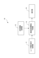
- FIG. 1 is a block diagram showing an example of a configuration of a thickness prediction device according to a first embodiment of the present disclosure.
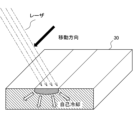
- FIG. FIG. 2 is an explanatory diagram for explaining laser hardening.
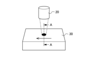
- 13 is a diagram showing a state in which the laser head irradiates a laser onto a workpiece while the workpiece is moved relative to the laser head.
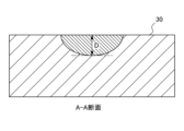
- FIG. 4 is a cross-sectional view showing the thickness of a surface modification layer formed on a workpiece.
- FIG. FIG. 13 is a diagram showing an example of a display image that displays the degree of thickness of a surface modification layer by changing the display mode of the workpiece.
- FIG. 2 is an explanatory diagram illustrating laser cladding.
- FIG. 13 is a diagram showing a state in which the laser head irradiates a laser onto a workpiece while the workpiece is moved relative to the laser head and powder is supplied.
- FIG. 4 is a cross-sectional view showing the thickness of a surface modification layer formed on a workpiece.
- FIG. 13 is a diagram showing a method for determining a laser irradiation area per unit time by laser irradiation.
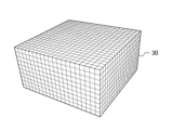
- FIG. 2 is a perspective view showing a workpiece divided into meshes.
- FIG. 2 shows the heat flux applied at time t.
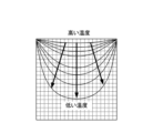
- FIG. 4 is a diagram showing a temperature distribution in a cross section of a workpiece. 4 is a cross-sectional view showing the thickness of a surface modification layer formed on a workpiece.
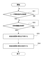
- FIG. 10 is a flowchart showing an example of an operation of a thickness prediction method of the thickness prediction device.
- FIG. 11 is a block diagram showing a configuration example of a thickness prediction device according to a second embodiment of the present disclosure.
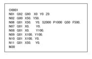
- FIG. 4 is a diagram showing an example of a machining program.
- FIG. 4 is a diagram showing the position of a workpiece origin relative to a machining origin.
- FIG. 2 is a diagram showing a machining path relative to a machining origin.
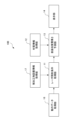
- FIG. 13 is a block diagram showing a configuration example of a thickness prediction device according to a third embodiment of the present disclosure.
- FIG. 13 is a block diagram showing a configuration example of a thickness prediction device according to a fourth embodiment of the present disclosure.
- FIG. 13 is a diagram showing an example of displaying the thickness of a surface modification layer at a specified position.
- embodiments of the present disclosure are not particularly limited to the method of surface modification as long as they are thickness prediction devices and thickness prediction methods for surface modification of a workpiece using a laser, but the following description will focus on the cases of laser hardening and laser cladding (coating).
- FIG. 1 is a block diagram showing an example of the configuration of a thickness prediction device according to a first embodiment of the present disclosure.
- the thickness prediction device 10 includes a laser irradiation condition acquisition unit 11, a material information acquisition unit 12, a surface modification layer thickness prediction unit 13, and a display unit 14.
- the display unit 14 is provided as necessary.
- the display unit 14 may be replaced with a component that can output information including the thickness of the surface modification layer to a user.
- the display unit 14 may be replaced with a printer or a communication unit that transmits information to an external device.
- the laser irradiation condition acquisition unit 11 acquires laser irradiation conditions including the processing speed and laser output conditions at each position on the workpiece surface.
- the processing speed refers to, for example, the speed at which the workpiece and the laser head that irradiates the workpiece with a laser are moved relatively.
- the laser output conditions are, for example, the laser output and the spot diameter.
- the laser irradiation conditions include the processing speed and laser output conditions as well as the additional material supply conditions.
- the additional material is a powder such as metal powder
- the additional material supply condition is, for example, the powder supply amount.
- the powder supply amount is the amount of powder supplied per unit time to the workpiece to be irradiated with the laser.
- the laser oscillator generates a laser upon receiving an output command, and the laser head focuses the laser and irradiates it on the workpiece.
- the material information acquisition unit 12 acquires material information of the workpiece.
- the material indicates at least one of the use, components, physical properties, and mechanical properties. For example, if the material information is indicated as S45C, this indicates that S45C is a type of carbon steel for mechanical construction, and is a medium carbon steel material with a carbon content of 0.45%.
- the surface modification layer thickness prediction unit 13 predicts the thickness of the surface modification layer at each position of the workpiece based on the laser irradiation conditions acquired from the laser irradiation condition acquisition unit 11 and the material information acquired from the material information acquisition unit 12. For example, in the case of hardening, the thickness of the surface modification layer is the depth at which the hardening temperature is reached, and in the case of laser cladding, it is the thickness of the heat-affected zone, which is affected by heat from the surface of the workpiece, plus the thickness of the build-up zone.
- the display unit 14 displays the thickness of the surface modification layer predicted by the surface modification layer thickness prediction unit 13.
- the display unit 14 is, for example, a liquid crystal display device, and displays the thickness of the surface modification layer as a numerical value.
- the display unit 14 may also display the degree of thickness of the surface modification layer by changing the display mode of the workpiece.
- the following describes how the surface modification layer thickness prediction unit 13 predicts the thickness of the surface modification layer at each position on the workpiece.
- the first method is to predict the thickness of the surface modification layer in the case of laser hardening using a table listing experimentally obtained information.
- FIG. 2 is an explanatory diagram for explaining laser hardening.
- a laser is applied to a workpiece 30 such as a metal to heat the surface, and then the laser moves relative to the workpiece 30, causing the temperature of the workpiece 30 to drop by self-cooling, thereby hardening the workpiece.
- the workpiece 30 is irradiated with a laser from the laser head 20 while moving the workpiece 30 at a processing speed.
- the thickness D of the surface modification layer of the workpiece 30 shown in the cross-sectional view of FIG. 4 is determined by the laser irradiation conditions and the material information of the workpiece.
- the thickness D of the surface modification layer is the vertical length (depth) from the surface of the workpiece to the hardening temperature.
- the surface modification layer thickness prediction unit 13 includes a memory unit that stores a table showing the relationship between the experimentally obtained laser irradiation conditions and material information, and the thickness of the surface modification layer. Specifically, the memory unit stores a table listing the processing speed (m/sec), laser output (W), spot diameter (m), material information, and the thickness of the surface modification layer. As already explained, the processing speed, laser output, and spot diameter are the laser irradiation conditions. The material information is, for example, S45C.
- the surface modification layer thickness prediction unit 13 refers to the table and determines the thickness of the surface modification layer corresponding to the acquired laser irradiation conditions and material information.
- the display unit 14 displays the thickness of the surface modification layer obtained by the method described above. For example, the display unit 14 displays the thickness of the surface modification layer by displaying the thickness of the surface modification layer numerically or by displaying the degree of thickness of the surface modification layer by a change in the display mode of the workpiece. In addition to the thickness of the surface modification layer, the display unit 14 may also display at least one of the laser irradiation conditions and material information.
- the display unit 14 displays the thickness of the surface modification layer numerically, for example, "The thickness of the surface modification layer is 1 mm.”
- FIG. 5 shows an example of a display image in which the degree of thickness of the surface modification layer is displayed by changing the display mode of the workpiece.
- the region from 0.8 mm to 1 mm is shown by a black-filled region AR1
- the region from 0.6 mm to 0.8 mm is shown by a hatched region AR2.
- the degree of thickness of the surface modification layer is shown in two display modes (black-filled region and hatched region), but three or more thickness stages, for example, 0.8 mm to 1 mm, 0.6 mm to 0.8 mm, and 0.4 mm to 0.6 mm, may be displayed in three or more display modes.
- the change in the display mode may be shown by color. For example, the region from 0.8 mm to 1 mm may be shown in red, the region from 0.6 mm to 0.8 mm may be shown in orange, and the region from 0.4 mm to 0.6 mm may be shown in yellow.
- the second method is to predict the thickness of the surface modification layer in the case of laser cladding (coating) using a table of experimentally determined information.
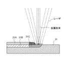
- Fig. 6 is an explanatory diagram for explaining laser cladding.
- laser cladding is performed by melting powder such as metal powder using a laser as a heat source and depositing the same or different material on the surface of a workpiece 31.
- a deposit 31A is formed by laser cladding.
- a molten pool 31C is formed by laser irradiation, and a heat-affected zone 31B is formed by cooling.
- the thickness D1 of the surface modification layer shown in Figure 8 is determined by the laser irradiation conditions, including the amount of powder supplied, and the material information of the workpiece.
- the thickness D1 of the surface modification layer is the sum of the thickness of the heat-affected zone 31B, which is the area from the surface of the workpiece to where the heat influences it, and the thickness of the padding zone 31A.
- the surface modification layer thickness prediction unit 13 includes a memory unit that stores a table showing the relationship between the experimentally obtained laser irradiation conditions, including the amount of powder supplied, and material information, and the thickness of the surface modification layer. Specifically, the memory unit stores a table listing the processing speed (m/sec), laser output (W), spot diameter (m), powder supply amount (g/sec), material information, and the thickness of the surface modification layer. As already explained, the processing speed, laser output, and spot diameter are the laser irradiation conditions.
- the material information is, for example, S45C.
- the surface modification layer thickness prediction unit 13 refers to the table to obtain the thickness of the surface modification layer corresponding to the obtained laser irradiation conditions, including the amount of powder supplied, and material information.
- the display unit 14 displays the thickness of the surface modification layer by displaying the thickness of the surface modification layer numerically, or by displaying the degree of thickness of the surface modification layer by changing the display mode of the workpiece, as in the first method described above.
- the third method is a method for predicting the thickness of the surface modification layer by performing calculations using the laser irradiation conditions and material information in the case of laser hardening.
- the surface modification layer thickness prediction unit 13 first obtains the heat flux q based on the laser irradiation conditions.
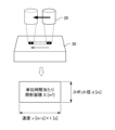
- FIG. 9 is a diagram showing a method for calculating the laser irradiation area per unit time by laser irradiation.
- the laser head 20 moves relative to the workpiece 30 at a processing speed v, and the laser spot moves at the processing speed v.
- the heat absorption rate AB is included in the material information.
- the surface modification layer thickness prediction unit 13 calculates the temperature distribution by the finite element method.
- the method of calculating the temperature distribution by the finite element method is described in, for example, https://www.jstage.jst.go.jp/article/imono/63/1/63_1_32/_pdf/-char/ja and https://www.jstage.jst.go.jp/article/jjasnaoe1968/1984/156/1984_156_406/_pdf/-char/en.
- the surface modification layer thickness prediction unit 13 divides the workpiece into meshes as shown in Fig. 10, and discretizes the heat conduction equation shown in Equation 1 (hereinafter, Equation 1).
- Equation 1 The thermal conductivity ⁇ , density ⁇ , and specific heat c are included in the material information.
- the surface modification layer thickness prediction unit 13 gives the condition for giving a heat flow rate q only in the spot range on the surface of the workpiece as the boundary condition of the discretized heat conduction equation.
- Figure 11 is a diagram showing the heat flux given at time t.
- the surface modification layer thickness prediction unit 13 solves the discretized heat conduction equation for each mesh element, calculates the temperature of each element, and calculates the temperature distribution.
- Figure 12 is a diagram showing the temperature distribution on the cross section of the workpiece 30. As shown in Figure 12, the temperature decreases with distance from the surface.
- the surface modification layer thickness prediction unit 13 determines the depth at which the hardening temperature is reached from the calculated temperature distribution, and sets this as the thickness of the surface modification layer.
- Figure 13 is a cross-sectional view showing the thickness of the surface modification layer formed on the workpiece.
- the thickness D2 of the surface modification layer of the workpiece 30 shown in the cross-sectional view of Figure 13 is determined by the laser irradiation conditions and the material information of the workpiece.
- Fig. 14 is a flowchart showing an example of the operation of the thickness prediction method of the thickness prediction device 10.
- Fig. 14 shows an example of the operation of the thickness prediction device 10 in the case of laser hardening, but the operation in the case of laser cladding is similar.
- step S11 the laser irradiation condition acquisition unit 11 determines whether or not it is possible to acquire laser irradiation conditions including the processing speed and laser output conditions at each position on the workpiece surface. If the laser irradiation condition acquisition unit 11 can acquire the laser irradiation conditions ("YES" in step S11), it acquires the laser irradiation conditions and outputs the acquired laser irradiation conditions to the surface modification layer thickness prediction unit 13, and then the material information acquisition unit 12 performs the operation of step S12. If the laser irradiation condition acquisition unit 11 cannot acquire the laser irradiation conditions ("NO" in step S11), it performs the process of step S11 again.
- step S12 the material information acquisition unit 12 determines whether or not it is possible to acquire material information of the workpiece.
- the material information is, for example, S45C. If the material information acquisition unit 12 can acquire the material information ("YES" in step S12), it acquires the material information and outputs the acquired material information to the surface modification layer thickness prediction unit 13, and then the surface modification layer thickness prediction unit 13 performs the operation of step S13. If the material information acquisition unit 12 cannot acquire the material information ("NO" in step S12), it performs the process of step S12 again. Step S12 may be performed before step S11, or may be performed in parallel with step S11.
- step S13 the surface modification layer thickness prediction unit 13 predicts the thickness of the surface modification layer at each position on the workpiece based on the laser irradiation conditions and material information.
- step S14 the display unit 14 displays the thickness of the surface modification layer predicted by the surface modification layer thickness prediction unit 13.
- the thickness prediction device 10 of this embodiment described above can predict the thickness of the surface modification layer without the need for additional inspection steps before processing or during or after processing.
- FIG. 15 is a block diagram showing an example configuration of a thickness prediction device according to the second embodiment of the present disclosure.
- the thickness prediction device 10A includes a CNC (Computerized Numerical Control) data storage unit 15, a machining simulation execution unit 16, and a workpiece placement information acquisition unit 17 in addition to the configuration of the thickness prediction device 10.
- the CNC data storage unit 15 stores CNC data including parameter settings and machining programs.
- the parameter settings include, for example, parameter settings related to speed control.
- An example of the parameter settings related to speed control is the time constant of cutting feed acceleration/deceleration for each of the X-axis, Y-axis, and Z-axis.
- An example of the machining program is shown in FIG. In the machining program shown in FIG. 16, S indicates a power command (W), P indicates a frequency command (Hz), Q indicates a duty command (%), and F indicates a feed speed command (mm/min).
- the processing simulation execution unit 16 executes a processing simulation based on the CNC data, and creates point sequence data including at least the coordinate values on the processing path, the feed rate, and the laser output conditions. In the case of laser cladding, the processing simulation execution unit 16 creates point sequence data including at least the coordinate values on the processing path, the feed rate, the laser output conditions, and the additional material supply conditions.
- the workpiece placement information acquisition unit 17 acquires workpiece placement information including at least the shape of the workpiece and the relative position between the workpiece and the machining path.
- the shape of the workpiece can be obtained from CAD (computer-aided design)/CAM (computer-aided manufacturing).
- the relative position between the workpiece and the machining path can be obtained as follows. Generally, in machining setup, after the workpiece is placed, the workpiece origin at the center of the workpiece relative to the machining origin is measured using a touch probe or the like, and the measurement result is used to set the offset of the coordinate system (workpiece coordinate system offset). This offset is the relative position between the workpiece and the machining path. In FIG. 17, the relative position corresponds to the relative position (x', y', z').
- FIG. 18 is a diagram showing the machining path relative to the machining origin.
- the laser irradiation condition acquisition unit 11 calculates the laser irradiation conditions on the workpiece surface based on the point sequence data and the workpiece installation information.
- the thickness prediction device 10A described above makes it possible to predict the thickness of the surface modification layer from the results of the processing simulation before processing.
- FIG. 19 is a block diagram showing an example configuration of a thickness prediction device according to the third embodiment of the present disclosure.
- the CNC data storage unit 15 and the machining simulation execution unit 16 are removed from the configuration of the thickness prediction device 10A, and an operation data acquisition unit 18 is added.
- the operation data acquisition unit 18 acquires operation data including at least the coordinate values, feed speed, and laser output conditions obtained during processing.
- the operation data acquisition unit 18 acquires operation data including at least the coordinate values, feed speed, laser output conditions, and additional material supply conditions obtained during processing.
- the laser irradiation condition acquisition unit 11 calculates the laser irradiation conditions on the workpiece surface based on the operation data and the workpiece placement information.
- the thickness prediction device 10B described above can predict the thickness of the surface modification layer from operational data during or after processing.
- FIG. 20 is a block diagram showing an example of the configuration of a thickness prediction device according to the fourth embodiment of the present disclosure.
- the thickness prediction device 10C includes a designated position specifying unit 19 in addition to the configuration of the thickness prediction device 10.
- the designated position identifying unit 19 identifies a position on the surface of the workpiece. The position on the surface of the workpiece is identified by inputting the position by a user via an input device such as a keyboard or a touch panel on a liquid crystal display device, but the designated position may be stored in advance in a storage unit and identified.
- the display unit 14 displays the thickness of the surface modification layer at the identified position.
- Figure 21 is a diagram showing an example of displaying the thickness of the surface modification layer at the identified position. Figure 21 shows that the thickness of the surface modification layer at the identified position is 1.5 mm from the surface.
- the thickness prediction device 10C described above can predict the thickness of the surface modification layer at a specified position.
- the thickness prediction device can be realized by hardware, software, or a combination of these.
- being realized by software means being realized by a computer reading and executing a program.
- the thickness prediction device includes a processor such as a CPU (Central Processing Unit).
- the processor functions as an execution unit.
- the thickness prediction device also includes a secondary storage device such as a HDD (Hard Disk Drive) that stores various control programs such as application software or an OS (Operating System), and a main storage device such as a RAM (Random Access Memory) for storing data temporarily required for the processor to execute the program.
- a processor such as a CPU (Central Processing Unit).
- the processor functions as an execution unit.
- the thickness prediction device also includes a secondary storage device such as a HDD (Hard Disk Drive) that stores various control programs such as application software or an OS (Operating System), and a main storage device such as a RAM (Random Access Memory) for storing data temporarily required for the processor to execute the program.
- a secondary storage device
- the thickness prediction device then performs calculations based on the application software or OS, with the calculation processing unit reading the application software or OS from the auxiliary storage device and expanding the loaded application software or OS into the main storage device. Also, based on the results of this calculation, the thickness prediction device controls various pieces of hardware. This realizes the functional blocks of this embodiment.
- the components included in the thickness prediction device can be realized by hardware including electronic circuits, etc.
- some or all of the functions of each component included in the thickness prediction device can be configured by integrated circuits (ICs), such as ASICs (Application Specific Integrated Circuits), gate arrays, FPGAs (Field Programmable Gate Arrays), and CPLDs (Complex Programmable Logic Devices).
- ICs integrated circuits
- ASICs Application Specific Integrated Circuits
- FPGAs Field Programmable Gate Arrays
- CPLDs Complex Programmable Logic Devices
- Non-transitory computer readable media include various types of tangible storage media.
- Examples of non-transitory computer readable media include magnetic recording media (e.g., hard disk drives), magneto-optical recording media (e.g., magneto-optical disks), CD-ROM (Read Only Memory), CD-R, CD-R/W, and semiconductor memory (e.g., mask ROM, PROM (Programmable ROM), EPROM (Erasable PROM), flash ROM, and RAM (random access memory)).
- the program may also be provided to the computer by various types of transitory computer readable media.
- the thickness prediction device and thickness prediction method disclosed herein make it possible to predict the thickness of the surface modification layer without adding any check before processing or any inspection process during or after processing.
- the thickness prediction device and method used in laser hardening or laser cladding can also be applied to thermal spraying, and can also be applied to the manufacturing methods described in Patent Documents 1 and 2.
- a device for predicting the thickness of a surface modification layer of a workpiece formed using a laser comprising: A laser irradiation condition acquisition unit that acquires laser irradiation conditions including at least a processing speed and a laser output condition for each position on the surface of the workpiece; A material information acquisition unit that acquires material information of the workpiece; a surface modification layer thickness prediction unit that predicts a thickness of the surface modification layer at each position of the workpiece based on the laser irradiation conditions and the material information;
- a thickness prediction device comprising:
- Appendix 3 a machining simulation execution unit that creates point sequence data including at least coordinate values, feed speeds, and laser output conditions on a machining path based on CNC data including at least parameter settings and a machining program;
- a workpiece setting information acquisition unit that acquires workpiece setting information including at least a shape of the workpiece and a relative position between the workpiece and the processing path, The thickness prediction device described in Appendix 1, wherein the laser irradiation condition acquisition unit calculates the laser irradiation conditions on the surface of the workpiece based on at least the point sequence data and the workpiece placement information.
- Appendix 4 an operation data acquisition unit that acquires operation data including at least coordinate values, a feed rate, and a laser output condition obtained during processing;
- a workpiece setting information acquisition unit that acquires workpiece setting information including at least a shape of the workpiece and a relative position between the workpiece and the processing path, The thickness prediction device described in Appendix 1, wherein the laser irradiation condition acquisition unit calculates the laser irradiation conditions on the surface of the workpiece based on at least the operation data and the workpiece placement information.
- Appendix 8 A thickness prediction device described in any one of appendix 1 to 6, which displays the degree of thickness of the surface modification layer by changing the display mode of the workpiece.
- a computer as a device for predicting the thickness of a surface modification layer of a workpiece formed using a laser, A process of acquiring laser irradiation conditions including at least a processing speed and a laser output condition for each position on the surface of the workpiece; A process of acquiring material information of the workpiece; A process of predicting a thickness of the surface modification layer at each position of the workpiece based on the laser irradiation conditions and the material information; A method for predicting the thickness of a surface modification layer.
Landscapes
- Engineering & Computer Science (AREA)
- Physics & Mathematics (AREA)
- Optics & Photonics (AREA)
- Plasma & Fusion (AREA)
- Mechanical Engineering (AREA)
- Chemical & Material Sciences (AREA)
- Chemical Kinetics & Catalysis (AREA)
- General Chemical & Material Sciences (AREA)
- Oil, Petroleum & Natural Gas (AREA)
- Laser Beam Processing (AREA)
Abstract
加工前の確認、又は加工中若しくは加工後の検査工程を追加することなく、表面改質層の厚さを予測する。 レーザを用いて形成される、被加工物の表面改質層の厚さ予測装置が、少なくとも前記被加工物の表面上の各位置の加工速度とレーザ出力条件とを含むレーザ照射条件を取得するレーザ照射条件取得部と、被加工物の材質情報を取得する材質情報取得部と、レーザ照射条件と材質情報とに基づいて、被加工物の各位置の前記表面改質層の厚さを予測する表面改質層厚さ予測部と、を備える。
Description
本開示は、表面改質層の厚さ予測装置及び厚さ予測方法に関わり、特に、レーザを用いて形成される、被加工物の表面改質層の厚さ予測装置及び厚さ予測方法に関する。
被加工物の表面にレーザを照射して、被加工物の表面改質を行う方法が、例えば、特許文献1及び特許文献2に記載されている。
特許文献1には、金属製基材の表面にレーザを照射して、基材の表面改質を行う表面改質基材の製造方法が記載されている。
具体的には、特許文献1には、金属製基材の表面にレーザを透過する樹脂層を設ける工程と、樹脂層を通して基材表面にレーザを照射し、基材の表面を溶融させると共に、基材の熱により樹脂層を熱分解させる工程とを備える表面改質基材の製造方法が記載されている。
具体的には、特許文献1には、金属製基材の表面にレーザを透過する樹脂層を設ける工程と、樹脂層を通して基材表面にレーザを照射し、基材の表面を溶融させると共に、基材の熱により樹脂層を熱分解させる工程とを備える表面改質基材の製造方法が記載されている。
特許文献2には、基材に対して高い密着性を持ち、かつ厚膜化された改質層を、基材成分の混入が低減された状態で得ることのできる表面改質部材の製造方法が記載されている。
具体的には、特許文献2には、基材上に溶射皮膜を形成する工程、溶射皮膜の表面に高エネルギービームを照射して、厚み方向における溶射皮膜の全体及び基材の一部を溶融し、凝固させて、緻密化された改質層を形成する工程、直前に形成した改質層上に、溶射皮膜を形成する工程、並びに、溶射皮膜の表面に高エネルギービームを照射して、厚み方向における溶射皮膜の全体及び直前に形成した改質層の一部を溶融し、凝固させて、緻密化された改質層を形成する工程を含む表面改質部材の製造方法が記載されている。
具体的には、特許文献2には、基材上に溶射皮膜を形成する工程、溶射皮膜の表面に高エネルギービームを照射して、厚み方向における溶射皮膜の全体及び基材の一部を溶融し、凝固させて、緻密化された改質層を形成する工程、直前に形成した改質層上に、溶射皮膜を形成する工程、並びに、溶射皮膜の表面に高エネルギービームを照射して、厚み方向における溶射皮膜の全体及び直前に形成した改質層の一部を溶融し、凝固させて、緻密化された改質層を形成する工程を含む表面改質部材の製造方法が記載されている。
レーザを用いた被加工物の表面改質には、例えば、レーザ焼入れ、及びレーザクラッディング(コーティング)があり、機械部品を部分的に強化することが行われている。
表面改質加工では、表面改質層の厚さが重要であり、表面改質を行った層の厚さを予測する厚さ予測装置及び厚さ予測方法が望まれる。
表面改質加工では、表面改質層の厚さが重要であり、表面改質を行った層の厚さを予測する厚さ予測装置及び厚さ予測方法が望まれる。
本開示の代表的な第1の態様は、レーザを用いて形成される、被加工物の表面改質層の厚さ予測装置であって、
少なくとも前記被加工物の表面上の各位置の、加工速度とレーザ出力条件とを含むレーザ照射条件を取得するレーザ照射条件取得部と、
前記被加工物の材質情報を取得する材質情報取得部と、
前記レーザ照射条件と前記材質情報とに基づいて、前記被加工物の各位置の前記表面改質層の厚さを予測する表面改質層厚さ予測部と、
を備えた、厚さ予測装置である。
少なくとも前記被加工物の表面上の各位置の、加工速度とレーザ出力条件とを含むレーザ照射条件を取得するレーザ照射条件取得部と、
前記被加工物の材質情報を取得する材質情報取得部と、
前記レーザ照射条件と前記材質情報とに基づいて、前記被加工物の各位置の前記表面改質層の厚さを予測する表面改質層厚さ予測部と、
を備えた、厚さ予測装置である。
本開示の代表的な第2の態様は、レーザを用いて形成される、被加工物の表面改質層の厚さ予測装置としてのコンピュータが、
少なくとも前記被加工物の表面上の各位置の、加工速度とレーザ出力条件とを含むレーザ照射条件を取得する処理と、
前記被加工物の材質情報を取得する処理と、
前記レーザ照射条件と前記材質情報とに基づいて、前記被加工物の各位置の前記表面改質層の厚さを予測する処理と、
を実行する、表面改質層の厚さ予測方法である。
少なくとも前記被加工物の表面上の各位置の、加工速度とレーザ出力条件とを含むレーザ照射条件を取得する処理と、
前記被加工物の材質情報を取得する処理と、
前記レーザ照射条件と前記材質情報とに基づいて、前記被加工物の各位置の前記表面改質層の厚さを予測する処理と、
を実行する、表面改質層の厚さ予測方法である。
以下、本開示の実施形態について図面を用いて詳細に説明する。
本開示の実施形態は、レーザを用いた被加工物の表面改質の厚さ予測装置及び厚さ予測方法であれば、特に表面改質の方法は限定されないが、以下の説明では、レーザ焼入れ、及びレーザクラッディング(コーティング)の場合について説明する。
本開示の実施形態は、レーザを用いた被加工物の表面改質の厚さ予測装置及び厚さ予測方法であれば、特に表面改質の方法は限定されないが、以下の説明では、レーザ焼入れ、及びレーザクラッディング(コーティング)の場合について説明する。
(第1実施形態)
図1は本開示の第1実施形態の厚さ予測装置の一構成例を示すブロック図である。
図1に示すように、厚さ予測装置10は、レーザ照射条件取得部11、材質情報取得部12、表面改質層厚さ予測部13、及び表示部14を備えている。表示部14は必要に応じて設けられる。表示部14は、ユーザに表面改質層の厚さを含む情報を出力できる構成部に置き換えてもよい。例えば、表示部14は、プリンター、又は外部機器に情報を送信する通信部に置き換えてもよい。
図1は本開示の第1実施形態の厚さ予測装置の一構成例を示すブロック図である。
図1に示すように、厚さ予測装置10は、レーザ照射条件取得部11、材質情報取得部12、表面改質層厚さ予測部13、及び表示部14を備えている。表示部14は必要に応じて設けられる。表示部14は、ユーザに表面改質層の厚さを含む情報を出力できる構成部に置き換えてもよい。例えば、表示部14は、プリンター、又は外部機器に情報を送信する通信部に置き換えてもよい。
レーザ照射条件取得部11は、被加工物表面上の各位置の加工速度とレーザ出力条件を含むレーザ照射条件を取得する。加工速度は、例えば、被加工物と、被加工物にレーザを照射するレーザヘッドとを相対的に移動させる速度をいう。レーザ出力条件は、例えば、レーザ出力、及びスポット径である。レーザクラッディングの場合は、レーザ照射条件は、加工速度とレーザ出力条件の他に、付加材料供給条件を含む。付加材料供給条件は、付加材料が金属粉末等の粉体の場合は、例えば粉末供給量である。粉末供給量は、レーザが照射される被加工物に、粉末を単位時間当たりに供給する量である。レーザ発振器が出力指令を受けてレーザを生成し、レーザヘッドがレーザを集光して被加工物に照射する。
材質情報取得部12は、被加工物の材質情報を取得する。材質は、少なくとも、用途、成分、物理的性質及び機械的性質の1つを示す。例えば、材質情報がS45Cと示された場合、S45Cは、機械構造用炭素鋼の一種で、炭素含有量が0.45%の中炭素鋼材料であることを示す。
表面改質層厚さ予測部13は、レーザ照射条件取得部11から取得したレーザ照射条件と、材質情報取得部12から取得した材質情報とに基づいて、被加工物の各位置の表面改質層の厚さを予測する。表面改質層の厚さは、例えば、焼入れの場合は焼き入れ温度に到達する深さであり、レーザクラッディングの場合は、被加工物の表面から熱による影響が及ぶ熱影響部と、肉盛り部とを加えた厚さとなる。
表示部14は、表面改質層厚さ予測部13によって予測された、表面改質層の厚さを表示する。表示部14は、例えば、液晶表示装置であり、表面改質層の厚さを数値で表示する。表示部14は、表面改質層の厚さの度合いを被加工物の表示態様の変化により表示してもよい。
以下、表面改質層厚さ予測部13が、被加工物の各位置の表面改質層の厚さを予測する方法について説明する。
(第1の方法)
第1の方法は、レーザ焼入れの場合に、実験的に求めた情報を並べたテーブルを用いて表面改質層の厚さを予測する方法である。
図2はレーザ焼入れを説明する説明図である。図2に示すように、レーザを金属等の被加工物30に当てて表面を加熱し、その後、レーザが被加工物30に対して相対的に移動することで、被加工物30の温度が自己冷却によって下がり、焼入れが行われる。例えば、図3に示すように、被加工物30を加工速度で移動させつつ、レーザヘッド20からレーザを被加工物30に照射する。レーザ照射条件及び被加工物の材質情報によって、図4の断面図に示す、被加工物30の表面改質層の厚さDが決まる。表面改質層の厚さDは、被加工物の表面から焼入れ温度に達する垂直方向の長さ(深さ)となる。
第1の方法は、レーザ焼入れの場合に、実験的に求めた情報を並べたテーブルを用いて表面改質層の厚さを予測する方法である。
図2はレーザ焼入れを説明する説明図である。図2に示すように、レーザを金属等の被加工物30に当てて表面を加熱し、その後、レーザが被加工物30に対して相対的に移動することで、被加工物30の温度が自己冷却によって下がり、焼入れが行われる。例えば、図3に示すように、被加工物30を加工速度で移動させつつ、レーザヘッド20からレーザを被加工物30に照射する。レーザ照射条件及び被加工物の材質情報によって、図4の断面図に示す、被加工物30の表面改質層の厚さDが決まる。表面改質層の厚さDは、被加工物の表面から焼入れ温度に達する垂直方向の長さ(深さ)となる。
表面改質層厚さ予測部13は、実験的に求めた、レーザ照射条件及び材質情報と、表面改質層の厚さとの関係を示すテーブルを記憶する記憶部を備えている。具体的には、記憶部は、加工速度(m/sec)、レーザ出力(W)、スポット径(m)、材質情報、及び表面改質層の厚さを並べたテーブルを記憶している。加工速度、レーザ出力、及びスポット径は、既に説明したようにレーザ照射条件である。材質情報は、例えばS45Cである。表面改質層厚さ予測部13は、テーブルを参照して、取得された、レーザ照射条件と材質情報とに対応する表面改質層の厚さを求める。
表示部14は、以上説明した方法により求められた表面改質層の厚さを表示する。表示部14は、例えば、表面改質層の厚さを数値で表示したり、表面改質層の厚さの度合いを被加工物の表示態様の変化により表示することで、表面改質層の厚さを表示する。表示部14は、表面改質層の厚さの他に、レーザ照射条件と材質情報の少なくとも1つを併せて表示してもよい。
表示部14は、例えば、「表面改質層の厚さは、1mmです。」のように、表面改質層の厚さを数値で表示する。
図5は、表面改質層の厚さの度合いを被加工物の表示態様の変化により表示する表示画像の一例を示している。図5では、表面改質層の厚さの範囲を0~1mmとした場合に、0.8mmから1mmの領域を黒塗り領域AR1で示し、0.6mmから0.8mmの領域を斜線領域AR2で示している。図5では表面改質層の厚さの度合いを2つの表示態様(黒塗り領域と斜線領域)で示しているが、3つ以上の厚さの段階、例えば、0.8mmから1mm、0.6mmから0.8mm、0.4mmから0.6mmを3以上の表示態様で示して示してもよい。表示態様の変化は、色で示してもよい。例えば、0.8mmから1mmの領域を赤色で示し、0.6mmから0.8mmの領域を橙色で示し、0.4mmから0.6mmを黄色で示してもよい。
図5は、表面改質層の厚さの度合いを被加工物の表示態様の変化により表示する表示画像の一例を示している。図5では、表面改質層の厚さの範囲を0~1mmとした場合に、0.8mmから1mmの領域を黒塗り領域AR1で示し、0.6mmから0.8mmの領域を斜線領域AR2で示している。図5では表面改質層の厚さの度合いを2つの表示態様(黒塗り領域と斜線領域)で示しているが、3つ以上の厚さの段階、例えば、0.8mmから1mm、0.6mmから0.8mm、0.4mmから0.6mmを3以上の表示態様で示して示してもよい。表示態様の変化は、色で示してもよい。例えば、0.8mmから1mmの領域を赤色で示し、0.6mmから0.8mmの領域を橙色で示し、0.4mmから0.6mmを黄色で示してもよい。
(第2の方法)
第2の方法は、レーザクラッディング(コーティング)の場合に、実験的に求めた情報を並べたテーブルを用いて表面改質層の厚さを予測する方法である。
図6はレーザクラッディングを説明する説明図である。図6に示すように、レーザを熱源として、金属粉末等の粉末を溶融させ、被加工物31の表面に同種材又は異種材を肉盛りすることで、レーザクラッディングが行われる。図6に示すように、レーザクラッディングにより肉盛り部31Aが形成される。レーザ照射により溶融池31Cが形成され、冷却により熱影響部31Bが形成される。
第2の方法は、レーザクラッディング(コーティング)の場合に、実験的に求めた情報を並べたテーブルを用いて表面改質層の厚さを予測する方法である。
図6はレーザクラッディングを説明する説明図である。図6に示すように、レーザを熱源として、金属粉末等の粉末を溶融させ、被加工物31の表面に同種材又は異種材を肉盛りすることで、レーザクラッディングが行われる。図6に示すように、レーザクラッディングにより肉盛り部31Aが形成される。レーザ照射により溶融池31Cが形成され、冷却により熱影響部31Bが形成される。
図7に示すように、被加工物31にレーザヘッド20からレーザを所定の加工速度で照射するとともに、粉末を供給した場合、粉末供給量を含むレーザ照射条件、及び被加工物の材質情報によって、図8に示す表面改質層の厚さD1が決まる。表面改質層の厚さD1は、被加工物の表面から熱による影響が及ぶまでの熱影響部31Bと、肉盛り部31Aとを加えた厚さとなる。
表面改質層厚さ予測部13は、実験的に求めた、粉末供給量を含むレーザ照射条件及び材質情報と、表面改質層の厚さとの関係を示すテーブルを記憶する記憶部を備えている。具体的には、記憶部は、加工速度(m/sec)、レーザ出力(W)、スポット径(m)、粉末供給量(g/sec)、材質情報、及び表面改質層の厚さを並べたテーブルを記憶している。加工速度、レーザ出力、及びスポット径は、既に説明したようにレーザ照射条件である。材質情報は、例えばS45Cである。表面改質層厚さ予測部13は、テーブルを参照して、取得された、粉末供給量を含むレーザ照射条件、及び材質情報に対応する表面改質層の厚さを求める。
表示部14は、前述した第1の方法と同様に、表面改質層の厚さを数値で表示したり、表面改質層の厚さの度合いを被加工物の表示態様の変化により表示することで、表面改質層の厚さを表示する。
(第3の方法)
第3の方法は、レーザ焼入れの場合に、レーザ照射条件及び材質情報を用いて計算することで表面改質層の厚さを予測する方法である。
表面改質層厚さ予測部13は、まず、レーザ照射条件に基づいて熱流束qを求める。
第3の方法は、レーザ焼入れの場合に、レーザ照射条件及び材質情報を用いて計算することで表面改質層の厚さを予測する方法である。
表面改質層厚さ予測部13は、まず、レーザ照射条件に基づいて熱流束qを求める。
図9は、レーザ照射による、単位時間当たりのレーザ照射面積を求める方法を示す図である。図9に示すように、被加工物30に対してレーザヘッド20が加工速度vで移動し、レーザスポットが加工速度vで移動する。表面改質層厚さ予測部13は、加工速度vと、レーザスポットのスポット径dとを掛けることで、単位時間当たりのレーザ照射面積S(S=v×d)を求める。また、表面改質層厚さ予測部13は、レーザ出力LPと熱吸収率ABとを掛けることで、単位時間当たりの入熱量P(P=LP×AB)を求める。そして、表面改質層厚さ予測部13は、入熱量Pをレーザ照射面積Sで割ることで、熱流束q(q=P/S)を求める。熱吸収率ABは材質情報に含まれる。
次に、表面改質層厚さ予測部13は、有限要素法により温度分布を算出する。有限要素法により温度分布を算出する方法は、例えば、https://www.jstage.jst.go.jp/article/imono/63/1/63_1_32/_pdf/-char/ja、及びhttps://www.jstage.jst.go.jp/article/jjasnaoe1968/1984/156/1984_156_406/_pdf/-char/enに記載されている。
具体的には、表面改質層厚さ予測部13は、図10に示すように、被加工物をメッシュ分割し、数式1(以下の数1)で示す熱伝導方程式を離散化する。熱伝導率κ、密度ρ、比熱cは材質情報に含まれる。

具体的には、表面改質層厚さ予測部13は、図10に示すように、被加工物をメッシュ分割し、数式1(以下の数1)で示す熱伝導方程式を離散化する。熱伝導率κ、密度ρ、比熱cは材質情報に含まれる。
次に、表面改質層厚さ予測部13は、被加工物の表面にスポット範囲だけ熱流速qを与える条件を、離散化した熱伝導方程式の境界条件として与える。図11は時間tに与えられる熱流束を示す図である。表面改質層厚さ予測部13は、それぞれのメッシュの要素について離散化した熱伝導方程式を解き、各要素の温度を算出し、温度分布を算出する。図12は被加工物30の断面の温度分布を示す図である。図12に示すように、温度は表面から離れるに従って温度が低下する。
表面改質層厚さ予測部13は、算出された温度分布から焼き入れ温度に到達する深さを求めて表面改質層の厚さとする。図13は、被加工物に形成された表面改質層の厚さを示す断面図である。レーザ照射条件及び被加工物の材質情報によって、図13の断面図に示す、被加工物30の表面改質層の厚さD2が決まる。
次に、厚さ予測装置10の厚さ予測方法についてフローチャートを用いて説明する。
図14は、厚さ予測装置10の厚さ予測方法による動作の一例を示すフローチャートである。図14は、レーザ焼入れの場合の厚さ予測装置10の動作の例を示しているが、レーザクラッディングの場合の動作も同様である。
図14は、厚さ予測装置10の厚さ予測方法による動作の一例を示すフローチャートである。図14は、レーザ焼入れの場合の厚さ予測装置10の動作の例を示しているが、レーザクラッディングの場合の動作も同様である。
ステップS11において、レーザ照射条件取得部11は、被加工物表面上の各位置の加工速度とレーザ出力条件を含むレーザ照射条件を取得できるか否かを判断する。レーザ照射条件取得部11は、レーザ照射条件を取得できれば(ステップS11の”YES”)、レーザ照射条件を取得して、表面改質層厚さ予測部13に取得したレーザ照射条件を出力し、その後、材質情報取得部12がステップS12の動作を行う。レーザ照射条件取得部11は、レーザ照射条件を取得できなければ(ステップS11の”NO”)、再度ステップS11の処理を行う。
ステップS12において、材質情報取得部12は、被加工物の材質情報を取得できるか否かを判断する。材質情報は、例えば、S45Cである。材質情報取得部12は、材質情報を取得できれば(ステップS12の”YES”)、材質情報を取得して、表面改質層厚さ予測部13に取得した材質情報を出力し、その後、表面改質層厚さ予測部13がステップS13の動作を行う。材質情報取得部12は、材質情報を取得できなければ(ステップS12の”NO”)、再度ステップS12の処理を行う。ステップS12はステップS11の前に行われてもよく、ステップS11と並行して行われてもよい。
ステップS13において、表面改質層厚さ予測部13は、レーザ照射条件と材質情報とに基づいて被加工物の各位置の表面改質層の厚さを予測する。
ステップS14において、表示部14は、表面改質層厚さ予測部13によって予測された、表面改質層の厚さを表示する。
以上説明した、本実施形態の厚さ予測装置10によれば、加工前の確認、又は加工中若しくは加工後の検査工程を追加することなく、表面改質層の厚さを予測することができる。
(第2実施形態)
図15は本開示の第2実施形態の厚さ予測装置の一構成例を示すブロック図である。
図15に示すように、厚さ予測装置10Aは、厚さ予測装置10の構成に加えて、CNC(Computerized Numerical Control)データ記憶部15、加工シミュレーション実行部16、及び被加工物設置情報取得部17を備えている。
CNCデータ記憶部15は、パラメータ設定と加工プログラムとを含むCNCデータを記憶する。パラメータ設定としては、例えば、速度制御に係るパラメータ設定がある。速度制御に係るパラメータ設定の例は、X軸、Y軸及びZ軸の軸ごとの切削送り加減速の時定数である。
加工プログラムの一例を図16に示す。
図16に示す加工プログラムにおいて、Sはパワー指令(W)で、Pは周波数指令(Hz)、Qはデューティ指令(%)、Fは送り速度指令(mm/min)を示す。
図15は本開示の第2実施形態の厚さ予測装置の一構成例を示すブロック図である。
図15に示すように、厚さ予測装置10Aは、厚さ予測装置10の構成に加えて、CNC(Computerized Numerical Control)データ記憶部15、加工シミュレーション実行部16、及び被加工物設置情報取得部17を備えている。
CNCデータ記憶部15は、パラメータ設定と加工プログラムとを含むCNCデータを記憶する。パラメータ設定としては、例えば、速度制御に係るパラメータ設定がある。速度制御に係るパラメータ設定の例は、X軸、Y軸及びZ軸の軸ごとの切削送り加減速の時定数である。
加工プログラムの一例を図16に示す。
図16に示す加工プログラムにおいて、Sはパワー指令(W)で、Pは周波数指令(Hz)、Qはデューティ指令(%)、Fは送り速度指令(mm/min)を示す。
加工シミュレーション実行部16は、CNCデータ基づいて加工シミュレーションを実行し、加工経路上の少なくとも座標値と送り速度とレーザ出力条件とを含む点列データを作成する。レーザクラッディングの場合は、加工シミュレーション実行部16は、加工経路上の少なくとも座標値、送り速度、レーザ出力条件、及び付加材料供給条件を含む点列データを作成する。
被加工物設置情報取得部17は、少なくとも被加工物の形状と、被加工物と加工経路との相対位置とを含む被加工物設置情報を取得する。被加工物の形状は、CAD(computer-aided design)/CAM(Computer-aided manufacturing)から得ることができる。被加工物と加工経路との相対位置は、次のようにして求めることができる。一般的には、加工の段取りでは、被加工物を設置した後に、加工原点に対する被加工物の中心のワーク原点を、タッチプローブ等を用いて計測し、計測結果を用いて座標系のオフセット(ワーク座標系オフセット)を設定する。このオフセットが、被加工物と加工経路との相対位置となる。相対位置は、図17において、相対位置(x’、y’、z’)が該当する。図18は加工原点に対する加工経路を示す図である。
レーザ照射条件取得部11は、点列データと被加工物設置情報とに基づいて被加工物表面上のレーザ照射条件を算出する。
以上説明した厚さ予測装置10Aによれば、加工前に加工シミュレーションの結果から表面改質層の厚さを予測することができる。
(第3実施形態)
図19は本開示の第3実施形態の厚さ予測装置の一構成例を示すブロック図である。
図19に示すように、厚さ予測装置10Bは、厚さ予測装置10Aの構成と比較して、CNCデータ記憶部15及び加工シミュレーション実行部16が除かれ、動作データ取得部18が加えられている。
動作データ取得部18は、加工時に得た少なくとも座標値、送り速度、及びレーザ出力条件を含む動作データを取得する。動作データ取得部18は、レーザクラッディングの場合は、加工時に得た少なくとも座標値、送り速度、レーザ出力条件及び付加材料供給条件を含む動作データを取得する。
図19は本開示の第3実施形態の厚さ予測装置の一構成例を示すブロック図である。
図19に示すように、厚さ予測装置10Bは、厚さ予測装置10Aの構成と比較して、CNCデータ記憶部15及び加工シミュレーション実行部16が除かれ、動作データ取得部18が加えられている。
動作データ取得部18は、加工時に得た少なくとも座標値、送り速度、及びレーザ出力条件を含む動作データを取得する。動作データ取得部18は、レーザクラッディングの場合は、加工時に得た少なくとも座標値、送り速度、レーザ出力条件及び付加材料供給条件を含む動作データを取得する。
レーザ照射条件取得部11は、動作データと被加工物設置情報とに基づいて被加工物表面上のレーザ照射条件を算出する。
以上説明した厚さ予測装置10Bによれば、加工中又は加工後の動作データから表面改質層の厚さを予測することができる。
(第4実施形態)
図20は本開示の第4実施形態の厚さ予測装置の一構成例を示すブロック図である。
図20に示すように、厚さ予測装置10Cは、厚さ予測装置10の構成に加えて、指定位置特定部19を備えている。
指定位置特定部19は、被加工物の表面上の位置を特定する。被加工物の表面上の位置は、ユーザによりキーボード、又は液晶表示装置上のタッチパネル等の入力装置で入力されて特定されるが、予め記憶部に指定位置が記憶されて特定されてもよい。
図20は本開示の第4実施形態の厚さ予測装置の一構成例を示すブロック図である。
図20に示すように、厚さ予測装置10Cは、厚さ予測装置10の構成に加えて、指定位置特定部19を備えている。
指定位置特定部19は、被加工物の表面上の位置を特定する。被加工物の表面上の位置は、ユーザによりキーボード、又は液晶表示装置上のタッチパネル等の入力装置で入力されて特定されるが、予め記憶部に指定位置が記憶されて特定されてもよい。
表示部14は、特定された位置における表面改質層の厚さを表示する。図21は、特定された位置における表面改質層の厚さを表示する例を示す図である。図21では特定された位置で、表面改質層の厚さが表面から1.5mmであることを示している。
以上説明した厚さ予測装置10Cによれば、特定された位置の表面改質層の厚さを予測することができる。
以上、各実施形態における、厚さ予測装置に含まれる機能ブロックを実現するために、厚さ予測装置は、ハードウェア、ソフトウェア又はこれらの組み合わせにより実現することができる。ここで、ソフトウェアによって実現されるとは、コンピュータがプログラムを読み込んで実行することにより実現されることを意味する。
厚さ予測装置に含まれる構成部をソフトウェア又はこれらの組み合わせにより実現する実現するために、厚さ予測装置は、CPU(Central Processing Unit)等の演算処理装置を備える。演算処理装置は実行部として機能する。また、厚さ予測装置は、アプリケーションソフトウェア又はOS(Operating System)等の各種の制御用プログラムを格納したHDD(Hard Disk Drive)等の補助記憶装置、及び演算処理装置がプログラムを実行する上で一時的に必要とされるデータを格納するためのRAM(Random Access Memory)といった主記憶装置も備える。
厚さ予測装置に含まれる構成部をソフトウェア又はこれらの組み合わせにより実現する実現するために、厚さ予測装置は、CPU(Central Processing Unit)等の演算処理装置を備える。演算処理装置は実行部として機能する。また、厚さ予測装置は、アプリケーションソフトウェア又はOS(Operating System)等の各種の制御用プログラムを格納したHDD(Hard Disk Drive)等の補助記憶装置、及び演算処理装置がプログラムを実行する上で一時的に必要とされるデータを格納するためのRAM(Random Access Memory)といった主記憶装置も備える。
そして、厚さ予測装置は、演算処理装置が補助記憶装置からアプリケーションソフトウェア又はOSを読み込み、読み込んだアプリケーションソフトウェア又はOSを主記憶装置に展開させながら、これらのアプリケーションソフトウェア又はOSに基づいた演算処理を行なう。また、この演算結果に基づいて、厚さ予測装置が備える各種のハードウェアを制御する。これにより、本実施形態の機能ブロックは実現される。
厚さ予測装置に含まれる構成部は、電子回路等を含むハードウェアにより実現することができる。厚さ予測装置をハードウェアで構成する場合、厚さ予測装置に含まれる各構成部の機能の一部又は全部を、例えば、ASIC(Application Specific Integrated Circuit)、ゲートアレイ、FPGA(Field Programmable Gate Array)、CPLD(Complex Programmable Logic Device)等の集積回路(IC)で構成することができる。
プログラムは、様々なタイプの非一時的なコンピュータ可読媒体(non-transitory computer readable medium)を用いて格納され、コンピュータに供給することができる。非一時的なコンピュータ可読媒体は、様々なタイプの実体のある記録媒体(tangible storage medium)を含む。非一時的なコンピュータ可読媒体の例は、磁気記録媒体(例えば、ハードディスクドライブ)、光磁気記録媒体(例えば、光磁気ディスク)、CD-ROM(Read Only Memory)、CD-R、CD-R/W、半導体メモリ(例えば、マスクROM、PROM(Programmable ROM)、EPROM(Erasable PROM)、フラッシュROM、RAM(random access memory))を含む。また、プログラムは、様々なタイプの一時的なコンピュータ可読媒体(transitory computer readable medium)によってコンピュータに供給されてもよい。
以上説明した各実施形態を含む本開示の厚さ予測装置及び厚さ予測方法によれば、加工前の確認、又は加工中若しくは加工後の検査工程を追加することなく、表面改質層の厚さを予測することができる。
上述した各実施形態は、本発明の好適な実施形態ではあるが、上記実施形態のみに本発明の範囲を限定するものではなく、本発明の要旨を逸脱しない範囲において種々の変更を施した形態での実施が可能である。
例えば、レーザ焼入れ又はレーザクラッディングで用いられた厚さ予測装置及び厚さ予測方法は、溶射にも適用でき、特許文献1、特許文献2に記載される製造方法にも適用できる。
例えば、レーザ焼入れ又はレーザクラッディングで用いられた厚さ予測装置及び厚さ予測方法は、溶射にも適用でき、特許文献1、特許文献2に記載される製造方法にも適用できる。
上記実施形態に関し、更に以下の付記を開示する。
(付記1)
レーザを用いて形成される、被加工物の表面改質層の厚さ予測装置であって、
少なくとも前記被加工物の表面上の各位置の、加工速度とレーザ出力条件とを含むレーザ照射条件を取得するレーザ照射条件取得部と、
前記被加工物の材質情報を取得する材質情報取得部と、
前記レーザ照射条件と前記材質情報とに基づいて、前記被加工物の各位置の前記表面改質層の厚さを予測する表面改質層厚さ予測部と、
を備えた、厚さ予測装置。
(付記1)
レーザを用いて形成される、被加工物の表面改質層の厚さ予測装置であって、
少なくとも前記被加工物の表面上の各位置の、加工速度とレーザ出力条件とを含むレーザ照射条件を取得するレーザ照射条件取得部と、
前記被加工物の材質情報を取得する材質情報取得部と、
前記レーザ照射条件と前記材質情報とに基づいて、前記被加工物の各位置の前記表面改質層の厚さを予測する表面改質層厚さ予測部と、
を備えた、厚さ予測装置。
(付記2)
前記表面改質層の厚さを表示する表示部を備えた、付記1に記載の厚さ予測装置。
前記表面改質層の厚さを表示する表示部を備えた、付記1に記載の厚さ予測装置。
(付記3)
少なくともパラメータ設定と加工プログラムとを含むCNCデータに基づいて、加工経路上の少なくとも座標値と送り速度とレーザ出力条件とを含む点列データを作成する加工シミュレーション実行部と、
少なくとも前記被加工物の形状と、前記被加工物と前記加工経路との相対位置と、を含む被加工物設置情報を取得する被加工物設置情報取得部と、を備え、
前記レーザ照射条件取得部は、少なくとも前記点列データと前記被加工物設置情報とに基づいて、前記被加工物の表面上の前記レーザ照射条件を算出する、付記1に記載の厚さ予測装置。
少なくともパラメータ設定と加工プログラムとを含むCNCデータに基づいて、加工経路上の少なくとも座標値と送り速度とレーザ出力条件とを含む点列データを作成する加工シミュレーション実行部と、
少なくとも前記被加工物の形状と、前記被加工物と前記加工経路との相対位置と、を含む被加工物設置情報を取得する被加工物設置情報取得部と、を備え、
前記レーザ照射条件取得部は、少なくとも前記点列データと前記被加工物設置情報とに基づいて、前記被加工物の表面上の前記レーザ照射条件を算出する、付記1に記載の厚さ予測装置。
(付記4)
加工時に得た、少なくとも座標値と送り速度とレーザ出力条件とを含む動作データを取得する動作データ取得部と、
少なくとも前記被加工物の形状と、前記被加工物と前記加工経路との相対位置と、を含む被加工物設置情報を取得する被加工物設置情報取得部と、を備え、
前記レーザ照射条件取得部は、少なくとも前記動作データと前記被加工物設置情報とに基づいて、前記被加工物の表面上の前記レーザ照射条件を算出する、付記1に記載の厚さ予測装置。
加工時に得た、少なくとも座標値と送り速度とレーザ出力条件とを含む動作データを取得する動作データ取得部と、
少なくとも前記被加工物の形状と、前記被加工物と前記加工経路との相対位置と、を含む被加工物設置情報を取得する被加工物設置情報取得部と、を備え、
前記レーザ照射条件取得部は、少なくとも前記動作データと前記被加工物設置情報とに基づいて、前記被加工物の表面上の前記レーザ照射条件を算出する、付記1に記載の厚さ予測装置。
(付記5)
前記被加工物の表面上の位置を特定する指定位置特定部を備え、
前記表示部は、特定された前記位置における前記表面改質層の厚さを表示する、付記2に記載の厚さ予測装置。
前記被加工物の表面上の位置を特定する指定位置特定部を備え、
前記表示部は、特定された前記位置における前記表面改質層の厚さを表示する、付記2に記載の厚さ予測装置。
(付記6)
前記加工シミュレーション実行部は、前記加工経路上の少なくとも座標値、レーザ出力条件、送り速度、及び付加材料供給条件を含む点列データを作成する、付記3に記載の厚さ予測装置。
前記加工シミュレーション実行部は、前記加工経路上の少なくとも座標値、レーザ出力条件、送り速度、及び付加材料供給条件を含む点列データを作成する、付記3に記載の厚さ予測装置。
(付記7)
前記表面改質層の厚さを数値で表示する、付記1から6のいずれか1項に記載の厚さ予測装置。
前記表面改質層の厚さを数値で表示する、付記1から6のいずれか1項に記載の厚さ予測装置。
(付記8)
前記表面改質層の厚さの度合いを、前記被加工物の表示態様の変化により表示する、付記1から6のいずれか1項に記載の厚さ予測装置。
前記表面改質層の厚さの度合いを、前記被加工物の表示態様の変化により表示する、付記1から6のいずれか1項に記載の厚さ予測装置。
(付記9)
レーザを用いて形成される、被加工物の表面改質層の厚さ予測装置としてのコンピュータが、
少なくとも前記被加工物の表面上の各位置の、加工速度とレーザ出力条件とを含むレーザ照射条件を取得する処理と、
前記被加工物の材質情報を取得する処理と、
前記レーザ照射条件と前記材質情報とに基づいて、前記被加工物の各位置の前記表面改質層の厚さを予測する処理と、
を実行する、表面改質層の厚さ予測方法。
レーザを用いて形成される、被加工物の表面改質層の厚さ予測装置としてのコンピュータが、
少なくとも前記被加工物の表面上の各位置の、加工速度とレーザ出力条件とを含むレーザ照射条件を取得する処理と、
前記被加工物の材質情報を取得する処理と、
前記レーザ照射条件と前記材質情報とに基づいて、前記被加工物の各位置の前記表面改質層の厚さを予測する処理と、
を実行する、表面改質層の厚さ予測方法。
10、10A、10B、10C 厚さ予測装置
11 レーザ照射条件取得部
12 材質情報取得部
13 表面改質層厚さ予測部
14 表示部
15 CNCデータ記憶部
16 加工シミュレーション実行部
17 被加工物設置情報取得部
18 動作データ取得部
19 指定位置特定部
11 レーザ照射条件取得部
12 材質情報取得部
13 表面改質層厚さ予測部
14 表示部
15 CNCデータ記憶部
16 加工シミュレーション実行部
17 被加工物設置情報取得部
18 動作データ取得部
19 指定位置特定部
Claims (9)
- レーザを用いて形成される、被加工物の表面改質層の厚さ予測装置であって、
少なくとも前記被加工物の表面上の各位置の、加工速度とレーザ出力条件とを含むレーザ照射条件を取得するレーザ照射条件取得部と、
前記被加工物の材質情報を取得する材質情報取得部と、
前記レーザ照射条件と前記材質情報とに基づいて、前記被加工物の各位置の前記表面改質層の厚さを予測する表面改質層厚さ予測部と、
を備えた、厚さ予測装置。 - 前記表面改質層の厚さを表示する表示部を備えた、請求項1に記載の厚さ予測装置。
- 少なくともパラメータ設定と加工プログラムとを含むCNCデータに基づいて、加工経路上の少なくとも座標値と送り速度とレーザ出力条件とを含む点列データを作成する加工シミュレーション実行部と、
少なくとも前記被加工物の形状と、前記被加工物と前記加工経路との相対位置と、を含む被加工物設置情報を取得する被加工物設置情報取得部と、を備え、
前記レーザ照射条件取得部は、少なくとも前記点列データと前記被加工物設置情報とに基づいて、前記被加工物の表面上の前記レーザ照射条件を算出する、請求項1に記載の厚さ予測装置。 - 加工時に得た、少なくとも座標値と送り速度とレーザ出力条件とを含む動作データを取得する動作データ取得部と、
少なくとも前記被加工物の形状と、前記被加工物と前記加工経路との相対位置と、を含む被加工物設置情報を取得する被加工物設置情報取得部と、を備え、
前記レーザ照射条件取得部は、少なくとも前記動作データと前記被加工物設置情報とに基づいて、前記被加工物の表面上の前記レーザ照射条件を算出する、請求項1に記載の厚さ予測装置。 - 前記被加工物の表面上の位置を特定する指定位置特定部を備え、
前記表示部は、特定された前記位置における前記表面改質層の厚さを表示する、請求項2に記載の厚さ予測装置。 - 前記加工シミュレーション実行部は、前記加工経路上の少なくとも座標値、レーザ出力条件、送り速度、及び付加材料供給条件を含む点列データを作成する、請求項3に記載の厚さ予測装置。
- 前記表面改質層の厚さを数値で表示する、請求項1から6のいずれか1項に記載の厚さ予測装置。
- 前記表面改質層の厚さの度合いを、前記被加工物の表示態様の変化により表示する、請求項1から6のいずれか1項に記載の厚さ予測装置。
- レーザを用いて形成される、被加工物の表面改質層の厚さ予測装置としてのコンピュータが、
少なくとも前記被加工物の表面上の各位置の、加工速度とレーザ出力条件とを含むレーザ照射条件を取得する処理と、
前記被加工物の材質情報を取得する処理と、
前記レーザ照射条件と前記材質情報とに基づいて、前記被加工物の各位置の前記表面改質層の厚さを予測する処理と、
を実行する、表面改質層の厚さ予測方法。
Priority Applications (1)
| Application Number | Priority Date | Filing Date | Title |
|---|---|---|---|
| PCT/JP2023/042803 WO2025115142A1 (ja) | 2023-11-29 | 2023-11-29 | 表面改質層の厚さ予測装置及び厚さ予測方法 |
Applications Claiming Priority (1)
| Application Number | Priority Date | Filing Date | Title |
|---|---|---|---|
| PCT/JP2023/042803 WO2025115142A1 (ja) | 2023-11-29 | 2023-11-29 | 表面改質層の厚さ予測装置及び厚さ予測方法 |
Publications (1)
| Publication Number | Publication Date |
|---|---|
| WO2025115142A1 true WO2025115142A1 (ja) | 2025-06-05 |
Family
ID=95896522
Family Applications (1)
| Application Number | Title | Priority Date | Filing Date |
|---|---|---|---|
| PCT/JP2023/042803 Pending WO2025115142A1 (ja) | 2023-11-29 | 2023-11-29 | 表面改質層の厚さ予測装置及び厚さ予測方法 |
Country Status (1)
| Country | Link |
|---|---|
| WO (1) | WO2025115142A1 (ja) |
Citations (3)
| Publication number | Priority date | Publication date | Assignee | Title |
|---|---|---|---|---|
| JP2021141247A (ja) * | 2020-03-06 | 2021-09-16 | 浜松ホトニクス株式会社 | 検査装置及び検査方法 |
| CN115354274A (zh) * | 2022-08-18 | 2022-11-18 | 山东大学 | 用于合金表层改性的动态微波热冲击方法、应用及工件 |
| CN116175083A (zh) * | 2023-01-30 | 2023-05-30 | 电子科技大学 | 一种基于激光辅助滚压调控的超精密加工方法 |
-
2023
- 2023-11-29 WO PCT/JP2023/042803 patent/WO2025115142A1/ja active Pending
Patent Citations (3)
| Publication number | Priority date | Publication date | Assignee | Title |
|---|---|---|---|---|
| JP2021141247A (ja) * | 2020-03-06 | 2021-09-16 | 浜松ホトニクス株式会社 | 検査装置及び検査方法 |
| CN115354274A (zh) * | 2022-08-18 | 2022-11-18 | 山东大学 | 用于合金表层改性的动态微波热冲击方法、应用及工件 |
| CN116175083A (zh) * | 2023-01-30 | 2023-05-30 | 电子科技大学 | 一种基于激光辅助滚压调控的超精密加工方法 |
Similar Documents
| Publication | Publication Date | Title |
|---|---|---|
| Galetto et al. | Defect probability estimation for hardness-optimised parts by selective laser melting | |
| Denlinger et al. | Thermal modeling of Inconel 718 processed with powder bed fusion and experimental validation using in situ measurements | |
| Charles et al. | Down-facing surfaces in laser powder bed fusion of Ti6Al4V: Effect of dross formation on dimensional accuracy and surface texture | |
| US20240393773A1 (en) | Methods and apparatus for 2-d and 3-d scanning path visualization | |
| Francis | The effects of laser and electron beam spot size in additive manufacturing processes | |
| Zaeh et al. | Investigations on residual stresses and deformations in selective laser melting | |
| CN109074410B (zh) | 用于确定增材制造的结构中的应力和形状偏差的方法 | |
| Malekipour et al. | Defects, process parameters and signatures for online monitoring and control in powder-based additive manufacturing | |
| Mohan et al. | Numerical modelling of thermal quantities for improving remote laser welding process capability space with consideration to beam oscillation | |
| Stavropoulos | Additive manufacturing: design, processes and applications | |
| Jonaet et al. | Prediction of residual stress and deformation based on the temperature distribution in 3D-printed parts | |
| TW201843031A (zh) | 決定列印程序參數值之方法、控制3d列印機之方法、電腦可讀式儲存媒體及3d列印機 | |
| Caiazzo et al. | Residual stress in laser-based directed energy deposition of aluminum alloy 2024: simulation and validation | |
| Milhomme et al. | Bead geometry prediction using multiple linear regression analysis: Application to Ti-6Al-4V beads made by laser metal powder deposition | |
| Hiren et al. | Experimental investigation and analysis of dimensional accuracy of laser-based powder bed fusion made specimen by application of response surface methodology | |
| CN111479661A (zh) | 用于确定至少一个打印过程参数值的方法、计算机可读存储介质和增材制造装置 | |
| WO2025115142A1 (ja) | 表面改質層の厚さ予測装置及び厚さ予測方法 | |
| Solheid et al. | Effect of process parameters on surface texture generated by laser polishing of additively manufactured Ti-6Al-4V | |
| Tepponen et al. | Mechanical and microstructural properties of 316LSi stainless steel manufactured via laser-directed energy deposition with rear lateral wire material feeding | |
| Dilawar et al. | Breaking the tradeoff: multiscale optimization for lower cost, lower residual stress LPBF of SS316L | |
| Novak et al. | Quality of weld bead in laser metal deposition of titanium wire using pulsed laser | |
| Karaş et al. | Activity-based costing of laser powder-bed additive manufacturing incorporating discrete event simulation | |
| Behrens et al. | Impact of hatching strategies on overhang displacement in PBF-LB/M | |
| Mohajerani et al. | Thermophysical simulation and experimental verification of remelting lines during laser polishing of H13 tool steel | |
| US20210213686A1 (en) | Strength prediction method and storage medium |
Legal Events
| Date | Code | Title | Description |
|---|---|---|---|
| 121 | Ep: the epo has been informed by wipo that ep was designated in this application |
Ref document number: 23960161 Country of ref document: EP Kind code of ref document: A1 |
|
| ENP | Entry into the national phase |
Ref document number: 2025560449 Country of ref document: JP Kind code of ref document: A |
|
| WWE | Wipo information: entry into national phase |
Ref document number: 2025560449 Country of ref document: JP |